Embed Size (px)
Citation preview
Mechanics and Mechanical Engineering
Vol. 14, No. 2 (2010) 325–337
c© Technical University of Lodz
Numerical Calculations of Stability of Spherical Shells
Tadeusz Niezgodzinski
Department of DynamicsTechnical University of ÃLodz
Stefanowskiego 1/15, 90–924 ÃLodz, Poland
Jacek Swiniarski
Department of Strength of Materials and StructuresTechnical University of ÃLodz
Stefanowskiego 1/15, 90–924 ÃLodz, Poland
Received (13 June 2010)
Revised (15 July 2010)
Accepted (25 August 2010)
The results of FEM calculations of stability of thin–walled spherical shells are presented.A static and dynamic stability analysis was conducted. Hemispherical shells and spher-ical caps with various dilation angles, subjected to external pressure, were considered.
For each shell calculated, various boundary conditions of support were analyzed:joint, fixed and elastically fixed support. In the calculations, an axisymmetric and ran-dom discretization of the model was accounted for
As a result of the calculations conducted for static loads, values of upper criticalpressures and buckling modes of the shells were obtained. The results were presentedfor various shell thicknesses.
The FEM solutions were compared to the available results obtained with analyticaland numerical methods, showing a good conformity.
Dynamic calculations were conducted for a triangular pulse load. On the basis ofthe Budiansky–Roth dynamic criterion of stability loss, values of upper dynamic criticalpressures were obtained. Shell buckling modes were determined as well.
Keywords: Structure stability, spherical shells, FEM
1. Introduction
Spherical shells are often applied in technological solutions. They are used as ele-ments of pressure vessels (loaded with internal pressure) or roof coverings and domes(external pressure). In the present study, the problem of stability loss in sphericalshells in aspect of their application to absorb blast wave energy (anti–blast protec-tions) is considered. The stability problem of hemispheres and spherical segmentsis analyzed.
326 Niezgodzinski, T. and Swiniarski, J.
b)a)
Figure 1 Geometrical dimensions of the spherical shells under consideration
Spherical shells made of steel of various sheet thickness from g = 0.1 mm to g =1.0 mm were analyzed. The mechanical properties of steel were assumed as for St3steel, namely:
- Young’s modulus E = 200 GPa,- Poisson’s ratio ν = 0.3,- density ρ = 7850 kg/m3.
a) b)
c) d)
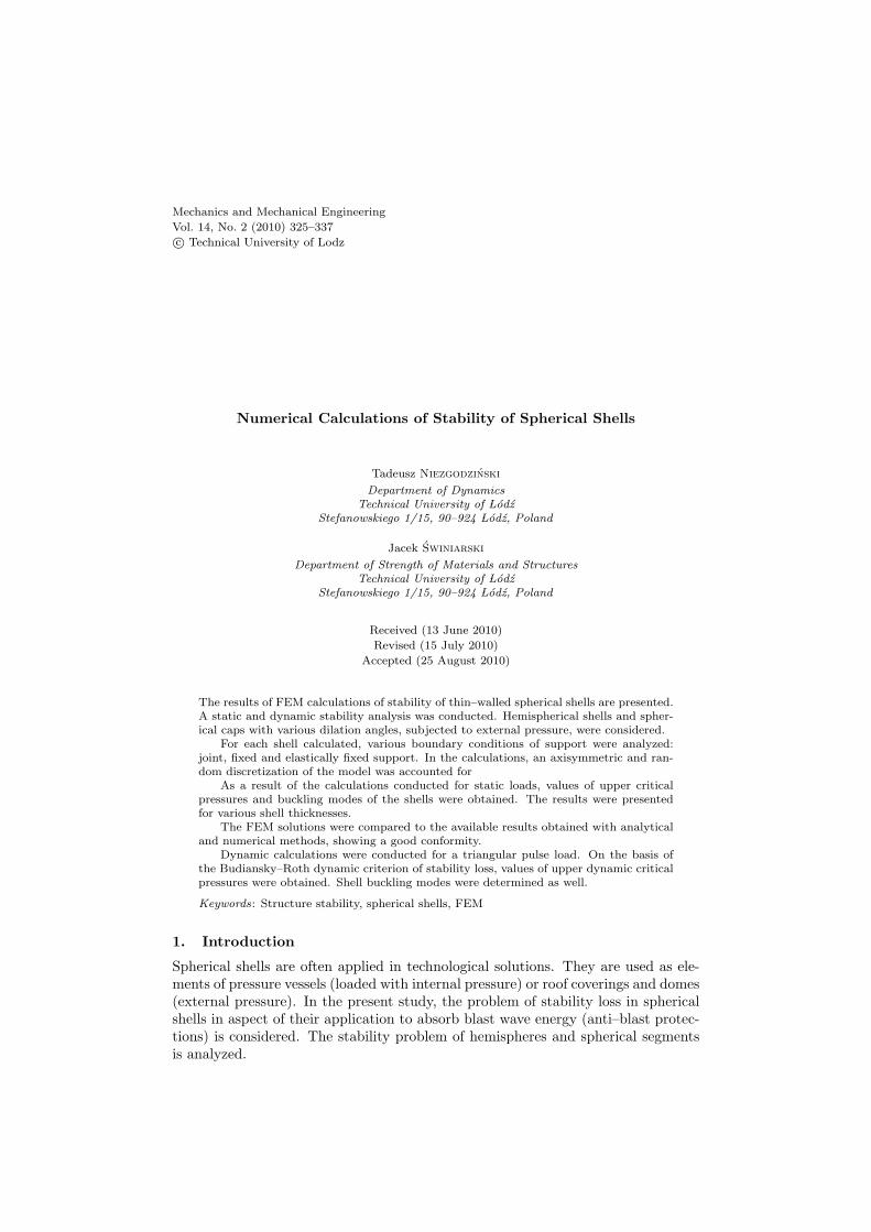
Figure 2 Division of a hemisphere and a spherical cap into finite elementsa)– axisymmetric division,b) c) d) – random division.
2. Solution method
The stability problem was solved numerically with the finite element method. TheFEM ANSYS 12.1 [6] package was employed. The FEM model was built withSHELL43 elements. Such an element enables modeling linear and nonlinear ma-terial properties. It also renders defining the material as a multilayer shell with apossibility to determine orthotropic properties of each layer possible.
Fig. 2 shows a division into finite elements. The computations were conductedboth for an axisymmetric division and for a random division as the axisymmetric
Numerical Calculations of Stability ... 327
division prefers the axially symmetrical deflection mode of the shell. In the case ofthe axisymmetric division, a regular mesh with quadrilateral, eight–node elements(SHELL43) with five degrees of freedom in each node was used [6]. A division intoelements of the whole shell without entailing the axial symmetry with same elementswas considered as well. The dimensions of the elements are comparable for bothdivision cases. The finite elements were selected as to have at least 10 elements pereach halfwave of the deformed shell.
a)b)
c)
uz=0
uy=0
ux=0
uy=0, My=0
uz=0, Mz=0ux=0, Mx=0
uz=0
uy=0
ux=0
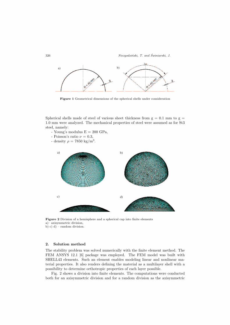
Figure 3 Boundary conditions assumed in the numerical computationsa) – joint support along the lower edge of the hemisphere,b) – fixed support along the lower edge of the hemisphere,c) – displacements ux= uy= uz= 0 along the ”hat rim” circumference.
The computations were conducted for various boundary conditions of the shell sup-port. The following kinds of boundary conditions shown in Fig. 3 were considered:
1. joint support (Fig. 3a),
2. fixed support (Fig. 3b),
3. elastically fixed support – the so-called ”hat with a rim” (Fig. 3c).
328 Niezgodzinski, T. and Swiniarski, J.
3. Calculations of the static stability
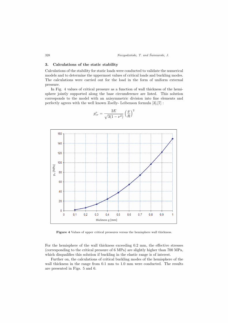
Calculations of the stability for static loads were conducted to validate the numericalmodels and to determine the uppermost values of critical loads and buckling modes.The calculations were carried out for the load in the form of uniform externalpressure.
In Fig. 4 values of critical pressure as a function of wall thickness of the hemi-sphere jointly supported along the base circumference are listed. This solutioncorresponds to the model with an axisymmetric division into fine elements andperfectly agrees with the well known Zoelly- Leibenson formula [3],[7] :
pocr =
2E√3(1− ν2)
( g
R
)2
pcr
[MP
a]
thickness g [mm]
Figure 4 Values of upper critical pressures versus the hemisphere wall thickness.
For the hemisphere of the wall thickness exceeding 0.2 mm, the effective stresses(corresponding to the critical pressure of 6 MPa) are slightly higher than 700 MPa,which disqualifies this solution if buckling in the elastic range is of interest.
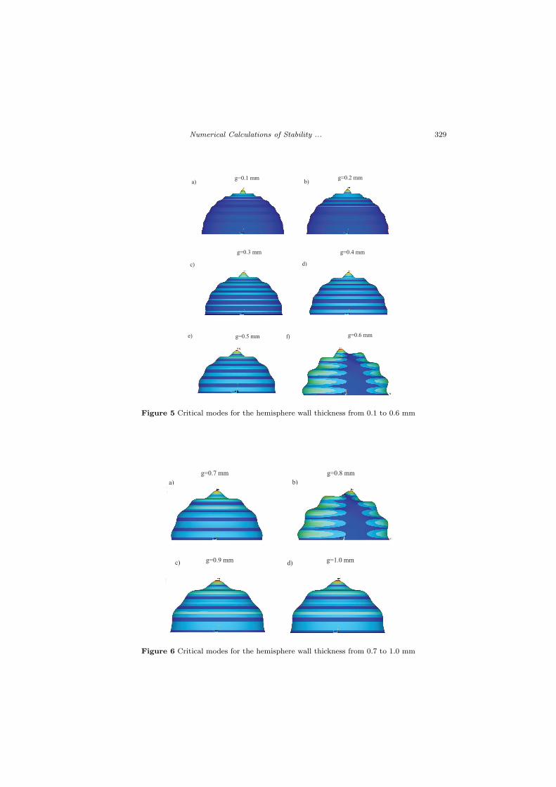
Further on, the calculations of critical buckling modes of the hemisphere of thewall thickness in the range from 0.1 mm to 1.0 mm were conducted. The resultsare presented in Figs. 5 and 6.
Numerical Calculations of Stability ... 329
g=0.1 mm g=0.2 mm
g=0.3 mm g=0.4 mm
a) b)
c) d)
g=0.5 mm g=0.6 mme) f)
Figure 5 Critical modes for the hemisphere wall thickness from 0.1 to 0.6 mm
g=0.8 mmg=0.7 mm
b)a)
d) g=1.0 mmg=0.9 mmc) d)
Figure 6 Critical modes for the hemisphere wall thickness from 0.7 to 1.0 mm
330 Niezgodzinski, T. and Swiniarski, J.
Attention should be paid to the fact that the mode corresponding to the lowestvalue of the upper critical load depends on the way the model is divided into finiteelements. The axisymmetric division entails the axisymmetric mode. An exceptionis the solution presented in Figs. 6.a and 6.d, where the antisymmetry plane canbe seen.
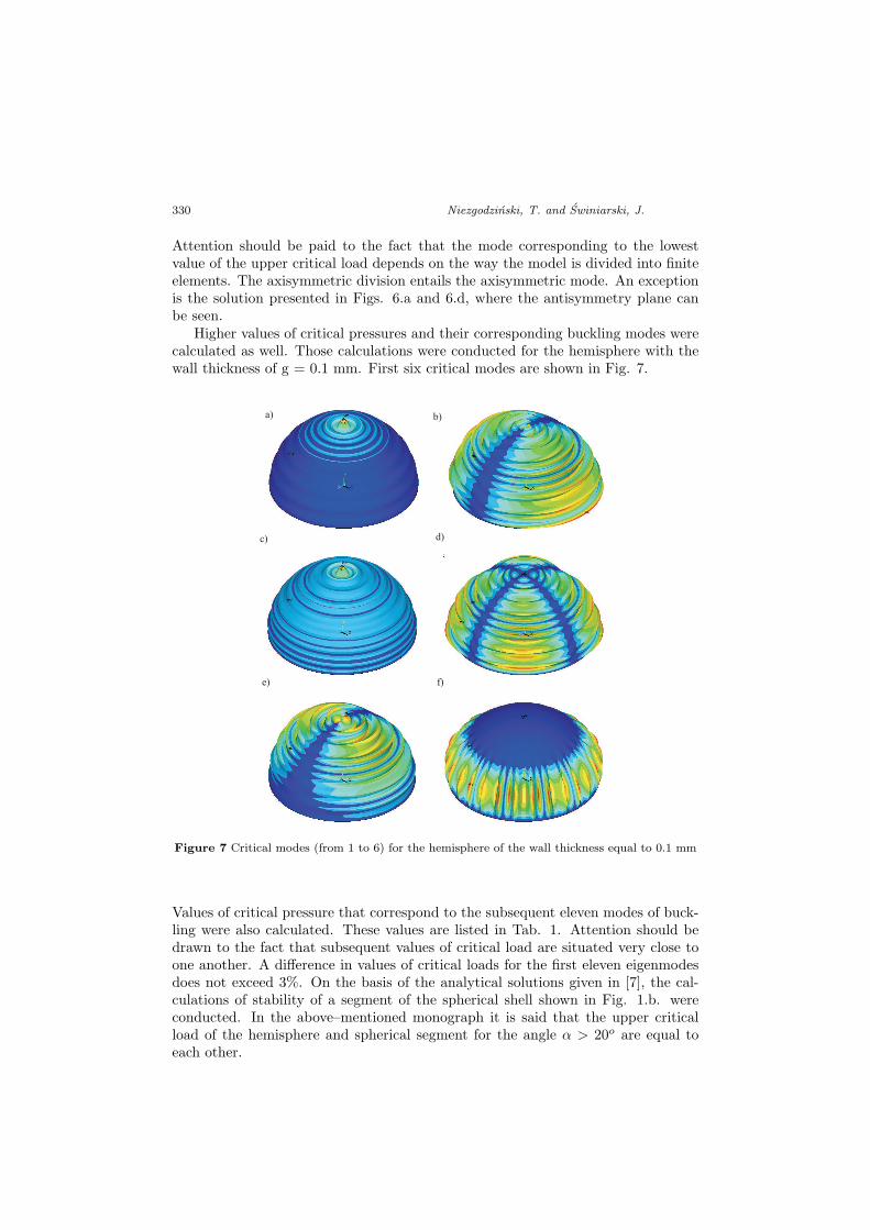
Higher values of critical pressures and their corresponding buckling modes werecalculated as well. Those calculations were conducted for the hemisphere with thewall thickness of g = 0.1 mm. First six critical modes are shown in Fig. 7.
c) d)
e) f)
a) b)
Figure 7 Critical modes (from 1 to 6) for the hemisphere of the wall thickness equal to 0.1 mm
Values of critical pressure that correspond to the subsequent eleven modes of buck-ling were also calculated. These values are listed in Tab. 1. Attention should bedrawn to the fact that subsequent values of critical load are situated very close toone another. A difference in values of critical loads for the first eleven eigenmodesdoes not exceed 3%. On the basis of the analytical solutions given in [7], the cal-culations of stability of a segment of the spherical shell shown in Fig. 1.b. wereconducted. In the above–mentioned monograph it is said that the upper criticalload of the hemisphere and spherical segment for the angle α > 20o are equal toeach other.

Numerical Calculations of Stability ... 331
Table 1 Values of upper critical loads of the hemisphere under external pressure
No. pcr
[MPa]difference %[-]
1 1.516788 02 1.528984 0.793 1.534597 1.164 1.540514 1.545 1.549312 2.096 1.554015 2.397 1.55447 2.428 1.555077 2.469 1.560386 2.7910 1.560538 2.8011 1.560993 2.83
Table 2 Values of critical loads
Analytical-numerical solution for spherical cap 2α=60˚ pcr [MPa]g [mm] solution
from [2]Joint support, non-linear precritical state[2]
Fixed support, non-linear precritical state[2]
0.1 1.513 1.12 / 1.06 1.22 / 1.170.2 6.05 4.79 / 4.25 4.87 / 4.670.3 13.62 10.79 / 9.57 10.96 / 10.510.4 24.21 19.17 / 17.02 19.49 / 18.69FEM solution pcr [MPa]g [mm] Hemisphere
joint sup-port, axialsymmetryof elements
Hemispherejoint sup-port,randomdivision
Hemispherefixed sup-port,axial sym-metry of el-ements
Hat Sphericalcap2α=60o
Sphericalcap2α=120o
0.1 1.51(Fig.8a)
1.528(Fig.8e)
1.51(Fig.8i)
1.51 1.53(Fig.8m)
1.527
0.2 6.04(Fig.8b)
6.086(Fig.8f)
6.05(Fig.8j)
6.06 6.08(Fig.8n)
6.095
0.3 13.57(Fig.8c)
13.64(Fig.8g)
13.6(Fig.8k)
13.60 13.75(Fig.8p)
13.706
0.4 24.08(Fig.8d)
24.21(Fig.8h)
24.16(Fig.8l)
24.16 24.40(Fig.8r)
24.293
332 Niezgodzinski, T. and Swiniarski, J.
d)h) l) r)
c)g) k)
p)
b) f) j) n)
a)e) i) m)
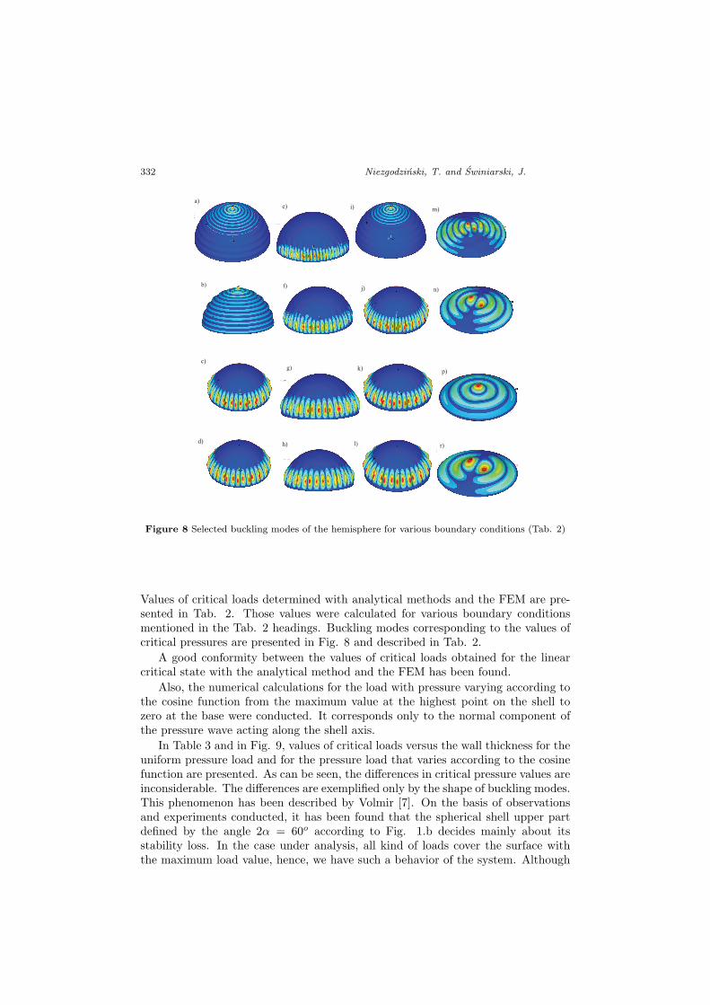
Figure 8 Selected buckling modes of the hemisphere for various boundary conditions (Tab. 2)
Values of critical loads determined with analytical methods and the FEM are pre-sented in Tab. 2. Those values were calculated for various boundary conditionsmentioned in the Tab. 2 headings. Buckling modes corresponding to the values ofcritical pressures are presented in Fig. 8 and described in Tab. 2.
A good conformity between the values of critical loads obtained for the linearcritical state with the analytical method and the FEM has been found.
Also, the numerical calculations for the load with pressure varying according tothe cosine function from the maximum value at the highest point on the shell tozero at the base were conducted. It corresponds only to the normal component ofthe pressure wave acting along the shell axis.
In Table 3 and in Fig. 9, values of critical loads versus the wall thickness for theuniform pressure load and for the pressure load that varies according to the cosinefunction are presented. As can be seen, the differences in critical pressure values areinconsiderable. The differences are exemplified only by the shape of buckling modes.This phenomenon has been described by Volmir [7]. On the basis of observationsand experiments conducted, it has been found that the spherical shell upper partdefined by the angle 2α = 60o according to Fig. 1.b decides mainly about itsstability loss. In the case under analysis, all kind of loads cover the surface withthe maximum load value, hence, we have such a behavior of the system. Although

Numerical Calculations of Stability ... 333
the way the load is applied does not affect the critical mode, it will influence thepostcritical behavior of the hemisphere or the spherical cap.
An effect of alternations in the base diameter at the constant model heightwas also considered. This assumption followed from the requirements imposed byapplications in anti–blast protections. The constant height of the spherical segmentwas assumed as H = 40 mm, whereas the base diameter varied within the rangefrom 2R = D = 80 mm to D = 120 mm, every 10 mm. The structure was subjectto the pressure distributed according to the cosine function.
Table 3 Values of the hemisphere critical pressure
g [mm]wall thickness
Pcr [MPa]uniform distribution
Pcr [MPa]distribution accord-ing to the cosinefunction
0.1 1.513 1.5200.2 6.058 6.0990.3 13.637 13.7490.4 24.225 24.480
0
5
10
15
20
25
30
0,1 0,2 0,3 0,4
gruboœæ œcianki t [mm]
ciœ
nie
nei
kry
tyczn
ep
kr
[MP
a]
obci¹¿enie równomierne
obci¹¿enie liniowo zmienne
obci¹¿enie zmienne wg. funkcji cosinus
pcr
[MP
a]
thickness g [mm]
uniformly distributed load
Figure 9 Critical pressure values for the hemisphere
334 Niezgodzinski, T. and Swiniarski, J.
5
6
7
8
9
10
11
12
13
14
15
80 90 100 110 120
œrednica podstawy D [mm]
pkr
[MP
a]
diameter of the base D [mm]
g [mm]
pcr
[MP
a]
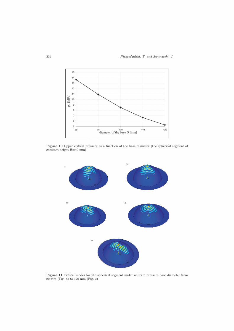
Figure 10 Upper critical pressure as a function of the base diameter (the spherical segment ofconstant height H=40 mm)
a)b)
c) d)
e)
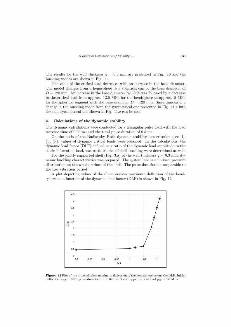
Figure 11 Critical modes for the spherical segment under uniform pressure base diameter from80 mm (Fig. a) to 120 mm (Fig. e)
Numerical Calculations of Stability ... 335
The results for the wall thickness g = 0.3 mm are presented in Fig. 10 and thebuckling modes are shown in Fig. 11.
The value of the critical load decreases with an increase in the base diameter.The model changes from a hemisphere to a spherical cap of the base diameter ofD = 120 mm. An increase in the base diameter by 50 % was followed by a decreasein the critical load from approx. 13.5 MPa for the hemisphere to approx. 5 MPafor the spherical segment with the base diameter D = 120 mm. Simultaneously, achange in the buckling mode from the symmetrical one presented in Fig. 11.a intothe non–symmetrical one shown in Fig. 11.e can be seen.
4. Calculations of the dynamic stability
The dynamic calculations were conducted for a triangular pulse load with the loadincrease time of 0.05 ms and the total pulse duration of 0.5 ms.
On the basis of the Budiansky–Roth dynamic stability loss criterion (see [1],[4], [5]), values of dynamic critical loads were obtained. In the calculations, thedynamic load factor (DLF) defined as a ratio of the dynamic load amplitude to thestatic bifurcation load, was used. Modes of shell buckling were determined as well.
For the jointly supported shell (Fig. 3.a) of the wall thickness g = 0.3 mm, dy-namic buckling characteristics was prepared. The system load is a uniform pressuredistribution on the whole surface of the shell. The pulse duration is comparable tothe free vibration period.
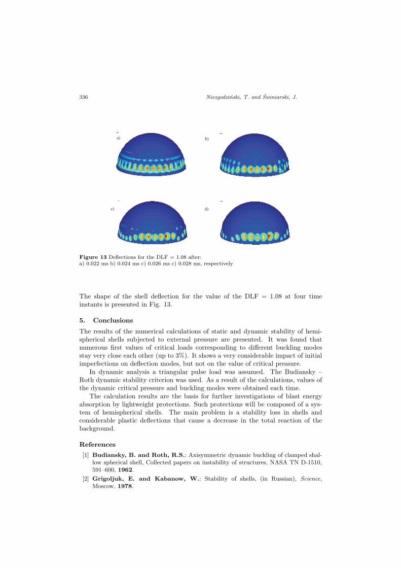
A plot depicting values of the dimensionless maximum deflection of the hemi-sphere as a function of the dynamic load factor (DLF) is shown in Fig. 12.
0
0,5
1
1,5
2
2,5
3
3,5
4
4,5
0,8 0,85 0,9 0,95 1 1,05 1,1
DLF
U/tw/g
Figure 12 Plot of the dimensionless maximum deflection of the hemisphere versus the DLF. Initialdeflection w/g = 0.01; pulse duration t = 0.09 ms. Static upper critical load pcr=13.6 MPa.
336 Niezgodzinski, T. and Swiniarski, J.
a) b)
c) d)
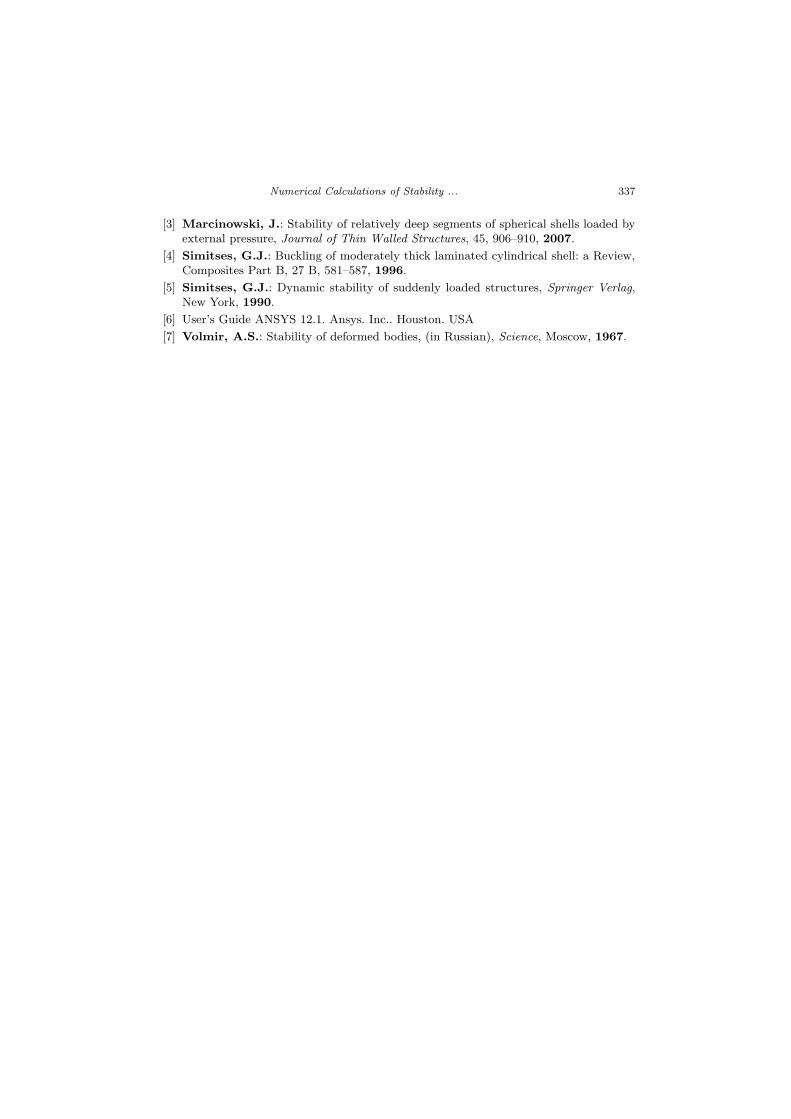
Figure 13 Deflections for the DLF = 1.08 after:a) 0.022 ms b) 0.024 ms c) 0.026 ms c) 0.028 ms, respectively
The shape of the shell deflection for the value of the DLF = 1.08 at four timeinstants is presented in Fig. 13.
5. Conclusions
The results of the numerical calculations of static and dynamic stability of hemi-spherical shells subjected to external pressure are presented. It was found thatnumerous first values of critical loads corresponding to different buckling modesstay very close each other (up to 3%). It shows a very considerable impact of initialimperfections on deflection modes, but not on the value of critical pressure.
In dynamic analysis a triangular pulse load was assumed. The Budiansky –Roth dynamic stability criterion was used. As a result of the calculations, values ofthe dynamic critical pressure and buckling modes were obtained each time.
The calculation results are the basis for further investigations of blast energyabsorption by lightweight protections. Such protections will be composed of a sys-tem of hemispherical shells. The main problem is a stability loss in shells andconsiderable plastic deflections that cause a decrease in the total reaction of thebackground.
References
[1] Budiansky, B. and Roth, R.S.: Axisymmetric dynamic buckling of clamped shal-low spherical shell, Collected papers on instability of structures, NASA TN D-1510,591–600, 1962.
[2] Grigoljuk, E. and Kabanow, W.: Stability of shells, (in Russian), Science,Moscow, 1978.
Numerical Calculations of Stability ... 337
[3] Marcinowski, J.: Stability of relatively deep segments of spherical shells loaded byexternal pressure, Journal of Thin Walled Structures, 45, 906–910, 2007.
[4] Simitses, G.J.: Buckling of moderately thick laminated cylindrical shell: a Review,Composites Part B, 27 B, 581–587, 1996.
[5] Simitses, G.J.: Dynamic stability of suddenly loaded structures, Springer Verlag,New York, 1990.
[6] User’s Guide ANSYS 12.1. Ansys. Inc.. Houston. USA
[7] Volmir, A.S.: Stability of deformed bodies, (in Russian), Science, Moscow, 1967.