Embed Size (px)
Citation preview
Purdue UniversityPurdue e-Pubs
CTRC Research Publications Cooling Technologies Research Center
2007
Numerical and Experimental Investigation ofSolidification ShrinkageD. Sun
S V. GarimellaPurdue University, [email protected]
Follow this and additional works at: http://docs.lib.purdue.edu/coolingpubs
This document has been made available through Purdue e-Pubs, a service of the Purdue University Libraries. Please contact [email protected] foradditional information.
Sun, D. and Garimella, S V., "Numerical and Experimental Investigation of Solidification Shrinkage" (2007). CTRC ResearchPublications. Paper 282.http://dx.doi.org/10.1080/10407780601115079
Numerical and Experimental Investigation of Solidification Shrinkage*
Dawei Sun and Suresh V Garimella†
School of Mechanical Engineering, Purdue University, West Lafayette, Indiana 47907 USA
Abstract
The solidification heat transfer, melt convection and volume shrinkage in the casting of an
energetic material are analyzed through numerical modeling and experimental investigation. The
shrinkage resulting from phase change is considered through the volume of fluid method. The
model is validated against an analytical solution and then applied to study the volume contraction
during the casting of tri-nitro-toluene (TNT). Good agreement is obtained between experimental
results and predictions of temperatures at selected locations as well as shrinkage shape. New
casting conditions are suggested based on the analysis, and improved results are observed both
numerically and experimentally.
* Accepted for publication in Numerical Heat Transfer, September 2006 † Corresponding author, email: [email protected], Tel: +1-765-494-5621, FAX: +1-765-494-0539
1
1. INTRODUCTION
Solid-liquid phase change is widely encountered in engineering applications such as casting,
thermal sprays and energy storage. Substantial shrinkage is often observed during these
processes due to the density change upon solidification [1-3]. In the absence of a feeding
mechanism in place to compensate for this volumetric change, the resulting shrinkage can lead to
undesirable features such as void formation, poor heat transfer, and excessive residual stresses.
In the casting of energetic materials, shrinkage-induced density non-uniformities and void
formation can significantly impair the detonation velocity, Gurney energy, and insensitive
munitions characteristics of the formulation, and lead to catastrophic accidents in explosives
handling [4, 5]. Compared to the trial and error approaches generally adopted in explosives
casting, numerical simulation offers improved understanding of solidification shrinkage and
associated phenomena, and can help to better control shrinkage behavior.
Numerical investigations of solidification heat transfer have focused on the analysis of heat
conduction and melt convection; the effects of shrinkage have often been ignored due to the
difficulties involved in multiphase pressure-velocity coupling, and the interaction between free
surface dynamics and solidification volume change [6-8]. The effects of density change on
solidification can be studied by using continuous mass feeding to avoid the difficulties of
tracking the shrinkage shapes explicitly [9, 10]. However, in many applications, phase change
takes place in an enclosure and predicting the shrinkage shapes is critical to understanding the
process. For problems involving relatively simple geometries, the shrinkage shape can be
tracked by deforming the computational mesh to accommodate the volumetric change [1, 2, 11,
12]. A simplified front-tracking method was used by Chiang and Tsai [13] to investigate the
effects of solidification-induced flow on heat transfer. The free surface was assumed to be flat,
2
so that the shrinkage shape could not be resolved. Based on coordinate transformation and
different grid adaptation schemes, the shrinkage of paraffin wax in an open cavity was studied by
Kim and Ro [11] and Zhang et al. [12]. A complex grid deformation scheme was developed by
Naterer [2] to track the free surface movement during solidification of a binary alloy. More
recently, Bellet et al. [14] proposed an arbitrary Lagrangian-Eulerian (ALE) method to
investigate the pipe shrinkage formation during solidification. In the studies discussed above,
the free surface movement due to volumetric change was tracked by deforming the finite element
mesh. The use of moving meshes for solidification shrinkage, however, has its limitations.
Comprehensive mesh deformation schemes have to be developed to accommodate the
volumetric changes and account for the free surface movement. This can be extremely
challenging as shrinkage shape evolves during solidification/melting. Maintaining the mesh
quality is another serious challenge.
Such difficulties are avoided in methods based on a fixed mesh, provided an efficient
tracking algorithm is developed. While considerable research has been targeted at developing
front tracking methods for free/moving surface problems, such as level set, phase field, and other
methods [15-20], limited effort has been devoted to the study of solidification shrinkage.
Trovant and Argyropoulos [1] proposed a fixed grid numerical model for phase change problems.
Effective shrinkage was calculated at each time step and the volume of the solidified material
was then subtracted from the liquid phase in the control volumes that contain the interface. A
free surface was, however, not considered. Solidification shrinkage in cylindrical and T-shaped
castings was studied [21], with only energy equations solved in the mold and casting; shrinkage
was calculated by evaluating local volume changes in each control volume. Ehlen et al. [22]
investigated the formation of shrinkage cavities and macrosegregation in steel casting. The VOF
3
method [23] was used to track the free surface movement and a slip solid method was proposed
to treat the dynamic change in solid fraction in the mushy zone. A very coarse mesh was used
and only qualitative comparisons of the cavity shape were provided. The effects of density
change due to solid/liquid phase change during droplet impact and solidification were
investigated recently by Raessi and Mostaghimi [3]. A generic three-dimensional formulation
was developed and the shrinkage shape captured using the VOF method. In all of these studies,
only qualitative comparisons of shrinkage shapes have been provided; detailed comparisons of
temperature predictions with experimental data were not made.
In the present work, a numerical method is developed for modeling solidification shrinkage
based on the volume of fluid (VOF) method. Special attention is paid to shrinkage formation
during the casting of an energetic material, tri-nitro-toluene (TNT), in a cylinder. The model is
first validated against an analytical solution, and then applied to the casting problem of interest.
Detailed comparisons are provided for the predicted and measured temperature fields and
shrinkage cavity shapes. Approaches for controlling shrinkage shape through active cooling are
also discussed.
2. EXPERIMENTAL INVESTIGATION
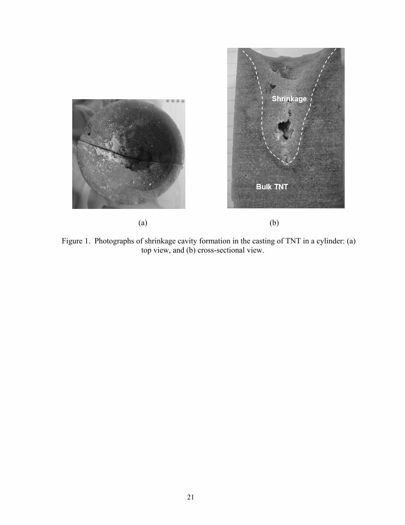
It is well known that TNT experiences a large density change upon solidification [24].
Macroscopic shrinkage is often observed in practice as shown in Figure 1. A tall riser is
generally used to avoid the effects of shrinkage on the cast munitions, resulting in significant
material waste.
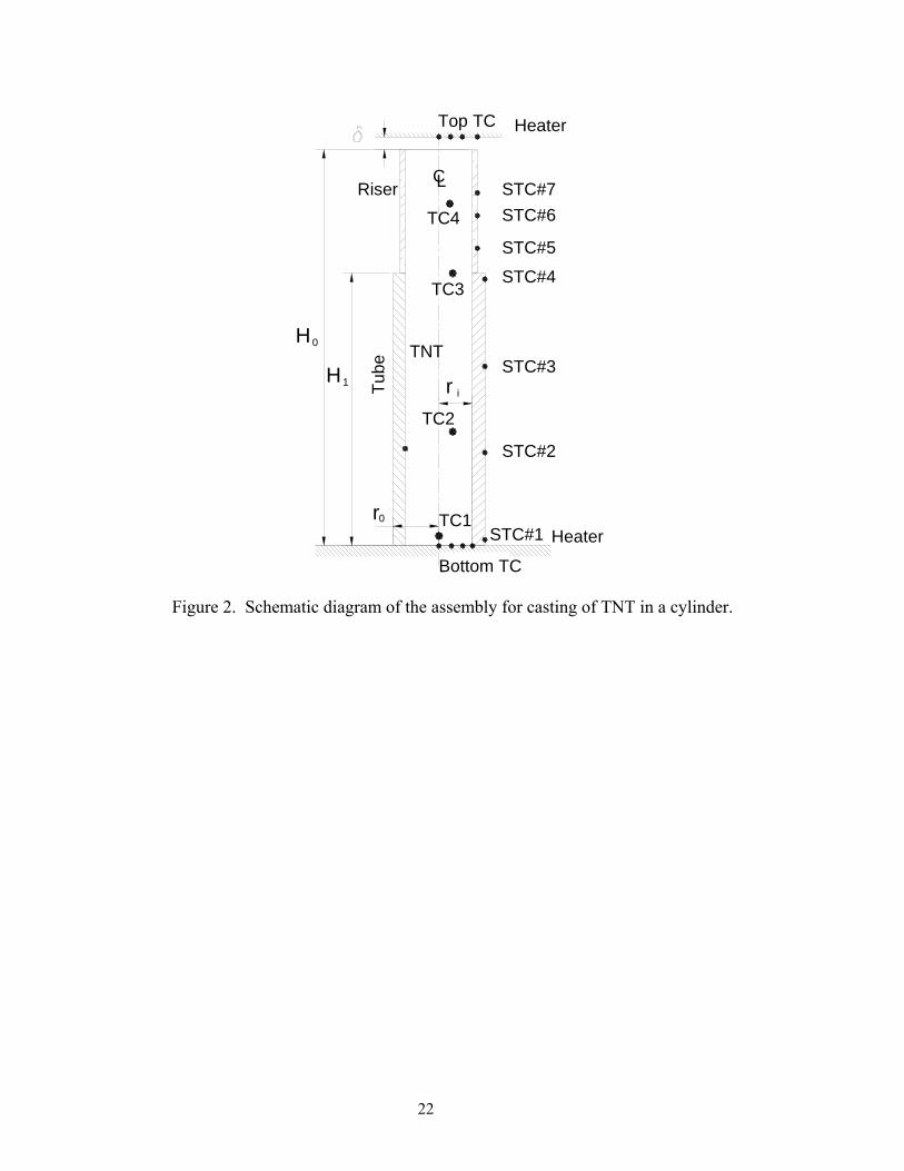
The casting assembly considered in this work consists of a stainless steel mold (ASTM 1026)
and an aluminum riser, as illustrated in Figure 2. Steam heaters are placed on the top and bottom
of the assembly to control the solidification process. Both heaters are instrumented with
4
thermocouples, as are the outside walls of the tube and riser, to provide temperature boundary
conditions for simulations; these are shown as solid dots on the figure. The casting is open to
ambient at the top; a small gap (δ = 1 cm) separates the top of the riser from the heater on top.
Twenty Type-K thermocouples are positioned in a grid inside the mold to record transient
temperature changes during casting. The locations of three representative internal thermocouples
are marked as TC1, 2, 3 and 4 in Figure 2. Seven thermocouples are attached to the outside
walls of the riser and tube, marked as STC#1-7, as depicted in Figure 2. The uncertainty in
measured temperatures is estimated to be 2 K.
The thermophysical properties for TNT are well documented [24-26], and the relevant values
are listed in Table 1. The density of TNT is strongly influenced by temperature, and can be
given as follows:
( )
3
3
1648 kg/m ,
1544.6 1.016 273.15 kg/m ,m
m
T T
T Tρ
⎧
T
<⎪= ⎨− − ≥⎪⎩
(1)
in which Tm = 354.15 K is the melting point of TNT and temperature T is in Kelvin. This 13%
density change upon solidification results in significant shrinkage (Figure 1).
Under normal operating conditions, TNT behaves like a Newtonian fluid, the viscosity of
which can be written as [26]
75.41exp(3570 ) 10 Pa sTµ −= × ⋅ (2)
where T is temperature in Kelvin.
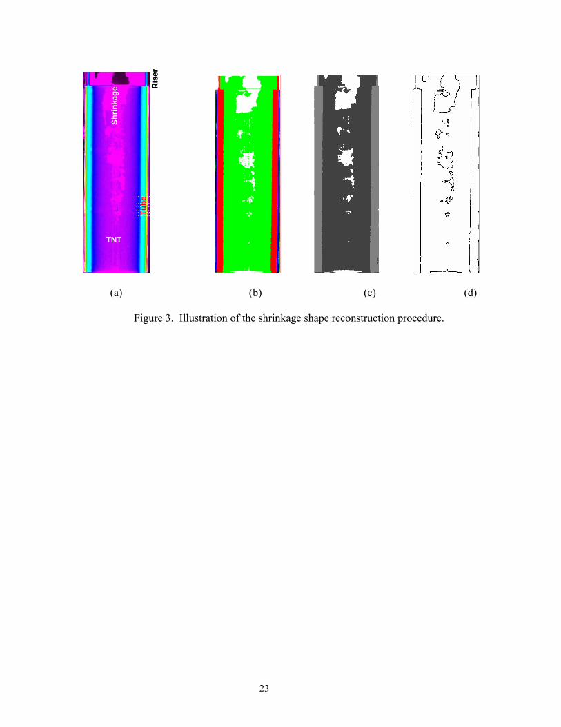
The solidified samples obtained by casting are examined by CT scan as shown in the vertical
cross-sectional scans of Figure 3. The outline of the solidification shrinkage is extracted from
the scans using the image processing toolbox in Matlab [27]. The solidified TNT, metal parts
(mold and riser) and air appear as different colors in the CT scan images, facilitating
5
identification of voids (Figure 3a). Contrast enhancement, intensity thresholding, and filtering
operations are used to unify the color indices and enhance the quality of the image so that the
shape of the shrinkage/voids may be more clearly detected. The detailed procedure is described
in Jones et al. [7] and consists of the following steps. The CT scan image is first processed to
change the colors in the riser region so that the mold and riser regions have similar color indices.
Linear contrast enhancement is then applied to different regions along the height of the image
based on the RGB values at a given pixel. This increases the contrast between different regions
and highlights the boundaries (Figure 3b). The image is then converted to grayscale format to
prepare for edge detection, as shown in Figure 3c.
A threshold was used to remove low-intensity pixel values. If Th represents the threshold
intensity value, this operation is described by
(3) ( ) ( )0, if ( , )
, = , if ( , )
ii
i i
h x y Th x y
h x y h x y T<⎧
⎨ ≥⎩
h
h
where hi(x,y) is the intensity in region i. The threshold value was manually adjusted until a good
compromise was achieved between attenuation of low-intensity noise and retention of original
detail.
A 10×10 median filter was employed to smooth out the remaining noise and artifacts. The
edge detection employed a gradient-based method by implementing Robert’s approximation for
the derivative. This method sets the pixel value to maximum intensity at the locations where the
gradient is a local maximum. Figure 3d shows the edges that were detected in the image shown
in Figure 3c. The inner curves in Figure 3d represent the shrinkage shape, and the outer edges
are the interfaces between different parts and the boundaries of the system. The actual shape of
the shrinkage was then determined from a knowledge of the image-to-object dimensional ratio,
6
which was found by comparing the known outer diameter and height of the tube to the number of
pixels these distances occupy in the image.
3. MATHEMATICAL MODELING
In order to analyze the shrinkage and void formation caused by the density change during
solidification, the algorithm employed must be capable of tracking a moving free surface. The
volume of fluid (VOF) method is employed in this work since it can handle free surface
movement and has been previously applied to study solidification shrinkage. For the casting
problem considered, only two phases, i.e., TNT and air, are present in the system. Molten TNT
is assumed to behave as a Newtonian, incompressible fluid. When the density change upon
solidification is taken into consideration, the mass conservation equation for the explosives can
be written as [3, 28]:
( ) ( ) ,l l lu St eααρ αρ∂
+∇⋅ =∂
(4)
The source term Sα,e in Eq. (4) is introduced due to the density difference between the solid and
liquid phases, and is given by
( ) [,e l s s sS ftα α ρ ρ α ρ∂
= − −∇⋅⎡ ⎤⎣ ⎦∂]l lf u (5)
where α is the volume fraction of TNT, fl is the liquid fraction, and subscripts l and s denote
liquid and solid, respectively.
The momentum and energy are dependent on the volume fraction of the different phases
through ρ, µ and k, which are evaluated according:
( ) ( )1 ; 1e a e aρ αρ α ρ µ αµ α µ= + − = + − (6)
7
( )12 2
TNT eff air eff
TNT eff air eff
k k k k
k k k kα α
− −0+ −
+ +
⎛ ⎞ ⎛⎜ ⎟ ⎜⎜ ⎟ ⎜⎝ ⎠ ⎝
=⎞⎟⎟⎠
(7)
where the subscripts e and a denote explosives and air, respectively. A single set of momentum
and energy equations may thus be solved for all phases. As a consequence, the momentum and
energy equations can be written in the following form with h denoting the specific enthalpy:
( ) ( ) ( ) ,l l
l l l l u uu u u p u g T T S St α
ρ ρ µ β ∞∂
+∇ ⋅ = −∇ +∇ ⋅ ∇ + − + +∂
(8)
( ) ( )ll l eff T
h u h k T Stρ
ρ∂
+∇⋅ = ∇⋅ ∇ +∂
(9)
where
( ) ( ) ( ),2 1 and 3
l lu l l e T s s s
f f hS u u S f Ht tα µ ρ α ρ ρ ρ∂ ∂ ∂
l t⎡ ⎤= − ∇ ∇⋅ − + = − ∆ + −⎢ ⎥∂ ∂ ∂⎣ ⎦
(10)
are additional source terms introduced due to the density change.
The transport equations for heat transfer, solidification and free surface movement, Eqs. (4),
(8), (9), are solved using the commercial software package FLUENT, with the SIMPLEC
algorithm employed for pressure-velocity coupling, the pressure staggered option (PRESTO!)
used for pressure correction, and the volume-of-fluid (VOF) method employed for the free
surface. The convective terms in the momentum and energy equation are discretized with
second-order upwind differencing. The solidification process is handled with an enthalpy-
porosity approach based on fixed grids [29]. The geometric reconstruction scheme is used for
convection and diffusion flux interpolations near the interface in the VOF implementation. The
additional source terms introduced due to the density change are handled through the user
defined function (UDF) and user defined memory (UDM) features in FLUENT.
8
4. RESULTS AND DISCUSSION
4.1. Model validation
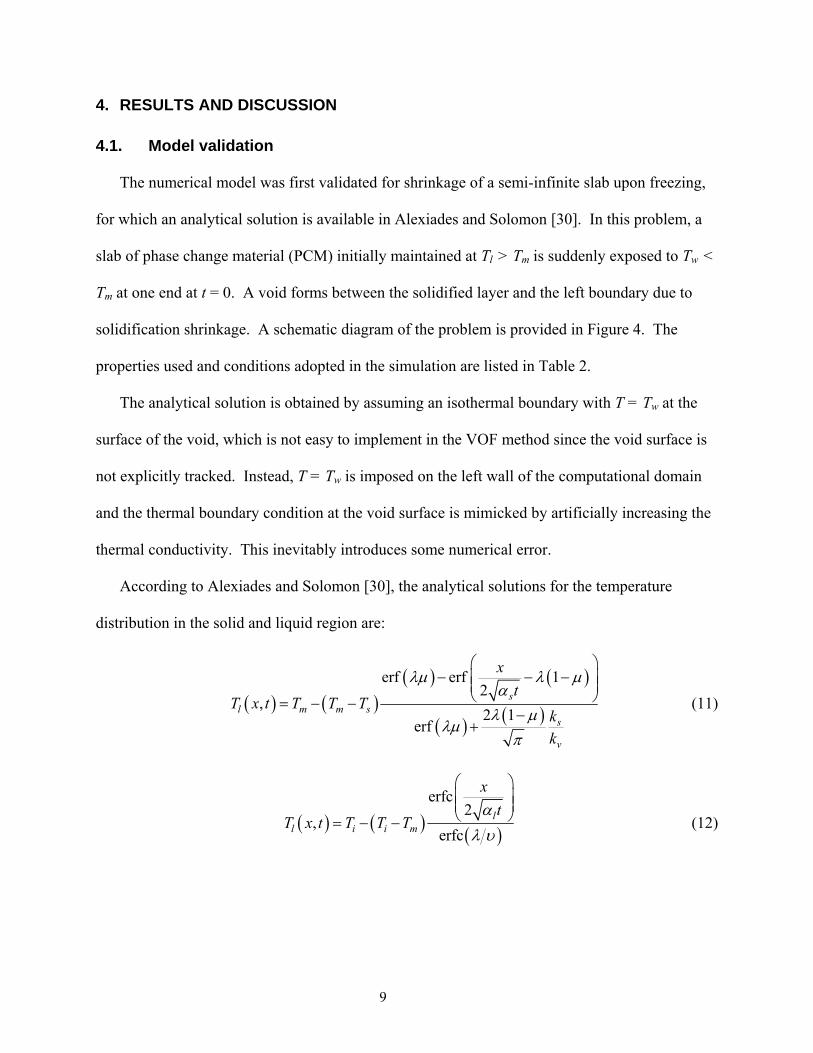
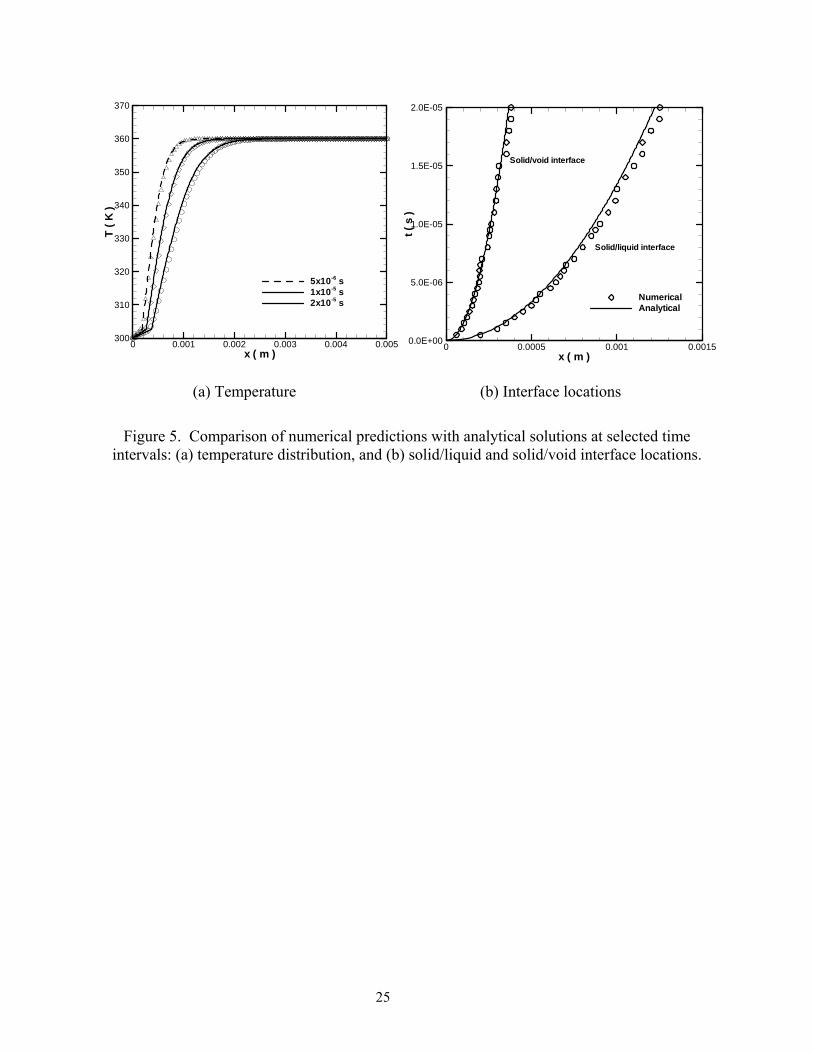
The numerical model was first validated for shrinkage of a semi-infinite slab upon freezing,
for which an analytical solution is available in Alexiades and Solomon [30]. In this problem, a
slab of phase change material (PCM) initially maintained at Tl > Tm is suddenly exposed to Tw <
Tm at one end at t = 0. A void forms between the solidified layer and the left boundary due to
solidification shrinkage. A schematic diagram of the problem is provided in Figure 4. The
properties used and conditions adopted in the simulation are listed in Table 2.
The analytical solution is obtained by assuming an isothermal boundary with T = Tw at the
surface of the void, which is not easy to implement in the VOF method since the void surface is
not explicitly tracked. Instead, T = Tw is imposed on the left wall of the computational domain
and the thermal boundary condition at the void surface is mimicked by artificially increasing the
thermal conductivity. This inevitably introduces some numerical error.
According to Alexiades and Solomon [30], the analytical solutions for the temperature
distribution in the solid and liquid region are:
( ) ( )( ) ( )
( ) ( )
erf erf 12
,2 1
erf
sl m m s
s
v
xt
T x t T T Tkk
λµ λαλ µ
λµπ
⎛ ⎞− − −⎜ ⎟⎜ ⎟
⎝= − −−
+
µ⎠ (11)
( ) ( ) ( )
erfc2
,erfc
ll i i m
xt
T x t T T Tα
λ υ
⎛ ⎞⎜ ⎟⎜ ⎟⎝= − − ⎠ (12)
9
where µ=ρl / ρs, υ2=αl /αs, and the parameter λ takes a value of 1.3564 for this problem
configuration. The solid/liquid front location X(t) and solid/void interface location Y(t) are
expressed as follows:
( ) ( ) ( )2 , and ( ) 1sX t t Y tλ α ν= = − X t (13)
The slab length of L = 5 mm was discretized into 102 mesh points in the x-direction. The
predicted temperature distributions, and solid-liquid and solid-void interface locations are
compared with the analytical solutions in Figure 5. The average deviation of the predicted
variable φ (temperature or location) from the analytical solution, defined as
, ,
1 0
1 100%N
Num i Ana i
iNφ φ
εφ=
−= ∑ × (14)
is examined, with N being the total number of grid points; φ0 is the temperature scale, ∆T = (Tl –
Tw), or the length scale L. The average deviations for predicted void interface and solid front
locations are 0.14% and 0.56%, respectively, after the first 2×10⁻⁵s. For predicted temperature,
deviations of 0.28%, 0.38% and 0.67% were found at t = 5×10⁻⁶ s, 1×10⁻⁵ s, and 2×10⁻⁵ s,
respectively. The agreement between predictions and analytical solutions is quite satisfactory.
The error introduced in implementing isothermal boundary conditions at the void surface is the
main reason for the observed discrepancy. The effects of such an approximation become more
pronounced as solidification progresses, as indicated in the comparisons.
4.2. Casting of TNT in a cylinder
The casting of the energetic material, TNT, in a cylinder is now considered as described in
Section 2. The transient nature of shrinkage formation during the casting process is analyzed
10
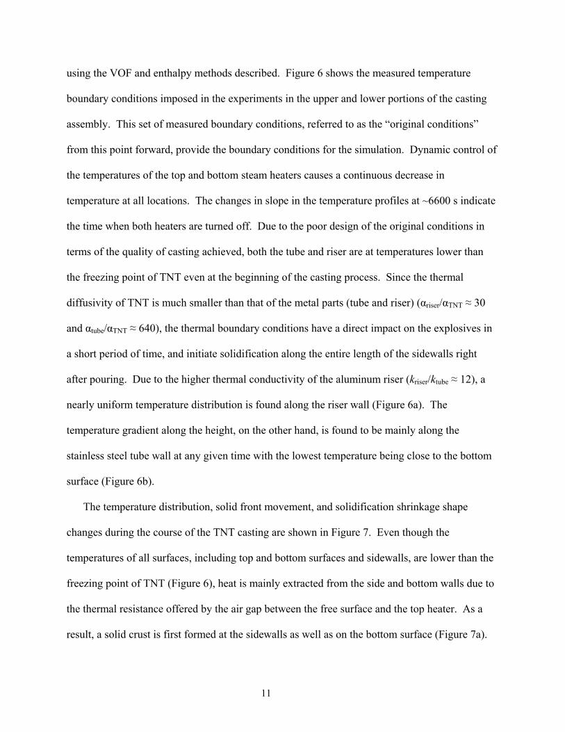
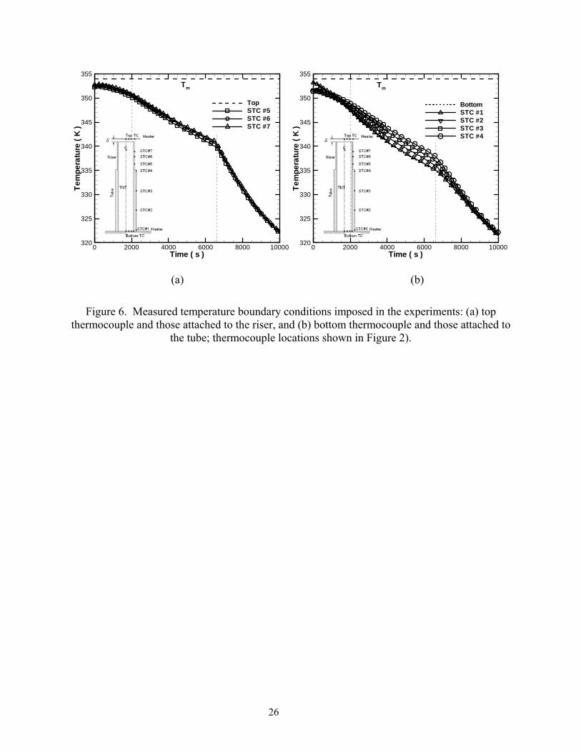
using the VOF and enthalpy methods described. Figure 6 shows the measured temperature
boundary conditions imposed in the experiments in the upper and lower portions of the casting
assembly. This set of measured boundary conditions, referred to as the “original conditions”
from this point forward, provide the boundary conditions for the simulation. Dynamic control of
the temperatures of the top and bottom steam heaters causes a continuous decrease in
temperature at all locations. The changes in slope in the temperature profiles at ~6600 s indicate
the time when both heaters are turned off. Due to the poor design of the original conditions in
terms of the quality of casting achieved, both the tube and riser are at temperatures lower than
the freezing point of TNT even at the beginning of the casting process. Since the thermal
diffusivity of TNT is much smaller than that of the metal parts (tube and riser) (αriser/αTNT ≈ 30
and αtube/αTNT ≈ 640), the thermal boundary conditions have a direct impact on the explosives in
a short period of time, and initiate solidification along the entire length of the sidewalls right
after pouring. Due to the higher thermal conductivity of the aluminum riser (kriser/ktube ≈ 12), a
nearly uniform temperature distribution is found along the riser wall (Figure 6a). The
temperature gradient along the height, on the other hand, is found to be mainly along the
stainless steel tube wall at any given time with the lowest temperature being close to the bottom
surface (Figure 6b).
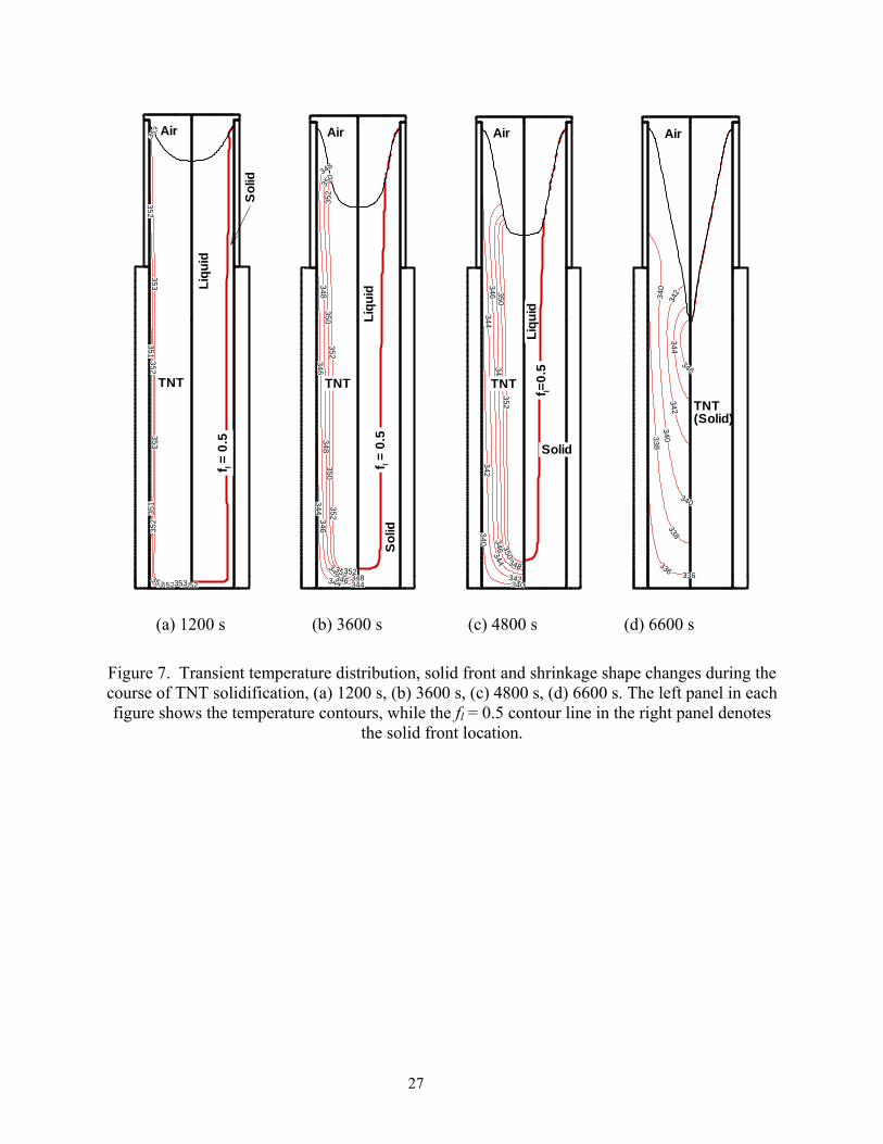
The temperature distribution, solid front movement, and solidification shrinkage shape
changes during the course of the TNT casting are shown in Figure 7. Even though the
temperatures of all surfaces, including top and bottom surfaces and sidewalls, are lower than the
freezing point of TNT (Figure 6), heat is mainly extracted from the side and bottom walls due to
the thermal resistance offered by the air gap between the free surface and the top heater. As a
result, a solid crust is first formed at the sidewalls as well as on the bottom surface (Figure 7a).
11
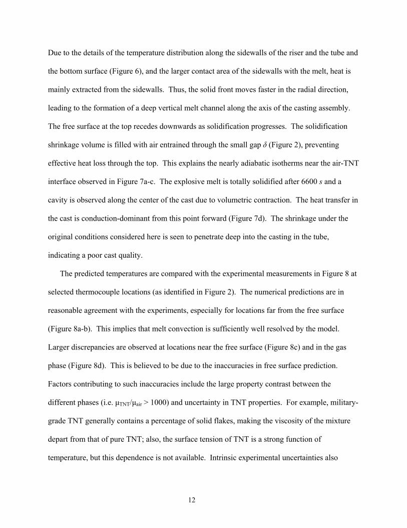
Due to the details of the temperature distribution along the sidewalls of the riser and the tube and
the bottom surface (Figure 6), and the larger contact area of the sidewalls with the melt, heat is
mainly extracted from the sidewalls. Thus, the solid front moves faster in the radial direction,
leading to the formation of a deep vertical melt channel along the axis of the casting assembly.
The free surface at the top recedes downwards as solidification progresses. The solidification
shrinkage volume is filled with air entrained through the small gap δ (Figure 2), preventing
effective heat loss through the top. This explains the nearly adiabatic isotherms near the air-TNT
interface observed in Figure 7a-c. The explosive melt is totally solidified after 6600 s and a
cavity is observed along the center of the cast due to volumetric contraction. The heat transfer in
the cast is conduction-dominant from this point forward (Figure 7d). The shrinkage under the
original conditions considered here is seen to penetrate deep into the casting in the tube,
indicating a poor cast quality.
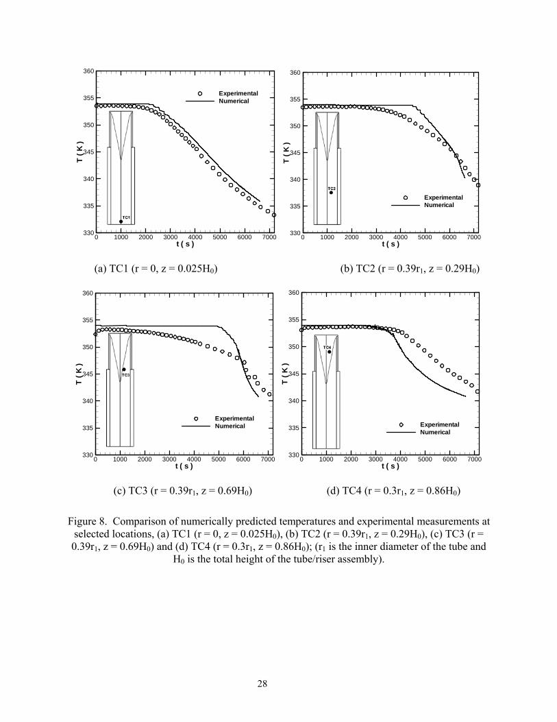
The predicted temperatures are compared with the experimental measurements in Figure 8 at
selected thermocouple locations (as identified in Figure 2). The numerical predictions are in
reasonable agreement with the experiments, especially for locations far from the free surface
(Figure 8a-b). This implies that melt convection is sufficiently well resolved by the model.
Larger discrepancies are observed at locations near the free surface (Figure 8c) and in the gas
phase (Figure 8d). This is believed to be due to the inaccuracies in free surface prediction.
Factors contributing to such inaccuracies include the large property contrast between the
different phases (i.e. µTNT/µair > 1000) and uncertainty in TNT properties. For example, military-
grade TNT generally contains a percentage of solid flakes, making the viscosity of the mixture
depart from that of pure TNT; also, the surface tension of TNT is a strong function of
temperature, but this dependence is not available. Intrinsic experimental uncertainties also
12
contribute to the differences between the experiment and predictions. The energetic nature of
TNT limited the choice of the thermocouple rake material to inert wooden dowels (4 mm
diameter) which impact the melt convection and solidification behavior due to their non-
negligible size compared to the size of the tube (~39 mm diameter). Significant deformation was
also observed in the aluminum riser after casting, resulting in an irregular shape of the cast
material (Figure 1b); this is not accounted for in the model and would also contribute to
discrepancies in the comparison. Due to the lack of detailed information on circumferential
variations in the thermal boundary condition, the three-dimensionality of the shrinkage formation
can also not be fully captured. Voids caused by dissolved gas also cannot be handled by the
model in its current form.
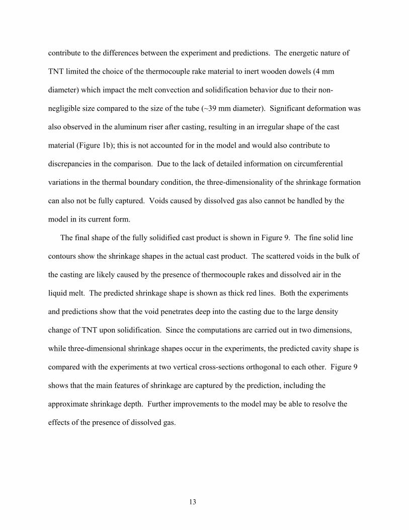
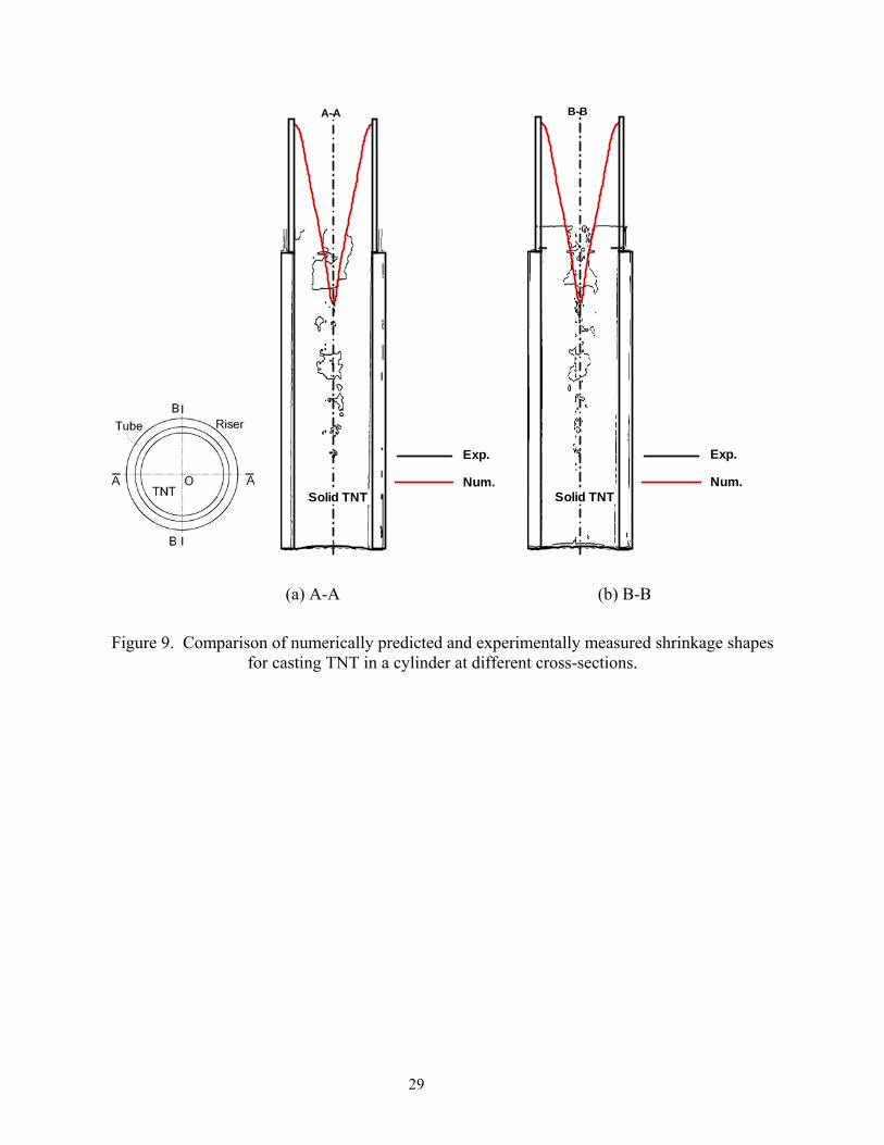
The final shape of the fully solidified cast product is shown in Figure 9. The fine solid line
contours show the shrinkage shapes in the actual cast product. The scattered voids in the bulk of
the casting are likely caused by the presence of thermocouple rakes and dissolved air in the
liquid melt. The predicted shrinkage shape is shown as thick red lines. Both the experiments
and predictions show that the void penetrates deep into the casting due to the large density
change of TNT upon solidification. Since the computations are carried out in two dimensions,
while three-dimensional shrinkage shapes occur in the experiments, the predicted cavity shape is
compared with the experiments at two vertical cross-sections orthogonal to each other. Figure 9
shows that the main features of shrinkage are captured by the prediction, including the
approximate shrinkage depth. Further improvements to the model may be able to resolve the
effects of the presence of dissolved gas.
13
4.3. Controlling shrinkage through improved casting conditions
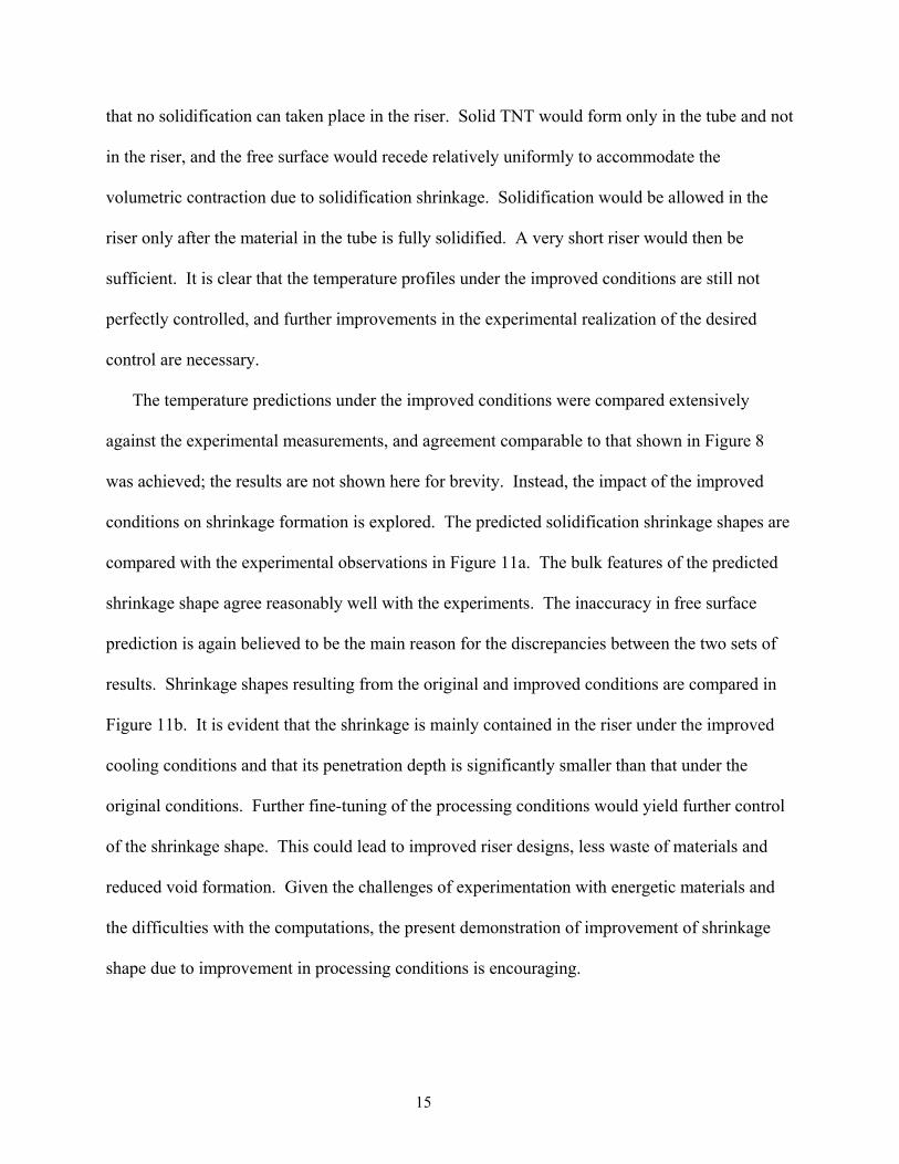
The large amount of shrinkage observed in Figure 9 can impair the quality of the cast; more
importantly, the presence of the shrinkage and air bubbles can lead to catastrophic accidents
during explosives handling. It is thus highly desirable to control the shape of the shrinkage so as
to restrict it to the riser portion of the casting. Analysis of the results discussed above
demonstrates that the transient solid front movement is determined by the imposed thermal
boundary conditions, which in turn control the final shape of the shrinkage after casting. When
melt in the riser solidifies at the same rate as that in the tube, as happens under the original
conditions considered thus far (Figure 6), radial solid front movement is observed, resulting in
shrinkage penetration into the tube (Figure 7). Deferring solidification of TNT in the riser while
promoting it in the tube, on the other hand, can contain the volumetric contraction in the riser
alone, thus preventing the deep vertical shrinkage pattern observed above. This can be achieved
by means of well-controlled thermal boundary conditions and appropriate choice of riser
dimensions.
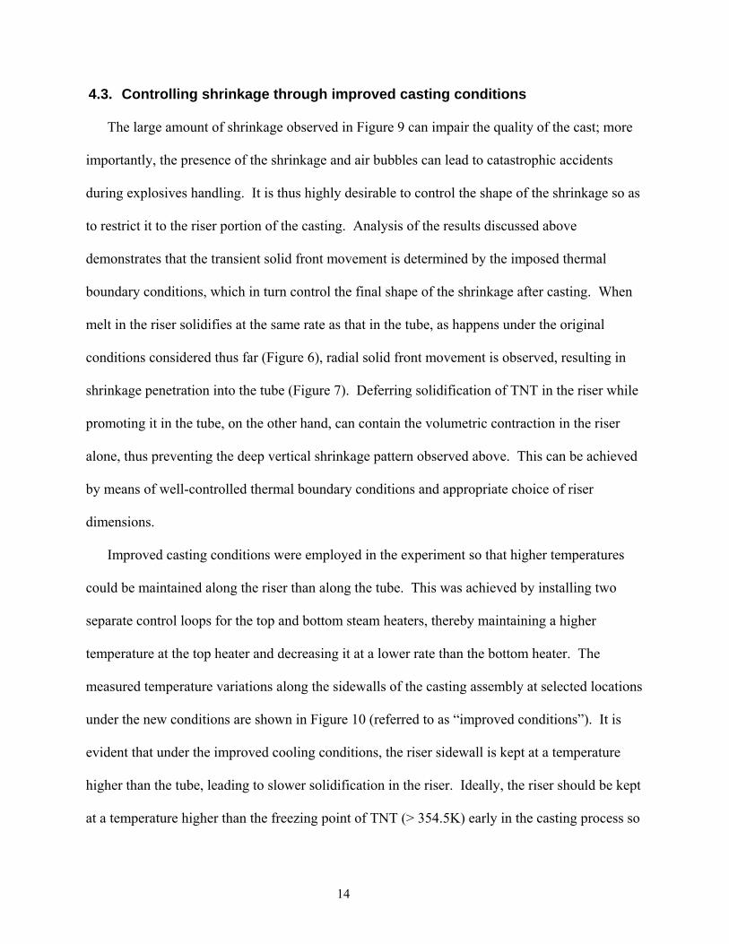
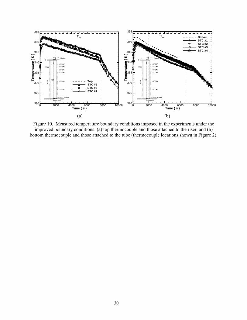
Improved casting conditions were employed in the experiment so that higher temperatures
could be maintained along the riser than along the tube. This was achieved by installing two
separate control loops for the top and bottom steam heaters, thereby maintaining a higher
temperature at the top heater and decreasing it at a lower rate than the bottom heater. The
measured temperature variations along the sidewalls of the casting assembly at selected locations
under the new conditions are shown in Figure 10 (referred to as “improved conditions”). It is
evident that under the improved cooling conditions, the riser sidewall is kept at a temperature
higher than the tube, leading to slower solidification in the riser. Ideally, the riser should be kept
at a temperature higher than the freezing point of TNT (> 354.5K) early in the casting process so
14
that no solidification can taken place in the riser. Solid TNT would form only in the tube and not
in the riser, and the free surface would recede relatively uniformly to accommodate the
volumetric contraction due to solidification shrinkage. Solidification would be allowed in the
riser only after the material in the tube is fully solidified. A very short riser would then be
sufficient. It is clear that the temperature profiles under the improved conditions are still not
perfectly controlled, and further improvements in the experimental realization of the desired
control are necessary.
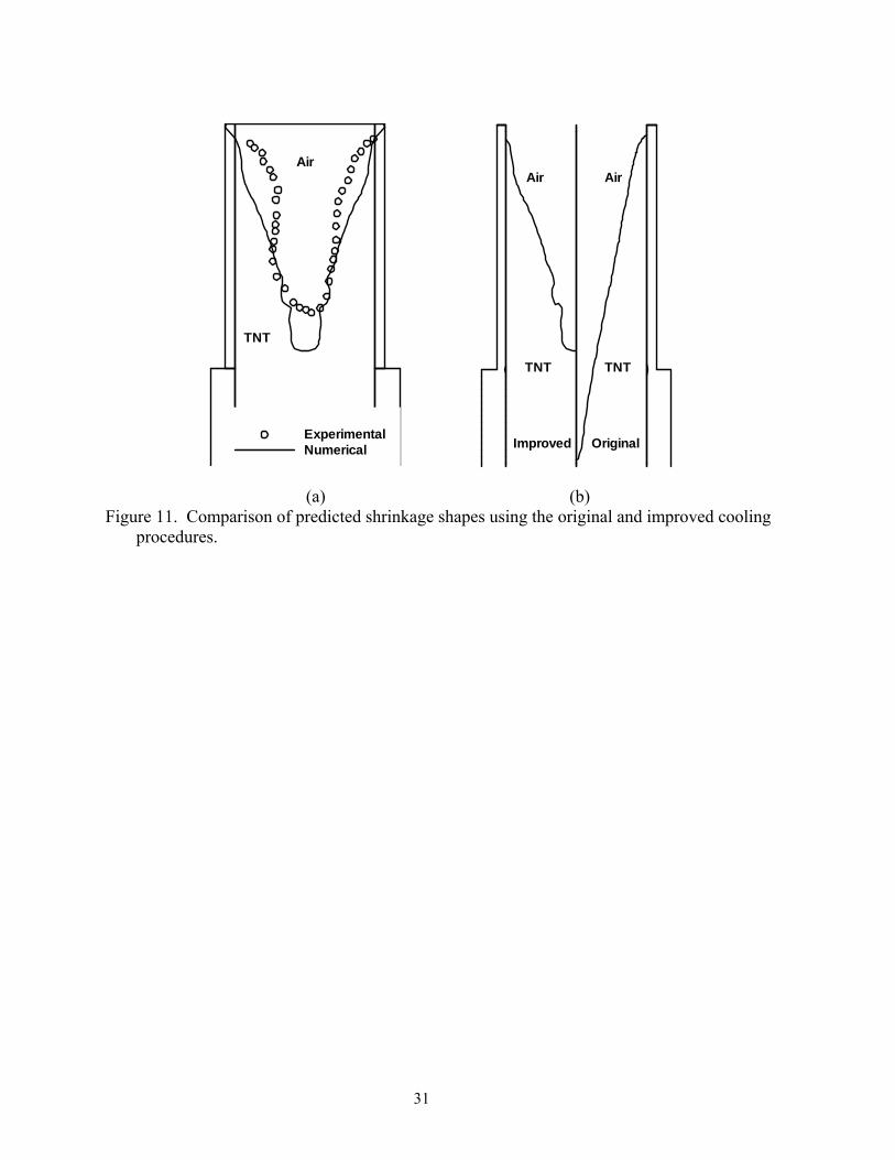
The temperature predictions under the improved conditions were compared extensively
against the experimental measurements, and agreement comparable to that shown in Figure 8
was achieved; the results are not shown here for brevity. Instead, the impact of the improved
conditions on shrinkage formation is explored. The predicted solidification shrinkage shapes are
compared with the experimental observations in Figure 11a. The bulk features of the predicted
shrinkage shape agree reasonably well with the experiments. The inaccuracy in free surface
prediction is again believed to be the main reason for the discrepancies between the two sets of
results. Shrinkage shapes resulting from the original and improved conditions are compared in
Figure 11b. It is evident that the shrinkage is mainly contained in the riser under the improved
cooling conditions and that its penetration depth is significantly smaller than that under the
original conditions. Further fine-tuning of the processing conditions would yield further control
of the shrinkage shape. This could lead to improved riser designs, less waste of materials and
reduced void formation. Given the challenges of experimentation with energetic materials and
the difficulties with the computations, the present demonstration of improvement of shrinkage
shape due to improvement in processing conditions is encouraging.
15
5. CONCLUSIONS
Solidification shrinkage in the melt casting of energetic materials is investigated using
volume-of-fluid (VOF) and enthalpy-porosity methods. The numerical model was benchmarked
against an analytical solution. The simulation results for shrinkage shape and temperature
profiles during the casting of an energetic material in a cylinder also compare satisfactorily with
experimental measurements. The present model can be employed in optimizing the explosives
melt casting process for reduced void formation. It was found that applied cooling conditions are
crucial in controlling solidification shrinkage. An improved cooling procedure is suggested
based on the analysis of existing casting conditions. Both numerical predictions and
experimental results under the improved conditions suggest that solidification shrinkage can
indeed be contained and controlled using improved cooling conditions.
Acknowledgements
The authors acknowledge financial support for this project from the US Army under the
management of Mr. Sanjeev K. Singh, and Mrs. Neelam Naik of ARDEC for her assistance with
the temperature measurements.
6. REFERENCES 1. M. Trovant, and S. Argyropoulos, Mathematical modeling and experimental measurements
of shrinkage in casting of metals, Canadian Metallurgical Quarterly, vol. 15, pp. 75-84, 1996.
2. G. F. Naterer, Simultaneous pressure-velocity coupling in the two-phase zone for solidification shrinkage in an open cavity, Modelling and Simulation in Materials Science and Engineering, vol. 5, pp. 595, 1997.
3. M. Raessi, and J. Mostaghimi, Three-dimensional modeling of density variation due to phase change in complex free surface flows, Numerical Heat Transfer, Part B: Fundamentals, vol. 47, pp. 507-531, 2005.
4. U. Teipel, Energetic Materials, Wiley-VCH, Berlin, Germany, 2005.
16
5. D. Sun, S. R. Annagradaga, and S. V. Garimella, Analysis of gap formation in the casting of energetic materials, Numerical Heat Transfer; Part A: Applications, In press.
6. F. Wolff, and R. Viskanta, Solidification of a pure metal at a vertical wall in the presence of liquid superheat, International Journal of Heat and Mass Transfer, vol. 31, pp. 1735, 1988.
7. B. Jones, D. Sun, S. Krishnan, and S. V. Garimella, Experimental and numerical study of melting in a cylinder, International Journal of Heat and Mass Transfer, vol. 49, pp. 2724-2738, 2006.
8. D. Sun, S. V. Garimella, S. K. Singh, and N. Naik, Numerical and Experimental Investigation of the Melt Casting of Explosives, Propellants, Explosives, Pyrotechnics, vol. 30, pp. 369-380, 2005.
9. E. McBride, J. C. Heinrich, and D. R. Poirier, Numerical simulation of incompressible flow driven by density variations during phase change, International Journal for Numerical Methods in Fluids, vol. 31, pp. 787, 1999.
10. J. C. Heinrich, and D. R. Poirier, The effect of volume change during directional solidification of binary alloys, Modelling and Simulation in Materials Science and Engineering, vol. 12, pp. 881, 2004.
11. C. J. Kim, and S. T. Ro, Shrinkage formation during the solidification process in an open rectangular cavity, Journal of Heat Transfer, Transactions ASME, vol. 115, pp. 1078, 1993.
12. H. Zhang, V. Prasad, and M. K. Moallemi, Numerical algorithm using multizone adaptive grid generation for multiphase transport processes with moving and free boundaries, Numerical Heat Transfer, Part B: Fundamentals, vol. 29, pp. 399, 1996.
13. K. C. Chiang, and H. L. Tsai, Shrinkage-induced fluid flow and domain change in two-dimensional alloy solidification, International Journal of Heat and Mass Transfer, vol. 35, pp. 1763, 1992.
14. M. Bellet, O. Jaouen, and I. Poitrault, An ALE-FEM approach to the thermomechanics of solidification processes with application to the prediction of pipe shrinkage, International Journal of Numerical Methods for Heat and Fluid Flow, vol. 15, pp. 120, 2005.
15. C. Beckermann, H.-J. Diepers, I. Steinbach, A. Karma, and X. Tong, Modeling melt convection in phase-field simulation of solidification, Journal of Computational Physics, vol. 154, pp. 468-496, 1999.
16. S. O. Unverdi, and G. Tryggvason, A front track method for viscous, incompressible, multi-fluid flows, Journal of Computational Physics, vol. 100, pp. 25, 1992.
17. J. A. Sethian, Level set methods, Cambridge University Press, New York, 1996.
18. H. S. Udaykumar, R. Mittal, and W. Shyy, Computations of solid-liquid fronts in sharp interface limit of fixed grids, Journal of Computational Physics, vol. 153, pp. 535-574, 1999.
19. C.-Y. Li, S. V. Garimella, and J. E. Simpson, Fixed-grid front-tracking algorithm for solidification problems, part I: Method and validation, Numerical Heat Transfer, Part B: Fundamentals, vol. 43, pp. 117, 2003.
17
20. C.-Y. Li, S. V. Garimella, and J. E. Simpson, Fixed-grid front-tracking algorithm for solidification problems, part II: Directional solidification with melt convection, Numerical Heat Transfer, Part B: Fundamentals, vol. 43, pp. 143, 2003.
21. J. Beech, M. Barkhudarov, K. Chang, and S. B. Chin, Computer modeling of the formation of macro shrinkage cavity during solidification, Eighth International Conference on Modeling of Casting, Welding and Advanced Solidification Processes, pp. 1071-1078, 1998.
22. G. Ehlen, A. Ludwig, P. R. Sahm, and A. Buhrig-Polaczek, Split-solid-model to simulate the formation of shrinkage cavities and macrosegregations in steel casting, Modeling of Casting, Welding and Advanced Solidification Processes X, pp. 285, 2003.
23. C. W. Hirt, and D. B. Nichols, Volume of fluid (VOF) method for the dynamics of free boundaries, Journal of Computational Physics, vol. 39, pp. 201-225, 1981.
24. S. M. Kaye, Encyclopedia of explosives and related items, v. 9, US Army Armament Research and Development Command, Dover, NJ, 1980.
25. C.-C. Ji, and C.-S. Lin, Solidification process of melt casting explosives in shell, Propellants, Explosives, Pyrotechnics, vol. 23, pp. 137, 1998.
26. M. A. Parry, and H. H. Billon, Flow behaviour of molten 2,4,6-trinitrotoluene (TNT) between concentric cylinders, Rheologica Acta, vol. 29, pp. 462, 1990.
27. Matlab, 2005, Matlab: The Language of Technical Computing.
28. S. Ganesan, and D. R. Poirier, Conservation of mass and momentum for the flow of interdendritic liquid during solidification, Metallurgical Trans. B, vol. 21B, pp. 173-181, 1990.
29. FLUENT 6.2.16 User Manual, Fluent, Inc., 2005.
30. V. Alexiades, and A. D. Solomon, Mathematical modeling of melting and freezing processes, Hemisphere Publishing Corporation, Washington D.C., 1993.
18
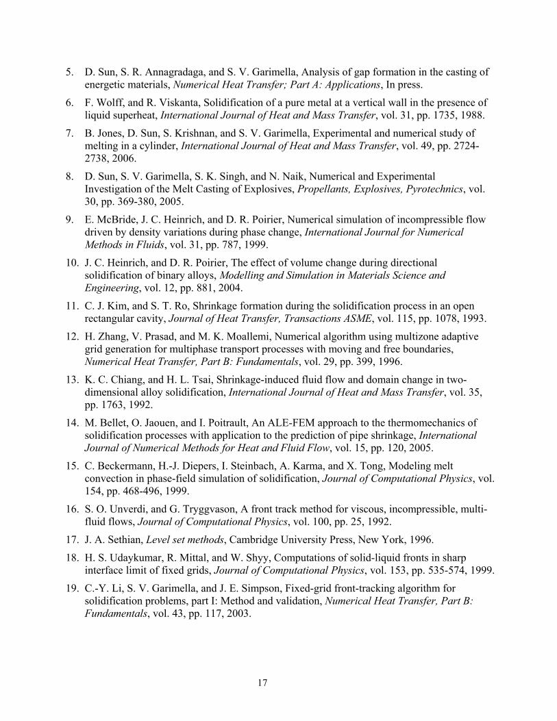
Table 1. Selected thermophysical properties of TNT [24-26].
Properties Unit Value Density, ρ kg/m3 Eq. (1) Viscosity, µ Pa⋅s Eq. (2) Thermal conductivity, k W/m-K 0.26 Specific heat, cP J/kg-K 1062.2 Melting point, Tm K 354.05 Latent heat, ∆H kJ/kg 98.4 Surface tension coefficient N/m 0.9
Table 2. Properties and conditions used in the simulation of solidification shrinkage in a slab.
PCM Unit Solid Liquid
Void
Density, ρ kg/m3 10 7 1 Thermal conductivity, k W/m-K 100 50 1000 Specific heat, cP J/mg-K 1000 1000 1 Initial temperature, Ti K 360 Wall temperature, Tw K 300 Melting point, Tm K 350 Latent heat, ∆H J/kg 1000
19
Figure Captions
Figure 1. Photographs of shrinkage cavity formation in the casting of TNT in a cylinder: (a) top view, and (b) cross-sectional view.
Figure 2. Schematic diagram of the assembly for casting of TNT in a cylinder.
Figure 3. Illustration of the shrinkage shape reconstruction procedure.
Figure 4. Schematic diagram of shrinkage in a semi-infinite slab.
Figure 5. Comparison of numerical predictions with analytical solutions at selected time intervals: (a) temperature distribution, and (b) solid/liquid and solid/void interface locations.
Figure 6. Measured temperature boundary conditions imposed in the experiments: (a) top thermocouple and those attached to the riser, and (b) bottom thermocouple and those attached to the tube; thermocouple locations shown in Figure 2).
Figure 7. Transient temperature distribution, solid front and shrinkage shape changes during the course of TNT solidification, (a) 1200 s, (b) 3600 s, (c) 4800 s, (d) 6600 s. The left panel in each figure shows the temperature contours, while the fl = 0.5 contour line in the right panel denotes the solid front location.
Figure 8. Comparison of numerically predicted temperatures and experimental measurements at selected locations, (a) TC1 (r = 0, z = 0.025H0), (b) TC2 (r = 0.39r1, z = 0.29H0), (c) TC3 (r = 0.39r1, z = 0.69H0) and (d) TC4 (r = 0.3r1, z = 0.86H0); (r1 is the inner diameter of the tube and H0 is the total height of the tube/riser assembly).
Figure 9. Comparison of numerically predicted and experimentally measured shrinkage shapes for casting TNT in a cylinder at different cross-sections.
Figure 10. Measured temperature boundary conditions imposed in the experiments under the improved boundary conditions: (a) top thermocouple and those attached to the riser, and (b) bottom thermocouple and those attached to the tube (thermocouple locations shown in Figure 2).
Figure 11. Comparison of predicted shrinkage shapes using the original and improved cooling procedures.
20
(a) (b)
Figure 1. Photographs of shrinkage cavity formation in the casting of TNT in a cylinder: (a) top view, and (b) cross-sectional view.
21
CLRiser
Tube
TNT
TC1
TC2
TC3
Top TC
STC#1
STC#2
STC#3
STC#4
STC#5
STC#6STC#7
Bottom TC
r0
ir
0H
1H
Heater
Heater
TC4
Figure 2. Schematic diagram of the assembly for casting of TNT in a cylinder.
22
Tube
TNT
Ris
er
Shrin
kage
Tube
TNT
Ris
er
Shrin
kage
(a) (b) (c) (d)
Figure 3. Illustration of the shrinkage shape reconstruction procedure.
23
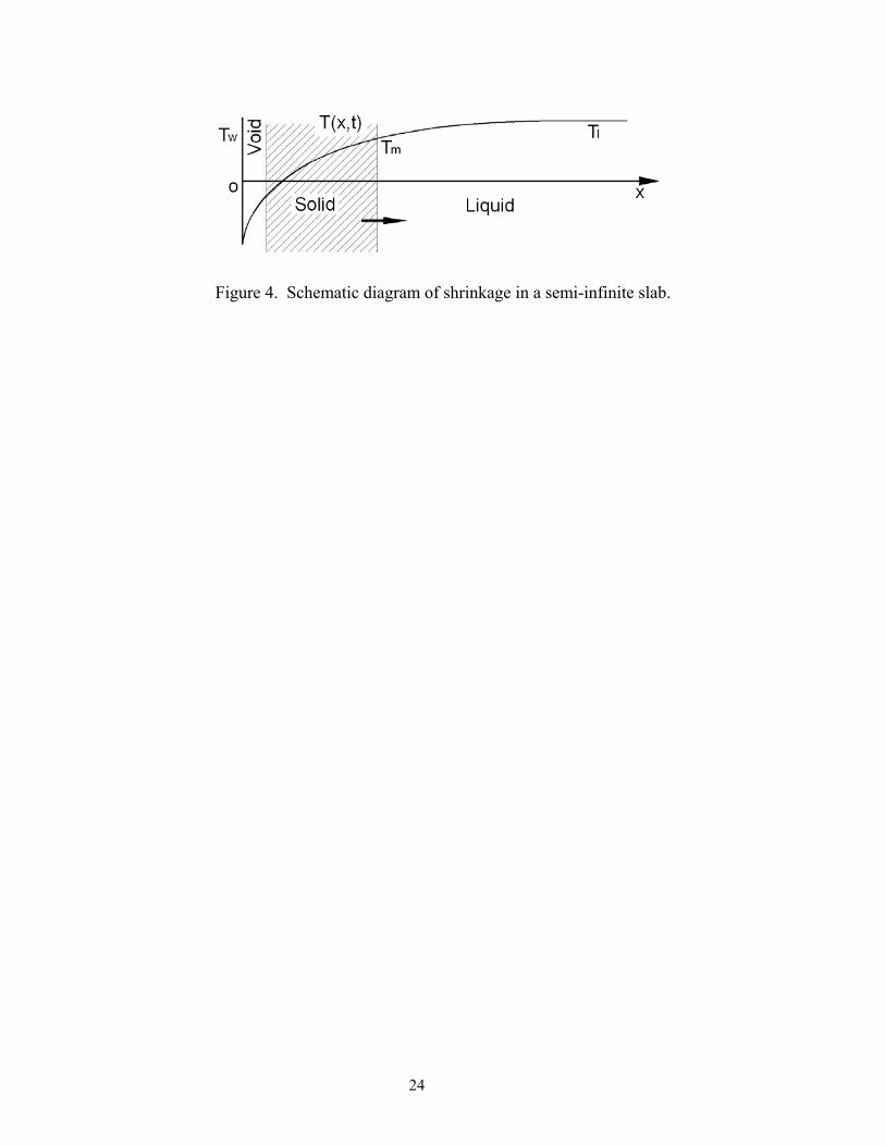
Figure 4. Schematic diagram of shrinkage in a semi-infinite slab.
24
x ( m )
T(K
)
0 0.001 0.002 0.003 0.004 0.005300
310
320
330
340
350
360
370
5x10⁻⁶ s1x10-5 s2x10-5 s
x ( m )
t(s
)
0 0.0005 0.001 0.00150.0E+00
5.0E-06
1.0E-05
1.5E-05
2.0E-05
NumericalAnalytical
Solid/liquid interface
Solid/void interface
(a) Temperature (b) Interface locations
Figure 5. Comparison of numerical predictions with analytical solutions at selected time intervals: (a) temperature distribution, and (b) solid/liquid and solid/void interface locations.
25
Time ( s )
Tem
pera
ture
(K)
0 2000 4000 6000 8000 10000320
325
330
335
340
345
350
355
TopSTC #5STC #6STC #7
Tm
Time ( s )
Tem
pera
ture
(K)
0 2000 4000 6000 8000 10000320
325
330
335
340
345
350
355
BottomSTC #1STC #2STC #3STC #4
Tm
(a) (b)
Figure 6. Measured temperature boundary conditions imposed in the experiments: (a) top thermocouple and those attached to the riser, and (b) bottom thermocouple and those attached to
the tube; thermocouple locations shown in Figure 2).
26
351351
351
351
352352
352
3523 52
353353
353353
353
f l=0.
5
TNT
Air
Liqu
id
Sol
id
344344
344346
3463 46
348348
348348
348
350
35035 0
350
352
35235 2
352
f l=0.
5TNT
Air
Liqu
idS
olid
340
340
342
342344
344346
346
348
348350
3503 5 2
TNT
Air
Solid
Liqu
idf l=
0.5
336336
338
338
340
340
340
342
342
344
346
TNT(Solid)
Air
(a) 1200 s (b) 3600 s (c) 4800 s (d) 6600 s
Figure 7. Transient temperature distribution, solid front and shrinkage shape changes during the course of TNT solidification, (a) 1200 s, (b) 3600 s, (c) 4800 s, (d) 6600 s. The left panel in each figure shows the temperature contours, while the fl = 0.5 contour line in the right panel denotes
the solid front location.
27
t ( s )
T(K
)
0 1000 2000 3000 4000 5000 6000 7000330
335
340
345
350
355
360
ExperimentalNumerical
t ( s )
T(K
)
0 1000 2000 3000 4000 5000 6000 7000330
335
340
345
350
355
360
ExperimentalNumerical
(a) TC1 (r = 0, z = 0.025H0) (b) TC2 (r = 0.39r1, z = 0.29H0)
t ( s )
T(K
)
0 1000 2000 3000 4000 5000 6000 7000330
335
340
345
350
355
360
ExperimentalNumerical
t ( s )
T(K
)
0 1000 2000 3000 4000 5000 6000 7000330
335
340
345
350
355
360
ExperimentalNumerical
(c) TC3 (r = 0.39r1, z = 0.69H0) (d) TC4 (r = 0.3r1, z = 0.86H0)
Figure 8. Comparison of numerically predicted temperatures and experimental measurements at selected locations, (a) TC1 (r = 0, z = 0.025H0), (b) TC2 (r = 0.39r1, z = 0.29H0), (c) TC3 (r = 0.39r1, z = 0.69H0) and (d) TC4 (r = 0.3r1, z = 0.86H0); (r1 is the inner diameter of the tube and
H0 is the total height of the tube/riser assembly).
28
Num.Solid TNT
Exp.
A-A
Num.Solid TNT
Exp.
B-B
(a) A-A (b) B-B
Figure 9. Comparison of numerically predicted and experimentally measured shrinkage shapes for casting TNT in a cylinder at different cross-sections.
29
Time ( s )
Tem
pera
ture
(K)
0 2000 4000 6000 8000 10000320
325
330
335
340
345
350
355
TopSTC #5STC #6STC #7
Tm
Time ( s )
Tem
pera
ture
(K)
0 2000 4000 6000 8000 10000320
325
330
335
340
345
350
355
BottomSTC #1STC #2STC #3STC #4
Tm
(a) (b)
Figure 10. Measured temperature boundary conditions imposed in the experiments under the improved boundary conditions: (a) top thermocouple and those attached to the riser, and (b)
bottom thermocouple and those attached to the tube (thermocouple locations shown in Figure 2).
30
ExperimentalNumerical
TNT
Air
OriginalImproved
TNT TNT
AirAir
(a) (b)
Figure 11. Comparison of predicted shrinkage shapes using the original and improved cooling procedures.
31