Embed Size (px)
Citation preview
1
Numerical and Experimental Analysis of Asymmetric Instabilities by Tube Forming
Adriano Henrique Crespo Gonçalves
ABSTRACT
The purpose of the present work is to develop the understanding on inclined sheet-tube and tube-tube
joints produced by plastic deformation. This knowledge will enable identifying the major operating
parameters of the process, determining its window of applicability and designing tooling prototypes to
produce strong and environmentally friendly structures. The joining process draws upon the fundamentals
of asymmetric local buckling of thin-walled tubes subjected to axial compression. Also it introduces two
different process setups for assembling sheets to tubes, or tube connections, at different inclination
angles that can easily and effectively join dissimilar materials, at room temperature.
This work is based on a numerical and experimental investigation and has the objective to widen and
enhance the previous research in the field. Therefore, it is a step forward in joining sheets and tubes by
plastic deformation. Several industrial prototypes of the proposed joining technology are also provided in
the present study. Results showed that tube-sheet and tube-tube joints by means of the proposed
technology are limited to a maximum inclination angle of 45 degrees.
Keywords: Mechanical Joint, Plastic Deformation, Tube Buckling, Experimentation, Numerical Simulation
1. INTRODUCTION
As stated by Messler [1], “joining was undoubtedly one of the first, if not the first, manufacturing
technology” when thinking on the first tools created by men for hunting and farming. With the passage of
time, industries advanced technologically and manufacturing processes became deep-rooted. The need
for joining materials became obvious when the limits of the shaping processes were reached, whether in
size, complexity, formability, accuracy or quality of the component to be produced. Joining enabled the
possibility to break those limits. Design for assembly involves adequate selection of materials, geometries
and manufacturing processes to facilitate fabrication of components made of many individual parts.
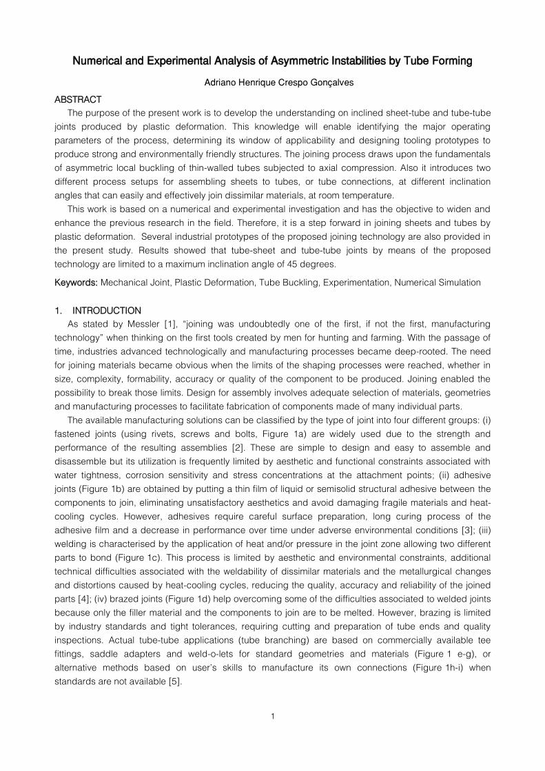
The available manufacturing solutions can be classified by the type of joint into four different groups: (i)
fastened joints (using rivets, screws and bolts, Figure 1a) are widely used due to the strength and
performance of the resulting assemblies [2]. These are simple to design and easy to assemble and
disassemble but its utilization is frequently limited by aesthetic and functional constraints associated with
water tightness, corrosion sensitivity and stress concentrations at the attachment points; (ii) adhesive
joints (Figure 1b) are obtained by putting a thin film of liquid or semisolid structural adhesive between the
components to join, eliminating unsatisfactory aesthetics and avoid damaging fragile materials and heat-
cooling cycles. However, adhesives require careful surface preparation, long curing process of the
adhesive film and a decrease in performance over time under adverse environmental conditions [3]; (iii)
welding is characterised by the application of heat and/or pressure in the joint zone allowing two different
parts to bond (Figure 1c). This process is limited by aesthetic and environmental constraints, additional
technical difficulties associated with the weldability of dissimilar materials and the metallurgical changes
and distortions caused by heat-cooling cycles, reducing the quality, accuracy and reliability of the joined
parts [4]; (iv) brazed joints (Figure 1d) help overcoming some of the difficulties associated to welded joints
because only the filler material and the components to join are to be melted. However, brazing is limited
by industry standards and tight tolerances, requiring cutting and preparation of tube ends and quality
inspections. Actual tube-tube applications (tube branching) are based on commercially available tee
fittings, saddle adapters and weld-o-lets for standard geometries and materials (Figure 1 e-g), or
alternative methods based on user’s skills to manufacture its own connections (Figure 1h-i) when
standards are not available [5].
2
Figure 1 - Conventional joining processes: (a) fasteners, (b) adhesives, (c) welding and (d) brazing. Conventional tube branching
methods: (e) tee fittings, (f) saddle adapters, (g) weld-o-lets, (h) nozzle-welds and (i) spin-forming
Authors have been discussing these problems with the objective of finding new solutions. As the case
of the automobile aluminium space-frames where cracking issues are common due to the permanent
formation of grain boundary films and oxide layers when welding [6]. Or, if mechanical fasteners are used,
complications in automation arise and the need to include more parts greatly increases the overall mass of
the structures and the production costs. The usage of adhesives is decreasing due to the exposition of
workers to hazardous environments which promote health and safety issues [7]. Besides, there must be a
technological objective to optimise production towards ecological compatibility and cleaner practices.
The process developed in this work proposes an innovative and environmentally friendly technology,
as it is performed at room temperature with low forming loads, while avoiding extra parts, heat-treatments
and hazardous lubricants and smokes. At the same time, it offers significant advantages that eliminate
some of the shortcomings described, such as the flexibility of handling different batch sizes, high levels of
repeatability and the possibility of joining dissimilar materials, only by means of tube metal forming.
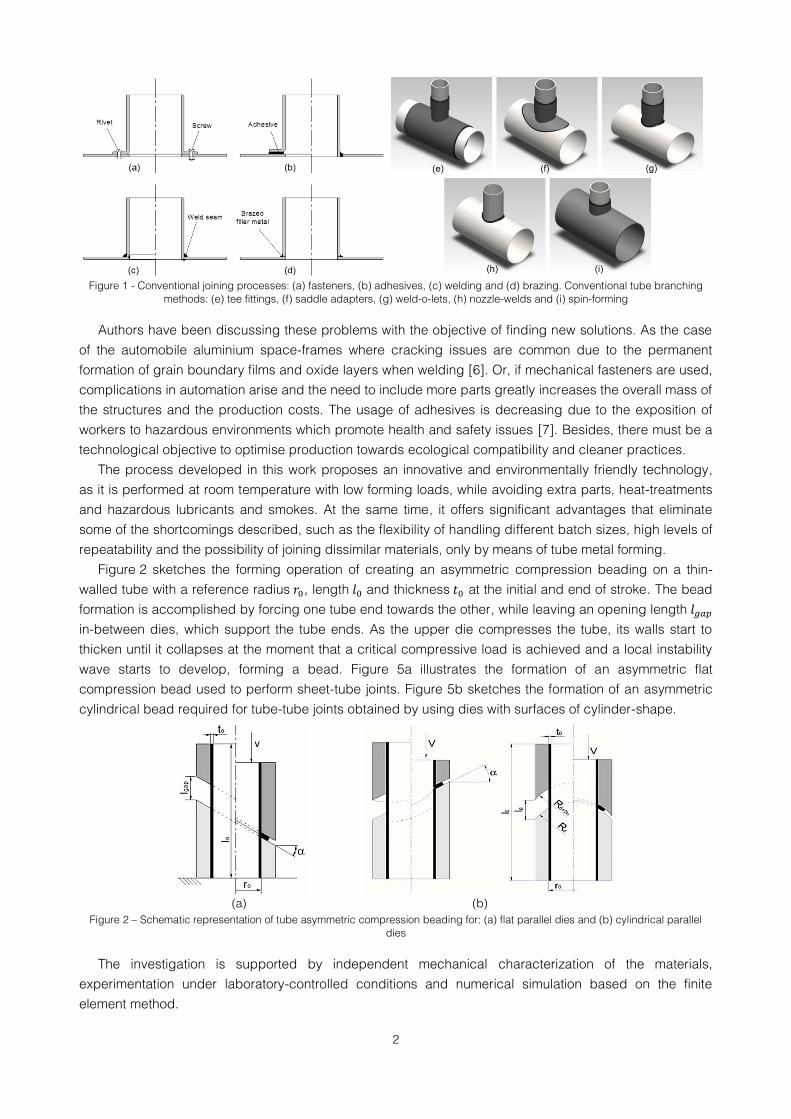
Figure 2 sketches the forming operation of creating an asymmetric compression beading on a thin-
walled tube with a reference radius , length and thickness at the initial and end of stroke. The bead
formation is accomplished by forcing one tube end towards the other, while leaving an opening length
in-between dies, which support the tube ends. As the upper die compresses the tube, its walls start to
thicken until it collapses at the moment that a critical compressive load is achieved and a local instability
wave starts to develop, forming a bead. Figure 5a illustrates the formation of an asymmetric flat
compression bead used to perform sheet-tube joints. Figure 5b sketches the formation of an asymmetric
cylindrical bead required for tube-tube joints obtained by using dies with surfaces of cylinder-shape.
Figure 2 – Schematic representation of tube asymmetric compression beading for: (a) flat parallel dies and (b) cylindrical parallel
dies
The investigation is supported by independent mechanical characterization of the materials,
experimentation under laboratory-controlled conditions and numerical simulation based on the finite
element method.
(a)
(b)
3
2. EXPERIMENTAL BACKGROUND
The tubular specimens utilised in the experimental work were obtained from commercial S460MC
(carbon steel) welded tubes with reference radius and wall thickness . The stress-
strain behaviour of the S460MC obtained in (1) was determined from tensile and stack compression tests
at room temperature performed in a previous work using samples from the same stock, [8],
(1)
As with every new manufacturing technology, there is a need to understand the mechanisms of the
proposed joining technique with the objective to identify the process feasibility window. Accordingly,
favourable results, supported by numerical and experimental analysis, have been recently published by
Alves and Martins [3, 5, 8] for sheet-tube and tube-tube plastically deformed joints, establishing guiding
parameters and conditions under which the process is viable. At this point, the parameters known for
controlling the process are threefold: (i) the slenderness ratio of the unsupported length to the
reference radius of the tube, (ii) the angle of inclination of the dies in relation to the perpendicular
plane of the tube axis and (iii) the utilization of internal mandrels to prevent the material to flow inwards.
Contrarily to axisymmetric ( ) axially compressed beads, naturally formed by local buckling in tubes
between parallel dies, asymmetric (inclined, ) beads require forcing the upper tube against the
bottom tube end by means of inclined parallel dies.
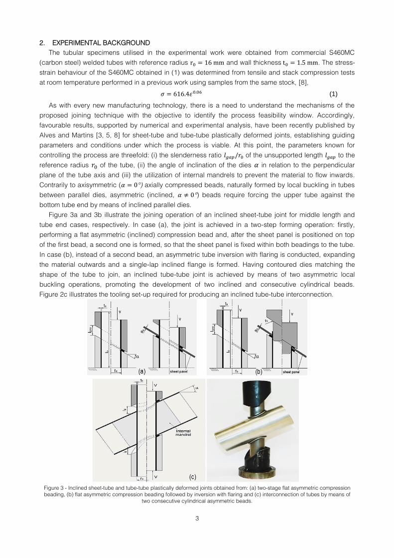
Figure 3a and 3b illustrate the joining operation of an inclined sheet-tube joint for middle length and
tube end cases, respectively. In case (a), the joint is achieved in a two-step forming operation: firstly,
performing a flat asymmetric (inclined) compression bead and, after the sheet panel is positioned on top
of the first bead, a second one is formed, so that the sheet panel is fixed within both beadings to the tube.
In case (b), instead of a second bead, an asymmetric tube inversion with flaring is conducted, expanding
the material outwards and a single-lap inclined flange is formed. Having contoured dies matching the
shape of the tube to join, an inclined tube-tube joint is achieved by means of two asymmetric local
buckling operations, promoting the development of two inclined and consecutive cylindrical beads.
Figure 2c illustrates the tooling set-up required for producing an inclined tube-tube interconnection.
Figure 3 - Inclined sheet-tube and tube-tube plastically deformed joints obtained from: (a) two-stage flat asymmetric compression
beading, (b) flat asymmetric compression beading followed by inversion with flaring and (c) interconnection of tubes by means of
two consecutive cylindrical asymmetric beads.
4
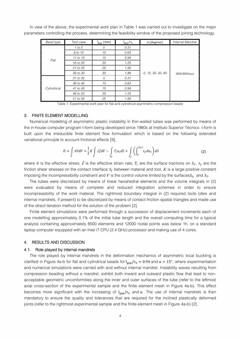
In view of the above, the experimental work plan in Table 1 was carried out to investigate on the major
parameters controlling the process, determining the feasibility window of the proposed joining technology.
Bead type Test case Internal Mandrel
Flat
1 to 5 5 0.31
0, 15, 30, 45, 60 With/Without
6 to 10 10 0.63
11 to 15 15 0.94
16 to 20 20 1.25
21 to 25 25 1.56
26 to 30 30 1.88
Cylindrical
31 to 35 5 0.31
36 to 40 10 0.63
41 to 45 15 0.94
46 to 50 20 1.25
51 to 55 25 1.56
Table 1- Experimental work plan for flat and cylindrical asymmetric compression beads
3. FINITE ELEMENT MODELLING
Numerical modelling of asymmetric plastic instability in thin-walled tubes was performed by means of
the in-house computer program I-form being developed since 1980s at Instituto Superior Técnico. I-form is
built upon the irreducible finite element flow formulation which is based on the following extended
variational principle to account frictional effects [9],
∫ ̅ ̅̇
∫ ̇
∫
∫ (∫
| |
)
(2)
where ̅ is the effective stress, ̅̇ is the effective strain rate, are the surface tractions on , are the
friction shear stresses on the contact interface between material and tool, is a large positive constant
imposing the incompressibility constraint and is the control volume limited by the surfaces and .
The tubes were discretized by means of linear hexahedral elements and the volume integrals in (2)
were evaluated by means of complete and reduced integration schemes in order to ensure
incompressibility of the work material. The rightmost boundary integral in (2) required tools (dies and
internal mandrels, if present) to be discretized by means of contact-friction spatial triangles and made use
of the direct iteration method for the solution of the problem [2].
Finite element simulations were performed through a succession of displacement increments each of
one modelling approximately 0.1% of the initial tube length and the overall computing time for a typical
analysis containing approximately 8500 elements and 12000 nodal points was below 1h. on a standard
laptop computer equipped with an Intel i7 CPU (2.4 GHz) processor and making use of 4 cores.
4. RESULTS AND DISCUSSION
4.1. Role played by internal mandrels
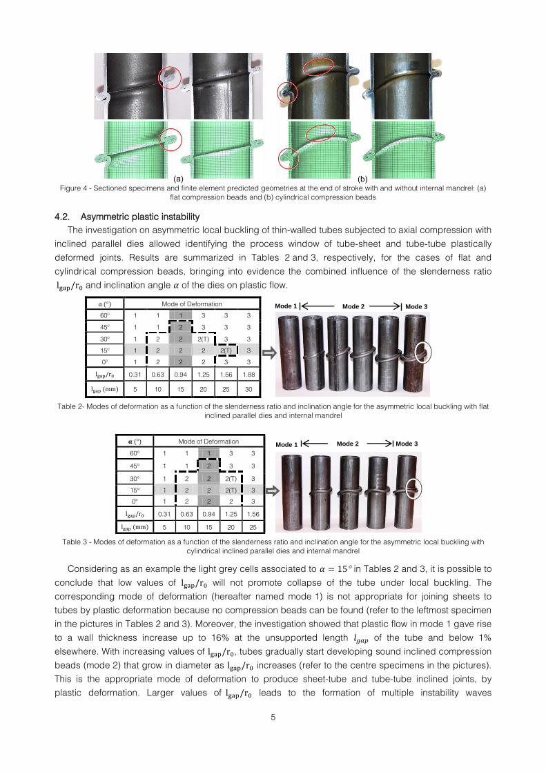
The role played by internal mandrels in the deformation mechanics of asymmetric local buckling is
clarified in Figure 4a-b for flat and cylindrical beads for and , where experimentation
and numerical simulations were carried with and without internal mandrel. Instability waves resulting from
compression beading without a mandrel, exhibit both inward and outward plastic flow that lead to non-
acceptable geometric unconformities along the inner and outer surfaces of the tube (refer to the leftmost
axial cross-section of the experimental sample and the finite element mesh in Figure 4a-b). This effect
becomes more significant with the increasing of and . The use of internal mandrels is then
mandatory to ensure the quality and tolerances that are required for the inclined plastically deformed
joints (refer to the rightmost experimental sample and the finite element mesh in Figure 4a-b) [2].
5
Figure 4 - Sectioned specimens and finite element predicted geometries at the end of stroke with and without internal mandrel: (a)
flat compression beads and (b) cylindrical compression beads
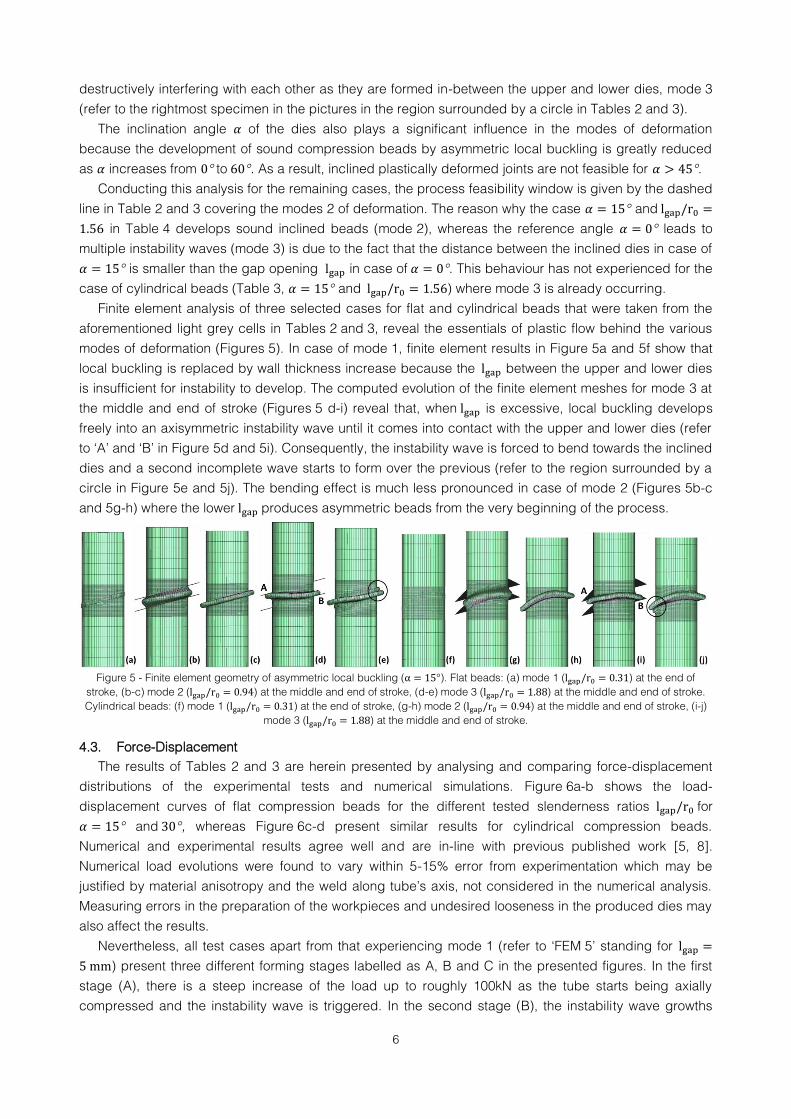
4.2. Asymmetric plastic instability
The investigation on asymmetric local buckling of thin-walled tubes subjected to axial compression with
inclined parallel dies allowed identifying the process window of tube-sheet and tube-tube plastically
deformed joints. Results are summarized in Tables 2 and 3, respectively, for the cases of flat and
cylindrical compression beads, bringing into evidence the combined influence of the slenderness ratio
and inclination angle of the dies on plastic flow.
Mode of Deformation
60º 1 1 1 3 3 3
45º 1 1 2 3 3 3
30º 1 2 2 2(T) 3 3
15º 1 2 2 2 2(T) 3
0º 1 2 2 2 3 3
0.31 0.63 0.94 1.25 1.56 1.88
5 10 15 20 25 30
Table 2- Modes of deformation as a function of the slenderness ratio and inclination angle for the asymmetric local buckling with flat
inclined parallel dies and internal mandrel
Table 3 - Modes of deformation as a function of the slenderness ratio and inclination angle for the asymmetric local buckling with
cylindrical inclined parallel dies and internal mandrel
Considering as an example the light grey cells associated to in Tables 2 and 3, it is possible to
conclude that low values of will not promote collapse of the tube under local buckling. The
corresponding mode of deformation (hereafter named mode 1) is not appropriate for joining sheets to
tubes by plastic deformation because no compression beads can be found (refer to the leftmost specimen
in the pictures in Tables 2 and 3). Moreover, the investigation showed that plastic flow in mode 1 gave rise
to a wall thickness increase up to 16% at the unsupported length of the tube and below 1%
elsewhere. With increasing values of , tubes gradually start developing sound inclined compression
beads (mode 2) that grow in diameter as increases (refer to the centre specimens in the pictures).
This is the appropriate mode of deformation to produce sheet-tube and tube-tube inclined joints, by
plastic deformation. Larger values of leads to the formation of multiple instability waves
Mode of Deformation
60° 1 1 1 3 3
45° 1 1 2 3 3
30° 1 2 2 2(T) 3
15° 1 2 2 2(T) 3
0° 1 2 2 2 3
0.31 0.63 0.94 1.25 1.56
5 10 15 20 25
Mode 1 Mode 2 Mode 3
Mode 1 Mode 2 Mode 3
6
destructively interfering with each other as they are formed in-between the upper and lower dies, mode 3
(refer to the rightmost specimen in the pictures in the region surrounded by a circle in Tables 2 and 3).
The inclination angle of the dies also plays a significant influence in the modes of deformation
because the development of sound compression beads by asymmetric local buckling is greatly reduced
as increases from to . As a result, inclined plastically deformed joints are not feasible for .
Conducting this analysis for the remaining cases, the process feasibility window is given by the dashed
line in Table 2 and 3 covering the modes 2 of deformation. The reason why the case and
in Table 4 develops sound inclined beads (mode 2), whereas the reference angle leads to
multiple instability waves (mode 3) is due to the fact that the distance between the inclined dies in case of
is smaller than the gap opening in case of . This behaviour has not experienced for the
case of cylindrical beads (Table 3, and ) where mode 3 is already occurring.
Finite element analysis of three selected cases for flat and cylindrical beads that were taken from the
aforementioned light grey cells in Tables 2 and 3, reveal the essentials of plastic flow behind the various
modes of deformation (Figures 5). In case of mode 1, finite element results in Figure 5a and 5f show that
local buckling is replaced by wall thickness increase because the between the upper and lower dies
is insufficient for instability to develop. The computed evolution of the finite element meshes for mode 3 at
the middle and end of stroke (Figures 5 d-i) reveal that, when is excessive, local buckling develops
freely into an axisymmetric instability wave until it comes into contact with the upper and lower dies (refer
to ‘A’ and ‘B’ in Figure 5d and 5i). Consequently, the instability wave is forced to bend towards the inclined
dies and a second incomplete wave starts to form over the previous (refer to the region surrounded by a
circle in Figure 5e and 5j). The bending effect is much less pronounced in case of mode 2 (Figures 5b-c
and 5g-h) where the lower produces asymmetric beads from the very beginning of the process.
Figure 5 - Finite element geometry of asymmetric local buckling ( ). Flat beads: (a) mode 1 ( ) at the end of
stroke, (b-c) mode 2 ( ) at the middle and end of stroke, (d-e) mode 3 ( ) at the middle and end of stroke.
Cylindrical beads: (f) mode 1 ( ) at the end of stroke, (g-h) mode 2 ( ) at the middle and end of stroke, (i-j)
mode 3 ( ) at the middle and end of stroke.
4.3. Force-Displacement
The results of Tables 2 and 3 are herein presented by analysing and comparing force-displacement
distributions of the experimental tests and numerical simulations. Figure 6a-b shows the load-
displacement curves of flat compression beads for the different tested slenderness ratios for
and , whereas Figure 6c-d present similar results for cylindrical compression beads.
Numerical and experimental results agree well and are in-line with previous published work [5, 8].
Numerical load evolutions were found to vary within 5-15% error from experimentation which may be
justified by material anisotropy and the weld along tube’s axis, not considered in the numerical analysis.
Measuring errors in the preparation of the workpieces and undesired looseness in the produced dies may
also affect the results.
Nevertheless, all test cases apart from that experiencing mode 1 (refer to ‘FEM 5’ standing for
) present three different forming stages labelled as A, B and C in the presented figures. In the first
stage (A), there is a steep increase of the load up to roughly 100kN as the tube starts being axially
compressed and the instability wave is triggered. In the second stage (B), the instability wave growths

7
and progressively bends to match the contour of the upper and lower inclined parallel dies. The load
drops as the degree of instability increases and the corresponding die stroke varies with the unsupported
length of the tube, being larger as increases. The third stage (C) is characterised by an abrupt
load increase caused by the closure of the instability waves. The exception case ‘FEM 5’ in Figure 6a-d,
presenting a monotonic load growth, is justified by mode 1 not experiencing local buckling. Curves
associated to mode 3 of deformation present a second load maximum characteristic of the formation of a
second instability wave (‘EXP 30/FEM 30’ in Figure 6a and ‘EXP 25/FEM 25’ in Figure 6c-d). Figure 6 - Load-displacement curves: (a) with from to ( from to ) and (b) with
from to ( from to ) for flat compression beads, (c-d) ) and with from to ( from
to ) for cylindrical compression beads, (e) flat asymmetric compression beads for and from to and (f)
cylindrical asymmetric compression beads for from to .
Figure 6e-f shows the results of the test cases of at different inclination angles for both
types of beads, flat and cylindrical (refer to the dark grey cells in Tables 2 and 3). The load-displacement
distributions reveal a load increase with the inclination angle for a constant slenderness ratio for
both flat and cylindrical bead types. The evolution of the load with displacement, for all test cases apart
8
from ‘EXP 60 ’ and ‘FEM 60 ’ (corresponding to the inclination angle in Figure 6e), is similar to the
general trend corresponding to mode 2 in Figure 6a-d. The monotonically increase of load with the
displacement in case of ‘FEM 60°’ is the result of incomplete triggering and propagation of the instability
wave when the inclination of the dies is very steep. In fact, the resulting compression bead presents
significant geometric variations along its major axis and is not appropriate for producing viable joints by
plastic deformation. This is the reason why test conditions and were labelled as
mode 1 (refer to uppermost dark grey cells in Table 2 and 3).
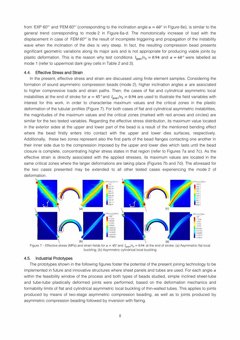
4.4. Effective Stress and Strain
In the present, effective stress and strain are discussed using finite element samples. Considering the
formation of sound asymmetric compression beads (mode 2), higher inclination angles are associated
to higher compressive loads and strain paths. Then, the cases of flat and cylindrical asymmetric local
instabilities at the end of stroke for and are used to illustrate the field variables with
interest for this work, in order to characterise maximum values and the critical zones in the plastic
deformation of the tubular profiles (Figure 7). For both cases of flat and cylindrical asymmetric instabilities,
the magnitudes of the maximum values and the critical zones (marked with red arrows and circles) are
similar for the two tested variables. Regarding the effective stress distribution, its maximum value located
in the exterior sides at the upper and lower part of the bead is a result of the mentioned bending effect
where the bead firstly enters into contact with the upper and lower dies surfaces, respectively.
Additionally, these two zones represent also the first parts of the bead flanges contacting one another in
their inner side due to the compression imposed by the upper and lower dies which lasts until the bead
closure is complete, concentrating higher stress states in that region (refer to Figures 7a and 7c). As the
effective strain is directly associated with the applied stresses, its maximum values are located in the
same critical zones where the larger deformations are taking place (Figures 7b and 7d). The aforesaid for
the two cases presented may be extended to all other tested cases experiencing the mode 2 of
deformation.
Figure 7 – Effective stress (MPa) and strain fields for and at the end of stroke: (a) Asymmetric flat local
buckling, (b) Asymmetric cylindrical local buckling
4.5. Industrial Prototypes
The prototypes shown in the following figures foster the potential of the present joining technology to be
implemented in future and innovative structures where sheet panels and tubes are used. For each angle
within the feasibility window of the process and both types of beads studied, simple inclined sheet-tube
and tube-tube plastically deformed joints were performed, based on the deformation mechanics and
formability limits of flat and cylindrical asymmetric local buckling of thin-walled tubes. This applies to joints
produced by means of two-stage asymmetric compression beading, as well as to joints produced by
asymmetric compression beading followed by inversion with flaring.
9
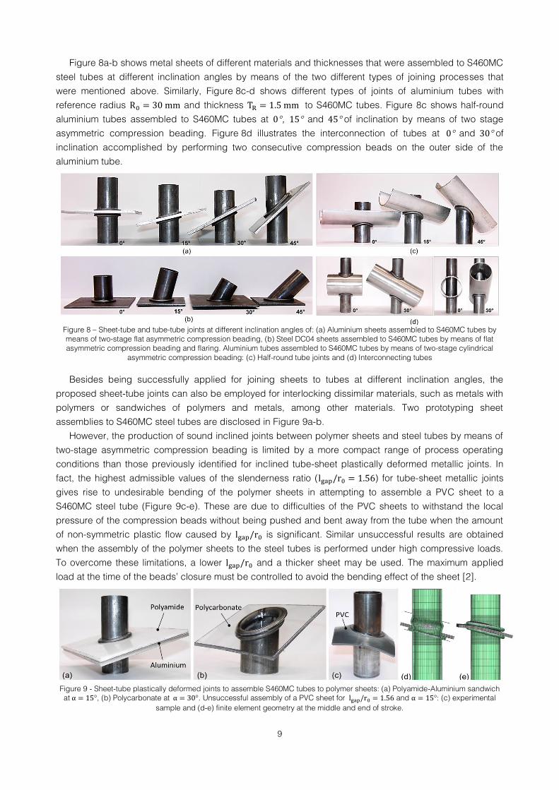
Figure 8a-b shows metal sheets of different materials and thicknesses that were assembled to S460MC
steel tubes at different inclination angles by means of the two different types of joining processes that
were mentioned above. Similarly, Figure 8c-d shows different types of joints of aluminium tubes with
reference radius and thickness to S460MC tubes. Figure 8c shows half-round
aluminium tubes assembled to S460MC tubes at , and of inclination by means of two stage
asymmetric compression beading. Figure 8d illustrates the interconnection of tubes at and of
inclination accomplished by performing two consecutive compression beads on the outer side of the
aluminium tube.
Figure 8 – Sheet-tube and tube-tube joints at different inclination angles of: (a) Aluminium sheets assembled to S460MC tubes by
means of two-stage flat asymmetric compression beading, (b) Steel DC04 sheets assembled to S460MC tubes by means of flat
asymmetric compression beading and flaring. Aluminium tubes assembled to S460MC tubes by means of two-stage cylindrical
asymmetric compression beading: (c) Half-round tube joints and (d) Interconnecting tubes
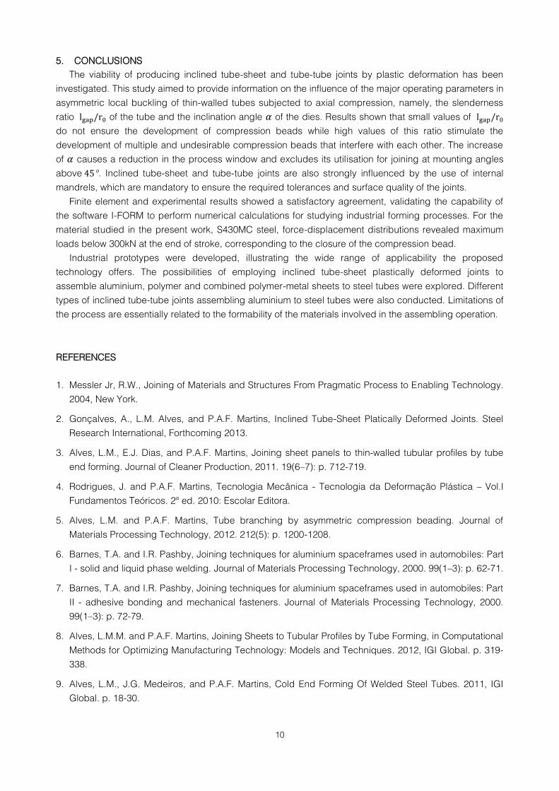
Besides being successfully applied for joining sheets to tubes at different inclination angles, the
proposed sheet-tube joints can also be employed for interlocking dissimilar materials, such as metals with
polymers or sandwiches of polymers and metals, among other materials. Two prototyping sheet
assemblies to S460MC steel tubes are disclosed in Figure 9a-b.
However, the production of sound inclined joints between polymer sheets and steel tubes by means of
two-stage asymmetric compression beading is limited by a more compact range of process operating
conditions than those previously identified for inclined tube-sheet plastically deformed metallic joints. In
fact, the highest admissible values of the slenderness ratio ( ) for tube-sheet metallic joints
gives rise to undesirable bending of the polymer sheets in attempting to assemble a PVC sheet to a
S460MC steel tube (Figure 9c-e). These are due to difficulties of the PVC sheets to withstand the local
pressure of the compression beads without being pushed and bent away from the tube when the amount
of non-symmetric plastic flow caused by is significant. Similar unsuccessful results are obtained
when the assembly of the polymer sheets to the steel tubes is performed under high compressive loads.
To overcome these limitations, a lower and a thicker sheet may be used. The maximum applied
load at the time of the beads’ closure must be controlled to avoid the bending effect of the sheet [2].
Figure 9 - Sheet-tube plastically deformed joints to assemble S460MC tubes to polymer sheets: (a) Polyamide-Aluminium sandwich
at , (b) Polycarbonate at . Unsuccessful assembly of a PVC sheet for and : (c) experimental
sample and (d-e) finite element geometry at the middle and end of stroke.
10
5. CONCLUSIONS
The viability of producing inclined tube-sheet and tube-tube joints by plastic deformation has been
investigated. This study aimed to provide information on the influence of the major operating parameters in
asymmetric local buckling of thin-walled tubes subjected to axial compression, namely, the slenderness
ratio of the tube and the inclination angle of the dies. Results shown that small values of
do not ensure the development of compression beads while high values of this ratio stimulate the
development of multiple and undesirable compression beads that interfere with each other. The increase
of causes a reduction in the process window and excludes its utilisation for joining at mounting angles
above . Inclined tube-sheet and tube-tube joints are also strongly influenced by the use of internal
mandrels, which are mandatory to ensure the required tolerances and surface quality of the joints.
Finite element and experimental results showed a satisfactory agreement, validating the capability of
the software I-FORM to perform numerical calculations for studying industrial forming processes. For the
material studied in the present work, S430MC steel, force-displacement distributions revealed maximum
loads below 300kN at the end of stroke, corresponding to the closure of the compression bead.
Industrial prototypes were developed, illustrating the wide range of applicability the proposed
technology offers. The possibilities of employing inclined tube-sheet plastically deformed joints to
assemble aluminium, polymer and combined polymer-metal sheets to steel tubes were explored. Different
types of inclined tube-tube joints assembling aluminium to steel tubes were also conducted. Limitations of
the process are essentially related to the formability of the materials involved in the assembling operation.
REFERENCES
1. Messler Jr, R.W., Joining of Materials and Structures From Pragmatic Process to Enabling Technology.
2004, New York.
2. Gonçalves, A., L.M. Alves, and P.A.F. Martins, Inclined Tube-Sheet Platically Deformed Joints. Steel
Research International, Forthcoming 2013.
3. Alves, L.M., E.J. Dias, and P.A.F. Martins, Joining sheet panels to thin-walled tubular profiles by tube
end forming. Journal of Cleaner Production, 2011. 19(6–7): p. 712-719.
4. Rodrigues, J. and P.A.F. Martins, Tecnologia Mecânica - Tecnologia da Deformação Plástica – Vol.I
Fundamentos Teóricos. 2ª ed. 2010: Escolar Editora.
5. Alves, L.M. and P.A.F. Martins, Tube branching by asymmetric compression beading. Journal of
Materials Processing Technology, 2012. 212(5): p. 1200-1208.
6. Barnes, T.A. and I.R. Pashby, Joining techniques for aluminium spaceframes used in automobiles: Part
I - solid and liquid phase welding. Journal of Materials Processing Technology, 2000. 99(1–3): p. 62-71.
7. Barnes, T.A. and I.R. Pashby, Joining techniques for aluminium spaceframes used in automobiles: Part
II - adhesive bonding and mechanical fasteners. Journal of Materials Processing Technology, 2000.
99(1–3): p. 72-79.
8. Alves, L.M.M. and P.A.F. Martins, Joining Sheets to Tubular Profiles by Tube Forming, in Computational
Methods for Optimizing Manufacturing Technology: Models and Techniques. 2012, IGI Global. p. 319-
338.
9. Alves, L.M., J.G. Medeiros, and P.A.F. Martins, Cold End Forming Of Welded Steel Tubes. 2011, IGI
Global. p. 18-30.

11