Embed Size (px)
Citation preview
Int. Journal of Applied Sciences and Engineering Research, Vol. 3, Issue 6, 2014 www.ijaser.com
© 2014 by the authors – Licensee IJASER- Under Creative Commons License 3.0 [email protected]
Research article ISSN 2277 – 9442
—————————————
*Corresponding author (e-mail: [email protected]) 1041
Received on August, 2014; Published on November, 2014
Numerical and experimental analysis for the stability of a 2500
tonnes offshore work boat
Nitonye Samson and Adumene Sidum
Department of Marine Engineering, Rivers State University of Science and Technology Port Harcourt,
Rivers State, Nigeria
DOI: 10.6088/ijaser.030600004
Abstract: The design of work Boat have become very important in the world especially in the Niger Delta
region of Nigeria, now that oil exploration is moving gradually from the onshore to the offshore. Hence the
stability of the vessel at sea becomes critical for the safety of life and properties onboard the work boat. The
design of a 2500 Tonnes offshore work boat, determination of optimal scantling for good stability
characteristics, estimation of principal dimension and the analysis of the stability of the work boat in an
offshore working condition was carried out. The stability characteristics of a rectangular work boat of
dimension 42m x 7.5m x 5m were determined and analyzed using International codes and standards. The
hydrostatic curves for the boat were plotted and used to determine the optimal values for safe operation of the
work Boat. Furthermore the analysis of the stability of the entire work boat was done to ascertain the
maximum load the vessel could carry not to exceed a safe value this shows the design is worth will. This was
also verified using an inclining experiment model.
Key words: Stability Analysis, Stability characteristics, Offshore Work Boat, Volume Displacement,
Metacentric height, Centre of Buoyancy, Static Forces and Dynamic Forces.
1. Introduction
The design and realization of Sea going vessels like the 2500 tonnes offshore work boat could not be
achieved all alone without the consideration of the concept of stability as the vessel would definitely be
affected by the disturbances created by water bodies usually termed ‘waves’ when it is floating. Therefore, at
this point, the concept of stability has become important both in the design and construction of vessels and
also in the operational modes. On a broad note, ship stability is an area of naval architecture and ship design
that deals with how a ship behaves at sea; both in still water and in waves generated when the bodies of
waters are disturbed. The instability of a boat is initiated when a ship is subjected to a number of forces
causing the structure to distort. These forces are basically divided into categories with respect to the
conditions of the water, whether it is in still water and disturbing waves which are static forces and dynamic
forces respectively. The former categories of forces, the static forces are forcing acting on the ship when it is
floating at rest in still water. These static forces comprises of the weight and the buoyant force. The later, the
dynamic forces are set of forces acting on the ship when it’s in motion. This latter category of forces, the
dynamic forces could be subdivided into six (6) degree of freedom with three linear and three rotational
forces. Pawlowski et al (2009) considered all the three linear forces under dynamic forces as (swaging,
heaving, and surging) and the rotational forces as pitching, yawing and rolling). There forces are largely due
to disturbing waves and could come from any direction. These former and later set of forces could be
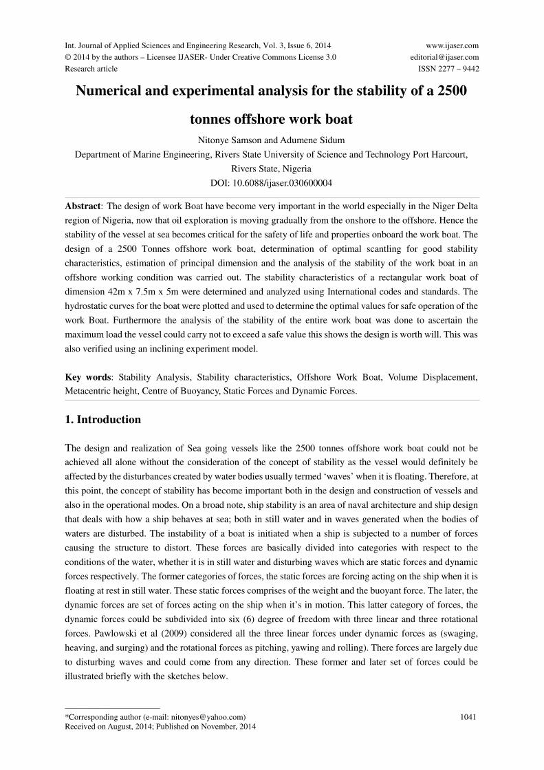
illustrated briefly with the sketches below.
Numerical and experimental analysis for the stability of a 2500 tonnes offshore work boat
Nitonye Samson and Adumene Sidum
Int. Journal of Applied Sciences and Engineering Research, Vol. 3, No. 6, 2014
1042
Figure 1: Dynamic forces in a 3-dimensional plane Figure 2: Static Forces.
However, the concept of equilibrium cannot be ruled out when the stability of a floating vessel is mentioned
or considered. The three types of equilibrium conditions usually considered are the stable, neutral and
unstable equilibrium with respect to a few number of hydrostatic parameters such as the center of gravity
(GG), the metacentric height (GM), metacentre (M) and the centre of buoyancy (CG) easily determined. Not
forgetting the Righting lever (+GZ) and the overturning lever (-GZ) as monitored by Edward (1988) which
was looked at by Norrbin (1950) many years ago and agree with the Lloyd’s (1997) on ship classification..
The stability of vessel could also be considered through the concept of the angle of lift, across two planes and
two degrees of freedom. The longitudinal section usually referred to as rolling and the transverse section
which is called pitching. So to consider the basic concept of the analysis of stability of a rectangular work
Boat, we must look at it when it is floating.
2. Materials and methods
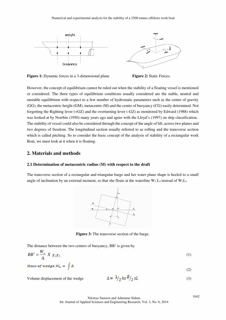
2.1 Determination of metacentric radius (M) with respect to the draft
The transverse section of a rectangular and triangular barge and her water plane shape is heeled to a small
angle of inclination by an external moment, so that she floats at the waterline W2 L2 instead of W1L1
Figure 3: The transverse section of the barge.
The distance between the two centers of buoyancy, BB1 is given by
21
1ggX
WBB w
∆= (1)
(2)
Volume displacement of the wedge (3)
Numerical and experimental analysis for the stability of a 2500 tonnes offshore work boat
Nitonye Samson and Adumene Sidum
Int. Journal of Applied Sciences and Engineering Research, Vol. 3, No. 6, 2014
1043
Height of wedge, ∂= tan2
BL (4)
Substituting equation 4 into equation 3, the Volume displace of the wedge will be
∂×××=∆ tan222
1 BLB
∂×××=∆ tan8
1 2 LB (5)
Substituting equation 5 into equation 2, LB
xWW ∂+=∆= tan8
2
λλ (6)
Substituting equation 6 into equation 1, LanggLB
BB δ+∆
=3
2tan 21
21 λ
λ (7)
Also the distance between the centre of the gravity of the wedges
Substituting for g1g2 into equation 7, 3
2
8
tan21 BxLB
BB∆
=δλ
∆=
12
tan31 LB
BBδλ
From the diagram, Metacentric radius, αtan
1BBBM = (8)
So, (9)
Substituting equation 8 into 9 we have, ∆
=12
tan3 LB
BMxλ
α (10)
But Volume displacement
And 12
3 LBI = Substituting into 10
∇=
IBM (11)
In case of longitudinal stability
∇= L
L
IBM (12)
2.2 Determination of center of buoyancy from keel (KG)
By the Geometry of the submerged section: The center of buoyancy is the centroid of the area of the
submerged section: for a barge as of draft d: the Buoyancy is given by:
KB = Centroid of the submerged section 2
dKB = (13)
2.3 Determination of height of metacenter above Keel (KM)
Again from the Geometry:
Substituting equations 13 for KB and ∆12
3 LBλ for BM
Numerical and experimental analysis for the stability of a 2500 tonnes offshore work boat
Nitonye Samson and Adumene Sidum
Int. Journal of Applied Sciences and Engineering Research, Vol. 3, No. 6, 2014
1044
Already formulated expression, we have ∆
+=122
3LBdKM
λ (14)
2.4 Determination of metacentric height (GM)
From the Geometry of the barge, through the transverse section of the pontoon:
By substituting the expression of KM from equation 14 so
KGLBdGM −
∆=
122
3λ (15)
2.5 Metacentric diagram
KB and BM depends upon the draft, their values for any ship or barge can be calculated for a number of
different draughts and plotted to form the metacentric diagram for the ship, the KM curve is the meta centric
diagram.
2.5 Tonne per centimeter immersion
Paulling et al (2007) in their paper motion and capsizing in Astern Sea looked at the amount of cargoes
loaded on a vessel that would to cause a parallel sinkage of one (1) cm which were supported by Grochwalski
et al (2007) and Hanshind (2008).
Mathematically, it is expressed as tonne per C on immersion
cmTondensityplanwaterofArea
TPC100
×=
= cm
tonA w
100
λ× (16)
Where Aw = Area of water – plane
= Density of sea water
IF cm
ton025.1=ρ
Substituting into 16 cm
tonATPC w
100
025.1×=
cm
tonxAW 0125.0= (17)
2.6 Preliminary calculations from the hull forms
The principal particulars of the barge are given as follows
Length overall, LOA = 42m
Beam moulded, B = 7.5m
Depth moulded, D = 5m
Light barge draft, d = 1.62m
KG = 2.02m
Dead weight = 2500 tons
Numerical and experimental analysis for the stability of a 2500 tonnes offshore work boat
Nitonye Samson and Adumene Sidum
Int. Journal of Applied Sciences and Engineering Research, Vol. 3, No. 6, 2014
1045
3. Calculation of the mass displacement of the barge
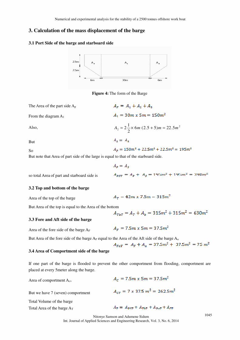
3.1 Port Side of the barge and starboard side
Figure 4: The form of the Barge
The Area of the part side Ap
From the diagram A1
Also, 2
2 5.22)55.2(62
12 mmmA =+×=
But
So
But note that Area of part side of the large is equal to that of the starboard side.
so total Area of part and starboard side is
3.2 Top and bottom of the barge
Area of the top of the barge
But Area of the top is equal to the Area of the bottom
3.3 Fore and Aft side of the barge
Area of the fore side of the barge AF
But Area of the fore side of the barge AF equal to the Area of the Aft side of the barge Aa
3.4 Area of Comportment side of the barge
If one part of the barge is flooded to prevent the other comportment from flooding, comportment are
placed at every 5meter along the barge.
Area of comportment Acv
But we have 7 (seven) comportment
Total Volume of the barge
Total Area of the barge AT
Numerical and experimental analysis for the stability of a 2500 tonnes offshore work boat
Nitonye Samson and Adumene Sidum
Int. Journal of Applied Sciences and Engineering Research, Vol. 3, No. 6, 2014
1046
The thickness of the plate use for the barge throughout to be 12mm
Volume of barge (Vb ) = AT x thickness
Total Volume of the Welding plate used for the barge
V.F a 6m by 6m plate is to be used and thickness of the place 12mm.
Volume of plate
Total Number of Plate used for construction
Barge Number of Plate (NP)
Number of plate Np ≈ 38
for 6m by 6m by 12mm
3.5 Mathematical relation for displacement with respect to draft
The mass displacement ( ∆ ) is the height of the water displaced by the rectangular barge. It is determined
by displacement
Displacement ∆
Light weight,
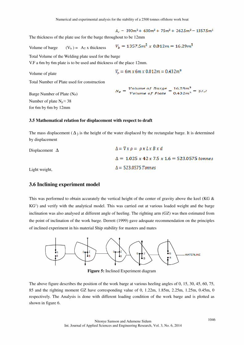
3.6 Inclining experiment model
This was performed to obtain accurately the vertical height of the center of gravity above the keel (KG &
KG1) and verify with the analytical model. This was carried out at various loaded weight and the barge
inclination was also analysed at different angle of heeling. The righting arm (GZ) was then estimated from
the point of inclination of the work barge. Derrett (1999) gave adequate recommendation on the principles
of inclined experiment in his material Ship stability for masters and mates
Figure 5: Inclined Experiment diagram
The above figure describes the position of the work barge at various heeling angles of 0, 15, 30, 45, 60, 75,
85 and the righting moment GZ have corresponding value of 0, 1.22m, 1.85m, 2.25m, 1.25m, 0.45m, 0
respectively. The Analysis is done with different loading condition of the work barge and is plotted as
shown in figure 6.
Numerical and experimental analysis for the stability of a 2500 tonnes offshore work boat
Nitonye Samson and Adumene Sidum
Int. Journal of Applied Sciences and Engineering Research, Vol. 3, No. 6, 2014
1047
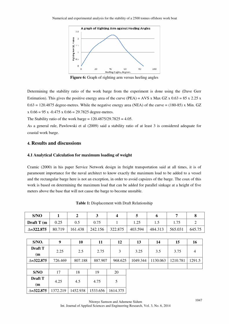
Figure 6: Graph of righting arm versus heeling angles
Determining the stability ratio of the work barge from the experiment is done using the (Dave Gerr
Estimation). This gives the positive energy area of the curve (PEA) = AVS x Max GZ x 0.63 = 85 x 2.25 x
0.63 = 120.4875 degree-metres. While the negative energy area (NEA) of the curve = (180-85) x Min. GZ
x 0.66 = 95 x -0.475 x 0.66 = 29.7825 degree-metres.
The Stability ratio of the work barge = 120.4875/29.7825 = 4.05.
As a general rule, Pawlowski et al (2009) said a stability ratio of at least 3 is considered adequate for
coastal work barge.
4. Results and discussions
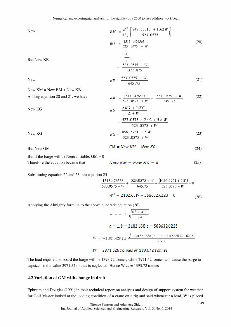
4.1 Analytical Calculation for maximum loading of weight
Cramic (2000) in his paper Service Network design in freight transportation said at all times, it is of
paramount importance for the naval architect to know exactly the maximum load to be added to a vessel
and the rectangular barge here is not an exception, in order to avoid capsizes of the barge. The coax of this
work is based on determining the maximum load that can be added for parallel sinkage at a height of five
meters above the base that will not cause the barge to become unstable.
Table 1: Displacement with Draft Relationship
S/NO 1 2 3 4 5 6 7 8
Draft T (m 0.25 0.5 0.75 1 1.25 1.5 1.75 2
∆=322.875 80.719 161.438 242.156 322.875 403.594 484.313 565.031 645.75
S/NO. 9 10 11 12 13 14 15 16
Draft T
(m 2.25 2.5 2.75 3 3.25 3.5 3.75 4
∆=322.875 726.469 807.188 887.907 968.625 1049.344 1130.063 1210.781 1291.5
S/NO 17 18 19 20
Draft T
(m 4.25 4.5 4.75 5
∆=322.875 1372.219 1452.938 1533.656 1614.375
Numerical and experimental analysis for the stability of a 2500 tonnes offshore work boat
Nitonye Samson and Adumene Sidum
Int. Journal of Applied Sciences and Engineering Research, Vol. 3, No. 6, 2014
1048
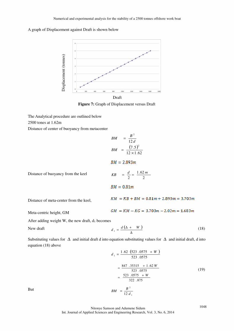
A graph of Displacement against Draft is shown below
0
1
2
3
4
5
6
0 200 400 600 800 1000 1200 1400 1600 1800
tonnes /cm
Draft
Figure 7: Graph of Displacement versus Draft
The Analytical procedure are outlined below
2500 tones at 1.62m
Distance of center of buoyancy from metacenter
( )62.112
5.7
122
2
×=
=
BM
d
BBM
Distance of buoyancy from the keel 2
62.1
2
mdKB ==
Distance of meta-center from the keel,
Meta-centric height, GM
After adding weight W, the new draft, d1 becomes
New draft ( )∆
+∆=
Wdd 1
(18)
Substituting values for ∆ and initial draft d into equation substituting values for ∆ and initial draft, d into
equation (18) above
( )0575.523
0575.52362.11
Wd
+=
875.322
0575.523
0575.523
62.135315.847
W
W
+=
+= (19)
But
1
2
12 d
BBM =
Dis
pla
cem
ent
(to
nn
es)
Numerical and experimental analysis for the stability of a 2500 tonnes offshore work boat
Nitonye Samson and Adumene Sidum
Int. Journal of Applied Sciences and Engineering Research, Vol. 3, No. 6, 2014
1049
New
+=
0575.523
62.135315.847
12 1
2WB
BM
W
BM+
=0575.523
476563.1513 (20)
But New KB
875.322
0575.523
2
1
W
d
+=
=
New 75.645
0575.523 WKB
+= (21)
New KM = New BM + New KB
Adding equation 20 and 21, we have 75.645
0575.523
0575.523
476563.1513 W
WKM
++
+= (22)
New KG W
WKGKGKG
+∆
+∆=
W
W
+
×+×=
0575.523
502.20575.523
New KG W
WKG
+
+=
0575.523
55761.1056 (23)
But New GM (24)
But if the barge will be Neutral stable, GM = 0
Therefore the equation became that (25)
Substituting equation 22 and 23 into equation 25
( )0
0575.523
55761.1056
75.645
0575.523
0575.523
476563.1513=
+
+−
++
+ W
WW
W
(26)
Applying the Almighty formula to the above quadratic equation (26)
a
acbbW
2
42 −±−=
12
6223.56863214)638.2182()628.2182(
2
×
××−−±−=W
The load required on board the barge will be 1393.72 tonnes, while 2971.52 tonnes will cause the barge to
capsize, so the value 2971.52 tonnes is neglected. Hence Wmax = 1393.72 tonnes
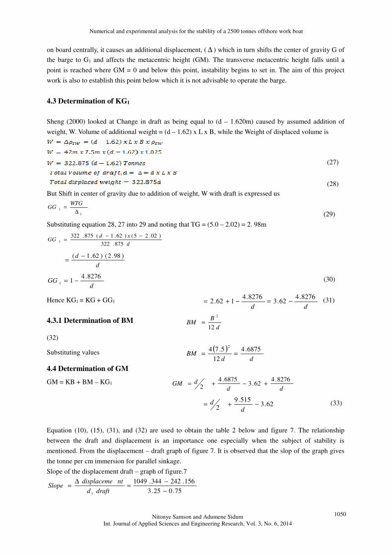
4.2 Variation of GM with change in draft
Ephraim and Douglas (1991) in their technical report on analysis and design of support system for weather
for Golf Master looked at the loading condition of a crane on a rig and said whenever a load, W is placed
Numerical and experimental analysis for the stability of a 2500 tonnes offshore work boat
Nitonye Samson and Adumene Sidum
Int. Journal of Applied Sciences and Engineering Research, Vol. 3, No. 6, 2014
1050
on board centrally, it causes an additional displacement, ( ∆ ) which in turn shifts the center of gravity G of
the barge to G1 and affects the metacentric height (GM). The transverse metacentric height falls until a
point is reached where GM = 0 and below this point, instability begins to set in. The aim of this project
work is also to establish this point below which it is not advisable to operate the barge.
4.3 Determination of KG1
Sheng (2000) looked at Change in draft as being equal to (d – 1.620m) caused by assumed addition of
weight, W. Volume of additional weight = (d – 1.62) x L x B, while the Weight of displaced volume is
(27)
(28)
But Shift in center of gravity due to addition of weight, W with draft is expressed us
1
1∆
=WTG
GG
(29)
Substituting equation 28, 27 into 29 and noting that TG = (5.0 – 2.02) = 2. 98m
d
xdGG
875.322
)02.25()62.1(875.3221
−−=
d
d )98.2()62.1( −=
dGG
8276.411 −= (30)
Hence KG1 = KG + GG1 dd
8276.462.3
8276.4162.2 −=−+= (31)
4.3.1 Determination of BM d
BBM
12
2
=
(32)
Substituting values ( )
ddBM
6875.4
12
5.742
==
4.4 Determination of GM
GM = KB + BM – KG1 dd
dGM8276.4
62.36875.4
2+−+=
62.3515.9
2−+=
dd (33)
Equation (10), (15), (31), and (32) are used to obtain the table 2 below and figure 7. The relationship
between the draft and displacement is an importance one especially when the subject of stability is
mentioned. From the displacement – draft graph of figure 7. It is observed that the slop of the graph gives
the tonne per cm immersion for parallel sinkage.
Slope of the displacement draft – graph of figure.7
75.025.3
156.242344.1049
1 −
−=
∆=
draftd
ntdisplacemeSlope
Numerical and experimental analysis for the stability of a 2500 tonnes offshore work boat
Nitonye Samson and Adumene Sidum
Int. Journal of Applied Sciences and Engineering Research, Vol. 3, No. 6, 2014
1051
cm
tonnes
m
tonnes229.3875.322 ==
The slope signifies that a load of 3.229 tonnes will cause a parallel sinkage of one cm.
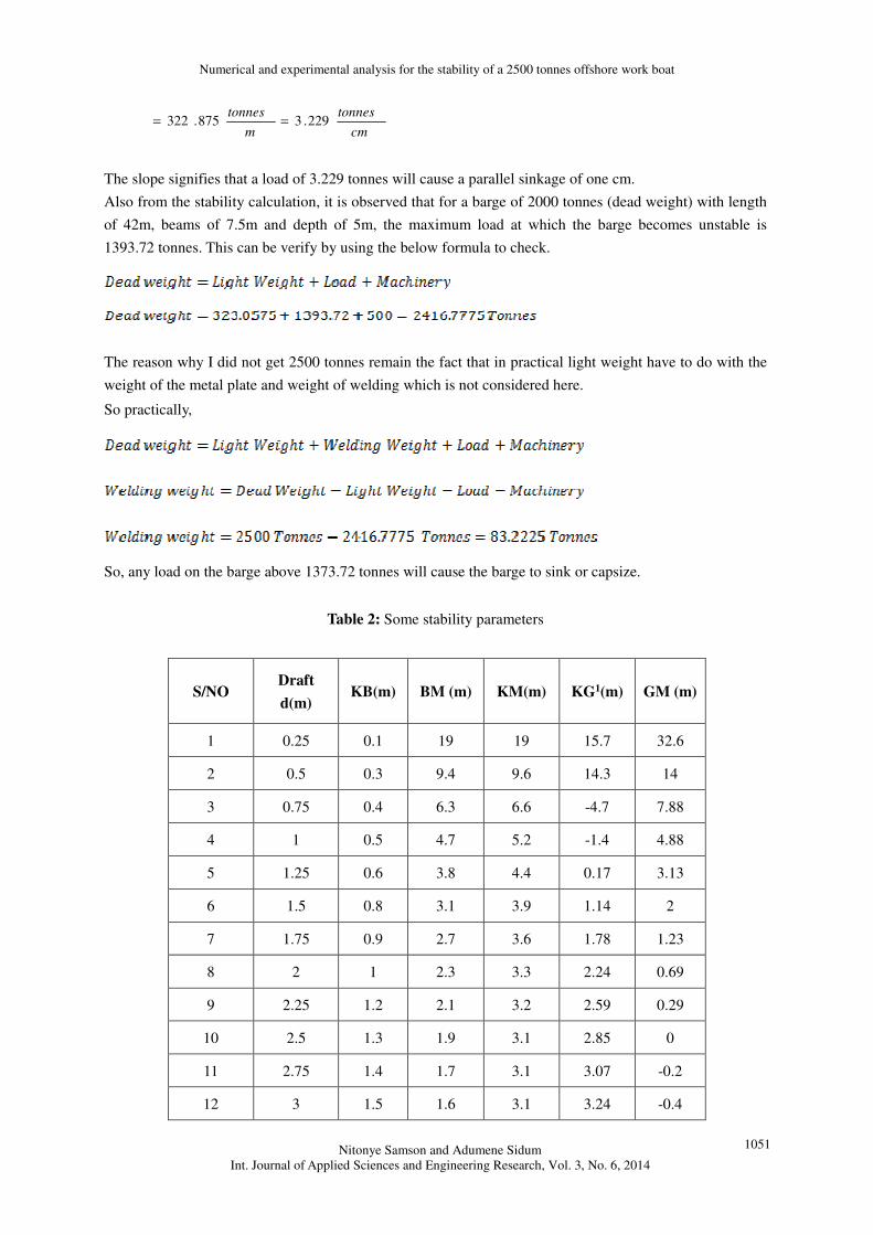
Also from the stability calculation, it is observed that for a barge of 2000 tonnes (dead weight) with length
of 42m, beams of 7.5m and depth of 5m, the maximum load at which the barge becomes unstable is
1393.72 tonnes. This can be verify by using the below formula to check.
The reason why I did not get 2500 tonnes remain the fact that in practical light weight have to do with the
weight of the metal plate and weight of welding which is not considered here.
So practically,
So, any load on the barge above 1373.72 tonnes will cause the barge to sink or capsize.
Table 2: Some stability parameters
S/NO Draft
d(m) KB(m) BM (m) KM(m) KG1(m) GM (m)
1 0.25 0.1 19 19 15.7 32.6
2 0.5 0.3 9.4 9.6 14.3 14
3 0.75 0.4 6.3 6.6 -4.7 7.88
4 1 0.5 4.7 5.2 -1.4 4.88
5 1.25 0.6 3.8 4.4 0.17 3.13
6 1.5 0.8 3.1 3.9 1.14 2
7 1.75 0.9 2.7 3.6 1.78 1.23
8 2 1 2.3 3.3 2.24 0.69
9 2.25 1.2 2.1 3.2 2.59 0.29
10 2.5 1.3 1.9 3.1 2.85 0
11 2.75 1.4 1.7 3.1 3.07 -0.2
12 3 1.5 1.6 3.1 3.24 -0.4
Numerical and experimental analysis for the stability of a 2500 tonnes offshore work boat
Nitonye Samson and Adumene Sidum
Int. Journal of Applied Sciences and Engineering Research, Vol. 3, No. 6, 2014
1052
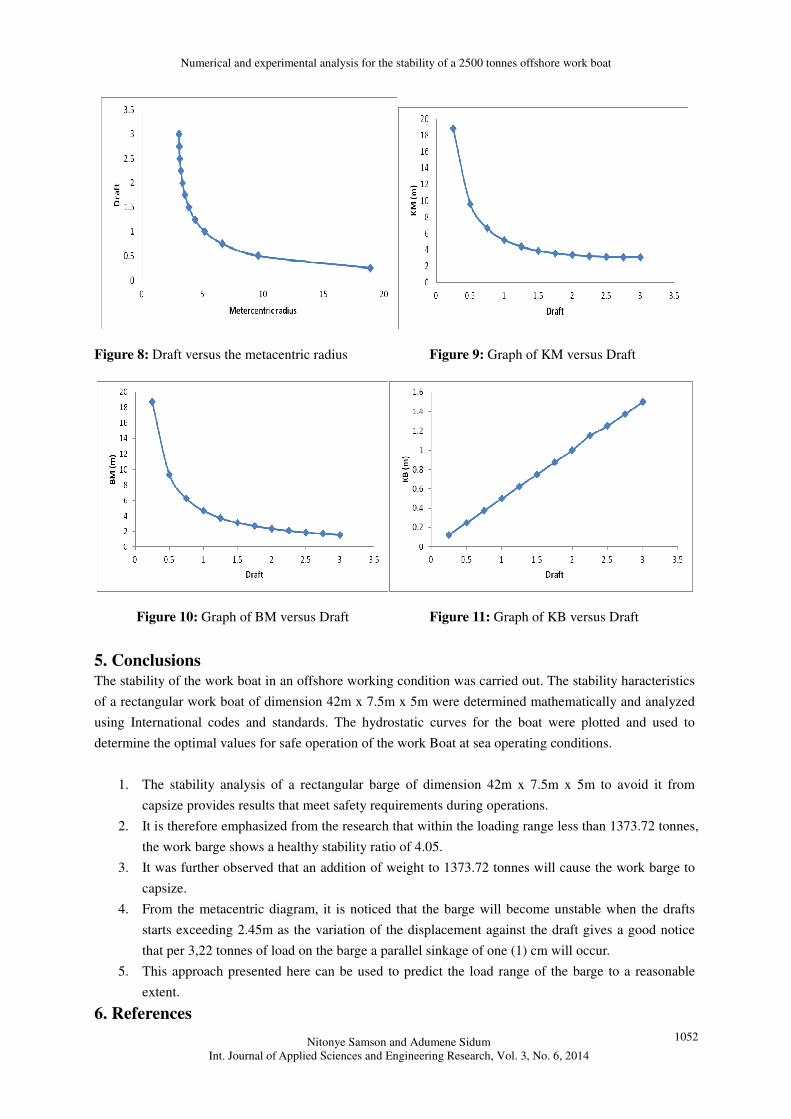
Figure 8: Draft versus the metacentric radius Figure 9: Graph of KM versus Draft
Figure 10: Graph of BM versus Draft Figure 11: Graph of KB versus Draft
5. Conclusions The stability of the work boat in an offshore working condition was carried out. The stability haracteristics
of a rectangular work boat of dimension 42m x 7.5m x 5m were determined mathematically and analyzed
using International codes and standards. The hydrostatic curves for the boat were plotted and used to
determine the optimal values for safe operation of the work Boat at sea operating conditions.
1. The stability analysis of a rectangular barge of dimension 42m x 7.5m x 5m to avoid it from
capsize provides results that meet safety requirements during operations.
2. It is therefore emphasized from the research that within the loading range less than 1373.72 tonnes,
the work barge shows a healthy stability ratio of 4.05.
3. It was further observed that an addition of weight to 1373.72 tonnes will cause the work barge to
capsize.
4. From the metacentric diagram, it is noticed that the barge will become unstable when the drafts
starts exceeding 2.45m as the variation of the displacement against the draft gives a good notice
that per 3,22 tonnes of load on the barge a parallel sinkage of one (1) cm will occur.
5. This approach presented here can be used to predict the load range of the barge to a reasonable
extent.
6. References
Numerical and experimental analysis for the stability of a 2500 tonnes offshore work boat
Nitonye Samson and Adumene Sidum
Int. Journal of Applied Sciences and Engineering Research, Vol. 3, No. 6, 2014
1053
1. Crainic, T. G, 2000. Service network design in freight transportation. European Journal of
operational Research, 122.
2. Derrett D. R, 1999. Ship Stability for masters and mates, Revised by Dr. C.B Reed Educational
and Professional Publishing Ltd Barras, Oxford Auckland Boston Johannesburg Melbourne New
Delhi,
3. Edward, V. L, 1988. Principle of Naval Architecture Second Revision: Stability and Strength
Volume I. The Society of Naval Architecture and Marine Engineers. New Jersey,
4. Ephraim M. E, and Douglas, I. E, 1991. Technical Report on Analysis and Design of support
system for weather ford Gulf master G 1 5F Crane on the Anini-1 Rig,
5. Grochwalski, S, Rask, I, and Soderberg, P, 2007. An Experimental Technique for investigation into
Physics of ship capsizing in Proceedings. Third International Conference on stability of ship and
Ocean vehicles, STAB’86, Gdansk, Poland.
6. Hanshind, M. D. 2008. Hydrodynamics Theory of ship motions. Published by Nauks, Moscow, (in
Russian).
7. Lloyd’s Register, 1997. Classification of Ship Rules and Regulations Part 3: Ship Structure
London,.
8. Norrbin, N. H. , 1950. The Design of Sea kindly Ships. North-East Coast Institution of Engineers
and Ship-owners, Newcastle upon Tyne, United Kingdom.
9. Pauling .J. R, Oakley, O. H, and Wood P. D, 2007. Motion and Capsizing in Astern Sea” in
Proceedings. Tenth Symposium on Naval hydrodynamics.
10. Pawlowski, J. S, Bass, D. W, and Grochowalski, S. A, 2009. Time Domain Simulation of ship
motion in Waves” in Proceedings. 17th Symposium on Naval Hydrodynamics, The Hague,
Netherlands.
11. SHENG Zhenbang 2002. Principle of Ship (M). Shanghai. Shanghai Jiaotong University press,.