Embed Size (px)
Citation preview

Earth Science Research; Vol. 6, No. 2; 2017 ISSN 1927-0542 E-ISSN 1927-0550
Published by Canadian Center of Science and Education
1
Numerical Analysis of Face Stability of Slurry Pipe Jacking Tunnel in Frozen Ground
Kai Wen1, Hideki Shimada1, Wei Zeng2, Takashi Sasaoka1 & Akihiro Hamanaka1 1 Laboratory of Rock Engineering and Mining Machinery, Department of Earth Resources Engineering, Kyushu University, Fukuoka, 819-0395, Japan 2 State Key Laboratory for Geomechanics & Deep Underground Engineering, China University of Mining and Technology, Xuzhou, 221116, China Correspondence: Kai Wen, Laboratory of Rock Engineering and Mining Machinery, Department of Earth Resources Engineering, Kyushu University, Fukuoka, 819-0395, Japan. E-mail: [email protected] Received: January 17, 2016 Accepted: February 9, 2016 Online Published: February 24, 2017 doi:10.5539/esr.v6n2p1 URL: https://doi.org/10.5539/esr.v6n2p1 Abstract In this paper, a series of parametric three-dimension numerical simulations were carried out to estimate the face stability and to calculate the minimum allowable slurry pressure of pipe jacking tunnel in frozen ground for the first time. In total, 5120 of simulation schemes were done with different ground temperature, diameter and cover thickness of tunnel, cohesion and friction angle of frozen soil. In order to figure out the optimal grouting pressure, 4 groups of additional simulations are computed with the uniform face support pressure of 0.5, 1.0, 1.5 and 2.0 times of horizontal stress, σH, at tunnel axis. The qualitative analysis of heading face deformation mechanism and quantitative analysis between deformation profiles and influential factors were implemented to comprehend the heading face deformation characteristics when conducting pipe jacking tunnel in frozen ground. The results show that ground temperature plays a dominant role to control the face deformation of jacking tunnel in frozen ground. And, factors of tunnel diameter and cover thickness have relatively greater influence on the deformation regulation than that of shearing parameters of frozen soil, cohesion and friction angle. Finally, the minimum allowable slurry pressure for each simulation schemes are obtained, which may be used in construction the pipe jacking tunnel in frozen ground. Keywords: face stability, frozen ground, numerical simulation, slurry pipe jacking 1. Introduction Seasonally and perennially frozen ground occupy about 24.91×10⁶ Km2, including glaciers and ice sheet, nearly 25.6% of the land surface in the Northern Hemisphere (Zhang, Barry, Knowles, Ling, & Armstrong, 2003; Zhang, Heginbottom, Barry, & Brown, 2000), where some cities aggregate with the underground construction activities. Freezing and thawing cycles influence the thermal and hydraulic properties of the soil, which in turn have a significant impact on the soil properties and interaction between underground structures and surrounding frozen ground. Generally, freezing of soil pore moisture increase the strength of frozen soil, which reduces the ground deformation and enhance the stability of tunnel face, compared with that of normal soil, which causes the discrepancy if continuing employing the conventional slurry pipe jacking method in the cold regions. Trenchless technology is a process for construction, renewal, and replacement of underground pipelines and utilities with minimal and subsurface disruptions (Najafi, 2005). Among which, pipe jacking is a non-destructive trenchless technique used for installing pipes under the ground using a tunnel boring machine and hydraulic jacks located inside a launch jacking pit (Chapman & Ichioka, 1999; Choo & Ong, 2015; Khazaei, Shimada, Kawai, Yotsumoto, & Matsui, 2006; Pipe Jacking Association, 1995; Rahjoo, Najafi, Williammee, & Khankarli, 2012; Shimada, Khazaei, & Matsui, 2004). A shield is inserted into the ground through a launch shaft or reception shaft and cuts a bore. As the shield advances forward, excavating the earth in its path, sections of pipe are jacked into place directly behind it using powerful hydraulic jacks (Pipe Jacking Association, 1995). Recent decades, slurry pipe jacking is widely used in the construction of underground infrastructure projects such as rectangular or circular pedestrian subways, culverts, road underpasses, bridge abutments and so on. However, till now, no literature reports about the application of pipe jacking technology in frozen ground can be found. In order to promote the development of slurry pipe jacking technology, this paper is presented to explore the issues

esr.ccsenet.org Earth Science Research Vol. 6, No. 2; 2017
2
which may be encountered when applying slurry pipe jacking in frozen ground. In this paper, a series of finite element simulations were carried out to estimate the stability of tunnel heading face and the minimum allowable face support pressure of slurry pipe jacking in frozen ground, which is essentially important to design the grouting pressure and to prevent the collapse and blow-out failure of the jacking tunnel face. As we know, ensuring tunnel face stability is directly related to the safe as successful construction of a tunnel (Kim & Tonon, 2010; Tang, Liu, Albers, & Savidis, 2014; Soranzo, Tamagnini, & Wu, 2015). The minimum support pressure to avoid face instability in cold regions is affected by various factors, such as ground temperature, cohesion, friction angle and permeability of frozen ground, the type of shield machine, advance rate, unit weight of slurry and conditioned soil, jacking tunnel diameter, cover thickness and so on. In this article, the qualitative analysis of the jacking tunnel face deformation mechanism is acquired. Then, the quantitative relationship between tunnel face deformation profiles and temperature, geological and geometric parameters are analyzed by using FLAC3D version 5.0, of which the most important outcome is the obtaining of the minimum allowable face support slurry pressure for each simulation schemes with various conditions. 2. Frozen Ground Materials It has become a limiting factor to select the material properties for use in design of frozen earth structures for some field applications (Bragg & Andersland, 1981). Generally, the geological material, soil and rock, is mainly comprised of three phases, solid grains, water and gases. However, from the point of view of the science of materials, the frozen soil is a natural particulate composite, which is composed of four different constituents: solid grains (mineral or organic), ice, unfrozen water and gases, showing in Figure 1. While the ground temperature decreasing, part of the water content will be frozen to ice crystal, which enhances the cohesion between soil particles. Because of the existence of ice crystal in frozen soil, there are great changes of material properties within frozen soil. The most important characteristic by which it differs from other similar materials—such as unfrozen soils and the majority of artificial composites—is that under natural conditions its matrix, which is mostly composed of ice and water changes continuously with varying temperature and applied stress (Andersland & Ladanyi, 2013).
Figure 1. Phase diagram of frozen and unfrozen soil
2.1 Targeted Frozen Soil The frozen soil is a kind of natural multicomponent and multiphase system and very complex geological material, the mechanical properties of which are affected by many factors, such as temperature, dry density or water content (Sayles & Carbee, 1981), mineral particle size and their distribution, applied strain rate, the sample size or shape, loading conditions (Bragg & Andersland, 1981) and so on. Many researchers have done a lot of experiments, including uniaxial compressive strength and tensile tests, split cylinder tests, dynamic tri-axial tests (Ling et al., 2009; Shi, He, & Bian, 2006), concentrating on the study of mechanical and deformation properties of frozen soil in the past few decades. Yuanlin Zhu and David L. Carbee (Yuanlin, 1986; Zhu & Carbee, 1984) conducted a series of UCS tests on remolded, saturated Fairbanks frozen silt, taken from the Fairbanks Permafrost Experiment Station (FPES) in Cold Regions Research and Engineering Laboratory (CRREL) of USA experimental permafrost tunnel at Fox near Fairbanks, Alaska, under various constant machine speeds, temperature and dry densities. Some of its physical properties are as follows: the plastic limit of 34.2%, liquid limit of 38.4%, organic content of 5.49%, and a specific gravity of 2.68. The initial tangent modulus is much less sensitive to strain rate than to temperature, shown in Figure 2.
(a) Unfrozen soil (b) Frozen soil
esr.ccsenet.org Earth Science Research Vol. 6, No. 2; 2017
3
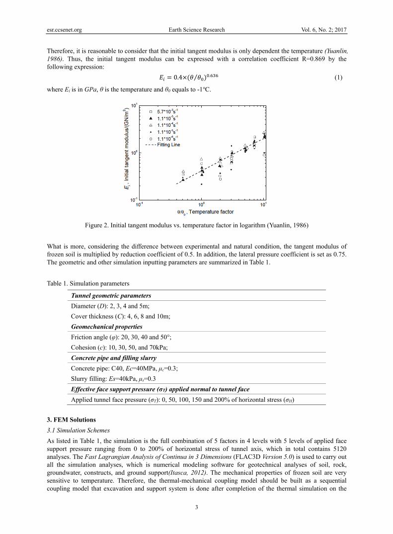
Therefore, it is reasonable to consider that the initial tangent modulus is only dependent the temperature (Yuanlin, 1986). Thus, the initial tangent modulus can be expressed with a correlation coefficient R=0.869 by the following expression: 0.4 ⁄ . (1)
where Ei is in GPa, θ is the temperature and θ0 equals to -1℃.
Figure 2. Initial tangent modulus vs. temperature factor in logarithm (Yuanlin, 1986)
What is more, considering the difference between experimental and natural condition, the tangent modulus of frozen soil is multiplied by reduction coefficient of 0.5. In addition, the lateral pressure coefficient is set as 0.75. The geometric and other simulation inputting parameters are summarized in Table 1. Table 1. Simulation parameters
Tunnel geometric parameters Diameter (D): 2, 3, 4 and 5m; Cover thickness (C): 4, 6, 8 and 10m; Geomechanical properties Friction angle (φ): 20, 30, 40 and 50°; Cohesion (c): 10, 30, 50, and 70kPa; Concrete pipe and filling slurry Concrete pipe: C40, Ec=40MPa, μc=0.3; Slurry filling: Es=40kPa, μs=0.3 Effective face support pressure (σT) applied normal to tunnel face Applied tunnel face pressure (σT): 0, 50, 100, 150 and 200% of horizontal stress (σH)
3. FEM Solutions 3.1 Simulation Schemes As listed in Table 1, the simulation is the full combination of 5 factors in 4 levels with 5 levels of applied face support pressure ranging from 0 to 200% of horizontal stress of tunnel axis, which in total contains 5120 analyses. The Fast Lagrangian Analysis of Continua in 3 Dimensions (FLAC3D Version 5.0) is used to carry out all the simulation analyses, which is numerical modeling software for geotechnical analyses of soil, rock, groundwater, constructs, and ground support(Itasca, 2012). The mechanical properties of frozen soil are very sensitive to temperature. Therefore, the thermal-mechanical coupling model should be built as a sequential coupling model that excavation and support system is done after completion of the thermal simulation on the
esr.ccsenet.org Earth Science Research Vol. 6, No. 2; 2017
4
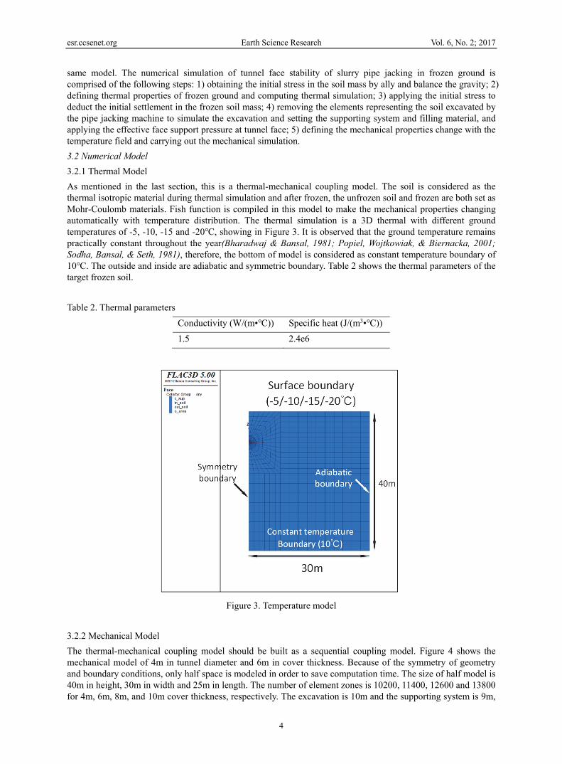
same model. The numerical simulation of tunnel face stability of slurry pipe jacking in frozen ground is comprised of the following steps: 1) obtaining the initial stress in the soil mass by ally and balance the gravity; 2) defining thermal properties of frozen ground and computing thermal simulation; 3) applying the initial stress to deduct the initial settlement in the frozen soil mass; 4) removing the elements representing the soil excavated by the pipe jacking machine to simulate the excavation and setting the supporting system and filling material, and applying the effective face support pressure at tunnel face; 5) defining the mechanical properties change with the temperature field and carrying out the mechanical simulation. 3.2 Numerical Model 3.2.1 Thermal Model As mentioned in the last section, this is a thermal-mechanical coupling model. The soil is considered as the thermal isotropic material during thermal simulation and after frozen, the unfrozen soil and frozen are both set as Mohr-Coulomb materials. Fish function is compiled in this model to make the mechanical properties changing automatically with temperature distribution. The thermal simulation is a 3D thermal with different ground temperatures of -5, -10, -15 and -20℃, showing in Figure 3. It is observed that the ground temperature remains practically constant throughout the year(Bharadwaj & Bansal, 1981; Popiel, Wojtkowiak, & Biernacka, 2001; Sodha, Bansal, & Seth, 1981), therefore, the bottom of model is considered as constant temperature boundary of 10℃. The outside and inside are adiabatic and symmetric boundary. Table 2 shows the thermal parameters of the target frozen soil. Table 2. Thermal parameters
Conductivity (W/(m•℃)) Specific heat (J/(m3•℃))1.5 2.4e6
Figure 3. Temperature model
3.2.2 Mechanical Model The thermal-mechanical coupling model should be built as a sequential coupling model. Figure 4 shows the mechanical model of 4m in tunnel diameter and 6m in cover thickness. Because of the symmetry of geometry and boundary conditions, only half space is modeled in order to save computation time. The size of half model is 40m in height, 30m in width and 25m in length. The number of element zones is 10200, 11400, 12600 and 13800 for 4m, 6m, 8m, and 10m cover thickness, respectively. The excavation is 10m and the supporting system is 9m,

esr.ccsenet.org Earth Science Research Vol. 6, No. 2; 2017
5
leaving behind 1m space as the excavation chamber. The concrete pipeline and lubricant fill material are modelled to behave linear elasticity. In order to figure out the minimum allowable face support pressure, five models are considered with 0, 50%, 100%, 150% and 200% of horizontal stress of tunnel axis applied at tunnel face, shown in Figure 4. Five points are taken on the tunnel face uniformly to monitor the face deformation. However, this model do not consider the procedure of tunnel shield in detail, including the cutter inclination, excavation ratio and its mechanical supporting effect on the surrounding ground. Also, the water table is not taken into account because of the frozen temperature.
Figure 4. Mechanical model
Figure 5. Schematic diagram of face support pressure
3.3 Simulation Results 3.3.1 Thermal Results In the thermal simulation, the temperature of surface ground is set -5, -10, -15 and -20℃, which stands for 4 different conditions of ground climatope. Figure 6 shows the thermal simulation results of these four cases, in which temperature is demonstrated as uniform layered distribution, because the soil is considered as the thermal isotropic material. In addition, the depth of 0℃ isothermal increases with the decreasing ground surface temperature. Within these simulation with ideal condition, the freezing depth of ground is ranging from 13.3m to

esr.ccsenet.org Earth Science Research Vol. 6, No. 2; 2017
6
26.7m, which means that all the simulation schemes are situated in frozen ground.
Figure 6. Temperature distribution with ground temperature. a) -5℃, b) -10℃, c) -15℃, d) -20℃ (3m diameter and 6m cover thickness)
3.3.2 Mechanical Results 1) Deformation Mechanism Types Generally, there are mainly two types of failure mechanism of tunnel face, the blow-out of upper part of the tunnel and the collapse of the lower part of the tunnel, like showing in Figure 7. In the upper part blow-out mechanism, as shown in Figure 7(a), the top of the failure area passes through the tunnel crown. In the lower part collapse mechanism, as shown in Figure 7(b), the bottom of the failure area passes through the tunnel invert(Li, Emeriault, Kastner, & Zhang, 2009). These two partial failure mechanism are the very common and dangerous failure mechanism, corresponding to deformation type II and type IV shown in Figure 8. However, for deformation mechanism without failure, type I and type III shown in Figure 8, are also taken into consideration in this paper. The mechanism procedure can be divided in the following types: 1) type I: bulges outward as a parabola along with tunnel axis, always happens in the condition with comparatively large tunnel diameter or small tunnel diameter with low property parameters, such as high deformation modulus, cohesion, and friction angle; 2) type II: the maximum tunnel face deformation comes up at the point of 1/3 diameter near tunnel invert, which always appears with low mechanical properties or insufficient slurry pressure and causes partial collapse; 3) type III: bulges inward as a parabola along with tunneling direction, and just behaves oppositely with type I, which happens with large grouting pressure; 4) type IV: the maximum deformation behaves near tunnel crown along with tunneling direction, which always occurs with too large slurry pressure and causes partial blow-out failure. Figure 9, Figure 10 and Figure 11 show the Deformation mechanism of type I, II and III.
0℃ isotherm
0℃ isotherm
0℃ isotherm
0℃ isotherm
a b
c d

esr.ccsenet.org Earth Science Research Vol. 6, No. 2; 2017
7
Figure 7. Two partial failure mechanisms(Li et al., 2009)
Figure 8. Deformation mechanisms of tunnel face
Face deformation
-5℃ -5℃
Info: Cover thickness:10m Diameter: 4m Cohesion:10kPa Friction: 20°
Info:Cover thickness:10m Diameter: 4m Cohesion:10kPa Friction: 30°
Face deformation
a b

esr.ccsenet.org Earth Science Research Vol. 6, No. 2; 2017
8
Figure 9. Deformation mechanism of type I with friction angle (magnified 10times)
Figure 10. Deformation mechanism of type II with temperature (magnified 10times)
-5℃ -10℃
-15℃ -20 ℃
Face deformation
Face deformation
Face deformation
Face deformation
Info: Cover thickness:4mDiameter: 5m Cohesion:10kPa Friction: 20°
Info:Cover thickness:4m Diameter: 5m Cohesion:10kPa Friction: 20°
Info: Cover thickness:4mDiameter: 5m Cohesion:10kPa Friction: 20°
Info:Cover thickness:4mDiameter: 5m Cohesion:10kPa Friction: 20°
-5℃ -5℃
Info: Cover thickness:10m Diameter: 4m Cohesion:10kPa Friction: 40°
Info:Cover thickness:10mDiameter: 4m Cohesion:10kPa Friction: 50°
Face deformation Face
deformation
c d
a b
c d

esr.ccsenet.org Earth Science Research Vol. 6, No. 2; 2017
9
Figure 11. Deformation mechanism of type III with friction angle (magnified 10times)
2) Tunnel Face Stability with Temperature, T In cold regions, temperature is a controlling factor to determine the strength parameters of frozen soil and the initial yield stress, the compressive peak strength, and the initial tangent modulus increase with decreasing temperature(Bragg & Andersland, 1981; Haynes & Karalius, 1977), which means that the stability of pipe jacking tunnel face is impacted by ground temperature. In the following analysis, only the maximum face deformation, UYmax, is take into consideration in the five deformation monitoring points on tunnel face. What should be clear that in the following all graphs, the legend is identified in this way: for example, the “10/20, 2/4” means that cohesion of 10kPa, friction angle of 20 degree, diameter of 2m and cover thickness of 4m, or the “-5℃, 20°, 2/4” means that temperature of -5℃, friction angle of 20 degree, diameter of 2m and cover thickness of 4m. Figure 9 and Figure 10 show the maximum face deformation with temperature when φ=20° and φ=30°, respectively. Both figures indicate that as the temperature decreases, the maximum face deformation, UYmax, drops quickly, especially from -5 to -10℃. When the temperature reaches less than -10℃, the deformation becomes slightly small. This is because the lower temperature of the ground, the higher mechanical property of frozen ground and therefore, and the tunnel face becomes more stable. For the temperature stays constant, as the tunnel gets deeper and tunnel diameter gets larger, the face deformation behaves larger. Comparison with Figure 12 and Figure 13, while the friction angle increases, the maximum face deformation decreases.
Face deformation
Face deformation
Face deformation
Face deformation
-5℃Info: Cover thickness:10m Diameter: 5m Cohesion:10kPa Friction: 20°
Info:Cover thickness:10m Diameter: 5m Cohesion:10kPa Friction: 30°
Info: Cover thickness:10m Diameter: 5m Cohesion:10kPa Friction: 40°
Info:Cover thickness:10m Diameter: 5m Cohesion:10kPa Friction: 50°
-5℃
-5℃ -5℃
a b
c d

esr.ccsenet.org Earth Science Research Vol. 6, No. 2; 2017
10
Figure 12. Maximum face deformation with temperature (φ=20°)
Figure 13. Maximum face deformation with temperature (φ=30°)

esr.ccsenet.org Earth Science Research Vol. 6, No. 2; 2017
11
3) Tunnel Face Stability with Tunnel Diameter, D Nowadays, large diameter tunnel is becoming more and more popular in pipe jacking engineering. Therefore, we consider that the pipe jacking tunnel diameter ranges from 2 to 5m. Figure 14 and Figure 15 give out relationship of the maximum face deformation with tunnel diameter when φ=20° and φ=30°, respectively. Obviously, it is found that the maximum face deformation increases with the increasing tunnel diameter, especially for the higher temperature (-5℃) situation. As we know, the larger pipe jacking tunnel diameter means bigger free face of excavation, which contributes to more larger face deformation. Therefore, for large diameter pipe jacking tunnel in frozen ground, to increase the slurry pressure is needed to prevent tunnel face failure. Besides, increasing another geometric parameter, cover thickness, results in larger face deformation.
Figure 14. Maximum face deformation with tunnel diameter (φ=20°)

esr.ccsenet.org Earth Science Research Vol. 6, No. 2; 2017
12
Figure 15. Maximum face deformation with tunnel diameter (c=30kPa, φ=30°)
4) Tunnel Face Stability with Cover Thickness, C Figure 16 shows the relationship between maximum face deformation and tunnel cover thickness. The results illustrate that when the cover of tunnel becomes deeper, the face deformation increases. As we know, the ground stress increases along with depth, therefore, excavation of deep buried tunnel causes relatively larger stress release of frozen ground, which results in large tunnel face deformation. In order to stabilize the tunnel face and prevent collapse and failure, more larger slurry pressure is needed in the construction of deep buried pipe jacking tunnel while shield machine moves ahead. It's worth noting that for shallow buried jacking tunnel, appropriate slurry pressure should be chosen to avoid blow-out failure and ground heave, rather than dig the tunnel without any grouting pressure because of its slight deformation. What’s more, construction of jacking tunnel under lower temperature is much safer than that of under higher ground temperature.
Figure 16. Maximum face deformation with cover thickness (c=30kPa, φ=20°)
esr.ccsenet.org Earth Science Research Vol. 6, No. 2; 2017
13
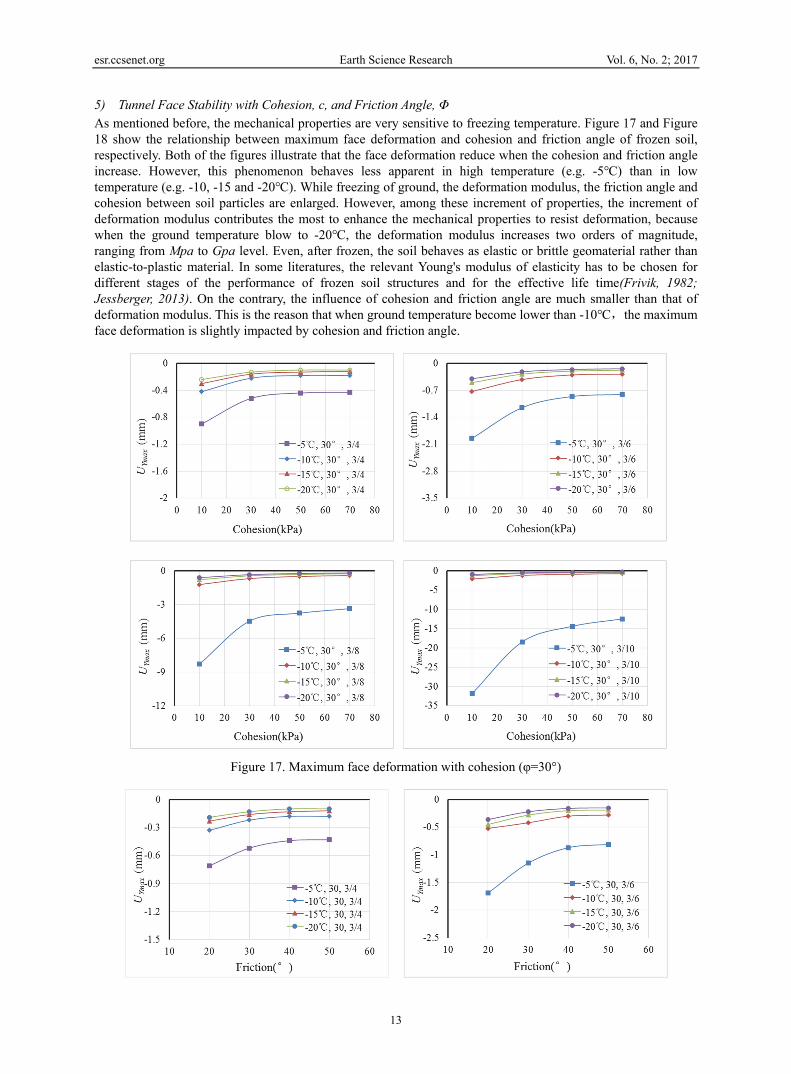
5) Tunnel Face Stability with Cohesion, c, and Friction Angle, Φ As mentioned before, the mechanical properties are very sensitive to freezing temperature. Figure 17 and Figure 18 show the relationship between maximum face deformation and cohesion and friction angle of frozen soil, respectively. Both of the figures illustrate that the face deformation reduce when the cohesion and friction angle increase. However, this phenomenon behaves less apparent in high temperature (e.g. -5℃) than in low temperature (e.g. -10, -15 and -20℃). While freezing of ground, the deformation modulus, the friction angle and cohesion between soil particles are enlarged. However, among these increment of properties, the increment of deformation modulus contributes the most to enhance the mechanical properties to resist deformation, because when the ground temperature blow to -20℃, the deformation modulus increases two orders of magnitude, ranging from Mpa to Gpa level. Even, after frozen, the soil behaves as elastic or brittle geomaterial rather than elastic-to-plastic material. In some literatures, the relevant Young's modulus of elasticity has to be chosen for different stages of the performance of frozen soil structures and for the effective life time(Frivik, 1982; Jessberger, 2013). On the contrary, the influence of cohesion and friction angle are much smaller than that of deformation modulus. This is the reason that when ground temperature become lower than -10℃,the maximum face deformation is slightly impacted by cohesion and friction angle.
Figure 17. Maximum face deformation with cohesion (φ=30°)

esr.ccsenet.org Earth Science Research Vol. 6, No. 2; 2017
14
Figure 18. Maximum face deformation with friction angle (c=30kPa)
4. Minimum Allowable Face Support Pressure In the last section, we talk about the deformation mechanism and the face deformation regularity of pipe jacking tunnel in frozen ground with temperature, tunnel diameter, cover thickness, cohesion and friction angle. As mentioned above, the final goal of this paper is to get the optimal face support pressure applied on tunnel face during conducting pipe jacking tunnel in cold regions. 4.1 Numerical Simulation Results with Various σT/σH Ratios In order to figure out the most suitable slurry pressure to stabilize the tunnel face, except for the simulation with no support pressure, 4 groups of additional simulations are carried out with the uniform support pressure of 0.5, 1.0, 1.5 and 2.0 times of horizontal stress , σH, at tunnel axis, as shown in Figure 5. Method of exhaustion is used in the FEM solutions to computing the maximum face deformation corresponding to each simulation schemes. Figure 19 and Figure 20 show the typical relationship between the maximum tunnel face deformation, UYmax, and the applied face support pressure ratios (σT/σH). The quality UYmax represents the maximum displacement in y-direction among the face monitoring points. When the curve locates under the horizontal axis, the deformation mechanism of tunnel face behaves like deformation type I or II, in contrast, it presents as deformation type III.

esr.ccsenet.org Earth Science Research Vol. 6, No. 2; 2017
15
Figure 19. Maximum face deformation with ratio of σT/σH (c=10kPa, φ=20°)
Figure 20. Maximum face deformation with ratio of σT/σH (c=30kPa, φ=20°) 4.2 Calculation of Minimum Allowable Slurry Pressure The identification of minimum allowable slurry pressure refers to the suitable face support pressure applied on the jacking face to ensure that allowable value of y-direction happens on the heading face. Figure 21 illustrates the typical curve of relationship between maximum tunnel face deformation and the ratio of σT/σH. The UYallow refers to allowable value of tunnel face deformation. The A point indicates the intersection of typical curve of UYmax and ratio of σT/σH with the allowable value of tunnel face deformation. The x-axis value, λ0, means that the most suitable ratio of UYmax and ratio of σT/σH when the displacement reaches to the allowable value on the tunnel face, which can be expressed in the following: ⁄ (2)where σT is the optimal face support pressure, and σH is the horizontal stress of jacking tunnel axis , and λ0 is the most appropriate ration of σT/σH. Therefore, the σT can be written as follow: 2⁄ (3)

esr.ccsenet.org Earth Science Research Vol. 6, No. 2; 2017
16
where K0 is coefficient of lateral earth pressure, 0.75; γ is unit weight of frozen soil, 25kN/m3; C is cover thickness and D is tunnel diameter. For each simulation scheme with face support pressure ranging from 0 to 2.0 times of σH, we can obtain a value of λ0, which can be substituted into exp. (3) to calculate the optimal face support pressure, σT. The minimum allowable tunnel face support pressures found from a series numerical simulation are summarized in Table 3, when the UYmax= -5mm. It can be seen from Table 3 that the minimum allowable slurry pressures are mainly gathered within the part of relatively higher temperature (-5℃), larger tunnel diameter and larger cover thickness. In addition, the minimum allowable slurry pressure becomes larger with the increasing tunnel diameter and cover thickness, and becomes smaller with the increasing cohesion and friction angle of frozen soil.
Figure 21. Calculation model of σT
Table 3. Minimum allowable slurry pressure
“-” represents that the jacking tunnel face can be self-stabilization and no need slurry pressure. “*” represents that the tunnel face failure happen so that simulation cannot be convergence.
4 6 8 10 4 6 8 10 4 6 8 10 4 6 8 1010/20 - 16.9 35.5 61.5 14.3 27.3 45.9 65.4 22.3 35.2 58.4 70.8 * * 59.3 78.710/30 - - - 42.5 - - 33.5 50.2 - - 42.5 54.2 - 36.7 47.1 57.310/40 - - - 36.1 - - - 49.1 - - 39.7 54.3 - 30.5 46.7 58.210/50 - - - 29.5 - - - 47.6 - - 35.7 54.5 - 26.4 46.4 59.130/20 - - - 43.0 - - 32.4 50.6 - - 42.5 55.2 - 38.4 47.8 63.130/30 - - - 37.2 - - - 49.0 - - 38.8 54.4 - 31.1 46.6 58.330/40 - - - 31.2 - - - 47.8 - - 35.4 54.5 - 26.5 46.3 59.130/50 - - - 26.4 - - - 47.2 - - 31.5 54.6 - - 46.0 59.750/20 - - - 37.7 - - - 49.1 - - 38.6 54.4 - 33.3 46.6 58.350/30 - - - 32.3 - - - 48.0 - - 35.0 54.4 - 27.3 46.3 59.150/40 - - - 27.1 - - - 47.3 - - 31.2 54.5 - - 46.0 59.750/50 - - - - - - - 47.1 - - 28.7 54.6 - - 45.8 59.970/20 - - - 33.1 - - - 48.2 - - 34.8 54.5 - 28.8 46.3 59.070/30 - - - 27.9 - - - 47.4 - - 31.1 54.5 - - 45.9 59.670/40 - - - - - - - 47.1 - - 28.7 54.6 - - 45.7 59.970/50 - - - - - - - 47.0 - - 28.7 54.6 - - 45.7 60.010/20 - - 18.6 31.7 - 13.5 28.7 42.6 15.9 24.4 38.1 51.1 * * * *10/30 - - - - - - - - - - - - - - - 38.3c =10
φ/30-50- - - - - - - - - - - - - - - -
c /30-70φ/20-50
- - - - - - - - - - - - - - - -
10/20 - - - 22.8 - - 19.6 32.9 15.5 23.4 33.9 45.1 * * * *c =10
φ/30-50- - - - - - - - - - - - - - - -
c /30-70φ/20-50
- - - - - - - - - - - - - - - -
10/20 - - - - - - - 27.1 14.9 22.3 31.6 42.0 * * * *c =10
φ/30-50- - - - - - - - - - - - - - - -
c /30-70φ/20-50 - - - - - - - - - - - - - - - -
2
-5
-20
-15
-10
3 4 5T/c/φ
DC

esr.ccsenet.org Earth Science Research Vol. 6, No. 2; 2017
17
5. Conclusion In this paper, the three-dimensional finite element simulations were carried out to investigate the tunnel face deformation behavior without slurry pressure and to estimate the relationship between maximum tunnel face deformation and various ground temperature, geotechnical and geometrical parameters, including cohesion and friction of frozen soil, tunnel diameter and cover thickness. Then, four groups of additional simulations were done with face support pressure of 0.5, 1.0, 1.5 and 2.0 times of horizontal stress of tunnel axis, through which the minimum allowable slurry pressure can be figured out. Following points are concluded upon above results and discussion: In frozen ground, the jacking shield tunnel face becomes more stable than that in the unfrozen ground,
because of the freezing temperature, which immensely enlarges the mechanical property. In addition, the face deformation profiles are nearly independent of friction angle and cohesion of frozen soil owing to the dominant ascendancy of deformation modulus to face deformation.
When the geotechnical parameters stay constant, the tunnel deformation increases with larger geometric parameters, such as tunnel diameter and cover thickness.
The minimum allowable slurry pressure is found through numerical simulation which can be used in the construction of pipe jacking tunnel in frozen ground. The larger slurry pressure is more needed with the condition of relative higher temperature (-5℃), larger tunnel diameter and cover thickness. In addition, the minimum allowable slurry pressure becomes larger with the increasing tunnel diameter and cover thickness, and becomes smaller with the increasing cohesion and friction angle of frozen soil.
Acknowledgement This research was made possible by financial support from the China Scholarship Council (CSC). References Andersland, O. B., & Ladanyi, B. (2013). An introduction to frozen ground engineering: Springer Science &
Business Media. Bharadwaj, S., & Bansal, N. (1981). Temperature distribution inside ground for various surface conditions.
Building and Environment, 16(3), 183-192. https://doi.org/10.1016/0360-1323(81)90012-3 Bragg, R. A., & Andersland, O. (1981). Strain rate, temperature, and sample size effects on compression and
tensile properties of frozen sand. Engineering Geology, 18(1), 35-46. https://doi.org/10.1016/0013-7952(81)90044-2
Chapman, D., & Ichioka, Y. (1999). Prediction of jacking forces for microtunnelling operations. Tunnelling and Underground Space Technology, 14, 31-41. https://doi.org/10.1016/S0886-7798(99)00019-X
Choo, C., & Ong, D. (2015). Evaluation of Pipe-Jacking Forces Based on Direct Shear Testing of Reconstituted Tunneling Rock Spoils. Journal of Geotechnical and Geoenvironmental Engineering, 141(10), 04015044. https://doi.org/10.1061/(ASCE)GT.1943-5606.0001348
Frivik, P. E. (1982). Ground Freezing 1980: Selected Papers of the Second International Symposium on Ground Freezing, Held in Trondheim, June 24-26, 1980: Elsevier Scientific Software.
Haynes, F. D., & Karalius, J. A. (1977). Effect of temperature on the strength of frozen silt (No. CRREL-77-3). Cold regions research and engineering lab hanover nh.
Itasca, F. D. (2012). Fast Lagrangian Analysis of Continua in 3 Dimensions, Version 5.0. Minneapolis, Minnesota, Itasca Consulting Group, 438.
Jessberger, H. (2013). A state-of-the-art report. Ground freezing: Mechanical properties, processes and design. Ground Freezing 1980: Second International Symposium on Ground Freezing, Trondheim, Norway, 24-26 June 1980. https://doi.org/10.1016/0013-7952(81)90042-9
Khazaei, S., Shimada, H., Kawai, T., Yotsumoto, J., & Matsui, K. (2006). Monitoring of over cutting area and lubrication distribution in a large slurry pipe jacking operation. Geotechnical & Geological Engineering, 24(3), 735-755. https://doi.org/10.1007/s10706-004-5436-1
Kim, S. H., & Tonon, F. (2010). Face stability and required support pressure for TBM driven tunnels with ideal face membrane–Drained case. Tunnelling and underground space technology, 25(5), 526-542. https://doi.org/10.1016/j.tust.2010.03.002
Li, Y., Emeriault, F., Kastner, R., & Zhang, Z. (2009). Stability analysis of large slurry shield-driven tunnel in

esr.ccsenet.org Earth Science Research Vol. 6, No. 2; 2017
18
soft clay. Tunnelling and Underground Space Technology, 24(4), 472-481. https://doi.org/10.1016/j.tust.2008.10.007
Ling, X., Zhu, Z., Zhang, F., Chen, S., Wang, L., Gao, X., & Lu, Q. (2009). Dynamic elastic modulus for frozen soil from the embankment on Beiluhe Basin along the Qinghai–Tibet Railway. Cold Regions Science and Technology, 57(1), 7-12. https://doi.org/10.1016/j.coldregions.2009.01.004
Najafi, M. (2005). Trenchless technology: pipeline and utility design, construction, and renewal: McGraw Hill Professional.
Pipe Jacking Association. (1995). Guide to best practice for the installation of pipe jacks and microtunnels. Tokyo, Japan.
Popiel, C. O., Wojtkowiak, J., & Biernacka, B. (2001). Measurements of temperature distribution in ground. Experimental thermal and fluid science, 25(5), 301-309. https://doi.org/10.1016/S0894-1777(01) 00078-4
Rahjoo, S., Najafi, M., Williammee, R., & Khankarli, G. (2012). Comparison of Jacking Load Models for Trenchless Pipe Jacking. Pipelines 2012, 1507-1520. https://doi.org/10.1061/9780784412480.140
Sayles, F. H., & Carbee, D. L. (1981). Strength of frozen silt as a function of ice content and dry unit weight. Engineering Geology, 18(1-4), 55-66. https://doi.org/10.1016/0013-7952(81)90046-6
Shi, Y., He, P., & Bian, X. (2006). Experimental Study on the Dynamic Parameters of Warm Permafrost from the Qinghai-Tibet Railway. Subgrade Engineering, 5, 93-95.
Shimada, H., Khazaei, S., & Matsui, K. (2004). Small diameter tunnel excavation method using slurry pipe-jacking. Geotechnical & Geological Engineering, 22(2), 161-186. https://doi.org/10.1023/B:GEGE.00000183 65.84174.ea
Sodha, M., Bansal, N., & Seth, A. (1981). Variance of the ground temperature distribution. Applied Energy, 8(4), 245-254. https://doi.org/10.1016/0306-2619(81)90021-0
Soranzo, E., Tamagnini, R., & Wu, W. (2015). Face stability of shallow tunnels in partially saturated soil: Centrifuge testing and numerical analysis. Géotechnique, 65(6), 454-467. https://doi.org/10.1680/geot.14.P.123
Tang, X. W., Liu, W., Albers, B., & Savidis, S. (2014). Upper bound analysis of tunnel face stability in layered soils. Acta Geotechnica, 9(4), 661-671. https://doi.org/10.1007/s11440-013-0256-1
Zhang, T., Barry, R., Knowles, K., Ling, F., & Armstrong, R. (2003). Distribution of seasonally and perennially frozen ground in the Northern Hemisphere. Proceedings of the 8th International Conference on Permafrost, At Zurich, Switzerland, V2.
Zhang, T., Heginbottom, J., Barry, R. G., & Brown, J. (2000). Further statistics on the distribution of permafrost and ground ice in the Northern Hemisphere 1. Polar Geography, 24(2), 126-131. https://doi.org/10.1080/10889370009377692
Zhu, Y., & Carbee, D. L. (1984). Uniaxial compressive strength of frozen silt under constant deformation rates. Cold Regions Science and Technology, 9(1), 3-15. https://doi.org/10.1016/0165-232X(84)90043-0
Zhu,Y. (1986). Uniaxial compressive strength of frozen silt under constant deformation rates. Journal of Glaciology and Geocryology, 4, 004. https://doi.org/10.1016/0165-232X(84)90043-0
Copyrights Copyright for this article is retained by the author(s), with first publication rights granted to the journal. This is an open-access article distributed under the terms and conditions of the Creative Commons Attribution license (http://creativecommons.org/licenses/by/4.0/).


![Interaction of slurry pipe flow with a T stationary bed · Interaction of slurry pipe flow with a stationary bed [1] and Ss is the relative density of solid particles, c0b the local](https://img.pdfslide.us/doc/110x75/5fd78b25bef18f488e1a8ab7/interaction-of-slurry-pipe-flow-with-a-t-stationary-interaction-of-slurry-pipe-flow.jpg)