Embed Size (px)
Citation preview

Fourth International Water Technology Conference IWTC 99, Alexandria, Egypt
29
Numerical Analysis & Technical Evaluation of a Newly Invented
Desalination & Power Cogeneration Cycle
Hassan E. S. Fath1, Fahad A. Al-Khaldi2, and Basel Abu-Shakh3 1 Mech. Dept., Alexandria Univ., Alexandria, Egypt
2 ARAMCO, Dhahran, Saudi Arabia 3 Chemical Eng. Dept., KFUPM, Dhahran, Saudi Arabia
ABSTRACT
This paper presents a numerical simulation & analysis and technical evaluation of a
recently invented cogeneration cycle of combined desalination water production and
power generation with salt recovery. The invented cycle claimed to provide a better
alternative to the existing duel purpose cycles (higher cycle thermal efficiency and
improved Top Brine Temperature (TBT) limitations over all currently operating thermal
desalination - power generation dual purpose plants). A computer code was developed to
quantitatively simulate the invented cycle and solve the governing heat, mass and salt
balance equations. The code was verified against the published data of Al-Jubail-II
desalination - power cogeneration plant (the world largest desalination plant). The
invented cycle analysis covers; i) the thermal performance & TBT limitations, ii) the
practicality and costs of the major components, iii) cycle chemistry and product water
quality, and iv) environmental considerations. The cycle originality is also high lighted.
The analysis concluded that the invented cycle does not provide a better alternative to the
existing duel purpose cycles.

Fourth International Water Technology Conference IWTC 99, Alexandria, Egypt 30
1- INTRODUCTION
Most of large thermal desalination plants are of duel purpose (cogeneration) type,
by which the electricity is generated in conjunction with water production. Cogeneration
desalination-power plants have many thermodynamics advantages and also have some
limitations, Al-Khaldi [1] and Awerbuch [2]. One of the major problem and constraint in
all thermal desalination plants is the scale formation on the heating surfaces.
In Multi Stage Flash (MSF) thermal desalination, for example, calcium sulfate
precipitation limits the Top Brine Temperature (TBT) to about 120 °C. Many of the
current researches are directed towards improving the TBT limitations through chemical
pre-treatment (Nano-filtration) and the developments of better anti-scalents. Direct
contact heat transfer process of brine heaters is another conceptual approach to increase
TBT, however, its major problem was the selection of the heat transfer medium.
Hydrocarbon and mineral oils have the disadvantages of emulsion formation, separation
and thermal degradation. Superheated steam was also proposed where the super heat
energy was used to evaporate part of the seawater.
Madani [3] & [4] proposed a new power - desalination cogeneration cycle using direct
contact heat transfer and allows the recovery of salts. The invented new cycle, Figure (1),
is based on a regenerative - reheat thermodynamics cycle with seawater as the working
fluid. The invented cycle is claimed to provide higher thermal efficiency and improve
TBT limitations over all currently operating thermal desalination-power plants.
This paper, as an extension of the published paper -by the same authors- Ref. [5], presents
a numerical simulation & analysis and technical evaluation of the invented cycle Madani
[4].
Fourth International Water Technology Conference IWTC 99, Alexandria, Egypt
31
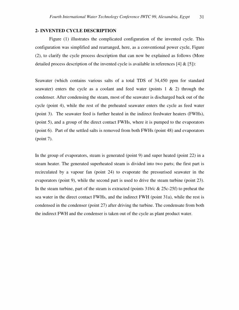
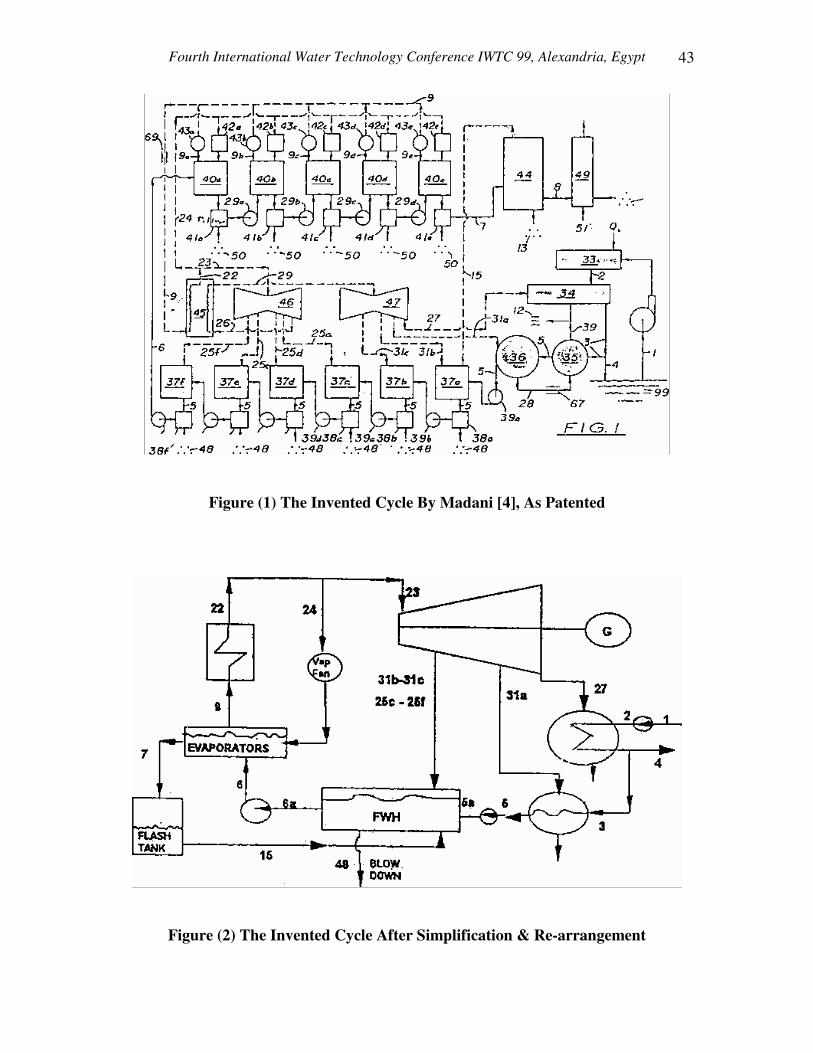
2- INVENTED CYCLE DESCRIPTION
Figure (1) illustrates the complicated configuration of the invented cycle. This
configuration was simplified and rearranged, here, as a conventional power cycle, Figure
(2), to clarify the cycle process description that can now be explained as follows (More
detailed process description of the invented cycle is available in references [4] & [5]):
Seawater (which contains various salts of a total TDS of 34,450 ppm for standard
seawater) enters the cycle as a coolant and feed water (points 1 & 2) through the
condenser. After condensing the steam, most of the seawater is discharged back out of the
cycle (point 4), while the rest of the preheated seawater enters the cycle as feed water
(point 3). The seawater feed is further heated in the indirect feedwater heaters (FWHs),
(point 5), and a group of the direct contact FWHs, where it is pumped to the evaporators
(point 6). Part of the settled salts is removed from both FWHs (point 48) and evaporators
(point 7).
In the group of evaporators, steam is generated (point 9) and super heated (point 22) in a
steam heater. The generated superheated steam is divided into two parts; the first part is
recirculated by a vapour fan (point 24) to evaporate the pressurised seawater in the
evaporators (point 9), while the second part is used to drive the steam turbine (point 23).
In the steam turbine, part of the steam is extracted (points 31b/c & 25c-25f) to preheat the
sea water in the direct contact FWHs, and the indirect FWH (point 31a), while the rest is
condensed in the condenser (point 27) after driving the turbine. The condensate from both
the indirect FWH and the condenser is taken out of the cycle as plant product water.

Fourth International Water Technology Conference IWTC 99, Alexandria, Egypt 32
3- INVENTED CYCLE ORIGINALITY
The main objective of the invented cycle is to overcome the TBT limitations
caused by scale formation on the heating surfaces. Many of the research work were
conducted to achieve this objective. The most interesting one is the patented cycle
developed by Blaskowski [6] in 1967, which is very similar to the present invented cycle
by Madani [4]. The following is a brief comparison between Blaskowski and Madani
cycles that shows the similarity between the two to the extent that one may question the
originality of the invented cycle by Madani [4].
i- The main concept
Both Blaskowski and Madani cycles produce water and generate electrical power using
seawater as a feed to the steam power plant. The seawater (in both cycles) is heated in a
group of direct contact FWHs to avoid scale formation on the heating surfaces. Then, the
heated seawater is evaporated in direct contact evaporators using part of the cycle
superheated steam. The evaporated steam is superheated to in a fuel fired steam heater to
drive the turbine, then condensed in the condenser and used as product water.
ii- FWHs Line
In both cycles, seawater is used to condense the steam in the condenser. Part of this
preheated seawater is used as a feed water to the cycle and heated in a series of direct
contact FWHs with pumps transferring seawater between each two heaters. The only
addition is that Madani suggested to use a filter after each heater to remove the
precipitated salts out of the system.
iii- Evaporation Process
In both cycles, the heated seawater is evaporated by recirculating part of the superheated
steam. Blaskowski suggested two methods of evaporation. The first method is to
evaporate the whole seawater to slightly superheated steam, then, the salt is removed from
the dry steam by a solids collection unit. The second is to use a liquid tank in which a
continuous blow down is provided to control the precipitates. Madani suggested to

Fourth International Water Technology Conference IWTC 99, Alexandria, Egypt
33
evaporate the seawater in a group of evaporators where filters are used after each
evaporator to remove (and recover) the formed salts precipitants. Madani’s arrangement
may seem better due to; a) Blaskowski’s first suggestion requires large quantity of steam
in addition to the design and operational difficulties, and b) Blaskowski’s second
suggestion results in a considerable loss of energy.
iv- Steam Heater
Blaskowski suggested two steam heaters, one to superheat the steam evaporated in the
evaporator where it is recirculated (using one steam compressor), and the second is to
superheat the steam produced for rolling the turbine. Madani combined the two with one
steam fan (compressor) before each evaporator.
4- INVENTED CYCLE NUMERICAL SIMULATION
The invented cycle, Figure (1), was divided into five interconnected segments,
Figure (3), namely; i) the condenser and the indirect FWH, ii) direct contact group of
FWHs, iii) direct contact group of evaporators, iv) steam turbines, and v) steam heater.
Each segment was treated individually to satisfy the heat, mass and salt balance of each
component. Iterative technique was used to satisfy the overall cycle balance. The
governing equations and the calculation procedure are well described in references [1]
and [5].
A computer code was developed to quantitatively simulate the invented cycle. The
program used Excel-5, PC computer spread sheet, to link the various relations of cycle
components and segments. The code was verified against the published data of Al-Jubail-
II power and desalination plant (the world largest desalination plant) before being used to
obtain the detailed data of the invented cycle. Table (1) presents the validation of the
simulated and the actual design data of Al-Jubail plant. The validation is satisfactory
since the errors percentage is within the accepted engineering research work.

Fourth International Water Technology Conference IWTC 99, Alexandria, Egypt 34
The invented cycle will now be evaluated based on the cycle; i) thermal efficiency &
TBT limitations, ii) practicality and costs of the major components, iii) cycle chemistry &
product water quality, and v) cycle environmental considerations.
5- RESULTS & DISCUSSION
5.1 Thermal Efficiency & TBT Limitations
The invented cycle as patented is mainly a power plant with water production as a
biproduct. When its simulated results were compared with existing power-desalination
cogeneration plant as Al-Jubail, the water production was found to be only 7 % of Al-
Jubail’s water production which is not acceptable as desalination unit product.
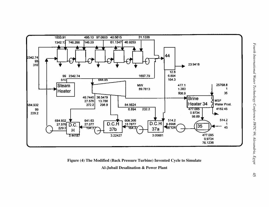
Two modifications were introduced to the invented cycle to increase its water production
to a range comparable to Al-Jubail plant’s cycle. The first was to replace the condenser by
multi stage flash (MSF) evaporator. The simulated results of this modification show a
slightly higher thermal efficiency than Al-Jubail plant. This result is expected because the
invented cycle uses more feed water heaters in a reheating - regenerative cycle. The
second was to eliminate reheating, use the same number of FWHs and apply similar
turbine configuration as Al-Jubail to the invented cycle. This modification, Figure (4)
provides more objective comparison between the two cycles. The results of this
simulation shows that the invented cycle has slightly lower thermal performance for both
power generation (power heat rate in kJ/MWe) and water production (Water heat rate in
kJ/Ton of product water). From these results one will conclude that the invented cycle
thermal efficiency does not exceed that of existing operating cogeneration cycles of the
same limiting pressures and temperatures.
On the other hand, one main objective of the invented cycle was to overcome the TBT
limitations. In current desalination technologies TBT is limited to 120 C to avoid scale
formation. This limited TBT limits the MSF flashing range and therefore limits the water

Fourth International Water Technology Conference IWTC 99, Alexandria, Egypt
35
production. The invented cycle succeeded to achieve this objective using the direct
contact heat exchangers. However, the problems raised to achieve this objective question
the practicality of implementing the cycle over the existing operating cycles.
5.2 Practicality & Costs of Major Components
The invented cycle poses some limitations to its practicality. In addition, for the
invented cycle to operate with a thermal performance close to the current power-
desalination plants, it has to operate with higher capital and operation costs. The
practicality and cost effective of the invented cycle will now be evaluated.
i- Steam heater Efficiency
In the invented cycle, steam heater uses direct firing as the heat source to super heat the
evaporated high pressure steam. The flue gases temperature (out of the steam heater) is
very high leading to a very poor heater efficiency. In conventional plants flue gases are
used to preheat the low temperature feed water (in the economiser) which is not present in
the invented cycle. For steam heater of the size on conventional plants, Figure (5) shows
that flue gas temperature of 635 °C with heater efficiency of 75.6 %. Increasing the steam
temperature (to improve the thermodynamic cycle efficiency) will further decrease the
heater efficiency due to the higher flue gas outlet temperature. On the other hand, the
amount of superheated steam required to evaporate the water in the evaporator is too
much (as seen in Figure (4), the super heated steam rate is 2342 tons/hr which is almost
four times as much as conventional plant superheater rate of 645 tons/hr) which leads to
higher heat transfer area of the heater and therefore the higher heater capital cost.
ii- High Pressure Evaporators & FWHs
With the required volume for direct contact heat & mass transfer, pressure vessels must
be used for both evaporators and FWHs to overcome the operating pressure and
temperature. The thickness and the cost of such pressure vessels are much larger than the
only one pressure vessel (steam drum) in the boilers of conventional power plants. In
addition, with the aggressive sea water working fluid at elevated pressure and

Fourth International Water Technology Conference IWTC 99, Alexandria, Egypt 36
temperature, the special material required for vessel cladding will make it more expensive
pressure vessels.
iii- Fan & Its Power Consumption
In the evaporators, feed seawater is evaporated using part of the superheated steam
generated in the steam heater. The superheated steam is recirculated using a steam fan
(compressor) to circulate large steam flow rate at very high pressure (above 150 bar) and
very high temperature (above 550 C). Such unconventional equipment requires 1.77 MW
electrical energy for each bar pressure drop. This is almost 90 times more power as
compared to the conventional circulating boiler feed water pumps in conventional power
plants which require only 19 kW / bar. As seen in Figure (4), the super heated steam rate
is 2342 tons/hr which is almost four times as much as conventional plant superheater rate
which leads to higher recirculating steam pressure drop and fan power. In addition, the
fan requires special design to accommodate the salty water carry over. The carry over
salts will deposit on the fan internals, deteriorates its performance and make its operation
& maintenance cost very expensive.
iv- Additional Equipment
The invented cycle require additional non-standard (large size, special materials, ..etc.)
equipment and components as salts separation filters, transferring pumps and piping
system with its ancillaries. Special design filters is required since the filtration (and salt
recovery) is a basic and essential part of the invented cycle. Transferring pumps between
high pressure evaporators to handle highly concentrated brine at elevated pressure and
temperatures are needed. Piping systems with its ancillaries (valves, steam traps, filters &
strainers,...etc.) should be specially designed to accommodate the aggressive concentrated
brine operation conditions.
v- Operation & Maintenance Cost
Using sea water and highly concentrated brine at elevated pressure and temperatures will
result in high rate of corrosion, erosion and scale deposits. The plant outage frequency

Fourth International Water Technology Conference IWTC 99, Alexandria, Egypt
37
will be very high with long shut down periods which increase the operation costs. The
high rate of corrosion, erosion and scale deposits will increase the rate of spare parts
replacements and increase the man-hours and, therefore, maintenance costs.
5.3 Cycle Chemistry & Product Water Quality
The current operating steam power plants are designed to use a well treated feed
water with a recommended TDS of not more than 15 ppm. On the contrary, the invented
cycle is based on using seawater (which contains various salts of a total TDS of 34,450
ppm for standard seawater) as continuous feed water. The seawater feed enters the cycle
and leaves it as a product water and very concentrated brine (or salt). When seawater is
used in the cycle at elevated temperature and pressure, three main potential problems
occur. These are; i) scale formation, ii) corrosion, and iii) un-acceptable product water
quality. These potential problems will now be discussed with its impact on the invented
cycle practicality.
i- Scale Deposits
In the invented cycle, salt separation and recovery is one potential bi-product. Scale
(salts) deposits, particularly the hard scale (as Calcium Sulfate - CaSO4 - and Silica (SiO2
-) is one of the main desalination problems that deteriorate the plant performance. There
are common methods in which the problems associated with the scale formation are
possibly reduced. Theses are i) Controlling the operation TBT (up to about 120 C) and
concentration range, ii) Removing the scale forming salts from seawater (pre-treatment),
iii) Adding chemical additives that can stop Crystal growth, and, iv) Adding a seed for
fast crystal formation in the free solution to avoid supersaturation and consequently scale
formation during temperature rise.
Although the invented cycle eliminates scale deposits on the heat transfer surfaces (by
using direct contact heat transfer equipment), scale formation will take place over various
parts of plant components, impose a problem to the whole plant. For example, the TDS
values at the evaporators section, Figure (6), vary from 47,300 ppm to 332,000 ppm.

Fourth International Water Technology Conference IWTC 99, Alexandria, Egypt 38
These values are extremely high and unacceptable at such high temperature (310 °C) and
pressure (99 bars). As a result the following serious problems will arise:
1- The sudden scale formation, due to the precipitation of CaSO4, would reduce
heaters and evaporators volume and might clog the transfer pipes. The settlements
of the suspended solids will also deposit on the connecting pipes and pumps blades
& casing. This will increase pumping pressure and deteriorates the pumps operation
performance.
2- Scale formation usually helps in inhibiting rate than conventional desalination-
power plants. In the current method to control CaSO4 precipitation (the seeding
method), the corrosion-erosion rates will be very high due to the existence of the
suspended crystals.
3- By heating seawater, a scale of mixed salts deposits is expected, and there will be
no control over the type of salt precipitation. This is obvious because at high
temperature, most of the existing salts will reach supersaturation condition and any
salt seed will act as a nucleus for the rest.
4- Scale prevention additives for such operating conditions (of high temperature &
temperature / high concentration) are not available in the market and not
scientifically proven and expected to be very expensive.
5- Due to the above problems, the shut down frequency (and outage time period to re-
start) will not be accepted as compared to proven conventional plants.
For the remaining direct contact heaters, Figure (6), the dilution rate is not significant and
the temperature is very high. For example after FWH # 1 (TDS = 29,585 ppm & T =
164.3 °C), after FWH # 2 (TDS = 27,908 ppm & T = 194.3 °C), after FWH # 3 (TDS =
26,010 ppm & T = 229.2 °C). The operation of these FWHs will also be complicated.
ii- Corrosion & Erosion
Another potential problem of using seawater as feed water to the plant is the expected
high rate of corrosion on plant components. Although the dissolved gases are easily
removed in the direct contact heaters and evaporators, the high salinity of seawater and

Fourth International Water Technology Conference IWTC 99, Alexandria, Egypt
39
the elevated temperature enhances the corrosion rate. Only high expensive alloys (as
titanium, see Table 2) are needed to overcome such aggressive operation conditions. In
addition to corrosion, the presence of high rate of scale deposits causes serious erosion
problems before they could be totally filtered. On the other hand, the current steam power
plant faces the difficulties from the high rate of erosion in the turbine blades due to carry
over. In the invented cycle, the carry over of salts to the steam system is expected to be
higher than conventional power plants due to the very concentrated brine in the
evaporators, see Figure (6). With higher concentration of salts in the carry over the steam
problems will be worse (erosion in high pressure and corrosion in low pressure section of
the turbine - an expensive, sensitive and important piece of plant equipment -). This will
deteriorate the turbine performance, availability and maintainability. On the other hand,
Salts carry over will cause serious problems in the high temperature steam heater tubes
that will lead to tube failure.
The scale deposits and the corrosion-erosion problems associated with invented cycle
make it un-acceptable from plant chemistry point of view. The cycle solved the heating
surface problem, but, creates many problems all over the plant.
iii- Product Water Quality
The turbine steam contains some conditioning chemicals and additives that make it more
protective for the plant equipment. Some of these chemicals will be transferred from the
seawater feed into the steam through carry over salty water and volatile substances. For
example, hydrazine, (N2H4, an de-oxygenation agent). The steam condensate, as the
invented cycle product water, will not, therefore, suit direct human use. Product water
post treatment of these additives is rather un-economical.
5.4 Environmental Considerations
The environmental aspect of the invented cycle, as claimed, is not different from
conventional plants. For example, i) in order for the invented cycle to generated a
specified electrical power and produced a specified rate of water, it must burn the same
amount of fuel as conventional cogeneration plant and generate the same amount of gas

Fourth International Water Technology Conference IWTC 99, Alexandria, Egypt 40
pollutants to the environment, ii) the concentrated disposal of the conventional
desalination plants could be treated similar to the invented cycle, and iii) the quantity and
quality of the chemical additives to be used in the invented cycle (to handle sea water)
will be as much or even more than that required for convention desalination-power plants.
6- CONCLUSIONS
A numerical analysis and technical evaluation of a newly invented cycle by
Madani [4] has been carried out. The cycle was proved to be a modification of
Blaskwski’s cycle, [6]. The advantages claimed of higher thermal efficiency was proved
to be not justified. Although the invented cycle was able to overcome the TBT limitation,
using direct contact heat exchangers, the cycle does not provide a better alternative to the
existing cogeneration cycle. The following are the cycle main drawbacks:
1- For the same boiler and condenser pressures, the water production of the invented
cycle (as patented) does not exceed 7% of the production of Al-Jubail II plant. In
addition, the water produced can not be used directly since it is contaminated with
different chemicals to suit its main function as boiler-turbine working fluid.
2- The invented cycle thermal efficiency is not better than the currently available power
cycles. The results shows that the invented cycle performance is slightly lower than
conventional cogeneration plants for both power generation (power heat rate in
kJ/MWe) and water production (Water heat rate in kJ/Ton of product water). The
claimed increase in cycle efficiency is mainly due to the high steam pressure which is
a rule of thumb for power plant. Under equivalent design conditions, For example,
the invented cycle shows lower thermal efficiency when compared with Al-Jubail
plant-II.
3- The invented cycle poses some limitations to its practicality due to the unavailability
of conventional equipment, to operate at high working fluid salinity and elevated
temperature and pressure. This equipment includes; circulating fans, direct contact
seawater FWHs and evaporators (pressure vessels), transferring seawater pumps,
filters … etc.

Fourth International Water Technology Conference IWTC 99, Alexandria, Egypt
41
4- With direct contact evaporators, the settlements of the suspended solids will deposit
on the vessel walls, connecting pipes and pumps blades and casing. This will reduce
the vessels size, increase pumping pressure and deteriorates the pumps operation
performance. Scale prevention additives for such operating conditions are not
available in the market and not scientifically proven and expected to be very
expensive.
5- When seawater is used as a feedwater for the power cycle, the plant chemistry and
the related problems (such as high rates of corrosion, scale formation, and carry-over)
are much more complex than conventional plants. The high frequency of the plant
outage and long shutdown duration is, therefore, likely to occur during plant
operation which increases operation & maintenance costs.
6- Although the invented cycle saves the capital cost of the MSF units, its water
production cost can not, still, compete with the existing duel purpose plant, due to the
high costs of the special components & equipment required, and the cost of product
water post treatment.
7- The environmental aspect of the power side of the patented cycle is not different than
conventional plants, as claimed. The concentrated disposal of the conventional
desalination plants could be treated similar to that of the invented cycle.

Fourth International Water Technology Conference IWTC 99, Alexandria, Egypt 42
REFERENCES
1- Fahad A. Al-Khaldy, M.Sc. Thesis, King Fahad University of Petroleum and
Minerals, Dhahran, Saudi Arabia (1996).
2- Leon Awerbuch “The Status of Desalination Technology & Trends”, Proceedings of
the Second IDA Conf. in Egypt, Cairo, Oct. 7 (1998)
3- Anas A. Madani “Analysis of a New Combined Desalination - Power Generation
Plant”, Desalination 105, pp. 199-205 (1996).
4- Anas A. Madani “A Combined Water Purification and Power Generation Plant - A
New Patented Technology”, US Patent No. 5,346,592, Sept. 13 (1994).
5- F. Al-Khaldi, Hassan Fath, and B. Abo-Sharkh, “Feasibility Study of a New
Combined Desalination-Power Generation Plant: Comparison with Al-Jubail
Cogeneration Plant”, Proceedings of the IDA World Congress, pp. 209-231, Madrid,
Spain, Oct. 6-9 (1997).
6- Blaskwski H. “Desalination and Power Generation System”, US patent # 3,352,107,
November (1967).
Fourth International Water Technology Conference IWTC 99, Alexandria, Egypt
43
Figure (1) The Invented Cycle By Madani [4], As Patented
Figure (2) The Invented Cycle After Simplification & Re-arrangement

Fourth International Water Technology Conference IWTC 99, Alexandria, Egypt 44
Figure (3) The Simulated Five Segments of the Invented Cycle
Fourth International W
ater Technology Conference IW
TC 99, A
lexandria, Egypt
45
Figure (4) The Modified (Back Pressure Turbine) Invented Cycle to Simulate
Al-Jubail Desalination & Power Plant

Fourth International Water Technology Conference IWTC 99, Alexandria, Egypt 46
Figure (5) Steam Heater Area and Thermal Efficiency
Versus Flue Gas Temperature

Fourth International W
ater Technology Conference IW
TC 99, A
lexandria, Egypt
47
Figure (6) Invented Cycle Main Simulated Parameters
(Mass Flow, Pressure, Temperature, and Total Dissolved Solids -TDS- )

Fourth International Water Technology Conference IWTC 99, Alexandria, Egypt 48
Table (1) The Simulated and Published Data for Al-Jubail-II Plant Table (2) Metals Potentials Series in Seawater
AL Jobail-II Plant Simulated Mass Flows
Given Design Data % Diff
POWER (MW) 89.78 89.88 -0.11 WATER (Ton/Hr) 3781.02 3781.02 0.00
Fuel cons (GJ) 1676.53 1680.00 -0.21 kW/kJ 0.19 0.19 0.10 M3/KJ 0.00 0.00 0.21
Line# 1 Mass Flow Steam to Turbine
618.93 620.20 -0.20
Line# 2 Mass Flow 1st Ext. Flow
45.57 45.68 -0.25
Line# 3 Mass Flow 2nd Ext. Flow
27.97 29.15 -4.04
Line# 4 Mass Flow 3rd Ext. Flow
58.56 58.53 0.05
Line# 5 Mass Flow Steam to Condenser
486.84 486.84 0.00
Line# 6 Mass Flow Condensate Flow
486.84 486.84 0.00
Line# 7 Mass Flow Condensate before FWT
486.84 486.84 0.00
Line# 8 Mass Flow Feed Water before FW Pump
618.93 620.18 -0.20
Line# 9 Mass Flow Feed Water after FW Pump
618.93 620.18 -0.20
Line# 10 Mass Flow Feed Water before Heater#2
618.93 620.18 -0.20
Line# 11 Mass Flow Feed Water before boiler
618.93 620.18 -0.20
Line# 12 Mass Flow Condensate to Heater#1
45.57 45.68 -0.20
Line# 13 Mass Flow Condensate from Heater#2
73.53 74.83 -1.73
Noble end Titanium Monel ( 67% Ni, 30% Cu, 1.2% Fe ) * Passive stainless Steels Inconel ( 80% Ni, 13% Cu, 6.5% Fe ) Nickel Copper/Nickel 70 730 Copper/Nickel 90/10 Aluminium bronze Copper Alpha brass ( 70% Cu, 30% Zn ) Aluminium brass Muntz metal ( 60% Cu, 40% Zn ) Tin * Active stainless steels Cast iron Mild steel Aluminium Zinc Magnesium
______________________________________________ * Passive stainless steel is covered with an oxide film and
resists corrosion. Active stainless steel is of the same composition, but the oxide film has been destroyed and the alloy behaves in a much less noble manner.