Embed Size (px)
Citation preview

M E A S U R E M E N T S Y S T E M S
NUFLO™
Liquid Turbine FlowmetersAccurate Flow Measurement
NuFlo developed its first flowmeter for oilfield applications in1957. The meter incorporated a tungsten-carbide shaft andbearing to withstand the rugged conditions of the oilfieldenvironment. Over the years, this flowmeter has built anunsurpassed reputation for withstanding severe punishmentwhile maintaining operational and measurement integrity.
NuFlo turbine flowmeters indicate flow rate and measure totalthroughput of a liquid line. As liquid flows through the meterand over the rotor, the rotor turns at a speed that is directlyproportional to the flow rate. A magnetic pickup senses therotor blades as they pass and generates an electrical (sinewave) signal. These electrical pulses are then transmitted to the flow measurement readout equipment.
4
3 5 6 8 7
2 1
2
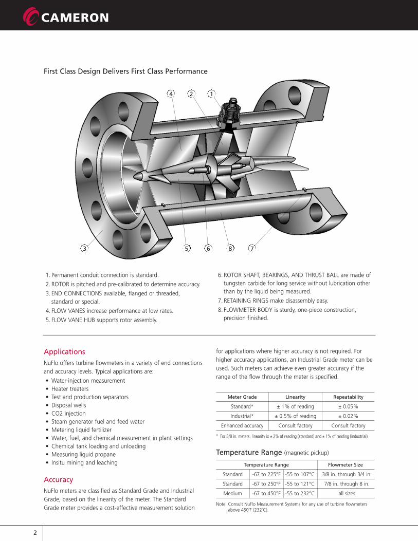
First Class Design Delivers First Class Performance
1. Permanent conduit connection is standard.
2. ROTOR is pitched and pre-calibrated to determine accuracy.
3. END CONNECTIONS available, flanged or threaded,standard or special.
4. FLOW VANES increase performance at low rates.
5. FLOW VANE HUB supports rotor assembly.
ApplicationsNuFlo offers turbine flowmeters in a variety of end connectionsand accuracy levels. Typical applications are:
• Water-injection measurement• Heater treaters• Test and production separators• Disposal wells• CO2 injection• Steam generator fuel and feed water• Metering liquid fertilizer• Water, fuel, and chemical measurement in plant settings• Chemical tank loading and unloading• Measuring liquid propane• Insitu mining and leaching
AccuracyNuFlo meters are classified as Standard Grade and IndustrialGrade, based on the linearity of the meter. The StandardGrade meter provides a cost-effective measurement solution
for applications where higher accuracy is not required. Forhigher accuracy applications, an Industrial Grade meter can beused. Such meters can achieve even greater accuracy if therange of the flow through the meter is specified.
Meter Grade Linearity Repeatability
Standard* ± 1% of reading ± 0.05%
Industrial* ± 0.5% of reading ± 0.02%
Enhanced accuracy Consult factory Consult factory
* For 3/8 in. meters, linearity is ± 2% of reading (standard) and ± 1% of reading (industrial).
Temperature Range (magnetic pickup)
Temperature Range Flowmeter Size
Standard -67 to 225°F -55 to 107°C 3/8 in. through 3/4 in.
Standard -67 to 250°F -55 to 121°C 7/8 in. through 8 in.
Medium -67 to 450°F -55 to 232°C all sizes
Note: Consult NuFlo Measurement Systems for any use of turbine flowmetersabove 450˚F (232˚C).
6. ROTOR SHAFT, BEARINGS, AND THRUST BALL are made oftungsten carbide for long service without lubrication otherthan by the liquid being measured.
7. RETAINING RINGS make disassembly easy.
8. FLOWMETER BODY is sturdy, one-piece construction,precision finished.
3
M E A S U R E M E N T S Y S T E M S
Compliances• CSA Certified Hazardous Locations Class I, Group A,B,C,D,
Div. 1
• NACE MR01-75 (NACE traceability available on pressurecontaining components - on request)
• EZ-IN® meters and 1502 WECO® union meters availablewith CE mark for Pressure Equipment Directive (PED,97/23/EC)
Materials of Construction• Meter Body & Vanes Grade 316L stainless steel
• Rotor CD-4MCu
• Shaft & Bearings Tungsten Carbide
Optional Materials• Shaft Binderless carbide for enhanced
corrosion resistance to selectedchemicals
• Shaft & Bearings Silver brazing to withstandtemperatures to 550˚F and chemicalsthat attack epoxy bonding bearingmaterials
• Rotor Nickel plating for enhanced corrosionresistance to selected chemicals(especially acids that corrode ferrousmaterials)
Benefits• More accurate and repeatable measurement
• An economical solution for turbine flowmeter applications
• Easy installation and a variety of end connections
• Minimum maintenance required
• Long service life even in severe applications
Meter Size SelectionFlowmeter size selection should be based on the instantaneousflow rate of the line into which the meter will be mounted.Meter size should never be based on the nominal piping sizeof the installation. Refer to Linear Flow Range Chart for metersize selection. The meter will remain accurate at flow rateshigher than its rating, but bearing wear and pressure dropacross the meter can shorten the life span of the meter. NuFloflowmeters can be over-ranged by 10% for short periodswithout damage.
Installation• The meter should be installed with the arrow on the meter
body corresponding to flow direction of the line.
• A 10-diameter length of straight unrestricted pipe must beupstream and a 5-diameter length of straight unrestrictedpipe must be downstream of the flowmeter. Both pipesections should be the same nominal pipe size as theflowmeter’s end connection.
• Throttling/Control valves should be located downstream ofthe flowmeter.
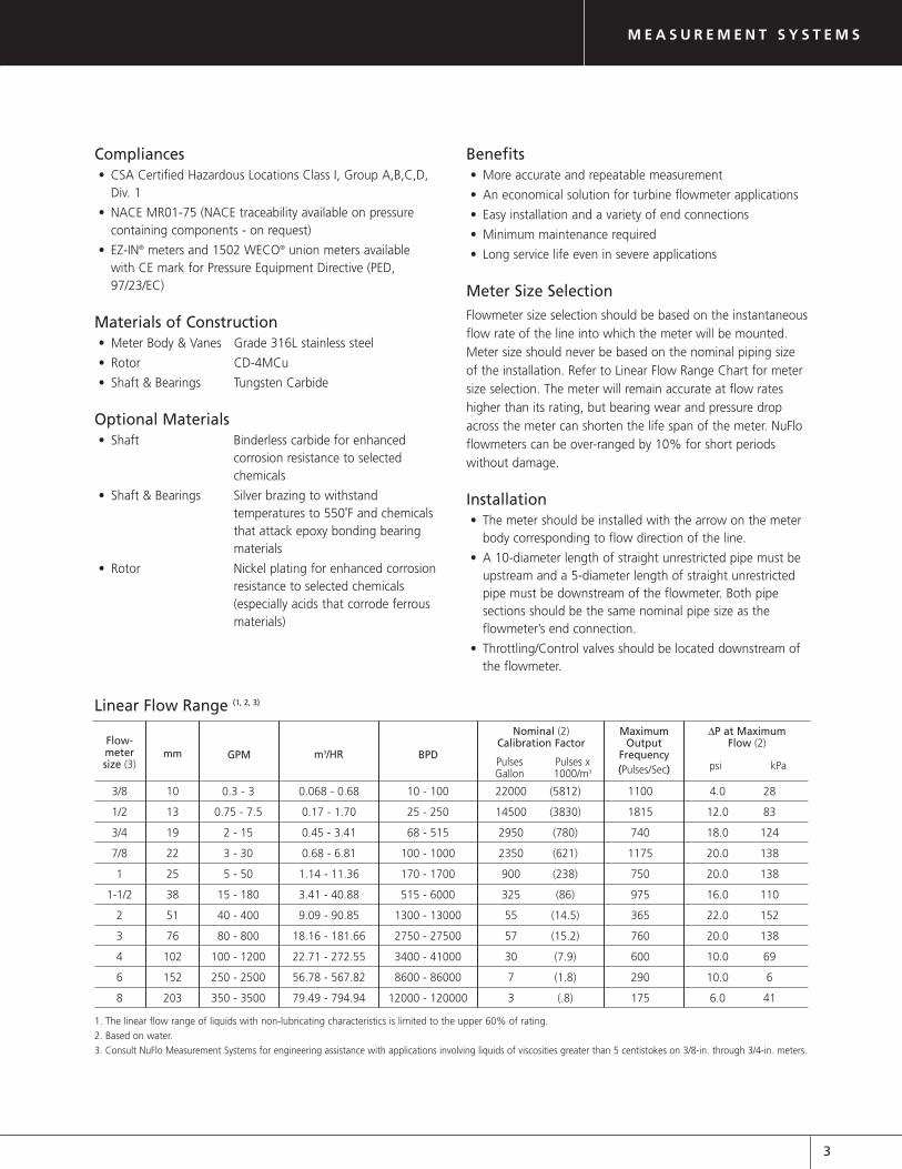
Linear Flow Range (1, 2, 3)
3/8 10 0.3 - 3 0.068 - 0.68 10 - 100 22000 (5812) 1100 4.0 28
1/2 13 0.75 - 7.5 0.17 - 1.70 25 - 250 14500 (3830) 1815 12.0 83
3/4 19 2 - 15 0.45 - 3.41 68 - 515 2950 (780) 740 18.0 124
7/8 22 3 - 30 0.68 - 6.81 100 - 1000 2350 (621) 1175 20.0 138
1 25 5 - 50 1.14 - 11.36 170 - 1700 900 (238) 750 20.0 138
1-1/2 38 15 - 180 3.41 - 40.88 515 - 6000 325 (86) 975 16.0 110
2 51 40 - 400 9.09 - 90.85 1300 - 13000 55 (14.5) 365 22.0 152
3 76 80 - 800 18.16 - 181.66 2750 - 27500 57 (15.2) 760 20.0 138
4 102 100 - 1200 22.71 - 272.55 3400 - 41000 30 (7.9) 600 10.0 69
6 152 250 - 2500 56.78 - 567.82 8600 - 86000 7 (1.8) 290 10.0 6
8 203 350 - 3500 79.49 - 794.94 12000 - 120000 3 (.8) 175 6.0 41
1. The linear flow range of liquids with non-lubricating characteristics is limited to the upper 60% of rating.
2. Based on water.
3. Consult NuFlo Measurement Systems for engineering assistance with applications involving liquids of viscosities greater than 5 centistokes on 3/8-in. through 3/4-in. meters.
Flow-metersize (3)
mm GPM m3/HR BPDPulsesGallon
Pulses x 1000/m3
Nominal (2)Calibration Factor
MaximumOutput
Frequency(Pulses/Sec)
∆P at MaximumFlow (2)
psi kPa
4
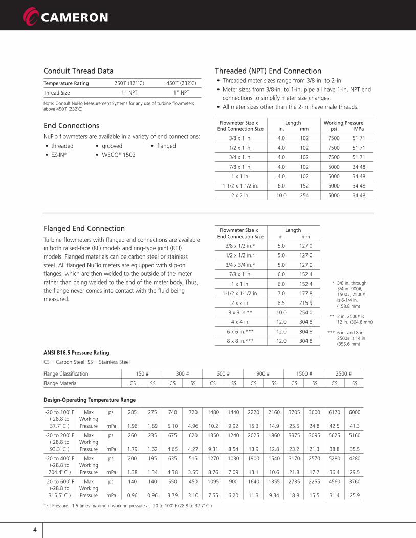
Flowmeter Size x Length Working PressureEnd Connection Size in. mm psi MPa
3/8 x 1 in. 4.0 102 7500 51.71
1/2 x 1 in. 4.0 102 7500 51.71
3/4 x 1 in. 4.0 102 7500 51.71
7/8 x 1 in. 4.0 102 5000 34.48
1 x 1 in. 4.0 102 5000 34.48
1-1/2 x 1-1/2 in. 6.0 152 5000 34.48
2 x 2 in. 10.0 254 5000 34.48
Threaded (NPT) End Connection• Threaded meter sizes range from 3/8-in. to 2-in.
• Meter sizes from 3/8-in. to 1-in. pipe all have 1-in. NPT endconnections to simplify meter size changes.
• All meter sizes other than the 2-in. have male threads.
Conduit Thread Data
Temperature Rating 250˚F (121˚C) 450˚F (232˚C)
Thread Size 1” NPT 1” NPT
Note: Consult NuFlo Measurement Systems for any use of turbine flowmetersabove 450˚F (232˚C).
End ConnectionsNuFlo flowmeters are available in a variety of end connections:
• threaded • grooved • flanged
• EZ-IN® • WECO® 1502
Flanged End ConnectionTurbine flowmeters with flanged end connections are availablein both raised-face (RF) models and ring-type joint (RTJ)models. Flanged materials can be carbon steel or stainlesssteel. All flanged NuFlo meters are equipped with slip-onflanges, which are then welded to the outside of the meterrather than being welded to the end of the meter body. Thus,the flange never comes into contact with the fluid beingmeasured.
Flowmeter Size x LengthEnd Connection Size in. mm
3/8 x 1/2 in.* 5.0 127.0
1/2 x 1/2 in.* 5.0 127.0
3/4 x 3/4 in.* 5.0 127.0
7/8 x 1 in. 6.0 152.4
1 x 1 in. 6.0 152.4
1-1/2 x 1-1/2 in. 7.0 177.8
2 x 2 in. 8.5 215.9
3 x 3 in.** 10.0 254.0
4 x 4 in. 12.0 304.8
6 x 6 in.*** 12.0 304.8
8 x 8 in.*** 12.0 304.8
* 3/8 in. through 3/4 in. 900#, 1500#, 2500# is 6-1/4 in. (158.8 mm)
** 3 in. 2500# is 12 in. (304.8 mm)
*** 6 in. and 8 in. 2500# is 14 in (355.6 mm)
ANSI B16.5 Pressure Rating
CS = Carbon Steel SS = Stainless Steel
Flange Classification 150 # 300 # 600 # 900 # 1500 # 2500 #
Flange Material CS SS CS SS CS SS CS SS CS SS CS SS
Design-Operating Temperature Range
-20 to 100˚ F Max psi 285 275 740 720 1480 1440 2220 2160 3705 3600 6170 6000( 28.8 to Working37.7˚ C ) Pressure mPa 1.96 1.89 5.10 4.96 10.2 9.92 15.3 14.9 25.5 24.8 42.5 41.3
-20 to 200˚ F Max psi 260 235 675 620 1350 1240 2025 1860 3375 3095 5625 5160( 28.8 to Working93.3˚ C ) Pressure mPa 1.79 1.62 4.65 4.27 9.31 8.54 13.9 12.8 23.2 21.3 38.8 35.5
-20 to 400˚ F Max psi 200 195 635 515 1270 1030 1900 1540 3170 2570 5280 4280(-28.8 to Working204.4˚ C ) Pressure mPa 1.38 1.34 4.38 3.55 8.76 7.09 13.1 10.6 21.8 17.7 36.4 29.5
-20 to 600˚ F Max psi 140 140 550 450 1095 900 1640 1355 2735 2255 4560 3760(-28.8 to Working315.5˚ C ) Pressure mPa 0.96 0.96 3.79 3.10 7.55 6.20 11.3 9.34 18.8 15.5 31.4 25.9
Test Pressure: 1.5 times maximum working pressure at -20 to 100˚ F (28.8 to 37.7˚ C )
5
M E A S U R E M E N T S Y S T E M S
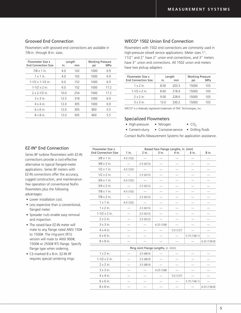
Flowmeter Size x Raised Face Flange Lengths, in. (mm)End Connection Size 1 in. 2 in. 3 in. 4 in. 6 in. 8 in.
3/8 x 1 in. 4.0 (102) –– –– –– –– ––
3/8 x 2 in. –– 2.5 (63.5) –– –– –– ––
1/2 x 1 in. 4.0 (102) –– –– –– –– ––
1/2 x 2 in. –– 2.5 (63.5) –– –– –– ––
3/4 x 1 in. 4.0 (102) –– –– –– –– ––
3/4 x 2 in. –– 2.5 (63.5) –– –– –– ––
7/8 x 1 in. 4.0 (102) –– –– –– –– ––
7/8 x 2 in. –– 2.5 (63.5) –– –– –– ––
1 x 1 in. 4.0 (102) –– –– –– –– ––
1 x 2 in. –– 2.5 (63.5) –– –– –– ––
1-1/2 x 2 in. –– 2.5 (63.5) –– –– –– ––
2 x 2 in. –– 2.5 (63.5) –– –– –– ––
3 x 3 in. –– –– 4.25 (108) –– –– ––
4 x 4 in. –– –– –– 5.0 (127) –– ––
6 x 6 in. –– –– –– –– 5.75 (146.1) ––
8 x 8 in. –– –– –– –– –– 6.25 (158.8)
Ring Joint Flange Lengths, in. (mm)
1 x 2 in. –– 3.5 (88.9) –– –– –– ––
1-1/2 x 2 in. –– 3.5 (88.9) –– –– –– ––
2 x 2 in. –– 3.5 (88.9) –– –– –– ––
3 x 3 in. –– –– 4.25 (108) –– –– ––
4 x 4 in. –– –– –– 5.0 (127) –– ––
6 x 6 in. –– –– –– –– 5.75 (146.1) ––
8 x 8 in. –– –– –– –– –– 6.25 (158.8)
EZ-IN® End ConnectionSeries BF turbine flowmeters with EZ-INconnections provide a cost-effectivealternative to typical flanged-meterapplications. Series BF meters with EZ-IN connections offer the accuracy,rugged construction, and maintenance-free operation of conventional NuFloflowmeters plus the followingadvantages:
• Lower installation cost.
• Less expensive than a conventional,flanged meter.
• Spreader nuts enable easy removaland inspection.
• The raised-face EZ-IN meter willmate to any flange rated ANSI 150#to 1500#. The ring-joint (RTJ)version will mate to ANSI 900#,1500# or 2500# RTJ flange. Specifyflange type when ordering.
• CE-marked 8 x 8-in. EZ-IN RFrequires special centering rings.
Specialized Flowmeters• High-pressure • Nitrogen • CO2
• Cement-slurry • Corrosive-service • Drilling fluids
Contact NuFlo Measurement Systems for application assistance.
Flowmeter Size x Length Working PressureEnd Connection Size in. mm psi MPa
7/8 x 1 in. 4.0 102 1000 6.9
1 x 1 in. 4.0 102 1000 6.9
1-1/2 x 1-1/2 in. 6.0 152 1000 6.9
1-1/2 x 2 in. 6.0 152 1000 17.2
2 x 2-1/2 in. 10.0 254 1000 17.2
3 x 3 in. 12.5 318 1000 6.9
4 x 4 in. 12.0 305 1000 6.9
6 x 6 in. 12.0 305 800 5.5
8 x 8 in. 12.0 305 800 5.5
Grooved End ConnectionFlowmeters with grooved end connections are available in 7/8-in. through 8-in. sizes.
Flowmeter Size x Length Working PressureEnd Connection Size in. mm psi MPa
1 x 2 in. 8.00 203.3 15000 103
1-1/2 x 2 in. 8.60 218.4 15000 103
2 x 2 in. 9.00 228.6 15000 103
3 x 3 in. 13.0 330.2 15000 103
WECO® is a federally registered trademark of FMC Technologies, Inc.
WECO® 1502 Union End ConnectionFlowmeters with 1502 end connections are commonly used inhigh-pressure oilwell service applications. Meter sizes 1”,11/2” and 2” have 2” union end connections, and 3” metershave 3” union end connections. All 1502 union end metershave two pickup adapters.
NORTH AMERICA
1.800.654.3760ms-us @ c-a-m.com
ASIAPACIFIC
EUROPE, MIDDLE EAST & AFRICA
HOUSTON HEAD OFFICE: 281.582.9500 • www.c-a-m.com/flo
USA: Houston, TX • Corpus Christi, TX • Kilgore, TX • Odessa, TX • Dallas, TX • Tulsa, OK Duncan, OK • Denver, CO • Bakersfield, CA • Shreveport, LA • Lafayette, LA Houma, LA • Pittsburgh, PA • Laurel, MS • Dunbar, WV • Casper, WY • Charleston, WV
CANADA: Calgary, AB • Edmonton, AB
INTERNATIONAL: Aberdeen, Scotland • Beijing, China • Bognor Regis, UK Dubai, UAE • Hassi Messaoud, Algeria • Kuala Lumpur, Malaysia • Singapore
Formerly: NuFlo Measurement Systems • Barton Instrument Systems • Caldon, Inc.
M E A S U R E M E N T S Y S T E M S
M E A S U R E M E N T S Y S T E M S
TUR-LIQ NF00001 0701
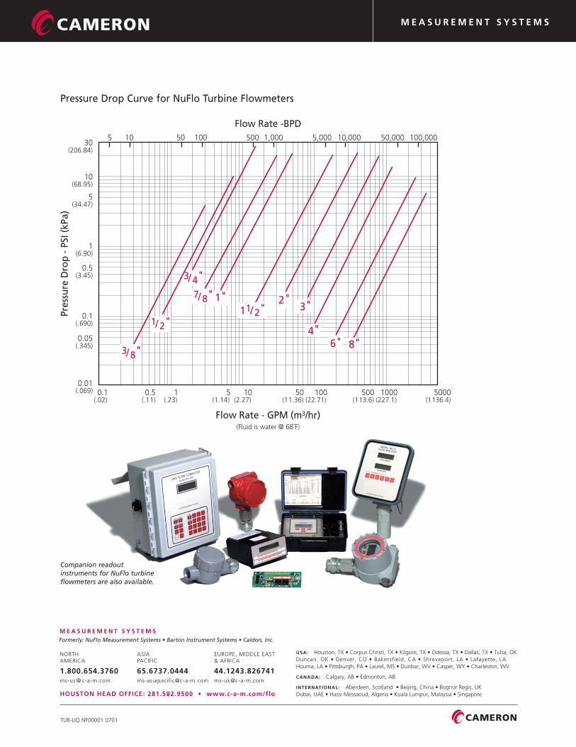
Companion readout instruments for NuFlo turbineflowmeters are also available.
5 10 50 100 500 1,000 5,000 10,000 50,000 100,000 30(206.84)
10(68.95)
5(34.47)
1(6.90)
0.5(3.45)
0.1(.690)
0.05(.345)
0.01(.069) 0.1
(.02) 0.5(.11)
1(.23)
5(1.14)
10(2.27)
50(11.36)
100(22.71)
500(113.6)
1000(227.1)
5000(1136.4)
Flow Rate -BPD
Flow Rate - GPM (m3/hr)
Pres
sure
Dro
p -
PSI
(kP
a)
1/ 2"
3/8"
3/4"
7/8" 1"11/2"
2"3"
4"6" 8"
(Fluid is water @ 68˚F)
Pressure Drop Curve for NuFlo Turbine Flowmeters