Embed Size (px)
Citation preview

© 1999 John T. Nordberg (All Rights Reserved) 12:10 PM, September 12, 1999 Page 1
Disclosure Document for
Nuclear Fusion Reactor DesignsUtilizing Spherical Electromagnetic Fieldsto Compress, Contain, and Extract Energy
from a Nuclear Fusion Reaction
byJohn Thomas Nordberg

© 1999 John T. Nordberg (All Rights Reserved) 12:10 PM, September 12, 1999 Page 2
This invention relates in general to Nuclear Fusion Reactors and in particular to reactorsthat provide active electromagnetic containment.
The Problem:Estimates of fossil fuel supplies for the world's energy supply indicate that productionwill drop below consumption within 10 to 20 years. Other energy sources can beimproved upon. Hydroelectric, solar, wind, geothermal, tidal are some of the variousalternative energy sources other than fossil fuel. One choice, nuclear fission reactorscould be relied upon, if needed. However, nuclear fission reactors have become veryunpopular due to their risk and highly radioactive waste products. One potential choicefor future energy production, that has always been described favorably, is nuclearfusion reactors. One benefit of fusion reactors is they do not rely on dangerousradioactive heavy elements as do fission reactors. Other benefits of fusion reactors are:fusion fuel is safer, fusion fuel supplies are essentially inexhaustible, and fusion wasteproducts are smaller in volume—estimated to be approximately 1,000 time less involume. Importantly, fusion reactors do not create highly radioactive waste products.While the fusion process does create some radioactive waste products, the volume issmall, and the radioactivity is mild and short-lived compared to fission wasteproducts—with half-lives estimated to be tens of years rather than thousands of years.In summary nuclear fusion reactors have always held the promise of unlimited,essentially clean power. The problem is, other than in nuclear fusion bombs, scientistshave been unable to get more energy out of a nuclear fusion reaction than has been usedto start the reaction. In other words, nuclear fusion reactors, to date, have failed in thegoal to produce energy because they consume more energy than they produce.Ultimately, the goal of the type of nuclear fusion reactors described in this document isto create more power than is used to start the process.
The most important, common problem in all past nuclear fusion reactor designs is theformation of instabilities in the plasma which have resulted in less than ideal burns.While many types of instabilities have been described in the past, a physicalunderstanding of the cause of these instabilities has eluded understanding. Thesereactor designs are in part based upon a new physical understanding of the cause ofplasma instabilities, and how they can be thwarted to begin with, and used for benefitwhen they do result.
The second most important problem in all past nuclear fusion reactor designs is theefficient creation of electrical power from the energy produced by the fusion reaction.Efficient conversion of extracted energy into electrical power is needed. Most designshave assumed the heat produced by the fusion process will be extracted to drive steamturbine and generator systems. Some designs have had the goal of usingMagnetohydrodynamics (MHD) to directly create electrical power from a movingplasma. The new reactor designs in this document use the MHD process—convertingextracted energy into electrical energy directly using MHD—as the primary energyconversion process and steam driven turbine generators as a secondary energyconversion process.
The third most important goal of nuclear fusion reactors is to create energyeconomically. This goal has not been approached by prior designs because they failed to

© 1999 John T. Nordberg (All Rights Reserved) 12:10 PM, September 12, 1999 Page 3
produce any net energy. Many designs rely on pulses of fusion burns. In other words,the fusion process does not continuously burn for extended periods of time. To beeconomical, the fusion burns must last for extended periods of time. A common designtrait of all of the reactor designs in this patent application is they entail use of: aspherical geometry of electromagnetic fields in order to contain the fusion burn andthwart instabilities in the fusion burn—which will result in greatly extending fusionburn times; and to utilize any instabilities that are formed to directly create electricalpower via the MHD process. Again, while these designs use extracted heat to drivesteam turbines, this process is secondary to the MHD process.
Related Art:Other people have tried to solve the problem of creating nuclear fusion reactors invarious ways. In order to provide background information so that the invention may becompletely understood and appreciated in its proper context, reference is made to anumber of prior art patents and publications as follows:
Inertial Confinement Methods
Inertial Confinement Fusion (ICF)
While the topology of the burn in prior ICF designs has been spherical, there has beenno active confinement of the burn. In other words, in prior designs: the reaction isimploded, the fusion burn starts, instabilities form, the process explodes. Numeroustypes of implosion methods have been tried in prior ICF designs, including: lasers,neutral particle beams, and ion particle beams. ICF reactor designs have succeeded inadvancing fusion research, reaching high temperatures and densities. However, theyhave failed to produce more energy than is consumed.
ICF reactor designs based on lasers are not considered viable long-term options forcommercial power plants simply because of the poor efficiency in converting electricalenergy into the intense beams needed for inertial confinement.
Key distinguishing features between prior art ICF designs and these new designs are:
• Prior inertial methods have not attempted to stop the resulting explosion via activeconfinement. (Magnetic confinement techniques have used active confinementmethods, but not in a spherical pattern.)
• Prior inertial methods have not attempted to create a harmonic burn or influencethe quality of the fusion burn via electromagnetic fields.
• Inertial methods have not attempted to use MHD to absorb the exploding energy.
• Prior art ICF designs have often utilized a surrounding spherical chamber or shield.However, the spherical chamber has only been used as a shield to contain theprocess and has played no role in keeping the fusion process burning or harmonic.Indeed the chambers are usually pierced with many sensors, holes, ports and other

© 1999 John T. Nordberg (All Rights Reserved) 12:10 PM, September 12, 1999 Page 4
devices. Such sensors, holes and protrusions through the reactor wall arecompletely eliminated or minimized in the new reactor designs described in thisdocument. While such sensors provide useful scientific information on the fusionburn, it is believed by the author that such sensors create a non-harmonic situationthat reduces the quality of the burn.
• A key difference in prior art is prior ICF spherical containment chambers have hadno, intentionally created, spherical electromagnetic fields set up over the surface ofthe containment shield to electromagnetically contain the fusion burn, influence thefusion burn, or extract electrical power via the MHD process.
Magnetic Confinement Methods
Standard Tokamak Fusion
Tokamak fusion reactor designs contain the fusion fuel plasma in a donut-shaped, ortorroidally-shaped electromagnetic containment field. These designs have been able: tocontain plasmas for extended periods of time, to reach high temperatures, and todevelop high densities. However, the geometry of the torus is less than ideal forcontainment in comparison to the geometry of a sphere. To properly utilize a plasma ina MHD process, the plasma velocity must be at right angle to the MHD's magnetic field.It is believed, from theory on which these reactors are designed, that plasma instabilitiesexpanding in a Spherical Electromagnetic Containment Field (40) either, always expandat a right angle to the external electromagnetic field, or are deflected back towards thecenter of the plasma, which is also beneficial. In a torus, the plasma may interact withthe containing magnetic field at less than a 90 degree angle. This allows instabilitieswithin a torus to grow and penetrate the containment field.
The geometry of a torus also prevents the coil windings around the torus to be perfectlysymmetrical. There is more area on the outside of the torus than on the inside. Thisgeometry prevents the containment field from being symmetrical. Instabilities are morelikely to penetrate the outer side of the torus than the inner side. In a spherical chamber,there is no preferential side to the chamber.
The plasma within a Tokamak orbits within the torus-shaped cavity. It does not just sitthere. A moving region of plasma in a circular orbit can induce electromagnetic fieldsthat are extremely unpredictable. These forces induce, at the moment of fusion burn,instabilities that the designers of Tokamaks have been unable to understand andcontrol. These instabilities grow too quickly for human operator or computer controlledresponse, and allow the plasma to penetrate the confining fields. The reactor designs inthis patent have electromagnetic fields in place prior to the fusion burn to respond toinstabilities as they occur. It is easier to contain a plasma in a spherical configurationrather than a torroidal configuration. The bulk of the plasma does not move or orbit, butis stationary, and thus does not have any orbit induced instabilities. Instabilitiesexploding outward in a spherical confinement field encounter electromagnetic fields atright angles which easily allows: direct conversion of instability energy to electricity viathe MHD process, or deflects the instability back towards the center of the fusion burn.

© 1999 John T. Nordberg (All Rights Reserved) 12:10 PM, September 12, 1999 Page 5
Spherical Tokamak Fusion
The cross section of a normal Tokamak is circular. The cross section of a “spherical”Tokamak is more elongated in the vertical direction. Spherical Tokamaks still use atorus-shaped tube. Indeed, the process is not “spherical” at all. Essentially, all of the keynegatives of normal Tokamaks apply to Spherical Tokamaks as well when compared tothe new designs in this document.
Stellarators
In general, there is little difference between Tokamaks and Stellarators. The orbit ofplasma in a Tokamak is planar—i.e., there is no vertical motion. The orbit of plasma insome Stellarator designs is non-planar—i.e., there is vertical motion. Basically,Stellarators using an even more complex path for the plasma to follow than Tokamaks.While Stellarators have reached high temperatures, and densities, their variousgeometries are not spherical, and the problem of unpredictable instabilities forming dueto the motion of the plasma are the same or even worse than in Tokamak designs.
Reversed-Field Pinch (RFP)
Reversed-Field Pinch devices are similar to a Tokamak in that the plasma is confined byboth torroidal and poloidal magnetic fields. The main difference is the relative strengthof the magnetic fields. The main disadvantages of Tokamaks, as compared to a sphericalconfinement field, would apply to RFP devices as well.
Field Reversed Configuration (FRC)
The Field Reversed Configuration is another torroidal system with magnetic field linesarranged differently. The overall negatives of this type of torroidal device as comparedto a Spherical Electromagnetic Containment Field (40) system would apply as well.
Cylindrical PatternsSome of the earliest devices for creating high-temperature plasmas used cylindricalpatterns. All of these devices suffer in stability and containment when compared to aSpherical Electromagnetic Containment Field (40).
Theta Pinch
Theta Pinch designs take the form of a long tube or a skinny torus. The Theta Pinch usesan electrically induced magnetic field to compress and heat the plasma. However, theplasma is not confined equally in all directions as in a spherical pattern. The plasma canescape down the ends of the tube, with the resulting motion of the plasma inducingvarious types of instabilities.

© 1999 John T. Nordberg (All Rights Reserved) 12:10 PM, September 12, 1999 Page 6
Mirror Machines
A Mirror Machine operates essentially like a Theta Pinch except a strong magnet isplaced around each end of the tube in an attempt to deflect the plasma backwardstowards the opposite end of the tube. To some degree this technique works. However,Mirror Machines have been unable to contain all of the various instabilities that form asthe plasma moves and changes direction within the device.
Z-pinch
The idea of Z-Pinch, best embodied in Sandia National Laboratory's Z-Pinch device, isto suddenly apply a massive voltage across a cylindrical pattern of wires. The wiresvaporize. The cross-product of the Electric and Magnetic fields produced, describedusing the Poynting Vector, or classically as the Electromagnetic Momentum, of theinduced fields, collapses the plasma in a cylindrical pattern. This collapsing of thepattern—for whatever theoretical reason put forth—is the same process that will beemployed in all of the reactor designs in this application. However all of the designs inthis patent application use this physical effect within a spherical pattern, rather thanwithin a cylindrical pattern. In other words, the Z-Pinch device is the closest prior art tothe designs in this patent application. Since the cylindrical pattern in a Z-Pinch is notspherical, instabilities form. The resulting instabilities disrupt the pattern of the fusionburn.
Another key difference between Z-Pinch designs and the new designs in this documentis Z-Pinch devices have made no attempt to actively contain the fusion burn afterimplosion. Z-Pinch devices have no external, Spherical Electromagnetic ContainmentFields (40). There is no attempt to extract energy from Z-Pinch devices using a SphericalElectromagnetic Containment Fields (40) around the burn and the MHD process.
MAGO
Russian researchers have developed a device called “MAGO.” This device passes alarge electrical pulse through an approximately cylindrical copper chamber. Thegeometry of this device is not spherical. In general, the new designs within thisapplication pass an electromagnetic pulse over the outer surface of a spherical pattern,rather than through the center of the device. (In some of the new designs in thisapplication, a fraction of the electromagnetic pulse is allowed to pass over theConductive Layer (18) of the Reactor Core (1), and a fraction of the electromagneticpulse is allowed to pass through an inner Spherical Wire Implosion Cage (51) in orderto ignite the Fuel Pellet (36) within the Spherical Wire Implosion Cage (51). (See Figures31, 32, 33, and 38.) The bulk of the electromagnetic pulse passes over the OuterContainment Sphere in a spherical pattern.)
In the MAGO system a deuterium and tritium gas is placed in the approximatelycylindrical copper chamber, then a massive electromagnetic pulse heats the gas to aplasma state, then the gas flows past an inner nozzle, further heating areas of theplasma.
There are key differences between how the MAGO device works and the devicesdescribed in this patent application. First the external containment geometry is

© 1999 John T. Nordberg (All Rights Reserved) 12:10 PM, September 12, 1999 Page 7
approximately cylindrical rather than spherical. Second, the nozzle inside of thecylinder essentially compresses the plasma outwards. Secondary forces from the outerwall do compress the plasma back inwards. However, in the new spherical designs inthis application, the portion of the plasma that is to be fused is always compressedtowards the center of the fusion burn. With respect to the MAGO device, the fusionburn would need to occur within the solid nozzle portion of the device if it were to havethe fusion burn occur in the center of the device. Third, there is no attempt to activelycontain and prolong the fusion burn. Fourth, there is no attempt to extract the energyfrom the fusion burn via MHD. Fifth, the geometry of the MAGO device is notharmonic, energy basically bounces around this non-symmetrical cavity. If the yields ofsubsequent fusion burns in a MAGO device were always identical, then it might bepossible to estimate where the fusion reactions would occur inside the device andoptimize the device. However, variations in subsequent fusion burns, combined withthe erratic bouncing of energy inside the device, will cause the physical locations offusion burns to be inconsistent, unpredictable, and essentially non harmonic.
Magnetized Target Fusion (MTF)
Magnetized Target Fusion is an intermediate approach between Magnetic Confinementdevices and Inertial Confinement devices. In a MTF device a “magnetized targetplasma” is placed within a containment vessel and is explosively imploded. As far as Iknow, these containers are cylindrical, or only “quasi-spherical”. Devices such as thesehave been used by the military to study fusion bombs. In essence, they are bombs. Inone planned device by Los Alamos National Laboratory, they describe potential plansto create a quasi-spherical compression by cylindrically compressing a sphericallyshaped liner. Much of the information in this area is classified due to the similarity tonuclear fusion bombs, and would be excluded from patentability as such. However,these devices: do not attempt to create a prolonged burn since they are explosivelyimploded by design; are cylindrical or only “quasi-spherical”; do not attempt to containthe burn since they are allowed to explode after they are imploded, and do not attemptto extract the energy using MHD. Finally, the destruction of the containment chamber isa distinguishing feature in comparison to the new designs in this patent application. Tobe a commercial viable reactor design, the new designs in this patent application do notdestroy, or attempt to destroy the device with each pulse.
Whatever the precise merits, features and advantages of the above cited references andthe hundreds, if not thousands, of attempted variations—other than nuclear fusionbombs—none of them achieves or fulfills the purpose of providing more nuclear energyoutput than was put into the devices. All of them, including nuclear fusion bombs, donot work with respect to the intended goal of producing usable, commercially availableenergy. None of the devices attempts to actively contain the fusion plasma in a sphericalgeometry. None of the devices attempts to surround the fusion burn in a sphericalelectromagnetic field. None of the devices attempts to use spherical MHD electricalenergy conversion. None of the devices attempts to create an extended, harmonic,spherical burn.
To summarize: all previous devices with the distinct goal of creating commercial energyfrom nuclear fusion have failed. After about 50 years of research, after billions of dollarsof research, there are no commercial fusion reactors. If the patent designs put forth inthis application perform as intended and provide more output than input energy, it is

© 1999 John T. Nordberg (All Rights Reserved) 12:10 PM, September 12, 1999 Page 8
proof that the designs contained in this patent application are original, not obvious fromprior art, new, and unique, and thus patentable. In fact, there is probably no other areain the history of science where more unsuccessful prior art exists—based upon moneyinvested—than in the area of commercial nuclear fusion energy production.
Summary of the InventionIn an attempt to explain the fundamental nature of time and develop a grand unifiedtheory of physics, I have developed a completely new method to create a nuclear fusionreactor. While I believe these designs will work because I believe I have been able tounify physics, I will not make use of any new physics to describe this patent. I willdescribe these new designs using commonly accepted physics.
All embodiments of these reactor designs have these common features: fusible matter—in plasma or solid form—is compressed and heated—in a spherical geometry—until thenuclear fusion process begins; the fusion burn is surrounded and wholly or partlycontained by a Spherical Electromagnetic Confinement Field (40); as the fusion burnprogresses, instabilities in the plasma that surrounds the center of the fusing matter willeither be suppressed by the surrounding Spherical Electromagnetic Confinement Field(40) or will move outwardly towards the surrounding Spherical ElectromagneticConfinement Field (40) in the form of positively, negatively, or neutral chargedparticles; the electric and magnetic fields of the outwardly moving particles will interactwith the surrounding Spherical Electromagnetic Confinement Field (40) in amagnetohydrodynamic (MHD) fashion; the MHD interaction will setup a voltage, or amagnetic field differential, across the surrounding Spherical ElectromagneticConfinement Field (40)—in the Core Area—that can be tapped directly—or indirectly,using coils—for commercial electric power; and in all designs the length of the fusionburn will be lengthened by the external Spherical Electromagnetic Containment Field(40). In some designs, the center of the fusion burn may pulsate. In some designs, if theSpherical Electromagnetic Containment Field (40) is strong enough, then the fusionburn will continue until the fuel is almost totally consumed. In all of these designs, thefusion burn will be spatially suspended approximately at the geometric center of theSpherical Electromagnetic Confinement Field (40). (Approximately, due to thegravitational pull on the fusion burn area. Reactors in space would primarily beinfluenced by any inertial accelerations of the reactor.)
The exact features and materials of designs that can create a spherical electromagneticfield that will compress and ignite the fusion fuel can vary considerably. However, eachof the design variations requires a description of: the Electromagnetic ContainmentCircuit, the Core Area, the method of positioning the fuel, the method of compressingand igniting the fuel, and the method of containing and extracting energy from the burnusing MHD and other techniques.
Some hybrid variations of these reactor designs combine features from earlier MagneticConfinement Reactor Designs and Inertial Confinement Reactor Designs with the newand unique features of these designs.
In all cases, the main goal of each reactor design is to create commercially usableelectrical energy. In some designs, amorphous carbon will be subjected to highly

© 1999 John T. Nordberg (All Rights Reserved) 12:10 PM, September 12, 1999 Page 9
compressive loads, high temperatures, and strong electromagnetic fields. Therefore, asecondary product of these reactor designs will be the manufacture of diamonds.
There are numerous major embodiments of these reactor designs and hundreds ofsignificant variations. The version described as the preferred embodiment, describedfirst, is chosen above the other designs based solely upon the likelihood that it would bethe first successful reactor to produce more energy than it consumes and that possibly itwill be easier to build because it uses a hybrid of technologies and materials currentlyavailable to the scientific community.
Overall Layout
Refer now to Figure 1, which is an overall drawing of the preferred embodiment of theinvention.
Figure 1 is on Page 109
It has one Reactor Core (1) and 31 Conducting Spheres (2) laid out in an oval pattern.(Variations from the preferred embodiment can use circular-path or straight-pathlayouts.)
The Core
The Reactor Core (1) is a hollow sphere with many layers of conducting and nonconducting materials, described later. The center of this sphere is the location where thefusion reaction will occur. A main goal of the overall reactor design is to have fusionreactions occur at the center of the core, and not to have fusion reactions occur at thecenters of the Conducting Spheres (2). (Variations of the preferred embodiment canreplace 1 or more Conducting Spheres with additional Reactor Cores.) (An analogy canbe made between the Reactor Cores of these designs, and the number of cylinders incombustion engine. Increased power can be obtained from using more Reactor Cores,but at the expense of increased complexity due to timing the fusion burns. Anotheranalogy is the power from one Core can be used to compress the fuel in another Corejust like the power in one piston can be used to compress the fuel in another piston.)
Conducting Spheres
The Conducting Spheres (2) are completely solid as shown in Figure 2. (A variation ofthe Conducting Sphere can be hollow. Another variation of the Conducting Sphere canuse a plasma.)

© 1999 John T. Nordberg (All Rights Reserved) 12:10 PM, September 12, 1999 Page 10
Conducting Layer (18)
Non-ConductingCore (19)
Figure 2
The outer layer of a Conducting Sphere is made of a conducting layer of material (18).The inside portion (19) of a Conducting Sphere (2) is made of a non conductingmaterial, or can be a vacuum. (While some variations of the Conducting Spheres couldbe filled with gases that are not likely to form fusable plasmas—including, but notlimited to Xenon—such variations are not recommended because of the possibility ofelectrical arcing inside of the Conducting Spheres (2). It is extremely important that thepossibility of electrical arcing must be minimized in these designs. Electrical arcinginside Conducting Spheres (2) has the potential to destroy all key components in thesereactor designs.)
The dimensions for this preferred embodiment are: outer diameter 5 meters, outer layerthickness 15.25 cm or about 6 inches. The material chosen for the outer ConductingLayer (18) for this preferred embodiment is a Copper-Niobium alloy, Cu-Nb. Thematerial for the inner Non-Conducting Core (19) is amorphous Carbon.
The outer surface of the Conducting Layer (18) of the Conducting Spheres (2) and theReactor Cores (1) must be polished to a very smooth finish to help improve theelectromagnetic harmonics on these surfaces. The inner surface of the Conducting Layer(18) of the Conducting Spheres (2) and the Reactor Cores (1) must be as smooth aspossible. In some designs, the smoothness of the inner layer may be limited bymanufacturing techniques.
These spheres will likely be formed in two hemispheres with a heat-shrunk overlappingbutt joint (20) as see in Figure 3.

© 1999 John T. Nordberg (All Rights Reserved) 12:10 PM, September 12, 1999 Page 11
Conducting Layer (18)
Overlapping ButtJoint (20)
Figure 3
The amorphous carbon fill will be placed into the Conducting Sphere through an Orifice(21) that will be carefully plugged, and smoothed to match the surrounding Cu-Nbmaterial.
If the surfaces of the Conducting Layer (18) of the Conducting Spheres (2) or ReactorCores (1) are not smooth and consistent, then the conductivity and electromagneticharmonics may be disrupted to some extent. It is believed, from theory, that every effortshould be made to reduce any influence that may cause a non harmonic electromagneticwave pattern in the Conducting Spheres (2) or Reactor Cores (1).
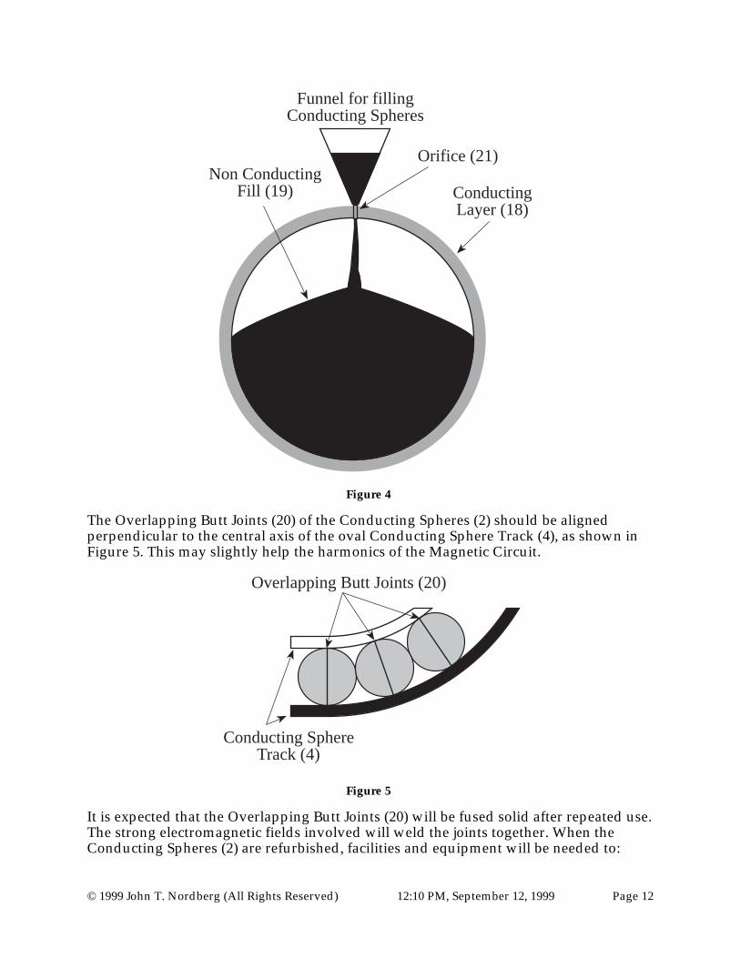
One possible method—using a funnel to pour the fill through an orifice (21)—for fillingthe Conducting Spheres (2) with a non conducting fill (19) such as amorphous Carboncan be seen in Figure 4.
© 1999 John T. Nordberg (All Rights Reserved) 12:10 PM, September 12, 1999 Page 12
ConductingLayer (18)
Non-ConductingCore (19)
Orifice (21)
Funnel for fillingConducting Spheres
Non ConductingFill (19)
Figure 4
The Overlapping Butt Joints (20) of the Conducting Spheres (2) should be alignedperpendicular to the central axis of the oval Conducting Sphere Track (4), as shown inFigure 5. This may slightly help the harmonics of the Magnetic Circuit.
Overlapping Butt Joints (20)
Conducting SphereTrack (4)
Figure 5
It is expected that the Overlapping Butt Joints (20) will be fused solid after repeated use.The strong electromagnetic fields involved will weld the joints together. When theConducting Spheres (2) are refurbished, facilities and equipment will be needed to:

© 1999 John T. Nordberg (All Rights Reserved) 12:10 PM, September 12, 1999 Page 13
• move these massive spheres (whether they are intact or damaged)
• cut open these massive spheres
• remove the carbon fill
• carefully crush the carbon fill and remove any diamond crystals
• melt and recycle the conducting material
• recycle carbon and graphite, or other fill material
Reactor Core
The cross section of the reactor core is shown in Figure 6.
High Temp.Ceramic (22)
RCC/Boron (23)
RCC (24)
Silica (25)Copper-Nb (18)
RCC (26)RCC (27)
Conducting SphereDivot (59)
LaserPort (37)
Figure 6
To summarize, an initial reactor core could be designed as such:
1) An inner layer of non-conducting material made up of an Ultra High TemperatureCeramic (22) such as: hafnium diboride silicon carbide; or, Zirconium diboridecomposite; or, other related ceramic compounds. The exact thickness of this layeris unknown at this time due to the classified nature of these ceramics—they arenow used to make nose-cones for ICBMs. The estimated required thickness is 1inch. They are estimated to be able to withstand temperatures up to 5,000° F.

© 1999 John T. Nordberg (All Rights Reserved) 12:10 PM, September 12, 1999 Page 14
Preferably, this inner layer of material will have a composition that includes someBoron. Neutral elementary particles such as neutrons may have enough energy topenetrate the Spherical Electromagnetic Confinement Field (40). Boron is knownto be able to stop neutrons. Thus, the purpose of the inner layer will be to shieldthe outer layers from massive thermal shock and neutrons. (Most likely, this innerlayer will be manufactured as two interlocking hemispheres. Possiblymanufactured as interlocking tiles.)
2) A second, essentially non-conducting layer, that is composed of material that canwithstand high temperatures, thermal shock, compressive forces from without,explosive forces from within and can stop neutrons, such as, a 1 inch wallcomposed of a reinforced carbon-carbon matrix (RCC) impregnated with Boron(23). (Most likely manufactured as two interlocking hemispheres. Possiblymanufactured as one piece around the inner layer of Ultra High TemperatureCeramics or SiC-SiC (Silicon/Carbide composites). Preferably, the material wouldhave a low activation, which means the material would not be negatively affectedby combining with neutrons coming from the nuclear reaction, creatingradioactive material.)
3) A third layer, essentially non-conducting, that is composed of material that canwithstand high temperatures, thermal shock, compressive forces from without,explosive forces from within, such as a layer composed of 1 inch of RCC (24).(Most likely manufactured as one piece around the inner layers of Ultra HighTemperature Ceramics and Boron impregnated RCC.)
4) A fourth layer, essentially non-conducting, that is composed of a material that canwithstand massive thermal shocks and lessen the thermal shock to the next layertowards the outside of the core. This layer could be composed of 5 inches of Silica(25) (99.8-percent amorphous fiber) made rigid by ceramic bonding. This is thesame material used in Space Shuttle heat shields. (Most likely manufactured astwo interlocking hemispheres. Possibly manufactured as multiple interlockingtiles attached to the outside of the inner 3 layers.)
5) A fifth layer, that is highly conductive and very low resistance, is economical, thatcan be formed into spherical shells of the size needed, and can withstand theinternal electromagnetic forces—e.g., Coulombic and Hall—created by massiveelectromagnetic fields used in these designs. Such as a layer could be composed ofCu-Nb (18)—Copper-Niobium—that is approximately 6 inches thick. (Most likelymanufactured as two interlocking hemispheres that are heat-shrunk to each otherwith the lap-joint situated at the eventual equator of the electromagnetic field.) (Insome variations, this layer may be a plasma instead of a solid.)
6) A sixth layer, essentially non-conducting, that is composed of material that canwithstand high temperatures, thermal shock, explosive forces from within. Suchas a layer might be composed of 2 inches of RCC (26). (Most likely manufacturedas two interlocking hemispheres.) This layer must have a Conducting SphereDivot (59). This cut out area allows the Anode/Cathode Conducting Sphere (13)to sit next to the Conducting Layer (18) of the Reactor Core (1). Without thisDivot, the harmonics of the electromagnetic fields would flow smoothly fromsphere to sphere.

© 1999 John T. Nordberg (All Rights Reserved) 12:10 PM, September 12, 1999 Page 15
7) A seventh layer, essentially non-conducting, that is composed of material that canwithstand high temperatures, thermal shock, explosive forces from within. Suchas a layer might be composed of 2 inches of RCC (27). The main purpose of thislayer would be to add additional structural strength to the 6th layer, but withstrands of Carbon and with the joint at a 90° layer to the sixth. (Most likelymanufactured as two interlocking hemispheres.) This layer must have aConducting Sphere Divot (59). This cut out area allows the Anode/CathodeConducting Sphere (13) to sit next to the Conducting Layer (18) of the ReactorCore (1). Without this Divot, the harmonics of the electromagnetic fields wouldflow smoothly from sphere to sphere.
8) Laser Ports (37) must be drilled through the Reactor Core in order to allow theLaser Beams—or Ion Beams in some variations—to impart their energy to thefusion Fuel Pellet (36).
In this version of the core wall, the total wall thickness is approximately 18 inches ofwhich 1/3—i.e., 6 inches—is conductive.
Placement of Conducting Spheres and Trough Description
The bulk of the conducting spheres—29 out of 31—sit in a non conducting trough calledthe Conducting Sphere Track (4). The trough could be made of a non conductingmaterial such as cement. A cross section of the Conducting Sphere Track (4) is shown inFigure 7.

© 1999 John T. Nordberg (All Rights Reserved) 12:10 PM, September 12, 1999 Page 16
Inside edgeof track
Outside edgeof track
PaddingMaterial (28)
Overhead Gantry& Cranes (32)
Conducting Spheres (2)can thermally expand
in & out.
Shield/Trough/Track
High VolumeCoolant Out Pipe (29)
ConductingSphere (2)(Coils notIllustrated)
Conducting SphereTrack (4)
Angle of Slopeis exaggeratedfor illustration.
Filled with coolant (30)
Sliding Trough Shield (31)
+
-
CoilLeads (33)
High VolumeCoolant In Pipe (29)
Figure 7
If cement is used, then it should not be reinforced with a metal such as traditional rebar.Instead it should be reinforced with non-conducting material such as glass fibers.Conducting reinforcement materials such as rebar in the cement would be too closephysically to the intense electromagnetic fields in the Conducting Spheres. This cancause many problems, including but not limited to: induction of electromagnetic fieldsin the rebar; heating of the rebar; cracking of the cement, disruption of harmonics in theConducting Spheres and Core(s).
The cement trough should be lined with a Padding Material (28) such as, but not limitedto, vulcanized rubber. The purpose of the Padding Material is to help protect the surfacetexture and geometrical shape of the Conducting Spheres. If the Conducting Sphereswere nicked or dented when placed into the trough, or if the weight of the ConductingSpheres gradually flattened the spheres, then the electromagnetic harmonics of theConducting Spheres would be reduced or lost.
The Padding Material ( 28) should be sloped towards the center of the trough. (Theslope is exaggerated in Figure 7 for illustration purposes. In reality the slope would bevery minor.) In essence, the conducting spheres are gently pulled in towards the center

© 1999 John T. Nordberg (All Rights Reserved) 12:10 PM, September 12, 1999 Page 17
of the trough by the force of gravity. This allows the Conducting Spheres (2) tothermally expand outward and inward and always be positioned next to each other onthe Conducting Sphere Track (4).
The trough should have numerous, high-volume input and output Coolant Pipes (29).This would allow the trough to be quickly filled with a Coolant (30), such as water, andquickly drained. Cooling of the Conducting Spheres and Core(s) will help theharmonics of the Spherical Electromagnetic Confinement Field (40) to be maintained.For example, if the temperature of a Conducting Sphere dramatically increased, thenthe conductivity of the Conducting Sphere will change, and, due to thermal expansion,the wavelength of the main harmonic would change.
The top of the Conducting Sphere Track (4) should have Sliding Trough Shields (31)that can be quickly moved on or off the trough portion of the Conducting Sphere Track(4). While over the trough the Sliding Trough Shields (31) will provide shielding in casea Conducting Sphere (2) ruptures. When the lids are retracted, it will allow theConducting Spheres (2) and other components such as the Hemispheric Coils (6) to bechecked, adjusted, or quickly replaced.
There should be a means to quickly replace the massive Conducting Spheres (2) andHemispheric Coils (6). This can be accomplished via an Overhead Gantry and Cranes(32).
There should be connecting lead wires that attach the Hemispheric Coils (6) to the mainElectrical Bus (7), the Capacitor Banks (5) and the Power Grid. These Coil Leads (33) canpenetrate through any side of the Conducting Sphere Track (4), or through the SlidingTrough Shields (31). The Coil Leads (33) should be highly conductive, evenly spacearound the track, and as short and straight as possible. The Coil Leads (33) will becooled by the Coolant (30) within the trough of the Conducting Sphere Track (4) and bythe Coolant Bath (8) outside of the Conducting Sphere Track (4). (An additional coolingjacket may be required within the concrete portion of the Conducting Sphere Track (4)but is not utilized in this design.)
In addition to the above details, the Conducting Sphere Track (4) will have numeroussensors to monitor: temperature, strain, electric fields, magnetic fields, diameters ofConducting Spheres (2), etc..

© 1999 John T. Nordberg (All Rights Reserved) 12:10 PM, September 12, 1999 Page 18
Placement of the Anode and Cathode Conducting Spheres
Coolant In (15)
Coolant Out (16)
CorePedestal (11)
Anode/CathodeConducting Sphere
Pedestals (12)
C/C InnerShield-Clamp (10)
Anode/CathodeConducting Spheres (13)
Coolant Tubes (14)
MiddleShield (9)
Middle ShieldCoolant (34)
Non ConductiveGasket (55)
LaserPorts (37)
LaserBeam (60)
Figure 8
Figure 8 shows some of the major details in the central reactor core area. The term“anode” and “cathode” with respect to this electric circuit is purely arbitrary. EitherConducting Sphere (2) that is adjacent to the Reactor Core (1) could act as an anode orcathode in an electric circuit, or neither, in a magnetic circuit. The “Anode/CathodeConducting Spheres” term simply refers to the two Conducting Spheres (2) that areclosest to the Reactor Core (1).
The Anode (13), Reactor Core (1), and Cathode (13) must be aligned next to each other.In this embodiment, the 3 spheres are held in position by an inner C/C Inner Shield-Clamp (10). This C/C Inner Shield-Clamp (10) is designed with two halves that act in aclamshell fashion. When the Middle Shield (9) opens, so does the C/C Inner Shield-Clamp (10).
The Middle Shield (9) is made with double walls. The walls are made of a strongmaterial that would resist heat and puncture due to the explosion of a Reactor Core (1),or Anode/Cathode Conducting Sphere (13). There are some Stainless Steels—such as316 Stainless Steel—that are not very reactive to neutrons. Low reactivity for metals isimportant. After a period of use, the shield material will become radioactive and mustbe replaced. This will be one of the biggest sources of radioactive waste products fromsuch power plants. The preferred embodiment will use 316 Stainless Steel. Othermaterials, including, but not limited to reinforced Carbon/Carbon matrixes could beused for the Middle Shield (9).
Inside the two layers of the Middle Shield (9) is the Middle Shield Coolant (34). Thecoolant is water in the preferred embodiment. It is pumped through the Middle Shield(9) at a high rate. In some variations, this water coolant could be replaced by some otherfluid, gas, or material appropriate for cooling.

© 1999 John T. Nordberg (All Rights Reserved) 12:10 PM, September 12, 1999 Page 19
The Anode/Cathode Conducting Spheres (13) sit on a non conducting ConductorPedestals (12) of fiber reinforced cement. The center of each pedestal contains CoolantTubes (14) for coolant to flow in and out. In this design, and there are many otherpossible designs, the coolant flows into the pedestals through the central Coolant In (15)tube, and flows out of the pedestals through the outer Coolant Out (16) tubes. Thepurpose of cooling the pedestals is so they do not become “hot spots” beneath theConducting Spheres. The coolant must also be carefully monitored so as not to cool thepedestals too much, creating “cold spots” beneath the Conducting Spheres. Hot spots orcold spots would affect the conductivity of the Conducting Layer (18) of the ConductingSpheres (2) and the Reactor Cores (1) and thus reduce the effectiveness of the SphericalElectromagnetic Confinement Fields (40).
Laser Ports (37) pierce the Middle Shield (9), the C/C Inner Shield-Clamp (10), and theReactor Core (1). In the preferred embodiment, the final focusing crystal of the LaserBeam is located in the Laser Ports (37) that are in the Middle Shield (9). The Laser Ports(37) through the C/C Inner Shield-Clamp (10) and the Reactor Core (1) are just holes.
Non Conductive Gaskets (55) are located between the Middle Shield (9) and the C/CInner Shield-Clamp (10) to reduce the possibility that current flow between theAnode/Cathode Conducting Spheres (13) and the Middle Shield (9) could take place.
The Core Pedestal (11) and the Conductor Pedestals (12) could be located on verticalhydraulic lifts that allow them to move up and down for easier opening and closing ofthe Middle Shield (9), the C/C Inner Shield-Clamp (10), and to allow fine adjusting ofsupported spheres as they thermally expand and contract through temperaturevariations.
Placement of the Reactor Core
While the Reactor Core sits in the C/C Inner Shield-Clamp, its weight is also supportedby a non conducting pedestal made of fiber reinforced cement, called the Core Pedestal(11).
The center of the Core Pedestal (11) also contains Coolant Tubes (14) for coolant to flowin (15) and out (16). The purpose of cooling the pedestals is so they do not become a“hot spot” beneath the Reactor Core(s) (1). The coolant must also be carefully monitoredso as not to cool the pedestal too much, creating a “cold spot” beneath the ReactorCore(s) (1).
Placement of Fusion Fuel
Initially, the fusion Fuel Pellet (36) will be in the form of spherical D-T pellets,presumably purchased from government sources. (Eventually, if the power of thesereactor designs reaches expected levels, the Tritium may be avoided, allowing cheaperand easier to produce D-D pellets, and possibly other combinations of light elements.)The pellets will be prepositioned within the replaceable Reactor Core (1) by a threedimensional grid of Ablatable Wires (35) made of materials such as glass fibers—seeFigure 9.

© 1999 John T. Nordberg (All Rights Reserved) 12:10 PM, September 12, 1999 Page 20
Ablatable Wires (35)
Fuel Pellet (36)
Laser Ports (37)
Figure 9
Laser Ports
The Middle Reactor Shield (9), the Inner Reactor Clamp/Shield (10), and the ReactorCore (1) will have small holes—Laser Ports (37)—that will allow the fusion pellet targetto be imploded using traditional inertial confinement techniques. The preferredembodiment will use lasers. The design of the lasers and related equipment could beidentical to the currently envisioned facility called the National Ignition Facility, orsimilar to many other inertial confinement devices. It is important that the Laser Portsbe as evenly spaced around the reactor core to assist in imploding the fusion pellet in aspherical fashion. (The NIF facility currently envisions compressing Holoraumcylinders rather than the older type of spherical D-T pellets envisioned for thispreferred embodiment.)
The Laser Ports (37) in the side of the Reactor Core (1) are needed for this preferredembodiment in order to allow the laser energy to reach the fusion Fuel Pellet (36).Lasers are needed in this design for the purpose of igniting the fusion Fuel Pellet (36).After the initial ignition of the pellet, the lasers are not needed.
The problem of having Laser Ports (37) in the side of the Reactor Core (1) is thedisruption of harmonics. The electromagnetic harmonics within the Reactor Core (1)will be disrupted, to some extent, by the Laser Ports (37). This disruption is a result ofthe electrons flowing around the ports rather than through the conducting material thathas been removed to make the ports. If the diameters of the ports are large, then thedisruption of the harmonics will be larger. Since the disruption of the harmonics is notdesired, the diameters must be minimized.
In some prior art, laser ports have used some kind of glass or crystal structure. Thedesign of these components has been extremely difficult. The design of such “windows”for the Laser Ports (37) that pass through the C/C Inner Shield-Clamp (10) and theReactor Core (1), in these designs at least, does not seem necessary. In this preferredembodiment, these inner Laser Ports (37) are simply holes. The final focusing optics forthe lasers are located just outside of, or within, the Laser Ports (37) that pass through theMiddle Shield (9). Their design can be identical to such components already designedfor the National Ignition Facility.

© 1999 John T. Nordberg (All Rights Reserved) 12:10 PM, September 12, 1999 Page 21
The size of the holes for the Laser Ports (37) that pass through the C/C Inner Shield-Clamp (10) and the Reactor Core (1) will depend on the diameter of the laser beams.Tests with specific reactor core materials and laser energies will be needed. If thediameters of the Laser Ports (37) are too small, then the laser beams will be diffracted bythe ports, and the energy will not reach the Fuel Pellet (36). If the diameters of the LaserPorts (37) are slightly too small, then the lasers will vaporize some of the ConductingLayer (18) of the Reactor Core (1) and plug the Laser Ports (37). If the diameters of theLaser Ports (37) are just right, then the lasers will slightly vaporize some of theConducting Layer (18) of the Reactor Core (1) but not plug the Laser Ports (37). With aslight amount of vaporized Conducting Layer (18) within the Laser Ports (37), and withthe diameter of the Laser Ports (37) minimized, when the massive pulse ofelectromagnetic energy that forms the Spherical Electromagnetic Containment Field (40)passes over the core, then electrons and the electromagnetic pulse will arc through theLaser Ports (37), instead of around the diameter of the Laser Ports (37), and this willhelp to minimize the disruption of the electromagnetic harmonics within the core.
If the Laser Ports (37) are simply holes, the question is, “Will material pour out the LaserPorts (37) when the fusion reactor occurs?” If there was no electromagnetic confinementfield, then the answer would be yes. However, with an electromagnetic confinementfield in place, all of, or the majority of the plasma would be blocked.
Laser Port Distribution
The positions and distributions of the Laser Ports (37) over the Reactor Core (1) isimportant. The key engineering factor is how the ports can be positioned to fire aroundthe Anode/Cathode Conducting Spheres (13) and pedestals (11) and (12). In general, itis preferable to implode the fusion Fuel Pellet (36) in a spherical pattern. TheAnode/Cathode Conducting Spheres (13) and the pedestals (11) and (12) create “blindspots” where Laser Ports (37) can not be positioned. If needed, this problem can beminimized by having some of the end lasers aimed slightly off-center. They can beaimed more towards the ends of the fusion Fuel Pellet (36)—the ends that face theAnode/Cathode Conducting Spheres.
An estimated minimum of about 14 laser ports is needed to adequately implode thefusion Fuel Pellet (36) in a spherical pattern. Since the Laser Ports (37) reduce theelectromagnetic harmonics on the Reactor Core (1), the number of ports, and thus lasers,must be minimized. However, if too few of lasers are used, then the plasma will notimplode spherically, and the initial plasma instabilities would be too large for theSpherical Electromagnetic Containment Fields (40) to contain. The optimum number ofports can not be stated at this time because of the number of variables involved. Thelaser beam diameter is important. The laser wavelength is important. The energy perbeam is a factor. The diameter of the fusion Fuel Pellet (36) is important.
Too many lasers could be used. For example, 50 lasers would probably be too many,creating too much of a disruption in the harmonics. Plus, the cost of the lasers couldbecome prohibitive.
For the preferred embodiment, 24 Laser Ports (37) will be used. Their approximatepositions are shown in Figure 10.

© 1999 John T. Nordberg (All Rights Reserved) 12:10 PM, September 12, 1999 Page 22
Figure 10
The dots in Figure 10 show the port positions. The circular line represents the ReactorCore’s (1) outer diameter. The radial lines represent the angle from the Laser Ports (37)to the fusion Fuel Pellet (36). Figure 10 represents the view of the Reactor Core (1) frominside the oval Conducting Sphere Track (4) looking outwards. There are only 12 portsvisible on this side. Another 12 ports would be on the opposite side (i.e., the outsideview of the Reactor Core (1)). The angles are chosen to fire around the Anode/CathodeConducting Spheres (13), and the Pedestals (11) and (12).
Laser Pulse, and Confinement Pulse Timing
In this preferred embodiment, the Confinement Field Pulse must come after the LaserPulse for the reasons just discussed. If the Spherical Electromagnetic Containment Field(40) is too strong when the lasers pulses pass through the Laser Ports (37), thenpremature arcing may occur across the Laser Ports (37) in front of the laser pulses,blocking the energy of the lasers. If the Spherical Electromagnetic Containment Field(40) is too weak when the plasma explodes, then the fusion reaction will not beadequately confined. Thus, timing is critical in this design, as is shown in Figure 11.

© 1999 John T. Nordberg (All Rights Reserved) 12:10 PM, September 12, 1999 Page 23
Ene
rgy
Time
Fusion Fuel Yieldover time
Energy AbsorptionCapability of Reactor &
(Confinement Field)
FusionYield Peak
1 2 3
Lase
r P
ulse
Pea
k
Con
finem
ent P
ulse
Pea
k
Fus
ion
Yie
ld P
eak
Laser EnergyYield over time
Figure 11
Tests must be performed to time the delay between when the laser pulses pass throughthe Laser Ports (37) and when the plasma starts to explode outwards. Further tests mustbe performed to determine the time needed for the energy from the Capacitor Bank (5)to pass through the Electrical Bus (7), through the Hemispheric Coils (6), to inducefields in the Conducting Spheres (4), pass through the Confinement Circuit, and buildup to a value that will arc across the Laser Ports (37) in the Reactor Core (1). When thereactor is triggered, the timing of the lasers must be designed so that the peak of thelaser pulse at time “1” is just prior to the timing of the peak of the SphericalElectromagnetic Containment Fields (40) at time “2”. (The total time width of the laserpulse and pellet explosion pulse will probably be only about 1 nanosecond. An estimateof the total width of the Confinement Pulse from triggering to peak will probably beabout 4 to 5 µseconds—based upon the estimated discharge rate of the Capacitor Bank(5)—if the Marx modules described later are used. Therefore it is likely that thetriggering of the Confinement Pulse will be required to begin prior to the triggering ofthe Laser Pulse.)
The delay and duration of each pulse after its triggering is unknown at this time andwill be specific to each reactor design. In the example of timing in Figure 11, theConfinement Pulse is triggered prior to the triggering of the Laser Pulse. The LaserPulse may need to be triggered first, or they may need to be triggered at the same time.The key detail is the Confinement Field Peak at time “2” lies between the Laser PulsePeak at time “1” and the Fusion Yield Peak at time “3”.

© 1999 John T. Nordberg (All Rights Reserved) 12:10 PM, September 12, 1999 Page 24
Middle Reactor Shield
Surrounding the Reactor Core (1) and the Anode/Cathode Conducting Spheres (13) is alarge double-walled Middle Reactor Shield (9). This shield is made up of strong materialcapable of halting debris from an exploding or rupturing core. The center of the doublewalls is filled with a coolant.
The Middle Reactor Shield (9) is of a clam-shell type. The two halves slide open foraccess to the central components. In the preferred embodiment, the two halves slideoutwards, rather than up and down. This allows the Overhead Gantry and Cranes (32)to easily drop replacement Anode/Cathode Conducting Spheres (13) and Reactor Cores(1) into place.
(Design variations for the Middle Reactor Shield (9) may include one wall with nocoolant, multi-wall shields with or without coolant.) Shield materials may beconducting or non-conducting. For the preferred embodiment, 316 Stainless Steel willbe used. (Another possible metal alloy based on Vanadium—V-15Cr-5Ti—would be agood example of a suitable material. Metals would have to be resistant to radiationinduced swelling and ductility loss and offer low residual activation. Other importantconsiderations are: relatively high thermal conductivity; low thermal expansioncoefficient and low modulus.)
If the Middle Reactor Shield (9) material is conducting, then Non Conductive Gaskets(55) must be placed between the Middle Reactor Shield (9) and the Anode/CathodeConducting Spheres (13)—see Figure 8. The Non Conductive Gaskets (55) materialcould be a vulcanized rubber, possibly ceramic, or other materials. In essence, the bulkof the electromagnetic confinement pulse must follow the conducting material in theConducting Spheres (2) and the Reactor Core (2) and not over the Middle Reactor Shield(9).
Ports through the Middle Reactor Shield (9) are required for the Lasers.
Inner Reactor Clamp/Shield
Attached to inside of the Middle Reactor Shield (9) is a non conducting Inner ReactorClamp/Shield. This shield is about two inches thick, is made of Reinforced CarbonCarbon (RCC) material, is also of a clam-shell type, and shields and clamps into positionaround the Anode/Cathode Conducting Spheres and the Reactor Core.
Holes in the Inner Reactor Clamp/Shield are positioned to mirror the Laser Ports (37).The diameter of the holes can be larger than the holes through the sides of the ReactorCores (1).
Description of Electrical Currents
The Conducting Spheres (2) and the Reactor Core (1) create an electric circuit.Potentially, a voltage could be set up so that current flows around the circuit. In thissituation, the circuit will be called an Electrical Circuit, and the reactor is acting in theElectric Mode. Alternatively, currents can be set up over the Conducting Spheres toinduce a magnetic potential across each Conducting Sphere. In this situation, the circuit

© 1999 John T. Nordberg (All Rights Reserved) 12:10 PM, September 12, 1999 Page 25
will be called a Magnetic Circuit, and the reactor is acting in the Magnetic Mode. Thispreferred embodiment uses a Magnetic Circuit.
If this reactor design were designed to be an Electrical Circuit, then there would resultlarge-scale transport of electrons around the oval track of the circuit. Large-scaletransport of electrons would be relatively dangerous and destructive to the circuit.
Voltage
current
currentM
agne
tic F
ield M
agnetic Field
Figure 12
Figure 12 demonstrates how, if a Voltage is set up over the Poles of the Reactor Core (1),then an Electric Circuit is made. The arrows that represent the direction of the currentshow how large-scale transport of electrons would flow over the core and accumulateon one pole of the core. The magnetic field would obey the left-hand rule on the lefthemisphere, and the right-hand rule on the right hemisphere.
If this reactor design were designed to be a Magnetic Circuit, then there would resultlarge-scale transport of electrons around the outer diameters of the Conducting Spheres(2) and Reactor Core(s) (1).
Magnetic “Voltage”
magnetic “current”
Ele
ctric
Fie
ld Electric F
ield
magnetic “current”
Figure 13

© 1999 John T. Nordberg (All Rights Reserved) 12:10 PM, September 12, 1999 Page 26
The arrows that represent the direction of the magnetic “current” show how large-scaletransport of the magnetic field would flow over the core. The electric field would obeythe left-hand rule on the left hemisphere, and the right-hand rule on the righthemisphere. Thus, the large scale flow of electrons would counter-rotate around theopposite hemispheres of the Conducting Spheres (2) and Reactor Core(s) (1) and wouldnot accumulate on one pole. The preferred embodiment of these fusion reactor designsuses a Magnetic Circuit.
In order to induce the magnetic fields in the Magnetic Circuit in the preferredembodiment of these reactor designs, inductive coils will be used. There are many typesof coils that can be used.
Hemispheric Coils (6)
I have coined the name “hemispheric” coil because I have not seen them used or namedbefore. Basically the coil is wrapped around one hemisphere of supporting material:which may include but not be limited to: ceramic or RCC.
i (current) i (current)support material
Wire
Figure 14
Other coil types could be used. Advantages of this type of coil are: they can use aconstant current to create a magnetic field because the flux area is changing, and theycreate a symmetrical magnetic wave pattern over the Conducting Spheres (2). Thesymmetrical magnetic wave pattern would be conducive to creating a harmonicSpherical Electromagnetic Containment Field (40) over the Reactor Core (1).

© 1999 John T. Nordberg (All Rights Reserved) 12:10 PM, September 12, 1999 Page 27
Because the geometrical design of this type of coil, the flux area of the coil is constantlydecreasing—or increasing depending on the direction of current flow. Since themagnetic flux is changing, this will induce an EMF across the coil according toFaraday's Law of Induction. The direction of flow of fields over a Conducting Sphere (2)will oppose the fields in the coil. The fields on the Conducting Spheres (2) will beinduced by the fields in the Hemispheric Coils (6). Thus, a magnetic field will be set upacross the poles of the Conducting Sphere (2), and the large-scale transport of electronsin the Conducting Sphere (2) will counter-rotate around each hemisphere of theConducting Sphere as indicated in Figure 15.
B
B
B
B
B
E
E
E
E
E
E
i (current) i (current)support material
E
E
E
BB
Electric Field onHemispheric Coils
Magnetic Field onHemispheric Coils
Induced Electric Field onConducting Spheres
Induced Magnetic Field onConducting Spheres
Figure 15
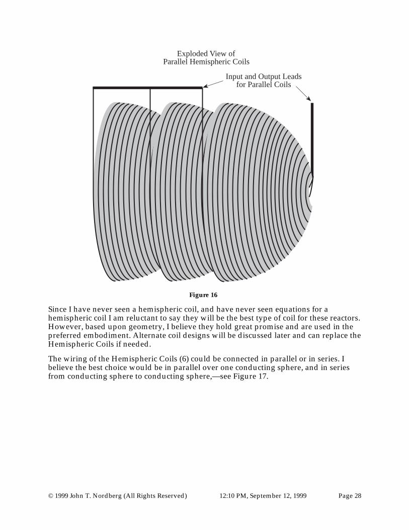
Just as it is possible to layer normal cylindrical coils, it should be possible to create amore powerful magnetic force by layering the hemispheric coils. Such a coil would belike a cup in a cup as shown in Figure 16.
© 1999 John T. Nordberg (All Rights Reserved) 12:10 PM, September 12, 1999 Page 28
Exploded View of Parallel Hemispheric Coils
Input and Output Leadsfor Parallel Coils
Figure 16
Since I have never seen a hemispheric coil, and have never seen equations for ahemispheric coil I am reluctant to say they will be the best type of coil for these reactors.However, based upon geometry, I believe they hold great promise and are used in thepreferred embodiment. Alternate coil designs will be discussed later and can replace theHemispheric Coils if needed.
The wiring of the Hemispheric Coils (6) could be connected in parallel or in series. Ibelieve the best choice would be in parallel over one conducting sphere, and in seriesfrom conducting sphere to conducting sphere,—see Figure 17.

© 1999 John T. Nordberg (All Rights Reserved) 12:10 PM, September 12, 1999 Page 29
Exploded View of Parallel Hemispheric Coils
Connected in Series
Figure 17
This is one method the Hemispheric Coils (6) can be connected in the preferredembodiment.
Energy Source to initially drive the Coils
As in all other fusion reactor designs, these reactor designs need an external energysource to start up. This external energy source could come from a variety of powersources such as: coal, oil, hydroelectric, fission, etc. Most external power plants wouldnot have sufficient short-term energy to start the fusion process. Thus, some sort ofenergy collection system is needed.
Capacitor Banks
In many other fusion reactor designs, banks of capacitors are charged. This designutilizes such preexisting equipment. As an example, the Los Alamos NationalLaboratory is building a device called Atlas. This device will use a 36 MJ array of 240kVolt Marx modules. These modules can be discharged rapidly. They can deliver a peakcurrent of 45 to 50 MA with a 4 to 5 µsecond rise time.
The exact amount of capacitors that are needed for the preferred embodiment is notknown at this time. This design is scalable. To meet the design goal of 1 to 3 Tesla ofinduced Magnetic fields over the Conducting Spheres (2) and Reactor Core(s) (1),additional capacitors and coils could be added as needed.

© 1999 John T. Nordberg (All Rights Reserved) 12:10 PM, September 12, 1999 Page 30
Applying Current to the Coils
Again, I would use preexisting equipment to switch the capacitors to the coils. Whiletests with each reactor design would be needed, it is assumed that the massive capacitorbanks must be discharged in unison. Special High-Speed Switches (38) have beenemployed for such purposes in other designs and could be purchased for thisapplication. (For example, some inertial confinement reactors use synchronized laser-triggered, gas-insulated switches.)
When the energy in the capacitors is discharged into the Hemispheric Coils (6), thenelectromagnetic fields would develop in the conducting layer of each ConductingSphere (2), and these fields would induce electromagnetic fields in adjacent ConductingSpheres (2). The Anode and Cathode Conducting Spheres (13) would induce the fieldswithin the Reactor Core (1).
A key question is whether all of the energy in the Capacitor Bank(s) (5), should bereleased at once, with one triggering, or, should the initial pulse be followed up withmore pulses. The answer is, it depends on economics. The Marx modules are obviouslyexpensive. The initial pulse is the most critical. It confines the initial explosion of thefusion fuel. However, to the lengthen the duration of the fusion burn, additional time inthe Spherical Electromagnetic Confinement Field (40) would be beneficial. The long-term costs of adding additional energy storage in the Capacitor Bank(s) (5) would beless than the additional energy captured from the fusion reactions. The bulk of the costis expended in the initial confinement pulse, not adding additional time to the pulse.
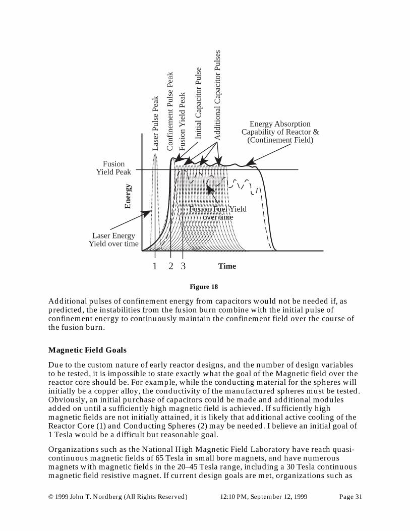
The frequency at which initial pulses are triggered will be determined by the resonanceof the Reactor Core (1). This rate is a function of the primary wavelength of the system.If designed correctly, this wavelength will be determined by the wavelength of theConducting Spheres (2). An example of how an initial pulse of energy could be releasedby a capacitor bank, followed by additional pulses of energy by additional capacitors, isshown in Figure 18.
© 1999 John T. Nordberg (All Rights Reserved) 12:10 PM, September 12, 1999 Page 31
Ene
rgy
Time
Fusion Fuel Yieldover time
Energy AbsorptionCapability of Reactor &
(Confinement Field)
FusionYield Peak
1 2 3
Lase
r P
ulse
Pea
k
Con
finem
ent P
ulse
Pea
k
Fus
ion
Yie
ld P
eak
Laser EnergyYield over time
Initi
al C
apac
itor
Pul
se
Add
ition
al C
apac
itor
Pul
ses
Figure 18
Additional pulses of confinement energy from capacitors would not be needed if, aspredicted, the instabilities from the fusion burn combine with the initial pulse ofconfinement energy to continuously maintain the confinement field over the course ofthe fusion burn.
Magnetic Field Goals
Due to the custom nature of early reactor designs, and the number of design variablesto be tested, it is impossible to state exactly what the goal of the Magnetic field over thereactor core should be. For example, while the conducting material for the spheres willinitially be a copper alloy, the conductivity of the manufactured spheres must be tested.Obviously, an initial purchase of capacitors could be made and additional modulesadded on until a sufficiently high magnetic field is achieved. If sufficiently highmagnetic fields are not initially attained, it is likely that additional active cooling of theReactor Core (1) and Conducting Spheres (2) may be needed. I believe an initial goal of1 Tesla would be a difficult but reasonable goal.
Organizations such as the National High Magnetic Field Laboratory have reach quasi-continuous magnetic fields of 65 Tesla in small bore magnets, and have numerousmagnets with magnetic fields in the 20–45 Tesla range, including a 30 Tesla continuousmagnetic field resistive magnet. If current design goals are met, organizations such as

© 1999 John T. Nordberg (All Rights Reserved) 12:10 PM, September 12, 1999 Page 32
the National High Magnetic Field Laboratory are expected to reach 100 Tesla in a non-destructive magnet. Magnetic fields of up to 820 Tesla have been reached usingdestructive magnets at the Los Alamos National Laboratory.
Incremental increases in reaching higher magnetic fields in test magnets are being madeby improving cooling, alloy selection, capacitors—or other energy sources—reinforcement structures, etc.. The modular designs of all of the new reactor designs inthis document allow new and improved materials and devices to be tested, and firstgeneration components to be replaced later, by more advanced components.
Reactor Core Spherical Electromagnetic Containment Field (40) Field Goal
The power that it transmitted to the focal point of the core can be found by using thefollowing expressions:
Equation #1 P =rSA
(Power is equal to the Poynting Vector times the area of the sphere.)
Equation #2
rS = 1
µ0
rE ×
rB
(The Poynting Vector is proportional to the cross product of the electric and magneticfields.)
Equation #3 E = cB
(The electric field is proportional to the magnetic field times the speed of light.)
Equation #4 A = 4πr2
(The surface area for a sphere.)
Solving:
Equation #5 P = 1
µ0
rB2c4πr2
As an example of what this implies for these reactor designs, if a magnetic field can begenerated at the surface of a 5 meter conducting sphere with a value of 1 Tesla, then thepower transmitted towards the focal point of the sphere would be:
Equation #6 P =1 T 2[ ] 3 ×10⁸ m / s[ ] 4π 25 m2[ ]
4π ×10−7 Wb / A ⋅ m[ ]= 1 T 2[ ] 3 ×10¹⁵ m / s[ ] 25 m2[ ] A ⋅ m / Wb[ ]
Equation #7 = 75 ×1015 kg ⋅ m2
s3
Thus, a 1 Tesla field over a 5 meter sphere would focus 75 petawatts at the core of thereactor. A magnetic field of 1.5 Tesla would focus 168.75 petawatts at the core of thereactor. A magnetic field of 2 Tesla would yield 300 petawatts. A magnetic field of 3

© 1999 John T. Nordberg (All Rights Reserved) 12:10 PM, September 12, 1999 Page 33
Tesla would yield 675 petawatts. A magnetic field of 4 Tesla would yield 1.2 exawatts.All of these example energies are very extreme. This is energy that is focused towardsthe center of the reactor core. It is referred to as the Spherical ElectromagneticContainment Field (40). (In some design variations, the Spherical ElectromagneticContainment Field (40) will be relied upon to ignite the fusion fuel.)
With a Spherical Electromagnetic Containment Field (40) that has enough power, thesteps to production of usable fusion energy are ready to begin.
General Steps for operation of reactor.It is believed that the invention operates as follows:
1) The Capacitor Bank(s) (5) for both the Containment Circuit (1) and (2), and theLasers (3) are charged.
2) A Reactor Core (1), with a spherical fusion Fuel Pellet (36)—held in place at thecenter of the Reactor Core (1) by 3 Abatable Glass Wires (35) in the x, y, and zaxis—is placed on the Central Core Pedestal (11).
3) The Inner (10) and Middle Reactor Shields (9) are closed.
4) The Conducting Sphere Track (4) and Middle Reactor Shield (9) are filled withcoolant and cooled. Coolant is pumped through the Anode/Cathode (12) andCore pedestals (11).
5) The Sliding Trough Shields (31) are closed.
6) The Overhead Gantry and Cranes (32) are retracted.
8) High-Speed Switches (38) allow energy stored in the Capacitor Banks to flow intothe Laser Circuit and the Containment Circuit. The Lasers are allowed to fire sothat their peak energy is applied to the fusion Fuel Pellet (36) slightly ahead ofwhen the peak of the containment energy sweeps around the Containment Circuit(2) and (1) and is applied to the Reactor Core (1).
9) The current through the Hemispherical Coils (6) induces electromagnetic fieldsover the Conducting Layer (18) of the Conducting Spheres (2). These fields createa Magnetic circuit around the Containment Circuit (1) and (2)—i.e., the electronsin the Conducting Spheres do not flow around the circuit, they counter-rotatearound each sphere, as shown in Figure 13, and create a strong magnetic field ateach pole of the Conducting Spheres (2). The cross product of the Electric andMagnetic fields—the Poynting Vector—creates a strong central pointing field ineach Conducting Sphere (2). The Non Conducting Fill (19) within eachConducting Sphere (2) would be heated and compressed, but not enough to starta fusion burn as in the Reactor Core (1). In the Reactor Core (1), a strong SphericalElectromagnetic Containment Field (40) will start to develop.
10) The Lasers (3) implode the fusion Fuel Pellet (36) and creates a nucleus of fusedmaterial.

© 1999 John T. Nordberg (All Rights Reserved) 12:10 PM, September 12, 1999 Page 34
11) The Spherical Electromagnetic Containment Field (40) over the Reactor Core (1)grows as the peak energy starts to flow through the Containment Circuit. (Extracapacitors are triggered—as needed—to lengthen the duration of the SphericalElectromagnetic Containment Field (40).)
12) Using High-Speed Switches (38), the Containment Circuit (1) and (2) is switchedfrom the Capacitor Bank (5) to the energy grid.
13) In general, the Spherical Electromagnetic Containment Field (40) that is set upover the Reactor Core (1) inhibits the nucleus of fused material from exploding. Amore precise way of saying this, is the fused fuel is inhibited from decaying. Ingeneral, the Spherical Electromagnetic Containment Field (40) will compress thefusion burn uniformly in all directions, helping the fusion burn to be harmonic. Ingeneral, some non harmonic Instabilities (39) will be ejected from the surface ofthe fusion burn in jet-like flows.
14) The outward exploding streams of plasma, the Instabilities (39), will setup flowsat right angles to the Spherical Electromagnetic Containment Field (40). Theexploding streams of plasma will interact with Spherical ElectromagneticContainment Field (40) that surrounds the core in a Magnetohydrodynamicfashion. The outward exploding streams of plasma will push out on the SphericalElectromagnetic Containment Field (40) via the MHD effect. The inward pointingSpherical Electromagnetic Containment Field (40) will push back on the explodingstreams of plasma. The rate of flow of the outward exploding streams of plasmawill be dramatically slowed. The energy lost in the slowing of the outwardmoving streams of plasma will be transferred to the Spherical ElectromagneticContainment Field (40), effectively increasing its strength, and creating anincreased Magnetic differential across the Reactor Core (1).
15) The increased Magnetic differential creates a Magnetic flow, analogous to acurrent flow, around the Containment Circuit (1) and (2). A current flow will beinduced in the Hemispheric Coils (6) by the Magnetic flow around theContainment Circuit (1) and (2). The induced current from the Hemispheric Coils(6) is allowed to flow out into the energy grid. High efficiency is obtained becausefusion energy is directly converted into electricity, and the excess energy in theSpherical Electromagnetic Containment Field (40) is recycled.
16) The active confinement of the fusion burn by the Spherical ElectromagneticContainment Field (40) will allow the fusion burn to have a duration that ismagnitudes longer than without active containment.
17) The central nucleus of fused fuel continues to eject exploding streams of plasmauntil the fuel is consumed. Then, when the fuel is almost totally consumed, theprocess stops. (The rate at which energy is released from the fusion burn willdepend on the harmonics of the burn. Smoother harmonics will allow a slowerrelease of energy. Poorer harmonics will release energy faster.)
18) Heat is extracted from the coolant in the Middle Reactor Shield (9) and theCoolant Bath (8) and is used to drive secondary turbine generators.

© 1999 John T. Nordberg (All Rights Reserved) 12:10 PM, September 12, 1999 Page 35
19) When the Reactor Core (1) is cooled sufficiently, the Outer Shield doors areopened and the Reactor Core is replaced. The Sliding Trough Shields (31) areretracted. Parts are inspected and replaced as needed.
20) The next cycle begins.
The length of the burn will be affected by many variables such as: materials selected forConducting Spheres (2) and the Reactor Core (1), and the size of the Capacitor Bank (5).These variables do not affect the general design concepts that patent protection is beingapplied for.
Theory of OperationThe simplest way to describe the idea of spherical confinement, is to take a hollowsphere made of a conducting material—e.g., copper—and to set up a voltage across thesphere as shown in Figure 19.
Voltage
Figure 19
It is important that the sphere is: symmetrical, smooth, of consistent material, and ofconsistent wall thickness. Also important is that the diameter of the sphere be muchlarger than the thickness of the wall of the sphere as shown in Figure 20.
Wall Thickness t
DiameterD
D >> t
Figure 20
© 1999 John T. Nordberg (All Rights Reserved) 12:10 PM, September 12, 1999 Page 36
The voltage across the sphere will create a current across the sphere. However, on onehemisphere the current density is decreasing as the current spreads out over the greatersurface area of the sphere, and on the other hemisphere the current density is increasingas the current comes together at the pole. This change in the current density will inducemagnetic fields at right angles on the surface of the sphere. Another way of describingthis is the electric flux is changing due to the geometry of the conducting sphere. Thechanging electric flux induces magnetic fields.
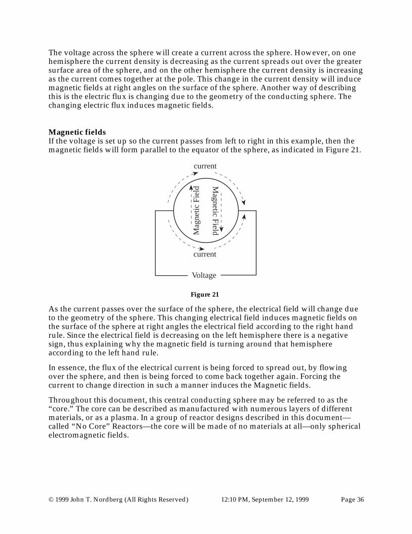
Magnetic fieldsIf the voltage is set up so the current passes from left to right in this example, then themagnetic fields will form parallel to the equator of the sphere, as indicated in Figure 21.
Voltage
current
current
Mag
netic
Fie
ld Magnetic F
ield
Figure 21
As the current passes over the surface of the sphere, the electrical field will change dueto the geometry of the sphere. This changing electrical field induces magnetic fields onthe surface of the sphere at right angles the electrical field according to the right handrule. Since the electrical field is decreasing on the left hemisphere there is a negativesign, thus explaining why the magnetic field is turning around that hemisphereaccording to the left hand rule.
In essence, the flux of the electrical current is being forced to spread out, by flowingover the sphere, and then is being forced to come back together again. Forcing thecurrent to change direction in such a manner induces the Magnetic fields.
Throughout this document, this central conducting sphere may be referred to as the“core.” The core can be described as manufactured with numerous layers of differentmaterials, or as a plasma. In a group of reactor designs described in this document—called “No Core” Reactors—the core will be made of no materials at all—only sphericalelectromagnetic fields.
© 1999 John T. Nordberg (All Rights Reserved) 12:10 PM, September 12, 1999 Page 37
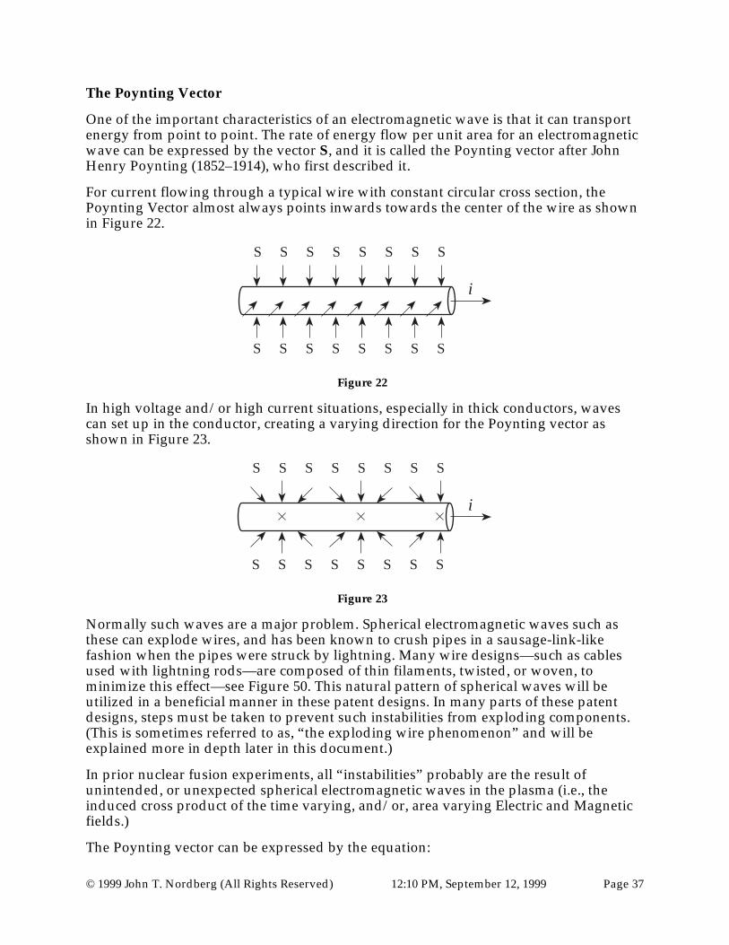
The Poynting Vector
One of the important characteristics of an electromagnetic wave is that it can transportenergy from point to point. The rate of energy flow per unit area for an electromagneticwave can be expressed by the vector S, and it is called the Poynting vector after JohnHenry Poynting (1852–1914), who first described it.
For current flowing through a typical wire with constant circular cross section, thePoynting Vector almost always points inwards towards the center of the wire as shownin Figure 22.
S S S S S S S S
S S S S S S S S
i
Figure 22
In high voltage and/or high current situations, especially in thick conductors, wavescan set up in the conductor, creating a varying direction for the Poynting vector asshown in Figure 23.
S S S S S S S S
S S S S S S S S
i
Figure 23
Normally such waves are a major problem. Spherical electromagnetic waves such asthese can explode wires, and has been known to crush pipes in a sausage-link-likefashion when the pipes were struck by lightning. Many wire designs—such as cablesused with lightning rods—are composed of thin filaments, twisted, or woven, tominimize this effect—see Figure 50. This natural pattern of spherical waves will beutilized in a beneficial manner in these patent designs. In many parts of these patentdesigns, steps must be taken to prevent such instabilities from exploding components.(This is sometimes referred to as, “the exploding wire phenomenon” and will beexplained more in depth later in this document.)
In prior nuclear fusion experiments, all “instabilities” probably are the result ofunintended, or unexpected spherical electromagnetic waves in the plasma (i.e., theinduced cross product of the time varying, and/or, area varying Electric and Magneticfields.)
The Poynting vector can be expressed by the equation:

© 1999 John T. Nordberg (All Rights Reserved) 12:10 PM, September 12, 1999 Page 38
Equation #2
rS = 1
µ0
rE ×
rB
In this form—i.e., with this constant—the Poynting vector can be described using SIBasic Units or SI Derived Units. In IS Derived Units, S is often expressed in terms ofwatts/meter2. In SI Basic Units, S is expressed in terms of kg/second3. The direction ofthe vector S gives the direction in which the energy moves. The vectors E and B refer tothe instantaneous vectors for the Electric and Magnetic fields.
Over the surface of the cores in the fusion reactors described here, the instantaneousvectors for E and B are normally tangential to the core's spherical surface. There are twoprimary possibilities for how the electric and magnetic fields are oriented over the core.(These two possibilities can be equated to “electric” circuits and “magnetic” circuits.)
In one of the two primary orientations of electric and magnetic fields, described in thesefusion reactors, the electric fields E are aligned so that they travel from pole to pole overthe conducting sphere, while the magnetic fields B point at a right angle to E—essentially parallel to the equator of the conducting spheres, as shown in Figure 24.
Side View of CoreTangential Electrical Field
End View of CoreTangential Magnetic Field
Figure 24
In the other of the two primary orientations of electric and magnetic fields, described inthese fusion reactors, the magnetic fields B are aligned so that they travel from pole topole over the conducting sphere, while the electric fields E point at a right angle to B—essentially parallel to the equator of the conducting spheres. This particulararrangement of electric and magnetic fields—essential for “magnetic” circuits—will bethe preferred field orientation and is required for the “No-Core” reactor design, asshown in Figure 25.

© 1999 John T. Nordberg (All Rights Reserved) 12:10 PM, September 12, 1999 Page 39
Side View of CoreTangential Magnetic Field
End View of CoreTangential Electrical Field
Figure 25
Analyzing the Poynting Vector on a Conducting Sphere or Core
At any point on the surface of a Conducting Sphere or Reactor Core, the electric andmagnetic field can be analyzed. By analyzing the cross product of the electric andmagnetic fields, the Poynting vector can be found. At all points on the surface of thesphere the cross product S is directed towards the center of the sphere. Two examplepoints of analyzing the Poynting vector for a sphere are shown in Figure 26.
E
B
SE
B
S
Figure 26
The Poynting vector can be expressed in different forms, but in general, energy is beingtransported to the focal point—to the center of the sphere.
In essence, the electrical current is being forced to spread out and then allowed to comeback together again by the geometry of the conducting sphere. If a current was travelingdown a long, straight conductor, then forced to spread out because of a bulge in theconductor, then there must be a force pointing towards the center of the bulge. Theequal and opposite force, equivalent to the mechanical force that is spreading theelectrical current apart over the sphere's region, is the central pointing energy transportthat can be expressed in the form of the Poynting Vector as shown in Figure 27.

© 1999 John T. Nordberg (All Rights Reserved) 12:10 PM, September 12, 1999 Page 40
i
i
i i
i
i
i
i i
i
Figure 27
The larger the voltage applied across the conducting sphere, the larger the currentacross the conducting sphere. The larger the current across the conducting sphere, thelarger the electric and magnetic fields. The larger the electric and magnetic fields, thelarger the amount of energy that is focused on the focal point—at the center of the core.
It is critical to note that, if a Conducting Sphere (2) or Reactor Core (1) is thin-walled,structurally weak, or in plasma form, then the electromagnetic fields will collapse andimplode the Conducting Sphere or Core. This is a problem if you do not wish theConducting Sphere or Core to collapse. Such a collapsing and implosion can be a benefitif it used as an ignition technique to ignite a plasma into a fusion burn. However, ingeneral, to prevent Conducting Spheres or Cores from vaporizing, imploding, crushing,rupturing or some other catastrophic event, and order to provide massive centralpointing impulses of energy at the center of the Reactor Core, the Conducting Spheres,and Reactor Cores must be relatively large, strong, and massive rather than small, andthin.
Plasma Fusion within the Core
A significant early question is, how could a fusion reaction be induced in the core of thereactors designs described in this document? The first two key issues are: How is thefuel placed in the core? and, How is the fuel ignited? The next section on MHD willaddress the issue of: How will the energy be extracted?
There are numerous techniques that could be used to place the fuel inside the core.
1) In one approach—shown in Figure 28—a Nozzle (49) could be placed in the sideof the Reactor Core (1) to inject a hot Plasma (50) into the core just prior to it beingignited. However, a permanently placed nozzle in the side of the core couldinterfere with the harmonics of the Spherical Electromagnetic Confinement Fields(40) and dramatically reduce their effectiveness to contain the fusion reaction.

© 1999 John T. Nordberg (All Rights Reserved) 12:10 PM, September 12, 1999 Page 41
Plasma (50)
Nozzle (49)Reactor Core (1)
Figure 28
2) A second approach—as shown in Figure 29—would be to place the fusion fuelPlasma (50) into the Reactor Core (1) when it is manufactured and have theplasma completely sealed in the core. Thus, the reactor would need to be designedso that the cores could be easily replaced between each fusion burn. With thistechnique, the core would need to be preheated before the mainconfinement/triggering pulse in order to re-ionize the plasma.
Plasma (50)
Reactor Core (1)Reactor Core (1)
Figure 29
3) A third approach—as shown in Figure 30—would be to place a fusion Fuel Pellet(36) at the center of the Reactor Core (1), pre-positioned and held in place byadjustable, Ablatable Wires (35) made of a materials which may include but not belimited to: Kevlar, carbon or silicon. There may be 1, 2, 3, or more wires used tohold the pellet in place. In this example, there are 3 wires forming a 3-dimensionalx, y, z-type grid.

© 1999 John T. Nordberg (All Rights Reserved) 12:10 PM, September 12, 1999 Page 42
Reactor Core (1)
Ablatable Wires (35)
Fuel Pellet (36)
Figure 30
4) A fourth approach—shown in Figure 31—would be to place a fusion Fuel Pellet(36) inside a small Spherical Wire Implosion Cage (51) made of Thin ConductingWires (52). How this cage is designed depends on if the Containment Circuit isacting in an Electric Mode or Magnetic Mode. In the Electric Mode, the ThinConducting Wires (52) would be aligned from pole to pole. In the Magnetic Mode,the Thin Conducting Wires (52) would be made of concentric wires as shown inFigure 33.
(The number of strands that make up the cage could be low—e.g., 20–30 wires.However, current tests by Sandia National Laboratories with cylindrical wirecages in their Z-Pinch device would suggest 100–300 wires would be optimal.Examples of materials for the cage's conducting wires would include, but not belimited to: tungsten, copper, aluminum, and gold.)
The purpose of the Spherical Wire Implosion Cage (51) is to implode and ignitethe fusion Fuel Pellet (36) located at the center of the cage. The Fuel Pellet (36)would be held in position inside the Spherical Wire Implosion Cage (51) byAblatable Non Conducting Wires (53). Examples of materials for the AblatableNon Conducting Wires (53) would include, but not be limited to: carbon, siliconand Kevlar. The Spherical Wire Implosion Cage (51) of Thin Conducting Wires(52) would be held in position within the larger, outer Reactor Core (1) by a ThickConducting Wire (54).

© 1999 John T. Nordberg (All Rights Reserved) 12:10 PM, September 12, 1999 Page 43
Reactor Core (1)Spherical Wire
Implosion Cage (51)
Thin ConductingWires (52)
Fuel Pellet (36)
AblatableNon Conducting
Wires (53)
ThickConductingWire (54)
Figure 31
A massive voltage would be setup across the Reactor Core (1)—as shown inFigure 32.
Voltage
Enlargement ofImplosion Cage
Figure 32
Part of the current would induce a Spherical Electromagnetic Containment Fieldaround the Reactor Core (1). Some of the current would pass along the innerThick Conducting Wire (54) which would vaporize the Thick Conducting Wire(54) and vaporize and implode the Spherical Wire Implosion Cage (51). Thisimplosion would ignite the fusion Fuel Pellet (36) inside the cage. The remainingcurrent passing over the outer Reactor Core (1) would provide the containmentforces for the fusion explosion.

© 1999 John T. Nordberg (All Rights Reserved) 12:10 PM, September 12, 1999 Page 44
Enlargement ofImplosion Cage
(Designed for MagneticMode operation)
Figure 33
The difficulty of inducing a harmonic Magnetic Mode containment field on theReactor Core (1) and in the Implosion Cage (51) at the same time probably willinhibit using this technique. The difficulty caused by the mass transport ofelectrons around the Containment Circuit when using the Implosion Cage (51)technique in the Electric Mode will inhibit using this technique.
5) A fifth approach would be to have the Reactor Core (1) placed inside a largerPlasma Container/Shield (56) that is filled with a low temperature Plasma (57)—see Figure 34 (a). In the sides of the reactor core would be small Plasma Flow Ports(58) that would allow the low temperature Plasma (57) to move inside the ReactorCore (1). With this technique, the Spherical Electromagnetic Containment Fields(40) over the Reactor Core (1) would compress and ignite the Plasma (57) insidethe Reactor Core (1) when a massive electric voltage, or magnetic differential is setup across the poles of the Reactor Core (1)—see Figure 34 (b). But this would notignite the Plasma (57) outside of the Reactor Core (1). At most it would compressit outward. As the reactor cools, there will be less pressure in the Reactor Corethan outside of the Reactor Core (1). The small Plasma Flow Ports (58) in the sidesof the Reactor Core (1) would allow the plasma outside the Reactor Core (1) backinto the Reactor Core (1) between each electromagnetic pulse—see Figure 34 (c).
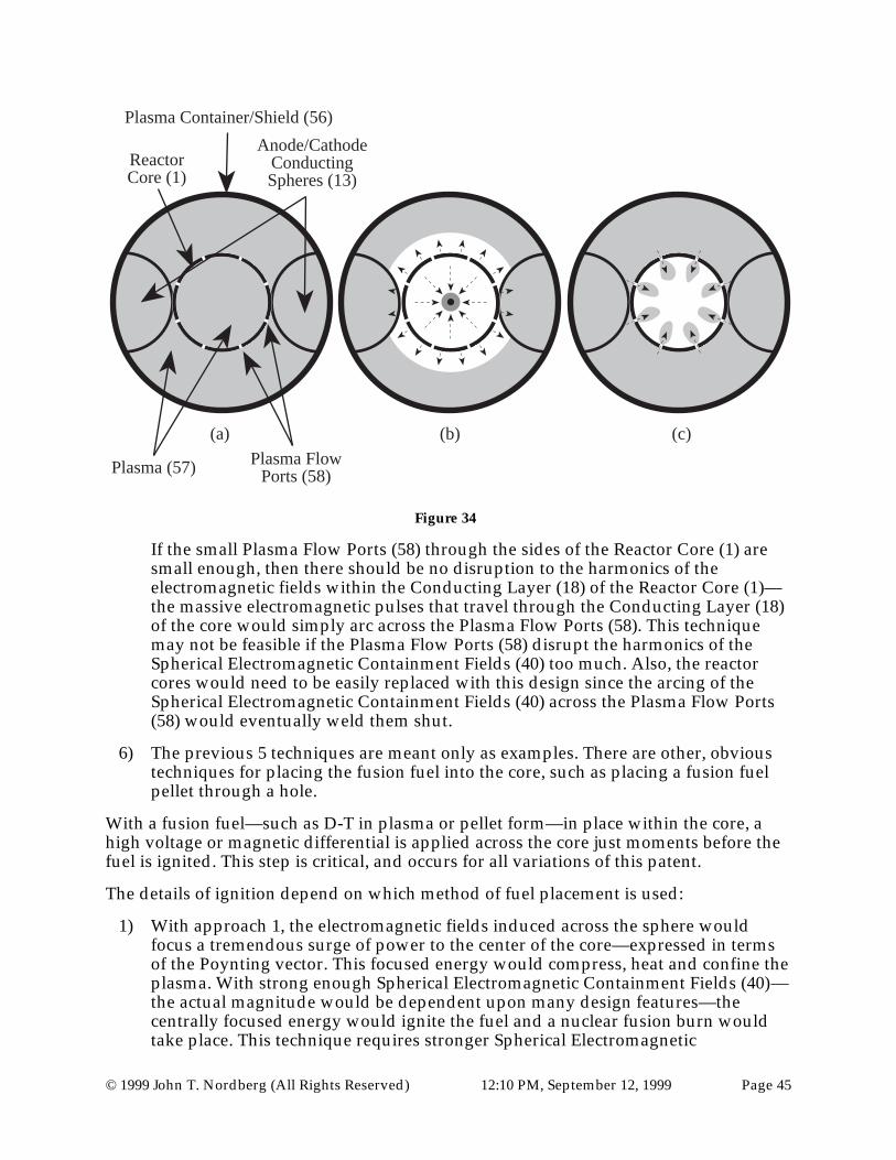
© 1999 John T. Nordberg (All Rights Reserved) 12:10 PM, September 12, 1999 Page 45
(a) (b) (c)
Plasma Container/Shield (56)
ReactorCore (1)
Anode/CathodeConductingSpheres (13)
Plasma (57) Plasma FlowPorts (58)
Figure 34
If the small Plasma Flow Ports (58) through the sides of the Reactor Core (1) aresmall enough, then there should be no disruption to the harmonics of theelectromagnetic fields within the Conducting Layer (18) of the Reactor Core (1)—the massive electromagnetic pulses that travel through the Conducting Layer (18)of the core would simply arc across the Plasma Flow Ports (58). This techniquemay not be feasible if the Plasma Flow Ports (58) disrupt the harmonics of theSpherical Electromagnetic Containment Fields (40) too much. Also, the reactorcores would need to be easily replaced with this design since the arcing of theSpherical Electromagnetic Containment Fields (40) across the Plasma Flow Ports(58) would eventually weld them shut.
6) The previous 5 techniques are meant only as examples. There are other, obvioustechniques for placing the fusion fuel into the core, such as placing a fusion fuelpellet through a hole.
With a fusion fuel—such as D-T in plasma or pellet form—in place within the core, ahigh voltage or magnetic differential is applied across the core just moments before thefuel is ignited. This step is critical, and occurs for all variations of this patent.
The details of ignition depend on which method of fuel placement is used:
1) With approach 1, the electromagnetic fields induced across the sphere wouldfocus a tremendous surge of power to the center of the core—expressed in termsof the Poynting vector. This focused energy would compress, heat and confine theplasma. With strong enough Spherical Electromagnetic Containment Fields (40)—the actual magnitude would be dependent upon many design features—thecentrally focused energy would ignite the fuel and a nuclear fusion burn wouldtake place. This technique requires stronger Spherical Electromagnetic

© 1999 John T. Nordberg (All Rights Reserved) 12:10 PM, September 12, 1999 Page 46
Containment Fields (40) across the core relative to the other techniques describedin this document since the Spherical Electromagnetic Containment Fields (40) areused not only for confinement but also for ignition.
Figure 35
2) With approach 2, the electromagnetic fields induced across the sphere wouldfocus a tremendous surge of power to the center of the core—expressed in termsof the Poynting vector. This focused energy would compress, heat and confine theplasma. With strong enough Spherical Electromagnetic Containment Fields (40)—the actual magnitude would be dependent upon many design features—thecentrally focused energy would ignite the fuel and a nuclear fusion burn wouldtake place. This technique requires stronger Spherical ElectromagneticContainment Fields (40) across the core relative to the other techniques describedin this document since the Spherical Electromagnetic Containment Fields (40) areused not only for confinement but also for ignition.
Figure 36
3) With the third technique, just as the Spherical Electromagnetic ContainmentFields (40) are growing in magnitude across the Conducting Layer (18) of theReactor Core (1), the fusion Fuel Pellet (36) is imploded with traditional inertialconfinement methods. For example, external lasers, or ion beams would passthrough Laser Ports (37 and focus on the Fuel Pellet (36). The key here is thetiming—an Electric voltage or Magnetic differential must be set up across the coreat the correct moment so that the Spherical Electromagnetic Containment Fields(40) are induced so that they should reaching a maximum just prior to when thefusion implosion changes direction to become an explosion. Since the inertialconfinement energy is applied directly to the fusion fuel pellet with relativelyeasy-to-use and understood inertial techniques, the required magnitude of theSpherical Electromagnetic Containment Fields (40) are less with this technique.

© 1999 John T. Nordberg (All Rights Reserved) 12:10 PM, September 12, 1999 Page 47
The confining fields are not required to start ignition of the fusion process. Theyare used to confine and lengthen the fusion burn, and extract energy via the MHDprocess.
Ablatable Wires (35)
Fuel Pellet (36)
Laser Ports (37)
Figure 37
4) With the fourth technique, just as the Spherical Electromagnetic ContainmentFields (40) are building, the fusion Fuel Pellet (36) is imploded with an “x, y, z”—or, “spherical”—pinch. This spherical pinch technique is enabled by passing acurrent through a Thick Conducting Wire (54) that is strung between theAnode/Cathode Conducting Spheres (13) within the Reactor Core (1)—Figure 38(a). As the massive Spherical Electromagnetic Containment Fields (40) set upacross the core area, some of the current (1) will flow over the Conducting Layer(18) of the Reactor Core (1)—Figure 38 (b) left—through the Thick ConductingWire (54), and through the thin wires of the Spherical Wire Implosion Cage (51)—Figure 38 (b) right. This current will be far too massive for the Thick ConductingWire (54) and will vaporize it. (According to the ideas expressed in the sectionbelow on the Exploding Wire Phenomena.) However, before the ThickConducting Wire (54) vaporizes, the current will also sweep across the thin wiresof the Spherical Wire Implosion Cage (51). This current will be far too massive forthe thin wires of the Spherical Wire Implosion Cage (51) and will also vaporizethem. Magnetic fields will setup across the Conducting Layer (18) of the ReactorCore (1) and the spherical Wire Implosion Cage (51) as is shown in Figure 38 (c).Due to the same geometry of electric and magnetic fields in both the ConductingLayer (18) of the Reactor Core (1) and the Spherical Wire Implosion Cage (51), theSpherical Wire Implosion Cage (51) will implode into the fusion Fuel Pellet (36)—Figure 38 (d) right—igniting the fusion reaction. The fusion reaction is furthercompressed and contained by the Spherical Electromagnetic Containment Fields(40)—Figure 38 (d) left—in the much larger, more massive, cooled, shielded andreinforced Conducting Layer (18) of the Reactor Core (1). In other words, if allgoes as planned, the Wire Implosion Cage (51) implodes but the Reactor Core (1)does not.

© 1999 John T. Nordberg (All Rights Reserved) 12:10 PM, September 12, 1999 Page 48
Voltage
Voltage
Voltage
Voltage
(a)
(b)
(c)
(d)
Figure 38
5) With this technique, a plasma is set up in the Plasma Container/Shield (56), someof which will flood the inner volume of the Reactor Core (1). A massive electricvoltage or magnetic differential is applied across the Reactor Core (1), inducingmassive Spherical Electromagnetic Containment Fields (40) across the core. Thecross product of this electromagnetic pulse, the Poynting vector: compresses,

© 1999 John T. Nordberg (All Rights Reserved) 12:10 PM, September 12, 1999 Page 49
heats, and ignites the plasma within the core (3)—Figure 39 (a). While the plasmaexternal to the core would also be heated and compressed to some extent, bydesigning the Plasma Container/Shield (56) to be large enough, it would not beheated and compressed sufficiently to ignite. Inside the Plasma Container/Shield(56), the energy from Spherical Electromagnetic Containment Fields (40) withinthe Reactor Core (1) concentrates the plasma. Outside the PlasmaContainer/Shield (56), the Spherical Electromagnetic Containment Fields (40) onthe Reactor Core (1) will repel the plasma, heating and compressing it outwards.The plasma inside the core would be burned until the fuel dissipates and thefusion reaction stops. As the Spherical Electromagnetic Containment Fields (40)over the core die off, the remaining plasma within the Reactor Core is free toexpand—Figure 39 (b). At some point the pressure of the plasma outside of theReactor Core (1) will be greater than the pressure of the plasma within the ReactorCore (1), creating a vacuum. Then, the some of the remaining plasma external tothe core would be sucked into the core due to the pressure difference—Figure 39(c). At this point, the next massive electric voltage or magnetic differential wouldbe applied across the Reactor Core (1), inducing another massive pulse ofSpherical Electromagnetic Containment Fields (40) across the core and the nextfusion burn would occur—Figure 39 (d). This process has many similarities withan internal combustion engine—especially, with diesel engines.
(a) (b) (c) (d)
Figure 39
While this process is simple, I don’t like how it relies on a vacuum to form. Iwould prefer seeing the plasma injected to control the timing better.
MHD (MagnetoHydroDynamics)
When a nuclear fusion burn occurs in the center of the core in these reactor designs, theplasmas will suddenly expand. In each reactor design, the expanding plasmas issurrounded by a massive spherical electromagnetic field. MHD is the study of theproperties of plasma flows exposed to intense electromagnetic fields. The three criticalfactors needed for MHD energy production—a highly ionized and conductive plasma; astrong, symmetrical confining magnetic field; and a high plasma flow speed directeddirectly at the confining magnetic field (at a right angle to a magnetic field)—are allincluded in these designs.
What happens next in the fusion reactor designs described here can be described usingthe MHD effect:
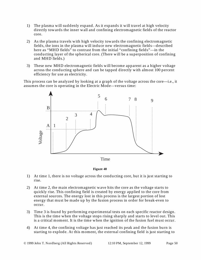
© 1999 John T. Nordberg (All Rights Reserved) 12:10 PM, September 12, 1999 Page 50
1) The plasma will suddenly expand. As it expands it will travel at high velocitydirectly towards the inner wall and confining electromagnetic fields of the reactorcore.
2) As the plasma travels with high velocity towards the confining electromagneticfields, the ions in the plasma will induce new electromagnetic fields—describedhere as “MHD fields” to contrast from the initial “confining fields”—in theconducting layer of the spherical core. (There will be a superposition of confiningand MHD fields.)
3) These new MHD electromagnetic fields will become apparent as a higher voltageacross the conducting sphere and can be tapped directly with almost 100 percentefficiency for use as electricity.
This process can be analyzed by looking at a graph of the voltage across the core—i.e., itassumes the core is operating in the Electric Mode—versus time:
Volta
ge
Time
A
B
1
23 4
56 7 8 9
Figure 40
1) At time 1, there is no voltage across the conducting core, but it is just starting torise.
2) At time 2, the main electromagnetic wave hits the core as the voltage starts toquickly rise. This confining field is created by energy applied to the core fromexternal sources. The energy lost in this process is the largest portion of lostenergy that must be made up by the fusion process in order for break-even tooccur.
3) Time 3 is found by performing experimental tests on each specific reactor design.This is the time when the voltage stops rising sharply and starts to level out. Thisis a critical moment. It is the time when the ignition of the fusion fuel must occur.
4) At time 4, the confining voltage has just reached its peak and the fusion burn isstarting to explode. At this moment, the external confining field is just starting to

© 1999 John T. Nordberg (All Rights Reserved) 12:10 PM, September 12, 1999 Page 51
react to the charged ions that are rapidly approaching it from within. The heightof the voltage at this point has the value “A” and is a critical design parameter.
5) Between time 4 and 5, the voltage suddenly spikes. This increase in voltage from“A” to “B” is the induced MHD voltage that resists, and, potentially stops theplasma instabilities. The reactor core and conducting circuit must be designed towithstand this maximum spike. This height difference—B minus A—must be lessthan the voltage A by 5–10% for safety sake. Otherwise, the MHD voltage will begreater than the confining voltage, and the voltage polarity could suddenlyreverse, with dangerous consequences. This spike in voltage should be relativelybrief and will end as the initial major instabilities are suppressed and dampened.
6) At time 6, the plasma has had its initial major instabilities suppressed anddampened. However, smaller, numerous instabilities continue to keep the averagevoltage relatively high. This excess voltage is where most of the useful energy willbe extracted. The electrical circuit must be designed to tap off the voltagedifference between voltage level B and A. If the voltage were to drop below A,then the fusion explosion would breach the confining field. (To maximize thelength of the burn at this stage, more fusion fuel is needed. However, the morefuel, the higher the peak voltage back at time 5 would be. This would requirebigger, stronger, more complex reactors.)
7) At time 7, the fusion burn has expended the bulk of its fuel, and the instabilitiesstop having enough energy to push against the confining field.
8) At time 8—without the addition of new fuel to the burn—the fusion process hasstopped. The electrical circuit must be designed to monitor voltage and cut off theany remaining confining voltage when this drop occurs.
9) At time 9, the voltage has dropped to zero. In initial designs, there would now bea period for cooling, safety checks, and maintenance. Then, the cycle would berepeated.
The main source of non-efficiency in these types of fusion reactors will come fromresistive heating of the core, which can be cooled—the heat being used for drivingsecondary steam generators.
Depending upon the design of the reactors it will be possible to create direct oralternating currents. In direct current designs, converters will be needed for conversionto alternating currents.
Magnetohydrodynamics and Plasma Instabilities
The main difficulty in all prior attempts at nuclear fusion has been various“instabilities” in the plasma that suddenly stop the fusion reaction and frequentlydamage the reactor. It is my contention that these “instabilities,” themselves, are very“strong” and “stable.” It is my contention that the sudden strength of the instabilities isa result of the cross product of the Electric and Magnetic fields in the plasma. In essence,all “instabilities” have been induced by time varying, or area varying electromagneticfields. They could be collectively called, “induced Poynting Vector Fields.”
© 1999 John T. Nordberg (All Rights Reserved) 12:10 PM, September 12, 1999 Page 52
For example, in Tokamak reactors, as the electric fields and magnetic fields that confineand heat the plasma build, the plasma rotates faster and faster in the torus. Eventually,when the fusion burn starts, the plasma is accelerated in new directions, inducing apowerful cross product of electric and magnetic fields, in a direction that can not beanticipated and counteracted in time. Without an appropriate containment field existingprior to the development the instability, the induced Poynting Vector is too powerful tobe contained. Inevitably, the containment fields collapse, and the plasma quickly cools,stopping the fusion burn.
Benefits of Spherical Electromagnetic Containment Field (40)
Many prior designs, such as Tokamaks, have not utilized spherical containmentgeometries. Only inertial confinement reactors have used spherical geometries forconfinement. In the new designs described within this document, the perfect symmetryof the sphere minimizes initial instabilities within the reactor core, thus maximizing thetime of the fusion burn.
Some instabilities are still expected to form inside these types of reactors. The expectedinstabilities will be identical to other previous attempts that used spherical inertialconfinement techniques, such as laser implosion of spherical D-T pellets. However, inthe new fusion reactor designs in this document, it is exactly these instabilities that willdrive the MHD process and be used to extract the fusion energy as useful electricalenergy. In earlier spherical inertial techniques, the plasma was allowed to expand andcool without attempting to confine the plasma further after the initial burn.
Thus, the main benefits of having a Spherical Electromagnetic Confinement Field(40)existing, prior to the fusion burn exploding, is that the fusion burn will: becontained, last longer, and push out on the Confinement Field to create energy in aMHD fashion.
Charged Particles/Neutral Particles Ratio
A fusion plasma is made of both charged particles—e.g., electrons, protons, etc.—andneutral particles—neutrinos, and neutrons the primary examples. Charged particles willinteract strongly with the confining fields. Since neutral particles still have a magneticmoment, it is expected they will interact at least weakly with the confining fields.However, the higher the percentage of charged particles in the plasma is, then the lowerthe percentage of neutral particles in the plasma will be, which is better.
It is assumed that the fusion fuel mixture will have some affect on the percentages ofcharged and neutral particles in the plasma. For example, a D-D mixture may be betterthan a D-T mixture, or perhaps, the other way around. In these early designs, attemptsat fine tuning the percentage of charged to neutral particles will be ignored.
MHD Interaction in Spherical Electromagnetic Containment Fields (40)
In the types of reactors described within this document, as an instability—appearing asa jet of plasma—travels with a velocity V away from the center of the fused material atthe center of the core and towards the Spherical Electromagnetic Containment Field

© 1999 John T. Nordberg (All Rights Reserved) 12:10 PM, September 12, 1999 Page 53
(40)—essentially, always at a right angle to the electric and magnetic fields, as a result ofthe perfect geometry of the sphere—the electrical charge of the moving plasma willinteract with the confining electric and magnetic fields via the magnetohydrodynamiceffect.
Creating this geometrical interaction is one of the key factors distinguishing thesedesigns and prior art.
This interaction will induce the magnitude of the confining fields to higher levels. In anelectric mode, the voltage across the core will increase. In a magnetic mode, themagnetic differential across the core will increase. The increase in the magnitude of theconfining field will be proportional to the magnitude of the energy of the chargedparticles in the instability. Since there exists a preexisting confinement field at the timeof the fusion burn, and since the instability induces new confining fields in directproportion to the size of the instability, the instability should dissipate and be confined.
Preexisting Confining Field versus Induced Confining Field
Thus, thus magnitude of the electric and magnetic fields over the core can be thought ofas having two components: the preexisting Spherical Electromagnetic ContainmentField (40), and the induced Spherical Electromagnetic Containment Field (40) If thecombination of the confinement field strength and induced strength is designed to begreater strength than the largest instability, then the fusion burn will remain essentiallyspherical until the fuel runs out.
Plasma particles, especially in the form of neutral particles, may penetrate SphericalElectromagnetic Containment Field (40) if the containment fields are not designed tohave a large enough initial strength.
If the too much energy is lost through neutral particles, then the fusion process will halt,and damage to the reactor could occur.
Description of an Example Plasma Stream (39) interacting with the SphericalElectromagnetic Containment Field (40)
To help visualize how this critical process works, imagine what the instabilities wouldlook like for a spherical target shortly after the implosion reverses direction to becomean explosion. At the point the plasma wall changes direction, the plasma will have ageometry approximating a sphere. Shortly after starting to explode, instabilities on thesurface of the sphere would start to appear. At this early stage, they would looksomething like knobs or bumps, as shown in Figure 41.
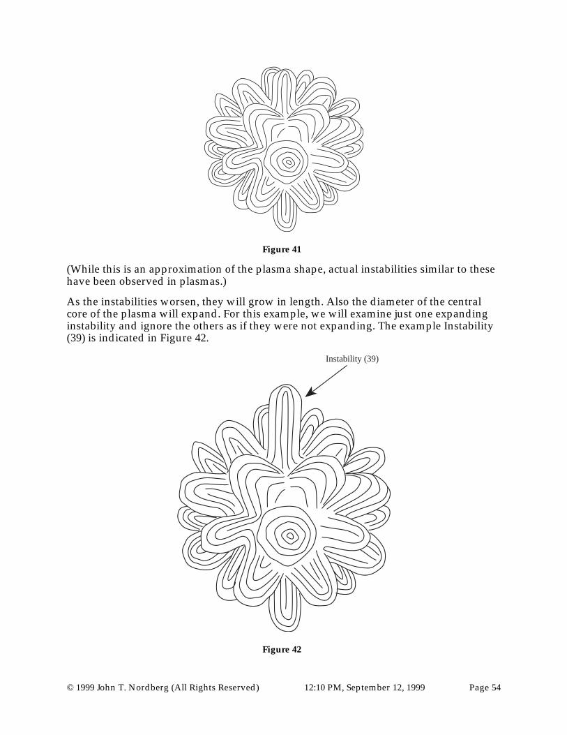
© 1999 John T. Nordberg (All Rights Reserved) 12:10 PM, September 12, 1999 Page 54
Figure 41
(While this is an approximation of the plasma shape, actual instabilities similar to thesehave been observed in plasmas.)
As the instabilities worsen, they will grow in length. Also the diameter of the centralcore of the plasma will expand. For this example, we will examine just one expandinginstability and ignore the others as if they were not expanding. The example Instability(39) is indicated in Figure 42.
Instability (39)
Figure 42

© 1999 John T. Nordberg (All Rights Reserved) 12:10 PM, September 12, 1999 Page 55
This instability is made up of plasma. The plasma is primarily made up of chargedparticles. The charged particles on the outside of the plasma are more likely to be thelighter particles, and therefore negative electrons, as shown in Figure 43. (It does notmatter for this example what the charge of individual ions in the plasma is however. Ifthe charge of the ions were positive, the net results would be the same.)
Figure 43
The example Instability is shown in Figures 43 and 44 moving away from the center ofthe plasma towards the confining wall of the fusion reactor with a velocity V. Inessence, it is acting as powerful current.

© 1999 John T. Nordberg (All Rights Reserved) 12:10 PM, September 12, 1999 Page 56
V
Figure 44
In the fusion reactor designs described in this document, the currents from theexploding instabilities interact with the Spherical Electromagnetic Containment Field(40), shown in Figure 45. Analyzing the example Instability's (39) current for anarbitrary angle of interaction with the Spherical Electromagnetic Containment Field(40)—in this example, acting in an Electric Mode—is shown in Figure 45.

© 1999 John T. Nordberg (All Rights Reserved) 12:10 PM, September 12, 1999 Page 57
V
B
E
ElectromagneticContainment
Field (40)
B
B
B B
B B BB
E
E
E
Figure 45
There are only two possible ways the Instability (39) may interact with the SphericalElectromagnetic Containment Field (40). First, the Instability (39) may induce newelectromagnetic fields that will combine with the preexisting Spherical ElectromagneticContainment Field (40) creating a more powerful Spherical ElectromagneticContainment Field (40). Second, the Instability (39) may be blocked by the SphericalElectromagnetic Containment Field (40). In essence, the Instability’s (39) growth willhalt. If instabilities are halted, then the fused material plasma fuel at the center of theReactor Core (1) will stay essentially spherical and harmonic. With these types ofreactors, both the possibility that the Spherical Electromagnetic Containment Field (40)will be increased, or that the fused material plasma fuel will stay spherical and

© 1999 John T. Nordberg (All Rights Reserved) 12:10 PM, September 12, 1999 Page 58
harmonic are good. Because an instability induces the Spherical ElectromagneticContainment Field (40) to higher values, its energy is dissipated and it is blocked. If theinstability is blocked, the fusion burn will last longer. If the instability induces newelectromagnetic fields that combine with the Spherical Electromagnetic ContainmentField (40), then the voltage across the core, if in the Electric Mode—or magneticdifferential across the core, if in the Magnetic Mode—will increase and will be availablefor creating useful electric energy by induction through the coils located around theContainment Circuit.
It is expected that both interactions will occur.
Looking closely at the details, the instability's current intersects with the existingElectric and Magnetic fields of the confining fields. The intersection occurs at rightangles. To summarize:
• The Instability’s (39) plasma current intersects the confining Magnetic field at aright angle.
• The Instability’s (39) plasma current intersects the confining Electric field at a rightangle.
• The confining Electric and Magnetic fields were already at right angles, by design.
Thus, the current must induce higher Electric and Magnetic fields in the confining field.Thus, all the requirements for inducing energy via MHD are present.
There are many implications because of this interaction between the instabilities and theconfining fields:
1) The instabilities will induce higher voltages or magnetic differentials across thecore
2) The instabilities will be blocked
3) The instabilities will be prevented from growing in the first place, in essence thefused fuel will remain harmonic
4) The confining fields will sap the energy of growing instabilities
5) The fusion burn will last longer
6) The plasma will be compressed to greater densities (which is actually a mootpoint if the fuel fuses into one particle)
7) The plasma will reach higher temperatures (which is actually a moot point if thefuel fuses into one particle)
8) The more powerful any particular individual instability is, the more powerful theinduced MHD field will be, and the more powerful the combined confining fieldand MHD field will be, thus locally blocking the instability
9) Large instabilities are not likely to occur, since the confining fields will inhibit andblock their formation, and sap their energy before they can grow to be large

© 1999 John T. Nordberg (All Rights Reserved) 12:10 PM, September 12, 1999 Page 59
10) The initial harmonics of the confining fields will have an effect on how harmonicthe fusion burn proceeds. Thus, it is beneficial to take all precautions in order tohelp the initial Spherical Electromagnetic Containment Field (40) to be highlyharmonic.
11) Non-harmonic Spherical Electromagnetic Containment Fields (40) may allow astrong instability to burst through the confining fields, possibly even causing theinstability to grow. As such an instability bursts through the confining field, adangerous jet of plasma will exist that could burn through very thick protectiveshields. Thus, catastrophic failure must be planned for. For example, if a powerfulplasma jet punctures the double walls of the reactor shield, which is filled withwater coolant, then, the coolant could suddenly explode. This requires that thereactor has an outer shield.
12) The initial confining fields must be stronger than the average large instability,otherwise possible combinations of the added MHD and confining fields couldoccur that would flip the polarity of the voltage across the core, or flip themagnetic field across the core.
13) The plasma will spherically pulsate—like a ringing bell—with a characteristicfrequency—which is unknown at this point—and will depend on many variablesof the reactor design. This pulsing plasma will create pulses of energy in theoutput circuit that will need a dampening mechanism before the current can goout into the power grid—most likely large banks of capacitors and coils.(However, the entire Confinement Circuit (1) and (2), will act as such adampening mechanism.) The peaks in the pulses will occur at the point theplasma is expanding outward with maximum acceleration. (In designs with twoor more cores, an outward pulsation in one core can be used to compress anothercore.)
14) Smooth harmonics within the initial confinement field will be reflected within theplasma as longer, smoother burns.
15) Poor quality harmonics within the initial confinement field will be reflectedwithin the plasma with shorter, non-smooth burns—possibly catastrophicrupturing of Conducting Spheres, Reactor Core(s), Coils, the Electrical Bus, andother components.
Reactor Efficiency
The overall efficiency of this type of nuclear fusion reactor can be roughly estimated bymultiplying the percent of energy carried away from the fusion burn by chargedparticles by the percent of energy converted directly to electricity by the MHD processin the conducting wall of the reactor core. For example, if 90% of the energy of thefusion burn is carried away in the form of charged particles, and if 10% of the energycreated by the MHD process is lost to thermal interaction within the conducting wall ofthe Reactor Core(s) (1), then the theoretical efficiency of such a reactor would be 81%.The actual final efficiency would be somewhat less due to thermal losses in theConducting Spheres (2). However, some of the lost heat in the Reactor Core(s) (1) andConducting Spheres (2) can be recovered using steam drive turbine generators.

© 1999 John T. Nordberg (All Rights Reserved) 12:10 PM, September 12, 1999 Page 60
Eventually, it might be possible to design the Reactor Core(s) (1) and ConductingSpheres (2) of such reactors with super conducting materials. If possible, the efficiencyof such a design could approach 100%. The only loss in efficiency would be due toneutral particles that can penetrate the confining field or add thermal losses to thereactor wall.
An unknown at this point is if the so-called “neutral” particles will also be deflected orslowed by the confining fields. Most neutral particles have magnetic moments that mayallow the neutral particles to be deflected to some extent by the massive SphericalElectromagnetic Containment Fields (40). Also, it is possible, that while a neutralparticle is “overall” neutral, it may have small, localized spots of electric and magneticcharge that may interact strongly with the confining fields rather than weakly. Thus,even the energy of neutral particles may be absorbed by the confining fields of thesereactor designs, pushing these reactor design’s efficiency to higher levels.
Active versus Passive Monitoring of Instabilities
There have been attempts to actively monitor confining fields in other types of reactors,such as in Tokamaks and Spheromaks, in order to actively increase the confining fieldstrength when an instability occurs. With the designs of the nuclear fusion reactors inthis document, the Electromagnetic Containment Fields (40) are passively—i.e., withoutcomputer interaction—self-healing. The confining forces are automaticallyelectromagnetically induced to greater values by the instability's MHD interaction withthe Spherical Electromagnetic Containment Fields (40). This process automaticallycloses the “wound” in the confining field, thus preventing the plasma from bleedingthrough. With these designs, there is no need to create sensors or a computer controlledfeedback system to try to monitor and respond to the instabilities.
Burn Duration
If the reactor core can be engineered to have enough strength, heat dissipationcapability, and current carrying capability—greater than the rate at which energy isreleased by the fusion burn—then it would be possible to contain the plasma until thefusion fuel is almost totally consumed. Fusion burns of minutes or even hours induration are possible. With the “No-Core” design, fusion burns of indefinite length arepossible. In some designs, plasma injectors could continuously inject small amounts ofnew fuel into the core to keep the fusion burn going.
The Danger of Polarity Reversals
As the fusion burn is proceeding, it is possible to describe the electromagnetic fields onthe core of the reactor in two parts: the initial confining fields created by the voltage ormagnetic field across the poles of the reactor core; and the later, plasma induced MHDfields. One potential problem in the nuclear fusion designs described in this documentis the electric and magnetic fields induced by the MHD process could be greater thanthe initial confining fields. If the induced MHD fields are less than the original confiningfields, then current or magnetic flow will remain in the same direction—the MHD fieldswill add to the confining fields. This will manifest itself by the voltage or magnetic fieldacross the conducting spheres and the core suddenly increasing. On the other hand, the

© 1999 John T. Nordberg (All Rights Reserved) 12:10 PM, September 12, 1999 Page 61
danger exists that if the induced MHD fields are larger in magnitude than the originalconfining fields, then current flow or magnetic field in the confining circuit couldsuddenly reverse direction. This could manifest itself by the voltage across theconducting sphere suddenly flipping values from + to -, to the values - to +, or themagnetic polarity flipping the values from N to S, to the values S to N.
It does not matter which direction an increased voltage or magnetic field appears acrossthe reactor core, the higher voltage or magnetic field could be utilized in eitherdirection. However, it would be better know, and control, which direction the current ormagnetic fields will flow for safety reasons. A sudden change in current flow ormagnetic fields could explode or vaporize equipment involved. Thus a major designfeature would be to design the yield of the fusion fuel to be less than the peak energy-absorption capability of the reactor. This capability is a function of many design featureswhich include: the total mass and material types of the reactor core; the thermal heatdissipation capability of the core; the active cooling capability of the reactor (whethernormally conductive or super conductive); the conductivity of the core as a function oftime and temperature over the course of the burn; the capacitance and inductance of theconfining circuit; and the ability of the electrical circuit to carry away the net MHDelectricity, which is also a function of the circuits maximum current load, capacitance,inductance, and conductivity.
Thus, the yield of the fusion fuel must be tailored to be less than the peak energyabsorption capability of the reactor. This can be visualized in the Figure 46.
Ene
rgy
Time
Fusion Fuel Yieldover time
Energy AbsorptionCapability of Reactor &
(Confinement Field)
FusionYield Peak
1 2 3
Lase
r P
ulse
Pea
k
Con
finem
ent P
ulse
Pea
k
Fus
ion
Yie
ld P
eak
Laser EnergyYield over time
Figure 46

© 1999 John T. Nordberg (All Rights Reserved) 12:10 PM, September 12, 1999 Page 62
Key details in Figure 46 are:
1) The peak of the fusion fuel yield is lower than the peak energy the reactor canabsorb
2) The reactor can absorb the energy faster than the energy will be released from thefusion burn. This is shown by the reactor's peak at 2 coming before the fuel's peakat 3.
3) The long-term ability of the reactor to absorb energy should be greater than thepeak energy release from the fusion fuel for safety considerations. For example, ifa reactor core with manufacturing imperfections was accidentally used, anabnormally large instability could occur and damage other areas of the reactor.
4) This graph also depicts the expected time-varying release of energy from thefusion fuel due to its interaction with the fusion reactor's confining fields. Theyield pulsates up and down. This pulsing in the yield would induce pulsing in theSpherical Electromagnetic Containment Fields (40).
5) The length of the fusion burn, as depicted in this graph, is partly dependent onthe initial strength of the Spherical Electromagnetic Containment Fields (40). Ifthey can not be maintained, then the fusion burn will cease before the fusion fuelis consumed.
This situation could be considered with an analogy using a hydroelectric dam. Ahypothetical dam is designed, with an empty reservoir, that would be big enough andstrong enough to stop a massive tidal wave and then, in a controlled fashion, let thewater poor out through the penstocks to electrical generators. The cores of these reactordesigns would be like the dam. Just as the dam must be strong enough to stop the initialtidal wave, the core's physical and electromagnetic strength must be strong enough tostop the fusion explosion. The penstock and generator is like the electrical circuit inthese reactor designs. Just like the penstock must have enough capacity for water toflow out and relieve the sudden pressure of the tidal wave before the dam would burst,these reactor's electrical circuits must have enough capacity for the electricity to flowout before the core or circuit would electrically burst.
Initial Critical Design Considerations
Initial critical design considerations for these reactors include:
1) A mechanism to place the fusion fuel inside the core of the reactor.
2) A mechanism to start an ignition burn inside the spherical reactor core.
3) Design the reactor core so that massive electromagnetic fields can be supported.Estimated sustained minimum induced magnetic field to be in the range of 0.5–5Tesla. Estimated peak magnetic field to be withstood briefly without bursting tobe in the range of 2-100 Tesla.
4) Design the reactor core to withstand massive forces from its electrons, which willcause Coulombic heating, Hall-effect forces, and others.

© 1999 John T. Nordberg (All Rights Reserved) 12:10 PM, September 12, 1999 Page 63
5) Design the reactor core so that it will not implode from the initial transport ofconfining energy, or explode from the latter fusion explosion.
6) Design the core so that it can be cooled, without the cooling process affecting thespherical harmonics of the Reactor Core's (1) Spherical ElectromagneticContainment Fields (40). This will likely preclude active cooling during the fusionburn and will likely require exceptional pre-burn and post-burn cooling ability.
7) Design an electrical circuit that can transfer to, and carry away from the coreextremely high electrical currents and maintain extremely high voltages.
8) Design a secondary cooling system that utilizes thermal heat from the core andelectrical circuit to power steam generators and increase efficiency.
Breeding Tritium with LithiumA design consideration that will not be fully addressed in this document, is the useLithium as a coolant for the core to breed new Tritium. Initial engineering concepts thatuse Lithium in these designs appear to be too dangerous. The massive electromagneticfields involved could create explosive currents within the Lithium that could burstcontainment walls and mix the Lithium with water—another coolant that must be usedfor reasons of economics. The possibility of the resulting explosive reaction that resultsfrom combining water and Lithium creates risks that may be too great to attemptbreeding of Tritium in these designs. However, it is possible that these reactors will beso efficient and powerful that Tritium may not be needed in the fuel. Instead, thesereactors may rely upon the fusion reaction of D-D fuel or a mixture of Deuterium andHelium 3. (Using Deuterium by itself would provide an almost infinite supply of fuel,but is harder to ignite than igniting mixtures of Deuterium and Tritium. The problemwith Tritium is that it is so rare that, in most fusion reactor designs, it must beartificially produced by using the interaction of Lithium and the neutrons released fromthe fusion reaction.)
High Voltage Containment Circuit
As shown in Figure 12 and Figure 13 the type of circuit needed for containment of theplasma can be quite simple. In the Electric Mode, it consists of a high voltage across aconducting sphere. In the Magnetic Mode, it consists of high Magnetic “voltage” acrossa conducting sphere. The points of contact between the conducting “wire” and the coredefine the poles of the sphere. However, while the circuits are simple, there are quite afew engineering hurdles that need to be solved in order safely maintain such a circuitand tap off the excess fusion energy.
The Exploding Wire Phenomena
When a large enough voltage is placed across a conducting wire it will vaporize andexplode. If a wire is exploded over a white background surface, the background surfacewill show regularly spaced transverse striations as is shown in Figure 47.

© 1999 John T. Nordberg (All Rights Reserved) 12:10 PM, September 12, 1999 Page 64
Figure 47
Exactly how the wire explodes depends on many variables: wire composition, voltage,wire resistance, wire length, wire diameter, initial wire geometry, etc. A entire sciencecould be devoted to this important idea.
(For example, thin strands of wire, woven in complex patterns, are used to create cablesresistant to this effect for use between lightning rods and grounding poles. See Figure50.)
As wire is exploded with increasingly more energy, the striations become sharper. Anexample is shown in Figure 48.
Figure 48
In general, these striations are a result of spherical electromagnetic waves sweepingthrough the wire. Where the spherical waves come to a point, or node, in the waves, theelectromagnetic fields become stronger, and move the electrons in the conductor faster.In essence, the heat becomes more intense at the nodes than at the antinodes. Thisdisparity in temperature vaporizes the wire locally at the nodes first. This creates thedashed pattern observed from exploding wires. Induced magnetic fields—which resultfrom the fast moving ionized plasma—further confine the exploding plasma, helping todirect the flow of the instabilities.
An example of how the electromagnetic waves vaporize the wire locally at the nodescan be seen in Figure 49.

© 1999 John T. Nordberg (All Rights Reserved) 12:10 PM, September 12, 1999 Page 65
Side-View of WireEnd-Viewof Wire
Primary EM Wave Nodes
Primary EM Wave Anti-Nodes
Temperature as a funciton of node location
Tem
pera
ture
Regions where wire first vaporize and explode.
Figure 49
In the lower part of Figure 49 is the side and end profile a round wire. It is believed,when a high-voltage current is set up across the wire, the most likely wave-form for theelectromagnetic wave, that sweeps over the wire, to take is a spherical wave where thewavelength is equal to the diameter of the wire. (Other wavelengths and wave-formsare possible, and can be greatly affected by how the voltage is connected to the wire.)
At the nodes of the waves, the local temperature is dramatically higher than at the anti-nodes. At the nodes, the electric field is focused to a very small spot. This intenseelectric field will induce local electrons to extremely high temperatures and velocities.This effect creates localized regions along the wire that vaporize and explode first—thatis, before vaporizing other areas such as at the anti-nodes.
These localized regions of exploding plasma, while primarily caused by focusedelectrical fields, will be further constrained by a radial pattern of intense magnetic fieldscurving around the wire according to alternating left-hand and right-hand rules.
The sharp “spikes” that are evident in the more violent examples of exploding wires arecaused by induced magnetic fields that axially confine the thin jets of plasmas as theymove away from the core of the wire. Thus, magnetic fields take at least two distinctforms. They curve around the wire, and they curve around the jets of plasma shootingaway from the wire at approximately right angles.
The danger of exploding the wires in the circuits required for these nuclear fusionreactors is not just great. If not planned for, such explosions are certain.

© 1999 John T. Nordberg (All Rights Reserved) 12:10 PM, September 12, 1999 Page 66
High Voltage Cabling
Two techniques used to prevent electrical wire or cable from exploding when highvoltages are applied are: to use many small strands of wire instead of one large strand;and to weave or twist the individual strands to make a larger wire or cable, as is shownin Figure 50.
Figure 50
These types of cabling are used in lightning protection systems. The purpose of usingthin strands is it reduces the radius of any individual conducting surface area. Thisreduces the wavelength of any resulting electromagnetic waves the follow along thewave guide formed by the strand. Shorter electromagnetic waves reduce the amount ofelectrons that can be piled up or focused at the nodes of a wave. The weaving, braidingand twisting of individual strands reduces the effects from induced magnetic fields. Themagnetic fields tend to have smaller, more complex fields and interactions. Thisprevents the intensity of any particular wave from growing and creating localized hotspots that would melt or explode the cabling. The drawback to such cabling is, if overallharmonic wave patterns are desired, then this type of cabling creates non harmonicpatterns, or patterns that are too complex to easily understand and control.
Alternative Design Variations
Coils VariationsHemispheric Coils (6) are used in the preferred embodiment. However, they areuntested. There are many other possible coil designs that could be used instead. Theyfall into two major categories: coils that create Electric Mode operation; and coils thatcreate Magnetic Mode operation. Magnetic Mode operation is preferred because, ingeneral, Electric Mode operation can cause electrons to pile up and burn outcomponents.
In general, the main Electrical Circuit or Magnetic Circuit—i.e., the Containment Circuitmade up of Conducting Spheres (2) and Reactor Core(s) (1)—described for these nuclearfusion reactor designs—with the exception of Straight-Line Designs—are closed circuits.

© 1999 John T. Nordberg (All Rights Reserved) 12:10 PM, September 12, 1999 Page 67
That is, they form a loop, with no “end” of the circuit directly connected to thecommercial power grid. Thus, the only way of adding or extracting energy to the closedloop, and controlling the flow of the energy around the closed loop, is by usinginductive coils.
There are three main types of coils that could be used for these purposes: normalwound coils; Rowland Ring coils; and hemispheric coils.
Normal Coil
Normally wound coil are shown in Figure 51.
a b c d
Figure 51
The cylindrical coil in (a) is one of the most common types of coils, it produces a simple,very well understood magnetic field. The strength of the magnetic fields created bythese coils is somewhat limited.
The concentric cylindrical coils in (b) combine their magnetic fields, thus creatingstronger magnetic fields. Some of the world's strongest magnetic fields are created bymagnets that are wound in this way. The more powerful designs using this type of coilmust be structurally reinforced both on the inside and out and must be provided withpowerful cooling mechanisms.
The helically wound coils in (c) can provide relatively strong magnetic fields but havesome harmonics problems. It is difficult for powerful currents to change directionquickly. At the center of a helical coil, the lead changes direction abruptly—see thecenter of the coil in Figure 51 (c)—and can lead to problems.
The coil in (d) is a combination of cylindrical and helical designs. It can produce largemagnetic fields but because of the back and forth, or random, winding patternstypically used in this design, the magnetic fields might not be harmonic enough forthese nuclear reactor designs.
Each of these coil types could be used to induce magnetic fields—and indirectly, electricfields over the conducting spheres—in the containment circuits of these nuclear fusion

© 1999 John T. Nordberg (All Rights Reserved) 12:10 PM, September 12, 1999 Page 68
reactor designs. These designs do lend themselves to effectively inducing harmonicelectromagnetic fields over a sphere. However, there are other reactor designs moreappropriate for coils such as these. They use a straight-wire type of Solid Conductor (60)with a circular cross section—See Figure 68—rather than a circuit of sphericalconductors. (The design in Figure 68, one of my earliest designs, is very dangerous. Ibelieve that is very susceptible to the exploding wire phenomena.)
Rowland Ring coils
A Rowland Ring coil is donut shaped coil. The current typically flows through the coilas is shown in Figure 52.
i (current)i (current)
Typically ironor hollow core.
B
B
B
BB
B
Figure 52
Rowland Ring coils sometimes have a solid, soft-iron core. Such cores allow highermagnetic fields, but only up to a point. Without a core, the coil is less efficient, but it ispossible to obtain much higher magnetic fields by using brute strength—by using moreturns and higher currents.
All Rowland Ring coils used in the designs described in this document will be designedfor very strong currents and magnetic fields. It is assumed that all of the Rowland Ringcoils in these designs are completely covered by a high-strength mechanical shield andcooling system.
The Electric and Magnetic Interaction of Coils with Conducting Spheres
When an electric current flows through a coil, according to Ampére's Law, the coilinduces a magnetic field. The magnetic field times the area of the coil gives the magneticflux of the coil.

© 1999 John T. Nordberg (All Rights Reserved) 12:10 PM, September 12, 1999 Page 69
If the current through the a coil is changing, then the induced magnetic flux through thecoil is changing. According to Faraday's Law of induction, as the magnetic flux ischanging, the coil will induce an EMF across the coil.
A coil can be placed next to a conducting sphere. If a current is set up through the coil,so that it grows rapidly from zero to some large value, then the current in the coil willinduce electromagnetic fields in the conducting sphere.
According to Lenz's Law, which applies to closed conducting circuits, the induced fieldsin the conducting spheres will appear in such directions as to oppose the changes thatproduced them.
Various configurations of coils can create different combinations of electric andmagnetic fields on the surface of the sphere. For example, a Rowland Ring coil willinduce electromagnetic fields over a conducting sphere in the opposite manner as aregular cylindrical coil, as is shown in Figure 53.
i (current)
i (current)
B
B B
BB
B
B
B
B
E
E
E
i (current)
i (current)
BBBBBB
B
B
B
B
B
E
E
E
E
E
B
B
B
E
E
EEEEEEE
E
E
E
Interaction ofa Rowland Ring coil's E & B fields with
a conducting sphere's E & B fields.
Interaction ofa normal coil's E & B fields with
a conducting sphere's E & B fields.
Figure 53
There is a significant advantage and disadvantage to using either types of coils. ARowland Ring coil that induces smooth electromagnetic fields in conducting sphereswould be easy to design, compared with other coil types. This is important forharmonics. All that is needed is for the wavelength of the coil to match the wavelengthof the sphere. Also, if the Rowland Ring coil has a soft iron core, then the Rowland Ringcoil will efficiently produce large magnetic fields. An added advantage to a RowlandRing coil having a soft iron core is that this inhibits the flipping of the polarity—a keysafety consideration—due to the phenomena of hysteresis in the soft iron core.However, a soft iron core limits Rowland Ring coil designs to “large” magnetic fields,that is, inhibiting induction of “massive” magnetic fields. Without the soft iron core,

© 1999 John T. Nordberg (All Rights Reserved) 12:10 PM, September 12, 1999 Page 70
and using the shear brute force of large, brief currents, a Rowland Ring can producemassive magnetic fields.
In Figure 53, note how the rotation of the magnetic field in the Rowland Ring isopposite to the rotation of the magnetic field in the conducting sphere—according toLenz's Law. Also, note how the electric fields sweep over the sphere from pole to pole.This is the disadvantage to using a Rowland Ring coil to induce electric and magneticfields in the conducting sphere. The electric field sweeping from pole to pole over theconducting sphere will create a current flow across the sphere. This will concentrateelectrons one pole. The electrons will build up only to a point before they will arc acrossto the next sphere. This arcing will damage the conducting spheres and weld themtogether. Tests will be required to prove how damaging this will be however.
It is possible that the magnetic fields induced around the sphere by a Rowland Ring willlimit the actual flow of the electrons. In essence, the conducting sphere may act as if:
• there is a large voltage across the sphere—from pole to pole
• there will be a massive resistance across the sphere—from the magnetic fields
• and there will be only a small current flow.
On the left side of Figure 53, note how the magnetic field in the coil is induced by thenormal coil’s current, and how the coil’s magnetic field opposes the induced magneticfield sweeping over the Conducting Sphere (2) from pole to pole—according to Lenz'sLaw. Also, note how the electric fields sweep over the sphere in counter-rotatinghemispheres. This is an advantage of using regular coils to induce the electric andmagnetic fields over the conducting spheres. Because the fields in this configurationpush the electrons in counter-rotating directions around each hemisphere, there is nonet electron migration around the main conducting circuit. In essence, the mainconducting circuit would not conduct electrons, it would conduct a magnetic field. Itwould be a magnetic circuit rather than an electric circuit.
As far as the ability of the confining fields at the core are concerned, there is nodifference between using an Electric or Magnetic Circuit.
The main drawback in using normal coils is they would be more difficult to design thanRowland Ring Coils or Hemispheric Coils. Because of the pattern in how the wire wrapsin the normal coil, the induced magnetic field would not be as smooth as with the fieldsinduced by the Rowland Ring coil. Two possible solutions for creating smoother fieldswould be to use parallel helical coils or Hemispheric coils. Parallel helical coils areshown in Figure 54.
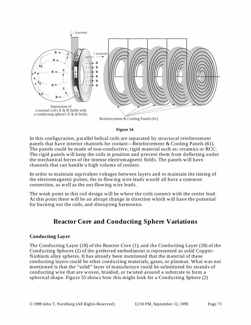
© 1999 John T. Nordberg (All Rights Reserved) 12:10 PM, September 12, 1999 Page 71
i (current)
i (current)
BBBBBB
B
B
B
B
B
E
E
E
E
E
E
E
E
Interaction ofa normal coil's E & B fields with
a conducting sphere's E & B fields.
E
Reinforcement & Cooling Panels (61)
Figure 54
In this configuration, parallel helical coils are separated by structural reinforcementpanels that have interior channels for coolant—Reinforcement & Cooling Panels (61).The panels could be made of non-conductive, rigid material such as: ceramics or RCC.The rigid panels will keep the coils in position and prevent them from deflecting underthe mechanical forces of the intense electromagnetic fields. The panels will havechannels that can handle a high volume of coolant.
In order to maintain equivalent voltages between layers and to maintain the timing ofthe electromagnetic pulses, the in-flowing wire leads would all have a commonconnection, as well as the out-flowing wire leads.
The weak point in this coil design will be where the coils connect with the center lead.At this point there will be an abrupt change in direction which will have the potentialfor burning out the coils, and disrupting harmonics.
Reactor Core and Conducting Sphere Variations
Conducting Layer
The Conducting Layer (18) of the Reactor Core (1), and the Conducting Layer (18) of theConducting Spheres (2) of the preferred embodiment is represented as solid Copper-Niobium alloy spheres. It has already been mentioned that the material of theseconducting layers could be other conducting materials, gases, or plasmas. What was notmentioned is that the “solid” layer of manufacture could be substituted for strands ofconducting wire that are woven, braided, or twisted around a substrate to form aspherical shape. Figure 55 shows how this might look for a Conducting Sphere (2)

© 1999 John T. Nordberg (All Rights Reserved) 12:10 PM, September 12, 1999 Page 72
Conducting Layer (18)
Non-ConductingCore (19)
Conducting Layer Strands (41)(Pointing out of page)
Conducting Layer Strands (41)(Parallel to page)
Figure 55
In Figure 55, the Conducting Layer Strands (41) are simply wound around the Non-Conducting Core (19). In essence, they create thousands of closed loops of conductors.This method would work in the Magnetic Mode, but probably not work in the ElectricMode.
Figure 55 does not represent any weaving, braiding or twisting of the strands as shownin Figure 50. However, with a much higher cost of manufacture, this is possible. Theadded benefits of this method of manufacture versus the potential benefits—reducingthe chance that individual strands will burn out—does not seem worth the extra cost ofmanufacture at this point.
Super Conductors
It would be preferable, if the Conducting Layer (18) of the Reactor Core (1), and theConducting Layer (18) of the Conducting Spheres (2) and the conducting material inany induction coils used in these designs were made of a super-conducting material. Atthis point, in the history of super-conducting materials, the costs associated withmanufacturing a nuclear fusion power plant following these designs and using super-conducting materials would appear to be too high. The modular form of these reactordesigns allows swapping out old materials with new as they become cost effective.
An example of a possible super-conducting material would include, but not be limitedto, multi-filamentary Nb3Sn and NbTi superconductors.

© 1999 John T. Nordberg (All Rights Reserved) 12:10 PM, September 12, 1999 Page 73
Other Conducting Layer Materials
The conducting layer within a core could be made of:
• Copper and copper alloys
• Aluminum and aluminum alloys
• Iron, steel and other ferrous alloys
• Silver, and silver alloys
• Gold, and gold alloys
• Titanium, and titanium alloys
• Vanadium, and vanadium alloys
• Magnesium, and magnesium alloys
• Other conductive metals and metal alloys, including but not limited to: Chromium,Lead, Molybdenum, Platinum, Tin, Tungsten, Mercury and Zinc.
• Conductive forms of glasses, ceramics, plastics and polymers, composites, andmulti-compound materials.
Plasma Core
One possible form for the conducting layer of the Conducting Spheres (2) or the ReactorCores (1) is the plasma form. The plasma form offers some key benefits. First, cooling ofthe conducting layer is not required, it must be hot to be in plasma form. Second,refurbishment of this layer is not required. Third, costs of materials for this layer arelow. Fourth, Hall and Coulombic forces tearing this layer apart are not an issue.
The key issue is, how can the plasma form the spherical shape needed? At first, thisissue may seem difficult. Difficult Reactor Core and Conducting Sphere designs willfollow. But it may not be difficult at all. A simple solution for using plasmas, at leastwithin the Reactor Core will be presented.
First, in Figure 56 is one “solution” that may be very difficult and problematic.
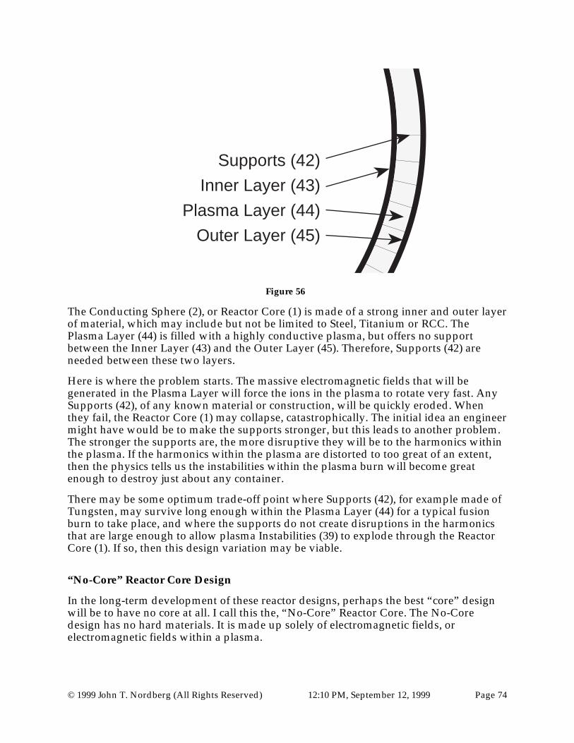
© 1999 John T. Nordberg (All Rights Reserved) 12:10 PM, September 12, 1999 Page 74
Inner Layer (43)
Plasma Layer (44)
Outer Layer (45)
Supports (42)
Figure 56
The Conducting Sphere (2), or Reactor Core (1) is made of a strong inner and outer layerof material, which may include but not be limited to Steel, Titanium or RCC. ThePlasma Layer (44) is filled with a highly conductive plasma, but offers no supportbetween the Inner Layer (43) and the Outer Layer (45). Therefore, Supports (42) areneeded between these two layers.
Here is where the problem starts. The massive electromagnetic fields that will begenerated in the Plasma Layer will force the ions in the plasma to rotate very fast. AnySupports (42), of any known material or construction, will be quickly eroded. Whenthey fail, the Reactor Core (1) may collapse, catastrophically. The initial idea an engineermight have would be to make the supports stronger, but this leads to another problem.The stronger the supports are, the more disruptive they will be to the harmonics withinthe plasma. If the harmonics within the plasma are distorted to too great of an extent,then the physics tells us the instabilities within the plasma burn will become greatenough to destroy just about any container.
There may be some optimum trade-off point where Supports (42), for example made ofTungsten, may survive long enough within the Plasma Layer (44) for a typical fusionburn to take place, and where the supports do not create disruptions in the harmonicsthat are large enough to allow plasma Instabilities (39) to explode through the ReactorCore (1). If so, then this design variation may be viable.
“No-Core” Reactor Core Design
In the long-term development of these reactor designs, perhaps the best “core” designwill be to have no core at all. I call this the, “No-Core” Reactor Core. The No-Coredesign has no hard materials. It is made up solely of electromagnetic fields, orelectromagnetic fields within a plasma.

© 1999 John T. Nordberg (All Rights Reserved) 12:10 PM, September 12, 1999 Page 75
The key to the No-Core design is a Conducting Circuit made of Conducting Spheresthat is designed so well that the Magnetic Fields over the core area exceed about 4 Teslaat a distance of about 2.5 meters from the center of the core area. At 4 Tesla, a 5 meterdiameter core would focus about 1.2 exawatts of energy at the focal point of the core.(At 5 Tesla, 1.875 exawatts, at 6 Tesla 2.7 exawatts, at 7 Tesla 3.675 exawatts, at 8 Tesla4.8 exawatts, at 9 Tesla 6.075 exawatts, and at 10 Tesla 7.5 exawatts would be focused atthe center of the core area!)
To reach such high magnetic fields at such large diameters would require extremelyoptimized reactor designs that may involve massive amounts of super conductingmaterials and unheard of cooling requirements. The capacitor and triggeringrequirements to start the process would be equaling daunting. However, theengineering is straightforward. There are no magical physics barriers to break through.The battle cry would simply be: more super conducting material, more cooling, morecapacitors.
At these energies, many problems with earlier designs would be moot. There would beno need to design complex reactors cores—the No-Core design would have to be used.There would be no need to have lasers to trigger the burn—the confinement field wouldbe powerful enough to be the triggering field. There would be no complexity of havingto trigger the lasers and containment circuit in the proper sequence since there would beno lasers.
A possible No-Core containment circuit might look like Figure 57.
The "No-Core" nuclear fusion reactorcontains the fusion burn with Electric,Magnetic & Poynting Vector fields.
Figure 57
The No-Core Core Area would look like Figure 58.

© 1999 John T. Nordberg (All Rights Reserved) 12:10 PM, September 12, 1999 Page 76
Plasma Injector (46)
Inner Shield (9)
ElectromagneticContainmentFields (40)
Anode/CathodeConducting Spheres (13)
Figure 58
The Inner Shield (9) would have a wider diameter to help make insure that nodisruption to the harmonics results from the shield. The Electromagnetic ContainmentFields (40) would provide containment of the fusion burn, and provide ignition of thefuel to begin with. The electromagnetic field orientation would be in the Magneticmode. The Anode/Cathode Conducting Spheres (13) would be the weak link. Whenthey melt, the harmonics would be lost. A fusion Fuel Pellet (36) could be prepositionedin the Inner Shield (9) via Ablatable Wires (35) similar to those shown in Figure 9,and/or, fusion fuel could be injected into the Electromagnetic Containment Fields (40)via a Plasma Injector (46). The advantage of an injection system is it would allow thefusion burn to be continually fed with additional fuel.
A variation would be to coat the Anode/Cathode Conducting Spheres (13) with somematerial, such as thin layer of Boron impregnated high-temperature ceramic to helpthem survive longer. Or, it might be possible to actively cool the spheres. The problemin cooling the spheres is that half of each sphere is inside the Inner Shield where nocooling equipment could be placed without disrupting the harmonics of theElectromagnetic Containment Fields (40). If only part of each sphere is cooled, then itwould create differences that would likely disrupt the electromagnetic harmonics of thecontainment field.
Most likely, the cooling plan would be to pre cool the entire circuit and operate untilheating disrupts the harmonics. It is possible that burns of several minutes could occurwith such a technique. This would not be bad. Thermonuclear fusion burns of severalminutes would give off tremendous amounts of energy.
There seems little doubt that the limits of this design would be in cooling theAnode/Cathode Conducting Spheres (13) rather than in fueling the burn area.
The No-Core design emphasizes a key detail of these patents. The design of the corearea depends not upon materials selection, but on the formation of powerful, spherical,

© 1999 John T. Nordberg (All Rights Reserved) 12:10 PM, September 12, 1999 Page 77
electromagnetic fields, that focus energy at the center of the core area. The other keydetail is how the same circuit can not only focus energy on the center of the reaction, butthe opposite, how energy coming out of the center of the reaction can be absorbed bythe circuit via the MHD process. If this process was not equal and opposite, then thedesign would not work.
RCC/Boron (23) & RCC Layers (24), (26), (27) in Reactor Core
The element carbon takes a wide range of forms from amorphous carbon, to Graphite,to Graphite fibers, to Diamond. Some of these forms, such as Graphite and Graphitefibers can be highly conductive. Some forms of carbon, such as amorphous carbon(lampblack) are relatively non conductive. Tests must be conducted to test the best formof carbon for layers (23), (24), (26), and (27) as shown in Figure 6. In general, conductiveor non conductive forms could be used. It is assumed at this point, that the nonconductive forms will perform better, due to smaller eddy currents, smaller inductivelosses, smaller thermal losses, and the possibility of being affected by massive Hall andCoulombic forces.
Since materials can change forms under high temperatures, pressures, andelectromagnetic forces, it is assumed that the material characteristics will vary over timeand possibly reduce the effectiveness of some or all of the Reactor Core (1) materials.Tests will be needed to determine the longevity of these components.
Secondary Diamond Manufacture
In the center of the Conducting Spheres of the preferred embodiment will beamorphous carbon. This material is essentially non conducting when compared withCopper-Niobium Conducting Layer (18). However, after repeated use, under hightemperatures, pressures and electromagnetic forces—highly resonant electromagneticforces—it is expected that the amorphous carbon will be transformed into other formsof carbon, including graphite and diamond. It is not the intended purpose of thesefusion power plant designs to manufacture diamonds. However, they may be extremelyefficient at doing exactly that. If the Non Conducting Fill (19) in a Conducting Sphere(2), or if carbon layers (23), (24), (26), (27) within the Reactor Core (1) transform intomore conductive forms of carbon, then failure may occur due to sudden increases incurrents within these components of the reactor.
Thus, to offset costs, to remove radioactive materials, and to prevent failure of these keycomponents, the Conducting Spheres (2) and the Reactor Cores (1) must be refurbishedat regular intervals. This will involve removing any diamonds forming at the center ofConducting Spheres (2).
Containment Circuit Variations
Circuit design
These designs need a closed electric or magnetic circuit for the confinement circuit. Theconducting spheres must be placed in a straight, circular or oval geometrical fashion.

© 1999 John T. Nordberg (All Rights Reserved) 12:10 PM, September 12, 1999 Page 78
Straight-Line Containment Circuit Designs
Tap Voltage &Confining Voltage
Rowland Ring Coils (47)
Magnetic Fields indicateElectric Mode of Operation
Figure 59
Figure 59 represents a type of straight-line configuration. It utilizes Rowland Ring Coils(47), and operates in the Electric Mode. In other words, the magnetic fields lines are asin Figure 12. The key to this design is very powerful, and harmonic coils. There is nooval or circular circuit in this design. The load is connected almost directly to the circuit.(There would be circuitry that includes capacitors and DC to AC inverters between theReactor and the load.)
The number of Conducting Spheres (2) in this design can be increased to improveharmonic over the core area, or reduced to reduce the overall reactor design costs. Thedesign in Figure 59 has 4 Conducting Spheres (2). The number of Conducting Spheres(2) could be reduced to 2 or 0. If zero Conducting Spheres (2) are used, then an almostperfect set of Hemispheric Coils would be needed to enclose the core area. While thismight be the limit to reducing these designs to a minimum set of components, I do notbelieve anyone has the capability to manufacture such coils at this time.

© 1999 John T. Nordberg (All Rights Reserved) 12:10 PM, September 12, 1999 Page 79
Circular Containment Circuit Designs
Figure 60
Circular Designs to not seem to offer an advantage over other designs except perhaps inreduced cost. The number of Reactor Cores (1) can be increased to provide more power,or reduced to minimize costs. The number of Conducting Spheres (2) can be increasedto improve harmonics, or reduced to minimize costs.
Oval Containment Circuit Designs
Figure 61
There is a symmetry problem with the circular and oval layouts. If a conducting sphereis analyzed, it is found that either the electric or the magnetic field sweeps over thesphere from pole to pole—in the Electric Mode or Magnetic Mode. However, the polesof the spheres are not perfectly aligned—pole to pole—in the curved sections of thecircular or oval layouts. There is an offset as shown in Figure 62.

© 1999 John T. Nordberg (All Rights Reserved) 12:10 PM, September 12, 1999 Page 80
Offset anglearound curves
Offset poles around curves
Distance aroundConducting Spheres
is not equalaround curves
shorter
longer
Figure 62
Because the poles are not aligned, the electromagnetic wave takes longer to sweeparound the outside edge of the conducting sphere than the inside edge. This pathdifference is where the bulk of eddy currents and heat loss in these designs will occur. Itis the main problem that might prevent these reactor designs from working well.
If the track were enlarged by adding more conducting spheres then this effect would belessened. If it had less conducting spheres, then this mismatch between the poles wouldbe greater. The smaller the quantity of conducting spheres in the track design, thegreater the mismatch between the poles will be, and thus, the greater the eddy currents,the greater the Coulombic heating and the greater the loss of efficiency will be. Thelarger the track, and quantity of conducting spheres, the less the mismatch between thepoles will be, but the greater the cost of the reactor will be.
A possible solution to this problem is having variable cooling for the ConductingSpheres (2) in the curved portions of the Conducting Sphere Track (4). If the coolant waspumped into the track from the outside edge of the track, and removed from the insideedge of the track, then the outside of the Conducting Spheres would be slightly moreconductive, and the inside of the Conducting Spheres would be slightly less conductive.This might reduce the non harmonics caused by the offset of the poles to the point ofnot being a factor.
The advantage of an oval track is: there are a number of conducting spheres adjacent toeach side of the reactor core that are aligned in a straight line. This would allow theeddy currents to diminish in each successive conducting sphere in the straight-lineportion of the oval leading in and out of the Reactor Core (1). This would tend to “cleanup” the main electromagnetic wave and allow for a more harmonic wave to pass overthe reactor core. Once again, here is a situation where there are trade-offs that createquestions that only experiments with different configurations of reactor designs anddifferent materials can answer. However, I believe these are optimization and costreduction problems, not fundamental questions of whether these reactor designs willwork.

© 1999 John T. Nordberg (All Rights Reserved) 12:10 PM, September 12, 1999 Page 81
In the preferred embodiment, there are 31 conducting spheres and one reactor core,each sphere with a 5 meter outside diameter.
Figure 63
Thus, the mean center path-length of this example circuit would be 160 meters long.
Multi-Core Reactors
Initially, the fusion reactors built on these designs would probably have one core perelectrical circuit. Later, as the design variations are perfected, at different price points, itwill be possible to create reactors with different numbers of cores. Each core would beanalogous to a piston in a gasoline engine. The energy produced from one igniting corecould be used to compress the next core in the electrical circuit while excess electricity issiphoned off using induction coils.

© 1999 John T. Nordberg (All Rights Reserved) 12:10 PM, September 12, 1999 Page 82
In Figure 64 two major design variations are demonstrated: the track is circular, andthere are two Reactor Cores (1).
Figure 642-Core Circular Circuit Design
An advantage of a two Reactor Core (1) design is that one Reactor Core (1) can beigniting and compressing the fuel in the other Reactor Core (1). The circular designreduces costs as compared to an oval design.
In Figure 65 two major variations are demonstrated: the track is oval, and there are twoReactor Cores (1).
Figure 652-Core Oval Circuit Design
An advantage of a two Reactor Core (1) design is that one Reactor Core (1) can beigniting and compressing the fuel in the other Reactor Core (1). The oval designimproves harmonics as compared to a circular design.

© 1999 John T. Nordberg (All Rights Reserved) 12:10 PM, September 12, 1999 Page 83
In Figure 66 two major design variations are demonstrated: the track is circular, andthere are four Reactor Cores (1).
Figure 664-Core Circular Circuit Design
Increasing the number of Reactor Cores (1) is possible, but does not seem to offer anykey benefits over a 2 Core design. The complexity of timing more than 2 cores appearsto be a major drawback.
Conducting Sphere Wavelengthto Reactor Core Wavelength
In all design variations shown so far, the diameter—or wavelength—of the ConductingSpheres (2) and Reactor Cores (1) were the same. Observations of planetary nebulaeusing the Hubble Space Telescope indicate that there would be an advantage to havingConducting Spheres (2) that have wavelengths that are larger than the wavelengths ofthe Reactor Cores (1). An example, of such a planetary nebula is shown in Figure 67.
Figure 67

© 1999 John T. Nordberg (All Rights Reserved) 12:10 PM, September 12, 1999 Page 84
The ratio of the wavelength of the Conducting Spheres (2) to the Reactor Cores (1) couldbe 2:1, 3:1, 4:1, and so on. A design like this amplifies the energy transmitted from theConducting Spheres to the core area and reduces the stress on the Conducting Spheres(2). An example of such a design is shown in Figure 68. The Diameter of the outer lobesin the planetary nebula in Figure 67—equivalent to the Anode/Cathode ConductingSpheres (2)—is a multiple of the diameter of the central star—equivalent to the ReactorCore (1).
(Note: Figure 67 visually shows how the electromagnetic confinement techniques inthese reactor designs work. There are two obvious shells of plasma in both lobes of thisplanetary nebula—which is not uncommon for planetary nebulae. There is an inner andan outer shell in each lobe. The outer plasma lobes are being ejected from the core of thecentral star. The inner plasma lobes are being created by nuclear explosions within eachlobe. They are trying to explode outward but are being confined. The explosions withinthe lobes are pushing out in a MHD type fashion, strengthening the confining forcesprovided by the outer layers of each lobe. This is an astronomical example of the self-healing design feature of these reactor designs. Because the electromagneticconfinement provided by the outer layers is not completely spherical, the plasma fromthe explosions within the lobes can vent out the two ends of the nebula. The reactordesigns within this document explicitly are designed to close the ends of the core area toprevent plasma from escaping like this.)
Figure 68 on page 110
This is a very advanced design. It has many advantages over the preferred embodiment.The main disadvantage is the increased sophistication and cost of components. Detailsof the Figure 68 design are:
• It is a No-Core design.
• It is a Dual Reactor Core (1) design.
• It operates in the AC mode.
• The left and right halves of the Conducting Sphere Track (4) are mounted onmassive Core Wavelength Adjustment Tracks (48) that allow the two halves to beadjusted in a left-to-right direction. (This allows fine tuning of the core wavelengthduring the burn. This will be important for long-duration burns as thermalexpansion and contraction causes changes in the primary wavelength of theelectromagnetic fields.)
• It uses hemispheric coils.
• It does not use lasers since implosion, ignition and confinement are performedsolely by the conducting circuit.
• It uses plasma fuel that is continuously replenished via Plasma Injectors (46).
There are many advantages to this design. First, because of the Core WavelengthAdjustment Tracks (48), the reactor can be continually adjusted to optimize theharmonics, even if thermal expansion of Conducting Spheres (2) occurs. Second, as onefusion reaction explodes, it will implode the other fusion reaction. The two cores cancontinually cycle back and forth like a two piston engine—creating an Alternating

© 1999 John T. Nordberg (All Rights Reserved) 12:10 PM, September 12, 1999 Page 85
Current. But in this case, at the center of the Reactor Cores Areas will be two pulsatingstars. The burn length of this design is potentially days or weeks—or longer—depending on active cooling capabilities.
Alternate Core DesignsThe core must be designed to be highly conductive or super conductive. One likelymaterial choice would be to use copper, or a copper alloy.
A Copper alloy, Cu-Nb, will be used as an example for the conducting layer in thisdocument but does not limit from a patent's legal point of view the use of otherconducting or superconducting metals, ceramics, fluids, plasmas and materials. The keydesign aspect is placing a spherical conducting or superconducting material around anuclear fusion reaction for the purposes of confining the reaction and extracting energyfrom the reaction. (Or, a Spherical Electromagnetic Confinement Field (40) in the “No-Core” designs.)
Some possible copper alloys include, but are not limited to: Cu, Cu-Al203, Cu-Ag, Cu-Nb, Cu-St.St., Cu-Be.
Some possible super-conducting materials include: niobium-titanium; and ceramics.
Some possible fluids include: liquid lead, liquid lithium.
Some possible gases include: vaporized water, and Xenon.
A vacuum is also a possibility as is explained in the “No-Core” reactor.
As the large electromagnetic fields are generated over the conducting layer of the core,mechanical forces are exerted on the material of the conducting core itself. Electricalenergy within the core is converted to heat as the electrons in the material are excitedand collide with atoms. In order to withstand these mechanical forces and stresses, andto minimize heating of the conducting layer of the core, a conducting material thatcombines both mechanical strength and electrical conductivity is needed. However, itappears that these two requirements oppose each other. Mechanically strong materialsappear to be poor conductors, and good conductors appear to be mechanically weak.
If copper, or some other similar conductor that could easily melt were used, then theremust be an inner wall to protect the conductor from the heat of the fusion reaction,otherwise the conducting layer would melt. Thus, since the conducting layer will beprone to melting, it must be shielded internally by a non-conducting inner wall. Thepurpose of the inner wall is not necessarily to completely prevent the melting of thecores. For a commercially viable reactor, all that is needed, is to significantly delay theheating of the conducting layer.
A shield material similar to that used to protect the exterior of space craft and rockets—such as space shuttle's exterior—from high temperatures during reentry would be anideal inner shield material. One of the shield materials used on NASA's Space Shuttlesis made of a low-density, high-purity silica consisting of 99.8 % amorphous fiberinsulation (fibers derived from common sand, 1 to 2 mils thick) that is made rigid byceramic bonding. This tile is 90 percent void and 10 percent material. This material is

© 1999 John T. Nordberg (All Rights Reserved) 12:10 PM, September 12, 1999 Page 86
used in 1 to 5 inch blocks on Space Shuttles and can withstand tremendous thermalshock. For example, experiments have been done where the material is transferred froman oven at 2300 degrees Fahrenheit to cold water without suffering damage.
For these reactor designs, a slurry of this silica material containing fibers mixed withwater and a colloidal silica binder solution would be formed over metal hemispheres,partially heated to remove the bulk of the moisture, removed from the metal forms, andthen sintered in high temperature ovens to form rigid hemispheres. The inner cores ofthese reactor designs would be made of this material by attaching two hemisphereswith an overlapping lap-joint. This layer would protect the conducting sphere from amassive thermal shock.
A thermal expansion problem may exist for this inner silica-based thermal shieldmaterial. The solid hemispheres might not expand well, cracking when heated. If this isthe case, a more complex—but still relatively simple—design of smaller tiles attached toa more flexible inner or outer wall may be required.
This silica type of shield material will work well if the temperature does not exceedabout 2300°F. If the temperature of the inner wall will exceed 2300°F, then another layerinside of the silica layer would be needed. Such a layer could be made of ReinforcedCarbon Carbon. RCC could withstand temperatures inside the core up to about 3000°F.
When the massive pulse of electromagnetic energy sweeps over the conducting layer ofthe core, forces within this layer will effectively try to implode the core. To prevent theimplosion of the core, the layers within the conducting layer must be able to withstandvery strong crushing forces. RCC is a material that can stand up well to these crushingforces. This is another good reason that an inner wall of RCC should be planned for.
RCC fabrication begins with a rayon cloth graphitized and impregnated with a phenolicresin. This impregnated cloth is laid up as a laminate and cured over a metalhemisphere in an autoclave. After being cured it is removed from the metal form, thenthe laminate is pyrolized to convert the resin to carbon. This material is thenimpregnated with furfural alcohol in a vacuum chamber, then cured and pyrolizedagain to convert the furfural alcohol to carbon. This process is repeated three or moretimes until the desired carbon-carbon properties are achieved. Such a layer canwithstand temperatures up to 3000°F.
In a reactor design by the Lawrence Livermore National Laboratory, for a reactor withslightly larger inner dimensions—6.5 meter inner diameter versus this example thatuses a 5 meter conducting wall diameter—called “Sombrero”, 400 MJ yield fusion fuelHoloraum targets were calculated to create a surface temperature at the inner wall ofabout 2100°C. If this inner wall temperature is correct—2100°C is equal to 3812°F—thenanother layer of material would be needed that can withstand higher temperatures, orlarger diameter cores of approximately 10 meters in diameter would be needed, ortargets with lower yields would be needed. Only tests will verify the temperature. It ispossible that the Spherical Electromagnetic Confinement Fields (40) will slow the fusionburn and reduce the inner wall temperature.
If the temperature of the inner wall will exceed 3000°F, then another wall inside of theRCC wall should planned for. It could be made of Ultra High Temperature Ceramics.One such material is hafnium diboride silicon carbide which has been tested totemperatures of at least 5,000°F. There are other similar ceramics that could be used.
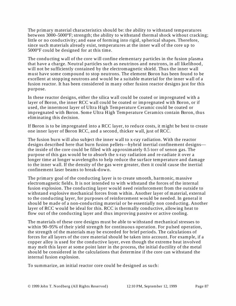
© 1999 John T. Nordberg (All Rights Reserved) 12:10 PM, September 12, 1999 Page 87
The primary material characteristics should be: the ability to withstand temperaturesbetween 3000–5000°F; strength; the ability to withstand thermal shock without cracking;little or no conductivity; and ease of forming into rigid, spherical shapes. Therefore,since such materials already exist, temperatures at the inner wall of the core up to5000°F could be designed for at this time.
The conducting wall of the core will confine elementary particles in the fusion plasmathat have a charge. Neutral particles such as neutrinos and neutrons, in all likelihood,will not be sufficiently contained by the electromagnetic shield. Thus the inner wallmust have some compound to stop neutrons. The element Boron has been found to beexcellent at stopping neutrons and would be a suitable material for the inner wall of afusion reactor. It has been considered in many other fusion reactor designs just for thispurpose.
In these reactor designs, either the silica wall could be coated or impregnated with alayer of Boron, the inner RCC wall could be coated or impregnated with Boron, or ifused, the innermost layer of Ultra High Temperature Ceramic could be coated orimpregnated with Boron. Some Ultra High Temperature Ceramics contain Boron, thuseliminating this decision.
If Boron is to be impregnated into a RCC layer, to reduce costs, it might be best to createone inner layer of Boron RCC, and a second, thicker wall, just of RCC.
The fusion burn will also subject the inner wall to x-ray radiation. With the reactordesigns described here that burn fusion pellets—hybrid inertial confinement designs—the inside of the core could be filled with approximately 0.5 torr of xenon gas. Thepurpose of this gas would be to absorb the x-ray radiation and re-radiate it over alonger time at longer wavelengths to help reduce the surface temperature and damageto the inner wall. If the density of the gas were greater, then it could cause the inertialconfinement laser beams to break-down.
The primary goal of the conducting layer is to create smooth, harmonic, massiveelectromagnetic fields. It is not intended to with withstand the forces of the internalfusion explosion. The conducting layer would need reinforcement from the outside towithstand explosive mechanical forces from within. Another layer of material, externalto the conducting layer, for purposes of reinforcement would be needed. In general itshould be made of a non-conducting material or be essentially non conducting. Anotherlayer of RCC would be ideal for this. RCC is thermally conductive, allowing heat toflow out of the conducting layer and thus improving passive or active cooling.
The materials of these core designs must be able to withstand mechanical stresses towithin 90–95% of their yield strength for continuous operation. For pulsed operation,the strength of the materials may be exceeded for brief periods. The calculations offorces for all layers of the core material should be taken into account. For example, if acopper alloy is used for the conductive layer, even though the extreme heat involvedmay melt this layer at some point later in the process, the initial ductility of the metalshould be considered in the calculations that determine if the core can withstand theinternal fusion explosion.
To summarize, an initial reactor core could be designed as such:
© 1999 John T. Nordberg (All Rights Reserved) 12:10 PM, September 12, 1999 Page 88
1) An inner layer of non conducting material made up of an Ultra High TemperatureCeramic such as: hafnium diboride silicon carbide; or, Zirconium diboridecomposite; or, other related ceramic compounds. The exact thickness of this layeris unknown at this time due to the classified nature of these ceramics—they arenow used to make nose-cones for missiles. The estimated required thickness is 1inch. Preferably, the material will have a composition that includes some Boron tostop neutrons. (Most likely manufactured as two interlocking hemispheres.)
2) A second, essentially non-conducting layer, that is composed of material that canwithstand high temperatures, thermal shock, compressive forces from without,explosive forces from within and can stop neutrons such as a 1 inch wallcomposed of: RCC impregnated with Boron. (Most likely manufactured as twointerlocking hemispheres. Possibly manufactured as one piece around the innerlayer of Ultra High Temperature Ceramics.)
3) A third layer, essentially non-conducting, that is composed of material that canwithstand high temperatures, thermal shock, compressive forces from without,explosive forces from within, such as a layer composed of 1 inch of RCC. (Mostlikely manufactured as one piece around the inner layers of Ultra HighTemperature Ceramics and Boron impregnated RCC.)
4) A fourth layer, essentially non-conducting, that is composed of a material that canwithstand massive thermal shocks and lessen the thermal shock to the next outerlayer such as a layer composed of 5 inches of silica (99.8-percent amorphous fiber)made rigid by ceramic bonding. (Most likely manufactured as two interlockinghemispheres. Possibly manufactured as multiple interlocking tiles attached to theoutside of the inner 3 layers.)
5) A fifth layer, essentially conductive, that is composed of a material with very lowresistance, is economical, that can be formed into spherical shells of the sizeneeded, and can withstand the internal forces, Coulombic and Hall, created bymassive electromagnetic fields such as a layer composed of Cu-Nb, 6 inches thick.(Most likely manufactured as two interlocking hemispheres that are heat-shrunkto each other with the lap-joint situated at the eventual equator of theelectromagnetic field.)
6) A sixth layer, essentially non-conducting, that is composed of material that canwithstand high temperatures, thermal shock, explosive forces from within such asa layer composed of 2 inches of RCC. (Most likely manufactured as twointerlocking hemispheres.)
7) A seventh layer, essentially non-conducting, that is composed of material that canwithstand high temperatures, thermal shock, explosive forces from within such asa layer composed of 2 inches of RCC. (Most likely manufactured as twointerlocking hemispheres with the joint oriented 90° from the hemispheres in thesixth layer.)
Total wall thickness approximately 18 inches of which 1/3—i.e., 6 inches—isconductive.
An example of this core wall, with possible sample materials, is shown in the followinggraphic.

© 1999 John T. Nordberg (All Rights Reserved) 12:10 PM, September 12, 1999 Page 89
Figure 69
To compensate for differences in thermal expansion, the inner and outer sides ofindividual layers may be designed with a grid of grooves—e.g., the outer side of layer 4and the inner side of layer 6. Using a copper alloy, as in this example, the inner surfaceof the conductive layer will thermally expand more than the external surface of thislayer. This is due to the greater temperatures experienced on the inner layer due to thefusion burn. The internal side of this layer may even melt. To compensate for thisvolume change, the outside of layer 4, of Silica in this example, and the inner side of the6th layer, RCC in this example, could be composed of voids created by a cross-hatchedgrid of grooves. In this example, as the conductive layer expands, it would expand intothe voids created by these grids of grooves. These voids are illustrated in Figure 70.

© 1999 John T. Nordberg (All Rights Reserved) 12:10 PM, September 12, 1999 Page 90
Figure 70
The voids would need to have a vacuum at the time of the fusion reaction. If they werefill with a gas, the gas would expand during heating of the core and potentially rupturethe core. Small channels through layers 1, 2, and 3 to the central core could be used torelieve such pressure. In most of these nuclear fusion reactors, the core will either beunder a vacuum, or will be filled with a low pressure gas such as Xenon. Periodic test ofthe cores for melting will be required. If the conductive layer melts into the voids after anumber of fusion burns, then the geometry required for harmonic containment fieldswill be lost. The melted core can be replaced with a new core, and the used core can berefurbished.
Expansion of the fourth layer would be easy to plan for since it is primarily a thermalbarrier and not key in preventing implosion or explosion of the core. This layer could bedesigned, if needed, with overlapping panels created with a tongue-and-groove typejoint. The panels could simply slide together for a tighter fit to deal with thermalexpansion.
It is not critical that the fourth layer be made of a solid material. It has been discoveredthat small ceramic spheres that have a hole drilled in them are not only excellentthermal barriers, but also excellent sound barriers. It should be expected that theinternal fusion explosion should create, not only a massive thermal shock, but also asignificant sound shock. Such shocks repeatedly reverberating through the core couldcause core failure. Therefore, layer four might simply start out as a hollow void, that isfilled with sound-deadening, thermally resistant, small, ceramic spheres. Currently,these spheres are rated to a temperature of about 2,000°F. But with more expensive,Ultra High Temperature Ceramics, temperatures of up to 5,000°F should be possibleand still retain the shock dampening characteristics. An example of this type of wall—with a thicker layer 3—might look like:

© 1999 John T. Nordberg (All Rights Reserved) 12:10 PM, September 12, 1999 Page 91
Figure 71
To summarize this wall design:
1) An inner layer of non conducting material made up of an Ultra High TemperatureCeramic such as: hafnium diboride silicon carbide; or, Zirconium diboridecomposite; or, other Ultra High Temperature Ceramic compounds. The exactthickness of this layer is unknown at this time due to the classified nature of theseceramics. (Their material composition is classified because they are now used tomake nose-cones for missiles.) The estimated required thickness for this layer is 1inch. Preferably, the material will have a composition that includes some Boron tohelp stop neutrons. (Most likely manufactured as two interlocking hemispheres.)
2) A second, essentially non-conducting layer, that is composed of material that canwithstand high temperatures, thermal shock, compressive forces from without,explosive forces from within, and can stop neutrons, such as, a 1 inch wallcomposed of RCC impregnated with Boron. (Most likely manufactured as twointerlocking hemispheres. Possibly manufactured as one piece around the innerlayer of Ultra High Temperature Ceramics.)
3) A third layer, essentially non-conducting, that is composed of material that canwithstand high temperatures, thermal shock, compressive forces from without,explosive forces from within, such as a layer composed of 2 inches of RCC. (Mostlikely manufactured as one piece around the inner layers of Ultra HighTemperature Ceramics and Boron impregnated RCC.)

© 1999 John T. Nordberg (All Rights Reserved) 12:10 PM, September 12, 1999 Page 92
4) A fourth layer, essentially non-conducting, that is composed of a material that canwithstand massive thermal and sound shocks and lessen the thermal shock to thenext outer layer, such as a layer composed of 5 inches of small hollow spheresmade up of High Temperature, or Ultra High Temperature Ceramics. (Most likelymanufactured as small—1/16–1/2 inch spheres with a small hole drilled orformed in them. The spheres would be poured into the void between layer 3 andlayer 5 through temporary openings in layer 5. The voids between the sphereswould be pumped to a vacuum or be allowed to fill with a slight pressure ofXenon gas as an added measure to absorb X-ray radiation.)
5) A fifth layer, essentially conductive, that is composed of a material with very lowresistance, is economical, that can be formed into spherical shells of the sizeneeded, and can withstand the internal forces, Coulombic and Hall, created bymassive electromagnetic fields such as a layer composed of Cu-Nb, 6 inches thick.(Most likely manufactured as two interlocking hemispheres that are heat-shrunkto each other with the lap joint situated at the eventual equator of theelectromagnetic field.)
6) A sixth layer, essentially non-conducting, that is composed of material that canwithstand high temperatures, thermal shock, explosive forces from within such asa layer composed of 2 inches of RCC. (Most likely manufactured as twointerlocking hemispheres.)
7) A seventh layer, essentially non-conducting, that is composed of material that canwithstand high temperatures, thermal shock, explosive forces from within such asa layer composed of 2 inches of RCC. (Most likely manufactured as twointerlocking hemispheres with the joint oriented 90° from the hemispheres in thesixth layer.)
Having the fourth layer filled with small ceramic spheres may have advantages. Butunder the unusual circumstances being described here, there are no guidelines to besure by. Only experiment will discover if this method is superior to using a moretraditional thermal barrier such as silica.
It is key that the conductive layer—a copper alloy in this case—be magnitudes moreconductive than the non-conductive, or essentially non-conductive layers. It is believedthis would exclude metals, plasmas and conductive gases for materials in layers 1, 2, 3,4, 6 and 7. However, the Spherical Electromagnetic Confinement Fields (40) may inhibitthe burn so efficiently that the conductive layer may be used for the inner layer. Testsmay prove that only a thin inner layer of material may be required to protect theconductive layer.
If conductive materials were used for these layers, then the main conductive layer, layer5 in this example, would induce dissipative, eddy-like currents in the other conductivelayers, increasing Coulombic and Hall forces, increasing thermal loss, and decreasingefficiency. In addition, if internal layers were made of conducting material—layers 1, 2,3, and 4 in this example—then it is possible that these layers might shield the fusionreaction from the Poynting vector energy transport, and from the confiningelectromagnetic fields. A solid internal conducting layer—for any one of layers 1, 2, 3, or4 in this example—might be the worst possible choice because it could reduce oreliminate the MHD effect altogether.

© 1999 John T. Nordberg (All Rights Reserved) 12:10 PM, September 12, 1999 Page 93
While materials for the inner layers should be chosen for their essential characteristics—non-conductivity, resistant to high temperatures and thermal shock, resistance to highenergy particles and photons, ability to absorb neutrons, and high strength—theyshould also be tested ahead of time to the transport energy induced in the conductivelayer. It is quite possible that the massive, central-pointing energy-transport, expressedin terms of the Poynting vector, could still shatter these inner layers. While the innerlayers may be non conductive, or essentially non-conductive—as in Boron impregnatedsilicas, carbides, ceramics or RCC structures—when compared to the conductive layer,the center pointing transport energy may interact at the elementary particle level,creating massive forces against charged elementary particles—such as electrons, andatomic nuclei within the inner layers. However, even if the induced central pointingenergy creates forces at the elementary particle level, these inner core materials may stillbe able to withstand the shocks without absorbing too much energy for these reasons:
1) The inner core layers are directly next to the conducting layer
2) The diameter of the core is large compared to the wall thickness
3) The imploding energy per square inch at the inner wall will be small compared toat the focal point of the core
4) The materials are strong by their nature
5) Also it is believed, the characteristic wavelength of the imploding energy will belarge, roughly equal to the diameter of the conducting layer of the core. This longwavelength will take time to excite charged elementary particles within the innerlayers of the core wall. By the time this happens, the exploding forces will becounteracting the imploding forces.
All core designs, except the “No-Core” core design, will face tremendous thermal,compressive, and explosive forces. It should be expected that early core designs may:crack, melt, crush, shatter, be pierced by instabilities, and possibly catastrophicallyexplode. The Core Shields and Reactor Room Walls should be designed for thesepossibilities. Again, the overall reactor design should allow for the cores to be quicklyand efficiently replaced.
Misc. Induction Coils NotesTwo key issues are:
• How can massive electromagnetic pulses be induced in the circuit of conductingspheres?
• How can excess electromagnetic energy be extracted from the circuit for use in thepower grid?
The circuit could be directly connected to the power grid. However, this would not bepractical since the massive pulses would easily burn out many components in powergrids.

© 1999 John T. Nordberg (All Rights Reserved) 12:10 PM, September 12, 1999 Page 94
Instead, induction coils and capacitors should be used to act as an intermediarybetween the conducting circuit and the electrical power grid.
There are hundreds if not thousands of possible combinations of arrangements for thecoils in such reactors. Possible coil arrangements include:
1) If a solid “wire-type” conducting circuit is used, then one large coil could bewrapped around the circuit. For this type of circuit to work, the coil must inducean electromagnetic pulse through the conductor with a wavelength much longerthan the diameter of the conductor, otherwise nodes in the waves will vaporizethe conductor and explode it as explained in the section on the exploding wirephenomena.
Inductive Coil
Large voltagewill vaporize
conductor here.
EnlargedDetail
Figure 72
However, even if it were possible to induce very long wavelength pulses usingthe inductive coil, the wavelength of the MHD effect in the core will be equal todiameter of the core, and if powerful enough, will explode the conductor at theanodes and cathodes as is shown in the enlarged detail of Figure 72. It appearsinevitable that too much energy will be focused on these small points to preventthe conducting wire from exploding.
2) A simple attempt at solving this problem might be to use a thicker conductor:

© 1999 John T. Nordberg (All Rights Reserved) 12:10 PM, September 12, 1999 Page 95
Inductive Coil
Figure 73
There are many problems with this approach. First, the massive energy will stillbe focused at the anodes and cathodes at the confinement wall. The type offocused energy that would occur reminds me of how the hollowed charge cone ina military anti-armor round focuses energy and pierces the toughest armor.Second, the larger the conductor, the less of a change in direction will occur at theconfinement wall, and the smaller will be the induced confining fields. Third, withthicker conductors, there will be more avenues for currents to “cut corners” andcreating eddy currents. There will be increased numbers of possible harmonicwaves around the conductor with corresponding increased numbers of nodes thatwill vaporize and explode the conductor.
3) One possible approach is to create a conductor that is exactly as thick as thecontainment core. However, there would be no induction of confinement fields. Afusion explosion in the core might be confined radially but not axially. It wouldexplode in opposite directions—straight down the conductor in both directions.Besides, the Reactor Core will still create waves of electromagnetic energy thatwill focus at nodes and explode the conductor.
4) To focus the energy, which would still allow the induction of the intensecontainment fields over the surface of the core, the cathode and anode could becapped with a hemispherical dome as shown in Figure 74.

© 1999 John T. Nordberg (All Rights Reserved) 12:10 PM, September 12, 1999 Page 96
Generator, Capacitor Banks& AC-DC-AC Converters
(For inducing the confining pulses& tapping excess energy)
Power Lines
Inductive Coil
HemisphericalDome
Massive, Solid Conductor
Figure 74
With enough active cooling of the conductor/superconductor, this is a possibleconfiguration that might work. However, the conducting “wire” would beextremely massive and expensive. The overall length of the conductor would needto be extremely precise—a multiple of the primary wavelength—to focus theenergy. But when heated, the harmonics would be lost since the conductor lengthwould not be a multiple of the primary wavelength. Manufacturing the conductorwith the incorrect length would be very difficult to correct for. The exploding wiredanger still exists at nodes of the primary electromagnetic wave. Finally, ifdamage did occur to either the conductor or coil, in this design they would beextremely difficult to repair or replace.
A two core version of this design is shown in Figure 75 on page 111.

© 1999 John T. Nordberg (All Rights Reserved) 12:10 PM, September 12, 1999 Page 97
5) Another possible arrangement would be to place numerous coils in series aroundthe conductor in an attempt to create electromagnetic pulses which havewavelengths equal to the diameter of the conductor and core, and then to try toactively cool the conductor to prevent it from overheating and exploding. I do notthink this technique will be feasible. It would certainly be dangerous.
Figure 76
The main advantage of this design is not for it practicality, but that it emphasizesthe importance of analyzing the primary electromagnetic wave: its wavelength, itsshape, the locations of nodes, the locations of eddy currents, the locations ofintense temperatures, etc.
6) This leads to the approach, indicated earlier, of using spherical conducting shells.

© 1999 John T. Nordberg (All Rights Reserved) 12:10 PM, September 12, 1999 Page 98
Figure 77
With this approach, the emphasis is not on inducing a current around the circuit.Large-scale flow of electrons around the circuit is not really desired—rather, local,short-distanced but very fast flow of electrons is desired. The emphasis of thisapproach is creating massive standing, spherical waves of electromagnetic fieldsthat result in a massive voltage across the containment sphere and massivecontaining fields—i.e., high voltage, high resistance, low current. (Or, massivemagnetic differentials if the reactor is operating in the Magnetic Mode.)
7) Another possible concept for the electrical conducting circuit—the main conceptthat is emphasized in this document—would be to create an electrical circuit usingconducting spheres as previously described, laid out in an oval track, and to placecoils around one or both of the hemispheres of one or more of the conductingspheres. The coils will be used to induce the electromagnetic pulses and to tapexcess energy.
Using this overall concept, there are hundreds of possible wiring schemes wherethe coils are connected in series, in parallel, on separate circuits, or incombinations of these.
This overall concept has many common advantages. They are in stark contrast tothe disadvantages of the circuit described in 3 above. Advantages include:
• The conducting spheres would be relatively cheap and easy to manufacture.• It would not be a problem to lengthen or shorten the circuit—new or old
spheres could be added or removed.• While the harmonics of the heated circuit would change, it would change
uniformly over the entire circuit because, by actively monitoring andequalizing coolant temperatures, the amount expanding and contracting of thespheres could be controlled.
• While localized eddy-currents from secondary currents still could melt orexplode small areas of spheres, the danger of the exploding wire phenomena

© 1999 John T. Nordberg (All Rights Reserved) 12:10 PM, September 12, 1999 Page 99
would be minimized since the main electromagnetic wave would not explodehuge sections of a conductor.
• Finally, the modular design would allow easy repair or replacement ofconductors or coils.
Wiring Pattern for CoilsHow the coils are wired to each other around the conducting circuit is a keyconsideration. Each coil could be treated as a separate circuit. The coils could be wiredin parallel, or in series. Or they could be wired in various combinations.
Examples of these reactor circuits include:
Voltage
Coils Wired in SeriesFigure 78

© 1999 John T. Nordberg (All Rights Reserved) 12:10 PM, September 12, 1999 Page 100
Voltage
Coils Wired in ParallelFigure 79
Graphic not yet completedCoils Wired as Separate Circuits
Graphic not yet completedCoils Wired in Combinations of Series, Parallel, and Separate Circuits
No particular example appears as the clear winner. Each example could work.However, it seems that simplest circuit would have advantages for maintainingharmonic current flows and lower costs.
One technique would be to use Rowland Ring coils placed around an electricalcircuit composed of conducting spheres, as previously described. A coil could beplaced at one point along the electrical circuit, or multiple coils could be placedaround one or both of the hemispheres of one or more of the conducting spheres.Again, there are hundreds of possible wiring schemes where the coils areconnected in series, in parallel, on separate circuits, or in combinations of these.The Rowland Ring coils may or may not have a soft iron core. Examples include:

© 1999 John T. Nordberg (All Rights Reserved) 12:10 PM, September 12, 1999 Page 101
Graphic not yet completedWired in series
Graphic not yet completedWired in parallel
Graphic not yet completedWired as separate circuit
Graphic not yet completedWired using combination of above
Each example could work. However, it seems that simplest circuit would haveadvantages for maintaining harmonic current flows and lower costs. I prefer thecoils in series because their inductance will add thus creating a powerful voltageacross the core that would be very difficult for the MHD effect to reversedirection.
Power SourceDepending on the reactor dimensions and materials, and depending on the designedyield for the D-T plasma or pellet, there would be a characteristic electric voltage ormagnetic differential required across the conducting sphere just prior to the ignition ofthe fusion process. Obviously, an external power source is needed for providing powerto the coils that provide the electromagnetic pulse that sweeps over the conductinglayer of the core in order to provide initial confinement and ignition—in the case of apurely inductive compressive technique—and the confining fields for the MHD effect.Also, in the case of using inertial techniques for initial ignition of a D-T pellet, a powersource would be needed for the lasers, or other beam devices.
Possible power sources could include:
1) Coal powered AC generators
2) Hydro powered AC generators
3) Nuclear fission powered AC generators
4) Coal powered DC generators
5) Hydro powered DC generators

© 1999 John T. Nordberg (All Rights Reserved) 12:10 PM, September 12, 1999 Page 102
6) Nuclear fission powered DC generators
7) Banks of capacitors charged by any of the above devices or: the commercial powergrid; liquid fuel generators; solar panels; geothermal energy capture devices; or avariety of other energy sources.
For the purposes of this example, a coal powered DC generator will be used.
Removing power form the conducting circuit
Again, depending on the reactor dimensions and materials, and depending on thedesigned yield for the D-T plasma or pellet, there would be a characteristic voltagerequired across the conducting sphere just prior to the ignition of the fusion process.
Once the fusion process starts, the MHD process will induce a higher electric voltage ormagnetic differential across the reactor core. All that is needed is the electrical circuitryto monitor this electric voltage or magnetic differential, and to use the excess to inducecurrent in the coils and to move the current to the power grid.
One possible technique for tapping the correct amount of energy from the circuit mightbe to attach a set number of coils to the circuit and have about 60% of the coilsmaintaining the required containing voltage and about 40% of the coils tapping offexcess voltage. For example, in an early design of one type of reactor, it had:
• 2 reactor cores—it is a 2 cycle engine
• 30 conducting spheres—15 per each half of an oval
• 48 total coils
• 32 coils for creating and maintaining the confining voltage—16 per each half of theoval
• 16 coils for tapping off excess voltage—induced by the MHD effect from the fusionreaction
Since 66% of the coils are for maintain voltage, and 33% of the coils are designed fortapping off excess voltage, the yield of the fusion burn should not exceed 29% of thetotal capacity of the circuit. This value of 29% would allow up to 2 of the tap coils toburn out and still be able to draw off the MHD energy.
This example gives insight on the best wiring techniques. What should happen if coilsburn out? If one containment coil burns out, then the whole containment circuit shouldshut down. This would allow the fusion plasma to expand, cool, and stop the fusionburn. However, if a tap coil burns out, then an opposite coil in the circuit should godown to keep a symmetric voltage. But to insure the ability of the circuit to keepdrawing off excess MHD power, the tapping coils should not all be wired in series. If allof the tapping coils went down, the MHD fields might be powerful enough to flip thepolarity of the entire conducting circuit—with the resulting danger of the rapid voltageflip-flop.

© 1999 John T. Nordberg (All Rights Reserved) 12:10 PM, September 12, 1999 Page 103
DC versus AC
There are possible designs—that use 1 or more cores—that would, for these types offusion reactors, create DC currents. In such cases an AC inverter would be required.There are possible designs—that use 2 or more cores—that would create AC currents. Insuch cases, if the frequency is appropriate, the current could go directly to the powergrid. If the frequency is not correct, then additional circuitry would be required forchanging the frequency.
Major Nuclear Fusion Reactor Types
To recap: the major types of nuclear fusion reactors in these designs all use a sphericallyshaped electromagnetic field for the purposes of confining the fusion burn and forMHD conversion of energy, and use spherical conducting spheres to create a harmonicpulse that sweeps over the core. Within these overall parameters, there are manypossible nuclear reactor design variations possible, using various combinations ofcomponents available. Some of the variables in the reactor design include:
1) Fusion Fuel: D-T, D-D, and D-He, and other elements
2) Fusion Fuel Type: Plasma, or Pellet
3) Reactor Core confinement field alignment: Magnetic Mode, Electrical Mode
4) Ignition technique: electromagnetic induction; laser beam inertial; ion beaminertial, implosion cage
5) Reactor confinement material: solid conductor, solid superconductor, plasma,liquid, gas, “No Core”
6) Various reactor core wall material choices, or “No-Core” design
7) Confinement circuit shape: oval, circular, straight
8) Confinement coil type: normal cylindrical coil; normal concentric cylindrical coils;normal (single) helical coils; normal (multiple) parallel helical coils; Rowland Ringcoils with soft iron cores; Rowland Ring coils without soft iron cores; individualhemispherical coils; grouped hemispherical coils
9) Conducting Sphere type: hollow with vacuum; solid filled
10) Conducting Sphere fill material
11) AC or DC output design
12) One, two, three, four, or more cores
13) Burn length: pulsed, quasi-continuous, or continuous operation
14) Cooling technique: pulsed, quasi-continuous, or continuous operation

© 1999 John T. Nordberg (All Rights Reserved) 12:10 PM, September 12, 1999 Page 104
Some major design choices
One Core, Plasma fuel designs:
1) One core, ignition by induced compression, plasma fuel (D-D, D-He, D-T),confinement by circuit using spherical conducting coils arranged in a circular oroval pattern, confinement fields induced by Rowland Ring coils with a soft ironcore, pulsed or quasi-continuous DC operation
2) One core, ignition by induced compression, plasma fuel (D-D, D-He, D-T),confinement by circuit using spherical conducting coils arranged in a circular oroval pattern, confinement fields induced by Rowland Ring coils without a softiron core, pulsed or quasi-continuous DC operation
3) One core, ignition by induced compression, plasma fuel (D-D, D-He, D-T),confinement by circuit using spherical conducting coils arranged in a circular oroval pattern, confinement fields induced by traditional coils, pulsed or quasi-continuous DC operation
4) One core, ignition by induced compression, plasma fuel (D-D, D-He, D-T),confinement by circuit using spherical conducting coils arranged in a circular oroval pattern, confinement fields induced by hemispheric coils, pulsed, quasi-continuous, or continuous DC operation
Two or more Core, Plasma fuel designs:
5) Two or more cores, ignition by induced compression, plasma fuel (D-D, D-He, D-T), confinement by circuit using spherical conducting coils arranged in a circularor oval pattern, confinement fields induced by Rowland Ring coils with a soft ironcore, pulsed or quasi-continuous AC operation
6) Two or more cores, ignition by induced compression, plasma fuel (D-D, D-He, D-T), confinement by circuit using spherical conducting coils arranged in a circularor oval pattern, confinement fields induced by Rowland Ring coils without a softiron core, pulsed or quasi-continuous AC operation
7) Two or more cores, ignition by induced compression, plasma fuel (D-D, D-He, D-T), confinement by circuit using spherical conducting coils arranged in a circularor oval pattern, confinement fields induced by traditional coils, pulsed or quasi-continuous AC operation
8) Two or more cores, ignition by induced compression, plasma fuel (D-D, D-He, D-T), confinement by circuit using spherical conducting coils arranged in a circularor oval pattern, confinement fields induced by hemispheric coils, pulsed or quasi-continuous AC operation
One Core, Pellet fuel designs:
9) One core, ignition by inertial beam technique, pellet fuel (D-D, D-He, D-T),confinement by circuit using spherical conducting coils arranged in a circular or

© 1999 John T. Nordberg (All Rights Reserved) 12:10 PM, September 12, 1999 Page 105
oval pattern, confinement fields induced by Rowland Ring coils with a soft ironcore, pulsed DC operation
10) One core, ignition by inertial beam technique, pellet fuel (D-D, D-He, D-T),confinement by circuit using spherical conducting coils arranged in a circular oroval pattern, confinement fields induced by Rowland Ring coils without a softiron core, pulsed DC operation
11) One core, ignition by inertial beam technique, pellet fuel (D-D, D-He, D-T),confinement by circuit using spherical conducting coils arranged in a circular oroval pattern, confinement fields induced by traditional coils, pulsed DCoperation
12) One core, ignition by inertial beam technique, pellet fuel (D-D, D-He, D-T),confinement by circuit using spherical conducting coils arranged in a circular oroval pattern, confinement fields induced by hemispheric coils, pulsed DCoperation
Two or more Cores, Pellet fuel designs:
13) Two or more cores, ignition by inertial beam technique, pellet fuel (D-D, D-He, D-T), confinement by circuit using spherical conducting coils arranged in a circularor oval pattern, confinement fields induced by Rowland Ring coils with a soft ironcore, pulsed AC operation
14) Two or more cores, ignition by inertial beam technique, pellet fuel (D-D, D-He, D-T), confinement by circuit using spherical conducting coils arranged in a circularor oval pattern, confinement fields induced by Rowland Ring coils without a softiron core, pulsed AC operation
15) Two or more cores, ignition by inertial beam technique, pellet fuel (D-D, D-He, D-T), confinement by circuit using spherical conducting coils arranged in a circularor oval pattern, confinement fields induced by traditional coils, pulsed ACoperation
16) Two or more cores, ignition by inertial beam technique, pellet fuel (D-D, D-He, D-T), confinement by circuit using spherical conducting coils arranged in a circularor oval pattern, confinement fields induced by hemispheric coils, pulsed ACoperation
1 No-Core core Plasma fuel designs in Electric Mode:
17) 1 No-Core core, plasma fuel gradually added to chamber by injection, ignition byinduced compression, continuous voltage provided by circuit using sphericalconducting coils arranged in a circular or oval pattern, confinement field voltageprovided by Rowland Ring coils with soft iron core, continuous DC operation.
18) 1 No-Core core, plasma fuel gradually added to chamber by injection, ignition byinduced compression, continuous voltage provided by circuit using sphericalconducting coils arranged in a circular or oval pattern, confinement field voltageprovided by Rowland Ring coils without soft iron core, continuous DC operation.

© 1999 John T. Nordberg (All Rights Reserved) 12:10 PM, September 12, 1999 Page 106
19) 1 No-Core core, plasma fuel gradually added to chamber by injection, ignition byinduced compression, continuous voltage provided by circuit using sphericalconducting coils arranged in a circular or oval pattern, confinement field voltageprovided by traditional coils, continuous DC operation.
1 No-Core core Plasma fuel designs in Magnetic Mode:
20) 1 No-Core core, plasma fuel gradually added to chamber by injection, ignition byinduced compression, continuous magnetic differential provided by circuit usingspherical conducting coils arranged in a circular or oval pattern, confinement fieldvoltage provided by traditional coils, continuous DC operation.
21) 1 No-Core core, plasma fuel gradually added to chamber by injection, ignition byinduced compression, continuous magnetic differential provided by circuit usingspherical conducting coils arranged in a circular or oval pattern, confinement fieldvoltage provided by hemispheric coils, continuous DC operation.
2 No-Core cores Plasma fuel designs in Magnetic Mode:
22) 2 No-Core cores, plasma fuel gradually added to chambers by injection, ignitionby induced compression, continuous magnetic differential provided by circuitusing spherical conducting coils arranged in a circular or oval pattern,confinement field voltage provided by traditional coils, continuous AC operation.
23) 2 No-Core cores, plasma fuel gradually added to chambers by injection, ignitionby induced compression, continuous magnetic differential provided by circuitusing spherical conducting coils arranged in a circular or oval pattern,confinement field voltage provided by hemispheric coils, continuous ACoperation.
1 No-Core core Plasma fuel Straight-Line designs:
24) 1 No-Core core, plasma fuel gradually added to chamber by injection, ignition byinduced compression, continuous magnetic differential provided by circuit usingspherical conducting coils arranged in a straight-line pattern, confinement fieldvoltage provided by traditional coils, continuous DC operation.
25) 1 No-Core core, plasma fuel gradually added to chamber by injection, ignition byinduced compression, continuous magnetic differential provided by circuit usingspherical conducting coils arranged in a straight-line pattern, confinement fieldvoltage provided by hemispheric coils, continuous DC operation.
I believe that the best design, for short-term testing and production, is reactor design 12using D-T fusion fuel pellets and laser inertial beams—as shown in the preferredembodiment. There currently is a facility being built called the National IgnitionFacility. The confinement circuit described here could, potentially be added to thatfacility. Or, a similar facility, using the same type of laser inertial confinement could bebuilt, but with the added confinement circuit. The benefits of this design are: thesimplicity of one core; the lower magnetic fields required due to inertial ignitiontechniques; and the smooth harmonics of the Hemispheric Coils.

© 1999 John T. Nordberg (All Rights Reserved) 12:10 PM, September 12, 1999 Page 107
In the mid-term, I believe design number 8 with: 2 cores; using D-D plasma fuel; usinghemispheric coils; and optimized for 60 MHz pulsed (AC) operation would be best. Thebenefits of this design are: efficient use of one reactor core's MHD fields for creating theother reactor core's confinement fields (like a two cylinder gasoline engine); quasi-continuous operation (i.e., requiring periodic replacement of cores and othercomponents) using injected plasma; and optimization for 60 MHz AC power for directcommercial electrical grid utilization.
In the long range, I believe design number 23 using 2 cores based on the adjustablewavelength “No-Core” design may be best. This design has many advantages: theability to operate almost nonstop since there are no cores to wear out; the magneticcircuit does not entail large-scale movements of electrons that could burn outconducting spheres; the hemispheric coils should provide smooth confining fields; theconducting spheres and hemispheric coils could be continuously cooled; the use ofpulse injected D-D plasma fuel into the confining fields allows the central burning mini-stars to continuously burn; the mini-stars would pulse with opposite beats (i.e., as onestar expands, inducing a MHD field, this induced MHD field will induce confiningfields that compress the other star, then the cycle reverses); and the induced current thatis tapped off will be AC.. And finally, the wavelength of the core area can be adjusted totake into account thermal heating and cooling. All that would be needed would beperiodic replacement of conducting spheres; shield materials; miscellaneous electricalcomponents, and cooling system components.
Summary of InventionThe primary of goal of the preferred embodiment of these designs is to createcommercial electric energy using the nuclear fusion process of converting the mass oflight elements into electrical energy. I believe the key to successfully doing this, in aneconomical manner, is to place the fusion burn inside a spherical electromagneticcontainment field. By doing so, this external spherical electromagnetic field providesmany benefits: it controls and contains the physical location of the fusion burn; itinhibits instabilities; it uses instabilities in a MHD fashion to extract electrical energy; itlengthens the burn; it allows a more controlled release of energy rather than anexplosive release of energy; and it can be used to ignite the fuel. A secondary goal ofsome of these reactor designs is to produce diamond crystals. The key to creating andmaintaining the spherical electromagnetic containment field is the use of sphericalreactor cores and conductors. A key in creating harmonic fields is the careful design ofelectromagnetic induction coils that can be used to transfer energy to and from thecontainment circuit. In particular, the new and unique design of hemispheric coilspromises to provide very clean harmonics at a relatively low cost. While there are manymaterial and design variations possible in these designs, they all are intended to createpowerful spherical electromagnetic fields around the fusion burn. In the past there hasbeen no design for fusion reactors that places spherical electromagnetic fields aroundthe fusion burn in order to impart energy to the fuel to contain and ignite the fuel, andto extract energy from the fusion burn using MHD. These designs are the first in historyto offer humanity inexpensive, practically unlimited, almost totally clean energy.
The foregoing description of the preferred embodiment of the invention has beenpresented for the purposes of illustration and description. It is not intended to be

© 1999 John T. Nordberg (All Rights Reserved) 12:10 PM, September 12, 1999 Page 108
exhaustive or to limit the invention to the precise form disclosed. Many modificationsand variations are possible in light of the above teaching. Any person schooled in the artof nuclear reactor design should be able to use this schooling to design and buildnuclear fusion reactors that provide more energy than they consume from thermallosses and from the energy required to start the fusion burn.
ClaimsAs a reward for my contributions, I claim rights to nuclear fusion reactor designscomprising:
spherical electromagnetic fields to contain, to transfer energy into, and transfer energyout of nuclear fusion reactions
comprising electromagnetic fields that surround a fusion process of converting matterinto energy using the MagnetoHydroDynamic interaction of the fusion reaction withthe spherical electromagnetic confinement fields
comprising an electromagnetic containment circuit
comprising spherical conductors forming a closed loop
comprising coils for transferring energy between the closed loop and the electricalenergy grid
comprising coils that provide a means for applying voltage or current to thecontainment circuit
comprising compression, heating, and electromagnetic fields to carbon in order toconvert carbon into diamond.
OathThis document describing nuclear fusion reactor designs utilizing sphericalelectromagnetic fields to compress, contain, and extract energy was created by me. I didnot create the original drawings of the high voltage cabling in Figure 50. I did not createthe original image of the planetary nebula in Figure 67. With these two exceptions, allgraphics and figures were created by myself.
John Thomas Nordberg
5/17/99