Embed Size (px)
Citation preview
A Joint Standard of AASHTO, ITE, and NEMA
NTCIP 1203 version v03
National Transportation Communications for ITS Protocol
Object Definitions for Dynamic Message Signs (DMS)
published September 2014
Published by American Association of State Highway and Transportation Officials (AASHTO) 444 North Capitol Street, N.W., Suite 249 Washington, D.C. 20001 Institute of Transportation Engineers (ITE) 1627 I (“Eye”) Street, N.W., Suite 600 Washington, D.C. 20006-4007 National Electrical Manufacturers Association (NEMA) 1300 North 17th Street, Suite 900 Rosslyn, Virginia 22209-3806
file version 1203 v0305p 2014 AASHTO / ITE / NEMA. All rights reserved

NOTICES
Copyright Notice © 2014 by the American Association of State Highway and Transportation Officials (AASHTO), the Institute of Transportation Engineers (ITE), and the National Electrical Manufacturers Association (NEMA). All intellectual property rights, including, but not limited to, the rights of reproduction, translation, and display are reserved under the laws of the United States of America, the Universal Copyright Convention, the Berne Convention, and the International and Pan American Copyright Conventions. Except as licensed or permitted, you may not copy these materials without prior written permission from AASHTO, ITE, or NEMA. Use of these materials does not give you any rights of ownership or claim of copyright in or to these materials. Visit www.ntcip.org for other copyright information, for instructions to request reprints of excerpts, and to request reproduction that is not granted below. PDF File License Agreement To the extent that these materials are distributed by AASHTO / ITE / NEMA in the form of an Adobe® Portable Document Format (PDF) electronic data file (the “PDF file”), AASHTO / ITE / NEMA authorizes each registered PDF file user to view, download, copy, or print the PDF file available from the authorized Web site, subject to the terms and conditions of this license agreement: a) you may download one copy of each PDF file for personal, noncommercial, and intraorganizational
use only; b) ownership of the PDF file is not transferred to you; you are licensed to use the PDF file; c) you may make one more electronic copy of the PDF file, such as to a second hard drive or burn to a
CD; d) you agree not to copy, distribute, or transfer the PDF file from that media to any other electronic
media or device; e) you may print one paper copy of the PDF file; f) you may make one paper reproduction of the printed copy; g) any permitted copies of the PDF file must retain the copyright notice, and any other proprietary
notices contained in the file; h) the PDF file license does not include: 1) resale of the PDF file or copies, 2) republishing the content in
compendiums or anthologies, 3) publishing excerpts in commercial publications or works for hire, 4) editing or modification of the PDF file except those portions as permitted, 5) posting on network servers or distribution by electronic mail or from electronic storage devices, and 6) translation to other languages or conversion to other electronic formats;
i) other use of the PDF file and printed copy requires express, prior written consent. Data Dictionary and MIB Distribution Permission To the extent that these materials are distributed by AASHTO / ITE / NEMA in the form of a Data Dictionary (“DD”) or Management Information Base (“MIB”), AASHTO / ITE / NEMA extend the following permission: You may make or distribute unlimited copies, including derivative works, of the DD or MIB, including copies for commercial distribution, provided that: a) each copy you make or distribute contains the citation “Derived from NTCIP 0000 [insert the standard
number]. Used by permission of AASHTO / ITE / NEMA.”; b) the copies or derivative works are not made part of the standards publications or works offered by
other standards developing organizations or publishers or as works-for-hire not associated with
commercial hardware or software products intended for field implementation; c) use of the DD or MIB is restricted in that the syntax fields may be modified only to reflect a more
restrictive subrange or enumerated values; d) the description field may be modified but only to the extent that: 1) only those bit values or
enumerated values that are supported are listed; and 2) the more restrictive subrange is expressed. These materials are delivered “AS IS” without any warranties as to their use or performance. AASHTO / ITE / NEMA and their suppliers do not warrant the performance or results you may obtain by using these materials. AASHTO / ITE / NEMA and their suppliers make no warranties, express or implied, as to noninfringement of third party rights, merchantability, or fitness for any particular purpose. In no event will AASHTO / ITE / NEMA or their suppliers be liable to you or any third party for any claim or for any consequential, incidental or special damages, including any lost profits or lost savings, arising from your reproduction or use of these materials, even if an AASHTO / ITE / NEMA representative has been advised of the possibility of such damages. Some states or jurisdictions do not allow the exclusion or limitation of incidental, consequential, or special damages, or the exclusion of implied warranties, so the above limitations may not apply to a given user. Use of these materials does not constitute an endorsement or affiliation by or between AASHTO, ITE, or NEMA and the user, the user’s company, or the products and services of the user’s company. If the user is unwilling to accept the foregoing restrictions, he or she should immediately return these materials. PRL and RTM Distribution Permission To the extent that these materials are distributed by AASHTO / ITE / NEMA in the form of a Profile Requirements List (“PRL”) or a Requirements Traceability Matrix (“RTM”), AASHTO / ITE / NEMA extend the following permission: a) you may make or distribute unlimited copies, including derivative works of the PRL (then known as a
Profile Implementation Conformance Statement (“PICS”)) or the RTM, provided that each copy you make or distribute contains the citation “Based on NTCIP 0000 [insert the standard number] PRL or RTM. Used by permission. Original text © AASHTO / ITE / NEMA.”;
b) you may only modify the PRL or the RTM by adding: 1) text in the Project Requirements column, which is the only column that may be modified to show a product’s implementation or the project-specific requirements; and/or 2) additional table columns or table rows that are clearly labeled as ADDITIONAL for project-unique or vendor-unique features; and
c) if the PRL or RTM excerpt is made from an unapproved draft, add to the citation “PRL (or RTM) excerpted from a draft standard containing preliminary information that is subject to change.”
This limited permission does not include reuse in works offered by other standards developing organizations or publishers, and does not include reuse in works-for-hire, compendiums, or electronic storage devices that are not associated with procurement documents, or commercial hardware, or commercial software products intended for field installation. A PICS is a Profile Requirements List which is completed to indicate the features that are supported in an implementation. Visit www.ntcip.org for information on electronic copies of the MIBs, PRLs, and RTMs. TRF Distribution Permission A Testing Requirements Form (“TRF”) may be a Testing Requirements Traceability Table and/or Test Procedures. To the extent that these materials are distributed by AASHTO / ITE / NEMA in the form of a
TRF, AASHTO / ITE / NEMA extend the following permission: a) you may make and/or distribute unlimited electronic or hard copies, including derivative works of the
TRF, provided that each copy you make and/or distribute contains the citation “Based on NTCIP 0000 [insert the standard number] TRF. Used by permission. Original text © AASHTO / ITE / NEMA.”;
b) you may not modify the logical flow of any test procedure, without clearly noting and marking any such modification; and
c) if the TRF excerpt is made from an unapproved draft, add to the citation “TRF excerpted from a draft standard containing preliminary information that is subject to change.”
Content and Liability Disclaimer The information in this publication was considered technically sound by the consensus of persons engaged in the development and approval of the document at the time it was developed. Consensus does not necessarily mean that there is unanimous agreement among every person participating in the development of this document. AASHTO, ITE, and NEMA standards and guideline publications, of which the document contained herein is one, are developed through a voluntary consensus standards development process. This process brings together volunteers and seeks out the views of persons who have an interest in the topic covered by this publication. While AASHTO, ITE, and NEMA administer the process and establish rules to promote fairness in the development of consensus, they do not write the document and they do not independently test, evaluate, or verify the accuracy or completeness of any information or the soundness of any judgments contained in their standards and guideline publications. AASHTO, ITE, and NEMA disclaim liability for any personal injury, property, or other damages of any nature whatsoever, whether special, indirect, consequential, or compensatory, directly or indirectly resulting from the publication, use of, application, or reliance on this document. AASHTO, ITE, and NEMA disclaim and make no guaranty or warranty, express or implied, as to the accuracy or completeness of any information published herein, and disclaims and makes no warranty that the information in this document will fulfill any of your particular purposes or needs. AASHTO, ITE, and NEMA do not undertake to guarantee the performance of any individual manufacturer or seller’s products or services by virtue of this standard or guide. In publishing and making this document available, AASHTO, ITE, and NEMA are not undertaking to render professional or other services for or on behalf of any person or entity, nor are AASHTO, ITE, and NEMA undertaking to perform any duty owed by any person or entity to someone else. Anyone using this document should rely on his or her own independent judgment or, as appropriate, seek the advice of a competent professional in determining the exercise of reasonable care in any given circumstances. Information and other standards on the topic covered by this publication may be available from other sources, which the user may wish to consult for additional views or information not covered by this publication. AASHTO, ITE, and NEMA have no power, nor do they undertake to police or enforce compliance with the contents of this document. AASHTO, ITE, and NEMA do not certify, test, or inspect products, designs, or installations for safety or health purposes. Any certification or other statement of compliance with any health or safety-related information in this document shall not be attributable to AASHTO, ITE, or NEMA and is solely the responsibility of the certifier or maker of the statement. Trademark Notice NTCIP is a trademark of AASHTO / ITE / NEMA. All other marks mentioned in this standard are the trademarks of their respective owners.

< This page intentionally left blank. >
NTCIP 1203 v03.05 Page i
ACKNOWLEDGEMENTS
NTCIP 1203 v03 was prepared by the NTCIP Dynamic Message Sign Working Group (DMS WG), a subdivision of the Joint Committee on the NTCIP. The Joint Committee is organized under a Memorandum of Understanding among the American Association of State Highway and Transportation Officials (AASHTO), the Institute of Transportation Engineers (ITE), and the National Electrical Manufacturers Association (NEMA). The NTCIP development effort is guided by the Joint Committee on the NTCIP, which consists of six representatives from each of the above organizations. When NTCIP 1203 v03 was prepared, the following individuals were active members of the NTCIP DMS WG: Lesly Bien-Aimé Russell Brookshire Patrick Chan Felix Cuellar Gene Daigle Terry Haukom Ira Huttner Amit Misra
Mark Morse, chair Peter Ragsdale Robert Rausch Joerg “Nu” Rosenbohm Ken Smith Ken Vaughn Derek Vollmer
Other individuals providing input include: Steve Alonge Blake Christie
Tom Kurihara
In addition to the many volunteer efforts, recognition is also given to those organizations who supported the efforts of the working groups by providing comments and funding for the standard, including: Consensus Systems Technologies Daktronics Intelligent Devices, Inc. McCain Minnesota DOT PBS&J Port Authority of NY & NJ
Skyline Southwest Research Institute Telvent Farradyne TransCore ITS Trevilon Ver-Mac Washington State DOT
The U.S. Department of Transportation Joint Program Office provided funding assistance for the development of NTCIP 1203 v03.
Do Not Copy Without Written Permission © 2014 AASHTO / ITE / NEMA

NTCIP 1203 v03.05 Page ii
FOREWORD NTCIP 1203 v03 uses only metric units. NTCIP 1203 v03 identifies and defines how a management station may wish to interface with a field device to control and monitor dynamic message signs (DMS). NTCIP 1203 v03 defines requirements that are applicable to all NTCIP DMS and it also contains optional and conditional sections that are applicable to specific environments for which they are intended. NTCIP 1203 v03 is an NTCIP Device Data Dictionary Standard. Device Data Dictionary Standards provide formal definitions of data elements for use within NTCIP systems. For more information about NTCIP standards, visit the NTCIP Web Site at www.ntcip.org . Approvals NTCIP 1203 v03 was separately balloted and approved by AASHTO, ITE, and NEMA after recommendation by the Joint Committee on the NTCIP. Each organization has approved this standard as the following standard type, as of the date:
AASHTO—Standard Specification; December 2011 ITE–Software Standard; May 2012 NEMA—Standard; March 2012
History The first version of NTCIP 1203 was published as NTCIP 1203:1997 and was also known as NEMA TS 3.6. In 2001, Amendment 1 was accepted by the Joint Committee on the NTCIP and subsequently Jointly Approved by all three SDOs. The Amendment did not add additional functionality but provided clarifications on object definitions and MULTI tags which have been detected by actual implementations. NTCIP 1203 v02 was developed to reflect lessons learned, to update the document to the new documentation formats, and to add new features such as the colors, graphics, and a 3-tiered equipment management structure. NTCIP 1203 v02 also follows an established ‘systems engineering’ approach. Several new sections were added to relate user needs identified in a concept of operations, functional requirements, interface specifications and a requirements traceability matrix to the existing sections. This Version 03 of the NTCIP 1203 standard adds test procedures that satisfy the functional requirements that has been provided. These test procedures, provided in Annex C of this standard, allows agencies procuring dynamic message signs to consistently test for conformance to this standard. Minor corrections and clarifications to the standard are also included. All changes are shown and explained in Annex D (Documentation of Revisions) of this standard. User Comment Instructions The term “User Comment” includes any type of written inquiry, comment, question, or proposed revision, from an individual person or organization, about any part of this standards publication’s content. A “Request for Interpretation” of this standards publication is also classified as a User Comment. User Comments are solicited at any time. In preparation of this NTCIP standards publication, input of users and other interested parties was sought and evaluated. All User Comments are referred to the committee responsible for developing and/or maintaining NTCIP 1209 v02. The committee chairperson, or their designee, may contact the submitter for clarification of the
© 2014 AASHTO / ITE / NEMA Do Not Copy Without Written Permission

NTCIP 1203 v03.05 Page iii
User Comment. When the committee chairperson or designee reports the committee’s consensus opinion related to the User Comment, that opinion is forwarded to the submitter. The committee chairperson may report that action on the User Comment may be deferred to a future committee meeting and/or a future revision of the standards publication. Previous User Comments and their disposition may be available for reference and information at www.ntcip.org. A User Comment should be submitted to this address:
NTCIP Coordinator National Electrical Manufacturers Association 1300 North 17th Street, Suite 900 Rosslyn, Virginia 22209-3801 e-mail: [email protected]
A User Comment should be submitted in the following form: Standards Publication number and version: Page: Section and Paragraph (with Table or Figure, where appropriate): Comment: Editorial or Substantive?: Suggested Alternative Language: Please include your name, organization, and address in your correspondence. Compatibility of Versions To distinguish NTCIP 1203 v03 (as published) from previous drafts, NTCIP 1203 v03 also includes NTCIP 1203 v03.05 on each page header. All NTCIP Standards Publications have a major and minor version number for configuration management. The version number syntax is "v00.00a," with the major version number before the period, and the minor version number and edition letter (if any) after the period. NTCIP 1203 v03 is designated, and should be cited as, NTCIP 1203 v03. Anyone using NTCIP 1203 v03 should seek information about the version number that is of interest to them in any given circumstance. The MIB, the PRL, and the PICS should all reference the version number of the standards publication that was the source of the excerpted material. Conformant systems based on later, or higher, version numbers MAY NOT be compatible with conformant systems based on earlier, or lower, version numbers. Anyone using NTCIP 1203 v03 should also consult NTCIP 8004 v02 for specific guidelines on compatibility.
Do Not Copy Without Written Permission © 2014 AASHTO / ITE / NEMA
NTCIP 1203 v03.05 Page iv
INTRODUCTION NTCIP 1203 v03 provides definitions of data elements for use with dynamic message signs. The data is defined using the Simple Network Management Protocol (SNMP) object-type format as defined in RFC 1212 and would typically be exchanged using one of the NTCIP recognized Application Layers (e.g., SNMP). The content of one object, the dmsMessageMultiString object, uses a complex syntax called the Mark-Up Language for Transportation Information (MULTI) format, also defined in NTCIP 1203 v03. The following keywords apply to this document: AASHTO, ITE, NEMA, NTCIP, DMS, VMS, CMS, data, data dictionary, object, message sign, message board, sign, MULTI. In 1992, the NEMA 3-TS Transportation Management Systems and Associated Control Devices Section began the effort to develop the NTCIP. The Transportation Section’s purpose was to respond to user needs to include standardized systems communication in the NEMA TS 2 standard, Traffic Controller Assemblies. Under the guidance of the Federal Highway Administration’s NTCIP Steering Group, the NEMA effort was expanded to include the development of communications standards for all transportation field devices that could be used in an Intelligent Transportation Systems (ITS) network. Message signs were identified as one of the highest priority expansion areas. As a result, in August 1995, NEMA created the DMS Technical Subcommittee to standardize DMS equipment. Their first task was the development of this document. In September 1996, an agreement was executed among AASHTO, ITE, and NEMA to jointly develop, approve, and maintain the NTCIP standards. One of the first tasks of this joint effort was to finalize the work that NEMA had already begun on the object definitions for dynamic message signs.
© 2014 AASHTO / ITE / NEMA Do Not Copy Without Written Permission
NTCIP 1203 v03.05 Page v
CONTENTS
Section 1 General [Informative] ................................................................................................................. 1 1.1 Scope ........................................................................................................................................ 1
1.2 References ............................................................................................................................... 1 1.2.1 Normative References .................................................................................................. 1 1.2.2 Other References ......................................................................................................... 2 1.2.3 Contact Information ...................................................................................................... 2
1.3 General Statements ................................................................................................................. 3 1.4 Terms ........................................................................................................................................ 3
1.5 Abbreviations ......................................................................................................................... 15
Section 2 Concept of Operations [Normative] ....................................................................................... 17
2.1 Tutorial [informative] ............................................................................................................. 17 2.1.1 About NTCIP 1203 v03 ............................................................................................... 18 2.1.2 Who are you? ............................................................................................................. 18 2.1.3 How NTCIP 1203 v03 is Organized ........................................................................... 19 2.1.4 Intended Audiences for the Sections in NTCIP 1203 v03 .......................................... 20
2.2 Current Situation and Problem Statement [informative] ................................................... 20
2.3 Reference Physical Architecture [informative] .................................................................. 20 2.3.1 Typical Physical Architecture...................................................................................... 20 2.3.2 DMS Characteristics ................................................................................................... 21
2.4 Architectural Needs ............................................................................................................... 22 2.4.1 Fundamental Needs Driving DMS Deployment ......................................................... 22 2.4.2 Operational Environment ............................................................................................ 22
2.5 Features .................................................................................................................................. 23 2.5.1 Manage the DMS Configuration ................................................................................. 23 2.5.2 Control the DMS ......................................................................................................... 24 2.5.3 Monitor the Status of the DMS ................................................................................... 26 2.5.4 Provide for Backwards Compatibility of DMS to NTCIP 1203 v1 ............................... 28
2.6 Security ................................................................................................................................... 28
2.7 Operational Policies and Constraints ................................................................................. 28
2.8 Relationship to the National ITS Architecture [Informative] ............................................. 28
Section 3 Functional Requirements [Normative] ................................................................................... 30 3.1 Tutorial [informative] ............................................................................................................. 30
3.2 Scope of the Interface [Informative] .................................................................................... 31
3.3 Protocol Requirements List (PRL) ....................................................................................... 31 3.3.1 Notation [Informative] ................................................................................................. 31 3.3.2 Instructions for Completing the PRL [Informative] ...................................................... 33 3.3.3 Protocol Requirements List (PRL) Table .................................................................... 35 3.3.4 Protocol Requirements List – Supplemental Table .................................................... 58 3.3.5 MULTI Field Traceability Matrix .................................................................................. 66
3.4 Architectural Requirements ................................................................................................. 73 3.4.1 Support Basic Communications ................................................................................. 73 3.4.2 Support Logged Data ................................................................................................. 73
Do Not Copy Without Written Permission © 2014 AASHTO / ITE / NEMA
NTCIP 1203 v03.05 Page vi
3.4.3 Support Exception Reporting...................................................................................... 73 3.4.4 Manage Access .......................................................................................................... 73
3.5 Data Exchange and operational environment Requirements ........................................... 74 3.5.1 Manage the DMS Configuration ................................................................................. 74 3.5.2 Control the DMS ......................................................................................................... 77 3.5.3 Monitor the Status of the DMS ................................................................................... 82 3.5.4 Providing for Multi-Version Interoperability ................................................................. 87
3.6 Supplemental Non-Communications Requirements ......................................................... 87 3.6.1 Supplemental Requirements for Fonts ....................................................................... 87 3.6.2 Supplemental Requirements for General Illumination Brightness.............................. 87 3.6.3 Supplemental Requirements for Automatic Brightness Control ................................. 87 3.6.4 Supplemental Requirements for Control Modes ........................................................ 88 3.6.5 Supplemental Requirements for Message Activation Request .................................. 88 3.6.6 Supplemental Requirements for Message Definition ................................................. 89 3.6.7 Supplemental Requirements for Locally Stored Messages ....................................... 93 3.6.8 Supplemental Requirements for Color Scheme ......................................................... 93 3.6.9 Supplemental Requirements for Monitoring Subsystems .......................................... 94 3.6.10 Supplemental Requirements for Scheduling .............................................................. 94 3.6.11 Supplemental Requirements for Graphics ................................................................. 95 3.6.12 Supplemental Requirements for Page Justification ................................................... 95 3.6.13 Supplemental Requirements for Line Justification ..................................................... 95
Section 4 Dialogs [Normative] ................................................................................................................. 96 4.1 Tutorial [Informative] ............................................................................................................. 97
4.2 Specified Dialogs ................................................................................................................... 98 4.2.1 Calculating the Checksum Value ............................................................................... 98 4.2.2 Managing the DMS Configuration .............................................................................. 98 4.2.3 Controlling the DMS ................................................................................................. 106 4.2.4 Monitoring the Status of the DMS ............................................................................ 114
4.3 State Transition Diagrams .................................................................................................. 118 4.3.1 Font State Machine Definition .................................................................................. 119 4.3.2 Graphic State Machine Definition ............................................................................. 123 4.3.3 Control Mode State Machine Definition .................................................................... 126 4.3.4 Message Table State Machine Definition ................................................................. 128 4.3.5 Message Activation Consistency Check Definition .................................................. 131
Section 5 Management Information Base (MIB) [Normative] ............................................................. 132
5.1 Object Definitions ................................................................................................................ 132
5.2 Sign Configuration and Capability Objects ...................................................................... 135 5.2.1 Sign Access Parameter ............................................................................................ 136 5.2.2 Sign Type Parameter ................................................................................................ 136 5.2.3 Sign Height Parameter ............................................................................................. 136 5.2.4 Sign Width Parameter .............................................................................................. 137 5.2.5 Horizontal Border Parameter .................................................................................... 137 5.2.6 Vertical Border Parameter ........................................................................................ 137 5.2.7 Legend Parameter .................................................................................................... 137 5.2.8 Beacon Type Parameter ........................................................................................... 138 5.2.9 Sign Technology Parameter ..................................................................................... 138
5.3 VMS Configuration Objects ................................................................................................ 139 5.3.1 Character Height in Pixels Parameter ...................................................................... 139 5.3.2 Character Width in Pixels Parameter ....................................................................... 139
© 2014 AASHTO / ITE / NEMA Do Not Copy Without Written Permission
NTCIP 1203 v03.05 Page vii
5.3.3 Sign Height in Pixels Parameter ............................................................................... 139 5.3.4 Sign Width in Pixels Parameter ................................................................................ 140 5.3.5 Horizontal Pitch Parameter....................................................................................... 140 5.3.6 Vertical Pitch Parameter ........................................................................................... 140 5.3.7 Monochrome Color Parameter ................................................................................. 140
5.4 Font Definition Objects ....................................................................................................... 141 5.4.1 Number of Fonts Parameter ..................................................................................... 141 5.4.2 Font Table Parameter ............................................................................................... 141 5.4.3 Maximum Characters per Font Parameter ............................................................... 146 5.4.4 Character Table Parameter ...................................................................................... 146 5.4.5 Maximum Character Size Parameter ....................................................................... 147
5.5 Multi-Configuration Objects ............................................................................................... 148 5.5.1 Default Background Color Parameter ...................................................................... 148 5.5.2 Default Foreground Color Parameter ....................................................................... 148 5.5.3 Default Flash On Time Parameter ............................................................................ 149 5.5.4 Default Flash On Time Parameter at Activation ....................................................... 149 5.5.5 Default Flash Off Time Parameter ............................................................................ 149 5.5.6 Default Flash Off Time Parameter at Activation ....................................................... 149 5.5.7 Default Font Parameter ............................................................................................ 150 5.5.8 Default Font Parameter at Activation ....................................................................... 150 5.5.9 Default Line Justification Parameter ......................................................................... 150 5.5.10 Default Line Justification Parameter at Activation .................................................... 150 5.5.11 Default Page Justification Parameter ....................................................................... 151 5.5.12 Default Page Justification Parameter at Activation .................................................. 151 5.5.13 Default Page On Time Parameter ............................................................................ 151 5.5.14 Default Page On Time Parameter at Activation ....................................................... 152 5.5.15 Default Page Off Time Parameter ............................................................................ 152 5.5.16 Default Page Off Time Parameter at Activation ....................................................... 152 5.5.17 Default Background Color RGB Parameter .............................................................. 152 5.5.18 Default Background Color RGB Parameter at Activation ......................................... 153 5.5.19 Default Foreground Color RGB Parameter .............................................................. 153 5.5.20 Default Foreground Color RGB Parameter at Activation ......................................... 154 5.5.21 Default Character Set Parameter ............................................................................. 154 5.5.22 Color Scheme Parameter ......................................................................................... 154 5.5.23 Supported MULTI Tags Parameter .......................................................................... 155 5.5.24 Maximum Number of Pages Parameter ................................................................... 156 5.5.25 Maximum MULTI String Length Parameter .............................................................. 156
5.6 Message Objects ................................................................................................................. 156 5.6.1 Number of Permanent Messages Parameter ........................................................... 156 5.6.2 Number of Changeable Messages Parameter ......................................................... 157 5.6.3 Maximum Number of Changeable Messages Parameter ........................................ 157 5.6.4 Free Bytes within Changeable Memory Parameter ................................................. 157 5.6.5 Number of Volatile Messages Parameter ................................................................. 157 5.6.6 Maximum Number of Volatile Messages Parameter ................................................ 158 5.6.7 Free Bytes within Volatile Memory Parameter ......................................................... 158 5.6.8 Message Table Parameter ....................................................................................... 158 5.6.9 Validate Message Error Parameter .......................................................................... 162
5.7 Sign Control Objects ........................................................................................................... 163 5.7.1 Control Mode Parameter .......................................................................................... 163 5.7.2 Software Reset Parameter ....................................................................................... 163 5.7.3 Activate Message Parameter ................................................................................... 163 5.7.4 Message Display Time Remaining Parameter ......................................................... 164 5.7.5 Message Table Source Parameter ........................................................................... 165
Do Not Copy Without Written Permission © 2014 AASHTO / ITE / NEMA
NTCIP 1203 v03.05 Page viii
5.7.6 Message Requester ID Parameter ........................................................................... 165 5.7.7 Message Source Mode Parameter ........................................................................... 165 5.7.8 Short Power Loss Recovery Message Parameter ................................................... 166 5.7.9 Long Power Loss Recovery Message Parameter .................................................... 167 5.7.10 Short Power Loss Time Definition Parameter .......................................................... 167 5.7.11 Reset Message Parameter ....................................................................................... 167 5.7.12 Communications Loss Message Parameter ............................................................. 168 5.7.13 Communication Loss Time Definition Parameter ..................................................... 168 5.7.14 Power Loss Message Parameter ............................................................................. 169 5.7.15 End Duration Message Parameter ........................................................................... 169 5.7.16 Memory Management Parameter ............................................................................. 170 5.7.17 Activate Message Error Parameter .......................................................................... 170 5.7.18 MULTI Syntax Error Parameter ................................................................................ 172 5.7.19 Position of MULTI Syntax Error Parameter .............................................................. 172 5.7.20 Other MULTI Error Parameter .................................................................................. 173 5.7.21 Pixel Service Duration Parameter ............................................................................ 173 5.7.22 Pixel Service Frequency Parameter ......................................................................... 173 5.7.23 Pixel Service Time Parameter .................................................................................. 173 5.7.24 Message Code of the Activation Error Parameter .................................................... 174 5.7.25 Activate Message State Parameter .......................................................................... 174
5.8 Illumination/Brightness Objects ........................................................................................ 175 5.8.1 Illumination Control Parameter ................................................................................. 175 5.8.2 Maximum Illumination Photocell Level Parameter ................................................... 175 5.8.3 Status of Illumination Photocell Level Parameter ..................................................... 176 5.8.4 Number of Illumination Brightness Levels Parameter .............................................. 176 5.8.5 Status of Illumination Brightness Level Parameter .................................................. 176 5.8.6 Illumination Manual Level Parameter ....................................................................... 176 5.8.7 Illumination Brightness Values Parameter ............................................................... 177 5.8.8 Brightness Values Error Parameter .......................................................................... 178 5.8.9 Status of Illumination Light Output Parameter.......................................................... 178
5.9 Scheduling Action Objects ................................................................................................. 179 5.9.1 Action Table Entries Parameter ............................................................................... 179 5.9.2 Action Table Parameter ............................................................................................ 179
5.10 Auxiliary I/O Objects ........................................................................................................... 180 5.11 Sign Status ........................................................................................................................... 180
5.11.1 Core Status ............................................................................................................... 180 5.11.2 Status Error Objects ................................................................................................. 182 5.11.3 Power Status Objects ............................................................................................... 208 5.11.4 Temperature Status Objects .................................................................................... 210
5.12 Graphic Definition Objects ................................................................................................. 212 5.12.1 Maximum Number of Graphics Parameter ............................................................... 212 5.12.2 Number of Graphics Parameter ............................................................................... 212 5.12.3 Maximum Graphic Size Parameter .......................................................................... 212 5.12.4 Available Graphic Memory Parameter ..................................................................... 213 5.12.5 Graphic Block Size Parameter ................................................................................. 213 5.12.6 Graphics Table Parameter ....................................................................................... 213 5.12.7 Graphics Bitmap Table Parameter ........................................................................... 218
Section 6 Markup Language for Transportation Information (MULTI) [Normative] ......................... 224
6.1 Scope .................................................................................................................................... 224
6.2 MULTI - Setup and Definition ............................................................................................. 224
© 2014 AASHTO / ITE / NEMA Do Not Copy Without Written Permission
NTCIP 1203 v03.05 Page ix
6.2.1 Definition ................................................................................................................... 224
6.3 Rules to apply attribute tags .............................................................................................. 224
6.4 Defined Tags ........................................................................................................................ 225 6.4.1 Color Background ..................................................................................................... 226 6.4.2 Page Background Color ........................................................................................... 227 6.4.3 Color Foreground ..................................................................................................... 227 6.4.4 Color Rectangle ........................................................................................................ 228 6.4.5 Fields ........................................................................................................................ 229 6.4.6 Flash Time ................................................................................................................ 231 6.4.7 Font ........................................................................................................................... 232 6.4.8 Graphic ..................................................................................................................... 233 6.4.9 Hexadecimal Character ............................................................................................ 234 6.4.10 Justification—Line .................................................................................................... 235 6.4.11 Justification—Page ................................................................................................... 236 6.4.12 Manufacturer Specific Tag........................................................................................ 237 6.4.13 Moving Text Tag ....................................................................................................... 237 6.4.14 New Line ................................................................................................................... 240 6.4.15 New Page ................................................................................................................. 241 6.4.16 Page Time ................................................................................................................ 241 6.4.17 Spacing – Character ................................................................................................. 242 6.4.18 Text Rectangle ......................................................................................................... 242
Annex A Requirements Traceability Matrix (RTM) [Normative] ......................................................... 245 A.1 Notation [Informative] ......................................................................................................... 245
A.1.1 Functional Requirement Columns ............................................................................ 245 A.1.2 Dialog Column .......................................................................................................... 245 A.1.3 Object Columns ........................................................................................................ 246 A.1.4 Additional Specifications ........................................................................................... 246
A.2 Instructions for Completing the RTM [Informative] ......................................................... 246
A.3 Requirements Traceability Matrix (RTM) Table ................................................................ 246
A.4 Supplemental Requirements Traceability Matrix ............................................................. 279
A.5 MULTI Field Traceability Matrix.......................................................................................... 288
Annex B Object Tree [Informative] ........................................................................................................ 296
Annex C Test Procedures [Normative] ................................................................................................. 297 C.1 Purpose ................................................................................................................................ 297
C.1.1 Scope ........................................................................................................................ 297 C.1.2 Keywords .................................................................................................................. 297 C.1.3 Keyword Combinations ............................................................................................. 297 C.1.4 Rules for Executing Test Procedures ....................................................................... 297
C.2 Testing Requirements ......................................................................................................... 298 C.2.1 Field Device Test Environment ................................................................................ 298 C.2.2 Test Case Traceability Table .................................................................................... 298
C.3 Test Procedures .................................................................................................................. 313 C.3.1 Configuration Tests .................................................................................................. 313 C.3.2 Font Tests ................................................................................................................. 323 C.3.3 Graphic Tests ........................................................................................................... 336 C.3.4 Illumination Tests ...................................................................................................... 352 C.3.5 Diagnostic Tests ....................................................................................................... 369 C.3.6 MULTI Default Tests ................................................................................................. 428
Do Not Copy Without Written Permission © 2014 AASHTO / ITE / NEMA
NTCIP 1203 v03.05 Page x
C.3.7 Sign Control Tests .................................................................................................... 460 C.3.8 MULTI Tag Tests ...................................................................................................... 498 C.3.9 MULTI Field Tests .................................................................................................... 562 C.3.10 Scheduling Tests ...................................................................................................... 588 C.3.11 Event Tests ............................................................................................................... 597 C.3.12 Event Log Tests ........................................................................................................ 608 C.3.13 Global Tests ............................................................................................................. 623 C.3.14 Test Procedures ....................................................................................................... 637
Annex D Documentation of Revisions [Informative] ........................................................................... 649 D.1 Changes to section headings............................................................................................. 649
D.2 Corrections to the PRL ....................................................................................................... 649
D.3 Conformance Changes ....................................................................................................... 649
D.4 Added New requirements ................................................................................................... 650
D.5 updated requirements ......................................................................................................... 650
D.6 Updated dialogs ................................................................................................................... 650 D.7 Updated Objects .................................................................................................................. 650
D.8 Added Clarifications to MULTI-ags .................................................................................... 651
Annex E Frequently Asked Questions [Informative] ........................................................................... 652
E.1 Does NTCIP 1203 v02 include a feature to automatically blank a sign (or take other action) in the event that the sign becomes illegible due to pixel errors? .................................. 652
E.2 Does NTCIP 1203 v02 include a feature to automatically dim an LED sign at a defined high temperature in an attempt to reduce internal heat? ............................................................. 652
E.3 Does NTCIP 1203 v02 include a feature to control multiple physical signs from a single controller? ......................................................................................................................................... 653
E.4 Does NTCIP 1203 v02 include a testing/training mode whereby a central can operate signs without any messages appearing on the face of the sign? ............................................... 653 E.5 Does NTCIP 1203 v02 include a feature to control external devices such as HOV lane gates? 653
E.6 Wouldn't it be useful to have an object to report back the version of NTCIP 1203 v02/MIB that is implemented in the device (e.g. DMS)? ............................................................... 653
E.7 Does NTCIP 1203 v02 support the control of Lane Use Signals. ................................... 653
E.8 Why is the range of the "brightness output" in the dmsIllumBrightnessValues table 0..65535 instead of 0..dmsIllumNumBrightLevels?....................................................................... 653
E.9 What is the correct way to interpolate a brightness table, and why would you do it? 654
E.10 Why does NTCIP 1203 v02 not address NTCIP-specific traps? ...................................... 654
E.11 Does NTCIP 1203 v02 support the capability to provide moving graphics (similar to moving text or arrows)? ................................................................................................................... 654
E.12 How does NTCIP 1203 v02 address inverted fonts? ........................................................ 655 E.13 In the User Comment Drafts of NTCIP 1203 v02, there was a mechanism to allow triggers to activate actions. In this version, it has been removed. Why? .................................. 655
Annex F ASCII Table and Description [Informative] ............................................................................ 656
F.1 Standard ASCII Chart (7 bit = 27) ........................................................................................ 656
© 2014 AASHTO / ITE / NEMA Do Not Copy Without Written Permission
NTCIP 1203 v03.05 Page xi
F.2 Extended ASCII Codes (8th bit => 28) ................................................................................. 656
Annex G SNMP Interface [Normative] ................................................................................................... 658
G.1 Generic SNMP Get Interface ............................................................................................... 658 G.2 Generic SNMP Get-Next Interface ...................................................................................... 659
G.3 Generic SNMP Set Interface ............................................................................................... 659
G.4 Variable Binding List Structure .......................................................................................... 660
G.5 Additional Requirements .................................................................................................... 660 G.5.1 Grouping of Objects in a Request ............................................................................ 660 G.5.2 Support of Get .......................................................................................................... 660 G.5.3 Support of Get-Next .................................................................................................. 660 G.5.4 Support of Set ........................................................................................................... 660 G.5.5 Performance ............................................................................................................. 660
Annex H NTCIP 1201 v03 Derived User Needs, Functional Requirements, and Dialogs [Informative]662
H.1 Introduction .......................................................................................................................... 662
H.2 Derived GLOBAL Functional Requirements ..................................................................... 662 H.2.1 Determine Device Component Information .............................................................. 662 H.2.2 Manage Time ............................................................................................................ 662 H.2.3 Schedule Device Actions .......................................................................................... 662 H.2.4 Determine Supported Standards .............................................................................. 663 H.2.5 Supplemental Requirements for Scheduling ............................................................ 663 H.2.6 Supplemental Requirements for Event Monitoring ................................................... 663 H.2.7 Support a Number of Events to Store in Log............................................................ 664
H.3 Derived GLOBAL Dialogs ................................................................................................... 664 H.3.1 Manage Communications Environment ................................................................... 664 H.3.2 Automatic Reporting of Events (SNMP Traps) ......................................................... 666 H.3.3 Determining Device Component Information ........................................................... 666 H.3.4 Global Time Data ...................................................................................................... 666
H.4 External Data Elements ....................................................................................................... 667
FIGURES Figure 1 View of a Typical DMS System Architecture ................................................................................ 21 Figure 2 Configuring a Font ...................................................................................................................... 101 Figure 3 Storing a Graphic ........................................................................................................................ 104 Figure 4 Configuring Light Output Algorithm ............................................................................................. 106 Figure 5 Activating a Message .................................................................................................................. 107 Figure 6 Defining a Message .................................................................................................................... 110 Figure 7 Defining a Schedule .................................................................................................................... 112 Figure 8 Graphic State Machine ............................................................................................................... 124 Figure 9 Control Mode State Machine ...................................................................................................... 127 Figure 10 Message Table State Machine ................................................................................................. 129 Figure 11 Object Tree for NTCIP 1203 v03 .............................................................................................. 296 Figure 12 Field Device Test Environment ................................................................................................. 298 Figure 13 SNMP Get Interface .................................................................................................................. 658 Figure 14 SNMP GetNext Interface .......................................................................................................... 659 Figure 15 SNMP Set Interface .................................................................................................................. 659 Figure 16 SNMP Interface—View of Participating Classes ...................................................................... 660 Figure 17 Global Time Data ...................................................................................................................... 667
Do Not Copy Without Written Permission © 2014 AASHTO / ITE / NEMA
NTCIP 1203 v03.05 Page xii
TABLES Table 1 Relationship between Main User Needs Groups and National ITS Architecture Flows ................ 29 Table 2 Conformance Symbols ................................................................................................................... 31 Table 3 Predicate Notations ........................................................................................................................ 32 Table 4 Predicate to NTCIP 1203 v03 Section Mapping ............................................................................ 32 Table 5 Support/Project Requirement Column Entries ............................................................................... 33 Table 6 MULTI Tags ................................................................................................................................. 225 Table 7 Field Descriptions ......................................................................................................................... 230 Table 8 Line Justification Codes ............................................................................................................... 235 Table 9 Page Justification Codes ............................................................................................................. 236 Table 10 Requirements to Test Case Traceability Table .......................................................................... 299 Table 11 Section Heading Revisions ........................................................................................................ 649
© 2014 AASHTO / ITE / NEMA Do Not Copy Without Written Permission
NTCIP 1203 v03.05 Page 1
Section 1 General [Informative]
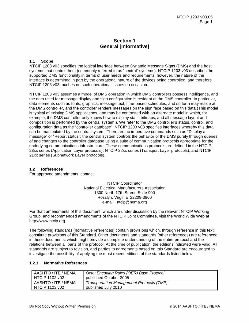
1.1 Scope NTCIP 1203 v03 specifies the logical interface between Dynamic Message Signs (DMS) and the host systems that control them (commonly referred to as “central” systems). NTCIP 1203 v03 describes the supported DMS functionality in terms of user needs and requirements; however, the nature of the interface is determined in part by the operational nature of the devices being controlled, and therefore NTCIP 1203 v03 touches on such operational issues on occasion. NTCIP 1203 v03 assumes a model of DMS operation in which DMS controllers possess intelligence, and the data used for message display and sign configuration is resident at the DMS controller. In particular, data elements such as fonts, graphics, message text, time-based schedules, and so forth may reside at the DMS controller, and the controller renders messages on the sign face based on this data (This model is typical of existing DMS applications, and may be contrasted with an alternate model in which, for example, the DMS controller only knows how to display static bitmaps, and all message layout and composition is performed by the central system.). We refer to the DMS controller’s status, control, and configuration data as the “controller database”; NTCIP 1203 v03 specifies interfaces whereby this data can be manipulated by the central system. There are no imperative commands such as “Display a message” or “Report status”; the central system controls the behavior of the DMS purely through queries of and changes to the controller database using a suite of communication protocols appropriate for the underlying communications infrastructure. These communications protocols are defined in the NTCIP 23xx series (Application Layer protocols), NTCIP 22xx series (Transport Layer protocols), and NTCIP 21xx series (Subnetwork Layer protocols). 1.2 References For approved amendments, contact:
NTCIP Coordinator National Electrical Manufacturers Association
1300 North 17th Street, Suite 900 Rosslyn, Virginia 22209-3806
e-mail: [email protected] For draft amendments of this document, which are under discussion by the relevant NTCIP Working Group, and recommended amendments of the NTCIP Joint Committee, visit the World Wide Web at http://www.ntcip.org. The following standards (normative references) contain provisions which, through reference in this text, constitute provisions of this Standard. Other documents and standards (other references) are referenced in these documents, which might provide a complete understanding of the entire protocol and the relations between all parts of the protocol. At the time of publication, the editions indicated were valid. All standards are subject to revision, and parties to agreements based on this Standard are encouraged to investigate the possibility of applying the most recent editions of the standards listed below. 1.2.1 Normative References
AASHTO / ITE / NEMA NTCIP 1102 v02
Octet Encoding Rules (OER) Base Protocol published October 2005
AASHTO / ITE / NEMA NTCIP 1103 v02
Transportation Management Protocols (TMP) published July 2010
Do Not Copy Without Written Permission © 2014 AASHTO / ITE / NEMA
NTCIP 1203 v03.05 Page 2
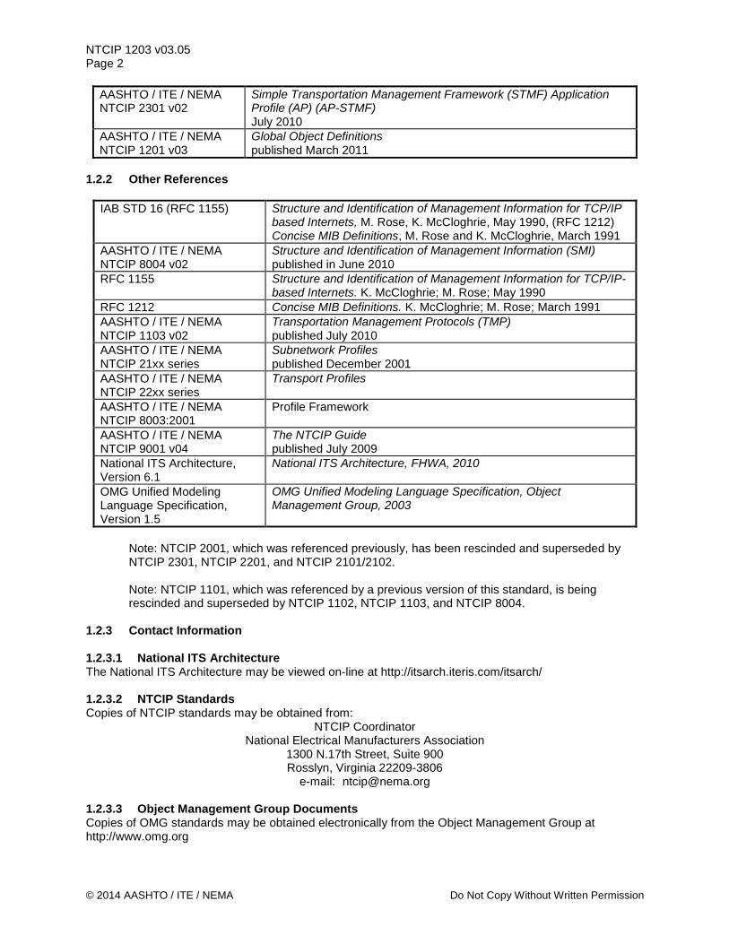
AASHTO / ITE / NEMA NTCIP 2301 v02
Simple Transportation Management Framework (STMF) Application Profile (AP) (AP-STMF) July 2010
AASHTO / ITE / NEMA NTCIP 1201 v03
Global Object Definitions published March 2011
1.2.2 Other References
IAB STD 16 (RFC 1155) Structure and Identification of Management Information for TCP/IP based Internets, M. Rose, K. McCloghrie, May 1990, (RFC 1212) Concise MIB Definitions, M. Rose and K. McCloghrie, March 1991
AASHTO / ITE / NEMA NTCIP 8004 v02
Structure and Identification of Management Information (SMI) published in June 2010
RFC 1155 Structure and Identification of Management Information for TCP/IP-based Internets. K. McCloghrie; M. Rose; May 1990
RFC 1212 Concise MIB Definitions. K. McCloghrie; M. Rose; March 1991 AASHTO / ITE / NEMA NTCIP 1103 v02
Transportation Management Protocols (TMP) published July 2010
AASHTO / ITE / NEMA NTCIP 21xx series
Subnetwork Profiles published December 2001
AASHTO / ITE / NEMA NTCIP 22xx series
Transport Profiles
AASHTO / ITE / NEMA NTCIP 8003:2001
Profile Framework
AASHTO / ITE / NEMA NTCIP 9001 v04
The NTCIP Guide published July 2009
National ITS Architecture, Version 6.1
National ITS Architecture, FHWA, 2010
OMG Unified Modeling Language Specification, Version 1.5
OMG Unified Modeling Language Specification, Object Management Group, 2003
Note: NTCIP 2001, which was referenced previously, has been rescinded and superseded by NTCIP 2301, NTCIP 2201, and NTCIP 2101/2102.
Note: NTCIP 1101, which was referenced by a previous version of this standard, is being rescinded and superseded by NTCIP 1102, NTCIP 1103, and NTCIP 8004.
1.2.3 Contact Information 1.2.3.1 National ITS Architecture The National ITS Architecture may be viewed on-line at http://itsarch.iteris.com/itsarch/ 1.2.3.2 NTCIP Standards Copies of NTCIP standards may be obtained from:
NTCIP Coordinator National Electrical Manufacturers Association
1300 N.17th Street, Suite 900 Rosslyn, Virginia 22209-3806
e-mail: [email protected] 1.2.3.3 Object Management Group Documents Copies of OMG standards may be obtained electronically from the Object Management Group at http://www.omg.org
© 2014 AASHTO / ITE / NEMA Do Not Copy Without Written Permission
NTCIP 1203 v03.05 Page 3
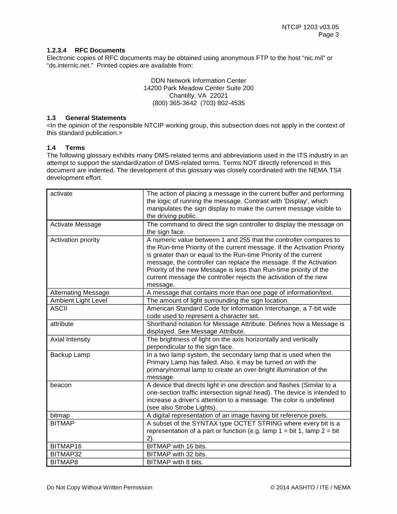
1.2.3.4 RFC Documents Electronic copies of RFC documents may be obtained using anonymous FTP to the host “nic.mil” or “ds.internic.net.” Printed copies are available from:
DDN Network Information Center 14200 Park Meadow Center Suite 200
Chantilly, VA 22021 (800) 365-3642 (703) 802-4535
1.3 General Statements <In the opinion of the responsible NTCIP working group, this subsection does not apply in the context of this standard publication.> 1.4 Terms The following glossary exhibits many DMS-related terms and abbreviations used in the ITS industry in an attempt to support the standardization of DMS-related terms. Terms NOT directly referenced in this document are indented. The development of this glossary was closely coordinated with the NEMA TS4 development effort. activate The action of placing a message in the current buffer and performing
the logic of running the message. Contrast with 'Display', which manipulates the sign display to make the current message visible to the driving public.
Activate Message The command to direct the sign controller to display the message on the sign face.
Activation priority A numeric value between 1 and 255 that the controller compares to the Run-time Priority of the current message. If the Activation Priority is greater than or equal to the Run-time Priority of the current message, the controller can replace the message. If the Activation Priority of the new Message is less than Run-time priority of the current message the controller rejects the activation of the new message.
Alternating Message A message that contains more than one page of information/text. Ambient Light Level The amount of light surrounding the sign location. ASCII American Standard Code for Information Interchange, a 7-bit wide
code used to represent a character set. attribute Shorthand notation for Message Attribute. Defines how a Message is
displayed. See Message Attribute. Axial Intensity The brightness of light on the axis horizontally and vertically
perpendicular to the sign face. Backup Lamp In a two lamp system, the secondary lamp that is used when the
Primary Lamp has failed. Also, it may be turned on with the primary/normal lamp to create an over-bright illumination of the message.
beacon A device that directs light in one direction and flashes (Similar to a one-section traffic intersection signal head). The device is intended to increase a driver’s attention to a message. The color is undefined (see also Strobe Lights).
bitmap A digital representation of an image having bit reference pixels. BITMAP A subset of the SYNTAX type OCTET STRING where every bit is a
representation of a part or function (e.g. lamp 1 = bit 1, lamp 2 = bit 2).
BITMAP16 BITMAP with 16 bits. BITMAP32 BITMAP with 32 bits. BITMAP8 BITMAP with 8 bits.
Do Not Copy Without Written Permission © 2014 AASHTO / ITE / NEMA
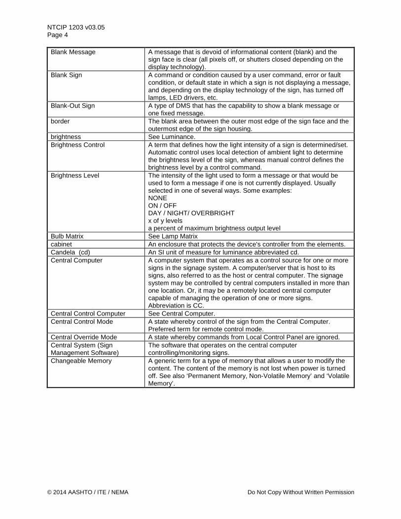
NTCIP 1203 v03.05 Page 4 Blank Message A message that is devoid of informational content (blank) and the
sign face is clear (all pixels off, or shutters closed depending on the display technology).
Blank Sign A command or condition caused by a user command, error or fault condition, or default state in which a sign is not displaying a message, and depending on the display technology of the sign, has turned off lamps, LED drivers, etc.
Blank-Out Sign A type of DMS that has the capability to show a blank message or one fixed message.
border The blank area between the outer most edge of the sign face and the outermost edge of the sign housing.
brightness See Luminance. Brightness Control A term that defines how the light intensity of a sign is determined/set.
Automatic control uses local detection of ambient light to determine the brightness level of the sign, whereas manual control defines the brightness level by a control command.
Brightness Level The intensity of the light used to form a message or that would be used to form a message if one is not currently displayed. Usually selected in one of several ways. Some examples: NONE ON / OFF DAY / NIGHT/ OVERBRIGHT x of y levels a percent of maximum brightness output level
Bulb Matrix See Lamp Matrix cabinet An enclosure that protects the device's controller from the elements. Candela (cd) An SI unit of measure for luminance abbreviated cd. Central Computer A computer system that operates as a control source for one or more
signs in the signage system. A computer/server that is host to its signs, also referred to as the host or central computer. The signage system may be controlled by central computers installed in more than one location. Or, it may be a remotely located central computer capable of managing the operation of one or more signs. Abbreviation is CC.
Central Control Computer See Central Computer. Central Control Mode A state whereby control of the sign from the Central Computer.
Preferred term for remote control mode. Central Override Mode A state whereby commands from Local Control Panel are ignored. Central System (Sign Management Software)
The software that operates on the central computer controlling/monitoring signs.
Changeable Memory A generic term for a type of memory that allows a user to modify the content. The content of the memory is not lost when power is turned off. See also ‘Permanent Memory, Non-Volatile Memory’ and ‘Volatile Memory’.
© 2014 AASHTO / ITE / NEMA Do Not Copy Without Written Permission
NTCIP 1203 v03.05 Page 5
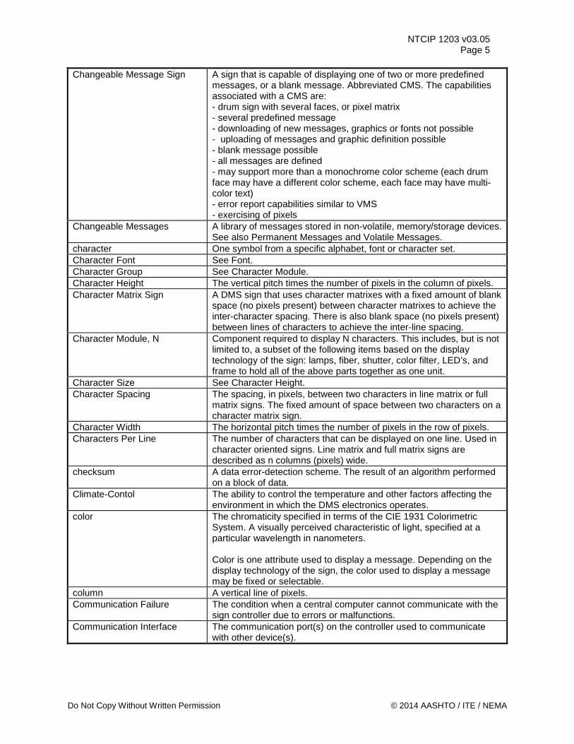
Changeable Message Sign A sign that is capable of displaying one of two or more predefined messages, or a blank message. Abbreviated CMS. The capabilities associated with a CMS are: - drum sign with several faces, or pixel matrix - several predefined message - downloading of new messages, graphics or fonts not possible - uploading of messages and graphic definition possible - blank message possible - all messages are defined - may support more than a monochrome color scheme (each drum face may have a different color scheme, each face may have multi-color text) - error report capabilities similar to VMS - exercising of pixels
Changeable Messages A library of messages stored in non-volatile, memory/storage devices. See also Permanent Messages and Volatile Messages.
character One symbol from a specific alphabet, font or character set. Character Font See Font. Character Group See Character Module. Character Height The vertical pitch times the number of pixels in the column of pixels. Character Matrix Sign A DMS sign that uses character matrixes with a fixed amount of blank
space (no pixels present) between character matrixes to achieve the inter-character spacing. There is also blank space (no pixels present) between lines of characters to achieve the inter-line spacing.
Character Module, N Component required to display N characters. This includes, but is not limited to, a subset of the following items based on the display technology of the sign: lamps, fiber, shutter, color filter, LED’s, and frame to hold all of the above parts together as one unit.
Character Size See Character Height. Character Spacing The spacing, in pixels, between two characters in line matrix or full
matrix signs. The fixed amount of space between two characters on a character matrix sign.
Character Width The horizontal pitch times the number of pixels in the row of pixels. Characters Per Line The number of characters that can be displayed on one line. Used in
character oriented signs. Line matrix and full matrix signs are described as n columns (pixels) wide.
checksum A data error-detection scheme. The result of an algorithm performed on a block of data.
Climate-Contol The ability to control the temperature and other factors affecting the environment in which the DMS electronics operates.
color The chromaticity specified in terms of the CIE 1931 Colorimetric System. A visually perceived characteristic of light, specified at a particular wavelength in nanometers. Color is one attribute used to display a message. Depending on the display technology of the sign, the color used to display a message may be fixed or selectable.
column A vertical line of pixels. Communication Failure The condition when a central computer cannot communicate with the
sign controller due to errors or malfunctions. Communication Interface The communication port(s) on the controller used to communicate
with other device(s).
Do Not Copy Without Written Permission © 2014 AASHTO / ITE / NEMA
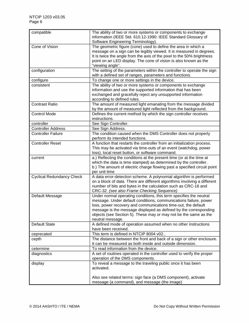
NTCIP 1203 v03.05 Page 6 compatible The ability of two or more systems or components to exchange
information (IEEE Std. 610.12-1990: IEEE Standard Glossary of Software Engineering Terminology).
Cone of Vision The geometric figure (cone) used to define the area in which a message on a sign can be legibly viewed. It is measured in degrees. It is twice the angle from the axis of the pixel to the 50% brightness point on an LED display. The cone of vision is also known as the “viewing angle”.
configuration The setting of the parameters within the controller to operate the sign with a defined set of ranges, parameters and functions.
configure To change one or more settings in the device. consistent The ability of two or more systems or components to exchange
information and use the supported information that has been exchanged and gracefully reject any unsupported information according to defined rules.
Contrast Ratio The amount of measured light emanating from the message divided by the amount of measured light reflected from the background.
Control Mode Defines the current method by which the sign controller receives instructions.
controller See Sign Controller. Controller Address See Sign Address. Controller Failure The condition caused when the DMS Controller does not properly
perform its intended functions. Controller Reset A function that restarts the controller from an initialization process.
This may be activated via time-outs of an event (watchdog, power loss), local reset button, or software command.
current a.) Reflecting the conditions at the present time (or at the time at which the data is time stamped) as determined by the controller. b.) The amount of electric charge flowing past a specified circuit point per unit time
Cyclical Redundancy Check A data error-detection scheme. A polynomial algorithm is performed on a block of data. There are different algorithms involving a different number of bits and bytes in the calculation such as CRC-16 and CRC-32. (see also Frame Checking Sequence)
Default Message Under normal operating conditions, this term specifies the neutral message. Under default conditions, communications failure, power loss, power recovery and communications time-out, the default message is the message displayed as defined by the corresponding objects (see Section 5). These may or may not be the same as the neutral message.
Default State A defined mode of operation assumed when no other instructions have been received.
ceprecated This term is defined in NTCIP 8004 v02.. cepth The distance between the front and back of a sign or other enclosure.
It can be measured as both inside and outside dimension. cetermine To read information from the device. diagnostics A set of routines operated in the controller used to verify the proper
operation of the DMS components. display To reveal a message to the traveling public once it has been
activated. Also see related terms: sign face (a DMS component), activate message (a command), and message (the image)
© 2014 AASHTO / ITE / NEMA Do Not Copy Without Written Permission
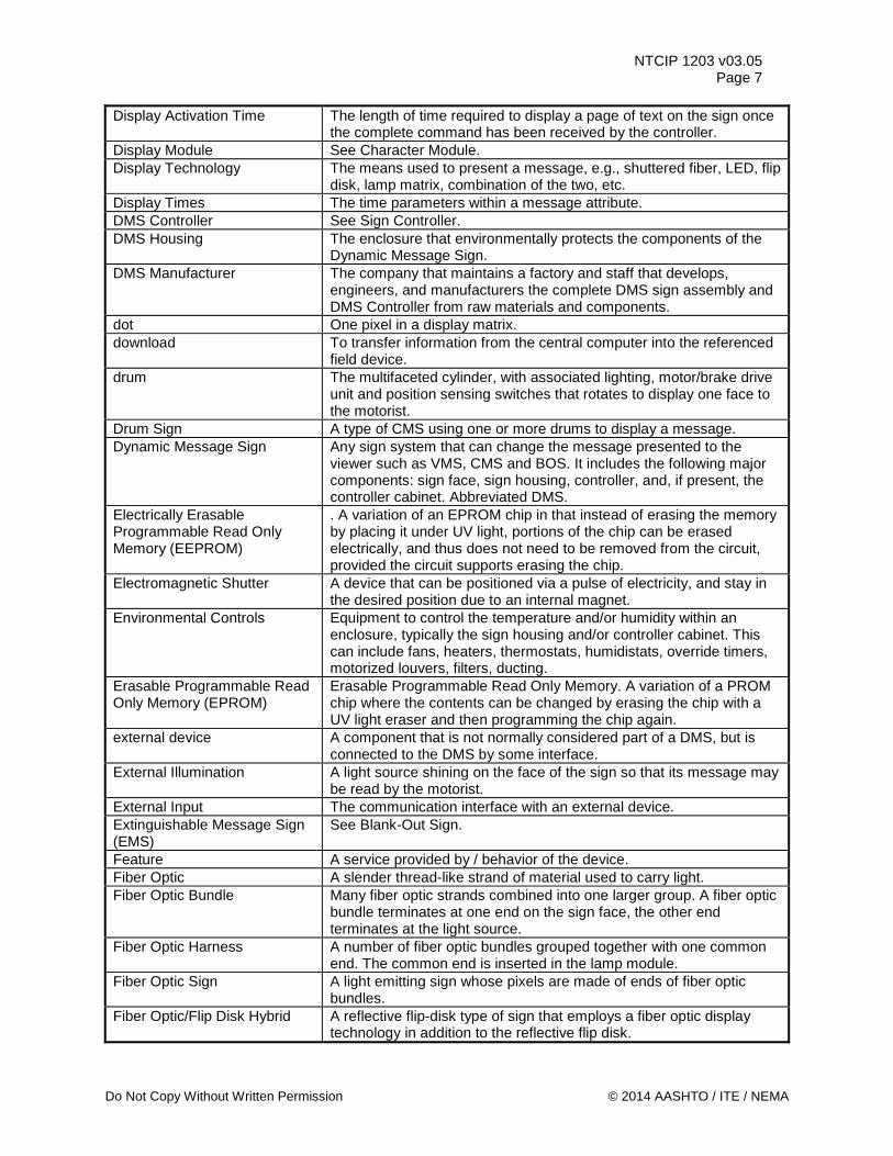
NTCIP 1203 v03.05 Page 7
Display Activation Time The length of time required to display a page of text on the sign once the complete command has been received by the controller.
Display Module See Character Module. Display Technology The means used to present a message, e.g., shuttered fiber, LED, flip
disk, lamp matrix, combination of the two, etc. Display Times The time parameters within a message attribute. DMS Controller See Sign Controller. DMS Housing The enclosure that environmentally protects the components of the
Dynamic Message Sign. DMS Manufacturer The company that maintains a factory and staff that develops,
engineers, and manufacturers the complete DMS sign assembly and DMS Controller from raw materials and components.
dot One pixel in a display matrix. download To transfer information from the central computer into the referenced
field device. drum The multifaceted cylinder, with associated lighting, motor/brake drive
unit and position sensing switches that rotates to display one face to the motorist.
Drum Sign A type of CMS using one or more drums to display a message. Dynamic Message Sign Any sign system that can change the message presented to the
viewer such as VMS, CMS and BOS. It includes the following major components: sign face, sign housing, controller, and, if present, the controller cabinet. Abbreviated DMS.
Electrically Erasable Programmable Read Only Memory (EEPROM)
. A variation of an EPROM chip in that instead of erasing the memory by placing it under UV light, portions of the chip can be erased electrically, and thus does not need to be removed from the circuit, provided the circuit supports erasing the chip.
Electromagnetic Shutter A device that can be positioned via a pulse of electricity, and stay in the desired position due to an internal magnet.
Environmental Controls Equipment to control the temperature and/or humidity within an enclosure, typically the sign housing and/or controller cabinet. This can include fans, heaters, thermostats, humidistats, override timers, motorized louvers, filters, ducting.
Erasable Programmable Read Only Memory (EPROM)
Erasable Programmable Read Only Memory. A variation of a PROM chip where the contents can be changed by erasing the chip with a UV light eraser and then programming the chip again.
external device A component that is not normally considered part of a DMS, but is connected to the DMS by some interface.
External Illumination A light source shining on the face of the sign so that its message may be read by the motorist.
External Input The communication interface with an external device. Extinguishable Message Sign (EMS)
See Blank-Out Sign.
Feature A service provided by / behavior of the device. Fiber Optic A slender thread-like strand of material used to carry light. Fiber Optic Bundle Many fiber optic strands combined into one larger group. A fiber optic
bundle terminates at one end on the sign face, the other end terminates at the light source.
Fiber Optic Harness A number of fiber optic bundles grouped together with one common end. The common end is inserted in the lamp module.
Fiber Optic Sign A light emitting sign whose pixels are made of ends of fiber optic bundles.
Fiber Optic/Flip Disk Hybrid A reflective flip-disk type of sign that employs a fiber optic display technology in addition to the reflective flip disk.
Do Not Copy Without Written Permission © 2014 AASHTO / ITE / NEMA
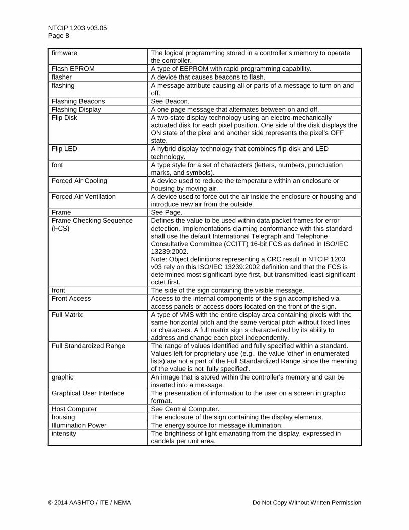
NTCIP 1203 v03.05 Page 8 firmware The logical programming stored in a controller’s memory to operate
the controller. Flash EPROM A type of EEPROM with rapid programming capability. flasher A device that causes beacons to flash. flashing A message attribute causing all or parts of a message to turn on and
off. Flashing Beacons See Beacon. Flashing Display A one page message that alternates between on and off. Flip Disk A two-state display technology using an electro-mechanically
actuated disk for each pixel position. One side of the disk displays the ON state of the pixel and another side represents the pixel’s OFF state.
Flip LED A hybrid display technology that combines flip-disk and LED technology.
font A type style for a set of characters (letters, numbers, punctuation marks, and symbols).
Forced Air Cooling A device used to reduce the temperature within an enclosure or housing by moving air.
Forced Air Ventilation A device used to force out the air inside the enclosure or housing and introduce new air from the outside.
Frame See Page. Frame Checking Sequence (FCS)
Defines the value to be used within data packet frames for error detection. Implementations claiming conformance with this standard shall use the default International Telegraph and Telephone Consultative Committee (CCITT) 16-bit FCS as defined in ISO/IEC 13239:2002. Note: Object definitions representing a CRC result in NTCIP 1203 v03 rely on this ISO/IEC 13239:2002 definition and that the FCS is determined most significant byte first, but transmitted least significant octet first.
front The side of the sign containing the visible message. Front Access Access to the internal components of the sign accomplished via
access panels or access doors located on the front of the sign. Full Matrix A type of VMS with the entire display area containing pixels with the
same horizontal pitch and the same vertical pitch without fixed lines or characters. A full matrix sign s characterized by its ability to address and change each pixel independently.
Full Standardized Range The range of values identified and fully specified within a standard. Values left for proprietary use (e.g., the value 'other' in enumerated lists) are not a part of the Full Standardized Range since the meaning of the value is not 'fully specified'.
graphic An image that is stored within the controller's memory and can be inserted into a message.
Graphical User Interface The presentation of information to the user on a screen in graphic format.
Host Computer See Central Computer. housing The enclosure of the sign containing the display elements. Illumination Power The energy source for message illumination. intensity The brightness of light emanating from the display, expressed in
candela per unit area.
© 2014 AASHTO / ITE / NEMA Do Not Copy Without Written Permission
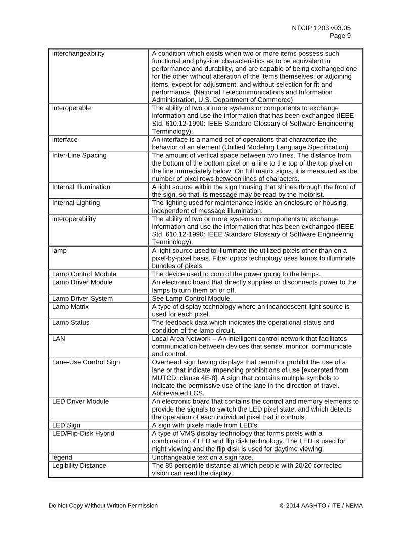
NTCIP 1203 v03.05 Page 9
interchangeability A condition which exists when two or more items possess such functional and physical characteristics as to be equivalent in performance and durability, and are capable of being exchanged one for the other without alteration of the items themselves, or adjoining items, except for adjustment, and without selection for fit and performance. (National Telecommunications and Information Administration, U.S. Department of Commerce)
interoperable The ability of two or more systems or components to exchange information and use the information that has been exchanged (IEEE Std. 610.12-1990: IEEE Standard Glossary of Software Engineering Terminology).
interface An interface is a named set of operations that characterize the behavior of an element (Unified Modeling Language Specification)
Inter-Line Spacing The amount of vertical space between two lines. The distance from the bottom of the bottom pixel on a line to the top of the top pixel on the line immediately below. On full matrix signs, it is measured as the number of pixel rows between lines of characters.
Internal Illumination A light source within the sign housing that shines through the front of the sign, so that its message may be read by the motorist.
Internal Lighting The lighting used for maintenance inside an enclosure or housing, independent of message illumination.
interoperability The ability of two or more systems or components to exchange information and use the information that has been exchanged (IEEE Std. 610.12-1990: IEEE Standard Glossary of Software Engineering Terminology).
lamp A light source used to illuminate the utilized pixels other than on a pixel-by-pixel basis. Fiber optics technology uses lamps to illuminate bundles of pixels.
Lamp Control Module The device used to control the power going to the lamps. Lamp Driver Module An electronic board that directly supplies or disconnects power to the
lamps to turn them on or off. Lamp Driver System See Lamp Control Module. Lamp Matrix A type of display technology where an incandescent light source is
used for each pixel. Lamp Status The feedback data which indicates the operational status and
condition of the lamp circuit. LAN Local Area Network – An intelligent control network that facilitates
communication between devices that sense, monitor, communicate and control.
Lane-Use Control Sign Overhead sign having displays that permit or prohibit the use of a lane or that indicate impending prohibitions of use [excerpted from MUTCD, clause 4E-8]. A sign that contains multiple symbols to indicate the permissive use of the lane in the direction of travel. Abbreviated LCS.
LED Driver Module An electronic board that contains the control and memory elements to provide the signals to switch the LED pixel state, and which detects the operation of each individual pixel that it controls.
LED Sign A sign with pixels made from LED’s. LED/Flip-Disk Hybrid A type of VMS display technology that forms pixels with a
combination of LED and flip disk technology. The LED is used for night viewing and the flip disk is used for daytime viewing.
legend Unchangeable text on a sign face. Legibility Distance The 85 percentile distance at which people with 20/20 corrected
vision can read the display.
Do Not Copy Without Written Permission © 2014 AASHTO / ITE / NEMA
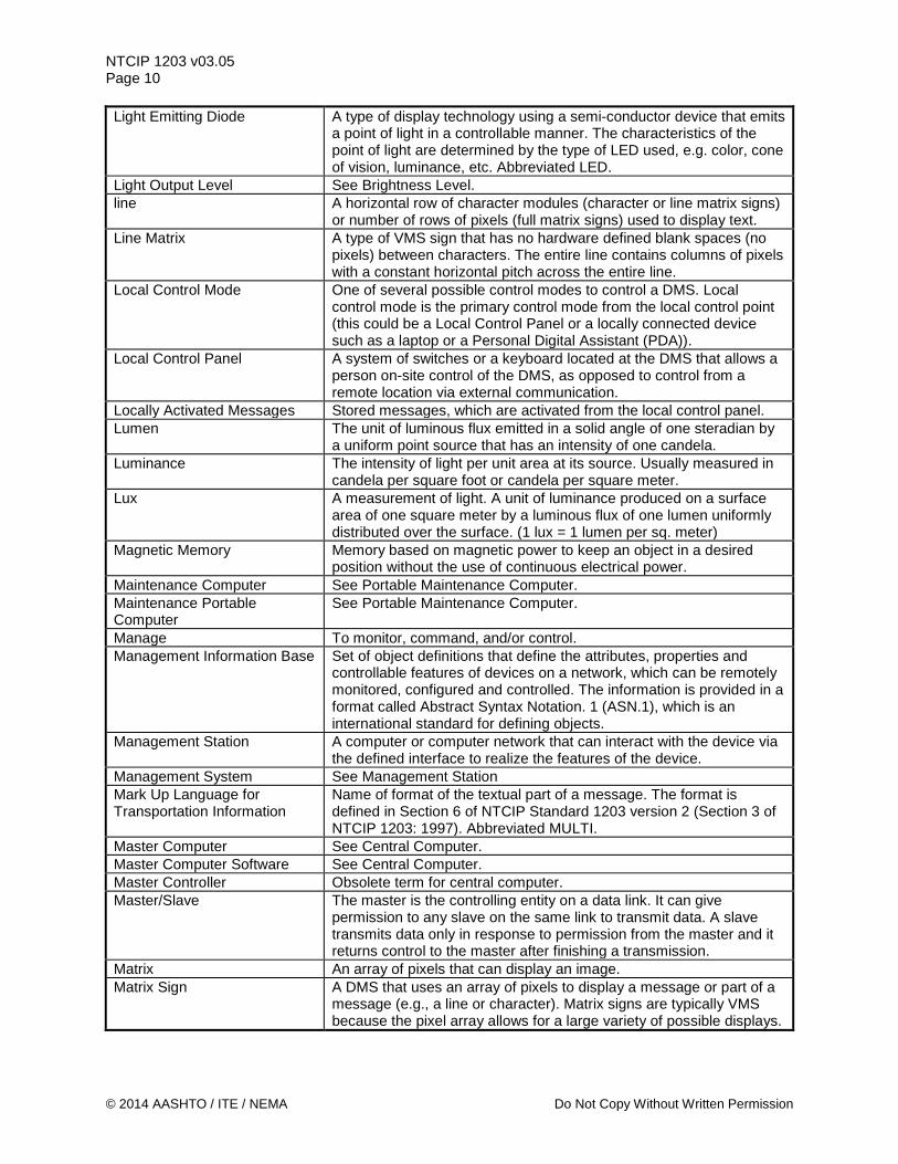
NTCIP 1203 v03.05 Page 10 Light Emitting Diode A type of display technology using a semi-conductor device that emits
a point of light in a controllable manner. The characteristics of the point of light are determined by the type of LED used, e.g. color, cone of vision, luminance, etc. Abbreviated LED.
Light Output Level See Brightness Level. line A horizontal row of character modules (character or line matrix signs)
or number of rows of pixels (full matrix signs) used to display text. Line Matrix A type of VMS sign that has no hardware defined blank spaces (no
pixels) between characters. The entire line contains columns of pixels with a constant horizontal pitch across the entire line.
Local Control Mode One of several possible control modes to control a DMS. Local control mode is the primary control mode from the local control point (this could be a Local Control Panel or a locally connected device such as a laptop or a Personal Digital Assistant (PDA)).
Local Control Panel A system of switches or a keyboard located at the DMS that allows a person on-site control of the DMS, as opposed to control from a remote location via external communication.
Locally Activated Messages Stored messages, which are activated from the local control panel. Lumen The unit of luminous flux emitted in a solid angle of one steradian by
a uniform point source that has an intensity of one candela. Luminance The intensity of light per unit area at its source. Usually measured in
candela per square foot or candela per square meter. Lux A measurement of light. A unit of luminance produced on a surface
area of one square meter by a luminous flux of one lumen uniformly distributed over the surface. (1 lux = 1 lumen per sq. meter)
Magnetic Memory Memory based on magnetic power to keep an object in a desired position without the use of continuous electrical power.
Maintenance Computer See Portable Maintenance Computer. Maintenance Portable Computer
See Portable Maintenance Computer.
Manage To monitor, command, and/or control. Management Information Base Set of object definitions that define the attributes, properties and
controllable features of devices on a network, which can be remotely monitored, configured and controlled. The information is provided in a format called Abstract Syntax Notation. 1 (ASN.1), which is an international standard for defining objects.
Management Station A computer or computer network that can interact with the device via the defined interface to realize the features of the device.
Management System See Management Station Mark Up Language for Transportation Information
Name of format of the textual part of a message. The format is defined in Section 6 of NTCIP Standard 1203 version 2 (Section 3 of NTCIP 1203: 1997). Abbreviated MULTI.
Master Computer See Central Computer. Master Computer Software See Central Computer. Master Controller Obsolete term for central computer. Master/Slave The master is the controlling entity on a data link. It can give
permission to any slave on the same link to transmit data. A slave transmits data only in response to permission from the master and it returns control to the master after finishing a transmission.
Matrix An array of pixels that can display an image. Matrix Sign A DMS that uses an array of pixels to display a message or part of a
message (e.g., a line or character). Matrix signs are typically VMS because the pixel array allows for a large variety of possible displays.
© 2014 AASHTO / ITE / NEMA Do Not Copy Without Written Permission
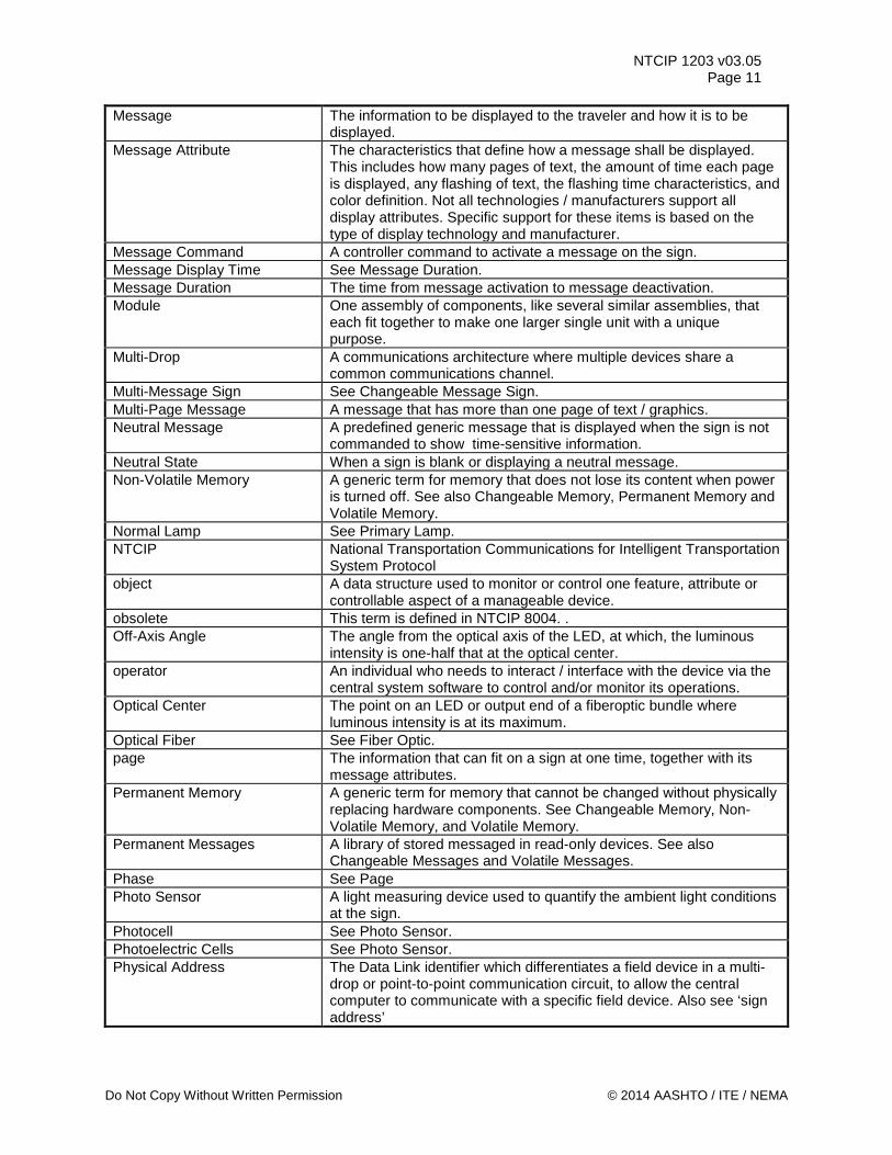
NTCIP 1203 v03.05 Page 11
Message The information to be displayed to the traveler and how it is to be displayed.
Message Attribute The characteristics that define how a message shall be displayed. This includes how many pages of text, the amount of time each page is displayed, any flashing of text, the flashing time characteristics, and color definition. Not all technologies / manufacturers support all display attributes. Specific support for these items is based on the type of display technology and manufacturer.
Message Command A controller command to activate a message on the sign. Message Display Time See Message Duration. Message Duration The time from message activation to message deactivation. Module One assembly of components, like several similar assemblies, that
each fit together to make one larger single unit with a unique purpose.
Multi-Drop A communications architecture where multiple devices share a common communications channel.
Multi-Message Sign See Changeable Message Sign. Multi-Page Message A message that has more than one page of text / graphics. Neutral Message A predefined generic message that is displayed when the sign is not
commanded to show time-sensitive information. Neutral State When a sign is blank or displaying a neutral message. Non-Volatile Memory A generic term for memory that does not lose its content when power
is turned off. See also Changeable Memory, Permanent Memory and Volatile Memory.
Normal Lamp See Primary Lamp. NTCIP National Transportation Communications for Intelligent Transportation
System Protocol object A data structure used to monitor or control one feature, attribute or
controllable aspect of a manageable device. obsolete This term is defined in NTCIP 8004. . Off-Axis Angle The angle from the optical axis of the LED, at which, the luminous
intensity is one-half that at the optical center. operator An individual who needs to interact / interface with the device via the
central system software to control and/or monitor its operations. Optical Center The point on an LED or output end of a fiberoptic bundle where
luminous intensity is at its maximum. Optical Fiber See Fiber Optic. page The information that can fit on a sign at one time, together with its
message attributes. Permanent Memory A generic term for memory that cannot be changed without physically
replacing hardware components. See Changeable Memory, Non-Volatile Memory, and Volatile Memory.
Permanent Messages A library of stored messaged in read-only devices. See also Changeable Messages and Volatile Messages.
Phase See Page Photo Sensor A light measuring device used to quantify the ambient light conditions
at the sign. Photocell See Photo Sensor. Photoelectric Cells See Photo Sensor. Physical Address The Data Link identifier which differentiates a field device in a multi-
drop or point-to-point communication circuit, to allow the central computer to communicate with a specific field device. Also see ‘sign address’
Do Not Copy Without Written Permission © 2014 AASHTO / ITE / NEMA
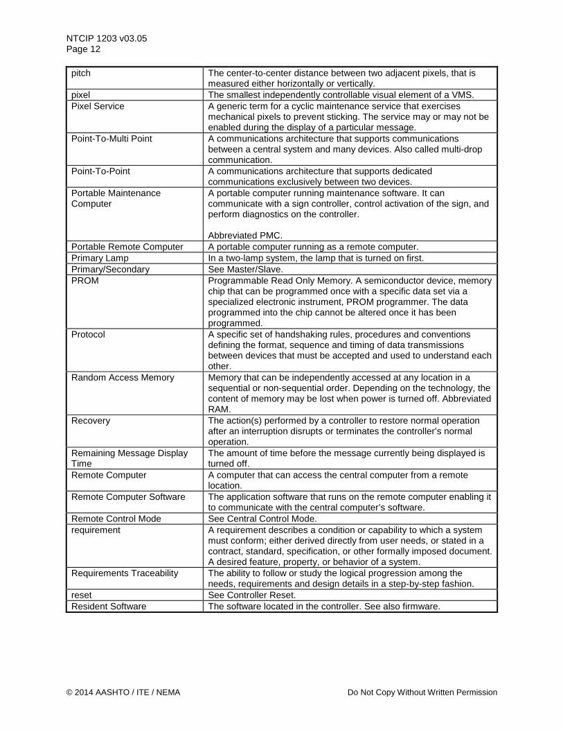
NTCIP 1203 v03.05 Page 12 pitch The center-to-center distance between two adjacent pixels, that is
measured either horizontally or vertically. pixel The smallest independently controllable visual element of a VMS. Pixel Service A generic term for a cyclic maintenance service that exercises
mechanical pixels to prevent sticking. The service may or may not be enabled during the display of a particular message.
Point-To-Multi Point A communications architecture that supports communications between a central system and many devices. Also called multi-drop communication.
Point-To-Point A communications architecture that supports dedicated communications exclusively between two devices.
Portable Maintenance Computer
A portable computer running maintenance software. It can communicate with a sign controller, control activation of the sign, and perform diagnostics on the controller. Abbreviated PMC.
Portable Remote Computer A portable computer running as a remote computer. Primary Lamp In a two-lamp system, the lamp that is turned on first. Primary/Secondary See Master/Slave. PROM Programmable Read Only Memory. A semiconductor device, memory
chip that can be programmed once with a specific data set via a specialized electronic instrument, PROM programmer. The data programmed into the chip cannot be altered once it has been programmed.
Protocol A specific set of handshaking rules, procedures and conventions defining the format, sequence and timing of data transmissions between devices that must be accepted and used to understand each other.
Random Access Memory Memory that can be independently accessed at any location in a sequential or non-sequential order. Depending on the technology, the content of memory may be lost when power is turned off. Abbreviated RAM.
Recovery The action(s) performed by a controller to restore normal operation after an interruption disrupts or terminates the controller’s normal operation.
Remaining Message Display Time
The amount of time before the message currently being displayed is turned off.
Remote Computer A computer that can access the central computer from a remote location.
Remote Computer Software The application software that runs on the remote computer enabling it to communicate with the central computer’s software.
Remote Control Mode See Central Control Mode. requirement A requirement describes a condition or capability to which a system
must conform; either derived directly from user needs, or stated in a contract, standard, specification, or other formally imposed document. A desired feature, property, or behavior of a system.
Requirements Traceability The ability to follow or study the logical progression among the needs, requirements and design details in a step-by-step fashion.
reset See Controller Reset. Resident Software The software located in the controller. See also firmware.
© 2014 AASHTO / ITE / NEMA Do Not Copy Without Written Permission
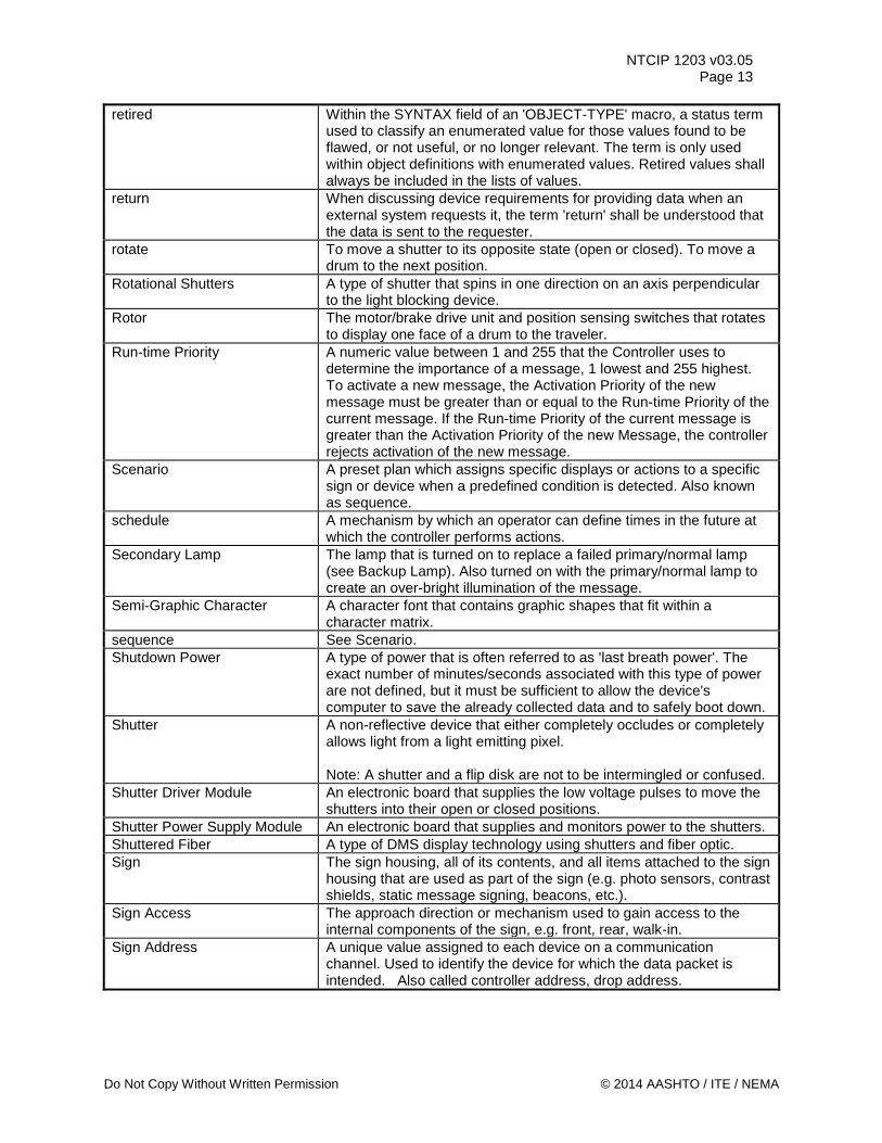
NTCIP 1203 v03.05 Page 13
retired Within the SYNTAX field of an 'OBJECT-TYPE' macro, a status term used to classify an enumerated value for those values found to be flawed, or not useful, or no longer relevant. The term is only used within object definitions with enumerated values. Retired values shall always be included in the lists of values.
return When discussing device requirements for providing data when an external system requests it, the term 'return' shall be understood that the data is sent to the requester.
rotate To move a shutter to its opposite state (open or closed). To move a drum to the next position.
Rotational Shutters A type of shutter that spins in one direction on an axis perpendicular to the light blocking device.
Rotor The motor/brake drive unit and position sensing switches that rotates to display one face of a drum to the traveler.
Run-time Priority A numeric value between 1 and 255 that the Controller uses to determine the importance of a message, 1 lowest and 255 highest. To activate a new message, the Activation Priority of the new message must be greater than or equal to the Run-time Priority of the current message. If the Run-time Priority of the current message is greater than the Activation Priority of the new Message, the controller rejects activation of the new message.
Scenario A preset plan which assigns specific displays or actions to a specific sign or device when a predefined condition is detected. Also known as sequence.
schedule A mechanism by which an operator can define times in the future at which the controller performs actions.
Secondary Lamp The lamp that is turned on to replace a failed primary/normal lamp (see Backup Lamp). Also turned on with the primary/normal lamp to create an over-bright illumination of the message.
Semi-Graphic Character A character font that contains graphic shapes that fit within a character matrix.
sequence See Scenario. Shutdown Power A type of power that is often referred to as 'last breath power'. The
exact number of minutes/seconds associated with this type of power are not defined, but it must be sufficient to allow the device's computer to save the already collected data and to safely boot down.
Shutter A non-reflective device that either completely occludes or completely allows light from a light emitting pixel. Note: A shutter and a flip disk are not to be intermingled or confused.
Shutter Driver Module An electronic board that supplies the low voltage pulses to move the shutters into their open or closed positions.
Shutter Power Supply Module An electronic board that supplies and monitors power to the shutters. Shuttered Fiber A type of DMS display technology using shutters and fiber optic. Sign The sign housing, all of its contents, and all items attached to the sign
housing that are used as part of the sign (e.g. photo sensors, contrast shields, static message signing, beacons, etc.).
Sign Access The approach direction or mechanism used to gain access to the internal components of the sign, e.g. front, rear, walk-in.
Sign Address A unique value assigned to each device on a communication channel. Used to identify the device for which the data packet is intended. Also called controller address, drop address.
Do Not Copy Without Written Permission © 2014 AASHTO / ITE / NEMA
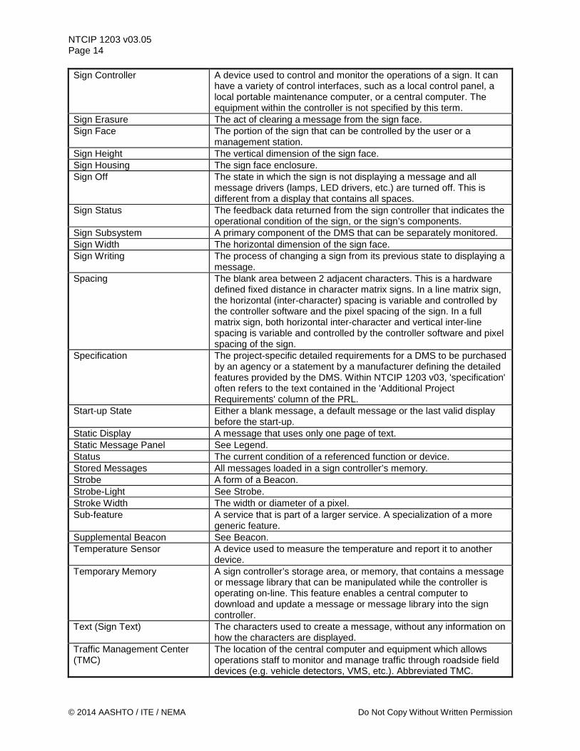
NTCIP 1203 v03.05 Page 14 Sign Controller A device used to control and monitor the operations of a sign. It can
have a variety of control interfaces, such as a local control panel, a local portable maintenance computer, or a central computer. The equipment within the controller is not specified by this term.
Sign Erasure The act of clearing a message from the sign face. Sign Face The portion of the sign that can be controlled by the user or a
management station. Sign Height The vertical dimension of the sign face. Sign Housing The sign face enclosure. Sign Off The state in which the sign is not displaying a message and all
message drivers (lamps, LED drivers, etc.) are turned off. This is different from a display that contains all spaces.
Sign Status The feedback data returned from the sign controller that indicates the operational condition of the sign, or the sign’s components.
Sign Subsystem A primary component of the DMS that can be separately monitored. Sign Width The horizontal dimension of the sign face. Sign Writing The process of changing a sign from its previous state to displaying a
message. Spacing The blank area between 2 adjacent characters. This is a hardware
defined fixed distance in character matrix signs. In a line matrix sign, the horizontal (inter-character) spacing is variable and controlled by the controller software and the pixel spacing of the sign. In a full matrix sign, both horizontal inter-character and vertical inter-line spacing is variable and controlled by the controller software and pixel spacing of the sign.
Specification The project-specific detailed requirements for a DMS to be purchased by an agency or a statement by a manufacturer defining the detailed features provided by the DMS. Within NTCIP 1203 v03, 'specification' often refers to the text contained in the 'Additional Project Requirements' column of the PRL.
Start-up State Either a blank message, a default message or the last valid display before the start-up.
Static Display A message that uses only one page of text. Static Message Panel See Legend. Status The current condition of a referenced function or device. Stored Messages All messages loaded in a sign controller’s memory. Strobe A form of a Beacon. Strobe-Light See Strobe. Stroke Width The width or diameter of a pixel. Sub-feature A service that is part of a larger service. A specialization of a more
generic feature. Supplemental Beacon See Beacon. Temperature Sensor A device used to measure the temperature and report it to another
device. Temporary Memory A sign controller’s storage area, or memory, that contains a message
or message library that can be manipulated while the controller is operating on-line. This feature enables a central computer to download and update a message or message library into the sign controller.
Text (Sign Text) The characters used to create a message, without any information on how the characters are displayed.
Traffic Management Center (TMC)
The location of the central computer and equipment which allows operations staff to monitor and manage traffic through roadside field devices (e.g. vehicle detectors, VMS, etc.). Abbreviated TMC.
© 2014 AASHTO / ITE / NEMA Do Not Copy Without Written Permission
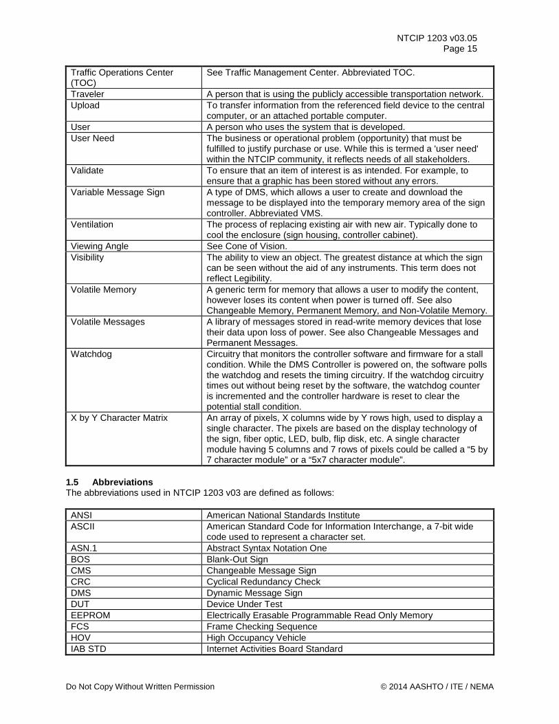
NTCIP 1203 v03.05 Page 15
Traffic Operations Center (TOC)
See Traffic Management Center. Abbreviated TOC.
Traveler A person that is using the publicly accessible transportation network. Upload To transfer information from the referenced field device to the central
computer, or an attached portable computer. User A person who uses the system that is developed. User Need The business or operational problem (opportunity) that must be
fulfilled to justify purchase or use. While this is termed a 'user need' within the NTCIP community, it reflects needs of all stakeholders.
Validate To ensure that an item of interest is as intended. For example, to ensure that a graphic has been stored without any errors.
Variable Message Sign A type of DMS, which allows a user to create and download the message to be displayed into the temporary memory area of the sign controller. Abbreviated VMS.
Ventilation The process of replacing existing air with new air. Typically done to cool the enclosure (sign housing, controller cabinet).
Viewing Angle See Cone of Vision. Visibility The ability to view an object. The greatest distance at which the sign
can be seen without the aid of any instruments. This term does not reflect Legibility.
Volatile Memory A generic term for memory that allows a user to modify the content, however loses its content when power is turned off. See also Changeable Memory, Permanent Memory, and Non-Volatile Memory.
Volatile Messages A library of messages stored in read-write memory devices that lose their data upon loss of power. See also Changeable Messages and Permanent Messages.
Watchdog Circuitry that monitors the controller software and firmware for a stall condition. While the DMS Controller is powered on, the software polls the watchdog and resets the timing circuitry. If the watchdog circuitry times out without being reset by the software, the watchdog counter is incremented and the controller hardware is reset to clear the potential stall condition.
X by Y Character Matrix An array of pixels, X columns wide by Y rows high, used to display a single character. The pixels are based on the display technology of the sign, fiber optic, LED, bulb, flip disk, etc. A single character module having 5 columns and 7 rows of pixels could be called a “5 by 7 character module” or a “5x7 character module”.
1.5 Abbreviations The abbreviations used in NTCIP 1203 v03 are defined as follows: ANSI American National Standards Institute ASCII American Standard Code for Information Interchange, a 7-bit wide
code used to represent a character set. ASN.1 Abstract Syntax Notation One BOS Blank-Out Sign CMS Changeable Message Sign CRC Cyclical Redundancy Check DMS Dynamic Message Sign DUT Device Under Test EEPROM Electrically Erasable Programmable Read Only Memory FCS Frame Checking Sequence HOV High Occupancy Vehicle IAB STD Internet Activities Board Standard
Do Not Copy Without Written Permission © 2014 AASHTO / ITE / NEMA
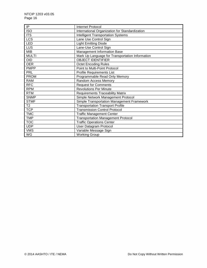
NTCIP 1203 v03.05 Page 16 IP Internet Protocol ISO International Organization for Standardization ITS Intelligent Transportation Systems LCS Lane Use Control Sign LED Light Emitting Diode LUS Lane-Use Control Sign MIB Management Information Base MULTI Mark Up Language for Transportation Information OID OBJECT IDENTIFIER OER Octet Encoding Rules PMPP Point to Multi-Point Protocol PRL Profile Requirements List PROM Programmable Read Only Memory RAM Random Access Memory RFC Request for Comments RPM Revolutions Per Minute RTM Requirements Traceability Matrix SNMP Simple Network Management Protocol STMF Simple Transportation Management Framework T2 Transportation Transport Profile TCP Transmission Control Protocol TMC Traffic Management Center TMP Transportation Management Protocol TOC Traffic Operations Center UDP User Datagram Protocol VMS Variable Message Sign WG Working Group
© 2014 AASHTO / ITE / NEMA Do Not Copy Without Written Permission
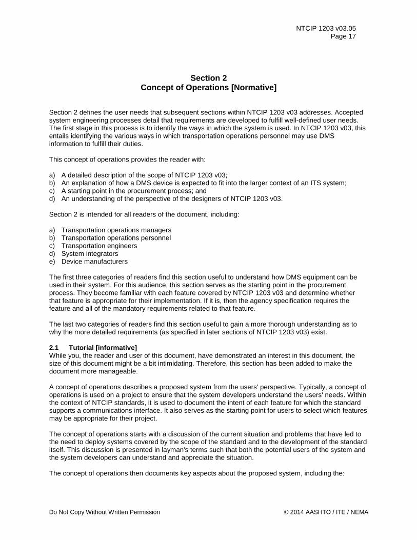
NTCIP 1203 v03.05 Page 17
Section 2 Concept of Operations [Normative]
Section 2 defines the user needs that subsequent sections within NTCIP 1203 v03 addresses. Accepted system engineering processes detail that requirements are developed to fulfill well-defined user needs. The first stage in this process is to identify the ways in which the system is used. In NTCIP 1203 v03, this entails identifying the various ways in which transportation operations personnel may use DMS information to fulfill their duties. This concept of operations provides the reader with: a) A detailed description of the scope of NTCIP 1203 v03; b) An explanation of how a DMS device is expected to fit into the larger context of an ITS system; c) A starting point in the procurement process; and d) An understanding of the perspective of the designers of NTCIP 1203 v03. Section 2 is intended for all readers of the document, including: a) Transportation operations managers b) Transportation operations personnel c) Transportation engineers d) System integrators e) Device manufacturers The first three categories of readers find this section useful to understand how DMS equipment can be used in their system. For this audience, this section serves as the starting point in the procurement process. They become familiar with each feature covered by NTCIP 1203 v03 and determine whether that feature is appropriate for their implementation. If it is, then the agency specification requires the feature and all of the mandatory requirements related to that feature. The last two categories of readers find this section useful to gain a more thorough understanding as to why the more detailed requirements (as specified in later sections of NTCIP 1203 v03) exist. 2.1 Tutorial [informative] While you, the reader and user of this document, have demonstrated an interest in this document, the size of this document might be a bit intimidating. Therefore, this section has been added to make the document more manageable. A concept of operations describes a proposed system from the users' perspective. Typically, a concept of operations is used on a project to ensure that the system developers understand the users' needs. Within the context of NTCIP standards, it is used to document the intent of each feature for which the standard supports a communications interface. It also serves as the starting point for users to select which features may be appropriate for their project. The concept of operations starts with a discussion of the current situation and problems that have led to the need to deploy systems covered by the scope of the standard and to the development of the standard itself. This discussion is presented in layman's terms such that both the potential users of the system and the system developers can understand and appreciate the situation. The concept of operations then documents key aspects about the proposed system, including the:
Do Not Copy Without Written Permission © 2014 AASHTO / ITE / NEMA
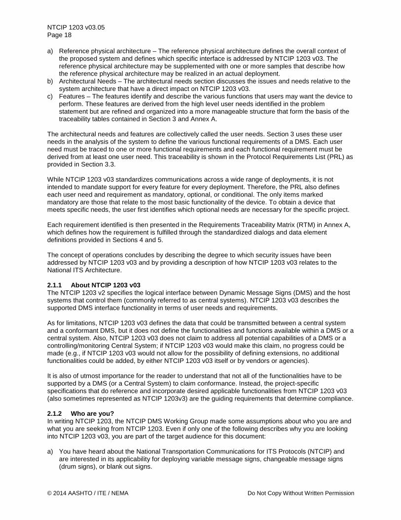
NTCIP 1203 v03.05 Page 18 a) Reference physical architecture – The reference physical architecture defines the overall context of
the proposed system and defines which specific interface is addressed by NTCIP 1203 v03. The reference physical architecture may be supplemented with one or more samples that describe how the reference physical architecture may be realized in an actual deployment.
b) Architectural Needs – The architectural needs section discusses the issues and needs relative to the system architecture that have a direct impact on NTCIP 1203 v03.
c) Features – The features identify and describe the various functions that users may want the device to perform. These features are derived from the high level user needs identified in the problem statement but are refined and organized into a more manageable structure that form the basis of the traceability tables contained in Section 3 and Annex A.
The architectural needs and features are collectively called the user needs. Section 3 uses these user needs in the analysis of the system to define the various functional requirements of a DMS. Each user need must be traced to one or more functional requirements and each functional requirement must be derived from at least one user need. This traceability is shown in the Protocol Requirements List (PRL) as provided in Section 3.3. While NTCIP 1203 v03 standardizes communications across a wide range of deployments, it is not intended to mandate support for every feature for every deployment. Therefore, the PRL also defines each user need and requirement as mandatory, optional, or conditional. The only items marked mandatory are those that relate to the most basic functionality of the device. To obtain a device that meets specific needs, the user first identifies which optional needs are necessary for the specific project. Each requirement identified is then presented in the Requirements Traceability Matrix (RTM) in Annex A, which defines how the requirement is fulfilled through the standardized dialogs and data element definitions provided in Sections 4 and 5. The concept of operations concludes by describing the degree to which security issues have been addressed by NTCIP 1203 v03 and by providing a description of how NTCIP 1203 v03 relates to the National ITS Architecture. 2.1.1 About NTCIP 1203 v03 The NTCIP 1203 v2 specifies the logical interface between Dynamic Message Signs (DMS) and the host systems that control them (commonly referred to as central systems). NTCIP 1203 v03 describes the supported DMS interface functionality in terms of user needs and requirements. As for limitations, NTCIP 1203 v03 defines the data that could be transmitted between a central system and a conformant DMS, but it does not define the functionalities and functions available within a DMS or a central system. Also, NTCIP 1203 v03 does not claim to address all potential capabilities of a DMS or a controlling/monitoring Central System; if NTCIP 1203 v03 would make this claim, no progress could be made (e.g., if NTCIP 1203 v03 would not allow for the possibility of defining extensions, no additional functionalities could be added, by either NTCIP 1203 v03 itself or by vendors or agencies). It is also of utmost importance for the reader to understand that not all of the functionalities have to be supported by a DMS (or a Central System) to claim conformance. Instead, the project-specific specifications that do reference and incorporate desired applicable functionalities from NTCIP 1203 v03 (also sometimes represented as NTCIP 1203v3) are the guiding requirements that determine compliance. 2.1.2 Who are you? In writing NTCIP 1203, the NTCIP DMS Working Group made some assumptions about who you are and what you are seeking from NTCIP 1203. Even if only one of the following describes why you are looking into NTCIP 1203 v03, you are part of the target audience for this document: a) You have heard about the National Transportation Communications for ITS Protocols (NTCIP) and
are interested in its applicability for deploying variable message signs, changeable message signs (drum signs), or blank out signs.
© 2014 AASHTO / ITE / NEMA Do Not Copy Without Written Permission
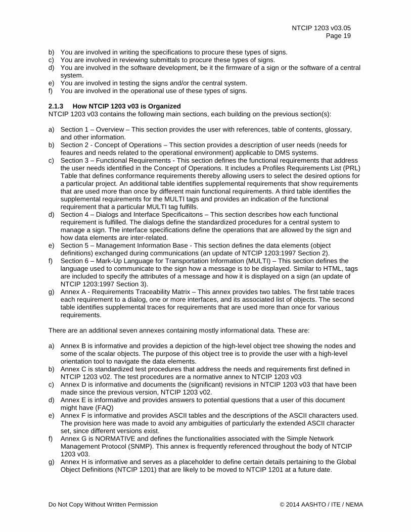
NTCIP 1203 v03.05 Page 19
b) You are involved in writing the specifications to procure these types of signs. c) You are involved in reviewing submittals to procure these types of signs. d) You are involved in the software development, be it the firmware of a sign or the software of a central
system. e) You are involved in testing the signs and/or the central system. f) You are involved in the operational use of these types of signs. 2.1.3 How NTCIP 1203 v03 is Organized NTCIP 1203 v03 contains the following main sections, each building on the previous section(s): a) Section 1 – Overview – This section provides the user with references, table of contents, glossary,
and other information. b) Section 2 - Concept of Operations – This section provides a description of user needs (needs for
feaures and needs related to the operational environment) applicable to DMS systems. c) Section 3 – Functional Requirements - This section defines the functional requirements that address
the user needs identified in the Concept of Operations. It includes a Profiles Requirements List (PRL) Table that defines conformance requirements thereby allowing users to select the desired options for a particular project. An additional table identifies supplemental requirements that show requirements that are used more than once by different main functional requirements. A third table identifies the supplemental requirements for the MULTI tags and provides an indication of the functional requirement that a particular MULTI tag fulfills.
d) Section 4 – Dialogs and Interface Specificaitons – This section describes how each functional requirement is fulfilled. The dialogs define the standardized procedures for a central system to manage a sign. The interface specifications define the operations that are allowed by the sign and how data elements are inter-related.
e) Section 5 – Management Information Base - This section defines the data elements (object definitions) exchanged during communications (an update of NTCIP 1203:1997 Section 2).
f) Section 6 – Mark-Up Language for Transportation Information (MULTI) – This section defines the language used to communicate to the sign how a message is to be displayed. Similar to HTML, tags are included to specify the attributes of a message and how it is displayed on a sign (an update of NTCIP 1203:1997 Section 3).
g) Annex A - Requirements Traceability Matrix – This annex provides two tables. The first table traces each requirement to a dialog, one or more interfaces, and its associated list of objects. The second table identifies supplemental traces for requirements that are used more than once for various requirements.
There are an additional seven annexes containing mostly informational data. These are: a) Annex B is informative and provides a depiction of the high-level object tree showing the nodes and
some of the scalar objects. The purpose of this object tree is to provide the user with a high-level orientation tool to navigate the data elements.
b) Annex C is standardized test procedures that address the needs and requirements first defined in NTCIP 1203 v02. The test procedures are a normative annex to NTCIP 1203 v03
c) Annex D is informative and documents the (significant) revisions in NTCIP 1203 v03 that have been made since the previous version, NTCIP 1203 v02.
d) Annex E is informative and provides answers to potential questions that a user of this document might have (FAQ)
e) Annex F is informative and provides ASCII tables and the descriptions of the ASCII characters used. The provision here was made to avoid any ambiguities of particularly the extended ASCII character set, since different versions exist.
f) Annex G is NORMATIVE and defines the functionalities associated with the Simple Network Management Protocol (SNMP). This annex is frequently referenced throughout the body of NTCIP 1203 v03.
g) Annex H is informative and serves as a placeholder to define certain details pertaining to the Global Object Definitions (NTCIP 1201) that are likely to be moved to NTCIP 1201 at a future date.
Do Not Copy Without Written Permission © 2014 AASHTO / ITE / NEMA
NTCIP 1203 v03.05 Page 20 2.1.4 Intended Audiences for the Sections in NTCIP 1203 v03 NTCIP 1203 v03 has been designed for different audiences. While the following is not be true for every reader, it is a guideline to reduce the number of pages a particular reader interested in particular topics should read / review. Additionally, you might want to have some understanding and/or documentation with you depending on your function within your organization: If you are a Specification Writer / Purchaser, you need a good understanding of the functional and operational requirements and the contexts for which the overall technical requirements of the signs are to be used. If you are a Submittal Reviewer, a Firmware/Software Developer, and/or a Tester, you need the project-specific specifications (or Technical Provisions). a) General Interest Users: Review Sections 1, 2, and the Frequently Asked Questions (FAQ) annex. b) Specifications Writers / Purchasers: Review Sections 1, 2, 3, and the FAQ annex c) Submittal Reviewers: Review Sections 1, 2, 3, the FAQ annex, and the Requirements Traceability
Matrix (RTM) annex. d) Firmware/Software Developers: Review all Sections and Annexes e) Testers: Review all Sections and Annexes f) Operators: Review Sections 1, 2, and the Frequently Asked Questions (FAQ) annex. 2.2 Current Situation and Problem Statement [informative] Transportation system managers use DMS in a variety of ways to improve transportation system operations. To perform their jobs, transportation system managers need to convey a variety of information to the traveling public. The information can be: a) Advisory, such as information about transit vehicle arrival times, road closures, traffic congestion,
estimated travel times, and weather warnings, b) Regulatory, such as regulations about speed limits, mandatory detour information, or availability of
high occupancy vehicle (HOV) lane access requirements. Dynamic Message Signs (DMS) are one tool that can be used to convey this information to the traveling public. Based upon their perceived needs, transportation system managers decide what capabilities they may need within their DMS and where these DMS are deployed. Depending on the needs and the budgets available, the DMS may be deployed in a network to provide coordinated operations or as stand-alone devices to provide information to travelers in areas where no integrated network capability exists. DMS can be deployed in both stationary deployments, such as the roadside (overhead or side mounted) or on transit platforms, or portable on moveable vehicles. Additionally, different communications technologies such as dial-up (e.g., via land-lines for stationary signs or to portable signs placed on permanent pads where dial-up lines have been provided), serial (mostly provided to stationary signs), or Ethernet (e.g., via hardwire or even over wireless networks) are used to communicate with DMS. 2.3 Reference Physical Architecture [informative] NTCIP 1203 v03 addresses the communications interface between a management station and a controller. The following paragraphs further explain the typical physical architectures used in conjunction with DMS and addressed by NTCIP 1203 v03. 2.3.1 Typical Physical Architecture Once installed, the operator is able to control the DMS through one of three mechanisms: a) Central computer – this type of operation configures and manages DMS from a computer located at a
traffic management location, such as a Traffic Management Center (TMC). This is known as either ‘central’ control or ‘remote’ operation.
© 2014 AASHTO / ITE / NEMA Do Not Copy Without Written Permission
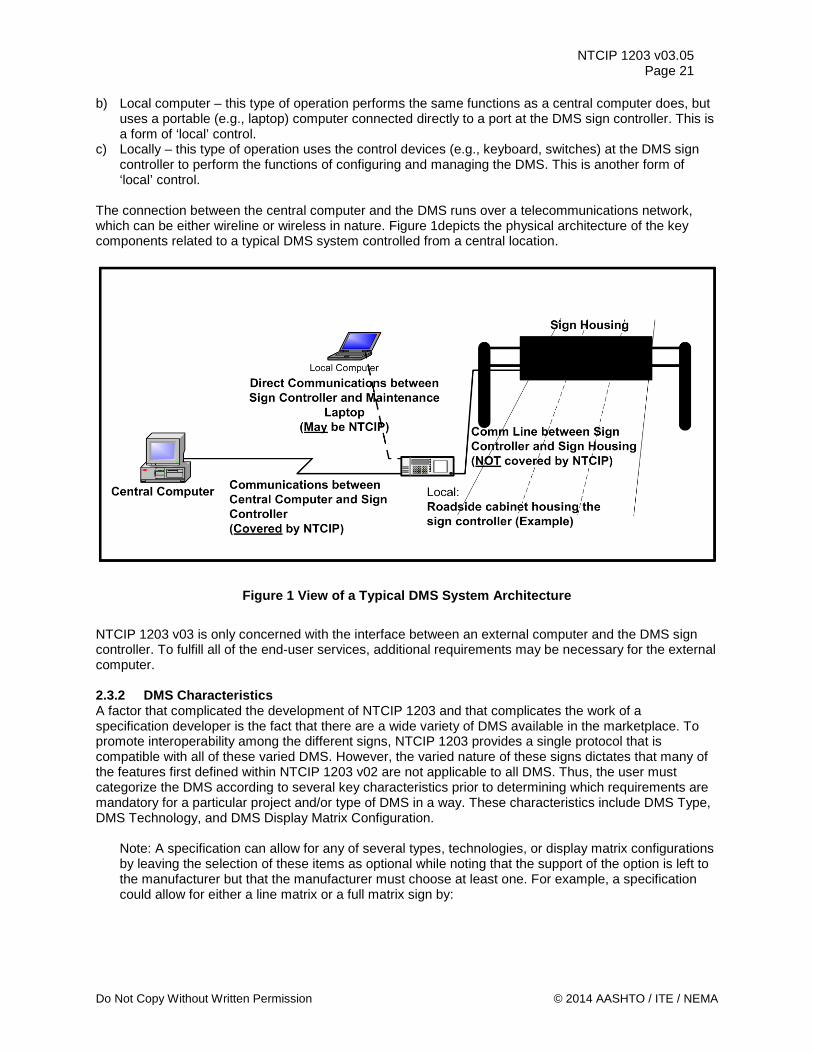
NTCIP 1203 v03.05 Page 21
b) Local computer – this type of operation performs the same functions as a central computer does, but uses a portable (e.g., laptop) computer connected directly to a port at the DMS sign controller. This is a form of ‘local’ control.
c) Locally – this type of operation uses the control devices (e.g., keyboard, switches) at the DMS sign controller to perform the functions of configuring and managing the DMS. This is another form of ‘local’ control.
The connection between the central computer and the DMS runs over a telecommunications network, which can be either wireline or wireless in nature. Figure 1depicts the physical architecture of the key components related to a typical DMS system controlled from a central location.
Figure 1 View of a Typical DMS System Architecture
NTCIP 1203 v03 is only concerned with the interface between an external computer and the DMS sign controller. To fulfill all of the end-user services, additional requirements may be necessary for the external computer. 2.3.2 DMS Characteristics A factor that complicated the development of NTCIP 1203 and that complicates the work of a specification developer is the fact that there are a wide variety of DMS available in the marketplace. To promote interoperability among the different signs, NTCIP 1203 provides a single protocol that is compatible with all of these varied DMS. However, the varied nature of these signs dictates that many of the features first defined within NTCIP 1203 v02 are not applicable to all DMS. Thus, the user must categorize the DMS according to several key characteristics prior to determining which requirements are mandatory for a particular project and/or type of DMS in a way. These characteristics include DMS Type, DMS Technology, and DMS Display Matrix Configuration.
Note: A specification can allow for any of several types, technologies, or display matrix configurations by leaving the selection of these items as optional while noting that the support of the option is left to the manufacturer but that the manufacturer must choose at least one. For example, a specification could allow for either a line matrix or a full matrix sign by:
Do Not Copy Without Written Permission © 2014 AASHTO / ITE / NEMA
NTCIP 1203 v03.05 Page 22
a) selecting ‘Yes’ on line 2.3.2.3.2, b) selecting 'Yes' on lines 2.3.2.3.2.1 and 2.3.2.3.2.2 blank and also entering the required
configurations, and c) selecting ‘No’ on line 2.3.2.3.2.3 in the PRL of Section 3.3.3.
2.3.2.1 DMS Types There are many types of DMS and they can be characterized in many ways. One way is by the capabilities the DMS offers for handling messages. This characterization places a DMS into one of three major categories: a) Blank-out Sign (BOS) – this type of DMS can only show one fixed message or nothing. b) Changeable Message Sign (CMS) – this type of DMS can display one of two or more predefined
messages, or be blank. c) Variable Message Sign (VMS) – this type of DMS is one in which the message to be displayed can be
created after the sign is installed in the field. It can also have predefined messages in its library of stored messages. By policy and/or system design, the management system may restrict the rights of selected operators to ensure that only authorized personnel can modify or create messages “on-the-fly”.
2.3.2.2 DMS Technologies DMS can also be characterized by the technology that is used in the sign. The technologies used can include any combination of the following technologies: a) Fiber Optic b) Light emitting diode (LED) c) Flip disk or Shutter d) Lamp matrix e) Drum (rotating, multifaceted cylinder) 2.3.2.3 DMS Display Matrix Configuration Finally, DMS can be characterized by the type of display layout employed by the sign, as follows: a) No matrix (i.e., it is not a pixel matrix sign) b) Matrix sign c) Full matrix d) Line matrix e) Character matrix
Note: Typically, matrix signs are VMS and VMS are matrix signs, but this is not always true; for example, the term VMS would also include: 7-segment displays, electronic ink displays, etc.
2.3.2.4 DMS Display Support (Beacons) The display of the DMS can also be supported or enhanced by the addition of beacons which are blinking lights attached to the DMS display. They may be activated as part of particular messages. 2.4 Architectural Needs 2.4.1 Fundamental Needs Driving DMS Deployment The provision of timely and reliable information to the traveling public improves public safety and convenience by providing advance notification of items that may be of interest (e.g., downstream road conditions or the arrival of a transit vehicle). DMS are typically dispersed along interstate highways, arterial roadways, and at transit stops. 2.4.2 Operational Environment NTCIP 1203 v03 addresses the interface between a DMS and a management station (e.g., a central computer). To enable communications between these components, the transportation system manager
© 2014 AASHTO / ITE / NEMA Do Not Copy Without Written Permission
NTCIP 1203 v03.05 Page 23
needs to establish a communication system that links the DMS with a management station. For some systems, the cost of communications may be minimal and as such the system may be designed for constant polling; other systems may encounter significant costs for communicating with the DMS and as such the system may be designed to minimize data exchanges. When deploying a DMS, the system designer must consider which of the following operational environments need to be supported. 2.4.2.1 Live Data Exchange The typical operational environment allows the management system to monitor and control the DMS by issuing requests (e.g., requests to access information, alter information, or control the sign). In this environment, the DMS responds to requests from the management station immediately (e.g., through the provision of live data, success/failure notice of information alteration, or success/failure of the command). 2.4.2.2 Logged Data Exchange Some operational environments do not have always-on connections (e.g., dial-up links). In such environments, a transportation system operator may wish to define conditions under which data is placed into a log, which can then be uploaded at a later time. For example, the operator may wish to maintain a log of all messages posted on the sign, regardless of which management station or algorithm posted the message. 2.4.2.3 Exceptional Condition Reporting In some operational environments, it may be desirable to have the DMS automatically transmit data to the management station when certain conditions occur. Under this scenario, the transportation system operator can define under what conditions s/he wishes to be notified and the device automatically notifies the management station when the condition occurs. An example may be the transportation system manager who wants to know when the cabinet door is open. 2.5 Features This section identifies and describes the various standardized user needs addressed by and features that may be offered by a DMS. Section 3 uses these features in the analysis of the system to define the various functional requirements of a DMS. The operation of a DMS can be categorized into three major areas: a) Manage the DMS configuration b) Control the DMS c) Monitor the status of the DMS 2.5.1 Manage the DMS Configuration The various sub-features for managing the DMS configuration include: a) Determine the DMS Identity b) Determine Sign Display Capabilities c) Manage Fonts d) Manage Graphics e) Manage Brightness f) Address Backwards Compatibility The subsequent sections detail these sub-features. 2.5.1.1 Determine the DMS Identity This feature allows the operator to determine basic information about the DMS, such as the type, technology, manufacturer, model, and version number of the DMS. It includes the ability to access information about both hardware and software elements of the DMS.
Do Not Copy Without Written Permission © 2014 AASHTO / ITE / NEMA
NTCIP 1203 v03.05 Page 24 2.5.1.2 Determine Sign Display Capabilities This feature allows the operator to retrieve the necessary information to produce a rendering of a suggested or active message. This feature also allows the system to ensure that a message can be displayed on the DMS. The feature allows the operator to determine the detailed physical limitations of the DMS as well as details regarding the current fonts and any graphics that are stored. 2.5.1.3 Manage Fonts This feature allows the operator to define and edit the appearance of the fonts used to display messages on the sign face. This helps an operator ensure that messages have a consistent appearance across many DMS in a large system despite the use of different manufacturers, etc. It allows the operator to manage the height and width of the font, and the color of the font. It allows the operator to edit or delete existing fonts, and to create new fonts in a controller. It also allows an operator to determine the existing configuration of fonts. Each font supported by the DMS should support a common set of characters (e.g., ASCII codes) to improve interoperability, including letters numbers and various special characters that are frequently used on DMS. 2.5.1.4 Manage Graphics This feature allows the operator to manage the graphics stored within a DMS. It allows the operator to define a graphic for later use, manage existing graphics, and determine the graphic storage capabilities of the DMS. 2.5.1.5 Manage Automatic Brightness This feature allows the operator to configure when the sign may automatically switch from one brightness level to the next. This allows the operator to configure how the sign automatically responds to changing lighting conditions to compensate for sun shining in the traveler's vision or 'wash-out' conditions, such as during early morning and pre-sunset conditions. 2.5.1.6 Configure Speed Limit This feature allows the operator to configure the speed limit applicable to the location of the DMS. 2.5.1.7 Configure Low Fuel Threshold This feature allows the operator to configure the threshold at which the fuel in a generator is to be considered low. This feature is associated with DMS using generators, which are typically portable signs. 2.5.2 Control the DMS The various sub-features for controlling the DMS include: a) Control a DMS from More than One Location b) Remotely Reset the Sign Controller c) Control the Sign Face d) Control External Devices e) Control the Brightness Outputs f) Perform Preventative Maintenance Subsequent sections detail these sub-features. 2.5.2.1 Control a DMS from More than One Location This feature addresses the need for DMS to be controlled both remotely (e.g., from one or more central computers) and locally (e.g., from the controller directly or from a laptop computer connected to the controller). Whether the DMS is controlled remotely or locally, the features and capabilities are the same. This feature also addresses the need to prevent different sources of control from interfering with one another by attempting to control the DMS simultaneously.
© 2014 AASHTO / ITE / NEMA Do Not Copy Without Written Permission
NTCIP 1203 v03.05 Page 25
2.5.2.2 Remotely Reset the Sign Controller This feature provides the capability to remotely reset the sign controller to attempt to recover from a software failure. This feature might be desired to avoid a field trip to reset the sign controller. 2.5.2.3 Control the Sign Face This feature addresses the need to place information on or remove information from the sign face to convey proper information to travelers. The feature includes the following sub-features: a) Activate and Display a Message b) Prioritize Messages c) Define a Message d) Blank the Sign e) Schedule Messages for Display f) Change Message Display based on an Internal Events g) Change Message Display based on External Device Inputs 2.5.2.3.1 Activate and Display a Message This feature allows an operator to activate a previously defined message to be displayed on the sign face. The message can be a blank message or come from a set of previously defined messages. When activating the message the operator will need to specify the desired duration for the display and the relative priority for the proposed message to override the currently displayed message.
Note: Activating a message that is stored in a central system library can be achieved by first downloading the message to the sign controller and then activating the message per this section. A user can also display a message defined "on-the-fly" by the same process.
2.5.2.3.2 Prioritize Messages This feature allows an operator to prioritize particular messages. For example, a priority scheme will allow an operator to maintain an accident-related message, even if the same operator previously scheduled the display of a non-accident related message. 2.5.2.3.3 Define a Message This feature enables the operator to create a message and to modify its format and content. The feature includes: a) Uniquely identifying a message b) Ensuring that a message is intact c) Defining the exact contents of the message to be displayed on the sign face. d) If supported, activating beacons when a message is displayed, to attract the traveler’s attention 2.5.2.3.4 Blank a Sign This feature enables the operator (or logic within the management station) to remove any messages displayed on a sign (causing the sign to appear blank). 2.5.2.3.5 Schedule Messages for Display This feature enables the operator to configure the DMS to activate messages at a future time (“scheduling”). The operator can indicate a series of times at which an associated message will be activated. The associated message can be any message stored in the sign controller, including a blank message. 2.5.2.3.6 Change Message Display Based on an Internal Event This feature allows the operator to indicate which message should be displayed when certain non-scheduled events occur, such as loss of communication or loss of power.
Do Not Copy Without Written Permission © 2014 AASHTO / ITE / NEMA
NTCIP 1203 v03.05 Page 26 2.5.2.4 Control External Devices This feature enables the operator to control simple external devices, such as High Occupancy Vehicle Lane Gates, through the auxiliary ports on the sign controller. 2.5.2.5 Control the Brightness Output This feature enables the operator to control the sign brightness either directly or through an automated algorithm, depending on the capabilities of the DMS. At a minimum, the operator must be able to control brightness of the sign display manually for light emitting signs. In addition, the operator should be able to control the brightness level through the use of light sensors (photocells) on the DMS, if available, that can detect the ambient light levels and adjust brightness levels in an appropriate fashion. This brightness control is needed to compensate for the external environment’s effect on the visibility of the message, such as when the sun is shining in the eyes of travelers. 2.5.2.6 Perform Preventative Maintenance This feature enables the operator to enable or disable the periodic exercise of pixels (activated either manually or via a schedule) to ensure that they are performing reliably. 2.5.3 Monitor the Status of the DMS The various sub-features for monitoring the status of the DMS include: a) Perform Diagnostics b) Monitor the Current Message Subsequent sections detail these sub-features. 2.5.3.1 Perform Diagnostics This feature enables the operator to test the operational status of system components. It consists of the following sub-features: a) Determine Sign Error Conditions (High-Level Diagnostics) b) Monitor Sign Subsystem Failures (Mid-Level Diagnostics) c) Monitor Subsystem Failure Details (Low-Level Diagnostics) d) Monitor Message Errors e) Monitor Sign Environment f) Monitor the Sign Control Source g) Monitor Attached Devices h) Monitor Door Status i) Monitor Controller Software Operations j) Monitor Automatic Blanking of Sign k) Monitor Power Source l) Monitor Power Voltage 2.5.3.1.1 Determine Sign Error Conditions (High-Level Diagnostics) This feature enables the operator to determine, at a very high level of abstraction, whether a DMS is experiencing any error or warning conditions. Errors and warnings are reported at the level of sign subsystems. For example, a single flag indicates that there are pixel errors. 2.5.3.1.2 Monitor Sign Subsystem Failures (Mid-Level Diagnostics) This feature enables the operator to determine which component(s) of a subsystem are reporting errors and/or warnings so that the operator can plan a proper response. The operator may need to monitor any of the following subsystems: a) Power sources b) Power supplies c) External Devices such as HOV Gates or external environmental sensors but controlled via the DMS
sign controller
© 2014 AASHTO / ITE / NEMA Do Not Copy Without Written Permission
NTCIP 1203 v03.05 Page 27
d) Lamps e) Pixels f) Light level sensors (commonly referred to as ‘Photocells’) g) Sign Controller h) Temperature Sensors i) Humidity j) Internal Environmental Systems (Fans and/or Heaters) k) Drum sign rotors It is only necessary for the DMS to support information about subsystems actually present in the DMS. For example, a matrix sign need not provide the drum-rotor status items, and a drum sign need not provide the pixel status items. A DMS that contains both matrix and drum display elements should provide both the drum-rotor and pixel status items. 2.5.3.1.3 Monitor Subsystem Failure Details (Low-Level Diagnostics) This feature enables the operator to obtain detailed information about a reported warning or error condition within a subsystem (detailed-level diagnostics). For example, if the DMS reports that photocell #2 has failed, then this feature enables the operator to determine that photocell #2 is "mounted on top of the sign housing." 2.5.3.1.4 Monitor Message Errors This feature enables the operator to monitor the errors associated with defining or activating a particular message. 2.5.3.1.5 Monitor Sign Environment This feature enables the operator to monitor the temperature and humidity within the sign housing and control cabinet. This allows the operator to determine whether the environmental conditions are approaching the environmental limits of the various DMS components. 2.5.3.1.6 Monitor the Sign Control Source This feature enables the operator to determine the physical location from or mechanism through which the DMS is being controlled. Possible control sources include: a) Central computer b) DMS time-based scheduler c) An individual physically present at the DMS site 2.5.3.1.7 Monitor Attached Speed Detectors This feature enables the operator to determine the current reading of any speed detectors attached to the DMS. 2.5.3.1.8 Monitor Door Status This feature enables the operator to determine whether the doors to the sign housing and control cabinet are open or closed. This feature may be used to detect unauthorized physical access to the DMS. 2.5.3.1.9 Monitor Controller Software Operations This feature enables the operator to determine whether the DMS controller software is operating properly through the use of watchdog timers. 2.5.3.1.10 Monitor Automatic Blanking of Sign This feature enables the operator to monitor the automatic display of a blank message when diagnostics detect that too many pixels are non-operational or that the light outputs are faulty. This prevents illegible messages from being displayed.
Do Not Copy Without Written Permission © 2014 AASHTO / ITE / NEMA
NTCIP 1203 v03.05 Page 28 2.5.3.1.11 Monitor Power Source This feature enables the operator to monitor the source of power that is being used to operate the DMS sign face. 2.5.3.1.12 Monitor Power Voltage This feature enables the operator to monitor the voltage of power that is being used to operate the DMS sign face. 2.5.3.1.13 Monitor Fuel Level This feature enables the operator to monitor the level of fuel within the tank of a generator that is being used to operate the DMS. This feature is typically used in portable signs. 2.5.3.1.14 Monitor Engine RPM This feature enables the operator to monitor the engine RPM that which a generator that is being used to operate the DMS is currently running. This feature is typically used in portable signs. 2.5.3.2 Monitor the Current Message This feature enables the operator to determine what message is currently displayed on the sign face. 2.5.4 Provide for Backwards Compatibility of DMS to NTCIP 1203 v1 The following sub-features were modified within NTCIP 1203 v2 and need to be specifically spelled out to achieve backwards compatibility for certain features within a DMS conforming to NTCIP 1203v2 a) Allow a DMS to obtain the number of fan failures using the method defined in NTCIP 1203v1 b) Allow a DMS to initiate the fan test using the method defined in NTCIP 1203v1 c) Allow a DMS to utilize a control mode of 'simulation' as defined in NTCIP 1203v1 2.6 Security NTCIP 1203 v03 does not address any security issues. Any security pertaining to protecting the communications with a DMS should be implemented either physically by protecting the communications access points, or logically by enabling security features associated with the underlying communications protocols. 2.7 Operational Policies and Constraints Operational policies are agency-specific and need to be determined and implemented by the agency operating the DMS. NTCIP 1203 v03 does not cover this topic, but instead provides a set of common functions that can support an agency’s operational policies. If assumptions pertaining to the operations of a DMS have been made, they have been stated clearly at the locations where they apply. 2.8 Relationship to the National ITS Architecture [Informative] There are three National ITS Architecture Flows associated with the operation of a DMS. These are: a) Driver Information b) Roadway Information System Status c) Roadway Information System Data The Driver Information flow deals with the message the driver sees on the sign. The other two flows deal with configuring, controlling, and monitoring the DMS. Each Architecture Flow is associated with one or more interfaces identified within the National ITS Architecture as: a) Between the DMS (Roadway Subsystem (RS)) and the Maintenance and Construction Management
Subsystem (MCMS)
© 2014 AASHTO / ITE / NEMA Do Not Copy Without Written Permission
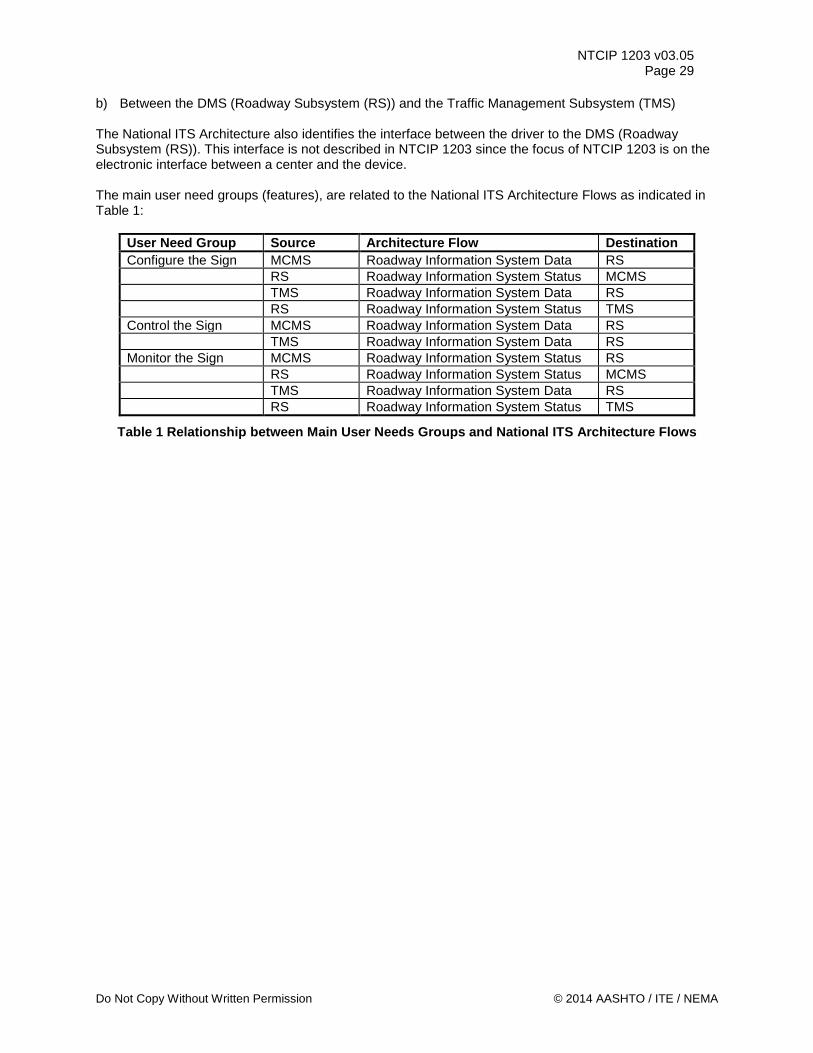
NTCIP 1203 v03.05 Page 29
b) Between the DMS (Roadway Subsystem (RS)) and the Traffic Management Subsystem (TMS) The National ITS Architecture also identifies the interface between the driver to the DMS (Roadway Subsystem (RS)). This interface is not described in NTCIP 1203 since the focus of NTCIP 1203 is on the electronic interface between a center and the device. The main user need groups (features), are related to the National ITS Architecture Flows as indicated in Table 1:
User Need Group Source Architecture Flow Destination Configure the Sign MCMS Roadway Information System Data RS RS Roadway Information System Status MCMS TMS Roadway Information System Data RS RS Roadway Information System Status TMS Control the Sign MCMS Roadway Information System Data RS TMS Roadway Information System Data RS Monitor the Sign MCMS Roadway Information System Status RS RS Roadway Information System Status MCMS TMS Roadway Information System Data RS RS Roadway Information System Status TMS
Table 1 Relationship between Main User Needs Groups and National ITS Architecture Flows
Do Not Copy Without Written Permission © 2014 AASHTO / ITE / NEMA
NTCIP 1203 v03.05 Page 30
Section 3 Functional Requirements [Normative]
This section defines the Functional Requirements based on the user needs identified in the Concept of Operations (see Section 2). This section includes: a) A tutorial b) The Protocol Requirements List – A Functional Requirement is a requirement of a given function and
therefore is only required to be implemented if the associated functionality (e.g., user need) is selected through the use of the Protocol Requirements List (PRL). The PRL also indicates which of the items are mandatory, conditional, or optional. The PRL can be used by procurement personnel to specify the desired features of a DMS or can be used by a manufacturer to document the features supported by their implementation.
c) Operational Environment Requirements – These are requirements related to the Operational Environment User needs defined in Section 2.4.2.
d) Data Exchange Requirements – These are requirements related to the features identified in Section 2.5 that can be realized through a data exchange. For example, this includes the requirement to be able to activate a message on a DMS.
e) Supplemental Requirements – These are additional requirements derived from the Concept of Operations that do not fall into one of the above two categories. For example, they include requirements related to the content of the message to be displayed on a DMS, which may be a supplemental requirement to activating a message, defining a message, etc.
This section is intended for all readers of the document, including: a) Transportation operations managers b) Transportation operations personnel c) Transportation engineers d) System integrators e) Device manufacturers The first three categories of readers will find this section useful to understand the details of what NTCIP 1203 v03 requires of a DMS. For this audience, Sections 3.3.3 and 3.3.4 are likely to be particularly useful in preparing agency (procurement) specifications and in mapping the various rows of this table to the more detailed text contained within the other sections. For the last two categories of readers, this section is likely to be useful in fully understanding what is required of equipment conformant with NTCIP 1203 v03. For these readers, the table in Sections 3.3.3 and 3.3.4 is also useful to document the capabilities of implementations. 3.1 Tutorial [informative] The Functional Requirements Section defines the formal requirements that are intended to fulfill the user needs identified in Section 2. This is achieved through the development of a Protocol Requirements List (PRL) that traces each user need to one or more requirements defined in this section. The details of each requirement are then presented following the PRL. The functional requirements are presented in three broad categories as follows: a) Architectural Requirements – These requirements define the required behavior of the system in
exchanging data across the communications interface, including any restrictions to general architectural requirements, based upon the architectural needs identified in the Concept of Operations.
© 2014 AASHTO / ITE / NEMA Do Not Copy Without Written Permission
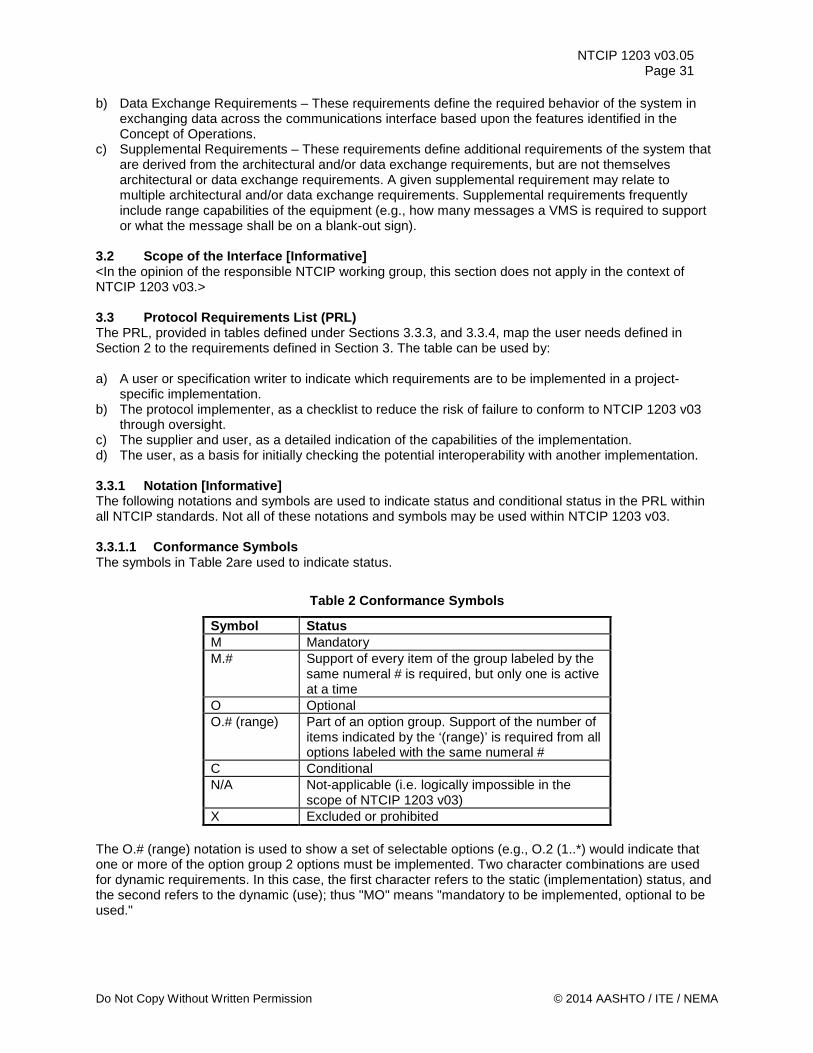
NTCIP 1203 v03.05 Page 31
b) Data Exchange Requirements – These requirements define the required behavior of the system in exchanging data across the communications interface based upon the features identified in the Concept of Operations.
c) Supplemental Requirements – These requirements define additional requirements of the system that are derived from the architectural and/or data exchange requirements, but are not themselves architectural or data exchange requirements. A given supplemental requirement may relate to multiple architectural and/or data exchange requirements. Supplemental requirements frequently include range capabilities of the equipment (e.g., how many messages a VMS is required to support or what the message shall be on a blank-out sign).
3.2 Scope of the Interface [Informative] <In the opinion of the responsible NTCIP working group, this section does not apply in the context of NTCIP 1203 v03.> 3.3 Protocol Requirements List (PRL) The PRL, provided in tables defined under Sections 3.3.3, and 3.3.4, map the user needs defined in Section 2 to the requirements defined in Section 3. The table can be used by: a) A user or specification writer to indicate which requirements are to be implemented in a project-
specific implementation. b) The protocol implementer, as a checklist to reduce the risk of failure to conform to NTCIP 1203 v03
through oversight. c) The supplier and user, as a detailed indication of the capabilities of the implementation. d) The user, as a basis for initially checking the potential interoperability with another implementation. 3.3.1 Notation [Informative] The following notations and symbols are used to indicate status and conditional status in the PRL within all NTCIP standards. Not all of these notations and symbols may be used within NTCIP 1203 v03. 3.3.1.1 Conformance Symbols The symbols in Table 2are used to indicate status.
Table 2 Conformance Symbols
Symbol Status M Mandatory M.# Support of every item of the group labeled by the
same numeral # is required, but only one is active at a time
O Optional O.# (range) Part of an option group. Support of the number of
items indicated by the ‘(range)’ is required from all options labeled with the same numeral #
C Conditional N/A Not-applicable (i.e. logically impossible in the
scope of NTCIP 1203 v03) X Excluded or prohibited
The O.# (range) notation is used to show a set of selectable options (e.g., O.2 (1..*) would indicate that one or more of the option group 2 options must be implemented. Two character combinations are used for dynamic requirements. In this case, the first character refers to the static (implementation) status, and the second refers to the dynamic (use); thus "MO" means "mandatory to be implemented, optional to be used."
Do Not Copy Without Written Permission © 2014 AASHTO / ITE / NEMA
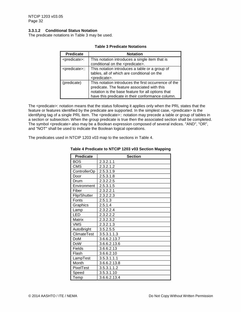
NTCIP 1203 v03.05 Page 32 3.3.1.2 Conditional Status Notation The predicate notations in Table 3 may be used.
Table 3 Predicate Notations
Predicate Notation <predicate>: This notation introduces a single item that is
conditional on the <predicate>. <predicate>:: This notation introduces a table or a group of
tables, all of which are conditional on the <predicate>.
(predicate) This notation introduces the first occurrence of the predicate. The feature associated with this notation is the base feature for all options that have this predicate in their conformance column.
The <predicate>: notation means that the status following it applies only when the PRL states that the feature or features identified by the predicate are supported. In the simplest case, <predicate> is the identifying tag of a single PRL item. The <predicate>:: notation may precede a table or group of tables in a section or subsection. When the group predicate is true then the associated section shall be completed. The symbol <predicate> also may be a Boolean expression composed of several indices. "AND", "OR", and "NOT" shall be used to indicate the Boolean logical operations. The predicates used in NTCIP 1203 v03 map to the sections in Table 4.
Table 4 Predicate to NTCIP 1203 v03 Section Mapping
Predicate Section BOS 2.3.2.1.1 CMS 2.3.2.1.2 ControllerOp 2.5.3.1.9 Door 2.5.3.1.8 Drum 2.3.2.2.5 Environment 2.5.3.1.5 Fiber 2.3.2.2.1 Flip/Shutter 2.3.2.2.3 Fonts 2.5.1.3 Graphics 2.5.1.4 Lamp 2.3.2.2.4 LED 2.3.2.2.2 Matrix 2.3.2.3.2 VMS 2.3.2.1.3 AutoBright 3.5.2.5.5 ClimateTest 3.5.3.1.1.3 DoM 3.6.6.2.13.7 DoW 3.6.6.2.13.6 Fields 3.6.6.2.13 Flash 3.6.6.2.10 LampTest 3.5.3.1.1.1 Month 3.6.6.2.13.8 PixelTest 3.5.3.1.1.2 Speed 3.5.3.1.10 Temp 3.6.6.2.13.4
© 2014 AASHTO / ITE / NEMA Do Not Copy Without Written Permission
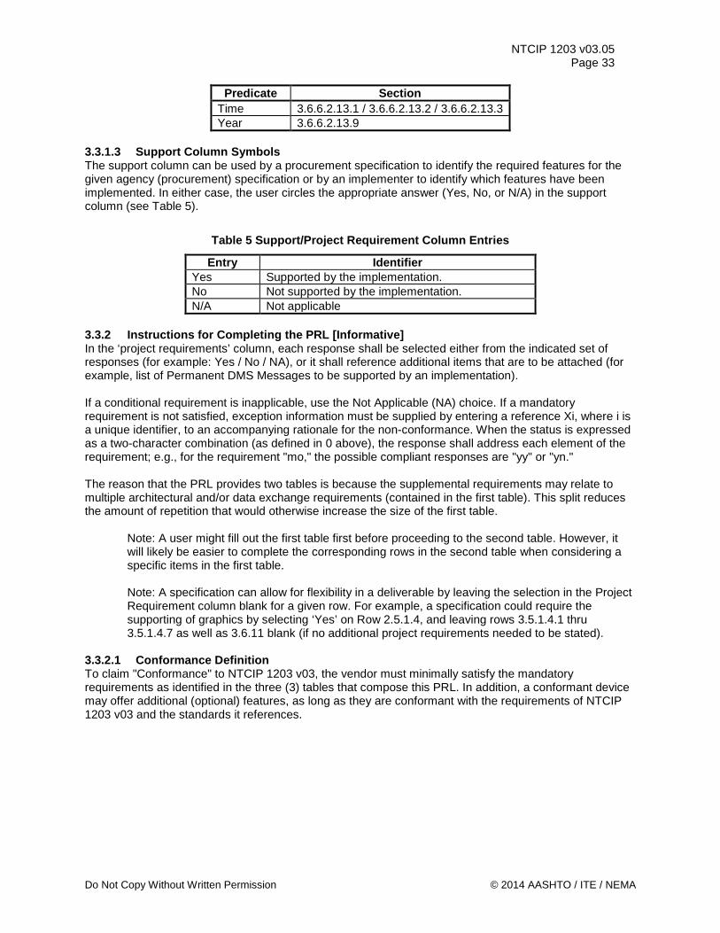
NTCIP 1203 v03.05 Page 33
Predicate Section Time 3.6.6.2.13.1 / 3.6.6.2.13.2 / 3.6.6.2.13.3 Year 3.6.6.2.13.9
3.3.1.3 Support Column Symbols The support column can be used by a procurement specification to identify the required features for the given agency (procurement) specification or by an implementer to identify which features have been implemented. In either case, the user circles the appropriate answer (Yes, No, or N/A) in the support column (see Table 5).
Table 5 Support/Project Requirement Column Entries
Entry Identifier Yes Supported by the implementation. No Not supported by the implementation. N/A Not applicable
3.3.2 Instructions for Completing the PRL [Informative] In the ‘project requirements’ column, each response shall be selected either from the indicated set of responses (for example: Yes / No / NA), or it shall reference additional items that are to be attached (for example, list of Permanent DMS Messages to be supported by an implementation). If a conditional requirement is inapplicable, use the Not Applicable (NA) choice. If a mandatory requirement is not satisfied, exception information must be supplied by entering a reference Xi, where i is a unique identifier, to an accompanying rationale for the non-conformance. When the status is expressed as a two-character combination (as defined in 0 above), the response shall address each element of the requirement; e.g., for the requirement "mo," the possible compliant responses are "yy" or "yn." The reason that the PRL provides two tables is because the supplemental requirements may relate to multiple architectural and/or data exchange requirements (contained in the first table). This split reduces the amount of repetition that would otherwise increase the size of the first table.
Note: A user might fill out the first table first before proceeding to the second table. However, it will likely be easier to complete the corresponding rows in the second table when considering a specific items in the first table.
Note: A specification can allow for flexibility in a deliverable by leaving the selection in the Project Requirement column blank for a given row. For example, a specification could require the supporting of graphics by selecting ‘Yes’ on Row 2.5.1.4, and leaving rows 3.5.1.4.1 thru 3.5.1.4.7 as well as 3.6.11 blank (if no additional project requirements needed to be stated).
3.3.2.1 Conformance Definition To claim "Conformance" to NTCIP 1203 v03, the vendor must minimally satisfy the mandatory requirements as identified in the three (3) tables that compose this PRL. In addition, a conformant device may offer additional (optional) features, as long as they are conformant with the requirements of NTCIP 1203 v03 and the standards it references.
Do Not Copy Without Written Permission © 2014 AASHTO / ITE / NEMA

NTCIP 1203 v03.05 Page 34
Note: The reader and user of NTCIP 1203 v03 is advised that 'conformance' to NTCIP 1203 v03 should not be confused with 'compliance' to a specification. NTCIP 1203 v03 is as broad as possible to allow a very simple device such as a blank-out sign to be 'conformant' to NTCIP 1203 v03. A specification will need to identify the requirements of a particular project and needs to require the support of those requirements. A specification writer is advised to match the requirements of a project with the corresponding standardized requirements defined in NTCIP 1203 v03 to achieve interoperability. This means that functions and requirements defined as 'optional' in NTCIP 1203 v03 might need to be selected in a specification (in effect made 'mandatory' for the project-specific specification).
A conformant device may offer additional features, as long as they are conformant with the requirements of NTCIP 1203 v03 and the standards it references (e.g., NTCIP 1201:2005, NTCIP 2301 v02, and NTCIP 8004 v02). For example, a device may support data that has not been defined by NTCIP 1203 v03; however, when exchanged via one of the NTCIP 2301 protocols, the data must be properly registered with a valid OBJECT IDENTIFIER under the Global ISO Naming Tree.
Note: Off-the-shelf interoperability and interchangeability can only be obtained through well documented features broadly supported by the industry as a whole. Designing a system that uses features not defined in a standard or not typically deployed in combination with one another will inhibit the goals of interoperability and interchangeability, especially if the documentation of these features is not available for distribution to system integrators. The standards allow the use of additional features to support innovation, which is constantly needed within the industry; but users should be aware of the risks involved with using such features.
3.3.2.2 Backward Compatibility and Support of Different Versions of NTCIP 1203 In NTCIP 1203 v02, the enhancement of certain functions caused corresponding objects to be replaced. A device conformant with NTCIP 1203 v03 shall by default support functions (and resulting objects) from all existing versions, if said device is required to support that particular functionality. For example, version 1 of NTCIP 1203 contained a set of objects that defined how two devices needed to communicate with each other when exchanging data pertaining to auxiliary input/output devices. These version 01 objects, which were defined as experimental objects, were moved to the global object definition set when version 2 for both NTCIP 1201 and NTCIP 1203 were created, because the functionality is applicable to other field device communications besides DMS. In the process, an alias of each of these objects was created to locate the functionality under a non-experimental node. to provide maximum backwards compatibility, a field device that is required to support the auxiliary input/output (auxIO) functionality and that wants to claim conformance to NTCIP 1203 v03 is required to support the objects defined in both, version 01 and version 02. However, a specification writer might determine that support of (an) older version(s) is not required and may state this within the following PRL table (the table contains within the ‘additional specifications requirements’ column statements where a user can de-select the support of any existing version).
© 2014 AASHTO / ITE / NEMA Do Not Copy Without Written Permission
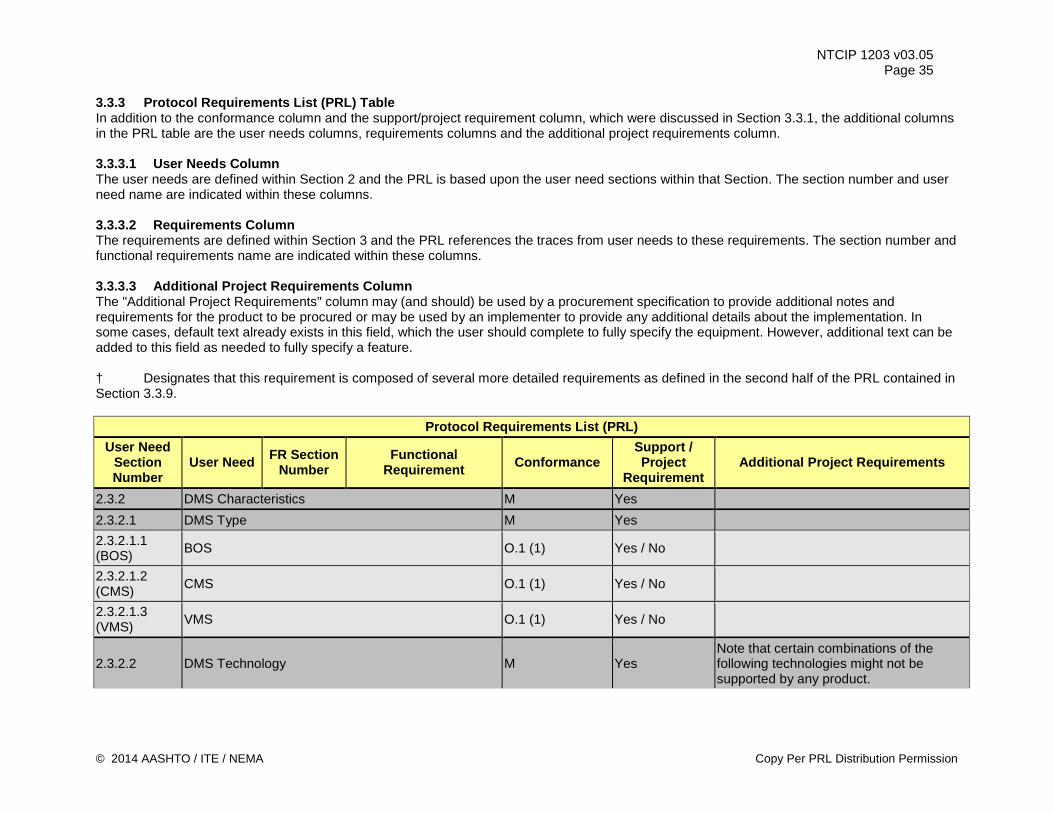
NTCIP 1203 v03.05 Page 35
3.3.3 Protocol Requirements List (PRL) Table In addition to the conformance column and the support/project requirement column, which were discussed in Section 3.3.1, the additional columns in the PRL table are the user needs columns, requirements columns and the additional project requirements column. 3.3.3.1 User Needs Column The user needs are defined within Section 2 and the PRL is based upon the user need sections within that Section. The section number and user need name are indicated within these columns. 3.3.3.2 Requirements Column The requirements are defined within Section 3 and the PRL references the traces from user needs to these requirements. The section number and functional requirements name are indicated within these columns. 3.3.3.3 Additional Project Requirements Column The "Additional Project Requirements" column may (and should) be used by a procurement specification to provide additional notes and requirements for the product to be procured or may be used by an implementer to provide any additional details about the implementation. In some cases, default text already exists in this field, which the user should complete to fully specify the equipment. However, additional text can be added to this field as needed to fully specify a feature. † Designates that this requirement is composed of several more detailed requirements as defined in the second half of the PRL contained in Section 3.3.9.
Protocol Requirements List (PRL) User Need
Section Number
User Need FR Section Number
Functional Requirement Conformance
Support / Project
Requirement Additional Project Requirements
2.3.2 DMS Characteristics M Yes 2.3.2.1 DMS Type M Yes 2.3.2.1.1 (BOS) BOS O.1 (1) Yes / No
2.3.2.1.2 (CMS) CMS O.1 (1) Yes / No
2.3.2.1.3 (VMS) VMS O.1 (1) Yes / No
2.3.2.2 DMS Technology M Yes Note that certain combinations of the following technologies might not be supported by any product.
© 2014 AASHTO / ITE / NEMA Copy Per PRL Distribution Permission
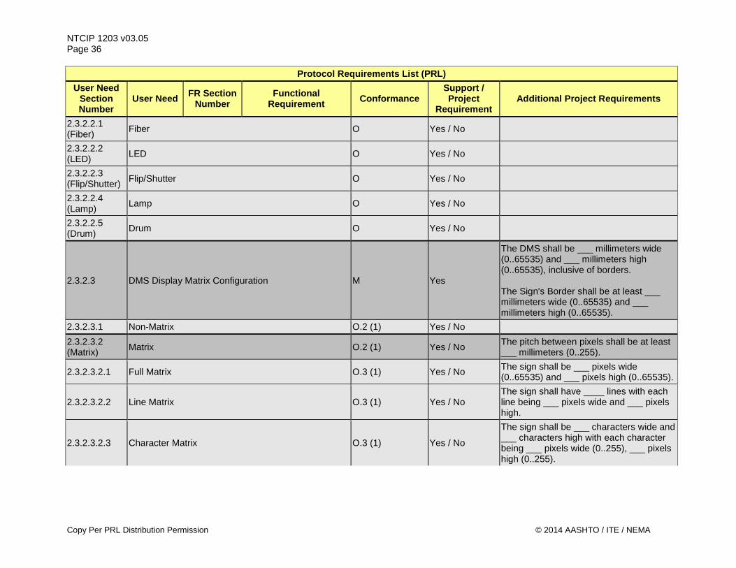
NTCIP 1203 v03.05 Page 36
Protocol Requirements List (PRL) User Need
Section Number
User Need FR Section Number
Functional Requirement Conformance
Support / Project
Requirement Additional Project Requirements
2.3.2.2.1 (Fiber) Fiber O Yes / No
2.3.2.2.2 (LED) LED O Yes / No
2.3.2.2.3 (Flip/Shutter) Flip/Shutter O Yes / No
2.3.2.2.4 (Lamp) Lamp O Yes / No
2.3.2.2.5 (Drum) Drum O Yes / No
2.3.2.3 DMS Display Matrix Configuration M Yes
The DMS shall be ___ millimeters wide (0..65535) and ___ millimeters high (0..65535), inclusive of borders. The Sign's Border shall be at least ___ millimeters wide (0..65535) and ___ millimeters high (0..65535).
2.3.2.3.1 Non-Matrix O.2 (1) Yes / No 2.3.2.3.2 (Matrix) Matrix O.2 (1) Yes / No The pitch between pixels shall be at least
___ millimeters (0..255).
2.3.2.3.2.1 Full Matrix O.3 (1) Yes / No The sign shall be ___ pixels wide (0..65535) and ___ pixels high (0..65535).
2.3.2.3.2.2 Line Matrix O.3 (1) Yes / No The sign shall have ____ lines with each line being ___ pixels wide and ___ pixels high.
2.3.2.3.2.3 Character Matrix O.3 (1) Yes / No
The sign shall be ___ characters wide and ___ characters high with each character being ___ pixels wide (0..255), ___ pixels high (0..255).
Copy Per PRL Distribution Permission © 2014 AASHTO / ITE / NEMA
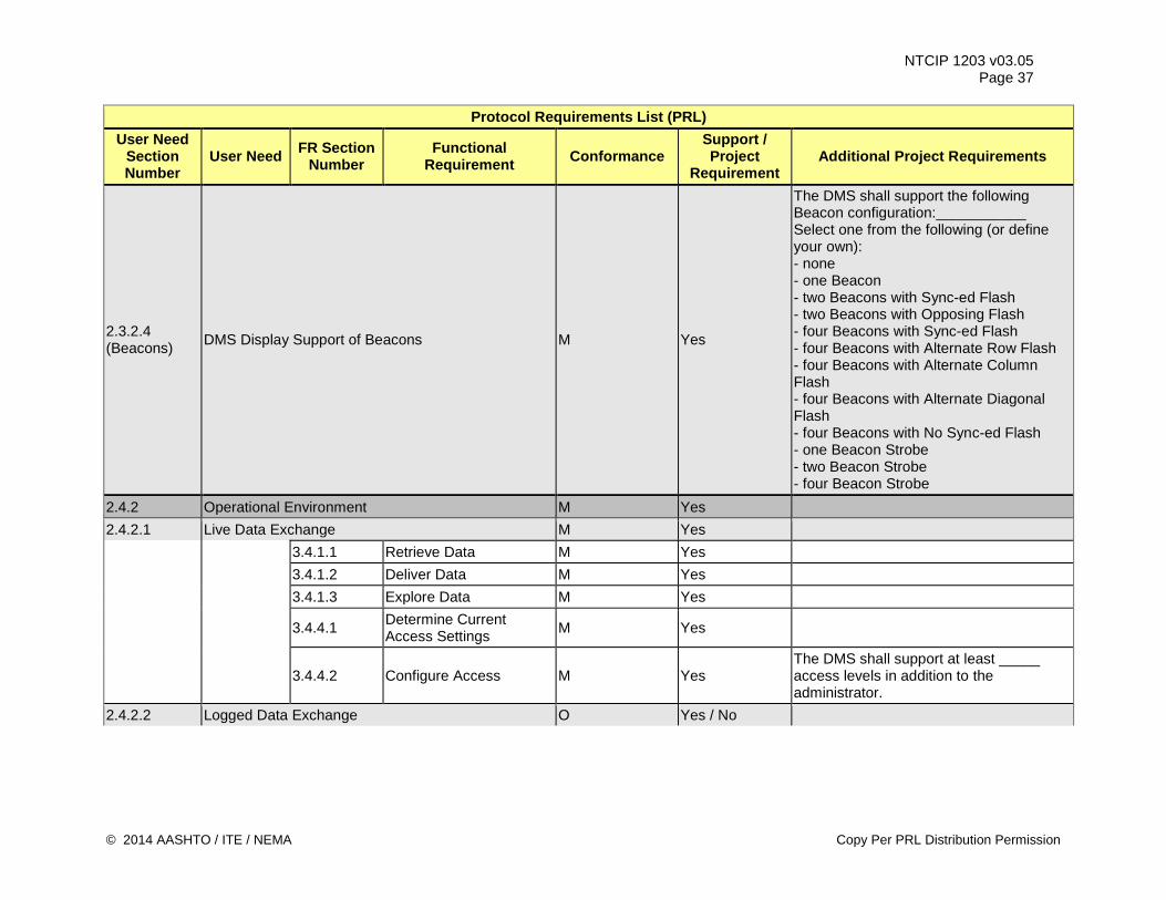
NTCIP 1203 v03.05 Page 37
Protocol Requirements List (PRL) User Need
Section Number
User Need FR Section Number
Functional Requirement Conformance
Support / Project
Requirement Additional Project Requirements
2.3.2.4 (Beacons) DMS Display Support of Beacons M Yes
The DMS shall support the following Beacon configuration:___________ Select one from the following (or define your own): - none - one Beacon - two Beacons with Sync-ed Flash - two Beacons with Opposing Flash - four Beacons with Sync-ed Flash - four Beacons with Alternate Row Flash - four Beacons with Alternate Column Flash - four Beacons with Alternate Diagonal Flash - four Beacons with No Sync-ed Flash - one Beacon Strobe - two Beacon Strobe - four Beacon Strobe
2.4.2 Operational Environment M Yes 2.4.2.1 Live Data Exchange M Yes 3.4.1.1 Retrieve Data M Yes 3.4.1.2 Deliver Data M Yes 3.4.1.3 Explore Data M Yes
3.4.4.1 Determine Current Access Settings M Yes
3.4.4.2 Configure Access M Yes The DMS shall support at least _____ access levels in addition to the administrator.
2.4.2.2 Logged Data Exchange O Yes / No
© 2014 AASHTO / ITE / NEMA Copy Per PRL Distribution Permission
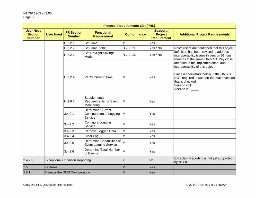
NTCIP 1203 v03.05 Page 38
Protocol Requirements List (PRL) User Need
Section Number
User Need FR Section Number
Functional Requirement Conformance
Support / Project
Requirement Additional Project Requirements
H.2.2.1 Set Time M Yes H.2.2.2 Set Time Zone H.2.2.1:O Yes / No Note: Users are cautioned that this object
definition has been revised to address interoperability issues in version 01, but remains at the same ObjectID. Pay close attention to the implementation, and interoperability of this object. Place a checkmark below, if the DMS is NOT required to support the major version that is checked. Version v01____ Version v02____
H.2.2.3 Set Daylight Savings Mode H.2.2.1:O Yes / No
H.2.2.4 Verify Current Time M Yes
H.2.6 † Supplemental Requirements for Event Monitoring
M Yes
3.4.2.1 Determine Current Configuration of Logging Service
M Yes
3.4.2.2 Configure Logging Service M Yes
3.4.2.3 Retrieve Logged Data M Yes 3.4.2.4 Clear Log M Yes
3.4.2.5 Determine Capabilities of Event Logging Service M Yes
3.4.2.6 Determine Total Number of Events M Yes
2.4.2.3 Exceptional Condition Reporting X No Exception Reporting is not yet supported by NTCIP.
2.5 Features M Yes 2.5.1 Manage the DMS Configuration M Yes
Copy Per PRL Distribution Permission © 2014 AASHTO / ITE / NEMA
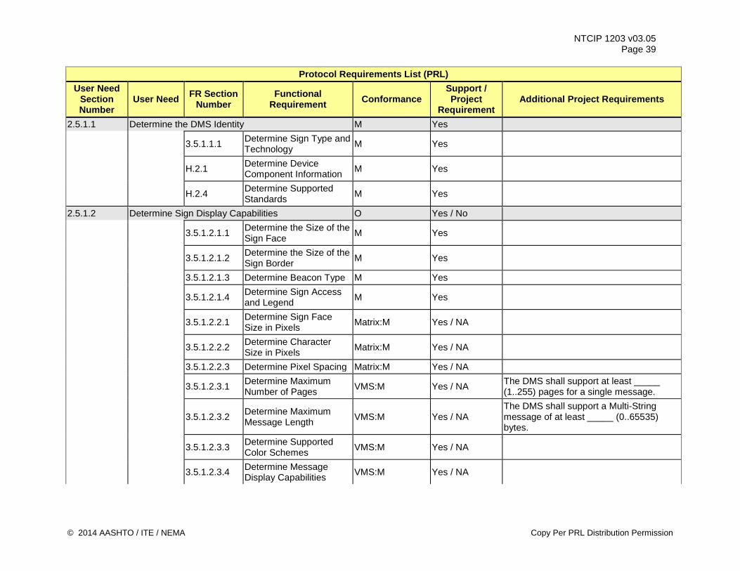
NTCIP 1203 v03.05 Page 39
Protocol Requirements List (PRL) User Need
Section Number
User Need FR Section Number
Functional Requirement Conformance
Support / Project
Requirement Additional Project Requirements
2.5.1.1 Determine the DMS Identity M Yes
3.5.1.1.1 Determine Sign Type and Technology M Yes
H.2.1 Determine Device Component Information M Yes
H.2.4 Determine Supported Standards M Yes
2.5.1.2 Determine Sign Display Capabilities O Yes / No
3.5.1.2.1.1 Determine the Size of the Sign Face M Yes
3.5.1.2.1.2 Determine the Size of the Sign Border M Yes
3.5.1.2.1.3 Determine Beacon Type M Yes
3.5.1.2.1.4 Determine Sign Access and Legend M Yes
3.5.1.2.2.1 Determine Sign Face Size in Pixels Matrix:M Yes / NA
3.5.1.2.2.2 Determine Character Size in Pixels Matrix:M Yes / NA
3.5.1.2.2.3 Determine Pixel Spacing Matrix:M Yes / NA
3.5.1.2.3.1 Determine Maximum Number of Pages VMS:M Yes / NA The DMS shall support at least _____
(1..255) pages for a single message.
3.5.1.2.3.2 Determine Maximum Message Length VMS:M Yes / NA
The DMS shall support a Multi-String message of at least _____ (0..65535) bytes.
3.5.1.2.3.3 Determine Supported Color Schemes VMS:M Yes / NA
3.5.1.2.3.4 Determine Message Display Capabilities VMS:M Yes / NA
© 2014 AASHTO / ITE / NEMA Copy Per PRL Distribution Permission
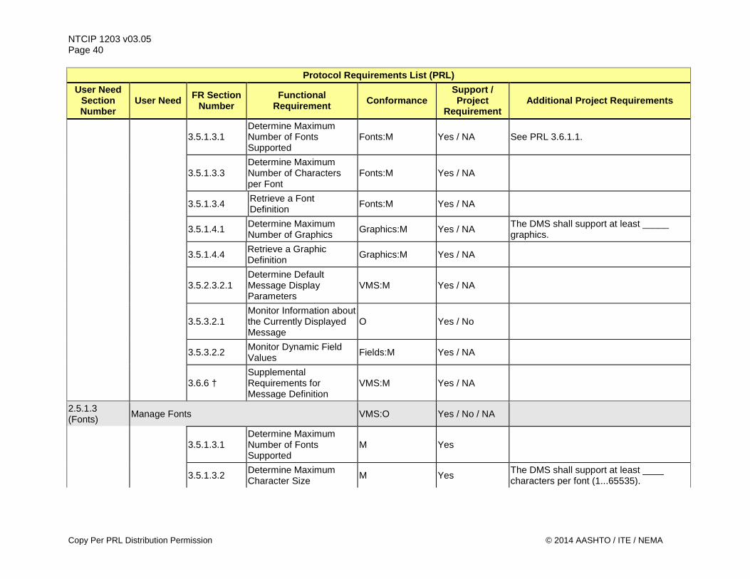
NTCIP 1203 v03.05 Page 40
Protocol Requirements List (PRL) User Need
Section Number
User Need FR Section Number
Functional Requirement Conformance
Support / Project
Requirement Additional Project Requirements
3.5.1.3.1 Determine Maximum Number of Fonts Supported
Fonts:M Yes / NA See PRL 3.6.1.1.
3.5.1.3.3 Determine Maximum Number of Characters per Font
Fonts:M Yes / NA
3.5.1.3.4 Retrieve a Font Definition Fonts:M Yes / NA
3.5.1.4.1 Determine Maximum Number of Graphics Graphics:M Yes / NA The DMS shall support at least _____
graphics.
3.5.1.4.4 Retrieve a Graphic Definition Graphics:M Yes / NA
3.5.2.3.2.1 Determine Default Message Display Parameters
VMS:M Yes / NA
3.5.3.2.1 Monitor Information about the Currently Displayed Message
O Yes / No
3.5.3.2.2 Monitor Dynamic Field Values Fields:M Yes / NA
3.6.6 † Supplemental Requirements for Message Definition
VMS:M Yes / NA
2.5.1.3 (Fonts) Manage Fonts VMS:O Yes / No / NA
3.5.1.3.1 Determine Maximum Number of Fonts Supported
M Yes
3.5.1.3.2 Determine Maximum Character Size M Yes The DMS shall support at least ____
characters per font (1...65535).
Copy Per PRL Distribution Permission © 2014 AASHTO / ITE / NEMA
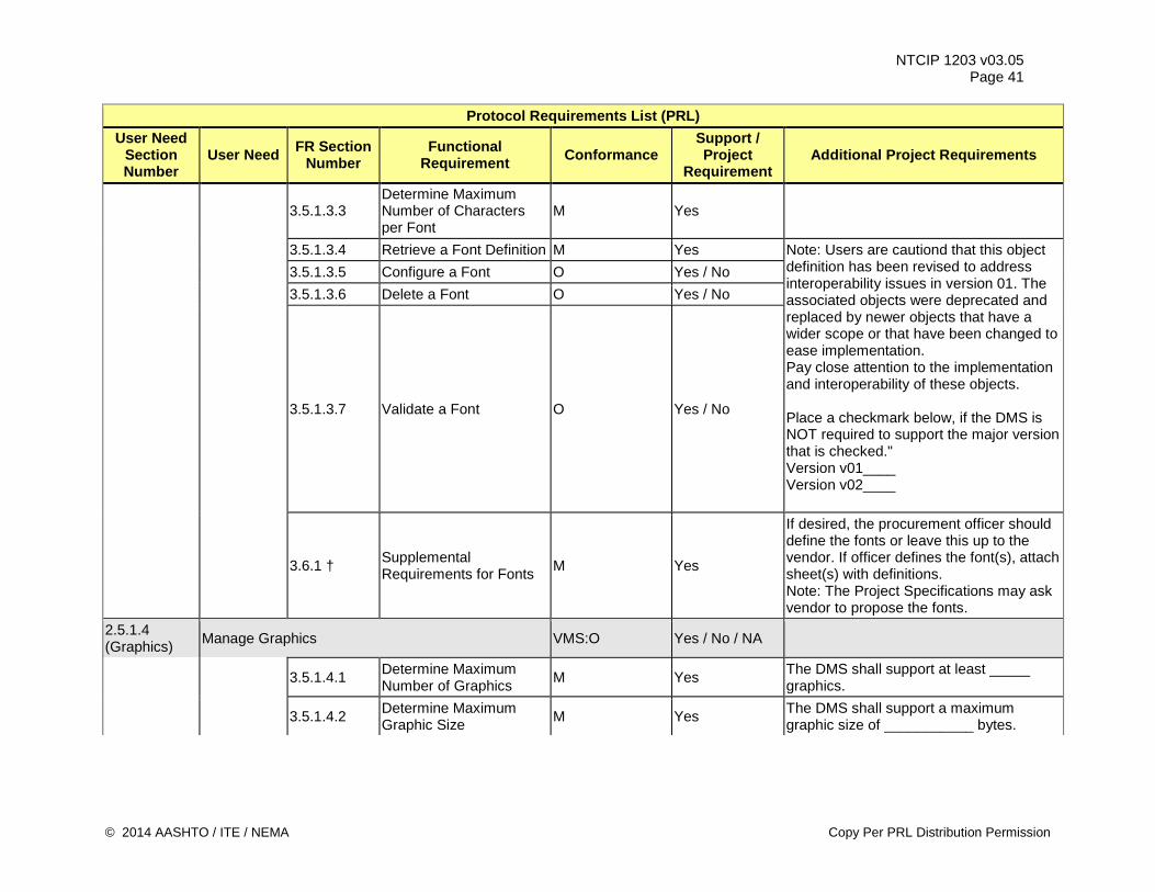
NTCIP 1203 v03.05 Page 41
Protocol Requirements List (PRL) User Need
Section Number
User Need FR Section Number
Functional Requirement Conformance
Support / Project
Requirement Additional Project Requirements
3.5.1.3.3 Determine Maximum Number of Characters per Font
M Yes
3.5.1.3.4 Retrieve a Font Definition M Yes Note: Users are cautiond that this object definition has been revised to address interoperability issues in version 01. The associated objects were deprecated and replaced by newer objects that have a wider scope or that have been changed to ease implementation. Pay close attention to the implementation and interoperability of these objects. Place a checkmark below, if the DMS is NOT required to support the major version that is checked." Version v01____ Version v02____
3.5.1.3.5 Configure a Font O Yes / No 3.5.1.3.6 Delete a Font O Yes / No
3.5.1.3.7 Validate a Font O Yes / No
3.6.1 † Supplemental Requirements for Fonts M Yes
If desired, the procurement officer should define the fonts or leave this up to the vendor. If officer defines the font(s), attach sheet(s) with definitions. Note: The Project Specifications may ask vendor to propose the fonts.
2.5.1.4 (Graphics) Manage Graphics VMS:O Yes / No / NA
3.5.1.4.1 Determine Maximum Number of Graphics M Yes The DMS shall support at least _____
graphics.
3.5.1.4.2 Determine Maximum Graphic Size M Yes The DMS shall support a maximum
graphic size of ___________ bytes.
© 2014 AASHTO / ITE / NEMA Copy Per PRL Distribution Permission
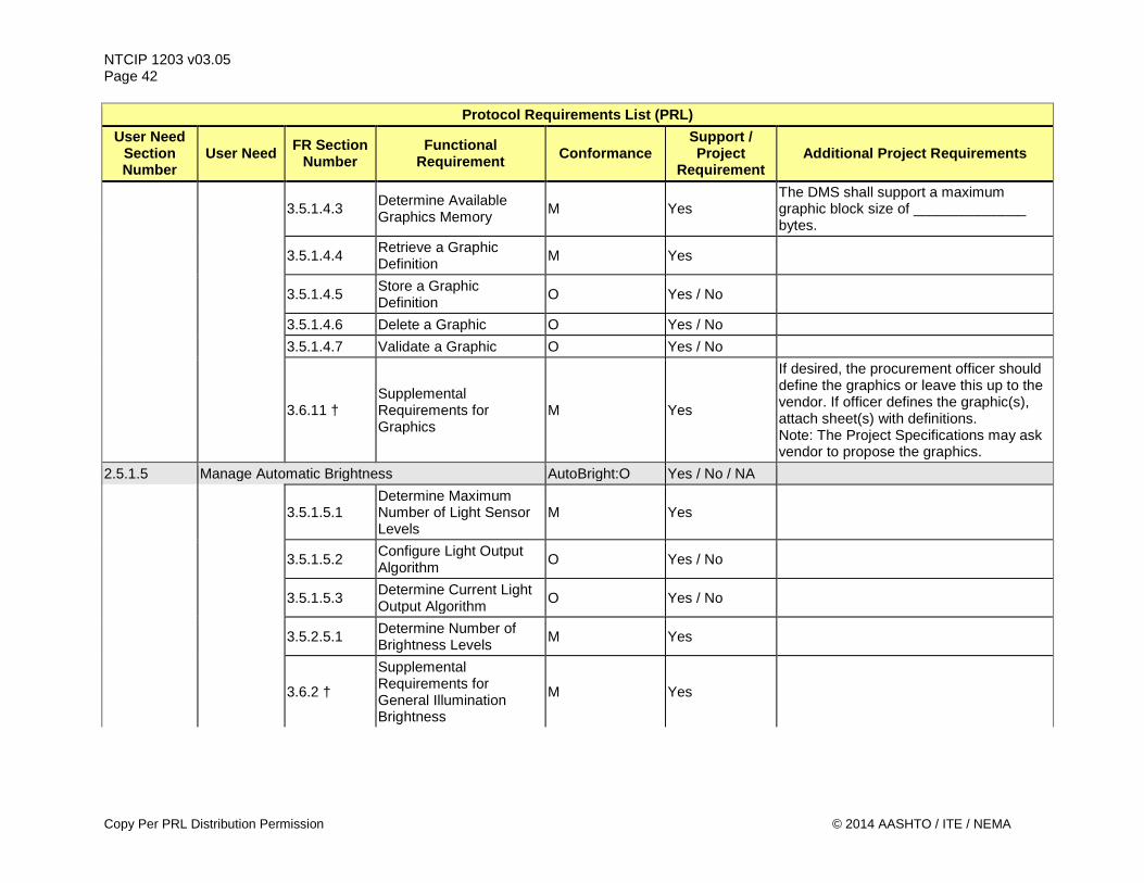
NTCIP 1203 v03.05 Page 42
Protocol Requirements List (PRL) User Need
Section Number
User Need FR Section Number
Functional Requirement Conformance
Support / Project
Requirement Additional Project Requirements
3.5.1.4.3 Determine Available Graphics Memory M Yes
The DMS shall support a maximum graphic block size of ______________ bytes.
3.5.1.4.4 Retrieve a Graphic Definition M Yes
3.5.1.4.5 Store a Graphic Definition O Yes / No
3.5.1.4.6 Delete a Graphic O Yes / No 3.5.1.4.7 Validate a Graphic O Yes / No
3.6.11 † Supplemental Requirements for Graphics
M Yes
If desired, the procurement officer should define the graphics or leave this up to the vendor. If officer defines the graphic(s), attach sheet(s) with definitions. Note: The Project Specifications may ask vendor to propose the graphics.
2.5.1.5 Manage Automatic Brightness AutoBright:O Yes / No / NA
3.5.1.5.1 Determine Maximum Number of Light Sensor Levels
M Yes
3.5.1.5.2 Configure Light Output Algorithm O Yes / No
3.5.1.5.3 Determine Current Light Output Algorithm O Yes / No
3.5.2.5.1 Determine Number of Brightness Levels M Yes
3.6.2 †
Supplemental Requirements for General Illumination Brightness
M Yes
Copy Per PRL Distribution Permission © 2014 AASHTO / ITE / NEMA
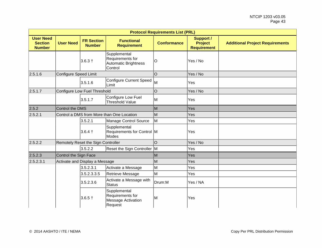
NTCIP 1203 v03.05 Page 43
Protocol Requirements List (PRL) User Need
Section Number
User Need FR Section Number
Functional Requirement Conformance
Support / Project
Requirement Additional Project Requirements
3.6.3 †
Supplemental Requirements for Automatic Brightness Control
O Yes / No
2.5.1.6 Configure Speed Limit O Yes / No
3.5.1.6 Configure Current Speed Limit M Yes
2.5.1.7 Configure Low Fuel Threshold O Yes / No
3.5.1.7 Configure Low Fuel Threshold Value M Yes
2.5.2 Control the DMS M Yes 2.5.2.1 Control a DMS from More than One Location M Yes 3.5.2.1 Manage Control Source M Yes
3.6.4 † Supplemental Requirements for Control Modes
M Yes
2.5.2.2 Remotely Reset the Sign Controller O Yes / No 3.5.2.2 Reset the Sign Controller M Yes 2.5.2.3 Control the Sign Face M Yes 2.5.2.3.1 Activate and Display a Message M Yes 3.5.2.3.1 Activate a Message M Yes 3.5.2.3.3.5 Retrieve Message M Yes
3.5.2.3.6 Activate a Message with Status Drum:M Yes / NA
3.6.5 †
Supplemental Requirements for Message Activation Request
M Yes
© 2014 AASHTO / ITE / NEMA Copy Per PRL Distribution Permission
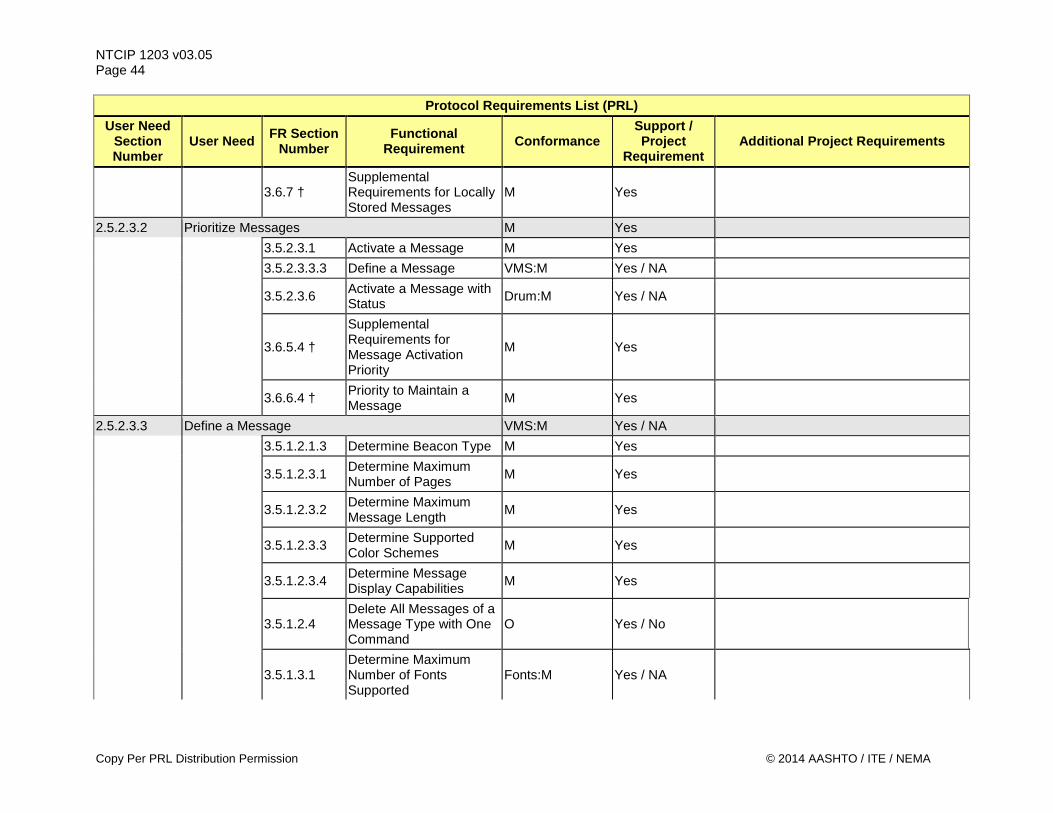
NTCIP 1203 v03.05 Page 44
Protocol Requirements List (PRL) User Need
Section Number
User Need FR Section Number
Functional Requirement Conformance
Support / Project
Requirement Additional Project Requirements
3.6.7 † Supplemental Requirements for Locally Stored Messages
M Yes
2.5.2.3.2 Prioritize Messages M Yes 3.5.2.3.1 Activate a Message M Yes 3.5.2.3.3.3 Define a Message VMS:M Yes / NA
3.5.2.3.6 Activate a Message with Status Drum:M Yes / NA
3.6.5.4 †
Supplemental Requirements for Message Activation Priority
M Yes
3.6.6.4 † Priority to Maintain a Message M Yes
2.5.2.3.3 Define a Message VMS:M Yes / NA 3.5.1.2.1.3 Determine Beacon Type M Yes
3.5.1.2.3.1 Determine Maximum Number of Pages M Yes
3.5.1.2.3.2 Determine Maximum Message Length M Yes
3.5.1.2.3.3 Determine Supported Color Schemes M Yes
3.5.1.2.3.4 Determine Message Display Capabilities M Yes
3.5.1.2.4 Delete All Messages of a Message Type with One Command
O Yes / No
3.5.1.3.1 Determine Maximum Number of Fonts Supported
Fonts:M Yes / NA
Copy Per PRL Distribution Permission © 2014 AASHTO / ITE / NEMA
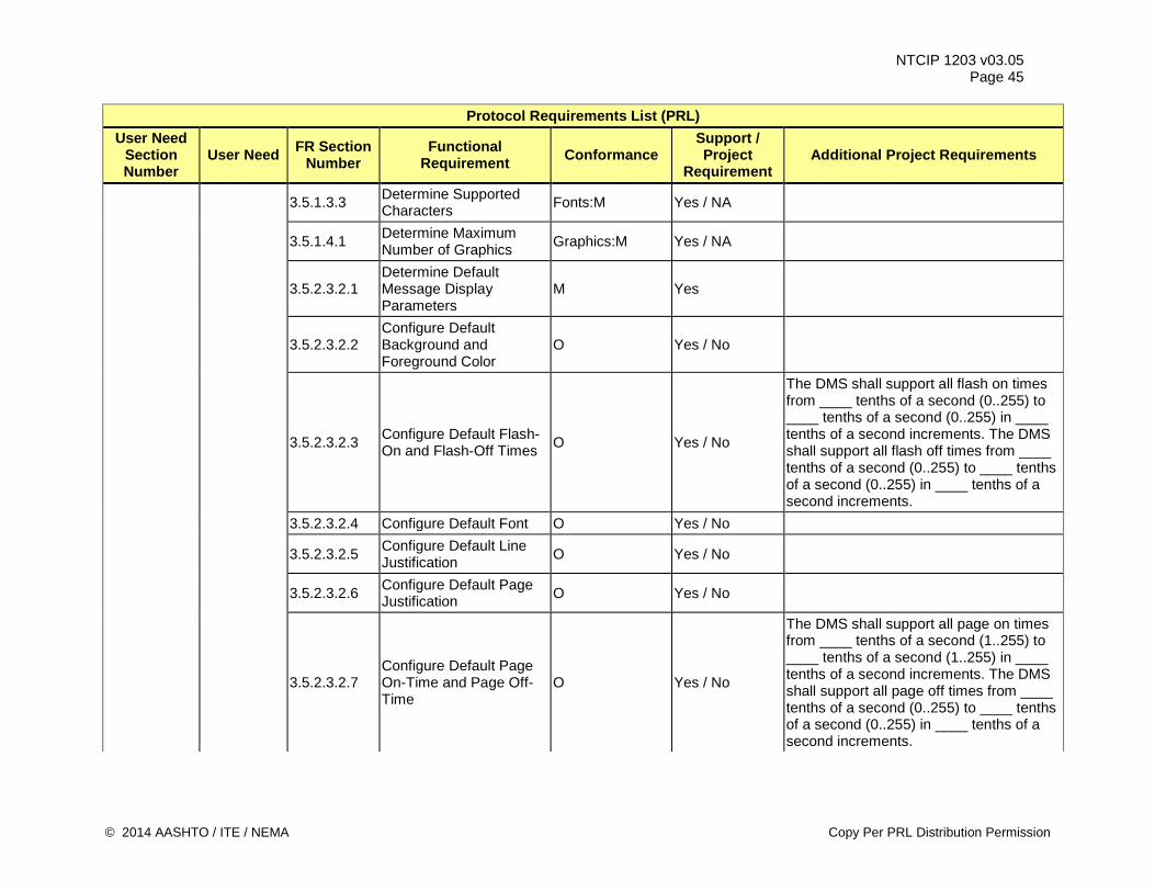
NTCIP 1203 v03.05 Page 45
Protocol Requirements List (PRL) User Need
Section Number
User Need FR Section Number
Functional Requirement Conformance
Support / Project
Requirement Additional Project Requirements
3.5.1.3.3 Determine Supported Characters Fonts:M Yes / NA
3.5.1.4.1 Determine Maximum Number of Graphics Graphics:M Yes / NA
3.5.2.3.2.1 Determine Default Message Display Parameters
M Yes
3.5.2.3.2.2 Configure Default Background and Foreground Color
O Yes / No
3.5.2.3.2.3 Configure Default Flash-On and Flash-Off Times O Yes / No
The DMS shall support all flash on times from ____ tenths of a second (0..255) to ____ tenths of a second (0..255) in ____ tenths of a second increments. The DMS shall support all flash off times from ____ tenths of a second (0..255) to ____ tenths of a second (0..255) in ____ tenths of a second increments.
3.5.2.3.2.4 Configure Default Font O Yes / No
3.5.2.3.2.5 Configure Default Line Justification O Yes / No
3.5.2.3.2.6 Configure Default Page Justification O Yes / No
3.5.2.3.2.7 Configure Default Page On-Time and Page Off-Time
O Yes / No
The DMS shall support all page on times from ____ tenths of a second (1..255) to ____ tenths of a second (1..255) in ____ tenths of a second increments. The DMS shall support all page off times from ____ tenths of a second (0..255) to ____ tenths of a second (0..255) in ____ tenths of a second increments.
© 2014 AASHTO / ITE / NEMA Copy Per PRL Distribution Permission
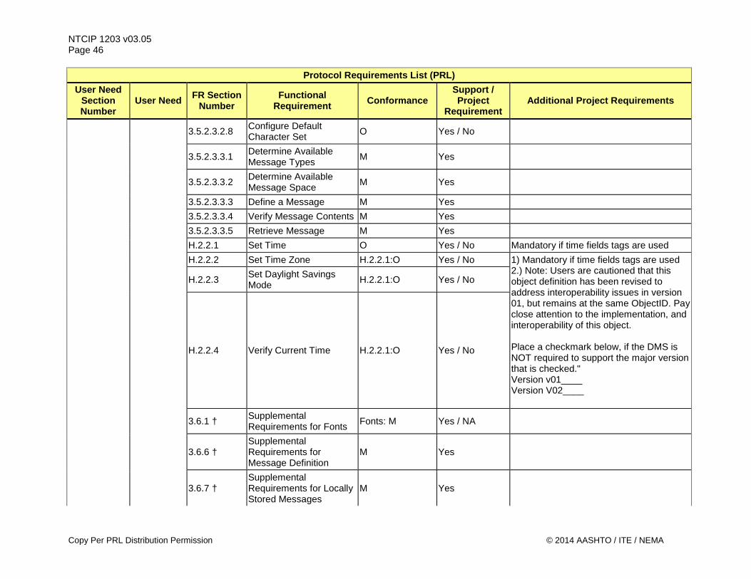
NTCIP 1203 v03.05 Page 46
Protocol Requirements List (PRL) User Need
Section Number
User Need FR Section Number
Functional Requirement Conformance
Support / Project
Requirement Additional Project Requirements
3.5.2.3.2.8 Configure Default Character Set O Yes / No
3.5.2.3.3.1 Determine Available Message Types M Yes
3.5.2.3.3.2 Determine Available Message Space M Yes
3.5.2.3.3.3 Define a Message M Yes 3.5.2.3.3.4 Verify Message Contents M Yes 3.5.2.3.3.5 Retrieve Message M Yes H.2.2.1 Set Time O Yes / No Mandatory if time fields tags are used H.2.2.2 Set Time Zone H.2.2.1:O Yes / No 1) Mandatory if time fields tags are used
2.) Note: Users are cautioned that this object definition has been revised to address interoperability issues in version 01, but remains at the same ObjectID. Pay close attention to the implementation, and interoperability of this object. Place a checkmark below, if the DMS is NOT required to support the major version that is checked." Version v01____ Version V02____
H.2.2.3 Set Daylight Savings Mode H.2.2.1:O Yes / No
H.2.2.4 Verify Current Time H.2.2.1:O Yes / No
3.6.1 † Supplemental Requirements for Fonts Fonts: M Yes / NA
3.6.6 † Supplemental Requirements for Message Definition
M Yes
3.6.7 † Supplemental Requirements for Locally Stored Messages
M Yes
Copy Per PRL Distribution Permission © 2014 AASHTO / ITE / NEMA
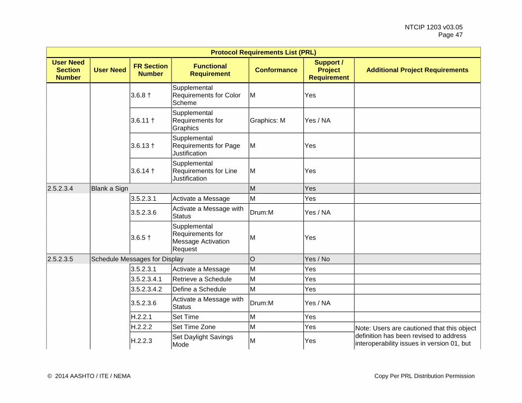
NTCIP 1203 v03.05 Page 47
Protocol Requirements List (PRL) User Need
Section Number
User Need FR Section Number
Functional Requirement Conformance
Support / Project
Requirement Additional Project Requirements
3.6.8 † Supplemental Requirements for Color Scheme
M Yes
3.6.11 † Supplemental Requirements for Graphics
Graphics: M Yes / NA
3.6.13 † Supplemental Requirements for Page Justification
M Yes
3.6.14 † Supplemental Requirements for Line Justification
M Yes
2.5.2.3.4 Blank a Sign M Yes 3.5.2.3.1 Activate a Message M Yes
3.5.2.3.6 Activate a Message with Status Drum:M Yes / NA
3.6.5 †
Supplemental Requirements for Message Activation Request
M Yes
2.5.2.3.5 Schedule Messages for Display O Yes / No 3.5.2.3.1 Activate a Message M Yes 3.5.2.3.4.1 Retrieve a Schedule M Yes 3.5.2.3.4.2 Define a Schedule M Yes
3.5.2.3.6 Activate a Message with Status Drum:M Yes / NA
H.2.2.1 Set Time M Yes H.2.2.2 Set Time Zone M Yes Note: Users are cautioned that this object
definition has been revised to address interoperability issues in version 01, but H.2.2.3 Set Daylight Savings
Mode M Yes
© 2014 AASHTO / ITE / NEMA Copy Per PRL Distribution Permission
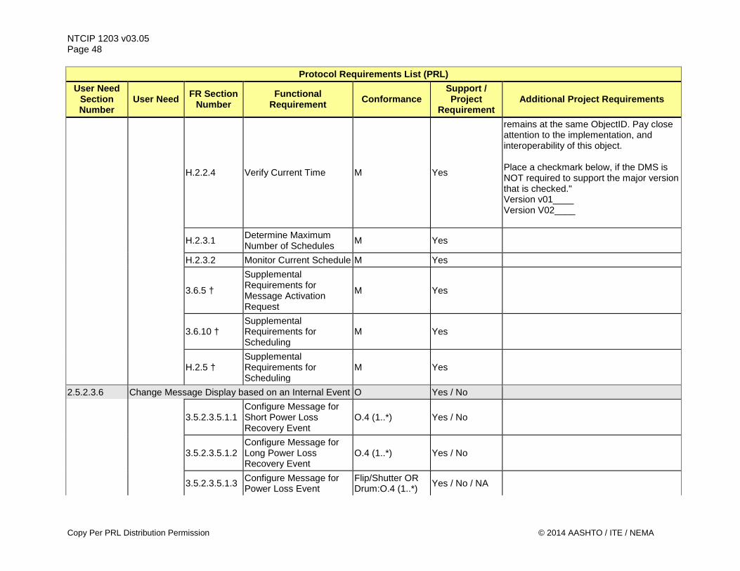
NTCIP 1203 v03.05 Page 48
Protocol Requirements List (PRL) User Need
Section Number
User Need FR Section Number
Functional Requirement Conformance
Support / Project
Requirement Additional Project Requirements
H.2.2.4 Verify Current Time M Yes
remains at the same ObjectID. Pay close attention to the implementation, and interoperability of this object. Place a checkmark below, if the DMS is NOT required to support the major version that is checked." Version v01____ Version V02____
H.2.3.1 Determine Maximum Number of Schedules M Yes
H.2.3.2 Monitor Current Schedule M Yes
3.6.5 †
Supplemental Requirements for Message Activation Request
M Yes
3.6.10 † Supplemental Requirements for Scheduling
M Yes
H.2.5 † Supplemental Requirements for Scheduling
M Yes
2.5.2.3.6 Change Message Display based on an Internal Event O Yes / No
3.5.2.3.5.1.1 Configure Message for Short Power Loss Recovery Event
O.4 (1..*) Yes / No
3.5.2.3.5.1.2 Configure Message for Long Power Loss Recovery Event
O.4 (1..*) Yes / No
3.5.2.3.5.1.3 Configure Message for Power Loss Event
Flip/Shutter OR Drum:O.4 (1..*) Yes / No / NA
Copy Per PRL Distribution Permission © 2014 AASHTO / ITE / NEMA
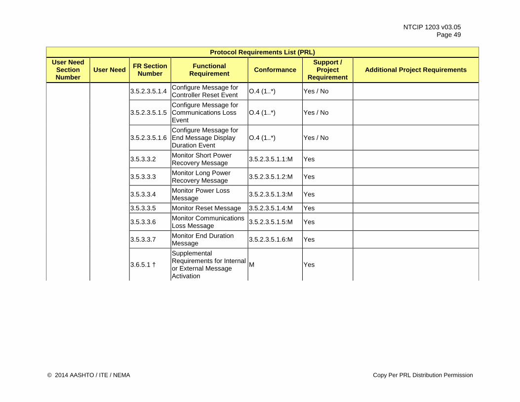
NTCIP 1203 v03.05 Page 49
Protocol Requirements List (PRL) User Need
Section Number
User Need FR Section Number
Functional Requirement Conformance
Support / Project
Requirement Additional Project Requirements
3.5.2.3.5.1.4 Configure Message for Controller Reset Event O.4 (1..*) Yes / No
3.5.2.3.5.1.5 Configure Message for Communications Loss Event
O.4 (1..*) Yes / No
3.5.2.3.5.1.6 Configure Message for End Message Display Duration Event
O.4 (1..*) Yes / No
3.5.3.3.2 Monitor Short Power Recovery Message 3.5.2.3.5.1.1:M Yes
3.5.3.3.3 Monitor Long Power Recovery Message 3.5.2.3.5.1.2:M Yes
3.5.3.3.4 Monitor Power Loss Message 3.5.2.3.5.1.3:M Yes
3.5.3.3.5 Monitor Reset Message 3.5.2.3.5.1.4:M Yes
3.5.3.3.6 Monitor Communications Loss Message 3.5.2.3.5.1.5:M Yes
3.5.3.3.7 Monitor End Duration Message 3.5.2.3.5.1.6:M Yes
3.6.5.1 †
Supplemental Requirements for Internal or External Message Activation
M Yes
© 2014 AASHTO / ITE / NEMA Copy Per PRL Distribution Permission
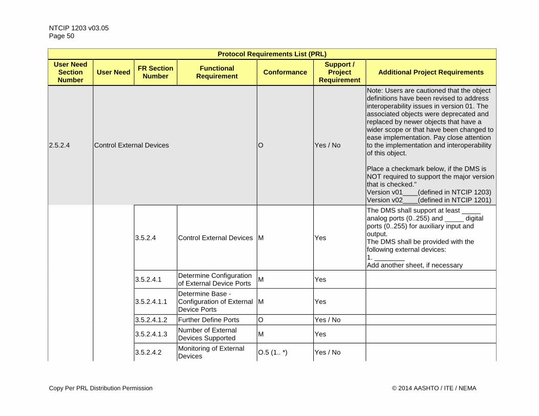
NTCIP 1203 v03.05 Page 50
Protocol Requirements List (PRL) User Need
Section Number
User Need FR Section Number
Functional Requirement Conformance
Support / Project
Requirement Additional Project Requirements
2.5.2.4 Control External Devices O Yes / No
Note: Users are cautioned that the object definitions have been revised to address interoperability issues in version 01. The associated objects were deprecated and replaced by newer objects that have a wider scope or that have been changed to ease implementation. Pay close attention to the implementation and interoperability of this object. Place a checkmark below, if the DMS is NOT required to support the major version that is checked." Version v01____(defined in NTCIP 1203) Version v02____(defined in NTCIP 1201)
3.5.2.4 Control External Devices M Yes
The DMS shall support at least _____ analog ports (0..255) and _____ digital ports (0..255) for auxiliary input and output. The DMS shall be provided with the following external devices: 1. ________ Add another sheet, if necessary
3.5.2.4.1 Determine Configuration of External Device Ports M Yes
3.5.2.4.1.1 Determine Base -Configuration of External Device Ports
M Yes
3.5.2.4.1.2 Further Define Ports O Yes / No
3.5.2.4.1.3 Number of External Devices Supported M Yes
3.5.2.4.2 Monitoring of External Devices O.5 (1.. *) Yes / No
Copy Per PRL Distribution Permission © 2014 AASHTO / ITE / NEMA
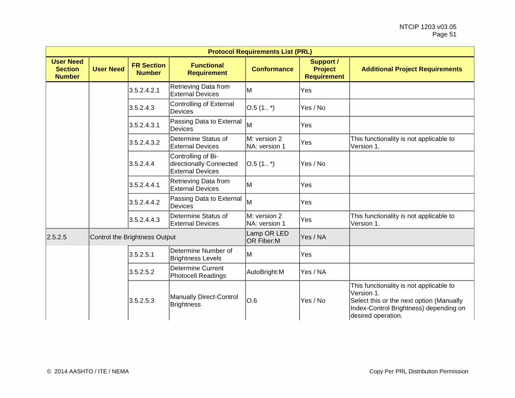
NTCIP 1203 v03.05 Page 51
Protocol Requirements List (PRL) User Need
Section Number
User Need FR Section Number
Functional Requirement Conformance
Support / Project
Requirement Additional Project Requirements
3.5.2.4.2.1 Retrieving Data from External Devices M Yes
3.5.2.4.3 Controlling of External Devices O.5 (1.. *) Yes / No
3.5.2.4.3.1 Passing Data to External Devices M Yes
3.5.2.4.3.2 Determine Status of External Devices
M: version 2 NA: version 1 Yes This functionality is not applicable to
Version 1.
3.5.2.4.4 Controlling of Bi-directionally Connected External Devices
O.5 (1.. *) Yes / No
3.5.2.4.4.1 Retrieving Data from External Devices M Yes
3.5.2.4.4.2 Passing Data to External Devices M Yes
3.5.2.4.4.3 Determine Status of External Devices
M: version 2 NA: version 1 Yes This functionality is not applicable to
Version 1.
2.5.2.5 Control the Brightness Output Lamp OR LED OR Fiber:M Yes / NA
3.5.2.5.1 Determine Number of Brightness Levels M Yes
3.5.2.5.2 Determine Current Photocell Readings AutoBright:M Yes / NA
3.5.2.5.3 Manually Direct-Control Brightness O.6 Yes / No
This functionality is not applicable to Version 1. Select this or the next option (Manually Index-Control Brightness) depending on desired operation.
© 2014 AASHTO / ITE / NEMA Copy Per PRL Distribution Permission
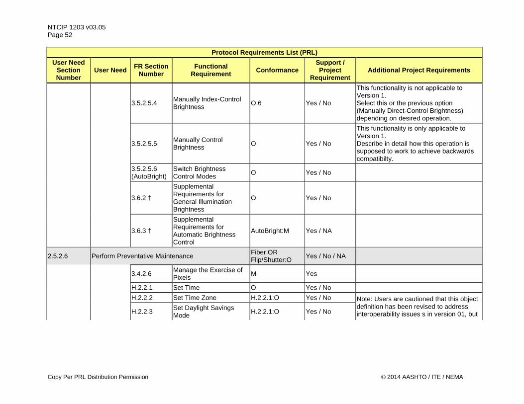
NTCIP 1203 v03.05 Page 52
Protocol Requirements List (PRL) User Need
Section Number
User Need FR Section Number
Functional Requirement Conformance
Support / Project
Requirement Additional Project Requirements
3.5.2.5.4 Manually Index-Control Brightness O.6 Yes / No
This functionality is not applicable to Version 1. Select this or the previous option (Manually Direct-Control Brightness) depending on desired operation.
3.5.2.5.5 Manually Control Brightness O Yes / No
This functionality is only applicable to Version 1. Describe in detail how this operation is supposed to work to achieve backwards compatibilty.
3.5.2.5.6 (AutoBright)
Switch Brightness Control Modes O Yes / No
3.6.2 †
Supplemental Requirements for General Illumination Brightness
O Yes / No
3.6.3 †
Supplemental Requirements for Automatic Brightness Control
AutoBright:M Yes / NA
2.5.2.6 Perform Preventative Maintenance Fiber OR Flip/Shutter:O Yes / No / NA
3.4.2.6 Manage the Exercise of Pixels M Yes
H.2.2.1 Set Time O Yes / No H.2.2.2 Set Time Zone H.2.2.1:O Yes / No Note: Users are cautioned that this object
definition has been revised to address interoperability issues s in version 01, but H.2.2.3 Set Daylight Savings
Mode H.2.2.1:O Yes / No
Copy Per PRL Distribution Permission © 2014 AASHTO / ITE / NEMA
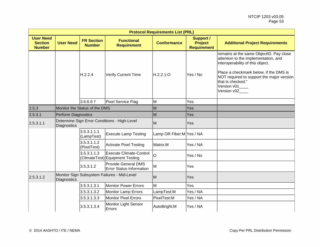
NTCIP 1203 v03.05 Page 53
Protocol Requirements List (PRL) User Need
Section Number
User Need FR Section Number
Functional Requirement Conformance
Support / Project
Requirement Additional Project Requirements
H.2.2.4 Verify Current Time H.2.2.1:O Yes / No
remains at the same ObjectID. Pay close attention to the implementation, and interoperability of this object. Place a checkmark below, if the DMS is NOT required to support the major version that is checked." Version v01____ Version v02____
3.6.6.6 † Pixel Service Flag M Yes 2.5.3 Monitor the Status of the DMS M Yes 2.5.3.1 Perform Diagnostics M Yes
2.5.3.1.1 Determine Sign Error Conditions - High-Level Diagnostics M Yes
3.5.3.1.1.1 (LampTest) Execute Lamp Testing Lamp OR Fiber:M Yes / NA
3.5.3.1.1.2 (PixelTest) Activate Pixel Testing Matrix:M Yes / NA
3.5.3.1.1.3 (ClimateTest)
Execute Climate-Control Equipment Testing O Yes / No
3.5.3.1.2 Provide General DMS Error Status Information M Yes
2.5.3.1.2 Monitor Sign Subsystem Failures - Mid-Level Diagnostics M Yes
3.5.3.1.3.1 Monitor Power Errors M Yes 3.5.3.1.3.2 Monitor Lamp Errors LampTest:M Yes / NA 3.5.3.1.3.3 Monitor Pixel Errors PixelTest:M Yes / NA
3.5.3.1.3.4 Monitor Light Sensor Errors AutoBright:M Yes / NA
© 2014 AASHTO / ITE / NEMA Copy Per PRL Distribution Permission
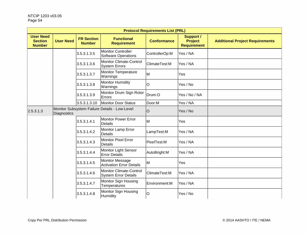
NTCIP 1203 v03.05 Page 54
Protocol Requirements List (PRL) User Need
Section Number
User Need FR Section Number
Functional Requirement Conformance
Support / Project
Requirement Additional Project Requirements
3.5.3.1.3.5 Monitor Controller Software Operations ControllerOp:M Yes / NA
3.5.3.1.3.6 Monitor Climate-Control System Errors ClimateTest:M Yes / NA
3.5.3.1.3.7 Monitor Temperature Warnings M Yes
3.5.3.1.3.8 Monitor Humidity Warnings O Yes / No
3.5.3.1.3.9 Monitor Drum Sign Rotor Errors Drum:O Yes / No / NA
3.5.3.1.3.10 Monitor Door Status Door:M Yes / NA
2.5.3.1.3 Monitor Subsystem Failure Details - Low-Level Diagnostics O Yes / No
3.5.3.1.4.1 Monitor Power Error Details M Yes
3.5.3.1.4.2 Monitor Lamp Error Details LampTest:M Yes / NA
3.5.3.1.4.3 Monitor Pixel Error Details PixelTest:M Yes / NA
3.5.3.1.4.4 Monitor Light Sensor Error Details AutoBright:M Yes / NA
3.5.3.1.4.5 Monitor Message Activation Error Details M Yes
3.5.3.1.4.6 Monitor Climate-Control System Error Details ClimateTest:M Yes / NA
3.5.3.1.4.7 Monitor Sign Housing Temperatures Environment:M Yes / NA
3.5.3.1.4.8 Monitor Sign Housing Humidity O Yes / No
Copy Per PRL Distribution Permission © 2014 AASHTO / ITE / NEMA
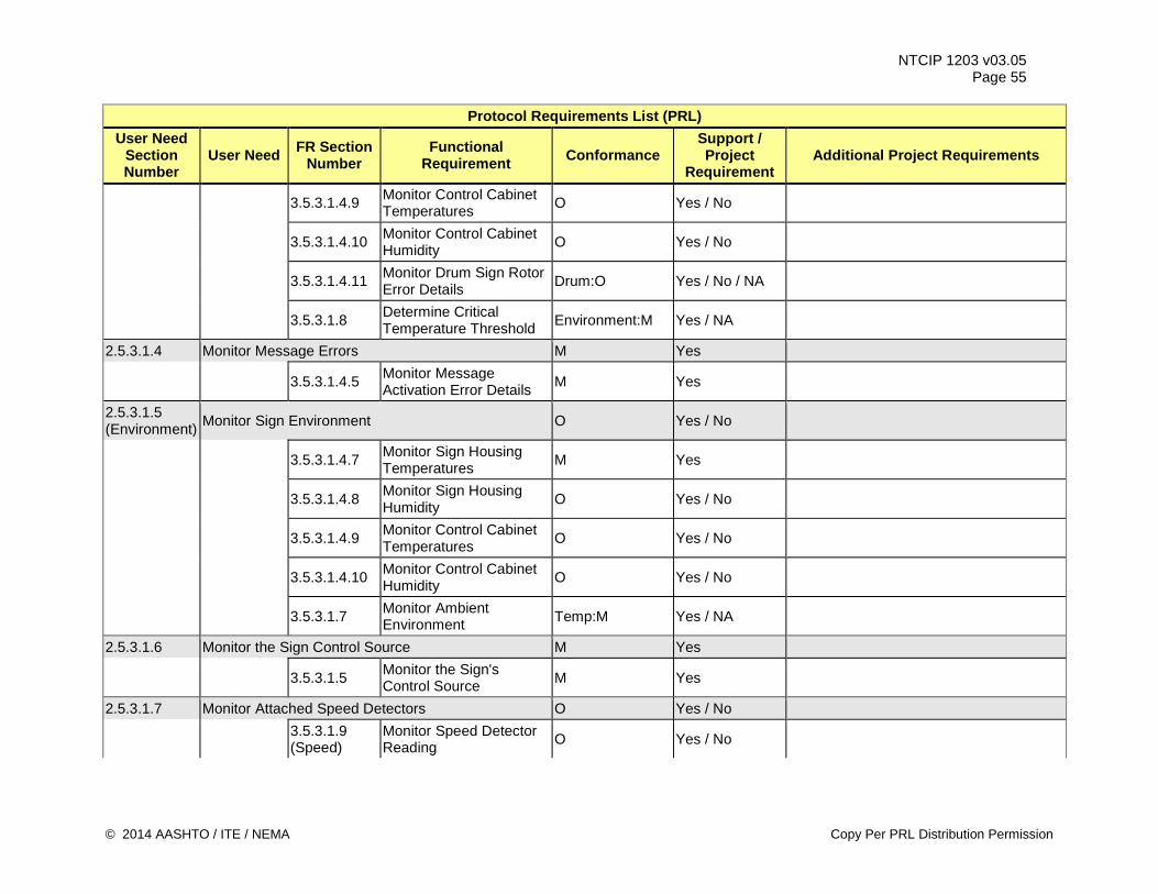
NTCIP 1203 v03.05 Page 55
Protocol Requirements List (PRL) User Need
Section Number
User Need FR Section Number
Functional Requirement Conformance
Support / Project
Requirement Additional Project Requirements
3.5.3.1.4.9 Monitor Control Cabinet Temperatures O Yes / No
3.5.3.1.4.10 Monitor Control Cabinet Humidity O Yes / No
3.5.3.1.4.11 Monitor Drum Sign Rotor Error Details Drum:O Yes / No / NA
3.5.3.1.8 Determine Critical Temperature Threshold Environment:M Yes / NA
2.5.3.1.4 Monitor Message Errors M Yes
3.5.3.1.4.5 Monitor Message Activation Error Details M Yes
2.5.3.1.5 (Environment) Monitor Sign Environment O Yes / No
3.5.3.1.4.7 Monitor Sign Housing Temperatures M Yes
3.5.3.1.4.8 Monitor Sign Housing Humidity O Yes / No
3.5.3.1.4.9 Monitor Control Cabinet Temperatures O Yes / No
3.5.3.1.4.10 Monitor Control Cabinet Humidity O Yes / No
3.5.3.1.7 Monitor Ambient Environment Temp:M Yes / NA
2.5.3.1.6 Monitor the Sign Control Source M Yes
3.5.3.1.5 Monitor the Sign's Control Source M Yes
2.5.3.1.7 Monitor Attached Speed Detectors O Yes / No
3.5.3.1.9 (Speed)
Monitor Speed Detector Reading O Yes / No
© 2014 AASHTO / ITE / NEMA Copy Per PRL Distribution Permission
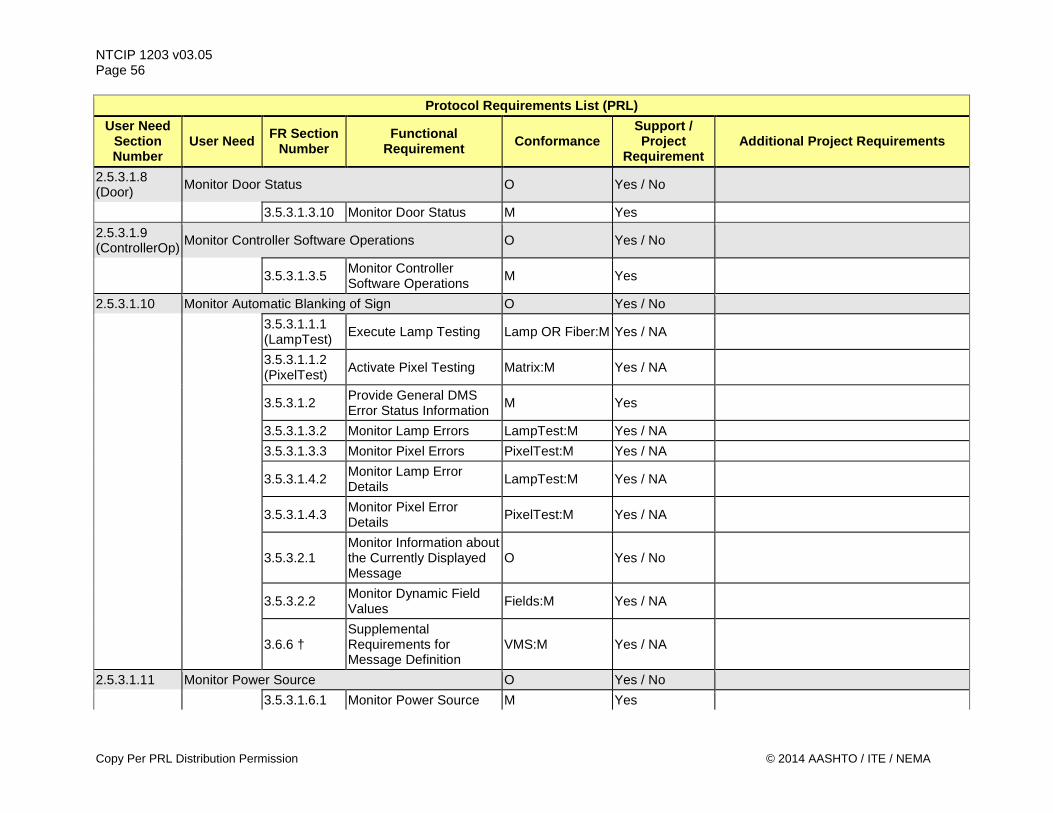
NTCIP 1203 v03.05 Page 56
Protocol Requirements List (PRL) User Need
Section Number
User Need FR Section Number
Functional Requirement Conformance
Support / Project
Requirement Additional Project Requirements
2.5.3.1.8 (Door) Monitor Door Status O Yes / No
3.5.3.1.3.10 Monitor Door Status M Yes 2.5.3.1.9 (ControllerOp) Monitor Controller Software Operations O Yes / No
3.5.3.1.3.5 Monitor Controller Software Operations M Yes
2.5.3.1.10 Monitor Automatic Blanking of Sign O Yes / No
3.5.3.1.1.1 (LampTest) Execute Lamp Testing Lamp OR Fiber:M Yes / NA
3.5.3.1.1.2 (PixelTest) Activate Pixel Testing Matrix:M Yes / NA
3.5.3.1.2 Provide General DMS Error Status Information M Yes
3.5.3.1.3.2 Monitor Lamp Errors LampTest:M Yes / NA 3.5.3.1.3.3 Monitor Pixel Errors PixelTest:M Yes / NA
3.5.3.1.4.2 Monitor Lamp Error Details LampTest:M Yes / NA
3.5.3.1.4.3 Monitor Pixel Error Details PixelTest:M Yes / NA
3.5.3.2.1 Monitor Information about the Currently Displayed Message
O Yes / No
3.5.3.2.2 Monitor Dynamic Field Values Fields:M Yes / NA
3.6.6 † Supplemental Requirements for Message Definition
VMS:M Yes / NA
2.5.3.1.11 Monitor Power Source O Yes / No 3.5.3.1.6.1 Monitor Power Source M Yes
Copy Per PRL Distribution Permission © 2014 AASHTO / ITE / NEMA
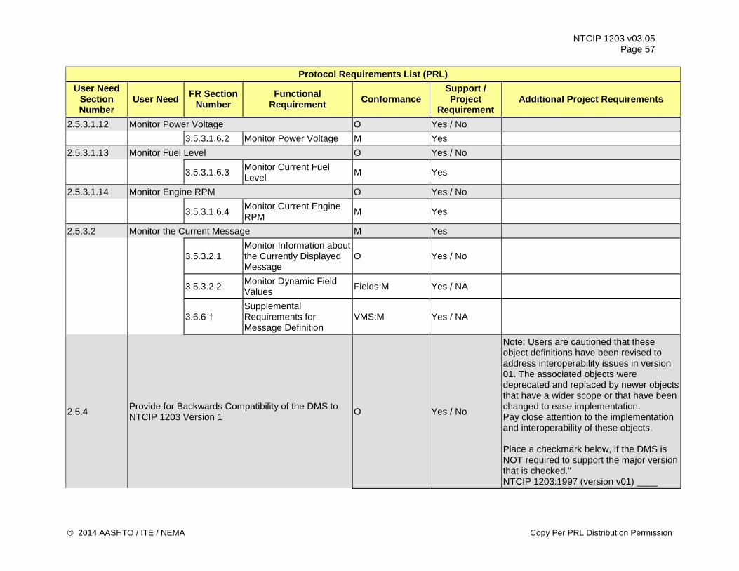
NTCIP 1203 v03.05 Page 57
Protocol Requirements List (PRL) User Need
Section Number
User Need FR Section Number
Functional Requirement Conformance
Support / Project
Requirement Additional Project Requirements
2.5.3.1.12 Monitor Power Voltage O Yes / No 3.5.3.1.6.2 Monitor Power Voltage M Yes 2.5.3.1.13 Monitor Fuel Level O Yes / No
3.5.3.1.6.3 Monitor Current Fuel Level M Yes
2.5.3.1.14 Monitor Engine RPM O Yes / No
3.5.3.1.6.4 Monitor Current Engine RPM M Yes
2.5.3.2 Monitor the Current Message M Yes
3.5.3.2.1 Monitor Information about the Currently Displayed Message
O Yes / No
3.5.3.2.2 Monitor Dynamic Field Values Fields:M Yes / NA
3.6.6 † Supplemental Requirements for Message Definition
VMS:M Yes / NA
2.5.4 Provide for Backwards Compatibility of the DMS to NTCIP 1203 Version 1 O Yes / No
Note: Users are cautioned that these object definitions have been revised to address interoperability issues in version 01. The associated objects were deprecated and replaced by newer objects that have a wider scope or that have been changed to ease implementation. Pay close attention to the implementation and interoperability of these objects. Place a checkmark below, if the DMS is NOT required to support the major version that is checked." NTCIP 1203:1997 (version v01) ____
© 2014 AASHTO / ITE / NEMA Copy Per PRL Distribution Permission
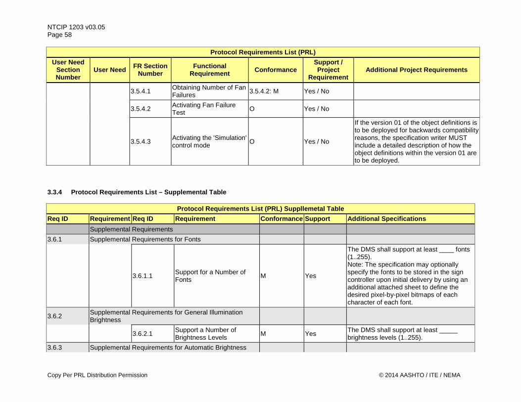
NTCIP 1203 v03.05 Page 58
Protocol Requirements List (PRL) User Need
Section Number
User Need FR Section Number
Functional Requirement Conformance
Support / Project
Requirement Additional Project Requirements
3.5.4.1 Obtaining Number of Fan Failures 3.5.4.2: M Yes / No
3.5.4.2 Activating Fan Failure Test O Yes / No
3.5.4.3 Activating the 'Simulation' control mode O Yes / No
If the version 01 of the object definitions is to be deployed for backwards compatibility reasons, the specification writer MUST include a detailed description of how the object definitions within the version 01 are to be deployed.
3.3.4 Protocol Requirements List – Supplemental Table
Protocol Requirements List (PRL) Suppllemetal Table Req ID Requirement Req ID Requirement Conformance Support Additional Specifications Supplemental Requirements 3.6.1 Supplemental Requirements for Fonts
3.6.1.1 Support for a Number of Fonts M Yes
The DMS shall support at least ____ fonts (1..255). Note: The specification may optionally specify the fonts to be stored in the sign controller upon initial delivery by using an additional attached sheet to define the desired pixel-by-pixel bitmaps of each character of each font.
3.6.2 Supplemental Requirements for General Illumination Brightness
3.6.2.1 Support a Number of Brightness Levels M Yes The DMS shall support at least _____
brightness levels (1..255). 3.6.3 Supplemental Requirements for Automatic Brightness
Copy Per PRL Distribution Permission © 2014 AASHTO / ITE / NEMA
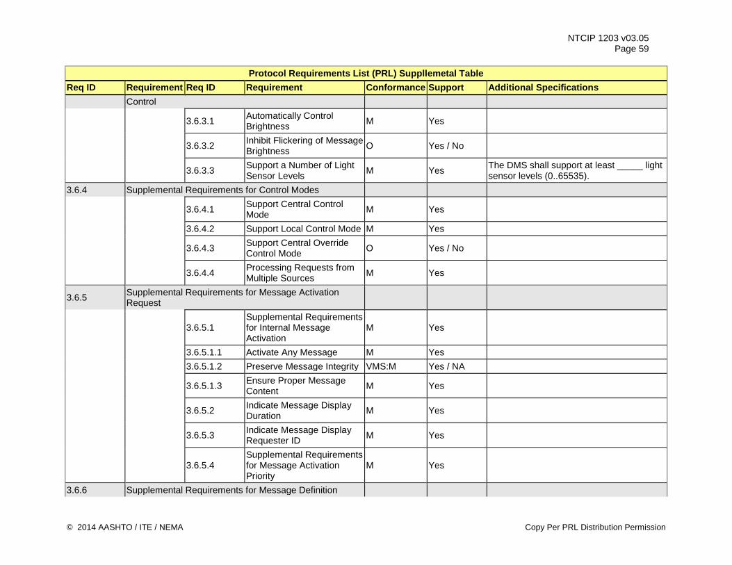
NTCIP 1203 v03.05 Page 59
Protocol Requirements List (PRL) Suppllemetal Table Req ID Requirement Req ID Requirement Conformance Support Additional Specifications
Control
3.6.3.1 Automatically Control Brightness M Yes
3.6.3.2 Inhibit Flickering of Message Brightness O Yes / No
3.6.3.3 Support a Number of Light Sensor Levels M Yes The DMS shall support at least _____ light
sensor levels (0..65535). 3.6.4 Supplemental Requirements for Control Modes
3.6.4.1 Support Central Control Mode M Yes
3.6.4.2 Support Local Control Mode M Yes
3.6.4.3 Support Central Override Control Mode O Yes / No
3.6.4.4 Processing Requests from Multiple Sources M Yes
3.6.5 Supplemental Requirements for Message Activation Request
3.6.5.1 Supplemental Requirements for Internal Message Activation
M Yes
3.6.5.1.1 Activate Any Message M Yes 3.6.5.1.2 Preserve Message Integrity VMS:M Yes / NA
3.6.5.1.3 Ensure Proper Message Content M Yes
3.6.5.2 Indicate Message Display Duration M Yes
3.6.5.3 Indicate Message Display Requester ID M Yes
3.6.5.4 Supplemental Requirements for Message Activation Priority
M Yes
3.6.6 Supplemental Requirements for Message Definition
© 2014 AASHTO / ITE / NEMA Copy Per PRL Distribution Permission
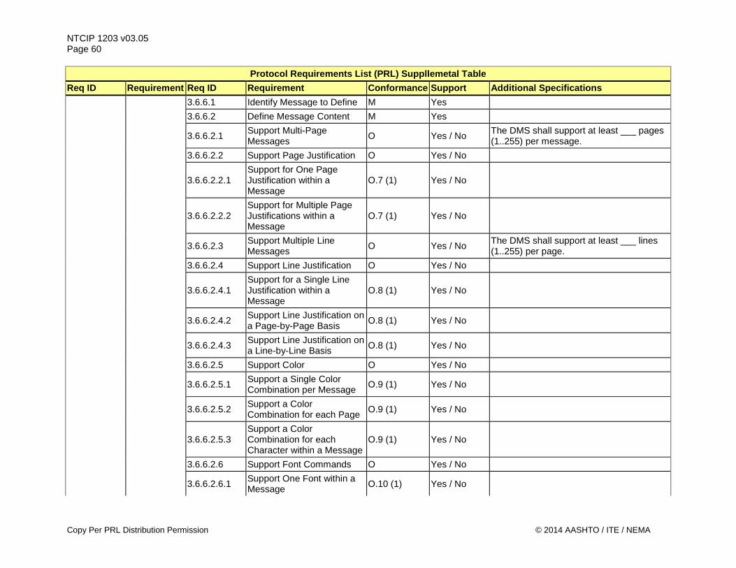
NTCIP 1203 v03.05 Page 60
Protocol Requirements List (PRL) Suppllemetal Table Req ID Requirement Req ID Requirement Conformance Support Additional Specifications 3.6.6.1 Identify Message to Define M Yes 3.6.6.2 Define Message Content M Yes
3.6.6.2.1 Support Multi-Page Messages O Yes / No The DMS shall support at least ___ pages
(1..255) per message. 3.6.6.2.2 Support Page Justification O Yes / No
3.6.6.2.2.1 Support for One Page Justification within a Message
O.7 (1) Yes / No
3.6.6.2.2.2 Support for Multiple Page Justifications within a Message
O.7 (1) Yes / No
3.6.6.2.3 Support Multiple Line Messages O Yes / No The DMS shall support at least ___ lines
(1..255) per page. 3.6.6.2.4 Support Line Justification O Yes / No
3.6.6.2.4.1 Support for a Single Line Justification within a Message
O.8 (1) Yes / No
3.6.6.2.4.2 Support Line Justification on a Page-by-Page Basis O.8 (1) Yes / No
3.6.6.2.4.3 Support Line Justification on a Line-by-Line Basis O.8 (1) Yes / No
3.6.6.2.5 Support Color O Yes / No
3.6.6.2.5.1 Support a Single Color Combination per Message O.9 (1) Yes / No
3.6.6.2.5.2 Support a Color Combination for each Page O.9 (1) Yes / No
3.6.6.2.5.3 Support a Color Combination for each Character within a Message
O.9 (1) Yes / No
3.6.6.2.6 Support Font Commands O Yes / No
3.6.6.2.6.1 Support One Font within a Message O.10 (1) Yes / No
Copy Per PRL Distribution Permission © 2014 AASHTO / ITE / NEMA
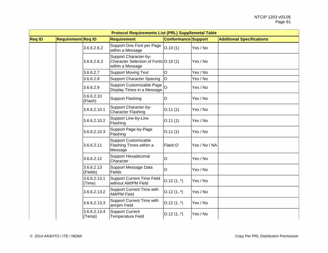
NTCIP 1203 v03.05 Page 61
Protocol Requirements List (PRL) Suppllemetal Table Req ID Requirement Req ID Requirement Conformance Support Additional Specifications
3.6.6.2.6.2 Support One Font per Page within a Message O.10 (1) Yes / No
3.6.6.2.6.3 Support Character-by-Character Selection of Fonts within a Message
O.10 (1) Yes / No
3.6.6.2.7 Support Moving Text O Yes / No 3.6.6.2.8 Support Character Spacing O Yes / No
3.6.6.2.9 Support Customizable Page Display Times in a Message O Yes / No
3.6.6.2.10 (Flash) Support Flashing O Yes / No
3.6.6.2.10.1 Support Character-by-Character Flashing O.11 (1) Yes / No
3.6.6.2.10.2 Support Line-by-Line Flashing O.11 (1) Yes / No
3.6.6.2.10.3 Support Page-by-Page Flashing O.11 (1) Yes / No
3.6.6.2.11 Support Customizable Flashing Times within a Message
Flash:O Yes / No / NA
3.6.6.2.12 Support Hexadecimal Character O Yes / No
3.6.6.2.13 (Fields)
Support Message Data Fields O Yes / No
3.6.6.2.13.1 (Time)
Support Current Time Field without AM/PM Field O.12 (1..*) Yes / No
3.6.6.2.13.2 Support Current Time with AM/PM Field O.12 (1..*) Yes / No
3.6.6.2.13.3 Support Current Time with am/pm Field O.12 (1..*) Yes / No
3.6.6.2.13.4 (Temp)
Support Current Temperature Field O.12 (1..*) Yes / No
© 2014 AASHTO / ITE / NEMA Copy Per PRL Distribution Permission
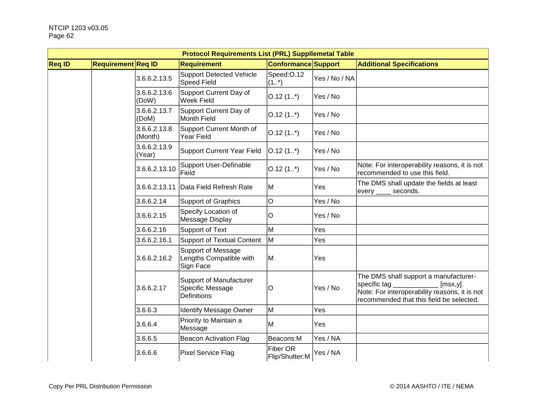
NTCIP 1203 v03.05 Page 62
Protocol Requirements List (PRL) Suppllemetal Table Req ID Requirement Req ID Requirement Conformance Support Additional Specifications
3.6.6.2.13.5 Support Detected Vehicle Speed Field
Speed:O.12 (1..*) Yes / No / NA
3.6.6.2.13.6 (DoW)
Support Current Day of Week Field O.12 (1..*) Yes / No
3.6.6.2.13.7 (DoM)
Support Current Day of Month Field O.12 (1..*) Yes / No
3.6.6.2.13.8 (Month)
Support Current Month of Year Field O.12 (1..*) Yes / No
3.6.6.2.13.9 (Year) Support Current Year Field O.12 (1..*) Yes / No
3.6.6.2.13.10 Support User-Definable Field O.12 (1..*) Yes / No Note: For interoperability reasons, it is not
recommended to use this field.
3.6.6.2.13.11 Data Field Refresh Rate M Yes The DMS shall update the fields at least every ____ seconds.
3.6.6.2.14 Support of Graphics O Yes / No
3.6.6.2.15 Specify Location of Message Display O Yes / No
3.6.6.2.16 Support of Text M Yes 3.6.6.2.16.1 Support of Textual Content M Yes
3.6.6.2.16.2 Support of Message Lengths Compatible with Sign Face
M Yes
3.6.6.2.17 Support of Manufacturer Specific Message Definitions
O Yes / No
The DMS shall support a manufacturer-specific tag ____________ [msx,y]. Note: For interoperability reasons, it is not recommended that this field be selected.
3.6.6.3 Identify Message Owner M Yes
3.6.6.4 Priority to Maintain a Message M Yes
3.6.6.5 Beacon Activation Flag Beacons:M Yes / NA
3.6.6.6 Pixel Service Flag Fiber OR Flip/Shutter:M Yes / NA
Copy Per PRL Distribution Permission © 2014 AASHTO / ITE / NEMA
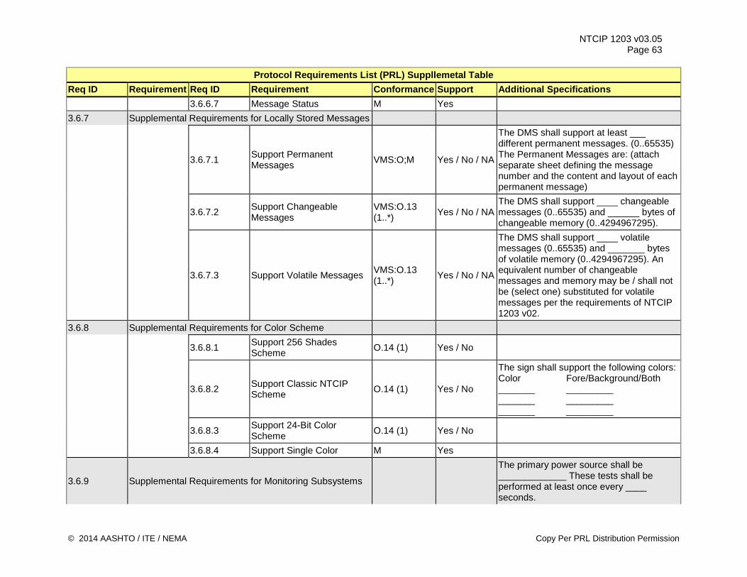
NTCIP 1203 v03.05 Page 63
Protocol Requirements List (PRL) Suppllemetal Table Req ID Requirement Req ID Requirement Conformance Support Additional Specifications 3.6.6.7 Message Status M Yes 3.6.7 Supplemental Requirements for Locally Stored Messages
3.6.7.1 Support Permanent Messages VMS:O;M Yes / No / NA
The DMS shall support at least ___ different permanent messages. (0..65535) The Permanent Messages are: (attach separate sheet defining the message number and the content and layout of each permanent message)
3.6.7.2 Support Changeable Messages
VMS:O.13 (1..*) Yes / No / NA
The DMS shall support ____ changeable messages (0..65535) and ______ bytes of changeable memory (0..4294967295).
3.6.7.3 Support Volatile Messages VMS:O.13 (1..*) Yes / No / NA
The DMS shall support ____ volatile messages (0..65535) and _______ bytes of volatile memory (0..4294967295). An equivalent number of changeable messages and memory may be / shall not be (select one) substituted for volatile messages per the requirements of NTCIP 1203 v02.
3.6.8 Supplemental Requirements for Color Scheme
3.6.8.1 Support 256 Shades Scheme O.14 (1) Yes / No
3.6.8.2 Support Classic NTCIP Scheme O.14 (1) Yes / No
The sign shall support the following colors: Color Fore/Background/Both _______ _________ _______ _________ _______ _________
3.6.8.3 Support 24-Bit Color Scheme O.14 (1) Yes / No
3.6.8.4 Support Single Color M Yes
3.6.9 Supplemental Requirements for Monitoring Subsystems
The primary power source shall be _____________ These tests shall be performed at least once every ____ seconds.
© 2014 AASHTO / ITE / NEMA Copy Per PRL Distribution Permission
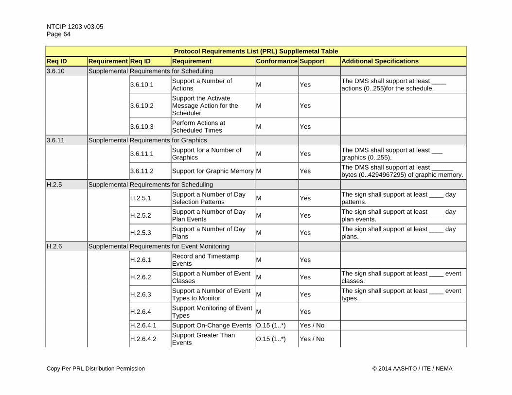
NTCIP 1203 v03.05 Page 64
Protocol Requirements List (PRL) Suppllemetal Table Req ID Requirement Req ID Requirement Conformance Support Additional Specifications 3.6.10 Supplemental Requirements for Scheduling
3.6.10.1 Support a Number of Actions M Yes The DMS shall support at least ____
actions (0..255)for the schedule.
3.6.10.2 Support the Activate Message Action for the Scheduler
M Yes
3.6.10.3 Perform Actions at Scheduled Times M Yes
3.6.11 Supplemental Requirements for Graphics
3.6.11.1 Support for a Number of Graphics M Yes The DMS shall support at least ___
graphics (0..255).
3.6.11.2 Support for Graphic Memory M Yes The DMS shall support at least ______ bytes (0..4294967295) of graphic memory.
H.2.5 Supplemental Requirements for Scheduling
H.2.5.1 Support a Number of Day Selection Patterns M Yes The sign shall support at least ____ day
patterns.
H.2.5.2 Support a Number of Day Plan Events M Yes The sign shall support at least ____ day
plan events.
H.2.5.3 Support a Number of Day Plans M Yes The sign shall support at least ____ day
plans. H.2.6 Supplemental Requirements for Event Monitoring
H.2.6.1 Record and Timestamp Events M Yes
H.2.6.2 Support a Number of Event Classes M Yes The sign shall support at least ____ event
classes.
H.2.6.3 Support a Number of Event Types to Monitor M Yes The sign shall support at least ____ event
types.
H.2.6.4 Support Monitoring of Event Types M Yes
H.2.6.4.1 Support On-Change Events O.15 (1..*) Yes / No
H.2.6.4.2 Support Greater Than Events O.15 (1..*) Yes / No
Copy Per PRL Distribution Permission © 2014 AASHTO / ITE / NEMA
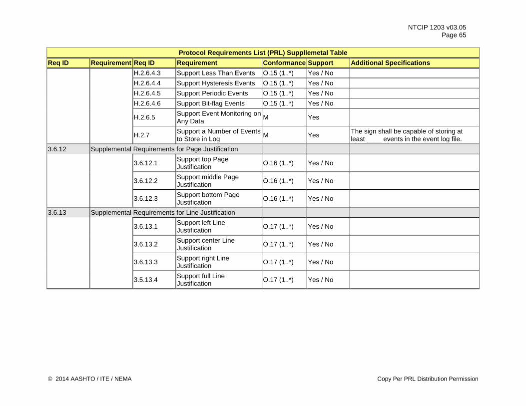
NTCIP 1203 v03.05 Page 65
Protocol Requirements List (PRL) Suppllemetal Table Req ID Requirement Req ID Requirement Conformance Support Additional Specifications H.2.6.4.3 Support Less Than Events O.15 (1..*) Yes / No H.2.6.4.4 Support Hysteresis Events O.15 (1..*) Yes / No H.2.6.4.5 Support Periodic Events O.15 (1..*) Yes / No H.2.6.4.6 Support Bit-flag Events O.15 (1..*) Yes / No
H.2.6.5 Support Event Monitoring on Any Data M Yes
H.2.7 Support a Number of Events to Store in Log M Yes The sign shall be capable of storing at
least ____ events in the event log file. 3.6.12 Supplemental Requirements for Page Justification
3.6.12.1 Support top Page Justification O.16 (1..*) Yes / No
3.6.12.2 Support middle Page Justification O.16 (1..*) Yes / No
3.6.12.3 Support bottom Page Justification O.16 (1..*) Yes / No
3.6.13 Supplemental Requirements for Line Justification
3.6.13.1 Support left Line Justification O.17 (1..*) Yes / No
3.6.13.2 Support center Line Justification O.17 (1..*) Yes / No
3.6.13.3 Support right Line Justification O.17 (1..*) Yes / No
3.5.13.4 Support full Line Justification O.17 (1..*) Yes / No
© 2014 AASHTO / ITE / NEMA Copy Per PRL Distribution Permission
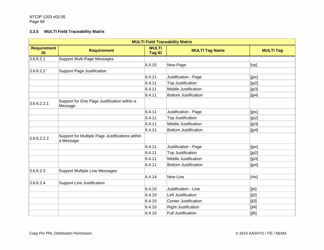
NTCIP 1203 v03.05 Page 66 3.3.5 MULTI Field Traceability Matrix
MULTI Field Traceability Matrix Requirement
ID Requirement MULTI Tag ID MULTI Tag Name MULTI Tag
3.6.6.2.1 Support Multi-Page Messages 6.4.15 New Page [np] 3.6.6.2.2 Support Page Justification 6.4.11 Justification - Page [jpx] 6.4.11 Top Justification [jp2] 6.4.11 Middle Justification [jp3] 6.4.11 Bottom Justification [jp4]
3.6.6.2.2.1 Support for One Page Justification within a Message
6.4.11 Justification - Page [jpx] 6.4.11 Top Justification [jp2] 6.4.11 Middle Justification [jp3] 6.4.11 Bottom Justification [jp4]
3.6.6.2.2.2 Support for Multiple Page Justifications within a Message
6.4.11 Justification - Page [jpx] 6.4.11 Top Justification [jp2] 6.4.11 Middle Justification [jp3] 6.4.11 Bottom Justification [jp4] 3.6.6.2.3 Support Multiple Line Messages 6.4.14 New Line [nlx] 3.6.6.2.4 Support Line Justification 6.4.10 Justification - Line [jlx] 6.4.10 Left Justification [jl2] 6.4.10 Center Justification [jl3] 6.4.10 Right Justification [jl4] 6.4.10 Full Justification [jl5]
Copy Per PRL Distribution Permission © 2014 AASHTO / ITE / NEMA
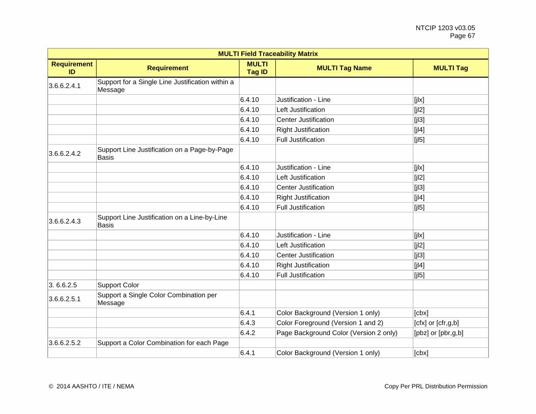
NTCIP 1203 v03.05 Page 67
MULTI Field Traceability Matrix Requirement
ID Requirement MULTI Tag ID MULTI Tag Name MULTI Tag
3.6.6.2.4.1 Support for a Single Line Justification within a Message
6.4.10 Justification - Line [jlx] 6.4.10 Left Justification [jl2] 6.4.10 Center Justification [jl3] 6.4.10 Right Justification [jl4] 6.4.10 Full Justification [jl5]
3.6.6.2.4.2 Support Line Justification on a Page-by-Page Basis
6.4.10 Justification - Line [jlx] 6.4.10 Left Justification [jl2] 6.4.10 Center Justification [jl3] 6.4.10 Right Justification [jl4] 6.4.10 Full Justification [jl5]
3.6.6.2.4.3 Support Line Justification on a Line-by-Line Basis
6.4.10 Justification - Line [jlx] 6.4.10 Left Justification [jl2] 6.4.10 Center Justification [jl3] 6.4.10 Right Justification [jl4] 6.4.10 Full Justification [jl5] 3. 6.6.2.5 Support Color
3.6.6.2.5.1 Support a Single Color Combination per Message
6.4.1 Color Background (Version 1 only) [cbx] 6.4.3 Color Foreground (Version 1 and 2) [cfx] or [cfr,g,b] 6.4.2 Page Background Color (Version 2 only) [pbz] or [pbr,g,b] 3.6.6.2.5.2 Support a Color Combination for each Page 6.4.1 Color Background (Version 1 only) [cbx]
© 2014 AASHTO / ITE / NEMA Copy Per PRL Distribution Permission
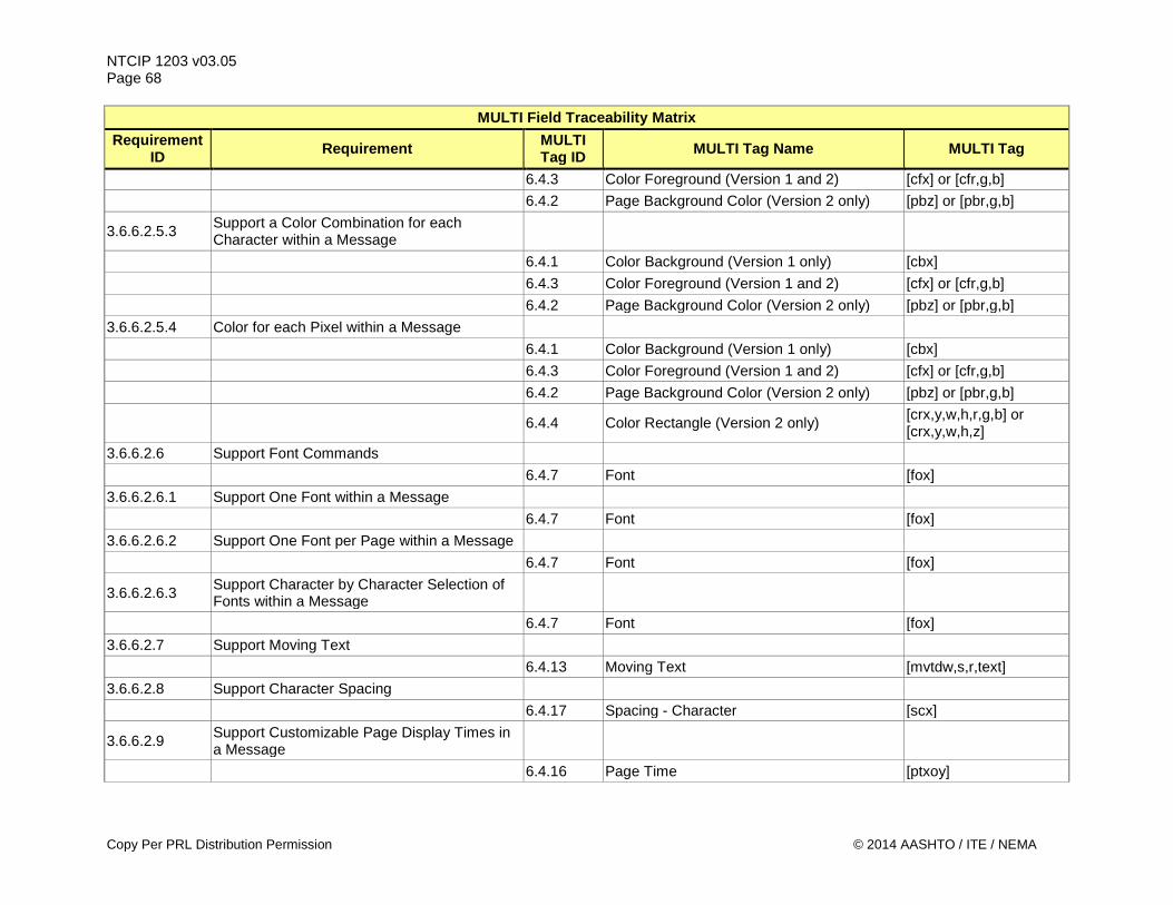
NTCIP 1203 v03.05 Page 68
MULTI Field Traceability Matrix Requirement
ID Requirement MULTI Tag ID MULTI Tag Name MULTI Tag
6.4.3 Color Foreground (Version 1 and 2) [cfx] or [cfr,g,b] 6.4.2 Page Background Color (Version 2 only) [pbz] or [pbr,g,b]
3.6.6.2.5.3 Support a Color Combination for each Character within a Message
6.4.1 Color Background (Version 1 only) [cbx] 6.4.3 Color Foreground (Version 1 and 2) [cfx] or [cfr,g,b] 6.4.2 Page Background Color (Version 2 only) [pbz] or [pbr,g,b] 3.6.6.2.5.4 Color for each Pixel within a Message 6.4.1 Color Background (Version 1 only) [cbx] 6.4.3 Color Foreground (Version 1 and 2) [cfx] or [cfr,g,b] 6.4.2 Page Background Color (Version 2 only) [pbz] or [pbr,g,b]
6.4.4 Color Rectangle (Version 2 only) [crx,y,w,h,r,g,b] or [crx,y,w,h,z]
3.6.6.2.6 Support Font Commands 6.4.7 Font [fox] 3.6.6.2.6.1 Support One Font within a Message 6.4.7 Font [fox] 3.6.6.2.6.2 Support One Font per Page within a Message 6.4.7 Font [fox]
3.6.6.2.6.3 Support Character by Character Selection of Fonts within a Message
6.4.7 Font [fox] 3.6.6.2.7 Support Moving Text 6.4.13 Moving Text [mvtdw,s,r,text] 3.6.6.2.8 Support Character Spacing 6.4.17 Spacing - Character [scx]
3.6.6.2.9 Support Customizable Page Display Times in a Message
6.4.16 Page Time [ptxoy]
Copy Per PRL Distribution Permission © 2014 AASHTO / ITE / NEMA
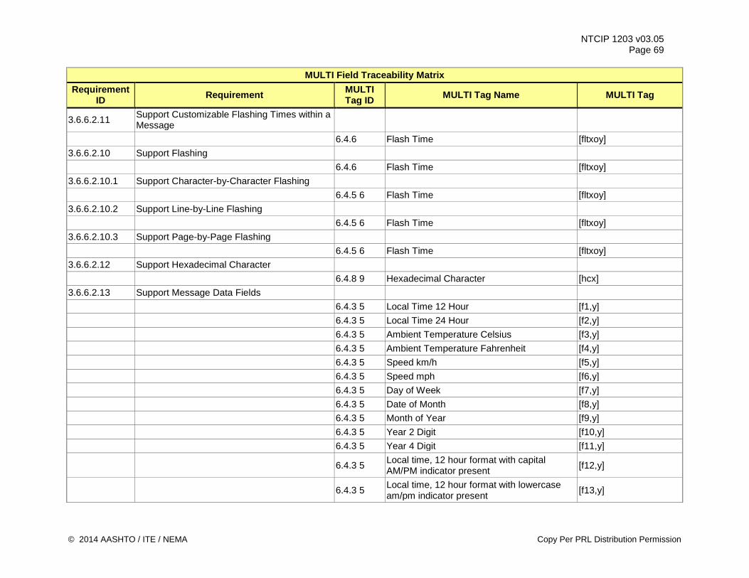
NTCIP 1203 v03.05 Page 69
MULTI Field Traceability Matrix Requirement
ID Requirement MULTI Tag ID MULTI Tag Name MULTI Tag
3.6.6.2.11 Support Customizable Flashing Times within a Message
6.4.6 Flash Time [fltxoy] 3.6.6.2.10 Support Flashing 6.4.6 Flash Time [fltxoy] 3.6.6.2.10.1 Support Character-by-Character Flashing 6.4.5 6 Flash Time [fltxoy] 3.6.6.2.10.2 Support Line-by-Line Flashing 6.4.5 6 Flash Time [fltxoy] 3.6.6.2.10.3 Support Page-by-Page Flashing 6.4.5 6 Flash Time [fltxoy] 3.6.6.2.12 Support Hexadecimal Character 6.4.8 9 Hexadecimal Character [hcx] 3.6.6.2.13 Support Message Data Fields 6.4.3 5 Local Time 12 Hour [f1,y] 6.4.3 5 Local Time 24 Hour [f2,y] 6.4.3 5 Ambient Temperature Celsius [f3,y] 6.4.3 5 Ambient Temperature Fahrenheit [f4,y] 6.4.3 5 Speed km/h [f5,y] 6.4.3 5 Speed mph [f6,y] 6.4.3 5 Day of Week [f7,y] 6.4.3 5 Date of Month [f8,y] 6.4.3 5 Month of Year [f9,y] 6.4.3 5 Year 2 Digit [f10,y] 6.4.3 5 Year 4 Digit [f11,y]
6.4.3 5 Local time, 12 hour format with capital AM/PM indicator present [f12,y]
6.4.3 5 Local time, 12 hour format with lowercase am/pm indicator present [f13,y]
© 2014 AASHTO / ITE / NEMA Copy Per PRL Distribution Permission
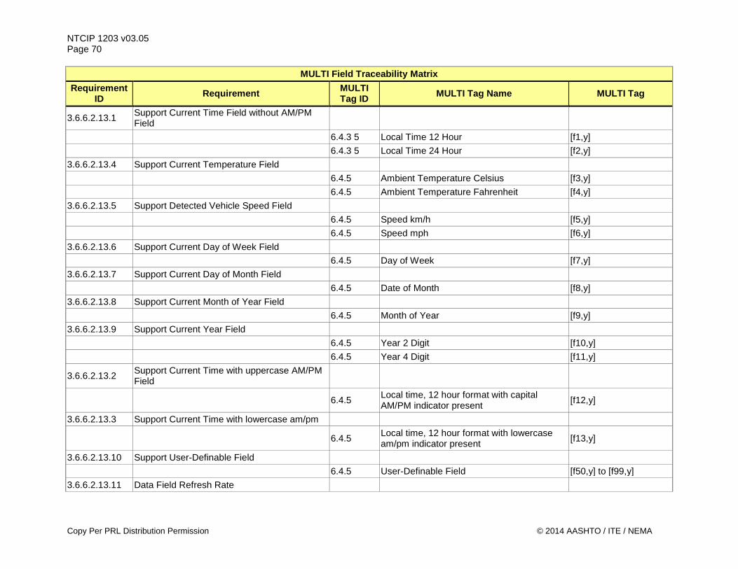
NTCIP 1203 v03.05 Page 70
MULTI Field Traceability Matrix Requirement
ID Requirement MULTI Tag ID MULTI Tag Name MULTI Tag
3.6.6.2.13.1 Support Current Time Field without AM/PM Field
6.4.3 5 Local Time 12 Hour [f1,y] 6.4.3 5 Local Time 24 Hour [f2,y] 3.6.6.2.13.4 Support Current Temperature Field 6.4.5 Ambient Temperature Celsius [f3,y] 6.4.5 Ambient Temperature Fahrenheit [f4,y] 3.6.6.2.13.5 Support Detected Vehicle Speed Field 6.4.5 Speed km/h [f5,y] 6.4.5 Speed mph [f6,y] 3.6.6.2.13.6 Support Current Day of Week Field 6.4.5 Day of Week [f7,y] 3.6.6.2.13.7 Support Current Day of Month Field 6.4.5 Date of Month [f8,y] 3.6.6.2.13.8 Support Current Month of Year Field 6.4.5 Month of Year [f9,y] 3.6.6.2.13.9 Support Current Year Field 6.4.5 Year 2 Digit [f10,y] 6.4.5 Year 4 Digit [f11,y]
3.6.6.2.13.2 Support Current Time with uppercase AM/PM Field
6.4.5 Local time, 12 hour format with capital AM/PM indicator present [f12,y]
3.6.6.2.13.3 Support Current Time with lowercase am/pm
6.4.5 Local time, 12 hour format with lowercase am/pm indicator present [f13,y]
3.6.6.2.13.10 Support User-Definable Field 6.4.5 User-Definable Field [f50,y] to [f99,y] 3.6.6.2.13.11 Data Field Refresh Rate
Copy Per PRL Distribution Permission © 2014 AASHTO / ITE / NEMA
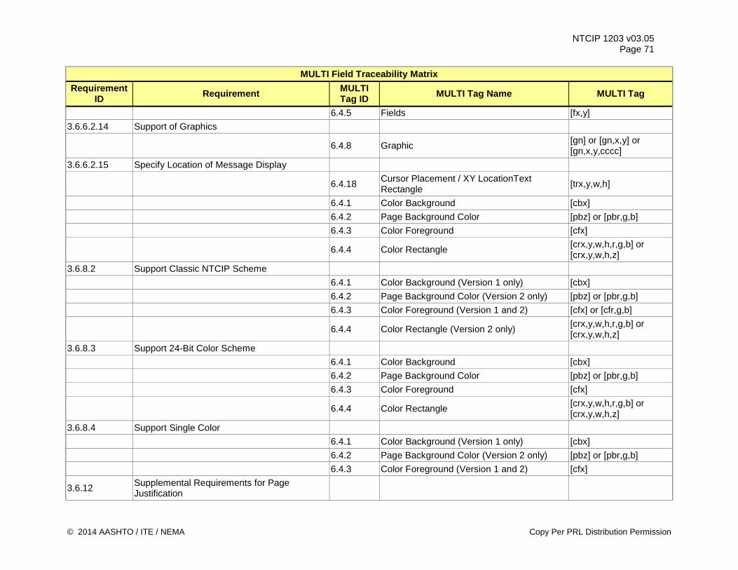
NTCIP 1203 v03.05 Page 71
MULTI Field Traceability Matrix Requirement
ID Requirement MULTI Tag ID MULTI Tag Name MULTI Tag
6.4.5 Fields [fx,y] 3.6.6.2.14 Support of Graphics
6.4.8 Graphic [gn] or [gn,x,y] or [gn,x,y,cccc]
3.6.6.2.15 Specify Location of Message Display
6.4.18 Cursor Placement / XY LocationText Rectangle [trx,y,w,h]
6.4.1 Color Background [cbx] 6.4.2 Page Background Color [pbz] or [pbr,g,b] 6.4.3 Color Foreground [cfx]
6.4.4 Color Rectangle [crx,y,w,h,r,g,b] or [crx,y,w,h,z]
3.6.8.2 Support Classic NTCIP Scheme 6.4.1 Color Background (Version 1 only) [cbx] 6.4.2 Page Background Color (Version 2 only) [pbz] or [pbr,g,b] 6.4.3 Color Foreground (Version 1 and 2) [cfx] or [cfr,g,b]
6.4.4 Color Rectangle (Version 2 only) [crx,y,w,h,r,g,b] or [crx,y,w,h,z]
3.6.8.3 Support 24-Bit Color Scheme 6.4.1 Color Background [cbx] 6.4.2 Page Background Color [pbz] or [pbr,g,b] 6.4.3 Color Foreground [cfx]
6.4.4 Color Rectangle [crx,y,w,h,r,g,b] or [crx,y,w,h,z]
3.6.8.4 Support Single Color 6.4.1 Color Background (Version 1 only) [cbx] 6.4.2 Page Background Color (Version 2 only) [pbz] or [pbr,g,b] 6.4.3 Color Foreground (Version 1 and 2) [cfx]
3.6.12 Supplemental Requirements for Page Justification
© 2014 AASHTO / ITE / NEMA Copy Per PRL Distribution Permission
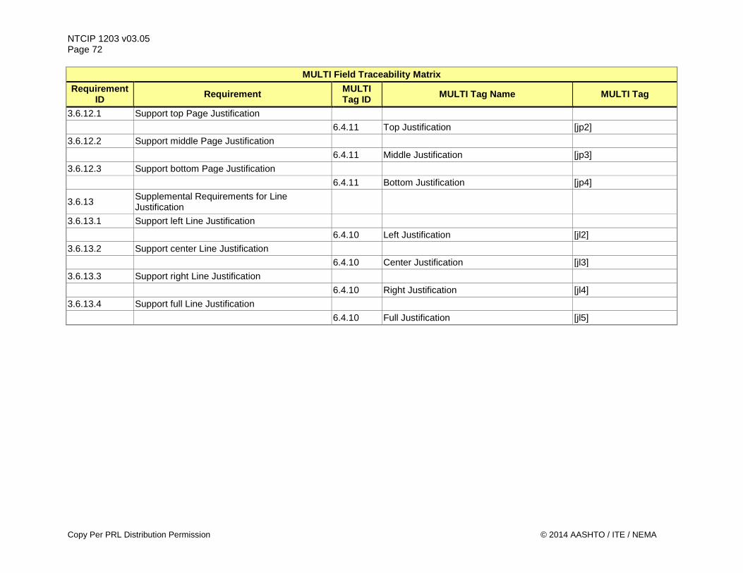
NTCIP 1203 v03.05 Page 72
MULTI Field Traceability Matrix Requirement
ID Requirement MULTI Tag ID MULTI Tag Name MULTI Tag
3.6.12.1 Support top Page Justification 6.4.11 Top Justification [jp2] 3.6.12.2 Support middle Page Justification 6.4.11 Middle Justification [jp3] 3.6.12.3 Support bottom Page Justification 6.4.11 Bottom Justification [jp4]
3.6.13 Supplemental Requirements for Line Justification
3.6.13.1 Support left Line Justification 6.4.10 Left Justification [jl2] 3.6.13.2 Support center Line Justification 6.4.10 Center Justification [jl3] 3.6.13.3 Support right Line Justification 6.4.10 Right Justification [jl4] 3.6.13.4 Support full Line Justification 6.4.10 Full Justification [jl5]
Copy Per PRL Distribution Permission © 2014 AASHTO / ITE / NEMA
NTCIP 1203 v03.05 Page 73
3.4 Architectural Requirements Requirements for communication capabilities are provided in the following subsections. 3.4.1 Support Basic Communications Requirements for making requests are provided in the following subsections. 3.4.1.1 Retrieve Data The DMS shall allow the management station to retrieve data from the sign controller. 3.4.1.2 Deliver Data The DMS shall allow the management station to deliver data (e.g., configuration data, commands, etc.) to the sign controller. 3.4.1.3 Explore Data The DMS shall allow the management station to dynamically discover what data and data instances are supported by the sign controller. 3.4.2 Support Logged Data Requirements for managing the logged data are provided in the following subsections. 3.4.2.1 Determine Current Configuration of Logging Service The DMS shall allow a management station to determine the current configuration of the event logging service, including the classes and types of events that are currently configured. 3.4.2.2 Configure Logging Service The DMS shall allow a management station to configure the event logging service, including configuration of the event classes and event types to log. 3.4.2.3 Retrieve Logged Data The DMS shall allow a management station to retrieve data from the event log. 3.4.2.4 Clear Log The DMS shall allow the management station to clear log entries of a given event class that are less than or equal to a given time. 3.4.2.5 Determine Capabilities of Event Logging Service The DMS shall allow a management station to determine the capabilities of the event logging service, including the number of classes, number of event types, and number of events that can be supported by the DMS. 3.4.2.6 Determine Total Number of Events The DMS shall allow a management station to determine the total number of events that the DMS has logged since powerup. 3.4.3 Support Exception Reporting Exception Reporting is not supported in NTCIP 1203 v03. 3.4.4 Manage Access Requirements for managing access to the information stored within the sign controller are provided in the following subsections. 3.4.4.1 Determine Current Access Settings The DMS shall allow the administrator at the management station to determine the current access settings.
© 2014 AASHTO / ITE / NEMA Do Not Copy Without Written Permission
NTCIP 1203 v03.05 Page 74 3.4.4.2 Configure Access The DMS shall allow the administrator at the management station to configure access settings for all access levels. The specification will identify the number of access levels that the DMS shall support. If the specification does not define the number of access levels, the DMS shall support at least one access level in addition to the administrator access level.
Note: Access Levels are the not the same as number of users, because several users might share the same access level. Access levels are managed within this function (and within the sign controller), while users might be managed within either or both, the sign controller and the central system. For the purpose of this function, the access level definitions manage the access to functions within the sign controller.
3.5 Data Exchange and operational environment Requirements The operation of a sign has been categorized into three major areas: a) Manage the DMS configuration b) Control the DMS c) Monitor the status of the DMS In the Concept of Operations (Section 2), each of these major areas has been broken down into sub-items. The Data Exchange Requirements also follow this structure. 3.5.1 Manage the DMS Configuration Requirements for managing DMS configuration are provided in the following subsections. 3.5.1.1 Identify DMS Requirements for identifying the DMS are provided in the following subsections. 3.5.1.1.1 Determine Sign Type and Technology The DMS shall allow a management station to determine its type and technology. 3.5.1.2 Determine Message Display Capabilities Requirements for determining the message display capabilities of the DMS are provided in the following subsections. 3.5.1.2.1 Determine Basic Message Display Capabilities Requirements for determining the basic message display capabilities of the sign face are provided in the following subsections. 3.5.1.2.1.1 Determine the Size of the Sign Face The DMS shall allow a management station to determine the height and width of the sign face. 3.5.1.2.1.2 Determine the Size of the Sign Border The DMS shall allow a management station to determine the size of the horizontal and vertical border around the sign face. 3.5.1.2.1.3 Determine Beacon Type The DMS shall allow a management station to determine the configuration of any beacons attached to the DMS, which may be 'none'. 3.5.1.2.1.4 Determine Sign Access and Legend The DMS shall allow a management station to determine the access mechanism to the sign internal components and whether the DMS has a legend.
Do Not Copy Without Written Permission © 2014 AASHTO / ITE / NEMA
NTCIP 1203 v03.05 Page 75
3.5.1.2.2 Determine Matrix Capabilities Requirements for determining the detailed matrix capabilities of the sign are provided in the following subsections. 3.5.1.2.2.1 Determine Sign Face Size in Pixels The DMS shall allow a management station to determine the height and width of the sign face in pixels. 3.5.1.2.2.2 Determine Character Size in Pixels The DMS shall allow a management station to determine the height and width of a character in pixels. 3.5.1.2.2.3 Determine Pixel Spacing The DMS shall allow a management station to determine the spacing of pixels (pitch). 3.5.1.2.3 Determine VMS Message Display Capabilities Requirements for determining the detailed capabilities of the VMS are provided in the following subsections. 3.5.1.2.3.1 Determine Maximum Number of Pages The DMS shall allow a management station to determine the maximum number of pages that can be included in a single message. 3.5.1.2.3.2 Determine Maximum Message Length The DMS shall allow a management station to determine the maximum length for a downloadable message. 3.5.1.2.3.3 Determine Supported Color Schemes The DMS shall allow a management station to determine whether the sign supports a color scheme other than the ' monochrome1bit' color scheme. 3.5.1.2.3.4 Determine Message Display Capabilities The DMS shall allow a management station to determine the MULTI tags supported by the DMS. 3.5.1.2.4 Delete All Messages of a Message Type with One Command The DMS shall allow a management station to delete all messages of a specific message type in one command. Messages types that can be deleted are either 'volatile' messages or 'changeable' messages. 3.5.1.3 Manage Fonts Requirements for managing the font information are provided in the following subsections. 3.5.1.3.1 Determine Maximum Number of Fonts Supported The DMS shall allow a management station to determine the maximum number of fonts that can be defined and the number that are defined within the sign controller. 3.5.1.3.2 Determine Maximum Character Size The DMS shall allow a management station to determine the maximum size (in bytes) that the DMS allows for each character bitmap. 3.5.1.3.3 Determine Maximum Number of Characters per Font The DMS shall allow a management station to determine the maximum number of characters that the DMS allows for an individual font. 3.5.1.3.4 Retrieve a Font Definition The DMS shall allow a management station to upload the fonts defined in the sign controller. 3.5.1.3.5 Configure a Font The DMS shall allow a management station to modify or create a font definition in the sign controller.
© 2014 AASHTO / ITE / NEMA Do Not Copy Without Written Permission
NTCIP 1203 v03.05 Page 76
Note: It is recognized that the message display on the sign could be unpredictable during the download of a font. Those specifying authorities or application developers who are sensitive to this issue can blank the display during a font download.
3.5.1.3.6 Delete a Font The DMS shall allow a management station to delete a font definition in the sign controller. 3.5.1.3.7 Validate a Font The DMS shall allow a management station to validate any font stored within the controller to ensure that the font specification is as expected and has not been corrupted during download or changed since last use. 3.5.1.4 Manage Graphics Requirements for managing the storage of graphics in the DMS are provided in the following subsections. 3.5.1.4.1 Determine Maximum Number of Graphics The DMS shall allow a management station to determine the number of graphics defined and the maximum number that can be defined within the sign controller. 3.5.1.4.2 Determine Maximum Graphic Size The DMS shall allow the management station to identify the maximum size (in bytes) allowed for each graphic. 3.5.1.4.3 Determine Available Graphics Memory The DMS shall allow the management station to identify the maximum memory available for graphics storage. 3.5.1.4.4 Retrieve a Graphic Definition The DMS shall allow a management station to retrieve any of the graphics defined in the sign controller. 3.5.1.4.5 Store a Graphic Definition The DMS shall allow a management station to store a graphic in the sign controller. 3.5.1.4.6 Delete a Graphic The DMS shall allow a management station to delete a graphic in the sign controller. 3.5.1.4.7 Validate a Graphic The DMS shall allow a management station to validate any graphic stored within the controller to ensure that the graphic is as expected and has not been corrupted during download or changed since last use. 3.5.1.5 Configure Brightness of Sign Requirements for configuring the sign controller's internal algorithm to set sign brightness are provided in the following subsections. 3.5.1.5.1 Determine Maximum Number of Light Sensor Levels The DMS shall allow a management station to determine the number of ambient light detection levels supported by the light sensors. 3.5.1.5.2 Configure Light Output Algorithm The DMS shall allow a management station to configure the relationships between the detection of ambient light (light sensor input reading) and the brightness level of the sign (light output). 3.5.1.5.3 Determine Current Light Output Algorithm The DMS shall allow a management station to determine the relationships between the detection of ambient light (light sensor input reading) and the brightness level of the sign (light output).
Do Not Copy Without Written Permission © 2014 AASHTO / ITE / NEMA
NTCIP 1203 v03.05 Page 77
3.5.1.6 Configure Current Speed Limit The DMS shall allow a management station to download a current speed limit to the sign controller. 3.5.1.7 Configure Low Fuel Threshold Value The DMS shall allow a management station to download a threshold that will indicate that the connected DMS has reached the low fuel level. 3.5.2 Control the DMS Requirements for controlling the DMS operation are provided in the following subsections. 3.5.2.1 Manage Control Source A DMS shall allow the user to switch between the local and central control modes.
Note: See the corresponding Dialog in Section 4 for further explanations. 3.5.2.2 Reset the Sign Controller The DMS shall allow a management station to reset the sign controller. 3.5.2.3 Control the Sign Face Requirements for controlling the sign face are provided in the following subsections. 3.5.2.3.1 Activate a Message The DMS shall allow a management station to display a message on the sign face, including: a) Any permanent message supported by the sign b) Any previously defined message c) A blank message of any run-time priority d) A message based on the scheduling logic, if a scheduler is supported by the sign. 3.5.2.3.2 Manage Default Message Display Parameters Requirements for managing default settings for certain message display parameters are provided in the following subsections. 3.5.2.3.2.1 Determine Default Message Display Parameters The DMS shall allow a management station to determine the current settings for the following message display defaults: a) Default background and foreground colors b) Default font c) Default flash-on and flash-off times d) Default line justification e) Default page justification f) Default page-on and page-off times g) Default character set 3.5.2.3.2.2 Configure Default Background and Foreground Color The DMS shall allow a management station to configure the default background and default foreground colors for a message on the sign face to any color supported by the sign (see Supplemental Requirements for Color Scheme).
Note: Reverse video in monochrome signs may be achieved by setting a color rectangle to the 'on' color and setting the foreground color to 'black'.
3.5.2.3.2.3 Configure Default Flash-On and Flash-Off Times The DMS shall allow a management station to configure the default on-time and default off-time for
© 2014 AASHTO / ITE / NEMA Do Not Copy Without Written Permission
NTCIP 1203 v03.05 Page 78 flashing text or graphics. The specification will identify the range of values that the DMS shall support. If the specification does not indicate the ranges for the flashing rates, the DMS shall at least support all on and off values ranging from 0.0 seconds to 10.0 seconds in 0.5 second increments, inclusive. 3.5.2.3.2.4 Configure Default Font The DMS shall allow a management station to select any font supported by the sign and configure it as the default font for displaying text. 3.5.2.3.2.5 Configure Default Line Justification The DMS shall allow a management station to configure the default justification for a line to any type of justification supported by the DMS. The specification will identify the types of line justification that the DMS shall support. If the specification does not indicate the types of justification, the DMS shall support at least left justified. 3.5.2.3.2.6 Configure Default Page Justification The DMS shall allow a management station to configure the default vertical justification for displaying a page of text on the sign face (e.g., at the top of the sign, in the middle, or at the bottom) to any type of justification supported by the DMS. The specification will identify the types of page justification that the DMS shall support. If the specification does not indicate the types of justification, the DMS shall support at least top justified. 3.5.2.3.2.7 Configure Default Page On-Time and Page Off-Time The DMS shall allow a management station to configure the default time to display each page of a multi-page message and the default time to blank the sign face between the display of each page of the message. The specification will identify the range of values that the DMS shall support. If the specification does not indicate the ranges for the page times, the DMS shall at least support all page-on and page-off values ranging from 0.0 seconds to 10.0 seconds in 0.5 second increments, inclusive. 3.5.2.3.2.8 Configure Default Character Set The DMS shall allow a management station to configure the default character set to be used when displaying a message (e.g., ASCII versus UNICODE) to any character set supported by the DMS. 3.5.2.3.3 Manage Message Library Requirements for managing the contents of a message library are provided in the following subsections. 3.5.2.3.3.1 Determine Available Message Types The DMS shall allow a management station to determine information about the different message storage memory types available within the sign controller. The different types are: a) Permanent memory (content cannot be edited and will not be lost upon power failure) b) Volatile memory (content is editable but will be lost upon power failure) c) Changeable memory (content is editable but will not be lost upon power failure) 3.5.2.3.3.2 Determine Available Message Space The DMS shall allow a management station to determine the number of messages that are currently stored and the remaining space within the controller's message library. 3.5.2.3.3.3 Define a Message The DMS shall allow a management station to download a message for storage in the sign controller's message library. 3.5.2.3.3.4 Verify Message Contents The DMS shall allow a management station to quickly verify that the contents of a message are as expected through the use of a relatively unique code. 3.5.2.3.3.5 Retrieve Message
Do Not Copy Without Written Permission © 2014 AASHTO / ITE / NEMA
NTCIP 1203 v03.05 Page 79
The DMS shall allow a management station to upload any message definition from the sign controller. 3.5.2.3.4 Schedule Messages for Display Requirements for managing the contents of a schedule to display one or more permanent or previously defined messages are provided in the following subsections. 3.5.2.3.4.1 Retrieve a Schedule The DMS shall allow a management station to retrieve the schedule as stored within the sign controller. 3.5.2.3.4.2 Define a Schedule The DMS shall allow a management station to define daily schedules of actions with a time resolution of one minute; the rules for selecting a daily schedule to run shall allow schedule configuration up to a year in advance. 3.5.2.3.5 Configure Event-Based Message Activation Requirements for configuring the controller to activate a message (including blank or schedule) in response to certain internal events are provided in the following subsections. 3.5.2.3.5.1 Configure Messages Activated by Standardized Events Requirements for configuring the message to be activated in response to various standardized internal events are provided in the following subsections. 3.5.2.3.5.1.1 Configure Message for Short Power Loss Recovery Event The DMS shall allow a management station to define which message to display upon recovery from a short power loss. 3.5.2.3.5.1.2 Configure Message for Long Power Loss Recovery Event The DMS shall allow a management station to define which message to display upon recovery from a long power loss. 3.5.2.3.5.1.3 Configure Message for Power Loss Event The DMS shall allow a management station to define which message to display upon a loss of power.
Note: This feature is not applicable to certain DMS technologies that require constant power to display messages such as pure LED, pure fiber optics, or bulb technologies.
3.5.2.3.5.1.4 Configure Message for Controller Reset Event The DMS shall allow a management station to define which message to display upon the DMS controller being reset. 3.5.2.3.5.1.5 Configure Message for Communications Loss Event The DMS shall allow a management station to define which message to display upon the detection of a loss of communications to the management station. 3.5.2.3.5.1.6 Configure Message for End Message Display Duration Event The DMS shall allow a management station to define which message to display upon the expiration of the message display duration.
Note: Every message is associated with a duration when it is activated, which may be infinite. If the duration expires, the message referenced by this configuration parameter defines the message to display next.
3.5.2.3.6 Activate a Message with Status The DMS shall adhere to requirement 3.5.2.3.1 "Activate a Message". The DMS shall provide status of any message activation for slow activating message signs such as drum signs.
© 2014 AASHTO / ITE / NEMA Do Not Copy Without Written Permission
NTCIP 1203 v03.05 Page 80 3.5.2.4 Control External Devices The following requirements apply to a DMS supporting control and monitoring of any connected external devices (e.g. gates). Requirements pertaining to usage of any data received by any external devices are outside of the scope of NTCIP 1203 v03. The received data might be used by the DMS or be passed through to the management station.
Note: Generally, the following requirements are applicable to DMS conforming to either Version 1 or Version 2 of NTCIP 1203. However, one object was added in Version 2 and the object identifiers were modified. Any requirements not applicable to Version 1 have been pointed out below, in the PRL, as well as other sections.
3.5.2.4.1 Determine Configuration of External Device Ports The following requirements allow a management station to determine the configuration characteristics of any pre-configured ports controlling external devices supported by the DMS. 3.5.2.4.1.1 Determine Base Configuration of External Device Ports The DMS shall allow a management station to determine the basic configuration characteristics of any pre-configured ports controlling external devices supported by the DMS. These configuration characteristics shall be: a) type of port - digital or analog b) port number c) resolution of the port - the number of bits used for a port controlling an external device d) direction of the port - input, output, or bi-directional e) description of the port 3.5.2.4.1.2 Further Define Ports The DMS shall allow a management station to set the port description of the external device configuration parameter to further define and/or describe the purpose of the supported ports. 3.5.2.4.1.3 Number of External Devices Supported The DMS shall support the number of external devices as specified in the specification. Note: this functional requirement is not applicable to version 1. 3.5.2.4.2 Monitoring of External Devices The following requirements allow a management station to monitor pre-defined external devices via any configured port, if the port is configured for input in the DMS being monitored. 3.5.2.4.2.1 Retrieving Data from External Devices The DMS shall allow a management station to retrieve data from an external device via any configured port via the ‘as input’-configured ports to support monitoring of the external device. 3.5.2.4.3 Controlling of External Devices The following requirements allow a management station to control pre-defined external devices via any configured port, if the port is configured for output in the DMS being controlled. 3.5.2.4.3.1 Passing Data to External Devices The DMS shall allow a management station to send data to an external device via any configured port via the ‘as output’-configured ports to support control of the external device. 3.5.2.4.3.2 Determine Status of External Devices The DMS shall allow a management station to determine the last commanded state sent to the external device via the ‘as output’-configured ports. 3.5.2.4.4 Controlling of Bi-directionally Connected External Devices The following requirements allow a management station to monitor and control pre-defined external
Do Not Copy Without Written Permission © 2014 AASHTO / ITE / NEMA
NTCIP 1203 v03.05 Page 81
devices via any configured port, if the port is configured for bi-directional data exchange in the DMS being monitored. 3.5.2.4.4.1 Retrieving Data from External Devices The DMS shall allow a management station to retrieve data from an external device via any configured port via the bi-directionally configured ports to support monitoring of the external device. 3.5.2.4.4.2 Passing Data to External Devices The DMS shall allow a management station to send data to an external device via any configured port via the bi-directionally configured ports to support control of the external device. 3.5.2.4.4.3 Determine Status of External Devices The DMS shall allow a management station to determine the last commanded state sent to the external device via the bi-directionally configured ports. Note: this functional requirement is not applicable to version 1. 3.5.2.5 Control Sign Brightness Requirements for controlling the brightness of the message on the sign face are provided in the following subsections. 3.5.2.5.1 Determine Number of Brightness Levels The DMS shall allow a management station to determine the maximum number of (settable) brightness levels. 3.5.2.5.2 Determine Current Photocell Readings The DMS shall allow a management station to determine the current photocell readings. 3.5.2.5.3 Manually Direct-Control Brightness (Version 2) The DMS shall allow a management station to manually control the light output of the display by selecting any of the brightness levels supported by the DMS. 3.5.2.5.4 Manually Index-Control Brightness (Version 2) The DMS shall allow a management station to manually control the light output of the display by selecting any of the brightness levels defined within the brightness table.
Note: The difference between these two manual modes ('manual direct-control' and 'manual index-control') is that a DMS might support 200 different brightness levels but only has three defined within the brightness table. For these three brightness levels, thresholds to switch from one level to another are defined in the brightness table; however, the DMS offers the possibility to define up to 200 brightness levels within the brightness table.
Note: The previously available control mode 'manual' has been retired to address an ambiguity within NTCIP 1203:1997 and its amendment (2001). Instead the above two manual modes have been introduced to address this ambiguity. See Annex D for further information regarding this change from v1 to v2 of NTCIP 1203.
3.5.2.5.5 Manually Control Brightness (Version 1 Only) The DMS shall allow a management station to manually control the light output of the display.
Note: The control mode 'manual' was used in Version 1, but has been retired in Version 2. This replacement was due because two different non-interoperable interpretations of this value were developed and deployed. Should a user require the use of the 'manual' value to address backwards compatibility issues, it should be noted that the user will need to specify in detail how this operations is supposed to work (likely one of the 2 methods defined above: manual-direct or manual-indexed). See Annex D for further information regarding this change from v1 to v2 of NTCIP 1203.\
© 2014 AASHTO / ITE / NEMA Do Not Copy Without Written Permission
NTCIP 1203 v03.05 Page 82 3.5.2.5.6 Switch Brightness Control Modes The DMS shall allow a management station to switch between the defined brightness control modes.
Note: See Section 3.6.2 for Supplemental Requirements related to brightness control modes. 3.5.2.6 Manage the Exercise of Pixels The DMS shall allow a management station to manage frequency and duration of the exercise of each pixel’s physical actuation mechanism. 3.5.3 Monitor the Status of the DMS Requirements for monitoring the status of the DMS are provided in the following subsections. 3.5.3.1 Perform Diagnostics Requirements for performing diagnostic functions on the DMS are provided in the following subsections. 3.5.3.1.1 Test Operational Status of DMS Components Requirements for activating tests are provided in the following subsections. 3.5.3.1.1.1 Execute Lamp Testing The DMS shall allow a management station to initiate a lamp test. 3.5.3.1.1.2 Activate Pixel Testing The DMS shall allow a management station to initiate a pixel test. 3.5.3.1.1.3 Execute Climate-Control Equipment Testing The DMS shall allow a management station to initiate a climate-control equipment test. 3.5.3.1.2 Provide General DMS Error Status Information The DMS shall allow a management station to retrieve a high-level overview of the operational status of the DMS that includes an indication of the following error and warning conditions: a) Communications Error b) Power Error c) Attached Device Error, if any attached devices are present d) Lamp Error, if lamp technology is used e) Pixel Error, if a pixel matrix is used f) Light Sensor Error, if light sensors are present g) Message Error h) Controller Error i) Temperature Warning, if temperature sensors are present in the sign housing or controller cabinet j) Climate-Control System Error, if there is a climate control system k) Critical Temperature Error, if temperature sensors are present in the sign housing or controller
cabinet l) Drum Sign Error, if drum technology is used m) Open Door Warning, if door sensors are present n) Humidity Warning, if humidity sensors are present
Note: Allowing the use of vendor defined errors may lead to interoperability problems. 3.5.3.1.3 Identify Problem Subsystem Requirements for identifying the component within a subsystem that is causing an error or warning are provided in the following subsections. 3.5.3.1.3.1 Monitor Power Errors The DMS shall allow a management system to determine the status of each power supply (not
Do Not Copy Without Written Permission © 2014 AASHTO / ITE / NEMA
NTCIP 1203 v03.05 Page 83
failed/failed). The potential equipment includes AC Power supplies, DC power supplies, UPSs, Solar Power supplies, and batteries. The DMS shall be accompanied with documentation that maps each individual bit to a specific piece of power equipment. 3.5.3.1.3.2 Monitor Lamp Errors The DMS shall allow a management system to determine the status of each lamp (not failed/stuck on/stuck off). The DMS shall be accompanied with documentation that maps each individual bit to a specific lamp. 3.5.3.1.3.3 Monitor Pixel Errors The DMS shall allow a management system to determine the status of each pixel (not failed/stuck on/stuck off). The DMS shall be accompanied with documentation that maps each individual bit to a specific pixel. 3.5.3.1.3.4 Monitor Light Sensor Errors The DMS shall allow a management system to determine the status of each light sensor (not failed/failed). The DMS shall be accompanied with documentation that maps each individual bit to a specific light sensor. 3.5.3.1.3.5 Monitor Controller Software Operations The DMS shall allow a management system to determine the status of the DMS controller hardware and software. The following error conditions shall be reported: a) PROM integrity error b) RAM integrity error c) Program/processor error d) Watchdog failure e) Other error not enumerated above – this will allow the vendor to report vendor-specific errors f) Controller to display interface errors
Note: Allowing the use of vendor defined errors may lead to interoperability problems. 3.5.3.1.3.6 Monitor Climate-Control System Errors The DMS shall allow a management system to determine the status of each climate control system such as fans or heaters (not failed/failed). The DMS shall be accompanied with documentation that maps each individual bit to a specific piece of climate-control system equipment. 3.5.3.1.3.7 Monitor Temperature Warnings The DMS shall allow a management system to determine whether the temperature is within acceptable limits, in a warning range (e.g., temperature warning), or outside of acceptable limits (e.g., critical temperature alarm). The DMS shall be accompanied with documentation that maps each individual bit to a specific temperature sensor. 3.5.3.1.3.8 Monitor Humidity Warnings The DMS shall allow a management system to determine whether each humidity sensor is reporting a humidity warning.
© 2014 AASHTO / ITE / NEMA Do Not Copy Without Written Permission
NTCIP 1203 v03.05 Page 84 The DMS shall be accompanied with documentation that maps each individual bit to a specific humidity sensor. 3.5.3.1.3.9 Monitor Drum Sign Rotor Errors The DMS shall allow a management system to determine the status of each drum rotor. The DMS shall be accompanied with documentation that maps each individual bit to a specific drum rotor. 3.5.3.1.3.10 Monitor Door Status The DMS shall allow a management system to determine which doors of the DMS are open or closed. The DMS shall be accompanied with documentation that maps each individual bit to a specific door. 3.5.3.1.4 Monitor Subsystems Status Details Requirements for determining low-level, detailed error status information are provided in the following subsections. 3.5.3.1.4.1 Monitor Power Error Details The DMS shall allow a management system to identify any detailed errors and information associated with each power supply. 3.5.3.1.4.2 Monitor Lamp Error Details The DMS shall allow a management system to obtain detailed information for any failed lamp, including: a) Lamp description b) Lamp status c) Location of the topmost row of pixels served by the lamp d) Location of the leftmost column of pixels served by the lamp e) Location of the bottommost row of pixels served by the lamp f) Location of the rightmost column of pixels served by the lamp 3.5.3.1.4.3 Monitor Pixel Error Details The DMS shall allow a management system to determine the detailed information for any pixels that are not operational, including: a) Horizontal location of the pixel b) Vertical location of the pixel c) The type of failure (stuck on/off, color error, electrical error, mechanical error, error affecting some/all
strings of the pixel) 3.5.3.1.4.4 Monitor Light Sensor Error Details The DMS shall allow a management system to determine the detailed information for any light sensor. 3.5.3.1.4.5 Monitor Message Activation Error Details The DMS shall allow a management system to obtain detailed information regarding the success or failure of the last message activation, including details related to any message content errors. This information may be overwritten by other actions in the device, but there shall be a way to verify that the error details still apply to the last activation command. 3.5.3.1.4.6 Monitor Climate-Control System Error Details The DMS shall allow a management system to determine the detailed information for any climate control system such as fans, heaters, or dehumidifiers. 3.5.3.1.4.7 Monitor Sign Housing Temperatures The DMS shall allow a management system to determine the minimum and maximum temperature of the
Do Not Copy Without Written Permission © 2014 AASHTO / ITE / NEMA
NTCIP 1203 v03.05 Page 85
sign housing. 3.5.3.1.4.8 Monitor Sign Housing Humidity The DMS shall allow a management station to determine the minimum and maximum humidity readings within the sign housing. 3.5.3.1.4.9 Monitor Control Cabinet Temperatures The DMS shall allow a management system to determine the minimum and maximum temperature of the control cabinet. If the controller is located in the sign housing without its own distinct cabinet, the values reported by the DMS shall be the same as for the sign housing. 3.5.3.1.4.10 Monitor Control Cabinet Humidity The DMS shall allow a management station to determine the minimum and maximum humidity readings within the control cabinet. 3.5.3.1.4.11 Monitor Drum Sign Rotor Error Details The DMS shall allow a management system to determine the particular error associated with a failed drum rotor. 3.5.3.1.5 Monitor the Sign's Control Source The DMS shall allow a management station to determine the current control source for the DMS. See Supplemental Requirements for Control Modes for a description of the possible control modes. 3.5.3.1.6 Monitor Power Information Requirements for determining power supply status information are provided in the following subsections. 3.5.3.1.6.1 Monitor Power Source The DMS shall allow a management station to determine current source of power. The possible sources include: a) Shutdown Power b) AC Line c) Generator d) Solar e) Battery - UPS f) Other power source 3.5.3.1.6.2 Monitor Power Voltage The DMS shall allow a management system to determine the current voltage of the utilized power source. This could mean AC line voltage and / or battery power voltage. 3.5.3.1.6.3 Monitor Current Fuel Level The DMS shall allow a management station to obtain the current fuel level within the tank of the connected DMS. 3.5.3.1.6.4 Monitor Current Engine RPM The DMS shall allow a management station to obtain the current engine RPM of the connected DMS. 3.5.3.1.7 Monitor Ambient Environment The DMS shall allow a management system to determine the minimum and maximum temperature of the ambient environment (i.e., outside of the sign housing and control cabinet). 3.5.3.1.8 Determine Critical Temperature Threshold The DMS shall allow a management station to determine the manufacturer's critical temperature, which if
© 2014 AASHTO / ITE / NEMA Do Not Copy Without Written Permission
NTCIP 1203 v03.05 Page 86 exceeded in either the sign housing or the controller cabinet, shall generate a critical temperature alarm and cause the sign to turn off. 3.5.3.1.9 Monitor Speed Detector Reading The DMS shall allow a management station to determine the current travel speed of the traffic. 3.5.3.2 Monitor the Current Message Requirements for monitoring the information about the currently displayed message and related parameters are provided in the following subsections. 3.5.3.2.1 Monitor Information about the Currently Displayed Message The DMS shall allow a management station to monitor details about the current message, including: a) The message content b) The stored message number used to activate the current message c) The message display time remaining d) The process or management station that activated the message e) The current brightness level of the message, if brightness is supported by the DMS f) The status of the beacons, if present g) The status of pixel service, if supported by the DMS 3.5.3.2.2 Monitor Dynamic Field Values The DMS shall allow a management station to monitor the value(s) currently being displayed within the dynamic fields of the current message. 3.5.3.3 Monitor Status of DMS Control Functions Requirements for monitoring the status of the various control functions are provided in the following subsections. 3.5.3.3.1 Determine Configuration of Event Trigger Not supported in this Version of NTCIP 1203. 3.5.3.3.2 Monitor Short Power Recovery Message The DMS shall allow a management station to determine which message is currently configured to be displayed in response to a power recovery event after a short power loss. 3.5.3.3.3 Monitor Long Power Recovery Message The DMS shall allow a management station to determine which message is currently configured to be displayed in response to a power recovery event after a long power loss. 3.5.3.3.4 Monitor Power Loss Message The DMS shall allow a management station to determine which message is currently configured to be displayed during a power loss. 3.5.3.3.5 Monitor Reset Message The DMS shall allow a management station to determine which message is currently configured to be displayed in response to a software or hardware reset event. 3.5.3.3.6 Monitor Communications Loss Message The DMS shall allow a management station to determine which message is currently configured to be displayed if communications with the management station are lost for a user-defined period of time. Detection of loss of communications shall be disabled when the DMS is in 'local' control mode. 3.5.3.3.7 Monitor End Duration Message The DMS shall allow a management station to determine which message is currently configured to be displayed upon the termination of the current message duration.
Do Not Copy Without Written Permission © 2014 AASHTO / ITE / NEMA
NTCIP 1203 v03.05 Page 87
3.5.4 Providing for Multi-Version Interoperability Requirements for providing backwards compatibility with NTCIP 1203 version 1 are provided in the following subsections. Further information regarding the reasons for the deprecation of object definitions can be found in Annex D of NTCIP 1203 v2.
Note: Selecting the requirements for the version 1 approach below does not mean interoperability with Version 2 or Version 3. It does mean that the device or central system that is required to support these requirements will (likely) be able to interface with v1-compatible central systems or devices (the parenthetical statement is added because compatibility for certain functions cannot be guaranteed).
3.5.4.1 Obtaining the Number of Fan Failures (Multi-Version Interoperability Issue) The DMS shall allow a management station to retrieve the number of fan failures determined using the method defined in NTCIP 1203 v1. This function shall be used only in conjunction with the 'Fan Failure Test' activation (see Section 3.5.4.2). 3.5.4.2 Activating a Fan Failure Test (Multi-Version Interoperability Issue) The DMS shall allow a management station to activate a fan failure test using the method defined in NTCIP 1203 v1. 3.5.4.3 Activating the 'Simulation' Control Mode (Multi-Version Interoperability Issue) The DMS shall allow a management station to activate simulation control mode as defined in NTCIP 1203 v1. 3.6 Supplemental Non-Communications Requirements Supplemental requirements for the DMS are provided in the following subsections. These requirements do not directly involve communications between the management station and the DMS, but, if the supplemental requirement is selected in the PRL, the DMS must perform the stated functionality to claim conformance to NTCIP 1203 v03. 3.6.1 Supplemental Requirements for Fonts Supplemental requirements for character set support are provided in the following subsections. 3.6.1.1 Support for a Number of Fonts The DMS shall support the number of fonts as defined by the specification. If the specification does not define the number of fonts, the DMS shall support at least one font. 3.6.2 Supplemental Requirements for General Illumination Brightness Supplemental requirements for general illumination brightness support are provided in the following subsections. 3.6.2.1 Support a Number of Brightness Levels The DMS shall support the number of brightness levels as specified in the specification. If the specification does not define the number of brightness levels, the DMS shall support at least 1 brightness level. 3.6.3 Supplemental Requirements for Automatic Brightness Control Supplemental requirements for automatically adjusting the brightness of a message are provided in the following subsections. 3.6.3.1 Automatically Control Brightness The DMS shall automatically manage the light sensor-driven light output of the display when this mode is enabled.
© 2014 AASHTO / ITE / NEMA Do Not Copy Without Written Permission
NTCIP 1203 v03.05 Page 88 3.6.3.2 Inhibit Flickering of Message Brightness The DMS shall allow the Light Output Algorithm to include overlapping values, which shall enable the Light Output Algorithm to avoid flickering of the light output due to small changes in the measured ambient light conditions. If this feature is not supported, the DMS shall return a badValue error whenever the dmsIllumBrightnessValues object is set to a value that includes overlapping brightness ranges. 3.6.3.3 Support a Number of Light Sensor Levels The DMS shall support the number of light sensor levels as specified in the specification. If the specification does not define the number of light sensor levels, the DMS shall support at least 3 light sensor levels. 3.6.4 Supplemental Requirements for Control Modes Supplemental requirements for allowing different entities to control the DMS are provided in the following subsections. 3.6.4.1 Support Central Control Mode A DMS shall allow an operator to control the sign from a remote location (e.g., from central). 3.6.4.2 Support Local Control Mode The DMS shall allow an operator to control the sign through a local interface. Note: A ‘local’ interface may include any of the following: a touch panel on the sign controller, a laptop connected directly to a 'local' port on the sign controller, or any other mounted or non-mounted panel that can be used to select a message for display. 3.6.4.3 Support Central Override Control Mode The DMS shall allow the central system to override the local control mode.
Note: An implementation may preclude the use of the "central override" mode, if it would pose a safety risk.
3.6.4.4 Processing Requests from Multiple Sources The DMS shall only allow a single source to control the sign at any one time. 3.6.5 Supplemental Requirements for Message Activation Request Supplemental requirements for activating a message for display on the sign face based on an external request are provided in the following subsections. 3.6.5.1 Supplemental Requirements for Message Activation Supplemental requirements for activating a message for display on the sign face are provided in the following subsections. 3.6.5.1.1 Activate Any Message The DMS shall allow the activation of any valid message that is stored in the sign controller. 3.6.5.1.2 Preserve Message Integrity The DMS shall prohibit the display of a message that uses memory objects such as fonts or graphics that were altered after the message was composed and saved within the sign’s local message library. 3.6.5.1.3 Ensure Proper Message Content The DMS shall ensure that the contents of the message are the same as what the requester requests. 3.6.5.2 Indicate Message Display Duration Each message activation shall be associated with a display duration for the sign controller to display the message. If the request is validated, the DMS shall display the associated message for the indicated duration.
Do Not Copy Without Written Permission © 2014 AASHTO / ITE / NEMA
NTCIP 1203 v03.05 Page 89
3.6.5.3 Indicate Message Display Requester ID Each message activation shall be associated with an indication of the entity that requested the display. The DMS shall store this information while the message is displayed. 3.6.5.4 Supplemental Requirements for Message Activation Priority The DMS shall only activate the newly requested message if the activation priority is higher than the run-time priority of the currently displayed message. 3.6.6 Supplemental Requirements for Message Definition Supplemental requirements for defining user-defined messages (e.g., volatile and changeable messages) are provided in the following subsections. 3.6.6.1 Identify Message to Define Each message stored in the sign controller shall be associated with a unique identifier. 3.6.6.2 Define Message Content Supplemental requirements for defining the message content are provided in the following subsections. 3.6.6.2.1 Support Multi-Page Messages The DMS shall allow the message to contain the number of distinct page displays as defined by the specification. If the specification does not define the number of distinct page displays that must be supported, the DMS shall support at least one page per message. 3.6.6.2.2 Support Page Justification The DMS shall allow the message content to specify all modes of vertical (page) justification supported by the sign (see Section 3.5.2.3.2.6). Supplemental requirements for supporting vertical justification of the message on the display are provided in the following subsections. 3.6.6.2.2.1 Support for One Page Justification within a Message The DMS shall allow the message content to specify a single vertical (page) justification, which shall apply to all pages of the message. 3.6.6.2.2.2 Support for Multiple Page Justifications within a Message The DMS shall allow the message content to specify vertical (page) justification on a page-by-page basis. 3.6.6.2.3 Support Multiple Line Messages The DMS shall allow each page of the message to contain up to the number of lines as defined by the specification. If the specification does not define the number of lines that must be supported, the DMS shall support at least one line per page. 3.6.6.2.4 Support Line Justification The DMS shall allow the message content to specify all modes of horizontal (line) justification supported by the sign (see Section 3.5.2.3.2.5). Supplemental requirements for horizontal (line) justification are provided in the following subsections. 3.6.6.2.4.1 Support for a Single Line Justification within a Message The DMS shall allow the message content to specify a single line justification, which shall be used for each line within the message. 3.6.6.2.4.2 Support Line Justification on a Page-by-Page Basis The DMS shall allow the message content to specify the line justification on a page-by-page basis. 3.6.6.2.4.3 Support Line Justification on a Line-by-Line Basis The DMS shall allow the message content to specify the line justification on a line-by-line basis.
© 2014 AASHTO / ITE / NEMA Do Not Copy Without Written Permission
NTCIP 1203 v03.05 Page 90 3.6.6.2.5 Support Color The DMS shall allow the message content to specify any color supported by the sign (see Section 3.6.8). Supplemental requirements for foreground and background color commands within a message are provided in the following subsections. 3.6.6.2.5.1 Support a Single Color Combination per Message The DMS shall allow the message content to specify a single foreground color and a single background color, both of which shall apply to the entire message. 3.6.6.2.5.2 Support a Color Combination for each Page The DMS shall allow the message content to specify the foreground color and background color on a page-by-page basis. 3.6.6.2.5.3 Support a Color Combination for each Character within a Message The DMS shall allow the message content to specify the foreground color and background color on a character-by-character basis. 3.6.6.2.5.4 Color Rectangle The DMS shall allow the message content to specify an area of the sign to display a selected color. 3.6.6.2.6 Support Font Commands The DMS shall allow the message content to specify any font supported by the sign (see Section 3.5.2.3.2.4). Supplemental requirements for supporting font commands within a message are provided in the following subsections.
Note: For an example of a font, see NEMA TS 4. 3.6.6.2.6.1 Support One Font within a Message The DMS shall allow the message content to specify a single font, which shall apply to the entire message. 3.6.6.2.6.2 Support One Font per Page within a Message A DMS shall allow the message content to specify the font on a page-by-page basis. 3.6.6.2.6.3 Support Character by Character Selection of Fonts within a Message A DMS shall allow the message content to specify the font on a character-by-character basis. 3.6.6.2.7 Support Moving Text The DMS shall allow the message content to include a 'window' that contains moving text at a defined speed and direction. If this function is supported, all of the configurable parameters of this function shall be fully supported. 3.6.6.2.8 Support Character Spacing The DMS shall allow the message content to specify the spacing between characters in a text string or between text and a graphic on a character-by-character basis. If this function is supported, all of the configurable parameters of this function shall be fully supported. 3.6.6.2.9 Support Customizable Page Display Times in a Message The DMS shall allow the message content to specify the time to display each page and the time to blank the sign face between each page when displaying a multi-page message. The allowed range for the display time and the blank time shall be identical to the range identified in the specification for Section 3.4.2.3.2.7. 3.6.6.2.10 Support Flashing Supplemental requirements for flashing text are provided in the following subsections.
Do Not Copy Without Written Permission © 2014 AASHTO / ITE / NEMA
NTCIP 1203 v03.05 Page 91
3.6.6.2.10.1 Support Character-by-Character Flashing The DMS shall allow the message content to identify portions of text (and/or graphics) to be flashed on a character-by-character basis. 3.6.6.2.10.2 Support Line-by-Line Flashing The DMS shall allow the message content to identify portions of text (and/or graphics) to be flashed on a line-by-line basis. 3.6.6.2.10.3 Support Page-by-Page Flashing The DMS shall allow the message content to identify portions of text (and/or graphics) to be flashed on a page-by-page basis. 3.6.6.2.11 Support Customizable Flashing Times within a Message The DMS shall allow the message content to specify the time to display and the time to blank each section of flashing text. The allowed range for the display time and the blank time shall be identical to the range identified in the specification for Section 3.5.2.3.2.3. 3.6.6.2.12 Support Hexadecimal Character The DMS shall allow the message content to specify the display of character numbers greater than 255 (0xFF).
Note: This allows the display of non-Latin-based characters using their standardized UNICODE values, assuming that support for these characters have also been specified by the Supplemental Requirements for Character Sets.
3.6.6.2.13 Support Message Data Fields Supplemental requirements for defining a message that includes fields that display dynamic data are provided in the following subsections. 3.6.6.2.13.1 Support Current Time Field without AM/PM Field The DMS shall allow the message content to include field(s) indicating the current time in either 12-hour or 24-hour format, selectable by the user. The 12-hour format shall not include any AM/PM indicator. 3.6.6.2.13.2 Support Current Time with Uppercase AM/PM Field The DMS shall allow the message content to include field(s) indicating the current time with uppercase AM/PM indicated after the time value. 3.6.6.2.13.3 Support Current Time with Lowercase AM/PM Field The DMS shall allow the message content to include field(s) indicating the current time with lowercase am/pm indicated after the time value. 3.6.6.2.13.4 Support Current Temperature Field A DMS shall allow the message content to include field(s) indicating the current ambient air temperature in either Fahrenheit or Celsius, selectable by the user, and using either 2 or 3 character fields, also selectable by the user. 3.6.6.2.13.5 Support Detected Vehicle Speed Field The DMS shall allow the message content to include field(s) indicating the current travel speed of the traffic in either miles-per-hour or kilometer-per-hour, selectable by the user, and using either 2 or 3 character fields, also selectable by the user. 3.6.6.2.13.6 Support Current Day of Week Field The DMS shall allow the message content to include field(s) indicating the current day of the week in a 3-character format such as SUN, MON, TUE, etc. 3.6.6.2.13.7 Support Current Day of Month Field
© 2014 AASHTO / ITE / NEMA Do Not Copy Without Written Permission
NTCIP 1203 v03.05 Page 92 The DMS shall allow the message content to include field(s) indicating the current date of the month. 3.6.6.2.13.8 Support Current Month of Year Field The DMS shall allow the message content to include field(s) indicating the current month of the year. 3.6.6.2.13.9 Support Current Year Field The DMS shall allow the message content to include field(s) indicating the current year. 3.6.6.2.13.10 Support User-Definable Field The DMS shall allow the message content to include field(s) indicating user-definable parameters.
Note: For interoperability reasons, it is not recommended to require this function. 3.6.6.2.13.11 Data Field Refresh Rate The DMS shall update each field at a refresh rate as defined in the specification. If the specification does not indicate the refresh rate, the DMS shall update the fields at least every 60 seconds.
Note: An operator or user of a DMS may want to display information based on data received from a device that has a direct interface with the DMS Controller. This is accomplished via fields within the displayed message, where the fields within the message being displayed change based on the data (typically real-time) from the other device. The device could be a clock calendar, a weather station, a speed station, etc. Fields can be defined as time, date, year, day of week, temperature, or speed.
3.6.6.2.14 Support of Graphics The DMS shall allow the message content to include zero or more graphic(s) at any location of the face of the display. 3.6.6.2.15 Specify Location of Message Display A DMS shall allow the message content to specify the starting position of text and graphics on the sign face at a one-pixel resolution. 3.6.6.2.16 Support of Text Supplemental requirements for including text characters in a message are provided in the following subsections. 3.6.6.2.16.1 Support of Textual Content The DMS shall allow the message content to include any character supported by the DMS in any order, unless otherwise restricted by the specification. 3.6.6.2.16.2 Support of Message Lengths Compatible with Sign Face The DMS shall allow the message to contain any number of characters per page for each page, up to the physical limits of the sign face. 3.6.6.2.17 Support of Manufacturer Specific Message Definitions The DMS shall support manufacturer-specific tags.
Note: For interoperability reasons, it is not recommended to require this function. 3.6.6.3 Identify Message Owner Each message stored in the sign controller shall be associated with an owner name. 3.6.6.4 Priority to Maintain a Message Each message stored in the sign controller shall be associated with a run-time priority.
Do Not Copy Without Written Permission © 2014 AASHTO / ITE / NEMA
NTCIP 1203 v03.05 Page 93
3.6.6.5 Beacon Activation Flag Each message stored in a sign controller library shall indicate whether any existing attached beacons are to flash while this message is displayed. 3.6.6.6 Pixel Service Flag Each message stored in a sign controller library shall indicate whether a pixel service can be executed while the message is displayed. 3.6.6.7 Message Status Each message stored in the sign controller shall be associated with a status to indicate if it is valid for display, being modified, etc.
Note: See Section 4.3 for state transition details. 3.6.7 Supplemental Requirements for Locally Stored Messages Supplemental requirements for storing local messages are provided in the following subsections. 3.6.7.1 Support Permanent Messages The DMS shall support the permanent message(s) as defined by the specification. If the procurement specification does not define the permanent messages, the DMS shall support at least one permanent message that can be used for testing the sign operation.
Note: A procurement specification should specify the minimum number of permanent messages that the DMS is required to support and their details (e.g., identification number, MULTI string including MULTI tags, beacon status, etc.).
Note: Refer to Section 1.4 for the definition of Permanent Messages.
3.6.7.2 Support Changeable Messages The DMS shall support the number of changeable messages and amount of changeable memory as defined by the specification. If the specification does not define the number of changeable messages, the DMS shall support at least one changeable message. If the specification does not define the amount of changeable memory, the DMS shall support an amount of changeable memory that is at least the product of the number of messages multiplied by 100 bytes.
Note: Refer to Section 1.4 for the definition of Changeable Messages. 3.6.7.3 Support Volatile Messages The DMS shall support the number of volatile messages and amount of volatile memory as defined by the specification. If the specification does not define the number of volatile messages, the DMS shall support at least one volatile message. If the specification does not define the amount of volatile memory, the DMS shall support an amount of volatile memory that is at least the product of the number of volatile messages multiplied by 100 bytes. Unless otherwise specified in a specification, the DMS may fulfill the requirements of this section by providing additional changeable messages and additional changeable memory. If the DMS implements this option, the total number of changeable messages supported by the DMS shall be at least the sum of the required changeable messages and the required volatile messages; likewise, the total changeable memory supported by the DMS shall be at least the sum of the required changeable memory and the required volatile memory.
Note: Refer to Section 1.4 for the definition of Volatile Messages. 3.6.8 Supplemental Requirements for Color Scheme Supplemental requirements for supporting color are provided in the following subsections.
© 2014 AASHTO / ITE / NEMA Do Not Copy Without Written Permission
NTCIP 1203 v03.05 Page 94 3.6.8.1 Support 256 Shades Scheme The DMS shall support the Monochrome 8 Bit color scheme where each pixel can be defined using a gray-scale palette with 256 shades ranging form 0 (off) to 255 (full intensity). 3.6.8.2 Support Classic NTCIP Scheme The DMS shall support the Classic NTCIP color scheme (for single-intensity multi-color signs): The defined colors are: a) black b) red c) yellow d) green e) cyan f) blue g) magenta h) white i) orange j) amber 3.6.8.3 Support 24-Bit Color Scheme The DMS shall support the Color 24 Bit color scheme where each pixel can be defined by three bytes, one for each red, green and blue. 3.6.8.4 Support Single Color The sign face shall support black (or off) and at least one other color. 3.6.9 Supplemental Requirements for Monitoring Subsystems The DMS shall automatically test and update the internally stored values for the status of the following subsystems without any input from the user at a frequency specified by the specification: a) Communications b) Power Supply c) Attached Device, if any attached devices are present (See Section 3.5.2.4) d) Photocell, if any photocells are present (See Section 3.5.2.5) e) Message f) Controller g) Temperature, if temperature sensors are present (See Sections 3.5.3.1.4.7 and 3.5.3.1.4.9) h) Humidity, if humidity sensors are present (See Section 3.5.3.1.4.8 and 3.5.3.1.4.10) i) Drum Sign Rotor, if drum technology is used (See Section 3.5.3.1.3.9) j) Door, if door-open sensors are present (See Section 3.5.3.1.3.10) If the specification does not specify the frequency at which these tests shall be performed, they are performed at least once every minute. 3.6.10 Supplemental Requirements for Scheduling Supplemental requirements for defining a time-based schedule are provided in the following subsections. 3.6.10.1 Support a Number of Actions The DMS shall support the number of actions as defined in the specification. If the specification does not define the number of actions, the DMS shall support at least two actions.
Note: An action is defined as being a unique command that might be called by a day plan event. For example, displaying changeable message number 1 would be one action, displaying changeable message number 2 would be a second action and blanking the sign would be a third action.
Do Not Copy Without Written Permission © 2014 AASHTO / ITE / NEMA
NTCIP 1203 v03.05 Page 95
3.6.10.2 Support the Activate Message Action for the Scheduler The DMS shall allow the scheduler to be configured to activate any message supported by the DMS and currently valid within the message table. 3.6.10.3 Perform Actions at Scheduled Times The DMS shall perform the actions configured in the scheduler at the times identified. The Activate Message action shall change the state of the scheduled message buffer and shall only cause the display of the message if the current message is the Scheduler. 3.6.11 Supplemental Requirements for Graphics Supplemental requirements for defining graphics are provided in the following subsections. 3.6.11.1 Support for a Number of Graphics The DMS shall support the number of graphics as defined by the specification. If the specification does not define the number of graphics, the DMS shall support at least one graphic. 3.6.11.2 Support for Graphic Memory The DMS shall support the number of bytes of graphic memory as defined in the specification. If the specification does not define the amount of graphic memory, the DMS shall support at least one kilobyte of graphic memory. 3.6.12 Supplemental Requirements for Page Justification Supplemental requirements for page justification are provided in the following subsections. 3.6.12.1 Support Top Page Justification The DMS shall support top page justification. 3.6.12.2 Support Middle Page Justification The DMS shall support middle page justification. 3.6.12.3 Support Bottom Page Justification The DMS shall support bottom page justification. 3.6.13 Supplemental Requirements for Line Justification 3.6.13.1 Support Left Line Justification The DMS shall support left line justification. 3.6.13.2 Support Center Line Justification The DMS shall support center line justification. 3.6.13.3 Support Right Line Justification The DMS shall support right line justification. 3.6.13.4 Support Full Line Justification The DMS shall support full line justification.
© 2014 AASHTO / ITE / NEMA Do Not Copy Without Written Permission

NTCIP 1203 v03.05 Page 96
Section 4 Dialogs [Normative]
This section is intended for product developers such as DMS manufacturers and system integrators. Other parties might find this section and the following two sections (Object Definitions and MULTI Definitions) helpful to gain a full understanding of the design details of NTCIP 1203. This section presents the standardized dialogs (i.e., sequence of data exchanges) that fulfill various requirements. As SNMP communications are largely driven by the management station, most of the requirements define how the device must respond to the various possible actions a management station might take. The NTCIP standards effort is based on SNMP. This protocol offers a high degree of flexibility as to how the management station structures its requests. For example, with SNMP, the management station can do any of the following: a) Send only those requests that are critical at the current time, whereas a standardized dialog typically
sends requests relating to all associated data, regardless of whether it is critical for current purposes b) Combine a number of requests in a single packet, whereas a standardized dialog dictates the exact
contents of each packet c) Separate a group of requests into multiple packets, whereas a standardized dialog dictates the exact
contents of each packet d) Interweave requests from multiple dialogs, whereas a standardized dialog dictates the exact ordering
of messages, which are not interrupted with other messages. This flexibility can be a powerful tool allowing a management system to optimize the use of communication facilities, which is the primary reason that SNMP was chosen as the core NTCIP protocol. However, the flexibility also means that there are numerous allowable variations in the management process that a management station may choose to use. Unfortunately, this flexibility presents a challenge to ensuring interoperability. While a conformant DMS is required to support any allowed sequence within NTCIP 1203 v03, ensuring that a given DMS actually supports every possible combination would be impractical. Instead, most agencies will only require that the device be tested to a standard set of procedures, which would use standardized dialogs (as defined in Section 4.2, Annex G, and Annex H). To improve communications efficiency, management stations may use non-standard dialogs (e.g., a combination of GET and/or SET requests that is not defined as a standardized dialog, but which a conformant device is required to support according to the ACCESS and SetConstraint rules defined in Section 4.3 and Section 5). Because these more efficient dialogs may not be known until the acquisition of the management station, which may be years after the acquisition of the device, there is a potential for an interoperability problem to arise. To overcome this complication, this section defines a lowest common denominator approach to communications between a management station and a DMS. It defines the standardized dialog for each Data Exchange Requirement. Management stations may support other dialogs to fulfill these same requirements, as long as these dialogs are consistent with the rules defined in NTCIP 1203 v03. Such a management station is termed a ‘consistent management station’. A consistent management station will interoperate with any ‘conformant’ device. However, since an agency can not be certain that a device is 100% conformant to every possible scenario (given practical constraints), interoperability problems could still arise. A ‘conformant management station’ is required to offer a mode in which it will only use the standardized
Do Not Copy Without Written Permission © 2014 AASHTO / ITE / NEMA
NTCIP 1203 v03.05 Page 97
dialogs as defined in this section. With this limited definition, there is relatively little variability in what constitutes a conformant management station. Thus, fully testing a management station for conformance is a relatively straight forward process that can be done within the practical constraints faced by most procuring agencies. Thus, a conformant management station will provide an agency with a much greater chance of achieving interoperability with off-the-shelf devices that have been tested against NTCIP 1203 and the designation of such a system is intended to provide a guaranteed base level of interoperability. The rules for the standardized dialogs are as follows: a) The dialogs are defined by a sequence of GET or SET requests. These requests shall equate to the
GET and SET operations defined in Annex G.1 and Annex G.3 and shall be transmitted as a single message.
b) The contents of each request are identified by an object name. Each object name consists of an object type and an instance identifier. Formal definitions of each object type are provided in Section 5 of NTCIP 1203 v03 and NTCIP 1201. The meaning of the instance identifier is provided by these same definitions coupled with standard SNMP rules (see RFC 1212).
c) Each message shall contain all of the objects as shown, unless otherwise indicated d) A message shall not contain any other objects e) The contents of each message sent by the management station may appear in any order
Note: Ideally, the order of objects should match the order as shown in NTCIP 1203 v03 to provide for the highest probability of interoperability. However, it is recognized that many implementations may use off-the-shelf software, which may prevent the designation of an exact ordering of objects and as a result, this ordering is not a requirement of NTCIP 1203 v03.
f) After sending a message, the management station shall not transmit any other data across the communications channel until the earlier of:
g) The management station receiving a response from the device or h) The expiration of the response time. i) If the response indicates an error occurred in the operation, the management station shall exit the
process, unless specific error-handling rules are specified by the dialog. j) Dialogs containing a sequence of only GET requests may request objects in any order. However, since consistent management stations can alter the order of requests, NTCIP 1203 v03 defines rules for when certain data exchanges are allowed. Unless otherwise indicated, a conformant device shall allow an object to be retrieved (through a GET request) or altered (through a SET request, if the object is write-able) at any time. However, the access to some data is associated with a state machine and Section 4.3 defines the various rules that apply to these state machines. Finally, Section 4.4 presents an overview of all of the data defined by NTCIP 1203 v03, prior to presenting the complete definition for each piece of data in Section 5. 4.1 Tutorial [Informative] The Requirements Traceability Matrix (RTM) presented in Annex A identifies the standardized dialog that can be used to achieve each of the data exchange requirements defined in Section 3.5. Simple data exchange requirements reference one of the generic SNMP dialogs along with a list of data elements (see Annex G). These equate to a single message being sent (e.g., a GET request) containing the referenced data elements followed the appropriate response per the generic dialog specification. This section defines the standardized dialogs for the more complicated data exchange requirements. Each of these dialogs is defined by a number of steps. Many of the steps reference data elements that are defined in Section Section 5. These data elements are also shown in the corresponding row of the RTM along with their precise section number. The dialogs may also be accompanied by an informative figure that provides a graphical depiction of the normative text. The figures conform to the Unified Modeling Language and depict the management station as an outside actor sending a series of messages to the device and the device returning responses. If there is any conflict between the figure and the text, the text takes precedence.
© 2014 AASHTO / ITE / NEMA Do Not Copy Without Written Permission
NTCIP 1203 v03.05 Page 98 Section 4.2 defines how the system is designed to work for a given data exchange requirement. It indicates the sequence of actions that a management station must follow to provide the specific service. Section 4.3 defines specific state-machine mechanisms used within NTCIP 1203 v03. It describes which states may be present, which transitions are or are not allowed. Whereas Section 4.2 describes the sequence of actions that must be performed by a management station to use a feature, Section 3.53.5 provides a formal definition of DMS requirements, specifically: a) What data must be supported b) The relationships among this data c) The operations that can be performed on each piece of data d) The required reaction to any action, which may be dependent upon the current state of the device. The section is divided into three major subsections. The first major subsection provides a class diagram depicting the relationships among the various data concepts involved in the topic area of the section. The second major subsection indicates major groupings of data that are referenced by the RTM (see Section Annex A) to indicate which data must be supported and what operations may be performed upon this data. The third major subsection defines any special rules for the configuration of the subject data. 4.2 Specified Dialogs This section provides the standardized data exchange sequences that can be used by management stations to ensure interoperable implementations for the various data exchange requirements identified in Section 3.4. Diagrams and graphical representations are included to supplement the text (i.e., not used as a replacement for the text). This section only includes dialogs that have special semantics or impose special restrictions on the operations that are allowed. 4.2.1 Calculating the Checksum Value NTCIP 1203 v03 requires the creation and usage of a checksum for several different functions including the graphic ID, font ID, message CRC as well as for the SYNTAX values used by several objects (e.g., MessageActivationCode and MessageCodeID). These checksums shall be calculated the same way in all instances. The algorithm is based on the CRC-16 algorithm defined in ISO 13239:2002. The following is provided as an example: a) Let us assume that the content of the message text to be displayed is "[jp3]TEST [fl]Flashing[/fl]"
(=MULTI String content), that the message is to be stored in volatile memory, in slot number 5, and that the sign does not support any beacons and no pixel service.
b) The resulting message ID Code is "04 00 05 95 F9" (see below for details). c) Let us further assume that this message is to be activated from IP address 103.8.9.10 and is to be
displayed for 267 minutes with activation priority 55. d) Using this and the above information, the resulting message Activation Code is
"01 0B 37 04 00 05 95 F9 67 08 09 0A" Where:
01 0B 2-byte duration value of '267' in hex 37 1-byte priority value of '55' in hex 04 1-byte message type value of 'volatile (4)' in hex 00 05 2-byte message number value of '5' in hex 95 F9 2-byte checksum value for a MULTI-string value of '[jp3]TEST [fl]Flashing[/fl]' in hex 67 08 09 0A 4-byte IP address value of '103.8.9.10' in hex
4.2.2 Managing the DMS Configuration Standardized dialogs for managing the DMS configuration and that are more complex than simple GETs
Do Not Copy Without Written Permission © 2014 AASHTO / ITE / NEMA
NTCIP 1203 v03.05 Page 99
or SETs are defined in the following subsections. 4.2.2.1 Retrieving a Font Definition The standardized dialog for a management station to retrieve a font shall be as follows: a) (Precondition) The management station shall be aware of the number of fonts supported by the DMS,
the character set supported by the DMS, and which font definition is being requested. b) The management station shall GET the fontStatus.x and verify the value is 'inUse', 'readyForUse',
'permanent', or 'unmanaged' or returns a ‘noSuchName’ error. If the value is any other value, the management station shall exit this process as the font is not valid.
c) The management station shall GET the following objects: 1) fontNumber.x, 2) fontName.x, 3) fontHeight.x, 4) fontCharSpacing.x, 5) fontLineSpacing.x, 6) fontVersionID.x, 7) fontStatus.x.
d) For each character of the font, the management station shall GET the following objects: 1) characterNumber.x.y 2) characterWidth.x.y 3) characterBitmap.x.y.
Where:
x = font index y = character number
Note: Since the character table may be sparsely populated, it is impossible to know which character numbers are supported without custom designing the management station to device documentation, doing an exhaustive search until all characters are found (and receiving SNMP noSuchName errors for entries that did not exist), or using GET-NEXT operations. The recommended solution for management stations that have to support this feature is to use a series of GET-NEXT operations to poll the device for each row until all rows of the table are retrieved.
This dialog is being used in conjunction with the State Machine Diagram as defined in Section 4.3.1. 4.2.2.2 Configuring a Font The standardized dialog for a management station to configure a font shall be as follows (see Figure 2): a) (Precondition) The management station shall be aware of the number of fonts supported by the
DMS, the characters supported by the DMS, the font to be configured, and the characters within the font to be configured.
b) The management station shall GET fontStatus.x. If its value is 'inUse' or 'permanent', the management station shall exit the process. The management station may then change the message and restart this process from the beginning.
c) The management station shall SET fontStatus.x to 'modifyReq' to put the selected font in the 'modifying' state.
d) The management station shall GET fontStatus.x. If its value is 'modifying', it is now safe to modify the font data. If its value is not 'modifying', exit the process. (See Section 4.3.1 for a complete state chart diagram for font status).
e) The management station shall SET fontHeight.x to the new value desired to ensure the font is deleted if height changes.
f) The management station shall SET the following data to the desired values: 1) fontNumber.x, 2) fontName.x,
© 2014 AASHTO / ITE / NEMA Do Not Copy Without Written Permission
NTCIP 1203 v03.05 Page 100
3) fontCharSpacing.x, and 4) fontLineSpacing.x.
g) The management station shall SET the following data to the desired values for the subject font and the subject character (Repeat for each character to be modified): 1) characterWidth.x.y and 2) characterBitmap.x.y.
h) The management station shall SET fontStatus.x to 'readyForUseReq' to allow messages using the font to be displayed successfully.
Where:
x = font index y = character number
Note: NTCIP 1203:1997 did not include a fontStatus object. Thus, management stations should be designed to gracefully recover if Step b) results in a noSuchNameError by skipping Steps c), d), and h).
Note: The DMS WG recognizes that the message display on the sign could be unpredictable during the download of a font. Those specifying authorities or application developers who are sensitive to this issue can blank the display during a font download.
This dialog is being used in conjunction with the State Machine Diagram as defined in Section 4.3.1.
Do Not Copy Without Written Permission © 2014 AASHTO / ITE / NEMA
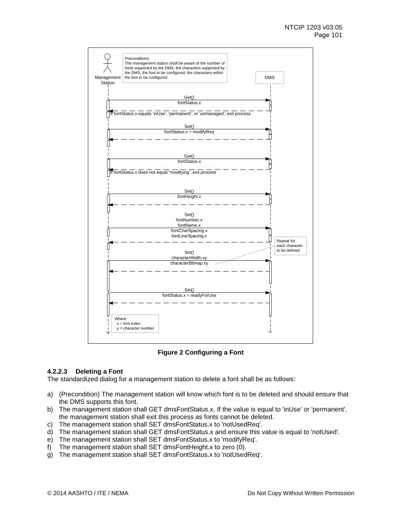
NTCIP 1203 v03.05 Page 101
Figure 2 Configuring a Font
4.2.2.3 Deleting a Font The standardized dialog for a management station to delete a font shall be as follows: a) (Precondition) The management station will know which font is to be deleted and should ensure that
the DMS supports this font. b) The management station shall GET dmsFontStatus.x. If the value is equal to 'inUse' or 'permanent',
the management station shall exit this process as fonts cannot be deleted. c) The management station shall SET dmsFontStatus.x to 'notUsedReq'. d) The management station shall GET dmsFontStatus.x and ensure this value is equal to 'notUsed'. e) The management station shall SET dmsFontStatus.x to 'modifyReq'. f) The management station shall SET dmsFontHeight.x to zero (0). g) The management station shall SET dmsFontStatus.x to 'notUsedReq'.
ManagementStation
DMS
Preconditions:The management station shall be aware of the number of fonts supported by the DMS, the characters supported by the DMS, the font to be configured, the characters within the font to be configured
Get()fontStatus.x
Set()fontStatus.x = modifyReq
Get()fontStatus.x
Set()fontHeight.x
Set()fontNumber.xfontName.x
fontCharSpacing.xfontLineSpacing.x
Set()characterWidth.xy
characterBitmap.xy
Set()fontStatus.x = readyForUse
If fontStatus.x equals ‘inUse’, ‘permanent’, or ‘unmanaged’, exit process
Repeat for each character to be defined
Where x = font index y = character number
If fontStatus.x does not equal “modifying’, exit process
© 2014 AASHTO / ITE / NEMA Do Not Copy Without Written Permission
NTCIP 1203 v03.05 Page 102
Where: x = dmsFontIndex
Note: NTCIP 1203:1997 did not include a fontStatus object. Thus, management stations should be designed to gracefully recover if Step b) results in a noSuchNameError by skipping Steps c), d), and e).
This dialog is being used in conjunction with the State Machine Diagram as defined in Section 4.3.1. 4.2.2.4 Validating a Font The standardized dialog for a management station to validate a font (i.e., ensure that the font configuration is as expected) shall be as follows: a) (Precondition) The management station shall be aware of which font it wants to validate and shall
ensure that the device supports this font. b) (Precondition) The management station shall be aware of the expected CRC value for the subject
font. The expected CRC value may be based on a previously retrieved value when the font was in a known state, or may be determined directly by calculating the CRC based on the expected font configuration.
c) The management station shall GET fontStatus.x. d) The management station shall ensure that fontStatus.x equals 'permanent', 'readyForUse',
'unmanaged', or 'inUse'. If fontStatus.x is any other value, the value for fontVersionID.x may not reflect the currently stored data and the management system shall exit this process.
e) The management station shall GET fontVersionID.x. f) The management station shall compare the expected value for fontVersionID.x to the newly retrieved
value. If the values match, the font configuration is (within a very high degree of probability) as expected. If the values are different, the font has changed.
Where:
x = font index
Note: If the fontVersionID values are different, the management station may want to delete the font or download the font again.
Note: NTCIP 1203:1997 did not include a fontStatus object. Thus, management stations should be designed to gracefully recover if Step c) results in a noSuchNameError by skipping Step d).
This dialog is being used in conjunction with the State Machine Diagram as defined in Section 4.3.1. 4.2.2.5 Retrieving a Graphic Definition The standardized dialog for a management station to retrieve a graphic shall be as follows: a) (Precondition) The management station shall ensure that the sign supports the graphic to be
retrieved. b) (Precondition) The management station shall ensure that it has the value of dmsGraphicBlockSize so
that it can decode the bitmap blocks properly. c) The management station shall GET dmsGraphicStatus.x. If the value is 'notUsed', 'modifying', or
'calculatingID', exit the process as the graphic is not defined. d) The management station shall GET the following objects:
1) dmsGraphicNumber.x 2) dmsGraphicName.x 3) dmsGraphicHeight.x 4) dmsGraphicWidth.x 5) dmsGraphicType.x 6) dmsGraphicTransparentEnabled.x, 7) dmsGraphicTransparentColor.x
Do Not Copy Without Written Permission © 2014 AASHTO / ITE / NEMA
NTCIP 1203 v03.05 Page 103
e) The management station shall GET the following objects: 1) dmsGraphicBlockBitmap.x.y (as needed to retrieve entire graphic)
Note: Repeat Step d) for number of bitmap blocks that is contained within the index of this entry.
Where: x = dmsGraphicIndex, and dmsGraphicBitmapIndex y = dmsGraphicBlockNumber This dialog is being used in conjunction with the State Machine Diagram as defined in Section 4.3.2. 4.2.2.6 Storing a Graphic Definition The standardized dialog for a management station to download a graphic (see Figure 3) shall be as follows: a) (Precondition) The management station shall ensure that the row of the graphic table to be changed
is within the range of the maximum graphics the DMS can store. b) (Precondition) The management station shall ensure that it has the value of dmsGraphicBlockSize so
that it can encode the bitmap blocks properly. c) The management station shall GET dmsGraphicStatus.x. If its value is 'inUse', 'permanent', or
'calculatingID', the management station shall exit the process. It may then change the message and then restart this process.
d) The management station shall SET dmsGraphicStatus.x to 'modifyReq' to put the selected graphic in the 'modifying' state.
e) The management station shall GET dmsGraphicStatus.x. If its value is 'modifying', it is now safe to modify the graphic data. If its value is anything other than 'modifying', exit the process. (See Section 4.3.2 for a complete state chart diagram for graphic status.)
f) The management station shall SET the following objects to the desired values: 1) dmsGraphicNumber.x, 2) dmsGraphicName.x, 3) dmsGraphicHeight.x, 4) dmsGraphicWidth.x, 5) dmsGraphicType.x, 6) dmsGraphicTransparentEnabled.x, 7) dmsGraphicTransparentColor.x.
g) The management station shall SET dmsGraphicBlockBitmap.x.y (as required to store entire graphic). h) The management station shall SET dmsGraphicStatus.x to 'readyForUseReq' to allow messages
using the graphic to be displayed successfully. Where: x = dmsGraphicIndex and dmsGraphicBitmapIndex y = dmsGraphicBlockNumber This dialog is being used in conjunction with the State Machine Diagram as defined in Section 4.3.2.
© 2014 AASHTO / ITE / NEMA Do Not Copy Without Written Permission
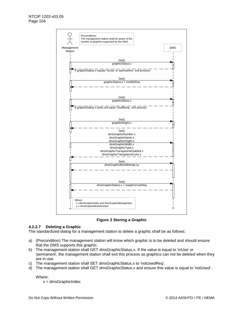
NTCIP 1203 v03.05 Page 104
ManagementStation
DMS
Preconditions:The management station shall be aware of the number of graphics supported by the DMS.
Get()graphicStatus.x
Set()graphicStatus.x = modifyReq
Get()graphicStatus.x
Set()graphicHeight.x
Set()dmsGraphicNumber.xdmsGraphicName.xdmsGraphicHeight.xdmsGraphicWidth.xdmsGraphicType.x
dmsGraphicTransparentEnabled.xdmsGraphicTransparentColor.x
Set()dmsGraphicBlockBitmap.xy
Set()dmsGraphicStatus.x = readyForUseReq
If graphicStatus.x equals ‘inUse’ or ‘permanent’, exit process
Where x =dmsGraphicIndex and dmsGraphicBitmapIndex y = dmsGraphicBlockNumber
If graphicStatus.x does not equal “modifying’, exit process
Figure 3 Storing a Graphic
4.2.2.7 Deleting a Graphic The standardized dialog for a management station to delete a graphic shall be as follows: a) (Precondition) The management station will know which graphic is to be deleted and should ensure
that the DMS supports this graphic. b) The management station shall GET dmsGraphicStatus.x. If the value is equal to 'inUse' or
'permanent', the management station shall exit this process as graphics can not be deleted when they are in use.
c) The management station shall SET dmsGraphicStatus.x to 'notUsedReq'. d) The management station shall GET dmsGraphicStatus.x and ensure this value is equal to 'notUsed'.
Where: x = dmsGraphicIndex
Do Not Copy Without Written Permission © 2014 AASHTO / ITE / NEMA
NTCIP 1203 v03.05 Page 105
This dialog is being used in conjunction with the State Machine Diagram as defined in Section 4.3.2. 4.2.2.8 Validating a Graphic The standardized dialog for a management station to validate a graphic (i.e., ensure that the graphic is as expected) shall be as follows: a) (Precondition) The management station shall be aware of which graphic it wants to validate and shall
ensure that the device supports this graphic. b) (Precondition) The management station shall be aware of the expected CRC value for the graphic.
The expected CRC value may be based on a previously retrieved value when the graphic was in a known state, or may be determined directly by calculating the CRC based on the expected graphic.
c) The management station shall GET dmsGraphicStatus.x and dmsGraphicID.x d) The management station shall ensure that dmsGraphicStatus.x is equal to 'permanent',
'readyForUse', or 'inUse'. If dmsGraphicStatus.x indicates any other value, the dmsGraphicID.x value may not be valid for the stored information and the management station should exit this process.
e) The management station shall ensure that the retrieved value for dmsGraphicID.x is equal to the expected value. If the values match, the graphic information is (within a very high degree of probability) as expected. If the values are different, the graphic information has changed.
f) (Postcondition) If the values are different, the management station may wish to delete the graphic or download the graphic again.
Where:
x = dmsGraphicIndex This dialog is being used in conjunction with the State Machine Diagram as defined in Section 4.3.2. 4.2.2.9 Configuring Light Output Algorithm The standardized dialog for a management station to configure the brightness values (see Figure 4) shall be as follows: a) (Precondition) The management station shall be aware of the maximum number of photocell levels
supported by the device and the desired photocell curve to be stored in the device, which must not contain photocell levels above that supported by the device.
b) The management station shall SET dmsIllumBrightnessValues.0 to the desired value (see Section 5.8.7 for example values).
c) If the response indicates a genErr, the management station shall GET dmsIllumBrightnessValuesError.0 to determine the cause of the error.
© 2014 AASHTO / ITE / NEMA Do Not Copy Without Written Permission
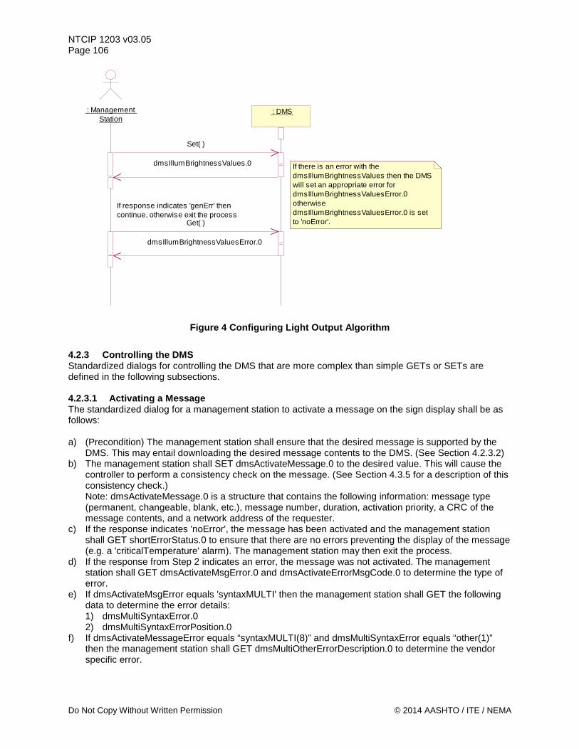
NTCIP 1203 v03.05 Page 106
Figure 4 Configuring Light Output Algorithm
4.2.3 Controlling the DMS Standardized dialogs for controlling the DMS that are more complex than simple GETs or SETs are defined in the following subsections. 4.2.3.1 Activating a Message The standardized dialog for a management station to activate a message on the sign display shall be as follows: a) (Precondition) The management station shall ensure that the desired message is supported by the
DMS. This may entail downloading the desired message contents to the DMS. (See Section 4.2.3.2) b) The management station shall SET dmsActivateMessage.0 to the desired value. This will cause the
controller to perform a consistency check on the message. (See Section 4.3.5 for a description of this consistency check.) Note: dmsActivateMessage.0 is a structure that contains the following information: message type (permanent, changeable, blank, etc.), message number, duration, activation priority, a CRC of the message contents, and a network address of the requester.
c) If the response indicates 'noError', the message has been activated and the management station shall GET shortErrorStatus.0 to ensure that there are no errors preventing the display of the message (e.g. a 'criticalTemperature' alarm). The management station may then exit the process.
d) If the response from Step 2 indicates an error, the message was not activated. The management station shall GET dmsActivateMsgError.0 and dmsActivateErrorMsgCode.0 to determine the type of error.
e) If dmsActivateMsgError equals 'syntaxMULTI' then the management station shall GET the following data to determine the error details: 1) dmsMultiSyntaxError.0 2) dmsMultiSyntaxErrorPosition.0
f) If dmsActivateMessageError equals “syntaxMULTI(8)” and dmsMultiSyntaxError equals “other(1)” then the management station shall GET dmsMultiOtherErrorDescription.0 to determine the vendor specific error.
: Management Station
: DMS
dmsIllumBrightnessValues.0
dmsIllumBrightnessValuesError.0
If there is an error with the dmsIllumBrightnessValues then the DMS will set an appropriate error for dmsIllumBrightnessValuesError.0 otherwise dmsIllumBrightnessValuesError.0 is set to 'noError'.
Set( )
Get( )
If response indicates 'genErr' then continue, otherwise exit the process
Do Not Copy Without Written Permission © 2014 AASHTO / ITE / NEMA
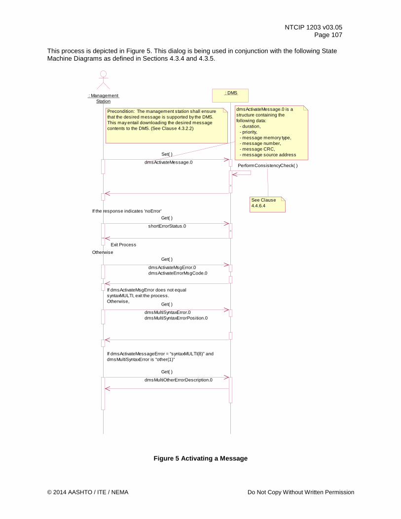
NTCIP 1203 v03.05 Page 107
This process is depicted in Figure 5. This dialog is being used in conjunction with the following State Machine Diagrams as defined in Sections 4.3.4 and 4.3.5.
Figure 5 Activating a Message
: Management Station
: DMS
dmsActivateMessage.0
dmsActivateMessage.0 is a structure containing the following data: - duration, - priority, - message memory type, - message number, - message CRC, - message source address
If the response indicates 'noError'
dmsActivateMsgError.0dmsActivateErrorMsgCode.0
Set( )
Get( )
See Clause 4.4.6.4
Get( )
dmsMultiSyntaxError.0dmsMultiSyntaxErrorPosition.0
If dmsActivateMsgError does not equal syntaxMULTI, exit the process.Otherwise,
Precondition: The management station shall ensure that the desired message is supported by the DMS. This may entail downloading the desired message contents to the DMS. (See Clause 4.3.2.2)
PerformConsistencyCheck( )
shortErrorStatus.0
OtherwiseExit Process
Get( )
Get( )
dmsMultiOtherErrorDescription.0
If dmsActivateMessageError = “syntaxMULTI(8)” and dmsMultiSyntaxError is “other(1)”
© 2014 AASHTO / ITE / NEMA Do Not Copy Without Written Permission
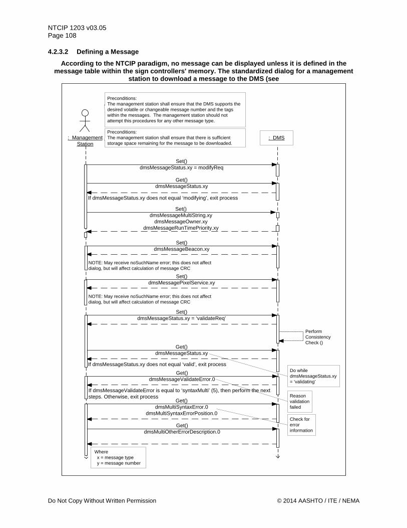
NTCIP 1203 v03.05 Page 108 4.2.3.2 Defining a Message
According to the NTCIP paradigm, no message can be displayed unless it is defined in the message table within the sign controllers' memory. The standardized dialog for a management
station to download a message to the DMS (see
: ManagementStation
: DMS
Preconditions:The management station shall ensure that the DMS supports the desired volatile or changeable message number and the tags within the messages. The management station should not attempt this procedures for any other message type.
Set()dmsMessageStatus.xy = modifyReq
Get()dmsMessageStatus.xy
Set()dmsMessageMultiString.xy
dmsMessageOwner.xydmsMessageRunTimePriority.xy
Set()dmsMessageBeacon.xy
Do while dmsMessageStatus.xy = ‘validating’
Where x = message type y = message number
If dmsMessageStatus.xy does not equal ‘modifying’, exit process
Preconditions:The management station shall ensure that there is sufficient storage space remaining for the message to be downloaded.
NOTE: May receive noSuchName error; this does not affect dialog, but will affect calculation of message CRC
Set()dmsMessagePixelService.xy
NOTE: May receive noSuchName error; this does not affect dialog, but will affect calculation of message CRC
Reason validation failed
Check for error information
Set()dmsMessageStatus.xy = ‘validateReq’
Perform ConsistencyCheck ()
Get()dmsMessageStatus.xy
If dmsMessageStatus.xy does not equal ‘valid’, exit processGet()
dmsMessageValidateError.0
If dmsMessageValidateError is equal to ‘syntaxMulti’ (5), then perform the next steps. Otherwise, exit process
Get()dmsMultiSyntaxError.0
dmsMultiSyntaxErrorPosition.0
Get()dmsMultiOtherErrorDescription.0
Do Not Copy Without Written Permission © 2014 AASHTO / ITE / NEMA
NTCIP 1203 v03.05 Page 109
Figure 6) shall be as follows: a) (Precondition) The management station shall ensure that the DMS supports the desired volatile or
changeable message number and the tags within the message. The management station should not attempt this procedure for any other message type.
b) (Precondition) The management station shall ensure that there is sufficient storage space remaining for the message to be downloaded.
c) The management station shall SET dmsMessageStatus.x.y to 'modifyReq'. d) The management station shall GET dmsMessageStatus.x.y. e) If the value is not 'modifying', exit the process. In this case, the management station may SET
dmsMessageStatus.x.y to 'notUsedReq' and attempt to restart this process from the beginning. (See Section 4.3.4 for a complete description of the Message Table State Machine.)
f) The management station shall SET the following data to the desired values: 1) dmsMessageMultiString.x.y 2) dmsMessageOwner.x.y 3) dmsMessageRunTimePriority.x.y
g) (Required step only if Requirement 3.6.6.5 Beacon Activation Flag is selected as Yes in PRL) The management station shall SET dmsMessageBeacon.x.y to the desired value. Note: The response to this request may be a noSuchName error, indicating that the DMS does not support this optional feature. This error will not affect the sequence of this dialog, but the management station should be aware that the CRC will be calculated with this value defaulted to zero (0).
h) (Required step only if 2.3.2.2.1 Fiber or 2.3.2.2.3 Flip/Shutter is selected as Yes in PRL) The management station shall SET dmsMessagePixelService.x.y to the desired value. Note: The response to this request may be a noSuchName error, indicating that the DMS does not support this optional feature. This error will not affect the sequence of this dialog, but the management station should be aware that the CRC will be calculated with this value defaulted to zero (0).
i) The management station shall SET dmsMessageStatus.x.y to 'validateReq'. This will cause the controller to initiate a consistency check on the message. (See Section 4.3.5 for a description of this consistency check.)
j) The management station shall repeatedly GET dmsMessageStatus.x.y until the value is not 'validating' or a time-out has been reached.
k) If the value is 'valid', exit the process. Otherwise, the management station shall GET dmsValidateMessageError.0 to determine the reason the message was not validated.
l) If the value is 'syntaxMULTI', the management station shall GET the following data to determine the error details: 1) dmsMultiSyntaxError.0 2) dmsMultiSyntaxErrorPosition.0
m) If the value is 'other', the management station shall GET the following data to determine the error details: 1) dmsMultiOtherErrorDescription.0
Where:
x = message type y = message number
Note: If, at the end of this process, the value of dmsMessageStatus.x.y is 'valid', the message can be activated.
This dialog is being used in conjunction with the State Machine Diagram as defined in Sections 4.3.4.
© 2014 AASHTO / ITE / NEMA Do Not Copy Without Written Permission
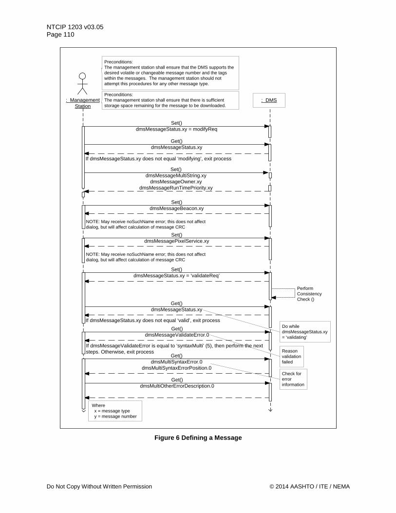
NTCIP 1203 v03.05 Page 110
: ManagementStation
: DMS
Preconditions:The management station shall ensure that the DMS supports the desired volatile or changeable message number and the tags within the messages. The management station should not attempt this procedures for any other message type.
Set()dmsMessageStatus.xy = modifyReq
Get()dmsMessageStatus.xy
Set()dmsMessageMultiString.xy
dmsMessageOwner.xydmsMessageRunTimePriority.xy
Set()dmsMessageBeacon.xy
Do while dmsMessageStatus.xy = ‘validating’
Where x = message type y = message number
If dmsMessageStatus.xy does not equal ‘modifying’, exit process
Preconditions:The management station shall ensure that there is sufficient storage space remaining for the message to be downloaded.
NOTE: May receive noSuchName error; this does not affect dialog, but will affect calculation of message CRC
Set()dmsMessagePixelService.xy
NOTE: May receive noSuchName error; this does not affect dialog, but will affect calculation of message CRC
Reason validation failed
Check for error information
Set()dmsMessageStatus.xy = ‘validateReq’
Perform ConsistencyCheck ()
Get()dmsMessageStatus.xy
If dmsMessageStatus.xy does not equal ‘valid’, exit processGet()
dmsMessageValidateError.0
If dmsMessageValidateError is equal to ‘syntaxMulti’ (5), then perform the next steps. Otherwise, exit process
Get()dmsMultiSyntaxError.0
dmsMultiSyntaxErrorPosition.0
Get()dmsMultiOtherErrorDescription.0
Figure 6 Defining a Message
Do Not Copy Without Written Permission © 2014 AASHTO / ITE / NEMA
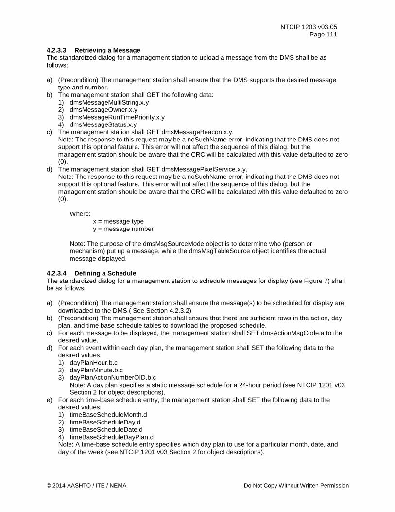
NTCIP 1203 v03.05 Page 111
4.2.3.3 Retrieving a Message The standardized dialog for a management station to upload a message from the DMS shall be as follows: a) (Precondition) The management station shall ensure that the DMS supports the desired message
type and number. b) The management station shall GET the following data:
1) dmsMessageMultiString.x.y 2) dmsMessageOwner.x.y 3) dmsMessageRunTimePriority.x.y 4) dmsMessageStatus.x.y
c) The management station shall GET dmsMessageBeacon.x.y. Note: The response to this request may be a noSuchName error, indicating that the DMS does not support this optional feature. This error will not affect the sequence of this dialog, but the management station should be aware that the CRC will be calculated with this value defaulted to zero (0).
d) The management station shall GET dmsMessagePixelService.x.y. Note: The response to this request may be a noSuchName error, indicating that the DMS does not support this optional feature. This error will not affect the sequence of this dialog, but the management station should be aware that the CRC will be calculated with this value defaulted to zero (0).
Where:
x = message type y = message number
Note: The purpose of the dmsMsgSourceMode object is to determine who (person or mechanism) put up a message, while the dmsMsgTableSource object identifies the actual message displayed.
4.2.3.4 Defining a Schedule The standardized dialog for a management station to schedule messages for display (see Figure 7) shall be as follows: a) (Precondition) The management station shall ensure the message(s) to be scheduled for display are
downloaded to the DMS ( See Section 4.2.3.2) b) (Precondition) The management station shall ensure that there are sufficient rows in the action, day
plan, and time base schedule tables to download the proposed schedule. c) For each message to be displayed, the management station shall SET dmsActionMsgCode.a to the
desired value. d) For each event within each day plan, the management station shall SET the following data to the
desired values: 1) dayPlanHour.b.c 2) dayPlanMinute.b.c 3) dayPlanActionNumberOID.b.c
Note: A day plan specifies a static message schedule for a 24-hour period (see NTCIP 1201 v03 Section 2 for object descriptions).
e) For each time-base schedule entry, the management station shall SET the following data to the desired values: 1) timeBaseScheduleMonth.d 2) timeBaseScheduleDay.d 3) timeBaseScheduleDate.d 4) timeBaseScheduleDayPlan.d Note: A time-base schedule entry specifies which day plan to use for a particular month, date, and day of the week (see NTCIP 1201 v03 Section 2 for object descriptions).
© 2014 AASHTO / ITE / NEMA Do Not Copy Without Written Permission
NTCIP 1203 v03.05 Page 112
Where: a = Action Index b = Day Plan Number c = Day Plan Event Number d = Time Base Schedule Number
Note: After the actions, day plans, and time-base schedule entries have been downloaded to the DMS, the DMS's scheduler function may be enabled using the "activate message" dialog (see Section 4.2.3.1) to set the message to the scheduler (e.g., dmsActivateMessage = { duration= as appropriate, priority= as appropriate, messageMemoryType=0x06, messageNumber=1, CRC=0x0000, sourceAddress= as appropriate }). The scheduler may also be activated by an event-activated message such as the dmsEndDurationMessage.
Figure 7 Defining a Schedule
: Management Station
: DMS
Set( )
dmsActionMsgCode.a
dayPlanHour.b.cdayPlanMinute.b.cdayPlanActionNumberOID.b.c
Set( )
Set( )
timeBaseScheduleMonth.dtimeBaseScheduleDay.dtimeBaseScheduleDate.dtimeBaseScheduleDayPlan.d
Configure day plans
Repeat for each event for each daily schedule.
Configure time-base schedule
Repeat for each time-base schedule entry.
Configure schedule actions
Repeat for each message to be displayed.
Precondition:The management station shall ensure the message(s) to be scheduled for display are downloaded to the DMS
Precondition: The management station shall ensure that there are sufficient rows in the action, day plan, and time base schedule tables to download the proposed schedule.
Where: a = Action Index b = Day Plan Number c = Day Plan Event Number d = Time Base Schedule Number
Do Not Copy Without Written Permission © 2014 AASHTO / ITE / NEMA
NTCIP 1203 v03.05 Page 113
4.2.3.5 Manually Controlling Sign Brightness The standardized dialog for a management station to manually control the brightness of the sign face shall be as follows: a) (Precondition)The management station shall be aware of the number of brightness levels supported
by the DMS and is shall be aware of the manual control mode that the DMS supports (either direct or indexed).
b) The management station shall SET dmsIllumControl.0 to 'manualDirect' or 'manualIndexed' depending what is supported by the DMS. The management station shall set this value in a separate data packet (VarBindList) before executing Step c). Note: Per the definition of dmsIllumControl, this step causes the value stored in dmsIllumManLevel to change to the current brightness level.
c) The management station shall SET dmsIllumManLevel.0 to the desired level ranging from 0 (off) to maximum number of brightness levels supported by the DMS (if 'manualDirect' is the dmsIllumControl mode) or to the maximum number of brightness levels defined in the dmsBrightnessValues talbe (if 'manualIndexed' is the dmsIllumControl mode). Note: The difference between the two manual control modes is due to the fact that different vendors implemented the original 'manual' mode differently pointing either to the number of brightness levels defined in the brightness values table or to the number of brightness levels that the DMS does support (but may not have defined in the brightness level table). To provide maximum backwards compatibility, these new two different values of the dmsIllumControl object was introduced. Note: The DMS may implement the new brightness level over a period of time to prevent a visible flicker effect.
4.2.3.6 Manage the Exercise of Pixels The standardized dialog for a management station to exercise the pixels on a sign face shall be as follows: a) The management station shall SET vmsPixelServiceTime.0 to the time when the first pixel service is
to occur during each day. b) The management station shall SET the vmsPixelServiceDuration.0 to the length of time the pixel
service is to last every time it is initiated. If this value is zero, the pixel service is disabled. c) The management station shall SET vmsPixelServiceFrequency.0 to the time between pixel services.
Set this value to zero for continuous exercising. d) (Postcondition) The management station shall activate a message that is defined to allow pixel
service (e.g., the dmsMessagePixelService object for the message has been set to a value of 1). (See Section 4.2.3.2)
4.2.3.7 Activating a Message with Status The standardized dialog for a management station to activate a message on the sign display shall be as follows: a) (Precondition) The management station shall follow the steps 1 through 2 within the section 4.2.3.1
"Activating a Message". b) If the response indicates 'noError', the message may or may not be activated c) The management station shall GET dmsActivateMessageState.0. d) If the response from step 3 indicates 'slowActivating(4)', the DMS is in the process of activating the
message. Goto step 3. e) If the response from step 3 indicates 'slowActivatedError(3)', the management station shall GET
shortErrorStatus.0 to determine the source of the error. f) If the response from step 3 indicates 'fastActivationSign(1)', the message is activated continue with
step 8. g) If the response from step 3 indicates 'slowActivatedOK(2)', the message is activated continue with
step 8. h) The message has been activated and the management station shall GET shortErrorStatus.0 to
ensure that there are no errors preventing the display of the message (e.g. a 'criticalTemperature'
© 2014 AASHTO / ITE / NEMA Do Not Copy Without Written Permission
NTCIP 1203 v03.05 Page 114
alarm). The management station may then exit the process. i) If the response from Step 2 indicates an error, the message was not activated. The management
station shall GET dmsActivateMsgError.0 and dmsActivateErrorMsgCode.0 to determine the type of error.
j) If dmsActivateMsgError equals 'syntaxMULTI' then the management station shall GET the following data to determine the error details: 1) dmsMultiSyntaxError.0 2) dmsMultiSyntaxErrorPosition.0
k) If dmsActivateMessageError equals “syntaxMULTI(8)” and dmsMultiSyntaxError equals “other(1)” then the management station shall GET dmsMultiOtherErrorDescription.0 to determine the vendor specific error.
Note: The information is only applicable to the manual activation command, if the Source is 'externalActivation' and the dmsActivateErrorMsgCode was identical to the activation code sent to the device.
4.2.4 Monitoring the Status of the DMS Standardized dialogs for monitoring the DMS configuration that are more complex than simple GETs or SETs are defined in the following subsections. 4.2.4.1 Executing Lamp Testing The standardized dialog for a management station to command the DMS to execute lamp testing shall be as follows: a) The management station shall SET lampTestActivation.0 to 'test'. b) The management station shall repeatedly GET lampTestActivation.0 until it either returns the value of
'noTest' or a maximum time-out is reached. If the time-out is reached, the DMS is apparently locked and the management station shall exit the process.
c) (PostCondition) The following objects will have been updated during the lamp test to reflect current conditions. The management station may GET any of these objects as appropriate. 1) lampFailureStuckOn 2) lampFailureStuckOff 3) any object within the dmsLampStatusTable
4.2.4.2 Activating Pixel Testing The standardized dialog for a management station to command the DMS to activate pixel testing shall be as follows: a) The management station shall SET pixelTestActivation.0 to 'test'. b) The management station shall repeatedly GET pixelTestActivation.0 until it either returns the value of
'noTest' or a maximum time-out is reached. If the time-out is reached, the DMS is apparently locked and the management station shall exit the process.
c) (PostCondition) The following objects will have been updated during the pixel test to reflect current conditions. The management station may GET any of these objects as appropriate. 1) pixelFailureTableNumRows 2) any object within the pixelFailureTable
4.2.4.3 Executing Climate-Control Equipment Testing The standardized dialog for a management station to command the DMS to execute lamp testing shall be as follows: a) The management station shall SET dmsClimateCtrlTestActivation.x to 'test'. b) The management station shall repeatedly GET dmsClimateCtrlTestActivation.x until it either returns
the value of 'noTest', a value of 'testAborted', or a maximum time-out is reached. If the time-out is reached, the DMS is apparently locked and the management station shall exit the process.
c) If the value of dmsClimateCtrlTestActivation.x is 'testAborted', the management station shall 'GET'
Do Not Copy Without Written Permission © 2014 AASHTO / ITE / NEMA
NTCIP 1203 v03.05 Page 115
dmsClimateCtrlAbortReason for a description of the reason for test denial. d) (PostCondition) The following objects will have been updated during the lamp test to reflect current
conditions. The management station may GET any of these objects as appropriate. 1) dmsClimateCtrlStatusMap 2) any object within the dmsClimateCtrlStatusTable
where
x = dmsClimateCtrlIndex 4.2.4.4 Monitoring Power Error Details The standardized dialog for a management station to monitor details about any power errors shall be as follows: a) (Precondition) The management station shall be aware of which power supplies are currently failed. b) For the desired failed power supply, the management station shall GET the following data:
1) dmsPowerDescription.x 2) dmsPowerMfrStatus.x 3) dmsPowerStatus.x 4) dmsPowerVoltage.x 5) dmsPowerType.x
Where:
x = power index. 4.2.4.5 Monitoring Lamp Error Details The standardized dialog for a management station to monitor details about any lamp errors shall be as follows: a) (Precondition) The management station shall execute lamp testing. (See Section 4.2.4.1) b) (Precondition) The management station shall be aware of which lamps are currently failed on or failed
off. c) For the desired failed lamp, the management station shall GET the following data:
1) dmsLampDescription.x 2) dmsLampMfrStatus.x 3) dmsLampStatus.x 4) dmsLampPixelTop.x 5) dmsLampPixelLeft.x 6) dmsLampPixelBottom.x 7) dmsLampPixelRight.x
Where:
x = lamp index. 4.2.4.6 Monitoring Pixel Error Details The standardized dialog for a management station to monitor details about any pixel errors shall be as follows: a) (Precondition) The management station shall execute pixel testing. (See Section 4.2.4.2) b) (Precondition) The management station shall be aware of which pixels are currently failed on or failed
off. c) For the desired failed pixel, the management station shall GET the following data:
1) pixelFailureXLocation.x.y 2) pixelFailureYLocation.x.y 3) pixelFailureStatus.x.y
© 2014 AASHTO / ITE / NEMA Do Not Copy Without Written Permission
NTCIP 1203 v03.05 Page 116
Where: x = failure detection type y = pixel failure index
4.2.4.7 Monitoring Light Sensor Error Details The standardized dialog for a management station to monitor details about any light sensor errors shall be as follows: a) (Precondition) The management station shall be aware of which light sensors are currently failed. b) For the desired failed light sensor, the management station shall GET the following data:
1) dmsLightSensorDescription.x 2) dmsLightSensorCurrentReading.x 3) dmsLightSensorStatus.x
Where:
x = light sensor index. 4.2.4.8 Monitoring Message Activation Error Details The standardized dialog for a management station to monitor details about any message activation errors shall be as follows: a) The management station shall GET the following data:
1) dmsActivateMsgError.0 2) dmsActivateErrorMsgCode.0 3) dmsMultiSyntaxError.0 4) dmsMultiSyntaxErrorPosition.0
b) If dmsActivateMessageError equals “syntaxMULTI(8)” and dmsMultiSyntaxError equals “other(1)” then the management station shall GET dmsMultiOtherErrorDescription.0 to determine the vendor specific error.
c) If the dmsActivateMsgError.0 has a value of anything other than 'syntaxMULTI', the full description of the error is given by the value, the remaining data shall be ignored, and the management station shall exit the process.
4.2.4.9 Monitoring Climate-Control System Error Details The standardized dialog for a management station to monitor details about any climate control equipment errors shall be as follows: a) (Precondition) The management station shall execute climate control equipment testing. (See Section
4.2.4.3.) b) (Precondition) The management station shall be aware of which climate control subsystems are
currently failed. c) For the desired failed climate control subsystem, the management station shall GET the following
data: 1) dmsClimateCtrlDescription.x 2) dmsClimateCtrlMfrStatus.x 3) dmsClimateCtrlErrorStatus.x 4) dmsClimateCtrlOn.x 5) dmsClimateCtrlType.x
Where:
x = climate control index. 4.2.4.10 Monitoring Sign Housing Humidity The standardized dialog for a management station to monitor details about sign housing humidity shall be as follows:
Do Not Copy Without Written Permission © 2014 AASHTO / ITE / NEMA
NTCIP 1203 v03.05 Page 117
a) (Precondition) The management station may wish to determine which humidity sensors are reporting warnings.
b) For the desired humidity sensor, the management station shall GET the following data: 1) dmsHumiditySensorDescription.x 2) dmsHumiditySensorCurrentReading.x 3) dmsHumiditySensorStatus.x
Where:
x = dmsHumiditySensorIndex 4.2.4.11 Monitoring Control Cabinet Humidity The standardized dialog for a management station to monitor details about control cabinet humidity shall be as follows: a) (Precondition) The management station may wish to determine which humidity sensors are reporting
warnings. b) For the desired humidity sensor, the management station shall GET the following data:
1) dmsHumiditySensorDescription.x 2) dmsHumiditySensorCurrentReading.x 3) dmsHumiditySensorStatus.x
Where: x = humidity sensor index. 4.2.4.12 Monitoring Drum Sign Rotor Error Details The standardized dialog for a management station to monitor details about any drum sign rotor errors shall be as follows: a) (Precondition) The management station shall be aware of which sign rotors are currently failed. b) For the desired failed rotor, the management station shall GET the following data:
1) dmsDrumDescription.x 2) dmsDrumMfrStatus.x 3) dmsDrumStatus.x
Where:
x = drum index. 4.2.4.13 Monitoring Attached Devices The standardized dialog for a management station to monitor attached devices shall be as follows: a) The management station shall GET the following data to determine the number of auxiliary ports
supported by the device: 1) maxAuxIOv2TableNumDigitalPorts.0 2) maxAuxIOv2TableNumAnalogPorts.0
b) For each attached device, the management station shall GET the following data: 1) auxIOv2PortDescription.x.y 2) auxIOv2PortResolution.x.y 3) auxIOv2PortValue.x.y 4) auxIOv2PortDirection.x.y 5) auxIOv2PortLastCommandedState.x.y
Where:
x = auxiliary I/O port type y = auxiliary I/O port number
© 2014 AASHTO / ITE / NEMA Do Not Copy Without Written Permission
NTCIP 1203 v03.05 Page 118
Note: A device might need to support the version 1 definitions for the auxiliary I/O functionality. However, if required, the specification writer will need to clarify within the specification how this version 1 functionality is to be implemented.
4.2.4.14 Monitoring the Current Message The standardized dialog for a management station to monitor the current message shall be as follows: a) The management station shall GET dmsMsgTableSource.0 to determine the message number,
message type, and message CRC of the currently displayed message. b) The management station shall GET dmsMessageTimeRemaining.0. c) The management station shall GET dmsMsgRequesterID.0 to determine the source address of the
controller that activated the currently displayed message. d) The management station shall GET dmsMsgSourceMode.0 to determine the source from which the
message was generated (e.g., default message, communications port, scheduler, etc.). e) The management station shall GET the following data:
1) dmsMessageMultiString.5.1 2) dmsMessageOwner.5.1 3) dmsMessageRunTimePriority.5.1 Note: Instance "5.1" is the currentBuffer row of the Message Table.
f) The management station shall GET dmsMesagePixelService.5.1. Note: The response to this request may be a noSuchName error, indicating that the DMS does not support this optional feature. This error will not affect the sequence of this dialog, but the management station should be aware that the CRC will be calculated with this value defaulted to zero (0).
g) The management station shall GET dmsMessageBeacon.5.1. Note: The response to this request may be a noSuchName error, indicating that the DMS does not support this optional feature. This error will not affect the sequence of this dialog, but the management station should be aware that the CRC will be calculated with this value defaulted to zero (0).
h) The management station shall GET the following data: 1) dmsIllumBrightLevelStatus.0 2) dmsIllumLightOutputStatus.0
4.2.4.15 Monitoring Dynamic Field Values The standardized dialog for a management station to monitor the value of dynamic fields within a message shall be as follows: a) The management station shall GET statMultiFieldRows.0 to determine the number of dynamic fields
used within the current message. b) For each dynamic field, the management station shall GET the following data:
1) statMultiFieldCode.x 2) statMultiCurrentFieldValue.x Note: If statMultiFieldRows.0 equals zero (0), step 2 should be skipped. Where:
x = MULTI Field Index 4.3 State Transition Diagrams State-Transition diagrams are included for those objects that have states or manage states. The State Transition Diagrams include state-transition tables (listing of the possible state transitions), legitimate transitions, and any illegitimate transitions. “State-transition diagrams describe all of the states that an object can have, the events under which an object changes state (transitions), the conditions that must be fulfilled before the transition will occur (guards), and the activities undertaken during the life of an object (actions).” (Reference: State-Transition Diagrams: Testing UML Models, Part 4 by Lee Copeland)
Do Not Copy Without Written Permission © 2014 AASHTO / ITE / NEMA
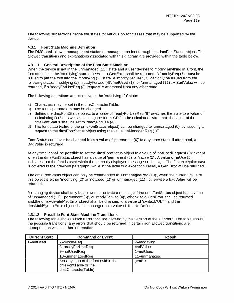
NTCIP 1203 v03.05 Page 119
The following subsections define the states for various object classes that may be supported by the device. 4.3.1 Font State Machine Definition The DMS shall allow a management station to manage each font through the dmsFontStatus object. The allowed transitions and explanations associated with this diagram are provided within the table below. 4.3.1.1 General Description of the Font State Machine When the device is not in the 'unmanaged (11)' state and a user desires to modify anything in a font, the font must be in the 'modifying' state otherwise a GenError shall be returned. A 'modifyReq (7)' must be issued to put the font into the 'modifying (2)' state. A 'modifyRequest (7)' can only be issued from the following states: 'modifying (2)'; 'readyForUse (4)'; 'notUsed (1)'; or 'unmanaged (11)'. A BadValue will be returned, if a 'readyForUseReq (8)' request is attempted from any other state. The following operations are exclusive to the 'modifying (2)' state: a) Characters may be set in the dmsCharacterTable. b) The font’s parameters may be changed. c) Setting the dmsFontStatus object to a value of 'readyForUseReq (8)' switches the state to a value of
'calculatingID (3)' as well as causing the font's CRC to be calculated. After that, the value of the dmsFontStatus shall be set to 'readyForUse (4)'.
d) The font state (value of the dmsFontStatus object) can be changed to 'unmanaged (9)' by issueing a request to the dmsFontStatus object using the value 'unManagedReq (10)'.
Font Status can never be changed from a value of 'permanent (6)' to any other state. If attempted, a BadValue is returned. At any time it shall be possible to set the dmsFontStatus object to a value of 'notUsedRequest (9)' except when the dmsFontStatus object has a value of 'permanent (6)' or 'inUse (5)'. A value of 'inUse (5)' indicates that the font is used within the currently displayed message on the sign. The first exception case is covered in the previous paragraph, while in the latter two exception cases, a GenError will be returned . The dmsFontStatus object can only be commanded to 'unmanagedReq (10)', when the current value of this object is either 'modifying (2)' or 'notUsed (1)' or ‘unmanaged (11)’, otherwise a badValue will be returned. A managing device shall only be allowed to activate a message if the dmsFontStatus object has a value of 'unmanaged (11)', 'permanent (6)', or 'readyForUse (4)', otherwise a GenError shall be returned and.the dmsActivateMsgError object shall be changed to a value of 'syntaxMULTI' and the dmsMultiSyntaxError object shall be changed to a value of 'fontNotDefined'. 4.3.1.2 Possible Font State Machine Transitions The following table shows which transitions are allowed by this version of the standard. The table shows the possible transitions, any errors that should be returned, if certain non-allowed transitions are attempted, as well as other information. Current State Command or Event Result
1–notUsed 7–modifyReq 2–modifying 8–readyForUseReq badValue 9–notUsedReq 1–notUsed 10–unmanagedReq 11–unmanaged Set any data of the font (within the dmsFontTable or the dmsCharacterTable)
genErr
© 2014 AASHTO / ITE / NEMA Do Not Copy Without Written Permission
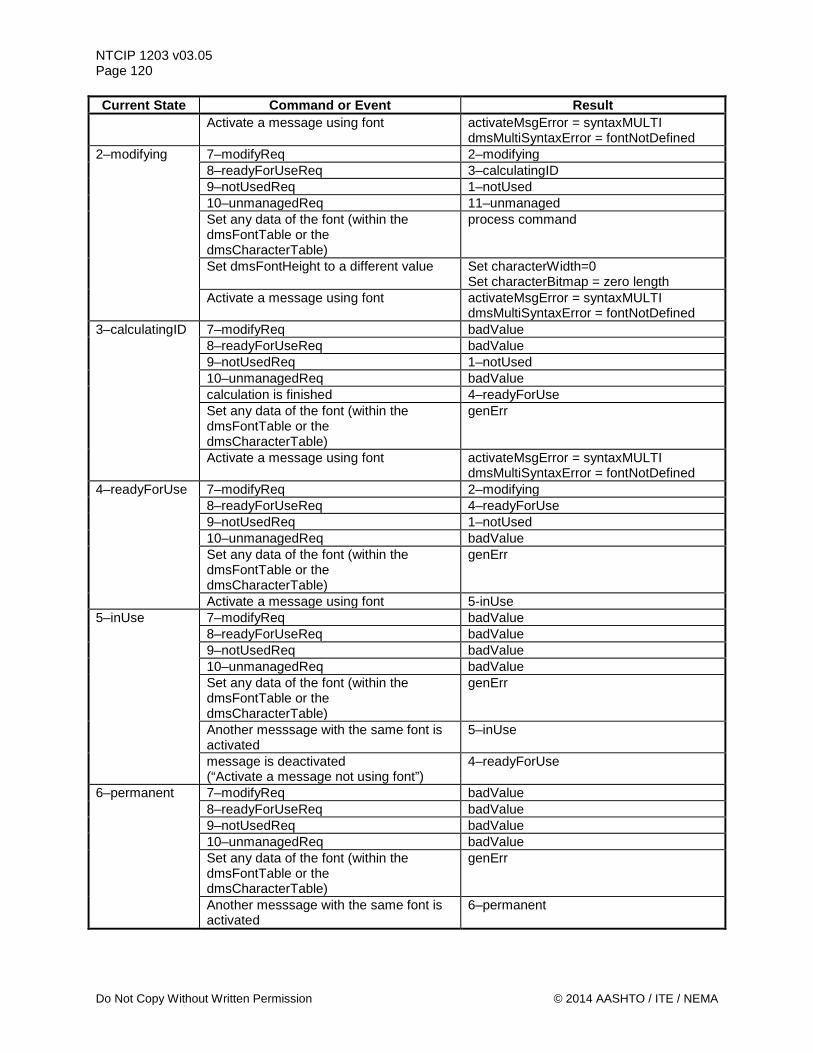
NTCIP 1203 v03.05 Page 120 Current State Command or Event Result
Activate a message using font activateMsgError = syntaxMULTI dmsMultiSyntaxError = fontNotDefined
2–modifying 7–modifyReq 2–modifying 8–readyForUseReq 3–calculatingID 9–notUsedReq 1–notUsed 10–unmanagedReq 11–unmanaged Set any data of the font (within the dmsFontTable or the dmsCharacterTable)
process command
Set dmsFontHeight to a different value Set characterWidth=0 Set characterBitmap = zero length
Activate a message using font activateMsgError = syntaxMULTI dmsMultiSyntaxError = fontNotDefined
3–calculatingID 7–modifyReq badValue 8–readyForUseReq badValue 9–notUsedReq 1–notUsed 10–unmanagedReq badValue calculation is finished 4–readyForUse Set any data of the font (within the dmsFontTable or the dmsCharacterTable)
genErr
Activate a message using font activateMsgError = syntaxMULTI dmsMultiSyntaxError = fontNotDefined
4–readyForUse 7–modifyReq 2–modifying 8–readyForUseReq 4–readyForUse 9–notUsedReq 1–notUsed 10–unmanagedReq badValue Set any data of the font (within the dmsFontTable or the dmsCharacterTable)
genErr
Activate a message using font 5-inUse 5–inUse 7–modifyReq badValue
8–readyForUseReq badValue 9–notUsedReq badValue 10–unmanagedReq badValue Set any data of the font (within the dmsFontTable or the dmsCharacterTable)
genErr
Another messsage with the same font is activated
5–inUse
message is deactivated (“Activate a message not using font”)
4–readyForUse
6–permanent 7–modifyReq badValue 8–readyForUseReq badValue 9–notUsedReq badValue 10–unmanagedReq badValue Set any data of the font (within the dmsFontTable or the dmsCharacterTable)
genErr
Another messsage with the same font is activated
6–permanent
Do Not Copy Without Written Permission © 2014 AASHTO / ITE / NEMA
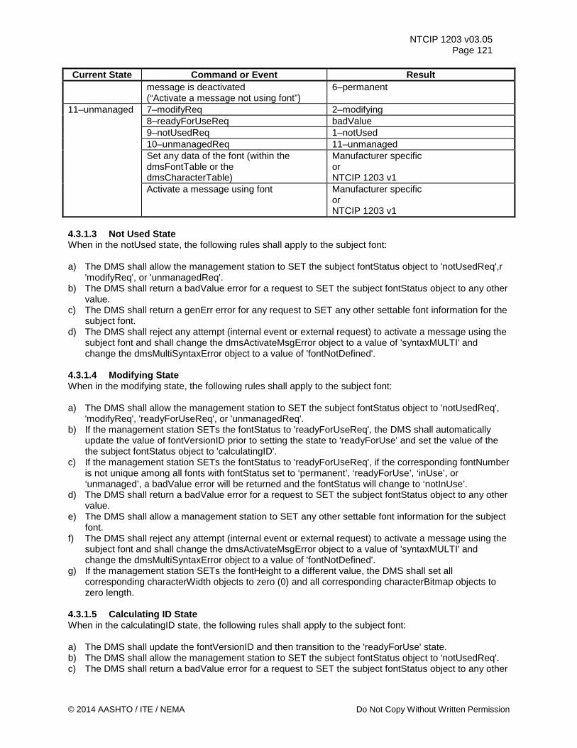
NTCIP 1203 v03.05 Page 121
Current State Command or Event Result message is deactivated (“Activate a message not using font”)
6–permanent
11–unmanaged 7–modifyReq 2–modifying 8–readyForUseReq badValue 9–notUsedReq 1–notUsed 10–unmanagedReq 11–unmanaged Set any data of the font (within the dmsFontTable or the dmsCharacterTable)
Manufacturer specific or NTCIP 1203 v1
Activate a message using font Manufacturer specific or NTCIP 1203 v1
4.3.1.3 Not Used State When in the notUsed state, the following rules shall apply to the subject font: a) The DMS shall allow the management station to SET the subject fontStatus object to 'notUsedReq',r
'modifyReq', or 'unmanagedReq'. b) The DMS shall return a badValue error for a request to SET the subject fontStatus object to any other
value. c) The DMS shall return a genErr error for any request to SET any other settable font information for the
subject font. d) The DMS shall reject any attempt (internal event or external request) to activate a message using the
subject font and shall change the dmsActivateMsgError object to a value of 'syntaxMULTI' and change the dmsMultiSyntaxError object to a value of 'fontNotDefined'.
4.3.1.4 Modifying State When in the modifying state, the following rules shall apply to the subject font: a) The DMS shall allow the management station to SET the subject fontStatus object to 'notUsedReq',
'modifyReq', 'readyForUseReq', or 'unmanagedReq'. b) If the management station SETs the fontStatus to 'readyForUseReq', the DMS shall automatically
update the value of fontVersionID prior to setting the state to 'readyForUse' and set the value of the the subject fontStatus object to 'calculatingID'.
c) If the management station SETs the fontStatus to 'readyForUseReq', if the corresponding fontNumber is not unique among all fonts with fontStatus set to ‘permanent’, ‘readyForUse’, ‘inUse’, or ‘unmanaged’, a badValue error will be returned and the fontStatus will change to ‘notInUse’.
d) The DMS shall return a badValue error for a request to SET the subject fontStatus object to any other value.
e) The DMS shall allow a management station to SET any other settable font information for the subject font.
f) The DMS shall reject any attempt (internal event or external request) to activate a message using the subject font and shall change the dmsActivateMsgError object to a value of 'syntaxMULTI' and change the dmsMultiSyntaxError object to a value of 'fontNotDefined'.
g) If the management station SETs the fontHeight to a different value, the DMS shall set all corresponding characterWidth objects to zero (0) and all corresponding characterBitmap objects to zero length.
4.3.1.5 Calculating ID State When in the calculatingID state, the following rules shall apply to the subject font: a) The DMS shall update the fontVersionID and then transition to the 'readyForUse' state. b) The DMS shall allow the management station to SET the subject fontStatus object to 'notUsedReq'. c) The DMS shall return a badValue error for a request to SET the subject fontStatus object to any other
© 2014 AASHTO / ITE / NEMA Do Not Copy Without Written Permission
NTCIP 1203 v03.05 Page 122
value. d) The DMS shall return a genErr error for any request to SET any other settable font information for the
subject font. e) The DMS shall reject any attempt (internal event or external request) to activate a message using the
subject font and shall change the dmsActivateMsgError object to a value of 'syntaxMULTI' and change the dmsMultiSyntaxError object to a value of 'fontNotDefined'.
4.3.1.6 Ready for Use State When in the readyForUse state, the following rules shall apply to the subject font: a) The DMS shall allow the management station to SET the subject fontStatus object to 'notUsedReq',
'modifyReq', or 'readyForUseReq'. b) The DMS shall return a badValue error for a request to SET the subject fontStatus object to any other
value. c) The DMS shall return a genErr error for any request to SET any other settable font information for the
subject font. d) The DMS shall allow the font to be used in a message being activated. e) Upon the successful activation of a message using the font, the subject fontStatus object shall
change to 'inUse'. 4.3.1.7 In Use State When in the inUse state, the following rules shall apply to the subject font: a) The DMS shall return a badValue error for a request to SET the subject fontStatus object. b) The DMS shall return a genErr error for any request to SET any other settable font information for the
subject font. c) Upon the activation of another message using the subject font, the subject fontStatus object shall
remain in the 'inUse' state. d) Upon the successful activation of another message that does not use the subject font, the subject
fontStatus object shall change to the 'readyForUse' state. 4.3.1.8 Permanent State When in the permanent state, the following rules shall apply to the subject font: a) The DMS shall return a badValue error for any request to SET the subject fontStatus object. b) The DMS shall return a genErr error for any request to SET any other settable font information for the
subject font. c) The DMS shall allow the font to be used in a message being activated. d) Upon the successful activation of a message using the font, the fontStatus shall remain 'permanent'. e) Upon successful activation of a message that does not use the font, the fontStatus shall remain
'permanent'. 4.3.1.9 Unmanaged State The 'unmanaged' state has been developed to allow for backwards compatibiity allowing a management system to manage both Version 1 and Version 2 signs. When in the 'unmanaged' state, the following rules shall apply to the subject font: a) The DMS shall allow the management station to SET the subject fontStatus object to 'notUsedReq',
'modifyReq', or 'unmanagedReq'. b) The DMS shall return a badValue error for a request to SET the subject fontStatus object to any other
value. c) When requesting to SET any other settable font information for the subject font, the DMS is assumed
to be a Version 1 sign and to react accordingly, i.e., manufacturer-specific. d) When requesting to activate a message using this font, the DMS is assumed to be a Version 1 sign
and to react accordingly, i.e., manufacturer-specific.
Do Not Copy Without Written Permission © 2014 AASHTO / ITE / NEMA
NTCIP 1203 v03.05 Page 123
4.3.1.10 Other Restrictions The DMS shall return a genErr to any SET request containing a fontStatus object for a subject font and any other settable font information for the subject font. The DMS shall not impose any restrictions on the operations of a subject font based on the status of any other font supported by the DMS (e.g., Font 1 shall not be disabled because Font 2 is being modified). The contents of the fontVersionID object shall only be considered valid when the fontStatus is readyForUse, inUse, permanent, or unmanaged (i.e., DMS is assumed to be a Version 1 sign).
Note: Modifying a font that is associated with a permanent message should be performed with extreme caution to prevent undesirable results.
4.3.1.11 Backwards Compatibility If a sign supports only Version 1, then the fontStatus object will not exist, and this will be equivalent to fontStatus being set to unmanaged (9). If a font is in the 'unmanaged' state, fonts will be modified exactly as before in Version 1, and it will not be possible for a font to have a 'permanent' state.
Note: DMS conforming to NTCIP 1203:1997 or its Amendment 1 do not support the fontStatus state machine. Further, the exact time at which the fontVersionID is calculated in such devices is not formally defined, but as the correct value was required upon any poll, most manufacturers updated the fontVersionID upon each change to either the font or the character table.
4.3.2 Graphic State Machine Definition The DMS shall allow a management station to monitor the current state of each graphic through the dmsGraphicStatus object. Figure 8 depicts the state transition diagram for a graphic; the detailed rules associated with this diagram follow.
© 2014 AASHTO / ITE / NEMA Do Not Copy Without Written Permission
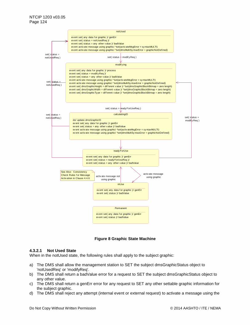
NTCIP 1203 v03.05 Page 124
Figure 8 Graphic State Machine
4.3.2.1 Not Used State When in the notUsed state, the following rules shall apply to the subject graphic: a) The DMS shall allow the management station to SET the subject dmsGraphicStatus object to
'notUsedReq' or 'modifyReq'. b) The DMS shall return a badValue error for a request to SET the subject dmsGraphicStatus object to
any other value. c) The DMS shall return a genErr error for any request to SET any other settable graphic information for
the subject graphic. d) The DMS shall reject any attempt (internal event or external request) to activate a message using the
notUsed
ev ent set( any data f or graphic )/ genErrev ent set( status = notUsedReq )/ ev ent set( status = any other v alue )/ badValueev ent activ ate message using graphic/ set(activ ateMsgError = sy ntaxMULTI)ev ent activ ate message using graphic/ set(dmsMultiSy ntaxError = graphicNotDef ined)
modif y ing
ev ent set( any data f or graphic )/ processev ent set( status = modif y Req )/ ev ent set( status = any other v alue )/ badValueev ent activ ate message using graphic/ set(activ ateMsgError = sy ntaxMULTI)ev ent activ ate message using graphic/ set(dmsMultiSy ntaxError = graphicNotDef ined)ev ent set( dmsGraphicHeight = dif f erent v alue )/ set(dmsGraphicBlockBitmap = zero length)ev ent set( dmsGraphcWidth = dif f erent v alue )/ set(dmsGraphicBlockBitmap = zero length)ev ent set( dmsGraphicTy pe = dif f erent v alue )/ set(dmsGraphicBlockBitmap = zero length)
inUse
ev ent set( any data f or graphic )/ genErrev ent set( status )/ badValue
ready ForUse
ev ent set( any data f or graphic )/ genErrev ent set( status = ready ForUseReq )/ ev ent set( status = any other v alue )/ badValue
set( status = modif y Req )
Permanent
ev ent set( any data f or graphic )/ genErrev ent set( status )/ badValue
See Also: Consistency Check Rules f or Message Activ ation in Clause 4.4.6
calculatingID
do/ update dmsGraphicIDev ent set( any data f or graphic )/ genErrev ent set( status = any other v alue )/ badValueev ent activ ate message using graphic/ set(activ ateMsgError = sy ntaxMULTI)ev ent activ ate message using graphic/ set(dmsMultiSy ntaxError = graphicNotDef ined)
activ ate message not using graphic
activ ate message using graphic
set( status = notUsedReq ) set( status =
modif y Req )
set( status = ready ForUseReq )
set( status = notUsedReq )
set( status = notUsedReq )
Do Not Copy Without Written Permission © 2014 AASHTO / ITE / NEMA
NTCIP 1203 v03.05 Page 125
subject graphic and shall change the dmsActivateMsgError object to a value of 'syntaxMULTI' and change the dmsMultiSyntaxError object to a value of 'graphicNotDefined'.
4.3.2.2 Modifying State When in the modifying state, the following rules shall apply to the subject graphic: a) The DMS shall allow the management station to SET the subject dmsGraphicStatus object to
'notUsedReq', 'modifyReq', or 'readyForUseReq'. b) If the management station SETs the dmsGraphicStatus to 'readyForUseReq', the DMS shall
automatically update the value of dmsGraphicID prior to setting the state to 'readyForUse'. c) The DMS shall return a badValue error for a request to SET the subject dmsGraphicStatus object to
any other value. d) The DMS shall allow a management station to SET any other settable graphic information for the
subject graphic. e) The DMS shall reject any attempt (internal event or external request) to activate a message using the
subject graphic and shall change the dmsActivateMsgError object to a value of 'syntaxMULTI' and change the dmsMultiSyntaxError object to a value of 'graphicNotDefined'.
f) If the management station SETs the graphicHeight, graphicWidth, or graphicType to a different value, the corresponding dmsGraphicBlockBitmap objects shall be set to zero length.
4.3.2.3 Calculating ID State When in the calculatingID state, the following rules shall apply to the subject graphic: a) The DMS shall update the dmsGraphicID and then transition to the readyForUse state. b) The DMS shall allow the management station to SET the subject dmsGraphicStatus object to
'notUsedReq'. c) The DMS shall return a badValue error for a request to SET the subject dmsGraphicStatus object to
any other value. d) The DMS shall return a genErr error for any request to SET any other settable information for the
subject graphic. e) The DMS shall reject any attempt (internal event or external request) to activate a message using the
subject graphic and shall change the dmsActivateMsgError object to a value of 'syntaxMULTI' and change the dmsMultiSyntaxError object to a value of 'graphicNotDefined'.
4.3.2.4 Ready for Use State When in the readyForUse state, the following rules shall apply to the subject graphic: a) The DMS shall allow the management station to SET the subject dmsGraphicStatus object to
'notUsedReq', 'modifyReq', or 'readyForUseReq'. b) The DMS shall return a badValue error for a request to SET the subject dmsGraphicStatus object to
any other value. c) The DMS shall return a genErr error for any request to SET any other settable graphic information for
the subject graphic. d) The DMS shall allow the graphic to be used in a message being activated. e) Upon the successful activation of a message using the graphic, the dmsGraphicStatus shall change
to 'inUse'. 4.3.2.5 In Use State When in the inUse state, the following rules shall apply to the subject graphic: a) The DMS shall return a badValue error for a request to SET the subject dmsGraphicStatus object. b) The DMS shall return a genErr error for any request to SET any other settable graphic information for
the subject graphic. c) Upon the activation of another message using the subject graphic, the dmsGraphicStatus shall
remain in the 'inUse' state. d) Upon the successful activation of another message that does not use the subject graphic, the
© 2014 AASHTO / ITE / NEMA Do Not Copy Without Written Permission
NTCIP 1203 v03.05 Page 126
dmsGraphicStatus shall change to the ‘readyForUse’ state. 4.3.2.6 Permanent State When in the permanent state, the following rules shall apply to the subject graphic: a) The DMS shall return a badValue error for any request to SET the subject dmsGraphicStatus object. b) The DMS shall return a genErr error for any request to SET any other 'settable' graphic information
for the subject graphic. c) The DMS shall allow the graphic to be used in a message being activated. d) Upon the successful activation of a message using the graphic, the dmsGraphicStatus shall remain
'permanent'. e) Upon successful activation of a message that does not use the graphic, the dmsGraphicStatus shall
remain 'permanent'. 4.3.2.7 Other Restrictions The DMS shall return a genErr to any SET request containing a dmsGraphicStatus object for a subject graphic and any other settable graphic information for the subject font. The DMS shall not impose any restrictions on the operations of a subject graphic based on the status of any other graphic supported by the DMS. (e.g., Graphic 1 shall not be disabled because Graphic 2 is being modified). The contents of the dmsGraphicID object shall only be considered valid when the dmsGraphicStatus is readyForUse, inUse, or permanent.
Note: Modifying a graphic that is associated with a permanent message should be performed with extreme caution to prevent undesirable results.
Note: DMS conforming to NTCIP 1203:1997 or its Amendment 1 do not support the graphic feature.
4.3.3 Control Mode State Machine Definition See Figure 9.
Do Not Copy Without Written Permission © 2014 AASHTO / ITE / NEMA
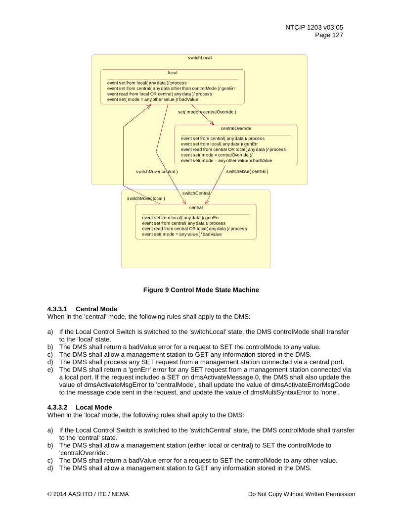
NTCIP 1203 v03.05 Page 127
Figure 9 Control Mode State Machine
4.3.3.1 Central Mode When in the 'central' mode, the following rules shall apply to the DMS: a) If the Local Control Switch is switched to the 'switchLocal' state, the DMS controlMode shall transfer
to the 'local' state. b) The DMS shall return a badValue error for a request to SET the controlMode to any value. c) The DMS shall allow a management station to GET any information stored in the DMS. d) The DMS shall process any SET request from a management station connected via a central port. e) The DMS shall return a 'genErr' error for any SET request from a management station connected via
a local port. If the request included a SET on dmsActivateMessage.0, the DMS shall also update the value of dmsActivateMsgError to 'centralMode', shall update the value of dmsActivateErrorMsgCode to the message code sent in the request, and update the value of dmsMultiSyntaxError to 'none'.
4.3.3.2 Local Mode When in the 'local' mode, the following rules shall apply to the DMS: a) If the Local Control Switch is switched to the 'switchCentral' state, the DMS controlMode shall transfer
to the 'central' state. b) The DMS shall allow a management station (either local or central) to SET the controlMode to
'centralOverride'. c) The DMS shall return a badValue error for a request to SET the controlMode to any other value. d) The DMS shall allow a management station to GET any information stored in the DMS.
switchLocal
local
event set from local( any data )/ processevent set from central( any data other than controlMode )/ genErrevent read from local OR central( any data )/ processevent set( mode = any other value )/ badValue
centralOverride
event set from central( any data )/ processevent set from local( any data )/ genErrevent read from central OR local( any data )/ processevent set( mode = centralOverride )/ event set( mode = any other value )/ badValue
switchCentral
central
event set from local( any data )/ genErrevent set from central( any data )/ processevent read from central OR local( any data )/ processevent set( mode = any value )/ badValue
central
event set from local( any data )/ genErrevent set from central( any data )/ processevent read from central OR local( any data )/ processevent set( mode = any value )/ badValue
switchMove( central )
switchMove( local )
set( mode = centralOverride )
switchMove( central )
© 2014 AASHTO / ITE / NEMA Do Not Copy Without Written Permission
NTCIP 1203 v03.05 Page 128 e) The DMS shall process any SET request from a management station connected via a 'local' port. f) The DMS shall return a genErr error for any SET request from a management station connected via a
'central' port, except for SETting controlMode to 'centralOverride'. If the request included a SET on dmsActivateMessage.0, the DMS shall also update the value of dmsActivateMsgError to 'localMode', shall update the value of dmsActivateErrorMsgCode to the message code sent in the request, and update the value of dmsMultiSyntaxError to 'none'.
4.3.3.3 Central Override Mode When in the 'centralOverride' mode, the following rules shall apply to the DMS: a) If the Local Control Switch is switched to the 'switchCentral' state, the DMS controlMode shall transfer
to the 'central' state. b) The DMS shall allow a management station connected through a 'central' port to SET the
controlMode to 'centralOverride'. c) The DMS shall return a badValue error for a request to SET the controlMode to any other value. d) The DMS shall allow a management station to GET any information stored in the DMS. e) The DMS shall process any SET request from a management station connected via a central port. f) The DMS shall return a genErr error for any SET request from a management station connected via a
local port. If the request included a SET on dmsActivateMessage.0, the DMS shall also update the value of dmsActivateMsgError to 'centralOverrideMode', shall update the value of dmsActivateErrorMsgCode to the message code sent in the request, and update the value of dmsMultiSyntaxError to 'none'.
4.3.3.4 Other Restrictions The DMS shall return a genErr to any SET request containing the controlMode object and any other data. 4.3.4 Message Table State Machine Definition See Figure 10.
Do Not Copy Without Written Permission © 2014 AASHTO / ITE / NEMA
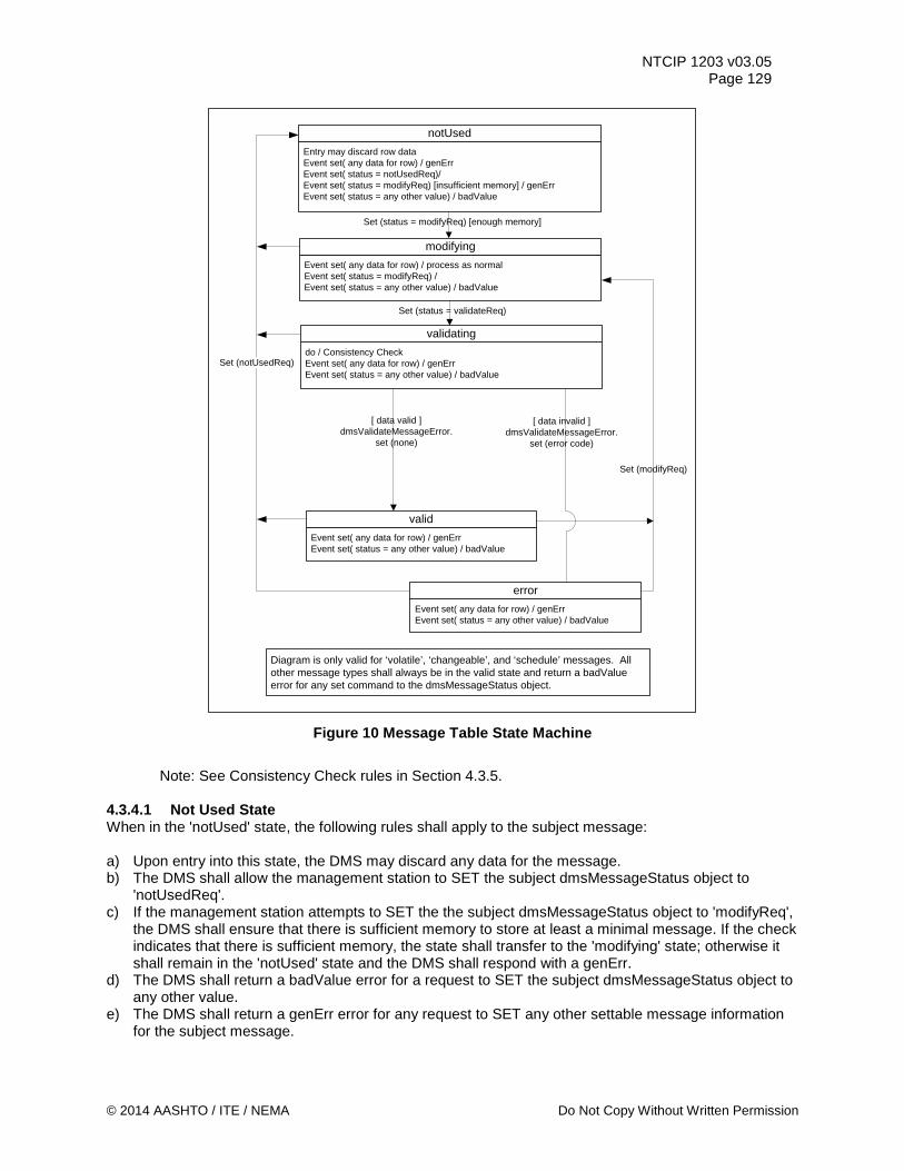
NTCIP 1203 v03.05 Page 129
Entry may discard row dataEvent set( any data for row) / genErrEvent set( status = notUsedReq)/Event set( status = modifyReq) [insufficient memory] / genErrEvent set( status = any other value) / badValue
notUsed
Event set( any data for row) / process as normalEvent set( status = modifyReq) / Event set( status = any other value) / badValue
modifying
do / Consistency CheckEvent set( any data for row) / genErrEvent set( status = any other value) / badValue
validating
Event set( any data for row) / genErrEvent set( status = any other value) / badValue
valid
Event set( any data for row) / genErrEvent set( status = any other value) / badValue
error
Diagram is only valid for ‘volatile’, ‘changeable’, and ‘schedule’ messages. All other message types shall always be in the valid state and return a badValue error for any set command to the dmsMessageStatus object.
Set (modifyReq)
Set (status = modifyReq) [enough memory]
Set (status = validateReq)
[ data valid ]dmsValidateMessageError.
set (none)
[ data invalid ]dmsValidateMessageError.
set (error code)
Set (notUsedReq)
Figure 10 Message Table State Machine
Note: See Consistency Check rules in Section 4.3.5.
4.3.4.1 Not Used State When in the 'notUsed' state, the following rules shall apply to the subject message: a) Upon entry into this state, the DMS may discard any data for the message. b) The DMS shall allow the management station to SET the subject dmsMessageStatus object to
'notUsedReq'. c) If the management station attempts to SET the the subject dmsMessageStatus object to 'modifyReq',
the DMS shall ensure that there is sufficient memory to store at least a minimal message. If the check indicates that there is sufficient memory, the state shall transfer to the 'modifying' state; otherwise it shall remain in the 'notUsed' state and the DMS shall respond with a genErr.
d) The DMS shall return a badValue error for a request to SET the subject dmsMessageStatus object to any other value.
e) The DMS shall return a genErr error for any request to SET any other settable message information for the subject message.
© 2014 AASHTO / ITE / NEMA Do Not Copy Without Written Permission
NTCIP 1203 v03.05 Page 130 4.3.4.2 Modifying State When in the 'modifying' state, the following rules shall apply to the subject message: a) The DMS shall allow the management station to SET the subject dmsMessageStatus object to
'notUsedReq', 'modifyReq', or 'validateReq'. b) The DMS shall return a badValue error for a request to SET the subject dmsMessageStatus object to
any other value. c) The DMS shall process any SET request for settable message information for the subject message. 4.3.4.3 Validating State When in the 'validating' state, the following rules shall apply to the subject message: a) Upon entry into this state, the DMS shall perform the following consistency check:
1) If the requested message type is not supported by the sign, the DMS shall return a genErr and shall set the dmsActivateMsgError to 'memoryType'.
2) If the requested message number is not supported by the sign, the DMS shall return a genErr and shall set the dmsActivateMsgError to messageNumber.
3) If the object dmsMessageMultiString contains MULTI tags that are not supported by the sign or if the resulting message text (text and/or graphics) could not be displayed on the display panel due excess size, excess length, and/or formatting of the text, the dmsMessageStatus shall automatically transfer to the 'error' state and the DMS shall set the dmsValidateMessageError object to a value of 'syntaxMULTI'. In addition, the DMS shall set proper values for the following objects to the appropriate values: dmsMultiSyntaxError, dmsMultiSyntaxErrorPosition, and dmsMultiOtherErrorDescription.
4) If object dmsMessageMultiString contains text and/or graphics that can not be supported by the DMS, the DMS shall set the dmsValidateMessageError object to 'syntaxMULTI' and shall set proper values for the dmsMultiSyntaxError, dmsMultiSyntaxErrorPosition, and dmsMultiOtherErrorDescription objects.
5) If the message is not validated for any other reason, the DMS shall set the dmsValidateMessageError object to 'other'.
6) Otherwise, the consistency check for this object passes, the dmsMessageStatus shall automatically transfer to the 'valid' state, and the DMS shall: set the dmsValidateMessageError object to 'none', set the dmsMultiSyntaxError object to a value of 'none', and set the dmsMultiSyntaxErrorPosition object to a value of zero (0).
b) The DMS shall allow the management station to SET the subject dmsMessageStatus object to 'notUsedReq'. Upon the receipt of such a request, the DMS shall terminate the validation process and transfer to the 'notUsed' state.
c) The DMS shall return a badValue error for a request to SET the subject dmsMessageStatus object to any other value.
d) The DMS shall return a genErr error for any request to SET any other settable message information for the subject message.
4.3.4.4 Valid State When in the 'valid' state, the following rules shall apply to the subject message: a) The DMS shall allow the management station to SET the subject dmsMessageStatus object to
'notUsedReq' or 'modifyReq'. b) The DMS shall return a badValue error for a request to SET the subject dmsMessageStatus object to
any other value. c) The DMS shall return a genErr error for any request to SET any other settable message information
for the subject message. 4.3.4.5 Error State When in the 'error' state, the following rules shall apply to the subject message: a) The DMS shall allow the management station to SET the subject dmsMessageStatus object to
Do Not Copy Without Written Permission © 2014 AASHTO / ITE / NEMA
NTCIP 1203 v03.05 Page 131
'notUsedReq' or 'modifyReq'. b) The DMS shall return a badValue error for a request to SET the subject dmsMessageStatus object to
any other value. c) The DMS shall return a genErr error for any request to SET any other settable message information
for the subject message. 4.3.4.6 Other Restrictions The DMS shall return a genErr to any SET request containing a dmsMessageStatus object for a subject message and any other settable message information for the subject message. The DMS shall not impose any restrictions on the operations of a subject message based on the status of any other message supported by the DMS. The contents of the dmsMessageCRC object shall only be considered valid when the dmsMessageStatus is 'valid'. 4.3.5 Message Activation Consistency Check Definition Whenever a message activation is attempted, whether by a management station SETting the dmsActivateMessage.0 object or via an internal message activation attempt (e.g., end duration, trigger event, etc), the DMS shall perform the following consistency checks, in order. If the message activation attempt was due to a management station SETting the dmsActivateMessage.0 object, the DMS shall return the response as indicated (otherwise there is no response message to be sent): a) If the request is valid and received from a 'central' communications port, and the object
dmsControlMode has a value of 'local', the DMS shall return a genErr and shall set the dmsActivateMsgError to 'localMode'.
b) If the request is valid and received from a 'local' communications port, and the object dmsControlMode has a value of 'central', the DMS shall return a genErr and shall set the dmsActivateMsgError to 'centralMode'.
c) If the request is valid and received from a 'local' communications port, and the object dmsControlMode has a value of 'centralOverride', the DMS shall return a genErr and shall set the dmsActivateMsgError to 'centralOverrideMode'.
d) If the requested message type is not supported by the sign, the DMS shall return a genErr and shall set the dmsActivateMsgError to 'memoryType'.
e) If the requested message number is not supported by the sign, the DMS shall return a genErr and shall set the dmsActivateMsgError to messageNumber.
f) If the requested message is supported by the sign but is not currently in the valid state, the DMS shall return a genErr and shall set the dmsActivateMsgError to messageStatus.
g) If the requested message is in the valid state but has a different CRC value than indicated in the set request, the DMS shall return a genErr and shall set the dmsActivateMsgError to messageCRC.
h) If the request is valid, but has insufficient priority to override the current message, the DMS shall return a genErr and shall set the dmsActivateMsgError to priority.
i) If the request is valid and has sufficient priority to override the current message, but cannot be displayed due to some error in presenting the MultiString on the display panel, the DMS shall return a genErr and shall set the dmsActivateMsgError to 'syntaxMULTI'. In addition, the DMS shall set proper values for the dmsMultiSyntaxError, dmsMultiSyntaxErrorPosition, dmsMultiOtherErrorDescription, and dmsActivationErrorMsgCode objects.
j) If the request does not result in activating the requested message for any other reason, the DMS shall return a genErr and shall set the dmsActivateMsgError to 'other'.
k) Otherwise, the consistency check for this object passes and the DMS shall set the dmsActivateMsgError to 'none'.
© 2014 AASHTO / ITE / NEMA Do Not Copy Without Written Permission
NTCIP 1203 v03.05 Page 132
Section 5 Management Information Base (MIB) [Normative]
Section 5 defines those objects which are expected to be used by dynamic message signs (DMS). The objects are presented using the OBJECT-TYPE macro as specified in RFC 1212 and NTCIP 8004. The text provided from Section 5.1 through the end of the section (except the section headings) constitutes the NTCIP1203-2005 MIB. The sections below generally present the objects in lexigraphical order of their OBJECT IDENTIFIERS which correspond to their physical location within the global naming tree. Most of the objects defined in this document reside under the “dms” node of the global naming tree. To aid in object management, the “dms” node has been subdivided into logical categories, each defined by a node under the “dms” node. The individual objects are then located under the appropriate node. Conformance requirements for any object are determined by the use of the Requirements Traceability Matrix (RTM) in Annex A. To support any defined Requirement, an implementation shall support all objects to which the Requirement traces in the RTM. The value of the STATUS field for every object in the MIB is "mandatory", and indicates that it is mandatory if any associated Requirement is selected. For all bitmapped objects, if a bit is zero (0), then the referenced function is disabled or not supported, and if a bit is one (1), then the referenced function is enabled or supported. The full standardized range of all objects defined within NTCIP 1203 v03 shall be supported, except as otherwise noted. This MIB is managed by the NTCIP DMS Working Group and proprietary features should be defined through vendor-specific nodes in vendor-specific extensions to this MIB. All values not explicitly defined (e.g., enumerated values not listed, bits not defined, etc.) are reserved for future use by the DMS Working Group. A computer readable format of this information, called a Management Information Base, is available from NEMA ([email protected]). The MIB has been verified using SMICng Version 2.2.07 (Book). Previous versions of NTCIP 1203 v03 defined data elements that have been replaced to resolve ambiguities; however, central systems may need to interoperate with older equipment and support such data elements. Annex D documents the reason that the WG decided to deprecate the various objects. 5.1 Object Definitions --*************************************************************************** -- Filename: 1203v0305.MIB -- Source: -- Description: This MIB defines the object definitions for dynamic -- message signs (DMS) -- MIB Revision History: -- 03/31/97 NEMA TS 3.6 approved -- 12/01/99 Changed filename to 1203 (from NEMA TS 3.6) -- 07/03/01 Amendment 1 approved -- 11/30/06 Changed filename and updated copyright years -- Modified header format and wording of copyright and MIB -- Distribution Notice -- Incorporated NTCIP 8004 format -- 9/30/2014 Published NTCIP 1203 v03.05 with revisions --
Copy per MIB Distribution Permission © 2014 AASHTO / ITE / NEMA
NTCIP 1203 v03.05 Page 133
--Copyright 2014 by the American Association of State Highway and --Transportation Officials (AASHTO), the Institute of Transportation -- Engineers (ITE), and the National Electrical Manufacturers Association --(NEMA). All intellectual property rights, including, but not limited to, -- the rights of reproduction in whole or in part in any form, translation -- into other languages and display are reserved by the copyright owners -- under the laws of the United States of America, the Universal Copyright -- Convention, the Berne Convention, and the International and Pan American -- Copyright Conventions. Except for the MIB, Do not copy without written -- permission of either AASHTO,ITE, or NEMA. -- -- Joint NEMA, AASHTO, and ITE -- NTCIP Management Information Base -- DISTRIBUTION NOTICE -- --To the extent and in the limited event these materials are distributed by --AASHTO/ITE/NEMA in the form of a Management Information Base ("MIB"), --AASHTO/ITE/NEMA extends the following permissions: -- -- (i) you may make and/or distribute unlimited copies (including derivative --works) of the MIB, including copies for commercial distribution, provided --that (a) each copy you make and/or distribute contains this Notice and (b) --each derivative work of the MIB uses the same module name followed by "-", --followed by your Internet Assigned Number Authority (IANA)-assigned --enterprise number; --(ii) use of the MIB is restricted in that the syntax field may be modified --only to reflect a more restrictive sub-range or enumerated values; --(iii) the description field may be modified but only to the extent that: --(a) only those bit values or enumerated values that are supported are --listed; and (b) the more restrictive subrange is expressed. -- --These materials are delivered "AS IS" without any warranties as to their -- use or performance. -- --AASHTO/ITE/NEMA AND THEIR SUPPLIERS DO NOT WARRANT THE PERFORMANCE OR --RESULTS YOU MAY OBTAIN BY USING THESE MATERIALS. AASHTO/ITE/NEMA AND THEIR --SUPPLIERS MAKE NO WARRANTIES, EXPRESS OR IMPLIED, AS TO NONINFRINGEMENT OF --THIRD PARTY RIGHTS, MERCHANTABILITY, OR FITNESS FOR ANY PARTICULAR PURPOSE. --IN NO EVENT WILL AASHTO, ITE OR NEMA OR THEIR SUPPLIERS BE LIABLE TO YOU OR --ANY THIRD PARTY FOR ANY CLAIM OR FOR ANY CONSEQUENTIAL, INCIDENTAL OR --SPECIAL DAMAGES, INCLUDING ANY LOST PROFITS OR LOST SAVINGS, ARISING FROM --YOUR REPRODUCTION OR USE OF THESE MATERIALS, EVEN IF AN AASHTO, ITE, OR --NEMA REPRESENTATIVE HAS BEEN ADVISED OF THE POSSIBILITY OF SUCH DAMAGES. --Some states or jurisdictions do not allow the exclusion or limitation of --incidental, consequential or special damages, or the exclusion of implied --warranties, so the above limitations may not apply to you. -- --Use of these materials does not constitute an endorsement or affiliation by --or between AASHTO, ITE, or NEMA and you, your company, or your products and --services. -- --NTCIP is a trademark of AASHTO/ITE/NEMA. --**************************************************************************** NTCIP1203 v03.05 DEFINITIONS ::= BEGIN
© 2014 AASHTO / ITE / NEMA. Copy Per MIB Distribution Permission
NTCIP 1203 v03.05 Page 134 IMPORTS IpAddress, Counter FROM RFC1155-SMI OBJECT-TYPE FROM RFC-1212 DisplayString FROM RFC1213-MIB OwnerString, dms -- Deleted displayString to reference from RFC 1213 -- and modified references to dms and OerString FROM NTCIP8004 v02; MessageIDCode ::= OCTET STRING (SIZE(5)) -- The MessageIDCode consists of those parameters required to define a -- message within a dmsMessageTable. It is defined as an OCTET STRING -- containing the OER-encoding of the following ASN.1 structure -- MessageIDCodeStructure ::= SEQUENCE -- { -- messageMemoryType INTEGER (0..255), -- messageNumber INTEGER (0..65535), -- messageCRC OCTET STRING (SIZE (2)) -- } MessageActivationCode ::= OCTET STRING (SIZE(12)) -- The MessageActivationCode consists of those parameters required to -- activate a message on a DMS. It is defined as an OCTET STRING -- containing the OER-encoding of the following ASN.1 structure. -- MessageActivationCodeStructure ::= SEQUENCE -- { -- duration INTEGER (0..65535), -- activatePriority INTEGER (0..255), -- messageMemoryType INTEGER (0..255), -- messageNumber INTEGER (0..65535), -- messageCRC OCTET STRING (SIZE (2)), -- sourceAddress OCTET STRING (SIZE (4)) -- } -- duration (16 bits) shall indicate the maximum amount of time, in -- minutes, the message may be displayed prior to activating the -- dmsDefaultEndDurationMessage. dmsMessageTimeRemaining shall be set to -- this value upon successful display of the indicated message. A -- value of 65535 shall indicate an infinite duration. -- -- activatePriority (8 bits) shall indicate the Activation Priority of -- the message. If this value is greater than or equal to the -- dmsMessageRunTimePriority of the currently displayed message, the new -- message shall be displayed unless errors are detected. -- -- messageMemoryType (8 bits) shall indicate the dmsMessageMemoryType of -- the desired message. -- -- messageNumber (16 bits) shall indicate the dmsMessageNumber of the
Copy per MIB Distribution Permission © 2014 AASHTO / ITE / NEMA
NTCIP 1203 v03.05 Page 135
-- desired message. -- -- messageCRC (16 bits) shall indicate the dmsMessageCRC of the -- desired message. -- -- sourceAddress (32 bits) shall indicate the 4-byte IP address of the -- device which requested the activation. -- -- For example, given the MULTI string ‘[jp3]TEST [fl]Flashing[/fl]’, -- stored in volatile memory slot 5 with no beacons and no pixel -- service, the message ID Code is ‘04 00 05 95 F9’. If this message -- is to be displayed for 267 minutes with activation priority 55 from -- IP address 103.8.9.10, the message Activation Code is -- ‘01 0B 37 04 00 05 95 F9 67 08 09 0A’. -- -- The dmsActivateMsgError object shall be used to indicate the success -- or failure of activating any message requested by an object with a SYNTAX -- of MessageActivationCode. -- Three special conditions exist with the MessageActivationCode and -- MessageIDCode structures. The first condition is related to blanking -- the sign. A blank sign is activated by setting the messageMemoryType -- to ‘blank’ and the messageNumber to the desired run time priority. -- Note that these are actual entries into the message table, but there are -- only 255 blank messages (because there are only 255 priority levels) -- and therefore the high-order byte of the messageNumber field shall -- always be 0x00. Further, to minimize errors in attempting to blank the -- sign, the messageCRC for all blank messages shall be 0x0000. -- -- The second condition is related to operating the scheduler. The scheduler -- is activated in a fashion similar to other messages. The -- dmsMessageMemoryType is set to ‘schedule’ (value of 6), the messageNumber -- is set to ‘1’, and the messageCRC is set to 0x0000. The schedule has a -- run-time priority, as defined by dmsRunTimePriority.6.1, that overrides -- the run-time priority of the called message. Thus, the run-time priority -- is constant for all scheduled messages, and the central system can set -- this priority by modifying the value of dmsRunTimePriority.6.1. If an -- invalid message code is received, the sign continues operations as -- if the code was not received, after the correct response is transmitted. -- -- The third special condition pertains to selecting the currently displayed -- message. This condition is only valid for the ‘MessageIDCode’ SYNTAX, not -- for the ‘MessageActivationCode’ SYNTAX. Specifying the currentBuffer.5.1 -- within the messageMemoryType and messageNumber fields of the -- ‘MessageIDCode’ SYNTAX is used within default messages such as -- dmsShortPowerRecoveryMessage. This allows a message that was running -- prior to a power loss to run after the power loss without changing the -- contents of dmsShortPowerRecoveryMessage every time the activateMessage -- is changed. The messageCRC field of the default messages (such as -- dmsShortPowerRecoveryMessage) shall be 0x0000, when the messageMemoryType -- field has a value of ‘currentBuffer’. 5.2 Sign Configuration and Capability Objects dmsSignCfg OBJECT IDENTIFIER ::= { dms 1 } -- This node is an identifier used to group all objects for DMS sign
© 2014 AASHTO / ITE / NEMA. Copy Per MIB Distribution Permission
NTCIP 1203 v03.05 Page 136 -- configurations that are common to all DMS devices. 5.2.1 Sign Access Parameter dmsSignAccess OBJECT-TYPE SYNTAX INTEGER (0..255) ACCESS read-only STATUS mandatory DESCRIPTION "<Definition> Indicates the access method to the sign. Methods that are defined are: <Format> Bit 0- Other Bit 1- Walk-in access Bit 2- Rear access Bit 3- Front access If a bit is set to one (1), then the associated feature exists; if the bit is set to zero (0), then the associated feature does not exist. <Object Identifier> 1.3.6.1.4.1.1206.4.2.3.1.1" ::= { dmsSignCfg 1 } 5.2.2 Sign Type Parameter dmsSignType OBJECT-TYPE SYNTAX INTEGER{ other (1), bos (2), cms (3), vmsChar (4), vmsLine (5), vmsFull (6), portableOther (129), portableBOS (130), portableCMS (131), portableVMSChar (132), portableVMSLine (133), portableVMSFull (134)} ACCESS read-only STATUS mandatory DESCRIPTION "<Definition> Indicates the type of sign. The descriptions are: other: Device not specified through any other definition, refer to device manual, bos: Device is a Blank-Out Sign, cms : Device is a Changeable Message Sign, vmsChar : Device is a Variable Message Sign with character matrix setup, vmsLine : Device is a Variable Message Sign with line matrix setup, vmsFull: Device is a Variable Message Sign with full matrix setup. Same is true for all portable signs. <Object Identifier> 1.3.6.1.4.1.1206.4.2.3.1.2" ::= { dmsSignCfg 2 } 5.2.3 Sign Height Parameter dmsSignHeight OBJECT-TYPE SYNTAX INTEGER (0..65535) ACCESS read-only
Copy per MIB Distribution Permission © 2014 AASHTO / ITE / NEMA
NTCIP 1203 v03.05 Page 137
STATUS mandatory DESCRIPTION "<Definition> Indicates the sign height in millimeters including the border (dmsVerticalBorder). <Unit>millimeter <Object Identifier> 1.3.6.1.4.1.1206.4.2.3.1.3" ::= { dmsSignCfg 3 } 5.2.4 Sign Width Parameter dmsSignWidth OBJECT-TYPE SYNTAX INTEGER (0..65535) ACCESS read-only STATUS mandatory DESCRIPTION "<Definition> Indicates the sign width in millimeters including the border (dmsHorizontalBorder). <Unit>millimeter <Object Identifier> 1.3.6.1.4.1.1206.4.2.3.1.4" ::= { dmsSignCfg 4 } 5.2.5 Horizontal Border Parameter dmsHorizontalBorder OBJECT-TYPE SYNTAX INTEGER (0..65535) ACCESS read-only STATUS mandatory DESCRIPTION "<Definition> Indicates the minimum border distance, in millimeters, that exists on the left and right sides of the sign. <Unit>millimeter <Object Identifier> 1.3.6.1.4.1.1206.4.2.3.1.5" ::= { dmsSignCfg 5 } 5.2.6 Vertical Border Parameter dmsVerticalBorder OBJECT-TYPE SYNTAX INTEGER (0..65535) ACCESS read-only STATUS mandatory DESCRIPTION "<Definition> Indicates the minimum border distance, in millimeters, that exists on the top and bottom of the sign. <Unit>millimeter <Object Identifier> 1.3.6.1.4.1.1206.4.2.3.1.6" ::= { dmsSignCfg 6 } 5.2.7 Legend Parameter dmsLegend OBJECT-TYPE SYNTAX INTEGER { --other (1), -retired noLegend (2), legendExists (3)} ACCESS read-only STATUS mandatory DESCRIPTION "<Definition> Indicates if a Legend is shown on the sign. <Object Identifier> 1.3.6.1.4.1.1206.4.2.3.1.7" ::= { dmsSignCfg 7 }
© 2014 AASHTO / ITE / NEMA. Copy Per MIB Distribution Permission
NTCIP 1203 v03.05 Page 138 -- In v02, the enumerated value of 'other' is RETIRED to improve -- interoperability. 5.2.8 Beacon Type Parameter dmsBeaconType OBJECT-TYPE SYNTAX INTEGER { other (1), none (2), oneBeacon (3), twoBeaconSyncFlash (4), twoBeaconsOppFlash (5), fourBeaconSyncFlash (6), fourBeaconAltRowFlash (7), fourBeaconAltColumnFlash (8), fourBeaconAltDiagonalFlash (9), fourBeaconNoSyncFlash (10), oneBeaconStrobe (11), twoBeaconStrobe (12), fourBeaconStrobe (13)} ACCESS read-only STATUS mandatory DESCRIPTION "<Definition> Indicates the configuration of the type, numbers and flashing patterns of beacons on a sign. The definitions are: other: other types, numbers and patterns of beacons attached to the sign display. none: no beacons attached to the sign display oneBeacon: one flashing beacon twoBeaconSyncFlash: two beacons, synchronized flashing twoBeaconsOppFlash: two beacons, opposing flashing fourBeaconSyncFlash: four beacons, synchronized flashing fourBeaconAltRowFlash: four beacons, alternate row flashing fourBeaconAltColumnFlash: four beacons, alternate column flashing fourBeaconAltDiagonalFlash: four beacons, alternate diagonal flashing fourBeaconNoSyncFlash: four beacons, no synchronized flashing oneBeaconStrobe: one beacon, strobe light twoBeaconStrobe: two beacons, strobe light fourBeaconStrobe: four beacons, strobe light <Object Identifier> 1.3.6.1.4.1.1206.4.2.3.1.8" ::= { dmsSignCfg 8 } 5.2.9 Sign Technology Parameter dmsSignTechnology OBJECT-TYPE SYNTAX INTEGER (0..65535) ACCESS read-only STATUS mandatory DESCRIPTION "<Definition> Indicates the utilized technology in a bitmap format (Hybrids will have to set the bits for all technologies that the sign utilizes). <Format> Bit 0- Other, Bit 1- LED, Bit 2- Flip Disk, Bit 3- Fiber Optics, Bit 4- Shuttered,
Copy per MIB Distribution Permission © 2014 AASHTO / ITE / NEMA
NTCIP 1203 v03.05 Page 139
Bit 5- Bulb, Bit 6- Drum If a bit is set to one (1), then the associated feature exists; if the bit is set to zero (0), then the associated feature does not exist. <Object Identifier> 1.3.6.1.4.1.1206.4.2.3.1.9" ::= { dmsSignCfg 9 } 5.3 VMS Configuration Objects vmsCfg OBJECT IDENTIFIER ::= { dms 2 } -- This subnode is an identifier used to group all objects for support of -- VMS sign configurations that are common to all VMS devices. 5.3.1 Character Height in Pixels Parameter vmsCharacterHeightPixels OBJECT-TYPE SYNTAX INTEGER (0..255) ACCESS read-only STATUS mandatory DESCRIPTION "<Definition> Indicates the height of a single character in Pixels. The value zero (0) indicates a variable character height, which implies a full-matrix sign. <Unit>pixel <Object Identifier> 1.3.6.1.4.1.1206.4.2.3.2.1" ::= { vmsCfg 1 } 5.3.2 Character Width in Pixels Parameter vmsCharacterWidthPixels OBJECT-TYPE SYNTAX INTEGER (0..255) ACCESS read-only STATUS mandatory DESCRIPTION "<Definition> Indicates the width of a single character in Pixels. The value zero (0) indicates a variable character width, which implies either a full-matrix or line-matrix sign. <Unit>pixel <Object Identifier> 1.3.6.1.4.1.1206.4.2.3.2.2" ::= { vmsCfg 2 } -- A full matrix sign is indicated by a height and width of zero (0). A line -- matrix sign is indicated by a width of zero (0). 5.3.3 Sign Height in Pixels Parameter vmsSignHeightPixels OBJECT-TYPE SYNTAX INTEGER (0..65535) ACCESS read-only STATUS mandatory DESCRIPTION "<Definition> Indicates the number of rows of pixels for the entire sign. <Unit>pixel <Object Identifier> 1.3.6.1.4.1.1206.4.2.3.2.3" ::= { vmsCfg 3 } -- To determine the number of lines for a line matrix or character matrix -- sign, divide the vmsSignHeightPixels object value by the -- vmsCharacterHeightPixels object value. This should result in a whole -- number, the number of lines in the sign.
© 2014 AASHTO / ITE / NEMA. Copy Per MIB Distribution Permission
NTCIP 1203 v03.05 Page 140 5.3.4 Sign Width in Pixels Parameter vmsSignWidthPixels OBJECT-TYPE SYNTAX INTEGER (0..65535) ACCESS read-only STATUS mandatory DESCRIPTION "<Definition> Indicates the number of columns of pixels for the entire sign. <Unit>pixel <Object Identifier> 1.3.6.1.4.1.1206.4.2.3.2.4" ::= { vmsCfg 4 } --To determine the number of characters for a character matrix sign, -- divide the vmsSignWidthPixels object value by the -- vmsCharacterWidthPixels object value. This results in the number of characters per line for the sign. 5.3.5 Horizontal Pitch Parameter vmsHorizontalPitch OBJECT-TYPE SYNTAX INTEGER (0..255) ACCESS read-only STATUS mandatory DESCRIPTION "<Definition> Indicates the horizontal distance from the center of one pixel to the center of the neighboring pixel in millimeters. The horizontal pitch on a character matrix DMS does not apply to the spacing between characters but does apply to the distance between pixels within a character. <Unit>millimeter <Object Identifier> 1.3.6.1.4.1.1206.4.2.3.2.5" ::= { vmsCfg 5 } 5.3.6 Vertical Pitch Parameter vmsVerticalPitch OBJECT-TYPE SYNTAX INTEGER (0..255) ACCESS read-only STATUS mandatory DESCRIPTION "<Definition> Indicates the vertical distance from the center of one pixel to the center of the neighboring pixel in millimeters. The vertical pitch on a line matrix DMS does not apply to the spacing between lines but does apply to the distance between pixels within a line. The vertical pitch on a character matrix DMS does not apply to the spacing between characters but does apply to the distance between pixels within a character. <Unit>millimeter <Object Identifier> 1.3.6.1.4.1.1206.4.2.3.2.6" ::= { vmsCfg 6 } 5.3.7 Monochrome Color Parameter monochromeColor OBJECT-TYPE SYNTAX OCTET STRING (SIZE (6)) ACCESS read-only STATUS mandatory DESCRIPTION "<Definition> Indicates the color supported by a monochrome sign. If the 'monochrome1Bit' or 'monochrome8Bit' scheme is used, then this object will contain six octets. The first 3 octets shall, in this order, indicate the red, green, and blue component values of the color when the pixels are turned 'ON'. The last 3 octets shall, in this order, indicate the red, green, and blue component values of the color when the pixels are turned 'OFF'. If the
Copy per MIB Distribution Permission © 2014 AASHTO / ITE / NEMA
NTCIP 1203 v03.05 Page 141
sign is a non-monochrome sign, then the value of this object shall be an octet string of six zeros (0x00 0x00 0x00 0x00 0x00 0x00). <Object Identifier> 1.3.6.1.4.1.1206.4.2.3.2.7" ::= { vmsCfg 7 } 5.4 Font Definition Objects fontDefinition OBJECT IDENTIFIER ::= { dms 3 } -- This node is an identifier used to group all objects for DMS font -- configurations that are common to DMS devices. 5.4.1 Number of Fonts Parameter numFonts OBJECT-TYPE SYNTAX INTEGER (0..255) ACCESS read-only STATUS mandatory DESCRIPTION "<Definition> Indicates the maximum number of fonts that the sign can store. See the Specification in association with the supplemental requirements for fonts to determine the number of fonts that the DMS must support. <Unit>font <Object Identifier> 1.3.6.1.4.1.1206.4.2.3.3.1" ::= { fontDefinition 1 } 5.4.2 Font Table Parameter fontTable OBJECT-TYPE SYNTAX SEQUENCE OF FontEntry ACCESS not-accessible STATUS mandatory DESCRIPTION " <Definition> A table containing the information needed to configure/define a particular font. Changing an object in a font or character table while the font is used by a displayed message yields unpredictable results. --Note: The DMS WG recognizes that the message display on the sign could be --unpredictable during the download of a font when using the unmanaged state --(V1 compatibility). Those specifying authorities --or application developers who are sensitive to this issue can blank the --display during a font download. <Table Type> static <Object Identifier> 1.3.6.1.4.1.1206.4.2.3.3.2" ::= {fontDefinition 2} fontEntry OBJECT-TYPE SYNTAX FontEntry ACCESS not-accessible STATUS mandatory DESCRIPTION "<Definition>Parameters of the Font Table. " INDEX {fontIndex} ::= {fontTable 1} FontEntry ::= SEQUENCE{ fontIndex INTEGER, fontNumber INTEGER, fontName DisplayString, fontHeight INTEGER, fontCharSpacing INTEGER,
© 2014 AASHTO / ITE / NEMA. Copy Per MIB Distribution Permission
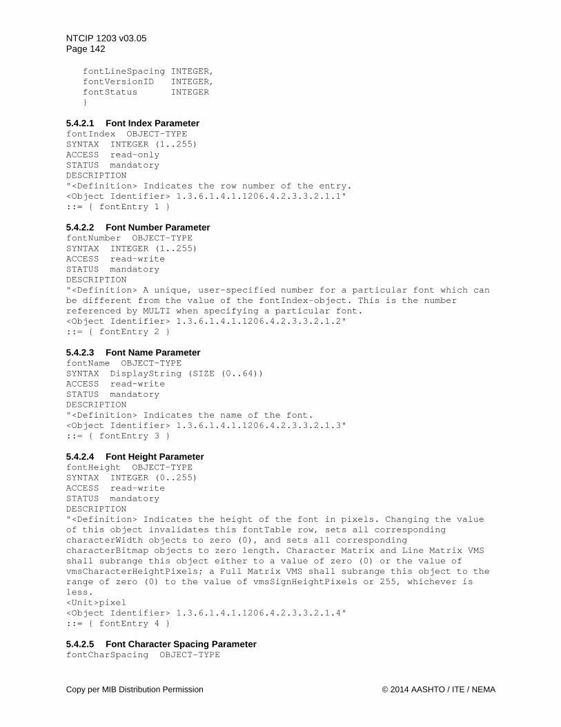
NTCIP 1203 v03.05 Page 142 fontLineSpacing INTEGER, fontVersionID INTEGER, fontStatus INTEGER } 5.4.2.1 Font Index Parameter fontIndex OBJECT-TYPE SYNTAX INTEGER (1..255) ACCESS read-only STATUS mandatory DESCRIPTION "<Definition> Indicates the row number of the entry. <Object Identifier> 1.3.6.1.4.1.1206.4.2.3.3.2.1.1" ::= { fontEntry 1 } 5.4.2.2 Font Number Parameter fontNumber OBJECT-TYPE SYNTAX INTEGER (1..255) ACCESS read-write STATUS mandatory DESCRIPTION "<Definition> A unique, user-specified number for a particular font which can be different from the value of the fontIndex-object. This is the number referenced by MULTI when specifying a particular font. <Object Identifier> 1.3.6.1.4.1.1206.4.2.3.3.2.1.2" ::= { fontEntry 2 } 5.4.2.3 Font Name Parameter fontName OBJECT-TYPE SYNTAX DisplayString (SIZE (0..64)) ACCESS read-write STATUS mandatory DESCRIPTION "<Definition> Indicates the name of the font. <Object Identifier> 1.3.6.1.4.1.1206.4.2.3.3.2.1.3" ::= { fontEntry 3 } 5.4.2.4 Font Height Parameter fontHeight OBJECT-TYPE SYNTAX INTEGER (0..255) ACCESS read-write STATUS mandatory DESCRIPTION "<Definition> Indicates the height of the font in pixels. Changing the value of this object invalidates this fontTable row, sets all corresponding characterWidth objects to zero (0), and sets all corresponding characterBitmap objects to zero length. Character Matrix and Line Matrix VMS shall subrange this object either to a value of zero (0) or the value of vmsCharacterHeightPixels; a Full Matrix VMS shall subrange this object to the range of zero (0) to the value of vmsSignHeightPixels or 255, whichever is less. <Unit>pixel <Object Identifier> 1.3.6.1.4.1.1206.4.2.3.3.2.1.4" ::= { fontEntry 4 } 5.4.2.5 Font Character Spacing Parameter fontCharSpacing OBJECT-TYPE
Copy per MIB Distribution Permission © 2014 AASHTO / ITE / NEMA
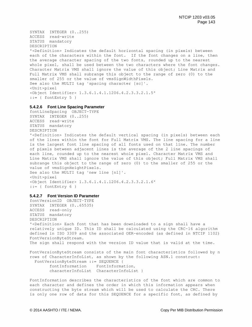
NTCIP 1203 v03.05 Page 143
SYNTAX INTEGER (0..255) ACCESS read-write STATUS mandatory DESCRIPTION "<Definition> Indicates the default horizontal spacing (in pixels) between each of the characters within the font. If the font changes on a line, then the average character spacing of the two fonts, rounded up to the nearest whole pixel, shall be used between the two characters where the font changes. Character Matrix VMS shall ignore the value of this object; Line Matrix and Full Matrix VMS shall subrange this object to the range of zero (0) to the smaller of 255 or the value of vmsSignWidthPixels. See also the MULTI tag 'spacing character [sc]'. <Unit>pixel <Object Identifier> 1.3.6.1.4.1.1206.4.2.3.3.2.1.5" ::= { fontEntry 5 } 5.4.2.6 Font Line Spacing Parameter fontLineSpacing OBJECT-TYPE SYNTAX INTEGER (0..255) ACCESS read-write STATUS mandatory DESCRIPTION "<Definition> Indicates the default vertical spacing (in pixels) between each of the lines within the font for Full Matrix VMS. The line spacing for a line is the largest font line spacing of all fonts used on that line. The number of pixels between adjacent lines is the average of the 2 line spacings of each line, rounded up to the nearest whole pixel. Character Matrix VMS and Line Matrix VMS shall ignore the value of this object; Full Matrix VMS shall subrange this object to the range of zero (0) to the smaller of 255 or the value of vmsSignHeightPixels. See also the MULTI tag 'new line [nl]'. <Unit>pixel <Object Identifier> 1.3.6.1.4.1.1206.4.2.3.3.2.1.6" ::= { fontEntry 6 } 5.4.2.7 Font Version ID Parameter fontVersionID OBJECT-TYPE SYNTAX INTEGER (0..65535) ACCESS read-only STATUS mandatory DESCRIPTION "<Definition> Each font that has been downloaded to a sign shall have a relatively unique ID. This ID shall be calculated using the CRC-16 algorithm defined in ISO 3309 and the associated OER-encoded (as defined in NTCIP 1102) FontVersionByteStream. The sign shall respond with the version ID value that is valid at the time. FontVersionByteStream consists of the main font characteristics followed by n rows of CharacterInfoList, as shown by the following ASN.1 construct: FontVersionByteStream ::= SEQUENCE { fontInformation FontInformation, characterInfoList CharacterInfoList } FontInformation describes the characteristics of the font which are common to each character and defines the order in which this information appears when constructing the byte stream which will be used to calculate the CRC. There is only one row of data for this SEQUENCE for a specific font, as defined by
© 2014 AASHTO / ITE / NEMA. Copy Per MIB Distribution Permission
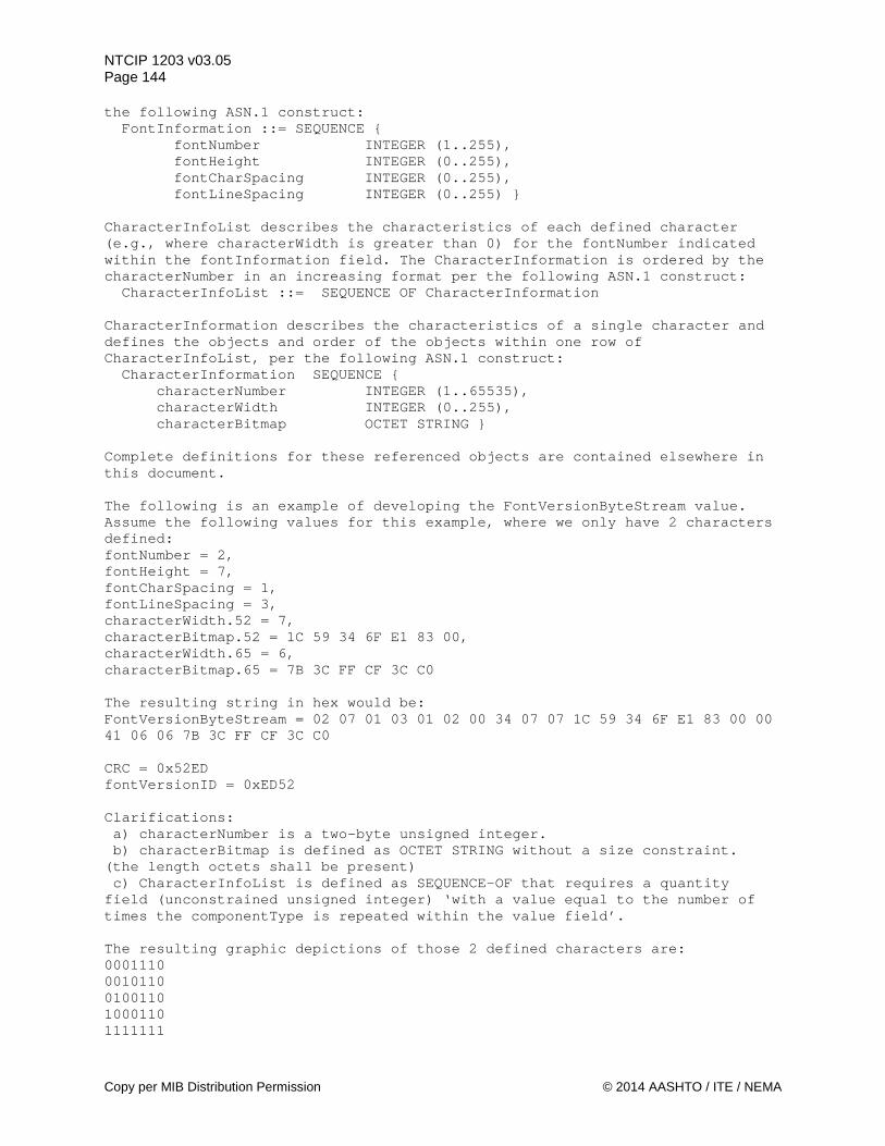
NTCIP 1203 v03.05 Page 144 the following ASN.1 construct: FontInformation ::= SEQUENCE { fontNumber INTEGER (1..255), fontHeight INTEGER (0..255), fontCharSpacing INTEGER (0..255), fontLineSpacing INTEGER (0..255) } CharacterInfoList describes the characteristics of each defined character (e.g., where characterWidth is greater than 0) for the fontNumber indicated within the fontInformation field. The CharacterInformation is ordered by the characterNumber in an increasing format per the following ASN.1 construct: CharacterInfoList ::= SEQUENCE OF CharacterInformation CharacterInformation describes the characteristics of a single character and defines the objects and order of the objects within one row of CharacterInfoList, per the following ASN.1 construct: CharacterInformation SEQUENCE { characterNumber INTEGER (1..65535), characterWidth INTEGER (0..255), characterBitmap OCTET STRING } Complete definitions for these referenced objects are contained elsewhere in this document. The following is an example of developing the FontVersionByteStream value. Assume the following values for this example, where we only have 2 characters defined: fontNumber = 2, fontHeight = 7, fontCharSpacing = 1, fontLineSpacing = 3, characterWidth.52 = 7, characterBitmap.52 = 1C 59 34 6F E1 83 00, characterWidth.65 = 6, characterBitmap.65 = 7B 3C FF CF 3C C0 The resulting string in hex would be: FontVersionByteStream = 02 07 01 03 01 02 00 34 07 07 1C 59 34 6F E1 83 00 00 41 06 06 7B 3C FF CF 3C C0 CRC = 0x52ED fontVersionID = 0xED52 Clarifications: a) characterNumber is a two-byte unsigned integer. b) characterBitmap is defined as OCTET STRING without a size constraint. (the length octets shall be present) c) CharacterInfoList is defined as SEQUENCE-OF that requires a quantity field (unconstrained unsigned integer) ‘with a value equal to the number of times the componentType is repeated within the value field’. The resulting graphic depictions of those 2 defined characters are: 0001110 0010110 0100110 1000110 1111111
Copy per MIB Distribution Permission © 2014 AASHTO / ITE / NEMA
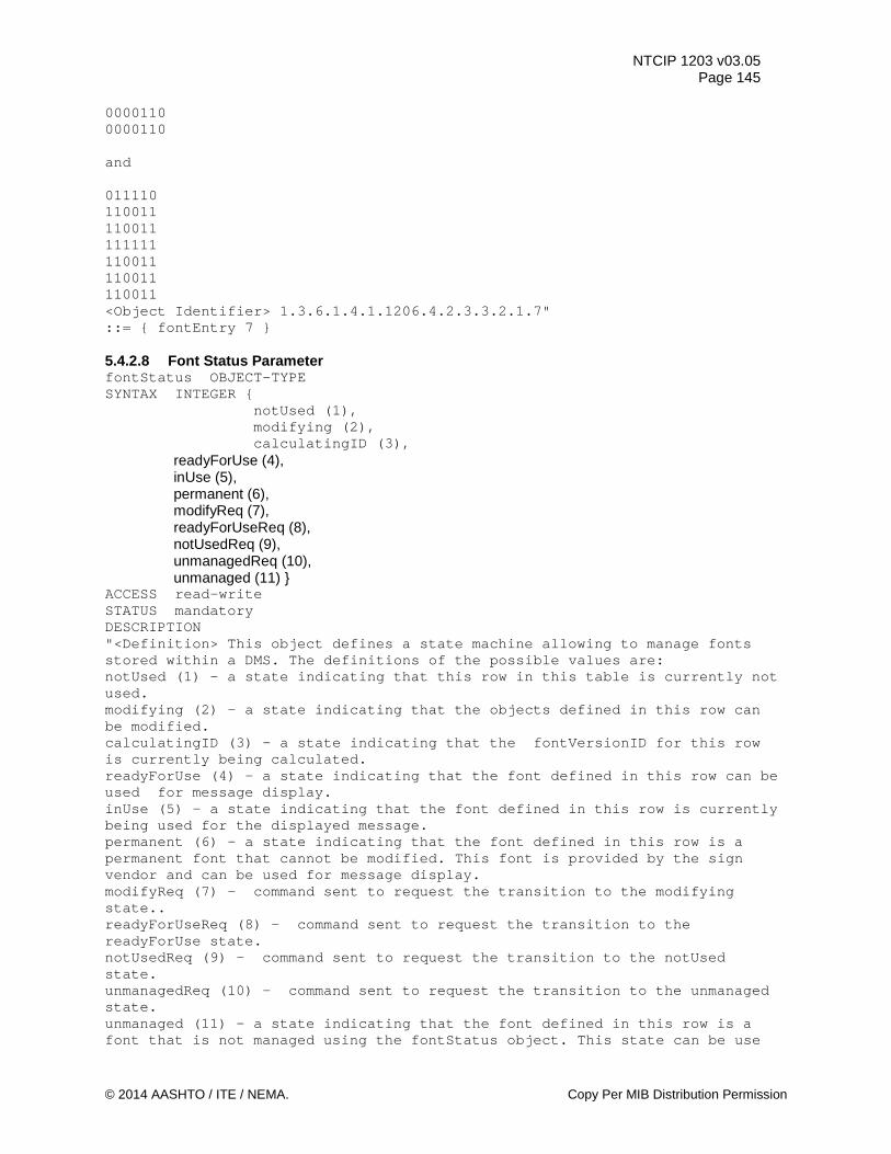
NTCIP 1203 v03.05 Page 145
0000110 0000110 and 011110 110011 110011 111111 110011 110011 110011 <Object Identifier> 1.3.6.1.4.1.1206.4.2.3.3.2.1.7" ::= { fontEntry 7 } 5.4.2.8 Font Status Parameter fontStatus OBJECT-TYPE SYNTAX INTEGER { notUsed (1), modifying (2), calculatingID (3), readyForUse (4), inUse (5), permanent (6), modifyReq (7), readyForUseReq (8), notUsedReq (9), unmanagedReq (10), unmanaged (11) } ACCESS read-write STATUS mandatory DESCRIPTION "<Definition> This object defines a state machine allowing to manage fonts stored within a DMS. The definitions of the possible values are: notUsed (1) - a state indicating that this row in this table is currently not used. modifying (2) - a state indicating that the objects defined in this row can be modified. calculatingID (3) - a state indicating that the fontVersionID for this row is currently being calculated. readyForUse (4) - a state indicating that the font defined in this row can be used for message display. inUse (5) - a state indicating that the font defined in this row is currently being used for the displayed message. permanent (6) - a state indicating that the font defined in this row is a permanent font that cannot be modified. This font is provided by the sign vendor and can be used for message display. modifyReq (7) - command sent to request the transition to the modifying state.. readyForUseReq (8) - command sent to request the transition to the readyForUse state. notUsedReq (9) - command sent to request the transition to the notUsed state. unmanagedReq (10) - command sent to request the transition to the unmanaged state. unmanaged (11) - a state indicating that the font defined in this row is a font that is not managed using the fontStatus object. This state can be use
© 2014 AASHTO / ITE / NEMA. Copy Per MIB Distribution Permission
NTCIP 1203 v03.05 Page 146 to manage the font as in NTCIP 1203 v1. Note: attempts to modify permanent fonts while in this state shall generate SNMP GenErr. <Object Identifier> 1.3.6.1.4.1.1206.4.2.3.3.2.1.8" DEFVAL {unmanaged} ::= { fontEntry 8 } -- The Default Value of 'unmanaged' needs to be supported by a version 2 -- signs because a version 1 central did not implement the -- fontStatus object since it was not defined in version 1 (NTCIP 1203:1997). -- This default value is needed to ensure that a version 1 central can -- download and upload font definitions a version 2 sign without using -- this object. The only exceptions are permanent fonts, which must default -- to a value of 'permanent'. 5.4.3 Maximum Characters per Font Parameter maxFontCharacters OBJECT-TYPE SYNTAX INTEGER (1..65535) ACCESS read-only STATUS mandatory DESCRIPTION "<Definition> Indicates the maximum number of rows in the character table that can exist for any given font. <Object Identifier> 1.3.6.1.4.1.1206.4.2.3.3.3" ::= { fontDefinition 3 } 5.4.4 Character Table Parameter characterTable OBJECT-TYPE SYNTAX SEQUENCE OF CharacterEntry ACCESS not-accessible STATUS mandatory DESCRIPTION "<Definition> A table containing the information needed to configure/define each character of a particular font. <Table Type> static <Object Identifier> 1.3.6.1.4.1.1206.4.2.3.3.4" ::= {fontDefinition 4} characterEntry OBJECT-TYPE SYNTAX CharacterEntry ACCESS not-accessible STATUS mandatory DESCRIPTION "<Definition> Parameters of the Character Configuration Table. " INDEX {fontIndex, characterNumber} ::= {characterTable 1} CharacterEntry ::= SEQUENCE { characterNumber INTEGER, characterWidth INTEGER, characterBitmap OCTET STRING} 5.4.4.1 Character Number Parameter characterNumber OBJECT-TYPE SYNTAX INTEGER (1..65535) ACCESS read-only STATUS mandatory DESCRIPTION "<Definition> Indicates the binary value associated with this character of this font. For example, if the font set followed the ASCII numbering scheme,
Copy per MIB Distribution Permission © 2014 AASHTO / ITE / NEMA
NTCIP 1203 v03.05 Page 147
the character giving the bitmap of 'A' would be characterNumber 65 (41 hex). <Object Identifier> 1.3.6.1.4.1.1206.4.2.3.3.4.1.1" ::= { characterEntry 1 } 5.4.4.2 Character Width Parameter characterWidth OBJECT-TYPE SYNTAX INTEGER (0..255) ACCESS read-write STATUS mandatory DESCRIPTION "<Definition> Indicates the width of this character in pixels. A width of zero (0) indicates this row is invalid. A Character Matrix VMS shall subrange this object either to a value of zero (0) or the value of the vmsCharacterWidthPixels object; a Line Matrix or Full Matrix VMS shall subrange this object to a range of zero (0) to vmsSignWidthPixels. <Unit>pixel <Object Identifier> 1.3.6.1.4.1.1206.4.2.3.3.4.1.2" ::= { characterEntry 2 } 5.4.4.3 Character Bitmap Parameter characterBitmap OBJECT-TYPE SYNTAX OCTET STRING ACCESS read-write STATUS mandatory DESCRIPTION "<Definition> A bitmap that defines each pixel within a rectangular region as being either displayed in the foreground color (bit=1) or transparent (bit=0). If the pixel is transparent, it will remain whatever color existed in the message before drawing the character. This might be the background color, a color rectangle (see MULTI tag) or a graphic. The result of this bitmap is how the character appears on the sign. The octet string is treated as a binary bit string. The most significant bit defines the state of the pixel in the upper left corner of the rectangular region. The rectangular region is processed by rows, left to right, then top to bottom. The size of the rectangular region is defined by the fontHeight and characterWidth objects; any remaining bits shall be ignored, except for use in the calculation of the CRC. This object shall be subranged by the device to the maximum number of bytes as indicated by fontMaxCharacterSize. Note: Version 1 Compatibility: Version 1 of this standard defined the bits as ON (foreground color) or OFF (background color). <Object Identifier> 1.3.6.1.4.1.1206.4.2.3.3.4.1.3" ::= { characterEntry 3 } 5.4.5 Maximum Character Size Parameter fontMaxCharacterSize OBJECT-TYPE SYNTAX INTEGER (0..65535) ACCESS read-only STATUS mandatory DESCRIPTION "<Definition> An indication of the maximum size, in bytes, that the DMS supports for each character's characterBitmap object.
© 2014 AASHTO / ITE / NEMA. Copy Per MIB Distribution Permission
NTCIP 1203 v03.05 Page 148 The largest value of this object must be equal or smaller than the total number of pixels of the sign. <Unit>byte <Object Identifier> 1.3.6.1.4.1.1206.4.2.3.3.5" ::= { fontDefinition 5 } 5.5 Multi-Configuration Objects multiCfg OBJECT IDENTIFIER ::= { dms 4 } -- This subnode is an identifier used to group all objects for support of -- MULTI language configuration such as all default tag values. 5.5.1 Default Background Color Parameter defaultBackgroundColor OBJECT-TYPE SYNTAX INTEGER (0..255) ACCESS read-write STATUS mandatory DESCRIPTION "<Definition> Indicates the color of the background shown on the sign for the 'colorClassic' scheme (see the dmsColorScheme object). If a different color scheme is used, a genErr shall be returned. The allowed values are: black (0), red (1), yellow (2), green(3), cyan (4), blue (5), magenta (6), white (7), orange (8), amber (9). Each of the background colors on a sign shall map to one of the colors listed. If a color is requested that is not supported, then a genErr shall be returned. <Object Identifier> 1.3.6.1.4.1.1206.4.2.3.4.1" DEFVAL {0} ::= { multiCfg 1 } 5.5.2 Default Foreground Color Parameter defaultForegroundColor OBJECT-TYPE SYNTAX INTEGER (0..255) ACCESS read-write STATUS mandatory DESCRIPTION "<Definition> Indicates the color of the foreground (the actual text) shown on the sign for the 'colorClassic' scheme (see the dmsColorScheme object). If a different color scheme is used, a genErr shall be returned. The allowed values are: black (0), red (1), yellow (2), green(3), cyan (4), blue (5), magenta (6), white (7), orange (8), amber (9).
Copy per MIB Distribution Permission © 2014 AASHTO / ITE / NEMA
NTCIP 1203 v03.05 Page 149
Each of the colors on a sign should map to one of the colors listed. If a color is requested that is not supported, then a genErr shall be returned. <Object Identifier> 1.3.6.1.4.1.1206.4.2.3.4.2" ::= { multiCfg 2 } 5.5.3 Default Flash On Time Parameter defaultFlashOn OBJECT-TYPE SYNTAX INTEGER (0..255) ACCESS read-write STATUS mandatory DESCRIPTION "<Definition> Indicates the default flash on time, in tenths of a second, for flashing text. If the time is set to zero (0), the default is NO FLASHing but the text remains visible. This object may be sub-ranged by an implementation; see Section 3.5.2.3.2.3 for more information. <Unit>tenth of seconds <Object Identifier> 1.3.6.1.4.1.1206.4.2.3.4.3" DEFVAL {5} ::= { multiCfg 3 } 5.5.4 Default Flash On Time Parameter at Activation defaultFlashOnActivate OBJECT-TYPE SYNTAX INTEGER (0..255) ACCESS read-only STATUS mandatory DESCRIPTION "<Definition> Indicates the value of defaultFlashOn at activation of the currently active message for the purpose of determining what the value was at the time of activation. The value shall be created (overwritten) at the time when the message was copied into the currentBuffer. <Unit>tenth of seconds <Object Identifier> 1.3.6.1.4.1.1206.4.2.3.4.17" ::= { multiCfg 17 } 5.5.5 Default Flash Off Time Parameter defaultFlashOff OBJECT-TYPE SYNTAX INTEGER (0..255) ACCESS read-write STATUS mandatory DESCRIPTION "<Definition> Indicates the default flash off time, in tenths of a second, for flashing text. If the time is set to zero (0), the default is NO FLASHing but the text remains visible. This object may be sub-ranged by an implementation; see Section 3.5.2.3.2.3 for more information. <Unit>tenth of seconds <Object Identifier> 1.3.6.1.4.1.1206.4.2.3.4.4" DEFVAL {5} ::= { multiCfg 4 } 5.5.6 Default Flash Off Time Parameter at Activation defaultFlashOffActivate OBJECT-TYPE SYNTAX INTEGER (0..255) ACCESS read-only STATUS mandatory DESCRIPTION "<Definition> Indicates the value of defaultFlashOff at activation of the currently active message for the purpose of determining what the value was at
© 2014 AASHTO / ITE / NEMA. Copy Per MIB Distribution Permission
NTCIP 1203 v03.05 Page 150 the time of activation. The value shall be created (overwritten) at the time when the message was copied into the currentBuffer. <Unit>tenth of seconds <Object Identifier> 1.3.6.1.4.1.1206.4.2.3.4.18" ::= { multiCfg 18 } 5.5.7 Default Font Parameter defaultFont OBJECT-TYPE SYNTAX INTEGER (1..255) ACCESS read-write STATUS mandatory DESCRIPTION "<Definition> Indicates the default font number (fontNumber-object) for a message. This object may be sub-ranged by an implementation; see Section 3.5.2.3.2.4 for more information. <Object Identifier> 1.3.6.1.4.1.1206.4.2.3.4.5" DEFVAL {1} ::= { multiCfg 5 } 5.5.8 Default Font Parameter at Activation defaultFontActivate OBJECT-TYPE SYNTAX INTEGER (1..255) ACCESS read-only STATUS mandatory DESCRIPTION "<Definition> Indicates the value of defaultFont at activation of the currently active message for the purpose of determining what the value was at the time of activation. The value shall be created (overwritten) at the time when the message was copied into the currentBuffer. <Object Identifier> 1.3.6.1.4.1.1206.4.2.3.4.19" ::= { multiCfg 19 } 5.5.9 Default Line Justification Parameter defaultJustificationLine OBJECT-TYPE SYNTAX INTEGER { --other(1), -retired left(2), center(3), right(4), full(5) } ACCESS read-write STATUS mandatory DESCRIPTION "<Definition> Indicates the default line justification for a message. This object may be sub-ranged by an implementation; see Section 3.5.2.3.2.5 for more information. <Object Identifier> 1.3.6.1.4.1.1206.4.2.3.4.6" DEFVAL {center} ::= { multiCfg 6 } -- In v02, the enumerated value of 'other' is RETIRED to improve -- interoperability. 5.5.10 Default Line Justification Parameter at Activation defaultJustificationLineActivate OBJECT-TYPE SYNTAX INTEGER { left(2), center(3),
Copy per MIB Distribution Permission © 2014 AASHTO / ITE / NEMA
NTCIP 1203 v03.05 Page 151
right(4), full(5) } ACCESS read-only STATUS mandatory DESCRIPTION "<Definition> Indicates the value of defaultJustificationLine at activation of the currently active message for the purpose of determining what the value was at the time of activation. The value shall be created (overwritten) at the time when the message was copied into the currentBuffer. <Object Identifier> 1.3.6.1.4.1.1206.4.2.3.4.20" ::= { multiCfg 20 } 5.5.11 Default Page Justification Parameter defaultJustificationPage OBJECT-TYPE SYNTAX INTEGER { --other(1), -retired top(2), middle(3), bottom(4) } ACCESS read-write STATUS mandatory DESCRIPTION "<Definition> Indicates the default page justification for a message. This object may be sub-ranged by an implementation; see Section 3.5.2.3.2.6 for more information. <Object Identifier> 1.3.6.1.4.1.1206.4.2.3.4.7" DEFVAL {middle} ::= { multiCfg 7 } -- In v02, the enumerated value of 'other' is RETIRED to improve -- interoperability. 5.5.12 Default Page Justification Parameter at Activation defaultJustificationPageActivate OBJECT-TYPE SYNTAX INTEGER { top(2), middle(3), bottom(4) } ACCESS read-only STATUS mandatory DESCRIPTION "<Definition> Indicates the value of defaultJustificationPage at activation of the currently active message for the purpose of determining what the value was at the time of activation. The value shall be created (overwritten) at the time when the message was copied into the currentBuffer. <Object Identifier> 1.3.6.1.4.1.1206.4.2.3.4.21" ::= { multiCfg 21 } 5.5.13 Default Page On Time Parameter defaultPageOnTime OBJECT-TYPE SYNTAX INTEGER (1..255) ACCESS read-write STATUS mandatory DESCRIPTION "<Definition> Indicates the default page on time, in tenths (1/10) of a second. If the message is only one page, this value is ignored, and the page is continuously displayed. This object may be sub-ranged by an implementation; see Section 3.5.2.3.2.7 for more information.
© 2014 AASHTO / ITE / NEMA. Copy Per MIB Distribution Permission
NTCIP 1203 v03.05 Page 152 <Unit>tenth of seconds <Object Identifier> 1.3.6.1.4.1.1206.4.2.3.4.8" DEFVAL {30} ::= { multiCfg 8 } 5.5.14 Default Page On Time Parameter at Activation defaultPageOnTimeActivate OBJECT-TYPE SYNTAX INTEGER (1..255) ACCESS read-only STATUS mandatory DESCRIPTION "<Definition> Indicates the value of defaultPageOnTime at activation of the currently active message for the purpose of determining what the value was at the time of activation. The value shall be created (overwritten) at the time when the message was copied into the currentBuffer. <Unit>tenth of seconds <Object Identifier> 1.3.6.1.4.1.1206.4.2.3.4.22" ::= { multiCfg 22 } 5.5.15 Default Page Off Time Parameter defaultPageOffTime OBJECT-TYPE SYNTAX INTEGER (0..255) ACCESS read-write STATUS mandatory DESCRIPTION "<Definition> Indicates the default page off time, in tenths (1/10) of a second. If the message is only one page, this value is ignored, and the page is continuously displayed. This object may be sub-ranged by an implementation; see Section 3.5.2.3.2.7 for more information. <Unit>tenth of seconds <Object Identifier> 1.3.6.1.4.1.1206.4.2.3.4.9" DEFVAL {0} ::= { multiCfg 9 } 5.5.16 Default Page Off Time Parameter at Activation defaultPageOffTimeActivate OBJECT-TYPE SYNTAX INTEGER (0..255) ACCESS read-only STATUS mandatory DESCRIPTION "<Definition> Indicates the value of defaultPageOffTime at activation of the currently active message for the purpose of determining what the value was at the time of activation. The value shall be created (overwritten) at the time when the message was copied into the currentBuffer. <Unit>tenth of seconds <Object Identifier> 1.3.6.1.4.1.1206.4.2.3.4.23" ::= { multiCfg 23 } 5.5.17 Default Background Color RGB Parameter defaultBackgroundRGB OBJECT-TYPE SYNTAX OCTET STRING (SIZE (1 | 3)) ACCESS read-write STATUS mandatory DESCRIPTION "<Definition> Indicates the color of the background shown on the sign if not changed by the ‘Page Background Color’ MULTI tag or the ‘Color Rectangle’ MULTI tag. The values are expressed in values appropriate to the color scheme
Copy per MIB Distribution Permission © 2014 AASHTO / ITE / NEMA
NTCIP 1203 v03.05 Page 153
indicated by the dmsColorScheme object. When the 'color24bit' scheme is used, then this object contains three octets. When 'color24bit' is used, then the object value contains 3 octets (first octet = red, second = green, third = blue). When 'monochrome1bit' is used, the value of this octet shall be either 0 or 1. When 'monochrome8bit' is used, the value of this octet shall be 0 to 255. In either the 'monochrome1bit' or 'monochrome8bit' scheme, the actual color is indicated in the monochromeColor object. When 'colorClassic' is used, the value of this octet shall be the value of the classic color. If the ‘colorClassic’ value (see dmsColorScheme object) is used, both defaultBackgroundColor and defaultBackgroundRGB objects shall return the same value if queried by a central system.. Each of the background colors on a sign shall map to one of the colors in the color scheme of the sign. If a color is requested that is not supported, then a genErr shall be returned. This object may be sub-ranged by an implementation; see Section 3.5.2.3.2.2 for more information. <Object Identifier> 1.3.6.1.4.1.1206.4.2.3.4.12" ::= { multiCfg 12 } 5.5.18 Default Background Color RGB Parameter at Activation defaultBackgroundRGBActivate OBJECT-TYPE SYNTAX OCTET STRING (SIZE (1 | 3)) ACCESS read-only STATUS mandatory DESCRIPTION "<Definition> Indicates the value of defaultBackgroundRGB at activation of the currently active message for the purpose of determining what the value was at the time of activation. The value shall be created (overwritten) at the time when the message was copied into the currentBuffer. <Object Identifier> 1.3.6.1.4.1.1206.4.2.3.4.24" ::= { multiCfg 24 } 5.5.19 Default Foreground Color RGB Parameter defaultForegroundRGB OBJECT-TYPE SYNTAX OCTET STRING (SIZE (1 | 3)) ACCESS read-write STATUS mandatory DESCRIPTION "<Definition> Indicates the color of the foreground shown on the sign unless changed by the ‘Color Foreground’ MULTI tag. This is the color used to illuminate the ‘ON’ pixels of displayed characters. The values are expressed in values appropriate to the color scheme indicated by the dmsColorScheme object. When the 'color24bit' scheme is used, then this object contains three octets (first octet = red, second = green, third = blue). When 'monochrome1bit' is used, the value of this octet shall be either 0 or 1. When 'monochrome8bit' is used, the value of this octet shall be 0 to 255. In either the 'monochrome1bit' or 'monochrome8bit' scheme, the actual color is indicated in the monochromeColor object. When 'colorClassic' is used, the value of this octet shall be the value of the classic color. If the ‘colorClassic’ value (see dmsColorScheme object) is used, both defaultForegroundColor and defaultForegroundRGB objects shall return the same value if queried by a central system. Each of the foreground colors on a sign shall map to one of the colors in the color scheme of the sign. If a color is requested that is not supported, then a genErr shall be
© 2014 AASHTO / ITE / NEMA. Copy Per MIB Distribution Permission
NTCIP 1203 v03.05 Page 154 returned. This object may be sub-ranged by an implementation; see Section 3.5.2.3.2.2 for more information. <Object Identifier> 1.3.6.1.4.1.1206.4.2.3.4.13" ::= { multiCfg 13 } 5.5.20 Default Foreground Color RGB Parameter at Activation defaultForegroundRGBActivate OBJECT-TYPE SYNTAX OCTET STRING (SIZE (1 | 3)) ACCESS read-only STATUS mandatory DESCRIPTION "<Definition> Indicates the value of defaultForegroundRGB at activation of the currently active message for the purpose of determining what the value was at the time of activation. The value shall be created (overwritten) at the time when the message was copied into the currentBuffer. <Object Identifier> 1.3.6.1.4.1.1206.4.2.3.4.25" ::= { multiCfg 25 } 5.5.21 Default Character Set Parameter defaultCharacterSet OBJECT-TYPE SYNTAX INTEGER { other (1), eightBit (2)} ACCESS read-write STATUS mandatory DESCRIPTION "<Definition> Indicates the default number of bits used to define a single character in a MULTI string. other (1): - a character size other than those listed below, refer to the device manual. eightBit (2): - each characterNumber of a given font is encoded as an 8-bit value. This object may be sub-ranged by an implementation; see Section 3.5.2.3.2.8 for more information. <Object Identifier> 1.3.6.1.4.1.1206.4.2.3.4.10" DEFVAL {eightBit} ::= { multiCfg 10 } -- The intent of this object is to provide a mechanism by which 16-bit -- character sets (and potentially other character sets ) can be -- supported in a future version. Currently, this object only provides a -- standard for 8-bit character encoding. 5.5.22 Color Scheme Parameter dmsColorScheme OBJECT-TYPE SYNTAX INTEGER { monochrome1bit (1), monochrome8bit (2), colorClassic (3), color24bit(4)} ACCESS read-only STATUS mandatory DESCRIPTION "<Definition> Indicates the color scheme supported by the DMS. The values are defined as: monochrome1bit (1): - Only two states are available for each pixel: on
(1) and off (0). A value of 'on (1)' shall indicate that the
Copy per MIB Distribution Permission © 2014 AASHTO / ITE / NEMA
NTCIP 1203 v03.05 Page 155
defaultForegroundRGB is used and value of 'off(0)' shall indicate that the defaultBackgroundRGB is used. monochrome8bit (2): - this color palette supports 256 shades ranging from 0 (off) to 255 (full intensity). Values between zero and 255 are scaled to the nearest intensity level supported by the VMS. Therefore, it is not required that a VMS have true 8-bit (256 shade) capabilities. colorClassic (3): - as defined in Version 1 of NTCIP 1203, the following values are available: black (0), red (1), yellow (2), green(3), cyan (4), blue (5), magenta (6), white (7), orange (8), amber (9). color24bit (4): - Each pixel is defined by three bytes, one each for red, green, and blue. Each color value ranges from 0 (off) to 255 (full intensity). The combination of the red, green, and blue colors equals the 16,777,216 number of colors. DMS with dmsColorScheme set to color24bit shall interpret MULTI tags with a single color parameter (e.g. [cfx]) as colorClassic. <Object Identifier> 1.3.6.1.4.1.1206.4.2.3.4.11" DEFVAL { monochrome1bit } ::= { multiCfg 11 } 5.5.23 Supported MULTI Tags Parameter dmsSupportedMultiTags OBJECT-TYPE SYNTAX OCTET STRING (SIZE (4)) ACCESS read-only STATUS mandatory DESCRIPTION "<Definition> An indication of the MULTI Tags supported by the device. This object is a bitmap representation of tag support. When a bit is set (=1), the device supports the corresponding tag. When a bit is cleared (=0), the device does not support the corresponding tag. <Format> Bit 0 : color background[cbx] / [cbr,g,b] Bit 1 : color foreground[cfx] / [cfr,g,b] Bit 2 : flashing[fltxoy] / [floytx] Bit 3 : font[fox] / [fox,cccc] Bit 4 : graphic [gn] / [gn,x,y] / [gn,x,y,cccc] Bit 5 : hexadecimal character[hcx] Bit 6 : justification line[jlx] Bit 7 : justification page[jpx] Bit 8 : manufacturer specific[msx,y] Bit 9 : moving text[mvtdw,s,r,text] Bit 10 : new line[nlx] Bit 11 : new page[np] Bit 12 : page time[ptxoy] Bit 13 : spacing character[scx] Bit 14 : field local time 12 hour[f1] Bit 15 : field local time 24 hour[f2] Bit 16 : ambient temperature Celsius[f3]
© 2014 AASHTO / ITE / NEMA. Copy Per MIB Distribution Permission
NTCIP 1203 v03.05 Page 156 Bit 17 : ambient temperature Fahrenheit[f4] Bit 18 : speed km/h[f5] Bit 19 : speed m/h[f6] Bit 20 : day of week[f7] Bit 21 : date of month[f8] Bit 22 : month of year[f9] Bit 23 : year 2 digits[f10] Bit 24 : year 4 digits[f11] Bit 25 : local time 12 hour AM/PM[f12] Bit 26 : local time 12 hour am/pm[f13] Bit 27 : text rectangle [trx,y,w,h] Bit 28 : color rectangle [crx,y,w,h,z] / [crx,y,w,h,r,g,b] Bit 29 : Page background [pbz] / [pbr,g,b] <Object Identifier> 1.3.6.1.4.1.1206.4.2.3.4.14" ::= { multiCfg 14 } 5.5.24 Maximum Number of Pages Parameter dmsMaxNumberPages OBJECT-TYPE SYNTAX INTEGER (1..255) ACCESS read-only STATUS mandatory DESCRIPTION "<Definition> Indicates the maximum number of pages allowed in the dmsMessageMultiString. <Unit>page <Object Identifier> 1.3.6.1.4.1.1206.4.2.3.4.15" ::= { multiCfg 15 } 5.5.25 Maximum MULTI String Length Parameter dmsMaxMultiStringLength OBJECT-TYPE SYNTAX INTEGER (0..65535) ACCESS read-only STATUS mandatory DESCRIPTION "<Definition> Indicates the maximum number of bytes allowed within the dmsMessageMultiString. <Unit>byte <Object Identifier> 1.3.6.1.4.1.1206.4.2.3.4.16" ::= { multiCfg 16 } 5.6 Message Objects dmsMessage OBJECT IDENTIFIER ::= { dms 5 } -- This node is an identifier used to group all objects for support of -- DMS Message Table functions that are common to DMS devices. 5.6.1 Number of Permanent Messages Parameter dmsNumPermanentMsg OBJECT-TYPE SYNTAX INTEGER (0..65535) ACCESS read-only STATUS mandatory DESCRIPTION "<Definition> Indicates the current number of Messages stored in non-volatile, non-changeable memory (e.g., EPROM). For CMS and BOS, this is the number of different messages that can be assembled. See the Specifications in association with Requirement 3.6.7.1 to determine the messages that must be supported.
Copy per MIB Distribution Permission © 2014 AASHTO / ITE / NEMA
NTCIP 1203 v03.05 Page 157
<Unit>message <Object Identifier> 1.3.6.1.4.1.1206.4.2.3.5.1" ::= { dmsMessage 1 } 5.6.2 Number of Changeable Messages Parameter dmsNumChangeableMsg OBJECT-TYPE SYNTAX INTEGER (0..65535) ACCESS read-only STATUS mandatory DESCRIPTION "<Definition> Indicates the current number of valid Messages stored in non-volatile, changeable memory. For CMS and BOS, this number shall be zero (0). <Unit>message <Object Identifier> 1.3.6.1.4.1.1206.4.2.3.5.2" ::= { dmsMessage 2 } 5.6.3 Maximum Number of Changeable Messages Parameter dmsMaxChangeableMsg OBJECT-TYPE SYNTAX INTEGER (0..65535) ACCESS read-only STATUS mandatory DESCRIPTION "<Definition> Indicates the maximum number of Messages that the sign can store in non-volatile, changeable memory. For CMS and BOS, this number shall be zero (0). See the Specifications in association with Requirement 3.5.6.2 to determine the messages that must be supported. <Unit>message <Object Identifier> 1.3.6.1.4.1.1206.4.2.3.5.3" ::= { dmsMessage 3 } 5.6.4 Free Bytes within Changeable Memory Parameter dmsFreeChangeableMemory OBJECT-TYPE SYNTAX INTEGER (0..4294967295) ACCESS read-only STATUS mandatory DESCRIPTION "<Definition> Indicates the number of bytes available within non-volatile, changeable memory. For CMS and BOS, this number shall be zero (0). See the Specifications in association with Requirement 3.5.6.2 to determine the total memory that must be provided. <Unit>byte <Object Identifier> 1.3.6.1.4.1.1206.4.2.3.5.4" ::= { dmsMessage 4 } 5.6.5 Number of Volatile Messages Parameter dmsNumVolatileMsg OBJECT-TYPE SYNTAX INTEGER (0..65535) ACCESS read-only STATUS mandatory DESCRIPTION "<Definition> Indicates the current number of valid Messages stored in volatile, changeable memory. For CMS and BOS, this number shall be zero (0). <Unit>message <Object Identifier> 1.3.6.1.4.1.1206.4.2.3.5.5" ::= { dmsMessage 5 }
© 2014 AASHTO / ITE / NEMA. Copy Per MIB Distribution Permission
NTCIP 1203 v03.05 Page 158 5.6.6 Maximum Number of Volatile Messages Parameter dmsMaxVolatileMsg OBJECT-TYPE SYNTAX INTEGER (0..65535) ACCESS read-only STATUS mandatory DESCRIPTION "<Definition> Indicates the maximum number of Messages that the sign can store in volatile, changeable memory. For CMS and BOS, this number shall be zero (0). See the Specifications in association with Requirement 3.5.6.3 to determine the messages that must be supported. <Unit>message <Object Identifier> 1.3.6.1.4.1.1206.4.2.3.5.6" ::= { dmsMessage 6 } 5.6.7 Free Bytes within Volatile Memory Parameter dmsFreeVolatileMemory OBJECT-TYPE SYNTAX INTEGER (0..4294967295) ACCESS read-only STATUS mandatory DESCRIPTION "<Definition> Indicates the number of bytes available within volatile, changeable memory. For CMS and BOS, this number shall be zero (0). See the Specifications in association with Requirement 3.5.6.3 to determine the total memory that must be provided. <Unit>byte <Object Identifier> 1.3.6.1.4.1.1206.4.2.3.5.7" ::= { dmsMessage 7 } 5.6.8 Message Table Parameter dmsMessageTable OBJECT-TYPE SYNTAX SEQUENCE OF DmsMessageEntry ACCESS not-accessible STATUS mandatory DESCRIPTION "<Definition> A table containing the information needed to activate a Message on a sign. The values of a columnar object (except the dmsMessageStatus) cannot be changed when the 'dmsMessageStatus'-object of that particular row is any value other than 'modifying'. <Table Type> static <Object Identifier> 1.3.6.1.4.1.1206.4.2.3.5.8" ::= {dmsMessage 8} dmsMessageEntry OBJECT-TYPE SYNTAX DmsMessageEntry ACCESS not-accessible STATUS mandatory DESCRIPTION "<Definition> Parameters of the Message Table. " INDEX {dmsMessageMemoryType, dmsMessageNumber} ::= {dmsMessageTable 1} DmsMessageEntry ::= SEQUENCE { dmsMessageMemoryType INTEGER, dmsMessageNumber INTEGER, dmsMessageMultiString OCTET STRING, dmsMessageOwner OwnerString, dmsMessageCRC INTEGER,
Copy per MIB Distribution Permission © 2014 AASHTO / ITE / NEMA
NTCIP 1203 v03.05 Page 159
dmsMessageBeacon INTEGER, dmsMessagePixelService INTEGER, dmsMessageRunTimePriority INTEGER, dmsMessageStatus INTEGER } 5.6.8.1 Message Memory Type Parameter dmsMessageMemoryType OBJECT-TYPE SYNTAX INTEGER { --other (1), -retired permanent (2), changeable (3), volatile (4), currentBuffer (5), schedule (6), blank (7)} ACCESS read-only STATUS mandatory DESCRIPTION "<Definition> Indicates the memory-type used to store a message. Also provides access to current message (currentBuffer) and currently scheduled message (schedule). The rows associated with the 'currentBuffer', 'schedule', and 'blank' message types cannot be written into, because these are either filled in by the controller (currentBuffer and schedule) or pre-defined and not modifiable (blank). The definitions of the enumerated values are: other - any other type of memory type that is not listed within one of the values below, refer to device manual; permanent - non-volatile and non-changeable; changeable - non-volatile and changeable; volatile - volatile and changeable; currentBuffer - contains the information regarding the currently displayed message (basically a copy of the message table row contents of the message that was successfully activated). Only one entry in the table can have the value of currentBuffer and the value of the dmsMessageNumber object shall be one (1). The content of the dmsMessageMultiString object shall be the currently displayed message (including a scheduled message), not the content of a failed message activation attempt; schedule - this entry contains information regarding the currently scheduled message as determined by the time-base scheduler (if present). Only one entry in the table can have the value of 'schedule' and the value of dmsMessageNumber for this entry shall be 1. Displaying a message through this table row shall set the dmsMsgSourceMode object value to 'timebasedScheduler'. When no message is currently active based upon the schedule or if the schedule currently does not point to any message within the message table, the schedule entry shall contain a copy of dmsMessageMemoryType 7 (blank) with a dmsMessageNumber value of 1. blank - there shall be 255 (message numbers 1 through 255) pre-defined, static rows with this message type. These rows are defined so that message codes (e.g., objects with SYNTAX of either MessageIDCode or MessageActivationCode) can blank the sign at a stated run-time priority. The run-time priority of the blank message is equal to the message number (e.g., blank message
© 2014 AASHTO / ITE / NEMA. Copy Per MIB Distribution Permission
NTCIP 1203 v03.05 Page 160 number 1 has a run time priority of 1 and so on). The dmsMessageCRC for all messages of this type shall be 0x0000 and the dmsMessageMultiString shall be an OCTET STRING with a length of zero (0). The activation priority shall be determined from the activation priority of the MessageActivationCode. <Object Identifier> 1.3.6.1.4.1.1206.4.2.3.5.8.1.1" ::= { dmsMessageEntry 1 } -- In v02, the enumerated value of 'other' is RETIRED to improve -- interoperability. 5.6.8.2 Message Number Parameter dmsMessageNumber OBJECT-TYPE SYNTAX INTEGER (1..65535) ACCESS read-only STATUS mandatory DESCRIPTION "<Definition> Enumerated listing of row entries within the value of the primary index to this table (dmsMessageMemoryType -object). When the primary index is 'currentBuffer' or 'schedule', then this value must be one (1). When the primary index is 'blank', this value shall be from 1 through 255 and all compliant devices must support all 255 of these 'blank' rows. <Object Identifier> 1.3.6.1.4.1.1206.4.2.3.5.8.1.2" ::= { dmsMessageEntry 2 } 5.6.8.3 Message MULTI String Parameter dmsMessageMultiString OBJECT-TYPE SYNTAX OCTET STRING ACCESS read-write STATUS mandatory DESCRIPTION "<Definition> Contains the message written in MULTI-language as defined in Section 6 and as subranged by the restrictions defined by dmsMaxMultiStringLength and dmsSupportedMultiTags. When the primary index is 'schedule', 'blank', 'currentBuffer' or 'permanent', this object shall return a genErr to any SET-request. When the primary index is 'schedule', the object shall return the MULTI string of the currently scheduled message in response to a GET-request (regardless whether this message is actually being displayed). The value of the MULTI string is not allowed to have any null character. <Object Identifier> 1.3.6.1.4.1.1206.4.2.3.5.8.1.3" ::= { dmsMessageEntry 3 } 5.6.8.4 Message Owner Parameter dmsMessageOwner OBJECT-TYPE SYNTAX OwnerString ACCESS read-write STATUS mandatory DESCRIPTION "<Definition> Indicates the owner or author of this row. <Object Identifier> 1.3.6.1.4.1.1206.4.2.3.5.8.1.4" ::= { dmsMessageEntry 4 } 5.6.8.5 Message CRC Parameter dmsMessageCRC OBJECT-TYPE SYNTAX INTEGER(0..65535) ACCESS read-only
Copy per MIB Distribution Permission © 2014 AASHTO / ITE / NEMA
NTCIP 1203 v03.05 Page 161
STATUS mandatory DESCRIPTION "<Definition> Indicates the CRC-16 (polynomial defined in ISO/IEC 3309) value created using the values of the dmsMessageMultiString (MULTI-Message), the dmsMessageBeacon, and the dmsMessagePixelService objects in the order listed, not including the OER type or length fields. Note that the calculation shall assume a value of zero (0) for the dmsMessageBeacon object and/or for the dmsMessagePixelService object if they are not supported. For messages of the 'blank' message type, the above algorithm shall be ignored and the dmsMessageCRC value shall always be zero (0). For messages of the 'schedule' message type, the CRC value of the currently scheduled message shall always be returned (regardless whether this message is actually being displayed). <Object Identifier> 1.3.6.1.4.1.1206.4.2.3.5.8.1.5" ::= { dmsMessageEntry 5 } 5.6.8.6 Message Beacon Parameter dmsMessageBeacon OBJECT-TYPE SYNTAX INTEGER (0..1) ACCESS read-write STATUS mandatory DESCRIPTION "<Definition> Indicates if connected beacon(s) are to be activated when the associated message is displayed. Zero (0) = Beacon(s) are Disabled ; one (1) = Beacon(s) are Enabled. When the primary index is 'schedule', 'blank', 'currentBuffer', or 'permanent', this object shall return a genErr to any SET-request. When the primary index is 'schedule', the object shall return the dmsMessageBeacon setting of the currently scheduled message in response to a GET-request (regardless whether this message is actually being displayed). When the dmsMessageMemoryType is 'permanent', the object shall return the dmsMessageBeacon setting of the factory-preset value in response to a GET-request. <Object Identifier> 1.3.6.1.4.1.1206.4.2.3.5.8.1.6" DEFVAL {0} ::= { dmsMessageEntry 6 } 5.6.8.7 Message Pixel Service Parameter dmsMessagePixelService OBJECT-TYPE SYNTAX INTEGER (0..1) ACCESS read-write STATUS mandatory DESCRIPTION "<Definition> Indicates whether pixel service shall be enabled (1) or disabled (0) while this message is active. When the primary index is 'schedule', 'blank', 'currentBuffer', or 'permanent', this object shall return a genErr to any SET-request. When the primary index is 'schedule', the object shall return the dmsMessagePixelService setting of the currently scheduled message in response to a GET-request (regardless whether this message is actually being displayed). When the primary index is 'permanent', the object shall return the dmsMessagePixelService setting of the factory-preset value in response to a GET-request. <Object Identifier> 1.3.6.1.4.1.1206.4.2.3.5.8.1.7" DEFVAL {0} ::= { dmsMessageEntry 7 }
© 2014 AASHTO / ITE / NEMA. Copy Per MIB Distribution Permission
NTCIP 1203 v03.05 Page 162 5.6.8.8 Message Run Time Priority Parameter dmsMessageRunTimePriority OBJECT-TYPE SYNTAX INTEGER (1..255) ACCESS read-write STATUS mandatory DESCRIPTION "<Definition> Indicates the run time priority assigned to a particular message. The value of 1 indicates the lowest level, the value of 255 indicates the highest level. When the dmsMessageMemoryType is 'schedule,' the value set in this object (e.g. dmsMessageRunTimePriority.6.1) shall override the run-time priority of the scheduled message. When the dmsMessageMemoryType is 'blank', the value returned shall be equal to the dmsMessageNumber of that particular message. When the dmsMessageMemoryType is 'permanent', the object shall return the dmsMessageRunTimePriority setting of the factory-preset value in response to a GET-request. <Object Identifier> 1.3.6.1.4.1.1206.4.2.3.5.8.1.8" ::= { dmsMessageEntry 8 } 5.6.8.9 Message Status Parameter dmsMessageStatus OBJECT-TYPE SYNTAX INTEGER { notUsed (1), modifying (2), validating (3), valid (4), error (5), modifyReq (6), validateReq (7), notUsedReq (8) } ACCESS read-write STATUS mandatory DESCRIPTION "<Definition> Indicates the current state of the message. This state-machine allows for defining a message, validating a message, and deleting a message. See Section 4.3.4 for additional details regarding the state-machine. <Object Identifier> 1.3.6.1.4.1.1206.4.2.3.5.8.1.9" ::= { dmsMessageEntry 9 } 5.6.9 Validate Message Error Parameter dmsValidateMessageError OBJECT-TYPE SYNTAX INTEGER { other (1), none (2), beacons (3), pixelService (4), syntaxMULTI (5) } ACCESS read-only STATUS mandatory DESCRIPTION "<Definition> This is an error code used to identify why a message was not validated. If multiple errors occur, only the first value is indicated. The syntaxMULTI error is further detailed in the dmsMultiSyntaxError, dmsMultiSyntaxErrorPosition and dmsMultiOtherErrorDescription objects. <Object Identifier> 1.3.6.1.4.1.1206.4.2.3.5.9" ::= { dmsMessage 9 }
Copy per MIB Distribution Permission © 2014 AASHTO / ITE / NEMA
NTCIP 1203 v03.05 Page 163
5.7 Sign Control Objects signControl OBJECT IDENTIFIER ::= { dms 6 } -- This node is an identifier used to group all objects for support of -- DMS sign control functions that are common to DMS devices. 5.7.1 Control Mode Parameter dmsControlMode OBJECT-TYPE SYNTAX INTEGER { --other (1), -retired local (2), --external (3), -retired central (4), centralOverride (5) --simulation (6) -retired } ACCESS read-write STATUS mandatory DESCRIPTION "<Definition> A value indicating the mode that is currently controlling the sign. The possible modes are: other - (deprecated) Other control mode supported by the device (refer to device manual); local - Local control mode (control is at DMS controller); external - (deprecated) External control mode; central - Central control mode; centralOverride - Central station took control over Local control, even though the control switch at the sign was set to Local; simulation - (deprecated) controller is in a mode where it accepts every command and it pretends that it would execute them but this does not happen because the controller only simulates. <Object Identifier> 1.3.6.1.4.1.1206.4.2.3.6.1" DEFVAL {central} ::= { signControl 1 } -- In v02, the enumerated values of 'other', 'external', and 'simulation' -- were RETIRED to improve interoperability. 5.7.2 Software Reset Parameter dmsSWReset OBJECT-TYPE SYNTAX INTEGER (0..1) ACCESS read-write STATUS mandatory DESCRIPTION "<Definition> A software interface to initiate a controller reset. The execution of the controller reset shall set this object to the value 0. Setting this object to a value of 1 causes the controller to reset. Value zero (0) = no reset, value one (1) = reset. <Object Identifier> 1.3.6.1.4.1.1206.4.2.3.6.2" DEFVAL {0} ::= { signControl 2 } 5.7.3 Activate Message Parameter dmsActivateMessage OBJECT-TYPE SYNTAX MessageActivationCode ACCESS read-write STATUS mandatory
© 2014 AASHTO / ITE / NEMA. Copy Per MIB Distribution Permission
NTCIP 1203 v03.05 Page 164 DESCRIPTION "<Definition> A code indicating the active message. The value of this object may be SET by a management station or modified by logic internal to the DMS (e.g., activation of the end duration message, etc.). When modified by internal logic with a reference to a message ID code, the duration indicates 65535 (infinite), the activate priority indicates 255, and the source address indicates an address of 127.0.0.1. If a GET is performed on this object, the DMS shall respond with the value for the last message that was successfully activated. The dmsActivateMsgError object shall be updated appropriately upon any attempt to update the value of this object, whether from an internal or external source. If a message activation error occurs (e.g., dmsActivateMsgError is updated to a value other than 'none'), the new message shall not be activated and, if the activation request originated from a SET request, a genErr shall be returned. A management station should then GET the dmsActivateMsgError object as soon as possible to minimize the chance of additional activation attempts from overwriting the dmsActivateMsgError. If a message is attempted to be activated via the scheduler or any internal message (e.g., end duration message, etc.) and the message to be activated contains an error, than the following objects shall be set to the appropriate values (as defined within these objects):
– dmsActivateMsgError, – dmsActivateErrorMsgCode, – dmsMultiSyntaxError, – dmsMultiSyntaxErrorPosition (if supported), – dmsMultiOtherErrorDescription (if supported), – dmsDrumStatus (if supported)
A 'criticalTemperature' alarm shall have no effect on the 'activation' of a message, it will only affect the display of the active message. Thus, a message activation may occur during a 'criticalTemperature' alarm and the sign controller will behave as if the message is displayed. However, the shortErrorStatus will indicate a criticalTemperature alarm and the sign face illumination will be off. As soon as the DMS determines that the 'criticalTemperature' alarm is no longer present, the DMS shall display the message stored in the currentBuffer. <Object Identifier> 1.3.6.1.4.1.1206.4.2.3.6.3" ::= { signControl 3 } 5.7.4 Message Display Time Remaining Parameter dmsMessageTimeRemaining OBJECT-TYPE SYNTAX INTEGER (0..65535) ACCESS read-write STATUS mandatory DESCRIPTION "<Definition> Indicates the amount of remaining time in minutes that the current message shall be active. The time shall be accurate to the nearest second and rounded up to the next full minute. For example, a value of 2 shall indicate that the time remaining is between 1 minute and 0.1 seconds and 2 minutes. When a new message is activated with a minute-based duration, or this object
Copy per MIB Distribution Permission © 2014 AASHTO / ITE / NEMA
NTCIP 1203 v03.05 Page 165
is directly SET, the minute-based duration value shall be multiplied by 60 to determine the number of seconds that the message shall be active. Thus, if a message activation is for 2 minutes, the DMS will be assured to display the message for 120 seconds. The value 65535 indicates an infinite duration. A value of zero (0) shall indicate that the current message display duration has expired. A SET operation on this object shall allow a Central Computer to extend or shorten the duration of the message. Setting this object to zero (0) shall result in the immediate display of the dmsEndDurationMessage. <Unit>minute <Object Identifier> 1.3.6.1.4.1.1206.4.2.3.6.4" DEFVAL {65535} ::= { signControl 4 } 5.7.5 Message Table Source Parameter dmsMsgTableSource OBJECT-TYPE SYNTAX MessageIDCode ACCESS read-only STATUS mandatory DESCRIPTION "<Definition> Identifies the message number used to generate the currently displayed message. This object is written to by the device when the new message is loaded into the currentBuffer of the dmsMessageTable. The value of this object contains the message ID code of the message that was copied into the 'currentBuffer'. This value can only be of message type 'permanent', 'volatile', 'changeable', or 'blank'. <Object Identifier> 1.3.6.1.4.1.1206.4.2.3.6.5" ::= { signControl 5 } 5.7.6 Message Requester ID Parameter dmsMsgRequesterID OBJECT-TYPE SYNTAX IpAddress ACCESS read-only STATUS mandatory DESCRIPTION "<Definition> A copy of the source-address field from the dmsActivateMessage-object used to activate the current message. If the current message was not activated by the dmsActivateMessage-object, then the value of this object shall be zero (0). <Object Identifier> 1.3.6.1.4.1.1206.4.2.3.6.6" REFERENCE "RFC 1155, May 1990" ::= { signControl 6 } 5.7.7 Message Source Mode Parameter dmsMsgSourceMode OBJECT-TYPE SYNTAX INTEGER { other (1), local (2), external (3), --otherCom1( 4), -retired --otherCom2 (5), -retired --otherCom3 (6), -retired --otherCom4 (7), -retired central (8), timebasedScheduler (9), powerRecovery (10),
© 2014 AASHTO / ITE / NEMA. Copy Per MIB Distribution Permission
NTCIP 1203 v03.05 Page 166 reset (11), commLoss (12), powerLoss (13), endDuration (14) } ACCESS read-only STATUS mandatory DESCRIPTION "<Definition> Indicates the source that initiated the currently displayed message. The enumerations are defined as: other (1) - the currently displayed message was activated based on a condition other than the ones defined below. This would include any auxiliary devices. local (2) - the currently displayed message was activated at the sign controller using either an onboard terminal or a local interface. external (3) - the currently displayed message was activated from a locally connected device using serial (or other type of) connection to the sign controller such as a laptop or a PDA. This mode shall only be used, if the sign controller is capable of distinguishing between a local input (see definition of 'local (2)') and a serial connection. central (8) - the currently displayed message was activated from the central computer. timebasedScheduler (9) - the currently displayed message was activated from the timebased scheduler as configured within the sign controller. powerRecovery (10) - the currently displayed message was activated based on the settings within the dmsLongPowerRecoveryMessage, dmsShortPowerRecoveryMessage, and the dmsShortPowerLossTime objects. reset (11) - the currently displayed message was activated based on the settings within the dmsResetMessage object. commLoss (12) - the currently displayed message was activated based on the settings within the dmsCommunicationsLossMessage object. powerLoss (13) - the currently displayed message was activated based on the settings within the dmsPowerLossMessage object. Note: it may not be possible to point to this message depending on the technology, e.g. it may not be possible to display a message on pure LED or fiber-optic signs DURING power loss. endDuration (14) - the currently displayed message was activated based on the settings within the dmsEndDurationMessage object. <Object Identifier> 1.3.6.1.4.1.1206.4.2.3.6.7" ::= { signControl 7 } -- In v02, the enumerated values of 'otherComX' is RETIRED to improve -- interoperability. 5.7.8 Short Power Loss Recovery Message Parameter dmsShortPowerRecoveryMessage OBJECT-TYPE SYNTAX MessageIDCode ACCESS read-write STATUS mandatory DESCRIPTION "<Definition> Indicates the message that shall be activated after a power
Copy per MIB Distribution Permission © 2014 AASHTO / ITE / NEMA
NTCIP 1203 v03.05 Page 167
recovery following a short power loss affecting the device (see dmsActivateMessage). The message shall be activated with:
– a duration of 65535 (infinite) (if this object points to a value of 'currentBuffer', the duration is determined by the value of the dmsMessageTimeRemaining object minus the power outage time); – an activation priority of 255; – a source address '127.0.0.1'.
Upon activation of the message, the run-time priority value shall be obtained from the message table row specified by this object. The length of time that defines a short power loss is indicated in the dmsShortPowerLossTime-object. <Object Identifier> 1.3.6.1.4.1.1206.4.2.3.6.8" -- DEFVAL MessageIDCode = messageMemoryType = 7, messageNumber = 1, -- messageCRC = 0 ::= { signControl 8 } 5.7.9 Long Power Loss Recovery Message Parameter dmsLongPowerRecoveryMessage OBJECT-TYPE SYNTAX MessageIDCode ACCESS read-write STATUS mandatory DESCRIPTION "<Definition> Indicates the message that shall be activated after a power recovery following a long power loss affecting the device (see dmsActivateMessage). The message shall be activated with
– a duration of 65535 (infinite), (if this object points to a value of 'currentBuffer', the duration is determined by the value of the dmsMessageTimeRemaining object minus the power outage time) – an activation priority of 255; – a source address of '127.0.0.1'.
Upon activation of the message, the run-time priority value shall be obtained from the message table row specified by this object. The length of time that defines a long power loss is indicated in the dmsShortPowerLossTime-object. <Object Identifier> 1.3.6.1.4.1.1206.4.2.3.6.9" -- DEFVAL MessageIDCode = messageMemoryType = 7, messageNumber = 1, -- messageCRC = 0 ::= { signControl 9 } 5.7.10 Short Power Loss Time Definition Parameter dmsShortPowerLossTime OBJECT-TYPE SYNTAX INTEGER (0..65535) ACCESS read-write STATUS mandatory DESCRIPTION "<Definition> Indicates the time, in seconds, from the start of power loss to the threshold where a short power loss becomes a long power loss. If the value is set to zero (0), all power failures are defined as long power losses. <Unit>second <Object Identifier> 1.3.6.1.4.1.1206.4.2.3.6.10" -- DEFVAL 0 ::= { signControl 10 } 5.7.11 Reset Message Parameter dmsResetMessage OBJECT-TYPE SYNTAX MessageIDCode
© 2014 AASHTO / ITE / NEMA. Copy Per MIB Distribution Permission
NTCIP 1203 v03.05 Page 168 ACCESS read-write STATUS mandatory DESCRIPTION "<Definition> Indicates the message that shall be activated after a Reset (either software or hardware) of the device (see dmsActivateMessage). This assumes that the device can differentiate between a reset and a power loss. The message shall be activated with
- a duration of 65535 (infinite) (if this object points to a value of 'currentBuffer', the duration is determined by the value of the dmsMessageTimeRemaining object minus the power outage time); - an activation priority of 255; - a source address of '127.0.0.1'.
Upon activation of the message, the run-time priority value shall be obtained from the message table row specified by this object. <Object Identifier> 1.3.6.1.4.1.1206.4.2.3.6.11" -- DEFVAL MessageIDCode = messageMemoryType = 7, messageNumber = 1, -- messageCRC = 0 ::= { signControl 11 } 5.7.12 Communications Loss Message Parameter dmsCommunicationsLossMessage OBJECT-TYPE SYNTAX MessageIDCode ACCESS read-write STATUS mandatory DESCRIPTION "<Definition> Indicates the message that shall be activated when the time since the last communications from a management station exceeds the dmsTimeCommLoss time (see dmsActivateMessage). The message shall be activated with
- a duration of 65535 (infinite) (if this object points to a value of 'currentBuffer', the duration is determined by the value of the dmsMessageTimeRemaining object); - an activation priority of 255; - a source address of '127.0.0.1'.
If the value referenced by this object is invalid, the sign will display a blank message. Upon activation of the message, the run-time priority value shall be obtained from the message table row specified by this object. The value of this object shall not be implemented when the value of the dmsControlMode is set to 2 (local). Once the value of the dmsControl Mode object is set to 4 (central) or 5 (centralOverride) and the value of the dmsTimeCommLoss parameter has been reached, the value of this object shall be implemented. <Object Identifier> 1.3.6.1.4.1.1206.4.2.3.6.12" -- DEFVAL MessageIDCode = messageMemoryType = 7, messageNumber = 1, -- messageCRC = 0 ::= { signControl 12 } 5.7.13 Communication Loss Time Definition Parameter dmsTimeCommLoss OBJECT-TYPE SYNTAX INTEGER (0..65535) ACCESS read-write STATUS mandatory DESCRIPTION "<Definition> Defines the maximum time (inclusive), in minutes, between successive Application Layer messages that can occur before a communication loss is assumed. If this object is set to zero (0), communications loss shall
Copy per MIB Distribution Permission © 2014 AASHTO / ITE / NEMA
NTCIP 1203 v03.05 Page 169
be ignored. The countdown timer associated with this parameter shall be suspended while the sign control parameter has a value of 'local (2)', e.g., the sign is in local control. The countdown timer shall be restarted (reset and started again) once the sign control parameter value is switched to 'central (4)' or 'centralOverride (5)'. <Unit>minute <Object Identifier> 1.3.6.1.4.1.1206.4.2.3.6.13"::= { signControl 13 } -- This timer differs from the Data Link Layer timers (T1 to T4). A dial-up -- circuit may have short time-outs at the DL Layer, but central might -- only dial up once a month to confirm operation, in which case this -- object would be set to ~ 35 days. 5.7.14 Power Loss Message Parameter dmsPowerLossMessage OBJECT-TYPE SYNTAX MessageIDCode ACCESS read-write STATUS mandatory DESCRIPTION "<Definition> Indicates the message that shall be activated DURING the loss of power of the device (see dmsActivateMessage). The message shall be activated with: a duration of 65535 (infinite) (if this object points to a value of 'currentBuffer', the duration is determined by the value of the dmsMessageTimeRemaining object); an activation priority of 255; a source address of '127.0.0.1'. Upon activation of the message, the run-time priority value shall be obtained from the message table row specified by this object. Note: Not all technologies support the means to display a message while the power is off. <Object Identifier> 1.3.6.1.4.1.1206.4.2.3.6.14" -- DEFVAL MessageIDCode = messageMemoryType = 7, messageNumber = 1, -- messageCRC = 0 ::= { signControl 14 } 5.7.15 End Duration Message Parameter dmsEndDurationMessage OBJECT-TYPE SYNTAX MessageIDCode ACCESS read-write STATUS mandatory DESCRIPTION "<Definition> Indicates the message that shall be activated after the indicated duration for a message has expired and no other Message had been scheduled (see dmsActivateMessage). The message shall be activated with
- a duration of 65535 (infinite) (if this object points to a value of 'currentBuffer', the duration is determined by the value of the dmsMessageTimeRemaining object); - an activation priority of 255; - a source address of '127.0.0.1'.
Upon activation of the message, the run-time priority value shall be obtained from the message table row specified by this object. If the end duration message does not activate because this object is an
© 2014 AASHTO / ITE / NEMA. Copy Per MIB Distribution Permission
NTCIP 1203 v03.05 Page 170 invalid value, the sign shall blank with the default value of this object. <Object Identifier> 1.3.6.1.4.1.1206.4.2.3.6.15" -- DEFVAL MessageIDCode = messageMemoryType = 7, messageNumber = 1, -- messageCRC = 0 ::= { signControl 15 } 5.7.16 Memory Management Parameter dmsMemoryMgmt OBJECT-TYPE SYNTAX INTEGER { --other (1), -retired normal (2), clearChangeableMessages (3), clearVolatileMessages (4) } ACCESS read-write STATUS mandatory DESCRIPTION "<Definition> Allows the system to manage the device's memory. SNMP Get operations on this object should always return normal (2). clearChangeableMessages (3): the controller shall set dmsMessageStatus for all changeable messages to notUsed (1), and release all memory associated with changeable messages. This action does not affect any changeable graphics or fonts. clearVolatileMessages (4): the controller shall set dmsMessageStatus for all volatile messages to notUsed (1), and release all memory associated with volatile messages. This action does not affect any changeable graphics or fonts. <Object Identifier> 1.3.6.1.4.1.1206.4.2.3.6.16" DEFVAL {normal} ::= { signControl 16 } -- In v02, the enumerated value of 'other' is RETIRED to improve -- interoperability. 5.7.17 Activate Message Error Parameter dmsActivateMsgError OBJECT-TYPE SYNTAX INTEGER { other (1), none (2), priority (3), messageStatus (4), messageMemoryType (5), messageNumber (6), messageCRC (7), syntaxMULTI (8), localMode (9), centralMode (10), centralOverrideMode (11) } ACCESS read-only STATUS mandatory DESCRIPTION "<Definition> This is an error code used to identify why a message was not displayed. Even if multiple errors occur, only one error is indicated. other (1): any error not defined below. none (2): no error.
Copy per MIB Distribution Permission © 2014 AASHTO / ITE / NEMA
NTCIP 1203 v03.05 Page 171
priority(3): the activation priority in the MessageActivationCode is less than the run time priority of the currently displayed message. If this error occurs, the corresponding bit (message error) within the 'shortErrorStatus' object shall be set. messageStatus(4): the 'dmsMessageStatus' of the message to be activated is not 'valid'. If this error occurs, the corresponding bit (message error) within the 'shortErrorStatus' object shall be set. Note: In the 1997 version of NTCIP 1203, this bit was assigned the name of 'underValidation'. It has been renamed to better reflect the fact that this bit can be set due to the message being in a number of different states, not just the 'validating' state. messageMemoryType(5): the message memory type in the MessageActivationCode is not supported by the device. If this error occurs, the corresponding bit (message error) within the 'shortErrorStatus' object shall be set. messageNumber(6): the message number in the MessageActivationCode is not supported or is not defined (populated) by the device. If this error occurs, the corresponding bit (message error) within the 'shortErrorStatus' object shall be set. messageCRC(7): the checksum in the MessageActivationCode is different than the CRC value contained in the 'dmsMessageCRC'. If this error occurs, the corresponding bit (message error) within the 'shortErrorStatus' object shall be set. syntaxMULTI(8): a MULTI syntax error was detected during message activation. The error is further detailed in the 'dmsMultiSyntaxError', 'dmsMultiSyntaxErrorPosition', and 'dmsMultiOtherErrorDescription' objects. If this error occurs, the corresponding bit (message error) within the 'shortErrorStatus' object shall be set. localMode(9): the central system attempted to activate a message while the 'dmsControlMode' object is 'local'. This error shall NOT be set if the value of the 'dmsControlMode' is set to 'central', or 'centralOverride'. If this error occurs, the corresponding bit (message error) within the 'shortErrorStatus' object shall be set. centralMode (10): a locally connected system attempted to activate a message while the 'dmsControlMode' object is 'central'. This error shall NOT be set if the value of the 'dmsControlMode' is set to 'local'. If this error occurs, the corresponding bit (message error) within the 'shortErrorStatus' object shall be set. centralOverrideMode (11): a locally connected system attempted to activate a message while the 'dmsControlMode' object is 'centralOverride', even though the local switch is set to local control. If this error occurs, the corresponding bit (message error) within the 'shortErrorStatus' object shall be set. A 'criticalTemperature' alarm shall have no effect on the 'activation' of a message, it only effects the display of the active message. Thus, a message activation may occur during a 'criticalTemperature' alarm and the sign controller behaves as if the message is displayed. However, the shortErrorStatus indicates a criticalTemperature alarm and the sign face illumination is off. As soon as the DMS determines that the 'criticalTemperature' alarm is no longer present, the DMS shall display the message stored in the currentBuffer. <Object Identifier> 1.3.6.1.4.1.1206.4.2.3.6.17" ::= { signControl 17 }
© 2014 AASHTO / ITE / NEMA. Copy Per MIB Distribution Permission
NTCIP 1203 v03.05 Page 172 5.7.18 MULTI Syntax Error Parameter dmsMultiSyntaxError OBJECT-TYPE SYNTAX INTEGER { other (1), none (2), unsupportedTag (3), unsupportedTagValue (4), textTooBig (5), fontNotDefined (6), characterNotDefined (7), fieldDeviceNotExist (8), fieldDeviceError (9), flashRegionError (10), tagConflict (11), tooManyPages (12), fontVersionID (13), graphicID (14), graphicNotDefined (15) } ACCESS read-only STATUS mandatory DESCRIPTION "<Definition> This is an error code used to identify the first detected syntax error within the MULTI message. other (1): An error other than one of those listed. none (2): No error detected. unsupportedTag (3): The tag is not supported by this device. unsupportedTagValue (4): The tag value is not supported by this device. textTooBig (5): Too many characters on a line, too many lines for a page, or font is too large for the display. fontNotDefined (6): The font is not defined in this device. characterNotDefined (7): The character is not defined in the selected font. fieldDeviceNotExist (8): The field device does not exist / is not connected to this device. fieldDeviceError (9): This device is not receiving input from the referenced field device and/or the field device has a fault. flashRegionError (10): The flashing region cannot be flashed by this device. tagConflict (11): The message cannot be displayed with the combination of tags and/or tag implementation cannot be resolved. tooManyPages (12): Too many pages of text exists in the message. fontVersionID (13): The fontVersionID contained in the MULTI tag [fox,cccc] does not match the fontVersionID for the fontNumber indicated. graphicID (14): The dmsGraphicID contained in the MULTI tag [gx,cccc] does not match the dmsGraphicID for the dmsGraphicIndex indicated. graphicNotDefined (15): The graphic is not defined in this device. <Object Identifier> 1.3.6.1.4.1.1206.4.2.3.6.18" ::= { signControl 18 } 5.7.19 Position of MULTI Syntax Error Parameter dmsMultiSyntaxErrorPosition OBJECT-TYPE SYNTAX INTEGER (0..65535) ACCESS read-only
Copy per MIB Distribution Permission © 2014 AASHTO / ITE / NEMA
NTCIP 1203 v03.05 Page 173
STATUS mandatory DESCRIPTION "<Definition> This is the offset from the first character (e.g. first character has offset 0, second is 1, etc.) of the MULTI string where the SYNTAX error occurred. <Unit>character <Object Identifier> 1.3.6.1.4.1.1206.4.2.3.6.19" ::= { signControl 19 } 5.7.20 Other MULTI Error Parameter dmsMultiOtherErrorDescription OBJECT-TYPE SYNTAX DisplayString (SIZE (0..50)) ACCESS read-only STATUS mandatory DESCRIPTION "<Definition> Indicates vendor-specified error message descriptions. Associated errors occurred due to vendor-specific MULTI-tag responses. The value of this object is valid only if dmsValidateMessageError has a value of ‘syntaxMULTI(5)’ or dmsActivateMsgError has a value of ‘syntaxMULTI(8)’ and dmsMultiSyntaxError is ‘other(1)’. <Object Identifier> 1.3.6.1.4.1.1206.4.2.3.6.20" ::= { signControl 20 } 5.7.21 Pixel Service Duration Parameter vmsPixelServiceDuration OBJECT-TYPE SYNTAX INTEGER (0..65535) ACCESS read-write STATUS mandatory DESCRIPTION "<Definition> Indicates the number of seconds to perform pixel service on an entire sign. If the vmsPixelServiceDuration expires during a pixel service routine, that routine shall be completed before stopping or restarting a new pixel service routine due to vmsPixelServiceFrequency. A value of zero disables pixel service. <Unit>second <Object Identifier> 1.3.6.1.4.1.1206.4.2.3.6.21" ::= { signControl 21 } 5.7.22 Pixel Service Frequency Parameter vmsPixelServiceFrequency OBJECT-TYPE SYNTAX INTEGER (0..1440) ACCESS read-write STATUS mandatory DESCRIPTION "<Definition> Indicates the pixel service cycle time (period) in minutes. A value of zero indicates continuous pixel service from vmsPixelServiceTime to the epoch of midnight. A value of 1440 indicates one pixel service in a 24-hour period. <Unit>minute <Object Identifier> 1.3.6.1.4.1.1206.4.2.3.6.22" DEFVAL {1440} ::= { signControl 22 } 5.7.23 Pixel Service Time Parameter vmsPixelServiceTime OBJECT-TYPE SYNTAX INTEGER (0..1440) ACCESS read-write
© 2014 AASHTO / ITE / NEMA. Copy Per MIB Distribution Permission
NTCIP 1203 v03.05 Page 174 STATUS mandatory DESCRIPTION "<Definition> Indicates the base time at which the first pixel service shall occur. Time is expressed in minutes from the epoch of Midnight of each day. <Unit>minute <Object Identifier> 1.3.6.1.4.1.1206.4.2.3.6.23" DEFVAL {1} ::= { signControl 23 } 5.7.24 Message Code of the Activation Error Parameter dmsActivateErrorMsgCode OBJECT-TYPE SYNTAX MessageActivationCode ACCESS read-only STATUS mandatory DESCRIPTION "<Definition> Indicates the MessageActivationCode that resulted in the current value of the dmsActivateMsgError object. <Object Identifier> 1.3.6.1.4.1.1206.4.2.3.6.24" ::= { signControl 24 } 5.7.25 Activate Message State Parameter dmsActivateMessageState OBJECT-TYPE SYNTAX INTEGER { fastActivationSign(1), slowActivatedOK(2), slowActivatedError(3), slowActivating(4) } ACCESS read-only STATUS mandatory DESCRIPTION "<Definition> Signs that are able to change their message with fast activation always return 'fastActivationSign(1)'. This allows a central to use this object to determine whether or not the sign does fast activation (that is, whether the sign can immediately change the display). Signs that do slow activation (such as a rotary drum sign) shall set this object to 'slowActivating(4)' during the changing of the display and when the message change has completed shall change it to 'slowActivatedOK(2)' if successful or 'slowActivatedError(3)' if an error occurred during the display change. A sign with fast activation uses this object only to indicate that it is a fast activation sign. Such a sign shows an immediate response to a SET of dmsActivateMessage that is either noError or a genErr. In the case of a genErr the specific error is found in dmsActivateMsgError. With a slow activation sign there are two opportunities to detect an error. The first comes when the SET of dmsActivateMessage is performed, just as in the fast activation sign. It could be a bad message number or other error. If such an error is received, the message change does not occur and therefore this object can be ignored. If the SET of dmsActivateMessage succeeds, then the central must wait for either slowActivatedOK or slowActivatedError in this object. If the sign detects an error, it shall set this object to slowActivatedError and set the ‘message error’ bit in the shortErrorStatus object. When a central receives slowActivatedError, it shall examine other status objects specific to the sign, such as the rotary drum status objects, to determine the precise error. <Object Identifier> 1.3.6.1.4.1.1206.4.2.3.6.25" ::= { signControl 25 }
Copy per MIB Distribution Permission © 2014 AASHTO / ITE / NEMA
NTCIP 1203 v03.05 Page 175
5.8 Illumination/Brightness Objects illum OBJECT IDENTIFIER ::= { dms 7 } -- This node is an identifier used to group all objects supporting DMS -- sign illumination functions that are common to DMS devices. 5.8.1 Illumination Control Parameter dmsIllumControl OBJECT-TYPE SYNTAX INTEGER { other (1), photocell (2), timer (3), manual (4), -- retired manualDirect (5), manualIndexed (6) } ACCESS read-write STATUS mandatory DESCRIPTION "<Definition> Indicates the method used to select the Brightness Level. A DMS may subrange the values supported, as indicated. other (1) - indicates that the Brightness Level is based on a mechanism not defined by this standard; see manufacturer documentation. photocell (2) - indicates that the Brightness Level is based on photocell status. Support for this mode shall be supported if Requirement 3.4.2.5.4 is selected. timer (3) - indicates that the Brightness Level is set by an internal timer. The details of this timer are not defined by this standard. manual (4) - indicates that the Brightness Level must be changed via the dmsIllumManLevel object. This mode is DEPRECATED.
manualDirect (5) - indicates that a user can change the brightness output to
any of the brightness levels supported by the sign. This is not the same as the number of brightness levels defined within the table of the dmsIllumBrightnessValues object. This mode is mandatory, if this is the manual mode that the DMS supports. manualIndexed (6) - indicates that a user can change the brightness output to any of the rows defined within the table of the dmsIllumBrightnessValues object. This mode is mandatory, if this is
the manual mode that the DMS supports. The DMS must support either one of the manualXxx modes. When switching to any of the manual modes (manual, manualDirect, manualIndexed) from any other mode, the current brightness level shall automatically be loaded into the dmsIllumManLevel object. <Object Identifier> 1.3.6.1.4.1.1206.4.2.3.7.1" DEFVAL {photocell} ::= { illum 1 } -- In v02, the enumerated value of 'other' is RETIRED to improve -- interoperability. 5.8.2 Maximum Illumination Photocell Level Parameter dmsIllumMaxPhotocellLevel OBJECT-TYPE SYNTAX INTEGER (0..65535) ACCESS read-only
© 2014 AASHTO / ITE / NEMA. Copy Per MIB Distribution Permission
NTCIP 1203 v03.05 Page 176 STATUS mandatory DESCRIPTION "<Definition> Indicates the maximum value given by the dmsIllumPhotocellLevelStatus-object. <Object Identifier> 1.3.6.1.4.1.1206.4.2.3.7.2" ::= { illum 2 } 5.8.3 Status of Illumination Photocell Level Parameter dmsIllumPhotocellLevelStatus OBJECT-TYPE SYNTAX INTEGER (0..65535) ACCESS read-only STATUS mandatory DESCRIPTION "<Definition> Indicates the level of Ambient Light as a value ranging from 0 (darkest) to the value of dmsIllumMaxPhotocellLevel object (brightest), based on the photocell detection. The dmsIllumPhotocellLevelStatus object is considered a virtual photocell level in that it may be algorithmically determined from one or more photocells and is the value used for calculations dealing with the brightness table. The algorithm used to determine the virtual level from the actual photocell readings is manufacturer specific to accommodate various hardware needs. <Object Identifier> 1.3.6.1.4.1.1206.4.2.3.7.3" ::= { illum 3 } 5.8.4 Number of Illumination Brightness Levels Parameter dmsIllumNumBrightLevels OBJECT-TYPE SYNTAX INTEGER (0..255) ACCESS read-only STATUS mandatory DESCRIPTION "<Definition> Indicates the number of individually selectable Brightness Levels supported by the device, excluding the OFF level (=value of zero [0]). This value indicates the total levels of brightness that this device supports, not the number of rows defined in the table of the dmsIllumBrightnessValues object. <Object Identifier> 1.3.6.1.4.1.1206.4.2.3.7.4" ::= { illum 4 } 5.8.5 Status of Illumination Brightness Level Parameter dmsIllumBrightLevelStatus OBJECT-TYPE SYNTAX INTEGER (0..255) ACCESS read-only STATUS mandatory DESCRIPTION "<Definition> Indicates the current Brightness Level of the device, ranging from 0 (OFF) to the maximum value given by the dmsIllumNumBrightLevels- object (Brightest). <Object Identifier> 1.3.6.1.4.1.1206.4.2.3.7.5" ::= { illum 5 } 5.8.6 Illumination Manual Level Parameter dmsIllumManLevel OBJECT-TYPE SYNTAX INTEGER (0..255) ACCESS read-write STATUS mandatory DESCRIPTION "<Definition> Indicates the desired value of the Brightness Level as a value
Copy per MIB Distribution Permission © 2014 AASHTO / ITE / NEMA
NTCIP 1203 v03.05 Page 177
ranging from 0 to the value of the dmsIllumNumBrightLevels-object when under manual control. When the dmsIllumControl object is set to a value of 'manualDirect (5)' then the maximum value that this object can have is the total levels of brightness that this device supports. A user can calculate the direct manual light output as (65535 * (dmsIllumManLevel object value / dmsIllumNumBrightLevels object value)). When the dmsIllumControl object is set to a value of 'manualIndexed (6)' then the maximum value that this object can be set to is the number of rows defined in the table of the dmsIllumBrightnessValues object. If the device supports version 1 and the dmsIllumControl object is set to a value of 'manual (4)', then the deployment could be either (contact your vendor to determine which way is implemented) <Object Identifier> 1.3.6.1.4.1.1206.4.2.3.7.6" ::= { illum 6 } 5.8.7 Illumination Brightness Values Parameter dmsIllumBrightnessValues OBJECT-TYPE SYNTAX OCTET STRING ACCESS read-write STATUS mandatory DESCRIPTION "<Definition> . An OCTET STRING describing the sign's light output in relationship to the Photocell(s) detection of ambient light. For each light output level, there is a corresponding range of photocell levels. The number of light output levels transmitted is defined by the first byte of the data packet, but cannot exceed the value of the dmsIllumNumBrightLevels object. Setting the value of this object to a non-supported or erroneous value shall lead to a genErr. Cause of this error shall be denoted by the dmsIllumBrightnessValuesError object. After a SET, an implementation may interpolate these entries to create a table with as many entries as needed, but the value of the object shall not be affected by such interpolations. For each light output level, there are three 16-bit values that occur in the following order: Light output level, Photocell level down, Photocell level up. The light output level is a value between 0 (no light output) and 65535 (maximum light output). Each step is 1/65535 of the maximum light output (linear scale). The Photocell-level-down is the lowest photocell level allowed to maintain the light output level. If the photocell level goes below this point, the light output level goes down one light output level. The Photocell-level-up is the highest photocell level for this light output level. If the photocell level goes above this point, the light output level goes up one light output level. The photocell level (Up and Down) values may not exceed the value of the dmsIllumMaxPhotocellLevel object. The points transmitted should be selected so that there is no photocell level which does not have a light output level. Hysteresis is possible by defining the photocell-level-up at a level higher than the upper level's photocell-level-down. The encoding of the structure shall consist of a one byte integer value indicating the number of rows in the table. This is followed by a series of OER encoded Strings of the following structure: SEQUENCE { lightOutput INTEGER (0..65535), photocellLevelDown INTEGER (0..65535),
© 2014 AASHTO / ITE / NEMA. Copy Per MIB Distribution Permission
NTCIP 1203 v03.05 Page 178 photocellLevelUp INTEGER (0..65535) } If the sign does not support photocell and the dmsIllumControl object value is set to 'manualIndexed', then the values for the 'photocellLevelDown' and 'photocellLevelUp' still need to be entered that the table does not cause any errors as defined in the dmsIllumBrightnessValuesError object. However, since no photocell is supported, the entered values for 'photocellLevelDown' and 'photocellLevelUp' for the various 'lightOutputs' are meaningless. <Object Identifier> 1.3.6.1.4.1.1206.4.2.3.7.7" ::= { illum 7 } 5.8.8 Brightness Values Error Parameter dmsIllumBrightnessValuesError OBJECT-TYPE SYNTAX INTEGER { other (1), none (2), photocellGap (3), negativeSlope (4), tooManyLevels (5), invalidData (6) } ACCESS read-only STATUS mandatory DESCRIPTION "<Definition> Indicates the error encountered when the brightness table was SET. other(1) - is for a manufacturer specific indication when none of the other possible values can be used. none(2) - indicates that no error was encountered. photocellGap(3) - indicates that certain photocell levels do not have an associated brightness level. negativeSlope(4) - indicates that the photocell range used to select a brighter brightness level is lower or overlaps the photocell range used to select a dimmer brightness level. Note that some signs may allow a negative slope for special conditions without generating an error; e.g., external illumination for a reflective sign may be allowed to turn off during daylight conditions rather than getting brighter. tooManyLevels(5) - indicates that more brightness levels are defined than are reported by dmsIllumNumBrightLevels. invalidData(6) - indicates a manufacturer defined condition of invalid data not described by the other options. <Object Identifier> 1.3.6.1.4.1.1206.4.2.3.7.8" ::= { illum 8 } 5.8.9 Status of Illumination Light Output Parameter dmsIllumLightOutputStatus OBJECT-TYPE SYNTAX INTEGER (0..65535) ACCESS read-only STATUS mandatory DESCRIPTION "<Definition> Indicates the current physical light output value ranging from 0 (darkest) to 65535 (maximum output). <Object Identifier> 1.3.6.1.4.1.1206.4.2.3.7.9" ::= { illum 9 }
Copy per MIB Distribution Permission © 2014 AASHTO / ITE / NEMA
NTCIP 1203 v03.05 Page 179
5.9 Scheduling Action Objects dmsSchedule OBJECT IDENTIFIER ::= { dms 8 } -- This node is an identifier used to group all DMS device-specific -- objects supporting DMS sign timebased scheduling. 5.9.1 Action Table Entries Parameter numActionTableEntries OBJECT-TYPE SYNTAX INTEGER (0..255) ACCESS read-only STATUS mandatory DESCRIPTION "<Definition> Indicates the number of rows that are stored in the dmsActionTable. See the Specification in association with Requirement 3.5.10.4 to determine the number of actions required. <Object Identifier> 1.3.6.1.4.1.1206.4.2.3.8.1" ::= { dmsSchedule 1 } 5.9.2 Action Table Parameter dmsActionTable OBJECT-TYPE SYNTAX SEQUENCE OF DmsActionEntry ACCESS not-accessible STATUS mandatory DESCRIPTION "<Definition> A table containing a list of message codes. The scheduler (as defined in the dayPlanTable within NTCIP 1201) determines when a message shall be displayed. This table determines which message shall be activated. <Table Type> static <Object Identifier> 1.3.6.1.4.1.1206.4.2.3.8.2" ::= {dmsSchedule 2} dmsActionEntry OBJECT-TYPE SYNTAX DmsActionEntry ACCESS not-accessible STATUS mandatory DESCRIPTION "<Definition> Parameters of the DMS Action Table. " INDEX {dmsActionIndex} ::= {dmsActionTable 1} DmsActionEntry ::= SEQUENCE { dmsActionIndex INTEGER, dmsActionMsgCode MessageIDCode } 5.9.2.1 Action Index Parameter dmsActionIndex OBJECT-TYPE SYNTAX INTEGER (1..255) ACCESS read-only STATUS mandatory DESCRIPTION "<Definition> Enumerated listing of row entries. The value of this object cannot exceed the value of the numActionTableEntries - object. <Object Identifier> 1.3.6.1.4.1.1206.4.2.3.8.2.1.1" ::= { dmsActionEntry 1 } 5.9.2.2 Action Message Code Parameter dmsActionMsgCode OBJECT-TYPE
© 2014 AASHTO / ITE / NEMA. Copy Per MIB Distribution Permission
NTCIP 1203 v03.05 Page 180 SYNTAX MessageIDCode ACCESS read-write STATUS mandatory DESCRIPTION "<Definition> A number indicating the message memory type, the message number and the associated message-specific CRC as indicated within the message table. Setting the CRC portion of this object to all zeros allows a message to become activated without the CRC validation process. <Object Identifier> 1.3.6.1.4.1.1206.4.2.3.8.2.1.2" DEFVAL {'0000000000'h} ::= { dmsActionEntry 2 } 5.10 Auxiliary I/O Objects -- The objects originally defined under this node have been moved -- under the 'global' node. The definition of these objects is now -- contained in NTCIP 1201 (Version 2-Amendment 2). 5.11 Sign Status dmsStatus OBJECT IDENTIFIER ::= { dms 9 } -- This node is an identifier used to group all objects supporting DMS -- sign status monitoring functions that are common to DMS devices. 5.11.1 Core Status 5.11.1.1 Number of Rows in MULTI Field Table Parameter statMultiFieldRows OBJECT-TYPE SYNTAX INTEGER (0..255) ACCESS read-only STATUS mandatory DESCRIPTION "<Definition> Indicates the number of rows in the statMultiFieldTable that are currently being used. <Unit>row <Object Identifier> 1.3.6.1.4.1.1206.4.2.3.9.1" ::= { dmsStatus 1 } 5.11.1.2 MULTI Field Table Parameter statMultiFieldTable OBJECT-TYPE SYNTAX SEQUENCE OF StatMultiFieldEntry ACCESS not-accessible STATUS mandatory DESCRIPTION "<Definition> A table containing the currently displayed value of a specified Field. The number of rows is given by the value of statMultiFieldRows-object. <Table Type> static <Object Identifier> 1.3.6.1.4.1.1206.4.2.3.9.2" ::= {dmsStatus 2} statMultiFieldEntry OBJECT-TYPE SYNTAX StatMultiFieldEntry ACCESS not-accessible STATUS mandatory DESCRIPTION "<Definition> Parameters of the Status Multi Field Table. " INDEX {statMultiFieldIndex}
Copy per MIB Distribution Permission © 2014 AASHTO / ITE / NEMA
NTCIP 1203 v03.05 Page 181
::= {statMultiFieldTable 1} StatMultiFieldEntry ::= SEQUENCE { statMultiFieldIndex INTEGER, statMultiFieldCode INTEGER, statMultiCurrentFieldValue OCTET STRING} 5.11.1.2.1 MULTI Field Index Parameter statMultiFieldIndex OBJECT-TYPE SYNTAX INTEGER (1..255) ACCESS read-only STATUS mandatory DESCRIPTION "<Definition> The index into this table indicating the sequential order of the field within the MULTI-string. <Object Identifier> 1.3.6.1.4.1.1206.4.2.3.9.2.1.1" ::= { statMultiFieldEntry 1 } 5.11.1.2.2 Code of MULTI Field Parameter statMultiFieldCode OBJECT-TYPE SYNTAX INTEGER (1..255) ACCESS read-only STATUS mandatory DESCRIPTION "<Definition> Indicates the ID of the statMultiCurrentFieldValue-object. The field codes are indicated under the 'Field'-tag in MULTI. <Object Identifier> 1.3.6.1.4.1.1206.4.2.3.9.2.1.2" ::= { statMultiFieldEntry 2 } 5.11.1.2.3 Current Value of the MULTI Field Parameter statMultiCurrentFieldValue OBJECT-TYPE SYNTAX OCTET STRING (SIZE (0..50)) ACCESS read-only STATUS mandatory DESCRIPTION "<Definition> Indicates the value of the field in the currently displayed MULTI-message. <Object Identifier> 1.3.6.1.4.1.1206.4.2.3.9.2.1.3" ::= { statMultiFieldEntry 3 } 5.11.1.3 Current Speed Parameter dmsCurrentSpeed OBJECT-TYPE SYNTAX INTEGER (0..255) ACCESS read-only STATUS mandatory DESCRIPTION "<Definition> The current speed value detected by the attached device. The speed is in kilometers per hour (km/h). This value may vary from the displayed speed value due to application specific implementation. <Unit>kilometers per hour <Object Identifier> 1.3.6.1.4.1.1206.4.2.3.9.3" ::= { dmsStatus 3 } 5.11.1.4 Current Speed Limit Parameter dmsCurrentSpeedLimit OBJECT-TYPE SYNTAX INTEGER (0..255) ACCESS read-write
© 2014 AASHTO / ITE / NEMA. Copy Per MIB Distribution Permission
NTCIP 1203 v03.05 Page 182 STATUS mandatory DESCRIPTION "<Definition> Indicates the current speed limit in kilometers per hour (km/h). <Object Identifier> 1.3.6.1.4.1.1206.4.2.3.9.4" ::= { dmsStatus 4 } 5.11.1.5 Watchdog Failure Count Parameter watchdogFailureCount OBJECT-TYPE SYNTAX Counter ACCESS read-only STATUS mandatory DESCRIPTION "<Definition> A counter indicating the number of watchdog failures that have been detected. <Object Identifier> 1.3.6.1.4.1.1206.4.2.3.9.5" ::= { dmsStatus 5 } 5.11.1.6 Open Door Status Parameter dmsStatDoorOpen OBJECT-TYPE SYNTAX INTEGER (0..255) ACCESS read-only STATUS mandatory DESCRIPTION "<Definition> Indicates whether any of the doors to the controller cabinet or the sign housing are open. This is a bitmap; if a bit is set (= 1) then the door is open; if a bit not is not set, then the associated door is closed. Each door is associated with a bit (bit-door correlation order specified by manufacturer) allowing for up to 8 doors. <Object Identifier> 1.3.6.1.4.1.1206.4.2.3.9.6" ::= { dmsStatus 6 } 5.11.2 Status Error Objects statError OBJECT IDENTIFIER ::= { dmsStatus 7 } -- This node is an identifier used to group all objects supporting DMS sign message error status functions that are common to DMS devices. 5.11.2.1 Controller Errors 5.11.2.1.1 Short Error Status Parameter shortErrorStatus OBJECT-TYPE SYNTAX INTEGER (0..65535) ACCESS read-only STATUS mandatory DESCRIPTION "<Definition> A bitmap of summary errors. When a bit is set, the error is presently active. When a bit is clear the error is not currently active. If no sensor is present or supported (for a corresponding bit), the bit shall not be set. The bits are defined as follows: <Format> Bit 0 - reserved -- The definition contained in Version 1 stated 'other'. However, -- 'other' is no longer allowed as a value. Bit 1- communications error - this bit shall be set if any error associated with the communications between the central computer and the device occurs.
Copy per MIB Distribution Permission © 2014 AASHTO / ITE / NEMA
NTCIP 1203 v03.05 Page 183
Bit 2- power error - this bit shall be set if any error associated with the power supply to any component occurs (see the objects dmsPowerFailureStatusMap and lowFuelThreshold). Bit 3- attached device error - this bit shall be set if any error associated with attached (supported, and enabled) external devices occurs. Bit 4- lamp error - this bit shall be set if any errors associated with any lamp occurs (see the objects lampFailureStuckOn and lampFailureStuckOff). This bit is only applicable to devices that support lamps such as fiber optic signs or front-illuminated reflective signs. This bit is not applicable to lamps or fluorescent lights illuminating the housing or cabinet. Bit 5- pixel error - this bit shall be set if any errors associated with any pixel occurs (see the objects pixelFailureTableNumRows for NTCIP 1203v1 deployments, and pixelFailureTableNumRows, and/or dmsPixelFailureTestRows and dmsPixelFailureMessageRows for NTCIP 1203v2 deployments.). This bit is only applicable to devices that support illumination of individual pixels, but not to drum signs. Note that certain sign technologies such as flip disk only sign may not be able to determine pixel errors. Bit 6- photocell error - this bit shall be set if any errors associated with the supported light sensors occurs (see the object dmsLightSensorStatusMap). Bit 7- message error - this bit shall be set if any errors associated with activating and/or displaying a message occurs (see the object dmsActivateMsgError). Bit 8- controller error - this bit shall be set if any errors associated with the controller occurs (see the controllerErrorStatus object) Bit 9- temperature warning - this bit shall be set if any of the temperature values detected by the device exceed non-standardized temperature values (see the object tempSensorWarningMap). This bit is included to allow vendors or agencies to define vendor- or agency-specific threshold objects that indicate temperature changes that are of interest but not dangerous to the life-expectancy of the device (see also the 'critical temperature' bit) Bit 10- climate-control system error - this bit shall be set if any errors associated with the climate control systems such as fans and/or heaters occurs (see the object dmsClimateCtrlStatusMap). Bit 11- critical temperature error - this bit shall be set if the critical temperature as defined by the value of the critical temperature objects have been exceeded. (see the object dmsTempSensorHighCriticalTemperature and dmsTempSensorLowCriticalTemperature). Bit 12- Drum-sign Rotor error - This bit shall be set if any errors associated with the rotor of a drum sign occurs. Bit 13- This bit shall be set if any door to any DMS field component (cabinet or housing) is open(see the object dmsStatDoorOpen). Bit 14- Humidity warning - This bit shall be set if any humidity sensor sensor is reporting a humidity warning (see the object dmsHumiditySensorStatusMap). -- To track a history of transient error conditions utilize the event -- logging table located in the Global Objects Definitions (NTCIP 1201).
© 2014 AASHTO / ITE / NEMA. Copy Per MIB Distribution Permission
NTCIP 1203 v03.05 Page 184 <Object Identifier> 1.3.6.1.4.1.1206.4.2.3.9.7.1" ::= { statError 1 } 5.11.2.1.2 Controller Error Status Parameter controllerErrorStatus OBJECT-TYPE SYNTAX INTEGER (0..255) ACCESS read-only STATUS mandatory DESCRIPTION "<Definition> A bitmap of controller related errors where the bits are defined as follows: <Format> Bit 0- other controller error Bit 1- PROM error Bit 2- program/processor error Bit 3- RAM error Bit 4- Controller to display interface error If a bit is set to one (1), then the associated error is existing; if the bit is set to zero (0), then the associated error is not existing. <Object Identifier> 1.3.6.1.4.1.1206.4.2.3.9.7.10" ::= { statError 10 } 5.11.2.2 Power Status Data 5.11.2.2.1 Power Failure Status Map Parameter dmsPowerFailureStatusMap OBJECT-TYPE SYNTAX OCTET STRING (SIZE (0..64)) ACCESS read-only STATUS mandatory DESCRIPTION "<Definition> Indicates whether each power supply within the sign has failed. If a power supply has failed, its associated bit is set to one (1). The size of this object shall always present one bit for each power supply supported by the system, but shall not contain more than seven bits that are not associated with any power supply. A power supply is a local supply of subsystem power, such as a voltage regulator. Further information about each failed subsystem may be found in the dmsPowerStatusTable. If any bit within this object is set, then the 'power error' bit within the shortErrorStatus object shall also be set. <Object Identifier> 1.3.6.1.4.1.1206.4.2.3.9.7.11" ::= { statError 11 } 5.11.2.2.2 Number of Rows in Power Table Parameter dmsPowerNumRows OBJECT-TYPE SYNTAX INTEGER (0..512) ACCESS read-only STATUS mandatory DESCRIPTION "<Definition> Indicates the number of rows in the dmsPowerStatusTable. <Unit>row <Object Identifier> 1.3.6.1.4.1.1206.4.2.3.9.7.12" ::= { statError 12 } 5.11.2.2.3 Power Status Table Parameter dmsPowerStatusTable OBJECT-TYPE SYNTAX SEQUENCE OF DmsPowerStatusEntry ACCESS not-accessible
Copy per MIB Distribution Permission © 2014 AASHTO / ITE / NEMA
NTCIP 1203 v03.05 Page 185
STATUS mandatory DESCRIPTION "<Definition> A table containing status information for each power supply within a DMS. <Table Type> static <Object Identifier> 1.3.6.1.4.1.1206.4.2.3.9.7.13" ::= {statError 13} dmsPowerStatusEntry OBJECT-TYPE SYNTAX DmsPowerStatusEntry ACCESS not-accessible STATUS mandatory DESCRIPTION "<Definition> An entry in the power status table. " INDEX { dmsPowerIndex } ::= {dmsPowerStatusTable 1} DmsPowerStatusEntry ::= SEQUENCE { dmsPowerIndex INTEGER, dmsPowerDescription DisplayString, dmsPowerMfrStatus DisplayString, dmsPowerStatus INTEGER, dmsPowerVoltage INTEGER, dmsPowerType INTEGER} 5.11.2.2.3.1 Power Index Parameter dmsPowerIndex OBJECT-TYPE SYNTAX INTEGER (1..512) ACCESS read-only STATUS mandatory DESCRIPTION "<Definition> Index of the power supply status table. This index corresponds to the bit position within the dmsPowerFailureStatusMap bitmap: the row with index 1 corresponds to the low-order bit of the dmsPowerFailureStatusMap, etc. <Object Identifier> 1.3.6.1.4.1.1206.4.2.3.9.7.13.1.1" ::= { dmsPowerStatusEntry 1 } 5.11.2.2.3.2 Power Description Parameter dmsPowerDescription OBJECT-TYPE SYNTAX DisplayString (SIZE (0..64)) ACCESS read-only STATUS mandatory DESCRIPTION "<Definition> Human-readable description of the power supply. This value should provide enough information for maintenance personnel to identify the physical location of the power supply within the DMS. The description shall include a meaningful definition of the location where the power supply defined in this row is located within the DMS. <Object Identifier> 1.3.6.1.4.1.1206.4.2.3.9.7.13.1.2" ::= { dmsPowerStatusEntry 2 } 5.11.2.2.3.3 Power Manufacturer-Defined Status Parameter dmsPowerMfrStatus OBJECT-TYPE SYNTAX DisplayString (SIZE (0..64)) ACCESS read-only STATUS mandatory DESCRIPTION
© 2014 AASHTO / ITE / NEMA. Copy Per MIB Distribution Permission
NTCIP 1203 v03.05 Page 186 "<Definition> Indicates the current manufacturer-defined status of the power supply. This object allows a vendor to provide the operator with additional information. <Object Identifier> 1.3.6.1.4.1.1206.4.2.3.9.7.13.1.3" ::= { dmsPowerStatusEntry 3 } 5.11.2.2.3.4 Power Status Parameter dmsPowerStatus OBJECT-TYPE SYNTAX INTEGER { --other (1), -not used noError (2), powerFail (3), -- The power supply is producing no output. voltageOutOfSpec (4), -- The power supply is producing voltage outside -- the vendor specification currentOutOfSpec (5) } -- The power supply is producing current outside of -- the vendor specification. ACCESS read-only STATUS mandatory DESCRIPTION "<Definition> Indicates the current status of the indicated power supply. <Object Identifier> 1.3.6.1.4.1.1206.4.2.3.9.7.13.1.4" ::= { dmsPowerStatusEntry 4 } 5.11.2.2.3.5 Power Voltage Status Parameter dmsPowerVoltage OBJECT-TYPE SYNTAX INTEGER (0..65535) ACCESS read-only STATUS mandatory DESCRIPTION "<Definition> A voltage measurement in units of hundredths (1/100) of a volt. The maximum value (0xFFFF) corresponds to a voltage of 655.35 volts. AC voltages are given in RMS (Root Mean Squared) value. <Object Identifier> 1.3.6.1.4.1.1206.4.2.3.9.7.13.1.5" ::= { dmsPowerStatusEntry 5 } 5.11.2.2.3.6 Power Status Type Parameter dmsPowerType OBJECT-TYPE SYNTAX INTEGER { other (1), acLine (2), generator (3), solar (4), battery-UPS (5), ledSupply (6), lampSupply (7) } ACCESS read-only STATUS mandatory DESCRIPTION "<Definition> Indicates the type of power source or power supply represented by the table row. other: indicates that the power source or supply is not one of the types listed below (see device manual), in which case the corresponding dmsPowerDescription field provides a description of the entity represented by the row.
Copy per MIB Distribution Permission © 2014 AASHTO / ITE / NEMA
NTCIP 1203 v03.05 Page 187
acLine: indicates that the row represents a source of AC power This is also reflected in the lineVolts object.; generator: indicates that the row represents a generator; solar: indicates that the row represents solar equipment; battery-UPS: indicates that the row represents a battery or UPS with no significant charging occurring. This is also reflected in the signVolts object. ledSupply: indicates that the row represents the power supply to one or more LED pixels. lampSupply: indicates that the row represents the power supply to one or more display lamps. <Object Identifier> 1.3.6.1.4.1.1206.4.2.3.9.7.13.1.6" ::= { dmsPowerStatusEntry 6 } 5.11.2.3 Climate Control Status Data 5.11.2.3.1 Fan Failure Parameter -- This object has been deprecated. See Annex D for more information. fanFailures OBJECT-TYPE SYNTAX OCTET STRING (SIZE (0..4)) ACCESS read-only STATUS deprecated DESCRIPTION "<Definition> Indicates whether each fan (system) within a DMS is capable of operating, expressed as a bitmap. If a fan (system) failed, its associated bit is set to one (1). Each fan system is associated with a bit (bit-fan correlation order specified by manufacturer) allowing for up to 32 fan systems to report failure status. A fan system is defined as a single fan, group of fans, sensors, or filter systems. Whether each bit specifies a fan or fan system is dependent on the manufacturer. <Object Identifier> 1.3.6.1.4.1.1206.4.2.3.9.7.8" ::= { statError 8 } 5.11.2.3.2 Fan Test Activation Parameter -- This object has been deprecated. See Annex D for more information. fanTestActivation OBJECT-TYPE SYNTAX INTEGER { --other (1), -not used noTest (2), test (3) } ACCESS read-write STATUS deprecated DESCRIPTION "<Definition> Indicates the state of the fan testing. The actual test routine can vary among different manufacturers. The results of the fan test shall be stored in either the fanFailures-objects. Setting the value to test starts the test, meaning this test is executed once. The sign controller automatically sets the value of this object back to noTest after completion. <Object Identifier> 1.3.6.1.4.1.1206.4.2.3.9.7.9" ::= { statError 9 } 5.11.2.3.3 Climate-control System Failure Status Map Parameter dmsClimateCtrlStatusMap OBJECT-TYPE SYNTAX OCTET STRING (SIZE (0..64)) ACCESS read-only STATUS mandatory
© 2014 AASHTO / ITE / NEMA. Copy Per MIB Distribution Permission
NTCIP 1203 v03.05 Page 188 DESCRIPTION "<Definition> Indicates whether each climate-control subsystem within the sign has failed. If a subsystem has failed, its associated bit is set to one (1). The size of this object shall always present one bit for each climate control-subsystem supported by the system, but shall not contain more than seven bits that are not associated with any climate-control subsystem. Further information about each failed subsystem may be found in the dmsClimateCtrlStatusTable. If any bit within this object is set, then the 'climate-control system error' bit within the shortErrorStatus object shall also be set. <Object Identifier> 1.3.6.1.4.1.1206.4.2.3.9.7.14" ::= { statError 14 } 5.11.2.3.4 Number of Rows in Climate-control Status Table Parameter dmsClimateCtrlNumRows OBJECT-TYPE SYNTAX INTEGER (0..512) ACCESS read-only STATUS mandatory DESCRIPTION "<Definition> Indicates the number of rows in the dmsClimateCtrlStatusTable. <Unit>row <Object Identifier> 1.3.6.1.4.1.1206.4.2.3.9.7.16" ::= { statError 16 } 5.11.2.3.5 Climate-control System Failure Status Table Parameter dmsClimateCtrlStatusTable OBJECT-TYPE SYNTAX SEQUENCE OF DmsClimateCtrlStatusEntry ACCESS not-accessible STATUS mandatory DESCRIPTION "<Definition> A table containing status information for each climate-control subsystem within a DMS. <Table Type> static <Object Identifier> 1.3.6.1.4.1.1206.4.2.3.9.7.17" ::= {statError 17} dmsClimateCtrlStatusEntry OBJECT-TYPE SYNTAX DmsClimateCtrlStatusEntry ACCESS not-accessible STATUS mandatory DESCRIPTION "<Definition> An entry in the climate-control status table. " INDEX { dmsClimateCtrlIndex } ::= {dmsClimateCtrlStatusTable 1} DmsClimateCtrlStatusEntry ::= SEQUENCE { dmsClimateCtrlIndex INTEGER, dmsClimateCtrlDescription DisplayString, dmsClimateCtrlMfrStatus DisplayString, dmsClimateCtrlErrorStatus INTEGER, dmsClimateCtrlOnStatus INTEGER, dmsClimateCtrlTestActivation INTEGER, dmsClimateCtrlAbortReason DisplayString, dmsClimateCtrlType INTEGER} 5.11.2.3.5.1 Climate-control Index Parameter dmsClimateCtrlIndex OBJECT-TYPE SYNTAX INTEGER (1..512)
Copy per MIB Distribution Permission © 2014 AASHTO / ITE / NEMA
NTCIP 1203 v03.05 Page 189
ACCESS read-only STATUS mandatory DESCRIPTION "<Definition> Index of the climate control table. This index corresponds to the bit position within the dmsClimateCtrlStatusMap bitmap: the row with index 1 corresponds to the low-order bit of the dmsClimateCtrlStatusMap, etc. <Object Identifier> 1.3.6.1.4.1.1206.4.2.3.9.7.17.1.1" ::= { dmsClimateCtrlStatusEntry 1 } 5.11.2.3.5.2 Climate-control Description Parameter dmsClimateCtrlDescription OBJECT-TYPE SYNTAX DisplayString (SIZE (0..64)) ACCESS read-only STATUS mandatory DESCRIPTION "<Definition> Human-readable description of the subsystem. This value should provide enough information for maintenance personnel to identify the type (AC, dehumidifier, heater, fan, etc) and physical location of the subsystem within the DMS. The description shall include a meaningful definition of the location where the sensor defined in this row is located within the DMS. <Object Identifier> 1.3.6.1.4.1.1206.4.2.3.9.7.17.1.2" ::= { dmsClimateCtrlStatusEntry 2 } 5.11.2.3.5.3 Climate-Control Manufacturer-Defined Status Parameter dmsClimateCtrlMfrStatus OBJECT-TYPE SYNTAX DisplayString (SIZE (0..64)) ACCESS read-only STATUS mandatory DESCRIPTION "<Definition> Indicates the current manufacturer-defined status of the climate-control equipment. This object allows a vendor to provide the operator with additional information. <Object Identifier> 1.3.6.1.4.1.1206.4.2.3.9.7.17.1.3" ::= { dmsClimateCtrlStatusEntry 3 } 5.11.2.3.5.4 Climate-control System Error Status Parameter dmsClimateCtrlErrorStatus OBJECT-TYPE SYNTAX INTEGER { --other (1), -not used noError (2), fail (3), notMonitored (4)} ACCESS read-only STATUS mandatory DESCRIPTION "<Definition> Indicates the current status of the indicated subsystem. <Object Identifier> 1.3.6.1.4.1.1206.4.2.3.9.7.17.1.4" ::= { dmsClimateCtrlStatusEntry 4 } 5.11.2.3.5.5 Climate-control On Status Parameter dmsClimateCtrlOnStatus OBJECT-TYPE SYNTAX INTEGER (0..1) ACCESS read-only STATUS mandatory DESCRIPTION "<Definition> Indicates whether the indicated climate-control subsystem is currently active. The bit orientation of 1 (set) indicates the system is on
© 2014 AASHTO / ITE / NEMA. Copy Per MIB Distribution Permission
NTCIP 1203 v03.05 Page 190 and a value of 0 (cleared) indicates the system is off. <Object Identifier> 1.3.6.1.4.1.1206.4.2.3.9.7.17.1.5" ::= { dmsClimateCtrlStatusEntry 5 } 5.11.2.3.5.6 Climate-control Test Activation Parameter dmsClimateCtrlTestActivation OBJECT-TYPE SYNTAX INTEGER { noTest(2), test(3), testAborted(4) } ACCESS read-write STATUS mandatory DESCRIPTION "<Definition> Set to test(3) to activate the test for the climate-control device indicated by this row of the table. If the test completes normally, upon completion the sign shall set this object to noTest(2), with the results of the test appearing in the dmsClimateCtrlStatusMap and the dmsClimateCtrolErrorStatus objects and optionally in the dmsClimateCtrlMfrStatus object. If the test does not complete normally (either the sign declined to run the test at all or the test was started but aborted), the sign shall set this object to testAborted(4) and shall specify the reason for the abort in the dmsClimateCtrlAbortReason object. In the case of an abort, the dmsClimateCtrlStatusMap, dmsClimateCtrolErrorStatus, and dmsClimateCtrlMfrStatus objects arenot be changed due to the test. At any time, this object can be set to noTest(2) to end any test in progress (in this case a subsequent read sees noTest(2) and not testAborted(4)). The value testAborted(4) is a read-only status—this object cannot be set to testAborted(4). <Object Identifier> 1.3.6.1.4.1.1206.4.2.3.9.7.17.1.6" ::= { dmsClimateCtrlStatusEntry 6 } 5.11.2.3.5.7 Climate-control Test Activation Abortion Parameter dmsClimateCtrlAbortReason OBJECT-TYPE SYNTAX DisplayString (SIZE (0..64)) ACCESS read-only STATUS mandatory DESCRIPTION "<Definition> If the dmsClimateCtrlTestActivation object has a value of testAborted(4), this object indicates the manufacturer-defined reason as to why the climate-control test was aborted. This object is meaningless if dmsClimateCtrlTestActivation has any value other than testAborted(4). <Object Identifier> 1.3.6.1.4.1.1206.4.2.3.9.7.17.1.7" ::= { dmsClimateCtrlStatusEntry 7 } 5.11.2.3.5.8 Climate-control Device Type Parameter dmsClimateCtrlType OBJECT-TYPE SYNTAX INTEGER { other (1), fansVentilation (2), fansSignFace (3), dehumidifier (4), heatCabinet (5), heatHousing (6), heatSignFace (7), airConditioningCabinet (8), airConditioningHousing (9)}
Copy per MIB Distribution Permission © 2014 AASHTO / ITE / NEMA
NTCIP 1203 v03.05 Page 191
ACCESS read-only STATUS mandatory DESCRIPTION "<Definition> Indicates the type of the climate control device described in this row of the table. <Object Identifier> 1.3.6.1.4.1.1206.4.2.3.9.7.17.1.8" ::= { dmsClimateCtrlStatusEntry 8 } 5.11.2.4 Pixel Failure Data 5.11.2.4.1 Number of Rows in Pixel Failure Table Parameter pixelFailureTableNumRows OBJECT-TYPE SYNTAX INTEGER (0..65535) ACCESS read-only STATUS mandatory DESCRIPTION "<Definition> The total number of rows contained in the pixelFailureTable each indicating failed pixels. The value is the sum of the dmsPixelFailureTestRows and the dmsPixelFailureMessageRows objects. <Unit>row <Object Identifier> 1.3.6.1.4.1.1206.4.2.3.9.7.2" ::= { statError 2 } 5.11.2.4.2 Pixel Failure Table Parameter pixelFailureTable OBJECT-TYPE SYNTAX SEQUENCE OF PixelFailureEntry ACCESS not-accessible STATUS mandatory DESCRIPTION "<Definition> A table containing the X and Y location of a failed pixel. The number of rows is given by the value of pixelFailureTableNumRows -object. <Table Type> static <Object Identifier> 1.3.6.1.4.1.1206.4.2.3.9.7.3" ::= {statError 3} pixelFailureEntry OBJECT-TYPE SYNTAX PixelFailureEntry ACCESS not-accessible STATUS mandatory DESCRIPTION "<Definition> Parameters of the Pixel Failure Table. The detection of pixel failures during message displays shall be appended to the end of the table. " INDEX { pixelFailureDetectionType, pixelFailureIndex} ::= {pixelFailureTable 1} PixelFailureEntry ::= SEQUENCE { pixelFailureDetectionType INTEGER, pixelFailureIndex INTEGER, pixelFailureXLocation INTEGER, pixelFailureYLocation INTEGER, pixelFailureStatus INTEGER} 5.11.2.4.2.1 Pixel Failure Detection Type Parameter pixelFailureDetectionType OBJECT-TYPE SYNTAX INTEGER {
© 2014 AASHTO / ITE / NEMA. Copy Per MIB Distribution Permission
NTCIP 1203 v03.05 Page 192 --other (1), -retired pixelTest (2), messageDisplay(3) } ACCESS read-only STATUS mandatory DESCRIPTION "<Definition> Indicates the type of test/display that leads to the pixel failure entry. Once a pixel is detected as failed, it is entered in the table with a type of either pixelTest or messageDisplay. In either case the failed pixel stays in the table until pixelTestActivation is set to either test or clearTable. Detection type pixelTest and messageDisplay are considered different methods of testing for failed pixels. The pixelTest method is considered a foreground processing method of failed pixel detection. Failed pixels detected during a foreground pixel test are entered in the pixelTest pixel failure type. During a foreground pixel test, the message on the display may or may not stay present on the display. The messageDisplay method is considered a background processing method of failed pixel detection. During a background test, the readability/legibility of the message shall not be affected by the test. If the manufacturer supports background pixel test, failed pixels detected during a background pixel test are entered in the messageDisplay pixel failure type. <Object Identifier> 1.3.6.1.4.1.1206.4.2.3.9.7.3.1.1" ::= { pixelFailureEntry 1 } -- In v02, the enumerated value of 'other' is RETIRED to improve -- interoperability. 5.11.2.4.2.2 Pixel Failure Index Parameter pixelFailureIndex OBJECT-TYPE SYNTAX INTEGER (1..65535) ACCESS read-only STATUS mandatory DESCRIPTION "<Definition> Enumerated listing of row entries. Within each pixelFailureDetectionType, entries shall start with one (1) and be sequential. <Object Identifier> 1.3.6.1.4.1.1206.4.2.3.9.7.3.1.2" ::= { pixelFailureEntry 2 } 5.11.2.4.2.3 Pixel Failure X Location Parameter pixelFailureXLocation OBJECT-TYPE SYNTAX INTEGER (1..65535) ACCESS read-only STATUS mandatory DESCRIPTION "<Definition> Indicates the X location of the failed pixel. The X direction is the horizontal direction. The X location is counted from the left-most pixel in number of pixels. <Object Identifier> 1.3.6.1.4.1.1206.4.2.3.9.7.3.1.3" ::= { pixelFailureEntry 3 } 5.11.2.4.2.4 Pixel Failure Y Location Parameter pixelFailureYLocation OBJECT-TYPE SYNTAX INTEGER (1..65535) ACCESS read-only STATUS mandatory
Copy per MIB Distribution Permission © 2014 AASHTO / ITE / NEMA
NTCIP 1203 v03.05 Page 193
DESCRIPTION "<Definition> Indicates the Y location of the failed pixel. The Y direction is the vertical direction. The Y location is counted from the top-most pixel in number of pixels. <Object Identifier> 1.3.6.1.4.1.1206.4.2.3.9.7.3.1.4" ::= { pixelFailureEntry 4 } 5.11.2.4.2.5 Pixel Failure Status Parameter pixelFailureStatus OBJECT-TYPE SYNTAX INTEGER (0..255) ACCESS read-only STATUS mandatory DESCRIPTION "<Definition> Indicates the current status of the specified pixel and the operation which made this determination. This is a bit field with the following format: <Format> Bit 0: 0: Not stuck on / 1: Stuck On Bit 1: 0: No Color Error / 1: Color Error Bit 2: 0: no electrical error / 1: electrical error Bit 3: 0: no mechanical error / 1: mechanical error Bit 4: 0: Not stuck off / 1: Stuck off Bit 5: 0: No partial failure / 1: Partial failure - a partial failure indicates a loss of pixel functionality that does not affect the full luminance or visible area of a pixel. For example, if an LED DMS uses multiple redundant LEDs at each pixel, the failure of a single LED at a given pixel would be flagged as a partial failure. A partial failure indicates that the pixel is still functioning, but with reduced visibility. <Object Identifier> 1.3.6.1.4.1.1206.4.2.3.9.7.3.1.5" ::= { pixelFailureEntry 5 } 5.11.2.4.3 Pixel Test Activation Parameter pixelTestActivation OBJECT-TYPE SYNTAX INTEGER { --other (1), -retired noTest (2), test (3), clearTable (4) } ACCESS read-write STATUS mandatory DESCRIPTION "<Definition> Indicates the state of the pixel testing. The actual test routine can vary among different manufacturers. The results of the pixel failure test shall be stored in the pixel failure table. The pixel failure table, pixelFailureTableNumRows objects are cleared (both messageDisplay and pixelTest types), when a pixel test is started (test) or a table is cleared (clearTable). Setting the value to test starts the test, meaning this test is executed once. Pixel failures identified by setting this object to test are entered into the pixelTest type of the pixelFailureDetectionType. The sign controller automatically sets the value of this object back to noTest after completion. <Object Identifier> 1.3.6.1.4.1.1206.4.2.3.9.7.4" DEFVAL {noTest} ::= { statError 4 } -- In v02, the enumerated value of 'other' is RETIRED to improve
© 2014 AASHTO / ITE / NEMA. Copy Per MIB Distribution Permission
NTCIP 1203 v03.05 Page 194 -- interoperability. 5.11.2.4.4 Pixel Status Table Parameter pixelStatusTable OBJECT-TYPE SYNTAX SEQUENCE OF PixelStatusEntry ACCESS not-accessible STATUS mandatory DESCRIPTION "<Definition> A table containing a bitmap of all pixels. Because the bitmap may be too large for a single data packet, the bitmap is broken into blocks (represented by a dmsPixelStatus object). The number of rows is determined by the number of pixels in the sign and the maximum size of the dmsPixelStatus object. <Table Type> static <Object Identifier> 1.3.6.1.4.1.1206.4.2.3.9.7.18" ::= {statError 18} pixelStatusEntry OBJECT-TYPE SYNTAX PixelStatusEntry ACCESS not-accessible STATUS mandatory DESCRIPTION "<Definition> Parameters of the Pixel Status Table. " INDEX { dmsPixelStatusIndex} ::= {pixelStatusTable 1} PixelStatusEntry ::= SEQUENCE { dmsPixelStatusIndex INTEGER, dmsPixelStatus OCTET STRING } 5.11.2.4.4.1 Pixel Status Index Parameter dmsPixelStatusIndex OBJECT-TYPE SYNTAX INTEGER (1..255) ACCESS read-only STATUS mandatory DESCRIPTION "<Definition> Index of the pixel status table. This index corresponds to one entry of maximum size of 400 octets containing the status of each pixel within the sign. <Object Identifier> 1.3.6.1.4.1.1206.4.2.3.9.7.18.1.1" ::= { pixelStatusEntry 1 } 5.11.2.4.4.2 Pixel Status Parameter dmsPixelStatus OBJECT-TYPE SYNTAX OCTET STRING (SIZE(1..400)) ACCESS read-only STATUS mandatory DESCRIPTION "<Definition> Indicates whether a pixel within the sign has failed. Indicates the status of each pixel within the sign. Each bit within this object is associated with an individual pixel. If a pixel has an error the associated bit shall be one (1). If a pixel has no error, the associated bit shall be zero (0). The lowest-order bit corresponds to the top-left pixel of the sign face; the next bit corresponds to the next pixel to the right, etc. At the end of a pixel row, the next bit corresponds to the leftmost bit of the row below. If
Copy per MIB Distribution Permission © 2014 AASHTO / ITE / NEMA
NTCIP 1203 v03.05 Page 195
any bit within this object is set, then the 'pixel error' bit within the shortErrorStatus object shall also be set. This object value is changed when any type of pixel test within pixelTestActivation has completed. Each row entry of this table contains a maximum of 400 octets which is equivalent to 3200 pixels per row entry. The last entry of this table does not need to be 400 octets but the preceding entries do. Any remaining bits within the final byte of the last entry of this table shall be zero. <Object Identifier> 1.3.6.1.4.1.1206.4.2.3.9.7.18.1.2" ::= { pixelStatusEntry 2 } 5.11.2.4.5 Number of Pixel Failures from Pixel Test Parameter dmsPixelFailureTestRows OBJECT-TYPE SYNTAX INTEGER (0..65535) ACCESS read-only STATUS mandatory DESCRIPTION "<Definition> Indicates the number of rows in the pixelFailureTable with a pixelFailureDetectionType of 'pixelTest'. <Unit>row <Object Identifier> 1.3.6.1.4.1.1206.4.2.3.9.7.19" ::= { statError 19 } 5.11.2.4.6 Number of Pixel Failures from Message Display Parameter dmsPixelFailureMessageRows OBJECT-TYPE SYNTAX INTEGER (0..65535) ACCESS read-only STATUS mandatory DESCRIPTION "<Definition> Indicates the number of rows in the pixelFailureTable with a pixelFailureDetectionType of 'messageDisplay'. <Unit>row <Object Identifier> 1.3.6.1.4.1.1206.4.2.3.9.7.20" ::= { statError 20 } 5.11.2.5 Lamp Status Data 5.11.2.5.1 Stuck On Lamp Failure Parameter lampFailureStuckOn OBJECT-TYPE SYNTAX OCTET STRING (SIZE (0..255)) ACCESS read-only STATUS mandatory DESCRIPTION "<Definition> Indicates whether each lamp within the sign is stuck on as a bitmap. If a lamp is stuck on, its associated bit is set to one (1). The size of this object shall always present one bit for each lamp supported by the DMS, but shall not contain more than seven bits that are not associated with any lamp. The lamp error bit in shortErrorStatus shall be set if any bit in lampFailureStuckOff is set. <Object Identifier> 1.3.6.1.4.1.1206.4.2.3.9.7.5" ::= { statError 5 } -- The size of this object shall always present one bit for each lamp -- supported by the DMS, regardless of the failure status of the individual -- lamps.
© 2014 AASHTO / ITE / NEMA. Copy Per MIB Distribution Permission
NTCIP 1203 v03.05 Page 196 5.11.2.5.2 Stuck Off Lamp Failure Parameter lampFailureStuckOff OBJECT-TYPE SYNTAX OCTET STRING (SIZE (0..255)) ACCESS read-only STATUS mandatory DESCRIPTION "<Definition> Indicates whether each lamp within the sign is stuck off as a bitmap. If a lamp is stuck off, its associated bit is set to one (1). The size of this object shall always present one bit for each lamp supported by the DMS, but shall not contain more than seven bits that are not associated with any lamp. The lamp error bit in shortErrorStatus shall be set if any bit in lampFailuresStuckOn is set. <Object Identifier> 1.3.6.1.4.1.1206.4.2.3.9.7.6" ::= { statError 6 } -- The size of this object shall always present one bit for each lamp -- supported by the DMS, regardless of the failure status of the individual -- lamps. 5.11.2.5.3 Lamp Test Activation Parameter lampTestActivation OBJECT-TYPE SYNTAX INTEGER { --other (1), -retired noTest (2), test (3) } ACCESS read-write STATUS mandatory DESCRIPTION "<Definition> Indicates the state of the lamp testing. The actual test routine can vary among different manufacturers. The results of the lamp failure test shall be stored appropriately, in the lampFailureStuckOn- and/or in the lampFailureStuckOff-objects. Setting the value to test starts the test, meaning this test is executed once. The sign controller shall automatically set the value of this object back to noTest after completion. Activation of lamp test shall clear the object lampFailureStuckOn and lampFailureStuckOff, the lamp status table, and the 'lamp fail' error bit in shortErrorStatus. Results of the lamp test shall update these two objects, the table and the error bit. <Object Identifier> 1.3.6.1.4.1.1206.4.2.3.9.7.7" DEFVAL {noTest} ::= { statError 7 } -- In v02, the enumerated value of 'other' is RETIRED to improve -- interoperability. 5.11.2.5.4 Number of Rows in Lamp Status Table Parameter dmsLampNumRows OBJECT-TYPE SYNTAX INTEGER (0..2040) ACCESS read-only STATUS mandatory DESCRIPTION "<Definition> Indicates the number of rows in the dmsLampStatusTable. The number of rows is equal to the total number of lamps contained in the DMS, regardless of the failure status of the individual lamps. <Unit>row <Object Identifier> 1.3.6.1.4.1.1206.4.2.3.9.7.23" ::= { statError 23 }
Copy per MIB Distribution Permission © 2014 AASHTO / ITE / NEMA
NTCIP 1203 v03.05 Page 197
5.11.2.5.5 Lamp Status Table Parameter dmsLampStatusTable OBJECT-TYPE SYNTAX SEQUENCE OF DmsLampStatusEntry ACCESS not-accessible STATUS mandatory DESCRIPTION "<Definition> A table containing status information for each lamp within a DMS. <Table Type> static <Object Identifier> 1.3.6.1.4.1.1206.4.2.3.9.7.24" ::= {statError 24} dmsLampStatusEntry OBJECT-TYPE SYNTAX DmsLampStatusEntry ACCESS not-accessible STATUS mandatory DESCRIPTION "<Definition> An entry in the lamp status table. " INDEX { dmsLampIndex } ::= {dmsLampStatusTable 1} DmsLampStatusEntry ::= SEQUENCE { dmsLampIndex INTEGER, dmsLampDescription DisplayString, dmsLampMfrStatus DisplayString, dmsLampStatus INTEGER, dmsLampPixelTop INTEGER, dmsLampPixelLeft INTEGER, dmsLampPixelBottom INTEGER, dmsLampPixelRight INTEGER} 5.11.2.5.5.1 Lamp Index Parameter dmsLampIndex OBJECT-TYPE SYNTAX INTEGER (1..2040) ACCESS read-only STATUS mandatory DESCRIPTION "<Definition> Index of the lamp status table. The number of rows in this table is equal to the value of the dmsLampNumRows object. <Object Identifier> 1.3.6.1.4.1.1206.4.2.3.9.7.24.1.1" ::= { dmsLampStatusEntry 1 } 5.11.2.5.5.2 Lamp Description Parameter dmsLampDescription OBJECT-TYPE SYNTAX DisplayString (SIZE (0..64)) ACCESS read-only STATUS mandatory DESCRIPTION "<Definition> Human-readable description of the lamp. This value should provide enough information for maintenance personnel to identify the physical location of the lamp within the DMS. <Object Identifier> 1.3.6.1.4.1.1206.4.2.3.9.7.24.1.2" ::= { dmsLampStatusEntry 2 } 5.11.2.5.5.3 Lamp Manufacturer-defined Status Parameter dmsLampMfrStatus OBJECT-TYPE SYNTAX DisplayString (SIZE (0..64)) ACCESS read-only
© 2014 AASHTO / ITE / NEMA. Copy Per MIB Distribution Permission
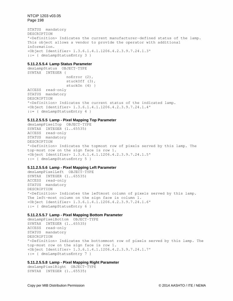
NTCIP 1203 v03.05 Page 198 STATUS mandatory DESCRIPTION "<Definition> Indicates the current manufacturer-defined status of the lamp. This object allows a vendor to provide the operator with additional information. <Object Identifier> 1.3.6.1.4.1.1206.4.2.3.9.7.24.1.3" ::= { dmsLampStatusEntry 3 } 5.11.2.5.5.4 Lamp Status Parameter dmsLampStatus OBJECT-TYPE SYNTAX INTEGER { noError (2), stuckOff (3), stuckOn (4) } ACCESS read-only STATUS mandatory DESCRIPTION "<Definition> Indicates the current status of the indicated lamp. <Object Identifier> 1.3.6.1.4.1.1206.4.2.3.9.7.24.1.4" ::= { dmsLampStatusEntry 4 } 5.11.2.5.5.5 Lamp - Pixel Mapping Top Parameter dmsLampPixelTop OBJECT-TYPE SYNTAX INTEGER (1..65535) ACCESS read-only STATUS mandatory DESCRIPTION "<Definition> Indicates the topmost row of pixels served by this lamp. The top-most row on the sign face is row 1. <Object Identifier> 1.3.6.1.4.1.1206.4.2.3.9.7.24.1.5" ::= { dmsLampStatusEntry 5 } 5.11.2.5.5.6 Lamp - Pixel Mapping Left Parameter dmsLampPixelLeft OBJECT-TYPE SYNTAX INTEGER (1..65535) ACCESS read-only STATUS mandatory DESCRIPTION "<Definition> Indicates the leftmost column of pixels served by this lamp. The left-most column on the sign face is column 1. <Object Identifier> 1.3.6.1.4.1.1206.4.2.3.9.7.24.1.6" ::= { dmsLampStatusEntry 6 } 5.11.2.5.5.7 Lamp - Pixel Mapping Bottom Parameter dmsLampPixelBottom OBJECT-TYPE SYNTAX INTEGER (1..65535) ACCESS read-only STATUS mandatory DESCRIPTION "<Definition> Indicates the bottommost row of pixels served by this lamp. The top-most row on the sign face is row 1. <Object Identifier> 1.3.6.1.4.1.1206.4.2.3.9.7.24.1.7" ::= { dmsLampStatusEntry 7 } 5.11.2.5.5.8 Lamp - Pixel Mapping Right Parameter dmsLampPixelRight OBJECT-TYPE SYNTAX INTEGER (1..65535)
Copy per MIB Distribution Permission © 2014 AASHTO / ITE / NEMA
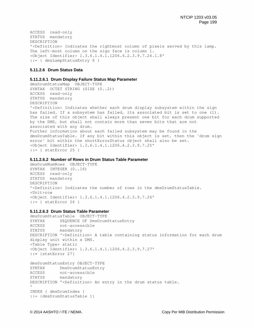
NTCIP 1203 v03.05 Page 199
ACCESS read-only STATUS mandatory DESCRIPTION "<Definition> Indicates the rightmost column of pixels served by this lamp. The left-most column on the sign face is column 1. <Object Identifier> 1.3.6.1.4.1.1206.4.2.3.9.7.24.1.8" ::= { dmsLampStatusEntry 8 } 5.11.2.6 Drum Status Data 5.11.2.6.1 Drum Display Failure Status Map Parameter dmsDrumStatusMap OBJECT-TYPE SYNTAX OCTET STRING (SIZE (0..2)) ACCESS read-only STATUS mandatory DESCRIPTION "<Definition> Indicates whether each drum display subsystem within the sign has failed. If a subsystem has failed, its associated bit is set to one (1). The size of this object shall always present one bit for each drum supported by the DMS, but shall not contain more than seven bits that are not associated with any drum. Further information about each failed subsystem may be found in the dmsDrumStatusTable. If any bit within this object is set, then the 'drum sign error' bit within the shortErrorStatus object shall also be set. <Object Identifier> 1.3.6.1.4.1.1206.4.2.3.9.7.25" ::= { statError 25 } 5.11.2.6.2 Number of Rows in Drum Status Table Parameter dmsDrumNumRows OBJECT-TYPE SYNTAX INTEGER (0..16) ACCESS read-only STATUS mandatory DESCRIPTION "<Definition> Indicates the number of rows in the dmsDrumStatusTable. <Unit>row <Object Identifier> 1.3.6.1.4.1.1206.4.2.3.9.7.26" ::= { statError 26 } 5.11.2.6.3 Drum Status Table Parameter dmsDrumStatusTable OBJECT-TYPE SYNTAX SEQUENCE OF DmsDrumStatusEntry ACCESS not-accessible STATUS mandatory DESCRIPTION "<Definition> A table containing status information for each drum display unit within a DMS. <Table Type> static <Object Identifier> 1.3.6.1.4.1.1206.4.2.3.9.7.27" ::= {statError 27} dmsDrumStatusEntry OBJECT-TYPE SYNTAX DmsDrumStatusEntry ACCESS not-accessible STATUS mandatory DESCRIPTION "<Definition> An entry in the drum status table. " INDEX { dmsDrumIndex } ::= {dmsDrumStatusTable 1}
© 2014 AASHTO / ITE / NEMA. Copy Per MIB Distribution Permission
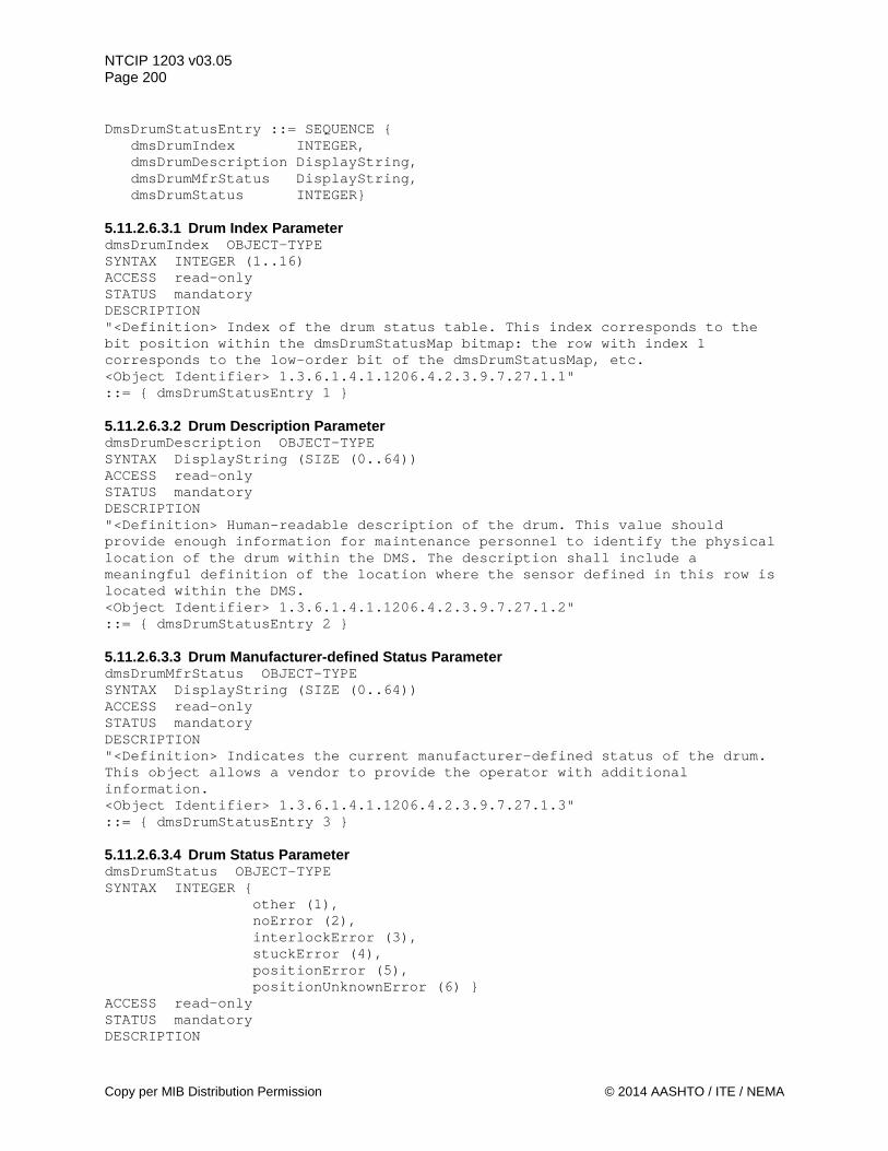
NTCIP 1203 v03.05 Page 200 DmsDrumStatusEntry ::= SEQUENCE { dmsDrumIndex INTEGER, dmsDrumDescription DisplayString, dmsDrumMfrStatus DisplayString, dmsDrumStatus INTEGER} 5.11.2.6.3.1 Drum Index Parameter dmsDrumIndex OBJECT-TYPE SYNTAX INTEGER (1..16) ACCESS read-only STATUS mandatory DESCRIPTION "<Definition> Index of the drum status table. This index corresponds to the bit position within the dmsDrumStatusMap bitmap: the row with index 1 corresponds to the low-order bit of the dmsDrumStatusMap, etc. <Object Identifier> 1.3.6.1.4.1.1206.4.2.3.9.7.27.1.1" ::= { dmsDrumStatusEntry 1 } 5.11.2.6.3.2 Drum Description Parameter dmsDrumDescription OBJECT-TYPE SYNTAX DisplayString (SIZE (0..64)) ACCESS read-only STATUS mandatory DESCRIPTION "<Definition> Human-readable description of the drum. This value should provide enough information for maintenance personnel to identify the physical location of the drum within the DMS. The description shall include a meaningful definition of the location where the sensor defined in this row is located within the DMS. <Object Identifier> 1.3.6.1.4.1.1206.4.2.3.9.7.27.1.2" ::= { dmsDrumStatusEntry 2 } 5.11.2.6.3.3 Drum Manufacturer-defined Status Parameter dmsDrumMfrStatus OBJECT-TYPE SYNTAX DisplayString (SIZE (0..64)) ACCESS read-only STATUS mandatory DESCRIPTION "<Definition> Indicates the current manufacturer-defined status of the drum. This object allows a vendor to provide the operator with additional information. <Object Identifier> 1.3.6.1.4.1.1206.4.2.3.9.7.27.1.3" ::= { dmsDrumStatusEntry 3 } 5.11.2.6.3.4 Drum Status Parameter dmsDrumStatus OBJECT-TYPE SYNTAX INTEGER { other (1), noError (2), interlockError (3), stuckError (4), positionError (5), positionUnknownError (6) } ACCESS read-only STATUS mandatory DESCRIPTION
Copy per MIB Distribution Permission © 2014 AASHTO / ITE / NEMA
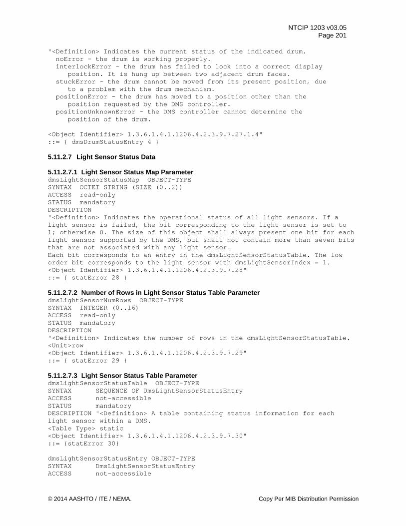
NTCIP 1203 v03.05 Page 201
"<Definition> Indicates the current status of the indicated drum. noError - the drum is working properly. interlockError - the drum has failed to lock into a correct display position. It is hung up between two adjacent drum faces. stuckError - the drum cannot be moved from its present position, due to a problem with the drum mechanism. positionError - the drum has moved to a position other than the position requested by the DMS controller. positionUnknownError - the DMS controller cannot determine the position of the drum. <Object Identifier> 1.3.6.1.4.1.1206.4.2.3.9.7.27.1.4" ::= { dmsDrumStatusEntry 4 } 5.11.2.7 Light Sensor Status Data 5.11.2.7.1 Light Sensor Status Map Parameter dmsLightSensorStatusMap OBJECT-TYPE SYNTAX OCTET STRING (SIZE (0..2)) ACCESS read-only STATUS mandatory DESCRIPTION "<Definition> Indicates the operational status of all light sensors. If a light sensor is failed, the bit corresponding to the light sensor is set to 1; otherwise 0. The size of this object shall always present one bit for each light sensor supported by the DMS, but shall not contain more than seven bits that are not associated with any light sensor. Each bit corresponds to an entry in the dmsLightSensorStatusTable. The low order bit corresponds to the light sensor with dmsLightSensorIndex = 1. <Object Identifier> 1.3.6.1.4.1.1206.4.2.3.9.7.28" ::= { statError 28 } 5.11.2.7.2 Number of Rows in Light Sensor Status Table Parameter dmsLightSensorNumRows OBJECT-TYPE SYNTAX INTEGER (0..16) ACCESS read-only STATUS mandatory DESCRIPTION "<Definition> Indicates the number of rows in the dmsLightSensorStatusTable. <Unit>row <Object Identifier> 1.3.6.1.4.1.1206.4.2.3.9.7.29" ::= { statError 29 } 5.11.2.7.3 Light Sensor Status Table Parameter dmsLightSensorStatusTable OBJECT-TYPE SYNTAX SEQUENCE OF DmsLightSensorStatusEntry ACCESS not-accessible STATUS mandatory DESCRIPTION "<Definition> A table containing status information for each light sensor within a DMS. <Table Type> static <Object Identifier> 1.3.6.1.4.1.1206.4.2.3.9.7.30" ::= {statError 30} dmsLightSensorStatusEntry OBJECT-TYPE SYNTAX DmsLightSensorStatusEntry ACCESS not-accessible
© 2014 AASHTO / ITE / NEMA. Copy Per MIB Distribution Permission
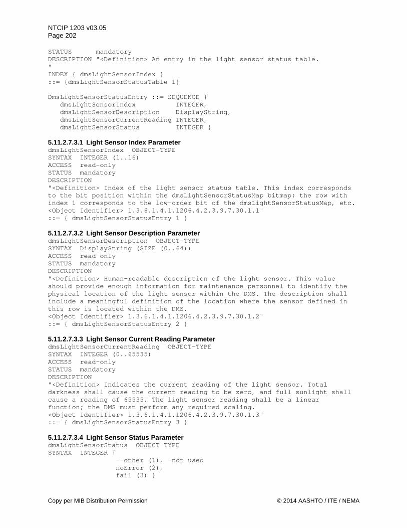
NTCIP 1203 v03.05 Page 202 STATUS mandatory DESCRIPTION "<Definition> An entry in the light sensor status table. " INDEX { dmsLightSensorIndex } ::= {dmsLightSensorStatusTable 1} DmsLightSensorStatusEntry ::= SEQUENCE { dmsLightSensorIndex INTEGER, dmsLightSensorDescription DisplayString, dmsLightSensorCurrentReading INTEGER, dmsLightSensorStatus INTEGER } 5.11.2.7.3.1 Light Sensor Index Parameter dmsLightSensorIndex OBJECT-TYPE SYNTAX INTEGER (1..16) ACCESS read-only STATUS mandatory DESCRIPTION "<Definition> Index of the light sensor status table. This index corresponds to the bit position within the dmsLightSensorStatusMap bitmap: the row with index 1 corresponds to the low-order bit of the dmsLightSensorStatusMap, etc. <Object Identifier> 1.3.6.1.4.1.1206.4.2.3.9.7.30.1.1" ::= { dmsLightSensorStatusEntry 1 } 5.11.2.7.3.2 Light Sensor Description Parameter dmsLightSensorDescription OBJECT-TYPE SYNTAX DisplayString (SIZE (0..64)) ACCESS read-only STATUS mandatory DESCRIPTION "<Definition> Human-readable description of the light sensor. This value should provide enough information for maintenance personnel to identify the physical location of the light sensor within the DMS. The description shall include a meaningful definition of the location where the sensor defined in this row is located within the DMS. <Object Identifier> 1.3.6.1.4.1.1206.4.2.3.9.7.30.1.2" ::= { dmsLightSensorStatusEntry 2 } 5.11.2.7.3.3 Light Sensor Current Reading Parameter dmsLightSensorCurrentReading OBJECT-TYPE SYNTAX INTEGER (0..65535) ACCESS read-only STATUS mandatory DESCRIPTION "<Definition> Indicates the current reading of the light sensor. Total darkness shall cause the current reading to be zero, and full sunlight shall cause a reading of 65535. The light sensor reading shall be a linear function; the DMS must perform any required scaling. <Object Identifier> 1.3.6.1.4.1.1206.4.2.3.9.7.30.1.3" ::= { dmsLightSensorStatusEntry 3 } 5.11.2.7.3.4 Light Sensor Status Parameter dmsLightSensorStatus OBJECT-TYPE SYNTAX INTEGER { --other (1), -not used noError (2), fail (3) }
Copy per MIB Distribution Permission © 2014 AASHTO / ITE / NEMA
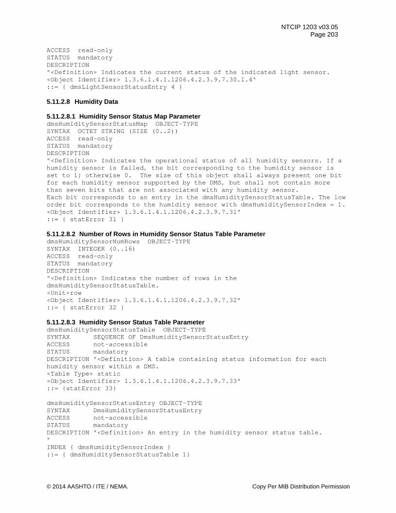
NTCIP 1203 v03.05 Page 203
ACCESS read-only STATUS mandatory DESCRIPTION "<Definition> Indicates the current status of the indicated light sensor. <Object Identifier> 1.3.6.1.4.1.1206.4.2.3.9.7.30.1.4" ::= { dmsLightSensorStatusEntry 4 } 5.11.2.8 Humidity Data 5.11.2.8.1 Humidity Sensor Status Map Parameter dmsHumiditySensorStatusMap OBJECT-TYPE SYNTAX OCTET STRING (SIZE (0..2)) ACCESS read-only STATUS mandatory DESCRIPTION "<Definition> Indicates the operational status of all humidity sensors. If a humidity sensor is failed, the bit corresponding to the humidity sensor is set to 1; otherwise 0. The size of this object shall always present one bit for each humidity sensor supported by the DMS, but shall not contain more than seven bits that are not associated with any humidity sensor. Each bit corresponds to an entry in the dmsHumiditySensorStatusTable. The low order bit corresponds to the humidity sensor with dmsHumiditySensorIndex = 1. <Object Identifier> 1.3.6.1.4.1.1206.4.2.3.9.7.31" ::= { statError 31 } 5.11.2.8.2 Number of Rows in Humidity Sensor Status Table Parameter dmsHumiditySensorNumRows OBJECT-TYPE SYNTAX INTEGER (0..16) ACCESS read-only STATUS mandatory DESCRIPTION "<Definition> Indicates the number of rows in the dmsHumiditySensorStatusTable. <Unit>row <Object Identifier> 1.3.6.1.4.1.1206.4.2.3.9.7.32" ::= { statError 32 } 5.11.2.8.3 Humidity Sensor Status Table Parameter dmsHumiditySensorStatusTable OBJECT-TYPE SYNTAX SEQUENCE OF DmsHumiditySensorStatusEntry ACCESS not-accessible STATUS mandatory DESCRIPTION "<Definition> A table containing status information for each humidity sensor within a DMS. <Table Type> static <Object Identifier> 1.3.6.1.4.1.1206.4.2.3.9.7.33" ::= {statError 33} dmsHumiditySensorStatusEntry OBJECT-TYPE SYNTAX DmsHumiditySensorStatusEntry ACCESS not-accessible STATUS mandatory DESCRIPTION "<Definition> An entry in the humidity sensor status table. " INDEX { dmsHumiditySensorIndex } ::= { dmsHumiditySensorStatusTable 1}
© 2014 AASHTO / ITE / NEMA. Copy Per MIB Distribution Permission
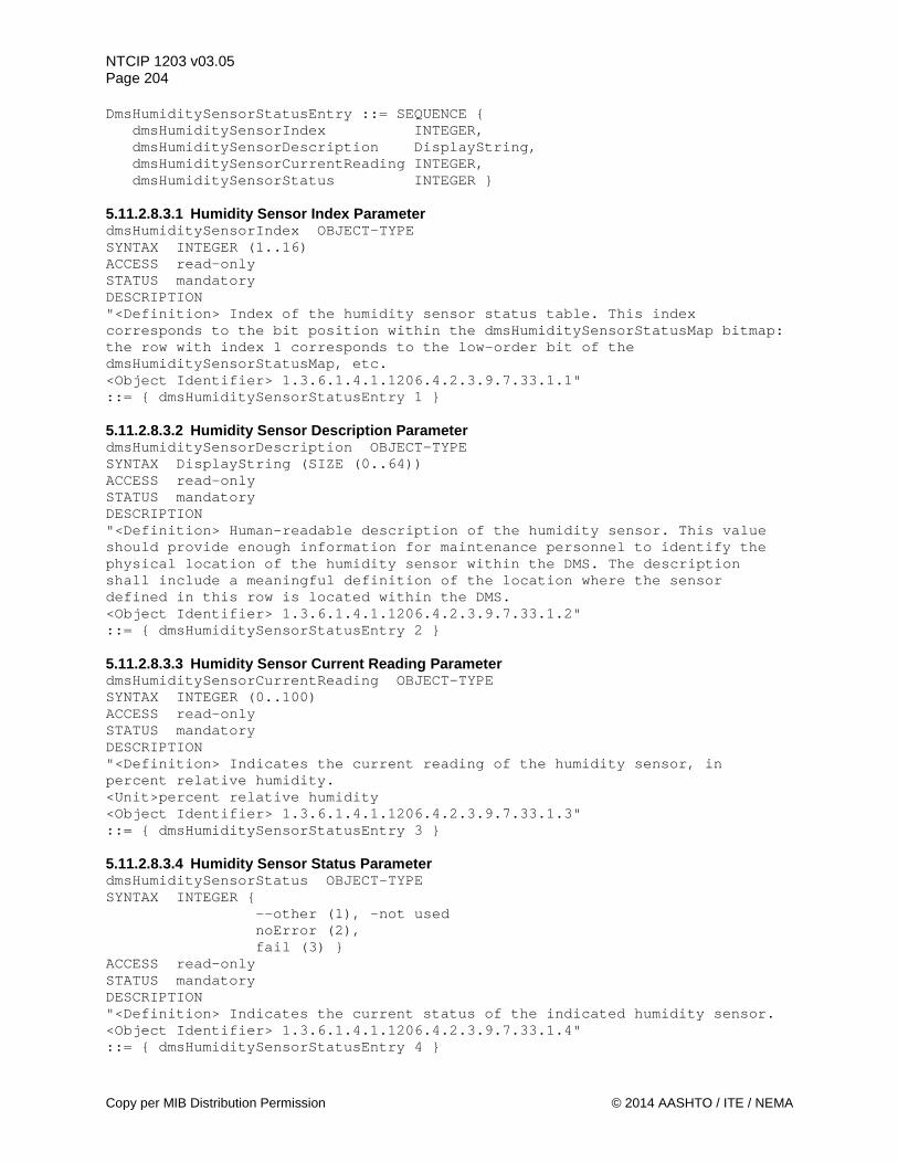
NTCIP 1203 v03.05 Page 204 DmsHumiditySensorStatusEntry ::= SEQUENCE { dmsHumiditySensorIndex INTEGER, dmsHumiditySensorDescription DisplayString, dmsHumiditySensorCurrentReading INTEGER, dmsHumiditySensorStatus INTEGER } 5.11.2.8.3.1 Humidity Sensor Index Parameter dmsHumiditySensorIndex OBJECT-TYPE SYNTAX INTEGER (1..16) ACCESS read-only STATUS mandatory DESCRIPTION "<Definition> Index of the humidity sensor status table. This index corresponds to the bit position within the dmsHumiditySensorStatusMap bitmap: the row with index 1 corresponds to the low-order bit of the dmsHumiditySensorStatusMap, etc. <Object Identifier> 1.3.6.1.4.1.1206.4.2.3.9.7.33.1.1" ::= { dmsHumiditySensorStatusEntry 1 } 5.11.2.8.3.2 Humidity Sensor Description Parameter dmsHumiditySensorDescription OBJECT-TYPE SYNTAX DisplayString (SIZE (0..64)) ACCESS read-only STATUS mandatory DESCRIPTION "<Definition> Human-readable description of the humidity sensor. This value should provide enough information for maintenance personnel to identify the physical location of the humidity sensor within the DMS. The description shall include a meaningful definition of the location where the sensor defined in this row is located within the DMS. <Object Identifier> 1.3.6.1.4.1.1206.4.2.3.9.7.33.1.2" ::= { dmsHumiditySensorStatusEntry 2 } 5.11.2.8.3.3 Humidity Sensor Current Reading Parameter dmsHumiditySensorCurrentReading OBJECT-TYPE SYNTAX INTEGER (0..100) ACCESS read-only STATUS mandatory DESCRIPTION "<Definition> Indicates the current reading of the humidity sensor, in percent relative humidity. <Unit>percent relative humidity <Object Identifier> 1.3.6.1.4.1.1206.4.2.3.9.7.33.1.3" ::= { dmsHumiditySensorStatusEntry 3 } 5.11.2.8.3.4 Humidity Sensor Status Parameter dmsHumiditySensorStatus OBJECT-TYPE SYNTAX INTEGER { --other (1), -not used noError (2), fail (3) } ACCESS read-only STATUS mandatory DESCRIPTION "<Definition> Indicates the current status of the indicated humidity sensor. <Object Identifier> 1.3.6.1.4.1.1206.4.2.3.9.7.33.1.4" ::= { dmsHumiditySensorStatusEntry 4 }
Copy per MIB Distribution Permission © 2014 AASHTO / ITE / NEMA
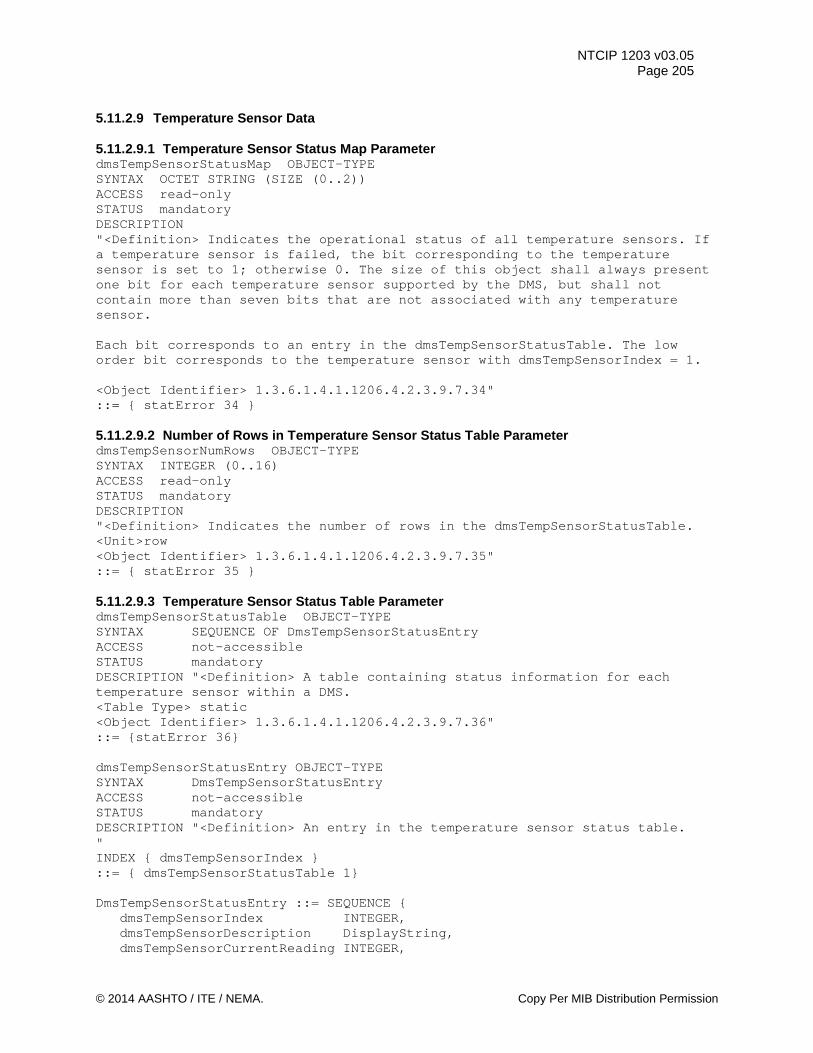
NTCIP 1203 v03.05 Page 205
5.11.2.9 Temperature Sensor Data 5.11.2.9.1 Temperature Sensor Status Map Parameter dmsTempSensorStatusMap OBJECT-TYPE SYNTAX OCTET STRING (SIZE (0..2)) ACCESS read-only STATUS mandatory DESCRIPTION "<Definition> Indicates the operational status of all temperature sensors. If a temperature sensor is failed, the bit corresponding to the temperature sensor is set to 1; otherwise 0. The size of this object shall always present one bit for each temperature sensor supported by the DMS, but shall not contain more than seven bits that are not associated with any temperature sensor. Each bit corresponds to an entry in the dmsTempSensorStatusTable. The low order bit corresponds to the temperature sensor with dmsTempSensorIndex = 1. <Object Identifier> 1.3.6.1.4.1.1206.4.2.3.9.7.34" ::= { statError 34 } 5.11.2.9.2 Number of Rows in Temperature Sensor Status Table Parameter dmsTempSensorNumRows OBJECT-TYPE SYNTAX INTEGER (0..16) ACCESS read-only STATUS mandatory DESCRIPTION "<Definition> Indicates the number of rows in the dmsTempSensorStatusTable. <Unit>row <Object Identifier> 1.3.6.1.4.1.1206.4.2.3.9.7.35" ::= { statError 35 } 5.11.2.9.3 Temperature Sensor Status Table Parameter dmsTempSensorStatusTable OBJECT-TYPE SYNTAX SEQUENCE OF DmsTempSensorStatusEntry ACCESS not-accessible STATUS mandatory DESCRIPTION "<Definition> A table containing status information for each temperature sensor within a DMS. <Table Type> static <Object Identifier> 1.3.6.1.4.1.1206.4.2.3.9.7.36" ::= {statError 36} dmsTempSensorStatusEntry OBJECT-TYPE SYNTAX DmsTempSensorStatusEntry ACCESS not-accessible STATUS mandatory DESCRIPTION "<Definition> An entry in the temperature sensor status table. " INDEX { dmsTempSensorIndex } ::= { dmsTempSensorStatusTable 1} DmsTempSensorStatusEntry ::= SEQUENCE { dmsTempSensorIndex INTEGER, dmsTempSensorDescription DisplayString, dmsTempSensorCurrentReading INTEGER,
© 2014 AASHTO / ITE / NEMA. Copy Per MIB Distribution Permission
NTCIP 1203 v03.05 Page 206 dmsTempSensorHighWarningTemperature INTEGER, dmsTempSensorLowWarningTemperature INTEGER, dmsTempSensorHighCriticalTemperature INTEGER, dmsTempSensorLowCriticalTemperature INTEGER, dmsTempSensorStatus INTEGER } 5.11.2.9.3.1 Temperature Sensor Index Parameter dmsTempSensorIndex OBJECT-TYPE SYNTAX INTEGER (1..16) ACCESS read-only STATUS mandatory DESCRIPTION "<Definition> Index of the temperature sensor status table. This index corresponds to the bit position within the dmsTempSensorStatusMap bitmap: the row with index 1 corresponds to the low-order bit of the dmsTempSensorStatusMap, etc. <Object Identifier> 1.3.6.1.4.1.1206.4.2.3.9.7.36.1.1" ::= { dmsTempSensorStatusEntry 1 } 5.11.2.9.3.2 Temperature Sensor Description Parameter dmsTempSensorDescription OBJECT-TYPE SYNTAX DisplayString (SIZE (0..64)) ACCESS read-only STATUS mandatory DESCRIPTION "<Definition> Human-readable description of the temperature sensor. This value should provide enough information for maintenance personnel to identify the physical location of the temperature sensor within the DMS. <Object Identifier> 1.3.6.1.4.1.1206.4.2.3.9.7.36.1.2" ::= { dmsTempSensorStatusEntry 2 } 5.11.2.9.3.3 Temperature Sensor Current Reading Parameter dmsTempSensorCurrentReading OBJECT-TYPE SYNTAX INTEGER (-128..127) ACCESS read-only STATUS mandatory DESCRIPTION "<Definition> Indicates the current reading of the temperature sensor in full degrees Celsius. <Unit>degrees Celsius <Object Identifier> 1.3.6.1.4.1.1206.4.2.3.9.7.36.1.3" ::= { dmsTempSensorStatusEntry 3 } 5.11.2.9.3.4 Temperature Sensor High Warning Temperature Parameter dmsTempSensorHighWarningTemperature OBJECT-TYPE SYNTAX INTEGER (-128..127) ACCESS read-only STATUS mandatory DESCRIPTION "<Definition> Indicates the high value of the temperature associated with this temperature sensor that generates a warning, in full degrees Celsius. This value should not be lower than the value of the dmsTempSensorLowWarningTemperature object. <Unit>degrees Celsius <Object Identifier> 1.3.6.1.4.1.1206.4.2.3.9.7.36.1.4" ::= { dmsTempSensorStatusEntry 4 }
Copy per MIB Distribution Permission © 2014 AASHTO / ITE / NEMA
NTCIP 1203 v03.05 Page 207
5.11.2.9.3.5 Temperature Sensor Low Warning Temperature Parameter dmsTempSensorLowWarningTemperature OBJECT-TYPE SYNTAX INTEGER (-128..127) ACCESS read-only STATUS mandatory DESCRIPTION "<Definition> Indicates the low value of the temperature associated with this temperature sensor that generates a warning, in full degrees Celsius. This value should not be higher than the value of the dmsTempSensorHighWarningTemperature object. <Unit>degrees Celsius <Object Identifier> 1.3.6.1.4.1.1206.4.2.3.9.7.36.1.5" ::= { dmsTempSensorStatusEntry 5 } 5.11.2.9.3.6 Temperature Sensor High Critical Temperature Parameter dmsTempSensorHighCriticalTemperature OBJECT-TYPE SYNTAX INTEGER (-128..127) ACCESS read-only STATUS mandatory DESCRIPTION "<Definition> Indicates the high value of the critical temperature associated with this temperature sensor, in full degrees Celsius. This value shall not be lower than the value of the dmsTempSensorLowCriticalTemperature object. <Unit>degrees Celsius <Object Identifier> 1.3.6.1.4.1.1206.4.2.3.9.7.36.1.6" ::= { dmsTempSensorStatusEntry 6 } 5.11.2.9.3.7 Temperature Sensor Low Critical Temperature Parameter dmsTempSensorLowCriticalTemperature OBJECT-TYPE SYNTAX INTEGER (-128..127) ACCESS read-only STATUS mandatory DESCRIPTION "<Definition> Indicates the low value of the critical temperature associated with this temperature sensor, in full degrees Celsius. This value shall not be higher than the value of the dmsTempSensorHighCriticalTemperature object. <Unit>degrees Celsius <Object Identifier> 1.3.6.1.4.1.1206.4.2.3.9.7.36.1.7" ::= { dmsTempSensorStatusEntry 7 } 5.11.2.9.3.8 Temperature Sensor Status Parameter dmsTempSensorStatus OBJECT-TYPE SYNTAX INTEGER { other (1), noError (2), fail (3) } ACCESS read-only STATUS mandatory DESCRIPTION "<Definition> Indicates the current status of the indicated temperature sensor. <Object Identifier> 1.3.6.1.4.1.1206.4.2.3.9.7.36.1.8" ::= { dmsTempSensorStatusEntry 8 } 5.11.2.9.4 Temperature Sensor Highest Critical Temperature Parameter dmsTempSensorHighestCriticalTempThreshold OBJECT-TYPE
© 2014 AASHTO / ITE / NEMA. Copy Per MIB Distribution Permission
NTCIP 1203 v03.05 Page 208 SYNTAX INTEGER (-128..127) ACCESS read-only STATUS mandatory DESCRIPTION "<Definition> Indicates the highest value of the critical temperature threshold associated with any of the supported temperature sensors in the DMS, in full degrees Celsius. This value shall not be lower than any of the high critical values of any of the dmsTempSensorHighCriticalTemperature objects within the dmsTempSensorStatusTable. <Unit>degrees Celsius <Object Identifier> 1.3.6.1.4.1.1206.4.2.3.9.7.37" ::= { statError 37 } 5.11.2.9.5 Temperature Sensor Lowest Critical Temperature Parameter dmsTempSensorLowestCriticalTempThreshold OBJECT-TYPE SYNTAX INTEGER (-128..127) ACCESS read-only STATUS mandatory DESCRIPTION "<Definition> Indicates the lowest value of the critical temperature threshold associated with any of the supported temperature sensors in the DMS, in full degrees Celsius. This value shall not be higher than any of the low critical values of any of the dmsTempSensorLowCriticalTemperature objects within the dmsTempSensorStatusTable. <Unit>degrees Celsius <Object Identifier> 1.3.6.1.4.1.1206.4.2.3.9.7.38" ::= { statError 38 } 5.11.3 Power Status Objects statPower OBJECT IDENTIFIER ::= { dmsStatus 8 } -- This node is an identifier used to group all objects supporting DMS sign power status monitoring functions that are common to DMS devices. 5.11.3.1 Sign Volts Parameter signVolts OBJECT-TYPE SYNTAX INTEGER (0..65535) ACCESS read-only STATUS mandatory DESCRIPTION "<Definition> A voltage measurement in units of hundredth (1/100) of a volt. The maximum value (0xFFFF) corresponds to a voltage of 655.35 volts. This is an indication of the sign battery voltage. <Object Identifier> 1.3.6.1.4.1.1206.4.2.3.9.8.1" ::= { statPower 1 } 5.11.3.2 Low Fuel Threshold Parameter lowFuelThreshold OBJECT-TYPE SYNTAX INTEGER (0..100) ACCESS read-write STATUS mandatory DESCRIPTION "<Definition> Indicates the low fuel level threshold used to alert the user. The threshold is indicated as a percent (%) of a full tank. When the level of fuel is below the threshold, the bit for power alarm (bit 2) in the shortErrorStatus-object shall be set to one (1). <Object Identifier> 1.3.6.1.4.1.1206.4.2.3.9.8.2" ::= { statPower 2 }
Copy per MIB Distribution Permission © 2014 AASHTO / ITE / NEMA
NTCIP 1203 v03.05 Page 209
5.11.3.3 Fuel Level Parameter fuelLevel OBJECT-TYPE SYNTAX INTEGER (0..100) ACCESS read-only STATUS mandatory DESCRIPTION "<Definition> A number indicating the amount of fuel remaining, specified as a percent (%) of a full tank. <Object Identifier> 1.3.6.1.4.1.1206.4.2.3.9.8.3" ::= { statPower 3 } 5.11.3.4 Engine RPM Parameter engineRPM OBJECT-TYPE SYNTAX INTEGER (0..255) ACCESS read-only STATUS mandatory DESCRIPTION "<Definition> Indicates the engine rpm in units of 100. This provides a range from 0 rpm to 25500 rpm. <Object Identifier> 1.3.6.1.4.1.1206.4.2.3.9.8.4" ::= { statPower 4 } 5.11.3.5 Line Volts Parameter lineVolts OBJECT-TYPE SYNTAX INTEGER (0..255) ACCESS read-only STATUS mandatory DESCRIPTION "<Definition> The DMS line voltage measurement in (1.0) volts. The range is 0 volts to 255 volts. <Object Identifier> 1.3.6.1.4.1.1206.4.2.3.9.8.5" ::= { statPower 5 } 5.11.3.6 Power Source Parameter powerSource OBJECT-TYPE SYNTAX INTEGER { other (1), powerShutdown (2), noSignPower (3), acLine (4), generator (5), solar (6), battery-UPS (7) } ACCESS read-only STATUS mandatory DESCRIPTION "<Definition> Indicates the source of power that is currently utilized by the sign. other: indicates that the sign is powered by a method not listed below (see device manual); powerShutdown: indicates that there is just enough power to perform shutdown activities. noSignPower: indicates that the sign controller has power but the sign display has no power; acLine: indicates that the controller and sign is powered by AC power;
© 2014 AASHTO / ITE / NEMA. Copy Per MIB Distribution Permission
NTCIP 1203 v03.05 Page 210 generator: indicates that the sign and the controller are powered by a generator; solar: indicates that the sign and the controller are powered by solar equipment; battery-UPS: indicates that the sign and controller are powered by battery or UPS with no significant charging occurring. <Object Identifier> 1.3.6.1.4.1.1206.4.2.3.9.8.6" ::= { statPower 6 } 5.11.4 Temperature Status Objects statTemp OBJECT IDENTIFIER ::= { dmsStatus 9 } -- This node is an identifier used to group all objects supporting DMS sign temperature status monitoring functions that are common to DMS devices. 5.11.4.1 Minimum Temperature of Control Cabinet Parameter tempMinCtrlCabinet OBJECT-TYPE SYNTAX INTEGER (-128..127) ACCESS read-only STATUS mandatory DESCRIPTION "<Definition> Indicates the current temperature (single sensor) or the current minimum temperature (multiple sensors) within the DMS Control Cabinet in degrees Celsius. <Unit>degrees Celsius <Object Identifier> 1.3.6.1.4.1.1206.4.2.3.9.9.1" ::= { statTemp 1 } 5.11.4.2 Maximum Temperature of Control Cabinet Parameter tempMaxCtrlCabinet OBJECT-TYPE SYNTAX INTEGER (-128..127) ACCESS read-only STATUS mandatory DESCRIPTION "<Definition> Indicates the current temperature (single sensor) or the current maximum temperature (multiple sensors) within the DMS Control Cabinet in degrees Celsius. <Unit>degrees Celsius <Object Identifier> 1.3.6.1.4.1.1206.4.2.3.9.9.2" ::= { statTemp 2 } 5.11.4.3 Minimum Ambient Temperature Parameter tempMinAmbient OBJECT-TYPE SYNTAX INTEGER (-128..127) ACCESS read-only STATUS mandatory DESCRIPTION "<Definition> Indicates the current outside ambient temperature (single sensor) or the current minimum outside ambient temperature (multiple sensors) in degrees Celsius. <Unit>degrees Celsius <Object Identifier> 1.3.6.1.4.1.1206.4.2.3.9.9.3" ::= { statTemp 3 } 5.11.4.4 Maximum Ambient Temperature Parameter tempMaxAmbient OBJECT-TYPE SYNTAX INTEGER (-128..127)
Copy per MIB Distribution Permission © 2014 AASHTO / ITE / NEMA
NTCIP 1203 v03.05 Page 211
ACCESS read-only STATUS mandatory DESCRIPTION "<Definition> Indicates the current outside ambient temperature (single sensor) or the current maximum outside ambient temperature (multiple sensors) in degrees Celsius. <Unit>degrees Celsius <Object Identifier> 1.3.6.1.4.1.1206.4.2.3.9.9.4" ::= { statTemp 4 } 5.11.4.5 Minimum Temperature of Sign Housing Parameter tempMinSignHousing OBJECT-TYPE SYNTAX INTEGER (-128..127) ACCESS read-only STATUS mandatory DESCRIPTION "<Definition> Indicates the current temperature (single sensor) or the current minimum temperature (multiple sensors) in the sign housing in degrees Celsius. <Unit>degrees Celsius <Object Identifier> 1.3.6.1.4.1.1206.4.2.3.9.9.5" ::= { statTemp 5 } 5.11.4.6 Maximum Temperature of Sign Housing Parameter tempMaxSignHousing OBJECT-TYPE SYNTAX INTEGER (-128..127) ACCESS read-only STATUS mandatory DESCRIPTION "<Definition> Indicates the current temperature (single sensor) or the current maximum temperature (multiple sensors) in the sign housing in degrees Celsius. <Unit>degrees Celsius <Object Identifier> 1.3.6.1.4.1.1206.4.2.3.9.9.6" ::= { statTemp 6 } 5.11.4.7 Temperature Sensor Warning Parameter tempSensorWarningMap OBJECT-TYPE SYNTAX OCTET STRING (SIZE (0..2)) ACCESS read-only STATUS mandatory DESCRIPTION "<Definition> Indicates whether each temperature sensor has exceeded a dmsTempSensorHighWarningTemperature or dmsTempSensorLowWarningTemperature value. If a temperature sensor has exceeded the defined value, the bit corresponding to the temperature sensor is set to 1; otherwise 0. The mapping of bits to individual sensors is manufacturer specific. This bitmap of this object shall be configured as defined in the dmsTempSensorStatusTable in that the first bit of this object shall correspond to the first row in that table, the second bit shall correspond to the second row, and so forth. <Object Identifier> 1.3.6.1.4.1.1206.4.2.3.9.9.7" ::= { statTemp 7 } 5.11.4.8 Critical Temperature Map Parameter tempSensorCriticalTempMap OBJECT-TYPE SYNTAX OCTET STRING (SIZE (0..2)) ACCESS read-only
© 2014 AASHTO / ITE / NEMA. Copy Per MIB Distribution Permission
NTCIP 1203 v03.05 Page 212 STATUS mandatory DESCRIPTION "<Definition> Indicates whether each temperature sensor has exceeded the dmsTempSensorHighCriticalTemperature or the dmsTempSensorLowCriticalTemperature threshold. If a temperature sensor has exceeded the defined value, the bit corresponding to the temperature sensor is set to 1; otherwise 0. The mapping of bits to individual sensors is manufacturer specific. This bitmap of this object shall be configured as defined in the dmsTempSensorStatusTable in that the first bit of this object shall correspond to the first row in that table, the second bit shall correspond to the second row, and so forth. <Object Identifier> 1.3.6.1.4.1.1206.4.2.3.9.9.8" ::= { statTemp 8 } 5.12 Graphic Definition Objects graphicDefinition OBJECT IDENTIFIER ::= { dms 10 } -- This node is an identifier used to group all objects for DMS graphic -- configurations that are common to DMS devices. 5.12.1 Maximum Number of Graphics Parameter dmsGraphicMaxEntries OBJECT-TYPE SYNTAX INTEGER (0..255) ACCESS read-only STATUS mandatory DESCRIPTION "<Definition> Indicates the maximum number of graphics that the sign can store. <Unit>graphic <Object Identifier> 1.3.6.1.4.1.1206.4.2.3.10.1" ::= { graphicDefinition 1 } 5.12.2 Number of Graphics Parameter dmsGraphicNumEntries OBJECT-TYPE SYNTAX INTEGER (0..255) ACCESS read-only STATUS mandatory DESCRIPTION "<Definition> Indicates the number of graphics currently stored within the sign. <Unit>graphic <Object Identifier> 1.3.6.1.4.1.1206.4.2.3.10.2" ::= { graphicDefinition 2 } 5.12.3 Maximum Graphic Size Parameter dmsGraphicMaxSize OBJECT-TYPE SYNTAX INTEGER (0..65535) ACCESS read-only STATUS mandatory DESCRIPTION "<Definition> Indicates the maximum size (in bytes) of each graphic the sign is capable of storing. This value shall be an even multiple of the object dmsGraphicBlockSize. <Unit>byte <Object Identifier> 1.3.6.1.4.1.1206.4.2.3.10.3" ::= { graphicDefinition 3 }
Copy per MIB Distribution Permission © 2014 AASHTO / ITE / NEMA
NTCIP 1203 v03.05 Page 213
5.12.4 Available Graphic Memory Parameter availableGraphicMemory OBJECT-TYPE SYNTAX Counter ACCESS read-only STATUS mandatory DESCRIPTION "<Definition> An indication of the amount of memory left, in bytes, to store graphics. <Unit>byte <Object Identifier> 1.3.6.1.4.1.1206.4.2.3.10.4" ::= { graphicDefinition 4 } 5.12.5 Graphic Block Size Parameter dmsGraphicBlockSize OBJECT-TYPE SYNTAX INTEGER (0..65535) ACCESS read-only STATUS mandatory DESCRIPTION "<Definition> Indicates the size of each block within each graphic bitmap image. A graphic bitmap may consist of at most dmsGraphicMaxSize/dmsGraphicBlockSize number of blocks. <Unit>byte <Object Identifier> 1.3.6.1.4.1.1206.4.2.3.10.5" ::= { graphicDefinition 5 } 5.12.6 Graphics Table Parameter dmsGraphicTable OBJECT-TYPE SYNTAX SEQUENCE OF DmsGraphicEntry ACCESS not-accessible STATUS mandatory DESCRIPTION "<Definition> A table containing the information needed to configure/define a particular graphic. The values of a columnar object (except the dmsGraphicStatus) cannot be changed when the 'dmsGraphicStatus'-object of that particular row is any value other than 'modifying'. <Table Type> static <Object Identifier> 1.3.6.1.4.1.1206.4.2.3.10.6" ::= {graphicDefinition 6} dmsGraphicEntry OBJECT-TYPE SYNTAX DmsGraphicEntry ACCESS not-accessible STATUS mandatory DESCRIPTION "<Definition> Parameters of the Graphic Table. " INDEX {dmsGraphicIndex} ::= {dmsGraphicTable 1} DmsGraphicEntry ::= SEQUENCE { dmsGraphicIndex INTEGER, dmsGraphicNumber INTEGER, dmsGraphicName DisplayString, dmsGraphicHeight INTEGER, dmsGraphicWidth INTEGER, dmsGraphicType INTEGER, dmsGraphicID INTEGER, dmsGraphicTransparentEnabled INTEGER,
© 2014 AASHTO / ITE / NEMA. Copy Per MIB Distribution Permission
NTCIP 1203 v03.05 Page 214 dmsGraphicTransparentColor OCTET STRING, dmsGraphicStatus INTEGER} 5.12.6.1 Graphic Index Parameter dmsGraphicIndex OBJECT-TYPE SYNTAX INTEGER (1..255) ACCESS read-only STATUS mandatory DESCRIPTION "<Definition> Indicates the row number of the entry. This index directly corresponds to dmsGraphicBitmapIndex located in dmsGraphicBitmapTable. The storage for each graphic of this table is located in dmsGraphicBitmapTable. <Object Identifier> 1.3.6.1.4.1.1206.4.2.3.10.6.1" ::= { dmsGraphicEntry 1 } 5.12.6.2 Graphic Number Parameter dmsGraphicNumber OBJECT-TYPE SYNTAX INTEGER (1..255) ACCESS read-write STATUS mandatory DESCRIPTION "<Definition> A unique, user-specified number for a particular graphic which can be different from the value of the dmsGraphicIndex-object. This is the number referenced by MULTI when specifying a particular graphic. A device shall return a badValue error, if this value is not unique. <Object Identifier> 1.3.6.1.4.1.1206.4.2.3.10.6.2" ::= { dmsGraphicEntry 2 } 5.12.6.3 Graphic Name Parameter dmsGraphicName OBJECT-TYPE SYNTAX DisplayString (SIZE (0..64)) ACCESS read-write STATUS mandatory DESCRIPTION "<Definition> Indicates the name of the graphic. <Object Identifier> 1.3.6.1.4.1.1206.4.2.3.10.6.3" ::= { dmsGraphicEntry 3 } 5.12.6.4 Graphic Height Parameter dmsGraphicHeight OBJECT-TYPE SYNTAX INTEGER (1..255) ACCESS read-write STATUS mandatory DESCRIPTION "<Definition> Indicates the height of the graphic in pixels. The value of this object shall not exceed vmsSignHeightPixels. <Unit>pixel <Object Identifier> 1.3.6.1.4.1.1206.4.2.3.10.6.4" ::= { dmsGraphicEntry 4 } 5.12.6.5 Graphic Width Parameter dmsGraphicWidth OBJECT-TYPE SYNTAX INTEGER (1..65535) ACCESS read-write STATUS mandatory DESCRIPTION "<Definition> Indicates the width of the graphic in pixels. The value of this
Copy per MIB Distribution Permission © 2014 AASHTO / ITE / NEMA
NTCIP 1203 v03.05 Page 215
object shall not exceed vmsSignWidthPixels. <Unit>pixel <Object Identifier> 1.3.6.1.4.1.1206.4.2.3.10.6.5" ::= { dmsGraphicEntry 5 } 5.12.6.6 Graphic Type Parameter dmsGraphicType OBJECT-TYPE SYNTAX INTEGER { monochrome1bit(1), monochrome8bit(2), colorClassic(3), color24bit(4) } ACCESS read-write STATUS mandatory DESCRIPTION "<Definition> Indicates the type of the graphic stored in this row. For definitions of the values see the dmsColorScheme object. All DMS shall support the monochrome1bit graphic type. <Object Identifier> 1.3.6.1.4.1.1206.4.2.3.10.6.6" ::= { dmsGraphicEntry 6 } 5.12.6.7 Graphic ID Parameter dmsGraphicID OBJECT-TYPE SYNTAX INTEGER (0..65535) ACCESS read-only STATUS mandatory DESCRIPTION "<Definition> Each graphic that has been downloaded to a sign shall have a relatively unique ID. This ID shall be calculated using the CRC-16 algorithm defined in ISO 3309 and the associated OER-encoded (as defined in NTCIP 1102) GraphicInfoList. The following definitions are used to define the above referenced GraphicInfoList. Complete definitions for these referenced objects, including size information, is contained elsewhere in this document. GraphicInfoList ::= SEQUENCE { number INTEGER(1..255), -- dmsGraphicNumber of the subject graphic height INTEGER(1..65535), -- dmsGraphicHeight of the subject graphic width INTEGER(1..65535), -- dmsGraphicWidth of the subject graphic type INTEGER (1..4), -- dmsGraphicType of the subject graphic transparentEnabled INTEGER(0..1) -- dmsGraphicTransparentEnabled of the graphic transparentColor OCTET STRING (SIZE(3)) -- dmsGraphicTransparentColor of the graphic -- if dmsGraphicType not color24bit, first octet is the -- transparent color and remaining octets are zero bitmap OCTET STRING (SIZE (Z)) -- the bitmap of the subject graphic }
© 2014 AASHTO / ITE / NEMA. Copy Per MIB Distribution Permission
NTCIP 1203 v03.05 Page 216 where Z = ((height * width) + 7) / 8 -- for monochrome1bit --(remaining bits are set to zero) Z = (height * width) -- for monochrome8bit or colorClassic Z = (height * width) * 3 -- for color24bit This gives a predictable byte stream for the GraphicInfoList: [number] -- 1 octet [height] -- 2 octets, MSB first [width] -- 2 octets, MSB first [type] -- 1 octet [transparentEnabled] -- 1 octet [transparentcolor] -- 3 octets (last 2 octets set to 0 if not color24bit) [bitmap] -- Z octets, according to height, width & color scheme Examples: Given the 10x6 bitmap - 84 92 63 08 C2 48 A1 70 = @OOOO@OO@O O@OO@OO@@O OO@@OOOO@O OO@@OOOO@O O@OO@OOO@O @OOOO@O@@@ OOOO 1) dmsGraphicNumber = 3 dmsGraphicHeight = 6 dmsGraphicWidth = 10 dmsGraphicType = 1 dmsGraphicTransparentEnabled = 0 dmsGraphicTransparentColor = 1 dmsGraphicBitmap = 84 92 63 08 C2 48 A1 70 GraphicInfoList = 03 00 06 00 0A 01 00 01 00 00 84 92 63 08 C2 48 A1 70 dmsGraphicID = 0xB95A where 03 = dmsGraphicNumber 00 06 = dmsGraphicHeight 00 0A = dmsGraphicWidth 01 = dmsGraphicType (monochrome1bit) 00 = dmsGraphicTransparentEnabled 01 00 00 = dmsGraphicTransparentColor 84 92 63 08 C2 48 A1 70 = dmsGraphicBitmap 2) dmsGraphicNumber = 4 dmsGraphicHeight = 6 dmsGraphicWidth = 10 dmsGraphicType = 1 dmsGraphicTransparentEnabled = 0 dmsGraphicTransparentColor = 0 dmsGraphicBitmap = 84 92 63 08 C2 48 A1 70 GraphicInfoList = 04 00 06 00 0A 01 00 00 00 00 84 92 63 08 C2 48 A1 70 dmsGraphicID = 0xBFF5 where 04 = dmsGraphicNumber 00 06 = dmsGraphicHeight 00 0A = dmsGraphicWidth
Copy per MIB Distribution Permission © 2014 AASHTO / ITE / NEMA
NTCIP 1203 v03.05 Page 217
01 = dmsGraphicType (monochrome1bit) 00 = dmsGraphicTransparentEnabled 00 00 00 = dmsGraphicTransparentColor 84 92 63 08 C2 48 A1 70 = dmsGraphicBitmap 3) A 4x4 pixel color classic graphic of the letter 'Z' in red dmsGraphicNumber = 5 dmsGraphicHeight = 4 dmsGraphicWidth = 4 dmsGraphicType = 3 dmsGraphicTransparentEnabled = 1 dmsGraphicTransparentColor = 7 dmsGraphicBitmap = 01 01 01 01 07 07 01 07 07 01 07 07 01 01 01 01 GraphicInfoList = 05 00 04 00 04 03 01 07 00 00 01 01 01 01 07 07 01 07 07 01 07 07 01 01 01 01 dmsGraphicID = 0x8FE0 where 05 = dmsGraphicNumber 00 04 = dmsGraphicHeight 00 04 = dmsGraphicWidth 03 = dmsGraphicType (colorClassic) 01 = dmsGraphicTransparentEnabled 07 00 00 = dmsGraphicTransparentColor (white) 01 01 01 01 07 07 01 07 07 01 07 07 01 01 01 01 = dmsGraphicBitmap 4) -- a 2x2 pixel square RGB graphic with green as the transparent color in the lower left pixel dmsGraphicNumber = 7 dmsGraphicHeight = 2 dmsGraphicWidth = 2 dmsGraphicType = 4 dmsGraphicTransparentEnabled = 1 dmsGraphicTransparentColor = 00 FF 00 dmsGraphicBitmap = FFFFFF FF00FF 00FF00 FF00FF GraphicInfoList = 07 00 02 00 02 04 01 00 FF 00 FFFFFF FF00FF 00FF00 FF00FF dmsGraphicID = 0x078D where 07 = dmsGraphicNumber 00 02 = dmsGraphicHeight 00 02 = dmsGraphicWidth 04 = dmsGraphicType (color24bit) 01 = dmsGraphicTransparentEnabled 00 FF 00 = dmsGraphicTransparentColor (green) FFFFFF FF00FF 00FF00 FF00FF = dmsGraphicBitmap <Object Identifier> 1.3.6.1.4.1.1206.4.2.3.10.6.7" ::= { dmsGraphicEntry 7 } 5.12.6.8 Graphic Transparent Enabled Parameter dmsGraphicTransparentEnabled OBJECT-TYPE SYNTAX INTEGER (0..1) ACCESS read-write STATUS mandatory DESCRIPTION
© 2014 AASHTO / ITE / NEMA. Copy Per MIB Distribution Permission
NTCIP 1203 v03.05 Page 218 "<Definition> Indicates whether the graphic contains a color that is considered transparent. A value of 0 means there is no transparent color. <Object Identifier> 1.3.6.1.4.1.1206.4.2.3.10.6.8" ::= { dmsGraphicEntry 8 } 5.12.6.9 Graphic Transparent Color Parameter dmsGraphicTransparentColor OBJECT-TYPE SYNTAX OCTET STRING (SIZE(1 | 3)) ACCESS read-write STATUS mandatory DESCRIPTION "<Definition> If dmsGraphicTransparentEnabled indicates that the graphic contains a transparent color, this object specifies the color. All pixels in the graphic that exactly match this color shall be considered transparent such that when the graphic is displayed on the sign, those transparent pixels will be left at whatever color exists on the message beneath the graphic (or before the graphic is ‘painted’ onto the sign). The format of this color specification depends on the graphic type specified in dmsGraphicType. When the 'color24bit' scheme is used, then this object will contain three octets. Otherwise, it will contain a single octet. When 'color24bit' is used, the first byte in this octet shall be red, the second byte green, and the third byte blue. For other color schemes, the color is specified by a single byte as defined in the color scheme. <Object Identifier> 1.3.6.1.4.1.1206.4.2.3.10.6.9" ::= { dmsGraphicEntry 9 } 5.12.6.10 Graphic Status Parameter dmsGraphicStatus OBJECT-TYPE SYNTAX INTEGER { notUsed (1), modifying (2), calculatingID (3), readyForUse (4), inUse (5), permanent (6), modifyReq (7), readyForUseReq (8), notUsedReq (9) } ACCESS read-write STATUS mandatory DESCRIPTION "<Definition> Indicates the current state of the graphic. This state-machine allows for defining a graphic, readying a graphic (making it usable by a message), and preventing its modification. See Section 4.3.2 for additional state-machine requirements. If dmsGraphicStatus is set to a value of notUsedReq (9), as this state-machine transitions to the state of notUsed (1) the device shall release all memory space allocated to that graphic bitmap. <Object Identifier> 1.3.6.1.4.1.1206.4.2.3.10.6.10" ::= { dmsGraphicEntry 10 } 5.12.7 Graphics Bitmap Table Parameter dmsGraphicBitmapTable OBJECT-TYPE SYNTAX SEQUENCE OF DmsGraphicBitmapEntry ACCESS not-accessible
Copy per MIB Distribution Permission © 2014 AASHTO / ITE / NEMA
NTCIP 1203 v03.05 Page 219
STATUS mandatory DESCRIPTION "<Definition> A table containing the bitmap information for the graphic entries within the dmsGraphicTable. The values of a columnar object in this table cannot be changed when the 'dmsGraphicStatus' object of the corresponding row (row with the same index) in the dmsGraphicTable is any value other than 'modifying'. The dmsGraphicBitmapTable permits a complete bitmap to be downloaded to a sign in pieces small enough to fit within a single SNMP SET request. Each dmsGraphicBlockSize-sized chunk within the bitmap is represented by a distinct row of the bitmap data Table; that is, the table is indexed by (1) the dmsGraphicIndex, and (2) the dmsGraphicBlockNumber of a particular data block within the graphic's data. Note that this mechanism is purely a piecewise transfer method layered atop the bitmap data; when all the blocks of a graphic image are downloaded, they must, as a group, conform to the format described below. For a particular value of dmsGraphicIndex, the bitmap defining the graphic image can be constructed in the following manner: Concatenate the rows of the dmsGraphicBitmapTable with the matching dmsGraphicIndex, in order of the dmsGraphicBlockNumber value, until the resultant OCTET STRING is large enough to contain the entire image as defined by the dmsGraphicHeight and dmsGraphicWidth values for the dmsGraphicIndex in question. The format of a complete bitmap is described here: A complete bitmap image is defined by the rows in dmsGraphicBitmapTable that share a common dmsGraphicIndex, as defined above. A bitmap image denotes the color of each pixel within a rectangular region. The size of the rectangular region is defined by the dmsGraphicHeight and dmsGraphicWidth objects. If dmsGraphicType is a value of 'monochrome1bit', each bit within the bitmap data corresponds to a pixel on the DMS display. Starting with the first byte of the bitmap data, the most significant bit defines the state of the pixel in the upper left corner of the rectangular region. Byte 1 through byte N of the bitmap data corresponds to the rectangular region by rows, left to right, then top to bottom. If the rectangular region is not divisible by 8, the remaining bits shall be 0 and contained in the lower bits of the last byte of the bitmap data. In this case, the total size of the bitmap image in bytes is given by this formula: B = ((dmsGraphicWidth * dmsGraphicHeight) + 7)/8 The first term computes the approximate size of the bitmap in bytes, +/- one byte. The second term computes whether the size of the bitmap in bits is divisible by 8; if not, an extra byte is required to hold the remaining few bits. If the dmsColorScheme is monochrome8bit, colorClassic, or color24bit, and the graphic is defined with dmsGraphicType monochrome1bit, then pixels are displayed with the foreground color (bit = 1) or black (bit = 0). Note that if dmsGraphicTransparentEnabled is set to 1 and dmsGraphicTransparentColor is set to 0 then a monochrome1bit graphic can be displayed in the same manner as a font character. If dmsGraphicType is a value of 'monochrome8bit', each byte within the bitmap data corresponds to a pixel on the DMS display. The first byte of the bitmap data defines the state of the pixel in the upper left corner of the rectangular region. Byte 1 through byte N of the bitmap data correspond to the rectangular region by rows, left to right, then top to bottom. Each byte is one of 255 shades of the monochrome color. In this case, the formula for
© 2014 AASHTO / ITE / NEMA. Copy Per MIB Distribution Permission
NTCIP 1203 v03.05 Page 220 the total size of the bitmap in bytes is given by this formula: B = (dmsGraphicWidth*dmsGraphicHeight) If dmsGraphicType is a value of 'colorClassic', each byte within the bitmap data corresponds to a pixel on the DMS display. The first byte of the bitmap data defines the state of the pixel in the upper left corner of the rectangular region. Byte 1 through byte N of the bitmap data correspond to the rectangular region by rows, left to right, then top to bottom. The data in each byte shall be one of the values indicated by dmsColorScheme under the colorClassic type. In this case, the formula for the total size of the bitmap in bytes is given by this formula: B = (dmsGraphicWidth*dmsGraphicHeight) If dmsGraphicType is a value of 'color24bit, sets of three bytes within the bitmap data correspond to a pixel on the DMS display. The first three bytes of the bitmap data define the state of the pixel in the upper left corner of the rectangular region. Byte 1 through byte N of the bitmap data corresponds to the rectangular region by rows, left to right, then top to bottom. The first byte of the bitmap data shall be the value of blue for the upper left pixel. The second byte of the bitmap data shall be the value of green for the upper left pixel. The third byte of the bitmap data shall be the value of red for the upper left pixel. In this case, the formula for the total size of the bitmap in bytes is given by this formula: B = (dmsGraphicWidth*dmsGraphicHeight)*3 All rows of the bitmap data Table must always logically exist (that is, under no circumstances shall a controller produce a noSuchName error when asked for a row of the dmsGraphicBitmapTable where dmsGraphicIndex<=dmsGraphicsMaxEntries and dmsGraphicBlockNumber<=dmsGraphicMaxSize/dmsGraphicBlockSize). If a GET request is received for a block for which no corresponding SET request has been accepted, then the controller shall return a block of length dmsGraphicBlockSize, each octet of which has the value 0 (zero). Similarly, when displaying a bitmap, the contents of any block within the bitmap image that has not been defined by a SET operation shall be assumed to be a sequence of octets with the value 0 (zero) and length dmsGraphicBlockSize. --Data Examples -- 'monochrome1bit' Example 1 -- -- Example 1 shows a graphic of an arrow as it would be shown on the -- DMS display. -- Since the graphic size is 24x7 pixels (which is divisible by 8), -- the bitwise layout below represents how it appears on the display. -- -- 765432107654321076543210 -- -- BYTE1..3 000000000000110000000000 -- BYTE4..6 000000000000011100000000 -- BYTE7..9 000000000000000111100000 -- BYTE10..12 001111111111111111111000 -- BYTE13..15 000000000000000111100000 -- BYTE16..18 000000000000011100000000 -- BYTE19..21 000000000000110000000000 -- -- The following represents the byte stream of the graphic above. The -- 24 by 7 pixel graphic takes 21 bytes to define. -- 00 0C 00 00 07 00 00 01 E0 3F FF F8 00 01 E0 00 07 00 00 0C 00
Copy per MIB Distribution Permission © 2014 AASHTO / ITE / NEMA
NTCIP 1203 v03.05 Page 221
-- -- -- 'monochrome1bit' Example 2 -- The following pattern is what would be displayed. The graphic is -- 10 pixels wide by 6 pixels high. The general appearance of the -- sample graphic is an X followed by a 1. -- -- 1000010010 -- 0100100110 -- 0011000010 -- 0011000010 -- 0100100010 -- 1000010111 -- -- Byte stream of example 2 -- -- Example 2 graphic is 8 bytes in length. Only 60 of the 64 bits -- make up the graphic. The last 4 bits are buffer -- 7654321076543210 -- -- BYTE1..2 1000010010010010 -- BYTE3..4 0110001100001000 -- BYTE5..6 1100001001001000 -- BYTE7..8 1010000101110000 -- -- The following represents the byte stream of the graphic above. The -- 10 by 6 pixel graphic takes 8 bytes to define. -- 84 92 63 08 C2 48 A1 70 -- -- -- 'color24bit' Example -- -- Using the same graphic of an multi-colored arrow as the first example, -- below is how it would -- appear on the display. A legend is listed below for color reference. -- -- 0-black, R-red, W-white, B-blue, G-green, P-purple -- -- 0000RW00000000 -- 00000RRW000000 -- 0000000RRRW000 -- GGGGGGGPPPPPW0 -- 0000000PPPB000 -- 00000PPB000000 -- 0000PB00000000 -- -- The following represents the byte stream of the graphic above. The -- 14 by 7 pixel graphic takes 294 bytes to define. The bytes below -- are and red, green, blue representation of the pixels to be displayed. -- In hexadecimal each grouping below represents a pixel. -- BBGGRR where BB represents a byte of blue in hexadecimal -- and GG represents a byte of green in hexadecimal -- and RR represents a byte of red in hexadecimal -- -- 000000 000000 000000 000000 0000FF FFFFFF 000000 000000 000000 000000 -- 000000 000000 000000 000000 000000 000000 000000 000000 000000 0000FF -- 0000FF FFFFFF 000000 000000 000000 000000 000000 000000 000000 000000
© 2014 AASHTO / ITE / NEMA. Copy Per MIB Distribution Permission
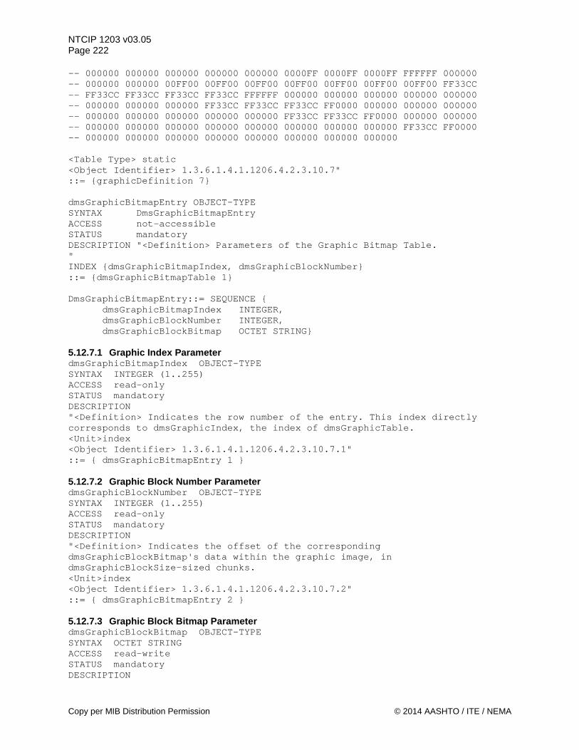
NTCIP 1203 v03.05 Page 222 -- 000000 000000 000000 000000 000000 0000FF 0000FF 0000FF FFFFFF 000000 -- 000000 000000 00FF00 00FF00 00FF00 00FF00 00FF00 00FF00 00FF00 FF33CC -- FF33CC FF33CC FF33CC FF33CC FFFFFF 000000 000000 000000 000000 000000 -- 000000 000000 000000 FF33CC FF33CC FF33CC FF0000 000000 000000 000000 -- 000000 000000 000000 000000 000000 FF33CC FF33CC FF0000 000000 000000 -- 000000 000000 000000 000000 000000 000000 000000 000000 FF33CC FF0000 -- 000000 000000 000000 000000 000000 000000 000000 000000 <Table Type> static <Object Identifier> 1.3.6.1.4.1.1206.4.2.3.10.7" ::= {graphicDefinition 7} dmsGraphicBitmapEntry OBJECT-TYPE SYNTAX DmsGraphicBitmapEntry ACCESS not-accessible STATUS mandatory DESCRIPTION "<Definition> Parameters of the Graphic Bitmap Table. " INDEX {dmsGraphicBitmapIndex, dmsGraphicBlockNumber} ::= {dmsGraphicBitmapTable 1} DmsGraphicBitmapEntry::= SEQUENCE { dmsGraphicBitmapIndex INTEGER, dmsGraphicBlockNumber INTEGER, dmsGraphicBlockBitmap OCTET STRING} 5.12.7.1 Graphic Index Parameter dmsGraphicBitmapIndex OBJECT-TYPE SYNTAX INTEGER (1..255) ACCESS read-only STATUS mandatory DESCRIPTION "<Definition> Indicates the row number of the entry. This index directly corresponds to dmsGraphicIndex, the index of dmsGraphicTable. <Unit>index <Object Identifier> 1.3.6.1.4.1.1206.4.2.3.10.7.1" ::= { dmsGraphicBitmapEntry 1 } 5.12.7.2 Graphic Block Number Parameter dmsGraphicBlockNumber OBJECT-TYPE SYNTAX INTEGER (1..255) ACCESS read-only STATUS mandatory DESCRIPTION "<Definition> Indicates the offset of the corresponding dmsGraphicBlockBitmap's data within the graphic image, in dmsGraphicBlockSize-sized chunks. <Unit>index <Object Identifier> 1.3.6.1.4.1.1206.4.2.3.10.7.2" ::= { dmsGraphicBitmapEntry 2 } 5.12.7.3 Graphic Block Bitmap Parameter dmsGraphicBlockBitmap OBJECT-TYPE SYNTAX OCTET STRING ACCESS read-write STATUS mandatory DESCRIPTION
Copy per MIB Distribution Permission © 2014 AASHTO / ITE / NEMA
NTCIP 1203 v03.05 Page 223
"<Definition> The contents of the given block of the bitmap of the graphic image. Each dmsGraphicBlockBitmap value is a sequence of dmsGraphicBlockSize octets. If a SET request for dmsGraphicBlockBitmap contains less than dmsGraphicBlockSize octets, then the supplied data shall be loaded into the beginning of the block, and the remainder of the block shall be filled with octets with the value 0 (zero). If a SET request for dmsGraphicBlockBitmap contains more than dmsGraphicBlockSize octets, the device shall return a SNMP badValue error. If a GET request is received for a dmsGraphicBlockBitmap entry for which no SET request has been accepted, then the controller shall respond with a successful GET reply, and the value returned to the central system shall be an OCTET STRING of dmsGraphicBlockSize octets, all of which have the value 0 (zero). <Object Identifier> 1.3.6.1.4.1.1206.4.2.3.10.7.3" ::= { dmsGraphicBitmapEntry 3 } END
© 2014 AASHTO / ITE / NEMA. Copy Per MIB Distribution Permission
NTCIP 1203 v03.05 Page 224
Section 6 Markup Language for Transportation Information (MULTI) [Normative]
6.1 Scope The scope of this section includes the identification and description of the “Markup Language for Transportation Information” (MULTI). MULTI is a language (not an object) used to convey a Message (Text and Message Attributes) between two entities. An object that makes use of MULTI has a syntax of octet string. The octet string shall conform to the MULTI language. 6.2 MULTI - Setup and Definition 6.2.1 Definition The Markup Language for Transportation Information (MULTI) is similar to HTML where text is transmitted, and tags define how the text appears (is displayed). Tags are enclosed within delimiters, contain an ID (one or more characters), and any optional parameters necessary for the tag. MULTI currently uses 8-bit characters, but there is consideration and planning to allow the selection of either 8-bit or 16-bit characters. The null character (0x00) is not allowed within MULTI strings. All of the MULTI tags are defined in ASCII, 8-bit characters with the most significant bit set to 0. Each MULTI tag begins with a left bracket ([), and ends with a right bracket (]). The tag ID appears after the left bracket ([), and is one or more case-insensitive letters. If the tag has any parameters, they immediately follow the tag ID and are case-insensitive (except where specified). No space or other separating character shall appear between the tag ID and the parameters. Some tags may operate in pairs, in which case the standard tag notation is defined as the opening tag. The opening tag defines where the tag's functionality begins. The closing tag defines where the functionality of the tag ends, and is defined as an opening tag with a forward slash preceding the tag ID e.g., the opening flash tag is “[fl],” and the closing flash tag is “[/fl].” A tag does not need to have all or any of its parameters specified. When this occurs, the Sign Controller uses stored default values to determine the complete attributes of the Message. The default parameter values are determined when the message is activated, not when it is stored. Thus, a message could change if the default attributes it uses are changed between the time the message is stored and the time it is activated. Changes to the default MULTI attributes do not affect the currently displayed message. However, the currently displayed message could be reactivated to reflect the changes. The left bracket ( [ ) and right bracket ( ] ) are restricted for tag delimiters. To display either of these symbols, two brackets, e.g., “[[“ or “]],” must appear together and is interpreted as a single bracket that shall be displayed. If a single right bracket is encountered, the device shall return a syntax error with a value of "unsupportedTag". If a single left bracket without a valid MULTI tag attribute is encountered, the device shall return a syntax error with a value of "unsupportedTag". MULTI allows tags within the text field of another tag (e.g. flashing within moving text), however there are limitations as to the number of tags, use of tags, and complexity of a Message due to the Display Technology of the Sign and the sign manufacturer. 6.3 Rules to apply attribute tags a) When a closing tag is defined, a closing tag shall turn off that attribute. b) A closing tag shall not be required to switch from one non-default state to a second non-default state
of the same attribute. In other words, nesting of the same attribute tag shall not be allowed.
Do Not Copy Without Written Permission © 2014 AASHTO / ITE / NEMA
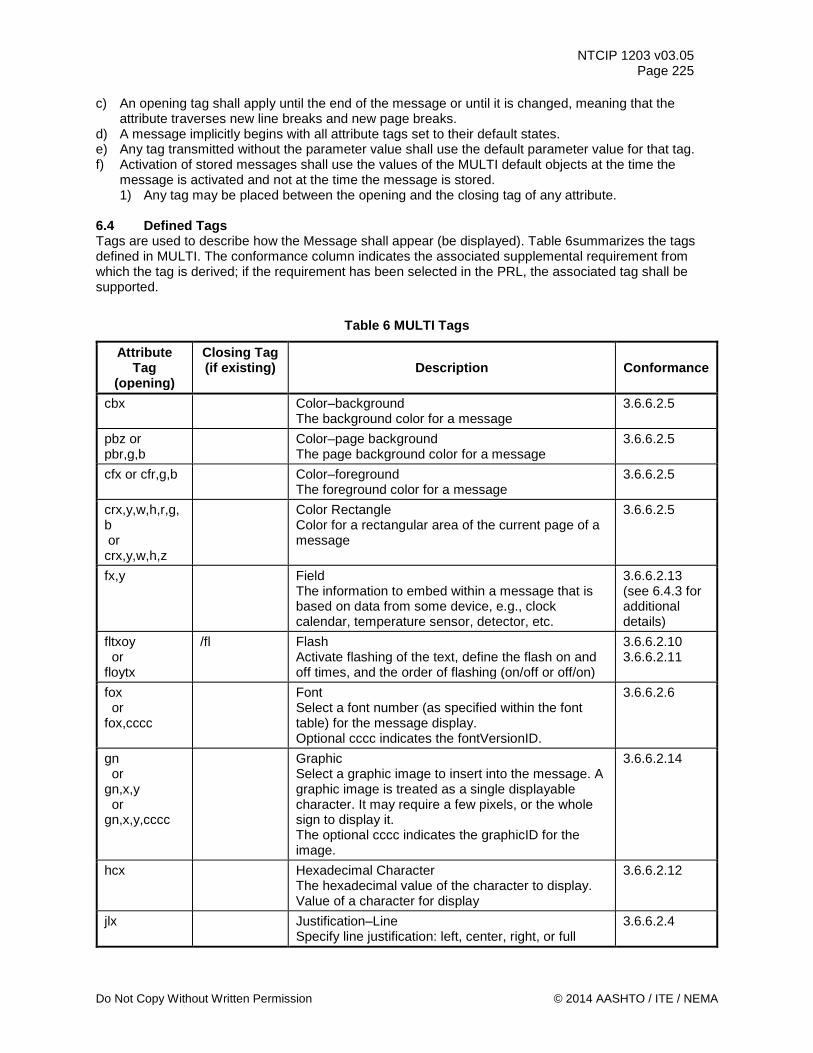
NTCIP 1203 v03.05 Page 225
c) An opening tag shall apply until the end of the message or until it is changed, meaning that the attribute traverses new line breaks and new page breaks.
d) A message implicitly begins with all attribute tags set to their default states. e) Any tag transmitted without the parameter value shall use the default parameter value for that tag. f) Activation of stored messages shall use the values of the MULTI default objects at the time the
message is activated and not at the time the message is stored. 1) Any tag may be placed between the opening and the closing tag of any attribute.
6.4 Defined Tags Tags are used to describe how the Message shall appear (be displayed). Table 6summarizes the tags defined in MULTI. The conformance column indicates the associated supplemental requirement from which the tag is derived; if the requirement has been selected in the PRL, the associated tag shall be supported.
Table 6 MULTI Tags
Attribute Tag
(opening)
Closing Tag (if existing)
Description
Conformance
cbx Color–background The background color for a message
3.6.6.2.5
pbz or pbr,g,b
Color–page background The page background color for a message
3.6.6.2.5
cfx or cfr,g,b Color–foreground The foreground color for a message
3.6.6.2.5
crx,y,w,h,r,g,b or crx,y,w,h,z
Color Rectangle Color for a rectangular area of the current page of a message
3.6.6.2.5
fx,y Field The information to embed within a message that is based on data from some device, e.g., clock calendar, temperature sensor, detector, etc.
3.6.6.2.13 (see 6.4.3 for additional details)
fltxoy or floytx
/fl Flash Activate flashing of the text, define the flash on and off times, and the order of flashing (on/off or off/on)
3.6.6.2.10 3.6.6.2.11
fox or fox,cccc
Font Select a font number (as specified within the font table) for the message display. Optional cccc indicates the fontVersionID.
3.6.6.2.6
gn or gn,x,y or gn,x,y,cccc
Graphic Select a graphic image to insert into the message. A graphic image is treated as a single displayable character. It may require a few pixels, or the whole sign to display it. The optional cccc indicates the graphicID for the image.
3.6.6.2.14
hcx Hexadecimal Character The hexadecimal value of the character to display. Value of a character for display
3.6.6.2.12
jlx Justification–Line Specify line justification: left, center, right, or full
3.6.6.2.4
Do Not Copy Without Written Permission © 2014 AASHTO / ITE / NEMA
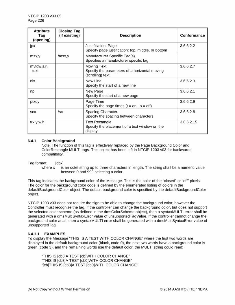
NTCIP 1203 v03.05 Page 226
Attribute Tag
(opening)
Closing Tag (if existing)
Description
Conformance
jpx Justification–Page Specify page justification: top, middle, or bottom
3.6.6.2.2
msx,y /msx,y Manufacturer Specific Tag(s) Specifies a manufacturer specific tag
mvtdw,s,r, text
Moving Text Specify the parameters of a horizontal moving (scrolling) text
3.6.6.2.7
nlx New Line Specify the start of a new line
3.6.6.2.3
np New Page Specify the start of a new page
3.6.6.2.1
ptxoy Page Time Specify the page times (t = on , o = off)
3.6.6.2.9
scx /sc Spacing Character Specify the spacing between characters
3.6.6.2.8
trx,y,w,h Text Rectangle Specify the placement of a text window on the display
3.6.6.2.15
6.4.1 Color Background
Note: The function of this tag is effectively replaced by the Page Background Color and ColorRectangle MULTI tags. This object has been left in NTCIP 1203 v03 for backwards compatibility.
Tag format: [cbx]
where x is an octet string up to three characters in length. The string shall be a numeric value between 0 and 999 selecting a color.
This tag indicates the background color of the Message. This is the color of the “closed” or “off” pixels. The color for the background color code is defined by the enumerated listing of colors in the defaultBackgroundColor object. The default background color is specified by the defaultBackgroundColor object. NTCIP 1203 v03 does not require the sign to be able to change the background color; however the Controller must recognize the tag. If the controller can change the background color, but does not support the selected color scheme (as defined in the dmsColorScheme object), then a syntaxMULTI error shall be generated with a dmsMultiSyntaxError value of unsupportedTagValue. If the controller cannot change the background color at all, then a syntaxMULTI error shall be generated with a dmsMultiSyntaxError value of unsupportedTag. 6.4.1.1 EXAMPLES To display the Message “THIS IS A TEST WITH COLOR CHANGE” where the first two words are displayed in the default background color (black, code 0), the next two words have a background color is green (code 3), and the remaining words use the default color, the MULTI string could read:
“THIS IS [cb3]A TEST [cb]WITH COLOR CHANGE” “THIS IS [cb3]A TEST [cb0]WITH COLOR CHANGE” “[cb]THIS IS [cb3]A TEST [cb0]WITH COLOR CHANGE”
Do Not Copy Without Written Permission © 2014 AASHTO / ITE / NEMA
NTCIP 1203 v03.05 Page 227
6.4.2 Page Background Color Tag format: [pbz] or [pbr,g,b]
where z is an octet string up to three characters in length. The string shall be a numeric value between 0 and 9 when using the colorClassic color scheme, between 0 and 1 when using the monochrome1Bit color scheme, or between 0 and 255 when using the monochrome8Bit color scheme (see 5.5.22 Color Scheme Parameter for definitions).
where r is an octet string up to three characters in length. The string shall be a numeric value
between 0 and 255 selecting a shade of the color red as defined within section 5.5.22 Color Scheme Parameter.
where g is an octet string up to three characters in length. The string shall be a numeric value
between 0 and 255 selecting a shade of the color green as defined within section 5.5.22 Color Scheme Parameter.
where b is an octet string up to three characters in length. The string shall be a numeric value
between 0 and 255 selecting a shade of the color blue as defined within section 5.5.22 Color Scheme Parameter.
This tag indicates the page background color of the message before the addition of any text, graphics, or color rectangles. It also specifies the color for bits with a value of zero in ‘monochrome1Bit’ graphics. The default page background color is specified by the defaultBackgroundRGB object. See the dmsColorScheme object for the definition of color codes (section 5.5.22). If there is more than one Page Background Color tag on a page, the last one specified will take precedence. The effect of the Page Background Color tag continues across message pages. All Page Background Color tags within a page must appear before any text, graphics or color rectangle specifications for that page. If a Page Background Color tag is specified after text, graphics or color rectangles appear on a page, the controller shall return a syntaxMULTI/tagConflict error. NTCIP 1203 v03 does not require the sign to be able to change the page background color; however the Controller must recognize the tag. If the controller can change the page background color, but does not support the selected color scheme (as defined in the dmsColorScheme object), then a syntaxMULTI error shall be generated with a dmsMultiSyntaxError value of unsupportedTagValue. If the controller cannot change the page background color at all, then a syntaxMULTI error shall be generated with a dmsMultiSyntaxError value of unsupportedTag 6.4.2.1 Examples To display a two-page message with a green (code 3) background on the first page and a black (code 0) background on the second page (and assuming a dmsColorScheme value of 'colorClassic (3)'), the MULTI string could read:
“[pb3]GREEN BACKGROUND[np][pb0]BLACK BACKGROUND” If the defaultBackgroundRGB object specified black, the previous example can be write as:
“[pb3]GREEN BACKGROUND[np][pb]BLACK BACKGROUND” 6.4.3 Color Foreground Tag format: [cfx] (version 1 and 2) or [cfr,g,b] (version 2 only)
where x is an octet string up to three characters in length. The string shall be a numeric value between 0 and 9 when using the colorClassic color scheme, between 0 and 1 when using the monochrome1Bit color scheme, or between 0 and 255 when using the monochrome8Bit color scheme (see 5.5.22 Color Scheme Parameter for definitions)..
Do Not Copy Without Written Permission © 2014 AASHTO / ITE / NEMA
NTCIP 1203 v03.05 Page 228
where r is an octet string up to three characters in length. The string shall be a numeric value between 0 and 255 selecting a shade of the color red as defined within section 5.5.22 Color Scheme Parameter.
where g is an octet string up to three characters in length. The string shall be a numeric value
between 0 and 255 selecting a shade of the color green as defined within section 5.5.22 Color Scheme Parameter.
where b is an octet string up to three characters in length. The string shall be a numeric value
between 0 and 255 selecting a shade of the color blue as defined within section 5.5.22 Color Scheme Parameter.
This tag indicates the foreground color of font characters or ‘monochrome1Bit’ graphics in the message. This is the color of the pixels with a ‘1’ bit in the characterBitmap object. The default foreground color is specified by the defaultForegroundRGB object. See the dmsColorScheme object for the definition of color codes (Section 5.5.22). NTCIP 1203 v03 does not require the sign to be able to change the foreground color, however the Controller must recognize the tag. If the controller can change the foreground color, but does not support the selected color scheme (as defined in the dmsColorScheme object), then a syntaxMULTI error shall be generated with a dmsMultiSyntaxError value of unsupportedTagValue. If the controller cannot change the foreground color at all, then a syntaxMULTI error shall be generated with a dmsMultiSyntaxError value of unsupportedTag. 6.4.3.1 Examples To display the Message “THIS IS A TEST WITH COLOR CHANGE” where the first two words are displayed in the in white (code 7), the next two words use the default foreground color (Amber, code 9), and the remaining words use the color green (code 3), the MULTI string could read:
“[cf7]THIS IS [cf]A TEST [cf3]WITH COLOR CHANGE” “[cf7]THIS IS [cf9]A TEST [cf3]WITH COLOR CHANGE”
6.4.4 Color Rectangle Tag format: [crx,y,w,h,r,g,b] or [crx,y,w,h,z]
where x is the left pixel coordinate (beginning with 1) of the upper left corner of a rectangle to receive the color specified in the “rgb” parameters.
where y is the top pixel coordinate (beginning with 1) of the upper left corner of a rectangle to
receive the color specified in the “rgb” parameters.
where w is the width in pixels of a rectangle to receive the color specified in the “rgb” parameters. A value of zero (0) specifies that the width is all the pixels from the specified x coordinate to the right edge of the sign. The value range is zero (0) to the width of the sign (as defined in 5.3.4 Sign Width in Pixels parameter.
where h is the height in pixels of a rectangle to receive the color specified in the “rgb”
parameters. A value of zero (0) specifies that the height is all the pixels from the specified y coordinate to the bottom edge of the sign. The value range is zero (0) to the height of the sign (as defined in 5.3.3. Sign Height in Pixels parameter).
Do Not Copy Without Written Permission © 2014 AASHTO / ITE / NEMA
NTCIP 1203 v03.05 Page 229
where r is an octet string up to three characters in length. The string shall be a numeric value between 0 and 255 selecting a shade of the color red as defined within section 5.5.22 Color Scheme Parameter.
where g is an octet string up to three characters in length. The string shall be a numeric value
between 0 and 255 selecting a shade of the color green as defined within section 5.5.22 Color Scheme Parameter.
where b is an octet string up to three characters in length. The string shall be a numeric value
between 0 and 255 selecting a shade of the color blue as defined within section 5.5.22 Color Scheme Parameter.
where z is an octet string up to three characters in length. The string shall be a numeric value
between 0 and 9 when using the colorClassic color scheme, between 0 and 1 when using the monochrome1Bit color scheme, or between 0 and 255 when using the monochrome8Bit color scheme (see 5.5.22 Color Scheme Parameter for definitions).
This tag indicates a background color for a rectangular area of the current page of a message. There can be multiple instances of this tag on a single page. This tag applies only to the current page of the message, it has no further effect after a new page tag. For rules on the order to display overlapping graphics, text rectangles and color rectangles see “Overlaying Graphics, Text Rectangles and Color Rectangles” in the “Text Rectangle” tag description. If a specified rectangle does not fully fit on the sign or if the specified color is not supported by the sign, the controller shall return a syntaxMULTI/unsupportedTagValue error. 6.4.4.1 Examples Assume a full-matrix 100 by 27 pixel sign. To display a message with the left half of the sign background being red (code 1) and the right half background being blue (code 5), the MULTI string could read:
“[cr1,1,50,27,1][cr51,1,50,27,5]TWO COLORS SHOWING” Assume a full-matrix 100 by 27 pixel sign. To create a message with a green (code 3) background for the entire sign along with a white (code 7) rectangle in the middle with black (code 0) text on the white rectangle, the MULTI string could read:
“[cb3][cr10,10,65,11,7][tr10,10,65,11][cf0]EXIT NOW” 6.4.5 Fields Tag format: [fx,y]
where x is an octet string up to two characters in length, indicating the field ID.
where y is an octet string up to two characters in length, indicating the number of characters used to display the data.
Both strings, x and y, shall be a numeric value between 1 and 99. An operator or user of a DMS may want to display information based on data received from a device that has a direct interface with the DMS Controller. This is accomplished via the field tag, where the Message being displayed changes based on the data (typically real-time) from the other device. The device could be a clock calendar, a weather station, a speed station, etc. There are two parameters for the field tag, x and y. The first parameter, x, is an ID to indicate the type of information. Table 7 shows the information to be displayed for each field ID.
Do Not Copy Without Written Permission © 2014 AASHTO / ITE / NEMA
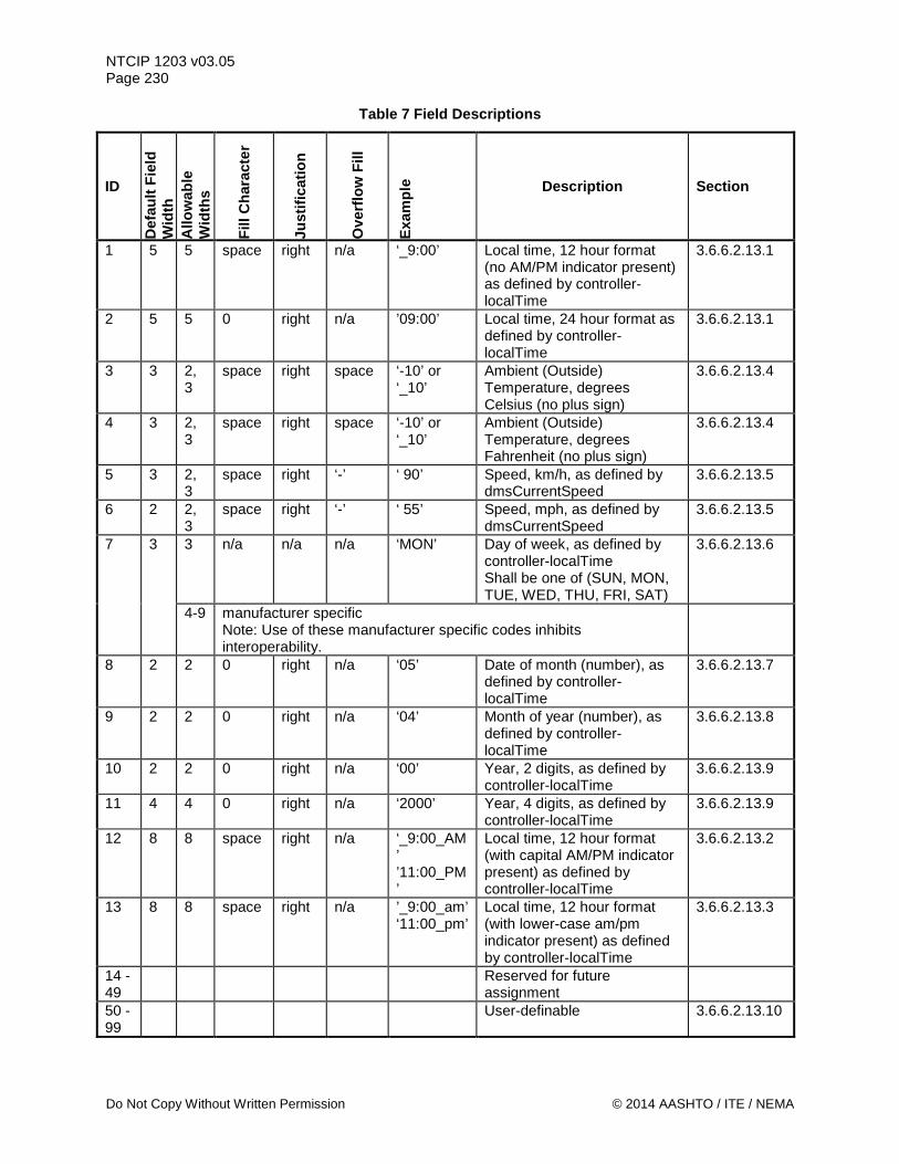
NTCIP 1203 v03.05 Page 230
Table 7 Field Descriptions
ID
Def
ault
Fiel
d W
idth
A
llow
able
W
idth
s
Fill
Cha
ract
er
Just
ifica
tion
Ove
rflo
w F
ill
Exam
ple Description Section
1 5 5 space right n/a ‘_9:00’ Local time, 12 hour format (no AM/PM indicator present) as defined by controller-localTime
3.6.6.2.13.1
2 5 5 0 right n/a ’09:00’ Local time, 24 hour format as defined by controller-localTime
3.6.6.2.13.1
3 3 2, 3
space right space ‘-10’ or ‘_10’
Ambient (Outside) Temperature, degrees Celsius (no plus sign)
3.6.6.2.13.4
4 3 2, 3
space right space ‘-10’ or ‘_10’
Ambient (Outside) Temperature, degrees Fahrenheit (no plus sign)
3.6.6.2.13.4
5 3 2, 3
space right ‘-’ ‘ 90’ Speed, km/h, as defined by dmsCurrentSpeed
3.6.6.2.13.5
6 2 2, 3
space right ‘-’ ‘ 55’ Speed, mph, as defined by dmsCurrentSpeed
3.6.6.2.13.5
7 3 3 n/a n/a n/a ‘MON’ Day of week, as defined by controller-localTime Shall be one of (SUN, MON, TUE, WED, THU, FRI, SAT)
3.6.6.2.13.6
4-9 manufacturer specific Note: Use of these manufacturer specific codes inhibits interoperability.
8 2 2 0 right n/a ‘05’ Date of month (number), as defined by controller-localTime
3.6.6.2.13.7
9 2 2 0 right n/a ‘04’ Month of year (number), as defined by controller-localTime
3.6.6.2.13.8
10 2 2 0 right n/a ‘00’ Year, 2 digits, as defined by controller-localTime
3.6.6.2.13.9
11 4 4 0 right n/a ‘2000’ Year, 4 digits, as defined by controller-localTime
3.6.6.2.13.9
12 8 8 space right n/a ‘_9:00_AM’ ’11:00_PM’
Local time, 12 hour format (with capital AM/PM indicator present) as defined by controller-localTime
3.6.6.2.13.2
13 8 8 space right n/a ’_9:00_am’ ‘11:00_pm’
Local time, 12 hour format (with lower-case am/pm indicator present) as defined by controller-localTime
3.6.6.2.13.3
14 - 49
Reserved for future assignment
50 - 99
User-definable 3.6.6.2.13.10
Do Not Copy Without Written Permission © 2014 AASHTO / ITE / NEMA
NTCIP 1203 v03.05 Page 231
The second parameter, y, is optional and, if included, must be in the range of ‘Allowable Widths’. This defines the width, or number of characters used to display the data. If the Default Field Width parameter is supplied, and the data requires fewer characters than specified, the data is right justified and the indicated Fill Character (4th column in Table above) will be used to make up the missing characters (e.g., if the local time, 12 hour format is 8:00 and the Default Field Width for Field Tag ID 1 is ‘5’, then the value of this field value would be expressed as ‘_8:00’). If the Default Field Width parameter is supplied, and the data requires more characters than specified, the indicated Overflow Fill character (6th column in Table above) is used for all characters (e.g., if the speed is larger than 100 km/h (assume 114 km/h), but the Default Field Width for Field Tag ID is ‘2’, then the field value would be expressed as ‘--’). If the width parameter is not supplied and there are more than one allowable widths, only the characters actually present in the data will be used. Overflow Fill characters will be used if the data is larger than the variable range, for example –100 degrees for field tag 3 or 4. Specifying widths other than the default width should only be used when you wish to force the fill character to be used, or when you wish to limit the range of displayed data, e.g. to display detected speeds of only 99 miles or kilometers per hour or less. There is no default object for the field tag. No fields exist in a Message unless explicitly defined in the MULTI Message. NTCIP 1203 v03 does not require the sign to be able to implement all field IDs, however the Controller must recognize the tag and take appropriate action by implementing the associated functionality or by generating a dmsMultiSyntaxError with a value of unsupportedTag. If a character immediately precedes or follows a field tag, the current character spacing shall be inserted between the character and the field. 6.4.5.1 Examples To display the Message “YOUR SPEED IS aa MPH,” where aa is filled with the real-time speed (limited to a maximum of 99 mph) from a local device, the MULTI string could read:
“YOUR SPEED IS [f6,2] MPH” To display the Message “TIME IS aa:aa TEMPERATURE IS bbb F,” aa:aa is filled with the current time and bbb is filled with the current temperature (using no fill characters), the MULTI string could read:
“TIME IS [f1] TEMPERATURE IS [f4] F” 6.4.6 Flash Time Tag format: [fltxoy] or [floytx]
where t is a fixed parameter code to indicate following number is the flash on time.
where x follows the parameter code “t” and is an octet string up to two characters in length, and indicating the flash on time in tenths (1/10ths) of a second.
where o is a fixed parameter code to indicate following number is the flash off time.
where y follows the parameter code “o” and is an octet string up to two characters in length,
and indicating the flash off time in tenths (1/10ths) of a second.
Do Not Copy Without Written Permission © 2014 AASHTO / ITE / NEMA
NTCIP 1203 v03.05 Page 232
Both strings, x and y, shall be a numeric value between 0 and 99. If either value is zero (0), flashing is turned off.
This tag controls the flashing of a Message or part of a Message. The default of this tag is its non-existence, meaning that each time a message or parts of it are to be flashed, this tag needs to be indicated. The flashing order, on then off or off then on, is performed in the order the tx and oy parameters appear. In the absence of the t and o parameters (no “t” and “o” codes within the tag), the default flashing order is always on then off with their respective default values. If the order of sequence is to be changed, then the parameters t and o can appear without any time values, in which case the default times (specified by the defaultFlashOn- and defaultFlashOff objectss) are used. If time parameters are indicated, the associated “t” and/or “o” code must appear. NTCIP 1203 v03 does not require what, if anything, a sign can or cannot flash: a specific character, word, line, or page. However, the Controller must recognize the tag and take appropriate action by implementing functionality or by generating a dmsMultiSyntaxError with a value of unsupportedTag. A graphic shall be flashing using the specified parameters (or the default flashing parameters) when MULTI graphic tag occurs within a flashing MULTI tag. Also, see the rules and limitations defined under ‘Overlaying Graphics, Text Rectangles and Color Rectangles’. 6.4.6.1 Examples To display the Message “THIS IS A TEST,” where “IS A” is flashing with an on-time of 1.0 seconds and then an off-time of 0.5 seconds (defaults of on- and off-times are set to 0), the MULTI string could read:
“THIS [flt10o5]IS A [/fl]TEST” “THIS [flt10o5]IS A [/fl]TEST”
To display the Message “THIS IS A TEST,” where “THIS IS A TEST” is flashing with an on-time of 1.0 seconds and then an off-time of 0.5 seconds (defaults: on-time = 1.0; off-time = 0.5), the MULTI string could read:
“[fl]THIS IS A TEST [/fl]” “[flt10o05]THIS IS A TEST[/fl]” “[fl]THIS IS A TEST” “[flt10o05]THIS IS A TEST”
To display the Message “THIS IS A TEST,” where “THIS” is flashing, on 1.0 seconds, then off 1.0 seconds, “TEST” is flashing, off 1.0 seconds, then on 1.0 seconds, with the default on and off times set to 0, the MULTI string could read:
“[flt10o10]THIS [/fl]IS A [flo10t10]TEST[/fl]” “[flt10o10]THIS [/fl]IS A [flo10t10]TEST”
6.4.7 Font Tag format: [fox] or [fox,cccc]
where x is an octet string up to three characters in length, and indicates the fontNumber. “X” shall be a numeric value between 1 and 255.
where cccc is an optional 4-digit hexadecimal number indicating the fontVersionID from the
font table. Each ‘c’ in “cccc” shall be an ASCII character in the range from 0-9 or A-F. This tag controls the selection of the font used to display a message. The font is selected using the
Do Not Copy Without Written Permission © 2014 AASHTO / ITE / NEMA
NTCIP 1203 v03.05 Page 233
fontNumber, not the fontIndex object from the fontTable. The default font is indicated in the defaultFont- object. When fonts of different heights are displayed on the same line, the bottom-most pixel of each font shall be aligned. The optional “cccc” is used to compare its value with that of the fontVersionID from the fontTable while dmsMessageStatus is in the validating state, and when the message is activated for display. The “cccc” from the tag and the fontVersionID from the fontTable must match for a successful operation. The fontVersionID from the message table is ignored during these operations when the “cccc” is not included in the tag. NTCIP 1203 v03 does not require how many fonts are to be supported. If a non-existing font is selected, either the dmsValidateMessageError or dmsActivateMsgError object (depending on whether dmsMessageStatus or dmsActivateMessage is set) must be set to a value of ‘syntaxMULTI’ and the dmsMultiSyntaxError object must be set to a value of ‘fontNotDefined’. If the “cccc” field is included, and its value does not match the value of fontVersionID for that font, then either dmsValidateMessageError or dmsActivateMsgError must be set to a value of ‘syntaxMULTI’ and the dmsMultiSyntaxError object must be set to a value of ‘fontVersionID’. Understanding and acting upon the “cccc” field is required for all devices, but the field does not have to be included in the tag. 6.4.7.1 Examples To display the Message “THIS IS A TEST,” where “IS A” uses the user font number 2, with the default font set to 1, the MULTI string could read:
“THIS [fo2]IS A [fo]TEST” “THIS [fo2,E19C]IS A [fo,8AC7] TEST” “THIS [fo2]IS A [fo1]TEST” “THIS [fo2,E19C]IS A [fo1,8AC7]TEST” “[fo1]THIS [fo2]IS A [fo]TEST” “[fo1,8AC7]THIS [fo2,E19C]IS A [fo,8AC7]TEST”
6.4.8 Graphic Tag format: [gn] or [gn,x,y] or [gn,x,y,cccc]
where n is an octet string up to three characters in length indicating the dmsGraphicNumber from the graphic table (not the dmsGraphicIndex). “n” shall be a numeric value between 1 and 255. where x specifies the horizontal displacement in pixels of the graphic image from the left edge of the sign. A value of 1 specifies that the left edge of the graphic image is in the left-most pixel column of the sign. “x” shall be a numeric value ranging from 1 to the width of the sign minus the width of the graphic plus 1. where y specifies the vertical displacement in pixels of the graphic image from the top edge of the sign. A value of 1 specifies that the top edge of the graphic image is in the top-most pixel row of the sign. “y” shall be a numeric value ranging from 1 to the height of the sign minus the height of the graphic plus 1. where cccc is an optional 4-digit hexadecimal number indicating the graphicVersionID from the graphic table. Each ‘c’ in “cccc” shall be an ASCII character in the range from 0-9 or A-F.
If the tag format [gn] is used, it is assume that the graphic will start at location 1.1 (upper left hand corner). This tag controls the selection of a graphic image to insert into a message. The image is selected from the dmsGraphicTable using the dmsGraphicNumber, not the dmsGraphicIndex object.
Do Not Copy Without Written Permission © 2014 AASHTO / ITE / NEMA
NTCIP 1203 v03.05 Page 234 The “cccc” is compared to the dmsGraphicID from the dmsGraphicTable while dmsMessageStatus is in the validating state, and when the message is activated for display. The “cccc” from the tag and the dmsGraphicID from the dmsGraphicTable must match for a successful operation. If this match is incorrect, the device shall return a syntaxMULTI / graphicID error. The dmsGraphicID from the dmsGraphicTable is ignored during these operations when the “cccc” is not included in the tag. NTCIP 1203 v03 does not require how many graphic images are to be supported. For rules on the order to display overlapping graphics, text rectangles and color rectangles see “Overlaying Graphics, Text Rectangles and Color Rectangles” in the “Text Rectangle” tag description. If a nonexistent image is selected by defining a message and validating via the dmsMessageStatus object, dmsValidateMessageError must be set to a value of ‘syntaxMULTI’ and dmsMultiSyntaxError object must be set to a value of ‘graphicNotDefined’. If a nonexistent image is selected by activating a message via the dmsActivateMessage object, dmsActivateMsgError must be set to a value of ‘syntaxMULTI’ and dmsMultiSyntaxError object must be set to a value of ‘graphicNotDefined’. If the optional “cccc” field is included, and its value does not match the value of dmsGraphicID for that image, then the dmsValidateMessageError or dmsActivateMsgError object (depending whether the message is stored in the message table => dmsValidateMessageError or activated => dmsActivateMsgError) must be set to a value of ‘graphicID’ and the dmsMultiSyntaxError object must be set to a value of ‘graphicID’. 6.4.8.1 Examples To display a message with a graphic (assume graphic #5) on the left and the word “DETOUR” in the middle (assume default line justification is center for the first example), the MULTI string could read:
“[g5,1,1]DETOUR” “[jl3][g5,1,1]DETOUR” “[jl3][g5,1,1,E19C]DETOUR”
If the graphic were to be placed on the right side of the sign (assume a sign width of 105 pixels and a graphic width of 25 pixels), the MULTI string could read:
“[g5,81,1]DETOUR” “DETOUR[g5,81,1,E19C]”
6.4.9 Hexadecimal Character Tag format: [hcx]
where x is an octet string up to four characters in length, and indicates the character from the current font using the hexadecimal value of the character code to be displayed. “X” shall be a hexadecimal (0-9, A-F) value between 1 and FFFF.
This tag is intended as a method to select a character from a font that cannot be typed on a keyboard (characters 0 through 31 and 128 through 65535. If this tag is not supported, but is encountered during a message validation, then dmsMultiSyntaxError shall be set to ‘unsupportedTag’. If this tag is supported, but it contains an unrecognized character, then dmsMultiSyntaxError shall be set to ‘characterNotDefined’. 6.4.9.1 Examples To display the Message “THIS IS * A TEST,” where “*“ is the hexadecimal code 8A to have all pixels of the character ON, the MULTI string could read:
Do Not Copy Without Written Permission © 2014 AASHTO / ITE / NEMA
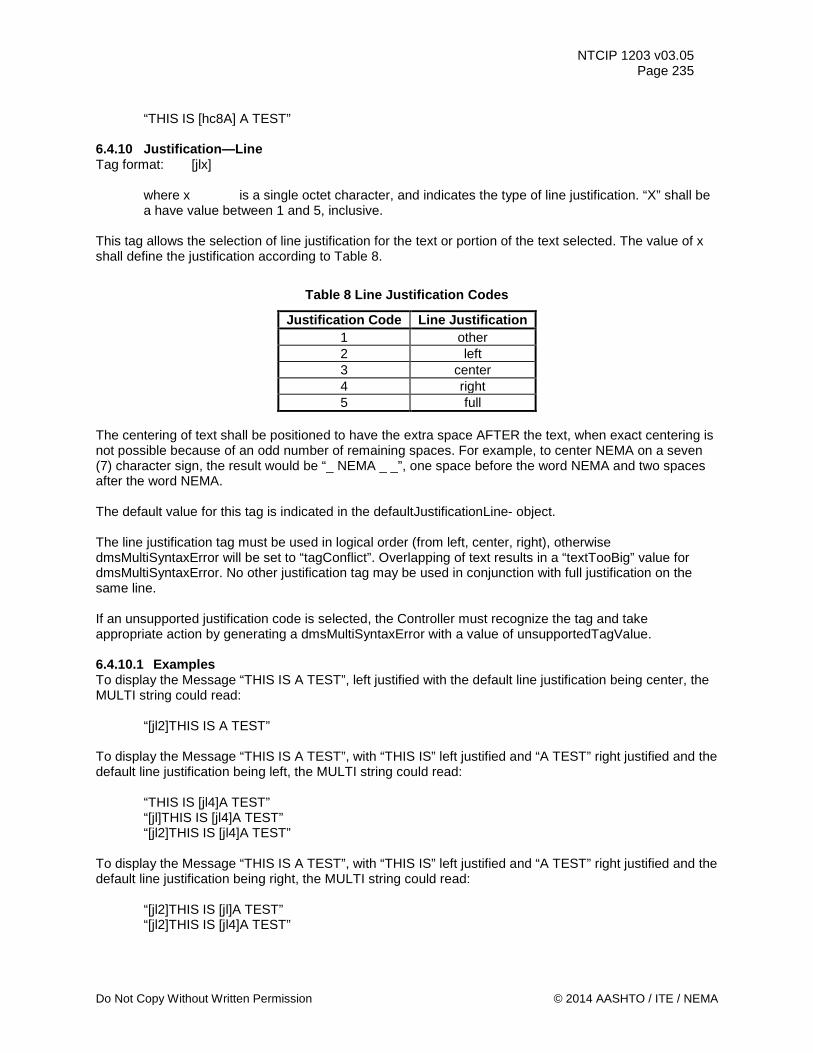
NTCIP 1203 v03.05 Page 235
“THIS IS [hc8A] A TEST”
6.4.10 Justification—Line Tag format: [jlx]
where x is a single octet character, and indicates the type of line justification. “X” shall be a have value between 1 and 5, inclusive.
This tag allows the selection of line justification for the text or portion of the text selected. The value of x shall define the justification according to Table 8.
Table 8 Line Justification Codes
Justification Code Line Justification 1 other 2 left 3 center 4 right 5 full
The centering of text shall be positioned to have the extra space AFTER the text, when exact centering is not possible because of an odd number of remaining spaces. For example, to center NEMA on a seven (7) character sign, the result would be “_ NEMA _ _”, one space before the word NEMA and two spaces after the word NEMA. The default value for this tag is indicated in the defaultJustificationLine- object. The line justification tag must be used in logical order (from left, center, right), otherwise dmsMultiSyntaxError will be set to “tagConflict”. Overlapping of text results in a “textTooBig” value for dmsMultiSyntaxError. No other justification tag may be used in conjunction with full justification on the same line. If an unsupported justification code is selected, the Controller must recognize the tag and take appropriate action by generating a dmsMultiSyntaxError with a value of unsupportedTagValue. 6.4.10.1 Examples To display the Message “THIS IS A TEST”, left justified with the default line justification being center, the MULTI string could read:
“[jl2]THIS IS A TEST”
To display the Message “THIS IS A TEST”, with “THIS IS” left justified and “A TEST” right justified and the default line justification being left, the MULTI string could read:
“THIS IS [jl4]A TEST” “[jl]THIS IS [jl4]A TEST” “[jl2]THIS IS [jl4]A TEST”
To display the Message “THIS IS A TEST”, with “THIS IS” left justified and “A TEST” right justified and the default line justification being right, the MULTI string could read:
“[jl2]THIS IS [jl]A TEST” “[jl2]THIS IS [jl4]A TEST”
Do Not Copy Without Written Permission © 2014 AASHTO / ITE / NEMA
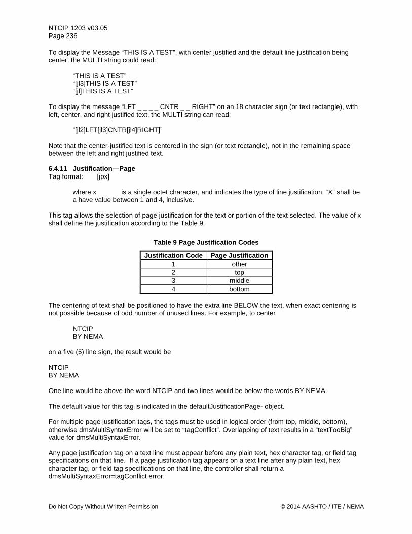
NTCIP 1203 v03.05 Page 236 To display the Message “THIS IS A TEST”, with center justified and the default line justification being center, the MULTI string could read:
“THIS IS A TEST” “[jl3]THIS IS A TEST” “[jl]THIS IS A TEST”
To display the message “LFT _ _ _ _ CNTR _ _ RIGHT” on an 18 character sign (or text rectangle), with left, center, and right justified text, the MULTI string can read:
“[jl2]LFT[jl3]CNTR[jl4]RIGHT]” Note that the center-justified text is centered in the sign (or text rectangle), not in the remaining space between the left and right justified text. 6.4.11 Justification—Page Tag format: [jpx]
where x is a single octet character, and indicates the type of line justification. “X” shall be a have value between 1 and 4, inclusive.
This tag allows the selection of page justification for the text or portion of the text selected. The value of x shall define the justification according to the Table 9.
Table 9 Page Justification Codes
Justification Code Page Justification 1 other 2 top 3 middle 4 bottom
The centering of text shall be positioned to have the extra line BELOW the text, when exact centering is not possible because of odd number of unused lines. For example, to center NTCIP BY NEMA on a five (5) line sign, the result would be NTCIP BY NEMA One line would be above the word NTCIP and two lines would be below the words BY NEMA. The default value for this tag is indicated in the defaultJustificationPage- object. For multiple page justification tags, the tags must be used in logical order (from top, middle, bottom), otherwise dmsMultiSyntaxError will be set to “tagConflict”. Overlapping of text results in a “textTooBig” value for dmsMultiSyntaxError. Any page justification tag on a text line must appear before any plain text, hex character tag, or field tag specifications on that line. If a page justification tag appears on a text line after any plain text, hex character tag, or field tag specifications on that line, the controller shall return a dmsMultiSyntaxError=tagConflict error.
Do Not Copy Without Written Permission © 2014 AASHTO / ITE / NEMA
NTCIP 1203 v03.05 Page 237
When an unsupported justification code is selected, the controller must generate a dmsMultiSyntaxError with a value of unsupportedTagValue. 6.4.11.1 Examples To display the Message “THIS IS[nl]A TEST”, top justified with the default page justification being middle, the MULTI string could read:
“[jp2]THIS IS[nl]A TEST” To display the Message “THIS IS[nl]A TEST”, middle justified with the default page justification being middle, the MULTI string could read:
“[jp3]THIS IS[nl]A TEST” “THIS IS[nl]A TEST” “[jp]THIS IS[nl]A TEST”
To display the following message on an 8-line sign,
TOP LINE 2 LINE 3 - MIDDLE - - - BOTTOM
the MULTI string could read: “[jp2]TOP[nl]LINE 2[nl]LINE 3[jp3]MIDDLE[jp4]BOTTOM”
Note that the middle-justified line is placed on the middle line of the sign (or text rectangle), not in the middle of the empty lines between the top and bottom justified lines. 6.4.12 Manufacturer Specific Tag Tag format: [msx,y]
where x is an ASCII number, and indicates the number assigned by NEMA to a specific manufacturer. where y is a manufacturer specific string. See the manufacturer’s manual for explanations. This string, if present, must be preceded by a comma.
This tag allows manufacturers to implement proprietary or experimental functions. 6.4.13 Moving Text Tag Tag format: [mvtdw,s,r,text]
where t is a character(s) indicating the type of the moving tag. Two types are available: c = circular, lx = linear with “x” optionally indicating the delay in tenths of a second between the end of linear motion and the restarting of the linear motion from the initial state. If x is not present, there shall be no delay.
Do Not Copy Without Written Permission © 2014 AASHTO / ITE / NEMA
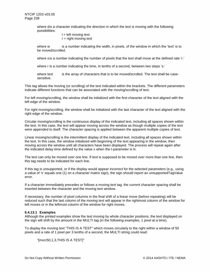
NTCIP 1203 v03.05 Page 238
where d is a character indicating the direction in which the text is moving with the following possibilities:
l = left moving text r = right moving text
where w is a number indicating the width, in pixels, of the window in which the ‘text’ is to be moved/scrolled. where s is a number indicating the number of pixels that the text shall move at the defined rate ‘r.’ where r is a number indicating the time, in tenths of a second, between two steps ‘s.’ where text is the array of characters that is to be moved/scrolled. The text shall be case-sensitive.
This tag allows the moving (or scrolling) of the text indicated within the brackets. The different parameters indicate different functions that can be associated with the moving/scrolling of text. For left moving/scrolling, the window shall be initialized with the first character of the text aligned with the left edge of the window. For right moving/scrolling, the window shall be initialized with the last character of the text aligned with the right edge of the window. Circular moving/scrolling is the continuous display of the indicated text, including all spaces shown within the text. In this case, the text will appear moving across the window as though multiple copies of the text were appended to itself. The character spacing is applied between the apparent multiple copies of text. Linear moving/scrolling is the intermittent display of the indicated text, including all spaces shown within the text. In this case, the window initialized with beginning of the text appearing in the window, then moving across the window until all characters have been displayed. The process will repeat again after the indicated delay time defined by the value x when the t-parameter is lx. The text can only be moved over one line. If text is supposed to be moved over more than one line, then this tag needs to be indicated for each line. If this tag is unsupported, or if the display would appear incorrect for the selected parameters (e.g., using a value of ‘s’ equals one (1) on a character matrix sign), the sign should report an unsupportedTagValue error. If a character immediately precedes or follows a moving text tag, the current character spacing shall be inserted between the character and the moving text window. If necessary, the number of pixel columns in the final shift of a linear move (before repeating) will be reduced such that the last column of the moving text will appear in the rightmost column of the window for left moves or in the leftmost column of the window for right moves. 6.4.13.1 Examples Although the printed examples show the text moving by whole character positions, the text displayed on the sign will shift by the amount in the MULTI tag (in the following examples, 1 pixel at a time). To display the moving text “THIS IS A TEST” which moves circularly to the right within a window of 50 pixels and a rate of 1 pixel per 3 tenths of a second, the MULTI string could read:
“[mvcr50,1,3,THIS IS A TEST]”
Do Not Copy Without Written Permission © 2014 AASHTO / ITE / NEMA
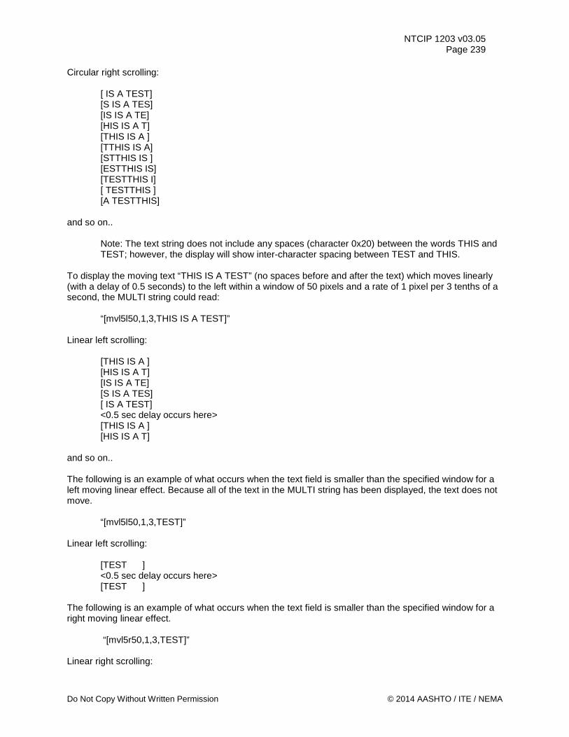
NTCIP 1203 v03.05 Page 239
Circular right scrolling:
[ IS A TEST] [S IS A TES] [IS IS A TE] [HIS IS A T] [THIS IS A ] [TTHIS IS A] [STTHIS IS ] [ESTTHIS IS] [TESTTHIS I] [ TESTTHIS ] [A TESTTHIS]
and so on..
Note: The text string does not include any spaces (character 0x20) between the words THIS and TEST; however, the display will show inter-character spacing between TEST and THIS.
To display the moving text “THIS IS A TEST” (no spaces before and after the text) which moves linearly (with a delay of 0.5 seconds) to the left within a window of 50 pixels and a rate of 1 pixel per 3 tenths of a second, the MULTI string could read:
“[mvl5l50,1,3,THIS IS A TEST]” Linear left scrolling:
[THIS IS A ] [HIS IS A T] [IS IS A TE] [S IS A TES] [ IS A TEST] <0.5 sec delay occurs here> [THIS IS A ] [HIS IS A T]
and so on.. The following is an example of what occurs when the text field is smaller than the specified window for a left moving linear effect. Because all of the text in the MULTI string has been displayed, the text does not move.
“[mvl5l50,1,3,TEST]” Linear left scrolling:
[TEST ] <0.5 sec delay occurs here> [TEST ]
The following is an example of what occurs when the text field is smaller than the specified window for a right moving linear effect.
“[mvl5r50,1,3,TEST]” Linear right scrolling:
Do Not Copy Without Written Permission © 2014 AASHTO / ITE / NEMA
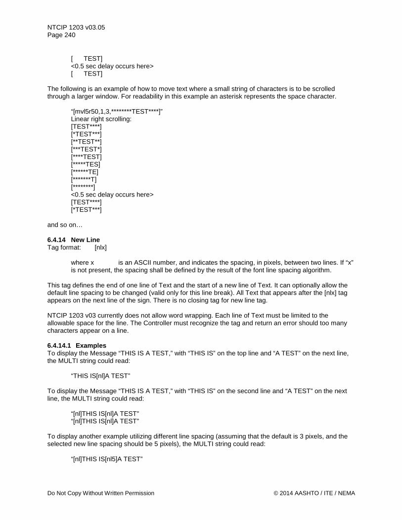
NTCIP 1203 v03.05 Page 240
[ TEST] <0.5 sec delay occurs here> [ TEST]
The following is an example of how to move text where a small string of characters is to be scrolled through a larger window. For readability in this example an asterisk represents the space character.
“[mvl5r50,1,3,********TEST****]” Linear right scrolling: [TEST****] [*TEST***] [**TEST**] [***TEST*] [****TEST] [*****TES] [******TE] [*******T] [********] <0.5 sec delay occurs here> [TEST****] [*TEST***]
and so on… 6.4.14 New Line Tag format: [nlx]
where x is an ASCII number, and indicates the spacing, in pixels, between two lines. If “x” is not present, the spacing shall be defined by the result of the font line spacing algorithm.
This tag defines the end of one line of Text and the start of a new line of Text. It can optionally allow the default line spacing to be changed (valid only for this line break). All Text that appears after the [nlx] tag appears on the next line of the sign. There is no closing tag for new line tag. NTCIP 1203 v03 currently does not allow word wrapping. Each line of Text must be limited to the allowable space for the line. The Controller must recognize the tag and return an error should too many characters appear on a line. 6.4.14.1 Examples To display the Message “THIS IS A TEST,” with “THIS IS” on the top line and “A TEST” on the next line, the MULTI string could read:
“THIS IS[nl]A TEST” To display the Message “THIS IS A TEST,” with “THIS IS” on the second line and “A TEST” on the next line, the MULTI string could read:
“[nl]THIS IS[nl]A TEST” “[nl]THIS IS[nl]A TEST”
To display another example utilizing different line spacing (assuming that the default is 3 pixels, and the selected new line spacing should be 5 pixels), the MULTI string could read:
“[nl]THIS IS[nl5]A TEST”
Do Not Copy Without Written Permission © 2014 AASHTO / ITE / NEMA
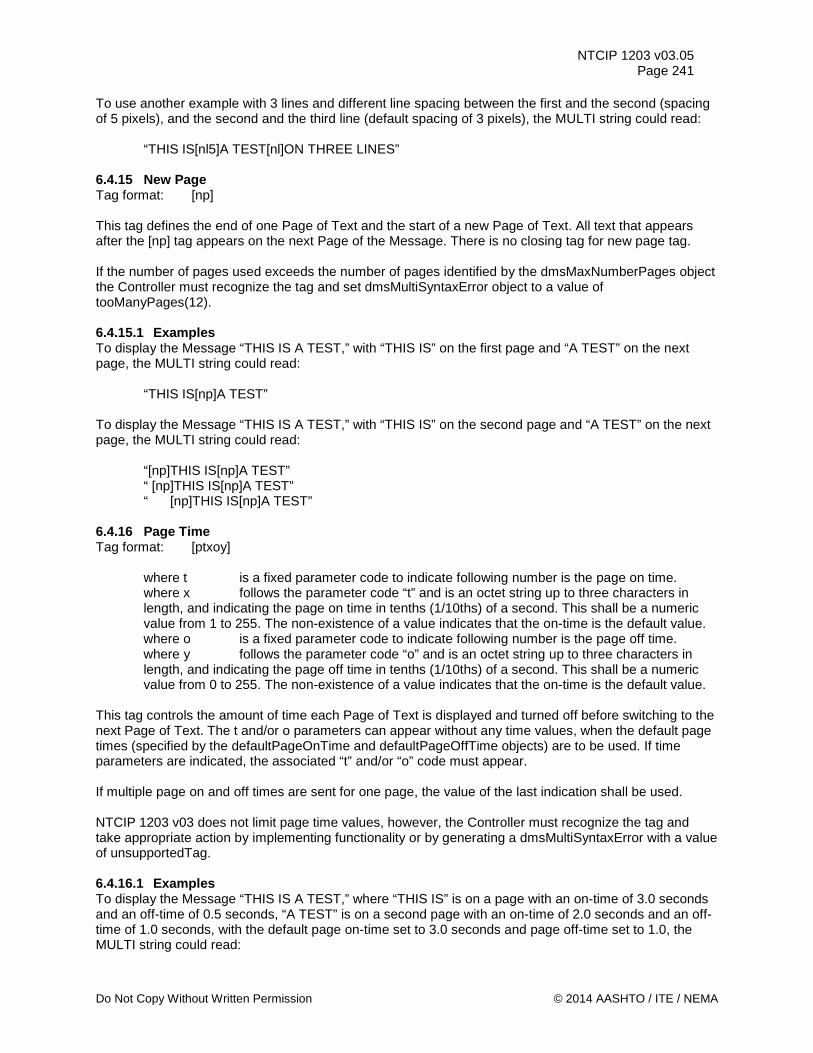
NTCIP 1203 v03.05 Page 241
To use another example with 3 lines and different line spacing between the first and the second (spacing of 5 pixels), and the second and the third line (default spacing of 3 pixels), the MULTI string could read:
“THIS IS[nl5]A TEST[nl]ON THREE LINES” 6.4.15 New Page Tag format: [np] This tag defines the end of one Page of Text and the start of a new Page of Text. All text that appears after the [np] tag appears on the next Page of the Message. There is no closing tag for new page tag. If the number of pages used exceeds the number of pages identified by the dmsMaxNumberPages object the Controller must recognize the tag and set dmsMultiSyntaxError object to a value of tooManyPages(12). 6.4.15.1 Examples To display the Message “THIS IS A TEST,” with “THIS IS” on the first page and “A TEST” on the next page, the MULTI string could read:
“THIS IS[np]A TEST” To display the Message “THIS IS A TEST,” with “THIS IS” on the second page and “A TEST” on the next page, the MULTI string could read:
“[np]THIS IS[np]A TEST” “ [np]THIS IS[np]A TEST” “ [np]THIS IS[np]A TEST”
6.4.16 Page Time Tag format: [ptxoy]
where t is a fixed parameter code to indicate following number is the page on time. where x follows the parameter code “t” and is an octet string up to three characters in length, and indicating the page on time in tenths (1/10ths) of a second. This shall be a numeric value from 1 to 255. The non-existence of a value indicates that the on-time is the default value. where o is a fixed parameter code to indicate following number is the page off time. where y follows the parameter code “o” and is an octet string up to three characters in length, and indicating the page off time in tenths (1/10ths) of a second. This shall be a numeric value from 0 to 255. The non-existence of a value indicates that the on-time is the default value.
This tag controls the amount of time each Page of Text is displayed and turned off before switching to the next Page of Text. The t and/or o parameters can appear without any time values, when the default page times (specified by the defaultPageOnTime and defaultPageOffTime objects) are to be used. If time parameters are indicated, the associated “t” and/or “o” code must appear. If multiple page on and off times are sent for one page, the value of the last indication shall be used. NTCIP 1203 v03 does not limit page time values, however, the Controller must recognize the tag and take appropriate action by implementing functionality or by generating a dmsMultiSyntaxError with a value of unsupportedTag. 6.4.16.1 Examples To display the Message “THIS IS A TEST,” where “THIS IS” is on a page with an on-time of 3.0 seconds and an off-time of 0.5 seconds, “A TEST” is on a second page with an on-time of 2.0 seconds and an off-time of 1.0 seconds, with the default page on-time set to 3.0 seconds and page off-time set to 1.0, the MULTI string could read:
Do Not Copy Without Written Permission © 2014 AASHTO / ITE / NEMA
NTCIP 1203 v03.05 Page 242
“[pt30o5]THIS IS[np][pt20o10]A TEST” “[pto5]THIS IS[np][pt20o]A TEST”
To display the Message “THIS IS A TEST,” where “THIS IS” is on a page with an on-time of 3.0 seconds and an off-time of 0.5 seconds, “A TEST” is on a second page with a page on-time of 2.0 seconds and an off-time of 1.0 seconds, with the default page on-time set to 3.0 seconds and page off-time set to 0.5, the MULTI string could read:
“[pto]THIS IS[np][pt20o10]A TEST” To display the Message “THIS IS A TEST,” where “THIS IS” is on a page with an on-time of 3.0 seconds and an of- time of 0.5 seconds, “A TEST” is on a second page with a page on-time of 2.0 seconds and an off-time of 1.0 seconds, with the default page on-time set to 2.0 seconds and page off-time set to 1.0, the MULTI string could read:
“[pt30o5]THIS IS[np][pto]A TEST” 6.4.17 Spacing – Character Tag format: [scx]
where x is an octet string up to two characters in length, and indicates the number of pixels between the characters. “x” is a mandatory parameter and shall be a numeric value between 0 and 99.
This tag controls the spacing between any two adjacent characters. The tag will override the character spacing defined by the result of the font character spacing algorithm. The default spacing for a character is the default spacing of that character’s font. A closing tag shall be required to return to the character’s font spacing. The space indicated shall apply to the space between the last character of the previous spacing and the first character of the new spacing. NTCIP 1203 v03 does not require support of spacing character values. However, the Controller must recognize the tag and take appropriate action by implementing functionality or by generating a dmsMultiSyntaxError with a value of unsupportedTag. 6.4.17.1 Examples To display the Message “THIS IS A TEST,” where “IS A” uses a different spacing between each character, with an assumed font character spacing of 1 pixel, the MULTI string could read:
“THIS_[sc2]IS_A_[/sc]TEST” the display would then show:
“T*H*I*S*_**I**S**_**A**_*T*E*S*T”
where an “*” indicates a space of one pixel, and where a "_" indicates a space character
6.4.18 Text Rectangle Tag format: [trx,y,w,h]
where x is the left pixel coordinate (beginning with 1) of the upper left corner of a
Do Not Copy Without Written Permission © 2014 AASHTO / ITE / NEMA
NTCIP 1203 v03.05 Page 243
rectangle to receive text (font characters). where y is the top pixel coordinate (beginning with 1) of the upper left corner of a rectangle to receive text (font characters). where w is the width in pixels of a rectangle to receive text (font characters). A value of zero (0) specifies that the width is all the pixels from the specified x coordinate to the right edge of the sign. The value range is zero (0) to the width of the sign (as defined in 5.3.4 Sign Width in Pixels parameter). where h is the height in pixels of a rectangle to receive text (font characters). A value of zero (0) specifies that the height is all the pixels from the specified y coordinate to the bottom edge of the sign. The value range is zero (0) to the height of the sign (as defined Section 5.3.3. Sign Height in Pixels parameter).
When text (comprised of font characters) is drawn on a message page, it is drawn within a predefined rectangle of pixel coordinates. By default, that rectangle is the entire face of the sign. This tag allows specification of a different rectangle. Any line justification or page justification tags justify the text relative to the currently specified rectangle. If specified text does not fully fit within the text rectangle, the controller shall return a syntaxMULTI/textTooBig error. If the specified text rectangle does not match character boundaries (of a character matrix signs) or line boundaries (of a line matrix sign), the controller shall return a syntaxMULTI/unsupportedTagValue error. Multiple text rectangles can be specified within a message page. All text following a text rectangle tag is drawn within that rectangle. Text rectangles only apply to the message page in which they are specified. In other words, when a new page tag is encountered, any current text rectangle specification is discarded and the new page begins with the default rectangle of the entire sign face. If a specified text rectangle does not fully fit on the sign, the controller shall return a syntaxMULTI/ unsupportedTagValue error. Overlaying Graphics, Text Rectangles and Color Rectangles Because graphics, text rectangles and color rectangles can be placed at any specified location on a message page, specific rules must be applied if any of these items are supposed to overlap. The order for adding these items to a message is as follows: a) The default background color or the color specified by a color background tag is applied to all pixels
of the message page (sign face). b) As graphics and color rectangles are encountered, they are added to the message page. Color
rectangles overlay or fill the specified color into the entire specified rectangle without regard to what has been previously drawn there. Graphics also overlay any previously drawn pixels unless a portion of the graphic is transparent (see the dmsGraphicTransparentEnabled and dmsGraphicTransparentColor objects).
c) Text shall not be drawn into the message, until a text rectangle (the whole sign, if no rectangle is defined) is ended by one of the following: 1) End of a page; 2) New text rectangle tag; 3) End of a message. This is done by coloring the foreground of the text with the foreground color while leaving the background unchanged.
d) At the end of a page, go back to step a). At the end of a text rectangle, go back to step b).
Do Not Copy Without Written Permission © 2014 AASHTO / ITE / NEMA
NTCIP 1203 v03.05 Page 244
Note: Graphics and color rectangles are not placed within the area of a text rectangle—they are placed relative to the entire sign face, not a text rectangle.
No portion of a region of text or graphic that flashes or moves (MULTI flash or moving tag) shall be overlaid by other graphics, text rectangles or color rectangles; otherwise the controller shall return a syntaxMULTI/tagConflict error. This flashing or moving region may be only a part of a text rectangle that contains the flashing or moving text. 6.4.18.1 Examples Assume a full-matrix 105 by 27 pixel sign. To display a 27 by 27 graphic (assume it is graphic #4) on the left side of the sign and place three lines of centered text in the area to the right of the graphic, the MULTI string could read:
“[g4,1,1][tr28,1,78,27]LEFT[nl]EXIT[nl]AHEAD” “[g4,1,1][tr28,1,0,0][jl3]LEFT[nl]EXIT[nl]AHEAD”
To put the same graphic on the right side of the sign with the text area to its left, the MULTI string could read:
“[g4,79,1][tr1,1,78,27]LEFT[nl]EXIT[nl]AHEAD” “[tr1,1,78,27][g4,79,1]LEFT[nl]EXIT[nl]AHEAD” “[tr1,1,78,27]LEFT[nl]EXIT[nl]AHEAD[g4,79,1]”
To create a one-page message with the graphic placed in the middle of the sign with a text area on either side of it, the MULTI string could read:
“[g4,40,1][tr1,1,39,27]LEFT[nl]SIDE[tr67,1,39,27]RIGHT[nl]SIDE” To place the graphic on the right side of the sign and place the text “65” (5x7 font) over the top and center of the graphic, the MULTI string could read:
“[g4,79,1][tr79,11,27,7]65” “[g4,79,1][tr79,1,27,27][jl3][jp3]65”
Do Not Copy Without Written Permission © 2014 AASHTO / ITE / NEMA
NTCIP 1203 v03.05 Page 245
Annex A Requirements Traceability Matrix (RTM) [Normative]
The Requirements Traceability Matrix (RTM) links the Functional Requirements as presented in Section 3 with the corresponding Dialogs (Section 4.2) on the same (gray) line. Each Functional Requirement/Dialog relates/uses one or more groups of Objects. The Objects (also known as Data Elements) are listed to the side; the formal definition of each object is contained within Section 5. Using this table, each Functional Requirement can thus be traced in a standardized way.
Note: The INDEX objects into any of the tables are not explicitly exchanged but are used as index values for other objects that are exchanged.
The audience for this table is implementers (vendors and central system developers) and conformance testers. Additionally, other interested parties might use this table to determine how particular functions are to be implemented using the standardized dialogs, interfaces, and object definitions. To conform to a Functional Requirement, a DMS shall implement all Objects and Dialogs traced from that Functional Requirement; a Management Station shall implement all Dialogs traced from the Functional Requirement. to be consistent with a Functional Requirement, a Management Station shall be able to fulfill the Functional Requirement using only Objects and Dialogs that a conforming DMS is required to support. Section 3 defines Supplemental Requirements, which are refining other functional requirements. These functional requirements in turn are generally traced to design elements (e.g., rather than being directly traced to design elements). The Supplemental RTM in Section A.4 below identifies and traces the implied relationships between supplemental requirements and direct requirements. Section 6 defines the ‘Mark-Up Language for Transportation Information’ (MULTI), which defines tags that can be used within the text of a DMS message to define its display on the face of the DMS display. The Multi Field Traceability Matrix in Section A.5 below identifies and traces the implied relationships between MULTI tags and direct requirements. A.1 Notation [Informative] A.1.1 Functional Requirement Columns The functional requirements are defined within Section 3 and the RTM is based upon the requirements within that Section. The section number and the functional requirement name are indicated within these columns. A.1.2 Dialog Column The standardized dialogs are defined within Section 4 and the RTM references the traces from requirements to this dialog. The section number of the dialog is indicated within this column.
© 2014 AASHTO / ITE / NEMA Copy Per RTM Distribution Permssion
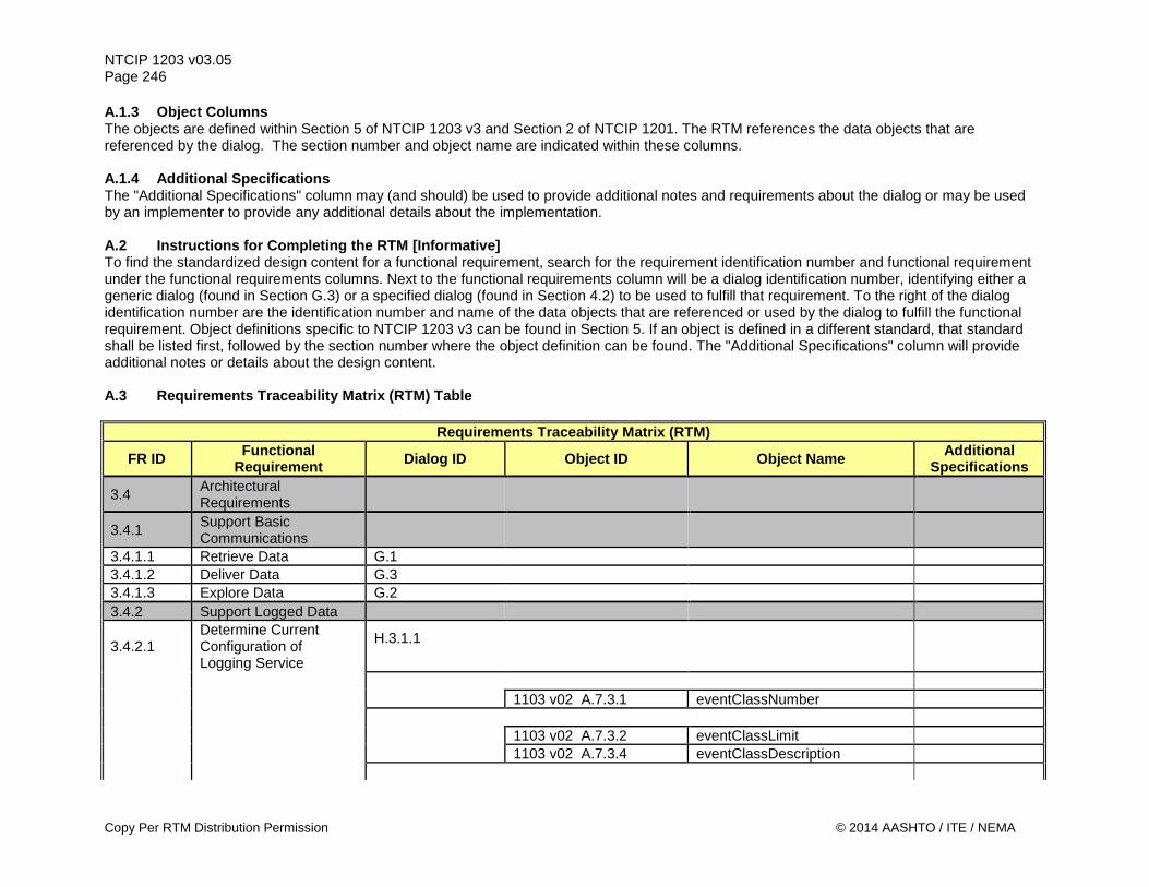
NTCIP 1203 v03.05 Page 246 A.1.3 Object Columns The objects are defined within Section 5 of NTCIP 1203 v3 and Section 2 of NTCIP 1201. The RTM references the data objects that are referenced by the dialog. The section number and object name are indicated within these columns. A.1.4 Additional Specifications The "Additional Specifications" column may (and should) be used to provide additional notes and requirements about the dialog or may be used by an implementer to provide any additional details about the implementation. A.2 Instructions for Completing the RTM [Informative] To find the standardized design content for a functional requirement, search for the requirement identification number and functional requirement under the functional requirements columns. Next to the functional requirements column will be a dialog identification number, identifying either a generic dialog (found in Section G.3) or a specified dialog (found in Section 4.2) to be used to fulfill that requirement. To the right of the dialog identification number are the identification number and name of the data objects that are referenced or used by the dialog to fulfill the functional requirement. Object definitions specific to NTCIP 1203 v3 can be found in Section 5. If an object is defined in a different standard, that standard shall be listed first, followed by the section number where the object definition can be found. The "Additional Specifications" column will provide additional notes or details about the design content. A.3 Requirements Traceability Matrix (RTM) Table
Requirements Traceability Matrix (RTM)
FR ID Functional Requirement Dialog ID Object ID Object Name Additional
Specifications
3.4 Architectural Requirements
3.4.1 Support Basic Communications
3.4.1.1 Retrieve Data G.1 3.4.1.2 Deliver Data G.3 3.4.1.3 Explore Data G.2 3.4.2 Support Logged Data
3.4.2.1 Determine Current Configuration of Logging Service
H.3.1.1
1103 v02 A.7.3.1 eventClassNumber 1103 v02 A.7.3.2 eventClassLimit 1103 v02 A.7.3.4 eventClassDescription
Copy Per RTM Distribution Permission © 2014 AASHTO / ITE / NEMA
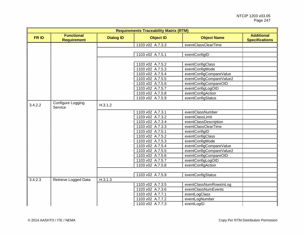
NTCIP 1203 v03.05 Page 247
Requirements Traceability Matrix (RTM)
FR ID Functional Requirement Dialog ID Object ID Object Name Additional
Specifications 1103 v02 A.7.3.3 eventClassClearTime 1103 v02 A.7.5.1 eventConfigID 1103 v02 A.7.5.2 eventConfigClass 1103 v02 A.7.5.3 eventConfigMode 1103 v02 A.7.5.4 eventConfigCompareValue 1103 v02 A.7.5.5 eventConfigCompareValue2 1103 v02 A.7.5.6 eventConfigCompareOID 1103 v02 A.7.5.7 eventConfigLogOID 1103 v02 A.7.5.8 eventConfigAction 1103 v02 A.7.5.9 eventConfigStatus
3.4.2.2 Configure Logging Service H.3.1.2
1103 v02 A.7.3.1 eventClassNumber 1103 v02 A.7.3.2 eventClassLimit 1103 v02 A.7.3.4 eventClassDescription 1103 v02 A.7.3.3 eventClassClearTime 1103 v02 A.7.5.1 eventConfigID 1103 v02 A.7.5.2 eventConfigClass 1103 v02 A.7.5.3 eventConfigMode 1103 v02 A.7.5.4 eventConfigCompareValue 1103 v02 A.7.5.5 eventConfigCompareValue2 1103 v02 A.7.5.6 eventConfigCompareOID 1103 v02 A.7.5.7 eventConfigLogOID 1103 v02 A.7.5.8 eventConfigAction 1103 v02 A.7.5.9 eventConfigStatus 3.4.2.3 Retrieve Logged Data H.3.1.3 1103 v02 A.7.3.5 eventClassNumRowsInLog 1103 v02 A.7.3.6 eventClassNumEvents 1103 v02 A.7.7.1 eventLogClass 1103 v02 A.7.7.2 eventLogNumber 1103 v02 A.7.7.3 eventLogID
© 2014 AASHTO / ITE / NEMA Copy Per RTM Distribution Permssion
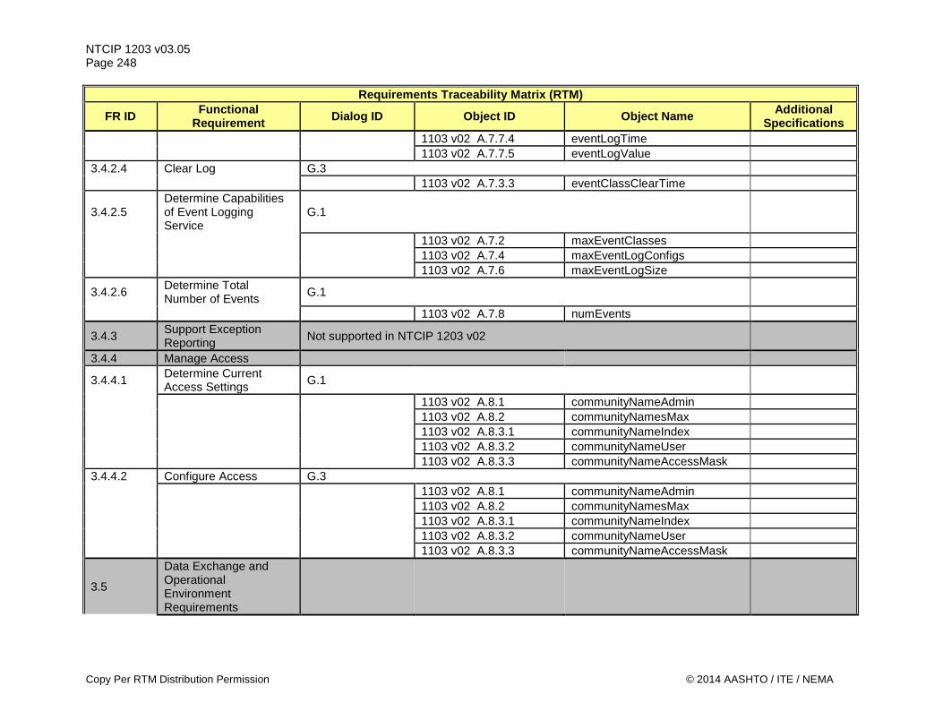
NTCIP 1203 v03.05 Page 248
Requirements Traceability Matrix (RTM)
FR ID Functional Requirement Dialog ID Object ID Object Name Additional
Specifications 1103 v02 A.7.7.4 eventLogTime 1103 v02 A.7.7.5 eventLogValue 3.4.2.4 Clear Log G.3 1103 v02 A.7.3.3 eventClassClearTime
3.4.2.5 Determine Capabilities of Event Logging Service
G.1
1103 v02 A.7.2 maxEventClasses 1103 v02 A.7.4 maxEventLogConfigs 1103 v02 A.7.6 maxEventLogSize
3.4.2.6 Determine Total Number of Events G.1
1103 v02 A.7.8 numEvents
3.4.3 Support Exception Reporting Not supported in NTCIP 1203 v02
3.4.4 Manage Access
3.4.4.1 Determine Current Access Settings G.1
1103 v02 A.8.1 communityNameAdmin 1103 v02 A.8.2 communityNamesMax 1103 v02 A.8.3.1 communityNameIndex 1103 v02 A.8.3.2 communityNameUser 1103 v02 A.8.3.3 communityNameAccessMask 3.4.4.2 Configure Access G.3 1103 v02 A.8.1 communityNameAdmin 1103 v02 A.8.2 communityNamesMax 1103 v02 A.8.3.1 communityNameIndex 1103 v02 A.8.3.2 communityNameUser 1103 v02 A.8.3.3 communityNameAccessMask
3.5
Data Exchange and Operational Environment Requirements
Copy Per RTM Distribution Permission © 2014 AASHTO / ITE / NEMA
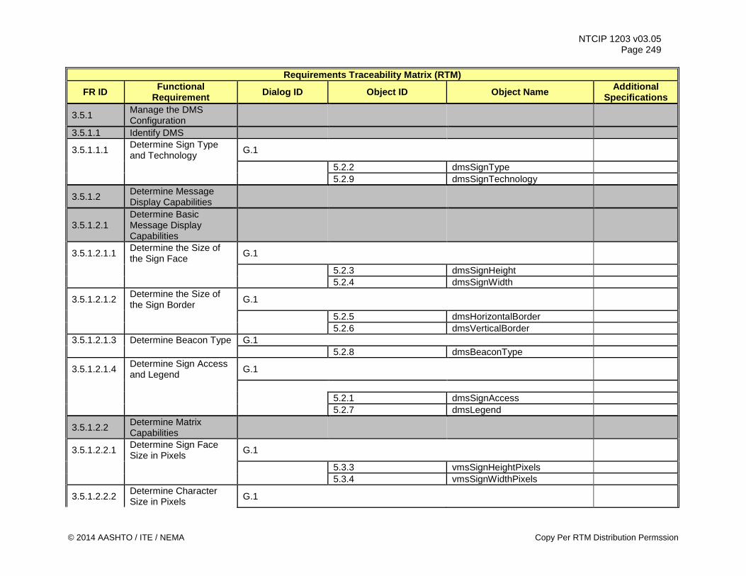
NTCIP 1203 v03.05 Page 249
Requirements Traceability Matrix (RTM)
FR ID Functional Requirement Dialog ID Object ID Object Name Additional
Specifications
3.5.1 Manage the DMS Configuration
3.5.1.1 Identify DMS
3.5.1.1.1 Determine Sign Type and Technology G.1
5.2.2 dmsSignType 5.2.9 dmsSignTechnology
3.5.1.2 Determine Message Display Capabilities
3.5.1.2.1 Determine Basic Message Display Capabilities
3.5.1.2.1.1 Determine the Size of the Sign Face G.1
5.2.3 dmsSignHeight 5.2.4 dmsSignWidth
3.5.1.2.1.2 Determine the Size of the Sign Border G.1
5.2.5 dmsHorizontalBorder 5.2.6 dmsVerticalBorder 3.5.1.2.1.3 Determine Beacon Type G.1 5.2.8 dmsBeaconType
3.5.1.2.1.4 Determine Sign Access and Legend G.1
5.2.1 dmsSignAccess 5.2.7 dmsLegend
3.5.1.2.2 Determine Matrix Capabilities
3.5.1.2.2.1 Determine Sign Face Size in Pixels G.1
5.3.3 vmsSignHeightPixels 5.3.4 vmsSignWidthPixels
3.5.1.2.2.2 Determine Character Size in Pixels G.1
© 2014 AASHTO / ITE / NEMA Copy Per RTM Distribution Permssion
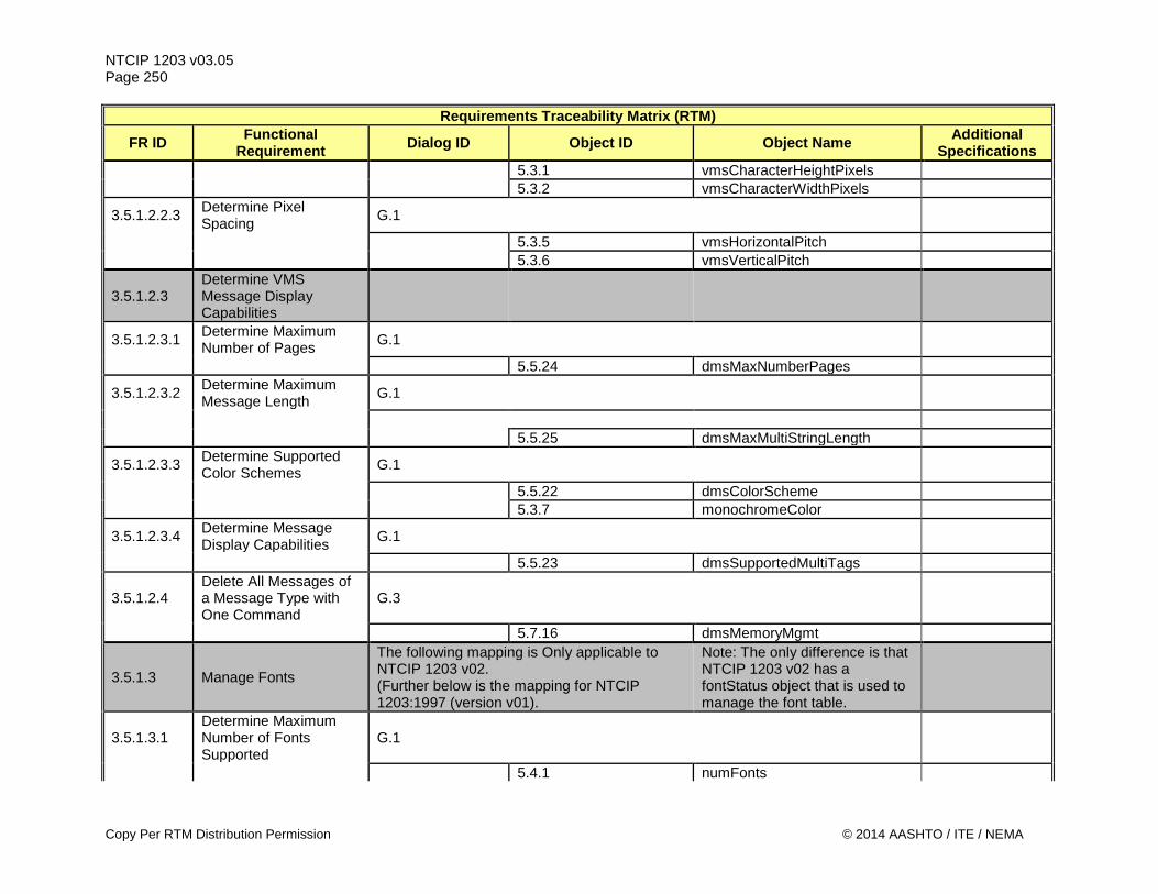
NTCIP 1203 v03.05 Page 250
Requirements Traceability Matrix (RTM)
FR ID Functional Requirement Dialog ID Object ID Object Name Additional
Specifications 5.3.1 vmsCharacterHeightPixels 5.3.2 vmsCharacterWidthPixels
3.5.1.2.2.3 Determine Pixel Spacing G.1
5.3.5 vmsHorizontalPitch 5.3.6 vmsVerticalPitch
3.5.1.2.3 Determine VMS Message Display Capabilities
3.5.1.2.3.1 Determine Maximum Number of Pages G.1
5.5.24 dmsMaxNumberPages
3.5.1.2.3.2 Determine Maximum Message Length G.1
5.5.25 dmsMaxMultiStringLength
3.5.1.2.3.3 Determine Supported Color Schemes G.1
5.5.22 dmsColorScheme 5.3.7 monochromeColor
3.5.1.2.3.4 Determine Message Display Capabilities G.1
5.5.23 dmsSupportedMultiTags
3.5.1.2.4 Delete All Messages of a Message Type with One Command
G.3
5.7.16 dmsMemoryMgmt
3.5.1.3 Manage Fonts
The following mapping is Only applicable to NTCIP 1203 v02. (Further below is the mapping for NTCIP 1203:1997 (version v01).
Note: The only difference is that NTCIP 1203 v02 has a fontStatus object that is used to manage the font table.
3.5.1.3.1 Determine Maximum Number of Fonts Supported
G.1
5.4.1 numFonts
Copy Per RTM Distribution Permission © 2014 AASHTO / ITE / NEMA
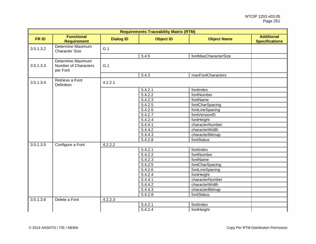
NTCIP 1203 v03.05 Page 251
Requirements Traceability Matrix (RTM)
FR ID Functional Requirement Dialog ID Object ID Object Name Additional
Specifications
3.5.1.3.2 Determine Maximum Character Size G.1
5.4.5 fontMaxCharacterSize
3.5.1.3.3 Determine Maximum Number of Characters per Font
G.1
5.4.3 maxFontCharacters
3.5.1.3.4 Retrieve a Font Definition 4.2.2.1
5.4.2.1 fontIndex 5.4.2.2 fontNumber 5.4.2.3 fontName 5.4.2.5 fontCharSpacing 5.4.2.6 fontLineSpacing 5.4.2.7 fontVersionID 5.4.2.4 fontHeight 5.4.4.1 characterNumber 5.4.4.2 characterWidth 5.4.4.3 characterBitmap 5.4.2.8 fontStatus 3.5.1.3.5 Configure a Font 4.2.2.2 5.4.2.1 fontIndex 5.4.2.2 fontNumber 5.4.2.3 fontName 5.4.2.5 fontCharSpacing 5.4.2.6 fontLineSpacing 5.4.2.4 fontHeight 5.4.4.1 characterNumber 5.4.4.2 characterWidth 5.4.4.3 characterBitmap 5.4.2.8 fontStatus 3.5.1.3.6 Delete a Font 4.2.2.3 5.4.2.1 fontIndex 5.4.2.4 fontHeight
© 2014 AASHTO / ITE / NEMA Copy Per RTM Distribution Permssion
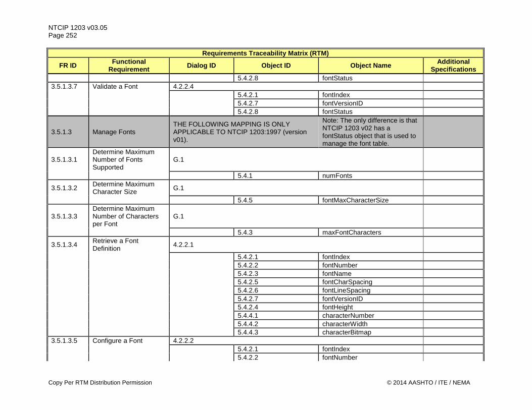
NTCIP 1203 v03.05 Page 252
Requirements Traceability Matrix (RTM)
FR ID Functional Requirement Dialog ID Object ID Object Name Additional
Specifications 5.4.2.8 fontStatus 3.5.1.3.7 Validate a Font 4.2.2.4 5.4.2.1 fontIndex 5.4.2.7 fontVersionID 5.4.2.8 fontStatus
3.5.1.3 Manage Fonts THE FOLLOWING MAPPING IS ONLY APPLICABLE TO NTCIP 1203:1997 (version v01).
Note: The only difference is that NTCIP 1203 v02 has a fontStatus object that is used to manage the font table.
3.5.1.3.1 Determine Maximum Number of Fonts Supported
G.1
5.4.1 numFonts
3.5.1.3.2 Determine Maximum Character Size G.1
5.4.5 fontMaxCharacterSize
3.5.1.3.3 Determine Maximum Number of Characters per Font
G.1
5.4.3 maxFontCharacters
3.5.1.3.4 Retrieve a Font Definition 4.2.2.1
5.4.2.1 fontIndex 5.4.2.2 fontNumber 5.4.2.3 fontName 5.4.2.5 fontCharSpacing 5.4.2.6 fontLineSpacing 5.4.2.7 fontVersionID 5.4.2.4 fontHeight 5.4.4.1 characterNumber 5.4.4.2 characterWidth 5.4.4.3 characterBitmap 3.5.1.3.5 Configure a Font 4.2.2.2 5.4.2.1 fontIndex 5.4.2.2 fontNumber
Copy Per RTM Distribution Permission © 2014 AASHTO / ITE / NEMA
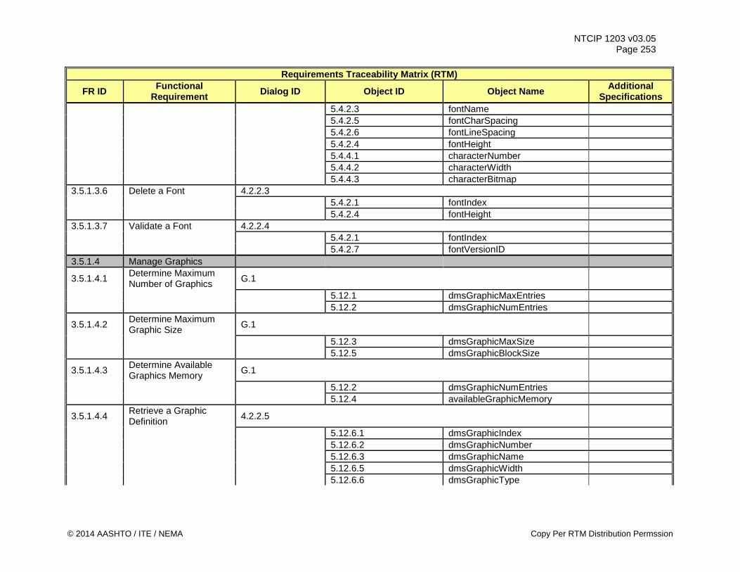
NTCIP 1203 v03.05 Page 253
Requirements Traceability Matrix (RTM)
FR ID Functional Requirement Dialog ID Object ID Object Name Additional
Specifications 5.4.2.3 fontName 5.4.2.5 fontCharSpacing 5.4.2.6 fontLineSpacing 5.4.2.4 fontHeight 5.4.4.1 characterNumber 5.4.4.2 characterWidth 5.4.4.3 characterBitmap 3.5.1.3.6 Delete a Font 4.2.2.3 5.4.2.1 fontIndex 5.4.2.4 fontHeight 3.5.1.3.7 Validate a Font 4.2.2.4 5.4.2.1 fontIndex 5.4.2.7 fontVersionID 3.5.1.4 Manage Graphics
3.5.1.4.1 Determine Maximum Number of Graphics G.1
5.12.1 dmsGraphicMaxEntries 5.12.2 dmsGraphicNumEntries
3.5.1.4.2 Determine Maximum Graphic Size G.1
5.12.3 dmsGraphicMaxSize 5.12.5 dmsGraphicBlockSize
3.5.1.4.3 Determine Available Graphics Memory G.1
5.12.2 dmsGraphicNumEntries 5.12.4 availableGraphicMemory
3.5.1.4.4 Retrieve a Graphic Definition 4.2.2.5
5.12.6.1 dmsGraphicIndex 5.12.6.2 dmsGraphicNumber 5.12.6.3 dmsGraphicName 5.12.6.5 dmsGraphicWidth 5.12.6.6 dmsGraphicType
© 2014 AASHTO / ITE / NEMA Copy Per RTM Distribution Permssion
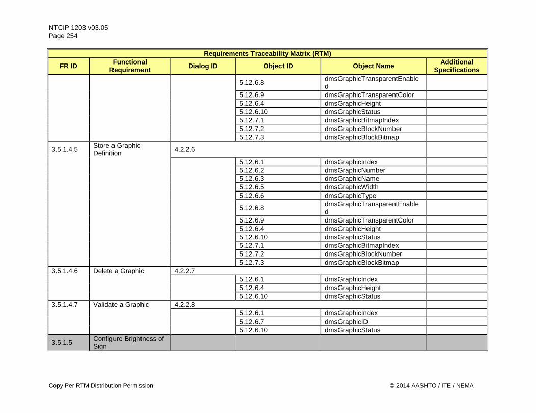
NTCIP 1203 v03.05 Page 254
Requirements Traceability Matrix (RTM)
FR ID Functional Requirement Dialog ID Object ID Object Name Additional
Specifications
5.12.6.8 dmsGraphicTransparentEnabled
5.12.6.9 dmsGraphicTransparentColor 5.12.6.4 dmsGraphicHeight 5.12.6.10 dmsGraphicStatus 5.12.7.1 dmsGraphicBitmapIndex 5.12.7.2 dmsGraphicBlockNumber 5.12.7.3 dmsGraphicBlockBitmap
3.5.1.4.5 Store a Graphic Definition 4.2.2.6
5.12.6.1 dmsGraphicIndex 5.12.6.2 dmsGraphicNumber 5.12.6.3 dmsGraphicName 5.12.6.5 dmsGraphicWidth 5.12.6.6 dmsGraphicType
5.12.6.8 dmsGraphicTransparentEnabled
5.12.6.9 dmsGraphicTransparentColor 5.12.6.4 dmsGraphicHeight 5.12.6.10 dmsGraphicStatus 5.12.7.1 dmsGraphicBitmapIndex 5.12.7.2 dmsGraphicBlockNumber 5.12.7.3 dmsGraphicBlockBitmap 3.5.1.4.6 Delete a Graphic 4.2.2.7 5.12.6.1 dmsGraphicIndex 5.12.6.4 dmsGraphicHeight 5.12.6.10 dmsGraphicStatus 3.5.1.4.7 Validate a Graphic 4.2.2.8 5.12.6.1 dmsGraphicIndex 5.12.6.7 dmsGraphicID 5.12.6.10 dmsGraphicStatus
3.5.1.5 Configure Brightness of Sign
Copy Per RTM Distribution Permission © 2014 AASHTO / ITE / NEMA
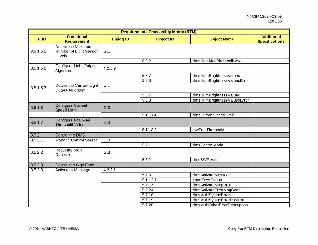
NTCIP 1203 v03.05 Page 255
Requirements Traceability Matrix (RTM)
FR ID Functional Requirement Dialog ID Object ID Object Name Additional
Specifications
3.5.1.5.1 Determine Maximum Number of Light Sensor Levels
G.1
5.8.2 dmsIllumMaxPhotocellLevel
3.5.1.5.2 Configure Light Output Algorithm 4.2.2.9
5.8.7 dmsIllumBrightnessValues 5.8.8 dmsIllumBrightnessValuesError
3.5.1.5.3 Determine Current Light Output Algorithm G.1
5.8.7 dmsIllumBrightnessValues 5.8.8 dmsIllumBrightnessValuesError
3.5.1.6 Configure Current Speed Limit G.3
5.11.1.4 dmsCurrentSpeedLimit
3.5.1.7 Configure Low Fuel Threshold Value G.3
5.11.3.2 lowFuelThreshold 3.5.2 Control the DMS 3.5.2.1 Manage Control Source G.3 5.7.1 dmsControlMode
3.5.2.2 Reset the Sign Controller G.3
5.7.2 dmsSWReset 3.5.2.3 Control the Sign Face 3.5.2.3.1 Activate a Message 4.2.3.1 5.7.3 dmsActivateMessage 5.11.2.1.1 shortErrorStatus 5.7.17 dmsActivateMsgError 5.7.24 dmsActivateErrorMsgCode 5.7.18 dmsMultiSyntaxError 5.7.19 dmsMultiSyntaxErrorPosition 5.7.20 dmsMultiOtherErrorDescription
© 2014 AASHTO / ITE / NEMA Copy Per RTM Distribution Permssion
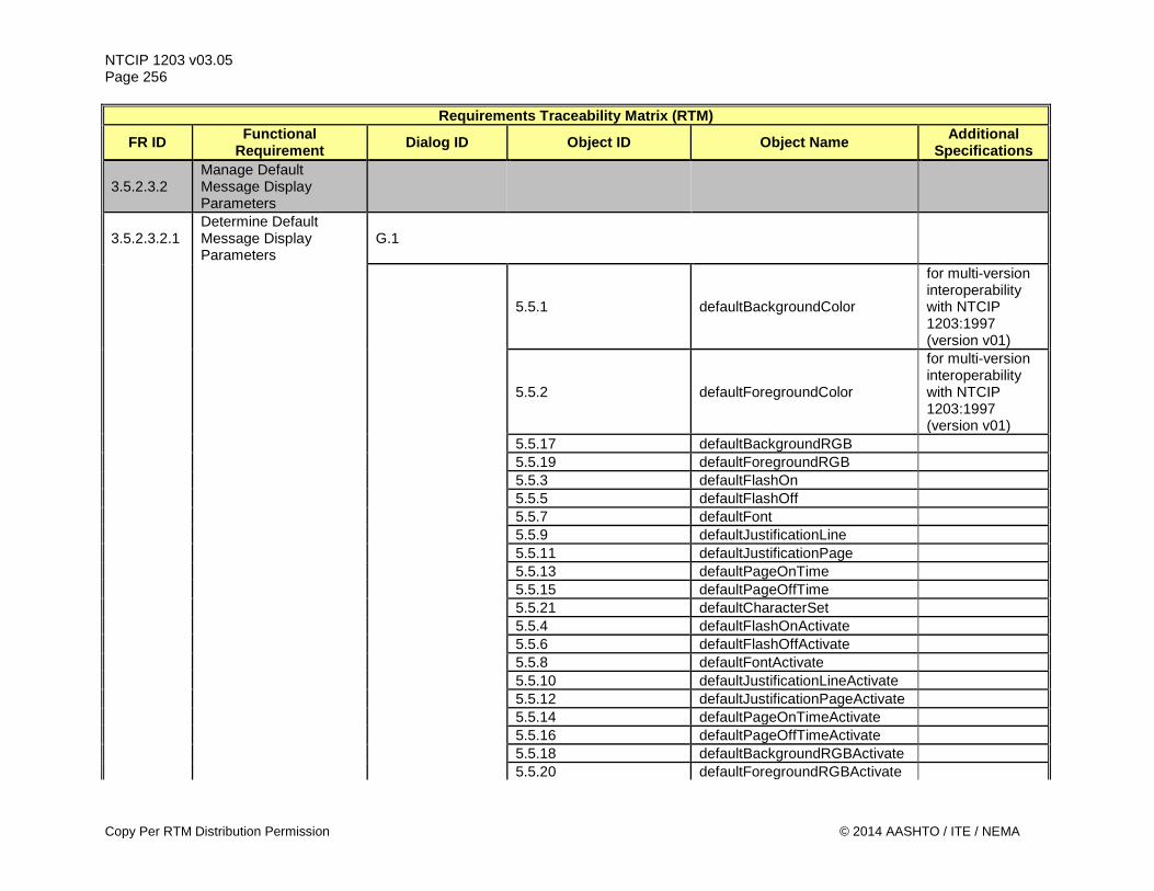
NTCIP 1203 v03.05 Page 256
Requirements Traceability Matrix (RTM)
FR ID Functional Requirement Dialog ID Object ID Object Name Additional
Specifications
3.5.2.3.2 Manage Default Message Display Parameters
3.5.2.3.2.1 Determine Default Message Display Parameters
G.1
5.5.1 defaultBackgroundColor
for multi-version interoperability with NTCIP 1203:1997 (version v01)
5.5.2 defaultForegroundColor
for multi-version interoperability with NTCIP 1203:1997 (version v01)
5.5.17 defaultBackgroundRGB 5.5.19 defaultForegroundRGB 5.5.3 defaultFlashOn 5.5.5 defaultFlashOff 5.5.7 defaultFont 5.5.9 defaultJustificationLine 5.5.11 defaultJustificationPage 5.5.13 defaultPageOnTime 5.5.15 defaultPageOffTime 5.5.21 defaultCharacterSet 5.5.4 defaultFlashOnActivate 5.5.6 defaultFlashOffActivate 5.5.8 defaultFontActivate 5.5.10 defaultJustificationLineActivate 5.5.12 defaultJustificationPageActivate 5.5.14 defaultPageOnTimeActivate 5.5.16 defaultPageOffTimeActivate 5.5.18 defaultBackgroundRGBActivate 5.5.20 defaultForegroundRGBActivate
Copy Per RTM Distribution Permission © 2014 AASHTO / ITE / NEMA
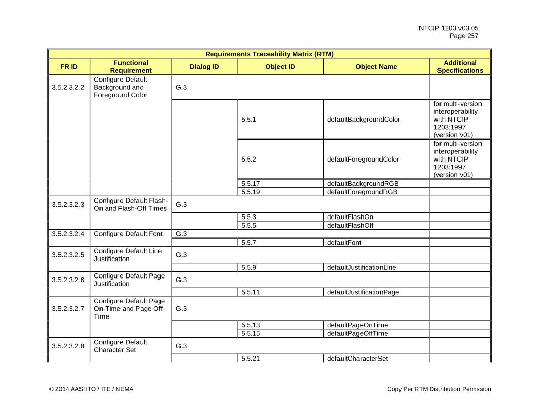
NTCIP 1203 v03.05 Page 257
Requirements Traceability Matrix (RTM)
FR ID Functional Requirement Dialog ID Object ID Object Name Additional
Specifications
3.5.2.3.2.2 Configure Default Background and Foreground Color
G.3
5.5.1 defaultBackgroundColor
for multi-version interoperability with NTCIP 1203:1997 (version v01)
5.5.2 defaultForegroundColor
for multi-version interoperability with NTCIP 1203:1997 (version v01)
5.5.17 defaultBackgroundRGB 5.5.19 defaultForegroundRGB
3.5.2.3.2.3 Configure Default Flash-On and Flash-Off Times G.3
5.5.3 defaultFlashOn 5.5.5 defaultFlashOff 3.5.2.3.2.4 Configure Default Font G.3 5.5.7 defaultFont
3.5.2.3.2.5 Configure Default Line Justification G.3
5.5.9 defaultJustificationLine
3.5.2.3.2.6 Configure Default Page Justification G.3
5.5.11 defaultJustificationPage
3.5.2.3.2.7 Configure Default Page On-Time and Page Off-Time
G.3
5.5.13 defaultPageOnTime 5.5.15 defaultPageOffTime
3.5.2.3.2.8 Configure Default Character Set G.3
5.5.21 defaultCharacterSet
© 2014 AASHTO / ITE / NEMA Copy Per RTM Distribution Permssion
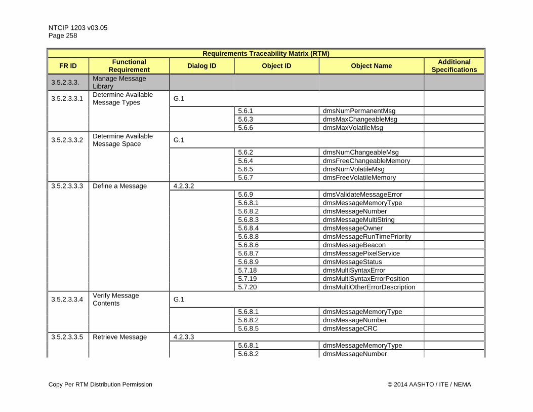
NTCIP 1203 v03.05 Page 258
Requirements Traceability Matrix (RTM)
FR ID Functional Requirement Dialog ID Object ID Object Name Additional
Specifications
3.5.2.3.3. Manage Message Library
3.5.2.3.3.1 Determine Available Message Types G.1
5.6.1 dmsNumPermanentMsg 5.6.3 dmsMaxChangeableMsg 5.6.6 dmsMaxVolatileMsg
3.5.2.3.3.2 Determine Available Message Space G.1
5.6.2 dmsNumChangeableMsg 5.6.4 dmsFreeChangeableMemory 5.6.5 dmsNumVolatileMsg 5.6.7 dmsFreeVolatileMemory 3.5.2.3.3.3 Define a Message 4.2.3.2 5.6.9 dmsValidateMessageError 5.6.8.1 dmsMessageMemoryType 5.6.8.2 dmsMessageNumber 5.6.8.3 dmsMessageMultiString 5.6.8.4 dmsMessageOwner 5.6.8.8 dmsMessageRunTimePriority 5.6.8.6 dmsMessageBeacon 5.6.8.7 dmsMessagePixelService 5.6.8.9 dmsMessageStatus 5.7.18 dmsMultiSyntaxError 5.7.19 dmsMultiSyntaxErrorPosition 5.7.20 dmsMultiOtherErrorDescription
3.5.2.3.3.4 Verify Message Contents G.1
5.6.8.1 dmsMessageMemoryType 5.6.8.2 dmsMessageNumber 5.6.8.5 dmsMessageCRC 3.5.2.3.3.5 Retrieve Message 4.2.3.3 5.6.8.1 dmsMessageMemoryType 5.6.8.2 dmsMessageNumber
Copy Per RTM Distribution Permission © 2014 AASHTO / ITE / NEMA
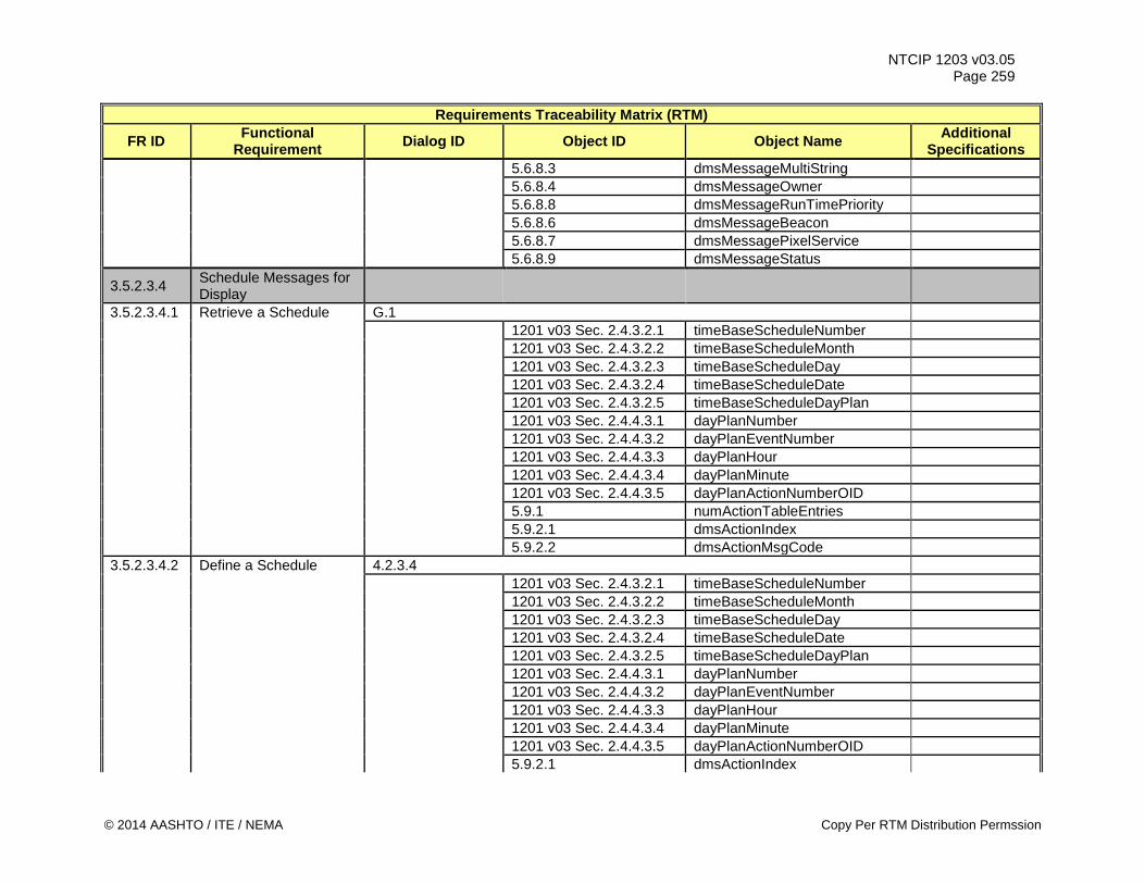
NTCIP 1203 v03.05 Page 259
Requirements Traceability Matrix (RTM)
FR ID Functional Requirement Dialog ID Object ID Object Name Additional
Specifications 5.6.8.3 dmsMessageMultiString 5.6.8.4 dmsMessageOwner 5.6.8.8 dmsMessageRunTimePriority 5.6.8.6 dmsMessageBeacon 5.6.8.7 dmsMessagePixelService 5.6.8.9 dmsMessageStatus
3.5.2.3.4 Schedule Messages for Display
3.5.2.3.4.1 Retrieve a Schedule G.1 1201 v03 Sec. 2.4.3.2.1 timeBaseScheduleNumber 1201 v03 Sec. 2.4.3.2.2 timeBaseScheduleMonth 1201 v03 Sec. 2.4.3.2.3 timeBaseScheduleDay 1201 v03 Sec. 2.4.3.2.4 timeBaseScheduleDate 1201 v03 Sec. 2.4.3.2.5 timeBaseScheduleDayPlan 1201 v03 Sec. 2.4.4.3.1 dayPlanNumber 1201 v03 Sec. 2.4.4.3.2 dayPlanEventNumber 1201 v03 Sec. 2.4.4.3.3 dayPlanHour 1201 v03 Sec. 2.4.4.3.4 dayPlanMinute 1201 v03 Sec. 2.4.4.3.5 dayPlanActionNumberOID 5.9.1 numActionTableEntries 5.9.2.1 dmsActionIndex 5.9.2.2 dmsActionMsgCode 3.5.2.3.4.2 Define a Schedule 4.2.3.4 1201 v03 Sec. 2.4.3.2.1 timeBaseScheduleNumber 1201 v03 Sec. 2.4.3.2.2 timeBaseScheduleMonth 1201 v03 Sec. 2.4.3.2.3 timeBaseScheduleDay 1201 v03 Sec. 2.4.3.2.4 timeBaseScheduleDate 1201 v03 Sec. 2.4.3.2.5 timeBaseScheduleDayPlan 1201 v03 Sec. 2.4.4.3.1 dayPlanNumber 1201 v03 Sec. 2.4.4.3.2 dayPlanEventNumber 1201 v03 Sec. 2.4.4.3.3 dayPlanHour 1201 v03 Sec. 2.4.4.3.4 dayPlanMinute 1201 v03 Sec. 2.4.4.3.5 dayPlanActionNumberOID 5.9.2.1 dmsActionIndex
© 2014 AASHTO / ITE / NEMA Copy Per RTM Distribution Permssion
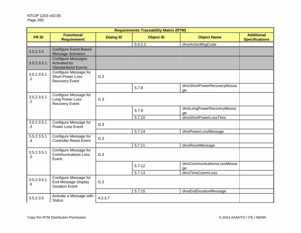
NTCIP 1203 v03.05 Page 260
Requirements Traceability Matrix (RTM)
FR ID Functional Requirement Dialog ID Object ID Object Name Additional
Specifications 5.9.2.2 dmsActionMsgCode
3.5.2.3.5 Configure Event-Based Message Activation
3.5.2.3.5.1 Configure Messages Activated by Standardized Events
3.5.2.3.5.1.1
Configure Message for Short Power Loss Recovery Event
G.3
5.7.8 dmsShortPowerRecoveryMessage
3.5.2.3.5.1.2
Configure Message for Long Power Loss Recovery Event
G.3
5.7.9 dmsLongPowerRecoveryMessage
5.7.10 dmsShortPowerLossTime 3.5.2.3.5.1.3
Configure Message for Power Loss Event G.3
5.7.14 dmsPowerLossMessage 3.5.2.3.5.1.4
Configure Message for Controller Reset Event G.3
5.7.11 dmsResetMessage
3.5.2.3.5.1.5
Configure Message for Communications Loss Event
G.3
5.7.12 dmsCommunicationsLossMessage
5.7.13 dmsTimeCommLoss
3.5.2.3.5.1.6
Configure Message for End Message Display Duration Event
G.3
5.7.15 dmsEndDurationMessage
3.5.2.3.6 Activate a Message with Status 4.2.3.7
Copy Per RTM Distribution Permission © 2014 AASHTO / ITE / NEMA
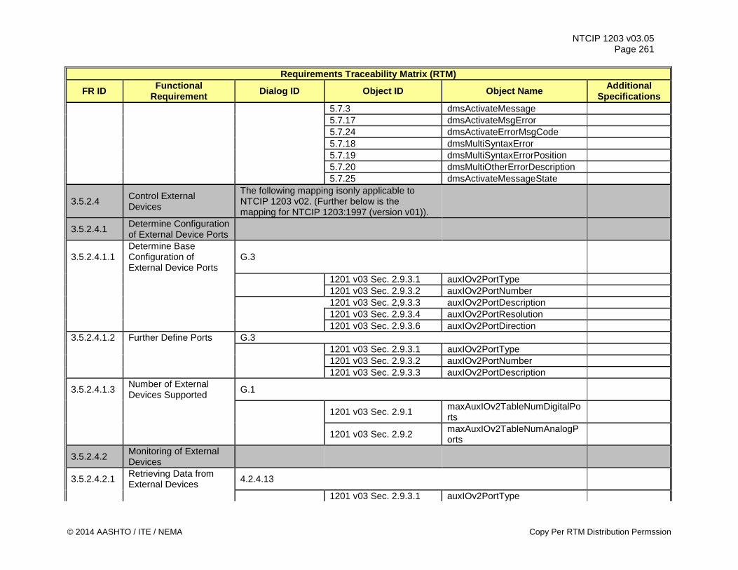
NTCIP 1203 v03.05 Page 261
Requirements Traceability Matrix (RTM)
FR ID Functional Requirement Dialog ID Object ID Object Name Additional
Specifications 5.7.3 dmsActivateMessage 5.7.17 dmsActivateMsgError 5.7.24 dmsActivateErrorMsgCode 5.7.18 dmsMultiSyntaxError 5.7.19 dmsMultiSyntaxErrorPosition 5.7.20 dmsMultiOtherErrorDescription 5.7.25 dmsActivateMessageState
3.5.2.4 Control External Devices
The following mapping isonly applicable to NTCIP 1203 v02. (Further below is the mapping for NTCIP 1203:1997 (version v01)).
3.5.2.4.1 Determine Configuration of External Device Ports
3.5.2.4.1.1 Determine Base Configuration of External Device Ports
G.3
1201 v03 Sec. 2.9.3.1 auxIOv2PortType 1201 v03 Sec. 2.9.3.2 auxIOv2PortNumber 1201 v03 Sec. 2,9.3.3 auxIOv2PortDescription 1201 v03 Sec. 2.9.3.4 auxIOv2PortResolution 1201 v03 Sec. 2.9.3.6 auxIOv2PortDirection 3.5.2.4.1.2 Further Define Ports G.3 1201 v03 Sec. 2.9.3.1 auxIOv2PortType 1201 v03 Sec. 2.9.3.2 auxIOv2PortNumber 1201 v03 Sec. 2.9.3.3 auxIOv2PortDescription
3.5.2.4.1.3 Number of External Devices Supported G.1
1201 v03 Sec. 2.9.1 maxAuxIOv2TableNumDigitalPorts
1201 v03 Sec. 2.9.2 maxAuxIOv2TableNumAnalogPorts
3.5.2.4.2 Monitoring of External Devices
3.5.2.4.2.1 Retrieving Data from External Devices 4.2.4.13
1201 v03 Sec. 2.9.3.1 auxIOv2PortType
© 2014 AASHTO / ITE / NEMA Copy Per RTM Distribution Permssion
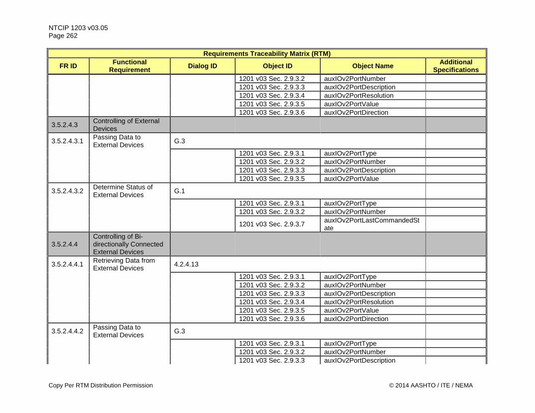
NTCIP 1203 v03.05 Page 262
Requirements Traceability Matrix (RTM)
FR ID Functional Requirement Dialog ID Object ID Object Name Additional
Specifications 1201 v03 Sec. 2.9.3.2 auxIOv2PortNumber 1201 v03 Sec. 2.9.3.3 auxIOv2PortDescription 1201 v03 Sec. 2.9.3.4 auxIOv2PortResolution 1201 v03 Sec. 2.9.3.5 auxIOv2PortValue 1201 v03 Sec. 2.9.3.6 auxIOv2PortDirection
3.5.2.4.3 Controlling of External Devices
3.5.2.4.3.1 Passing Data to External Devices G.3
1201 v03 Sec. 2.9.3.1 auxIOv2PortType 1201 v03 Sec. 2.9.3.2 auxIOv2PortNumber 1201 v03 Sec. 2.9.3.3 auxIOv2PortDescription 1201 v03 Sec. 2.9.3.5 auxIOv2PortValue
3.5.2.4.3.2 Determine Status of External Devices G.1
1201 v03 Sec. 2.9.3.1 auxIOv2PortType 1201 v03 Sec. 2.9.3.2 auxIOv2PortNumber
1201 v03 Sec. 2.9.3.7 auxIOv2PortLastCommandedState
3.5.2.4.4 Controlling of Bi-directionally Connected External Devices
3.5.2.4.4.1 Retrieving Data from External Devices 4.2.4.13
1201 v03 Sec. 2.9.3.1 auxIOv2PortType 1201 v03 Sec. 2.9.3.2 auxIOv2PortNumber 1201 v03 Sec. 2.9.3.3 auxIOv2PortDescription 1201 v03 Sec. 2.9.3.4 auxIOv2PortResolution 1201 v03 Sec. 2.9.3.5 auxIOv2PortValue 1201 v03 Sec. 2.9.3.6 auxIOv2PortDirection
3.5.2.4.4.2 Passing Data to External Devices G.3
1201 v03 Sec. 2.9.3.1 auxIOv2PortType 1201 v03 Sec. 2.9.3.2 auxIOv2PortNumber 1201 v03 Sec. 2.9.3.3 auxIOv2PortDescription
Copy Per RTM Distribution Permission © 2014 AASHTO / ITE / NEMA
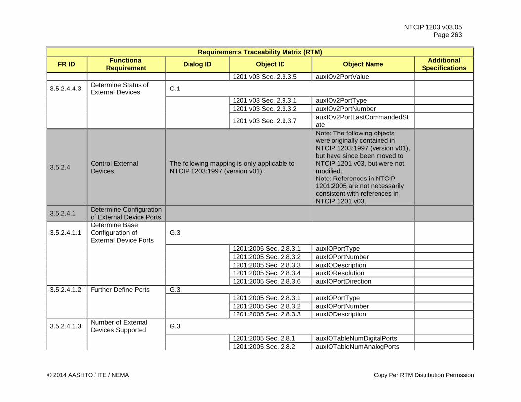
NTCIP 1203 v03.05 Page 263
Requirements Traceability Matrix (RTM)
FR ID Functional Requirement Dialog ID Object ID Object Name Additional
Specifications 1201 v03 Sec. 2.9.3.5 auxIOv2PortValue
3.5.2.4.4.3 Determine Status of External Devices G.1
1201 v03 Sec. 2.9.3.1 auxIOv2PortType 1201 v03 Sec. 2.9.3.2 auxIOv2PortNumber
1201 v03 Sec. 2.9.3.7 auxIOv2PortLastCommandedState
3.5.2.4 Control External Devices
The following mapping is only applicable to NTCIP 1203:1997 (version v01).
Note: The following objects were originally contained in NTCIP 1203:1997 (version v01), but have since been moved to NTCIP 1201 v03, but were not modified. Note: References in NTCIP 1201:2005 are not necessarily consistent with references in NTCIP 1201 v03.
3.5.2.4.1 Determine Configuration of External Device Ports
3.5.2.4.1.1 Determine Base Configuration of External Device Ports
G.3
1201:2005 Sec. 2.8.3.1 auxIOPortType 1201:2005 Sec. 2.8.3.2 auxIOPortNumber 1201:2005 Sec. 2.8.3.3 auxIODescription 1201:2005 Sec. 2.8.3.4 auxIOResolution 1201:2005 Sec. 2.8.3.6 auxIOPortDirection 3.5.2.4.1.2 Further Define Ports G.3 1201:2005 Sec. 2.8.3.1 auxIOPortType 1201:2005 Sec. 2.8.3.2 auxIOPortNumber 1201:2005 Sec. 2.8.3.3 auxIODescription
3.5.2.4.1.3 Number of External Devices Supported G.3
1201:2005 Sec. 2.8.1 auxIOTableNumDigitalPorts 1201:2005 Sec. 2.8.2 auxIOTableNumAnalogPorts
© 2014 AASHTO / ITE / NEMA Copy Per RTM Distribution Permssion
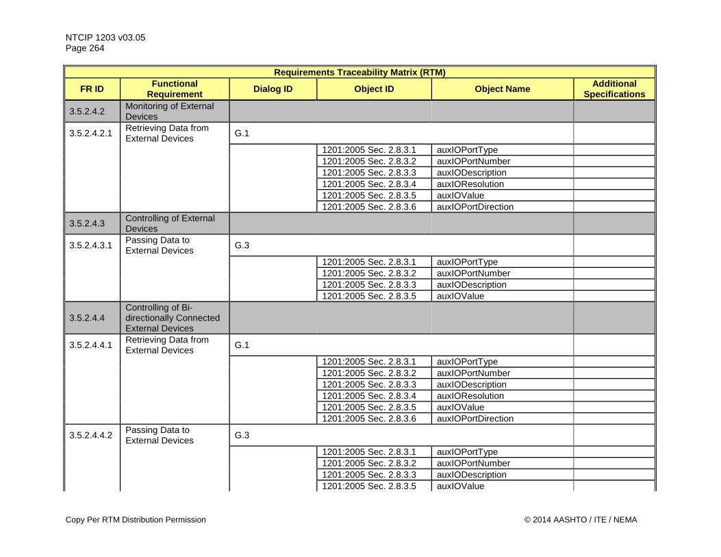
NTCIP 1203 v03.05 Page 264
Requirements Traceability Matrix (RTM)
FR ID Functional Requirement Dialog ID Object ID Object Name Additional
Specifications
3.5.2.4.2 Monitoring of External Devices
3.5.2.4.2.1 Retrieving Data from External Devices G.1
1201:2005 Sec. 2.8.3.1 auxIOPortType 1201:2005 Sec. 2.8.3.2 auxIOPortNumber 1201:2005 Sec. 2.8.3.3 auxIODescription 1201:2005 Sec. 2.8.3.4 auxIOResolution 1201:2005 Sec. 2.8.3.5 auxIOValue 1201:2005 Sec. 2.8.3.6 auxIOPortDirection
3.5.2.4.3 Controlling of External Devices
3.5.2.4.3.1 Passing Data to External Devices G.3
1201:2005 Sec. 2.8.3.1 auxIOPortType 1201:2005 Sec. 2.8.3.2 auxIOPortNumber 1201:2005 Sec. 2.8.3.3 auxIODescription 1201:2005 Sec. 2.8.3.5 auxIOValue
3.5.2.4.4 Controlling of Bi-directionally Connected External Devices
3.5.2.4.4.1 Retrieving Data from External Devices G.1
1201:2005 Sec. 2.8.3.1 auxIOPortType 1201:2005 Sec. 2.8.3.2 auxIOPortNumber 1201:2005 Sec. 2.8.3.3 auxIODescription 1201:2005 Sec. 2.8.3.4 auxIOResolution 1201:2005 Sec. 2.8.3.5 auxIOValue 1201:2005 Sec. 2.8.3.6 auxIOPortDirection
3.5.2.4.4.2 Passing Data to External Devices G.3
1201:2005 Sec. 2.8.3.1 auxIOPortType 1201:2005 Sec. 2.8.3.2 auxIOPortNumber 1201:2005 Sec. 2.8.3.3 auxIODescription 1201:2005 Sec. 2.8.3.5 auxIOValue
Copy Per RTM Distribution Permission © 2014 AASHTO / ITE / NEMA
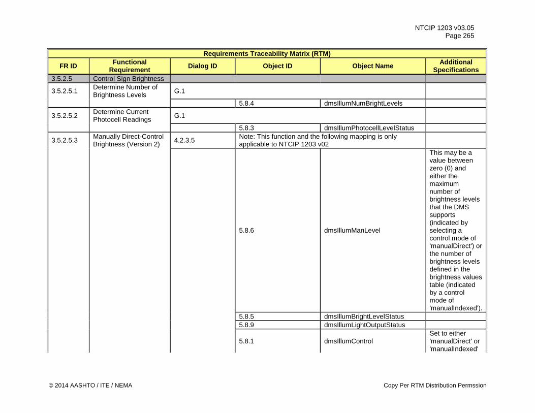
NTCIP 1203 v03.05 Page 265
Requirements Traceability Matrix (RTM)
FR ID Functional Requirement Dialog ID Object ID Object Name Additional
Specifications 3.5.2.5 Control Sign Brightness
3.5.2.5.1 Determine Number of Brightness Levels G.1
5.8.4 dmsIllumNumBrightLevels
3.5.2.5.2 Determine Current Photocell Readings G.1
5.8.3 dmsIllumPhotocellLevelStatus
3.5.2.5.3 Manually Direct-Control Brightness (Version 2) 4.2.3.5 Note: This function and the following mapping is only
applicable to NTCIP 1203 v02
5.8.6 dmsIllumManLevel
This may be a value between zero (0) and either the maximum number of brightness levels that the DMS supports (indicated by selecting a control mode of 'manualDirect') or the number of brightness levels defined in the brightness values table (indicated by a control mode of 'manualIndexed').
5.8.5 dmsIllumBrightLevelStatus 5.8.9 dmsIllumLightOutputStatus
5.8.1 dmsIllumControl Set to either 'manualDirect' or 'manualIndexed'
© 2014 AASHTO / ITE / NEMA Copy Per RTM Distribution Permssion
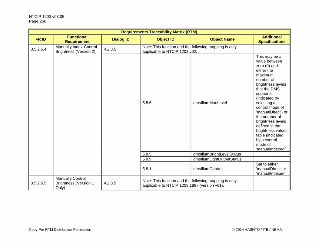
NTCIP 1203 v03.05 Page 266
Requirements Traceability Matrix (RTM)
FR ID Functional Requirement Dialog ID Object ID Object Name Additional
Specifications
3.5.2.5.4 Manually Index-Control Brightness (Version 2) 4.2.3.5 Note: This function and the following mapping is only
applicable to NTCIP 1203 v02.
5.8.6 dmsIllumManLevel
This may be a value between zero (0) and either the maximum number of brightness levels that the DMS supports (indicated by selecting a control mode of 'manualDirect') or the number of brightness levels defined in the brightness values table (indicated by a control mode of 'manualIndexed').
5.8.5 dmsIllumBrightLevelStatus 5.8.9 dmsIllumLightOutputStatus
5.8.1 dmsIllumControl Set to either 'manualDirect' or 'manualIndexed'
3.5.2.5.5 Manually Control Brightness (Version 1 Only)
4.2.3.5 Note: This function and the following mapping is only applicable to NTCIP 1203:1997 (version v01).
Copy Per RTM Distribution Permission © 2014 AASHTO / ITE / NEMA
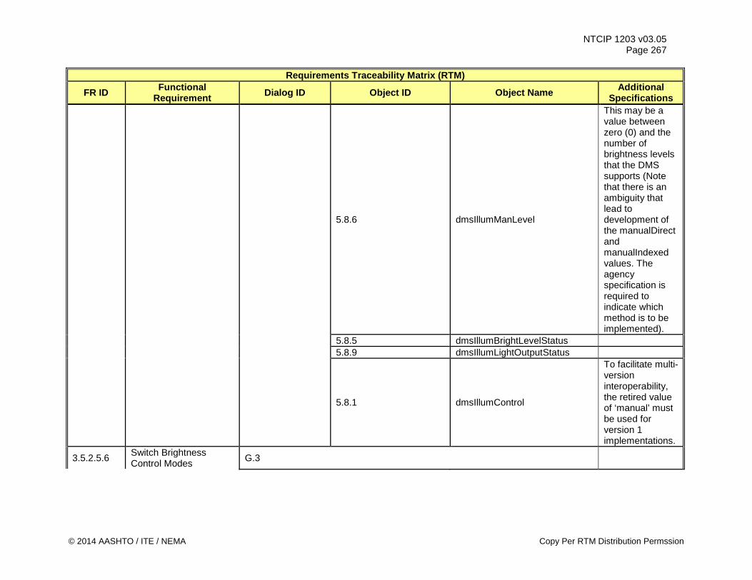
NTCIP 1203 v03.05 Page 267
Requirements Traceability Matrix (RTM)
FR ID Functional Requirement Dialog ID Object ID Object Name Additional
Specifications
5.8.6 dmsIllumManLevel
This may be a value between zero (0) and the number of brightness levels that the DMS supports (Note that there is an ambiguity that lead to development of the manualDirect and manualIndexed values. The agency specification is required to indicate which method is to be implemented).
5.8.5 dmsIllumBrightLevelStatus 5.8.9 dmsIllumLightOutputStatus
5.8.1 dmsIllumControl
To facilitate multi-version interoperability, the retired value of ‘manual’ must be used for version 1 implementations.
3.5.2.5.6 Switch Brightness Control Modes G.3
© 2014 AASHTO / ITE / NEMA Copy Per RTM Distribution Permssion
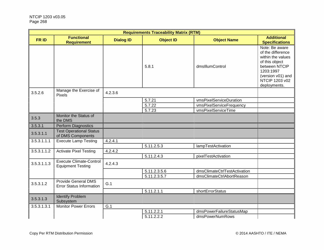
NTCIP 1203 v03.05 Page 268
Requirements Traceability Matrix (RTM)
FR ID Functional Requirement Dialog ID Object ID Object Name Additional
Specifications
5.8.1 dmsIllumControl
Note: Be aware of the difference within the values of this object between NTCIP 1203:1997 (version v01) and NTCIP 1203 v02 deployments.
3.5.2.6 Manage the Exercise of Pixels 4.2.3.6
5.7.21 vmsPixelServiceDuration 5.7.22 vmsPixelServiceFrequency 5.7.23 vmsPixelServiceTime
3.5.3 Monitor the Status of the DMS
3.5.3.1 Perform Diagnostics
3.5.3.1.1 Test Operational Status of DMS Components
3.5.3.1.1.1 Execute Lamp Testing 4.2.4.1 5.11.2.5.3 lampTestActivation 3.5.3.1.1.2 Activate Pixel Testing 4.2.4.2 5.11.2.4.3 pixelTestActivation
3.5.3.1.1.3 Execute Climate-Control Equipment Testing 4.2.4.3
5.11.2.3.5.6 dmsClimateCtrlTestActivation 5.11.2.3.5.7 dmsClimateCtrlAbortReason
3.5.3.1.2 Provide General DMS Error Status Information G.1
5.11.2.1.1 shortErrorStatus
3.5.3.1.3 Identify Problem Subsystem
3.5.3.1.3.1 Monitor Power Errors G.1 5.11.2.2.1 dmsPowerFailureStatusMap 5.11.2.2.2 dmsPowerNumRows
Copy Per RTM Distribution Permission © 2014 AASHTO / ITE / NEMA
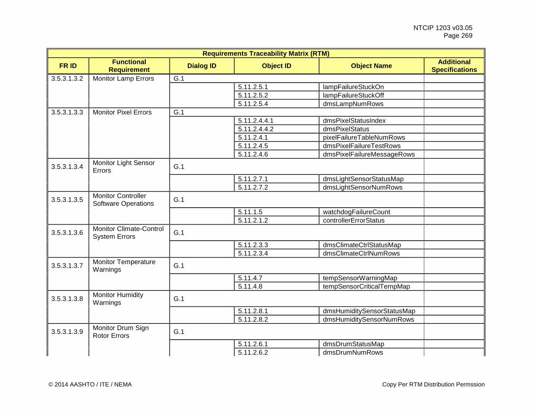
NTCIP 1203 v03.05 Page 269
Requirements Traceability Matrix (RTM)
FR ID Functional Requirement Dialog ID Object ID Object Name Additional
Specifications 3.5.3.1.3.2 Monitor Lamp Errors G.1 5.11.2.5.1 lampFailureStuckOn 5.11.2.5.2 lampFailureStuckOff 5.11.2.5.4 dmsLampNumRows 3.5.3.1.3.3 Monitor Pixel Errors G.1 5.11.2.4.4.1 dmsPixelStatusIndex 5.11.2.4.4.2 dmsPixelStatus 5.11.2.4.1 pixelFailureTableNumRows 5.11.2.4.5 dmsPixelFailureTestRows 5.11.2.4.6 dmsPixelFailureMessageRows
3.5.3.1.3.4 Monitor Light Sensor Errors G.1
5.11.2.7.1 dmsLightSensorStatusMap 5.11.2.7.2 dmsLightSensorNumRows
3.5.3.1.3.5 Monitor Controller Software Operations G.1
5.11.1.5 watchdogFailureCount 5.11.2.1.2 controllerErrorStatus
3.5.3.1.3.6 Monitor Climate-Control System Errors G.1
5.11.2.3.3 dmsClimateCtrlStatusMap 5.11.2.3.4 dmsClimateCtrlNumRows
3.5.3.1.3.7 Monitor Temperature Warnings G.1
5.11.4.7 tempSensorWarningMap 5.11.4.8 tempSensorCriticalTempMap
3.5.3.1.3.8 Monitor Humidity Warnings G.1
5.11.2.8.1 dmsHumiditySensorStatusMap 5.11.2.8.2 dmsHumiditySensorNumRows
3.5.3.1.3.9 Monitor Drum Sign Rotor Errors G.1
5.11.2.6.1 dmsDrumStatusMap 5.11.2.6.2 dmsDrumNumRows
© 2014 AASHTO / ITE / NEMA Copy Per RTM Distribution Permssion
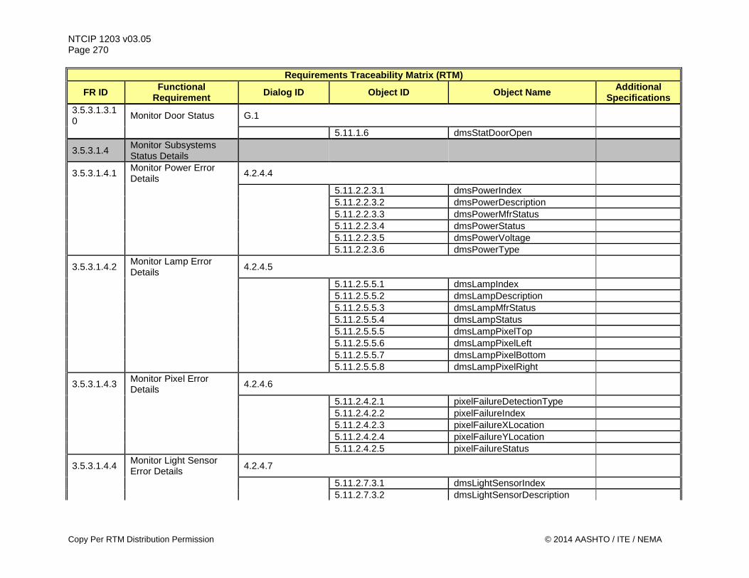
NTCIP 1203 v03.05 Page 270
Requirements Traceability Matrix (RTM)
FR ID Functional Requirement Dialog ID Object ID Object Name Additional
Specifications 3.5.3.1.3.10 Monitor Door Status G.1
5.11.1.6 dmsStatDoorOpen
3.5.3.1.4 Monitor Subsystems Status Details
3.5.3.1.4.1 Monitor Power Error Details 4.2.4.4
5.11.2.2.3.1 dmsPowerIndex 5.11.2.2.3.2 dmsPowerDescription 5.11.2.2.3.3 dmsPowerMfrStatus 5.11.2.2.3.4 dmsPowerStatus 5.11.2.2.3.5 dmsPowerVoltage 5.11.2.2.3.6 dmsPowerType
3.5.3.1.4.2 Monitor Lamp Error Details 4.2.4.5
5.11.2.5.5.1 dmsLampIndex 5.11.2.5.5.2 dmsLampDescription 5.11.2.5.5.3 dmsLampMfrStatus 5.11.2.5.5.4 dmsLampStatus 5.11.2.5.5.5 dmsLampPixelTop 5.11.2.5.5.6 dmsLampPixelLeft 5.11.2.5.5.7 dmsLampPixelBottom 5.11.2.5.5.8 dmsLampPixelRight
3.5.3.1.4.3 Monitor Pixel Error Details 4.2.4.6
5.11.2.4.2.1 pixelFailureDetectionType 5.11.2.4.2.2 pixelFailureIndex 5.11.2.4.2.3 pixelFailureXLocation 5.11.2.4.2.4 pixelFailureYLocation 5.11.2.4.2.5 pixelFailureStatus
3.5.3.1.4.4 Monitor Light Sensor Error Details 4.2.4.7
5.11.2.7.3.1 dmsLightSensorIndex 5.11.2.7.3.2 dmsLightSensorDescription
Copy Per RTM Distribution Permission © 2014 AASHTO / ITE / NEMA
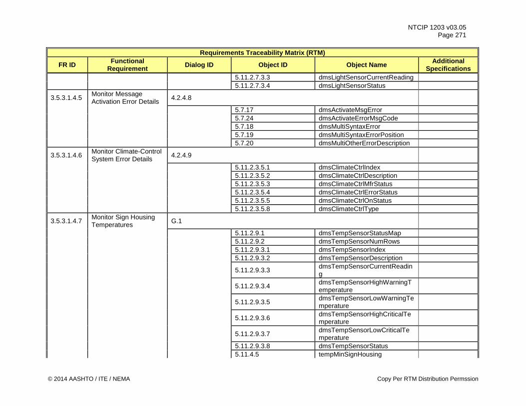
NTCIP 1203 v03.05 Page 271
Requirements Traceability Matrix (RTM)
FR ID Functional Requirement Dialog ID Object ID Object Name Additional
Specifications 5.11.2.7.3.3 dmsLightSensorCurrentReading 5.11.2.7.3.4 dmsLightSensorStatus
3.5.3.1.4.5 Monitor Message Activation Error Details 4.2.4.8
5.7.17 dmsActivateMsgError 5.7.24 dmsActivateErrorMsgCode 5.7.18 dmsMultiSyntaxError 5.7.19 dmsMultiSyntaxErrorPosition 5.7.20 dmsMultiOtherErrorDescription
3.5.3.1.4.6 Monitor Climate-Control System Error Details 4.2.4.9
5.11.2.3.5.1 dmsClimateCtrlIndex 5.11.2.3.5.2 dmsClimateCtrlDescription 5.11.2.3.5.3 dmsClimateCtrlMfrStatus 5.11.2.3.5.4 dmsClimateCtrlErrorStatus 5.11.2.3.5.5 dmsClimateCtrlOnStatus 5.11.2.3.5.8 dmsClimateCtrlType
3.5.3.1.4.7 Monitor Sign Housing Temperatures G.1
5.11.2.9.1 dmsTempSensorStatusMap 5.11.2.9.2 dmsTempSensorNumRows 5.11.2.9.3.1 dmsTempSensorIndex 5.11.2.9.3.2 dmsTempSensorDescription
5.11.2.9.3.3 dmsTempSensorCurrentReading
5.11.2.9.3.4 dmsTempSensorHighWarningTemperature
5.11.2.9.3.5 dmsTempSensorLowWarningTemperature
5.11.2.9.3.6 dmsTempSensorHighCriticalTemperature
5.11.2.9.3.7 dmsTempSensorLowCriticalTemperature
5.11.2.9.3.8 dmsTempSensorStatus 5.11.4.5 tempMinSignHousing
© 2014 AASHTO / ITE / NEMA Copy Per RTM Distribution Permssion
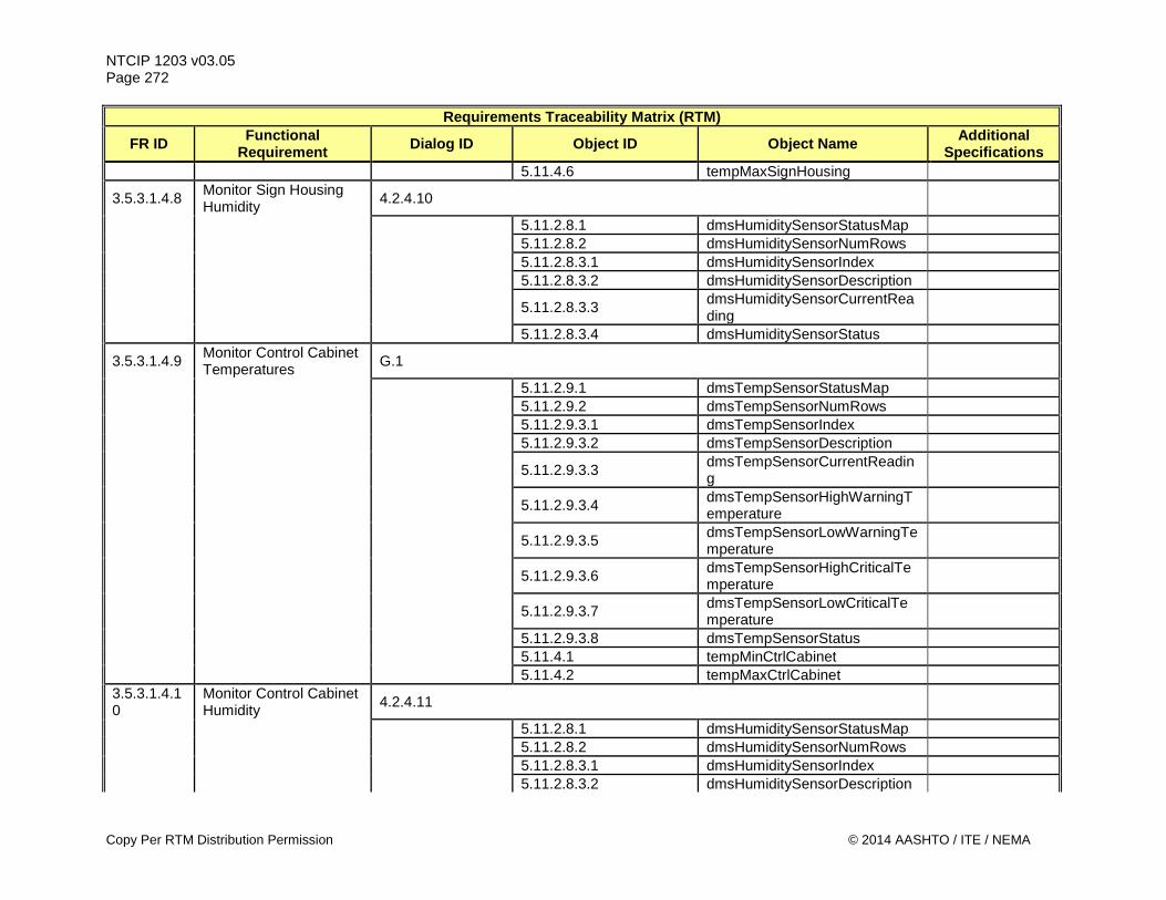
NTCIP 1203 v03.05 Page 272
Requirements Traceability Matrix (RTM)
FR ID Functional Requirement Dialog ID Object ID Object Name Additional
Specifications 5.11.4.6 tempMaxSignHousing
3.5.3.1.4.8 Monitor Sign Housing Humidity 4.2.4.10
5.11.2.8.1 dmsHumiditySensorStatusMap 5.11.2.8.2 dmsHumiditySensorNumRows 5.11.2.8.3.1 dmsHumiditySensorIndex 5.11.2.8.3.2 dmsHumiditySensorDescription
5.11.2.8.3.3 dmsHumiditySensorCurrentReading
5.11.2.8.3.4 dmsHumiditySensorStatus
3.5.3.1.4.9 Monitor Control Cabinet Temperatures G.1
5.11.2.9.1 dmsTempSensorStatusMap 5.11.2.9.2 dmsTempSensorNumRows 5.11.2.9.3.1 dmsTempSensorIndex 5.11.2.9.3.2 dmsTempSensorDescription
5.11.2.9.3.3 dmsTempSensorCurrentReading
5.11.2.9.3.4 dmsTempSensorHighWarningTemperature
5.11.2.9.3.5 dmsTempSensorLowWarningTemperature
5.11.2.9.3.6 dmsTempSensorHighCriticalTemperature
5.11.2.9.3.7 dmsTempSensorLowCriticalTemperature
5.11.2.9.3.8 dmsTempSensorStatus 5.11.4.1 tempMinCtrlCabinet 5.11.4.2 tempMaxCtrlCabinet 3.5.3.1.4.10
Monitor Control Cabinet Humidity 4.2.4.11
5.11.2.8.1 dmsHumiditySensorStatusMap 5.11.2.8.2 dmsHumiditySensorNumRows 5.11.2.8.3.1 dmsHumiditySensorIndex 5.11.2.8.3.2 dmsHumiditySensorDescription
Copy Per RTM Distribution Permission © 2014 AASHTO / ITE / NEMA
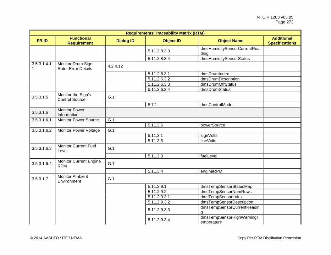
NTCIP 1203 v03.05 Page 273
Requirements Traceability Matrix (RTM)
FR ID Functional Requirement Dialog ID Object ID Object Name Additional
Specifications
5.11.2.8.3.3 dmsHumiditySensorCurrentReading
5.11.2.8.3.4 dmsHumiditySensorStatus 3.5.3.1.4.11
Monitor Drum Sign Rotor Error Details 4.2.4.12
5.11.2.6.3.1 dmsDrumIndex 5.11.2.6.3.2 dmsDrumDescription 5.11.2.6.3.3 dmsDrumMfrStatus 5.11.2.6.3.4 dmsDrumStatus
3.5.3.1.5 Monitor the Sign's Control Source G.1
5.7.1 dmsControlMode
3.5.3.1.6 Monitor Power Information
3.5.3.1.6.1 Monitor Power Source G.1 5.11.3.6 powerSource 3.5.3.1.6.2 Monitor Power Voltage G.1 5.11.3.1 signVolts 5.11.3.5 lineVolts
3.5.3.1.6.3 Monitor Current Fuel Level G.1
5.11.3.3 fuelLevel
3.5.3.1.6.4 Monitor Current Engine RPM G.1
5.11.3.4 engineRPM
3.5.3.1.7 Monitor Ambient Environment G.1
5.11.2.9.1 dmsTempSensorStatusMap 5.11.2.9.2 dmsTempSensorNumRows 5.11.2.9.3.1 dmsTempSensorIndex 5.11.2.9.3.2 dmsTempSensorDescription
5.11.2.9.3.3 dmsTempSensorCurrentReading
5.11.2.9.3.4 dmsTempSensorHighWarningTemperature
© 2014 AASHTO / ITE / NEMA Copy Per RTM Distribution Permssion
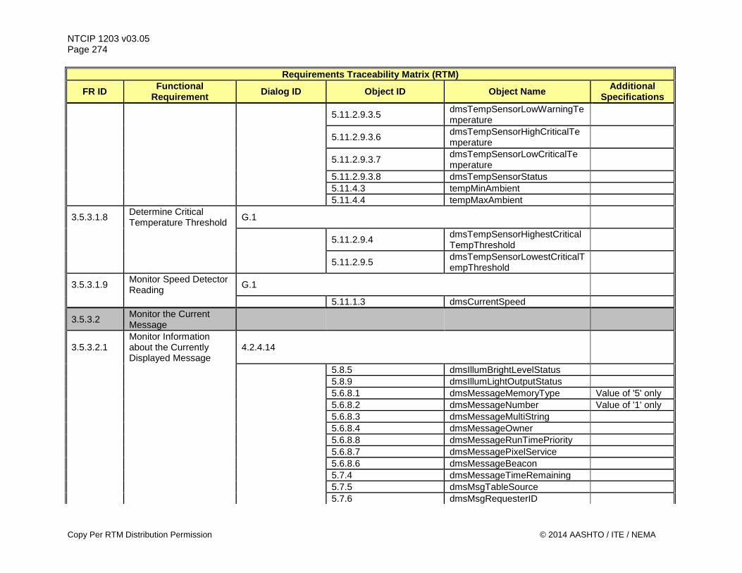
NTCIP 1203 v03.05 Page 274
Requirements Traceability Matrix (RTM)
FR ID Functional Requirement Dialog ID Object ID Object Name Additional
Specifications
5.11.2.9.3.5 dmsTempSensorLowWarningTemperature
5.11.2.9.3.6 dmsTempSensorHighCriticalTemperature
5.11.2.9.3.7 dmsTempSensorLowCriticalTemperature
5.11.2.9.3.8 dmsTempSensorStatus 5.11.4.3 tempMinAmbient 5.11.4.4 tempMaxAmbient
3.5.3.1.8 Determine Critical Temperature Threshold G.1
5.11.2.9.4 dmsTempSensorHighestCriticalTempThreshold
5.11.2.9.5 dmsTempSensorLowestCriticalTempThreshold
3.5.3.1.9 Monitor Speed Detector Reading G.1
5.11.1.3 dmsCurrentSpeed
3.5.3.2 Monitor the Current Message
3.5.3.2.1 Monitor Information about the Currently Displayed Message
4.2.4.14
5.8.5 dmsIllumBrightLevelStatus 5.8.9 dmsIllumLightOutputStatus 5.6.8.1 dmsMessageMemoryType Value of '5' only 5.6.8.2 dmsMessageNumber Value of '1' only 5.6.8.3 dmsMessageMultiString 5.6.8.4 dmsMessageOwner 5.6.8.8 dmsMessageRunTimePriority 5.6.8.7 dmsMessagePixelService 5.6.8.6 dmsMessageBeacon 5.7.4 dmsMessageTimeRemaining 5.7.5 dmsMsgTableSource 5.7.6 dmsMsgRequesterID
Copy Per RTM Distribution Permission © 2014 AASHTO / ITE / NEMA
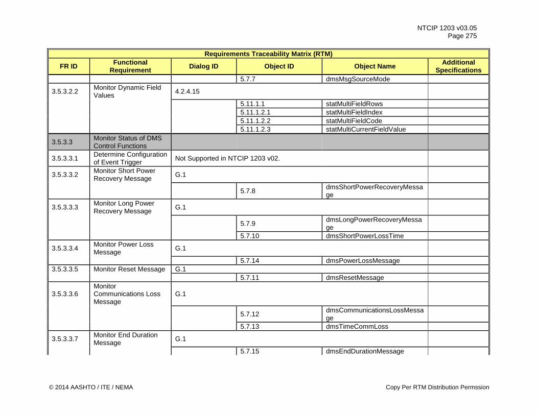
NTCIP 1203 v03.05 Page 275
Requirements Traceability Matrix (RTM)
FR ID Functional Requirement Dialog ID Object ID Object Name Additional
Specifications 5.7.7 dmsMsgSourceMode
3.5.3.2.2 Monitor Dynamic Field Values 4.2.4.15
5.11.1.1 statMultiFieldRows 5.11.1.2.1 statMultiFieldIndex 5.11.1.2.2 statMultiFieldCode 5.11.1.2.3 statMultiCurrentFieldValue
3.5.3.3 Monitor Status of DMS Control Functions
3.5.3.3.1 Determine Configuration of Event Trigger Not Supported in NTCIP 1203 v02.
3.5.3.3.2 Monitor Short Power Recovery Message G.1
5.7.8 dmsShortPowerRecoveryMessage
3.5.3.3.3 Monitor Long Power Recovery Message G.1
5.7.9 dmsLongPowerRecoveryMessage
5.7.10 dmsShortPowerLossTime
3.5.3.3.4 Monitor Power Loss Message G.1
5.7.14 dmsPowerLossMessage 3.5.3.3.5 Monitor Reset Message G.1 5.7.11 dmsResetMessage
3.5.3.3.6 Monitor Communications Loss Message
G.1
5.7.12 dmsCommunicationsLossMessage
5.7.13 dmsTimeCommLoss
3.5.3.3.7 Monitor End Duration Message G.1
5.7.15 dmsEndDurationMessage
© 2014 AASHTO / ITE / NEMA Copy Per RTM Distribution Permssion
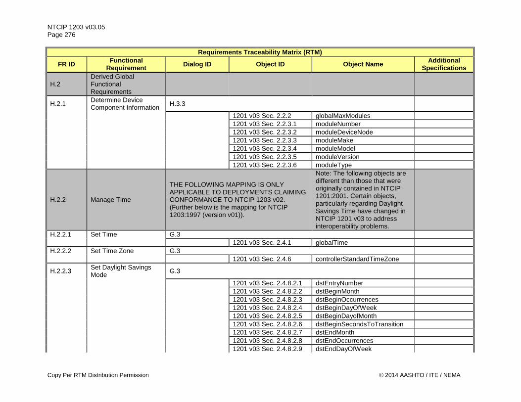
NTCIP 1203 v03.05 Page 276
Requirements Traceability Matrix (RTM)
FR ID Functional Requirement Dialog ID Object ID Object Name Additional
Specifications
H.2 Derived Global Functional Requirements
H.2.1 Determine Device Component Information H.3.3
1201 v03 Sec. 2.2.2 globalMaxModules 1201 v03 Sec. 2.2.3.1 moduleNumber 1201 v03 Sec. 2.2.3.2 moduleDeviceNode 1201 v03 Sec. 2.2.3.3 moduleMake 1201 v03 Sec. 2.2.3.4 moduleModel 1201 v03 Sec. 2.2.3.5 moduleVersion 1201 v03 Sec. 2.2.3.6 moduleType
H.2.2 Manage Time
THE FOLLOWING MAPPING IS ONLY APPLICABLE TO DEPLOYMENTS CLAIMING CONFORMANCE TO NTCIP 1203 v02. (Further below is the mapping for NTCIP 1203:1997 (version v01)).
Note: The following objects are different than those that were originally contained in NTCIP 1201:2001. Certain objects, particularly regarding Daylight Savings Time have changed in NTCIP 1201 v03 to address interoperability problems.
H.2.2.1 Set Time G.3 1201 v03 Sec. 2.4.1 globalTime H.2.2.2 Set Time Zone G.3 1201 v03 Sec. 2.4.6 controllerStandardTimeZone
H.2.2.3 Set Daylight Savings Mode G.3
1201 v03 Sec. 2.4.8.2.1 dstEntryNumber 1201 v03 Sec. 2.4.8.2.2 dstBeginMonth 1201 v03 Sec. 2.4.8.2.3 dstBeginOccurrences 1201 v03 Sec. 2.4.8.2.4 dstBeginDayOfWeek 1201 v03 Sec. 2.4.8.2.5 dstBeginDayofMonth 1201 v03 Sec. 2.4.8.2.6 dstBeginSecondsToTransition 1201 v03 Sec. 2.4.8.2.7 dstEndMonth 1201 v03 Sec. 2.4.8.2.8 dstEndOccurrences 1201 v03 Sec. 2.4.8.2.9 dstEndDayOfWeek
Copy Per RTM Distribution Permission © 2014 AASHTO / ITE / NEMA
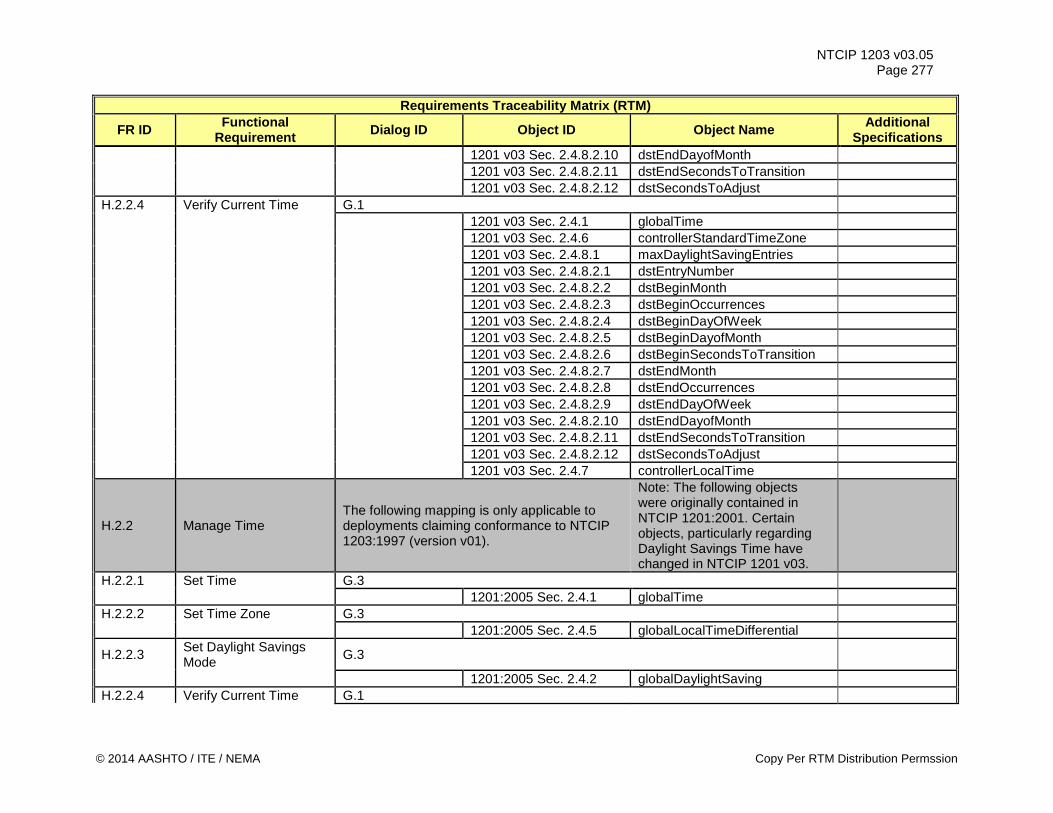
NTCIP 1203 v03.05 Page 277
Requirements Traceability Matrix (RTM)
FR ID Functional Requirement Dialog ID Object ID Object Name Additional
Specifications 1201 v03 Sec. 2.4.8.2.10 dstEndDayofMonth 1201 v03 Sec. 2.4.8.2.11 dstEndSecondsToTransition 1201 v03 Sec. 2.4.8.2.12 dstSecondsToAdjust H.2.2.4 Verify Current Time G.1 1201 v03 Sec. 2.4.1 globalTime 1201 v03 Sec. 2.4.6 controllerStandardTimeZone 1201 v03 Sec. 2.4.8.1 maxDaylightSavingEntries 1201 v03 Sec. 2.4.8.2.1 dstEntryNumber 1201 v03 Sec. 2.4.8.2.2 dstBeginMonth 1201 v03 Sec. 2.4.8.2.3 dstBeginOccurrences 1201 v03 Sec. 2.4.8.2.4 dstBeginDayOfWeek 1201 v03 Sec. 2.4.8.2.5 dstBeginDayofMonth 1201 v03 Sec. 2.4.8.2.6 dstBeginSecondsToTransition 1201 v03 Sec. 2.4.8.2.7 dstEndMonth 1201 v03 Sec. 2.4.8.2.8 dstEndOccurrences 1201 v03 Sec. 2.4.8.2.9 dstEndDayOfWeek 1201 v03 Sec. 2.4.8.2.10 dstEndDayofMonth 1201 v03 Sec. 2.4.8.2.11 dstEndSecondsToTransition 1201 v03 Sec. 2.4.8.2.12 dstSecondsToAdjust 1201 v03 Sec. 2.4.7 controllerLocalTime
H.2.2 Manage Time The following mapping is only applicable to deployments claiming conformance to NTCIP 1203:1997 (version v01).
Note: The following objects were originally contained in NTCIP 1201:2001. Certain objects, particularly regarding Daylight Savings Time have changed in NTCIP 1201 v03.
H.2.2.1 Set Time G.3 1201:2005 Sec. 2.4.1 globalTime H.2.2.2 Set Time Zone G.3 1201:2005 Sec. 2.4.5 globalLocalTimeDifferential
H.2.2.3 Set Daylight Savings Mode G.3
1201:2005 Sec. 2.4.2 globalDaylightSaving H.2.2.4 Verify Current Time G.1
© 2014 AASHTO / ITE / NEMA Copy Per RTM Distribution Permssion
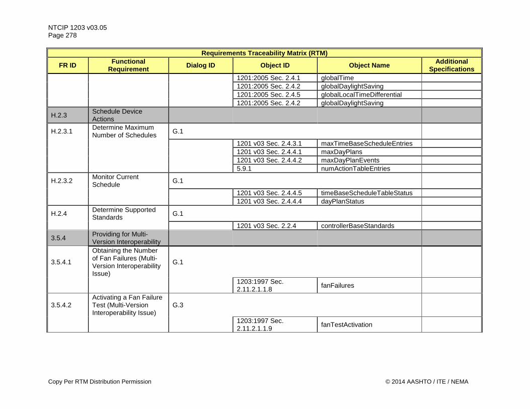
NTCIP 1203 v03.05 Page 278
Requirements Traceability Matrix (RTM)
FR ID Functional Requirement Dialog ID Object ID Object Name Additional
Specifications 1201:2005 Sec. 2.4.1 globalTime 1201:2005 Sec. 2.4.2 globalDaylightSaving 1201:2005 Sec. 2.4.5 globalLocalTimeDifferential 1201:2005 Sec. 2.4.2 globalDaylightSaving
H.2.3 Schedule Device Actions
H.2.3.1 Determine Maximum Number of Schedules G.1
1201 v03 Sec. 2.4.3.1 maxTimeBaseScheduleEntries 1201 v03 Sec. 2.4.4.1 maxDayPlans 1201 v03 Sec. 2.4.4.2 maxDayPlanEvents 5.9.1 numActionTableEntries
H.2.3.2 Monitor Current Schedule G.1
1201 v03 Sec. 2.4.4.5 timeBaseScheduleTableStatus 1201 v03 Sec. 2.4.4.4 dayPlanStatus
H.2.4 Determine Supported Standards G.1
1201 v03 Sec. 2.2.4 controllerBaseStandards
3.5.4 Providing for Multi-Version Interoperability
3.5.4.1
Obtaining the Number of Fan Failures (Multi-Version Interoperability Issue)
G.1
1203:1997 Sec. 2.11.2.1.1.8 fanFailures
3.5.4.2 Activating a Fan Failure Test (Multi-Version Interoperability Issue)
G.3
1203:1997 Sec. 2.11.2.1.1.9 fanTestActivation
Copy Per RTM Distribution Permission © 2014 AASHTO / ITE / NEMA
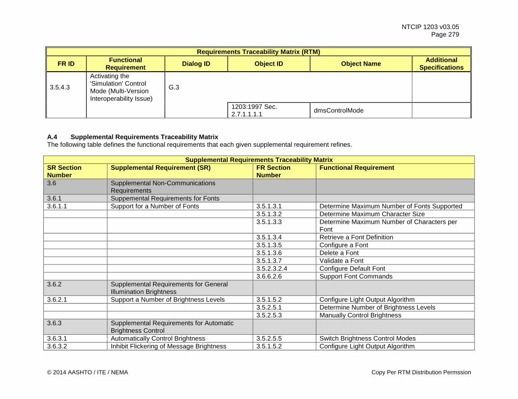
NTCIP 1203 v03.05 Page 279
Requirements Traceability Matrix (RTM)
FR ID Functional Requirement Dialog ID Object ID Object Name Additional
Specifications
3.5.4.3
Activating the 'Simulation' Control Mode (Multi-Version Interoperability Issue)
G.3
1203:1997 Sec. 2.7.1.1.1.1 dmsControlMode
A.4 Supplemental Requirements Traceability Matrix The following table defines the functional requirements that each given supplemental requirement refines.
Supplemental Requirements Traceability Matrix SR Section Number
Supplemental Requirement (SR) FR Section Number
Functional Requirement
3.6 Supplemental Non-Communications Requirements
3.6.1 Suppemental Requirements for Fonts 3.6.1.1 Support for a Number of Fonts 3.5.1.3.1 Determine Maximum Number of Fonts Supported 3.5.1.3.2 Determine Maximum Character Size 3.5.1.3.3 Determine Maximum Number of Characters per
Font 3.5.1.3.4 Retrieve a Font Definition 3.5.1.3.5 Configure a Font 3.5.1.3.6 Delete a Font 3.5.1.3.7 Validate a Font 3.5.2.3.2.4 Configure Default Font 3.6.6.2.6 Support Font Commands 3.6.2 Supplemental Requirements for General
Illumination Brightness
3.6.2.1 Support a Number of Brightness Levels 3.5.1.5.2 Configure Light Output Algorithm 3.5.2.5.1 Determine Number of Brightness Levels 3.5.2.5.3 Manually Control Brightness 3.6.3 Supplemental Requirements for Automatic
Brightness Control
3.6.3.1 Automatically Control Brightness 3.5.2.5.5 Switch Brightness Control Modes 3.6.3.2 Inhibit Flickering of Message Brightness 3.5.1.5.2 Configure Light Output Algorithm
© 2014 AASHTO / ITE / NEMA Copy Per RTM Distribution Permssion
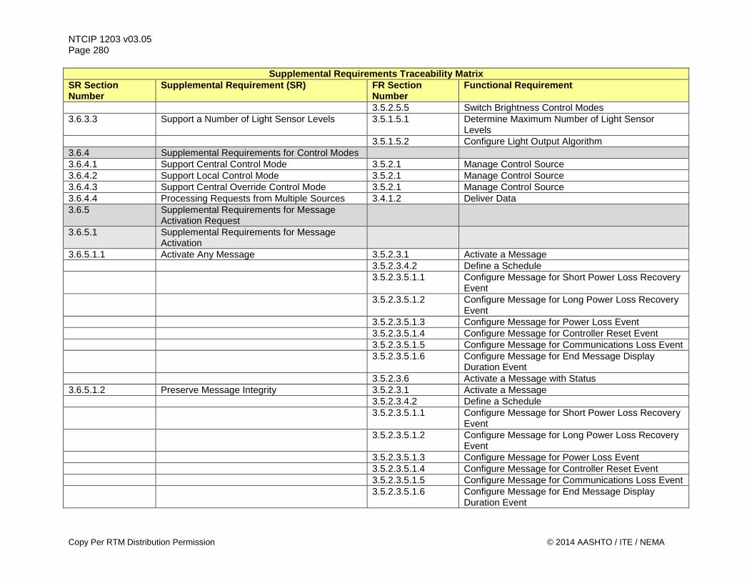
NTCIP 1203 v03.05 Page 280
Supplemental Requirements Traceability Matrix SR Section Number
Supplemental Requirement (SR) FR Section Number
Functional Requirement
3.5.2.5.5 Switch Brightness Control Modes 3.6.3.3 Support a Number of Light Sensor Levels 3.5.1.5.1 Determine Maximum Number of Light Sensor
Levels 3.5.1.5.2 Configure Light Output Algorithm 3.6.4 Supplemental Requirements for Control Modes 3.6.4.1 Support Central Control Mode 3.5.2.1 Manage Control Source 3.6.4.2 Support Local Control Mode 3.5.2.1 Manage Control Source 3.6.4.3 Support Central Override Control Mode 3.5.2.1 Manage Control Source 3.6.4.4 Processing Requests from Multiple Sources 3.4.1.2 Deliver Data 3.6.5 Supplemental Requirements for Message
Activation Request
3.6.5.1 Supplemental Requirements for Message Activation
3.6.5.1.1 Activate Any Message 3.5.2.3.1 Activate a Message 3.5.2.3.4.2 Define a Schedule 3.5.2.3.5.1.1 Configure Message for Short Power Loss Recovery
Event 3.5.2.3.5.1.2 Configure Message for Long Power Loss Recovery
Event 3.5.2.3.5.1.3 Configure Message for Power Loss Event 3.5.2.3.5.1.4 Configure Message for Controller Reset Event 3.5.2.3.5.1.5 Configure Message for Communications Loss Event 3.5.2.3.5.1.6 Configure Message for End Message Display
Duration Event 3.5.2.3.6 Activate a Message with Status 3.6.5.1.2 Preserve Message Integrity 3.5.2.3.1 Activate a Message 3.5.2.3.4.2 Define a Schedule 3.5.2.3.5.1.1 Configure Message for Short Power Loss Recovery
Event 3.5.2.3.5.1.2 Configure Message for Long Power Loss Recovery
Event 3.5.2.3.5.1.3 Configure Message for Power Loss Event 3.5.2.3.5.1.4 Configure Message for Controller Reset Event 3.5.2.3.5.1.5 Configure Message for Communications Loss Event 3.5.2.3.5.1.6 Configure Message for End Message Display
Duration Event
Copy Per RTM Distribution Permission © 2014 AASHTO / ITE / NEMA
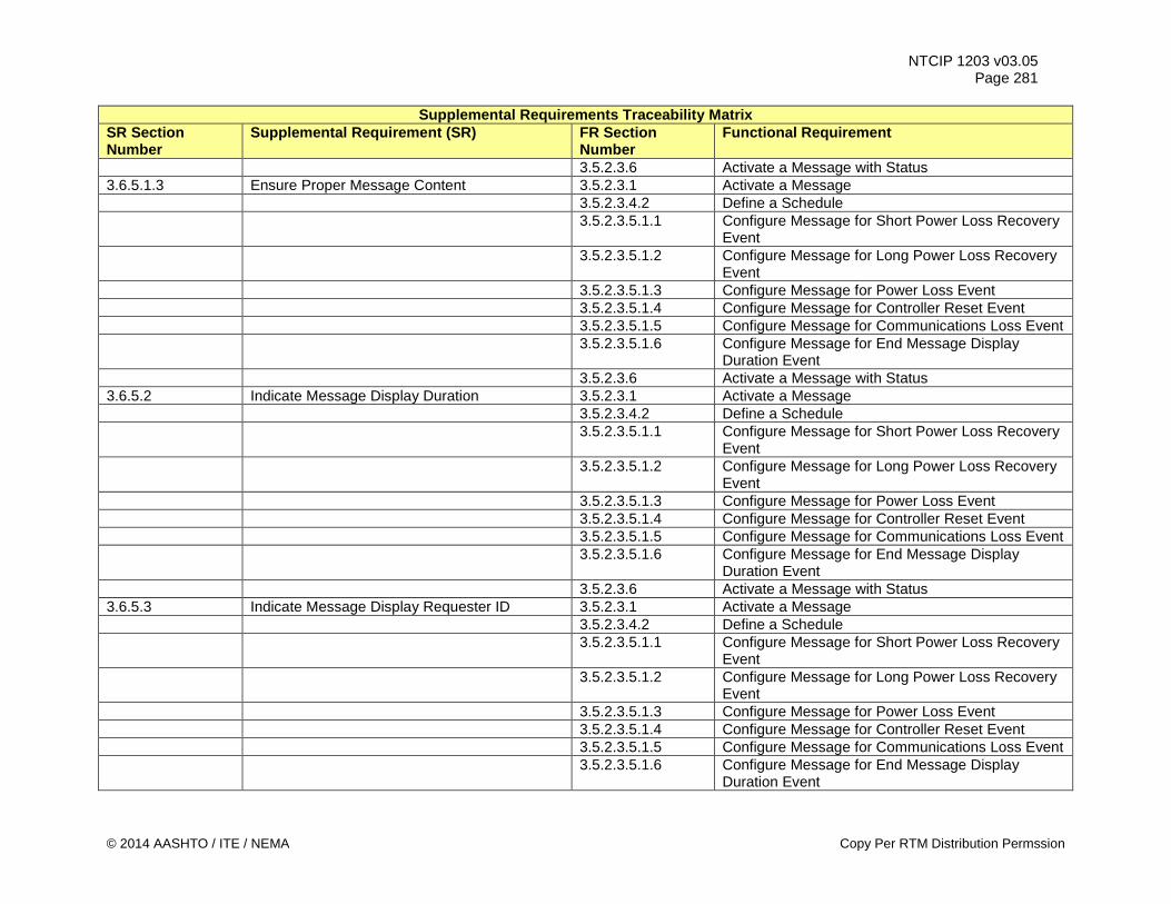
NTCIP 1203 v03.05 Page 281
Supplemental Requirements Traceability Matrix SR Section Number
Supplemental Requirement (SR) FR Section Number
Functional Requirement
3.5.2.3.6 Activate a Message with Status 3.6.5.1.3 Ensure Proper Message Content 3.5.2.3.1 Activate a Message 3.5.2.3.4.2 Define a Schedule 3.5.2.3.5.1.1 Configure Message for Short Power Loss Recovery
Event 3.5.2.3.5.1.2 Configure Message for Long Power Loss Recovery
Event 3.5.2.3.5.1.3 Configure Message for Power Loss Event 3.5.2.3.5.1.4 Configure Message for Controller Reset Event 3.5.2.3.5.1.5 Configure Message for Communications Loss Event 3.5.2.3.5.1.6 Configure Message for End Message Display
Duration Event 3.5.2.3.6 Activate a Message with Status 3.6.5.2 Indicate Message Display Duration 3.5.2.3.1 Activate a Message 3.5.2.3.4.2 Define a Schedule 3.5.2.3.5.1.1 Configure Message for Short Power Loss Recovery
Event 3.5.2.3.5.1.2 Configure Message for Long Power Loss Recovery
Event 3.5.2.3.5.1.3 Configure Message for Power Loss Event 3.5.2.3.5.1.4 Configure Message for Controller Reset Event 3.5.2.3.5.1.5 Configure Message for Communications Loss Event 3.5.2.3.5.1.6 Configure Message for End Message Display
Duration Event 3.5.2.3.6 Activate a Message with Status 3.6.5.3 Indicate Message Display Requester ID 3.5.2.3.1 Activate a Message 3.5.2.3.4.2 Define a Schedule 3.5.2.3.5.1.1 Configure Message for Short Power Loss Recovery
Event 3.5.2.3.5.1.2 Configure Message for Long Power Loss Recovery
Event 3.5.2.3.5.1.3 Configure Message for Power Loss Event 3.5.2.3.5.1.4 Configure Message for Controller Reset Event 3.5.2.3.5.1.5 Configure Message for Communications Loss Event 3.5.2.3.5.1.6 Configure Message for End Message Display
Duration Event
© 2014 AASHTO / ITE / NEMA Copy Per RTM Distribution Permssion
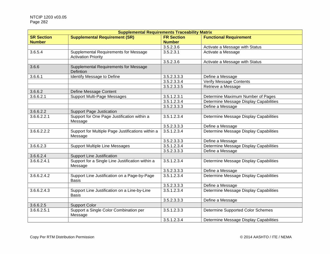
NTCIP 1203 v03.05 Page 282
Supplemental Requirements Traceability Matrix SR Section Number
Supplemental Requirement (SR) FR Section Number
Functional Requirement
3.5.2.3.6 Activate a Message with Status 3.6.5.4 Supplemental Requirements for Message
Activation Priority 3.5.2.3.1 Activate a Message
3.5.2.3.6 Activate a Message with Status 3.6.6 Supplemental Requirements for Message
Defintion
3.6.6.1 Identify Message to Define 3.5.2.3.3.3 Define a Message 3.5.2.3.3.4 Verify Message Contents 3.5.2.3.3.5 Retrieve a Message 3.6.6.2 Define Message Content 3.6.6.2.1 Support Multi-Page Messages 3.5.1.2.3.1 Determine Maximum Number of Pages 3.5.1.2.3.4 Determine Message Display Capabilities 3.5.2.3.3.3 Define a Message 3.6.6.2.2 Support Page Justication 3.6.6.2.2.1 Support for One Page Justification within a
Message 3.5.1.2.3.4 Determine Message Display Capabilities
3.5.2.3.3.3 Define a Message 3.6.6.2.2.2 Support for Multiple Page Justifications within a
Message 3.5.1.2.3.4 Determine Message Display Capabilities
3.5.2.3.3.3 Define a Message 3.6.6.2.3 Support Multiple Line Messages 3.5.1.2.3.4 Determine Message Display Capabilities 3.5.2.3.3.3 Define a Message 3.6.6.2.4 Support Line Justification 3.6.6.2.4.1 Support for a Single Line Justification within a
Message 3.5.1.2.3.4 Determine Message Display Capabilities
3.5.2.3.3.3 Define a Message 3.6.6.2.4.2 Support Line Justification on a Page-by-Page
Basis 3.5.1.2.3.4 Determine Message Display Capabilities
3.5.2.3.3.3 Define a Message 3.6.6.2.4.3 Support Line Justification on a Line-by-Line
Basis 3.5.1.2.3.4 Determine Message Display Capabilities
3.5.2.3.3.3 Define a Message 3.6.6.2.5 Support Color 3.6.6.2.5.1 Support a Single Color Combination per
Message 3.5.1.2.3.3 Determine Supported Color Schemes
3.5.1.2.3.4 Determine Message Display Capabilities
Copy Per RTM Distribution Permission © 2014 AASHTO / ITE / NEMA
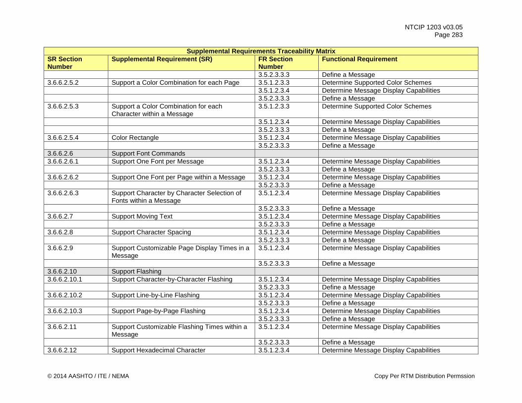
NTCIP 1203 v03.05 Page 283
Supplemental Requirements Traceability Matrix SR Section Number
Supplemental Requirement (SR) FR Section Number
Functional Requirement
3.5.2.3.3.3 Define a Message 3.6.6.2.5.2 Support a Color Combination for each Page 3.5.1.2.3.3 Determine Supported Color Schemes 3.5.1.2.3.4 Determine Message Display Capabilities 3.5.2.3.3.3 Define a Message 3.6.6.2.5.3 Support a Color Combination for each
Character within a Message 3.5.1.2.3.3 Determine Supported Color Schemes
3.5.1.2.3.4 Determine Message Display Capabilities 3.5.2.3.3.3 Define a Message 3.6.6.2.5.4 Color Rectangle 3.5.1.2.3.4 Determine Message Display Capabilities 3.5.2.3.3.3 Define a Message 3.6.6.2.6 Support Font Commands 3.6.6.2.6.1 Support One Font per Message 3.5.1.2.3.4 Determine Message Display Capabilities 3.5.2.3.3.3 Define a Message 3.6.6.2.6.2 Support One Font per Page within a Message 3.5.1.2.3.4 Determine Message Display Capabilities 3.5.2.3.3.3 Define a Message 3.6.6.2.6.3 Support Character by Character Selection of
Fonts within a Message 3.5.1.2.3.4 Determine Message Display Capabilities
3.5.2.3.3.3 Define a Message 3.6.6.2.7 Support Moving Text 3.5.1.2.3.4 Determine Message Display Capabilities 3.5.2.3.3.3 Define a Message 3.6.6.2.8 Support Character Spacing 3.5.1.2.3.4 Determine Message Display Capabilities 3.5.2.3.3.3 Define a Message 3.6.6.2.9 Support Customizable Page Display Times in a
Message 3.5.1.2.3.4 Determine Message Display Capabilities
3.5.2.3.3.3 Define a Message 3.6.6.2.10 Support Flashing 3.6.6.2.10.1 Support Character-by-Character Flashing 3.5.1.2.3.4 Determine Message Display Capabilities 3.5.2.3.3.3 Define a Message 3.6.6.2.10.2 Support Line-by-Line Flashing 3.5.1.2.3.4 Determine Message Display Capabilities 3.5.2.3.3.3 Define a Message 3.6.6.2.10.3 Support Page-by-Page Flashing 3.5.1.2.3.4 Determine Message Display Capabilities 3.5.2.3.3.3 Define a Message 3.6.6.2.11 Support Customizable Flashing Times within a
Message 3.5.1.2.3.4 Determine Message Display Capabilities
3.5.2.3.3.3 Define a Message 3.6.6.2.12 Support Hexadecimal Character 3.5.1.2.3.4 Determine Message Display Capabilities
© 2014 AASHTO / ITE / NEMA Copy Per RTM Distribution Permssion
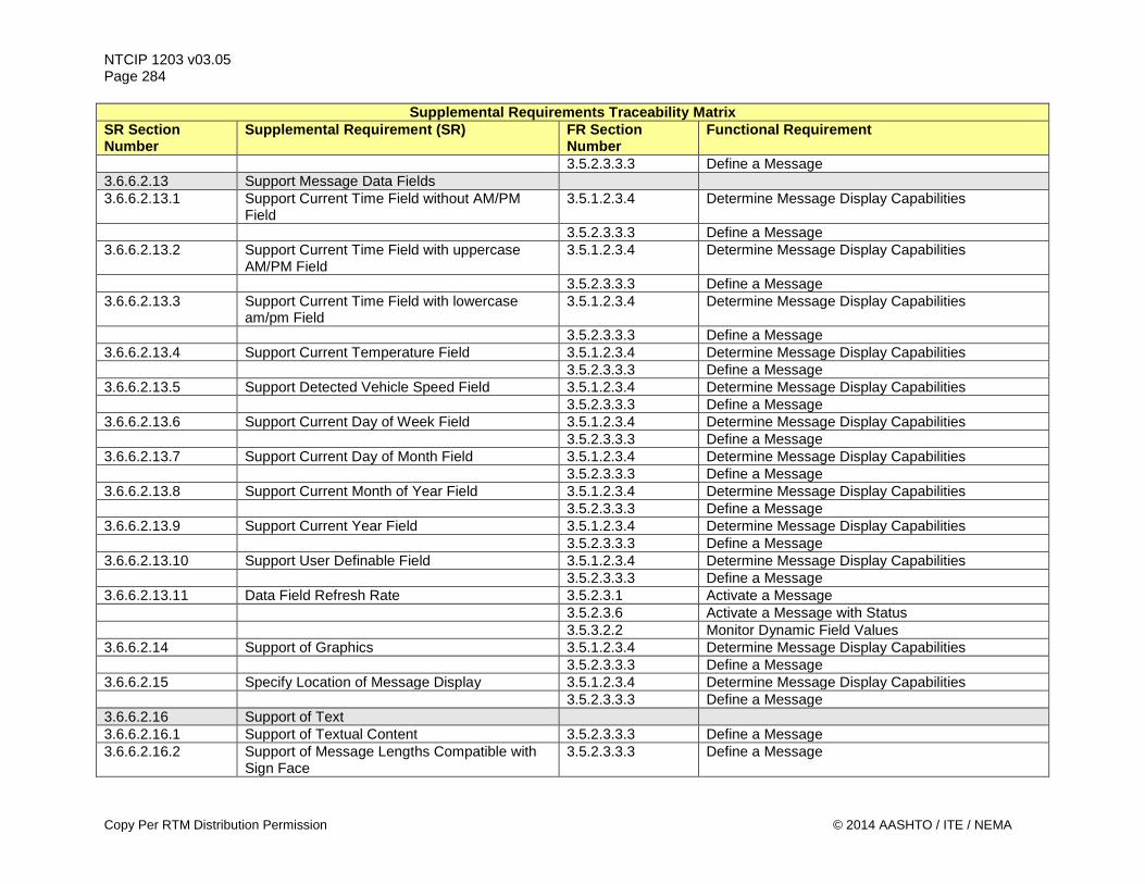
NTCIP 1203 v03.05 Page 284
Supplemental Requirements Traceability Matrix SR Section Number
Supplemental Requirement (SR) FR Section Number
Functional Requirement
3.5.2.3.3.3 Define a Message 3.6.6.2.13 Support Message Data Fields 3.6.6.2.13.1 Support Current Time Field without AM/PM
Field 3.5.1.2.3.4 Determine Message Display Capabilities
3.5.2.3.3.3 Define a Message 3.6.6.2.13.2 Support Current Time Field with uppercase
AM/PM Field 3.5.1.2.3.4 Determine Message Display Capabilities
3.5.2.3.3.3 Define a Message 3.6.6.2.13.3 Support Current Time Field with lowercase
am/pm Field 3.5.1.2.3.4 Determine Message Display Capabilities
3.5.2.3.3.3 Define a Message 3.6.6.2.13.4 Support Current Temperature Field 3.5.1.2.3.4 Determine Message Display Capabilities 3.5.2.3.3.3 Define a Message 3.6.6.2.13.5 Support Detected Vehicle Speed Field 3.5.1.2.3.4 Determine Message Display Capabilities 3.5.2.3.3.3 Define a Message 3.6.6.2.13.6 Support Current Day of Week Field 3.5.1.2.3.4 Determine Message Display Capabilities 3.5.2.3.3.3 Define a Message 3.6.6.2.13.7 Support Current Day of Month Field 3.5.1.2.3.4 Determine Message Display Capabilities 3.5.2.3.3.3 Define a Message 3.6.6.2.13.8 Support Current Month of Year Field 3.5.1.2.3.4 Determine Message Display Capabilities 3.5.2.3.3.3 Define a Message 3.6.6.2.13.9 Support Current Year Field 3.5.1.2.3.4 Determine Message Display Capabilities 3.5.2.3.3.3 Define a Message 3.6.6.2.13.10 Support User Definable Field 3.5.1.2.3.4 Determine Message Display Capabilities 3.5.2.3.3.3 Define a Message 3.6.6.2.13.11 Data Field Refresh Rate 3.5.2.3.1 Activate a Message 3.5.2.3.6 Activate a Message with Status 3.5.3.2.2 Monitor Dynamic Field Values 3.6.6.2.14 Support of Graphics 3.5.1.2.3.4 Determine Message Display Capabilities 3.5.2.3.3.3 Define a Message 3.6.6.2.15 Specify Location of Message Display 3.5.1.2.3.4 Determine Message Display Capabilities 3.5.2.3.3.3 Define a Message 3.6.6.2.16 Support of Text 3.6.6.2.16.1 Support of Textual Content 3.5.2.3.3.3 Define a Message 3.6.6.2.16.2 Support of Message Lengths Compatible with
Sign Face 3.5.2.3.3.3 Define a Message
Copy Per RTM Distribution Permission © 2014 AASHTO / ITE / NEMA
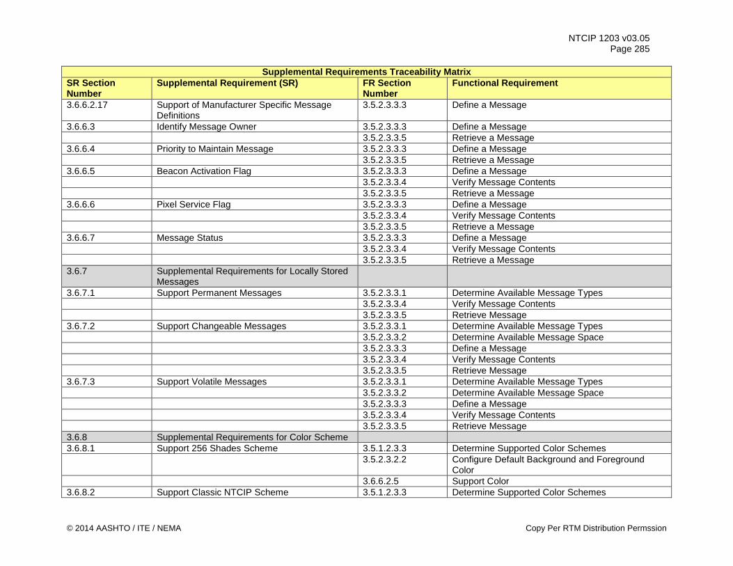
NTCIP 1203 v03.05 Page 285
Supplemental Requirements Traceability Matrix SR Section Number
Supplemental Requirement (SR) FR Section Number
Functional Requirement
3.6.6.2.17 Support of Manufacturer Specific Message Definitions
3.5.2.3.3.3 Define a Message
3.6.6.3 Identify Message Owner 3.5.2.3.3.3 Define a Message 3.5.2.3.3.5 Retrieve a Message 3.6.6.4 Priority to Maintain Message 3.5.2.3.3.3 Define a Message 3.5.2.3.3.5 Retrieve a Message 3.6.6.5 Beacon Activation Flag 3.5.2.3.3.3 Define a Message 3.5.2.3.3.4 Verify Message Contents 3.5.2.3.3.5 Retrieve a Message 3.6.6.6 Pixel Service Flag 3.5.2.3.3.3 Define a Message 3.5.2.3.3.4 Verify Message Contents 3.5.2.3.3.5 Retrieve a Message 3.6.6.7 Message Status 3.5.2.3.3.3 Define a Message 3.5.2.3.3.4 Verify Message Contents 3.5.2.3.3.5 Retrieve a Message 3.6.7 Supplemental Requirements for Locally Stored
Messages
3.6.7.1 Support Permanent Messages 3.5.2.3.3.1 Determine Available Message Types 3.5.2.3.3.4 Verify Message Contents 3.5.2.3.3.5 Retrieve Message 3.6.7.2 Support Changeable Messages 3.5.2.3.3.1 Determine Available Message Types 3.5.2.3.3.2 Determine Available Message Space 3.5.2.3.3.3 Define a Message 3.5.2.3.3.4 Verify Message Contents 3.5.2.3.3.5 Retrieve Message 3.6.7.3 Support Volatile Messages 3.5.2.3.3.1 Determine Available Message Types 3.5.2.3.3.2 Determine Available Message Space 3.5.2.3.3.3 Define a Message 3.5.2.3.3.4 Verify Message Contents 3.5.2.3.3.5 Retrieve Message 3.6.8 Supplemental Requirements for Color Scheme 3.6.8.1 Support 256 Shades Scheme 3.5.1.2.3.3 Determine Supported Color Schemes 3.5.2.3.2.2 Configure Default Background and Foreground
Color 3.6.6.2.5 Support Color 3.6.8.2 Support Classic NTCIP Scheme 3.5.1.2.3.3 Determine Supported Color Schemes
© 2014 AASHTO / ITE / NEMA Copy Per RTM Distribution Permssion
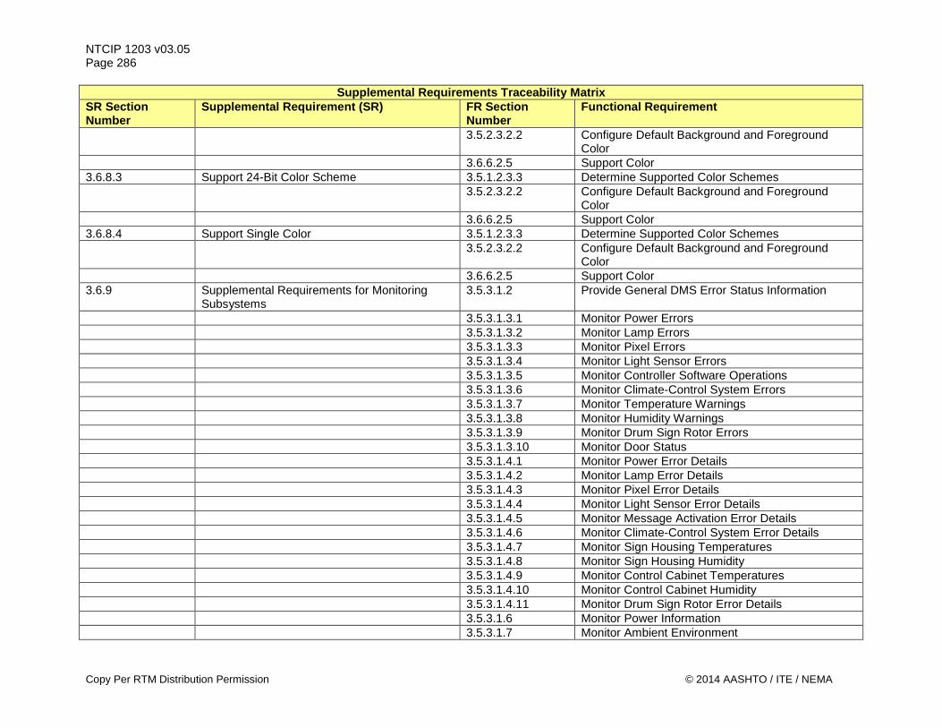
NTCIP 1203 v03.05 Page 286
Supplemental Requirements Traceability Matrix SR Section Number
Supplemental Requirement (SR) FR Section Number
Functional Requirement
3.5.2.3.2.2 Configure Default Background and Foreground Color
3.6.6.2.5 Support Color 3.6.8.3 Support 24-Bit Color Scheme 3.5.1.2.3.3 Determine Supported Color Schemes 3.5.2.3.2.2 Configure Default Background and Foreground
Color 3.6.6.2.5 Support Color 3.6.8.4 Support Single Color 3.5.1.2.3.3 Determine Supported Color Schemes 3.5.2.3.2.2 Configure Default Background and Foreground
Color 3.6.6.2.5 Support Color 3.6.9 Supplemental Requirements for Monitoring
Subsystems 3.5.3.1.2 Provide General DMS Error Status Information
3.5.3.1.3.1 Monitor Power Errors 3.5.3.1.3.2 Monitor Lamp Errors 3.5.3.1.3.3 Monitor Pixel Errors 3.5.3.1.3.4 Monitor Light Sensor Errors 3.5.3.1.3.5 Monitor Controller Software Operations 3.5.3.1.3.6 Monitor Climate-Control System Errors 3.5.3.1.3.7 Monitor Temperature Warnings 3.5.3.1.3.8 Monitor Humidity Warnings 3.5.3.1.3.9 Monitor Drum Sign Rotor Errors 3.5.3.1.3.10 Monitor Door Status 3.5.3.1.4.1 Monitor Power Error Details 3.5.3.1.4.2 Monitor Lamp Error Details 3.5.3.1.4.3 Monitor Pixel Error Details 3.5.3.1.4.4 Monitor Light Sensor Error Details 3.5.3.1.4.5 Monitor Message Activation Error Details 3.5.3.1.4.6 Monitor Climate-Control System Error Details 3.5.3.1.4.7 Monitor Sign Housing Temperatures 3.5.3.1.4.8 Monitor Sign Housing Humidity 3.5.3.1.4.9 Monitor Control Cabinet Temperatures 3.5.3.1.4.10 Monitor Control Cabinet Humidity 3.5.3.1.4.11 Monitor Drum Sign Rotor Error Details 3.5.3.1.6 Monitor Power Information 3.5.3.1.7 Monitor Ambient Environment
Copy Per RTM Distribution Permission © 2014 AASHTO / ITE / NEMA
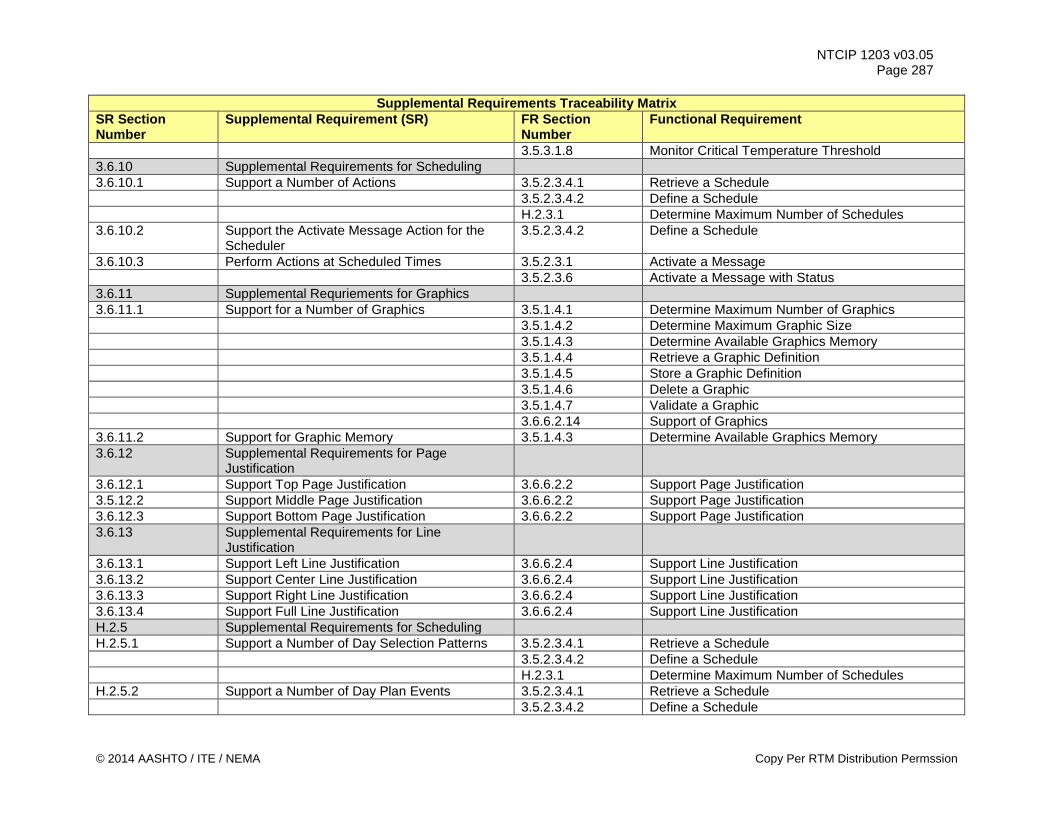
NTCIP 1203 v03.05 Page 287
Supplemental Requirements Traceability Matrix SR Section Number
Supplemental Requirement (SR) FR Section Number
Functional Requirement
3.5.3.1.8 Monitor Critical Temperature Threshold 3.6.10 Supplemental Requirements for Scheduling 3.6.10.1 Support a Number of Actions 3.5.2.3.4.1 Retrieve a Schedule 3.5.2.3.4.2 Define a Schedule H.2.3.1 Determine Maximum Number of Schedules 3.6.10.2 Support the Activate Message Action for the
Scheduler 3.5.2.3.4.2 Define a Schedule
3.6.10.3 Perform Actions at Scheduled Times 3.5.2.3.1 Activate a Message 3.5.2.3.6 Activate a Message with Status 3.6.11 Supplemental Requriements for Graphics 3.6.11.1 Support for a Number of Graphics 3.5.1.4.1 Determine Maximum Number of Graphics 3.5.1.4.2 Determine Maximum Graphic Size 3.5.1.4.3 Determine Available Graphics Memory 3.5.1.4.4 Retrieve a Graphic Definition 3.5.1.4.5 Store a Graphic Definition 3.5.1.4.6 Delete a Graphic 3.5.1.4.7 Validate a Graphic 3.6.6.2.14 Support of Graphics 3.6.11.2 Support for Graphic Memory 3.5.1.4.3 Determine Available Graphics Memory 3.6.12 Supplemental Requirements for Page
Justification
3.6.12.1 Support Top Page Justification 3.6.6.2.2 Support Page Justification 3.5.12.2 Support Middle Page Justification 3.6.6.2.2 Support Page Justification 3.6.12.3 Support Bottom Page Justification 3.6.6.2.2 Support Page Justification 3.6.13 Supplemental Requirements for Line
Justification
3.6.13.1 Support Left Line Justification 3.6.6.2.4 Support Line Justification 3.6.13.2 Support Center Line Justification 3.6.6.2.4 Support Line Justification 3.6.13.3 Support Right Line Justification 3.6.6.2.4 Support Line Justification 3.6.13.4 Support Full Line Justification 3.6.6.2.4 Support Line Justification H.2.5 Supplemental Requirements for Scheduling H.2.5.1 Support a Number of Day Selection Patterns 3.5.2.3.4.1 Retrieve a Schedule 3.5.2.3.4.2 Define a Schedule H.2.3.1 Determine Maximum Number of Schedules H.2.5.2 Support a Number of Day Plan Events 3.5.2.3.4.1 Retrieve a Schedule 3.5.2.3.4.2 Define a Schedule
© 2014 AASHTO / ITE / NEMA Copy Per RTM Distribution Permssion
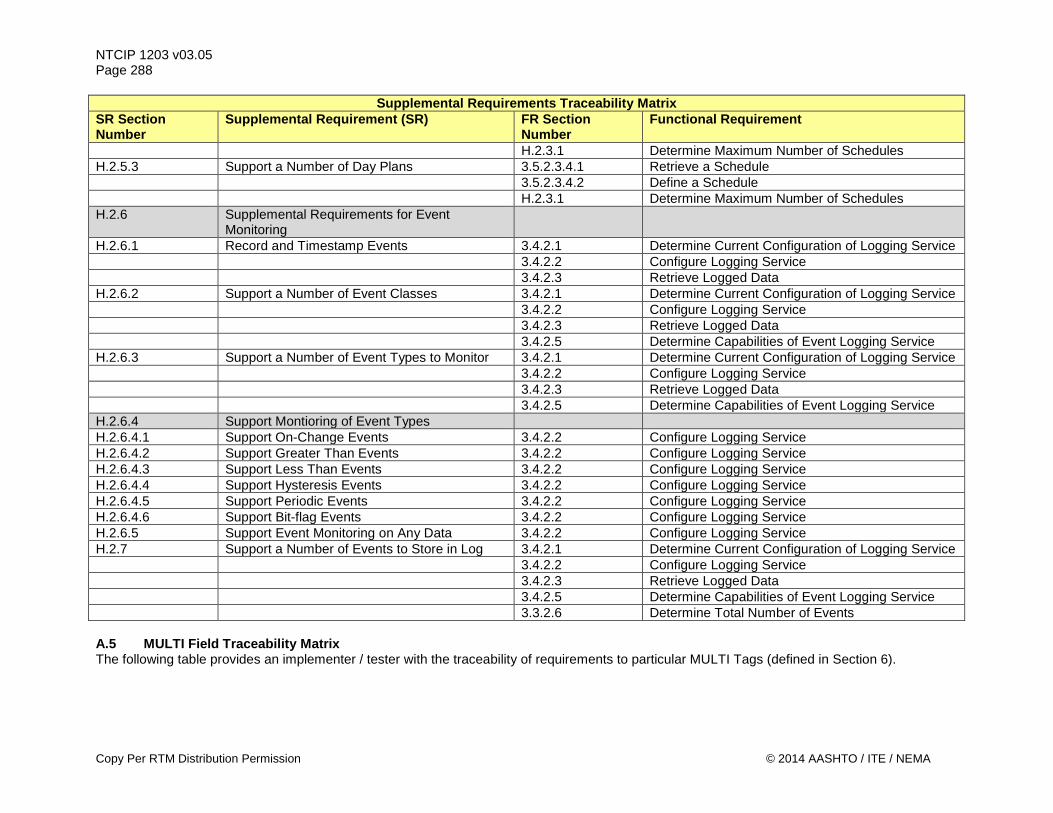
NTCIP 1203 v03.05 Page 288
Supplemental Requirements Traceability Matrix SR Section Number
Supplemental Requirement (SR) FR Section Number
Functional Requirement
H.2.3.1 Determine Maximum Number of Schedules H.2.5.3 Support a Number of Day Plans 3.5.2.3.4.1 Retrieve a Schedule 3.5.2.3.4.2 Define a Schedule H.2.3.1 Determine Maximum Number of Schedules H.2.6 Supplemental Requirements for Event
Monitoring
H.2.6.1 Record and Timestamp Events 3.4.2.1 Determine Current Configuration of Logging Service 3.4.2.2 Configure Logging Service 3.4.2.3 Retrieve Logged Data H.2.6.2 Support a Number of Event Classes 3.4.2.1 Determine Current Configuration of Logging Service 3.4.2.2 Configure Logging Service 3.4.2.3 Retrieve Logged Data 3.4.2.5 Determine Capabilities of Event Logging Service H.2.6.3 Support a Number of Event Types to Monitor 3.4.2.1 Determine Current Configuration of Logging Service 3.4.2.2 Configure Logging Service 3.4.2.3 Retrieve Logged Data 3.4.2.5 Determine Capabilities of Event Logging Service H.2.6.4 Support Montioring of Event Types H.2.6.4.1 Support On-Change Events 3.4.2.2 Configure Logging Service H.2.6.4.2 Support Greater Than Events 3.4.2.2 Configure Logging Service H.2.6.4.3 Support Less Than Events 3.4.2.2 Configure Logging Service H.2.6.4.4 Support Hysteresis Events 3.4.2.2 Configure Logging Service H.2.6.4.5 Support Periodic Events 3.4.2.2 Configure Logging Service H.2.6.4.6 Support Bit-flag Events 3.4.2.2 Configure Logging Service H.2.6.5 Support Event Monitoring on Any Data 3.4.2.2 Configure Logging Service H.2.7 Support a Number of Events to Store in Log 3.4.2.1 Determine Current Configuration of Logging Service 3.4.2.2 Configure Logging Service 3.4.2.3 Retrieve Logged Data 3.4.2.5 Determine Capabilities of Event Logging Service 3.3.2.6 Determine Total Number of Events A.5 MULTI Field Traceability Matrix The following table provides an implementer / tester with the traceability of requirements to particular MULTI Tags (defined in Section 6).
Copy Per RTM Distribution Permission © 2014 AASHTO / ITE / NEMA
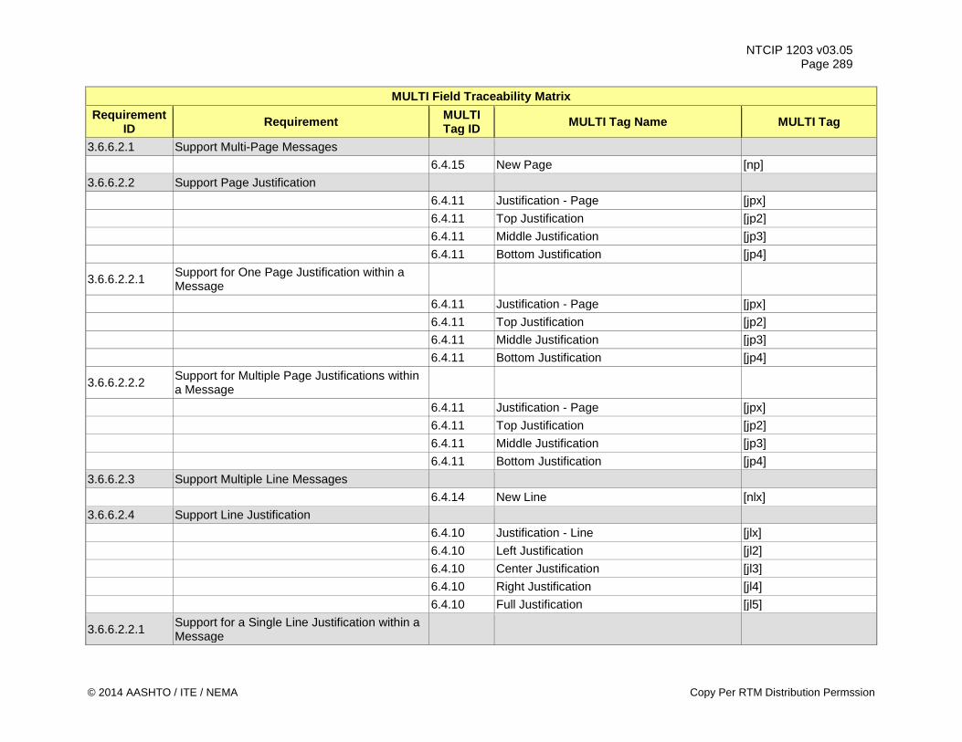
NTCIP 1203 v03.05 Page 289
MULTI Field Traceability Matrix Requirement
ID Requirement MULTI Tag ID MULTI Tag Name MULTI Tag
3.6.6.2.1 Support Multi-Page Messages 6.4.15 New Page [np] 3.6.6.2.2 Support Page Justification 6.4.11 Justification - Page [jpx] 6.4.11 Top Justification [jp2] 6.4.11 Middle Justification [jp3] 6.4.11 Bottom Justification [jp4]
3.6.6.2.2.1 Support for One Page Justification within a Message
6.4.11 Justification - Page [jpx] 6.4.11 Top Justification [jp2] 6.4.11 Middle Justification [jp3] 6.4.11 Bottom Justification [jp4]
3.6.6.2.2.2 Support for Multiple Page Justifications within a Message
6.4.11 Justification - Page [jpx] 6.4.11 Top Justification [jp2] 6.4.11 Middle Justification [jp3] 6.4.11 Bottom Justification [jp4] 3.6.6.2.3 Support Multiple Line Messages 6.4.14 New Line [nlx] 3.6.6.2.4 Support Line Justification 6.4.10 Justification - Line [jlx] 6.4.10 Left Justification [jl2] 6.4.10 Center Justification [jl3] 6.4.10 Right Justification [jl4] 6.4.10 Full Justification [jl5]
3.6.6.2.2.1 Support for a Single Line Justification within a Message
© 2014 AASHTO / ITE / NEMA Copy Per RTM Distribution Permssion
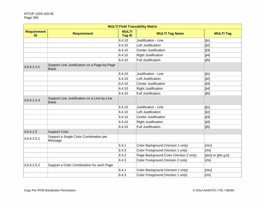
NTCIP 1203 v03.05 Page 290
MULTI Field Traceability Matrix Requirement
ID Requirement MULTI Tag ID MULTI Tag Name MULTI Tag
6.4.10 Justification - Line [jlx] 6.4.10 Left Justification [jl2] 6.4.10 Center Justification [jl3] 6.4.10 Right Justification [jl4] 6.4.10 Full Justification [jl5]
3.6.6.2.4.2 Support Line Justification on a Page-by-Page Basis
6.4.10 Justification - Line [jlx] 6.4.10 Left Justification [jl2] 6.4.10 Center Justification [jl3] 6.4.10 Right Justification [jl4] 6.4.10 Full Justification [jl5]
3.6.6.2.4.3 Support Line Justification on a Line-by-Line Basis
6.4.10 Justification - Line [jlx] 6.4.10 Left Justification [jl2] 6.4.10 Center Justification [jl3] 6.4.10 Right Justification [jl4] 6.4.10 Full Justification [jl5] 3.6.6.2.5 Support Color
3.6.6.2.5.1 Support a Single Color Combination per Message
6.4.1 Color Background (Version 1 only) [cbx] 6.4.3 Color Foreground (Version 1 only) [cfx] 6.4.2 Page Background Color (Version 2 only) [pbz] or [pbr,g,b] 6.4.3 Color Foreground (Version 2 only) [cfx] 3.6.6.2.5.2 Support a Color Combination for each Page 6.4.1 Color Background (Version 1 only) [cbx] 6.4.3 Color Foreground (Version 1 only) [cfx]
Copy Per RTM Distribution Permission © 2014 AASHTO / ITE / NEMA
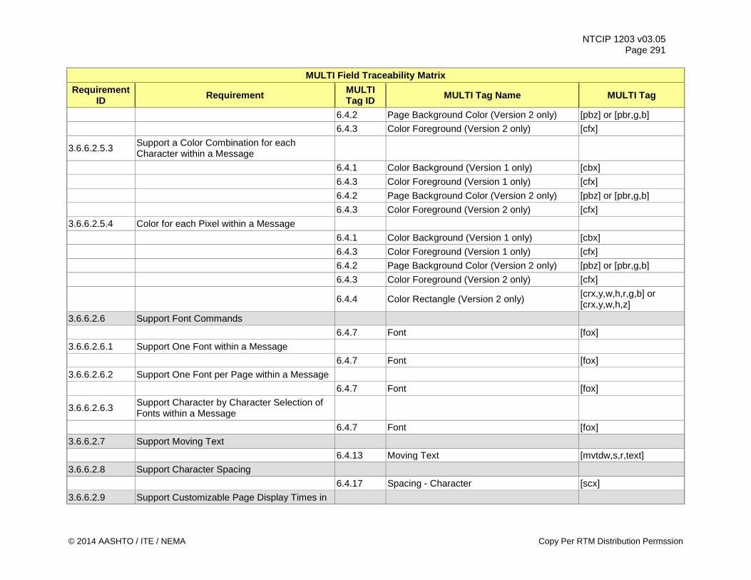
NTCIP 1203 v03.05 Page 291
MULTI Field Traceability Matrix Requirement
ID Requirement MULTI Tag ID MULTI Tag Name MULTI Tag
6.4.2 Page Background Color (Version 2 only) [pbz] or [pbr,g,b] 6.4.3 Color Foreground (Version 2 only) [cfx]
3.6.6.2.5.3 Support a Color Combination for each Character within a Message
6.4.1 Color Background (Version 1 only) [cbx] 6.4.3 Color Foreground (Version 1 only) [cfx] 6.4.2 Page Background Color (Version 2 only) [pbz] or [pbr,g,b] 6.4.3 Color Foreground (Version 2 only) [cfx] 3.6.6.2.5.4 Color for each Pixel within a Message 6.4.1 Color Background (Version 1 only) [cbx] 6.4.3 Color Foreground (Version 1 only) [cfx] 6.4.2 Page Background Color (Version 2 only) [pbz] or [pbr,g,b] 6.4.3 Color Foreground (Version 2 only) [cfx]
6.4.4 Color Rectangle (Version 2 only) [crx,y,w,h,r,g,b] or [crx,y,w,h,z]
3.6.6.2.6 Support Font Commands 6.4.7 Font [fox] 3.6.6.2.6.1 Support One Font within a Message 6.4.7 Font [fox] 3.6.6.2.6.2 Support One Font per Page within a Message 6.4.7 Font [fox]
3.6.6.2.6.3 Support Character by Character Selection of Fonts within a Message
6.4.7 Font [fox] 3.6.6.2.7 Support Moving Text 6.4.13 Moving Text [mvtdw,s,r,text] 3.6.6.2.8 Support Character Spacing 6.4.17 Spacing - Character [scx] 3.6.6.2.9 Support Customizable Page Display Times in
© 2014 AASHTO / ITE / NEMA Copy Per RTM Distribution Permssion
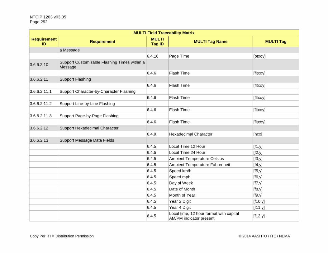
NTCIP 1203 v03.05 Page 292
MULTI Field Traceability Matrix Requirement
ID Requirement MULTI Tag ID MULTI Tag Name MULTI Tag
a Message 6.4.16 Page Time [ptxoy]
3.6.6.2.10 Support Customizable Flashing Times within a Message
6.4.6 Flash Time [fltxoy] 3.6.6.2.11 Support Flashing 6.4.6 Flash Time [fltxoy] 3.6.6.2.11.1 Support Character-by-Character Flashing 6.4.6 Flash Time [fltxoy] 3.6.6.2.11.2 Support Line-by-Line Flashing 6.4.6 Flash Time [fltxoy] 3.6.6.2.11.3 Support Page-by-Page Flashing 6.4.6 Flash Time [fltxoy] 3.6.6.2.12 Support Hexadecimal Character 6.4.9 Hexadecimal Character [hcx] 3.6.6.2.13 Support Message Data Fields 6.4.5 Local Time 12 Hour [f1,y] 6.4.5 Local Time 24 Hour [f2,y] 6.4.5 Ambient Temperature Celsius [f3,y] 6.4.5 Ambient Temperature Fahrenheit [f4,y] 6.4.5 Speed km/h [f5,y] 6.4.5 Speed mph [f6,y] 6.4.5 Day of Week [f7,y] 6.4.5 Date of Month [f8,y] 6.4.5 Month of Year [f9,y] 6.4.5 Year 2 Digit [f10,y] 6.4.5 Year 4 Digit [f11,y]
6.4.5 Local time, 12 hour format with capital AM/PM indicator present [f12,y]
Copy Per RTM Distribution Permission © 2014 AASHTO / ITE / NEMA
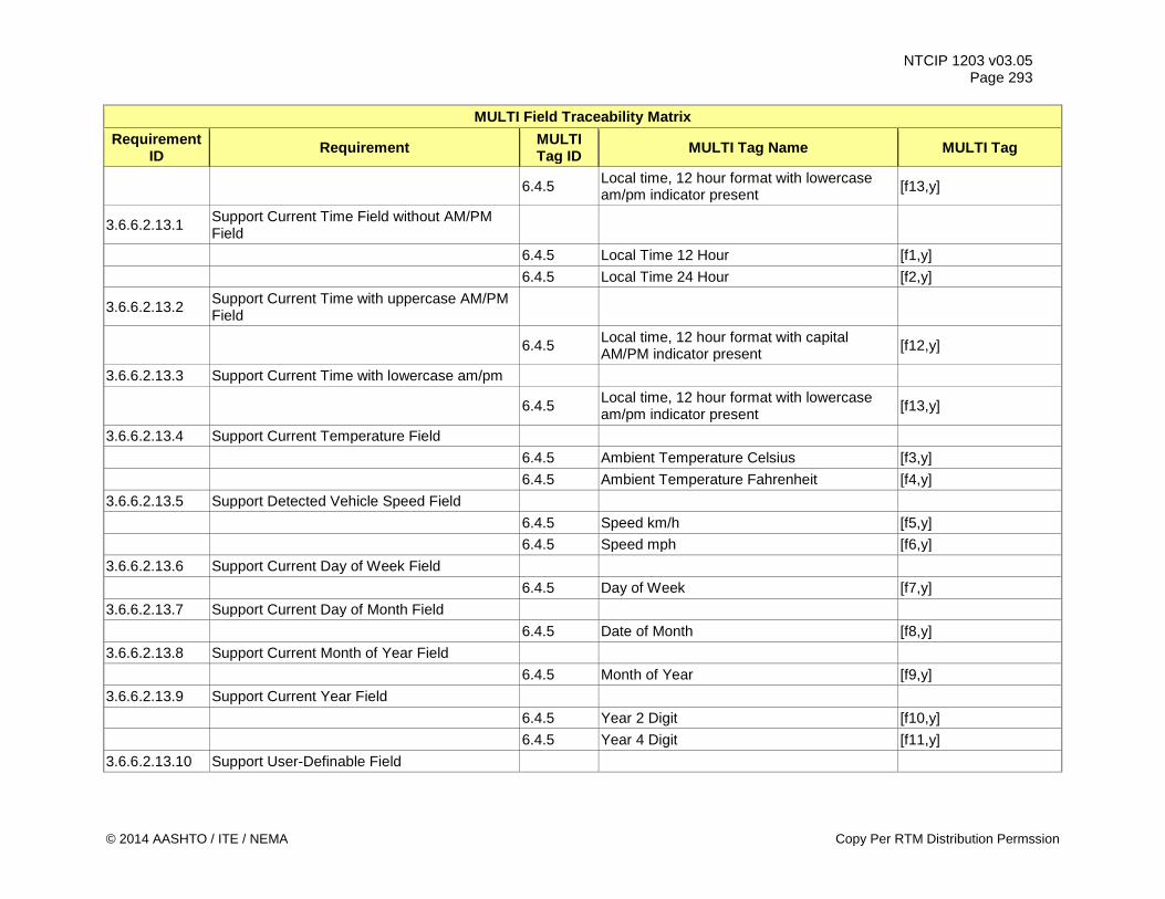
NTCIP 1203 v03.05 Page 293
MULTI Field Traceability Matrix Requirement
ID Requirement MULTI Tag ID MULTI Tag Name MULTI Tag
6.4.5 Local time, 12 hour format with lowercase am/pm indicator present [f13,y]
3.6.6.2.13.1 Support Current Time Field without AM/PM Field
6.4.5 Local Time 12 Hour [f1,y] 6.4.5 Local Time 24 Hour [f2,y]
3.6.6.2.13.2 Support Current Time with uppercase AM/PM Field
6.4.5 Local time, 12 hour format with capital AM/PM indicator present [f12,y]
3.6.6.2.13.3 Support Current Time with lowercase am/pm
6.4.5 Local time, 12 hour format with lowercase am/pm indicator present [f13,y]
3.6.6.2.13.4 Support Current Temperature Field 6.4.5 Ambient Temperature Celsius [f3,y] 6.4.5 Ambient Temperature Fahrenheit [f4,y] 3.6.6.2.13.5 Support Detected Vehicle Speed Field 6.4.5 Speed km/h [f5,y] 6.4.5 Speed mph [f6,y] 3.6.6.2.13.6 Support Current Day of Week Field 6.4.5 Day of Week [f7,y] 3.6.6.2.13.7 Support Current Day of Month Field 6.4.5 Date of Month [f8,y] 3.6.6.2.13.8 Support Current Month of Year Field 6.4.5 Month of Year [f9,y] 3.6.6.2.13.9 Support Current Year Field 6.4.5 Year 2 Digit [f10,y] 6.4.5 Year 4 Digit [f11,y] 3.6.6.2.13.10 Support User-Definable Field
© 2014 AASHTO / ITE / NEMA Copy Per RTM Distribution Permssion
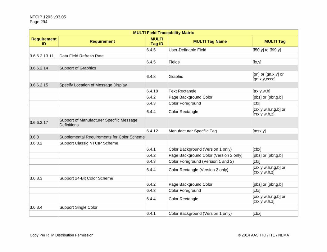
NTCIP 1203 v03.05 Page 294
MULTI Field Traceability Matrix Requirement
ID Requirement MULTI Tag ID MULTI Tag Name MULTI Tag
6.4.5 User-Definable Field [f50,y] to [f99,y] 3.6.6.2.13.11 Data Field Refresh Rate 6.4.5 Fields [fx,y] 3.6.6.2.14 Support of Graphics
6.4.8 Graphic [gn] or [gn,x,y] or [gn,x,y,cccc]
3.6.6.2.15 Specify Location of Message Display 6.4.18 Text Rectangle [trx,y,w,h] 6.4.2 Page Background Color [pbz] or [pbr,g,b] 6.4.3 Color Foreground [cfx]
6.4.4 Color Rectangle [crx,y,w,h,r,g,b] or [crx,y,w,h,z]
3.6.6.2.17 Support of Manufacturer Specfiic Message Definitions
6.4.12 Manufacturer Specfiic Tag [msx,y] 3.6.8 Supplemental Requirements for Color Scheme 3.6.8.2 Support Classic NTCIP Scheme 6.4.1 Color Background (Version 1 only) [cbx] 6.4.2 Page Background Color (Version 2 only) [pbz] or [pbr,g,b] 6.4.3 Color Foreground (Version 1 and 2) [cfx]
6.4.4 Color Rectangle (Version 2 only) [crx,y,w,h,r,g,b] or [crx,y,w,h,z]
3.6.8.3 Support 24-Bit Color Scheme 6.4.2 Page Background Color [pbz] or [pbr,g,b] 6.4.3 Color Foreground [cfx]
6.4.4 Color Rectangle [crx,y,w,h,r,g,b] or [crx,y,w,h,z]
3.6.8.4 Support Single Color 6.4.1 Color Background (Version 1 only) [cbx]
Copy Per RTM Distribution Permission © 2014 AASHTO / ITE / NEMA
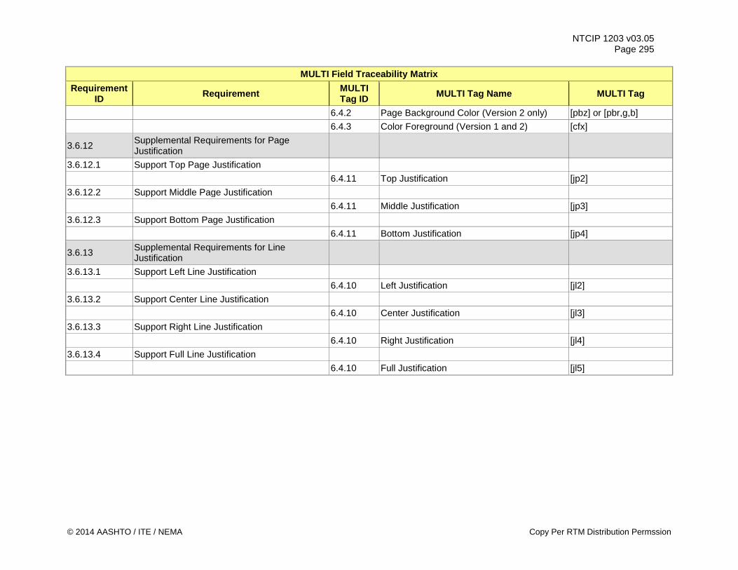
NTCIP 1203 v03.05 Page 295
MULTI Field Traceability Matrix Requirement
ID Requirement MULTI Tag ID MULTI Tag Name MULTI Tag
6.4.2 Page Background Color (Version 2 only) [pbz] or [pbr,g,b] 6.4.3 Color Foreground (Version 1 and 2) [cfx]
3.6.12 Supplemental Requirements for Page Justification
3.6.12.1 Support Top Page Justification 6.4.11 Top Justification [jp2] 3.6.12.2 Support Middle Page Justification 6.4.11 Middle Justification [jp3] 3.6.12.3 Support Bottom Page Justification 6.4.11 Bottom Justification [jp4]
3.6.13 Supplemental Requirements for Line Justification
3.6.13.1 Support Left Line Justification 6.4.10 Left Justification [jl2] 3.6.13.2 Support Center Line Justification 6.4.10 Center Justification [jl3] 3.6.13.3 Support Right Line Justification 6.4.10 Right Justification [jl4] 3.6.13.4 Support Full Line Justification 6.4.10 Full Justification [jl5]
© 2014 AASHTO / ITE / NEMA Copy Per RTM Distribution Permssion
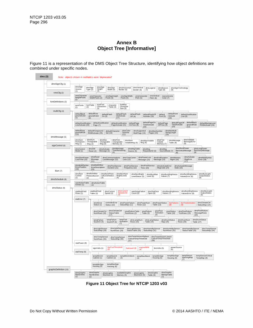
NTCIP 1203 v03.05 Page 296
Annex B Object Tree [Informative]
Figure 11 is a representation of the DMS Object Tree Structure, identifying how object definitions are combined under specific nodes.
dms (3)
dmsSignCfg (1)
dmsSignHeight (3)
dmsSignWidth (4)
dmsHorizontalBorder (5)
dmsSignAccess (1)
dmsSignType (2)
dmsBeaconType (8)
dmsSignTechnology (9)
dmsVerticalBorder (6)
dmsLegend (7)
vmsSignHeigthPixels (3)
vmsSignWidthPixels (4)
vmsHorizontalPitch (5)
vmsCharacterHeightPixels (1)
vmsCharacterWidthPixels (2)
vmsVerticalPitch (6)
monochromeColor (7)
maxFont Characters (3)
characterTable (4)
fontMax CharacterSize (5)
numFonts (1)
fontTable (2)
defaultBackgroundColor (1)
defaultForegroundColor (2)
defaultFlashOn (3)
vmsCfg (2)
fontDefinitions (3)
multiCfg (4)defaultFlashOnActivate (17)
defaultFlashOff (4)
defaultFlashOffActivate (18)
defaultFont (5)
defaultFontActivate (19)
defaultJustificationLine (6)
defaultJustificationLineActivate (20)
defaultJustificationPage (7)
defaultJustificationPageActivate (21)
defaultPageOnTime (8)
defaultPageOnTimeActivate (22)
defaultPageOffTime (9)
defaultPageOffTimeActivate (23)
defaultBackgroundRGB (12)
defaultBackgroundRGBActivate (24)
dmsNumPermanentMsg (1)
dmsNumChangeableMsg (2)
dmsMaxChangeableMsg (3)
dmsMessage (5)dmsFreeChangeableMemory (4)
dmsNumVolatileMsg (5)
dmsMaxVolatileMsg (6)
dmsFreeVolatileMemory (7)
dmsMessageTable (8)
dmsValidateMessageError (9)
defaultForegroundRGB (13)
defaultForegroundRGBActivate (25)
defaultCharacterSet (10)
dmsColorScheme (11)
dmsSupportedMultiTags (14)
dmsMaxNumberPages (15)
dmsMaxMultiStringLength (16)
dmsControlMode (1)
dmsSWReset (2)
dmsActivateMessage (3)
signControl (6)dmsMessageTimeRemaining (4)
dmsMsgTableSource (5)
dmsMsgRequesterID (6)
dmsMsgSourceMode (7)
dmsShortPowerRecoveryMessage (8)
dmsLongPowerRecoveryMessage (9)
dmsShortPowerLossTime (10)
dmsResetMessage (11)
dmsCommunicationsLossMessage (12)
dmsTimeCommLoss (13)
dmsPowerLossMessage (14)
dmsEndDurationMessage (15)
dmsMemoryMgmt (16)
dmsActivateMsgError (17)
dmsMultiSyntaxError (18)
dmsMultiSyntaxErrorPosition (19)
dmsMultiOtherErrorDescription (20)
dmsPixelServiceDuration (21)
dmsPixelServiceFrequency (22)
dmsPixelServiceTime (23)
dmsActivateErrorMsgCode (24)
dmsActivateMessageState (25)
dmsIllumControl (1)
dmsIllumMaxPhotocellLevel (2)
dmsIllumPhotocellLevelStatus (3)
illum (7)dmsIllumNumBrightLevels (4)
dmsIllumBrightLevelStatus (5)
dmsIllumManLevel (6)
dmsIllumBrightnessValues (7)
dmsIllumBrightnessValuesError (8)
dmsIllumLightOutputStatus (9)
numActionTableEntries (1)
dmsActionTable (2)
dmsSchedule (8)
statMultiFieldRows (1)
statMultiFieldTable (2)
dmsCurrentSpeed (3)
dmsStatus (9)dmsCurrentSpeedLimit (4)
watchdogFailureCount (5)
dmsStatDoorOpen (6)
dmsIllumBrightnessValues (7)
dmsIllumBrightnessValuesError (8)
dmsIllumLightOutputStatus (9)
statError (7)
shortErrorStatus (1)
controllerErrorStatus (10)
dmsPowerFailureStatusMap (11)
dmsPowerNumRows (12)
dmsPowerStatusTable (13)
fanFailures (8)
fanTestActivation (9)
dmsClimateCtrlStatusMap (14)
dmsClimateCtrlNumRows (16)
dmsClimateCtrlStatusTable (17)
pixelFailureTableNumRows (2)
pixelFailureTable (3)
pixelTestActivation (4)
pixelStatusTable (18)
dmsPixelFailureTestRows (19)
dmsPixelFailureMessageRows (20)
lampFailureStuckOn (5)
lampFailureStuckOff (6)
lampTestActivation (7)
dmsLampNumRows (23)
dmsLampStatusTable (24)
dmsDrumStatusMap (25)
dmsDrumNumRows (26)
dmsDrumStatusTable (27)
dmsLightSensorStatusMap (28)
dmsLightSensorNumRows (29)
dmsLightSensorStatusTable (30)
dmsHumiditySensorStatusMap (31)
dmsHumiditySensorNumRows (32)
dmsHumiditySensorStatusTable (33)
dmsTempSensorStstusMap (34)
dmsTempSensorNumRows (35)
dmsTempSensorStatusMap (36)
dmsTempSensorHighestCriticalTempThreshold (37)
dmsTempSensorLowestCriticalTempThreshold (38)
statPower (8)
signVolts (1) lowFuelThreshold (2) fuelLevel (3) engineRPM
(4) lineVolts (5) powerSource (6)
statTemp (9)
tempMinCtrlCabinet (1)
tempMaxCtrlCabinet (2)
tempMinAmbient (3)
tempMaxAbient (4)
tempMinSignHousing (5)
tempMaxSignHousing (6)
tempSensorWarningMap (7)
tempSensorCriticalTempMap (8)
tempMinSignHousing (5)
tempMaxSignHousing (6)
dmsGraphicMaxEntries (1)
dmsGraphicNumEntries (2)
graphicDefinition (10)
dmsGraphicMaxSize (3)
availableGraphicMemory (4)
dmsGraphicBlockSize (5)
dmsGraphicTable (6)
dmsGraphicBitmapTable (7)
Note: objects shown in red/italics were ‘deprecated’
Figure 11 Object Tree for NTCIP 1203 v03
Do Not Copy Without Written Permission © 2014 AASHTO / ITE / NEMA
NTCIP 1203 v03.05 Page 297
Annex C Test Procedures [Normative]
C.1 Purpose This annex defines the detailed, but generic, test procedures for testing an implementation of this standard. C.1.1 Scope Annex C defines test procedures in a format that is consistent with NTCIP 8007 v01 and that covers the entire scope of NTCIP 1203 v03. It includes tests of some of the features defined in NTCIP 1201 v03, but only to the extent that these features have been incorporated by reference in NTCIP 1203 v03. These test procedures are intended to be used as a portion of the overall set of tests that would be performed during component testing of a management station. C.1.2 Keywords C.1.2.1 Additional Keywords Keywords are words that are presented in all capital letters within the test procedures. Definitions of keywords are presented below. Keywords that are not defined below are defined in NTCIP 8007 v01.
Keyword Definition IF This keyword shall cause the user (or application) to perform a comparison and take
one action if the comparison evaluates to true and another action if the comparison evaluates to false. It is comparable to the “if…else…” expression in C.
FOR EACH This keyword causes the user (or application) to begin a looping process that shall increment through a series of values. It is comparable to the “for…next” expression in C.
GOTO This keyword shall cause the user (or application) to immediately jump to the indicated location in the test procedure (e.g., to another Step).
C.1.3 Keyword Combinations These test procedures frequently use the "SET-UP" and "VERIFY" keywords as defined in NTCIP 8007 v01 in the definition of a single step. When used jointly in these procedures, the failure logic of the "SET-UP" keyword shall override that of the "VERIFY" keyword. In other words, a failure of a step that uses both the "SET-UP" and "VERIFY" keywords shall mean that the test case neither passes nor fails, the test case shall EXIT, and the user shall correct the problem and restart the test case. C.1.4 Rules for Executing Test Procedures The test procedures contained in this annex are designed to be used for component testing a device for conformance to the NTCIP 1203 v03 interface standard. To component test a device for conformance to the NTCIP 1203 v03 interface standard, the user shall follow the steps as written, filling in the pass/fail information in the ‘Results' column. A given test procedure may entail multiple steps that may require multiple interactions between the user and the management station to fulfill the complete test procedure. For example, a single test procedure may transfer the definition of a message to the device and then retrieve the contents of the message to ensure that the values were updated; this might require two user interface operations.
© 2014 AASHTO / ITE / NEMA Copy Per TRF Distributtion Permission
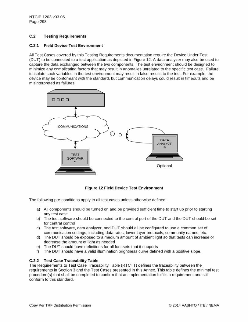
NTCIP 1203 v03.05 Page 298 C.2 Testing Requirements C.2.1 Field Device Test Environment All Test Cases covered by this Testing Requirements documentation require the Device Under Test (DUT) to be connected to a test application as depicted in Figure 12. A data analyzer may also be used to capture the data exchanged between the two components. The test environment should be designed to minimize any complicating factors that may result in anomalies unrelated to the specific test case. Failure to isolate such variables in the test environment may result in false results to the test. For example, the device may be conformant with the standard, but communication delays could result in timeouts and be misinterpreted as failures.
Figure 12 Field Device Test Environment
The following pre-conditions apply to all test cases unless otherwise defined:
a) All components should be turned on and be provided sufficient time to start up prior to starting any test case
b) The test software should be connected to the central port of the DUT and the DUT should be set for central control
c) The test software, data analyzer, and DUT should all be configured to use a common set of communication settings, including data rates, lower layer protocols, community names, etc.
d) The DUT should be exposed to a medium amount of ambient light so that tests can increase or decrease the amount of light as needed
e) The DUT should have definitions for all font sets that it supports f) The DUT should have a valid illumination brightness curve defined with a positive slope.
C.2.2 Test Case Traceability Table The Requirements to Test Case Traceability Table (RTCTT) defines the traceability between the requirements in Section 3 and the Test Cases presented in this Annex. This table defines the minimal test procedure(s) that shall be completed to confirm that an implementation fulfills a requirement and still conform to this standard.
COMMUNICATIONS
TEST SOFTWAR
E
DATA ANALYZE
R
Optional
Copy Per TRF Distribution Permission © 2014 AASHTO / ITE / NEMA
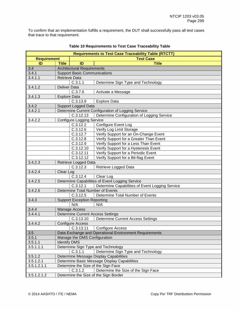
NTCIP 1203 v03.05 Page 299
To confirm that an implementation fulfills a requirement, the DUT shall successfully pass all test cases that trace to that requirement.
Table 10 Requirements to Test Case Traceability Table
Requirements to Test Case Traceability Table (RTCTT) Requirement Test Case
ID Title ID Title 3.4 Architectural Requirements 3.4.1 Support Basic Communications 3.4.1.1 Retrieve Data C.3.1.1 Determine Sign Type and Technology 3.4.1.2 Deliver Data C.3.7.6 Activate a Message 3.4.1.3 Explore Data C.3.13.9 Explore Data 3.4.2 Support Logged Data 3.4.2.1 Determine Current Configuration of Logging Service C.3.12.13 Determine Configuration of Logging Service 3.4.2.2 Configure Logging Service C.3.12.2 Configure Event Log C.3.12.6 Verify Log Limit Storage C.3.12.7 Verify Support for an On-Change Event C.3.12.8 Verify Support for a Greater Than Event C.3.12.9 Verify Support for a Less Than Event C.3.12.10 Verify Support for a Hysteresis Event C.3.12.11 Verify Support for a Periodic Event C.3.12.12 Verify Support for a Bit-flag Event 3.4.2.3 Retrieve Logged Data C.3.12.3 Retrieve Logged Data 3.4.2.4 Clear Log C.3.12.4 Clear Log 3.4.2.5 Determine Capabilities of Event Logging Service C.3.12.1 Determine Capabilities of Event Logging Service 3.4.2.6 Determine Total Number of Events C.3.12.5 Determine Total Number of Events 3.4.3 Support Exception Reporting N/A N/A 3.4.4 Manage Access 3.4.4.1 Determine Current Access Settings C.3.13.10 Determine Current Access Settings 3.4.4.2 Configure Access C.3.13.11 Configure Access 3.5 Data Exchange and Operational Environment Requirements 3.5.1 Manage the DMS Configuration 3.5.1.1 Identify DMS 3.5.1.1.1 Determine Sign Type and Technology C.3.1.1 Determine Sign Type and Technology 3.5.1.2 Determine Message Display Capabilities 3.5.1.2.1 Determine Basic Message Display Capabilities 3.5.1.2.1.1 Determine the Size of the Sign Face C.3.1.2 Determine the Size of the Sign Face 3.5.1.2.1.2 Determine the Size of the Sign Border
© 2014 AASHTO / ITE / NEMA Copy Per TRF Distributtion Permission
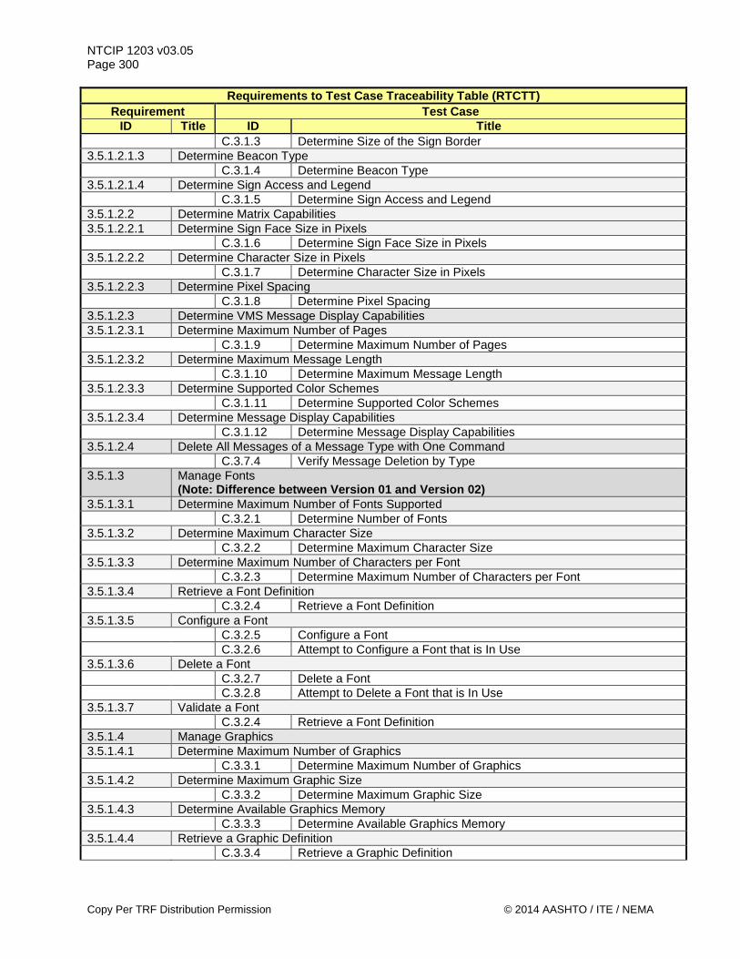
NTCIP 1203 v03.05 Page 300
Requirements to Test Case Traceability Table (RTCTT) Requirement Test Case
ID Title ID Title C.3.1.3 Determine Size of the Sign Border 3.5.1.2.1.3 Determine Beacon Type C.3.1.4 Determine Beacon Type 3.5.1.2.1.4 Determine Sign Access and Legend C.3.1.5 Determine Sign Access and Legend 3.5.1.2.2 Determine Matrix Capabilities 3.5.1.2.2.1 Determine Sign Face Size in Pixels C.3.1.6 Determine Sign Face Size in Pixels 3.5.1.2.2.2 Determine Character Size in Pixels C.3.1.7 Determine Character Size in Pixels 3.5.1.2.2.3 Determine Pixel Spacing C.3.1.8 Determine Pixel Spacing 3.5.1.2.3 Determine VMS Message Display Capabilities 3.5.1.2.3.1 Determine Maximum Number of Pages C.3.1.9 Determine Maximum Number of Pages 3.5.1.2.3.2 Determine Maximum Message Length C.3.1.10 Determine Maximum Message Length 3.5.1.2.3.3 Determine Supported Color Schemes C.3.1.11 Determine Supported Color Schemes 3.5.1.2.3.4 Determine Message Display Capabilities C.3.1.12 Determine Message Display Capabilities 3.5.1.2.4 Delete All Messages of a Message Type with One Command C.3.7.4 Verify Message Deletion by Type 3.5.1.3 Manage Fonts
(Note: Difference between Version 01 and Version 02) 3.5.1.3.1 Determine Maximum Number of Fonts Supported C.3.2.1 Determine Number of Fonts 3.5.1.3.2 Determine Maximum Character Size C.3.2.2 Determine Maximum Character Size 3.5.1.3.3 Determine Maximum Number of Characters per Font C.3.2.3 Determine Maximum Number of Characters per Font 3.5.1.3.4 Retrieve a Font Definition C.3.2.4 Retrieve a Font Definition 3.5.1.3.5 Configure a Font C.3.2.5 Configure a Font C.3.2.6 Attempt to Configure a Font that is In Use 3.5.1.3.6 Delete a Font C.3.2.7 Delete a Font C.3.2.8 Attempt to Delete a Font that is In Use 3.5.1.3.7 Validate a Font C.3.2.4 Retrieve a Font Definition 3.5.1.4 Manage Graphics 3.5.1.4.1 Determine Maximum Number of Graphics C.3.3.1 Determine Maximum Number of Graphics 3.5.1.4.2 Determine Maximum Graphic Size C.3.3.2 Determine Maximum Graphic Size 3.5.1.4.3 Determine Available Graphics Memory C.3.3.3 Determine Available Graphics Memory 3.5.1.4.4 Retrieve a Graphic Definition C.3.3.4 Retrieve a Graphic Definition
Copy Per TRF Distribution Permission © 2014 AASHTO / ITE / NEMA
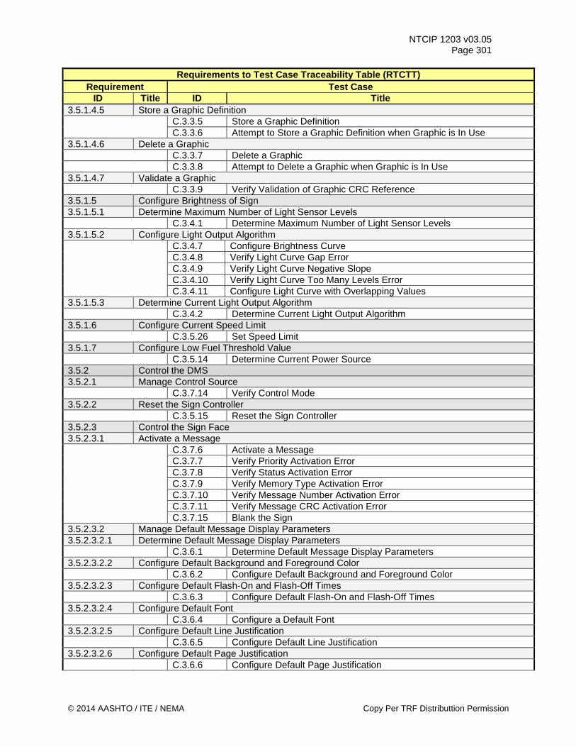
NTCIP 1203 v03.05 Page 301
Requirements to Test Case Traceability Table (RTCTT) Requirement Test Case
ID Title ID Title 3.5.1.4.5 Store a Graphic Definition C.3.3.5 Store a Graphic Definition C.3.3.6 Attempt to Store a Graphic Definition when Graphic is In Use 3.5.1.4.6 Delete a Graphic C.3.3.7 Delete a Graphic C.3.3.8 Attempt to Delete a Graphic when Graphic is In Use 3.5.1.4.7 Validate a Graphic C.3.3.9 Verify Validation of Graphic CRC Reference 3.5.1.5 Configure Brightness of Sign 3.5.1.5.1 Determine Maximum Number of Light Sensor Levels C.3.4.1 Determine Maximum Number of Light Sensor Levels 3.5.1.5.2 Configure Light Output Algorithm C.3.4.7 Configure Brightness Curve C.3.4.8 Verify Light Curve Gap Error C.3.4.9 Verify Light Curve Negative Slope C.3.4.10 Verify Light Curve Too Many Levels Error C.3.4.11 Configure Light Curve with Overlapping Values 3.5.1.5.3 Determine Current Light Output Algorithm C.3.4.2 Determine Current Light Output Algorithm 3.5.1.6 Configure Current Speed Limit C.3.5.26 Set Speed Limit 3.5.1.7 Configure Low Fuel Threshold Value C.3.5.14 Determine Current Power Source 3.5.2 Control the DMS 3.5.2.1 Manage Control Source C.3.7.14 Verify Control Mode 3.5.2.2 Reset the Sign Controller C.3.5.15 Reset the Sign Controller 3.5.2.3 Control the Sign Face 3.5.2.3.1 Activate a Message C.3.7.6 Activate a Message C.3.7.7 Verify Priority Activation Error C.3.7.8 Verify Status Activation Error C.3.7.9 Verify Memory Type Activation Error C.3.7.10 Verify Message Number Activation Error C.3.7.11 Verify Message CRC Activation Error C.3.7.15 Blank the Sign 3.5.2.3.2 Manage Default Message Display Parameters 3.5.2.3.2.1 Determine Default Message Display Parameters C.3.6.1 Determine Default Message Display Parameters 3.5.2.3.2.2 Configure Default Background and Foreground Color C.3.6.2 Configure Default Background and Foreground Color 3.5.2.3.2.3 Configure Default Flash-On and Flash-Off Times C.3.6.3 Configure Default Flash-On and Flash-Off Times 3.5.2.3.2.4 Configure Default Font C.3.6.4 Configure a Default Font 3.5.2.3.2.5 Configure Default Line Justification C.3.6.5 Configure Default Line Justification 3.5.2.3.2.6 Configure Default Page Justification C.3.6.6 Configure Default Page Justification
© 2014 AASHTO / ITE / NEMA Copy Per TRF Distributtion Permission
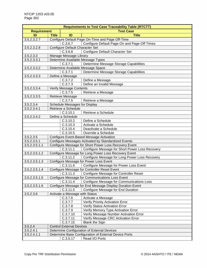
NTCIP 1203 v03.05 Page 302
Requirements to Test Case Traceability Table (RTCTT) Requirement Test Case
ID Title ID Title 3.5.2.3.2.7 Configure Default Page On-Time and Page Off-Time C.3.6.7 Configure Default Page-On and Page-Off Times 3.5.2.3.2.8 Configure Default Character Set C.3.6.8 Configure Default Character Set 3.5.2.3.3 Manage Message Library 3.5.2.3.3.1 Determine Available Message Types C.3.7.1 Determine Message Storage Capabilities 3.5.2.3.3.2 Determine Available Message Space C.3.7.1 Determine Message Storage Capabilities 3.5.2.3.3.3 Define a Message C.3.7.2 Define a Message C.3.7.3 Define an Invalid Message 3.5.2.3.3.4 Verify Message Contents C.3.7.5 Retrieve a Message 3.5.2.3.3.5 Retrieve Message C.3.7.5 Retrieve a Message 3.5.2.3.4 Schedule Messages for Display 3.5.2.3.4.1 Retrieve a Schedule C.3.10.1 Retrieve a Schedule 3.5.2.3.4.2 Define a Schedule C.3.10.2 Define a Schedule C.3.10.3 Activate a Schedule C.3.10.4 Deactivate a Schedule C.3.10.5 Override a Schedule 3.5.2.3.5 Configure Event-Based Message Activation 3.5.2.3.5.1 Configure Messages Activated by Standardized Events 3.5.2.3.5.1.1 Configure Message for Short Power Loss Recovery Event C.3.11.1 Configure Message for Short Power Loss Recovery 3.5.2.3.5.1.2 Configure Message for Long Power Loss Recovery Event C.3.11.2 Configure Message for Long Power Loss Recovery 3.5.2.3.5.1.3 Configure Message for Power Loss Event C.3.11.6 Configure Message for Power Loss Event 3.5.2.3.5.1.4 Configure Message for Controller Reset Event C.3.11.3 Configure Message for Controller Reset 3.5.2.3.5.1.5 Configure Message for Communications Loss Event C.3.11.4 Configure Message for Communications Loss 3.5.2.3.5.1.6 Configure Message for End Message Display Duration Event C.3.11.5 Configure Message for End Duration 3.5.2.3.6 Activate a Message with Status C.3.7.6 Activate a Message C.3.7.7 Verify Priority Activation Error C.3.7.8 Verify Status Activation Error C.3.7.9 Verify Memory Type Activation Error C.3.7.10 Verify Message Number Activation Error C.3.7.11 Verify Message CRC Activation Error C.3.7.15 Blank the Sign 3.5.2.4 Control External Devices 3.5.2.4.1 Determine Configuration of External Devices 3.5.2.4.1.1 Determine Base Configuration of External Device Ports C.3.5.17 Read I/O Ports
Copy Per TRF Distribution Permission © 2014 AASHTO / ITE / NEMA
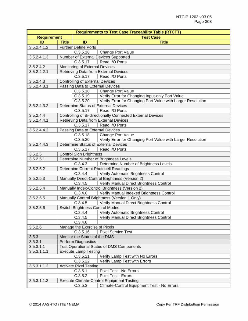
NTCIP 1203 v03.05 Page 303
Requirements to Test Case Traceability Table (RTCTT) Requirement Test Case
ID Title ID Title 3.5.2.4.1.2 Further Define Ports C.3.5.18 Change Port Value 3.5.2.4.1.3 Number of External Devices Supported C.3.5.17 Read I/O Ports 3.5.2.4.2 Monitoring of External Devices 3.5.2.4.2.1 Retrieving Data from External Devices C.3.5.17 Read I/O Ports 3.5.2.4.3 Controlling of External Devices 3.5.2.4.3.1 Passing Data to External Devices C.3.5.18 Change Port Value C.3.5.19 Verify Error for Changing Input-only Port Value C.3.5.20 Verify Error for Changing Port Value with Larger Resolution 3.5.2.4.3.2 Determine Status of External Devices C.3.5.17 Read I/O Ports 3.5.2.4.4 Controlling of Bi-directionally Connected External Devices 3.5.2.4.4.1 Retrieving Data from External Devices C.3.5.17 Read I/O Ports 3.5.2.4.4.2 Passing Data to External Devices
C.3.5.18 C.3.5.20
Change Port Value Verify Error for Changing Port Value with Larger Resolution
3.5.2.4.4.3 Determine Status of External Devices C.3.5.17 Read I/O Ports 3.5.2.5 Control Sign Brightness 3.5.2.5.1 Determine Number of Brightness Levels C.3.4.3 Determine Number of Brightness Levels 3.5.2.5.2 Determine Current Photocell Readings C.3.4.4 Verify Automatic Brightness Control 3.5.2.5.3 Manually Direct-Control Brightness (Version 2) C.3.4.5 Verify Manual Direct Brightness Control 3.5.2.5.4 Manually Index-Control Brightness (Version 2) C.3.4.6 Verify Manual Indexed Brightness Control 3.5.2.5.5 Manually Control Brightness (Version 1 Only) C.3.4.5 Verify Manual Direct Brightness Control 3.5.2.5.6 Switch Brightness Control Modes C.3.4.4 Verify Automatic Brightness Control C.3.4.5 Verify Manual Direct Brightness Control C.3.4.6 3.5.2.6 Manage the Exercise of Pixels C.3.5.16 Pixel Service Test 3.5.3 Monitor the Status of the DMS 3.5.3.1 Perform Diagnostics 3.5.3.1.1 Test Operational Status of DMS Components 3.5.3.1.1.1 Execute Lamp Testing C.3.5.21 Verify Lamp Test with No Errors C.3.5.22 Verify Lamp Test with Errors 3.5.3.1.1.2 Activate Pixel Testing C.3.5.1 Pixel Test - No Errors C.3.5.2 Pixel Test - Errors 3.5.3.1.1.3 Execute Climate-Control Equipment Testing C.3.5.3 Climate-Control Equipment Test - No Errors
© 2014 AASHTO / ITE / NEMA Copy Per TRF Distributtion Permission
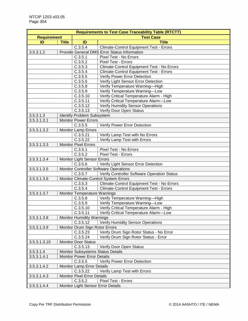
NTCIP 1203 v03.05 Page 304
Requirements to Test Case Traceability Table (RTCTT) Requirement Test Case
ID Title ID Title C.3.5.4 Climate-Control Equipment Test - Errors 3.5.3.1.2 Provide General DMS Error Status Information C.3.5.1 Pixel Test - No Errors C.3.5.2 Pixel Test - Errors C.3.5.3 Climate-Control Equipment Test - No Errors C.3.5.4 Climate-Control Equipment Test - Errors C.3.5.5 Verify Power Error Detection C.3.5.6 Verify Light Sensor Error Detection C.3.5.8 Verify Temperature Warning—High C.3.5.9 Verify Temperature Warning—Low C.3.5.10 Verify Critical Temperature Alarm - High C.3.5.11 Verify Critical Temperature Alarm—Low C.3.5.12 Verify Humidity Sensor Operations C.3.5.13 Verify Door Open Status 3.5.3.1.3 Identify Problem Subsystem 3.5.3.1.3.1 Monitor Power Errors C.3.5.5 Verify Power Error Detection 3.5.3.1.3.2 Monitor Lamp Errors C.3.5.21 Verify Lamp Test with No Errors C.3.5.22 Verify Lamp Test with Errors 3.5.3.1.3.3 Monitor Pixel Errors C.3.5.1 Pixel Test - No Errors C.3.5.2 Pixel Test - Errors 3.5.3.1.3.4 Monitor Light Sensor Errors C.3.5.6 Verify Light Sensor Error Detection 3.5.3.1.3.5 Monitor Controller Software Operations C.3.5.7 Verify Controller Software Operation Status 3.5.3.1.3.6 Monitor Climate-Control System Errors C.3.5.3 Climate-Control Equipment Test - No Errors C.3.5.4 Climate-Control Equipment Test - Errors 3.5.3.1.3.7 Monitor Temperature Warnings C.3.5.8 Verify Temperature Warning—High C.3.5.9 Verify Temperature Warning—Low C.3.5.10 Verify Critical Temperature Alarm - High C.3.5.11 Verify Critical Temperature Alarm—Low 3.5.3.1.3.8 Monitor Humidity Warnings C.3.5.12 Verify Humidity Sensor Operations 3.5.3.1.3.9 Monitor Drum Sign Rotor Errors C.3.5.23 Verify Drum Sign Rotor Status - No Error C.3.5.24 Verify Drum Sign Rotor Status - Error 3.5.3.1.3.10 Monitor Door Status C.3.5.13 Verify Door Open Status 3.5.3.1.4 Monitor Subsystems Status Details 3.5.3.1.4.1 Monitor Power Error Details C.3.5.5 Verify Power Error Detection 3.5.3.1.4.2 Monitor Lamp Error Details C.3.5.22 Verify Lamp Test with Errors 3.5.3.1.4.3 Monitor Pixel Error Details C.3.5.2 Pixel Test - Errors 3.5.3.1.4.4 Monitor Light Sensor Error Details
Copy Per TRF Distribution Permission © 2014 AASHTO / ITE / NEMA

NTCIP 1203 v03.05 Page 305
Requirements to Test Case Traceability Table (RTCTT) Requirement Test Case
ID Title ID Title C.3.5.6 Verify Light Sensor Error Detection 3.5.3.1.4.5 Monitor Message Activation Error Details C.3.7.7 Verify Priority Activation Error C.3.7.8 Verify Status Activation Error C.3.7.9 Verify Memory Type Activation Error C.3.7.10 Verify Message Number Activation Error C.3.7.11 Verify Message CRC Activation Error 3.5.3.1.4.6 Monitor Climate-Control System Error Details C.3.5.4 Climate-Control Equipment Test - Errors 3.5.3.1.4.7 Monitor Sign Housing Temperatures C.3.5.8 Verify Temperature Warning—High C.3.5.9 Verify Temperature Warning—Low C.3.5.10 Verify Critical Temperature Alarm - High C.3.5.11 Verify Critical Temperature Alarm—Low 3.5.3.1.4.8 Monitor Sign Housing Humidity C.3.5.12 Verify Humidity Sensor Operations 3.5.3.1.4.9 Monitor Control Cabinet Temperatures C.3.5.8 Verify Temperature Warning—High C.3.5.9 Verify Temperature Warning—Low C.3.5.10 Verify Critical Temperature Alarm - High C.3.5.11 Verify Critical Temperature Alarm—Low 3.5.3.1.4.10 Monitor Control Cabinet Humidity C.3.5.12 Verify Humidity Sensor Operations 3.5.3.1.4.11 Monitor Drum Sign Rotor Error Details C.3.5.24 Verify Drum Sign Rotor Status - Error 3.5.3.1.5 Monitor the Sign’s Control Source C.3.7.14 Verify Control Mode 3.5.3.1.6 Monitor Power Information 3.5.3.1.6.1 Monitor Power Source C.3.5.14 Determine Current Power Source 3.5.3.1.6.2 Monitor Power Voltage C.3.5.14 Determine Current Power Source 3.5.3.1.6.3 Monitor Current Fuel Level C.3.5.14 Determine Current Power Source 3.5.3.1.6.4 Monitor Current Engine RPM C.3.5.14 Determine Current Power Source 3.5.3.1.7 Monitor Ambient Environment C.3.5.8 Verify Temperature Warning—High C.3.5.9 Verify Temperature Warning—Low C.3.5.10 Verify Critical Temperature Alarm - High C.3.5.11 Verify Critical Temperature Alarm—Low 3.5.3.1.8 Determine Critical Temperature Threshold C.3.5.10 Verify Critical Temperature Alarm - High C.3.5.11 Verify Critical Temperature Alarm—Low 3.5.3.1.9 Monitor Speed Detector Reading C.3.5.25 Verify Speed Detector Reading 3.5.3.2 Monitor the Current Message 3.5.3.2.1 Monitor Information about the Currently Displayed Message C.3.7.16 Monitor the Current Message 3.5.3.2.2 Monitor Dynamic Field Values
© 2014 AASHTO / ITE / NEMA Copy Per TRF Distributtion Permission
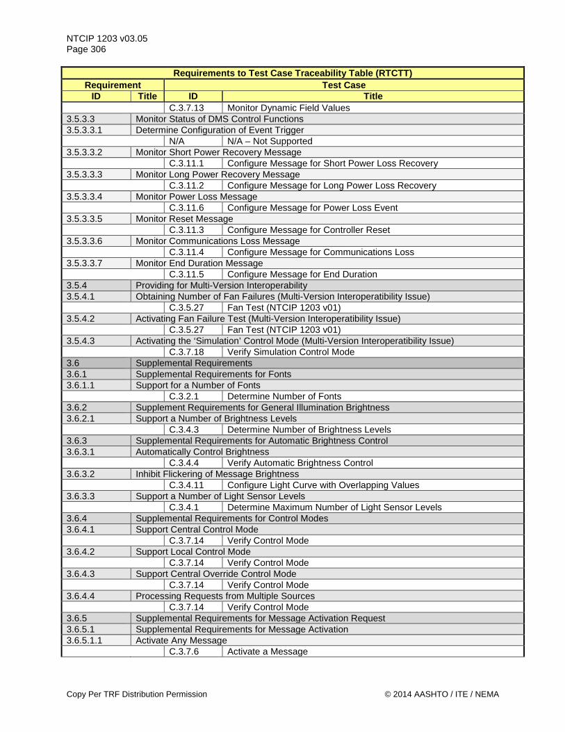
NTCIP 1203 v03.05 Page 306
Requirements to Test Case Traceability Table (RTCTT) Requirement Test Case
ID Title ID Title C.3.7.13 Monitor Dynamic Field Values 3.5.3.3 Monitor Status of DMS Control Functions 3.5.3.3.1 Determine Configuration of Event Trigger N/A N/A – Not Supported 3.5.3.3.2 Monitor Short Power Recovery Message C.3.11.1 Configure Message for Short Power Loss Recovery 3.5.3.3.3 Monitor Long Power Recovery Message C.3.11.2 Configure Message for Long Power Loss Recovery 3.5.3.3.4 Monitor Power Loss Message C.3.11.6 Configure Message for Power Loss Event 3.5.3.3.5 Monitor Reset Message C.3.11.3 Configure Message for Controller Reset 3.5.3.3.6 Monitor Communications Loss Message C.3.11.4 Configure Message for Communications Loss 3.5.3.3.7 Monitor End Duration Message C.3.11.5 Configure Message for End Duration 3.5.4 Providing for Multi-Version Interoperability 3.5.4.1 Obtaining Number of Fan Failures (Multi-Version Interoperatibility Issue) C.3.5.27 Fan Test (NTCIP 1203 v01) 3.5.4.2 Activating Fan Failure Test (Multi-Version Interoperatibility Issue) C.3.5.27 Fan Test (NTCIP 1203 v01) 3.5.4.3 Activating the ‘Simulation’ Control Mode (Multi-Version Interoperatibility Issue) C.3.7.18 Verify Simulation Control Mode 3.6 Supplemental Requirements 3.6.1 Supplemental Requirements for Fonts 3.6.1.1 Support for a Number of Fonts C.3.2.1 Determine Number of Fonts 3.6.2 Supplement Requirements for General Illumination Brightness 3.6.2.1 Support a Number of Brightness Levels C.3.4.3 Determine Number of Brightness Levels 3.6.3 Supplemental Requirements for Automatic Brightness Control 3.6.3.1 Automatically Control Brightness C.3.4.4 Verify Automatic Brightness Control 3.6.3.2 Inhibit Flickering of Message Brightness C.3.4.11 Configure Light Curve with Overlapping Values 3.6.3.3 Support a Number of Light Sensor Levels C.3.4.1 Determine Maximum Number of Light Sensor Levels 3.6.4 Supplemental Requirements for Control Modes 3.6.4.1 Support Central Control Mode C.3.7.14 Verify Control Mode 3.6.4.2 Support Local Control Mode C.3.7.14 Verify Control Mode 3.6.4.3 Support Central Override Control Mode C.3.7.14 Verify Control Mode 3.6.4.4 Processing Requests from Multiple Sources C.3.7.14 Verify Control Mode 3.6.5 Supplemental Requirements for Message Activation Request 3.6.5.1 Supplemental Requirements for Message Activation 3.6.5.1.1 Activate Any Message C.3.7.6 Activate a Message
Copy Per TRF Distribution Permission © 2014 AASHTO / ITE / NEMA
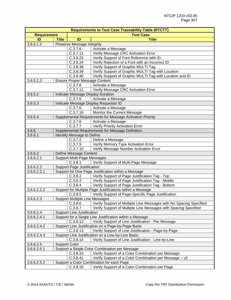
NTCIP 1203 v03.05 Page 307
Requirements to Test Case Traceability Table (RTCTT) Requirement Test Case
ID Title ID Title 3.6.5.1.2 Preserve Message Integrity C.3.7.6 Activate a Message C.3.7.11 Verify Message CRC Activation Error C.3.8.23 Verify Support of Font Reference with ID C.3.8.24 Verify Rejection of a Font with an Incorrect ID C.3.8.38 Verify Support of Graphic MULTI Tag C.3.8.39 Verify Support of Graphic MULTI Tag with Location C.3.8.40 Verify Support of Graphic MULTI Tag with Location and ID 3.6.5.1.3 Ensure Proper Message Content C.3.7.6 Activate a Message C.3.7.11 Verify Message CRC Activation Error 3.6.5.2 Indicate Message Display Duration C.3.7.6 Activate a Message 3.6.5.3 Indicate Message Display Requester ID C.3.7.6 Activate a Message C.3.7.16 Monitor the Current Message 3.6.5.4 Supplemental Requirements for Message Activation Priority C.3.7.6 Activate a Message C.3.7.7 Verify Priority Activation Error 3.6.6 Supplemental Requirements for Message Definition 3.6.6.1 Identify Message to Define C.3.7.2 Define a Message C.3.7.9 Verify Memory Type Activation Error C.3.7.10 Verify Message Number Activation Error 3.6.6.2 Define Message Content 3.6.6.2.1 Support Multi-Page Messages C.3.8.1 Verify Support of Multi-Page Message 3.6.6.2.2 Support Page Justification 3.6.6.2.2.1 Support for One Page Justification within a Message C.3.8.2 Verify Support of Page Justification Tag - Top C.3.8.3 Verify Support of Page Justification Tag - Middle C.3.8.4 Verify Support of Page Justification Tag - Bottom 3.6.6.2.2.2 Support for Multiple Page Justifications within a Message C.3.8.5 Verify Support of Page-Specific Page Justification 3.6.6.2.3 Support Multiple Line Messages C.3.8.6 Verify Support of Multiple Line Messages with No Spacing Specified C.3.8.7 Verify Support of Multiple Line Messages with Spacing Specified 3.6.6.2.4 Support Line Justification 3.6.6.2.4.1 Support for a Single Line Justification within a Message C.3.8.12 Verify Support of Line Justification - Per Message 3.6.6.2.4.2 Support Line Justification on a Page-by-Page Basis C.3.8.13 Verify Support of Line Justification - Page-by-Page 3.6.6.2.4.3 Support Line Justification on a Line-by-Line Basis C.3.8.14 Verify Support of Line Justification - Line-by-Line 3.6.6.2.5 Support Color 3.6.6.2.5.1 Support a Single Color Combination per Message C.3.8.15 Verify Support of a Color Combination per Message C.3.8.41 Verify Support of a Color Combination per Message – v2 3.6.6.2.5.2 Support a Color Combination for each Page C.3.8.16 Verify Support of a Color Combination per Page
© 2014 AASHTO / ITE / NEMA Copy Per TRF Distributtion Permission

NTCIP 1203 v03.05 Page 308
Requirements to Test Case Traceability Table (RTCTT) Requirement Test Case
ID Title ID Title C.3.8.42 Verify Support of a Color Combination per Page – v2 3.6.6.2.5.3 Support a Color Combination for each Character within a Message C.3.8.17 Verify Support of a Color Combination per Character C.3.8.43 Verify Support of a Color Combination per Character – v2 3.6.6.2.5.4 Support Color for Each Pixel Within A Message C.3.8.18 Verify Support of a Color Rectangle 3.6.6.2.6 Support Font Commands 3.6.6.2.6.1 Support One Font within a Message C.3.8.20 Verify Support of One Font per Message 3.6.6.2.6.2 Support One Font per Page within a Message C.3.8.21 Verify Support of One Font per Page 3.6.6.2.6.3 Support Character by Character Selection of Fonts within a Message C.3.8.22 Verify Support of a Font per Character 3.6.6.2.7 Support Moving Text C.3.8.25 Verify Support of Moving Text (Circular Left) C.3.8.26 Verify Support of Moving Text (Circular Right) C.3.8.27 Verify Support of Moving Text (Linear Left) C.3.8.28 Verify Support of Moving Text (Linear Right) C.3.8.29 Verify Support of Moving Text (Linear with Pause) 3.6.6.2.8 Support Character Spacing C.3.8.30 Verify Support of Character Spacing 3.6.6.2.9 Support Customizable Page Display Times in a Message C.3.8.31 Verify Support of Customized Page Display Times 3.6.6.2.10 Support Flashing 3.6.6.2.10.1 Support Character-By-Character Flashing C.3.8.36 Verify Support of Character-by-Character Flashing 3.6.6.2.10.2 Support Line-by-line Flashing C.3.8.35 Verify Support of Line-by-Line Flashing 3.6.6.2.10.3 Support Page-by-Page Flashing C.3.8.34 Verify Support of Page-by-Page Flashing 3.6.6.2.11 Support Customizable Flashing Times within a Message C.3.8.32 Verify Support of Customized Flashing Times (On First) C.3.8.33 Verify Support of Customized Flashing Times (Off First) 3.6.6.2.12 Support Hexadecimal Character C.3.8.37 Verify Support of Hexadecimal Character 3.6.6.2.13 Support Message Data Fields 3.6.6.2.13.1 Support Current Time Field without AM/PM Field C.3.9.1 Verify Support of Current Time Field (12 hour) C.3.9.2 Verify Support of Current Time Field (24 hour) 3.6.6.2.13.2 Support Current Time Field with uppercase AM/PM Field C.3.9.3 Verify Support of Current Time Field (12 hour Uppercase AM/PM) 3.6.6.2.13.3 Support Current Time Field with lowercase am/pm Field C.3.9.4 Verify Support of Current Time Field (12 hour Lowercase am/pm) 3.6.6.2.13.4 Support Current Temperature Field C.3.9.10 Verify Support of Current Temperature Field Celsius C.3.9.11 Verify Support of Current Temperature Field Fahrenheit 3.6.6.2.13.5 Support Detected Vehicle Speed Field C.3.9.12 Verify Support of Detected Vehicle Speed Field (km/h) C.3.9.13 Verify Support of Detected Vehicle Speed Field (mph) 3.6.6.2.13.6 Support Current Day of Week Field
Copy Per TRF Distribution Permission © 2014 AASHTO / ITE / NEMA
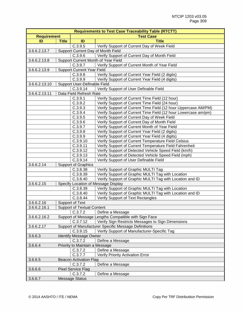
NTCIP 1203 v03.05 Page 309
Requirements to Test Case Traceability Table (RTCTT) Requirement Test Case
ID Title ID Title C.3.9.5 Verify Support of Current Day of Week Field 3.6.6.2.13.7 Support Current Day of Month Field C.3.9.6 Verify Support of Current Day of Month Field 3.6.6.2.13.8 Support Current Month of Year Field C.3.9.7 Verify Support of Current Month of Year Field 3.6.6.2.13.9 Support Current Year Field C.3.9.8 Verify Support of Current Year Field (2 digits) C.3.9.9 Verify Support of Current Year Field (4 digits) 3.6.6.2.13.10 Support User-Definable Field C.3.9.14 Verify Support of User Definable Field 3.6.6.2.13.11 Data Field Refresh Rate C.3.9.1 Verify Support of Current Time Field (12 hour) C.3.9.2 Verify Support of Current Time Field (24 hour) C.3.9.3 Verify Support of Current Time Field (12 hour Uppercase AM/PM) C.3.9.4 Verify Support of Current Time Field (12 hour Lowercase am/pm) C.3.9.5 Verify Support of Current Day of Week Field C.3.9.6 Verify Support of Current Day of Month Field C.3.9.7 Verify Support of Current Month of Year Field C.3.9.8 Verify Support of Current Year Field (2 digits) C.3.9.9 Verify Support of Current Year Field (4 digits) C.3.9.10 Verify Support of Current Temperature Field Celsius C.3.9.11 Verify Support of Current Temperature Field Fahrenheit C.3.9.12 Verify Support of Detected Vehicle Speed Field (km/h) C.3.9.13 Verify Support of Detected Vehicle Speed Field (mph) C.3.9.14 Verify Support of User Definable Field 3.6.6.2.14 Support of Graphics C.3.8.38 Verify Support of Graphic MULTI Tag C.3.8.39 Verify Support of Graphic MULTI Tag with Location C.3.8.40 Verify Support of Graphic MULTI Tag with Location and ID 3.6.6.2.15 Specify Location of Message Display C.3.8.39 Verify Support of Graphic MULTI Tag with Location C.3.8.40 Verify Support of Graphic MULTI Tag with Location and ID C.3.8.44 Verify Support of Text Rectangles 3.6.6.2.16 Support of Text 3.6.6.2.16.1 Support of Textual Content C.3.7.2 Define a Message 3.6.6.2.16.2 Support of Message Lengths Compatible with Sign Face C.3.7.12 Verify Sign Restricts Messages to Sign Dimensions 3.6.6.2.17 Support of Manufacturer Specific Message Definitions C.3.9.15 Verify Support of Manufacturer-Specific Tag 3.6.6.3 Identify Message Owner C.3.7.2 Define a Message 3.6.6.4 Priority to Maintain a Message C.3.7.2 Define a Message C.3.7.7 Verify Priority Activation Error 3.6.6.5 Beacon Activation Flag C.3.7.2 Define a Message 3.6.6.6 Pixel Service Flag C.3.7.2 Define a Message 3.6.6.7 Message Status
© 2014 AASHTO / ITE / NEMA Copy Per TRF Distributtion Permission
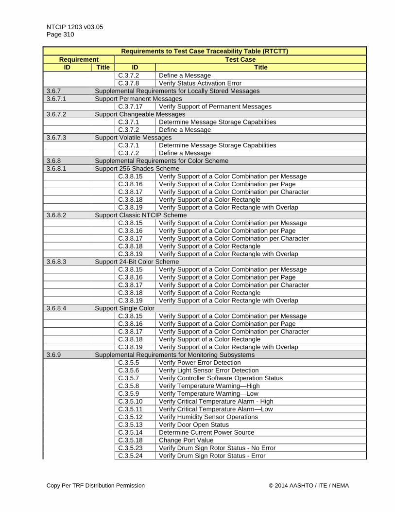
NTCIP 1203 v03.05 Page 310
Requirements to Test Case Traceability Table (RTCTT) Requirement Test Case
ID Title ID Title C.3.7.2 Define a Message C.3.7.8 Verify Status Activation Error 3.6.7 Supplemental Requirements for Locally Stored Messages 3.6.7.1 Support Permanent Messages C.3.7.17 Verify Support of Permanent Messages 3.6.7.2 Support Changeable Messages C.3.7.1 Determine Message Storage Capabilities C.3.7.2 Define a Message 3.6.7.3 Support Volatile Messages C.3.7.1 Determine Message Storage Capabilities C.3.7.2 Define a Message 3.6.8 Supplemental Requirements for Color Scheme 3.6.8.1 Support 256 Shades Scheme C.3.8.15 Verify Support of a Color Combination per Message C.3.8.16 Verify Support of a Color Combination per Page C.3.8.17 Verify Support of a Color Combination per Character C.3.8.18 Verify Support of a Color Rectangle C.3.8.19 Verify Support of a Color Rectangle with Overlap 3.6.8.2 Support Classic NTCIP Scheme C.3.8.15 Verify Support of a Color Combination per Message C.3.8.16 Verify Support of a Color Combination per Page C.3.8.17 Verify Support of a Color Combination per Character C.3.8.18 Verify Support of a Color Rectangle C.3.8.19 Verify Support of a Color Rectangle with Overlap 3.6.8.3 Support 24-Bit Color Scheme C.3.8.15 Verify Support of a Color Combination per Message C.3.8.16 Verify Support of a Color Combination per Page C.3.8.17 Verify Support of a Color Combination per Character C.3.8.18 Verify Support of a Color Rectangle C.3.8.19 Verify Support of a Color Rectangle with Overlap 3.6.8.4 Support Single Color C.3.8.15 Verify Support of a Color Combination per Message C.3.8.16 Verify Support of a Color Combination per Page C.3.8.17 Verify Support of a Color Combination per Character C.3.8.18 Verify Support of a Color Rectangle C.3.8.19 Verify Support of a Color Rectangle with Overlap 3.6.9 Supplemental Requirements for Monitoring Subsystems C.3.5.5 Verify Power Error Detection C.3.5.6 Verify Light Sensor Error Detection C.3.5.7 Verify Controller Software Operation Status C.3.5.8 Verify Temperature Warning—High C.3.5.9 Verify Temperature Warning—Low C.3.5.10 Verify Critical Temperature Alarm - High C.3.5.11 Verify Critical Temperature Alarm—Low C.3.5.12 Verify Humidity Sensor Operations C.3.5.13 Verify Door Open Status C.3.5.14 Determine Current Power Source C.3.5.18 Change Port Value C.3.5.23 Verify Drum Sign Rotor Status - No Error C.3.5.24 Verify Drum Sign Rotor Status - Error
Copy Per TRF Distribution Permission © 2014 AASHTO / ITE / NEMA
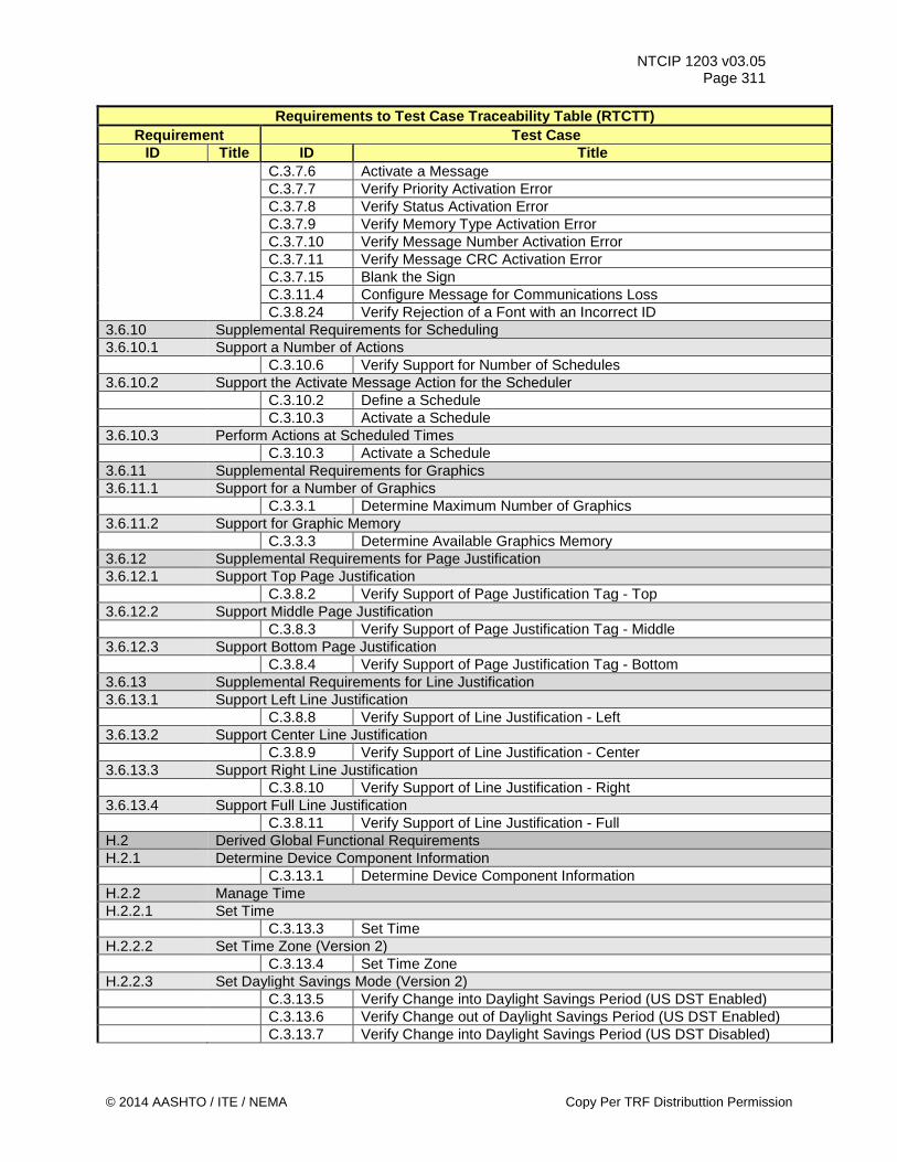
NTCIP 1203 v03.05 Page 311
Requirements to Test Case Traceability Table (RTCTT) Requirement Test Case
ID Title ID Title C.3.7.6 Activate a Message C.3.7.7 Verify Priority Activation Error C.3.7.8 Verify Status Activation Error C.3.7.9 Verify Memory Type Activation Error C.3.7.10 Verify Message Number Activation Error C.3.7.11 Verify Message CRC Activation Error C.3.7.15 Blank the Sign C.3.11.4 Configure Message for Communications Loss C.3.8.24 Verify Rejection of a Font with an Incorrect ID 3.6.10 Supplemental Requirements for Scheduling 3.6.10.1 Support a Number of Actions C.3.10.6 Verify Support for Number of Schedules 3.6.10.2 Support the Activate Message Action for the Scheduler C.3.10.2 Define a Schedule C.3.10.3 Activate a Schedule 3.6.10.3 Perform Actions at Scheduled Times C.3.10.3 Activate a Schedule 3.6.11 Supplemental Requirements for Graphics 3.6.11.1 Support for a Number of Graphics C.3.3.1 Determine Maximum Number of Graphics 3.6.11.2 Support for Graphic Memory C.3.3.3 Determine Available Graphics Memory 3.6.12 Supplemental Requirements for Page Justification 3.6.12.1 Support Top Page Justification C.3.8.2 Verify Support of Page Justification Tag - Top 3.6.12.2 Support Middle Page Justification C.3.8.3 Verify Support of Page Justification Tag - Middle 3.6.12.3 Support Bottom Page Justification C.3.8.4 Verify Support of Page Justification Tag - Bottom 3.6.13 Supplemental Requirements for Line Justification 3.6.13.1 Support Left Line Justification C.3.8.8 Verify Support of Line Justification - Left 3.6.13.2 Support Center Line Justification C.3.8.9 Verify Support of Line Justification - Center 3.6.13.3 Support Right Line Justification C.3.8.10 Verify Support of Line Justification - Right 3.6.13.4 Support Full Line Justification C.3.8.11 Verify Support of Line Justification - Full H.2 Derived Global Functional Requirements H.2.1 Determine Device Component Information C.3.13.1 Determine Device Component Information H.2.2 Manage Time H.2.2.1 Set Time C.3.13.3 Set Time H.2.2.2 Set Time Zone (Version 2) C.3.13.4 Set Time Zone H.2.2.3 Set Daylight Savings Mode (Version 2) C.3.13.5 Verify Change into Daylight Savings Period (US DST Enabled) C.3.13.6 Verify Change out of Daylight Savings Period (US DST Enabled) C.3.13.7 Verify Change into Daylight Savings Period (US DST Disabled)
© 2014 AASHTO / ITE / NEMA Copy Per TRF Distributtion Permission
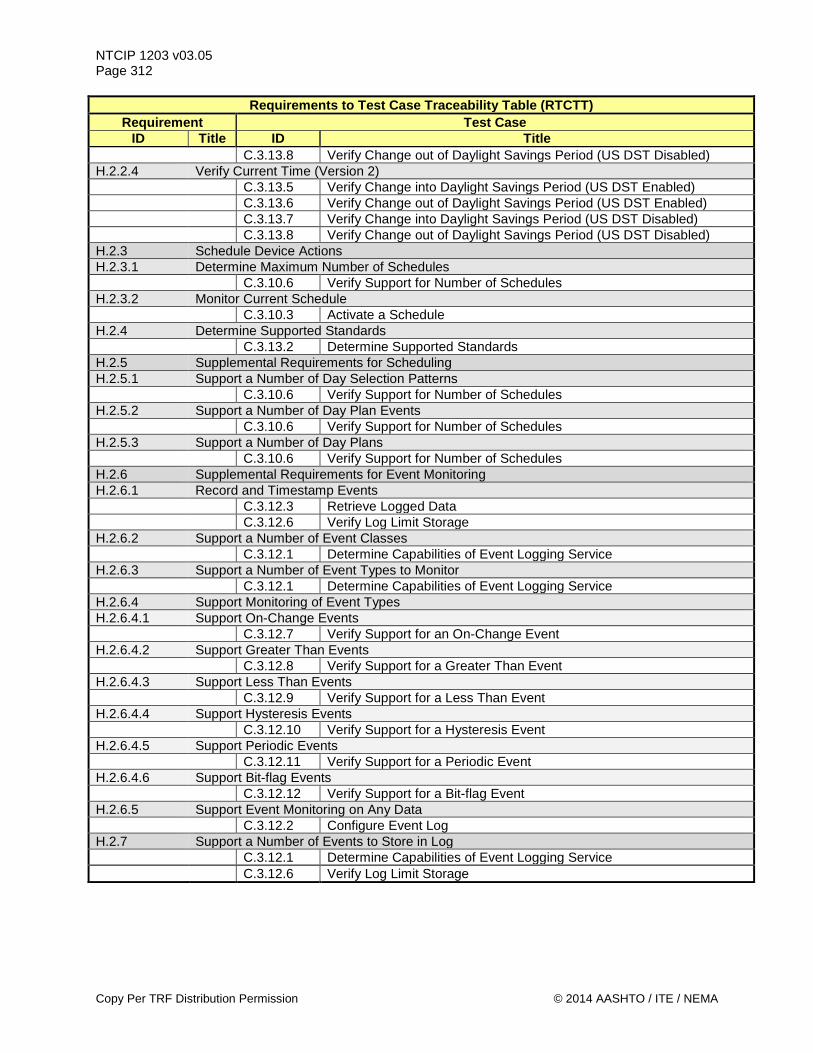
NTCIP 1203 v03.05 Page 312
Requirements to Test Case Traceability Table (RTCTT) Requirement Test Case
ID Title ID Title C.3.13.8 Verify Change out of Daylight Savings Period (US DST Disabled) H.2.2.4 Verify Current Time (Version 2) C.3.13.5 Verify Change into Daylight Savings Period (US DST Enabled) C.3.13.6 Verify Change out of Daylight Savings Period (US DST Enabled) C.3.13.7 Verify Change into Daylight Savings Period (US DST Disabled) C.3.13.8 Verify Change out of Daylight Savings Period (US DST Disabled) H.2.3 Schedule Device Actions H.2.3.1 Determine Maximum Number of Schedules C.3.10.6 Verify Support for Number of Schedules H.2.3.2 Monitor Current Schedule C.3.10.3 Activate a Schedule H.2.4 Determine Supported Standards C.3.13.2 Determine Supported Standards H.2.5 Supplemental Requirements for Scheduling H.2.5.1 Support a Number of Day Selection Patterns C.3.10.6 Verify Support for Number of Schedules H.2.5.2 Support a Number of Day Plan Events C.3.10.6 Verify Support for Number of Schedules H.2.5.3 Support a Number of Day Plans C.3.10.6 Verify Support for Number of Schedules H.2.6 Supplemental Requirements for Event Monitoring H.2.6.1 Record and Timestamp Events C.3.12.3 Retrieve Logged Data C.3.12.6 Verify Log Limit Storage H.2.6.2 Support a Number of Event Classes C.3.12.1 Determine Capabilities of Event Logging Service H.2.6.3 Support a Number of Event Types to Monitor C.3.12.1 Determine Capabilities of Event Logging Service H.2.6.4 Support Monitoring of Event Types H.2.6.4.1 Support On-Change Events C.3.12.7 Verify Support for an On-Change Event H.2.6.4.2 Support Greater Than Events C.3.12.8 Verify Support for a Greater Than Event H.2.6.4.3 Support Less Than Events C.3.12.9 Verify Support for a Less Than Event H.2.6.4.4 Support Hysteresis Events C.3.12.10 Verify Support for a Hysteresis Event H.2.6.4.5 Support Periodic Events C.3.12.11 Verify Support for a Periodic Event H.2.6.4.6 Support Bit-flag Events C.3.12.12 Verify Support for a Bit-flag Event H.2.6.5 Support Event Monitoring on Any Data C.3.12.2 Configure Event Log H.2.7 Support a Number of Events to Store in Log C.3.12.1 Determine Capabilities of Event Logging Service C.3.12.6 Verify Log Limit Storage
Copy Per TRF Distribution Permission © 2014 AASHTO / ITE / NEMA
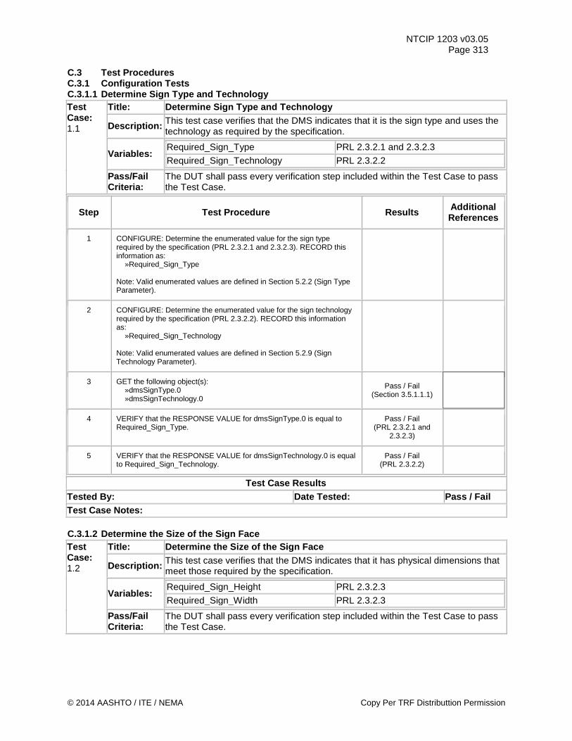
NTCIP 1203 v03.05 Page 313
C.3 Test Procedures C.3.1 Configuration Tests C.3.1.1 Determine Sign Type and Technology Test Case: 1.1
Title: Determine Sign Type and Technology
Description: This test case verifies that the DMS indicates that it is the sign type and uses the technology as required by the specification.
Variables: Required_Sign_Type PRL 2.3.2.1 and 2.3.2.3 Required_Sign_Technology PRL 2.3.2.2
Pass/Fail Criteria:
The DUT shall pass every verification step included within the Test Case to pass the Test Case.
Step Test Procedure Results Additional References
1 CONFIGURE: Determine the enumerated value for the sign type required by the specification (PRL 2.3.2.1 and 2.3.2.3). RECORD this information as: »Required_Sign_Type Note: Valid enumerated values are defined in Section 5.2.2 (Sign Type Parameter).
2 CONFIGURE: Determine the enumerated value for the sign technology required by the specification (PRL 2.3.2.2). RECORD this information as: »Required_Sign_Technology Note: Valid enumerated values are defined in Section 5.2.9 (Sign Technology Parameter).
3 GET the following object(s): »dmsSignType.0 »dmsSignTechnology.0
Pass / Fail (Section 3.5.1.1.1)
4 VERIFY that the RESPONSE VALUE for dmsSignType.0 is equal to Required_Sign_Type.
Pass / Fail (PRL 2.3.2.1 and
2.3.2.3)
5 VERIFY that the RESPONSE VALUE for dmsSignTechnology.0 is equal to Required_Sign_Technology.
Pass / Fail (PRL 2.3.2.2)
Test Case Results Tested By: Date Tested: Pass / Fail Test Case Notes: C.3.1.2 Determine the Size of the Sign Face Test Case: 1.2
Title: Determine the Size of the Sign Face
Description: This test case verifies that the DMS indicates that it has physical dimensions that meet those required by the specification.
Variables: Required_Sign_Height PRL 2.3.2.3 Required_Sign_Width PRL 2.3.2.3
Pass/Fail Criteria:
The DUT shall pass every verification step included within the Test Case to pass the Test Case.
© 2014 AASHTO / ITE / NEMA Copy Per TRF Distributtion Permission
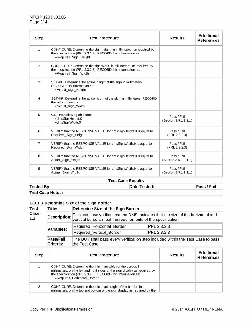
NTCIP 1203 v03.05 Page 314
Step Test Procedure Results Additional References
1 CONFIGURE: Determine the sign height, in millimeters, as required by the specification (PRL 2.3.2.3). RECORD this information as: »Required_Sign_Height
2 CONFIGURE: Determine the sign width, in millimeters, as required by the specification (PRL 2.3.2.3). RECORD this information as: »Required_Sign_Width
3 SET-UP: Determine the actual height of the sign in millimeters. RECORD this information as: »Actual_Sign_Height
4 SET-UP: Determine the actual width of the sign in millimeters. RECORD this information as: »Actual_Sign_Width
5 GET the following object(s): »dmsSignHeight.0 »dmsSignWidth.0
Pass / Fail (Section 3.5.1.2.1.1)
6 VERIFY that the RESPONSE VALUE for dmsSignHeight.0 is equal to Required_Sign_Height.
Pass / Fail (PRL 2.3.2.3)
7 VERIFY that the RESPONSE VALUE for dmsSignWidth.0 is equal to Required_Sign_Width.
Pass / Fail (PRL 2.3.2.3)
8 VERIFY that the RESPONSE VALUE for dmsSignHeight.0 is equal to Actual_Sign_Height.
Pass / Fail (Section 3.5.1.2.1.1)
9 VERIFY that the RESPONSE VALUE for dmsSignWidth.0 is equal to Actual_Sign_Width.
Pass / Fail (Section 3.5.1.2.1.1)
Test Case Results Tested By: Date Tested: Pass / Fail Test Case Notes: C.3.1.3 Determine Size of the Sign Border Test Case: 1.3
Title: Determine Size of the Sign Border
Description: This test case verifies that the DMS indicates that the size of the horizontal and vertical borders meet the requirements of the specification.
Variables: Required_Horizontal_Border PRL 2.3.2.3 Required_Vertical_Border PRL 2.3.2.3
Pass/Fail Criteria:
The DUT shall pass every verification step included within the Test Case to pass the Test Case.
Step Test Procedure Results Additional References
1 CONFIGURE: Determine the minimum width of the border, in millimeters, on the left and right sides of the sign display as required by the specification (PRL 2.3.2.3). RECORD this information as: »Required_Horizontal_Border
2 CONFIGURE: Determine the minimum height of the border, in millimeters, on the top and bottom of the sign display as required by the
Copy Per TRF Distribution Permission © 2014 AASHTO / ITE / NEMA
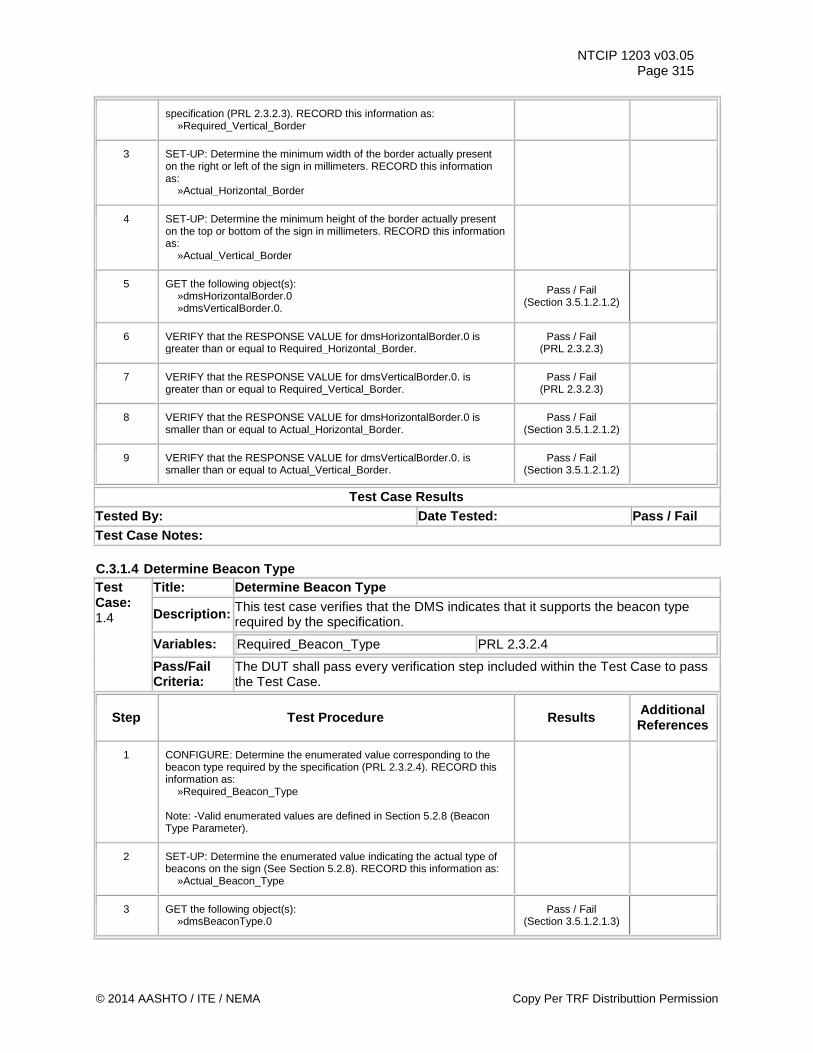
NTCIP 1203 v03.05 Page 315
specification (PRL 2.3.2.3). RECORD this information as: »Required_Vertical_Border
3 SET-UP: Determine the minimum width of the border actually present on the right or left of the sign in millimeters. RECORD this information as: »Actual_Horizontal_Border
4 SET-UP: Determine the minimum height of the border actually present on the top or bottom of the sign in millimeters. RECORD this information as: »Actual_Vertical_Border
5 GET the following object(s): »dmsHorizontalBorder.0 »dmsVerticalBorder.0.
Pass / Fail (Section 3.5.1.2.1.2)
6 VERIFY that the RESPONSE VALUE for dmsHorizontalBorder.0 is greater than or equal to Required_Horizontal_Border.
Pass / Fail (PRL 2.3.2.3)
7 VERIFY that the RESPONSE VALUE for dmsVerticalBorder.0. is greater than or equal to Required_Vertical_Border.
Pass / Fail (PRL 2.3.2.3)
8 VERIFY that the RESPONSE VALUE for dmsHorizontalBorder.0 is smaller than or equal to Actual_Horizontal_Border.
Pass / Fail (Section 3.5.1.2.1.2)
9 VERIFY that the RESPONSE VALUE for dmsVerticalBorder.0. is smaller than or equal to Actual_Vertical_Border.
Pass / Fail (Section 3.5.1.2.1.2)
Test Case Results Tested By: Date Tested: Pass / Fail Test Case Notes: C.3.1.4 Determine Beacon Type Test Case: 1.4
Title: Determine Beacon Type
Description: This test case verifies that the DMS indicates that it supports the beacon type required by the specification.
Variables: Required_Beacon_Type PRL 2.3.2.4
Pass/Fail Criteria:
The DUT shall pass every verification step included within the Test Case to pass the Test Case.
Step Test Procedure Results Additional References
1 CONFIGURE: Determine the enumerated value corresponding to the beacon type required by the specification (PRL 2.3.2.4). RECORD this information as: »Required_Beacon_Type Note: -Valid enumerated values are defined in Section 5.2.8 (Beacon Type Parameter).
2 SET-UP: Determine the enumerated value indicating the actual type of beacons on the sign (See Section 5.2.8). RECORD this information as: »Actual_Beacon_Type
3 GET the following object(s): »dmsBeaconType.0
Pass / Fail (Section 3.5.1.2.1.3)
© 2014 AASHTO / ITE / NEMA Copy Per TRF Distributtion Permission
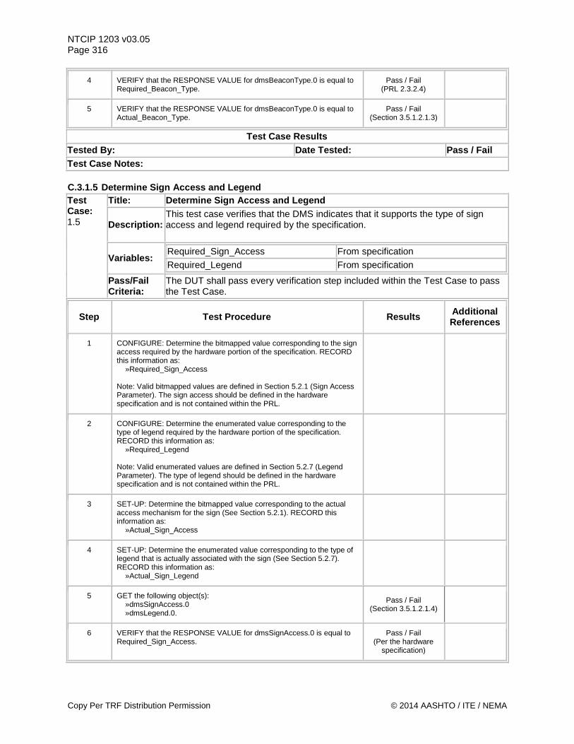
NTCIP 1203 v03.05 Page 316
4 VERIFY that the RESPONSE VALUE for dmsBeaconType.0 is equal to Required_Beacon_Type.
Pass / Fail (PRL 2.3.2.4)
5 VERIFY that the RESPONSE VALUE for dmsBeaconType.0 is equal to Actual_Beacon_Type.
Pass / Fail (Section 3.5.1.2.1.3)
Test Case Results Tested By: Date Tested: Pass / Fail Test Case Notes: C.3.1.5 Determine Sign Access and Legend Test Case: 1.5
Title: Determine Sign Access and Legend
Description: This test case verifies that the DMS indicates that it supports the type of sign access and legend required by the specification.
Variables: Required_Sign_Access From specification Required_Legend From specification
Pass/Fail Criteria:
The DUT shall pass every verification step included within the Test Case to pass the Test Case.
Step Test Procedure Results Additional References
1 CONFIGURE: Determine the bitmapped value corresponding to the sign access required by the hardware portion of the specification. RECORD this information as: »Required_Sign_Access Note: Valid bitmapped values are defined in Section 5.2.1 (Sign Access Parameter). The sign access should be defined in the hardware specification and is not contained within the PRL.
2 CONFIGURE: Determine the enumerated value corresponding to the type of legend required by the hardware portion of the specification. RECORD this information as: »Required_Legend Note: Valid enumerated values are defined in Section 5.2.7 (Legend Parameter). The type of legend should be defined in the hardware specification and is not contained within the PRL.
3 SET-UP: Determine the bitmapped value corresponding to the actual access mechanism for the sign (See Section 5.2.1). RECORD this information as: »Actual_Sign_Access
4 SET-UP: Determine the enumerated value corresponding to the type of legend that is actually associated with the sign (See Section 5.2.7). RECORD this information as: »Actual_Sign_Legend
5 GET the following object(s): »dmsSignAccess.0 »dmsLegend.0.
Pass / Fail (Section 3.5.1.2.1.4)
6 VERIFY that the RESPONSE VALUE for dmsSignAccess.0 is equal to Required_Sign_Access.
Pass / Fail (Per the hardware
specification)
Copy Per TRF Distribution Permission © 2014 AASHTO / ITE / NEMA
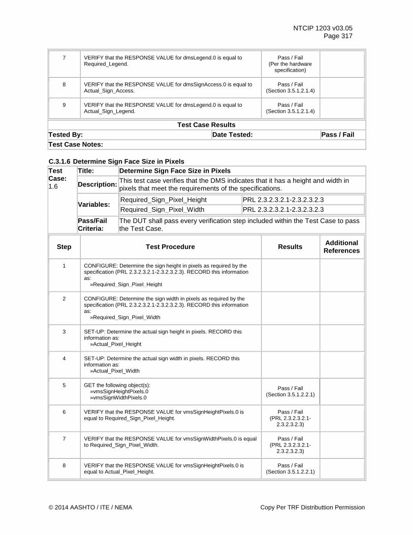
NTCIP 1203 v03.05 Page 317
7 VERIFY that the RESPONSE VALUE for dmsLegend.0 is equal to Required_Legend.
Pass / Fail (Per the hardware
specification)
8 VERIFY that the RESPONSE VALUE for dmsSignAccess.0 is equal to Actual_Sign_Access.
Pass / Fail (Section 3.5.1.2.1.4)
9 VERIFY that the RESPONSE VALUE for dmsLegend.0 is equal to Actual_Sign_Legend.
Pass / Fail (Section 3.5.1.2.1.4)
Test Case Results Tested By: Date Tested: Pass / Fail Test Case Notes: C.3.1.6 Determine Sign Face Size in Pixels Test Case: 1.6
Title: Determine Sign Face Size in Pixels
Description: This test case verifies that the DMS indicates that it has a height and width in pixels that meet the requirements of the specifications.
Variables: Required_Sign_Pixel_Height PRL 2.3.2.3.2.1-2.3.2.3.2.3 Required_Sign_Pixel_Width PRL 2.3.2.3.2.1-2.3.2.3.2.3
Pass/Fail Criteria:
The DUT shall pass every verification step included within the Test Case to pass the Test Case.
Step Test Procedure Results Additional References
1 CONFIGURE: Determine the sign height in pixels as required by the specification (PRL 2.3.2.3.2.1-2.3.2.3.2.3). RECORD this information as: »Required_Sign_Pixel_Height
2 CONFIGURE: Determine the sign width in pixels as required by the specification (PRL 2.3.2.3.2.1-2.3.2.3.2.3). RECORD this information as: »Required_Sign_Pixel_Width
3 SET-UP: Determine the actual sign height in pixels. RECORD this information as: »Actual_Pixel_Height
4 SET-UP: Determine the actual sign width in pixels. RECORD this information as: »Actual_Pixel_Width
5 GET the following object(s): »vmsSignHeightPixels.0 »vmsSignWidthPixels.0
Pass / Fail (Section 3.5.1.2.2.1)
6 VERIFY that the RESPONSE VALUE for vmsSignHeightPixels.0 is equal to Required_Sign_Pixel_Height.
Pass / Fail (PRL 2.3.2.3.2.1-
2.3.2.3.2.3)
7 VERIFY that the RESPONSE VALUE for vmsSignWidthPixels.0 is equal to Required_Sign_Pixel_Width.
Pass / Fail (PRL 2.3.2.3.2.1-
2.3.2.3.2.3)
8 VERIFY that the RESPONSE VALUE for vmsSignHeightPixels.0 is equal to Actual_Pixel_Height.
Pass / Fail (Section 3.5.1.2.2.1)
© 2014 AASHTO / ITE / NEMA Copy Per TRF Distributtion Permission
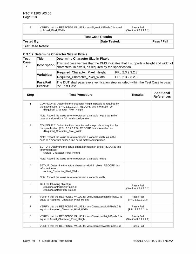
NTCIP 1203 v03.05 Page 318
9 VERIFY that the RESPONSE VALUE for vmsSignWidthPixels.0 is equal to Actual_Pixel_Width.
Pass / Fail (Section 3.5.1.2.2.1)
Test Case Results Tested By: Date Tested: Pass / Fail Test Case Notes: C.3.1.7 Determine Character Size in Pixels Test Case: 1.7
Title: Determine Character Size in Pixels
Description: This test case verifies that the DMS indicates that it supports a height and width of characters, in pixels, as required by the specification.
Variables: Required_Character_Pixel_Height PRL 2.3.2.3.2.3 Required_Character_Pixel_Width PRL 2.3.2.3.2.3
Pass/Fail Criteria:
The DUT shall pass every verification step included within the Test Case to pass the Test Case.
Step Test Procedure Results Additional References
1 CONFIGURE: Determine the character height in pixels as required by the specification (PRL 2.3.2.3.2.3). RECORD this information as: »Required_Character_Pixel_Height Note: Record the value zero to represent a variable height, as in the case of a sign with a full matrix configuration.
2 CONFIGURE: Determine the character width in pixels as required by the specification (PRL 2.3.2.3.2.3). RECORD this information as: »Required_Character_Pixel_Width Note: Record the value zero to represent a variable width, as in the case of a sign with either a line or full matrix configuration.
3 SET-UP: Determine the actual character height in pixels. RECORD this information as: »Actual_Character_Pixel_Height Note: Record the value zero to represent a variable height.
4 SET-UP: Determine the actual character width in pixels. RECORD this information as: »Actual_Character_Pixel_Width Note: Record the value zero to represent a variable width.
5 GET the following object(s): »vmsCharacterHeightPixels.0 »vmsCharacterWidthPixels.0
Pass / Fail (Section 3.5.1.2.2.2)
6 VERIFY that the RESPONSE VALUE for vmsCharacterHeightPixels.0 is equal to Required_Character_Pixel_Height.
Pass / Fail (PRL 2.3.2.3.2.3)
7 VERIFY that the RESPONSE VALUE for vmsCharacterWidthPixels.0 is equal to Required_Character_Pixel_Width.
Pass / Fail (PRL 2.3.2.3.2.3)
8 VERIFY that the RESPONSE VALUE for vmsCharacterHeightPixels.0 is equal to Actual_Character_Pixel_Height.
Pass / Fail (Section 3.5.1.2.2.2)
9 VERIFY that the RESPONSE VALUE for vmsCharacterWidthPixels.0 is Pass / Fail
Copy Per TRF Distribution Permission © 2014 AASHTO / ITE / NEMA
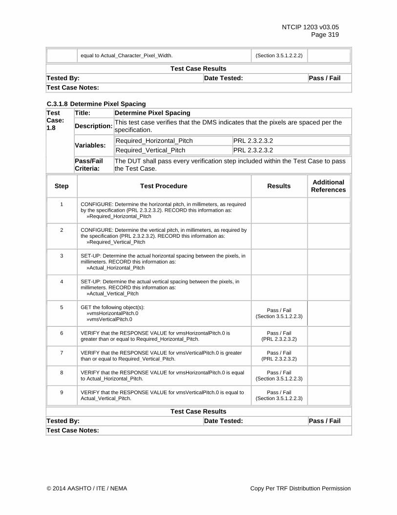
NTCIP 1203 v03.05 Page 319
equal to Actual_Character_Pixel_Width. (Section 3.5.1.2.2.2)
Test Case Results Tested By: Date Tested: Pass / Fail Test Case Notes: C.3.1.8 Determine Pixel Spacing Test Case: 1.8
Title: Determine Pixel Spacing
Description: This test case verifies that the DMS indicates that the pixels are spaced per the specification.
Variables: Required_Horizontal_Pitch PRL 2.3.2.3.2 Required_Vertical_Pitch PRL 2.3.2.3.2
Pass/Fail Criteria:
The DUT shall pass every verification step included within the Test Case to pass the Test Case.
Step Test Procedure Results Additional References
1 CONFIGURE: Determine the horizontal pitch, in millimeters, as required by the specification (PRL 2.3.2.3.2). RECORD this information as: »Required_Horizontal_Pitch
2 CONFIGURE: Determine the vertical pitch, in millimeters, as required by the specification (PRL 2.3.2.3.2). RECORD this information as: »Required_Vertical_Pitch
3 SET-UP: Determine the actual horizontal spacing between the pixels, in millimeters. RECORD this information as: »Actual_Horizontal_Pitch
4 SET-UP: Determine the actual vertical spacing between the pixels, in millimeters. RECORD this information as: »Actual_Vertical_Pitch
5 GET the following object(s): »vmsHorizontalPitch.0 »vmsVerticalPitch.0
Pass / Fail (Section 3.5.1.2.2.3)
6 VERIFY that the RESPONSE VALUE for vmsHorizontalPitch.0 is greater than or equal to Required_Horizontal_Pitch.
Pass / Fail (PRL 2.3.2.3.2)
7 VERIFY that the RESPONSE VALUE for vmsVerticalPitch.0 is greater than or equal to Required_Vertical_Pitch.
Pass / Fail (PRL 2.3.2.3.2)
8 VERIFY that the RESPONSE VALUE for vmsHorizontalPitch.0 is equal to Actual_Horizontal_Pitch.
Pass / Fail (Section 3.5.1.2.2.3)
9 VERIFY that the RESPONSE VALUE for vmsVerticalPitch.0 is equal to Actual_Vertical_Pitch.
Pass / Fail (Section 3.5.1.2.2.3)
Test Case Results Tested By: Date Tested: Pass / Fail Test Case Notes:
© 2014 AASHTO / ITE / NEMA Copy Per TRF Distributtion Permission
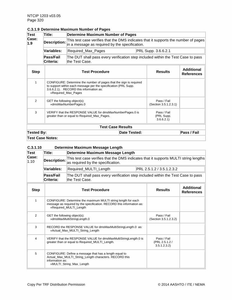
NTCIP 1203 v03.05 Page 320 C.3.1.9 Determine Maximum Number of Pages Test Case: 1.9
Title: Determine Maximum Number of Pages
Description: This test case verifies that the DMS indicates that it supports the number of pages in a message as required by the specification.
Variables: Required_Max_Pages PRL Supp. 3.6.6.2.1
Pass/Fail Criteria:
The DUT shall pass every verification step included within the Test Case to pass the Test Case.
Step Test Procedure Results Additional References
1 CONFIGURE: Determine the number of pages that the sign is required to support within each message per the specification (PRL Supp. 3.6.6.2.1). RECORD this information as: »Required_Max_Pages
2 GET the following object(s): »dmsMaxNumberPages.0
Pass / Fail (Section 3.5.1.2.3.1)
3 VERIFY that the RESPONSE VALUE for dmsMaxNumberPages.0 is greater than or equal to Required_Max_Pages.
Pass / Fail (PRL Supp. 3.6.6.2.1)
Test Case Results Tested By: Date Tested: Pass / Fail Test Case Notes: C.3.1.10 Determine Maximum Message Length Test Case: 1.10
Title: Determine Maximum Message Length
Description: This test case verifies that the DMS indicates that it supports MULTI string lengths as required by the specification.
Variables: Required_MULTI_Length PRL 2.5.1.2 / 3.5.1.2.3.2
Pass/Fail Criteria:
The DUT shall pass every verification step included within the Test Case to pass the Test Case.
Step Test Procedure Results Additional References
1 CONFIGURE: Determine the maximum MULTI string length for each message as required by the specification. RECORD this information as: »Required_MULTI_Length
2 GET the following object(s): »dmsMaxMultiStringLength.0
Pass / Fail (Section 3.5.1.2.3.2)
3 RECORD the RESPONSE VALUE for dmsMaxMultiStringLength.0 as: »Actual_Max_MULTI_String_Length
4 VERIFY that the RESPONSE VALUE for dmsMaxMultiStringLength.0 is greater than or equal to Required_MULTI_Length.
Pass / Fail (PRL 2.5.1.2 / 3.5.1.2.3.2)
5 CONFIGURE: Define a message that has a length equal to Actual_Max_MULTI_String_Length characters. RECORD this information as: »MULTI_String_Max_Length
Copy Per TRF Distribution Permission © 2014 AASHTO / ITE / NEMA
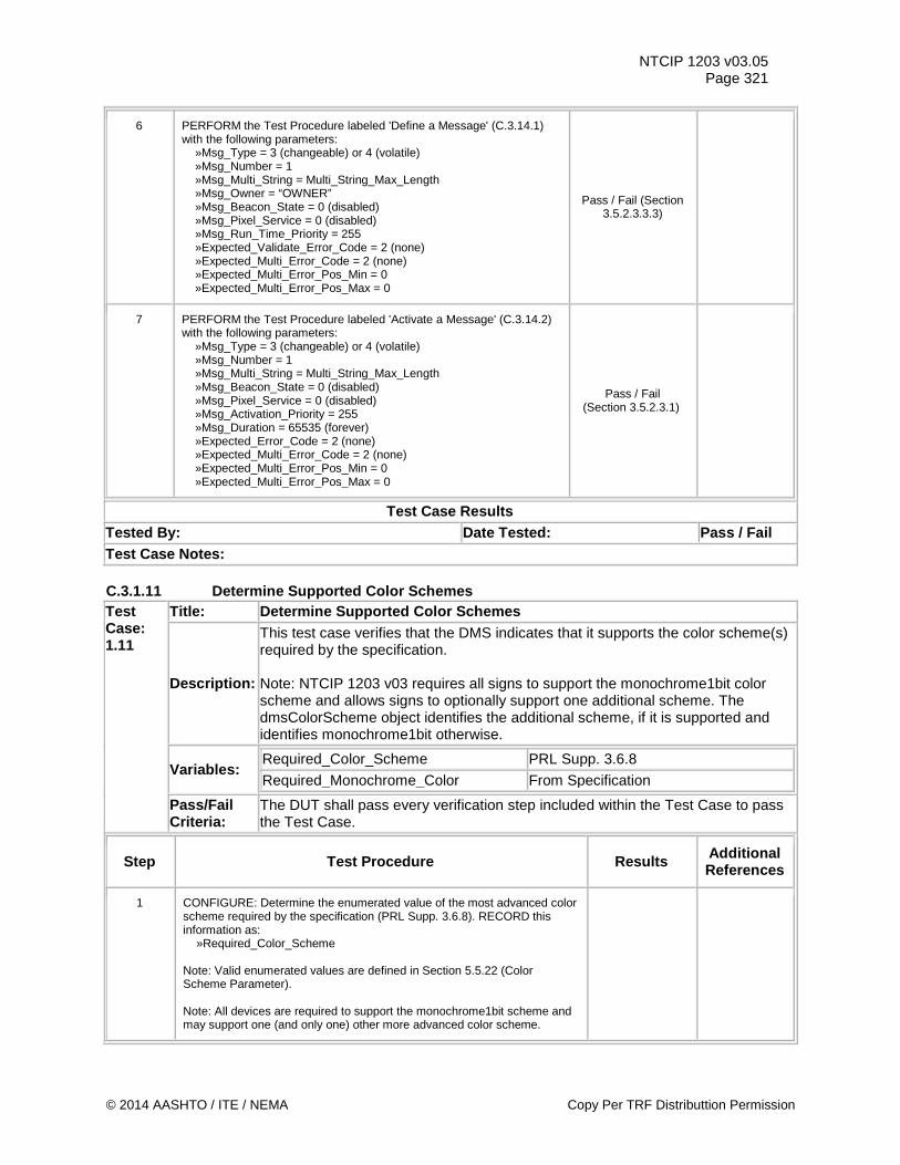
NTCIP 1203 v03.05 Page 321
6 PERFORM the Test Procedure labeled 'Define a Message' (C.3.14.1) with the following parameters: »Msg_Type = 3 (changeable) or 4 (volatile) »Msg_Number = 1 »Msg_Multi_String = Multi_String_Max_Length »Msg_Owner = “OWNER” »Msg_Beacon_State = 0 (disabled) »Msg_Pixel_Service = 0 (disabled) »Msg_Run_Time_Priority = 255 »Expected_Validate_Error_Code = 2 (none) »Expected_Multi_Error_Code = 2 (none) »Expected_Multi_Error_Pos_Min = 0 »Expected_Multi_Error_Pos_Max = 0
Pass / Fail (Section 3.5.2.3.3.3)
7 PERFORM the Test Procedure labeled 'Activate a Message' (C.3.14.2) with the following parameters: »Msg_Type = 3 (changeable) or 4 (volatile) »Msg_Number = 1 »Msg_Multi_String = Multi_String_Max_Length »Msg_Beacon_State = 0 (disabled) »Msg_Pixel_Service = 0 (disabled) »Msg_Activation_Priority = 255 »Msg_Duration = 65535 (forever) »Expected_Error_Code = 2 (none) »Expected_Multi_Error_Code = 2 (none) »Expected_Multi_Error_Pos_Min = 0 »Expected_Multi_Error_Pos_Max = 0
Pass / Fail (Section 3.5.2.3.1)
Test Case Results Tested By: Date Tested: Pass / Fail Test Case Notes: C.3.1.11 Determine Supported Color Schemes Test Case: 1.11
Title: Determine Supported Color Schemes
Description:
This test case verifies that the DMS indicates that it supports the color scheme(s) required by the specification. Note: NTCIP 1203 v03 requires all signs to support the monochrome1bit color scheme and allows signs to optionally support one additional scheme. The dmsColorScheme object identifies the additional scheme, if it is supported and identifies monochrome1bit otherwise.
Variables: Required_Color_Scheme PRL Supp. 3.6.8 Required_Monochrome_Color From Specification
Pass/Fail Criteria:
The DUT shall pass every verification step included within the Test Case to pass the Test Case.
Step Test Procedure Results Additional References
1 CONFIGURE: Determine the enumerated value of the most advanced color scheme required by the specification (PRL Supp. 3.6.8). RECORD this information as: »Required_Color_Scheme Note: Valid enumerated values are defined in Section 5.5.22 (Color Scheme Parameter). Note: All devices are required to support the monochrome1bit scheme and may support one (and only one) other more advanced color scheme.
© 2014 AASHTO / ITE / NEMA Copy Per TRF Distributtion Permission
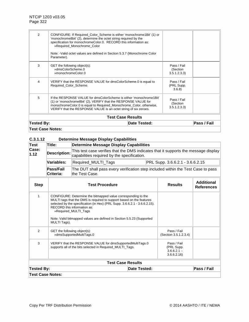
NTCIP 1203 v03.05 Page 322
2 CONFIGURE: If Required_Color_Scheme is either ‘monochrome1Bit’ (1) or ‘monochrome8bit’ (2), determine the octet string required by the specification for monochromeColor.0. RECORD this information as: »Required_Monochrome_Color Note: -Valid octet values are defined in Section 5.3.7 (Monochrome Color Parameter).
3 GET the following object(s): »dmsColorScheme.0 »monochromeColor.0
Pass / Fail (Section
3.5.1.2.3.3)
4 VERIFY that the RESPONSE VALUE for dmsColorScheme.0 is equal to Required_Color_Scheme.
Pass / Fail (PRL Supp.
3.6.8)
5 If the RESPONSE VALUE for dmsColorScheme is either ‘monochrome1Bit’ (1) or ‘monochrome8bit’ (2), VERIFY that the RESPONSE VALUE for monochromeColor.0 is equal to Required_Monochrome_Color, otherwise, VERIFY that the RESPONSE VALUE is an octet string of six zeroes.
Pass / Fail (Section
3.5.1.2.3.3)
Test Case Results Tested By: Date Tested: Pass / Fail Test Case Notes: C.3.1.12 Determine Message Display Capabilities Test Case: 1.12
Title: Determine Message Display Capabilities
Description: This test case verifies that the DMS indicates that it supports the message display capabilities required by the specification.
Variables: Required_MULTI_Tags PRL Supp. 3.6.6.2.1 - 3.6.6.2.15
Pass/Fail Criteria:
The DUT shall pass every verification step included within the Test Case to pass the Test Case.
Step Test Procedure Results Additional References
1 CONFIGURE: Determine the bitmapped value corresponding to the MULTI tags that the DMS is required to support based on the features selected by the specification (in Hex) (PRL Supp. 3.6.6.2.1 - 3.6.6.2.15). RECORD this information as: »Required_MULTI_Tags Note: Valid bitmapped values are defined in Section 5.5.23 (Supported MULTI Tags).
2 GET the following object(s): »dmsSupportedMultiTags.0
Pass / Fail (Section 3.5.1.2.3.4)
3 VERIFY that the RESPONSE VALUE for dmsSupportedMultiTags.0 supports all of the bits selected in Required_MULTI_Tags.
Pass / Fail (PRL Supp. 3.6.6.2.1 – 3.6.6.2.16)
Test Case Results Tested By: Date Tested: Pass / Fail Test Case Notes:
Copy Per TRF Distribution Permission © 2014 AASHTO / ITE / NEMA
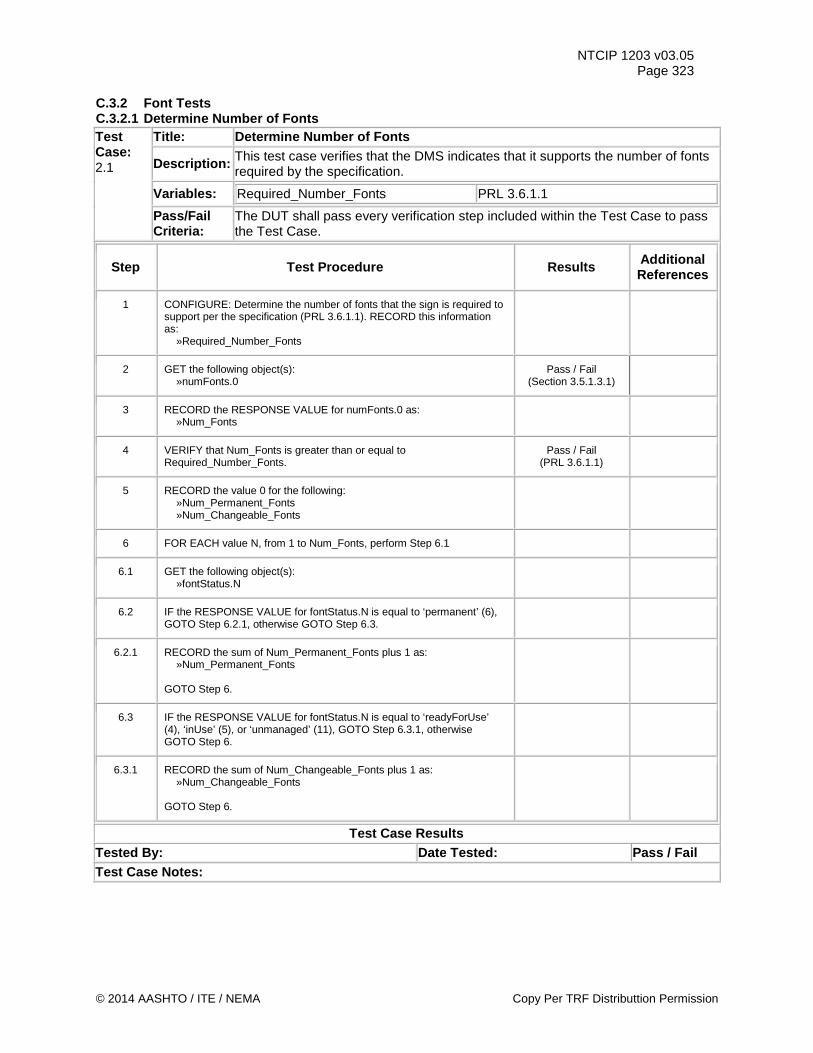
NTCIP 1203 v03.05 Page 323
C.3.2 Font Tests C.3.2.1 Determine Number of Fonts Test Case: 2.1
Title: Determine Number of Fonts
Description: This test case verifies that the DMS indicates that it supports the number of fonts required by the specification.
Variables: Required_Number_Fonts PRL 3.6.1.1
Pass/Fail Criteria:
The DUT shall pass every verification step included within the Test Case to pass the Test Case.
Step Test Procedure Results Additional References
1 CONFIGURE: Determine the number of fonts that the sign is required to support per the specification (PRL 3.6.1.1). RECORD this information as: »Required_Number_Fonts
2 GET the following object(s): »numFonts.0
Pass / Fail (Section 3.5.1.3.1)
3 RECORD the RESPONSE VALUE for numFonts.0 as: »Num_Fonts
4 VERIFY that Num_Fonts is greater than or equal to Required_Number_Fonts.
Pass / Fail (PRL 3.6.1.1)
5 RECORD the value 0 for the following: »Num_Permanent_Fonts »Num_Changeable_Fonts
6 FOR EACH value N, from 1 to Num_Fonts, perform Step 6.1
6.1 GET the following object(s): »fontStatus.N
6.2 IF the RESPONSE VALUE for fontStatus.N is equal to ‘permanent’ (6), GOTO Step 6.2.1, otherwise GOTO Step 6.3.
6.2.1 RECORD the sum of Num_Permanent_Fonts plus 1 as: »Num_Permanent_Fonts GOTO Step 6.
6.3 IF the RESPONSE VALUE for fontStatus.N is equal to ‘readyForUse’ (4), ‘inUse’ (5), or ‘unmanaged’ (11), GOTO Step 6.3.1, otherwise GOTO Step 6.
6.3.1 RECORD the sum of Num_Changeable_Fonts plus 1 as: »Num_Changeable_Fonts GOTO Step 6.
Test Case Results Tested By: Date Tested: Pass / Fail Test Case Notes:
© 2014 AASHTO / ITE / NEMA Copy Per TRF Distributtion Permission
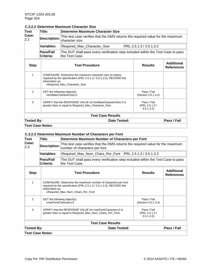
NTCIP 1203 v03.05 Page 324 C.3.2.2 Determine Maximum Character Size Test Case: 2.2
Title: Determine Maximum Character Size
Description: This test case verifies that the DMS returns the required value for the maximum character size.
Variables: Required_Max_Character_Size PRL 2.5.1.3 / 3.5.1.3.2
Pass/Fail Criteria:
The DUT shall pass every verification step included within the Test Case to pass the Test Case.
Step Test Procedure Results Additional References
1 CONFIGURE: Determine the maximum character size (in bytes) required by the specification (PRL 2.5.1.3 / 3.5.1.3.2). RECORD this information as: »Required_Max_Character_Size
2 GET the following object(s): »fontMaxCharacterSize.0
Pass / Fail (Section 3.5.1.3.2)
3 VERIFY that the RESPONSE VALUE for fontMaxCharacterSize.0 is greater than or equal to Required_Max_Character_Size.
Pass / Fail (PRL 2.5.1.3 /
3.5.1.3.2)
Test Case Results Tested By: Date Tested: Pass / Fail Test Case Notes: C.3.2.3 Determine Maximum Number of Characters per Font Test Case: 2.3
Title: Determine Maximum Number of Characters per Font
Description: This test case verifies that the DMS returns the required value for the maximum number of characters per font.
Variables: Required_Max_Num_Chars_Per_Font PRL 2.5.1.3 / 3.5.1.3.3
Pass/Fail Criteria:
The DUT shall pass every verification step included within the Test Case to pass the Test Case.
Step Test Procedure Results Additional References
1 CONFIGURE: Determine the maximum number of characters per font required by the specification (PRL 2.5.1.3 / 3.5.1.3.3). RECORD this information as: »Required_Max_Num_Chars_Per_Font
2 GET the following object(s): »maxFontCharacters.0
Pass / Fail (Section 3.5.1.3.3)
3 VERIFY that the RESPONSE VALUE for maxFontCharacters.0 is greater than or equal to Required_Max_Num_Chars_Per_Font.
Pass / Fail (PRL 2.5.1.3 /
3.5.1.3.3)
Test Case Results Tested By: Date Tested: Pass / Fail Test Case Notes:
Copy Per TRF Distribution Permission © 2014 AASHTO / ITE / NEMA
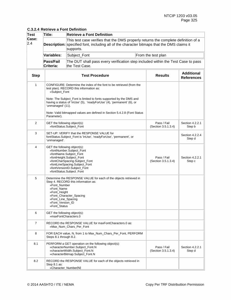
NTCIP 1203 v03.05 Page 325
C.3.2.4 Retrieve a Font Definition Test Case: 2.4
Title: Retrieve a Font Definition
Description: This test case verifies that the DMS properly returns the complete definition of a specified font, including all of the character bitmaps that the DMS claims it supports.
Variables: Subject_Font From the test plan
Pass/Fail Criteria:
The DUT shall pass every verification step included within the Test Case to pass the Test Case.
Step Test Procedure Results Additional References
1 CONFIGURE: Determine the index of the font to be retrieved (from the test plan). RECORD this information as: »Subject_Font Note: The Subject_Font is limited to fonts supported by the DMS and having a status of 'inUse' (5), 'readyForUse' (4), ‘permanent’ (6), or ‘unmanaged’ (11). Note: Valid bitmapped values are defined in Section 5.4.2.8 (Font Status Parameter).
2 GET the following object(s): »fontStatus.Subject_Font
Pass / Fail (Section 3.5.1.3.4)
Section 4.2.2.1 Step b
3 SET-UP: VERIFY that the RESPONSE VALUE for fontStatus.Subject_Font is 'inUse', 'readyForUse', ‘permanent’, or ‘unmanaged’.
Section 4.2.2.4 Step d
4 GET the following object(s): »fontNumber.Subject_Font »fontName.Subject_Font »fontHeight.Subject_Font »fontCharSpacing.Subject_Font »fontLineSpacing.Subject_Font »fontVersionID.Subject_Font »fontStatus.Subject_Font
Pass / Fail (Section 3.5.1.3.4)
Section 4.2.2.1 Step c
5 Determine the RESPONSE VALUE for each of the objects retrieved in Step 4. RECORD this information as: »Font_Number »Font_Name »Font_Height »Font_Character_Spacing »Font_Line_Spacing »Font_Version_ID »Font_Status
6 GET the following object(s): »maxFontCharacters.0
7 RECORD the RESPONSE VALUE for maxFontCharacters.0 as: »Max_Num_Chars_Per_Font
8 FOR EACH value, N, from 1 to Max_Num_Chars_Per_Font, PERFORM Steps 8.1 through 8.2.
8.1 PERFORM a GET operation on the following object(s): »characterNumber.Subject_Font.N »characterWidth.Subject_Font.N »characterBitmap.Subject_Font.N
Pass / Fail (Section 3.5.1.3.4)
Section 4.2.2.1 Step d
8.2 RECORD the RESPONSE VALUE for each of the objects retrieved in Step 8.1 as: »Character_Number[N]
© 2014 AASHTO / ITE / NEMA Copy Per TRF Distributtion Permission
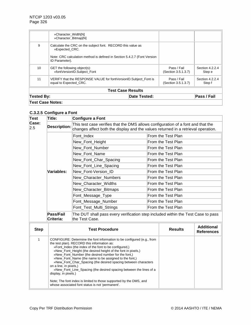
NTCIP 1203 v03.05 Page 326
»Character_Width[N] »Character_Bitmap[N]
9 Calculate the CRC on the subject font. RECORD this value as »Expected_CRC. Note: CRC calculation method is defined in Section 5.4.2.7 (Font Version ID Parameter).
10 GET the following object(s): »fontVersionID.Subject_Font
Pass / Fail (Section 3.5.1.3.7)
Section 4.2.2.4 Step e
11 VERIFY that the RESPONSE VALUE for fontVersionID.Subject_Font is equal to Expected_CRC.
Pass / Fail (Section 3.5.1.3.7)
Section 4.2.2.4 Step f
Test Case Results Tested By: Date Tested: Pass / Fail Test Case Notes: C.3.2.5 Configure a Font Test Case: 2.5
Title: Configure a Font
Description: This test case verifies that the DMS allows configuration of a font and that the changes affect both the display and the values returned in a retrieval operation.
Variables:
Font_Index From the Test Plan New_Font_Height From the Test Plan
New_Font_Number From the Test Plan
New_Font_Name From the Test Plan
New_Font_Char_Spacing From the Test Plan
New_Font_Line_Spacing From the Test Plan
New_Font-Version_ID From the Test Plan
New_Character_Numbers From the Test Plan
New_Character_Widths From the Test Plan
New_Character_Bitmaps From the Test Plan
Font_Message_Type From the Test Plan
Font_Message_Number From the Test Plan
Font_Test_Multi_Strings From the Test Plan
Pass/Fail Criteria:
The DUT shall pass every verification step included within the Test Case to pass the Test Case.
Step Test Procedure Results Additional References
1 CONFIGURE: Determine the font information to be configured (e.g., from the test plan). RECORD this information as: »Font_Index (the index of the font to be configured,) »New_Font_Height (the desired height of the font in pixels,) »New_Font_Number (the desired number for the font,) »New_Font_Name (the name to be assigned to the font,) »New_Font_Char_Spacing (the desired spacing between characters on a line, in pixels,) »New_Font_Line_Spacing (the desired spacing between the lines of a display, in pixels.) Note; The font index is limited to those supported by the DMS, and whose associated font status is not 'permanent'.
Copy Per TRF Distribution Permission © 2014 AASHTO / ITE / NEMA
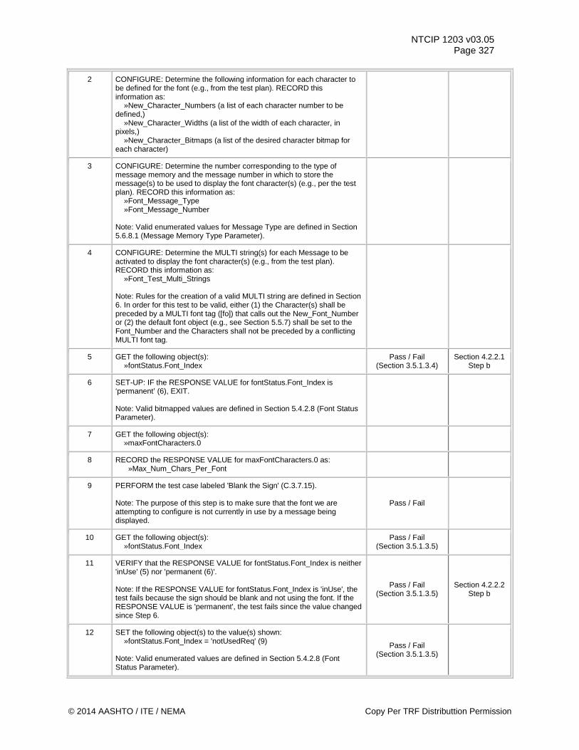
NTCIP 1203 v03.05 Page 327
2 CONFIGURE: Determine the following information for each character to be defined for the font (e.g., from the test plan). RECORD this information as: »New_Character_Numbers (a list of each character number to be defined,) »New_Character_Widths (a list of the width of each character, in pixels,) »New_Character_Bitmaps (a list of the desired character bitmap for each character)
3 CONFIGURE: Determine the number corresponding to the type of message memory and the message number in which to store the message(s) to be used to display the font character(s) (e.g., per the test plan). RECORD this information as: »Font_Message_Type »Font_Message_Number Note: Valid enumerated values for Message Type are defined in Section 5.6.8.1 (Message Memory Type Parameter).
4 CONFIGURE: Determine the MULTI string(s) for each Message to be activated to display the font character(s) (e.g., from the test plan). RECORD this information as: »Font_Test_Multi_Strings Note: Rules for the creation of a valid MULTI string are defined in Section 6. In order for this test to be valid, either (1) the Character(s) shall be preceded by a MULTI font tag ([fo]) that calls out the New_Font_Number or (2) the default font object (e.g., see Section 5.5.7) shall be set to the Font_Number and the Characters shall not be preceded by a conflicting MULTI font tag.
5 GET the following object(s): »fontStatus.Font_Index
Pass / Fail (Section 3.5.1.3.4)
Section 4.2.2.1 Step b
6 SET-UP: IF the RESPONSE VALUE for fontStatus.Font_Index is ‘permanent’ (6), EXIT. Note: Valid bitmapped values are defined in Section 5.4.2.8 (Font Status Parameter).
7 GET the following object(s): »maxFontCharacters.0
8 RECORD the RESPONSE VALUE for maxFontCharacters.0 as: »Max_Num_Chars_Per_Font
9 PERFORM the test case labeled 'Blank the Sign' (C.3.7.15). Note: The purpose of this step is to make sure that the font we are attempting to configure is not currently in use by a message being displayed.
Pass / Fail
10 GET the following object(s): »fontStatus.Font_Index
Pass / Fail (Section 3.5.1.3.5)
11 VERIFY that the RESPONSE VALUE for fontStatus.Font_Index is neither 'inUse' (5) nor 'permanent (6)'. Note: If the RESPONSE VALUE for fontStatus.Font_Index is 'inUse', the test fails because the sign should be blank and not using the font. If the RESPONSE VALUE is 'permanent', the test fails since the value changed since Step 6.
Pass / Fail (Section 3.5.1.3.5)
Section 4.2.2.2 Step b
12 SET the following object(s) to the value(s) shown: »fontStatus.Font_Index = 'notUsedReq' (9) Note: Valid enumerated values are defined in Section 5.4.2.8 (Font Status Parameter).
Pass / Fail (Section 3.5.1.3.5)
© 2014 AASHTO / ITE / NEMA Copy Per TRF Distributtion Permission
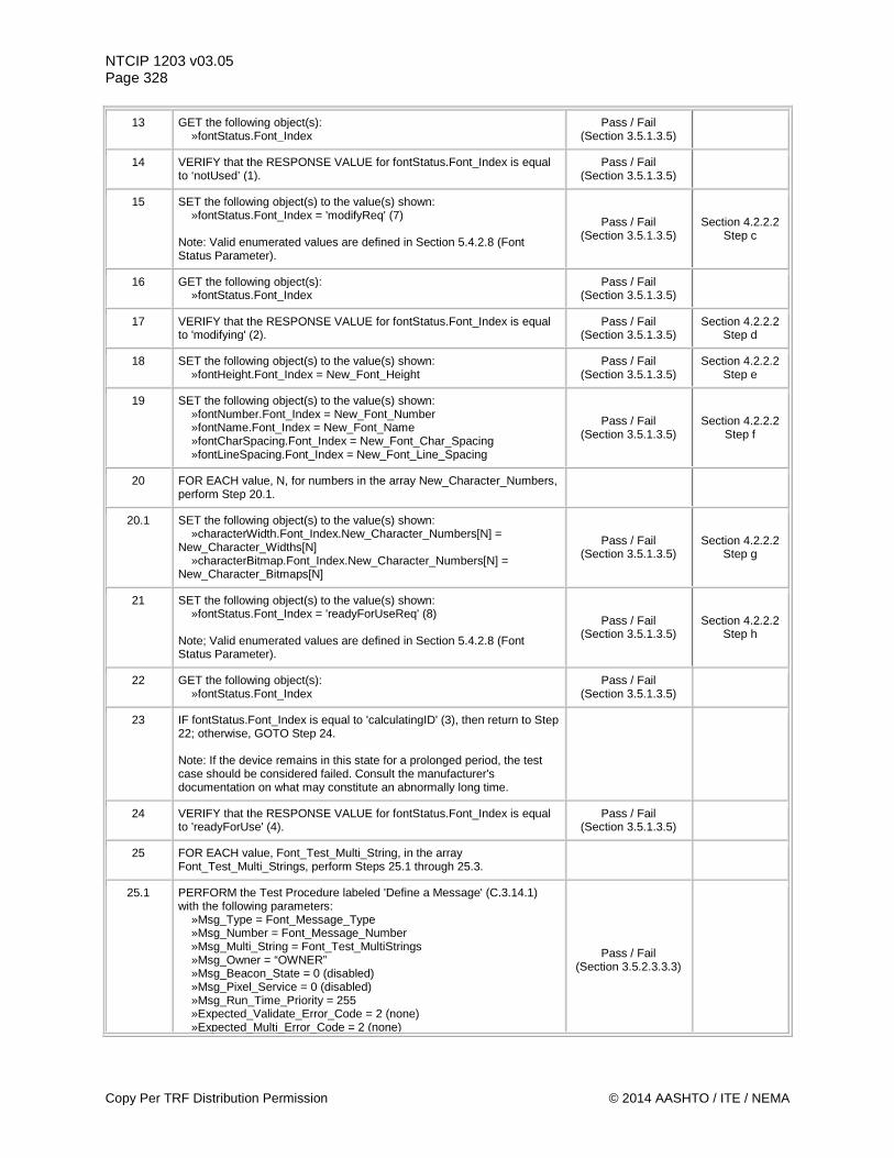
NTCIP 1203 v03.05 Page 328
13 GET the following object(s): »fontStatus.Font_Index
Pass / Fail (Section 3.5.1.3.5)
14 VERIFY that the RESPONSE VALUE for fontStatus.Font_Index is equal to ‘notUsed’ (1).
Pass / Fail (Section 3.5.1.3.5)
15 SET the following object(s) to the value(s) shown: »fontStatus.Font_Index = 'modifyReq' (7) Note: Valid enumerated values are defined in Section 5.4.2.8 (Font Status Parameter).
Pass / Fail (Section 3.5.1.3.5)
Section 4.2.2.2 Step c
16 GET the following object(s): »fontStatus.Font_Index
Pass / Fail (Section 3.5.1.3.5)
17 VERIFY that the RESPONSE VALUE for fontStatus.Font_Index is equal to 'modifying' (2).
Pass / Fail (Section 3.5.1.3.5)
Section 4.2.2.2 Step d
18 SET the following object(s) to the value(s) shown: »fontHeight.Font_Index = New_Font_Height
Pass / Fail (Section 3.5.1.3.5)
Section 4.2.2.2 Step e
19 SET the following object(s) to the value(s) shown: »fontNumber.Font_Index = New_Font_Number »fontName.Font_Index = New_Font_Name »fontCharSpacing.Font_Index = New_Font_Char_Spacing »fontLineSpacing.Font_Index = New_Font_Line_Spacing
Pass / Fail (Section 3.5.1.3.5)
Section 4.2.2.2 Step f
20 FOR EACH value, N, for numbers in the array New_Character_Numbers, perform Step 20.1.
20.1 SET the following object(s) to the value(s) shown: »characterWidth.Font_Index.New_Character_Numbers[N] = New_Character_Widths[N] »characterBitmap.Font_Index.New_Character_Numbers[N] = New_Character_Bitmaps[N]
Pass / Fail (Section 3.5.1.3.5)
Section 4.2.2.2 Step g
21 SET the following object(s) to the value(s) shown: »fontStatus.Font_Index = 'readyForUseReq' (8) Note; Valid enumerated values are defined in Section 5.4.2.8 (Font Status Parameter).
Pass / Fail (Section 3.5.1.3.5)
Section 4.2.2.2 Step h
22 GET the following object(s): »fontStatus.Font_Index
Pass / Fail (Section 3.5.1.3.5)
23 IF fontStatus.Font_Index is equal to 'calculatingID' (3), then return to Step 22; otherwise, GOTO Step 24. Note: If the device remains in this state for a prolonged period, the test case should be considered failed. Consult the manufacturer's documentation on what may constitute an abnormally long time.
24 VERIFY that the RESPONSE VALUE for fontStatus.Font_Index is equal to 'readyForUse' (4).
Pass / Fail (Section 3.5.1.3.5)
25 FOR EACH value, Font_Test_Multi_String, in the array Font_Test_Multi_Strings, perform Steps 25.1 through 25.3.
25.1 PERFORM the Test Procedure labeled 'Define a Message' (C.3.14.1) with the following parameters: »Msg_Type = Font_Message_Type »Msg_Number = Font_Message_Number »Msg_Multi_String = Font_Test_MultiStrings »Msg_Owner = “OWNER” »Msg_Beacon_State = 0 (disabled) »Msg_Pixel_Service = 0 (disabled) »Msg_Run_Time_Priority = 255 »Expected_Validate_Error_Code = 2 (none) »Expected_Multi_Error_Code = 2 (none)
Pass / Fail (Section 3.5.2.3.3.3)
Copy Per TRF Distribution Permission © 2014 AASHTO / ITE / NEMA
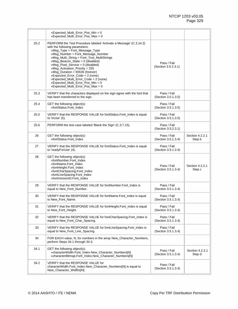
NTCIP 1203 v03.05 Page 329
»Expected_Multi_Error_Pos_Min = 0 »Expected_Multi_Error_Pos_Max = 0
25.2 PERFORM the Test Procedure labeled 'Activate a Message' (C.3.14.2) with the following parameters: »Msg_Type = Font_Message_Type »Msg_Number = Font_Message_Number »Msg_Multi_String = Font_Test_MultiStrings »Msg_Beacon_State = 0 (disabled) »Msg_Pixel_Service = 0 (disabled) »Msg_Activation_Priority = 255 »Msg_Duration = 65535 (forever) »Expected_Error_Code = 2 (none) »Expected_Multi_Error_Code = 2 (none) »Expected_Multi_Error_Pos_Min = 0 »Expected_Multi_Error_Pos_Max = 0
Pass / Fail (Section 3.5.2.3.1)
25.3 VERIFY that the characters displayed on the sign agree with the font that has been transferred to the sign.
Pass / Fail (Section 3.5.1.3.5)
25.4 GET the following object(s): »fontStatus.Font_Index
Pass / Fail (Section 3.5.1.3.5)
25.5 VERIFY that the RESPONSE VALUE for fontStatus.Font_Index is equal to 'inUse' (5).
Pass / Fail (Section 3.5.1.3.5)
25.6 PERFORM the test case labeled 'Blank the Sign' (C.3.7.15). Pass / Fail (Section 3.5.2.3.1)
26 GET the following object(s): »fontStatus.Font_Index
Pass / Fail (Section 3.5.1.3.4)
Section 4.2.2.1 Step b
27 VERIFY that the RESPONSE VALUE for fontStatus.Font_Index is equal to 'readyForUse' (4).
Pass / Fail (Section 3.5.1.3.4)
28 GET the following object(s): »fontNumber.Font_Index »fontName.Font_Index »fontHeight.Font_Index »fontCharSpacing.Font_Index »fontLineSpacing.Font_Index »fontVersionID.Font_Index
Pass / Fail (Section 3.5.1.3.4)
Section 4.2.2.1 Step c
29 VERIFY that the RESPONSE VALUE for fontNumber.Font_Index is equal to New_Font_Number.
Pass / Fail (Section 3.5.1.3.4)
30 VERIFY that the RESPONSE VALUE for fontName.Font_Index is equal to New_Font_Name.
Pass / Fail (Section 3.5.1.3.4)
31 VERIFY that the RESPONSE VALUE for fontHeight.Font_Index is equal to New_Font_Height.
Pass / Fail (Section 3.5.1.3.4)
32 VERIFY that the RESPONSE VALUE for fontCharSpacing.Font_Index is equal to New_Font_Char_Spacing.
Pass / Fail (Section 3.5.1.3.4)
33 VERIFY that the RESPONSE VALUE for fontLineSpacing.Font_Index is equal to New_Font_Line_Spacing.
Pass / Fail (Section 3.5.1.3.4)
34 FOR EACH value, N, for numbers in the array New_Character_Numbers, perform Steps 34.1 through 34.3.
34.1 GET the following object(s): »characterWidth.Font_Index.New_Character_Numbers[N] »characterBitmap.Font_Index.New_Character_Numbers[N]
Pass / Fail (Section 3.5.1.3.4)
Section 4.2.2.1 Step d
34.2 VERIFY that the RESPONSE VALUE for characterWidth.Font_Index.New_Character_Numbers[N] is equal to New_Character_Widths[N].
Pass / Fail (Section 3.5.1.3.4)
© 2014 AASHTO / ITE / NEMA Copy Per TRF Distributtion Permission
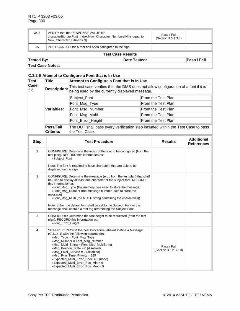
NTCIP 1203 v03.05 Page 330
34.3 VERIFY that the RESPONSE VALUE for characterBitmap.Font_Index.New_Character_Numbers[N] is equal to New_Character_Bitmaps[N].
Pass / Fail (Section 3.5.1.3.4)
35 POST-CONDITION: A font has been configured in the sign.
Test Case Results Tested By: Date Tested: Pass / Fail Test Case Notes: C.3.2.6 Attempt to Configure a Font that is In Use Test Case: 2.6
Title: Attempt to Configure a Font that is In Use
Description: This test case verifies that the DMS does not allow configuration of a font if it is being used by the currently displayed message.
Variables:
Subject_Font From the Test Plan Font_Msg_Type From the Test Plan
Font_Msg_Number From the Test Plan
Font_Msg_Multi From the Test Plan
Font_Error_Height From the Test Plan
Pass/Fail Criteria:
The DUT shall pass every verification step included within the Test Case to pass the Test Case.
Step Test Procedure Results Additional References
1 CONFIGURE: Determine the index of the font to be configured (from the test plan). RECORD this information as: »Subject_Font Note: The font is required to have characters that are able to be displayed on the sign.
2 CONFIGURE: Determine the message (e.g., from the test plan) that shall be used to display at least one character of the subject font. RECORD this information as: »Font_Msg_Type (the memory type used to store the message) »Font_Msg_Number (the message number used to store the message) »Font_Msg_Multi (the MULTI string containing the character(s)) Note: Either the default font shall be set to the Subject_Font or the message shall contain a font tag referencing the Subject Font.
3 CONFIGURE: Determine the font height to be requested (from the test plan). RECORD this information as: »Font_Error_Height
4 SET-UP: PERFORM the Test Procedure labeled 'Define a Message' (C.3.14.1) with the following parameters: »Msg_Type = Font_Msg_Type »Msg_Number = Font_Msg_Number »Msg_Multi_String = Font_Msg_MultiString »Msg_Beacon_State = 0 (disabled) »Msg_Pixel_Service = 0 (disabled) »Msg_Run_Time_Priority = 255 »Expected_Multi_Error_Code = 2 (none) »Expected_Multi_Error_Pos_Min = 0 »Expected_Multi_Error_Pos_Max = 0
Pass / Fail (Section 3.5.2.3.3.3)
Copy Per TRF Distribution Permission © 2014 AASHTO / ITE / NEMA
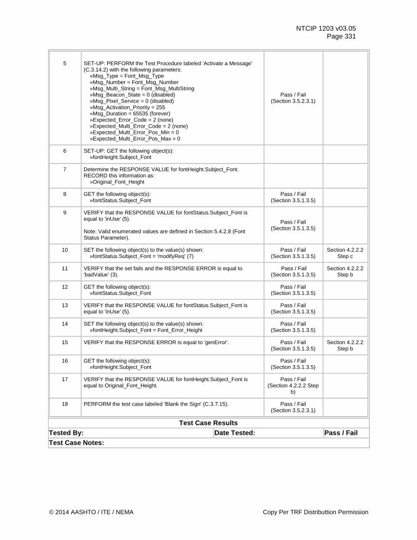
NTCIP 1203 v03.05 Page 331
5
SET-UP: PERFORM the Test Procedure labeled 'Activate a Message' (C.3.14.2) with the following parameters: »Msg_Type = Font_Msg_Type »Msg_Number = Font_Msg_Number »Msg_Multi_String = Font_Msg_MultiString »Msg_Beacon_State = 0 (disabled) »Msg_Pixel_Service = 0 (disabled) »Msg_Activation_Priority = 255 »Msg_Duration = 65535 (forever) »Expected_Error_Code = 2 (none) »Expected_Multi_Error_Code = 2 (none) »Expected_Multi_Error_Pos_Min = 0 »Expected_Multi_Error_Pos_Max = 0
Pass / Fail (Section 3.5.2.3.1)
6 SET-UP: GET the following object(s): »fontHeight.Subject_Font
7 Determine the RESPONSE VALUE for fontHeight.Subject_Font. RECORD this information as: »Original_Font_Height
8 GET the following object(s): »fontStatus.Subject_Font
Pass / Fail (Section 3.5.1.3.5)
9 VERIFY that the RESPONSE VALUE for fontStatus.Subject_Font is equal to 'inUse' (5). Note: Valid enumerated values are defined in Section 5.4.2.8 (Font Status Parameter).
Pass / Fail (Section 3.5.1.3.5)
10 SET the following object(s) to the value(s) shown: »fontStatus.Subject_Font = 'modifyReq' (7)
Pass / Fail (Section 3.5.1.3.5)
Section 4.2.2.2 Step c
11 VERIFY that the set fails and the RESPONSE ERROR is equal to 'badValue' (3).
Pass / Fail (Section 3.5.1.3.5)
Section 4.2.2.2 Step b
12 GET the following object(s): »fontStatus.Subject_Font
Pass / Fail (Section 3.5.1.3.5)
13 VERIFY that the RESPONSE VALUE for fontStatus.Subject_Font is equal to 'inUse' (5).
Pass / Fail (Section 3.5.1.3.5)
14 SET the following object(s) to the value(s) shown: »fontHeight.Subject_Font = Font_Error_Height
Pass / Fail (Section 3.5.1.3.5)
15 VERIFY that the RESPONSE ERROR is equal to 'genError'. Pass / Fail (Section 3.5.1.3.5)
Section 4.2.2.2 Step b
16 GET the following object(s): »fontHeight.Subject_Font
Pass / Fail (Section 3.5.1.3.5)
17 VERIFY that the RESPONSE VALUE for fontHeight.Subject_Font is equal to Original_Font_Height.
Pass / Fail (Section 4.2.2.2 Step
b)
18 PERFORM the test case labeled 'Blank the Sign' (C.3.7.15). Pass / Fail (Section 3.5.2.3.1)
Test Case Results Tested By: Date Tested: Pass / Fail Test Case Notes:
© 2014 AASHTO / ITE / NEMA Copy Per TRF Distributtion Permission
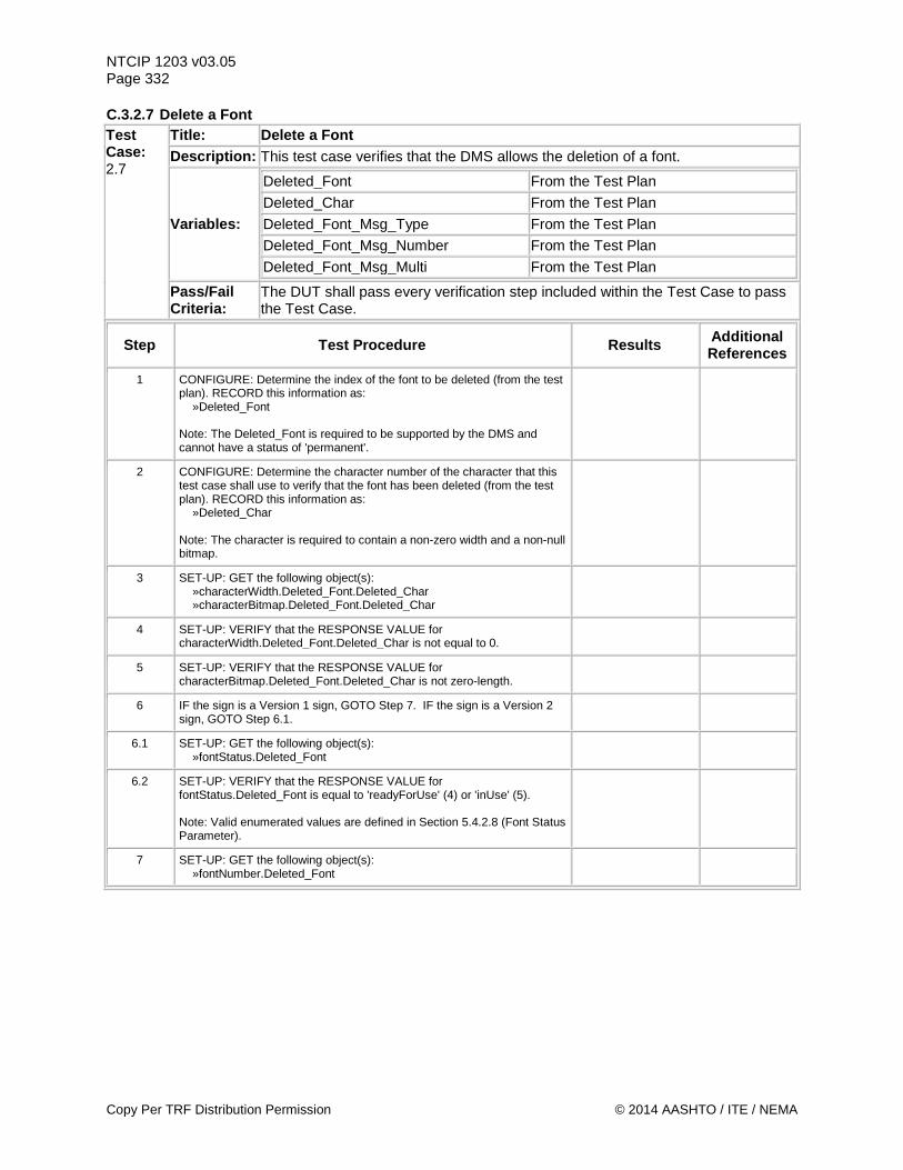
NTCIP 1203 v03.05 Page 332 C.3.2.7 Delete a Font Test Case: 2.7
Title: Delete a Font Description: This test case verifies that the DMS allows the deletion of a font.
Variables:
Deleted_Font From the Test Plan Deleted_Char From the Test Plan Deleted_Font_Msg_Type From the Test Plan Deleted_Font_Msg_Number From the Test Plan Deleted_Font_Msg_Multi From the Test Plan
Pass/Fail Criteria:
The DUT shall pass every verification step included within the Test Case to pass the Test Case.
Step Test Procedure Results Additional References
1 CONFIGURE: Determine the index of the font to be deleted (from the test plan). RECORD this information as: »Deleted_Font Note: The Deleted_Font is required to be supported by the DMS and cannot have a status of 'permanent'.
2 CONFIGURE: Determine the character number of the character that this test case shall use to verify that the font has been deleted (from the test plan). RECORD this information as: »Deleted_Char Note: The character is required to contain a non-zero width and a non-null bitmap.
3 SET-UP: GET the following object(s): »characterWidth.Deleted_Font.Deleted_Char »characterBitmap.Deleted_Font.Deleted_Char
4 SET-UP: VERIFY that the RESPONSE VALUE for characterWidth.Deleted_Font.Deleted_Char is not equal to 0.
5 SET-UP: VERIFY that the RESPONSE VALUE for characterBitmap.Deleted_Font.Deleted_Char is not zero-length.
6 IF the sign is a Version 1 sign, GOTO Step 7. IF the sign is a Version 2 sign, GOTO Step 6.1.
6.1 SET-UP: GET the following object(s): »fontStatus.Deleted_Font
6.2 SET-UP: VERIFY that the RESPONSE VALUE for fontStatus.Deleted_Font is equal to 'readyForUse' (4) or 'inUse' (5). Note: Valid enumerated values are defined in Section 5.4.2.8 (Font Status Parameter).
7 SET-UP: GET the following object(s): »fontNumber.Deleted_Font
Copy Per TRF Distribution Permission © 2014 AASHTO / ITE / NEMA
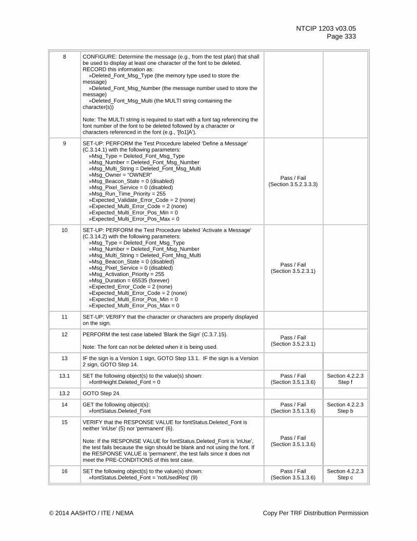
NTCIP 1203 v03.05 Page 333
8 CONFIGURE: Determine the message (e.g., from the test plan) that shall be used to display at least one character of the font to be deleted. RECORD this information as: »Deleted_Font_Msg_Type (the memory type used to store the message) »Deleted_Font_Msg_Number (the message number used to store the message) »Deleted_Font_Msg_Multi (the MULTI string containing the character(s)) Note: The MULTI string is required to start with a font tag referencing the font number of the font to be deleted followed by a character or characters referenced in the font (e.g., '[fo1]A').
9 SET-UP: PERFORM the Test Procedure labeled 'Define a Message' (C.3.14.1) with the following parameters: »Msg_Type = Deleted_Font_Msg_Type »Msg_Number = Deleted_Font_Msg_Number »Msg_Multi_String = Deleted_Font_Msg_Multi »Msg_Owner = “OWNER” »Msg_Beacon_State = 0 (disabled) »Msg_Pixel_Service = 0 (disabled) »Msg_Run_Time_Priority = 255 »Expected_Validate_Error_Code = 2 (none) »Expected_Multi_Error_Code = 2 (none) »Expected_Multi_Error_Pos_Min = 0 »Expected_Multi_Error_Pos_Max = 0
Pass / Fail (Section 3.5.2.3.3.3)
10 SET-UP: PERFORM the Test Procedure labeled 'Activate a Message' (C.3.14.2) with the following parameters: »Msg_Type = Deleted_Font_Msg_Type »Msg_Number = Deleted_Font_Msg_Number »Msg_Multi_String = Deleted_Font_Msg_Multi »Msg_Beacon_State = 0 (disabled) »Msg_Pixel_Service = 0 (disabled) »Msg_Activation_Priority = 255 »Msg_Duration = 65535 (forever) »Expected_Error_Code = 2 (none) »Expected_Multi_Error_Code = 2 (none) »Expected_Multi_Error_Pos_Min = 0 »Expected_Multi_Error_Pos_Max = 0
Pass / Fail (Section 3.5.2.3.1)
11 SET-UP: VERIFY that the character or characters are properly displayed on the sign.
12 PERFORM the test case labeled 'Blank the Sign' (C.3.7.15). Note: The font can not be deleted when it is being used.
Pass / Fail (Section 3.5.2.3.1)
13 IF the sign is a Version 1 sign, GOTO Step 13.1. IF the sign is a Version 2 sign, GOTO Step 14.
13.1 SET the following object(s) to the value(s) shown: »fontHeight.Deleted_Font = 0
Pass / Fail (Section 3.5.1.3.6)
Section 4.2.2.3 Step f
13.2 GOTO Step 24.
14 GET the following object(s): »fontStatus.Deleted_Font
Pass / Fail (Section 3.5.1.3.6)
Section 4.2.2.3 Step b
15 VERIFY that the RESPONSE VALUE for fontStatus.Deleted_Font is neither 'inUse' (5) nor 'permanent' (6). Note: If the RESPONSE VALUE for fontStatus.Deleted_Font is 'inUse', the test fails because the sign should be blank and not using the font. If the RESPONSE VALUE is 'permanent', the test fails since it does not meet the PRE-CONDITIONS of this test case.
Pass / Fail (Section 3.5.1.3.6)
16 SET the following object(s) to the value(s) shown: »fontStatus.Deleted_Font = 'notUsedReq' (9)
Pass / Fail (Section 3.5.1.3.6)
Section 4.2.2.3 Step c
© 2014 AASHTO / ITE / NEMA Copy Per TRF Distributtion Permission
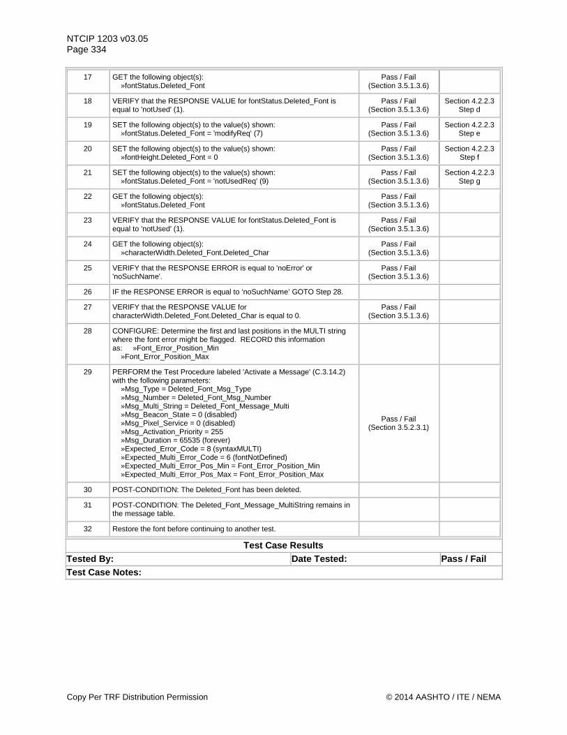
NTCIP 1203 v03.05 Page 334
17 GET the following object(s): »fontStatus.Deleted_Font
Pass / Fail (Section 3.5.1.3.6)
18 VERIFY that the RESPONSE VALUE for fontStatus.Deleted_Font is equal to 'notUsed' (1).
Pass / Fail (Section 3.5.1.3.6)
Section 4.2.2.3 Step d
19 SET the following object(s) to the value(s) shown: »fontStatus.Deleted_Font = 'modifyReq' (7)
Pass / Fail (Section 3.5.1.3.6)
Section 4.2.2.3 Step e
20 SET the following object(s) to the value(s) shown: »fontHeight.Deleted_Font = 0
Pass / Fail (Section 3.5.1.3.6)
Section 4.2.2.3 Step f
21 SET the following object(s) to the value(s) shown: »fontStatus.Deleted_Font = 'notUsedReq' (9)
Pass / Fail (Section 3.5.1.3.6)
Section 4.2.2.3 Step g
22 GET the following object(s): »fontStatus.Deleted_Font
Pass / Fail (Section 3.5.1.3.6)
23 VERIFY that the RESPONSE VALUE for fontStatus.Deleted_Font is equal to 'notUsed' (1).
Pass / Fail (Section 3.5.1.3.6)
24 GET the following object(s): »characterWidth.Deleted_Font.Deleted_Char
Pass / Fail (Section 3.5.1.3.6)
25 VERIFY that the RESPONSE ERROR is equal to 'noError' or 'noSuchName'.
Pass / Fail (Section 3.5.1.3.6)
26 IF the RESPONSE ERROR is equal to ‘noSuchName’ GOTO Step 28.
27 VERIFY that the RESPONSE VALUE for characterWidth.Deleted_Font.Deleted_Char is equal to 0.
Pass / Fail (Section 3.5.1.3.6)
28 CONFIGURE: Determine the first and last positions in the MULTI string where the font error might be flagged. RECORD this information as: »Font_Error_Position_Min »Font_Error_Position_Max
29 PERFORM the Test Procedure labeled 'Activate a Message' (C.3.14.2) with the following parameters: »Msg_Type = Deleted_Font_Msg_Type »Msg_Number = Deleted_Font_Msg_Number »Msg_Multi_String = Deleted_Font_Message_Multi »Msg_Beacon_State = 0 (disabled) »Msg_Pixel_Service = 0 (disabled) »Msg_Activation_Priority = 255 »Msg_Duration = 65535 (forever) »Expected_Error_Code = 8 (syntaxMULTI) »Expected_Multi_Error_Code = 6 (fontNotDefined) »Expected_Multi_Error_Pos_Min = Font_Error_Position_Min »Expected_Multi_Error_Pos_Max = Font_Error_Position_Max
Pass / Fail (Section 3.5.2.3.1)
30 POST-CONDITION: The Deleted_Font has been deleted.
31 POST-CONDITION: The Deleted_Font_Message_MultiString remains in the message table.
32 Restore the font before continuing to another test.
Test Case Results Tested By: Date Tested: Pass / Fail Test Case Notes:
Copy Per TRF Distribution Permission © 2014 AASHTO / ITE / NEMA
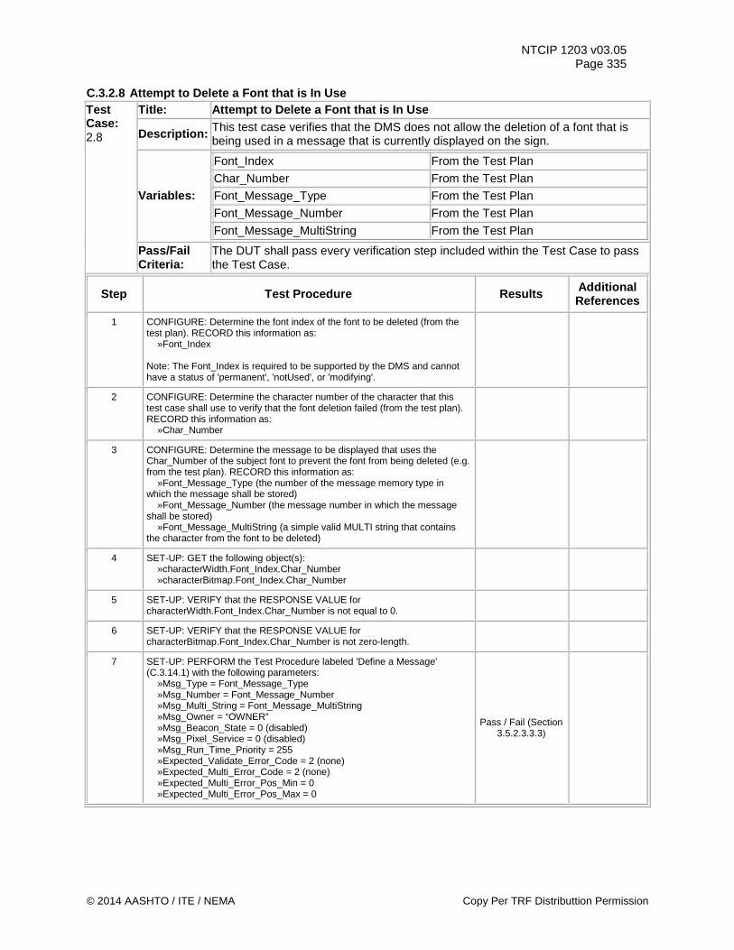
NTCIP 1203 v03.05 Page 335
C.3.2.8 Attempt to Delete a Font that is In Use Test Case: 2.8
Title: Attempt to Delete a Font that is In Use
Description: This test case verifies that the DMS does not allow the deletion of a font that is being used in a message that is currently displayed on the sign.
Variables:
Font_Index From the Test Plan Char_Number From the Test Plan Font_Message_Type From the Test Plan
Font_Message_Number From the Test Plan
Font_Message_MultiString From the Test Plan
Pass/Fail Criteria:
The DUT shall pass every verification step included within the Test Case to pass the Test Case.
Step Test Procedure Results Additional References
1 CONFIGURE: Determine the font index of the font to be deleted (from the test plan). RECORD this information as: »Font_Index Note: The Font_Index is required to be supported by the DMS and cannot have a status of 'permanent', 'notUsed', or 'modifying'.
2 CONFIGURE: Determine the character number of the character that this test case shall use to verify that the font deletion failed (from the test plan). RECORD this information as: »Char_Number
3 CONFIGURE: Determine the message to be displayed that uses the Char_Number of the subject font to prevent the font from being deleted (e.g. from the test plan). RECORD this information as: »Font_Message_Type (the number of the message memory type in which the message shall be stored) »Font_Message_Number (the message number in which the message shall be stored) »Font_Message_MultiString (a simple valid MULTI string that contains the character from the font to be deleted)
4 SET-UP: GET the following object(s): »characterWidth.Font_Index.Char_Number »characterBitmap.Font_Index.Char_Number
5 SET-UP: VERIFY that the RESPONSE VALUE for characterWidth.Font_Index.Char_Number is not equal to 0.
6 SET-UP: VERIFY that the RESPONSE VALUE for characterBitmap.Font_Index.Char_Number is not zero-length.
7 SET-UP: PERFORM the Test Procedure labeled 'Define a Message' (C.3.14.1) with the following parameters: »Msg_Type = Font_Message_Type »Msg_Number = Font_Message_Number »Msg_Multi_String = Font_Message_MultiString »Msg_Owner = “OWNER” »Msg_Beacon_State = 0 (disabled) »Msg_Pixel_Service = 0 (disabled) »Msg_Run_Time_Priority = 255 »Expected_Validate_Error_Code = 2 (none) »Expected_Multi_Error_Code = 2 (none) »Expected_Multi_Error_Pos_Min = 0 »Expected_Multi_Error_Pos_Max = 0
Pass / Fail (Section 3.5.2.3.3.3)
© 2014 AASHTO / ITE / NEMA Copy Per TRF Distributtion Permission
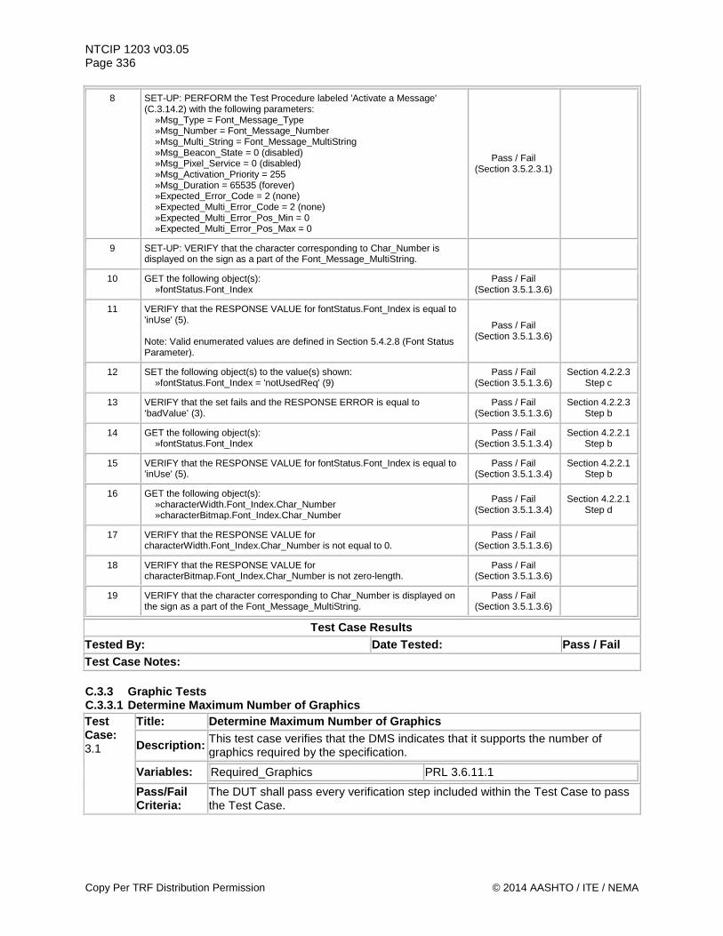
NTCIP 1203 v03.05 Page 336
8 SET-UP: PERFORM the Test Procedure labeled 'Activate a Message' (C.3.14.2) with the following parameters: »Msg_Type = Font_Message_Type »Msg_Number = Font_Message_Number »Msg_Multi_String = Font_Message_MultiString »Msg_Beacon_State = 0 (disabled) »Msg_Pixel_Service = 0 (disabled) »Msg_Activation_Priority = 255 »Msg_Duration = 65535 (forever) »Expected_Error_Code = 2 (none) »Expected_Multi_Error_Code = 2 (none) »Expected_Multi_Error_Pos_Min = 0 »Expected_Multi_Error_Pos_Max = 0
Pass / Fail (Section 3.5.2.3.1)
9 SET-UP: VERIFY that the character corresponding to Char_Number is displayed on the sign as a part of the Font_Message_MultiString.
10 GET the following object(s): »fontStatus.Font_Index
Pass / Fail (Section 3.5.1.3.6)
11 VERIFY that the RESPONSE VALUE for fontStatus.Font_Index is equal to 'inUse' (5). Note: Valid enumerated values are defined in Section 5.4.2.8 (Font Status Parameter).
Pass / Fail (Section 3.5.1.3.6)
12 SET the following object(s) to the value(s) shown: »fontStatus.Font_Index = 'notUsedReq' (9)
Pass / Fail (Section 3.5.1.3.6)
Section 4.2.2.3 Step c
13 VERIFY that the set fails and the RESPONSE ERROR is equal to ‘badValue’ (3).
Pass / Fail (Section 3.5.1.3.6)
Section 4.2.2.3 Step b
14 GET the following object(s): »fontStatus.Font_Index
Pass / Fail (Section 3.5.1.3.4)
Section 4.2.2.1 Step b
15 VERIFY that the RESPONSE VALUE for fontStatus.Font_Index is equal to 'inUse' (5).
Pass / Fail (Section 3.5.1.3.4)
Section 4.2.2.1 Step b
16 GET the following object(s): »characterWidth.Font_Index.Char_Number »characterBitmap.Font_Index.Char_Number
Pass / Fail (Section 3.5.1.3.4)
Section 4.2.2.1 Step d
17 VERIFY that the RESPONSE VALUE for characterWidth.Font_Index.Char_Number is not equal to 0.
Pass / Fail (Section 3.5.1.3.6)
18 VERIFY that the RESPONSE VALUE for characterBitmap.Font_Index.Char_Number is not zero-length.
Pass / Fail (Section 3.5.1.3.6)
19 VERIFY that the character corresponding to Char_Number is displayed on the sign as a part of the Font_Message_MultiString.
Pass / Fail (Section 3.5.1.3.6)
Test Case Results Tested By: Date Tested: Pass / Fail Test Case Notes: C.3.3 Graphic Tests C.3.3.1 Determine Maximum Number of Graphics Test Case: 3.1
Title: Determine Maximum Number of Graphics
Description: This test case verifies that the DMS indicates that it supports the number of graphics required by the specification.
Variables: Required_Graphics PRL 3.6.11.1
Pass/Fail Criteria:
The DUT shall pass every verification step included within the Test Case to pass the Test Case.
Copy Per TRF Distribution Permission © 2014 AASHTO / ITE / NEMA
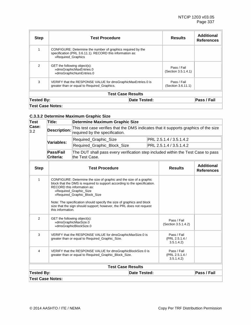
NTCIP 1203 v03.05 Page 337
Step Test Procedure Results Additional References
1 CONFIGURE: Determine the number of graphics required by the specification (PRL 3.6.11.1). RECORD this information as: »Required_Graphics
2 GET the following object(s): »dmsGraphicMaxEntries.0 »dmsGraphicNumEntries.0
Pass / Fail (Section 3.5.1.4.1)
3 VERIFY that the RESPONSE VALUE for dmsGraphicMaxEntries.0 is greater than or equal to Required_Graphics.
Pass / Fail (Section 3.6.11.1)
Test Case Results Tested By: Date Tested: Pass / Fail Test Case Notes: C.3.3.2 Determine Maximum Graphic Size Test Case: 3.2
Title: Determine Maximum Graphic Size
Description: This test case verifies that the DMS indicates that it supports graphics of the size required by the specification.
Variables: Required_Graphic_Size PRL 2.5.1.4 / 3.5.1.4.2 Required_Graphic_Block_Size PRL 2.5.1.4 / 3.5.1.4.2
Pass/Fail Criteria:
The DUT shall pass every verification step included within the Test Case to pass the Test Case.
Step Test Procedure Results Additional References
1 CONFIGURE: Determine the size of graphic and the size of a graphic block that the DMS is required to support according to the specification. RECORD this information as: »Required_Graphic_Size »Required_Graphic_Block_Size Note: The specification should specify the size of graphics and block size that the sign should support; however, the PRL does not request this information.
2 GET the following object(s): »dmsGraphicMaxSize.0 »dmsGraphicBlockSize.0
Pass / Fail (Section 3.5.1.4.2)
3 VERIFY that the RESPONSE VALUE for dmsGraphicMaxSize.0 is greater than or equal to Required_Graphic_Size.
Pass / Fail (PRL 2.5.1.4 /
3.5.1.4.2)
4 VERIFY that the RESPONSE VALUE for dmsGraphicBlockSize.0 is greater than or equal to Required_Graphic_Block_Size.
Pass / Fail (PRL 2.5.1.4 /
3.5.1.4.2)
Test Case Results Tested By: Date Tested: Pass / Fail Test Case Notes:
© 2014 AASHTO / ITE / NEMA Copy Per TRF Distributtion Permission
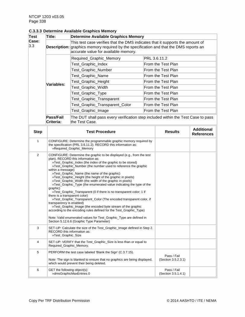
NTCIP 1203 v03.05 Page 338 C.3.3.3 Determine Available Graphics Memory Test Case: 3.3
Title: Determine Available Graphics Memory
Description: This test case verifies that the DMS indicates that it supports the amount of graphics memory required by the specification and that the DMS reports an accurate value for available memory.
Variables:
Required_Graphic_Memory PRL 3.6.11.2 Test_Graphic_Index From the Test Plan Test_Graphic_Number From the Test Plan Test_Graphic_Name From the Test Plan Test_Graphic_Height From the Test Plan Test_Graphic_Width From the Test Plan Test_Graphic_Type From the Test Plan Test_Graphic_Transparent From the Test Plan Test_Graphic_Transparent_Color From the Test Plan Test_Graphic_Image From the Test Plan
Pass/Fail Criteria:
The DUT shall pass every verification step included within the Test Case to pass the Test Case.
Step Test Procedure Results Additional References
1 CONFIGURE: Determine the programmable graphic memory required by the specification (PRL 3.6.11.2). RECORD this information as: »Required_Graphic_Memory
2 CONFIGURE: Determine the graphic to be displayed (e.g., from the test plan). RECORD this information as: »Test_Graphic_Index (the index of the graphic to be stored) »Test_Graphic_Number (the number used to reference the graphic within a message) »Test_Graphic_Name (the name of the graphic) »Test_Graphic_Height (the height of the graphic in pixels) »Test_Graphic_Width (the width of the graphic in pixels) »Test_Graphic_Type (the enumerated value indicating the type of the graphic) »Test_Graphic_Transparent (0 if there is no transparent color; 1 if there is a transparent color) »Test_Graphic_Transparent_Color (The encoded transparent color, if transparency is enabled) »Test_Graphic_Image (the encoded byte stream of the graphic according to the encoding rules defined for the Test_Graphic_Type) Note: Valid enumerated values for Test_Graphic_Type are defined in Section 5.12.6.6 (Graphic Type Parameter)
3 SET-UP: Calculate the size of the Test_Graphic_Image defined in Step 2. RECORD this information as: »Test_Graphic_Size
4 SET-UP: VERIFY that the Test_Graphic_Size is less than or equal to Required_Graphic_Memory.
5 PERFORM the test case labeled 'Blank the Sign' (C.3.7.15). Note: The sign is blanked to ensure that no graphics are being displayed, which would prevent their being deleted.
Pass / Fail (Section 3.5.2.3.1)
6 GET the following object(s): »dmsGraphicMaxEntries.0
Pass / Fail (Section 3.5.1.4.1)
Copy Per TRF Distribution Permission © 2014 AASHTO / ITE / NEMA
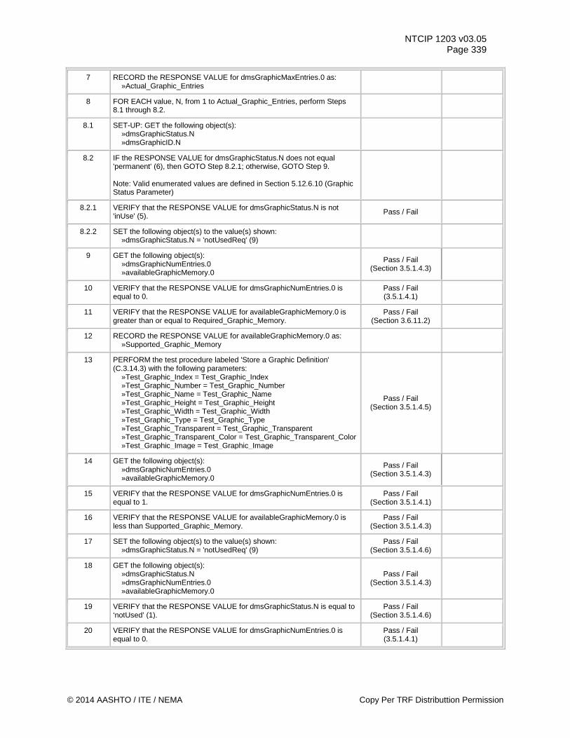
NTCIP 1203 v03.05 Page 339
7 RECORD the RESPONSE VALUE for dmsGraphicMaxEntries.0 as: »Actual_Graphic_Entries
8 FOR EACH value, N, from 1 to Actual_Graphic_Entries, perform Steps 8.1 through 8.2.
8.1 SET-UP: GET the following object(s): »dmsGraphicStatus.N »dmsGraphicID.N
8.2 IF the RESPONSE VALUE for dmsGraphicStatus.N does not equal 'permanent' (6), then GOTO Step 8.2.1; otherwise, GOTO Step 9. Note: Valid enumerated values are defined in Section 5.12.6.10 (Graphic Status Parameter)
8.2.1 VERIFY that the RESPONSE VALUE for dmsGraphicStatus.N is not 'inUse' (5). Pass / Fail
8.2.2 SET the following object(s) to the value(s) shown: »dmsGraphicStatus.N = 'notUsedReq' (9)
9 GET the following object(s): »dmsGraphicNumEntries.0 »availableGraphicMemory.0
Pass / Fail (Section 3.5.1.4.3)
10 VERIFY that the RESPONSE VALUE for dmsGraphicNumEntries.0 is equal to 0.
Pass / Fail (3.5.1.4.1)
11 VERIFY that the RESPONSE VALUE for availableGraphicMemory.0 is greater than or equal to Required_Graphic_Memory.
Pass / Fail (Section 3.6.11.2)
12 RECORD the RESPONSE VALUE for availableGraphicMemory.0 as: »Supported_Graphic_Memory
13 PERFORM the test procedure labeled 'Store a Graphic Definition' (C.3.14.3) with the following parameters: »Test_Graphic_Index = Test_Graphic_Index »Test_Graphic_Number = Test_Graphic_Number »Test_Graphic_Name = Test_Graphic_Name »Test_Graphic_Height = Test_Graphic_Height »Test_Graphic_Width = Test_Graphic_Width »Test_Graphic_Type = Test_Graphic_Type »Test_Graphic_Transparent = Test_Graphic_Transparent »Test_Graphic_Transparent_Color = Test_Graphic_Transparent_Color »Test_Graphic_Image = Test_Graphic_Image
Pass / Fail (Section 3.5.1.4.5)
14 GET the following object(s): »dmsGraphicNumEntries.0 »availableGraphicMemory.0
Pass / Fail (Section 3.5.1.4.3)
15 VERIFY that the RESPONSE VALUE for dmsGraphicNumEntries.0 is equal to 1.
Pass / Fail (Section 3.5.1.4.1)
16 VERIFY that the RESPONSE VALUE for availableGraphicMemory.0 is less than Supported_Graphic_Memory.
Pass / Fail (Section 3.5.1.4.3)
17 SET the following object(s) to the value(s) shown: »dmsGraphicStatus.N = 'notUsedReq' (9)
Pass / Fail (Section 3.5.1.4.6)
18 GET the following object(s): »dmsGraphicStatus.N »dmsGraphicNumEntries.0 »availableGraphicMemory.0
Pass / Fail (Section 3.5.1.4.3)
19 VERIFY that the RESPONSE VALUE for dmsGraphicStatus.N is equal to ‘notUsed’ (1).
Pass / Fail (Section 3.5.1.4.6)
20 VERIFY that the RESPONSE VALUE for dmsGraphicNumEntries.0 is equal to 0.
Pass / Fail (3.5.1.4.1)
© 2014 AASHTO / ITE / NEMA Copy Per TRF Distributtion Permission
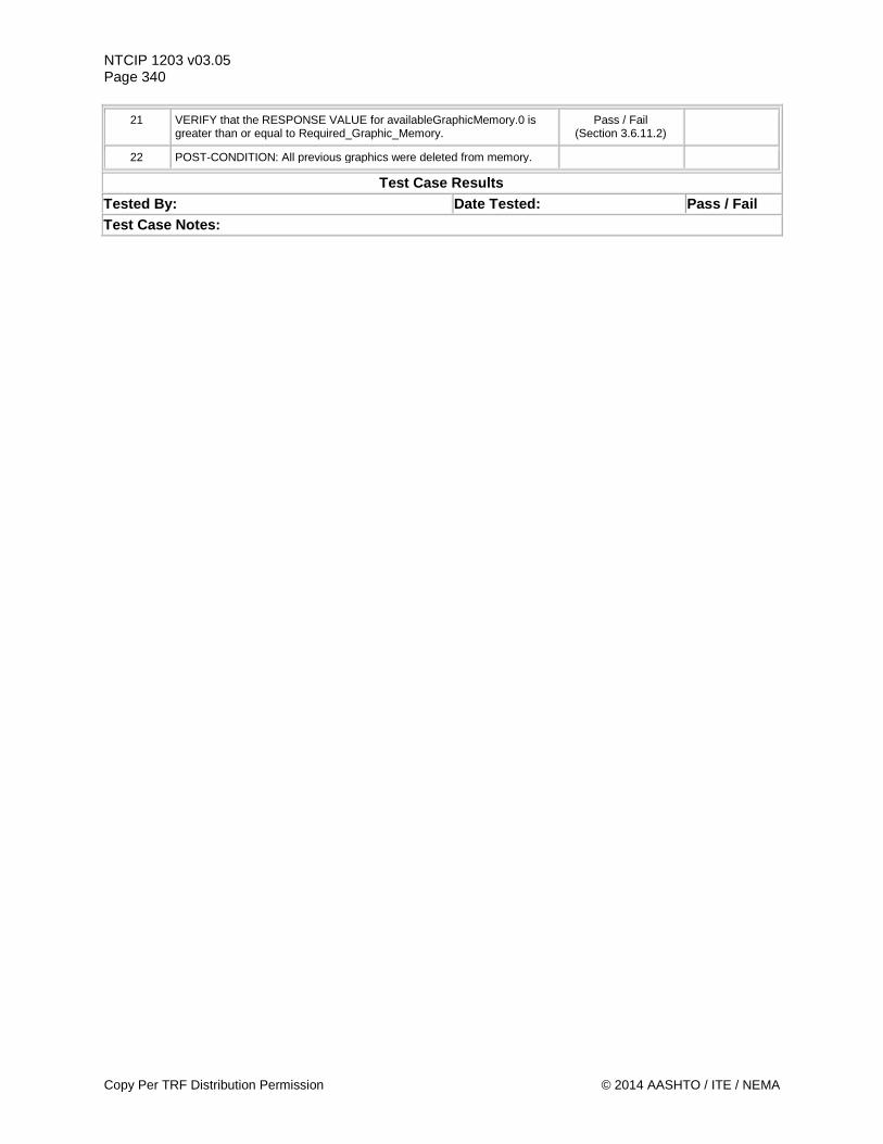
NTCIP 1203 v03.05 Page 340
21 VERIFY that the RESPONSE VALUE for availableGraphicMemory.0 is greater than or equal to Required_Graphic_Memory.
Pass / Fail (Section 3.6.11.2)
22 POST-CONDITION: All previous graphics were deleted from memory.
Test Case Results Tested By: Date Tested: Pass / Fail Test Case Notes:
Copy Per TRF Distribution Permission © 2014 AASHTO / ITE / NEMA
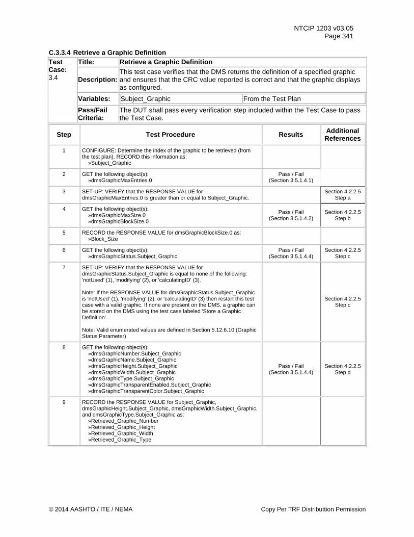
NTCIP 1203 v03.05 Page 341
C.3.3.4 Retrieve a Graphic Definition Test Case: 3.4
Title: Retrieve a Graphic Definition
Description: This test case verifies that the DMS returns the definition of a specified graphic and ensures that the CRC value reported is correct and that the graphic displays as configured.
Variables: Subject_Graphic From the Test Plan
Pass/Fail Criteria:
The DUT shall pass every verification step included within the Test Case to pass the Test Case.
Step Test Procedure Results Additional References
1 CONFIGURE: Determine the index of the graphic to be retrieved (from the test plan). RECORD this information as: »Subject_Graphic
2 GET the following object(s): »dmsGraphicMaxEntries.0
Pass / Fail (Section 3.5.1.4.1)
3 SET-UP: VERIFY that the RESPONSE VALUE for dmsGraphicMaxEntries.0 is greater than or equal to Subject_Graphic. Section 4.2.2.5
Step a
4 GET the following object(s): »dmsGraphicMaxSize.0 »dmsGraphicBlockSize.0
Pass / Fail (Section 3.5.1.4.2)
Section 4.2.2.5 Step b
5 RECORD the RESPONSE VALUE for dmsGraphicBlockSize.0 as: »Block_Size
6 GET the following object(s): »dmsGraphicStatus.Subject_Graphic
Pass / Fail (Section 3.5.1.4.4)
Section 4.2.2.5 Step c
7 SET-UP: VERIFY that the RESPONSE VALUE for dmsGraphicStatus.Subject_Graphic is equal to none of the following: 'notUsed' (1), 'modifying' (2), or 'calculatingID' (3). Note: If the RESPONSE VALUE for dmsGraphicStatus.Subject_Graphic is 'notUsed' (1), 'modifying' (2), or 'calculatingID' (3) then restart this test case with a valid graphic. If none are present on the DMS, a graphic can be stored on the DMS using the test case labeled 'Store a Graphic Definition'. Note: Valid enumerated values are defined in Section 5.12.6.10 (Graphic Status Parameter)
Section 4.2.2.5 Step c
8 GET the following object(s): »dmsGraphicNumber.Subject_Graphic »dmsGraphicName.Subject_Graphic »dmsGraphicHeight.Subject_Graphic »dmsGraphicWidth.Subject_Graphic »dmsGraphicType.Subject_Graphic »dmsGraphicTransparentEnabled.Subject_Graphic »dmsGraphicTransparentColor.Subject_Graphic
Pass / Fail (Section 3.5.1.4.4)
Section 4.2.2.5 Step d
9 RECORD the RESPONSE VALUE for Subject_Graphic, dmsGraphicHeight.Subject_Graphic, dmsGraphicWidth.Subject_Graphic, and dmsGraphicType.Subject_Graphic as: »Retrieved_Graphic_Number »Retrieved_Graphic_Height »Retrieved_Graphic_Width »Retrieved_Graphic_Type
© 2014 AASHTO / ITE / NEMA Copy Per TRF Distributtion Permission
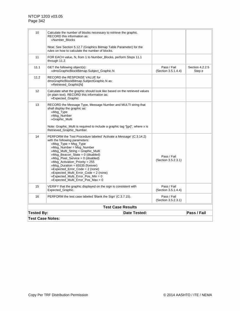
NTCIP 1203 v03.05 Page 342
10 Calculate the number of blocks necessary to retrieve the graphic. RECORD this information as: »Number_Blocks Ntoe: See Section 5.12.7 (Graphics Bitmap Table Parameter) for the rules on how to calculate the number of blocks.
11 FOR EACH value, N, from 1 to Number_Blocks, perform Steps 11.1 through 11.2.
11.1 GET the following object(s): »dmsGraphicBlockBitmap.Subject_Graphic.N
Pass / Fail (Section 3.5.1.4.4)
Section 4.2.2.5 Step e
11.2 RECORD the RESPONSE VALUE for dmsGraphicBlockBitmap.SubjectGraphic.N as: »Retrieved_Graphic[N]
12 Calculate what the graphic should look like based on the retrieved values (in plain text). RECORD this information as: »Expected_Graphic
13 RECORD the Message Type, Message Number and MULTI string that shall display the graphic as: »Msg_Type »Msg_Number »Graphic_Multi Note: Graphic_Multi is required to include a graphic tag “[gx]”, where x is Retrieved_Graphic_Number.
14 PERFORM the Test Procedure labeled 'Activate a Message' (C.3.14.2) with the following parameters: »Msg_Type = Msg_Type »Msg_Number = Msg_Number »Msg_Multi_String = Graphic_Multi »Msg_Beacon_State = 0 (disabled) »Msg_Pixel_Service = 0 (disabled) »Msg_Activation_Priority = 255 »Msg_Duration = 65535 (forever) »Expected_Error_Code = 2 (none) »Expected_Multi_Error_Code = 2 (none) »Expected_Multi_Error_Pos_Min = 0 »Expected_Multi_Error_Pos_Max = 0
Pass / Fail (Section 3.5.2.3.1)
15 VERIFY that the graphic displayed on the sign is consistent with Expected_Graphic.
Pass / Fail (Section 3.5.1.4.4)
16 PERFORM the test case labeled 'Blank the Sign' (C.3.7.15). Pass / Fail (Section 3.5.2.3.1)
Test Case Results Tested By: Date Tested: Pass / Fail Test Case Notes:
Copy Per TRF Distribution Permission © 2014 AASHTO / ITE / NEMA
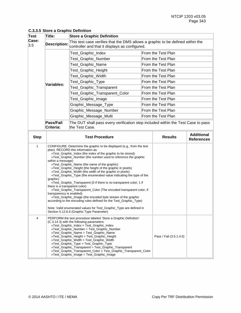
NTCIP 1203 v03.05 Page 343
C.3.3.5 Store a Graphic Definition Test Case: 3.5
Title: Store a Graphic Definition
Description: This test case verifies that the DMS allows a graphic to be defined within the controller and that it displays as configured.
Variables:
Test_Graphic_Index From the Test Plan
Test_Graphic_Number From the Test Plan
Test_Graphic_Name From the Test Plan
Test_Graphic_Height From the Test Plan
Test_Graphic_Width From the Test Plan
Test_Graphic_Type From the Test Plan
Test_Graphic_Transparent From the Test Plan
Test_Graphic_Transparent_Color From the Test Plan
Test_Graphic_Image From the Test Plan
Graphic_Message_Type From the Test Plan
Graphic_Message_Number From the Test Plan
Graphic_Message_Multi From the Test Plan
Pass/Fail Criteria:
The DUT shall pass every verification step included within the Test Case to pass the Test Case.
Step Test Procedure Results Additional References
1 CONFIGURE: Determine the graphic to be displayed (e.g., from the test plan). RECORD this information as: »Test_Graphic_Index (the index of the graphic to be stored) »Test_Graphic_Number (the number used to reference the graphic within a message) »Test_Graphic_Name (the name of the graphic) »Test_Graphic_Height (the height of the graphic in pixels) »Test_Graphic_Width (the width of the graphic in pixels) »Test_Graphic_Type (the enumerated value indicating the type of the graphic) »Test_Graphic_Transparent (0 if there is no transparent color; 1 if there is a transparent color) »Test_Graphic_Transparent_Color (The encoded transparent color, if transparency is enabled) »Test_Graphic_Image (the encoded byte stream of the graphic according to the encoding rules defined for the Test_Graphic_Type) Note: Valid enumerated values for Test_Graphic_Type are defined in Section 5.12.6.6 (Graphic Type Parameter)
4 PERFORM the test procedure labeled 'Store a Graphic Definition' (C.3.14.3) with the following parameters: »Test_Graphic_Index = Test_Graphic_Index »Test_Graphic_Number = Test_Graphic_Number »Test_Graphic_Name = Test_Graphic_Name »Test_Graphic_Height = Test_Graphic_Height »Test_Graphic_Width = Test_Graphic_Width »Test_Graphic_Type = Test_Graphic_Type »Test_Graphic_Transparent = Test_Graphic_Transparent »Test_Graphic_Transparent_Color = Test_Graphic_Transparent_Color »Test_Graphic_Image = Test_Graphic_Image
Pass / Fail (3.5.1.4.5)
© 2014 AASHTO / ITE / NEMA Copy Per TRF Distributtion Permission
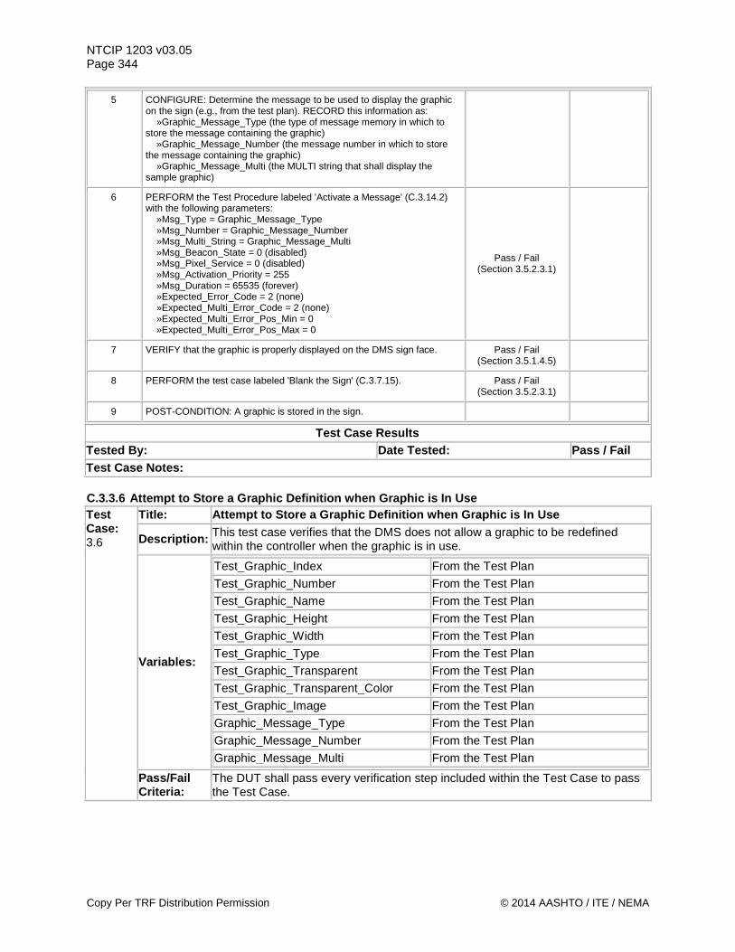
NTCIP 1203 v03.05 Page 344
5 CONFIGURE: Determine the message to be used to display the graphic on the sign (e.g., from the test plan). RECORD this information as: »Graphic_Message_Type (the type of message memory in which to store the message containing the graphic) »Graphic_Message_Number (the message number in which to store the message containing the graphic) »Graphic_Message_Multi (the MULTI string that shall display the sample graphic)
6 PERFORM the Test Procedure labeled 'Activate a Message' (C.3.14.2) with the following parameters: »Msg_Type = Graphic_Message_Type »Msg_Number = Graphic_Message_Number »Msg_Multi_String = Graphic_Message_Multi »Msg_Beacon_State = 0 (disabled) »Msg_Pixel_Service = 0 (disabled) »Msg_Activation_Priority = 255 »Msg_Duration = 65535 (forever) »Expected_Error_Code = 2 (none) »Expected_Multi_Error_Code = 2 (none) »Expected_Multi_Error_Pos_Min = 0 »Expected_Multi_Error_Pos_Max = 0
Pass / Fail (Section 3.5.2.3.1)
7 VERIFY that the graphic is properly displayed on the DMS sign face. Pass / Fail (Section 3.5.1.4.5)
8 PERFORM the test case labeled 'Blank the Sign' (C.3.7.15). Pass / Fail (Section 3.5.2.3.1)
9 POST-CONDITION: A graphic is stored in the sign.
Test Case Results Tested By: Date Tested: Pass / Fail Test Case Notes: C.3.3.6 Attempt to Store a Graphic Definition when Graphic is In Use Test Case: 3.6
Title: Attempt to Store a Graphic Definition when Graphic is In Use
Description: This test case verifies that the DMS does not allow a graphic to be redefined within the controller when the graphic is in use.
Variables:
Test_Graphic_Index From the Test Plan Test_Graphic_Number From the Test Plan Test_Graphic_Name From the Test Plan Test_Graphic_Height From the Test Plan Test_Graphic_Width From the Test Plan Test_Graphic_Type From the Test Plan Test_Graphic_Transparent From the Test Plan Test_Graphic_Transparent_Color From the Test Plan Test_Graphic_Image From the Test Plan Graphic_Message_Type From the Test Plan Graphic_Message_Number From the Test Plan Graphic_Message_Multi From the Test Plan
Pass/Fail Criteria:
The DUT shall pass every verification step included within the Test Case to pass the Test Case.
Copy Per TRF Distribution Permission © 2014 AASHTO / ITE / NEMA
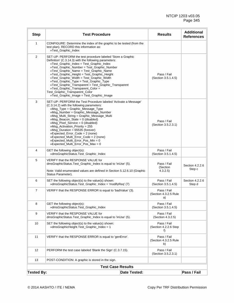
NTCIP 1203 v03.05 Page 345
Step Test Procedure Results Additional References
1 CONFIGURE: Determine the index of the graphic to be tested (from the test plan). RECORD this information as: »Test_Graphic_Index
2 SET-UP: PERFORM the test procedure labeled 'Store a Graphic Definition' (C.3.14.3) with the following parameters: »Test_Graphic_Index = Test_Graphic_Index »Test_Graphic_Number = Test_Graphic_Number »Test_Graphic_Name = Test_Graphic_Name »Test_Graphic_Height = Test_Graphic_Height »Test_Graphic_Width = Test_Graphic_Width »Test_Graphic_Type = Test_Graphic_Type »Test_Graphic_Transparent = Test_Graphic_Transparent »Test_Graphic_Transparent_Color = Test_Graphic_Transparent_Color »Test_Graphic_Image = Test_Graphic_Image
Pass / Fail (Section 3.5.1.4.5)
3 SET-UP: PERFORM the Test Procedure labeled 'Activate a Message' (C.3.14.2) with the following parameters: »Msg_Type = Graphic_Message_Type »Msg_Number = Graphic_Message_Number »Msg_Multi_String = Graphic_Message_Multi »Msg_Beacon_State = 0 (disabled) »Msg_Pixel_Service = 0 (disabled) »Msg_Activation_Priority = 255 »Msg_Duration = 65535 (forever) »Expected_Error_Code = 2 (none) »Expected_Multi_Error_Code = 2 (none) »Expected_Multi_Error_Pos_Min = 0 »Expected_Multi_Error_Pos_Max = 0
Pass / Fail (Section 3.5.2.3.1)
4 GET the following object(s): »dmsGraphicStatus.Test_Graphic_Index
Pass / Fail (Section 3.5.1.4.5)
5 VERIFY that the RESPONSE VALUE for dmsGraphicStatus.Test_Graphic_Index is equal to 'inUse' (5). Note: Valid enumerated values are defined in Section 5.12.6.10 (Graphic Status Parameter).
Pass / Fail (Section 4.3.2.5)
Section 4.2.2.6 Step c
6 SET the following object(s) to the value(s) shown: »dmsGraphicStatus.Test_Graphic_Index = 'modifyReq' (7)
Pass / Fail (Section 3.5.1.4.5)
Section 4.2.2.6 Step d
7 VERIFY that the RESPONSE ERROR is equal to 'badValue' (3). Pass / Fail (Section 4.3.2.5 Rule
a)
8 GET the following object(s): »dmsGraphicStatus.Test_Graphic_Index
Pass / Fail (Section 3.5.1.4.5)
9 VERIFY that the RESPONSE VALUE for dmsGraphicStatus.Test_Graphic_Index is equal to 'inUse' (5).
Pass / Fail (Section 4.3.2.5)
10 SET the following object(s) to the value(s) shown: »dmsGraphicHeight.Test_Graphic_Index = 1
Pass / Fail (Section 4.2.2.6 Step
f)
11 VERIFY that the RESPONSE ERROR is equal to 'genError'. Pass / Fail (Section 4.3.2.5 Rule
b)
12 PERFORM the test case labeled 'Blank the Sign' (C.3.7.15). Pass / Fail (Section 3.5.2.3.1)
13 POST-CONDITION: A graphic is stored in the sign.
Test Case Results Tested By: Date Tested: Pass / Fail
© 2014 AASHTO / ITE / NEMA Copy Per TRF Distributtion Permission
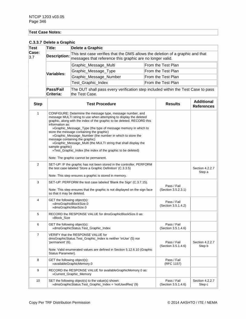
NTCIP 1203 v03.05 Page 346 Test Case Notes: C.3.3.7 Delete a Graphic Test Case: 3.7
Title: Delete a Graphic
Description: This test case verifies that the DMS allows the deletion of a graphic and that messages that reference this graphic are no longer valid.
Variables:
Graphic_Message_Multi From the Test Plan
Graphic_Message_Type From the Test Plan
Graphic_Message_Number From the Test Plan
Test_Graphic_Index From the Test Plan
Pass/Fail Criteria:
The DUT shall pass every verification step included within the Test Case to pass the Test Case.
Step Test Procedure Results Additional References
1 CONFIGURE: Determine the message type, message number, and message MULTI string to use when attempting to display the deleted graphic, along with the index of the graphic to be deleted. RECORD this information as: »Graphic_Message_Type (the type of message memory in which to store the message containing the graphic) »Graphic_Message_Number (the number in which to store the message containing the graphic) »Graphic_Message_Multi (the MULTI string that shall display the sample graphic) »Test_Graphic_Index (the index of the graphic to be deleted) Note: The graphic cannot be permanent.
2 SET-UP: IF the graphic has not been stored in the controller, PERFORM the test case labeled 'Store a Graphic Definition' (C.3.3.5) Note: This step ensures a graphic is stored in memory.
Section 4.2.2.7 Step a
3 SET-UP: PERFORM the test case labeled 'Blank the Sign' (C.3.7.15). Note: This step ensures that the graphic is not displayed on the sign face so that it may be deleted.
Pass / Fail (Section 3.5.2.3.1)
4 GET the following object(s): »dmsGraphicBlockSize.0 »dmsGraphicMaxSize.0
Pass / Fail (Section 3.5.1.4.2)
5 RECORD the RESPONSE VALUE for dmsGraphicBlockSize.0 as: »Block_Size
6 GET the following object(s): »dmsGraphicStatus.Test_Graphic_Index
Pass / Fail (Section 3.5.1.4.6)
7 VERIFY that the RESPONSE VALUE for dmsGraphicStatus.Test_Graphic_Index is neither 'inUse' (5) nor 'permanent' (6). Note: Valid enumerated values are defined in Section 5.12.6.10 (Graphic Status Parameter).
Pass / Fail (Section 3.5.1.4.6)
Section 4.2.2.7 Step b
8 GET the following object(s): »availableGraphicMemory.0
Pass / Fail (RFC 1157)
9 RECORD the RESPONSE VALUE for availableGraphicMemory.0 as: »Current_Graphic_Memory
10 SET the following object(s) to the value(s) shown: »dmsGraphicStatus.Test_Graphic_Index = 'notUsedReq' (9)
Pass / Fail (Section 3.5.1.4.6)
Section 4.2.2.7 Step c
Copy Per TRF Distribution Permission © 2014 AASHTO / ITE / NEMA
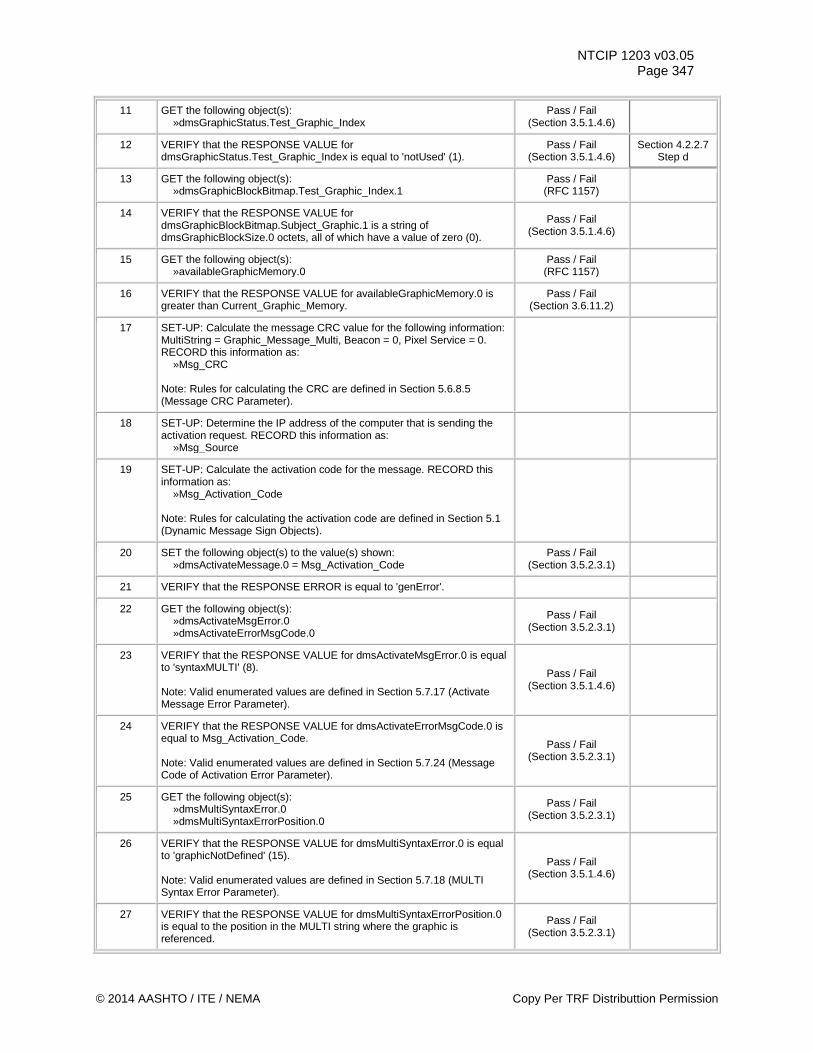
NTCIP 1203 v03.05 Page 347
11 GET the following object(s): »dmsGraphicStatus.Test_Graphic_Index
Pass / Fail (Section 3.5.1.4.6)
12 VERIFY that the RESPONSE VALUE for dmsGraphicStatus.Test_Graphic_Index is equal to 'notUsed' (1).
Pass / Fail (Section 3.5.1.4.6)
Section 4.2.2.7 Step d
13 GET the following object(s): »dmsGraphicBlockBitmap.Test_Graphic_Index.1
Pass / Fail (RFC 1157)
14 VERIFY that the RESPONSE VALUE for dmsGraphicBlockBitmap.Subject_Graphic.1 is a string of dmsGraphicBlockSize.0 octets, all of which have a value of zero (0).
Pass / Fail (Section 3.5.1.4.6)
15 GET the following object(s): »availableGraphicMemory.0
Pass / Fail (RFC 1157)
16 VERIFY that the RESPONSE VALUE for availableGraphicMemory.0 is greater than Current_Graphic_Memory.
Pass / Fail (Section 3.6.11.2)
17 SET-UP: Calculate the message CRC value for the following information: MultiString = Graphic_Message_Multi, Beacon = 0, Pixel Service = 0. RECORD this information as: »Msg_CRC Note: Rules for calculating the CRC are defined in Section 5.6.8.5 (Message CRC Parameter).
18 SET-UP: Determine the IP address of the computer that is sending the activation request. RECORD this information as: »Msg_Source
19 SET-UP: Calculate the activation code for the message. RECORD this information as: »Msg_Activation_Code Note: Rules for calculating the activation code are defined in Section 5.1 (Dynamic Message Sign Objects).
20 SET the following object(s) to the value(s) shown: »dmsActivateMessage.0 = Msg_Activation_Code
Pass / Fail (Section 3.5.2.3.1)
21 VERIFY that the RESPONSE ERROR is equal to 'genError'.
22 GET the following object(s): »dmsActivateMsgError.0 »dmsActivateErrorMsgCode.0
Pass / Fail (Section 3.5.2.3.1)
23 VERIFY that the RESPONSE VALUE for dmsActivateMsgError.0 is equal to 'syntaxMULTI' (8). Note: Valid enumerated values are defined in Section 5.7.17 (Activate Message Error Parameter).
Pass / Fail (Section 3.5.1.4.6)
24 VERIFY that the RESPONSE VALUE for dmsActivateErrorMsgCode.0 is equal to Msg_Activation_Code. Note: Valid enumerated values are defined in Section 5.7.24 (Message Code of Activation Error Parameter).
Pass / Fail (Section 3.5.2.3.1)
25 GET the following object(s): »dmsMultiSyntaxError.0 »dmsMultiSyntaxErrorPosition.0
Pass / Fail (Section 3.5.2.3.1)
26 VERIFY that the RESPONSE VALUE for dmsMultiSyntaxError.0 is equal to 'graphicNotDefined' (15). Note: Valid enumerated values are defined in Section 5.7.18 (MULTI Syntax Error Parameter).
Pass / Fail (Section 3.5.1.4.6)
27 VERIFY that the RESPONSE VALUE for dmsMultiSyntaxErrorPosition.0 is equal to the position in the MULTI string where the graphic is referenced.
Pass / Fail (Section 3.5.2.3.1)
© 2014 AASHTO / ITE / NEMA Copy Per TRF Distributtion Permission
NTCIP 1203 v03.05 Page 348
Test Case Results Tested By: Date Tested: Pass / Fail Test Case Notes:
Copy Per TRF Distribution Permission © 2014 AASHTO / ITE / NEMA
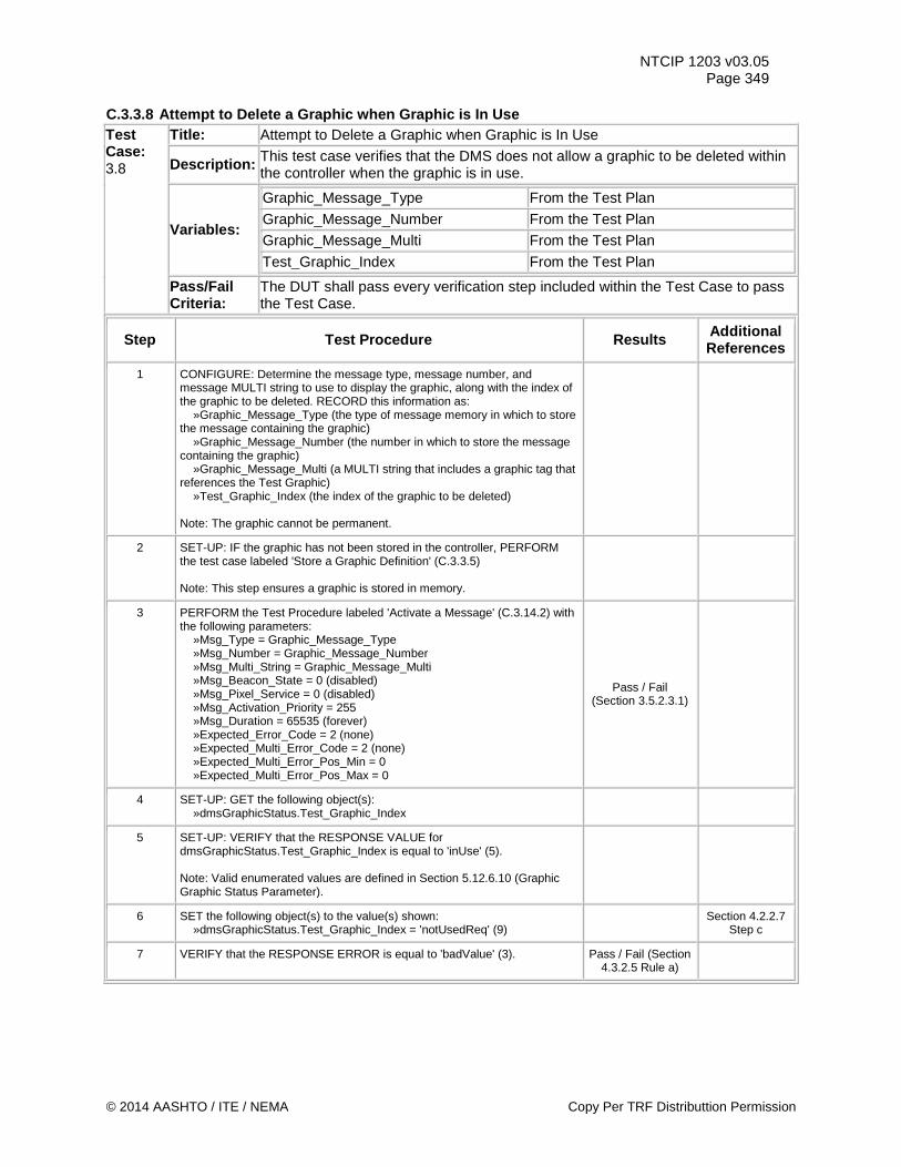
NTCIP 1203 v03.05 Page 349
C.3.3.8 Attempt to Delete a Graphic when Graphic is In Use Test Case: 3.8
Title: Attempt to Delete a Graphic when Graphic is In Use
Description: This test case verifies that the DMS does not allow a graphic to be deleted within the controller when the graphic is in use.
Variables:
Graphic_Message_Type From the Test Plan
Graphic_Message_Number From the Test Plan
Graphic_Message_Multi From the Test Plan
Test_Graphic_Index From the Test Plan
Pass/Fail Criteria:
The DUT shall pass every verification step included within the Test Case to pass the Test Case.
Step Test Procedure Results Additional References
1 CONFIGURE: Determine the message type, message number, and message MULTI string to use to display the graphic, along with the index of the graphic to be deleted. RECORD this information as: »Graphic_Message_Type (the type of message memory in which to store the message containing the graphic) »Graphic_Message_Number (the number in which to store the message containing the graphic) »Graphic_Message_Multi (a MULTI string that includes a graphic tag that references the Test Graphic) »Test_Graphic_Index (the index of the graphic to be deleted) Note: The graphic cannot be permanent.
2 SET-UP: IF the graphic has not been stored in the controller, PERFORM the test case labeled 'Store a Graphic Definition' (C.3.3.5) Note: This step ensures a graphic is stored in memory.
3 PERFORM the Test Procedure labeled 'Activate a Message' (C.3.14.2) with the following parameters: »Msg_Type = Graphic_Message_Type »Msg_Number = Graphic_Message_Number »Msg_Multi_String = Graphic_Message_Multi »Msg_Beacon_State = 0 (disabled) »Msg_Pixel_Service = 0 (disabled) »Msg_Activation_Priority = 255 »Msg_Duration = 65535 (forever) »Expected_Error_Code = 2 (none) »Expected_Multi_Error_Code = 2 (none) »Expected_Multi_Error_Pos_Min = 0 »Expected_Multi_Error_Pos_Max = 0
Pass / Fail (Section 3.5.2.3.1)
4 SET-UP: GET the following object(s): »dmsGraphicStatus.Test_Graphic_Index
5 SET-UP: VERIFY that the RESPONSE VALUE for dmsGraphicStatus.Test_Graphic_Index is equal to 'inUse' (5). Note: Valid enumerated values are defined in Section 5.12.6.10 (Graphic Graphic Status Parameter).
6 SET the following object(s) to the value(s) shown: »dmsGraphicStatus.Test_Graphic_Index = 'notUsedReq' (9) Section 4.2.2.7
Step c
7 VERIFY that the RESPONSE ERROR is equal to 'badValue' (3). Pass / Fail (Section 4.3.2.5 Rule a)
© 2014 AASHTO / ITE / NEMA Copy Per TRF Distributtion Permission
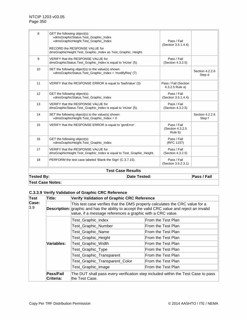
NTCIP 1203 v03.05 Page 350
8 GET the following object(s): »dmsGraphicStatus.Test_Graphic_Index »dmsGraphicHeight.Test_Graphic_Index RECORD the RESPONSE VALUE for dmsGraphicHeight.Test_Graphic_Index as Test_Graphic_Height.
Pass / Fail (Section 3.5.1.4.4)
9 VERIFY that the RESPONSE VALUE for dmsGraphicStatus.Test_Graphic_Index is equal to 'inUse' (5).
Pass / Fail (Section 4.3.2.5)
10 SET the following object(s) to the value(s) shown: »dmsGraphicStatus.Test_Graphic_Index = 'modifyReq' (7)
Section 4.2.2.6 Step d
11 VERIFY that the RESPONSE ERROR is equal to 'badValue' (3).
Pass / Fail (Section 4.3.2.5 Rule a)
12 GET the following object(s): »dmsGraphicStatus.Test_Graphic_Index
Pass / Fail (Section 3.5.1.4.4)
13 VERIFY that the RESPONSE VALUE for dmsGraphicStatus.Test_Graphic_Index is equal to 'inUse' (5).
Pass / Fail (Section 4.3.2.5)
14 SET the following object(s) to the value(s) shown: »dmsGraphicHeight.Test_Graphic_Index = 0 Section 4.2.2.6
Step f
15 VERIFY that the RESPONSE ERROR is equal to 'genError'. Pass / Fail (Section 4.3.2.5
Rule b)
16 GET the following object(s): »dmsGraphicHeight.Test_Graphic_Index
Pass / Fail (RFC 1157)
17 VERIFY that the RESPONSE VALUE for dmsGraphicHeight.Test_Graphic_Index is equal to Test_Graphic_Height.
Pass / Fail (Section 4.3.2.5)
18 PERFORM the test case labeled 'Blank the Sign' (C.3.7.15). Pass / Fail (Section 3.5.2.3.1)
Test Case Results Tested By: Date Tested: Pass / Fail Test Case Notes: C.3.3.9 Verify Validation of Graphic CRC Reference Test Case: 3.9
Title: Verify Validation of Graphic CRC Reference
Description: This test case verifies that the DMS properly calculates the CRC value for a graphic and has the ability to accept the valid CRC value and reject an invalid value, if a message references a graphic with a CRC value.
Variables:
Test_Graphic_Index From the Test Plan
Test_Graphic_Number From the Test Plan Test_Graphic_Name From the Test Plan Test_Graphic_Height From the Test Plan
Test_Graphic_Width From the Test Plan
Test_Graphic_Type From the Test Plan
Test_Graphic_Transparent From the Test Plan Test_Graphic_Transparent_Color From the Test Plan Test_Graphic_Image From the Test Plan
Pass/Fail Criteria:
The DUT shall pass every verification step included within the Test Case to pass the Test Case.
Copy Per TRF Distribution Permission © 2014 AASHTO / ITE / NEMA
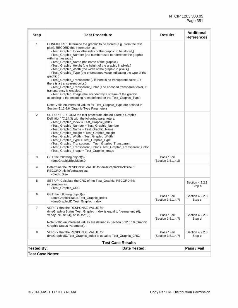
NTCIP 1203 v03.05 Page 351
Step Test Procedure Results Additional References
1 CONFIGURE: Determine the graphic to be stored (e.g., from the test plan). RECORD this information as: »Test_Graphic_Index (the index of the graphic to be stored,) »Test_Graphic_Number (the number used to reference the graphic within a message,) »Test_Graphic_Name (the name of the graphic,) »Test_Graphic_Height (the height of the graphic in pixels,) »Test_Graphic_Width (the width of the graphic in pixels,) »Test_Graphic_Type (the enumerated value indicating the type of the graphic,) »Test_Graphic_Transparent (0 if there is no transparent color; 1 if there is a transparent color,) »Test_Graphic_Transparent_Color (The encoded transparent color, if transparency is enabled,) »Test_Graphic_Image (the encoded byte stream of the graphic according to the encoding rules defined for the Test_Graphic_Type) Note: Valid enumerated values for Test_Graphic_Type are defined in Section 5.12.6.6 (Graphic Type Parameter)
2 SET-UP: PERFORM the test procedure labeled 'Store a Graphic Definition' (C.14.3) with the following parameters: »Test_Graphic_Index = Test_Graphic_Index »Test_Graphic_Number = Test_Graphic_Number »Test_Graphic_Name = Test_Graphic_Name »Test_Graphic_Height = Test_Graphic_Height »Test_Graphic_Width = Test_Graphic_Width »Test_Graphic_Type = Test_Graphic_Type »Test_Graphic_Transparent = Test_Graphic_Transparent »Test_Graphic_Transparent_Color = Test_Graphic_Transparent_Color »Test_Graphic_Image = Test_Graphic_Image
3 GET the following object(s): »dmsGraphicBlockSize.0
Pass / Fail (Section 3.5.1.4.2)
4 Determine the RESPONSE VALUE for dmsGraphicBlockSize.0. RECORD this information as: »Block_Size
5 SET-UP: Calculate the CRC of the Test_Graphic. RECORD this information as: »Test_Graphic_CRC
Section 4.2.2.8 Step b
6 GET the following object(s): »dmsGraphicStatus.Test_Graphic_Index »dmsGraphicID.Test_Graphic_Index
Pass / Fail (Section 3.5.1.4.7)
Section 4.2.2.8 Step c
7 VERIFY that the RESPONSE VALUE for dmsGraphicsStatus.Test_Graphic_Index is equal to 'permanent' (6), ‘readyForUse' (4), or 'inUse' (5). Note: Valid enumerated values are defined in Section 5.12.6.10 (Graphic Graphic Status Parameter).
Pass / Fail (Section 3.5.1.4.7)
Section 4.2.2.8 Step d
8 VERIFY that the RESPONSE VALUE for dmsGraphicID.Test_Graphic_Index is equal to Test_Graphic_CRC.
Pass / Fail (Section 3.5.1.4.7)
Section 4.2.2.8 Step e
Test Case Results Tested By: Date Tested: Pass / Fail Test Case Notes:
© 2014 AASHTO / ITE / NEMA Copy Per TRF Distributtion Permission
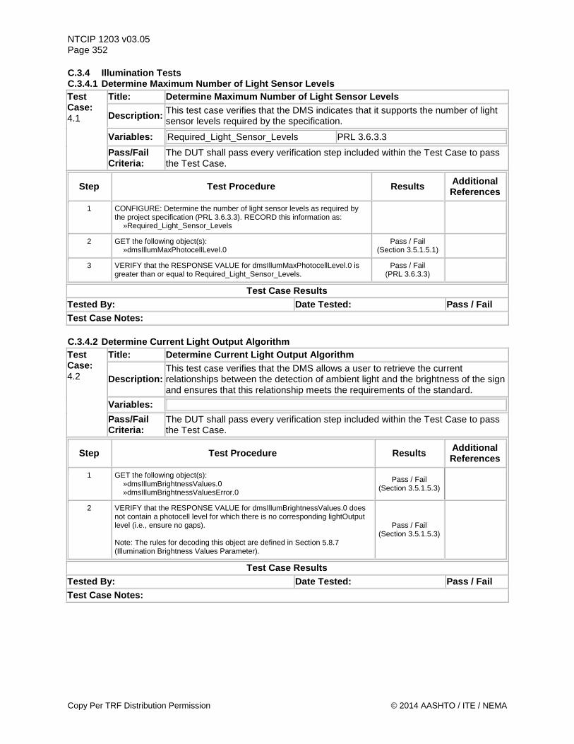
NTCIP 1203 v03.05 Page 352 C.3.4 Illumination Tests C.3.4.1 Determine Maximum Number of Light Sensor Levels Test Case: 4.1
Title: Determine Maximum Number of Light Sensor Levels
Description: This test case verifies that the DMS indicates that it supports the number of light sensor levels required by the specification.
Variables: Required_Light_Sensor_Levels PRL 3.6.3.3
Pass/Fail Criteria:
The DUT shall pass every verification step included within the Test Case to pass the Test Case.
Step Test Procedure Results Additional References
1 CONFIGURE: Determine the number of light sensor levels as required by the project specification (PRL 3.6.3.3). RECORD this information as: »Required_Light_Sensor_Levels
2 GET the following object(s): »dmsIllumMaxPhotocellLevel.0
Pass / Fail (Section 3.5.1.5.1)
3 VERIFY that the RESPONSE VALUE for dmsIllumMaxPhotocellLevel.0 is greater than or equal to Required_Light_Sensor_Levels.
Pass / Fail (PRL 3.6.3.3)
Test Case Results Tested By: Date Tested: Pass / Fail Test Case Notes: C.3.4.2 Determine Current Light Output Algorithm Test Case: 4.2
Title: Determine Current Light Output Algorithm
Description: This test case verifies that the DMS allows a user to retrieve the current relationships between the detection of ambient light and the brightness of the sign and ensures that this relationship meets the requirements of the standard.
Variables:
Pass/Fail Criteria:
The DUT shall pass every verification step included within the Test Case to pass the Test Case.
Step Test Procedure Results Additional References
1 GET the following object(s): »dmsIllumBrightnessValues.0 »dmsIllumBrightnessValuesError.0
Pass / Fail (Section 3.5.1.5.3)
2 VERIFY that the RESPONSE VALUE for dmsIllumBrightnessValues.0 does not contain a photocell level for which there is no corresponding lightOutput level (i.e., ensure no gaps). Note: The rules for decoding this object are defined in Section 5.8.7 (Illumination Brightness Values Parameter).
Pass / Fail (Section 3.5.1.5.3)
Test Case Results Tested By: Date Tested: Pass / Fail Test Case Notes:
Copy Per TRF Distribution Permission © 2014 AASHTO / ITE / NEMA
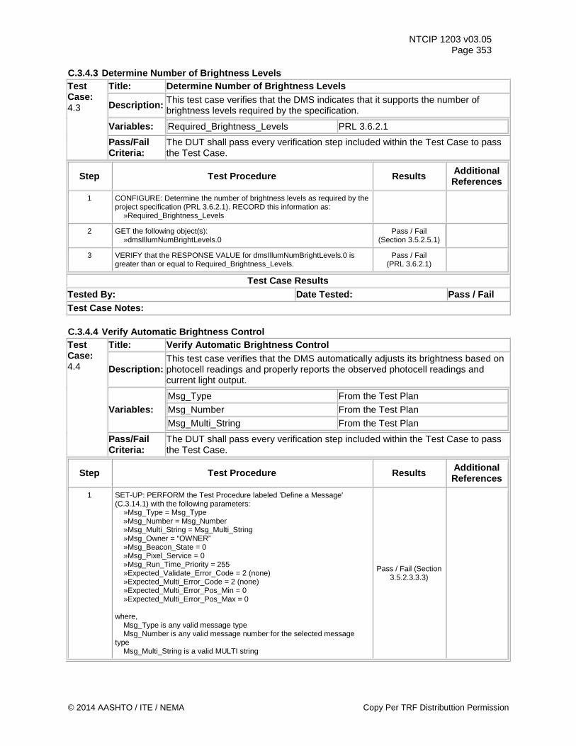
NTCIP 1203 v03.05 Page 353
C.3.4.3 Determine Number of Brightness Levels Test Case: 4.3
Title: Determine Number of Brightness Levels
Description: This test case verifies that the DMS indicates that it supports the number of brightness levels required by the specification.
Variables: Required_Brightness_Levels PRL 3.6.2.1
Pass/Fail Criteria:
The DUT shall pass every verification step included within the Test Case to pass the Test Case.
Step Test Procedure Results Additional References
1 CONFIGURE: Determine the number of brightness levels as required by the project specification (PRL 3.6.2.1). RECORD this information as: »Required_Brightness_Levels
2 GET the following object(s): »dmsIllumNumBrightLevels.0
Pass / Fail (Section 3.5.2.5.1)
3 VERIFY that the RESPONSE VALUE for dmsIllumNumBrightLevels.0 is greater than or equal to Required_Brightness_Levels.
Pass / Fail (PRL 3.6.2.1)
Test Case Results Tested By: Date Tested: Pass / Fail Test Case Notes: C.3.4.4 Verify Automatic Brightness Control Test Case: 4.4
Title: Verify Automatic Brightness Control
Description: This test case verifies that the DMS automatically adjusts its brightness based on photocell readings and properly reports the observed photocell readings and current light output.
Variables: Msg_Type From the Test Plan Msg_Number From the Test Plan Msg_Multi_String From the Test Plan
Pass/Fail Criteria:
The DUT shall pass every verification step included within the Test Case to pass the Test Case.
Step Test Procedure Results Additional References
1 SET-UP: PERFORM the Test Procedure labeled 'Define a Message' (C.3.14.1) with the following parameters: »Msg_Type = Msg_Type »Msg_Number = Msg_Number »Msg_Multi_String = Msg_Multi_String »Msg_Owner = “OWNER” »Msg_Beacon_State = 0 »Msg_Pixel_Service = 0 »Msg_Run_Time_Priority = 255 »Expected_Validate_Error_Code = 2 (none) »Expected_Multi_Error_Code = 2 (none) »Expected_Multi_Error_Pos_Min = 0 »Expected_Multi_Error_Pos_Max = 0 where, Msg_Type is any valid message type Msg_Number is any valid message number for the selected message type Msg_Multi_String is a valid MULTI string
Pass / Fail (Section 3.5.2.3.3.3)
© 2014 AASHTO / ITE / NEMA Copy Per TRF Distributtion Permission
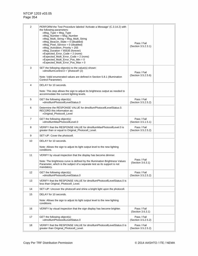
NTCIP 1203 v03.05 Page 354
2 PERFORM the Test Procedure labeled 'Activate a Message' (C.3.14.2) with the following parameters: »Msg_Type = Msg_Type »Msg_Number = Msg_Number »Msg_Multi_String = Msg_Multi_String »Msg_Beacon_State = 0 (disabled) »Msg_Pixel_Service = 0 (disabled) »Msg_Activation_Priority = 255 »Msg_Duration = 65535 (forever) »Expected_Error_Code = 2 (none) »Expected_Multi_Error_Code = 2 (none) »Expected_Multi_Error_Pos_Min = 0 »Expected_Multi_Error_Pos_Max = 0
Pass / Fail (Section 3.5.2.3.1)
3 SET the following object(s) to the value(s) shown: »dmsIllumControl.0 = 'photocell' (2) Note: Valid enumerated values are defined in Section 5.8.1 (Illumination Control Parameter).
Pass / Fail (Section 3.5.2.5.6)
4 DELAY for 10 seconds. Note: This step allows the sign to adjust its brightness output as needed to accommodate the current lighting levels.
5 GET the following object(s): »dmsIllumPhotocellLevelStatus.0
Pass / Fail (Section 3.5.2.5.2)
6 Determine the RESPONSE VALUE for dmsIllumPhotocellLevelStatus.0. RECORD this information as: »Original_Photocell_Level
7 GET the following object(s): »dmsIllumMaxPhotocellLevel.0
Pass / Fail (Section 3.5.1.5.1)
8 VERIFY that the RESPONSE VALUE for dmsIllumMaxPhotocellLevel.0 is greater than or equal to Original_Photocell_Level.
Pass / Fail (Section 3.5.2.5.2)
9 SET-UP: Cover the photocell.
10 DELAY for 10 seconds. Note: Allows the sign to adjust its light output level to the new lighting conditions.
11 VERIFY by visual inspection that the display has become dimmer. Note: The brightness curve is defined by the Illumination Brightness Values Parameter, which is the subject of a separate test as its support is not mandatory.
Pass / Fail (Section 3.6.3.1)
12 GET the following object(s): »dmsIllumPhotocellLevelStatus.0
Pass / Fail (Section 3.5.2.5.2)
13 VERIFY that the RESPONSE VALUE for dmsIllumPhotocellLevelStatus.0 is less than Original_Photocell_Level.
14 SET-UP: Uncover the photocell and shine a bright light upon the photocell.
15 DELAY for 10 seconds. Note: Allows the sign to adjust its light output level to the new lighting conditions.
16 VERIFY by visual inspection that the sign display has become brighter. Pass / Fail (Section 3.6.3.1)
17 GET the following object(s): »dmsIllumPhotocellLevelStatus.0
Pass / Fail (Section 3.5.2.5.2)
18 VERIFY that the RESPONSE VALUE for dmsIllumPhotocellLevelStatus.0 is greater than Original_Photocell_Level.
Pass / Fail (Section 3.5.2.5.2)
Copy Per TRF Distribution Permission © 2014 AASHTO / ITE / NEMA
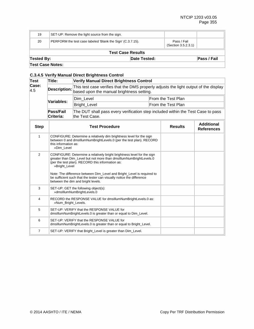
NTCIP 1203 v03.05 Page 355
19 SET-UP: Remove the light source from the sign.
20 PERFORM the test case labeled 'Blank the Sign' (C.3.7.15). Pass / Fail (Section 3.5.2.3.1)
Test Case Results Tested By: Date Tested: Pass / Fail Test Case Notes: C.3.4.5 Verify Manual Direct Brightness Control Test Case: 4.5
Title: Verify Manual Direct Brightness Control
Description: This test case verifies that the DMS properly adjusts the light output of the display based upon the manual brightness setting.
Variables: Dim_Level From the Test Plan Bright_Level From the Test Plan
Pass/Fail Criteria:
The DUT shall pass every verification step included within the Test Case to pass the Test Case.
Step Test Procedure Results Additional References
1 CONFIGURE: Determine a relatively dim brightness level for the sign between 0 and dmsIllumNumBrightLevels.0 (per the test plan). RECORD this information as: »Dim_Level
2 CONFIGURE: Determine a relatively bright brightness level for the sign greater than Dim_Level but not more than dmsIllumNumBrightLevels.0 (per the test plan). RECORD this information as: »Bright_Level Note: The difference between Dim_Level and Bright_Level is required to be sufficient such that the tester can visually notice the difference between the dim and bright levels.
3 SET-UP: GET the following object(s): »dmsIllumNumBrightLevels.0
4 RECORD the RESPONSE VALUE for dmsIllumNumBrightLevels.0 as: »Num_Bright_Levels.
5 SET-UP: VERIFY that the RESPONSE VALUE for dmsIllumNumBrightLevels.0 is greater than or equal to Dim_Level.
6 SET-UP: VERIFY that the RESPONSE VALUE for dmsIllumNumBrightLevels.0 is greater than or equal to Bright_Level.
7 SET-UP: VERIFY that Bright_Level is greater than Dim_Level.
© 2014 AASHTO / ITE / NEMA Copy Per TRF Distributtion Permission
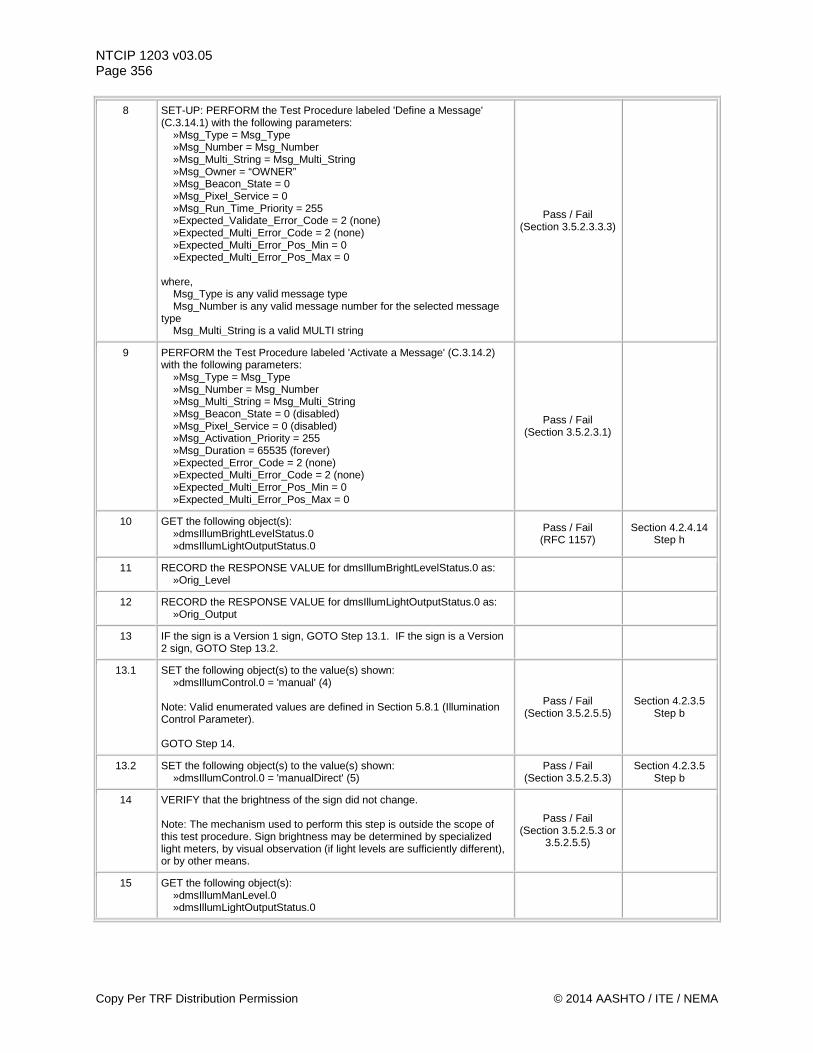
NTCIP 1203 v03.05 Page 356
8 SET-UP: PERFORM the Test Procedure labeled 'Define a Message' (C.3.14.1) with the following parameters: »Msg_Type = Msg_Type »Msg_Number = Msg_Number »Msg_Multi_String = Msg_Multi_String »Msg_Owner = “OWNER” »Msg_Beacon_State = 0 »Msg_Pixel_Service = 0 »Msg_Run_Time_Priority = 255 »Expected_Validate_Error_Code = 2 (none) »Expected_Multi_Error_Code = 2 (none) »Expected_Multi_Error_Pos_Min = 0 »Expected_Multi_Error_Pos_Max = 0 where, Msg_Type is any valid message type Msg_Number is any valid message number for the selected message type Msg_Multi_String is a valid MULTI string
Pass / Fail (Section 3.5.2.3.3.3)
9 PERFORM the Test Procedure labeled 'Activate a Message' (C.3.14.2) with the following parameters: »Msg_Type = Msg_Type »Msg_Number = Msg_Number »Msg_Multi_String = Msg_Multi_String »Msg_Beacon_State = 0 (disabled) »Msg_Pixel_Service = 0 (disabled) »Msg_Activation_Priority = 255 »Msg_Duration = 65535 (forever) »Expected_Error_Code = 2 (none) »Expected_Multi_Error_Code = 2 (none) »Expected_Multi_Error_Pos_Min = 0 »Expected_Multi_Error_Pos_Max = 0
Pass / Fail (Section 3.5.2.3.1)
10 GET the following object(s): »dmsIllumBrightLevelStatus.0 »dmsIllumLightOutputStatus.0
Pass / Fail (RFC 1157)
Section 4.2.4.14 Step h
11 RECORD the RESPONSE VALUE for dmsIllumBrightLevelStatus.0 as: »Orig_Level
12 RECORD the RESPONSE VALUE for dmsIllumLightOutputStatus.0 as: »Orig_Output
13 IF the sign is a Version 1 sign, GOTO Step 13.1. IF the sign is a Version 2 sign, GOTO Step 13.2.
13.1 SET the following object(s) to the value(s) shown: »dmsIllumControl.0 = 'manual' (4) Note: Valid enumerated values are defined in Section 5.8.1 (Illumination Control Parameter). GOTO Step 14.
Pass / Fail (Section 3.5.2.5.5)
Section 4.2.3.5 Step b
13.2 SET the following object(s) to the value(s) shown: »dmsIllumControl.0 = 'manualDirect' (5)
Pass / Fail (Section 3.5.2.5.3)
Section 4.2.3.5 Step b
14 VERIFY that the brightness of the sign did not change. Note: The mechanism used to perform this step is outside the scope of this test procedure. Sign brightness may be determined by specialized light meters, by visual observation (if light levels are sufficiently different), or by other means.
Pass / Fail (Section 3.5.2.5.3 or
3.5.2.5.5)
15 GET the following object(s): »dmsIllumManLevel.0 »dmsIllumLightOutputStatus.0
Copy Per TRF Distribution Permission © 2014 AASHTO / ITE / NEMA
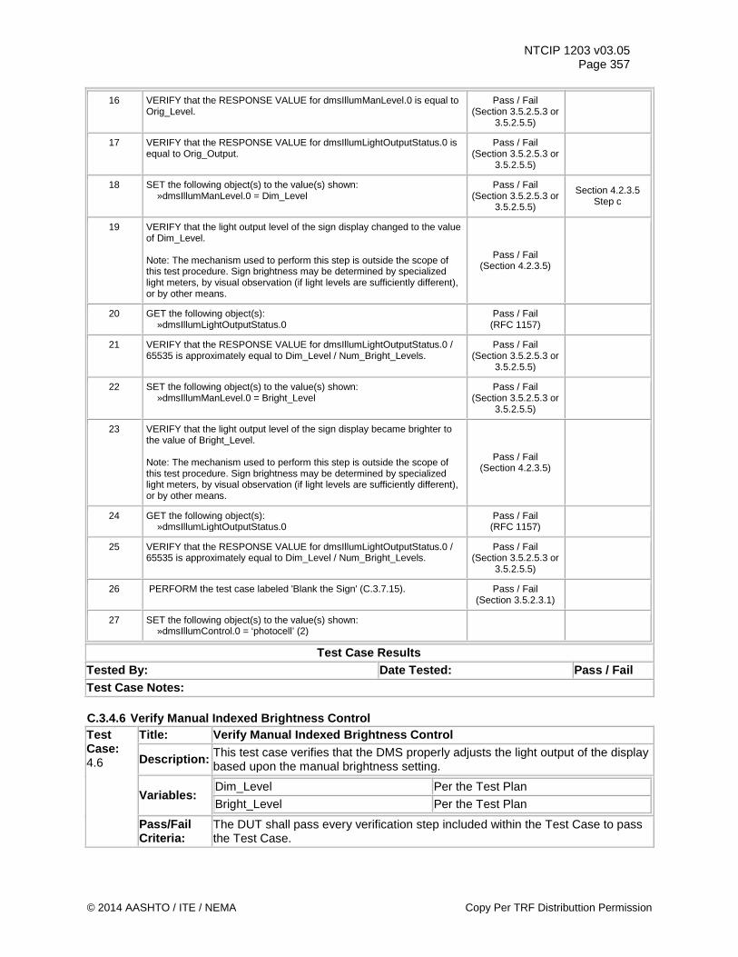
NTCIP 1203 v03.05 Page 357
16 VERIFY that the RESPONSE VALUE for dmsIllumManLevel.0 is equal to Orig_Level.
Pass / Fail (Section 3.5.2.5.3 or
3.5.2.5.5)
17 VERIFY that the RESPONSE VALUE for dmsIllumLightOutputStatus.0 is equal to Orig_Output.
Pass / Fail (Section 3.5.2.5.3 or
3.5.2.5.5)
18 SET the following object(s) to the value(s) shown: »dmsIllumManLevel.0 = Dim_Level
Pass / Fail (Section 3.5.2.5.3 or
3.5.2.5.5)
Section 4.2.3.5 Step c
19 VERIFY that the light output level of the sign display changed to the value of Dim_Level. Note: The mechanism used to perform this step is outside the scope of this test procedure. Sign brightness may be determined by specialized light meters, by visual observation (if light levels are sufficiently different), or by other means.
Pass / Fail (Section 4.2.3.5)
20 GET the following object(s): »dmsIllumLightOutputStatus.0
Pass / Fail (RFC 1157)
21 VERIFY that the RESPONSE VALUE for dmsIllumLightOutputStatus.0 / 65535 is approximately equal to Dim_Level / Num_Bright_Levels.
Pass / Fail (Section 3.5.2.5.3 or
3.5.2.5.5)
22 SET the following object(s) to the value(s) shown: »dmsIllumManLevel.0 = Bright_Level
Pass / Fail (Section 3.5.2.5.3 or
3.5.2.5.5)
23 VERIFY that the light output level of the sign display became brighter to the value of Bright_Level. Note: The mechanism used to perform this step is outside the scope of this test procedure. Sign brightness may be determined by specialized light meters, by visual observation (if light levels are sufficiently different), or by other means.
Pass / Fail (Section 4.2.3.5)
24 GET the following object(s): »dmsIllumLightOutputStatus.0
Pass / Fail (RFC 1157)
25 VERIFY that the RESPONSE VALUE for dmsIllumLightOutputStatus.0 / 65535 is approximately equal to Dim_Level / Num_Bright_Levels.
Pass / Fail (Section 3.5.2.5.3 or
3.5.2.5.5)
26 PERFORM the test case labeled 'Blank the Sign' (C.3.7.15). Pass / Fail (Section 3.5.2.3.1)
27 SET the following object(s) to the value(s) shown: »dmsIllumControl.0 = ‘photocell’ (2)
Test Case Results Tested By: Date Tested: Pass / Fail Test Case Notes: C.3.4.6 Verify Manual Indexed Brightness Control Test Case: 4.6
Title: Verify Manual Indexed Brightness Control
Description: This test case verifies that the DMS properly adjusts the light output of the display based upon the manual brightness setting.
Variables: Dim_Level Per the Test Plan Bright_Level Per the Test Plan
Pass/Fail Criteria:
The DUT shall pass every verification step included within the Test Case to pass the Test Case.
© 2014 AASHTO / ITE / NEMA Copy Per TRF Distributtion Permission
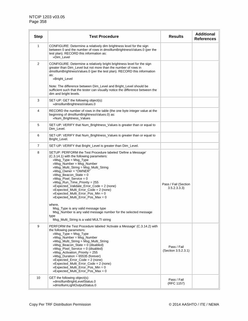
NTCIP 1203 v03.05 Page 358
Step Test Procedure Results Additional References
1 CONFIGURE: Determine a relatively dim brightness level for the sign between 0 and the number of rows in dmsIllumBrightnessValues.0 (per the test plan). RECORD this information as: »Dim_Level
2 CONFIGURE: Determine a relatively bright brightness level for the sign greater than Dim_Level but not more than the number of rows in dmsIllumBrightnessValues.0 (per the test plan). RECORD this information as: »Bright_Level Note: The difference between Dim_Level and Bright_Level should be sufficient such that the tester can visually notice the difference between the dim and bright levels.
3 SET-UP: GET the following object(s): »dmsIllumBrightnessValues.0
4 RECORD the number of rows in the table (the one byte integer value at the beginning of dmsIllumBrightnessValues.0) as: »Num_Brightness_Values
5 SET-UP: VERIFY that Num_Brightness_Values is greater than or equal to Dim_Level.
6 SET-UP: VERIFY that Num_Brightness_Values is greater than or equal to Bright_Level.
7 SET-UP: VERIFY that Bright_Level is greater than Dim_Level.
8 SETUP: PERFORM the Test Procedure labeled 'Define a Message' (C.3.14.1) with the following parameters: »Msg_Type = Msg_Type »Msg_Number = Msg_Number »Msg_Multi_String = Msg_Multi_String »Msg_Owner = “OWNER” »Msg_Beacon_State = 0 »Msg_Pixel_Service = 0 »Msg_Run_Time_Priority = 255 »Expected_Validate_Error_Code = 2 (none) »Expected_Multi_Error_Code = 2 (none) »Expected_Multi_Error_Pos_Min = 0 »Expected_Multi_Error_Pos_Max = 0 where, Msg_Type is any valid message type Msg_Number is any valid message number for the selected message type Msg_Multi_String is a valid MULTI string
Pass / Fail (Section 3.5.2.3.3.3)
9 PERFORM the Test Procedure labeled 'Activate a Message' (C.3.14.2) with the following parameters: »Msg_Type = Msg_Type »Msg_Number = Msg_Number »Msg_Multi_String = Msg_Multi_String »Msg_Beacon_State = 0 (disabled) »Msg_Pixel_Service = 0 (disabled) »Msg_Activation_Priority = 255 »Msg_Duration = 65535 (forever) »Expected_Error_Code = 2 (none) »Expected_Multi_Error_Code = 2 (none) »Expected_Multi_Error_Pos_Min = 0 »Expected_Multi_Error_Pos_Max = 0
Pass / Fail (Section 3.5.2.3.1)
10 GET the following object(s): »dmsIllumBrightLevelStatus.0 »dmsIllumLightOutputStatus.0
Pass / Fail (RFC 1157)
Copy Per TRF Distribution Permission © 2014 AASHTO / ITE / NEMA
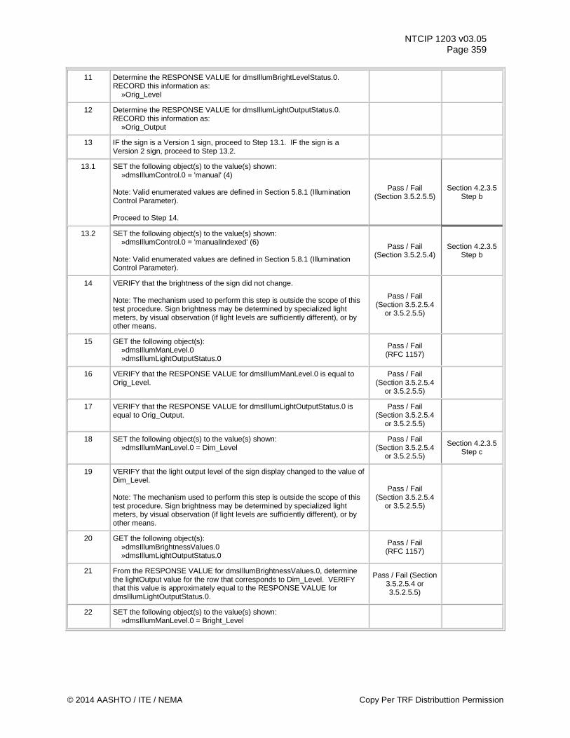
NTCIP 1203 v03.05 Page 359
11 Determine the RESPONSE VALUE for dmsIllumBrightLevelStatus.0. RECORD this information as: »Orig_Level
12 Determine the RESPONSE VALUE for dmsIllumLightOutputStatus.0. RECORD this information as: »Orig_Output
13 IF the sign is a Version 1 sign, proceed to Step 13.1. IF the sign is a Version 2 sign, proceed to Step 13.2.
13.1 SET the following object(s) to the value(s) shown: »dmsIllumControl.0 = 'manual' (4) Note: Valid enumerated values are defined in Section 5.8.1 (Illumination Control Parameter). Proceed to Step 14.
Pass / Fail (Section 3.5.2.5.5)
Section 4.2.3.5 Step b
13.2 SET the following object(s) to the value(s) shown: »dmsIllumControl.0 = 'manualIndexed' (6) Note: Valid enumerated values are defined in Section 5.8.1 (Illumination Control Parameter).
Pass / Fail (Section 3.5.2.5.4)
Section 4.2.3.5 Step b
14 VERIFY that the brightness of the sign did not change. Note: The mechanism used to perform this step is outside the scope of this test procedure. Sign brightness may be determined by specialized light meters, by visual observation (if light levels are sufficiently different), or by other means.
Pass / Fail (Section 3.5.2.5.4
or 3.5.2.5.5)
15 GET the following object(s): »dmsIllumManLevel.0 »dmsIllumLightOutputStatus.0
Pass / Fail (RFC 1157)
16 VERIFY that the RESPONSE VALUE for dmsIllumManLevel.0 is equal to Orig_Level.
Pass / Fail (Section 3.5.2.5.4
or 3.5.2.5.5)
17 VERIFY that the RESPONSE VALUE for dmsIllumLightOutputStatus.0 is equal to Orig_Output.
Pass / Fail (Section 3.5.2.5.4
or 3.5.2.5.5)
18 SET the following object(s) to the value(s) shown: »dmsIllumManLevel.0 = Dim_Level
Pass / Fail (Section 3.5.2.5.4
or 3.5.2.5.5)
Section 4.2.3.5 Step c
19 VERIFY that the light output level of the sign display changed to the value of Dim_Level. Note: The mechanism used to perform this step is outside the scope of this test procedure. Sign brightness may be determined by specialized light meters, by visual observation (if light levels are sufficiently different), or by other means.
Pass / Fail (Section 3.5.2.5.4
or 3.5.2.5.5)
20 GET the following object(s): »dmsIllumBrightnessValues.0 »dmsIllumLightOutputStatus.0
Pass / Fail (RFC 1157)
21 From the RESPONSE VALUE for dmsIllumBrightnessValues.0, determine the lightOutput value for the row that corresponds to Dim_Level. VERIFY that this value is approximately equal to the RESPONSE VALUE for dmsIllumLightOutputStatus.0.
Pass / Fail (Section 3.5.2.5.4 or 3.5.2.5.5)
22 SET the following object(s) to the value(s) shown: »dmsIllumManLevel.0 = Bright_Level
© 2014 AASHTO / ITE / NEMA Copy Per TRF Distributtion Permission
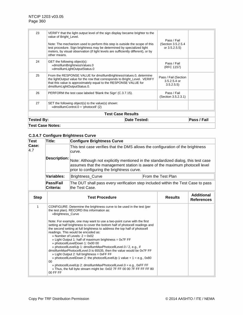
NTCIP 1203 v03.05 Page 360
23 VERIFY that the light output level of the sign display became brighter to the value of Bright_Level. Note: The mechanism used to perform this step is outside the scope of this test procedure. Sign brightness may be determined by specialized light meters, by visual observation (if light levels are sufficiently different), or by other means.
Pass / Fail (Section 3.5.2.5.4
or 3.5.2.5.5)
24 GET the following object(s): »dmsIllumBrightnessValues.0 »dmsIllumLightOutputStatus.0
Pass / Fail (RFC 1157)
25 From the RESPONSE VALUE for dmsIllumBrightnessValues.0, determine the lightOutput value for the row that corresponds to Bright_Level. VERIFY that this value is approximately equal to the RESPONSE VALUE for dmsIllumLightOutputStatus.0.
Pass / Fail (Section 3.5.2.5.4 or 3.5.2.5.5)
26 PERFORM the test case labeled 'Blank the Sign' (C.3.7.15). Pass / Fail (Section 3.5.2.3.1)
27 SET the following object(s) to the value(s) shown: »dmsIllumControl.0 = ‘photocell’ (2)
Test Case Results Tested By: Date Tested: Pass / Fail Test Case Notes: C.3.4.7 Configure Brightness Curve Test Case: 4.7
Title: Configure Brightness Curve
Description:
This test case verifies that the DMS allows the configuration of the brightness curve. Note: Although not explicitly mentioned in the standardized dialog, this test case assumes that the management station is aware of the maximum photocell level prior to configuring the brightness curve.
Variables: Brightness_Curve From the Test Plan
Pass/Fail Criteria:
The DUT shall pass every verification step included within the Test Case to pass the Test Case.
Step Test Procedure Results Additional References
1 CONFIGURE: Determine the brightness curve to be used in the test (per the test plan). RECORD this information as: »Brightness_Curve Note: For example, one may want to use a two-point curve with the first setting at half brightness to cover the bottom half of photocell readings and the second setting at full brightness to address the top half of photocell readings. This would be encoded as: » Number of Levels: 2 = 0x02 » Light Output 1: half of maximum brightness = 0x7F FF » photocellLevelDown 1: 0x00 00 » photocellLevelUp 1: dmsIllumMaxPhotocellLevel.0 / 2, e.g., if dmsIllumMaxPhotocellLevel.0 is 65535, then the value would be 0x7F FF » Light Output 2: full brightness = 0xFF FF » photocellLevelDown 2: the photocellLevelUp 1 value + 1 = e.g., 0x80 00 » photocellLevelUp 2: dmsIllumMaxPhotocellLevel.0 = e.g., 0xFF FF » Thus, the full byte stream might be: 0x02 7F FF 00 00 7F FF FF FF 80 00 FF FF
Copy Per TRF Distribution Permission © 2014 AASHTO / ITE / NEMA
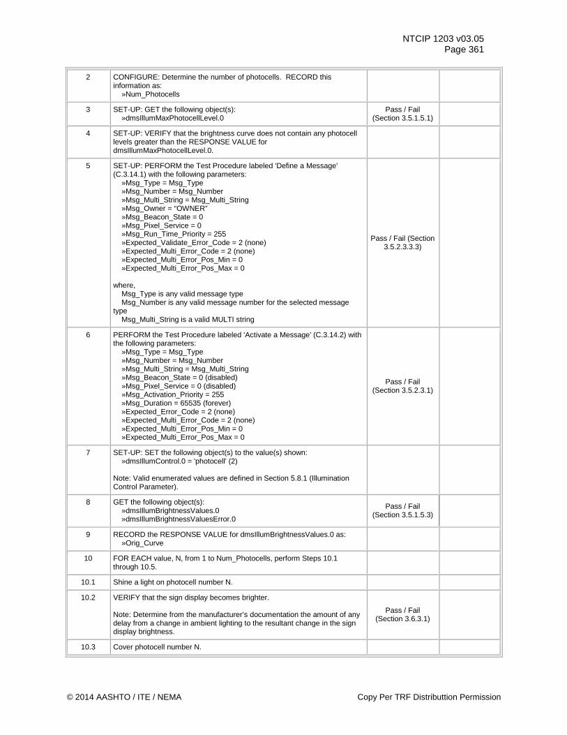
NTCIP 1203 v03.05 Page 361
2 CONFIGURE: Determine the number of photocells. RECORD this information as: »Num_Photocells
3 SET-UP: GET the following object(s): »dmsIllumMaxPhotocellLevel.0
Pass / Fail (Section 3.5.1.5.1)
4 SET-UP: VERIFY that the brightness curve does not contain any photocell levels greater than the RESPONSE VALUE for dmsIllumMaxPhotocellLevel.0.
5 SET-UP: PERFORM the Test Procedure labeled 'Define a Message' (C.3.14.1) with the following parameters: »Msg_Type = Msg_Type »Msg_Number = Msg_Number »Msg_Multi_String = Msg_Multi_String »Msg_Owner = “OWNER” »Msg_Beacon_State = 0 »Msg_Pixel_Service = 0 »Msg_Run_Time_Priority = 255 »Expected_Validate_Error_Code = 2 (none) »Expected_Multi_Error_Code = 2 (none) »Expected_Multi_Error_Pos_Min = 0 »Expected_Multi_Error_Pos_Max = 0 where, Msg_Type is any valid message type Msg_Number is any valid message number for the selected message type Msg_Multi_String is a valid MULTI string
Pass / Fail (Section 3.5.2.3.3.3)
6 PERFORM the Test Procedure labeled 'Activate a Message' (C.3.14.2) with the following parameters: »Msg_Type = Msg_Type »Msg_Number = Msg_Number »Msg_Multi_String = Msg_Multi_String »Msg_Beacon_State = 0 (disabled) »Msg_Pixel_Service = 0 (disabled) »Msg_Activation_Priority = 255 »Msg_Duration = 65535 (forever) »Expected_Error_Code = 2 (none) »Expected_Multi_Error_Code = 2 (none) »Expected_Multi_Error_Pos_Min = 0 »Expected_Multi_Error_Pos_Max = 0
Pass / Fail (Section 3.5.2.3.1)
7 SET-UP: SET the following object(s) to the value(s) shown: »dmsIllumControl.0 = 'photocell' (2) Note: Valid enumerated values are defined in Section 5.8.1 (Illumination Control Parameter).
8 GET the following object(s): »dmsIllumBrightnessValues.0 »dmsIllumBrightnessValuesError.0
Pass / Fail (Section 3.5.1.5.3)
9 RECORD the RESPONSE VALUE for dmsIllumBrightnessValues.0 as: »Orig_Curve
10 FOR EACH value, N, from 1 to Num_Photocells, perform Steps 10.1 through 10.5.
10.1 Shine a light on photocell number N.
10.2 VERIFY that the sign display becomes brighter. Note: Determine from the manufacturer’s documentation the amount of any delay from a change in ambient lighting to the resultant change in the sign display brightness.
Pass / Fail (Section 3.6.3.1)
10.3 Cover photocell number N.
© 2014 AASHTO / ITE / NEMA Copy Per TRF Distributtion Permission
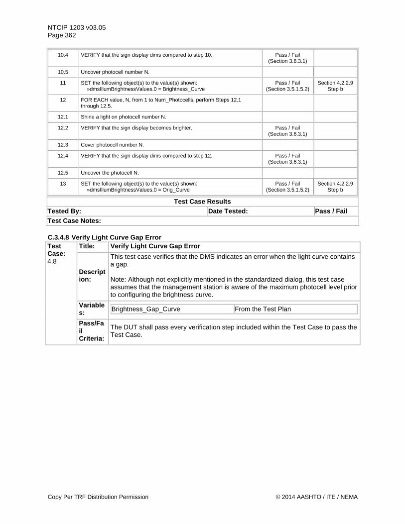
NTCIP 1203 v03.05 Page 362
10.4 VERIFY that the sign display dims compared to step 10. Pass / Fail (Section 3.6.3.1)
10.5 Uncover photocell number N.
11 SET the following object(s) to the value(s) shown: »dmsIllumBrightnessValues.0 = Brightness_Curve
Pass / Fail (Section 3.5.1.5.2)
Section 4.2.2.9 Step b
12 FOR EACH value, N, from 1 to Num_Photocells, perform Steps 12.1 through 12.5.
12.1 Shine a light on photocell number N.
12.2 VERIFY that the sign display becomes brighter. Pass / Fail (Section 3.6.3.1)
12.3 Cover photocell number N.
12.4 VERIFY that the sign display dims compared to step 12. Pass / Fail (Section 3.6.3.1)
12.5 Uncover the photocell N.
13 SET the following object(s) to the value(s) shown: »dmsIllumBrightnessValues.0 = Orig_Curve
Pass / Fail (Section 3.5.1.5.2)
Section 4.2.2.9 Step b
Test Case Results Tested By: Date Tested: Pass / Fail Test Case Notes: C.3.4.8 Verify Light Curve Gap Error Test Case: 4.8
Title: Verify Light Curve Gap Error
Description:
This test case verifies that the DMS indicates an error when the light curve contains a gap. Note: Although not explicitly mentioned in the standardized dialog, this test case assumes that the management station is aware of the maximum photocell level prior to configuring the brightness curve.
Variables: Brightness_Gap_Curve From the Test Plan
Pass/Fail Criteria:
The DUT shall pass every verification step included within the Test Case to pass the Test Case.
Copy Per TRF Distribution Permission © 2014 AASHTO / ITE / NEMA
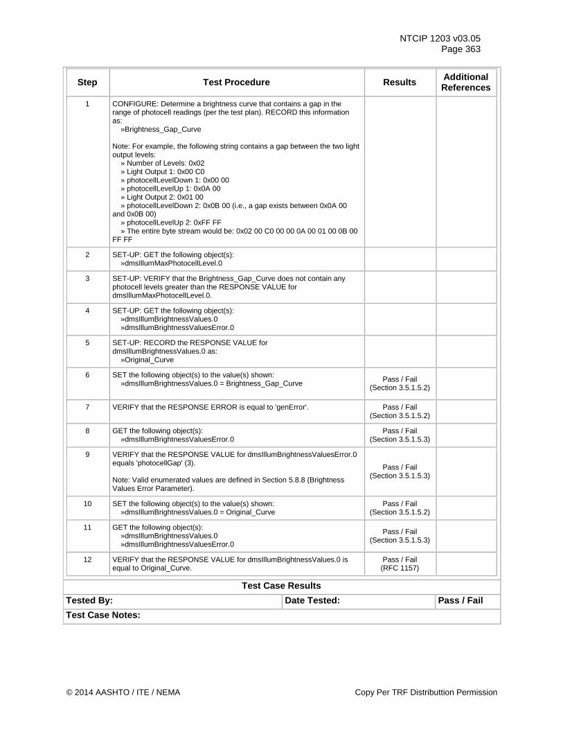
NTCIP 1203 v03.05 Page 363
Step Test Procedure Results Additional References
1 CONFIGURE: Determine a brightness curve that contains a gap in the range of photocell readings (per the test plan). RECORD this information as: »Brightness_Gap_Curve Note: For example, the following string contains a gap between the two light output levels: » Number of Levels: 0x02 » Light Output 1: 0x00 C0 » photocellLevelDown 1: 0x00 00 » photocellLevelUp 1: 0x0A 00 » Light Output 2: 0x01 00 » photocellLevelDown 2: 0x0B 00 (i.e., a gap exists between 0x0A 00 and 0x0B 00) » photocellLevelUp 2: 0xFF FF » The entire byte stream would be: 0x02 00 C0 00 00 0A 00 01 00 0B 00 FF FF
2 SET-UP: GET the following object(s): »dmsIllumMaxPhotocellLevel.0
3 SET-UP: VERIFY that the Brightness_Gap_Curve does not contain any photocell levels greater than the RESPONSE VALUE for dmsIllumMaxPhotocellLevel.0.
4 SET-UP: GET the following object(s): »dmsIllumBrightnessValues.0 »dmsIllumBrightnessValuesError.0
5 SET-UP: RECORD the RESPONSE VALUE for dmsIllumBrightnessValues.0 as: »Original_Curve
6 SET the following object(s) to the value(s) shown: »dmsIllumBrightnessValues.0 = Brightness_Gap_Curve
Pass / Fail (Section 3.5.1.5.2)
7 VERIFY that the RESPONSE ERROR is equal to 'genError'. Pass / Fail (Section 3.5.1.5.2)
8 GET the following object(s): »dmsIllumBrightnessValuesError.0
Pass / Fail (Section 3.5.1.5.3)
9 VERIFY that the RESPONSE VALUE for dmsIllumBrightnessValuesError.0 equals 'photocellGap' (3). Note: Valid enumerated values are defined in Section 5.8.8 (Brightness Values Error Parameter).
Pass / Fail (Section 3.5.1.5.3)
10 SET the following object(s) to the value(s) shown: »dmsIllumBrightnessValues.0 = Original_Curve
Pass / Fail (Section 3.5.1.5.2)
11 GET the following object(s): »dmsIllumBrightnessValues.0 »dmsIllumBrightnessValuesError.0
Pass / Fail (Section 3.5.1.5.3)
12 VERIFY that the RESPONSE VALUE for dmsIllumBrightnessValues.0 is equal to Original_Curve.
Pass / Fail (RFC 1157)
Test Case Results Tested By: Date Tested: Pass / Fail Test Case Notes:
© 2014 AASHTO / ITE / NEMA Copy Per TRF Distributtion Permission
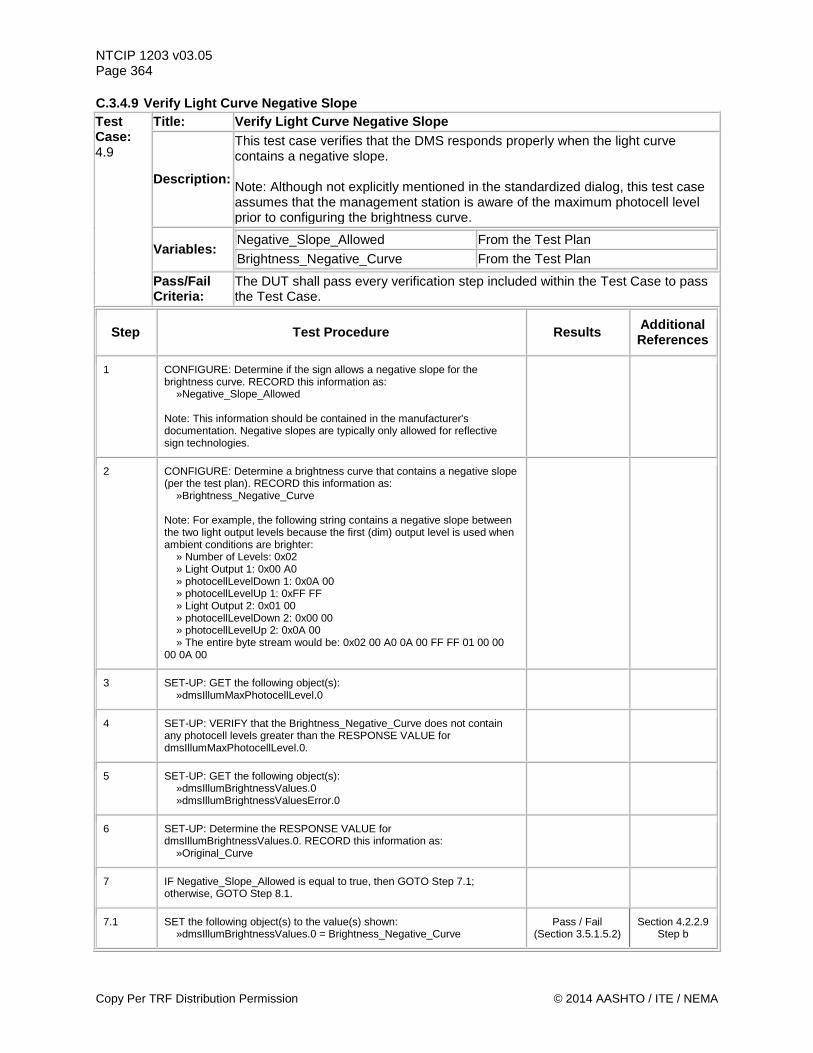
NTCIP 1203 v03.05 Page 364 C.3.4.9 Verify Light Curve Negative Slope Test Case: 4.9
Title: Verify Light Curve Negative Slope
Description:
This test case verifies that the DMS responds properly when the light curve contains a negative slope. Note: Although not explicitly mentioned in the standardized dialog, this test case assumes that the management station is aware of the maximum photocell level prior to configuring the brightness curve.
Variables: Negative_Slope_Allowed From the Test Plan
Brightness_Negative_Curve From the Test Plan
Pass/Fail Criteria:
The DUT shall pass every verification step included within the Test Case to pass the Test Case.
Step Test Procedure Results Additional References
1 CONFIGURE: Determine if the sign allows a negative slope for the brightness curve. RECORD this information as: »Negative_Slope_Allowed Note: This information should be contained in the manufacturer's documentation. Negative slopes are typically only allowed for reflective sign technologies.
2 CONFIGURE: Determine a brightness curve that contains a negative slope (per the test plan). RECORD this information as: »Brightness_Negative_Curve Note: For example, the following string contains a negative slope between the two light output levels because the first (dim) output level is used when ambient conditions are brighter: » Number of Levels: 0x02 » Light Output 1: 0x00 A0 » photocellLevelDown 1: 0x0A 00 » photocellLevelUp 1: 0xFF FF » Light Output 2: 0x01 00 » photocellLevelDown 2: 0x00 00 » photocellLevelUp 2: 0x0A 00 » The entire byte stream would be: 0x02 00 A0 0A 00 FF FF 01 00 00 00 0A 00
3 SET-UP: GET the following object(s): »dmsIllumMaxPhotocellLevel.0
4 SET-UP: VERIFY that the Brightness_Negative_Curve does not contain any photocell levels greater than the RESPONSE VALUE for dmsIllumMaxPhotocellLevel.0.
5 SET-UP: GET the following object(s): »dmsIllumBrightnessValues.0 »dmsIllumBrightnessValuesError.0
6 SET-UP: Determine the RESPONSE VALUE for dmsIllumBrightnessValues.0. RECORD this information as: »Original_Curve
7 IF Negative_Slope_Allowed is equal to true, then GOTO Step 7.1; otherwise, GOTO Step 8.1.
7.1 SET the following object(s) to the value(s) shown: »dmsIllumBrightnessValues.0 = Brightness_Negative_Curve
Pass / Fail (Section 3.5.1.5.2)
Section 4.2.2.9 Step b
Copy Per TRF Distribution Permission © 2014 AASHTO / ITE / NEMA
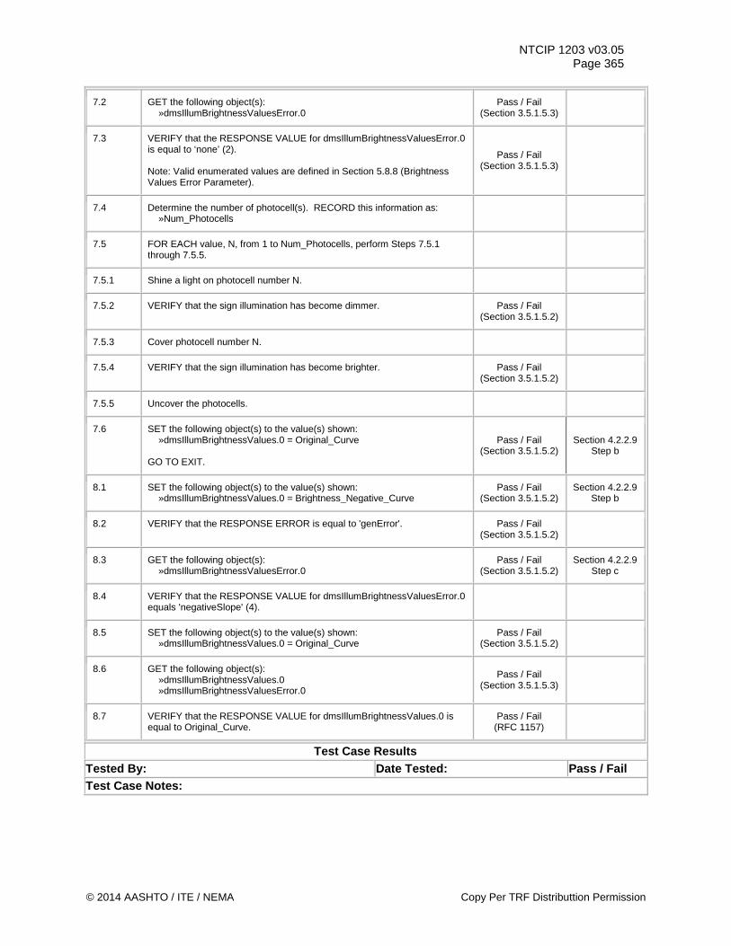
NTCIP 1203 v03.05 Page 365
7.2 GET the following object(s): »dmsIllumBrightnessValuesError.0
Pass / Fail (Section 3.5.1.5.3)
7.3 VERIFY that the RESPONSE VALUE for dmsIllumBrightnessValuesError.0 is equal to ‘none’ (2). Note: Valid enumerated values are defined in Section 5.8.8 (Brightness Values Error Parameter).
Pass / Fail (Section 3.5.1.5.3)
7.4 Determine the number of photocell(s). RECORD this information as: »Num_Photocells
7.5 FOR EACH value, N, from 1 to Num_Photocells, perform Steps 7.5.1 through 7.5.5.
7.5.1 Shine a light on photocell number N.
7.5.2 VERIFY that the sign illumination has become dimmer. Pass / Fail (Section 3.5.1.5.2)
7.5.3 Cover photocell number N.
7.5.4 VERIFY that the sign illumination has become brighter. Pass / Fail (Section 3.5.1.5.2)
7.5.5 Uncover the photocells.
7.6 SET the following object(s) to the value(s) shown: »dmsIllumBrightnessValues.0 = Original_Curve GO TO EXIT.
Pass / Fail (Section 3.5.1.5.2)
Section 4.2.2.9 Step b
8.1 SET the following object(s) to the value(s) shown: »dmsIllumBrightnessValues.0 = Brightness_Negative_Curve
Pass / Fail (Section 3.5.1.5.2)
Section 4.2.2.9 Step b
8.2 VERIFY that the RESPONSE ERROR is equal to 'genError'. Pass / Fail (Section 3.5.1.5.2)
8.3 GET the following object(s): »dmsIllumBrightnessValuesError.0
Pass / Fail (Section 3.5.1.5.2)
Section 4.2.2.9 Step c
8.4 VERIFY that the RESPONSE VALUE for dmsIllumBrightnessValuesError.0 equals 'negativeSlope' (4).
8.5 SET the following object(s) to the value(s) shown: »dmsIllumBrightnessValues.0 = Original_Curve
Pass / Fail (Section 3.5.1.5.2)
8.6 GET the following object(s): »dmsIllumBrightnessValues.0 »dmsIllumBrightnessValuesError.0
Pass / Fail (Section 3.5.1.5.3)
8.7 VERIFY that the RESPONSE VALUE for dmsIllumBrightnessValues.0 is equal to Original_Curve.
Pass / Fail (RFC 1157)
Test Case Results Tested By: Date Tested: Pass / Fail Test Case Notes:
© 2014 AASHTO / ITE / NEMA Copy Per TRF Distributtion Permission
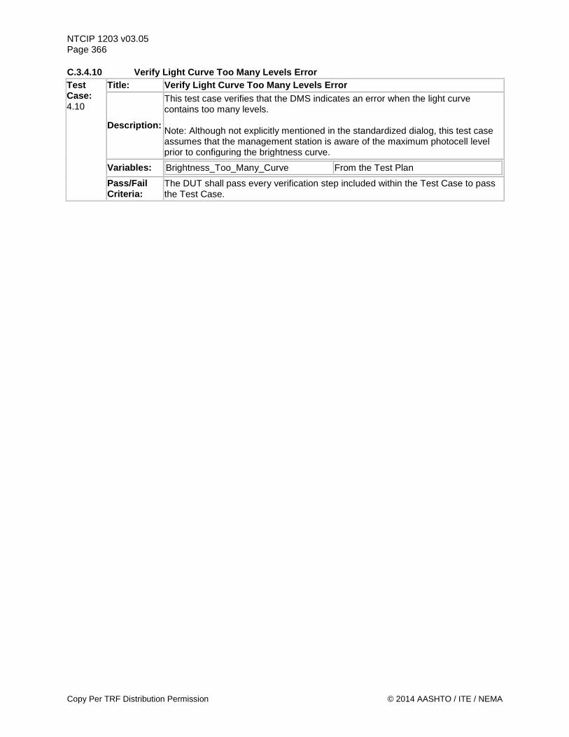
NTCIP 1203 v03.05 Page 366 C.3.4.10 Verify Light Curve Too Many Levels Error Test Case: 4.10
Title: Verify Light Curve Too Many Levels Error
Description:
This test case verifies that the DMS indicates an error when the light curve contains too many levels. Note: Although not explicitly mentioned in the standardized dialog, this test case assumes that the management station is aware of the maximum photocell level prior to configuring the brightness curve.
Variables: Brightness_Too_Many_Curve From the Test Plan
Pass/Fail Criteria:
The DUT shall pass every verification step included within the Test Case to pass the Test Case.
Copy Per TRF Distribution Permission © 2014 AASHTO / ITE / NEMA
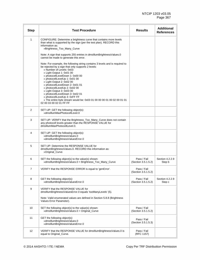
NTCIP 1203 v03.05 Page 367
Step Test Procedure Results Additional References
1 CONFIGURE: Determine a brightness curve that contains more levels than what is supported by the sign (per the test plan). RECORD this information as: »Brightness_Too_Many_Curve Note: A sign that supports 255 entries in dmsIllumBrightnessValues.0 cannot be made to generate this error. Note: For example, the following string contains 3 levels and is required to be rejected by a sign that only supports 2 levels: » Number of Levels: 0x03 » Light Output 1: 0x01 00 » photocellLevelDown 1: 0x00 00 » photocellLevelUp 1: 0x01 00 » Light Output 2: 0x02 00 » photocellLevelDown 2: 0x01 01 » photocellLevelUp 2: 0x02 00 » Light Output 3: 0x03 00 » photocellLevelDown 3: 0x02 01 » photocellLevelUp 3: 0xFF FF » The entire byte stream would be: 0x03 01 00 00 00 01 00 02 00 01 01 02 00 03 00 02 01 FF FF
2 SET-UP: GET the following object(s): »dmsIllumMaxPhotocellLevel.0
3 SET-UP: VERIFY that the Brightness_Too_Many_Curve does not contain any photocell levels greater than the RESPONSE VALUE for dmsIllumMaxPhotocellLevel.0.
4 SET-UP: GET the following object(s): »dmsIllumBrightnessValues.0 »dmsIllumBrightnessValuesError.0
5 SET-UP: Determine the RESPONSE VALUE for dmsIllumBrightnessValues.0. RECORD this information as: »Original_Curve
6 SET the following object(s) to the value(s) shown: »dmsIllumBrightnessValues.0 = Brightness_Too_Many_Curve
Pass / Fail (Section 3.5.1.5.2)
Section 4.2.2.9 Step b
7 VERIFY that the RESPONSE ERROR is equal to 'genError'. Pass / Fail (Section 3.5.1.5.2)
8 GET the following object(s): »dmsIllumBrightnessValuesError.0
Pass / Fail (Section 3.5.1.5.2)
Section 4.2.2.9 Step c
9 VERIFY that the RESPONSE VALUE for dmsIllumBrightnessValuesError.0 equals 'tooManyLevels' (5). Note: Valid enumerated values are defined in Section 5.8.8 (Brightness Values Error Parameter).
10 SET the following object(s) to the value(s) shown: »dmsIllumBrightnessValues.0 = Original_Curve
Pass / Fail (Section 3.5.1.5.2)
11 GET the following object(s): »dmsIllumBrightnessValues.0 »dmsIllumBrightnessValuesError.0
Pass / Fail (Section 3.5.1.5.3)
12 VERIFY that the RESPONSE VALUE for dmsIllumBrightnessValues.0 is equal to Original_Curve.
Pass / Fail (RFC 1157)
© 2014 AASHTO / ITE / NEMA Copy Per TRF Distributtion Permission
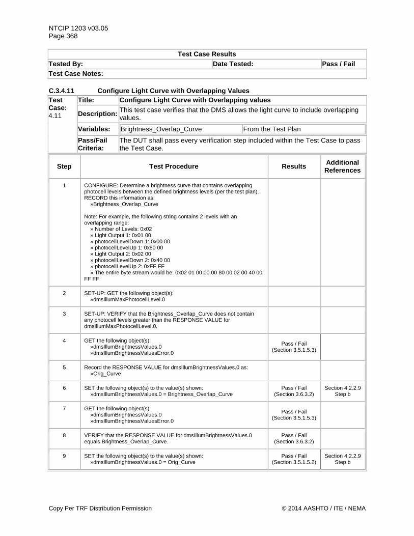
NTCIP 1203 v03.05 Page 368
Test Case Results Tested By: Date Tested: Pass / Fail Test Case Notes: C.3.4.11 Configure Light Curve with Overlapping Values Test Case: 4.11
Title: Configure Light Curve with Overlapping values
Description: This test case verifies that the DMS allows the light curve to include overlapping values.
Variables: Brightness_Overlap_Curve From the Test Plan
Pass/Fail Criteria:
The DUT shall pass every verification step included within the Test Case to pass the Test Case.
Step Test Procedure Results Additional References
1 CONFIGURE: Determine a brightness curve that contains overlapping photocell levels between the defined brightness levels (per the test plan). RECORD this information as: »Brightness_Overlap_Curve Note: For example, the following string contains 2 levels with an overlapping range: » Number of Levels: 0x02 » Light Output 1: 0x01 00 » photocellLevelDown 1: 0x00 00 » photocellLevelUp 1: 0x80 00 » Light Output 2: 0x02 00 » photocellLevelDown 2: 0x40 00 » photocellLevelUp 2: 0xFF FF » The entire byte stream would be: 0x02 01 00 00 00 80 00 02 00 40 00 FF FF
2 SET-UP: GET the following object(s): »dmsIllumMaxPhotocellLevel.0
3 SET-UP: VERIFY that the Brightness_Overlap_Curve does not contain any photocell levels greater than the RESPONSE VALUE for dmsIllumMaxPhotocellLevel.0.
4 GET the following object(s): »dmsIllumBrightnessValues.0 »dmsIllumBrightnessValuesError.0
Pass / Fail (Section 3.5.1.5.3)
5 Record the RESPONSE VALUE for dmsIllumBrightnessValues.0 as: »Orig_Curve
6 SET the following object(s) to the value(s) shown: »dmsIllumBrightnessValues.0 = Brightness_Overlap_Curve
Pass / Fail (Section 3.6.3.2)
Section 4.2.2.9 Step b
7 GET the following object(s): »dmsIllumBrightnessValues.0 »dmsIllumBrightnessValuesError.0
Pass / Fail (Section 3.5.1.5.3)
8 VERIFY that the RESPONSE VALUE for dmsIllumBrightnessValues.0 equals Brightness_Overlap_Curve.
Pass / Fail (Section 3.6.3.2)
9 SET the following object(s) to the value(s) shown: »dmsIllumBrightnessValues.0 = Orig_Curve
Pass / Fail (Section 3.5.1.5.2)
Section 4.2.2.9 Step b
Copy Per TRF Distribution Permission © 2014 AASHTO / ITE / NEMA
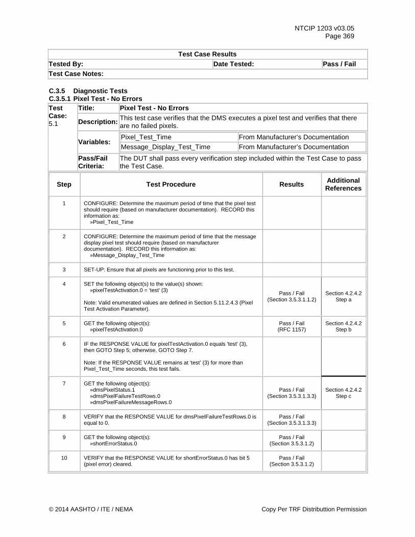
NTCIP 1203 v03.05 Page 369
Test Case Results Tested By: Date Tested: Pass / Fail Test Case Notes: C.3.5 Diagnostic Tests C.3.5.1 Pixel Test - No Errors Test Case: 5.1
Title: Pixel Test - No Errors
Description: This test case verifies that the DMS executes a pixel test and verifies that there are no failed pixels.
Variables: Pixel_Test_Time From Manufacturer’s Documentation Message_Display_Test_Time From Manufacturer’s Documentation
Pass/Fail Criteria:
The DUT shall pass every verification step included within the Test Case to pass the Test Case.
Step Test Procedure Results Additional References
1 CONFIGURE: Determine the maximum period of time that the pixel test should require (based on manufacturer documentation). RECORD this information as: »Pixel_Test_Time
2 CONFIGURE: Determine the maximum period of time that the message display pixel test should require (based on manufacturer documentation). RECORD this information as: »Message_Display_Test_Time
3 SET-UP: Ensure that all pixels are functioning prior to this test.
4 SET the following object(s) to the value(s) shown: »pixelTestActivation.0 = 'test' (3) Note: Valid enumerated values are defined in Section 5.11.2.4.3 (Pixel Test Activation Parameter).
Pass / Fail (Section 3.5.3.1.1.2)
Section 4.2.4.2 Step a
5 GET the following object(s): »pixelTestActivation.0
Pass / Fail (RFC 1157)
Section 4.2.4.2 Step b
6 IF the RESPONSE VALUE for pixelTestActivation.0 equals 'test' (3), then GOTO Step 5; otherwise, GOTO Step 7. Note: If the RESPONSE VALUE remains at ‘test’ (3) for more than Pixel_Test_Time seconds, this test fails.
7 GET the following object(s): »dmsPixelStatus.1 »dmsPixelFailureTestRows.0 »dmsPixelFailureMessageRows.0
Pass / Fail (Section 3.5.3.1.3.3)
Section 4.2.4.2 Step c
8 VERIFY that the RESPONSE VALUE for dmsPixelFailureTestRows.0 is equal to 0.
Pass / Fail (Section 3.5.3.1.3.3)
9 GET the following object(s): »shortErrorStatus.0
Pass / Fail (Section 3.5.3.1.2)
10 VERIFY that the RESPONSE VALUE for shortErrorStatus.0 has bit 5 (pixel error) cleared.
Pass / Fail (Section 3.5.3.1.2)
© 2014 AASHTO / ITE / NEMA Copy Per TRF Distributtion Permission
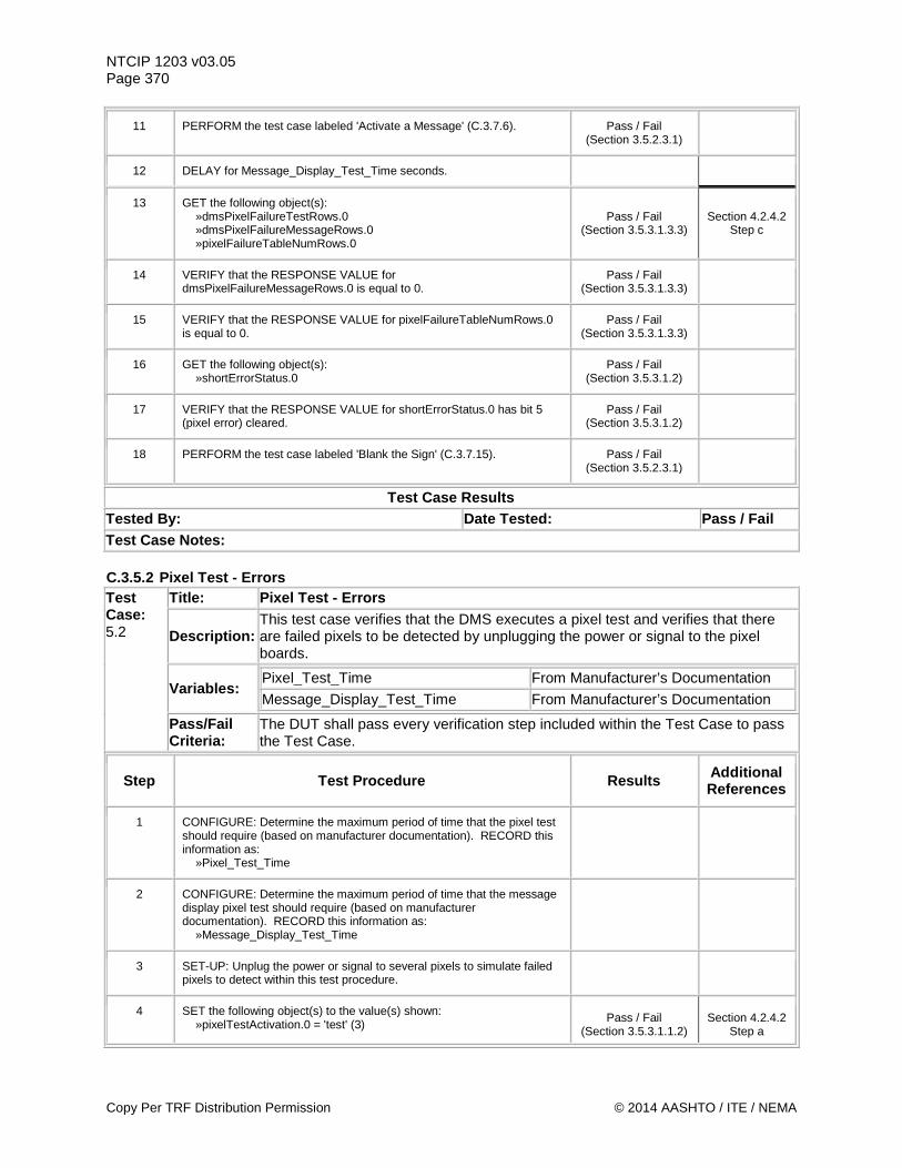
NTCIP 1203 v03.05 Page 370
11 PERFORM the test case labeled 'Activate a Message' (C.3.7.6). Pass / Fail (Section 3.5.2.3.1)
12 DELAY for Message_Display_Test_Time seconds.
13 GET the following object(s): »dmsPixelFailureTestRows.0 »dmsPixelFailureMessageRows.0 »pixelFailureTableNumRows.0
Pass / Fail (Section 3.5.3.1.3.3)
Section 4.2.4.2 Step c
14 VERIFY that the RESPONSE VALUE for dmsPixelFailureMessageRows.0 is equal to 0.
Pass / Fail (Section 3.5.3.1.3.3)
15 VERIFY that the RESPONSE VALUE for pixelFailureTableNumRows.0 is equal to 0.
Pass / Fail (Section 3.5.3.1.3.3)
16 GET the following object(s): »shortErrorStatus.0
Pass / Fail (Section 3.5.3.1.2)
17 VERIFY that the RESPONSE VALUE for shortErrorStatus.0 has bit 5 (pixel error) cleared.
Pass / Fail (Section 3.5.3.1.2)
18 PERFORM the test case labeled 'Blank the Sign' (C.3.7.15). Pass / Fail (Section 3.5.2.3.1)
Test Case Results Tested By: Date Tested: Pass / Fail Test Case Notes: C.3.5.2 Pixel Test - Errors Test Case: 5.2
Title: Pixel Test - Errors
Description: This test case verifies that the DMS executes a pixel test and verifies that there are failed pixels to be detected by unplugging the power or signal to the pixel boards.
Variables: Pixel_Test_Time From Manufacturer’s Documentation
Message_Display_Test_Time From Manufacturer’s Documentation
Pass/Fail Criteria:
The DUT shall pass every verification step included within the Test Case to pass the Test Case.
Step Test Procedure Results Additional References
1 CONFIGURE: Determine the maximum period of time that the pixel test should require (based on manufacturer documentation). RECORD this information as: »Pixel_Test_Time
2 CONFIGURE: Determine the maximum period of time that the message display pixel test should require (based on manufacturer documentation). RECORD this information as: »Message_Display_Test_Time
3 SET-UP: Unplug the power or signal to several pixels to simulate failed pixels to detect within this test procedure.
4 SET the following object(s) to the value(s) shown: »pixelTestActivation.0 = 'test' (3)
Pass / Fail (Section 3.5.3.1.1.2)
Section 4.2.4.2 Step a
Copy Per TRF Distribution Permission © 2014 AASHTO / ITE / NEMA
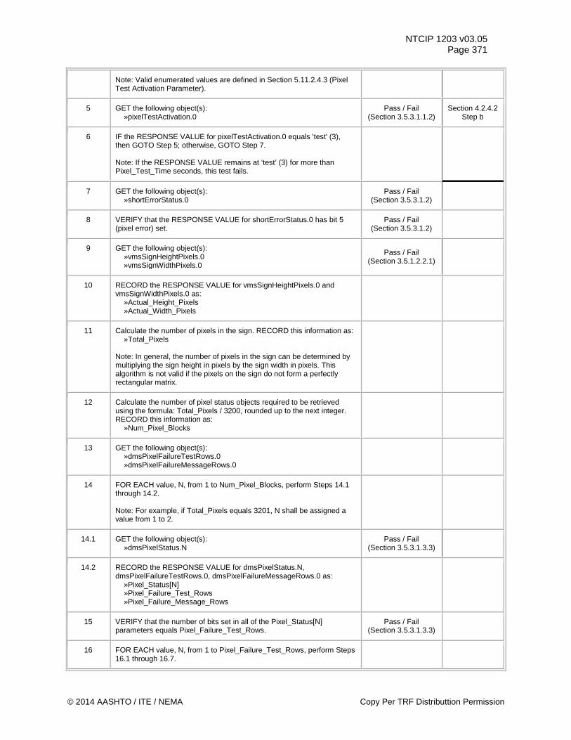
NTCIP 1203 v03.05 Page 371
Note: Valid enumerated values are defined in Section 5.11.2.4.3 (Pixel Test Activation Parameter).
5 GET the following object(s): »pixelTestActivation.0
Pass / Fail (Section 3.5.3.1.1.2)
Section 4.2.4.2 Step b
6 IF the RESPONSE VALUE for pixelTestActivation.0 equals 'test' (3), then GOTO Step 5; otherwise, GOTO Step 7. Note: If the RESPONSE VALUE remains at ‘test’ (3) for more than Pixel_Test_Time seconds, this test fails.
7 GET the following object(s): »shortErrorStatus.0
Pass / Fail (Section 3.5.3.1.2)
8 VERIFY that the RESPONSE VALUE for shortErrorStatus.0 has bit 5 (pixel error) set.
Pass / Fail (Section 3.5.3.1.2)
9 GET the following object(s): »vmsSignHeightPixels.0 »vmsSignWidthPixels.0
Pass / Fail (Section 3.5.1.2.2.1)
10 RECORD the RESPONSE VALUE for vmsSignHeightPixels.0 and vmsSignWidthPixels.0 as: »Actual_Height_Pixels »Actual_Width_Pixels
11 Calculate the number of pixels in the sign. RECORD this information as: »Total_Pixels Note: In general, the number of pixels in the sign can be determined by multiplying the sign height in pixels by the sign width in pixels. This algorithm is not valid if the pixels on the sign do not form a perfectly rectangular matrix.
12 Calculate the number of pixel status objects required to be retrieved using the formula: Total_Pixels / 3200, rounded up to the next integer. RECORD this information as: »Num_Pixel_Blocks
13 GET the following object(s): »dmsPixelFailureTestRows.0 »dmsPixelFailureMessageRows.0
14 FOR EACH value, N, from 1 to Num_Pixel_Blocks, perform Steps 14.1 through 14.2. Note: For example, if Total_Pixels equals 3201, N shall be assigned a value from 1 to 2.
14.1 GET the following object(s): »dmsPixelStatus.N
Pass / Fail (Section 3.5.3.1.3.3)
14.2 RECORD the RESPONSE VALUE for dmsPixelStatus.N, dmsPixelFailureTestRows.0, dmsPixelFailureMessageRows.0 as: »Pixel_Status[N] »Pixel_Failure_Test_Rows »Pixel_Failure_Message_Rows
15 VERIFY that the number of bits set in all of the Pixel_Status[N] parameters equals Pixel_Failure_Test_Rows.
Pass / Fail (Section 3.5.3.1.3.3)
16 FOR EACH value, N, from 1 to Pixel_Failure_Test_Rows, perform Steps 16.1 through 16.7.
© 2014 AASHTO / ITE / NEMA Copy Per TRF Distributtion Permission
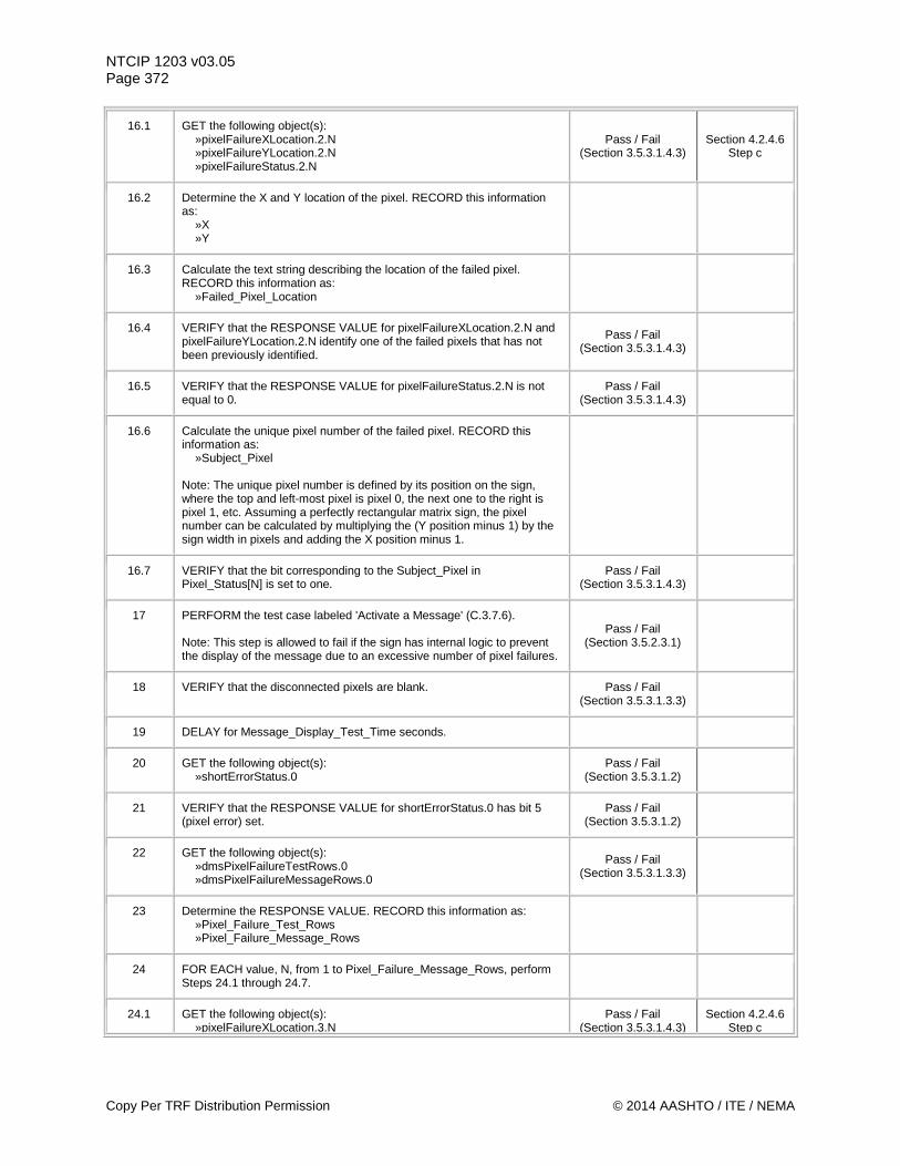
NTCIP 1203 v03.05 Page 372
16.1 GET the following object(s): »pixelFailureXLocation.2.N »pixelFailureYLocation.2.N »pixelFailureStatus.2.N
Pass / Fail (Section 3.5.3.1.4.3)
Section 4.2.4.6 Step c
16.2 Determine the X and Y location of the pixel. RECORD this information as: »X »Y
16.3 Calculate the text string describing the location of the failed pixel. RECORD this information as: »Failed_Pixel_Location
16.4 VERIFY that the RESPONSE VALUE for pixelFailureXLocation.2.N and pixelFailureYLocation.2.N identify one of the failed pixels that has not been previously identified.
Pass / Fail (Section 3.5.3.1.4.3)
16.5 VERIFY that the RESPONSE VALUE for pixelFailureStatus.2.N is not equal to 0.
Pass / Fail (Section 3.5.3.1.4.3)
16.6 Calculate the unique pixel number of the failed pixel. RECORD this information as: »Subject_Pixel Note: The unique pixel number is defined by its position on the sign, where the top and left-most pixel is pixel 0, the next one to the right is pixel 1, etc. Assuming a perfectly rectangular matrix sign, the pixel number can be calculated by multiplying the (Y position minus 1) by the sign width in pixels and adding the X position minus 1.
16.7 VERIFY that the bit corresponding to the Subject_Pixel in Pixel_Status[N] is set to one.
Pass / Fail (Section 3.5.3.1.4.3)
17 PERFORM the test case labeled 'Activate a Message' (C.3.7.6). Note: This step is allowed to fail if the sign has internal logic to prevent the display of the message due to an excessive number of pixel failures.
Pass / Fail (Section 3.5.2.3.1)
18 VERIFY that the disconnected pixels are blank. Pass / Fail (Section 3.5.3.1.3.3)
19 DELAY for Message_Display_Test_Time seconds.
20 GET the following object(s): »shortErrorStatus.0
Pass / Fail (Section 3.5.3.1.2)
21 VERIFY that the RESPONSE VALUE for shortErrorStatus.0 has bit 5 (pixel error) set.
Pass / Fail (Section 3.5.3.1.2)
22 GET the following object(s): »dmsPixelFailureTestRows.0 »dmsPixelFailureMessageRows.0
Pass / Fail (Section 3.5.3.1.3.3)
23 Determine the RESPONSE VALUE. RECORD this information as: »Pixel_Failure_Test_Rows »Pixel_Failure_Message_Rows
24 FOR EACH value, N, from 1 to Pixel_Failure_Message_Rows, perform Steps 24.1 through 24.7.
24.1 GET the following object(s): »pixelFailureXLocation.3.N
Pass / Fail (Section 3.5.3.1.4.3)
Section 4.2.4.6 Step c
Copy Per TRF Distribution Permission © 2014 AASHTO / ITE / NEMA
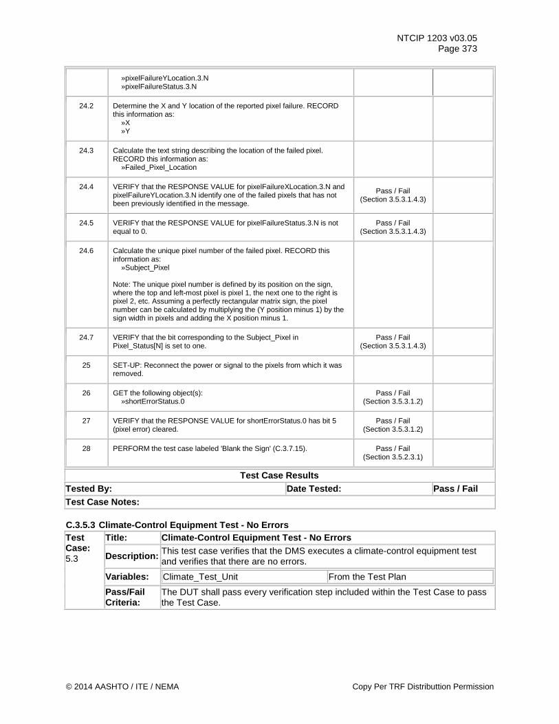
NTCIP 1203 v03.05 Page 373
»pixelFailureYLocation.3.N »pixelFailureStatus.3.N
24.2 Determine the X and Y location of the reported pixel failure. RECORD this information as: »X »Y
24.3 Calculate the text string describing the location of the failed pixel. RECORD this information as: »Failed_Pixel_Location
24.4 VERIFY that the RESPONSE VALUE for pixelFailureXLocation.3.N and pixelFailureYLocation.3.N identify one of the failed pixels that has not been previously identified in the message.
Pass / Fail (Section 3.5.3.1.4.3)
24.5 VERIFY that the RESPONSE VALUE for pixelFailureStatus.3.N is not equal to 0.
Pass / Fail (Section 3.5.3.1.4.3)
24.6 Calculate the unique pixel number of the failed pixel. RECORD this information as: »Subject_Pixel Note: The unique pixel number is defined by its position on the sign, where the top and left-most pixel is pixel 1, the next one to the right is pixel 2, etc. Assuming a perfectly rectangular matrix sign, the pixel number can be calculated by multiplying the (Y position minus 1) by the sign width in pixels and adding the X position minus 1.
24.7 VERIFY that the bit corresponding to the Subject_Pixel in Pixel_Status[N] is set to one.
Pass / Fail (Section 3.5.3.1.4.3)
25 SET-UP: Reconnect the power or signal to the pixels from which it was removed.
26 GET the following object(s): »shortErrorStatus.0
Pass / Fail (Section 3.5.3.1.2)
27 VERIFY that the RESPONSE VALUE for shortErrorStatus.0 has bit 5 (pixel error) cleared.
Pass / Fail (Section 3.5.3.1.2)
28 PERFORM the test case labeled 'Blank the Sign' (C.3.7.15). Pass / Fail (Section 3.5.2.3.1)
Test Case Results Tested By: Date Tested: Pass / Fail Test Case Notes: C.3.5.3 Climate-Control Equipment Test - No Errors Test Case: 5.3
Title: Climate-Control Equipment Test - No Errors
Description: This test case verifies that the DMS executes a climate-control equipment test and verifies that there are no errors.
Variables: Climate_Test_Unit From the Test Plan
Pass/Fail Criteria:
The DUT shall pass every verification step included within the Test Case to pass the Test Case.
© 2014 AASHTO / ITE / NEMA Copy Per TRF Distributtion Permission
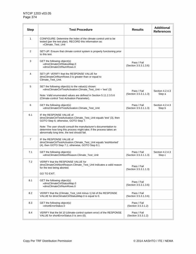
NTCIP 1203 v03.05 Page 374
Step Test Procedure Results Additional References
1 CONFIGURE: Determine the index of the climate control unit to be tested (per the test plan). RECORD this information as: »Climate_Test_Unit
2 SET-UP: Ensure that climate control system is properly functioning prior to this test.
3 GET the following object(s): »dmsClimateCtrlStatusMap.0 »dmsClimateCtrlNumRows.0
Pass / Fail (Section 3.5.3.1.3.6)
4 SET-UP: VERIFY that the RESPONSE VALUE for dmsClimateCtrlNumRows.0 is greater than or equal to Climate_Test_Unit.
5 SET the following object(s) to the value(s) shown: »dmsClimateCtrlTestActivation.Climate_Test_Unit = 'test' (3) Note: Valid enumerated values are defined in Section 5.11.2.3.5.6 (Climate-control Test Activation Parameter).
Pass / Fail (Section 3.5.3.1.1.3)
Section 4.2.4.3 Step a
6 GET the following object(s): »dmsClimateCtrlTestActivation.Climate_Test_Unit
Pass / Fail (Section 3.5.3.1.1.3)
Section 4.2.4.3 Step b
6.1 IF the RESPONSE VALUE of dmsClimateCtrlTestActivation.Climate_Test_Unit equals 'test' (3), then GOTO Step 6; otherwise, GOTO Step 7. Note: The user should consult the manufacturer's documentation to determine how long this process might take; if the process takes an abnormally long time, the test should fail.
7 IF the RESPONSE VALUE of dmsClimateCtrlTestActivation.Climate_Test_Unit equals 'testAborted' (4), then GOTO Step 7.1; otherwise, GOTO Step 8.1.
7.1 GET the following object(s): »dmsClimateCtrlAbortReason.Climate_Test_Unit
Pass / Fail (Section 3.5.3.1.1.3)
Section 4.2.4.3 Step c
7.2 VERIFY that the RESPONSE VALUE for dmsClimateCtrlAbortReason.Climate_Test_Unit indicates a valid reason for the test being aborted. GO TO EXIT.
Pass / Fail (Section 3.5.3.1.1.3)
8.1 GET the following object(s): »dmsClimateCtrlStatusMap.0 »dmsClimateCtrlNumRows.0
Pass / Fail (Section 3.5.3.1.3.6)
8.2 VERIFY that the (Climate_Test_Unit minus 1) bit of the RESPONSE VALUE for dmsClimateCtrlStatusMap.0 is equal to 0.
Pass / Fail (Section 3.5.3.1.3.6)
8.3 GET the following object(s): »shortErrorStatus.0
Pass / Fail (Section 3.5.3.1.2)
8.4 VERIFY that the bit 10 (climate-control system error) of the RESPONSE VALUE for shortErrorStatus.0 is zero (0).
Pass / Fail (Section 3.5.3.1.2)
Copy Per TRF Distribution Permission © 2014 AASHTO / ITE / NEMA
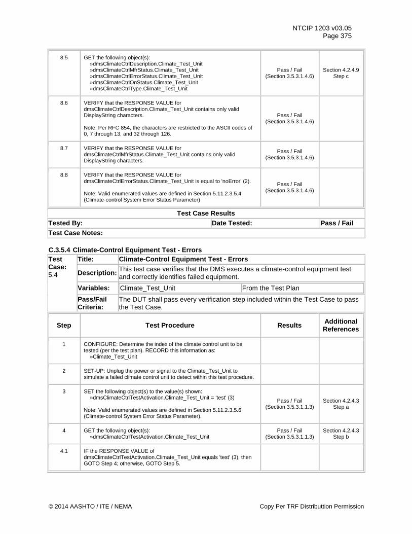
NTCIP 1203 v03.05 Page 375
8.5 GET the following object(s): »dmsClimateCtrlDescription.Climate_Test_Unit »dmsClimateCtrlMfrStatus.Climate_Test_Unit »dmsClimateCtrlErrorStatus.Climate_Test_Unit »dmsClimateCtrlOnStatus.Climate_Test_Unit »dmsClimateCtrlType.Climate_Test_Unit
Pass / Fail (Section 3.5.3.1.4.6)
Section 4.2.4.9 Step c
8.6 VERIFY that the RESPONSE VALUE for dmsClimateCtrlDescription.Climate_Test_Unit contains only valid DisplayString characters. Note: Per RFC 854, the characters are restricted to the ASCII codes of 0, 7 through 13, and 32 through 126.
Pass / Fail (Section 3.5.3.1.4.6)
8.7 VERIFY that the RESPONSE VALUE for dmsClimateCtrlMfrStatus.Climate_Test_Unit contains only valid DisplayString characters.
Pass / Fail (Section 3.5.3.1.4.6)
8.8 VERIFY that the RESPONSE VALUE for dmsClimateCtrlErrorStatus.Climate_Test_Unit is equal to 'noError' (2). Note: Valid enumerated values are defined in Section 5.11.2.3.5.4 (Climate-control System Error Status Parameter)
Pass / Fail (Section 3.5.3.1.4.6)
Test Case Results Tested By: Date Tested: Pass / Fail Test Case Notes: C.3.5.4 Climate-Control Equipment Test - Errors Test Case: 5.4
Title: Climate-Control Equipment Test - Errors
Description: This test case verifies that the DMS executes a climate-control equipment test and correctly identifies failed equipment.
Variables: Climate_Test_Unit From the Test Plan
Pass/Fail Criteria:
The DUT shall pass every verification step included within the Test Case to pass the Test Case.
Step Test Procedure Results Additional References
1 CONFIGURE: Determine the index of the climate control unit to be tested (per the test plan). RECORD this information as: »Climate_Test_Unit
2 SET-UP: Unplug the power or signal to the Climate_Test_Unit to simulate a failed climate control unit to detect within this test procedure.
3 SET the following object(s) to the value(s) shown: »dmsClimateCtrlTestActivation.Climate_Test_Unit = 'test' (3) Note: Valid enumerated values are defined in Section 5.11.2.3.5.6 (Climate-control System Error Status Parameter).
Pass / Fail (Section 3.5.3.1.1.3)
Section 4.2.4.3 Step a
4 GET the following object(s): »dmsClimateCtrlTestActivation.Climate_Test_Unit
Pass / Fail (Section 3.5.3.1.1.3)
Section 4.2.4.3 Step b
4.1 IF the RESPONSE VALUE of dmsClimateCtrlTestActivation.Climate_Test_Unit equals 'test' (3), then GOTO Step 4; otherwise, GOTO Step 5.
© 2014 AASHTO / ITE / NEMA Copy Per TRF Distributtion Permission
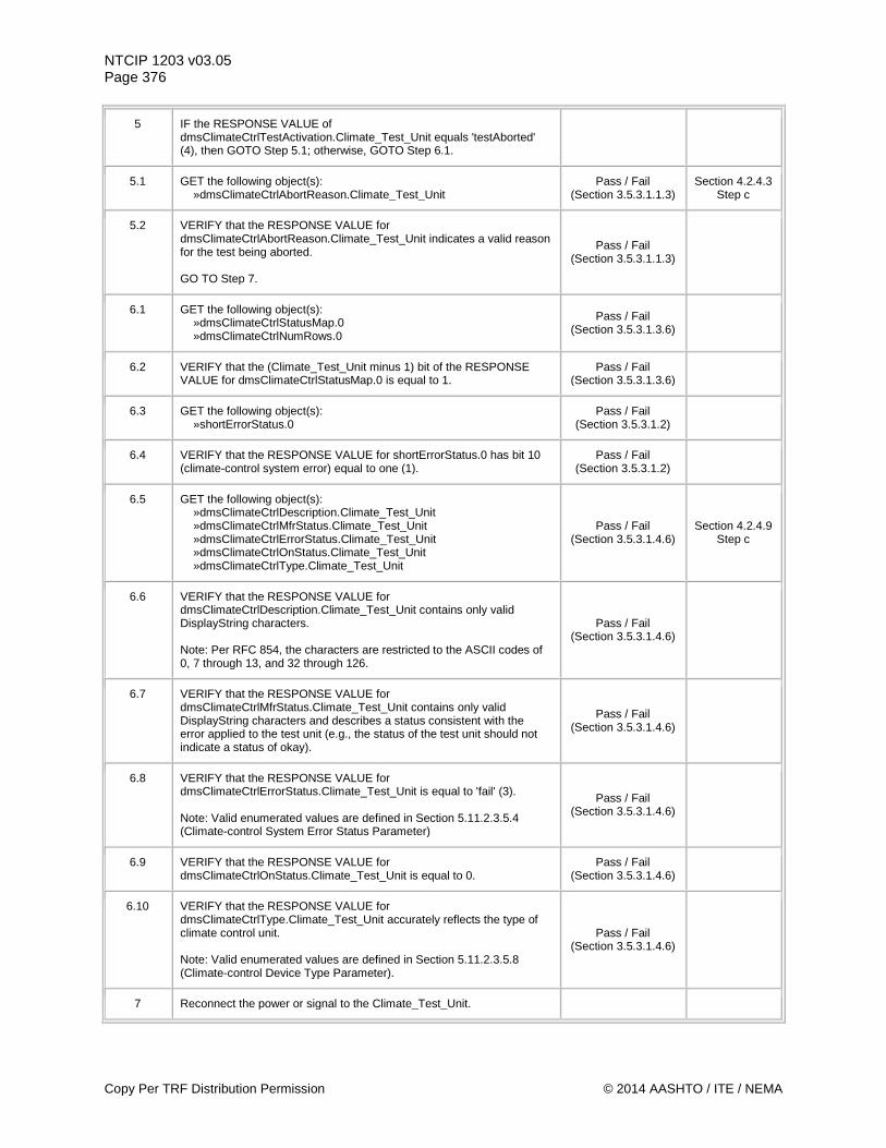
NTCIP 1203 v03.05 Page 376
5 IF the RESPONSE VALUE of dmsClimateCtrlTestActivation.Climate_Test_Unit equals 'testAborted' (4), then GOTO Step 5.1; otherwise, GOTO Step 6.1.
5.1 GET the following object(s): »dmsClimateCtrlAbortReason.Climate_Test_Unit
Pass / Fail (Section 3.5.3.1.1.3)
Section 4.2.4.3 Step c
5.2 VERIFY that the RESPONSE VALUE for dmsClimateCtrlAbortReason.Climate_Test_Unit indicates a valid reason for the test being aborted. GO TO Step 7.
Pass / Fail (Section 3.5.3.1.1.3)
6.1 GET the following object(s): »dmsClimateCtrlStatusMap.0 »dmsClimateCtrlNumRows.0
Pass / Fail (Section 3.5.3.1.3.6)
6.2 VERIFY that the (Climate_Test_Unit minus 1) bit of the RESPONSE VALUE for dmsClimateCtrlStatusMap.0 is equal to 1.
Pass / Fail (Section 3.5.3.1.3.6)
6.3 GET the following object(s): »shortErrorStatus.0
Pass / Fail (Section 3.5.3.1.2)
6.4 VERIFY that the RESPONSE VALUE for shortErrorStatus.0 has bit 10 (climate-control system error) equal to one (1).
Pass / Fail (Section 3.5.3.1.2)
6.5 GET the following object(s): »dmsClimateCtrlDescription.Climate_Test_Unit »dmsClimateCtrlMfrStatus.Climate_Test_Unit »dmsClimateCtrlErrorStatus.Climate_Test_Unit »dmsClimateCtrlOnStatus.Climate_Test_Unit »dmsClimateCtrlType.Climate_Test_Unit
Pass / Fail (Section 3.5.3.1.4.6)
Section 4.2.4.9 Step c
6.6 VERIFY that the RESPONSE VALUE for dmsClimateCtrlDescription.Climate_Test_Unit contains only valid DisplayString characters. Note: Per RFC 854, the characters are restricted to the ASCII codes of 0, 7 through 13, and 32 through 126.
Pass / Fail (Section 3.5.3.1.4.6)
6.7 VERIFY that the RESPONSE VALUE for dmsClimateCtrlMfrStatus.Climate_Test_Unit contains only valid DisplayString characters and describes a status consistent with the error applied to the test unit (e.g., the status of the test unit should not indicate a status of okay).
Pass / Fail (Section 3.5.3.1.4.6)
6.8 VERIFY that the RESPONSE VALUE for dmsClimateCtrlErrorStatus.Climate_Test_Unit is equal to 'fail' (3). Note: Valid enumerated values are defined in Section 5.11.2.3.5.4 (Climate-control System Error Status Parameter)
Pass / Fail (Section 3.5.3.1.4.6)
6.9 VERIFY that the RESPONSE VALUE for dmsClimateCtrlOnStatus.Climate_Test_Unit is equal to 0.
Pass / Fail (Section 3.5.3.1.4.6)
6.10 VERIFY that the RESPONSE VALUE for dmsClimateCtrlType.Climate_Test_Unit accurately reflects the type of climate control unit. Note: Valid enumerated values are defined in Section 5.11.2.3.5.8 (Climate-control Device Type Parameter).
Pass / Fail (Section 3.5.3.1.4.6)
7 Reconnect the power or signal to the Climate_Test_Unit.
Copy Per TRF Distribution Permission © 2014 AASHTO / ITE / NEMA
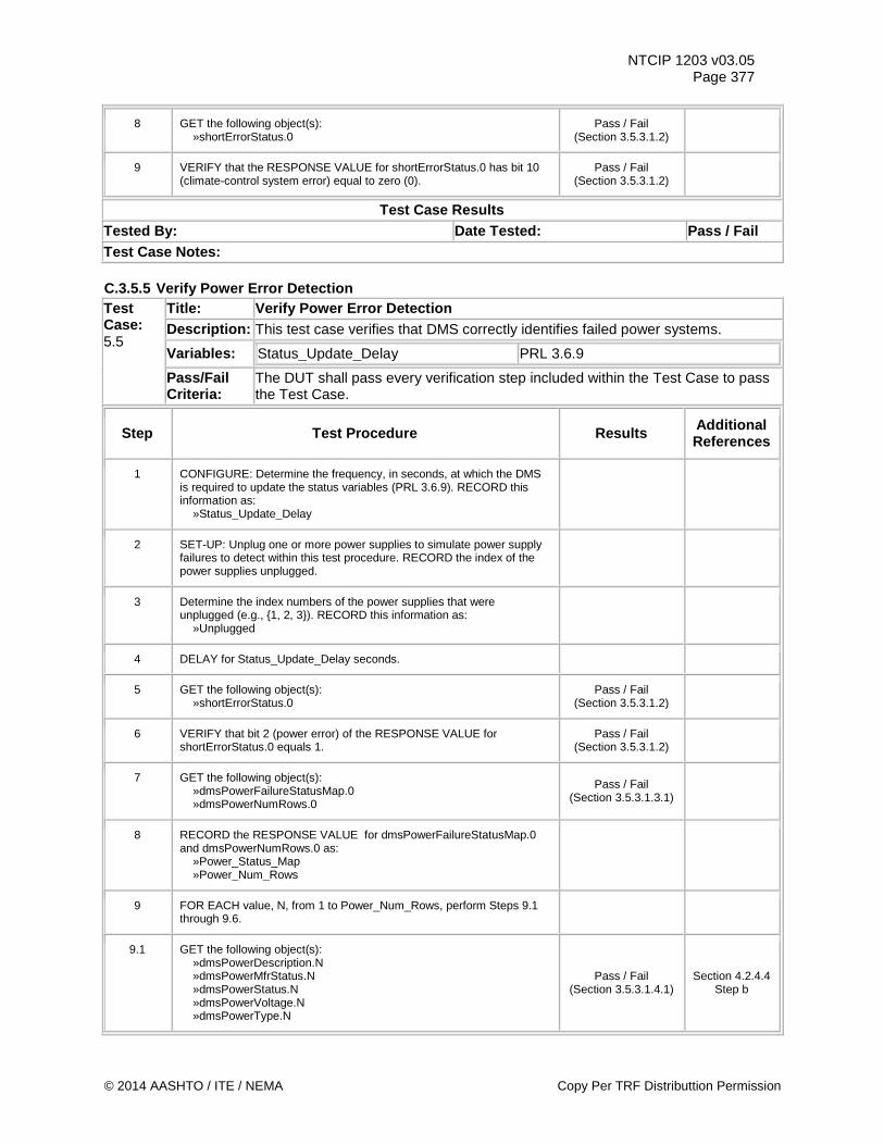
NTCIP 1203 v03.05 Page 377
8 GET the following object(s): »shortErrorStatus.0
Pass / Fail (Section 3.5.3.1.2)
9 VERIFY that the RESPONSE VALUE for shortErrorStatus.0 has bit 10 (climate-control system error) equal to zero (0).
Pass / Fail (Section 3.5.3.1.2)
Test Case Results Tested By: Date Tested: Pass / Fail Test Case Notes: C.3.5.5 Verify Power Error Detection Test Case: 5.5
Title: Verify Power Error Detection Description: This test case verifies that DMS correctly identifies failed power systems.
Variables: Status_Update_Delay PRL 3.6.9
Pass/Fail Criteria:
The DUT shall pass every verification step included within the Test Case to pass the Test Case.
Step Test Procedure Results Additional References
1 CONFIGURE: Determine the frequency, in seconds, at which the DMS is required to update the status variables (PRL 3.6.9). RECORD this information as: »Status_Update_Delay
2 SET-UP: Unplug one or more power supplies to simulate power supply failures to detect within this test procedure. RECORD the index of the power supplies unplugged.
3 Determine the index numbers of the power supplies that were unplugged (e.g., {1, 2, 3}). RECORD this information as: »Unplugged
4 DELAY for Status_Update_Delay seconds.
5 GET the following object(s): »shortErrorStatus.0
Pass / Fail (Section 3.5.3.1.2)
6 VERIFY that bit 2 (power error) of the RESPONSE VALUE for shortErrorStatus.0 equals 1.
Pass / Fail (Section 3.5.3.1.2)
7 GET the following object(s): »dmsPowerFailureStatusMap.0 »dmsPowerNumRows.0
Pass / Fail (Section 3.5.3.1.3.1)
8 RECORD the RESPONSE VALUE for dmsPowerFailureStatusMap.0 and dmsPowerNumRows.0 as: »Power_Status_Map »Power_Num_Rows
9 FOR EACH value, N, from 1 to Power_Num_Rows, perform Steps 9.1 through 9.6.
9.1 GET the following object(s): »dmsPowerDescription.N »dmsPowerMfrStatus.N »dmsPowerStatus.N »dmsPowerVoltage.N »dmsPowerType.N
Pass / Fail (Section 3.5.3.1.4.1)
Section 4.2.4.4 Step b
© 2014 AASHTO / ITE / NEMA Copy Per TRF Distributtion Permission
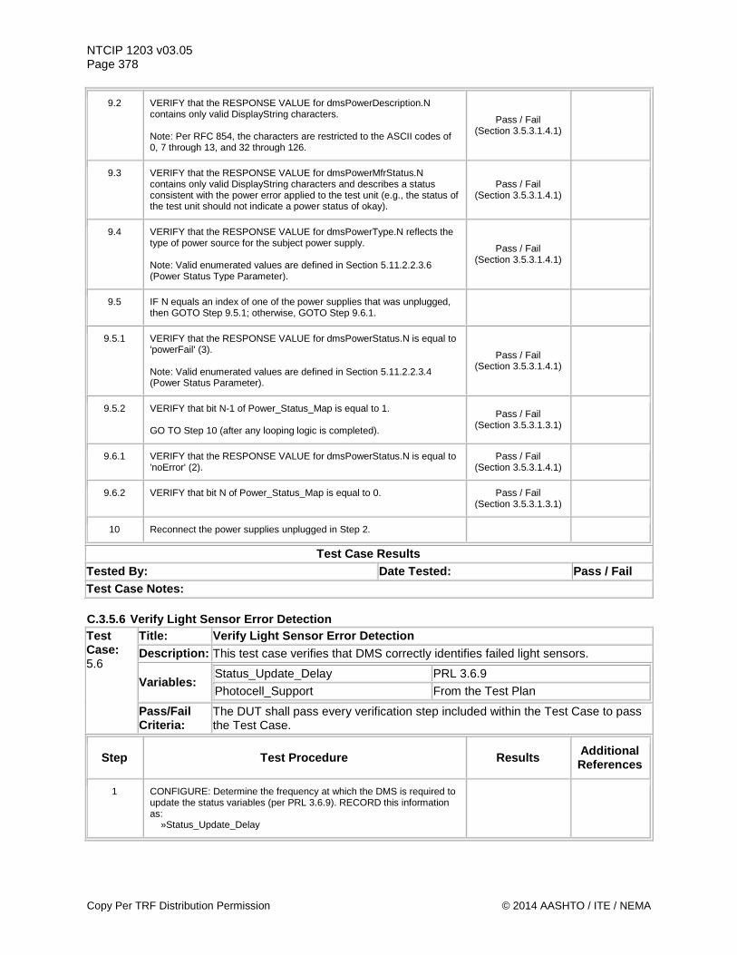
NTCIP 1203 v03.05 Page 378
9.2 VERIFY that the RESPONSE VALUE for dmsPowerDescription.N contains only valid DisplayString characters. Note: Per RFC 854, the characters are restricted to the ASCII codes of 0, 7 through 13, and 32 through 126.
Pass / Fail (Section 3.5.3.1.4.1)
9.3 VERIFY that the RESPONSE VALUE for dmsPowerMfrStatus.N contains only valid DisplayString characters and describes a status consistent with the power error applied to the test unit (e.g., the status of the test unit should not indicate a power status of okay).
Pass / Fail (Section 3.5.3.1.4.1)
9.4 VERIFY that the RESPONSE VALUE for dmsPowerType.N reflects the type of power source for the subject power supply. Note: Valid enumerated values are defined in Section 5.11.2.2.3.6 (Power Status Type Parameter).
Pass / Fail (Section 3.5.3.1.4.1)
9.5 IF N equals an index of one of the power supplies that was unplugged, then GOTO Step 9.5.1; otherwise, GOTO Step 9.6.1.
9.5.1 VERIFY that the RESPONSE VALUE for dmsPowerStatus.N is equal to 'powerFail' (3). Note: Valid enumerated values are defined in Section 5.11.2.2.3.4 (Power Status Parameter).
Pass / Fail (Section 3.5.3.1.4.1)
9.5.2 VERIFY that bit N-1 of Power_Status_Map is equal to 1. GO TO Step 10 (after any looping logic is completed).
Pass / Fail (Section 3.5.3.1.3.1)
9.6.1 VERIFY that the RESPONSE VALUE for dmsPowerStatus.N is equal to 'noError' (2).
Pass / Fail (Section 3.5.3.1.4.1)
9.6.2 VERIFY that bit N of Power_Status_Map is equal to 0. Pass / Fail (Section 3.5.3.1.3.1)
10 Reconnect the power supplies unplugged in Step 2.
Test Case Results Tested By: Date Tested: Pass / Fail Test Case Notes: C.3.5.6 Verify Light Sensor Error Detection Test Case: 5.6
Title: Verify Light Sensor Error Detection Description: This test case verifies that DMS correctly identifies failed light sensors.
Variables: Status_Update_Delay PRL 3.6.9 Photocell_Support From the Test Plan
Pass/Fail Criteria:
The DUT shall pass every verification step included within the Test Case to pass the Test Case.
Step Test Procedure Results Additional References
1 CONFIGURE: Determine the frequency at which the DMS is required to update the status variables (per PRL 3.6.9). RECORD this information as: »Status_Update_Delay
Copy Per TRF Distribution Permission © 2014 AASHTO / ITE / NEMA
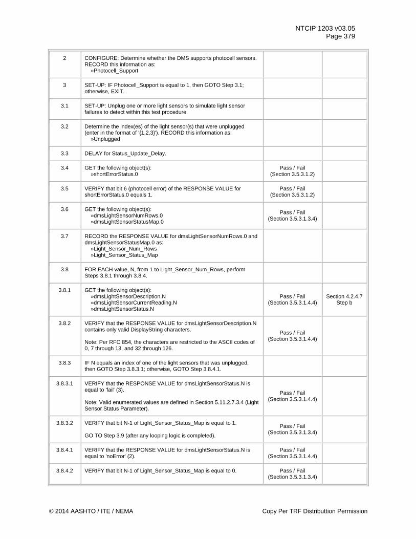
NTCIP 1203 v03.05 Page 379
2 CONFIGURE: Determine whether the DMS supports photocell sensors. RECORD this information as: »Photocell_Support
3 SET-UP: IF Photocell_Support is equal to 1, then GOTO Step 3.1; otherwise, EXIT.
3.1 SET-UP: Unplug one or more light sensors to simulate light sensor failures to detect within this test procedure.
3.2 Determine the index(es) of the light sensor(s) that were unplugged (enter in the format of '{1,2,3}'). RECORD this information as: »Unplugged
3.3 DELAY for Status_Update_Delay.
3.4 GET the following object(s): »shortErrorStatus.0
Pass / Fail (Section 3.5.3.1.2)
3.5 VERIFY that bit 6 (photocell error) of the RESPONSE VALUE for shortErrorStatus.0 equals 1.
Pass / Fail (Section 3.5.3.1.2)
3.6 GET the following object(s): »dmsLightSensorNumRows.0 »dmsLightSensorStatusMap.0
Pass / Fail (Section 3.5.3.1.3.4)
3.7 RECORD the RESPONSE VALUE for dmsLightSensorNumRows.0 and dmsLightSensorStatusMap.0 as: »Light_Sensor_Num_Rows »Light_Sensor_Status_Map
3.8 FOR EACH value, N, from 1 to Light_Sensor_Num_Rows, perform Steps 3.8.1 through 3.8.4.
3.8.1 GET the following object(s): »dmsLightSensorDescription.N »dmsLightSensorCurrentReading.N »dmsLightSensorStatus.N
Pass / Fail (Section 3.5.3.1.4.4)
Section 4.2.4.7 Step b
3.8.2 VERIFY that the RESPONSE VALUE for dmsLightSensorDescription.N contains only valid DisplayString characters. Note: Per RFC 854, the characters are restricted to the ASCII codes of 0, 7 through 13, and 32 through 126.
Pass / Fail (Section 3.5.3.1.4.4)
3.8.3 IF N equals an index of one of the light sensors that was unplugged, then GOTO Step 3.8.3.1; otherwise, GOTO Step 3.8.4.1.
3.8.3.1 VERIFY that the RESPONSE VALUE for dmsLightSensorStatus.N is equal to 'fail' (3). Note: Valid enumerated values are defined in Section 5.11.2.7.3.4 (Light Sensor Status Parameter).
Pass / Fail (Section 3.5.3.1.4.4)
3.8.3.2 VERIFY that bit N-1 of Light_Sensor_Status_Map is equal to 1. GO TO Step 3.9 (after any looping logic is completed).
Pass / Fail (Section 3.5.3.1.3.4)
3.8.4.1 VERIFY that the RESPONSE VALUE for dmsLightSensorStatus.N is equal to 'noError' (2).
Pass / Fail (Section 3.5.3.1.4.4)
3.8.4.2 VERIFY that bit N-1 of Light_Sensor_Status_Map is equal to 0. Pass / Fail (Section 3.5.3.1.3.4)
© 2014 AASHTO / ITE / NEMA Copy Per TRF Distributtion Permission
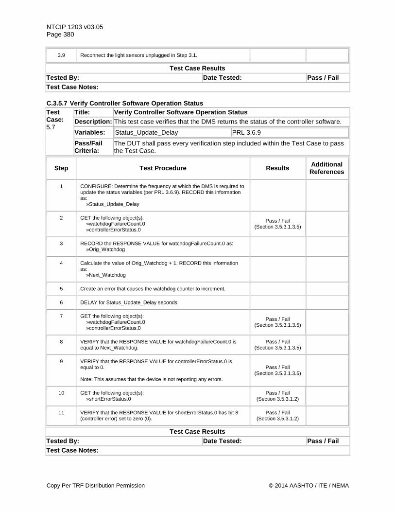
NTCIP 1203 v03.05 Page 380
3.9 Reconnect the light sensors unplugged in Step 3.1.
Test Case Results Tested By: Date Tested: Pass / Fail Test Case Notes: C.3.5.7 Verify Controller Software Operation Status Test Case: 5.7
Title: Verify Controller Software Operation Status Description: This test case verifies that the DMS returns the status of the controller software.
Variables: Status_Update_Delay PRL 3.6.9
Pass/Fail Criteria:
The DUT shall pass every verification step included within the Test Case to pass the Test Case.
Step Test Procedure Results Additional References
1 CONFIGURE: Determine the frequency at which the DMS is required to update the status variables (per PRL 3.6.9). RECORD this information as: »Status_Update_Delay
2 GET the following object(s): »watchdogFailureCount.0 »controllerErrorStatus.0
Pass / Fail (Section 3.5.3.1.3.5)
3 RECORD the RESPONSE VALUE for watchdogFailureCount.0 as: »Orig_Watchdog
4 Calculate the value of Orig_Watchdog + 1. RECORD this information as: »Next_Watchdog
5 Create an error that causes the watchdog counter to increment.
6 DELAY for Status_Update_Delay seconds.
7 GET the following object(s): »watchdogFailureCount.0 »controllerErrorStatus.0
Pass / Fail (Section 3.5.3.1.3.5)
8 VERIFY that the RESPONSE VALUE for watchdogFailureCount.0 is equal to Next_Watchdog.
Pass / Fail (Section 3.5.3.1.3.5)
9 VERIFY that the RESPONSE VALUE for controllerErrorStatus.0 is equal to 0. Note: This assumes that the device is not reporting any errors.
Pass / Fail (Section 3.5.3.1.3.5)
10 GET the following object(s): »shortErrorStatus.0
Pass / Fail (Section 3.5.3.1.2)
11 VERIFY that the RESPONSE VALUE for shortErrorStatus.0 has bit 8 (controller error) set to zero (0).
Pass / Fail (Section 3.5.3.1.2)
Test Case Results Tested By: Date Tested: Pass / Fail Test Case Notes:
Copy Per TRF Distribution Permission © 2014 AASHTO / ITE / NEMA
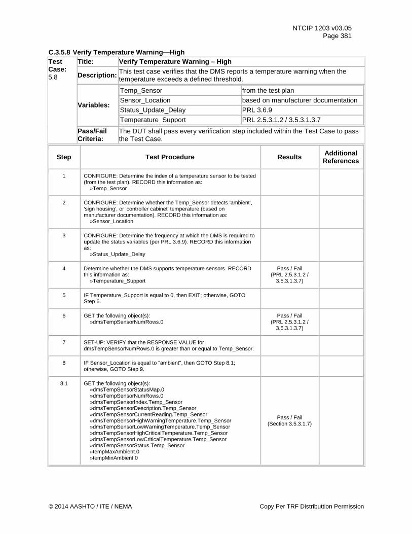
NTCIP 1203 v03.05 Page 381
C.3.5.8 Verify Temperature Warning—High Test Case: 5.8
Title: Verify Temperature Warning – High
Description: This test case verifies that the DMS reports a temperature warning when the temperature exceeds a defined threshold.
Variables:
Temp_Sensor from the test plan Sensor_Location based on manufacturer documentation Status_Update_Delay PRL 3.6.9 Temperature_Support PRL 2.5.3.1.2 / 3.5.3.1.3.7
Pass/Fail Criteria:
The DUT shall pass every verification step included within the Test Case to pass the Test Case.
Step Test Procedure Results Additional References
1 CONFIGURE: Determine the index of a temperature sensor to be tested (from the test plan). RECORD this information as: »Temp_Sensor
2 CONFIGURE: Determine whether the Temp_Sensor detects 'ambient', 'sign housing', or 'controller cabinet' temperature (based on manufacturer documentation). RECORD this information as: »Sensor_Location
3 CONFIGURE: Determine the frequency at which the DMS is required to update the status variables (per PRL 3.6.9). RECORD this information as: »Status_Update_Delay
4 Determine whether the DMS supports temperature sensors. RECORD this information as: »Temperature_Support
Pass / Fail (PRL 2.5.3.1.2 /
3.5.3.1.3.7)
5 IF Temperature_Support is equal to 0, then EXIT; otherwise, GOTO Step 6.
6 GET the following object(s): »dmsTempSensorNumRows.0
Pass / Fail (PRL 2.5.3.1.2 /
3.5.3.1.3.7)
7 SET-UP: VERIFY that the RESPONSE VALUE for dmsTempSensorNumRows.0 is greater than or equal to Temp_Sensor.
8 IF Sensor_Location is equal to "ambient", then GOTO Step 8.1; otherwise, GOTO Step 9.
8.1 GET the following object(s): »dmsTempSensorStatusMap.0 »dmsTempSensorNumRows.0 »dmsTempSensorIndex.Temp_Sensor »dmsTempSensorDescription.Temp_Sensor »dmsTempSensorCurrentReading.Temp_Sensor »dmsTempSensorHighWarningTemperature.Temp_Sensor »dmsTempSensorLowWarningTemperature.Temp_Sensor »dmsTempSensorHighCriticalTemperature.Temp_Sensor »dmsTempSensorLowCriticalTemperature.Temp_Sensor »dmsTempSensorStatus.Temp_Sensor »tempMaxAmbient.0 »tempMinAmbient.0
Pass / Fail (Section 3.5.3.1.7)
© 2014 AASHTO / ITE / NEMA Copy Per TRF Distributtion Permission
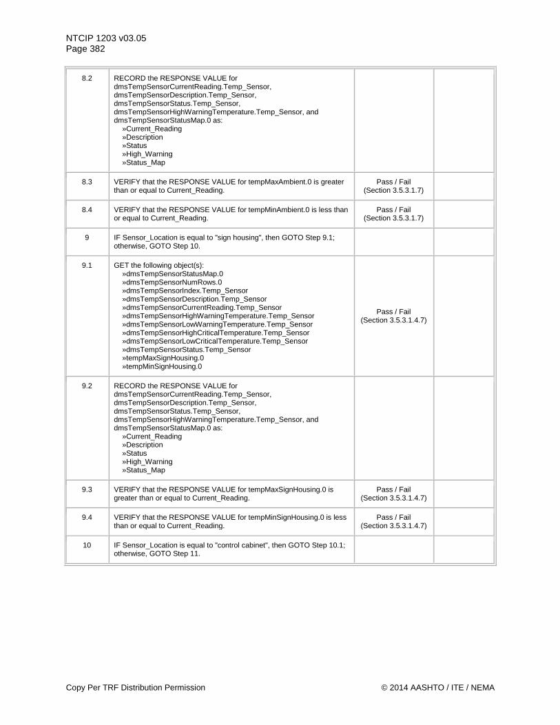
NTCIP 1203 v03.05 Page 382
8.2 RECORD the RESPONSE VALUE for dmsTempSensorCurrentReading.Temp_Sensor, dmsTempSensorDescription.Temp_Sensor, dmsTempSensorStatus.Temp_Sensor, dmsTempSensorHighWarningTemperature.Temp_Sensor, and dmsTempSensorStatusMap.0 as: »Current_Reading »Description »Status »High_Warning »Status_Map
8.3 VERIFY that the RESPONSE VALUE for tempMaxAmbient.0 is greater than or equal to Current_Reading.
Pass / Fail (Section 3.5.3.1.7)
8.4 VERIFY that the RESPONSE VALUE for tempMinAmbient.0 is less than or equal to Current_Reading.
Pass / Fail (Section 3.5.3.1.7)
9 IF Sensor_Location is equal to "sign housing", then GOTO Step 9.1; otherwise, GOTO Step 10.
9.1 GET the following object(s): »dmsTempSensorStatusMap.0 »dmsTempSensorNumRows.0 »dmsTempSensorIndex.Temp_Sensor »dmsTempSensorDescription.Temp_Sensor »dmsTempSensorCurrentReading.Temp_Sensor »dmsTempSensorHighWarningTemperature.Temp_Sensor »dmsTempSensorLowWarningTemperature.Temp_Sensor »dmsTempSensorHighCriticalTemperature.Temp_Sensor »dmsTempSensorLowCriticalTemperature.Temp_Sensor »dmsTempSensorStatus.Temp_Sensor »tempMaxSignHousing.0 »tempMinSignHousing.0
Pass / Fail (Section 3.5.3.1.4.7)
9.2 RECORD the RESPONSE VALUE for dmsTempSensorCurrentReading.Temp_Sensor, dmsTempSensorDescription.Temp_Sensor, dmsTempSensorStatus.Temp_Sensor, dmsTempSensorHighWarningTemperature.Temp_Sensor, and dmsTempSensorStatusMap.0 as: »Current_Reading »Description »Status »High_Warning »Status_Map
9.3 VERIFY that the RESPONSE VALUE for tempMaxSignHousing.0 is greater than or equal to Current_Reading.
Pass / Fail (Section 3.5.3.1.4.7)
9.4 VERIFY that the RESPONSE VALUE for tempMinSignHousing.0 is less than or equal to Current_Reading.
Pass / Fail (Section 3.5.3.1.4.7)
10 IF Sensor_Location is equal to "control cabinet", then GOTO Step 10.1; otherwise, GOTO Step 11.
Copy Per TRF Distribution Permission © 2014 AASHTO / ITE / NEMA
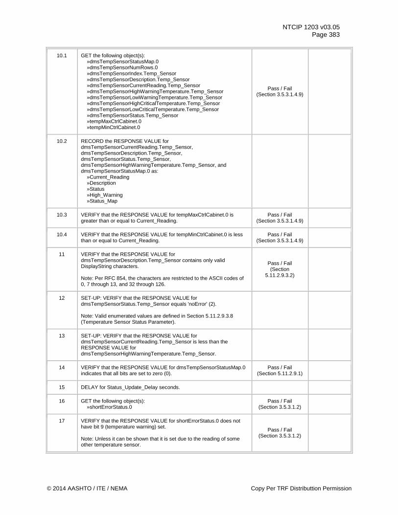
NTCIP 1203 v03.05 Page 383
10.1 GET the following object(s): »dmsTempSensorStatusMap.0 »dmsTempSensorNumRows.0 »dmsTempSensorIndex.Temp_Sensor »dmsTempSensorDescription.Temp_Sensor »dmsTempSensorCurrentReading.Temp_Sensor »dmsTempSensorHighWarningTemperature.Temp_Sensor »dmsTempSensorLowWarningTemperature.Temp_Sensor »dmsTempSensorHighCriticalTemperature.Temp_Sensor »dmsTempSensorLowCriticalTemperature.Temp_Sensor »dmsTempSensorStatus.Temp_Sensor »tempMaxCtrlCabinet.0 »tempMinCtrlCabinet.0
Pass / Fail (Section 3.5.3.1.4.9)
10.2 RECORD the RESPONSE VALUE for dmsTempSensorCurrentReading.Temp_Sensor, dmsTempSensorDescription.Temp_Sensor, dmsTempSensorStatus.Temp_Sensor, dmsTempSensorHighWarningTemperature.Temp_Sensor, and dmsTempSensorStatusMap.0 as: »Current_Reading »Description »Status »High_Warning »Status_Map
10.3 VERIFY that the RESPONSE VALUE for tempMaxCtrlCabinet.0 is greater than or equal to Current_Reading.
Pass / Fail (Section 3.5.3.1.4.9)
10.4 VERIFY that the RESPONSE VALUE for tempMinCtrlCabinet.0 is less than or equal to Current_Reading.
Pass / Fail (Section 3.5.3.1.4.9)
11 VERIFY that the RESPONSE VALUE for dmsTempSensorDescription.Temp_Sensor contains only valid DisplayString characters. Note: Per RFC 854, the characters are restricted to the ASCII codes of 0, 7 through 13, and 32 through 126.
Pass / Fail (Section
5.11.2.9.3.2)
12 SET-UP: VERIFY that the RESPONSE VALUE for dmsTempSensorStatus.Temp_Sensor equals 'noError' (2). Note: Valid enumerated values are defined in Section 5.11.2.9.3.8 (Temperature Sensor Status Parameter).
13 SET-UP: VERIFY that the RESPONSE VALUE for dmsTempSensorCurrentReading.Temp_Sensor is less than the RESPONSE VALUE for dmsTempSensorHighWarningTemperature.Temp_Sensor.
14 VERIFY that the RESPONSE VALUE for dmsTempSensorStatusMap.0 indicates that all bits are set to zero (0).
Pass / Fail (Section 5.11.2.9.1)
15 DELAY for Status_Update_Delay seconds.
16 GET the following object(s): »shortErrorStatus.0
Pass / Fail (Section 3.5.3.1.2)
17 VERIFY that the RESPONSE VALUE for shortErrorStatus.0 does not have bit 9 (temperature warning) set. Note: Unless it can be shown that it is set due to the reading of some other temperature sensor.
Pass / Fail (Section 3.5.3.1.2)
© 2014 AASHTO / ITE / NEMA Copy Per TRF Distributtion Permission
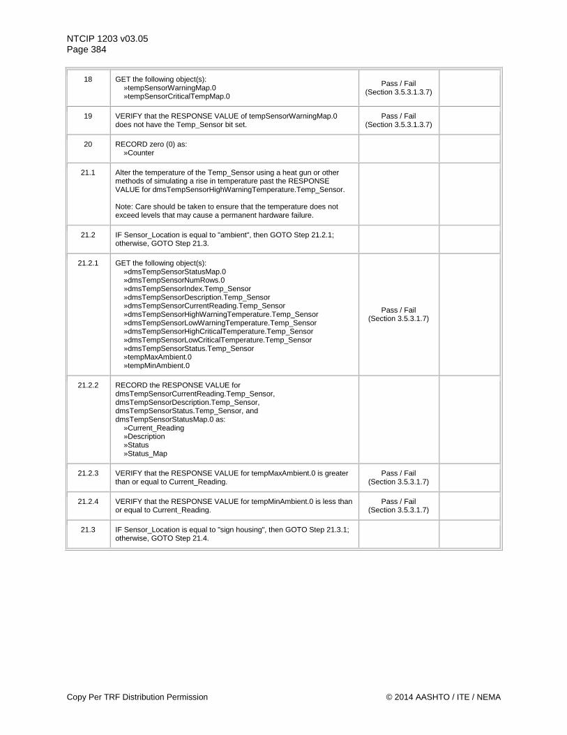
NTCIP 1203 v03.05 Page 384
18 GET the following object(s): »tempSensorWarningMap.0 »tempSensorCriticalTempMap.0
Pass / Fail (Section 3.5.3.1.3.7)
19 VERIFY that the RESPONSE VALUE of tempSensorWarningMap.0 does not have the Temp_Sensor bit set.
Pass / Fail (Section 3.5.3.1.3.7)
20 RECORD zero (0) as: »Counter
21.1 Alter the temperature of the Temp_Sensor using a heat gun or other methods of simulating a rise in temperature past the RESPONSE VALUE for dmsTempSensorHighWarningTemperature.Temp_Sensor. Note: Care should be taken to ensure that the temperature does not exceed levels that may cause a permanent hardware failure.
21.2 IF Sensor_Location is equal to "ambient", then GOTO Step 21.2.1; otherwise, GOTO Step 21.3.
21.2.1 GET the following object(s): »dmsTempSensorStatusMap.0 »dmsTempSensorNumRows.0 »dmsTempSensorIndex.Temp_Sensor »dmsTempSensorDescription.Temp_Sensor »dmsTempSensorCurrentReading.Temp_Sensor »dmsTempSensorHighWarningTemperature.Temp_Sensor »dmsTempSensorLowWarningTemperature.Temp_Sensor »dmsTempSensorHighCriticalTemperature.Temp_Sensor »dmsTempSensorLowCriticalTemperature.Temp_Sensor »dmsTempSensorStatus.Temp_Sensor »tempMaxAmbient.0 »tempMinAmbient.0
Pass / Fail (Section 3.5.3.1.7)
21.2.2 RECORD the RESPONSE VALUE for dmsTempSensorCurrentReading.Temp_Sensor, dmsTempSensorDescription.Temp_Sensor, dmsTempSensorStatus.Temp_Sensor, and dmsTempSensorStatusMap.0 as: »Current_Reading »Description »Status »Status_Map
21.2.3 VERIFY that the RESPONSE VALUE for tempMaxAmbient.0 is greater than or equal to Current_Reading.
Pass / Fail (Section 3.5.3.1.7)
21.2.4 VERIFY that the RESPONSE VALUE for tempMinAmbient.0 is less than or equal to Current_Reading.
Pass / Fail (Section 3.5.3.1.7)
21.3 IF Sensor_Location is equal to "sign housing", then GOTO Step 21.3.1; otherwise, GOTO Step 21.4.
Copy Per TRF Distribution Permission © 2014 AASHTO / ITE / NEMA
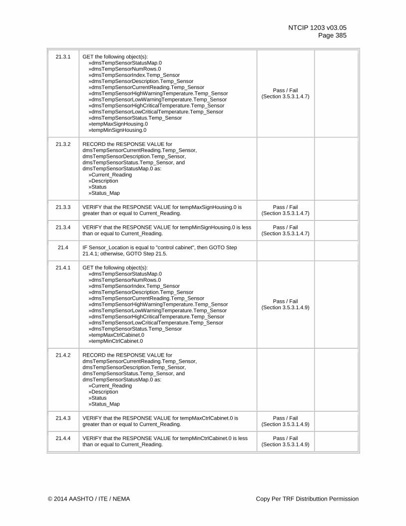
NTCIP 1203 v03.05 Page 385
21.3.1 GET the following object(s): »dmsTempSensorStatusMap.0 »dmsTempSensorNumRows.0 »dmsTempSensorIndex.Temp_Sensor »dmsTempSensorDescription.Temp_Sensor »dmsTempSensorCurrentReading.Temp_Sensor »dmsTempSensorHighWarningTemperature.Temp_Sensor »dmsTempSensorLowWarningTemperature.Temp_Sensor »dmsTempSensorHighCriticalTemperature.Temp_Sensor »dmsTempSensorLowCriticalTemperature.Temp_Sensor »dmsTempSensorStatus.Temp_Sensor »tempMaxSignHousing.0 »tempMinSignHousing.0
Pass / Fail (Section 3.5.3.1.4.7)
21.3.2 RECORD the RESPONSE VALUE for dmsTempSensorCurrentReading.Temp_Sensor, dmsTempSensorDescription.Temp_Sensor, dmsTempSensorStatus.Temp_Sensor, and dmsTempSensorStatusMap.0 as: »Current_Reading »Description »Status »Status_Map
21.3.3 VERIFY that the RESPONSE VALUE for tempMaxSignHousing.0 is greater than or equal to Current_Reading.
Pass / Fail (Section 3.5.3.1.4.7)
21.3.4 VERIFY that the RESPONSE VALUE for tempMinSignHousing.0 is less than or equal to Current_Reading.
Pass / Fail (Section 3.5.3.1.4.7)
21.4 IF Sensor_Location is equal to "control cabinet", then GOTO Step 21.4.1; otherwise, GOTO Step 21.5.
21.4.1 GET the following object(s): »dmsTempSensorStatusMap.0 »dmsTempSensorNumRows.0 »dmsTempSensorIndex.Temp_Sensor »dmsTempSensorDescription.Temp_Sensor »dmsTempSensorCurrentReading.Temp_Sensor »dmsTempSensorHighWarningTemperature.Temp_Sensor »dmsTempSensorLowWarningTemperature.Temp_Sensor »dmsTempSensorHighCriticalTemperature.Temp_Sensor »dmsTempSensorLowCriticalTemperature.Temp_Sensor »dmsTempSensorStatus.Temp_Sensor »tempMaxCtrlCabinet.0 »tempMinCtrlCabinet.0
Pass / Fail (Section 3.5.3.1.4.9)
21.4.2 RECORD the RESPONSE VALUE for dmsTempSensorCurrentReading.Temp_Sensor, dmsTempSensorDescription.Temp_Sensor, dmsTempSensorStatus.Temp_Sensor, and dmsTempSensorStatusMap.0 as: »Current_Reading »Description »Status »Status_Map
21.4.3 VERIFY that the RESPONSE VALUE for tempMaxCtrlCabinet.0 is greater than or equal to Current_Reading.
Pass / Fail (Section 3.5.3.1.4.9)
21.4.4 VERIFY that the RESPONSE VALUE for tempMinCtrlCabinet.0 is less than or equal to Current_Reading.
Pass / Fail (Section 3.5.3.1.4.9)
© 2014 AASHTO / ITE / NEMA Copy Per TRF Distributtion Permission
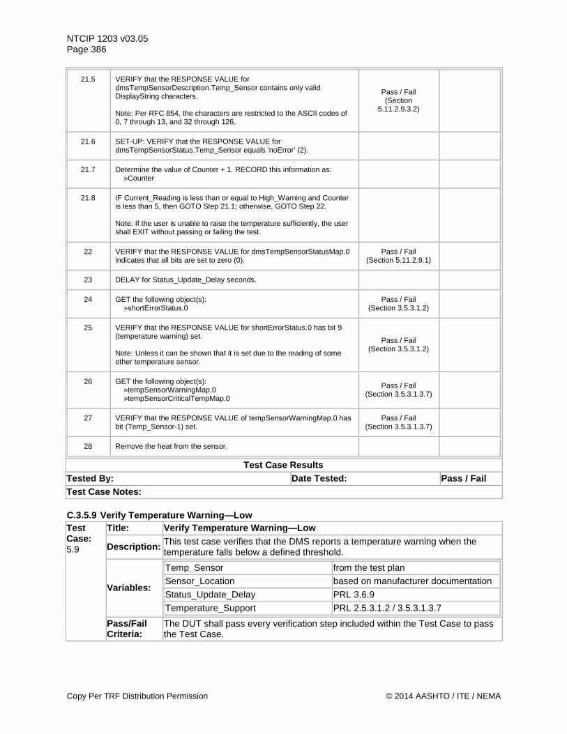
NTCIP 1203 v03.05 Page 386
21.5 VERIFY that the RESPONSE VALUE for dmsTempSensorDescription.Temp_Sensor contains only valid DisplayString characters. Note: Per RFC 854, the characters are restricted to the ASCII codes of 0, 7 through 13, and 32 through 126.
Pass / Fail (Section
5.11.2.9.3.2)
21.6 SET-UP: VERIFY that the RESPONSE VALUE for dmsTempSensorStatus.Temp_Sensor equals 'noError' (2).
21.7 Determine the value of Counter + 1. RECORD this information as: »Counter
21.8 IF Current_Reading is less than or equal to High_Warning and Counter is less than 5, then GOTO Step 21.1; otherwise, GOTO Step 22. Note: If the user is unable to raise the temperature sufficiently, the user shall EXIT without passing or failing the test.
22 VERIFY that the RESPONSE VALUE for dmsTempSensorStatusMap.0 indicates that all bits are set to zero (0).
Pass / Fail (Section 5.11.2.9.1)
23 DELAY for Status_Update_Delay seconds.
24 GET the following object(s): »shortErrorStatus.0
Pass / Fail (Section 3.5.3.1.2)
25 VERIFY that the RESPONSE VALUE for shortErrorStatus.0 has bit 9 (temperature warning) set. Note: Unless it can be shown that it is set due to the reading of some other temperature sensor.
Pass / Fail (Section 3.5.3.1.2)
26 GET the following object(s): »tempSensorWarningMap.0 »tempSensorCriticalTempMap.0
Pass / Fail (Section 3.5.3.1.3.7)
27 VERIFY that the RESPONSE VALUE of tempSensorWarningMap.0 has bit (Temp_Sensor-1) set.
Pass / Fail (Section 3.5.3.1.3.7)
28 Remove the heat from the sensor.
Test Case Results Tested By: Date Tested: Pass / Fail Test Case Notes: C.3.5.9 Verify Temperature Warning—Low Test Case: 5.9
Title: Verify Temperature Warning—Low
Description: This test case verifies that the DMS reports a temperature warning when the temperature falls below a defined threshold.
Variables:
Temp_Sensor from the test plan Sensor_Location based on manufacturer documentation Status_Update_Delay PRL 3.6.9 Temperature_Support PRL 2.5.3.1.2 / 3.5.3.1.3.7
Pass/Fail Criteria:
The DUT shall pass every verification step included within the Test Case to pass the Test Case.
Copy Per TRF Distribution Permission © 2014 AASHTO / ITE / NEMA
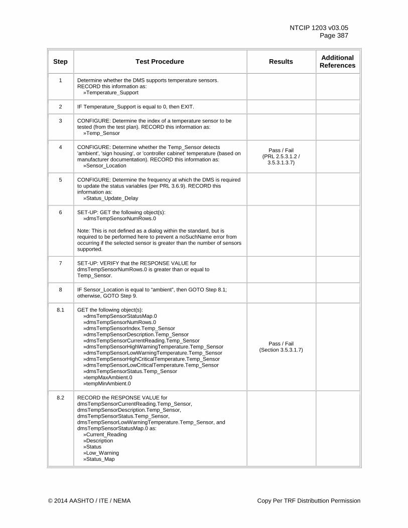
NTCIP 1203 v03.05 Page 387
Step Test Procedure Results Additional References
1 Determine whether the DMS supports temperature sensors. RECORD this information as: »Temperature_Support
2 IF Temperature_Support is equal to 0, then EXIT.
3 CONFIGURE: Determine the index of a temperature sensor to be tested (from the test plan). RECORD this information as: »Temp_Sensor
4 CONFIGURE: Determine whether the Temp_Sensor detects 'ambient', 'sign housing', or 'controller cabinet' temperature (based on manufacturer documentation). RECORD this information as: »Sensor_Location
Pass / Fail (PRL 2.5.3.1.2 /
3.5.3.1.3.7)
5 CONFIGURE: Determine the frequency at which the DMS is required to update the status variables (per PRL 3.6.9). RECORD this information as: »Status_Update_Delay
6 SET-UP: GET the following object(s): »dmsTempSensorNumRows.0 Note: This is not defined as a dialog within the standard, but is required to be performed here to prevent a noSuchName error from occurring if the selected sensor is greater than the number of sensors supported.
7 SET-UP: VERIFY that the RESPONSE VALUE for dmsTempSensorNumRows.0 is greater than or equal to Temp_Sensor.
8 IF Sensor_Location is equal to “ambient”, then GOTO Step 8.1; otherwise, GOTO Step 9.
8.1 GET the following object(s): »dmsTempSensorStatusMap.0 »dmsTempSensorNumRows.0 »dmsTempSensorIndex.Temp_Sensor »dmsTempSensorDescription.Temp_Sensor »dmsTempSensorCurrentReading.Temp_Sensor »dmsTempSensorHighWarningTemperature.Temp_Sensor »dmsTempSensorLowWarningTemperature.Temp_Sensor »dmsTempSensorHighCriticalTemperature.Temp_Sensor »dmsTempSensorLowCriticalTemperature.Temp_Sensor »dmsTempSensorStatus.Temp_Sensor »tempMaxAmbient.0 »tempMinAmbient.0
Pass / Fail (Section 3.5.3.1.7)
8.2 RECORD the RESPONSE VALUE for dmsTempSensorCurrentReading.Temp_Sensor, dmsTempSensorDescription.Temp_Sensor, dmsTempSensorStatus.Temp_Sensor, dmsTempSensorLowWarningTemperature.Temp_Sensor, and dmsTempSensorStatusMap.0 as: »Current_Reading »Description »Status »Low_Warning »Status_Map
© 2014 AASHTO / ITE / NEMA Copy Per TRF Distributtion Permission
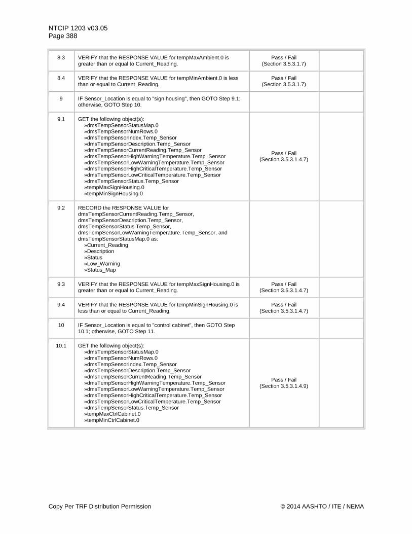
NTCIP 1203 v03.05 Page 388
8.3 VERIFY that the RESPONSE VALUE for tempMaxAmbient.0 is greater than or equal to Current_Reading.
Pass / Fail (Section 3.5.3.1.7)
8.4 VERIFY that the RESPONSE VALUE for tempMinAmbient.0 is less than or equal to Current_Reading.
Pass / Fail (Section 3.5.3.1.7)
9 IF Sensor_Location is equal to "sign housing", then GOTO Step 9.1; otherwise, GOTO Step 10.
9.1 GET the following object(s): »dmsTempSensorStatusMap.0 »dmsTempSensorNumRows.0 »dmsTempSensorIndex.Temp_Sensor »dmsTempSensorDescription.Temp_Sensor »dmsTempSensorCurrentReading.Temp_Sensor »dmsTempSensorHighWarningTemperature.Temp_Sensor »dmsTempSensorLowWarningTemperature.Temp_Sensor »dmsTempSensorHighCriticalTemperature.Temp_Sensor »dmsTempSensorLowCriticalTemperature.Temp_Sensor »dmsTempSensorStatus.Temp_Sensor »tempMaxSignHousing.0 »tempMinSignHousing.0
Pass / Fail (Section 3.5.3.1.4.7)
9.2 RECORD the RESPONSE VALUE for dmsTempSensorCurrentReading.Temp_Sensor, dmsTempSensorDescription.Temp_Sensor, dmsTempSensorStatus.Temp_Sensor, dmsTempSensorLowWarningTemperature.Temp_Sensor, and dmsTempSensorStatusMap.0 as: »Current_Reading »Description »Status »Low_Warning »Status_Map
9.3 VERIFY that the RESPONSE VALUE for tempMaxSignHousing.0 is greater than or equal to Current_Reading.
Pass / Fail (Section 3.5.3.1.4.7)
9.4 VERIFY that the RESPONSE VALUE for tempMinSignHousing.0 is less than or equal to Current_Reading.
Pass / Fail (Section 3.5.3.1.4.7)
10 IF Sensor_Location is equal to "control cabinet", then GOTO Step 10.1; otherwise, GOTO Step 11.
10.1 GET the following object(s): »dmsTempSensorStatusMap.0 »dmsTempSensorNumRows.0 »dmsTempSensorIndex.Temp_Sensor »dmsTempSensorDescription.Temp_Sensor »dmsTempSensorCurrentReading.Temp_Sensor »dmsTempSensorHighWarningTemperature.Temp_Sensor »dmsTempSensorLowWarningTemperature.Temp_Sensor »dmsTempSensorHighCriticalTemperature.Temp_Sensor »dmsTempSensorLowCriticalTemperature.Temp_Sensor »dmsTempSensorStatus.Temp_Sensor »tempMaxCtrlCabinet.0 »tempMinCtrlCabinet.0
Pass / Fail (Section 3.5.3.1.4.9)
Copy Per TRF Distribution Permission © 2014 AASHTO / ITE / NEMA
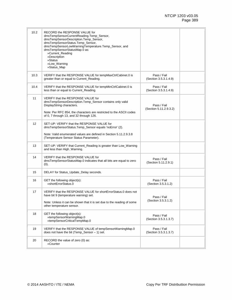
NTCIP 1203 v03.05 Page 389
10.2 RECORD the RESPONSE VALUE for dmsTempSensorCurrentReading.Temp_Sensor, dmsTempSensorDescription.Temp_Sensor, dmsTempSensorStatus.Temp_Sensor, dmsTempSensorLowWarningTemperature.Temp_Sensor, and dmsTempSensorStatusMap.0 as: »Current_Reading »Description »Status »Low_Warning »Status_Map
10.3 VERIFY that the RESPONSE VALUE for tempMaxCtrlCabinet.0 is greater than or equal to Current_Reading.
Pass / Fail (Section 3.5.3.1.4.9)
10.4 VERIFY that the RESPONSE VALUE for tempMinCtrlCabinet.0 is less than or equal to Current_Reading.
Pass / Fail (Section 3.5.3.1.4.9)
11 VERIFY that the RESPONSE VALUE for dmsTempSensorDescription.Temp_Sensor contains only valid DisplayString characters. Note: Per RFC 854, the characters are restricted to the ASCII codes of 0, 7 through 13, and 32 through 126.
Pass / Fail (Section 5.11.2.9.3.2)
12 SET-UP: VERIFY that the RESPONSE VALUE for dmsTempSensorStatus.Temp_Sensor equals 'noError' (2). Note: Valid enumerated values are defined in Section 5.11.2.9.3.8 (Temperature Sensor Status Parameter).
13 SET-UP: VERIFY that Current_Reading is greater than Low_Warning and less than High_Warning.
14 VERIFY that the RESPONSE VALUE for dmsTempSensorStatusMap.0 indicates that all bits are equal to zero (0).
Pass / Fail (Section 5.11.2.9.1)
15 DELAY for Status_Update_Delay seconds.
16 GET the following object(s): »shortErrorStatus.0
Pass / Fail (Section 3.5.3.1.2)
17 VERIFY that the RESPONSE VALUE for shortErrorStatus.0 does not have bit 9 (temperature warning) set. Note: Unless it can be shown that it is set due to the reading of some other temperature sensor.
Pass / Fail (Section 3.5.3.1.2)
18 GET the following object(s): »tempSensorWarningMap.0 »tempSensorCriticalTempMap.0
Pass / Fail (Section 3.5.3.1.3.7)
19 VERIFY that the RESPONSE VALUE of tempSensorWarningMap.0 does not have the bit (Temp_Sensor – 1) set.
Pass / Fail (Section 3.5.3.1.3.7)
20 RECORD the value of zero (0) as: »Counter
© 2014 AASHTO / ITE / NEMA Copy Per TRF Distributtion Permission
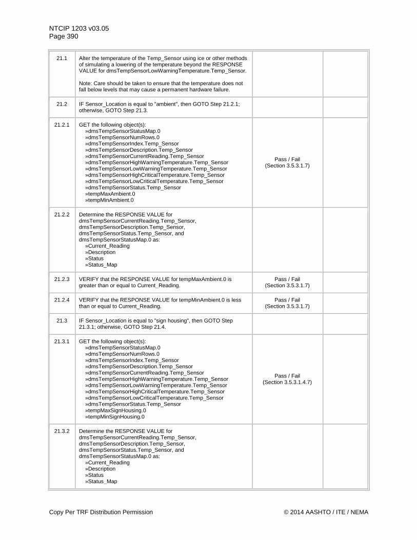
NTCIP 1203 v03.05 Page 390
21.1 Alter the temperature of the Temp_Sensor using ice or other methods of simulating a lowering of the temperature beyond the RESPONSE VALUE for dmsTempSensorLowWarningTemperature.Temp_Sensor. Note: Care should be taken to ensure that the temperature does not fall below levels that may cause a permanent hardware failure.
21.2 IF Sensor_Location is equal to "ambient", then GOTO Step 21.2.1; otherwise, GOTO Step 21.3.
21.2.1 GET the following object(s): »dmsTempSensorStatusMap.0 »dmsTempSensorNumRows.0 »dmsTempSensorIndex.Temp_Sensor »dmsTempSensorDescription.Temp_Sensor »dmsTempSensorCurrentReading.Temp_Sensor »dmsTempSensorHighWarningTemperature.Temp_Sensor »dmsTempSensorLowWarningTemperature.Temp_Sensor »dmsTempSensorHighCriticalTemperature.Temp_Sensor »dmsTempSensorLowCriticalTemperature.Temp_Sensor »dmsTempSensorStatus.Temp_Sensor »tempMaxAmbient.0 »tempMinAmbient.0
Pass / Fail (Section 3.5.3.1.7)
21.2.2 Determine the RESPONSE VALUE for dmsTempSensorCurrentReading.Temp_Sensor, dmsTempSensorDescription.Temp_Sensor, dmsTempSensorStatus.Temp_Sensor, and dmsTempSensorStatusMap.0 as: »Current_Reading »Description »Status »Status_Map
21.2.3 VERIFY that the RESPONSE VALUE for tempMaxAmbient.0 is greater than or equal to Current_Reading.
Pass / Fail (Section 3.5.3.1.7)
21.2.4 VERIFY that the RESPONSE VALUE for tempMinAmbient.0 is less than or equal to Current_Reading.
Pass / Fail (Section 3.5.3.1.7)
21.3 IF Sensor_Location is equal to "sign housing", then GOTO Step 21.3.1; otherwise, GOTO Step 21.4.
21.3.1 GET the following object(s): »dmsTempSensorStatusMap.0 »dmsTempSensorNumRows.0 »dmsTempSensorIndex.Temp_Sensor »dmsTempSensorDescription.Temp_Sensor »dmsTempSensorCurrentReading.Temp_Sensor »dmsTempSensorHighWarningTemperature.Temp_Sensor »dmsTempSensorLowWarningTemperature.Temp_Sensor »dmsTempSensorHighCriticalTemperature.Temp_Sensor »dmsTempSensorLowCriticalTemperature.Temp_Sensor »dmsTempSensorStatus.Temp_Sensor »tempMaxSignHousing.0 »tempMinSignHousing.0
Pass / Fail (Section 3.5.3.1.4.7)
21.3.2 Determine the RESPONSE VALUE for dmsTempSensorCurrentReading.Temp_Sensor, dmsTempSensorDescription.Temp_Sensor, dmsTempSensorStatus.Temp_Sensor, and dmsTempSensorStatusMap.0 as: »Current_Reading »Description »Status »Status_Map
Copy Per TRF Distribution Permission © 2014 AASHTO / ITE / NEMA
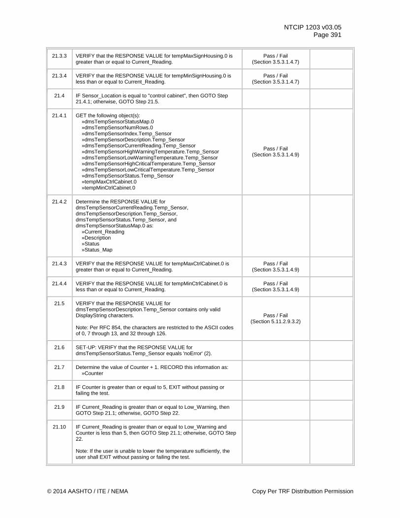
NTCIP 1203 v03.05 Page 391
21.3.3 VERIFY that the RESPONSE VALUE for tempMaxSignHousing.0 is greater than or equal to Current_Reading.
Pass / Fail (Section 3.5.3.1.4.7)
21.3.4 VERIFY that the RESPONSE VALUE for tempMinSignHousing.0 is less than or equal to Current_Reading.
Pass / Fail (Section 3.5.3.1.4.7)
21.4 IF Sensor_Location is equal to "control cabinet", then GOTO Step 21.4.1; otherwise, GOTO Step 21.5.
21.4.1 GET the following object(s): »dmsTempSensorStatusMap.0 »dmsTempSensorNumRows.0 »dmsTempSensorIndex.Temp_Sensor »dmsTempSensorDescription.Temp_Sensor »dmsTempSensorCurrentReading.Temp_Sensor »dmsTempSensorHighWarningTemperature.Temp_Sensor »dmsTempSensorLowWarningTemperature.Temp_Sensor »dmsTempSensorHighCriticalTemperature.Temp_Sensor »dmsTempSensorLowCriticalTemperature.Temp_Sensor »dmsTempSensorStatus.Temp_Sensor »tempMaxCtrlCabinet.0 »tempMinCtrlCabinet.0
Pass / Fail (Section 3.5.3.1.4.9)
21.4.2 Determine the RESPONSE VALUE for dmsTempSensorCurrentReading.Temp_Sensor, dmsTempSensorDescription.Temp_Sensor, dmsTempSensorStatus.Temp_Sensor, and dmsTempSensorStatusMap.0 as: »Current_Reading »Description »Status »Status_Map
21.4.3 VERIFY that the RESPONSE VALUE for tempMaxCtrlCabinet.0 is greater than or equal to Current_Reading.
Pass / Fail (Section 3.5.3.1.4.9)
21.4.4 VERIFY that the RESPONSE VALUE for tempMinCtrlCabinet.0 is less than or equal to Current_Reading.
Pass / Fail (Section 3.5.3.1.4.9)
21.5 VERIFY that the RESPONSE VALUE for dmsTempSensorDescription.Temp_Sensor contains only valid DisplayString characters. Note: Per RFC 854, the characters are restricted to the ASCII codes of 0, 7 through 13, and 32 through 126.
Pass / Fail (Section 5.11.2.9.3.2)
21.6 SET-UP: VERIFY that the RESPONSE VALUE for dmsTempSensorStatus.Temp_Sensor equals 'noError' (2).
21.7 Determine the value of Counter + 1. RECORD this information as: »Counter
21.8 IF Counter is greater than or equal to 5, EXIT without passing or failing the test.
21.9 IF Current_Reading is greater than or equal to Low_Warning, then GOTO Step 21.1; otherwise, GOTO Step 22.
21.10 IF Current_Reading is greater than or equal to Low_Warning and Counter is less than 5, then GOTO Step 21.1; otherwise, GOTO Step 22. Note: If the user is unable to lower the temperature sufficiently, the user shall EXIT without passing or failing the test.
© 2014 AASHTO / ITE / NEMA Copy Per TRF Distributtion Permission
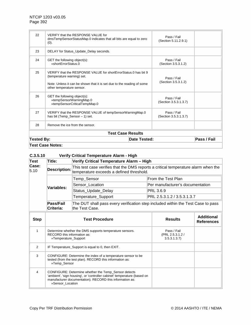
NTCIP 1203 v03.05 Page 392
22 VERIFY that the RESPONSE VALUE for dmsTempSensorStatusMap.0 indicates that all bits are equal to zero (0).
Pass / Fail (Section 5.11.2.9.1)
23 DELAY for Status_Update_Delay seconds.
24 GET the following object(s): »shortErrorStatus.0
Pass / Fail (Section 3.5.3.1.2)
25 VERIFY that the RESPONSE VALUE for shortErrorStatus.0 has bit 9 (temperature warning) set. Note: Unless it can be shown that it is set due to the reading of some other temperature sensor.
Pass / Fail (Section 3.5.3.1.2)
26 GET the following object(s): »tempSensorWarningMap.0 »tempSensorCriticalTempMap.0
Pass / Fail (Section 3.5.3.1.3.7)
27 VERIFY that the RESPONSE VALUE of tempSensorWarningMap.0 has bit (Temp_Sensor – 1) set.
Pass / Fail (Section 3.5.3.1.3.7)
28 Remove the ice from the sensor.
Test Case Results Tested By: Date Tested: Pass / Fail Test Case Notes: C.3.5.10 Verify Critical Temperature Alarm - High Test Case: 5.10
Title: Verify Critical Temperature Alarm – High
Description: This test case verifies that the DMS reports a critical temperature alarm when the temperature exceeds a defined threshold.
Variables:
Temp_Sensor From the Test Plan Sensor_Location Per manufacturer’s documentation Status_Update_Delay PRL 3.6.9 Temperature_Support PRL 2.5.3.1.2 / 3.5.3.1.3.7
Pass/Fail Criteria:
The DUT shall pass every verification step included within the Test Case to pass the Test Case.
Step Test Procedure Results Additional References
1 Determine whether the DMS supports temperature sensors. RECORD this information as: »Temperature_Support
Pass / Fail (PRL 2.5.3.1.2 /
3.5.3.1.3.7)
2 IF Temperature_Support is equal to 0, then EXIT.
3 CONFIGURE: Determine the index of a temperature sensor to be tested (from the test plan). RECORD this information as: »Temp_Sensor
4 CONFIGURE: Determine whether the Temp_Sensor detects 'ambient', 'sign housing', or 'controller cabinet' temperature (based on manufacturer documentation). RECORD this information as: »Sensor_Location
Copy Per TRF Distribution Permission © 2014 AASHTO / ITE / NEMA
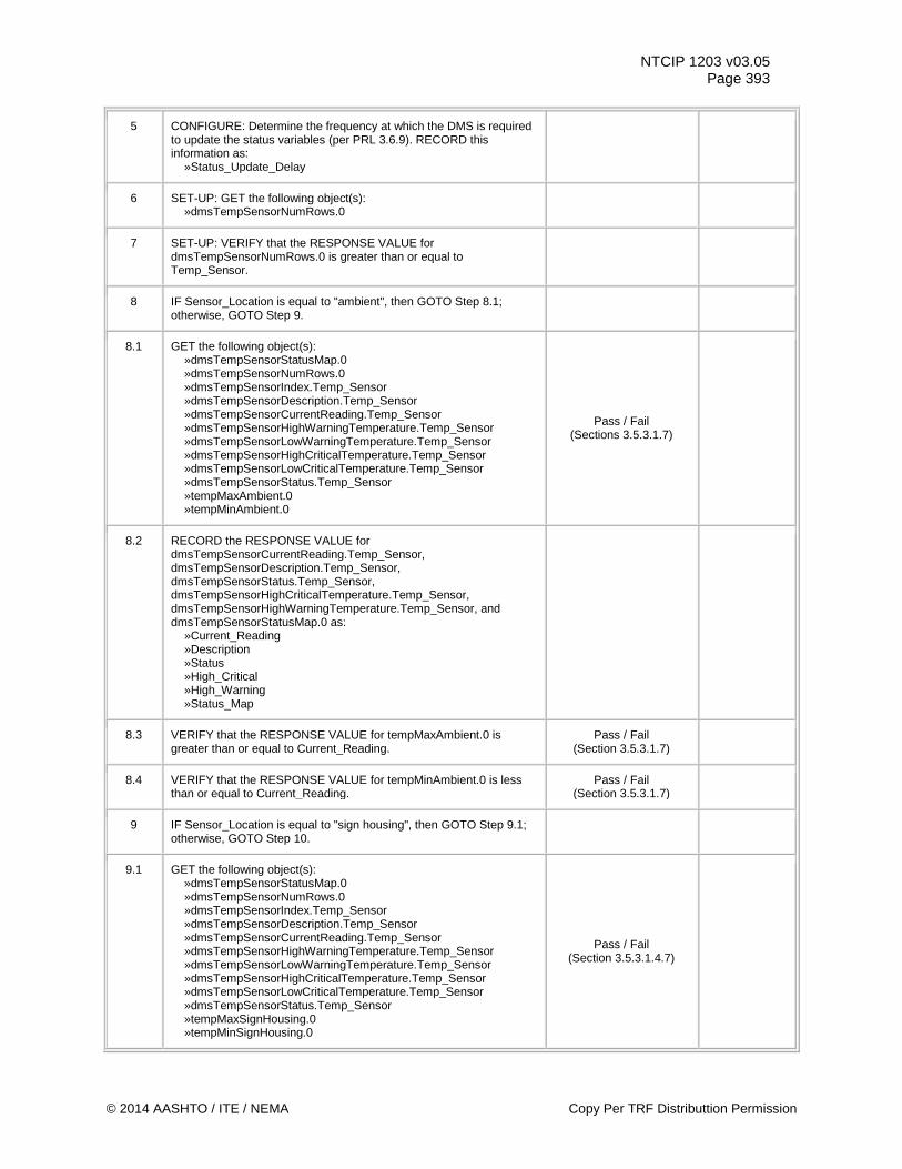
NTCIP 1203 v03.05 Page 393
5 CONFIGURE: Determine the frequency at which the DMS is required to update the status variables (per PRL 3.6.9). RECORD this information as: »Status_Update_Delay
6 SET-UP: GET the following object(s): »dmsTempSensorNumRows.0
7 SET-UP: VERIFY that the RESPONSE VALUE for dmsTempSensorNumRows.0 is greater than or equal to Temp_Sensor.
8 IF Sensor_Location is equal to "ambient", then GOTO Step 8.1; otherwise, GOTO Step 9.
8.1 GET the following object(s): »dmsTempSensorStatusMap.0 »dmsTempSensorNumRows.0 »dmsTempSensorIndex.Temp_Sensor »dmsTempSensorDescription.Temp_Sensor »dmsTempSensorCurrentReading.Temp_Sensor »dmsTempSensorHighWarningTemperature.Temp_Sensor »dmsTempSensorLowWarningTemperature.Temp_Sensor »dmsTempSensorHighCriticalTemperature.Temp_Sensor »dmsTempSensorLowCriticalTemperature.Temp_Sensor »dmsTempSensorStatus.Temp_Sensor »tempMaxAmbient.0 »tempMinAmbient.0
Pass / Fail (Sections 3.5.3.1.7)
8.2 RECORD the RESPONSE VALUE for dmsTempSensorCurrentReading.Temp_Sensor, dmsTempSensorDescription.Temp_Sensor, dmsTempSensorStatus.Temp_Sensor, dmsTempSensorHighCriticalTemperature.Temp_Sensor, dmsTempSensorHighWarningTemperature.Temp_Sensor, and dmsTempSensorStatusMap.0 as: »Current_Reading »Description »Status »High_Critical »High_Warning »Status_Map
8.3 VERIFY that the RESPONSE VALUE for tempMaxAmbient.0 is greater than or equal to Current_Reading.
Pass / Fail (Section 3.5.3.1.7)
8.4 VERIFY that the RESPONSE VALUE for tempMinAmbient.0 is less than or equal to Current_Reading.
Pass / Fail (Section 3.5.3.1.7)
9 IF Sensor_Location is equal to "sign housing", then GOTO Step 9.1; otherwise, GOTO Step 10.
9.1 GET the following object(s): »dmsTempSensorStatusMap.0 »dmsTempSensorNumRows.0 »dmsTempSensorIndex.Temp_Sensor »dmsTempSensorDescription.Temp_Sensor »dmsTempSensorCurrentReading.Temp_Sensor »dmsTempSensorHighWarningTemperature.Temp_Sensor »dmsTempSensorLowWarningTemperature.Temp_Sensor »dmsTempSensorHighCriticalTemperature.Temp_Sensor »dmsTempSensorLowCriticalTemperature.Temp_Sensor »dmsTempSensorStatus.Temp_Sensor »tempMaxSignHousing.0 »tempMinSignHousing.0
Pass / Fail (Section 3.5.3.1.4.7)
© 2014 AASHTO / ITE / NEMA Copy Per TRF Distributtion Permission
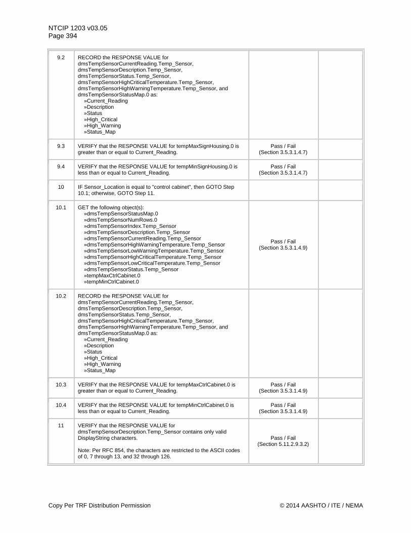
NTCIP 1203 v03.05 Page 394
9.2 RECORD the RESPONSE VALUE for dmsTempSensorCurrentReading.Temp_Sensor, dmsTempSensorDescription.Temp_Sensor, dmsTempSensorStatus.Temp_Sensor, dmsTempSensorHighCriticalTemperature.Temp_Sensor, dmsTempSensorHighWarningTemperature.Temp_Sensor, and dmsTempSensorStatusMap.0 as: »Current_Reading »Description »Status »High_Critical »High_Warning »Status_Map
9.3 VERIFY that the RESPONSE VALUE for tempMaxSignHousing.0 is greater than or equal to Current_Reading.
Pass / Fail (Section 3.5.3.1.4.7)
9.4 VERIFY that the RESPONSE VALUE for tempMinSignHousing.0 is less than or equal to Current_Reading.
Pass / Fail (Section 3.5.3.1.4.7)
10 IF Sensor_Location is equal to "control cabinet", then GOTO Step 10.1; otherwise, GOTO Step 11.
10.1 GET the following object(s): »dmsTempSensorStatusMap.0 »dmsTempSensorNumRows.0 »dmsTempSensorIndex.Temp_Sensor »dmsTempSensorDescription.Temp_Sensor »dmsTempSensorCurrentReading.Temp_Sensor »dmsTempSensorHighWarningTemperature.Temp_Sensor »dmsTempSensorLowWarningTemperature.Temp_Sensor »dmsTempSensorHighCriticalTemperature.Temp_Sensor »dmsTempSensorLowCriticalTemperature.Temp_Sensor »dmsTempSensorStatus.Temp_Sensor »tempMaxCtrlCabinet.0 »tempMinCtrlCabinet.0
Pass / Fail (Section 3.5.3.1.4.9)
10.2 RECORD the RESPONSE VALUE for dmsTempSensorCurrentReading.Temp_Sensor, dmsTempSensorDescription.Temp_Sensor, dmsTempSensorStatus.Temp_Sensor, dmsTempSensorHighCriticalTemperature.Temp_Sensor, dmsTempSensorHighWarningTemperature.Temp_Sensor, and dmsTempSensorStatusMap.0 as: »Current_Reading »Description »Status »High_Critical »High_Warning »Status_Map
10.3 VERIFY that the RESPONSE VALUE for tempMaxCtrlCabinet.0 is greater than or equal to Current_Reading.
Pass / Fail (Section 3.5.3.1.4.9)
10.4 VERIFY that the RESPONSE VALUE for tempMinCtrlCabinet.0 is less than or equal to Current_Reading.
Pass / Fail (Section 3.5.3.1.4.9)
11 VERIFY that the RESPONSE VALUE for dmsTempSensorDescription.Temp_Sensor contains only valid DisplayString characters. Note: Per RFC 854, the characters are restricted to the ASCII codes of 0, 7 through 13, and 32 through 126.
Pass / Fail (Section 5.11.2.9.3.2)
Copy Per TRF Distribution Permission © 2014 AASHTO / ITE / NEMA
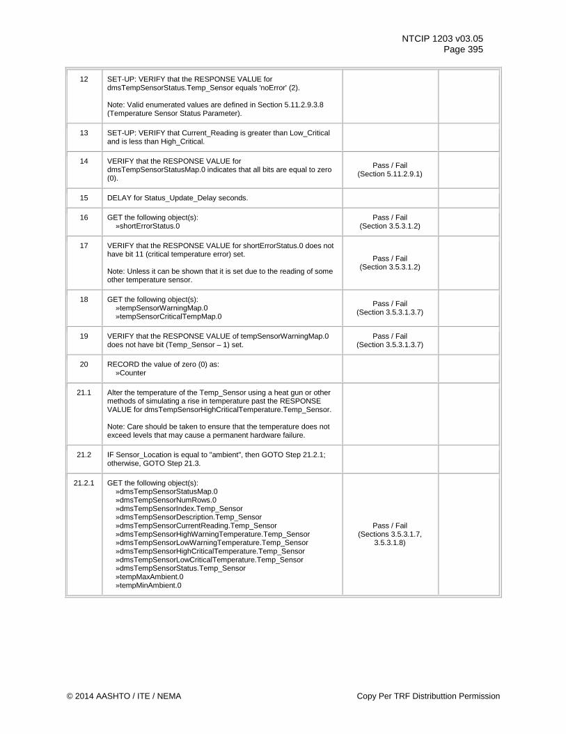
NTCIP 1203 v03.05 Page 395
12 SET-UP: VERIFY that the RESPONSE VALUE for dmsTempSensorStatus.Temp_Sensor equals 'noError' (2). Note: Valid enumerated values are defined in Section 5.11.2.9.3.8 (Temperature Sensor Status Parameter).
13 SET-UP: VERIFY that Current_Reading is greater than Low_Critical and is less than High_Critical.
14 VERIFY that the RESPONSE VALUE for dmsTempSensorStatusMap.0 indicates that all bits are equal to zero (0).
Pass / Fail (Section 5.11.2.9.1)
15 DELAY for Status_Update_Delay seconds.
16 GET the following object(s): »shortErrorStatus.0
Pass / Fail (Section 3.5.3.1.2)
17 VERIFY that the RESPONSE VALUE for shortErrorStatus.0 does not have bit 11 (critical temperature error) set. Note: Unless it can be shown that it is set due to the reading of some other temperature sensor.
Pass / Fail (Section 3.5.3.1.2)
18 GET the following object(s): »tempSensorWarningMap.0 »tempSensorCriticalTempMap.0
Pass / Fail (Section 3.5.3.1.3.7)
19 VERIFY that the RESPONSE VALUE of tempSensorWarningMap.0 does not have bit (Temp_Sensor – 1) set.
Pass / Fail (Section 3.5.3.1.3.7)
20 RECORD the value of zero (0) as: »Counter
21.1 Alter the temperature of the Temp_Sensor using a heat gun or other methods of simulating a rise in temperature past the RESPONSE VALUE for dmsTempSensorHighCriticalTemperature.Temp_Sensor. Note: Care should be taken to ensure that the temperature does not exceed levels that may cause a permanent hardware failure.
21.2 IF Sensor_Location is equal to "ambient", then GOTO Step 21.2.1; otherwise, GOTO Step 21.3.
21.2.1 GET the following object(s): »dmsTempSensorStatusMap.0 »dmsTempSensorNumRows.0 »dmsTempSensorIndex.Temp_Sensor »dmsTempSensorDescription.Temp_Sensor »dmsTempSensorCurrentReading.Temp_Sensor »dmsTempSensorHighWarningTemperature.Temp_Sensor »dmsTempSensorLowWarningTemperature.Temp_Sensor »dmsTempSensorHighCriticalTemperature.Temp_Sensor »dmsTempSensorLowCriticalTemperature.Temp_Sensor »dmsTempSensorStatus.Temp_Sensor »tempMaxAmbient.0 »tempMinAmbient.0
Pass / Fail (Sections 3.5.3.1.7,
3.5.3.1.8)
© 2014 AASHTO / ITE / NEMA Copy Per TRF Distributtion Permission

NTCIP 1203 v03.05 Page 396
21.2.2 RECORD the RESPONSE VALUE for dmsTempSensorCurrentReading.Temp_Sensor, dmsTempSensorDescription.Temp_Sensor, dmsTempSensorStatus.Temp_Sensor, dmsTempSensorHighCriticalTemperature.Temp_Sensor, and dmsTempSensorStatusMap.0 as: »Current_Reading »Description »Status »High_Critical »Status_Map
21.2.3 VERIFY that the RESPONSE VALUE for tempMaxAmbient.0 is greater than or equal to Current_Reading.
Pass / Fail (Section 3.5.3.1.7)
21.2.4 VERIFY that the RESPONSE VALUE for tempMinAmbient.0 is less than or equal to Current_Reading.
Pass / Fail (Section 3.5.3.1.7)
21.3 IF Sensor_Location is equal to "sign housing", then GOTO Step 21.3.1; otherwise, GOTO Step 21.4.
21.3.1 GET the following object(s): »dmsTempSensorStatusMap.0 »dmsTempSensorNumRows.0 »dmsTempSensorIndex.Temp_Sensor »dmsTempSensorDescription.Temp_Sensor »dmsTempSensorCurrentReading.Temp_Sensor »dmsTempSensorHighWarningTemperature.Temp_Sensor »dmsTempSensorLowWarningTemperature.Temp_Sensor »dmsTempSensorHighCriticalTemperature.Temp_Sensor »dmsTempSensorLowCriticalTemperature.Temp_Sensor »dmsTempSensorStatus.Temp_Sensor »tempMaxSignHousing.0 »tempMinSignHousing.0
Pass / Fail (Sections 3.5.3.1.4.7,
3.5.3.1.8)
21.3.2 RECORD the RESPONSE VALUE for dmsTempSensorCurrentReading.Temp_Sensor, dmsTempSensorDescription.Temp_Sensor, dmsTempSensorStatus.Temp_Sensor, dmsTempSensorHighCriticalTemperature.Temp_Sensor, and dmsTempSensorStatusMap.0 as: »Current_Reading »Description »Status »High_Critical »Status_Map
21.3.3 VERIFY that the RESPONSE VALUE for tempMaxSignHousing.0 is greater than or equal to Current_Reading.
Pass / Fail (Section 3.5.3.1.4.7)
21.3.4 VERIFY that the RESPONSE VALUE for tempMinSignHousing.0 is less than or equal to Current_Reading.
Pass / Fail (Section 3.5.3.1.4.7)
21.4 IF Sensor_Location is equal to "control cabinet", then GOTO Step 21.4.1; otherwise, GOTO Step 21.5.
Copy Per TRF Distribution Permission © 2014 AASHTO / ITE / NEMA
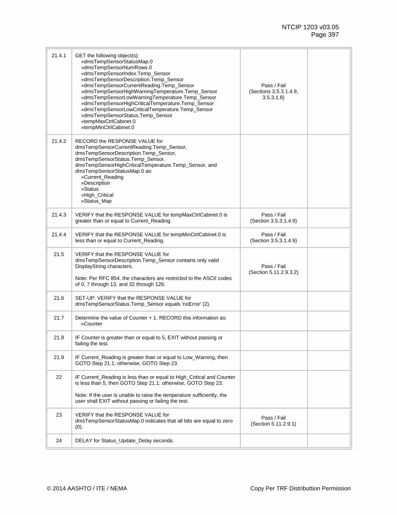
NTCIP 1203 v03.05 Page 397
21.4.1 GET the following object(s): »dmsTempSensorStatusMap.0 »dmsTempSensorNumRows.0 »dmsTempSensorIndex.Temp_Sensor »dmsTempSensorDescription.Temp_Sensor »dmsTempSensorCurrentReading.Temp_Sensor »dmsTempSensorHighWarningTemperature.Temp_Sensor »dmsTempSensorLowWarningTemperature.Temp_Sensor »dmsTempSensorHighCriticalTemperature.Temp_Sensor »dmsTempSensorLowCriticalTemperature.Temp_Sensor »dmsTempSensorStatus.Temp_Sensor »tempMaxCtrlCabinet.0 »tempMinCtrlCabinet.0
Pass / Fail (Sections 3.5.3.1.4.9,
3.5.3.1.8)
21.4.2 RECORD the RESPONSE VALUE for dmsTempSensorCurrentReading.Temp_Sensor, dmsTempSensorDescription.Temp_Sensor, dmsTempSensorStatus.Temp_Sensor, dmsTempSensorHighCriticalTemperature.Temp_Sensor, and dmsTempSensorStatusMap.0 as: »Current_Reading »Description »Status »High_Critical »Status_Map
21.4.3 VERIFY that the RESPONSE VALUE for tempMaxCtrlCabinet.0 is greater than or equal to Current_Reading.
Pass / Fail (Section 3.5.3.1.4.9)
21.4.4 VERIFY that the RESPONSE VALUE for tempMinCtrlCabinet.0 is less than or equal to Current_Reading.
Pass / Fail (Section 3.5.3.1.4.9)
21.5 VERIFY that the RESPONSE VALUE for dmsTempSensorDescription.Temp_Sensor contains only valid DisplayString characters. Note: Per RFC 854, the characters are restricted to the ASCII codes of 0, 7 through 13, and 32 through 126.
Pass / Fail (Section 5.11.2.9.3.2)
21.6 SET-UP: VERIFY that the RESPONSE VALUE for dmsTempSensorStatus.Temp_Sensor equals 'noError' (2).
21.7 Determine the value of Counter + 1. RECORD this information as: »Counter
21.8 IF Counter is greater than or equal to 5, EXIT without passing or failing the test.
21.9 IF Current_Reading is greater than or equal to Low_Warning, then GOTO Step 21.1; otherwise, GOTO Step 23.
22 IF Current_Reading is less than or equal to High_Critical and Counter is less than 5, then GOTO Step 21.1; otherwise, GOTO Step 23. Note: If the user is unable to raise the temperature sufficiently, the user shall EXIT without passing or failing the test.
23 VERIFY that the RESPONSE VALUE for dmsTempSensorStatusMap.0 indicates that all bits are equal to zero (0).
Pass / Fail (Section 5.11.2.9.1)
24 DELAY for Status_Update_Delay seconds.
© 2014 AASHTO / ITE / NEMA Copy Per TRF Distributtion Permission
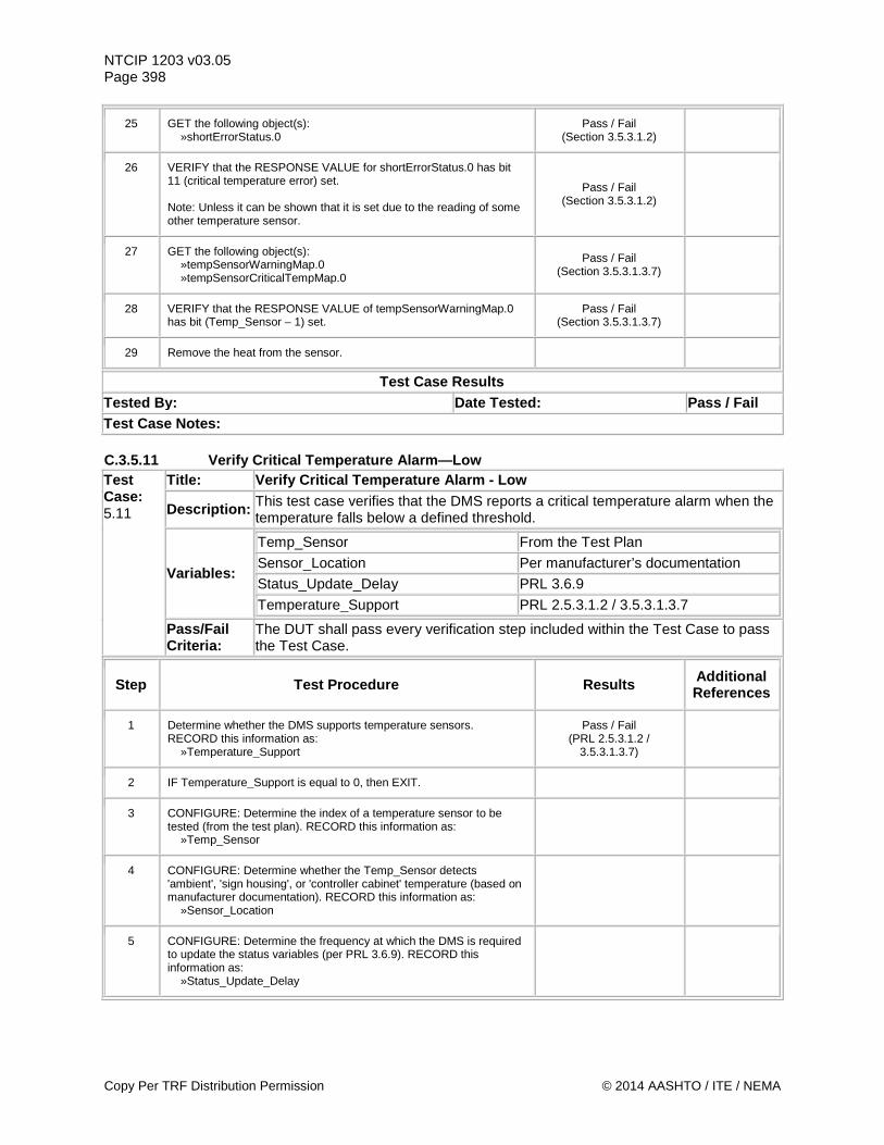
NTCIP 1203 v03.05 Page 398
25 GET the following object(s): »shortErrorStatus.0
Pass / Fail (Section 3.5.3.1.2)
26 VERIFY that the RESPONSE VALUE for shortErrorStatus.0 has bit 11 (critical temperature error) set. Note: Unless it can be shown that it is set due to the reading of some other temperature sensor.
Pass / Fail (Section 3.5.3.1.2)
27 GET the following object(s): »tempSensorWarningMap.0 »tempSensorCriticalTempMap.0
Pass / Fail (Section 3.5.3.1.3.7)
28 VERIFY that the RESPONSE VALUE of tempSensorWarningMap.0 has bit (Temp_Sensor – 1) set.
Pass / Fail (Section 3.5.3.1.3.7)
29 Remove the heat from the sensor.
Test Case Results Tested By: Date Tested: Pass / Fail Test Case Notes: C.3.5.11 Verify Critical Temperature Alarm—Low Test Case: 5.11
Title: Verify Critical Temperature Alarm - Low
Description: This test case verifies that the DMS reports a critical temperature alarm when the temperature falls below a defined threshold.
Variables:
Temp_Sensor From the Test Plan Sensor_Location Per manufacturer’s documentation Status_Update_Delay PRL 3.6.9 Temperature_Support PRL 2.5.3.1.2 / 3.5.3.1.3.7
Pass/Fail Criteria:
The DUT shall pass every verification step included within the Test Case to pass the Test Case.
Step Test Procedure Results Additional References
1 Determine whether the DMS supports temperature sensors. RECORD this information as: »Temperature_Support
Pass / Fail (PRL 2.5.3.1.2 /
3.5.3.1.3.7)
2 IF Temperature_Support is equal to 0, then EXIT.
3 CONFIGURE: Determine the index of a temperature sensor to be tested (from the test plan). RECORD this information as: »Temp_Sensor
4 CONFIGURE: Determine whether the Temp_Sensor detects 'ambient', 'sign housing', or 'controller cabinet' temperature (based on manufacturer documentation). RECORD this information as: »Sensor_Location
5 CONFIGURE: Determine the frequency at which the DMS is required to update the status variables (per PRL 3.6.9). RECORD this information as: »Status_Update_Delay
Copy Per TRF Distribution Permission © 2014 AASHTO / ITE / NEMA
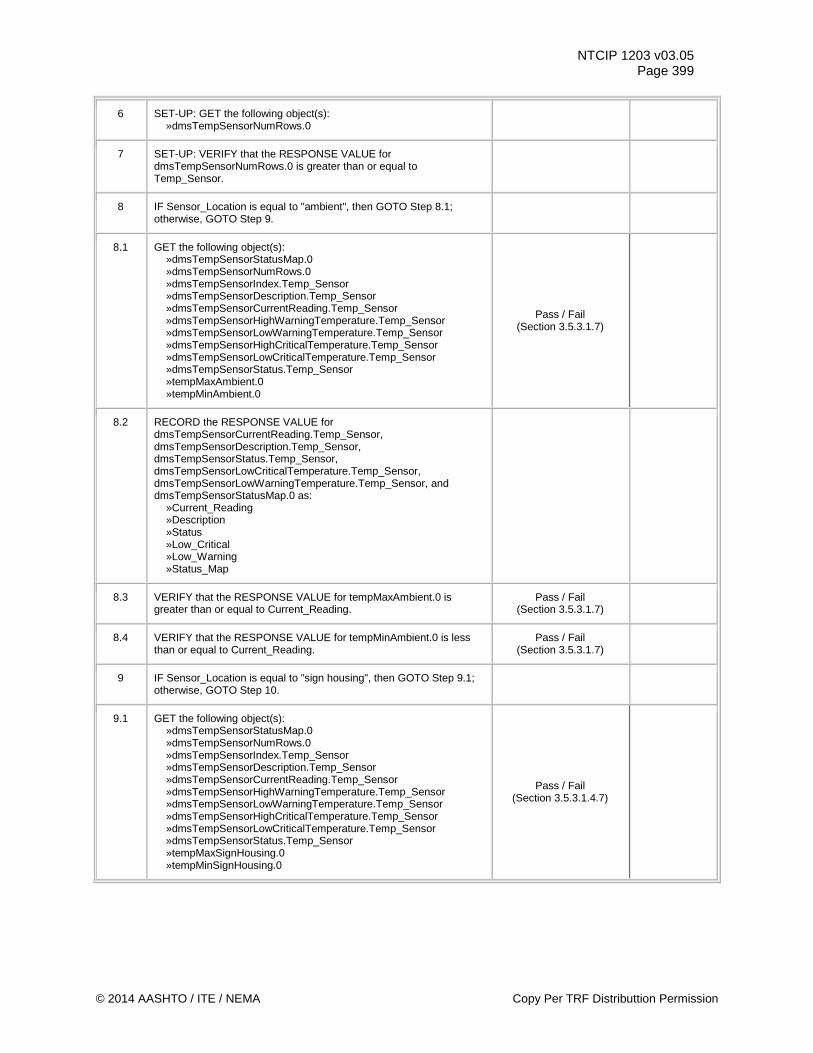
NTCIP 1203 v03.05 Page 399
6 SET-UP: GET the following object(s): »dmsTempSensorNumRows.0
7 SET-UP: VERIFY that the RESPONSE VALUE for dmsTempSensorNumRows.0 is greater than or equal to Temp_Sensor.
8 IF Sensor_Location is equal to "ambient", then GOTO Step 8.1; otherwise, GOTO Step 9.
8.1 GET the following object(s): »dmsTempSensorStatusMap.0 »dmsTempSensorNumRows.0 »dmsTempSensorIndex.Temp_Sensor »dmsTempSensorDescription.Temp_Sensor »dmsTempSensorCurrentReading.Temp_Sensor »dmsTempSensorHighWarningTemperature.Temp_Sensor »dmsTempSensorLowWarningTemperature.Temp_Sensor »dmsTempSensorHighCriticalTemperature.Temp_Sensor »dmsTempSensorLowCriticalTemperature.Temp_Sensor »dmsTempSensorStatus.Temp_Sensor »tempMaxAmbient.0 »tempMinAmbient.0
Pass / Fail (Section 3.5.3.1.7)
8.2 RECORD the RESPONSE VALUE for dmsTempSensorCurrentReading.Temp_Sensor, dmsTempSensorDescription.Temp_Sensor, dmsTempSensorStatus.Temp_Sensor, dmsTempSensorLowCriticalTemperature.Temp_Sensor, dmsTempSensorLowWarningTemperature.Temp_Sensor, and dmsTempSensorStatusMap.0 as: »Current_Reading »Description »Status »Low_Critical »Low_Warning »Status_Map
8.3 VERIFY that the RESPONSE VALUE for tempMaxAmbient.0 is greater than or equal to Current_Reading.
Pass / Fail (Section 3.5.3.1.7)
8.4 VERIFY that the RESPONSE VALUE for tempMinAmbient.0 is less than or equal to Current_Reading.
Pass / Fail (Section 3.5.3.1.7)
9 IF Sensor_Location is equal to "sign housing", then GOTO Step 9.1; otherwise, GOTO Step 10.
9.1 GET the following object(s): »dmsTempSensorStatusMap.0 »dmsTempSensorNumRows.0 »dmsTempSensorIndex.Temp_Sensor »dmsTempSensorDescription.Temp_Sensor »dmsTempSensorCurrentReading.Temp_Sensor »dmsTempSensorHighWarningTemperature.Temp_Sensor »dmsTempSensorLowWarningTemperature.Temp_Sensor »dmsTempSensorHighCriticalTemperature.Temp_Sensor »dmsTempSensorLowCriticalTemperature.Temp_Sensor »dmsTempSensorStatus.Temp_Sensor »tempMaxSignHousing.0 »tempMinSignHousing.0
Pass / Fail (Section 3.5.3.1.4.7)
© 2014 AASHTO / ITE / NEMA Copy Per TRF Distributtion Permission
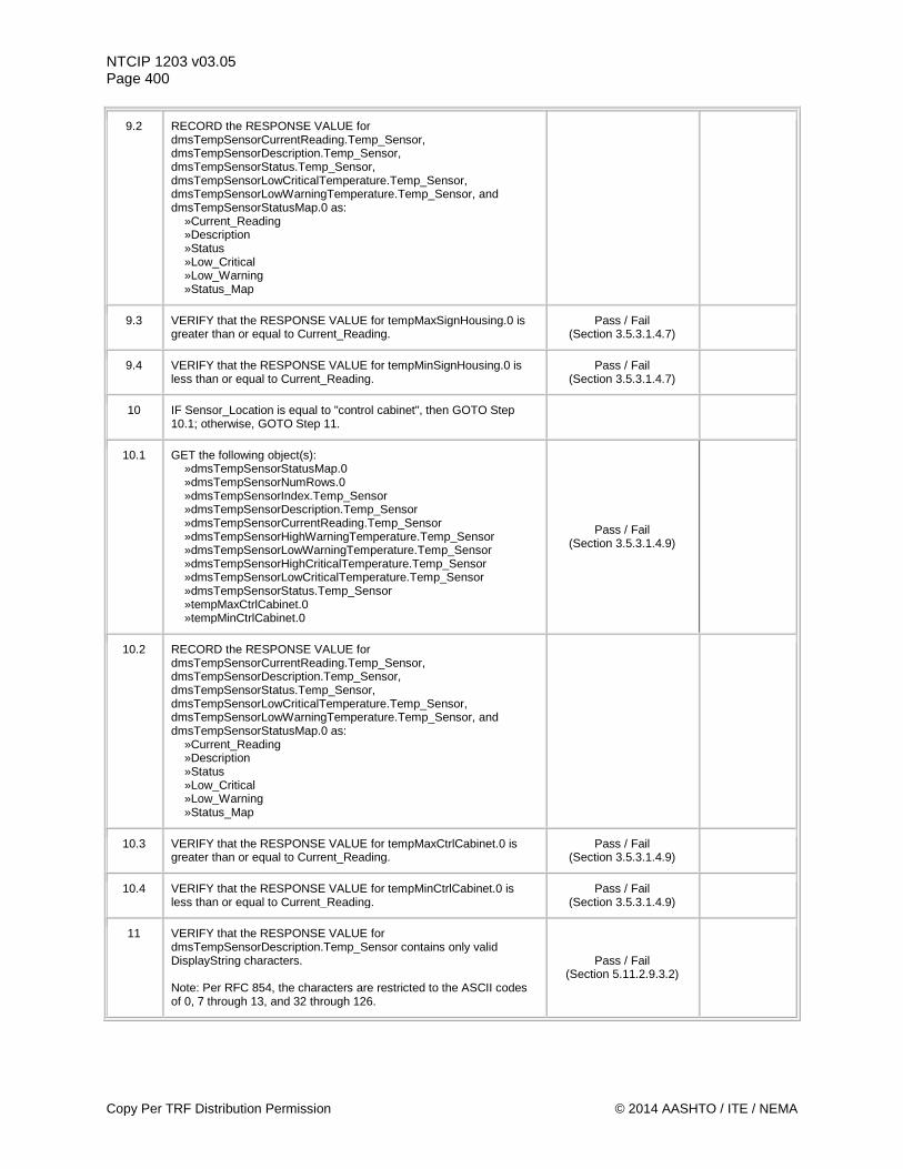
NTCIP 1203 v03.05 Page 400
9.2 RECORD the RESPONSE VALUE for dmsTempSensorCurrentReading.Temp_Sensor, dmsTempSensorDescription.Temp_Sensor, dmsTempSensorStatus.Temp_Sensor, dmsTempSensorLowCriticalTemperature.Temp_Sensor, dmsTempSensorLowWarningTemperature.Temp_Sensor, and dmsTempSensorStatusMap.0 as: »Current_Reading »Description »Status »Low_Critical »Low_Warning »Status_Map
9.3 VERIFY that the RESPONSE VALUE for tempMaxSignHousing.0 is greater than or equal to Current_Reading.
Pass / Fail (Section 3.5.3.1.4.7)
9.4 VERIFY that the RESPONSE VALUE for tempMinSignHousing.0 is less than or equal to Current_Reading.
Pass / Fail (Section 3.5.3.1.4.7)
10 IF Sensor_Location is equal to "control cabinet", then GOTO Step 10.1; otherwise, GOTO Step 11.
10.1 GET the following object(s): »dmsTempSensorStatusMap.0 »dmsTempSensorNumRows.0 »dmsTempSensorIndex.Temp_Sensor »dmsTempSensorDescription.Temp_Sensor »dmsTempSensorCurrentReading.Temp_Sensor »dmsTempSensorHighWarningTemperature.Temp_Sensor »dmsTempSensorLowWarningTemperature.Temp_Sensor »dmsTempSensorHighCriticalTemperature.Temp_Sensor »dmsTempSensorLowCriticalTemperature.Temp_Sensor »dmsTempSensorStatus.Temp_Sensor »tempMaxCtrlCabinet.0 »tempMinCtrlCabinet.0
Pass / Fail (Section 3.5.3.1.4.9)
10.2 RECORD the RESPONSE VALUE for dmsTempSensorCurrentReading.Temp_Sensor, dmsTempSensorDescription.Temp_Sensor, dmsTempSensorStatus.Temp_Sensor, dmsTempSensorLowCriticalTemperature.Temp_Sensor, dmsTempSensorLowWarningTemperature.Temp_Sensor, and dmsTempSensorStatusMap.0 as: »Current_Reading »Description »Status »Low_Critical »Low_Warning »Status_Map
10.3 VERIFY that the RESPONSE VALUE for tempMaxCtrlCabinet.0 is greater than or equal to Current_Reading.
Pass / Fail (Section 3.5.3.1.4.9)
10.4 VERIFY that the RESPONSE VALUE for tempMinCtrlCabinet.0 is less than or equal to Current_Reading.
Pass / Fail (Section 3.5.3.1.4.9)
11 VERIFY that the RESPONSE VALUE for dmsTempSensorDescription.Temp_Sensor contains only valid DisplayString characters. Note: Per RFC 854, the characters are restricted to the ASCII codes of 0, 7 through 13, and 32 through 126.
Pass / Fail (Section 5.11.2.9.3.2)
Copy Per TRF Distribution Permission © 2014 AASHTO / ITE / NEMA

NTCIP 1203 v03.05 Page 401
12 SET-UP: VERIFY that the RESPONSE VALUE for dmsTempSensorStatus.Temp_Sensor equals 'noError'.
13 SET-UP: VERIFY that Current_Reading is greater than Low_Critical and less than High_Critical.
14 VERIFY that the RESPONSE VALUE for dmsTempSensorStatusMap.0 indicates that all bits are equal to zero (0).
Pass / Fail (Section 5.11.2.9.1)
15 DELAY for Status_Update_Delay seconds.
16 GET the following object(s): »shortErrorStatus.0
Pass / Fail (Section 3.5.3.1.2)
17 VERIFY that the RESPONSE VALUE for shortErrorStatus.0 does not have bit 11 (critical temperature error) set. Note: Unless it can be shown that it is set due to the reading of some other temperature sensor.
Pass / Fail (Section 3.5.3.1.2)
18 GET the following object(s): »tempSensorWarningMap.0 »tempSensorCriticalTempMap.0
Pass / Fail (Section 3.5.3.1.3.7)
19 VERIFY that the RESPONSE VALUE of tempSensorWarningMap.0 does not have the Temp_Sensor bit (Temp_Sensor – 1) set.
Pass / Fail (Section 3.5.3.1.3.7)
20 RECORD the value of zero (0) as: »Counter
21.1 Alter the temperature of the Temp_Sensor using ice or other methods of simulating a lowering of the temperature beyond the RESPONSE VALUE for dmsTempSensorLowCriticalTemperature.Temp_Sensor. Note: Care should be taken to ensure that the temperature does not fall below levels that may cause a permanent hardware failure.
21.2 IF Sensor_Location is equal to "ambient", then GOTO Step 21.2.1; otherwise, GOTO Step 21.3.
21.2.1 GET the following object(s): »dmsTempSensorStatusMap.0 »dmsTempSensorNumRows.0 »dmsTempSensorIndex.Temp_Sensor »dmsTempSensorDescription.Temp_Sensor »dmsTempSensorCurrentReading.Temp_Sensor »dmsTempSensorHighWarningTemperature.Temp_Sensor »dmsTempSensorLowWarningTemperature.Temp_Sensor »dmsTempSensorHighCriticalTemperature.Temp_Sensor »dmsTempSensorLowCriticalTemperature.Temp_Sensor »dmsTempSensorStatus.Temp_Sensor »tempMaxAmbient.0 »tempMinAmbient.0
Pass / Fail (Sections 3.5.3.1.7,
3.5.3.1.8)
© 2014 AASHTO / ITE / NEMA Copy Per TRF Distributtion Permission
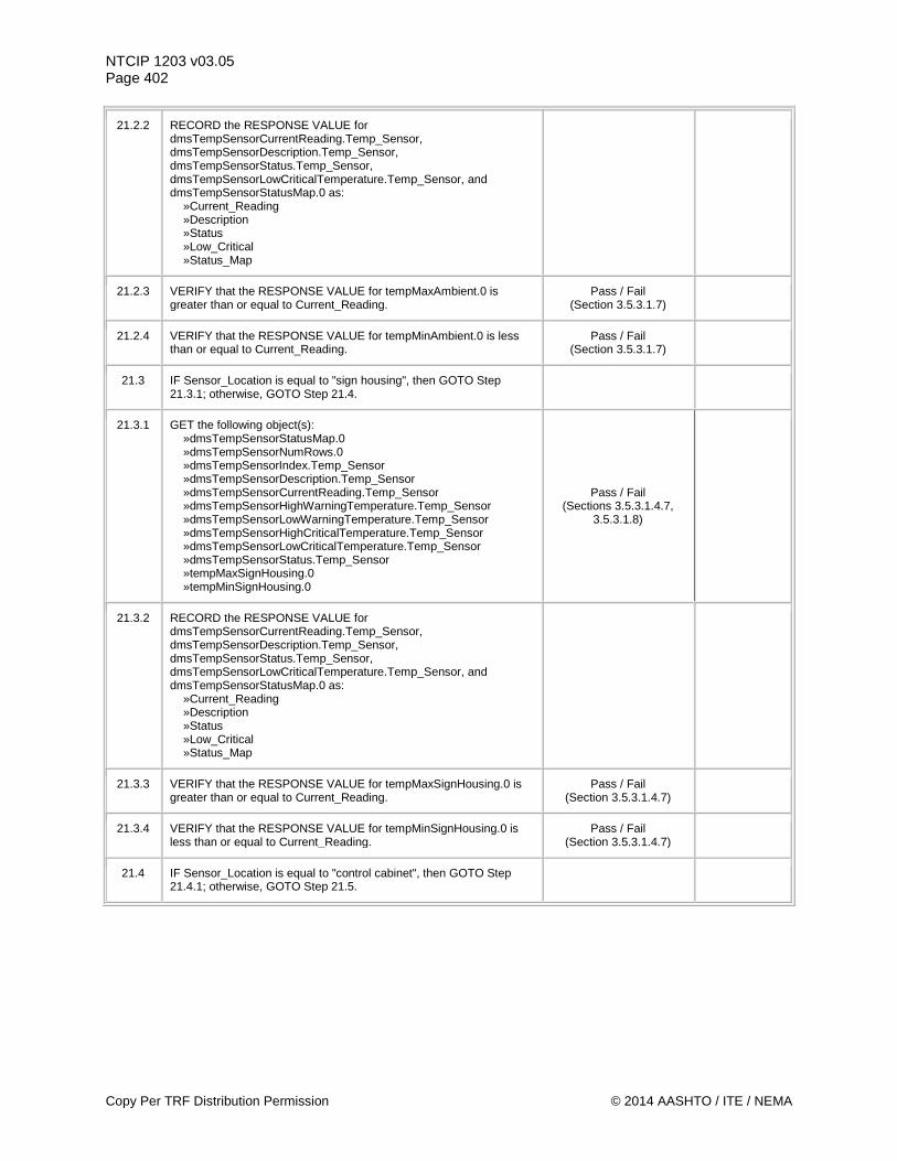
NTCIP 1203 v03.05 Page 402
21.2.2 RECORD the RESPONSE VALUE for dmsTempSensorCurrentReading.Temp_Sensor, dmsTempSensorDescription.Temp_Sensor, dmsTempSensorStatus.Temp_Sensor, dmsTempSensorLowCriticalTemperature.Temp_Sensor, and dmsTempSensorStatusMap.0 as: »Current_Reading »Description »Status »Low_Critical »Status_Map
21.2.3 VERIFY that the RESPONSE VALUE for tempMaxAmbient.0 is greater than or equal to Current_Reading.
Pass / Fail (Section 3.5.3.1.7)
21.2.4 VERIFY that the RESPONSE VALUE for tempMinAmbient.0 is less than or equal to Current_Reading.
Pass / Fail (Section 3.5.3.1.7)
21.3 IF Sensor_Location is equal to "sign housing", then GOTO Step 21.3.1; otherwise, GOTO Step 21.4.
21.3.1 GET the following object(s): »dmsTempSensorStatusMap.0 »dmsTempSensorNumRows.0 »dmsTempSensorIndex.Temp_Sensor »dmsTempSensorDescription.Temp_Sensor »dmsTempSensorCurrentReading.Temp_Sensor »dmsTempSensorHighWarningTemperature.Temp_Sensor »dmsTempSensorLowWarningTemperature.Temp_Sensor »dmsTempSensorHighCriticalTemperature.Temp_Sensor »dmsTempSensorLowCriticalTemperature.Temp_Sensor »dmsTempSensorStatus.Temp_Sensor »tempMaxSignHousing.0 »tempMinSignHousing.0
Pass / Fail (Sections 3.5.3.1.4.7,
3.5.3.1.8)
21.3.2 RECORD the RESPONSE VALUE for dmsTempSensorCurrentReading.Temp_Sensor, dmsTempSensorDescription.Temp_Sensor, dmsTempSensorStatus.Temp_Sensor, dmsTempSensorLowCriticalTemperature.Temp_Sensor, and dmsTempSensorStatusMap.0 as: »Current_Reading »Description »Status »Low_Critical »Status_Map
21.3.3 VERIFY that the RESPONSE VALUE for tempMaxSignHousing.0 is greater than or equal to Current_Reading.
Pass / Fail (Section 3.5.3.1.4.7)
21.3.4 VERIFY that the RESPONSE VALUE for tempMinSignHousing.0 is less than or equal to Current_Reading.
Pass / Fail (Section 3.5.3.1.4.7)
21.4 IF Sensor_Location is equal to "control cabinet", then GOTO Step 21.4.1; otherwise, GOTO Step 21.5.
Copy Per TRF Distribution Permission © 2014 AASHTO / ITE / NEMA

NTCIP 1203 v03.05 Page 403
21.4.1 GET the following object(s): »dmsTempSensorStatusMap.0 »dmsTempSensorNumRows.0 »dmsTempSensorIndex.Temp_Sensor »dmsTempSensorDescription.Temp_Sensor »dmsTempSensorCurrentReading.Temp_Sensor »dmsTempSensorHighWarningTemperature.Temp_Sensor »dmsTempSensorLowWarningTemperature.Temp_Sensor »dmsTempSensorHighCriticalTemperature.Temp_Sensor »dmsTempSensorLowCriticalTemperature.Temp_Sensor »dmsTempSensorStatus.Temp_Sensor »tempMaxCtrlCabinet.0 »tempMinCtrlCabinet.0
Pass / Fail (Sections 3.5.3.1.4.9,
3.5.3.1.8)
21.4.2 RECORD the RESPONSE VALUE for dmsTempSensorCurrentReading.Temp_Sensor, dmsTempSensorDescription.Temp_Sensor, dmsTempSensorStatus.Temp_Sensor, dmsTempSensorLowCriticalTemperature.Temp_Sensor, and dmsTempSensorStatusMap.0 as:as: »Current_Reading »Description »Status »Low_Critical »Status_Map
21.4.3 VERIFY that the RESPONSE VALUE for tempMaxCtrlCabinet.0 is greater than or equal to Current_Reading.
Pass / Fail (Section 3.5.3.1.4.9)
21.4.4 VERIFY that the RESPONSE VALUE for tempMinCtrlCabinet.0 is less than or equal to Current_Reading.
Pass / Fail (Section 3.5.3.1.4.9)
21.5 VERIFY that the RESPONSE VALUE for dmsTempSensorDescription.Temp_Sensor contains only valid DisplayString characters. Note: Per RFC 854, the characters are restricted to the ASCII codes of 0, 7 through 13, and 32 through 126.
Pass / Fail (Section 5.11.2.9.3.2)
21.6 SET-UP: VERIFY that the RESPONSE VALUE for dmsTempSensorStatus.Temp_Sensor equals 'noError' (2).
21.7 Determine the value of Counter + 1. RECORD this information as: »Counter
21.8 IF Counter is greater than or equal to 5, EXIT without passing or failing the test.
21.9 IF Current_Reading is greater than or equal to Low_Warning, then GOTO Step 21.1; otherwise, GOTO Step 23.
22 IF Current_Reading is greater than or equal to Low_Critical and Counter is less than 5, then GOTO Step 21.1; otherwise, GOTO Step 23. Note: If the user is unable to lower the temperature sufficiently, the user shall EXIT without passing or failing the test.
23 VERIFY that the RESPONSE VALUE for dmsTempSensorStatusMap.0 indicates that all bits are equal to zero (0).
Pass / Fail (Section 5.11.2.9.1)
24 DELAY for Status_Update_Delay seconds.
© 2014 AASHTO / ITE / NEMA Copy Per TRF Distributtion Permission
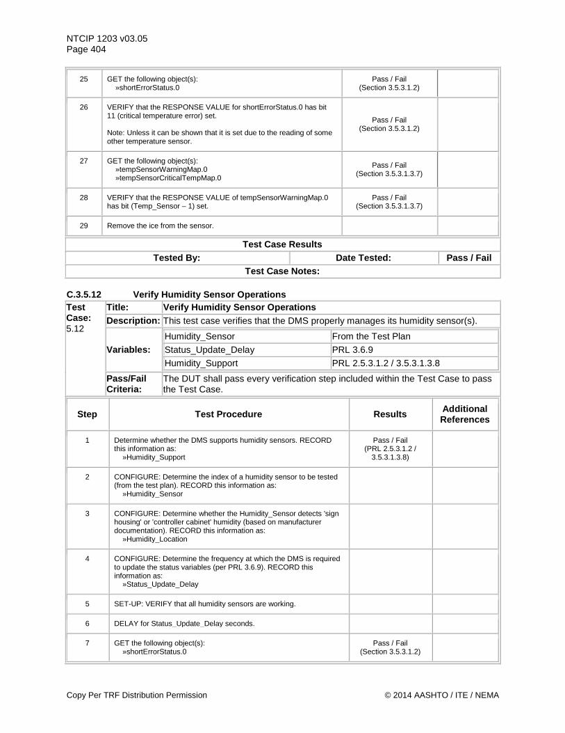
NTCIP 1203 v03.05 Page 404
25 GET the following object(s): »shortErrorStatus.0
Pass / Fail (Section 3.5.3.1.2)
26 VERIFY that the RESPONSE VALUE for shortErrorStatus.0 has bit 11 (critical temperature error) set. Note: Unless it can be shown that it is set due to the reading of some other temperature sensor.
Pass / Fail (Section 3.5.3.1.2)
27 GET the following object(s): »tempSensorWarningMap.0 »tempSensorCriticalTempMap.0
Pass / Fail (Section 3.5.3.1.3.7)
28 VERIFY that the RESPONSE VALUE of tempSensorWarningMap.0 has bit (Temp_Sensor – 1) set.
Pass / Fail (Section 3.5.3.1.3.7)
29 Remove the ice from the sensor.
Test Case Results Tested By: Date Tested: Pass / Fail
Test Case Notes: C.3.5.12 Verify Humidity Sensor Operations Test Case: 5.12
Title: Verify Humidity Sensor Operations Description: This test case verifies that the DMS properly manages its humidity sensor(s).
Variables: Humidity_Sensor From the Test Plan Status_Update_Delay PRL 3.6.9 Humidity_Support PRL 2.5.3.1.2 / 3.5.3.1.3.8
Pass/Fail Criteria:
The DUT shall pass every verification step included within the Test Case to pass the Test Case.
Step Test Procedure Results Additional References
1 Determine whether the DMS supports humidity sensors. RECORD this information as: »Humidity_Support
Pass / Fail (PRL 2.5.3.1.2 /
3.5.3.1.3.8)
2 CONFIGURE: Determine the index of a humidity sensor to be tested (from the test plan). RECORD this information as: »Humidity_Sensor
3 CONFIGURE: Determine whether the Humidity_Sensor detects 'sign housing' or 'controller cabinet' humidity (based on manufacturer documentation). RECORD this information as: »Humidity_Location
4 CONFIGURE: Determine the frequency at which the DMS is required to update the status variables (per PRL 3.6.9). RECORD this information as: »Status_Update_Delay
5 SET-UP: VERIFY that all humidity sensors are working.
6 DELAY for Status_Update_Delay seconds.
7 GET the following object(s): »shortErrorStatus.0
Pass / Fail (Section 3.5.3.1.2)
Copy Per TRF Distribution Permission © 2014 AASHTO / ITE / NEMA
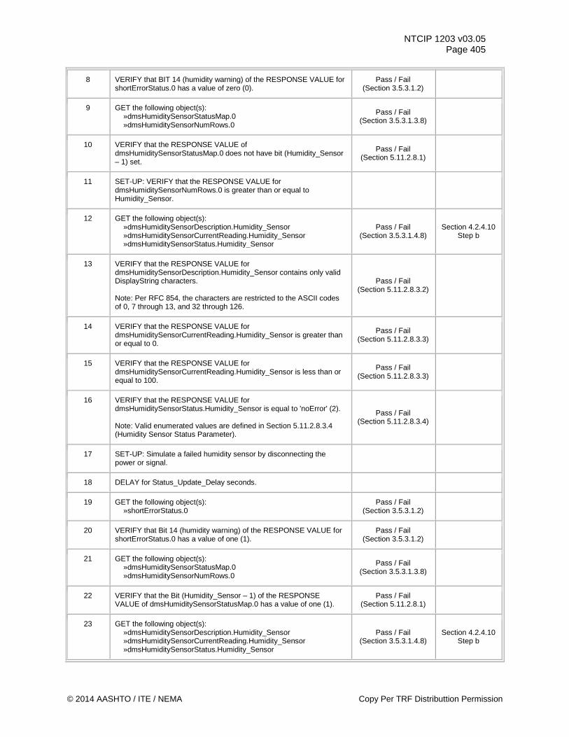
NTCIP 1203 v03.05 Page 405
8 VERIFY that BIT 14 (humidity warning) of the RESPONSE VALUE for shortErrorStatus.0 has a value of zero (0).
Pass / Fail (Section 3.5.3.1.2)
9 GET the following object(s): »dmsHumiditySensorStatusMap.0 »dmsHumiditySensorNumRows.0
Pass / Fail (Section 3.5.3.1.3.8)
10 VERIFY that the RESPONSE VALUE of dmsHumiditySensorStatusMap.0 does not have bit (Humidity_Sensor – 1) set.
Pass / Fail (Section 5.11.2.8.1)
11 SET-UP: VERIFY that the RESPONSE VALUE for dmsHumiditySensorNumRows.0 is greater than or equal to Humidity_Sensor.
12 GET the following object(s): »dmsHumiditySensorDescription.Humidity_Sensor »dmsHumiditySensorCurrentReading.Humidity_Sensor »dmsHumiditySensorStatus.Humidity_Sensor
Pass / Fail (Section 3.5.3.1.4.8)
Section 4.2.4.10 Step b
13 VERIFY that the RESPONSE VALUE for dmsHumiditySensorDescription.Humidity_Sensor contains only valid DisplayString characters. Note: Per RFC 854, the characters are restricted to the ASCII codes of 0, 7 through 13, and 32 through 126.
Pass / Fail (Section 5.11.2.8.3.2)
14 VERIFY that the RESPONSE VALUE for dmsHumiditySensorCurrentReading.Humidity_Sensor is greater than or equal to 0.
Pass / Fail (Section 5.11.2.8.3.3)
15 VERIFY that the RESPONSE VALUE for dmsHumiditySensorCurrentReading.Humidity_Sensor is less than or equal to 100.
Pass / Fail (Section 5.11.2.8.3.3)
16 VERIFY that the RESPONSE VALUE for dmsHumiditySensorStatus.Humidity_Sensor is equal to 'noError' (2). Note: Valid enumerated values are defined in Section 5.11.2.8.3.4 (Humidity Sensor Status Parameter).
Pass / Fail (Section 5.11.2.8.3.4)
17 SET-UP: Simulate a failed humidity sensor by disconnecting the power or signal.
18 DELAY for Status_Update_Delay seconds.
19 GET the following object(s): »shortErrorStatus.0
Pass / Fail (Section 3.5.3.1.2)
20 VERIFY that Bit 14 (humidity warning) of the RESPONSE VALUE for shortErrorStatus.0 has a value of one (1).
Pass / Fail (Section 3.5.3.1.2)
21 GET the following object(s): »dmsHumiditySensorStatusMap.0 »dmsHumiditySensorNumRows.0
Pass / Fail (Section 3.5.3.1.3.8)
22 VERIFY that the Bit (Humidity_Sensor – 1) of the RESPONSE VALUE of dmsHumiditySensorStatusMap.0 has a value of one (1).
Pass / Fail (Section 5.11.2.8.1)
23 GET the following object(s): »dmsHumiditySensorDescription.Humidity_Sensor »dmsHumiditySensorCurrentReading.Humidity_Sensor »dmsHumiditySensorStatus.Humidity_Sensor
Pass / Fail (Section 3.5.3.1.4.8)
Section 4.2.4.10 Step b
© 2014 AASHTO / ITE / NEMA Copy Per TRF Distributtion Permission
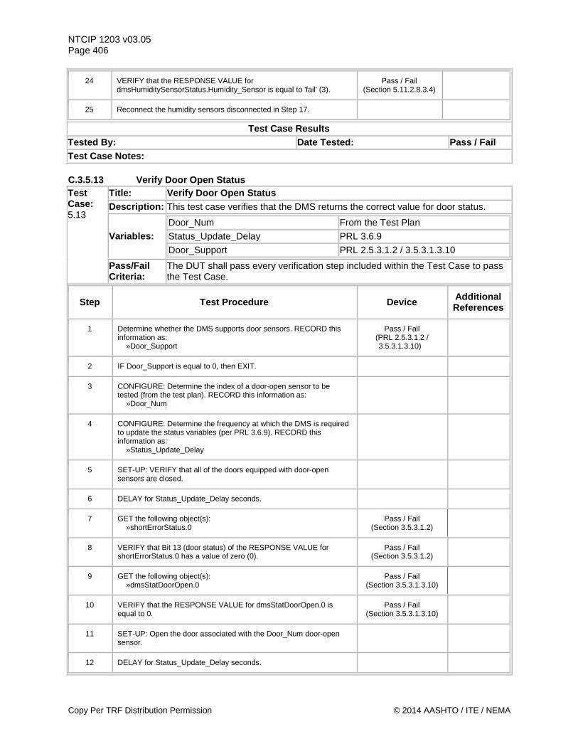
NTCIP 1203 v03.05 Page 406
24 VERIFY that the RESPONSE VALUE for dmsHumiditySensorStatus.Humidity_Sensor is equal to 'fail' (3).
Pass / Fail (Section 5.11.2.8.3.4)
25 Reconnect the humidity sensors disconnected in Step 17.
Test Case Results Tested By: Date Tested: Pass / Fail Test Case Notes: C.3.5.13 Verify Door Open Status Test Case: 5.13
Title: Verify Door Open Status Description: This test case verifies that the DMS returns the correct value for door status.
Variables: Door_Num From the Test Plan Status_Update_Delay PRL 3.6.9 Door_Support PRL 2.5.3.1.2 / 3.5.3.1.3.10
Pass/Fail Criteria:
The DUT shall pass every verification step included within the Test Case to pass the Test Case.
Step Test Procedure Device Additional References
1 Determine whether the DMS supports door sensors. RECORD this information as: »Door_Support
Pass / Fail (PRL 2.5.3.1.2 / 3.5.3.1.3.10)
2 IF Door_Support is equal to 0, then EXIT.
3 CONFIGURE: Determine the index of a door-open sensor to be tested (from the test plan). RECORD this information as: »Door_Num
4 CONFIGURE: Determine the frequency at which the DMS is required to update the status variables (per PRL 3.6.9). RECORD this information as: »Status_Update_Delay
5 SET-UP: VERIFY that all of the doors equipped with door-open sensors are closed.
6 DELAY for Status_Update_Delay seconds.
7 GET the following object(s): »shortErrorStatus.0
Pass / Fail (Section 3.5.3.1.2)
8 VERIFY that Bit 13 (door status) of the RESPONSE VALUE for shortErrorStatus.0 has a value of zero (0).
Pass / Fail (Section 3.5.3.1.2)
9 GET the following object(s): »dmsStatDoorOpen.0
Pass / Fail (Section 3.5.3.1.3.10)
10 VERIFY that the RESPONSE VALUE for dmsStatDoorOpen.0 is equal to 0.
Pass / Fail (Section 3.5.3.1.3.10)
11 SET-UP: Open the door associated with the Door_Num door-open sensor.
12 DELAY for Status_Update_Delay seconds.
Copy Per TRF Distribution Permission © 2014 AASHTO / ITE / NEMA
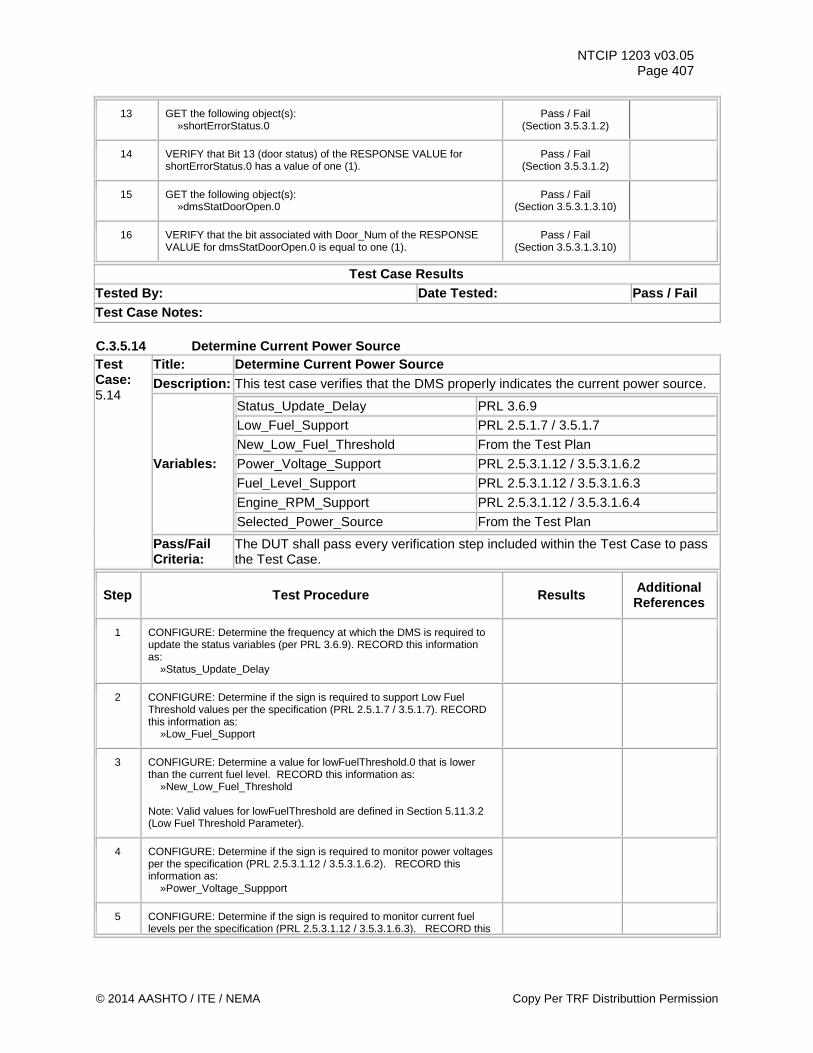
NTCIP 1203 v03.05 Page 407
13 GET the following object(s): »shortErrorStatus.0
Pass / Fail (Section 3.5.3.1.2)
14 VERIFY that Bit 13 (door status) of the RESPONSE VALUE for shortErrorStatus.0 has a value of one (1).
Pass / Fail (Section 3.5.3.1.2)
15 GET the following object(s): »dmsStatDoorOpen.0
Pass / Fail (Section 3.5.3.1.3.10)
16 VERIFY that the bit associated with Door_Num of the RESPONSE VALUE for dmsStatDoorOpen.0 is equal to one (1).
Pass / Fail (Section 3.5.3.1.3.10)
Test Case Results Tested By: Date Tested: Pass / Fail Test Case Notes: C.3.5.14 Determine Current Power Source Test Case: 5.14
Title: Determine Current Power Source Description: This test case verifies that the DMS properly indicates the current power source.
Variables:
Status_Update_Delay PRL 3.6.9 Low_Fuel_Support PRL 2.5.1.7 / 3.5.1.7 New_Low_Fuel_Threshold From the Test Plan Power_Voltage_Support PRL 2.5.3.1.12 / 3.5.3.1.6.2 Fuel_Level_Support PRL 2.5.3.1.12 / 3.5.3.1.6.3 Engine_RPM_Support PRL 2.5.3.1.12 / 3.5.3.1.6.4 Selected_Power_Source From the Test Plan
Pass/Fail Criteria:
The DUT shall pass every verification step included within the Test Case to pass the Test Case.
Step Test Procedure Results Additional References
1 CONFIGURE: Determine the frequency at which the DMS is required to update the status variables (per PRL 3.6.9). RECORD this information as: »Status_Update_Delay
2 CONFIGURE: Determine if the sign is required to support Low Fuel Threshold values per the specification (PRL 2.5.1.7 / 3.5.1.7). RECORD this information as: »Low_Fuel_Support
3 CONFIGURE: Determine a value for lowFuelThreshold.0 that is lower than the current fuel level. RECORD this information as: »New_Low_Fuel_Threshold Note: Valid values for lowFuelThreshold are defined in Section 5.11.3.2 (Low Fuel Threshold Parameter).
4 CONFIGURE: Determine if the sign is required to monitor power voltages per the specification (PRL 2.5.3.1.12 / 3.5.3.1.6.2). RECORD this information as: »Power_Voltage_Suppport
5 CONFIGURE: Determine if the sign is required to monitor current fuel levels per the specification (PRL 2.5.3.1.12 / 3.5.3.1.6.3). RECORD this
© 2014 AASHTO / ITE / NEMA Copy Per TRF Distributtion Permission
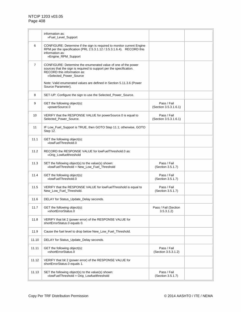
NTCIP 1203 v03.05 Page 408
information as: »Fuel_Level_Support
6 CONFIGURE: Determine if the sign is required to monitor current Engine RPM per the specification (PRL 2.5.3.1.12 / 3.5.3.1.6.4). RECORD this information as: »Engine_RPM_Support
7 CONFIGURE: Determine the enumerated value of one of the power sources that the sign is required to support per the specification. RECORD this information as: »Selected_Power_Source Note: Valid enumerated values are defined in Section 5.11.3.6 (Power Source Parameter).
8 SET-UP: Configure the sign to use the Selected_Power_Source.
9 GET the following object(s): »powerSource.0
Pass / Fail (Section 3.5.3.1.6.1)
10 VERIFY that the RESPONSE VALUE for powerSource.0 is equal to Selected_Power_Source.
Pass / Fail (Section 3.5.3.1.6.1)
11 IF Low_Fuel_Support is TRUE, then GOTO Step 11.1; otherwise, GOTO Step 12.
11.1 GET the following object(s): »lowFuelThreshold.0
11.2 RECORD the RESPONSE VALUE for lowFuelThreshold.0 as: »Orig_Lowfuelthreshold
11.3 SET the following object(s) to the value(s) shown: »lowFuelThreshold = New_Low_Fuel_Threshold
Pass / Fail (Section 3.5.1.7)
11.4 GET the following object(s): »lowFuelThreshold.0
Pass / Fail (Section 3.5.1.7)
11.5 VERIFY that the RESPONSE VALUE for lowFuelThreshold is equal to New_Low_Fuel_Threshold.
Pass / Fail (Section 3.5.1.7)
11.6 DELAY for Status_Update_Delay seconds.
11.7 GET the following object(s): »shortErrorStatus.0
Pass / Fail (Section 3.5.3.1.2)
11.8 VERIFY that bit 2 (power error) of the RESPONSE VALUE for shortErrorStatus.0 equals 0.
11.9 Cause the fuel level to drop below New_Low_Fuel_Threshold.
11.10 DELAY for Status_Update_Delay seconds.
11.11 GET the following object(s): »shortErrorStatus.0
Pass / Fail (Section 3.5.3.1.2)
11.12 VERIFY that bit 2 (power error) of the RESPONSE VALUE for shortErrorStatus.0 equals 1.
11.13 SET the following object(s) to the value(s) shown: »lowFuelThreshold = Orig_Lowfuelthreshold
Pass / Fail (Section 3.5.1.7)
Copy Per TRF Distribution Permission © 2014 AASHTO / ITE / NEMA
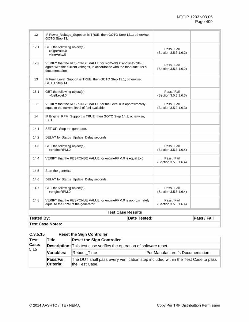
NTCIP 1203 v03.05 Page 409
12 IF Power_Voltage_Suppport is TRUE, then GOTO Step 12.1; otherwise, GOTO Step 13.
12.1 GET the following object(s): »signVolts.0 »lineVolts.0
Pass / Fail (Section 3.5.3.1.6.2)
12.2 VERIFY that the RESPONSE VALUE for signVolts.0 and lineVolts.0 agree with the current voltages, in accordance with the manufacturer’s documentation.
Pass / Fail (Section 3.5.3.1.6.2)
13 IF Fuel_Level_Support is TRUE, then GOTO Step 13.1; otherwise, GOTO Step 14.
13.1 GET the following object(s): »fuelLevel.0
Pass / Fail (Section 3.5.3.1.6.3)
13.2 VERIFY that the RESPONSE VALUE for fuelLevel.0 is approximately equal to the current level of fuel available.
Pass / Fail (Section 3.5.3.1.6.3)
14 IF Engine_RPM_Support is TRUE, then GOTO Step 14.1; otherwise, EXIT.
14.1 SET-UP: Stop the generator.
14.2 DELAY for Status_Update_Delay seconds.
14.3 GET the following object(s): »engineRPM.0
Pass / Fail (Section 3.5.3.1.6.4)
14.4 VERIFY that the RESPONSE VALUE for engineRPM.0 is equal to 0. Pass / Fail (Section 3.5.3.1.6.4)
14.5 Start the generator.
14.6 DELAY for Status_Update_Delay seconds.
14.7 GET the following object(s): »engineRPM.0
Pass / Fail (Section 3.5.3.1.6.4)
14.8 VERIFY that the RESPONSE VALUE for engineRPM.0 is approximately equal to the RPM of the generator.
Pass / Fail (Section 3.5.3.1.6.4)
Test Case Results Tested By: Date Tested: Pass / Fail Test Case Notes: C.3.5.15 Reset the Sign Controller Test Case: 5.15
Title: Reset the Sign Controller Description: This test case verifies the operation of software reset.
Variables: Reboot_Time Per Manufacturer’s Documentation
Pass/Fail Criteria:
The DUT shall pass every verification step included within the Test Case to pass the Test Case.
© 2014 AASHTO / ITE / NEMA Copy Per TRF Distributtion Permission
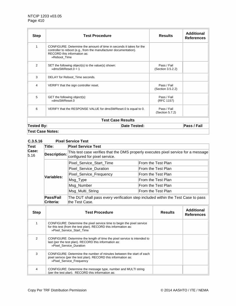
NTCIP 1203 v03.05 Page 410
Step Test Procedure Results Additional References
1 CONFIGURE: Determine the amount of time in seconds it takes for the controller to reboot (e.g., from the manufacturer documentation). RECORD this information as: »Reboot_Time
2 SET the following object(s) to the value(s) shown: »dmsSWReset.0 = 1
Pass / Fail (Section 3.5.2.2)
3 DELAY for Reboot_Time seconds.
4 VERIFY that the sign controller reset. Pass / Fail (Section 3.5.2.2)
5 GET the following object(s): »dmsSWReset.0
Pass / Fail (RFC 1157)
6 VERIFY that the RESPONSE VALUE for dmsSWReset.0 is equal to 0. Pass / Fail (Section 5.7.2)
Test Case Results Tested By: Date Tested: Pass / Fail Test Case Notes: C.3.5.16 Pixel Service Test Test Case: 5.16
Title: Pixel Service Test
Description: This test case verifies that the DMS properly executes pixel service for a message configured for pixel service.
Variables:
Pixel_Service_Start_Time From the Test Plan Pixel_Service_Duration From the Test Plan Pixel_Service_Frequency From the Test Plan Msg_Type From the Test Plan Msg_Number From the Test Plan Msg_Multi_String From the Test Plan
Pass/Fail Criteria:
The DUT shall pass every verification step included within the Test Case to pass the Test Case.
Step Test Procedure Results Additional References
1 CONFIGURE: Determine the pixel service time to begin the pixel service for this test (from the test plan). RECORD this information as: »Pixel_Service_Start_Time
2 CONFIGURE: Determine the length of time the pixel service is intended to last (per the test plan). RECORD this information as: »Pixel_Service_Duration
3 CONFIGURE: Determine the number of minutes between the start of each pixel serivce (per the test plan). RECORD this information as: »Pixel_Service_Frequency
4 CONFIGURE: Determine the message type, number and MULTI string (per the test plan). RECORD this information as:
Copy Per TRF Distribution Permission © 2014 AASHTO / ITE / NEMA
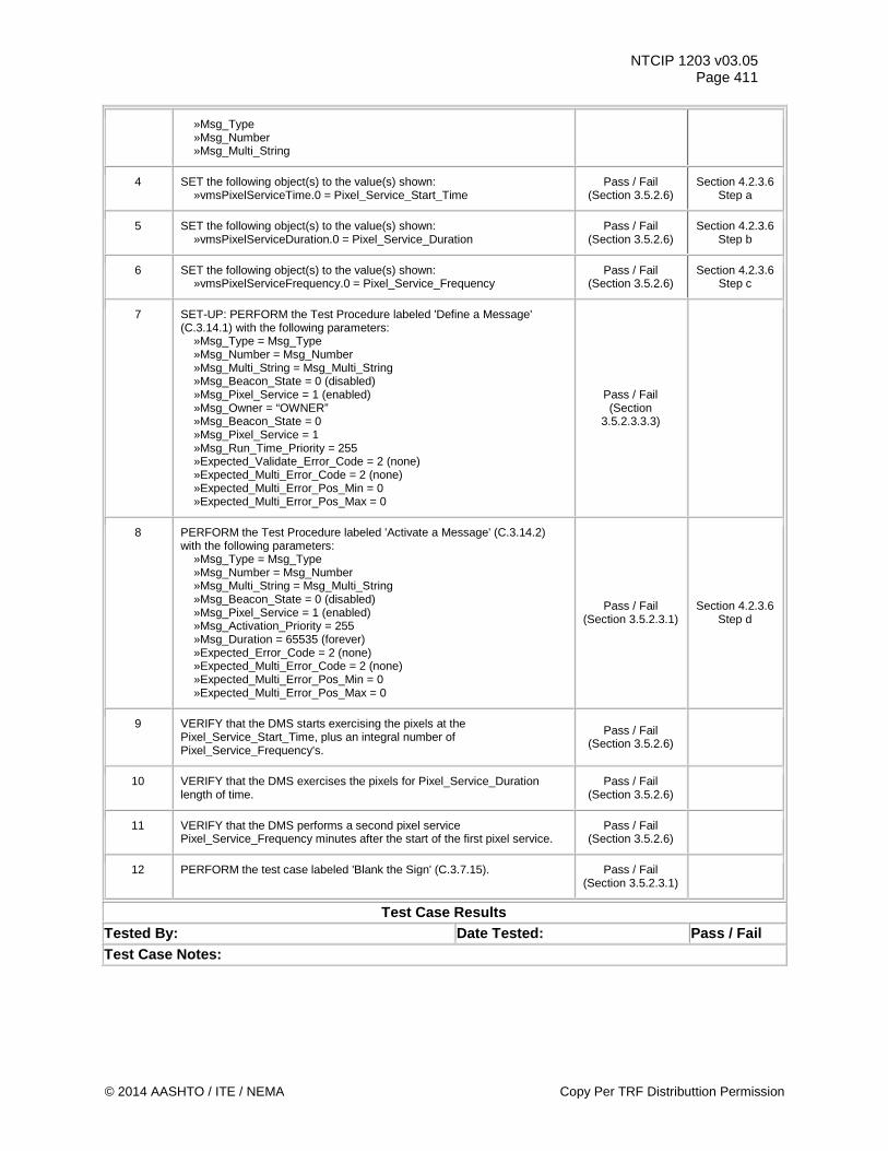
NTCIP 1203 v03.05 Page 411
»Msg_Type »Msg_Number »Msg_Multi_String
4 SET the following object(s) to the value(s) shown: »vmsPixelServiceTime.0 = Pixel_Service_Start_Time
Pass / Fail (Section 3.5.2.6)
Section 4.2.3.6 Step a
5 SET the following object(s) to the value(s) shown: »vmsPixelServiceDuration.0 = Pixel_Service_Duration
Pass / Fail (Section 3.5.2.6)
Section 4.2.3.6 Step b
6 SET the following object(s) to the value(s) shown: »vmsPixelServiceFrequency.0 = Pixel_Service_Frequency
Pass / Fail (Section 3.5.2.6)
Section 4.2.3.6 Step c
7 SET-UP: PERFORM the Test Procedure labeled 'Define a Message' (C.3.14.1) with the following parameters: »Msg_Type = Msg_Type »Msg_Number = Msg_Number »Msg_Multi_String = Msg_Multi_String »Msg_Beacon_State = 0 (disabled) »Msg_Pixel_Service = 1 (enabled) »Msg_Owner = “OWNER” »Msg_Beacon_State = 0 »Msg_Pixel_Service = 1 »Msg_Run_Time_Priority = 255 »Expected_Validate_Error_Code = 2 (none) »Expected_Multi_Error_Code = 2 (none) »Expected_Multi_Error_Pos_Min = 0 »Expected_Multi_Error_Pos_Max = 0
Pass / Fail (Section
3.5.2.3.3.3)
8 PERFORM the Test Procedure labeled 'Activate a Message' (C.3.14.2) with the following parameters: »Msg_Type = Msg_Type »Msg_Number = Msg_Number »Msg_Multi_String = Msg_Multi_String »Msg_Beacon_State = 0 (disabled) »Msg_Pixel_Service = 1 (enabled) »Msg_Activation_Priority = 255 »Msg_Duration = 65535 (forever) »Expected_Error_Code = 2 (none) »Expected_Multi_Error_Code = 2 (none) »Expected_Multi_Error_Pos_Min = 0 »Expected_Multi_Error_Pos_Max = 0
Pass / Fail (Section 3.5.2.3.1)
Section 4.2.3.6 Step d
9 VERIFY that the DMS starts exercising the pixels at the Pixel_Service_Start_Time, plus an integral number of Pixel_Service_Frequency's.
Pass / Fail (Section 3.5.2.6)
10 VERIFY that the DMS exercises the pixels for Pixel_Service_Duration length of time.
Pass / Fail (Section 3.5.2.6)
11 VERIFY that the DMS performs a second pixel service Pixel_Service_Frequency minutes after the start of the first pixel service.
Pass / Fail (Section 3.5.2.6)
12 PERFORM the test case labeled 'Blank the Sign' (C.3.7.15). Pass / Fail (Section 3.5.2.3.1)
Test Case Results Tested By: Date Tested: Pass / Fail Test Case Notes:
© 2014 AASHTO / ITE / NEMA Copy Per TRF Distributtion Permission
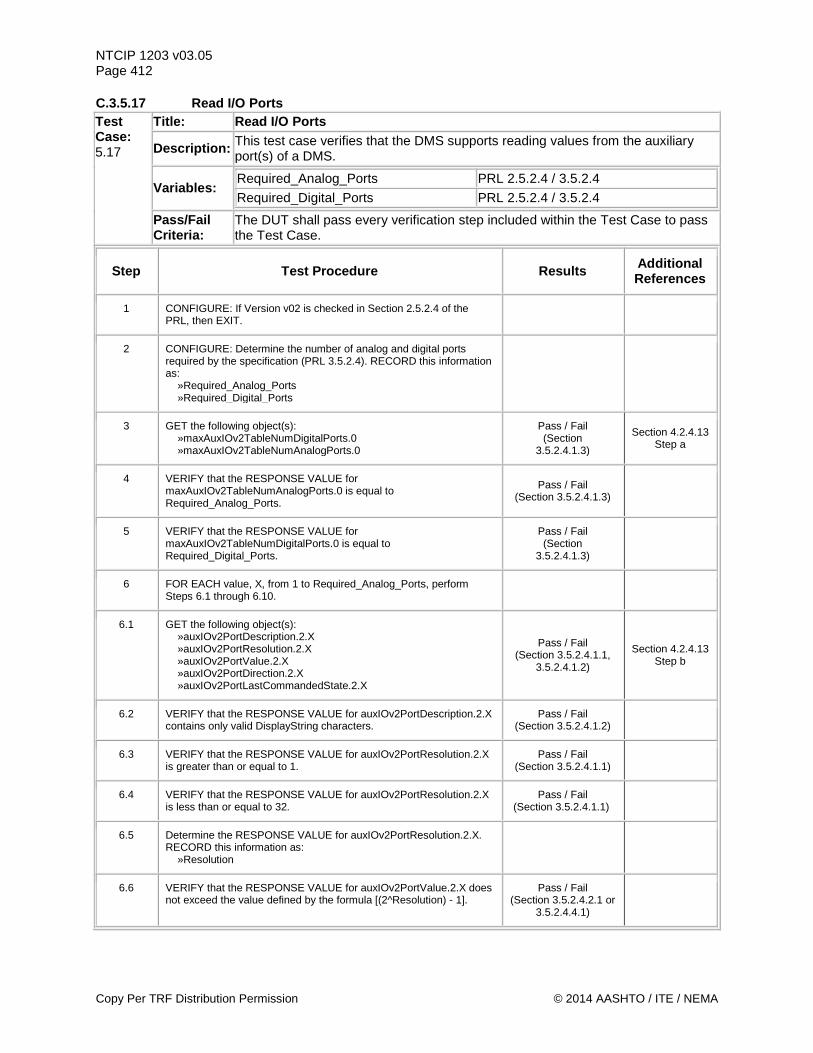
NTCIP 1203 v03.05 Page 412 C.3.5.17 Read I/O Ports Test Case: 5.17
Title: Read I/O Ports
Description: This test case verifies that the DMS supports reading values from the auxiliary port(s) of a DMS.
Variables: Required_Analog_Ports PRL 2.5.2.4 / 3.5.2.4 Required_Digital_Ports PRL 2.5.2.4 / 3.5.2.4
Pass/Fail Criteria:
The DUT shall pass every verification step included within the Test Case to pass the Test Case.
Step Test Procedure Results Additional References
1 CONFIGURE: If Version v02 is checked in Section 2.5.2.4 of the PRL, then EXIT.
2 CONFIGURE: Determine the number of analog and digital ports required by the specification (PRL 3.5.2.4). RECORD this information as: »Required_Analog_Ports »Required_Digital_Ports
3 GET the following object(s): »maxAuxIOv2TableNumDigitalPorts.0 »maxAuxIOv2TableNumAnalogPorts.0
Pass / Fail (Section
3.5.2.4.1.3)
Section 4.2.4.13 Step a
4 VERIFY that the RESPONSE VALUE for maxAuxIOv2TableNumAnalogPorts.0 is equal to Required_Analog_Ports.
Pass / Fail (Section 3.5.2.4.1.3)
5 VERIFY that the RESPONSE VALUE for maxAuxIOv2TableNumDigitalPorts.0 is equal to Required_Digital_Ports.
Pass / Fail (Section
3.5.2.4.1.3)
6 FOR EACH value, X, from 1 to Required_Analog_Ports, perform Steps 6.1 through 6.10.
6.1 GET the following object(s): »auxIOv2PortDescription.2.X »auxIOv2PortResolution.2.X »auxIOv2PortValue.2.X »auxIOv2PortDirection.2.X »auxIOv2PortLastCommandedState.2.X
Pass / Fail (Section 3.5.2.4.1.1,
3.5.2.4.1.2)
Section 4.2.4.13 Step b
6.2 VERIFY that the RESPONSE VALUE for auxIOv2PortDescription.2.X contains only valid DisplayString characters.
Pass / Fail (Section 3.5.2.4.1.2)
6.3 VERIFY that the RESPONSE VALUE for auxIOv2PortResolution.2.X is greater than or equal to 1.
Pass / Fail (Section 3.5.2.4.1.1)
6.4 VERIFY that the RESPONSE VALUE for auxIOv2PortResolution.2.X is less than or equal to 32.
Pass / Fail (Section 3.5.2.4.1.1)
6.5 Determine the RESPONSE VALUE for auxIOv2PortResolution.2.X. RECORD this information as: »Resolution
6.6 VERIFY that the RESPONSE VALUE for auxIOv2PortValue.2.X does not exceed the value defined by the formula [(2^Resolution) - 1].
Pass / Fail (Section 3.5.2.4.2.1 or
3.5.2.4.4.1)
Copy Per TRF Distribution Permission © 2014 AASHTO / ITE / NEMA
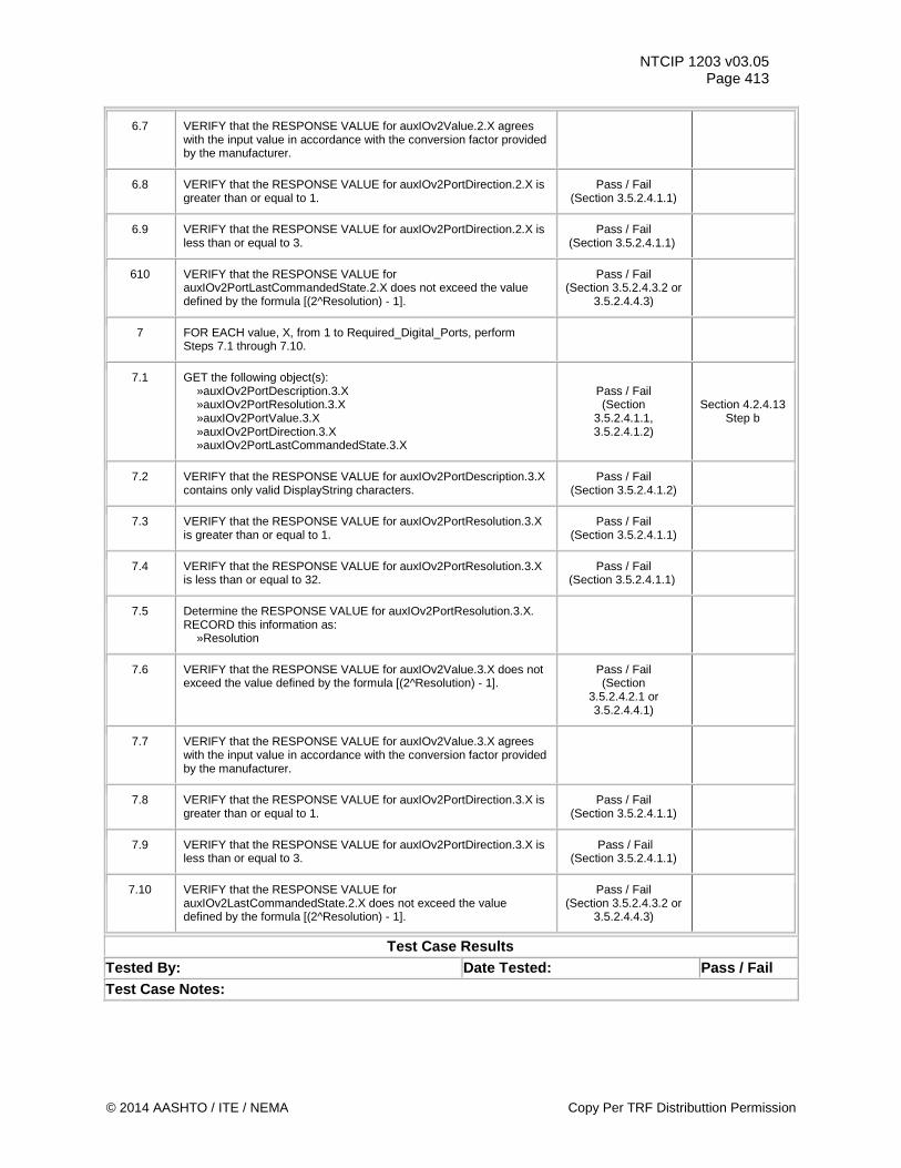
NTCIP 1203 v03.05 Page 413
6.7 VERIFY that the RESPONSE VALUE for auxIOv2Value.2.X agrees with the input value in accordance with the conversion factor provided by the manufacturer.
6.8 VERIFY that the RESPONSE VALUE for auxIOv2PortDirection.2.X is greater than or equal to 1.
Pass / Fail (Section 3.5.2.4.1.1)
6.9 VERIFY that the RESPONSE VALUE for auxIOv2PortDirection.2.X is less than or equal to 3.
Pass / Fail (Section 3.5.2.4.1.1)
610 VERIFY that the RESPONSE VALUE for auxIOv2PortLastCommandedState.2.X does not exceed the value defined by the formula [(2^Resolution) - 1].
Pass / Fail (Section 3.5.2.4.3.2 or
3.5.2.4.4.3)
7 FOR EACH value, X, from 1 to Required_Digital_Ports, perform Steps 7.1 through 7.10.
7.1 GET the following object(s): »auxIOv2PortDescription.3.X »auxIOv2PortResolution.3.X »auxIOv2PortValue.3.X »auxIOv2PortDirection.3.X »auxIOv2PortLastCommandedState.3.X
Pass / Fail (Section
3.5.2.4.1.1, 3.5.2.4.1.2)
Section 4.2.4.13 Step b
7.2 VERIFY that the RESPONSE VALUE for auxIOv2PortDescription.3.X contains only valid DisplayString characters.
Pass / Fail (Section 3.5.2.4.1.2)
7.3 VERIFY that the RESPONSE VALUE for auxIOv2PortResolution.3.X is greater than or equal to 1.
Pass / Fail (Section 3.5.2.4.1.1)
7.4 VERIFY that the RESPONSE VALUE for auxIOv2PortResolution.3.X is less than or equal to 32.
Pass / Fail (Section 3.5.2.4.1.1)
7.5 Determine the RESPONSE VALUE for auxIOv2PortResolution.3.X. RECORD this information as: »Resolution
7.6 VERIFY that the RESPONSE VALUE for auxIOv2Value.3.X does not exceed the value defined by the formula [(2^Resolution) - 1].
Pass / Fail (Section
3.5.2.4.2.1 or 3.5.2.4.4.1)
7.7 VERIFY that the RESPONSE VALUE for auxIOv2Value.3.X agrees with the input value in accordance with the conversion factor provided by the manufacturer.
7.8 VERIFY that the RESPONSE VALUE for auxIOv2PortDirection.3.X is greater than or equal to 1.
Pass / Fail (Section 3.5.2.4.1.1)
7.9 VERIFY that the RESPONSE VALUE for auxIOv2PortDirection.3.X is less than or equal to 3.
Pass / Fail (Section 3.5.2.4.1.1)
7.10 VERIFY that the RESPONSE VALUE for auxIOv2LastCommandedState.2.X does not exceed the value defined by the formula [(2^Resolution) - 1].
Pass / Fail (Section 3.5.2.4.3.2 or
3.5.2.4.4.3)
Test Case Results Tested By: Date Tested: Pass / Fail Test Case Notes:
© 2014 AASHTO / ITE / NEMA Copy Per TRF Distributtion Permission
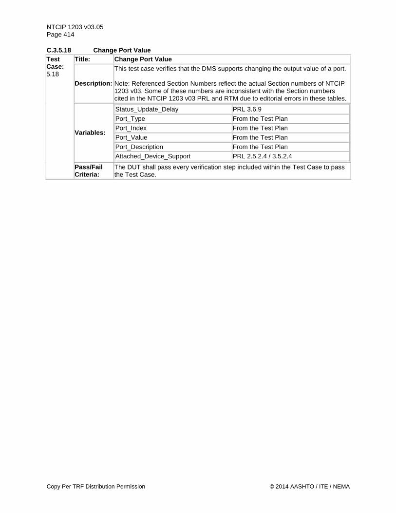
NTCIP 1203 v03.05 Page 414 C.3.5.18 Change Port Value Test Case: 5.18
Title: Change Port Value
Description:
This test case verifies that the DMS supports changing the output value of a port. Note: Referenced Section Numbers reflect the actual Section numbers of NTCIP 1203 v03. Some of these numbers are inconsistent with the Section numbers cited in the NTCIP 1203 v03 PRL and RTM due to editorial errors in these tables.
Variables:
Status_Update_Delay PRL 3.6.9 Port_Type From the Test Plan Port_Index From the Test Plan Port_Value From the Test Plan Port_Description From the Test Plan
Attached_Device_Support PRL 2.5.2.4 / 3.5.2.4
Pass/Fail Criteria:
The DUT shall pass every verification step included within the Test Case to pass the Test Case.
Copy Per TRF Distribution Permission © 2014 AASHTO / ITE / NEMA
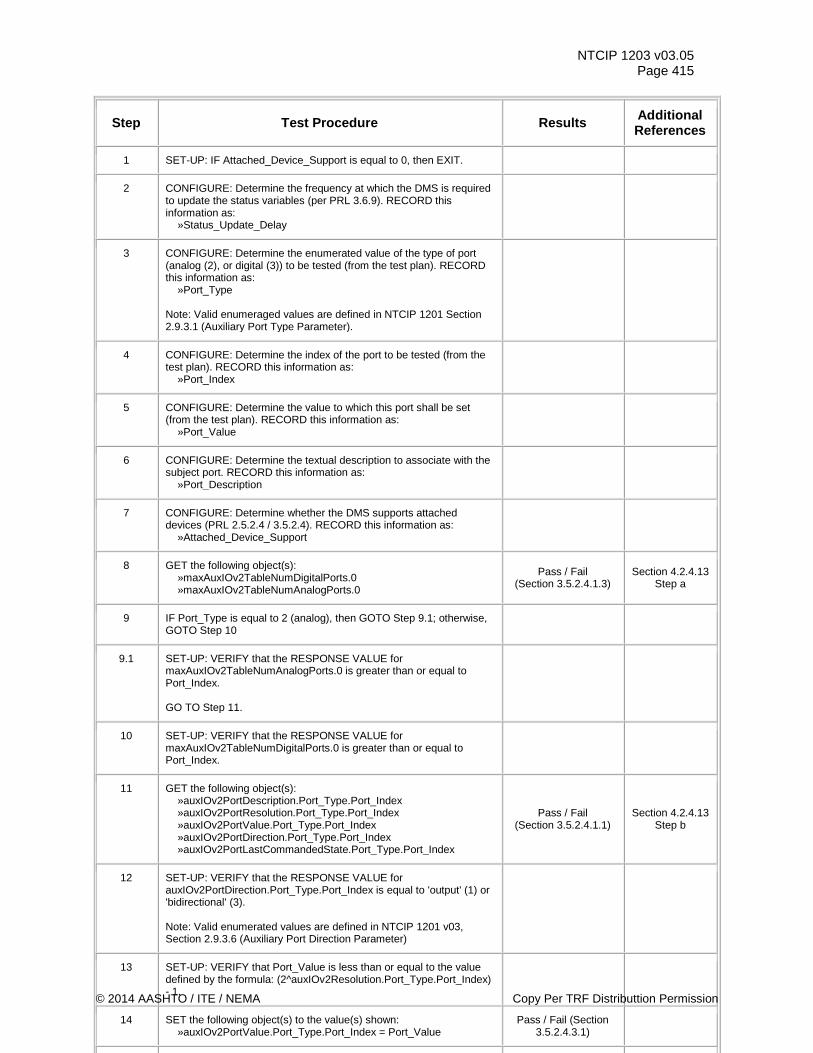
NTCIP 1203 v03.05 Page 415
Step Test Procedure Results Additional References
1 SET-UP: IF Attached_Device_Support is equal to 0, then EXIT.
2 CONFIGURE: Determine the frequency at which the DMS is required to update the status variables (per PRL 3.6.9). RECORD this information as: »Status_Update_Delay
3 CONFIGURE: Determine the enumerated value of the type of port (analog (2), or digital (3)) to be tested (from the test plan). RECORD this information as: »Port_Type Note: Valid enumeraged values are defined in NTCIP 1201 Section 2.9.3.1 (Auxiliary Port Type Parameter).
4 CONFIGURE: Determine the index of the port to be tested (from the test plan). RECORD this information as: »Port_Index
5 CONFIGURE: Determine the value to which this port shall be set (from the test plan). RECORD this information as: »Port_Value
6 CONFIGURE: Determine the textual description to associate with the subject port. RECORD this information as: »Port_Description
7 CONFIGURE: Determine whether the DMS supports attached devices (PRL 2.5.2.4 / 3.5.2.4). RECORD this information as: »Attached_Device_Support
8 GET the following object(s): »maxAuxIOv2TableNumDigitalPorts.0 »maxAuxIOv2TableNumAnalogPorts.0
Pass / Fail (Section 3.5.2.4.1.3)
Section 4.2.4.13 Step a
9 IF Port_Type is equal to 2 (analog), then GOTO Step 9.1; otherwise, GOTO Step 10
9.1 SET-UP: VERIFY that the RESPONSE VALUE for maxAuxIOv2TableNumAnalogPorts.0 is greater than or equal to Port_Index. GO TO Step 11.
10 SET-UP: VERIFY that the RESPONSE VALUE for maxAuxIOv2TableNumDigitalPorts.0 is greater than or equal to Port_Index.
11 GET the following object(s): »auxIOv2PortDescription.Port_Type.Port_Index »auxIOv2PortResolution.Port_Type.Port_Index »auxIOv2PortValue.Port_Type.Port_Index »auxIOv2PortDirection.Port_Type.Port_Index »auxIOv2PortLastCommandedState.Port_Type.Port_Index
Pass / Fail (Section 3.5.2.4.1.1)
Section 4.2.4.13 Step b
12 SET-UP: VERIFY that the RESPONSE VALUE for auxIOv2PortDirection.Port_Type.Port_Index is equal to 'output' (1) or 'bidirectional' (3). Note: Valid enumerated values are defined in NTCIP 1201 v03, Section 2.9.3.6 (Auxiliary Port Direction Parameter)
13 SET-UP: VERIFY that Port_Value is less than or equal to the value defined by the formula: (2^auxIOv2Resolution.Port_Type.Port_Index) - 1.
14 SET the following object(s) to the value(s) shown: »auxIOv2PortValue.Port_Type.Port_Index = Port_Value
Pass / Fail (Section 3.5.2.4.3.1)
© 2014 AASHTO / ITE / NEMA Copy Per TRF Distributtion Permission
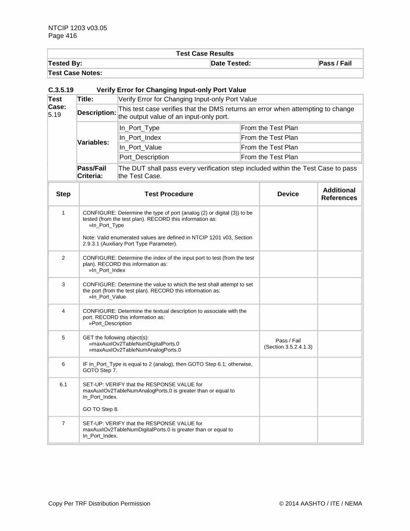
NTCIP 1203 v03.05 Page 416
Test Case Results Tested By: Date Tested: Pass / Fail Test Case Notes: C.3.5.19 Verify Error for Changing Input-only Port Value Test Case: 5.19
Title: Verify Error for Changing Input-only Port Value
Description: This test case verifies that the DMS returns an error when attempting to change the output value of an input-only port.
Variables:
In_Port_Type From the Test Plan In_Port_Index From the Test Plan In_Port_Value From the Test Plan Port_Description From the Test Plan
Pass/Fail Criteria:
The DUT shall pass every verification step included within the Test Case to pass the Test Case.
Step Test Procedure Device Additional References
1 CONFIGURE: Determine the type of port (analog (2) or digital (3)) to be tested (from the test plan). RECORD this information as: »In_Port_Type Note: Valid enumerated values are defined in NTCIP 1201 v03, Section 2.9.3.1 (Auxiliary Port Type Parameter).
2 CONFIGURE: Determine the index of the input port to test (from the test plan). RECORD this information as: »In_Port_Index
3 CONFIGURE: Determine the value to which the test shall attempt to set the port (from the test plan). RECORD this information as: »In_Port_Value
4 CONFIGURE: Determine the textual description to associate with the port. RECORD this information as: »Port_Description
5 GET the following object(s): »maxAuxIOv2TableNumDigitalPorts.0 »maxAuxIOv2TableNumAnalogPorts.0
Pass / Fail (Section 3.5.2.4.1.3)
6 IF In_Port_Type is equal to 2 (analog), then GOTO Step 6.1; otherwise, GOTO Step 7.
6.1 SET-UP: VERIFY that the RESPONSE VALUE for maxAuxIOv2TableNumAnalogPorts.0 is greater than or equal to In_Port_Index. GO TO Step 8.
7 SET-UP: VERIFY that the RESPONSE VALUE for maxAuxIOv2TableNumDigitalPorts.0 is greater than or equal to In_Port_Index.
Copy Per TRF Distribution Permission © 2014 AASHTO / ITE / NEMA
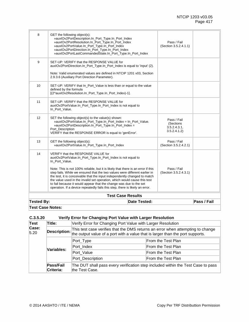
NTCIP 1203 v03.05 Page 417
8 GET the following object(s): »auxIOv2PortDescription.In_Port_Type.In_Port_Index »auxIOv2PortResolution.In_Port_Type.In_Port_Index »auxIOv2PortValue.In_Port_Type.In_Port_Index »auxIOv2PortDirection.In_Port_Type.In_Port_Index »auxIOv2PortLastCommandedState.In_Port_Type.In_Port_Index
Pass / Fail (Section 3.5.2.4.1.1)
9 SET-UP: VERIFY that the RESPONSE VALUE for auxIOv2PortDirection.In_Port_Type.In_Port_Index is equal to 'input' (2). Note: Valid enumerated values are defined in NTCIP 1201 v03, Section 2.9.3.6 (Auxiliary Port Direction Parameter).
10 SET-UP: VERIFY that In_Port_Value is less than or equal to the value defined by the formula [(2^auxIOv2Resolution.In_Port_Type.In_Port_Index)-1].
11 SET-UP: VERIFY that the RESPONSE VALUE for auxIOv2PortValue.In_Port_Type.In_Port_Index is not equal to In_Port_Value.
12 SET the following object(s) to the value(s) shown: »auxIOv2PortValue.In_Port_Type.In_Port_Index = In_Port_Value. »auxIOv2PortDescription.In_Port_Type.In_Port_Index = Port_Description VERIFY that the RESPONSE ERROR is equal to 'genError'.
Pass / Fail (Sections
3.5.2.4.3.1, 3.5.2.4.1.2)
13 GET the following object(s): »auxIOv2PortValue.In_Port_Type.In_Port_Index
Pass / Fail (Section 3.5.2.4.2.1)
14 VERIFY that the RESPONSE VALUE for auxIOv2PortValue.In_Port_Type.In_Port_Index is not equal to In_Port_Value. Note: This is not 100% reliable, but it is likely that there is an error if this step fails. While we ensured that the two values were different earlier in the test, it is conceivable that the input independently changed to match the value used in the invalid set operation, which would cause this test to fail because it would appear that the change was due to the set operation. If a device repeatedly fails this step, there is likely an error.
Pass / Fail (Section 3.5.2.4.3.1)
Test Case Results Tested By: Date Tested: Pass / Fail Test Case Notes: C.3.5.20 Verify Error for Changing Port Value with Larger Resolution Test Case: 5.20
Title: Verify Error for Changing Port Value with Larger Resolution
Description: This test case verifies that the DMS returns an error when attempting to change the output value of a port with a value that is larger than the port supports.
Variables:
Port_Type From the Test Plan Port_Index From the Test Plan Port_Value From the Test Plan Port_Description From the Test Plan
Pass/Fail Criteria:
The DUT shall pass every verification step included within the Test Case to pass the Test Case.
© 2014 AASHTO / ITE / NEMA Copy Per TRF Distributtion Permission
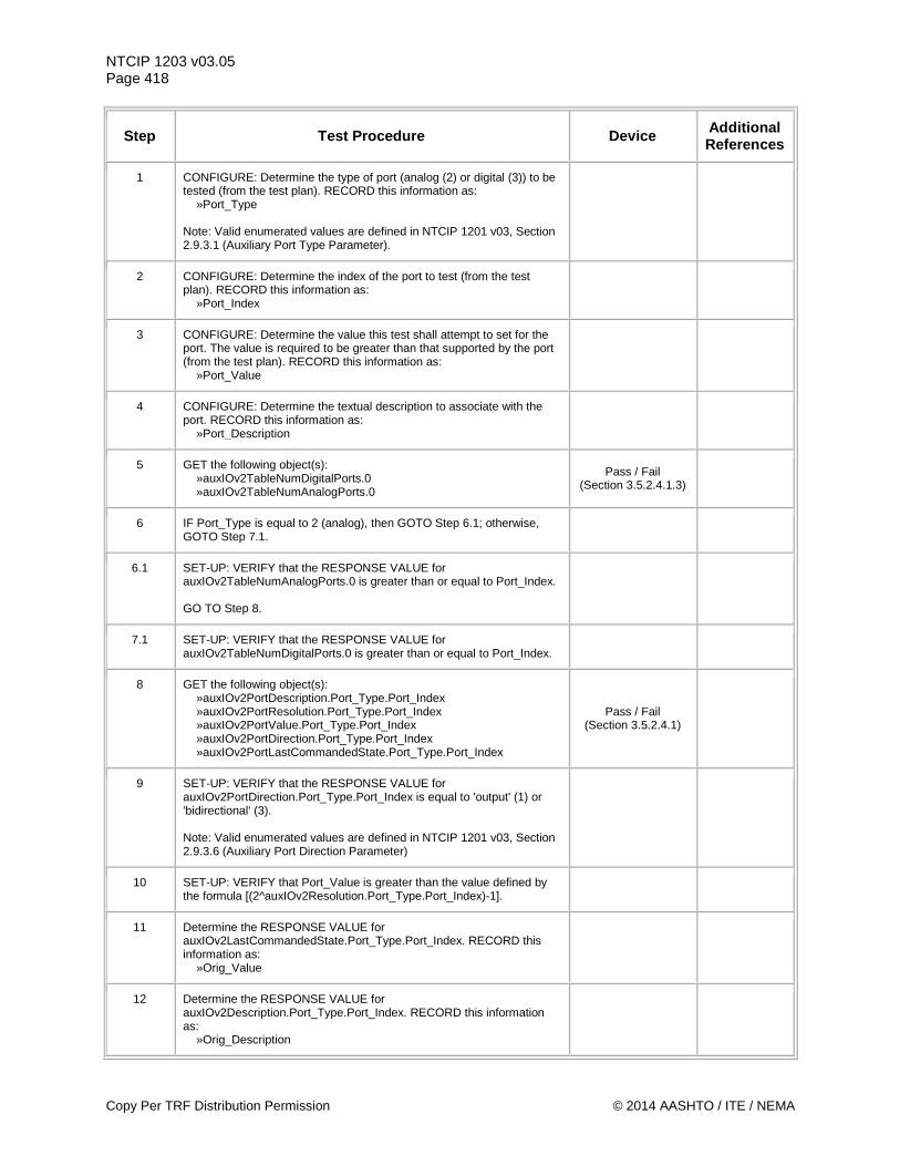
NTCIP 1203 v03.05 Page 418
Step Test Procedure Device Additional References
1 CONFIGURE: Determine the type of port (analog (2) or digital (3)) to be tested (from the test plan). RECORD this information as: »Port_Type Note: Valid enumerated values are defined in NTCIP 1201 v03, Section 2.9.3.1 (Auxiliary Port Type Parameter).
2 CONFIGURE: Determine the index of the port to test (from the test plan). RECORD this information as: »Port_Index
3 CONFIGURE: Determine the value this test shall attempt to set for the port. The value is required to be greater than that supported by the port (from the test plan). RECORD this information as: »Port_Value
4 CONFIGURE: Determine the textual description to associate with the port. RECORD this information as: »Port_Description
5 GET the following object(s): »auxIOv2TableNumDigitalPorts.0 »auxIOv2TableNumAnalogPorts.0
Pass / Fail (Section 3.5.2.4.1.3)
6 IF Port_Type is equal to 2 (analog), then GOTO Step 6.1; otherwise, GOTO Step 7.1.
6.1 SET-UP: VERIFY that the RESPONSE VALUE for auxIOv2TableNumAnalogPorts.0 is greater than or equal to Port_Index. GO TO Step 8.
7.1 SET-UP: VERIFY that the RESPONSE VALUE for auxIOv2TableNumDigitalPorts.0 is greater than or equal to Port_Index.
8 GET the following object(s): »auxIOv2PortDescription.Port_Type.Port_Index »auxIOv2PortResolution.Port_Type.Port_Index »auxIOv2PortValue.Port_Type.Port_Index »auxIOv2PortDirection.Port_Type.Port_Index »auxIOv2PortLastCommandedState.Port_Type.Port_Index
Pass / Fail (Section 3.5.2.4.1)
9 SET-UP: VERIFY that the RESPONSE VALUE for auxIOv2PortDirection.Port_Type.Port_Index is equal to 'output' (1) or 'bidirectional' (3). Note: Valid enumerated values are defined in NTCIP 1201 v03, Section 2.9.3.6 (Auxiliary Port Direction Parameter)
10 SET-UP: VERIFY that Port_Value is greater than the value defined by the formula [(2^auxIOv2Resolution.Port_Type.Port_Index)-1].
11 Determine the RESPONSE VALUE for auxIOv2LastCommandedState.Port_Type.Port_Index. RECORD this information as: »Orig_Value
12 Determine the RESPONSE VALUE for auxIOv2Description.Port_Type.Port_Index. RECORD this information as: »Orig_Description
Copy Per TRF Distribution Permission © 2014 AASHTO / ITE / NEMA
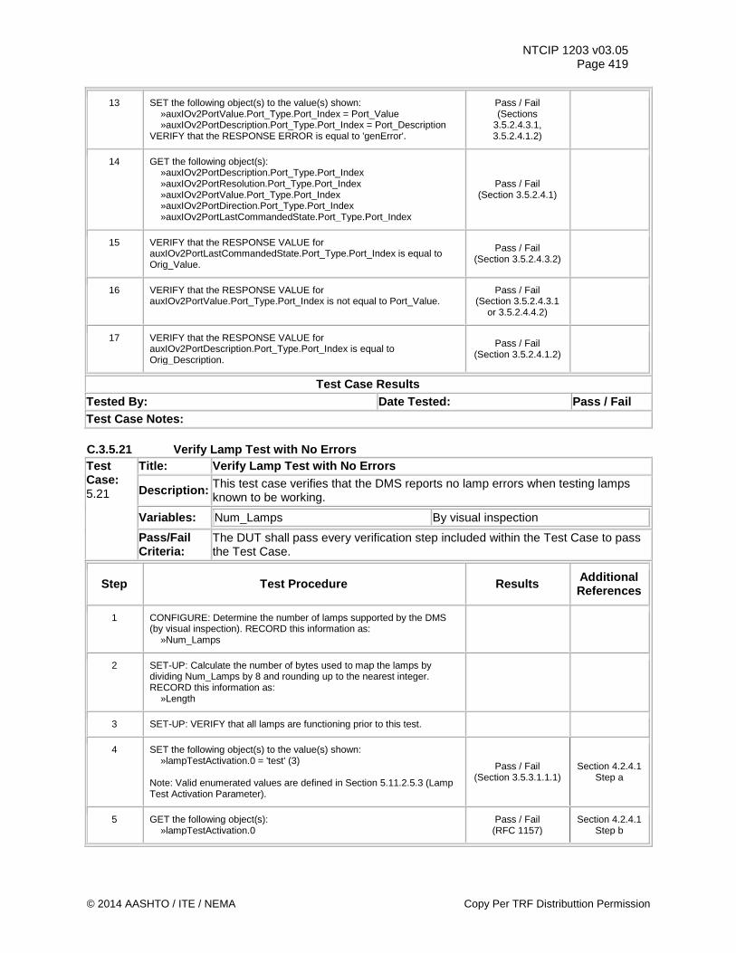
NTCIP 1203 v03.05 Page 419
13 SET the following object(s) to the value(s) shown: »auxIOv2PortValue.Port_Type.Port_Index = Port_Value »auxIOv2PortDescription.Port_Type.Port_Index = Port_Description VERIFY that the RESPONSE ERROR is equal to 'genError'.
Pass / Fail (Sections
3.5.2.4.3.1, 3.5.2.4.1.2)
14 GET the following object(s): »auxIOv2PortDescription.Port_Type.Port_Index »auxIOv2PortResolution.Port_Type.Port_Index »auxIOv2PortValue.Port_Type.Port_Index »auxIOv2PortDirection.Port_Type.Port_Index »auxIOv2PortLastCommandedState.Port_Type.Port_Index
Pass / Fail (Section 3.5.2.4.1)
15 VERIFY that the RESPONSE VALUE for auxIOv2PortLastCommandedState.Port_Type.Port_Index is equal to Orig_Value.
Pass / Fail (Section 3.5.2.4.3.2)
16 VERIFY that the RESPONSE VALUE for auxIOv2PortValue.Port_Type.Port_Index is not equal to Port_Value.
Pass / Fail (Section 3.5.2.4.3.1
or 3.5.2.4.4.2)
17 VERIFY that the RESPONSE VALUE for auxIOv2PortDescription.Port_Type.Port_Index is equal to Orig_Description.
Pass / Fail (Section 3.5.2.4.1.2)
Test Case Results Tested By: Date Tested: Pass / Fail Test Case Notes: C.3.5.21 Verify Lamp Test with No Errors Test Case: 5.21
Title: Verify Lamp Test with No Errors
Description: This test case verifies that the DMS reports no lamp errors when testing lamps known to be working.
Variables: Num_Lamps By visual inspection
Pass/Fail Criteria:
The DUT shall pass every verification step included within the Test Case to pass the Test Case.
Step Test Procedure Results Additional References
1 CONFIGURE: Determine the number of lamps supported by the DMS (by visual inspection). RECORD this information as: »Num_Lamps
2 SET-UP: Calculate the number of bytes used to map the lamps by dividing Num_Lamps by 8 and rounding up to the nearest integer. RECORD this information as: »Length
3 SET-UP: VERIFY that all lamps are functioning prior to this test.
4 SET the following object(s) to the value(s) shown: »lampTestActivation.0 = 'test' (3) Note: Valid enumerated values are defined in Section 5.11.2.5.3 (Lamp Test Activation Parameter).
Pass / Fail (Section 3.5.3.1.1.1)
Section 4.2.4.1 Step a
5 GET the following object(s): »lampTestActivation.0
Pass / Fail (RFC 1157)
Section 4.2.4.1 Step b
© 2014 AASHTO / ITE / NEMA Copy Per TRF Distributtion Permission
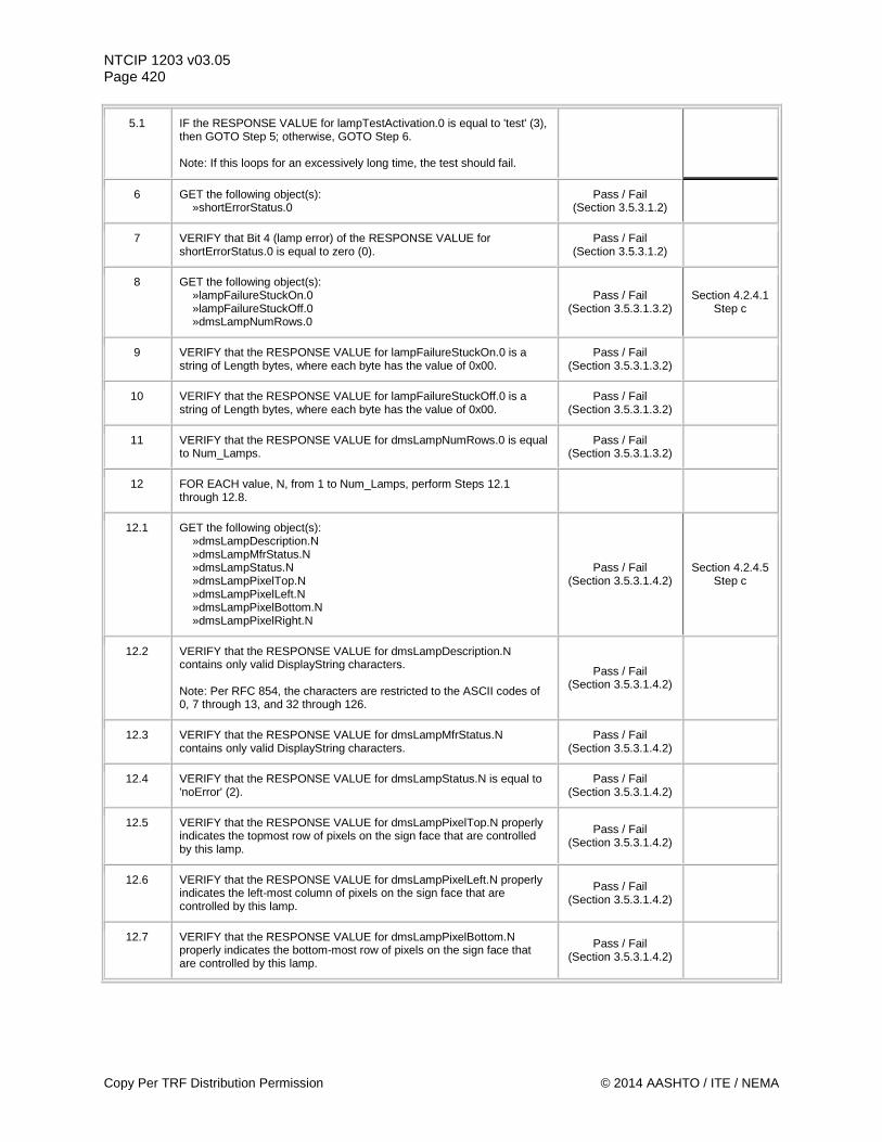
NTCIP 1203 v03.05 Page 420
5.1 IF the RESPONSE VALUE for lampTestActivation.0 is equal to 'test' (3), then GOTO Step 5; otherwise, GOTO Step 6. Note: If this loops for an excessively long time, the test should fail.
6 GET the following object(s): »shortErrorStatus.0
Pass / Fail (Section 3.5.3.1.2)
7 VERIFY that Bit 4 (lamp error) of the RESPONSE VALUE for shortErrorStatus.0 is equal to zero (0).
Pass / Fail (Section 3.5.3.1.2)
8 GET the following object(s): »lampFailureStuckOn.0 »lampFailureStuckOff.0 »dmsLampNumRows.0
Pass / Fail (Section 3.5.3.1.3.2)
Section 4.2.4.1 Step c
9 VERIFY that the RESPONSE VALUE for lampFailureStuckOn.0 is a string of Length bytes, where each byte has the value of 0x00.
Pass / Fail (Section 3.5.3.1.3.2)
10 VERIFY that the RESPONSE VALUE for lampFailureStuckOff.0 is a string of Length bytes, where each byte has the value of 0x00.
Pass / Fail (Section 3.5.3.1.3.2)
11 VERIFY that the RESPONSE VALUE for dmsLampNumRows.0 is equal to Num_Lamps.
Pass / Fail (Section 3.5.3.1.3.2)
12 FOR EACH value, N, from 1 to Num_Lamps, perform Steps 12.1 through 12.8.
12.1 GET the following object(s): »dmsLampDescription.N »dmsLampMfrStatus.N »dmsLampStatus.N »dmsLampPixelTop.N »dmsLampPixelLeft.N »dmsLampPixelBottom.N »dmsLampPixelRight.N
Pass / Fail (Section 3.5.3.1.4.2)
Section 4.2.4.5 Step c
12.2 VERIFY that the RESPONSE VALUE for dmsLampDescription.N contains only valid DisplayString characters. Note: Per RFC 854, the characters are restricted to the ASCII codes of 0, 7 through 13, and 32 through 126.
Pass / Fail (Section 3.5.3.1.4.2)
12.3 VERIFY that the RESPONSE VALUE for dmsLampMfrStatus.N contains only valid DisplayString characters.
Pass / Fail (Section 3.5.3.1.4.2)
12.4 VERIFY that the RESPONSE VALUE for dmsLampStatus.N is equal to 'noError' (2).
Pass / Fail (Section 3.5.3.1.4.2)
12.5 VERIFY that the RESPONSE VALUE for dmsLampPixelTop.N properly indicates the topmost row of pixels on the sign face that are controlled by this lamp.
Pass / Fail (Section 3.5.3.1.4.2)
12.6 VERIFY that the RESPONSE VALUE for dmsLampPixelLeft.N properly indicates the left-most column of pixels on the sign face that are controlled by this lamp.
Pass / Fail (Section 3.5.3.1.4.2)
12.7 VERIFY that the RESPONSE VALUE for dmsLampPixelBottom.N properly indicates the bottom-most row of pixels on the sign face that are controlled by this lamp.
Pass / Fail (Section 3.5.3.1.4.2)
Copy Per TRF Distribution Permission © 2014 AASHTO / ITE / NEMA
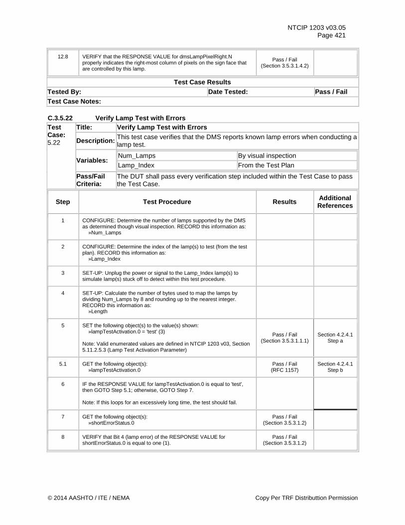
NTCIP 1203 v03.05 Page 421
12.8 VERIFY that the RESPONSE VALUE for dmsLampPixelRight.N properly indicates the right-most column of pixels on the sign face that are controlled by this lamp.
Pass / Fail (Section 3.5.3.1.4.2)
Test Case Results Tested By: Date Tested: Pass / Fail Test Case Notes: C.3.5.22 Verify Lamp Test with Errors Test Case: 5.22
Title: Verify Lamp Test with Errors
Description: This test case verifies that the DMS reports known lamp errors when conducting a lamp test.
Variables: Num_Lamps By visual inspection
Lamp_Index From the Test Plan
Pass/Fail Criteria:
The DUT shall pass every verification step included within the Test Case to pass the Test Case.
Step Test Procedure Results Additional References
1 CONFIGURE: Determine the number of lamps supported by the DMS as determined though visual inspection. RECORD this information as: »Num_Lamps
2 CONFIGURE: Determine the index of the lamp(s) to test (from the test plan). RECORD this information as: »Lamp_Index
3 SET-UP: Unplug the power or signal to the Lamp_Index lamp(s) to simulate lamp(s) stuck off to detect within this test procedure.
4 SET-UP: Calculate the number of bytes used to map the lamps by dividing Num_Lamps by 8 and rounding up to the nearest integer. RECORD this information as: »Length
5 SET the following object(s) to the value(s) shown: »lampTestActivation.0 = 'test' (3) Note: Valid enumerated values are defined in NTCIP 1203 v03, Section 5.11.2.5.3 (Lamp Test Activation Parameter)
Pass / Fail (Section 3.5.3.1.1.1)
Section 4.2.4.1 Step a
5.1 GET the following object(s): »lampTestActivation.0
Pass / Fail (RFC 1157)
Section 4.2.4.1 Step b
6 IF the RESPONSE VALUE for lampTestActivation.0 is equal to 'test', then GOTO Step 5.1; otherwise, GOTO Step 7. Note: If this loops for an excessively long time, the test should fail.
7 GET the following object(s): »shortErrorStatus.0
Pass / Fail (Section 3.5.3.1.2)
8 VERIFY that Bit 4 (lamp error) of the RESPONSE VALUE for shortErrorStatus.0 is equal to one (1).
Pass / Fail (Section 3.5.3.1.2)
© 2014 AASHTO / ITE / NEMA Copy Per TRF Distributtion Permission
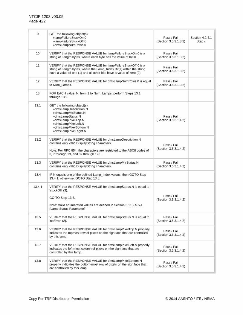
NTCIP 1203 v03.05 Page 422
9 GET the following object(s): »lampFailureStuckOn.0 »lampFailureStuckOff.0 »dmsLampNumRows.0
Pass / Fail (Section 3.5.3.1.3.2)
Section 4.2.4.1 Step c
10 VERIFY that the RESPONSE VALUE for lampFailureStuckOn.0 is a string of Length bytes, where each byte has the value of 0x00.
Pass / Fail (Section 3.5.3.1.3.2)
11 VERIFY that the RESPONSE VALUE for lampFailureStuckOff.0 is a string of Length bytes, where the Lamp_Index Bit(s) within the string have a value of one (1) and all other bits have a value of zero (0).
Pass / Fail (Section 3.5.3.1.3.2)
12 VERIFY that the RESPONSE VALUE for dmsLampNumRows.0 is equal to Num_Lamps.
Pass / Fail (Section 3.5.3.1.3.2)
13 FOR EACH value, N, from 1 to Num_Lamps, perform Steps 13.1 through 13.9.
13.1 GET the following object(s): »dmsLampDescription.N »dmsLampMfrStatus.N »dmsLampStatus.N »dmsLampPixelTop.N »dmsLampPixelLeft.N »dmsLampPixelBottom.N »dmsLampPixelRight.N
Pass / Fail (Section 3.5.3.1.4.2)
13.2 VERIFY that the RESPONSE VALUE for dmsLampDescription.N contains only valid DisplayString characters. Note: Per RFC 854, the characters are restricted to the ASCII codes of 0, 7 through 13, and 32 through 126.
Pass / Fail (Section 3.5.3.1.4.2)
13.3 VERIFY that the RESPONSE VALUE for dmsLampMfrStatus.N contains only valid DisplayString characters.
Pass / Fail (Section 3.5.3.1.4.2)
13.4 IF N equals one of the defined Lamp_Index values, then GOTO Step 13.4.1; otherwise, GOTO Step 13.5.
13.4.1 VERIFY that the RESPONSE VALUE for dmsLampStatus.N is equal to 'stuckOff' (3). GO TO Step 13.6. Note: Valid enumerated values are defined in Section 5.11.2.5.5.4 (Lamp Status Parameter)
Pass / Fail (Section 3.5.3.1.4.2)
13.5 VERIFY that the RESPONSE VALUE for dmsLampStatus.N is equal to 'noError' (2).
Pass / Fail (Section 3.5.3.1.4.2)
13.6 VERIFY that the RESPONSE VALUE for dmsLampPixelTop.N properly indicates the topmost row of pixels on the sign face that are controlled by this lamp.
Pass / Fail (Section 3.5.3.1.4.2)
13.7 VERIFY that the RESPONSE VALUE for dmsLampPixelLeft.N properly indicates the left-most column of pixels on the sign face that are controlled by this lamp.
Pass / Fail (Section 3.5.3.1.4.2)
13.8 VERIFY that the RESPONSE VALUE for dmsLampPixelBottom.N properly indicates the bottom-most row of pixels on the sign face that are controlled by this lamp.
Pass / Fail (Section 3.5.3.1.4.2)
Copy Per TRF Distribution Permission © 2014 AASHTO / ITE / NEMA
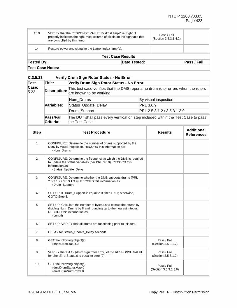
NTCIP 1203 v03.05 Page 423
13.9 VERIFY that the RESPONSE VALUE for dmsLampPixelRight.N properly indicates the right-most column of pixels on the sign face that are controlled by this lamp.
Pass / Fail (Section 3.5.3.1.4.2)
14 Restore power and signal to the Lamp_Index lamp(s).
Test Case Results Tested By: Date Tested: Pass / Fail Test Case Notes: C.3.5.23 Verify Drum Sign Rotor Status - No Error Test Case: 5.23
Title: Verify Drum Sign Rotor Status - No Error
Description: This test case verifies that the DMS reports no drum rotor errors when the rotors are known to be working.
Variables: Num_Drums By visual inspection Status_Update_Delay PRL 3.6.9 Drum_Support PRL 2.5.3.1.2 / 3.5.3.1.3.9
Pass/Fail Criteria:
The DUT shall pass every verification step included within the Test Case to pass the Test Case.
Step Test Procedure Results Additional References
1 CONFIGURE: Determine the number of drums supported by the DMS by visual inspection. RECORD this information as: »Num_Drums
2 CONFIGURE: Determine the frequency at which the DMS is required to update the status variables (per PRL 3.6.9). RECORD this information as: »Status_Update_Delay
3 CONFIGURE: Determine whether the DMS supports drums (PRL 2.5.3.1.2 / 3.5.3.1.3.9). RECORD this information as: »Drum_Support
4 SET-UP: IF Drum_Support is equal to 0, then EXIT; otherwise, GOTO Step 5.
5 SET-UP: Calculate the number of bytes used to map the drums by dividing Num_Drums by 8 and rounding up to the nearest integer. RECORD this information as: »Length
6 SET-UP: VERIFY that all drums are functioning prior to this test.
7 DELAY for Status_Update_Delay seconds.
8 GET the following object(s): »shortErrorStatus.0
Pass / Fail (Section 3.5.3.1.2)
9 VERIFY that Bit 12 (drum sign rotor error) of the RESPONSE VALUE for shortErrorStatus.0 is equal to zero (0).
Pass / Fail (Section 3.5.3.1.2)
10 GET the following object(s): »dmsDrumStatusMap.0 »dmsDrumNumRows.0
Pass / Fail (Section 3.5.3.1.3.9)
© 2014 AASHTO / ITE / NEMA Copy Per TRF Distributtion Permission
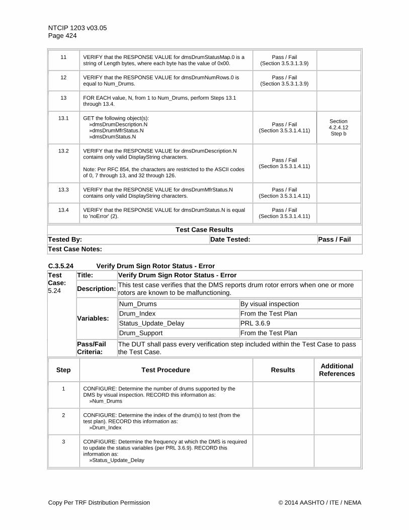
NTCIP 1203 v03.05 Page 424
11 VERIFY that the RESPONSE VALUE for dmsDrumStatusMap.0 is a string of Length bytes, where each byte has the value of 0x00.
Pass / Fail (Section 3.5.3.1.3.9)
12 VERIFY that the RESPONSE VALUE for dmsDrumNumRows.0 is equal to Num_Drums.
Pass / Fail (Section 3.5.3.1.3.9)
13 FOR EACH value, N, from 1 to Num_Drums, perform Steps 13.1 through 13.4.
13.1 GET the following object(s): »dmsDrumDescription.N »dmsDrumMfrStatus.N »dmsDrumStatus.N
Pass / Fail (Section 3.5.3.1.4.11)
Section 4.2.4.12 Step b
13.2 VERIFY that the RESPONSE VALUE for dmsDrumDescription.N contains only valid DisplayString characters. Note: Per RFC 854, the characters are restricted to the ASCII codes of 0, 7 through 13, and 32 through 126.
Pass / Fail (Section 3.5.3.1.4.11)
13.3 VERIFY that the RESPONSE VALUE for dmsDrumMfrStatus.N contains only valid DisplayString characters.
Pass / Fail (Section 3.5.3.1.4.11)
13.4 VERIFY that the RESPONSE VALUE for dmsDrumStatus.N is equal to 'noError' (2).
Pass / Fail (Section 3.5.3.1.4.11)
Test Case Results Tested By: Date Tested: Pass / Fail Test Case Notes: C.3.5.24 Verify Drum Sign Rotor Status - Error Test Case: 5.24
Title: Verify Drum Sign Rotor Status - Error
Description: This test case verifies that the DMS reports drum rotor errors when one or more rotors are known to be malfunctioning.
Variables:
Num_Drums By visual inspection Drum_Index From the Test Plan Status_Update_Delay PRL 3.6.9 Drum_Support From the Test Plan
Pass/Fail Criteria:
The DUT shall pass every verification step included within the Test Case to pass the Test Case.
Step Test Procedure Results Additional References
1 CONFIGURE: Determine the number of drums supported by the DMS by visual inspection. RECORD this information as: »Num_Drums
2 CONFIGURE: Determine the index of the drum(s) to test (from the test plan). RECORD this information as: »Drum_Index
3 CONFIGURE: Determine the frequency at which the DMS is required to update the status variables (per PRL 3.6.9). RECORD this information as: »Status_Update_Delay
Copy Per TRF Distribution Permission © 2014 AASHTO / ITE / NEMA
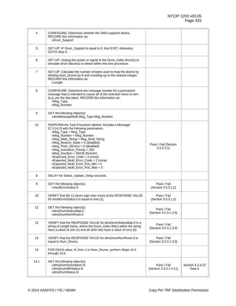
NTCIP 1203 v03.05 Page 425
4 CONFIGURE: Determine whether the DMS supports drums. RECORD this information as: »Drum_Support
5 SET-UP: IF Drum_Support is equal to 0, then EXIT; otherwise, GOTO Step 6.
6 SET-UP: Unplug the power or signal to the Drum_Index drum(s) to simulate drum failure(s) to detect within this test procedure.
7 SET-UP: Calculate the number of bytes used to map the drums by dividing Num_Drums by 8 and rounding up to the nearest integer. RECORD this information as: »Length
8 CONFIGURE: Determine the message number for a permanent message that is intended to cause all of the selected rotors to turn (e.g. per the test plan). RECORD this information as: »Msg_Type »Msg_Number
9 GET the following object(s): »dmsMessageMulti.Msg_Type.Msg_Number
10 PERFORM the Test Procedure labeled 'Activate a Message' (C.3.14.2) with the following parameters: »Msg_Type = Msg_Type »Msg_Number = Msg_Number »Msg_Multi_String = Msg_Multi_String »Msg_Beacon_State = 0 (disabled) »Msg_Pixel_Service = 0 (disabled) »Msg_Activation_Priority = 255 »Msg_Duration = 65535 (forever) »Expected_Error_Code = 2 (none) »Expected_Multi_Error_Code = 2 (none) »Expected_Multi_Error_Pos_Min = 0 »Expected_Multi_Error_Pos_Max = 0
Pass / Fail (Section 3.5.2.3.1)
8 DELAY for Status_Update_Delay seconds.
9 GET the following object(s): »shortErrorStatus.0
Pass / Fail (Section 3.5.3.1.2)
10 VERIFY that Bit 12 (drum sign rotor error) of the RESPONSE VALUE for shortErrorStatus.0 is equal to one (1).
Pass / Fail (Section 3.5.3.1.2)
11 GET the following object(s): »dmsDrumStatusMap.0 »dmsDrumNumRows.0
Pass / Fail (Section 3.5.3.1.3.9)
12 VERIFY that the RESPONSE VALUE for dmsDrumStatusMap.0 is a string of Length bytes, where the Drum_Index Bit(s) within the string have a value of one (1) and all other bits have a value of zero (0).
Pass / Fail (Section 3.5.3.1.3.9)
13 VERIFY that the RESPONSE VALUE for dmsDrumNumRows.0 is equal to Num_Drums.
Pass / Fail (Section 3.5.3.1.3.9)
14 FOR EACH value, N, from 1 to Num_Drums, perform Steps 14.1 through 14.5.
14.1 GET the following object(s): »dmsDrumDescription.N »dmsDrumMfrStatus.N »dmsDrumStatus.N
Pass / Fail (Section 3.5.3.1.4.11)
Section 4.2.4.12 Step b
© 2014 AASHTO / ITE / NEMA Copy Per TRF Distributtion Permission
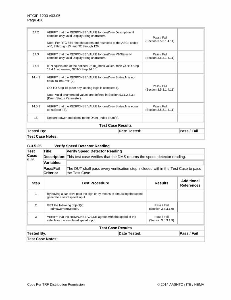
NTCIP 1203 v03.05 Page 426
14.2 VERIFY that the RESPONSE VALUE for dmsDrumDescription.N contains only valid DisplayString characters. Note: Per RFC 854, the characters are restricted to the ASCII codes of 0, 7 through 13, and 32 through 126.
Pass / Fail (Section 3.5.3.1.4.11)
14.3 VERIFY that the RESPONSE VALUE for dmsDrumMfrStatus.N contains only valid DisplayString characters.
Pass / Fail (Section 3.5.3.1.4.11)
14.4 IF N equals one of the defined Drum_Index values, then GOTO Step 14.4.1; otherwise, GOTO Step 14.5.1.
14.4.1 VERIFY that the RESPONSE VALUE for dmsDrumStatus.N is not equal to 'noError' (2). GO TO Step 15 (after any looping logic is completed). Note: Valid enumerated values are defined in Section 5.11.2.6.3.4 (Drum Status Parameter).
Pass / Fail (Section 3.5.3.1.4.11)
14.5.1 VERIFY that the RESPONSE VALUE for dmsDrumStatus.N is equal to 'noError' (2).
Pass / Fail (Section 3.5.3.1.4.11)
15 Restore power and signal to the Drum_Index drum(s).
Test Case Results Tested By: Date Tested: Pass / Fail Test Case Notes: C.3.5.25 Verify Speed Detector Reading Test Case: 5.25
Title: Verify Speed Detector Reading Description: This test case verifies that the DMS returns the speed detector reading. Variables:
Pass/Fail Criteria:
The DUT shall pass every verification step included within the Test Case to pass the Test Case.
Step Test Procedure Results Additional References
1 By having a car drive past the sign or by means of simulating the speed, generate a valid speed input.
2 GET the following object(s): »dmsCurrentSpeed.0
Pass / Fail (Section 3.5.3.1.9)
3 VERIFY that the RESPONSE VALUE agrees with the speed of the vehicle or the simulated speed input.
Pass / Fail (Section 3.5.3.1.9)
Test Case Results Tested By: Date Tested: Pass / Fail Test Case Notes:
Copy Per TRF Distribution Permission © 2014 AASHTO / ITE / NEMA
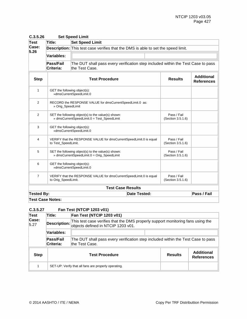
NTCIP 1203 v03.05 Page 427
C.3.5.26 Set Speed Limit Test Case: 5.26
Title: Set Speed Limit Description: This test case verifies that the DMS is able to set the speed limit.
Variables:
Pass/Fail Criteria:
The DUT shall pass every verification step included within the Test Case to pass the Test Case.
Step Test Procedure Results Additional References
1 GET the following object(s): »dmsCurrentSpeedLimit.0
2 RECORD the RESPONSE VALUE for dmsCurrentSpeedLimit.0 as: » Orig_SpeedLimit
2 SET the following object(s) to the value(s) shown: » dmsCurrentSpeedLimit.0 = Test_SpeedLimit
Pass / Fail (Section 3.5.1.6)
3 GET the following object(s): »dmsCurrentSpeedLimit.0
4 VERIFY that the RESPONSE VALUE for dmsCurrentSpeedLimit.0 is equal to Test_SpeedLimit.
Pass / Fail (Section 3.5.1.6)
5 SET the following object(s) to the value(s) shown: » dmsCurrentSpeedLimit.0 = Orig_SpeedLimit
Pass / Fail (Section 3.5.1.6)
6 GET the following object(s): »dmsCurrentSpeedLimit.0
7 VERIFY that the RESPONSE VALUE for dmsCurrentSpeedLimit.0 is equal to Orig_SpeedLimit.
Pass / Fail (Section 3.5.1.6)
Test Case Results Tested By: Date Tested: Pass / Fail Test Case Notes: C.3.5.27 Fan Test (NTCIP 1203 v01) Test Case: 5.27
Title: Fan Test (NTCIP 1203 v01)
Description: This test case verifies that the DMS properly support monitoring fans using the objects defined in NTCIP 1203 v01.
Variables:
Pass/Fail Criteria:
The DUT shall pass every verification step included within the Test Case to pass the Test Case.
Step Test Procedure Results Additional References
1 SET-UP: Verify that all fans are properly operating.
© 2014 AASHTO / ITE / NEMA Copy Per TRF Distributtion Permission
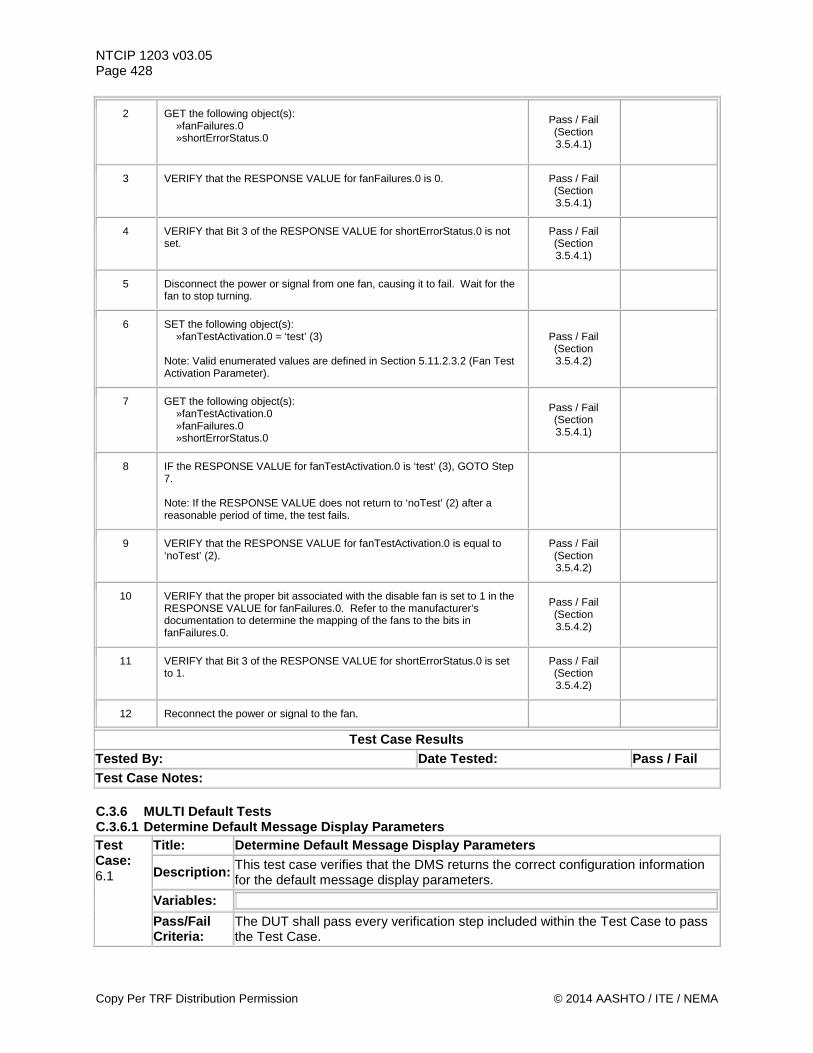
NTCIP 1203 v03.05 Page 428
2 GET the following object(s): »fanFailures.0 »shortErrorStatus.0
Pass / Fail (Section 3.5.4.1)
3 VERIFY that the RESPONSE VALUE for fanFailures.0 is 0. Pass / Fail (Section 3.5.4.1)
4 VERIFY that Bit 3 of the RESPONSE VALUE for shortErrorStatus.0 is not set.
Pass / Fail (Section 3.5.4.1)
5 Disconnect the power or signal from one fan, causing it to fail. Wait for the fan to stop turning.
6 SET the following object(s): »fanTestActivation.0 = ‘test’ (3) Note: Valid enumerated values are defined in Section 5.11.2.3.2 (Fan Test Activation Parameter).
Pass / Fail (Section 3.5.4.2)
7 GET the following object(s): »fanTestActivation.0 »fanFailures.0 »shortErrorStatus.0
Pass / Fail (Section 3.5.4.1)
8 IF the RESPONSE VALUE for fanTestActivation.0 is ‘test’ (3), GOTO Step 7. Note: If the RESPONSE VALUE does not return to ‘noTest’ (2) after a reasonable period of time, the test fails.
9 VERIFY that the RESPONSE VALUE for fanTestActivation.0 is equal to ‘noTest’ (2).
Pass / Fail (Section 3.5.4.2)
10 VERIFY that the proper bit associated with the disable fan is set to 1 in the RESPONSE VALUE for fanFailures.0. Refer to the manufacturer’s documentation to determine the mapping of the fans to the bits in fanFailures.0.
Pass / Fail (Section 3.5.4.2)
11 VERIFY that Bit 3 of the RESPONSE VALUE for shortErrorStatus.0 is set to 1.
Pass / Fail (Section 3.5.4.2)
12 Reconnect the power or signal to the fan.
Test Case Results Tested By: Date Tested: Pass / Fail Test Case Notes: C.3.6 MULTI Default Tests C.3.6.1 Determine Default Message Display Parameters Test Case: 6.1
Title: Determine Default Message Display Parameters
Description: This test case verifies that the DMS returns the correct configuration information for the default message display parameters.
Variables:
Pass/Fail Criteria:
The DUT shall pass every verification step included within the Test Case to pass the Test Case.
Copy Per TRF Distribution Permission © 2014 AASHTO / ITE / NEMA
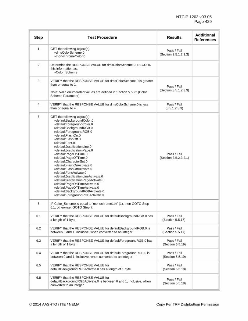
NTCIP 1203 v03.05 Page 429
Step Test Procedure Results Additional References
1 GET the following object(s): »dmsColorScheme.0 »monochromeColor.0
Pass / Fail (Section 3.5.1.2.3.3)
2 Determine the RESPONSE VALUE for dmsColorScheme.0. RECORD this information as: »Color_Scheme
3 VERIFY that the RESPONSE VALUE for dmsColorScheme.0 is greater than or equal to 1. Note: Valid enumerated values are defined in Section 5.5.22 (Color Scheme Parameter).
Pass / Fail (Section 3.5.1.2.3.3)
4 VERIFY that the RESPONSE VALUE for dmsColorScheme.0 is less than or equal to 4.
Pass / Fail (3.5.1.2.3.3)
5 GET the following object(s): »defaultBackgroundColor.0 »defaultForegroundColor.0 »defaultBackgroundRGB.0 »defaultForegroundRGB.0 »defaultFlashOn.0 »defaultFlashOff.0 »defaultFont.0 »defaultJustificationLine.0 »defaultJustificationPage.0 »defaultPageOnTime.0 »defaultPageOffTime.0 »defaultCharacterSet.0 »defaultFlashOnActivate.0 »defaultFlashOffActivate.0 »defaultFontActivate.0 »defaultJustificationLineActivate.0 »defaultJustificationPageActivate.0 »defaultPageOnTimeActivate.0 »defaultPageOffTimeActivate.0 »defaultBackgroundRGBActivate.0 »defaultForegroundRGBActivate.0
Pass / Fail (Section 3.5.2.3.2.1)
6 IF Color_Scheme is equal to ‘monochrome1bit’ (1), then GOTO Step 6.1; otherwise, GOTO Step 7.
6.1 VERIFY that the RESPONSE VALUE for defaultBackgroundRGB.0 has a length of 1 byte.
Pass / Fail (Section 5.5.17)
6.2 VERIFY that the RESPONSE VALUE for defaultBackgroundRGB.0 is between 0 and 1, inclusive, when converted to an integer.
Pass / Fail (Section 5.5.17)
6.3 VERIFY that the RESPONSE VALUE for defaultForegroundRGB.0 has a length of 1 byte.
Pass / Fail (Section 5.5.19)
6.4 VERIFY that the RESPONSE VALUE for defaultForegroundRGB.0 is between 0 and 1, inclusive, when converted to an integer.
Pass / Fail (Section 5.5.19)
6.5 VERIFY that the RESPONSE VALUE for defaultBackgroundRGBActivate.0 has a length of 1 byte.
Pass / Fail (Section 5.5.18)
6.6 VERIFY that the RESPONSE VALUE for defaultBackgroundRGBActivate.0 is between 0 and 1, inclusive, when converted to an integer.
Pass / Fail (Section 5.5.18)
© 2014 AASHTO / ITE / NEMA Copy Per TRF Distributtion Permission
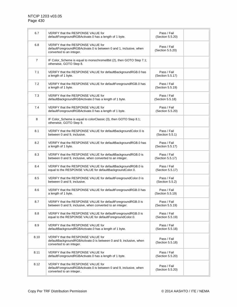
NTCIP 1203 v03.05 Page 430
6.7 VERIFY that the RESPONSE VALUE for defaultForegroundRGBActivate.0 has a length of 1 byte.
Pass / Fail (Section 5.5.20)
6.8 VERIFY that the RESPONSE VALUE for defaultForegroundRGBActivate.0 is between 0 and 1, inclusive, when converted to an integer.
Pass / Fail (Section 5.5.20)
7 IF Color_Scheme is equal to monochrome8bit (2), then GOTO Step 7.1; otherwise, GOTO Step 8.
7.1 VERIFY that the RESPONSE VALUE for defaultBackgroundRGB.0 has a length of 1 byte.
Pass / Fail (Section 5.5.17)
7.2 VERIFY that the RESPONSE VALUE for defaultForegroundRGB.0 has a length of 1 byte.
Pass / Fail (Section 5.5.19)
7.3 VERIFY that the RESPONSE VALUE for defaultBackgroundRGBActivate.0 has a length of 1 byte.
Pass / Fail (Section 5.5.18)
7.4 VERIFY that the RESPONSE VALUE for defaultForegroundRGBActivate.0 has a length of 1 byte.
Pass / Fail (Section 5.5.20)
8 IF Color_Scheme is equal to colorClassic (3), then GOTO Step 8.1; otherwise, GOTO Step 9.
8.1 VERIFY that the RESPONSE VALUE for defaultBackgroundColor.0 is between 0 and 9, inclusive.
Pass / Fail (Section 5.5.1)
8.2 VERIFY that the RESPONSE VALUE for defaultBackgroundRGB.0 has a length of 1 byte.
Pass / Fail (Section 5.5.17)
8.3 VERIFY that the RESPONSE VALUE for defaultBackgroundRGB.0 is between 0 and 9, inclusive, when converted to an integer.
Pass / Fail (Section 5.5.17)
8.4 VERIFY that the RESPONSE VALUE for defaultBackgroundRGB.0 is equal to the RESPONSE VALUE for defaultBackgroundColor.0.
Pass / Fail (Section 5.5.17)
8.5 VERIFY that the RESPONSE VALUE for defaultForegroundColor.0 is between 0 and 9, inclusive.
Pass / Fail (Section 5.5.2)
8.6 VERIFY that the RESPONSE VALUE for defaultForegroundRGB.0 has a length of 1 byte.
Pass / Fail (Section 5.5.19)
8.7 VERIFY that the RESPONSE VALUE for defaultForegroundRGB.0 is between 0 and 9, inclusive, when converted to an integer.
Pass / Fail (Section 5.5.19)
8.8 VERIFY that the RESPONSE VALUE for defaultForegroundRGB.0 is equal to the RESPONSE VALUE for defaultForegroundColor.0.
Pass / Fail (Section 5.5.19)
8.9 VERIFY that the RESPONSE VALUE for defaultBackgroundRGBActivate.0 has a length of 1 byte.
Pass / Fail (Section 5.5.18)
8.10 VERIFY that the RESPONSE VALUE for defaultBackgroundRGBActivate.0 is between 0 and 9, inclusive, when converted to an integer.
Pass / Fail (Section 5.5.18)
8.11 VERIFY that the RESPONSE VALUE for defaultForegroundRGBActivate.0 has a length of 1 byte.
Pass / Fail (Section 5.5.20)
8.12 VERIFY that the RESPONSE VALUE for defaultForegroundRGBActivate.0 is between 0 and 9, inclusive, when converted to an integer..
Pass / Fail (Section 5.5.20)
Copy Per TRF Distribution Permission © 2014 AASHTO / ITE / NEMA
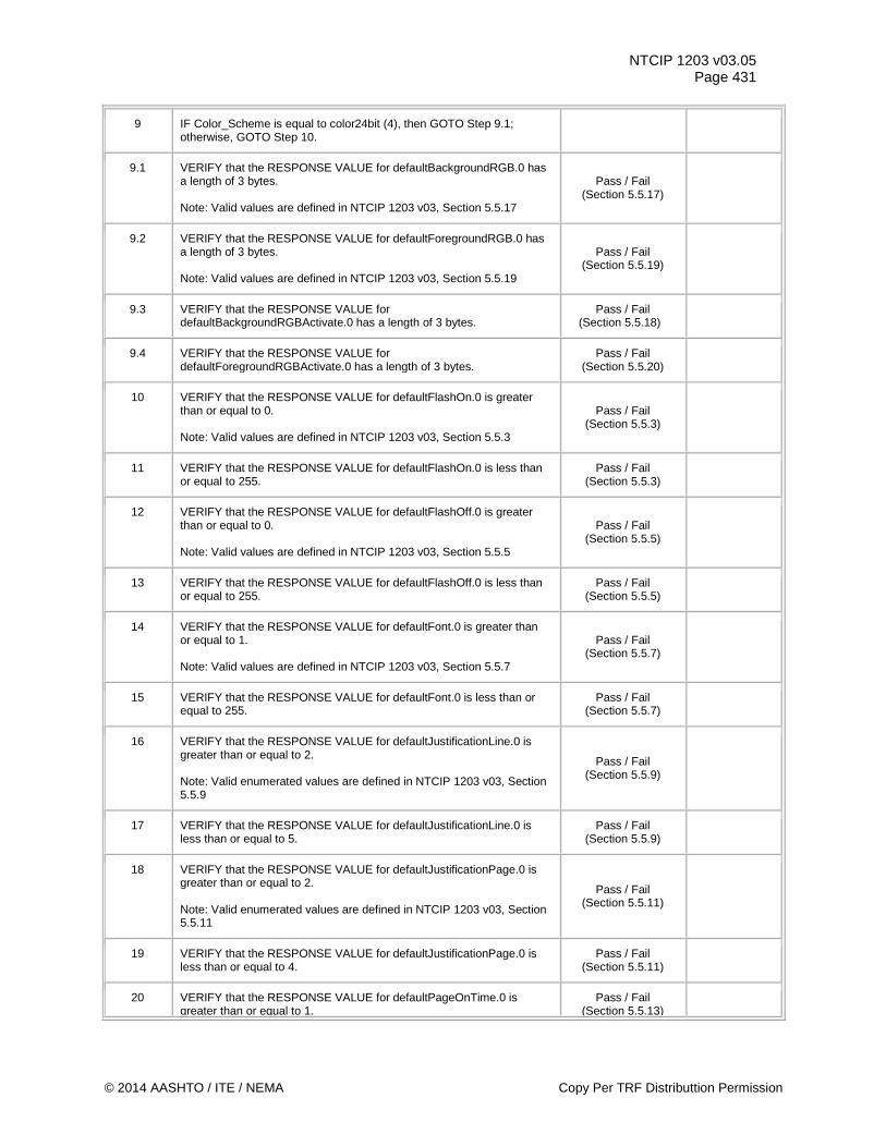
NTCIP 1203 v03.05 Page 431
9 IF Color_Scheme is equal to color24bit (4), then GOTO Step 9.1; otherwise, GOTO Step 10.
9.1 VERIFY that the RESPONSE VALUE for defaultBackgroundRGB.0 has a length of 3 bytes. Note: Valid values are defined in NTCIP 1203 v03, Section 5.5.17
Pass / Fail (Section 5.5.17)
9.2 VERIFY that the RESPONSE VALUE for defaultForegroundRGB.0 has a length of 3 bytes. Note: Valid values are defined in NTCIP 1203 v03, Section 5.5.19
Pass / Fail (Section 5.5.19)
9.3 VERIFY that the RESPONSE VALUE for defaultBackgroundRGBActivate.0 has a length of 3 bytes.
Pass / Fail (Section 5.5.18)
9.4 VERIFY that the RESPONSE VALUE for defaultForegroundRGBActivate.0 has a length of 3 bytes.
Pass / Fail (Section 5.5.20)
10 VERIFY that the RESPONSE VALUE for defaultFlashOn.0 is greater than or equal to 0. Note: Valid values are defined in NTCIP 1203 v03, Section 5.5.3
Pass / Fail (Section 5.5.3)
11 VERIFY that the RESPONSE VALUE for defaultFlashOn.0 is less than or equal to 255.
Pass / Fail (Section 5.5.3)
12 VERIFY that the RESPONSE VALUE for defaultFlashOff.0 is greater than or equal to 0. Note: Valid values are defined in NTCIP 1203 v03, Section 5.5.5
Pass / Fail (Section 5.5.5)
13 VERIFY that the RESPONSE VALUE for defaultFlashOff.0 is less than or equal to 255.
Pass / Fail (Section 5.5.5)
14 VERIFY that the RESPONSE VALUE for defaultFont.0 is greater than or equal to 1. Note: Valid values are defined in NTCIP 1203 v03, Section 5.5.7
Pass / Fail (Section 5.5.7)
15 VERIFY that the RESPONSE VALUE for defaultFont.0 is less than or equal to 255.
Pass / Fail (Section 5.5.7)
16 VERIFY that the RESPONSE VALUE for defaultJustificationLine.0 is greater than or equal to 2. Note: Valid enumerated values are defined in NTCIP 1203 v03, Section 5.5.9
Pass / Fail (Section 5.5.9)
17 VERIFY that the RESPONSE VALUE for defaultJustificationLine.0 is less than or equal to 5.
Pass / Fail (Section 5.5.9)
18 VERIFY that the RESPONSE VALUE for defaultJustificationPage.0 is greater than or equal to 2. Note: Valid enumerated values are defined in NTCIP 1203 v03, Section 5.5.11
Pass / Fail (Section 5.5.11)
19 VERIFY that the RESPONSE VALUE for defaultJustificationPage.0 is less than or equal to 4.
Pass / Fail (Section 5.5.11)
20 VERIFY that the RESPONSE VALUE for defaultPageOnTime.0 is greater than or equal to 1.
Pass / Fail (Section 5.5.13)
© 2014 AASHTO / ITE / NEMA Copy Per TRF Distributtion Permission
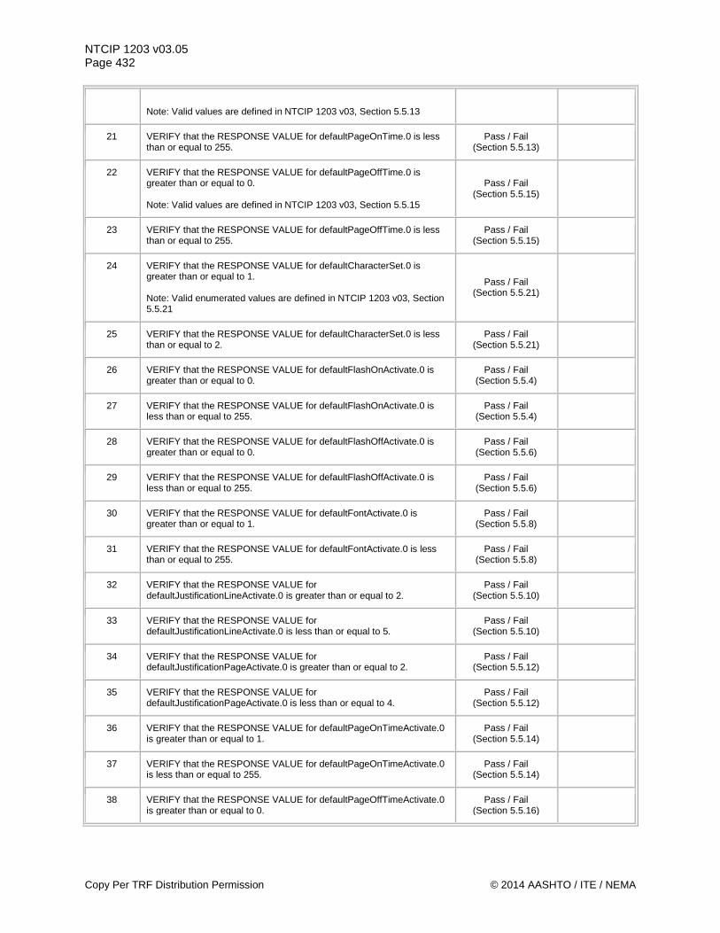
NTCIP 1203 v03.05 Page 432
Note: Valid values are defined in NTCIP 1203 v03, Section 5.5.13
21 VERIFY that the RESPONSE VALUE for defaultPageOnTime.0 is less than or equal to 255.
Pass / Fail (Section 5.5.13)
22 VERIFY that the RESPONSE VALUE for defaultPageOffTime.0 is greater than or equal to 0. Note: Valid values are defined in NTCIP 1203 v03, Section 5.5.15
Pass / Fail (Section 5.5.15)
23 VERIFY that the RESPONSE VALUE for defaultPageOffTime.0 is less than or equal to 255.
Pass / Fail (Section 5.5.15)
24 VERIFY that the RESPONSE VALUE for defaultCharacterSet.0 is greater than or equal to 1. Note: Valid enumerated values are defined in NTCIP 1203 v03, Section 5.5.21
Pass / Fail (Section 5.5.21)
25 VERIFY that the RESPONSE VALUE for defaultCharacterSet.0 is less than or equal to 2.
Pass / Fail (Section 5.5.21)
26 VERIFY that the RESPONSE VALUE for defaultFlashOnActivate.0 is greater than or equal to 0.
Pass / Fail (Section 5.5.4)
27 VERIFY that the RESPONSE VALUE for defaultFlashOnActivate.0 is less than or equal to 255.
Pass / Fail (Section 5.5.4)
28 VERIFY that the RESPONSE VALUE for defaultFlashOffActivate.0 is greater than or equal to 0.
Pass / Fail (Section 5.5.6)
29 VERIFY that the RESPONSE VALUE for defaultFlashOffActivate.0 is less than or equal to 255.
Pass / Fail (Section 5.5.6)
30 VERIFY that the RESPONSE VALUE for defaultFontActivate.0 is greater than or equal to 1.
Pass / Fail (Section 5.5.8)
31 VERIFY that the RESPONSE VALUE for defaultFontActivate.0 is less than or equal to 255.
Pass / Fail (Section 5.5.8)
32 VERIFY that the RESPONSE VALUE for defaultJustificationLineActivate.0 is greater than or equal to 2.
Pass / Fail (Section 5.5.10)
33 VERIFY that the RESPONSE VALUE for defaultJustificationLineActivate.0 is less than or equal to 5.
Pass / Fail (Section 5.5.10)
34 VERIFY that the RESPONSE VALUE for defaultJustificationPageActivate.0 is greater than or equal to 2.
Pass / Fail (Section 5.5.12)
35 VERIFY that the RESPONSE VALUE for defaultJustificationPageActivate.0 is less than or equal to 4.
Pass / Fail (Section 5.5.12)
36 VERIFY that the RESPONSE VALUE for defaultPageOnTimeActivate.0 is greater than or equal to 1.
Pass / Fail (Section 5.5.14)
37 VERIFY that the RESPONSE VALUE for defaultPageOnTimeActivate.0 is less than or equal to 255.
Pass / Fail (Section 5.5.14)
38 VERIFY that the RESPONSE VALUE for defaultPageOffTimeActivate.0 is greater than or equal to 0.
Pass / Fail (Section 5.5.16)
Copy Per TRF Distribution Permission © 2014 AASHTO / ITE / NEMA
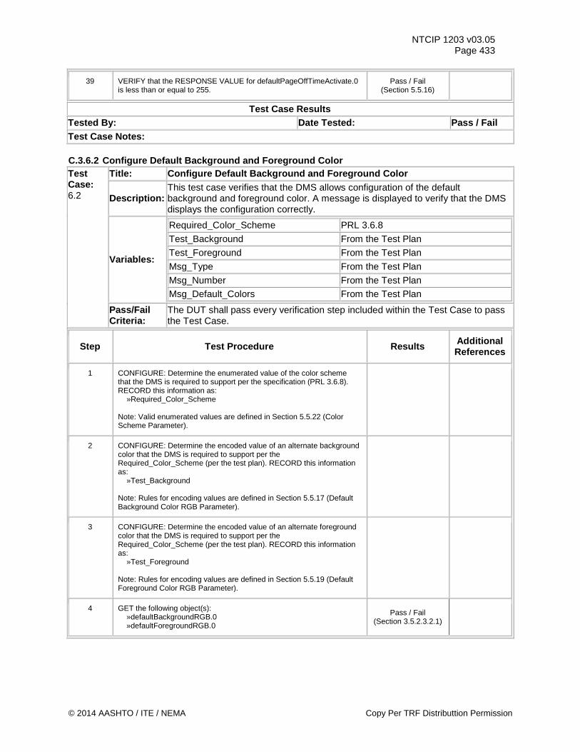
NTCIP 1203 v03.05 Page 433
39 VERIFY that the RESPONSE VALUE for defaultPageOffTimeActivate.0 is less than or equal to 255.
Pass / Fail (Section 5.5.16)
Test Case Results Tested By: Date Tested: Pass / Fail Test Case Notes: C.3.6.2 Configure Default Background and Foreground Color Test Case: 6.2
Title: Configure Default Background and Foreground Color
Description: This test case verifies that the DMS allows configuration of the default background and foreground color. A message is displayed to verify that the DMS displays the configuration correctly.
Variables:
Required_Color_Scheme PRL 3.6.8 Test_Background From the Test Plan Test_Foreground From the Test Plan Msg_Type From the Test Plan Msg_Number From the Test Plan Msg_Default_Colors From the Test Plan
Pass/Fail Criteria:
The DUT shall pass every verification step included within the Test Case to pass the Test Case.
Step Test Procedure Results Additional References
1 CONFIGURE: Determine the enumerated value of the color scheme that the DMS is required to support per the specification (PRL 3.6.8). RECORD this information as: »Required_Color_Scheme Note: Valid enumerated values are defined in Section 5.5.22 (Color Scheme Parameter).
2 CONFIGURE: Determine the encoded value of an alternate background color that the DMS is required to support per the Required_Color_Scheme (per the test plan). RECORD this information as: »Test_Background Note: Rules for encoding values are defined in Section 5.5.17 (Default Background Color RGB Parameter).
3 CONFIGURE: Determine the encoded value of an alternate foreground color that the DMS is required to support per the Required_Color_Scheme (per the test plan). RECORD this information as: »Test_Foreground Note: Rules for encoding values are defined in Section 5.5.19 (Default Foreground Color RGB Parameter).
4 GET the following object(s): »defaultBackgroundRGB.0 »defaultForegroundRGB.0
Pass / Fail (Section 3.5.2.3.2.1)
© 2014 AASHTO / ITE / NEMA Copy Per TRF Distributtion Permission
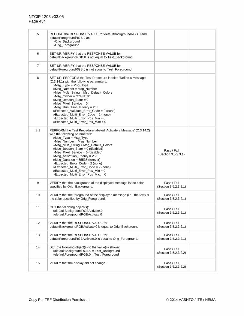
NTCIP 1203 v03.05 Page 434
5 RECORD the RESPONSE VALUE for defaultBackgroundRGB.0 and defaultForegroundRGB.0 as: »Orig_Background »Orig_Foreground
6 SET-UP: VERIFY that the RESPONSE VALUE for defaultBackgroundRGB.0 is not equal to Test_Background.
7 SET-UP: VERIFY that the RESPONSE VALUE for defaultForegroundRGB.0 is not equal to Test_Foreground.
8 SET-UP: PERFORM the Test Procedure labeled 'Define a Message' (C.3.14.1) with the following parameters: »Msg_Type = Msg_Type »Msg_Number = Msg_Number »Msg_Multi_String = Msg_Default_Colors »Msg_Owner = “OWNER” »Msg_Beacon_State = 0 »Msg_Pixel_Service = 0 »Msg_Run_Time_Priority = 255 »Expected_Validate_Error_Code = 2 (none) »Expected_Multi_Error_Code = 2 (none) »Expected_Multi_Error_Pos_Min = 0 »Expected_Multi_Error_Pos_Max = 0
8.1 PERFORM the Test Procedure labeled 'Activate a Message' (C.3.14.2) with the following parameters: »Msg_Type = Msg_Type »Msg_Number = Msg_Number »Msg_Multi_String = Msg_Default_Colors »Msg_Beacon_State = 0 (disabled) »Msg_Pixel_Service = 0 (disabled) »Msg_Activation_Priority = 255 »Msg_Duration = 65535 (forever) »Expected_Error_Code = 2 (none) »Expected_Multi_Error_Code = 2 (none) »Expected_Multi_Error_Pos_Min = 0 »Expected_Multi_Error_Pos_Max = 0
Pass / Fail (Section 3.5.2.3.1)
9 VERIFY that the background of the displayed message is the color specified by Orig_Background.
Pass / Fail (Section 3.5.2.3.2.1)
10 VERIFY that the foreground of the displayed message (i.e., the text) is the color specified by Orig_Foreground.
Pass / Fail (Section 3.5.2.3.2.1)
11 GET the following object(s): »defaultBackgroundRGBActivate.0 »defaultForegroundRGBActivate.0
Pass / Fail (Section 3.5.2.3.2.1)
12 VERIFY that the RESPONSE VALUE for defaultBackgroundRGBActivate.0 is equal to Orig_Background.
Pass / Fail (Section 3.5.2.3.2.1)
13 VERIFY that the RESPONSE VALUE for defaultForegroundRGBActivate.0 is equal to Orig_Foreground.
Pass / Fail (Section 3.5.2.3.2.1)
14 SET the following object(s) to the value(s) shown: »defaultBackgroundRGB.0 = Test_Background »defaultForegroundRGB.0 = Test_Foreground
Pass / Fail (Section 3.5.2.3.2.2)
15 VERIFY that the display did not change. Pass / Fail (Section 3.5.2.3.2.2)
Copy Per TRF Distribution Permission © 2014 AASHTO / ITE / NEMA
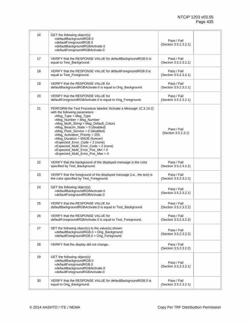
NTCIP 1203 v03.05 Page 435
16 GET the following object(s): »defaultBackgroundRGB.0 »defaultForegroundRGB.0 »defaultBackgroundRGBActivate.0 »defaultForegroundRGBActivate.0
Pass / Fail (Section 3.5.2.3.2.1)
17 VERIFY that the RESPONSE VALUE for defaultBackgroundRGB.0 is equal to Test_Background.
Pass / Fail (Section 3.5.2.3.2.1)
18 VERIFY that the RESPONSE VALUE for defaultForegroundRGB.0 is equal to Test_Foreground.
Pass / Fail (Section 3.5.2.3.2.1)
19 VERIFY that the RESPONSE VALUE for defaultBackgroundRGBActivate.0 is equal to Orig_Background.
Pass / Fail (Section 3.5.2.3.2.1)
20 VERIFY that the RESPONSE VALUE for defaultForegroundRGBActivate.0 is equal to Orig_Foreground.
Pass / Fail (Section 3.5.2.3.2.1)
21 PERFORM the Test Procedure labeled 'Activate a Message' (C.3.14.2) with the following parameters: »Msg_Type = Msg_Type »Msg_Number = Msg_Number »Msg_Multi_String = Msg_Default_Colors »Msg_Beacon_State = 0 (disabled) »Msg_Pixel_Service = 0 (disabled) »Msg_Activation_Priority = 255 »Msg_Duration = 65535 (forever) »Expected_Error_Code = 2 (none) »Expected_Multi_Error_Code = 2 (none) »Expected_Multi_Error_Pos_Min = 0 »Expected_Multi_Error_Pos_Max = 0
Pass / Fail (Section 3.5.2.3.1)
22 VERIFY that the background of the displayed message is the color specified by Test_Background.
Pass / Fail (Section 3.5.2.3.2.2)
23 VERIFY that the foreground of the displayed message (i.e., the text) is the color specified by Test_Foreground.
Pass / Fail (Section 3.5.2.3.2.2)
24 GET the following object(s): »defaultBackgroundRGBActivate.0 »defaultForegroundRGBActivate.0
Pass / Fail (Section 3.5.2.3.2.1)
25 VERIFY that the RESPONSE VALUE for defaultBackgroundRGBActivate.0 is equal to Test_Background.
Pass / Fail (Section 3.5.2.3.2.2)
26 VERIFY that the RESPONSE VALUE for defaultForegroundRGBActivate.0 is equal to Test_Foreground.
Pass / Fail (Section 3.5.2.3.2.2)
27 SET the following object(s) to the value(s) shown: »defaultBackgroundRGB.0 = Orig_Background »defaultForegroundRGB.0 = Orig_Foreground
Pass / Fail (Section 3.5.2.3.2.2)
28 VERIFY that the display did not change. Pass / Fail (Section 3.5.2.3.2.2)
29 GET the following object(s): »defaultBackgroundRGB.0 »defaultForegroundRGB.0 »defaultBackgroundRGBActivate.0 »defaultForegroundRGBActivate.0
Pass / Fail (Section 3.5.2.3.2.1)
30 VERIFY that the RESPONSE VALUE for defaultBackgroundRGB.0 is equal to Orig_Background.
Pass / Fail (Section 3.5.2.3.2.1)
© 2014 AASHTO / ITE / NEMA Copy Per TRF Distributtion Permission
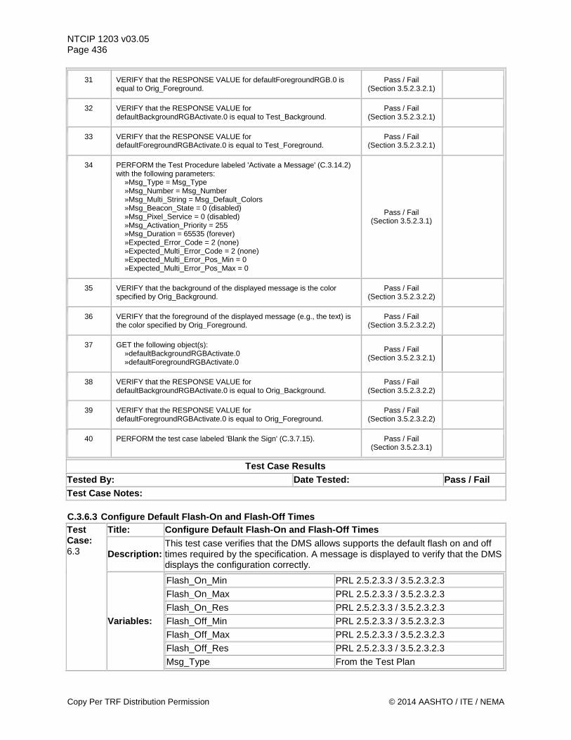
NTCIP 1203 v03.05 Page 436
31 VERIFY that the RESPONSE VALUE for defaultForegroundRGB.0 is equal to Orig_Foreground.
Pass / Fail (Section 3.5.2.3.2.1)
32 VERIFY that the RESPONSE VALUE for defaultBackgroundRGBActivate.0 is equal to Test_Background.
Pass / Fail (Section 3.5.2.3.2.1)
33 VERIFY that the RESPONSE VALUE for defaultForegroundRGBActivate.0 is equal to Test_Foreground.
Pass / Fail (Section 3.5.2.3.2.1)
34 PERFORM the Test Procedure labeled 'Activate a Message' (C.3.14.2) with the following parameters: »Msg_Type = Msg_Type »Msg_Number = Msg_Number »Msg_Multi_String = Msg_Default_Colors »Msg_Beacon_State = 0 (disabled) »Msg_Pixel_Service = 0 (disabled) »Msg_Activation_Priority = 255 »Msg_Duration = 65535 (forever) »Expected_Error_Code = 2 (none) »Expected_Multi_Error_Code = 2 (none) »Expected_Multi_Error_Pos_Min = 0 »Expected_Multi_Error_Pos_Max = 0
Pass / Fail (Section 3.5.2.3.1)
35 VERIFY that the background of the displayed message is the color specified by Orig_Background.
Pass / Fail (Section 3.5.2.3.2.2)
36 VERIFY that the foreground of the displayed message (e.g., the text) is the color specified by Orig_Foreground.
Pass / Fail (Section 3.5.2.3.2.2)
37 GET the following object(s): »defaultBackgroundRGBActivate.0 »defaultForegroundRGBActivate.0
Pass / Fail (Section 3.5.2.3.2.1)
38 VERIFY that the RESPONSE VALUE for defaultBackgroundRGBActivate.0 is equal to Orig_Background.
Pass / Fail (Section 3.5.2.3.2.2)
39 VERIFY that the RESPONSE VALUE for defaultForegroundRGBActivate.0 is equal to Orig_Foreground.
Pass / Fail (Section 3.5.2.3.2.2)
40 PERFORM the test case labeled 'Blank the Sign' (C.3.7.15). Pass / Fail (Section 3.5.2.3.1)
Test Case Results Tested By: Date Tested: Pass / Fail Test Case Notes: C.3.6.3 Configure Default Flash-On and Flash-Off Times Test Case: 6.3
Title: Configure Default Flash-On and Flash-Off Times
Description: This test case verifies that the DMS allows supports the default flash on and off times required by the specification. A message is displayed to verify that the DMS displays the configuration correctly.
Variables:
Flash_On_Min PRL 2.5.2.3.3 / 3.5.2.3.2.3 Flash_On_Max PRL 2.5.2.3.3 / 3.5.2.3.2.3 Flash_On_Res PRL 2.5.2.3.3 / 3.5.2.3.2.3 Flash_Off_Min PRL 2.5.2.3.3 / 3.5.2.3.2.3 Flash_Off_Max PRL 2.5.2.3.3 / 3.5.2.3.2.3 Flash_Off_Res PRL 2.5.2.3.3 / 3.5.2.3.2.3 Msg_Type From the Test Plan
Copy Per TRF Distribution Permission © 2014 AASHTO / ITE / NEMA
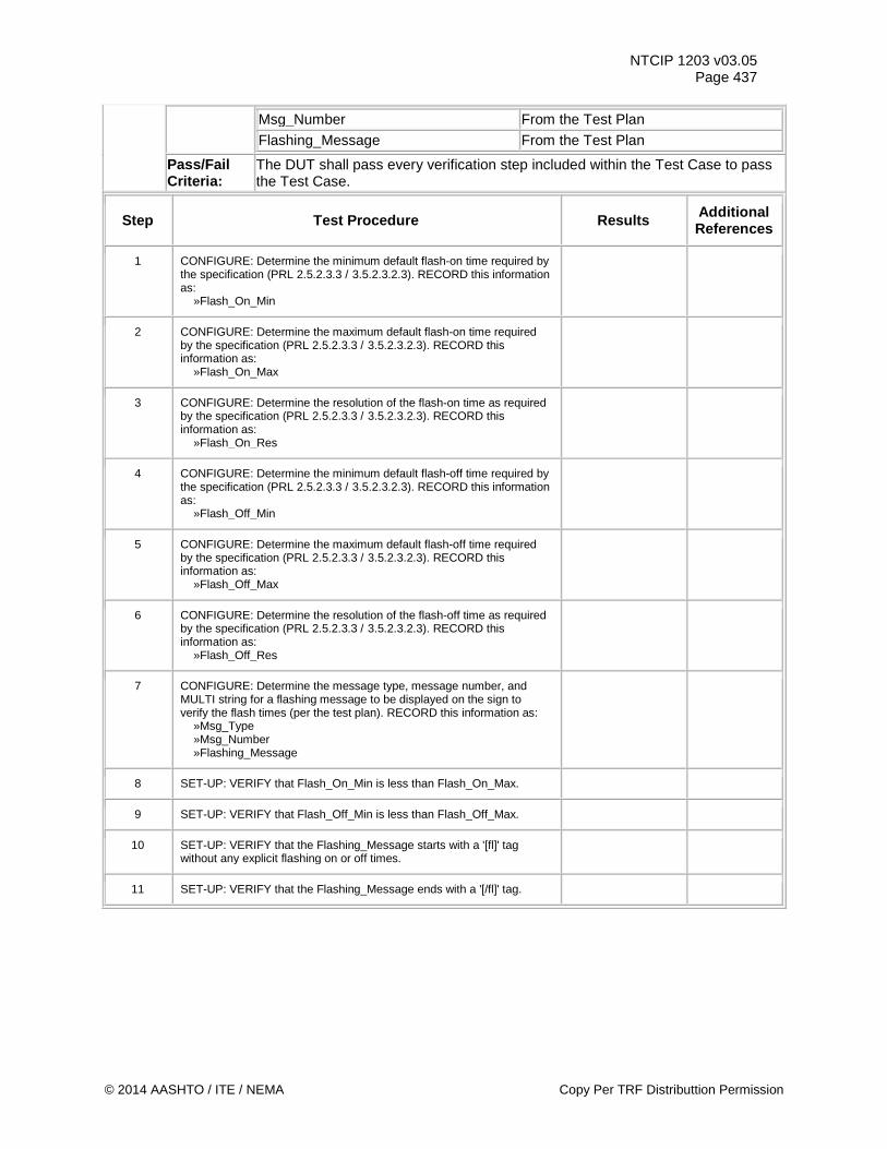
NTCIP 1203 v03.05 Page 437
Msg_Number From the Test Plan Flashing_Message From the Test Plan
Pass/Fail Criteria:
The DUT shall pass every verification step included within the Test Case to pass the Test Case.
Step Test Procedure Results Additional References
1 CONFIGURE: Determine the minimum default flash-on time required by the specification (PRL 2.5.2.3.3 / 3.5.2.3.2.3). RECORD this information as: »Flash_On_Min
2 CONFIGURE: Determine the maximum default flash-on time required by the specification (PRL 2.5.2.3.3 / 3.5.2.3.2.3). RECORD this information as: »Flash_On_Max
3 CONFIGURE: Determine the resolution of the flash-on time as required by the specification (PRL 2.5.2.3.3 / 3.5.2.3.2.3). RECORD this information as: »Flash_On_Res
4 CONFIGURE: Determine the minimum default flash-off time required by the specification (PRL 2.5.2.3.3 / 3.5.2.3.2.3). RECORD this information as: »Flash_Off_Min
5 CONFIGURE: Determine the maximum default flash-off time required by the specification (PRL 2.5.2.3.3 / 3.5.2.3.2.3). RECORD this information as: »Flash_Off_Max
6 CONFIGURE: Determine the resolution of the flash-off time as required by the specification (PRL 2.5.2.3.3 / 3.5.2.3.2.3). RECORD this information as: »Flash_Off_Res
7 CONFIGURE: Determine the message type, message number, and MULTI string for a flashing message to be displayed on the sign to verify the flash times (per the test plan). RECORD this information as: »Msg_Type »Msg_Number »Flashing_Message
8 SET-UP: VERIFY that Flash_On_Min is less than Flash_On_Max.
9 SET-UP: VERIFY that Flash_Off_Min is less than Flash_Off_Max.
10 SET-UP: VERIFY that the Flashing_Message starts with a '[fl]' tag without any explicit flashing on or off times.
11 SET-UP: VERIFY that the Flashing_Message ends with a '[/fl]' tag.
© 2014 AASHTO / ITE / NEMA Copy Per TRF Distributtion Permission
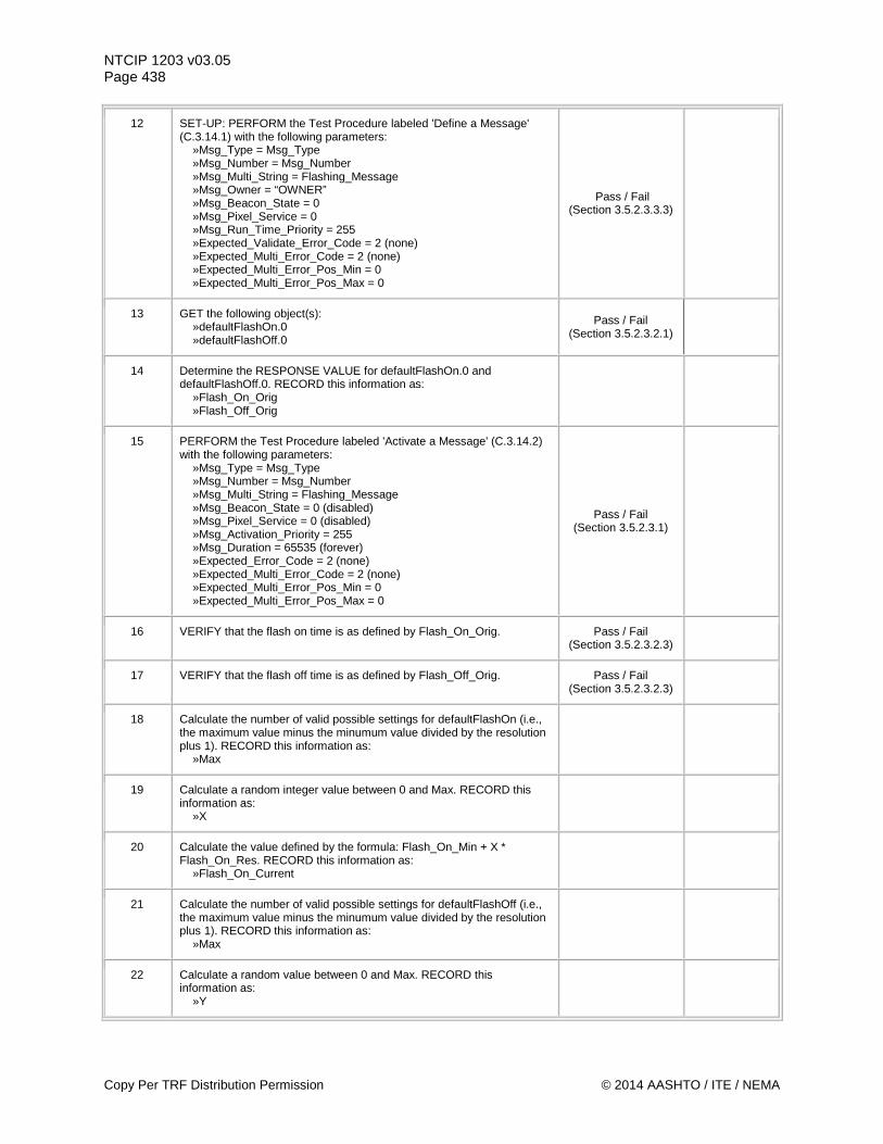
NTCIP 1203 v03.05 Page 438
12 SET-UP: PERFORM the Test Procedure labeled 'Define a Message' (C.3.14.1) with the following parameters: »Msg_Type = Msg_Type »Msg_Number = Msg_Number »Msg_Multi_String = Flashing_Message »Msg_Owner = “OWNER” »Msg_Beacon_State = 0 »Msg_Pixel_Service = 0 »Msg_Run_Time_Priority = 255 »Expected_Validate_Error_Code = 2 (none) »Expected_Multi_Error_Code = 2 (none) »Expected_Multi_Error_Pos_Min = 0 »Expected_Multi_Error_Pos_Max = 0
Pass / Fail (Section 3.5.2.3.3.3)
13 GET the following object(s): »defaultFlashOn.0 »defaultFlashOff.0
Pass / Fail (Section 3.5.2.3.2.1)
14 Determine the RESPONSE VALUE for defaultFlashOn.0 and defaultFlashOff.0. RECORD this information as: »Flash_On_Orig »Flash_Off_Orig
15 PERFORM the Test Procedure labeled 'Activate a Message' (C.3.14.2) with the following parameters: »Msg_Type = Msg_Type »Msg_Number = Msg_Number »Msg_Multi_String = Flashing_Message »Msg_Beacon_State = 0 (disabled) »Msg_Pixel_Service = 0 (disabled) »Msg_Activation_Priority = 255 »Msg_Duration = 65535 (forever) »Expected_Error_Code = 2 (none) »Expected_Multi_Error_Code = 2 (none) »Expected_Multi_Error_Pos_Min = 0 »Expected_Multi_Error_Pos_Max = 0
Pass / Fail (Section 3.5.2.3.1)
16 VERIFY that the flash on time is as defined by Flash_On_Orig. Pass / Fail (Section 3.5.2.3.2.3)
17 VERIFY that the flash off time is as defined by Flash_Off_Orig. Pass / Fail (Section 3.5.2.3.2.3)
18 Calculate the number of valid possible settings for defaultFlashOn (i.e., the maximum value minus the minumum value divided by the resolution plus 1). RECORD this information as: »Max
19 Calculate a random integer value between 0 and Max. RECORD this information as: »X
20 Calculate the value defined by the formula: Flash_On_Min + X * Flash_On_Res. RECORD this information as: »Flash_On_Current
21 Calculate the number of valid possible settings for defaultFlashOff (i.e., the maximum value minus the minumum value divided by the resolution plus 1). RECORD this information as: »Max
22 Calculate a random value between 0 and Max. RECORD this information as: »Y
Copy Per TRF Distribution Permission © 2014 AASHTO / ITE / NEMA
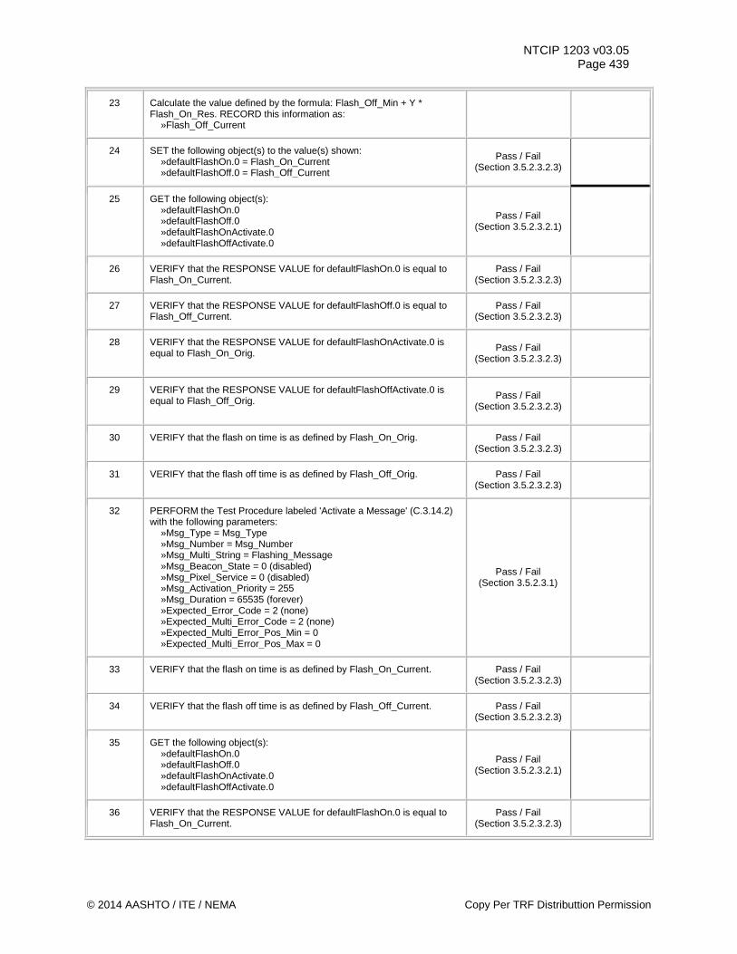
NTCIP 1203 v03.05 Page 439
23 Calculate the value defined by the formula: Flash_Off_Min + Y * Flash_On_Res. RECORD this information as: »Flash_Off_Current
24 SET the following object(s) to the value(s) shown: »defaultFlashOn.0 = Flash_On_Current »defaultFlashOff.0 = Flash_Off_Current
Pass / Fail (Section 3.5.2.3.2.3)
25 GET the following object(s): »defaultFlashOn.0 »defaultFlashOff.0 »defaultFlashOnActivate.0 »defaultFlashOffActivate.0
Pass / Fail (Section 3.5.2.3.2.1)
26 VERIFY that the RESPONSE VALUE for defaultFlashOn.0 is equal to Flash_On_Current.
Pass / Fail (Section 3.5.2.3.2.3)
27 VERIFY that the RESPONSE VALUE for defaultFlashOff.0 is equal to Flash_Off_Current.
Pass / Fail (Section 3.5.2.3.2.3)
28 VERIFY that the RESPONSE VALUE for defaultFlashOnActivate.0 is equal to Flash_On_Orig.
Pass / Fail (Section 3.5.2.3.2.3)
29 VERIFY that the RESPONSE VALUE for defaultFlashOffActivate.0 is equal to Flash_Off_Orig.
Pass / Fail (Section 3.5.2.3.2.3)
30 VERIFY that the flash on time is as defined by Flash_On_Orig. Pass / Fail (Section 3.5.2.3.2.3)
31 VERIFY that the flash off time is as defined by Flash_Off_Orig. Pass / Fail (Section 3.5.2.3.2.3)
32 PERFORM the Test Procedure labeled 'Activate a Message' (C.3.14.2) with the following parameters: »Msg_Type = Msg_Type »Msg_Number = Msg_Number »Msg_Multi_String = Flashing_Message »Msg_Beacon_State = 0 (disabled) »Msg_Pixel_Service = 0 (disabled) »Msg_Activation_Priority = 255 »Msg_Duration = 65535 (forever) »Expected_Error_Code = 2 (none) »Expected_Multi_Error_Code = 2 (none) »Expected_Multi_Error_Pos_Min = 0 »Expected_Multi_Error_Pos_Max = 0
Pass / Fail (Section 3.5.2.3.1)
33 VERIFY that the flash on time is as defined by Flash_On_Current. Pass / Fail (Section 3.5.2.3.2.3)
34 VERIFY that the flash off time is as defined by Flash_Off_Current. Pass / Fail (Section 3.5.2.3.2.3)
35 GET the following object(s): »defaultFlashOn.0 »defaultFlashOff.0 »defaultFlashOnActivate.0 »defaultFlashOffActivate.0
Pass / Fail (Section 3.5.2.3.2.1)
36 VERIFY that the RESPONSE VALUE for defaultFlashOn.0 is equal to Flash_On_Current.
Pass / Fail (Section 3.5.2.3.2.3)
© 2014 AASHTO / ITE / NEMA Copy Per TRF Distributtion Permission
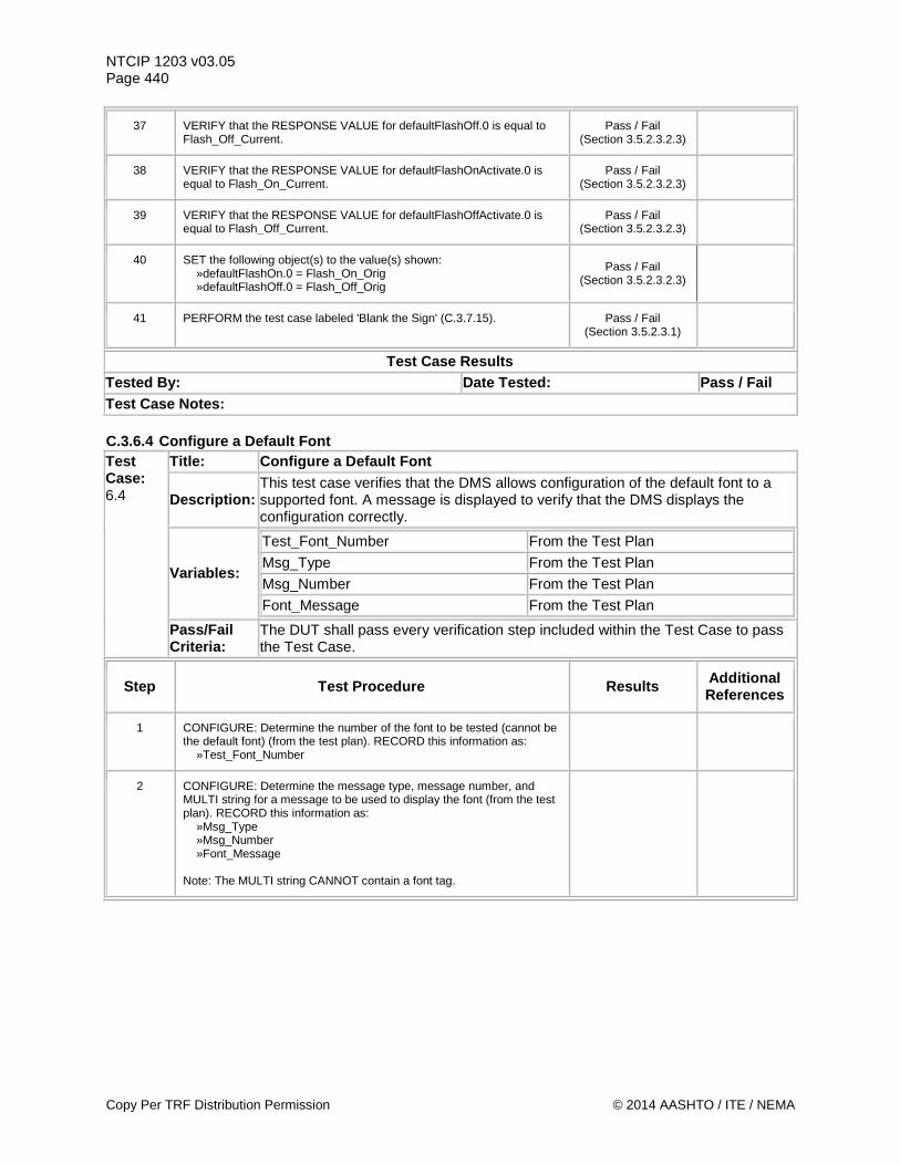
NTCIP 1203 v03.05 Page 440
37 VERIFY that the RESPONSE VALUE for defaultFlashOff.0 is equal to Flash_Off_Current.
Pass / Fail (Section 3.5.2.3.2.3)
38 VERIFY that the RESPONSE VALUE for defaultFlashOnActivate.0 is equal to Flash_On_Current.
Pass / Fail (Section 3.5.2.3.2.3)
39 VERIFY that the RESPONSE VALUE for defaultFlashOffActivate.0 is equal to Flash_Off_Current.
Pass / Fail (Section 3.5.2.3.2.3)
40 SET the following object(s) to the value(s) shown: »defaultFlashOn.0 = Flash_On_Orig »defaultFlashOff.0 = Flash_Off_Orig
Pass / Fail (Section 3.5.2.3.2.3)
41 PERFORM the test case labeled 'Blank the Sign' (C.3.7.15). Pass / Fail (Section 3.5.2.3.1)
Test Case Results Tested By: Date Tested: Pass / Fail Test Case Notes: C.3.6.4 Configure a Default Font Test Case: 6.4
Title: Configure a Default Font
Description: This test case verifies that the DMS allows configuration of the default font to a supported font. A message is displayed to verify that the DMS displays the configuration correctly.
Variables:
Test_Font_Number From the Test Plan Msg_Type From the Test Plan Msg_Number From the Test Plan Font_Message From the Test Plan
Pass/Fail Criteria:
The DUT shall pass every verification step included within the Test Case to pass the Test Case.
Step Test Procedure Results Additional References
1 CONFIGURE: Determine the number of the font to be tested (cannot be the default font) (from the test plan). RECORD this information as: »Test_Font_Number
2 CONFIGURE: Determine the message type, message number, and MULTI string for a message to be used to display the font (from the test plan). RECORD this information as: »Msg_Type »Msg_Number »Font_Message Note: The MULTI string CANNOT contain a font tag.
Copy Per TRF Distribution Permission © 2014 AASHTO / ITE / NEMA
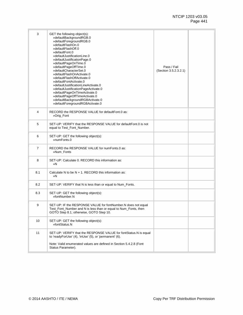
NTCIP 1203 v03.05 Page 441
3 GET the following object(s): »defaultBackgroundRGB.0 »defaultForegroundRGB.0 »defaultFlashOn.0 »defaultFlashOff.0 »defaultFont.0 »defaultJustificationLine.0 »defaultJustificationPage.0 »defaultPageOnTime.0 »defaultPageOffTime.0 »defaultCharacterSet.0 »defaultFlashOnActivate.0 »defaultFlashOffActivate.0 »defaultFontActivate.0 »defaultJustificationLineActivate.0 »defaultJustificationPageActivate.0 »defaultPageOnTimeActivate.0 »defaultPageOffTimeActivate.0 »defaultBackgroundRGBActivate.0 »defaultForegroundRGBActivate.0
Pass / Fail (Section 3.5.2.3.2.1)
4 RECORD the RESPONSE VALUE for defaultFont.0 as: »Orig_Font
5 SET-UP: VERIFY that the RESPONSE VALUE for defaultFont.0 is not equal to Test_Font_Number.
6 SET-UP: GET the following object(s): »numFonts.0
7 RECORD the RESPONSE VALUE for numFonts.0 as: »Num_Fonts
8 SET-UP: Calculate 0. RECORD this information as: »N
8.1 Calculate N to be N + 1. RECORD this information as: »N
8.2 SET-UP: VERIFY that N is less than or equal to Num_Fonts.
8.3 SET-UP: GET the following object(s): »fontNumber.N
9 SET-UP: IF the RESPONSE VALUE for fontNumber.N does not equal Test_Font_Number and N is less than or equal to Num_Fonts, then GOTO Step 8.1; otherwise, GOTO Step 10.
10 SET-UP: GET the following object(s): »fontStatus.N
11 SET-UP: VERIFY that the RESPONSE VALUE for fontStatus.N is equal to 'readyForUse' (4), 'inUse' (5), or 'permanent' (6). Note: Valid enumerated values are defined in Section 5.4.2.8 (Font Status Parameter).
© 2014 AASHTO / ITE / NEMA Copy Per TRF Distributtion Permission
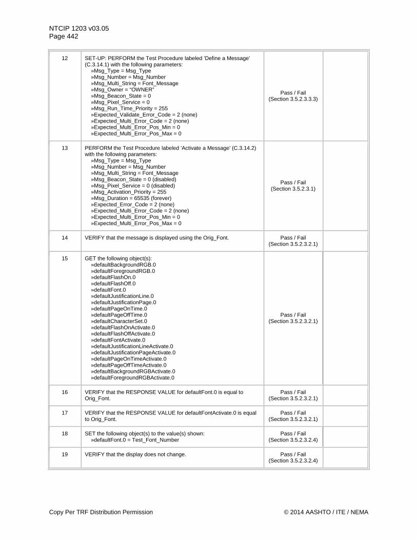
NTCIP 1203 v03.05 Page 442
12 SET-UP: PERFORM the Test Procedure labeled 'Define a Message' (C.3.14.1) with the following parameters: »Msg_Type = Msg_Type »Msg_Number = Msg_Number »Msg_Multi_String = Font_Message »Msg_Owner = “OWNER” »Msg_Beacon_State = 0 »Msg_Pixel_Service = 0 »Msg_Run_Time_Priority = 255 »Expected_Validate_Error_Code = 2 (none) »Expected_Multi_Error_Code = 2 (none) »Expected_Multi_Error_Pos_Min = 0 »Expected_Multi_Error_Pos_Max = 0
Pass / Fail (Section 3.5.2.3.3.3)
13 PERFORM the Test Procedure labeled 'Activate a Message' (C.3.14.2) with the following parameters: »Msg_Type = Msg_Type »Msg_Number = Msg_Number »Msg_Multi_String = Font_Message »Msg_Beacon_State = 0 (disabled) »Msg_Pixel_Service = 0 (disabled) »Msg_Activation_Priority = 255 »Msg_Duration = 65535 (forever) »Expected_Error_Code = 2 (none) »Expected_Multi_Error_Code = 2 (none) »Expected_Multi_Error_Pos_Min = 0 »Expected_Multi_Error_Pos_Max = 0
Pass / Fail (Section 3.5.2.3.1)
14 VERIFY that the message is displayed using the Orig_Font. Pass / Fail (Section 3.5.2.3.2.1)
15 GET the following object(s): »defaultBackgroundRGB.0 »defaultForegroundRGB.0 »defaultFlashOn.0 »defaultFlashOff.0 »defaultFont.0 »defaultJustificationLine.0 »defaultJustificationPage.0 »defaultPageOnTime.0 »defaultPageOffTime.0 »defaultCharacterSet.0 »defaultFlashOnActivate.0 »defaultFlashOffActivate.0 »defaultFontActivate.0 »defaultJustificationLineActivate.0 »defaultJustificationPageActivate.0 »defaultPageOnTimeActivate.0 »defaultPageOffTimeActivate.0 »defaultBackgroundRGBActivate.0 »defaultForegroundRGBActivate.0
Pass / Fail (Section 3.5.2.3.2.1)
16 VERIFY that the RESPONSE VALUE for defaultFont.0 is equal to Orig_Font.
Pass / Fail (Section 3.5.2.3.2.1)
17 VERIFY that the RESPONSE VALUE for defaultFontActivate.0 is equal to Orig_Font.
Pass / Fail (Section 3.5.2.3.2.1)
18 SET the following object(s) to the value(s) shown: »defaultFont.0 = Test_Font_Number
Pass / Fail (Section 3.5.2.3.2.4)
19 VERIFY that the display does not change. Pass / Fail (Section 3.5.2.3.2.4)
Copy Per TRF Distribution Permission © 2014 AASHTO / ITE / NEMA
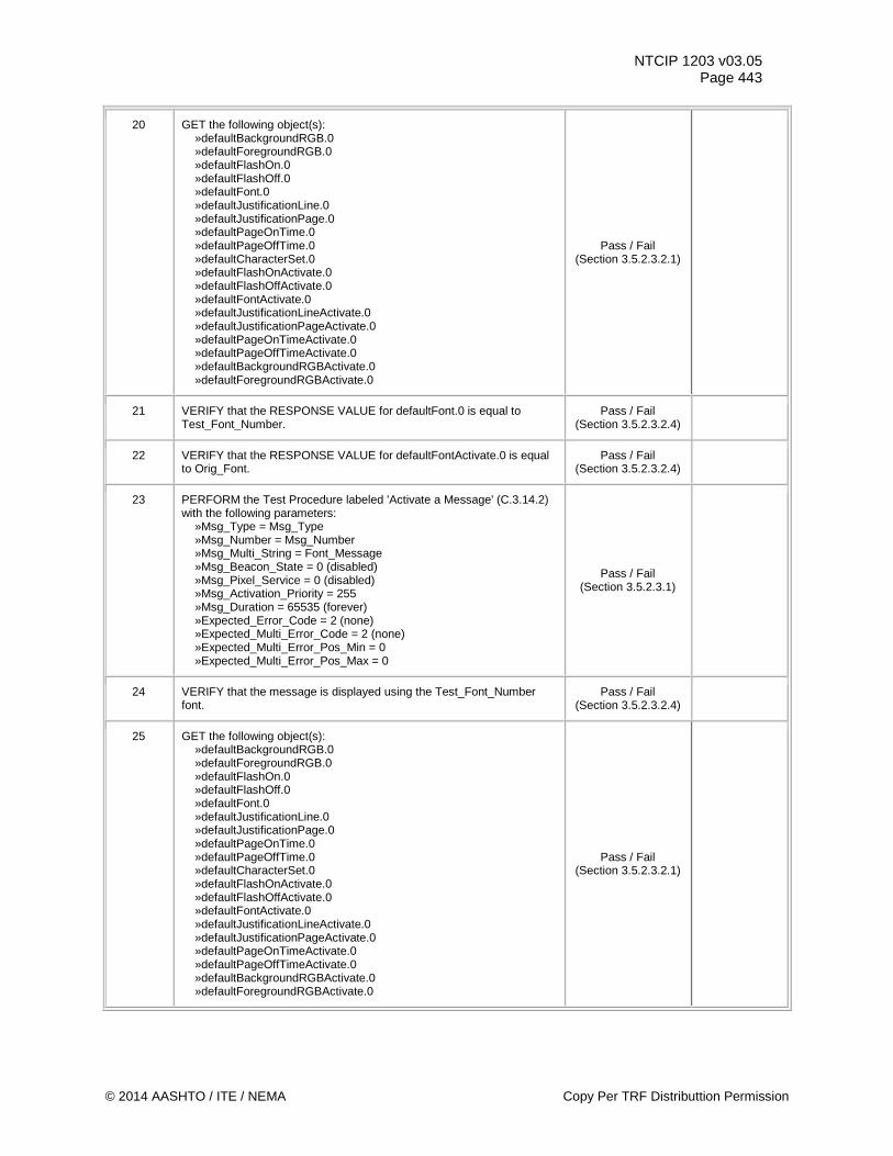
NTCIP 1203 v03.05 Page 443
20 GET the following object(s): »defaultBackgroundRGB.0 »defaultForegroundRGB.0 »defaultFlashOn.0 »defaultFlashOff.0 »defaultFont.0 »defaultJustificationLine.0 »defaultJustificationPage.0 »defaultPageOnTime.0 »defaultPageOffTime.0 »defaultCharacterSet.0 »defaultFlashOnActivate.0 »defaultFlashOffActivate.0 »defaultFontActivate.0 »defaultJustificationLineActivate.0 »defaultJustificationPageActivate.0 »defaultPageOnTimeActivate.0 »defaultPageOffTimeActivate.0 »defaultBackgroundRGBActivate.0 »defaultForegroundRGBActivate.0
Pass / Fail (Section 3.5.2.3.2.1)
21 VERIFY that the RESPONSE VALUE for defaultFont.0 is equal to Test_Font_Number.
Pass / Fail (Section 3.5.2.3.2.4)
22 VERIFY that the RESPONSE VALUE for defaultFontActivate.0 is equal to Orig_Font.
Pass / Fail (Section 3.5.2.3.2.4)
23 PERFORM the Test Procedure labeled 'Activate a Message' (C.3.14.2) with the following parameters: »Msg_Type = Msg_Type »Msg_Number = Msg_Number »Msg_Multi_String = Font_Message »Msg_Beacon_State = 0 (disabled) »Msg_Pixel_Service = 0 (disabled) »Msg_Activation_Priority = 255 »Msg_Duration = 65535 (forever) »Expected_Error_Code = 2 (none) »Expected_Multi_Error_Code = 2 (none) »Expected_Multi_Error_Pos_Min = 0 »Expected_Multi_Error_Pos_Max = 0
Pass / Fail (Section 3.5.2.3.1)
24 VERIFY that the message is displayed using the Test_Font_Number font.
Pass / Fail (Section 3.5.2.3.2.4)
25 GET the following object(s): »defaultBackgroundRGB.0 »defaultForegroundRGB.0 »defaultFlashOn.0 »defaultFlashOff.0 »defaultFont.0 »defaultJustificationLine.0 »defaultJustificationPage.0 »defaultPageOnTime.0 »defaultPageOffTime.0 »defaultCharacterSet.0 »defaultFlashOnActivate.0 »defaultFlashOffActivate.0 »defaultFontActivate.0 »defaultJustificationLineActivate.0 »defaultJustificationPageActivate.0 »defaultPageOnTimeActivate.0 »defaultPageOffTimeActivate.0 »defaultBackgroundRGBActivate.0 »defaultForegroundRGBActivate.0
Pass / Fail (Section 3.5.2.3.2.1)
© 2014 AASHTO / ITE / NEMA Copy Per TRF Distributtion Permission
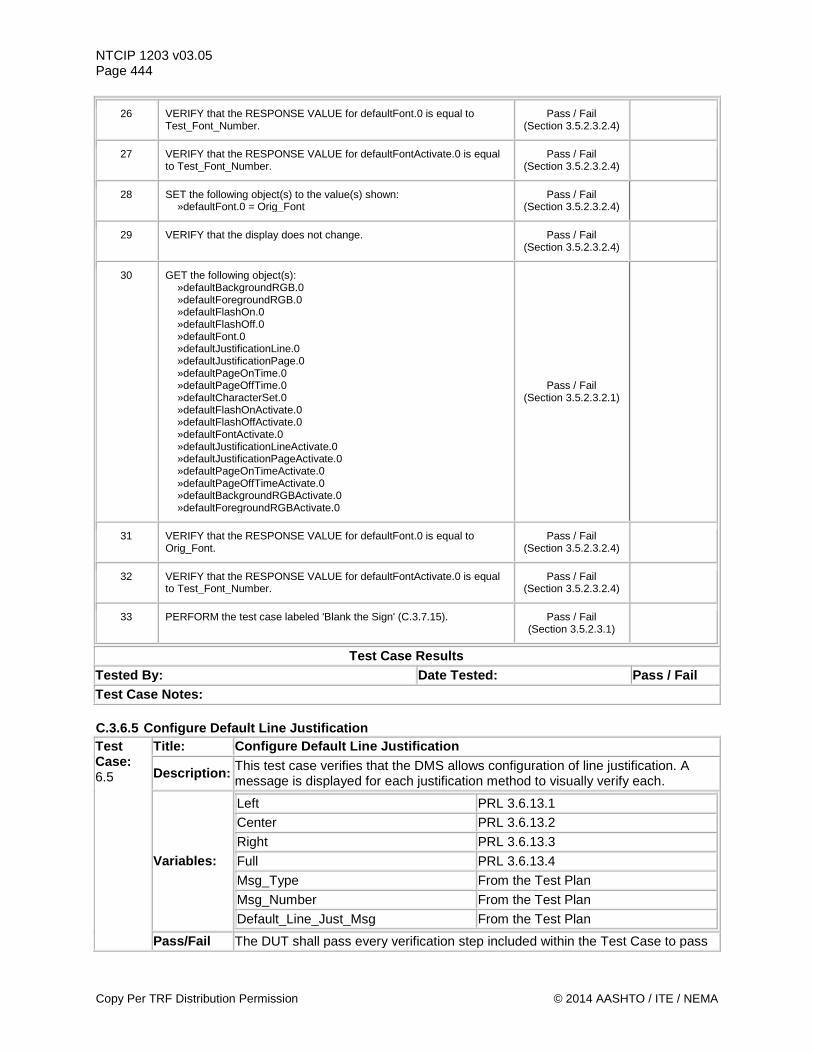
NTCIP 1203 v03.05 Page 444
26 VERIFY that the RESPONSE VALUE for defaultFont.0 is equal to Test_Font_Number.
Pass / Fail (Section 3.5.2.3.2.4)
27 VERIFY that the RESPONSE VALUE for defaultFontActivate.0 is equal to Test_Font_Number.
Pass / Fail (Section 3.5.2.3.2.4)
28 SET the following object(s) to the value(s) shown: »defaultFont.0 = Orig_Font
Pass / Fail (Section 3.5.2.3.2.4)
29 VERIFY that the display does not change. Pass / Fail (Section 3.5.2.3.2.4)
30 GET the following object(s): »defaultBackgroundRGB.0 »defaultForegroundRGB.0 »defaultFlashOn.0 »defaultFlashOff.0 »defaultFont.0 »defaultJustificationLine.0 »defaultJustificationPage.0 »defaultPageOnTime.0 »defaultPageOffTime.0 »defaultCharacterSet.0 »defaultFlashOnActivate.0 »defaultFlashOffActivate.0 »defaultFontActivate.0 »defaultJustificationLineActivate.0 »defaultJustificationPageActivate.0 »defaultPageOnTimeActivate.0 »defaultPageOffTimeActivate.0 »defaultBackgroundRGBActivate.0 »defaultForegroundRGBActivate.0
Pass / Fail (Section 3.5.2.3.2.1)
31 VERIFY that the RESPONSE VALUE for defaultFont.0 is equal to Orig_Font.
Pass / Fail (Section 3.5.2.3.2.4)
32 VERIFY that the RESPONSE VALUE for defaultFontActivate.0 is equal to Test_Font_Number.
Pass / Fail (Section 3.5.2.3.2.4)
33 PERFORM the test case labeled 'Blank the Sign' (C.3.7.15). Pass / Fail (Section 3.5.2.3.1)
Test Case Results Tested By: Date Tested: Pass / Fail Test Case Notes: C.3.6.5 Configure Default Line Justification Test Case: 6.5
Title: Configure Default Line Justification
Description: This test case verifies that the DMS allows configuration of line justification. A message is displayed for each justification method to visually verify each.
Variables:
Left PRL 3.6.13.1 Center PRL 3.6.13.2 Right PRL 3.6.13.3 Full PRL 3.6.13.4 Msg_Type From the Test Plan Msg_Number From the Test Plan Default_Line_Just_Msg From the Test Plan
Pass/Fail The DUT shall pass every verification step included within the Test Case to pass
Copy Per TRF Distribution Permission © 2014 AASHTO / ITE / NEMA
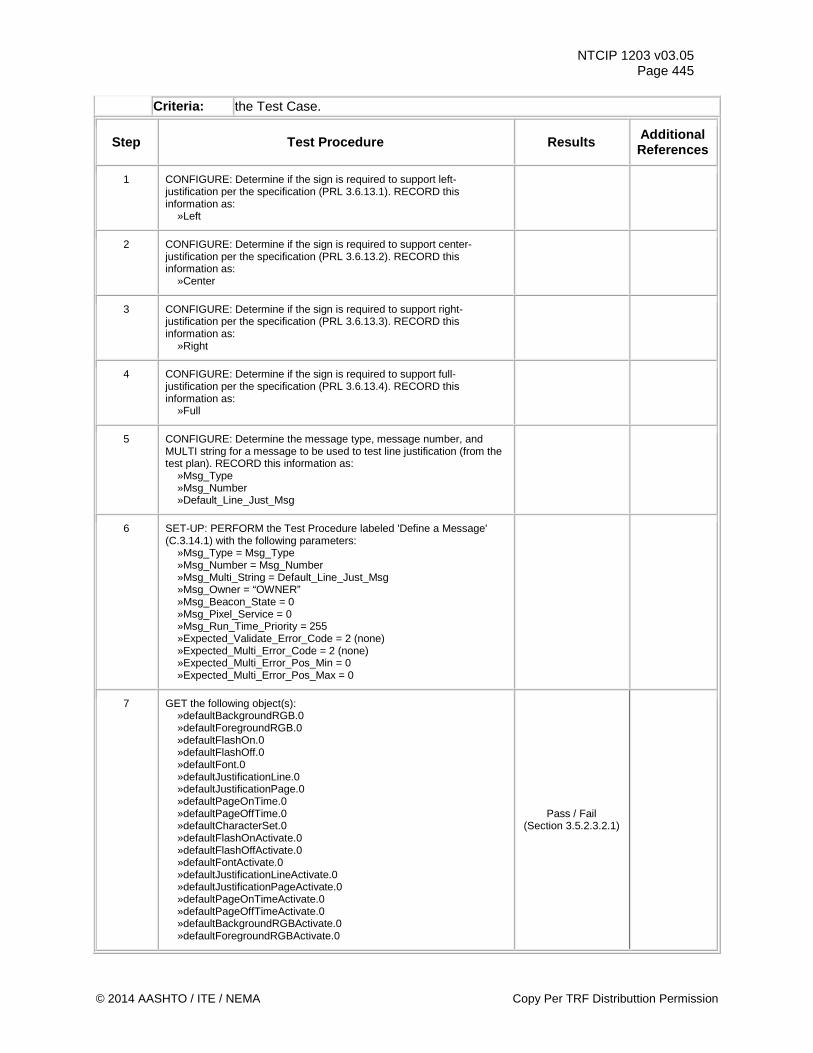
NTCIP 1203 v03.05 Page 445
Criteria: the Test Case.
Step Test Procedure Results Additional References
1 CONFIGURE: Determine if the sign is required to support left-justification per the specification (PRL 3.6.13.1). RECORD this information as: »Left
2 CONFIGURE: Determine if the sign is required to support center-justification per the specification (PRL 3.6.13.2). RECORD this information as: »Center
3 CONFIGURE: Determine if the sign is required to support right-justification per the specification (PRL 3.6.13.3). RECORD this information as: »Right
4 CONFIGURE: Determine if the sign is required to support full-justification per the specification (PRL 3.6.13.4). RECORD this information as: »Full
5 CONFIGURE: Determine the message type, message number, and MULTI string for a message to be used to test line justification (from the test plan). RECORD this information as: »Msg_Type »Msg_Number »Default_Line_Just_Msg
6 SET-UP: PERFORM the Test Procedure labeled 'Define a Message' (C.3.14.1) with the following parameters: »Msg_Type = Msg_Type »Msg_Number = Msg_Number »Msg_Multi_String = Default_Line_Just_Msg »Msg_Owner = “OWNER” »Msg_Beacon_State = 0 »Msg_Pixel_Service = 0 »Msg_Run_Time_Priority = 255 »Expected_Validate_Error_Code = 2 (none) »Expected_Multi_Error_Code = 2 (none) »Expected_Multi_Error_Pos_Min = 0 »Expected_Multi_Error_Pos_Max = 0
7 GET the following object(s): »defaultBackgroundRGB.0 »defaultForegroundRGB.0 »defaultFlashOn.0 »defaultFlashOff.0 »defaultFont.0 »defaultJustificationLine.0 »defaultJustificationPage.0 »defaultPageOnTime.0 »defaultPageOffTime.0 »defaultCharacterSet.0 »defaultFlashOnActivate.0 »defaultFlashOffActivate.0 »defaultFontActivate.0 »defaultJustificationLineActivate.0 »defaultJustificationPageActivate.0 »defaultPageOnTimeActivate.0 »defaultPageOffTimeActivate.0 »defaultBackgroundRGBActivate.0 »defaultForegroundRGBActivate.0
Pass / Fail (Section 3.5.2.3.2.1)
© 2014 AASHTO / ITE / NEMA Copy Per TRF Distributtion Permission
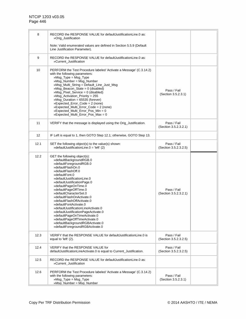
NTCIP 1203 v03.05 Page 446
8 RECORD the RESPONSE VALUE for defaultJustificationLine.0 as: »Orig_Justification Note: Valid enumerated values are defined in Section 5.5.9 (Default Line Justification Parameter).
9 RECORD the RESPONSE VALUE for defaultJustificationLine.0 as: »Current_Justification
10 PERFORM the Test Procedure labeled 'Activate a Message' (C.3.14.2) with the following parameters: »Msg_Type = Msg_Type »Msg_Number = Msg_Number »Msg_Multi_String = Default_Line_Just_Msg »Msg_Beacon_State = 0 (disabled) »Msg_Pixel_Service = 0 (disabled) »Msg_Activation_Priority = 255 »Msg_Duration = 65535 (forever) »Expected_Error_Code = 2 (none) »Expected_Multi_Error_Code = 2 (none) »Expected_Multi_Error_Pos_Min = 0 »Expected_Multi_Error_Pos_Max = 0
Pass / Fail (Section 3.5.2.3.1)
11 VERIFY that the message is displayed using the Orig_Justification. Pass / Fail (Section 3.5.2.3.2.1)
12 IF Left is equal to 1, then GOTO Step 12.1; otherwise, GOTO Step 13.
12.1 SET the following object(s) to the value(s) shown: »defaultJustificationLine.0 = 'left' (2)
Pass / Fail (Section 3.5.2.3.2.5)
12.2 GET the following object(s): »defaultBackgroundRGB.0 »defaultForegroundRGB.0 »defaultFlashOn.0 »defaultFlashOff.0 »defaultFont.0 »defaultJustificationLine.0 »defaultJustificationPage.0 »defaultPageOnTime.0 »defaultPageOffTime.0 »defaultCharacterSet.0 »defaultFlashOnActivate.0 »defaultFlashOffActivate.0 »defaultFontActivate.0 »defaultJustificationLineActivate.0 »defaultJustificationPageActivate.0 »defaultPageOnTimeActivate.0 »defaultPageOffTimeActivate.0 »defaultBackgroundRGBActivate.0 »defaultForegroundRGBActivate.0
Pass / Fail (Section 3.5.2.3.2.1)
12.3 VERIFY that the RESPONSE VALUE for defaultJustificationLine.0 is equal to 'left' (2).
Pass / Fail (Section 3.5.2.3.2.5)
12.4 VERIFY that the RESPONSE VALUE for defaultJustificationLineActivate.0 is equal to Current_Justification.
Pass / Fail (Section 3.5.2.3.2.5)
12.5 RECORD the RESPONSE VALUE for defaultJustificationLine.0 as: »Current_Justification
12.6 PERFORM the Test Procedure labeled 'Activate a Message' (C.3.14.2) with the following parameters: »Msg_Type = Msg_Type »Msg_Number = Msg_Number
Pass / Fail (Section 3.5.2.3.1)
Copy Per TRF Distribution Permission © 2014 AASHTO / ITE / NEMA
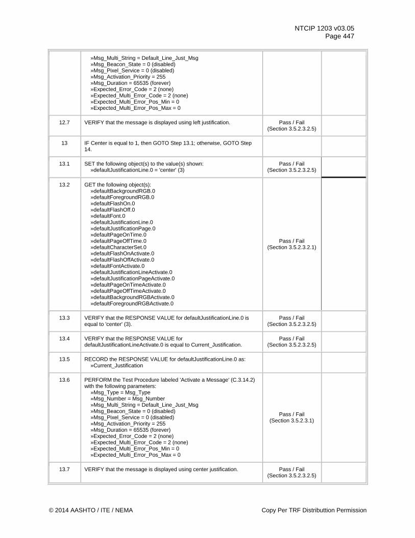
NTCIP 1203 v03.05 Page 447
»Msg_Multi_String = Default_Line_Just_Msg »Msg_Beacon_State = 0 (disabled) »Msg_Pixel_Service = 0 (disabled) »Msg_Activation_Priority = 255 »Msg_Duration = 65535 (forever) »Expected_Error_Code = 2 (none) »Expected_Multi_Error_Code = 2 (none) »Expected_Multi_Error_Pos_Min = 0 »Expected_Multi_Error_Pos_Max = 0
12.7 VERIFY that the message is displayed using left justification. Pass / Fail (Section 3.5.2.3.2.5)
13 IF Center is equal to 1, then GOTO Step 13.1; otherwise, GOTO Step 14.
13.1 SET the following object(s) to the value(s) shown: »defaultJustificationLine.0 = 'center' (3)
Pass / Fail (Section 3.5.2.3.2.5)
13.2 GET the following object(s): »defaultBackgroundRGB.0 »defaultForegroundRGB.0 »defaultFlashOn.0 »defaultFlashOff.0 »defaultFont.0 »defaultJustificationLine.0 »defaultJustificationPage.0 »defaultPageOnTime.0 »defaultPageOffTime.0 »defaultCharacterSet.0 »defaultFlashOnActivate.0 »defaultFlashOffActivate.0 »defaultFontActivate.0 »defaultJustificationLineActivate.0 »defaultJustificationPageActivate.0 »defaultPageOnTimeActivate.0 »defaultPageOffTimeActivate.0 »defaultBackgroundRGBActivate.0 »defaultForegroundRGBActivate.0
Pass / Fail (Section 3.5.2.3.2.1)
13.3 VERIFY that the RESPONSE VALUE for defaultJustificationLine.0 is equal to 'center' (3).
Pass / Fail (Section 3.5.2.3.2.5)
13.4 VERIFY that the RESPONSE VALUE for defaultJustificationLineActivate.0 is equal to Current_Justification.
Pass / Fail (Section 3.5.2.3.2.5)
13.5 RECORD the RESPONSE VALUE for defaultJustificationLine.0 as: »Current_Justification
13.6 PERFORM the Test Procedure labeled 'Activate a Message' (C.3.14.2) with the following parameters: »Msg_Type = Msg_Type »Msg_Number = Msg_Number »Msg_Multi_String = Default_Line_Just_Msg »Msg_Beacon_State = 0 (disabled) »Msg_Pixel_Service = 0 (disabled) »Msg_Activation_Priority = 255 »Msg_Duration = 65535 (forever) »Expected_Error_Code = 2 (none) »Expected_Multi_Error_Code = 2 (none) »Expected_Multi_Error_Pos_Min = 0 »Expected_Multi_Error_Pos_Max = 0
Pass / Fail (Section 3.5.2.3.1)
13.7 VERIFY that the message is displayed using center justification. Pass / Fail (Section 3.5.2.3.2.5)
© 2014 AASHTO / ITE / NEMA Copy Per TRF Distributtion Permission
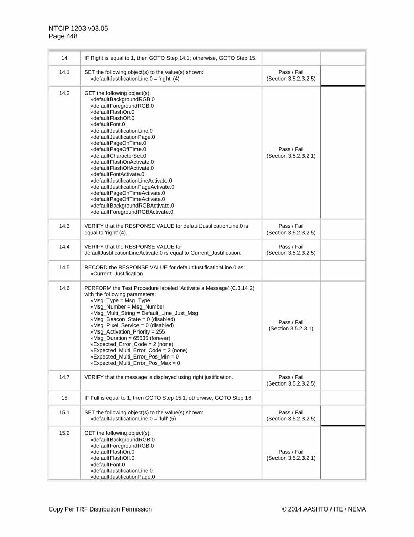
NTCIP 1203 v03.05 Page 448
14 IF Right is equal to 1, then GOTO Step 14.1; otherwise, GOTO Step 15.
14.1 SET the following object(s) to the value(s) shown: »defaultJustificationLine.0 = 'right' (4)
Pass / Fail (Section 3.5.2.3.2.5)
14.2 GET the following object(s): »defaultBackgroundRGB.0 »defaultForegroundRGB.0 »defaultFlashOn.0 »defaultFlashOff.0 »defaultFont.0 »defaultJustificationLine.0 »defaultJustificationPage.0 »defaultPageOnTime.0 »defaultPageOffTime.0 »defaultCharacterSet.0 »defaultFlashOnActivate.0 »defaultFlashOffActivate.0 »defaultFontActivate.0 »defaultJustificationLineActivate.0 »defaultJustificationPageActivate.0 »defaultPageOnTimeActivate.0 »defaultPageOffTimeActivate.0 »defaultBackgroundRGBActivate.0 »defaultForegroundRGBActivate.0
Pass / Fail (Section 3.5.2.3.2.1)
14.3 VERIFY that the RESPONSE VALUE for defaultJustificationLine.0 is equal to 'right' (4).
Pass / Fail (Section 3.5.2.3.2.5)
14.4 VERIFY that the RESPONSE VALUE for defaultJustificationLineActivate.0 is equal to Current_Justification.
Pass / Fail (Section 3.5.2.3.2.5)
14.5 RECORD the RESPONSE VALUE for defaultJustificationLine.0 as: »Current_Justification
14.6 PERFORM the Test Procedure labeled 'Activate a Message' (C.3.14.2) with the following parameters: »Msg_Type = Msg_Type »Msg_Number = Msg_Number »Msg_Multi_String = Default_Line_Just_Msg »Msg_Beacon_State = 0 (disabled) »Msg_Pixel_Service = 0 (disabled) »Msg_Activation_Priority = 255 »Msg_Duration = 65535 (forever) »Expected_Error_Code = 2 (none) »Expected_Multi_Error_Code = 2 (none) »Expected_Multi_Error_Pos_Min = 0 »Expected_Multi_Error_Pos_Max = 0
Pass / Fail (Section 3.5.2.3.1)
14.7 VERIFY that the message is displayed using right justification. Pass / Fail (Section 3.5.2.3.2.5)
15 IF Full is equal to 1, then GOTO Step 15.1; otherwise, GOTO Step 16.
15.1 SET the following object(s) to the value(s) shown: »defaultJustificationLine.0 = 'full' (5)
Pass / Fail (Section 3.5.2.3.2.5)
15.2 GET the following object(s): »defaultBackgroundRGB.0 »defaultForegroundRGB.0 »defaultFlashOn.0 »defaultFlashOff.0 »defaultFont.0 »defaultJustificationLine.0 »defaultJustificationPage.0
Pass / Fail (Section 3.5.2.3.2.1)
Copy Per TRF Distribution Permission © 2014 AASHTO / ITE / NEMA
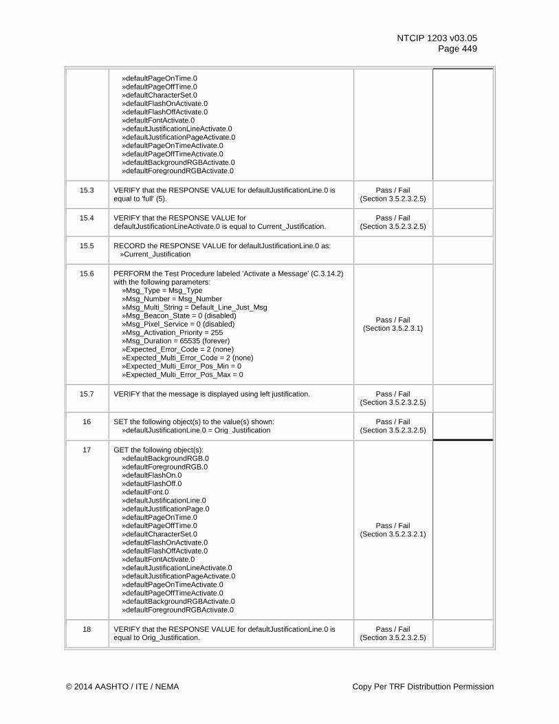
NTCIP 1203 v03.05 Page 449
»defaultPageOnTime.0 »defaultPageOffTime.0 »defaultCharacterSet.0 »defaultFlashOnActivate.0 »defaultFlashOffActivate.0 »defaultFontActivate.0 »defaultJustificationLineActivate.0 »defaultJustificationPageActivate.0 »defaultPageOnTimeActivate.0 »defaultPageOffTimeActivate.0 »defaultBackgroundRGBActivate.0 »defaultForegroundRGBActivate.0
15.3 VERIFY that the RESPONSE VALUE for defaultJustificationLine.0 is equal to 'full' (5).
Pass / Fail (Section 3.5.2.3.2.5)
15.4 VERIFY that the RESPONSE VALUE for defaultJustificationLineActivate.0 is equal to Current_Justification.
Pass / Fail (Section 3.5.2.3.2.5)
15.5 RECORD the RESPONSE VALUE for defaultJustificationLine.0 as: »Current_Justification
15.6 PERFORM the Test Procedure labeled 'Activate a Message' (C.3.14.2) with the following parameters: »Msg_Type = Msg_Type »Msg_Number = Msg_Number »Msg_Multi_String = Default_Line_Just_Msg »Msg_Beacon_State = 0 (disabled) »Msg_Pixel_Service = 0 (disabled) »Msg_Activation_Priority = 255 »Msg_Duration = 65535 (forever) »Expected_Error_Code = 2 (none) »Expected_Multi_Error_Code = 2 (none) »Expected_Multi_Error_Pos_Min = 0 »Expected_Multi_Error_Pos_Max = 0
Pass / Fail (Section 3.5.2.3.1)
15.7 VERIFY that the message is displayed using left justification. Pass / Fail (Section 3.5.2.3.2.5)
16 SET the following object(s) to the value(s) shown: »defaultJustificationLine.0 = Orig_Justification
Pass / Fail (Section 3.5.2.3.2.5)
17 GET the following object(s): »defaultBackgroundRGB.0 »defaultForegroundRGB.0 »defaultFlashOn.0 »defaultFlashOff.0 »defaultFont.0 »defaultJustificationLine.0 »defaultJustificationPage.0 »defaultPageOnTime.0 »defaultPageOffTime.0 »defaultCharacterSet.0 »defaultFlashOnActivate.0 »defaultFlashOffActivate.0 »defaultFontActivate.0 »defaultJustificationLineActivate.0 »defaultJustificationPageActivate.0 »defaultPageOnTimeActivate.0 »defaultPageOffTimeActivate.0 »defaultBackgroundRGBActivate.0 »defaultForegroundRGBActivate.0
Pass / Fail (Section 3.5.2.3.2.1)
18 VERIFY that the RESPONSE VALUE for defaultJustificationLine.0 is equal to Orig_Justification.
Pass / Fail (Section 3.5.2.3.2.5)
© 2014 AASHTO / ITE / NEMA Copy Per TRF Distributtion Permission
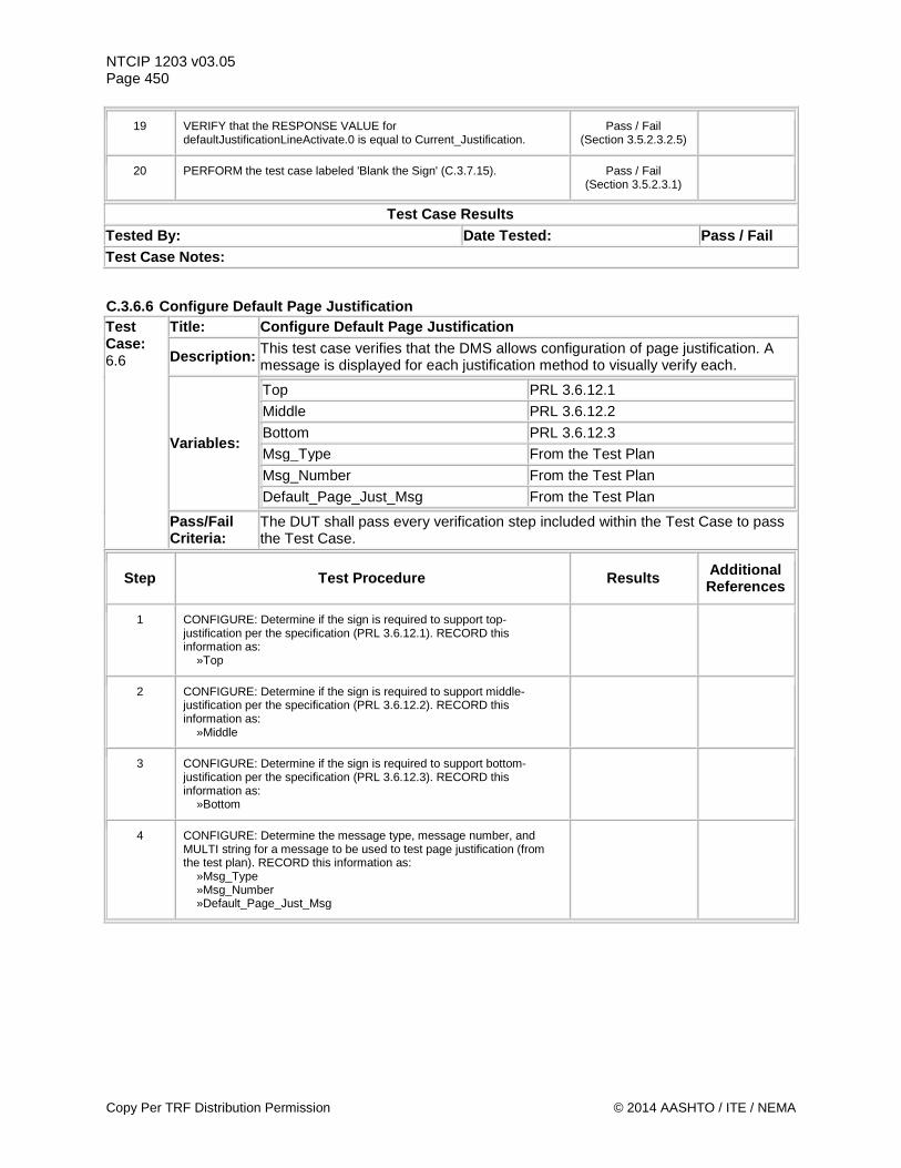
NTCIP 1203 v03.05 Page 450
19 VERIFY that the RESPONSE VALUE for defaultJustificationLineActivate.0 is equal to Current_Justification.
Pass / Fail (Section 3.5.2.3.2.5)
20 PERFORM the test case labeled 'Blank the Sign' (C.3.7.15). Pass / Fail (Section 3.5.2.3.1)
Test Case Results Tested By: Date Tested: Pass / Fail Test Case Notes:
C.3.6.6 Configure Default Page Justification Test Case: 6.6
Title: Configure Default Page Justification
Description: This test case verifies that the DMS allows configuration of page justification. A message is displayed for each justification method to visually verify each.
Variables:
Top PRL 3.6.12.1 Middle PRL 3.6.12.2 Bottom PRL 3.6.12.3 Msg_Type From the Test Plan Msg_Number From the Test Plan Default_Page_Just_Msg From the Test Plan
Pass/Fail Criteria:
The DUT shall pass every verification step included within the Test Case to pass the Test Case.
Step Test Procedure Results Additional References
1 CONFIGURE: Determine if the sign is required to support top-justification per the specification (PRL 3.6.12.1). RECORD this information as: »Top
2 CONFIGURE: Determine if the sign is required to support middle-justification per the specification (PRL 3.6.12.2). RECORD this information as: »Middle
3 CONFIGURE: Determine if the sign is required to support bottom-justification per the specification (PRL 3.6.12.3). RECORD this information as: »Bottom
4 CONFIGURE: Determine the message type, message number, and MULTI string for a message to be used to test page justification (from the test plan). RECORD this information as: »Msg_Type »Msg_Number »Default_Page_Just_Msg
Copy Per TRF Distribution Permission © 2014 AASHTO / ITE / NEMA
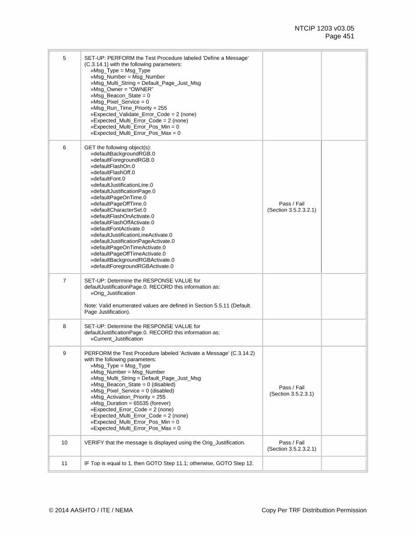
NTCIP 1203 v03.05 Page 451
5 SET-UP: PERFORM the Test Procedure labeled 'Define a Message' (C.3.14.1) with the following parameters: »Msg_Type = Msg_Type »Msg_Number = Msg_Number »Msg_Multi_String = Default_Page_Just_Msg »Msg_Owner = “OWNER” »Msg_Beacon_State = 0 »Msg_Pixel_Service = 0 »Msg_Run_Time_Priority = 255 »Expected_Validate_Error_Code = 2 (none) »Expected_Multi_Error_Code = 2 (none) »Expected_Multi_Error_Pos_Min = 0 »Expected_Multi_Error_Pos_Max = 0
6 GET the following object(s): »defaultBackgroundRGB.0 »defaultForegroundRGB.0 »defaultFlashOn.0 »defaultFlashOff.0 »defaultFont.0 »defaultJustificationLine.0 »defaultJustificationPage.0 »defaultPageOnTime.0 »defaultPageOffTime.0 »defaultCharacterSet.0 »defaultFlashOnActivate.0 »defaultFlashOffActivate.0 »defaultFontActivate.0 »defaultJustificationLineActivate.0 »defaultJustificationPageActivate.0 »defaultPageOnTimeActivate.0 »defaultPageOffTimeActivate.0 »defaultBackgroundRGBActivate.0 »defaultForegroundRGBActivate.0
Pass / Fail (Section 3.5.2.3.2.1)
7 SET-UP: Determine the RESPONSE VALUE for defaultJustificationPage.0. RECORD this information as: »Orig_Justification Note: Valid enumerated values are defined in Section 5.5.11 (Default. Page Justification).
8 SET-UP: Determine the RESPONSE VALUE for defaultJustificationPage.0. RECORD this information as: »Current_Justification
9 PERFORM the Test Procedure labeled 'Activate a Message' (C.3.14.2) with the following parameters: »Msg_Type = Msg_Type »Msg_Number = Msg_Number »Msg_Multi_String = Default_Page_Just_Msg »Msg_Beacon_State = 0 (disabled) »Msg_Pixel_Service = 0 (disabled) »Msg_Activation_Priority = 255 »Msg_Duration = 65535 (forever) »Expected_Error_Code = 2 (none) »Expected_Multi_Error_Code = 2 (none) »Expected_Multi_Error_Pos_Min = 0 »Expected_Multi_Error_Pos_Max = 0
Pass / Fail (Section 3.5.2.3.1)
10 VERIFY that the message is displayed using the Orig_Justification. Pass / Fail (Section 3.5.2.3.2.1)
11 IF Top is equal to 1, then GOTO Step 11.1; otherwise, GOTO Step 12.
© 2014 AASHTO / ITE / NEMA Copy Per TRF Distributtion Permission
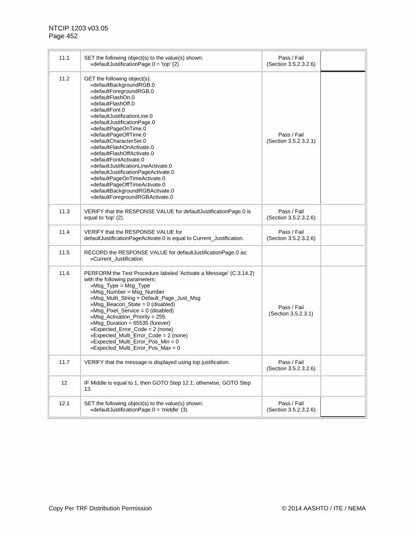
NTCIP 1203 v03.05 Page 452
11.1 SET the following object(s) to the value(s) shown: »defaultJustificationPage.0 = 'top' (2)
Pass / Fail (Section 3.5.2.3.2.6)
11.2 GET the following object(s): »defaultBackgroundRGB.0 »defaultForegroundRGB.0 »defaultFlashOn.0 »defaultFlashOff.0 »defaultFont.0 »defaultJustificationLine.0 »defaultJustificationPage.0 »defaultPageOnTime.0 »defaultPageOffTime.0 »defaultCharacterSet.0 »defaultFlashOnActivate.0 »defaultFlashOffActivate.0 »defaultFontActivate.0 »defaultJustificationLineActivate.0 »defaultJustificationPageActivate.0 »defaultPageOnTimeActivate.0 »defaultPageOffTimeActivate.0 »defaultBackgroundRGBActivate.0 »defaultForegroundRGBActivate.0
Pass / Fail (Section 3.5.2.3.2.1)
11.3 VERIFY that the RESPONSE VALUE for defaultJustificationPage.0 is equal to 'top' (2).
Pass / Fail (Section 3.5.2.3.2.6)
11.4 VERIFY that the RESPONSE VALUE for defaultJustificationPageActivate.0 is equal to Current_Justification.
Pass / Fail (Section 3.5.2.3.2.6)
11.5 RECORD the RESPONSE VALUE for defaultJustificationPage.0 as: »Current_Justification
11.6 PERFORM the Test Procedure labeled 'Activate a Message' (C.3.14.2) with the following parameters: »Msg_Type = Msg_Type »Msg_Number = Msg_Number »Msg_Multi_String = Default_Page_Just_Msg »Msg_Beacon_State = 0 (disabled) »Msg_Pixel_Service = 0 (disabled) »Msg_Activation_Priority = 255 »Msg_Duration = 65535 (forever) »Expected_Error_Code = 2 (none) »Expected_Multi_Error_Code = 2 (none) »Expected_Multi_Error_Pos_Min = 0 »Expected_Multi_Error_Pos_Max = 0
Pass / Fail (Section 3.5.2.3.1)
11.7 VERIFY that the message is displayed using top justification. Pass / Fail (Section 3.5.2.3.2.6)
12 IF Middle is equal to 1, then GOTO Step 12.1; otherwise, GOTO Step 13.
12.1 SET the following object(s) to the value(s) shown: »defaultJustificationPage.0 = 'middle' (3)
Pass / Fail (Section 3.5.2.3.2.6)
Copy Per TRF Distribution Permission © 2014 AASHTO / ITE / NEMA
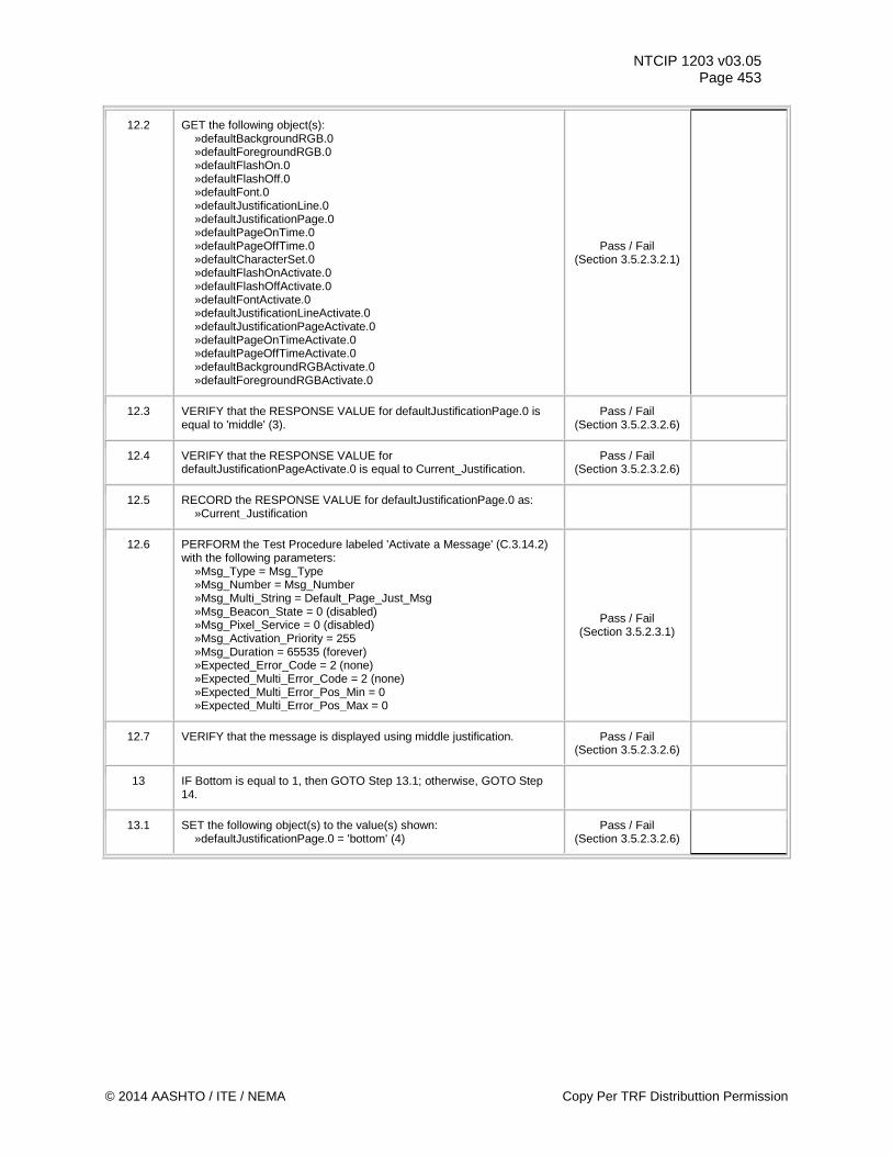
NTCIP 1203 v03.05 Page 453
12.2 GET the following object(s): »defaultBackgroundRGB.0 »defaultForegroundRGB.0 »defaultFlashOn.0 »defaultFlashOff.0 »defaultFont.0 »defaultJustificationLine.0 »defaultJustificationPage.0 »defaultPageOnTime.0 »defaultPageOffTime.0 »defaultCharacterSet.0 »defaultFlashOnActivate.0 »defaultFlashOffActivate.0 »defaultFontActivate.0 »defaultJustificationLineActivate.0 »defaultJustificationPageActivate.0 »defaultPageOnTimeActivate.0 »defaultPageOffTimeActivate.0 »defaultBackgroundRGBActivate.0 »defaultForegroundRGBActivate.0
Pass / Fail (Section 3.5.2.3.2.1)
12.3 VERIFY that the RESPONSE VALUE for defaultJustificationPage.0 is equal to 'middle' (3).
Pass / Fail (Section 3.5.2.3.2.6)
12.4 VERIFY that the RESPONSE VALUE for defaultJustificationPageActivate.0 is equal to Current_Justification.
Pass / Fail (Section 3.5.2.3.2.6)
12.5 RECORD the RESPONSE VALUE for defaultJustificationPage.0 as: »Current_Justification
12.6 PERFORM the Test Procedure labeled 'Activate a Message' (C.3.14.2) with the following parameters: »Msg_Type = Msg_Type »Msg_Number = Msg_Number »Msg_Multi_String = Default_Page_Just_Msg »Msg_Beacon_State = 0 (disabled) »Msg_Pixel_Service = 0 (disabled) »Msg_Activation_Priority = 255 »Msg_Duration = 65535 (forever) »Expected_Error_Code = 2 (none) »Expected_Multi_Error_Code = 2 (none) »Expected_Multi_Error_Pos_Min = 0 »Expected_Multi_Error_Pos_Max = 0
Pass / Fail (Section 3.5.2.3.1)
12.7 VERIFY that the message is displayed using middle justification. Pass / Fail (Section 3.5.2.3.2.6)
13 IF Bottom is equal to 1, then GOTO Step 13.1; otherwise, GOTO Step 14.
13.1 SET the following object(s) to the value(s) shown: »defaultJustificationPage.0 = 'bottom' (4)
Pass / Fail (Section 3.5.2.3.2.6)
© 2014 AASHTO / ITE / NEMA Copy Per TRF Distributtion Permission
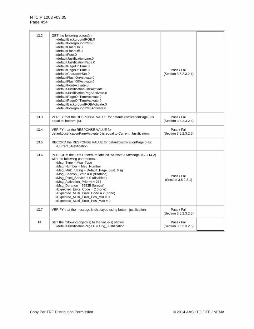
NTCIP 1203 v03.05 Page 454
13.2 GET the following object(s): »defaultBackgroundRGB.0 »defaultForegroundRGB.0 »defaultFlashOn.0 »defaultFlashOff.0 »defaultFont.0 »defaultJustificationLine.0 »defaultJustificationPage.0 »defaultPageOnTime.0 »defaultPageOffTime.0 »defaultCharacterSet.0 »defaultFlashOnActivate.0 »defaultFlashOffActivate.0 »defaultFontActivate.0 »defaultJustificationLineActivate.0 »defaultJustificationPageActivate.0 »defaultPageOnTimeActivate.0 »defaultPageOffTimeActivate.0 »defaultBackgroundRGBActivate.0 »defaultForegroundRGBActivate.0
Pass / Fail (Section 3.5.2.3.2.1)
13.3 VERIFY that the RESPONSE VALUE for defaultJustificationPage.0 is equal to 'bottom' (4).
Pass / Fail (Section 3.5.2.3.2.6)
13.4 VERIFY that the RESPONSE VALUE for defaultJustificationPageActivate.0 is equal to Current_Justification.
Pass / Fail (Section 3.5.2.3.2.6)
13.5 RECORD the RESPONSE VALUE for defaultJustificationPage.0 as: »Current_Justification
13.6 PERFORM the Test Procedure labeled 'Activate a Message' (C.3.14.2) with the following parameters: »Msg_Type = Msg_Type »Msg_Number = Msg_Number »Msg_Multi_String = Default_Page_Just_Msg »Msg_Beacon_State = 0 (disabled) »Msg_Pixel_Service = 0 (disabled) »Msg_Activation_Priority = 255 »Msg_Duration = 65535 (forever) »Expected_Error_Code = 2 (none) »Expected_Multi_Error_Code = 2 (none) »Expected_Multi_Error_Pos_Min = 0 »Expected_Multi_Error_Pos_Max = 0
Pass / Fail (Section 3.5.2.3.1)
13.7 VERIFY that the message is displayed using bottom justification. Pass / Fail (Section 3.5.2.3.2.6)
14 SET the following object(s) to the value(s) shown: »defaultJustificationPage.0 = Orig_Justification
Pass / Fail (Section 3.5.2.3.2.6)
Copy Per TRF Distribution Permission © 2014 AASHTO / ITE / NEMA
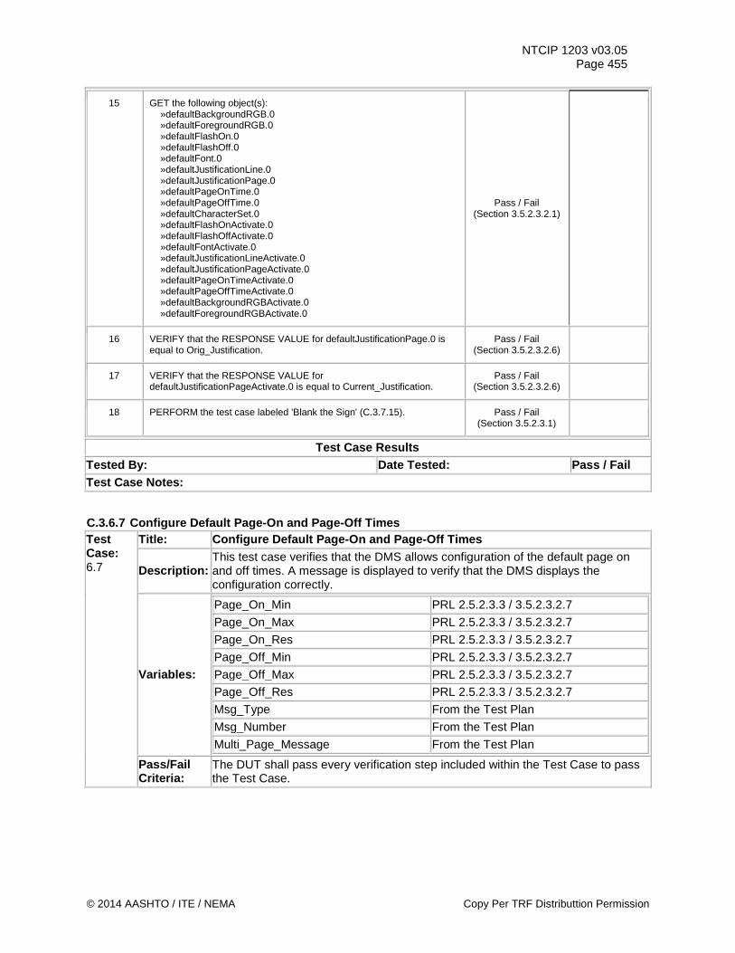
NTCIP 1203 v03.05 Page 455
15 GET the following object(s): »defaultBackgroundRGB.0 »defaultForegroundRGB.0 »defaultFlashOn.0 »defaultFlashOff.0 »defaultFont.0 »defaultJustificationLine.0 »defaultJustificationPage.0 »defaultPageOnTime.0 »defaultPageOffTime.0 »defaultCharacterSet.0 »defaultFlashOnActivate.0 »defaultFlashOffActivate.0 »defaultFontActivate.0 »defaultJustificationLineActivate.0 »defaultJustificationPageActivate.0 »defaultPageOnTimeActivate.0 »defaultPageOffTimeActivate.0 »defaultBackgroundRGBActivate.0 »defaultForegroundRGBActivate.0
Pass / Fail (Section 3.5.2.3.2.1)
16 VERIFY that the RESPONSE VALUE for defaultJustificationPage.0 is equal to Orig_Justification.
Pass / Fail (Section 3.5.2.3.2.6)
17 VERIFY that the RESPONSE VALUE for defaultJustificationPageActivate.0 is equal to Current_Justification.
Pass / Fail (Section 3.5.2.3.2.6)
18 PERFORM the test case labeled 'Blank the Sign' (C.3.7.15). Pass / Fail (Section 3.5.2.3.1)
Test Case Results Tested By: Date Tested: Pass / Fail Test Case Notes:
C.3.6.7 Configure Default Page-On and Page-Off Times Test Case: 6.7
Title: Configure Default Page-On and Page-Off Times
Description: This test case verifies that the DMS allows configuration of the default page on and off times. A message is displayed to verify that the DMS displays the configuration correctly.
Variables:
Page_On_Min PRL 2.5.2.3.3 / 3.5.2.3.2.7 Page_On_Max PRL 2.5.2.3.3 / 3.5.2.3.2.7 Page_On_Res PRL 2.5.2.3.3 / 3.5.2.3.2.7 Page_Off_Min PRL 2.5.2.3.3 / 3.5.2.3.2.7 Page_Off_Max PRL 2.5.2.3.3 / 3.5.2.3.2.7 Page_Off_Res PRL 2.5.2.3.3 / 3.5.2.3.2.7 Msg_Type From the Test Plan Msg_Number From the Test Plan Multi_Page_Message From the Test Plan
Pass/Fail Criteria:
The DUT shall pass every verification step included within the Test Case to pass the Test Case.
© 2014 AASHTO / ITE / NEMA Copy Per TRF Distributtion Permission
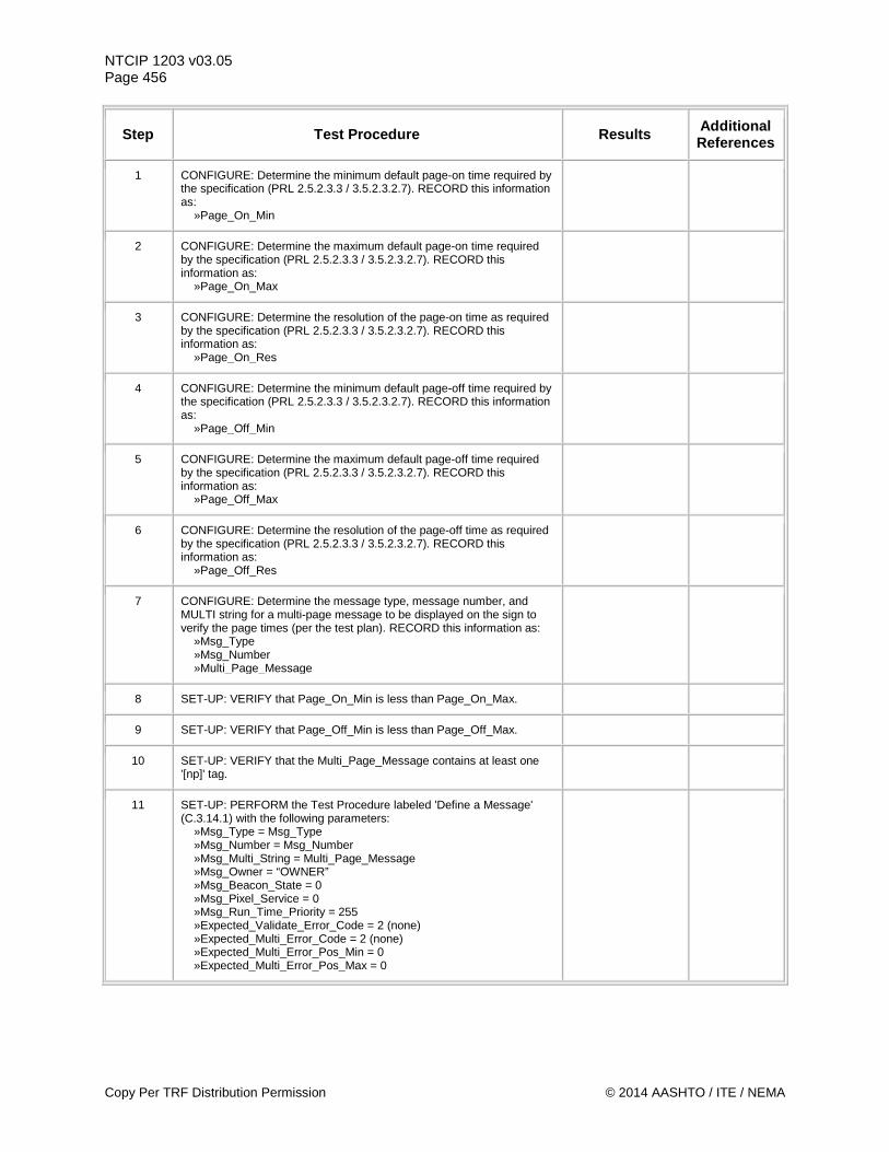
NTCIP 1203 v03.05 Page 456
Step Test Procedure Results Additional References
1 CONFIGURE: Determine the minimum default page-on time required by the specification (PRL 2.5.2.3.3 / 3.5.2.3.2.7). RECORD this information as: »Page_On_Min
2 CONFIGURE: Determine the maximum default page-on time required by the specification (PRL 2.5.2.3.3 / 3.5.2.3.2.7). RECORD this information as: »Page_On_Max
3 CONFIGURE: Determine the resolution of the page-on time as required by the specification (PRL 2.5.2.3.3 / 3.5.2.3.2.7). RECORD this information as: »Page_On_Res
4 CONFIGURE: Determine the minimum default page-off time required by the specification (PRL 2.5.2.3.3 / 3.5.2.3.2.7). RECORD this information as: »Page_Off_Min
5 CONFIGURE: Determine the maximum default page-off time required by the specification (PRL 2.5.2.3.3 / 3.5.2.3.2.7). RECORD this information as: »Page_Off_Max
6 CONFIGURE: Determine the resolution of the page-off time as required by the specification (PRL 2.5.2.3.3 / 3.5.2.3.2.7). RECORD this information as: »Page_Off_Res
7 CONFIGURE: Determine the message type, message number, and MULTI string for a multi-page message to be displayed on the sign to verify the page times (per the test plan). RECORD this information as: »Msg_Type »Msg_Number »Multi_Page_Message
8 SET-UP: VERIFY that Page_On_Min is less than Page_On_Max.
9 SET-UP: VERIFY that Page_Off_Min is less than Page_Off_Max.
10 SET-UP: VERIFY that the Multi_Page_Message contains at least one '[np]' tag.
11 SET-UP: PERFORM the Test Procedure labeled 'Define a Message' (C.3.14.1) with the following parameters: »Msg_Type = Msg_Type »Msg_Number = Msg_Number »Msg_Multi_String = Multi_Page_Message »Msg_Owner = “OWNER” »Msg_Beacon_State = 0 »Msg_Pixel_Service = 0 »Msg_Run_Time_Priority = 255 »Expected_Validate_Error_Code = 2 (none) »Expected_Multi_Error_Code = 2 (none) »Expected_Multi_Error_Pos_Min = 0 »Expected_Multi_Error_Pos_Max = 0
Copy Per TRF Distribution Permission © 2014 AASHTO / ITE / NEMA
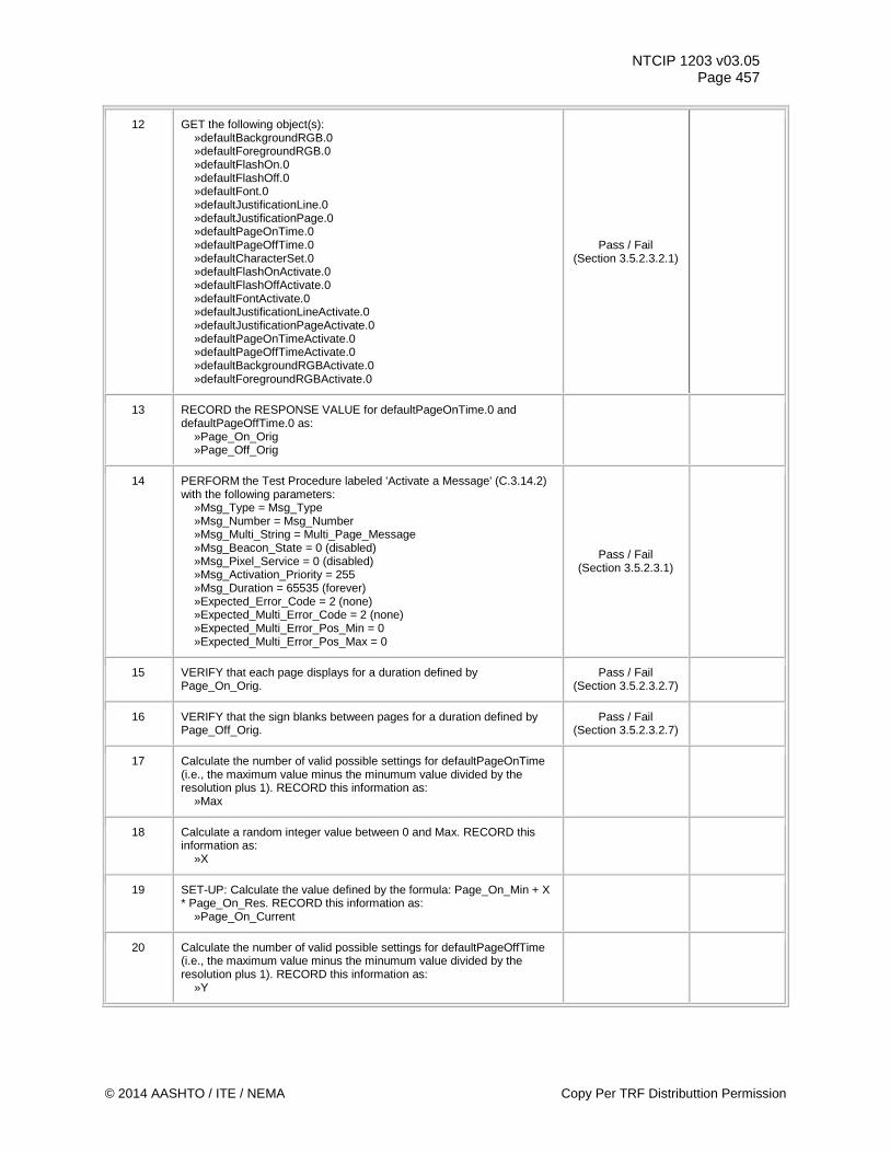
NTCIP 1203 v03.05 Page 457
12 GET the following object(s): »defaultBackgroundRGB.0 »defaultForegroundRGB.0 »defaultFlashOn.0 »defaultFlashOff.0 »defaultFont.0 »defaultJustificationLine.0 »defaultJustificationPage.0 »defaultPageOnTime.0 »defaultPageOffTime.0 »defaultCharacterSet.0 »defaultFlashOnActivate.0 »defaultFlashOffActivate.0 »defaultFontActivate.0 »defaultJustificationLineActivate.0 »defaultJustificationPageActivate.0 »defaultPageOnTimeActivate.0 »defaultPageOffTimeActivate.0 »defaultBackgroundRGBActivate.0 »defaultForegroundRGBActivate.0
Pass / Fail (Section 3.5.2.3.2.1)
13 RECORD the RESPONSE VALUE for defaultPageOnTime.0 and defaultPageOffTime.0 as: »Page_On_Orig »Page_Off_Orig
14 PERFORM the Test Procedure labeled 'Activate a Message' (C.3.14.2) with the following parameters: »Msg_Type = Msg_Type »Msg_Number = Msg_Number »Msg_Multi_String = Multi_Page_Message »Msg_Beacon_State = 0 (disabled) »Msg_Pixel_Service = 0 (disabled) »Msg_Activation_Priority = 255 »Msg_Duration = 65535 (forever) »Expected_Error_Code = 2 (none) »Expected_Multi_Error_Code = 2 (none) »Expected_Multi_Error_Pos_Min = 0 »Expected_Multi_Error_Pos_Max = 0
Pass / Fail (Section 3.5.2.3.1)
15 VERIFY that each page displays for a duration defined by Page_On_Orig.
Pass / Fail (Section 3.5.2.3.2.7)
16 VERIFY that the sign blanks between pages for a duration defined by Page_Off_Orig.
Pass / Fail (Section 3.5.2.3.2.7)
17 Calculate the number of valid possible settings for defaultPageOnTime (i.e., the maximum value minus the minumum value divided by the resolution plus 1). RECORD this information as: »Max
18 Calculate a random integer value between 0 and Max. RECORD this information as: »X
19 SET-UP: Calculate the value defined by the formula: Page_On_Min + X * Page_On_Res. RECORD this information as: »Page_On_Current
20 Calculate the number of valid possible settings for defaultPageOffTime (i.e., the maximum value minus the minumum value divided by the resolution plus 1). RECORD this information as: »Y
© 2014 AASHTO / ITE / NEMA Copy Per TRF Distributtion Permission
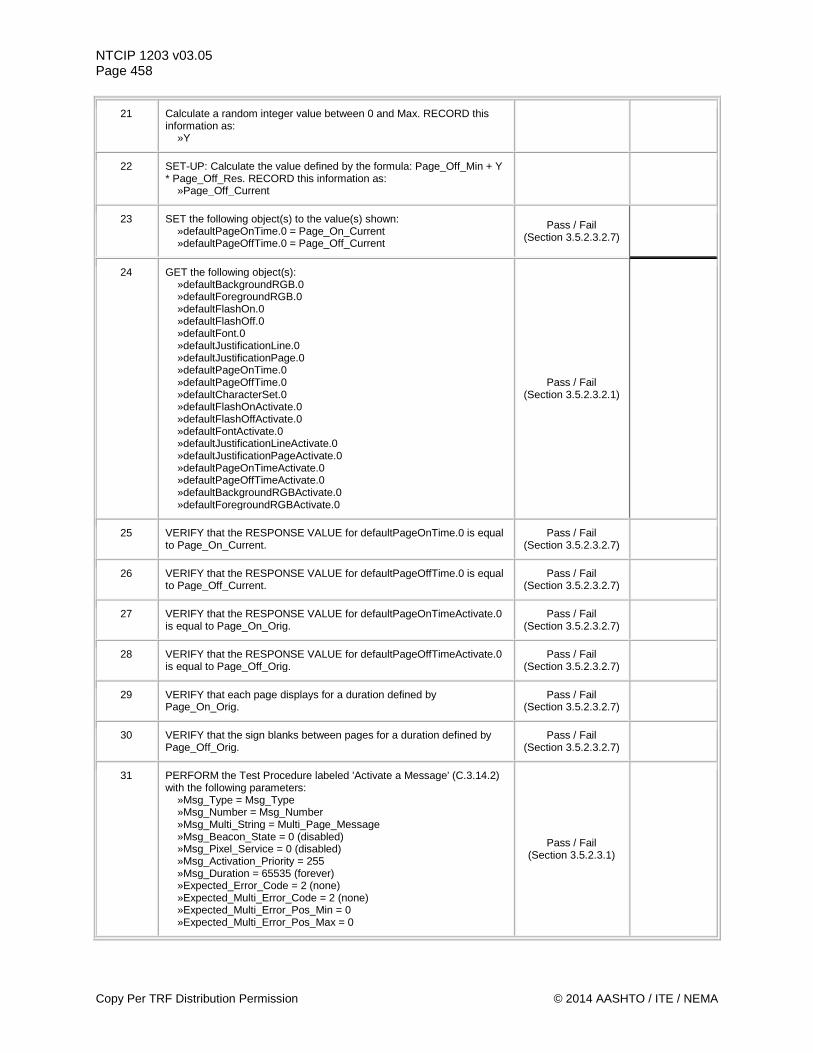
NTCIP 1203 v03.05 Page 458
21 Calculate a random integer value between 0 and Max. RECORD this information as: »Y
22 SET-UP: Calculate the value defined by the formula: Page_Off_Min + Y * Page_Off_Res. RECORD this information as: »Page_Off_Current
23 SET the following object(s) to the value(s) shown: »defaultPageOnTime.0 = Page_On_Current »defaultPageOffTime.0 = Page_Off_Current
Pass / Fail (Section 3.5.2.3.2.7)
24 GET the following object(s): »defaultBackgroundRGB.0 »defaultForegroundRGB.0 »defaultFlashOn.0 »defaultFlashOff.0 »defaultFont.0 »defaultJustificationLine.0 »defaultJustificationPage.0 »defaultPageOnTime.0 »defaultPageOffTime.0 »defaultCharacterSet.0 »defaultFlashOnActivate.0 »defaultFlashOffActivate.0 »defaultFontActivate.0 »defaultJustificationLineActivate.0 »defaultJustificationPageActivate.0 »defaultPageOnTimeActivate.0 »defaultPageOffTimeActivate.0 »defaultBackgroundRGBActivate.0 »defaultForegroundRGBActivate.0
Pass / Fail (Section 3.5.2.3.2.1)
25 VERIFY that the RESPONSE VALUE for defaultPageOnTime.0 is equal to Page_On_Current.
Pass / Fail (Section 3.5.2.3.2.7)
26 VERIFY that the RESPONSE VALUE for defaultPageOffTime.0 is equal to Page_Off_Current.
Pass / Fail (Section 3.5.2.3.2.7)
27 VERIFY that the RESPONSE VALUE for defaultPageOnTimeActivate.0 is equal to Page_On_Orig.
Pass / Fail (Section 3.5.2.3.2.7)
28 VERIFY that the RESPONSE VALUE for defaultPageOffTimeActivate.0 is equal to Page_Off_Orig.
Pass / Fail (Section 3.5.2.3.2.7)
29 VERIFY that each page displays for a duration defined by Page_On_Orig.
Pass / Fail (Section 3.5.2.3.2.7)
30 VERIFY that the sign blanks between pages for a duration defined by Page_Off_Orig.
Pass / Fail (Section 3.5.2.3.2.7)
31 PERFORM the Test Procedure labeled 'Activate a Message' (C.3.14.2) with the following parameters: »Msg_Type = Msg_Type »Msg_Number = Msg_Number »Msg_Multi_String = Multi_Page_Message »Msg_Beacon_State = 0 (disabled) »Msg_Pixel_Service = 0 (disabled) »Msg_Activation_Priority = 255 »Msg_Duration = 65535 (forever) »Expected_Error_Code = 2 (none) »Expected_Multi_Error_Code = 2 (none) »Expected_Multi_Error_Pos_Min = 0 »Expected_Multi_Error_Pos_Max = 0
Pass / Fail (Section 3.5.2.3.1)
Copy Per TRF Distribution Permission © 2014 AASHTO / ITE / NEMA
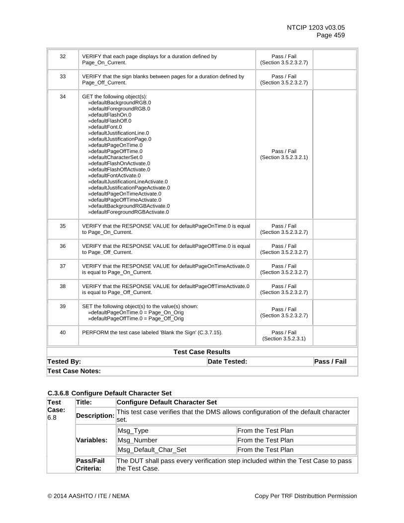
NTCIP 1203 v03.05 Page 459
32 VERIFY that each page displays for a duration defined by Page_On_Current.
Pass / Fail (Section 3.5.2.3.2.7)
33 VERIFY that the sign blanks between pages for a duration defined by Page_Off_Current.
Pass / Fail (Section 3.5.2.3.2.7)
34 GET the following object(s): »defaultBackgroundRGB.0 »defaultForegroundRGB.0 »defaultFlashOn.0 »defaultFlashOff.0 »defaultFont.0 »defaultJustificationLine.0 »defaultJustificationPage.0 »defaultPageOnTime.0 »defaultPageOffTime.0 »defaultCharacterSet.0 »defaultFlashOnActivate.0 »defaultFlashOffActivate.0 »defaultFontActivate.0 »defaultJustificationLineActivate.0 »defaultJustificationPageActivate.0 »defaultPageOnTimeActivate.0 »defaultPageOffTimeActivate.0 »defaultBackgroundRGBActivate.0 »defaultForegroundRGBActivate.0
Pass / Fail (Section 3.5.2.3.2.1)
35 VERIFY that the RESPONSE VALUE for defaultPageOnTime.0 is equal to Page_On_Current.
Pass / Fail (Section 3.5.2.3.2.7)
36 VERIFY that the RESPONSE VALUE for defaultPageOffTime.0 is equal to Page_Off_Current.
Pass / Fail (Section 3.5.2.3.2.7)
37 VERIFY that the RESPONSE VALUE for defaultPageOnTimeActivate.0 is equal to Page_On_Current.
Pass / Fail (Section 3.5.2.3.2.7)
38 VERIFY that the RESPONSE VALUE for defaultPageOffTimeActivate.0 is equal to Page_Off_Current.
Pass / Fail (Section 3.5.2.3.2.7)
39 SET the following object(s) to the value(s) shown: »defaultPageOnTime.0 = Page_On_Orig »defaultPageOffTime.0 = Page_Off_Orig
Pass / Fail (Section 3.5.2.3.2.7)
40 PERFORM the test case labeled 'Blank the Sign' (C.3.7.15). Pass / Fail (Section 3.5.2.3.1)
Test Case Results Tested By: Date Tested: Pass / Fail Test Case Notes:
C.3.6.8 Configure Default Character Set Test Case: 6.8
Title: Configure Default Character Set
Description: This test case verifies that the DMS allows configuration of the default character set.
Variables: Msg_Type From the Test Plan Msg_Number From the Test Plan Msg_Default_Char_Set From the Test Plan
Pass/Fail Criteria:
The DUT shall pass every verification step included within the Test Case to pass the Test Case.
© 2014 AASHTO / ITE / NEMA Copy Per TRF Distributtion Permission
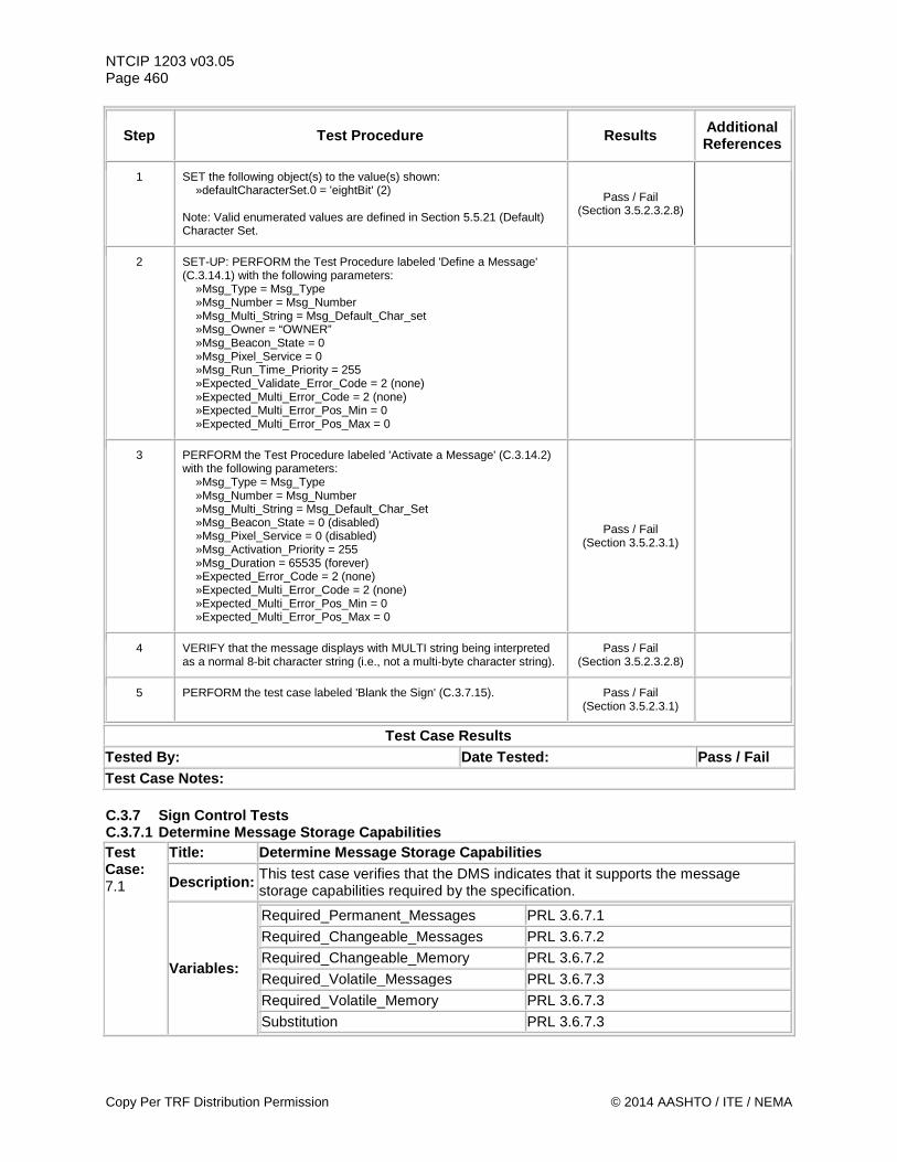
NTCIP 1203 v03.05 Page 460
Step Test Procedure Results Additional References
1 SET the following object(s) to the value(s) shown: »defaultCharacterSet.0 = 'eightBit' (2) Note: Valid enumerated values are defined in Section 5.5.21 (Default) Character Set.
Pass / Fail (Section 3.5.2.3.2.8)
2 SET-UP: PERFORM the Test Procedure labeled 'Define a Message' (C.3.14.1) with the following parameters: »Msg_Type = Msg_Type »Msg_Number = Msg_Number »Msg_Multi_String = Msg_Default_Char_set »Msg_Owner = “OWNER” »Msg_Beacon_State = 0 »Msg_Pixel_Service = 0 »Msg_Run_Time_Priority = 255 »Expected_Validate_Error_Code = 2 (none) »Expected_Multi_Error_Code = 2 (none) »Expected_Multi_Error_Pos_Min = 0 »Expected_Multi_Error_Pos_Max = 0
3 PERFORM the Test Procedure labeled 'Activate a Message' (C.3.14.2) with the following parameters: »Msg_Type = Msg_Type »Msg_Number = Msg_Number »Msg_Multi_String = Msg_Default_Char_Set »Msg_Beacon_State = 0 (disabled) »Msg_Pixel_Service = 0 (disabled) »Msg_Activation_Priority = 255 »Msg_Duration = 65535 (forever) »Expected_Error_Code = 2 (none) »Expected_Multi_Error_Code = 2 (none) »Expected_Multi_Error_Pos_Min = 0 »Expected_Multi_Error_Pos_Max = 0
Pass / Fail (Section 3.5.2.3.1)
4 VERIFY that the message displays with MULTI string being interpreted as a normal 8-bit character string (i.e., not a multi-byte character string).
Pass / Fail (Section 3.5.2.3.2.8)
5 PERFORM the test case labeled 'Blank the Sign' (C.3.7.15). Pass / Fail (Section 3.5.2.3.1)
Test Case Results Tested By: Date Tested: Pass / Fail Test Case Notes: C.3.7 Sign Control Tests C.3.7.1 Determine Message Storage Capabilities Test Case: 7.1
Title: Determine Message Storage Capabilities
Description: This test case verifies that the DMS indicates that it supports the message storage capabilities required by the specification.
Variables:
Required_Permanent_Messages PRL 3.6.7.1 Required_Changeable_Messages PRL 3.6.7.2 Required_Changeable_Memory PRL 3.6.7.2 Required_Volatile_Messages PRL 3.6.7.3 Required_Volatile_Memory PRL 3.6.7.3 Substitution PRL 3.6.7.3
Copy Per TRF Distribution Permission © 2014 AASHTO / ITE / NEMA
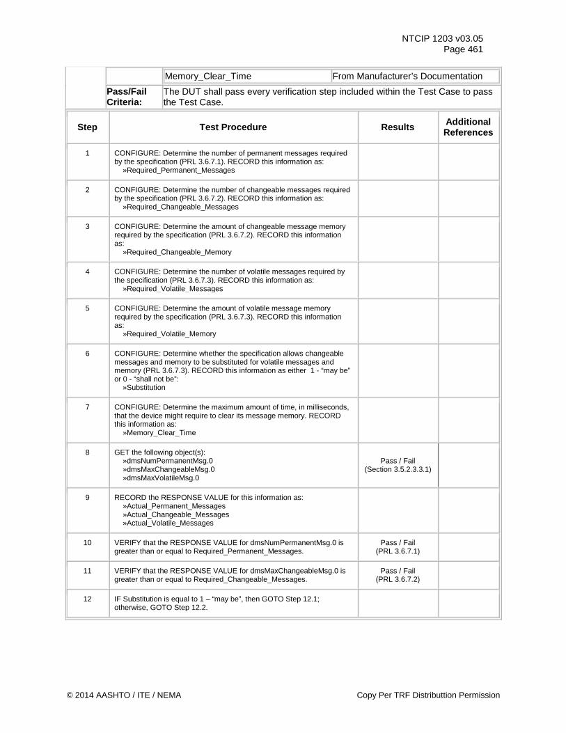
NTCIP 1203 v03.05 Page 461
Memory_Clear_Time From Manufacturer’s Documentation
Pass/Fail Criteria:
The DUT shall pass every verification step included within the Test Case to pass the Test Case.
Step Test Procedure Results Additional References
1 CONFIGURE: Determine the number of permanent messages required by the specification (PRL 3.6.7.1). RECORD this information as: »Required_Permanent_Messages
2 CONFIGURE: Determine the number of changeable messages required by the specification (PRL 3.6.7.2). RECORD this information as: »Required_Changeable_Messages
3 CONFIGURE: Determine the amount of changeable message memory required by the specification (PRL 3.6.7.2). RECORD this information as: »Required_Changeable_Memory
4 CONFIGURE: Determine the number of volatile messages required by the specification (PRL 3.6.7.3). RECORD this information as: »Required_Volatile_Messages
5 CONFIGURE: Determine the amount of volatile message memory required by the specification (PRL 3.6.7.3). RECORD this information as: »Required_Volatile_Memory
6 CONFIGURE: Determine whether the specification allows changeable messages and memory to be substituted for volatile messages and memory (PRL 3.6.7.3). RECORD this information as either 1 - “may be” or 0 - “shall not be”: »Substitution
7 CONFIGURE: Determine the maximum amount of time, in milliseconds, that the device might require to clear its message memory. RECORD this information as: »Memory_Clear_Time
8 GET the following object(s): »dmsNumPermanentMsg.0 »dmsMaxChangeableMsg.0 »dmsMaxVolatileMsg.0
Pass / Fail (Section 3.5.2.3.3.1)
9 RECORD the RESPONSE VALUE for this information as: »Actual_Permanent_Messages »Actual_Changeable_Messages »Actual_Volatile_Messages
10 VERIFY that the RESPONSE VALUE for dmsNumPermanentMsg.0 is greater than or equal to Required_Permanent_Messages.
Pass / Fail (PRL 3.6.7.1)
11 VERIFY that the RESPONSE VALUE for dmsMaxChangeableMsg.0 is greater than or equal to Required_Changeable_Messages.
Pass / Fail (PRL 3.6.7.2)
12 IF Substitution is equal to 1 – “may be”, then GOTO Step 12.1; otherwise, GOTO Step 12.2.
© 2014 AASHTO / ITE / NEMA Copy Per TRF Distributtion Permission
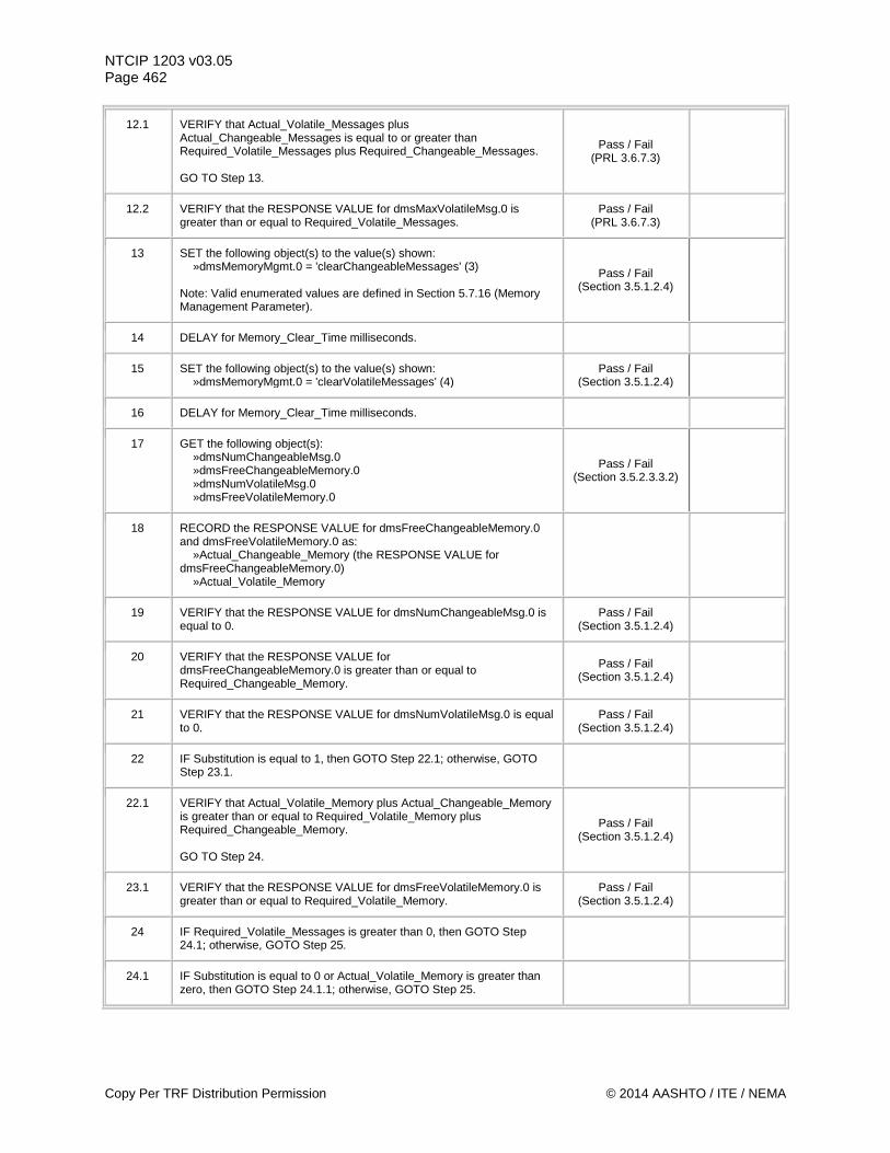
NTCIP 1203 v03.05 Page 462
12.1 VERIFY that Actual_Volatile_Messages plus Actual_Changeable_Messages is equal to or greater than Required_Volatile_Messages plus Required_Changeable_Messages. GO TO Step 13.
Pass / Fail (PRL 3.6.7.3)
12.2 VERIFY that the RESPONSE VALUE for dmsMaxVolatileMsg.0 is greater than or equal to Required_Volatile_Messages.
Pass / Fail (PRL 3.6.7.3)
13 SET the following object(s) to the value(s) shown: »dmsMemoryMgmt.0 = 'clearChangeableMessages' (3) Note: Valid enumerated values are defined in Section 5.7.16 (Memory Management Parameter).
Pass / Fail (Section 3.5.1.2.4)
14 DELAY for Memory_Clear_Time milliseconds.
15 SET the following object(s) to the value(s) shown: »dmsMemoryMgmt.0 = 'clearVolatileMessages' (4)
Pass / Fail (Section 3.5.1.2.4)
16 DELAY for Memory_Clear_Time milliseconds.
17 GET the following object(s): »dmsNumChangeableMsg.0 »dmsFreeChangeableMemory.0 »dmsNumVolatileMsg.0 »dmsFreeVolatileMemory.0
Pass / Fail (Section 3.5.2.3.3.2)
18 RECORD the RESPONSE VALUE for dmsFreeChangeableMemory.0 and dmsFreeVolatileMemory.0 as: »Actual_Changeable_Memory (the RESPONSE VALUE for dmsFreeChangeableMemory.0) »Actual_Volatile_Memory
19 VERIFY that the RESPONSE VALUE for dmsNumChangeableMsg.0 is equal to 0.
Pass / Fail (Section 3.5.1.2.4)
20 VERIFY that the RESPONSE VALUE for dmsFreeChangeableMemory.0 is greater than or equal to Required_Changeable_Memory.
Pass / Fail (Section 3.5.1.2.4)
21 VERIFY that the RESPONSE VALUE for dmsNumVolatileMsg.0 is equal to 0.
Pass / Fail (Section 3.5.1.2.4)
22 IF Substitution is equal to 1, then GOTO Step 22.1; otherwise, GOTO Step 23.1.
22.1 VERIFY that Actual_Volatile_Memory plus Actual_Changeable_Memory is greater than or equal to Required_Volatile_Memory plus Required_Changeable_Memory. GO TO Step 24.
Pass / Fail (Section 3.5.1.2.4)
23.1 VERIFY that the RESPONSE VALUE for dmsFreeVolatileMemory.0 is greater than or equal to Required_Volatile_Memory.
Pass / Fail (Section 3.5.1.2.4)
24 IF Required_Volatile_Messages is greater than 0, then GOTO Step 24.1; otherwise, GOTO Step 25.
24.1 IF Substitution is equal to 0 or Actual_Volatile_Memory is greater than zero, then GOTO Step 24.1.1; otherwise, GOTO Step 25.
Copy Per TRF Distribution Permission © 2014 AASHTO / ITE / NEMA
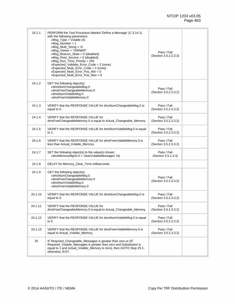
NTCIP 1203 v03.05 Page 463
24.1.1 PERFORM the Test Procedure labeled 'Define a Message' (C.3.14.1) with the following parameters: »Msg_Type = Volatile (4) »Msg_Number = 1 »Msg_Multi_String = ‘A’ »Msg_Owner = “OWNER” »Msg_Beacon_State = 0 (disabled) »Msg_Pixel_Service = 0 (disabled) »Msg_Run_Time_Priority = 255 »Expected_Validate_Error_Code = 2 (none) »Expected_Multi_Error_Code = 2 (none) »Expected_Multi_Error_Pos_Min = 0 »Expected_Multi_Error_Pos_Max = 0
Pass / Fail (Section 3.5.2.3.3.3)
24.1.2 GET the following object(s): »dmsNumChangeableMsg.0 »dmsFreeChangeableMemory.0 »dmsNumVolatileMsg.0 »dmsFreeVolatileMemory.0
Pass / Fail (Section 3.5.2.3.3.2)
24.1.3 VERIFY that the RESPONSE VALUE for dmsNumChangeableMsg.0 is equal to 0.
Pass / Fail (Section 3.5.2.3.3.2)
24.1.4 VERIFY that the RESPONSE VALUE for dmsFreeChangeableMemory.0 is equal to Actual_Changeable_Memory.
Pass / Fail (Section 3.5.2.3.3.2)
24.1.5 VERIFY that the RESPONSE VALUE for dmsNumVolatileMsg.0 is equal to 1.
Pass / Fail (Section 3.5.2.3.3.2)
24.1.6 VERIFY that the RESPONSE VALUE for dmsFreeVolatileMemory.0 is less than Actual_Volatile_Memory.
Pass / Fail (Section 3.5.2.3.3.2)
24.1.7 SET the following object(s) to the value(s) shown: »dmsMemoryMgmt.0 = 'clearVolatileMessages' (4)
Pass / Fail (Section 3.5.1.2.4)
24.1.8 DELAY for Memory_Clear_Time milliseconds.
24.1.9 GET the following object(s): »dmsNumChangeableMsg.0 »dmsFreeChangeableMemory.0 »dmsNumVolatileMsg.0 »dmsFreeVolatileMemory.0
Pass / Fail (Section 3.5.2.3.3.2)
24.1.10 VERIFY that the RESPONSE VALUE for dmsNumChangeableMsg.0 is equal to 0.
Pass / Fail (Section 3.5.2.3.3.2)
24.1.11 VERIFY that the RESPONSE VALUE for dmsFreeChangeableMemory.0 is equal to Actual_Changeable_Memory.
Pass / Fail (Section 3.5.2.3.3.2)
24.1.12 VERIFY that the RESPONSE VALUE for dmsNumVolatileMsg.0 is equal to 0.
Pass / Fail (Section 3.5.2.3.3.2)
24.1.13 VERIFY that the RESPONSE VALUE for dmsFreeVolatileMemory.0 is equal to Actual_Volatile_Memory.
Pass / Fail (Section 3.5.2.3.3.2)
25 IF Required_Changeable_Messages is greater than zero or (IF Required_Volatile_Messages is greater than zero and Substitution is equal to 1 and Actual_Volatile_Memory is zero), then GOTO Step 25.1; otherwise, EXIT.
© 2014 AASHTO / ITE / NEMA Copy Per TRF Distributtion Permission
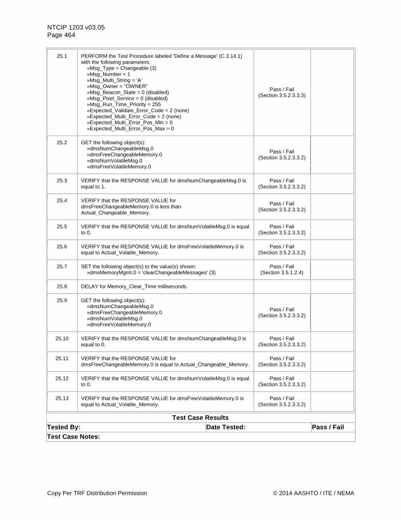
NTCIP 1203 v03.05 Page 464
25.1 PERFORM the Test Procedure labeled 'Define a Message' (C.3.14.1) with the following parameters: »Msg_Type = Changeable (3) »Msg_Number = 1 »Msg_Multi_String = ‘A’ »Msg_Owner = “OWNER” »Msg_Beacon_State = 0 (disabled) »Msg_Pixel_Service = 0 (disabled) »Msg_Run_Time_Priority = 255 »Expected_Validate_Error_Code = 2 (none) »Expected_Multi_Error_Code = 2 (none) »Expected_Multi_Error_Pos_Min = 0 »Expected_Multi_Error_Pos_Max = 0
Pass / Fail (Section 3.5.2.3.3.3)
25.2 GET the following object(s): »dmsNumChangeableMsg.0 »dmsFreeChangeableMemory.0 »dmsNumVolatileMsg.0 »dmsFreeVolatileMemory.0
Pass / Fail (Section 3.5.2.3.3.2)
25.3 VERIFY that the RESPONSE VALUE for dmsNumChangeableMsg.0 is equal to 1.
Pass / Fail (Section 3.5.2.3.3.2)
25.4 VERIFY that the RESPONSE VALUE for dmsFreeChangeableMemory.0 is less than Actual_Changeable_Memory.
Pass / Fail (Section 3.5.2.3.3.2)
25.5 VERIFY that the RESPONSE VALUE for dmsNumVolatileMsg.0 is equal to 0.
Pass / Fail (Section 3.5.2.3.3.2)
25.6 VERIFY that the RESPONSE VALUE for dmsFreeVolatileMemory.0 is equal to Actual_Volatile_Memory.
Pass / Fail (Section 3.5.2.3.3.2)
25.7 SET the following object(s) to the value(s) shown: »dmsMemoryMgmt.0 = 'clearChangeableMessages' (3)
Pass / Fail (Section 3.5.1.2.4)
25.8 DELAY for Memory_Clear_Time milliseconds.
25.9 GET the following object(s): »dmsNumChangeableMsg.0 »dmsFreeChangeableMemory.0 »dmsNumVolatileMsg.0 »dmsFreeVolatileMemory.0
Pass / Fail (Section 3.5.2.3.3.2)
25.10 VERIFY that the RESPONSE VALUE for dmsNumChangeableMsg.0 is equal to 0.
Pass / Fail (Section 3.5.2.3.3.2)
25.11 VERIFY that the RESPONSE VALUE for dmsFreeChangeableMemory.0 is equal to Actual_Changeable_Memory.
Pass / Fail (Section 3.5.2.3.3.2)
25.12 VERIFY that the RESPONSE VALUE for dmsNumVolatileMsg.0 is equal to 0.
Pass / Fail (Section 3.5.2.3.3.2)
25.13 VERIFY that the RESPONSE VALUE for dmsFreeVolatileMemory.0 is equal to Actual_Volatile_Memory.
Pass / Fail (Section 3.5.2.3.3.2)
Test Case Results Tested By: Date Tested: Pass / Fail Test Case Notes:
Copy Per TRF Distribution Permission © 2014 AASHTO / ITE / NEMA
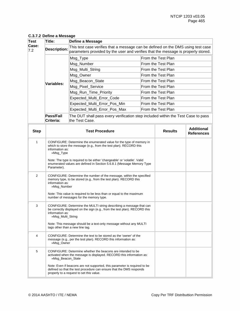
NTCIP 1203 v03.05 Page 465
C.3.7.2 Define a Message Test Case: 7.2
Title: Define a Message
Description: This test case verifies that a message can be defined on the DMS using test case parameters provided by the user and verifies that the message is properly stored.
Variables:
Msg_Type From the Test Plan
Msg_Number From the Test Plan
Msg_Multi_String From the Test Plan
Msg_Owner From the Test Plan
Msg_Beacon_State From the Test Plan
Msg_Pixel_Service From the Test Plan
Msg_Run_Time_Priority From the Test Plan
Expected_Multi_Error_Code From the Test Plan
Expected_Multi_Error_Pos_Min From the Test Plan
Expected_Multi_Error_Pos_Max From the Test Plan
Pass/Fail Criteria:
The DUT shall pass every verification step included within the Test Case to pass the Test Case.
Step Test Procedure Results Additional References
1 CONFIGURE: Determine the enumerated value for the type of memory in which to store the message (e.g., from the test plan). RECORD this information as: »Msg_Type Note: The type is required to be either 'changeable' or 'volatile'. Valid enumerated values are defined in Section 5.6.8.1 (Message Memory Type Parameter).
2 CONFIGURE: Determine the number of the message, within the specified memory type, to be stored (e.g., from the test plan). RECORD this information as: »Msg_Number Note: This value is required to be less than or equal to the maximum number of messages for the memory type.
3 CONFIGURE: Determine the MULTI string describing a message that can be correctly displayed on the sign (e.g., from the test plan). RECORD this information as: »Msg_Multi_String Note: This message should be a text-only message without any MULTI tags other than a new line tag.
4 CONFIGURE: Determine the text to be stored as the 'owner' of the message (e.g., per the test plan). RECORD this information as: »Msg_Owner
5 CONFIGURE: Determine whether the beacons are intended to be activated when the message is displayed. RECORD this information as: »Msg_Beacon_State Note: Even if beacons are not supported, this parameter is required to be defined so that the test procedure can ensure that the DMS responds properly to a request to set this value.
© 2014 AASHTO / ITE / NEMA Copy Per TRF Distributtion Permission
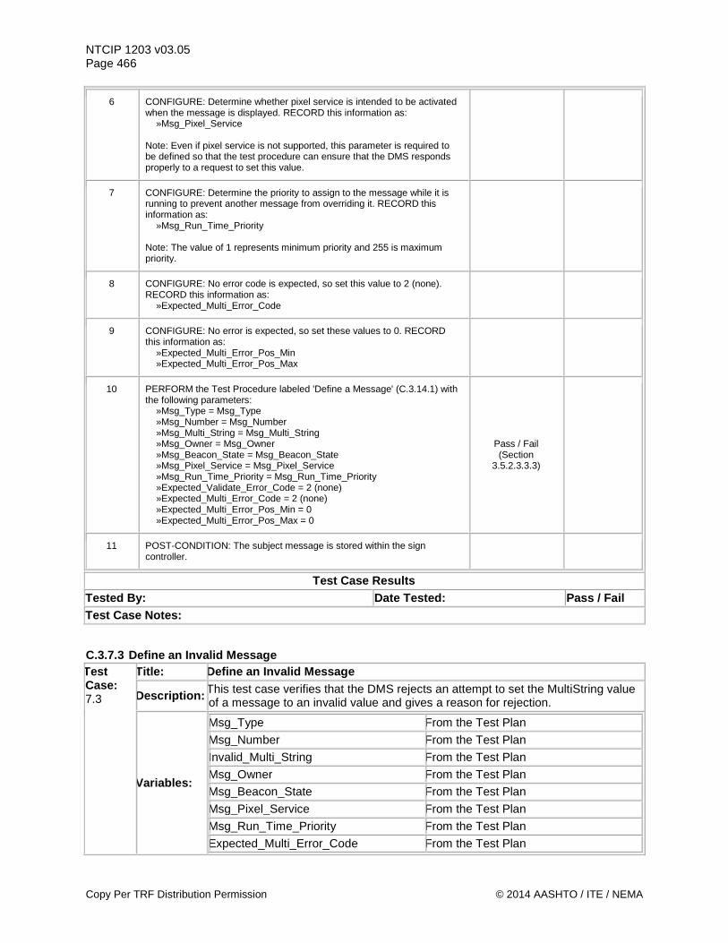
NTCIP 1203 v03.05 Page 466
6 CONFIGURE: Determine whether pixel service is intended to be activated when the message is displayed. RECORD this information as: »Msg_Pixel_Service Note: Even if pixel service is not supported, this parameter is required to be defined so that the test procedure can ensure that the DMS responds properly to a request to set this value.
7 CONFIGURE: Determine the priority to assign to the message while it is running to prevent another message from overriding it. RECORD this information as: »Msg_Run_Time_Priority Note: The value of 1 represents minimum priority and 255 is maximum priority.
8 CONFIGURE: No error code is expected, so set this value to 2 (none). RECORD this information as: »Expected_Multi_Error_Code
9 CONFIGURE: No error is expected, so set these values to 0. RECORD this information as: »Expected_Multi_Error_Pos_Min »Expected_Multi_Error_Pos_Max
10 PERFORM the Test Procedure labeled 'Define a Message' (C.3.14.1) with the following parameters: »Msg_Type = Msg_Type »Msg_Number = Msg_Number »Msg_Multi_String = Msg_Multi_String »Msg_Owner = Msg_Owner »Msg_Beacon_State = Msg_Beacon_State »Msg_Pixel_Service = Msg_Pixel_Service »Msg_Run_Time_Priority = Msg_Run_Time_Priority »Expected_Validate_Error_Code = 2 (none) »Expected_Multi_Error_Code = 2 (none) »Expected_Multi_Error_Pos_Min = 0 »Expected_Multi_Error_Pos_Max = 0
Pass / Fail (Section
3.5.2.3.3.3)
11 POST-CONDITION: The subject message is stored within the sign controller.
Test Case Results Tested By: Date Tested: Pass / Fail Test Case Notes:
C.3.7.3 Define an Invalid Message Test Case: 7.3
Title: Define an Invalid Message
Description: This test case verifies that the DMS rejects an attempt to set the MultiString value of a message to an invalid value and gives a reason for rejection.
Variables:
Msg_Type From the Test Plan Msg_Number From the Test Plan Invalid_Multi_String From the Test Plan Msg_Owner From the Test Plan Msg_Beacon_State From the Test Plan Msg_Pixel_Service From the Test Plan Msg_Run_Time_Priority From the Test Plan Expected_Multi_Error_Code From the Test Plan
Copy Per TRF Distribution Permission © 2014 AASHTO / ITE / NEMA
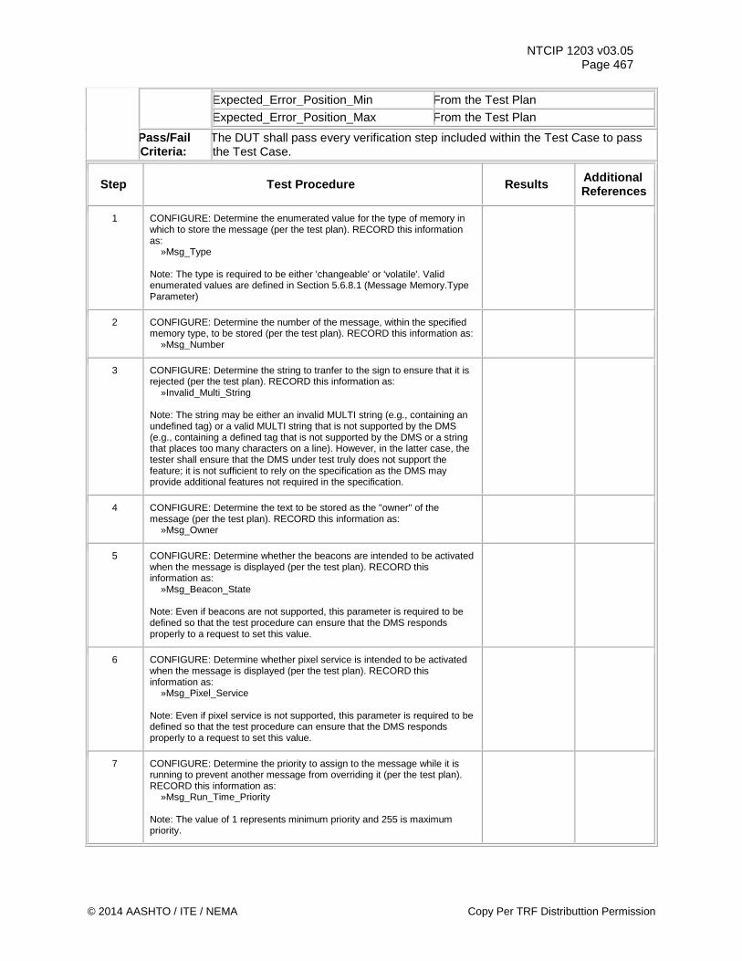
NTCIP 1203 v03.05 Page 467
Expected_Error_Position_Min From the Test Plan
Expected_Error_Position_Max From the Test Plan
Pass/Fail Criteria:
The DUT shall pass every verification step included within the Test Case to pass the Test Case.
Step Test Procedure Results Additional References
1 CONFIGURE: Determine the enumerated value for the type of memory in which to store the message (per the test plan). RECORD this information as: »Msg_Type Note: The type is required to be either 'changeable' or 'volatile'. Valid enumerated values are defined in Section 5.6.8.1 (Message Memory.Type Parameter)
2 CONFIGURE: Determine the number of the message, within the specified memory type, to be stored (per the test plan). RECORD this information as: »Msg_Number
3 CONFIGURE: Determine the string to tranfer to the sign to ensure that it is rejected (per the test plan). RECORD this information as: »Invalid_Multi_String Note: The string may be either an invalid MULTI string (e.g., containing an undefined tag) or a valid MULTI string that is not supported by the DMS (e.g., containing a defined tag that is not supported by the DMS or a string that places too many characters on a line). However, in the latter case, the tester shall ensure that the DMS under test truly does not support the feature; it is not sufficient to rely on the specification as the DMS may provide additional features not required in the specification.
4 CONFIGURE: Determine the text to be stored as the "owner" of the message (per the test plan). RECORD this information as: »Msg_Owner
5 CONFIGURE: Determine whether the beacons are intended to be activated when the message is displayed (per the test plan). RECORD this information as: »Msg_Beacon_State Note: Even if beacons are not supported, this parameter is required to be defined so that the test procedure can ensure that the DMS responds properly to a request to set this value.
6 CONFIGURE: Determine whether pixel service is intended to be activated when the message is displayed (per the test plan). RECORD this information as: »Msg_Pixel_Service Note: Even if pixel service is not supported, this parameter is required to be defined so that the test procedure can ensure that the DMS responds properly to a request to set this value.
7 CONFIGURE: Determine the priority to assign to the message while it is running to prevent another message from overriding it (per the test plan). RECORD this information as: »Msg_Run_Time_Priority Note: The value of 1 represents minimum priority and 255 is maximum priority.
© 2014 AASHTO / ITE / NEMA Copy Per TRF Distributtion Permission
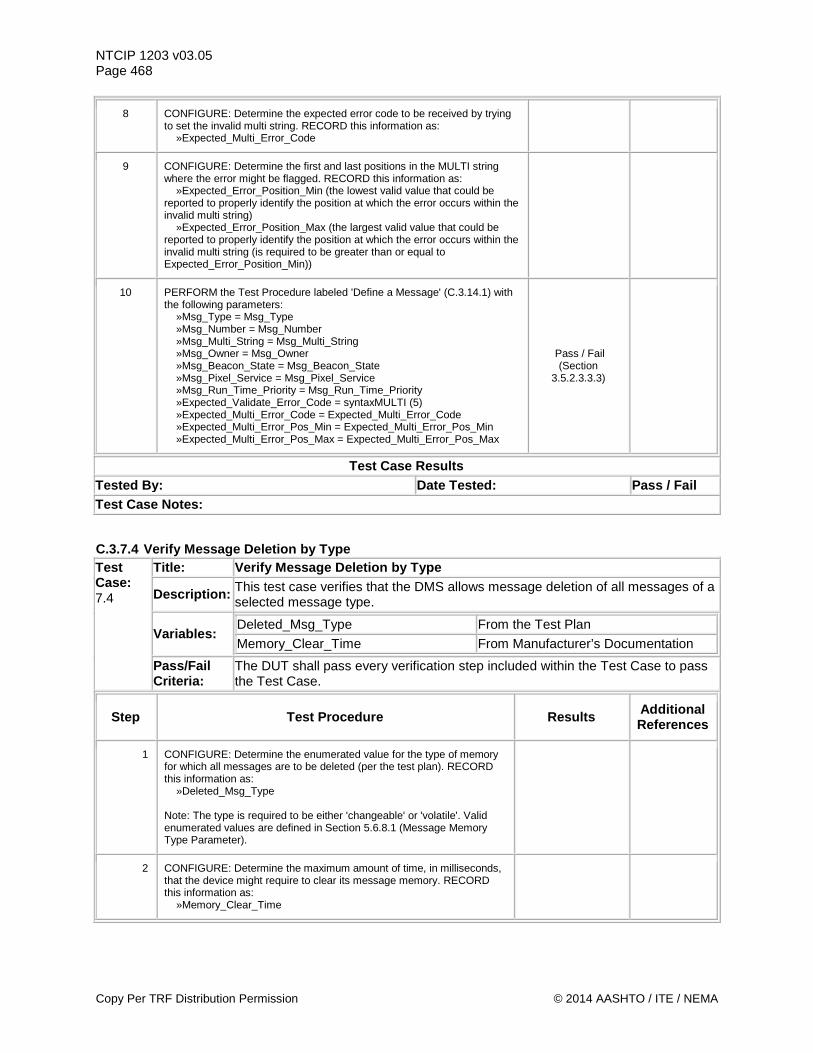
NTCIP 1203 v03.05 Page 468
8 CONFIGURE: Determine the expected error code to be received by trying to set the invalid multi string. RECORD this information as: »Expected_Multi_Error_Code
9 CONFIGURE: Determine the first and last positions in the MULTI string where the error might be flagged. RECORD this information as: »Expected_Error_Position_Min (the lowest valid value that could be reported to properly identify the position at which the error occurs within the invalid multi string) »Expected_Error_Position_Max (the largest valid value that could be reported to properly identify the position at which the error occurs within the invalid multi string (is required to be greater than or equal to Expected_Error_Position_Min))
10 PERFORM the Test Procedure labeled 'Define a Message' (C.3.14.1) with the following parameters: »Msg_Type = Msg_Type »Msg_Number = Msg_Number »Msg_Multi_String = Msg_Multi_String »Msg_Owner = Msg_Owner »Msg_Beacon_State = Msg_Beacon_State »Msg_Pixel_Service = Msg_Pixel_Service »Msg_Run_Time_Priority = Msg_Run_Time_Priority »Expected_Validate_Error_Code = syntaxMULTI (5) »Expected_Multi_Error_Code = Expected_Multi_Error_Code »Expected_Multi_Error_Pos_Min = Expected_Multi_Error_Pos_Min »Expected_Multi_Error_Pos_Max = Expected_Multi_Error_Pos_Max
Pass / Fail (Section
3.5.2.3.3.3)
Test Case Results Tested By: Date Tested: Pass / Fail Test Case Notes:
C.3.7.4 Verify Message Deletion by Type Test Case: 7.4
Title: Verify Message Deletion by Type
Description: This test case verifies that the DMS allows message deletion of all messages of a selected message type.
Variables: Deleted_Msg_Type From the Test Plan Memory_Clear_Time From Manufacturer’s Documentation
Pass/Fail Criteria:
The DUT shall pass every verification step included within the Test Case to pass the Test Case.
Step Test Procedure Results Additional References
1 CONFIGURE: Determine the enumerated value for the type of memory for which all messages are to be deleted (per the test plan). RECORD this information as: »Deleted_Msg_Type Note: The type is required to be either 'changeable' or 'volatile'. Valid enumerated values are defined in Section 5.6.8.1 (Message Memory Type Parameter).
2 CONFIGURE: Determine the maximum amount of time, in milliseconds, that the device might require to clear its message memory. RECORD this information as: »Memory_Clear_Time
Copy Per TRF Distribution Permission © 2014 AASHTO / ITE / NEMA
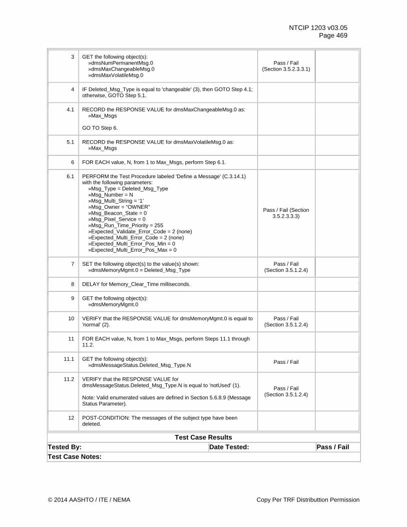
NTCIP 1203 v03.05 Page 469
3 GET the following object(s): »dmsNumPermanentMsg.0 »dmsMaxChangeableMsg.0 »dmsMaxVolatileMsg.0
Pass / Fail (Section 3.5.2.3.3.1)
4 IF Deleted_Msg_Type is equal to 'changeable' (3), then GOTO Step 4.1; otherwise, GOTO Step 5.1.
4.1 RECORD the RESPONSE VALUE for dmsMaxChangeableMsg.0 as: »Max_Msgs GO TO Step 6.
5.1 RECORD the RESPONSE VALUE for dmsMaxVolatileMsg.0 as: »Max_Msgs
6 FOR EACH value, N, from 1 to Max_Msgs, perform Step 6.1.
6.1 PERFORM the Test Procedure labeled 'Define a Message' (C.3.14.1) with the following parameters: »Msg_Type = Deleted_Msg_Type »Msg_Number = N »Msg_Multi_String = ‘1’ »Msg_Owner = “OWNER” »Msg_Beacon_State = 0 »Msg_Pixel_Service = 0 »Msg_Run_Time_Priority = 255 »Expected_Validate_Error_Code = 2 (none) »Expected_Multi_Error_Code = 2 (none) »Expected_Multi_Error_Pos_Min = 0 »Expected_Multi_Error_Pos_Max = 0
Pass / Fail (Section 3.5.2.3.3.3)
7 SET the following object(s) to the value(s) shown: »dmsMemoryMgmt.0 = Deleted_Msg_Type
Pass / Fail (Section 3.5.1.2.4)
8 DELAY for Memory_Clear_Time milliseconds.
9 GET the following object(s): »dmsMemoryMgmt.0
10 VERIFY that the RESPONSE VALUE for dmsMemoryMgmt.0 is equal to 'normal' (2).
Pass / Fail (Section 3.5.1.2.4)
11 FOR EACH value, N, from 1 to Max_Msgs, perform Steps 11.1 through 11.2.
11.1 GET the following object(s): »dmsMessageStatus.Deleted_Msg_Type.N Pass / Fail
11.2 VERIFY that the RESPONSE VALUE for dmsMessageStatus.Deleted_Msg_Type.N is equal to 'notUsed' (1). Note: Valid enumerated values are defined in Section 5.6.8.9 (Message Status Parameter).
Pass / Fail (Section 3.5.1.2.4)
12 POST-CONDITION: The messages of the subject type have been deleted.
Test Case Results Tested By: Date Tested: Pass / Fail Test Case Notes:
© 2014 AASHTO / ITE / NEMA Copy Per TRF Distributtion Permission
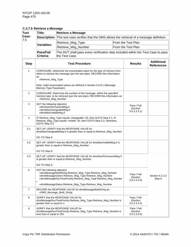
NTCIP 1203 v03.05 Page 470 C.3.7.5 Retrieve a Message Test Case: 7.5
Title: Retrieve a Message Description: This test case verifies that the DMS allows the retrieval of a message definition.
Variables: Retrieve_Msg_Type From the Test Plan Retrieve_Msg_Number From the Test Plan
Pass/Fail Criteria:
The DUT shall pass every verification step included within the Test Case to pass the Test Case.
Step Test Procedure Results Additional References
1 CONFIGURE: Determine the enumerated value for the type of memory from which to retrieve the message (per the test plan). RECORD this information as: »Retrieve_Msg_Type Note: Valid enumerated values are defined in Section 5.6.8.1 (Message Memory Type Parameter).
2 CONFIGURE: Determine the number of the message, within the specified memory type, to be retrieved (per the test plan). RECORD this information as: »Retrieve_Msg_Number
3 GET the following object(s): »dmsNumPermanentMsg.0 »dmsMaxChangeableMsg.0 »dmsMaxVolatileMsg.0
Pass / Fail (Section
3.5.2.3.3.1)
4 IF Retrieve_Msg_Type equals 'changeable' (3), then GOTO Step 5.1; IF Retrieve_Msg_Type equals ‘volatile’ (4), then GOTO Step 5.2; otherwise, GOTO Step 5.3.
5.1 SET-UP: VERIFY that the RESPONSE VALUE for dmsMaxChangeableMsg.0 is greater than or equal to Retrieve_Msg_Number. GO TO Step 6.
5.2 SET-UP: VERIFY that the RESPONSE VALUE for dmsMaxVolatileMsg.0 is greater than or equal to Retrieve_Msg_Number. GO TO Step 6.
5.3 SET-UP: VERIFY that the RESPONSE VALUE for dmsNumPermanentMsg.0 is greater than or equal to Retrieve_Msg_Number. GO TO Step 6.
6 GET the following object(s): »dmsMessageMultiString.Retrieve_Msg_Type.Retrieve_Msg_Number »dmsMessageOwner.Retrieve_Msg_Type.Retrieve_Msg_Number »dmsMessageRunTimePriority.Retrieve_Msg_Type.Retrieve_Msg_Number »dmsMessageStatus.Retrieve_Msg_Type.Retrieve_Msg_Number
Pass / Fail (Section
3.5.2.3.3.5)
Section 4.2.3.3 Step b
7 RECORD the RESPONSE VALUE for dmsMessageMultiString as: »DMS_Message_Multi_String
8 VERIFY that the RESPONSE VALUE for dmsMessageRunTimePriority.Retrieve_Msg_Type.Retrieve_Msg_Number is greater than or equal to 1.
Pass / Fail (Section
3.5.2.3.3.5)
9 VERIFY that the RESPONSE VALUE for dmsMessageRunTimePriority.Retrieve_Msg_Type.Retrieve_Msg_Number is less than or equal to 255.
Pass / Fail (Section
3.5.2.3.3.5)
Copy Per TRF Distribution Permission © 2014 AASHTO / ITE / NEMA
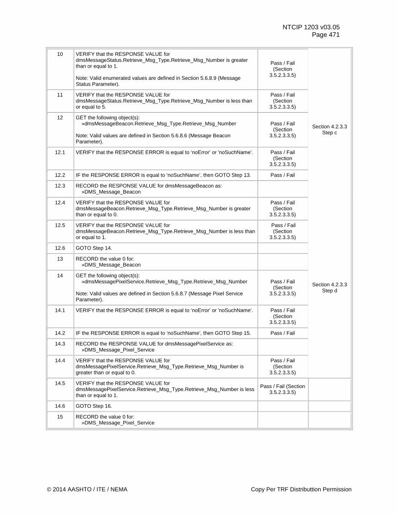
NTCIP 1203 v03.05 Page 471
10 VERIFY that the RESPONSE VALUE for dmsMessageStatus.Retrieve_Msg_Type.Retrieve_Msg_Number is greater than or equal to 1. Note: Valid enumerated values are defined in Section 5.6.8.9 (Message Status Parameter).
Pass / Fail (Section
3.5.2.3.3.5)
11 VERIFY that the RESPONSE VALUE for dmsMessageStatus.Retrieve_Msg_Type.Retrieve_Msg_Number is less than or equal to 5.
Pass / Fail (Section
3.5.2.3.3.5)
12 GET the following object(s): »dmsMessageBeacon.Retrieve_Msg_Type.Retrieve_Msg_Number Note: Valid values are defined in Section 5.6.8.6 (Message Beacon Parameter).
Pass / Fail (Section
3.5.2.3.3.5)
Section 4.2.3.3 Step c
12.1 VERIFY that the RESPONSE ERROR is equal to ‘noError’ or 'noSuchName'. Pass / Fail (Section
3.5.2.3.3.5)
12.2 IF the RESPONSE ERROR is equal to ‘noSuchName’, then GOTO Step 13. Pass / Fail
12.3 RECORD the RESPONSE VALUE for dmsMessageBeacon as: »DMS_Message_Beacon
12.4 VERIFY that the RESPONSE VALUE for dmsMessageBeacon.Retrieve_Msg_Type.Retrieve_Msg_Number is greater than or equal to 0.
Pass / Fail (Section
3.5.2.3.3.5)
12.5 VERIFY that the RESPONSE VALUE for dmsMessageBeacon.Retrieve_Msg_Type.Retrieve_Msg_Number is less than or equal to 1.
Pass / Fail (Section
3.5.2.3.3.5)
12.6 GOTO Step 14.
13 RECORD the value 0 for: »DMS_Message_Beacon
14 GET the following object(s): »dmsMessagePixelService.Retrieve_Msg_Type.Retrieve_Msg_Number Note: Valid values are defined in Section 5.6.8.7 (Message Pixel Service Parameter).
Pass / Fail (Section
3.5.2.3.3.5)
Section 4.2.3.3 Step d
14.1 VERIFY that the RESPONSE ERROR is equal to ‘noError’ or 'noSuchName'. Pass / Fail (Section
3.5.2.3.3.5)
14.2 IF the RESPONSE ERROR is equal to ‘noSuchName’, then GOTO Step 15. Pass / Fail
14.3 RECORD the RESPONSE VALUE for dmsMessagePixelService as: »DMS_Message_Pixel_Service
14.4 VERIFY that the RESPONSE VALUE for dmsMessagePixelService.Retrieve_Msg_Type.Retrieve_Msg_Number is greater than or equal to 0.
Pass / Fail (Section
3.5.2.3.3.5)
14.5 VERIFY that the RESPONSE VALUE for dmsMessagePixelService.Retrieve_Msg_Type.Retrieve_Msg_Number is less than or equal to 1.
Pass / Fail (Section 3.5.2.3.3.5)
14.6 GOTO Step 16.
15 RECORD the value 0 for: »DMS_Message_Pixel_Service
© 2014 AASHTO / ITE / NEMA Copy Per TRF Distributtion Permission
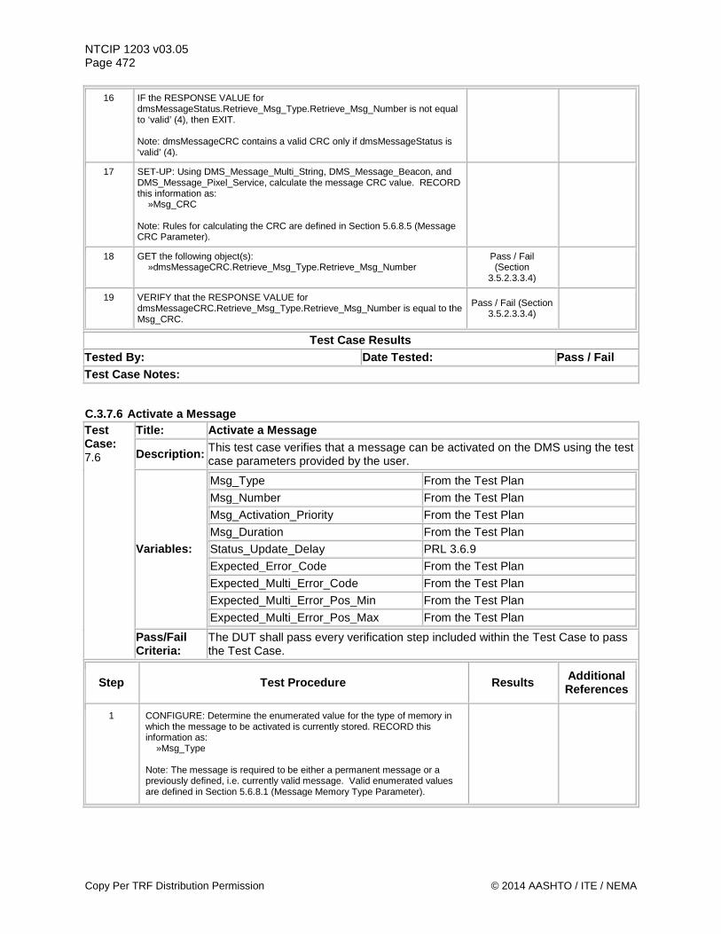
NTCIP 1203 v03.05 Page 472
16 IF the RESPONSE VALUE for dmsMessageStatus.Retrieve_Msg_Type.Retrieve_Msg_Number is not equal to ‘valid’ (4), then EXIT. Note: dmsMessageCRC contains a valid CRC only if dmsMessageStatus is ‘valid’ (4).
17 SET-UP: Using DMS_Message_Multi_String, DMS_Message_Beacon, and DMS_Message_Pixel_Service, calculate the message CRC value. RECORD this information as: »Msg_CRC Note: Rules for calculating the CRC are defined in Section 5.6.8.5 (Message CRC Parameter).
18 GET the following object(s): »dmsMessageCRC.Retrieve_Msg_Type.Retrieve_Msg_Number
Pass / Fail (Section
3.5.2.3.3.4)
19 VERIFY that the RESPONSE VALUE for dmsMessageCRC.Retrieve_Msg_Type.Retrieve_Msg_Number is equal to the Msg_CRC.
Pass / Fail (Section 3.5.2.3.3.4)
Test Case Results Tested By: Date Tested: Pass / Fail Test Case Notes:
C.3.7.6 Activate a Message Test Case: 7.6
Title: Activate a Message
Description: This test case verifies that a message can be activated on the DMS using the test case parameters provided by the user.
Variables:
Msg_Type From the Test Plan
Msg_Number From the Test Plan
Msg_Activation_Priority From the Test Plan
Msg_Duration From the Test Plan
Status_Update_Delay PRL 3.6.9 Expected_Error_Code From the Test Plan Expected_Multi_Error_Code From the Test Plan
Expected_Multi_Error_Pos_Min From the Test Plan
Expected_Multi_Error_Pos_Max From the Test Plan
Pass/Fail Criteria:
The DUT shall pass every verification step included within the Test Case to pass the Test Case.
Step Test Procedure Results Additional References
1 CONFIGURE: Determine the enumerated value for the type of memory in which the message to be activated is currently stored. RECORD this information as: »Msg_Type Note: The message is required to be either a permanent message or a previously defined, i.e. currently valid message. Valid enumerated values are defined in Section 5.6.8.1 (Message Memory Type Parameter).
Copy Per TRF Distribution Permission © 2014 AASHTO / ITE / NEMA
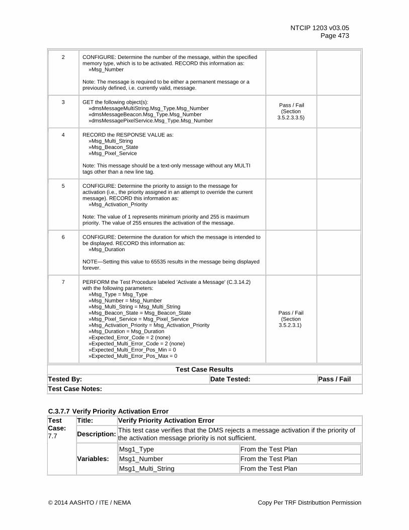
NTCIP 1203 v03.05 Page 473
2 CONFIGURE: Determine the number of the message, within the specified memory type, which is to be activated. RECORD this information as: »Msg_Number Note: The message is required to be either a permanent message or a previously defined, i.e. currently valid, message.
3 GET the following object(s): »dmsMessageMultiString.Msg_Type.Msg_Number »dmsMessageBeacon.Msg_Type.Msg_Number »dmsMessagePixelService.Msg_Type.Msg_Number
Pass / Fail (Section
3.5.2.3.3.5)
4 RECORD the RESPONSE VALUE as: »Msg_Multi_String »Msg_Beacon_State »Msg_Pixel_Service Note: This message should be a text-only message without any MULTI tags other than a new line tag.
5 CONFIGURE: Determine the priority to assign to the message for activation (i.e., the priority assigned in an attempt to override the current message). RECORD this information as: »Msg_Activation_Priority Note: The value of 1 represents minimum priority and 255 is maximum priority. The value of 255 ensures the activation of the message.
6 CONFIGURE: Determine the duration for which the message is intended to be displayed. RECORD this information as: »Msg_Duration NOTE—Setting this value to 65535 results in the message being displayed forever.
7 PERFORM the Test Procedure labeled 'Activate a Message' (C.3.14.2) with the following parameters: »Msg_Type = Msg_Type »Msg_Number = Msg_Number »Msg_Multi_String = Msg_Multi_String »Msg_Beacon_State = Msg_Beacon_State »Msg_Pixel_Service = Msg_Pixel_Service »Msg_Activation_Priority = Msg_Activation_Priority »Msg_Duration = Msg_Duration »Expected_Error_Code = 2 (none) »Expected_Multi_Error_Code = 2 (none) »Expected_Multi_Error_Pos_Min = 0 »Expected_Multi_Error_Pos_Max = 0
Pass / Fail (Section
3.5.2.3.1)
Test Case Results Tested By: Date Tested: Pass / Fail Test Case Notes:
C.3.7.7 Verify Priority Activation Error Test Case: 7.7
Title: Verify Priority Activation Error
Description: This test case verifies that the DMS rejects a message activation if the priority of the activation message priority is not sufficient.
Variables: Msg1_Type From the Test Plan
Msg1_Number From the Test Plan
Msg1_Multi_String From the Test Plan
© 2014 AASHTO / ITE / NEMA Copy Per TRF Distributtion Permission
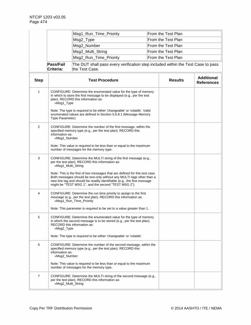
NTCIP 1203 v03.05 Page 474
Msg1_Run_Time_Priority From the Test Plan
Msg2_Type From the Test Plan
Msg2_Number From the Test Plan
Msg2_Multi_String From the Test Plan
Msg2_Run_Time_Priority From the Test Plan
Pass/Fail Criteria:
The DUT shall pass every verification step included within the Test Case to pass the Test Case.
Step Test Procedure Results Additional References
1 CONFIGURE: Determine the enumerated value for the type of memory in which to store the first message to be displayed (e.g., per the test plan). RECORD this information as: »Msg1_Type Note: The type is required to be either 'changeable' or 'volatile'. Valid enumerated values are defined in Section 5.6.8.1 (Message Memory Type Parameter).
2 CONFIGURE: Determine the number of the first message, within the specified memory type (e.g., per the test plan). RECORD this information as: »Msg1_Number Note: This value is required to be less than or equal to the maximum number of messages for the memory type.
3 CONFIGURE: Determine the MULTI string of the first message (e.g., per the test plan). RECORD this information as: »Msg1_Multi_String Note: This is the first of two messages that are defined for this test case. Both messages should be text-only without any MULTI tags other than a new line tag and should be readily identifiable (e.g., the first message might be "TEST MSG 1", and the second "TEST MSG 2").
4 CONFIGURE: Determine the run time priority to assign to the first message (e.g., per the test plan). RECORD this information as: »Msg1_Run_Time_Priority Note: This parameter is required to be set to a value greater than 1.
5 CONFIGURE: Determine the enumerated value for the type of memory in which the second message is to be stored (e.g., per the test plan). RECORD this information as: »Msg2_Type Note: The type is required to be either 'changeable' or 'volatile'.
6 CONFIGURE: Determine the number of the second message, within the specified memory type (e.g., per the test plan). RECORD this information as: »Msg2_Number Note: This value is required to be less than or equal to the maximum number of messages for the memory type.
7 CONFIGURE: Determine the MULTI string of the second message (e.g., per the test plan). RECORD this information as: »Msg2_Multi_String
Copy Per TRF Distribution Permission © 2014 AASHTO / ITE / NEMA
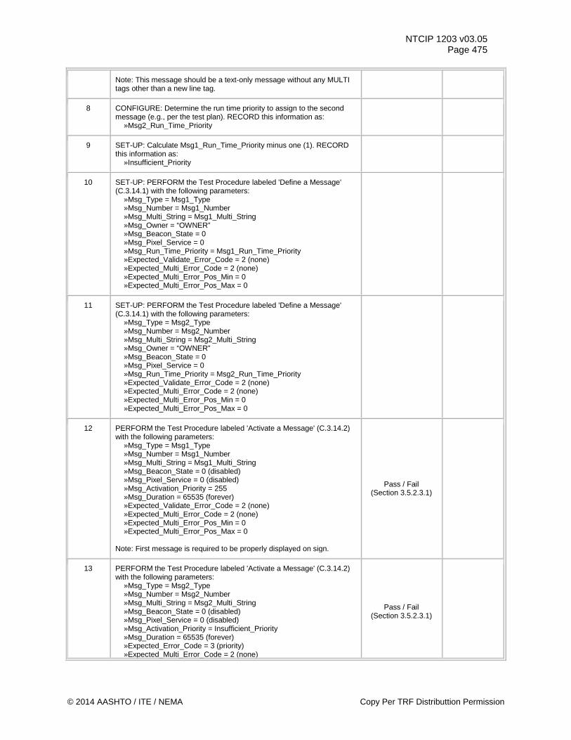
NTCIP 1203 v03.05 Page 475
Note: This message should be a text-only message without any MULTI tags other than a new line tag.
8 CONFIGURE: Determine the run time priority to assign to the second message (e.g., per the test plan). RECORD this information as: »Msg2_Run_Time_Priority
9 SET-UP: Calculate Msg1_Run_Time_Priority minus one (1). RECORD this information as: »Insufficient_Priority
10 SET-UP: PERFORM the Test Procedure labeled 'Define a Message' (C.3.14.1) with the following parameters: »Msg_Type = Msg1_Type »Msg_Number = Msg1_Number »Msg_Multi_String = Msg1_Multi_String »Msg_Owner = “OWNER” »Msg_Beacon_State = 0 »Msg_Pixel_Service = 0 »Msg_Run_Time_Priority = Msg1_Run_Time_Priority »Expected_Validate_Error_Code = 2 (none) »Expected_Multi_Error_Code = 2 (none) »Expected_Multi_Error_Pos_Min = 0 »Expected_Multi_Error_Pos_Max = 0
11 SET-UP: PERFORM the Test Procedure labeled 'Define a Message' (C.3.14.1) with the following parameters: »Msg_Type = Msg2_Type »Msg_Number = Msg2_Number »Msg_Multi_String = Msg2_Multi_String »Msg_Owner = “OWNER” »Msg_Beacon_State = 0 »Msg_Pixel_Service = 0 »Msg_Run_Time_Priority = Msg2_Run_Time_Priority »Expected_Validate_Error_Code = 2 (none) »Expected_Multi_Error_Code = 2 (none) »Expected_Multi_Error_Pos_Min = 0 »Expected_Multi_Error_Pos_Max = 0
12 PERFORM the Test Procedure labeled 'Activate a Message' (C.3.14.2) with the following parameters: »Msg_Type = Msg1_Type »Msg_Number = Msg1_Number »Msg_Multi_String = Msg1_Multi_String »Msg_Beacon_State = 0 (disabled) »Msg_Pixel_Service = 0 (disabled) »Msg_Activation_Priority = 255 »Msg_Duration = 65535 (forever) »Expected_Validate_Error_Code = 2 (none) »Expected_Multi_Error_Code = 2 (none) »Expected_Multi_Error_Pos_Min = 0 »Expected_Multi_Error_Pos_Max = 0 Note: First message is required to be properly displayed on sign.
Pass / Fail (Section 3.5.2.3.1)
13 PERFORM the Test Procedure labeled 'Activate a Message' (C.3.14.2) with the following parameters: »Msg_Type = Msg2_Type »Msg_Number = Msg2_Number »Msg_Multi_String = Msg2_Multi_String »Msg_Beacon_State = 0 (disabled) »Msg_Pixel_Service = 0 (disabled) »Msg_Activation_Priority = Insufficient_Priority »Msg_Duration = 65535 (forever) »Expected_Error_Code = 3 (priority) »Expected_Multi_Error_Code = 2 (none)
Pass / Fail (Section 3.5.2.3.1)
© 2014 AASHTO / ITE / NEMA Copy Per TRF Distributtion Permission
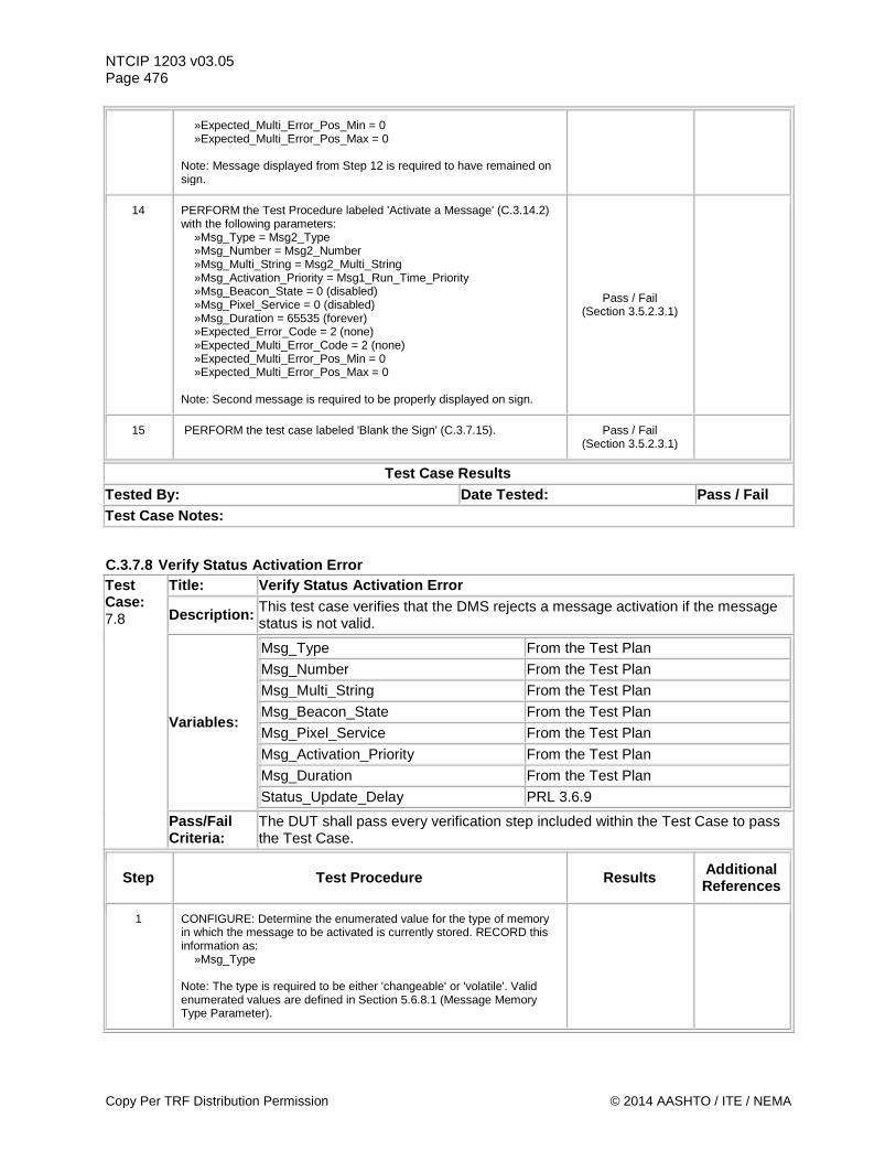
NTCIP 1203 v03.05 Page 476
»Expected_Multi_Error_Pos_Min = 0 »Expected_Multi_Error_Pos_Max = 0 Note: Message displayed from Step 12 is required to have remained on sign.
14 PERFORM the Test Procedure labeled 'Activate a Message' (C.3.14.2) with the following parameters: »Msg_Type = Msg2_Type »Msg_Number = Msg2_Number »Msg_Multi_String = Msg2_Multi_String »Msg_Activation_Priority = Msg1_Run_Time_Priority »Msg_Beacon_State = 0 (disabled) »Msg_Pixel_Service = 0 (disabled) »Msg_Duration = 65535 (forever) »Expected_Error_Code = 2 (none) »Expected_Multi_Error_Code = 2 (none) »Expected_Multi_Error_Pos_Min = 0 »Expected_Multi_Error_Pos_Max = 0 Note: Second message is required to be properly displayed on sign.
Pass / Fail (Section 3.5.2.3.1)
15 PERFORM the test case labeled 'Blank the Sign' (C.3.7.15). Pass / Fail (Section 3.5.2.3.1)
Test Case Results Tested By: Date Tested: Pass / Fail Test Case Notes:
C.3.7.8 Verify Status Activation Error Test Case: 7.8
Title: Verify Status Activation Error
Description: This test case verifies that the DMS rejects a message activation if the message status is not valid.
Variables:
Msg_Type From the Test Plan
Msg_Number From the Test Plan
Msg_Multi_String From the Test Plan
Msg_Beacon_State From the Test Plan
Msg_Pixel_Service From the Test Plan
Msg_Activation_Priority From the Test Plan
Msg_Duration From the Test Plan
Status_Update_Delay PRL 3.6.9
Pass/Fail Criteria:
The DUT shall pass every verification step included within the Test Case to pass the Test Case.
Step Test Procedure Results Additional References
1 CONFIGURE: Determine the enumerated value for the type of memory in which the message to be activated is currently stored. RECORD this information as: »Msg_Type Note: The type is required to be either 'changeable' or 'volatile'. Valid enumerated values are defined in Section 5.6.8.1 (Message Memory Type Parameter).
Copy Per TRF Distribution Permission © 2014 AASHTO / ITE / NEMA
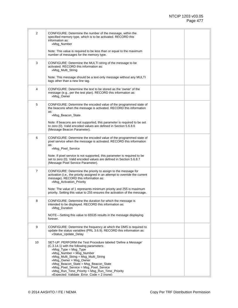
NTCIP 1203 v03.05 Page 477
2 CONFIGURE: Determine the number of the message, within the specified memory type, which is to be activated. RECORD this information as: »Msg_Number Note: This value is required to be less than or equal to the maximum number of messages for the memory type.
3 CONFIGURE: Determine the MULTI string of the message to be activated. RECORD this information as: »Msg_Multi_String Note: This message should be a text-only message without any MULTI tags other than a new line tag.
4 CONFIGURE: Determine the text to be stored as the 'owner' of the message (e.g., per the test plan). RECORD this information as: »Msg_Owner
5 CONFIGURE: Determine the encoded value of the programmed state of the beacons when the message is activated. RECORD this information as: »Msg_Beacon_State Note: If beacons are not supported, this parameter is required to be set to zero (0). Valid encoded values are defined in Section 5.6.8.6 (Message Beacon Parameter).
6 CONFIGURE: Determine the encoded value of the programmed state of pixel service when the message is activated. RECORD this information as: »Msg_Pixel_Service Note: If pixel service is not supported, this parameter is required to be set to zero (0). Valid encoded values are defined in Section 5.6.8.7 (Message Pixel Service Parameter).
7 CONFIGURE: Determine the priority to assign to the message for activation (i.e., the priority assigned in an attempt to override the current message). RECORD this information as: »Msg_Activation_Priority Note: The value of 1 represents minimum priority and 255 is maximum priority. Setting this value to 255 ensures the activation of the message.
8 CONFIGURE: Determine the duration for which the message is intended to be displayed. RECORD this information as: »Msg_Duration NOTE—Setting this value to 65535 results in the message displaying forever.
9 CONFIGURE: Determine the frequency at which the DMS is required to update the status variables (PRL 3.6.9). RECORD this information as: »Status_Update_Delay
10 SET-UP: PERFORM the Test Procedure labeled 'Define a Message' (C.3.14.1) with the following parameters: »Msg_Type = Msg_Type »Msg_Number = Msg_Number »Msg_Multi_String = Msg_Multi_String »Msg_Owner = Msg_Owner »Msg_Beacon_State = Msg_Beacon_State »Msg_Pixel_Service = Msg_Pixel_Service »Msg_Run_Time_Priority = Msg_Run_Time_Priority »Expected_Validate_Error_Code = 2 (none)
© 2014 AASHTO / ITE / NEMA Copy Per TRF Distributtion Permission
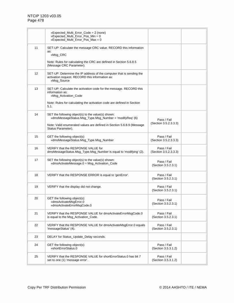
NTCIP 1203 v03.05 Page 478
»Expected_Multi_Error_Code = 2 (none) »Expected_Multi_Error_Pos_Min = 0 »Expected_Multi_Error_Pos_Max = 0
11 SET-UP: Calculate the message CRC value. RECORD this information as: »Msg_CRC Note: Rules for calculating the CRC are defined in Section 5.6.8.5 (Message CRC Parameter).
12 SET-UP: Determine the IP address of the computer that is sending the activation request. RECORD this information as: »Msg_Source
13 SET-UP: Calculate the activation code for the message. RECORD this information as: »Msg_Activation_Code Note: Rules for calculating the activation code are defined in Section 5.1.
14 SET the following object(s) to the value(s) shown: »dmsMessageStatus.Msg_Type.Msg_Number = 'modifyReq' (6) Note: Valid enumerated values are defined in Section 5.6.8.9 (Message Status Parameter).
Pass / Fail (Section 3.5.2.3.3.3)
15 GET the following object(s): »dmsMessageStatus.Msg_Type.Msg_Number
Pass / Fail (Section 3.5.2.3.3.3)
16 VERIFY that the RESPONSE VALUE for dmsMessageStatus.Msg_Type.Msg_Number is equal to 'modifying' (2).
Pass / Fail (Section 3.5.2.3.3.3)
17 SET the following object(s) to the value(s) shown: »dmsActivateMessage.0 = Msg_Activation_Code
Pass / Fail (Section 3.5.2.3.1)
18 VERIFY that the RESPONSE ERROR is equal to 'genError'. Pass / Fail (Section 3.5.2.3.1)
19 VERIFY that the display did not change. Pass / Fail (Section 3.5.2.3.1)
20 GET the following object(s): »dmsActivateMsgError.0 »dmsActivateErrorMsgCode.0
Pass / Fail (Section 3.5.2.3.1)
21 VERIFY that the RESPONSE VALUE for dmsActivateErrorMsgCode.0 is equal to the Msg_Activation_Code.
Pass / Fail (Section 3.5.2.3.1)
22 VERIFY that the RESPONSE VALUE for dmsActivateMsgError.0 equals 'messageStatus' (4).
Pass / Fail (Section 3.5.2.3.1)
23 DELAY for Status_Update_Delay seconds.
24 GET the following object(s): »shortErrorStatus.0
Pass / Fail (Section 3.5.3.1.2)
25 VERIFY that the RESPONSE VALUE for shortErrorStatus.0 has bit 7 set to one (1) ‘message error’.
Pass / Fail (Section 3.5.3.1.2)
Copy Per TRF Distribution Permission © 2014 AASHTO / ITE / NEMA
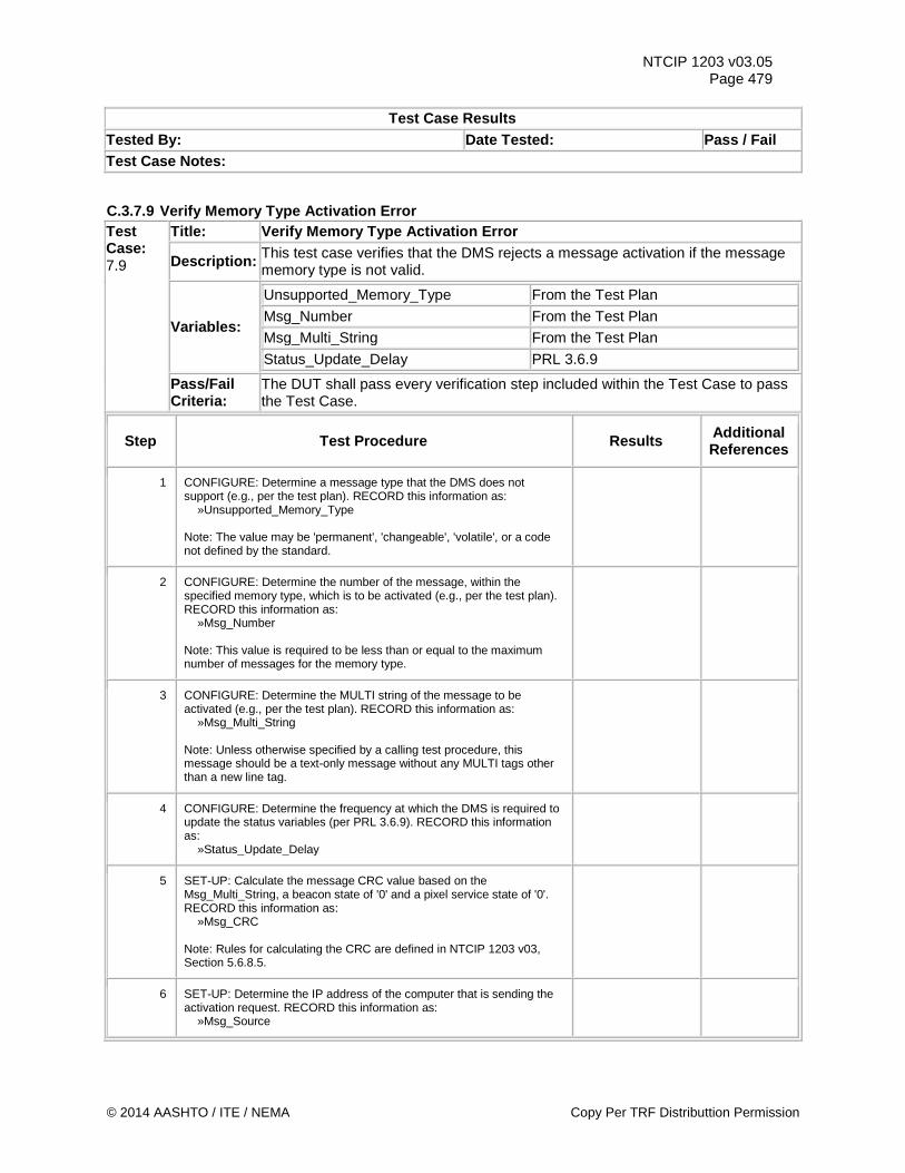
NTCIP 1203 v03.05 Page 479
Test Case Results Tested By: Date Tested: Pass / Fail Test Case Notes:
C.3.7.9 Verify Memory Type Activation Error Test Case: 7.9
Title: Verify Memory Type Activation Error
Description: This test case verifies that the DMS rejects a message activation if the message memory type is not valid.
Variables:
Unsupported_Memory_Type From the Test Plan
Msg_Number From the Test Plan
Msg_Multi_String From the Test Plan
Status_Update_Delay PRL 3.6.9
Pass/Fail Criteria:
The DUT shall pass every verification step included within the Test Case to pass the Test Case.
Step Test Procedure Results Additional References
1 CONFIGURE: Determine a message type that the DMS does not support (e.g., per the test plan). RECORD this information as: »Unsupported_Memory_Type Note: The value may be 'permanent', 'changeable', 'volatile', or a code not defined by the standard.
2 CONFIGURE: Determine the number of the message, within the specified memory type, which is to be activated (e.g., per the test plan). RECORD this information as: »Msg_Number Note: This value is required to be less than or equal to the maximum number of messages for the memory type.
3 CONFIGURE: Determine the MULTI string of the message to be activated (e.g., per the test plan). RECORD this information as: »Msg_Multi_String Note: Unless otherwise specified by a calling test procedure, this message should be a text-only message without any MULTI tags other than a new line tag.
4 CONFIGURE: Determine the frequency at which the DMS is required to update the status variables (per PRL 3.6.9). RECORD this information as: »Status_Update_Delay
5 SET-UP: Calculate the message CRC value based on the Msg_Multi_String, a beacon state of '0' and a pixel service state of '0'. RECORD this information as: »Msg_CRC Note: Rules for calculating the CRC are defined in NTCIP 1203 v03, Section 5.6.8.5.
6 SET-UP: Determine the IP address of the computer that is sending the activation request. RECORD this information as: »Msg_Source
© 2014 AASHTO / ITE / NEMA Copy Per TRF Distributtion Permission
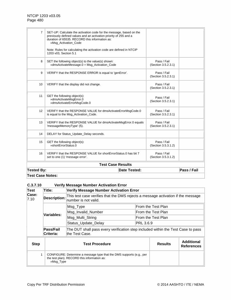
NTCIP 1203 v03.05 Page 480
7 SET-UP: Calculate the activation code for the message, based on the previously defined values and an activation priority of 255 and a duration of 65535. RECORD this information as: »Msg_Activation_Code Note: Rules for calculating the activation code are defined in NTCIP 1203 v03, Section 5.1
8 SET the following object(s) to the value(s) shown: »dmsActivateMessage.0 = Msg_Activation_Code
Pass / Fail (Section 3.5.2.3.1)
9 VERIFY that the RESPONSE ERROR is equal to 'genError'. Pass / Fail (Section 3.5.2.3.1)
10 VERIFY that the display did not change. Pass / Fail (Section 3.5.2.3.1)
11 GET the following object(s): »dmsActivateMsgError.0 »dmsActivateErrorMsgCode.0
Pass / Fail (Section 3.5.2.3.1)
12 VERIFY that the RESPONSE VALUE for dmsActivateErrorMsgCode.0 is equal to the Msg_Activation_Code.
Pass / Fail (Section 3.5.2.3.1)
13 VERIFY that the RESPONSE VALUE for dmsActivateMsgError.0 equals 'messageMemoryType' (5).
Pass / Fail (Section 3.5.2.3.1)
14 DELAY for Status_Update_Delay seconds.
15 GET the following object(s): »shortErrorStatus.0
Pass / Fail (Section 3.5.3.1.2)
16 VERIFY that the RESPONSE VALUE for shortErrorStatus.0 has bit 7 set to one (1) ‘message error’.
Pass / Fail (Section 3.5.3.1.2)
Test Case Results Tested By: Date Tested: Pass / Fail Test Case Notes: C.3.7.10 Verify Message Number Activation Error Test Case: 7.10
Title: Verify Message Number Activation Error
Description: This test case verifies that the DMS rejects a message activation if the message number is not valid.
Variables:
Msg_Type From the Test Plan
Msg_Invalid_Number From the Test Plan
Msg_Multi_String From the Test Plan
Status_Update_Delay PRL 3.6.9
Pass/Fail Criteria:
The DUT shall pass every verification step included within the Test Case to pass the Test Case.
Step Test Procedure Results Additional References
1 CONFIGURE: Determine a message type that the DMS supports (e.g., per the test plan). RECORD this information as: »Msg_Type
Copy Per TRF Distribution Permission © 2014 AASHTO / ITE / NEMA
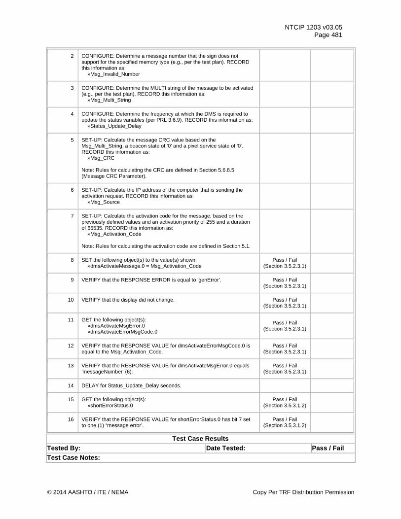
NTCIP 1203 v03.05 Page 481
2 CONFIGURE: Determine a message number that the sign does not support for the specified memory type (e.g., per the test plan). RECORD this information as: »Msg_Invalid_Number
3 CONFIGURE: Determine the MULTI string of the message to be activated (e.g., per the test plan). RECORD this information as: »Msg_Multi_String
4 CONFIGURE: Determine the frequency at which the DMS is required to update the status variables (per PRL 3.6.9). RECORD this information as: »Status_Update_Delay
5 SET-UP: Calculate the message CRC value based on the Msg_Multi_String, a beacon state of '0' and a pixel service state of '0'. RECORD this information as: »Msg_CRC Note: Rules for calculating the CRC are defined in Section 5.6.8.5 (Message CRC Parameter).
6 SET-UP: Calculate the IP address of the computer that is sending the activation request. RECORD this information as: »Msg_Source
7 SET-UP: Calculate the activation code for the message, based on the previously defined values and an activation priority of 255 and a duration of 65535. RECORD this information as: »Msg_Activation_Code Note: Rules for calculating the activation code are defined in Section 5.1.
8 SET the following object(s) to the value(s) shown: »dmsActivateMessage.0 = Msg_Activation_Code
Pass / Fail (Section 3.5.2.3.1)
9 VERIFY that the RESPONSE ERROR is equal to 'genError'. Pass / Fail (Section 3.5.2.3.1)
10 VERIFY that the display did not change. Pass / Fail (Section 3.5.2.3.1)
11 GET the following object(s): »dmsActivateMsgError.0 »dmsActivateErrorMsgCode.0
Pass / Fail (Section 3.5.2.3.1)
12 VERIFY that the RESPONSE VALUE for dmsActivateErrorMsgCode.0 is equal to the Msg_Activation_Code.
Pass / Fail (Section 3.5.2.3.1)
13 VERIFY that the RESPONSE VALUE for dmsActivateMsgError.0 equals 'messageNumber' (6).
Pass / Fail (Section 3.5.2.3.1)
14 DELAY for Status_Update_Delay seconds.
15 GET the following object(s): »shortErrorStatus.0
Pass / Fail (Section 3.5.3.1.2)
16 VERIFY that the RESPONSE VALUE for shortErrorStatus.0 has bit 7 set to one (1) “message error’.
Pass / Fail (Section 3.5.3.1.2)
Test Case Results Tested By: Date Tested: Pass / Fail Test Case Notes:
© 2014 AASHTO / ITE / NEMA Copy Per TRF Distributtion Permission
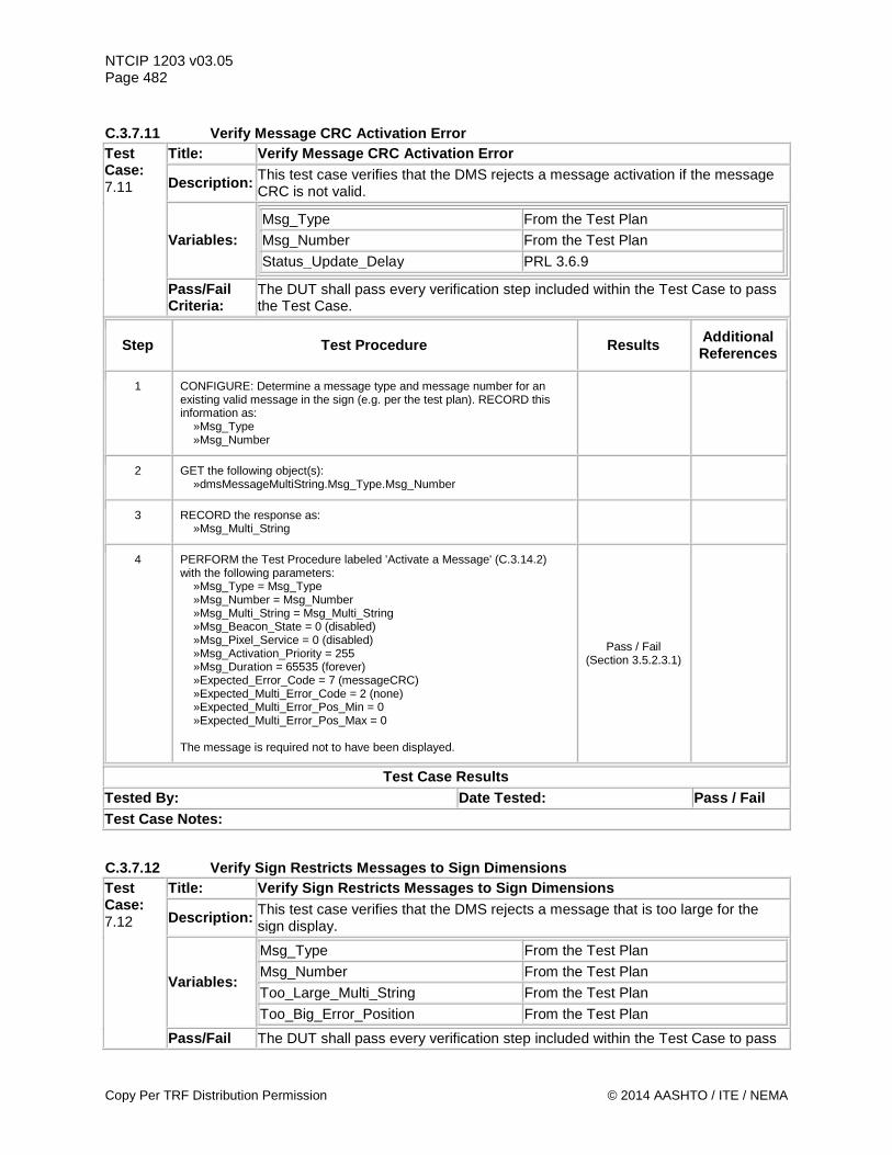
NTCIP 1203 v03.05 Page 482 C.3.7.11 Verify Message CRC Activation Error Test Case: 7.11
Title: Verify Message CRC Activation Error
Description: This test case verifies that the DMS rejects a message activation if the message CRC is not valid.
Variables: Msg_Type From the Test Plan
Msg_Number From the Test Plan
Status_Update_Delay PRL 3.6.9
Pass/Fail Criteria:
The DUT shall pass every verification step included within the Test Case to pass the Test Case.
Step Test Procedure Results Additional References
1 CONFIGURE: Determine a message type and message number for an existing valid message in the sign (e.g. per the test plan). RECORD this information as: »Msg_Type »Msg_Number
2 GET the following object(s): »dmsMessageMultiString.Msg_Type.Msg_Number
3 RECORD the response as: »Msg_Multi_String
4 PERFORM the Test Procedure labeled 'Activate a Message' (C.3.14.2) with the following parameters: »Msg_Type = Msg_Type »Msg_Number = Msg_Number »Msg_Multi_String = Msg_Multi_String »Msg_Beacon_State = 0 (disabled) »Msg_Pixel_Service = 0 (disabled) »Msg_Activation_Priority = 255 »Msg_Duration = 65535 (forever) »Expected_Error_Code = 7 (messageCRC) »Expected_Multi_Error_Code = 2 (none) »Expected_Multi_Error_Pos_Min = 0 »Expected_Multi_Error_Pos_Max = 0 The message is required not to have been displayed.
Pass / Fail (Section 3.5.2.3.1)
Test Case Results Tested By: Date Tested: Pass / Fail Test Case Notes:
C.3.7.12 Verify Sign Restricts Messages to Sign Dimensions Test Case: 7.12
Title: Verify Sign Restricts Messages to Sign Dimensions
Description: This test case verifies that the DMS rejects a message that is too large for the sign display.
Variables:
Msg_Type From the Test Plan Msg_Number From the Test Plan Too_Large_Multi_String From the Test Plan
Too_Big_Error_Position From the Test Plan
Pass/Fail The DUT shall pass every verification step included within the Test Case to pass
Copy Per TRF Distribution Permission © 2014 AASHTO / ITE / NEMA
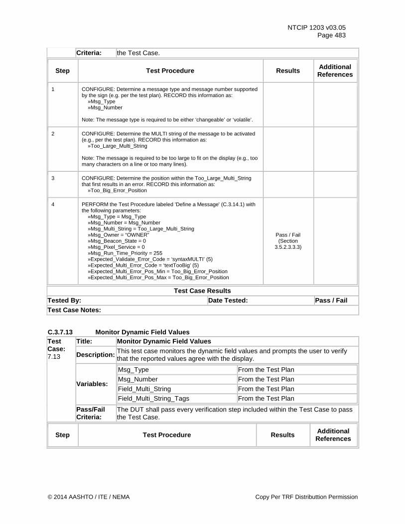
NTCIP 1203 v03.05 Page 483
Criteria: the Test Case.
Step Test Procedure Results Additional References
1 CONFIGURE: Determine a message type and message number supported by the sign (e.g. per the test plan). RECORD this information as: »Msg_Type »Msg_Number Note: The message type is required to be either ‘changeable’ or ‘volatile’.
2 CONFIGURE: Determine the MULTI string of the message to be activated (e.g., per the test plan). RECORD this information as: »Too_Large_Multi_String Note: The message is required to be too large to fit on the display (e.g., too many characters on a line or too many lines).
3 CONFIGURE: Determine the position within the Too_Large_Multi_String that first results in an error. RECORD this information as: »Too_Big_Error_Position
4 PERFORM the Test Procedure labeled 'Define a Message' (C.3.14.1) with the following parameters: »Msg_Type = Msg_Type »Msg_Number = Msg_Number »Msg_Multi_String = Too_Large_Multi_String »Msg_Owner = “OWNER” »Msg_Beacon_State = 0 »Msg_Pixel_Service = 0 »Msg_Run_Time_Priority = 255 »Expected_Validate_Error_Code = ‘syntaxMULTI’ (5) »Expected_Multi_Error_Code = ‘textTooBig’ (5) »Expected_Multi_Error_Pos_Min = Too_Big_Error_Position »Expected_Multi_Error_Pos_Max = Too_Big_Error_Position
Pass / Fail (Section
3.5.2.3.3.3)
Test Case Results Tested By: Date Tested: Pass / Fail Test Case Notes:
C.3.7.13 Monitor Dynamic Field Values Test Case: 7.13
Title: Monitor Dynamic Field Values
Description: This test case monitors the dynamic field values and prompts the user to verify that the reported values agree with the display.
Variables:
Msg_Type From the Test Plan Msg_Number From the Test Plan Field_Multi_String From the Test Plan
Field_Multi_String_Tags From the Test Plan
Pass/Fail Criteria:
The DUT shall pass every verification step included within the Test Case to pass the Test Case.
Step Test Procedure Results Additional References
© 2014 AASHTO / ITE / NEMA Copy Per TRF Distributtion Permission
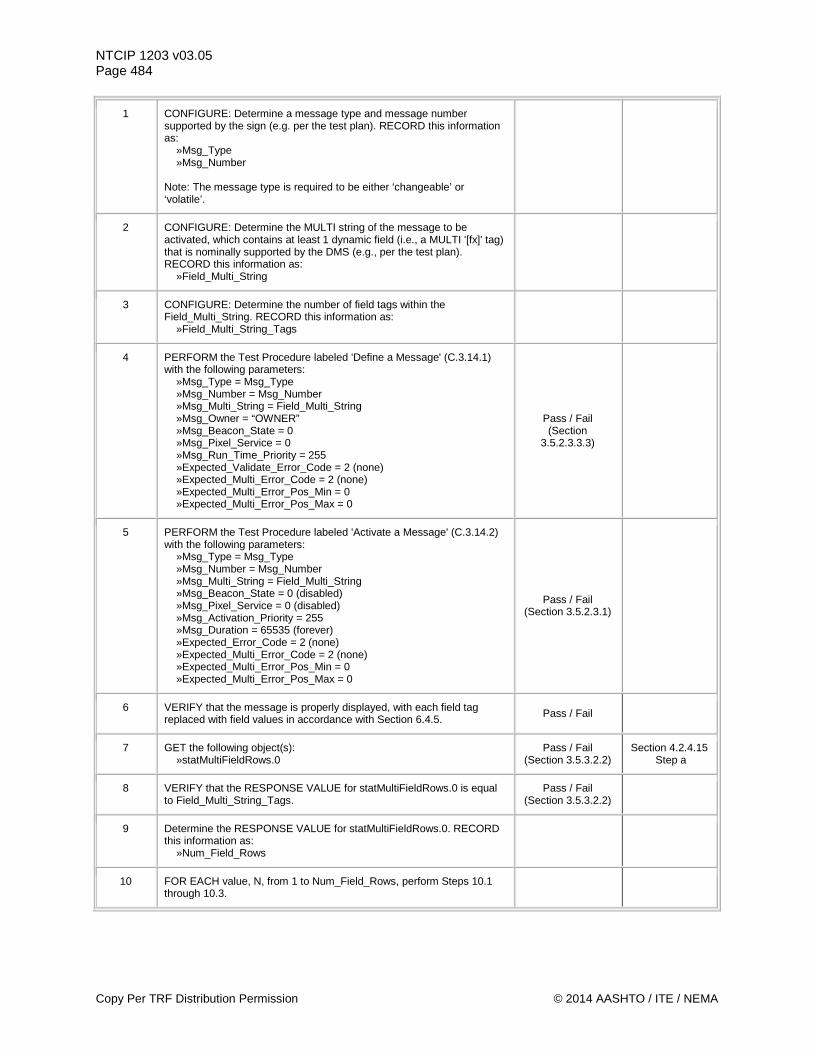
NTCIP 1203 v03.05 Page 484
1 CONFIGURE: Determine a message type and message number supported by the sign (e.g. per the test plan). RECORD this information as: »Msg_Type »Msg_Number Note: The message type is required to be either ‘changeable’ or ‘volatile’.
2 CONFIGURE: Determine the MULTI string of the message to be activated, which contains at least 1 dynamic field (i.e., a MULTI '[fx]' tag) that is nominally supported by the DMS (e.g., per the test plan). RECORD this information as: »Field_Multi_String
3 CONFIGURE: Determine the number of field tags within the Field_Multi_String. RECORD this information as: »Field_Multi_String_Tags
4 PERFORM the Test Procedure labeled 'Define a Message' (C.3.14.1) with the following parameters: »Msg_Type = Msg_Type »Msg_Number = Msg_Number »Msg_Multi_String = Field_Multi_String »Msg_Owner = “OWNER” »Msg_Beacon_State = 0 »Msg_Pixel_Service = 0 »Msg_Run_Time_Priority = 255 »Expected_Validate_Error_Code = 2 (none) »Expected_Multi_Error_Code = 2 (none) »Expected_Multi_Error_Pos_Min = 0 »Expected_Multi_Error_Pos_Max = 0
Pass / Fail (Section
3.5.2.3.3.3)
5 PERFORM the Test Procedure labeled 'Activate a Message' (C.3.14.2) with the following parameters: »Msg_Type = Msg_Type »Msg_Number = Msg_Number »Msg_Multi_String = Field_Multi_String »Msg_Beacon_State = 0 (disabled) »Msg_Pixel_Service = 0 (disabled) »Msg_Activation_Priority = 255 »Msg_Duration = 65535 (forever) »Expected_Error_Code = 2 (none) »Expected_Multi_Error_Code = 2 (none) »Expected_Multi_Error_Pos_Min = 0 »Expected_Multi_Error_Pos_Max = 0
Pass / Fail (Section 3.5.2.3.1)
6 VERIFY that the message is properly displayed, with each field tag replaced with field values in accordance with Section 6.4.5. Pass / Fail
7 GET the following object(s): »statMultiFieldRows.0
Pass / Fail (Section 3.5.3.2.2)
Section 4.2.4.15 Step a
8 VERIFY that the RESPONSE VALUE for statMultiFieldRows.0 is equal to Field_Multi_String_Tags.
Pass / Fail (Section 3.5.3.2.2)
9 Determine the RESPONSE VALUE for statMultiFieldRows.0. RECORD this information as: »Num_Field_Rows
10 FOR EACH value, N, from 1 to Num_Field_Rows, perform Steps 10.1 through 10.3.
Copy Per TRF Distribution Permission © 2014 AASHTO / ITE / NEMA
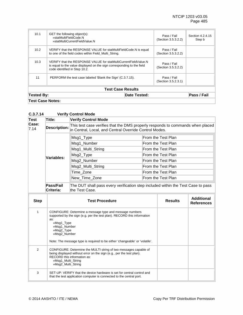
NTCIP 1203 v03.05 Page 485
10.1 GET the following object(s): »statMultiFieldCode.N »statMultiCurrentFieldValue.N
Pass / Fail (Section 3.5.3.2.2)
Section 4.2.4.15 Step b
10.2 VERIFY that the RESPONSE VALUE for statMultiFieldCode.N is equal to one of the field codes within Field_Multi_String.
Pass / Fail (Section 3.5.3.2.2)
10.3 VERIFY that the RESPONSE VALUE for statMultiCurrentFieldValue.N is equal to the value displayed on the sign corresponding to the field code identified in Step 10.2.
Pass / Fail (Section 3.5.3.2.2)
11 PERFORM the test case labeled 'Blank the Sign' (C.3.7.15). Pass / Fail (Section 3.5.2.3.1)
Test Case Results Tested By: Date Tested: Pass / Fail Test Case Notes:
C.3.7.14 Verify Control Mode Test Case: 7.14
Title: Verify Control Mode
Description: This test case verifies that the DMS properly responds to commands when placed in Central, Local, and Central Override Control Modes.
Variables:
Msg1_Type From the Test Plan Msg1_Number From the Test Plan Msg1_Multi_String From the Test Plan Msg2_Type From the Test Plan Msg2_Number From the Test Plan Msg2_Multi_String From the Test Plan Time_Zone From the Test Plan New_Time_Zone From the Test Plan
Pass/Fail Criteria:
The DUT shall pass every verification step included within the Test Case to pass the Test Case.
Step Test Procedure Results Additional References
1 CONFIGURE: Determine a message type and message numbers supported by the sign (e.g. per the test plan). RECORD this information as: »Msg1_Type »Msg1_Number »Msg2_Type »Msg2_Number Note: The message type is required to be either ‘changeable’ or ‘volatile’.
2 CONFIGURE: Determine the MULTI string of two messages capable of being displayed without error on the sign (e.g., per the test plan). RECORD this information as: »Msg1_Multi_String »Msg2_Multi_String
3 SET-UP: VERIFY that the device hardware is set for central control and that the test application computer is connected to the central port.
© 2014 AASHTO / ITE / NEMA Copy Per TRF Distributtion Permission
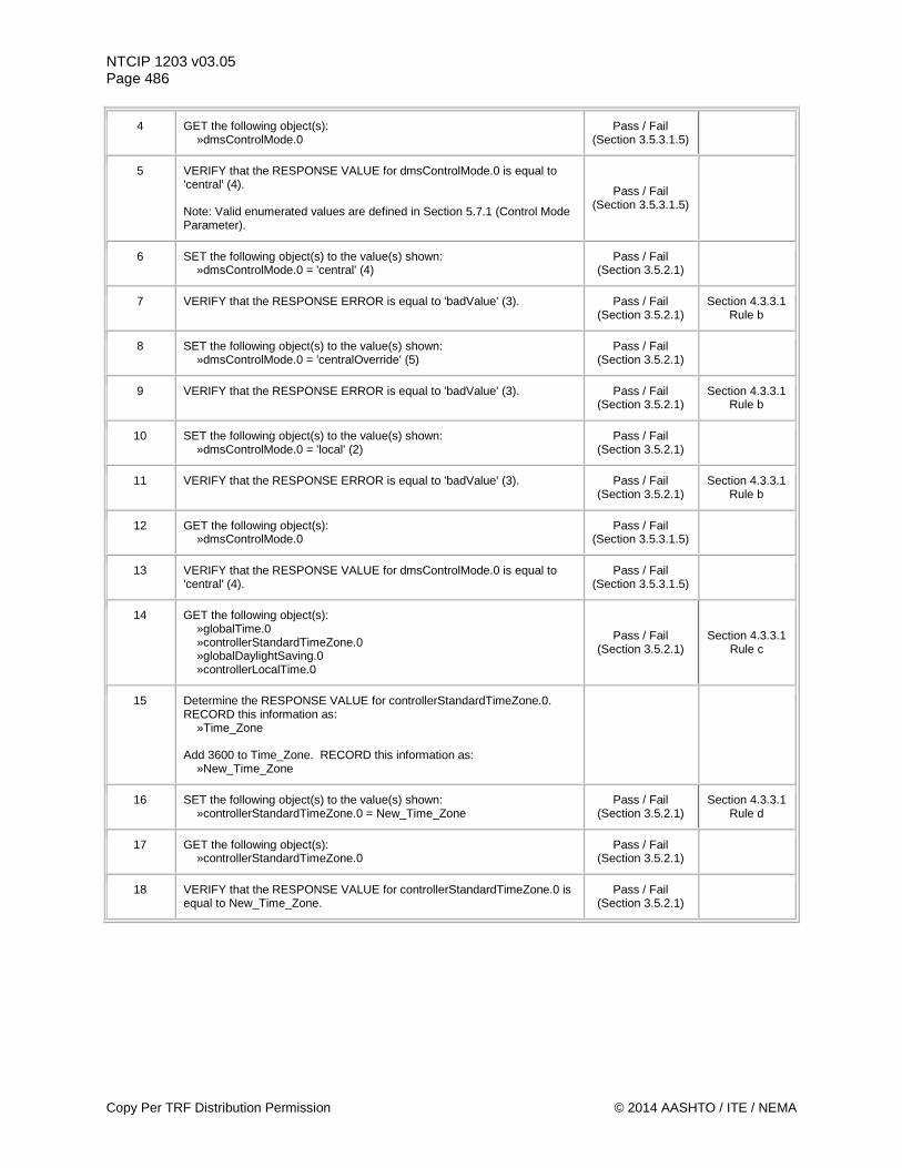
NTCIP 1203 v03.05 Page 486
4 GET the following object(s): »dmsControlMode.0
Pass / Fail (Section 3.5.3.1.5)
5 VERIFY that the RESPONSE VALUE for dmsControlMode.0 is equal to 'central' (4). Note: Valid enumerated values are defined in Section 5.7.1 (Control Mode Parameter).
Pass / Fail (Section 3.5.3.1.5)
6 SET the following object(s) to the value(s) shown: »dmsControlMode.0 = 'central' (4)
Pass / Fail (Section 3.5.2.1)
7 VERIFY that the RESPONSE ERROR is equal to 'badValue' (3). Pass / Fail (Section 3.5.2.1)
Section 4.3.3.1 Rule b
8 SET the following object(s) to the value(s) shown: »dmsControlMode.0 = 'centralOverride' (5)
Pass / Fail (Section 3.5.2.1)
9 VERIFY that the RESPONSE ERROR is equal to 'badValue' (3). Pass / Fail (Section 3.5.2.1)
Section 4.3.3.1 Rule b
10 SET the following object(s) to the value(s) shown: »dmsControlMode.0 = 'local' (2)
Pass / Fail (Section 3.5.2.1)
11 VERIFY that the RESPONSE ERROR is equal to 'badValue' (3). Pass / Fail (Section 3.5.2.1)
Section 4.3.3.1 Rule b
12 GET the following object(s): »dmsControlMode.0
Pass / Fail (Section 3.5.3.1.5)
13 VERIFY that the RESPONSE VALUE for dmsControlMode.0 is equal to 'central' (4).
Pass / Fail (Section 3.5.3.1.5)
14 GET the following object(s): »globalTime.0 »controllerStandardTimeZone.0 »globalDaylightSaving.0 »controllerLocalTime.0
Pass / Fail (Section 3.5.2.1)
Section 4.3.3.1 Rule c
15 Determine the RESPONSE VALUE for controllerStandardTimeZone.0. RECORD this information as: »Time_Zone Add 3600 to Time_Zone. RECORD this information as: »New_Time_Zone
16 SET the following object(s) to the value(s) shown: »controllerStandardTimeZone.0 = New_Time_Zone
Pass / Fail (Section 3.5.2.1)
Section 4.3.3.1 Rule d
17 GET the following object(s): »controllerStandardTimeZone.0
Pass / Fail (Section 3.5.2.1)
18 VERIFY that the RESPONSE VALUE for controllerStandardTimeZone.0 is equal to New_Time_Zone.
Pass / Fail (Section 3.5.2.1)
Copy Per TRF Distribution Permission © 2014 AASHTO / ITE / NEMA
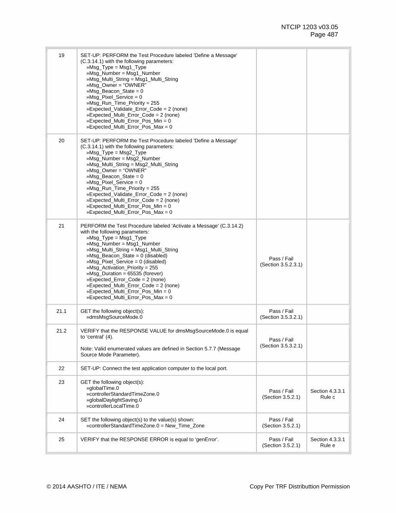
NTCIP 1203 v03.05 Page 487
19 SET-UP: PERFORM the Test Procedure labeled 'Define a Message' (C.3.14.1) with the following parameters: »Msg_Type = Msg1_Type »Msg_Number = Msg1_Number »Msg_Multi_String = Msg1_Multi_String »Msg_Owner = “OWNER” »Msg_Beacon_State = 0 »Msg_Pixel_Service = 0 »Msg_Run_Time_Priority = 255 »Expected_Validate_Error_Code = 2 (none) »Expected_Multi_Error_Code = 2 (none) »Expected_Multi_Error_Pos_Min = 0 »Expected_Multi_Error_Pos_Max = 0
20 SET-UP: PERFORM the Test Procedure labeled 'Define a Message' (C.3.14.1) with the following parameters: »Msg_Type = Msg2_Type »Msg_Number = Msg2_Number »Msg_Multi_String = Msg2_Multi_String »Msg_Owner = “OWNER” »Msg_Beacon_State = 0 »Msg_Pixel_Service = 0 »Msg_Run_Time_Priority = 255 »Expected_Validate_Error_Code = 2 (none) »Expected_Multi_Error_Code = 2 (none) »Expected_Multi_Error_Pos_Min = 0 »Expected_Multi_Error_Pos_Max = 0
21 PERFORM the Test Procedure labeled 'Activate a Message' (C.3.14.2) with the following parameters: »Msg_Type = Msg1_Type »Msg_Number = Msg1_Number »Msg_Multi_String = Msg1_Multi_String »Msg_Beacon_State = 0 (disabled) »Msg_Pixel_Service = 0 (disabled) »Msg_Activation_Priority = 255 »Msg_Duration = 65535 (forever) »Expected_Error_Code = 2 (none) »Expected_Multi_Error_Code = 2 (none) »Expected_Multi_Error_Pos_Min = 0 »Expected_Multi_Error_Pos_Max = 0
Pass / Fail (Section 3.5.2.3.1)
21.1 GET the following object(s): »dmsMsgSourceMode.0
Pass / Fail (Section 3.5.3.2.1)
21.2 VERIFY that the RESPONSE VALUE for dmsMsgSourceMode.0 is equal to ‘central’ (4). Note: Valid enumerated values are defined in Section 5.7.7 (Message Source Mode Parameter).
Pass / Fail (Section 3.5.3.2.1)
22 SET-UP: Connect the test application computer to the local port.
23 GET the following object(s): »globalTime.0 »controllerStandardTimeZone.0 »globalDaylightSaving.0 »controllerLocalTime.0
Pass / Fail (Section 3.5.2.1)
Section 4.3.3.1 Rule c
24 SET the following object(s) to the value(s) shown: »controllerStandardTimeZone.0 = New_Time_Zone
Pass / Fail (Section 3.5.2.1)
25 VERIFY that the RESPONSE ERROR is equal to ‘genError’. Pass / Fail (Section 3.5.2.1)
Section 4.3.3.1 Rule e
© 2014 AASHTO / ITE / NEMA Copy Per TRF Distributtion Permission
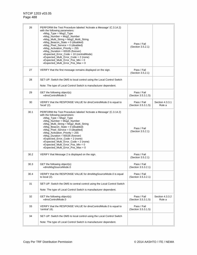
NTCIP 1203 v03.05 Page 488
26 PERFORM the Test Procedure labeled 'Activate a Message' (C.3.14.2) with the following parameters: »Msg_Type = Msg2_Type »Msg_Number = Msg2_Number »Msg_Multi_String = Msg2_Multi_String »Msg_Beacon_State = 0 (disabled) »Msg_Pixel_Service = 0 (disabled) »Msg_Activation_Priority = 255 »Msg_Duration = 65535 (forever) »Expected_Error_Code = 10 (centralMode) »Expected_Multi_Error_Code = 2 (none) »Expected_Multi_Error_Pos_Min = 0 »Expected_Multi_Error_Pos_Max = 0
Pass / Fail (Section 3.5.2.1)
27 VERIFY that the first message remains displayed on the sign. Pass / Fail (Section 3.5.2.1)
28 SET-UP: Switch the DMS to local control using the Local Control Switch Note: The type of Local Control Switch is manufacturer dependent.
29 GET the following object(s): »dmsControlMode.0
Pass / Fail (Section 3.5.3.1.5)
30 VERIFY that the RESPONSE VALUE for dmsControlMode.0 is equal to 'local' (2).
Pass / Fail (Section 3.5.3.1.5)
Section 4.3.3.1 Rule a
30.1 PERFORM the Test Procedure labeled 'Activate a Message' (C.3.14.2) with the following parameters: »Msg_Type = Msg2_Type »Msg_Number = Msg2_Number »Msg_Multi_String = Msg2_Multi_String »Msg_Beacon_State = 0 (disabled) »Msg_Pixel_Service = 0 (disabled) »Msg_Activation_Priority = 255 »Msg_Duration = 65535 (forever) »Expected_Error_Code = 2 (none) »Expected_Multi_Error_Code = 2 (none) »Expected_Multi_Error_Pos_Min = 0 »Expected_Multi_Error_Pos_Max = 0
Pass / Fail (Section 3.5.2.1)
30.2 VERIFY that Message 2 is displayed on the sign. Pass / Fail (Section 3.5.2.1)
30.3 GET the following object(s): »dmsMsgSourceMode.0
Pass / Fail (Section 3.5.3.2.1)
30.4 VERIFY that the RESPONSE VALUE for dmsMsgSourceMode.0 is equal to local (2).
Pass / Fail (Section 3.5.3.2.1)
31 SET-UP: Switch the DMS to central control using the Local Control Switch Note: The type of Local Control Switch is manufacturer dependent.
32 GET the following object(s): »dmsControlMode.0
Pass / Fail (Section 3.5.3.1.5)
Section 4.3.3.2 Rule a
33 VERIFY that the RESPONSE VALUE for dmsControlMode.0 is equal to 'central' (4).
Pass / Fail (Section 3.5.3.1.5)
34 SET-UP: Switch the DMS to local control using the Local Control Switch Note: The type of Local Control Switch is manufacturer dependent.
Copy Per TRF Distribution Permission © 2014 AASHTO / ITE / NEMA
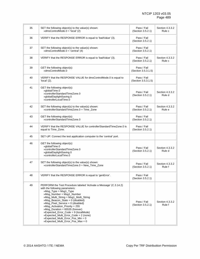
NTCIP 1203 v03.05 Page 489
35 SET the following object(s) to the value(s) shown: »dmsControlMode.0 = 'local' (2)
Pass / Fail (Section 3.5.2.1)
Section 4.3.3.2 Rule c
36 VERIFY that the RESPONSE ERROR is equal to 'badValue' (3).
Pass / Fail (Section 3.5.2.1)
37 SET the following object(s) to the value(s) shown: »dmsControlMode.0 = 'central' (4)
Pass / Fail (Section 3.5.2.1)
38 VERIFY that the RESPONSE ERROR is equal to 'badValue' (3). Pass / Fail (Section 3.5.2.1)
Section 4.3.3.2 Rule c
39 GET the following object(s): »dmsControlMode.0
Pass / Fail (Section 3.5.3.1.5)
40 VERIFY that the RESPONSE VALUE for dmsControlMode.0 is equal to 'local' (2).
Pass / Fail (Section 3.5.3.1.5)
41 GET the following object(s): »globalTime.0 »controllerStandardTimeZone.0 »globalDaylightSaving.0 »controllerLocalTime.0
Pass / Fail (Section 3.5.2.1)
Section 4.3.3.2 Rule d
42 SET the following object(s) to the value(s) shown: »controllerStandardTimeZone.0 = Time_Zone
Pass / Fail (Section 3.5.2.1)
Section 4.3.3.2 Rule e
43 GET the following object(s): »controllerStandardTimeZone.0
Pass / Fail (Section 3.5.2.1)
44 VERIFY that the RESPONSE VALUE for controllerStandardTimeZone.0 is equal to Time_Zone.
Pass / Fail (Section 3.5.2.1)
45 SET-UP: Connect the test application computer to the ‘central’ port.
46 GET the following object(s): »globalTime.0 »controllerStandardTimeZone.0 »globalDaylightSaving.0 »controllerLocalTime.0
Pass / Fail (Section 3.5.2.1)
Section 4.3.3.2 Rule d
47 SET the following object(s) to the value(s) shown: »controllerStandardTimeZone.0 = New_Time_Zone
Pass / Fail (Section 3.5.2.1)
Section 4.3.3.2 Rule f
48 VERIFY that the RESPONSE ERROR is equal to ‘genError’. Pass / Fail (Section 3.5.2.1)
49 PERFORM the Test Procedure labeled 'Activate a Message' (C.3.14.2) with the following parameters: »Msg_Type = Msg1_Type »Msg_Number = Msg1_Number »Msg_Multi_String = Msg1_Multi_String »Msg_Beacon_State = 0 (disabled) »Msg_Pixel_Service = 0 (disabled) »Msg_Activation_Priority = 255 »Msg_Duration = 65535 (forever) »Expected_Error_Code = 9 (localMode) »Expected_Multi_Error_Code = 2 (none) »Expected_Multi_Error_Pos_Min = 0 »Expected_Multi_Error_Pos_Max = 0
Pass / Fail (Section 3.5.2.1)
Section 4.3.3.2 Rule f
© 2014 AASHTO / ITE / NEMA Copy Per TRF Distributtion Permission
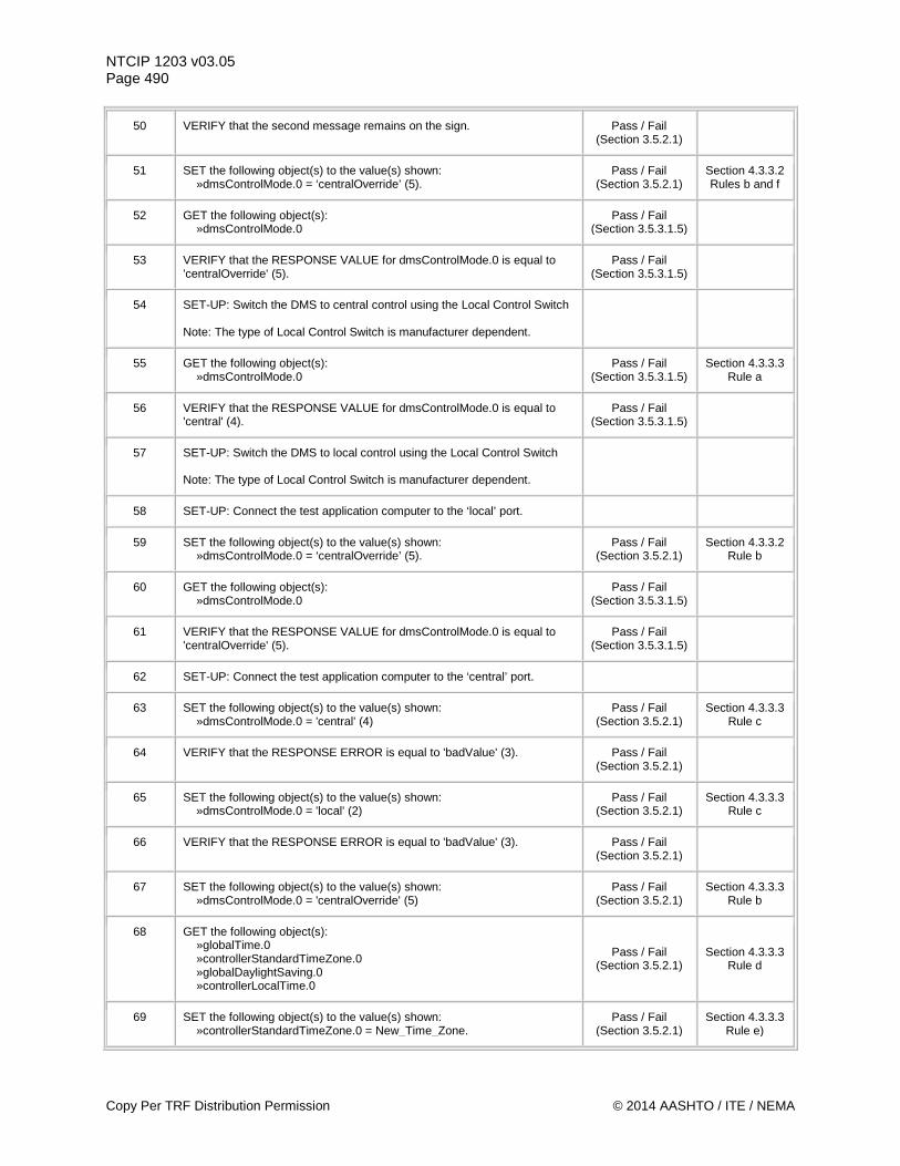
NTCIP 1203 v03.05 Page 490
50 VERIFY that the second message remains on the sign. Pass / Fail (Section 3.5.2.1)
51 SET the following object(s) to the value(s) shown: »dmsControlMode.0 = ‘centralOverride’ (5).
Pass / Fail (Section 3.5.2.1)
Section 4.3.3.2 Rules b and f
52 GET the following object(s): »dmsControlMode.0
Pass / Fail (Section 3.5.3.1.5)
53 VERIFY that the RESPONSE VALUE for dmsControlMode.0 is equal to 'centralOverride' (5).
Pass / Fail (Section 3.5.3.1.5)
54 SET-UP: Switch the DMS to central control using the Local Control Switch Note: The type of Local Control Switch is manufacturer dependent.
55 GET the following object(s): »dmsControlMode.0
Pass / Fail (Section 3.5.3.1.5)
Section 4.3.3.3 Rule a
56 VERIFY that the RESPONSE VALUE for dmsControlMode.0 is equal to 'central' (4).
Pass / Fail (Section 3.5.3.1.5)
57 SET-UP: Switch the DMS to local control using the Local Control Switch Note: The type of Local Control Switch is manufacturer dependent.
58 SET-UP: Connect the test application computer to the ‘local’ port.
59 SET the following object(s) to the value(s) shown: »dmsControlMode.0 = ‘centralOverride’ (5).
Pass / Fail (Section 3.5.2.1)
Section 4.3.3.2 Rule b
60 GET the following object(s): »dmsControlMode.0
Pass / Fail (Section 3.5.3.1.5)
61 VERIFY that the RESPONSE VALUE for dmsControlMode.0 is equal to 'centralOverride' (5).
Pass / Fail (Section 3.5.3.1.5)
62 SET-UP: Connect the test application computer to the ‘central’ port.
63 SET the following object(s) to the value(s) shown: »dmsControlMode.0 = 'central' (4)
Pass / Fail (Section 3.5.2.1)
Section 4.3.3.3 Rule c
64 VERIFY that the RESPONSE ERROR is equal to 'badValue' (3). Pass / Fail (Section 3.5.2.1)
65 SET the following object(s) to the value(s) shown: »dmsControlMode.0 = 'local' (2)
Pass / Fail (Section 3.5.2.1)
Section 4.3.3.3 Rule c
66 VERIFY that the RESPONSE ERROR is equal to 'badValue' (3). Pass / Fail (Section 3.5.2.1)
67 SET the following object(s) to the value(s) shown: »dmsControlMode.0 = 'centralOverride' (5)
Pass / Fail (Section 3.5.2.1)
Section 4.3.3.3 Rule b
68 GET the following object(s): »globalTime.0 »controllerStandardTimeZone.0 »globalDaylightSaving.0 »controllerLocalTime.0
Pass / Fail (Section 3.5.2.1)
Section 4.3.3.3 Rule d
69 SET the following object(s) to the value(s) shown: »controllerStandardTimeZone.0 = New_Time_Zone.
Pass / Fail (Section 3.5.2.1)
Section 4.3.3.3 Rule e)
Copy Per TRF Distribution Permission © 2014 AASHTO / ITE / NEMA
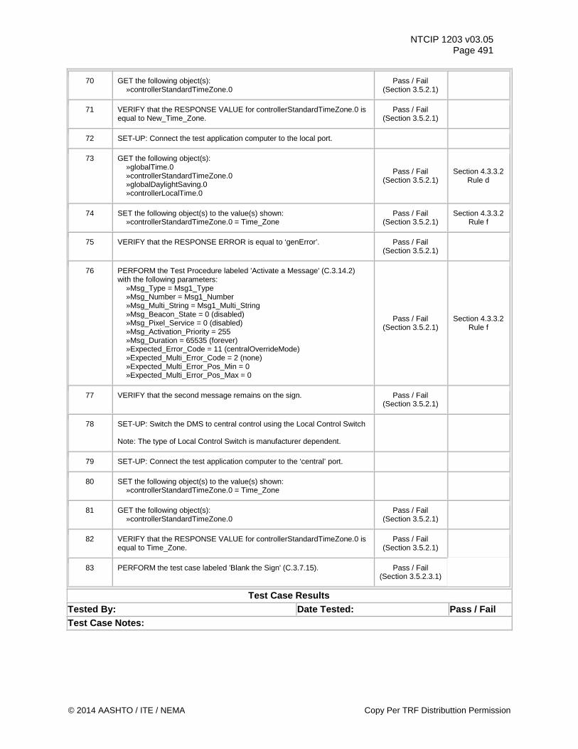
NTCIP 1203 v03.05 Page 491
70 GET the following object(s): »controllerStandardTimeZone.0
Pass / Fail (Section 3.5.2.1)
71 VERIFY that the RESPONSE VALUE for controllerStandardTimeZone.0 is equal to New_Time_Zone.
Pass / Fail (Section 3.5.2.1)
72 SET-UP: Connect the test application computer to the local port.
73 GET the following object(s): »globalTime.0 »controllerStandardTimeZone.0 »globalDaylightSaving.0 »controllerLocalTime.0
Pass / Fail (Section 3.5.2.1)
Section 4.3.3.2 Rule d
74 SET the following object(s) to the value(s) shown: »controllerStandardTimeZone.0 = Time_Zone
Pass / Fail (Section 3.5.2.1)
Section 4.3.3.2 Rule f
75 VERIFY that the RESPONSE ERROR is equal to ‘genError’. Pass / Fail (Section 3.5.2.1)
76 PERFORM the Test Procedure labeled 'Activate a Message' (C.3.14.2) with the following parameters: »Msg_Type = Msg1_Type »Msg_Number = Msg1_Number »Msg_Multi_String = Msg1_Multi_String »Msg_Beacon_State = 0 (disabled) »Msg_Pixel_Service = 0 (disabled) »Msg_Activation_Priority = 255 »Msg_Duration = 65535 (forever) »Expected_Error_Code = 11 (centralOverrideMode) »Expected_Multi_Error_Code = 2 (none) »Expected_Multi_Error_Pos_Min = 0 »Expected_Multi_Error_Pos_Max = 0
Pass / Fail (Section 3.5.2.1)
Section 4.3.3.2 Rule f
77 VERIFY that the second message remains on the sign. Pass / Fail (Section 3.5.2.1)
78 SET-UP: Switch the DMS to central control using the Local Control Switch Note: The type of Local Control Switch is manufacturer dependent.
79 SET-UP: Connect the test application computer to the ‘central’ port.
80 SET the following object(s) to the value(s) shown: »controllerStandardTimeZone.0 = Time_Zone
81 GET the following object(s): »controllerStandardTimeZone.0
Pass / Fail (Section 3.5.2.1)
82 VERIFY that the RESPONSE VALUE for controllerStandardTimeZone.0 is equal to Time_Zone.
Pass / Fail (Section 3.5.2.1)
83 PERFORM the test case labeled 'Blank the Sign' (C.3.7.15). Pass / Fail (Section 3.5.2.3.1)
Test Case Results Tested By: Date Tested: Pass / Fail Test Case Notes:
© 2014 AASHTO / ITE / NEMA Copy Per TRF Distributtion Permission
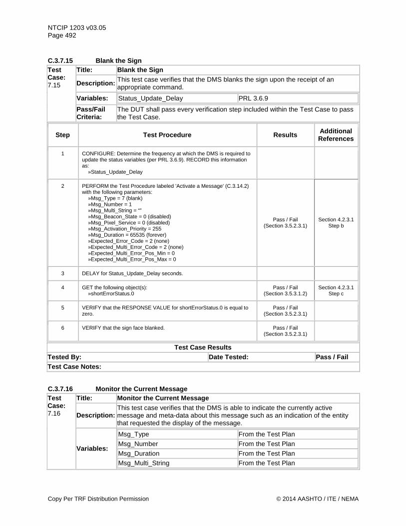
NTCIP 1203 v03.05 Page 492 C.3.7.15 Blank the Sign Test Case: 7.15
Title: Blank the Sign
Description: This test case verifies that the DMS blanks the sign upon the receipt of an appropriate command.
Variables: Status_Update_Delay PRL 3.6.9
Pass/Fail Criteria:
The DUT shall pass every verification step included within the Test Case to pass the Test Case.
Step Test Procedure Results Additional References
1 CONFIGURE: Determine the frequency at which the DMS is required to update the status variables (per PRL 3.6.9). RECORD this information as: »Status_Update_Delay
2 PERFORM the Test Procedure labeled 'Activate a Message' (C.3.14.2) with the following parameters: »Msg_Type = 7 (blank) »Msg_Number = 1 »Msg_Multi_String = “” »Msg_Beacon_State = 0 (disabled) »Msg_Pixel_Service = 0 (disabled) »Msg_Activation_Priority = 255 »Msg_Duration = 65535 (forever) »Expected_Error_Code = 2 (none) »Expected_Multi_Error_Code = 2 (none) »Expected_Multi_Error_Pos_Min = 0 »Expected_Multi_Error_Pos_Max = 0
Pass / Fail (Section 3.5.2.3.1)
Section 4.2.3.1 Step b
3 DELAY for Status_Update_Delay seconds.
4 GET the following object(s): »shortErrorStatus.0
Pass / Fail (Section 3.5.3.1.2)
Section 4.2.3.1 Step c
5 VERIFY that the RESPONSE VALUE for shortErrorStatus.0 is equal to zero.
Pass / Fail (Section 3.5.2.3.1)
6 VERIFY that the sign face blanked. Pass / Fail (Section 3.5.2.3.1)
Test Case Results Tested By: Date Tested: Pass / Fail Test Case Notes:
C.3.7.16 Monitor the Current Message Test Case: 7.16
Title: Monitor the Current Message
Description: This test case verifies that the DMS is able to indicate the currently active message and meta-data about this message such as an indication of the entity that requested the display of the message.
Variables:
Msg_Type From the Test Plan Msg_Number From the Test Plan Msg_Duration From the Test Plan Msg_Multi_String From the Test Plan
Copy Per TRF Distribution Permission © 2014 AASHTO / ITE / NEMA
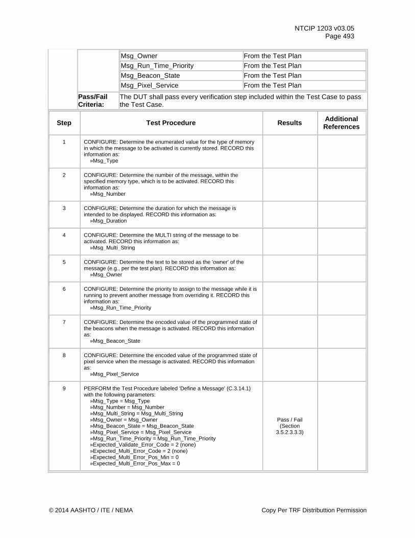
NTCIP 1203 v03.05 Page 493
Msg_Owner From the Test Plan Msg_Run_Time_Priority From the Test Plan Msg_Beacon_State From the Test Plan Msg_Pixel_Service From the Test Plan
Pass/Fail Criteria:
The DUT shall pass every verification step included within the Test Case to pass the Test Case.
Step Test Procedure Results Additional References
1 CONFIGURE: Determine the enumerated value for the type of memory in which the message to be activated is currently stored. RECORD this information as: »Msg_Type
2 CONFIGURE: Determine the number of the message, within the specified memory type, which is to be activated. RECORD this information as: »Msg_Number
3 CONFIGURE: Determine the duration for which the message is intended to be displayed. RECORD this information as: »Msg_Duration
4 CONFIGURE: Determine the MULTI string of the message to be activated. RECORD this information as: »Msg_Multi_String
5 CONFIGURE: Determine the text to be stored as the 'owner' of the message (e.g., per the test plan). RECORD this information as: »Msg_Owner
6 CONFIGURE: Determine the priority to assign to the message while it is running to prevent another message from overriding it. RECORD this information as: »Msg_Run_Time_Priority
7 CONFIGURE: Determine the encoded value of the programmed state of the beacons when the message is activated. RECORD this information as: »Msg_Beacon_State
8 CONFIGURE: Determine the encoded value of the programmed state of pixel service when the message is activated. RECORD this information as: »Msg_Pixel_Service
9 PERFORM the Test Procedure labeled 'Define a Message' (C.3.14.1) with the following parameters: »Msg_Type = Msg_Type »Msg_Number = Msg_Number »Msg_Multi_String = Msg_Multi_String »Msg_Owner = Msg_Owner »Msg_Beacon_State = Msg_Beacon_State »Msg_Pixel_Service = Msg_Pixel_Service »Msg_Run_Time_Priority = Msg_Run_Time_Priority »Expected_Validate_Error_Code = 2 (none) »Expected_Multi_Error_Code = 2 (none) »Expected_Multi_Error_Pos_Min = 0 »Expected_Multi_Error_Pos_Max = 0
Pass / Fail (Section
3.5.2.3.3.3)
© 2014 AASHTO / ITE / NEMA Copy Per TRF Distributtion Permission
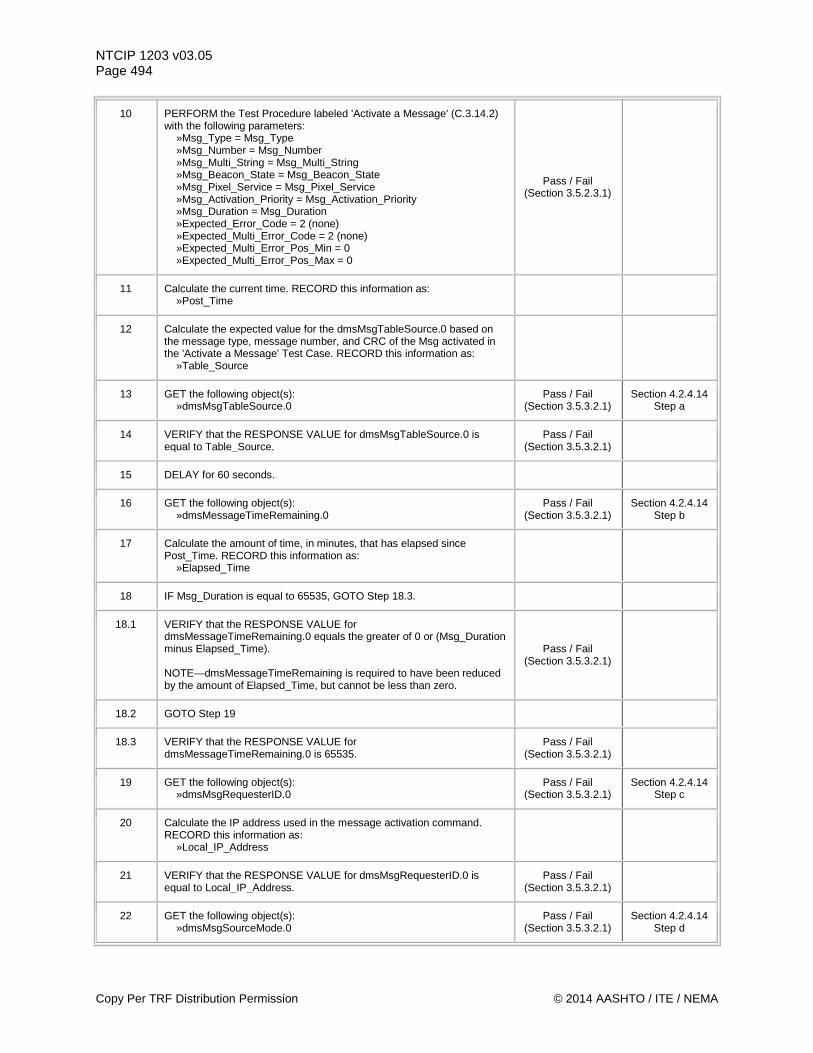
NTCIP 1203 v03.05 Page 494
10 PERFORM the Test Procedure labeled 'Activate a Message' (C.3.14.2) with the following parameters: »Msg_Type = Msg_Type »Msg_Number = Msg_Number »Msg_Multi_String = Msg_Multi_String »Msg_Beacon_State = Msg_Beacon_State »Msg_Pixel_Service = Msg_Pixel_Service »Msg_Activation_Priority = Msg_Activation_Priority »Msg_Duration = Msg_Duration »Expected_Error_Code = 2 (none) »Expected_Multi_Error_Code = 2 (none) »Expected_Multi_Error_Pos_Min = 0 »Expected_Multi_Error_Pos_Max = 0
Pass / Fail (Section 3.5.2.3.1)
11 Calculate the current time. RECORD this information as: »Post_Time
12 Calculate the expected value for the dmsMsgTableSource.0 based on the message type, message number, and CRC of the Msg activated in the 'Activate a Message' Test Case. RECORD this information as: »Table_Source
13 GET the following object(s): »dmsMsgTableSource.0
Pass / Fail (Section 3.5.3.2.1)
Section 4.2.4.14 Step a
14 VERIFY that the RESPONSE VALUE for dmsMsgTableSource.0 is equal to Table_Source.
Pass / Fail (Section 3.5.3.2.1)
15 DELAY for 60 seconds.
16 GET the following object(s): »dmsMessageTimeRemaining.0
Pass / Fail (Section 3.5.3.2.1)
Section 4.2.4.14 Step b
17 Calculate the amount of time, in minutes, that has elapsed since Post_Time. RECORD this information as: »Elapsed_Time
18 IF Msg_Duration is equal to 65535, GOTO Step 18.3.
18.1 VERIFY that the RESPONSE VALUE for dmsMessageTimeRemaining.0 equals the greater of 0 or (Msg_Duration minus Elapsed_Time). NOTE—dmsMessageTimeRemaining is required to have been reduced by the amount of Elapsed_Time, but cannot be less than zero.
Pass / Fail (Section 3.5.3.2.1)
18.2 GOTO Step 19
18.3 VERIFY that the RESPONSE VALUE for dmsMessageTimeRemaining.0 is 65535.
Pass / Fail (Section 3.5.3.2.1)
19 GET the following object(s): »dmsMsgRequesterID.0
Pass / Fail (Section 3.5.3.2.1)
Section 4.2.4.14 Step c
20 Calculate the IP address used in the message activation command. RECORD this information as: »Local_IP_Address
21 VERIFY that the RESPONSE VALUE for dmsMsgRequesterID.0 is equal to Local_IP_Address.
Pass / Fail (Section 3.5.3.2.1)
22 GET the following object(s): »dmsMsgSourceMode.0
Pass / Fail (Section 3.5.3.2.1)
Section 4.2.4.14 Step d
Copy Per TRF Distribution Permission © 2014 AASHTO / ITE / NEMA
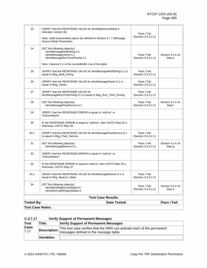
NTCIP 1203 v03.05 Page 495
23 VERIFY that the RESPONSE VALUE for dmsMsgSourceMode.0 indicates 'central' (8). Note: Valid enumerated values are defined in Section 5.7.7 (Message Source Mode Parameter).
Pass / Fail (Section 3.5.3.2.1)
24 GET the following object(s): »dmsMessageMultiString.5.1 »dmsMessageOwner.5.1 »dmsMessageRunTimePriority.5.1 Note: Instance 5.1 is the currentBuffer row of the table.
Pass / Fail (Section 3.5.3.2.1)
Section 4.2.4.14 Step e
25 VERIFY that the RESPONSE VALUE for dmsMessageMultiString.5.1 is equal to Msg_Multi_String.
Pass / Fail (Section 3.5.3.2.1)
26 VERIFY that the RESPONSE VALUE for dmsMessageOwner.5.1 is equal to Msg_Owner.
Pass / Fail (Section 3.5.3.2.1)
27 VERIFY that the RESPONSE VALUE for dmsMessageRunTimePriority.5.1 is equal to Msg_Run_Time_Priority.
Pass / Fail (Section 3.5.3.2.1)
28 GET the following object(s): »dmsMessagePixelService.5.1
Pass / Fail (Section 3.5.3.2.1)
Section 4.2.4.14 Step f
29 VERIFY that the RESPONSE ERROR is equal to ‘noError’ or 'noSuchName'.
30 IF the RESPONSE ERROR is equal to ‘noError’, then GOTO Step 30.1; otherwise, GOTO Step 35.
30.1 VERIFY that the RESPONSE VALUE for dmsMessagePixelService.5.1 is equal to Msg_Pixel_Service.
Pass / Fail (Section 3.5.3.2.1)
31 GET the following object(s): »dmsMessageBeacon.5.1
Pass / Fail (Section 3.5.3.2.1)
Section 4.2.4.14 Step g
32 VERIFY that the RESPONSE ERROR is equal to ‘noError’ or 'noSuchName'.
33 IF the RESPONSE ERROR is equal to noError, then GOTO Step 33.1; otherwise, GOTO Step 37.
33.1 VERIFY that the RESPONSE VALUE for dmsMessageBeacon.5.1 is equal to Msg_Beacon_State.
Pass / Fail (Section 3.5.3.2.1)
34 GET the following object(s): »dmsIllumBrightLevelStatus.0 »dmsIllumLightOutputStatus.0
Pass / Fail (Section 3.5.3.2.1)
Section 4.2.4.14 Step h
Test Case Results Tested By: Date Tested: Pass / Fail Test Case Notes:
C.3.7.17 Verify Support of Permanent Messages Test Case: 7.17
Title: Verify Support of Permanent Messages
Description: This test case verifies that the DMS can activate each of the permanent messages defined in the message table.
Variables:
© 2014 AASHTO / ITE / NEMA Copy Per TRF Distributtion Permission
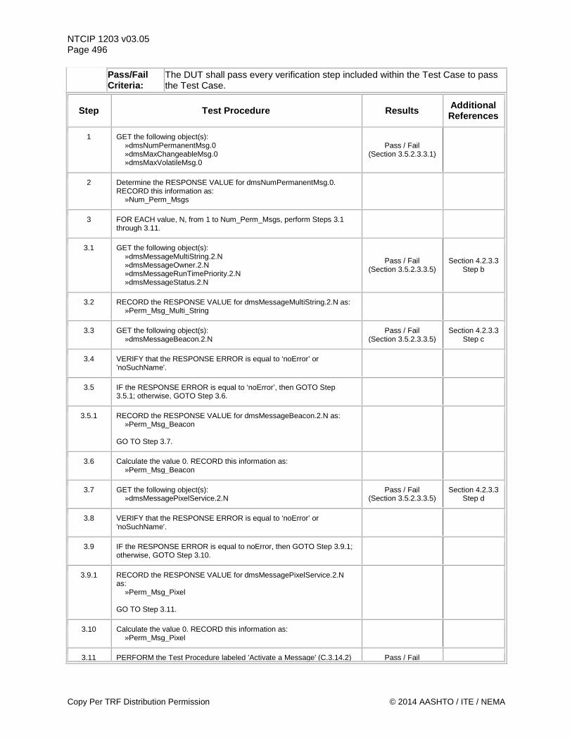
NTCIP 1203 v03.05 Page 496
Pass/Fail Criteria:
The DUT shall pass every verification step included within the Test Case to pass the Test Case.
Step Test Procedure Results Additional References
1 GET the following object(s): »dmsNumPermanentMsg.0 »dmsMaxChangeableMsg.0 »dmsMaxVolatileMsg.0
Pass / Fail (Section 3.5.2.3.3.1)
2 Determine the RESPONSE VALUE for dmsNumPermanentMsg.0. RECORD this information as: »Num_Perm_Msgs
3 FOR EACH value, N, from 1 to Num_Perm_Msgs, perform Steps 3.1 through 3.11.
3.1 GET the following object(s): »dmsMessageMultiString.2.N »dmsMessageOwner.2.N »dmsMessageRunTimePriority.2.N »dmsMessageStatus.2.N
Pass / Fail (Section 3.5.2.3.3.5)
Section 4.2.3.3 Step b
3.2 RECORD the RESPONSE VALUE for dmsMessageMultiString.2.N as: »Perm_Msg_Multi_String
3.3 GET the following object(s): »dmsMessageBeacon.2.N
Pass / Fail (Section 3.5.2.3.3.5)
Section 4.2.3.3 Step c
3.4 VERIFY that the RESPONSE ERROR is equal to ‘noError’ or 'noSuchName'.
3.5 IF the RESPONSE ERROR is equal to ‘noError’, then GOTO Step 3.5.1; otherwise, GOTO Step 3.6.
3.5.1 RECORD the RESPONSE VALUE for dmsMessageBeacon.2.N as: »Perm_Msg_Beacon GO TO Step 3.7.
3.6 Calculate the value 0. RECORD this information as: »Perm_Msg_Beacon
3.7 GET the following object(s): »dmsMessagePixelService.2.N
Pass / Fail (Section 3.5.2.3.3.5)
Section 4.2.3.3 Step d
3.8 VERIFY that the RESPONSE ERROR is equal to ‘noError’ or 'noSuchName'.
3.9 IF the RESPONSE ERROR is equal to noError, then GOTO Step 3.9.1; otherwise, GOTO Step 3.10.
3.9.1 RECORD the RESPONSE VALUE for dmsMessagePixelService.2.N as: »Perm_Msg_Pixel GO TO Step 3.11.
3.10 Calculate the value 0. RECORD this information as: »Perm_Msg_Pixel
3.11 PERFORM the Test Procedure labeled 'Activate a Message' (C.3.14.2) Pass / Fail
Copy Per TRF Distribution Permission © 2014 AASHTO / ITE / NEMA
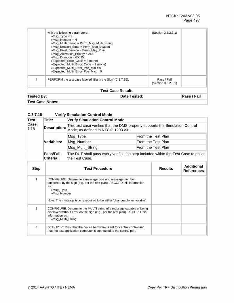
NTCIP 1203 v03.05 Page 497
with the following parameters: »Msg_Type = 2 »Msg_Number = N »Msg_Multi_String = Perm_Msg_Multi_String »Msg_Beacon_State = Perm_Msg_Beacon »Msg_Pixel_Service = Perm_Msg_Pixel »Msg_Activation_Priority = 255 »Msg_Duration = 65535 »Expected_Error_Code = 2 (none) »Expected_Multi_Error_Code = 2 (none) »Expected_Multi_Error_Pos_Min = 0 »Expected_Multi_Error_Pos_Max = 0
(Section 3.5.2.3.1)
4 PERFORM the test case labeled 'Blank the Sign' (C.3.7.15). Pass / Fail (Section 3.5.2.3.1)
Test Case Results Tested By: Date Tested: Pass / Fail Test Case Notes:
C.3.7.18 Verify Simulation Control Mode Test Case: 7.18
Title: Verify Simulation Control Mode
Description: This test case verifies that the DMS properly supports the Simulation Control Mode, as defined in NTCIP 1203 v01.
Variables: Msg_Type From the Test Plan Msg_Number From the Test Plan Msg_Multi_String From the Test Plan
Pass/Fail Criteria:
The DUT shall pass every verification step included within the Test Case to pass the Test Case.
Step Test Procedure Results Additional References
1 CONFIGURE: Determine a message type and message number supported by the sign (e.g. per the test plan). RECORD this information as: »Msg_Type »Msg_Number Note: The message type is required to be either ‘changeable’ or ‘volatile’.
2 CONFIGURE: Determine the MULTI string of a message capable of being displayed without error on the sign (e.g., per the test plan). RECORD this information as: »Msg_Multi_String
3 SET-UP: VERIFY that the device hardware is set for central control and that the test application computer is connected to the central port.
© 2014 AASHTO / ITE / NEMA Copy Per TRF Distributtion Permission
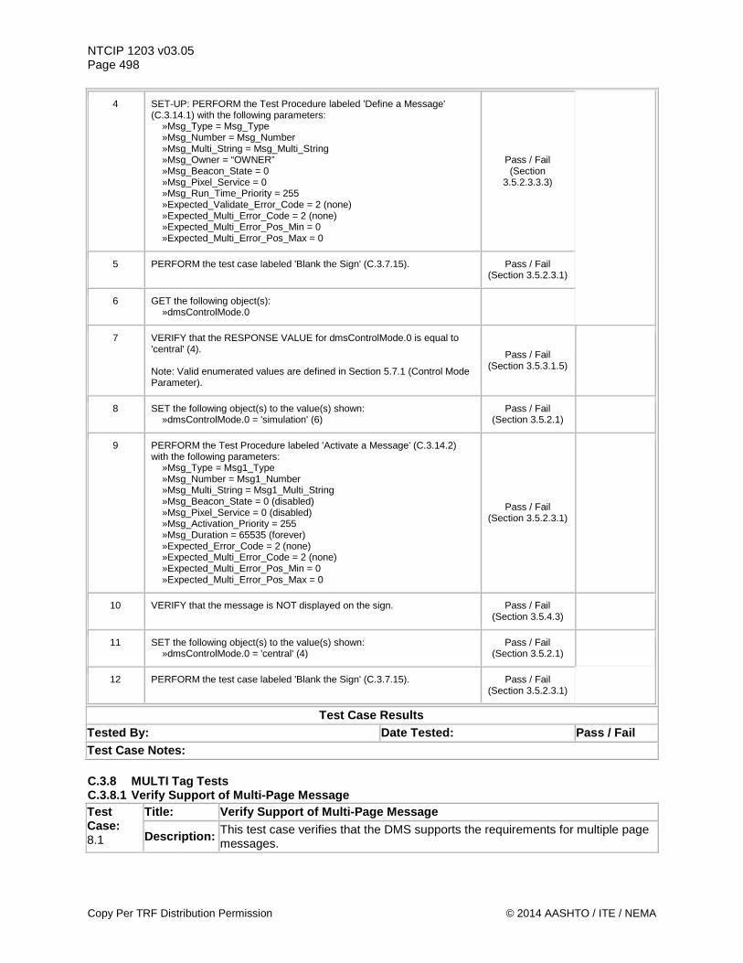
NTCIP 1203 v03.05 Page 498
4 SET-UP: PERFORM the Test Procedure labeled 'Define a Message' (C.3.14.1) with the following parameters: »Msg_Type = Msg_Type »Msg_Number = Msg_Number »Msg_Multi_String = Msg_Multi_String »Msg_Owner = “OWNER” »Msg_Beacon_State = 0 »Msg_Pixel_Service = 0 »Msg_Run_Time_Priority = 255 »Expected_Validate_Error_Code = 2 (none) »Expected_Multi_Error_Code = 2 (none) »Expected_Multi_Error_Pos_Min = 0 »Expected_Multi_Error_Pos_Max = 0
Pass / Fail (Section
3.5.2.3.3.3)
5 PERFORM the test case labeled 'Blank the Sign' (C.3.7.15). Pass / Fail (Section 3.5.2.3.1)
6 GET the following object(s): »dmsControlMode.0
7 VERIFY that the RESPONSE VALUE for dmsControlMode.0 is equal to 'central' (4). Note: Valid enumerated values are defined in Section 5.7.1 (Control Mode Parameter).
Pass / Fail (Section 3.5.3.1.5)
8 SET the following object(s) to the value(s) shown: »dmsControlMode.0 = 'simulation' (6)
Pass / Fail (Section 3.5.2.1)
9 PERFORM the Test Procedure labeled 'Activate a Message' (C.3.14.2) with the following parameters: »Msg_Type = Msg1_Type »Msg_Number = Msg1_Number »Msg_Multi_String = Msg1_Multi_String »Msg_Beacon_State = 0 (disabled) »Msg_Pixel_Service = 0 (disabled) »Msg_Activation_Priority = 255 »Msg_Duration = 65535 (forever) »Expected_Error_Code = 2 (none) »Expected_Multi_Error_Code = 2 (none) »Expected_Multi_Error_Pos_Min = 0 »Expected_Multi_Error_Pos_Max = 0
Pass / Fail (Section 3.5.2.3.1)
10 VERIFY that the message is NOT displayed on the sign. Pass / Fail (Section 3.5.4.3)
11 SET the following object(s) to the value(s) shown: »dmsControlMode.0 = 'central' (4)
Pass / Fail (Section 3.5.2.1)
12 PERFORM the test case labeled 'Blank the Sign' (C.3.7.15). Pass / Fail (Section 3.5.2.3.1)
Test Case Results Tested By: Date Tested: Pass / Fail Test Case Notes: C.3.8 MULTI Tag Tests C.3.8.1 Verify Support of Multi-Page Message Test Case: 8.1
Title: Verify Support of Multi-Page Message
Description: This test case verifies that the DMS supports the requirements for multiple page messages.
Copy Per TRF Distribution Permission © 2014 AASHTO / ITE / NEMA
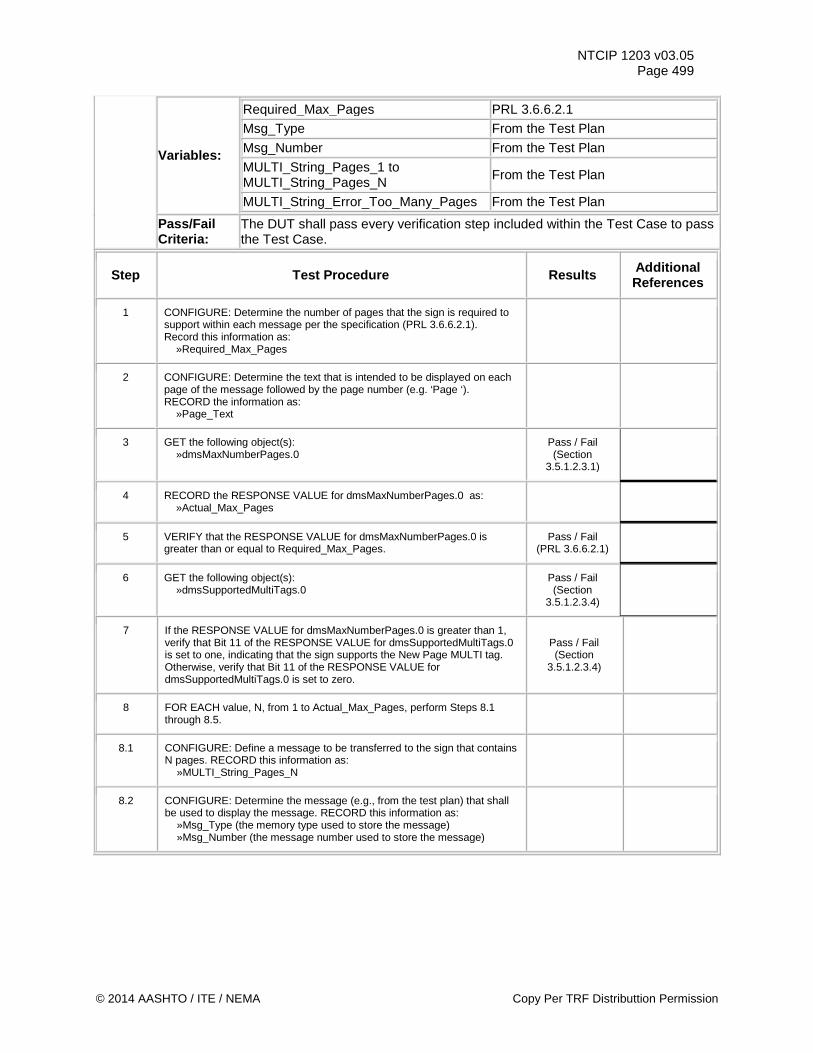
NTCIP 1203 v03.05 Page 499
Variables:
Required_Max_Pages PRL 3.6.6.2.1 Msg_Type From the Test Plan Msg_Number From the Test Plan MULTI_String_Pages_1 to MULTI_String_Pages_N From the Test Plan
MULTI_String_Error_Too_Many_Pages From the Test Plan
Pass/Fail Criteria:
The DUT shall pass every verification step included within the Test Case to pass the Test Case.
Step Test Procedure Results Additional References
1 CONFIGURE: Determine the number of pages that the sign is required to support within each message per the specification (PRL 3.6.6.2.1). Record this information as: »Required_Max_Pages
2 CONFIGURE: Determine the text that is intended to be displayed on each page of the message followed by the page number (e.g. ‘Page ‘). RECORD the information as: »Page_Text
3 GET the following object(s): »dmsMaxNumberPages.0
Pass / Fail (Section
3.5.1.2.3.1)
4 RECORD the RESPONSE VALUE for dmsMaxNumberPages.0 as: »Actual_Max_Pages
5 VERIFY that the RESPONSE VALUE for dmsMaxNumberPages.0 is greater than or equal to Required_Max_Pages.
Pass / Fail (PRL 3.6.6.2.1)
6 GET the following object(s): »dmsSupportedMultiTags.0
Pass / Fail (Section
3.5.1.2.3.4)
7 If the RESPONSE VALUE for dmsMaxNumberPages.0 is greater than 1, verify that Bit 11 of the RESPONSE VALUE for dmsSupportedMultiTags.0 is set to one, indicating that the sign supports the New Page MULTI tag. Otherwise, verify that Bit 11 of the RESPONSE VALUE for dmsSupportedMultiTags.0 is set to zero.
Pass / Fail (Section
3.5.1.2.3.4)
8 FOR EACH value, N, from 1 to Actual_Max_Pages, perform Steps 8.1 through 8.5.
8.1 CONFIGURE: Define a message to be transferred to the sign that contains N pages. RECORD this information as: »MULTI_String_Pages_N
8.2 CONFIGURE: Determine the message (e.g., from the test plan) that shall be used to display the message. RECORD this information as: »Msg_Type (the memory type used to store the message) »Msg_Number (the message number used to store the message)
© 2014 AASHTO / ITE / NEMA Copy Per TRF Distributtion Permission
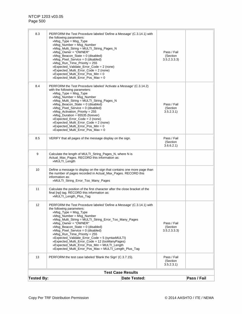
NTCIP 1203 v03.05 Page 500
8.3 PERFORM the Test Procedure labeled 'Define a Message' (C.3.14.1) with the following parameters: »Msg_Type = Msg_Type »Msg_Number = Msg_Number »Msg_Multi_String = MULTI_String_Pages_N »Msg_Owner = “OWNER” »Msg_Beacon_State = 0 (disabled) »Msg_Pixel_Service = 0 (disabled) »Msg_Run_Time_Priority = 255 »Expected_Validate_Error_Code = 2 (none) »Expected_Multi_Error_Code = 2 (none) »Expected_Multi_Error_Pos_Min = 0 »Expected_Multi_Error_Pos_Max = 0
Pass / Fail (Section
3.5.2.3.3.3)
8.4 PERFORM the Test Procedure labeled 'Activate a Message' (C.3.14.2) with the following parameters: »Msg_Type = Msg_Type »Msg_Number = Msg_Number »Msg_Multi_String = MULTI_String_Pages_N »Msg_Beacon_State = 0 (disabled) »Msg_Pixel_Service = 0 (disabled) »Msg_Activation_Priority = 255 »Msg_Duration = 65535 (forever) »Expected_Error_Code = 2 (none) »Expected_Multi_Error_Code = 2 (none) »Expected_Multi_Error_Pos_Min = 0 »Expected_Multi_Error_Pos_Max = 0
Pass / Fail (Section
3.5.2.3.1)
8.5 VERIFY that all pages of the message display on the sign. Pass / Fail (Section
3.6.6.2.1)
9 Calculate the length of MULTI_String_Pages_N, where N is Actual_Max_Pages. RECORD this information as: »MULTI_Length
10 Define a message to display on the sign that contains one more page than the number of pages recorded in Actual_Max_Pages. RECORD this information as: »MULTI_String_Error_Too_Many_Pages
11 Calculate the position of the first character after the close bracket of the final [np] tag. RECORD this information as: »MULTI_Length_Plus_Tag
12 PERFORM the Test Procedure labeled 'Define a Message' (C.3.14.1) with the following parameters: »Msg_Type = Msg_Type »Msg_Number = Msg_Number »Msg_Multi_String = MULTI_String_Error_Too_Many_Pages »Msg_Owner = “OWNER” »Msg_Beacon_State = 0 (disabled) »Msg_Pixel_Service = 0 (disabled) »Msg_Run_Time_Priority = 255 »Expected_Validate_Error_Code = 5 (syntaxMULTI) »Expected_Multi_Error_Code = 12 (tooManyPages) »Expected_Multi_Error_Pos_Min = MULTI_Length »Expected_Multi_Error_Pos_Max = MULTI_Length_Plus_Tag
Pass / Fail (Section
3.5.2.3.3.3)
13 PERFORM the test case labeled 'Blank the Sign' (C.3.7.15). Pass / Fail (Section
3.5.2.3.1)
Test Case Results Tested By: Date Tested: Pass / Fail
Copy Per TRF Distribution Permission © 2014 AASHTO / ITE / NEMA
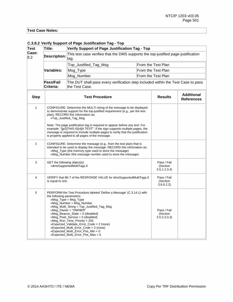
NTCIP 1203 v03.05 Page 501
Test Case Notes:
C.3.8.2 Verify Support of Page Justification Tag - Top Test Case: 8.2
Title: Verify Support of Page Justification Tag - Top
Description: This test case verifies that the DMS supports the top-justified page-justification tag.
Variables: Top_Justified_Tag_Msg From the Test Plan Msg_Type From the Test Plan
Msg_Number From the Test Plan
Pass/Fail Criteria:
The DUT shall pass every verification step included within the Test Case to pass the Test Case.
Step Test Procedure Results Additional References
1 CONFIGURE: Determine the MULTI string of the message to be displayed to demonstrate support for the top-justified requirement (e.g., per the test plan). RECORD this information as: »Top_Justified_Tag_Msg Note: The page justification tag is required to appear before any text. For example: "[jp2]THIS IS[nl]A TEST". If the sign supports multiple pages, the message is required to include multiple pages to verify that the justification is properly applied to all pages of the message.
2 CONFIGURE: Determine the message (e.g., from the test plan) that is intended to be used to display the message. RECORD this information as: »Msg_Type (the memory type used to store the message) »Msg_Number (the message number used to store the message)
3 GET the following object(s): »dmsSupportedMultiTags.0
Pass / Fail (Section
3.5.1.2.3.4)
4 VERIFY that Bit 7 of the RESPONSE VALUE for dmsSupportedMultiTags.0 is equal to one.
Pass / Fail (Section 3.6.6.2.2)
5 PERFORM the Test Procedure labeled 'Define a Message' (C.3.14.1) with the following parameters: »Msg_Type = Msg_Type »Msg_Number = Msg_Number »Msg_Multi_String = Top_Justified_Tag_Msg »Msg_Owner = “OWNER” »Msg_Beacon_State = 0 (disabled) »Msg_Pixel_Service = 0 (disabled) »Msg_Run_Time_Priority = 255 »Expected_Validate_Error_Code = 2 (none) »Expected_Multi_Error_Code = 2 (none) »Expected_Multi_Error_Pos_Min = 0 »Expected_Multi_Error_Pos_Max = 0
Pass / Fail (Section
3.5.2.3.3.3)
© 2014 AASHTO / ITE / NEMA Copy Per TRF Distributtion Permission
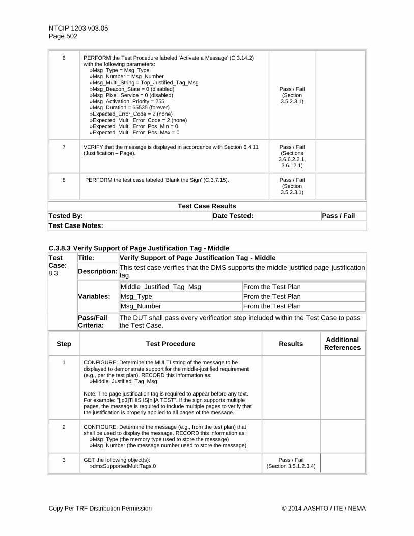
NTCIP 1203 v03.05 Page 502
6 PERFORM the Test Procedure labeled 'Activate a Message' (C.3.14.2) with the following parameters: »Msg_Type = Msg_Type »Msg_Number = Msg_Number »Msg_Multi_String = Top_Justified_Tag_Msg »Msg_Beacon_State = 0 (disabled) »Msg_Pixel_Service = 0 (disabled) »Msg_Activation_Priority = 255 »Msg_Duration = 65535 (forever) »Expected_Error_Code = 2 (none) »Expected_Multi_Error_Code = 2 (none) »Expected_Multi_Error_Pos_Min = 0 »Expected_Multi_Error_Pos_Max = 0
Pass / Fail (Section 3.5.2.3.1)
7 VERIFY that the message is displayed in accordance with Section 6.4.11 (Justification – Page).
Pass / Fail (Sections
3.6.6.2.2.1, 3.6.12.1)
8 PERFORM the test case labeled 'Blank the Sign' (C.3.7.15). Pass / Fail (Section 3.5.2.3.1)
Test Case Results Tested By: Date Tested: Pass / Fail Test Case Notes:
C.3.8.3 Verify Support of Page Justification Tag - Middle Test Case: 8.3
Title: Verify Support of Page Justification Tag - Middle
Description: This test case verifies that the DMS supports the middle-justified page-justification tag.
Variables: Middle_Justified_Tag_Msg From the Test Plan
Msg_Type From the Test Plan
Msg_Number From the Test Plan
Pass/Fail Criteria:
The DUT shall pass every verification step included within the Test Case to pass the Test Case.
Step Test Procedure Results Additional References
1 CONFIGURE: Determine the MULTI string of the message to be displayed to demonstrate support for the middle-justified requirement (e.g., per the test plan). RECORD this information as: »Middle_Justified_Tag_Msg Note: The page justification tag is required to appear before any text. For example: "[jp3]THIS IS[nl]A TEST". If the sign supports multiple pages, the message is required to include multiple pages to verify that the justification is properly applied to all pages of the message.
2 CONFIGURE: Determine the message (e.g., from the test plan) that shall be used to display the message. RECORD this information as: »Msg_Type (the memory type used to store the message) »Msg_Number (the message number used to store the message)
3 GET the following object(s): »dmsSupportedMultiTags.0
Pass / Fail (Section 3.5.1.2.3.4)
Copy Per TRF Distribution Permission © 2014 AASHTO / ITE / NEMA
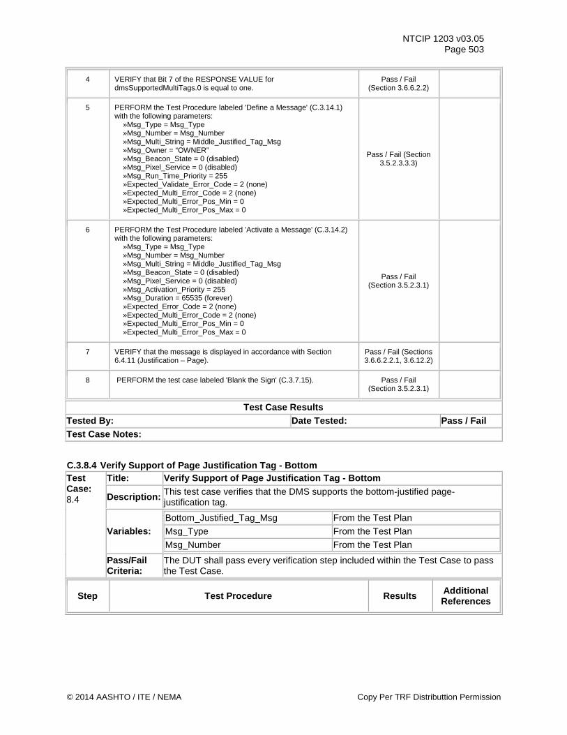
NTCIP 1203 v03.05 Page 503
4 VERIFY that Bit 7 of the RESPONSE VALUE for dmsSupportedMultiTags.0 is equal to one.
Pass / Fail (Section 3.6.6.2.2)
5 PERFORM the Test Procedure labeled 'Define a Message' (C.3.14.1) with the following parameters: »Msg_Type = Msg_Type »Msg_Number = Msg_Number »Msg_Multi_String = Middle_Justified_Tag_Msg »Msg_Owner = “OWNER” »Msg_Beacon_State = 0 (disabled) »Msg_Pixel_Service = 0 (disabled) »Msg_Run_Time_Priority = 255 »Expected_Validate_Error_Code = 2 (none) »Expected_Multi_Error_Code = 2 (none) »Expected_Multi_Error_Pos_Min = 0 »Expected_Multi_Error_Pos_Max = 0
Pass / Fail (Section 3.5.2.3.3.3)
6 PERFORM the Test Procedure labeled 'Activate a Message' (C.3.14.2) with the following parameters: »Msg_Type = Msg_Type »Msg_Number = Msg_Number »Msg_Multi_String = Middle_Justified_Tag_Msg »Msg_Beacon_State = 0 (disabled) »Msg_Pixel_Service = 0 (disabled) »Msg_Activation_Priority = 255 »Msg_Duration = 65535 (forever) »Expected_Error_Code = 2 (none) »Expected_Multi_Error_Code = 2 (none) »Expected_Multi_Error_Pos_Min = 0 »Expected_Multi_Error_Pos_Max = 0
Pass / Fail (Section 3.5.2.3.1)
7 VERIFY that the message is displayed in accordance with Section 6.4.11 (Justification – Page).
Pass / Fail (Sections 3.6.6.2.2.1, 3.6.12.2)
8 PERFORM the test case labeled 'Blank the Sign' (C.3.7.15). Pass / Fail (Section 3.5.2.3.1)
Test Case Results Tested By: Date Tested: Pass / Fail Test Case Notes:
C.3.8.4 Verify Support of Page Justification Tag - Bottom Test Case: 8.4
Title: Verify Support of Page Justification Tag - Bottom
Description: This test case verifies that the DMS supports the bottom-justified page-justification tag.
Variables: Bottom_Justified_Tag_Msg From the Test Plan
Msg_Type From the Test Plan
Msg_Number From the Test Plan
Pass/Fail Criteria:
The DUT shall pass every verification step included within the Test Case to pass the Test Case.
Step Test Procedure Results Additional References
© 2014 AASHTO / ITE / NEMA Copy Per TRF Distributtion Permission
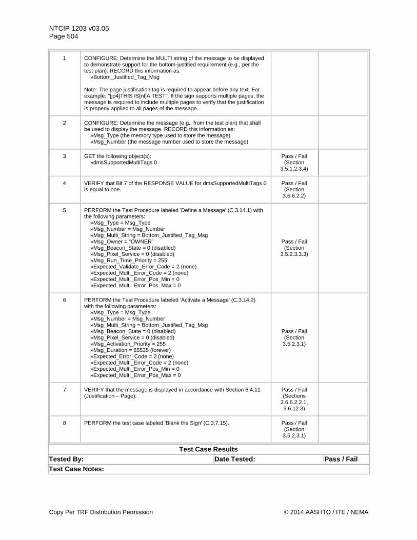
NTCIP 1203 v03.05 Page 504
1 CONFIGURE: Determine the MULTI string of the message to be displayed to demonstrate support for the bottom-justified requirement (e.g., per the test plan). RECORD this information as: »Bottom_Justified_Tag_Msg Note: The page justification tag is required to appear before any text. For example: "[jp4]THIS IS[nl]A TEST". If the sign supports multiple pages, the message is required to include multiple pages to verify that the justification is properly applied to all pages of the message.
2 CONFIGURE: Determine the message (e.g., from the test plan) that shall be used to display the message. RECORD this information as: »Msg_Type (the memory type used to store the message) »Msg_Number (the message number used to store the message)
3 GET the following object(s): »dmsSupportedMultiTags.0
Pass / Fail (Section
3.5.1.2.3.4)
4 VERIFY that Bit 7 of the RESPONSE VALUE for dmsSupportedMultiTags.0 is equal to one.
Pass / Fail (Section 3.6.6.2.2)
5 PERFORM the Test Procedure labeled 'Define a Message' (C.3.14.1) with the following parameters: »Msg_Type = Msg_Type »Msg_Number = Msg_Number »Msg_Multi_String = Bottom_Justified_Tag_Msg »Msg_Owner = “OWNER” »Msg_Beacon_State = 0 (disabled) »Msg_Pixel_Service = 0 (disabled) »Msg_Run_Time_Priority = 255 »Expected_Validate_Error_Code = 2 (none) »Expected_Multi_Error_Code = 2 (none) »Expected_Multi_Error_Pos_Min = 0 »Expected_Multi_Error_Pos_Max = 0
Pass / Fail (Section
3.5.2.3.3.3)
6 PERFORM the Test Procedure labeled 'Activate a Message' (C.3.14.2) with the following parameters: »Msg_Type = Msg_Type »Msg_Number = Msg_Number »Msg_Multi_String = Bottom_Justified_Tag_Msg »Msg_Beacon_State = 0 (disabled) »Msg_Pixel_Service = 0 (disabled) »Msg_Activation_Priority = 255 »Msg_Duration = 65535 (forever) »Expected_Error_Code = 2 (none) »Expected_Multi_Error_Code = 2 (none) »Expected_Multi_Error_Pos_Min = 0 »Expected_Multi_Error_Pos_Max = 0
Pass / Fail (Section 3.5.2.3.1)
7 VERIFY that the message is displayed in accordance with Section 6.4.11 (Justification – Page).
Pass / Fail (Sections
3.6.6.2.2.1, 3.6.12.3)
8 PERFORM the test case labeled 'Blank the Sign' (C.3.7.15). Pass / Fail (Section 3.5.2.3.1)
Test Case Results Tested By: Date Tested: Pass / Fail Test Case Notes:
Copy Per TRF Distribution Permission © 2014 AASHTO / ITE / NEMA
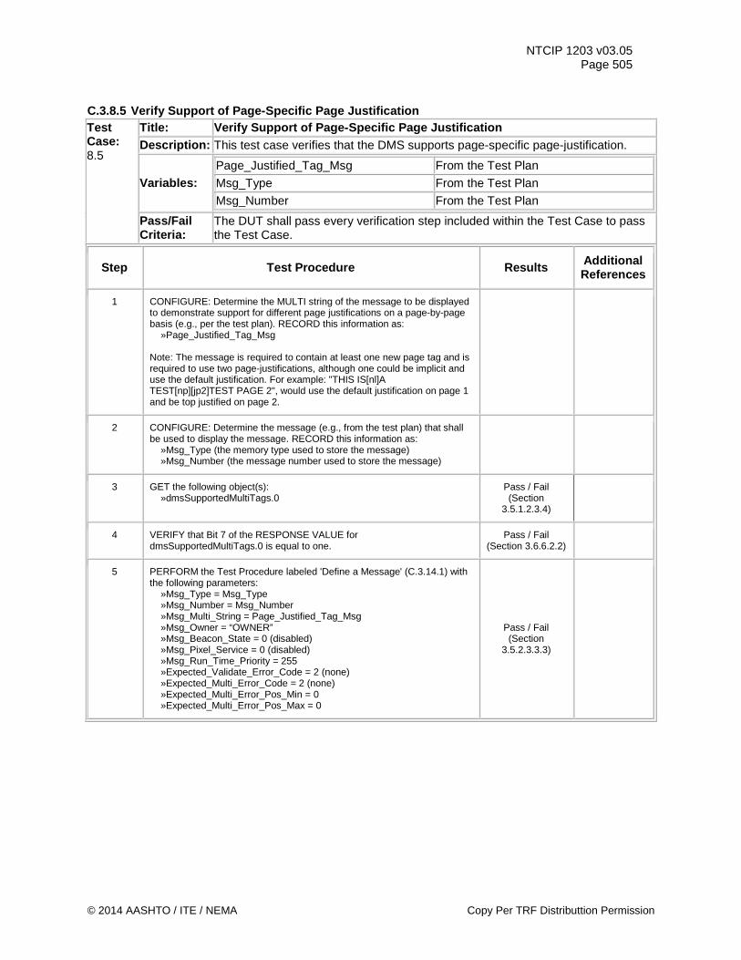
NTCIP 1203 v03.05 Page 505
C.3.8.5 Verify Support of Page-Specific Page Justification Test Case: 8.5
Title: Verify Support of Page-Specific Page Justification Description: This test case verifies that the DMS supports page-specific page-justification.
Variables: Page_Justified_Tag_Msg From the Test Plan
Msg_Type From the Test Plan
Msg_Number From the Test Plan
Pass/Fail Criteria:
The DUT shall pass every verification step included within the Test Case to pass the Test Case.
Step Test Procedure Results Additional References
1 CONFIGURE: Determine the MULTI string of the message to be displayed to demonstrate support for different page justifications on a page-by-page basis (e.g., per the test plan). RECORD this information as: »Page_Justified_Tag_Msg Note: The message is required to contain at least one new page tag and is required to use two page-justifications, although one could be implicit and use the default justification. For example: "THIS IS[nl]A TEST[np][jp2]TEST PAGE 2", would use the default justification on page 1 and be top justified on page 2.
2 CONFIGURE: Determine the message (e.g., from the test plan) that shall be used to display the message. RECORD this information as: »Msg_Type (the memory type used to store the message) »Msg_Number (the message number used to store the message)
3 GET the following object(s): »dmsSupportedMultiTags.0
Pass / Fail (Section
3.5.1.2.3.4)
4 VERIFY that Bit 7 of the RESPONSE VALUE for dmsSupportedMultiTags.0 is equal to one.
Pass / Fail (Section 3.6.6.2.2)
5 PERFORM the Test Procedure labeled 'Define a Message' (C.3.14.1) with the following parameters: »Msg_Type = Msg_Type »Msg_Number = Msg_Number »Msg_Multi_String = Page_Justified_Tag_Msg »Msg_Owner = “OWNER” »Msg_Beacon_State = 0 (disabled) »Msg_Pixel_Service = 0 (disabled) »Msg_Run_Time_Priority = 255 »Expected_Validate_Error_Code = 2 (none) »Expected_Multi_Error_Code = 2 (none) »Expected_Multi_Error_Pos_Min = 0 »Expected_Multi_Error_Pos_Max = 0
Pass / Fail (Section
3.5.2.3.3.3)
© 2014 AASHTO / ITE / NEMA Copy Per TRF Distributtion Permission
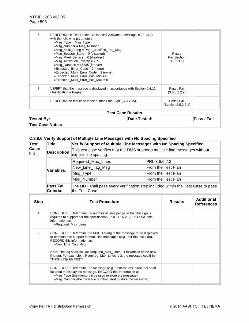
NTCIP 1203 v03.05 Page 506
6 PERFORM the Test Procedure labeled 'Activate a Message' (C.3.14.2) with the following parameters: »Msg_Type = Msg_Type »Msg_Number = Msg_Number »Msg_Multi_String = Page_Justified_Tag_Msg »Msg_Beacon_State = 0 (disabled) »Msg_Pixel_Service = 0 (disabled) »Msg_Activation_Priority = 255 »Msg_Duration = 65535 (forever) »Expected_Error_Code = 2 (none) »Expected_Multi_Error_Code = 2 (none) »Expected_Multi_Error_Pos_Min = 0 »Expected_Multi_Error_Pos_Max = 0
Pass / Fail(Section 3.5.2.3.1)
7 VERIFY that the message is displayed in accordance with Section 6.4.11 (Justification – Page).
Pass / Fail (3.6.6.2.2.2)
8 PERFORM the test case labeled 'Blank the Sign' (C.3.7.15). Pass / Fail (Section 3.5.2.3.1)
Test Case Results Tested By: Date Tested: Pass / Fail Test Case Notes:
C.3.8.6 Verify Support of Multiple Line Messages with No Spacing Specified Test Case: 8.6
Title: Verify Support of Multiple Line Messages with No Spacing Specified
Description: This test case verifies that the DMS supports multiple line messages without explicit line spacing.
Variables:
Required_Max_Lines PRL 3.6.6.2.3 New_Line_Tag_Msg From the Test Plan Msg_Type From the Test Plan Msg_Number From the Test Plan
Pass/Fail Criteria:
The DUT shall pass every verification step included within the Test Case to pass the Test Case.
Step Test Procedure Results Additional References
1 CONFIGURE: Determine the number of lines per page that the sign is required to support per the specification (PRL 3.6.6.2.3) RECORD this information as: »Required_Max_Lines
2 CONFIGURE: Determine the MULTI string of the message to be displayed to demonstrate support for multi-line messages (e.g., per the test plan). RECORD this information as: »New_Line_Tag_Msg Note: The tag shall include Required_Max_Lines - 1 instances of the new line tag. For example, if Required_Max_Lines is 3, the message could be "THIS[nl]IS[nl]A TEST".
3 CONFIGURE: Determine the message (e.g., from the test plan) that shall be used to display the message. RECORD this information as: »Msg_Type (the memory type used to store the message) »Msg_Number (the message number used to store the message)
Copy Per TRF Distribution Permission © 2014 AASHTO / ITE / NEMA
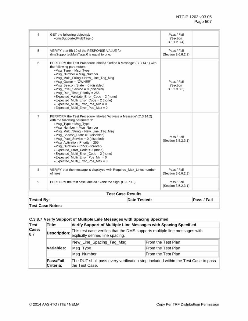
NTCIP 1203 v03.05 Page 507
4 GET the following object(s): »dmsSupportedMultiTags.0
Pass / Fail (Section
3.5.1.2.3.4)
5 VERIFY that Bit 10 of the RESPONSE VALUE for dmsSupportedMultiTags.0 is equal to one.
Pass / Fail (Section 3.6.6.2.3)
6 PERFORM the Test Procedure labeled 'Define a Message' (C.3.14.1) with the following parameters: »Msg_Type = Msg_Type »Msg_Number = Msg_Number »Msg_Multi_String = New_Line_Tag_Msg »Msg_Owner = “OWNER” »Msg_Beacon_State = 0 (disabled) »Msg_Pixel_Service = 0 (disabled) »Msg_Run_Time_Priority = 255 »Expected_Validate_Error_Code = 2 (none) »Expected_Multi_Error_Code = 2 (none) »Expected_Multi_Error_Pos_Min = 0 »Expected_Multi_Error_Pos_Max = 0
Pass / Fail (Section
3.5.2.3.3.3)
7 PERFORM the Test Procedure labeled 'Activate a Message' (C.3.14.2) with the following parameters: »Msg_Type = Msg_Type »Msg_Number = Msg_Number »Msg_Multi_String = New_Line_Tag_Msg »Msg_Beacon_State = 0 (disabled) »Msg_Pixel_Service = 0 (disabled) »Msg_Activation_Priority = 255 »Msg_Duration = 65535 (forever) »Expected_Error_Code = 2 (none) »Expected_Multi_Error_Code = 2 (none) »Expected_Multi_Error_Pos_Min = 0 »Expected_Multi_Error_Pos_Max = 0
Pass / Fail (Section 3.5.2.3.1)
8 VERIFY that the message is displayed with Required_Max_Lines number of lines.
Pass / Fail (Section 3.6.6.2.3)
9 PERFORM the test case labeled 'Blank the Sign' (C.3.7.15). Pass / Fail (Section 3.5.2.3.1)
Test Case Results Tested By: Date Tested: Pass / Fail Test Case Notes:
C.3.8.7 Verify Support of Multiple Line Messages with Spacing Specified Test Case: 8.7
Title: Verify Support of Multiple Line Messages with Spacing Specified
Description: This test case verifies that the DMS supports multiple line messages with explicitly defined line spacing.
Variables: New_Line_Spacing_Tag_Msg From the Test Plan
Msg_Type From the Test Plan
Msg_Number From the Test Plan
Pass/Fail Criteria:
The DUT shall pass every verification step included within the Test Case to pass the Test Case.
© 2014 AASHTO / ITE / NEMA Copy Per TRF Distributtion Permission
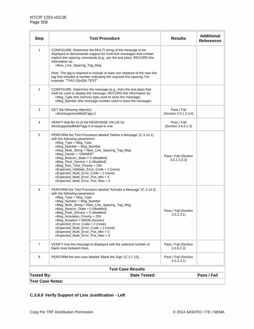
NTCIP 1203 v03.05 Page 508
Step Test Procedure Results Additional References
1 CONFIGURE: Determine the MULTI string of the message to be displayed to demonstrate support for multi-line messages that contain explicit line spacing commands (e.g., per the test plan). RECORD this information as: »New_Line_Spacing_Tag_Msg Note: The tag is required to include at least one instance of the new line tag that includes a number indicating the required line spacing. For example: "THIS IS[nl3]A TEST"
2 CONFIGURE: Determine the message (e.g., from the test plan) that shall be used to display the message. RECORD this information as: »Msg_Type (the memory type used to store the message) »Msg_Number (the message number used to store the message)
3 GET the following object(s): »dmsSupportedMultiTags.0
Pass / Fail (Section 3.5.1.2.3.4)
4 VERIFY that Bit 10 of the RESPONSE VALUE for dmsSupportedMultiTags.0 is equal to one.
Pass / Fail (Section 3.6.6.2.3)
5 PERFORM the Test Procedure labeled 'Define a Message' (C.3.14.1) with the following parameters: »Msg_Type = Msg_Type »Msg_Number = Msg_Number »Msg_Multi_String = New_Line_Spacing_Tag_Msg »Msg_Owner = “OWNER” »Msg_Beacon_State = 0 (disabled) »Msg_Pixel_Service = 0 (disabled) »Msg_Run_Time_Priority = 255 »Expected_Validate_Error_Code = 2 (none) »Expected_Multi_Error_Code = 2 (none) »Expected_Multi_Error_Pos_Min = 0 »Expected_Multi_Error_Pos_Max = 0
Pass / Fail (Section 3.5.2.3.3.3)
6 PERFORM the Test Procedure labeled 'Activate a Message' (C.3.14.2) with the following parameters: »Msg_Type = Msg_Type »Msg_Number = Msg_Number »Msg_Multi_String = New_Line_Spacing_Tag_Msg »Msg_Beacon_State = 0 (disabled) »Msg_Pixel_Service = 0 (disabled) »Msg_Activation_Priority = 255 »Msg_Duration = 65535 (forever) »Expected_Error_Code = 2 (none) »Expected_Multi_Error_Code = 2 (none) »Expected_Multi_Error_Pos_Min = 0 »Expected_Multi_Error_Pos_Max = 0
Pass / Fail (Section 3.5.2.3.1)
7 VERIFY that the message is displayed with the selected number of blank rows between lines.
Pass / Fail (Section 3.6.6.2.3)
8 PERFORM the test case labeled 'Blank the Sign' (C.3.7.15). Pass / Fail (Section 3.5.2.3.1)
Test Case Results Tested By: Date Tested: Pass / Fail Test Case Notes:
C.3.8.8 Verify Support of Line Justification - Left
Copy Per TRF Distribution Permission © 2014 AASHTO / ITE / NEMA
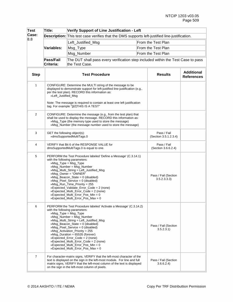
NTCIP 1203 v03.05 Page 509
Test Case: 8.8
Title: Verify Support of Line Justification - Left Description: This test case verifies that the DMS supports left-justified line-justification.
Variables: Left_Justified_Msg From the Test Plan
Msg_Type From the Test Plan
Msg_Number From the Test Plan
Pass/Fail Criteria:
The DUT shall pass every verification step included within the Test Case to pass the Test Case.
Step Test Procedure Results Additional References
1 CONFIGURE: Determine the MULTI string of the message to be displayed to demonstrate support for left-justified line-justification (e.g., per the test plan). RECORD this information as: »Left_Justified_Msg Note: The message is required to contain at least one left justification tag. For example "[jl2]THIS IS A TEST"
2 CONFIGURE: Determine the message (e.g., from the test plan) that shall be used to display the message. RECORD this information as: »Msg_Type (the memory type used to store the message) »Msg_Number (the message number used to store the message)
3 GET the following object(s): »dmsSupportedMultiTags.0
Pass / Fail (Section 3.5.1.2.3.4)
4 VERIFY that Bit 6 of the RESPONSE VALUE for dmsSupportedMultiTags.0 is equal to one.
Pass / Fail (Section 3.6.6.2.4)
5 PERFORM the Test Procedure labeled 'Define a Message' (C.3.14.1) with the following parameters: »Msg_Type = Msg_Type »Msg_Number = Msg_Number »Msg_Multi_String = Left_Justified_Msg »Msg_Owner = “OWNER” »Msg_Beacon_State = 0 (disabled) »Msg_Pixel_Service = 0 (disabled) »Msg_Run_Time_Priority = 255 »Expected_Validate_Error_Code = 2 (none) »Expected_Multi_Error_Code = 2 (none) »Expected_Multi_Error_Pos_Min = 0 »Expected_Multi_Error_Pos_Max = 0
Pass / Fail (Section 3.5.2.3.3.3)
6 PERFORM the Test Procedure labeled 'Activate a Message' (C.3.14.2) with the following parameters: »Msg_Type = Msg_Type »Msg_Number = Msg_Number »Msg_Multi_String = Left_Justified_Msg »Msg_Beacon_State = 0 (disabled) »Msg_Pixel_Service = 0 (disabled) »Msg_Activation_Priority = 255 »Msg_Duration = 65535 (forever) »Expected_Error_Code = 2 (none) »Expected_Multi_Error_Code = 2 (none) »Expected_Multi_Error_Pos_Min = 0 »Expected_Multi_Error_Pos_Max = 0
Pass / Fail (Section 3.5.2.3.1)
7 For character-matrix signs, VERIFY that the left-most character of the text is displayed on the sign in the left-most module. For line and full matrix signs, VERIFY that the left-most column of the text is displayed on the sign in the left-most column of pixels.
Pass / Fail (Section 3.6.6.2.4)
© 2014 AASHTO / ITE / NEMA Copy Per TRF Distributtion Permission
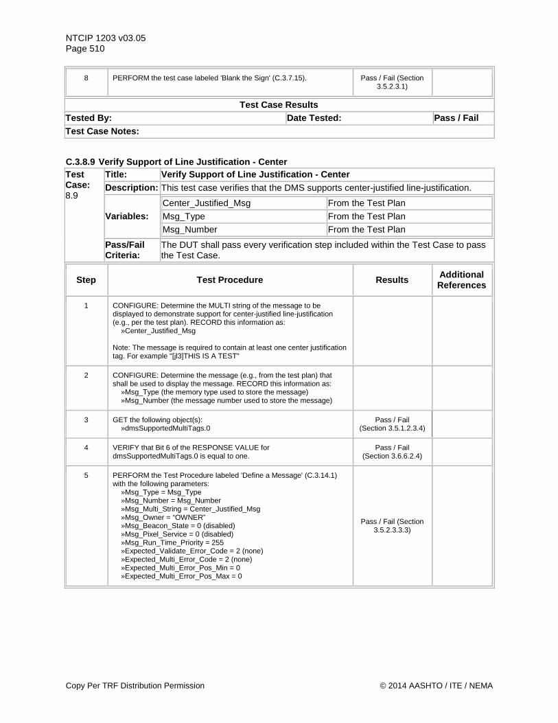
NTCIP 1203 v03.05 Page 510
8 PERFORM the test case labeled 'Blank the Sign' (C.3.7.15). Pass / Fail (Section 3.5.2.3.1)
Test Case Results Tested By: Date Tested: Pass / Fail Test Case Notes:
C.3.8.9 Verify Support of Line Justification - Center Test Case: 8.9
Title: Verify Support of Line Justification - Center Description: This test case verifies that the DMS supports center-justified line-justification.
Variables: Center_Justified_Msg From the Test Plan
Msg_Type From the Test Plan
Msg_Number From the Test Plan
Pass/Fail Criteria:
The DUT shall pass every verification step included within the Test Case to pass the Test Case.
Step Test Procedure Results Additional References
1 CONFIGURE: Determine the MULTI string of the message to be displayed to demonstrate support for center-justified line-justification (e.g., per the test plan). RECORD this information as: »Center_Justified_Msg Note: The message is required to contain at least one center justification tag. For example "[jl3]THIS IS A TEST"
2 CONFIGURE: Determine the message (e.g., from the test plan) that shall be used to display the message. RECORD this information as: »Msg_Type (the memory type used to store the message) »Msg_Number (the message number used to store the message)
3 GET the following object(s): »dmsSupportedMultiTags.0
Pass / Fail (Section 3.5.1.2.3.4)
4 VERIFY that Bit 6 of the RESPONSE VALUE for dmsSupportedMultiTags.0 is equal to one.
Pass / Fail (Section 3.6.6.2.4)
5 PERFORM the Test Procedure labeled 'Define a Message' (C.3.14.1) with the following parameters: »Msg_Type = Msg_Type »Msg_Number = Msg_Number »Msg_Multi_String = Center_Justified_Msg »Msg_Owner = “OWNER” »Msg_Beacon_State = 0 (disabled) »Msg_Pixel_Service = 0 (disabled) »Msg_Run_Time_Priority = 255 »Expected_Validate_Error_Code = 2 (none) »Expected_Multi_Error_Code = 2 (none) »Expected_Multi_Error_Pos_Min = 0 »Expected_Multi_Error_Pos_Max = 0
Pass / Fail (Section 3.5.2.3.3.3)
Copy Per TRF Distribution Permission © 2014 AASHTO / ITE / NEMA
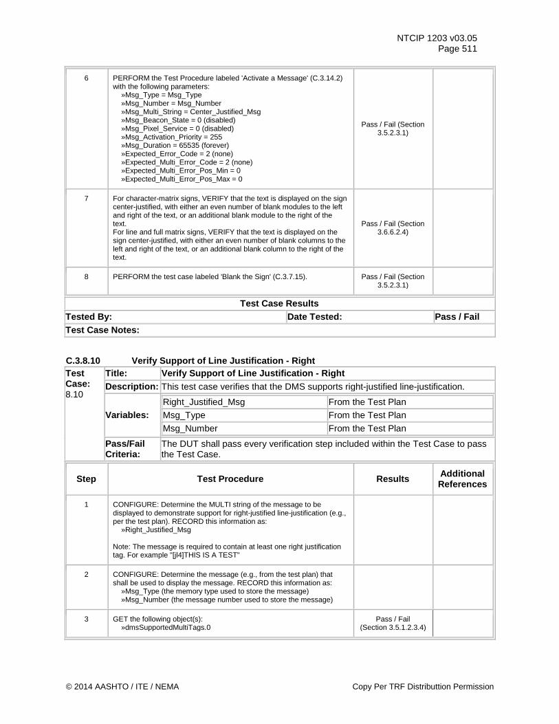
NTCIP 1203 v03.05 Page 511
6 PERFORM the Test Procedure labeled 'Activate a Message' (C.3.14.2) with the following parameters: »Msg_Type = Msg_Type »Msg_Number = Msg_Number »Msg_Multi_String = Center_Justified_Msg »Msg_Beacon_State = 0 (disabled) »Msg_Pixel_Service = 0 (disabled) »Msg_Activation_Priority = 255 »Msg_Duration = 65535 (forever) »Expected_Error_Code = 2 (none) »Expected_Multi_Error_Code = 2 (none) »Expected_Multi_Error_Pos_Min = 0 »Expected_Multi_Error_Pos_Max = 0
Pass / Fail (Section 3.5.2.3.1)
7 For character-matrix signs, VERIFY that the text is displayed on the sign center-justified, with either an even number of blank modules to the left and right of the text, or an additional blank module to the right of the text. For line and full matrix signs, VERIFY that the text is displayed on the sign center-justified, with either an even number of blank columns to the left and right of the text, or an additional blank column to the right of the text.
Pass / Fail (Section 3.6.6.2.4)
8 PERFORM the test case labeled 'Blank the Sign' (C.3.7.15). Pass / Fail (Section 3.5.2.3.1)
Test Case Results Tested By: Date Tested: Pass / Fail Test Case Notes:
C.3.8.10 Verify Support of Line Justification - Right Test Case: 8.10
Title: Verify Support of Line Justification - Right Description: This test case verifies that the DMS supports right-justified line-justification.
Variables: Right_Justified_Msg From the Test Plan
Msg_Type From the Test Plan
Msg_Number From the Test Plan
Pass/Fail Criteria:
The DUT shall pass every verification step included within the Test Case to pass the Test Case.
Step Test Procedure Results Additional References
1 CONFIGURE: Determine the MULTI string of the message to be displayed to demonstrate support for right-justified line-justification (e.g., per the test plan). RECORD this information as: »Right_Justified_Msg Note: The message is required to contain at least one right justification tag. For example "[jl4]THIS IS A TEST"
2 CONFIGURE: Determine the message (e.g., from the test plan) that shall be used to display the message. RECORD this information as: »Msg_Type (the memory type used to store the message) »Msg_Number (the message number used to store the message)
3 GET the following object(s): »dmsSupportedMultiTags.0
Pass / Fail (Section 3.5.1.2.3.4)
© 2014 AASHTO / ITE / NEMA Copy Per TRF Distributtion Permission
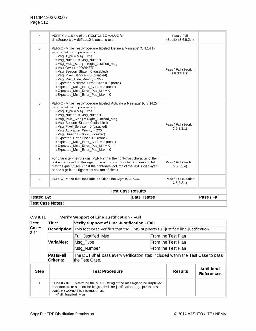
NTCIP 1203 v03.05 Page 512
4 VERIFY that Bit 6 of the RESPONSE VALUE for dmsSupportedMultiTags.0 is equal to one.
Pass / Fail (Section 3.6.6.2.4)
5 PERFORM the Test Procedure labeled 'Define a Message' (C.3.14.1) with the following parameters: »Msg_Type = Msg_Type »Msg_Number = Msg_Number »Msg_Multi_String = Right_Justified_Msg »Msg_Owner = “OWNER” »Msg_Beacon_State = 0 (disabled) »Msg_Pixel_Service = 0 (disabled) »Msg_Run_Time_Priority = 255 »Expected_Validate_Error_Code = 2 (none) »Expected_Multi_Error_Code = 2 (none) »Expected_Multi_Error_Pos_Min = 0 »Expected_Multi_Error_Pos_Max = 0
Pass / Fail (Section 3.5.2.3.3.3)
6 PERFORM the Test Procedure labeled 'Activate a Message' (C.3.14.2) with the following parameters: »Msg_Type = Msg_Type »Msg_Number = Msg_Number »Msg_Multi_String = Right_Justified_Msg »Msg_Beacon_State = 0 (disabled) »Msg_Pixel_Service = 0 (disabled) »Msg_Activation_Priority = 255 »Msg_Duration = 65535 (forever) »Expected_Error_Code = 2 (none) »Expected_Multi_Error_Code = 2 (none) »Expected_Multi_Error_Pos_Min = 0 »Expected_Multi_Error_Pos_Max = 0
Pass / Fail (Section 3.5.2.3.1)
7 For character-matrix signs, VERIFY that the right-most character of the text is displayed on the sign in the right-most module. For line and full matrix signs, VERIFY that the right-most column of the text is displayed on the sign in the right-most column of pixels.
Pass / Fail (Section 3.6.6.2.4)
8 PERFORM the test case labeled 'Blank the Sign' (C.3.7.15). Pass / Fail (Section 3.5.2.3.1)
Test Case Results Tested By: Date Tested: Pass / Fail Test Case Notes:
C.3.8.11 Verify Support of Line Justification - Full Test Case: 8.11
Title: Verify Support of Line Justification - Full Description: This test case verifies that the DMS supports full-justified line-justification.
Variables: Full_Justified_Msg From the Test Plan
Msg_Type From the Test Plan
Msg_Number From the Test Plan
Pass/Fail Criteria:
The DUT shall pass every verification step included within the Test Case to pass the Test Case.
Step Test Procedure Results Additional References
1 CONFIGURE: Determine the MULTI string of the message to be displayed to demonstrate support for full-justified line-justification (e.g., per the test plan). RECORD this information as: »Full_Justified_Msg
Copy Per TRF Distribution Permission © 2014 AASHTO / ITE / NEMA
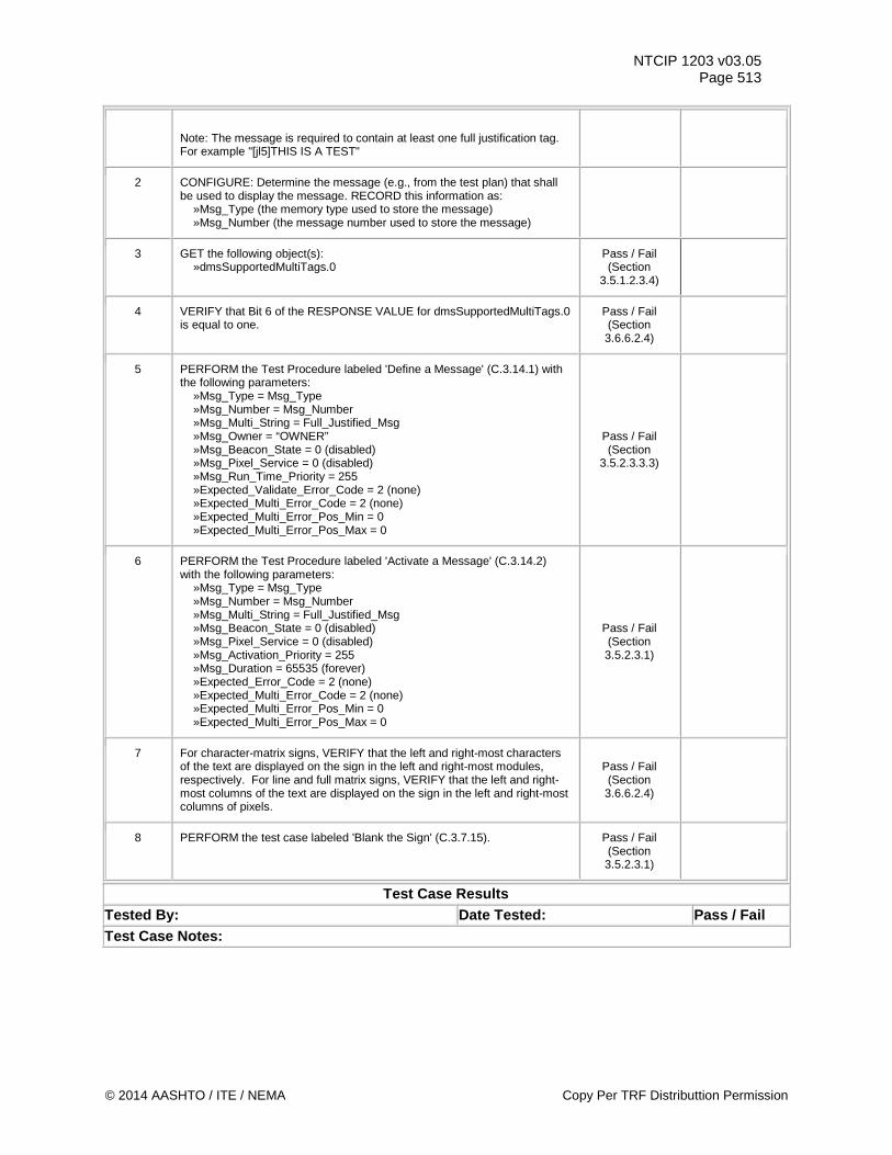
NTCIP 1203 v03.05 Page 513
Note: The message is required to contain at least one full justification tag. For example "[jl5]THIS IS A TEST"
2 CONFIGURE: Determine the message (e.g., from the test plan) that shall be used to display the message. RECORD this information as: »Msg_Type (the memory type used to store the message) »Msg_Number (the message number used to store the message)
3 GET the following object(s): »dmsSupportedMultiTags.0
Pass / Fail (Section
3.5.1.2.3.4)
4 VERIFY that Bit 6 of the RESPONSE VALUE for dmsSupportedMultiTags.0 is equal to one.
Pass / Fail (Section 3.6.6.2.4)
5 PERFORM the Test Procedure labeled 'Define a Message' (C.3.14.1) with the following parameters: »Msg_Type = Msg_Type »Msg_Number = Msg_Number »Msg_Multi_String = Full_Justified_Msg »Msg_Owner = “OWNER” »Msg_Beacon_State = 0 (disabled) »Msg_Pixel_Service = 0 (disabled) »Msg_Run_Time_Priority = 255 »Expected_Validate_Error_Code = 2 (none) »Expected_Multi_Error_Code = 2 (none) »Expected_Multi_Error_Pos_Min = 0 »Expected_Multi_Error_Pos_Max = 0
Pass / Fail (Section
3.5.2.3.3.3)
6 PERFORM the Test Procedure labeled 'Activate a Message' (C.3.14.2) with the following parameters: »Msg_Type = Msg_Type »Msg_Number = Msg_Number »Msg_Multi_String = Full_Justified_Msg »Msg_Beacon_State = 0 (disabled) »Msg_Pixel_Service = 0 (disabled) »Msg_Activation_Priority = 255 »Msg_Duration = 65535 (forever) »Expected_Error_Code = 2 (none) »Expected_Multi_Error_Code = 2 (none) »Expected_Multi_Error_Pos_Min = 0 »Expected_Multi_Error_Pos_Max = 0
Pass / Fail (Section 3.5.2.3.1)
7 For character-matrix signs, VERIFY that the left and right-most characters of the text are displayed on the sign in the left and right-most modules, respectively. For line and full matrix signs, VERIFY that the left and right-most columns of the text are displayed on the sign in the left and right-most columns of pixels.
Pass / Fail (Section 3.6.6.2.4)
8 PERFORM the test case labeled 'Blank the Sign' (C.3.7.15). Pass / Fail (Section 3.5.2.3.1)
Test Case Results Tested By: Date Tested: Pass / Fail Test Case Notes:
© 2014 AASHTO / ITE / NEMA Copy Per TRF Distributtion Permission
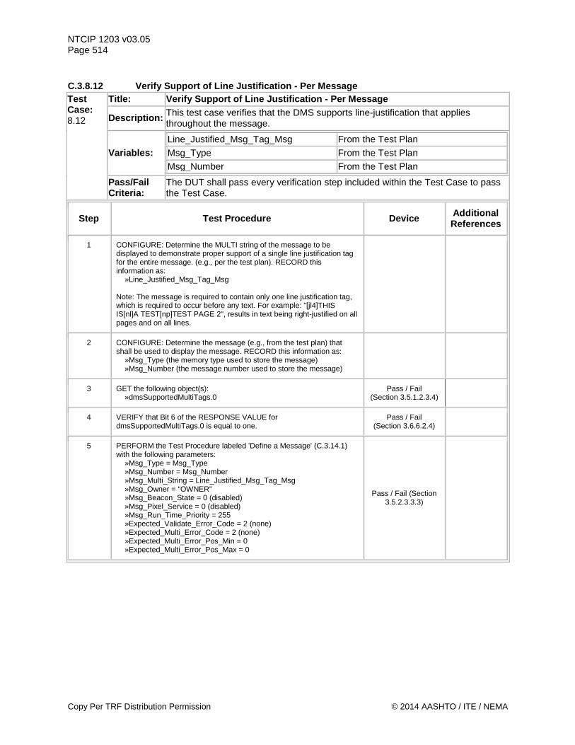
NTCIP 1203 v03.05 Page 514 C.3.8.12 Verify Support of Line Justification - Per Message Test Case: 8.12
Title: Verify Support of Line Justification - Per Message
Description: This test case verifies that the DMS supports line-justification that applies throughout the message.
Variables: Line_Justified_Msg_Tag_Msg From the Test Plan
Msg_Type From the Test Plan
Msg_Number From the Test Plan
Pass/Fail Criteria:
The DUT shall pass every verification step included within the Test Case to pass the Test Case.
Step Test Procedure Device Additional References
1 CONFIGURE: Determine the MULTI string of the message to be displayed to demonstrate proper support of a single line justification tag for the entire message. (e.g., per the test plan). RECORD this information as: »Line_Justified_Msg_Tag_Msg Note: The message is required to contain only one line justification tag, which is required to occur before any text. For example: "[jl4]THIS IS[nl]A TEST[np]TEST PAGE 2", results in text being right-justified on all pages and on all lines.
2 CONFIGURE: Determine the message (e.g., from the test plan) that shall be used to display the message. RECORD this information as: »Msg_Type (the memory type used to store the message) »Msg_Number (the message number used to store the message)
3 GET the following object(s): »dmsSupportedMultiTags.0
Pass / Fail (Section 3.5.1.2.3.4)
4 VERIFY that Bit 6 of the RESPONSE VALUE for dmsSupportedMultiTags.0 is equal to one.
Pass / Fail (Section 3.6.6.2.4)
5 PERFORM the Test Procedure labeled 'Define a Message' (C.3.14.1) with the following parameters: »Msg_Type = Msg_Type »Msg_Number = Msg_Number »Msg_Multi_String = Line_Justified_Msg_Tag_Msg »Msg_Owner = “OWNER” »Msg_Beacon_State = 0 (disabled) »Msg_Pixel_Service = 0 (disabled) »Msg_Run_Time_Priority = 255 »Expected_Validate_Error_Code = 2 (none) »Expected_Multi_Error_Code = 2 (none) »Expected_Multi_Error_Pos_Min = 0 »Expected_Multi_Error_Pos_Max = 0
Pass / Fail (Section 3.5.2.3.3.3)
Copy Per TRF Distribution Permission © 2014 AASHTO / ITE / NEMA
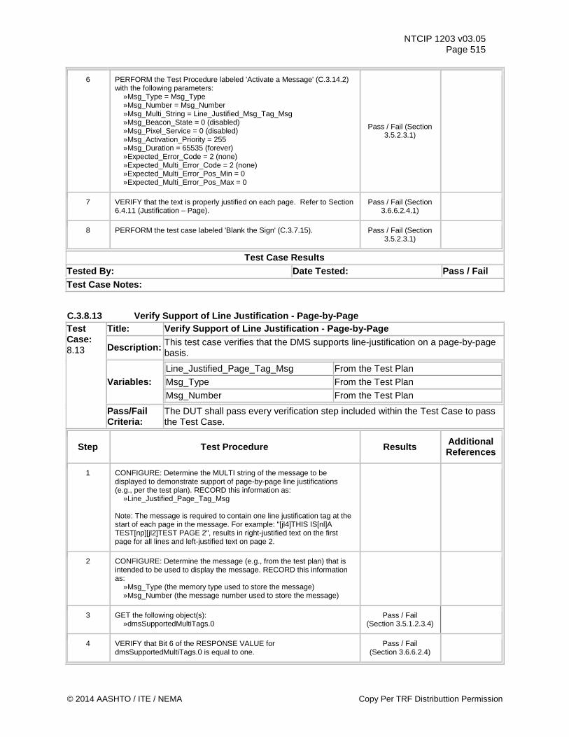
NTCIP 1203 v03.05 Page 515
6 PERFORM the Test Procedure labeled 'Activate a Message' (C.3.14.2) with the following parameters: »Msg_Type = Msg_Type »Msg_Number = Msg_Number »Msg_Multi_String = Line_Justified_Msg_Tag_Msg »Msg_Beacon_State = 0 (disabled) »Msg_Pixel_Service = 0 (disabled) »Msg_Activation_Priority = 255 »Msg_Duration = 65535 (forever) »Expected_Error_Code = 2 (none) »Expected_Multi_Error_Code = 2 (none) »Expected_Multi_Error_Pos_Min = 0 »Expected_Multi_Error_Pos_Max = 0
Pass / Fail (Section 3.5.2.3.1)
7 VERIFY that the text is properly justified on each page. Refer to Section 6.4.11 (Justification – Page).
Pass / Fail (Section 3.6.6.2.4.1)
8 PERFORM the test case labeled 'Blank the Sign' (C.3.7.15). Pass / Fail (Section 3.5.2.3.1)
Test Case Results Tested By: Date Tested: Pass / Fail Test Case Notes:
C.3.8.13 Verify Support of Line Justification - Page-by-Page Test Case: 8.13
Title: Verify Support of Line Justification - Page-by-Page
Description: This test case verifies that the DMS supports line-justification on a page-by-page basis.
Variables: Line_Justified_Page_Tag_Msg From the Test Plan
Msg_Type From the Test Plan
Msg_Number From the Test Plan
Pass/Fail Criteria:
The DUT shall pass every verification step included within the Test Case to pass the Test Case.
Step Test Procedure Results Additional References
1 CONFIGURE: Determine the MULTI string of the message to be displayed to demonstrate support of page-by-page line justifications (e.g., per the test plan). RECORD this information as: »Line_Justified_Page_Tag_Msg Note: The message is required to contain one line justification tag at the start of each page in the message. For example: "[jl4]THIS IS[nl]A TEST[np][jl2]TEST PAGE 2", results in right-justified text on the first page for all lines and left-justified text on page 2.
2 CONFIGURE: Determine the message (e.g., from the test plan) that is intended to be used to display the message. RECORD this information as: »Msg_Type (the memory type used to store the message) »Msg_Number (the message number used to store the message)
3 GET the following object(s): »dmsSupportedMultiTags.0
Pass / Fail (Section 3.5.1.2.3.4)
4 VERIFY that Bit 6 of the RESPONSE VALUE for dmsSupportedMultiTags.0 is equal to one.
Pass / Fail (Section 3.6.6.2.4)
© 2014 AASHTO / ITE / NEMA Copy Per TRF Distributtion Permission
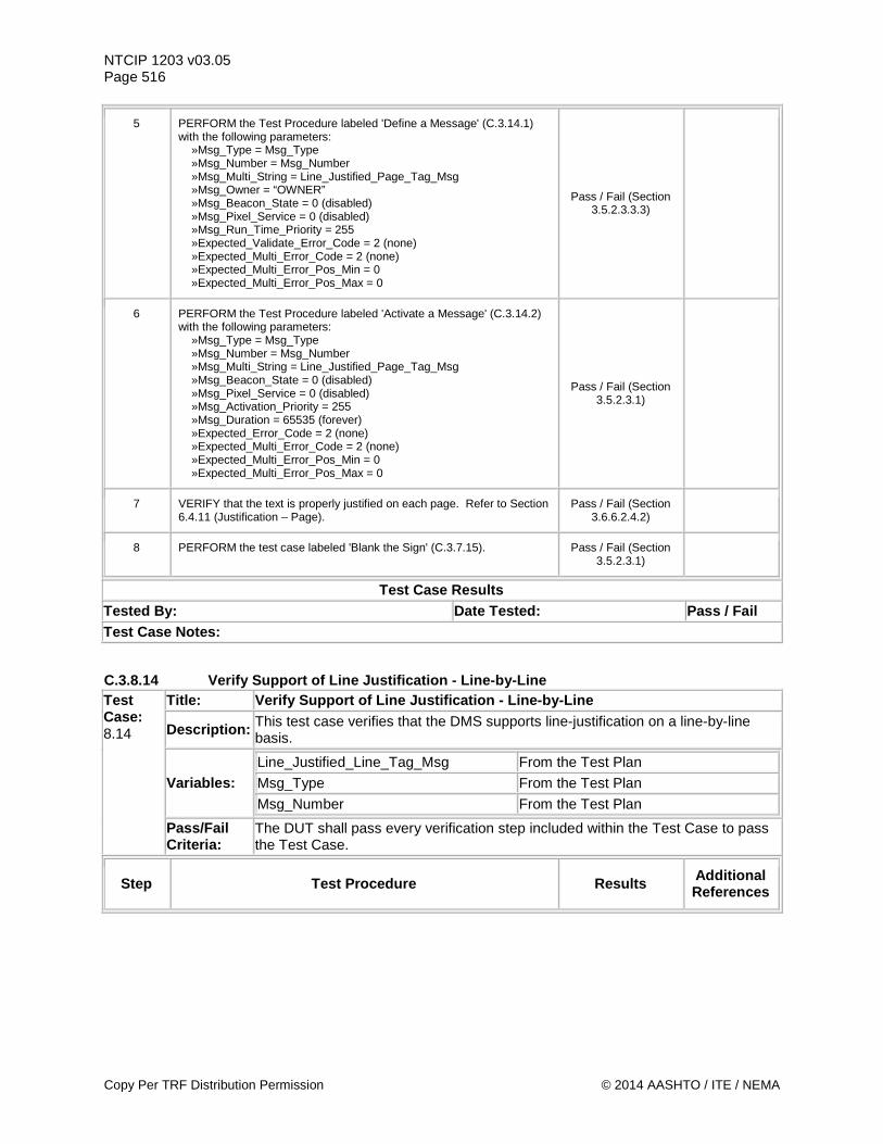
NTCIP 1203 v03.05 Page 516
5 PERFORM the Test Procedure labeled 'Define a Message' (C.3.14.1) with the following parameters: »Msg_Type = Msg_Type »Msg_Number = Msg_Number »Msg_Multi_String = Line_Justified_Page_Tag_Msg »Msg_Owner = “OWNER” »Msg_Beacon_State = 0 (disabled) »Msg_Pixel_Service = 0 (disabled) »Msg_Run_Time_Priority = 255 »Expected_Validate_Error_Code = 2 (none) »Expected_Multi_Error_Code = 2 (none) »Expected_Multi_Error_Pos_Min = 0 »Expected_Multi_Error_Pos_Max = 0
Pass / Fail (Section 3.5.2.3.3.3)
6 PERFORM the Test Procedure labeled 'Activate a Message' (C.3.14.2) with the following parameters: »Msg_Type = Msg_Type »Msg_Number = Msg_Number »Msg_Multi_String = Line_Justified_Page_Tag_Msg »Msg_Beacon_State = 0 (disabled) »Msg_Pixel_Service = 0 (disabled) »Msg_Activation_Priority = 255 »Msg_Duration = 65535 (forever) »Expected_Error_Code = 2 (none) »Expected_Multi_Error_Code = 2 (none) »Expected_Multi_Error_Pos_Min = 0 »Expected_Multi_Error_Pos_Max = 0
Pass / Fail (Section 3.5.2.3.1)
7 VERIFY that the text is properly justified on each page. Refer to Section 6.4.11 (Justification – Page).
Pass / Fail (Section 3.6.6.2.4.2)
8 PERFORM the test case labeled 'Blank the Sign' (C.3.7.15). Pass / Fail (Section 3.5.2.3.1)
Test Case Results Tested By: Date Tested: Pass / Fail Test Case Notes:
C.3.8.14 Verify Support of Line Justification - Line-by-Line Test Case: 8.14
Title: Verify Support of Line Justification - Line-by-Line
Description: This test case verifies that the DMS supports line-justification on a line-by-line basis.
Variables: Line_Justified_Line_Tag_Msg From the Test Plan
Msg_Type From the Test Plan
Msg_Number From the Test Plan
Pass/Fail Criteria:
The DUT shall pass every verification step included within the Test Case to pass the Test Case.
Step Test Procedure Results Additional References
Copy Per TRF Distribution Permission © 2014 AASHTO / ITE / NEMA
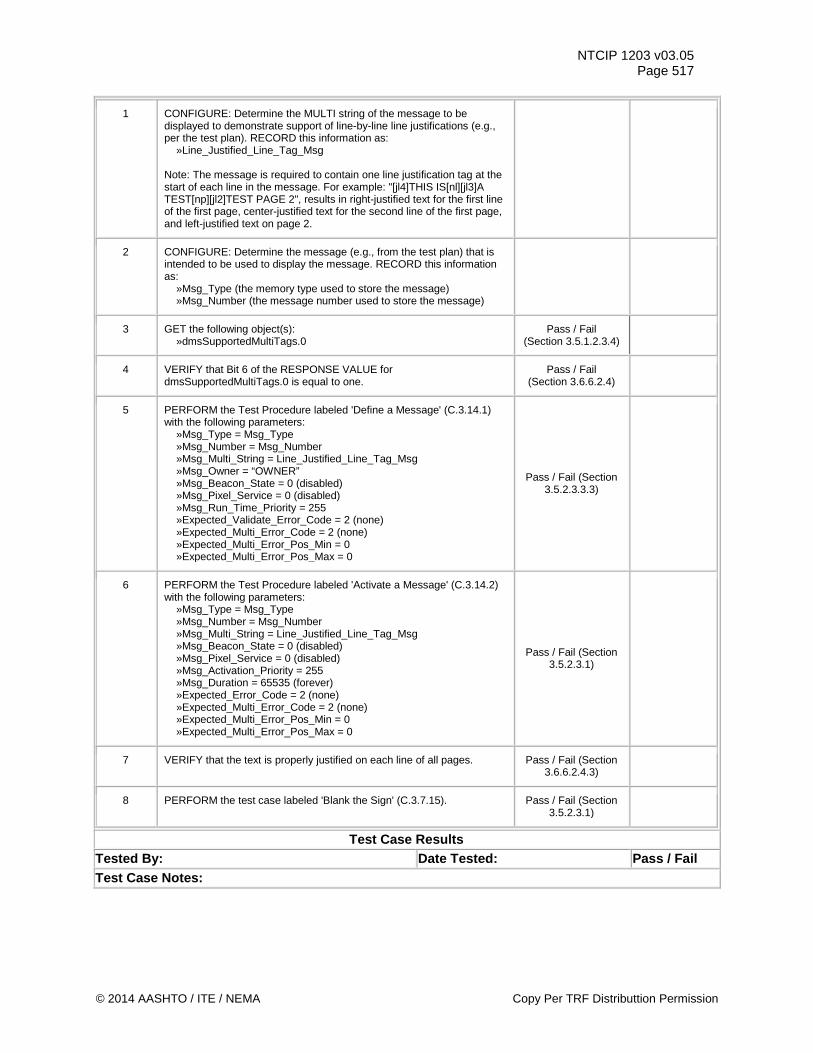
NTCIP 1203 v03.05 Page 517
1 CONFIGURE: Determine the MULTI string of the message to be displayed to demonstrate support of line-by-line line justifications (e.g., per the test plan). RECORD this information as: »Line_Justified_Line_Tag_Msg Note: The message is required to contain one line justification tag at the start of each line in the message. For example: "[jl4]THIS IS[nl][jl3]A TEST[np][jl2]TEST PAGE 2", results in right-justified text for the first line of the first page, center-justified text for the second line of the first page, and left-justified text on page 2.
2 CONFIGURE: Determine the message (e.g., from the test plan) that is intended to be used to display the message. RECORD this information as: »Msg_Type (the memory type used to store the message) »Msg_Number (the message number used to store the message)
3 GET the following object(s): »dmsSupportedMultiTags.0
Pass / Fail (Section 3.5.1.2.3.4)
4 VERIFY that Bit 6 of the RESPONSE VALUE for dmsSupportedMultiTags.0 is equal to one.
Pass / Fail (Section 3.6.6.2.4)
5 PERFORM the Test Procedure labeled 'Define a Message' (C.3.14.1) with the following parameters: »Msg_Type = Msg_Type »Msg_Number = Msg_Number »Msg_Multi_String = Line_Justified_Line_Tag_Msg »Msg_Owner = “OWNER” »Msg_Beacon_State = 0 (disabled) »Msg_Pixel_Service = 0 (disabled) »Msg_Run_Time_Priority = 255 »Expected_Validate_Error_Code = 2 (none) »Expected_Multi_Error_Code = 2 (none) »Expected_Multi_Error_Pos_Min = 0 »Expected_Multi_Error_Pos_Max = 0
Pass / Fail (Section 3.5.2.3.3.3)
6 PERFORM the Test Procedure labeled 'Activate a Message' (C.3.14.2) with the following parameters: »Msg_Type = Msg_Type »Msg_Number = Msg_Number »Msg_Multi_String = Line_Justified_Line_Tag_Msg »Msg_Beacon_State = 0 (disabled) »Msg_Pixel_Service = 0 (disabled) »Msg_Activation_Priority = 255 »Msg_Duration = 65535 (forever) »Expected_Error_Code = 2 (none) »Expected_Multi_Error_Code = 2 (none) »Expected_Multi_Error_Pos_Min = 0 »Expected_Multi_Error_Pos_Max = 0
Pass / Fail (Section 3.5.2.3.1)
7 VERIFY that the text is properly justified on each line of all pages. Pass / Fail (Section 3.6.6.2.4.3)
8 PERFORM the test case labeled 'Blank the Sign' (C.3.7.15). Pass / Fail (Section 3.5.2.3.1)
Test Case Results Tested By: Date Tested: Pass / Fail Test Case Notes:
© 2014 AASHTO / ITE / NEMA Copy Per TRF Distributtion Permission
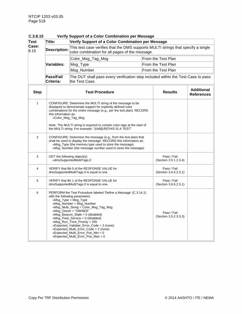
NTCIP 1203 v03.05 Page 518 C.3.8.15 Verify Support of a Color Combination per Message Test Case: 8.15
Title: Verify Support of a Color Combination per Message
Description: This test case verifies that the DMS supports MULTI strings that specify a single color combination for all pages of the message.
Variables: Color_Msg_Tag_Msg From the Test Plan Msg_Type From the Test Plan Msg_Number From the Test Plan
Pass/Fail Criteria:
The DUT shall pass every verification step included within the Test Case to pass the Test Case.
Step Test Procedure Results Additional References
1 CONFIGURE: Determine the MULTI string of the message to be displayed to demonstrate support for explicitly defined color combinations for the entire message (e.g., per the test plan). RECORD this information as: »Color_Msg_Tag_Msg Note: The MULTI string is required to contain color tags at the start of the MULTI string. For example: "[cb9][cf0]THIS IS A TEST"
2 CONFIGURE: Determine the message (e.g., from the test plan) that shall be used to display the message. RECORD this information as: »Msg_Type (the memory type used to store the message) »Msg_Number (the message number used to store the message)
3 GET the following object(s): »dmsSupportedMultiTags.0
Pass / Fail (Section 3.5.1.2.3.4)
4 VERIFY that Bit 0 of the RESPONSE VALUE for dmsSupportedMultiTags.0 is equal to one.
Pass / Fail (Section 3.6.6.2.5.1)
5 VERIFY that Bit 1 of the RESPONSE VALUE for dmsSupportedMultiTags.0 is equal to one.
Pass / Fail (Section 3.6.6.2.5.1)
6 PERFORM the Test Procedure labeled 'Define a Message' (C.3.14.1) with the following parameters: »Msg_Type = Msg_Type »Msg_Number = Msg_Number »Msg_Multi_String = Color_Msg_Tag_Msg »Msg_Owner = “OWNER” »Msg_Beacon_State = 0 (disabled) »Msg_Pixel_Service = 0 (disabled) »Msg_Run_Time_Priority = 255 »Expected_Validate_Error_Code = 2 (none) »Expected_Multi_Error_Code = 2 (none) »Expected_Multi_Error_Pos_Min = 0 »Expected_Multi_Error_Pos_Max = 0
Pass / Fail (Section 3.5.2.3.3.3)
Copy Per TRF Distribution Permission © 2014 AASHTO / ITE / NEMA
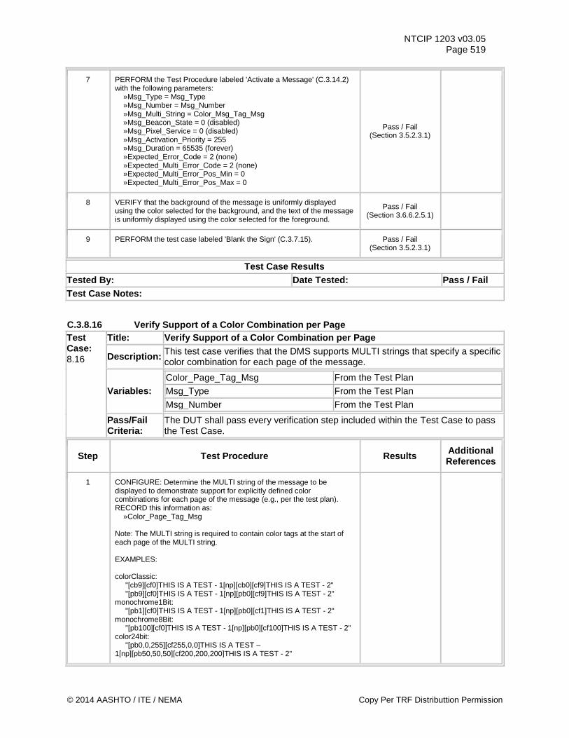
NTCIP 1203 v03.05 Page 519
7 PERFORM the Test Procedure labeled 'Activate a Message' (C.3.14.2) with the following parameters: »Msg_Type = Msg_Type »Msg_Number = Msg_Number »Msg_Multi_String = Color_Msg_Tag_Msg »Msg_Beacon_State = 0 (disabled) »Msg_Pixel_Service = 0 (disabled) »Msg_Activation_Priority = 255 »Msg_Duration = 65535 (forever) »Expected_Error_Code = 2 (none) »Expected_Multi_Error_Code = 2 (none) »Expected_Multi_Error_Pos_Min = 0 »Expected_Multi_Error_Pos_Max = 0
Pass / Fail (Section 3.5.2.3.1)
8 VERIFY that the background of the message is uniformly displayed using the color selected for the background, and the text of the message is uniformly displayed using the color selected for the foreground.
Pass / Fail (Section 3.6.6.2.5.1)
9 PERFORM the test case labeled 'Blank the Sign' (C.3.7.15). Pass / Fail (Section 3.5.2.3.1)
Test Case Results Tested By: Date Tested: Pass / Fail Test Case Notes:
C.3.8.16 Verify Support of a Color Combination per Page Test Case: 8.16
Title: Verify Support of a Color Combination per Page
Description: This test case verifies that the DMS supports MULTI strings that specify a specific color combination for each page of the message.
Variables: Color_Page_Tag_Msg From the Test Plan Msg_Type From the Test Plan Msg_Number From the Test Plan
Pass/Fail Criteria:
The DUT shall pass every verification step included within the Test Case to pass the Test Case.
Step Test Procedure Results Additional References
1 CONFIGURE: Determine the MULTI string of the message to be displayed to demonstrate support for explicitly defined color combinations for each page of the message (e.g., per the test plan). RECORD this information as: »Color_Page_Tag_Msg Note: The MULTI string is required to contain color tags at the start of each page of the MULTI string. EXAMPLES: colorClassic: "[cb9][cf0]THIS IS A TEST - 1[np][cb0][cf9]THIS IS A TEST - 2" "[pb9][cf0]THIS IS A TEST - 1[np][pb0][cf9]THIS IS A TEST - 2" monochrome1Bit: "[pb1][cf0]THIS IS A TEST - 1[np][pb0][cf1]THIS IS A TEST - 2" monochrome8Bit: "[pb100][cf0]THIS IS A TEST - 1[np][pb0][cf100]THIS IS A TEST - 2" color24bit: "[pb0,0,255][cf255,0,0]THIS IS A TEST – 1[np][pb50,50,50][cf200,200,200]THIS IS A TEST - 2"
© 2014 AASHTO / ITE / NEMA Copy Per TRF Distributtion Permission
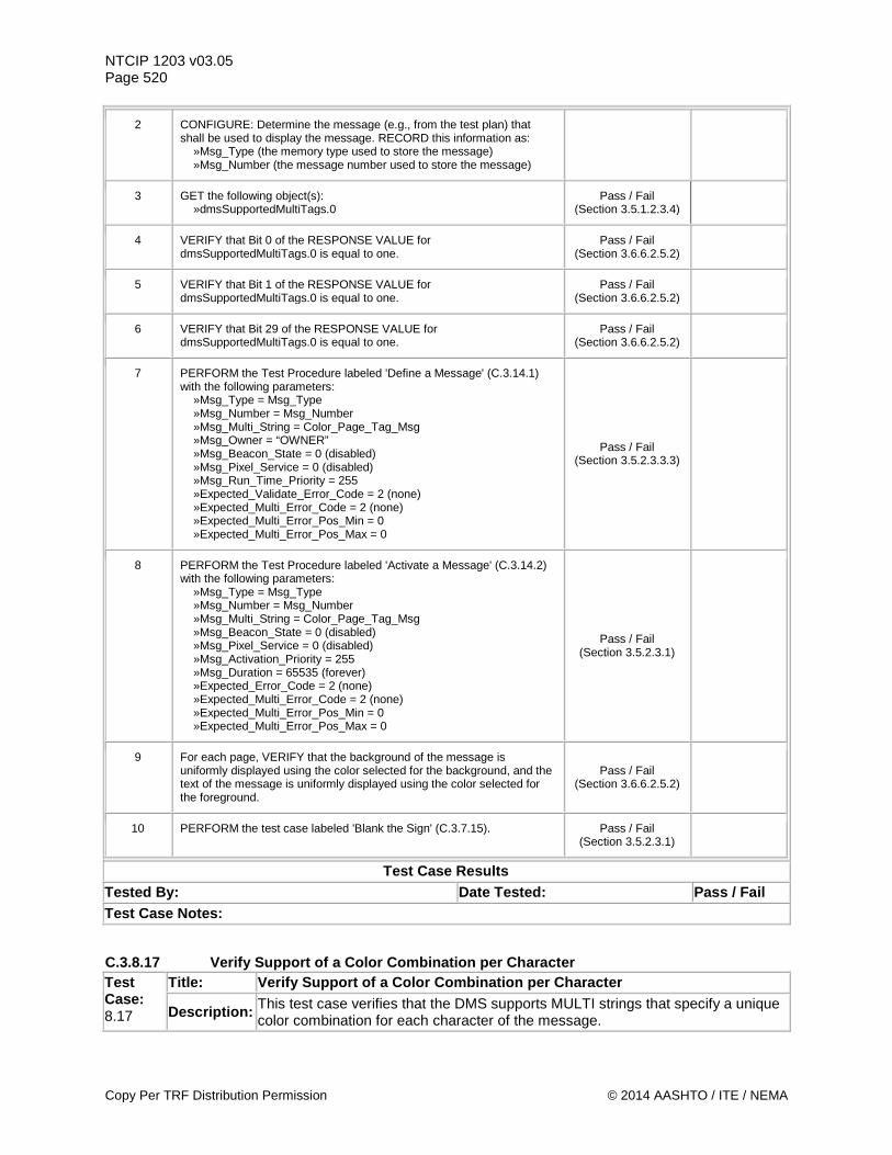
NTCIP 1203 v03.05 Page 520
2 CONFIGURE: Determine the message (e.g., from the test plan) that shall be used to display the message. RECORD this information as: »Msg_Type (the memory type used to store the message) »Msg_Number (the message number used to store the message)
3 GET the following object(s): »dmsSupportedMultiTags.0
Pass / Fail (Section 3.5.1.2.3.4)
4 VERIFY that Bit 0 of the RESPONSE VALUE for dmsSupportedMultiTags.0 is equal to one.
Pass / Fail (Section 3.6.6.2.5.2)
5 VERIFY that Bit 1 of the RESPONSE VALUE for dmsSupportedMultiTags.0 is equal to one.
Pass / Fail (Section 3.6.6.2.5.2)
6 VERIFY that Bit 29 of the RESPONSE VALUE for dmsSupportedMultiTags.0 is equal to one.
Pass / Fail (Section 3.6.6.2.5.2)
7 PERFORM the Test Procedure labeled 'Define a Message' (C.3.14.1) with the following parameters: »Msg_Type = Msg_Type »Msg_Number = Msg_Number »Msg_Multi_String = Color_Page_Tag_Msg »Msg_Owner = “OWNER” »Msg_Beacon_State = 0 (disabled) »Msg_Pixel_Service = 0 (disabled) »Msg_Run_Time_Priority = 255 »Expected_Validate_Error_Code = 2 (none) »Expected_Multi_Error_Code = 2 (none) »Expected_Multi_Error_Pos_Min = 0 »Expected_Multi_Error_Pos_Max = 0
Pass / Fail (Section 3.5.2.3.3.3)
8 PERFORM the Test Procedure labeled 'Activate a Message' (C.3.14.2) with the following parameters: »Msg_Type = Msg_Type »Msg_Number = Msg_Number »Msg_Multi_String = Color_Page_Tag_Msg »Msg_Beacon_State = 0 (disabled) »Msg_Pixel_Service = 0 (disabled) »Msg_Activation_Priority = 255 »Msg_Duration = 65535 (forever) »Expected_Error_Code = 2 (none) »Expected_Multi_Error_Code = 2 (none) »Expected_Multi_Error_Pos_Min = 0 »Expected_Multi_Error_Pos_Max = 0
Pass / Fail (Section 3.5.2.3.1)
9 For each page, VERIFY that the background of the message is uniformly displayed using the color selected for the background, and the text of the message is uniformly displayed using the color selected for the foreground.
Pass / Fail (Section 3.6.6.2.5.2)
10 PERFORM the test case labeled 'Blank the Sign' (C.3.7.15). Pass / Fail (Section 3.5.2.3.1)
Test Case Results Tested By: Date Tested: Pass / Fail Test Case Notes:
C.3.8.17 Verify Support of a Color Combination per Character Test Case: 8.17
Title: Verify Support of a Color Combination per Character
Description: This test case verifies that the DMS supports MULTI strings that specify a unique color combination for each character of the message.
Copy Per TRF Distribution Permission © 2014 AASHTO / ITE / NEMA
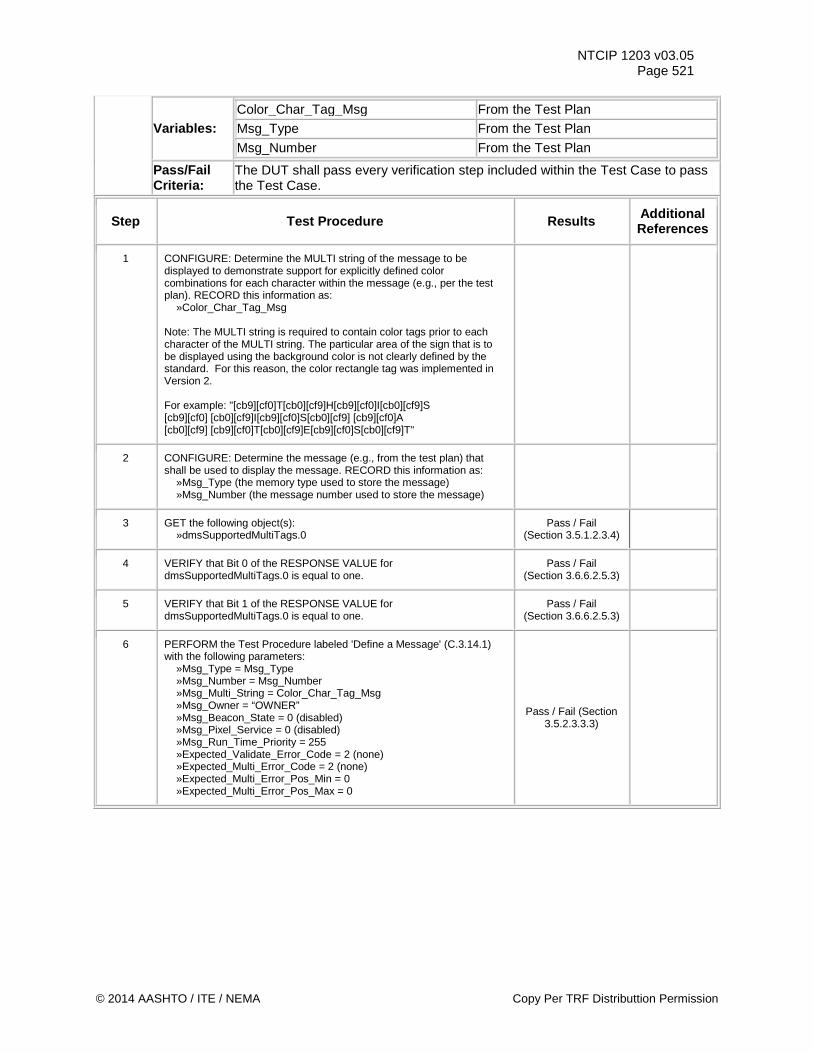
NTCIP 1203 v03.05 Page 521
Variables: Color_Char_Tag_Msg From the Test Plan Msg_Type From the Test Plan Msg_Number From the Test Plan
Pass/Fail Criteria:
The DUT shall pass every verification step included within the Test Case to pass the Test Case.
Step Test Procedure Results Additional References
1 CONFIGURE: Determine the MULTI string of the message to be displayed to demonstrate support for explicitly defined color combinations for each character within the message (e.g., per the test plan). RECORD this information as: »Color_Char_Tag_Msg Note: The MULTI string is required to contain color tags prior to each character of the MULTI string. The particular area of the sign that is to be displayed using the background color is not clearly defined by the standard. For this reason, the color rectangle tag was implemented in Version 2. For example: "[cb9][cf0]T[cb0][cf9]H[cb9][cf0]I[cb0][cf9]S [cb9][cf0] [cb0][cf9]I[cb9][cf0]S[cb0][cf9] [cb9][cf0]A [cb0][cf9] [cb9][cf0]T[cb0][cf9]E[cb9][cf0]S[cb0][cf9]T"
2 CONFIGURE: Determine the message (e.g., from the test plan) that shall be used to display the message. RECORD this information as: »Msg_Type (the memory type used to store the message) »Msg_Number (the message number used to store the message)
3 GET the following object(s): »dmsSupportedMultiTags.0
Pass / Fail (Section 3.5.1.2.3.4)
4 VERIFY that Bit 0 of the RESPONSE VALUE for dmsSupportedMultiTags.0 is equal to one.
Pass / Fail (Section 3.6.6.2.5.3)
5 VERIFY that Bit 1 of the RESPONSE VALUE for dmsSupportedMultiTags.0 is equal to one.
Pass / Fail (Section 3.6.6.2.5.3)
6 PERFORM the Test Procedure labeled 'Define a Message' (C.3.14.1) with the following parameters: »Msg_Type = Msg_Type »Msg_Number = Msg_Number »Msg_Multi_String = Color_Char_Tag_Msg »Msg_Owner = “OWNER” »Msg_Beacon_State = 0 (disabled) »Msg_Pixel_Service = 0 (disabled) »Msg_Run_Time_Priority = 255 »Expected_Validate_Error_Code = 2 (none) »Expected_Multi_Error_Code = 2 (none) »Expected_Multi_Error_Pos_Min = 0 »Expected_Multi_Error_Pos_Max = 0
Pass / Fail (Section 3.5.2.3.3.3)
© 2014 AASHTO / ITE / NEMA Copy Per TRF Distributtion Permission
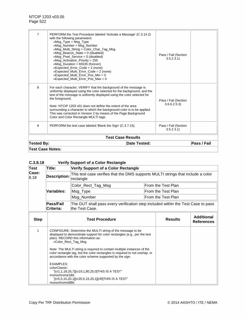
NTCIP 1203 v03.05 Page 522
7 PERFORM the Test Procedure labeled 'Activate a Message' (C.3.14.2) with the following parameters: »Msg_Type = Msg_Type »Msg_Number = Msg_Number »Msg_Multi_String = Color_Char_Tag_Msg »Msg_Beacon_State = 0 (disabled) »Msg_Pixel_Service = 0 (disabled) »Msg_Activation_Priority = 255 »Msg_Duration = 65535 (forever) »Expected_Error_Code = 2 (none) »Expected_Multi_Error_Code = 2 (none) »Expected_Multi_Error_Pos_Min = 0 »Expected_Multi_Error_Pos_Max = 0
Pass / Fail (Section 3.5.2.3.1)
8 For each character, VERIFY that the background of the message is uniformly displayed using the color selected for the background, and the text of the message is uniformly displayed using the color selected for the foreground. Note: NTCIP 1203 v01 does not define the extent of the area surrounding a character to which the background color is to be applied. This was corrected in Version 2 by means of the Page Background Color and Color Rectangle MULTI tags.
Pass / Fail (Section 3.6.6.2.5.3)
9 PERFORM the test case labeled 'Blank the Sign' (C.3.7.15). Pass / Fail (Section 3.5.2.3.1)
Test Case Results Tested By: Date Tested: Pass / Fail Test Case Notes:
C.3.8.18 Verify Support of a Color Rectangle Test Case: 8.18
Title: Verify Support of a Color Rectangle
Description: This test case verifies that the DMS supports MULTI strings that include a color rectangle
Variables: Color_Rect_Tag_Msg From the Test Plan Msg_Type From the Test Plan Msg_Number From the Test Plan
Pass/Fail Criteria:
The DUT shall pass every verification step included within the Test Case to pass the Test Case.
Step Test Procedure Results Additional References
1 CONFIGURE: Determine the MULTI string of the message to be displayed to demonstrate support for color rectangles (e.g., per the test plan). RECORD this information as: »Color_Rect_Tag_Msg Note: The MULTI string is required to contain multiple instances of the color rectangle tag, but the color rectangles is required to not overlap, in accordance with the color scheme supported by the sign. EXAMPLES: colorClassic: "[cr1,1,18,25,7][cr19,1,80,25,0]THIS IS A TEST" monochrome1Bit: “[cr5,5,15,20,1][cr20,5,15,20,1][cf0]THIS IS A TEST” monochrome8Bit:
Copy Per TRF Distribution Permission © 2014 AASHTO / ITE / NEMA
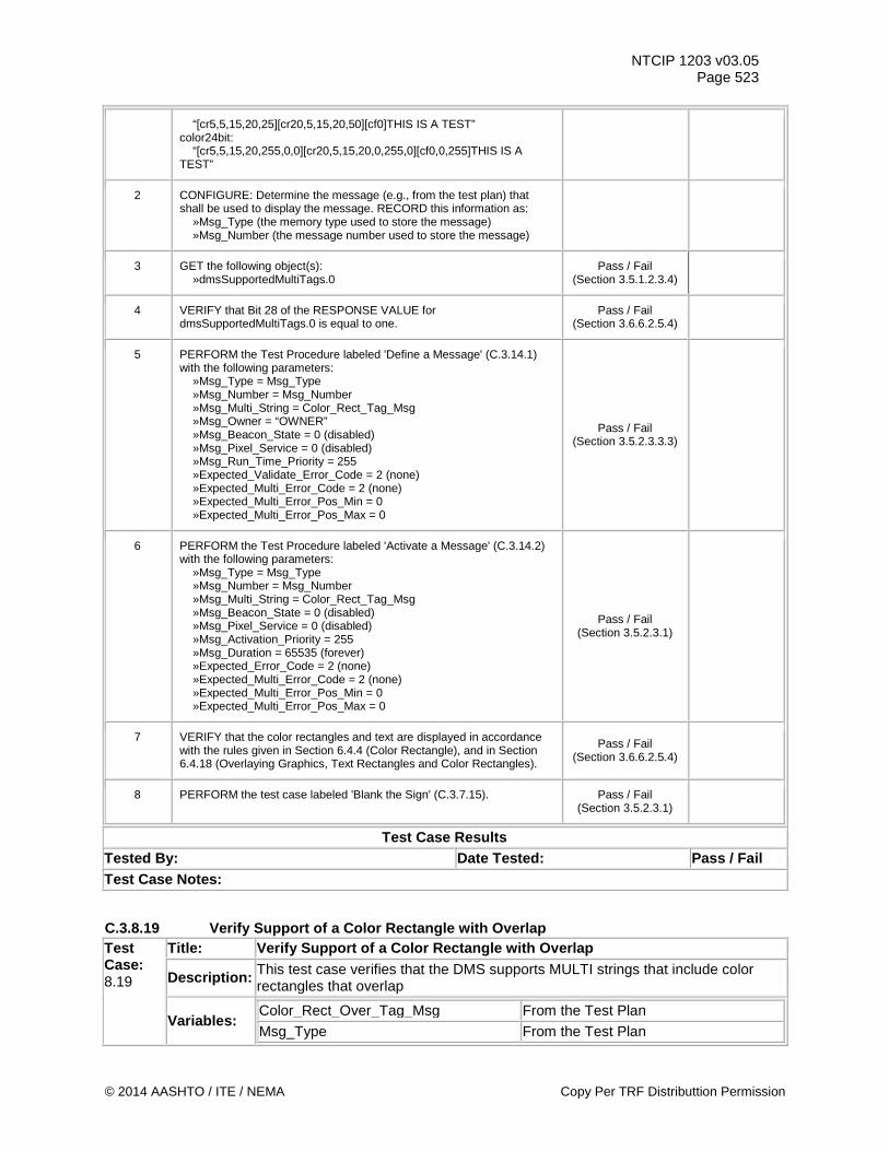
NTCIP 1203 v03.05 Page 523
“[cr5,5,15,20,25][cr20,5,15,20,50][cf0]THIS IS A TEST” color24bit: “[cr5,5,15,20,255,0,0][cr20,5,15,20,0,255,0][cf0,0,255]THIS IS A TEST”
2 CONFIGURE: Determine the message (e.g., from the test plan) that shall be used to display the message. RECORD this information as: »Msg_Type (the memory type used to store the message) »Msg_Number (the message number used to store the message)
3 GET the following object(s): »dmsSupportedMultiTags.0
Pass / Fail (Section 3.5.1.2.3.4)
4 VERIFY that Bit 28 of the RESPONSE VALUE for dmsSupportedMultiTags.0 is equal to one.
Pass / Fail (Section 3.6.6.2.5.4)
5 PERFORM the Test Procedure labeled 'Define a Message' (C.3.14.1) with the following parameters: »Msg_Type = Msg_Type »Msg_Number = Msg_Number »Msg_Multi_String = Color_Rect_Tag_Msg »Msg_Owner = “OWNER” »Msg_Beacon_State = 0 (disabled) »Msg_Pixel_Service = 0 (disabled) »Msg_Run_Time_Priority = 255 »Expected_Validate_Error_Code = 2 (none) »Expected_Multi_Error_Code = 2 (none) »Expected_Multi_Error_Pos_Min = 0 »Expected_Multi_Error_Pos_Max = 0
Pass / Fail (Section 3.5.2.3.3.3)
6 PERFORM the Test Procedure labeled 'Activate a Message' (C.3.14.2) with the following parameters: »Msg_Type = Msg_Type »Msg_Number = Msg_Number »Msg_Multi_String = Color_Rect_Tag_Msg »Msg_Beacon_State = 0 (disabled) »Msg_Pixel_Service = 0 (disabled) »Msg_Activation_Priority = 255 »Msg_Duration = 65535 (forever) »Expected_Error_Code = 2 (none) »Expected_Multi_Error_Code = 2 (none) »Expected_Multi_Error_Pos_Min = 0 »Expected_Multi_Error_Pos_Max = 0
Pass / Fail (Section 3.5.2.3.1)
7 VERIFY that the color rectangles and text are displayed in accordance with the rules given in Section 6.4.4 (Color Rectangle), and in Section 6.4.18 (Overlaying Graphics, Text Rectangles and Color Rectangles).
Pass / Fail (Section 3.6.6.2.5.4)
8 PERFORM the test case labeled 'Blank the Sign' (C.3.7.15). Pass / Fail (Section 3.5.2.3.1)
Test Case Results Tested By: Date Tested: Pass / Fail Test Case Notes:
C.3.8.19 Verify Support of a Color Rectangle with Overlap Test Case: 8.19
Title: Verify Support of a Color Rectangle with Overlap
Description: This test case verifies that the DMS supports MULTI strings that include color rectangles that overlap
Variables: Color_Rect_Over_Tag_Msg From the Test Plan Msg_Type From the Test Plan
© 2014 AASHTO / ITE / NEMA Copy Per TRF Distributtion Permission
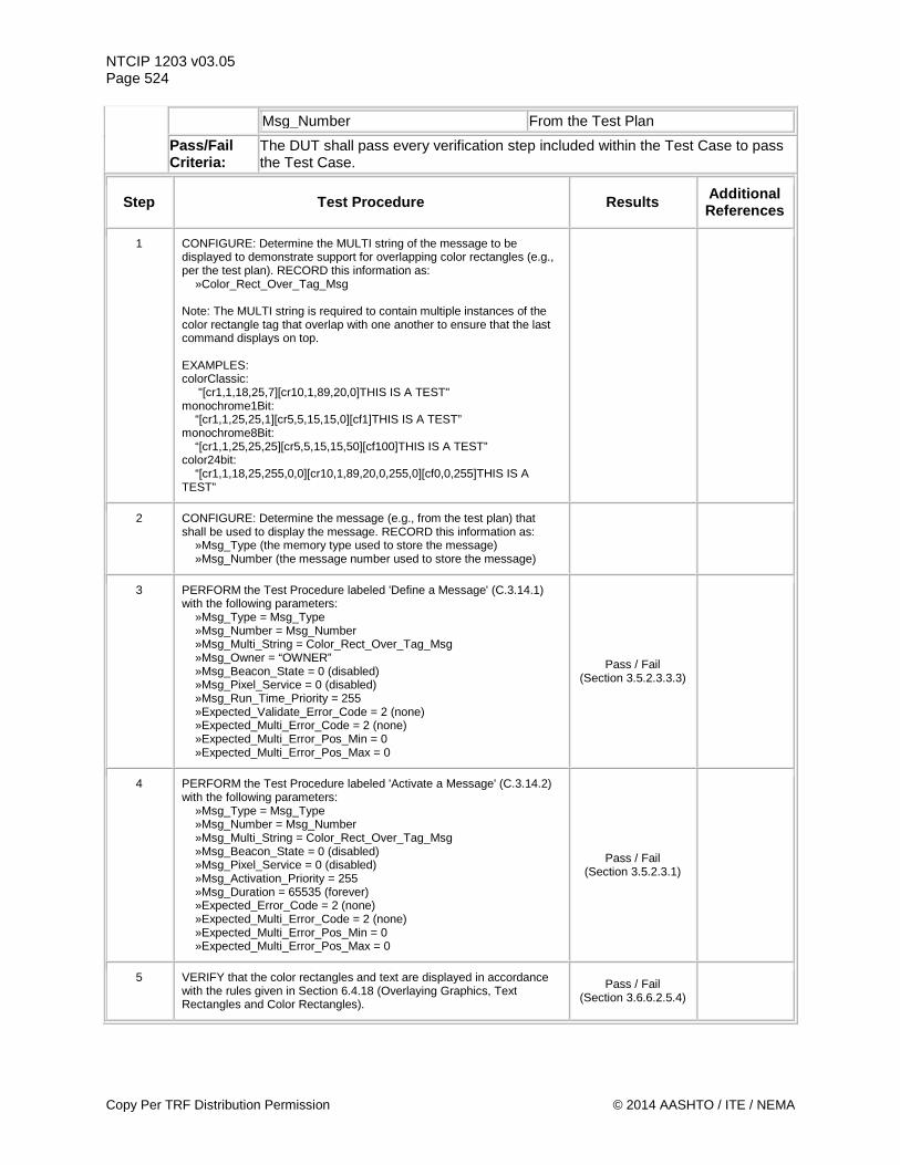
NTCIP 1203 v03.05 Page 524
Msg_Number From the Test Plan
Pass/Fail Criteria:
The DUT shall pass every verification step included within the Test Case to pass the Test Case.
Step Test Procedure Results Additional References
1 CONFIGURE: Determine the MULTI string of the message to be displayed to demonstrate support for overlapping color rectangles (e.g., per the test plan). RECORD this information as: »Color_Rect_Over_Tag_Msg Note: The MULTI string is required to contain multiple instances of the color rectangle tag that overlap with one another to ensure that the last command displays on top. EXAMPLES: colorClassic: "[cr1,1,18,25,7][cr10,1,89,20,0]THIS IS A TEST" monochrome1Bit: “[cr1,1,25,25,1][cr5,5,15,15,0][cf1]THIS IS A TEST” monochrome8Bit: “[cr1,1,25,25,25][cr5,5,15,15,50][cf100]THIS IS A TEST” color24bit: “[cr1,1,18,25,255,0,0][cr10,1,89,20,0,255,0][cf0,0,255]THIS IS A TEST”
2 CONFIGURE: Determine the message (e.g., from the test plan) that shall be used to display the message. RECORD this information as: »Msg_Type (the memory type used to store the message) »Msg_Number (the message number used to store the message)
3 PERFORM the Test Procedure labeled 'Define a Message' (C.3.14.1) with the following parameters: »Msg_Type = Msg_Type »Msg_Number = Msg_Number »Msg_Multi_String = Color_Rect_Over_Tag_Msg »Msg_Owner = “OWNER” »Msg_Beacon_State = 0 (disabled) »Msg_Pixel_Service = 0 (disabled) »Msg_Run_Time_Priority = 255 »Expected_Validate_Error_Code = 2 (none) »Expected_Multi_Error_Code = 2 (none) »Expected_Multi_Error_Pos_Min = 0 »Expected_Multi_Error_Pos_Max = 0
Pass / Fail (Section 3.5.2.3.3.3)
4 PERFORM the Test Procedure labeled 'Activate a Message' (C.3.14.2) with the following parameters: »Msg_Type = Msg_Type »Msg_Number = Msg_Number »Msg_Multi_String = Color_Rect_Over_Tag_Msg »Msg_Beacon_State = 0 (disabled) »Msg_Pixel_Service = 0 (disabled) »Msg_Activation_Priority = 255 »Msg_Duration = 65535 (forever) »Expected_Error_Code = 2 (none) »Expected_Multi_Error_Code = 2 (none) »Expected_Multi_Error_Pos_Min = 0 »Expected_Multi_Error_Pos_Max = 0
Pass / Fail (Section 3.5.2.3.1)
5 VERIFY that the color rectangles and text are displayed in accordance with the rules given in Section 6.4.18 (Overlaying Graphics, Text Rectangles and Color Rectangles).
Pass / Fail (Section 3.6.6.2.5.4)
Copy Per TRF Distribution Permission © 2014 AASHTO / ITE / NEMA
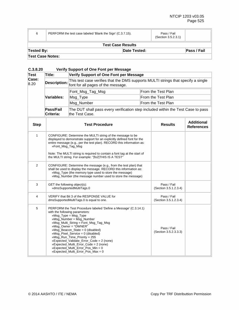
NTCIP 1203 v03.05 Page 525
6 PERFORM the test case labeled 'Blank the Sign' (C.3.7.15). Pass / Fail (Section 3.5.2.3.1)
Test Case Results Tested By: Date Tested: Pass / Fail Test Case Notes:
C.3.8.20 Verify Support of One Font per Message Test Case: 8.20
Title: Verify Support of One Font per Message
Description: This test case verifies that the DMS supports MULTI strings that specify a single font for all pages of the message.
Variables: Font_Msg_Tag_Msg From the Test Plan Msg_Type From the Test Plan Msg_Number From the Test Plan
Pass/Fail Criteria:
The DUT shall pass every verification step included within the Test Case to pass the Test Case.
Step Test Procedure Results Additional References
1 CONFIGURE: Determine the MULTI string of the message to be displayed to demonstrate support for an explicitly defined font for the entire message (e.g., per the test plan). RECORD this information as: »Font_Msg_Tag_Msg Note: The MULTI string is required to contain a font tag at the start of the MULTI string. For example: "[fo2]THIS IS A TEST"
2 CONFIGURE: Determine the message (e.g., from the test plan) that shall be used to display the message. RECORD this information as: »Msg_Type (the memory type used to store the message) »Msg_Number (the message number used to store the message)
3 GET the following object(s): »dmsSupportedMultiTags.0
Pass / Fail (Section 3.5.1.2.3.4)
4 VERIFY that Bit 3 of the RESPONSE VALUE for dmsSupportedMultiTags.0 is equal to one.
Pass / Fail (Section 3.5.1.2.3.4)
5 PERFORM the Test Procedure labeled 'Define a Message' (C.3.14.1) with the following parameters: »Msg_Type = Msg_Type »Msg_Number = Msg_Number »Msg_Multi_String = Font_Msg_Tag_Msg »Msg_Owner = “OWNER” »Msg_Beacon_State = 0 (disabled) »Msg_Pixel_Service = 0 (disabled) »Msg_Run_Time_Priority = 255 »Expected_Validate_Error_Code = 2 (none) »Expected_Multi_Error_Code = 2 (none) »Expected_Multi_Error_Pos_Min = 0 »Expected_Multi_Error_Pos_Max = 0
Pass / Fail (Section 3.5.2.3.3.3)
© 2014 AASHTO / ITE / NEMA Copy Per TRF Distributtion Permission
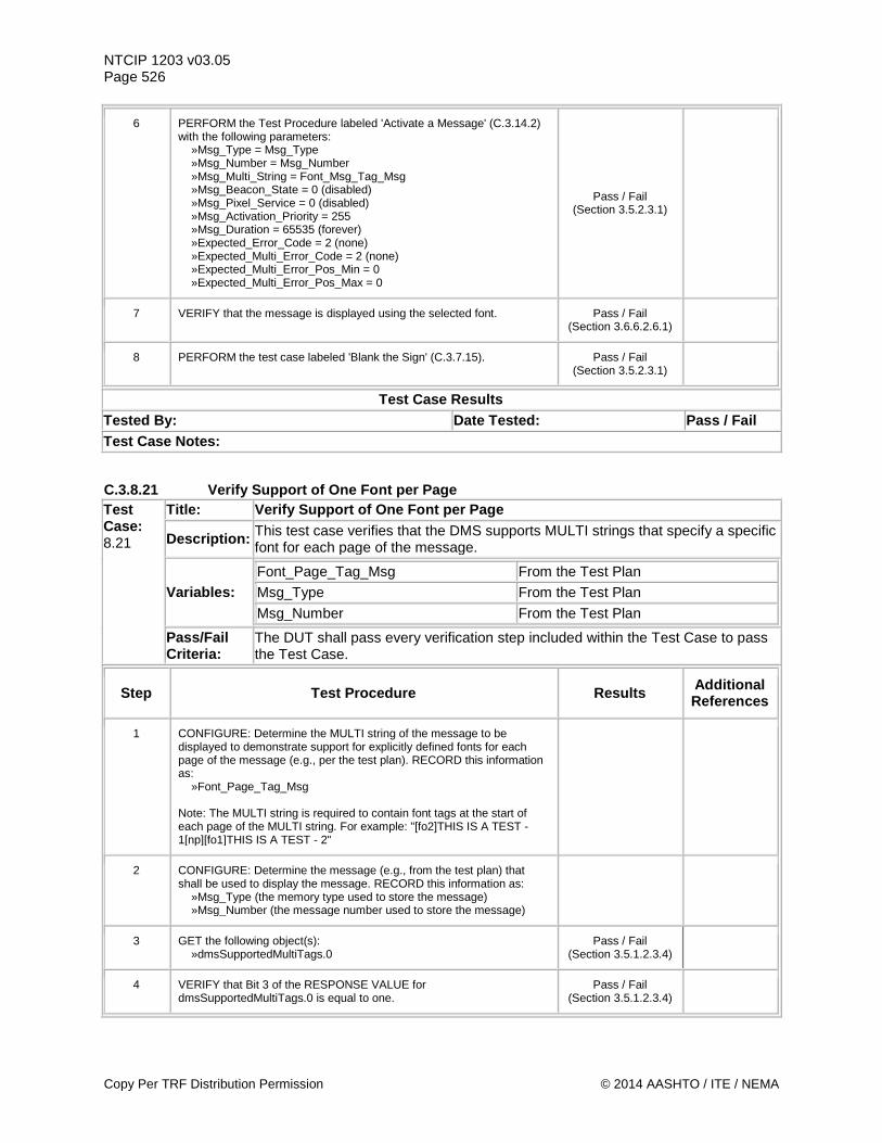
NTCIP 1203 v03.05 Page 526
6 PERFORM the Test Procedure labeled 'Activate a Message' (C.3.14.2) with the following parameters: »Msg_Type = Msg_Type »Msg_Number = Msg_Number »Msg_Multi_String = Font_Msg_Tag_Msg »Msg_Beacon_State = 0 (disabled) »Msg_Pixel_Service = 0 (disabled) »Msg_Activation_Priority = 255 »Msg_Duration = 65535 (forever) »Expected_Error_Code = 2 (none) »Expected_Multi_Error_Code = 2 (none) »Expected_Multi_Error_Pos_Min = 0 »Expected_Multi_Error_Pos_Max = 0
Pass / Fail (Section 3.5.2.3.1)
7 VERIFY that the message is displayed using the selected font. Pass / Fail (Section 3.6.6.2.6.1)
8 PERFORM the test case labeled 'Blank the Sign' (C.3.7.15). Pass / Fail (Section 3.5.2.3.1)
Test Case Results Tested By: Date Tested: Pass / Fail Test Case Notes:
C.3.8.21 Verify Support of One Font per Page Test Case: 8.21
Title: Verify Support of One Font per Page
Description: This test case verifies that the DMS supports MULTI strings that specify a specific font for each page of the message.
Variables: Font_Page_Tag_Msg From the Test Plan Msg_Type From the Test Plan Msg_Number From the Test Plan
Pass/Fail Criteria:
The DUT shall pass every verification step included within the Test Case to pass the Test Case.
Step Test Procedure Results Additional References
1 CONFIGURE: Determine the MULTI string of the message to be displayed to demonstrate support for explicitly defined fonts for each page of the message (e.g., per the test plan). RECORD this information as: »Font_Page_Tag_Msg Note: The MULTI string is required to contain font tags at the start of each page of the MULTI string. For example: "[fo2]THIS IS A TEST - 1[np][fo1]THIS IS A TEST - 2"
2 CONFIGURE: Determine the message (e.g., from the test plan) that shall be used to display the message. RECORD this information as: »Msg_Type (the memory type used to store the message) »Msg_Number (the message number used to store the message)
3 GET the following object(s): »dmsSupportedMultiTags.0
Pass / Fail (Section 3.5.1.2.3.4)
4 VERIFY that Bit 3 of the RESPONSE VALUE for dmsSupportedMultiTags.0 is equal to one.
Pass / Fail (Section 3.5.1.2.3.4)
Copy Per TRF Distribution Permission © 2014 AASHTO / ITE / NEMA
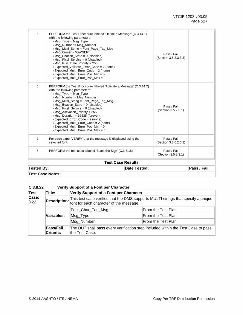
NTCIP 1203 v03.05 Page 527
5 PERFORM the Test Procedure labeled 'Define a Message' (C.3.14.1) with the following parameters: »Msg_Type = Msg_Type »Msg_Number = Msg_Number »Msg_Multi_String = Font_Page_Tag_Msg »Msg_Owner = “OWNER” »Msg_Beacon_State = 0 (disabled) »Msg_Pixel_Service = 0 (disabled) »Msg_Run_Time_Priority = 255 »Expected_Validate_Error_Code = 2 (none) »Expected_Multi_Error_Code = 2 (none) »Expected_Multi_Error_Pos_Min = 0 »Expected_Multi_Error_Pos_Max = 0
Pass / Fail (Section 3.5.2.3.3.3)
6 PERFORM the Test Procedure labeled 'Activate a Message' (C.3.14.2) with the following parameters: »Msg_Type = Msg_Type »Msg_Number = Msg_Number »Msg_Multi_String = Font_Page_Tag_Msg »Msg_Beacon_State = 0 (disabled) »Msg_Pixel_Service = 0 (disabled) »Msg_Activation_Priority = 255 »Msg_Duration = 65535 (forever) »Expected_Error_Code = 2 (none) »Expected_Multi_Error_Code = 2 (none) »Expected_Multi_Error_Pos_Min = 0 »Expected_Multi_Error_Pos_Max = 0
Pass / Fail (Section 3.5.2.3.1)
7 For each page, VERIFY that the message is displayed using the selected font.
Pass / Fail (Section 3.6.6.2.6.2)
8 PERFORM the test case labeled 'Blank the Sign' (C.3.7.15). Pass / Fail (Section 3.5.2.3.1)
Test Case Results Tested By: Date Tested: Pass / Fail Test Case Notes:
C.3.8.22 Verify Support of a Font per Character Test Case: 8.22
Title: Verify Support of a Font per Character
Description: This test case verifies that the DMS supports MULTI strings that specify a unique font for each character of the message.
Variables: Font_Char_Tag_Msg From the Test Plan Msg_Type From the Test Plan Msg_Number From the Test Plan
Pass/Fail Criteria:
The DUT shall pass every verification step included within the Test Case to pass the Test Case.
© 2014 AASHTO / ITE / NEMA Copy Per TRF Distributtion Permission
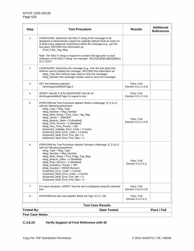
NTCIP 1203 v03.05 Page 528
Step Test Procedure Results Additional References
1 CONFIGURE: Determine the MULTI string of the message to be displayed to demonstrate support for explicitly defined fonts for each (or at least many adjacent) character(s) within the message (e.g., per the test plan). RECORD this information as: »Font_Char_Tag_Msg Note: The MULTI string is required to contain font tags prior to each character of the MULTI string. For example: "[fo1]T[fo2]H[fo1]I[fo2]S[fo1] IS A TEST"
2 CONFIGURE: Determine the message (e.g., from the test plan) that shall be used to display the message. RECORD this information as: »Msg_Type (the memory type used to store the message) »Msg_Number (the message number used to store the message)
3 GET the following object(s): »dmsSupportedMultiTags.0
Pass / Fail (Section 3.5.1.2.3.4)
4 VERIFY that Bit 3 of the RESPONSE VALUE for dmsSupportedMultiTags.0 is equal to one.
Pass / Fail (Section 3.5.1.2.3.4)
5 PERFORM the Test Procedure labeled 'Define a Message' (C.3.14.1) with the following parameters: »Msg_Type = Msg_Type »Msg_Number = Msg_Number »Msg_Multi_String = Font_Char_Tag_Msg »Msg_Owner = “OWNER” »Msg_Beacon_State = 0 (disabled) »Msg_Pixel_Service = 0 (disabled) »Msg_Run_Time_Priority = 255 »Expected_Validate_Error_Code = 2 (none) »Expected_Multi_Error_Code = 2 (none) »Expected_Multi_Error_Pos_Min = 0 »Expected_Multi_Error_Pos_Max = 0
Pass / Fail (Section 3.5.2.3.3.3)
6 PERFORM the Test Procedure labeled 'Activate a Message' (C.3.14.2) with the following parameters: »Msg_Type = Msg_Type »Msg_Number = Msg_Number »Msg_Multi_String = Font_Page_Tag_Msg »Msg_Beacon_State = 0 (disabled) »Msg_Pixel_Service = 0 (disabled) »Msg_Activation_Priority = 255 »Msg_Duration = 65535 (forever) »Expected_Error_Code = 2 (none) »Expected_Multi_Error_Code = 2 (none) »Expected_Multi_Error_Pos_Min = 0 »Expected_Multi_Error_Pos_Max = 0
Pass / Fail (Section 3.5.2.3.1)
7 For each character, VERIFY that the text is displayed using the selected font.
Pass / Fail (Section 3.6.6.2.6.3)
8 PERFORM the test case labeled 'Blank the Sign' (C.3.7.15). Pass / Fail (Section 3.5.2.3.1)
Test Case Results Tested By: Date Tested: Pass / Fail Test Case Notes: C.3.8.23 Verify Support of Font Reference with ID
Copy Per TRF Distribution Permission © 2014 AASHTO / ITE / NEMA
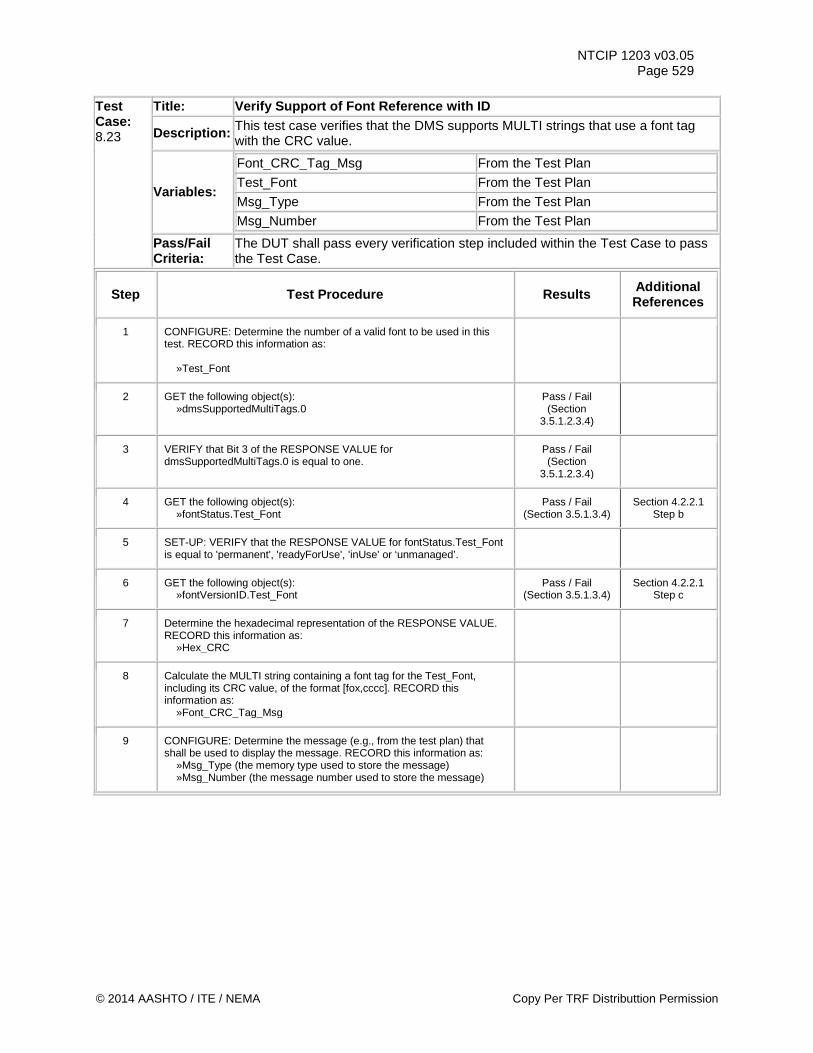
NTCIP 1203 v03.05 Page 529
Test Case: 8.23
Title: Verify Support of Font Reference with ID
Description: This test case verifies that the DMS supports MULTI strings that use a font tag with the CRC value.
Variables:
Font_CRC_Tag_Msg From the Test Plan Test_Font From the Test Plan Msg_Type From the Test Plan Msg_Number From the Test Plan
Pass/Fail Criteria:
The DUT shall pass every verification step included within the Test Case to pass the Test Case.
Step Test Procedure Results Additional References
1 CONFIGURE: Determine the number of a valid font to be used in this test. RECORD this information as: »Test_Font
2 GET the following object(s): »dmsSupportedMultiTags.0
Pass / Fail (Section
3.5.1.2.3.4)
3 VERIFY that Bit 3 of the RESPONSE VALUE for dmsSupportedMultiTags.0 is equal to one.
Pass / Fail (Section
3.5.1.2.3.4)
4 GET the following object(s): »fontStatus.Test_Font
Pass / Fail (Section 3.5.1.3.4)
Section 4.2.2.1 Step b
5 SET-UP: VERIFY that the RESPONSE VALUE for fontStatus.Test_Font is equal to 'permanent', 'readyForUse', 'inUse' or ‘unmanaged’.
6 GET the following object(s): »fontVersionID.Test_Font
Pass / Fail (Section 3.5.1.3.4)
Section 4.2.2.1 Step c
7 Determine the hexadecimal representation of the RESPONSE VALUE. RECORD this information as: »Hex_CRC
8 Calculate the MULTI string containing a font tag for the Test_Font, including its CRC value, of the format [fox,cccc]. RECORD this information as: »Font_CRC_Tag_Msg
9 CONFIGURE: Determine the message (e.g., from the test plan) that shall be used to display the message. RECORD this information as: »Msg_Type (the memory type used to store the message) »Msg_Number (the message number used to store the message)
© 2014 AASHTO / ITE / NEMA Copy Per TRF Distributtion Permission
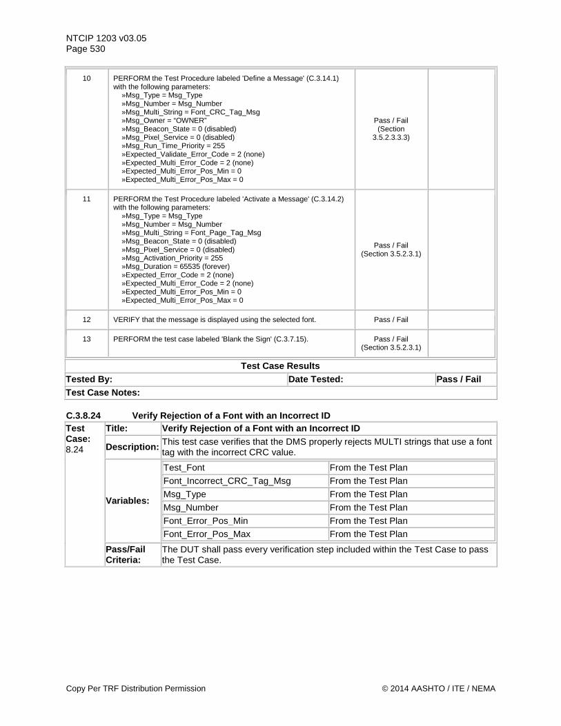
NTCIP 1203 v03.05 Page 530
10 PERFORM the Test Procedure labeled 'Define a Message' (C.3.14.1) with the following parameters: »Msg_Type = Msg_Type »Msg_Number = Msg_Number »Msg_Multi_String = Font_CRC_Tag_Msg »Msg_Owner = “OWNER” »Msg_Beacon_State = 0 (disabled) »Msg_Pixel_Service = 0 (disabled) »Msg_Run_Time_Priority = 255 »Expected_Validate_Error_Code = 2 (none) »Expected_Multi_Error_Code = 2 (none) »Expected_Multi_Error_Pos_Min = 0 »Expected_Multi_Error_Pos_Max = 0
Pass / Fail (Section
3.5.2.3.3.3)
11 PERFORM the Test Procedure labeled 'Activate a Message' (C.3.14.2) with the following parameters: »Msg_Type = Msg_Type »Msg_Number = Msg_Number »Msg_Multi_String = Font_Page_Tag_Msg »Msg_Beacon_State = 0 (disabled) »Msg_Pixel_Service = 0 (disabled) »Msg_Activation_Priority = 255 »Msg_Duration = 65535 (forever) »Expected_Error_Code = 2 (none) »Expected_Multi_Error_Code = 2 (none) »Expected_Multi_Error_Pos_Min = 0 »Expected_Multi_Error_Pos_Max = 0
Pass / Fail (Section 3.5.2.3.1)
12 VERIFY that the message is displayed using the selected font. Pass / Fail
13 PERFORM the test case labeled 'Blank the Sign' (C.3.7.15). Pass / Fail (Section 3.5.2.3.1)
Test Case Results Tested By: Date Tested: Pass / Fail Test Case Notes: C.3.8.24 Verify Rejection of a Font with an Incorrect ID Test Case: 8.24
Title: Verify Rejection of a Font with an Incorrect ID
Description: This test case verifies that the DMS properly rejects MULTI strings that use a font tag with the incorrect CRC value.
Variables:
Test_Font From the Test Plan Font_Incorrect_CRC_Tag_Msg From the Test Plan Msg_Type From the Test Plan Msg_Number From the Test Plan Font_Error_Pos_Min From the Test Plan Font_Error_Pos_Max From the Test Plan
Pass/Fail Criteria:
The DUT shall pass every verification step included within the Test Case to pass the Test Case.
Copy Per TRF Distribution Permission © 2014 AASHTO / ITE / NEMA
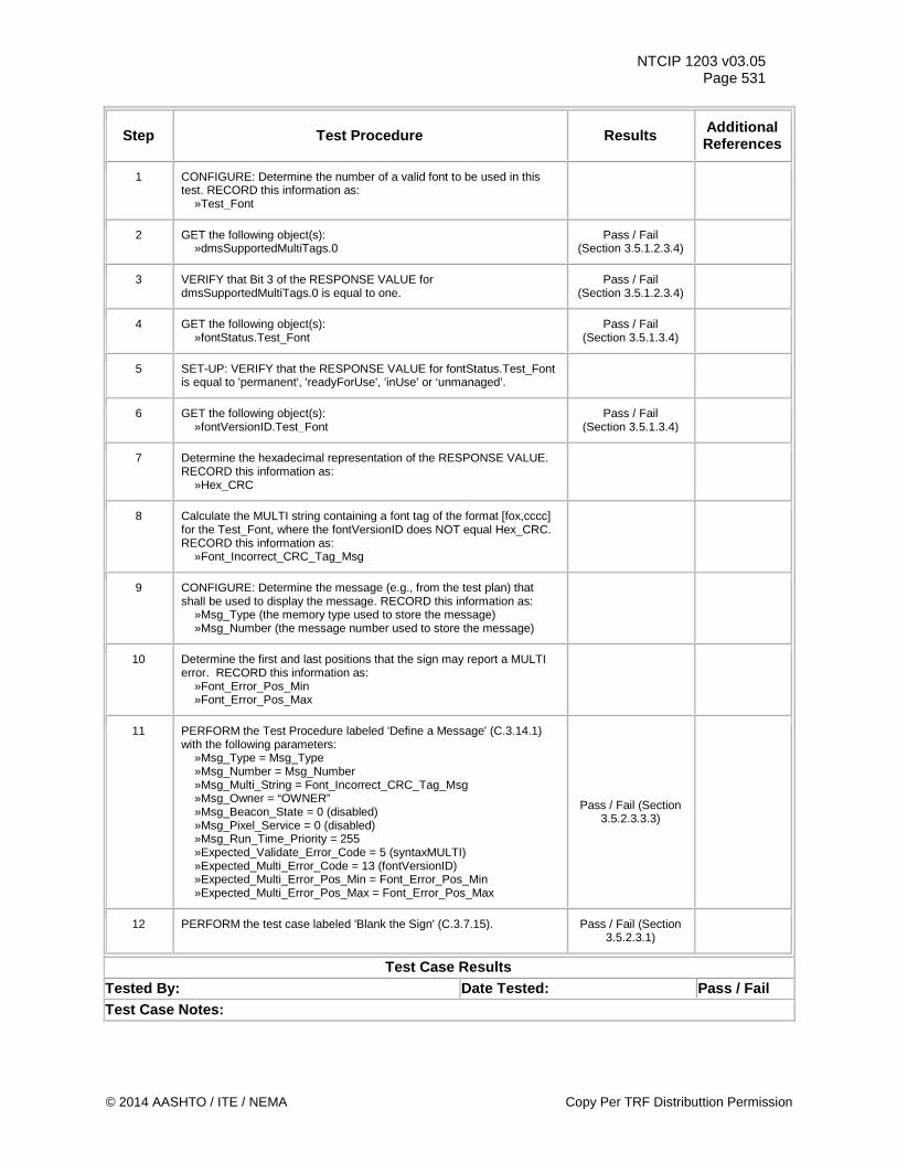
NTCIP 1203 v03.05 Page 531
Step Test Procedure Results Additional References
1 CONFIGURE: Determine the number of a valid font to be used in this test. RECORD this information as: »Test_Font
2 GET the following object(s): »dmsSupportedMultiTags.0
Pass / Fail (Section 3.5.1.2.3.4)
3 VERIFY that Bit 3 of the RESPONSE VALUE for dmsSupportedMultiTags.0 is equal to one.
Pass / Fail (Section 3.5.1.2.3.4)
4 GET the following object(s): »fontStatus.Test_Font
Pass / Fail (Section 3.5.1.3.4)
5 SET-UP: VERIFY that the RESPONSE VALUE for fontStatus.Test_Font is equal to 'permanent', 'readyForUse', 'inUse' or ‘unmanaged’.
6 GET the following object(s): »fontVersionID.Test_Font
Pass / Fail (Section 3.5.1.3.4)
7 Determine the hexadecimal representation of the RESPONSE VALUE. RECORD this information as: »Hex_CRC
8 Calculate the MULTI string containing a font tag of the format [fox,cccc] for the Test_Font, where the fontVersionID does NOT equal Hex_CRC. RECORD this information as: »Font_Incorrect_CRC_Tag_Msg
9 CONFIGURE: Determine the message (e.g., from the test plan) that shall be used to display the message. RECORD this information as: »Msg_Type (the memory type used to store the message) »Msg_Number (the message number used to store the message)
10 Determine the first and last positions that the sign may report a MULTI error. RECORD this information as: »Font_Error_Pos_Min »Font_Error_Pos_Max
11 PERFORM the Test Procedure labeled 'Define a Message' (C.3.14.1) with the following parameters: »Msg_Type = Msg_Type »Msg_Number = Msg_Number »Msg_Multi_String = Font_Incorrect_CRC_Tag_Msg »Msg_Owner = “OWNER” »Msg_Beacon_State = 0 (disabled) »Msg_Pixel_Service = 0 (disabled) »Msg_Run_Time_Priority = 255 »Expected_Validate_Error_Code = 5 (syntaxMULTI) »Expected_Multi_Error_Code = 13 (fontVersionID) »Expected_Multi_Error_Pos_Min = Font_Error_Pos_Min »Expected_Multi_Error_Pos_Max = Font_Error_Pos_Max
Pass / Fail (Section 3.5.2.3.3.3)
12 PERFORM the test case labeled 'Blank the Sign' (C.3.7.15). Pass / Fail (Section 3.5.2.3.1)
Test Case Results Tested By: Date Tested: Pass / Fail Test Case Notes:
© 2014 AASHTO / ITE / NEMA Copy Per TRF Distributtion Permission
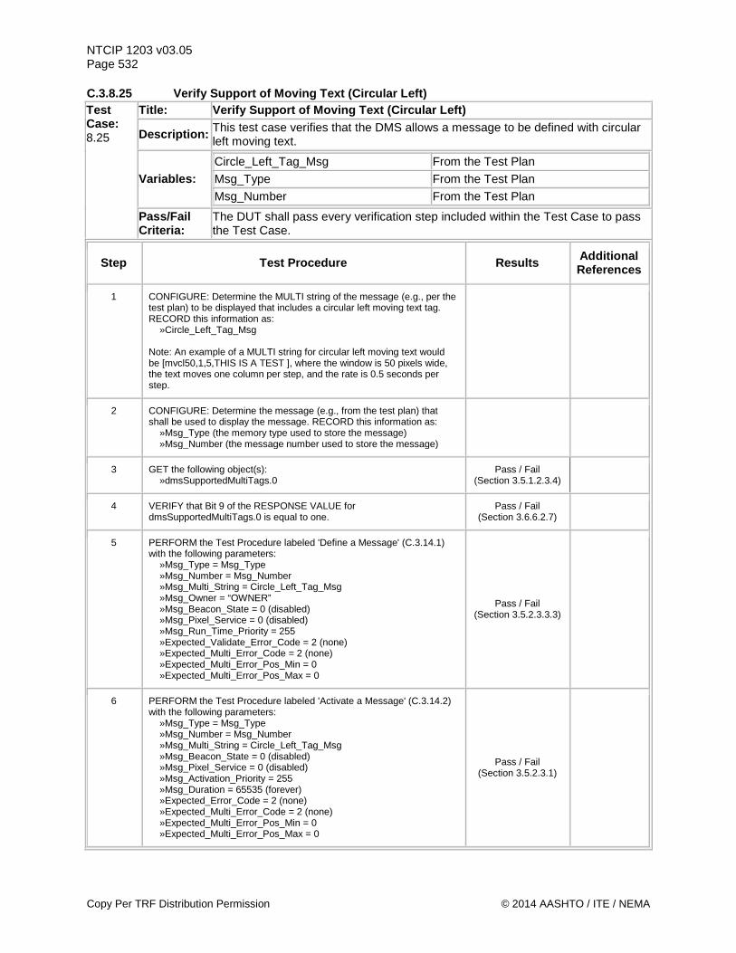
NTCIP 1203 v03.05 Page 532 C.3.8.25 Verify Support of Moving Text (Circular Left) Test Case: 8.25
Title: Verify Support of Moving Text (Circular Left)
Description: This test case verifies that the DMS allows a message to be defined with circular left moving text.
Variables: Circle_Left_Tag_Msg From the Test Plan Msg_Type From the Test Plan Msg_Number From the Test Plan
Pass/Fail Criteria:
The DUT shall pass every verification step included within the Test Case to pass the Test Case.
Step Test Procedure Results Additional References
1 CONFIGURE: Determine the MULTI string of the message (e.g., per the test plan) to be displayed that includes a circular left moving text tag. RECORD this information as: »Circle_Left_Tag_Msg Note: An example of a MULTI string for circular left moving text would be [mvcl50,1,5,THIS IS A TEST ], where the window is 50 pixels wide, the text moves one column per step, and the rate is 0.5 seconds per step.
2 CONFIGURE: Determine the message (e.g., from the test plan) that shall be used to display the message. RECORD this information as: »Msg_Type (the memory type used to store the message) »Msg_Number (the message number used to store the message)
3 GET the following object(s): »dmsSupportedMultiTags.0
Pass / Fail (Section 3.5.1.2.3.4)
4 VERIFY that Bit 9 of the RESPONSE VALUE for dmsSupportedMultiTags.0 is equal to one.
Pass / Fail (Section 3.6.6.2.7)
5 PERFORM the Test Procedure labeled 'Define a Message' (C.3.14.1) with the following parameters: »Msg_Type = Msg_Type »Msg_Number = Msg_Number »Msg_Multi_String = Circle_Left_Tag_Msg »Msg_Owner = “OWNER” »Msg_Beacon_State = 0 (disabled) »Msg_Pixel_Service = 0 (disabled) »Msg_Run_Time_Priority = 255 »Expected_Validate_Error_Code = 2 (none) »Expected_Multi_Error_Code = 2 (none) »Expected_Multi_Error_Pos_Min = 0 »Expected_Multi_Error_Pos_Max = 0
Pass / Fail (Section 3.5.2.3.3.3)
6 PERFORM the Test Procedure labeled 'Activate a Message' (C.3.14.2) with the following parameters: »Msg_Type = Msg_Type »Msg_Number = Msg_Number »Msg_Multi_String = Circle_Left_Tag_Msg »Msg_Beacon_State = 0 (disabled) »Msg_Pixel_Service = 0 (disabled) »Msg_Activation_Priority = 255 »Msg_Duration = 65535 (forever) »Expected_Error_Code = 2 (none) »Expected_Multi_Error_Code = 2 (none) »Expected_Multi_Error_Pos_Min = 0 »Expected_Multi_Error_Pos_Max = 0
Pass / Fail (Section 3.5.2.3.1)
Copy Per TRF Distribution Permission © 2014 AASHTO / ITE / NEMA
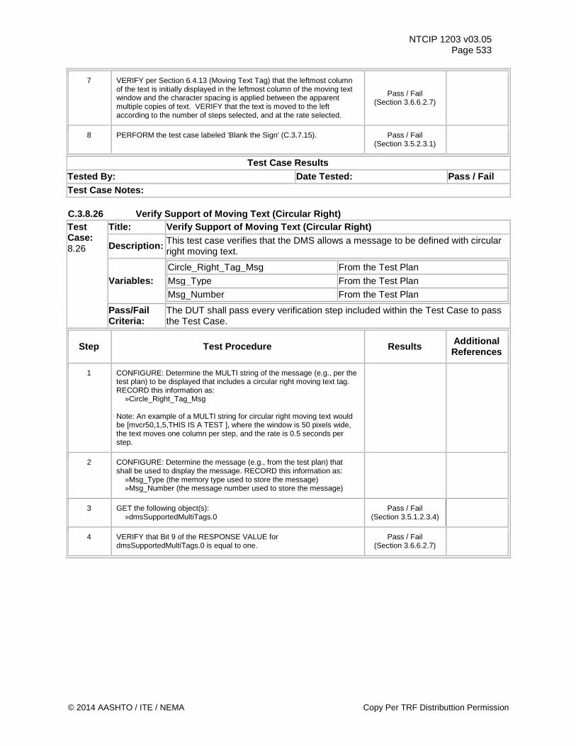
NTCIP 1203 v03.05 Page 533
7 VERIFY per Section 6.4.13 (Moving Text Tag) that the leftmost column of the text is initially displayed in the leftmost column of the moving text window and the character spacing is applied between the apparent multiple copies of text. VERIFY that the text is moved to the left according to the number of steps selected, and at the rate selected.
Pass / Fail (Section 3.6.6.2.7)
8 PERFORM the test case labeled 'Blank the Sign' (C.3.7.15). Pass / Fail (Section 3.5.2.3.1)
Test Case Results Tested By: Date Tested: Pass / Fail Test Case Notes: C.3.8.26 Verify Support of Moving Text (Circular Right) Test Case: 8.26
Title: Verify Support of Moving Text (Circular Right)
Description: This test case verifies that the DMS allows a message to be defined with circular right moving text.
Variables: Circle_Right_Tag_Msg From the Test Plan Msg_Type From the Test Plan Msg_Number From the Test Plan
Pass/Fail Criteria:
The DUT shall pass every verification step included within the Test Case to pass the Test Case.
Step Test Procedure Results Additional References
1 CONFIGURE: Determine the MULTI string of the message (e.g., per the test plan) to be displayed that includes a circular right moving text tag. RECORD this information as: »Circle_Right_Tag_Msg Note: An example of a MULTI string for circular right moving text would be [mvcr50,1,5,THIS IS A TEST ], where the window is 50 pixels wide, the text moves one column per step, and the rate is 0.5 seconds per step.
2 CONFIGURE: Determine the message (e.g., from the test plan) that shall be used to display the message. RECORD this information as: »Msg_Type (the memory type used to store the message) »Msg_Number (the message number used to store the message)
3 GET the following object(s): »dmsSupportedMultiTags.0
Pass / Fail (Section 3.5.1.2.3.4)
4 VERIFY that Bit 9 of the RESPONSE VALUE for dmsSupportedMultiTags.0 is equal to one.
Pass / Fail (Section 3.6.6.2.7)
© 2014 AASHTO / ITE / NEMA Copy Per TRF Distributtion Permission
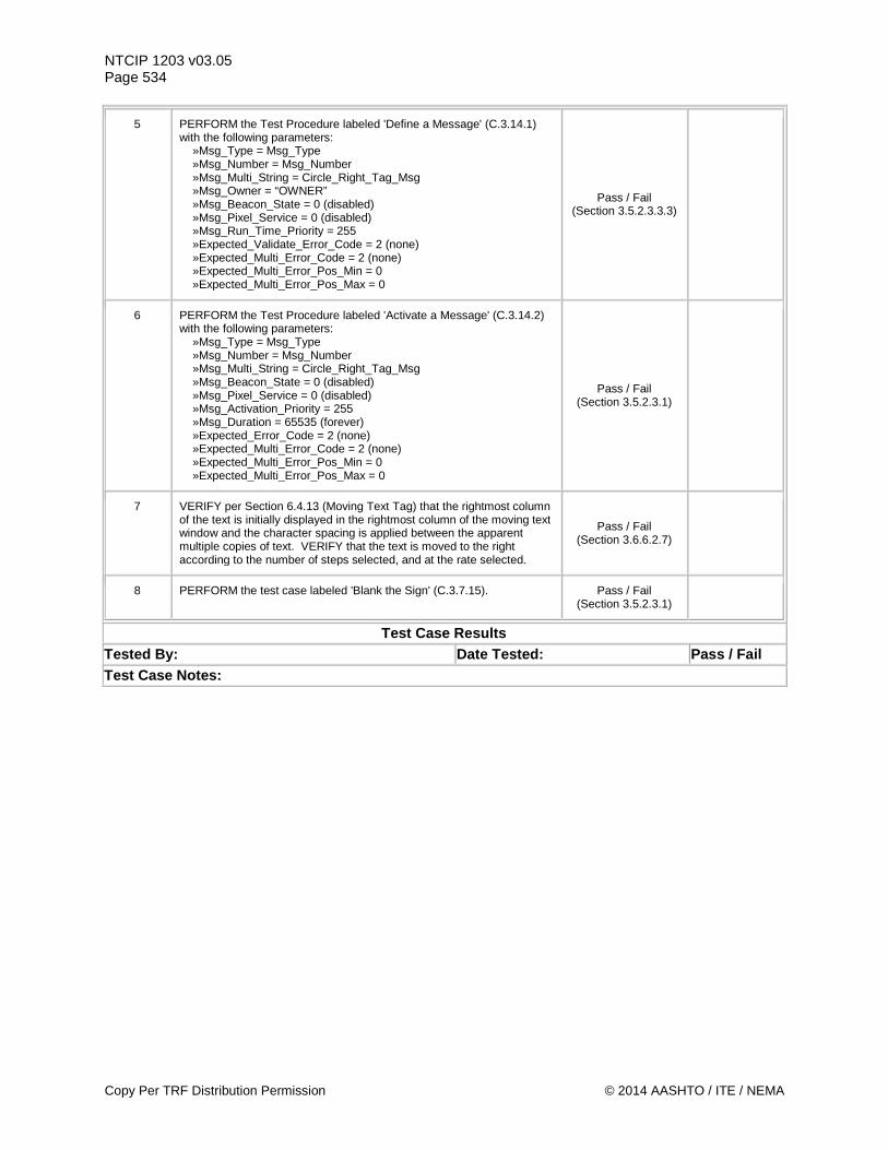
NTCIP 1203 v03.05 Page 534
5 PERFORM the Test Procedure labeled 'Define a Message' (C.3.14.1) with the following parameters: »Msg_Type = Msg_Type »Msg_Number = Msg_Number »Msg_Multi_String = Circle_Right_Tag_Msg »Msg_Owner = “OWNER” »Msg_Beacon_State = 0 (disabled) »Msg_Pixel_Service = 0 (disabled) »Msg_Run_Time_Priority = 255 »Expected_Validate_Error_Code = 2 (none) »Expected_Multi_Error_Code = 2 (none) »Expected_Multi_Error_Pos_Min = 0 »Expected_Multi_Error_Pos_Max = 0
Pass / Fail (Section 3.5.2.3.3.3)
6 PERFORM the Test Procedure labeled 'Activate a Message' (C.3.14.2) with the following parameters: »Msg_Type = Msg_Type »Msg_Number = Msg_Number »Msg_Multi_String = Circle_Right_Tag_Msg »Msg_Beacon_State = 0 (disabled) »Msg_Pixel_Service = 0 (disabled) »Msg_Activation_Priority = 255 »Msg_Duration = 65535 (forever) »Expected_Error_Code = 2 (none) »Expected_Multi_Error_Code = 2 (none) »Expected_Multi_Error_Pos_Min = 0 »Expected_Multi_Error_Pos_Max = 0
Pass / Fail (Section 3.5.2.3.1)
7 VERIFY per Section 6.4.13 (Moving Text Tag) that the rightmost column of the text is initially displayed in the rightmost column of the moving text window and the character spacing is applied between the apparent multiple copies of text. VERIFY that the text is moved to the right according to the number of steps selected, and at the rate selected.
Pass / Fail (Section 3.6.6.2.7)
8 PERFORM the test case labeled 'Blank the Sign' (C.3.7.15). Pass / Fail (Section 3.5.2.3.1)
Test Case Results Tested By: Date Tested: Pass / Fail Test Case Notes:
Copy Per TRF Distribution Permission © 2014 AASHTO / ITE / NEMA
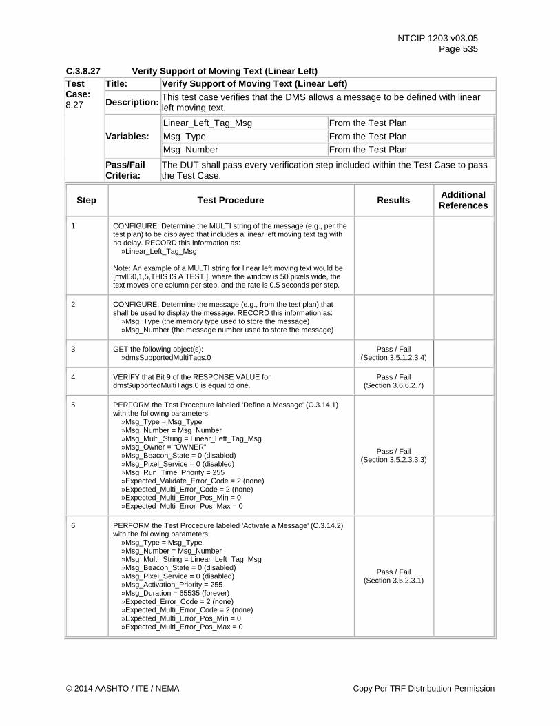
NTCIP 1203 v03.05 Page 535
C.3.8.27 Verify Support of Moving Text (Linear Left) Test Case: 8.27
Title: Verify Support of Moving Text (Linear Left)
Description: This test case verifies that the DMS allows a message to be defined with linear left moving text.
Variables: Linear_Left_Tag_Msg From the Test Plan Msg_Type From the Test Plan Msg_Number From the Test Plan
Pass/Fail Criteria:
The DUT shall pass every verification step included within the Test Case to pass the Test Case.
Step Test Procedure Results Additional References
1 CONFIGURE: Determine the MULTI string of the message (e.g., per the test plan) to be displayed that includes a linear left moving text tag with no delay. RECORD this information as: »Linear_Left_Tag_Msg Note: An example of a MULTI string for linear left moving text would be [mvll50,1,5,THIS IS A TEST ], where the window is 50 pixels wide, the text moves one column per step, and the rate is 0.5 seconds per step.
2 CONFIGURE: Determine the message (e.g., from the test plan) that shall be used to display the message. RECORD this information as: »Msg_Type (the memory type used to store the message) »Msg_Number (the message number used to store the message)
3 GET the following object(s): »dmsSupportedMultiTags.0
Pass / Fail (Section 3.5.1.2.3.4)
4 VERIFY that Bit 9 of the RESPONSE VALUE for dmsSupportedMultiTags.0 is equal to one.
Pass / Fail (Section 3.6.6.2.7)
5 PERFORM the Test Procedure labeled 'Define a Message' (C.3.14.1) with the following parameters: »Msg_Type = Msg_Type »Msg_Number = Msg_Number »Msg_Multi_String = Linear_Left_Tag_Msg »Msg_Owner = “OWNER” »Msg_Beacon_State = 0 (disabled) »Msg_Pixel_Service = 0 (disabled) »Msg_Run_Time_Priority = 255 »Expected_Validate_Error_Code = 2 (none) »Expected_Multi_Error_Code = 2 (none) »Expected_Multi_Error_Pos_Min = 0 »Expected_Multi_Error_Pos_Max = 0
Pass / Fail (Section 3.5.2.3.3.3)
6 PERFORM the Test Procedure labeled 'Activate a Message' (C.3.14.2) with the following parameters: »Msg_Type = Msg_Type »Msg_Number = Msg_Number »Msg_Multi_String = Linear_Left_Tag_Msg »Msg_Beacon_State = 0 (disabled) »Msg_Pixel_Service = 0 (disabled) »Msg_Activation_Priority = 255 »Msg_Duration = 65535 (forever) »Expected_Error_Code = 2 (none) »Expected_Multi_Error_Code = 2 (none) »Expected_Multi_Error_Pos_Min = 0 »Expected_Multi_Error_Pos_Max = 0
Pass / Fail (Section 3.5.2.3.1)
© 2014 AASHTO / ITE / NEMA Copy Per TRF Distributtion Permission
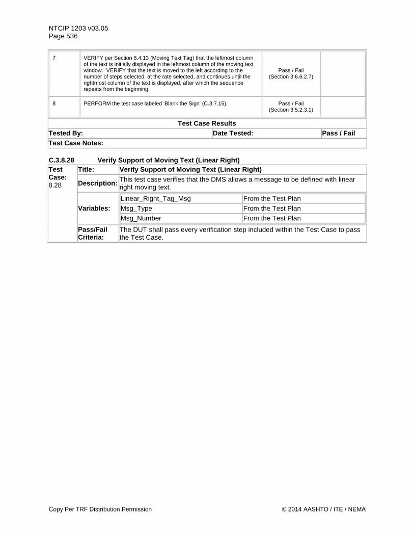
NTCIP 1203 v03.05 Page 536
7 VERIFY per Section 6.4.13 (Moving Text Tag) that the leftmost column of the text is initially displayed in the leftmost column of the moving text window. VERIFY that the text is moved to the left according to the number of steps selected, at the rate selected, and continues until the rightmost column of the text is displayed, after which the sequence repeats from the beginning.
Pass / Fail (Section 3.6.6.2.7)
8 PERFORM the test case labeled 'Blank the Sign' (C.3.7.15). Pass / Fail (Section 3.5.2.3.1)
Test Case Results Tested By: Date Tested: Pass / Fail Test Case Notes: C.3.8.28 Verify Support of Moving Text (Linear Right) Test Case: 8.28
Title: Verify Support of Moving Text (Linear Right)
Description: This test case verifies that the DMS allows a message to be defined with linear right moving text.
Variables: Linear_Right_Tag_Msg From the Test Plan
Msg_Type From the Test Plan
Msg_Number From the Test Plan
Pass/Fail Criteria:
The DUT shall pass every verification step included within the Test Case to pass the Test Case.
Copy Per TRF Distribution Permission © 2014 AASHTO / ITE / NEMA
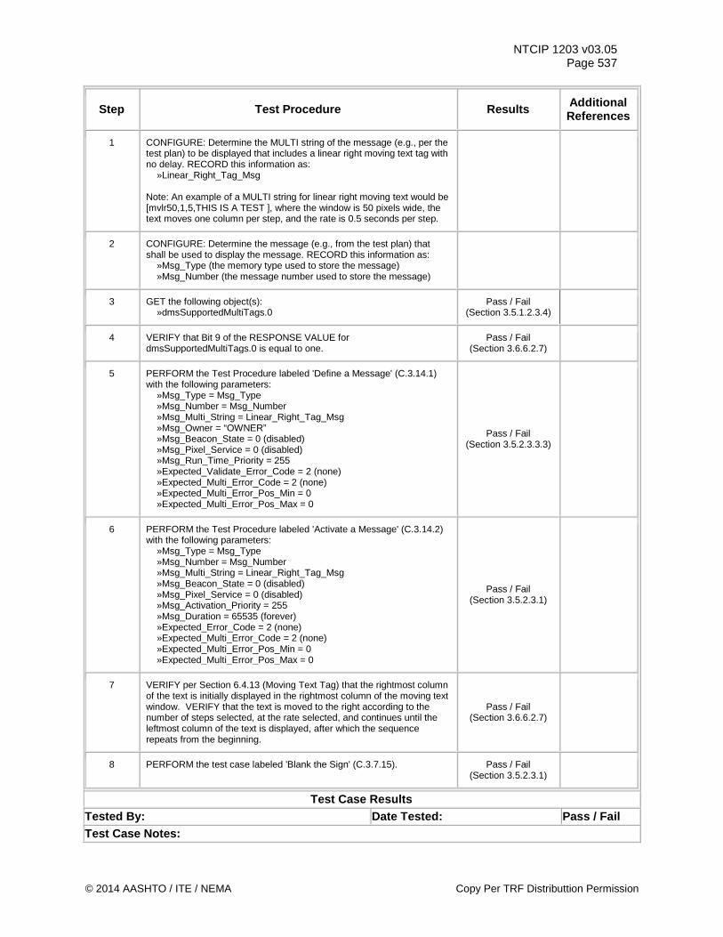
NTCIP 1203 v03.05 Page 537
Step Test Procedure Results Additional References
1 CONFIGURE: Determine the MULTI string of the message (e.g., per the test plan) to be displayed that includes a linear right moving text tag with no delay. RECORD this information as: »Linear_Right_Tag_Msg Note: An example of a MULTI string for linear right moving text would be [mvlr50,1,5,THIS IS A TEST ], where the window is 50 pixels wide, the text moves one column per step, and the rate is 0.5 seconds per step.
2 CONFIGURE: Determine the message (e.g., from the test plan) that shall be used to display the message. RECORD this information as: »Msg_Type (the memory type used to store the message) »Msg_Number (the message number used to store the message)
3 GET the following object(s): »dmsSupportedMultiTags.0
Pass / Fail (Section 3.5.1.2.3.4)
4 VERIFY that Bit 9 of the RESPONSE VALUE for dmsSupportedMultiTags.0 is equal to one.
Pass / Fail (Section 3.6.6.2.7)
5 PERFORM the Test Procedure labeled 'Define a Message' (C.3.14.1) with the following parameters: »Msg_Type = Msg_Type »Msg_Number = Msg_Number »Msg_Multi_String = Linear_Right_Tag_Msg »Msg_Owner = “OWNER” »Msg_Beacon_State = 0 (disabled) »Msg_Pixel_Service = 0 (disabled) »Msg_Run_Time_Priority = 255 »Expected_Validate_Error_Code = 2 (none) »Expected_Multi_Error_Code = 2 (none) »Expected_Multi_Error_Pos_Min = 0 »Expected_Multi_Error_Pos_Max = 0
Pass / Fail (Section 3.5.2.3.3.3)
6 PERFORM the Test Procedure labeled 'Activate a Message' (C.3.14.2) with the following parameters: »Msg_Type = Msg_Type »Msg_Number = Msg_Number »Msg_Multi_String = Linear_Right_Tag_Msg »Msg_Beacon_State = 0 (disabled) »Msg_Pixel_Service = 0 (disabled) »Msg_Activation_Priority = 255 »Msg_Duration = 65535 (forever) »Expected_Error_Code = 2 (none) »Expected_Multi_Error_Code = 2 (none) »Expected_Multi_Error_Pos_Min = 0 »Expected_Multi_Error_Pos_Max = 0
Pass / Fail (Section 3.5.2.3.1)
7 VERIFY per Section 6.4.13 (Moving Text Tag) that the rightmost column of the text is initially displayed in the rightmost column of the moving text window. VERIFY that the text is moved to the right according to the number of steps selected, at the rate selected, and continues until the leftmost column of the text is displayed, after which the sequence repeats from the beginning.
Pass / Fail (Section 3.6.6.2.7)
8 PERFORM the test case labeled 'Blank the Sign' (C.3.7.15). Pass / Fail (Section 3.5.2.3.1)
Test Case Results Tested By: Date Tested: Pass / Fail Test Case Notes:
© 2014 AASHTO / ITE / NEMA Copy Per TRF Distributtion Permission
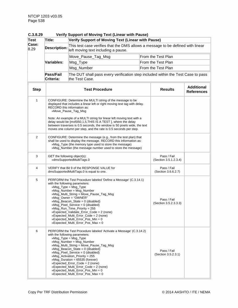
NTCIP 1203 v03.05 Page 538 C.3.8.29 Verify Support of Moving Text (Linear with Pause) Test Case: 8.29
Title: Verify Support of Moving Text (Linear with Pause)
Description: This test case verifies that the DMS allows a message to be defined with linear left moving text including a pause.
Variables: Move_Pause_Tag_Msg From the Test Plan
Msg_Type From the Test Plan
Msg_Number From the Test Plan
Pass/Fail Criteria:
The DUT shall pass every verification step included within the Test Case to pass the Test Case.
Step Test Procedure Results Additional References
1 CONFIGURE: Determine the MULTI string of the message to be displayed that includes a linear left or right moving text tag with delay. RECORD this information as: »Move_Pause_Tag_Msg Note: An example of a MULTI string for linear left moving text with a delay would be [mvl5l50,1,5,THIS IS A TEST ], where the delay between traverses is 0.5 seconds, the window is 50 pixels wide, the text moves one column per step, and the rate is 0.5 seconds per step.
2 CONFIGURE: Determine the message (e.g., from the test plan) that shall be used to display the message. RECORD this information as: »Msg_Type (the memory type used to store the message) »Msg_Number (the message number used to store the message)
3 GET the following object(s): »dmsSupportedMultiTags.0
Pass / Fail (Section 3.5.1.2.3.4)
4 VERIFY that Bit 9 of the RESPONSE VALUE for dmsSupportedMultiTags.0 is equal to one.
Pass / Fail (Section 3.6.6.2.7)
5 PERFORM the Test Procedure labeled 'Define a Message' (C.3.14.1) with the following parameters: »Msg_Type = Msg_Type »Msg_Number = Msg_Number »Msg_Multi_String = Move_Pause_Tag_Msg »Msg_Owner = “OWNER” »Msg_Beacon_State = 0 (disabled) »Msg_Pixel_Service = 0 (disabled) »Msg_Run_Time_Priority = 255 »Expected_Validate_Error_Code = 2 (none) »Expected_Multi_Error_Code = 2 (none) »Expected_Multi_Error_Pos_Min = 0 »Expected_Multi_Error_Pos_Max = 0
Pass / Fail (Section 3.5.2.3.3.3)
6 PERFORM the Test Procedure labeled 'Activate a Message' (C.3.14.2) with the following parameters: »Msg_Type = Msg_Type »Msg_Number = Msg_Number »Msg_Multi_String = Move_Pause_Tag_Msg »Msg_Beacon_State = 0 (disabled) »Msg_Pixel_Service = 0 (disabled) »Msg_Activation_Priority = 255 »Msg_Duration = 65535 (forever) »Expected_Error_Code = 2 (none) »Expected_Multi_Error_Code = 2 (none) »Expected_Multi_Error_Pos_Min = 0 »Expected_Multi_Error_Pos_Max = 0
Pass / Fail (Section 3.5.2.3.1)
Copy Per TRF Distribution Permission © 2014 AASHTO / ITE / NEMA
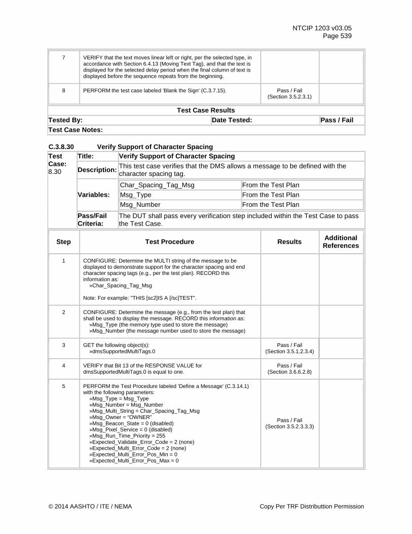
NTCIP 1203 v03.05 Page 539
7 VERIFY that the text moves linear left or right, per the selected type, in accordance with Section 6.4.13 (Moving Text Tag), and that the text is displayed for the selected delay period when the final column of text is displayed before the sequence repeats from the beginning.
8 PERFORM the test case labeled 'Blank the Sign' (C.3.7.15). Pass / Fail (Section 3.5.2.3.1)
Test Case Results Tested By: Date Tested: Pass / Fail Test Case Notes: C.3.8.30 Verify Support of Character Spacing Test Case: 8.30
Title: Verify Support of Character Spacing
Description: This test case verifies that the DMS allows a message to be defined with the character spacing tag.
Variables: Char_Spacing_Tag_Msg From the Test Plan Msg_Type From the Test Plan Msg_Number From the Test Plan
Pass/Fail Criteria:
The DUT shall pass every verification step included within the Test Case to pass the Test Case.
Step Test Procedure Results Additional References
1 CONFIGURE: Determine the MULTI string of the message to be displayed to demonstrate support for the character spacing and end character spacing tags (e.g., per the test plan). RECORD this information as: »Char_Spacing_Tag_Msg Note: For example: "THIS [sc2]IS A [/sc]TEST".
2 CONFIGURE: Determine the message (e.g., from the test plan) that shall be used to display the message. RECORD this information as: »Msg_Type (the memory type used to store the message) »Msg_Number (the message number used to store the message)
3 GET the following object(s): »dmsSupportedMultiTags.0
Pass / Fail (Section 3.5.1.2.3.4)
4 VERIFY that Bit 13 of the RESPONSE VALUE for dmsSupportedMultiTags.0 is equal to one.
Pass / Fail (Section 3.6.6.2.8)
5 PERFORM the Test Procedure labeled 'Define a Message' (C.3.14.1) with the following parameters: »Msg_Type = Msg_Type »Msg_Number = Msg_Number »Msg_Multi_String = Char_Spacing_Tag_Msg »Msg_Owner = “OWNER” »Msg_Beacon_State = 0 (disabled) »Msg_Pixel_Service = 0 (disabled) »Msg_Run_Time_Priority = 255 »Expected_Validate_Error_Code = 2 (none) »Expected_Multi_Error_Code = 2 (none) »Expected_Multi_Error_Pos_Min = 0 »Expected_Multi_Error_Pos_Max = 0
Pass / Fail (Section 3.5.2.3.3.3)
© 2014 AASHTO / ITE / NEMA Copy Per TRF Distributtion Permission
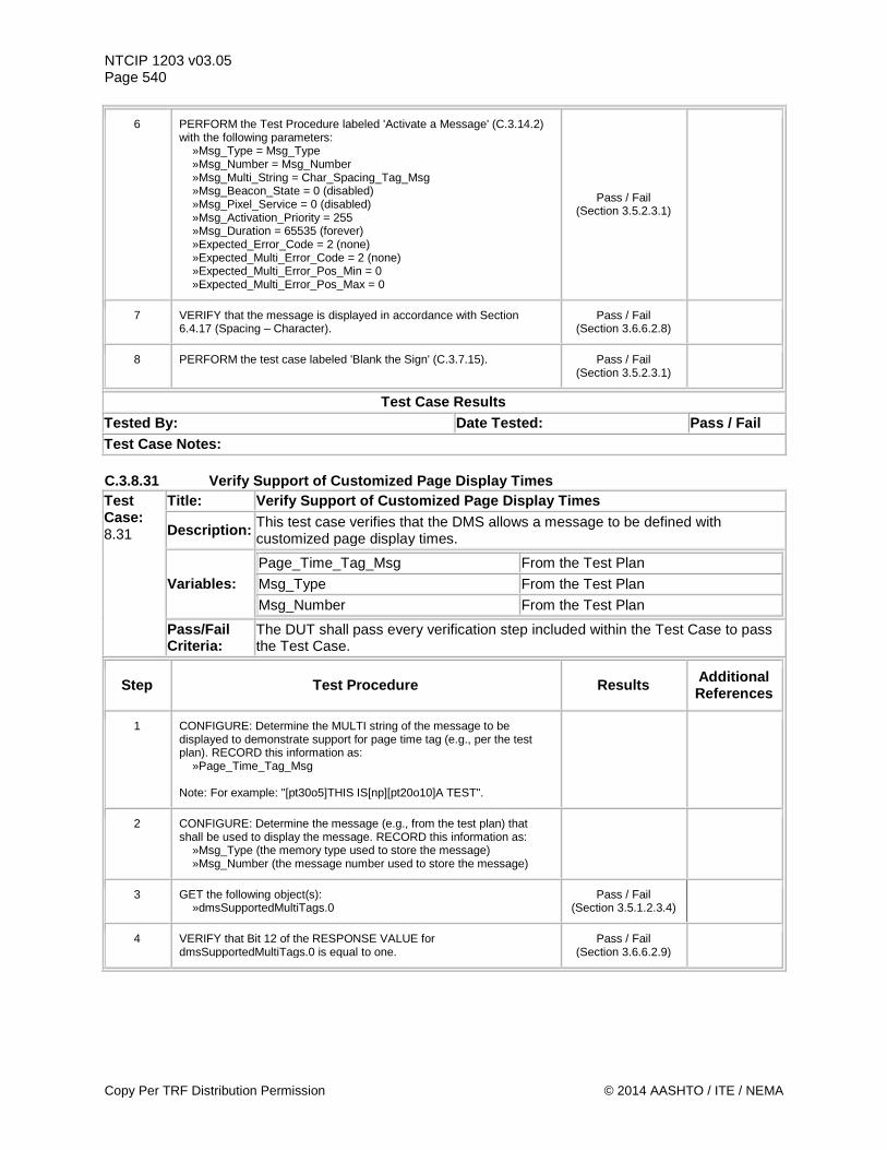
NTCIP 1203 v03.05 Page 540
6 PERFORM the Test Procedure labeled 'Activate a Message' (C.3.14.2) with the following parameters: »Msg_Type = Msg_Type »Msg_Number = Msg_Number »Msg_Multi_String = Char_Spacing_Tag_Msg »Msg_Beacon_State = 0 (disabled) »Msg_Pixel_Service = 0 (disabled) »Msg_Activation_Priority = 255 »Msg_Duration = 65535 (forever) »Expected_Error_Code = 2 (none) »Expected_Multi_Error_Code = 2 (none) »Expected_Multi_Error_Pos_Min = 0 »Expected_Multi_Error_Pos_Max = 0
Pass / Fail (Section 3.5.2.3.1)
7 VERIFY that the message is displayed in accordance with Section 6.4.17 (Spacing – Character).
Pass / Fail (Section 3.6.6.2.8)
8 PERFORM the test case labeled 'Blank the Sign' (C.3.7.15). Pass / Fail (Section 3.5.2.3.1)
Test Case Results Tested By: Date Tested: Pass / Fail Test Case Notes: C.3.8.31 Verify Support of Customized Page Display Times Test Case: 8.31
Title: Verify Support of Customized Page Display Times
Description: This test case verifies that the DMS allows a message to be defined with customized page display times.
Variables: Page_Time_Tag_Msg From the Test Plan Msg_Type From the Test Plan Msg_Number From the Test Plan
Pass/Fail Criteria:
The DUT shall pass every verification step included within the Test Case to pass the Test Case.
Step Test Procedure Results Additional References
1 CONFIGURE: Determine the MULTI string of the message to be displayed to demonstrate support for page time tag (e.g., per the test plan). RECORD this information as: »Page_Time_Tag_Msg Note: For example: "[pt30o5]THIS IS[np][pt20o10]A TEST".
2 CONFIGURE: Determine the message (e.g., from the test plan) that shall be used to display the message. RECORD this information as: »Msg_Type (the memory type used to store the message) »Msg_Number (the message number used to store the message)
3 GET the following object(s): »dmsSupportedMultiTags.0
Pass / Fail (Section 3.5.1.2.3.4)
4 VERIFY that Bit 12 of the RESPONSE VALUE for dmsSupportedMultiTags.0 is equal to one.
Pass / Fail (Section 3.6.6.2.9)
Copy Per TRF Distribution Permission © 2014 AASHTO / ITE / NEMA
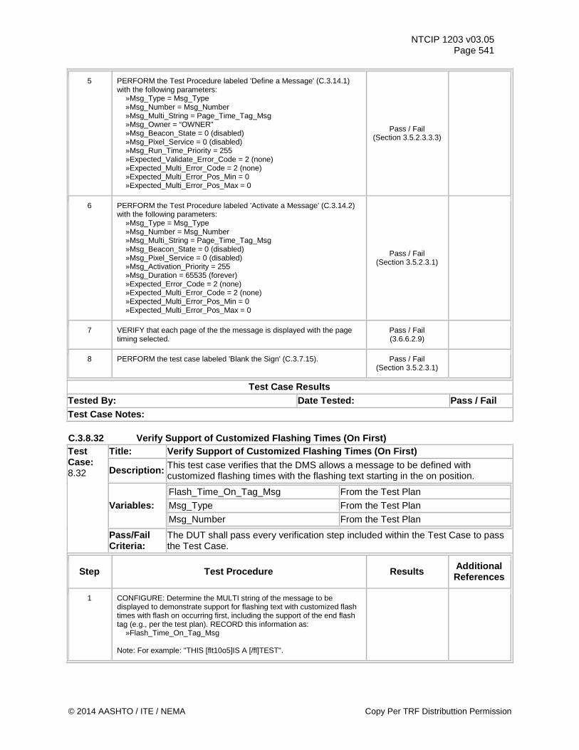
NTCIP 1203 v03.05 Page 541
5 PERFORM the Test Procedure labeled 'Define a Message' (C.3.14.1) with the following parameters: »Msg_Type = Msg_Type »Msg_Number = Msg_Number »Msg_Multi_String = Page_Time_Tag_Msg »Msg_Owner = “OWNER” »Msg_Beacon_State = 0 (disabled) »Msg_Pixel_Service = 0 (disabled) »Msg_Run_Time_Priority = 255 »Expected_Validate_Error_Code = 2 (none) »Expected_Multi_Error_Code = 2 (none) »Expected_Multi_Error_Pos_Min = 0 »Expected_Multi_Error_Pos_Max = 0
Pass / Fail (Section 3.5.2.3.3.3)
6 PERFORM the Test Procedure labeled 'Activate a Message' (C.3.14.2) with the following parameters: »Msg_Type = Msg_Type »Msg_Number = Msg_Number »Msg_Multi_String = Page_Time_Tag_Msg »Msg_Beacon_State = 0 (disabled) »Msg_Pixel_Service = 0 (disabled) »Msg_Activation_Priority = 255 »Msg_Duration = 65535 (forever) »Expected_Error_Code = 2 (none) »Expected_Multi_Error_Code = 2 (none) »Expected_Multi_Error_Pos_Min = 0 »Expected_Multi_Error_Pos_Max = 0
Pass / Fail (Section 3.5.2.3.1)
7 VERIFY that each page of the the message is displayed with the page timing selected.
Pass / Fail (3.6.6.2.9)
8 PERFORM the test case labeled 'Blank the Sign' (C.3.7.15). Pass / Fail (Section 3.5.2.3.1)
Test Case Results Tested By: Date Tested: Pass / Fail Test Case Notes: C.3.8.32 Verify Support of Customized Flashing Times (On First) Test Case: 8.32
Title: Verify Support of Customized Flashing Times (On First)
Description: This test case verifies that the DMS allows a message to be defined with customized flashing times with the flashing text starting in the on position.
Variables: Flash_Time_On_Tag_Msg From the Test Plan Msg_Type From the Test Plan Msg_Number From the Test Plan
Pass/Fail Criteria:
The DUT shall pass every verification step included within the Test Case to pass the Test Case.
Step Test Procedure Results Additional References
1 CONFIGURE: Determine the MULTI string of the message to be displayed to demonstrate support for flashing text with customized flash times with flash on occurring first, including the support of the end flash tag (e.g., per the test plan). RECORD this information as: »Flash_Time_On_Tag_Msg Note: For example: "THIS [flt10o5]IS A [/fl]TEST".
© 2014 AASHTO / ITE / NEMA Copy Per TRF Distributtion Permission
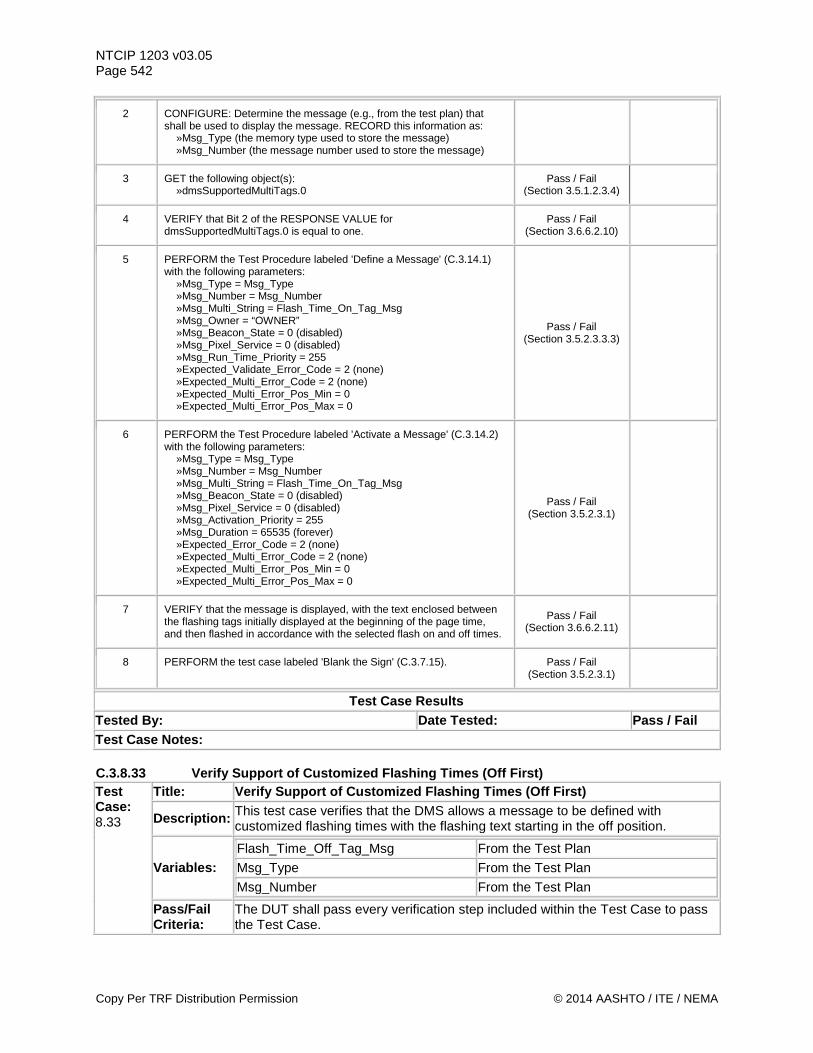
NTCIP 1203 v03.05 Page 542
2 CONFIGURE: Determine the message (e.g., from the test plan) that shall be used to display the message. RECORD this information as: »Msg_Type (the memory type used to store the message) »Msg_Number (the message number used to store the message)
3 GET the following object(s): »dmsSupportedMultiTags.0
Pass / Fail (Section 3.5.1.2.3.4)
4 VERIFY that Bit 2 of the RESPONSE VALUE for dmsSupportedMultiTags.0 is equal to one.
Pass / Fail (Section 3.6.6.2.10)
5 PERFORM the Test Procedure labeled 'Define a Message' (C.3.14.1) with the following parameters: »Msg_Type = Msg_Type »Msg_Number = Msg_Number »Msg_Multi_String = Flash_Time_On_Tag_Msg »Msg_Owner = “OWNER” »Msg_Beacon_State = 0 (disabled) »Msg_Pixel_Service = 0 (disabled) »Msg_Run_Time_Priority = 255 »Expected_Validate_Error_Code = 2 (none) »Expected_Multi_Error_Code = 2 (none) »Expected_Multi_Error_Pos_Min = 0 »Expected_Multi_Error_Pos_Max = 0
Pass / Fail (Section 3.5.2.3.3.3)
6 PERFORM the Test Procedure labeled 'Activate a Message' (C.3.14.2) with the following parameters: »Msg_Type = Msg_Type »Msg_Number = Msg_Number »Msg_Multi_String = Flash_Time_On_Tag_Msg »Msg_Beacon_State = 0 (disabled) »Msg_Pixel_Service = 0 (disabled) »Msg_Activation_Priority = 255 »Msg_Duration = 65535 (forever) »Expected_Error_Code = 2 (none) »Expected_Multi_Error_Code = 2 (none) »Expected_Multi_Error_Pos_Min = 0 »Expected_Multi_Error_Pos_Max = 0
Pass / Fail (Section 3.5.2.3.1)
7 VERIFY that the message is displayed, with the text enclosed between the flashing tags initially displayed at the beginning of the page time, and then flashed in accordance with the selected flash on and off times.
Pass / Fail (Section 3.6.6.2.11)
8 PERFORM the test case labeled 'Blank the Sign' (C.3.7.15). Pass / Fail (Section 3.5.2.3.1)
Test Case Results Tested By: Date Tested: Pass / Fail Test Case Notes: C.3.8.33 Verify Support of Customized Flashing Times (Off First) Test Case: 8.33
Title: Verify Support of Customized Flashing Times (Off First)
Description: This test case verifies that the DMS allows a message to be defined with customized flashing times with the flashing text starting in the off position.
Variables: Flash_Time_Off_Tag_Msg From the Test Plan Msg_Type From the Test Plan Msg_Number From the Test Plan
Pass/Fail Criteria:
The DUT shall pass every verification step included within the Test Case to pass the Test Case.
Copy Per TRF Distribution Permission © 2014 AASHTO / ITE / NEMA
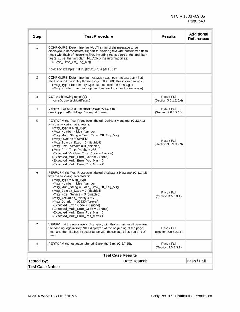
NTCIP 1203 v03.05 Page 543
Step Test Procedure Results Additional References
1 CONFIGURE: Determine the MULTI string of the message to be displayed to demonstrate support for flashing text with customized flash times with flash off occurring first, including the support of the end flash tag (e.g., per the test plan). RECORD this information as: »Flash_Time_Off_Tag_Msg Note: For example: "THIS [flo5t10]IS A [/fl]TEST".
2 CONFIGURE: Determine the message (e.g., from the test plan) that shall be used to display the message. RECORD this information as: »Msg_Type (the memory type used to store the message) »Msg_Number (the message number used to store the message)
3 GET the following object(s): »dmsSupportedMultiTags.0
Pass / Fail (Section 3.5.1.2.3.4)
4 VERIFY that Bit 2 of the RESPONSE VALUE for dmsSupportedMultiTags.0 is equal to one.
Pass / Fail (Section 3.6.6.2.10)
5 PERFORM the Test Procedure labeled 'Define a Message' (C.3.14.1) with the following parameters: »Msg_Type = Msg_Type »Msg_Number = Msg_Number »Msg_Multi_String = Flash_Time_Off_Tag_Msg »Msg_Owner = “OWNER” »Msg_Beacon_State = 0 (disabled) »Msg_Pixel_Service = 0 (disabled) »Msg_Run_Time_Priority = 255 »Expected_Validate_Error_Code = 2 (none) »Expected_Multi_Error_Code = 2 (none) »Expected_Multi_Error_Pos_Min = 0 »Expected_Multi_Error_Pos_Max = 0
Pass / Fail (Section 3.5.2.3.3.3)
6 PERFORM the Test Procedure labeled 'Activate a Message' (C.3.14.2) with the following parameters: »Msg_Type = Msg_Type »Msg_Number = Msg_Number »Msg_Multi_String = Flash_Time_Off_Tag_Msg »Msg_Beacon_State = 0 (disabled) »Msg_Pixel_Service = 0 (disabled) »Msg_Activation_Priority = 255 »Msg_Duration = 65535 (forever) »Expected_Error_Code = 2 (none) »Expected_Multi_Error_Code = 2 (none) »Expected_Multi_Error_Pos_Min = 0 »Expected_Multi_Error_Pos_Max = 0
Pass / Fail (Section 3.5.2.3.1)
7 VERIFY that the message is displayed, with the text enclosed between the flashing tags initially NOT displayed at the beginning of the page time, and then flashed in accordance with the selected flash on and off times.
Pass / Fail (Section 3.6.6.2.11)
8 PERFORM the test case labeled 'Blank the Sign' (C.3.7.15). Pass / Fail (Section 3.5.2.3.1)
Test Case Results Tested By: Date Tested: Pass / Fail Test Case Notes:
© 2014 AASHTO / ITE / NEMA Copy Per TRF Distributtion Permission
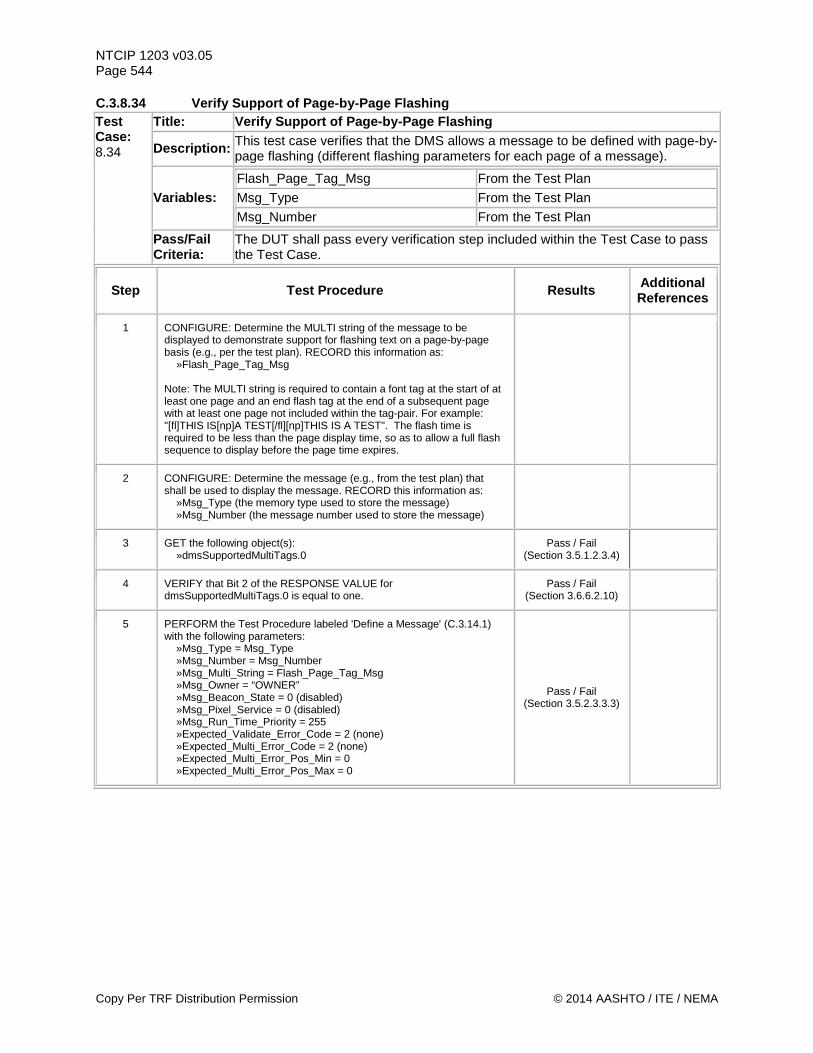
NTCIP 1203 v03.05 Page 544 C.3.8.34 Verify Support of Page-by-Page Flashing Test Case: 8.34
Title: Verify Support of Page-by-Page Flashing
Description: This test case verifies that the DMS allows a message to be defined with page-by-page flashing (different flashing parameters for each page of a message).
Variables: Flash_Page_Tag_Msg From the Test Plan Msg_Type From the Test Plan Msg_Number From the Test Plan
Pass/Fail Criteria:
The DUT shall pass every verification step included within the Test Case to pass the Test Case.
Step Test Procedure Results Additional References
1 CONFIGURE: Determine the MULTI string of the message to be displayed to demonstrate support for flashing text on a page-by-page basis (e.g., per the test plan). RECORD this information as: »Flash_Page_Tag_Msg Note: The MULTI string is required to contain a font tag at the start of at least one page and an end flash tag at the end of a subsequent page with at least one page not included within the tag-pair. For example: "[fl]THIS IS[np]A TEST[/fl][np]THIS IS A TEST". The flash time is required to be less than the page display time, so as to allow a full flash sequence to display before the page time expires.
2 CONFIGURE: Determine the message (e.g., from the test plan) that shall be used to display the message. RECORD this information as: »Msg_Type (the memory type used to store the message) »Msg_Number (the message number used to store the message)
3 GET the following object(s): »dmsSupportedMultiTags.0
Pass / Fail (Section 3.5.1.2.3.4)
4 VERIFY that Bit 2 of the RESPONSE VALUE for dmsSupportedMultiTags.0 is equal to one.
Pass / Fail (Section 3.6.6.2.10)
5 PERFORM the Test Procedure labeled 'Define a Message' (C.3.14.1) with the following parameters: »Msg_Type = Msg_Type »Msg_Number = Msg_Number »Msg_Multi_String = Flash_Page_Tag_Msg »Msg_Owner = “OWNER” »Msg_Beacon_State = 0 (disabled) »Msg_Pixel_Service = 0 (disabled) »Msg_Run_Time_Priority = 255 »Expected_Validate_Error_Code = 2 (none) »Expected_Multi_Error_Code = 2 (none) »Expected_Multi_Error_Pos_Min = 0 »Expected_Multi_Error_Pos_Max = 0
Pass / Fail (Section 3.5.2.3.3.3)
Copy Per TRF Distribution Permission © 2014 AASHTO / ITE / NEMA
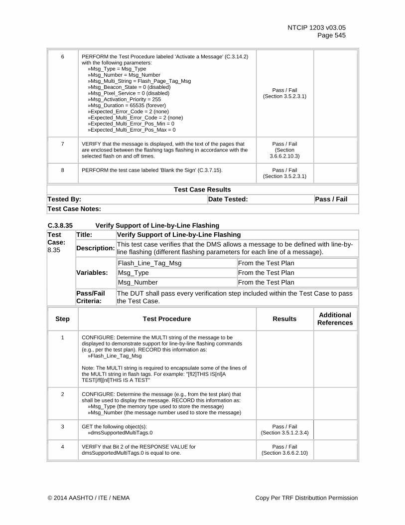
NTCIP 1203 v03.05 Page 545
6 PERFORM the Test Procedure labeled 'Activate a Message' (C.3.14.2) with the following parameters: »Msg_Type = Msg_Type »Msg_Number = Msg_Number »Msg_Multi_String = Flash_Page_Tag_Msg »Msg_Beacon_State = 0 (disabled) »Msg_Pixel_Service = 0 (disabled) »Msg_Activation_Priority = 255 »Msg_Duration = 65535 (forever) »Expected_Error_Code = 2 (none) »Expected_Multi_Error_Code = 2 (none) »Expected_Multi_Error_Pos_Min = 0 »Expected_Multi_Error_Pos_Max = 0
Pass / Fail (Section 3.5.2.3.1)
7 VERIFY that the message is displayed, with the text of the pages that are enclosed between the flashing tags flashing in accordance with the selected flash on and off times.
Pass / Fail (Section
3.6.6.2.10.3)
8 PERFORM the test case labeled 'Blank the Sign' (C.3.7.15). Pass / Fail (Section 3.5.2.3.1)
Test Case Results Tested By: Date Tested: Pass / Fail Test Case Notes: C.3.8.35 Verify Support of Line-by-Line Flashing Test Case: 8.35
Title: Verify Support of Line-by-Line Flashing
Description: This test case verifies that the DMS allows a message to be defined with line-by-line flashing (different flashing parameters for each line of a message).
Variables: Flash_Line_Tag_Msg From the Test Plan Msg_Type From the Test Plan Msg_Number From the Test Plan
Pass/Fail Criteria:
The DUT shall pass every verification step included within the Test Case to pass the Test Case.
Step Test Procedure Results Additional References
1 CONFIGURE: Determine the MULTI string of the message to be displayed to demonstrate support for line-by-line flashing commands (e.g., per the test plan). RECORD this information as: »Flash_Line_Tag_Msg Note: The MULTI string is required to encapsulate some of the lines of the MULTI string in flash tags. For example: "[fl2]THIS IS[nl]A TEST[/fl][nl]THIS IS A TEST"
2 CONFIGURE: Determine the message (e.g., from the test plan) that shall be used to display the message. RECORD this information as: »Msg_Type (the memory type used to store the message) »Msg_Number (the message number used to store the message)
3 GET the following object(s): »dmsSupportedMultiTags.0
Pass / Fail (Section 3.5.1.2.3.4)
4 VERIFY that Bit 2 of the RESPONSE VALUE for dmsSupportedMultiTags.0 is equal to one.
Pass / Fail (Section 3.6.6.2.10)
© 2014 AASHTO / ITE / NEMA Copy Per TRF Distributtion Permission
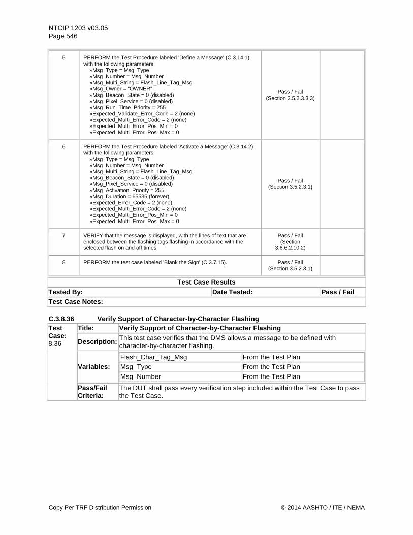
NTCIP 1203 v03.05 Page 546
5 PERFORM the Test Procedure labeled 'Define a Message' (C.3.14.1) with the following parameters: »Msg_Type = Msg_Type »Msg_Number = Msg_Number »Msg_Multi_String = Flash_Line_Tag_Msg »Msg_Owner = “OWNER” »Msg_Beacon_State = 0 (disabled) »Msg_Pixel_Service = 0 (disabled) »Msg_Run_Time_Priority = 255 »Expected_Validate_Error_Code = 2 (none) »Expected_Multi_Error_Code = 2 (none) »Expected_Multi_Error_Pos_Min = 0 »Expected_Multi_Error_Pos_Max = 0
Pass / Fail (Section 3.5.2.3.3.3)
6 PERFORM the Test Procedure labeled 'Activate a Message' (C.3.14.2) with the following parameters: »Msg_Type = Msg_Type »Msg_Number = Msg_Number »Msg_Multi_String = Flash_Line_Tag_Msg »Msg_Beacon_State = 0 (disabled) »Msg_Pixel_Service = 0 (disabled) »Msg_Activation_Priority = 255 »Msg_Duration = 65535 (forever) »Expected_Error_Code = 2 (none) »Expected_Multi_Error_Code = 2 (none) »Expected_Multi_Error_Pos_Min = 0 »Expected_Multi_Error_Pos_Max = 0
Pass / Fail (Section 3.5.2.3.1)
7 VERIFY that the message is displayed, with the lines of text that are enclosed between the flashing tags flashing in accordance with the selected flash on and off times.
Pass / Fail (Section
3.6.6.2.10.2)
8 PERFORM the test case labeled 'Blank the Sign' (C.3.7.15). Pass / Fail (Section 3.5.2.3.1)
Test Case Results Tested By: Date Tested: Pass / Fail Test Case Notes: C.3.8.36 Verify Support of Character-by-Character Flashing Test Case: 8.36
Title: Verify Support of Character-by-Character Flashing
Description: This test case verifies that the DMS allows a message to be defined with character-by-character flashing.
Variables: Flash_Char_Tag_Msg From the Test Plan Msg_Type From the Test Plan Msg_Number From the Test Plan
Pass/Fail Criteria:
The DUT shall pass every verification step included within the Test Case to pass the Test Case.
Copy Per TRF Distribution Permission © 2014 AASHTO / ITE / NEMA
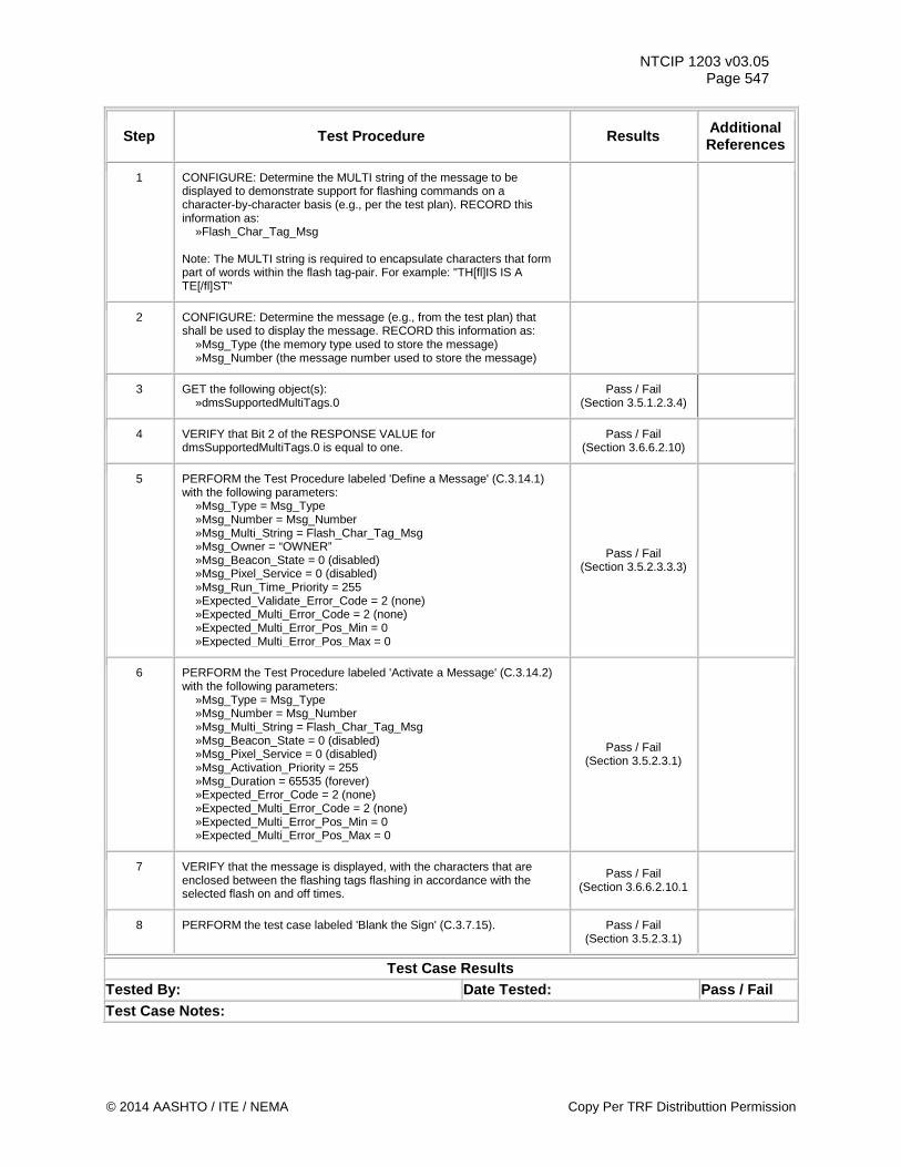
NTCIP 1203 v03.05 Page 547
Step Test Procedure Results Additional References
1 CONFIGURE: Determine the MULTI string of the message to be displayed to demonstrate support for flashing commands on a character-by-character basis (e.g., per the test plan). RECORD this information as: »Flash_Char_Tag_Msg Note: The MULTI string is required to encapsulate characters that form part of words within the flash tag-pair. For example: "TH[fl]IS IS A TE[/fl]ST"
2 CONFIGURE: Determine the message (e.g., from the test plan) that shall be used to display the message. RECORD this information as: »Msg_Type (the memory type used to store the message) »Msg_Number (the message number used to store the message)
3 GET the following object(s): »dmsSupportedMultiTags.0
Pass / Fail (Section 3.5.1.2.3.4)
4 VERIFY that Bit 2 of the RESPONSE VALUE for dmsSupportedMultiTags.0 is equal to one.
Pass / Fail (Section 3.6.6.2.10)
5 PERFORM the Test Procedure labeled 'Define a Message' (C.3.14.1) with the following parameters: »Msg_Type = Msg_Type »Msg_Number = Msg_Number »Msg_Multi_String = Flash_Char_Tag_Msg »Msg_Owner = “OWNER” »Msg_Beacon_State = 0 (disabled) »Msg_Pixel_Service = 0 (disabled) »Msg_Run_Time_Priority = 255 »Expected_Validate_Error_Code = 2 (none) »Expected_Multi_Error_Code = 2 (none) »Expected_Multi_Error_Pos_Min = 0 »Expected_Multi_Error_Pos_Max = 0
Pass / Fail (Section 3.5.2.3.3.3)
6 PERFORM the Test Procedure labeled 'Activate a Message' (C.3.14.2) with the following parameters: »Msg_Type = Msg_Type »Msg_Number = Msg_Number »Msg_Multi_String = Flash_Char_Tag_Msg »Msg_Beacon_State = 0 (disabled) »Msg_Pixel_Service = 0 (disabled) »Msg_Activation_Priority = 255 »Msg_Duration = 65535 (forever) »Expected_Error_Code = 2 (none) »Expected_Multi_Error_Code = 2 (none) »Expected_Multi_Error_Pos_Min = 0 »Expected_Multi_Error_Pos_Max = 0
Pass / Fail (Section 3.5.2.3.1)
7 VERIFY that the message is displayed, with the characters that are enclosed between the flashing tags flashing in accordance with the selected flash on and off times.
Pass / Fail (Section 3.6.6.2.10.1
8 PERFORM the test case labeled 'Blank the Sign' (C.3.7.15). Pass / Fail (Section 3.5.2.3.1)
Test Case Results Tested By: Date Tested: Pass / Fail Test Case Notes:
© 2014 AASHTO / ITE / NEMA Copy Per TRF Distributtion Permission
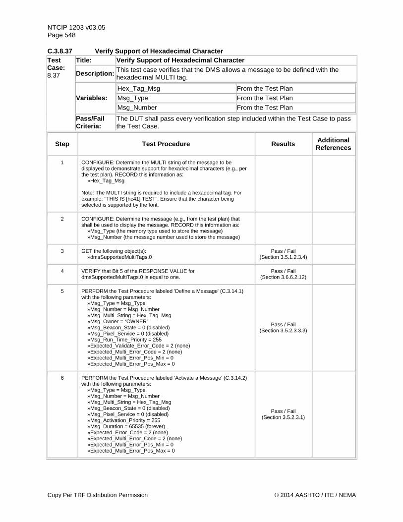
NTCIP 1203 v03.05 Page 548 C.3.8.37 Verify Support of Hexadecimal Character Test Case: 8.37
Title: Verify Support of Hexadecimal Character
Description: This test case verifies that the DMS allows a message to be defined with the hexadecimal MULTI tag.
Variables: Hex_Tag_Msg From the Test Plan Msg_Type From the Test Plan Msg_Number From the Test Plan
Pass/Fail Criteria:
The DUT shall pass every verification step included within the Test Case to pass the Test Case.
Step Test Procedure Results Additional References
1 CONFIGURE: Determine the MULTI string of the message to be displayed to demonstrate support for hexadecimal characters (e.g., per the test plan). RECORD this information as: »Hex_Tag_Msg Note: The MULTI string is required to include a hexadecimal tag. For example: "THIS IS [hc41] TEST". Ensure that the character being selected is supported by the font.
2 CONFIGURE: Determine the message (e.g., from the test plan) that shall be used to display the message. RECORD this information as: »Msg_Type (the memory type used to store the message) »Msg_Number (the message number used to store the message)
3 GET the following object(s): »dmsSupportedMultiTags.0
Pass / Fail (Section 3.5.1.2.3.4)
4 VERIFY that Bit 5 of the RESPONSE VALUE for dmsSupportedMultiTags.0 is equal to one.
Pass / Fail (Section 3.6.6.2.12)
5 PERFORM the Test Procedure labeled 'Define a Message' (C.3.14.1) with the following parameters: »Msg_Type = Msg_Type »Msg_Number = Msg_Number »Msg_Multi_String = Hex_Tag_Msg »Msg_Owner = “OWNER” »Msg_Beacon_State = 0 (disabled) »Msg_Pixel_Service = 0 (disabled) »Msg_Run_Time_Priority = 255 »Expected_Validate_Error_Code = 2 (none) »Expected_Multi_Error_Code = 2 (none) »Expected_Multi_Error_Pos_Min = 0 »Expected_Multi_Error_Pos_Max = 0
Pass / Fail (Section 3.5.2.3.3.3)
6 PERFORM the Test Procedure labeled 'Activate a Message' (C.3.14.2) with the following parameters: »Msg_Type = Msg_Type »Msg_Number = Msg_Number »Msg_Multi_String = Hex_Tag_Msg »Msg_Beacon_State = 0 (disabled) »Msg_Pixel_Service = 0 (disabled) »Msg_Activation_Priority = 255 »Msg_Duration = 65535 (forever) »Expected_Error_Code = 2 (none) »Expected_Multi_Error_Code = 2 (none) »Expected_Multi_Error_Pos_Min = 0 »Expected_Multi_Error_Pos_Max = 0
Pass / Fail (Section 3.5.2.3.1)
Copy Per TRF Distribution Permission © 2014 AASHTO / ITE / NEMA
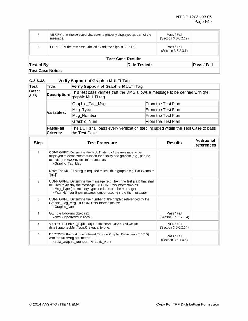
NTCIP 1203 v03.05 Page 549
7 VERIFY that the selected character is properly displayed as part of the message.
Pass / Fail (Section 3.6.6.2.12)
8 PERFORM the test case labeled 'Blank the Sign' (C.3.7.15). Pass / Fail (Section 3.5.2.3.1)
Test Case Results Tested By: Date Tested: Pass / Fail Test Case Notes: C.3.8.38 Verify Support of Graphic MULTI Tag Test Case: 8.38
Title: Verify Support of Graphic MULTI Tag
Description: This test case verifies that the DMS allows a message to be defined with the graphic MULTI tag.
Variables:
Graphic_Tag_Msg From the Test Plan Msg_Type From the Test Plan Msg_Number From the Test Plan Graphic_Num From the Test Plan
Pass/Fail Criteria:
The DUT shall pass every verification step included within the Test Case to pass the Test Case.
Step Test Procedure Results Additional References
1 CONFIGURE: Determine the MULTI string of the message to be displayed to demonstrate support for display of a graphic (e.g., per the test plan). RECORD this information as: »Graphic_Tag_Msg Note: The MULTI string is required to include a graphic tag. For example: "[g1]"
2 CONFIGURE: Determine the message (e.g., from the test plan) that shall be used to display the message. RECORD this information as: »Msg_Type (the memory type used to store the message) »Msg_Number (the message number used to store the message)
3 CONFIGURE: Determine the number of the graphic referenced by the Graphic_Tag_Msg. RECORD this information as: »Graphic_Num
4 GET the following object(s): »dmsSupportedMultiTags.0
Pass / Fail (Section 3.5.1.2.3.4)
5 VERIFY that Bit 4 (graphic tag) of the RESPONSE VALUE for dmsSupportedMultiTags.0 is equal to one.
Pass / Fail (Section 3.6.6.2.14)
6 PERFORM the test case labeled 'Store a Graphic Definition' (C.3.3.5) with the following parameters: »Test_Graphic_Number = Graphic_Num
Pass / Fail (Section 3.5.1.4.5)
© 2014 AASHTO / ITE / NEMA Copy Per TRF Distributtion Permission
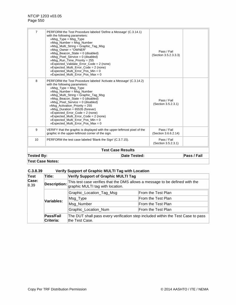
NTCIP 1203 v03.05 Page 550
7 PERFORM the Test Procedure labeled 'Define a Message' (C.3.14.1) with the following parameters: »Msg_Type = Msg_Type »Msg_Number = Msg_Number »Msg_Multi_String = Graphic_Tag_Msg »Msg_Owner = “OWNER” »Msg_Beacon_State = 0 (disabled) »Msg_Pixel_Service = 0 (disabled) »Msg_Run_Time_Priority = 255 »Expected_Validate_Error_Code = 2 (none) »Expected_Multi_Error_Code = 2 (none) »Expected_Multi_Error_Pos_Min = 0 »Expected_Multi_Error_Pos_Max = 0
Pass / Fail (Section 3.5.2.3.3.3)
8 PERFORM the Test Procedure labeled 'Activate a Message' (C.3.14.2) with the following parameters: »Msg_Type = Msg_Type »Msg_Number = Msg_Number »Msg_Multi_String = Graphic_Tag_Msg »Msg_Beacon_State = 0 (disabled) »Msg_Pixel_Service = 0 (disabled) »Msg_Activation_Priority = 255 »Msg_Duration = 65535 (forever) »Expected_Error_Code = 2 (none) »Expected_Multi_Error_Code = 2 (none) »Expected_Multi_Error_Pos_Min = 0 »Expected_Multi_Error_Pos_Max = 0
Pass / Fail (Section 3.5.2.3.1)
9 VERIFY that the graphic is displayed with the upper-leftmost pixel of the graphic in the upper-leftmost corner of the sign.
Pass / Fail (Section 3.6.6.2.14)
10 PERFORM the test case labeled 'Blank the Sign' (C.3.7.15). Pass / Fail (Section 3.5.2.3.1)
Test Case Results Tested By: Date Tested: Pass / Fail Test Case Notes: C.3.8.39 Verify Support of Graphic MULTI Tag with Location Test Case: 8.39
Title: Verify Support of Graphic MULTI Tag
Description: This test case verifies that the DMS allows a message to be defined with the graphic MULTI tag with location.
Variables:
Graphic_Location_Tag_Msg From the Test Plan Msg_Type From the Test Plan Msg_Number From the Test Plan Graphic_Location_Num From the Test Plan
Pass/Fail Criteria:
The DUT shall pass every verification step included within the Test Case to pass the Test Case.
Copy Per TRF Distribution Permission © 2014 AASHTO / ITE / NEMA
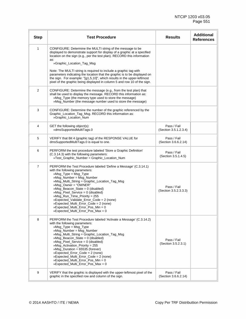
NTCIP 1203 v03.05 Page 551
Step Test Procedure Results Additional References
1 CONFIGURE: Determine the MULTI string of the message to be displayed to demonstrate support for display of a graphic at a specified location on the sign (e.g., per the test plan). RECORD this information as: »Graphic_Location_Tag_Msg Note: The MULTI string is required to include a graphic tag with parameters indicating the location that the graphic is to be displayed on the sign. For example: "[g1,5,10]", which results in the upper-leftmost pixel of the graphic being displayed in column 5 and row 10 of the sign.
2 CONFIGURE: Determine the message (e.g., from the test plan) that shall be used to display the message. RECORD this information as: »Msg_Type (the memory type used to store the message) »Msg_Number (the message number used to store the message)
3 CONFIGURE: Determine the number of the graphic referenced by the Graphic_Location_Tag_Msg. RECORD this information as: »Graphic_Location_Num
4 GET the following object(s): »dmsSupportedMultiTags.0
Pass / Fail (Section 3.5.1.2.3.4)
5 VERIFY that Bit 4 (graphic tag) of the RESPONSE VALUE for dmsSupportedMultiTags.0 is equal to one.
Pass / Fail (Section 3.6.6.2.14)
6 PERFORM the test procedure labeled 'Store a Graphic Definition' (C.3.14.3) with the following parameters: »Test_Graphic_Number = Graphic_Location_Num
Pass / Fail (Section 3.5.1.4.5)
7 PERFORM the Test Procedure labeled 'Define a Message' (C.3.14.1) with the following parameters: »Msg_Type = Msg_Type »Msg_Number = Msg_Number »Msg_Multi_String = Graphic_Location_Tag_Msg »Msg_Owner = “OWNER” »Msg_Beacon_State = 0 (disabled) »Msg_Pixel_Service = 0 (disabled) »Msg_Run_Time_Priority = 255 »Expected_Validate_Error_Code = 2 (none) »Expected_Multi_Error_Code = 2 (none) »Expected_Multi_Error_Pos_Min = 0 »Expected_Multi_Error_Pos_Max = 0
Pass / Fail (Section 3.5.2.3.3.3)
8 PERFORM the Test Procedure labeled 'Activate a Message' (C.3.14.2) with the following parameters: »Msg_Type = Msg_Type »Msg_Number = Msg_Number »Msg_Multi_String = Graphic_Location_Tag_Msg »Msg_Beacon_State = 0 (disabled) »Msg_Pixel_Service = 0 (disabled) »Msg_Activation_Priority = 255 »Msg_Duration = 65535 (forever) »Expected_Error_Code = 2 (none) »Expected_Multi_Error_Code = 2 (none) »Expected_Multi_Error_Pos_Min = 0 »Expected_Multi_Error_Pos_Max = 0
Pass / Fail (Section 3.5.2.3.1)
9 VERIFY that the graphic is displayed with the upper-leftmost pixel of the graphic in the specified row and column of the sign.
Pass / Fail (Section 3.6.6.2.14)
© 2014 AASHTO / ITE / NEMA Copy Per TRF Distributtion Permission
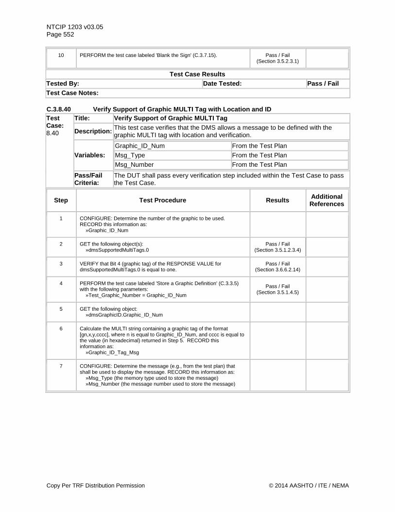
NTCIP 1203 v03.05 Page 552
10 PERFORM the test case labeled 'Blank the Sign' (C.3.7.15). Pass / Fail (Section 3.5.2.3.1)
Test Case Results Tested By: Date Tested: Pass / Fail Test Case Notes: C.3.8.40 Verify Support of Graphic MULTI Tag with Location and ID Test Case: 8.40
Title: Verify Support of Graphic MULTI Tag
Description: This test case verifies that the DMS allows a message to be defined with the graphic MULTI tag with location and verification.
Variables: Graphic_ID_Num From the Test Plan Msg_Type From the Test Plan Msg_Number From the Test Plan
Pass/Fail Criteria:
The DUT shall pass every verification step included within the Test Case to pass the Test Case.
Step Test Procedure Results Additional References
1 CONFIGURE: Determine the number of the graphic to be used. RECORD this information as: »Graphic_ID_Num
2 GET the following object(s): »dmsSupportedMultiTags.0
Pass / Fail (Section 3.5.1.2.3.4)
3 VERIFY that Bit 4 (graphic tag) of the RESPONSE VALUE for dmsSupportedMultiTags.0 is equal to one.
Pass / Fail (Section 3.6.6.2.14)
4 PERFORM the test case labeled 'Store a Graphic Definition' (C.3.3.5) with the following parameters: »Test_Graphic_Number = Graphic_ID_Num
Pass / Fail (Section 3.5.1.4.5)
5 GET the following object: »dmsGraphicID.Graphic_ID_Num
6 Calculate the MULTI string containing a graphic tag of the format [gn,x,y,cccc], where n is equal to Graphic_ID_Num, and cccc is equal to the value (in hexadecimal) returned in Step 5. RECORD this information as: »Graphic_ID_Tag_Msg
7 CONFIGURE: Determine the message (e.g., from the test plan) that shall be used to display the message. RECORD this information as: »Msg_Type (the memory type used to store the message) »Msg_Number (the message number used to store the message)
Copy Per TRF Distribution Permission © 2014 AASHTO / ITE / NEMA
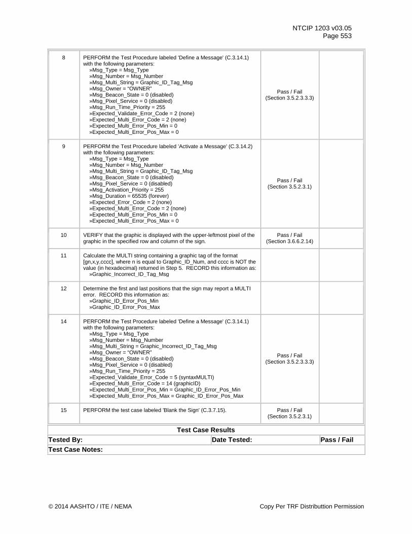
NTCIP 1203 v03.05 Page 553
8 PERFORM the Test Procedure labeled 'Define a Message' (C.3.14.1) with the following parameters: »Msg_Type = Msg_Type »Msg_Number = Msg_Number »Msg_Multi_String = Graphic_ID_Tag_Msg »Msg_Owner = “OWNER” »Msg_Beacon_State = 0 (disabled) »Msg_Pixel_Service = 0 (disabled) »Msg_Run_Time_Priority = 255 »Expected_Validate_Error_Code = 2 (none) »Expected_Multi_Error_Code = 2 (none) »Expected_Multi_Error_Pos_Min = 0 »Expected_Multi_Error_Pos_Max = 0
Pass / Fail (Section 3.5.2.3.3.3)
9 PERFORM the Test Procedure labeled 'Activate a Message' (C.3.14.2) with the following parameters: »Msg_Type = Msg_Type »Msg_Number = Msg_Number »Msg_Multi_String = Graphic_ID_Tag_Msg »Msg_Beacon_State = 0 (disabled) »Msg_Pixel_Service = 0 (disabled) »Msg_Activation_Priority = 255 »Msg_Duration = 65535 (forever) »Expected_Error_Code = 2 (none) »Expected_Multi_Error_Code = 2 (none) »Expected_Multi_Error_Pos_Min = 0 »Expected_Multi_Error_Pos_Max = 0
Pass / Fail (Section 3.5.2.3.1)
10 VERIFY that the graphic is displayed with the upper-leftmost pixel of the graphic in the specified row and column of the sign.
Pass / Fail (Section 3.6.6.2.14)
11 Calculate the MULTI string containing a graphic tag of the format [gn,x,y,cccc], where n is equal to Graphic_ID_Num, and cccc is NOT the value (in hexadecimal) returned in Step 5. RECORD this information as: »Graphic_Incorrect_ID_Tag_Msg
12 Determine the first and last positions that the sign may report a MULTI error. RECORD this information as: »Graphic_ID_Error_Pos_Min »Graphic_ID_Error_Pos_Max
14 PERFORM the Test Procedure labeled 'Define a Message' (C.3.14.1) with the following parameters: »Msg_Type = Msg_Type »Msg_Number = Msg_Number »Msg_Multi_String = Graphic_Incorrect_ID_Tag_Msg »Msg_Owner = “OWNER” »Msg_Beacon_State = 0 (disabled) »Msg_Pixel_Service = 0 (disabled) »Msg_Run_Time_Priority = 255 »Expected_Validate_Error_Code = 5 (syntaxMULTI) »Expected_Multi_Error_Code = 14 (graphicID) »Expected_Multi_Error_Pos_Min = Graphic_ID_Error_Pos_Min »Expected_Multi_Error_Pos_Max = Graphic_ID_Error_Pos_Max
Pass / Fail (Section 3.5.2.3.3.3)
15 PERFORM the test case labeled 'Blank the Sign' (C.3.7.15). Pass / Fail (Section 3.5.2.3.1)
Test Case Results Tested By: Date Tested: Pass / Fail Test Case Notes:
© 2014 AASHTO / ITE / NEMA Copy Per TRF Distributtion Permission
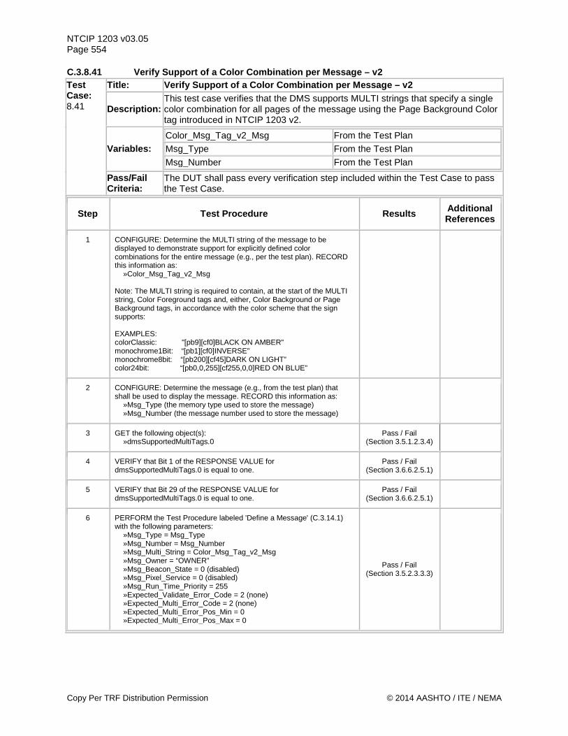
NTCIP 1203 v03.05 Page 554 C.3.8.41 Verify Support of a Color Combination per Message – v2 Test Case: 8.41
Title: Verify Support of a Color Combination per Message – v2
Description: This test case verifies that the DMS supports MULTI strings that specify a single color combination for all pages of the message using the Page Background Color tag introduced in NTCIP 1203 v2.
Variables: Color_Msg_Tag_v2_Msg From the Test Plan Msg_Type From the Test Plan Msg_Number From the Test Plan
Pass/Fail Criteria:
The DUT shall pass every verification step included within the Test Case to pass the Test Case.
Step Test Procedure Results Additional References
1 CONFIGURE: Determine the MULTI string of the message to be displayed to demonstrate support for explicitly defined color combinations for the entire message (e.g., per the test plan). RECORD this information as: »Color_Msg_Tag_v2_Msg Note: The MULTI string is required to contain, at the start of the MULTI string, Color Foreground tags and, either, Color Background or Page Background tags, in accordance with the color scheme that the sign supports: EXAMPLES: colorClassic: "[pb9][cf0]BLACK ON AMBER" monochrome1Bit: “[pb1][cf0]INVERSE” monochrome8bit: “[pb200][cf45]DARK ON LIGHT” color24bit: “[pb0,0,255][cf255,0,0]RED ON BLUE”
2 CONFIGURE: Determine the message (e.g., from the test plan) that shall be used to display the message. RECORD this information as: »Msg_Type (the memory type used to store the message) »Msg_Number (the message number used to store the message)
3 GET the following object(s): »dmsSupportedMultiTags.0
Pass / Fail (Section 3.5.1.2.3.4)
4 VERIFY that Bit 1 of the RESPONSE VALUE for dmsSupportedMultiTags.0 is equal to one.
Pass / Fail (Section 3.6.6.2.5.1)
5 VERIFY that Bit 29 of the RESPONSE VALUE for dmsSupportedMultiTags.0 is equal to one.
Pass / Fail (Section 3.6.6.2.5.1)
6 PERFORM the Test Procedure labeled 'Define a Message' (C.3.14.1) with the following parameters: »Msg_Type = Msg_Type »Msg_Number = Msg_Number »Msg_Multi_String = Color_Msg_Tag_v2_Msg »Msg_Owner = “OWNER” »Msg_Beacon_State = 0 (disabled) »Msg_Pixel_Service = 0 (disabled) »Msg_Run_Time_Priority = 255 »Expected_Validate_Error_Code = 2 (none) »Expected_Multi_Error_Code = 2 (none) »Expected_Multi_Error_Pos_Min = 0 »Expected_Multi_Error_Pos_Max = 0
Pass / Fail (Section 3.5.2.3.3.3)
Copy Per TRF Distribution Permission © 2014 AASHTO / ITE / NEMA
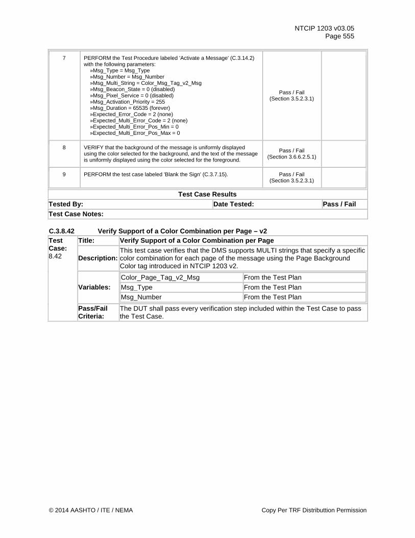
NTCIP 1203 v03.05 Page 555
7 PERFORM the Test Procedure labeled 'Activate a Message' (C.3.14.2) with the following parameters: »Msg_Type = Msg_Type »Msg_Number = Msg_Number »Msg_Multi_String = Color_Msg_Tag_v2_Msg »Msg_Beacon_State = 0 (disabled) »Msg_Pixel_Service = 0 (disabled) »Msg_Activation_Priority = 255 »Msg_Duration = 65535 (forever) »Expected_Error_Code = 2 (none) »Expected_Multi_Error_Code = 2 (none) »Expected_Multi_Error_Pos_Min = 0 »Expected_Multi_Error_Pos_Max = 0
Pass / Fail (Section 3.5.2.3.1)
8 VERIFY that the background of the message is uniformly displayed using the color selected for the background, and the text of the message is uniformly displayed using the color selected for the foreground.
Pass / Fail (Section 3.6.6.2.5.1)
9 PERFORM the test case labeled 'Blank the Sign' (C.3.7.15). Pass / Fail (Section 3.5.2.3.1)
Test Case Results Tested By: Date Tested: Pass / Fail Test Case Notes: C.3.8.42 Verify Support of a Color Combination per Page – v2 Test Case: 8.42
Title: Verify Support of a Color Combination per Page
Description: This test case verifies that the DMS supports MULTI strings that specify a specific color combination for each page of the message using the Page Background Color tag introduced in NTCIP 1203 v2.
Variables: Color_Page_Tag_v2_Msg From the Test Plan Msg_Type From the Test Plan Msg_Number From the Test Plan
Pass/Fail Criteria:
The DUT shall pass every verification step included within the Test Case to pass the Test Case.
© 2014 AASHTO / ITE / NEMA Copy Per TRF Distributtion Permission
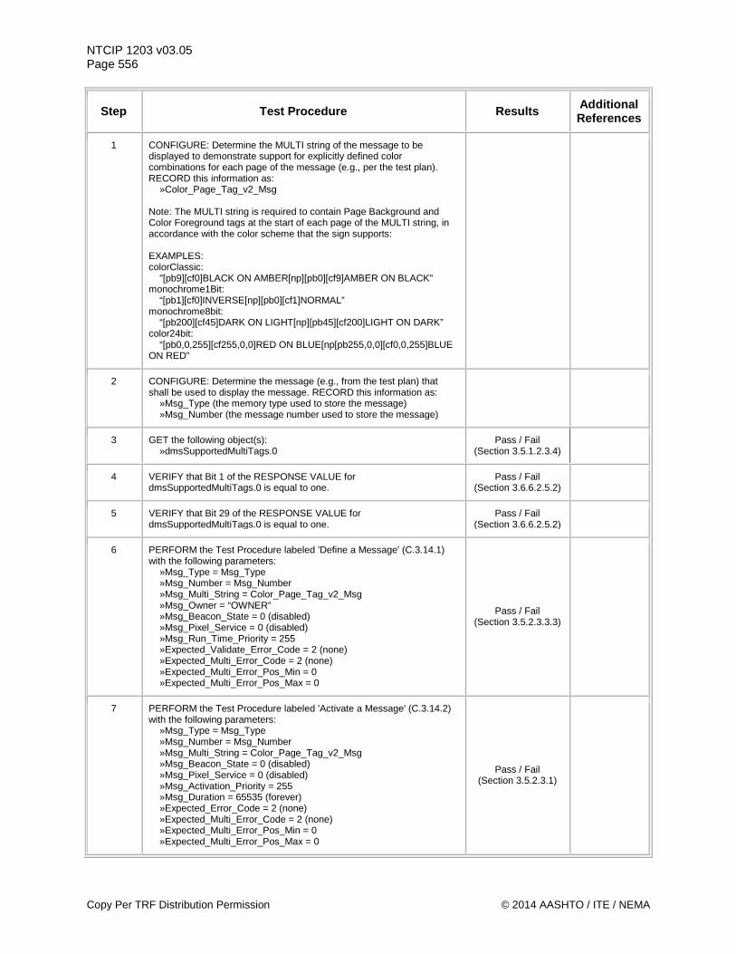
NTCIP 1203 v03.05 Page 556
Step Test Procedure Results Additional References
1 CONFIGURE: Determine the MULTI string of the message to be displayed to demonstrate support for explicitly defined color combinations for each page of the message (e.g., per the test plan). RECORD this information as: »Color_Page_Tag_v2_Msg Note: The MULTI string is required to contain Page Background and Color Foreground tags at the start of each page of the MULTI string, in accordance with the color scheme that the sign supports: EXAMPLES: colorClassic: "[pb9][cf0]BLACK ON AMBER[np][pb0][cf9]AMBER ON BLACK" monochrome1Bit: “[pb1][cf0]INVERSE[np][pb0][cf1]NORMAL” monochrome8bit: “[pb200][cf45]DARK ON LIGHT[np][pb45][cf200]LIGHT ON DARK” color24bit: “[pb0,0,255][cf255,0,0]RED ON BLUE[np[pb255,0,0][cf0,0,255]BLUE ON RED”
2 CONFIGURE: Determine the message (e.g., from the test plan) that shall be used to display the message. RECORD this information as: »Msg_Type (the memory type used to store the message) »Msg_Number (the message number used to store the message)
3 GET the following object(s): »dmsSupportedMultiTags.0
Pass / Fail (Section 3.5.1.2.3.4)
4 VERIFY that Bit 1 of the RESPONSE VALUE for dmsSupportedMultiTags.0 is equal to one.
Pass / Fail (Section 3.6.6.2.5.2)
5 VERIFY that Bit 29 of the RESPONSE VALUE for dmsSupportedMultiTags.0 is equal to one.
Pass / Fail (Section 3.6.6.2.5.2)
6 PERFORM the Test Procedure labeled 'Define a Message' (C.3.14.1) with the following parameters: »Msg_Type = Msg_Type »Msg_Number = Msg_Number »Msg_Multi_String = Color_Page_Tag_v2_Msg »Msg_Owner = “OWNER” »Msg_Beacon_State = 0 (disabled) »Msg_Pixel_Service = 0 (disabled) »Msg_Run_Time_Priority = 255 »Expected_Validate_Error_Code = 2 (none) »Expected_Multi_Error_Code = 2 (none) »Expected_Multi_Error_Pos_Min = 0 »Expected_Multi_Error_Pos_Max = 0
Pass / Fail (Section 3.5.2.3.3.3)
7 PERFORM the Test Procedure labeled 'Activate a Message' (C.3.14.2) with the following parameters: »Msg_Type = Msg_Type »Msg_Number = Msg_Number »Msg_Multi_String = Color_Page_Tag_v2_Msg »Msg_Beacon_State = 0 (disabled) »Msg_Pixel_Service = 0 (disabled) »Msg_Activation_Priority = 255 »Msg_Duration = 65535 (forever) »Expected_Error_Code = 2 (none) »Expected_Multi_Error_Code = 2 (none) »Expected_Multi_Error_Pos_Min = 0 »Expected_Multi_Error_Pos_Max = 0
Pass / Fail (Section 3.5.2.3.1)
Copy Per TRF Distribution Permission © 2014 AASHTO / ITE / NEMA
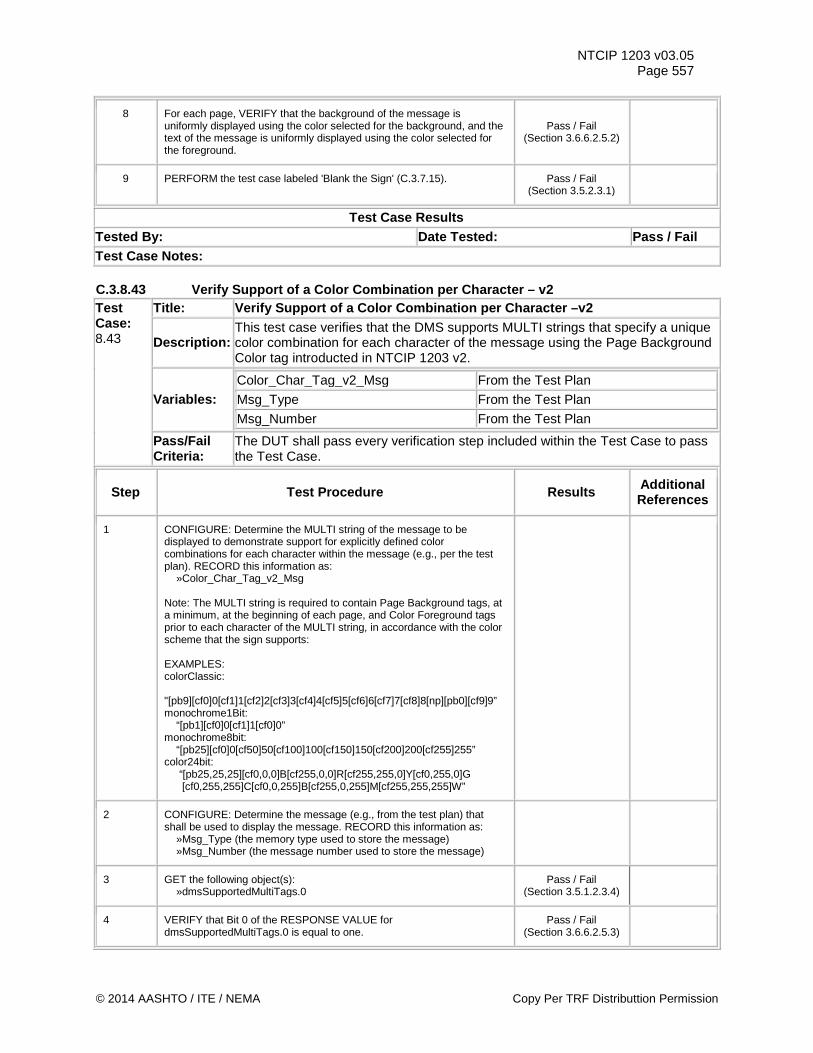
NTCIP 1203 v03.05 Page 557
8 For each page, VERIFY that the background of the message is uniformly displayed using the color selected for the background, and the text of the message is uniformly displayed using the color selected for the foreground.
Pass / Fail (Section 3.6.6.2.5.2)
9 PERFORM the test case labeled 'Blank the Sign' (C.3.7.15). Pass / Fail (Section 3.5.2.3.1)
Test Case Results Tested By: Date Tested: Pass / Fail Test Case Notes: C.3.8.43 Verify Support of a Color Combination per Character – v2 Test Case: 8.43
Title: Verify Support of a Color Combination per Character –v2
Description: This test case verifies that the DMS supports MULTI strings that specify a unique color combination for each character of the message using the Page Background Color tag introducted in NTCIP 1203 v2.
Variables: Color_Char_Tag_v2_Msg From the Test Plan Msg_Type From the Test Plan Msg_Number From the Test Plan
Pass/Fail Criteria:
The DUT shall pass every verification step included within the Test Case to pass the Test Case.
Step Test Procedure Results Additional References
1 CONFIGURE: Determine the MULTI string of the message to be displayed to demonstrate support for explicitly defined color combinations for each character within the message (e.g., per the test plan). RECORD this information as: »Color_Char_Tag_v2_Msg Note: The MULTI string is required to contain Page Background tags, at a minimum, at the beginning of each page, and Color Foreground tags prior to each character of the MULTI string, in accordance with the color scheme that the sign supports: EXAMPLES: colorClassic: "[pb9][cf0]0[cf1]1[cf2]2[cf3]3[cf4]4[cf5]5[cf6]6[cf7]7[cf8]8[np][pb0][cf9]9” monochrome1Bit: “[pb1][cf0]0[cf1]1[cf0]0” monochrome8bit: “[pb25][cf0]0[cf50]50[cf100]100[cf150]150[cf200]200[cf255]255” color24bit: “[pb25,25,25][cf0,0,0]B[cf255,0,0]R[cf255,255,0]Y[cf0,255,0]G [cf0,255,255]C[cf0,0,255]B[cf255,0,255]M[cf255,255,255]W”
2 CONFIGURE: Determine the message (e.g., from the test plan) that shall be used to display the message. RECORD this information as: »Msg_Type (the memory type used to store the message) »Msg_Number (the message number used to store the message)
3 GET the following object(s): »dmsSupportedMultiTags.0
Pass / Fail (Section 3.5.1.2.3.4)
4 VERIFY that Bit 0 of the RESPONSE VALUE for dmsSupportedMultiTags.0 is equal to one.
Pass / Fail (Section 3.6.6.2.5.3)
© 2014 AASHTO / ITE / NEMA Copy Per TRF Distributtion Permission
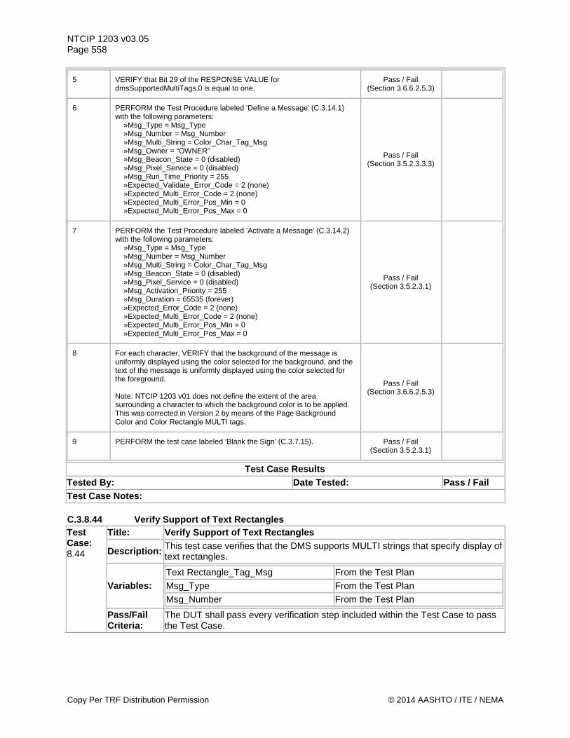
NTCIP 1203 v03.05 Page 558
5 VERIFY that Bit 29 of the RESPONSE VALUE for dmsSupportedMultiTags.0 is equal to one.
Pass / Fail (Section 3.6.6.2.5.3)
6 PERFORM the Test Procedure labeled 'Define a Message' (C.3.14.1) with the following parameters: »Msg_Type = Msg_Type »Msg_Number = Msg_Number »Msg_Multi_String = Color_Char_Tag_Msg »Msg_Owner = “OWNER” »Msg_Beacon_State = 0 (disabled) »Msg_Pixel_Service = 0 (disabled) »Msg_Run_Time_Priority = 255 »Expected_Validate_Error_Code = 2 (none) »Expected_Multi_Error_Code = 2 (none) »Expected_Multi_Error_Pos_Min = 0 »Expected_Multi_Error_Pos_Max = 0
Pass / Fail (Section 3.5.2.3.3.3)
7 PERFORM the Test Procedure labeled 'Activate a Message' (C.3.14.2) with the following parameters: »Msg_Type = Msg_Type »Msg_Number = Msg_Number »Msg_Multi_String = Color_Char_Tag_Msg »Msg_Beacon_State = 0 (disabled) »Msg_Pixel_Service = 0 (disabled) »Msg_Activation_Priority = 255 »Msg_Duration = 65535 (forever) »Expected_Error_Code = 2 (none) »Expected_Multi_Error_Code = 2 (none) »Expected_Multi_Error_Pos_Min = 0 »Expected_Multi_Error_Pos_Max = 0
Pass / Fail (Section 3.5.2.3.1)
8 For each character, VERIFY that the background of the message is uniformly displayed using the color selected for the background, and the text of the message is uniformly displayed using the color selected for the foreground. Note: NTCIP 1203 v01 does not define the extent of the area surrounding a character to which the background color is to be applied. This was corrected in Version 2 by means of the Page Background Color and Color Rectangle MULTI tags.
Pass / Fail (Section 3.6.6.2.5.3)
9 PERFORM the test case labeled 'Blank the Sign' (C.3.7.15). Pass / Fail (Section 3.5.2.3.1)
Test Case Results Tested By: Date Tested: Pass / Fail Test Case Notes: C.3.8.44 Verify Support of Text Rectangles Test Case: 8.44
Title: Verify Support of Text Rectangles
Description: This test case verifies that the DMS supports MULTI strings that specify display of text rectangles.
Variables: Text Rectangle_Tag_Msg From the Test Plan Msg_Type From the Test Plan Msg_Number From the Test Plan
Pass/Fail Criteria:
The DUT shall pass every verification step included within the Test Case to pass the Test Case.
Copy Per TRF Distribution Permission © 2014 AASHTO / ITE / NEMA
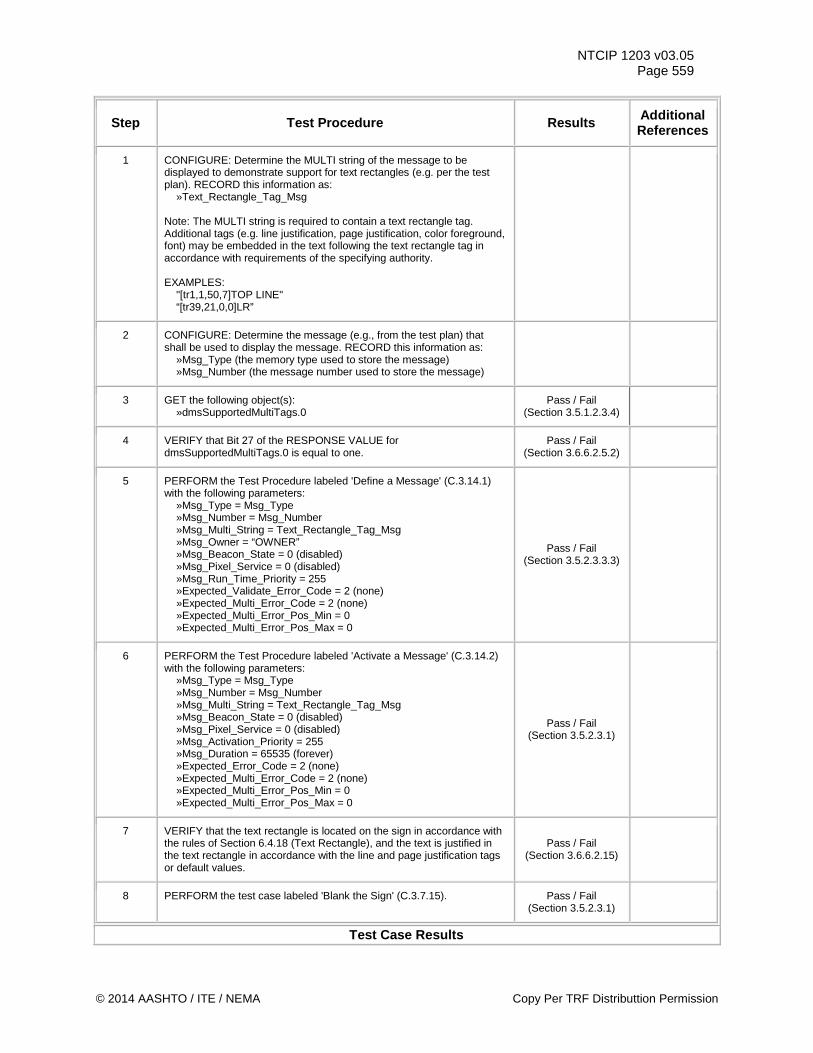
NTCIP 1203 v03.05 Page 559
Step Test Procedure Results Additional References
1 CONFIGURE: Determine the MULTI string of the message to be displayed to demonstrate support for text rectangles (e.g. per the test plan). RECORD this information as: »Text_Rectangle_Tag_Msg Note: The MULTI string is required to contain a text rectangle tag. Additional tags (e.g. line justification, page justification, color foreground, font) may be embedded in the text following the text rectangle tag in accordance with requirements of the specifying authority. EXAMPLES: "[tr1,1,50,7]TOP LINE" “[tr39,21,0,0]LR”
2 CONFIGURE: Determine the message (e.g., from the test plan) that shall be used to display the message. RECORD this information as: »Msg_Type (the memory type used to store the message) »Msg_Number (the message number used to store the message)
3 GET the following object(s): »dmsSupportedMultiTags.0
Pass / Fail (Section 3.5.1.2.3.4)
4 VERIFY that Bit 27 of the RESPONSE VALUE for dmsSupportedMultiTags.0 is equal to one.
Pass / Fail (Section 3.6.6.2.5.2)
5 PERFORM the Test Procedure labeled 'Define a Message' (C.3.14.1) with the following parameters: »Msg_Type = Msg_Type »Msg_Number = Msg_Number »Msg_Multi_String = Text_Rectangle_Tag_Msg »Msg_Owner = “OWNER” »Msg_Beacon_State = 0 (disabled) »Msg_Pixel_Service = 0 (disabled) »Msg_Run_Time_Priority = 255 »Expected_Validate_Error_Code = 2 (none) »Expected_Multi_Error_Code = 2 (none) »Expected_Multi_Error_Pos_Min = 0 »Expected_Multi_Error_Pos_Max = 0
Pass / Fail (Section 3.5.2.3.3.3)
6 PERFORM the Test Procedure labeled 'Activate a Message' (C.3.14.2) with the following parameters: »Msg_Type = Msg_Type »Msg_Number = Msg_Number »Msg_Multi_String = Text_Rectangle_Tag_Msg »Msg_Beacon_State = 0 (disabled) »Msg_Pixel_Service = 0 (disabled) »Msg_Activation_Priority = 255 »Msg_Duration = 65535 (forever) »Expected_Error_Code = 2 (none) »Expected_Multi_Error_Code = 2 (none) »Expected_Multi_Error_Pos_Min = 0 »Expected_Multi_Error_Pos_Max = 0
Pass / Fail (Section 3.5.2.3.1)
7 VERIFY that the text rectangle is located on the sign in accordance with the rules of Section 6.4.18 (Text Rectangle), and the text is justified in the text rectangle in accordance with the line and page justification tags or default values.
Pass / Fail (Section 3.6.6.2.15)
8 PERFORM the test case labeled 'Blank the Sign' (C.3.7.15). Pass / Fail (Section 3.5.2.3.1)
Test Case Results
© 2014 AASHTO / ITE / NEMA Copy Per TRF Distributtion Permission
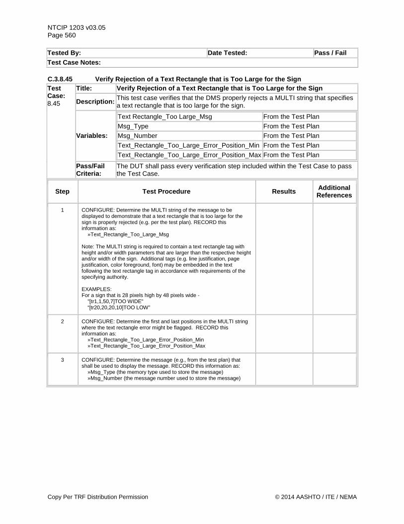
NTCIP 1203 v03.05 Page 560 Tested By: Date Tested: Pass / Fail Test Case Notes: C.3.8.45 Verify Rejection of a Text Rectangle that is Too Large for the Sign Test Case: 8.45
Title: Verify Rejection of a Text Rectangle that is Too Large for the Sign
Description: This test case verifies that the DMS properly rejects a MULTI string that specifies a text rectangle that is too large for the sign.
Variables:
Text Rectangle_Too Large_Msg From the Test Plan Msg_Type From the Test Plan Msg_Number From the Test Plan Text_Rectangle_Too_Large_Error_Position_Min From the Test Plan Text_Rectangle_Too_Large_Error_Position_Max From the Test Plan
Pass/Fail Criteria:
The DUT shall pass every verification step included within the Test Case to pass the Test Case.
Step Test Procedure Results Additional References
1 CONFIGURE: Determine the MULTI string of the message to be displayed to demonstrate that a text rectangle that is too large for the sign is properly rejected (e.g. per the test plan). RECORD this information as: »Text_Rectangle_Too_Large_Msg Note: The MULTI string is required to contain a text rectangle tag with height and/or width parameters that are larger than the respective height and/or width of the sign. Additional tags (e.g. line justification, page justification, color foreground, font) may be embedded in the text following the text rectangle tag in accordance with requirements of the specifying authority. EXAMPLES: For a sign that is 28 pixels high by 48 pixels wide - "[tr1,1,50,7]TOO WIDE" “[tr20,20,20,10]TOO LOW”
2 CONFIGURE: Determine the first and last positions in the MULTI string where the text rectangle error might be flagged. RECORD this information as: »Text_Rectangle_Too_Large_Error_Position_Min »Text_Rectangle_Too_Large_Error_Position_Max
3 CONFIGURE: Determine the message (e.g., from the test plan) that shall be used to display the message. RECORD this information as: »Msg_Type (the memory type used to store the message) »Msg_Number (the message number used to store the message)
Copy Per TRF Distribution Permission © 2014 AASHTO / ITE / NEMA
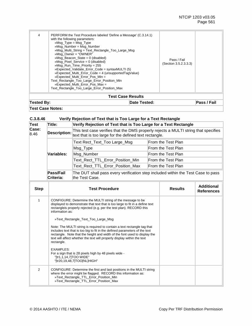
NTCIP 1203 v03.05 Page 561
4 PERFORM the Test Procedure labeled 'Define a Message' (C.3.14.1) with the following parameters: »Msg_Type = Msg_Type »Msg_Number = Msg_Number »Msg_Multi_String = Text_Rectangle_Too_Large_Msg »Msg_Owner = “OWNER” »Msg_Beacon_State = 0 (disabled) »Msg_Pixel_Service = 0 (disabled) »Msg_Run_Time_Priority = 255 »Expected_Validate_Error_Code = syntaxMULTI (5) »Expected_Multi_Error_Code = 4 (unsupportedTagValue) »Expected_Multi_Error_Pos_Min = Text_Rectangle_Too_Large_Error_Position_Min »Expected_Multi_Error_Pos_Max = Text_Rectangle_Too_Large_Error_Position_Max
Pass / Fail (Section 3.5.2.3.3.3)
Test Case Results Tested By: Date Tested: Pass / Fail Test Case Notes: C.3.8.46 Verify Rejection of Text that is Too Large for a Text Rectangle Test Case: 8.46
Title: Verify Rejection of Text that is Too Large for a Text Rectangle
Description: This test case verifies that the DMS properly rejects a MULTI string that specifies text that is too large for the defined text rectangle.
Variables:
Text Rect_Text_Too Large_Msg From the Test Plan Msg_Type From the Test Plan Msg_Number From the Test Plan Text_Rect_TTL_Error_Position_Min From the Test Plan Text_Rect_TTL_Error_Position_Max From the Test Plan
Pass/Fail Criteria:
The DUT shall pass every verification step included within the Test Case to pass the Test Case.
Step Test Procedure Results Additional References
1 CONFIGURE: Determine the MULTI string of the message to be displayed to demonstrate that text that is too large to fit in a define text rectangleis properly rejected (e.g. per the test plan). RECORD this information as: »Text_Rectangle_Text_Too_Large_Msg Note: The MULTI string is required to contain a text rectangle tag that includes text that is too big to fit in the defined parameters of the text rectangle. Note that the height and width of the font used to display the text will affect whether the text will properly display within the text rectangle. EXAMPLES: For a sign that is 28 pixels high by 48 pixels wide - "[tr1,1,14,7]TOO WIDE" “[tr20,19,48,7]TOO[NL]HIGH”
2 CONFIGURE: Determine the first and last positions in the MULTI string where the error might be flagged. RECORD this information as: »Text_Rectangle_TTL_Error_Position_Min »Text_Rectangle_TTL_Error_Position_Max
© 2014 AASHTO / ITE / NEMA Copy Per TRF Distributtion Permission
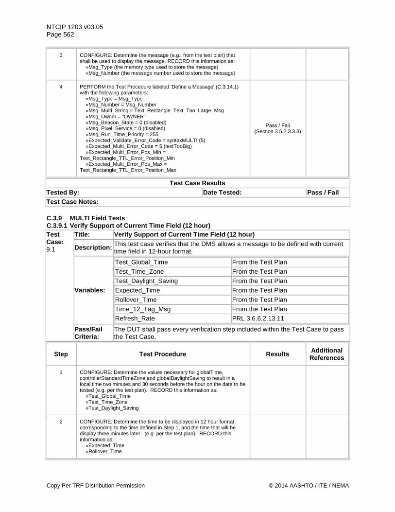
NTCIP 1203 v03.05 Page 562
3 CONFIGURE: Determine the message (e.g., from the test plan) that shall be used to display the message. RECORD this information as: »Msg_Type (the memory type used to store the message) »Msg_Number (the message number used to store the message)
4 PERFORM the Test Procedure labeled 'Define a Message' (C.3.14.1) with the following parameters: »Msg_Type = Msg_Type »Msg_Number = Msg_Number »Msg_Multi_String = Text_Rectangle_Text_Too_Large_Msg »Msg_Owner = “OWNER” »Msg_Beacon_State = 0 (disabled) »Msg_Pixel_Service = 0 (disabled) »Msg_Run_Time_Priority = 255 »Expected_Validate_Error_Code = syntaxMULTI (5) »Expected_Multi_Error_Code = 5 (textTooBig) »Expected_Multi_Error_Pos_Min = Text_Rectangle_TTL_Error_Position_Min »Expected_Multi_Error_Pos_Max = Text_Rectangle_TTL_Error_Position_Max
Pass / Fail (Section 3.5.2.3.3.3)
Test Case Results Tested By: Date Tested: Pass / Fail Test Case Notes: C.3.9 MULTI Field Tests C.3.9.1 Verify Support of Current Time Field (12 hour) Test Case: 9.1
Title: Verify Support of Current Time Field (12 hour)
Description: This test case verifies that the DMS allows a message to be defined with current time field in 12-hour format.
Variables:
Test_Global_Time From the Test Plan
Test_Time_Zone From the Test Plan Test_Daylight_Saving From the Test Plan Expected_Time From the Test Plan Rollover_Time From the Test Plan Time_12_Tag_Msg From the Test Plan Refresh_Rate PRL 3.6.6.2.13.11
Pass/Fail Criteria:
The DUT shall pass every verification step included within the Test Case to pass the Test Case.
Step Test Procedure Results Additional References
1 CONFIGURE: Determine the values necessary for globalTime, controllerStandardTimeZone and globalDaylightSaving to result in a local time two minutes and 30 seconds before the hour on the date to be tested (e.g. per the test plan). RECORD this information as: »Test_Global_Time »Test_Time_Zone »Test_Daylight_Saving
2 CONFIGURE: Determine the time to be displayed in 12 hour format corresponding to the time defined in Step 1, and the time that will be display three minutes later. (e.g. per the test plan). RECORD this information as: »Expected_Time »Rollover_Time
Copy Per TRF Distribution Permission © 2014 AASHTO / ITE / NEMA
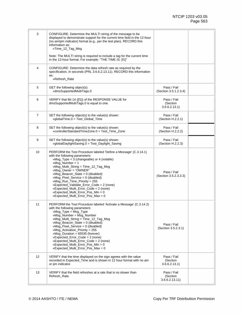
NTCIP 1203 v03.05 Page 563
3 CONFIGURE: Determine the MULTI string of the message to be displayed to demonstrate support for the current time field in the 12-hour (no am/pm indicator) format (e.g., per the test plan). RECORD this information as: »Time_12_Tag_Msg Note: The MULTI string is required to include a tag for the current time in the 12-hour format. For example: "THE TIME IS: [f1]"
4 CONFIGURE: Determine the data refresh rate as required by the specification, in seconds (PRL 3.6.6.2.13.11). RECORD this information as: »Refresh_Rate
5 GET the following object(s): »dmsSupportedMultiTags.0
Pass / Fail (Section 3.5.1.2.3.4)
6 VERIFY that Bit 14 ([f1]) of the RESPONSE VALUE for dmsSupportedMultiTags.0 is equal to one.
Pass / Fail (Section
3.6.6.2.13.1)
7 SET the following object(s) to the value(s) shown: »globalTime.0 = Test_Global_Time
Pass / Fail (Section H.2.2.1)
8 SET the following object(s) to the value(s) shown: »controllerStandardTimeZone.0 = Test_Time_Zone
Pass / Fail (Section H.2.2.2)
9 SET the following object(s) to the value(s) shown: »globalDaylightSaving.0 = Test_Daylight_Saving
Pass / Fail (Section H.2.2.3)
10 PERFORM the Test Procedure labeled 'Define a Message' (C.3.14.1) with the following parameters: »Msg_Type = 3 (changeable) or 4 (volatile) »Msg_Number = 1 »Msg_Multi_String = Time_12_Tag_Msg »Msg_Owner = “OWNER” »Msg_Beacon_State = 0 (disabled) »Msg_Pixel_Service = 0 (disabled) »Msg_Run_Time_Priority = 255 »Expected_Validate_Error_Code = 2 (none) »Expected_Multi_Error_Code = 2 (none) »Expected_Multi_Error_Pos_Min = 0 »Expected_Multi_Error_Pos_Max = 0
Pass / Fail (Section 3.5.2.3.3.3)
11 PERFORM the Test Procedure labeled 'Activate a Message' (C.3.14.2) with the following parameters: »Msg_Type = Msg_Type »Msg_Number = Msg_Number »Msg_Multi_String = Time_12_Tag_Msg »Msg_Beacon_State = 0 (disabled) »Msg_Pixel_Service = 0 (disabled) »Msg_Activation_Priority = 255 »Msg_Duration = 65535 (forever) »Expected_Error_Code = 2 (none) »Expected_Multi_Error_Code = 2 (none) »Expected_Multi_Error_Pos_Min = 0 »Expected_Multi_Error_Pos_Max = 0
Pass / Fail (Section 3.5.2.3.1)
12 VERIFY that the time displayed on the sign agrees with the value recorded in Expected_Time and is shown in 12 hour format with no am or pm indicator.
Pass / Fail (Section
3.6.6.2.13.1)
13 VERIFY that the field refreshes at a rate that is no slower than Refresh_Rate.
Pass / Fail (Section
3.6.6.2.13.11)
© 2014 AASHTO / ITE / NEMA Copy Per TRF Distributtion Permission
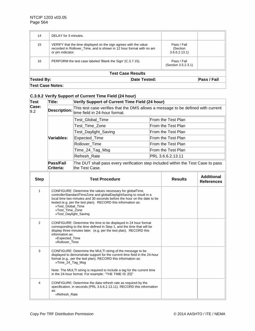
NTCIP 1203 v03.05 Page 564
14 DELAY for 3 minutes.
15 VERIFY that the time displayed on the sign agrees with the value recorded in Rollover_Time, and is shown in 12 hour format with no am or pm indicator.
Pass / Fail (Section
3.6.6.2.13.1)
16 PERFORM the test case labeled 'Blank the Sign' (C.3.7.15). Pass / Fail (Section 3.5.2.3.1)
Test Case Results Tested By: Date Tested: Pass / Fail Test Case Notes: C.3.9.2 Verify Support of Current Time Field (24 hour) Test Case: 9.2
Title: Verify Support of Current Time Field (24 hour)
Description: This test case verifies that the DMS allows a message to be defined with current time field in 24-hour format.
Variables:
Test_Global_Time From the Test Plan
Test_Time_Zone From the Test Plan Test_Daylight_Saving From the Test Plan Expected_Time From the Test Plan Rollover_Time From the Test Plan Time_24_Tag_Msg From the Test Plan Refresh_Rate PRL 3.6.6.2.13.11
Pass/Fail Criteria:
The DUT shall pass every verification step included within the Test Case to pass the Test Case.
Step Test Procedure Results Additional References
1 CONFIGURE: Determine the values necessary for globalTime, controllerStandardTimeZone and globalDaylightSaving to result in a local time two minutes and 30 seconds before the hour on the date to be tested (e.g. per the test plan). RECORD this information as: »Test_Global_Time »Test_Time_Zone »Test_Daylight_Saving
2 CONFIGURE: Determine the time to be displayed in 24 hour format corresponding to the time defined in Step 1, and the time that will be display three minutes later. (e.g. per the test plan). RECORD this information as: »Expected_Time »Rollover_Time
3 CONFIGURE: Determine the MULTI string of the message to be displayed to demonstrate support for the current time field in the 24-hour format (e.g., per the test plan). RECORD this information as: »Time_24_Tag_Msg Note: The MULTI string is required to include a tag for the current time in the 24-hour format. For example: "THE TIME IS: [f2]"
4 CONFIGURE: Determine the data refresh rate as required by the specification, in seconds (PRL 3.6.6.2.13.11). RECORD this information as: »Refresh_Rate
Copy Per TRF Distribution Permission © 2014 AASHTO / ITE / NEMA
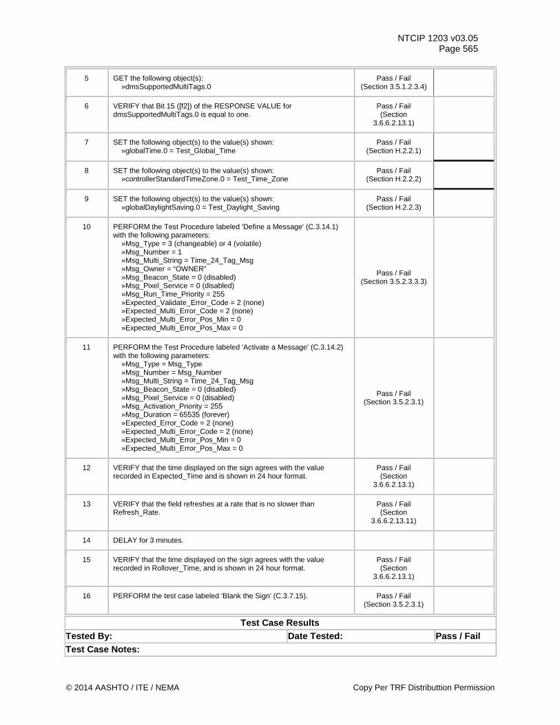
NTCIP 1203 v03.05 Page 565
5 GET the following object(s): »dmsSupportedMultiTags.0
Pass / Fail (Section 3.5.1.2.3.4)
6 VERIFY that Bit 15 ([f2]) of the RESPONSE VALUE for dmsSupportedMultiTags.0 is equal to one.
Pass / Fail (Section
3.6.6.2.13.1)
7 SET the following object(s) to the value(s) shown: »globalTime.0 = Test_Global_Time
Pass / Fail (Section H.2.2.1)
8 SET the following object(s) to the value(s) shown: »controllerStandardTimeZone.0 = Test_Time_Zone
Pass / Fail (Section H.2.2.2)
9 SET the following object(s) to the value(s) shown: »globalDaylightSaving.0 = Test_Daylight_Saving
Pass / Fail (Section H.2.2.3)
10 PERFORM the Test Procedure labeled 'Define a Message' (C.3.14.1) with the following parameters: »Msg_Type = 3 (changeable) or 4 (volatile) »Msg_Number = 1 »Msg_Multi_String = Time_24_Tag_Msg »Msg_Owner = “OWNER” »Msg_Beacon_State = 0 (disabled) »Msg_Pixel_Service = 0 (disabled) »Msg_Run_Time_Priority = 255 »Expected_Validate_Error_Code = 2 (none) »Expected_Multi_Error_Code = 2 (none) »Expected_Multi_Error_Pos_Min = 0 »Expected_Multi_Error_Pos_Max = 0
Pass / Fail (Section 3.5.2.3.3.3)
11 PERFORM the Test Procedure labeled 'Activate a Message' (C.3.14.2) with the following parameters: »Msg_Type = Msg_Type »Msg_Number = Msg_Number »Msg_Multi_String = Time_24_Tag_Msg »Msg_Beacon_State = 0 (disabled) »Msg_Pixel_Service = 0 (disabled) »Msg_Activation_Priority = 255 »Msg_Duration = 65535 (forever) »Expected_Error_Code = 2 (none) »Expected_Multi_Error_Code = 2 (none) »Expected_Multi_Error_Pos_Min = 0 »Expected_Multi_Error_Pos_Max = 0
Pass / Fail (Section 3.5.2.3.1)
12 VERIFY that the time displayed on the sign agrees with the value recorded in Expected_Time and is shown in 24 hour format.
Pass / Fail (Section
3.6.6.2.13.1)
13 VERIFY that the field refreshes at a rate that is no slower than Refresh_Rate.
Pass / Fail (Section
3.6.6.2.13.11)
14 DELAY for 3 minutes.
15 VERIFY that the time displayed on the sign agrees with the value recorded in Rollover_Time, and is shown in 24 hour format.
Pass / Fail (Section
3.6.6.2.13.1)
16 PERFORM the test case labeled 'Blank the Sign' (C.3.7.15). Pass / Fail (Section 3.5.2.3.1)
Test Case Results Tested By: Date Tested: Pass / Fail Test Case Notes:
© 2014 AASHTO / ITE / NEMA Copy Per TRF Distributtion Permission
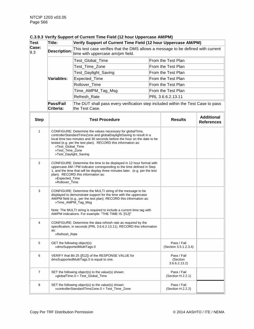
NTCIP 1203 v03.05 Page 566 C.3.9.3 Verify Support of Current Time Field (12 hour Uppercase AM/PM) Test Case: 9.3
Title: Verify Support of Current Time Field (12 hour Uppercase AM/PM)
Description: This test case verifies that the DMS allows a message to be defined with current time with uppercase am/pm field.
Variables:
Test_Global_Time From the Test Plan Test_Time_Zone From the Test Plan Test_Daylight_Saving From the Test Plan Expected_Time From the Test Plan Rollover_Time From the Test Plan Time_AMPM_Tag_Msg From the Test Plan
Refresh_Rate PRL 3.6.6.2.13.11
Pass/Fail Criteria:
The DUT shall pass every verification step included within the Test Case to pass the Test Case.
Step Test Procedure Results Additional References
1 CONFIGURE: Determine the values necessary for globalTime, controllerStandardTimeZone and globalDaylightSaving to result in a local time two minutes and 30 seconds before the hour on the date to be tested (e.g. per the test plan). RECORD this information as: »Test_Global_Time »Test_Time_Zone »Test_Daylight_Saving
2 CONFIGURE: Determine the time to be displayed in 12 hour format with uppercase AM / PM indicator corresponding to the time defined in Step 1, and the time that will be display three minutes later. (e.g. per the test plan). RECORD this information as: »Expected_Time »Rollover_Time
3 CONFIGURE: Determine the MULTI string of the message to be displayed to demonstrate support for the time with the uppercase AM/PM field (e.g., per the test plan). RECORD this information as: »Time_AMPM_Tag_Msg Note: The MULTI string is required to include a current time tag with AM/PM indications. For example: "THE TIME IS: [f12]"
4 CONFIGURE: Determine the data refresh rate as required by the specification, in seconds (PRL 3.6.6.2.13.11). RECORD this information as: »Refresh_Rate
5 GET the following object(s): »dmsSupportedMultiTags.0
Pass / Fail (Section 3.5.1.2.3.4)
6 VERIFY that Bit 25 ([f12]) of the RESPONSE VALUE for dmsSupportedMultiTags.0 is equal to one.
Pass / Fail (Section
3.6.6.2.13.2)
7 SET the following object(s) to the value(s) shown: »globalTime.0 = Test_Global_Time
Pass / Fail (Section H.2.2.1)
8 SET the following object(s) to the value(s) shown: »controllerStandardTimeZone.0 = Test_Time_Zone
Pass / Fail (Section H.2.2.2)
Copy Per TRF Distribution Permission © 2014 AASHTO / ITE / NEMA
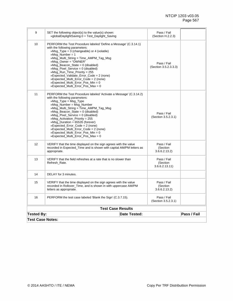
NTCIP 1203 v03.05 Page 567
9 SET the following object(s) to the value(s) shown: »globalDaylightSaving.0 = Test_Daylight_Saving
Pass / Fail (Section H.2.2.3)
10 PERFORM the Test Procedure labeled 'Define a Message' (C.3.14.1) with the following parameters: »Msg_Type = 3 (changeable) or 4 (volatile) »Msg_Number = 1 »Msg_Multi_String = Time_AMPM_Tag_Msg »Msg_Owner = “OWNER” »Msg_Beacon_State = 0 (disabled) »Msg_Pixel_Service = 0 (disabled) »Msg_Run_Time_Priority = 255 »Expected_Validate_Error_Code = 2 (none) »Expected_Multi_Error_Code = 2 (none) »Expected_Multi_Error_Pos_Min = 0 »Expected_Multi_Error_Pos_Max = 0
Pass / Fail (Section 3.5.2.3.3.3)
11 PERFORM the Test Procedure labeled 'Activate a Message' (C.3.14.2) with the following parameters: »Msg_Type = Msg_Type »Msg_Number = Msg_Number »Msg_Multi_String = Time_AMPM_Tag_Msg »Msg_Beacon_State = 0 (disabled) »Msg_Pixel_Service = 0 (disabled) »Msg_Activation_Priority = 255 »Msg_Duration = 65535 (forever) »Expected_Error_Code = 2 (none) »Expected_Multi_Error_Code = 2 (none) »Expected_Multi_Error_Pos_Min = 0 »Expected_Multi_Error_Pos_Max = 0
Pass / Fail (Section 3.5.2.3.1)
12 VERIFY that the time displayed on the sign agrees with the value recorded in Expected_Time and is shown with capital AM/PM letters as appropriate.
Pass / Fail (Section
3.6.6.2.13.2)
13 VERIFY that the field refreshes at a rate that is no slower than Refresh_Rate.
Pass / Fail (Section
3.6.6.2.13.11)
14 DELAY for 3 minutes.
15 VERIFY that the time displayed on the sign agrees with the value recorded in Rollover_Time, and is shown in with uppercase AM/PM letters as appropriate.
Pass / Fail (Section
3.6.6.2.13.2)
16 PERFORM the test case labeled 'Blank the Sign' (C.3.7.15). Pass / Fail (Section 3.5.2.3.1)
Test Case Results Tested By: Date Tested: Pass / Fail Test Case Notes:
© 2014 AASHTO / ITE / NEMA Copy Per TRF Distributtion Permission
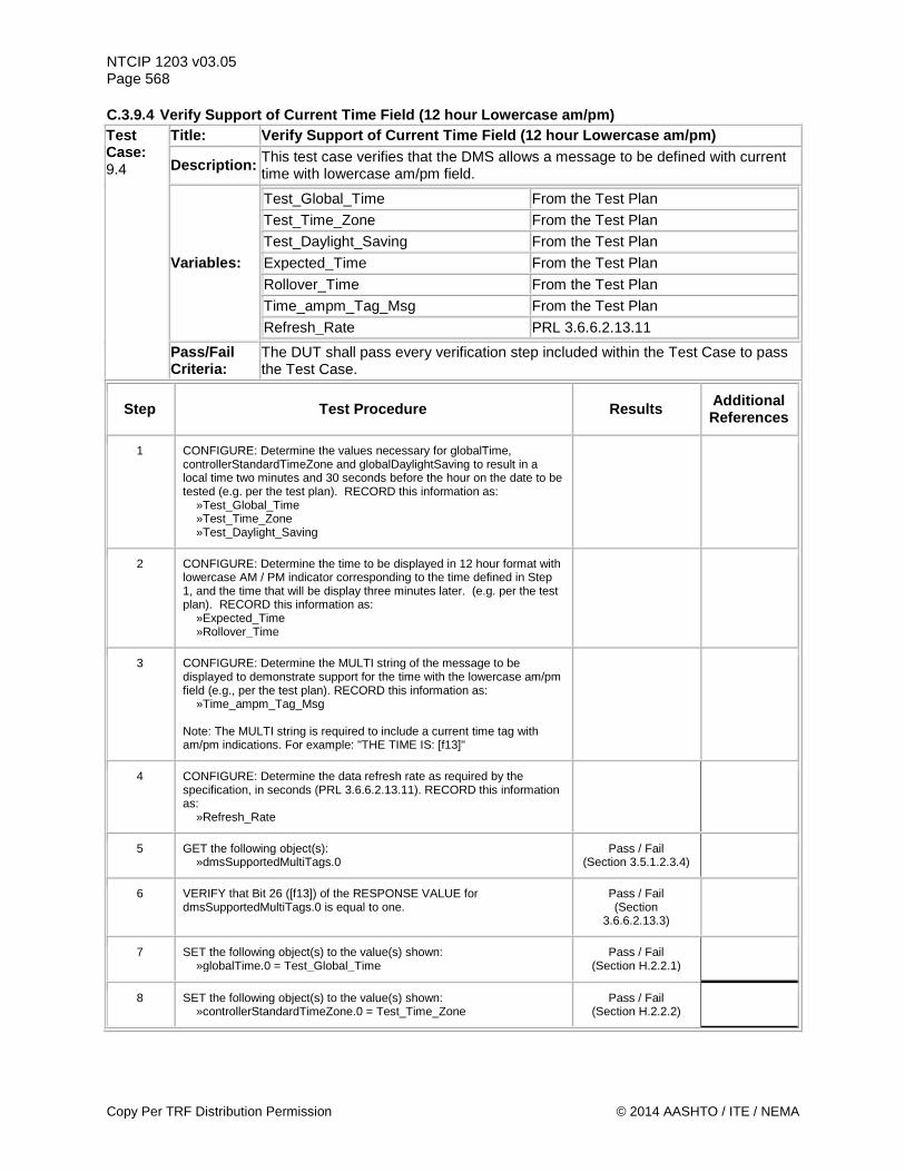
NTCIP 1203 v03.05 Page 568 C.3.9.4 Verify Support of Current Time Field (12 hour Lowercase am/pm) Test Case: 9.4
Title: Verify Support of Current Time Field (12 hour Lowercase am/pm)
Description: This test case verifies that the DMS allows a message to be defined with current time with lowercase am/pm field.
Variables:
Test_Global_Time From the Test Plan Test_Time_Zone From the Test Plan Test_Daylight_Saving From the Test Plan Expected_Time From the Test Plan Rollover_Time From the Test Plan Time_ampm_Tag_Msg From the Test Plan
Refresh_Rate PRL 3.6.6.2.13.11
Pass/Fail Criteria:
The DUT shall pass every verification step included within the Test Case to pass the Test Case.
Step Test Procedure Results Additional References
1 CONFIGURE: Determine the values necessary for globalTime, controllerStandardTimeZone and globalDaylightSaving to result in a local time two minutes and 30 seconds before the hour on the date to be tested (e.g. per the test plan). RECORD this information as: »Test_Global_Time »Test_Time_Zone »Test_Daylight_Saving
2 CONFIGURE: Determine the time to be displayed in 12 hour format with lowercase AM / PM indicator corresponding to the time defined in Step 1, and the time that will be display three minutes later. (e.g. per the test plan). RECORD this information as: »Expected_Time »Rollover_Time
3 CONFIGURE: Determine the MULTI string of the message to be displayed to demonstrate support for the time with the lowercase am/pm field (e.g., per the test plan). RECORD this information as: »Time_ampm_Tag_Msg Note: The MULTI string is required to include a current time tag with am/pm indications. For example: "THE TIME IS: [f13]"
4 CONFIGURE: Determine the data refresh rate as required by the specification, in seconds (PRL 3.6.6.2.13.11). RECORD this information as: »Refresh_Rate
5 GET the following object(s): »dmsSupportedMultiTags.0
Pass / Fail (Section 3.5.1.2.3.4)
6 VERIFY that Bit 26 ([f13]) of the RESPONSE VALUE for dmsSupportedMultiTags.0 is equal to one.
Pass / Fail (Section
3.6.6.2.13.3)
7 SET the following object(s) to the value(s) shown: »globalTime.0 = Test_Global_Time
Pass / Fail (Section H.2.2.1)
8 SET the following object(s) to the value(s) shown: »controllerStandardTimeZone.0 = Test_Time_Zone
Pass / Fail (Section H.2.2.2)
Copy Per TRF Distribution Permission © 2014 AASHTO / ITE / NEMA

NTCIP 1203 v03.05 Page 569
9 SET the following object(s) to the value(s) shown: »globalDaylightSaving.0 = Test_Daylight_Saving
Pass / Fail (Section H.2.2.3)
10 PERFORM the Test Procedure labeled 'Define a Message' (C.3.14.1) with the following parameters: »Msg_Type = 3 (changeable) or 4 (volatile) »Msg_Number = 1 »Msg_Multi_String = Time_ampm_Tag_Msg »Msg_Owner = “OWNER” »Msg_Beacon_State = 0 (disabled) »Msg_Pixel_Service = 0 (disabled) »Msg_Run_Time_Priority = 255 »Expected_Validate_Error_Code = 2 (none) »Expected_Multi_Error_Code = 2 (none) »Expected_Multi_Error_Pos_Min = 0 »Expected_Multi_Error_Pos_Max = 0
Pass / Fail (Section 3.5.2.3.3.3)
11 PERFORM the Test Procedure labeled 'Activate a Message' (C.3.14.2) with the following parameters: »Msg_Type = Msg_Type »Msg_Number = Msg_Number »Msg_Multi_String = Time_ampm_Tag_Msg »Msg_Beacon_State = 0 (disabled) »Msg_Pixel_Service = 0 (disabled) »Msg_Activation_Priority = 255 »Msg_Duration = 65535 (forever) »Expected_Error_Code = 2 (none) »Expected_Multi_Error_Code = 2 (none) »Expected_Multi_Error_Pos_Min = 0 »Expected_Multi_Error_Pos_Max = 0
Pass / Fail (Section 3.5.2.3.1)
12 VERIFY that the time displayed on the sign agrees with the value recorded in Expected_Time and is shown with lowercase am/pm letters as appropriate.
Pass / Fail (Section
3.6.6.2.13.3)
13 VERIFY that the field refreshes at a rate that is no slower than Refresh_Rate.
Pass / Fail (Section
3.6.6.2.13.11)
14 DELAY for 3 minutes.
15 VERIFY that the time displayed on the sign agrees with the value recorded in Rollover_Time, and is shown in with lowercase AM/PM letters as appropriate.
Pass / Fail (Section
3.6.6.2.13.3)
16 PERFORM the test case labeled 'Blank the Sign' (C.3.7.15). Pass / Fail (Section 3.5.2.3.1)
Test Case Results Tested By: Date Tested: Pass / Fail Test Case Notes:
© 2014 AASHTO / ITE / NEMA Copy Per TRF Distributtion Permission
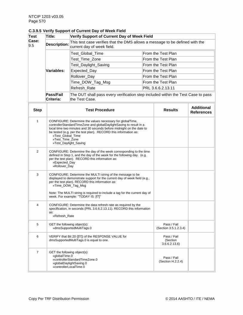
NTCIP 1203 v03.05 Page 570 C.3.9.5 Verify Support of Current Day of Week Field Test Case: 9.5
Title: Verify Support of Current Day of Week Field
Description: This test case verifies that the DMS allows a message to be defined with the current day of week field.
Variables:
Test_Global_Time From the Test Plan Test_Time_Zone From the Test Plan Test_Daylight_Saving From the Test Plan Expected_Day From the Test Plan Rollover_Day From the Test Plan Time_DOW_Tag_Msg From the Test Plan
Refresh_Rate PRL 3.6.6.2.13.11
Pass/Fail Criteria:
The DUT shall pass every verification step included within the Test Case to pass the Test Case.
Step Test Procedure Results Additional References
1 CONFIGURE: Determine the values necessary for globalTime, controllerStandardTimeZone and globalDaylightSaving to result in a local time two minutes and 30 seconds before midnight on the date to be tested (e.g. per the test plan). RECORD this information as: »Test_Global_Time »Test_Time_Zone »Test_Daylight_Saving
2 CONFIGURE: Determine the day of the week corresponding to the time defined in Step 1, and the day of the week for the following day. (e.g. per the test plan). RECORD this information as: »Expected_Day »Rollover_Day
3 CONFIGURE: Determine the MULTI string of the message to be displayed to demonstrate support for the current day of week field (e.g., per the test plan). RECORD this information as: »Time_DOW_Tag_Msg Note: The MULTI string is required to include a tag for the current day of week. For example: "TODAY IS: [f7]"
4 CONFIGURE: Determine the data refresh rate as required by the specification, in seconds (PRL 3.6.6.2.13.11). RECORD this information as: »Refresh_Rate
5 GET the following object(s): »dmsSupportedMultiTags.0
Pass / Fail (Section 3.5.1.2.3.4)
6 VERIFY that Bit 20 ([f7]) of the RESPONSE VALUE for dmsSupportedMultiTags.0 is equal to one.
Pass / Fail (Section
3.6.6.2.13.6)
7 GET the following object(s): »globalTime.0 »controllerStandardTimeZone.0 »globalDaylightSaving.0 »controllerLocalTime.0
Pass / Fail (Section H.2.2.4)
Copy Per TRF Distribution Permission © 2014 AASHTO / ITE / NEMA
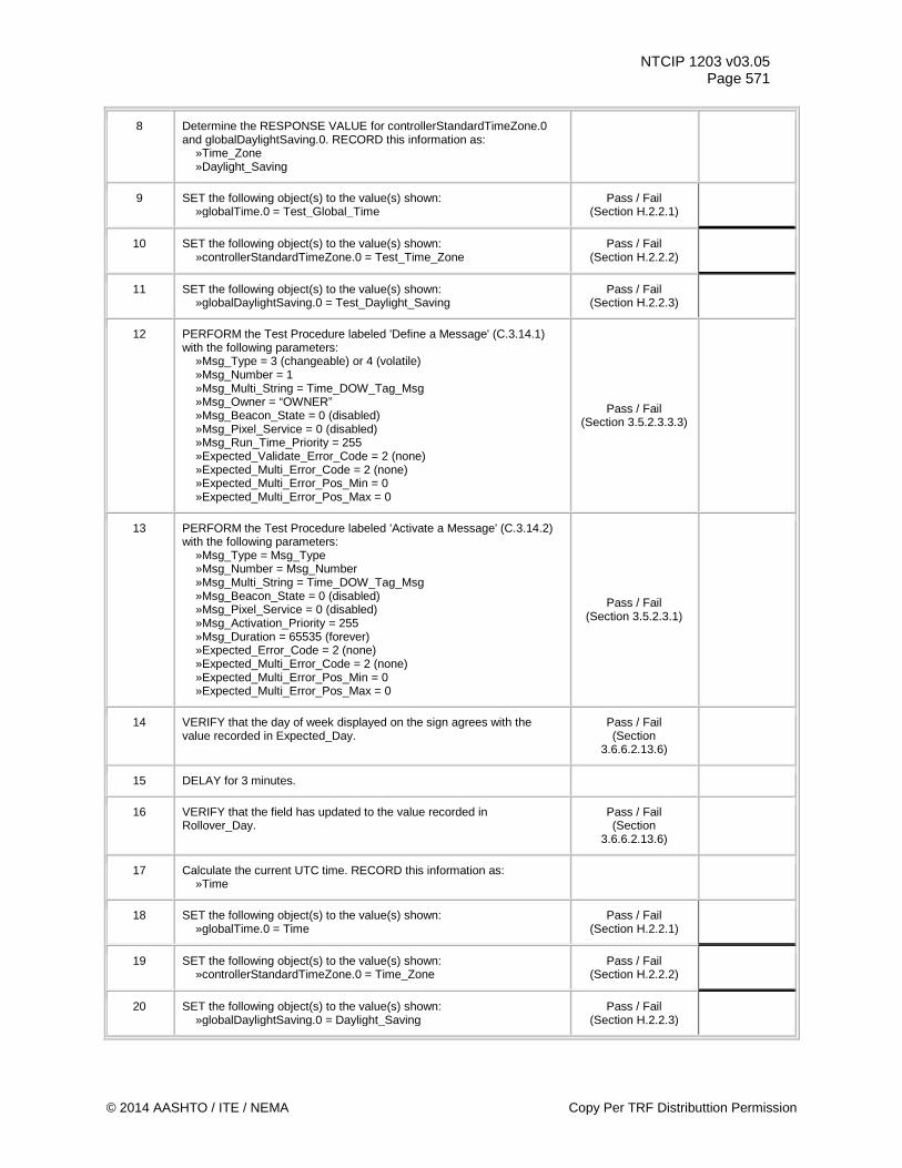
NTCIP 1203 v03.05 Page 571
8 Determine the RESPONSE VALUE for controllerStandardTimeZone.0 and globalDaylightSaving.0. RECORD this information as: »Time_Zone »Daylight_Saving
9 SET the following object(s) to the value(s) shown: »globalTime.0 = Test_Global_Time
Pass / Fail (Section H.2.2.1)
10 SET the following object(s) to the value(s) shown: »controllerStandardTimeZone.0 = Test_Time_Zone
Pass / Fail (Section H.2.2.2)
11 SET the following object(s) to the value(s) shown: »globalDaylightSaving.0 = Test_Daylight_Saving
Pass / Fail (Section H.2.2.3)
12 PERFORM the Test Procedure labeled 'Define a Message' (C.3.14.1) with the following parameters: »Msg_Type = 3 (changeable) or 4 (volatile) »Msg_Number = 1 »Msg_Multi_String = Time_DOW_Tag_Msg »Msg_Owner = “OWNER” »Msg_Beacon_State = 0 (disabled) »Msg_Pixel_Service = 0 (disabled) »Msg_Run_Time_Priority = 255 »Expected_Validate_Error_Code = 2 (none) »Expected_Multi_Error_Code = 2 (none) »Expected_Multi_Error_Pos_Min = 0 »Expected_Multi_Error_Pos_Max = 0
Pass / Fail (Section 3.5.2.3.3.3)
13 PERFORM the Test Procedure labeled 'Activate a Message' (C.3.14.2) with the following parameters: »Msg_Type = Msg_Type »Msg_Number = Msg_Number »Msg_Multi_String = Time_DOW_Tag_Msg »Msg_Beacon_State = 0 (disabled) »Msg_Pixel_Service = 0 (disabled) »Msg_Activation_Priority = 255 »Msg_Duration = 65535 (forever) »Expected_Error_Code = 2 (none) »Expected_Multi_Error_Code = 2 (none) »Expected_Multi_Error_Pos_Min = 0 »Expected_Multi_Error_Pos_Max = 0
Pass / Fail (Section 3.5.2.3.1)
14 VERIFY that the day of week displayed on the sign agrees with the value recorded in Expected_Day.
Pass / Fail (Section
3.6.6.2.13.6)
15 DELAY for 3 minutes.
16 VERIFY that the field has updated to the value recorded in Rollover_Day.
Pass / Fail (Section
3.6.6.2.13.6)
17 Calculate the current UTC time. RECORD this information as: »Time
18 SET the following object(s) to the value(s) shown: »globalTime.0 = Time
Pass / Fail (Section H.2.2.1)
19 SET the following object(s) to the value(s) shown: »controllerStandardTimeZone.0 = Time_Zone
Pass / Fail (Section H.2.2.2)
20 SET the following object(s) to the value(s) shown: »globalDaylightSaving.0 = Daylight_Saving
Pass / Fail (Section H.2.2.3)
© 2014 AASHTO / ITE / NEMA Copy Per TRF Distributtion Permission
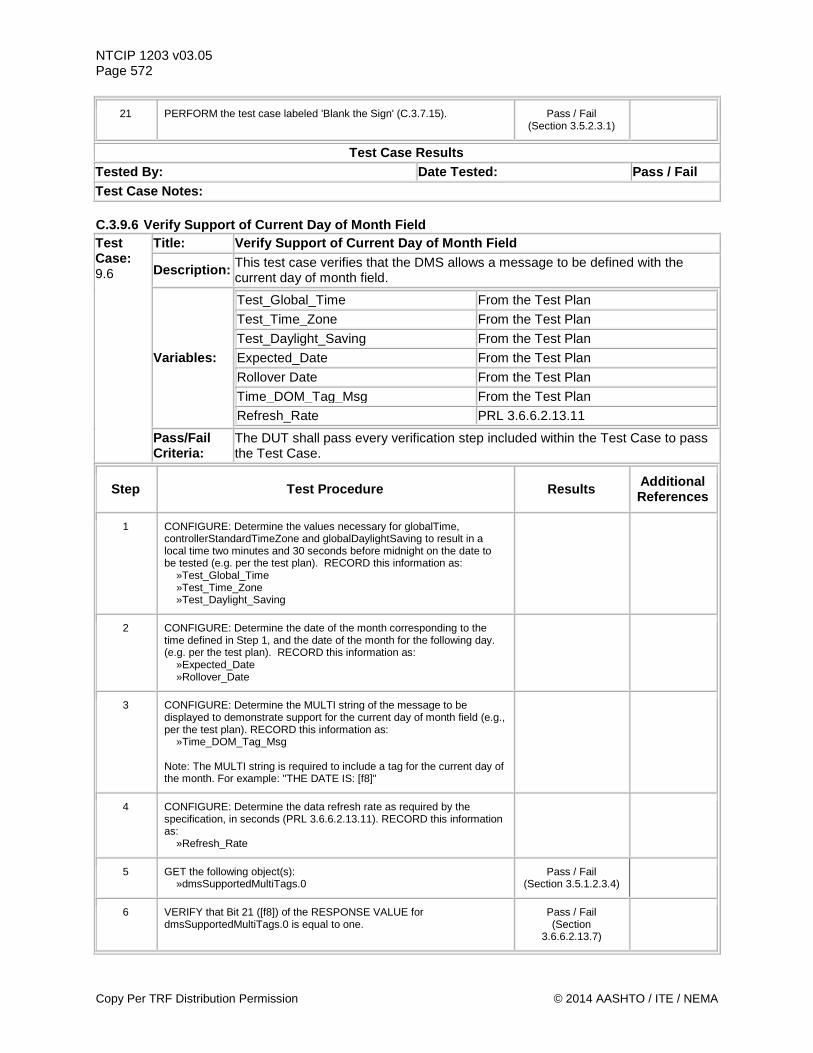
NTCIP 1203 v03.05 Page 572
21 PERFORM the test case labeled 'Blank the Sign' (C.3.7.15). Pass / Fail (Section 3.5.2.3.1)
Test Case Results Tested By: Date Tested: Pass / Fail Test Case Notes: C.3.9.6 Verify Support of Current Day of Month Field Test Case: 9.6
Title: Verify Support of Current Day of Month Field
Description: This test case verifies that the DMS allows a message to be defined with the current day of month field.
Variables:
Test_Global_Time From the Test Plan
Test_Time_Zone From the Test Plan Test_Daylight_Saving From the Test Plan Expected_Date From the Test Plan Rollover Date From the Test Plan Time_DOM_Tag_Msg From the Test Plan Refresh_Rate PRL 3.6.6.2.13.11
Pass/Fail Criteria:
The DUT shall pass every verification step included within the Test Case to pass the Test Case.
Step Test Procedure Results Additional References
1 CONFIGURE: Determine the values necessary for globalTime, controllerStandardTimeZone and globalDaylightSaving to result in a local time two minutes and 30 seconds before midnight on the date to be tested (e.g. per the test plan). RECORD this information as: »Test_Global_Time »Test_Time_Zone »Test_Daylight_Saving
2 CONFIGURE: Determine the date of the month corresponding to the time defined in Step 1, and the date of the month for the following day. (e.g. per the test plan). RECORD this information as: »Expected_Date »Rollover_Date
3 CONFIGURE: Determine the MULTI string of the message to be displayed to demonstrate support for the current day of month field (e.g., per the test plan). RECORD this information as: »Time_DOM_Tag_Msg Note: The MULTI string is required to include a tag for the current day of the month. For example: "THE DATE IS: [f8]"
4 CONFIGURE: Determine the data refresh rate as required by the specification, in seconds (PRL 3.6.6.2.13.11). RECORD this information as: »Refresh_Rate
5 GET the following object(s): »dmsSupportedMultiTags.0
Pass / Fail (Section 3.5.1.2.3.4)
6 VERIFY that Bit 21 ([f8]) of the RESPONSE VALUE for dmsSupportedMultiTags.0 is equal to one.
Pass / Fail (Section
3.6.6.2.13.7)
Copy Per TRF Distribution Permission © 2014 AASHTO / ITE / NEMA
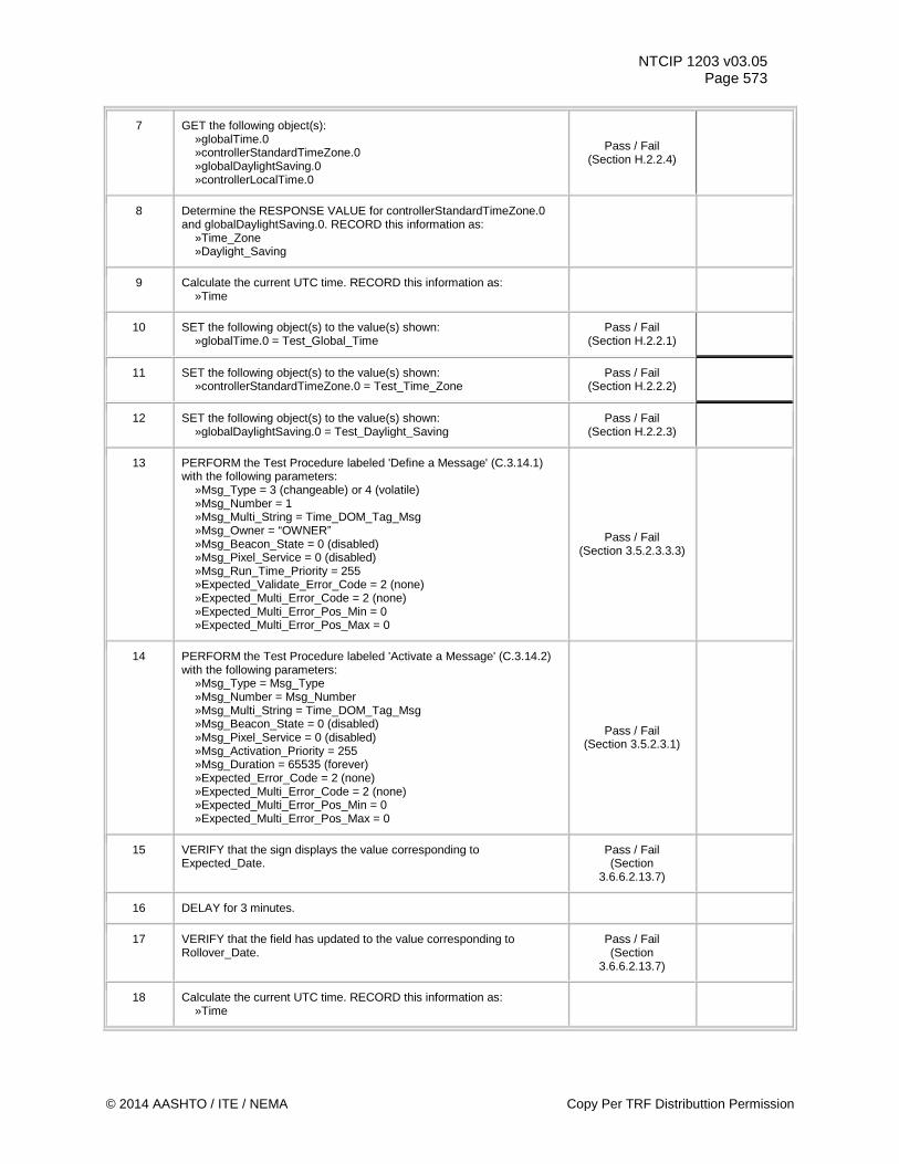
NTCIP 1203 v03.05 Page 573
7 GET the following object(s): »globalTime.0 »controllerStandardTimeZone.0 »globalDaylightSaving.0 »controllerLocalTime.0
Pass / Fail (Section H.2.2.4)
8 Determine the RESPONSE VALUE for controllerStandardTimeZone.0 and globalDaylightSaving.0. RECORD this information as: »Time_Zone »Daylight_Saving
9 Calculate the current UTC time. RECORD this information as: »Time
10 SET the following object(s) to the value(s) shown: »globalTime.0 = Test_Global_Time
Pass / Fail (Section H.2.2.1)
11 SET the following object(s) to the value(s) shown: »controllerStandardTimeZone.0 = Test_Time_Zone
Pass / Fail (Section H.2.2.2)
12 SET the following object(s) to the value(s) shown: »globalDaylightSaving.0 = Test_Daylight_Saving
Pass / Fail (Section H.2.2.3)
13 PERFORM the Test Procedure labeled 'Define a Message' (C.3.14.1) with the following parameters: »Msg_Type = 3 (changeable) or 4 (volatile) »Msg_Number = 1 »Msg_Multi_String = Time_DOM_Tag_Msg »Msg_Owner = “OWNER” »Msg_Beacon_State = 0 (disabled) »Msg_Pixel_Service = 0 (disabled) »Msg_Run_Time_Priority = 255 »Expected_Validate_Error_Code = 2 (none) »Expected_Multi_Error_Code = 2 (none) »Expected_Multi_Error_Pos_Min = 0 »Expected_Multi_Error_Pos_Max = 0
Pass / Fail (Section 3.5.2.3.3.3)
14 PERFORM the Test Procedure labeled 'Activate a Message' (C.3.14.2) with the following parameters: »Msg_Type = Msg_Type »Msg_Number = Msg_Number »Msg_Multi_String = Time_DOM_Tag_Msg »Msg_Beacon_State = 0 (disabled) »Msg_Pixel_Service = 0 (disabled) »Msg_Activation_Priority = 255 »Msg_Duration = 65535 (forever) »Expected_Error_Code = 2 (none) »Expected_Multi_Error_Code = 2 (none) »Expected_Multi_Error_Pos_Min = 0 »Expected_Multi_Error_Pos_Max = 0
Pass / Fail (Section 3.5.2.3.1)
15 VERIFY that the sign displays the value corresponding to Expected_Date.
Pass / Fail (Section
3.6.6.2.13.7)
16 DELAY for 3 minutes.
17 VERIFY that the field has updated to the value corresponding to Rollover_Date.
Pass / Fail (Section
3.6.6.2.13.7)
18 Calculate the current UTC time. RECORD this information as: »Time
© 2014 AASHTO / ITE / NEMA Copy Per TRF Distributtion Permission
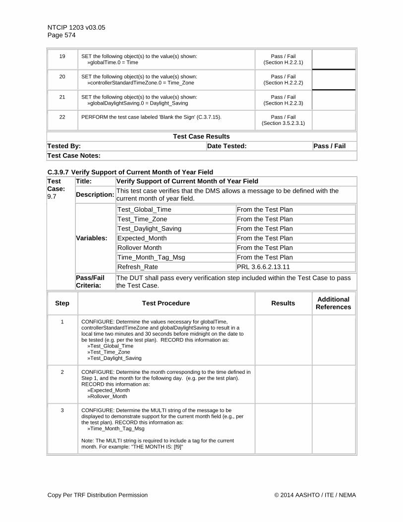
NTCIP 1203 v03.05 Page 574
19 SET the following object(s) to the value(s) shown: »globalTime.0 = Time
Pass / Fail (Section H.2.2.1)
20 SET the following object(s) to the value(s) shown: »controllerStandardTimeZone.0 = Time_Zone
Pass / Fail (Section H.2.2.2)
21 SET the following object(s) to the value(s) shown: »globalDaylightSaving.0 = Daylight_Saving
Pass / Fail (Section H.2.2.3)
22 PERFORM the test case labeled 'Blank the Sign' (C.3.7.15). Pass / Fail (Section 3.5.2.3.1)
Test Case Results Tested By: Date Tested: Pass / Fail Test Case Notes: C.3.9.7 Verify Support of Current Month of Year Field Test Case: 9.7
Title: Verify Support of Current Month of Year Field
Description: This test case verifies that the DMS allows a message to be defined with the current month of year field.
Variables:
Test_Global_Time From the Test Plan Test_Time_Zone From the Test Plan Test_Daylight_Saving From the Test Plan Expected_Month From the Test Plan Rollover Month From the Test Plan Time_Month_Tag_Msg From the Test Plan
Refresh_Rate PRL 3.6.6.2.13.11
Pass/Fail Criteria:
The DUT shall pass every verification step included within the Test Case to pass the Test Case.
Step Test Procedure Results Additional References
1 CONFIGURE: Determine the values necessary for globalTime, controllerStandardTimeZone and globalDaylightSaving to result in a local time two minutes and 30 seconds before midnight on the date to be tested (e.g. per the test plan). RECORD this information as: »Test_Global_Time »Test_Time_Zone »Test_Daylight_Saving
2 CONFIGURE: Determine the month corresponding to the time defined in Step 1, and the month for the following day. (e.g. per the test plan). RECORD this information as: »Expected_Month »Rollover_Month
3 CONFIGURE: Determine the MULTI string of the message to be displayed to demonstrate support for the current month field (e.g., per the test plan). RECORD this information as: »Time_Month_Tag_Msg Note: The MULTI string is required to include a tag for the current month. For example: "THE MONTH IS: [f9]"
Copy Per TRF Distribution Permission © 2014 AASHTO / ITE / NEMA
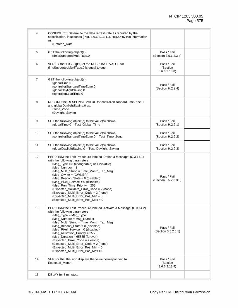
NTCIP 1203 v03.05 Page 575
4 CONFIGURE: Determine the data refresh rate as required by the specification, in seconds (PRL 3.6.6.2.13.11). RECORD this information as: »Refresh_Rate
5 GET the following object(s): »dmsSupportedMultiTags.0
Pass / Fail (Section 3.5.1.2.3.4)
6 VERIFY that Bit 22 ([f9]) of the RESPONSE VALUE for dmsSupportedMultiTags.0 is equal to one.
Pass / Fail (Section
3.6.6.2.13.8)
7 GET the following object(s): »globalTime.0 »controllerStandardTimeZone.0 »globalDaylightSaving.0 »controllerLocalTime.0
Pass / Fail (Section H.2.2.4)
8 RECORD the RESPONSE VALUE for controllerStandardTimeZone.0 and globalDaylightSaving.0 as: »Time_Zone »Daylight_Saving
9 SET the following object(s) to the value(s) shown: »globalTime.0 = Test_Global_Time
Pass / Fail (Section H.2.2.1)
10 SET the following object(s) to the value(s) shown: »controllerStandardTimeZone.0 = Test_Time_Zone
Pass / Fail (Section H.2.2.2)
11 SET the following object(s) to the value(s) shown: »globalDaylightSaving.0 = Test_Daylight_Saving
Pass / Fail (Section H.2.2.3)
12 PERFORM the Test Procedure labeled 'Define a Message' (C.3.14.1) with the following parameters: »Msg_Type = 3 (changeable) or 4 (volatile) »Msg_Number = 1 »Msg_Multi_String = Time_Month_Tag_Msg »Msg_Owner = “OWNER” »Msg_Beacon_State = 0 (disabled) »Msg_Pixel_Service = 0 (disabled) »Msg_Run_Time_Priority = 255 »Expected_Validate_Error_Code = 2 (none) »Expected_Multi_Error_Code = 2 (none) »Expected_Multi_Error_Pos_Min = 0 »Expected_Multi_Error_Pos_Max = 0
Pass / Fail (Section 3.5.2.3.3.3)
13 PERFORM the Test Procedure labeled 'Activate a Message' (C.3.14.2) with the following parameters: »Msg_Type = Msg_Type »Msg_Number = Msg_Number »Msg_Multi_String = Time_Month_Tag_Msg »Msg_Beacon_State = 0 (disabled) »Msg_Pixel_Service = 0 (disabled) »Msg_Activation_Priority = 255 »Msg_Duration = 65535 (forever) »Expected_Error_Code = 2 (none) »Expected_Multi_Error_Code = 2 (none) »Expected_Multi_Error_Pos_Min = 0 »Expected_Multi_Error_Pos_Max = 0
Pass / Fail (Section 3.5.2.3.1)
14 VERIFY that the sign displays the value corresponding to Expected_Month.
Pass / Fail (Section
3.6.6.2.13.8)
15 DELAY for 3 minutes.
© 2014 AASHTO / ITE / NEMA Copy Per TRF Distributtion Permission
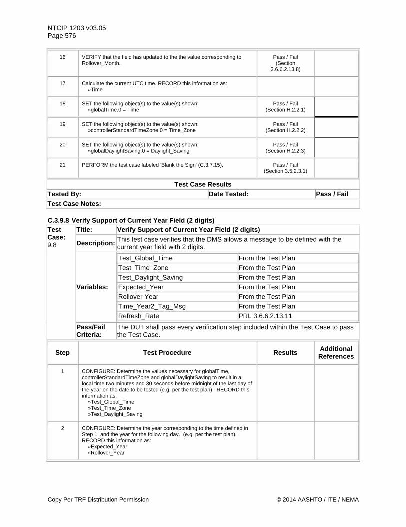
NTCIP 1203 v03.05 Page 576
16 VERIFY that the field has updated to the the value corresponding to Rollover_Month.
Pass / Fail (Section
3.6.6.2.13.8)
17 Calculate the current UTC time. RECORD this information as: »Time
18 SET the following object(s) to the value(s) shown: »globalTime.0 = Time
Pass / Fail (Section H.2.2.1)
19 SET the following object(s) to the value(s) shown: »controllerStandardTimeZone.0 = Time_Zone
Pass / Fail (Section H.2.2.2)
20 SET the following object(s) to the value(s) shown: »globalDaylightSaving.0 = Daylight_Saving
Pass / Fail (Section H.2.2.3)
21 PERFORM the test case labeled 'Blank the Sign' (C.3.7.15). Pass / Fail (Section 3.5.2.3.1)
Test Case Results Tested By: Date Tested: Pass / Fail Test Case Notes: C.3.9.8 Verify Support of Current Year Field (2 digits) Test Case: 9.8
Title: Verify Support of Current Year Field (2 digits)
Description: This test case verifies that the DMS allows a message to be defined with the current year field with 2 digits.
Variables:
Test_Global_Time From the Test Plan Test_Time_Zone From the Test Plan Test_Daylight_Saving From the Test Plan Expected_Year From the Test Plan Rollover Year From the Test Plan Time_Year2_Tag_Msg From the Test Plan
Refresh_Rate PRL 3.6.6.2.13.11
Pass/Fail Criteria:
The DUT shall pass every verification step included within the Test Case to pass the Test Case.
Step Test Procedure Results Additional References
1 CONFIGURE: Determine the values necessary for globalTime, controllerStandardTimeZone and globalDaylightSaving to result in a local time two minutes and 30 seconds before midnight of the last day of the year on the date to be tested (e.g. per the test plan). RECORD this information as: »Test_Global_Time »Test_Time_Zone »Test_Daylight_Saving
2 CONFIGURE: Determine the year corresponding to the time defined in Step 1, and the year for the following day. (e.g. per the test plan). RECORD this information as: »Expected_Year »Rollover_Year
Copy Per TRF Distribution Permission © 2014 AASHTO / ITE / NEMA
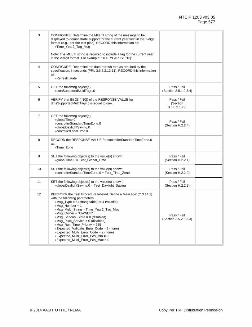
NTCIP 1203 v03.05 Page 577
3 CONFIGURE: Determine the MULTI string of the message to be displayed to demonstrate support for the current year field in the 2-digit format (e.g., per the test plan). RECORD this information as: »Time_Year2_Tag_Msg Note: The MULTI string is required to include a tag for the current year in the 2-digit format. For example: "THE YEAR IS: [f10]"
4 CONFIGURE: Determine the data refresh rate as required by the specification, in seconds (PRL 3.6.6.2.13.11). RECORD this information as: »Refresh_Rate
5 GET the following object(s): »dmsSupportedMultiTags.0
Pass / Fail (Section 3.5.1.2.3.4)
6 VERIFY that Bit 23 ([f10]) of the RESPONSE VALUE for dmsSupportedMultiTags.0 is equal to one.
Pass / Fail (Section
3.6.6.2.13.9)
7 GET the following object(s): »globalTime.0 »controllerStandardTimeZone.0 »globalDaylightSaving.0 »controllerLocalTime.0
Pass / Fail (Section H.2.2.4)
8 RECORD the RESPONSE VALUE for controllerStandardTimeZone.0 as: »Time_Zone
9 SET the following object(s) to the value(s) shown: »globalTime.0 = Test_Global_Time
Pass / Fail (Section H.2.2.1)
10 SET the following object(s) to the value(s) shown: »controllerStandardTimeZone.0 = Test_Time_Zone
Pass / Fail (Section H.2.2.2)
11 SET the following object(s) to the value(s) shown: »globalDaylightSaving.0 = Test_Daylight_Saving
Pass / Fail (Section H.2.2.3)
12 PERFORM the Test Procedure labeled 'Define a Message' (C.3.14.1) with the following parameters: »Msg_Type = 3 (changeable) or 4 (volatile) »Msg_Number = 1 »Msg_Multi_String = Time_Year2_Tag_Msg »Msg_Owner = “OWNER” »Msg_Beacon_State = 0 (disabled) »Msg_Pixel_Service = 0 (disabled) »Msg_Run_Time_Priority = 255 »Expected_Validate_Error_Code = 2 (none) »Expected_Multi_Error_Code = 2 (none) »Expected_Multi_Error_Pos_Min = 0 »Expected_Multi_Error_Pos_Max = 0
Pass / Fail (Section 3.5.2.3.3.3)
© 2014 AASHTO / ITE / NEMA Copy Per TRF Distributtion Permission
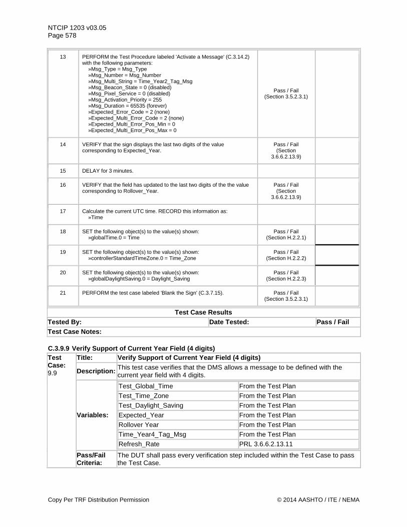
NTCIP 1203 v03.05 Page 578
13 PERFORM the Test Procedure labeled 'Activate a Message' (C.3.14.2) with the following parameters: »Msg_Type = Msg_Type »Msg_Number = Msg_Number »Msg_Multi_String = Time_Year2_Tag_Msg »Msg_Beacon_State = 0 (disabled) »Msg_Pixel_Service = 0 (disabled) »Msg_Activation_Priority = 255 »Msg_Duration = 65535 (forever) »Expected_Error_Code = 2 (none) »Expected_Multi_Error_Code = 2 (none) »Expected_Multi_Error_Pos_Min = 0 »Expected_Multi_Error_Pos_Max = 0
Pass / Fail (Section 3.5.2.3.1)
14 VERIFY that the sign displays the last two digits of the value corresponding to Expected_Year.
Pass / Fail (Section
3.6.6.2.13.9)
15 DELAY for 3 minutes.
16 VERIFY that the field has updated to the last two digits of the the value corresponding to Rollover_Year.
Pass / Fail (Section
3.6.6.2.13.9)
17 Calculate the current UTC time. RECORD this information as: »Time
18 SET the following object(s) to the value(s) shown: »globalTime.0 = Time
Pass / Fail (Section H.2.2.1)
19 SET the following object(s) to the value(s) shown: »controllerStandardTimeZone.0 = Time_Zone
Pass / Fail (Section H.2.2.2)
20 SET the following object(s) to the value(s) shown: »globalDaylightSaving.0 = Daylight_Saving
Pass / Fail (Section H.2.2.3)
21 PERFORM the test case labeled 'Blank the Sign' (C.3.7.15). Pass / Fail (Section 3.5.2.3.1)
Test Case Results Tested By: Date Tested: Pass / Fail Test Case Notes: C.3.9.9 Verify Support of Current Year Field (4 digits) Test Case: 9.9
Title: Verify Support of Current Year Field (4 digits)
Description: This test case verifies that the DMS allows a message to be defined with the current year field with 4 digits.
Variables:
Test_Global_Time From the Test Plan Test_Time_Zone From the Test Plan Test_Daylight_Saving From the Test Plan Expected_Year From the Test Plan Rollover Year From the Test Plan Time_Year4_Tag_Msg From the Test Plan
Refresh_Rate PRL 3.6.6.2.13.11
Pass/Fail Criteria:
The DUT shall pass every verification step included within the Test Case to pass the Test Case.
Copy Per TRF Distribution Permission © 2014 AASHTO / ITE / NEMA
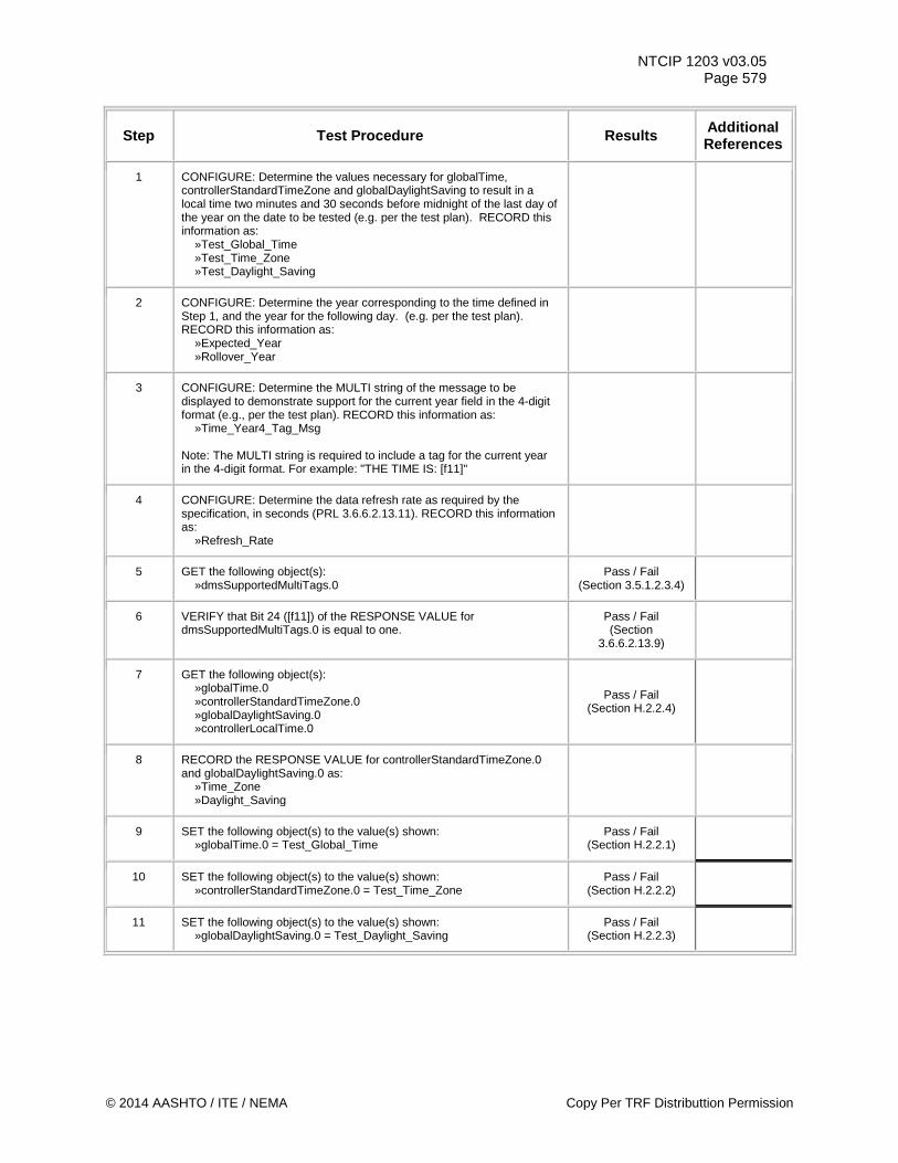
NTCIP 1203 v03.05 Page 579
Step Test Procedure Results Additional References
1 CONFIGURE: Determine the values necessary for globalTime, controllerStandardTimeZone and globalDaylightSaving to result in a local time two minutes and 30 seconds before midnight of the last day of the year on the date to be tested (e.g. per the test plan). RECORD this information as: »Test_Global_Time »Test_Time_Zone »Test_Daylight_Saving
2 CONFIGURE: Determine the year corresponding to the time defined in Step 1, and the year for the following day. (e.g. per the test plan). RECORD this information as: »Expected_Year »Rollover_Year
3 CONFIGURE: Determine the MULTI string of the message to be displayed to demonstrate support for the current year field in the 4-digit format (e.g., per the test plan). RECORD this information as: »Time_Year4_Tag_Msg Note: The MULTI string is required to include a tag for the current year in the 4-digit format. For example: "THE TIME IS: [f11]"
4 CONFIGURE: Determine the data refresh rate as required by the specification, in seconds (PRL 3.6.6.2.13.11). RECORD this information as: »Refresh_Rate
5 GET the following object(s): »dmsSupportedMultiTags.0
Pass / Fail (Section 3.5.1.2.3.4)
6 VERIFY that Bit 24 ([f11]) of the RESPONSE VALUE for dmsSupportedMultiTags.0 is equal to one.
Pass / Fail (Section
3.6.6.2.13.9)
7 GET the following object(s): »globalTime.0 »controllerStandardTimeZone.0 »globalDaylightSaving.0 »controllerLocalTime.0
Pass / Fail (Section H.2.2.4)
8 RECORD the RESPONSE VALUE for controllerStandardTimeZone.0 and globalDaylightSaving.0 as: »Time_Zone »Daylight_Saving
9 SET the following object(s) to the value(s) shown: »globalTime.0 = Test_Global_Time
Pass / Fail (Section H.2.2.1)
10 SET the following object(s) to the value(s) shown: »controllerStandardTimeZone.0 = Test_Time_Zone
Pass / Fail (Section H.2.2.2)
11 SET the following object(s) to the value(s) shown: »globalDaylightSaving.0 = Test_Daylight_Saving
Pass / Fail (Section H.2.2.3)
© 2014 AASHTO / ITE / NEMA Copy Per TRF Distributtion Permission
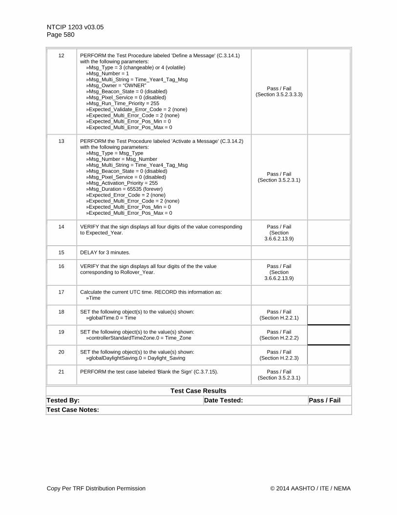
NTCIP 1203 v03.05 Page 580
12 PERFORM the Test Procedure labeled 'Define a Message' (C.3.14.1) with the following parameters: »Msg_Type = 3 (changeable) or 4 (volatile) »Msg_Number = 1 »Msg_Multi_String = Time_Year4_Tag_Msg »Msg_Owner = “OWNER” »Msg_Beacon_State = 0 (disabled) »Msg_Pixel_Service = 0 (disabled) »Msg_Run_Time_Priority = 255 »Expected_Validate_Error_Code = 2 (none) »Expected_Multi_Error_Code = 2 (none) »Expected_Multi_Error_Pos_Min = 0 »Expected_Multi_Error_Pos_Max = 0
Pass / Fail (Section 3.5.2.3.3.3)
13 PERFORM the Test Procedure labeled 'Activate a Message' (C.3.14.2) with the following parameters: »Msg_Type = Msg_Type »Msg_Number = Msg_Number »Msg_Multi_String = Time_Year4_Tag_Msg »Msg_Beacon_State = 0 (disabled) »Msg_Pixel_Service = 0 (disabled) »Msg_Activation_Priority = 255 »Msg_Duration = 65535 (forever) »Expected_Error_Code = 2 (none) »Expected_Multi_Error_Code = 2 (none) »Expected_Multi_Error_Pos_Min = 0 »Expected_Multi_Error_Pos_Max = 0
Pass / Fail (Section 3.5.2.3.1)
14 VERIFY that the sign displays all four digits of the value corresponding to Expected_Year.
Pass / Fail (Section
3.6.6.2.13.9)
15 DELAY for 3 minutes.
16 VERIFY that the sign displays all four digits of the the value corresponding to Rollover_Year.
Pass / Fail (Section
3.6.6.2.13.9)
17 Calculate the current UTC time. RECORD this information as: »Time
18 SET the following object(s) to the value(s) shown: »globalTime.0 = Time
Pass / Fail (Section H.2.2.1)
19 SET the following object(s) to the value(s) shown: »controllerStandardTimeZone.0 = Time_Zone
Pass / Fail (Section H.2.2.2)
20 SET the following object(s) to the value(s) shown: »globalDaylightSaving.0 = Daylight_Saving
Pass / Fail (Section H.2.2.3)
21 PERFORM the test case labeled 'Blank the Sign' (C.3.7.15). Pass / Fail (Section 3.5.2.3.1)
Test Case Results Tested By: Date Tested: Pass / Fail Test Case Notes:
Copy Per TRF Distribution Permission © 2014 AASHTO / ITE / NEMA
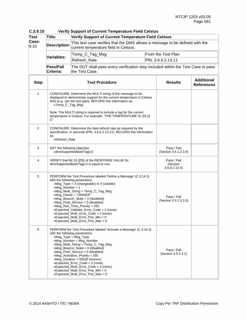
NTCIP 1203 v03.05 Page 581
C.3.9.10 Verify Support of Current Temperature Field Celsius Test Case: 9.10
Title: Verify Support of Current Temperature Field Celsius
Description: This test case verifies that the DMS allows a message to be defined with the current temperature field in Celsius.
Variables: Temp_C_Tag_Msg From the Test Plan
Refresh_Rate PRL 3.6.6.2.13.11
Pass/Fail Criteria:
The DUT shall pass every verification step included within the Test Case to pass the Test Case.
Step Test Procedure Results Additional References
1 CONFIGURE: Determine the MULTI string of the message to be displayed to demonstrate support for the current temperature in Celsius field (e.g., per the test plan). RECORD this information as: »Temp_C_Tag_Msg Note: The MULTI string is required to include a tag for the current temperature in Celsius. For example: "THE TEMPERATURE IS: [f3,2] C"
2 CONFIGURE: Determine the data refresh rate as required by the specification, in seconds (PRL 3.6.6.2.13.11). RECORD this information as: »Refresh_Rate
3 GET the following object(s): »dmsSupportedMultiTags.0
Pass / Fail (Section 3.5.1.2.3.4)
4 VERIFY that Bit 16 ([f3]) of the RESPONSE VALUE for dmsSupportedMultiTags.0 is equal to one.
Pass / Fail (Section
3.6.6.2.13.4)
5 PERFORM the Test Procedure labeled 'Define a Message' (C.3.14.1) with the following parameters: »Msg_Type = 3 (changeable) or 4 (volatile) »Msg_Number = 1 »Msg_Multi_String = Temp_C_Tag_Msg »Msg_Owner = “OWNER” »Msg_Beacon_State = 0 (disabled) »Msg_Pixel_Service = 0 (disabled) »Msg_Run_Time_Priority = 255 »Expected_Validate_Error_Code = 2 (none) »Expected_Multi_Error_Code = 2 (none) »Expected_Multi_Error_Pos_Min = 0 »Expected_Multi_Error_Pos_Max = 0
Pass / Fail (Section 3.5.2.3.3.3)
6 PERFORM the Test Procedure labeled 'Activate a Message' (C.3.14.2) with the following parameters: »Msg_Type = Msg_Type »Msg_Number = Msg_Number »Msg_Multi_String = Temp_C_Tag_Msg »Msg_Beacon_State = 0 (disabled) »Msg_Pixel_Service = 0 (disabled) »Msg_Activation_Priority = 255 »Msg_Duration = 65535 (forever) »Expected_Error_Code = 2 (none) »Expected_Multi_Error_Code = 2 (none) »Expected_Multi_Error_Pos_Min = 0 »Expected_Multi_Error_Pos_Max = 0
Pass / Fail (Section 3.5.2.3.1)
© 2014 AASHTO / ITE / NEMA Copy Per TRF Distributtion Permission
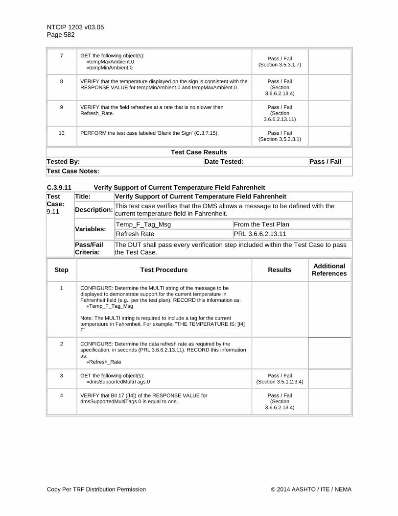
NTCIP 1203 v03.05 Page 582
7 GET the following object(s): »tempMaxAmbient.0 »tempMinAmbient.0
Pass / Fail (Section 3.5.3.1.7)
8 VERIFY that the temperature displayed on the sign is consistent with the RESPONSE VALUE for tempMinAmbient.0 and tempMaxAmbient.0.
Pass / Fail (Section
3.6.6.2.13.4)
9 VERIFY that the field refreshes at a rate that is no slower than Refresh_Rate.
Pass / Fail (Section
3.6.6.2.13.11)
10 PERFORM the test case labeled 'Blank the Sign' (C.3.7.15). Pass / Fail (Section 3.5.2.3.1)
Test Case Results Tested By: Date Tested: Pass / Fail Test Case Notes: C.3.9.11 Verify Support of Current Temperature Field Fahrenheit Test Case: 9.11
Title: Verify Support of Current Temperature Field Fahrenheit
Description: This test case verifies that the DMS allows a message to be defined with the current temperature field in Fahrenheit.
Variables: Temp_F_Tag_Msg From the Test Plan
Refresh Rate PRL 3.6.6.2.13.11
Pass/Fail Criteria:
The DUT shall pass every verification step included within the Test Case to pass the Test Case.
Step Test Procedure Results Additional References
1 CONFIGURE: Determine the MULTI string of the message to be displayed to demonstrate support for the current temperature in Fahrenheit field (e.g., per the test plan). RECORD this information as: »Temp_F_Tag_Msg Note: The MULTI string is required to include a tag for the current temperature in Fahrenheit. For example: "THE TEMPERATURE IS: [f4] F"
2 CONFIGURE: Determine the data refresh rate as required by the specification, in seconds (PRL 3.6.6.2.13.11). RECORD this information as: »Refresh_Rate
3 GET the following object(s): »dmsSupportedMultiTags.0
Pass / Fail (Section 3.5.1.2.3.4)
4 VERIFY that Bit 17 ([f4]) of the RESPONSE VALUE for dmsSupportedMultiTags.0 is equal to one.
Pass / Fail (Section
3.6.6.2.13.4)
Copy Per TRF Distribution Permission © 2014 AASHTO / ITE / NEMA
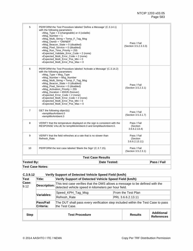
NTCIP 1203 v03.05 Page 583
5 PERFORM the Test Procedure labeled 'Define a Message' (C.3.14.1) with the following parameters: »Msg_Type = 3 (changeable) or 4 (volatile) »Msg_Number = 1 »Msg_Multi_String = Temp_F_Tag_Msg »Msg_Owner = “OWNER” »Msg_Beacon_State = 0 (disabled) »Msg_Pixel_Service = 0 (disabled) »Msg_Run_Time_Priority = 255 »Expected_Validate_Error_Code = 2 (none) »Expected_Multi_Error_Code = 2 (none) »Expected_Multi_Error_Pos_Min = 0 »Expected_Multi_Error_Pos_Max = 0
Pass / Fail (Section 3.5.2.3.3.3)
6 PERFORM the Test Procedure labeled 'Activate a Message' (C.3.14.2) with the following parameters: »Msg_Type = Msg_Type »Msg_Number = Msg_Number »Msg_Multi_String = Temp_F_Tag_Msg »Msg_Beacon_State = 0 (disabled) »Msg_Pixel_Service = 0 (disabled) »Msg_Activation_Priority = 255 »Msg_Duration = 65535 (forever) »Expected_Error_Code = 2 (none) »Expected_Multi_Error_Code = 2 (none) »Expected_Multi_Error_Pos_Min = 0 »Expected_Multi_Error_Pos_Max = 0
Pass / Fail (Section 3.5.2.3.1)
7 GET the following object(s): »tempMaxAmbient.0 »tempMinAmbient.0
Pass / Fail (Section 3.5.3.1.7)
8 VERIFY that the temperature displayed on the sign is consistent with the RESPONSE VALUE for tempMinAmbient.0 and tempMaxAmbient.0.
Pass / Fail (Section
3.6.6.2.13.4)
9 VERIFY that the field refreshes at a rate that is no slower than Refresh_Rate.
Pass / Fail (Section
3.6.6.2.13.11)
10 PERFORM the test case labeled 'Blank the Sign' (C.3.7.15). Pass / Fail (Section 3.5.2.3.1)
Test Case Results Tested By: Date Tested: Pass / Fail Test Case Notes: C.3.9.12 Verify Support of Detected Vehicle Speed Field (km/h) Test Case: 9.12
Title: Verify Support of Detected Vehicle Speed Field (km/h)
Description: This test case verifies that the DMS allows a message to be defined with the detected vehicle speed in kilometers per hour field.
Variables: Speed_KPH_Tag_Msg From the Test Plan
Refresh_Rate PRL 3.6.6.2.13.11
Pass/Fail Criteria:
The DUT shall pass every verification step included within the Test Case to pass the Test Case.
Step Test Procedure Results Additional References
© 2014 AASHTO / ITE / NEMA Copy Per TRF Distributtion Permission
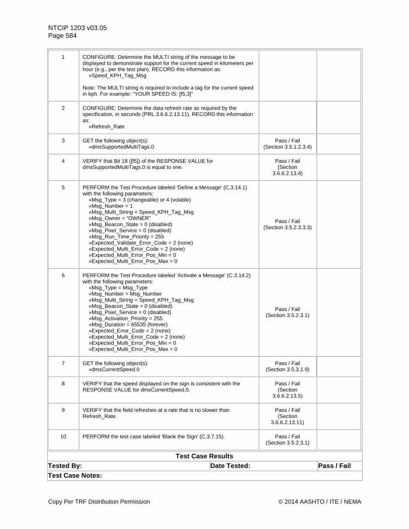
NTCIP 1203 v03.05 Page 584
1 CONFIGURE: Determine the MULTI string of the message to be displayed to demonstrate support for the current speed in kilometers per hour (e.g., per the test plan). RECORD this information as: »Speed_KPH_Tag_Msg Note: The MULTI string is required to include a tag for the current speed in kph. For example: "YOUR SPEED IS: [f5,3]"
2 CONFIGURE: Determine the data refresh rate as required by the specification, in seconds (PRL 3.6.6.2.13.11). RECORD this information as: »Refresh_Rate
3 GET the following object(s): »dmsSupportedMultiTags.0
Pass / Fail (Section 3.5.1.2.3.4)
4 VERIFY that Bit 18 ([f5]) of the RESPONSE VALUE for dmsSupportedMultiTags.0 is equal to one.
Pass / Fail (Section
3.6.6.2.13.4)
5 PERFORM the Test Procedure labeled 'Define a Message' (C.3.14.1) with the following parameters: »Msg_Type = 3 (changeable) or 4 (volatile) »Msg_Number = 1 »Msg_Multi_String = Speed_KPH_Tag_Msg »Msg_Owner = “OWNER” »Msg_Beacon_State = 0 (disabled) »Msg_Pixel_Service = 0 (disabled) »Msg_Run_Time_Priority = 255 »Expected_Validate_Error_Code = 2 (none) »Expected_Multi_Error_Code = 2 (none) »Expected_Multi_Error_Pos_Min = 0 »Expected_Multi_Error_Pos_Max = 0
Pass / Fail (Section 3.5.2.3.3.3)
6 PERFORM the Test Procedure labeled 'Activate a Message' (C.3.14.2) with the following parameters: »Msg_Type = Msg_Type »Msg_Number = Msg_Number »Msg_Multi_String = Speed_KPH_Tag_Msg »Msg_Beacon_State = 0 (disabled) »Msg_Pixel_Service = 0 (disabled) »Msg_Activation_Priority = 255 »Msg_Duration = 65535 (forever) »Expected_Error_Code = 2 (none) »Expected_Multi_Error_Code = 2 (none) »Expected_Multi_Error_Pos_Min = 0 »Expected_Multi_Error_Pos_Max = 0
Pass / Fail (Section 3.5.2.3.1)
7 GET the following object(s): »dmsCurrentSpeed.0
Pass / Fail (Section 3.5.3.1.9)
8 VERIFY that the speed displayed on the sign is consistent with the RESPONSE VALUE for dmsCurrentSpeed.0.
Pass / Fail (Section
3.6.6.2.13.5)
9 VERIFY that the field refreshes at a rate that is no slower than Refresh_Rate.
Pass / Fail (Section
3.6.6.2.13.11)
10 PERFORM the test case labeled 'Blank the Sign' (C.3.7.15). Pass / Fail (Section 3.5.2.3.1)
Test Case Results Tested By: Date Tested: Pass / Fail Test Case Notes:
Copy Per TRF Distribution Permission © 2014 AASHTO / ITE / NEMA
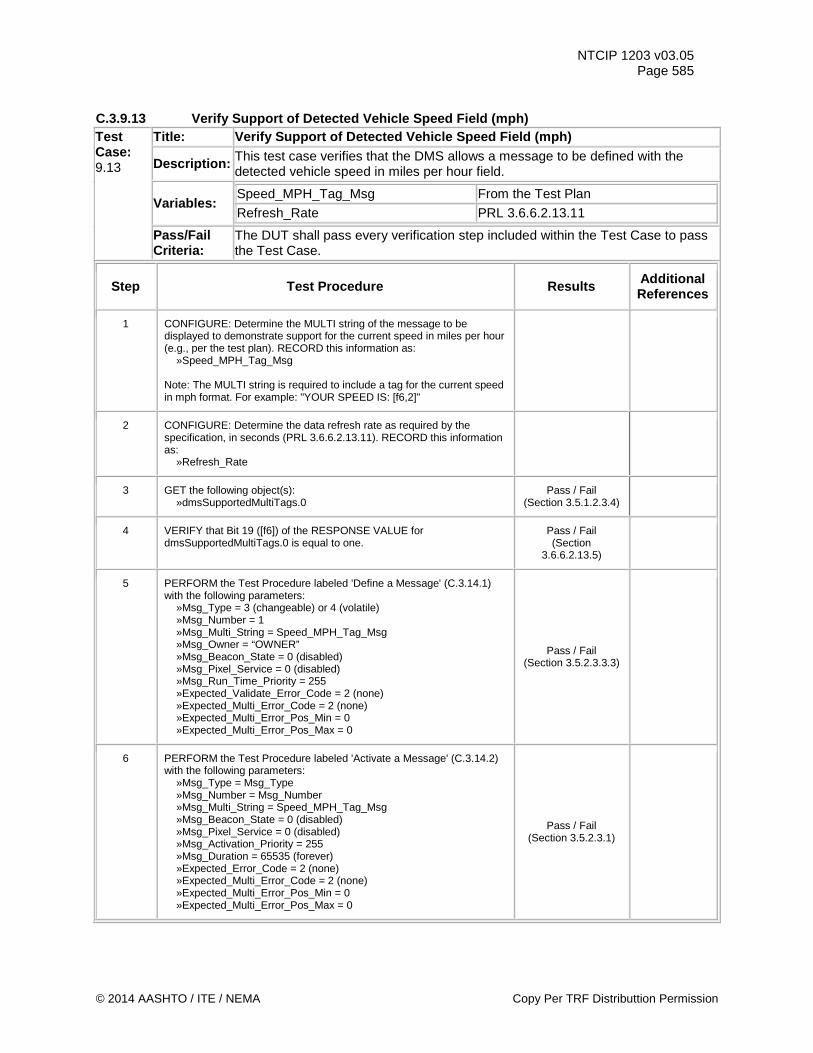
NTCIP 1203 v03.05 Page 585
C.3.9.13 Verify Support of Detected Vehicle Speed Field (mph) Test Case: 9.13
Title: Verify Support of Detected Vehicle Speed Field (mph)
Description: This test case verifies that the DMS allows a message to be defined with the detected vehicle speed in miles per hour field.
Variables: Speed_MPH_Tag_Msg From the Test Plan
Refresh_Rate PRL 3.6.6.2.13.11
Pass/Fail Criteria:
The DUT shall pass every verification step included within the Test Case to pass the Test Case.
Step Test Procedure Results Additional References
1 CONFIGURE: Determine the MULTI string of the message to be displayed to demonstrate support for the current speed in miles per hour (e.g., per the test plan). RECORD this information as: »Speed_MPH_Tag_Msg Note: The MULTI string is required to include a tag for the current speed in mph format. For example: "YOUR SPEED IS: [f6,2]"
2 CONFIGURE: Determine the data refresh rate as required by the specification, in seconds (PRL 3.6.6.2.13.11). RECORD this information as: »Refresh_Rate
3 GET the following object(s): »dmsSupportedMultiTags.0
Pass / Fail (Section 3.5.1.2.3.4)
4 VERIFY that Bit 19 ([f6]) of the RESPONSE VALUE for dmsSupportedMultiTags.0 is equal to one.
Pass / Fail (Section
3.6.6.2.13.5)
5 PERFORM the Test Procedure labeled 'Define a Message' (C.3.14.1) with the following parameters: »Msg_Type = 3 (changeable) or 4 (volatile) »Msg_Number = 1 »Msg_Multi_String = Speed_MPH_Tag_Msg »Msg_Owner = “OWNER” »Msg_Beacon_State = 0 (disabled) »Msg_Pixel_Service = 0 (disabled) »Msg_Run_Time_Priority = 255 »Expected_Validate_Error_Code = 2 (none) »Expected_Multi_Error_Code = 2 (none) »Expected_Multi_Error_Pos_Min = 0 »Expected_Multi_Error_Pos_Max = 0
Pass / Fail (Section 3.5.2.3.3.3)
6 PERFORM the Test Procedure labeled 'Activate a Message' (C.3.14.2) with the following parameters: »Msg_Type = Msg_Type »Msg_Number = Msg_Number »Msg_Multi_String = Speed_MPH_Tag_Msg »Msg_Beacon_State = 0 (disabled) »Msg_Pixel_Service = 0 (disabled) »Msg_Activation_Priority = 255 »Msg_Duration = 65535 (forever) »Expected_Error_Code = 2 (none) »Expected_Multi_Error_Code = 2 (none) »Expected_Multi_Error_Pos_Min = 0 »Expected_Multi_Error_Pos_Max = 0
Pass / Fail (Section 3.5.2.3.1)
© 2014 AASHTO / ITE / NEMA Copy Per TRF Distributtion Permission
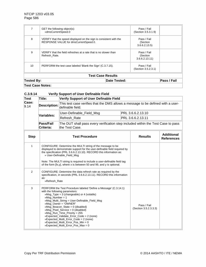
NTCIP 1203 v03.05 Page 586
7 GET the following object(s): »dmsCurrentSpeed.0
Pass / Fail (Section 3.5.3.1.9)
8 VERIFY that the speed displayed on the sign is consistent with the RESPONSE VALUE for dmsCurrentSpeed.0.
Pass / Fail (Section
3.6.6.2.13.5)
9 VERIFY that the field refreshes at a rate that is no slower than Refresh_Rate.
Pass / Fail (Section
3.6.6.2.13.11)
10 PERFORM the test case labeled 'Blank the Sign' (C.3.7.15). Pass / Fail (Section 3.5.2.3.1)
Test Case Results Tested By: Date Tested: Pass / Fail Test Case Notes: C.3.9.14 Verify Support of User Definable Field Test Case: 9.14
Title: Verify Support of User Definable Field
Description: This test case verifies that the DMS allows a message to be defined with a user-definable field.
Variables: User-Definable_Field_Msg PRL 3.6.6.2.13.10
Refresh_Rate PRL 3.6.6.2.13.11
Pass/Fail Criteria:
The DUT shall pass every verification step included within the Test Case to pass the Test Case.
Step Test Procedure Results Additional References
1 CONFIGURE: Determine the MULTI string of the message to be displayed to demonstrate support for the user-definable field required by the specification (PRL 3.6.6.2.13.10). RECORD this information as: » User-Definable_Field_Msg Note: The MULTI string is required to include a user-definable field tag of the form [fx,y], where x is between 50 and 99, and y is optional.
2 CONFIGURE: Determine the data refresh rate as required by the specification, in seconds (PRL 3.6.6.2.13.11). RECORD this information as: »Refresh_Rate
3 PERFORM the Test Procedure labeled 'Define a Message' (C.3.14.1) with the following parameters: »Msg_Type = 3 (changeable) or 4 (volatile) »Msg_Number = 1 »Msg_Multi_String = User-Definable_Field_Msg »Msg_Owner = “OWNER” »Msg_Beacon_State = 0 (disabled) »Msg_Pixel_Service = 0 (disabled) »Msg_Run_Time_Priority = 255 »Expected_Validate_Error_Code = 2 (none) »Expected_Multi_Error_Code = 2 (none) »Expected_Multi_Error_Pos_Min = 0 »Expected_Multi_Error_Pos_Max = 0
Pass / Fail (Section 3.5.2.3.3.3)
Copy Per TRF Distribution Permission © 2014 AASHTO / ITE / NEMA
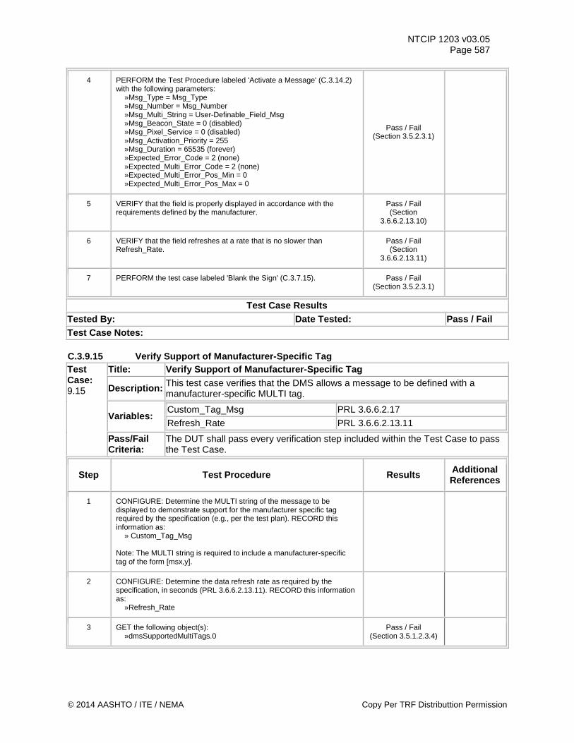
NTCIP 1203 v03.05 Page 587
4 PERFORM the Test Procedure labeled 'Activate a Message' (C.3.14.2) with the following parameters: »Msg_Type = Msg_Type »Msg_Number = Msg_Number »Msg_Multi_String = User-Definable_Field_Msg »Msg_Beacon_State = 0 (disabled) »Msg_Pixel_Service = 0 (disabled) »Msg_Activation_Priority = 255 »Msg_Duration = 65535 (forever) »Expected_Error_Code = 2 (none) »Expected_Multi_Error_Code = 2 (none) »Expected_Multi_Error_Pos_Min = 0 »Expected_Multi_Error_Pos_Max = 0
Pass / Fail (Section 3.5.2.3.1)
5 VERIFY that the field is properly displayed in accordance with the requirements defined by the manufacturer.
Pass / Fail (Section
3.6.6.2.13.10)
6 VERIFY that the field refreshes at a rate that is no slower than Refresh_Rate.
Pass / Fail (Section
3.6.6.2.13.11)
7 PERFORM the test case labeled 'Blank the Sign' (C.3.7.15). Pass / Fail (Section 3.5.2.3.1)
Test Case Results Tested By: Date Tested: Pass / Fail Test Case Notes: C.3.9.15 Verify Support of Manufacturer-Specific Tag Test Case: 9.15
Title: Verify Support of Manufacturer-Specific Tag
Description: This test case verifies that the DMS allows a message to be defined with a manufacturer-specific MULTI tag.
Variables: Custom_Tag_Msg PRL 3.6.6.2.17
Refresh_Rate PRL 3.6.6.2.13.11
Pass/Fail Criteria:
The DUT shall pass every verification step included within the Test Case to pass the Test Case.
Step Test Procedure Results Additional References
1 CONFIGURE: Determine the MULTI string of the message to be displayed to demonstrate support for the manufacturer specific tag required by the specification (e.g., per the test plan). RECORD this information as: » Custom_Tag_Msg Note: The MULTI string is required to include a manufacturer-specific tag of the form [msx,y].
2 CONFIGURE: Determine the data refresh rate as required by the specification, in seconds (PRL 3.6.6.2.13.11). RECORD this information as: »Refresh_Rate
3 GET the following object(s): »dmsSupportedMultiTags.0
Pass / Fail (Section 3.5.1.2.3.4)
© 2014 AASHTO / ITE / NEMA Copy Per TRF Distributtion Permission
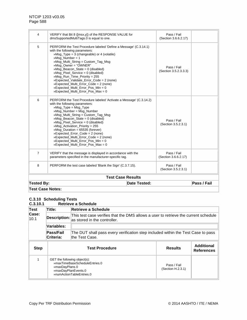
NTCIP 1203 v03.05 Page 588
4 VERIFY that Bit 8 ([msx,y]) of the RESPONSE VALUE for dmsSupportedMultiTags.0 is equal to one.
Pass / Fail (Section 3.6.6.2.17)
5 PERFORM the Test Procedure labeled 'Define a Message' (C.3.14.1) with the following parameters: »Msg_Type = 3 (changeable) or 4 (volatile) »Msg_Number = 1 »Msg_Multi_String = Custom_Tag_Msg »Msg_Owner = “OWNER” »Msg_Beacon_State = 0 (disabled) »Msg_Pixel_Service = 0 (disabled) »Msg_Run_Time_Priority = 255 »Expected_Validate_Error_Code = 2 (none) »Expected_Multi_Error_Code = 2 (none) »Expected_Multi_Error_Pos_Min = 0 »Expected_Multi_Error_Pos_Max = 0
Pass / Fail (Section 3.5.2.3.3.3)
6 PERFORM the Test Procedure labeled 'Activate a Message' (C.3.14.2) with the following parameters: »Msg_Type = Msg_Type »Msg_Number = Msg_Number »Msg_Multi_String = Custom_Tag_Msg »Msg_Beacon_State = 0 (disabled) »Msg_Pixel_Service = 0 (disabled) »Msg_Activation_Priority = 255 »Msg_Duration = 65535 (forever) »Expected_Error_Code = 2 (none) »Expected_Multi_Error_Code = 2 (none) »Expected_Multi_Error_Pos_Min = 0 »Expected_Multi_Error_Pos_Max = 0
Pass / Fail (Section 3.5.2.3.1)
7 VERIFY that the message is displayed in accordance with the parameters specified in the manufacturer-specific tag.
Pass / Fail (Section 3.6.6.2.17)
8 PERFORM the test case labeled 'Blank the Sign' (C.3.7.15). Pass / Fail (Section 3.5.2.3.1)
Test Case Results Tested By: Date Tested: Pass / Fail Test Case Notes: C.3.10 Scheduling Tests C.3.10.1 Retrieve a Schedule Test Case: 10.1
Title: Retrieve a Schedule
Description: This test case verifies that the DMS allows a user to retrieve the current schedule as stored in the controller.
Variables:
Pass/Fail Criteria:
The DUT shall pass every verification step included within the Test Case to pass the Test Case.
Step Test Procedure Results Additional References
1 GET the following object(s): »maxTimeBaseScheduleEntries.0 »maxDayPlans.0 »maxDayPlanEvents.0 »numActionTableEntries.0
Pass / Fail (Section H.2.3.1)
Copy Per TRF Distribution Permission © 2014 AASHTO / ITE / NEMA
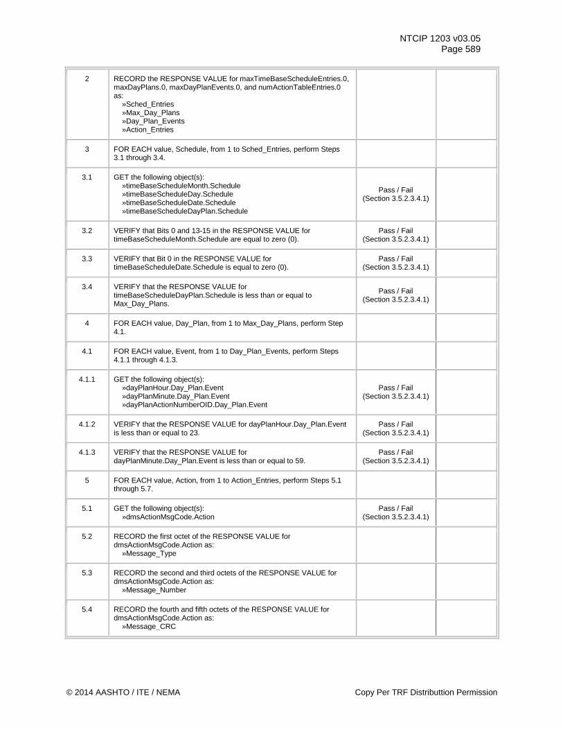
NTCIP 1203 v03.05 Page 589
2 RECORD the RESPONSE VALUE for maxTimeBaseScheduleEntries.0, maxDayPlans.0, maxDayPlanEvents.0, and numActionTableEntries.0 as: »Sched_Entries
»Max_Day_Plans »Day_Plan_Events »Action_Entries
3 FOR EACH value, Schedule, from 1 to Sched_Entries, perform Steps 3.1 through 3.4.
3.1 GET the following object(s): »timeBaseScheduleMonth.Schedule »timeBaseScheduleDay.Schedule »timeBaseScheduleDate.Schedule »timeBaseScheduleDayPlan.Schedule
Pass / Fail (Section 3.5.2.3.4.1)
3.2 VERIFY that Bits 0 and 13-15 in the RESPONSE VALUE for timeBaseScheduleMonth.Schedule are equal to zero (0).
Pass / Fail (Section 3.5.2.3.4.1)
3.3 VERIFY that Bit 0 in the RESPONSE VALUE for timeBaseScheduleDate.Schedule is equal to zero (0).
Pass / Fail (Section 3.5.2.3.4.1)
3.4 VERIFY that the RESPONSE VALUE for timeBaseScheduleDayPlan.Schedule is less than or equal to Max_Day_Plans.
Pass / Fail (Section 3.5.2.3.4.1)
4 FOR EACH value, Day_Plan, from 1 to Max_Day_Plans, perform Step 4.1.
4.1 FOR EACH value, Event, from 1 to Day_Plan_Events, perform Steps 4.1.1 through 4.1.3.
4.1.1 GET the following object(s): »dayPlanHour.Day_Plan.Event »dayPlanMinute.Day_Plan.Event »dayPlanActionNumberOID.Day_Plan.Event
Pass / Fail (Section 3.5.2.3.4.1)
4.1.2 VERIFY that the RESPONSE VALUE for dayPlanHour.Day_Plan.Event is less than or equal to 23.
Pass / Fail (Section 3.5.2.3.4.1)
4.1.3 VERIFY that the RESPONSE VALUE for dayPlanMinute.Day_Plan.Event is less than or equal to 59.
Pass / Fail (Section 3.5.2.3.4.1)
5 FOR EACH value, Action, from 1 to Action_Entries, perform Steps 5.1 through 5.7.
5.1 GET the following object(s): »dmsActionMsgCode.Action
Pass / Fail (Section 3.5.2.3.4.1)
5.2 RECORD the first octet of the RESPONSE VALUE for dmsActionMsgCode.Action as: »Message_Type
5.3 RECORD the second and third octets of the RESPONSE VALUE for dmsActionMsgCode.Action as: »Message_Number
5.4 RECORD the fourth and fifth octets of the RESPONSE VALUE for dmsActionMsgCode.Action as: »Message_CRC
© 2014 AASHTO / ITE / NEMA Copy Per TRF Distributtion Permission
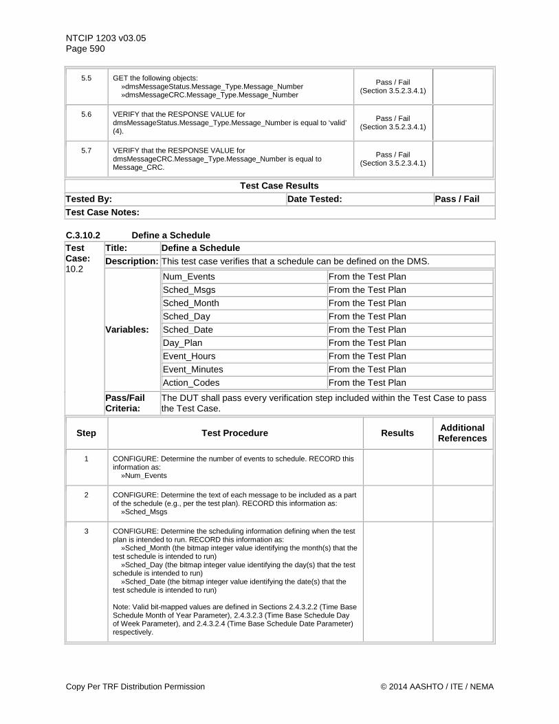
NTCIP 1203 v03.05 Page 590
5.5 GET the following objects: »dmsMessageStatus.Message_Type.Message_Number »dmsMessageCRC.Message_Type.Message_Number
Pass / Fail (Section 3.5.2.3.4.1)
5.6 VERIFY that the RESPONSE VALUE for dmsMessageStatus.Message_Type.Message_Number is equal to ‘valid’ (4).
Pass / Fail (Section 3.5.2.3.4.1)
5.7 VERIFY that the RESPONSE VALUE for dmsMessageCRC.Message_Type.Message_Number is equal to Message_CRC.
Pass / Fail (Section 3.5.2.3.4.1)
Test Case Results Tested By: Date Tested: Pass / Fail Test Case Notes: C.3.10.2 Define a Schedule Test Case: 10.2
Title: Define a Schedule Description: This test case verifies that a schedule can be defined on the DMS.
Variables:
Num_Events From the Test Plan
Sched_Msgs From the Test Plan
Sched_Month From the Test Plan Sched_Day From the Test Plan Sched_Date From the Test Plan Day_Plan From the Test Plan
Event_Hours From the Test Plan
Event_Minutes From the Test Plan
Action_Codes From the Test Plan
Pass/Fail Criteria:
The DUT shall pass every verification step included within the Test Case to pass the Test Case.
Step Test Procedure Results Additional References
1 CONFIGURE: Determine the number of events to schedule. RECORD this information as: »Num_Events
2 CONFIGURE: Determine the text of each message to be included as a part of the schedule (e.g., per the test plan). RECORD this information as: »Sched_Msgs
3 CONFIGURE: Determine the scheduling information defining when the test plan is intended to run. RECORD this information as: »Sched_Month (the bitmap integer value identifying the month(s) that the test schedule is intended to run) »Sched_Day (the bitmap integer value identifying the day(s) that the test schedule is intended to run) »Sched_Date (the bitmap integer value identifying the date(s) that the test schedule is intended to run) Note: Valid bit-mapped values are defined in Sections 2.4.3.2.2 (Time Base Schedule Month of Year Parameter), 2.4.3.2.3 (Time Base Schedule Day of Week Parameter), and 2.4.3.2.4 (Time Base Schedule Date Parameter) respectively.
Copy Per TRF Distribution Permission © 2014 AASHTO / ITE / NEMA
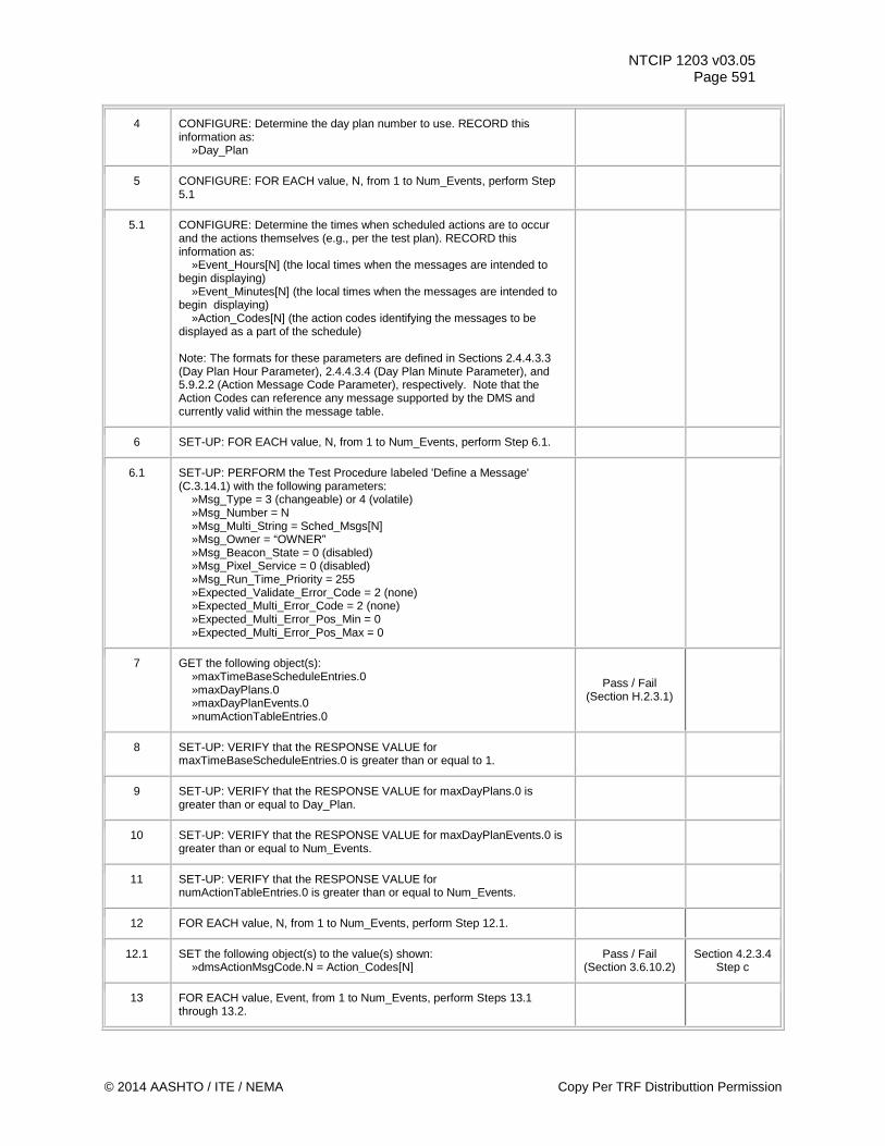
NTCIP 1203 v03.05 Page 591
4 CONFIGURE: Determine the day plan number to use. RECORD this information as: »Day_Plan
5 CONFIGURE: FOR EACH value, N, from 1 to Num_Events, perform Step 5.1
5.1 CONFIGURE: Determine the times when scheduled actions are to occur and the actions themselves (e.g., per the test plan). RECORD this information as: »Event_Hours[N] (the local times when the messages are intended to begin displaying) »Event_Minutes[N] (the local times when the messages are intended to begin displaying) »Action_Codes[N] (the action codes identifying the messages to be displayed as a part of the schedule) Note: The formats for these parameters are defined in Sections 2.4.4.3.3 (Day Plan Hour Parameter), 2.4.4.3.4 (Day Plan Minute Parameter), and 5.9.2.2 (Action Message Code Parameter), respectively. Note that the Action Codes can reference any message supported by the DMS and currently valid within the message table.
6 SET-UP: FOR EACH value, N, from 1 to Num_Events, perform Step 6.1.
6.1 SET-UP: PERFORM the Test Procedure labeled 'Define a Message' (C.3.14.1) with the following parameters: »Msg_Type = 3 (changeable) or 4 (volatile) »Msg_Number = N »Msg_Multi_String = Sched_Msgs[N] »Msg_Owner = “OWNER” »Msg_Beacon_State = 0 (disabled) »Msg_Pixel_Service = 0 (disabled) »Msg_Run_Time_Priority = 255 »Expected_Validate_Error_Code = 2 (none) »Expected_Multi_Error_Code = 2 (none) »Expected_Multi_Error_Pos_Min = 0 »Expected_Multi_Error_Pos_Max = 0
7 GET the following object(s): »maxTimeBaseScheduleEntries.0 »maxDayPlans.0 »maxDayPlanEvents.0 »numActionTableEntries.0
Pass / Fail (Section H.2.3.1)
8 SET-UP: VERIFY that the RESPONSE VALUE for maxTimeBaseScheduleEntries.0 is greater than or equal to 1.
9 SET-UP: VERIFY that the RESPONSE VALUE for maxDayPlans.0 is greater than or equal to Day_Plan.
10 SET-UP: VERIFY that the RESPONSE VALUE for maxDayPlanEvents.0 is greater than or equal to Num_Events.
11 SET-UP: VERIFY that the RESPONSE VALUE for numActionTableEntries.0 is greater than or equal to Num_Events.
12 FOR EACH value, N, from 1 to Num_Events, perform Step 12.1.
12.1 SET the following object(s) to the value(s) shown: »dmsActionMsgCode.N = Action_Codes[N]
Pass / Fail (Section 3.6.10.2)
Section 4.2.3.4 Step c
13 FOR EACH value, Event, from 1 to Num_Events, perform Steps 13.1 through 13.2.
© 2014 AASHTO / ITE / NEMA Copy Per TRF Distributtion Permission
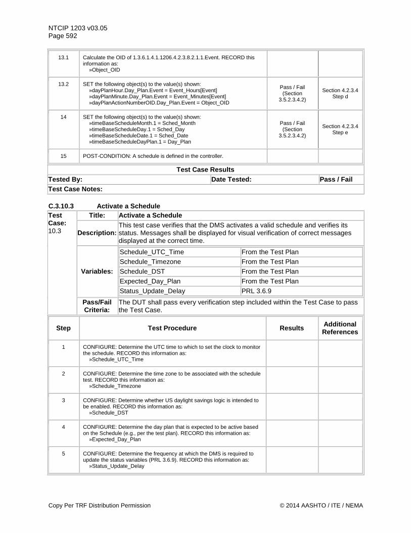
NTCIP 1203 v03.05 Page 592
13.1 Calculate the OID of 1.3.6.1.4.1.1206.4.2.3.8.2.1.1.Event. RECORD this information as: »Object_OID
13.2 SET the following object(s) to the value(s) shown: »dayPlanHour.Day_Plan.Event = Event_Hours[Event] »dayPlanMinute.Day_Plan.Event = Event_Minutes[Event] »dayPlanActionNumberOID.Day_Plan.Event = Object_OID
Pass / Fail (Section
3.5.2.3.4.2)
Section 4.2.3.4 Step d
14 SET the following object(s) to the value(s) shown: »timeBaseScheduleMonth.1 = Sched_Month »timeBaseScheduleDay.1 = Sched_Day »timeBaseScheduleDate.1 = Sched_Date »timeBaseScheduleDayPlan.1 = Day_Plan
Pass / Fail (Section
3.5.2.3.4.2)
Section 4.2.3.4 Step e
15 POST-CONDITION: A schedule is defined in the controller.
Test Case Results Tested By: Date Tested: Pass / Fail Test Case Notes: C.3.10.3 Activate a Schedule Test Case: 10.3
Title: Activate a Schedule
Description: This test case verifies that the DMS activates a valid schedule and verifies its status. Messages shall be displayed for visual verification of correct messages displayed at the correct time.
Variables:
Schedule_UTC_Time From the Test Plan
Schedule_Timezone From the Test Plan
Schedule_DST From the Test Plan
Expected_Day_Plan From the Test Plan
Status_Update_Delay PRL 3.6.9
Pass/Fail Criteria:
The DUT shall pass every verification step included within the Test Case to pass the Test Case.
Step Test Procedure Results Additional References
1 CONFIGURE: Determine the UTC time to which to set the clock to monitor the schedule. RECORD this information as: »Schedule_UTC_Time
2 CONFIGURE: Determine the time zone to be associated with the schedule test. RECORD this information as: »Schedule_Timezone
3 CONFIGURE: Determine whether US daylight savings logic is intended to be enabled. RECORD this information as: »Schedule_DST
4 CONFIGURE: Determine the day plan that is expected to be active based on the Schedule (e.g., per the test plan). RECORD this information as: »Expected_Day_Plan
5 CONFIGURE: Determine the frequency at which the DMS is required to update the status variables (PRL 3.6.9). RECORD this information as: »Status_Update_Delay
Copy Per TRF Distribution Permission © 2014 AASHTO / ITE / NEMA
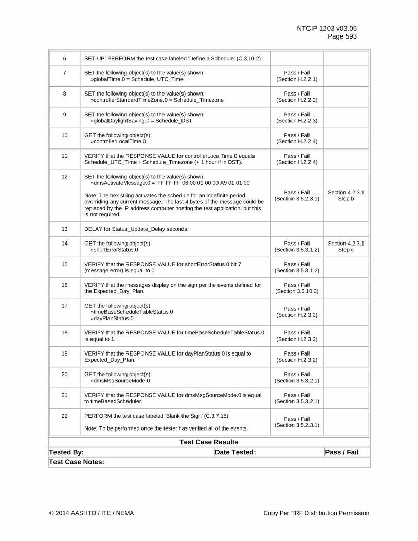
NTCIP 1203 v03.05 Page 593
6 SET-UP: PERFORM the test case labeled 'Define a Schedule' (C.3.10.2).
7 SET the following object(s) to the value(s) shown: »globalTime.0 = Schedule_UTC_Time
Pass / Fail (Section H.2.2.1)
8 SET the following object(s) to the value(s) shown: »controllerStandardTimeZone.0 = Schedule_Timezone
Pass / Fail (Section H.2.2.2)
9 SET the following object(s) to the value(s) shown: »globalDaylightSaving.0 = Schedule_DST
Pass / Fail (Section H.2.2.3)
10 GET the following object(s): »controllerLocalTime.0
Pass / Fail (Section H.2.2.4)
11 VERIFY that the RESPONSE VALUE for controllerLocalTime.0 equals Schedule_UTC_Time + Schedule_Timezone (+ 1 hour if in DST).
Pass / Fail (Section H.2.2.4)
12 SET the following object(s) to the value(s) shown: »dmsActivateMessage.0 = 'FF FF FF 06 00 01 00 00 A9 01 01 00' Note: The hex string activates the schedule for an indefinite period, overriding any current message. The last 4 bytes of the message could be replaced by the IP address computer hosting the test application, but this is not required.
Pass / Fail (Section 3.5.2.3.1)
Section 4.2.3.1 Step b
13 DELAY for Status_Update_Delay seconds.
14 GET the following object(s): »shortErrorStatus.0
Pass / Fail (Section 3.5.3.1.2)
Section 4.2.3.1 Step c
15 VERIFY that the RESPONSE VALUE for shortErrorStatus.0 bit 7 (message error) is equal to 0.
Pass / Fail (Section 3.5.3.1.2)
16 VERIFY that the messages display on the sign per the events defined for the Expected_Day_Plan.
Pass / Fail (Section 3.6.10.3)
17 GET the following object(s): »timeBaseScheduleTableStatus.0 »dayPlanStatus.0
Pass / Fail (Section H.2.3.2)
18 VERIFY that the RESPONSE VALUE for timeBaseScheduleTableStatus.0 is equal to 1.
Pass / Fail (Section H.2.3.2)
19 VERIFY that the RESPONSE VALUE for dayPlanStatus.0 is equal to Expected_Day_Plan.
Pass / Fail (Section H.2.3.2)
20 GET the following object(s): »dmsMsgSourceMode.0
Pass / Fail (Section 3.5.3.2.1)
21 VERIFY that the RESPONSE VALUE for dmsMsgSourceMode.0 is equal to timeBasedScheduler.
Pass / Fail (Section 3.5.3.2.1)
22 PERFORM the test case labeled 'Blank the Sign' (C.3.7.15). Note: To be performed once the tester has verified all of the events.
Pass / Fail (Section 3.5.2.3.1)
Test Case Results Tested By: Date Tested: Pass / Fail Test Case Notes:
© 2014 AASHTO / ITE / NEMA Copy Per TRF Distributtion Permission
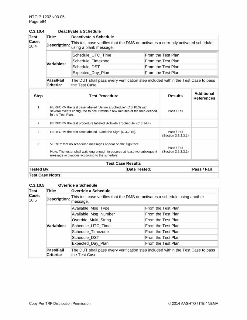
NTCIP 1203 v03.05 Page 594 C.3.10.4 Deactivate a Schedule Test Case: 10.4
Title: Deactivate a Schedule
Description: This test case verifies that the DMS de-activates a currently activated schedule using a blank message.
Variables:
Schedule_UTC_Time From the Test Plan
Schedule_Timezone From the Test Plan
Schedule_DST From the Test Plan
Expected_Day_Plan From the Test Plan
Pass/Fail Criteria:
The DUT shall pass every verification step included within the Test Case to pass the Test Case.
Step Test Procedure Results Additional References
1 PERFORM the test case labeled 'Define a Schedule' (C.3.10.3) with several events configured to occur within a few minutes of the time defined in the Test Plan.
Pass / Fail
2 PERFORM the test procedure labeled 'Activate a Schedule' (C.3.14.4).
2 PERFORM the test case labeled 'Blank the Sign' (C.3.7.15). Pass / Fail (Section 3.5.2.3.1)
3 VERIFY that no scheduled messages appear on the sign face. Note: The tester shall wait long enough to observe at least two subsequent message activations according to the schedule.
Pass / Fail (Section 3.5.2.3.1)
Test Case Results Tested By: Date Tested: Pass / Fail Test Case Notes: C.3.10.5 Override a Schedule Test Case: 10.5
Title: Override a Schedule
Description: This test case verifies that the DMS de-activates a schedule using another message.
Variables:
Available_Msg_Type From the Test Plan
Available_Msg_Number From the Test Plan
Override_Multi_String From the Test Plan Schedule_UTC_Time From the Test Plan Schedule_Timezone From the Test Plan Schedule_DST From the Test Plan Expected_Day_Plan From the Test Plan
Pass/Fail Criteria:
The DUT shall pass every verification step included within the Test Case to pass the Test Case.
Copy Per TRF Distribution Permission © 2014 AASHTO / ITE / NEMA
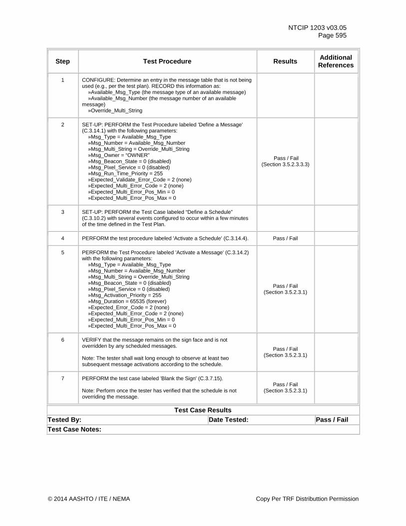
NTCIP 1203 v03.05 Page 595
Step Test Procedure Results Additional References
1 CONFIGURE: Determine an entry in the message table that is not being used (e.g., per the test plan). RECORD this information as: »Available_Msg_Type (the message type of an available message) »Available_Msg_Number (the message number of an available message) »Override_Multi_String
2 SET-UP: PERFORM the Test Procedure labeled 'Define a Message' (C.3.14.1) with the following parameters: »Msg_Type = Available_Msg_Type »Msg_Number = Available_Msg_Number »Msg_Multi_String = Override_Multi_String »Msg_Owner = “OWNER” »Msg_Beacon_State = 0 (disabled) »Msg_Pixel_Service = 0 (disabled) »Msg_Run_Time_Priority = 255 »Expected_Validate_Error_Code = 2 (none) »Expected_Multi_Error_Code = 2 (none) »Expected_Multi_Error_Pos_Min = 0 »Expected_Multi_Error_Pos_Max = 0
Pass / Fail (Section 3.5.2.3.3.3)
3 SET-UP: PERFORM the Test Case labeled “Define a Schedule” (C.3.10.2) with several events configured to occur within a few minutes of the time defined in the Test Plan.
4 PERFORM the test procedure labeled 'Activate a Schedule' (C.3.14.4). Pass / Fail
5 PERFORM the Test Procedure labeled 'Activate a Message' (C.3.14.2) with the following parameters: »Msg_Type = Available_Msg_Type »Msg_Number = Available_Msg_Number »Msg_Multi_String = Override_Multi_String »Msg_Beacon_State = 0 (disabled) »Msg_Pixel_Service = 0 (disabled) »Msg_Activation_Priority = 255 »Msg_Duration = 65535 (forever) »Expected_Error_Code = 2 (none) »Expected_Multi_Error_Code = 2 (none) »Expected_Multi_Error_Pos_Min = 0 »Expected_Multi_Error_Pos_Max = 0
Pass / Fail (Section 3.5.2.3.1)
6 VERIFY that the message remains on the sign face and is not overridden by any scheduled messages. Note: The tester shall wait long enough to observe at least two subsequent message activations according to the schedule.
Pass / Fail (Section 3.5.2.3.1)
7 PERFORM the test case labeled 'Blank the Sign' (C.3.7.15). Note: Perform once the tester has verified that the schedule is not overriding the message.
Pass / Fail (Section 3.5.2.3.1)
Test Case Results Tested By: Date Tested: Pass / Fail Test Case Notes:
© 2014 AASHTO / ITE / NEMA Copy Per TRF Distributtion Permission
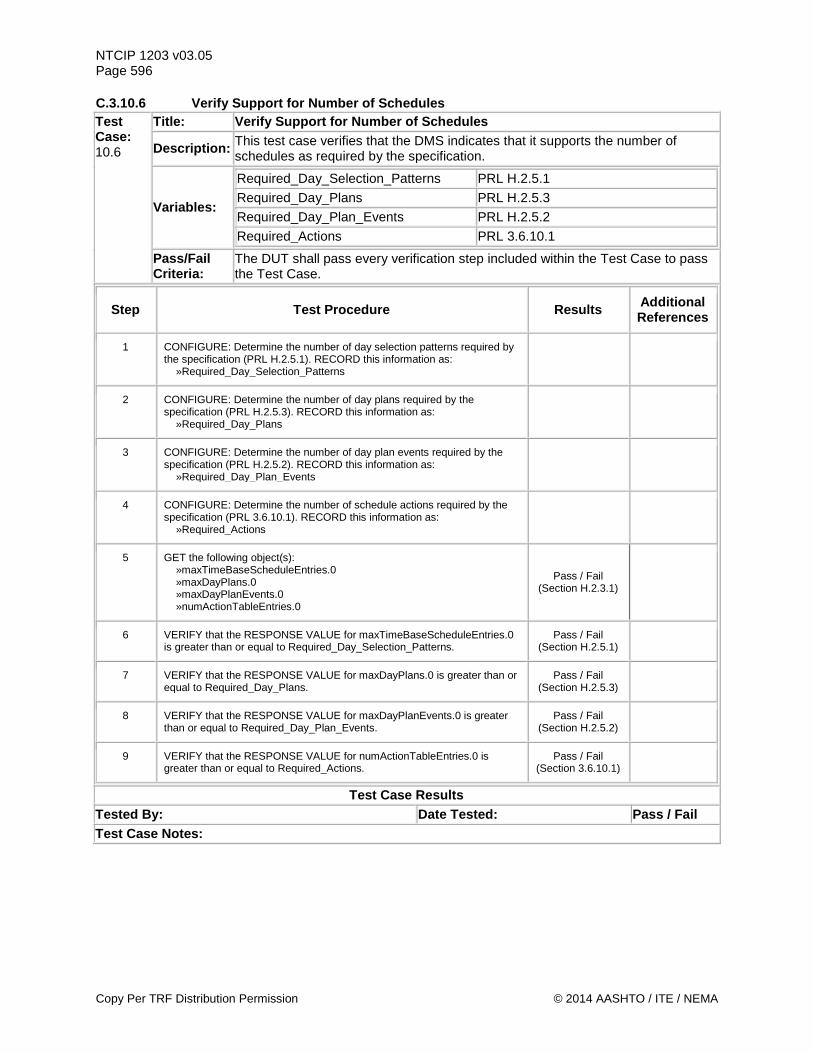
NTCIP 1203 v03.05 Page 596 C.3.10.6 Verify Support for Number of Schedules Test Case: 10.6
Title: Verify Support for Number of Schedules
Description: This test case verifies that the DMS indicates that it supports the number of schedules as required by the specification.
Variables:
Required_Day_Selection_Patterns PRL H.2.5.1 Required_Day_Plans PRL H.2.5.3 Required_Day_Plan_Events PRL H.2.5.2 Required_Actions PRL 3.6.10.1
Pass/Fail Criteria:
The DUT shall pass every verification step included within the Test Case to pass the Test Case.
Step Test Procedure Results Additional References
1 CONFIGURE: Determine the number of day selection patterns required by the specification (PRL H.2.5.1). RECORD this information as: »Required_Day_Selection_Patterns
2 CONFIGURE: Determine the number of day plans required by the specification (PRL H.2.5.3). RECORD this information as: »Required_Day_Plans
3 CONFIGURE: Determine the number of day plan events required by the specification (PRL H.2.5.2). RECORD this information as: »Required_Day_Plan_Events
4 CONFIGURE: Determine the number of schedule actions required by the specification (PRL 3.6.10.1). RECORD this information as: »Required_Actions
5 GET the following object(s): »maxTimeBaseScheduleEntries.0 »maxDayPlans.0 »maxDayPlanEvents.0 »numActionTableEntries.0
Pass / Fail (Section H.2.3.1)
6 VERIFY that the RESPONSE VALUE for maxTimeBaseScheduleEntries.0 is greater than or equal to Required_Day_Selection_Patterns.
Pass / Fail (Section H.2.5.1)
7 VERIFY that the RESPONSE VALUE for maxDayPlans.0 is greater than or equal to Required_Day_Plans.
Pass / Fail (Section H.2.5.3)
8 VERIFY that the RESPONSE VALUE for maxDayPlanEvents.0 is greater than or equal to Required_Day_Plan_Events.
Pass / Fail (Section H.2.5.2)
9 VERIFY that the RESPONSE VALUE for numActionTableEntries.0 is greater than or equal to Required_Actions.
Pass / Fail (Section 3.6.10.1)
Test Case Results Tested By: Date Tested: Pass / Fail Test Case Notes:
Copy Per TRF Distribution Permission © 2014 AASHTO / ITE / NEMA
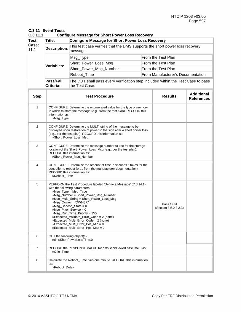
NTCIP 1203 v03.05 Page 597
C.3.11 Event Tests C.3.11.1 Configure Message for Short Power Loss Recovery Test Case: 11.1
Title: Configure Message for Short Power Loss Recovery
Description: This test case verifies that the DMS supports the short power loss recovery message.
Variables:
Msg_Type From the Test Plan
Short_Power_Loss_Msg From the Test Plan
Short_Power_Msg_Number From the Test Plan
Reboot_Time From Manufacturer’s Documentation
Pass/Fail Criteria:
The DUT shall pass every verification step included within the Test Case to pass the Test Case.
Step Test Procedure Results Additional References
1 CONFIGURE: Determine the enumerated value for the type of memory in which to store the message (e.g., from the test plan). RECORD this information as: »Msg_Type
2 CONFIGURE: Determine the MULTI string of the message to be displayed upon restoration of power to the sign after a short power loss (e.g., per the test plan). RECORD this information as: »Short_Power_Loss_Msg
3 CONFIGURE: Determine the message number to use for the storage location of the Short_Power_Loss_Msg (e.g., per the test plan). RECORD this information as: »Short_Power_Msg_Number
4 CONFIGURE: Determine the amount of time in seconds it takes for the controller to reboot (e.g., from the manufacturer documentation). RECORD this information as: »Reboot_Time
5 PERFORM the Test Procedure labeled 'Define a Message' (C.3.14.1) with the following parameters: »Msg_Type = Msg_Type »Msg_Number = Short_Power_Msg_Number »Msg_Multi_String = Short_Power_Loss_Msg »Msg_Owner = “OWNER” »Msg_Beacon_State = 0 »Msg_Pixel_Service = 0 »Msg_Run_Time_Priority = 255 »Expected_Validate_Error_Code = 2 (none) »Expected_Multi_Error_Code = 2 (none) »Expected_Multi_Error_Pos_Min = 0 »Expected_Multi_Error_Pos_Max = 0
Pass / Fail (Section 3.5.2.3.3.3)
6 GET the following object(s): »dmsShortPowerLossTime.0
7 RECORD the RESPONSE VALUE for dmsShortPowerLossTime.0 as: »Orig_Time
8 Calculate the Reboot_Time plus one minute. RECORD this information as: »Reboot_Delay
© 2014 AASHTO / ITE / NEMA Copy Per TRF Distributtion Permission
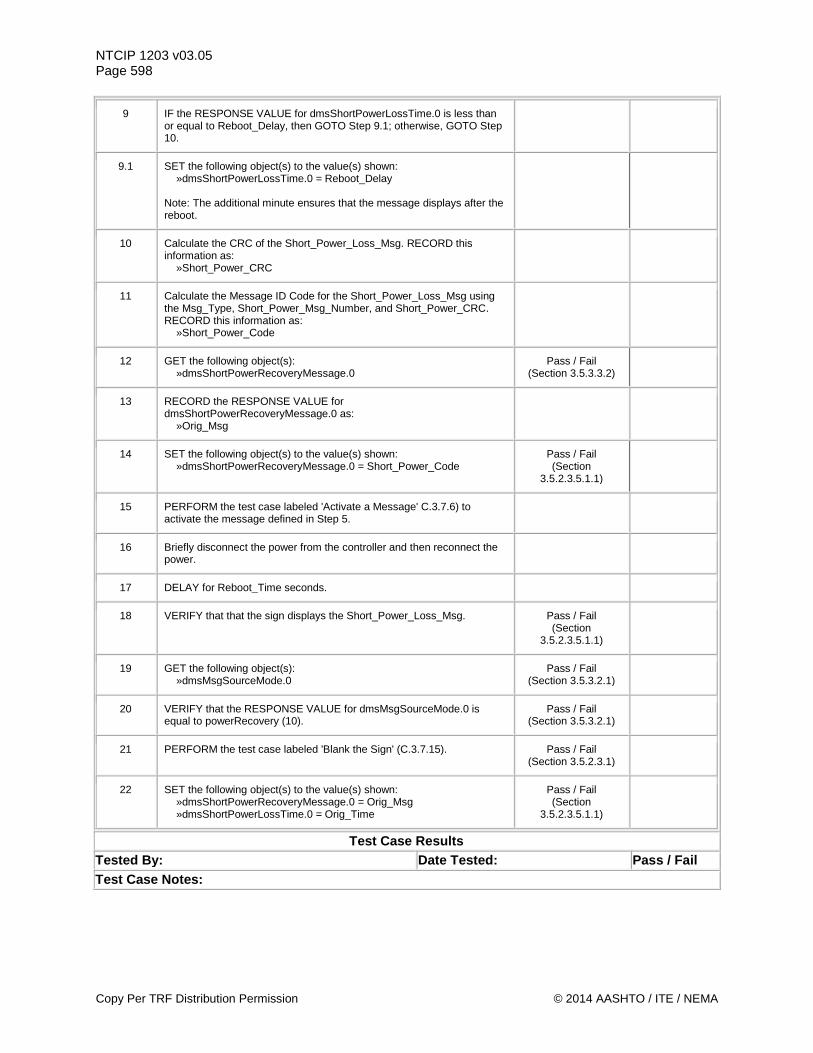
NTCIP 1203 v03.05 Page 598
9 IF the RESPONSE VALUE for dmsShortPowerLossTime.0 is less than or equal to Reboot_Delay, then GOTO Step 9.1; otherwise, GOTO Step 10.
9.1 SET the following object(s) to the value(s) shown: »dmsShortPowerLossTime.0 = Reboot_Delay Note: The additional minute ensures that the message displays after the reboot.
10 Calculate the CRC of the Short_Power_Loss_Msg. RECORD this information as: »Short_Power_CRC
11 Calculate the Message ID Code for the Short_Power_Loss_Msg using the Msg_Type, Short_Power_Msg_Number, and Short_Power_CRC. RECORD this information as: »Short_Power_Code
12 GET the following object(s): »dmsShortPowerRecoveryMessage.0
Pass / Fail (Section 3.5.3.3.2)
13 RECORD the RESPONSE VALUE for dmsShortPowerRecoveryMessage.0 as: »Orig_Msg
14 SET the following object(s) to the value(s) shown: »dmsShortPowerRecoveryMessage.0 = Short_Power_Code
Pass / Fail (Section
3.5.2.3.5.1.1)
15 PERFORM the test case labeled 'Activate a Message' C.3.7.6) to activate the message defined in Step 5.
16 Briefly disconnect the power from the controller and then reconnect the power.
17 DELAY for Reboot_Time seconds.
18 VERIFY that that the sign displays the Short_Power_Loss_Msg. Pass / Fail (Section
3.5.2.3.5.1.1)
19 GET the following object(s): »dmsMsgSourceMode.0
Pass / Fail (Section 3.5.3.2.1)
20 VERIFY that the RESPONSE VALUE for dmsMsgSourceMode.0 is equal to powerRecovery (10).
Pass / Fail (Section 3.5.3.2.1)
21 PERFORM the test case labeled 'Blank the Sign' (C.3.7.15). Pass / Fail (Section 3.5.2.3.1)
22 SET the following object(s) to the value(s) shown: »dmsShortPowerRecoveryMessage.0 = Orig_Msg »dmsShortPowerLossTime.0 = Orig_Time
Pass / Fail (Section
3.5.2.3.5.1.1)
Test Case Results Tested By: Date Tested: Pass / Fail Test Case Notes:
Copy Per TRF Distribution Permission © 2014 AASHTO / ITE / NEMA
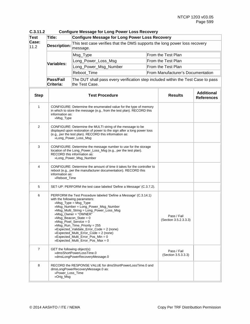
NTCIP 1203 v03.05 Page 599
C.3.11.2 Configure Message for Long Power Loss Recovery Test Case: 11.2
Title: Configure Message for Long Power Loss Recovery
Description: This test case verifies that the DMS supports the long power loss recovery message.
Variables:
Msg_Type From the Test Plan
Long_Power_Loss_Msg From the Test Plan
Long_Power_Msg_Number From the Test Plan
Reboot_Time From Manufacturer’s Documentation
Pass/Fail Criteria:
The DUT shall pass every verification step included within the Test Case to pass the Test Case.
Step Test Procedure Results Additional References
1 CONFIGURE: Determine the enumerated value for the type of memory in which to store the message (e.g., from the test plan). RECORD this information as: »Msg_Type
2 CONFIGURE: Determine the MULTI string of the message to be displayed upon restoration of power to the sign after a long power loss (e.g., per the test plan). RECORD this information as: »Long_Power_Loss_Msg
3 CONFIGURE: Determine the message number to use for the storage location of the Long_Power_Loss_Msg (e.g., per the test plan). RECORD this information as: »Long_Power_Msg_Number
4 CONFIGURE: Determine the amount of time it takes for the controller to reboot (e.g., per the manufacturer documentation). RECORD this information as: »Reboot_Time
5 SET-UP: PERFORM the test case labeled 'Define a Message' (C.3.7.2).
6 PERFORM the Test Procedure labeled 'Define a Message' (C.3.14.1) with the following parameters: »Msg_Type = Msg_Type »Msg_Number = Long_Power_Msg_Number »Msg_Multi_String = Long_Power_Loss_Msg »Msg_Owner = “OWNER” »Msg_Beacon_State = 0 »Msg_Pixel_Service = 0 »Msg_Run_Time_Priority = 255 »Expected_Validate_Error_Code = 2 (none) »Expected_Multi_Error_Code = 2 (none) »Expected_Multi_Error_Pos_Min = 0 »Expected_Multi_Error_Pos_Max = 0
Pass / Fail (Section 3.5.2.3.3.3)
7 GET the following object(s): »dmsShortPowerLossTime.0 »dmsLongPowerRecoveryMessage.0
Pass / Fail (Section 3.5.3.3.3)
8 RECORD the RESPONSE VALUE for dmsShortPowerLossTime.0 and dmsLongPowerRecoveryMessage.0 as: »Power_Loss_Time »Orig_Msg
© 2014 AASHTO / ITE / NEMA Copy Per TRF Distributtion Permission
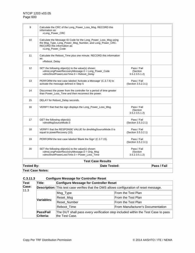
NTCIP 1203 v03.05 Page 600
9 Calculate the CRC of the Long_Power_Loss_Msg. RECORD this information as: »Long_Power_CRC
10 Calculate the Message ID Code for the Long_Power_Loss_Msg using the Msg_Type, Long_Power_Msg_Number, and Long_Power_CRC. RECORD this information as: »Long_Power_Code
11 Calculate the Reboot_Time plus one minute. RECORD this information as: »Reboot_Delay
12 SET the following object(s) to the value(s) shown: »dmsLongPowerRecoveryMessage.0 = Long_Power_Code »dmsShortPowerLossTime.0 = Reboot_Delay
Pass / Fail (Section
3.5.2.3.5.1.2)
13 PERFORM the test case labeled 'Activate a Message' (C.3.7.6) to activate the message defined in Step 5
Pass / Fail (Section 3.5.2.3.1)
14 Disconnect the power from the controller for a period of time greater than Power_Loss_Time and then reconnect the power.
15 DELAY for Reboot_Delay seconds.
16 VERIFY that that the sign displays the Long_Power_Loss_Msg. Pass / Fail (Section
3.5.2.3.5.1.2)
17 GET the following object(s): »dmsMsgSourceMode.0
Pass / Fail (Section 3.5.3.2.1)
18 VERIFY that the RESPONSE VALUE for dmsMsgSourceMode.0 is equal to powerRecovery (10).
Pass / Fail (Section 3.5.3.2.1)
19 PERFORM the test case labeled 'Blank the Sign' (C.3.7.15). Pass / Fail (Section 3.5.2.3.1)
20 SET the following object(s) to the value(s) shown: »dmsLongPowerRecoveryMessage.0 = Orig_Msg »dmsShortPowerLossTime.0 = Power_Loss_Time
Pass / Fail (Section
3.5.2.3.5.1.2)
Test Case Results Tested By: Date Tested: Pass / Fail Test Case Notes: C.3.11.3 Configure Message for Controller Reset Test Case: 11.3
Title: Configure Message for Controller Reset Description: This test case verifies that the DMS allows configuration of reset message.
Variables:
Msg_Type From the Test Plan
Reset_Msg From the Test Plan
Reset_Number From the Test Plan
Reboot_Time From Manufacturer’s Documentation
Pass/Fail Criteria:
The DUT shall pass every verification step included within the Test Case to pass the Test Case.
Copy Per TRF Distribution Permission © 2014 AASHTO / ITE / NEMA
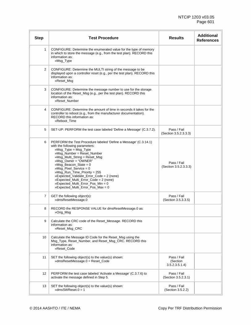
NTCIP 1203 v03.05 Page 601
Step Test Procedure Results Additional References
1 CONFIGURE: Determine the enumerated value for the type of memory in which to store the message (e.g., from the test plan). RECORD this information as: »Msg_Type
2 CONFIGURE: Determine the MULTI string of the message to be displayed upon a controller reset (e.g., per the test plan). RECORD this information as: »Reset_Msg
3 CONFIGURE: Determine the message number to use for the storage location of the Reset_Msg (e.g., per the test plan). RECORD this information as: »Reset_Number
4 CONFIGURE: Determine the amount of time in seconds it takes for the controller to reboot (e.g., from the manufacturer documentation). RECORD this information as: »Reboot_Time
5 SET-UP: PERFORM the test case labeled 'Define a Message' (C.3.7.2). Pass / Fail (Section 3.5.2.3.3.3)
6 PERFORM the Test Procedure labeled 'Define a Message' (C.3.14.1) with the following parameters: »Msg_Type = Msg_Type »Msg_Number = Reset_Number »Msg_Multi_String = Reset_Msg »Msg_Owner = “OWNER” »Msg_Beacon_State = 0 »Msg_Pixel_Service = 0 »Msg_Run_Time_Priority = 255 »Expected_Validate_Error_Code = 2 (none) »Expected_Multi_Error_Code = 2 (none) »Expected_Multi_Error_Pos_Min = 0 »Expected_Multi_Error_Pos_Max = 0
Pass / Fail (Section 3.5.2.3.3.3)
7 GET the following object(s): »dmsResetMessage.0
Pass / Fail (Section 3.5.3.3.5)
8 RECORD the RESPONSE VALUE for dmsResetMessage.0 as: »Orig_Msg
9 Calculate the CRC code of the Reset_Message. RECORD this information as: »Reset_Msg_CRC
10 Calculate the Message ID Code for the Reset_Msg using the Msg_Type, Reset_Number, and Reset_Msg_CRC. RECORD this information as: »Reset_Code
11 SET the following object(s) to the value(s) shown: »dmsResetMessage.0 = Reset_Code
Pass / Fail (Section
3.5.2.3.5.1.4)
12 PERFORM the test case labeled 'Activate a Message' (C.3.7.6) to activate the message defined in Step 5.
Pass / Fail (Section 3.5.2.3.1)
13 SET the following object(s) to the value(s) shown: »dmsSWReset.0 = 1
Pass / Fail (Section 3.5.2.2)
© 2014 AASHTO / ITE / NEMA Copy Per TRF Distributtion Permission
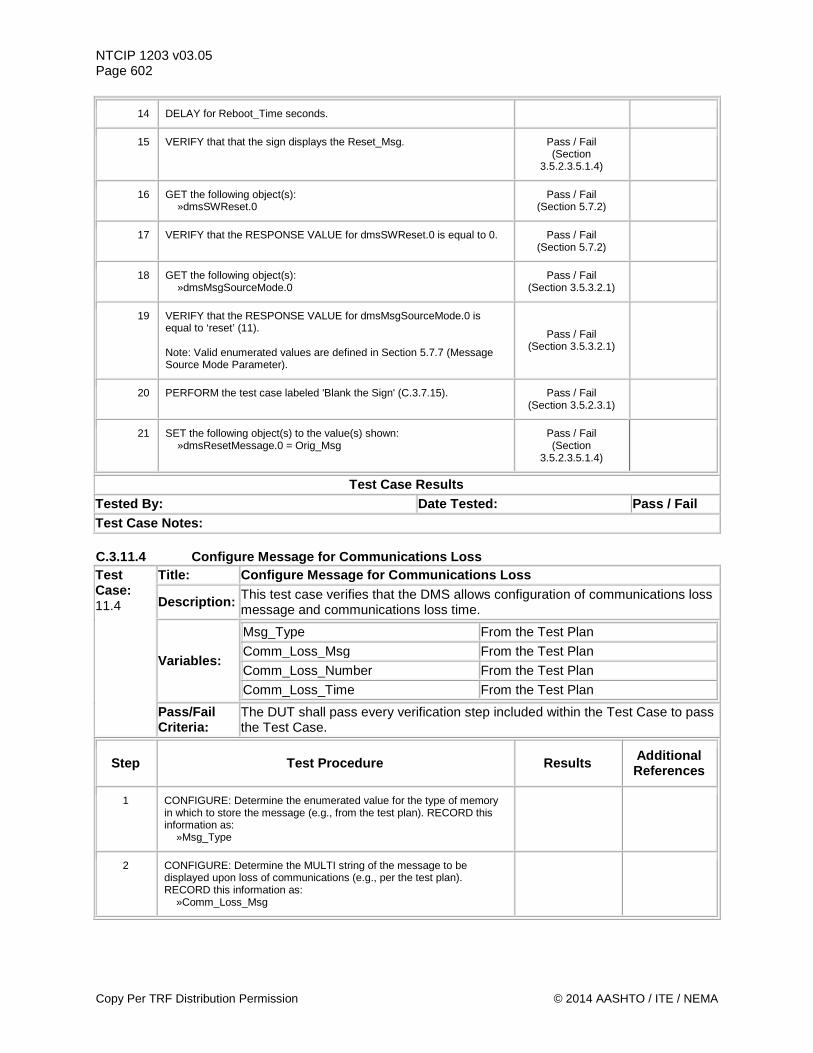
NTCIP 1203 v03.05 Page 602
14 DELAY for Reboot_Time seconds.
15 VERIFY that that the sign displays the Reset_Msg. Pass / Fail (Section
3.5.2.3.5.1.4)
16 GET the following object(s): »dmsSWReset.0
Pass / Fail (Section 5.7.2)
17 VERIFY that the RESPONSE VALUE for dmsSWReset.0 is equal to 0. Pass / Fail (Section 5.7.2)
18 GET the following object(s): »dmsMsgSourceMode.0
Pass / Fail (Section 3.5.3.2.1)
19 VERIFY that the RESPONSE VALUE for dmsMsgSourceMode.0 is equal to ‘reset’ (11). Note: Valid enumerated values are defined in Section 5.7.7 (Message Source Mode Parameter).
Pass / Fail (Section 3.5.3.2.1)
20 PERFORM the test case labeled 'Blank the Sign' (C.3.7.15). Pass / Fail (Section 3.5.2.3.1)
21 SET the following object(s) to the value(s) shown: »dmsResetMessage.0 = Orig_Msg
Pass / Fail (Section
3.5.2.3.5.1.4)
Test Case Results Tested By: Date Tested: Pass / Fail Test Case Notes: C.3.11.4 Configure Message for Communications Loss Test Case: 11.4
Title: Configure Message for Communications Loss
Description: This test case verifies that the DMS allows configuration of communications loss message and communications loss time.
Variables:
Msg_Type From the Test Plan
Comm_Loss_Msg From the Test Plan
Comm_Loss_Number From the Test Plan
Comm_Loss_Time From the Test Plan
Pass/Fail Criteria:
The DUT shall pass every verification step included within the Test Case to pass the Test Case.
Step Test Procedure Results Additional References
1 CONFIGURE: Determine the enumerated value for the type of memory in which to store the message (e.g., from the test plan). RECORD this information as: »Msg_Type
2 CONFIGURE: Determine the MULTI string of the message to be displayed upon loss of communications (e.g., per the test plan). RECORD this information as: »Comm_Loss_Msg
Copy Per TRF Distribution Permission © 2014 AASHTO / ITE / NEMA
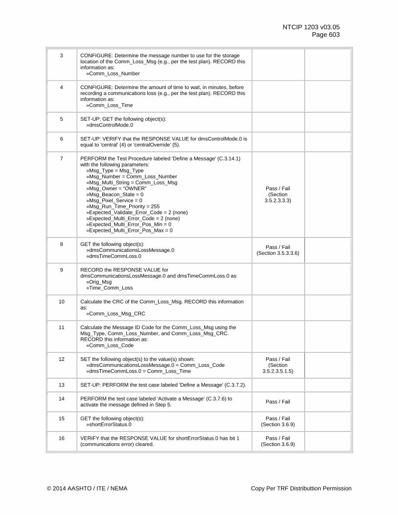
NTCIP 1203 v03.05 Page 603
3 CONFIGURE: Determine the message number to use for the storage location of the Comm_Loss_Msg (e.g., per the test plan). RECORD this information as: »Comm_Loss_Number
4 CONFIGURE: Determine the amount of time to wait, in minutes, before recording a communications loss (e.g., per the test plan). RECORD this information as: »Comm_Loss_Time
5 SET-UP: GET the following object(s): »dmsControlMode.0
6 SET-UP: VERIFY that the RESPONSE VALUE for dmsControlMode.0 is equal to 'central' (4) or 'centralOverride' (5).
7 PERFORM the Test Procedure labeled 'Define a Message' (C.3.14.1) with the following parameters: »Msg_Type = Msg_Type »Msg_Number = Comm_Loss_Number »Msg_Multi_String = Comm_Loss_Msg »Msg_Owner = “OWNER” »Msg_Beacon_State = 0 »Msg_Pixel_Service = 0 »Msg_Run_Time_Priority = 255 »Expected_Validate_Error_Code = 2 (none) »Expected_Multi_Error_Code = 2 (none) »Expected_Multi_Error_Pos_Min = 0 »Expected_Multi_Error_Pos_Max = 0
Pass / Fail (Section
3.5.2.3.3.3)
8 GET the following object(s): »dmsCommunicationsLossMessage.0 »dmsTimeCommLoss.0
Pass / Fail (Section 3.5.3.3.6)
9 RECORD the RESPONSE VALUE for dmsCommunicationsLossMessage.0 and dmsTimeCommLoss.0 as: »Orig_Msg »Time_Comm_Loss
10 Calculate the CRC of the Comm_Loss_Msg. RECORD this information as: »Comm_Loss_Msg_CRC
11 Calculate the Message ID Code for the Comm_Loss_Msg using the Msg_Type, Comm_Loss_Number, and Comm_Loss_Msg_CRC. RECORD this information as: »Comm_Loss_Code
12 SET the following object(s) to the value(s) shown: »dmsCommunicationsLossMessage.0 = Comm_Loss_Code »dmsTimeCommLoss.0 = Comm_Loss_Time
Pass / Fail (Section
3.5.2.3.5.1.5)
13 SET-UP: PERFORM the test case labeled 'Define a Message' (C.3.7.2).
14 PERFORM the test case labeled 'Activate a Message' (C.3.7.6) to activate the message defined in Step 5. Pass / Fail
15 GET the following object(s): »shortErrorStatus.0
Pass / Fail (Section 3.6.9)
16 VERIFY that the RESPONSE VALUE for shortErrorStatus.0 has bit 1 (communications error) cleared.
Pass / Fail (Section 3.6.9)
© 2014 AASHTO / ITE / NEMA Copy Per TRF Distributtion Permission
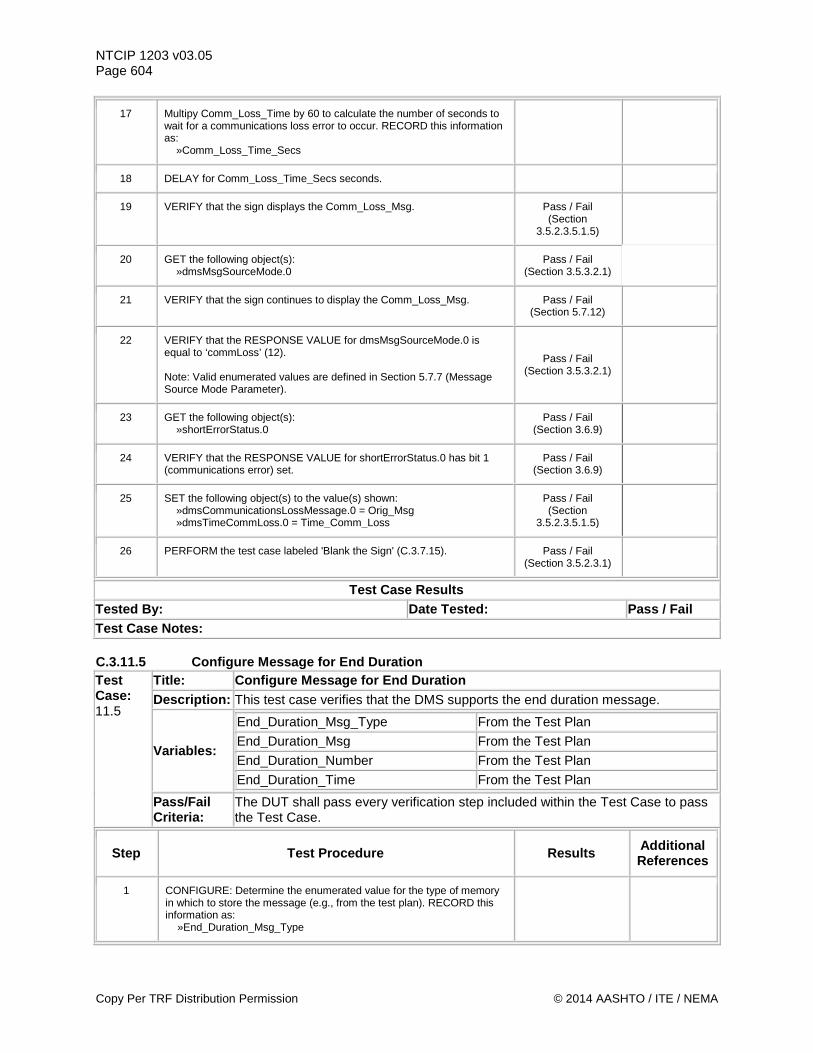
NTCIP 1203 v03.05 Page 604
17 Multipy Comm_Loss_Time by 60 to calculate the number of seconds to wait for a communications loss error to occur. RECORD this information as: »Comm_Loss_Time_Secs
18 DELAY for Comm_Loss_Time_Secs seconds.
19 VERIFY that the sign displays the Comm_Loss_Msg. Pass / Fail (Section
3.5.2.3.5.1.5)
20 GET the following object(s): »dmsMsgSourceMode.0
Pass / Fail (Section 3.5.3.2.1)
21 VERIFY that the sign continues to display the Comm_Loss_Msg.
Pass / Fail (Section 5.7.12)
22 VERIFY that the RESPONSE VALUE for dmsMsgSourceMode.0 is equal to ‘commLoss’ (12). Note: Valid enumerated values are defined in Section 5.7.7 (Message Source Mode Parameter).
Pass / Fail (Section 3.5.3.2.1)
23 GET the following object(s): »shortErrorStatus.0
Pass / Fail (Section 3.6.9)
24 VERIFY that the RESPONSE VALUE for shortErrorStatus.0 has bit 1 (communications error) set.
Pass / Fail (Section 3.6.9)
25 SET the following object(s) to the value(s) shown: »dmsCommunicationsLossMessage.0 = Orig_Msg »dmsTimeCommLoss.0 = Time_Comm_Loss
Pass / Fail (Section
3.5.2.3.5.1.5)
26 PERFORM the test case labeled 'Blank the Sign' (C.3.7.15). Pass / Fail (Section 3.5.2.3.1)
Test Case Results Tested By: Date Tested: Pass / Fail Test Case Notes: C.3.11.5 Configure Message for End Duration Test Case: 11.5
Title: Configure Message for End Duration Description: This test case verifies that the DMS supports the end duration message.
Variables:
End_Duration_Msg_Type From the Test Plan
End_Duration_Msg From the Test Plan
End_Duration_Number From the Test Plan
End_Duration_Time From the Test Plan
Pass/Fail Criteria:
The DUT shall pass every verification step included within the Test Case to pass the Test Case.
Step Test Procedure Results Additional References
1 CONFIGURE: Determine the enumerated value for the type of memory in which to store the message (e.g., from the test plan). RECORD this information as: »End_Duration_Msg_Type
Copy Per TRF Distribution Permission © 2014 AASHTO / ITE / NEMA
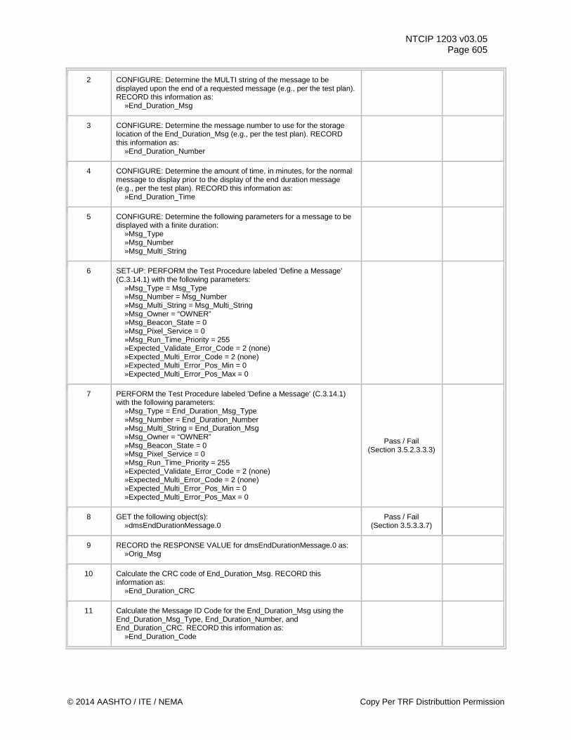
NTCIP 1203 v03.05 Page 605
2 CONFIGURE: Determine the MULTI string of the message to be displayed upon the end of a requested message (e.g., per the test plan). RECORD this information as: »End_Duration_Msg
3 CONFIGURE: Determine the message number to use for the storage location of the End_Duration_Msg (e.g., per the test plan). RECORD this information as: »End_Duration_Number
4 CONFIGURE: Determine the amount of time, in minutes, for the normal message to display prior to the display of the end duration message (e.g., per the test plan). RECORD this information as: »End_Duration_Time
5 CONFIGURE: Determine the following parameters for a message to be displayed with a finite duration: »Msg_Type »Msg_Number »Msg_Multi_String
6 SET-UP: PERFORM the Test Procedure labeled 'Define a Message' (C.3.14.1) with the following parameters: »Msg_Type = Msg_Type »Msg_Number = Msg_Number »Msg_Multi_String = Msg_Multi_String »Msg_Owner = “OWNER” »Msg_Beacon_State = 0 »Msg_Pixel_Service = 0 »Msg_Run_Time_Priority = 255 »Expected_Validate_Error_Code = 2 (none) »Expected_Multi_Error_Code = 2 (none) »Expected_Multi_Error_Pos_Min = 0 »Expected_Multi_Error_Pos_Max = 0
7 PERFORM the Test Procedure labeled 'Define a Message' (C.3.14.1) with the following parameters: »Msg_Type = End_Duration_Msg_Type »Msg_Number = End_Duration_Number »Msg_Multi_String = End_Duration_Msg »Msg_Owner = “OWNER” »Msg_Beacon_State = 0 »Msg_Pixel_Service = 0 »Msg_Run_Time_Priority = 255 »Expected_Validate_Error_Code = 2 (none) »Expected_Multi_Error_Code = 2 (none) »Expected_Multi_Error_Pos_Min = 0 »Expected_Multi_Error_Pos_Max = 0
Pass / Fail (Section 3.5.2.3.3.3)
8 GET the following object(s): »dmsEndDurationMessage.0
Pass / Fail (Section 3.5.3.3.7)
9 RECORD the RESPONSE VALUE for dmsEndDurationMessage.0 as: »Orig_Msg
10 Calculate the CRC code of End_Duration_Msg. RECORD this information as: »End_Duration_CRC
11 Calculate the Message ID Code for the End_Duration_Msg using the End_Duration_Msg_Type, End_Duration_Number, and End_Duration_CRC. RECORD this information as: »End_Duration_Code
© 2014 AASHTO / ITE / NEMA Copy Per TRF Distributtion Permission
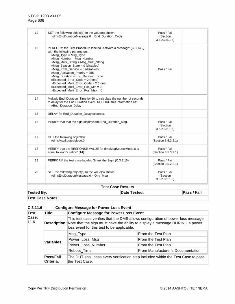
NTCIP 1203 v03.05 Page 606
12 SET the following object(s) to the value(s) shown: »dmsEndDurationMessage.0 = End_Duration_Code
Pass / Fail (Section
3.5.2.3.5.1.6)
13 PERFORM the Test Procedure labeled 'Activate a Message' (C.3.14.2) with the following parameters: »Msg_Type = Msg_Type »Msg_Number = Msg_Number »Msg_Multi_String = Msg_Multi_String »Msg_Beacon_State = 0 (disabled) »Msg_Pixel_Service = 0 (disabled) »Msg_Activation_Priority = 255 »Msg_Duration = End_Duration_Time »Expected_Error_Code = 2 (none) »Expected_Multi_Error_Code = 2 (none) »Expected_Multi_Error_Pos_Min = 0 »Expected_Multi_Error_Pos_Max = 0
Pass / Fail
14 Multiply End_Duration_Time by 60 to calculate the number of seconds to delay for the End Duration event. RECORD this information as: »End_Duration_Delay
15 DELAY for End_Duration_Delay seconds.
16 VERIFY that that the sign displays the End_Duration_Msg. Pass / Fail (Section
3.5.2.3.5.1.6)
17 GET the following object(s): »dmsMsgSourceMode.0
Pass / Fail (Section 3.5.3.2.1)
18 VERIFY that the RESPONSE VALUE for dmsMsgSourceMode.0 is equal to ‘endDuration’ (14).
Pass / Fail (Section 3.5.3.2.1)
19 PERFORM the test case labeled 'Blank the Sign' (C.3.7.15). Pass / Fail (Section 3.5.2.3.1)
20 SET the following object(s) to the value(s) shown: »dmsEndDurationMessage.0 = Orig_Msg
Pass / Fail (Section
3.5.2.3.5.1.6)
Test Case Results Tested By: Date Tested: Pass / Fail Test Case Notes: C.3.11.6 Configure Message for Power Loss Event Test Case: 11.6
Title: Configure Message for Power Loss Event
Description: This test case verifies that the DMS allows configuration of power loss message. Note that the sign must have the ability to display a message DURING a power loss event for this test to be applicable.
Variables:
Msg_Type From the Test Plan
Power_Loss_Msg From the Test Plan
Power_Loss_Number From the Test Plan
Reboot_Time From Manufacturer’s Documentation
Pass/Fail Criteria:
The DUT shall pass every verification step included within the Test Case to pass the Test Case.
Copy Per TRF Distribution Permission © 2014 AASHTO / ITE / NEMA
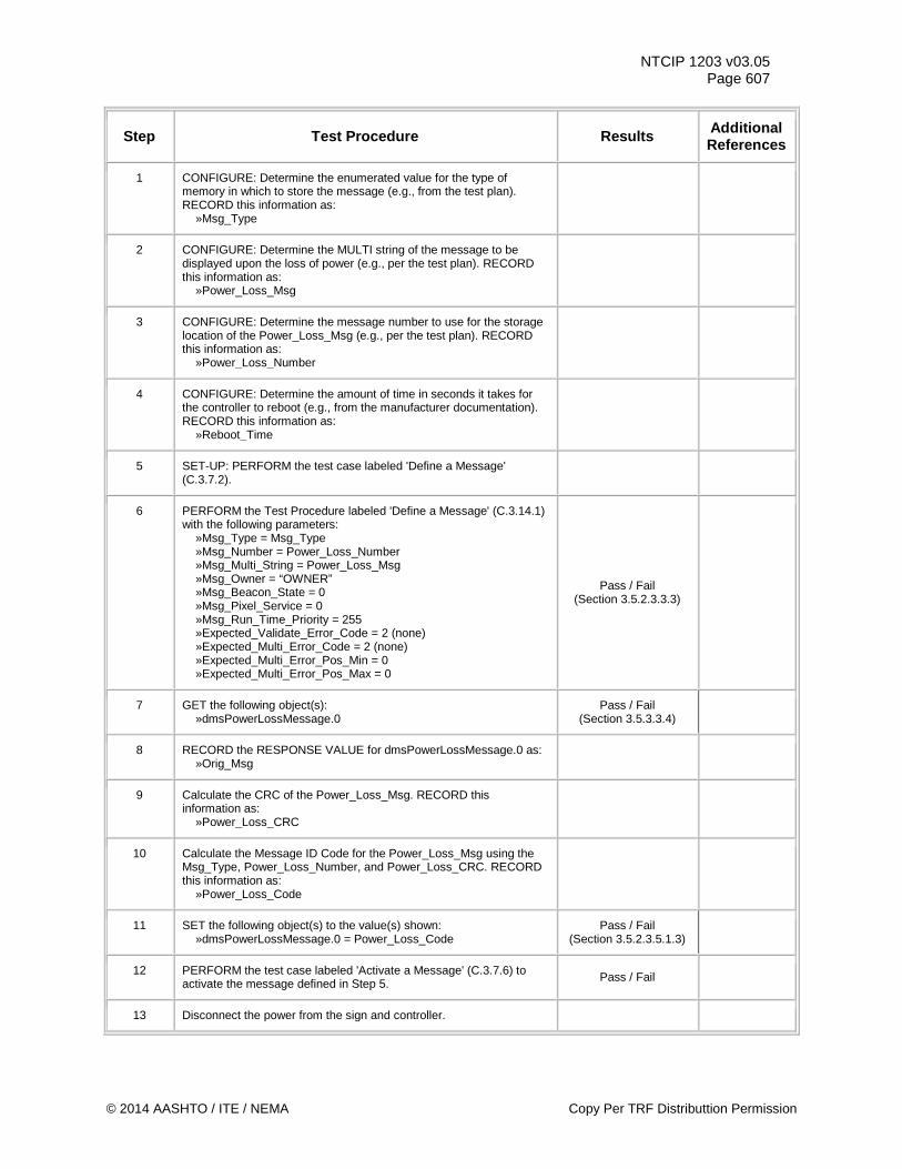
NTCIP 1203 v03.05 Page 607
Step Test Procedure Results Additional References
1 CONFIGURE: Determine the enumerated value for the type of memory in which to store the message (e.g., from the test plan). RECORD this information as: »Msg_Type
2 CONFIGURE: Determine the MULTI string of the message to be displayed upon the loss of power (e.g., per the test plan). RECORD this information as: »Power_Loss_Msg
3 CONFIGURE: Determine the message number to use for the storage location of the Power_Loss_Msg (e.g., per the test plan). RECORD this information as: »Power_Loss_Number
4 CONFIGURE: Determine the amount of time in seconds it takes for the controller to reboot (e.g., from the manufacturer documentation). RECORD this information as: »Reboot_Time
5 SET-UP: PERFORM the test case labeled 'Define a Message' (C.3.7.2).
6 PERFORM the Test Procedure labeled 'Define a Message' (C.3.14.1) with the following parameters: »Msg_Type = Msg_Type »Msg_Number = Power_Loss_Number »Msg_Multi_String = Power_Loss_Msg »Msg_Owner = “OWNER” »Msg_Beacon_State = 0 »Msg_Pixel_Service = 0 »Msg_Run_Time_Priority = 255 »Expected_Validate_Error_Code = 2 (none) »Expected_Multi_Error_Code = 2 (none) »Expected_Multi_Error_Pos_Min = 0 »Expected_Multi_Error_Pos_Max = 0
Pass / Fail (Section 3.5.2.3.3.3)
7 GET the following object(s): »dmsPowerLossMessage.0
Pass / Fail (Section 3.5.3.3.4)
8 RECORD the RESPONSE VALUE for dmsPowerLossMessage.0 as: »Orig_Msg
9 Calculate the CRC of the Power_Loss_Msg. RECORD this information as: »Power_Loss_CRC
10 Calculate the Message ID Code for the Power_Loss_Msg using the Msg_Type, Power_Loss_Number, and Power_Loss_CRC. RECORD this information as: »Power_Loss_Code
11 SET the following object(s) to the value(s) shown: »dmsPowerLossMessage.0 = Power_Loss_Code
Pass / Fail (Section 3.5.2.3.5.1.3)
12 PERFORM the test case labeled 'Activate a Message' (C.3.7.6) to activate the message defined in Step 5. Pass / Fail
13 Disconnect the power from the sign and controller.
© 2014 AASHTO / ITE / NEMA Copy Per TRF Distributtion Permission
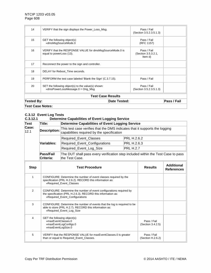
NTCIP 1203 v03.05 Page 608
14 VERIFY that the sign displays the Power_Loss_Msg. Pass / Fail (Section 3.5.2.3.5.1.3)
15 GET the following object(s): »dmsMsgSourceMode.0
Pass / Fail (RFC 1157)
16 VERIFY that the RESPONSE VALUE for dmsMsgSourceMode.0 is equal to powerLoss (13).
Pass / Fail (Section 3.5.3.2.1,
Item d)
17 Reconnect the power to the sign and controller.
18 DELAY for Reboot_Time seconds.
19 PERFORM the test case labeled 'Blank the Sign' (C.3.7.15). Pass / Fail
20 SET the following object(s) to the value(s) shown: »dmsPowerLossMessage.0 = Orig_Msg
Pass / Fail (Section 3.5.2.3.5.1.3)
Test Case Results Tested By: Date Tested: Pass / Fail Test Case Notes: C.3.12 Event Log Tests C.3.12.1 Determine Capabilities of Event Logging Service Test Case: 12.1
Title: Determine Capabilities of Event Logging Service
Description: This test case verifies that the DMS indicates that it supports the logging capabilities required by the specification
Variables: Required_Event_Classes PRL H.2.6.2 Required_Event_Configurations PRL H.2.6.3 Required_Event_Log_Size PRL H.2.7
Pass/Fail Criteria:
The DUT shall pass every verification step included within the Test Case to pass the Test Case.
Step Test Procedure Results Additional References
1 CONFIGURE: Determine the number of event classes required by the specification (PRL H.2.6.2). RECORD this information as: »Required_Event_Classes
2 CONFIGURE: Determine the number of event configurations required by the specification (PRL H.2.6.3). RECORD this information as: »Required_Event_Configurations
3 CONFIGURE: Determine the number of events that the log is required to be able to store (PRL H.2.7). RECORD this information as: »Required_Event_Log_Size
4 GET the following object(s): »maxEventClasses.0 »maxEventLogConfigs.0 »maxEventLogSize.0
Pass / Fail (Section 3.4.2.5)
5 VERIFY that the RESPONSE VALUE for maxEventClasses.0 is greater than or equal to Required_Event_Classes.
Pass / Fail (Section H.2.6.2)
Copy Per TRF Distribution Permission © 2014 AASHTO / ITE / NEMA
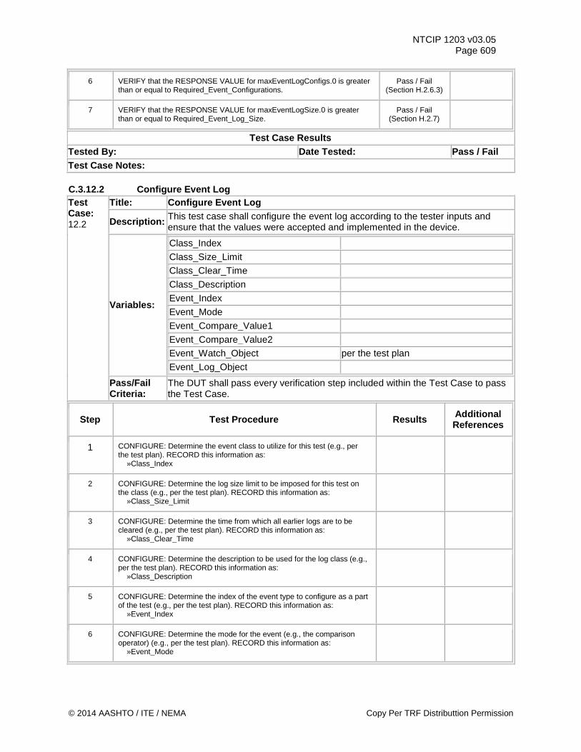
NTCIP 1203 v03.05 Page 609
6 VERIFY that the RESPONSE VALUE for maxEventLogConfigs.0 is greater than or equal to Required_Event_Configurations.
Pass / Fail (Section H.2.6.3)
7 VERIFY that the RESPONSE VALUE for maxEventLogSize.0 is greater than or equal to Required_Event_Log_Size.
Pass / Fail (Section H.2.7)
Test Case Results Tested By: Date Tested: Pass / Fail Test Case Notes: C.3.12.2 Configure Event Log Test Case: 12.2
Title: Configure Event Log
Description: This test case shall configure the event log according to the tester inputs and ensure that the values were accepted and implemented in the device.
Variables:
Class_Index
Class_Size_Limit
Class_Clear_Time
Class_Description
Event_Index
Event_Mode
Event_Compare_Value1
Event_Compare_Value2
Event_Watch_Object per the test plan Event_Log_Object
Pass/Fail Criteria:
The DUT shall pass every verification step included within the Test Case to pass the Test Case.
Step Test Procedure Results Additional References
1 CONFIGURE: Determine the event class to utilize for this test (e.g., per the test plan). RECORD this information as: »Class_Index
2 CONFIGURE: Determine the log size limit to be imposed for this test on the class (e.g., per the test plan). RECORD this information as: »Class_Size_Limit
3 CONFIGURE: Determine the time from which all earlier logs are to be cleared (e.g., per the test plan). RECORD this information as: »Class_Clear_Time
4 CONFIGURE: Determine the description to be used for the log class (e.g., per the test plan). RECORD this information as: »Class_Description
5 CONFIGURE: Determine the index of the event type to configure as a part of the test (e.g., per the test plan). RECORD this information as: »Event_Index
6 CONFIGURE: Determine the mode for the event (e.g., the comparison operator) (e.g., per the test plan). RECORD this information as: »Event_Mode
© 2014 AASHTO / ITE / NEMA Copy Per TRF Distributtion Permission
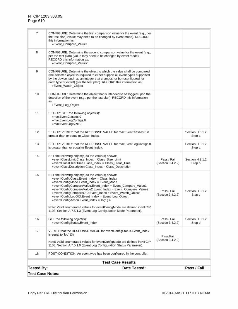
NTCIP 1203 v03.05 Page 610
7 CONFIGURE: Determine the first comparison value for the event (e.g., per the test plan) (value may need to be changed by event mode). RECORD this information as: »Event_Compare_Value1
8 CONFIGURE: Determine the second comparison value for the event (e.g., per the test plan) (value may need to be changed by event mode). RECORD this information as: »Event_Compare_Value2
9 CONFIGURE: Determine the object to which the value shall be compared (the selected object is required to either support all event types supported by the device, such as an integer that changes, or be reconfigured for each type of event) (per the test plan). RECORD this information as: »Event_Watch_Object
10 CONFIGURE: Determine the object that is intended to be logged upon the detection of the event (e.g., per the test plan). RECORD this information as: »Event_Log_Object
11 SET-UP: GET the following object(s): »maxEventClasses.0 »maxEventLogConfigs.0 »maxEventLogSize.0
12 SET-UP: VERIFY that the RESPONSE VALUE for maxEventClasses.0 is greater than or equal to Class_Index. Section H.3.1.2
Step a
13 SET-UP: VERIFY that the RESPONSE VALUE for maxEventLogConfigs.0 is greater than or equal to Event_Index. Section H.3.1.2
Step a
14 SET the following object(s) to the value(s) shown: »eventClassLimit.Class_Index = Class_Size_Limit »eventClassClearTime.Class_Index = Class_Clear_Time »eventClassDescription.Class_Index = Class_Description
Pass / Fail (Section 3.4.2.2)
Section H.3.1.2 Step b
15 SET the following object(s) to the value(s) shown: »eventConfigClass.Event_Index = Class_Index »eventConfigMode.Event_Index = Event_Mode »eventConfigCompareValue.Event_Index = Event_Compare_Value1 »eventConfigCompareValue2.Event_Index = Event_Compare_Value2 »eventConfigCompareOID.Event_Index = Event_Watch_Object »eventConfigLogOID.Event_Index = Event_Log_Object »eventConfigAction.Event_Index = 'log' (3) Note: Valid enumerated values for eventConfigMode are defined in NTCIP 1103, Section A.7.5.1.3 (Event Log Configuration Mode Parameter).
Pass / Fail (Section 3.4.2.2)
Section H.3.1.2 Step c
16 GET the following object(s): »eventConfigStatus.Event_Index
Pass / Fail (Section 3.4.2.2)
Section H.3.1.2 Step d
17 VERIFY that the RESPONSE VALUE for eventConfigStatus.Event_Index is equal to ‘log’ (3). Note: Valid enumerated values for eventConfigMode are defined in NTCIP 1103, Section A.7.5.1.9 (Event Log Configuration Status Parameter).
Pass/Fail (Section 3.4.2.2)
18 POST-CONDITION: An event type has been configured in the controller.
Test Case Results Tested By: Date Tested: Pass / Fail Test Case Notes:
Copy Per TRF Distribution Permission © 2014 AASHTO / ITE / NEMA
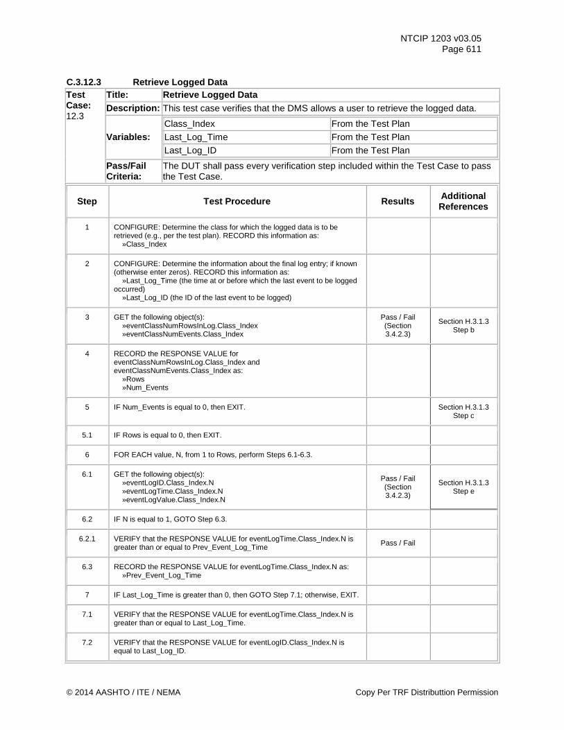
NTCIP 1203 v03.05 Page 611
C.3.12.3 Retrieve Logged Data Test Case: 12.3
Title: Retrieve Logged Data Description: This test case verifies that the DMS allows a user to retrieve the logged data.
Variables: Class_Index From the Test Plan
Last_Log_Time From the Test Plan
Last_Log_ID From the Test Plan
Pass/Fail Criteria:
The DUT shall pass every verification step included within the Test Case to pass the Test Case.
Step Test Procedure Results Additional References
1 CONFIGURE: Determine the class for which the logged data is to be retrieved (e.g., per the test plan). RECORD this information as: »Class_Index
2 CONFIGURE: Determine the information about the final log entry; if known (otherwise enter zeros). RECORD this information as: »Last_Log_Time (the time at or before which the last event to be logged occurred) »Last_Log_ID (the ID of the last event to be logged)
3 GET the following object(s): »eventClassNumRowsInLog.Class_Index »eventClassNumEvents.Class_Index
Pass / Fail (Section 3.4.2.3)
Section H.3.1.3 Step b
4 RECORD the RESPONSE VALUE for eventClassNumRowsInLog.Class_Index and eventClassNumEvents.Class_Index as: »Rows »Num_Events
5 IF Num_Events is equal to 0, then EXIT. Section H.3.1.3 Step c
5.1 IF Rows is equal to 0, then EXIT.
6 FOR EACH value, N, from 1 to Rows, perform Steps 6.1-6.3.
6.1 GET the following object(s): »eventLogID.Class_Index.N »eventLogTime.Class_Index.N »eventLogValue.Class_Index.N
Pass / Fail (Section 3.4.2.3)
Section H.3.1.3 Step e
6.2 IF N is equal to 1, GOTO Step 6.3.
6.2.1 VERIFY that the RESPONSE VALUE for eventLogTime.Class_Index.N is greater than or equal to Prev_Event_Log_Time Pass / Fail
6.3 RECORD the RESPONSE VALUE for eventLogTime.Class_Index.N as: »Prev_Event_Log_Time
7 IF Last_Log_Time is greater than 0, then GOTO Step 7.1; otherwise, EXIT.
7.1 VERIFY that the RESPONSE VALUE for eventLogTime.Class_Index.N is greater than or equal to Last_Log_Time.
7.2 VERIFY that the RESPONSE VALUE for eventLogID.Class_Index.N is equal to Last_Log_ID.
© 2014 AASHTO / ITE / NEMA Copy Per TRF Distributtion Permission
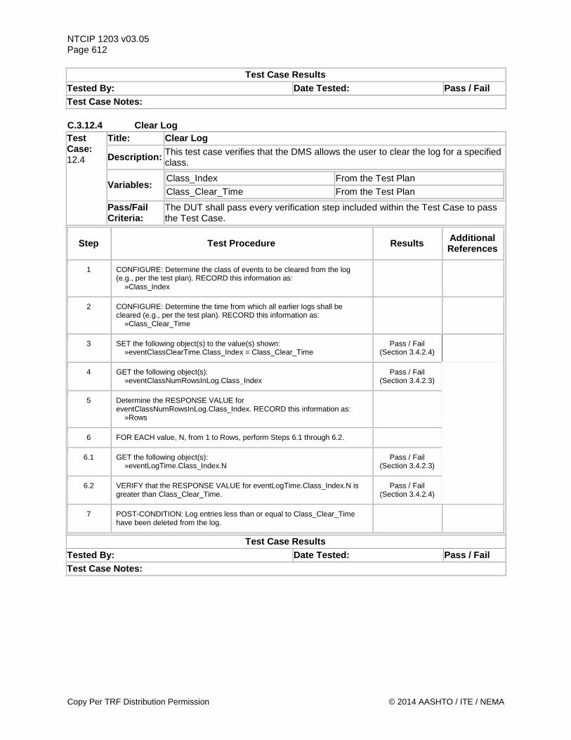
NTCIP 1203 v03.05 Page 612
Test Case Results Tested By: Date Tested: Pass / Fail Test Case Notes: C.3.12.4 Clear Log Test Case: 12.4
Title: Clear Log
Description: This test case verifies that the DMS allows the user to clear the log for a specified class.
Variables: Class_Index From the Test Plan
Class_Clear_Time From the Test Plan
Pass/Fail Criteria:
The DUT shall pass every verification step included within the Test Case to pass the Test Case.
Step Test Procedure Results Additional References
1 CONFIGURE: Determine the class of events to be cleared from the log (e.g., per the test plan). RECORD this information as: »Class_Index
2 CONFIGURE: Determine the time from which all earlier logs shall be cleared (e.g., per the test plan). RECORD this information as: »Class_Clear_Time
3 SET the following object(s) to the value(s) shown: »eventClassClearTime.Class_Index = Class_Clear_Time
Pass / Fail (Section 3.4.2.4)
4 GET the following object(s): »eventClassNumRowsInLog.Class_Index
Pass / Fail (Section 3.4.2.3)
5 Determine the RESPONSE VALUE for eventClassNumRowsInLog.Class_Index. RECORD this information as: »Rows
6 FOR EACH value, N, from 1 to Rows, perform Steps 6.1 through 6.2.
6.1 GET the following object(s): »eventLogTime.Class_Index.N
Pass / Fail (Section 3.4.2.3)
6.2 VERIFY that the RESPONSE VALUE for eventLogTime.Class_Index.N is greater than Class_Clear_Time.
Pass / Fail (Section 3.4.2.4)
7 POST-CONDITION: Log entries less than or equal to Class_Clear_Time have been deleted from the log.
Test Case Results Tested By: Date Tested: Pass / Fail Test Case Notes:
Copy Per TRF Distribution Permission © 2014 AASHTO / ITE / NEMA
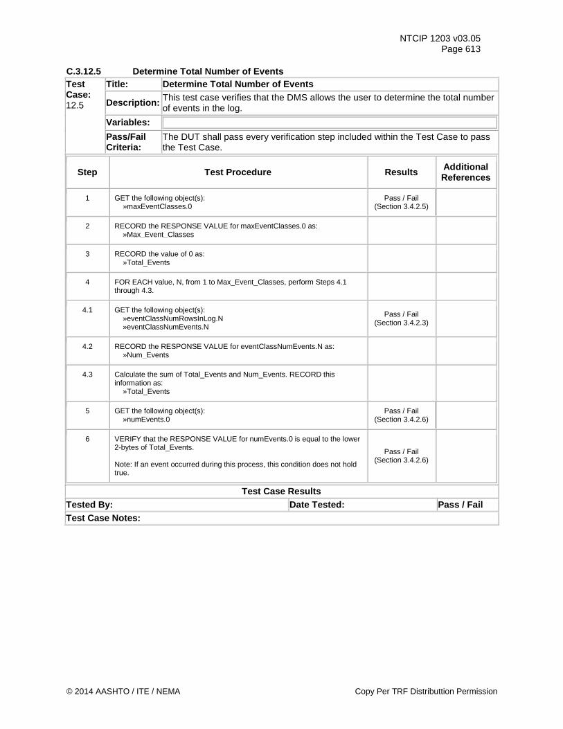
NTCIP 1203 v03.05 Page 613
C.3.12.5 Determine Total Number of Events Test Case: 12.5
Title: Determine Total Number of Events
Description: This test case verifies that the DMS allows the user to determine the total number of events in the log.
Variables:
Pass/Fail Criteria:
The DUT shall pass every verification step included within the Test Case to pass the Test Case.
Step Test Procedure Results Additional References
1 GET the following object(s): »maxEventClasses.0
Pass / Fail (Section 3.4.2.5)
2 RECORD the RESPONSE VALUE for maxEventClasses.0 as: »Max_Event_Classes
3 RECORD the value of 0 as: »Total_Events
4 FOR EACH value, N, from 1 to Max_Event_Classes, perform Steps 4.1 through 4.3.
4.1 GET the following object(s): »eventClassNumRowsInLog.N »eventClassNumEvents.N
Pass / Fail (Section 3.4.2.3)
4.2 RECORD the RESPONSE VALUE for eventClassNumEvents.N as: »Num_Events
4.3 Calculate the sum of Total_Events and Num_Events. RECORD this information as: »Total_Events
5 GET the following object(s): »numEvents.0
Pass / Fail (Section 3.4.2.6)
6 VERIFY that the RESPONSE VALUE for numEvents.0 is equal to the lower 2-bytes of Total_Events. Note: If an event occurred during this process, this condition does not hold true.
Pass / Fail (Section 3.4.2.6)
Test Case Results Tested By: Date Tested: Pass / Fail Test Case Notes:
© 2014 AASHTO / ITE / NEMA Copy Per TRF Distributtion Permission

NTCIP 1203 v03.05 Page 614 C.3.12.6 Verify Log Limit Storage Test Case: 12.6
Title: Verify Log Limit Storage
Description: This test case verifies that the DMS stores only the latest of the maximum number of events per class.
Variables: Class_Index From the Test Plan
Class_Size_Limit From the Test Plan
Pass/Fail Criteria:
The DUT shall pass every verification step included within the Test Case to pass the Test Case.
Step Test Procedure Results Additional References
1 CONFIGURE: Determine the class for which the logged data is to be retrieved (e.g., per the test plan). RECORD this information as: »Class_Index
2 CONFIGURE: Determine the log size limit that the test shall impose on the class (e.g., per the test plan). RECORD this information as: »Class_Size_Limit
3 CONFIGURE: GET the following object(s): »globalTime.0
4 CONFIGURE: RECORD the RESPONSE VALUE for globalTime.0 as: »Class_Clear_Time
5 PERFORM the test case labeled 'Configure Event Log' (C.3.12.2). Pass / Fail
6 GET the following object(s): »numEvents.0
Pass / Fail (Section 3.4.2.6)
7 RECORD the RESPONSE VALUE for numEvents.0 as: »Num_Events
8 Create conditions to cause the device to log the event Class_Size_Limit times. Note: This may require physically changing a sensor reading or setting an object within the device.
9 GET the following object(s): »numEvents.0
Pass / Fail (Section 3.4.2.6)
10 VERIFY that the RESPONSE VALUE for numEvents.0 is equal to Num_Events plus Class_Size_Limit.
Pass / Fail (Section 3.4.2.6)
11 RECORD the RESPONSE VALUE for numEvents.0 as: »Num_Events
12 GET the following object(s): »eventClassNumRowsInLog.Class_Index »eventClassNumEvents.Class_Index
Pass / Fail (Section 3.4.2.3)
Section H.3.1.3 Step b
13 VERIFY that the RESPONSE VALUE for eventClassNumRowsInLog.Class_Index is equal to Class_Size_Limit.
Pass / Fail (Section H.2.6.2)
14 RECORD the RESPONSE VALUE for eventClassNumRowsInLog.Class_Index as: »Rows
Copy Per TRF Distribution Permission © 2014 AASHTO / ITE / NEMA
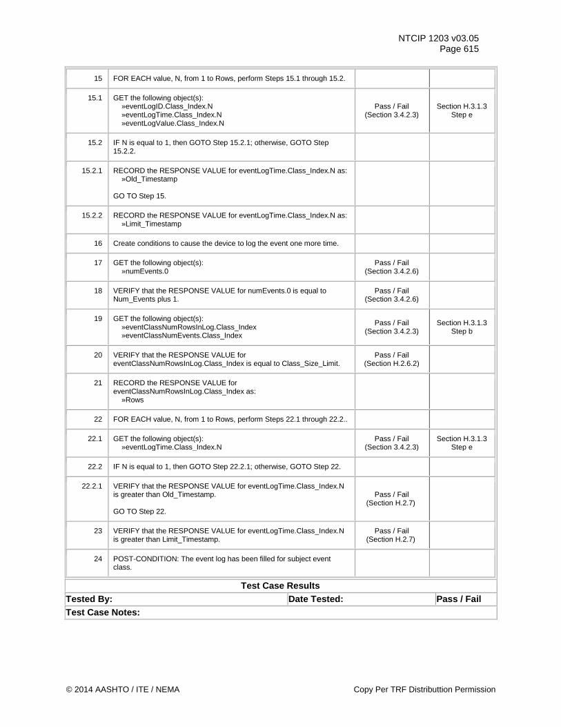
NTCIP 1203 v03.05 Page 615
15 FOR EACH value, N, from 1 to Rows, perform Steps 15.1 through 15.2.
15.1 GET the following object(s): »eventLogID.Class_Index.N »eventLogTime.Class_Index.N »eventLogValue.Class_Index.N
Pass / Fail (Section 3.4.2.3)
Section H.3.1.3 Step e
15.2 IF N is equal to 1, then GOTO Step 15.2.1; otherwise, GOTO Step 15.2.2.
15.2.1 RECORD the RESPONSE VALUE for eventLogTime.Class_Index.N as: »Old_Timestamp GO TO Step 15.
15.2.2 RECORD the RESPONSE VALUE for eventLogTime.Class_Index.N as: »Limit_Timestamp
16 Create conditions to cause the device to log the event one more time.
17 GET the following object(s): »numEvents.0
Pass / Fail (Section 3.4.2.6)
18 VERIFY that the RESPONSE VALUE for numEvents.0 is equal to Num_Events plus 1.
Pass / Fail (Section 3.4.2.6)
19 GET the following object(s): »eventClassNumRowsInLog.Class_Index »eventClassNumEvents.Class_Index
Pass / Fail (Section 3.4.2.3)
Section H.3.1.3 Step b
20 VERIFY that the RESPONSE VALUE for eventClassNumRowsInLog.Class_Index is equal to Class_Size_Limit.
Pass / Fail (Section H.2.6.2)
21 RECORD the RESPONSE VALUE for eventClassNumRowsInLog.Class_Index as: »Rows
22 FOR EACH value, N, from 1 to Rows, perform Steps 22.1 through 22.2..
22.1 GET the following object(s): »eventLogTime.Class_Index.N
Pass / Fail (Section 3.4.2.3)
Section H.3.1.3 Step e
22.2 IF N is equal to 1, then GOTO Step 22.2.1; otherwise, GOTO Step 22.
22.2.1 VERIFY that the RESPONSE VALUE for eventLogTime.Class_Index.N is greater than Old_Timestamp. GO TO Step 22.
Pass / Fail (Section H.2.7)
23 VERIFY that the RESPONSE VALUE for eventLogTime.Class_Index.N is greater than Limit_Timestamp.
Pass / Fail (Section H.2.7)
24 POST-CONDITION: The event log has been filled for subject event class.
Test Case Results Tested By: Date Tested: Pass / Fail Test Case Notes:
© 2014 AASHTO / ITE / NEMA Copy Per TRF Distributtion Permission
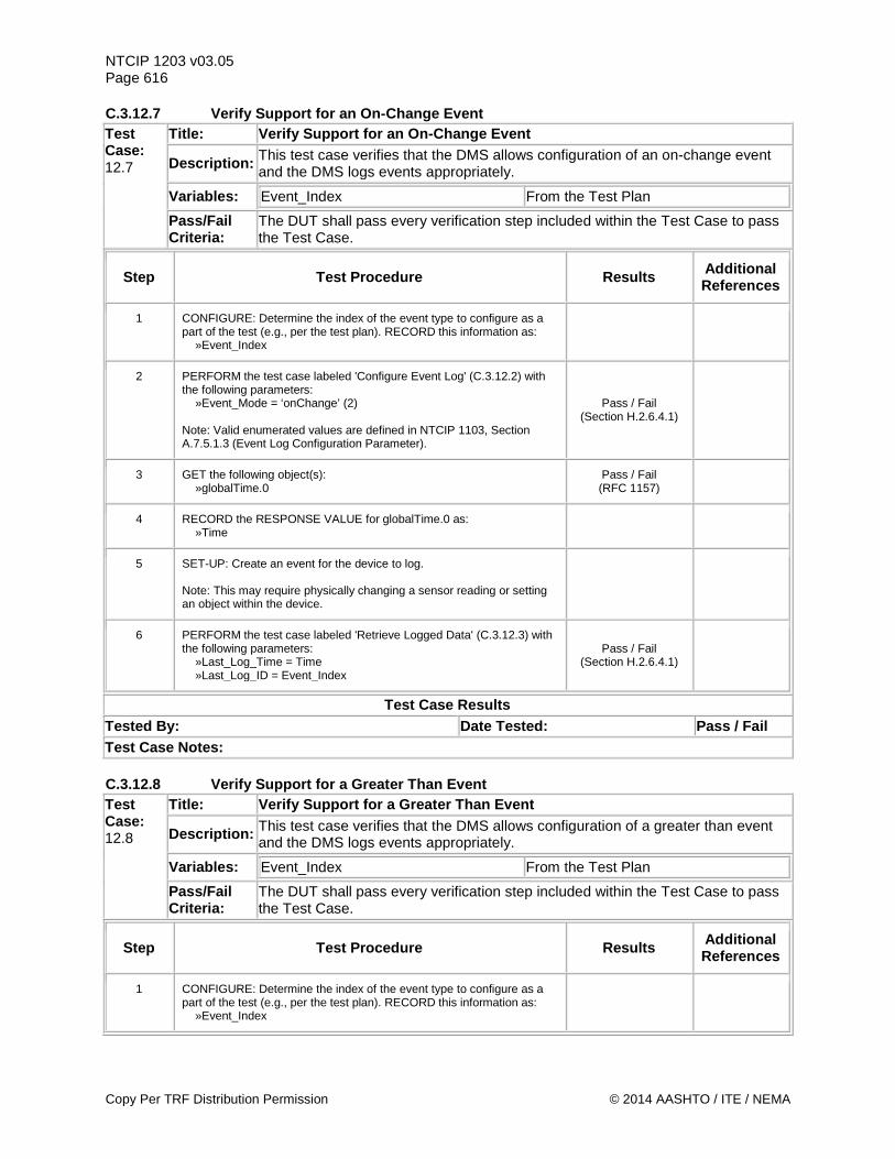
NTCIP 1203 v03.05 Page 616 C.3.12.7 Verify Support for an On-Change Event Test Case: 12.7
Title: Verify Support for an On-Change Event
Description: This test case verifies that the DMS allows configuration of an on-change event and the DMS logs events appropriately.
Variables: Event_Index From the Test Plan
Pass/Fail Criteria:
The DUT shall pass every verification step included within the Test Case to pass the Test Case.
Step Test Procedure Results Additional References
1 CONFIGURE: Determine the index of the event type to configure as a part of the test (e.g., per the test plan). RECORD this information as: »Event_Index
2 PERFORM the test case labeled 'Configure Event Log' (C.3.12.2) with the following parameters: »Event_Mode = ‘onChange’ (2) Note: Valid enumerated values are defined in NTCIP 1103, Section A.7.5.1.3 (Event Log Configuration Parameter).
Pass / Fail (Section H.2.6.4.1)
3 GET the following object(s): »globalTime.0
Pass / Fail (RFC 1157)
4 RECORD the RESPONSE VALUE for globalTime.0 as: »Time
5 SET-UP: Create an event for the device to log. Note: This may require physically changing a sensor reading or setting an object within the device.
6 PERFORM the test case labeled 'Retrieve Logged Data' (C.3.12.3) with the following parameters: »Last_Log_Time = Time »Last_Log_ID = Event_Index
Pass / Fail (Section H.2.6.4.1)
Test Case Results Tested By: Date Tested: Pass / Fail Test Case Notes: C.3.12.8 Verify Support for a Greater Than Event Test Case: 12.8
Title: Verify Support for a Greater Than Event
Description: This test case verifies that the DMS allows configuration of a greater than event and the DMS logs events appropriately.
Variables: Event_Index From the Test Plan
Pass/Fail Criteria:
The DUT shall pass every verification step included within the Test Case to pass the Test Case.
Step Test Procedure Results Additional References
1 CONFIGURE: Determine the index of the event type to configure as a part of the test (e.g., per the test plan). RECORD this information as: »Event_Index
Copy Per TRF Distribution Permission © 2014 AASHTO / ITE / NEMA
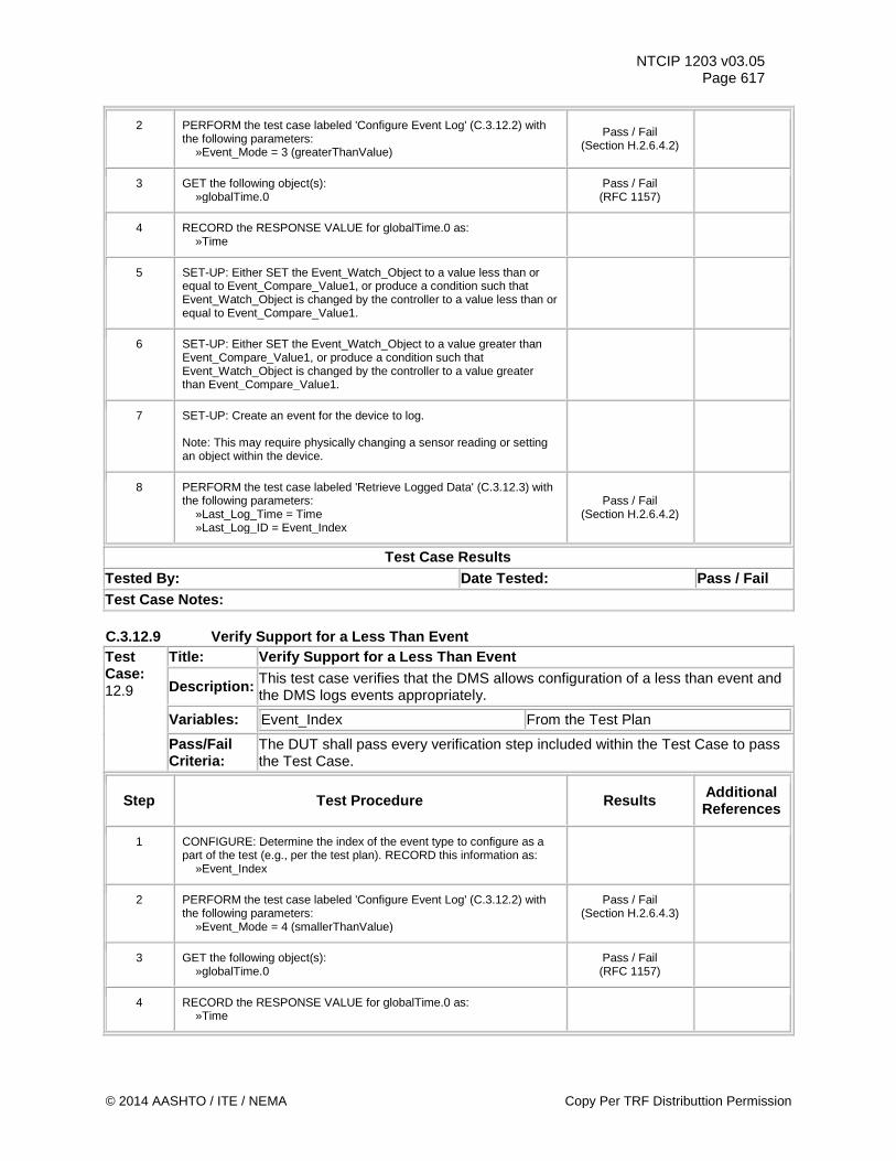
NTCIP 1203 v03.05 Page 617
2 PERFORM the test case labeled 'Configure Event Log' (C.3.12.2) with the following parameters: »Event_Mode = 3 (greaterThanValue)
Pass / Fail (Section H.2.6.4.2)
3 GET the following object(s): »globalTime.0
Pass / Fail (RFC 1157)
4 RECORD the RESPONSE VALUE for globalTime.0 as: »Time
5 SET-UP: Either SET the Event_Watch_Object to a value less than or equal to Event_Compare_Value1, or produce a condition such that Event_Watch_Object is changed by the controller to a value less than or equal to Event_Compare_Value1.
6 SET-UP: Either SET the Event_Watch_Object to a value greater than Event_Compare_Value1, or produce a condition such that Event_Watch_Object is changed by the controller to a value greater than Event_Compare_Value1.
7 SET-UP: Create an event for the device to log. Note: This may require physically changing a sensor reading or setting an object within the device.
8 PERFORM the test case labeled 'Retrieve Logged Data' (C.3.12.3) with the following parameters: »Last_Log_Time = Time »Last_Log_ID = Event_Index
Pass / Fail (Section H.2.6.4.2)
Test Case Results Tested By: Date Tested: Pass / Fail Test Case Notes: C.3.12.9 Verify Support for a Less Than Event Test Case: 12.9
Title: Verify Support for a Less Than Event
Description: This test case verifies that the DMS allows configuration of a less than event and the DMS logs events appropriately.
Variables: Event_Index From the Test Plan
Pass/Fail Criteria:
The DUT shall pass every verification step included within the Test Case to pass the Test Case.
Step Test Procedure Results Additional References
1 CONFIGURE: Determine the index of the event type to configure as a part of the test (e.g., per the test plan). RECORD this information as: »Event_Index
2 PERFORM the test case labeled 'Configure Event Log' (C.3.12.2) with the following parameters: »Event_Mode = 4 (smallerThanValue)
Pass / Fail (Section H.2.6.4.3)
3 GET the following object(s): »globalTime.0
Pass / Fail (RFC 1157)
4 RECORD the RESPONSE VALUE for globalTime.0 as: »Time
© 2014 AASHTO / ITE / NEMA Copy Per TRF Distributtion Permission
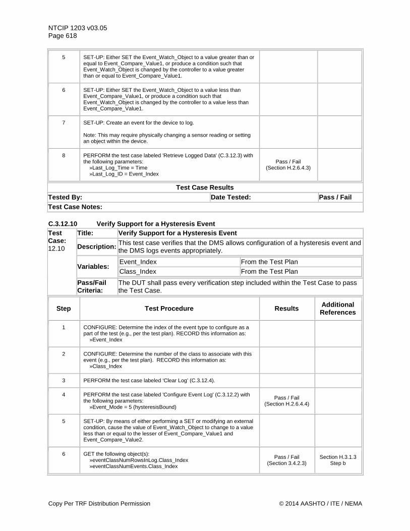
NTCIP 1203 v03.05 Page 618
5 SET-UP: Either SET the Event_Watch_Object to a value greater than or equal to Event_Compare_Value1, or produce a condition such that Event_Watch_Object is changed by the controller to a value greater than or equal to Event_Compare_Value1.
6 SET-UP: Either SET the Event_Watch_Object to a value less than Event_Compare_Value1, or produce a condition such that Event_Watch_Object is changed by the controller to a value less than Event_Compare_Value1.
7 SET-UP: Create an event for the device to log. Note: This may require physically changing a sensor reading or setting an object within the device.
8 PERFORM the test case labeled 'Retrieve Logged Data' (C.3.12.3) with the following parameters: »Last_Log_Time = Time »Last_Log_ID = Event_Index
Pass / Fail (Section H.2.6.4.3)
Test Case Results Tested By: Date Tested: Pass / Fail Test Case Notes: C.3.12.10 Verify Support for a Hysteresis Event Test Case: 12.10
Title: Verify Support for a Hysteresis Event
Description: This test case verifies that the DMS allows configuration of a hysteresis event and the DMS logs events appropriately.
Variables: Event_Index From the Test Plan
Class_Index From the Test Plan
Pass/Fail Criteria:
The DUT shall pass every verification step included within the Test Case to pass the Test Case.
Step Test Procedure Results Additional References
1 CONFIGURE: Determine the index of the event type to configure as a part of the test (e.g., per the test plan). RECORD this information as: »Event_Index
2 CONFIGURE: Determine the number of the class to associate with this event (e.g., per the test plan). RECORD this information as: »Class_Index
3 PERFORM the test case labeled ‘Clear Log’ (C.3.12.4).
4 PERFORM the test case labeled 'Configure Event Log' (C.3.12.2) with the following parameters: »Event_Mode = 5 (hysteresisBound)
Pass / Fail (Section H.2.6.4.4)
5 SET-UP: By means of either performing a SET or modifying an external condition, cause the value of Event_Watch_Object to change to a value less than or equal to the lesser of Event_Compare_Value1 and Event_Compare_Value2.
6 GET the following object(s): »eventClassNumRowsInLog.Class_Index »eventClassNumEvents.Class_Index
Pass / Fail (Section 3.4.2.3)
Section H.3.1.3 Step b
Copy Per TRF Distribution Permission © 2014 AASHTO / ITE / NEMA
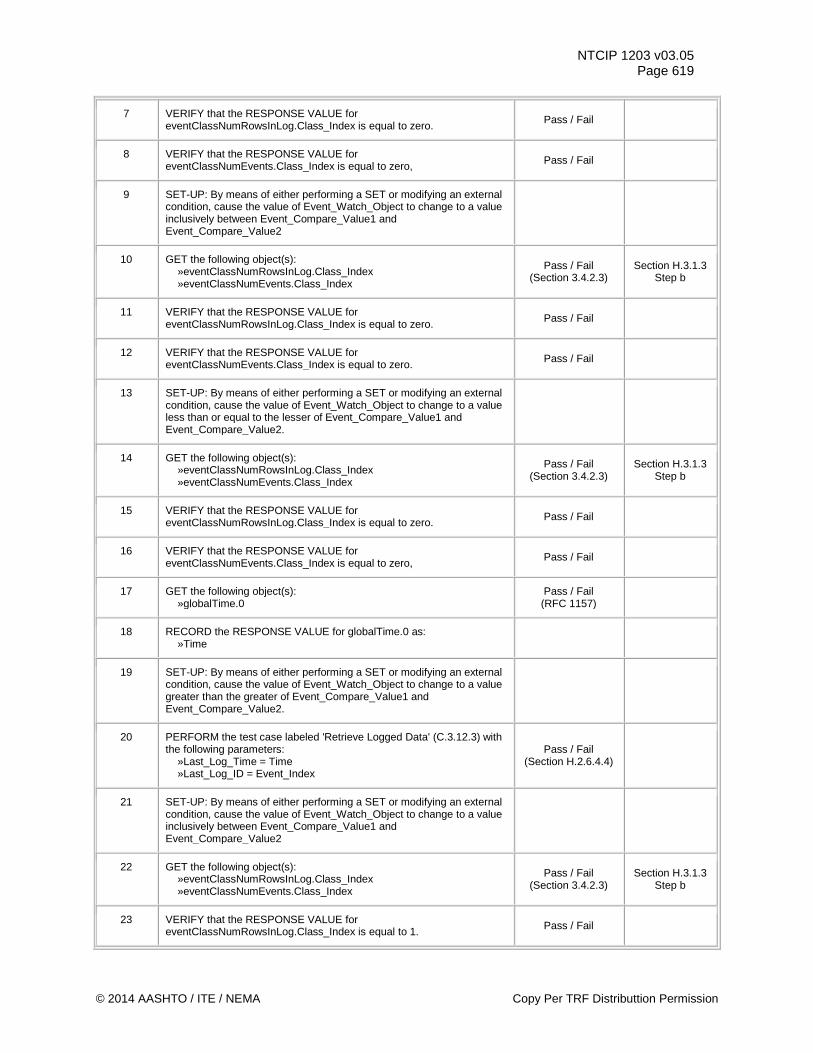
NTCIP 1203 v03.05 Page 619
7 VERIFY that the RESPONSE VALUE for eventClassNumRowsInLog.Class_Index is equal to zero. Pass / Fail
8 VERIFY that the RESPONSE VALUE for eventClassNumEvents.Class_Index is equal to zero, Pass / Fail
9 SET-UP: By means of either performing a SET or modifying an external condition, cause the value of Event_Watch_Object to change to a value inclusively between Event_Compare_Value1 and Event_Compare_Value2
10 GET the following object(s): »eventClassNumRowsInLog.Class_Index »eventClassNumEvents.Class_Index
Pass / Fail (Section 3.4.2.3)
Section H.3.1.3 Step b
11 VERIFY that the RESPONSE VALUE for eventClassNumRowsInLog.Class_Index is equal to zero. Pass / Fail
12 VERIFY that the RESPONSE VALUE for eventClassNumEvents.Class_Index is equal to zero. Pass / Fail
13 SET-UP: By means of either performing a SET or modifying an external condition, cause the value of Event_Watch_Object to change to a value less than or equal to the lesser of Event_Compare_Value1 and Event_Compare_Value2.
14 GET the following object(s): »eventClassNumRowsInLog.Class_Index »eventClassNumEvents.Class_Index
Pass / Fail (Section 3.4.2.3)
Section H.3.1.3 Step b
15 VERIFY that the RESPONSE VALUE for eventClassNumRowsInLog.Class_Index is equal to zero. Pass / Fail
16 VERIFY that the RESPONSE VALUE for eventClassNumEvents.Class_Index is equal to zero, Pass / Fail
17 GET the following object(s): »globalTime.0
Pass / Fail (RFC 1157)
18 RECORD the RESPONSE VALUE for globalTime.0 as: »Time
19 SET-UP: By means of either performing a SET or modifying an external condition, cause the value of Event_Watch_Object to change to a value greater than the greater of Event_Compare_Value1 and Event_Compare_Value2.
20 PERFORM the test case labeled 'Retrieve Logged Data' (C.3.12.3) with the following parameters: »Last_Log_Time = Time »Last_Log_ID = Event_Index
Pass / Fail (Section H.2.6.4.4)
21 SET-UP: By means of either performing a SET or modifying an external condition, cause the value of Event_Watch_Object to change to a value inclusively between Event_Compare_Value1 and Event_Compare_Value2
22 GET the following object(s): »eventClassNumRowsInLog.Class_Index »eventClassNumEvents.Class_Index
Pass / Fail (Section 3.4.2.3)
Section H.3.1.3 Step b
23 VERIFY that the RESPONSE VALUE for eventClassNumRowsInLog.Class_Index is equal to 1. Pass / Fail
© 2014 AASHTO / ITE / NEMA Copy Per TRF Distributtion Permission
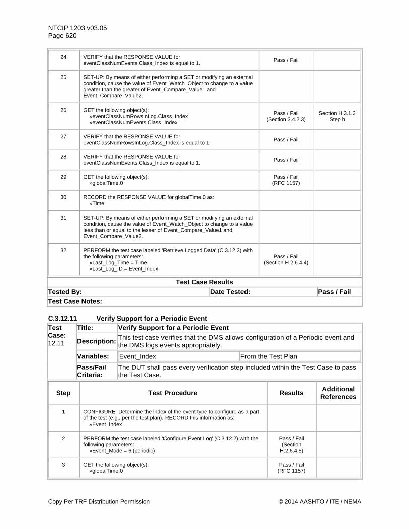
NTCIP 1203 v03.05 Page 620
24 VERIFY that the RESPONSE VALUE for eventClassNumEvents.Class_Index is equal to 1. Pass / Fail
25 SET-UP: By means of either performing a SET or modifying an external condition, cause the value of Event_Watch_Object to change to a value greater than the greater of Event_Compare_Value1 and Event_Compare_Value2.
26 GET the following object(s): »eventClassNumRowsInLog.Class_Index »eventClassNumEvents.Class_Index
Pass / Fail (Section 3.4.2.3)
Section H.3.1.3 Step b
27 VERIFY that the RESPONSE VALUE for eventClassNumRowsInLog.Class_Index is equal to 1. Pass / Fail
28 VERIFY that the RESPONSE VALUE for eventClassNumEvents.Class_Index is equal to 1. Pass / Fail
29 GET the following object(s): »globalTime.0
Pass / Fail (RFC 1157)
30 RECORD the RESPONSE VALUE for globalTime.0 as: »Time
31 SET-UP: By means of either performing a SET or modifying an external condition, cause the value of Event_Watch_Object to change to a value less than or equal to the lesser of Event_Compare_Value1 and Event_Compare_Value2.
32 PERFORM the test case labeled 'Retrieve Logged Data' (C.3.12.3) with the following parameters: »Last_Log_Time = Time »Last_Log_ID = Event_Index
Pass / Fail (Section H.2.6.4.4)
Test Case Results Tested By: Date Tested: Pass / Fail Test Case Notes: C.3.12.11 Verify Support for a Periodic Event Test Case: 12.11
Title: Verify Support for a Periodic Event
Description: This test case verifies that the DMS allows configuration of a Periodic event and the DMS logs events appropriately.
Variables: Event_Index From the Test Plan
Pass/Fail Criteria:
The DUT shall pass every verification step included within the Test Case to pass the Test Case.
Step Test Procedure Results Additional References
1 CONFIGURE: Determine the index of the event type to configure as a part of the test (e.g., per the test plan). RECORD this information as: »Event_Index
2 PERFORM the test case labeled 'Configure Event Log' (C.3.12.2) with the following parameters: »Event_Mode = 6 (periodic)
Pass / Fail (Section
H.2.6.4.5)
3 GET the following object(s): »globalTime.0
Pass / Fail (RFC 1157)
Copy Per TRF Distribution Permission © 2014 AASHTO / ITE / NEMA
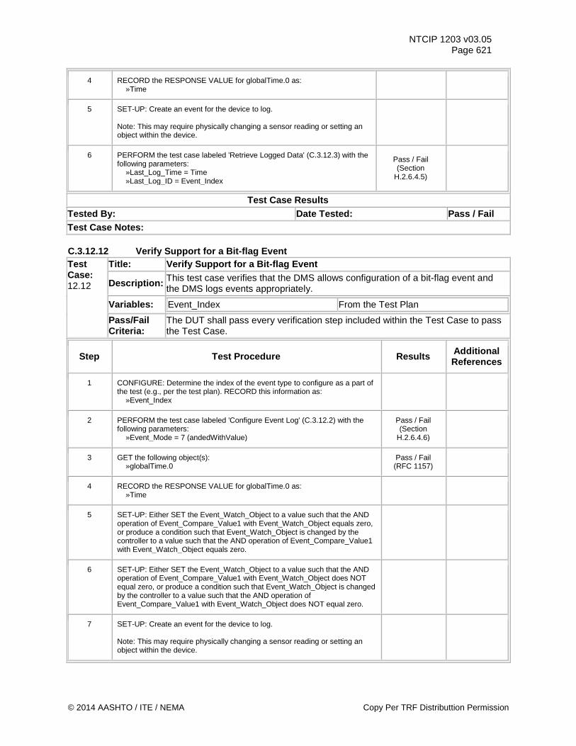
NTCIP 1203 v03.05 Page 621
4 RECORD the RESPONSE VALUE for globalTime.0 as: »Time
5 SET-UP: Create an event for the device to log. Note: This may require physically changing a sensor reading or setting an object within the device.
6 PERFORM the test case labeled 'Retrieve Logged Data' (C.3.12.3) with the following parameters: »Last_Log_Time = Time »Last_Log_ID = Event_Index
Pass / Fail (Section
H.2.6.4.5)
Test Case Results Tested By: Date Tested: Pass / Fail Test Case Notes: C.3.12.12 Verify Support for a Bit-flag Event Test Case: 12.12
Title: Verify Support for a Bit-flag Event
Description: This test case verifies that the DMS allows configuration of a bit-flag event and the DMS logs events appropriately.
Variables: Event_Index From the Test Plan
Pass/Fail Criteria:
The DUT shall pass every verification step included within the Test Case to pass the Test Case.
Step Test Procedure Results Additional References
1 CONFIGURE: Determine the index of the event type to configure as a part of the test (e.g., per the test plan). RECORD this information as: »Event_Index
2 PERFORM the test case labeled 'Configure Event Log' (C.3.12.2) with the following parameters: »Event_Mode = 7 (andedWithValue)
Pass / Fail (Section
H.2.6.4.6)
3 GET the following object(s): »globalTime.0
Pass / Fail (RFC 1157)
4 RECORD the RESPONSE VALUE for globalTime.0 as: »Time
5 SET-UP: Either SET the Event_Watch_Object to a value such that the AND operation of Event_Compare_Value1 with Event_Watch_Object equals zero, or produce a condition such that Event_Watch_Object is changed by the controller to a value such that the AND operation of Event_Compare_Value1 with Event_Watch_Object equals zero.
6 SET-UP: Either SET the Event_Watch_Object to a value such that the AND operation of Event_Compare_Value1 with Event_Watch_Object does NOT equal zero, or produce a condition such that Event_Watch_Object is changed by the controller to a value such that the AND operation of Event_Compare_Value1 with Event_Watch_Object does NOT equal zero.
7 SET-UP: Create an event for the device to log. Note: This may require physically changing a sensor reading or setting an object within the device.
© 2014 AASHTO / ITE / NEMA Copy Per TRF Distributtion Permission
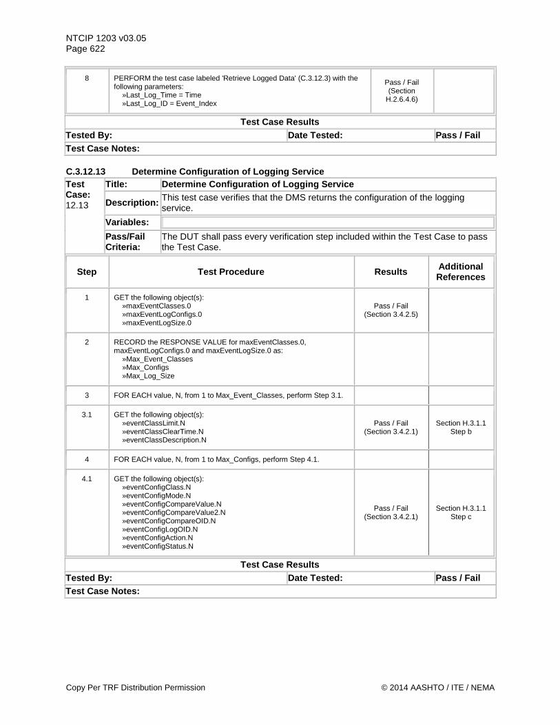
NTCIP 1203 v03.05 Page 622
8 PERFORM the test case labeled 'Retrieve Logged Data' (C.3.12.3) with the following parameters: »Last_Log_Time = Time »Last_Log_ID = Event_Index
Pass / Fail (Section
H.2.6.4.6)
Test Case Results Tested By: Date Tested: Pass / Fail Test Case Notes: C.3.12.13 Determine Configuration of Logging Service Test Case: 12.13
Title: Determine Configuration of Logging Service
Description: This test case verifies that the DMS returns the configuration of the logging service.
Variables:
Pass/Fail Criteria:
The DUT shall pass every verification step included within the Test Case to pass the Test Case.
Step Test Procedure Results Additional References
1 GET the following object(s): »maxEventClasses.0 »maxEventLogConfigs.0 »maxEventLogSize.0
Pass / Fail (Section 3.4.2.5)
2 RECORD the RESPONSE VALUE for maxEventClasses.0, maxEventLogConfigs.0 and maxEventLogSize.0 as: »Max_Event_Classes »Max_Configs »Max_Log_Size
3 FOR EACH value, N, from 1 to Max_Event_Classes, perform Step 3.1.
3.1 GET the following object(s): »eventClassLimit.N »eventClassClearTime.N »eventClassDescription.N
Pass / Fail (Section 3.4.2.1)
Section H.3.1.1 Step b
4 FOR EACH value, N, from 1 to Max_Configs, perform Step 4.1.
4.1 GET the following object(s): »eventConfigClass.N »eventConfigMode.N »eventConfigCompareValue.N »eventConfigCompareValue2.N »eventConfigCompareOID.N »eventConfigLogOID.N »eventConfigAction.N »eventConfigStatus.N
Pass / Fail (Section 3.4.2.1)
Section H.3.1.1 Step c
Test Case Results Tested By: Date Tested: Pass / Fail Test Case Notes:
Copy Per TRF Distribution Permission © 2014 AASHTO / ITE / NEMA
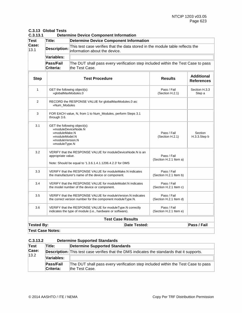
NTCIP 1203 v03.05 Page 623
C.3.13 Global Tests C.3.13.1 Determine Device Component Information Test Case: 13.1
Title: Determine Device Component Information
Description: This test case verifies that the data stored in the module table reflects the information about the device.
Variables:
Pass/Fail Criteria:
The DUT shall pass every verification step included within the Test Case to pass the Test Case.
Step Test Procedure Results Additional References
1 GET the following object(s): »globalMaxModules.0
Pass / Fail (Section H.2.1)
Section H.3.3 Step a
2 RECORD the RESPONSE VALUE for globalMaxModules.0 as: »Num_Modules
3 FOR EACH value, N, from 1 to Num_Modules, perform Steps 3.1 through 3.6.
3.1 GET the following object(s): »moduleDeviceNode.N »moduleMake.N »moduleModel.N »moduleVersion.N »moduleType.N
Pass / Fail (Section H.2.1)
Section H.3.3.Step b
3.2 VERIFY that the RESPONSE VALUE for moduleDeviceNode.N is an appropriate value. Note: Should be equal to '1.3.6.1.4.1.1206.4.2.3' for DMS
Pass / Fail (Section H.2.1 Item a)
3.3 VERIFY that the RESPONSE VALUE for moduleMake.N indicates the manufacturer's name of the device or component.
Pass / Fail (Section H.2.1 Item b)
3.4 VERIFY that the RESPONSE VALUE for moduleModel.N indicates the model number of the device or component.
Pass / Fail (Section H.2.1 Item c)
3.5 VERIFY that the RESPONSE VALUE for moduleVersion.N indicates the correct version number for the component moduleType.N.
Pass / Fail (Section H.2.1 Item d)
3.6 VERIFY that the RESPONSE VALUE for moduleType.N correctly indicates the type of module (i.e., hardware or software).
Pass / Fail (Section H.2.1 Item e)
Test Case Results Tested By: Date Tested: Pass / Fail Test Case Notes: C.3.13.2 Determine Supported Standards Test Case: 13.2
Title: Determine Supported Standards Description: This test case verifies that the DMS indicates the standards that it supports. Variables:
Pass/Fail Criteria:
The DUT shall pass every verification step included within the Test Case to pass the Test Case.
© 2014 AASHTO / ITE / NEMA Copy Per TRF Distributtion Permission
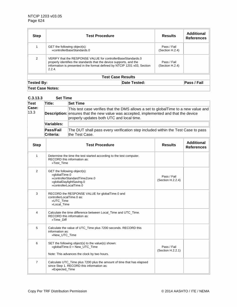
NTCIP 1203 v03.05 Page 624
Step Test Procedure Results Additional References
1 GET the following object(s): »controllerBaseStandards.0
Pass / Fail (Section H.2.4)
2 VERIFY that the RESPONSE VALUE for controllerBaseStandards.0 properly identifies the standards that the device supports, and the information is presented in the format defined by NTCIP 1201 v03, Section 2.2.4.
Pass / Fail (Section H.2.4)
Test Case Results Tested By: Date Tested: Pass / Fail Test Case Notes: C.3.13.3 Set Time Test Case: 13.3
Title: Set Time
Description: This test case verifies that the DMS allows a set to globalTime to a new value and ensures that the new value was accepted, implemented and that the device properly updates both UTC and local time.
Variables:
Pass/Fail Criteria:
The DUT shall pass every verification step included within the Test Case to pass the Test Case.
Step Test Procedure Results Additional References
1 Determine the time the test started according to the test computer. RECORD this information as: »Test_Time
2 GET the following object(s): »globalTime.0 »controllerStandardTimeZone.0 »globalDaylightSaving.0 »controllerLocalTime.0
Pass / Fail (Section H.2.2.4)
3 RECORD the RESPONSE VALUE for globalTime.0 and controllerLocalTime.0 as: »UTC_Time »Local_Time
4 Calculate the time difference between Local_Time and UTC_Time. RECORD this information as: »Time_Diff
5 Calculate the value of UTC_Time plus 7200 seconds. RECORD this information as: »New_UTC_Time
6 SET the following object(s) to the value(s) shown: »globalTime.0 = New_UTC_Time Note: This advances the clock by two hours.
Pass / Fail (Section H.2.2.1)
7 Calculate UTC_Time plus 7200 plus the amount of time that has elapsed since Step 1. RECORD this information as: »Expected_Time
Copy Per TRF Distribution Permission © 2014 AASHTO / ITE / NEMA
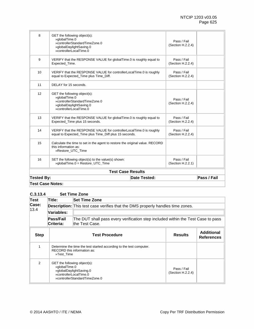
NTCIP 1203 v03.05 Page 625
8 GET the following object(s): »globalTime.0 »controllerStandardTimeZone.0 »globalDaylightSaving.0 »controllerLocalTime.0
Pass / Fail (Section H.2.2.4)
9 VERIFY that the RESPONSE VALUE for globalTime.0 is roughly equal to Expected_Time.
Pass / Fail (Section H.2.2.4)
10 VERIFY that the RESPONSE VALUE for controllerLocalTime.0 is roughly equal to Expected_Time plus Time_Diff.
Pass / Fail (Section H.2.2.4)
11 DELAY for 15 seconds.
12 GET the following object(s): »globalTime.0 »controllerStandardTimeZone.0 »globalDaylightSaving.0 »controllerLocalTime.0
Pass / Fail (Section H.2.2.4)
13 VERIFY that the RESPONSE VALUE for globalTime.0 is roughly equal to Expected_Time plus 15 seconds.
Pass / Fail (Section H.2.2.4)
14 VERIFY that the RESPONSE VALUE for controllerLocalTime.0 is roughly equal to Expected_Time plus Time_Diff plus 15 seconds.
Pass / Fail (Section H.2.2.4)
15 Calculate the time to set in the agent to restore the original value. RECORD this information as: »Restore_UTC_Time
16 SET the following object(s) to the value(s) shown: »globalTime.0 = Restore_UTC_Time
Pass / Fail (Section H.2.2.1)
Test Case Results Tested By: Date Tested: Pass / Fail Test Case Notes: C.3.13.4 Set Time Zone Test Case: 13.4
Title: Set Time Zone Description: This test case verifies that the DMS properly handles time zones. Variables:
Pass/Fail Criteria:
The DUT shall pass every verification step included within the Test Case to pass the Test Case.
Step Test Procedure Results Additional References
1 Determine the time the test started according to the test computer. RECORD this information as: »Test_Time
2 GET the following object(s): »globalTime.0 »globalDaylightSaving.0 »controllerLocalTime.0 »controllerStandardTimeZone.0
Pass / Fail (Section H.2.2.4)
© 2014 AASHTO / ITE / NEMA Copy Per TRF Distributtion Permission
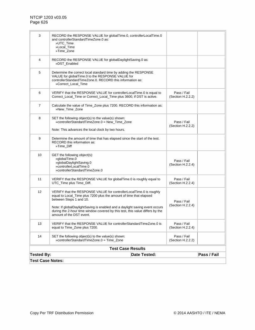
NTCIP 1203 v03.05 Page 626
3 RECORD the RESPONSE VALUE for globalTime.0, controllerLocalTime.0 and controllerStandardTimeZone.0 as: »UTC_Time »Local_Time »Time_Zone
4 RECORD the RESPONSE VALUE for globalDaylightSaving.0 as: »DST_Enabled
5 Determine the correct local standard time by adding the RESPONSE VALUE for globalTime.0 to the RESPONSE VALUE for controllerStandardTimeZone.0. RECORD this information as: »Correct_Local_Time
6 VERIFY that the RESPONSE VALUE for controllerLocalTime.0 is equal to Correct_Local_Time or Correct_Local_Time plus 3600, if DST is active.
Pass / Fail (Section H.2.2.2)
7 Calculate the value of Time_Zone plus 7200. RECORD this information as: »New_Time_Zone
8 SET the following object(s) to the value(s) shown: »controllerStandardTimeZone.0 = New_Time_Zone Note: This advances the local clock by two hours.
Pass / Fail (Section H.2.2.2)
9 Determine the amount of time that has elapsed since the start of the test. RECORD this information as: »Time_Diff
10 GET the following object(s): »globalTime.0 »globalDaylightSaving.0 »controllerLocalTime.0 »controllerStandardTimeZone.0
Pass / Fail (Section H.2.2.4)
11 VERIFY that the RESPONSE VALUE for globalTime.0 is roughly equal to UTC_Time plus Time_Diff.
Pass / Fail (Section H.2.2.4)
12 VERIFY that the RESPONSE VALUE for controllerLocalTime.0 is roughly equal to Local_Time plus 7200 plus the amount of time that elapsed between Steps 1 and 10. Note: If globalDaylightSaving is enabled and a daylight saving event occurs during the 2-hour time window covered by this test, this value differs by the amount of the DST event.
Pass / Fail (Section H.2.2.4)
13 VERIFY that the RESPONSE VALUE for controllerStandardTimeZone.0 is equal to Time_Zone plus 7200.
Pass / Fail (Section H.2.2.4)
14 SET the following object(s) to the value(s) shown: »controllerStandardTimeZone.0 = Time_Zone
Pass / Fail (Section H.2.2.2)
Test Case Results Tested By: Date Tested: Pass / Fail Test Case Notes:
Copy Per TRF Distribution Permission © 2014 AASHTO / ITE / NEMA
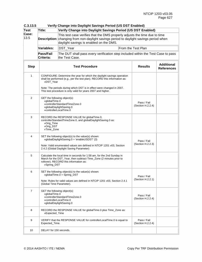
NTCIP 1203 v03.05 Page 627
C.3.13.5 Verify Change into Daylight Savings Period (US DST Enabled) Test Case: 13.5
Title: Verify Change into Daylight Savings Period (US DST Enabled)
Description: This test case verifies that the DMS properly adjusts the time due to time changing from non-daylight savings period to daylight savings period when daylight savings is enabled on the DMS.
Variables: DST_Year From the Test Plan
Pass/Fail Criteria:
The DUT shall pass every verification step included within the Test Case to pass the Test Case.
Step Test Procedure Results Additional References
1 CONFIGURE: Determine the year for which the daylight savings operation shall be performed (e.g., per the test plan). RECORD this information as: »DST_Year Note: The periods during which DST is in effect were changed in 2007. This test procedure is only valid for years 2007 and higher.
2 GET the following object(s): »globalTime.0 »controllerStandardTimeZone.0 »globalDaylightSaving.0 »controllerLocalTime.0
Pass / Fail (Section H.2.2.4)
3 RECORD the RESPONSE VALUE for globalTime.0, controllerStandardTimeZone.0, and globalDaylightSaving.0 as: »Orig_Time »Orig_DST »Time_Zone
4 SET the following object(s) to the value(s) shown: »globalDaylightSaving.0 = 'enableUSDST' (3) Note: Valid enumerated values are defined in NTCIP 1201 v03, Section 2.4.2 (Global Daylight Saving Parameter)
Pass / Fail (Section H.2.2.3)
5 Calculate the local time in seconds for 1:58 am, for the 2nd Sunday in March for the DST_Year, then subtract Time_Zone (2 minutes prior to rollover). RECORD this information as: »Spring_DST
6 SET the following object(s) to the value(s) shown: »globalTime.0 = Spring_DST Note: Rules for valid values are defined in NTCIP 1201 v03, Section 2.4.1 (Global Time Parameter).
Pass / Fail (Section H.2.2.1)
7 GET the following object(s): »globalTime.0 »controllerStandardTimeZone.0 »controllerLocalTime.0 »globalDaylightSaving.0
Pass / Fail (Section H.2.2.4)
8 RECORD the RESPONSE VALUE for globalTime.0 plus Time_Zone as: »Expected_Time
9 VERIFY that the RESPONSE VALUE for controllerLocalTime.0 is equal to Expected_Time.
Pass / Fail (Section H.2.2.4)
10 DELAY for 150 seconds.
© 2014 AASHTO / ITE / NEMA Copy Per TRF Distributtion Permission
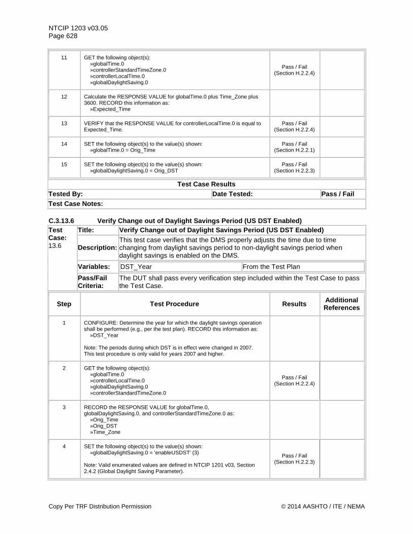
NTCIP 1203 v03.05 Page 628
11 GET the following object(s): »globalTime.0 »controllerStandardTimeZone.0 »controllerLocalTime.0 »globalDaylightSaving.0
Pass / Fail (Section H.2.2.4)
12 Calculate the RESPONSE VALUE for globalTime.0 plus Time_Zone plus 3600. RECORD this information as: »Expected_Time
13 VERIFY that the RESPONSE VALUE for controllerLocalTime.0 is equal to Expected_Time.
Pass / Fail (Section H.2.2.4)
14 SET the following object(s) to the value(s) shown: »globalTime.0 = Orig_Time
Pass / Fail (Section H.2.2.1)
15 SET the following object(s) to the value(s) shown: »globalDaylightSaving.0 = Orig_DST
Pass / Fail (Section H.2.2.3)
Test Case Results Tested By: Date Tested: Pass / Fail Test Case Notes: C.3.13.6 Verify Change out of Daylight Savings Period (US DST Enabled) Test Case: 13.6
Title: Verify Change out of Daylight Savings Period (US DST Enabled)
Description: This test case verifies that the DMS properly adjusts the time due to time changing from daylight savings period to non-daylight savings period when daylight savings is enabled on the DMS.
Variables: DST_Year From the Test Plan
Pass/Fail Criteria:
The DUT shall pass every verification step included within the Test Case to pass the Test Case.
Step Test Procedure Results Additional References
1 CONFIGURE: Determine the year for which the daylight savings operation shall be performed (e.g., per the test plan). RECORD this information as: »DST_Year Note: The periods during which DST is in effect were changed in 2007. This test procedure is only valid for years 2007 and higher.
2 GET the following object(s): »globalTime.0 »controllerLocalTime.0 »globalDaylightSaving.0 »controllerStandardTimeZone.0
Pass / Fail (Section H.2.2.4)
3 RECORD the RESPONSE VALUE for globalTime.0, globalDaylightSaving.0, and controllerStandardTimeZone.0 as: »Orig_Time »Orig_DST »Time_Zone
4 SET the following object(s) to the value(s) shown: »globalDaylightSaving.0 = 'enableUSDST' (3) Note: Valid enumerated values are defined in NTCIP 1201 v03, Section 2.4.2 (Global Daylight Saving Parameter).
Pass / Fail (Section H.2.2.3)
Copy Per TRF Distribution Permission © 2014 AASHTO / ITE / NEMA
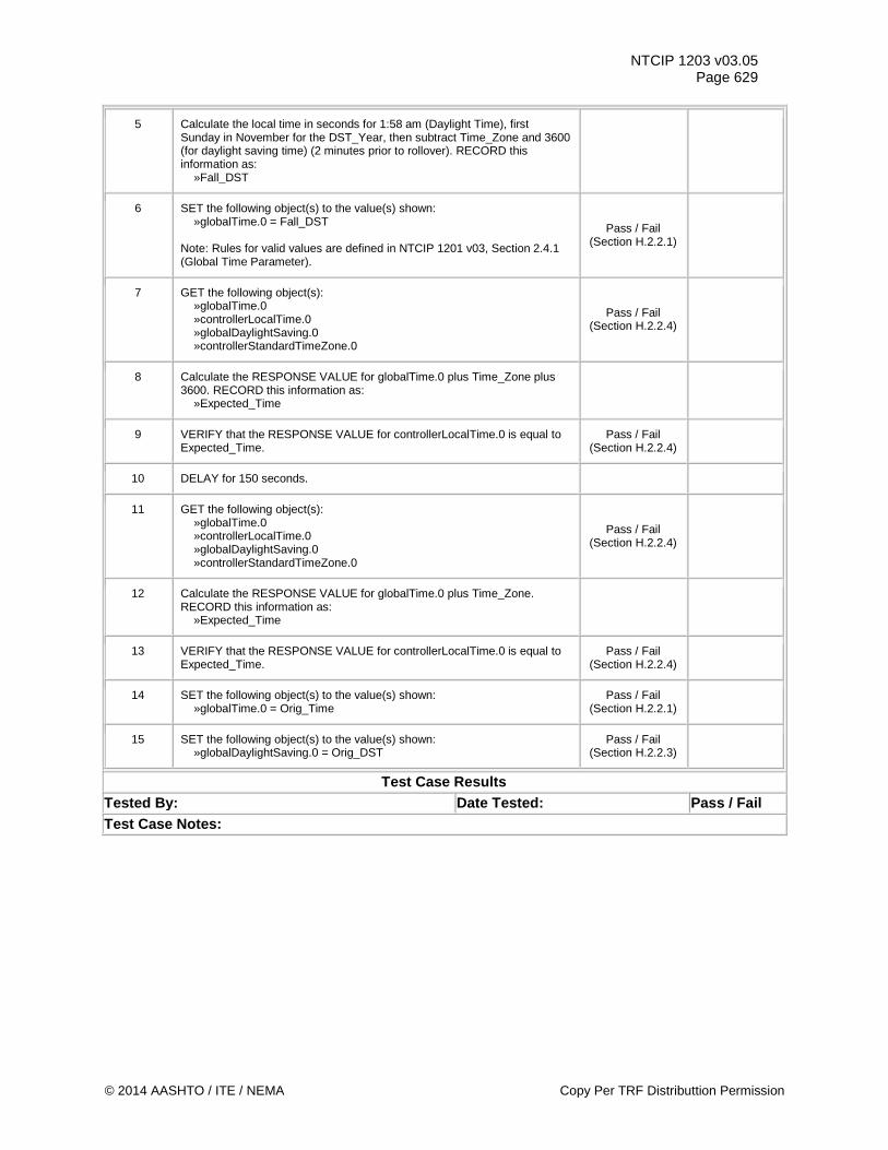
NTCIP 1203 v03.05 Page 629
5 Calculate the local time in seconds for 1:58 am (Daylight Time), first Sunday in November for the DST_Year, then subtract Time_Zone and 3600 (for daylight saving time) (2 minutes prior to rollover). RECORD this information as: »Fall_DST
6 SET the following object(s) to the value(s) shown: »globalTime.0 = Fall_DST Note: Rules for valid values are defined in NTCIP 1201 v03, Section 2.4.1 (Global Time Parameter).
Pass / Fail (Section H.2.2.1)
7 GET the following object(s): »globalTime.0 »controllerLocalTime.0 »globalDaylightSaving.0 »controllerStandardTimeZone.0
Pass / Fail (Section H.2.2.4)
8 Calculate the RESPONSE VALUE for globalTime.0 plus Time_Zone plus 3600. RECORD this information as: »Expected_Time
9 VERIFY that the RESPONSE VALUE for controllerLocalTime.0 is equal to Expected_Time.
Pass / Fail (Section H.2.2.4)
10 DELAY for 150 seconds.
11 GET the following object(s): »globalTime.0 »controllerLocalTime.0 »globalDaylightSaving.0 »controllerStandardTimeZone.0
Pass / Fail (Section H.2.2.4)
12 Calculate the RESPONSE VALUE for globalTime.0 plus Time_Zone. RECORD this information as: »Expected_Time
13 VERIFY that the RESPONSE VALUE for controllerLocalTime.0 is equal to Expected_Time.
Pass / Fail (Section H.2.2.4)
14 SET the following object(s) to the value(s) shown: »globalTime.0 = Orig_Time
Pass / Fail (Section H.2.2.1)
15 SET the following object(s) to the value(s) shown: »globalDaylightSaving.0 = Orig_DST
Pass / Fail (Section H.2.2.3)
Test Case Results Tested By: Date Tested: Pass / Fail Test Case Notes:
© 2014 AASHTO / ITE / NEMA Copy Per TRF Distributtion Permission
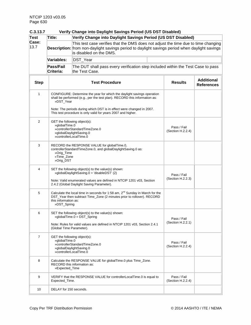
NTCIP 1203 v03.05 Page 630 C.3.13.7 Verify Change into Daylight Savings Period (US DST Disabled) Test Case: 13.7
Title: Verify Change into Daylight Savings Period (US DST Disabled)
Description: This test case verifies that the DMS does not adjust the time due to time changing from non-daylight savings period to daylight savings period when daylight savings is disabled on the DMS.
Variables: DST_Year
Pass/Fail Criteria:
The DUT shall pass every verification step included within the Test Case to pass the Test Case.
Step Test Procedure Results Additional References
1 CONFIGURE: Determine the year for which the daylight savings operation shall be performed (e.g., per the test plan). RECORD this information as: »DST_Year Note: The periods during which DST is in effect were changed in 2007. This test procedure is only valid for years 2007 and higher.
2 GET the following object(s): »globalTime.0 »controllerStandardTimeZone.0 »globalDaylightSaving.0 »controllerLocalTime.0
Pass / Fail (Section H.2.2.4)
3 RECORD the RESPONSE VALUE for globalTime.0, controllerStandardTimeZone.0, and globalDaylightSaving.0 as: »Orig_Time »Time_Zone »Orig_DST
4 SET the following object(s) to the value(s) shown: »globalDaylightSaving.0 = 'disableDST' (2) Note: Valid enumerated values are defined in NTCIP 1201 v03, Section 2.4.2 (Global Daylight Saving Parameter).
Pass / Fail (Section H.2.2.3)
5 Calculate the local time in seconds for 1:58 am, 2nd Sunday in March for the DST_Year then subtract Time_Zone (2 minutes prior to rollover). RECORD this information as: »DST_Spring
6 SET the following object(s) to the value(s) shown: »globalTime.0 = DST_Spring Note: Rules for valid values are defined in NTCIP 1201 v03, Section 2.4.1 (Global Time Parameter).
Pass / Fail (Section H.2.2.1)
7 GET the following object(s): »globalTime.0 »controllerStandardTimeZone.0 »globalDaylightSaving.0 »controllerLocalTime.0
Pass / Fail (Section H.2.2.4)
8 Calculate the RESPONSE VALUE for globalTime.0 plus Time_Zone. RECORD this information as: »Expected_Time
9 VERIFY that the RESPONSE VALUE for controllerLocalTime.0 is equal to Expected_Time.
Pass / Fail (Section H.2.2.4)
10 DELAY for 150 seconds.
Copy Per TRF Distribution Permission © 2014 AASHTO / ITE / NEMA
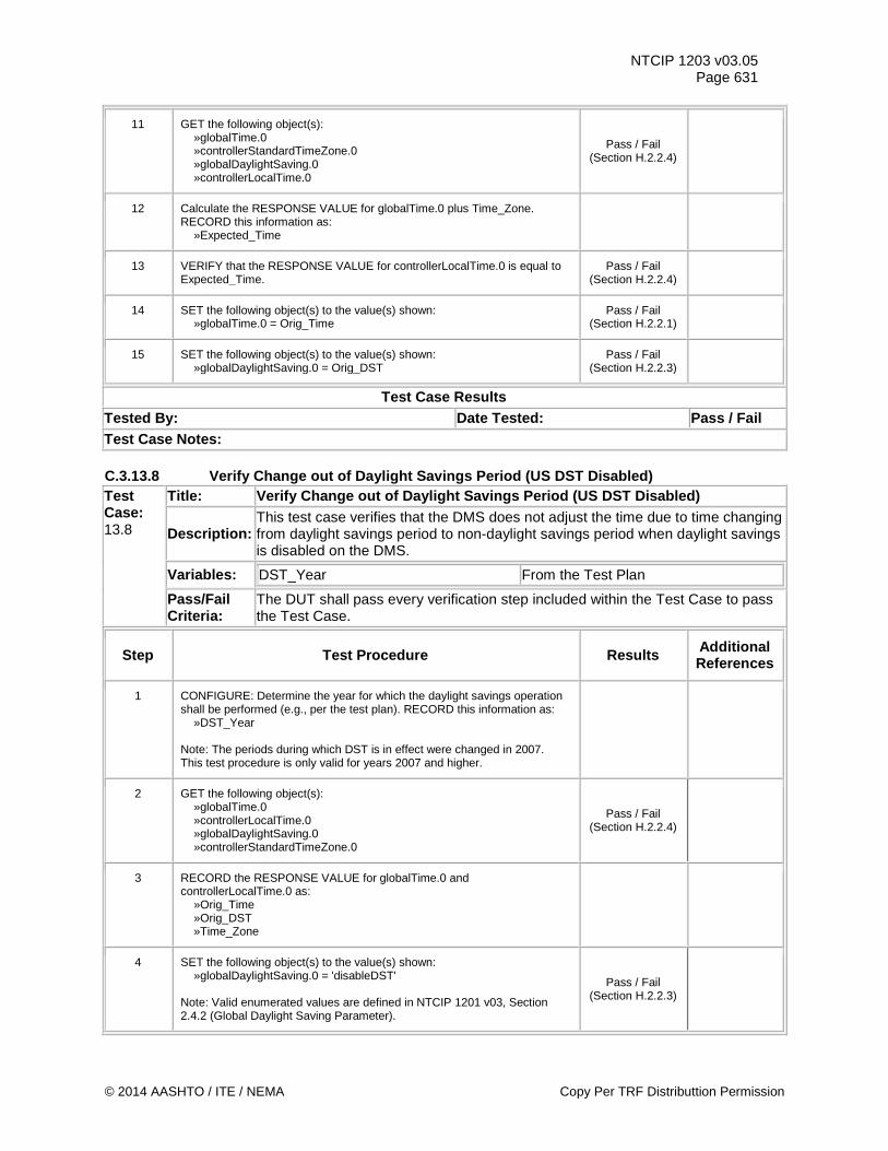
NTCIP 1203 v03.05 Page 631
11 GET the following object(s): »globalTime.0 »controllerStandardTimeZone.0 »globalDaylightSaving.0 »controllerLocalTime.0
Pass / Fail (Section H.2.2.4)
12 Calculate the RESPONSE VALUE for globalTime.0 plus Time_Zone. RECORD this information as: »Expected_Time
13 VERIFY that the RESPONSE VALUE for controllerLocalTime.0 is equal to Expected_Time.
Pass / Fail (Section H.2.2.4)
14 SET the following object(s) to the value(s) shown: »globalTime.0 = Orig_Time
Pass / Fail (Section H.2.2.1)
15 SET the following object(s) to the value(s) shown: »globalDaylightSaving.0 = Orig_DST
Pass / Fail (Section H.2.2.3)
Test Case Results Tested By: Date Tested: Pass / Fail Test Case Notes: C.3.13.8 Verify Change out of Daylight Savings Period (US DST Disabled) Test Case: 13.8
Title: Verify Change out of Daylight Savings Period (US DST Disabled)
Description: This test case verifies that the DMS does not adjust the time due to time changing from daylight savings period to non-daylight savings period when daylight savings is disabled on the DMS.
Variables: DST_Year From the Test Plan
Pass/Fail Criteria:
The DUT shall pass every verification step included within the Test Case to pass the Test Case.
Step Test Procedure Results Additional References
1 CONFIGURE: Determine the year for which the daylight savings operation shall be performed (e.g., per the test plan). RECORD this information as: »DST_Year Note: The periods during which DST is in effect were changed in 2007. This test procedure is only valid for years 2007 and higher.
2 GET the following object(s): »globalTime.0 »controllerLocalTime.0 »globalDaylightSaving.0 »controllerStandardTimeZone.0
Pass / Fail (Section H.2.2.4)
3 RECORD the RESPONSE VALUE for globalTime.0 and controllerLocalTime.0 as: »Orig_Time »Orig_DST »Time_Zone
4 SET the following object(s) to the value(s) shown: »globalDaylightSaving.0 = 'disableDST' Note: Valid enumerated values are defined in NTCIP 1201 v03, Section 2.4.2 (Global Daylight Saving Parameter).
Pass / Fail (Section H.2.2.3)
© 2014 AASHTO / ITE / NEMA Copy Per TRF Distributtion Permission
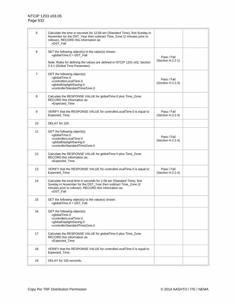
NTCIP 1203 v03.05 Page 632
5 Calculate the time in seconds for 12:58 am (Standard Time), first Sunday in November for the DST_Year then subtract Time_Zone (2 minutes prior to rollover). RECORD this information as: »DST_Fall
6 SET the following object(s) to the value(s) shown: »globalTime.0 = DST_Fall Note: Rules for defining the values are defined in NTCIP 1201 v03, Section 2.4.1 (Global Time Parameter).
Pass / Fail (Section H.2.2.1)
7 GET the following object(s): »globalTime.0 »controllerLocalTime.0 »globalDaylightSaving.0 »controllerStandardTimeZone.0
Pass / Fail (Section H.2.2.4)
8 Calculate the RESPONSE VALUE for globalTime.0 plus Time_Zone. RECORD this information as: »Expected_Time
9 VERIFY that the RESPONSE VALUE for controllerLocalTime.0 is equal to Expected_Time.
Pass / Fail (Section H.2.2.4)
10 DELAY for 150 .
11 GET the following object(s): »globalTime.0 »controllerLocalTime.0 »globalDaylightSaving.0 »controllerStandardTimeZone.0
Pass / Fail (Section H.2.2.4)
12 Calculate the RESPONSE VALUE for globalTime.0 plus Time_Zone. RECORD this information as: »Expected_Time
13 VERIFY that the RESPONSE VALUE for controllerLocalTime.0 is equal to Expected_Time.
Pass / Fail (Section H.2.2.4)
14 Calculate the local time in seconds for 1:58 am (Standard Time), first Sunday in November for the DST_Year then subtract Time_Zone (2 minutes prior to rollover). RECORD this information as: »DST_Fall
15 SET the following object(s) to the value(s) shown: »globalTime.0 = DST_Fall
16 GET the following object(s): »globalTime.0 »controllerLocalTime.0 »globalDaylightSaving.0 »controllerStandardTimeZone.0
17 Calculate the RESPONSE VALUE for globalTime.0 plus Time_Zone. RECORD this information as: »Expected_Time
18 VERIFY that the RESPONSE VALUE for controllerLocalTime.0 is equal to Expected_Time.
19 DELAY for 150 seconds.
Copy Per TRF Distribution Permission © 2014 AASHTO / ITE / NEMA
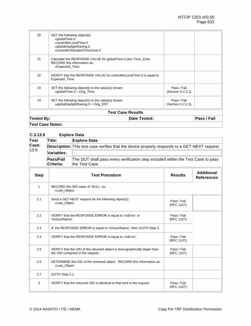
NTCIP 1203 v03.05 Page 633
20 GET the following object(s): »globalTime.0 »controllerLocalTime.0 »globalDaylightSaving.0 »controllerStandardTimeZone.0
21 Calculate the RESPONSE VALUE for globalTime.0 plus Time_Zone. RECORD this information as: »Expected_Time
22 VERIFY that the RESPONSE VALUE for controllerLocalTime.0 is equal to Expected_Time.
23 SET the following object(s) to the value(s) shown: »globalTime.0 = Orig_Time
Pass / Fail (Section H.2.2.1)
24 SET the following object(s) to the value(s) shown: »globalDaylightSaving.0 = Orig_DST
Pass / Fail (Section H.2.2.3)
Test Case Results Tested By: Date Tested: Pass / Fail Test Case Notes: C.3.13.9 Explore Data Test Case: 13.9
Title: Explore Data Description: This test case verifies that the device properly responds to a GET-NEXT request. Variables:
Pass/Fail Criteria:
The DUT shall pass every verification step included within the Test Case to pass the Test Case.
Step Test Procedure Results Additional References
1 RECORD the OID value of ‘NULL’ as: »Last_Object
2.1 Send a GET-NEXT request for the following object(s): »Last_Object
Pass / Fail (RFC 1157)
2.2 VERIFY that the RESPONSE ERROR is equal to ‘noError’ or ‘noSuchName’.
Pass / Fail (RFC 1157)
2.3 IF the RESPONSE ERROR is equal to ‘noSuchName’, then GOTO Step 3
2.4 VERIFY that the RESPONSE ERROR is equal to ‘noError’. Pass / Fail (RFC 1157)
2.5 VERIFY that the OID of the returned object is lexicographically larger than the OID contained in the request.
Pass / Fail (RFC 1157)
2.6 DETERMINE the OID of the retrieved object. RECORD this information as: »Last_Object
2.7 GOTO Step 2.1.
3 VERIFY that the returned OID is identical to that sent in the request. Pass / Fail (RFC 1157)
© 2014 AASHTO / ITE / NEMA Copy Per TRF Distributtion Permission
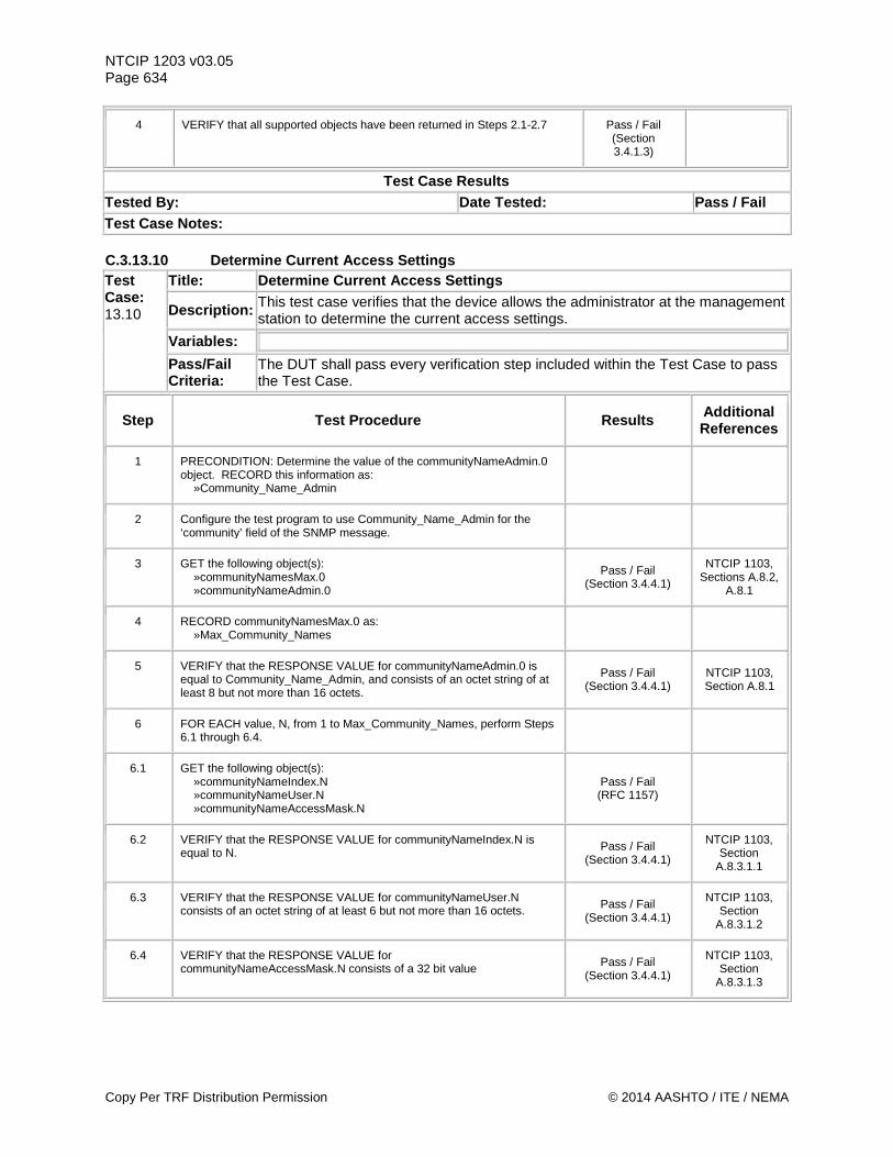
NTCIP 1203 v03.05 Page 634
4 VERIFY that all supported objects have been returned in Steps 2.1-2.7 Pass / Fail (Section 3.4.1.3)
Test Case Results Tested By: Date Tested: Pass / Fail Test Case Notes: C.3.13.10 Determine Current Access Settings Test Case: 13.10
Title: Determine Current Access Settings
Description: This test case verifies that the device allows the administrator at the management station to determine the current access settings.
Variables:
Pass/Fail Criteria:
The DUT shall pass every verification step included within the Test Case to pass the Test Case.
Step Test Procedure Results Additional References
1 PRECONDITION: Determine the value of the communityNameAdmin.0 object. RECORD this information as: »Community_Name_Admin
2 Configure the test program to use Community_Name_Admin for the ‘community’ field of the SNMP message.
3 GET the following object(s): »communityNamesMax.0 »communityNameAdmin.0
Pass / Fail (Section 3.4.4.1)
NTCIP 1103, Sections A.8.2,
A.8.1
4 RECORD communityNamesMax.0 as: »Max_Community_Names
5 VERIFY that the RESPONSE VALUE for communityNameAdmin.0 is equal to Community_Name_Admin, and consists of an octet string of at least 8 but not more than 16 octets.
Pass / Fail (Section 3.4.4.1)
NTCIP 1103, Section A.8.1
6 FOR EACH value, N, from 1 to Max_Community_Names, perform Steps 6.1 through 6.4.
6.1 GET the following object(s): »communityNameIndex.N »communityNameUser.N »communityNameAccessMask.N
Pass / Fail (RFC 1157)
6.2 VERIFY that the RESPONSE VALUE for communityNameIndex.N is equal to N. Pass / Fail
(Section 3.4.4.1)
NTCIP 1103, Section
A.8.3.1.1
6.3 VERIFY that the RESPONSE VALUE for communityNameUser.N consists of an octet string of at least 6 but not more than 16 octets. Pass / Fail
(Section 3.4.4.1)
NTCIP 1103, Section
A.8.3.1.2
6.4 VERIFY that the RESPONSE VALUE for communityNameAccessMask.N consists of a 32 bit value Pass / Fail
(Section 3.4.4.1)
NTCIP 1103, Section
A.8.3.1.3
Copy Per TRF Distribution Permission © 2014 AASHTO / ITE / NEMA
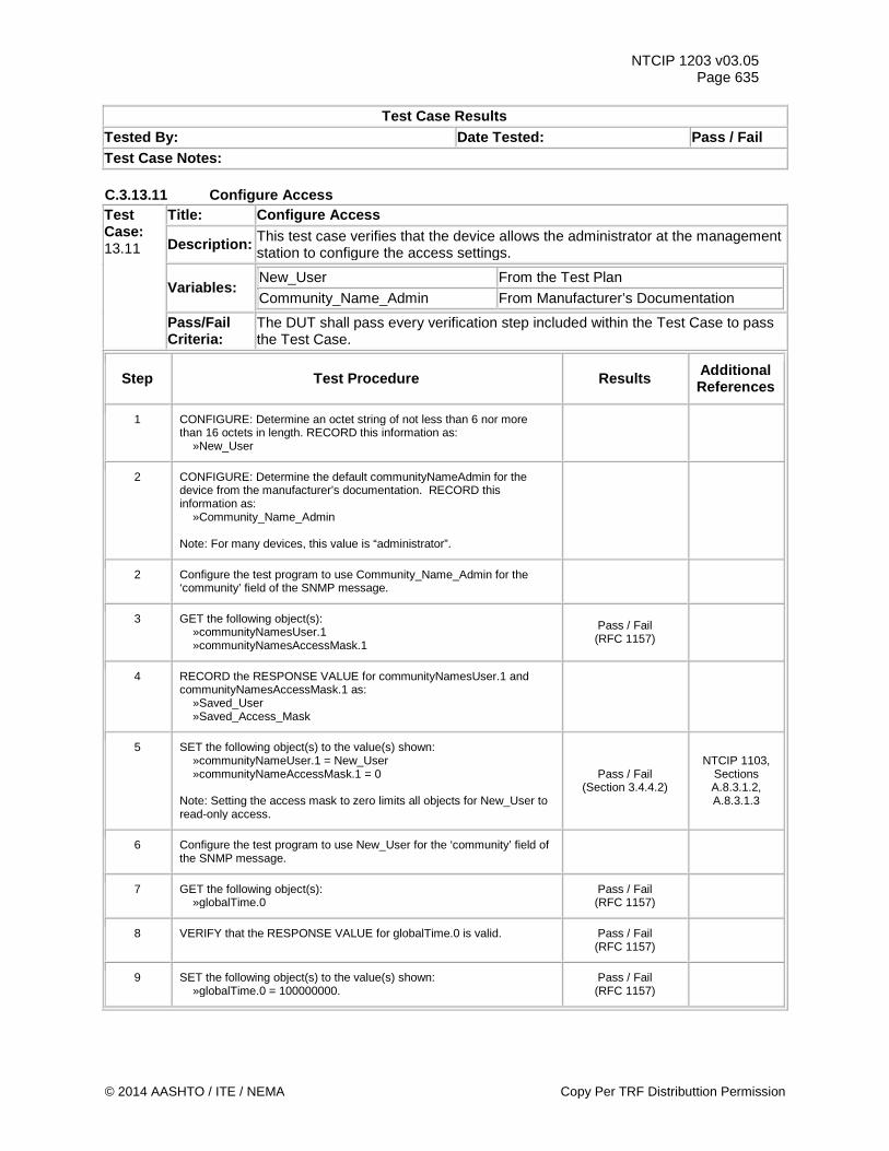
NTCIP 1203 v03.05 Page 635
Test Case Results Tested By: Date Tested: Pass / Fail Test Case Notes: C.3.13.11 Configure Access Test Case: 13.11
Title: Configure Access
Description: This test case verifies that the device allows the administrator at the management station to configure the access settings.
Variables: New_User From the Test Plan Community_Name_Admin From Manufacturer’s Documentation
Pass/Fail Criteria:
The DUT shall pass every verification step included within the Test Case to pass the Test Case.
Step Test Procedure Results Additional References
1 CONFIGURE: Determine an octet string of not less than 6 nor more than 16 octets in length. RECORD this information as: »New_User
2 CONFIGURE: Determine the default communityNameAdmin for the device from the manufacturer’s documentation. RECORD this information as: »Community_Name_Admin Note: For many devices, this value is “administrator”.
2 Configure the test program to use Community_Name_Admin for the ‘community’ field of the SNMP message.
3 GET the following object(s): »communityNamesUser.1 »communityNamesAccessMask.1
Pass / Fail (RFC 1157)
4 RECORD the RESPONSE VALUE for communityNamesUser.1 and communityNamesAccessMask.1 as: »Saved_User »Saved_Access_Mask
5 SET the following object(s) to the value(s) shown: »communityNameUser.1 = New_User »communityNameAccessMask.1 = 0 Note: Setting the access mask to zero limits all objects for New_User to read-only access.
Pass / Fail (Section 3.4.4.2)
NTCIP 1103, Sections A.8.3.1.2, A.8.3.1.3
6 Configure the test program to use New_User for the ‘community’ field of the SNMP message.
7 GET the following object(s): »globalTime.0
Pass / Fail (RFC 1157)
8 VERIFY that the RESPONSE VALUE for globalTime.0 is valid. Pass / Fail (RFC 1157)
9 SET the following object(s) to the value(s) shown: »globalTime.0 = 100000000.
Pass / Fail (RFC 1157)
© 2014 AASHTO / ITE / NEMA Copy Per TRF Distributtion Permission
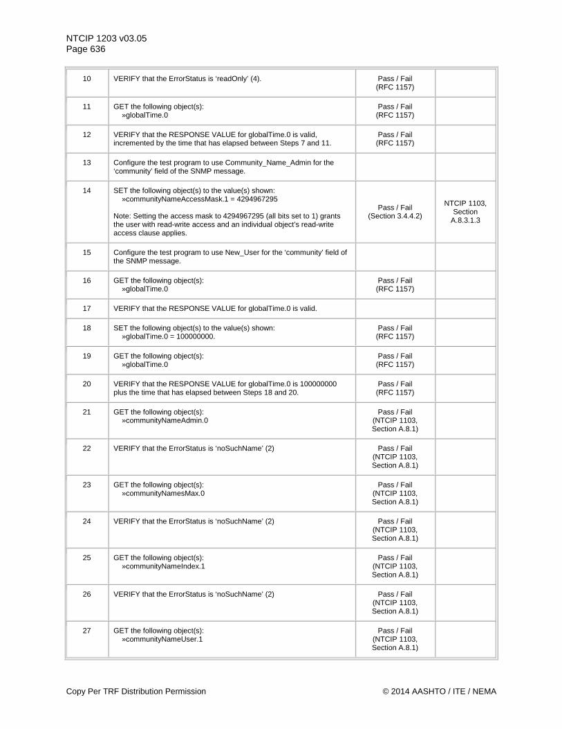
NTCIP 1203 v03.05 Page 636
10 VERIFY that the ErrorStatus is ‘readOnly’ (4). Pass / Fail (RFC 1157)
11 GET the following object(s): »globalTime.0
Pass / Fail (RFC 1157)
12 VERIFY that the RESPONSE VALUE for globalTime.0 is valid, incremented by the time that has elapsed between Steps 7 and 11.
Pass / Fail (RFC 1157)
13 Configure the test program to use Community_Name_Admin for the ‘community’ field of the SNMP message.
14 SET the following object(s) to the value(s) shown: »communityNameAccessMask.1 = 4294967295 Note: Setting the access mask to 4294967295 (all bits set to 1) grants the user with read-write access and an individual object’s read-write access clause applies.
Pass / Fail (Section 3.4.4.2)
NTCIP 1103, Section
A.8.3.1.3
15 Configure the test program to use New_User for the ‘community’ field of the SNMP message.
16 GET the following object(s): »globalTime.0
Pass / Fail (RFC 1157)
17 VERIFY that the RESPONSE VALUE for globalTime.0 is valid.
18 SET the following object(s) to the value(s) shown: »globalTime.0 = 100000000.
Pass / Fail (RFC 1157)
19 GET the following object(s): »globalTime.0
Pass / Fail (RFC 1157)
20 VERIFY that the RESPONSE VALUE for globalTime.0 is 100000000 plus the time that has elapsed between Steps 18 and 20.
Pass / Fail (RFC 1157)
21 GET the following object(s): »communityNameAdmin.0
Pass / Fail (NTCIP 1103, Section A.8.1)
22 VERIFY that the ErrorStatus is ‘noSuchName’ (2) Pass / Fail (NTCIP 1103, Section A.8.1)
23 GET the following object(s): »communityNamesMax.0
Pass / Fail (NTCIP 1103, Section A.8.1)
24 VERIFY that the ErrorStatus is ‘noSuchName’ (2) Pass / Fail (NTCIP 1103, Section A.8.1)
25 GET the following object(s): »communityNameIndex.1
Pass / Fail (NTCIP 1103, Section A.8.1)
26 VERIFY that the ErrorStatus is ‘noSuchName’ (2) Pass / Fail (NTCIP 1103, Section A.8.1)
27 GET the following object(s): »communityNameUser.1
Pass / Fail (NTCIP 1103, Section A.8.1)
Copy Per TRF Distribution Permission © 2014 AASHTO / ITE / NEMA
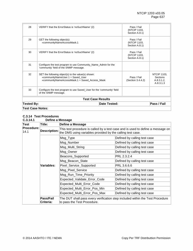
NTCIP 1203 v03.05 Page 637
28 VERIFY that the ErrorStatus is ‘noSuchName’ (2) Pass / Fail (NTCIP 1103, Section A.8.1)
29 GET the following object(s): »communityNameAccessMask.1
Pass / Fail (NTCIP 1103, Section A.8.1)
30 VERIFY that the ErrorStatus is ‘noSuchName’ (2) Pass / Fail (NTCIP 1103, Section A.8.1)
31 Configure the test program to use Community_Name_Admin for the ‘community’ field of the SNMP message.
32 SET the following object(s) to the value(s) shown: »communityNameUser.1 = Saved_User »communityNameAccessMask.1 = Saved_Access_Mask
Pass / Fail (Section 3.4.4.2)
NTCIP 1103, Sections A.8.3.1.2, A.8.3.1.3
33 Configure the test program to use Saved_User for the ‘community’ field of the SNMP message.
Test Case Results Tested By: Date Tested: Pass / Fail Test Case Notes: C.3.14 Test Procedures C.3.14.1 Define a Message Test Procedure: 14.1
Title: Define a Message
Description: This test procedure is called by a test case and is used to define a message on the DMS using variables provided by the calling test case.
Variables:
Msg_Type Defined by calling test case Msg_Number Defined by calling test case Msg_Multi_String Defined by calling test case Msg_Owner Defined by calling test case Beacons_Supported PRL 2.3.2.4 Msg_Beacon_State Defined by calling test case Pixel_Service_Supported PRL 3.6.6.6 Msg_Pixel_Service Defined by calling test case Msg_Run_Time_Priority Defined by calling test case Expected_Validate_Error_Code Defined by calling test case Expected_Multi_Error_Code Defined by calling test case Expected_Multi_Error_Pos_Min Defined by calling test case Expected_Multi_Error_Pos_Max Defined by calling test case
Pass/Fail Criteria:
The DUT shall pass every verification step included within the Test Procedure to pass the Test Procedure.
© 2014 AASHTO / ITE / NEMA Copy Per TRF Distributtion Permission
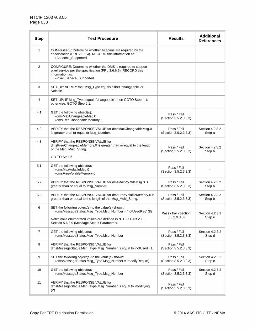
NTCIP 1203 v03.05 Page 638
Step Test Procedure Results Additional References
1 CONFIGURE: Determine whether beacons are required by the specification (PRL 2.3.2.4). RECORD this information as: »Beacons_Supported
2 CONFIGURE: Determine whether the DMS is required to support pixel service per the specification (PRL 3.6.6.6). RECORD this information as: »Pixel_Service_Supported
3 SET-UP: VERIFY that Msg_Type equals either 'changeable' or 'volatile'.
4 SET-UP: IF Msg_Type equals 'changeable', then GOTO Step 4.1; otherwise, GOTO Step 5.1.
4.1 GET the following object(s): »dmsMaxChangeableMsg.0 »dmsFreeChangeableMemory.0
Pass / Fail (Section 3.5.2.3.3.3)
4.2 VERIFY that the RESPONSE VALUE for dmsMaxChangeableMsg.0 is greater than or equal to Msg_Number.
Pass / Fail (Section 3.5.2.3.3.3)
Section 4.2.3.2 Step a
4.3 VERIFY that the RESPONSE VALUE for dmsFreeChangeableMemory.0 is greater than or equal to the length of the Msg_Multi_String. GO TO Step 6.
Pass / Fail (Section 3.5.2.3.3.3)
Section 4.2.3.2 Step b
5.1 GET the following object(s): »dmsMaxVolatileMsg.0 »dmsFreeVolatileMemory.0
Pass / Fail (Section 3.5.2.3.3.3) -
5.2 VERIFY that the RESPONSE VALUE for dmsMaxVolatileMsg.0 is greater than or equal to Msg_Number.
Pass / Fail (Section 3.5.2.3.3.3)
Section 4.2.3.2 Step a
5.3 VERIFY that the RESPONSE VALUE for dmsFreeVolatileMemory.0 is greater than or equal to the length of the Msg_Multi_String.
Pass / Fail (Section 3.5.2.3.3.3)
Section 4.2.3.2 Step b
6 SET the following object(s) to the value(s) shown: »dmsMessageStatus.Msg_Type.Msg_Number = 'notUsedReq' (8) Note: Valid enumerated values are defined in NTCIP 1203 v03, Section 5.6.8.9 (Message Status Parameter).
Pass / Fail (Section 3.5.2.3.3.3)
Section 4.2.3.2 Step e
7 GET the following object(s): »dmsMessageStatus.Msg_Type.Msg_Number
Pass / Fail (Section 3.5.2.3.3.3)
Section 4.2.3.2 Step d
8 VERIFY that the RESPONSE VALUE for dmsMessageStatus.Msg_Type.Msg_Number is equal to 'notUsed' (1).
Pass / Fail (Section 3.5.2.3.3.3)
9 SET the following object(s) to the value(s) shown: »dmsMessageStatus.Msg_Type.Msg_Number = 'modifyReq' (6)
Pass / Fail (Section 3.5.2.3.3.3)
Section 4.2.3.2 Step c
10 GET the following object(s): »dmsMessageStatus.Msg_Type.Msg_Number
Pass / Fail (Section 3.5.2.3.3.3)
Section 4.2.3.2 Step d
11 VERIFY that the RESPONSE VALUE for dmsMessageStatus.Msg_Type.Msg_Number is equal to 'modifying' (2).
Pass / Fail (Section 3.5.2.3.3.3)
Copy Per TRF Distribution Permission © 2014 AASHTO / ITE / NEMA
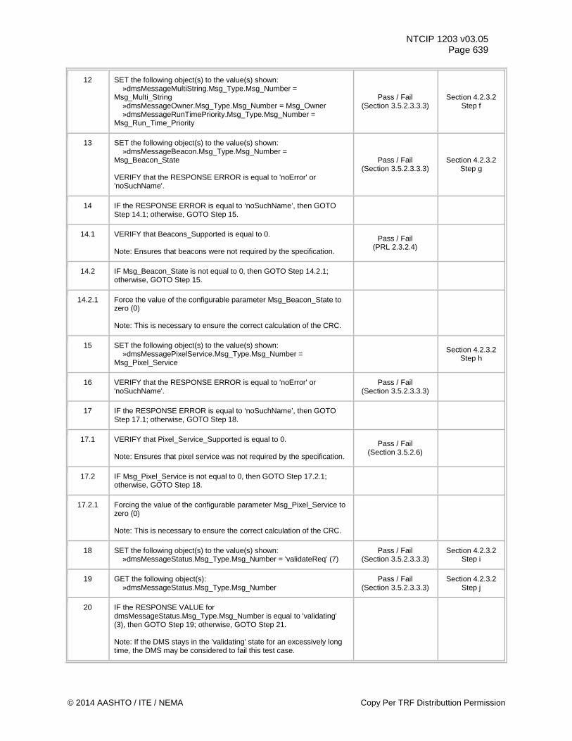
NTCIP 1203 v03.05 Page 639
12 SET the following object(s) to the value(s) shown: »dmsMessageMultiString.Msg_Type.Msg_Number = Msg_Multi_String »dmsMessageOwner.Msg_Type.Msg_Number = Msg_Owner »dmsMessageRunTimePriority.Msg_Type.Msg_Number = Msg_Run_Time_Priority
Pass / Fail (Section 3.5.2.3.3.3)
Section 4.2.3.2 Step f
13 SET the following object(s) to the value(s) shown: »dmsMessageBeacon.Msg_Type.Msg_Number = Msg_Beacon_State VERIFY that the RESPONSE ERROR is equal to 'noError' or 'noSuchName'.
Pass / Fail (Section 3.5.2.3.3.3)
Section 4.2.3.2 Step g
14 IF the RESPONSE ERROR is equal to ‘noSuchName’, then GOTO Step 14.1; otherwise, GOTO Step 15.
14.1 VERIFY that Beacons_Supported is equal to 0. Note: Ensures that beacons were not required by the specification.
Pass / Fail (PRL 2.3.2.4)
14.2 IF Msg_Beacon_State is not equal to 0, then GOTO Step 14.2.1; otherwise, GOTO Step 15.
14.2.1 Force the value of the configurable parameter Msg_Beacon_State to zero (0) Note: This is necessary to ensure the correct calculation of the CRC.
15 SET the following object(s) to the value(s) shown: »dmsMessagePixelService.Msg_Type.Msg_Number = Msg_Pixel_Service
Section 4.2.3.2 Step h
16 VERIFY that the RESPONSE ERROR is equal to 'noError' or 'noSuchName'.
Pass / Fail (Section 3.5.2.3.3.3)
17 IF the RESPONSE ERROR is equal to ‘noSuchName’, then GOTO Step 17.1; otherwise, GOTO Step 18.
17.1 VERIFY that Pixel_Service_Supported is equal to 0. Note: Ensures that pixel service was not required by the specification.
Pass / Fail (Section 3.5.2.6)
17.2 IF Msg_Pixel_Service is not equal to 0, then GOTO Step 17.2.1; otherwise, GOTO Step 18.
17.2.1 Forcing the value of the configurable parameter Msg_Pixel_Service to zero (0) Note: This is necessary to ensure the correct calculation of the CRC.
18 SET the following object(s) to the value(s) shown: »dmsMessageStatus.Msg_Type.Msg_Number = 'validateReq' (7)
Pass / Fail (Section 3.5.2.3.3.3)
Section 4.2.3.2 Step i
19 GET the following object(s): »dmsMessageStatus.Msg_Type.Msg_Number
Pass / Fail (Section 3.5.2.3.3.3)
Section 4.2.3.2 Step j
20 IF the RESPONSE VALUE for dmsMessageStatus.Msg_Type.Msg_Number is equal to 'validating' (3), then GOTO Step 19; otherwise, GOTO Step 21. Note: If the DMS stays in the 'validating' state for an excessively long time, the DMS may be considered to fail this test case.
© 2014 AASHTO / ITE / NEMA Copy Per TRF Distributtion Permission
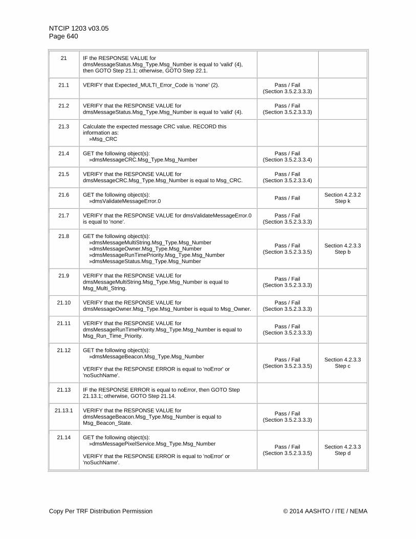
NTCIP 1203 v03.05 Page 640
21 IF the RESPONSE VALUE for dmsMessageStatus.Msg_Type.Msg_Number is equal to 'valid' (4), then GOTO Step 21.1; otherwise, GOTO Step 22.1.
21.1 VERIFY that Expected_MULTI_Error_Code is ‘none’ (2). Pass / Fail (Section 3.5.2.3.3.3)
21.2 VERIFY that the RESPONSE VALUE for dmsMessageStatus.Msg_Type.Msg_Number is equal to 'valid' (4).
Pass / Fail (Section 3.5.2.3.3.3)
21.3 Calculate the expected message CRC value. RECORD this information as: »Msg_CRC
21.4 GET the following object(s): »dmsMessageCRC.Msg_Type.Msg_Number
Pass / Fail (Section 3.5.2.3.3.4)
21.5 VERIFY that the RESPONSE VALUE for dmsMessageCRC.Msg_Type.Msg_Number is equal to Msg_CRC.
Pass / Fail (Section 3.5.2.3.3.4)
21.6 GET the following object(s): »dmsValidateMessageError.0 Pass / Fail Section 4.2.3.2
Step k
21.7 VERIFY that the RESPONSE VALUE for dmsValidateMessageError.0 is equal to 'none'.
Pass / Fail (Section 3.5.2.3.3.3)
21.8 GET the following object(s): »dmsMessageMultiString.Msg_Type.Msg_Number »dmsMessageOwner.Msg_Type.Msg_Number »dmsMessageRunTimePriority.Msg_Type.Msg_Number »dmsMessageStatus.Msg_Type.Msg_Number
Pass / Fail (Section 3.5.2.3.3.5)
Section 4.2.3.3 Step b
21.9 VERIFY that the RESPONSE VALUE for dmsMessageMultiString.Msg_Type.Msg_Number is equal to Msg_Multi_String.
Pass / Fail (Section 3.5.2.3.3.3)
21.10 VERIFY that the RESPONSE VALUE for dmsMessageOwner.Msg_Type.Msg_Number is equal to Msg_Owner.
Pass / Fail (Section 3.5.2.3.3.3)
21.11 VERIFY that the RESPONSE VALUE for dmsMessageRunTimePriority.Msg_Type.Msg_Number is equal to Msg_Run_Time_Priority.
Pass / Fail (Section 3.5.2.3.3.3)
21.12 GET the following object(s): »dmsMessageBeacon.Msg_Type.Msg_Number VERIFY that the RESPONSE ERROR is equal to 'noError' or 'noSuchName'.
Pass / Fail (Section 3.5.2.3.3.5)
Section 4.2.3.3 Step c
21.13 IF the RESPONSE ERROR is equal to noError, then GOTO Step 21.13.1; otherwise, GOTO Step 21.14.
21.13.1 VERIFY that the RESPONSE VALUE for dmsMessageBeacon.Msg_Type.Msg_Number is equal to Msg_Beacon_State.
Pass / Fail (Section 3.5.2.3.3.3)
21.14 GET the following object(s): »dmsMessagePixelService.Msg_Type.Msg_Number VERIFY that the RESPONSE ERROR is equal to 'noError' or 'noSuchName'.
Pass / Fail (Section 3.5.2.3.3.5)
Section 4.2.3.3 Step d
Copy Per TRF Distribution Permission © 2014 AASHTO / ITE / NEMA
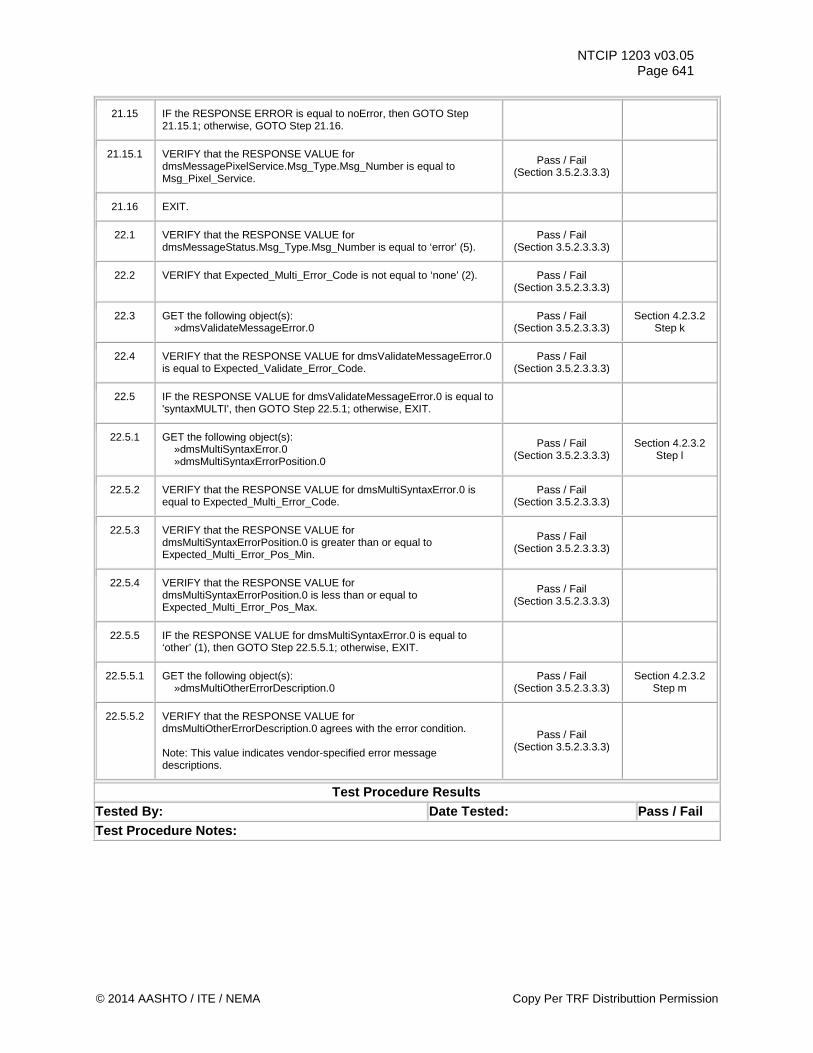
NTCIP 1203 v03.05 Page 641
21.15 IF the RESPONSE ERROR is equal to noError, then GOTO Step 21.15.1; otherwise, GOTO Step 21.16.
21.15.1 VERIFY that the RESPONSE VALUE for dmsMessagePixelService.Msg_Type.Msg_Number is equal to Msg_Pixel_Service.
Pass / Fail (Section 3.5.2.3.3.3)
21.16 EXIT.
22.1 VERIFY that the RESPONSE VALUE for dmsMessageStatus.Msg_Type.Msg_Number is equal to ‘error’ (5).
Pass / Fail (Section 3.5.2.3.3.3)
22.2 VERIFY that Expected_Multi_Error_Code is not equal to ‘none’ (2). Pass / Fail (Section 3.5.2.3.3.3)
22.3 GET the following object(s): »dmsValidateMessageError.0
Pass / Fail (Section 3.5.2.3.3.3)
Section 4.2.3.2 Step k
22.4 VERIFY that the RESPONSE VALUE for dmsValidateMessageError.0 is equal to Expected_Validate_Error_Code.
Pass / Fail (Section 3.5.2.3.3.3)
22.5 IF the RESPONSE VALUE for dmsValidateMessageError.0 is equal to 'syntaxMULTI', then GOTO Step 22.5.1; otherwise, EXIT.
22.5.1 GET the following object(s): »dmsMultiSyntaxError.0 »dmsMultiSyntaxErrorPosition.0
Pass / Fail (Section 3.5.2.3.3.3)
Section 4.2.3.2 Step l
22.5.2 VERIFY that the RESPONSE VALUE for dmsMultiSyntaxError.0 is equal to Expected_Multi_Error_Code.
Pass / Fail (Section 3.5.2.3.3.3)
22.5.3 VERIFY that the RESPONSE VALUE for dmsMultiSyntaxErrorPosition.0 is greater than or equal to Expected_Multi_Error_Pos_Min.
Pass / Fail (Section 3.5.2.3.3.3)
22.5.4 VERIFY that the RESPONSE VALUE for dmsMultiSyntaxErrorPosition.0 is less than or equal to Expected_Multi_Error_Pos_Max.
Pass / Fail (Section 3.5.2.3.3.3)
22.5.5 IF the RESPONSE VALUE for dmsMultiSyntaxError.0 is equal to ‘other’ (1), then GOTO Step 22.5.5.1; otherwise, EXIT.
22.5.5.1 GET the following object(s): »dmsMultiOtherErrorDescription.0
Pass / Fail (Section 3.5.2.3.3.3)
Section 4.2.3.2 Step m
22.5.5.2 VERIFY that the RESPONSE VALUE for dmsMultiOtherErrorDescription.0 agrees with the error condition. Note: This value indicates vendor-specified error message descriptions.
Pass / Fail (Section 3.5.2.3.3.3)
Test Procedure Results Tested By: Date Tested: Pass / Fail Test Procedure Notes:
© 2014 AASHTO / ITE / NEMA Copy Per TRF Distributtion Permission
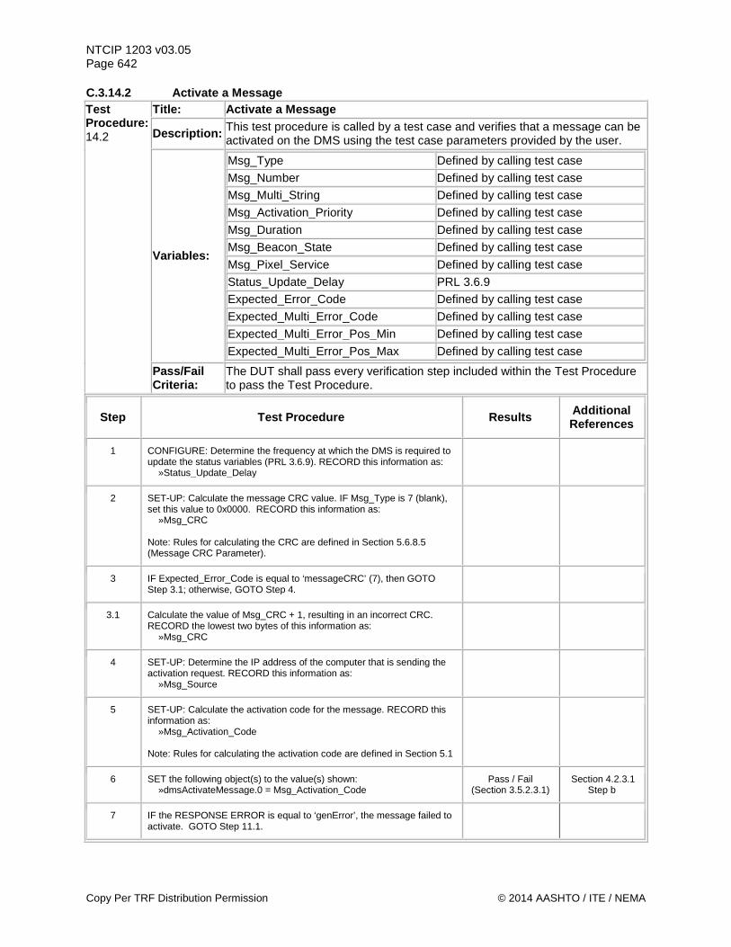
NTCIP 1203 v03.05 Page 642 C.3.14.2 Activate a Message Test Procedure: 14.2
Title: Activate a Message
Description: This test procedure is called by a test case and verifies that a message can be activated on the DMS using the test case parameters provided by the user.
Variables:
Msg_Type Defined by calling test case Msg_Number Defined by calling test case Msg_Multi_String Defined by calling test case Msg_Activation_Priority Defined by calling test case Msg_Duration Defined by calling test case Msg_Beacon_State Defined by calling test case Msg_Pixel_Service Defined by calling test case Status_Update_Delay PRL 3.6.9 Expected_Error_Code Defined by calling test case Expected_Multi_Error_Code Defined by calling test case Expected_Multi_Error_Pos_Min Defined by calling test case Expected_Multi_Error_Pos_Max Defined by calling test case
Pass/Fail Criteria:
The DUT shall pass every verification step included within the Test Procedure to pass the Test Procedure.
Step Test Procedure Results Additional References
1 CONFIGURE: Determine the frequency at which the DMS is required to update the status variables (PRL 3.6.9). RECORD this information as: »Status_Update_Delay
2 SET-UP: Calculate the message CRC value. IF Msg_Type is 7 (blank), set this value to 0x0000. RECORD this information as: »Msg_CRC Note: Rules for calculating the CRC are defined in Section 5.6.8.5 (Message CRC Parameter).
3 IF Expected_Error_Code is equal to ‘messageCRC’ (7), then GOTO Step 3.1; otherwise, GOTO Step 4.
3.1 Calculate the value of Msg_CRC + 1, resulting in an incorrect CRC. RECORD the lowest two bytes of this information as: »Msg_CRC
4 SET-UP: Determine the IP address of the computer that is sending the activation request. RECORD this information as: »Msg_Source
5 SET-UP: Calculate the activation code for the message. RECORD this information as: »Msg_Activation_Code Note: Rules for calculating the activation code are defined in Section 5.1
6 SET the following object(s) to the value(s) shown: »dmsActivateMessage.0 = Msg_Activation_Code
Pass / Fail (Section 3.5.2.3.1)
Section 4.2.3.1 Step b
7 IF the RESPONSE ERROR is equal to ‘genError’, the message failed to activate. GOTO Step 11.1.
Copy Per TRF Distribution Permission © 2014 AASHTO / ITE / NEMA
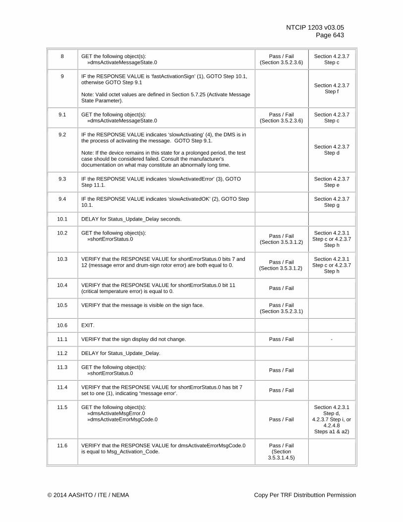
NTCIP 1203 v03.05 Page 643
8 GET the following object(s): »dmsActivateMessageState.0
Pass / Fail (Section 3.5.2.3.6)
Section 4.2.3.7 Step c
9 IF the RESPONSE VALUE is ‘fastActivationSign’ (1), GOTO Step 10.1, otherwise GOTO Step 9.1 Note: Valid octet values are defined in Section 5.7.25 (Activate Message State Parameter).
Section 4.2.3.7 Step f
9.1 GET the following object(s): »dmsActivateMessageState.0
Pass / Fail (Section 3.5.2.3.6)
Section 4.2.3.7 Step c
9.2 IF the RESPONSE VALUE indicates ‘slowActivating’ (4), the DMS is in the process of activating the message. GOTO Step 9.1. Note: If the device remains in this state for a prolonged period, the test case should be considered failed. Consult the manufacturer's documentation on what may constitute an abnormally long time.
Section 4.2.3.7 Step d
9.3 IF the RESPONSE VALUE indicates ‘slowActivatedError’ (3), GOTO Step 11.1. Section 4.2.3.7
Step e
9.4 IF the RESPONSE VALUE indicates ‘slowActivatedOK’ (2), GOTO Step 10.1. Section 4.2.3.7
Step g
10.1 DELAY for Status_Update_Delay seconds.
10.2 GET the following object(s): »shortErrorStatus.0 Pass / Fail
(Section 3.5.3.1.2)
Section 4.2.3.1 Step c or 4.2.3.7
Step h
10.3 VERIFY that the RESPONSE VALUE for shortErrorStatus.0 bits 7 and 12 (message error and drum-sign rotor error) are both equal to 0. Pass / Fail
(Section 3.5.3.1.2)
Section 4.2.3.1 Step c or 4.2.3.7
Step h
10.4 VERIFY that the RESPONSE VALUE for shortErrorStatus.0 bit 11 (critical temperature error) is equal to 0. Pass / Fail
10.5 VERIFY that the message is visible on the sign face. Pass / Fail (Section 3.5.2.3.1)
10.6 EXIT.
11.1 VERIFY that the sign display did not change. Pass / Fail -
11.2 DELAY for Status_Update_Delay.
11.3 GET the following object(s): »shortErrorStatus.0 Pass / Fail
11.4 VERIFY that the RESPONSE VALUE for shortErrorStatus.0 has bit 7 set to one (1), indicating “message error’. Pass / Fail
11.5 GET the following object(s): »dmsActivateMsgError.0 »dmsActivateErrorMsgCode.0 Pass / Fail
Section 4.2.3.1 Step d,
4.2.3.7 Step i, or 4.2.4.8
Steps a1 & a2)
11.6 VERIFY that the RESPONSE VALUE for dmsActivateErrorMsgCode.0 is equal to Msg_Activation_Code.
Pass / Fail (Section
3.5.3.1.4.5)
© 2014 AASHTO / ITE / NEMA Copy Per TRF Distributtion Permission
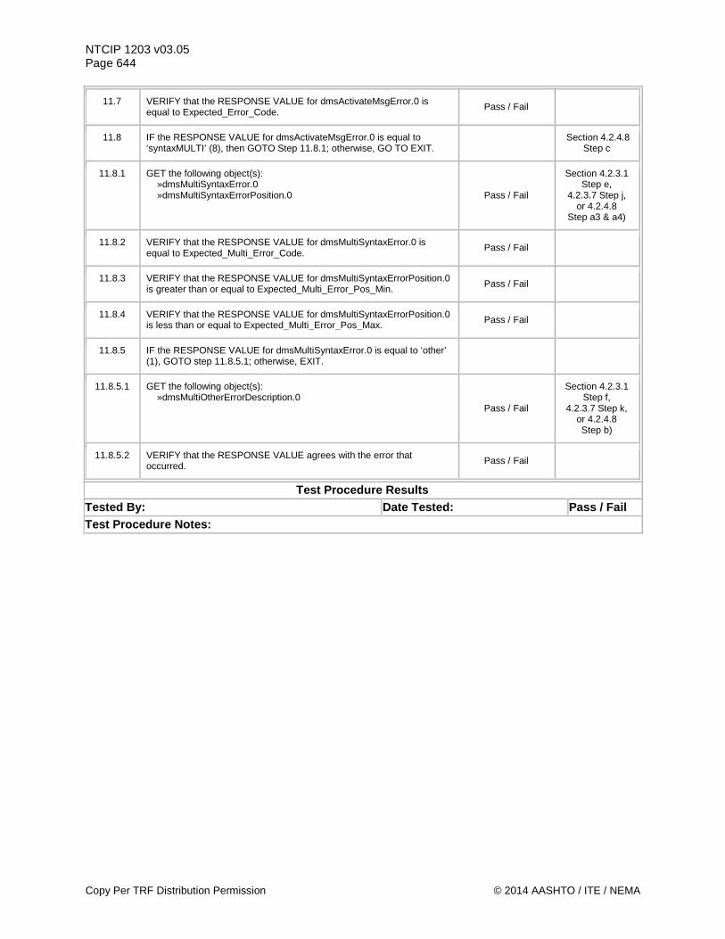
NTCIP 1203 v03.05 Page 644
11.7 VERIFY that the RESPONSE VALUE for dmsActivateMsgError.0 is equal to Expected_Error_Code. Pass / Fail
11.8 IF the RESPONSE VALUE for dmsActivateMsgError.0 is equal to ‘syntaxMULTI’ (8), then GOTO Step 11.8.1; otherwise, GO TO EXIT. Section 4.2.4.8
Step c
11.8.1 GET the following object(s): »dmsMultiSyntaxError.0 »dmsMultiSyntaxErrorPosition.0 Pass / Fail
Section 4.2.3.1 Step e,
4.2.3.7 Step j, or 4.2.4.8
Step a3 & a4)
11.8.2 VERIFY that the RESPONSE VALUE for dmsMultiSyntaxError.0 is equal to Expected_Multi_Error_Code. Pass / Fail
11.8.3 VERIFY that the RESPONSE VALUE for dmsMultiSyntaxErrorPosition.0 is greater than or equal to Expected_Multi_Error_Pos_Min. Pass / Fail
11.8.4 VERIFY that the RESPONSE VALUE for dmsMultiSyntaxErrorPosition.0 is less than or equal to Expected_Multi_Error_Pos_Max. Pass / Fail
11.8.5 IF the RESPONSE VALUE for dmsMultiSyntaxError.0 is equal to ‘other’ (1), GOTO step 11.8.5.1; otherwise, EXIT.
11.8.5.1 GET the following object(s): »dmsMultiOtherErrorDescription.0
Pass / Fail
Section 4.2.3.1 Step f,
4.2.3.7 Step k, or 4.2.4.8 Step b)
11.8.5.2 VERIFY that the RESPONSE VALUE agrees with the error that occurred. Pass / Fail
Test Procedure Results Tested By: Date Tested: Pass / Fail Test Procedure Notes:
Copy Per TRF Distribution Permission © 2014 AASHTO / ITE / NEMA
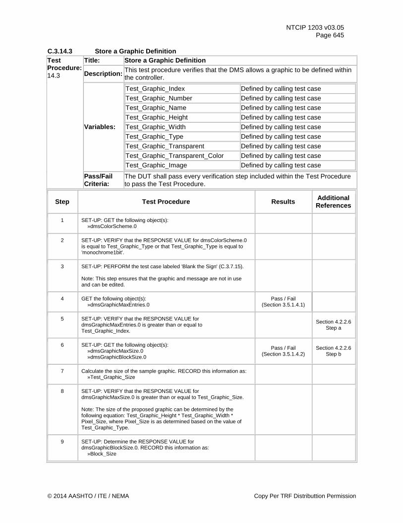
NTCIP 1203 v03.05 Page 645
C.3.14.3 Store a Graphic Definition Test Procedure: 14.3
Title: Store a Graphic Definition
Description: This test procedure verifies that the DMS allows a graphic to be defined within the controller.
Variables:
Test_Graphic_Index Defined by calling test case
Test_Graphic_Number Defined by calling test case
Test_Graphic_Name Defined by calling test case
Test_Graphic_Height Defined by calling test case
Test_Graphic_Width Defined by calling test case
Test_Graphic_Type Defined by calling test case
Test_Graphic_Transparent Defined by calling test case
Test_Graphic_Transparent_Color Defined by calling test case
Test_Graphic_Image Defined by calling test case
Pass/Fail Criteria:
The DUT shall pass every verification step included within the Test Procedure to pass the Test Procedure.
Step Test Procedure Results Additional References
1 SET-UP: GET the following object(s): »dmsColorScheme.0
2 SET-UP: VERIFY that the RESPONSE VALUE for dmsColorScheme.0 is equal to Test_Graphic_Type or that Test_Graphic_Type is equal to 'monochrome1bit'.
3 SET-UP: PERFORM the test case labeled 'Blank the Sign' (C.3.7.15). Note: This step ensures that the graphic and message are not in use and can be edited.
4 GET the following object(s): »dmsGraphicMaxEntries.0
Pass / Fail (Section 3.5.1.4.1)
5 SET-UP: VERIFY that the RESPONSE VALUE for dmsGraphicMaxEntries.0 is greater than or equal to Test_Graphic_Index.
Section 4.2.2.6 Step a
6 SET-UP: GET the following object(s): »dmsGraphicMaxSize.0 »dmsGraphicBlockSize.0
Pass / Fail (Section 3.5.1.4.2)
Section 4.2.2.6 Step b
7 Calculate the size of the sample graphic. RECORD this information as: »Test_Graphic_Size
8 SET-UP: VERIFY that the RESPONSE VALUE for dmsGraphicMaxSize.0 is greater than or equal to Test_Graphic_Size. Note: The size of the proposed graphic can be determined by the following equation: Test_Graphic_Height * Test_Graphic_Width * Pixel_Size, where Pixel_Size is as determined based on the value of Test_Graphic_Type.
9 SET-UP: Determine the RESPONSE VALUE for dmsGraphicBlockSize.0. RECORD this information as: »Block_Size
© 2014 AASHTO / ITE / NEMA Copy Per TRF Distributtion Permission
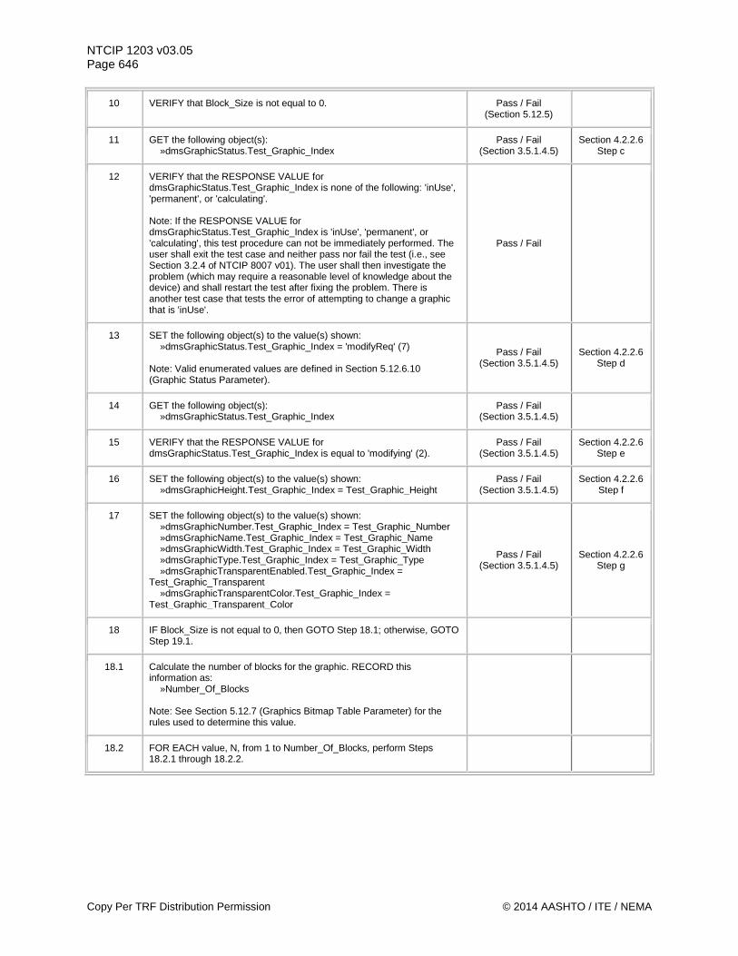
NTCIP 1203 v03.05 Page 646
10 VERIFY that Block_Size is not equal to 0. Pass / Fail (Section 5.12.5)
11 GET the following object(s): »dmsGraphicStatus.Test_Graphic_Index
Pass / Fail (Section 3.5.1.4.5)
Section 4.2.2.6 Step c
12 VERIFY that the RESPONSE VALUE for dmsGraphicStatus.Test_Graphic_Index is none of the following: 'inUse', 'permanent', or 'calculating'. Note: If the RESPONSE VALUE for dmsGraphicStatus.Test_Graphic_Index is 'inUse', 'permanent', or 'calculating', this test procedure can not be immediately performed. The user shall exit the test case and neither pass nor fail the test (i.e., see Section 3.2.4 of NTCIP 8007 v01). The user shall then investigate the problem (which may require a reasonable level of knowledge about the device) and shall restart the test after fixing the problem. There is another test case that tests the error of attempting to change a graphic that is 'inUse'.
Pass / Fail
13 SET the following object(s) to the value(s) shown: »dmsGraphicStatus.Test_Graphic_Index = 'modifyReq' (7) Note: Valid enumerated values are defined in Section 5.12.6.10 (Graphic Status Parameter).
Pass / Fail (Section 3.5.1.4.5)
Section 4.2.2.6 Step d
14 GET the following object(s): »dmsGraphicStatus.Test_Graphic_Index
Pass / Fail (Section 3.5.1.4.5)
15 VERIFY that the RESPONSE VALUE for dmsGraphicStatus.Test_Graphic_Index is equal to 'modifying' (2).
Pass / Fail (Section 3.5.1.4.5)
Section 4.2.2.6 Step e
16 SET the following object(s) to the value(s) shown: »dmsGraphicHeight.Test_Graphic_Index = Test_Graphic_Height
Pass / Fail (Section 3.5.1.4.5)
Section 4.2.2.6 Step f
17 SET the following object(s) to the value(s) shown: »dmsGraphicNumber.Test_Graphic_Index = Test_Graphic_Number »dmsGraphicName.Test_Graphic_Index = Test_Graphic_Name »dmsGraphicWidth.Test_Graphic_Index = Test_Graphic_Width »dmsGraphicType.Test_Graphic_Index = Test_Graphic_Type »dmsGraphicTransparentEnabled.Test_Graphic_Index = Test_Graphic_Transparent »dmsGraphicTransparentColor.Test_Graphic_Index = Test_Graphic_Transparent_Color
Pass / Fail (Section 3.5.1.4.5)
Section 4.2.2.6 Step g
18 IF Block_Size is not equal to 0, then GOTO Step 18.1; otherwise, GOTO Step 19.1.
18.1 Calculate the number of blocks for the graphic. RECORD this information as: »Number_Of_Blocks Note: See Section 5.12.7 (Graphics Bitmap Table Parameter) for the rules used to determine this value.
18.2 FOR EACH value, N, from 1 to Number_Of_Blocks, perform Steps 18.2.1 through 18.2.2.
Copy Per TRF Distribution Permission © 2014 AASHTO / ITE / NEMA
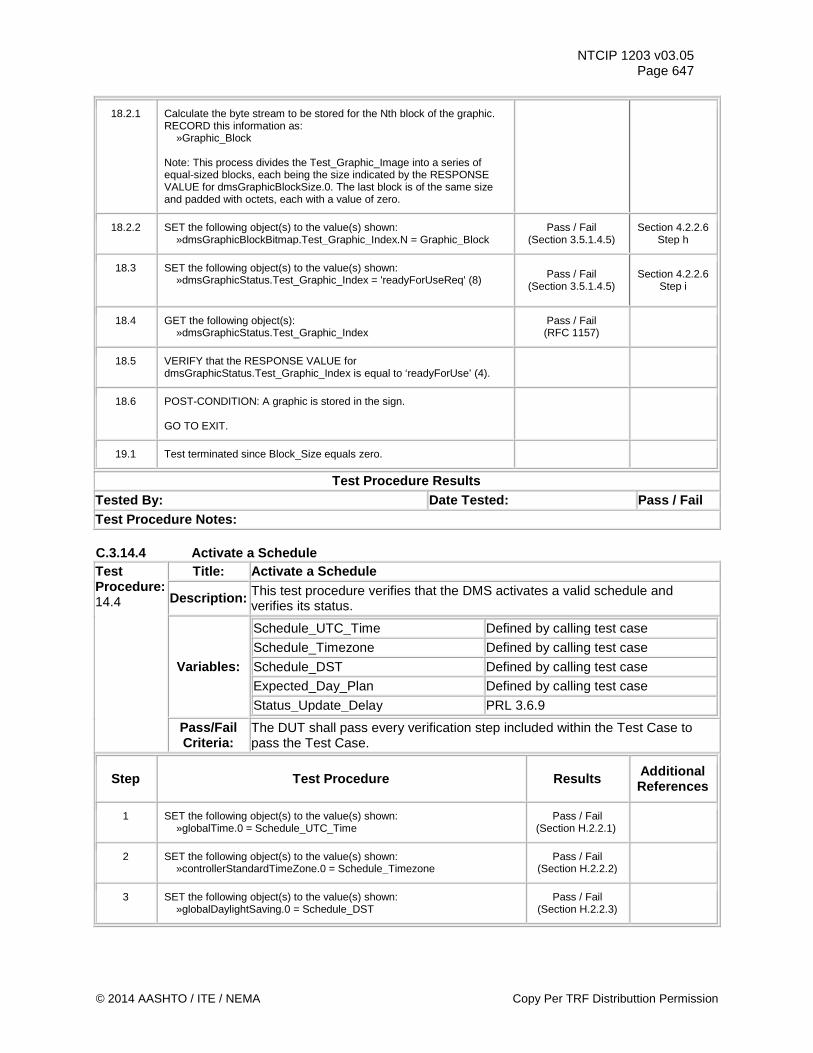
NTCIP 1203 v03.05 Page 647
18.2.1 Calculate the byte stream to be stored for the Nth block of the graphic. RECORD this information as: »Graphic_Block Note: This process divides the Test_Graphic_Image into a series of equal-sized blocks, each being the size indicated by the RESPONSE VALUE for dmsGraphicBlockSize.0. The last block is of the same size and padded with octets, each with a value of zero.
18.2.2 SET the following object(s) to the value(s) shown: »dmsGraphicBlockBitmap.Test_Graphic_Index.N = Graphic_Block
Pass / Fail (Section 3.5.1.4.5)
Section 4.2.2.6 Step h
18.3 SET the following object(s) to the value(s) shown: »dmsGraphicStatus.Test_Graphic_Index = 'readyForUseReq' (8)
Pass / Fail (Section 3.5.1.4.5)
Section 4.2.2.6 Step i
18.4 GET the following object(s): »dmsGraphicStatus.Test_Graphic_Index
Pass / Fail (RFC 1157)
18.5 VERIFY that the RESPONSE VALUE for dmsGraphicStatus.Test_Graphic_Index is equal to ‘readyForUse’ (4).
18.6 POST-CONDITION: A graphic is stored in the sign. GO TO EXIT.
19.1 Test terminated since Block_Size equals zero.
Test Procedure Results Tested By: Date Tested: Pass / Fail Test Procedure Notes: C.3.14.4 Activate a Schedule Test Procedure: 14.4
Title: Activate a Schedule
Description: This test procedure verifies that the DMS activates a valid schedule and verifies its status.
Variables:
Schedule_UTC_Time Defined by calling test case
Schedule_Timezone Defined by calling test case
Schedule_DST Defined by calling test case
Expected_Day_Plan Defined by calling test case
Status_Update_Delay PRL 3.6.9
Pass/Fail Criteria:
The DUT shall pass every verification step included within the Test Case to pass the Test Case.
Step Test Procedure Results Additional References
1 SET the following object(s) to the value(s) shown: »globalTime.0 = Schedule_UTC_Time
Pass / Fail (Section H.2.2.1)
2 SET the following object(s) to the value(s) shown: »controllerStandardTimeZone.0 = Schedule_Timezone
Pass / Fail (Section H.2.2.2)
3 SET the following object(s) to the value(s) shown: »globalDaylightSaving.0 = Schedule_DST
Pass / Fail (Section H.2.2.3)
© 2014 AASHTO / ITE / NEMA Copy Per TRF Distributtion Permission
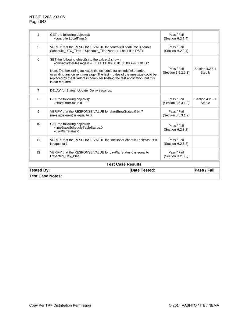
NTCIP 1203 v03.05 Page 648
4 GET the following object(s): »controllerLocalTime.0
Pass / Fail (Section H.2.2.4)
5 VERIFY that the RESPONSE VALUE for controllerLocalTime.0 equals Schedule_UTC_Time + Schedule_Timezone (+ 1 hour if in DST).
Pass / Fail (Section H.2.2.4)
6 SET the following object(s) to the value(s) shown: »dmsActivateMessage.0 = 'FF FF FF 06 00 01 00 00 A9 01 01 00' Note: The hex string activates the schedule for an indefinite period, overriding any current message. The last 4 bytes of the message could be replaced by the IP address computer hosting the test application, but this is not required.
Pass / Fail (Section 3.5.2.3.1)
Section 4.2.3.1 Step b
7 DELAY for Status_Update_Delay seconds.
8 GET the following object(s): »shortErrorStatus.0
Pass / Fail (Section 3.5.3.1.2)
Section 4.2.3.1 Step c
9 VERIFY that the RESPONSE VALUE for shortErrorStatus.0 bit 7 (message error) is equal to 0.
Pass / Fail (Section 3.5.3.1.2)
10 GET the following object(s): »timeBaseScheduleTableStatus.0 »dayPlanStatus.0
Pass / Fail (Section H.2.3.2)
11 VERIFY that the RESPONSE VALUE for timeBaseScheduleTableStatus.0 is equal to 1.
Pass / Fail (Section H.2.3.2)
12 VERIFY that the RESPONSE VALUE for dayPlanStatus.0 is equal to Expected_Day_Plan.
Pass / Fail (Section H.2.3.2)
Test Case Results Tested By: Date Tested: Pass / Fail Test Case Notes:
Copy Per TRF Distribution Permission © 2014 AASHTO / ITE / NEMA
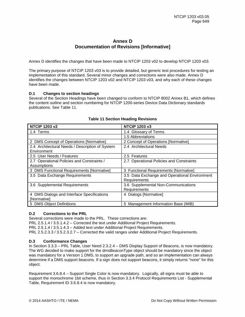
NTCIP 1203 v03.05 Page 649
Annex D Documentation of Revisions [Informative]
Annex D identifies the changes that have been made to NTCIP 1203 v02 to develop NTCIP 1203 v03. The primary purpose of NTCIP 1203 v03 is to provide detailed, but generic test procedures for testing an implementation of this standard. Several minor changes and corrections were also made. Annex D identifies the changes between NTCIP 1203 v02 and NTCIP 1203 v03, and why each of these changes have been made. D.1 Changes to section headings Several of the Section Headings have been changed to conform to NTCIP 8002 Annex B1, which defines the content outline and section numbering for NTCIP 1200-series Device Data Dictionary standards publications. See Table 11.
Table 11 Section Heading Revisions
NTCIP 1203 v2 NTCIP 1203 v3 1.4 Terms 1.4 Glossary of Terms 1.5 Abbreviations 2 DMS Concept of Operations [Normative] 2 Concept of Operations [Normative] 2.4 Architectural Needs / Description of System Environment
2.4 Architectural Needs
2.5 User Needs / Features 2.5 Features 2.7 Operational Policies and Constraints / Assumptions
2.7 Operational Policies and Constraints
3 DMS Functional Requirements [Normative] 3 Functional Requirements [Normative] 3.5 Data Exchange Requirements 3.5 Data Exchange and Operational Environment
Requirements 3.6 Supplemental Requirements 3.6 Supplemental Non-Communications
Requirements 4 DMS Dialogs and Interface Specifications [Normative]
4 Dialogs [Normative]
5 DMS Object Definitions 5 Management Information Base (MIB) D.2 Corrections to the PRL Several corrections were made to the PRL. These corrections are: PRL 2.5.1.4 / 3.5.1.4.2 – Corrected the text under Additional Project Requirements. PRL 2.5.1.4 / 3.5.1.4.3 – Added text under Additional Project Requirements. PRL 2.5.2.3.3 / 3.5.2.3.2.7 – Corrected the valid ranges under Additional Project Requirements. D.3 Conformance Changes In Section 3.3.3 – PRL Table, User Need 2.3.2.4 – DMS Display Support of Beacons, is now mandatory. The WG decided to make support for the dmsBeaconType object should be mandatory since the object was mandatory for a Version 1 DMS, to support an upgrade path, and so an implementation can always determine if a DMS support beacons. If a sign does not support beacons, it simply returns “none” for this object. Requirement 3.6.8.4 – Support Single Color is now mandatory. Logically, all signs must be able to support the monochrome 1bit scheme, thus in Section 3.3.4 Protocol Requirements List - Supplemental Table, Requirement ID 3.6.8.4 is now mandatory.
© 2014 AASHTO / ITE / NEMA Do Not Copy Without Written Permission
NTCIP 1203 v03.05 Page 650 D.4 Added New requirements Added a new requirement, 3.6.6.2.17 – Support of Manufacturer Specific Message Definitions. A manufacturer-specific MULTI tag was added in 1203 v02, but was never traced to a requirement. D.5 updated requirements Requirement 3.6.6.2.5.4, “Support Color for each Pixel in a Message” in NTCIP 1203 v02, was updated to “Color Rectangles”. NTCIP 1203 v02 required selection of foreground color on a pixel-by-pixel basis, but was not actually possible. The use of color rectangles provides that capability and additional flexibility, so the requirement was updated. The text in NTCIP 1203 v02 was, “The DMS shall allow the message content to specify the foreground color on a pixel-by-pixel basis.”, and this was changed to, “The DMS shall allow the message content to specify an area of the sign to display a selected color.” in NTCIP 1203 v03. D.6 Updated dialogs For dialog, 4.2.2.1, Retrieving a Font Definition, a management station should also be prepared to receive a 'noSuchName' error (i.e., from a v1 device). Thus a change was made to Step b of the dialog so that the standard explicitly considers the operation of v1 signs. When a font is deleted by changing its fontStatus to ‘notUsed’ the fontNumber remains, and, according to Section 5.4.2.2, values for this object must be unique across all entries, not just valid entries. Thus, for dialog 4.3.1.4, added the following step after Step B, "If the management station SETs the fontStatus to 'readyForUseReq', if the corresponding fontNumber is not unique among all fonts with fontStatus set to permanent, readyForUse, inUse, or unmanaged, a badValue error will be returned and the fontStatus will change to notInUse." Also, removed the last sentence, “A device shall return a badValue error if this value is not unique.” from Section 5.4.2.2, fontNumber. A change was made to dialog 4.3.5, Message Activation Consistency Check Definition. Steps e-g were moved to the beginning of the dialog so a management station can verify it has permission to set the value before attempting to validate the activation of a message. D.7 Updated Objects Corrected the definition of horizontal pitch and vertical pitch for objects 5.3.5, Horizontal Pitch Parameter and 5.3.6, Vertical Pitch Parameter. Added clarifications to the description for object 5.5.22, Color Scheme Parameter. Corrected the reference in the description for object 5.6.1, Number of Permanent Messages Parameter. Added default values for message parameters in objects 5.7.8 to 5.7.14. Clarified the description for object 5.7.15, End Duration Message Parameter. Previously, reference is made to assigning a new message to replace the previous method, but NTCIP does not support this functionality – only one message may be active at a time. Changed to description to clarify the intent. A change was made to object 5.7.16, Memory Management Parameter. As the graphic table contents are changeable by the user and must survive a controller reset, by definition, graphics are stored in changeable memory. To preclude ambiguous interpretation of the description of the dmsMemoryMgmt object, this change provides a clear distinction between clearing all changeable memory and clearing messages in changeable memory. Clarified the description in object 5.8.1, Illumination Control Parameter. Corrected the formula for calculating the direct manual light output in object 5.8.6, Illumination Manual Level Parameter.
Copy Per TRF Distribution Permission © 2014 AASHTO / ITE / NEMA

NTCIP 1203 v03.05 Page 651
D.8 Added Clarifications to MULTI-ags Additional examples and clarifications were made in Section 6.
© 2014 AASHTO / ITE / NEMA Do Not Copy Without Written Permission
NTCIP 1203 v03.05 Page 652
Annex E Frequently Asked Questions [Informative]
Annex E addresses questions that readers of NTCIP 1203 v02 or , in future, NTCIP 1203 v03 might ask. The intent is to clarify issues in NTCIP 1203 v02 and NTCIP 1203 v03 that are not easily understood and to point out features that are intentionally not covered by NTCIP 1203 v02 or NTCIP 1203 v03. E.1 Does NTCIP 1203 v02 include a feature to automatically blank a sign (or take other action) in the event that the sign becomes illegible due to pixel errors? The idea here is to have the sign monitor the number of pixel errors and, through some non-standardized, non-defined, vendor-specific algorithm, determine whether the sign is considered “legible.” If illegible, the sign could automatically blank itself or take another action. This is conceptually a good idea, but practically very difficult to effectively implement and therefore not recommended by the NTCIP DMS Working Group (WG). The difficulty comes in determining what constitutes illegibility. The WG determined that purely basing illegibility on a percentage or number of failed pixels is not sufficient. For example, consider the following cases: a) A hundred (100) failed pixels in an unused portion of the sign face and the maximum allowable
number of pixels is defined as ninety (90) pixels. The message would still be legible, but the number of failed pixels would have been exceeded. However, another message might not be legible depending on line and/or page justification, characters used, etc.
b) Consider an “8” character that appears as a “3” by failing only four pixels in the left column. A more complicated algorithm may be possible, but the computational requirements would likely exceed typical sign controllers.
From a larger perspective, if the displayed message is important, it is not desirable to arbitrarily blank the sign, when the intent of the message may still be discernable even with a large number of failed pixels. However, there is a solution to this potential user need, which may not be executed via the interface between the central computer and the sign controller (the content of NTCIP 1203 v02), but instead be determined via the central computer software. Such a feature could be implemented in the central (with no interface to the sign) by examining pixel error information that is already provided by NTCIP 1203 v02. Alternatively, the legibility feature could be implemented in a sign without requiring any interface between central and sign. However, this implementation would necessitate the need for additional (vendor-specific) objects so that the operator at the central computer is alerted, when a sign controller takes a non-operator-recommended action based on the results of a sign controller-internal legibility algorithm. E.2 Does NTCIP 1203 v02 include a feature to automatically dim an LED sign at a defined high temperature in an attempt to reduce internal heat? The NTCIP DMS WG does not believe that implementing this feature necessarily requires any interaction between the central and the sign; therefore, no additional MIB objects are defined. Since dimming a sign will reduce the sign’s legibility by some degree, there is a concern that arbitrarily doing so—with no guarantee that the sign’s temperature will NOT continue to increase to the point of a sign display shutdown due to exceeding the critical temperature (see dmsTempSensorHighCriticalTemperature and dmsTempSensorLowCriticalTemperature object)—could be counterproductive.
Copy Per TRF Distribution Permission © 2014 AASHTO / ITE / NEMA
NTCIP 1203 v03.05 Page 653
E.3 Does NTCIP 1203 v02 include a feature to control multiple physical signs from a single controller? The NTCIP DMS WG has decided that there is no need for additions to NTCIP 1203 v02 to address this issue. It is expected that in such a setup, the controller would respond to multiple addresses with each appearing as a complete, independent sign to the central. In theory, there would be an entirely unique MIB database for each sign, but in practice portions of the MIB data may be shared. However, due to the multitude of possible combinations of the various data elements that could be shared, the WG believes that any attempt to standardize this feature would fail in real-life implementations. E.4 Does NTCIP 1203 v02 include a testing/training mode whereby a central can operate signs without any messages appearing on the face of the sign? The NTCIP DMS Working Group does not recommend such a mode, which is the reason why the ‘simulation’ mode as previously defined within the dmsControlMode object was deprecated. The main concern is that with such a mode, the operator could easily forget that a sign was in the testing/training mode and falsely believe s/he was activating a real message on the face of the sign. It was also decided that there was insufficient demand for such a mode to warrant the time required to carefully defining such a mode and how it would impact all other operations and data in the sign. E.5 Does NTCIP 1203 v02 include a feature to control external devices such as HOV lane gates? The NTCIP DMS WG has decided that this functionality is already defined via the ‘auxiliary input output’ object definitions defined in NTCIP 1201 v2. E.6 Wouldn't it be useful to have an object to report back the version of NTCIP 1203 v02/MIB that is implemented in the device (e.g. DMS)? This has to do with compatibility between version 1 and version 2 of the objects. This way the central system would know, without the MIB of the device, what version is implemented in the device. The NTCIP DMS WG decided to address this functionality in NTCIP 1201 version 2 (Global Objects), because this capability should be universally available. The name of this object definition is 'controller-BaseStandards' defined under NTCIP 1201 v2 Section 2.2.4. E.7 Does NTCIP 1203 v02 support the control of Lane Use Signals. NTCIP 1203 v02 allows addressing Lane Use Signals by defining each Signal Head basically as a DMS. Each possible indication (Red X, Green ↓, and potentially other indications) would be defined as a message in the dmsMessageTable. While the NTCIP DMS WG understands that this is not the most efficient implementation and that coordinated activation of subsequent signal heads over a particular lane cannot be managed via this method, the decision was made not to further complicate NTCIP 1203 v02 by attempting to address this advanced function. Additionally, the coordinated activation could potentially be addressed by a Central System managing the LUS. E.8 Why is the range of the "brightness output" in the dmsIllumBrightnessValues table 0..65535 instead of 0..dmsIllumNumBrightLevels? This question points out one confusing aspect of the illumination objects, and their usage. That is the relationship between 'Brightness Levels', 'Light Output' and the brightness table defined by 'dmsIllumBrightnessValues'. Brightness level refers to the values used by the objects dmsIllumNumBrightLevels, dmsIllumBrightLevelStatus and dmsIllumManLevel. There is no direct correlation between the Brightness Level and the amount of light actually used to illuminate the sign (except for level 0, which indicates no illumination, and that numerically higher Brightness levels do not have a Light Output lower than the previous level). The actual amount of light, or Light Output, used for a given Brightness Level is defined using the dmsIllumBrightnessValues (in the fields labeled lightOutput x) and is reported to the user in the dmsIllumLightOutputStatus object. In addition to defining the light output for a given lightOutput n, the dmsIllumBrightnessValues object also defines the photocell readings used to move up or down to other levels when dmsIllumControl is set to photocell (2). When defining the light
© 2014 AASHTO / ITE / NEMA Do Not Copy Without Written Permission
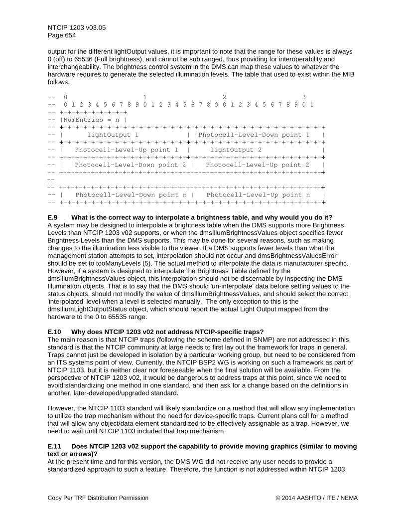
NTCIP 1203 v03.05 Page 654 output for the different lightOutput values, it is important to note that the range for these values is always 0 (off) to 65536 (Full brightness), and cannot be sub ranged, thus providing for interoperability and interchangeability. The brightness control system in the DMS can map these values to whatever the hardware requires to generate the selected illumination levels. The table that used to exist within the MIB follows. -- 0 1 2 3 -- 0 1 2 3 4 5 6 7 8 9 0 1 2 3 4 5 6 7 8 9 0 1 2 3 4 5 6 7 8 9 0 1 -- +-+-+-+-+-+-+-+-+ -- |NumEntries = n | -- +-+-+-+-+-+-+-+-+-+-+-+-+-+-+-+-+-+-+-+-+-+-+-+-+-+-+-+-+-+-+-+-+-+ -- | lightOutput 1 | Photocell-Level-Down point 1 | -- +-+-+-+-+-+-+-+-+-+-+-+-+-+-+-+-+-+-+-+-+-+-+-+-+-+-+-+-+-+-+-+-+-+ -- | Photocell-Level-Up point 1 | lightOutput 2 | -- +-+-+-+-+-+-+-+-+-+-+-+-+-+-+-+-+-+-+-+-+-+-+-+-+-+-+-+-+-+-+-+-+-+ -- | Photocell-Level-Down point 2 | Photocell-Level-Up point 2 | -- +-+-+-+-+-+-+-+-+-+-+-+-+-+-+-+-+-+-+-+-+-+-+-+-+-+-+-+-+-+-+-+-+-+ -- -- +-+-+-+-+-+-+-+-+-+-+-+-+-+-+-+-+-+-+-+-+-+-+-+-+-+-+-+-+-+-+-+-+-+ -- | Photocell-Level-Down point n | Photocell-Level-Up point n | -- +-+-+-+-+-+-+-+-+-+-+-+-+-+-+-+-+-+-+-+-+-+-+-+-+-+-+-+-+-+-+-+-+-+ E.9 What is the correct way to interpolate a brightness table, and why would you do it? A system may be designed to interpolate a brightness table when the DMS supports more Brightness Levels than NTCIP 1203 v02 supports, or when the dmsIllumBrightnessValues object specifies fewer Brightness Levels than the DMS supports. This may be done for several reasons, such as making changes to the illumination less visible to the viewer. If a DMS supports fewer levels than what the management station attempts to set, interpolation should not occur and dmsBrightnessValuesError should be set to tooManyLevels (5). The actual method to interpolate the data is manufacturer specific. However, if a system is designed to interpolate the Brightness Table defined by the dmsIllumBrightnessValues object, this interpolation should not be discernable by inspecting the DMS Illumination objects. That is to say that the DMS should 'un-interpolate' data before setting values to the status objects, should not modify the value of dmsIllumBrightnessValues, and should select the correct 'interpolated' level when a level is selected manually. The only exception to this is the dmsIllumLightOutputStatus object, which should report the actual Light Output mapped from the hardware to the 0 to 65535 range. E.10 Why does NTCIP 1203 v02 not address NTCIP-specific traps? The main reason is that NTCIP traps (following the scheme defined in SNMP) are not addressed in this standard is that the NTCIP community at large needs to first lay out the framework for traps in general. Traps cannot just be developed in isolation by a particular working group, but need to be considered from an ITS systems point of view. Currently, the NTCIP BSP2 WG is working on such a framework as part of NTCIP 1103, but it is neither clear nor foreseeable when the final solution will be available. From the perspective of NTCIP 1203 v02, it would be dangerous to address traps at this point, since we need to avoid standardizing one method in one standard, and then ask for a change based on the definitions in another, later-developed/upgraded standard. However, the NTCIP 1103 standard will likely standardize on a method that will allow any implementation to utilize the trap mechanism without the need for device-specific traps. Current plans call for a method that will allow any object/data element standardized to be effectively assignable as a trap. However, we need to wait until NTCIP 1103 included that trap mechanism. E.11 Does NTCIP 1203 v02 support the capability to provide moving graphics (similar to moving text or arrows)? At the present time and for this version, the DMS WG did not receive any user needs to provide a standardized approach to such a feature. Therefore, this function is not addressed within NTCIP 1203
Copy Per TRF Distribution Permission © 2014 AASHTO / ITE / NEMA
NTCIP 1203 v03.05 Page 655
v02. E.12 How does NTCIP 1203 v02 address inverted fonts? Version 1 of this standard was silent on this issue, but it was the original intent that another font would be used to achieve the display of an inverted font. However, some implementations have used the foreground color and background color MULTI tags to achieve this function. While both of these methods are valid, the latter method is ambiguous since it is not clear whether the spacing pixel row before and/or after the actual character is inverted. So, the resulting display might be different among implementations. In Version 2, the intended and correct way of creating an inverted font is to use the color rectangle MULTI tag in conjunction with the color foreground MULTI tag. Another method is to create another font with zero character spacing and zero line spacing; but this is not the preferred method. E.13 In the User Comment Drafts of NTCIP 1203 v02, there was a mechanism to allow triggers to activate actions. In this version, it has been removed. Why? During the development of version 2, the WG considered adding a mechanism to provide a mechanism to use certain triggers (both internal and external inputs) to allow activation of actions (again, internal and external outputs). However, after receiving many comments regarding the resulting complexity and subsequent WG discussions, it was concluded that the mechanism will either remain as complex as it was proposed or it will become so simple that it looses the originally desired flexibility. After much discussion, the WG decided to not include this mechanism in NTCIP 1203 v02. Users desiring this functionality may still acquire and implement it by using manufacturer-specific object definitions.
© 2014 AASHTO / ITE / NEMA Do Not Copy Without Written Permission
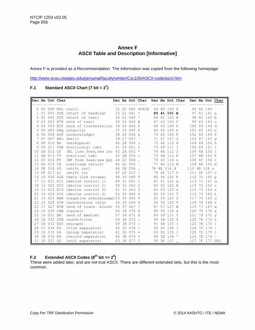
NTCIP 1203 v03.05 Page 656
Annex F ASCII Table and Description [Informative]
Annex F is provided as a Recommendation. The information was copied from the following homepage: http://www.ecsu.ctstateu.edu/personal/faculty/whiter/Csc100/ASCII-code/ascii.htm F.1 Standard ASCII Chart (7 bit = 27)
Dec Hx Oct Char Dec Hx Oct Char Dec Hx Oct Char Dec Hx Oct Char --------------- --------------- --------------- --------------- 0 00 000 NUL (null) 32 20 040 SPACE 64 40 100 @ 96 60 140 ` 1 01 001 SOH (start of heading) 33 21 041 ! 65 41 101 A 97 61 141 a 2 02 002 STX (start of text) 34 22 042 " 66 42 102 B 98 62 142 b 3 03 003 ETX (end of text) 35 23 043 # 67 43 103 C 99 63 143 c 4 04 004 EOT (end of transmission) 36 24 044 $ 68 44 104 D 100 64 144 d 5 05 005 ENQ (enquiry) 37 25 045 % 69 45 105 E 101 65 145 e 6 06 006 ACK (acknowledge) 38 26 046 & 70 46 106 F 102 66 146 f 7 07 007 BEL (bell) 39 27 047 ' 71 47 107 G 103 67 147 g 8 08 010 BS (backspace) 40 28 050 ( 72 48 110 H 104 68 150 h 9 09 011 TAB (horizontal tab) 41 29 051 ) 73 49 111 I 105 69 151 i 10 0A 012 LF (NL line feed,new ln) 42 2A 052 * 74 4A 112 J 106 6A 152 j 11 0B 013 VT (vertical tab) 43 2B 053 + 75 4B 113 K 107 6B 153 k 12 0C 014 FF (NP form feed,new pg) 44 2C 054 , 76 4C 114 L 108 6C 154 l 13 0D 015 CR (carriage return) 45 2D 055 - 77 4D 115 M 109 6D 155 m 14 0E 016 SO (shift out) 46 2E 056 . 78 4E 116 N 110 6E 156 n 15 0F 017 SI (shift in) 47 2F 057 / 79 4F 117 O 111 6F 157 o 16 10 020 DLE (data link escape) 48 30 060 0 80 50 120 P 112 70 160 p 17 11 021 DC1 (device control 1) 49 31 061 1 81 51 121 Q 113 71 161 q 18 12 022 DC2 (device control 2) 50 32 062 2 82 52 122 R 114 72 162 r 19 13 023 DC3 (device control 3) 51 33 063 3 83 53 123 S 115 73 163 s 20 14 024 DC4 (device control 4) 52 34 064 4 84 54 124 T 116 74 164 t 21 15 025 NAK (negative acknowledge)53 35 065 5 85 55 125 U 117 75 165 u 22 16 026 SYN (synchronous idle) 54 36 066 6 86 56 126 V 118 76 166 v 23 17 027 ETB (end of trans. block) 55 37 067 7 87 57 127 W 119 77 167 w 24 18 030 CAN (cancel) 56 38 070 8 88 58 130 X 120 78 170 x 25 19 031 EM (end of medium) 57 39 071 9 89 59 131 Y 121 79 171 y 26 1A 032 SUB (substitute) 58 3A 072 : 90 5A 132 Z 122 7A 172 z 27 1B 033 ESC (escape) 59 3B 073 ; 91 5B 133 [ 123 7B 173 { 28 1C 034 FS (file separator) 60 3C 074 < 92 5C 134 \ 124 7C 174 | 29 1D 035 GS (group separator) 61 3D 075 = 93 5D 135 ] 125 7D 175 } 30 1E 036 RS (record separator) 62 3E 076 > 94 5E 136 ^ 126 7E 176 ~ 31 1F 037 US (unit separator) 63 3F 077 ? 95 5F 137 _ 127 7F 177 DEL
F.2 Extended ASCII Codes (8th bit => 28) These were added later, and are not true ASCII. There are different extended sets, but this is the most common.
Copy Per TRF Distribution Permission © 2014 AASHTO / ITE / NEMA
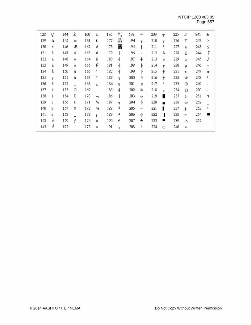
NTCIP 1203 v03.05 Page 657
© 2014 AASHTO / ITE / NEMA Do Not Copy Without Written Permission
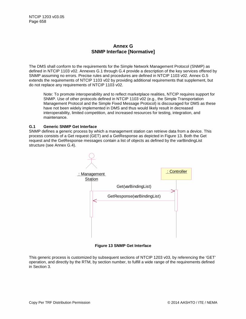
NTCIP 1203 v03.05 Page 658
Annex G SNMP Interface [Normative]
The DMS shall conform to the requirements for the Simple Network Management Protocol (SNMP) as defined in NTCIP 1103 v02. Annexes G.1 through G.4 provide a description of the key services offered by SNMP assuming no errors. Precise rules and procedures are defined in NTCIP 1103 v02. Annex G.5 extends the requirements of NTCIP 1103 v02 by providing additional requirements that supplement, but do not replace any requirements of NTCIP 1103 v02.
Note: To promote interoperability and to reflect marketplace realities, NTCIP requires support for SNMP. Use of other protocols defined in NTCIP 1103 v02 (e.g., the Simple Transportation Management Protocol and the Simple Fixed Message Protocol) is discouraged for DMS as these have not been widely implemented in DMS and thus would likely result in decreased interoperability, limited competition, and increased resources for testing, integration, and maintenance.
G.1 Generic SNMP Get Interface SNMP defines a generic process by which a management station can retrieve data from a device. This process consists of a Get request (GET) and a GetResponse as depicted in Figure 13. Both the Get request and the GetResponse messages contain a list of objects as defined by the varBindingList structure (see Annex G.4).
Figure 13 SNMP Get Interface
This generic process is customized by subsequent sections of NTCIP 1203 v03, by referencing the ‘GET’ operation, and directly by the RTM, by section number, to fulfill a wide range of the requirements defined in Section 3.
: Management Station
: Controller
Get(varBindingList)
GetResponse(varBindingList)
Copy Per TRF Distribution Permission © 2014 AASHTO / ITE / NEMA
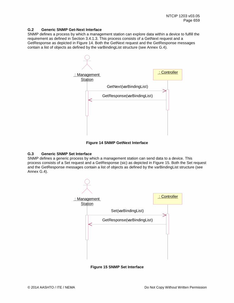
NTCIP 1203 v03.05 Page 659
G.2 Generic SNMP Get-Next Interface SNMP defines a process by which a management station can explore data within a device to fulfill the requirement as defined in Section 3.4.1.3. This process consists of a GetNext request and a GetResponse as depicted in Figure 14. Both the GetNext request and the GetResponse messages contain a list of objects as defined by the varBindingList structure (see Annex G.4).
Figure 14 SNMP GetNext Interface
G.3 Generic SNMP Set Interface SNMP defines a generic process by which a management station can send data to a device. This process consists of a Set request and a GetResponse (sic) as depicted in Figure 15. Both the Set request and the GetResponse messages contain a list of objects as defined by the varBindingList structure (see Annex G.4).
Figure 15 SNMP Set Interface
: Management Station
: Controller
GetNext(varBindingList)
GetResponse(varBindingList)
: Management Station
: Controller
Set(varBindingList)
GetResponse(varBindingList)
© 2014 AASHTO / ITE / NEMA Do Not Copy Without Written Permission
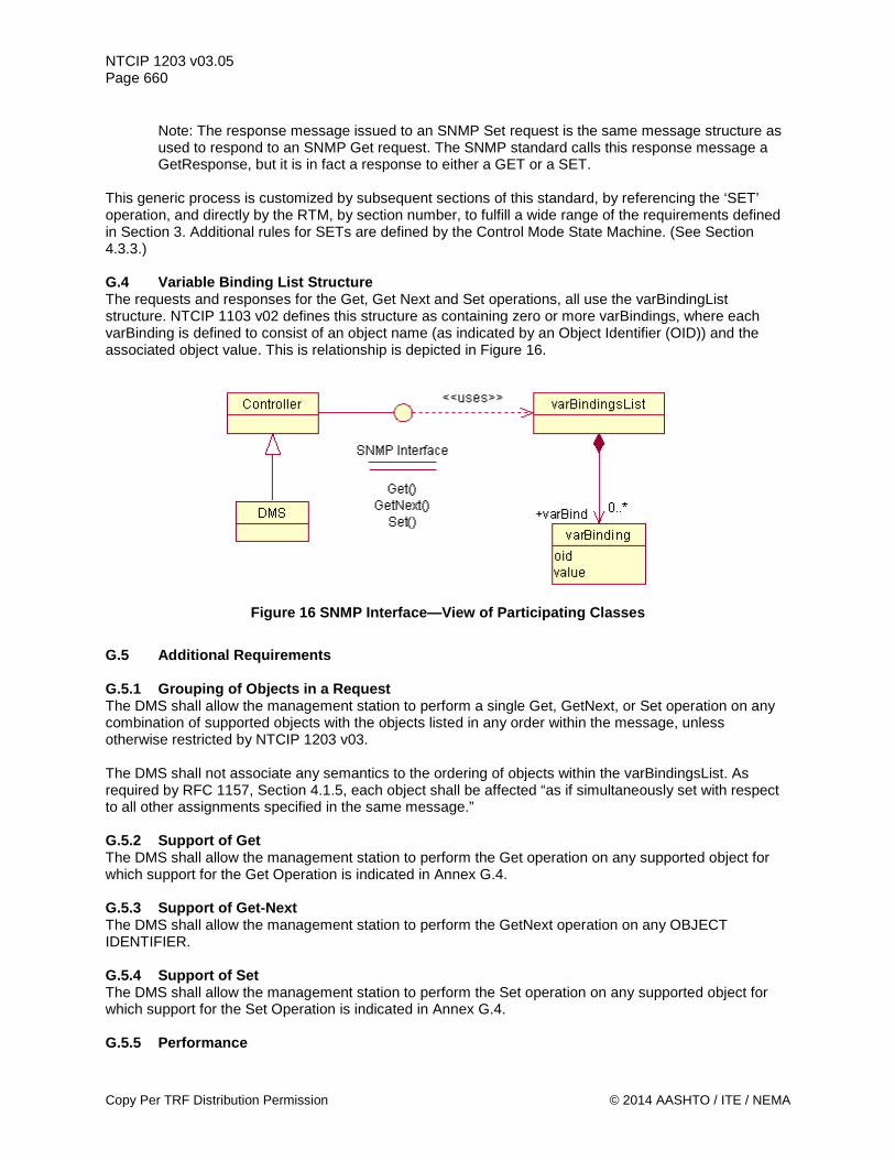
NTCIP 1203 v03.05 Page 660
Note: The response message issued to an SNMP Set request is the same message structure as used to respond to an SNMP Get request. The SNMP standard calls this response message a GetResponse, but it is in fact a response to either a GET or a SET.
This generic process is customized by subsequent sections of this standard, by referencing the ‘SET’ operation, and directly by the RTM, by section number, to fulfill a wide range of the requirements defined in Section 3. Additional rules for SETs are defined by the Control Mode State Machine. (See Section 4.3.3.) G.4 Variable Binding List Structure The requests and responses for the Get, Get Next and Set operations, all use the varBindingList structure. NTCIP 1103 v02 defines this structure as containing zero or more varBindings, where each varBinding is defined to consist of an object name (as indicated by an Object Identifier (OID)) and the associated object value. This is relationship is depicted in Figure 16.
Figure 16 SNMP Interface—View of Participating Classes
G.5 Additional Requirements G.5.1 Grouping of Objects in a Request The DMS shall allow the management station to perform a single Get, GetNext, or Set operation on any combination of supported objects with the objects listed in any order within the message, unless otherwise restricted by NTCIP 1203 v03. The DMS shall not associate any semantics to the ordering of objects within the varBindingsList. As required by RFC 1157, Section 4.1.5, each object shall be affected “as if simultaneously set with respect to all other assignments specified in the same message.” G.5.2 Support of Get The DMS shall allow the management station to perform the Get operation on any supported object for which support for the Get Operation is indicated in Annex G.4. G.5.3 Support of Get-Next The DMS shall allow the management station to perform the GetNext operation on any OBJECT IDENTIFIER. G.5.4 Support of Set The DMS shall allow the management station to perform the Set operation on any supported object for which support for the Set Operation is indicated in Annex G.4. G.5.5 Performance
Copy Per TRF Distribution Permission © 2014 AASHTO / ITE / NEMA

NTCIP 1203 v03.05 Page 661
The DMS shall process the Get, GetNext, or Set request in accordance with all of the rules of NTCIP 1103 v02, including updating the value in the database and initiating the transmission of the appropriate response (assuming that the DMS has permission to transmit) within 1 second of receiving the last byte of the request.
Note: If a user desires a shorter response time, s/he will need to specify this in the specifications.
© 2014 AASHTO / ITE / NEMA Do Not Copy Without Written Permission
NTCIP 1203 v03.05 Page 662
Annex H NTCIP 1201 v03 Derived User Needs, Functional Requirements, and Dialogs
[Informative]
The annex content serves as a reference for NTCIP 1203 v02. Eventually this reference information may be moved to successors of NTCIP 1201 v03 and NTCIP 1103 v02.
Note: At the time, the DMS WG needed to reference certain information from NTCIP 1201 (Global Object Definitions) such as user needs, functional requirements, and dialogs, NTCIP 1201 did not contain this type of information to the extent necessary NTCIP 1201 v2 does contain a Concept of Operations for 3 relevant functions that might be used in conjunction with DMS). The DMS WG, with support from the NTCIP BSP2 WG and from NEMA, decided to develop and provide the following temporary references within an annex in this standard (NTCIP 1203 v03). Annex H wiill be deleted when NTCIP 1201 supports the information contained within.
H.1 Introduction Content in Annex H exists to serve as a reference for NTCIP 1203 v02. Eventually this information needed for reference may exist within the standard referenced. H.2 Derived GLOBAL Functional Requirements The following functional requirements address features defined in NTCIP 1201:2005. H.2.1 Determine Device Component Information The device shall allow a management station to determine identification information for each module contained in the device including: a) An indication of the type of device b) The manufacturer of the module c) The model number or firmware reference of the module d) The version of the module e) An indication of whether it is a software or hardware module H.2.2 Manage Time Requirements for managing the sign controller's clock are provided in the following subsections. H.2.2.1 Set Time The device shall allow a management station to set the coordinated universal time to the nearest second. H.2.2.2 Set Time Zone The device shall allow a management station to configure the time zone in which the DMS is located. H.2.2.3 Set Daylight Savings Mode The device shall allow a management station to indicate whether or not day light savings time adjustments should be performed when determining local time. H.2.2.4 Verify Current Time The device shall allow a management station to determine the current time settings within the controller. H.2.3 Schedule Device Actions Requirements for managing the sign controller's scheduling feature are provided in the following subsections.
Copy Per TRF Distribution Permission © 2014 AASHTO / ITE / NEMA
NTCIP 1203 v03.05 Page 663
H.2.3.1 Determine Maximum Number of Schedules The device shall allow a management station to determine the maximum number of schedules and day plans supported by the sign controller. H.2.3.2 Monitor Current Schedule The device shall allow a management station to monitor the current schedule to determine which schedule entry has been selected. H.2.4 Determine Supported Standards The device shall allow a management station to determine the NTCIP standards which it supports. H.2.5 Supplemental Requirements for Scheduling Supplemental requirements for defining a time-based schedule are provided in the following subsections. H.2.5.1 Support a Number of Day Selection Patterns The device shall support the number of day selection patterns as specified in the specification. If the specification does not define the number of day selection patterns, the device shall support at least one day selection pattern.
Note: A day selection pattern is a mechanism that selects a day plan to run based on the given day matching a pattern for months, days of week, and dates of month.
H.2.5.2 Support a Number of Day Plan Events The device shall support the number of day plan events for each supported day plan as defined in the specification. If the specification does not define the number of day plan events, the device shall support at least two day plan events per day plan. H.2.5.3 Support a Number of Day Plans The device shall support the number of day plans as defined by the specification. If the specification does not define the number of day plans, the device shall support at least one day plan. H.2.6 Supplemental Requirements for Event Monitoring Supplemental requirements for monitoring for the occurrence of certain events are provided in the following subsections. H.2.6.1 Record and Timestamp Events The device shall support the capability to record configured event types with timestamps, in a local log (log contained in the device controller), upon request by the user and/or the management station. H.2.6.2 Support a Number of Event Classes The device shall support the number of event classes as defined by the specification. If the specification does not define the number of event classes, the device shall support at least one event class. H.2.6.3 Support a Number of Event Types to Monitor The device shall support the number of event types as defined by the specification. If the specification does not define the number of event types, the device shall support at least one event type. H.2.6.4 Support Monitoring of Event Types Supplemental requirements for monitoring types of events are provided in the following subsections. H.2.6.4.1 Support On-Change Events The device shall allow any event type configuration to monitor data for changes in value. H.2.6.4.2 Support Greater Than Events The device shall allow any event type configuration to monitor data for values exceeding a defined
© 2014 AASHTO / ITE / NEMA Do Not Copy Without Written Permission
NTCIP 1203 v03.05 Page 664 threshold for a period of time. H.2.6.4.3 Support Less Than Events The device shall allow any event type configuration to monitor data for values falling below a defined threshold for a period of time. H.2.6.4.4 Support Hysteresis Events The device shall allow any event type configuration to monitor data for values exceeding an upper limit or dropping below a lower limit. H.2.6.4.5 Support Periodic Events The device shall allow any event type configuration to monitor data on a periodic basis. H.2.6.4.6 Support Bit-flag Events The device shall allow any event type configuration to monitor one or more bits of a value becoming true (e.g., obtaining a value of one). H.2.6.4.7 Support Event Monitoring on Any Data The device shall allow a management station to configure any event type to monitor any piece of data supported by the device within the logical rules of the type of event (e.g., ASCII strings should not be monitored with greater than or less than conditions).
Note: This allows a user to monitor an event based on the value of any data. H.2.7 Support a Number of Events to Store in Log The device event log shall support the number of events as defined by the specification. If the specification does not define the number of events for the log, the device shall support at least one event in the log. H.3 Derived GLOBAL Dialogs H.3.1 Manage Communications Environment Standardized dialogs for managing the communications environment that are more complex than simple GETs or SETs are defined in the following subsections. H.3.1.1 Determining Current Configuration of Event Reporting/Logging Service The standardized dialog for a management station to determine the current configuration of the logging service and/or exception reporting events shall be as follows: a) (Precondition) The management station shall be aware of the number of classes and event
configurations supported by the DMS. (See Annex A for Requirement 3.4.2.5) b) For each row of the event class table, the management station shall GET the following data:
1) eventClassLimit.x 2) eventClassClearTime.x 3) eventClassDescription.x
c) For each row of the event configuration table, the management station shall GET the following data: 1) eventConfigClass.y 2) eventConfigMode.y 3) eventConfigCompareValue.y 4) eventConfigCompareValue2.y 5) eventConfigCompareOID.y 6) eventConfigLogOID.y 7) eventConfigAction.y 8) eventConfigStatus.y
Copy Per TRF Distribution Permission © 2014 AASHTO / ITE / NEMA
NTCIP 1203 v03.05 Page 665
Where: x = event class number y = event configuration identifier
H.3.1.2 Configuring Reporting/Logging Service The standardized dialog for a management station to configure the logging service or events to be reported shall be as follows: a) (Precondition) The management station shall ensure that there are sufficient rows in the event
configuration and event class tables to download the proposed configuration. b) The management station shall SET the following data to the desired values to configure each desired
event class: 1) eventClassLimit.x 2) eventClassClearTime.x 3) eventClassDescription.x NOTE—Each event type to be monitored is classified into one event class. For example, critical events may be grouped into Class 1 events and warnings may be grouped into Class 2 events. This step, defines the structure of each class of events.
c) The management station shall SET the following data to the desired values to configure each desired event to be monitored: 1) eventConfigClass.y 2) eventConfigMode.y 3) eventConfigCompareValue.y 4) eventConfigCompareValue2.y 5) eventConfigCompareOID.y 6) eventConfigLogOID.y 7) eventConfigAction.y Note: Depending on the value of eventConfigMode, not all other objects may be necessary for the event to be defined, however, they shall always be SET as a part of the standardized dialog.
d) The management station shall GET eventConfigStatus.y to ensure that there is not an error in the configuration.
Where: x = event class number y = event configuration identifier
H.3.1.3 Retrieving Logged Data The standardized dialog for a management station to retrieve logged data shall be as follows: a) (Precondition) The management station shall be aware of the number of events that had previously
been reported for the device for the subject event class (e.g., from the previous performance of this operation).
b) The management station shall GET the following data: 1) eventClassNumRowsInLog.x 2) eventClassNumEvents.x
c) If eventClassNumEvents.x has not changed since the previous reading, the management station shall exit the process. Otherwise, the management station shall determine the additional number of events that have occurred since the last read. Note: This is generally determined by subtracting the previous number of events from eventClassNumEvents; however, since this object wraps at 65535, the management station should be prepared to determine the differential if eventClassNumEvents is less than the previous number.
d) The management station shall determine the lesser of eventClassNumRowsInLog and the additional number of events that have occurred since the last read. This number shall be termed the Events to Read.
e) Starting with y = eventClassNumRowsInLog and working down until y = (eventClassNumRowsInLog - Events to Read), the management station shall GET the following data:
© 2014 AASHTO / ITE / NEMA Do Not Copy Without Written Permission
NTCIP 1203 v03.05 Page 666
1) eventLogID.x.y 2) eventLogTime.x.y 3) eventLogValue.x.y
f) Repeat the same GET operation with y decremented by one (1) for each set of duplicated values (until y reaches a value of zero (0)). Note: If the event class is full and another event occurs, the new event is recorded in the last entry and all previously logged data is moved to one index lower with index 1 being deleted from the table. Thus, if a duplicate row is detected (e.g., same event at same time), it is likely an indication that the same event is being read and that a new event was added to the log. Note: The management station may wish to clear the event log after the read to minimize the above problem.
Where: x = event log class y = event log number
H.3.2 Automatic Reporting of Events (SNMP Traps)
Note: Ultimately, the NTCIP-specific handling of traps will be defined in NTCIP 1103. However, the current version (NTCIP 1103 v02) does not contain any trap definitions. Therefore, NTCIP 1203 v03 does not address traps.
H.3.3 Determining Device Component Information The standardized dialog for a management station to identify the hardware and software configuration of a NTCIP device shall be as follows: a) The management station shall GET the object globalMaxModules.0. b) For each row in the module table, the management station shall GET the following objects:
1) moduleDeviceNode.x, 2) moduleMake.x, 3) moduleModel.x, 4) moduleVersion.x, 5) moduleType.x.
Where: x = module number.
H.3.4 Global Time Data The following subsection identifies the interface to a field device to obtain and manage time related information. H.3.4.1 Graphical Depiction of Global Time Data See Figure 17.
Copy Per TRF Distribution Permission © 2014 AASHTO / ITE / NEMA
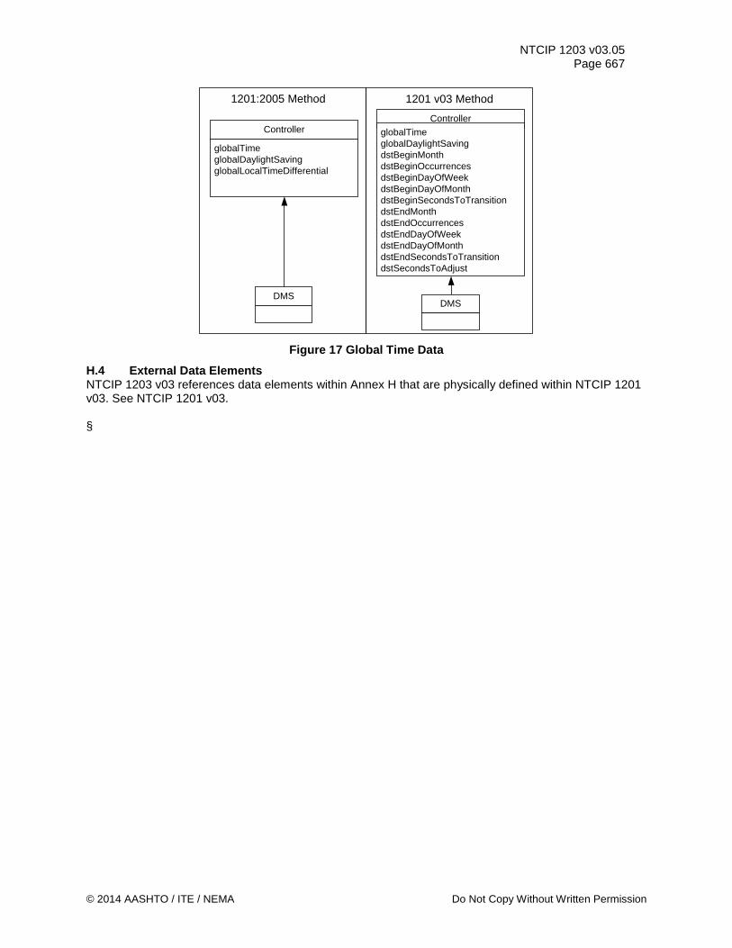
NTCIP 1203 v03.05 Page 667
Controller
globalTimeglobalDaylightSavingglobalLocalTimeDifferential
DMS
ControllerglobalTimeglobalDaylightSavingdstBeginMonthdstBeginOccurrencesdstBeginDayOfWeekdstBeginDayOfMonthdstBeginSecondsToTransitiondstEndMonthdstEndOccurrencesdstEndDayOfWeekdstEndDayOfMonthdstEndSecondsToTransitiondstSecondsToAdjust
DMS
1201:2005 Method 1201 v03 Method
Figure 17 Global Time Data
H.4 External Data Elements NTCIP 1203 v03 references data elements within Annex H that are physically defined within NTCIP 1201 v03. See NTCIP 1201 v03. §
© 2014 AASHTO / ITE / NEMA Do Not Copy Without Written Permission