Embed Size (px)
Citation preview
( . 1
User's Guide
NTCIP Message Sign Software
Wanco, Inc. December, 2004

rev. 12/30/2004 User's Guide: NTCIP Message Sign Software 2/39
Table of Contents 1. INTRODUCTION 5
1.1. INSTRUCTIONS 5
1.2. SCOPE 5
1.3. SIGN TYPES 5
1.4. CONTACT SERVICE/SALES 5
1.5. NTCIP 6
2. BASIC OPERATION »„.7
2.1. LOCAL CONSOLE 7
2.2. MENU NAVIGATION 7
2.3. PASSWORDS 7
2.4. FRONT PANEL L E D S 8
2.5. POWER-OFF THE SIGN DISPLAY 8
3. MENUS 9
3.1. MENU HIERARCHY 9
3.2. MAIN MENU 10
3.3. QUICK MSG MENU , 10
3.4. MESSAGE MENU ,, 10
3.5. MSG OPTIONS/MAINTENANCE MENU 10
3.6. STATUS MENU ..10
3.7. MULTI FIELD MENU 11 3.8. CONFIG/AUX MENU 12
3.9. ADVANCED MENU 12
3.10. SERVICE MENU 12
3.11. SETTINGS MENU 12
4. HOTKEYS 13
4.1. OVERVIEW 13
4.2. MENU HOT KEYS 13
4.3. FUNCTION KEYS .1 13
4.4. MESSAGE HOT KEYS .,, 13
4.5. CONFIG SCREEN HOT KEYS 13
4.6. STATUS SCREEN HOT KEYS 13
4.7. SERVICE SCREEN HOT KEYS 13
4.8. TEST MESSAGE HOT KEYS 13
4.9. EDITOR HOT KEYS 14
4.10. SPECIAL CHARACTER HOT KEYS 14
5. MESSAGES 15
5.1. OVERVIEW 15
5.2. QUICK MESSAGE 15
5.3. MESSAGE TYPES 15
5.4. MESSAGE ACTIVATION 15
5.5. ACTIVATE CUSTOM MESSAGES 15
5.6. ACTIVATE STANDARD MESSAGES 15
P/N: 106812-001 Wanco, Inc.

rev. 12/30/2004 User's Guide: NTCIP Message Sign Software 3/39
5.7. ACTIVATE ARROW MESSAGES 16
5.8. MESSAGE PREVIEW 16
5.9. MESSAGE SELECTION 16
5.10. MESSAGE DELETION 17
5.11. MESSAGE EDIT/MODIFY 17
5.12. MESSAGE SAVE/EXIT 18
5.13. JUSTIFICATION/CENTERING 18
5.14. FLASHING/BLINKING 19
5.15. ARROWS 19
5.16. GRAPHICS 19
5.17. FONTS 19
5.18. EDITOR DEFAULT SETTINGS 21
5.19. REAL-TIME DATA (MULTI FIELDS) 21 5.20. SCALE WEIGHT 21
5.21. RADAR SPEEDS 21
5.22. PAGE TIMING 21
5.23. MESSAGE TIMER (AUTO-BLANKING) 22
5.24. MULTI-TEXT EDITOR 22
6. STATUS 23
6.1. SIGN DISPLAY 23
6.2. ALARMS •,.>.- 23 6.3. VOLTAGES .« 24
6.4. TIME & DATE 24
6.5. IDs & VERSIONS 24
6.6. DISPLAY CARDS...., 24
6.7. POWER CONTROLS 25
7. MESSAGE SCHEDULER 26
7.1. OVERVIEW 26
7.2. SCHEDULE CONFIG 26
7.3. DAY PLANS 26
8. AUX DEVICES ..,....» 27
8.1. OVERVIEW.... ^ 27
8.2. RADAR ;, 27
8.3. HIGHWAY ALERT RADIO (HAR) 28
8.4. DIGITAL ENCODER 28
9. SIGN SETTINGS 29
9.1. OVERVIEW 29
9.2. TIME & DATE SETTINGS 29
9.3. PAGE AND BLINK TIMING 29
9.4. MESSAGE CENTERING 29
9.5. CHARACTER FONT 29
9.6. CHANGE PASSWORDS 29
10. NTCIP SETTINGS 30
10.1. MODEM SETUP 30
P/N: 106812-001 Wanco,Inc.

rev. 12/30/2004 User's Guide: NTCIP Message Sign Software 4/39
10.2. SERIAL CABLE SETUP 30
10.3. HDLC DROP ADDRESS ..30 10.4. CHANGE PASSWORDS 30
10.5. EVENT MESSAGES 30
10.6. NTCIP RAW VO 30 10.7. MULTI-TEXT EDITOR 30
11. SERVICE MODE SETTINGS 31
11.1. OVERVIEW 31
11.2. HARDWARE INFO 31
11.3. FAN TEMPERATURES 32
11.4. CHARGER RELAY VOLTAGES 32
11.5. Low POWER SETTINGS 32
11.6. LED BRIGHTNESS CONTROL 32
11.7. ALARM LIMITS 33
12. SERVICE MODE CONTROLS 34
12.1. OVERVIEW 34
12.2. FANS & CHARGER 34
12.3. DISPLAY POWER & BRIGHTNESS 34
12.4. DIAGNOSTIC MESSAGES 34
12.5. MATRIX CARD REPLACEMENT 35
13. ACCENTED CHARACTER CODES (FONTS 4 & 5) 36
14. PERMANENT MESSAGES 37
P/N: 106812-001 Wanco, Inc.

rev. 12/30/2004 User's Guide: NTCIP Message Sign Software 5/39
1. Introduction
1.1. Instructions Before use, please read this manual carefully. For questions, contact Service/Sales.
1.2. Scope This manual explains control of the message sign using the local software user interface. Mechanical operation, safety, maintenance, troubleshooting and parts diagrams are covered in the Owner's Guide. Operation of the optional remote control software is covered separately.
1.3. Sign Types This software is designed to operate a variety of sign models, each with slightly different power management requirements, user input configurations and/or auxilliary device options. Some information presented here may not apply to all sign models running this software, or to all software versions in-use, or may refer to optional or added-cost features. Ignore sections that do not apply.
1.3.1. Character Signs Character signs display messages in a single font, in fixed row/column positions. These signs typically use the 4 line by 20 character LCD panel. Graphics and multiple fonts are not supported.
1.3.2. Matrix Signs Matrix signs can display bitmap graphics and a variety of font sizes. These signs use the 160x128 pixel graphic LCD panel. The upper half of the LCD displays the menu system, and the lower half displays graphic versions of the messages.
1.3.3. Trailer-Mount Signs These signs are solar-powered and fan-cooled, with a weatherproof electronics control cabinet, run unattended, and require extensive controls to maintain optimum battery charge life.
1.3.4. Truck-Mount Signs These signs are powered from the truck engine and require less-critical power-management. 1.3.5. Pole-Mount Solar Signs These signs have the same power management requirements as the trailer-mount signs. 1.3.6. Fixed-Mount Signs Fixed-mount signs have hard-wired power systems and require almost no power management.
1.4. Contact Service/Sales For tech support, product questions, sales support, customer service or product service, contact the number below with the sign type, model number and software version. For trailer-mount signs, also have the VIN number ready. It is available on the label mounted on the front inside of the A-frame tongue of the trailer.
Address: Wanco, Inc. 5870 Tennyson St Arvada, CO 80003-6903
Phone: 303.427.5700 Fax: 303.427.5725
E-mail: [email protected]
P/N: 106812-001 Wanco, Inc.

rev. 12/30/2004 User's Guide: NTCIP Message Sign Software 6/39
Web: www.wanco.com
1.5. NTCIP 1.5.1. Overview NTCIP stands for the "National Transportation Communications for ITS Protocol". It is a family of standards for communicating with traffic control equipment (over modem, LAN, serial cable, etc.), to facilitate creation of intelligent traffic systems (ITS). It includes the protocols and data vocabulary necessary for a message sign to interact with a remote control program. It does not explicitly define local sign control or user interface issues.
1.5.2. Local Operation No knowledge of NTCIP is required for basic sign operation. However, the data fields and terminology used here should be familiar to knowledgeable users. Some NTCIP advanced features are also supported through the local menus.
1.5.3. Conformance This software conforms to the relevant standards for Changeable Message Signs and uses a standard MIB OID database internally. All signs support direct serial communication with an NTCIP-compatible Central Control program, however, not all signs are equipped with a cellular modem or LAN option.
P/N: 106812-001 Wanco, Inc.
rev. 12/30/2004 User's Guide: NTCIP Message Sign Software 7/39
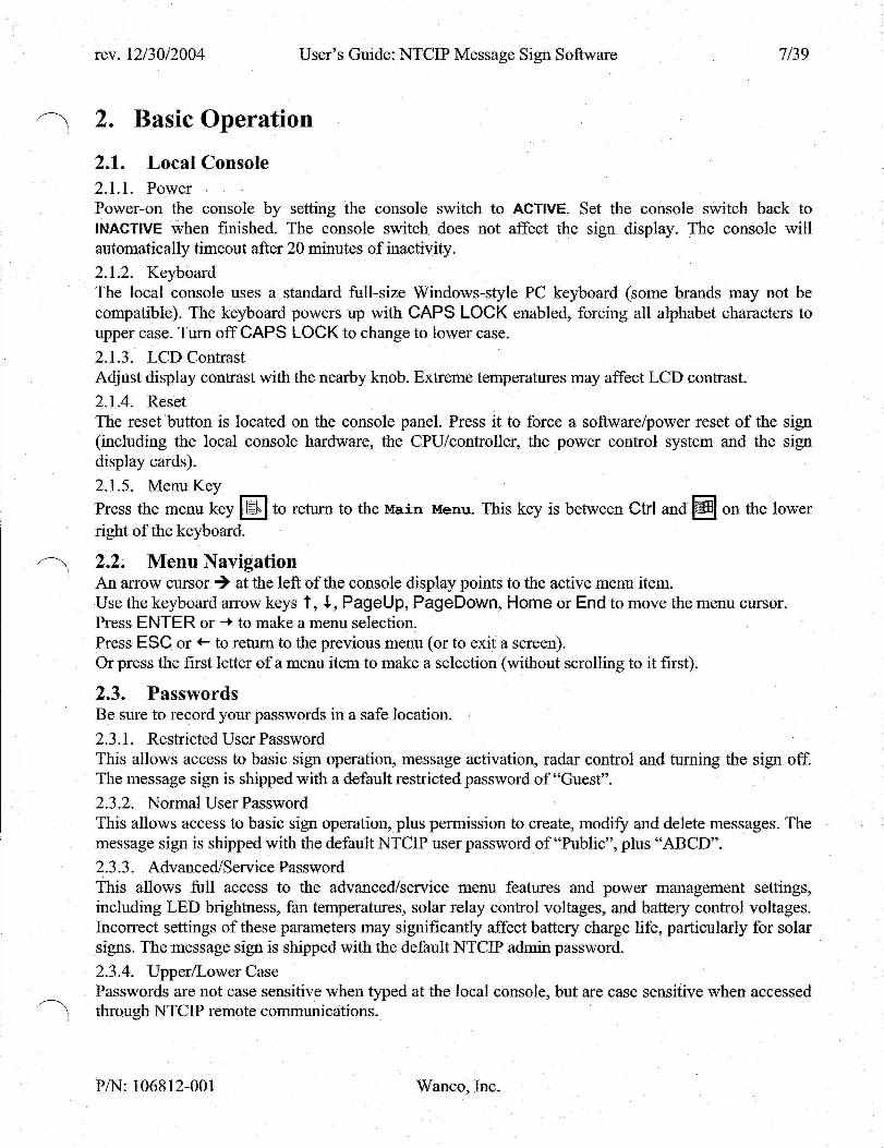
2. Basic Operation
2.1. Local Console 2.1.1. Power Power-on the console by setting the console switch to ACTIVE. Set the console switch back to INACTIVE when finished. The console switch does not affect the sign display. The console will automatically timeout after 20 minutes of inactivity.
2.1.2. Keyboard The local console uses a standard full-size Windows-style PC keyboard (some brands may not be compatible). The keyboard powers up with CAPS LOCK enabled, forcing all alphabet characters to upper case. Turn off CAPS LOCK to change to lower case.
2.1.3. LCD Contrast Adjust display contrast with the nearby knob. Extreme temperatures may affect LCD contrast.
2.1.4. Reset The reset button is located on the console panel. Press it to force a software/power reset of the sign (including the local console hardware, the CPU/controller, the power control system and the sign display cards).
2.1.5. Menu Key Press the menu key |ll>| to return to the Main Menu. This key is between Ctrl and on the lower right of the keyboard.
2.2. Menu Navigation An arrow cursor •¥ at the left of the console display points to the active menu item. Use the keyboard arrow keys t , 4, PageUp, PageDown, Home or End to move the menu cursor. Press ENTER or -• to make a menu selection. Press ESC or *- to return to the previous menu (or to exit a screen). Or press the first letter of a menu item to make a selection (without scrolling to it first).
2.3. Passwords Be sure to record your passwords in a safe location. 2.3.1. Restricted User Password This allows access to basic sign operation, message activation, radar control and turning the sign off. The message sign is shipped with a default restricted password of "Guest". 2.3.2. Normal User Pass word This allows access to basic sign operation, plus permission to create, modify and delete messages. The message sign is shipped with the default NTCIP user password of "Public", plus "ABCD".
2.3.3. Advanced/Service Password This allows full access to the advanced/service menu features and power management settings, including LED brightness, fan temperatures, solar relay control voltages, and battery control voltages. Incorrect settings of these parameters may significantly affect battery charge life, particularly for solar signs. The message sign is shipped with the default NTCIP admin password.
2.3.4. Upper/Lower Case Passwords are not case sensitive when typed at the local console, but are case sensitive when accessed through NTCIP remote communications.
P/N: 106812-001 Wanco, Inc.

rev. 12/30/2004 User's Guide: NTCIP Message Sign Software 8/39
2.4. Front Panel LEDs Some sign models have a column of LED indicators near the LCD. These will light when the console door is opened - the user does not have to be logged in. Not all LEDs are on all sign models. Alarm/Warning Message Sign On Solar Charging Schedule Active Radar Pwr On Hwy Radio On Encoder Active Battery Saver
Check alarm and status screens for details Message sign is not powered off Charging relay is on, and charging current detected Message scheduler is enabled Radar head has power and radar message system is active HAR has power and alert system is active Sign accepting message changes from encoder hardware Battery voltage very low, system shutdown or sleep mode. Press reset button, if still in shutdown, recharge batteries.
2.5. Power-Off The Sign Display To disable power to the sign (and blank the sign display cards), select "Message Menu" at the Main Menu, then select "Off (Blank Sign) " (or press Alt-B). Note: this does not also turn off the aux devices (e.g. radar), use the specific config screen to turn them off if desired.
P/N: 106812-001 Wanco, Inc.

rev. 12/30/2004 User's Guide: NTCIP Message Sign Software 9/39
3. Menus
3.1. Menu Hierarchy (Note, menu titles in brackets [] do not actually appear on the console display.)
[Main Menu] -[Quick Msg Menu]
-Create New Msg —Quick Message-
—Message Menu
—Select/View Msg--Off (Blank Sign) Msg Blank Timer
—Editor Settings Default Messages
!—Default Msg Times
Config/Aux Menu —Radar Settings —HwyRadio Settings —Schedule Settings —Encoder Settings
Status Menu —Message on Sign —Alarms & Warnings Volts & Temps Time & Date
—IDs & Versions Display Cards
•—Power Controls
Advanced Menu Service Menu
—Set Time & Date —Set Page Times Change Password
LNTCIP Raw I/O
Modify Sign Displays Edit Prev Quick Msg-
LSelect/View Qck Msg
[Msg Options Menu] —Activate Sign Msg —Modify This Msg — -Delete This Msg —Set Page Times -MULTI-Text Editor
•[Msg Edit Screen] L[MULTI Field Menu]
T—Fan/Charger Power —Display Brght/Pwr — Settings Menu — Hardware Info
t—Fan Temperatures —Power Controls —Ilium Controls —Voltage Alarms —Temp Alarms —Photocell Alarms —Serial Baud Rates —HDLC Drop Address
P/N: 106812-001 Wanco, Inc.
rev. 12/30/2004 User's Guide: NTCIP Message Sign Software 10/39
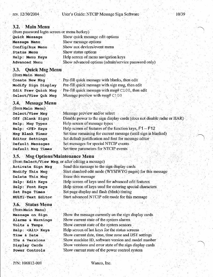
3.2. Main Menu (from password login screen or menu hotkey) Quick Message Message Menu Config/Aux Menu Status Menu Help: Menu Keys Advanced Menu
3.3. Quick Msg Menu (from Main Menu)
Create New Msg
Modify Sign Display
Edit Prev Quick Msg
Select/View Qck Msg
3.4. Message Menu (from Main Menu) Select/View Msg Off (Blank Sign) Help: Msg Types Help: <F#> Keys Msg Blank Timer Editor Settings Default Messages Default Msg Times
Show quick message edit options Show message options Show aux devices/event menu Show status options Help screen of menu navigation keys Show advanced options (admin/service password only)
Pre-fill quick message with blanks, then edit Pre-fill quick message with sign msg, then edit Pre-fill quick message with msg# C100, then edit Message preview with msg# CI 00
Message preview and/or select Disable power to the sign display cards (does not disable radar or HAR) Help screen of message types Help screen of features of the function keys, F1 — F12 Set time remaining for current message (until sign is blanked) Set default justification and font for message editor Set messages for special NTCIP events Set time parameters for NTCIP events
3.5. Msg Options/Maintenance Menu (from Select /View Msg, or after editing a message) Activate Sign Msg Modify This Msg Delete This Msg Help: Edit Keys Help: Font Keys Set Page Times MULTI-Text Editor
3.6. Status Menu (from Main Menu) Message on Sign Alarms & Warnings Volts & Temps Help: <Alt> Keys Time & Date IDs & Versions Display Cards Power Controls
Send this message to the sign display cards Start standard edit mode (WYSIWYG pages) for this message Erase this message Help screen of keys used for advanced edit features Help screen of keys used for entering special characters Set page display and flash (blink) timing Start advanced NTCIP edit mode for this message
Show the message currently on the sign display cards Show current state of the system alarms Show current state of the system sensors Help screen of hot keys for the status screens Show current date, time, time zone and DST settings Show machine ID, software version and model number Show versions and error state of the sign display cards Show current state of the power control system
P/N: 106812-001 Wanco, Inc.

rev. 12/30/2004 User's Guide: NTCIP Message Sign Software 11/39
3.7. MULTI Field Menu (press Alt-F when editing a message) Date m/d/y Date d-m-y Date y.m.d Date dd Date mm Date yy Date yyyy Date day Frequency Speed mph Speed mph Speed kph Speed kph SpeedLim m SpeedLim k SpeedMin m SpeedMin k SpeedXX m SpeedXXX m SpeedXX k SpeedXXX k Temp ambi°F Temp ambi°C Temp ambi°F Temp ambi°C Temp ctrl°F Temp ctrl°C Temp disp°F Temp disp°C Time 12:00 Time 12 AM Time 12:ss Time 24:00 Time 24:ss Time :ss Timer msg Volts line Volts sign Weight lb
[f82 [f83
[f84
[f08, [f09,
[fio, [fll [f07
[f68, [f06
[f06
[f05 [f05 [f72
[f71 [f74
[f73
[f70 [f70 [f69
[f69 [f04
[f03
[f04
[f03
[f78
[f77
[f76
[f75 [fOl
[f81 [f79 [f02
[f80 [f67
[f85
[f66 [f65 [f86
8] 8]
8]
2] 2] 2] 4]
3] 4]
2] 3]
3]
2] 2]
3] 2]
2] 2]
3] 2] 3]
3]
3]
2]
2] -3]
3] r3]
,3] r5] r8] r8]
r5] r8] r3] -8}
r5] ,5]
,6]
Date, US format, 8 chars Date, European format, 8 chars Date, Japanese format, 8 chars Day of the month, 2 chars Month, 2 chars Year, 2 chars Year, 4 chars Day of the week, English, 3 chars AM radio frequency, 4 chars (e.g. for traffic info) Radar speed, mph, 2 chars Radar speed, mph, 3 chars Radar speed, kph, 3 chars Radar speed, kph, 2 chars Speed limit, mph, 2 chars Speed limit, kph, 3 chars Minimum speed, mph, 2 chars Minimum speed, kph, 2 chars Radar speed, mph, 2 chars, XX for over-speed Radar speed, mph, 3 chars, XXX for over-speed Radar speed, kph, 2 chars, XX for over-speed Radar speed, kph, 3 chars, XXX for over-speed Temperature, ambient, ° F, 3 chars Temperature, ambient, °C, 3 chars Temperature, ambient, °F, 2 chars Temperature, ambient, °C, 2 chars Temperature, control box, ° F, 3 chars Temperature, control box, ° C, 3 chars Temperature, sign display box, ° F, 3 chars Temperature, sign display box, °C, 3 chars Time, hours & minutes, 12-hr format, 5 chars Time, hours & minutes, 12-hr format w/ AM/PM, 8 chars Time, hours, minutes & seconds, 12-hr format, 8 chars Time, hours & minutes, 24-hr format, 5 chars Time, hours, minutes & seconds, 24-hr format, 8 chars Time, seconds only, 3 chars Msg time remaining, days, hours & minutes, 8 chars Line voltage (solar charger), 5 chars Sign voltage (battery or main power), 5 chars Scale weight, pounds, 6 chars
P/N: 106812-001 Wanco, Inc.

rev. 12/30/2004 User's Guide: NTCIP Message Sign Software 12/39
3.8. Config/Aux Menu (from Main Menu) Radar Settings HwyRadio Settings Schedule Settings Encoder Settings
Turn radar power on/off, set speed limits & messages for radar events Turn HAR power on/off, set traffic advisory radio frequency Turn schedule system on/off, create day plans and set message times Turn encoder system on/off
3.9. Advanced Menu (from Main Menu, admin/service password only) Serv ice Menu Show service options Se t Time & Date Set date, time, time zone & DST options Set Page Times Set default page display and flash (blink) timing Change Password Set new password NTCIP Raw I/O View/set NTCIP OIDs directly
3.10. Service Menu (from Advanced Menu, admin/service password only) Fan/Charger Power Display Brght/Pwr Settings Menu Hardware Info Main Menu
Manual control of fans, charger and console light Manual control of display card power and LED brightness Show settings options Show hardware subsytem version numbers Return to top level menu
3.11. Settings Menu (from Serv ice Menu, admin/service password only) Fan Temperatures Power Controls Ilium Controls Voltage Alarms Temp Alarms Photocell Alarms Serial Baud Rates HDLC Drop Address
Set points for fan control Set points for charger control and low power warning Set points for photocell control of display card LED brightness Set points for voltage out-of-range warnings Set points for temperature out-of-range warnings Set point for photocell out-of-range warnings Set baud rates for RS-232 ports Set NTCIP PMPP HDLC drop address
P/N: 106812-001 Wanco, Inc.

rev. 12/30/2004 User's Guide: NTCIP Message Sign Software 13/39
4. Hot Keys
4.1. Overview Hot keys are quick shortcuts to screens or menus using one or two keys instead of navigating the menu structure. They are not required for basic sign operations, but simplify or speed many common tasks (or provide advanced edit features). Most hot keys involve pressing the Alt key with a letter key.
4.2. Menu Hot Keys I JP> [ (menu key) Show Main Menu Alt-U Show Message Menu
4.3. Function Keys AIt-F1 - F12 Activate arrow message 1-12 (see Permanent Message list) Shift-F1 - F12 Activate standard message 1-12 (see Permanent Message list) Ctrl-F 1 - F12 Activate custom message C001-C012 F1 - F12 Preview custom message C001-C012 if defined, else preview P001-P012
4.4. Message Hot Keys Alt-B or Alt-K Off (Blank Sign) (does not disable radar or HAR) Alt-N Edit Quick Message (new/blank message) Alt-O Edit Quick Message (pre-fill with message on sign) Alt-Q Show Quick Message Menu Alt-S Select /View Msg (pre-select last message)
4.5. Config Screen Hot Keys Alt-R Show radar screen: Radar S e t t i n g s Alt-H Show HAR screen: HwyRadio S e t t i n g s Alt-C Show schedule screen: Schedule S e t t i n g s Alt-E Show encoder screen: Encoder S e t t i n g s
4.6. Status Screen Hot Keys Alt-M Show status screen: Message on Sign Alt-A Show status screen: Alarms & Warnings Alt-V Show status screen: Vol t s & Temps Alt-T Show status screen: Time & Date Alt-I Show status screen: IDs & Vers ions Alt-D Show status screen: Display Cards Alt-P Show status screen: Power Cont ro ls
4.7. Service Screen Hot Keys (admin/service password only) Alt-F Show fan service screen: Fan/Charger Power Alt-L Show LED service screen: Display Brght/Pwr
4.8. Test Message Hot Keys (service/testing use) Alt-+ Activate message: LED test (1 page) Alt— Activate message: alphabet test (1 page) Alt-[ Activate message: factory test (multi-page)
P/N: 106812-001 Wanco,Inc.

rev. 12/30/2004 User's Guide: NTCIP Message Sign Software 14/39
4.9. Editor Hot Keys (only when modifying a message) Alt-CorAlt-t Center all text in page Alt-L or Alt-'*— Left justify all text in page Att-R or Alt--*- Right justify all text in page Alt-F or Alt-M Show MULTI F i e l d Menu (real-time fields) to insert in message Alt-G Show graphics menu to insert a full-page arrow in message PageDown Add a new page (frame) to this message sequence (up to 6) Alt-* Turn flash (blink) on/off for a line Alt-+ Increase font size for a line (Matrix only) Alt— Decrease font size for a line (Matrix only)
4.10. Special Character Hot Keys (only when modifying a message) Alt- # # # Use NumPad keys to type ASCII code of desired character Alt-/ Insert / character (left arrow, top) Alt-< Insert ( character (left arrow, middle) Alt-' Insert \ character (left arrow, bottom) Alt-\ Insert \ character (right arrow, top) Alt-> Insert } character (right arrow, middle) Alt-' Insert / character (right arrow, bottom)
P/N: 106812-001 Wanco, Inc.
rev. 12/30/2004 User's Guide: NTCIP Message Sign Software 15/39
5. Messages
5.1. Overview The sign contains individual messages, each of which can contain one to six pages to form a multi-page sequence. Each message is completely independent from all other messages; pages from one message can not be inserted or transferred into another message.
5.2. Quick Message To quickly create and put up a new message on the sign, select "Quick Message" from the Main Menu. Then select "Create New Msg", or press Alt-N. (To copy and edit the message currently on the sign, select "Modify Sign Display" instead, or press Alt-O.) The message edit screen will display. Type the desired text. Press ESC when finished, "Save & preview msg?" will display. Press ENTER to answer "yes" to save the changes. The preview screen will simulate the new message. Verify the correct message appearance. Press ENTER again, the Msg Options Menu will display. Select "Ac t iva te Sign Msg" to send this to the sign display (or select "Modify This Msg" to re-edit).
5.3. Message Types There are four types of messages. Not all types can be selected from all screens.
P C T B
Q: A: L: N:
Quick Active Last None
Permanent (not user programmable) Custom/Changeable (user programmable, stored in permanent memory) Temporary/Volatile (user programmable, stored in RAM and erased after reset) Blank (not user programmable, also disables sign display power)
Note: there are 255 blank messages, each with a different priority, for use in conjunction with the NTCIP message scheduler. Most users can ignore these and just use BO 01 to blank the sign and disable sign power to the sign display cards.
Some screens also allow the following keys for message selection: (changeable message# C10 0) (message# currently displayed on the sign) (last message displayed before NTCIP reset event) (no message used - event ignored)
5.4. Message Activation To activate a message, first select "Message Menu" from the Main Menu, then select "Select /View Msg", or press Alt-S. Type the number of the desired message (e.g. P0 02, C055), verify the correct message is shown in the preview. Press ENTER again to select the message, then select "Ac t iva te Sign Msg" (press ENTER again).
5.5. Activate Custom Messages To quickly activate Custom message 1 through 12, press Ctrl-Fl through Ctrf-F12.
5.6. Activate Standard Messages To quickly activate one of the 12 standard messages, press Shift-Fl through Shift-F12. Each SHIFT function key activates a different message, e.g. CONSTRUCTION AHEAD, MERGE LEFT or PAINT CREW - see the list of permanent messages for more information. These messages can also be previewed and activated by number, just like any other message.
P/N: 106812-001 Wanco,Inc.

rev. 12/30/2004 User's Guide: NTCIP Message Sign Software 16/39
5.7. Activate Arrow Messages To quickly activate a flashing arrow message (emulating a standard arrow sign), press Alt-Fl through Alt-F12. Each ALT function key activates a different arrow board message, e.g. sequential arrow or 4-corner caution - see the list of permanent messages for more information. The timing and appearance of these messages is designed to comply with federal and state specifications, and they can not be modified or deleted. These messages can also be previewed and activated by number, just like any other message.
5.8. Message Preview To preview the messages in the system, first select "Message Menu" from the Main Menu, and then select "Select /View Msg". A screen showing the message will appear, with the simulated sign display in a box on the left, and the current message number on the right. Arrows above or below the message number indicate when the t or 4- keys can be used to scroll to the next or previous message. Note that only standard characters will be shown on this display; special characters may be shown as an empty box: I. For matrix signs, the true graphic message (with actual fonts, spacing, centering, bitmaps, etc.) will be shown in the "Preview Message" window in the lower half of the LCD panel.
Sample preview screen (8x3 character sign): \
HEAVY | TRAFFIC | AHEAD I
A Msg# POlf \/
Sample preview screen (48x27 matrix sign):
SPEED LIMIT
65
A Msg# P03§ \/
Press enter to select
SPEED LIMIT
85 Preview Message • Press A for the active message on sign, or Q for the quick message. • To browse a desired message type, press its letter key (P, C or T). • To browse the messages within a type, use t , i , PageUp, PageDown, Home or End. • To preview a specific message, type its number directly (e.g. 001). • If a custom message is selected which has not been defined, "Unused! " appears. • If an invalid message number is selected (e.g. B999), "Er r ###!" appears.
5.9. Message Selection When the desired message is shown in the preview screen, press ENTER to select it (for edit, delete or activation), and the Msg Options Menu will appear. Invalid message numbers can not be selected.
P/N: 106812-001 Wanco, Inc.

rev. 12/30/2004 User's Guide: NTCIP Message Sign Software 17/39
5.10. Message Deletion First select a message from the preview screen, and then select "Dele te This Msg" from the Msg Options Menu. Only custom and temporary messages can be deleted.
5.11. Message Edit/Modify First select a message from the preview screen, and then select "Modify This Msg" from the Msg Options Menu. Only custom and temporary messages can be edited. A screen similar to the preview screen will appear, with the message text in a box on the left, and the current message number on the right. In addition, the current and total number of pages in the message is shown below the message number. For matrix signs, the true graphic message (with actual fonts, spacing, centering, bitmaps, etc.) will be shown in the "Page Preview" window in the lower half of the LCD panel. For the 48x27 matrix sign, the edit window will allow 4 lines of 10 characters, however, the smallest font must be used to display this many characters. If the edit text does not fit on the sign, it will be truncated in the preview window, and not saved with the message.
The edit box (left-hand panel) will be sized to match the sign model:
Sample edit screen (8x3 character sign):
TEST MESSAGE
A Msg#:C015 It Pgl/2 |t Altt=Cntr |t Alt*=Flsh
Sample edit screen (7x2 character sign):
TEST - \
I t MESSAGE|t
- /
Msg#
A l t t = A l t *
:C015 P g l / 2 =Cn t r = F l s h
Sample edit screen (4x1 character sign)
TESJ | t
Msg#:C015 P g l / 2
A l t t = C n t r A l t * = F l s h
Sample edit screen (72x36 matrix sign 4 . r > n o 1
CADON CLOSED TODAY:
t P g 3 / 5 t t = C n t r t * = F l s h t +=Fn t+
• r n u Sample edit screen
CADON CLOSED TODAY.
(56x25 matrix sign
t t t t
Msg#:C021 Pg3/5
A l t t = C n t r A l t * = F l s h Al t+=Fnt+ A l t - = F n t -
P/N: 106812-001 Wanco, Inc.

rev. 12/30/2004 User's Guide: NTCIP Message Sign Software 18/39
Sample edit screen (48x27 matrix sign)
CADON CLOSED TODAJ
M s g # : C 0 2 1 T P g 3 / 5 f A l t t = C n t r T A l t * = F l s h T A l t + = F n t +
A l t — F n t -
Page Preview
Type the desired message in the text box. • Press ESC to exit, • Press ENTER to go down a line, or to exit (when on the last line). • Press Insert to toggle between insert (underbar cursor) and overstrike (block cursor) • Press Delete or Backspace to delete a character. • Press t , 4-, -•, «-, Home or End to move the cursor in the text box. • Press Ctrl-Home to go to the top left corner. • Press Ctrl-End to go to the bottom right corner. • Press PageUp or PageDown to change pages. • Press PageDown to add a new page, up to 6 total (when on the last page). • Arrows next to the message box indicate the line justification (center, left, right).
Note: individual pages can not be deleted or re-ordered, the entire message must be deleted and recreated.
5.12. Message Save/Exit After exiting the message edit screen (by pressing Esc), the message save screen will appear.
Sample save message screen: Save & preview msg# C015 (Y/N)? f PgDn=add new page
<Esc>=return to edit • Press ENTER or Y to save the changes and return to the message preview screen. • Press N to discard the changes and return to the Msg Options Menu. • Press Esc to return to the edit screen. • Press PageDown to add a new page and return to the edit screen.
5.13. Justification/Centering To justify all the text on the current page, use the edit hot keys, (Alt-t, Alt-*-, Alt--+; or Alt-C, Alt-L, Alt-R) for center, left or right justification. An arrow (t, <-, -») will display to the right of each line indicating the current justification.
P/N: 106812-001 Wanco, Inc.

rev. 12/30/2004 User's Guide: NTCIP Message Sign Software 19/39
5.14. Flashing/Blinking To turn character flashing (blinking) on/off for a line, press Alt-*. To mix flashing and non-flashing, first enter the flashing characters and press Alt-*, then enter the non-flashing characters.
5.15. Arrows To add a row of chevrons to a message page, use the chevron hotkeys (Alt-< or Alt->).
Sample edit screen (8x3 character sign): \ Msg#:C015
EVENT |T Pg2/2 PARKINS |T AltT=Cntr «««< IT Alt*=Flsh
To add a full-page arrow to a message, use the graphic hotkey (Alt-G). Select a left, right or double arrow. Note that any text or formatting on this page will be erased. The edit screen will show a text version of the arrow, however, the sign will display an actual arrow graphic.
Sample edit screen (8x3 character sign): — \ Msg#:C015 \ IT Pg3/3 » | T Al tT=Cntr / |T A l t * = F l s h
5.16. Graphics Matrix signs can display simple bitmap graphics. To add a full-page graphic to a message, use the graphic hotkey (Alt-G). Select either a full-page arrow, or enter the message number containing the desired graphic. Several permanent messages contain graphics, and custom graphics can be downloaded to custom messages using the Remote Control software (using a laptop or a modem). Each message may hold one graphic page and five text pages - inserting a second graphic page may reduce the number of text pages available.
On a character sign, the graphic menu only allows insertion of full-page arrows.
5.17. Fonts Matrix signs can display a variety of fonts. While editing, use the font hotkeys (Alt-+ or Alt—) to change the font. Monitor the actual sign display in the lower half of the LCD panel until the desired font is selected. Portions of the message which are too large to fit on the sign will not be shown; reduce the font size until the entire message can be seen. On a character sign, all font numbers refer to the standard 5x7 font.
To increase or decrease the font size on a line, press Alt-+ or Alt—. Each page may use multiple fonts.
To enter an accented character (using its ASCII code), hold down Alt while typing the ASCII code (using the number keys on the NumPad), then release the Alt key. Note: the standard text sign models only support standard US keyboard characters, and the console display shows unknown characters as an empty box, I See the Accented Character Code section for a list of codes.
Note that federal highway safety standards require 16"-high characters for 650 feet of visibility at highway speeds (55 mph and over). When deploying a full-size matrix sign on a highway, do not use the 4x5 font. When deploying a mini-matrix sign on a highway, use only the 5x12 or 7x12 fonts (2 lines of text). Do not deploy the small-size character signs (14", 12") on federal highways. Smaller size fonts and characters are only intended for use on residential streets (45 mph and under), parking areas and at special events.
P/N: 106812-001 Wanco, Inc.
rev. 12/30/2004 User's Guide: NTCIP Message Sign Software 20/39
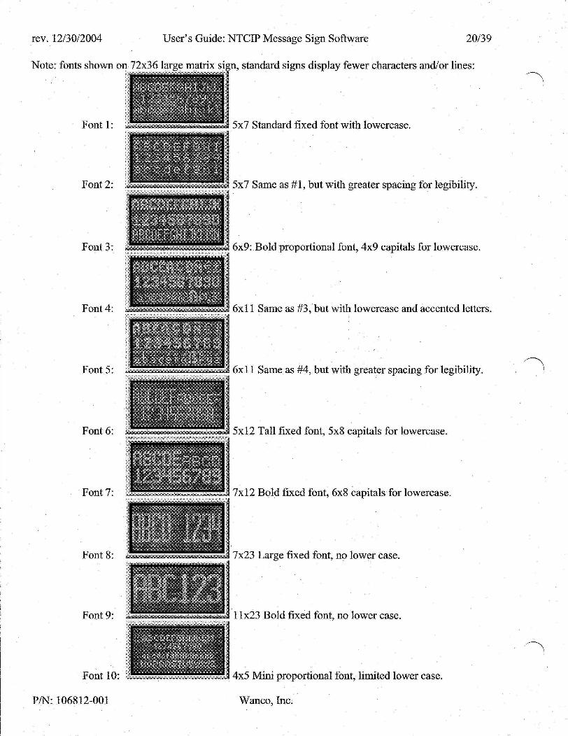
Note: fonts shown on 72x36 large matrix sign, standard signs display fewer characters and/or lines:
Fontl:
Font 2:
Font 3:
Font 4:
Font 5:
Font 6:
Font 7:
Font 8:
Font 9:
Font 10:
P/N: 106812-001
5x7 Standard fixed font with lowercase.
5x7 Same as #1, but with greater spacing for legibility.
6x9: Bold proportional font, 4x9 capitals for lowercase.
6x11 Same as #3, but with lowercase and accented letters.
6x11 Same as #4, but with greater spacing for legibility.
5x12 Tall fixed font, 5x8 capitals for lowercase.
7x12 Bold fixed font, 6x8 capitals for lowercase.
7x23 Large fixed font, no lower case.
11x23 Bold fixed font, no lower case.
4x5 Mini proportional font, limited lower case.
Wanco, Inc.

rev. 12/30/2004 User's Guide: NTCIP Message Sign Software 21/39
5.18. Editor Default Settings To configure the default message justification and font, select "Edi to r S e t t i n g s " from the Message Menu.
5.19. Real-Time Data (MULTI Fields) MULTI fields display live data when the message is activated. These fields are not fixed when the message is edited. This includes date, time, sensors (temperatures, voltages), auxiliary devices (radar speed, scale weight), message time remaining, and NTCIP database fields (radio frequency, speed limit, minimum speed). Press Alt-F (or Alt-M) to show the MULTI F i e l d Menu (when editing a message). This menu contains a list of all the available real-time fields. Each line shows a different field, with its description, MULTI field code number, and character width. Scroll to the desired field, then press ENTER to select it and return to edit mode. If there is sufficient room on the current line, a field placeholder will appear in the message (e.g. Zxxxxx), blocking out the required number of characters. This field can be moved or deleted, but can not be modified. Several fields can be embedded into the same message or page. To find out what an existing field refers to, place the cursor on the field and press Alt-F, the field type will be pre-selected when the MULTI F i e l d Menu appears.
Sample edit screen with MULTI field placeholders (8x3 character sign): \ Msg#:C015
Sxxxx |f Pg2/2 TODAY IS|f Altf=Cntr Sx/Sx %\f Alt*=Flsh
Sample preview screen with live MULTI field data (8x3 character sign):
\ A 10:24 | Msg#
TODAY IS| COlS 12/13 | \/
5.20. Scale Weight To display the actual weight from a compatible truck scale in a message, select the "Weight l b " MULTI field from the menu. The weight field takes six characters and is in pounds.
5.21. Radar Speeds To display the actual speed from a compatible radar unit in a message, select one of the "Speed mph" or "Speed kph" MULTI fields from the menu. There are different fields for mph or kph, and 2- or 3-character widths. The "SpeedXXX" fields display XXX when the actual speed exceeds the set speed limit by 20 mph or more (to discourage speeders from using the radar for high-speed racing). See the radar section for information on assigning these messages to radar events and configuring speed limits. Note that default permanent messages are already provided for the radar system, in either kph or mph, which should work for most applications.
5.22. Page Timing To modify timing settings for a single message, select the "Se t Page Times" screen from the Msg Options Menu.. To modify the default timing settings for the entire sign, select "Set Page Times" screen from the "Advanced Menu". These settings control how long each page (in a multi-page message) is displayed before changing to the next page, and how long the sign display is blanked between pages, and what the character flash rate is on each page. Note that single page messages with no flashing characters will have nothing to configure (they are always on).
P/N: 106812-001 Wanco, Inc.

rev. 12/30/2004 User's Guide: NTCIP Message Sign Software 22/39
5.23. Message Timer (Auto-Blanking) To display a message for a limited time, select "Msg Blank Timer" from the Message Menu (after activating a message). Enter the desired message time remaining in minutes; enter 65535 to disable the timer (i.e. no auto-blanking). When the timer ends, the sign display will be blanked automatically. The actual time remaining will update on this screen automatically. This timer will be reset (disabled) whenever a new message is activated. To use this feature as a countdown timer in a message, edit the message and embed the "Timer msg" field from the MULTI F i e l d Menu, activate it, then set this timer. Note that although the default is to blank the sign (display msg# BO 01), the actual message displayed is for the NTCIP "End Dura t ion" event, configured on the "Defaul t Messages" screen from the Message Menu.
5.24. MULTI-Text Editor For direct editing of the raw message MULTI-text, select "MULTI-Text E d i t o r " from the Msg Options Menu. Note: some MULTI codes may not be supported by all sign types.
P/N: 106812-001 Wanco, Inc.

rev. 12/30/2004 User's Guide: NTCIP Message Sign Software 23/39
6. Status
6.1. Sign Display To view the actual text being displayed on the sign, select "Message on Sign" from the S t a t u s Menu, or press Alt-M. To select this active message from the preview screen, press A.
Sample message status screen (8x3 character sign): \
10:24 | TODAY IS| 12/13 |
Msg# C015 on sign
Sample message status screen (48x27 matrix sign):
-Bitmap-Msg# P093 on sign
Message on S i g n
6.2. Alarms To view the alarms, select "Alarms & Warnings" from the S t a t u s Menu, or press Alt-A. Active alarms are shown as " ! ! " , inactive alarms are shown as "OK". These alarms are also summarized on the password login screen. For additional information, see the voltage, power control and display card status screens.
Sample alarm status screen: Dsply=!! VoltWarn=OK PwrBd=OK TempWarn=OK NTCIP=OK TempCrit=OK AuxIO=OK PhtoCell=!!
• Dsply • PwrBd • NTCIP • AuxIO • VoltWarn • TempWarn • TempCrit • PhtoCell
Sign display card(s) not responding Power control system not responding NTCIP system communications error Auxiliary device communications error Voltage(s) out-of-range Temperature(s) out-of-range Sign temperature critically high, sign display blanked Photocell(s) out-of-range
The out-of-range warning limits are configurable via the S e t t i n g s Menu (admin/service only).
P/N: 106812-001 Wane©, Inc.

rev. 12/30/2004 User's Guide: NTCIP Message Sign Software 24/39
6.3. Voltages To view the sensors, select "Vol ts & Temps" from the S t a t u s Menu, or press Alt-V.
Sample voltage status screen: Ts=156°F Vs=12.75 Tc=101°F Is=4.321 Pl= 62% Vl=12.35 P2= 56% 11=0.543
• Ts Temperature of sign display box (ambient plus solar heat) • Tc Temperature of control box (near ambient) • Ta Temperature of ambient sensor (if equipped) • PI Illumination detected by photocell #1 • P2 Illumination detected by photocell #2 • Vs Sign voltage, Volts (battery or main power) • I s Sign current, Amps (battery or main power) • VI Line voltage, Volts (solar charger) • I I Line current, Amps (solar charger)
6.4. Time & Date To view the time and date, select "Time & Date" from the S t a t u s Menu, or press Alt-T.
Sample time & date status screen: Hours the sign display has been powered on (not blanked) Hours relative to Coordinated Universal Time (GMT/Zulu) US-standard Daylight Saving Time
Run Timer: 4.9 hrs Time Zone: -7 hrs
DST: Enabled 12/13/2003 16:06:35
• Time zone is -5 for Eastern, -6 for Central, -7 for Mountain, -8 for Pacific, etc. • The date is shown in US-standard month/day/year format. • The time is shown in 24-hour format, with seconds.
Time settings are changed via the "Set Time & Date" screen from the Advanced Menu (admin/service password only).
6.5. IDs & Versions To view the machine ID (serial number, order number and/or VIN), model number, and software version (also visible during power-up on the splash screen, along with the model description), select "IDs & Vers ions" from the S t a t u s Menu, or press Alt-I.
6.6. Display Cards To view the state of the sign display cards, select "Display Cards" from the S t a t u s Menu, or press Alt-D. A screen similar to the message screens will appear, with each display card shown in the simulated sign display in the box on the left, and the total number of responsive cards in the upper right. Each responsive card is shown with a letter (indicating its software version), or a ?, if not responsive. The actual numeric version of the first card is shown in the upper right below the card count.
Sample display cards status screen (8x3 character sign, no errors): \
EEEEEEEE| EEEEEEEE| EEEEEEEE|
#024 vl.22
S=Scan
P/N: 106812-001 Wanco, Inc.

rev. 12/30/2004 User's Guide: NTCIP Message Sign Software 25/39
Sample display cards status screen (8x3 character sign, with errors): \
DDDDDDDDI DDDDDDDAI A??????? |
#= 017 vl.21
S=Scan
Sample display cards status screen (48x27 matrix sign, no errors)
BBBBBB BBBBBB BBBBBB
#=018 v3.01
S=Scan For normal operation, all display cards should have the same software version (i.e. all the same letter), and no cards should be listed as ?. Mixing cards of different software versions may result in mismatches in font characters or brightness levels, and is not recommended. Be sure to specify the correct software revision when ordering a replacement card.
To force a retest of all cards, press ENTER. The display map will blank out, and then refresh after several seconds. The sign display must not be blanked, and the test will automatically activate the alphabet test message. Note: a ? does not automatically indicate the display card needs replacement, just that the controller has lost communications to it. This could be due to a cable problem, or due to problems with an upstream card.
6.7. Power Controls To view the power system, select "Power Con t ro l s " from the S t a t u s Menu, or press Alt-P.
Sample power controls status screen: Fan 1=0 DispPwr=0 Fan 2=0 Brght=62% Chrgr=0 State=Blnk Door=+ MBPC=0xl8
Fan 1 + if Fan #1 is on, 0 if off
Fan 2 + if Fan #2 is on, 0 if off
Chrgr + if solar charging system is on, 0 if off
Door + if door switch reads open, 0 if closed
DispPwr + if sign display cards have power, 0 if off Brght Current brightness level of the LEDs S t a t e Current power control state: Good, Low (warn), or Blnk (sign blanked) MBPC Current power control command (for service use)
P/N: 106812-001 Wanco, Inc.

rev. 12/30/2004 User's Guide: NTCIP Message Sign Software 26/39
7. Message Scheduler
7.1. Overview Enabling this system causes the sign display to change automatically based clock/timer changes. Some sign models have an LED on the front panel to indicate when this scheduler is enabled. Note: manually activating any message automatically disables the scheduler. Whenever using the message scheduler, the sign must have the correct date and time. To view the time and date, select "Time & Date" from the S t a t u s Menu, or press Alt-T.
7.2. Schedule Config To configure the message scheduling system, select "Schedule S e t t i n g s " from the Conf ig/Aux Menu, or press Alt-C.
Sample schedule config screen: -^Schedule: Edit Day Edit Day Edit Day
On,Plan#2 Plan #1... Plan #2... Plan #3...
7.3. Day Plans Each Day Plan is a separate schedule with a specific date range, valid days of the week, and set of messages. Only one Day Plan is active at a time. Each day, the system automatically selects the Day Plan that most closely corresponds to the current date and day of the week. For example, one plan may be used for weekdays and another for weekends; or one plan may be used to warn of upcoming construction and another may provide information during the construction. It is possible for the schedule system to be enabled, but to have no plan active for the current day.
Sample Day Plan edit screen: -»Set Msgs & Tiroes... Dates Days: Erase
04/01-10/31 MTWTFss
Day Plan #2?
Use Dates to set the start and end date for this plan. Use Days to enable each desired day of the week. Move to the desired day and press any key to toggle it on/off. Days with capital letters indicate the plan is active on those days, days with lower case letters indicate the plan is inactive on those days.
Sample message schedule screen (Day Plan #2): •*Msg2-l: C001 Msg2-2: C002 Msg2-3: C003 Msg2-4: B001
06:59 09:01 15:59 19:01
Enter the desired message number and time for each slot. Times are in 24-hour format. Use blank messages (B0 01) to turn the sign off. Press N to deactivate a message (NONE —: —).
P/N: 106812-001 Wanco, Inc.

rev. 12/30/2004 User's Guide: NTCIP Message Sign Software 27/39
8. Aux Devices
8.1. Overview Enabling these systems causes the sign display to change automatically based on optional hardware. Some sign models have LEDs on the front panel to indicate when these systems are enabled. Note: enabling multiple systems at the same time may cause important messages to be replaced with lower priority ones.
8.2. Radar To configure the optional radar event system, select Conf ig/Aux Menu, or press Alt-R.
Sample radar con fig screen:
xRadar/Speed L imi t s " from the
•»Radar
Speed
Excess
Power:
Limit:
> Speed:
Off 30
+ 20 Advanced Options...
Radar detector power/Radar event system enable Regulatory speed limit Value over the speed limit to display special message
By default, when the radar system is active, the sign will display a message indicating the regulatory speed limit. When the radar detects an oncoming car, the message will change to display the actual radar speed. If this speed is over the speed limit, the displayed speed will flash (blink). If this speed is over the excessive speed limit (Speed L imi t plus Excess Speed), the message will change to "SLOW DOWN". This discourages certain drivers from driving at dangerous speeds simply to see it appear on the sign. When no car is detected, the sign reverts to the regulatory speed limit message.
Novice users can simply press Alt-R, enter the desired Speed Limit and toggle Radar Power as needed. No knowledge of message creation/activation or sign operation is required, and this feature is available to users with restricted-level passwords.
To access additional settings, select "Advanced Options".
Sample advanced radar options screen: -»Radar Messages Units & Min Speed Restore Defaults
To change the default radar system behavior, select "Radar Messages".
Sample radar messages screen: when no radar speed is detected when radar speed is <= the speed limit setting when radar speed is > the speed limit setting when radar speed is >= the excessive speed setting
For example, a user may not want to show the actual speed of a legal driver. Simply assign the same message to both the Spd Limit and Legal Spd messages. Then the sign display will only change when a driver exceeds the regulatory speed limit.
Similarly, a construction zone may wish to display an informational message most of the time, and only display "SLOW DOWN" when an excessive speed is detected. Simply create a custom message
->Spd Limit Msg:
Legal Spd Msg:
Overspeed Msg:
Excessive Msg:
P039
P040
P041
P046
P/N: 106812-001 Wanco, Inc.

rev. 12/30/2004 User's Guide: NTCIP Message Sign Software 28/39
(e.g. CO 01) and assign it to the first three slots (Spd Limit, Legal Spd, and Overspeed messages). Then the sign display will only change when a driver reaches the excessive speed limit.
When creating custom messages, use the MULTI F i e l d Menu to embed radar speed fields.
To use KPH instead, or set the displayed minimum speed, select "Uni ts & Min Speed".
Sample units and minimum speed screen: Select between MPH and KPH messages Set the value shown on the minimum speed message
-»Speed Units: MPH Minimum Speed: 4 5 (Min Spd Msg: P038)
Note: changing Speed Uni t s will automatically reset the three radar speed messages to defaults, i.e. P038-P041 are MPH Only, P042-P045 are KPH only.
The minimum speed message is not normally used by the radar, but could be selected for the Spd Limit message, or simply used on its own without a radar system. The Minimum Speed field is also available from the MULTI F i e l d Menu when creating custom messages.
To restore the default settings for the current units, select "Res tore Defau l t s " .
Sample radar reset screen: All radar speeds and messages have been reset to factory default settings.
8.3. Highway Alert Radio (HAR) To configure the optional HAR event system, select Conf ig/Aux Menu, or press Alt-H.
Sample HAR config screen:
* HwyRadio A l e r t Msg" from the
-^HwyRadio Pwr: Off AM Frequency: 530 Advisory Msg: P037 (Default Msg: P037)
Enable/disable radio power and event system Value displayed on "TRAFFIC ADVISORY" message Displayed when a highway alert is detected.
By default, when the HAR system is active, the sign will display the advisory message whenever an alert is detected, and will revert to the previous message when the alert is over.
Novice users can simply press Alt-H, enter the desired AM Frequency and toggle HwyRadio Pwr as needed. No knowledge of message creation/activation or sign operation is required, and this feature is available to users with restricted-level passwords.
8.4. Digital Encoder The encoder system is used to select a custom message directly, and is compatible with several different hardware options.
Sample encoder screen: •^Encoder: Enab led
C u r r e n t V a l u e : C012
P/N: 106812-001 Wanco, Inc.

rev. 12/30/2004 User's Guide: NTCIP Message Sign Software 29/39
9. Sign Settings
9.1. Overview Select Advanced Menu from the Main Menu to set system defaults for the sign. Advanced level password required to access this menu.
9.2. Time & Date Settings To change the date and time settings, select "Se t Time & Date" from the Advanced Menu. Make sure the date, time zone and DST options are correct before setting the local time, else the displayed time will change automatically.
Sample time and date screen: -»Time: Date: Zone: DST:
09:37:59 02/03/04 -07 hrs Enabled (USA)
9.3. Page and Blink Timing To view or change the default message page display times and character flash rates, select "Se t Page Times" from the Advanced Menu.
Sample page times screen: ->Page Page Flash Flash
On : Off: On : Off:
02.6 00.2 01.0 00.4
sec sec sec sec
9.4. Message Centering To configure the default message justification, select Message Menu.
"Editor S e t t i n g s " from the
9.5. Character Font To configure the default message font, select "Ed i to r S e t t i n g s " from the Message Menu.
9.6. Change Passwords To change one of the passwords, select "Change Password" from the Advanced Menu. The same passwords are used for both local login and remote NTCIP access. For remote access, passwords are case sensitive. Be sure to record your passwords in a safe location.
Sample change password screen: Confirm p a s s w o r d : Old :***** New:*******
P/N: 106812-001 Wanco, Inc.

rev. 12/30/2004 User's Guide: NTCIP Message Sign Software 30/39
10. NTCIP Settings
10.1. Modem Setup If enabled for this sign model, the optional NTCIP modem must be set to auto-answer, 9600-8-N-l with hardware flow control (to the sign), and connected to the modem port with a standard 9-pin serial cable. Note: to change the default from 9600 baud, select " S e r i a l Baud Ra tes" from the S e t t i n g s Menu, and change the Modem port setting.
10.2. Serial Cable Setup If enabled for this sign model, a laptop computer running an NTCIP central control program may be connected to the modem port with a standard 9-pin null-modem cable. Communications must be set to 9600-8-N-l with hardware flow control. Note: to change the default from 9600 baud, select " S e r i a l Baud Ra tes" from the S e t t i n g s Menu, and change the Modem port setting.
10.3. HDLC Drop Address To view or change the hardware drop address for HDLC serial/modem communications, select "HDLC Drop Address" from the S e t t i n g s Menu. Note: setting this value incorrectly will disable remote communications to the NTCIP Central software.
10.4. Change Passwords To change one of the passwords, select "Change Password" from the Advanced Menu. The same passwords are used for both local login and remote NTCIP access. For remote access, passwords are case sensitive.
10.5. Event Messages To configure the default messages and time parameters for NTCIP reset events (e.g. power loss), select "Defaul t Messages" and/or "Defaul t Msg Times" from the Message Menu. Press N (none) or L (last msg) to disable a message change for that event.
10.6. NTCIP Raw I/O To view or change an OID directly, select "NTCIP Raw I /O" from the Advanced Menu.
Sample raw I/O screen: Enter NEMA OID: 4.2.3.1.2.0
Val=132 (1 - 134)
RO Integer
10.7. MULTI-Text Editor For direct editing of the raw message MULTI-text, select "MULTI-Text E d i t o r " from the Msg Options Menu. Note: some MULTI codes may not be supported by all sign types.
P/N: 106812-001 Wanco, Inc.

rev. 12/30/2004 User's Guide: NTCIP Message Sign Software 31/39
11. Service Mode Settings
11.1. Overview Select Advanced Menu from the Main Menu to set system defaults for the sign. Service level password required to access this menu.
11.2. Hardware Info To view the sign dimensions and the software versions of the hardware subsystems, select "Hardware In fo" from the Serv ice Menu.
Sample hardware info screen (8x3 character sign): number of display cards on sign panel number of pixels per display card display card type & version (CHR=character, MTX=matrix) power control board version
Sample hardware info screen (7x2 character sign):
Cards: 8 x 3 Pixel: 5 x 7 CHR00: v. 1.21 MBPC: v. 3
C a r d s : P i x e l : CHR00:
MBPC:
7 x 2 5 x 7 v . 1 . 23 v . 3
Sample C a r d s P i x e l MTX03
MBPC
hardware info 6 8 v . V
x 3 x 9
3 . 0 1 4
screen (48x27 f ull-size matrix sign):
Sample hardware info screen (48x27 mini matrix sign): Cards: 4 x 3 Pixel: 12 x 9 MTX05: v. 4.02 MBPC: v. 4
Sample hardware info screen (56x25 mini matrix sign): C a r d s : 7 P i x e l : 8 MTX03: v
MBPC: v
x 5 x 5
3 . 0 3 4
P/N: 106812-001 Wanco, Inc.

rev. 12/30/2004 User's Guide: NTCIP Message Sign Software 32/39
Sample hardware info screen (72x36 hi-def matrix sign): Cards: 6 x 4 Pixel: 12 x 9 MTX05: v. 4.03 MBPC: v. 4
11.3. Fan Temperatures To view or change the fan turn-on temperatures, select "Fan Temperatures" from the S e t t i n g s Menu.
Sample fan temperatures screen (recommended values shown): Fan 1 Temp: 165°F
*Fan 2 Temp: 175°F
11.4. Charger Relay Voltages To view or change the solar charger on-off voltages, select S e t t i n g s Menu.
Sample power controls screen (recommended values shown):
^Power Con t ro l s " from the
-»Chrgr Chrgr Power Power
Off: On : Low: Off:
14750 12600 11500 11300
mV mV mV mV
11.5. Low Power Settings To configure the sign to display a low power warning message, select "Defaul t Messages" from the Message Menu, and change the Low Voltage message setting. To view or change the battery control voltages, select "Power Con t ro l s " from the S e t t i n g s Menu. When the voltage drops to the Low setting, the a low voltage alarm is triggered (and the optional warning message is displayed) until the voltage returns to normal. When the voltage drops to the Off setting, the sign display panel is shut off. If the voltage falls extremely low, all sign and console power will be shut off and the battery saver/shutdown LED will light.
Sample power controls screen: Chrgr Chrgr
-»Power Power
Off: On : Low: Off:
14750 mV 12600 mV 11500 mV 11300 mV use 11.30V for solar and 10.50V for non-solar signs
In cold weather, increase these settings by IV (very low batteries may freeze at 19°F).
11.6. LED Brightness Control To view or change the illumination settings, select " I l ium Con t ro l s " from the S e t t i n g s Menu. Press S for a standard solar sign, or press H for a non-solar, hi-intensity sign, or set the brightness levels directly. The system uses the 3 set points to construct a table of 16 levels with hysteresis control. The higher the LED setting, the greater the drain on the batteries. Increasing the settings beyond the factory defaults is not recommended, and may cause the battery charge life to be less than 30 days.
P/N: 106812-001 Wanco, Inc.

rev. 12/30/2004 User's Guide: NTCIP Message Sign Software 33/39
Sample illumination control screen: -»LED%: 005,
(Night, Solar: 005, HiLED: 012,
043, Day, 043, 100,
060 Hi) 060 100
recommended for solar signs recommended for non-solar, high-intensity signs
11.7. Alarm Limits To view or change the out-of-range limits for the alarms, select the appropriate alarms screen from the S e t t i n g s Menu (e.g. Voltage, Temp, or Pho toce l l Alarms).
P/N: 106812-001 Wanco, Inc.

rev. 12/30/2004 User's Guide: NTCIP Message Sign Software 34/39
12. Service Mode Controls
12.1. Overview These screens override the power and display control systems, and are intended for troubleshooting and QA use by qualified service personnel only (service password required). After 10 minutes without a key press, these screens automatically exit to the prior menu. Normal automated system controls are automatically restored when leaving these screens (i.e. manual mode is cancelled).
12.2. Fans & Charger To manually control power to the fans and the solar charger, select "Fan/Charger Power" from the Serv ice Menu, or press Alt-F. Line voltage and current (solar charger) are also shown.
Sample fan/charger screen: *Fan 1=0 line/ Fan 2=0 charger Chrgr=+ Vl=12.35 Light=+ 11=2.856
12.2.1. Fan Test Note: may not apply to all sign models. Sign may have 0, 1 or 2 fans. Turn on each fan and verify it is operational by inspecting air flow at the fan vents on the back of the sign display panel. Clean fan filters and/or replace fans as necessary. 12.2.2. Solar Panel and Charger Relay Test Note: may not apply to all sign models. Sign may have 0,2 or 4 solar panels. Verify solar panels are in good sunlight, charger relay is on, and current reading is 5-10 Amps (if battery is not folly charged and sign display panel has an active message). Cover one solar panel with a large piece of cardboard and verify the current reading drops to half its value. Repeat for the other panel, then remove the cardboard. Manually turn off the charging relay. The current reading should drop to zero, and the indicated voltage will increase to the open-circuit value.
12.3. Display Power & Brightness To manually control power to the display cards and the LED brightness, select "Display Brght/Pwr" from the Serv ice Menu, or press Alt-L. For full LED testing, activate the LED test message (press Alt-+) before entering this screen. Sign voltage and current are also shown; sign current (and battery charge life) varies greatly with LED brightness.
Sample brightness/power screen: •»DispPwr=+
A Brght=75%
\ /
Vs=12.75 I s = 5 . 8 6 2
s i g n / b a t t e r y
12.4. Diagnostic Messages To view status and error messages, connect a laptop computer running a serial capture terminal program (e.g. HyperTerminal) to the debug port with a standard 9-pin null-modem cable. Communications must be set to 9600-8-N-l with hardware flow control enabled. Note: to change the default from 9600 baud, select " S e r i a l Baud Ra tes" from the S e t t i n g s Menu, and change the Debug port setting.. For additional output message buffering (to prevent data loss), send XXT to enable and XXF to disable (or press reset). Note: leaving buffering enabled without a connected laptop can reduce system performance.
P/N: 106812-001 Wanco, Inc.

rev. 12/30/2004 User's Guide: NTCIP Message Sign Software 35/39
12.5. Matrix Card Replacement The display cards for matrix signs have software programmable addresses to determine their location in the sign board. If a card is replaced or moved to a new location, its new address must be programmed for proper message display. Log in with a service-level password, and select "Display Cards" from the S t a t u s Menu, or press Alt-D. The service option " I n i t " will now appear above "Scan". Press I to reprogram all the display card addresses. The display map will blank out, and then refresh after several seconds. Note: do not perform this initialization unless required due to a card replacement, its effects can not be undone and may interfere with troubleshooting hardware problems.
Sample d
BB?BBB BBBB?B BBBBBB
splay cards status screen (wi #=016 v 3 . 0 1
I = I n i t S=Scan
For normal operation, all display cards should have the same software version (i.e. all the same letter), and no cards should be listed as ?. Mixing cards of different software versions may result in communications errors or unmatched brightness levels, and is not recommended. Be sure to specify the correct software revision when ordering a replacement card.
P/N: 106812-001 Wanco, Inc.

rev. 12/30/2004 User's Guide: NTCIP Message Sign Software 36/39
13. Accented Character Codes (Fonts 4 & 5)
€ *
c t S • r z z c s s s L z Y •
i o £
A 3 i i
ij ? z N
AH
AH
AH
AH
AH
AH
AH
AH
AH
AH
AH
AH
AH
AH
AH
AH
AH
AH
AH
AH
AH
AH
Al
-128
-134
-136
.-138
-141
:-142
t-143
t-151
t-152
t-154
t-157
t-158
t-159
t-161
t-162
t-163
t-164
t-165
t-166
t-168
t-169
t-171
t-187
n Alt-188
Z Alt-189
Z AIM 90
I AIM 91
A AIM 92
A AIM 93
A AIM 94
A AIM 95
A AIM 96
A AIM 97
K. AIM 98
Q AIM 99
E Alt-200
E Alt-201
E Alt-202
E Alt-203
1 Alt-204
1 Alt-205
1 Alt-206 • a 1 Alt-207
D Alt-208
N Alt-209
O Alt-210
o o
0*0 o KM o
X
0 u u u • • u Y P a
a a a »•
a o
a
Alt-211
Alt-212
Alt-213
Alt-214
Alt-215
Alt-216
Alt-217
Alt-218
Alt-219
Alt-220
Alt-221
Alt-222
Alt-223
Alt-224
Alt-225
Alt-226
Alt-227
AIt-228
Alt-229
a e Ait-23o
9 e e
Alt-231
Alt-232
Alt-233
e e i jr
1
1
1
6 n o o W •
o o 6 •
0 u u u • •
u y l> M *
y
Alt-234
Alt-235
Alt-236
Alt-237
Alt-238
Alt-239
Alt-240
Alt-241
Alt-242
Alt-243
Alt-244
Alt-245
Alt-246
Alt-247
Alt-248
Alt-249
Alt-250
Alt-251
Alt-252
Alt-253
Alt-254
Alt-255
P/N: 106812-001 Wanco, Inc.

rev. 12/30/2004 User's Guide: NTCIP Message Sign Software 37/39
14. Permanent Messages The following messages are standard on matrix and 3-line character signs. Matrix messages will use a variety of fonts and bitmap graphics. Character messages will use the standard font, text versions of the MUTCD signs and arrow graphics. Messages for 2-line character signs may be shortened or reformatted. For 1-line signs, most permanent messages will be blank. All sign models will have the 3 standard test messages: LED on (Alt-+), alphabet (Alt—), and factory test (Alt-[).
P 0 0 1 : Blank Message P002 : Time & Temperature P 0 0 3 : Standard Message P 0 0 4 : Standard Message P 0 0 5 : Standard Message POO 6: Standard Message P007: Standard Message P 0 0 8 : Standard Message P 0 0 9 : Standard Message P 010 : Standard Message P 0 1 1 : Standard Message P 0 1 2 : Standard Message P 013 : Standard Message P 014 : Standard Message P 0 1 5 : Arrow Message: « KEEP LEFT P 0 1 6 : Arrow Message: » KEEP RIGHT P 0 1 7 : FHWA Message: ALL LANES OPEN P 0 1 8 : FHWA Message: BLOWING SNOW P 0 1 9 : FHWA Message: BRIDGE CLOSED AHEAD P 0 2 0 : FHWA Message: CAUTION DUST STORM P 0 2 1 : FHWA Message: CAUTION FOG AHEAD P 0 2 2 : FHWA Message: CAUTION HIGH WINDS P 0 2 3 : FHWA Message: CAUTION ICY ROAD P 0 2 4 : FHWA Message: CAUTION ROAD FLOODED P 0 2 5 : FHWA Message: CAUTION SLIPPERY ROAD P02 6: FHWA Message: CHAINS REQUIRED AHEAD P 0 2 7 : FHWA Message: DANGER FALLING ROCKS P 0 2 8 : FHWA Message: DO NOT PASS P 0 2 9 : FHWA Message: EMERGENCY VEHICLES P030 : FHWA Message: FLAGGER AHEAD P 0 3 1 : FHWA Message: FOLLOW DETOURS AHEAD P 0 3 2 : FHWA Message: FOLLOW PACE CAR P 0 3 3 : FHWA Message: HEAVY TRAFFIC AHEAD P 0 3 4 : FHWA Message: LANES CHANGE AHEAD P 0 3 5 : FHWA Message: LOAD SPILL P 0 3 6 : FHWA Message: WORKERS AHEAD P037 : FHWA Message: PAINT CREW P 0 3 8 : FHWA Message: ROAD CLOSED AHEAD
P/N: 106812-001 Wanco,bac.
Shift-F3): CLICK IT OR TICKET
Shift-F4): CONSTR. ZONE FINES DOUBLED
Shift-F5): WORKERS AHEAD GIVE EM A BRAKE
Shift-F6): REPAIRS AHEAD USE CAUTION
Shift-F7): WRECK AHEAD REDUCE SPEED
Shift-F8): DEICING AHEAD STAY BACK
Shift-F9): SNOW REMOVAL STAY BACK
Shift-F10): PAINT CREW LANES WET DO NOT PASS
Shift-F11): PAINT CREW « KEEP LEFT
Shift-F12): PAINT CREW » KEEP RIGHT
Shift-F1): MERGE < — — —
Shift-F2): MERGE >

rev. 12/30/2004
P039:
P040:
P041:
P042:
P043: P044:
P045:
P046:
P047:
P048:
P049:
P050:
P051:
P052:
P053:
P054:
P055:
P056:
P057:
P058:
P059:
P060:
P061:
P062:
P063: P064:
P065:
P066:
P067:
P068: P069:
P070:
P071:
P072:
P073:
P074:
P075:
P076:
P077:
P078:
P079:
P080:
P081:
P082:
P083:
P/N: 106812-001
User's Guide: NTCIP Message Sign Software 38/39
FHWA Message: SLOW MOVING TRAFFIC FHWA Message: STEEL PLATES FHWA Message: TRAFFIC SIGNAL OUT FHWA Message: WATCH FOR TRUCKS Arrow Message (Alt-F1): 4-Corner Caution (flashing) Arrow Message (Alt-F2): Diamonds Caution (flashing) Arrow Message (Alt-F3): Bar Caution (flashing) Arrow Message (Alt-F4): Double Arrow (flashing) Arrow Message (Alt-F5): Left Arrow (flashing) Arrow Message (Alt-F6): Right Arrow (flashing) Arrow Message (Alt-F7): Left Arrow (walking) Arrow Message (Alt-F8): Right Arrow (walking) Arrow Message (Alt-F9): Left Chevrons (walking) Arrow Message (Ait-F10): Right Chevrons (walking) Arrow Message (AIt-F11): Left Stem Arrow (walking) Arrow Message (Alt-F12): Right Stem Arrow (walking) Hwy Radio Message: ADVISORY TUNE TO #### AM Speed Message: MINIMUM SPEED ## mph Radar Message: SPEED LIMIT ## mph Radar Message: ## mph YOUR SPEED Radar Message: ## mph YOUR SPEED (flashing) Speed Message: MINIMUM SPEED ## kph Radar Message: SPEED LIMIT ## kph Radar Message: ## kph YOUR SPEED Radar Message: ## kph YOUR SPEED (flashing) Radar Message: SLOW DOWN (flashing) Speed Message: SLOW Speed Message: STOP NTCIP Message: LOW POWER NTCIP Message: POWER RESET NTCIP Message: COMM LOST NTCIP Message: SYSTEM RESET LED Test Page (Alt-+) Alphabet Test Page (Alt—) Time & Voltages Time & Temperatures MUTCD Sign, M4-10L: Detour < — — MUTCD Sign, M4-10R: Detour > MUTCD Sign, Wl-4bL: < — — Lanes Shift Left MUTCD Sign, Wl-4bR: — — > Lanes Shift Right MUTCD Sign, W7-1: Steep Grade (Truck Downhill) MUTCD Sign, Wl-5 : Curvy Road (Reverse Curve) MUTCD Sign, W6-1: Median Begins 2-Way Traffic (Begin Divided Hwy) MUTCD Sign, W6-2: Median Ends 2-Way Traffic Keep Right (End Div Hwy) MUTCD Sign, R4-7: Keep Right Median Begins
Wanco, Inc.
. 12/30/2004
P084: P085: P086: P087: P088: P089: P090: P091: P092: P093: P094:
User's Guide: NTCIP Message Sign Software 39/39
MUTCD Sign, W4-1R: Merge Ahead (Incoming from Right) MUTCD Sign, W20-7a: Flagger Ahead MUTCD Sign, W21-la: Workers Ahead MUTCD Sign, W8-5: Slippery Road MUTCD Sign, Wl-7: Double Arrow (non-flashing) MUTCD Sign, W1-6L: Left Arrow (non-flashing) MUTCD Sign, W1-6R: Right Arrow (non-flashing) OPEN
CLOSED
Manufacturer/Logo Factory Test Sequence (Alt-[)
P/N: 106812-001 Wanco,Inc.