Embed Size (px)
Citation preview
1
Abstract— While distribution system analysis has been
utilized for capacitor placement problems, this panel discusses some adaptations that can be made for capacitor control. First, several constraints are experienced during capacitor operations which are often not explicitly formulated. Second, balance between speed of computation and availability and organization of data is an issue. Finally, this summary discusses a centralized algorithm based on system analysis tools for capacitor control for conservation voltage reduction; however, we will discuss ways to distribute analysis and control. Results on several field circuits will be presented.
Index Terms—power distribution system analysis, capacitor control,
I. INTRODUCTION apacitor control has typically been employed by system operators to support voltage regulation, power factor
correction and network loss reduction. Recently, utilities have come under increased pressure to achieve network level energy consumption reductions, e.g. [1]. Thus, renewed interest in conservation voltage reduction (CVR) has emerged and is being achieved via advanced distribution automation in both centralized and decentralized efforts.
In this panel summary, the capacitor control problem is formulated to address voltage spread reduction in distribution networks. Voltage spread reduction aims to minimize the voltage differential along all feeders in the network. Subsequently, this will enable CVR by allowing operators to reduce substation voltages with feeder capacitor banks supplying voltage support throughout the network. There are many formulations and algorithms for capacitor control; examples can be found in [2], [3] and [4-6].
In particular, this paper addresses practical considerations and their integration into the formal problem formulation. Specifically, given a capacitor placement, voltage rise constraints are mathematically included. This results in point-in-load feasible switching sequences.
It is also noted, that this work focuses on a centralized implementation of voltage spread reduction. This approach is
This work was supported by the U.S. Department of Energy and PPL
Electric Utilities. N. Segal, M. Kleinberg and K. Miu are the Department of Electrical and
Computer Engineering, Drexel University, Philadelphia, PA 19104, USA (e-mail: [email protected], [email protected], [email protected]).
A. Madonna is with Delmarva Power, 401 Eagle Run Road, Newark, DE 19714-9239 USA
H. J. Lehmann and T.R. Figura are with PPL Electric Utilities, 2 N. 9th Street, Allentown, PA 18101 USA
coupled with select utility efforts; for example PPL Electric Utilities. Distributed and decentralized efforts are also viable and an example can be found in [7-9]. Select alterations envisioned for a distributed control environment are discussed.
Recapping, this summary addresses: • a capacitor control problem formulation addressing
VSR in distribution networks • a review of practical and algorithmic considerations for
the capacitor control problem • simulation results for a PPL circuit • a discussion on distributed control scenarios for
capacitor control.
II. PROBLEM FORMULATION In this work, the capacitor control problem is formulated as
a constrained, non-differentiable, mixed integer, nonlinear optimization problem. The objective considered here is to minimize the voltage spread throughout a distribution network. A feasible solution satisfies the traditionally considered equality constraints expressed as the multi-phase power flow equations and inequality operating constraints of voltage magnitude and branch current flow limits. In addition, a voltage rise constraint is included here to maintain acceptable voltage magnitude changes during capacitor switching operations.
Each utility will have unique circuit specifications and safety constraints. As a result, available control actions will be limited by the existing distribution system equipment and operational requirements. For example, PPL's existing capacitor control equipment is three-phase gang operated and controlled in a single operation. Therefore, the formulation limits capacitor control operations to three-phase switching between two control states for each bank, either on or off.
In addition, the total number of reliable switching operations available over a device’s lifetime will be limited. Thus, system operators will dictate a daily maximum number of allowable switching operations for each device. Previous works have embedded this constraint directly into the problem formulation [10], or alternatively, modified the number of load levels considered to fit the number of switching operations available [11]. This panel will illustrate studies where the maximum number of switching operations per capacitor is greater than the number of load levels considered; hence, like [11] this constraint is not explicitly included in the formulation. The problem may then be stated: for each load level,
[ ]1,..., LLl N∈ :
Analytically Driven Capacitor Control for Voltage Spread Reduction
Nicole Segal, Student Member, IEEE, Michael Kleinberg, Student Member, IEEE, Anthony Madonna, Karen Miu, Member, IEEE, Horst Lehmann and Timothy Figura
C
978-1-4673-1935-5/12/$31.00 ©2012 IEEE
2
( ) ( ),
, ,
min max p pi ju U i j N
p a b c
V u V u∈ ∈
∈
− (1)
subject to:
∃ a control sequence [ ]0 1 1 1, , ... , , , , ... , k k ku u u u u u− + (2)
( ), 0kf V u = k∀ (3)
( )min max , , , , & p
i i k iV V u V i N p a b c k≤ ≤ ∀ ∈ ∈ ∀ (4)
( ) max , , , , & p
i k iI u I i N p a b c k≤ ∀ ∈ ∈ ∀ (5)
( ) ( ) max
1 , , , , & p p
i k i k riseV u V u V i N p a b c k−− ≤ ∀ ∈ ∈ ∀ (6)
where, alphabetically:
( , ) :kf V u multi-phase power flow equations p
iI : current flow entering bus i, phase p max
iI : maximum current flow or upstream protection setting of feeder entering bus i, whichever is least
N : set of all buses
LLN : number of load levels u : final capacitor control scheme, load level l
ku : kth capacitor control scheme in transition from 0u to u
0u : initial capacitor control scheme, load level l
U : set of possible capacitor control operations V : vector of node voltages
p
iV : voltage at bus i, phase p min
iV : minimum operating voltage, bus i max
iV : maximum operating voltage, bus i max
riseV : maximum allowable voltage rise
The solution search space is the combinatorial product of all capacitor control options available at each load level considered. In this work, control decisions are driven by rigorous multi-phase power flow analysis using detailed network component models. Algorithmic considerations for the capacitor control problem are discussed in the next section.
III. PRACTICAL AND ALGORITHMIC CONSIDERATIONS Capacitor control switching sequences will be limited by
the system's operating limits. Hence, the following will be highlighted:
• load distribution and load levels • feasible switching sequences • control algorithm
A. Load Distribution and Load Levels The type of load measurements available, the load model
and the number of load levels considered play a significant role in determining capacitor control decisions. For the presented cases, access to AMR data of multi-phase loads is available [12]. Therefore, in this work all loads are represented in the network at their measured locations.
Additionally, by using measured load data, distinct load levels over which to compute capacitor control actions may be defined. The decision to define these load levels via AMR, or scaling influences the resulting control decisions. In this work, load levels are defined using both AMR and scaling.
B. Feasible switching sequence Finally, many global optimization schemes have been
shown to be successful at finding high quality solutions to the capacitor control problem [6]. In many cases, however, these results provide no means for system operators to realize the computed solutions. Algorithms must then be designed to provide such a sequence directly or utilize post-processing techniques to constructively determine if a feasible sequence exists [13]. In this work, enforcing the voltage rise constraint as expressed in (6), allows for a functional check that the solution provided will also be physically realizable.
C. Control Algorithm In this work a focus on the achievability of including voltage rise constraints is desired, as opposed to contributions in algorithmic developments. Thus, since the total number of capacitors in the network is small an exhaustive search was performed to determine the control actions. The procedure for a given load level is as follows:
Step 1. Compile list of all possible capacitor control settings, select initial setting and continue.
Step 2. Run a multi-phase unbalanced power flow, post-process solution and check for voltage and current violations
Step 3. Compute the maximum voltage spread Step 4. Select next capacitor control setting on list and go to
Step 2, if no more exist, continue to Step 5 Step 5. Check voltage rise constraint between each setting Step 6. Find the set of feasible capacitor control sequences Step 7. Evaluate feasible results to determine optimal
switch settings It is noted that economic and other practical issues may limit the total number of automated devices (including capacitors) in a system. However, when large numbers of capacitors exist heuristic or other optimization routines can be implemented which may yield suboptimal yet feasible sequence. Results of the above algorithm applied to a PPL circuit test case are presented next.
IV. SIMULATION RESULTS In order to illustrate the proposed capacitor control
application, simulation results from a PPL test case are presented. Basic circuit details are provided along with study parameters and constraint values. The resulting capacitor control schemes and voltage spread results for the system will be shown along with a discussion on the application of the voltage rise constraint.
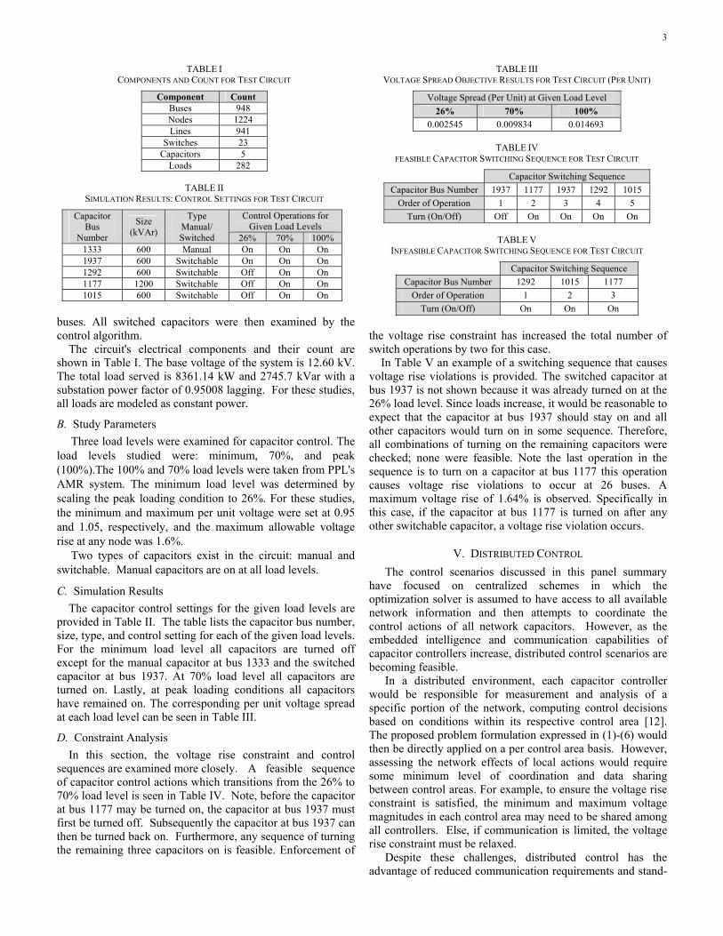
A. Test System Over 50 cases were studied. While many did not encounter capacitor switching sequence violations; several did. One circuit is selected here to highlight the importance of the voltage rise constraint Capacitors are installed on three-phase
3
TABLE III VOLTAGE SPREAD OBJECTIVE RESULTS FOR TEST CIRCUIT (PER UNIT)
Voltage Spread (Per Unit) at Given Load Level 26% 70% 100%
0.002545 0.009834 0.014693
TABLE IV FEASIBLE CAPACITOR SWITCHING SEQUENCE FOR TEST CIRCUIT
Capacitor Switching Sequence Capacitor Bus Number 1937 1177 1937 1292 1015
Order of Operation 1 2 3 4 5 Turn (On/Off) Off On On On On
TABLE V
INFEASIBLE CAPACITOR SWITCHING SEQUENCE FOR TEST CIRCUIT
Capacitor Switching Sequence Capacitor Bus Number 1292 1015 1177
Order of Operation 1 2 3 Turn (On/Off) On On On
TABLE I COMPONENTS AND COUNT FOR TEST CIRCUIT
Component Count Buses 948 Nodes 1224 Lines 941
Switches 23 Capacitors 5
Loads 282
TABLE II SIMULATION RESULTS: CONTROL SETTINGS FOR TEST CIRCUIT
Capacitor Bus
Number
Size (kVAr)
Type Manual/ Switched
Control Operations for Given Load Levels
26% 70% 100% 1333 600 Manual On On On 1937 600 Switchable On On On 1292 600 Switchable Off On On 1177 1200 Switchable Off On On 1015 600 Switchable Off On On
buses. All switched capacitors were then examined by the control algorithm. The circuit's electrical components and their count are shown in Table I. The base voltage of the system is 12.60 kV. The total load served is 8361.14 kW and 2745.7 kVar with a substation power factor of 0.95008 lagging. For these studies, all loads are modeled as constant power.
B. Study Parameters Three load levels were examined for capacitor control. The
load levels studied were: minimum, 70%, and peak (100%).The 100% and 70% load levels were taken from PPL's AMR system. The minimum load level was determined by scaling the peak loading condition to 26%. For these studies, the minimum and maximum per unit voltage were set at 0.95 and 1.05, respectively, and the maximum allowable voltage rise at any node was 1.6%.
Two types of capacitors exist in the circuit: manual and switchable. Manual capacitors are on at all load levels.
C. Simulation Results The capacitor control settings for the given load levels are
provided in Table II. The table lists the capacitor bus number, size, type, and control setting for each of the given load levels. For the minimum load level all capacitors are turned off except for the manual capacitor at bus 1333 and the switched capacitor at bus 1937. At 70% load level all capacitors are turned on. Lastly, at peak loading conditions all capacitors have remained on. The corresponding per unit voltage spread at each load level can be seen in Table III.
D. Constraint Analysis In this section, the voltage rise constraint and control sequences are examined more closely. A feasible sequence of capacitor control actions which transitions from the 26% to 70% load level is seen in Table IV. Note, before the capacitor at bus 1177 may be turned on, the capacitor at bus 1937 must first be turned off. Subsequently the capacitor at bus 1937 can then be turned back on. Furthermore, any sequence of turning the remaining three capacitors on is feasible. Enforcement of
the voltage rise constraint has increased the total number of switch operations by two for this case. In Table V an example of a switching sequence that causes voltage rise violations is provided. The switched capacitor at bus 1937 is not shown because it was already turned on at the 26% load level. Since loads increase, it would be reasonable to expect that the capacitor at bus 1937 should stay on and all other capacitors would turn on in some sequence. Therefore, all combinations of turning on the remaining capacitors were checked; none were feasible. Note the last operation in the sequence is to turn on a capacitor at bus 1177 this operation causes voltage rise violations to occur at 26 buses. A maximum voltage rise of 1.64% is observed. Specifically in this case, if the capacitor at bus 1177 is turned on after any other switchable capacitor, a voltage rise violation occurs.
V. DISTRIBUTED CONTROL The control scenarios discussed in this panel summary
have focused on centralized schemes in which the optimization solver is assumed to have access to all available network information and then attempts to coordinate the control actions of all network capacitors. However, as the embedded intelligence and communication capabilities of capacitor controllers increase, distributed control scenarios are becoming feasible.
In a distributed environment, each capacitor controller would be responsible for measurement and analysis of a specific portion of the network, computing control decisions based on conditions within its respective control area [12]. The proposed problem formulation expressed in (1)-(6) would then be directly applied on a per control area basis. However, assessing the network effects of local actions would require some minimum level of coordination and data sharing between control areas. For example, to ensure the voltage rise constraint is satisfied, the minimum and maximum voltage magnitudes in each control area may need to be shared among all controllers. Else, if communication is limited, the voltage rise constraint must be relaxed.
Despite these challenges, distributed control has the advantage of reduced communication requirements and stand-
4
alone capability in the event of a communication failure. This type of decentralized approach offers an alternative to high investment and costs associated with centralized control centers.
VI. CONCLUSIONS In this panel summary the capacitor control problem was
formulated to include a voltage spread reduction objective and voltage rise constraint. An overview of practical and algorithm considerations was given. To illustrate these concepts simulation results for a PPL test case were provided and the resulting control operations and voltage spread at three load levels were reported. A feasible switching sequence was given and to demonstrate the importance of the voltage rise constraint an infeasible switching sequence was identified.
It was demonstrated that without the voltage rise constraint, seemingly logical, yet infeasible switch sequences result. Thus embedding the constraint could assist operators in better coordinating capacitor control operations.
VII. REFERENCES [1] Pennsylvania Act 129, Nov. 2008. [2] M. E. Baran and F. F. Wu, “Optimal sizing of capacitors placed on a
radial distribution system,” IEEE Trans. on Power Delivery, vol. 4, no. 1, pp. 735–743, Jan. 1989.
[3] J. Hambrick, R. P. Broadwater, “Configurable, hierarchical, model-based control of electrical distribution circuits,” IEEE Trans. on Power Systems, vol. 26, no. 3, pp. 1072-1079, Aug. 2011.
[4] Y. Baghzouz, “Effects of nonlinear loads on optimal capacitor placement in radial feeders,” IEEE Trans. on Power Delivery, vol. 6, no. 1, pp. 245-251, Jan. 1991.
[5] H.-D. Chiang; J.-C. Wang; J. Tong, G. Darling, “Optimal capacitor placement, replacement and control in large-scale unbalanced distribution systems: system modeling and a new formulation,” IEEE Transactions on Power Systems, vol.10, no.1, pp.356-362, Feb. 1995.
[6] H. N. Ng, M. M. A. Salama, A. Y. Chikhani, “Classification of capacitor allocation techniques,” IEEE Trans. on Power Delivery, vol. 15, no. 1, pp. 387-391, Jan. 2000.
[7] M. Kleinberg, K. Miu, “A study of distribution capacitor control for electric power distribution networks,” Proc. of the 2011 North American Powers Systems Symposium, Boston MA, Aug. 2011.
[8] S. D. J. McArthur, E. M. Davidson, V. M. Catterson, A. L. Dimeas, N. D. Hatziargyriou, F. Ponci, T. Funabashi, “Multi-agent systems for power engineering applications-part I,” IEEE Trans. on Power Systems, vol. 22. no. 4, 1743-1752, Nov. 2007.
[9] S. Toma, T. Senjyu, Y. Miyazato, A. Yona, K. Tanaka, C.-H. Kim, “Decentralized voltage control in distribution system using neural network,” Proc. of the IEEE Power and Energy Conference, pp. 1557 – 1562, Dec. 2008.
[10] M. B. Liu, C.A. Cañizares, W. Huang, “Reactive power and voltage control in distribution systems with limited switching operations,” IEEE Trans. on Power Systems, vol. 24, no. 2, pp. 889-899, May 2009.
[11] Z. Hu, X.Wang, H. Chen, and G. A. Taylor, “Volt/var control in distribution systems using a time-interval based approach,” IEE Proc. Generation, Transmission, and Distribution, vol. 150, no. 5, pp. 548–554, Sep. 2003.
[12] B. Bujnowski, “Lessons from a successful AMR implementation,” Transmission and Distribution World, 2005.
[13] K. N. Miu and J. Wan, “A post-processing method for determining the control sequence of distribution application functions formulated using discrete load levels,” Proc. of the 2000 IEEE Power Engineering Society Summer Meeting, Seattle, WA, July 2000.
VIII. BIOGRAPHIES
Nicole Segal is currently a Ph. D. student with the Department of Electrical and Computer Engineering at Drexel University, Philadelphia, PA.
Michael Kleinberg is currently a Ph. D. student with the Department of Electrical and Computer Engineering at Drexel University, Philadelphia, PA.
Anthony Madonna is currently with Delmarva Power a Pepco Holdings Inc. Company in Newark, DE.
Karen Miu is a Professor with the Department of Electrical and Computer Engineering at Drexel University, Philadelphia, PA. Her research interests include distribution system analysis, control and optimization.
Horst Lehmann is currently with PPL Electric Utilities in Allentown, PA.
Timothy R. Figura is currently with PPL Electric Utilities in Allentown, PA.


