Embed Size (px)
Citation preview
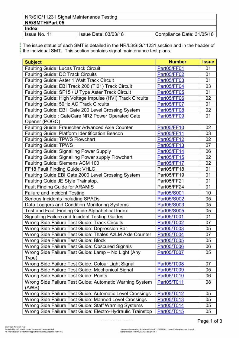
NR/SIG/11231 Signal Maintenance Testing NR/SMTH/Part 05 Index Issue No. 11 Issue Date: 03/03/18 Compliance Date: 31/05/18
Page 1 of 3
The issue status of each SMT is detailed in the NR/L3/SIG/11231 section and in the header of the individual SMT. This section contains signal maintenance test plans. Subject Number Issue Faulting Guide: Lucas Track Circuit Part05/FF01 01 Faulting Guide: DC Track Circuits Part05/FF02 01 Faulting Guide: Aster 1 Watt Track Circuit Part05/FF03 01 Faulting Guide: EBI Track 200 (TI21) Track Circuit Part05/FF04 03 Faulting Guide: SF15 / U Type Aster Track Circuit Part05/FF05 01 Faulting Guide: High Voltage Impulse (HVI) Track Circuits Part05/FF06 02 Faulting Guide: 50Hz AC Track Circuits Part05/FF07 01 Faulting Guide: EBI Gate 200 Level Crossing System Part05/FF08 02 Faulting Guide : GateCare NR2 Power Operated Gate Opener (POGO)
Part05/FF09 01
Faulting Guide: Frauscher Advanced Axle Counter Part05/FF10 02 Faulting Guide: Platform Identification Beacon Part05/FF11 03 Faulting Guide: TPWS Flowchart Part05/FF12 02 Faulting Guide: TPWS Part05/FF13 07 Faulting Guide: Signalling Power Supply Part05/FF14 06 Faulting Guide: Signalling Power supply Flowchart Part05/FF15 02 Faulting Guide: Siemens ACM 100 Part05/FF17 02 FF18 Fault Finding Guide: VHLC Part05/FF18 01 Faulting Guide EBI Gate 2000 Level Crossing System Part05/FF19 01 Faulting Guide JE Style Trainstop. Part05/FF21 01 Fault Finding Guide for ARAMIS Part05/FF24 01 Failure and Incident Testing Part05/S001 10 Serious Incidents Including SPADs Part05/S002 05 Data Loggers and Condition Monitoring Systems Part05/S003 05 Test and Fault Finding Guide Alphabetical Index Part05/S005 05 Signalling Failure and Incident Testing Guides Part05/T001 01 Wrong Side Failure Test Guide: Track Circuits Part05/T002 07 Wrong Side Failure Test Guide: Depression Bar Part05/T003 05 Wrong Side Failure Test Guide: Thales AzLM Axle Counter Part05/T004 07 Wrong Side Failure Test Guide: Block Part05/T005 05 Wrong Side Failure Test Guide: Obscured Signals Part05/T006 06 Wrong Side Failure Test Guide: Lamp – No Light (Any Type)
Part05/T007 05
Wrong Side Failure Test Guide: Colour Light Signal Part05/T008 07 Wrong Side Failure Test Guide: Mechanical Signal Part05/T009 05 Wrong Side Failure Test Guide: Points Part05/T010 06 Wrong Side Failure Test Guide: Automatic Warning System (AWS)
Part05/T011 08
Wrong Side Failure Test Guide: Automatic Level Crossings Part05/T012 05 Wrong Side Failure Test Guide: Manned Level Crossings Part05/T013 05 Wrong Side Failure Test Guide: Staff Warning Systems Part05/T014 05 Wrong Side Failure Test Guide: Electro-Hydraulic Trainstop Part05/T015 05
Copyright Network Rail Provided by IHS Markit under license with Network Rail Licensee=Resourcing Solutions Limited /1121226001, User=Christopherson, Joseph
Not for Resale, 03/09/2018 03:56:27 MSTNo reproduction or networking permitted without license from IHS
--``,,``,`,,`,```,,``,,````,,,`,-`-`,,`,,`,`,,`---
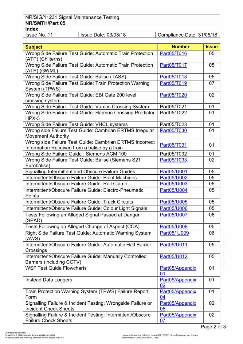
NR/SIG/11231 Signal Maintenance Testing NR/SMTH/Part 05 Index Issue No. 11 Issue Date: 03/03/18 Compliance Date: 31/05/18
Page 2 of 3
Subject Number Issue Wrong Side Failure Test Guide: Automatic Train Protection (ATP) (Chilterns)
Part05/T016 05
Wrong Side Failure Test Guide: Automatic Train Protection (ATP) (GWML)
Part05/T017 05
Wrong Side Failure Test Guide: Balise (TASS) Part05/T018 05 Wrong Side Failure Test Guide: Train Protection Warning System (TPWS)
Part05/T019 07
Wrong Side Failure Test Guide: EBI Gate 200 level crossing system
Part05/T020 02
Wrong Side Failure Test Guide: Vamos Crossing System Part05/T021 01 Wrong Side Failure Test Guide: Harmon Crossing Predictor HPX-3
Part05/T022 01
Wrong Side Failure Test Guide: VHCL systems Part05/T023 01 Wrong side Failure Test Guide: Cambrian ERTMS Irregular Movement Authority
Part05/T030 01
Wrong side Failure Test Guide: Cambrian ERTMS Incorrect Information Received from a balise by a train Part05/T031 01
Wrong Side Failure Guide : Siemens ACM 100 Part05/T032 01 Wrong Side Failure Test Guide: Balise (Siemens S21 Eurobalise)
Part05/T033 02
Signalling Intermittent and Obscure Failure Guides Part05/U001 05 Intermittent/Obscure Failure Guide: Point Machines Part05/U002 05 Intermittent/Obscure Failure Guide: Rail Clamp Part05/U003 05 Intermittent/Obscure Failure Guide: Electro-Pneumatic Points
Part05/U004 05
Intermittent/Obscure Failure Guide: Track Circuits Part05/U005 05 Intermittent/Obscure Failure Guide: Colour Light Signals Part05/U006 05 Tests Following an Alleged Signal Passed at Danger (SPAD)
Part05/U007 06
Tests Following an Alleged Change of Aspect (COA) Part05/U008 05 Right Side Failure Test Guide: Automatic Warning System (AWS)
Part05/ U009 06
Intermittent/Obscure Failure Guide: Automatic Half Barrier Crossings
Part05/U011 05
Intermittent/Obscure Failure Guide: Manually Controlled Barriers (including CCTV)
Part05/U012 05
WSF Test Guide Flowcharts Part05/Appendix 01
01
Instead Data Loggers Part05/Appendix 02
01
Train Protection Warning System (TPWS) Failure Report Form
Part05/Appendix 04
01
Signalling Failure & Incident Testing: Wrongside Failure or Incident Check Sheets
Part05/Appendix 06
02
Signalling Failure & Incident Testing: Intermittent/Obscure Failure Check Sheets
Part05/Appendix 07
02
Copyright Network Rail Provided by IHS Markit under license with Network Rail Licensee=Resourcing Solutions Limited /1121226001, User=Christopherson, Joseph
Not for Resale, 03/09/2018 03:56:27 MSTNo reproduction or networking permitted without license from IHS
--``,,``,`,,`,```,,``,,````,,,`,-`-`,,`,,`,`,,`---
NR/SIG/11231 Signal Maintenance Testing NR/SMTH/Part 05 Index Issue No. 11 Issue Date: 03/03/18 Compliance Date: 31/05/18
Page 3 of 3
End
Copyright Network Rail Provided by IHS Markit under license with Network Rail Licensee=Resourcing Solutions Limited /1121226001, User=Christopherson, Joseph
Not for Resale, 03/09/2018 03:56:27 MSTNo reproduction or networking permitted without license from IHS
--``,,``,`,,`,```,,``,,````,,,`,-`-`,,`,,`,`,,`---
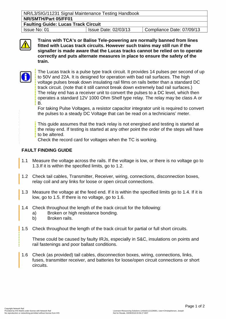
NR/L3/SIG/11231 Signal Maintenance Testing Handbook NR/SMTH/Part 05/FF01 Faulting Guide: Lucas Track Circuit Issue No: 01 Issue Date: 02/03/13 Compliance Date: 07/09/13
Page 1 of 2
Trains with TCA’s or Balise Tele-powering are normally banned from lines fitted with Lucas track circuits. However such trains may still run if the signaller is made aware that the Lucas tracks cannot be relied on to operate correctly and puts alternate measures in place to ensure the safety of the train.
The Lucas track is a pulse type track circuit. It provides 14 pulses per second of up to 50V and 22A. It is designed for operation with bad rail surfaces. The high voltage pulses break down insulating rail films on rails better than a standard DC track circuit. (note that it still cannot break down extremely bad rail surfaces.) The relay end has a receiver unit to convert the pulses to a DC level, which then operates a standard 12V 1000 Ohm Shelf type relay. The relay may be class A or B. For taking Pulse Voltages, a resistor capacitor integrator unit is required to convert the pulses to a steady DC Voltage that can be read on a technicians’ meter. This guide assumes that the track relay is not energised and testing is started at the relay end. If testing is started at any other point the order of the steps will have to be altered. Check the record card for voltages when the TC is working.
FAULT FINDING GUIDE 1.1 Measure the voltage across the rails. If the voltage is low, or there is no voltage go to
1.3.If it is within the specified limits, go to 1.2. 1.2 Check tail cables, Transmitter, Receiver, wiring, connections, disconnection boxes,
relay coil and any links for loose or open circuit connections. 1.3 Measure the voltage at the feed end. If it is within the specified limits go to 1.4. If it is
low, go to 1.5. If there is no voltage, go to 1.6. 1.4 Check throughout the length of the track circuit for the following:
a) Broken or high resistance bonding. b) Broken rails.
1.5 Check throughout the length of the track circuit for partial or full short circuits.
These could be caused by faulty IRJs, especially in S&C, insulations on points and rail fastenings and poor ballast conditions.
1.6 Check (as provided) tail cables, disconnection boxes, wiring, connections, links,
fuses, transmitter receiver, and batteries for loose/open circuit connections or short circuits.
Copyright Network Rail Provided by IHS Markit under license with Network Rail Licensee=Resourcing Solutions Limited /1121226001, User=Christopherson, Joseph
Not for Resale, 03/09/2018 03:56:27 MSTNo reproduction or networking permitted without license from IHS
--``,,``,`,,`,```,,``,,````,,,`,-`-`,,`,,`,`,,`---
NR/L3/SIG/11231 Signal Maintenance Testing Handbook NR/SMTH/Part 05/FF01 Faulting Guide: Lucas Track Circuit Issue No: 01 Issue Date: 02/03/13 Compliance Date: 07/09/13
Page 2 of 2
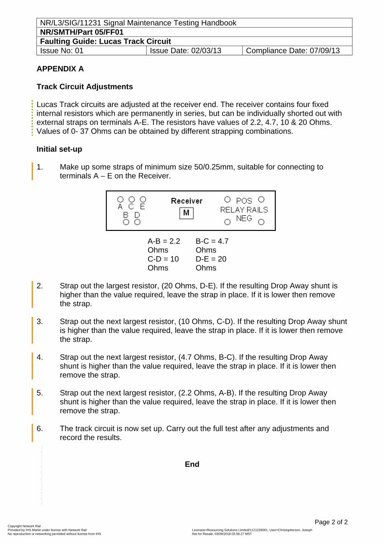
APPENDIX A Track Circuit Adjustments Lucas Track circuits are adjusted at the receiver end. The receiver contains four fixed internal resistors which are permanently in series, but can be individually shorted out with external straps on terminals A-E. The resistors have values of 2.2, 4.7, 10 & 20 Ohms. Values of 0- 37 Ohms can be obtained by different strapping combinations. Initial set-up 1. Make up some straps of minimum size 50/0.25mm, suitable for connecting to
terminals A – E on the Receiver.
A-B = 2.2 Ohms
B-C = 4.7 Ohms
C-D = 10 Ohms
D-E = 20 Ohms
2. Strap out the largest resistor, (20 Ohms, D-E). If the resulting Drop Away shunt is
higher than the value required, leave the strap in place. If it is lower then remove the strap.
3. Strap out the next largest resistor, (10 Ohms, C-D). If the resulting Drop Away shunt
is higher than the value required, leave the strap in place. If it is lower then remove the strap.
4. Strap out the next largest resistor, (4.7 Ohms, B-C). If the resulting Drop Away
shunt is higher than the value required, leave the strap in place. If it is lower then remove the strap.
5. Strap out the next largest resistor, (2.2 Ohms, A-B). If the resulting Drop Away
shunt is higher than the value required, leave the strap in place. If it is lower then remove the strap.
6. The track circuit is now set up. Carry out the full test after any adjustments and
record the results.
End
Copyright Network Rail Provided by IHS Markit under license with Network Rail Licensee=Resourcing Solutions Limited /1121226001, User=Christopherson, Joseph
Not for Resale, 03/09/2018 03:56:27 MSTNo reproduction or networking permitted without license from IHS
--``,,``,`,,`,```,,``,,````,,,`,-`-`,,`,,`,`,,`---
NR/L3/SIG/11231 Signal Maintenance Testing Handbook NR/SMTH/Part-05/FF02 Faulting Guide: DC Track Circuits Issue No: 01 Issue Date: 02/03/13 Compliance Date: 07/09/13
Page 1 of 2
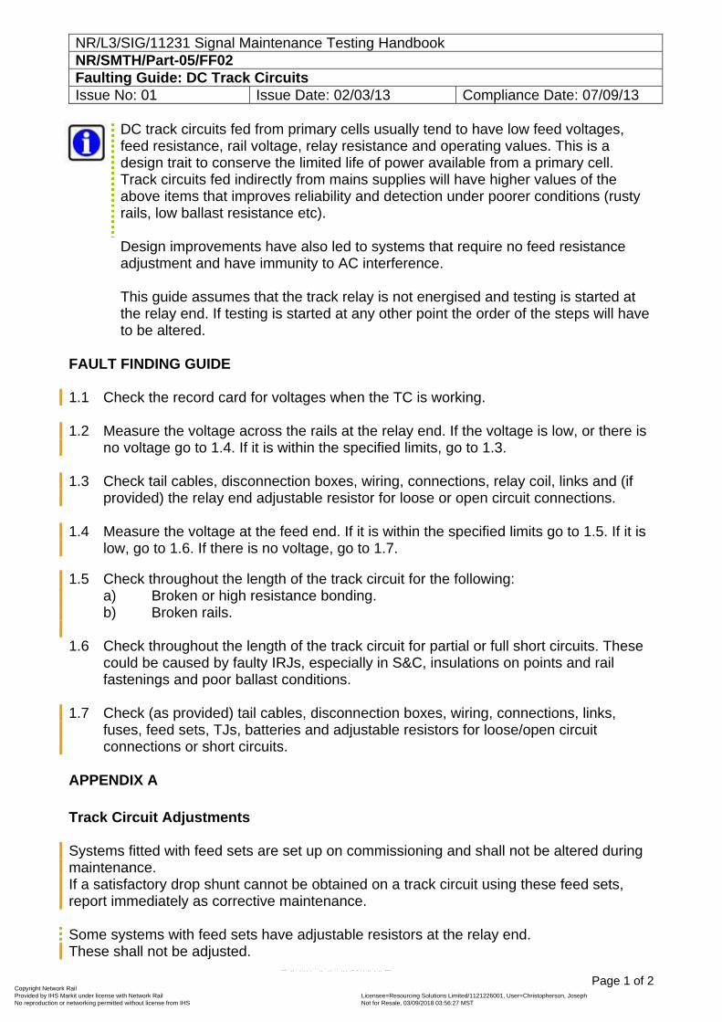
DC track circuits fed from primary cells usually tend to have low feed voltages, feed resistance, rail voltage, relay resistance and operating values. This is a design trait to conserve the limited life of power available from a primary cell. Track circuits fed indirectly from mains supplies will have higher values of the above items that improves reliability and detection under poorer conditions (rusty rails, low ballast resistance etc). Design improvements have also led to systems that require no feed resistance adjustment and have immunity to AC interference. This guide assumes that the track relay is not energised and testing is started at the relay end. If testing is started at any other point the order of the steps will have to be altered.
FAULT FINDING GUIDE 1.1 Check the record card for voltages when the TC is working. 1.2 Measure the voltage across the rails at the relay end. If the voltage is low, or there is
no voltage go to 1.4. If it is within the specified limits, go to 1.3. 1.3 Check tail cables, disconnection boxes, wiring, connections, relay coil, links and (if
provided) the relay end adjustable resistor for loose or open circuit connections. 1.4 Measure the voltage at the feed end. If it is within the specified limits go to 1.5. If it is
low, go to 1.6. If there is no voltage, go to 1.7. 1.5 Check throughout the length of the track circuit for the following:
a) Broken or high resistance bonding. b) Broken rails.
1.6 Check throughout the length of the track circuit for partial or full short circuits. These
could be caused by faulty IRJs, especially in S&C, insulations on points and rail fastenings and poor ballast conditions.
1.7 Check (as provided) tail cables, disconnection boxes, wiring, connections, links,
fuses, feed sets, TJs, batteries and adjustable resistors for loose/open circuit connections or short circuits.
APPENDIX A
Track Circuit Adjustments Systems fitted with feed sets are set up on commissioning and shall not be altered during maintenance. If a satisfactory drop shunt cannot be obtained on a track circuit using these feed sets, report immediately as corrective maintenance. Some systems with feed sets have adjustable resistors at the relay end. These shall not be adjusted.
Copyright Network Rail Provided by IHS Markit under license with Network Rail Licensee=Resourcing Solutions Limited /1121226001, User=Christopherson, Joseph
Not for Resale, 03/09/2018 03:56:27 MSTNo reproduction or networking permitted without license from IHS
--``,,``,`,,`,```,,``,,````,,,`,-`-`,,`,,`,`,,`---
NR/L3/SIG/11231 Signal Maintenance Testing Handbook NR/SMTH/Part-05/FF02 Faulting Guide: DC Track Circuits Issue No: 01 Issue Date: 02/03/13 Compliance Date: 07/09/13
Page 2 of 2
Systems that do not use a feed set (primary cell and TJ/secondary cell fed) are usually fitted with a separate adjustable resistor block at the feed end that can be adjusted by using the input/output leads and straps to obtain the resistance necessary to obtain a satisfactory drop shunt. Increasing the resistance will decrease the voltage and increase the drop shunt; conversely decreasing the resistance will increase the voltage and decrease the drop shunt. Drop shunt values are detailed in NR/SMS/Part/Z03.
End
Copyright Network Rail Provided by IHS Markit under license with Network Rail Licensee=Resourcing Solutions Limited /1121226001, User=Christopherson, Joseph
Not for Resale, 03/09/2018 03:56:27 MSTNo reproduction or networking permitted without license from IHS
--``,,``,`,,`,```,,``,,````,,,`,-`-`,,`,,`,`,,`---
NR/L3/SIG/11231 Signal Maintenance Testing Handbook NR/SMTH/Part 05/FF03 Faulting Guide: Aster 1 Watt Track Circuit Issue No. 01 Issue Date: 02/03/13 Compliance Date: 07/09/13
Page 1 of 2
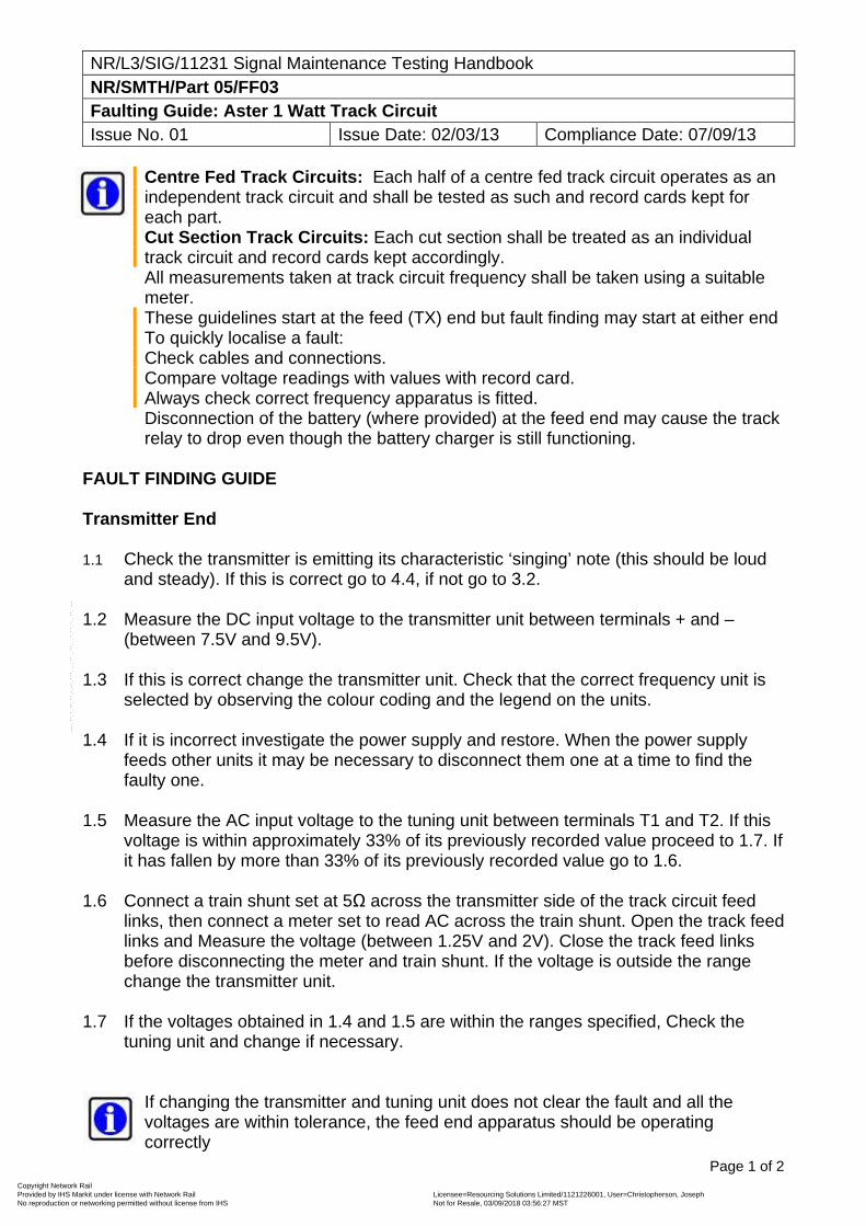
Centre Fed Track Circuits: Each half of a centre fed track circuit operates as an independent track circuit and shall be tested as such and record cards kept for each part. Cut Section Track Circuits: Each cut section shall be treated as an individual track circuit and record cards kept accordingly. All measurements taken at track circuit frequency shall be taken using a suitable meter. These guidelines start at the feed (TX) end but fault finding may start at either end To quickly localise a fault: Check cables and connections. Compare voltage readings with values with record card. Always check correct frequency apparatus is fitted. Disconnection of the battery (where provided) at the feed end may cause the track relay to drop even though the battery charger is still functioning.
FAULT FINDING GUIDE Transmitter End 1.1 Check the transmitter is emitting its characteristic ‘singing’ note (this should be loud
and steady). If this is correct go to 4.4, if not go to 3.2. 1.2 Measure the DC input voltage to the transmitter unit between terminals + and –
(between 7.5V and 9.5V). 1.3 If this is correct change the transmitter unit. Check that the correct frequency unit is
selected by observing the colour coding and the legend on the units. 1.4 If it is incorrect investigate the power supply and restore. When the power supply
feeds other units it may be necessary to disconnect them one at a time to find the faulty one.
1.5 Measure the AC input voltage to the tuning unit between terminals T1 and T2. If this
voltage is within approximately 33% of its previously recorded value proceed to 1.7. If it has fallen by more than 33% of its previously recorded value go to 1.6.
1.6 Connect a train shunt set at 5Ω across the transmitter side of the track circuit feed
links, then connect a meter set to read AC across the train shunt. Open the track feed links and Measure the voltage (between 1.25V and 2V). Close the track feed links before disconnecting the meter and train shunt. If the voltage is outside the range change the transmitter unit.
1.7 If the voltages obtained in 1.4 and 1.5 are within the ranges specified, Check the
tuning unit and change if necessary.
If changing the transmitter and tuning unit does not clear the fault and all the voltages are within tolerance, the feed end apparatus should be operating correctly
Copyright Network Rail Provided by IHS Markit under license with Network Rail Licensee=Resourcing Solutions Limited /1121226001, User=Christopherson, Joseph
Not for Resale, 03/09/2018 03:56:27 MSTNo reproduction or networking permitted without license from IHS
--``,,``,`,,`,```,,``,,````,,,`,-`-`,,`,,`,`,,`---
NR/L3/SIG/11231 Signal Maintenance Testing Handbook NR/SMTH/Part 05/FF03 Faulting Guide: Aster 1 Watt Track Circuit Issue No. 01 Issue Date: 02/03/13 Compliance Date: 07/09/13
Page 2 of 2
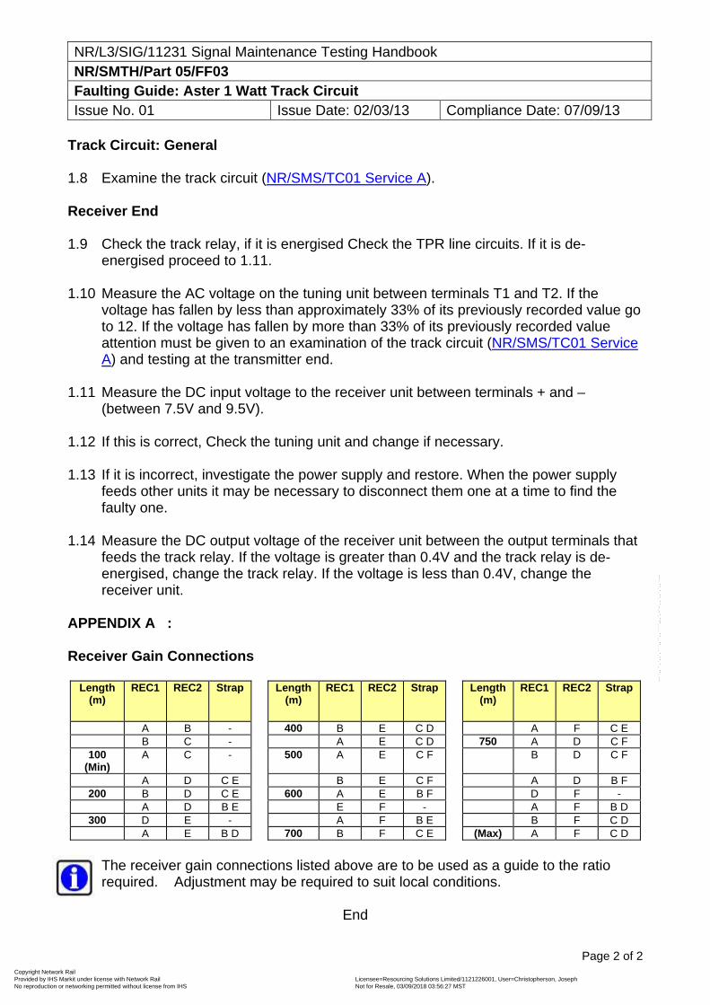
Track Circuit: General 1.8 Examine the track circuit (NR/SMS/TC01 Service A). Receiver End 1.9 Check the track relay, if it is energised Check the TPR line circuits. If it is de-
energised proceed to 1.11. 1.10 Measure the AC voltage on the tuning unit between terminals T1 and T2. If the
voltage has fallen by less than approximately 33% of its previously recorded value go to 12. If the voltage has fallen by more than 33% of its previously recorded value attention must be given to an examination of the track circuit (NR/SMS/TC01 Service A) and testing at the transmitter end.
1.11 Measure the DC input voltage to the receiver unit between terminals + and –
(between 7.5V and 9.5V). 1.12 If this is correct, Check the tuning unit and change if necessary. 1.13 If it is incorrect, investigate the power supply and restore. When the power supply
feeds other units it may be necessary to disconnect them one at a time to find the faulty one.
1.14 Measure the DC output voltage of the receiver unit between the output terminals that
feeds the track relay. If the voltage is greater than 0.4V and the track relay is de-energised, change the track relay. If the voltage is less than 0.4V, change the receiver unit.
APPENDIX A : Receiver Gain Connections
Length (m)
REC1 REC2 Strap Length (m)
REC1 REC2 Strap Length (m)
REC1 REC2 Strap
A B - 400 B E C D A F C E B C - A E C D 750 A D C F
100 (Min)
A C - 500 A E C F B D C F
A D C E B E C F A D B F 200 B D C E 600 A E B F D F -
A D B E E F - A F B D 300 D E - A F B E B F C D
A E B D 700 B F C E (Max) A F C D
The receiver gain connections listed above are to be used as a guide to the ratio required. Adjustment may be required to suit local conditions.
End
Copyright Network Rail Provided by IHS Markit under license with Network Rail Licensee=Resourcing Solutions Limited /1121226001, User=Christopherson, Joseph
Not for Resale, 03/09/2018 03:56:27 MSTNo reproduction or networking permitted without license from IHS
--``,,``,`,,`,```,,``,,````,,,`,-`-`,,`,,`,`,,`---
NR/SIG/11231 Signal Maintenance Testing Handbook NR/SMTH/Part-05/FF04 Faulting Guide: EBI Track 200 (TI21) Track Circuit Issue No. 02 Issue Date: 04/03/17 Compliance Date: 03/12/16
Page 1 of 1
For the Fault Finding Guide please use section 2 of NRSMS/Appendix08.
End
Copyright Network Rail Provided by IHS Markit under license with Network Rail Licensee=Resourcing Solutions Limited /1121226001, User=Christopherson, Joseph
Not for Resale, 03/09/2018 03:56:27 MSTNo reproduction or networking permitted without license from IHS
--``,,``,`,,`,```,,``,,````,,,`,-`-`,,`,,`,`,,`---
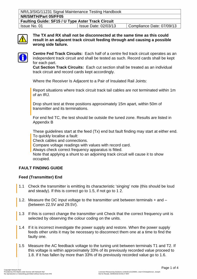
NR/L3/SIG/11231 Signal Maintenance Testing Handbook NR/SMTH/Part 05/FF05 Faulting Guide: SF15 / U Type Aster Track Circuit Issue No. 01 Issue Date: 02/03/13 Compliance Date: 07/09/13
Page 1 of 4
The TX and RX shall not be disconnected at the same time as this could result in an adjacent track circuit feeding through and causing a possible wrong side failure. Centre Fed Track Circuits: Each half of a centre fed track circuit operates as an independent track circuit and shall be tested as such. Record cards shall be kept for each part. Cut Section Track Circuits: Each cut section shall be treated as an individual track circuit and record cards kept accordingly. Where the Receiver Is Adjacent to a Pair of Insulated Rail Joints: Report situations where track circuit track tail cables are not terminated within 1m of an IRJ. Drop shunt test at three positions approximately 15m apart, within 50m of transmitter and its terminations. For end fed TC, the test should be outside the tuned zone. Results are listed in Appendix B These guidelines start at the feed (Tx) end but fault finding may start at either end. To quickly localise a fault: Check cables and connections. Compare voltage readings with values with record card. Always check correct frequency apparatus is fitted. Note that applying a shunt to an adjoining track circuit will cause it to show occupied.
FAULT FINDING GUIDE Feed (Transmitter) End 1.1 Check the transmitter is emitting its characteristic ‘singing’ note (this should be loud
and steady). If this is correct go to 1.5, if not go to 1 2. 1.2. Measure the DC input voltage to the transmitter unit between terminals + and –
(between 22.5V and 29.5V). 1.3 If this is correct change the transmitter unit Check that the correct frequency unit is
selected by observing the colour coding on the units. 1.4 If it is incorrect investigate the power supply and restore. When the power supply
feeds other units it may be necessary to disconnect them one at a time to find the faulty one.
1.5 Measure the AC feedback voltage to the tuning unit between terminals T1 and T2. If
this voltage is within approximately 33% of its previously recorded value proceed to 1.8. If it has fallen by more than 33% of its previously recorded value go to 1.6.
Copyright Network Rail Provided by IHS Markit under license with Network Rail Licensee=Resourcing Solutions Limited /1121226001, User=Christopherson, Joseph
Not for Resale, 03/09/2018 03:56:27 MSTNo reproduction or networking permitted without license from IHS
--``,,``,`,,`,```,,``,,````,,,`,-`-`,,`,,`,`,,`---
NR/L3/SIG/11231 Signal Maintenance Testing Handbook NR/SMTH/Part 05/FF05 Faulting Guide: SF15 / U Type Aster Track Circuit Issue No. 01 Issue Date: 02/03/13 Compliance Date: 07/09/13
Page 2 of 4
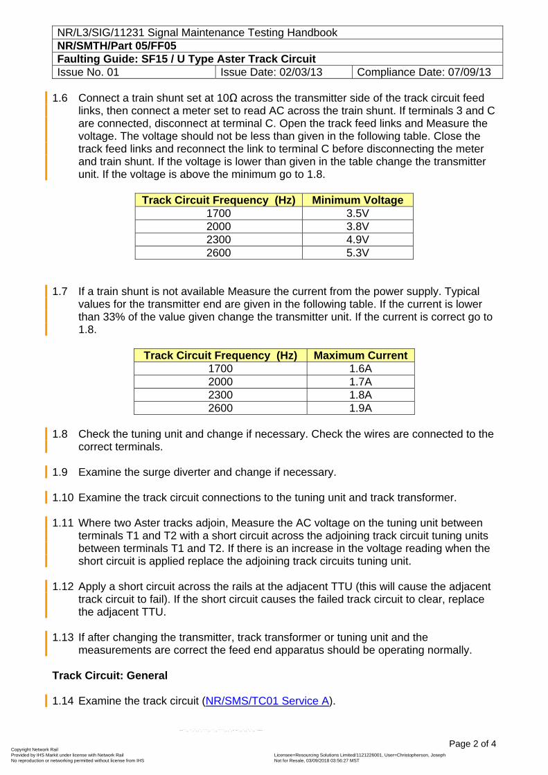
1.6 Connect a train shunt set at 10Ω across the transmitter side of the track circuit feed links, then connect a meter set to read AC across the train shunt. If terminals 3 and C are connected, disconnect at terminal C. Open the track feed links and Measure the voltage. The voltage should not be less than given in the following table. Close the track feed links and reconnect the link to terminal C before disconnecting the meter and train shunt. If the voltage is lower than given in the table change the transmitter unit. If the voltage is above the minimum go to 1.8.
Track Circuit Frequency (Hz) Minimum Voltage
1700 3.5V 2000 3.8V 2300 4.9V 2600 5.3V
1.7 If a train shunt is not available Measure the current from the power supply. Typical
values for the transmitter end are given in the following table. If the current is lower than 33% of the value given change the transmitter unit. If the current is correct go to 1.8.
Track Circuit Frequency (Hz) Maximum Current
1700 1.6A 2000 1.7A 2300 1.8A 2600 1.9A
1.8 Check the tuning unit and change if necessary. Check the wires are connected to the
correct terminals. 1.9 Examine the surge diverter and change if necessary. 1.10 Examine the track circuit connections to the tuning unit and track transformer. 1.11 Where two Aster tracks adjoin, Measure the AC voltage on the tuning unit between
terminals T1 and T2 with a short circuit across the adjoining track circuit tuning units between terminals T1 and T2. If there is an increase in the voltage reading when the short circuit is applied replace the adjoining track circuits tuning unit.
1.12 Apply a short circuit across the rails at the adjacent TTU (this will cause the adjacent
track circuit to fail). If the short circuit causes the failed track circuit to clear, replace the adjacent TTU.
1.13 If after changing the transmitter, track transformer or tuning unit and the
measurements are correct the feed end apparatus should be operating normally. Track Circuit: General 1.14 Examine the track circuit (NR/SMS/TC01 Service A).
Copyright Network Rail Provided by IHS Markit under license with Network Rail Licensee=Resourcing Solutions Limited /1121226001, User=Christopherson, Joseph
Not for Resale, 03/09/2018 03:56:27 MSTNo reproduction or networking permitted without license from IHS
--``,,``,`,,`,```,,``,,````,,,`,-`-`,,`,,`,`,,`---
NR/L3/SIG/11231 Signal Maintenance Testing Handbook NR/SMTH/Part 05/FF05 Faulting Guide: SF15 / U Type Aster Track Circuit Issue No. 01 Issue Date: 02/03/13 Compliance Date: 07/09/13
Page 3 of 4
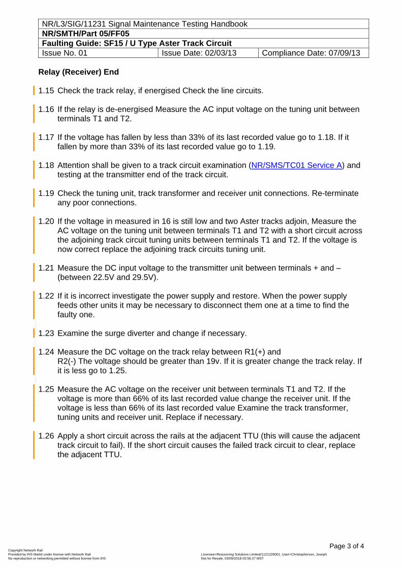
Relay (Receiver) End 1.15 Check the track relay, if energised Check the line circuits. 1.16 If the relay is de-energised Measure the AC input voltage on the tuning unit between
terminals T1 and T2. 1.17 If the voltage has fallen by less than 33% of its last recorded value go to 1.18. If it
fallen by more than 33% of its last recorded value go to 1.19. 1.18 Attention shall be given to a track circuit examination (NR/SMS/TC01 Service A) and
testing at the transmitter end of the track circuit. 1.19 Check the tuning unit, track transformer and receiver unit connections. Re-terminate
any poor connections. 1.20 If the voltage in measured in 16 is still low and two Aster tracks adjoin, Measure the
AC voltage on the tuning unit between terminals T1 and T2 with a short circuit across the adjoining track circuit tuning units between terminals T1 and T2. If the voltage is now correct replace the adjoining track circuits tuning unit.
1.21 Measure the DC input voltage to the transmitter unit between terminals + and –
(between 22.5V and 29.5V). 1.22 If it is incorrect investigate the power supply and restore. When the power supply
feeds other units it may be necessary to disconnect them one at a time to find the faulty one.
1.23 Examine the surge diverter and change if necessary. 1.24 Measure the DC voltage on the track relay between R1(+) and
R2(-) The voltage should be greater than 19v. If it is greater change the track relay. If it is less go to 1.25.
1.25 Measure the AC voltage on the receiver unit between terminals T1 and T2. If the
voltage is more than 66% of its last recorded value change the receiver unit. If the voltage is less than 66% of its last recorded value Examine the track transformer, tuning units and receiver unit. Replace if necessary.
1.26 Apply a short circuit across the rails at the adjacent TTU (this will cause the adjacent
track circuit to fail). If the short circuit causes the failed track circuit to clear, replace the adjacent TTU.
Copyright Network Rail Provided by IHS Markit under license with Network Rail Licensee=Resourcing Solutions Limited /1121226001, User=Christopherson, Joseph
Not for Resale, 03/09/2018 03:56:27 MSTNo reproduction or networking permitted without license from IHS
--``,,``,`,,`,```,,``,,````,,,`,-`-`,,`,,`,`,,`---
NR/L3/SIG/11231 Signal Maintenance Testing Handbook NR/SMTH/Part 05/FF05 Faulting Guide: SF15 / U Type Aster Track Circuit Issue No. 01 Issue Date: 02/03/13 Compliance Date: 07/09/13
Page 4 of 4
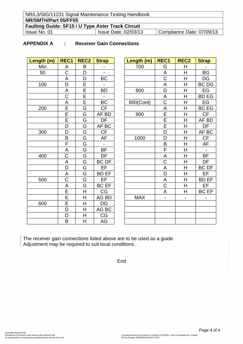
APPENDIX A : Receiver Gain Connections
Length (m) REC1 REC2 Strap Length (m) REC1 REC2 Strap Min A B - 700 G H - 50 C D - A H BG A D BC C H DG
100 D E - A H BC DG A E BD 800 D H EG C E - A H BD EG A E BC 800(Cont) C H EG
200 E G CF A H BC EG E G AF BD 900 E H CF E G DF E H AF BD D G AF BC E H DF
300 D G CF D H AF BC B G AF 1000 D H CF F G - B H AF A G BF F H -
400 C G DF A H BF A G BC DF C H DF D G EF A H BC DF A G BD EF D H EF
500 C G EF A H BD EF A G BC EF C H EF E H CG A H BC EF E H AG BD MAX - - -
600 E H DG D H AG BC D H CG B H AG
The receiver gain connections listed above are to be used as a guide. Adjustment may be required to suit local conditions.
End
Copyright Network Rail Provided by IHS Markit under license with Network Rail Licensee=Resourcing Solutions Limited /1121226001, User=Christopherson, Joseph
Not for Resale, 03/09/2018 03:56:27 MSTNo reproduction or networking permitted without license from IHS
--``,,``,`,,`,```,,``,,````,,,`,-`-`,,`,,`,`,,`---
NR/SIG/111231 Signal Maintenance Testing Handbook NR/SMTH/Part 05/FF06 Faulting Guide: High Voltage Impulse (HVI) Track Circuits Issue No. 02 Issue Date: 03/03/18 Compliance Date: 31/05/18
Page 1 of 2
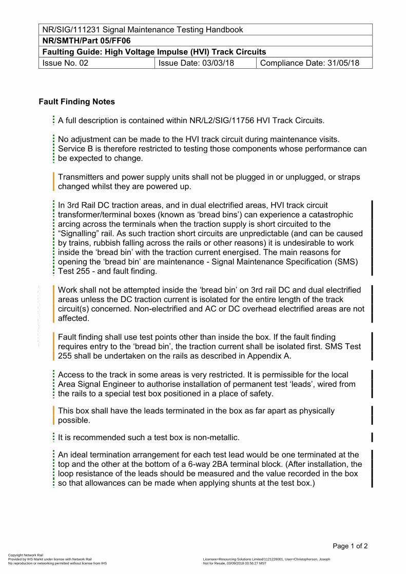
Fault Finding Notes
A full description is contained within NR/L2/SIG/11756 HVI Track Circuits. No adjustment can be made to the HVI track circuit during maintenance visits. Service B is therefore restricted to testing those components whose performance can be expected to change. Transmitters and power supply units shall not be plugged in or unplugged, or straps changed whilst they are powered up. In 3rd Rail DC traction areas, and in dual electrified areas, HVI track circuit transformer/terminal boxes (known as ‘bread bins’) can experience a catastrophic arcing across the terminals when the traction supply is short circuited to the “Signalling” rail. As such traction short circuits are unpredictable (and can be caused by trains, rubbish falling across the rails or other reasons) it is undesirable to work inside the ‘bread bin’ with the traction current energised. The main reasons for opening the ‘bread bin’ are maintenance - Signal Maintenance Specification (SMS) Test 255 - and fault finding. Work shall not be attempted inside the ‘bread bin’ on 3rd rail DC and dual electrified areas unless the DC traction current is isolated for the entire length of the track circuit(s) concerned. Non-electrified and AC or DC overhead electrified areas are not affected. Fault finding shall use test points other than inside the box. If the fault finding requires entry to the ‘bread bin’, the traction current shall be isolated first. SMS Test 255 shall be undertaken on the rails as described in Appendix A. Access to the track in some areas is very restricted. It is permissible for the local Area Signal Engineer to authorise installation of permanent test ‘leads’, wired from the rails to a special test box positioned in a place of safety.
This box shall have the leads terminated in the box as far apart as physically possible.
It is recommended such a test box is non-metallic.
An ideal termination arrangement for each test lead would be one terminated at the top and the other at the bottom of a 6-way 2BA terminal block. (After installation, the loop resistance of the leads should be measured and the value recorded in the box so that allowances can be made when applying shunts at the test box.)
Copyright Network Rail Provided by IHS Markit under license with Network Rail Licensee=Resourcing Solutions Limited /1121226001, User=Christopherson, Joseph
Not for Resale, 03/09/2018 03:56:27 MSTNo reproduction or networking permitted without license from IHS
--``,,``,`,,`,```,,``,,````,,,`,-`-`,,`,,`,`,,`---
NR/SIG/111231 Signal Maintenance Testing Handbook NR/SMTH/Part 05/FF06 Faulting Guide: High Voltage Impulse (HVI) Track Circuits Issue No. 02 Issue Date: 03/03/18 Compliance Date: 31/05/18
Page 2 of 2
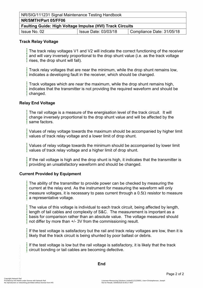
Track Relay Voltage
The track relay voltages V1 and V2 will indicate the correct functioning of the receiver and will vary inversely proportional to the drop shunt value (i.e. as the track voltage rises, the drop shunt will fall). Track relay voltages that are near the minimum, while the drop shunt remains low, indicates a developing fault in the receiver, which should be changed. Track voltages which are near the maximum, while the drop shunt remains high, indicates that the transmitter is not providing the required waveform and should be changed.
Relay End Voltage
The rail voltage is a measure of the energisation level of the track circuit. It will change inversely proportional to the drop shunt value and will be affected by the same factors. Values of relay voltage towards the maximum should be accompanied by higher limit values of track relay voltage and a lower limit of drop shunt. Values of relay voltage towards the minimum should be accompanied by lower limit values of track relay voltage and a higher limit of drop shunt. If the rail voltage is high and the drop shunt is high, it indicates that the transmitter is providing an unsatisfactory waveform and should be changed.
Current Provided by Equipment
The ability of the transmitter to provide power can be checked by measuring the current at the relay end. As the instrument for measuring the waveform will only measure voltages, it is necessary to pass current through a 0.5 resistor to measure a representative voltage. The value of this voltage is individual to each track circuit, being affected by length, length of tail cables and complexity of S&C. The measurement is important as a basis for comparison rather than an absolute value. The voltage measured should not differ by more than +/- 3V from the commissioning result.
If the test voltage is satisfactory but the rail and track relay voltages are low, then it is likely that the track circuit is being shunted by poor ballast or debris. If the test voltage is low but the rail voltage is satisfactory, it is likely that the track circuit bonding or tail cables are becoming defective.
End
Copyright Network Rail Provided by IHS Markit under license with Network Rail Licensee=Resourcing Solutions Limited /1121226001, User=Christopherson, Joseph
Not for Resale, 03/09/2018 03:56:27 MSTNo reproduction or networking permitted without license from IHS
--``,,``,`,,`,```,,``,,````,,,`,-`-`,,`,,`,`,,`---
NR/L3/SIG/111231 Signal Maintenance Testing Handbook NR/SMTH/Part 05/FF07 Faulting Guide: 50Hz AC Track Circuits Issue No. 01 Issue Date: 02/03/13 Compliance Date: 07/09/13
Page 1 of 4
FAULTING GUIDE
SR = Single Rail Installations Only. DR = Double Rail Installations Only.
Relay End 1. Check the position of the relay vane.
If the vane is up (delay unit for VT1(SP) also up) Check the status of the track with the signaller. If it is showing occupied at the signal box end investigate for an indication fault. If the vane is down proceed to 02 For VT1(SP) only, if the vane is up and the delay unit is down, go to the Delay Unit Tests(15).
2. Measure the voltage on the relay local coil.
If the voltage is within spec (99V to 121V) go to 03. If the voltage is below spec or at zero Check the BX110 supply and fuse.
3. Measure the voltage on the relay control coil.
If the voltage is within spec (approximately 25% above the relay nominal value) visually inspect the relay for signs of damage. Check for a tendency to drive in the opposite direction, if found a Full Test will be required. Check the control coil resistor (DR). If the voltage is low, Check the stabiliser (SR). If a transient suppressor (GDT or Spark Gap) is fitted, remove it from its base then recheck the voltage. If the voltage increases, check the rating of the suppressor noting that long track circuits with Type 3 bonds may require a 1000V type at the feed and first intermediate bonds.
4. If there is no voltage Check the track fuse. Check the control coil resistance is at
least 3. Check the control coil resistor (DR). 5. Check for any DC voltage across the relay control coil with a multimeter whilst trains
are in vicinity (SR). If none found proceed to 06. If more than 0.5V DC is found at any instant and the relay chatters, Check all negative bonding in area. If all present and functioning correctly, refer to the Route Asset Manager (Signals) for possible fitment of interference suppressor unit.
6. Measure phase angle and voltage and compare with the NR/SMS record card (DR).
If the phase angle is higher and the control voltage lower, Check the relay capacitor, Check for impedance bond faults. If the phase angle is the same and the control voltage is lower, Check for a high resistance connection, rail to rail fault etc.
Copyright Network Rail Provided by IHS Markit under license with Network Rail Licensee=Resourcing Solutions Limited /1121226001, User=Christopherson, Joseph
Not for Resale, 03/09/2018 03:56:27 MSTNo reproduction or networking permitted without license from IHS
--``,,``,`,,`,```,,``,,````,,,`,-`-`,,`,,`,`,,`---
NR/L3/SIG/111231 Signal Maintenance Testing Handbook NR/SMTH/Part 05/FF07 Faulting Guide: 50Hz AC Track Circuits Issue No. 01 Issue Date: 02/03/13 Compliance Date: 07/09/13
Page 2 of 4
7. Measure the AC voltage across the rails at the relay end and compare with the record card. If the voltage is approximately 45V AC (SR), Check for high resistance at the relay end. If the voltage is within the specified limits or higher, Check track leads to relay. Check the phase angle of control and local voltages (DR). Check the relay end impedance bond (DR). If the voltage is low, Check the relay end and intermediate impedance bonds (DR). If there is no voltage, Check for voltage across rails proceeding towards the feed end.
8. Measure the rail end current to the rails (SR). If it is over 0.5A AC replace the
stabilising rectifier. 9. Measure the AC voltage across the rails and compare with the NR/SMS record card.
If the voltage is higher than the specified limits, Check for a high resistance fault in the bonding and relay end circuitry, also Check for a possible increase in the ballast resistance. Check feed end and intermediate impedance bonds (DR). If the voltage is within the specified limits, Check again the rails at relay end. Check for high resistance bonding fault. Check feed end and intermediate impedance bonds (DR). If the voltage is low, Check the track feed transformer outputs, step 10. Check bonding and cables for possible short circuit. Check IRJ’s and other insulations for possible breakdown. If there is no voltage Check the 10A fuse. If OK proceed to step 11.
10. Measure the voltage across the 110v supply fuse (SR).
If the voltage is between 150V & 180V AC Check for high resistance at the feed end. Feed End 11. Measure the output voltage of the track feed transformer.
If the voltage is within the specified limits, go to step 12. 99V to 121V for the standard type, 85V to 90V or 90V to 99V if the former is not achievable for the VT1(SP) type. If the voltage is outside the specified limits, Check the feed end supply. (Step12), Check the 110V feed fuse. Replace or adjust feed transformer.
12. Measure the output voltage at the feed end with the track feed fuse removed.
If the voltage is within the specified limits, replace the fuse and re-check. If the voltage is low or at zero, Check the 110V supply and fuse. Test the capacitor by setting a value using alternative switch settings or replace, and then re-check the voltage.
13. Remove the surge arrestor and re-check, if it is now correct replace surge arrestor
and carry out a Full Test (DR). 14. Measure the current to rails at the feed end and compare against the NR/SMS record
card.
Copyright Network Rail Provided by IHS Markit under license with Network Rail Licensee=Resourcing Solutions Limited /1121226001, User=Christopherson, Joseph
Not for Resale, 03/09/2018 03:56:27 MSTNo reproduction or networking permitted without license from IHS
--``,,``,`,,`,```,,``,,````,,,`,-`-`,,`,,`,`,,`---
NR/L3/SIG/111231 Signal Maintenance Testing Handbook NR/SMTH/Part 05/FF07 Faulting Guide: 50Hz AC Track Circuits Issue No. 01 Issue Date: 02/03/13 Compliance Date: 07/09/13
Page 3 of 4
If the current has increased, Check the stabilising rectifier (SR), Check for a short circuit bonding fault, Check for impedance bond short circuit (DR). If the current has decreased, Check for a high resistance in feed cable connections or track circuit bonding, or a fault in feed or relay equipment. If the feed end current is significantly greater than the relay end current (SR), Check for a rail-to-rail fault.
VT1 (SP) Delay Unit Tests 15. Check the delay unit after the VT1(SP) relay has been energised for more than 2
seconds. If the unit is not completely energised, (e.g. one or more relays in the unit not energised) go to step 16. If the unit is completely energised, go to step 17.
16. With the VT1(SP) relay energised, remove the interconnecting cable between the
relay and the delay unit. At the fixed connector on the delay unit connect a multimeter (set to 100V DC.) between pin A (+ve) and pin B (-ve). If the voltage is not between 55V to 60V DC, replace the VT1(SP) relay. If the voltage is between 55V to 60V DC, go to step 17.
17. Reconnect the cable at the relay end and Check for a voltage of 55V to 60V DC. on
pins A and B at free end of cable. If the voltage is not present, replace the connecting cable. If the voltage is present, replace the delay unit.
Copyright Network Rail Provided by IHS Markit under license with Network Rail Licensee=Resourcing Solutions Limited /1121226001, User=Christopherson, Joseph
Not for Resale, 03/09/2018 03:56:27 MSTNo reproduction or networking permitted without license from IHS
--``,,``,`,,`,```,,``,,````,,,`,-`-`,,`,,`,`,,`---
NR/L3/SIG/111231 Signal Maintenance Testing Handbook NR/SMTH/Part 05/FF07 Faulting Guide: 50Hz AC Track Circuits Issue No. 01 Issue Date: 02/03/13 Compliance Date: 07/09/13
Page 4 of 4
18. Check the sequence of operation of delay unit as follows:
Observe that relay R1 (on right hand side of delay unit when viewed from front) energises, de-energises and re-energises and that relay R2a energises followed by relay R2b. If the delay unit does not operate in this manner, replace the delay unit. If the delay unit does operate in this manner, Check for possible high resistance output contacts between pins 23 & 24 and 13 & 14 of the VT1(SP) relay.
End
Copyright Network Rail Provided by IHS Markit under license with Network Rail Licensee=Resourcing Solutions Limited /1121226001, User=Christopherson, Joseph
Not for Resale, 03/09/2018 03:56:27 MSTNo reproduction or networking permitted without license from IHS
--``,,``,`,,`,```,,``,,````,,,`,-`-`,,`,,`,`,,`---
NR/L3/SIG/11231 Signal Maintenance Testing Handbook NR/SMTH/Part-05/FF08 Faulting Guide - EBI Gate 200 Level Crossing System Issue No. 02 Issue Date: 04/03/17 Compliance Date: 31/05/17
Includes: EBI Gate 200 Excludes: All other Overlay MSL crossings
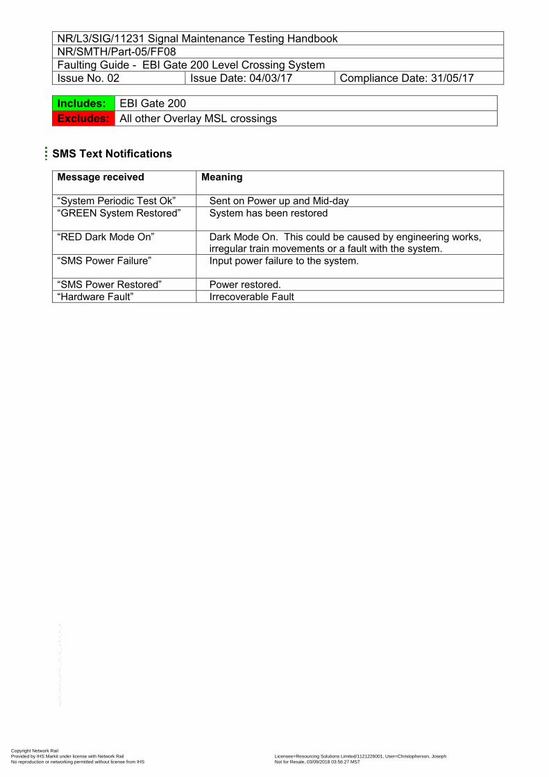
SMS Text Notifications
Message received Meaning
“System Periodic Test Ok” Sent on Power up and Mid-day “GREEN System Restored”
System has been restored
“RED Dark Mode On”
Dark Mode On. This could be caused by engineering works, irregular train movements or a fault with the system.
“SMS Power Failure”
Input power failure to the system.
“SMS Power Restored” Power restored. “Hardware Fault” Irrecoverable Fault
Copyright Network Rail Provided by IHS Markit under license with Network Rail Licensee=Resourcing Solutions Limited /1121226001, User=Christopherson, Joseph
Not for Resale, 03/09/2018 03:56:27 MSTNo reproduction or networking permitted without license from IHS
--``,,``,`,,`,```,,``,,````,,,`,-`-`,,`,,`,`,,`---
NR/L3/SIG/11231 Signal Maintenance Testing Handbook NR/SMTH/Part-05/FF08 Faulting Guide - EBI Gate 200 Level Crossing System Issue No. 02 Issue Date: 04/03/17 Compliance Date: 31/05/17
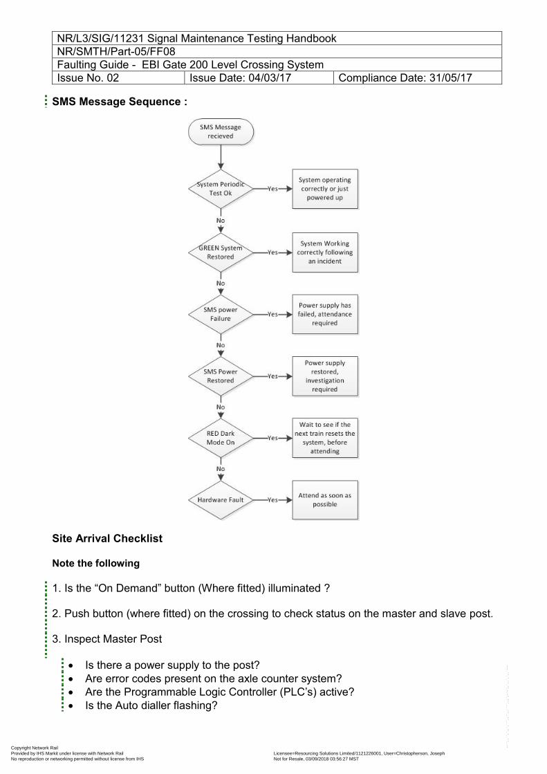
SMS Message Sequence :
Site Arrival Checklist
Note the following 1. Is the “On Demand” button (Where fitted) illuminated ? 2. Push button (where fitted) on the crossing to check status on the master and slave post. 3. Inspect Master Post
Is there a power supply to the post? Are error codes present on the axle counter system? Are the Programmable Logic Controller (PLC’s) active? Is the Auto dialler flashing?
Copyright Network Rail Provided by IHS Markit under license with Network Rail Licensee=Resourcing Solutions Limited /1121226001, User=Christopherson, Joseph
Not for Resale, 03/09/2018 03:56:27 MSTNo reproduction or networking permitted without license from IHS
--``,,``,`,,`,```,,``,,````,,,`,-`-`,,`,,`,`,,`---
NR/L3/SIG/11231 Signal Maintenance Testing Handbook NR/SMTH/Part-05/FF08 Faulting Guide - EBI Gate 200 Level Crossing System Issue No. 02 Issue Date: 04/03/17 Compliance Date: 31/05/17
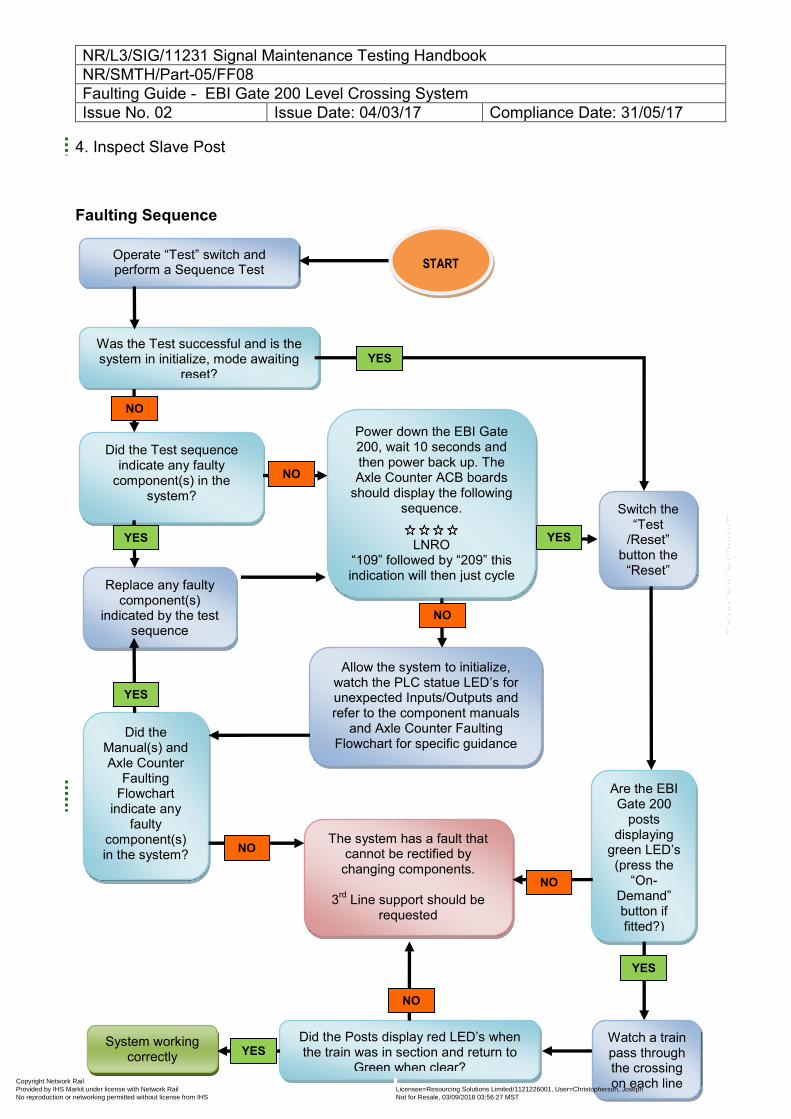
4. Inspect Slave Post START
Faulting Sequence
Operate “Test” switch and perform a Sequence Test
Was the Test successful and is the system in initialize, mode awaiting
reset?
Did the Test sequence indicate any faulty
component(s) in the system?
The system has a fault that cannot be rectified by
changing components.
3rd Line support should be requested
Replace any faulty component(s)
indicated by the test sequence
Switch the “Test
/Reset” button the
“Reset” and
System working correctly
Are the EBI Gate 200
posts displaying
green LED’s (press the
“On-Demand” button if fitted?)
Did the Posts display red LED’s when the train was in section and return to
Green when clear?
Allow the system to initialize, watch the PLC statue LED’s for unexpected Inputs/Outputs and refer to the component manuals
and Axle Counter Faulting Flowchart for specific guidance
Did the Manual(s) and Axle Counter
Faulting Flowchart
indicate any faulty
component(s) in the system?
Power down the EBI Gate 200, wait 10 seconds and then power back up. The Axle Counter ACB boards
should display the following sequence.
LNRO
“109” followed by “209” this indication will then just cycle
Watch a train pass through the crossing on each line
NO
YES
NO
NO
NO
YES
YES
YES YES
NO
NO
YES
START
Copyright Network Rail Provided by IHS Markit under license with Network Rail Licensee=Resourcing Solutions Limited /1121226001, User=Christopherson, Joseph
Not for Resale, 03/09/2018 03:56:27 MSTNo reproduction or networking permitted without license from IHS
--``,,``,`,,`,```,,``,,````,,,`,-`-`,,`,,`,`,,`---
NR/L3/SIG/11231 Signal Maintenance Testing Handbook NR/SMTH/Part-05/FF08 Faulting Guide - EBI Gate 200 Level Crossing System Issue No. 02 Issue Date: 04/03/17 Compliance Date: 31/05/17
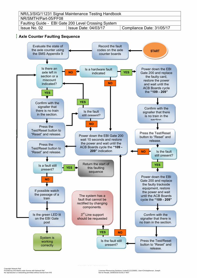
Axle Counter Faulting Sequence
Is there an axle left in
section or a miscount indicated?
Press the Test/Reset button to “Reset” and release.
Record the fault codes on the axle
counter boards
Is a hardware fault indicated
Is the fault still present?
NO
YES
NO
YES
YES
NO
YES
START
Confirm with the signaller that
there is no train in the section.
Evaluate the state of the axle counter using the SMS Appendix 9
System is working correctly
If possible watch the passage of a
train
Is the green LED lit on the EBI Gate
post
Return the start of this faulting sequence
Power down the EBI Gate 200 and replace
the faulty card, restore the power and wait until the ACB Boards cycle
the “109 - 209” indication
Confirm with the signaller that there
is no train in the section.
Press the Test/Reset button to “Reset” and
release.
Is the fault still present?
Power down the EBI Gate 200 wait 10 seconds and restore the power and wait until the
ACB Boards cycle the “109 - 209” indication
Press the Test/Reset button to “Reset” and release.
Is a fault still present?
Power down the EBI Gate 200 and replace
the faulty trackside equipment, restore the power and wait
until the ACB Boards cycle the “109 - 209”
indication
Confirm with the signaller that there is
no train in the section.
Press the Test/Reset button to “Reset” and
release.
Is the fault still present?
The system has a fault that cannot be
rectified by changing components.
3rd Line support
should be requested
NO
NO
YES
YES NO
Copyright Network Rail Provided by IHS Markit under license with Network Rail Licensee=Resourcing Solutions Limited /1121226001, User=Christopherson, Joseph
Not for Resale, 03/09/2018 03:56:27 MSTNo reproduction or networking permitted without license from IHS
--``,,``,`,,`,```,,``,,````,,,`,-`-`,,`,,`,`,,`---
NR/L3/SIG/11231 Signal Maintenance Testing Handbook NR/SMTH/Part-05/FF08 Faulting Guide - EBI Gate 200 Level Crossing System Issue No. 02 Issue Date: 04/03/17 Compliance Date: 31/05/17
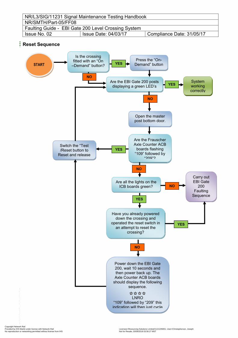
Reset Sequence
Press the “On-Demand” button
Are all the lights on the ICB boards green?
System working correctly
Are the EBI Gate 200 posts displaying a green LED’s
Open the master post bottom door.
Carry out EBI Gate
200 Faulting
Sequence flowchart
Have you already powered down the crossing and
operated the reset switch in an attempt to reset the
crossing?
Are the Frauscher Axle Counter ACB
boards flashing “109” followed by
“209”?
Switch the “Test /Reset button to
Reset and release
Is the crossing fitted with an “On
–Demand” button?
START
Power down the EBI Gate 200, wait 10 seconds and then power back up. The Axle Counter ACB boards
should display the following sequence.
LNRO
“109” followed by “209” this indication will then just cycle
NO
YES
YES
YES
YES
NO
NO
NO
NO
YES
Copyright Network Rail Provided by IHS Markit under license with Network Rail Licensee=Resourcing Solutions Limited /1121226001, User=Christopherson, Joseph
Not for Resale, 03/09/2018 03:56:27 MSTNo reproduction or networking permitted without license from IHS
--``,,``,`,,`,```,,``,,````,,,`,-`-`,,`,,`,`,,`---
NR/L3/SIG/11231 Signal Maintenance Testing Handbook NR/SMTH/Part-05/FF08 Faulting Guide - EBI Gate 200 Level Crossing System Issue No. 02 Issue Date: 04/03/17 Compliance Date: 31/05/17
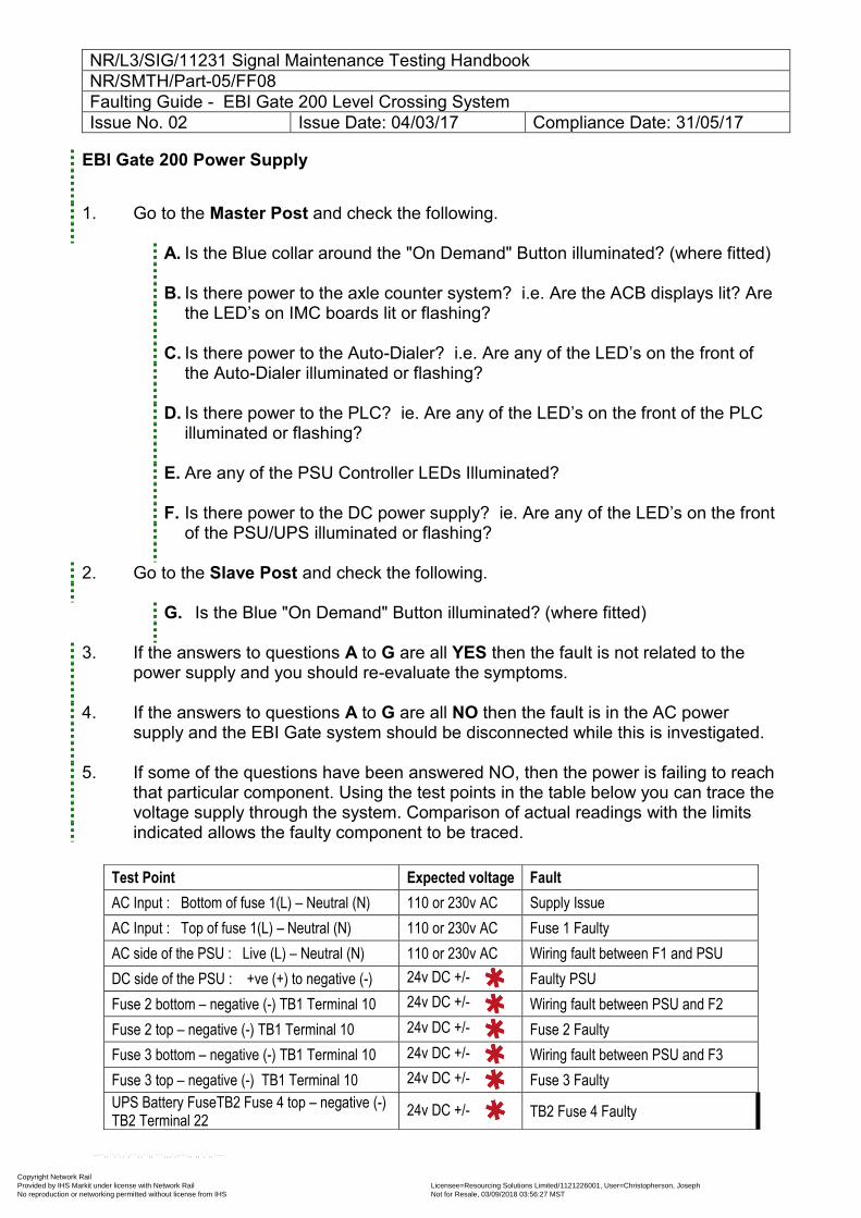
EBI Gate 200 Power Supply
1. Go to the Master Post and check the following.
A. Is the Blue collar around the "On Demand" Button illuminated? (where fitted) B. Is there power to the axle counter system? i.e. Are the ACB displays lit? Are
the LED’s on IMC boards lit or flashing?
C. Is there power to the Auto-Dialer? i.e. Are any of the LED’s on the front of the Auto-Dialer illuminated or flashing?
D. Is there power to the PLC? ie. Are any of the LED’s on the front of the PLC illuminated or flashing?
E. Are any of the PSU Controller LEDs Illuminated?
F. Is there power to the DC power supply? ie. Are any of the LED’s on the front of the PSU/UPS illuminated or flashing?
2. Go to the Slave Post and check the following.
G. Is the Blue "On Demand" Button illuminated? (where fitted)
3. If the answers to questions A to G are all YES then the fault is not related to the power supply and you should re-evaluate the symptoms.
4. If the answers to questions A to G are all NO then the fault is in the AC power
supply and the EBI Gate system should be disconnected while this is investigated.
5. If some of the questions have been answered NO, then the power is failing to reach that particular component. Using the test points in the table below you can trace the voltage supply through the system. Comparison of actual readings with the limits indicated allows the faulty component to be traced.
Test Point Expected voltage Fault
AC Input : Bottom of fuse 1(L) – Neutral (N) 110 or 230v AC Supply Issue
AC Input : Top of fuse 1(L) – Neutral (N) 110 or 230v AC Fuse 1 Faulty
AC side of the PSU : Live (L) – Neutral (N) 110 or 230v AC Wiring fault between F1 and PSU
DC side of the PSU : +ve (+) to negative (-) 24v DC +/- Faulty PSU
Fuse 2 bottom – negative (-) TB1 Terminal 10 24v DC +/- Wiring fault between PSU and F2
Fuse 2 top – negative (-) TB1 Terminal 10 24v DC +/- Fuse 2 Faulty
Fuse 3 bottom – negative (-) TB1 Terminal 10 24v DC +/- Wiring fault between PSU and F3
Fuse 3 top – negative (-) TB1 Terminal 10 24v DC +/- Fuse 3 Faulty
UPS Battery FuseTB2 Fuse 4 top – negative (-) TB2 Terminal 22
24v DC +/- TB2 Fuse 4 Faulty
Copyright Network Rail Provided by IHS Markit under license with Network Rail Licensee=Resourcing Solutions Limited /1121226001, User=Christopherson, Joseph
Not for Resale, 03/09/2018 03:56:27 MSTNo reproduction or networking permitted without license from IHS
--``,,``,`,,`,```,,``,,````,,,`,-`-`,,`,,`,`,,`---
NR/L3/SIG/11231 Signal Maintenance Testing Handbook NR/SMTH/Part-05/FF08 Faulting Guide - EBI Gate 200 Level Crossing System Issue No. 02 Issue Date: 04/03/17 Compliance Date: 31/05/17
The expected DC voltage is a non-adjustable value: if it is not achieved the backplane should be replaced. If a replaced fuse blows again during power up then the relevant backplane should be replaced.
End
Copyright Network Rail Provided by IHS Markit under license with Network Rail Licensee=Resourcing Solutions Limited /1121226001, User=Christopherson, Joseph
Not for Resale, 03/09/2018 03:56:27 MSTNo reproduction or networking permitted without license from IHS
--``,,``,`,,`,```,,``,,````,,,`,-`-`,,`,,`,`,,`---
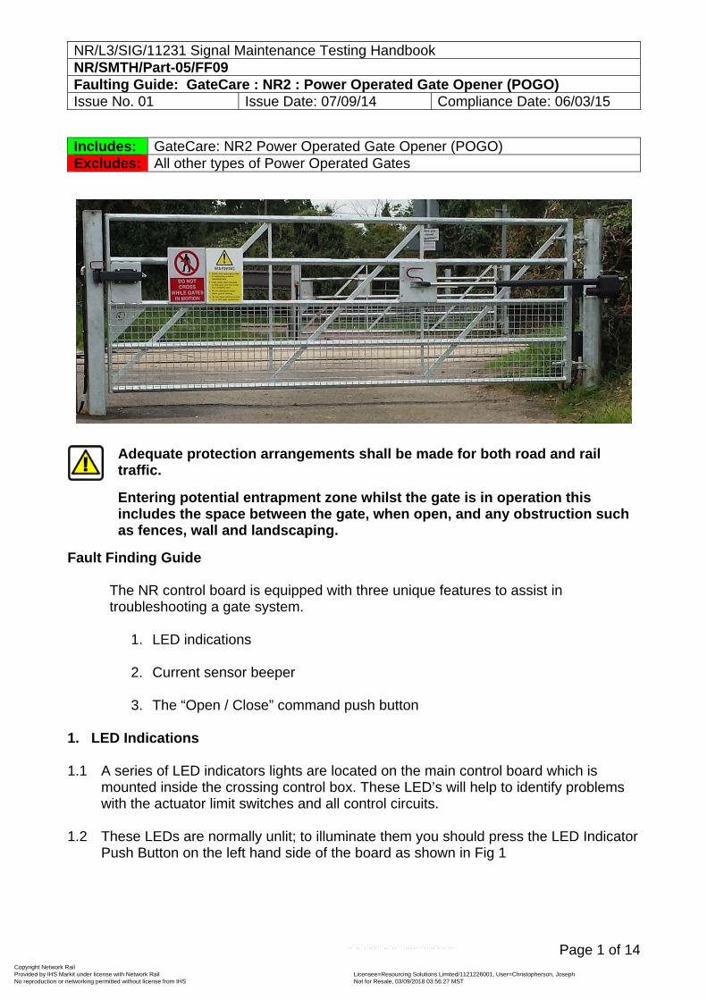
NR/L3/SIG/11231 Signal Maintenance Testing Handbook NR/SMTH/Part-05/FF09 Faulting Guide: GateCare : NR2 : Power Operated Gate Opener (POGO) Issue No. 01 Issue Date: 07/09/14 Compliance Date: 06/03/15
Page 1 of 14
Includes: GateCare: NR2 Power Operated Gate Opener (POGO) Excludes: All other types of Power Operated Gates
Adequate protection arrangements shall be made for both road and rail traffic.
Entering potential entrapment zone whilst the gate is in operation this includes the space between the gate, when open, and any obstruction such as fences, wall and landscaping.
Fault Finding Guide
The NR control board is equipped with three unique features to assist in troubleshooting a gate system.
1. LED indications
2. Current sensor beeper
3. The “Open / Close” command push button
1. LED Indications
1.1 A series of LED indicators lights are located on the main control board which is mounted inside the crossing control box. These LED’s will help to identify problems with the actuator limit switches and all control circuits.
1.2 These LEDs are normally unlit; to illuminate them you should press the LED Indicator
Push Button on the left hand side of the board as shown in Fig 1
Copyright Network Rail Provided by IHS Markit under license with Network Rail Licensee=Resourcing Solutions Limited /1121226001, User=Christopherson, Joseph
Not for Resale, 03/09/2018 03:56:27 MSTNo reproduction or networking permitted without license from IHS
--``,,``,`,,`,```,,``,,````,,,`,-`-`,,`,,`,`,,`---
NR/L3/SIG/11231 Signal Maintenance Testing Handbook NR/SMTH/Part-05/FF09 Faulting Guide: GateCare : NR2 : Power Operated Gate Opener (POGO) Issue No. 01 Issue Date: 07/09/14 Compliance Date: 06/03/15
Page 2 of 14
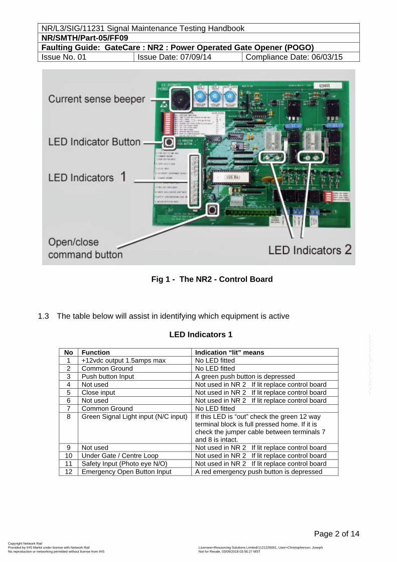
Fig 1 - The NR2 - Control Board 1.3 The table below will assist in identifying which equipment is active
LED Indicators 1
No Function Indication “lit” means 1 +12vdc output 1.5amps max No LED fitted 2 Common Ground No LED fitted 3 Push button Input A green push button is depressed 4 Not used Not used in NR 2 If lit replace control board 5 Close input Not used in NR 2 If lit replace control board 6 Not used Not used in NR 2 If lit replace control board 7 Common Ground No LED fitted 8 Green Signal Light input (N/C input) If this LED is “out” check the green 12 way
terminal block is full pressed home. If it is check the jumper cable between terminals 7 and 8 is intact.
9 Not used Not used in NR 2 If lit replace control board 10 Under Gate / Centre Loop Not used in NR 2 If lit replace control board 11 Safety Input (Photo eye N/O) Not used in NR 2 If lit replace control board 12 Emergency Open Button Input A red emergency push button is depressed
Copyright Network Rail Provided by IHS Markit under license with Network Rail Licensee=Resourcing Solutions Limited /1121226001, User=Christopherson, Joseph
Not for Resale, 03/09/2018 03:56:27 MSTNo reproduction or networking permitted without license from IHS
--``,,``,`,,`,```,,``,,````,,,`,-`-`,,`,,`,`,,`---
NR/L3/SIG/11231 Signal Maintenance Testing Handbook NR/SMTH/Part-05/FF09 Faulting Guide: GateCare : NR2 : Power Operated Gate Opener (POGO) Issue No. 01 Issue Date: 07/09/14 Compliance Date: 06/03/15
Page 3 of 14
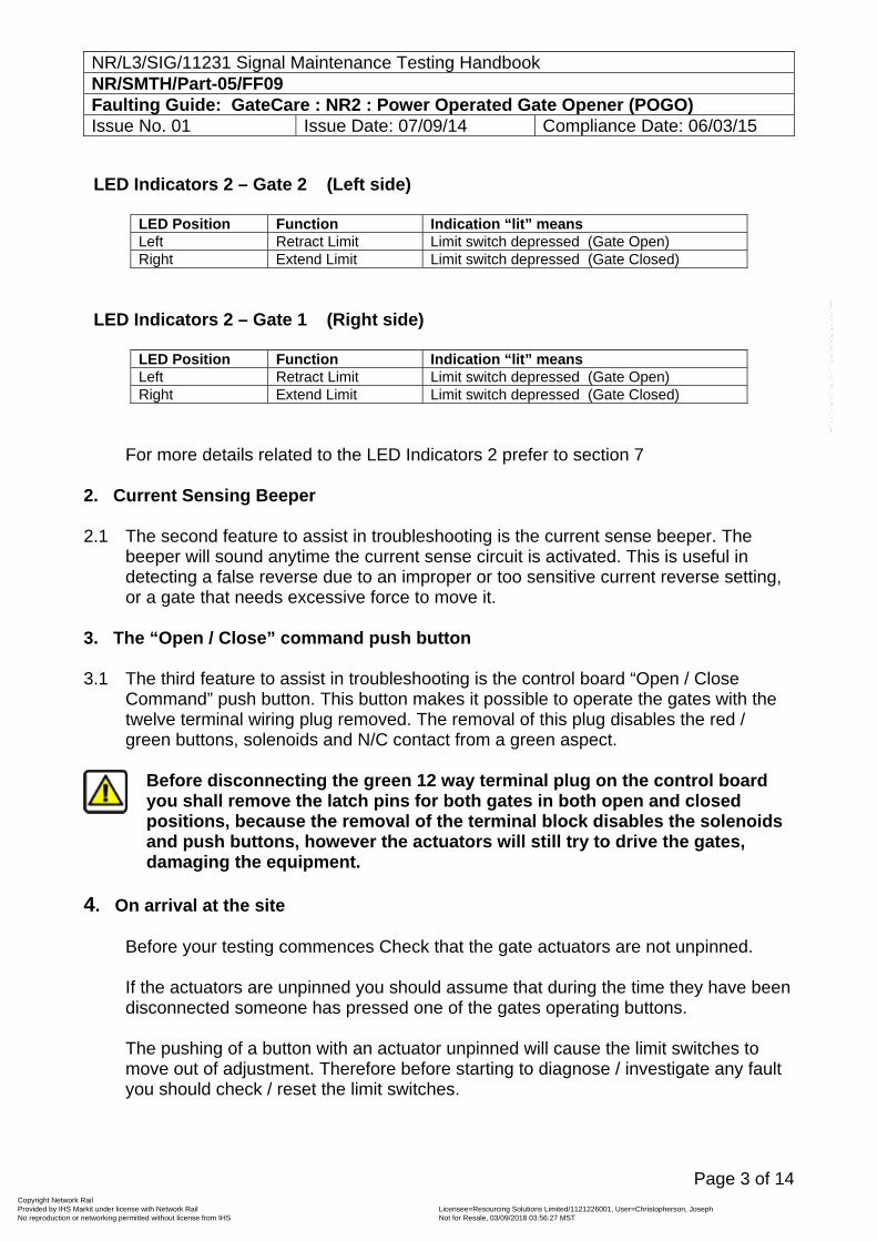
LED Indicators 2 – Gate 2 (Left side)
LED Position Function Indication “lit” meansLeft Retract Limit Limit switch depressed (Gate Open) Right Extend Limit Limit switch depressed (Gate Closed)
LED Indicators 2 – Gate 1 (Right side)
LED Position Function Indication “lit” meansLeft Retract Limit Limit switch depressed (Gate Open) Right Extend Limit Limit switch depressed (Gate Closed)
For more details related to the LED Indicators 2 prefer to section 7
2. Current Sensing Beeper 2.1 The second feature to assist in troubleshooting is the current sense beeper. The
beeper will sound anytime the current sense circuit is activated. This is useful in detecting a false reverse due to an improper or too sensitive current reverse setting, or a gate that needs excessive force to move it.
3. The “Open / Close” command push button 3.1 The third feature to assist in troubleshooting is the control board “Open / Close
Command” push button. This button makes it possible to operate the gates with the twelve terminal wiring plug removed. The removal of this plug disables the red / green buttons, solenoids and N/C contact from a green aspect.
Before disconnecting the green 12 way terminal plug on the control board you shall remove the latch pins for both gates in both open and closed positions, because the removal of the terminal block disables the solenoids and push buttons, however the actuators will still try to drive the gates, damaging the equipment.
4. On arrival at the site
Before your testing commences Check that the gate actuators are not unpinned. If the actuators are unpinned you should assume that during the time they have been disconnected someone has pressed one of the gates operating buttons. The pushing of a button with an actuator unpinned will cause the limit switches to move out of adjustment. Therefore before starting to diagnose / investigate any fault you should check / reset the limit switches.
Copyright Network Rail Provided by IHS Markit under license with Network Rail Licensee=Resourcing Solutions Limited /1121226001, User=Christopherson, Joseph
Not for Resale, 03/09/2018 03:56:27 MSTNo reproduction or networking permitted without license from IHS
--``,,``,`,,`,```,,``,,````,,,`,-`-`,,`,,`,`,,`---
NR/L3/SIG/11231 Signal Maintenance Testing Handbook NR/SMTH/Part-05/FF09 Faulting Guide: GateCare : NR2 : Power Operated Gate Opener (POGO) Issue No. 01 Issue Date: 07/09/14 Compliance Date: 06/03/15
Page 4 of 14
5. A Gate or Gates do not open
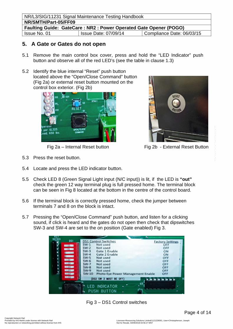
5.1 Remove the main control box cover, press and hold the “LED Indicator” push button and observe all of the red LED’s (see the table in clause 1.3)
5.2 Identify the blue internal “Reset” push button
located above the “Open/Close Command” button (Fig 2a) or external reset button mounted on the control box exterior. (Fig 2b)
Fig 2a – Internal Reset button Fig 2b - External Reset Button
5.3 Press the reset button.
5.4 Locate and press the LED indicator button. 5.5 Check LED 8 (Green Signal Light input (N/C input)) is lit, if the LED is “out”
check the green 12 way terminal plug is full pressed home. The terminal block can be seen in Fig 8 located at the bottom in the centre of the control board.
5.6 If the terminal block is correctly pressed home, check the jumper between
terminals 7 and 8 on the block is intact.
5.7 Pressing the “Open/Close Command” push button, and listen for a clicking sound, if click is heard and the gates do not open then check that dipswitches SW-3 and SW-4 are set to the on position (Gate enabled) Fig 3.
Fig 3 – DS1 Control switches
Copyright Network Rail Provided by IHS Markit under license with Network Rail Licensee=Resourcing Solutions Limited /1121226001, User=Christopherson, Joseph
Not for Resale, 03/09/2018 03:56:27 MSTNo reproduction or networking permitted without license from IHS
--``,,``,`,,`,```,,``,,````,,,`,-`-`,,`,,`,`,,`---
NR/L3/SIG/11231 Signal Maintenance Testing Handbook NR/SMTH/Part-05/FF09 Faulting Guide: GateCare : NR2 : Power Operated Gate Opener (POGO) Issue No. 01 Issue Date: 07/09/14 Compliance Date: 06/03/15
Page 5 of 14
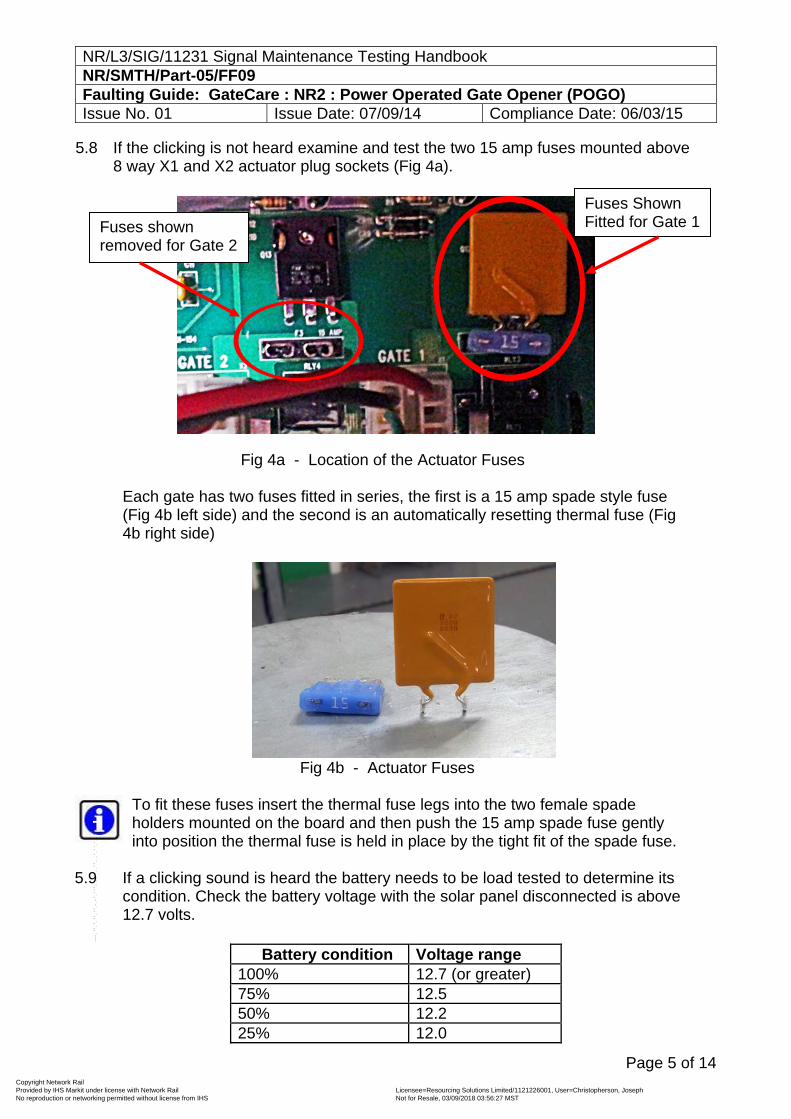
5.8 If the clicking is not heard examine and test the two 15 amp fuses mounted above 8 way X1 and X2 actuator plug sockets (Fig 4a).
Fig 4a - Location of the Actuator Fuses
Each gate has two fuses fitted in series, the first is a 15 amp spade style fuse (Fig 4b left side) and the second is an automatically resetting thermal fuse (Fig 4b right side)
Fig 4b - Actuator Fuses To fit these fuses insert the thermal fuse legs into the two female spade holders mounted on the board and then push the 15 amp spade fuse gently into position the thermal fuse is held in place by the tight fit of the spade fuse.
5.9 If a clicking sound is heard the battery needs to be load tested to determine its
condition. Check the battery voltage with the solar panel disconnected is above 12.7 volts.
Battery condition Voltage range 100% 12.7 (or greater) 75% 12.5 50% 12.2 25% 12.0
Fuses Shown Fitted for Gate 1 Fuses shown
removed for Gate 2
Copyright Network Rail Provided by IHS Markit under license with Network Rail Licensee=Resourcing Solutions Limited /1121226001, User=Christopherson, Joseph
Not for Resale, 03/09/2018 03:56:27 MSTNo reproduction or networking permitted without license from IHS
--``,,``,`,,`,```,,``,,````,,,`,-`-`,,`,,`,`,,`---
NR/L3/SIG/11231 Signal Maintenance Testing Handbook NR/SMTH/Part-05/FF09 Faulting Guide: GateCare : NR2 : Power Operated Gate Opener (POGO) Issue No. 01 Issue Date: 07/09/14 Compliance Date: 06/03/15
Page 6 of 14
5.10 Charge or replace the battery depending on results. 5.11 Locate and press the LED indicator button
5.12 Both the retract limit and extend limit LEDs beneath the same Actuator plug
should never be on simultaneously
If they are with the gate in the open position and the actuator connected the actuator will not operate. You should adjust the closed limit switch until its LED goes off. By adjusting this switch you are setting the point at which the gate will stop, so from time to time you should operate the gate towards the closed position and adjust the limit switch to stop the gate at the desired point. As shown in NR/SMS/Test 084.
If they are with the gate in the closed position and the actuator connected the actuator will not operate. You should adjust the closed limit switch until its LED goes off. By adjusting this switch you are setting the point at which the gate will stop, so from time to time you should operate the gate towards the open position and adjust the limit switch to stop the gate at the desired point. As shown in NR/SMS/Test 084.
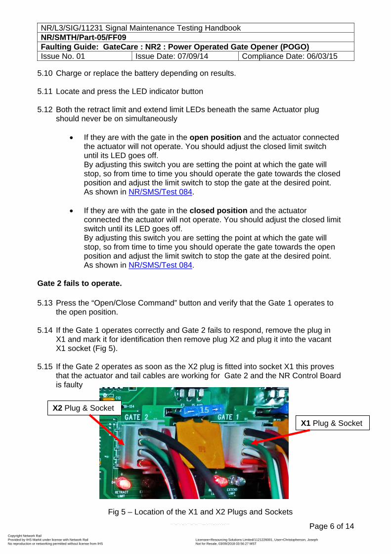
Gate 2 fails to operate. 5.13 Press the “Open/Close Command” button and verify that the Gate 1 operates to
the open position. 5.14 If the Gate 1 operates correctly and Gate 2 fails to respond, remove the plug in
X1 and mark it for identification then remove plug X2 and plug it into the vacant X1 socket (Fig 5).
5.15 If the Gate 2 operates as soon as the X2 plug is fitted into socket X1 this proves
that the actuator and tail cables are working for Gate 2 and the NR Control Board is faulty
Fig 5 – Location of the X1 and X2 Plugs and Sockets
X2 Plug & Socket
X1 Plug & Socket
Copyright Network Rail Provided by IHS Markit under license with Network Rail Licensee=Resourcing Solutions Limited /1121226001, User=Christopherson, Joseph
Not for Resale, 03/09/2018 03:56:27 MSTNo reproduction or networking permitted without license from IHS
--``,,``,`,,`,```,,``,,````,,,`,-`-`,,`,,`,`,,`---
NR/L3/SIG/11231 Signal Maintenance Testing Handbook NR/SMTH/Part-05/FF09 Faulting Guide: GateCare : NR2 : Power Operated Gate Opener (POGO) Issue No. 01 Issue Date: 07/09/14 Compliance Date: 06/03/15
Page 7 of 14
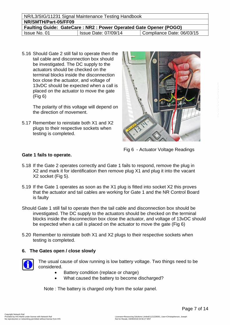
5.16 Should Gate 2 still fail to operate then the
tail cable and disconnection box should be investigated. The DC supply to the actuators should be checked on the terminal blocks inside the disconnection box close the actuator, and voltage of 13vDC should be expected when a call is placed on the actuator to move the gate (Fig 6) The polarity of this voltage will depend on the direction of movement.
5.17 Remember to reinstate both X1 and X2
plugs to their respective sockets when testing is completed.
Fig 6 - Actuator Voltage Readings
Gate 1 fails to operate. 5.18 If the Gate 2 operates correctly and Gate 1 fails to respond, remove the plug in
X2 and mark it for identification then remove plug X1 and plug it into the vacant X2 socket (Fig 5).
5.19 If the Gate 1 operates as soon as the X1 plug is fitted into socket X2 this proves
that the actuator and tail cables are working for Gate 1 and the NR Control Board is faulty
Should Gate 1 still fail to operate then the tail cable and disconnection box should be
investigated. The DC supply to the actuators should be checked on the terminal blocks inside the disconnection box close the actuator, and voltage of 13vDC should be expected when a call is placed on the actuator to move the gate (Fig 6)
5.20 Remember to reinstate both X1 and X2 plugs to their respective sockets when testing is completed.
6. The Gates open / close slowly
The usual cause of slow running is low battery voltage. Two things need to be considered.
Battery condition (replace or charge) What caused the battery to become discharged?
Note : The battery is charged only from the solar panel.
Copyright Network Rail Provided by IHS Markit under license with Network Rail Licensee=Resourcing Solutions Limited /1121226001, User=Christopherson, Joseph
Not for Resale, 03/09/2018 03:56:27 MSTNo reproduction or networking permitted without license from IHS
--``,,``,`,,`,```,,``,,````,,,`,-`-`,,`,,`,`,,`---
NR/L3/SIG/11231 Signal Maintenance Testing Handbook NR/SMTH/Part-05/FF09 Faulting Guide: GateCare : NR2 : Power Operated Gate Opener (POGO) Issue No. 01 Issue Date: 07/09/14 Compliance Date: 06/03/15
Page 8 of 14
6.1 Check the panel is facing a southerly direction and is not located in a completely shaded area.
6.2 Inspect solar panel surface for contamination and cable for damage.
Should it be necessary for the Solar panel to be disconnected you shall disconnect and insulated the exposed conductors one at a time as the short circuit caused by the cable cores touching will damage or destroy the power generation capabilities of the solar panel
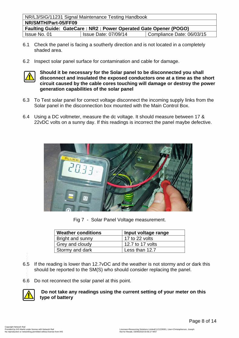
6.3 To Test solar panel for correct voltage disconnect the incoming supply links from the
Solar panel in the disconnection box mounted with the Main Control Box.
6.4 Using a DC voltmeter, measure the dc voltage. It should measure between 17 & 22vDC volts on a sunny day. If this readings is incorrect the panel maybe defective.
Fig 7 - Solar Panel Voltage measurement.
6.5 If the reading is lower than 12.7vDC and the weather is not stormy and or dark this
should be reported to the SM(S) who should consider replacing the panel. 6.6 Do not reconnect the solar panel at this point.
Do not take any readings using the current setting of your meter on this type of battery
Weather conditions Input voltage range Bright and sunny 17 to 22 volts Grey and cloudy 12.7 to 17 volts Stormy and dark Less than 12.7
Copyright Network Rail Provided by IHS Markit under license with Network Rail Licensee=Resourcing Solutions Limited /1121226001, User=Christopherson, Joseph
Not for Resale, 03/09/2018 03:56:27 MSTNo reproduction or networking permitted without license from IHS
--``,,``,`,,`,```,,``,,````,,,`,-`-`,,`,,`,`,,`---
NR/L3/SIG/11231 Signal Maintenance Testing Handbook NR/SMTH/Part-05/FF09 Faulting Guide: GateCare : NR2 : Power Operated Gate Opener (POGO) Issue No. 01 Issue Date: 07/09/14 Compliance Date: 06/03/15
Page 9 of 14
6.7 Check the battery voltage with the solar panel disconnected is above 12.7vDC.
6.8 Check the correct deep cycle battery is installed
6.9 Replacement of the battery should be considered if the voltage is lower than 11.5vDC.
It should be noted that this type of battery, if allowed to completely discharge, will never reagain its full capacity. This type of damage is cumulative. This loss of capacity will show up as a quicker than expected discharge rate. (ie the gates will start to slow after fewer moves).
6.10 Check that solar panel leads are connected to the battery correctly.
6.11 Reinstate the disconnected links for the Solar Panel described in section 6.3.
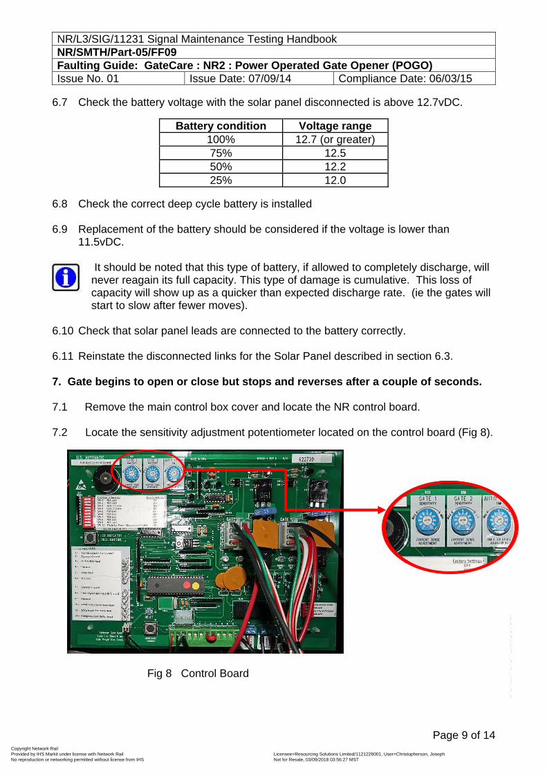
7. Gate begins to open or close but stops and reverses after a couple of seconds. 7.1 Remove the main control box cover and locate the NR control board.
7.2 Locate the sensitivity adjustment potentiometer located on the control board (Fig 8).
Fig 8 Control Board
Battery condition Voltage range 100% 12.7 (or greater) 75% 12.5 50% 12.2 25% 12.0
Copyright Network Rail Provided by IHS Markit under license with Network Rail Licensee=Resourcing Solutions Limited /1121226001, User=Christopherson, Joseph
Not for Resale, 03/09/2018 03:56:27 MSTNo reproduction or networking permitted without license from IHS
--``,,``,`,,`,```,,``,,````,,,`,-`-`,,`,,`,`,,`---
NR/L3/SIG/11231 Signal Maintenance Testing Handbook NR/SMTH/Part-05/FF09 Faulting Guide: GateCare : NR2 : Power Operated Gate Opener (POGO) Issue No. 01 Issue Date: 07/09/14 Compliance Date: 06/03/15
Page 10 of 14
7.3 The white centre is adjustable, and normally a setting of 5 will operate most gates.
7.4 If the gate requires a setting above 8 to open and close the gate there is a good chance the gate has a problem that should be corrected. Possible causes are incorrect hinges / lubrication; gate touching the ground, gate not level or the actuator arm connected to the gate is bent or incorrectly installed.
8. Gate opens correctly, then immediately reverses direction.
8.1 The most likely cause is an incorrectly adjusted retract limit switch. Firstly
determine which gate is in need of adjustment. 8.2 Operate the gates to the open position, while the gate is in motion press the LED
Indications button and observe the retract LED indications for the limit switches that are directly below the X1 and X2 sockets.
8.3 When the Gates reach the fully open position the overload bleep will sound, the
gates will both move away from the latch posts and stop. 8.4 At the point the gate was closed and one or both of the retract limit switch LED
will not have been lit. The unlit LED indicates that the gate is incorrectly adjusted. 8.5 Once the gate, or gates, that need adjustment are identified you should carry out
the adjustment as shown in NR/SMS/Test 084. And retest.
9. Gate closes correctly, then immediately reverses direction and fully opens. 9.1 The most likely cause is an incorrectly adjusted extend limit switch. Firstly
determine which gate is in need of adjustment. 9.2 Operate the gates to the closed position, while the gate is in motion press the
LED Indications button and observe the extend LED indications for the limit switches that are directly below the X1 and X2 sockets.
9.3 When the Gates reach the fully closed position the overload bleep will sound, the
gates will return to the fully open position. 9.4 At the point the gate was closed and one or both of the extend limit switch LED
will not have been lit. The unlit LED indicates that the gate is incorrectly adjusted. 9.5 Once the gate, or gates, that need adjustment are identified you should carry out the
adjustment as shown in NR/SMS/Test 084. And retest.
Copyright Network Rail Provided by IHS Markit under license with Network Rail Licensee=Resourcing Solutions Limited /1121226001, User=Christopherson, Joseph
Not for Resale, 03/09/2018 03:56:27 MSTNo reproduction or networking permitted without license from IHS
--``,,``,`,,`,```,,``,,````,,,`,-`-`,,`,,`,`,,`---
NR/L3/SIG/11231 Signal Maintenance Testing Handbook NR/SMTH/Part-05/FF09 Faulting Guide: GateCare : NR2 : Power Operated Gate Opener (POGO) Issue No. 01 Issue Date: 07/09/14 Compliance Date: 06/03/15
Page 11 of 14
10. The Gates or Gate fails to complete it travel before stopping. 10. 1 The most likely cause is an incorrect limit switch adjustment.
10. 2 Carry out the adjustment on the limit switch of the gate which is not closing fully
as shown in NR/SMS/Test 084. And retest. 11. Control board 15 amp fuse blows when Open/Close command is given. 11.1 A blown fuse means the gates will not operate in power mode. Possible causes
are an obstruction that prevents the gate from moving, the gate is attempting to ‘over close’ or ‘over open’ due to incorrect limit switch setting or there might be a wiring problem as a result of a faulty connection.
11.2 Before commencing any testing you should remove the latch pins and manually operate both gates to check they are not binding or catching at any point across their full range of movement.
11.3 Open the main control box cover and locate the NR control board. Locate the 2
LED’s under the X1 and X2 actuator connectors on the control board.
11.4 Press the “LED Indicator” push button and hold it in, observe the LED’s and determine if the retract limit or extend limit LED is on.
11.5 Check if the correct LED is on for the gate position. For example if the left LED is on that is the retract limit and the gate should be in the open position. The right LED represents the extend position.
11.6 If the retract limit LED is on and the gate is closed, a command to operate the
gate will try to force the gate beyond the closed position which could blow a fuse.
11.7 If the retract limit LED is on and the gate is open a command to operate the gate will try to force the gate beyond the open position. Again this could blow a fuse. In either case, the actuator limit switches need to be adjusted as shown in NR/SMS/Test 084.and then the cause for them becoming misadjusted needs to be determined. The cause will likely be incorrect wiring, a poor actuator plug connection at the NR control board or excessive sensitivity adjustment applied during installation.
11.8 Check all wiring and verify actuator connector is connected at the control board.
12. The Gate only operates when the “LED INDICATOR” is pressed.
12.1 Advise you SM(S) or on call Supervisor immediately. Third line Technical
Support Advice should be requested.
Copyright Network Rail Provided by IHS Markit under license with Network Rail Licensee=Resourcing Solutions Limited /1121226001, User=Christopherson, Joseph
Not for Resale, 03/09/2018 03:56:27 MSTNo reproduction or networking permitted without license from IHS
--``,,``,`,,`,```,,``,,````,,,`,-`-`,,`,,`,`,,`---
NR/L3/SIG/11231 Signal Maintenance Testing Handbook NR/SMTH/Part-05/FF09 Faulting Guide: GateCare : NR2 : Power Operated Gate Opener (POGO) Issue No. 01 Issue Date: 07/09/14 Compliance Date: 06/03/15
Page 12 of 14
13. Solenoid Lock Issues
Before commencing any testing you should check that the solenoids are not binding or catching. If the solenoids are binding the current sensing bleeper will sound.
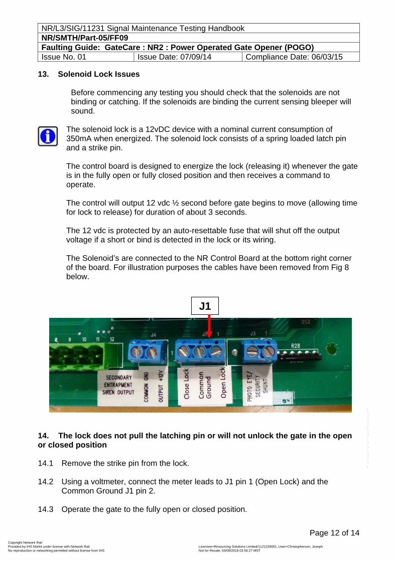
The solenoid lock is a 12vDC device with a nominal current consumption of 350mA when energized. The solenoid lock consists of a spring loaded latch pin and a strike pin. The control board is designed to energize the lock (releasing it) whenever the gate is in the fully open or fully closed position and then receives a command to operate. The control will output 12 vdc ½ second before gate begins to move (allowing time for lock to release) for duration of about 3 seconds. The 12 vdc is protected by an auto-resettable fuse that will shut off the output voltage if a short or bind is detected in the lock or its wiring. The Solenoid’s are connected to the NR Control Board at the bottom right corner of the board. For illustration purposes the cables have been removed from Fig 8 below.
14. The lock does not pull the latching pin or will not unlock the gate in the open or closed position 14.1 Remove the strike pin from the lock.
14.2 Using a voltmeter, connect the meter leads to J1 pin 1 (Open Lock) and the
Common Ground J1 pin 2.
14.3 Operate the gate to the fully open or closed position.
J1
Copyright Network Rail Provided by IHS Markit under license with Network Rail Licensee=Resourcing Solutions Limited /1121226001, User=Christopherson, Joseph
Not for Resale, 03/09/2018 03:56:27 MSTNo reproduction or networking permitted without license from IHS
--``,,``,`,,`,```,,``,,````,,,`,-`-`,,`,,`,`,,`---
NR/L3/SIG/11231 Signal Maintenance Testing Handbook NR/SMTH/Part-05/FF09 Faulting Guide: GateCare : NR2 : Power Operated Gate Opener (POGO) Issue No. 01 Issue Date: 07/09/14 Compliance Date: 06/03/15
Page 13 of 14
14.4 Observe the voltmeter press the open/close command button. The meter should read 12vDC – for about 3 seconds on start up
14.5 If 12vDC is present then the problem is in the wiring, lock or binding of the lock Verify wiring. 14.6 Open or close the gate fully
14.7 Disconnect the green and blue wire from the lock (at the gate lock)
14.8 Using voltmeter connect to the red and black wire which are now disconnected from
the lock
14.9 Operate the gate, the meter should read 12vDC (for about 3 seconds) on start up
14.10 If voltage is present proceed to step 12.13. Verify the lock 14.11 Reconnect the green and blue wires to the lock (at the gate lock)
14.12 Verify the strike pin is removed (eliminates the possibility of binding)
14.13 Open or close the gate fully
14.14 Operate the gate and verify the latch pin is pulled (for about 3 seconds) on startup.
If correct the lock is not the problem, proceed to step 12.17 Verify binding of the latch pin 14.15 Open or close the gate fully
14.16 Install the strike into the lock (gate should be In the locked position once strike pin is
installed)
14.17 Operate the gate to see if gate lock releases.
14.18 If not then the latch pin is binding up because of too much pressure on the strike pin.
14.19 This is a mechanical issue, caused by incorrect gate stop position or the lock is not aligned correctly.
14.20 Identify which is causing the bind and correct.
Copyright Network Rail Provided by IHS Markit under license with Network Rail Licensee=Resourcing Solutions Limited /1121226001, User=Christopherson, Joseph
Not for Resale, 03/09/2018 03:56:27 MSTNo reproduction or networking permitted without license from IHS
--``,,``,`,,`,```,,``,,````,,,`,-`-`,,`,,`,`,,`---
NR/L3/SIG/11231 Signal Maintenance Testing Handbook NR/SMTH/Part-05/FF09 Faulting Guide: GateCare : NR2 : Power Operated Gate Opener (POGO) Issue No. 01 Issue Date: 07/09/14 Compliance Date: 06/03/15
Page 14 of 14
The lock does not pull the latch pin (unlock) from the open gate position 14.21 Verify gate is on the retract limit. Lock pin will only pull if the retract limit is activated.
14.22 Adjust retract if limit is not activated. The lock does not pull the latch pin (unlock) from the closed gate position 14.23 Verify the gate is on the closed limit. Lock only activates if the closed limit is
activated.
14.24 Adjust closed limit if limit is not activated.
END
Copyright Network Rail Provided by IHS Markit under license with Network Rail Licensee=Resourcing Solutions Limited /1121226001, User=Christopherson, Joseph
Not for Resale, 03/09/2018 03:56:27 MSTNo reproduction or networking permitted without license from IHS
--``,,``,`,,`,```,,``,,````,,,`,-`-`,,`,,`,`,,`---
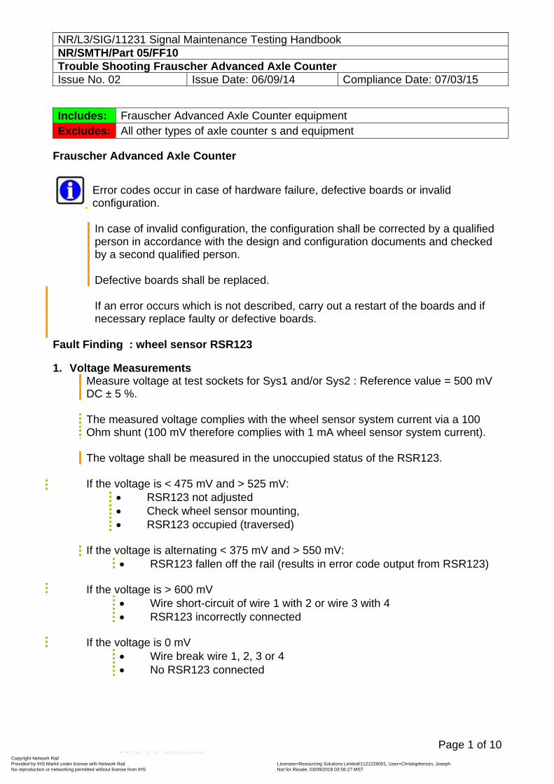
NR/L3/SIG/11231 Signal Maintenance Testing Handbook NR/SMTH/Part 05/FF10 Trouble Shooting Frauscher Advanced Axle Counter Issue No. 02 Issue Date: 06/09/14 Compliance Date: 07/03/15
Page 1 of 10
Includes: Frauscher Advanced Axle Counter equipment Excludes: All other types of axle counter s and equipment
Frauscher Advanced Axle Counter
Error codes occur in case of hardware failure, defective boards or invalid configuration.
In case of invalid configuration, the configuration shall be corrected by a qualified person in accordance with the design and configuration documents and checked by a second qualified person. Defective boards shall be replaced.
If an error occurs which is not described, carry out a restart of the boards and if
necessary replace faulty or defective boards.
Fault Finding : wheel sensor RSR123 1. Voltage Measurements
Measure voltage at test sockets for Sys1 and/or Sys2 : Reference value = 500 mV DC ± 5 %. The measured voltage complies with the wheel sensor system current via a 100 Ohm shunt (100 mV therefore complies with 1 mA wheel sensor system current). The voltage shall be measured in the unoccupied status of the RSR123.
If the voltage is < 475 mV and > 525 mV:
RSR123 not adjusted Check wheel sensor mounting, RSR123 occupied (traversed)
If the voltage is alternating < 375 mV and > 550 mV:
RSR123 fallen off the rail (results in error code output from RSR123)
If the voltage is > 600 mV Wire short-circuit of wire 1 with 2 or wire 3 with 4 RSR123 incorrectly connected
If the voltage is 0 mV
Wire break wire 1, 2, 3 or 4 No RSR123 connected
Copyright Network Rail Provided by IHS Markit under license with Network Rail Licensee=Resourcing Solutions Limited /1121226001, User=Christopherson, Joseph
Not for Resale, 03/09/2018 03:56:27 MSTNo reproduction or networking permitted without license from IHS
--``,,``,`,,`,```,,``,,````,,,`,-`-`,,`,,`,`,,`---
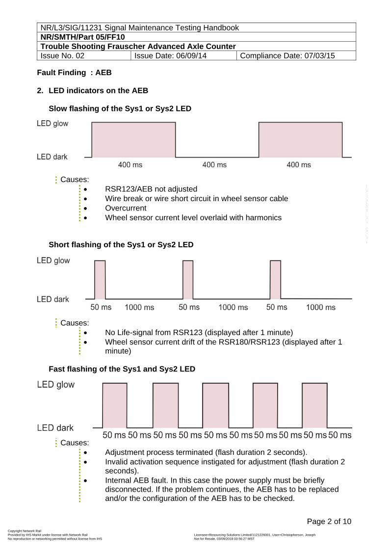
NR/L3/SIG/11231 Signal Maintenance Testing Handbook NR/SMTH/Part 05/FF10 Trouble Shooting Frauscher Advanced Axle Counter Issue No. 02 Issue Date: 06/09/14 Compliance Date: 07/03/15
Page 2 of 10
Fault Finding : AEB 2. LED indicators on the AEB
Slow flashing of the Sys1 or Sys2 LED
Causes: RSR123/AEB not adjusted Wire break or wire short circuit in wheel sensor cable Overcurrent Wheel sensor current level overlaid with harmonics
Short flashing of the Sys1 or Sys2 LED
Causes: No Life-signal from RSR123 (displayed after 1 minute) Wheel sensor current drift of the RSR180/RSR123 (displayed after 1
minute)
Fast flashing of the Sys1 and Sys2 LED
Causes:
Adjustment process terminated (flash duration 2 seconds). Invalid activation sequence instigated for adjustment (flash duration 2
seconds). Internal AEB fault. In this case the power supply must be briefly
disconnected. If the problem continues, the AEB has to be replaced and/or the configuration of the AEB has to be checked.
Copyright Network Rail Provided by IHS Markit under license with Network Rail Licensee=Resourcing Solutions Limited /1121226001, User=Christopherson, Joseph
Not for Resale, 03/09/2018 03:56:27 MSTNo reproduction or networking permitted without license from IHS
--``,,``,`,,`,```,,``,,````,,,`,-`-`,,`,,`,`,,`---
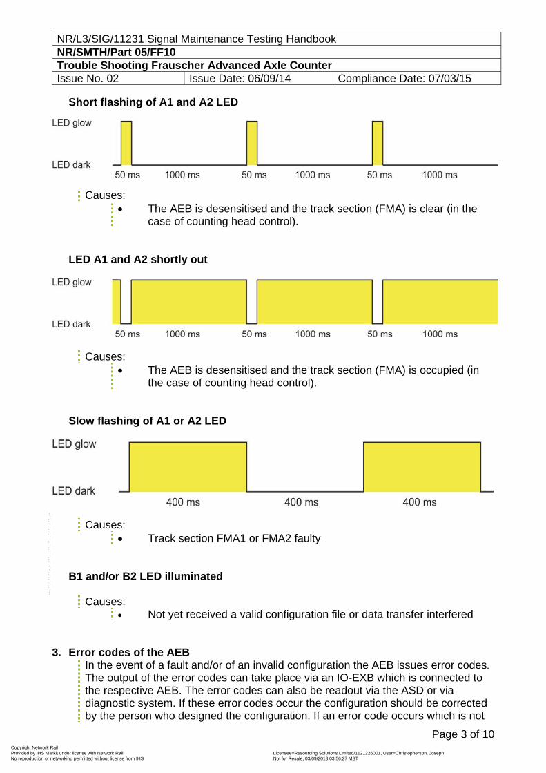
NR/L3/SIG/11231 Signal Maintenance Testing Handbook NR/SMTH/Part 05/FF10 Trouble Shooting Frauscher Advanced Axle Counter Issue No. 02 Issue Date: 06/09/14 Compliance Date: 07/03/15
Page 3 of 10
Short flashing of A1 and A2 LED
Causes: The AEB is desensitised and the track section (FMA) is clear (in the
case of counting head control).
LED A1 and A2 shortly out
Causes: The AEB is desensitised and the track section (FMA) is occupied (in
the case of counting head control).
Slow flashing of A1 or A2 LED
Causes: Track section FMA1 or FMA2 faulty
B1 and/or B2 LED illuminated
Causes: Not yet received a valid configuration file or data transfer interfered
3. Error codes of the AEB In the event of a fault and/or of an invalid configuration the AEB issues error codes. The output of the error codes can take place via an IO-EXB which is connected to the respective AEB. The error codes can also be readout via the ASD or via diagnostic system. If these error codes occur the configuration should be corrected by the person who designed the configuration. If an error code occurs which is not
Copyright Network Rail Provided by IHS Markit under license with Network Rail Licensee=Resourcing Solutions Limited /1121226001, User=Christopherson, Joseph
Not for Resale, 03/09/2018 03:56:27 MSTNo reproduction or networking permitted without license from IHS
--``,,``,`,,`,```,,``,,````,,,`,-`-`,,`,,`,`,,`---
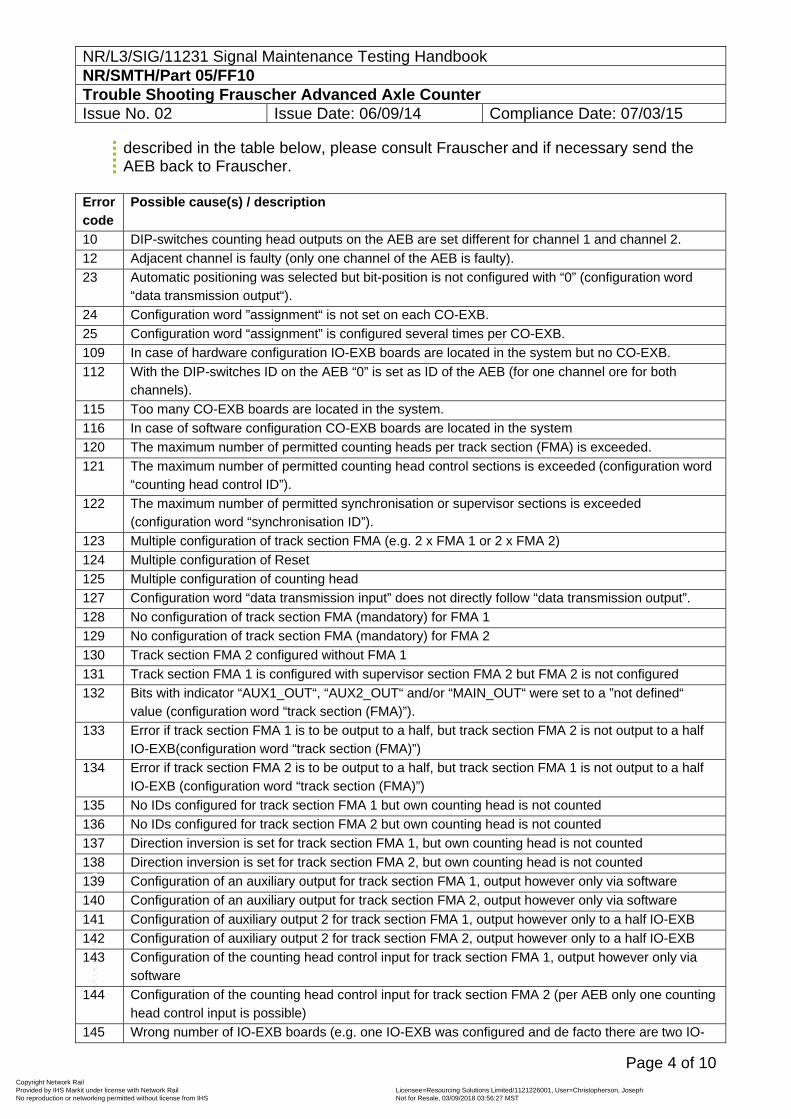
NR/L3/SIG/11231 Signal Maintenance Testing Handbook NR/SMTH/Part 05/FF10 Trouble Shooting Frauscher Advanced Axle Counter Issue No. 02 Issue Date: 06/09/14 Compliance Date: 07/03/15
Page 4 of 10
described in the table below, please consult Frauscher and if necessary send the AEB back to Frauscher.
Error code
Possible cause(s) / description
10 DIP-switches counting head outputs on the AEB are set different for channel 1 and channel 2.
12 Adjacent channel is faulty (only one channel of the AEB is faulty).
23 Automatic positioning was selected but bit-position is not configured with “0” (configuration word “data transmission output“).
24 Configuration word ”assignment“ is not set on each CO-EXB.
25 Configuration word “assignment” is configured several times per CO-EXB.
109 In case of hardware configuration IO-EXB boards are located in the system but no CO-EXB.
112 With the DIP-switches ID on the AEB “0” is set as ID of the AEB (for one channel ore for both channels).
115 Too many CO-EXB boards are located in the system.
116 In case of software configuration CO-EXB boards are located in the system
120 The maximum number of permitted counting heads per track section (FMA) is exceeded.
121 The maximum number of permitted counting head control sections is exceeded (configuration word “counting head control ID”).
122 The maximum number of permitted synchronisation or supervisor sections is exceeded (configuration word “synchronisation ID”).
123 Multiple configuration of track section FMA (e.g. 2 x FMA 1 or 2 x FMA 2)
124 Multiple configuration of Reset
125 Multiple configuration of counting head
127 Configuration word “data transmission input” does not directly follow “data transmission output”.
128 No configuration of track section FMA (mandatory) for FMA 1
129 No configuration of track section FMA (mandatory) for FMA 2
130 Track section FMA 2 configured without FMA 1
131 Track section FMA 1 is configured with supervisor section FMA 2 but FMA 2 is not configured
132 Bits with indicator “AUX1_OUT“, “AUX2_OUT“ and/or “MAIN_OUT“ were set to a ”not defined“ value (configuration word “track section (FMA)”).
133 Error if track section FMA 1 is to be output to a half, but track section FMA 2 is not output to a half IO-EXB(configuration word “track section (FMA)”)
134 Error if track section FMA 2 is to be output to a half, but track section FMA 1 is not output to a half IO-EXB (configuration word “track section (FMA)”)
135 No IDs configured for track section FMA 1 but own counting head is not counted
136 No IDs configured for track section FMA 2 but own counting head is not counted
137 Direction inversion is set for track section FMA 1, but own counting head is not counted
138 Direction inversion is set for track section FMA 2, but own counting head is not counted
139 Configuration of an auxiliary output for track section FMA 1, output however only via software
140 Configuration of an auxiliary output for track section FMA 2, output however only via software
141 Configuration of auxiliary output 2 for track section FMA 1, output however only to a half IO-EXB
142 Configuration of auxiliary output 2 for track section FMA 2, output however only to a half IO-EXB
143 Configuration of the counting head control input for track section FMA 1, output however only via software
144 Configuration of the counting head control input for track section FMA 2 (per AEB only one counting head control input is possible)
145 Wrong number of IO-EXB boards (e.g. one IO-EXB was configured and de facto there are two IO-
Copyright Network Rail Provided by IHS Markit under license with Network Rail Licensee=Resourcing Solutions Limited /1121226001, User=Christopherson, Joseph
Not for Resale, 03/09/2018 03:56:27 MSTNo reproduction or networking permitted without license from IHS
--``,,``,`,,`,```,,``,,````,,,`,-`-`,,`,,`,`,,`---
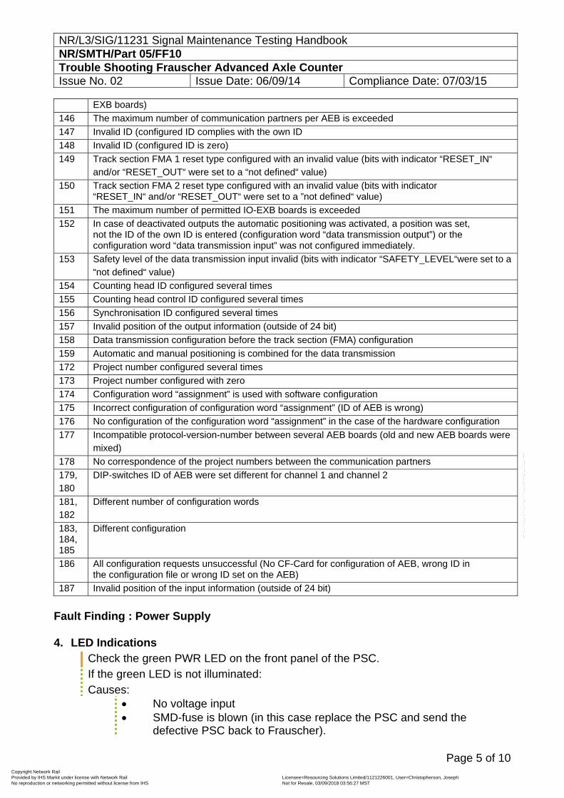
NR/L3/SIG/11231 Signal Maintenance Testing Handbook NR/SMTH/Part 05/FF10 Trouble Shooting Frauscher Advanced Axle Counter Issue No. 02 Issue Date: 06/09/14 Compliance Date: 07/03/15
Page 5 of 10
EXB boards)
146 The maximum number of communication partners per AEB is exceeded
147 Invalid ID (configured ID complies with the own ID
148 Invalid ID (configured ID is zero)
149 Track section FMA 1 reset type configured with an invalid value (bits with indicator “RESET_IN“ and/or “RESET_OUT“ were set to a “not defined“ value)
150 Track section FMA 2 reset type configured with an invalid value (bits with indicator “RESET_IN“ and/or “RESET_OUT“ were set to a ”not defined“ value)
151 The maximum number of permitted IO-EXB boards is exceeded
152 In case of deactivated outputs the automatic positioning was activated, a position was set, not the ID of the own ID is entered (configuration word “data transmission output”) or the configuration word “data transmission input” was not configured immediately.
153 Safety level of the data transmission input invalid (bits with indicator “SAFETY_LEVEL“were set to a “not defined“ value)
154 Counting head ID configured several times
155 Counting head control ID configured several times
156 Synchronisation ID configured several times
157 Invalid position of the output information (outside of 24 bit)
158 Data transmission configuration before the track section (FMA) configuration
159 Automatic and manual positioning is combined for the data transmission
172 Project number configured several times
173 Project number configured with zero
174 Configuration word “assignment” is used with software configuration
175 Incorrect configuration of configuration word “assignment” (ID of AEB is wrong)
176 No configuration of the configuration word “assignment” in the case of the hardware configuration
177 Incompatible protocol-version-number between several AEB boards (old and new AEB boards were mixed)
178 No correspondence of the project numbers between the communication partners
179, 180
DIP-switches ID of AEB were set different for channel 1 and channel 2
181, 182
Different number of configuration words
183, 184, 185
Different configuration
186 All configuration requests unsuccessful (No CF-Card for configuration of AEB, wrong ID in the configuration file or wrong ID set on the AEB)
187 Invalid position of the input information (outside of 24 bit)
Fault Finding : Power Supply 4. LED Indications
Check the green PWR LED on the front panel of the PSC. If the green LED is not illuminated: Causes:
No voltage input SMD-fuse is blown (in this case replace the PSC and send the
defective PSC back to Frauscher).
Copyright Network Rail Provided by IHS Markit under license with Network Rail Licensee=Resourcing Solutions Limited /1121226001, User=Christopherson, Joseph
Not for Resale, 03/09/2018 03:56:27 MSTNo reproduction or networking permitted without license from IHS
--``,,``,`,,`,```,,``,,````,,,`,-`-`,,`,,`,`,,`---
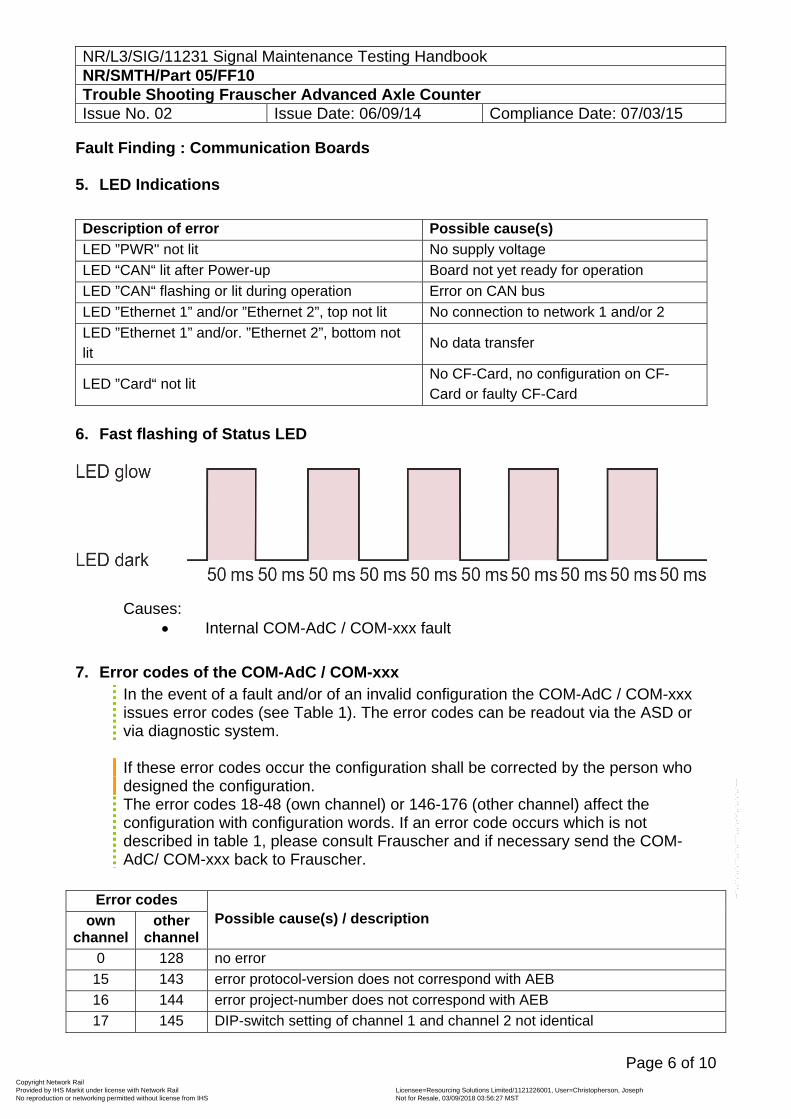
NR/L3/SIG/11231 Signal Maintenance Testing Handbook NR/SMTH/Part 05/FF10 Trouble Shooting Frauscher Advanced Axle Counter Issue No. 02 Issue Date: 06/09/14 Compliance Date: 07/03/15
Page 6 of 10
Fault Finding : Communication Boards 5. LED Indications Description of error Possible cause(s)
LED ”PWR" not lit No supply voltage
LED “CAN“ lit after Power-up Board not yet ready for operation
LED ”CAN“ flashing or lit during operation Error on CAN bus
LED ”Ethernet 1” and/or ”Ethernet 2”, top not lit No connection to network 1 and/or 2
LED ”Ethernet 1” and/or. ”Ethernet 2”, bottom not lit
No data transfer
LED ”Card“ not lit No CF-Card, no configuration on CF-Card or faulty CF-Card
6. Fast flashing of Status LED
Causes:
Internal COM-AdC / COM-xxx fault 7. Error codes of the COM-AdC / COM-xxx
In the event of a fault and/or of an invalid configuration the COM-AdC / COM-xxx issues error codes (see Table 1). The error codes can be readout via the ASD or via diagnostic system. If these error codes occur the configuration shall be corrected by the person who designed the configuration. The error codes 18-48 (own channel) or 146-176 (other channel) affect the configuration with configuration words. If an error code occurs which is not described in table 1, please consult Frauscher and if necessary send the COM-AdC/ COM-xxx back to Frauscher.
Error codes
Possible cause(s) / description own channel
other channel
0 128 no error
15 143 error protocol-version does not correspond with AEB
16 144 error project-number does not correspond with AEB
17 145 DIP-switch setting of channel 1 and channel 2 not identical
Copyright Network Rail Provided by IHS Markit under license with Network Rail Licensee=Resourcing Solutions Limited /1121226001, User=Christopherson, Joseph
Not for Resale, 03/09/2018 03:56:27 MSTNo reproduction or networking permitted without license from IHS
--``,,``,`,,`,```,,``,,````,,,`,-`-`,,`,,`,`,,`---
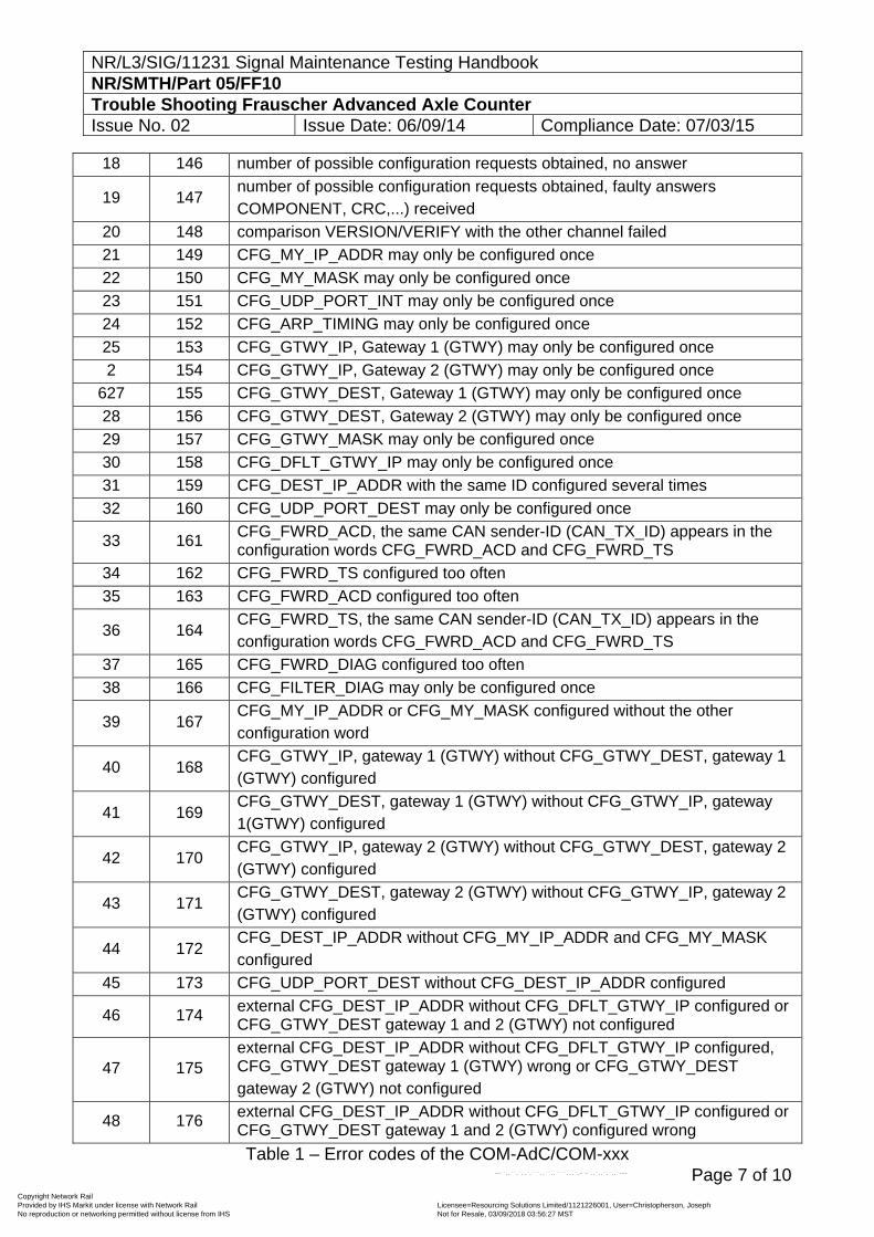
NR/L3/SIG/11231 Signal Maintenance Testing Handbook NR/SMTH/Part 05/FF10 Trouble Shooting Frauscher Advanced Axle Counter Issue No. 02 Issue Date: 06/09/14 Compliance Date: 07/03/15
Page 7 of 10
18 146 number of possible configuration requests obtained, no answer
19 147 number of possible configuration requests obtained, faulty answers COMPONENT, CRC,...) received
20 148 comparison VERSION/VERIFY with the other channel failed
21 149 CFG_MY_IP_ADDR may only be configured once
22 150 CFG_MY_MASK may only be configured once
23 151 CFG_UDP_PORT_INT may only be configured once
24 152 CFG_ARP_TIMING may only be configured once
25 153 CFG_GTWY_IP, Gateway 1 (GTWY) may only be configured once
2 154 CFG_GTWY_IP, Gateway 2 (GTWY) may only be configured once
627 155 CFG_GTWY_DEST, Gateway 1 (GTWY) may only be configured once
28 156 CFG_GTWY_DEST, Gateway 2 (GTWY) may only be configured once
29 157 CFG_GTWY_MASK may only be configured once
30 158 CFG_DFLT_GTWY_IP may only be configured once
31 159 CFG_DEST_IP_ADDR with the same ID configured several times
32 160 CFG_UDP_PORT_DEST may only be configured once
33 161 CFG_FWRD_ACD, the same CAN sender-ID (CAN_TX_ID) appears in the configuration words CFG_FWRD_ACD and CFG_FWRD_TS
34 162 CFG_FWRD_TS configured too often
35 163 CFG_FWRD_ACD configured too often
36 164 CFG_FWRD_TS, the same CAN sender-ID (CAN_TX_ID) appears in the configuration words CFG_FWRD_ACD and CFG_FWRD_TS
37 165 CFG_FWRD_DIAG configured too often
38 166 CFG_FILTER_DIAG may only be configured once
39 167 CFG_MY_IP_ADDR or CFG_MY_MASK configured without the other configuration word
40 168 CFG_GTWY_IP, gateway 1 (GTWY) without CFG_GTWY_DEST, gateway 1 (GTWY) configured
41 169 CFG_GTWY_DEST, gateway 1 (GTWY) without CFG_GTWY_IP, gateway 1(GTWY) configured
42 170 CFG_GTWY_IP, gateway 2 (GTWY) without CFG_GTWY_DEST, gateway 2 (GTWY) configured
43 171 CFG_GTWY_DEST, gateway 2 (GTWY) without CFG_GTWY_IP, gateway 2 (GTWY) configured
44 172 CFG_DEST_IP_ADDR without CFG_MY_IP_ADDR and CFG_MY_MASK configured
45 173 CFG_UDP_PORT_DEST without CFG_DEST_IP_ADDR configured
46 174 external CFG_DEST_IP_ADDR without CFG_DFLT_GTWY_IP configured or CFG_GTWY_DEST gateway 1 and 2 (GTWY) not configured
47 175 external CFG_DEST_IP_ADDR without CFG_DFLT_GTWY_IP configured, CFG_GTWY_DEST gateway 1 (GTWY) wrong or CFG_GTWY_DEST gateway 2 (GTWY) not configured
48 176 external CFG_DEST_IP_ADDR without CFG_DFLT_GTWY_IP configured or CFG_GTWY_DEST gateway 1 and 2 (GTWY) configured wrong
Table 1 – Error codes of the COM-AdC/COM-xxx
Copyright Network Rail Provided by IHS Markit under license with Network Rail Licensee=Resourcing Solutions Limited /1121226001, User=Christopherson, Joseph
Not for Resale, 03/09/2018 03:56:27 MSTNo reproduction or networking permitted without license from IHS
--``,,``,`,,`,```,,``,,````,,,`,-`-`,,`,,`,`,,`---
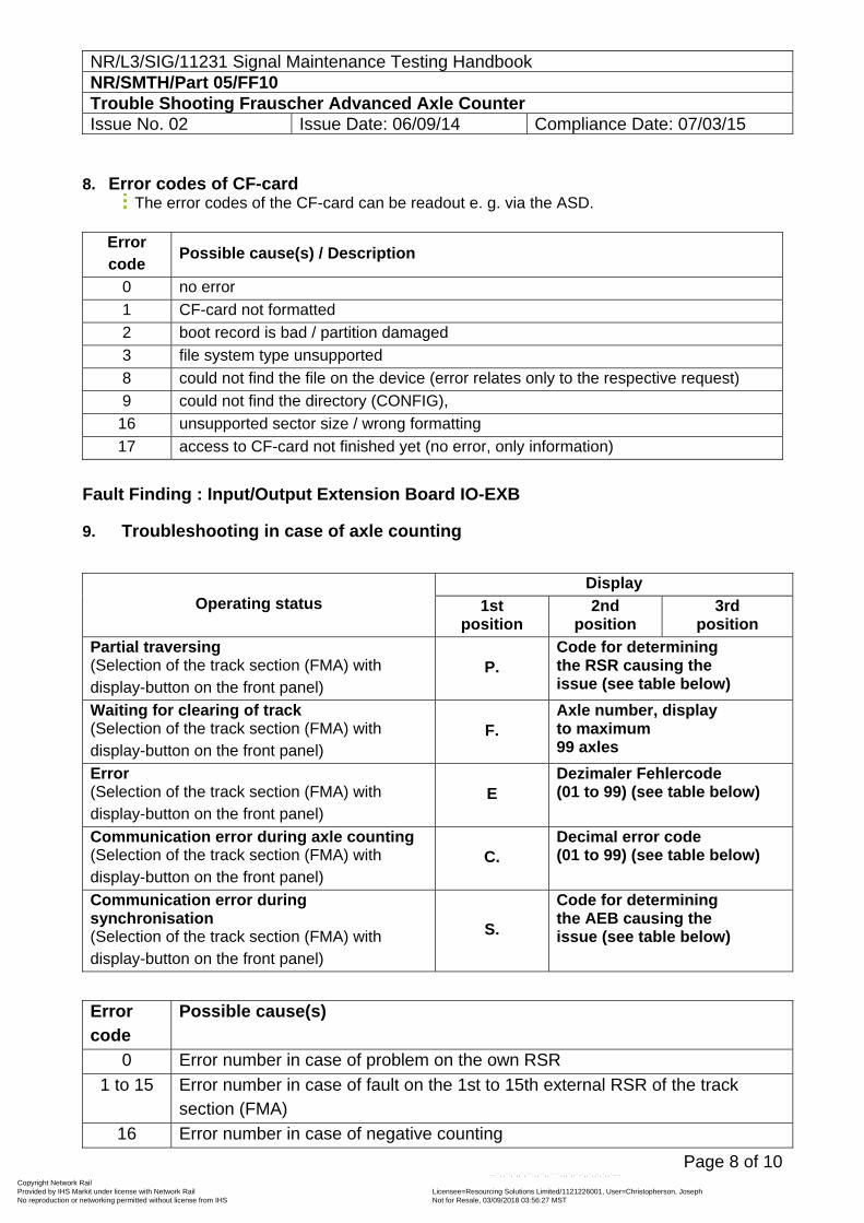
NR/L3/SIG/11231 Signal Maintenance Testing Handbook NR/SMTH/Part 05/FF10 Trouble Shooting Frauscher Advanced Axle Counter Issue No. 02 Issue Date: 06/09/14 Compliance Date: 07/03/15
Page 8 of 10
8. Error codes of CF-card The error codes of the CF-card can be readout e. g. via the ASD.
Error code
Possible cause(s) / Description
0 no error
1 CF-card not formatted
2 boot record is bad / partition damaged
3 file system type unsupported
8 could not find the file on the device (error relates only to the respective request)
9 could not find the directory (CONFIG),
16 unsupported sector size / wrong formatting
17 access to CF-card not finished yet (no error, only information)
Fault Finding : Input/Output Extension Board IO-EXB 9. Troubleshooting in case of axle counting
Operating status Display
1st position
2nd position
3rd position
Partial traversing (Selection of the track section (FMA) with display-button on the front panel)
P. Code for determining the RSR causing the issue (see table below)
Waiting for clearing of track (Selection of the track section (FMA) with display-button on the front panel)
F. Axle number, display to maximum 99 axles
Error (Selection of the track section (FMA) with display-button on the front panel)
E Dezimaler Fehlercode (01 to 99) (see table below)
Communication error during axle counting (Selection of the track section (FMA) with display-button on the front panel)
C. Decimal error code (01 to 99) (see table below)
Communication error during synchronisation (Selection of the track section (FMA) with display-button on the front panel)
S.
Code for determining the AEB causing the issue (see table below)
Error code
Possible cause(s)
0 Error number in case of problem on the own RSR
1 to 15 Error number in case of fault on the 1st to 15th external RSR of the track section (FMA)
16 Error number in case of negative counting
Copyright Network Rail Provided by IHS Markit under license with Network Rail Licensee=Resourcing Solutions Limited /1121226001, User=Christopherson, Joseph
Not for Resale, 03/09/2018 03:56:27 MSTNo reproduction or networking permitted without license from IHS
--``,,``,`,,`,```,,``,,````,,,`,-`-`,,`,,`,`,,`---
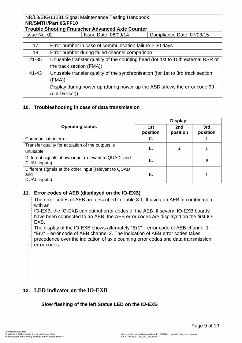
NR/L3/SIG/11231 Signal Maintenance Testing Handbook NR/SMTH/Part 05/FF10 Trouble Shooting Frauscher Advanced Axle Counter Issue No. 02 Issue Date: 06/09/14 Compliance Date: 07/03/15
Page 9 of 10
17 Error number in case of communication failure > 30 days
18 Error number during failed channel comparison
21-35 Unusable transfer quality of the counting head (for 1st to 15th external RSR of the track section (FMA))
41-43 Unusable transfer quality of the synchronisation (for 1st to 3rd track section (FMA))
- - - Display during power up (during power-up the ASD shows the error code 99 (until Reset))
10. Troubleshooting in case of data transmission
Operating status Display
1st position
2nd position
3rd position
Communication error C. 1
Transfer quality for actuation of the outputs is unusable
E. 2 1
Different signals at own input (relevant to QUAD- and DUAL-inputs)
E. 0
Different signals at the other input (relevant to QUAD and DUAL-inputs)
E. 1
11. Error codes of AEB (displayed on the IO-EXB)
The error codes of AEB are described in Table 8.1. If using an AEB in combination with an IO-EXB, the IO-EXB can output error codes of the AEB. If several IO-EXB boards have been connected to an AEB, the AEB error codes are displayed on the first IO-EXB. The display of the IO-EXB shows alternately “Er1” – error code of AEB channel 1 – “Er2” – error code of AEB channel 2. The indication of AEB error codes takes precedence over the indication of axle counting error codes and data transmission error codes.
12. LED indicator on the IO-EXB
Slow flashing of the left Status LED on the IO-EXB
Copyright Network Rail Provided by IHS Markit under license with Network Rail Licensee=Resourcing Solutions Limited /1121226001, User=Christopherson, Joseph
Not for Resale, 03/09/2018 03:56:27 MSTNo reproduction or networking permitted without license from IHS
--``,,``,`,,`,```,,``,,````,,,`,-`-`,,`,,`,`,,`---
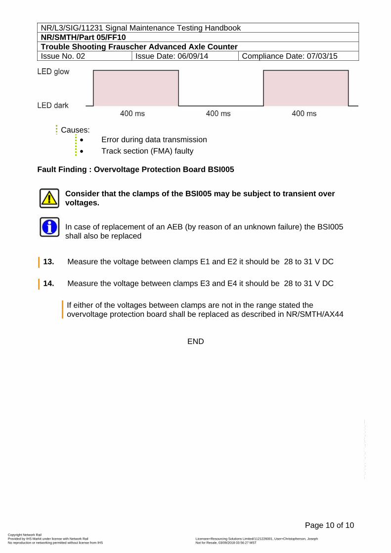
NR/L3/SIG/11231 Signal Maintenance Testing Handbook NR/SMTH/Part 05/FF10 Trouble Shooting Frauscher Advanced Axle Counter Issue No. 02 Issue Date: 06/09/14 Compliance Date: 07/03/15
Page 10 of 10
Causes: Error during data transmission
Track section (FMA) faulty Fault Finding : Overvoltage Protection Board BSI005
Consider that the clamps of the BSI005 may be subject to transient over voltages.
In case of replacement of an AEB (by reason of an unknown failure) the BSI005 shall also be replaced
13. Measure the voltage between clamps E1 and E2 it should be 28 to 31 V DC
14. Measure the voltage between clamps E3 and E4 it should be 28 to 31 V DC
If either of the voltages between clamps are not in the range stated the overvoltage protection board shall be replaced as described in NR/SMTH/AX44
END
Copyright Network Rail Provided by IHS Markit under license with Network Rail Licensee=Resourcing Solutions Limited /1121226001, User=Christopherson, Joseph
Not for Resale, 03/09/2018 03:56:27 MSTNo reproduction or networking permitted without license from IHS
--``,,``,`,,`,```,,``,,````,,,`,-`-`,,`,,`,`,,`---
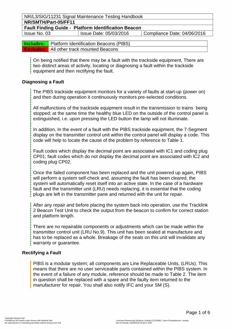
NR/L3/SIG/11231 Signal Maintenance Testing Handbook NR/SMTH/Part-05/FF11 Fault Finding Guide - Platform Identification Beacon Issue No. 03 Issue Date: 05/03/2016 Compliance Date: 04/06/2016
Page 1 of 6
Includes: Platform Identification Beacons (PIBS) Excludes: All other track mounted Beacons
On being notified that there may be a fault with the trackside equipment, There are two distinct areas of activity, locating or diagnosing a fault within the trackside equipment and then rectifying the fault.
Diagnosing a Fault
The PIBS trackside equipment monitors for a variety of faults at start-up (power on) and then during operation it continuously monitors pre-selected conditions. All malfunctions of the trackside equipment result in the transmission to trains being stopped; at the same time the healthy blue LED on the outside of the control panel is extinguished, i.e. upon pressing the LED button the lamp will not illuminate. In addition, In the event of a fault with the PIBS trackside equipment, the 7-Segment display on the transmitter control unit within the control panel will display a code. This code will help to locate the cause of the problem by reference to Table 1. Fault codes which display the decimal point are associated with IC1 and coding plug CP01; fault codes which do not display the decimal point are associated with lC2 and coding plug CP02. Once the failed component has been replaced and the unit powered up again, PIBS will perform a system self-check and, assuming the fault has been cleared, the system will automatically reset itself into an active state. In the case of a hardware fault and the transmitter unit (LRU) needs replacing, it is essential that the coding plugs are left in the transmitter pane and returned with the unit for repair.
After any repair and before placing the system back into operation, use the Tracklink 2 Beacon Test Unit to check the output from the beacon to confirm for correct station and platform length. There are no repairable components or adjustments which can be made within the transmitter control unit (LRU No.9). This unit has been sealed at manufacture and has to be replaced as a whole. Breakage of the seals on this unit will invalidate any warranty or guarantee.
Rectifying a Fault
PIBS is a modular system; all components are Line Replaceable Units, (LRUs). This means that there are no user serviceable parts contained within the PIBS system. In the event of a failure of any module, reference should be made to Table 2. The item in question shall be replaced with a spare and the faulty item returned to the manufacturer for repair. You shall also notify IFC and your SM (S).
Copyright Network Rail Provided by IHS Markit under license with Network Rail Licensee=Resourcing Solutions Limited /1121226001, User=Christopherson, Joseph
Not for Resale, 03/09/2018 03:56:27 MSTNo reproduction or networking permitted without license from IHS
--``,,``,`,,`,```,,``,,````,,,`,-`-`,,`,,`,`,,`---
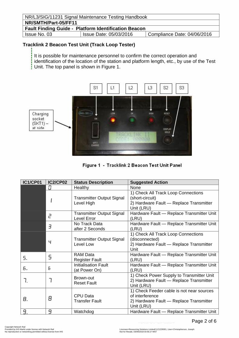
NR/L3/SIG/11231 Signal Maintenance Testing Handbook NR/SMTH/Part-05/FF11 Fault Finding Guide - Platform Identification Beacon Issue No. 03 Issue Date: 05/03/2016 Compliance Date: 04/06/2016
Page 2 of 6
Tracklink 2 Beacon Test Unit (Track Loop Tester) It is possible for maintenance personnel to confirm the correct operation and identification of the location of the station and platform length, etc., by use of the Test Unit. The top panel is shown in Figure 1.
IC1/CP01 IC2/CP02 Status Description Suggested Action Healthy None
Transmitter Output Signal Level High
1) Check All Track Loop Connections (short-circuit) 2) Hardware Fault — Replace Transmitter Unit (LRU)
Transmitter Output Signal Level Error
Hardware Fault — Replace Transmitter Unit (LRU)
No Track Data after 2 Seconds
Hardware Fault — Replace Transmitter Unit (LRU)
Transmitter Output Signal Level Low
1) Check All Track Loop Connections (disconnected) 2) Hardware Fault — Replace Transmitter Unit
RAM Data Register Fault
Hardware Fault — Replace Transmitter Unit (LRU)
Initialisation Fault (at Power On)
Hardware Fault — Replace Transmitter Unit (LRU)
Brown-out Reset Fault
1) Check Power Supply to Transmitter Unit 2) Hardware Fault — Replace Transmitter Unit (LRU)
CPU Data Transfer Fault
1) Check Feeder cable is not near sources of interference 2) Hardware Fault — Replace Transmitter Unit (LRU)
Watchdog Hardware Fault — Replace Transmitter Unit
Copyright Network Rail Provided by IHS Markit under license with Network Rail Licensee=Resourcing Solutions Limited /1121226001, User=Christopherson, Joseph
Not for Resale, 03/09/2018 03:56:27 MSTNo reproduction or networking permitted without license from IHS
--``,,``,`,,`,```,,``,,````,,,`,-`-`,,`,,`,`,,`---
NR/L3/SIG/11231 Signal Maintenance Testing Handbook NR/SMTH/Part-05/FF11 Fault Finding Guide - Platform Identification Beacon Issue No. 03 Issue Date: 05/03/2016 Compliance Date: 04/06/2016
Page 3 of 6
IC1/CP01 IC2/CP02 Status Description Suggested Action Reset Fault (LRU)
5V Logic Supply High Hardware Fault — Replace Transmitter Unit (LRU)
Coding Plug Parity Fault
1) Check Coding Plug installed correctly 2) Faulty Coding Plug 3) Hardware Fault — Replace Transmitter Unit (LRU)
Coding Plug Not Present
1) Check Coding Plug installed correctly 2) Faulty Coding Plug. 3) Hardware Fault — Replace Transmitter Unit (LRU)
Track Data Check Fault
1) Check Coding Plugs installed Correctly 2) Check Coding Plug Numbers Match
Feedback Coil Connection Fault
Hardware Fault — Replace Transmitter Unit (LRU)
Track Data Receive Fault
1) Check All Track Loop Connections 2) Check Feeder cable is not near sources of interference
Operation Stopped Hardware Fault — Replace Transmitter Unit (LRU)
Table 1 – Transmitter Control Unit Fault Code Table
LRI Item No.
HSD 2000 Part No.
Description Quantity per System
PADS Cat. No.
1 2000/066/00 Tracklink 2 Beacon (complete)
1 off 3492/098996
2 2000/066/01 Tracklink 2 Support Beams(specify fixings)
5 off
3 2000/066/02 5m Track Cable Type C3, 2 core, 2.5mm2 c/w 3 pin moulded socket
1 off 006/160086
4 2000/066/03 10m Track Cable Type C3, 2 core, 2.5mm2 c/w 3 pin moulded socket
5 2000/066/04 60m Tail Cable Type C3, 2 core, 2.5mm2
1 off 006/160086
6 2000/016/00 3 way Disconnection Box (complete)
1 off 3492/098997
7 2000/016/01 Dis. Box Support Stake 1 off
8 2000/046/00 Tracklink 2 Transmitter S/S Enclosure
1 off
3492/098995
9 2000/046/01 Transmitter Control Unit 1 off
10 2000/046/02 Transmitter Control Unit Power Supply Unit
1 off
11 2000/046/03 Matched Coding Plug Set 2 off
12 2000/046/04 Replacement LED Switch Indicator Complete (White)
1 off
13 2000/046/05 Replacement LED Switch 1 off
Copyright Network Rail Provided by IHS Markit under license with Network Rail Licensee=Resourcing Solutions Limited /1121226001, User=Christopherson, Joseph
Not for Resale, 03/09/2018 03:56:27 MSTNo reproduction or networking permitted without license from IHS
--``,,``,`,,`,```,,``,,````,,,`,-`-`,,`,,`,`,,`---
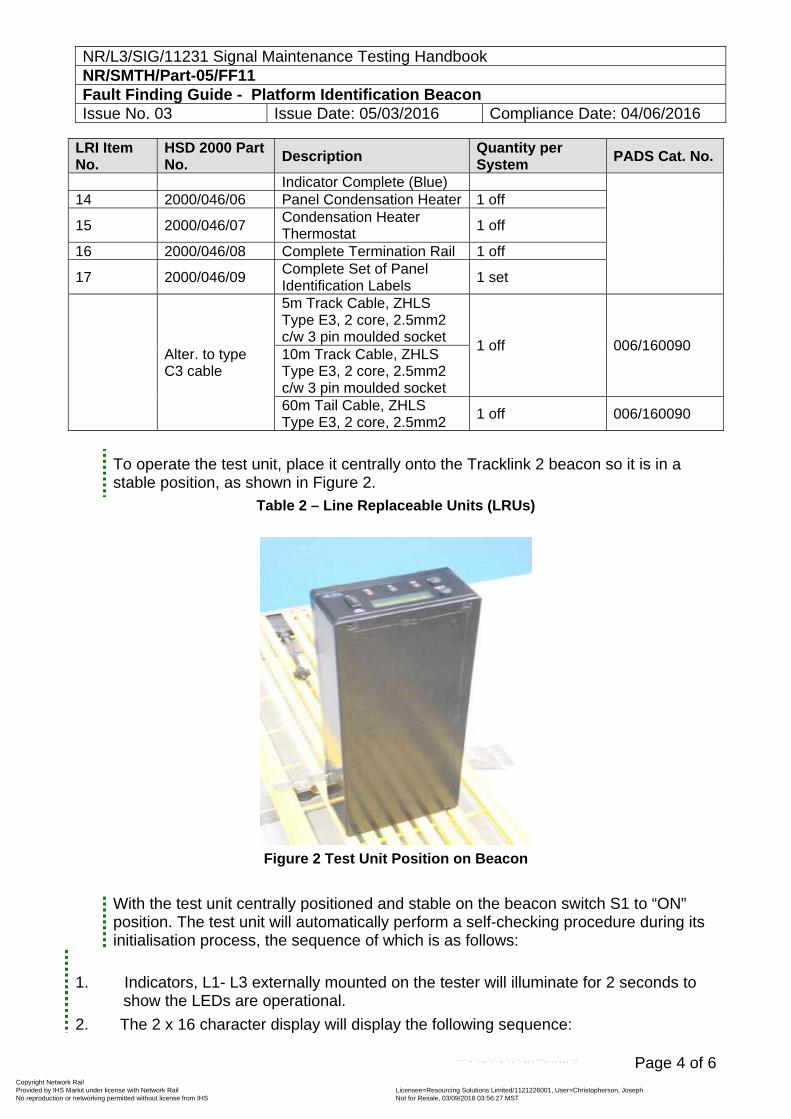
NR/L3/SIG/11231 Signal Maintenance Testing Handbook NR/SMTH/Part-05/FF11 Fault Finding Guide - Platform Identification Beacon Issue No. 03 Issue Date: 05/03/2016 Compliance Date: 04/06/2016
Page 4 of 6
LRI Item No.
HSD 2000 Part No.
Description Quantity per System
PADS Cat. No.
Indicator Complete (Blue) 14 2000/046/06 Panel Condensation Heater 1 off
15 2000/046/07 Condensation Heater Thermostat
1 off
16 2000/046/08 Complete Termination Rail 1 off
17 2000/046/09 Complete Set of Panel Identification Labels
1 set
Alter. to type C3 cable
5m Track Cable, ZHLS Type E3, 2 core, 2.5mm2 c/w 3 pin moulded socket
1 off 006/160090 10m Track Cable, ZHLS Type E3, 2 core, 2.5mm2 c/w 3 pin moulded socket 60m Tail Cable, ZHLS Type E3, 2 core, 2.5mm2
1 off 006/160090
To operate the test unit, place it centrally onto the Tracklink 2 beacon so it is in a stable position, as shown in Figure 2.
Table 2 – Line Replaceable Units (LRUs)
Figure 2 Test Unit Position on Beacon
With the test unit centrally positioned and stable on the beacon switch S1 to “ON” position. The test unit will automatically perform a self-checking procedure during its initialisation process, the sequence of which is as follows:
1. Indicators, L1- L3 externally mounted on the tester will illuminate for 2 seconds to show the LEDs are operational.
2. The 2 x 16 character display will display the following sequence:
Copyright Network Rail Provided by IHS Markit under license with Network Rail Licensee=Resourcing Solutions Limited /1121226001, User=Christopherson, Joseph
Not for Resale, 03/09/2018 03:56:27 MSTNo reproduction or networking permitted without license from IHS
--``,,``,`,,`,```,,``,,````,,,`,-`-`,,`,,`,`,,`---
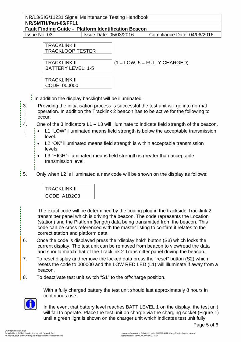
NR/L3/SIG/11231 Signal Maintenance Testing Handbook NR/SMTH/Part-05/FF11 Fault Finding Guide - Platform Identification Beacon Issue No. 03 Issue Date: 05/03/2016 Compliance Date: 04/06/2016
Page 5 of 6
TRACKLINK II TRACKLOOP TESTER
TRACKLINK II BATTERY LEVEL: 1-5
(1 = LOW, 5 = FULLY CHARGED)
TRACKLINK II CODE: 000000
In addition the display backlight will be illuminated.
3. Providing the initialisation process is successful the test unit will go into normal operation. In addition the Tracklink 2 beacon has to be active for the following to occur:
4. One of the 3 indicators L1 – L3 will illuminate to indicate field strength of the beacon. L1 “LOW” illuminated means field strength is below the acceptable transmission
level. L2 “OK” illuminated means field strength is within acceptable transmission
levels. L3 “HIGH” illuminated means field strength is greater than acceptable
transmission level.
5. Only when L2 is illuminated a new code will be shown on the display as follows:
TRACKLINK II
CODE: A1B2C3
The exact code will be determined by the coding plug in the trackside Tracklink 2 transmitter panel which is driving the beacon. The code represents the Location (station) and the Platform (length) data being transmitted from the beacon. This code can be cross referenced with the master listing to confirm it relates to the correct station and platform data.
6. Once the code is displayed press the “display hold” button (S3) which locks the current display. The test unit can be removed from beacon to view/read the data and should match that of the Tracklink 2 Transmitter panel driving the beacon.
7. To reset display and remove the locked data press the “reset” button (S2) which resets the code to 000000 and the LOW RED LED (L1) will illuminate if away from a beacon.
8. To deactivate test unit switch “S1” to the off/charge position.
With a fully charged battery the test unit should last approximately 8 hours in continuous use. In the event that battery level reaches BATT LEVEL 1 on the display, the test unit will fail to operate. Place the test unit on charge via the charging socket (Figure 1) until a green light is shown on the charger unit which indicates test unit fully
Copyright Network Rail Provided by IHS Markit under license with Network Rail Licensee=Resourcing Solutions Limited /1121226001, User=Christopherson, Joseph
Not for Resale, 03/09/2018 03:56:27 MSTNo reproduction or networking permitted without license from IHS
--``,,``,`,,`,```,,``,,````,,,`,-`-`,,`,,`,`,,`---
NR/L3/SIG/11231 Signal Maintenance Testing Handbook NR/SMTH/Part-05/FF11 Fault Finding Guide - Platform Identification Beacon Issue No. 03 Issue Date: 05/03/2016 Compliance Date: 04/06/2016
Page 6 of 6
charged. While test unit is charging the charger unit shows a red light.
Maintenance of the Tracklink 2 Test Unit Visual Checks:
Check external charging connector for damage. Check external of tester for physical damage. Check main label for secure fixing. Yearly: Return to Hima-Sella Limited for calibration.
END
Copyright Network Rail Provided by IHS Markit under license with Network Rail Licensee=Resourcing Solutions Limited /1121226001, User=Christopherson, Joseph
Not for Resale, 03/09/2018 03:56:27 MSTNo reproduction or networking permitted without license from IHS
--``,,``,`,,`,```,,``,,````,,,`,-`-`,,`,,`,`,,`---
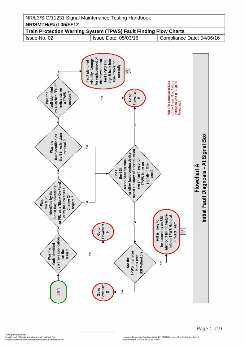
NR/L3/SIG/11231 Signal Maintenance Testing Handbook NR/SMTH/Part 05/FF12 Train Protection Warning System (TPWS) Fault Finding Flow Charts Issue No. 02 Issue Date: 05/03/16 Compliance Date: 04/06/16
Page 1 of 9
Copyright Network Rail Provided by IHS Markit under license with Network Rail Licensee=Resourcing Solutions Limited /1121226001, User=Christopherson, Joseph
Not for Resale, 03/09/2018 03:56:27 MSTNo reproduction or networking permitted without license from IHS
--``,,``,`,,`,```,,``,,````,,,`,-`-`,,`,,`,`,,`---
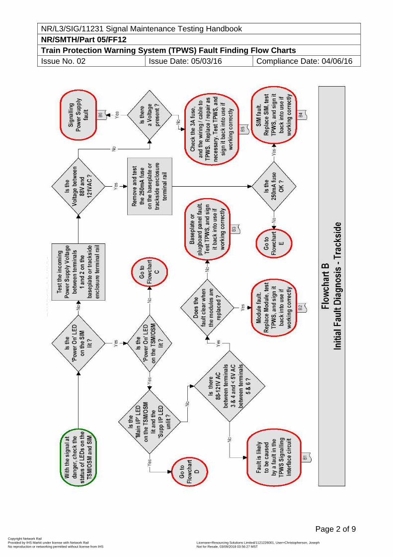
NR/L3/SIG/11231 Signal Maintenance Testing Handbook NR/SMTH/Part 05/FF12 Train Protection Warning System (TPWS) Fault Finding Flow Charts Issue No. 02 Issue Date: 05/03/16 Compliance Date: 04/06/16
Page 2 of 9
Copyright Network Rail Provided by IHS Markit under license with Network Rail Licensee=Resourcing Solutions Limited /1121226001, User=Christopherson, Joseph
Not for Resale, 03/09/2018 03:56:27 MSTNo reproduction or networking permitted without license from IHS
--``,,``,`,,`,```,,``,,````,,,`,-`-`,,`,,`,`,,`---
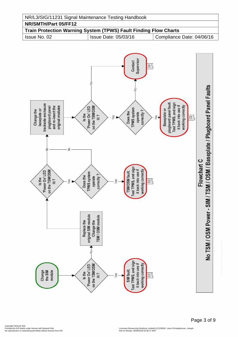
NR/L3/SIG/11231 Signal Maintenance Testing Handbook NR/SMTH/Part 05/FF12 Train Protection Warning System (TPWS) Fault Finding Flow Charts Issue No. 02 Issue Date: 05/03/16 Compliance Date: 04/06/16
Page 3 of 9
Copyright Network Rail Provided by IHS Markit under license with Network Rail Licensee=Resourcing Solutions Limited /1121226001, User=Christopherson, Joseph
Not for Resale, 03/09/2018 03:56:27 MSTNo reproduction or networking permitted without license from IHS
--``,,``,`,,`,```,,``,,````,,,`,-`-`,,`,,`,`,,`---
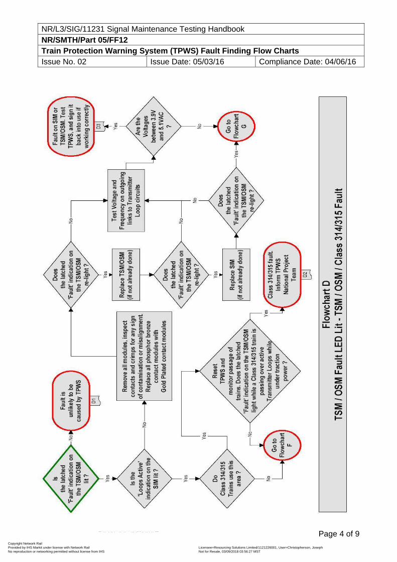
NR/L3/SIG/11231 Signal Maintenance Testing Handbook NR/SMTH/Part 05/FF12 Train Protection Warning System (TPWS) Fault Finding Flow Charts Issue No. 02 Issue Date: 05/03/16 Compliance Date: 04/06/16
Page 4 of 9
Copyright Network Rail Provided by IHS Markit under license with Network Rail Licensee=Resourcing Solutions Limited /1121226001, User=Christopherson, Joseph
Not for Resale, 03/09/2018 03:56:27 MSTNo reproduction or networking permitted without license from IHS
--``,,``,`,,`,```,,``,,````,,,`,-`-`,,`,,`,`,,`---
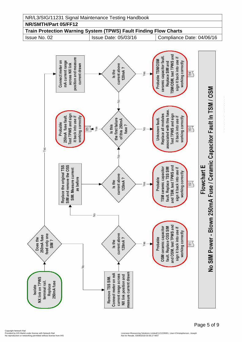
NR/L3/SIG/11231 Signal Maintenance Testing Handbook NR/SMTH/Part 05/FF12 Train Protection Warning System (TPWS) Fault Finding Flow Charts Issue No. 02 Issue Date: 05/03/16 Compliance Date: 04/06/16
Page 5 of 9
Copyright Network Rail Provided by IHS Markit under license with Network Rail Licensee=Resourcing Solutions Limited /1121226001, User=Christopherson, Joseph
Not for Resale, 03/09/2018 03:56:27 MSTNo reproduction or networking permitted without license from IHS
--``,,``,`,,`,```,,``,,````,,,`,-`-`,,`,,`,`,,`---
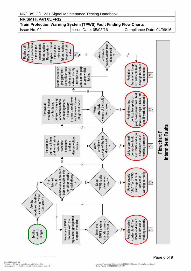
NR/L3/SIG/11231 Signal Maintenance Testing Handbook NR/SMTH/Part 05/FF12 Train Protection Warning System (TPWS) Fault Finding Flow Charts Issue No. 02 Issue Date: 05/03/16 Compliance Date: 04/06/16
Page 6 of 9
Copyright Network Rail Provided by IHS Markit under license with Network Rail Licensee=Resourcing Solutions Limited /1121226001, User=Christopherson, Joseph
Not for Resale, 03/09/2018 03:56:27 MSTNo reproduction or networking permitted without license from IHS
--``,,``,`,,`,```,,``,,````,,,`,-`-`,,`,,`,`,,`---
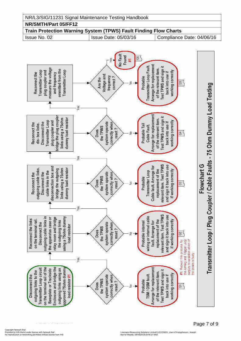
NR/L3/SIG/11231 Signal Maintenance Testing Handbook NR/SMTH/Part 05/FF12 Train Protection Warning System (TPWS) Fault Finding Flow Charts Issue No. 02 Issue Date: 05/03/16 Compliance Date: 04/06/16
Page 7 of 9
Copyright Network Rail Provided by IHS Markit under license with Network Rail Licensee=Resourcing Solutions Limited /1121226001, User=Christopherson, Joseph
Not for Resale, 03/09/2018 03:56:27 MSTNo reproduction or networking permitted without license from IHS
--``,,``,`,,`,```,,``,,````,,,`,-`-`,,`,,`,`,,`---
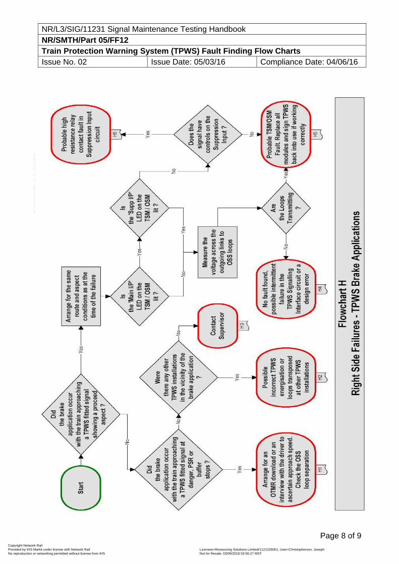
NR/L3/SIG/11231 Signal Maintenance Testing Handbook NR/SMTH/Part 05/FF12 Train Protection Warning System (TPWS) Fault Finding Flow Charts Issue No. 02 Issue Date: 05/03/16 Compliance Date: 04/06/16
Page 8 of 9
Copyright Network Rail Provided by IHS Markit under license with Network Rail Licensee=Resourcing Solutions Limited /1121226001, User=Christopherson, Joseph
Not for Resale, 03/09/2018 03:56:27 MSTNo reproduction or networking permitted without license from IHS
--``,,``,`,,`,```,,``,,````,,,`,-`-`,,`,,`,`,,`---
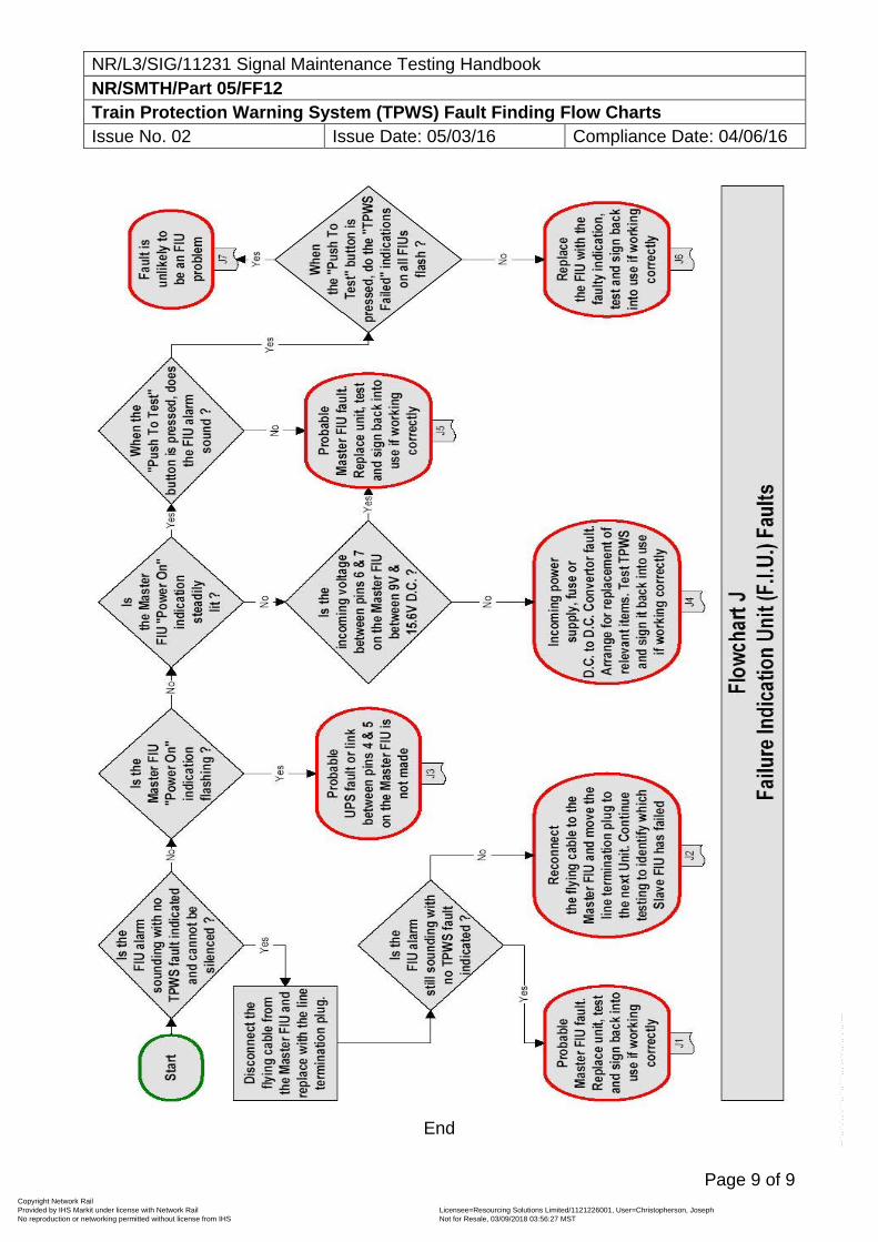
NR/L3/SIG/11231 Signal Maintenance Testing Handbook NR/SMTH/Part 05/FF12 Train Protection Warning System (TPWS) Fault Finding Flow Charts Issue No. 02 Issue Date: 05/03/16 Compliance Date: 04/06/16
Page 9 of 9
End
Copyright Network Rail Provided by IHS Markit under license with Network Rail Licensee=Resourcing Solutions Limited /1121226001, User=Christopherson, Joseph
Not for Resale, 03/09/2018 03:56:27 MSTNo reproduction or networking permitted without license from IHS
--``,,``,`,,`,```,,``,,````,,,`,-`-`,,`,,`,`,,`---
NR/L3/SIG/11231 Signal Maintenance Testing Handbook NR/SMTH/Part 05/FF13 Fault Finding Guide: Train Protection Warning System (TPWS) Issue No. 07 Issue Date: 04/03/17 Compliance Date: 31/05/17
Page 1 of 10
TPWS Failure Indications The TPWS trackside equipment has two methods of detecting and indicating faults; an internal proving relay, which is generally connected to a signalling indication circuit (signal lamp proving relay circuit, SSI proving input or dedicated FIU circuit); and a 'Fault' LED. The internal proving relay is energised whenever TPWS is transmitting and the internal circuits of the TPWS modules are not detecting a fault. It is de-energised whenever TPWS is not transmitting, even if it is not required to be transmitting. The status of the relay is indicated by the 'Loops Active' LED on the SIM. The 'Fault' LED on the TPWS OSM/TSM module is a latched indication. Once a fault occurs the LED will continue to be illuminated until reset (achieved by removing the power to the SIM) even if the signal is at a proceed aspect or the fault has cleared. However, this indicator is purely a visual indication to the maintainer and will not in itself cause a TPWS failure to be reported to the signaller. Further information on 'Fault' LED indications is given in sections 2 and 4. For signals, failure of TPWS to transmit when required, is generally reported in the lamp lit indication of the signal fitted. For buffer stops TPWS failure is reported in the platform starter signal's first filament failure proving circuit. TPWS at PSRs will not normally have any remote fault reporting. Signals, PSRs and buffer stops that are fitted with TPWS as part of a re-signalling scheme will have dedicated indications for TPWS failure. In relay areas and some SSI areas (non-data change TPWS installation), the VCR relay is incorporated into the lamp proving circuit of the fitted signal, and hence needs to be conditioned with contacts of signal operation relays in order that no TPWS fault is reported when the signal is off and TPWS is de-energised. In other SSI areas (data change TPWS installations), the TPWS internal proving relay contact is used to operate an input to an SSI TFM, and any conditioning of fault reporting is done within the SSI data. In mechanically signalled areas and the most recent re-signalling schemes using new NX panels or VDUs, TPWS failures are reported using a dedicated proving circuit and indication (an FIU indication in mechanically signalled areas and dedicated TPWS indications on new panels / VDU operated signalling systems). TPWS failure in these areas may still result in the signal in rear being automatically replaced to danger. As a result of the above circuit arrangements, the TPWS internal proving relay contact is included in the lamp proving circuit only when the signal is at danger, and failures of TPWS have no effect on the signalling system when a proceed aspect is being displayed. When the signal is at danger TPWS failures will have the same effect as a red lamp failure, causing the signal in rear to be held at or replaced to danger, and the signaller's panel to display a lamp out indication (or a TPWS failed indication if a dedicated indication is provided).
Copyright Network Rail Provided by IHS Markit under license with Network Rail Licensee=Resourcing Solutions Limited /1121226001, User=Christopherson, Joseph
Not for Resale, 03/09/2018 03:56:27 MSTNo reproduction or networking permitted without license from IHS
--``,,``,`,,`,```,,``,,````,,,`,-`-`,,`,,`,`,,`---
NR/L3/SIG/11231 Signal Maintenance Testing Handbook NR/SMTH/Part 05/FF13 Fault Finding Guide: Train Protection Warning System (TPWS) Issue No. 07 Issue Date: 04/03/17 Compliance Date: 31/05/17
Page 2 of 10
Actions to be Taken if TPWS Fault LED is Illuminated The 'Fault' LED on the TPWS OSMs / TSMs is a latched indication to help the maintainer identify and rectify faults. However, as explained in sections 14 and 16, it may register a fault due to external causes, such as Class 314/315 trains running over energised loops or short duration power supply outages. This means that a lit 'Fault' LED does not necessarily indicate the ongoing presence of a TPWS fault. Where a TPWS installation has fault reporting to the signaller, and latched fault indications are frequently found in an area where such power supply outages or Class 314/315 problems are known, these fault indications may be ignored providing there is no other evidence of ongoing TPWS failure (e.g. 'blank on panel' or 'Loops Active' LEDs not lit with signal at danger). In this case there is neither a requirement to report a latched fault indication to the signaller, nor to enter it into FRAME. However where there is no remote fault reporting, if a 'Fault' LED is found lit during three monthly and annual maintenance visits, the TPWS fault indication shall be reset and, as a minimum, voltages checked at the output terminals (see section 17). To re-set a latched 'Fault' LED indication, the associated BX 110 250mA fuse holder shall be pulled out or MCB switched off for 5 seconds and then replaced (see section 18).
This reset procedure is intrusive, so you shall set up a safe system of work with the signaller. When the power supply to TPWS is disconnected, a fault alarm will be generated every time the signal displays a red aspect, this will generally include replacement of the signal in rear to danger.
Failure Identification Once a failure has been isolated to the TPWS trackside equipment, the fault finding process outlined in the flowcharts in Part 05/FF12 shall be carried out. The TPWS trackside equipment shall be isolated, using the BX110 250mA fuse on the terminal rail of the baseplate, the MCB on the racking or trackside enclosure backplane, before any modules are removed or replaced. Remember that the main and subsidiary 110V AC. inputs to the SIM may still be live. The results of all tests undertaken shall be recorded on a copy of the TPWS Fault Report Form in Part 05/Appendix 04 All equipment that is removed from site and returned to the manufacturer shall be accompanied by a completed TPWS Fault Report Form to aid further failure diagnosis of any returned equipment. This form can also be used to aid the process of escalating the fault to a second or third line faulting team.. If any item of equipment is changed then appropriate testing shall be carried out using the relevant maintenance test plans, as detailed in Part 03 (Tests B20, B21, B22, and B23) and Part 04. All faults, whether rectified or cleared with no fault found (tested OK), shall be recorded in the Fault Management System (FMS).
Copyright Network Rail Provided by IHS Markit under license with Network Rail Licensee=Resourcing Solutions Limited /1121226001, User=Christopherson, Joseph
Not for Resale, 03/09/2018 03:56:27 MSTNo reproduction or networking permitted without license from IHS
--``,,``,`,,`,```,,``,,````,,,`,-`-`,,`,,`,`,,`---
NR/L3/SIG/11231 Signal Maintenance Testing Handbook NR/SMTH/Part 05/FF13 Fault Finding Guide: Train Protection Warning System (TPWS) Issue No. 07 Issue Date: 04/03/17 Compliance Date: 31/05/17
Page 3 of 10
Note: cases of 'Fault' LEDs being lit with no other evidence of failure (e.g. blank on panel, or change of aspect), do not count as faults to be recorded in FMS. Any failure within the internal wiring of a baseplate or trackside enclosure plugboard panel (including the module plugboard and/or spade connections) shall require the entire unit to be changed. The units are not to be repaired on site. Where baseplates have not been provided then plugboard wiring should be checked or replaced
'No Cause Found' (NCF) or 'No Fault Found' (NFF) - Failure Procedure There are a number of possible failure modes of TPWS trackside equipment that lead to intermittent faults that are difficult to identify other than the presence of a latched 'Fault' LED. The method of fault finding in the flowcharts (Figure 5:5) identifies many, but not necessarily all, of these failures. With the exception of failures in areas known to be susceptible to Class 315 and Power Supply faults, if having completed all procedures outlined in the fault finding flowcharts in Figure 5:5, there is still no cause found for an intermittent fault, proceed as follows:
a) On first failure, replace any phosphor bronze contact modules with gold contact modules, and test as per the faultfinding flowchart.
b) On second failure repeat all tests, if still NCF, replace all TPWS modules. c) On third failure repeat all tests, if still NCF, replace the baseplate or
backplane or plugboard and wiring where no baseplate is provided. d) On fourth failure repeat all tests, if still NCF, replace the tail cables and
loops. Following this procedure will check that repeat failures are kept to a minimum.
It may be advisable to perform items b), c) and d) on the second failure in certain high-risk locations.
Loose Terminals The TPWS transmitter loop output circuit is particularly prone to high resistances, as would be caused by loose connections on terminals and links. It is hence important that all connections to the loops (i.e. the terminals at the trackside enclosure or baseplate terminal railsor plugboards where baseplates are not provided and outgoing links in apparatus cases and disconnection boxes) are thoroughly checked for tightness.
Contamination of Spring Contacts High resistance contacts between the TPWS modules and the BR829 relay base are a known cause of failures with TPWS equipment with un-plated phosphor bronze contacts. Although the action of removal and replacement of the TPWS modules can sometimes, in itself, clean the contacts and remove the source of the failure, it is recommended that all such modules are replaced with the equivalent modules with gold plated contacts.
Copyright Network Rail Provided by IHS Markit under license with Network Rail Licensee=Resourcing Solutions Limited /1121226001, User=Christopherson, Joseph
Not for Resale, 03/09/2018 03:56:27 MSTNo reproduction or networking permitted without license from IHS
--``,,``,`,,`,```,,``,,````,,,`,-`-`,,`,,`,`,,`---
NR/L3/SIG/11231 Signal Maintenance Testing Handbook NR/SMTH/Part 05/FF13 Fault Finding Guide: Train Protection Warning System (TPWS) Issue No. 07 Issue Date: 04/03/17 Compliance Date: 31/05/17
Page 4 of 10
Thales Trackside Enclosures Door Seals Some isolated cases of trackside enclosures have been found with moisture inside. Two causes have been established by Thales; the first due to the rubber door seal having been damaged during installation. This damage is generally visible, and if found, the entire door shall be changed as individual seals are not available. Replacement doors for trackside enclosures are available from your supplier. The second cause established is failure to correctly install the sealing washer for the cabinet support fixing holes as shown in NR/L3/SIG/11303 (Signalling Installation Handbook).
Ceramic capacitors in OSM/TSM Ceramic capacitors in OSM and TSM modules can fail due to cracking, resulting in SIM failure due to excessive current draw. In this case a failure within the OSM/TSM would only be identified by either the corresponding SIM overheating or by the SIM 250mA fuse blowingor MCB tripping. When a TPWS failure occurs and the SIM is found to be overheated, indicating a capacitor failure, if the SIM only is replaced it will fail again as the cause of the fault is in the OSM or TSM. In this case, both the SIM and the OSM/TSM shall be changed.
Transmitter Loop Related Failures A fault in TPWS transmitter loop windings can be identified by testing the DC resistance of the transmitter loop across the tail cable connections, using the Fluke 187/TPWS digital multi-meter, with the loop isolated. A healthy loop should give an indicated DC resistance reading in the area of 0.5 to 1.5 Ohms, when measured across the two smaller pins of the loop plug coupler. A faulty loop would give a much greater reading.
The meter shall be used in the ‘Rel’ mode for this test to compensate for the resistance of the test leads (i.e. normalise the reading first by shorting the two leads, then repeat the test with the Transmitter loop plug coupler in circuit). During insulation resistance (Megger) testing of TPWS transmitter loop feeder cables and tail cables, damage may be caused to the loop tuning circuit if the cables are tested with the cable still connected to the loop. All insulation resistance testing of TPWS transmitter loop feeder cables and tail cables shall be performed with the transmitter loop disconnected at the plug coupler. The transmitter loop tuning unit can become detached from the loop itself if the tail cable is pulled to disconnect the tail cable from the loop. The end caps of the transmitter loops, if they become detached from the Loop, can be glued back on if the transmitter loop is still working correctly, as described in NR/L3/SIG/11303 (Signalling Installation Handbook). Replacement end caps are available from your supplier.
Copyright Network Rail Provided by IHS Markit under license with Network Rail Licensee=Resourcing Solutions Limited /1121226001, User=Christopherson, Joseph
Not for Resale, 03/09/2018 03:56:27 MSTNo reproduction or networking permitted without license from IHS
--``,,``,`,,`,```,,``,,````,,,`,-`-`,,`,,`,`,,`---
NR/L3/SIG/11231 Signal Maintenance Testing Handbook NR/SMTH/Part 05/FF13 Fault Finding Guide: Train Protection Warning System (TPWS) Issue No. 07 Issue Date: 04/03/17 Compliance Date: 31/05/17
Page 5 of 10
Plug Coupler Related Failures TPWS cables are susceptible to damage at the point where the cable enters the plug coupler, caused by axial rotation or lateral flexing / twisting of the plug coupler. This could lead to high resistance readings during insulation resistance testing or a short circuit between cores and the drain wire. For information on the correct handling of plug couplers see the NR/L3/SIG/11303 (Signalling Installation Handbook). The plug coupler itself has an Ingress Protection (IP) rating of 67, which would allow it maintain its internal electrical integrity when totally submerged in water. However, this also has the effect that any dirt or moisture appearing on the mating halves of the plug coupler prior to installation will remain there when the plug coupler is mated, leading to failure possibility.
Differential Loop Readings Voltage readings taken from the TSS / OSS module outputs measured at the baseplate where provided or trackside enclosure terminal rail (as per section 17), for a pair of loops comprising one OSS or TSS function, should be roughly the same for the arming and trigger loop. For a TSS loop pair, a difference between the two readings of more than 0.3V AC may indicate the possible presence of a fault in the loop feeder cable circuit for the higher of the two readings, as the length of the two loop feeder cables is generally equal. For an OSS loop pair (other than buffer stop mini-loops), it is expected that the voltage on the arming loop output will be slightly higher than the trigger loop output as the loop feeder cable circuit is generally longer due to the relative distances of the two loops from the controlling apparatus case. If the reading from the trigger loops is higher than the arming loop, or if the reading from the arming loop is significantly higher than the trigger loop, then this can also indicate the possible presence of a fault in the circuit giving the higher voltage reading.
Trends in Loop Voltage or Frequency The record card should be available on site (if not inform the SM (S). Maintenance readings should be compared to those previously noted in order to observe any ongoing system deterioration. Any continuing or sudden drift ft in the voltage or frequency readings for any particular loop, taken either from the OSS / TSS outputs to the transmitter loops or from the loops themselves, indicates the presence of a possible fault within either the OSS / TSS module, the loop feeder cable circuit, or the signalling power supply. This will depend on correct use of the maintenance jig and calibrated test equipment. It is required that readings taken with the commissioning jig are recorded on the maintenance record card. These reading will be significantly lower than the readings taken with the maintenance jig and should not be confused with the downward drift in maintenance readings referred to above.
Copyright Network Rail Provided by IHS Markit under license with Network Rail Licensee=Resourcing Solutions Limited /1121226001, User=Christopherson, Joseph
Not for Resale, 03/09/2018 03:56:27 MSTNo reproduction or networking permitted without license from IHS
--``,,``,`,,`,```,,``,,````,,,`,-`-`,,`,,`,`,,`---
NR/L3/SIG/11231 Signal Maintenance Testing Handbook NR/SMTH/Part 05/FF13 Fault Finding Guide: Train Protection Warning System (TPWS) Issue No. 07 Issue Date: 04/03/17 Compliance Date: 31/05/17
Page 6 of 10
SSI Method 3 Timing Feature For SSI interlockings installed using method 3, there is a potential timing feature such that, upon the signal returning to danger and energising TPWS, the fault reporting circuit, due to the slow to drop RECR, may not complete the lamp proving circuit within the settling time allowed by a TFM. In this case, a loss of proving will be reported to the central interlocking, which may immediately result in a blank signal aspect being displayed to the signaller for 2 to 3 seconds (two or three major interlocking cycles). If the signal in rear is showing a proceed aspect when the above situation occurs, then the signal in rear will revert to danger and then clear again when TPWS proving is correctly established. This will normally only become evident when a signal is replaced to danger by the signaller (or by a track circuit failure), as during the normal passage of a train the signal in rear will already be held at danger. The Technicians Terminal should filter out any interruptions lasting less than one major interlocking cycle and it is possible that a fault may be reported by the signaller that is not actually recorded by the Technicians Terminal. The above situation will normally only occur with TFMs with software to version SSI4311-C3 or earlier, which have a settling time of about 90ms. Later TFMs with software to SSI4311-C4/D1 or later have a settling time of around 250ms. If a similar failure occurs with these TFMs, this will generally indicate that either the signal lamp voltage is out of specification, or that the signal main filament has blown. Persistent failures of TFMs with software to SSI4311-C4/D1 or later may be cured by installing SL35 8000 hour lamps and increasing the signal lamp voltage to 12 Volts. Local policy shall be followed as to whether all lamps in a signal are changed to SL35 8000 hour lamps. Records shall be kept as to which signals/aspects are so changed.
Failures Related to A.C. Traction Units (Class 314/315) Certain 25kV AC Electrical Multiple Units (EMUS), when pulling away under power, induce interference that may cause TPWS faults to be indicated, both by the TSM / OSM 'Fault' LED and to the signaller. The units that are known to cause such faults are Class 315 units. It is also possible that Class 314 EMUs operating in the Glasgow area may cause TPWS faults. The interference is caused by a magnetic field radiated from the traction equipment on the Driving Motor Cars, which is always mounted further back than the TPWS aerial, hence it is not likely that this will prevent TPWS from being operational when required, however it may cause a large amount of spurious fault indications. Confirmation that spurious fault indications of the TPWS track sub-system are being caused by interference from traction units, can be obtained by observing the passage of trains accelerating over the energised TPWS transmitter loops (note no faults will occur if the loops are not transmitting). The effect is most consistent at locations where the units accelerate hard past a TPWS fitted signal that is replaced to danger before the traction unit of the train has passed over the transmitter loops.
Copyright Network Rail Provided by IHS Markit under license with Network Rail Licensee=Resourcing Solutions Limited /1121226001, User=Christopherson, Joseph
Not for Resale, 03/09/2018 03:56:27 MSTNo reproduction or networking permitted without license from IHS
--``,,``,`,,`,```,,``,,````,,,`,-`-`,,`,,`,`,,`---
NR/L3/SIG/11231 Signal Maintenance Testing Handbook NR/SMTH/Part 05/FF13 Fault Finding Guide: Train Protection Warning System (TPWS) Issue No. 07 Issue Date: 04/03/17 Compliance Date: 31/05/17
Page 7 of 10
The interference will cause the 'Fault' LED on the TSM / OSM to illuminate and the 'Loops Active' LED on the associated SIM to be extinguished, and will probably cause a brief loss of lamp proving (or TPWS proving if a dedicated indication circuit is used) for approximately one second or less, as each driving motor car passes over an energised transmitter loop. The TPWS System Authority is currently pursuing a solution to this problem.
Baseplate Fuses The 250 mA fuses used in TPWS trackside enclosures and baseplates are fitted with indicating devices in one of the end caps. These are a yellow disk attached to a spring, which when visible, show that the fuse has ruptured. In some instances the indicator device may become activated without the fuse having blown. This is a known defect with the fuses, and does not require the fuse to be replaced, provided that the 'Power On' indications on the TPWS equipment are still lit. Do not to drop the fuses when the fuse holder is pulled out. Some installations where baseplates are not provided may be protected by 250mA MCB.
Power Supply Interruptions Signalling power supply interruptions of between 70msec and 700msec can result in short duration TPWS faults, and hence a latched fault appearing on any TPWS module that is transmitting at the time of the power supply interruption. Normally this would occur on a number of the TPWS installations in an area and would almost certainly affect both the OSS and TSS on a signal installation that has both functions. Thus the presence of multiple latched fault indications in an area will probably be indicative of a power supply interruption and not genuine TPWS faults. Due to the short duration of the power supply fault the TPWS failure will not usually be seen either by the signaller or by the remote fault reporting system. Longer power supply faults will lead to any TPWS latched failures being reset, however this would be seen by the signaller and be recorded on any remote fault reporting system (e.g. Technicians’ Terminal). Following a reset of TPWS after a power supply interruption (see section 2), it is still advisable to take a full set of voltage and frequency readings to identify any other latent failures, as a voltage reading on the TSS / OSS module output to the transmitter loops that is higher than expected (see sections 11 and 12) would make the function more susceptible to failures caused by any fluctuations in the signalling power supply.
Voltage Testing and Dummy Load Testing The expected voltage on the TSS / OSS module output to the transmitter loops when driving a nominal 75 Ohm load, should be approximately 4.2V. When connected to a TPWS Transmitter Loop circuit this can vary between 3.9 V and 5.1 V AC. If there is a failure somewhere in the transmitter loop circuit that is causing the 'Fault'
Copyright Network Rail Provided by IHS Markit under license with Network Rail Licensee=Resourcing Solutions Limited /1121226001, User=Christopherson, Joseph
Not for Resale, 03/09/2018 03:56:27 MSTNo reproduction or networking permitted without license from IHS
--``,,``,`,,`,```,,``,,````,,,`,-`-`,,`,,`,`,,`---
NR/L3/SIG/11231 Signal Maintenance Testing Handbook NR/SMTH/Part 05/FF13 Fault Finding Guide: Train Protection Warning System (TPWS) Issue No. 07 Issue Date: 04/03/17 Compliance Date: 31/05/17
Page 8 of 10
LED to remain lit when the TPWS equipment is reset, then a 75 ohm 0.5 W resistor can be used to aid identification of the exact location of the failure. This test method will require an electrical disconnection and appropriate protection of the operational railway, as the testing is intrusive and the signal in rear will be replaced to danger during the investigation process. The TPWS BX 110 V AC supply shall be isolated using the 250 mA fuse or MCB, and the arming transmitter loop for the failed function shall be disconnected from the module outputs using the appropriate sliding links on the terminal rail of the baseplate, trackside enclosure or outgoing links where no baseplate provided, and the 75 Ohm load placed across the two legs of the output and the module output voltage recorded. When the fuse to the module is replaced or the MCB switched back on, and the TPWS equipment is required to transmit, the 'Fault' LED should no longer light, indicating that the fault is in the loop feeder cable circuit or the transmitter loop itself. If the failure still does not clear then the failure is likely to be in either the trigger loop circuit (the above process shall then be followed for that circuit), or in the module / baseplate itself. If the failure does clear then the module shall once again be isolated and this process repeated at various points in the loop feeder cable circuit (i.e. any disconnection boxes and the plug coupler) with the circuit disconnected downstream from the point at which the dummy load is inserted. The voltage at the module output to the transmitted loop shall be recorded and the 'Fault' LED monitored in each case, to identify the failure point. Once the component causing the failure has been identified using the above process, it shall be replaced, TPWS re-energised, and the appropriate testing of the equipment carried out.
It is essential that the 75 Ohm resistor is not left in circuit, as this will prevent TPWS from working correctly. A final check shall be made for this, before leaving the site.
1. Resetting TPWS Equipment To reset any lit 'Fault' LEDs on the TPWS equipment, isolate the BX110 supply to the TPWS equipment for at least five seconds by pulling out the 250mA power supply fuse holder or switching off the MCB to the SIM (position I on the baseplate, where provided or trackside enclosure terminal rail), and then replacing it. Care shall be taken not to drop the fuse when the fuse holder is pulled out.
Removing the 250mA fuse or switching off the MCB when TPWS is transmitting will cause a TPWS fault to be reported and the signal in rear replaced to danger (with the exception of PSR installations), hence all resetting of TPWS shall be done with the full co-operation of the signaller and when no trains will be affected. It is best to reset TPWS when the controlling signal is showing a proceed aspect, as this will not cause a TPWS fault to be reported and not lead to a reversion of the signal in rear to danger.
After re-applying the power, the green 'Power on' LEDs on all modules associated with the supply fuse/ MCB should be lit and all red 'Fault' LEDs should be unlit. If they
Copyright Network Rail Provided by IHS Markit under license with Network Rail Licensee=Resourcing Solutions Limited /1121226001, User=Christopherson, Joseph
Not for Resale, 03/09/2018 03:56:27 MSTNo reproduction or networking permitted without license from IHS
--``,,``,`,,`,```,,``,,````,,,`,-`-`,,`,,`,`,,`---
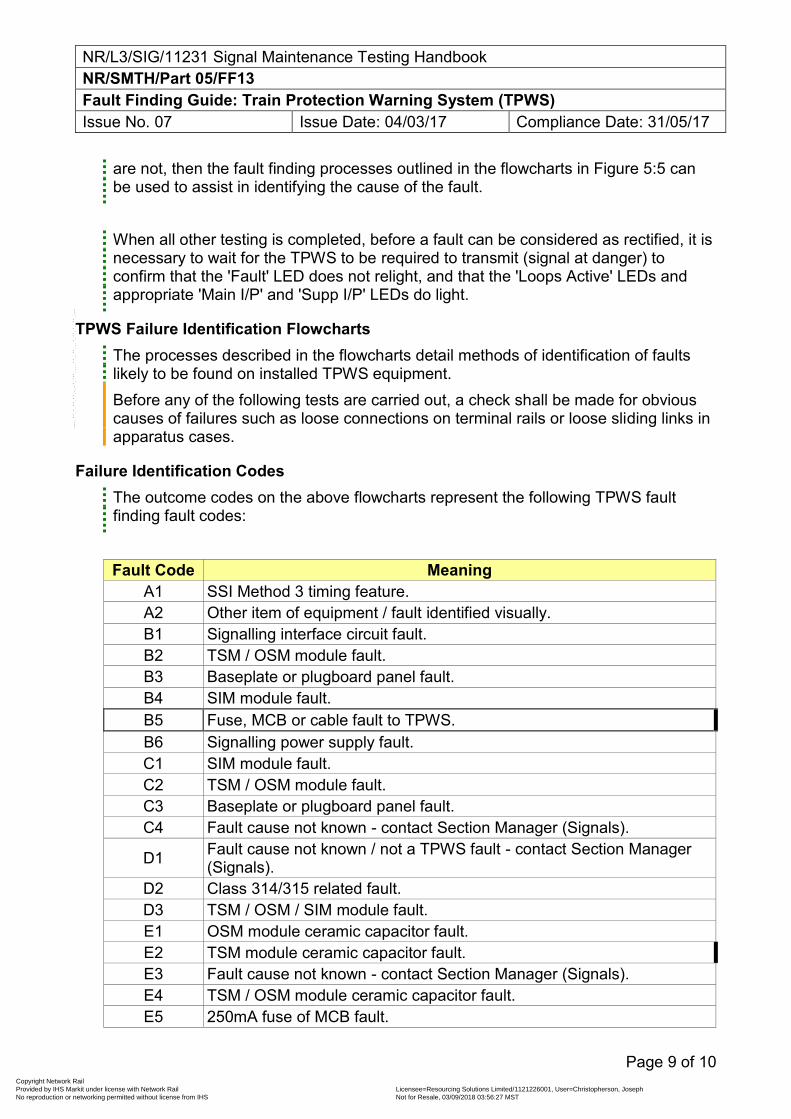
NR/L3/SIG/11231 Signal Maintenance Testing Handbook NR/SMTH/Part 05/FF13 Fault Finding Guide: Train Protection Warning System (TPWS) Issue No. 07 Issue Date: 04/03/17 Compliance Date: 31/05/17
Page 9 of 10
are not, then the fault finding processes outlined in the flowcharts in Figure 5:5 can be used to assist in identifying the cause of the fault. When all other testing is completed, before a fault can be considered as rectified, it is necessary to wait for the TPWS to be required to transmit (signal at danger) to confirm that the 'Fault' LED does not relight, and that the 'Loops Active' LEDs and appropriate 'Main I/P' and 'Supp I/P' LEDs do light.
TPWS Failure Identification Flowcharts The processes described in the flowcharts detail methods of identification of faults likely to be found on installed TPWS equipment. Before any of the following tests are carried out, a check shall be made for obvious causes of failures such as loose connections on terminal rails or loose sliding links in apparatus cases.
Failure Identification Codes The outcome codes on the above flowcharts represent the following TPWS fault finding fault codes:
Fault Code Meaning A1 SSI Method 3 timing feature. A2 Other item of equipment / fault identified visually. B1 Signalling interface circuit fault. B2 TSM / OSM module fault. B3 Baseplate or plugboard panel fault. B4 SIM module fault. B5 Fuse, MCB or cable fault to TPWS. B6 Signalling power supply fault. C1 SIM module fault. C2 TSM / OSM module fault. C3 Baseplate or plugboard panel fault. C4 Fault cause not known - contact Section Manager (Signals).
D1 Fault cause not known / not a TPWS fault - contact Section Manager (Signals).
D2 Class 314/315 related fault. D3 TSM / OSM / SIM module fault. E1 OSM module ceramic capacitor fault. E2 TSM module ceramic capacitor fault. E3 Fault cause not known - contact Section Manager (Signals). E4 TSM / OSM module ceramic capacitor fault. E5 250mA fuse of MCB fault.
Copyright Network Rail Provided by IHS Markit under license with Network Rail Licensee=Resourcing Solutions Limited /1121226001, User=Christopherson, Joseph
Not for Resale, 03/09/2018 03:56:27 MSTNo reproduction or networking permitted without license from IHS
--``,,``,`,,`,```,,``,,````,,,`,-`-`,,`,,`,`,,`---
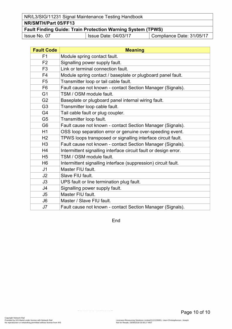
NR/L3/SIG/11231 Signal Maintenance Testing Handbook NR/SMTH/Part 05/FF13 Fault Finding Guide: Train Protection Warning System (TPWS) Issue No. 07 Issue Date: 04/03/17 Compliance Date: 31/05/17
Page 10 of 10
Fault Code Meaning F1 Module spring contact fault. F2 Signalling power supply fault. F3 Link or terminal connection fault. F4 Module spring contact / baseplate or plugboard panel fault. F5 Transmitter loop or tail cable fault. F6 Fault cause not known - contact Section Manager (Signals). G1 TSM / OSM module fault. G2 Baseplate or plugboard panel internal wiring fault. G3 Transmitter loop cable fault. G4 Tail cable fault or plug coupler. G5 Transmitter loop fault. G6 Fault cause not known - contact Section Manager (Signals). H1 OSS loop separation error or genuine over-speeding event. H2 TPWS loops transposed or signalling interface circuit fault. H3 Fault cause not known - contact Section Manager (Signals). H4 Intermittent signalling interface circuit fault or design error. H5 TSM / OSM module fault. H6 Intermittent signalling interface (suppression) circuit fault. J1 Master FIU fault. J2 Slave FIU fault. J3 UPS fault or line termination plug fault. J4 Signalling power supply fault. J5 Master FIU fault. J6 Master / Slave FIU fault. J7 Fault cause not known - contact Section Manager (Signals).
End
Copyright Network Rail Provided by IHS Markit under license with Network Rail Licensee=Resourcing Solutions Limited /1121226001, User=Christopherson, Joseph
Not for Resale, 03/09/2018 03:56:27 MSTNo reproduction or networking permitted without license from IHS
--``,,``,`,,`,```,,``,,````,,,`,-`-`,,`,,`,`,,`---
NR/L3/SIG/11231 Signal Maintenance Testing Handbook NR/SMTH/Part 05/FF14 Fault Finding Guide: Signalling Power Supplies above 175V Issue No. 06 Issue Date: 05/03/2016 Compliance Date: 04/06/2016
Page 1 of 1
Upon notification of a signalling power failure the technician shall:
refer to the signalling power schematic diagrams to ascertain which feeder or section of feeder has failed
the exact start of that feeder or section.
The technician shall then isolate the fault using the flow chart Part 05/FF15 Flow chart for Power Supplies 175v and above to facilitate the rapid restoration of the signalling system.
Fault vehicles should be equipment with the following:
Crimps, fuses and heatshrinks as applicable.
A bar for lifting glued troughing lids.
Back to back radios.
Class 0 or 00 Insulated gloves are tested and in date.
Gas bottle with heatshrink attachments.
Personal padlocks and danger notices for power supply lockout devices/isolators/switches
Pulse echo equipment.
Temporary cable jointing kits.
End
Copyright Network Rail Provided by IHS Markit under license with Network Rail Licensee=Resourcing Solutions Limited /1121226001, User=Christopherson, Joseph
Not for Resale, 03/09/2018 03:56:27 MSTNo reproduction or networking permitted without license from IHS
--``,,``,`,,`,```,,``,,````,,,`,-`-`,,`,,`,`,,`---
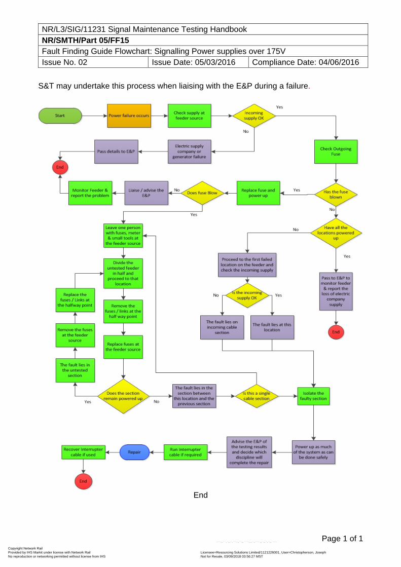
NR/L3/SIG/11231 Signal Maintenance Testing Handbook NR/SMTH/Part 05/FF15 Fault Finding Guide Flowchart: Signalling Power supplies over 175V Issue No. 02 Issue Date: 05/03/2016 Compliance Date: 04/06/2016
Page 1 of 1
S&T may undertake this process when liaising with the E&P during a failure.
End
Copyright Network Rail Provided by IHS Markit under license with Network Rail Licensee=Resourcing Solutions Limited /1121226001, User=Christopherson, Joseph
Not for Resale, 03/09/2018 03:56:27 MSTNo reproduction or networking permitted without license from IHS
--``,,``,`,,`,```,,``,,````,,,`,-`-`,,`,,`,`,,`---
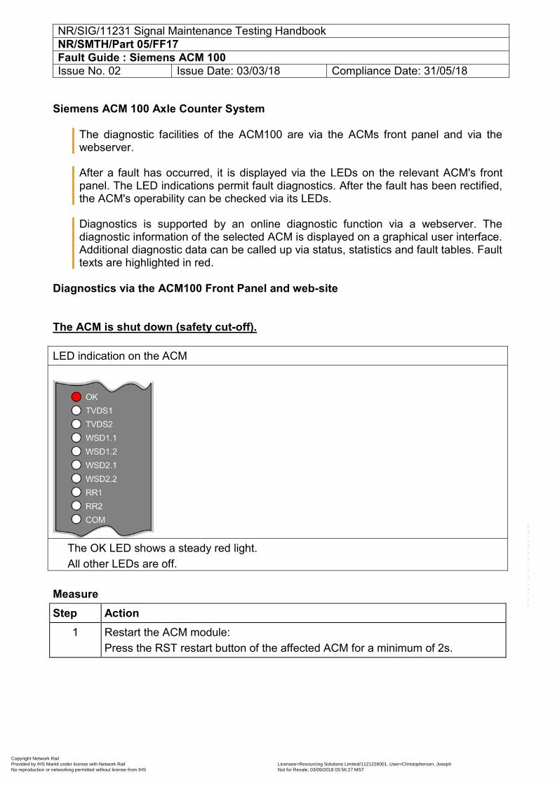
NR/SIG/11231 Signal Maintenance Testing Handbook NR/SMTH/Part 05/FF17 Fault Guide : Siemens ACM 100 Issue No. 02 Issue Date: 03/03/18 Compliance Date: 31/05/18
Siemens ACM 100 Axle Counter System
The diagnostic facilities of the ACM100 are via the ACMs front panel and via the webserver.
After a fault has occurred, it is displayed via the LEDs on the relevant ACM's front panel. The LED indications permit fault diagnostics. After the fault has been rectified, the ACM's operability can be checked via its LEDs.
Diagnostics is supported by an online diagnostic function via a webserver. The diagnostic information of the selected ACM is displayed on a graphical user interface. Additional diagnostic data can be called up via status, statistics and fault tables. Fault texts are highlighted in red.
Diagnostics via the ACM100 Front Panel and web-site The ACM is shut down (safety cut-off). LED indication on the ACM
The OK LED shows a steady red light. All other LEDs are off.
Measure Step Action
1 Restart the ACM module: Press the RST restart button of the affected ACM for a minimum of 2s.
Copyright Network Rail Provided by IHS Markit under license with Network Rail Licensee=Resourcing Solutions Limited /1121226001, User=Christopherson, Joseph
Not for Resale, 03/09/2018 03:56:27 MSTNo reproduction or networking permitted without license from IHS
--``,,``,`,,`,```,,``,,````,,,`,-`-`,,`,,`,`,,`---
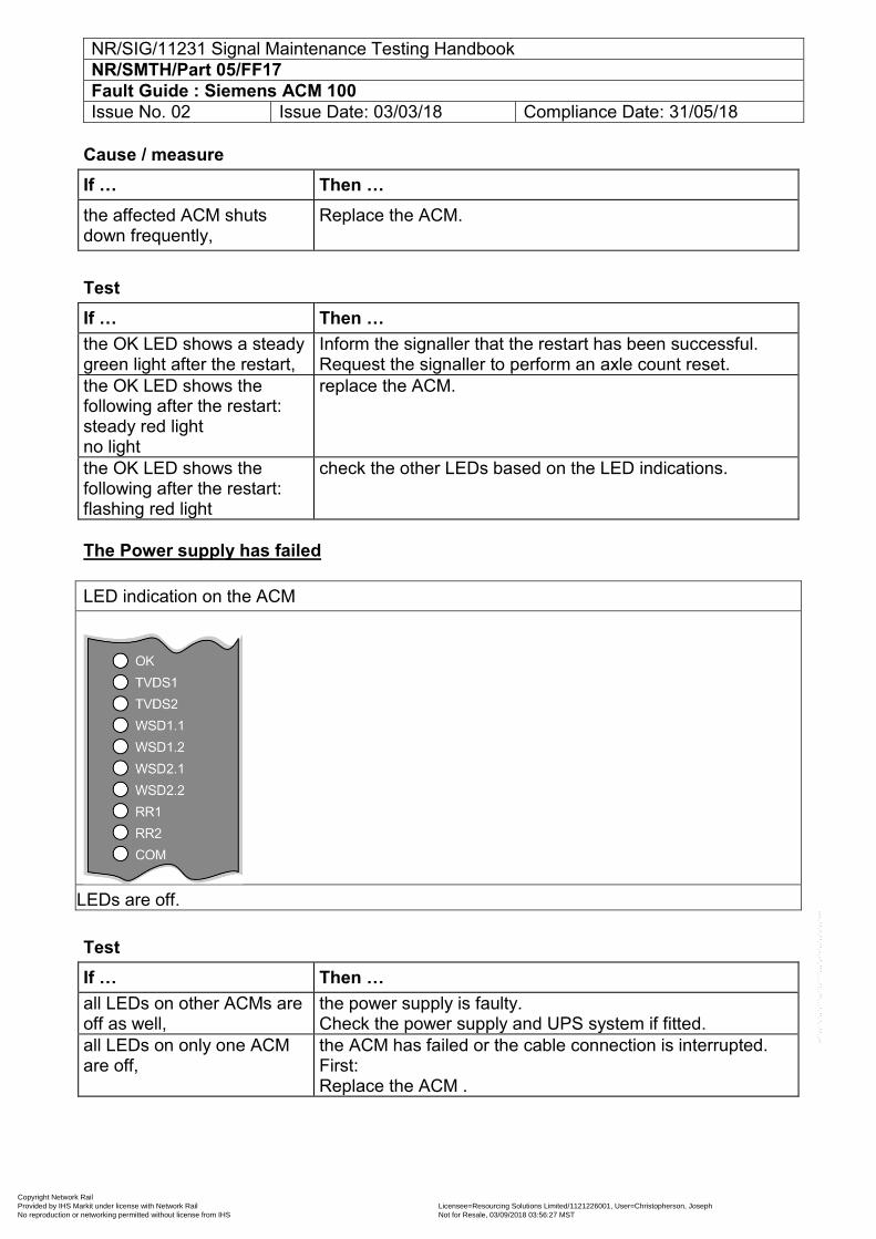
NR/SIG/11231 Signal Maintenance Testing Handbook NR/SMTH/Part 05/FF17 Fault Guide : Siemens ACM 100 Issue No. 02 Issue Date: 03/03/18 Compliance Date: 31/05/18
Cause / measure If … Then … the affected ACM shuts down frequently,
Replace the ACM.
Test If … Then … the OK LED shows a steady green light after the restart,
Inform the signaller that the restart has been successful. Request the signaller to perform an axle count reset.
the OK LED shows the following after the restart: steady red light no light
replace the ACM.
the OK LED shows the following after the restart: flashing red light
check the other LEDs based on the LED indications.
The Power supply has failed LED indication on the ACM
All LEDs are off.
Test If … Then … all LEDs on other ACMs are off as well,
the power supply is faulty. Check the power supply and UPS system if fitted.
all LEDs on only one ACM are off,
the ACM has failed or the cable connection is interrupted. First: Replace the ACM .
Copyright Network Rail Provided by IHS Markit under license with Network Rail Licensee=Resourcing Solutions Limited /1121226001, User=Christopherson, Joseph
Not for Resale, 03/09/2018 03:56:27 MSTNo reproduction or networking permitted without license from IHS
--``,,``,`,,`,```,,``,,````,,,`,-`-`,,`,,`,`,,`---
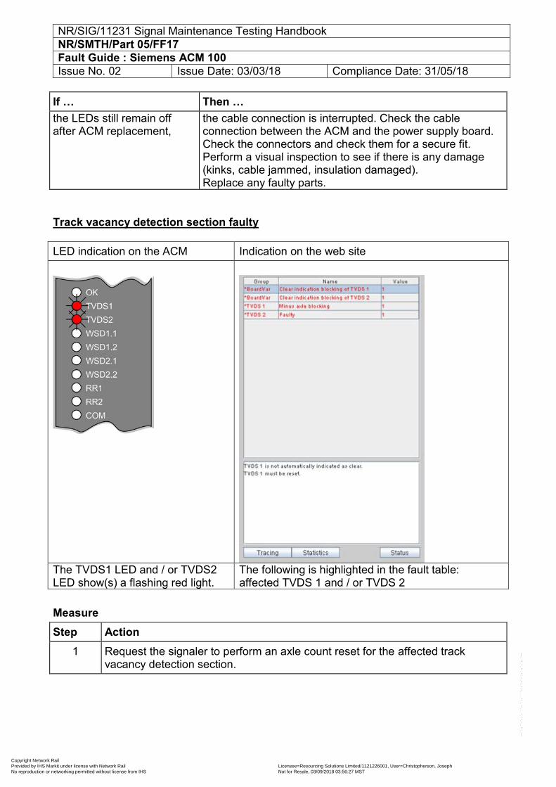
NR/SIG/11231 Signal Maintenance Testing Handbook NR/SMTH/Part 05/FF17 Fault Guide : Siemens ACM 100 Issue No. 02 Issue Date: 03/03/18 Compliance Date: 31/05/18
If … Then … the LEDs still remain off after ACM replacement,
the cable connection is interrupted. Check the cable connection between the ACM and the power supply board. Check the connectors and check them for a secure fit. Perform a visual inspection to see if there is any damage (kinks, cable jammed, insulation damaged). Replace any faulty parts.
Track vacancy detection section faulty LED indication on the ACM Indication on the web site
The TVDS1 LED and / or TVDS2 LED show(s) a flashing red light.
The following is highlighted in the fault table: affected TVDS 1 and / or TVDS 2
Measure Step Action
1 Request the signaler to perform an axle count reset for the affected track vacancy detection section.
Copyright Network Rail Provided by IHS Markit under license with Network Rail Licensee=Resourcing Solutions Limited /1121226001, User=Christopherson, Joseph
Not for Resale, 03/09/2018 03:56:27 MSTNo reproduction or networking permitted without license from IHS
--``,,``,`,,`,```,,``,,````,,,`,-`-`,,`,,`,`,,`---
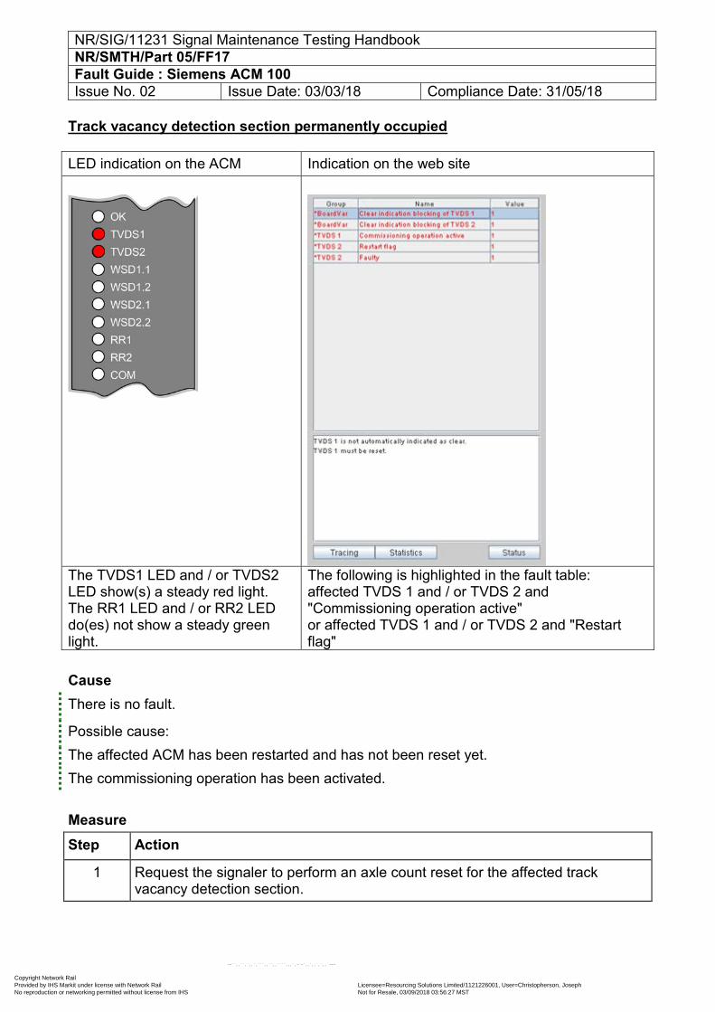
NR/SIG/11231 Signal Maintenance Testing Handbook NR/SMTH/Part 05/FF17 Fault Guide : Siemens ACM 100 Issue No. 02 Issue Date: 03/03/18 Compliance Date: 31/05/18
Track vacancy detection section permanently occupied LED indication on the ACM Indication on the web site
The TVDS1 LED and / or TVDS2 LED show(s) a steady red light. The RR1 LED and / or RR2 LED do(es) not show a steady green light.
The following is highlighted in the fault table: affected TVDS 1 and / or TVDS 2 and "Commissioning operation active" or affected TVDS 1 and / or TVDS 2 and "Restart flag"
Cause There is no fault.
Possible cause: The affected ACM has been restarted and has not been reset yet. The commissioning operation has been activated.
Measure Step Action
1 Request the signaler to perform an axle count reset for the affected track vacancy detection section.
Copyright Network Rail Provided by IHS Markit under license with Network Rail Licensee=Resourcing Solutions Limited /1121226001, User=Christopherson, Joseph
Not for Resale, 03/09/2018 03:56:27 MSTNo reproduction or networking permitted without license from IHS
--``,,``,`,,`,```,,``,,````,,,`,-`-`,,`,,`,`,,`---
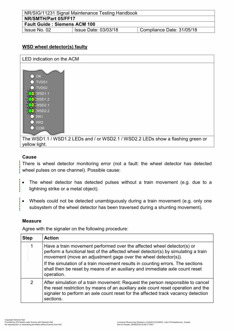
NR/SIG/11231 Signal Maintenance Testing Handbook NR/SMTH/Part 05/FF17 Fault Guide : Siemens ACM 100 Issue No. 02 Issue Date: 03/03/18 Compliance Date: 31/05/18
WSD wheel detector(s) faulty LED indication on the ACM
The WSD1.1 / WSD1.2 LEDs and / or WSD2.1 / WSD2.2 LEDs show a flashing green or yellow light.
Cause There is wheel detector monitoring error (not a fault: the wheel detector has detected wheel pulses on one channel). Possible cause:
The wheel detector has detected pulses without a train movement (e.g. due to a lightning strike or a metal object).
Wheels could not be detected unambiguously during a train movement (e.g. only one subsystem of the wheel detector has been traversed during a shunting movement).
Measure Agree with the signaler on the following procedure:
Step Action 1 Have a train movement performed over the affected wheel detector(s) or
perform a functional test of the affected wheel detector(s) by simulating a train movement (move an adjustment gage over the wheel detector(s)). If the simulation of a train movement results in counting errors. The sections shall then be reset by means of an auxiliary and immediate axle count reset operation.
2 After simulation of a train movement: Request the person responsible to cancel the reset restriction by means of an auxiliary axle count reset operation and the signaler to perform an axle count reset for the affected track vacancy detection sections.
Copyright Network Rail Provided by IHS Markit under license with Network Rail Licensee=Resourcing Solutions Limited /1121226001, User=Christopherson, Joseph
Not for Resale, 03/09/2018 03:56:27 MSTNo reproduction or networking permitted without license from IHS
--``,,``,`,,`,```,,``,,````,,,`,-`-`,,`,,`,`,,`---
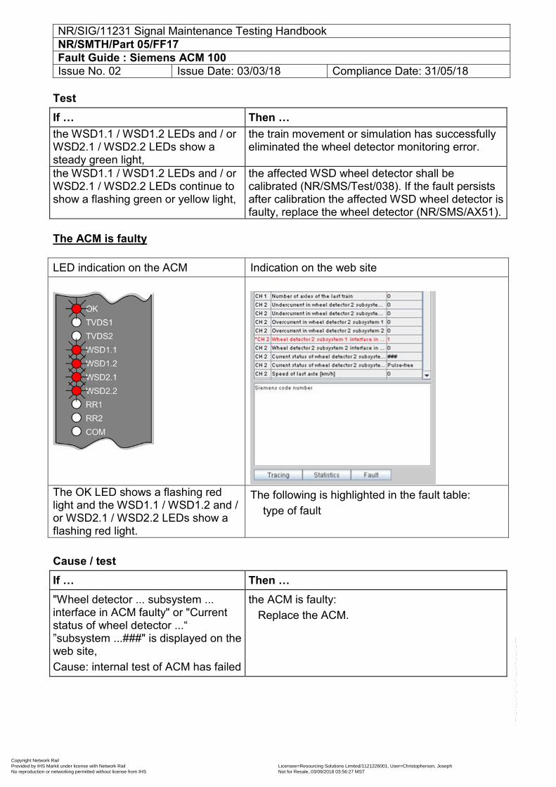
NR/SIG/11231 Signal Maintenance Testing Handbook NR/SMTH/Part 05/FF17 Fault Guide : Siemens ACM 100 Issue No. 02 Issue Date: 03/03/18 Compliance Date: 31/05/18
Test If … Then … the WSD1.1 / WSD1.2 LEDs and / or WSD2.1 / WSD2.2 LEDs show a steady green light,
the train movement or simulation has successfully eliminated the wheel detector monitoring error.
the WSD1.1 / WSD1.2 LEDs and / or WSD2.1 / WSD2.2 LEDs continue to show a flashing green or yellow light,
the affected WSD wheel detector shall be calibrated (NR/SMS/Test/038). If the fault persists after calibration the affected WSD wheel detector is faulty, replace the wheel detector (NR/SMS/AX51).
The ACM is faulty LED indication on the ACM Indication on the web site
The OK LED shows a flashing red light and the WSD1.1 / WSD1.2 and / or WSD2.1 / WSD2.2 LEDs show a flashing red light.
The following is highlighted in the fault table: type of fault
Cause / test If … Then … "Wheel detector ... subsystem ... interface in ACM faulty" or "Current status of wheel detector ...“ ”subsystem ...###" is displayed on the web site, Cause: internal test of ACM has failed
the ACM is faulty: Replace the ACM.
Copyright Network Rail Provided by IHS Markit under license with Network Rail Licensee=Resourcing Solutions Limited /1121226001, User=Christopherson, Joseph
Not for Resale, 03/09/2018 03:56:27 MSTNo reproduction or networking permitted without license from IHS
--``,,``,`,,`,```,,``,,````,,,`,-`-`,,`,,`,`,,`---
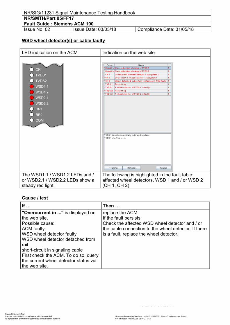
NR/SIG/11231 Signal Maintenance Testing Handbook NR/SMTH/Part 05/FF17 Fault Guide : Siemens ACM 100 Issue No. 02 Issue Date: 03/03/18 Compliance Date: 31/05/18
WSD wheel detector(s) or cable faulty LED indication on the ACM Indication on the web site
The WSD1.1 / WSD1.2 LEDs and / or WSD2.1 / WSD2.2 LEDs show a steady red light.
The following is highlighted in the fault table: affected wheel detectors, WSD 1 and / or WSD 2 (CH 1, CH 2)
Cause / test If … Then … "Overcurrent in ..." is displayed on the web site, Possible cause: ACM faulty WSD wheel detector faulty WSD wheel detector detached from rail short-circuit in signaling cable First check the ACM. To do so, query the current wheel detector status via the web site.
replace the ACM. If the fault persists: Check the affected WSD wheel detector and / or the cable connection to the wheel detector. If there is a fault, replace the wheel detector.
Copyright Network Rail Provided by IHS Markit under license with Network Rail Licensee=Resourcing Solutions Limited /1121226001, User=Christopherson, Joseph
Not for Resale, 03/09/2018 03:56:27 MSTNo reproduction or networking permitted without license from IHS
--``,,``,`,,`,```,,``,,````,,,`,-`-`,,`,,`,`,,`---
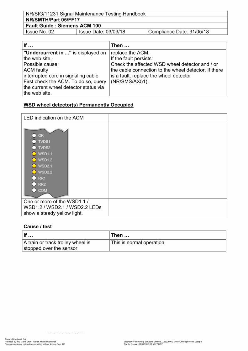
NR/SIG/11231 Signal Maintenance Testing Handbook NR/SMTH/Part 05/FF17 Fault Guide : Siemens ACM 100 Issue No. 02 Issue Date: 03/03/18 Compliance Date: 31/05/18
If … Then … "Undercurrent in ..." is displayed on the web site, Possible cause: ACM faulty interrupted core in signaling cable First check the ACM. To do so, query the current wheel detector status via the web site.
replace the ACM. If the fault persists: Check the affected WSD wheel detector and / or the cable connection to the wheel detector. If there is a fault, replace the wheel detector (NR/SMS/AX51).
WSD wheel detector(s) Permanently Occupied LED indication on the ACM
One or more of the WSD1.1 / WSD1.2 / WSD2.1 / WSD2.2 LEDs show a steady yellow light.
Cause / test If … Then … A train or track trolley wheel is stopped over the sensor
This is normal operation
Copyright Network Rail Provided by IHS Markit under license with Network Rail Licensee=Resourcing Solutions Limited /1121226001, User=Christopherson, Joseph
Not for Resale, 03/09/2018 03:56:27 MSTNo reproduction or networking permitted without license from IHS
--``,,``,`,,`,```,,``,,````,,,`,-`-`,,`,,`,`,,`---
NR/SIG/11231 Signal Maintenance Testing Handbook NR/SMTH/Part 05/FF17 Fault Guide : Siemens ACM 100 Issue No. 02 Issue Date: 03/03/18 Compliance Date: 31/05/18
If … Then … No wheel is over the sensor Check the affected WSD wheel detector. If there is
metallic debris on or close to the wheel sensor, remove it. If the fault persists: Check the affected WSD wheel detector is at the correct height and parallel with the rail head. If necessary, adjust the mounting position and recalibrate the sensor (NR/SMS/AX51), (NR/SMS/TEST038). If the fault persists: Check the cable to the affected WSD wheel detector for loose or high resistance connections. If necessary replace the cable. If the fault persists: Replace the wheel sensor (NR/SMTH/AX28)
Copyright Network Rail Provided by IHS Markit under license with Network Rail Licensee=Resourcing Solutions Limited /1121226001, User=Christopherson, Joseph
Not for Resale, 03/09/2018 03:56:27 MSTNo reproduction or networking permitted without license from IHS
--``,,``,`,,`,```,,``,,````,,,`,-`-`,,`,,`,`,,`---
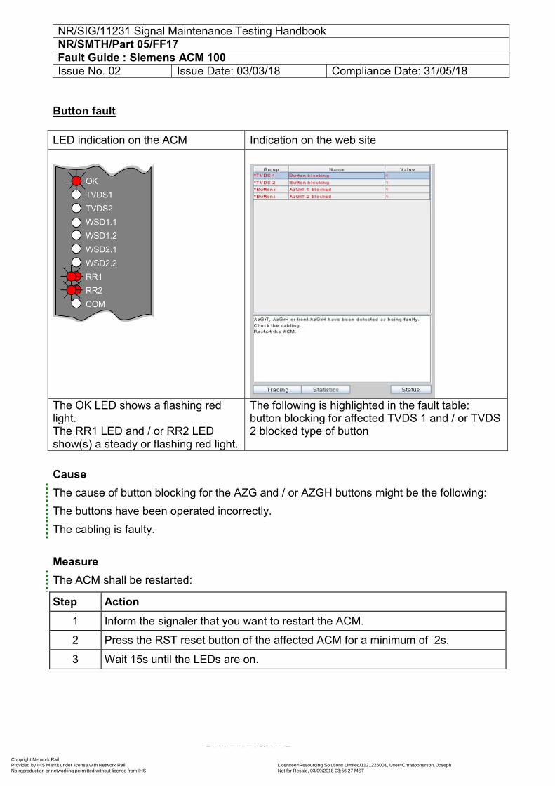
NR/SIG/11231 Signal Maintenance Testing Handbook NR/SMTH/Part 05/FF17 Fault Guide : Siemens ACM 100 Issue No. 02 Issue Date: 03/03/18 Compliance Date: 31/05/18
Button fault LED indication on the ACM Indication on the web site
The OK LED shows a flashing red light. The RR1 LED and / or RR2 LED show(s) a steady or flashing red light.
The following is highlighted in the fault table: button blocking for affected TVDS 1 and / or TVDS 2 blocked type of button
Cause The cause of button blocking for the AZG and / or AZGH buttons might be the following: The buttons have been operated incorrectly. The cabling is faulty.
Measure The ACM shall be restarted:
Step Action 1 Inform the signaler that you want to restart the ACM.
2 Press the RST reset button of the affected ACM for a minimum of 2s.
3 Wait 15s until the LEDs are on.
Copyright Network Rail Provided by IHS Markit under license with Network Rail Licensee=Resourcing Solutions Limited /1121226001, User=Christopherson, Joseph
Not for Resale, 03/09/2018 03:56:27 MSTNo reproduction or networking permitted without license from IHS
--``,,``,`,,`,```,,``,,````,,,`,-`-`,,`,,`,`,,`---
NR/SIG/11231 Signal Maintenance Testing Handbook NR/SMTH/Part 05/FF17 Fault Guide : Siemens ACM 100 Issue No. 02 Issue Date: 03/03/18 Compliance Date: 31/05/18
Test If … Then … the OK LED shows a steady green light,
inform the signaler that the restart has been successful. Request the signaler to perform an axle count reset.
the RR1 LED and / or RR2 LED continue(s) to show a steady red light, continue(s) to show a flashing red light,
replace the ACM (NR/SMTH/Part 04/AX29).
Cause / measure: fault continues to be displayed although ACM has been replaced The cable connection to the AZG and / or AZGH or SRI buttons shall be checked.
Step Action 1 Locate the status of the affected buttons via the web site.
2 To do so, select the status table. The blocked button(s) is (are) displayed. The status of the blocked button(s) is displayed (operated / not operated).
Test If … Then … the status "operated" is displayed for the blocked button on the web site,
a core might be broken: Check the connectors and check them for a secure fit. Perform a visual inspection to see if there is any damage (kinks, cable jammed, insulation damaged). Replace any faulty parts.
the status "not operated" is displayed for the blocked button on the web site,
a core might be broken: Check the connectors and check them for a secure fit. Perform a visual inspection to see if there is any damage (kinks, cable jammed, insulation damaged). Replace any faulty parts.
Copyright Network Rail Provided by IHS Markit under license with Network Rail Licensee=Resourcing Solutions Limited /1121226001, User=Christopherson, Joseph
Not for Resale, 03/09/2018 03:56:27 MSTNo reproduction or networking permitted without license from IHS
--``,,``,`,,`,```,,``,,````,,,`,-`-`,,`,,`,`,,`---
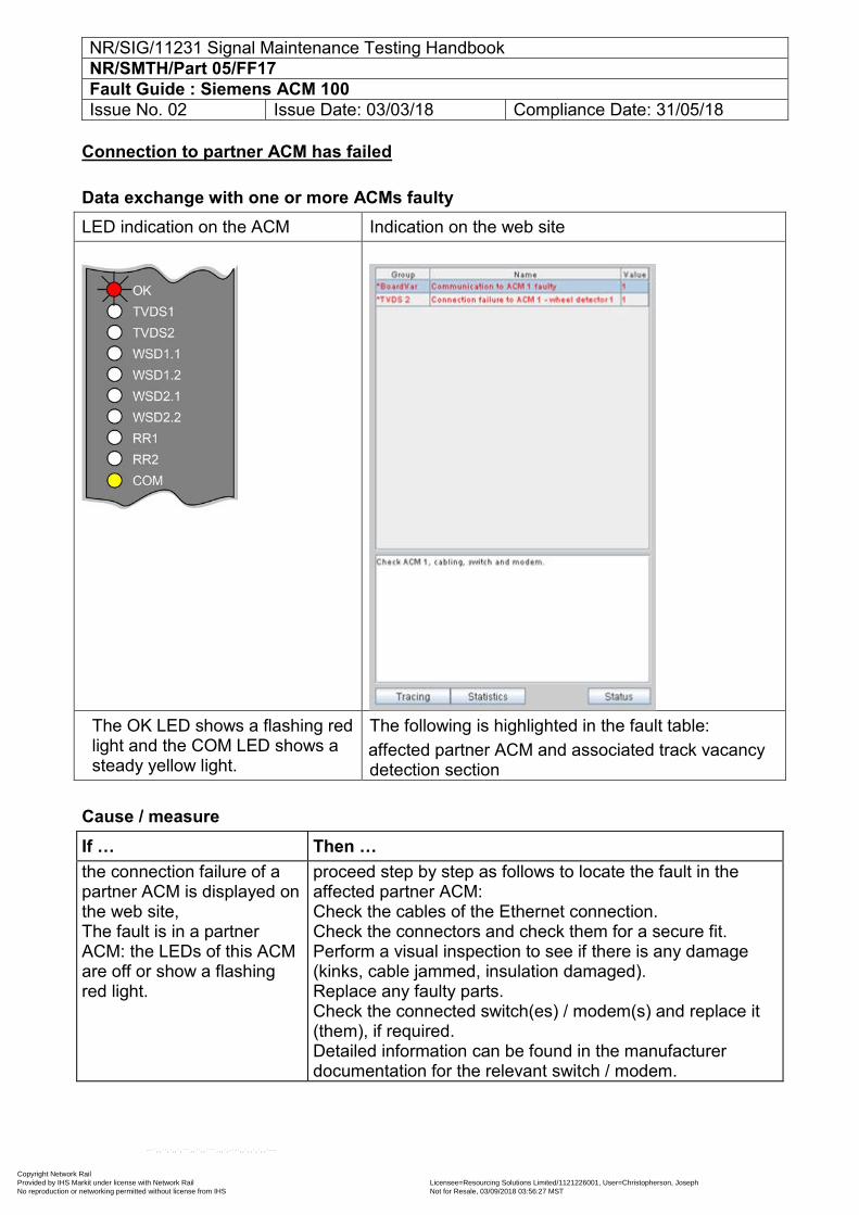
NR/SIG/11231 Signal Maintenance Testing Handbook NR/SMTH/Part 05/FF17 Fault Guide : Siemens ACM 100 Issue No. 02 Issue Date: 03/03/18 Compliance Date: 31/05/18
Connection to partner ACM has failed
Data exchange with one or more ACMs faulty LED indication on the ACM Indication on the web site
The OK LED shows a flashing red light and the COM LED shows a steady yellow light.
The following is highlighted in the fault table: affected partner ACM and associated track vacancy detection section
Cause / measure If … Then … the connection failure of a partner ACM is displayed on the web site, The fault is in a partner ACM: the LEDs of this ACM are off or show a flashing red light.
proceed step by step as follows to locate the fault in the affected partner ACM: Check the cables of the Ethernet connection. Check the connectors and check them for a secure fit. Perform a visual inspection to see if there is any damage (kinks, cable jammed, insulation damaged). Replace any faulty parts. Check the connected switch(es) / modem(s) and replace it (them), if required. Detailed information can be found in the manufacturer documentation for the relevant switch / modem.
Copyright Network Rail Provided by IHS Markit under license with Network Rail Licensee=Resourcing Solutions Limited /1121226001, User=Christopherson, Joseph
Not for Resale, 03/09/2018 03:56:27 MSTNo reproduction or networking permitted without license from IHS
--``,,``,`,,`,```,,``,,````,,,`,-`-`,,`,,`,`,,`---
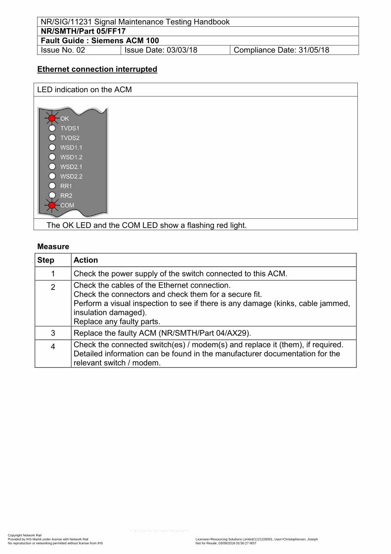
NR/SIG/11231 Signal Maintenance Testing Handbook NR/SMTH/Part 05/FF17 Fault Guide : Siemens ACM 100 Issue No. 02 Issue Date: 03/03/18 Compliance Date: 31/05/18
Ethernet connection interrupted LED indication on the ACM
The OK LED and the COM LED show a flashing red light.
Measure Step Action
1 Check the power supply of the switch connected to this ACM.
2 Check the cables of the Ethernet connection. Check the connectors and check them for a secure fit. Perform a visual inspection to see if there is any damage (kinks, cable jammed, insulation damaged). Replace any faulty parts.
3 Replace the faulty ACM (NR/SMTH/Part 04/AX29).
4 Check the connected switch(es) / modem(s) and replace it (them), if required. Detailed information can be found in the manufacturer documentation for the relevant switch / modem.
Copyright Network Rail Provided by IHS Markit under license with Network Rail Licensee=Resourcing Solutions Limited /1121226001, User=Christopherson, Joseph
Not for Resale, 03/09/2018 03:56:27 MSTNo reproduction or networking permitted without license from IHS
--``,,``,`,,`,```,,``,,````,,,`,-`-`,,`,,`,`,,`---
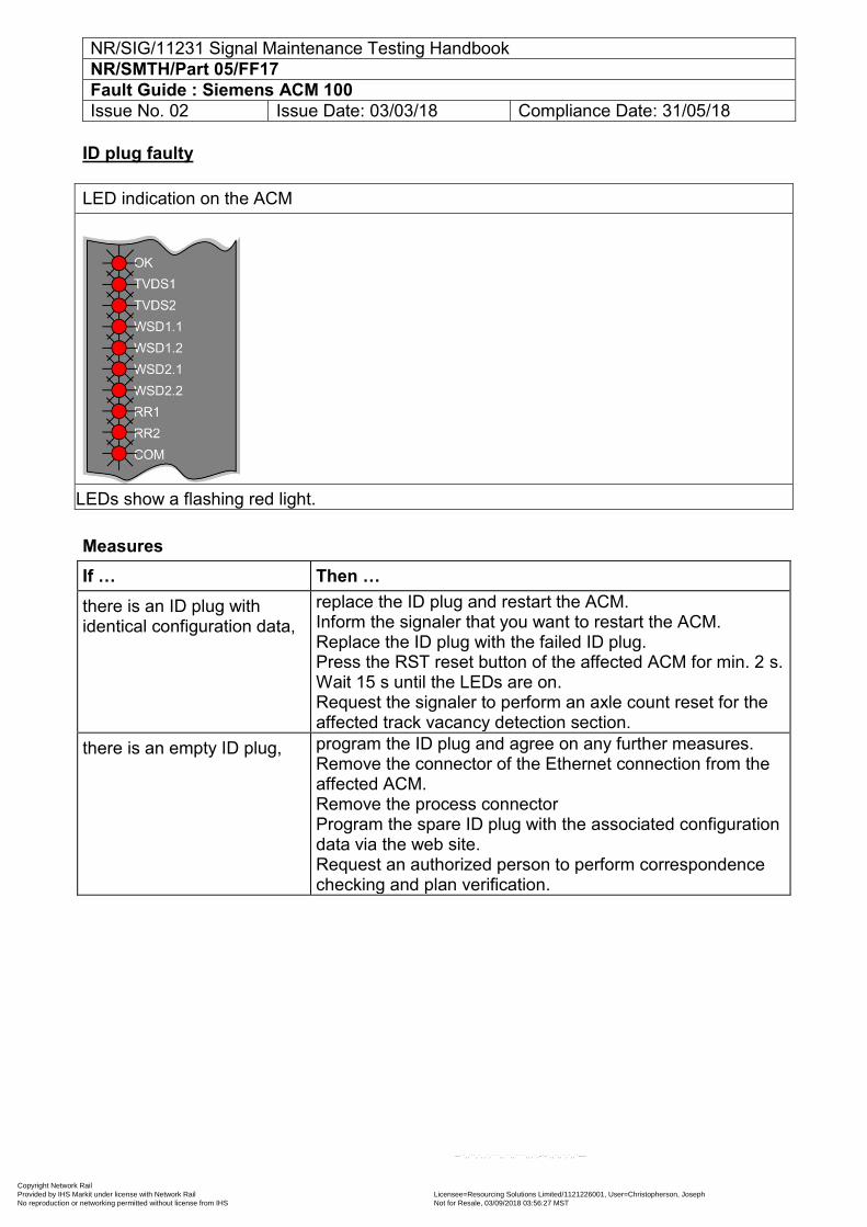
NR/SIG/11231 Signal Maintenance Testing Handbook NR/SMTH/Part 05/FF17 Fault Guide : Siemens ACM 100 Issue No. 02 Issue Date: 03/03/18 Compliance Date: 31/05/18
ID plug faulty LED indication on the ACM
All LEDs show a flashing red light.
Measures If … Then … there is an ID plug with identical configuration data,
replace the ID plug and restart the ACM. Inform the signaler that you want to restart the ACM. Replace the ID plug with the failed ID plug. Press the RST reset button of the affected ACM for min. 2 s. Wait 15 s until the LEDs are on. Request the signaler to perform an axle count reset for the affected track vacancy detection section.
there is an empty ID plug, program the ID plug and agree on any further measures. Remove the connector of the Ethernet connection from the affected ACM. Remove the process connector Program the spare ID plug with the associated configuration data via the web site. Request an authorized person to perform correspondence checking and plan verification.
Copyright Network Rail Provided by IHS Markit under license with Network Rail Licensee=Resourcing Solutions Limited /1121226001, User=Christopherson, Joseph
Not for Resale, 03/09/2018 03:56:27 MSTNo reproduction or networking permitted without license from IHS
--``,,``,`,,`,```,,``,,````,,,`,-`-`,,`,,`,`,,`---
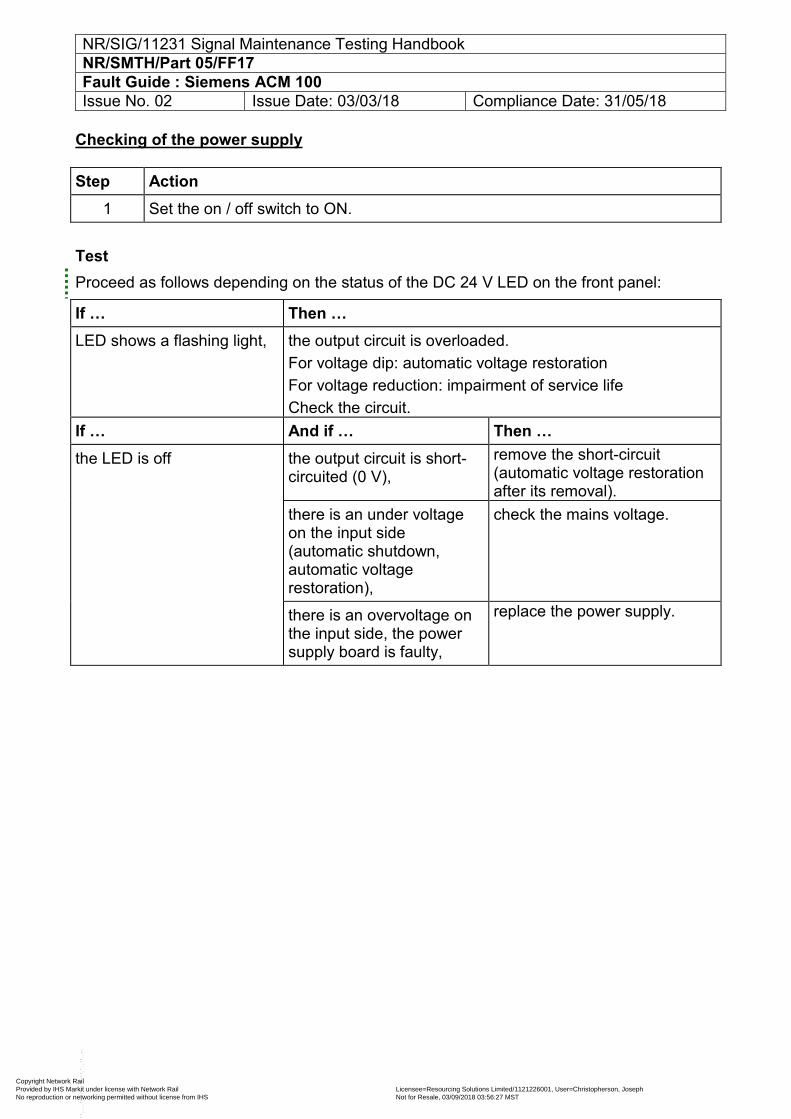
NR/SIG/11231 Signal Maintenance Testing Handbook NR/SMTH/Part 05/FF17 Fault Guide : Siemens ACM 100 Issue No. 02 Issue Date: 03/03/18 Compliance Date: 31/05/18
Checking of the power supply Step Action
1 Set the on / off switch to ON.
Test Proceed as follows depending on the status of the DC 24 V LED on the front panel:
If … Then … LED shows a flashing light, the output circuit is overloaded.
For voltage dip: automatic voltage restoration For voltage reduction: impairment of service life Check the circuit.
If … And if … Then … the LED is off the output circuit is short-
circuited (0 V), remove the short-circuit (automatic voltage restoration after its removal).
there is an under voltage on the input side (automatic shutdown, automatic voltage restoration),
check the mains voltage.
there is an overvoltage on the input side, the power supply board is faulty,
replace the power supply.
Copyright Network Rail Provided by IHS Markit under license with Network Rail Licensee=Resourcing Solutions Limited /1121226001, User=Christopherson, Joseph
Not for Resale, 03/09/2018 03:56:27 MSTNo reproduction or networking permitted without license from IHS
--``,,``,`,,`,```,,``,,````,,,`,-`-`,,`,,`,`,,`---
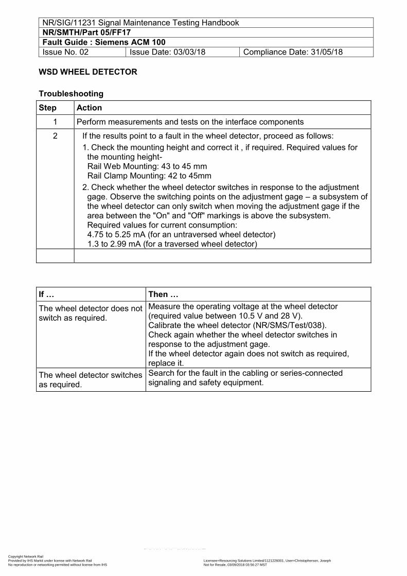
NR/SIG/11231 Signal Maintenance Testing Handbook NR/SMTH/Part 05/FF17 Fault Guide : Siemens ACM 100 Issue No. 02 Issue Date: 03/03/18 Compliance Date: 31/05/18
WSD WHEEL DETECTOR
Troubleshooting Step Action
1 Perform measurements and tests on the interface components
2 If the results point to a fault in the wheel detector, proceed as follows: 1. Check the mounting height and correct it , if required. Required values for
the mounting height- Rail Web Mounting: 43 to 45 mm Rail Clamp Mounting: 42 to 45mm
2. Check whether the wheel detector switches in response to the adjustment gage. Observe the switching points on the adjustment gage – a subsystem of the wheel detector can only switch when moving the adjustment gage if the area between the "On" and "Off" markings is above the subsystem. Required values for current consumption: 4.75 to 5.25 mA (for an untraversed wheel detector) 1.3 to 2.99 mA (for a traversed wheel detector)
If … Then … The wheel detector does not switch as required.
Measure the operating voltage at the wheel detector (required value between 10.5 V and 28 V). Calibrate the wheel detector (NR/SMS/Test/038). Check again whether the wheel detector switches in response to the adjustment gage. If the wheel detector again does not switch as required, replace it.
The wheel detector switches as required.
Search for the fault in the cabling or series-connected signaling and safety equipment.
Copyright Network Rail Provided by IHS Markit under license with Network Rail Licensee=Resourcing Solutions Limited /1121226001, User=Christopherson, Joseph
Not for Resale, 03/09/2018 03:56:27 MSTNo reproduction or networking permitted without license from IHS
--``,,``,`,,`,```,,``,,````,,,`,-`-`,,`,,`,`,,`---
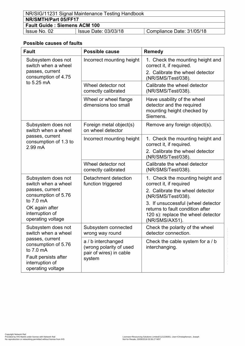
NR/SIG/11231 Signal Maintenance Testing Handbook NR/SMTH/Part 05/FF17 Fault Guide : Siemens ACM 100 Issue No. 02 Issue Date: 03/03/18 Compliance Date: 31/05/18
Possible causes of faults Fault Possible cause Remedy
Subsystem does not switch when a wheel passes, current consumption of 4.75 to 5.25 mA
Incorrect mounting height 1. Check the mounting height and correct it, if required. 2. Calibrate the wheel detector (NR/SMS/Test/038).
Wheel detector not correctly calibrated
Calibrate the wheel detector (NR/SMS/Test/038).
Wheel or wheel flange dimensions too small
Have usability of the wheel detector and the required mounting height checked by Siemens.
Subsystem does not switch when a wheel passes, current consumption of 1.3 to 2.99 mA
Foreign metal object(s) on wheel detector
Remove any foreign object(s).
Incorrect mounting height 1. Check the mounting height and correct it, if required. 2. Calibrate the wheel detector (NR/SMS/Test/038).
Wheel detector not correctly calibrated
Calibrate the wheel detector (NR/SMS/Test/038).
Subsystem does not switch when a wheel passes, current consumption of 5.76 to 7.0 mA OK again after interruption of operating voltage
Detachment detection function triggered
1. Check the mounting height and correct it, if required 2. Calibrate the wheel detector (NR/SMS/Test/038). 3. If unsuccessful (wheel detector returns to fault condition after 120 s): replace the wheel detector (NR/SMS/AX51).
Subsystem does not switch when a wheel passes, current consumption of 5.76 to 7.0 mA Fault persists after interruption of operating voltage
Subsystem connected wrong way round
Check the polarity of the wheel detector connection.
a / b interchanged (wrong polarity of used pair of wires) in cable system
Check the cable system for a / b interchanging.
Copyright Network Rail Provided by IHS Markit under license with Network Rail Licensee=Resourcing Solutions Limited /1121226001, User=Christopherson, Joseph
Not for Resale, 03/09/2018 03:56:27 MSTNo reproduction or networking permitted without license from IHS
--``,,``,`,,`,```,,``,,````,,,`,-`-`,,`,,`,`,,`---
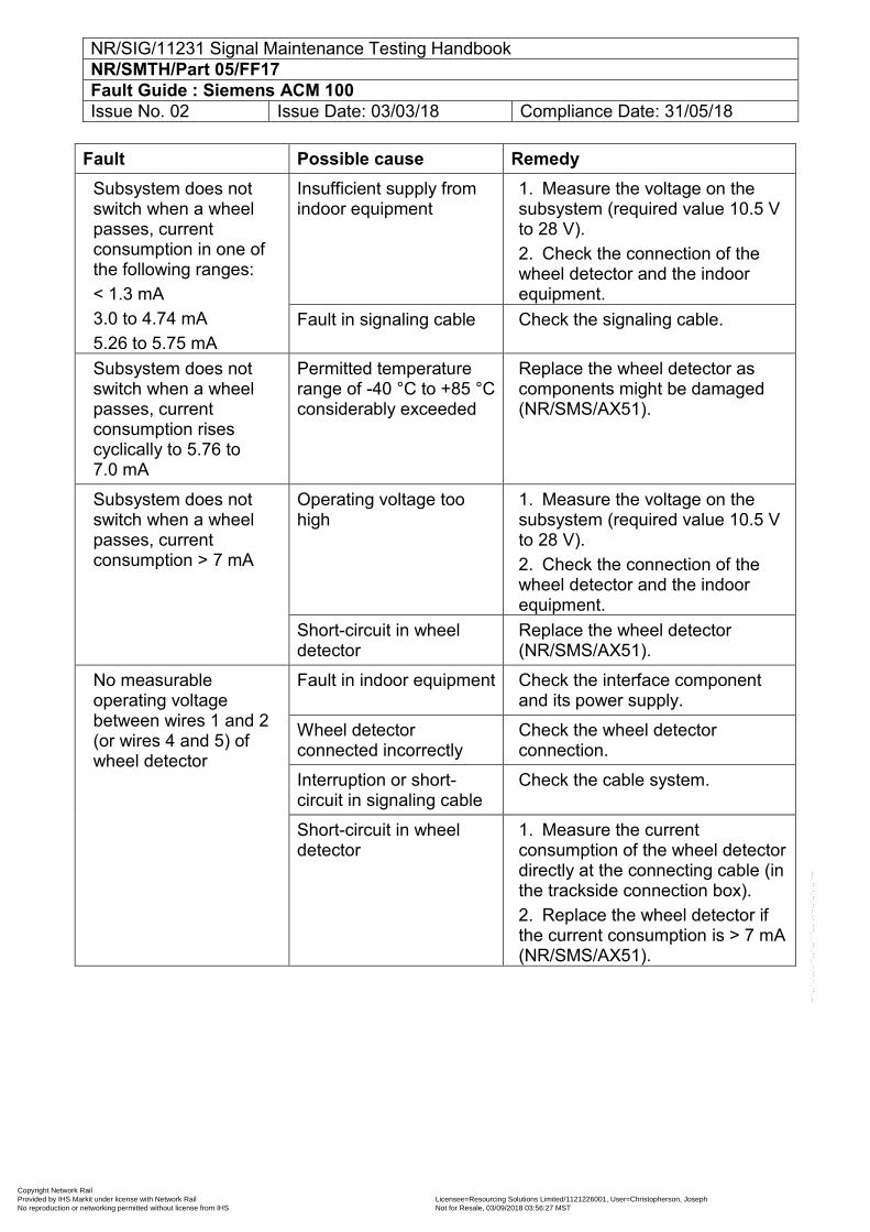
NR/SIG/11231 Signal Maintenance Testing Handbook NR/SMTH/Part 05/FF17 Fault Guide : Siemens ACM 100 Issue No. 02 Issue Date: 03/03/18 Compliance Date: 31/05/18
Fault Possible cause Remedy Subsystem does not switch when a wheel passes, current consumption in one of the following ranges: < 1.3 mA 3.0 to 4.74 mA 5.26 to 5.75 mA
Insufficient supply from indoor equipment
1. Measure the voltage on the subsystem (required value 10.5 V to 28 V). 2. Check the connection of the wheel detector and the indoor equipment.
Fault in signaling cable Check the signaling cable.
Subsystem does not switch when a wheel passes, current consumption rises cyclically to 5.76 to 7.0 mA
Permitted temperature range of -40 °C to +85 °C considerably exceeded
Replace the wheel detector as components might be damaged (NR/SMS/AX51).
Subsystem does not switch when a wheel passes, current consumption > 7 mA
Operating voltage too high
1. Measure the voltage on the subsystem (required value 10.5 V to 28 V). 2. Check the connection of the wheel detector and the indoor equipment.
Short-circuit in wheel detector
Replace the wheel detector (NR/SMS/AX51).
No measurable operating voltage between wires 1 and 2 (or wires 4 and 5) of wheel detector
Fault in indoor equipment Check the interface component and its power supply.
Wheel detector connected incorrectly
Check the wheel detector connection.
Interruption or short-circuit in signaling cable
Check the cable system.
Short-circuit in wheel detector
1. Measure the current consumption of the wheel detector directly at the connecting cable (in the trackside connection box). 2. Replace the wheel detector if the current consumption is > 7 mA (NR/SMS/AX51).
Copyright Network Rail Provided by IHS Markit under license with Network Rail Licensee=Resourcing Solutions Limited /1121226001, User=Christopherson, Joseph
Not for Resale, 03/09/2018 03:56:27 MSTNo reproduction or networking permitted without license from IHS
--``,,``,`,,`,```,,``,,````,,,`,-`-`,,`,,`,`,,`---
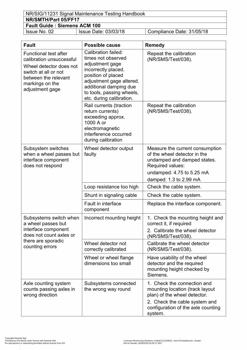
NR/SIG/11231 Signal Maintenance Testing Handbook NR/SMTH/Part 05/FF17 Fault Guide : Siemens ACM 100 Issue No. 02 Issue Date: 03/03/18 Compliance Date: 31/05/18
Fault Possible cause Remedy Functional test after calibration unsuccessful Wheel detector does not switch at all or not between the relevant markings on the adjustment gage
Calibration failed: times not observed adjustment gage incorrectly placed. position of placed adjustment gage altered. additional damping due to tools, passing wheels, etc. during calibration.
Repeat the calibration (NR/SMS/Test/038).
Rail currents (traction return currents) exceeding approx. 1000 A or electromagnetic interference occurred during calibration
Repeat the calibration (NR/SMS/Test/038).
Subsystem switches when a wheel passes but interface component does not respond
Wheel detector output faulty
Measure the current consumption of the wheel detector in the undamped and damped states. Required values: undamped: 4.75 to 5.25 mA damped: 1.3 to 2.99 mA
Loop resistance too high Check the cable system.
Shunt in signaling cable Check the cable system.
Fault in interface component
Replace the interface component.
Subsystems switch when a wheel passes but interface component does not count axles or there are sporadic counting errors
Incorrect mounting height 1. Check the mounting height and correct it, if required 2. Calibrate the wheel detector (NR/SMS/Test/038).
Wheel detector not correctly calibrated
Calibrate the wheel detector (NR/SMS/Test/038).
Wheel or wheel flange dimensions too small
Have usability of the wheel detector and the required mounting height checked by Siemens.
Axle counting system counts passing axles in wrong direction
Subsystems connected the wrong way round
1. Check the connection and mounting location (track layout plan) of the wheel detector. 2. Check the cable system and configuration of the axle counting system.
Copyright Network Rail Provided by IHS Markit under license with Network Rail Licensee=Resourcing Solutions Limited /1121226001, User=Christopherson, Joseph
Not for Resale, 03/09/2018 03:56:27 MSTNo reproduction or networking permitted without license from IHS
--``,,``,`,,`,```,,``,,````,,,`,-`-`,,`,,`,`,,`---
NR/SIG/11231 Signal Maintenance Testing Handbook NR/SMTH/Part 05/FF17 Fault Guide : Siemens ACM 100 Issue No. 02 Issue Date: 03/03/18 Compliance Date: 31/05/18
It might be necessary to replace the wheel detector (NR/SMS/AX51) if you cannot identify and rectify the cause of the fault.
END
Copyright Network Rail Provided by IHS Markit under license with Network Rail Licensee=Resourcing Solutions Limited /1121226001, User=Christopherson, Joseph
Not for Resale, 03/09/2018 03:56:27 MSTNo reproduction or networking permitted without license from IHS
--``,,``,`,,`,```,,``,,````,,,`,-`-`,,`,,`,`,,`---
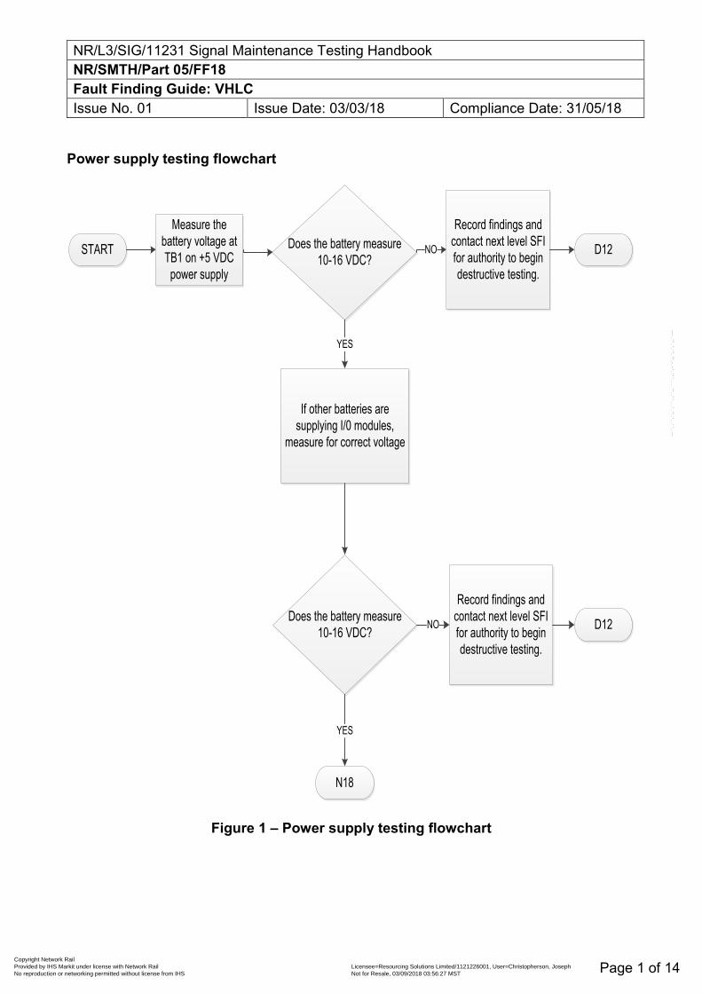
NR/L3/SIG/11231 Signal Maintenance Testing Handbook NR/SMTH/Part 05/FF18 Fault Finding Guide: VHLC Issue No. 01 Issue Date: 03/03/18 Compliance Date: 31/05/18
Page 1 of 14
Power supply testing flowchart
START
Measure the battery voltage at TB1 on +5 VDC
power supply
Does the battery measure 10-16 VDC?
Record findings and contact next level SFI for authority to begin destructive testing.
D12
If other batteries are supplying I/0 modules,
measure for correct voltage
Does the battery measure 10-16 VDC?
Record findings and contact next level SFI for authority to begin destructive testing.
D12
N18
NO
YES
YES
NO
Figure 1 – Power supply testing flowchart
Copyright Network Rail Provided by IHS Markit under license with Network Rail Licensee=Resourcing Solutions Limited /1121226001, User=Christopherson, Joseph
Not for Resale, 03/09/2018 03:56:27 MSTNo reproduction or networking permitted without license from IHS
--``,,``,`,,`,```,,``,,````,,,`,-`-`,,`,,`,`,,`---
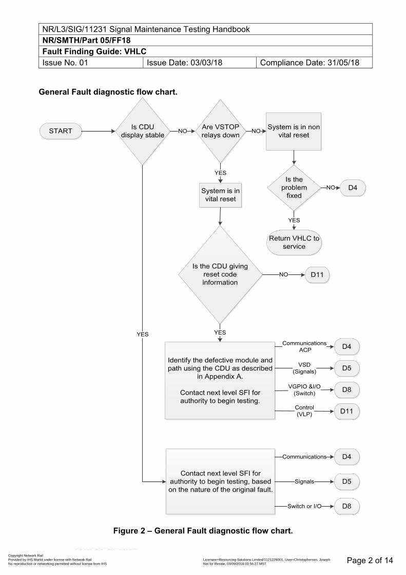
NR/L3/SIG/11231 Signal Maintenance Testing Handbook NR/SMTH/Part 05/FF18 Fault Finding Guide: VHLC Issue No. 01 Issue Date: 03/03/18 Compliance Date: 31/05/18
Page 2 of 14
General Fault diagnostic flow chart.
START Is CDU display stable
Are VSTOP relays down
System is in non vital reset
Is the problem
fixedD4System is in
vital reset
Is the CDU giving reset code information
Return VHLC to service
Identify the defective module and path using the CDU as described
in Appendix A.
Contact next level SFI for authority to begin testing.
D4
D5
D8
D11
Contact next level SFI for authority to begin testing, based on the nature of the original fault.
D4
D5
D8
NO NO
YES
NO
YESYES
Control(VLP)
VGPIO &I/O(Switch)
VSD(Signals)
Communications ACP
Communications
Signals
Switch or I/O
YES
D11NO
Figure 2 – General Fault diagnostic flow chart.
Copyright Network Rail Provided by IHS Markit under license with Network Rail Licensee=Resourcing Solutions Limited /1121226001, User=Christopherson, Joseph
Not for Resale, 03/09/2018 03:56:27 MSTNo reproduction or networking permitted without license from IHS
--``,,``,`,,`,```,,``,,````,,,`,-`-`,,`,,`,`,,`---
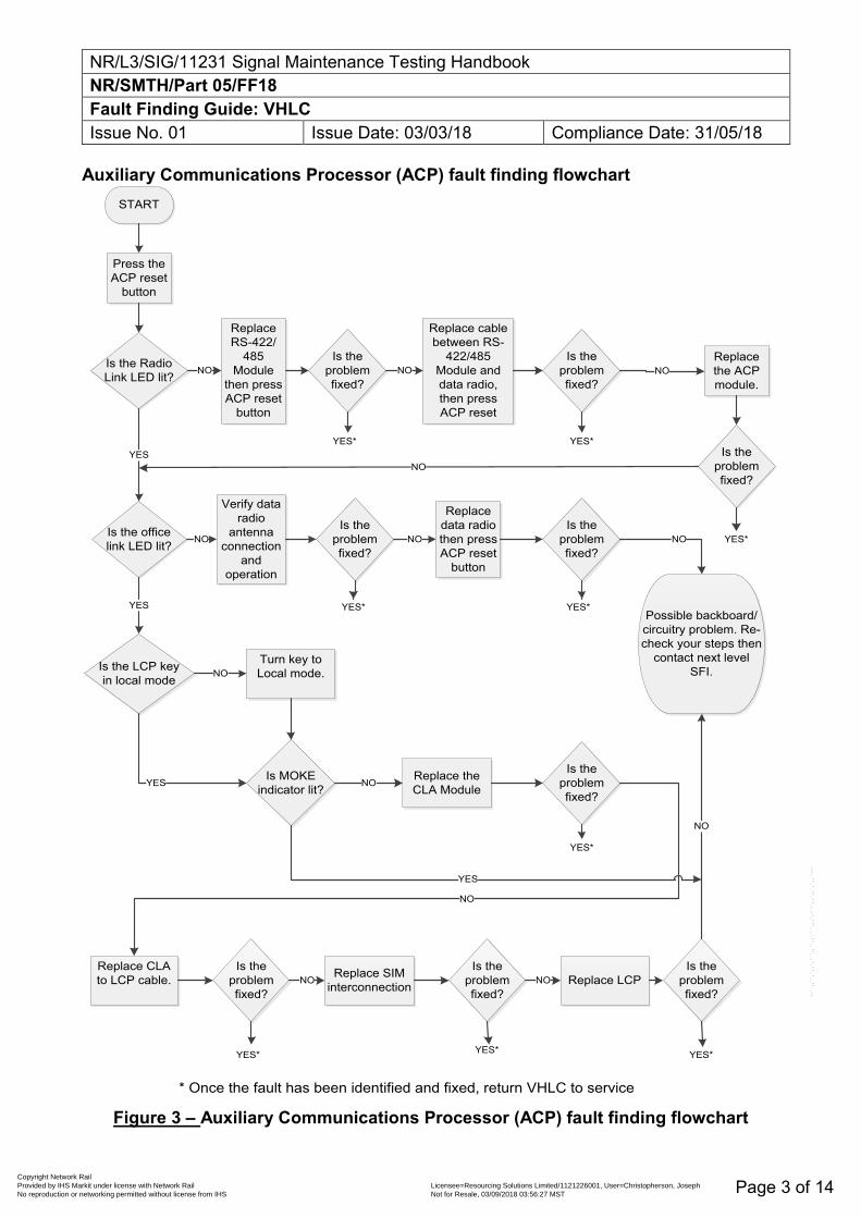
NR/L3/SIG/11231 Signal Maintenance Testing Handbook NR/SMTH/Part 05/FF18 Fault Finding Guide: VHLC Issue No. 01 Issue Date: 03/03/18 Compliance Date: 31/05/18
Page 3 of 14
Auxiliary Communications Processor (ACP) fault finding flowchart START
Press the ACP reset
button
Is the Radio Link LED lit?
Replace RS-422/
485 Module
then press ACP reset
button
Is the problem fixed?
Replace cable between RS-
422/485 Module and data radio, then press ACP reset
Replace the ACP module.
Is the problem fixed?
Is the problem fixed?
Is the office link LED lit?
Verify data radio
antenna connection
and operation
Is the problem fixed?
Replace data radio then press ACP reset
button
Is the problem fixed?
Possible backboard/circuitry problem. Re-check your steps then
contact next level SFI.
NO NO
NOYES
NO
NO NO NO
Is the LCP key in local mode
YES
Turn key to Local mode.
Is MOKE indicator lit?
Replace the CLA Module
Replace CLA to LCP cable.
YES
NO
NO
Replace SIM interconnection
Is the problem fixed?
Is the problem fixed?
Is the problem fixed?
NO
NO Replace LCPNO
YES
Is the problem fixed?
NO
YES*
YES* YES*YES*
YES* YES*
YES*YES*
* Once the fault has been identified and fixed, return VHLC to service
YES*
Figure 3 – Auxiliary Communications Processor (ACP) fault finding flowchart
Copyright Network Rail Provided by IHS Markit under license with Network Rail Licensee=Resourcing Solutions Limited /1121226001, User=Christopherson, Joseph
Not for Resale, 03/09/2018 03:56:27 MSTNo reproduction or networking permitted without license from IHS
--``,,``,`,,`,```,,``,,````,,,`,-`-`,,`,,`,`,,`---
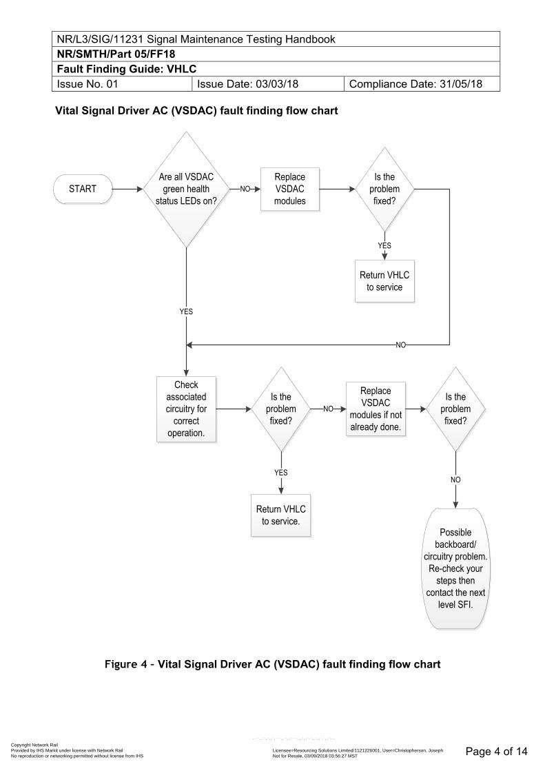
NR/L3/SIG/11231 Signal Maintenance Testing Handbook NR/SMTH/Part 05/FF18 Fault Finding Guide: VHLC Issue No. 01 Issue Date: 03/03/18 Compliance Date: 31/05/18
Page 4 of 14
Vital Signal Driver AC (VSDAC) fault finding flow chart
STARTAre all VSDAC green health
status LEDs on?
Replace VSDAC modules
NOIs the
problem fixed?
Return VHLC to service
YES
Check associated circuitry for
correct operation.
YES
NO
Is the problem fixed?
Replace VSDAC
modules if not already done.
Is the problem fixed?
NO
Return VHLC to service.
YES
Possible backboard/
circuitry problem. Re-check your
steps then contact the next
level SFI.
NO
Figure 4 – Vital Signal Driver AC (VSDAC) fault finding flow chart
Copyright Network Rail Provided by IHS Markit under license with Network Rail Licensee=Resourcing Solutions Limited /1121226001, User=Christopherson, Joseph
Not for Resale, 03/09/2018 03:56:27 MSTNo reproduction or networking permitted without license from IHS
--``,,``,`,,`,```,,``,,````,,,`,-`-`,,`,,`,`,,`---
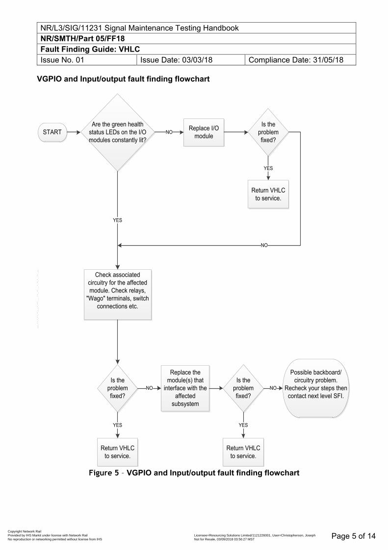
NR/L3/SIG/11231 Signal Maintenance Testing Handbook NR/SMTH/Part 05/FF18 Fault Finding Guide: VHLC Issue No. 01 Issue Date: 03/03/18 Compliance Date: 31/05/18
Page 5 of 14
VGPIO and Input/output fault finding flowchart
STARTAre the green health
status LEDs on the I/O modules constantly lit?
Replace I/O moduleNO
Is the problem fixed?
Return VHLC to service.
YES
Check associated circuitry for the affected module. Check relays,
"Wago" terminals, switch connections etc.
YES
Is the problem fixed?
Return VHLC to service.
YES
Replace the module(s) that
interface with the affected
subsystem
NOIs the
problem fixed?
Return VHLC to service.
YES
Possible backboard/ circuitry problem.
Recheck your steps then contact next level SFI.
NO
NO
Figure 5 – VGPIO and Input/output fault finding flowchart
Copyright Network Rail Provided by IHS Markit under license with Network Rail Licensee=Resourcing Solutions Limited /1121226001, User=Christopherson, Joseph
Not for Resale, 03/09/2018 03:56:27 MSTNo reproduction or networking permitted without license from IHS
--``,,``,`,,`,```,,``,,````,,,`,-`-`,,`,,`,`,,`---
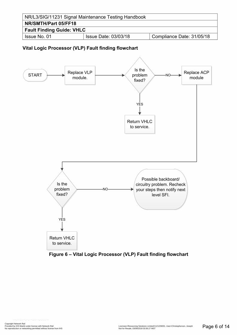
NR/L3/SIG/11231 Signal Maintenance Testing Handbook NR/SMTH/Part 05/FF18 Fault Finding Guide: VHLC Issue No. 01 Issue Date: 03/03/18 Compliance Date: 31/05/18
Page 6 of 14
Vital Logic Processor (VLP) Fault finding flowchart
START Replace VLP module.
Is the problem fixed?
Replace ACP moduleNO
Is the problem fixed?
Possible backboard/ circuitry problem. Recheck your steps then notify next
level SFI.NO
Return VHLC to service.
Return VHLC to service.
YES
YES
Figure 6 – Vital Logic Processor (VLP) Fault finding flowchart
Copyright Network Rail Provided by IHS Markit under license with Network Rail Licensee=Resourcing Solutions Limited /1121226001, User=Christopherson, Joseph
Not for Resale, 03/09/2018 03:56:27 MSTNo reproduction or networking permitted without license from IHS
--``,,``,`,,`,```,,``,,````,,,`,-`-`,,`,,`,`,,`---
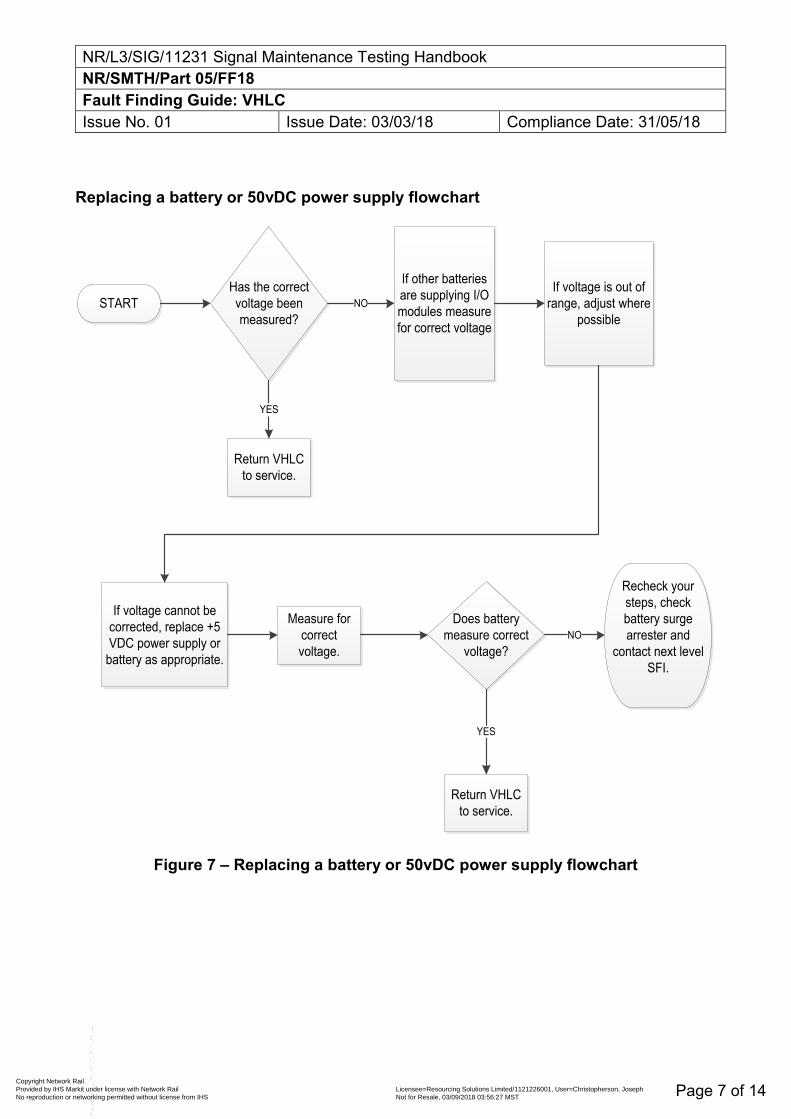
NR/L3/SIG/11231 Signal Maintenance Testing Handbook NR/SMTH/Part 05/FF18 Fault Finding Guide: VHLC Issue No. 01 Issue Date: 03/03/18 Compliance Date: 31/05/18
Page 7 of 14
Replacing a battery or 50vDC power supply flowchart
STARTHas the correct voltage been measured?
If other batteries are supplying I/O modules measure for correct voltage
NOIf voltage is out of
range, adjust where possible
If voltage cannot be corrected, replace +5 VDC power supply or
battery as appropriate.
Measure for correct voltage.
Does battery measure correct
voltage?
Return VHLC to service.
YES
Recheck your steps, check battery surge arrester and
contact next level SFI.
NO
Return VHLC to service.
YES
Figure 7 – Replacing a battery or 50vDC power supply flowchart
Copyright Network Rail Provided by IHS Markit under license with Network Rail Licensee=Resourcing Solutions Limited /1121226001, User=Christopherson, Joseph
Not for Resale, 03/09/2018 03:56:27 MSTNo reproduction or networking permitted without license from IHS
--``,,``,`,,`,```,,``,,````,,,`,-`-`,,`,,`,`,,`---
NR/L3/SIG/11231 Signal Maintenance Testing Handbook NR/SMTH/Part 05/FF18 Fault Finding Guide: VHLC Issue No. 01 Issue Date: 03/03/18 Compliance Date: 31/05/18
Page 8 of 14
Fault finding using the CDU
Fault finding on the VHLC is carried out using the reset source code and software reset code, which are incorporated as part of the error messages displayed on the CDU. These error messages take two distinct forms:
a) VLP specific error messages.
b) ACP specific error messages.
These error messages are made up of a series of up 13 numbers and letters, which can be interpreted to give fault finding information.
The CDU can also be used to access the VHLC's fault log, which records faults codes for the last 16 faults experienced by the machine.
VLP Error Messages
The VLP specific error messages displayed by the CDU are made up of a series of 12 number and letters and take the following format:
a) 31 RS mm qqqq pp
All VLP error messages begin with the number 31, as shown here, and contain two elements specific to the fault finding process. These are the reset source code, indicated above as 'mm', and the software reset code, indicated above as 'qqqq'.
The remaining information contained within these error messages is not relevant to the fault finding process. A full list of VLP reset source codes and software reset codes is given in the following tables along with information on how to interpret them.
VLP reset source codes
Table 1 lists the VLP reset source codes, their possible causes and the appropriate corrective actions to take.
Copyright Network Rail Provided by IHS Markit under license with Network Rail Licensee=Resourcing Solutions Limited /1121226001, User=Christopherson, Joseph
Not for Resale, 03/09/2018 03:56:27 MSTNo reproduction or networking permitted without license from IHS
--``,,``,`,,`,```,,``,,````,,,`,-`-`,,`,,`,`,,`---
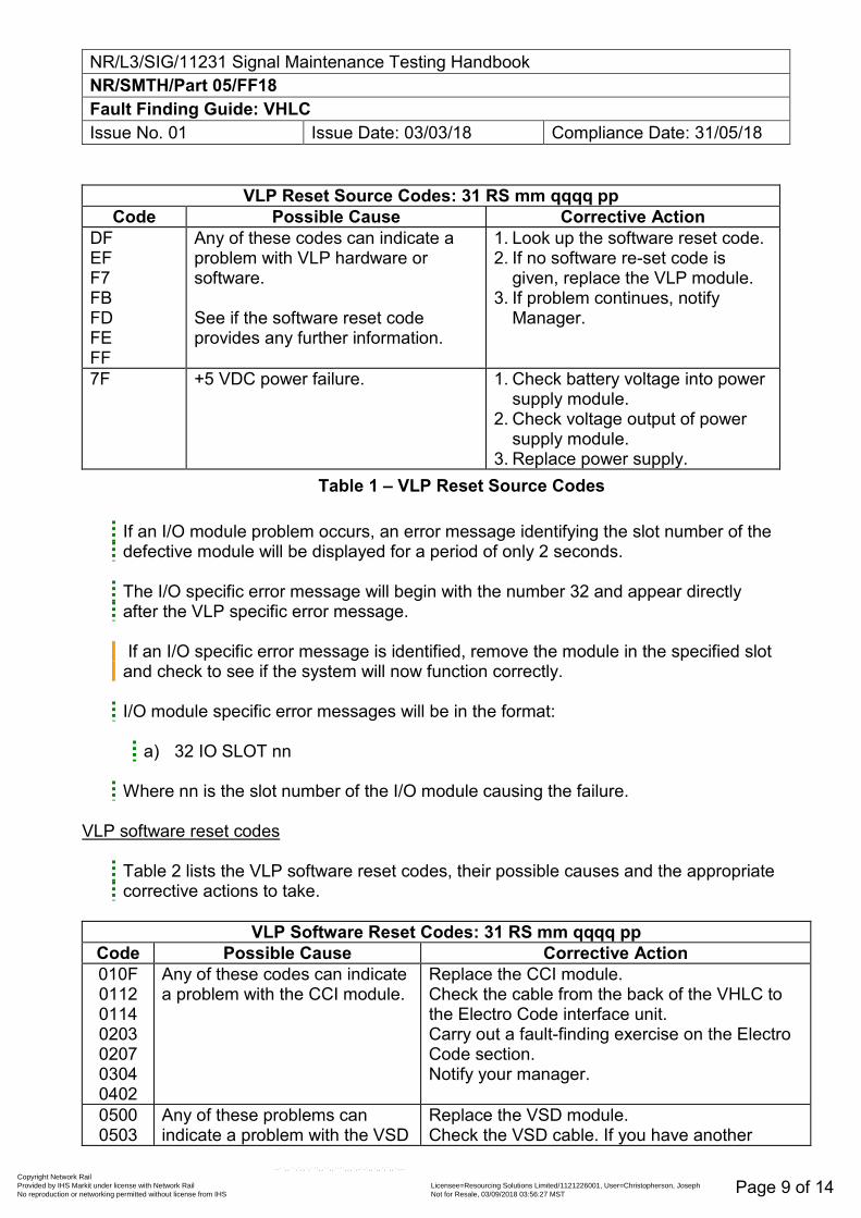
NR/L3/SIG/11231 Signal Maintenance Testing Handbook NR/SMTH/Part 05/FF18 Fault Finding Guide: VHLC Issue No. 01 Issue Date: 03/03/18 Compliance Date: 31/05/18
Page 9 of 14
VLP Reset Source Codes: 31 RS mm qqqq pp
Code Possible Cause Corrective Action DF EF F7 FB FD FE FF
Any of these codes can indicate a problem with VLP hardware or software. See if the software reset code provides any further information.
1. Look up the software reset code. 2. If no software re-set code is
given, replace the VLP module. 3. If problem continues, notify
Manager.
7F +5 VDC power failure. 1. Check battery voltage into power supply module.
2. Check voltage output of power supply module.
3. Replace power supply. Table 1 – VLP Reset Source Codes
If an I/O module problem occurs, an error message identifying the slot number of the defective module will be displayed for a period of only 2 seconds.
The I/O specific error message will begin with the number 32 and appear directly after the VLP specific error message.
If an I/O specific error message is identified, remove the module in the specified slot and check to see if the system will now function correctly.
I/O module specific error messages will be in the format:
a) 32 IO SLOT nn
Where nn is the slot number of the I/O module causing the failure.
VLP software reset codes
Table 2 lists the VLP software reset codes, their possible causes and the appropriate corrective actions to take.
VLP Software Reset Codes: 31 RS mm qqqq pp
Code Possible Cause Corrective Action 010F 0112 0114 0203 0207 0304 0402
Any of these codes can indicate a problem with the CCI module.
Replace the CCI module. Check the cable from the back of the VHLC to the Electro Code interface unit. Carry out a fault-finding exercise on the Electro Code section. Notify your manager.
0500 0503
Any of these problems can indicate a problem with the VSD
Replace the VSD module. Check the VSD cable. If you have another
Copyright Network Rail Provided by IHS Markit under license with Network Rail Licensee=Resourcing Solutions Limited /1121226001, User=Christopherson, Joseph
Not for Resale, 03/09/2018 03:56:27 MSTNo reproduction or networking permitted without license from IHS
--``,,``,`,,`,```,,``,,````,,,`,-`-`,,`,,`,`,,`---
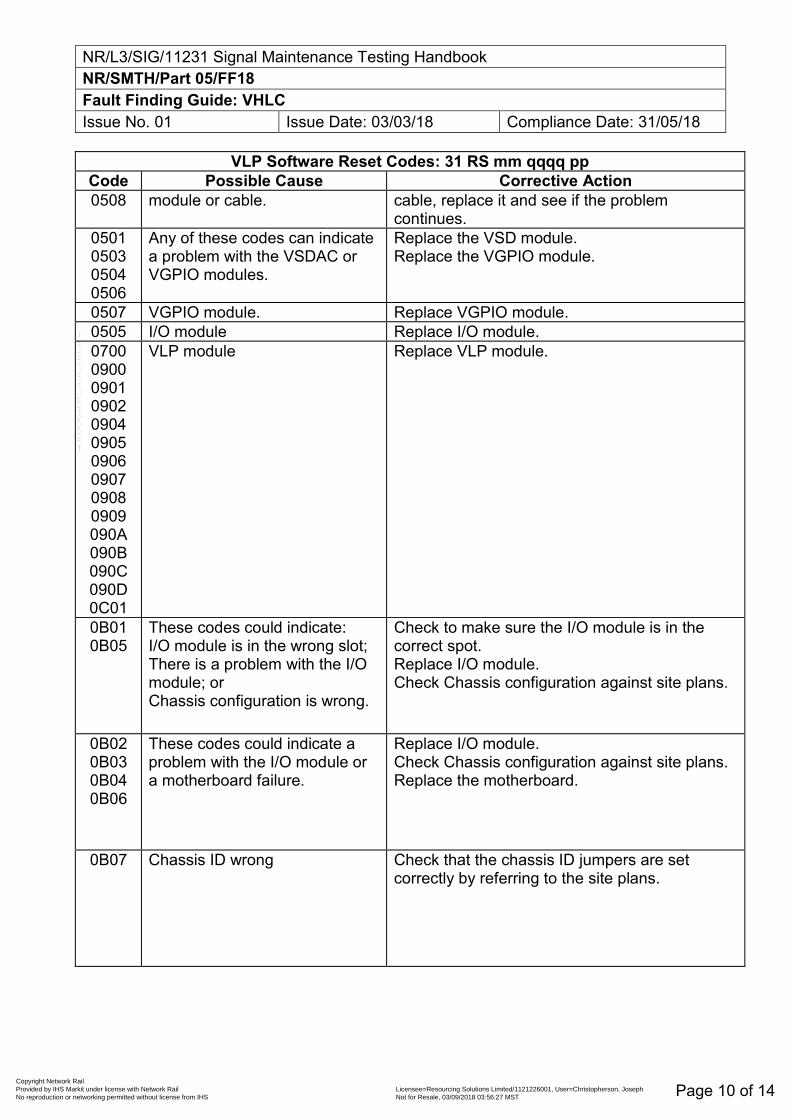
NR/L3/SIG/11231 Signal Maintenance Testing Handbook NR/SMTH/Part 05/FF18 Fault Finding Guide: VHLC Issue No. 01 Issue Date: 03/03/18 Compliance Date: 31/05/18
Page 10 of 14
VLP Software Reset Codes: 31 RS mm qqqq pp Code Possible Cause Corrective Action 0508 module or cable. cable, replace it and see if the problem
continues. 0501 0503 0504 0506
Any of these codes can indicate a problem with the VSDAC or VGPIO modules.
Replace the VSD module. Replace the VGPIO module.
0507 VGPIO module. Replace VGPIO module. 0505 I/O module Replace I/O module. 0700 0900 0901 0902 0904 0905 0906 0907 0908 0909 090A 090B 090C 090D 0C01
VLP module Replace VLP module.
0B01 0B05
These codes could indicate: I/O module is in the wrong slot; There is a problem with the I/O module; or Chassis configuration is wrong.
Check to make sure the I/O module is in the correct spot. Replace I/O module. Check Chassis configuration against site plans.
0B02 0B03 0B04 0B06
These codes could indicate a problem with the I/O module or a motherboard failure.
Replace I/O module. Check Chassis configuration against site plans. Replace the motherboard.
0B07 Chassis ID wrong Check that the chassis ID jumpers are set correctly by referring to the site plans.
Copyright Network Rail Provided by IHS Markit under license with Network Rail Licensee=Resourcing Solutions Limited /1121226001, User=Christopherson, Joseph
Not for Resale, 03/09/2018 03:56:27 MSTNo reproduction or networking permitted without license from IHS
--``,,``,`,,`,```,,``,,````,,,`,-`-`,,`,,`,`,,`---
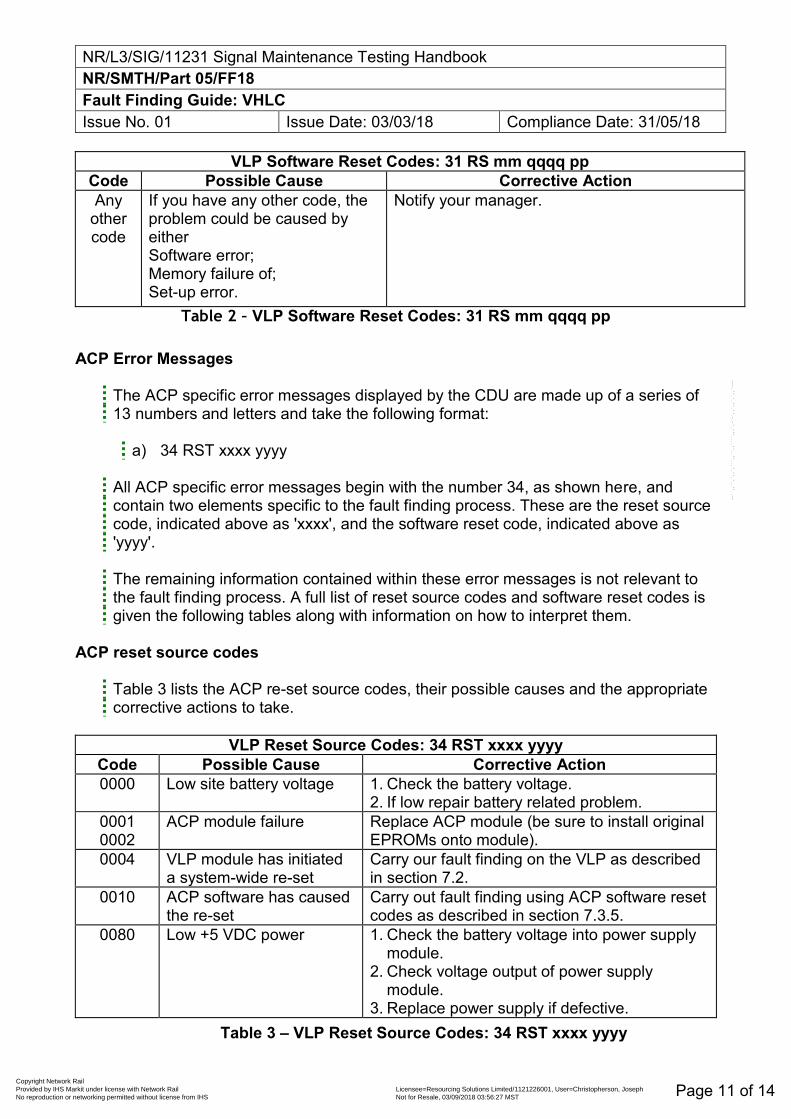
NR/L3/SIG/11231 Signal Maintenance Testing Handbook NR/SMTH/Part 05/FF18 Fault Finding Guide: VHLC Issue No. 01 Issue Date: 03/03/18 Compliance Date: 31/05/18
Page 11 of 14
VLP Software Reset Codes: 31 RS mm qqqq pp Code Possible Cause Corrective Action Any
other code
If you have any other code, the problem could be caused by either Software error; Memory failure of; Set-up error.
Notify your manager.
Table 2 – VLP Software Reset Codes: 31 RS mm qqqq pp
ACP Error Messages
The ACP specific error messages displayed by the CDU are made up of a series of 13 numbers and letters and take the following format:
a) 34 RST xxxx yyyy
All ACP specific error messages begin with the number 34, as shown here, and contain two elements specific to the fault finding process. These are the reset source code, indicated above as 'xxxx', and the software reset code, indicated above as 'yyyy'.
The remaining information contained within these error messages is not relevant to the fault finding process. A full list of reset source codes and software reset codes is given the following tables along with information on how to interpret them.
ACP reset source codes
Table 3 lists the ACP re-set source codes, their possible causes and the appropriate corrective actions to take.
VLP Reset Source Codes: 34 RST xxxx yyyy
Code Possible Cause Corrective Action 0000
Low site battery voltage 1. Check the battery voltage.
2. If low repair battery related problem. 0001 0002
ACP module failure Replace ACP module (be sure to install original EPROMs onto module).
0004 VLP module has initiated a system-wide re-set
Carry our fault finding on the VLP as described in section 7.2.
0010 ACP software has caused the re-set
Carry out fault finding using ACP software reset codes as described in section 7.3.5.
0080 Low +5 VDC power 1. Check the battery voltage into power supply module.
2. Check voltage output of power supply module.
3. Replace power supply if defective. Table 3 – VLP Reset Source Codes: 34 RST xxxx yyyy
Copyright Network Rail Provided by IHS Markit under license with Network Rail Licensee=Resourcing Solutions Limited /1121226001, User=Christopherson, Joseph
Not for Resale, 03/09/2018 03:56:27 MSTNo reproduction or networking permitted without license from IHS
--``,,``,`,,`,```,,``,,````,,,`,-`-`,,`,,`,`,,`---
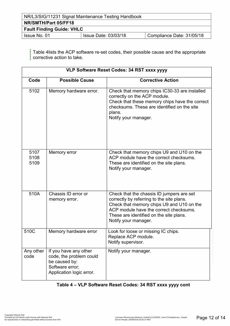
NR/L3/SIG/11231 Signal Maintenance Testing Handbook NR/SMTH/Part 05/FF18 Fault Finding Guide: VHLC Issue No. 01 Issue Date: 03/03/18 Compliance Date: 31/05/18
Page 12 of 14
Table 4lists the ACP software re-set codes, their possible cause and the appropriate corrective action to take.
VLP Software Reset Codes: 34 RST xxxx yyyy
Code Possible Cause Corrective Action
5102
Memory hardware error. Check that memory chips IC30-33 are installed correctly on the ACP module. Check that these memory chips have the correct checksums. These are identified on the site plans. Notify your manager.
5107 5108 5109
Memory error Check that memory chips U9 and U10 on the ACP module have the correct checksums. These are identified on the site plans. Notify your manager.
510A Chassis ID error or memory error.
Check that the chassis ID jumpers are set correctly by referring to the site plans. Check that memory chips U9 and U10 on the ACP module have the correct checksums. These are identified on the site plans. Notify your manager.
510C Memory hardware error Look for loose or missing IC chips. Replace ACP module. Notify supervisor.
Any other code
If you have any other code, the problem could be caused by: Software error; Application logic error.
Notify your manager.
Table 4 – VLP Software Reset Codes: 34 RST xxxx yyyy cont
Copyright Network Rail Provided by IHS Markit under license with Network Rail Licensee=Resourcing Solutions Limited /1121226001, User=Christopherson, Joseph
Not for Resale, 03/09/2018 03:56:27 MSTNo reproduction or networking permitted without license from IHS
--``,,``,`,,`,```,,``,,````,,,`,-`-`,,`,,`,`,,`---
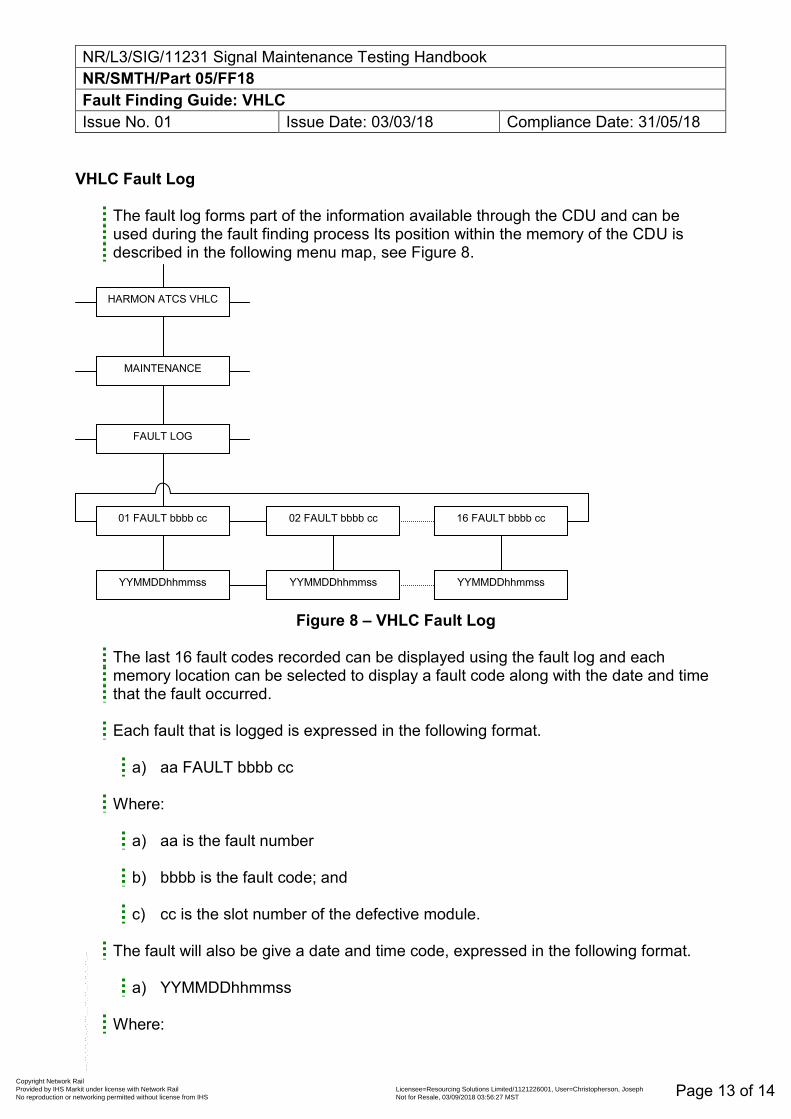
NR/L3/SIG/11231 Signal Maintenance Testing Handbook NR/SMTH/Part 05/FF18 Fault Finding Guide: VHLC Issue No. 01 Issue Date: 03/03/18 Compliance Date: 31/05/18
Page 13 of 14
VHLC Fault Log
The fault log forms part of the information available through the CDU and can be used during the fault finding process Its position within the memory of the CDU is described in the following menu map, see Figure 8.
Figure 8 – VHLC Fault Log
The last 16 fault codes recorded can be displayed using the fault log and each memory location can be selected to display a fault code along with the date and time that the fault occurred.
Each fault that is logged is expressed in the following format.
a) aa FAULT bbbb cc
Where:
a) aa is the fault number b) bbbb is the fault code; and c) cc is the slot number of the defective module.
The fault will also be give a date and time code, expressed in the following format.
a) YYMMDDhhmmss
Where:
HARMON ATCS VHLC
MAINTENANCE
FAULT LOG
01 FAULT bbbb cc 02 FAULT bbbb cc 16 FAULT bbbb cc
YYMMDDhhmmss YYMMDDhhmmss YYMMDDhhmmss
Copyright Network Rail Provided by IHS Markit under license with Network Rail Licensee=Resourcing Solutions Limited /1121226001, User=Christopherson, Joseph
Not for Resale, 03/09/2018 03:56:27 MSTNo reproduction or networking permitted without license from IHS
--``,,``,`,,`,```,,``,,````,,,`,-`-`,,`,,`,`,,`---
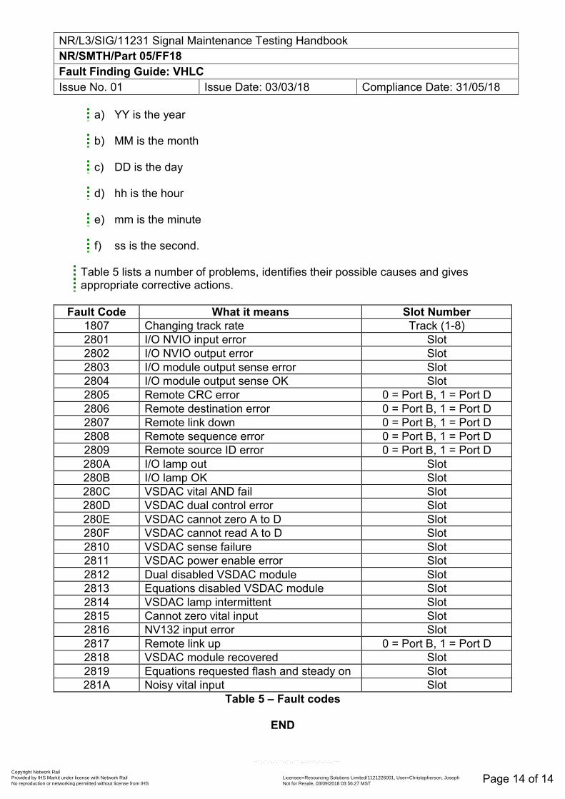
NR/L3/SIG/11231 Signal Maintenance Testing Handbook NR/SMTH/Part 05/FF18 Fault Finding Guide: VHLC Issue No. 01 Issue Date: 03/03/18 Compliance Date: 31/05/18
Page 14 of 14
a) YY is the year b) MM is the month c) DD is the day d) hh is the hour e) mm is the minute f) ss is the second.
Table 5 lists a number of problems, identifies their possible causes and gives appropriate corrective actions.
Fault Code What it means Slot Number
1807 Changing track rate Track (1-8) 2801 I/O NVIO input error Slot 2802 I/O NVIO output error Slot 2803 I/O module output sense error Slot 2804 I/O module output sense OK Slot 2805 Remote CRC error 0 = Port B, 1 = Port D 2806 Remote destination error 0 = Port B, 1 = Port D 2807 Remote link down 0 = Port B, 1 = Port D 2808 Remote sequence error 0 = Port B, 1 = Port D 2809 Remote source ID error 0 = Port B, 1 = Port D 280A I/O lamp out Slot 280B I/O lamp OK Slot 280C VSDAC vital AND fail Slot 280D VSDAC dual control error Slot 280E VSDAC cannot zero A to D Slot 280F VSDAC cannot read A to D Slot 2810 VSDAC sense failure Slot 2811 VSDAC power enable error Slot 2812 Dual disabled VSDAC module Slot 2813 Equations disabled VSDAC module Slot 2814 VSDAC lamp intermittent Slot 2815 Cannot zero vital input Slot 2816 NV132 input error Slot 2817 Remote link up 0 = Port B, 1 = Port D 2818 VSDAC module recovered Slot 2819 Equations requested flash and steady on Slot 281A Noisy vital input Slot
Table 5 – Fault codes
END
Copyright Network Rail Provided by IHS Markit under license with Network Rail Licensee=Resourcing Solutions Limited /1121226001, User=Christopherson, Joseph
Not for Resale, 03/09/2018 03:56:27 MSTNo reproduction or networking permitted without license from IHS
--``,,``,`,,`,```,,``,,````,,,`,-`-`,,`,,`,`,,`---
NR/SIG/11231 Signal Maintenance Testing Handbook NR/SMTH/Part 05/FF19 Fault Finding Guide for the EBI Gate 2000 Level Crossing System Issue No. 01 Issue Date: 03/03/18 Compliance Date: 31/05/18
Includes: EBI Gate 2000 Level Crossing Systems Excludes: All other types of Level Crossing System
Fault Finding Power Supply and Control Rack (ERR-8) failures are reported by the Remote Control Device (ERP-9).
The actions required to rectify these failures are presented below. In some more complex situations it is required to work with signalling wiring diagrams
Usually it is recommended to observe related Programmable Logic Controller (PLC) inputs.
You shall not connect any diagnostic or additional devices to ETHERNET nets within ERR-8.
Failure Mode Index
1. No battery charging of channel A / B / C
2. Battery voltage is too low
3. Earth leakage detection failure (first threshold/second threshold)
4. Door of control cabinet is open
5. Failure of EOD module & set of EOD related failures
6. Discrepancy of engagement in channels of LX controllers
7. Road signals / Audible alarms communication failure
8. Road signals / Audible alarms hardware failure
9. Failure of audible alarm
10. Failure of red / amber road signal
11. Failure of Crossing Clear Unit / Local Control Unit
12. Failure of Signal Box control panel
13. Failure of the barriers / exit barriers direction of movement
14. Barrier machine not ready
15. Boom intact failure of barrier
16. Failure of barrier machine position
17. Failure of current transducer of barriers
18. Overcurrent failure of barrier
19. Failure of event logger
20. Failure of event logger backup
21. Failure of interlocking interface Copyright Network Rail
Provided by IHS Markit under license with Network Rail Licensee=Resourcing Solutions Limited /1121226001, User=Christopherson, JosephNot for Resale, 03/09/2018 03:56:27 MSTNo reproduction or networking permitted without license from IHS
--``,,``,`,,`,```,,``,,````,,,`,-`-`,,`,,`,`,,`---
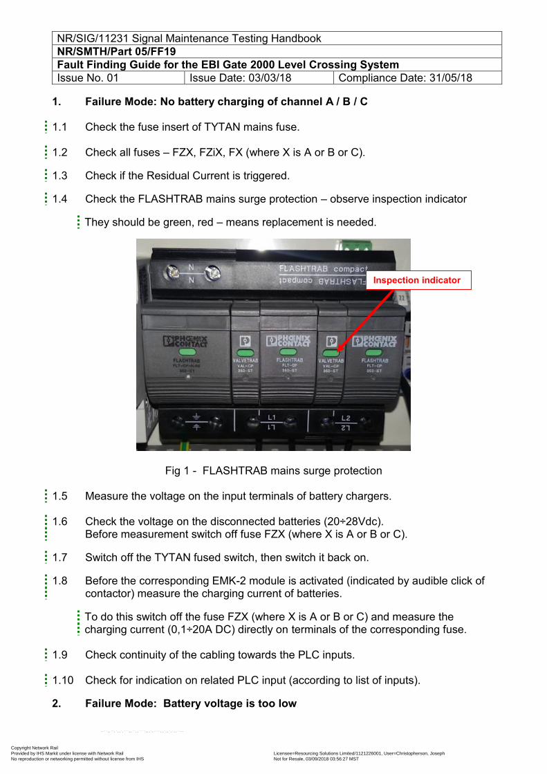
NR/SIG/11231 Signal Maintenance Testing Handbook NR/SMTH/Part 05/FF19 Fault Finding Guide for the EBI Gate 2000 Level Crossing System Issue No. 01 Issue Date: 03/03/18 Compliance Date: 31/05/18
1. Failure Mode: No battery charging of channel A / B / C 1.1 Check the fuse insert of TYTAN mains fuse. 1.2 Check all fuses – FZX, FZiX, FX (where X is A or B or C).
1.3 Check if the Residual Current is triggered.
1.4 Check the FLASHTRAB mains surge protection – observe inspection indicator
They should be green, red – means replacement is needed.
Fig 1 - FLASHTRAB mains surge protection
1.5 Measure the voltage on the input terminals of battery chargers. 1.6 Check the voltage on the disconnected batteries (20÷28Vdc).
Before measurement switch off fuse FZX (where X is A or B or C).
1.7 Switch off the TYTAN fused switch, then switch it back on.
1.8 Before the corresponding EMK-2 module is activated (indicated by audible click of contactor) measure the charging current of batteries.
To do this switch off the fuse FZX (where X is A or B or C) and measure the charging current (0,1÷20A DC) directly on terminals of the corresponding fuse.
1.9 Check continuity of the cabling towards the PLC inputs. 1.10 Check for indication on related PLC input (according to list of inputs).
2. Failure Mode: Battery voltage is too low
Inspection indicator
Copyright Network Rail Provided by IHS Markit under license with Network Rail Licensee=Resourcing Solutions Limited /1121226001, User=Christopherson, Joseph
Not for Resale, 03/09/2018 03:56:27 MSTNo reproduction or networking permitted without license from IHS
--``,,``,`,,`,```,,``,,````,,,`,-`-`,,`,,`,`,,`---
NR/SIG/11231 Signal Maintenance Testing Handbook NR/SMTH/Part 05/FF19 Fault Finding Guide for the EBI Gate 2000 Level Crossing System Issue No. 01 Issue Date: 03/03/18 Compliance Date: 31/05/18
2.1 When this failure is reported together with indication “No battery charging of channel A/B/C” than it means that the batteries are discharged due to the lack of mains power supply.
2.2 The other option is that the batteries are broken. Disconnect the batteries using
fuse FZX (where X is A or B or C) and measure the voltage directly on terminals of each battery (10÷15Vdc).
2.3 Reconnect the batteries (using the respective fuse) and cycle the mains power supply.
2.4 Observe the batteries voltage before and after the moment when module EMK-2 is activated (audible click of contactor). In each case the voltage of the battery should be in the range 10-15Vdc.
2.5 If the batteries voltage is above 25V DC and the failure is still reported this means failure of the EMK-2 module. Replace the faulty EMK-2 module.
2.6 Check continuity of the cabling towards the PLC inputs.
2.7 Check for indication on related PLC input (according to list of inputs).
3. Failure Mode: Battery voltage is too low
3.1 When this failure is reported together with indication „No battery charging of channel A/B/C” than it means that the batteries are discharged due to the lack of mains power supply.
3.2 The other option is that the batteries are broken. Disconnect the batteries using fuse FZX (where X is A or B or C) and measure the voltage directly on terminals of each battery (10÷15Vdc).
3.3 Reconnect the batteries (using the respective fuse) and cycle the mains power supply.
Observe the batteries voltage before and after the moment when module EMK-2 is activated (audible click of contactor). In each case the voltage of the battery should be in the range 10-15Vdc.
3.4 If the batteries voltage is above 25V DC and the failure is still reported this means failure of the EMK-2 module. Replace the faulty EMK-2 module.
3.5 Check continuity of the cabling towards the PLC inputs. 3.6 Check for indication on related PLC input (according to list of inputs).
4. Failure Mode: Earth leakage detection failure (first threshold/second threshold)
4.1 Check for readout of earth leakage detection modules (Bender Units) marked MD A, MD B, MD C. Compare readouts with defined values for first and second threshold (110kΩ and 100kΩ).
Copyright Network Rail Provided by IHS Markit under license with Network Rail Licensee=Resourcing Solutions Limited /1121226001, User=Christopherson, Joseph
Not for Resale, 03/09/2018 03:56:27 MSTNo reproduction or networking permitted without license from IHS
--``,,``,`,,`,```,,``,,````,,,`,-`-`,,`,,`,`,,`---
NR/SIG/11231 Signal Maintenance Testing Handbook NR/SMTH/Part 05/FF19 Fault Finding Guide for the EBI Gate 2000 Level Crossing System Issue No. 01 Issue Date: 03/03/18 Compliance Date: 31/05/18
4.2 Check continuity of the cabling towards the PLC inputs. 4.3 Check for indication on related PLC input (according to list of inputs). 4.4 Disconnect external LX devices – this test allows you to narrow down the location of
the earth leakage to either inside or outside of the LX hut. 4.5 Disconnect power supply and check the resistance between PE (Protective Earth)
and both terminals of DC power supply in all sub circuits.
5. Failure Mode: Door of control cabinet is open
5.1 Check if the door is locked – otherwise the door limit switch is not activated. 5.2 Check continuity of the cabling towards the PLC inputs.
5.3 Check for indication on related PLC input (according to list of inputs) while closing and opening the door lock.
6. Failure Mode: Failure of EOD module & set of EOD related failures
6.1 Check continuity of the cabling towards the PLC inputs.
6.2 Check for indication on related PLC input (according to list of inputs). Test of the EOD module is visible as a short extinguish of the LED in the PLC input card.
6.3 If the result of the above inspection is negative replace the corresponding EOD
module.
7. Failure Mode: Discrepancy of engagement in channels of LX controllers
7.1 Restart the LX system. This action should rectify the failure. 7.2 It is absolutely indispensable to inform the manufacturer about occurrence of this
failure and all simultaneously reported failures (on the ERP-9).
8. Failure Mode: Road signals / Audible alarms communication failure
8.1 Check if EMF / EDG module is powered.
8.2 Observe and analyse the indications on module – LED indicators, activity of yellow and green LEDs on Ethernet socket of the module.
8.3 Check for communication activity on related Ethernet switch.
8.4 If the result of the above inspection is negative - replace faulty module.
9. Failure Mode: Road signals / Audible alarms hardware failure
9.1 Check if the EMF / EDG module is powered and its wiring is intact.
9.2 The diagnostic information on the ERP-9 provide more detailed information pointing the module for replacement.
Copyright Network Rail Provided by IHS Markit under license with Network Rail Licensee=Resourcing Solutions Limited /1121226001, User=Christopherson, Joseph
Not for Resale, 03/09/2018 03:56:27 MSTNo reproduction or networking permitted without license from IHS
--``,,``,`,,`,```,,``,,````,,,`,-`-`,,`,,`,`,,`---
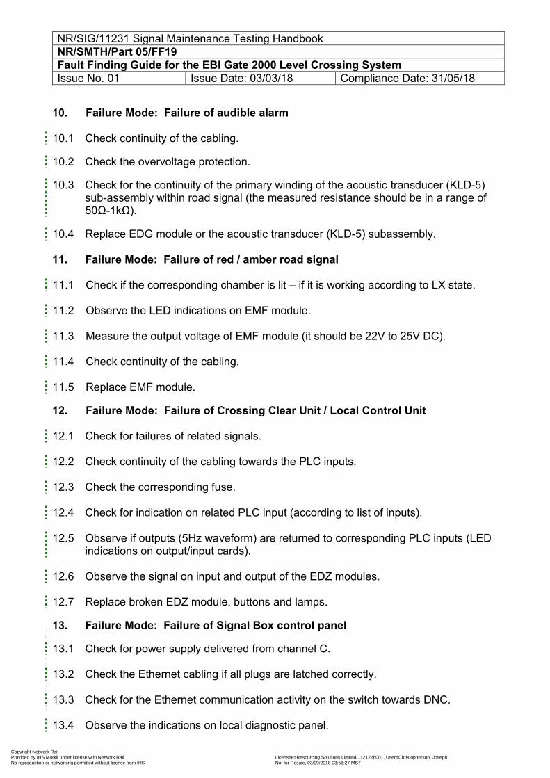
NR/SIG/11231 Signal Maintenance Testing Handbook NR/SMTH/Part 05/FF19 Fault Finding Guide for the EBI Gate 2000 Level Crossing System Issue No. 01 Issue Date: 03/03/18 Compliance Date: 31/05/18
10. Failure Mode: Failure of audible alarm 10.1 Check continuity of the cabling.
10.2 Check the overvoltage protection.
10.3 Check for the continuity of the primary winding of the acoustic transducer (KLD-5) sub-assembly within road signal (the measured resistance should be in a range of 50Ω-1kΩ).
10.4 Replace EDG module or the acoustic transducer (KLD-5) subassembly. 11. Failure Mode: Failure of red / amber road signal
11.1 Check if the corresponding chamber is lit – if it is working according to LX state.
11.2 Observe the LED indications on EMF module.
11.3 Measure the output voltage of EMF module (it should be 22V to 25V DC).
11.4 Check continuity of the cabling.
11.5 Replace EMF module.
12. Failure Mode: Failure of Crossing Clear Unit / Local Control Unit
12.1 Check for failures of related signals. 12.2 Check continuity of the cabling towards the PLC inputs. 12.3 Check the corresponding fuse. 12.4 Check for indication on related PLC input (according to list of inputs). 12.5 Observe if outputs (5Hz waveform) are returned to corresponding PLC inputs (LED
indications on output/input cards). 12.6 Observe the signal on input and output of the EDZ modules. 12.7 Replace broken EDZ module, buttons and lamps.
13. Failure Mode: Failure of Signal Box control panel
13.1 Check for power supply delivered from channel C. 13.2 Check the Ethernet cabling if all plugs are latched correctly. 13.3 Check for the Ethernet communication activity on the switch towards DNC. 13.4 Observe the indications on local diagnostic panel.
Copyright Network Rail Provided by IHS Markit under license with Network Rail Licensee=Resourcing Solutions Limited /1121226001, User=Christopherson, Joseph
Not for Resale, 03/09/2018 03:56:27 MSTNo reproduction or networking permitted without license from IHS
--``,,``,`,,`,```,,``,,````,,,`,-`-`,,`,,`,`,,`---
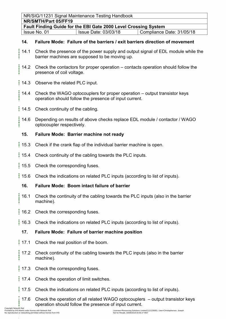
NR/SIG/11231 Signal Maintenance Testing Handbook NR/SMTH/Part 05/FF19 Fault Finding Guide for the EBI Gate 2000 Level Crossing System Issue No. 01 Issue Date: 03/03/18 Compliance Date: 31/05/18
14. Failure Mode: Failure of the barriers / exit barriers direction of movement
14.1 Check the presence of the power supply and output signal of EDL module while the barrier machines are supposed to be moving up.
14.2 Check the contactors for proper operation – contacts operation should follow the
presence of coil voltage.
14.3 Observe the related PLC input.
14.4 Check the WAGO optocouplers for proper operation – output transistor keys operation should follow the presence of input current.
14.5 Check continuity of the cabling.
14.6 Depending on results of above checks replace EDL module / contactor / WAGO
optocoupler respectively.
15. Failure Mode: Barrier machine not ready
15.3 Check if the crank flap of the individual barrier machine is open.
15.4 Check continuity of the cabling towards the PLC inputs.
15.5 Check the corresponding fuses.
15.6 Check the indications on related PLC inputs (according to list of inputs).
16. Failure Mode: Boom intact failure of barrier 16.1 Check the continuity of the cabling towards the PLC inputs (also in the barrier
machine).
16.2 Check the corresponding fuses.
16.3 Check the indications on related PLC inputs (according to list of inputs).
17. Failure Mode: Failure of barrier machine position
17.1 Check the real position of the boom.
17.2 Check continuity of the cabling towards the PLC inputs (also in the barrier machine).
17.3 Check the corresponding fuses.
17.4 Check the operation of limit switches.
17.5 Check the indications on related PLC inputs (according to list of inputs).
17.6 Check the operation of all related WAGO optocouplers – output transistor keys operation should follow the presence of input current.
Copyright Network Rail Provided by IHS Markit under license with Network Rail Licensee=Resourcing Solutions Limited /1121226001, User=Christopherson, Joseph
Not for Resale, 03/09/2018 03:56:27 MSTNo reproduction or networking permitted without license from IHS
--``,,``,`,,`,```,,``,,````,,,`,-`-`,,`,,`,`,,`---
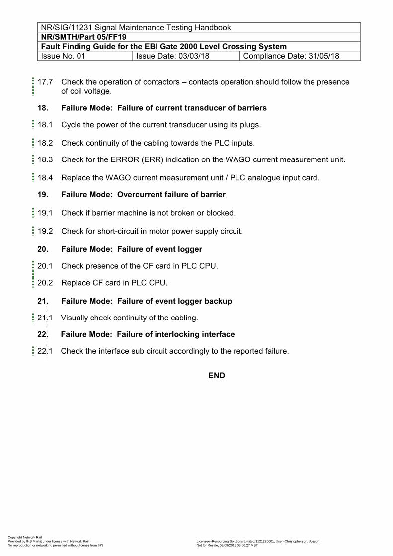
NR/SIG/11231 Signal Maintenance Testing Handbook NR/SMTH/Part 05/FF19 Fault Finding Guide for the EBI Gate 2000 Level Crossing System Issue No. 01 Issue Date: 03/03/18 Compliance Date: 31/05/18
17.7 Check the operation of contactors – contacts operation should follow the presence
of coil voltage.
18. Failure Mode: Failure of current transducer of barriers
18.1 Cycle the power of the current transducer using its plugs. 18.2 Check continuity of the cabling towards the PLC inputs.
18.3 Check for the ERROR (ERR) indication on the WAGO current measurement unit. 18.4 Replace the WAGO current measurement unit / PLC analogue input card.
19. Failure Mode: Overcurrent failure of barrier 19.1 Check if barrier machine is not broken or blocked. 19.2 Check for short-circuit in motor power supply circuit. 20. Failure Mode: Failure of event logger
20.1 Check presence of the CF card in PLC CPU.
20.2 Replace CF card in PLC CPU. 21. Failure Mode: Failure of event logger backup
21.1 Visually check continuity of the cabling.
22. Failure Mode: Failure of interlocking interface
22.1 Check the interface sub circuit accordingly to the reported failure.
END
Copyright Network Rail Provided by IHS Markit under license with Network Rail Licensee=Resourcing Solutions Limited /1121226001, User=Christopherson, Joseph
Not for Resale, 03/09/2018 03:56:27 MSTNo reproduction or networking permitted without license from IHS
--``,,``,`,,`,```,,``,,````,,,`,-`-`,,`,,`,`,,`---
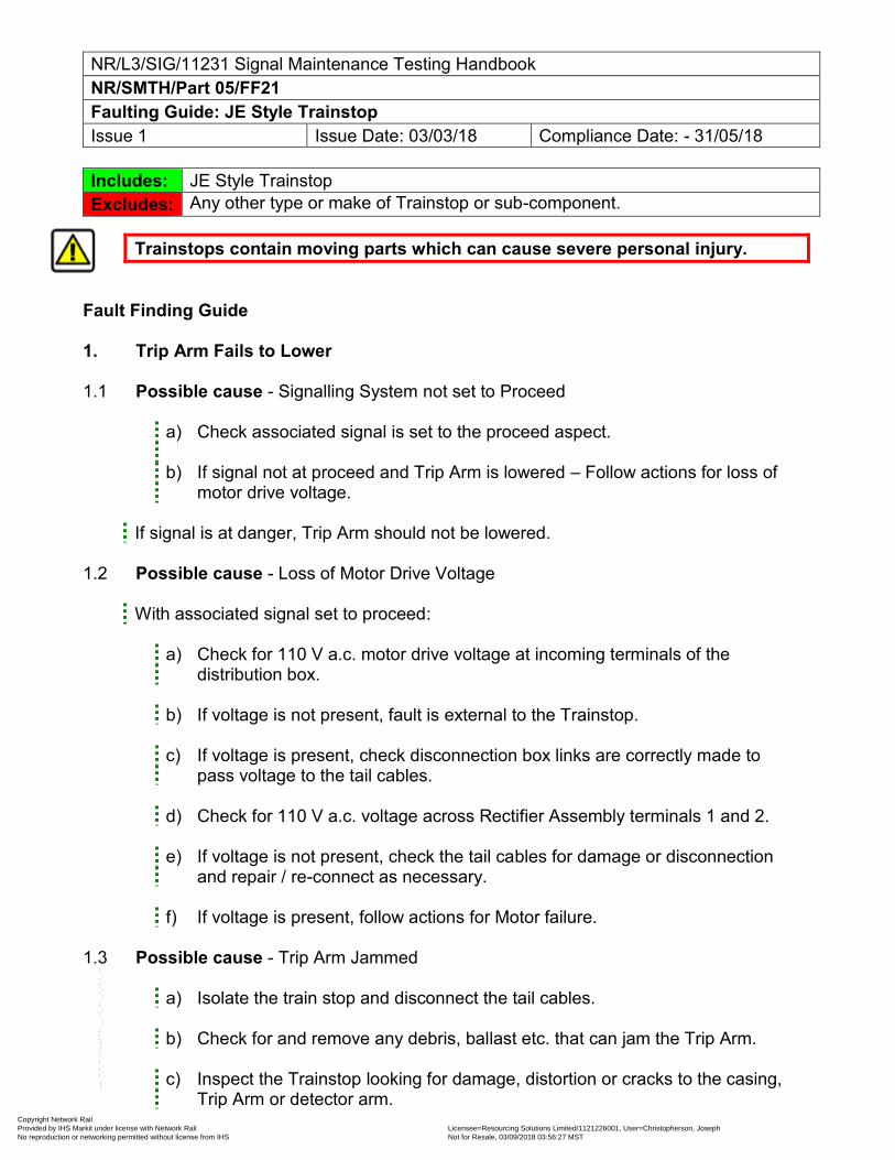
NR/L3/SIG/11231 Signal Maintenance Testing Handbook NR/SMTH/Part 05/FF21 Faulting Guide: JE Style Trainstop Issue 1 Issue Date: 03/03/18 Compliance Date: - 31/05/18
Includes: JE Style Trainstop Excludes: Any other type or make of Trainstop or sub-component.
Trainstops contain moving parts which can cause severe personal injury. Fault Finding Guide 1. Trip Arm Fails to Lower 1.1 Possible cause - Signalling System not set to Proceed
a) Check associated signal is set to the proceed aspect. b) If signal not at proceed and Trip Arm is lowered – Follow actions for loss of
motor drive voltage.
If signal is at danger, Trip Arm should not be lowered. 1.2 Possible cause - Loss of Motor Drive Voltage
With associated signal set to proceed:
a) Check for 110 V a.c. motor drive voltage at incoming terminals of the distribution box.
b) If voltage is not present, fault is external to the Trainstop.
c) If voltage is present, check disconnection box links are correctly made to
pass voltage to the tail cables.
d) Check for 110 V a.c. voltage across Rectifier Assembly terminals 1 and 2.
e) If voltage is not present, check the tail cables for damage or disconnection and repair / re-connect as necessary.
f) If voltage is present, follow actions for Motor failure.
1.3 Possible cause - Trip Arm Jammed
a) Isolate the train stop and disconnect the tail cables.
b) Check for and remove any debris, ballast etc. that can jam the Trip Arm.
c) Inspect the Trainstop looking for damage, distortion or cracks to the casing, Trip Arm or detector arm.
Copyright Network Rail Provided by IHS Markit under license with Network Rail Licensee=Resourcing Solutions Limited /1121226001, User=Christopherson, Joseph
Not for Resale, 03/09/2018 03:56:27 MSTNo reproduction or networking permitted without license from IHS
--``,,``,`,,`,```,,``,,````,,,`,-`-`,,`,,`,`,,`---
NR/L3/SIG/11231 Signal Maintenance Testing Handbook NR/SMTH/Part 05/FF21 Faulting Guide: JE Style Trainstop Issue 1 Issue Date: 03/03/18 Compliance Date: - 31/05/18
d) If the Trip Arm is damaged, but the remainder of the Trainstop is serviceable, replace the Trip Arm.
e) Other damages could require the replacement of the complete Trainstop.
f) If no damage is found, attempt to manually operate the Trip Arm.
g) If Trip Arm remains jammed, replace Trainstop.
h) If manual operation is satisfactory, re-connect the tail cables and supply.
i) Test the operation under power. If fault still present, replace the Trainstop.
1.4 Possible cause - Motor Failure.
a) With motor supply applied, at the Rectifier Assembly terminals measure the D.C. voltage between terminal 4 (+100 V) and terminal 5 (0 V).
b) If the voltage is present, replace the motor. c) Isolate the supply from the Trainstop and disconnect the tail cables.
d) If the motor brushes are badly worn, replace them.
e) Re-connect the tail cables and the supply then check for correct operation.
f) If the voltage was not present, replace Trainstop.
1.5 Possible cause - Clutch Failure
a) A clutch failure is indicated by the motor operating, driving Gear C via Gear B
(see Error! Reference source not found.), but Gear D not being driven.
b) If Gear D is not being driven then the replace the Trainstop.
Copyright Network Rail Provided by IHS Markit under license with Network Rail Licensee=Resourcing Solutions Limited /1121226001, User=Christopherson, Joseph
Not for Resale, 03/09/2018 03:56:27 MSTNo reproduction or networking permitted without license from IHS
--``,,``,`,,`,```,,``,,````,,,`,-`-`,,`,,`,`,,`---
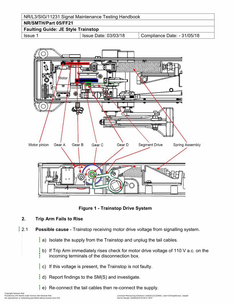
NR/L3/SIG/11231 Signal Maintenance Testing Handbook NR/SMTH/Part 05/FF21 Faulting Guide: JE Style Trainstop Issue 1 Issue Date: 03/03/18 Compliance Date: - 31/05/18
Figure 1 - Trainstop Drive System 2. Trip Arm Fails to Rise 2.1 Possible cause - Trainstop receiving motor drive voltage from signalling system.
a) Isolate the supply from the Trainstop and unplug the tail cables.
b) If Trip Arm immediately rises check for motor drive voltage of 110 V a.c. on the incoming terminals of the disconnection box.
c) If this voltage is present, the Trainstop is not faulty.
d) Report findings to the SM(S) and investigate.
e) Re-connect the tail cables then re-connect the supply.
Copyright Network Rail Provided by IHS Markit under license with Network Rail Licensee=Resourcing Solutions Limited /1121226001, User=Christopherson, Joseph
Not for Resale, 03/09/2018 03:56:27 MSTNo reproduction or networking permitted without license from IHS
--``,,``,`,,`,```,,``,,````,,,`,-`-`,,`,,`,`,,`---
NR/L3/SIG/11231 Signal Maintenance Testing Handbook NR/SMTH/Part 05/FF21 Faulting Guide: JE Style Trainstop Issue 1 Issue Date: 03/03/18 Compliance Date: - 31/05/18
2.2 Possible cause - Trip Arm jammed
a) Isolate the supply from the Trainstop and unplug the tail cables.
b) If the Trip Arm does not rise when the electrical supply is isolated, visually check for jamming of the Trip Arm.
c) If jammed by debris, manually depress the Trip Arm and carefully remove the
debris.
d) Release the Trip Arm and check it moves freely to the fully raised position.
e) If not jammed by debris but Trip Arm will not rise, make the machine safe by securing the Trip Arm in the lowered position.
f) With the Trip Arm of the faulty machine secured, replace the Trainstop.
g) Mark the faulty Trainstop prominently with a warning “Not to release the Trip
Arm”.
2.3 Possible cause - Return mechanism broken.
a) Replace the Trainstop. 3. Symptom – Trip Arm attempt to Lower and then Rises 3.1 Possible cause - Debris / ballast preventing Trip Arm from lowering fully.
a) Isolate the supply from the Trainstop and unplug the tail cables.
b) Remove any debris / ballast preventing the Trip Arm from lowering.
c) Manually lower the Trip Arm to check for correct operation.
d) If manual operation appears to be correct, re-connect the tail cables to the Trainstop and then re-connect the supply.
e) Request the signaller to operate the signal associated with the Trainstop and check for correct operation of the Trainstop.
3.2 Possible cause – Clutch Failure.
a) A clutch failure is indicated by the motor operating, driving Gear C via Gear B (see Error! Reference source not found.), but Gear D not being driven.
b) If Gear D is not being driven then the replace the Trainstop.
Copyright Network Rail Provided by IHS Markit under license with Network Rail Licensee=Resourcing Solutions Limited /1121226001, User=Christopherson, Joseph
Not for Resale, 03/09/2018 03:56:27 MSTNo reproduction or networking permitted without license from IHS
--``,,``,`,,`,```,,``,,````,,,`,-`-`,,`,,`,`,,`---
NR/L3/SIG/11231 Signal Maintenance Testing Handbook NR/SMTH/Part 05/FF21 Faulting Guide: JE Style Trainstop Issue 1 Issue Date: 03/03/18 Compliance Date: - 31/05/18
3.3 Possible cause - Trip Arm distorted.
a) Isolate the supply from the Trainstop and unplug the tail cables.
b) Inspect the Trainstop looking for damage, distortion or cracks to the casing, Trip Arm or detector arm.
c) If the Trip Arm is damaged, but the remainder of the Trainstop is serviceable, replace
the Trip Arm. Other damage entails replacement of the complete Trainstop.
3.4 Possible cause - Trainstop loose on fixings.
a) Keeping clear of the Trip Arm, isolate the supply from the Trainstop and unplug the tail cables.
b) Slacken the four fixings securing the Trainstop to the bearer
c) Adjust the position of the Trainstop to give required distance of the Trip Arm from the running rail.
d) Tighten the fixings and re-check the measurement.
e) Re-connect the tail cables to the Trainstop and then re-connect the supply.
f) Request the Signaller to operate the signal associated with the Trainstop and check for correct operation of the Trainstop.
3.5 Possible cause - Trainstop badly damaged.
a) Replace the Trainstop. 4. Symptom – Trip Arm Out Of Gauge 4.1 Possible cause - Trainstop loose on fixings.
a) Isolate the supply from the Trainstop and disconnect the tail cables.
b) Check the centre of the Trip Arm is 222 mm +/-3 mm from the inside of the running rail (Figure 2).
Copyright Network Rail Provided by IHS Markit under license with Network Rail Licensee=Resourcing Solutions Limited /1121226001, User=Christopherson, Joseph
Not for Resale, 03/09/2018 03:56:27 MSTNo reproduction or networking permitted without license from IHS
--``,,``,`,,`,```,,``,,````,,,`,-`-`,,`,,`,`,,`---
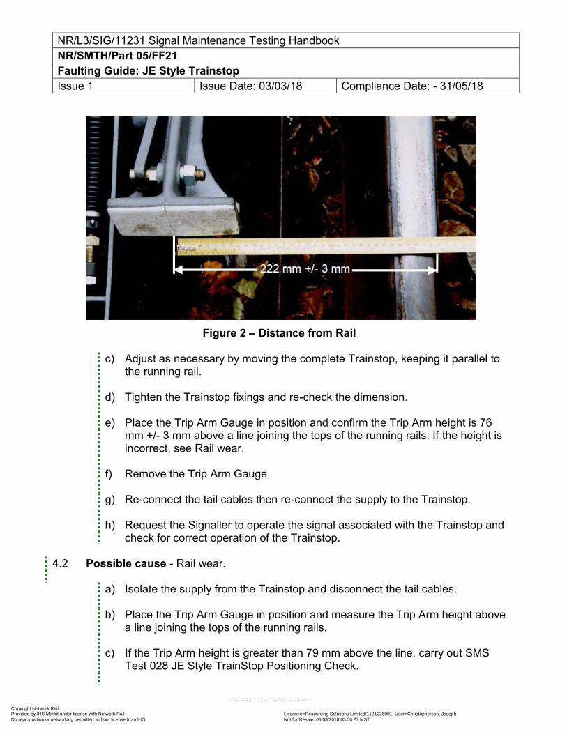
NR/L3/SIG/11231 Signal Maintenance Testing Handbook NR/SMTH/Part 05/FF21 Faulting Guide: JE Style Trainstop Issue 1 Issue Date: 03/03/18 Compliance Date: - 31/05/18
Figure 2 – Distance from Rail
c) Adjust as necessary by moving the complete Trainstop, keeping it parallel to
the running rail.
d) Tighten the Trainstop fixings and re-check the dimension.
e) Place the Trip Arm Gauge in position and confirm the Trip Arm height is 76 mm +/- 3 mm above a line joining the tops of the running rails. If the height is incorrect, see Rail wear.
f) Remove the Trip Arm Gauge.
g) Re-connect the tail cables then re-connect the supply to the Trainstop.
h) Request the Signaller to operate the signal associated with the Trainstop and check for correct operation of the Trainstop.
4.2 Possible cause - Rail wear.
a) Isolate the supply from the Trainstop and disconnect the tail cables.
b) Place the Trip Arm Gauge in position and measure the Trip Arm height above
a line joining the tops of the running rails.
c) If the Trip Arm height is greater than 79 mm above the line, carry out SMS Test 028 JE Style TrainStop Positioning Check.
Copyright Network Rail Provided by IHS Markit under license with Network Rail Licensee=Resourcing Solutions Limited /1121226001, User=Christopherson, Joseph
Not for Resale, 03/09/2018 03:56:27 MSTNo reproduction or networking permitted without license from IHS
--``,,``,`,,`,```,,``,,````,,,`,-`-`,,`,,`,`,,`---
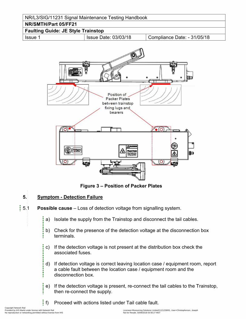
NR/L3/SIG/11231 Signal Maintenance Testing Handbook NR/SMTH/Part 05/FF21 Faulting Guide: JE Style Trainstop Issue 1 Issue Date: 03/03/18 Compliance Date: - 31/05/18
Figure 3 – Position of Packer Plates
5. Symptom - Detection Failure
5.1 Possible cause – Loss of detection voltage from signalling system.
a) Isolate the supply from the Trainstop and disconnect the tail cables.
b) Check for the presence of the detection voltage at the disconnection box
terminals.
c) If the detection voltage is not present at the distribution box check the associated fuses.
d) If detection voltage is correct leaving location case / equipment room, report a cable fault between the location case / equipment room and the disconnection box.
e) If the detection voltage is present, re-connect the tail cables to the Trainstop,
then re-connect the supply. f) Proceed with actions listed under Tail cable fault.
Copyright Network Rail Provided by IHS Markit under license with Network Rail Licensee=Resourcing Solutions Limited /1121226001, User=Christopherson, Joseph
Not for Resale, 03/09/2018 03:56:27 MSTNo reproduction or networking permitted without license from IHS
--``,,``,`,,`,```,,``,,````,,,`,-`-`,,`,,`,`,,`---
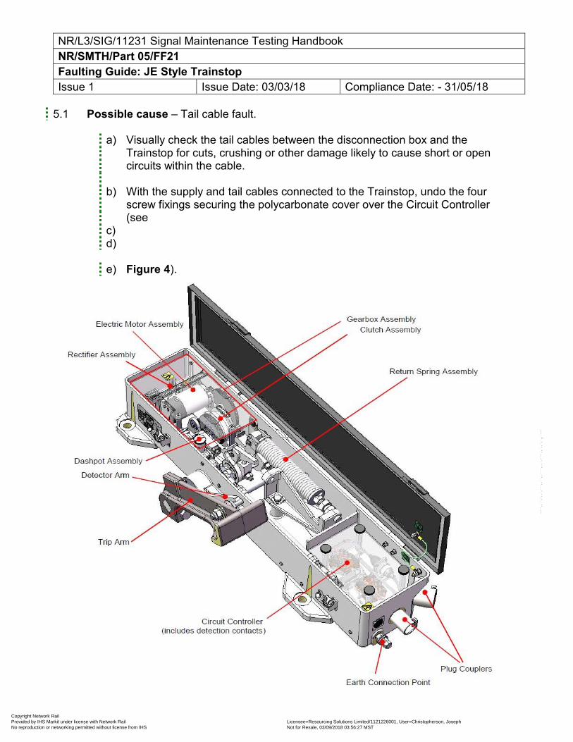
NR/L3/SIG/11231 Signal Maintenance Testing Handbook NR/SMTH/Part 05/FF21 Faulting Guide: JE Style Trainstop Issue 1 Issue Date: 03/03/18 Compliance Date: - 31/05/18
5.1 Possible cause – Tail cable fault.
a) Visually check the tail cables between the disconnection box and the Trainstop for cuts, crushing or other damage likely to cause short or open circuits within the cable.
b) With the supply and tail cables connected to the Trainstop, undo the four screw fixings securing the polycarbonate cover over the Circuit Controller (see
c) d)
e) Figure 4).
Copyright Network Rail Provided by IHS Markit under license with Network Rail Licensee=Resourcing Solutions Limited /1121226001, User=Christopherson, Joseph
Not for Resale, 03/09/2018 03:56:27 MSTNo reproduction or networking permitted without license from IHS
--``,,``,`,,`,```,,``,,````,,,`,-`-`,,`,,`,`,,`---
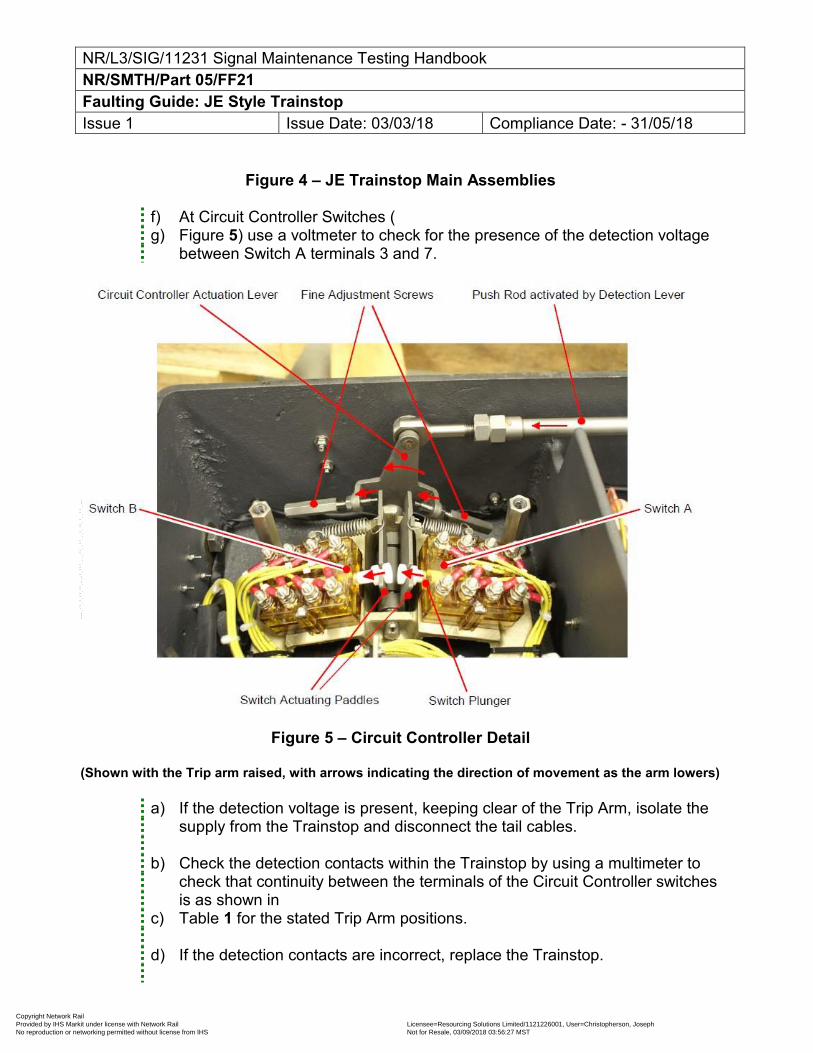
NR/L3/SIG/11231 Signal Maintenance Testing Handbook NR/SMTH/Part 05/FF21 Faulting Guide: JE Style Trainstop Issue 1 Issue Date: 03/03/18 Compliance Date: - 31/05/18
Figure 4 – JE Trainstop Main Assemblies
f) At Circuit Controller Switches ( g) Figure 5) use a voltmeter to check for the presence of the detection voltage
between Switch A terminals 3 and 7.
Figure 5 – Circuit Controller Detail
(Shown with the Trip arm raised, with arrows indicating the direction of movement as the arm lowers)
a) If the detection voltage is present, keeping clear of the Trip Arm, isolate the supply from the Trainstop and disconnect the tail cables.
b) Check the detection contacts within the Trainstop by using a multimeter to check that continuity between the terminals of the Circuit Controller switches is as shown in
c) Table 1 for the stated Trip Arm positions.
d) If the detection contacts are incorrect, replace the Trainstop.
Copyright Network Rail Provided by IHS Markit under license with Network Rail Licensee=Resourcing Solutions Limited /1121226001, User=Christopherson, Joseph
Not for Resale, 03/09/2018 03:56:27 MSTNo reproduction or networking permitted without license from IHS
--``,,``,`,,`,```,,``,,````,,,`,-`-`,,`,,`,`,,`---
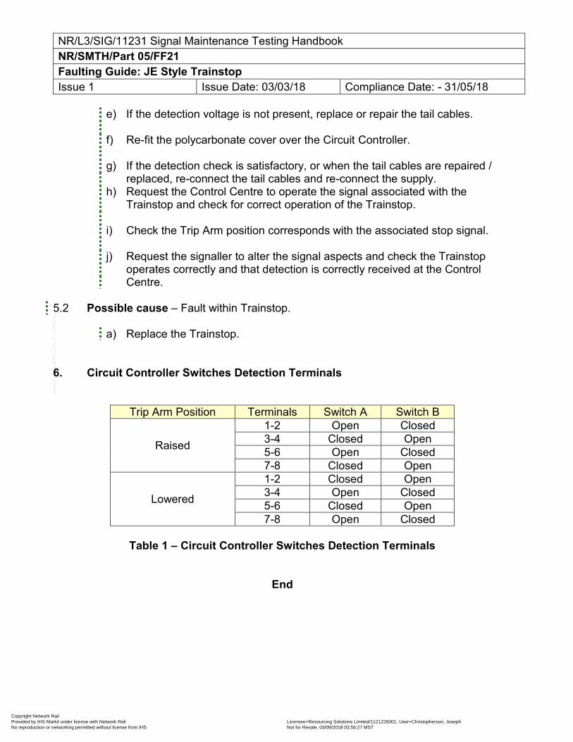
NR/L3/SIG/11231 Signal Maintenance Testing Handbook NR/SMTH/Part 05/FF21 Faulting Guide: JE Style Trainstop Issue 1 Issue Date: 03/03/18 Compliance Date: - 31/05/18
e) If the detection voltage is not present, replace or repair the tail cables.
f) Re-fit the polycarbonate cover over the Circuit Controller.
g) If the detection check is satisfactory, or when the tail cables are repaired /
replaced, re-connect the tail cables and re-connect the supply. h) Request the Control Centre to operate the signal associated with the
Trainstop and check for correct operation of the Trainstop.
i) Check the Trip Arm position corresponds with the associated stop signal.
j) Request the signaller to alter the signal aspects and check the Trainstop operates correctly and that detection is correctly received at the Control Centre.
5.2 Possible cause – Fault within Trainstop.
a) Replace the Trainstop. 6. Circuit Controller Switches Detection Terminals
Trip Arm Position Terminals Switch A Switch B
Raised
1-2 Open Closed 3-4 Closed Open 5-6 Open Closed 7-8 Closed Open
Lowered
1-2 Closed Open 3-4 Open Closed 5-6 Closed Open 7-8 Open Closed
Table 1 – Circuit Controller Switches Detection Terminals
End
Copyright Network Rail Provided by IHS Markit under license with Network Rail Licensee=Resourcing Solutions Limited /1121226001, User=Christopherson, Joseph
Not for Resale, 03/09/2018 03:56:27 MSTNo reproduction or networking permitted without license from IHS
--``,,``,`,,`,```,,``,,````,,,`,-`-`,,`,,`,`,,`---
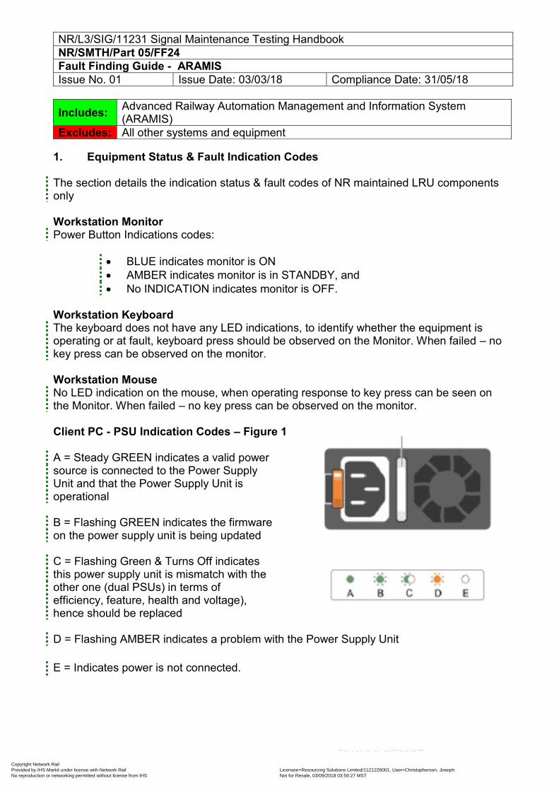
NR/L3/SIG/11231 Signal Maintenance Testing Handbook NR/SMTH/Part 05/FF24 Fault Finding Guide - ARAMIS Issue No. 01 Issue Date: 03/03/18 Compliance Date: 31/05/18
1. Equipment Status & Fault Indication Codes The section details the indication status & fault codes of NR maintained LRU components only Workstation Monitor Power Button Indications codes:
BLUE indicates monitor is ON AMBER indicates monitor is in STANDBY, and No INDICATION indicates monitor is OFF.
Workstation Keyboard The keyboard does not have any LED indications, to identify whether the equipment is operating or at fault, keyboard press should be observed on the Monitor. When failed – no key press can be observed on the monitor. Workstation Mouse No LED indication on the mouse, when operating response to key press can be seen on the Monitor. When failed – no key press can be observed on the monitor. Client PC - PSU Indication Codes – Figure 1
A = Steady GREEN indicates a valid power source is connected to the Power Supply Unit and that the Power Supply Unit is operational B = Flashing GREEN indicates the firmware on the power supply unit is being updated C = Flashing Green & Turns Off indicates this power supply unit is mismatch with the other one (dual PSUs) in terms of efficiency, feature, health and voltage), hence should be replaced D = Flashing AMBER indicates a problem with the Power Supply Unit E = Indicates power is not connected.
Includes: Advanced Railway Automation Management and Information System (ARAMIS)
Excludes: All other systems and equipment
Copyright Network Rail Provided by IHS Markit under license with Network Rail Licensee=Resourcing Solutions Limited /1121226001, User=Christopherson, Joseph
Not for Resale, 03/09/2018 03:56:27 MSTNo reproduction or networking permitted without license from IHS
--``,,``,`,,`,```,,``,,````,,,`,-`-`,,`,,`,`,,`---
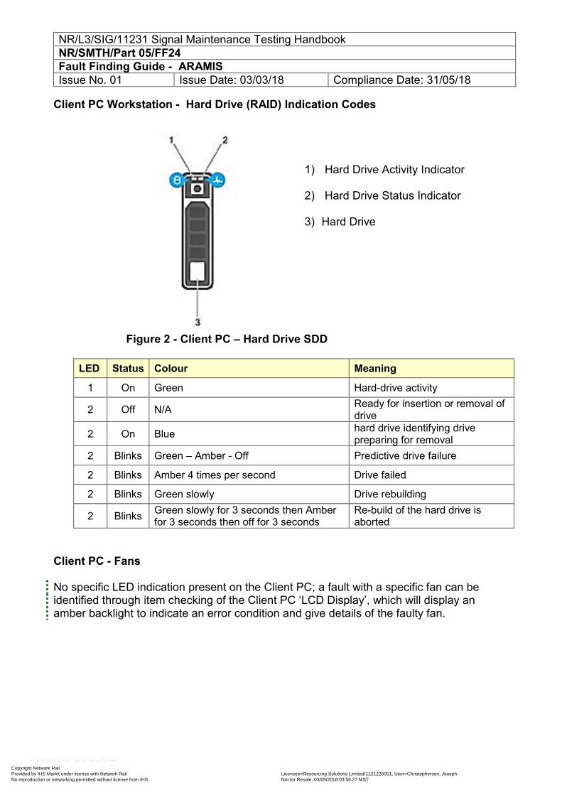
NR/L3/SIG/11231 Signal Maintenance Testing Handbook NR/SMTH/Part 05/FF24 Fault Finding Guide - ARAMIS Issue No. 01 Issue Date: 03/03/18 Compliance Date: 31/05/18
Client PC Workstation - Hard Drive (RAID) Indication Codes
1) Hard Drive Activity Indicator
2) Hard Drive Status Indicator
3) Hard Drive
Figure 2 - Client PC – Hard Drive SDD
LED Status Colour Meaning
1 On Green Hard-drive activity
2 Off N/A Ready for insertion or removal of drive
2 On Blue hard drive identifying drive preparing for removal
2 Blinks Green – Amber - Off Predictive drive failure
2 Blinks Amber 4 times per second Drive failed
2 Blinks Green slowly Drive rebuilding
2 Blinks Green slowly for 3 seconds then Amber for 3 seconds then off for 3 seconds
Re-build of the hard drive is aborted
Client PC - Fans No specific LED indication present on the Client PC; a fault with a specific fan can be identified through item checking of the Client PC ‘LCD Display’, which will display an amber backlight to indicate an error condition and give details of the faulty fan.
Copyright Network Rail Provided by IHS Markit under license with Network Rail Licensee=Resourcing Solutions Limited /1121226001, User=Christopherson, Joseph
Not for Resale, 03/09/2018 03:56:27 MSTNo reproduction or networking permitted without license from IHS
--``,,``,`,,`,```,,``,,````,,,`,-`-`,,`,,`,`,,`---
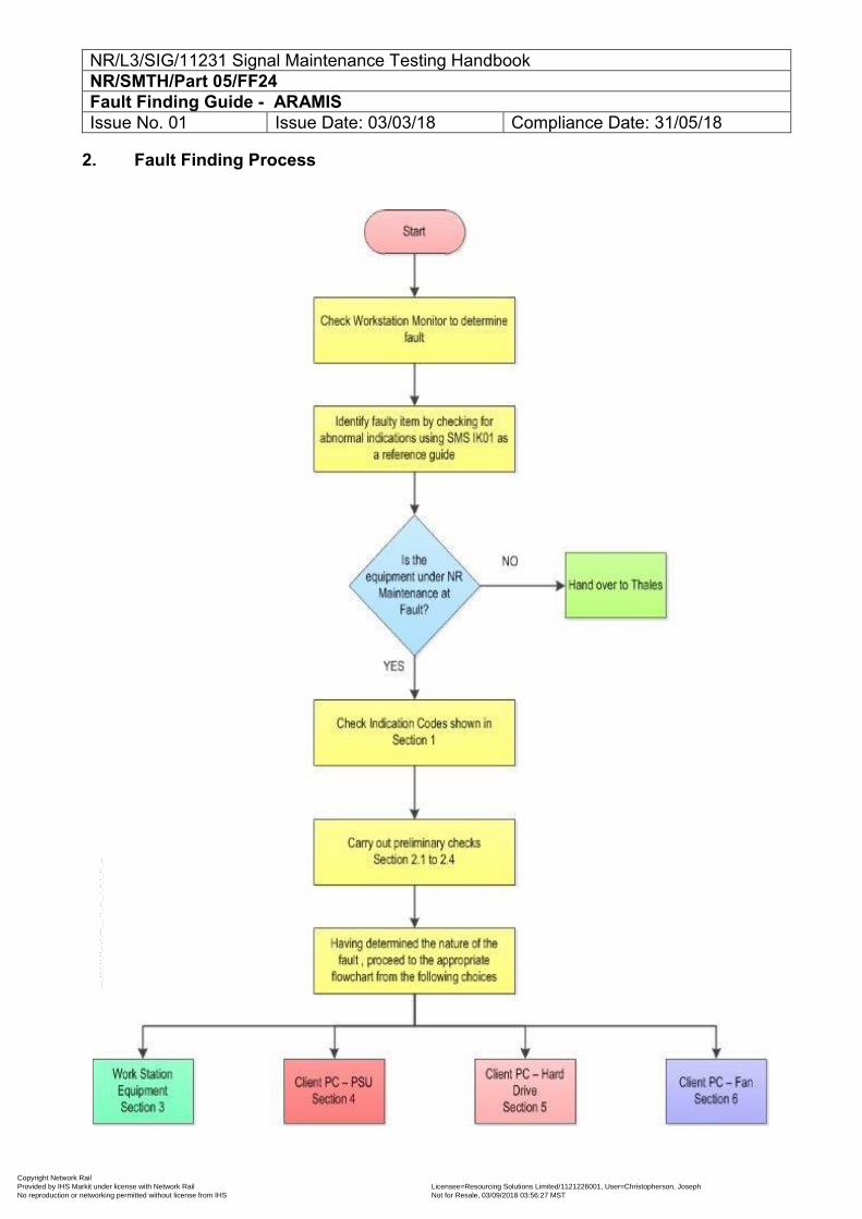
NR/L3/SIG/11231 Signal Maintenance Testing Handbook NR/SMTH/Part 05/FF24 Fault Finding Guide - ARAMIS Issue No. 01 Issue Date: 03/03/18 Compliance Date: 31/05/18
2. Fault Finding Process
Copyright Network Rail Provided by IHS Markit under license with Network Rail Licensee=Resourcing Solutions Limited /1121226001, User=Christopherson, Joseph
Not for Resale, 03/09/2018 03:56:27 MSTNo reproduction or networking permitted without license from IHS
--``,,``,`,,`,```,,``,,````,,,`,-`-`,,`,,`,`,,`---
NR/L3/SIG/11231 Signal Maintenance Testing Handbook NR/SMTH/Part 05/FF24 Fault Finding Guide - ARAMIS Issue No. 01 Issue Date: 03/03/18 Compliance Date: 31/05/18
2.1 Preliminary Checks Before removing suspected faulty equipment, check the following: 2.2 Power Supplies Check the equipment Power Supply Indications, check the associated fuses are intact. Refer to the As Built drawings for power information. To eliminate a momentary sensing problem; hard reboot can be used to restart the equipment, from non-recoverable hardware fault.
If a fault persists follow the fault finding procedure below. 2.3 Connectors Check all plugs and sockets on equipment associated with fault area are correctly mated and any screw fasteners are tightened. 2.4 Equipment Indications The ARAMIS LRU component are normally provided with monitoring indications to aid the maintainer in monitoring the status of the system, if a fault is suspected.
Copyright Network Rail Provided by IHS Markit under license with Network Rail Licensee=Resourcing Solutions Limited /1121226001, User=Christopherson, Joseph
Not for Resale, 03/09/2018 03:56:27 MSTNo reproduction or networking permitted without license from IHS
--``,,``,`,,`,```,,``,,````,,,`,-`-`,,`,,`,`,,`---
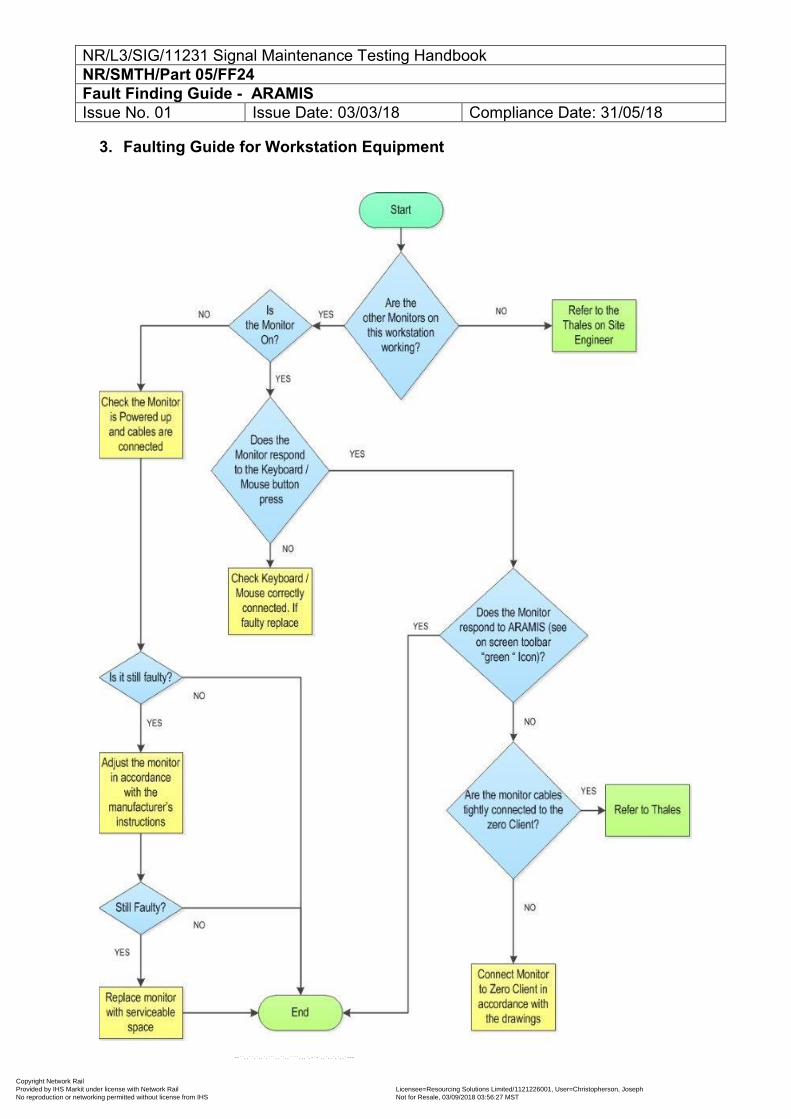
NR/L3/SIG/11231 Signal Maintenance Testing Handbook NR/SMTH/Part 05/FF24 Fault Finding Guide - ARAMIS Issue No. 01 Issue Date: 03/03/18 Compliance Date: 31/05/18
3. Faulting Guide for Workstation Equipment
Copyright Network Rail Provided by IHS Markit under license with Network Rail Licensee=Resourcing Solutions Limited /1121226001, User=Christopherson, Joseph
Not for Resale, 03/09/2018 03:56:27 MSTNo reproduction or networking permitted without license from IHS
--``,,``,`,,`,```,,``,,````,,,`,-`-`,,`,,`,`,,`---
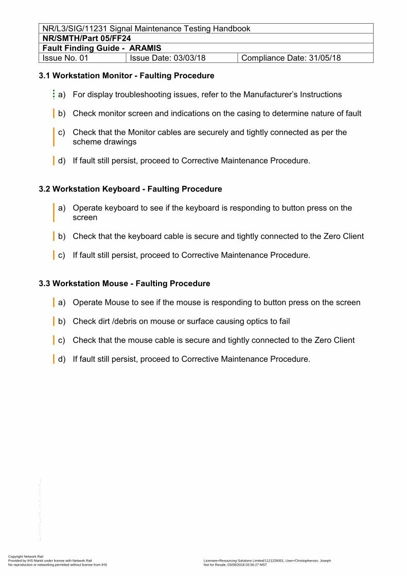
NR/L3/SIG/11231 Signal Maintenance Testing Handbook NR/SMTH/Part 05/FF24 Fault Finding Guide - ARAMIS Issue No. 01 Issue Date: 03/03/18 Compliance Date: 31/05/18
3.1 Workstation Monitor - Faulting Procedure
a) For display troubleshooting issues, refer to the Manufacturer’s Instructions b) Check monitor screen and indications on the casing to determine nature of fault c) Check that the Monitor cables are securely and tightly connected as per the
scheme drawings d) If fault still persist, proceed to Corrective Maintenance Procedure.
3.2 Workstation Keyboard - Faulting Procedure
a) Operate keyboard to see if the keyboard is responding to button press on the screen
b) Check that the keyboard cable is secure and tightly connected to the Zero Client c) If fault still persist, proceed to Corrective Maintenance Procedure.
3.3 Workstation Mouse - Faulting Procedure
a) Operate Mouse to see if the mouse is responding to button press on the screen b) Check dirt /debris on mouse or surface causing optics to fail c) Check that the mouse cable is secure and tightly connected to the Zero Client d) If fault still persist, proceed to Corrective Maintenance Procedure.
Copyright Network Rail Provided by IHS Markit under license with Network Rail Licensee=Resourcing Solutions Limited /1121226001, User=Christopherson, Joseph
Not for Resale, 03/09/2018 03:56:27 MSTNo reproduction or networking permitted without license from IHS
--``,,``,`,,`,```,,``,,````,,,`,-`-`,,`,,`,`,,`---
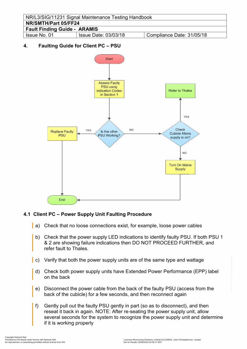
NR/L3/SIG/11231 Signal Maintenance Testing Handbook NR/SMTH/Part 05/FF24 Fault Finding Guide - ARAMIS Issue No. 01 Issue Date: 03/03/18 Compliance Date: 31/05/18
4. Faulting Guide for Client PC – PSU
4.1 Client PC – Power Supply Unit Faulting Procedure
a) Check that no loose connections exist, for example, loose power cables b) Check that the power supply LED indications to identify faulty PSU. If both PSU 1
& 2 are showing failure indications then DO NOT PROCEED FURTHER, and refer fault to Thales.
c) Verify that both the power supply units are of the same type and wattage d) Check both power supply units have Extended Power Performance (EPP) label
on the back e) Disconnect the power cable from the back of the faulty PSU (access from the
back of the cubicle) for a few seconds, and then reconnect again f) Gently pull out the faulty PSU gently in part (so as to disconnect), and then
reseat it back in again. NOTE: After re-seating the power supply unit, allow several seconds for the system to recognize the power supply unit and determine if it is working properly
Copyright Network Rail Provided by IHS Markit under license with Network Rail Licensee=Resourcing Solutions Limited /1121226001, User=Christopherson, Joseph
Not for Resale, 03/09/2018 03:56:27 MSTNo reproduction or networking permitted without license from IHS
--``,,``,`,,`,```,,``,,````,,,`,-`-`,,`,,`,`,,`---
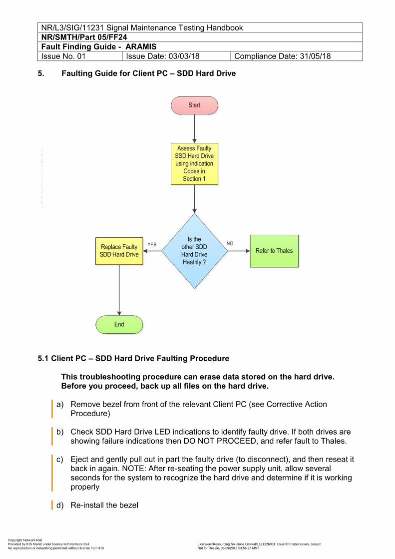
NR/L3/SIG/11231 Signal Maintenance Testing Handbook NR/SMTH/Part 05/FF24 Fault Finding Guide - ARAMIS Issue No. 01 Issue Date: 03/03/18 Compliance Date: 31/05/18
5. Faulting Guide for Client PC – SDD Hard Drive
5.1 Client PC – SDD Hard Drive Faulting Procedure
This troubleshooting procedure can erase data stored on the hard drive. Before you proceed, back up all files on the hard drive.
a) Remove bezel from front of the relevant Client PC (see Corrective Action
Procedure) b) Check SDD Hard Drive LED indications to identify faulty drive. If both drives are
showing failure indications then DO NOT PROCEED, and refer fault to Thales. c) Eject and gently pull out in part the faulty drive (to disconnect), and then reseat it
back in again. NOTE: After re-seating the power supply unit, allow several seconds for the system to recognize the hard drive and determine if it is working properly
d) Re-install the bezel
Copyright Network Rail Provided by IHS Markit under license with Network Rail Licensee=Resourcing Solutions Limited /1121226001, User=Christopherson, Joseph
Not for Resale, 03/09/2018 03:56:27 MSTNo reproduction or networking permitted without license from IHS
--``,,``,`,,`,```,,``,,````,,,`,-`-`,,`,,`,`,,`---

NR/L3/SIG/11231 Signal Maintenance Testing Handbook NR/SMTH/Part 05/FF24 Fault Finding Guide - ARAMIS Issue No. 01 Issue Date: 03/03/18 Compliance Date: 31/05/18
6. Faulting Guide for Client PC – Fans
6.1 Client PC – Fan Faulting Procedure
This troubleshooting procedure can erase data stored on the hard drive. Before you proceed, back up all files on the hard drive.
a) Check LCD display on affected Client PC for any faults OR observe audible excessive fan noise
b) If no fan issue is apparent, refer fault to Thales.
In the event of a problem with a particular fan, the fan number is referenced by the system’s management software, allowing you to easily identify and replace the proper fan by noting the fan numbers on the cooling fan assembly.
END
Copyright Network Rail Provided by IHS Markit under license with Network Rail Licensee=Resourcing Solutions Limited /1121226001, User=Christopherson, Joseph
Not for Resale, 03/09/2018 03:56:27 MSTNo reproduction or networking permitted without license from IHS
--``,,``,`,,`,```,,``,,````,,,`,-`-`,,`,,`,`,,`---
NR/L3/SIG/11231 Signal Maintenance Testing Handbook NR/SMTH/Part 05/S001 Failure and Incident Testing Issue No. 10 Issue Date: 03/03/18 Compliance Date: 31/05/18
1. Purpose The purpose is to provide instruction and guidance on the investigation of Wrong Side Failures (WSFs) and serious incidents. It also provides Fault Finding Guides for use where a WSF is not suspected.
2. Scope
The contents of this part are designed to:
a) Investigate signalling equipment failure
b) Arrange specialist investigation services
c) Deal with serious incidents
3. Principles All reported wrong side failures shall be investigated and be treated as being genuine until proven otherwise.
After the Test Guide(s) have been selected, it will usually be necessary to define the suspect circuit or circuits.
Following a Test Guide will find a wrong side failure that is still present but, if the fault is not present at the time of testing, only by carrying out the full range of steps on the correct circuit will a hidden wrong side failure be found.
The suspect circuit is not always obvious.
Reports of wrong side failures often occur during unusual operating conditions.
It is then necessary to determine which circuit or circuits should have prevented the wrong side failure from happening. (Where Solid State Interlockings are in use it will not normally be necessary to select a suspect circuit.) In the event of a serious incident or accident, the arrangements for investigation may need to be changed, particularly if the Police are involved (see section NR/SMTH/Part05/S002). The procedure for the investigation process is summarised as a flow chart in NR/SMTH/11231/Part05/Appendix 01.
Copyright Network Rail Provided by IHS Markit under license with Network Rail Licensee=Resourcing Solutions Limited /1121226001, User=Christopherson, Joseph
Not for Resale, 03/09/2018 03:56:27 MSTNo reproduction or networking permitted without license from IHS
--``,,``,`,,`,```,,``,,````,,,`,-`-`,,`,,`,`,,`---
NR/L3/SIG/11231 Signal Maintenance Testing Handbook NR/SMTH/Part 05/S001 Failure and Incident Testing Issue No. 10 Issue Date: 03/03/18 Compliance Date: 31/05/18
4. Derailments
In the event of a derailment at S&C, if the S&C is operated by signalling equipment or has detection fitted and there has been no report of an irregular aspect or SPAD of the protecting signals, then either:
a) Any derailment shall be assumed to be a result of either points moving when
they should have been locked, or
b) Point detection was incorrectly set, combined with some reason for the switch rail not being in the correct position.
In these circumstances, incident testing using the appropriate Test Guide shall be started immediately and can only be abandoned when either:
a) The Rail Incident Officer (RIO), see section NR/SMTH/Part05/S002, states
formally that a definite cause, unrelated to the signalling has been established, or
b) The S&TME instructs the investigation to be stopped so that it can be
completed by an independent testing organisation, or c) On the direct instructions of the Police
5. Protecting the Line
It is the signaller’s duty to protect the line. It is NOT the duty of signal technicians to provide protection by disconnecting signals or track circuits.
Signalling or telecommunications staff shall advise the signaller of the protection required for the risks associated with the reported wrong side failure are minimised.
Disconnections or adjustments to equipment to assist traffic flow can be requested by operations staff. This is only permitted with the authority of the S&TME with responsibility for the equipment and even then, only when any investigation testing affected by such disconnections has been completed.
Any disconnections shall be recorded and arrangements made to restore them as soon as the reported failure has been rectified and any other circumstances allow.
Where an incident does not involve any failure of the signalling system, or allegation of failure, signal technicians shall co-operate fully with the operations staff, providing advice on the benefits and risks of the protection proposed.
Further information on the giving of releases is contained in NR/L3/SIG/10064/B003.
Copyright Network Rail Provided by IHS Markit under license with Network Rail Licensee=Resourcing Solutions Limited /1121226001, User=Christopherson, Joseph
Not for Resale, 03/09/2018 03:56:27 MSTNo reproduction or networking permitted without license from IHS
--``,,``,`,,`,```,,``,,````,,,`,-`-`,,`,,`,`,,`---
NR/L3/SIG/11231 Signal Maintenance Testing Handbook NR/SMTH/Part 05/S001 Failure and Incident Testing Issue No. 10 Issue Date: 03/03/18 Compliance Date: 31/05/18
6. Testing
Testing shall only be carried out once line protection arrangements have been agreed with the signaller. Before testing commences, the person responsible shall consider all the available facts and evidence, obtaining additional reports and information where necessary (e.g. from the driver, signaller, data recorders, train describer stepping records). From this information, the possible causes should be identified and the appropriate Test Guide(s) shall be selected and applied to any suspect circuit(s).
The test guides detail the tests required for investigating each possible cause, and the order in which they are to be performed. The test plan shall also include the identification of requirements for recreating the circumstances of the incident. The Test Guides are comprehensive but are necessarily in the correct test sequence for every investigation.
Tests considered most relevant to the reported problem or observed symptoms shall be carried out first.
Testing shall include associated equipment and circuits which could have led to the failure.
Always consider possibilities beyond the ’obvious’ cause.
Testing shall be carried out in two distinct stages using the Section T Test Guides:
Non-destructive tests Carried out or directly supervised by Maintenance Testers, these can involve:
a) Visual examination of equipment
b) Taking measurements or readings without disturbing or disconnecting the
equipment or its wiring, or without affecting the electrical characteristics of the system.
Independent confirmation of fault diagnosis is required.
All conditions that existed at the time of failure shall be recorded by questioning and observing.
Where it is not possible to perform a test which is designated as ‘non-destructive’ without risk of disturbing equipment/wiring, then this fact shall be recorded and the test conducted during the ‘destructive testing’ phase instead.
Copyright Network Rail Provided by IHS Markit under license with Network Rail Licensee=Resourcing Solutions Limited /1121226001, User=Christopherson, Joseph
Not for Resale, 03/09/2018 03:56:27 MSTNo reproduction or networking permitted without license from IHS
--``,,``,`,,`,```,,``,,````,,,`,-`-`,,`,,`,`,,`---
NR/L3/SIG/11231 Signal Maintenance Testing Handbook NR/SMTH/Part 05/S001 Failure and Incident Testing Issue No. 10 Issue Date: 03/03/18 Compliance Date: 31/05/18
Doors can be opened, but equipment covers can only be removed by persons competent to do so, and then only if no disturbance to the equipment/wiring or disarrangement of locking would occur.
Destructive tests
Carried out by Maintenance Testers, these tests can sometimes alter the electrical, mechanical or physical state of the equipment. This disturbance might make a repeat of the fault impossible. Destructive tests shall be authorised by an SFI level 2 or 3 and independent confirmation of fault diagnosis is required.
7. Deferred Testing
Testing can only be deferred if:
Requested by a Network Rail Operations Manager and endorsed by the
Route Asset Manager (Signalling), and
The railway can be operated safely after making the assumption that the wrong side failure report is genuine, and
The S&TME records the names of those involved in this decision.
8. Testing Methods
If the circumstances allow, try to repeat the equipment operations that led to the reported failure. This can include dropping track circuits to recreate the effect of a passing train or actually observing a train through a section.
This allows equipment to be operated, but can cause the destruction of evidence about its state, such as relay positions, and therefore shall be undertaken at an early stage of destructive testing.
Any such tests shall be done with the signaller’s approval and after consideration of any risks involved.
Equipment shall be signed out of use before test straps are used.
Test straps shall be removed and accounted for before equipment is made available for use.
Seals shall not be broken during testing.
Copyright Network Rail Provided by IHS Markit under license with Network Rail Licensee=Resourcing Solutions Limited /1121226001, User=Christopherson, Joseph
Not for Resale, 03/09/2018 03:56:27 MSTNo reproduction or networking permitted without license from IHS
--``,,``,`,,`,```,,``,,````,,,`,-`-`,,`,,`,`,,`---
NR/L3/SIG/11231 Signal Maintenance Testing Handbook NR/SMTH/Part 05/S001 Failure and Incident Testing Issue No. 10 Issue Date: 03/03/18 Compliance Date: 31/05/18
Connecting test instruments to vital signalling systems has the potential to create wrong side failures. Unwanted connections can arise via internal instrument circuits and these may be far from obvious.
Specialist test equipment shall only be connected to vital signalling equipment by competent staff.
9. Defined Tests Particular care is required when carrying out a WIRE COUNT especially at some older installations.
Wire counting is therefore specified as a destructive test within the Test Guides.
Wiring with poor terminations and/or insulation degradation or wiring trapped against metallic or moving equipment can cause faults and is easily disturbed.
In some cases the removal of covers to allow inspection of wiring within trunking may also disturb faults and so should be undertaken with care.
It may be appropriate to consider this activity as a destructive test carried out after an INSULATION TEST of the wiring.
10. Competence This section details the additional competency requirements to undertake WSF investigations. Level 1 Staff (L1) Authority to undertake SFI investigations shall typically be granted by the S&TME on the recommendation of the SM(S) and after successful completion of the appropriate training course. Where response teams are provided these teams shall include SFI Level 1 competent staff for the duration of each shift. SFI level 2 staff can used to assist with management of signalling Wrong Side Failures. Level 2 Staff (L2) As per Level 1 plus additional experience either:
a) As a leader of a team investigating failures on site at first instance and
preparing reports for consideration by others, or
b) As a SM(S) or member of a technical support team who has regularly attended failures, provided advice or endorsement of others actions, or
Copyright Network Rail Provided by IHS Markit under license with Network Rail Licensee=Resourcing Solutions Limited /1121226001, User=Christopherson, Joseph
Not for Resale, 03/09/2018 03:56:27 MSTNo reproduction or networking permitted without license from IHS
--``,,``,`,,`,```,,``,,````,,,`,-`-`,,`,,`,`,,`---
NR/L3/SIG/11231 Signal Maintenance Testing Handbook NR/SMTH/Part 05/S001 Failure and Incident Testing Issue No. 10 Issue Date: 03/03/18 Compliance Date: 31/05/18
c) With thorough relevant technical knowledge of the equipment in the locality
gained by such activities as signal works testing, design or installation.
It is therefore necessary for them to be certified SMTH testers.
They are typically a SM(S) or manager of Level 1 staff, or member of a technical support group. Level 3 Staff (L3)
A level 3 shall have knowledge of Signalling Maintenance Testing and Failure & Incident Testing procedures.
Therefore they shall be certified SMTH testers or be approved by the RAM (Signalling). They are typically signal engineers with a higher level of technical expertise, such as the S&TME or Route Asset Manager (Signals). Access to a competent SFI level 3 is not normally needed at the onset of SFI testing, but staff should have access to SFI level 3 competent staff when required
11. Escalation Procedure It is the responsibility of the RAM (Signalling) or their nominated representative to check that the levels of authority to be applied for the various stages of wrong side failure investigation are established and documented.
These are to be based on the three levels of competence defined in section 10.
All other reportable wrong side failures shall be escalated to the Level 2 Tester as soon as possible.
This would normally be done before testing commences. This is so that a second independent mind considers the symptoms and agrees the required degree of testing. This person shall be independent of the actual testing and not physically involved. If a fault is found during non-destructive testing, independent confirmation is required from a Level 2 Tester that the fault found accounts for the reported failure and that adequate testing has been carried out.
If the level 2 agrees the failure has been identified, repairs should be carried out.
The equipment shall be signed back into use in accordance with the matrix in section 18.
Copyright Network Rail Provided by IHS Markit under license with Network Rail Licensee=Resourcing Solutions Limited /1121226001, User=Christopherson, Joseph
Not for Resale, 03/09/2018 03:56:27 MSTNo reproduction or networking permitted without license from IHS
--``,,``,`,,`,```,,``,,````,,,`,-`-`,,`,,`,`,,`---
NR/L3/SIG/11231 Signal Maintenance Testing Handbook NR/SMTH/Part 05/S001 Failure and Incident Testing Issue No. 10 Issue Date: 03/03/18 Compliance Date: 31/05/18
If No Fault has been found, permission shall be sort from the Level 2 Tester to move to the destructive phase.
If a fault is found during destructive testing, independent confirmation is required from the Level 2 Tester that the fault found accounts for the reported failure and that adequate testing has been carried out.
If the level 2 agrees the failure has been identified, repairs should be carried out.
At each of the above stages, the Level 2 Tester should confirm that the items listed under ‘Other Considerations’ have been sufficiently tested.
If no fault is found after testing, a Level 3 Engineer, independent of the actual testing to date, shall decide what further action is to be taken. The Level 2 and Level 3 staff shall always ask if any steps have been omitted and confirm that the reason for not carrying out the steps were valid and have not reduced the effectiveness of the testing. If any doubt exists with the failure investigation or findings the wrong side failure can be escalated to an appropriate level of expertise or authority at any time. Additional testing resource may be considered necessary. Following an investigation the Level 3 Engineer should pass any necessary details to the Route Infrastructure Control if more than one stakeholder or engineering discipline is involved in the incident.
It is the responsibility of the Route Infrastructure Control to share details of no fault found after testing, in accordance with GE/RT8106 (Clause 2.2.3.3) which states:
Infrastructure managers and railway undertakings shall share information as soon as it is available:
a) About the conclusions of the initial failure investigation, and
b) When the result of any follow-up investigation has implications at the technical
interface that can impact on another infrastructure manager or railway undertaking.
12. Exempted (Level 1) Failures Some easement of the requirements for escalation and independence is acceptable where a single, obvious cause of failure is found, as defined in the following list:
a) Failure of any electric signal lamp
b) Failure of any paraffin signal lamp
Copyright Network Rail Provided by IHS Markit under license with Network Rail Licensee=Resourcing Solutions Limited /1121226001, User=Christopherson, Joseph
Not for Resale, 03/09/2018 03:56:27 MSTNo reproduction or networking permitted without license from IHS
--``,,``,`,,`,```,,``,,````,,,`,-`-`,,`,,`,`,,`---
NR/L3/SIG/11231 Signal Maintenance Testing Handbook NR/SMTH/Part 05/S001 Failure and Incident Testing Issue No. 10 Issue Date: 03/03/18 Compliance Date: 31/05/18
c) Failure of level crossing lamps
d) Signallers panel lamps
e) Failure of a lamp holder (life expired, wear and tear),
f) SPT or level crossing telephones, unless there is any doubt as to the
cause of the failure or the failure could not be found using the checks and tests defined in Part 06
g) AWS permanent magnet missing or faulty
h) Failure of a transformer, transformer/rectifier or rectifier
i) Failure of a fuse
j) Failure of a timing device
k) Failure of an audible warning device (expect level crossings)
l) Failure of a primary cell
m) Failure of an electronic or mechanical flashing device
n) Failure of a filament changeover relay
o) Failure of barrier / gate mechanisms / hydraulics (where the failure can be
restored by simple adjustment or ‘like-for-like’ replacement),
p) Failure of any equipment caused by vandalism (providing destructive testing is not required to resolve the failure)
q) Failure of a mechanical signal to return to the ‘ON’ position due to an
obstruction, extreme weather conditions or simple adjustment of other mechanical equipment
r) Failure caused by loss of electrical supply from an Electricity Supply
Company and no standby facility has been provided.
13. Specialist Investigation of Equipment
All equipment suspected of, or confirmed as, causing a wrong side failure shall undergo specialist investigation unless the RAM confirms this to be unnecessary, e.g. on the grounds that the failure mode is well known.
Copyright Network Rail Provided by IHS Markit under license with Network Rail Licensee=Resourcing Solutions Limited /1121226001, User=Christopherson, Joseph
Not for Resale, 03/09/2018 03:56:27 MSTNo reproduction or networking permitted without license from IHS
--``,,``,`,,`,```,,``,,````,,,`,-`-`,,`,,`,`,,`---
NR/L3/SIG/11231 Signal Maintenance Testing Handbook NR/SMTH/Part 05/S001 Failure and Incident Testing Issue No. 10 Issue Date: 03/03/18 Compliance Date: 31/05/18
Any associated train-borne equipment which interfaces with the signalling system and which is suspected of causing a wrong side failure, shall also undergo specialist investigation, this shall be undertaken by the appropriate stake holder/function.
Where equipment is sent away for specialist investigation, it shall be suitably packaged and labelled. All efforts shall be taken to avoid transit damage, particularly where evidence needs to be preserved.
Details of the equipment and its reported failure circumstances shall be provided with the equipment.
14. Keeping Records It is important to record all relevant information. Notes shall be made at the time of observation. Even if these notes are rewritten later, it is important to retain the original notes in accordance with company policy.
Priority shall be given to information that may quickly disappear. Any information given by members of the public shall be recorded with particular care as their terminology may not have the same meaning as railway terminology.
In addition to the specific information requested in the Test Guides the following shall be recorded:
a) Train identity, formation and vehicle number.
b) Train driver’s name & depot.
c) Signaller’s name.
d) Names of any other staff or public involved.
e) Witness information (staff/public) .
f) Details of Protection arrangements made.
15. Data Loggers, Event Recorders, or Condition Monitoring
Where equipment has built-in and/or portable event recording, arrangements shall be made to recover and protect any data,
16. Test Result Reporting All staff involved in the investigation of failures shall, when reporting rectification, provide the following test results as a minimum:
General
The tester's name, Test Guide used and SMTH logbook sheet number.
Copyright Network Rail Provided by IHS Markit under license with Network Rail Licensee=Resourcing Solutions Limited /1121226001, User=Christopherson, Joseph
Not for Resale, 03/09/2018 03:56:27 MSTNo reproduction or networking permitted without license from IHS
--``,,``,`,,`,```,,``,,````,,,`,-`-`,,`,,`,`,,`---
NR/L3/SIG/11231 Signal Maintenance Testing Handbook NR/SMTH/Part 05/S001 Failure and Incident Testing Issue No. 10 Issue Date: 03/03/18 Compliance Date: 31/05/18
The relevant test readings. e.g. track circuit voltages, drop shunt, lamp voltages, date lamp last changed, cable test: lowest reading / cores / circuit affected, for a fuse the current drawn.
The items of equipment that were replaced and why they were replaced.
Details shall include the manufacturer, the date of last service (if known), serial numbers, any other references such as pin code, type, etc.
Environmental conditions depending on the nature of the failure / incident, e.g.
rail head condition, ballast condition, weather conditions at the time of the failure / incident, position of the sun relevant to the affected equipment.
Signal Lamp Failures
Lamp type and make, (e.g. SL35) Lamp voltage If lamp voltage was adjusted then the voltage before and after adjustment is
required Batch number if available and last changed date
Track Circuit Failures
Drop shunt value Pick-up shunt value Rail volts feed & relay end Relay coil volts
Point Failures
FPL Test OK Detection Test OK
TPWS Failures
Any fault indications displayed by the various modules
AWS Failures
S&P meter readings for Electro and Permanent Magnets
Copyright Network Rail Provided by IHS Markit under license with Network Rail Licensee=Resourcing Solutions Limited /1121226001, User=Christopherson, Joseph
Not for Resale, 03/09/2018 03:56:27 MSTNo reproduction or networking permitted without license from IHS
--``,,``,`,,`,```,,``,,````,,,`,-`-`,,`,,`,`,,`---
NR/L3/SIG/11231 Signal Maintenance Testing Handbook NR/SMTH/Part 05/S001 Failure and Incident Testing Issue No. 10 Issue Date: 03/03/18 Compliance Date: 31/05/18
Cables Failures
Lowest insulation resistance reading core to core Lowest insulation resistance reading core to earth
Blown Fuses
Current rating of fuse Current in circuit (measure AC and DC separately)
Changing Equipment
Test Plan used
17. Feedback
Wherever possible, the Infrastructure Fault Control can provide feedback to the organisation / individual who originally reported the wrongside failure (e.g. the signaller, or the Train Operating Company in respect of a report from a driver).
In the case of SPAD investigation, feedback is mandated in NR/L1/OPS/010.
18. Signing Back
The equipment shall not be made available for use until those investigating are assured with the results and conclusions of the testing undertaken. Pressure to sign the equipment back is to be resisted until the testing is complete. When work is completed and the equipment is in working order, the equipment shall be signed back as available for use in accordance with the Rule Book. The decision whether or not to accept the equipment for use in normal service is the responsibility of the Network Rail operations staff. Authority Levels for sign back are detailed in Table 1 Table 1 – Sign Back Matrix
System Failure Mode or Consequence Fault Found
No Fault
Found SIGNALS
Main Colour Light Signal
No danger aspect – failed signal fitted with AWS – signal in rear held at danger L1 L2
Main Colour Light Signal
No proceed aspect – failed signal fitted with AWS – signal in rear held at danger L1 L2
Copyright Network Rail Provided by IHS Markit under license with Network Rail Licensee=Resourcing Solutions Limited /1121226001, User=Christopherson, Joseph
Not for Resale, 03/09/2018 03:56:27 MSTNo reproduction or networking permitted without license from IHS
--``,,``,`,,`,```,,``,,````,,,`,-`-`,,`,,`,`,,`---
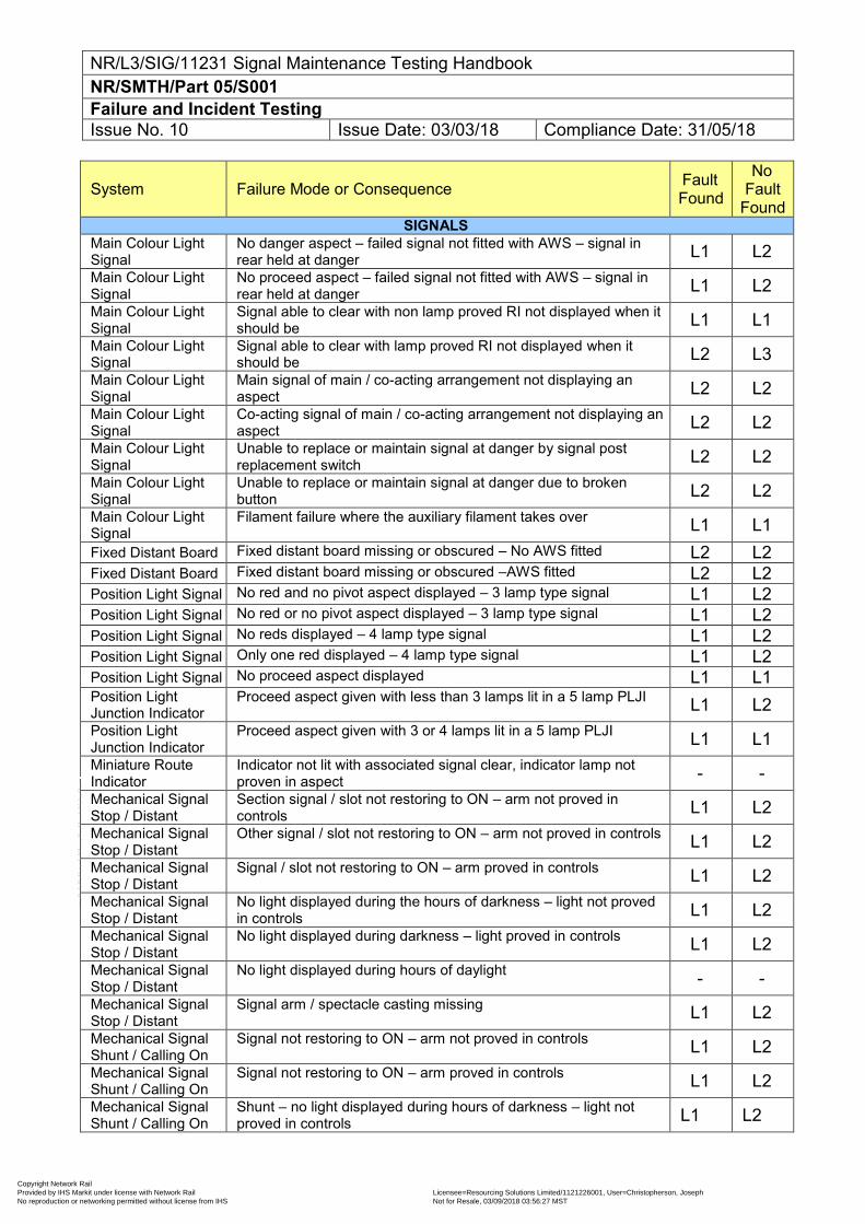
NR/L3/SIG/11231 Signal Maintenance Testing Handbook NR/SMTH/Part 05/S001 Failure and Incident Testing Issue No. 10 Issue Date: 03/03/18 Compliance Date: 31/05/18
System Failure Mode or Consequence Fault Found
No Fault
Found SIGNALS
Main Colour Light Signal
No danger aspect – failed signal not fitted with AWS – signal in rear held at danger L1 L2
Main Colour Light Signal
No proceed aspect – failed signal not fitted with AWS – signal in rear held at danger L1 L2
Main Colour Light Signal
Signal able to clear with non lamp proved RI not displayed when it should be L1 L1
Main Colour Light Signal
Signal able to clear with lamp proved RI not displayed when it should be L2 L3
Main Colour Light Signal
Main signal of main / co-acting arrangement not displaying an aspect L2 L2
Main Colour Light Signal
Co-acting signal of main / co-acting arrangement not displaying an aspect L2 L2
Main Colour Light Signal
Unable to replace or maintain signal at danger by signal post replacement switch L2 L2
Main Colour Light Signal
Unable to replace or maintain signal at danger due to broken button L2 L2
Main Colour Light Signal
Filament failure where the auxiliary filament takes over L1 L1 Fixed Distant Board Fixed distant board missing or obscured – No AWS fitted L2 L2 Fixed Distant Board Fixed distant board missing or obscured –AWS fitted L2 L2 Position Light Signal No red and no pivot aspect displayed – 3 lamp type signal L1 L2 Position Light Signal No red or no pivot aspect displayed – 3 lamp type signal L1 L2 Position Light Signal No reds displayed – 4 lamp type signal L1 L2 Position Light Signal Only one red displayed – 4 lamp type signal L1 L2 Position Light Signal No proceed aspect displayed L1 L1 Position Light Junction Indicator
Proceed aspect given with less than 3 lamps lit in a 5 lamp PLJI L1 L2 Position Light Junction Indicator
Proceed aspect given with 3 or 4 lamps lit in a 5 lamp PLJI L1 L1 Miniature Route Indicator
Indicator not lit with associated signal clear, indicator lamp not proven in aspect - -
Mechanical Signal Stop / Distant
Section signal / slot not restoring to ON – arm not proved in controls L1 L2
Mechanical Signal Stop / Distant
Other signal / slot not restoring to ON – arm not proved in controls L1 L2 Mechanical Signal Stop / Distant
Signal / slot not restoring to ON – arm proved in controls L1 L2 Mechanical Signal Stop / Distant
No light displayed during the hours of darkness – light not proved in controls L1 L2
Mechanical Signal Stop / Distant
No light displayed during darkness – light proved in controls L1 L2 Mechanical Signal Stop / Distant
No light displayed during hours of daylight - - Mechanical Signal Stop / Distant
Signal arm / spectacle casting missing L1 L2 Mechanical Signal Shunt / Calling On
Signal not restoring to ON – arm not proved in controls L1 L2 Mechanical Signal Shunt / Calling On
Signal not restoring to ON – arm proved in controls L1 L2 Mechanical Signal Shunt / Calling On
Shunt – no light displayed during hours of darkness – light not proved in controls L1 L2
Copyright Network Rail Provided by IHS Markit under license with Network Rail Licensee=Resourcing Solutions Limited /1121226001, User=Christopherson, Joseph
Not for Resale, 03/09/2018 03:56:27 MSTNo reproduction or networking permitted without license from IHS
--``,,``,`,,`,```,,``,,````,,,`,-`-`,,`,,`,`,,`---
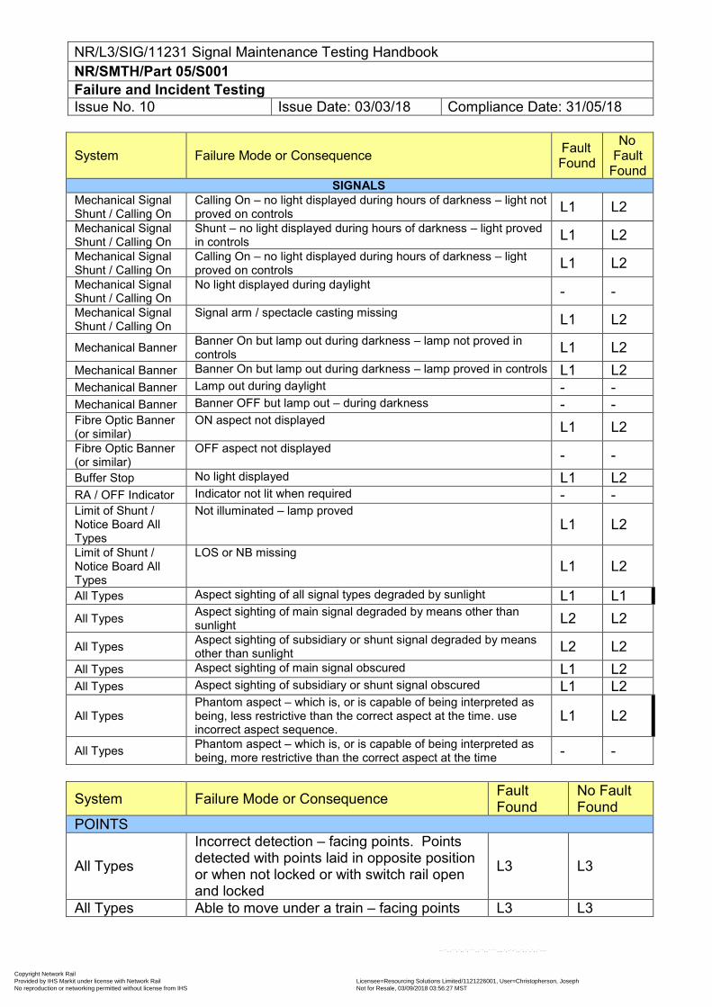
NR/L3/SIG/11231 Signal Maintenance Testing Handbook NR/SMTH/Part 05/S001 Failure and Incident Testing Issue No. 10 Issue Date: 03/03/18 Compliance Date: 31/05/18
System Failure Mode or Consequence Fault Found
No Fault
Found SIGNALS
Mechanical Signal Shunt / Calling On
Calling On – no light displayed during hours of darkness – light not proved on controls L1 L2
Mechanical Signal Shunt / Calling On
Shunt – no light displayed during hours of darkness – light proved in controls L1 L2
Mechanical Signal Shunt / Calling On
Calling On – no light displayed during hours of darkness – light proved on controls L1 L2
Mechanical Signal Shunt / Calling On
No light displayed during daylight - - Mechanical Signal Shunt / Calling On
Signal arm / spectacle casting missing L1 L2
Mechanical Banner Banner On but lamp out during darkness – lamp not proved in controls L1 L2
Mechanical Banner Banner On but lamp out during darkness – lamp proved in controls L1 L2 Mechanical Banner Lamp out during daylight - - Mechanical Banner Banner OFF but lamp out – during darkness - - Fibre Optic Banner (or similar)
ON aspect not displayed L1 L2 Fibre Optic Banner (or similar)
OFF aspect not displayed - - Buffer Stop No light displayed L1 L2 RA / OFF Indicator Indicator not lit when required - - Limit of Shunt / Notice Board All Types
Not illuminated – lamp proved L1 L2
Limit of Shunt / Notice Board All Types
LOS or NB missing L1 L2
All Types Aspect sighting of all signal types degraded by sunlight L1 L1 All Types Aspect sighting of main signal degraded by means other than
sunlight L2 L2
All Types Aspect sighting of subsidiary or shunt signal degraded by means other than sunlight L2 L2
All Types Aspect sighting of main signal obscured L1 L2 All Types Aspect sighting of subsidiary or shunt signal obscured L1 L2
All Types Phantom aspect – which is, or is capable of being interpreted as being, less restrictive than the correct aspect at the time. use incorrect aspect sequence.
L1 L2
All Types Phantom aspect – which is, or is capable of being interpreted as being, more restrictive than the correct aspect at the time - -
System Failure Mode or Consequence Fault Found
No Fault Found
POINTS
All Types
Incorrect detection – facing points. Points detected with points laid in opposite position or when not locked or with switch rail open and locked
L3 L3
All Types Able to move under a train – facing points L3 L3
Copyright Network Rail Provided by IHS Markit under license with Network Rail Licensee=Resourcing Solutions Limited /1121226001, User=Christopherson, Joseph
Not for Resale, 03/09/2018 03:56:27 MSTNo reproduction or networking permitted without license from IHS
--``,,``,`,,`,```,,``,,````,,,`,-`-`,,`,,`,`,,`---
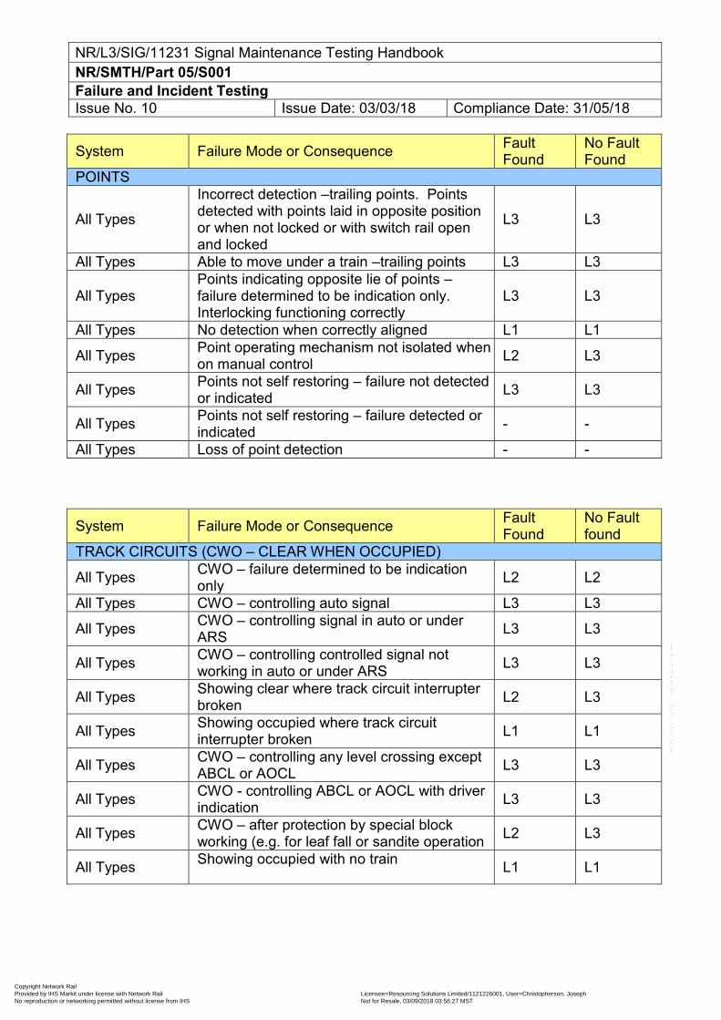
NR/L3/SIG/11231 Signal Maintenance Testing Handbook NR/SMTH/Part 05/S001 Failure and Incident Testing Issue No. 10 Issue Date: 03/03/18 Compliance Date: 31/05/18
System Failure Mode or Consequence Fault Found
No Fault Found
POINTS
All Types
Incorrect detection –trailing points. Points detected with points laid in opposite position or when not locked or with switch rail open and locked
L3 L3
All Types Able to move under a train –trailing points L3 L3
All Types Points indicating opposite lie of points – failure determined to be indication only. Interlocking functioning correctly
L3 L3
All Types No detection when correctly aligned L1 L1
All Types Point operating mechanism not isolated when on manual control L2 L3
All Types Points not self restoring – failure not detected or indicated L3 L3
All Types Points not self restoring – failure detected or indicated - -
All Types Loss of point detection - -
System Failure Mode or Consequence Fault Found
No Fault found
TRACK CIRCUITS (CWO – CLEAR WHEN OCCUPIED)
All Types CWO – failure determined to be indication only L2 L2
All Types CWO – controlling auto signal L3 L3
All Types CWO – controlling signal in auto or under ARS L3 L3
All Types CWO – controlling controlled signal not working in auto or under ARS L3 L3
All Types Showing clear where track circuit interrupter broken L2 L3
All Types Showing occupied where track circuit interrupter broken L1 L1
All Types CWO – controlling any level crossing except ABCL or AOCL L3 L3
All Types CWO - controlling ABCL or AOCL with driver indication L3 L3
All Types CWO – after protection by special block working (e.g. for leaf fall or sandite operation L2 L3
All Types Showing occupied with no train L1 L1
Copyright Network Rail Provided by IHS Markit under license with Network Rail Licensee=Resourcing Solutions Limited /1121226001, User=Christopherson, Joseph
Not for Resale, 03/09/2018 03:56:27 MSTNo reproduction or networking permitted without license from IHS
--``,,``,`,,`,```,,``,,````,,,`,-`-`,,`,,`,`,,`---
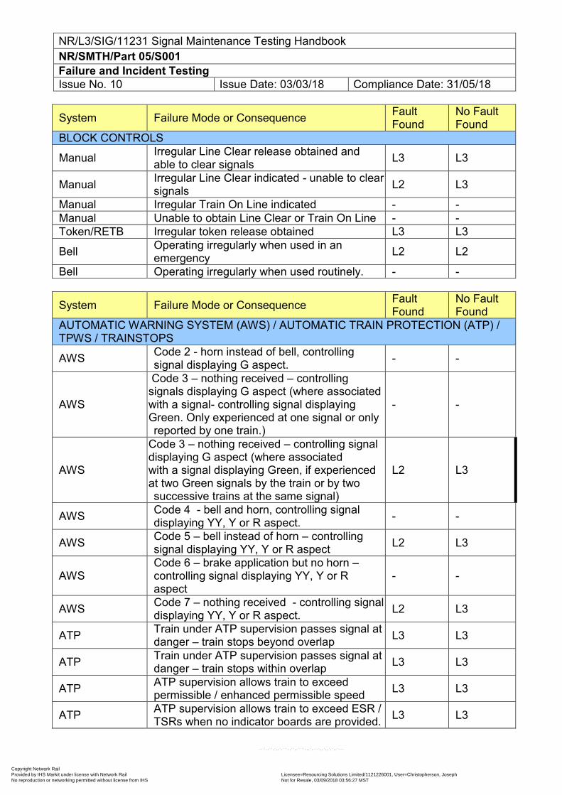
NR/L3/SIG/11231 Signal Maintenance Testing Handbook NR/SMTH/Part 05/S001 Failure and Incident Testing Issue No. 10 Issue Date: 03/03/18 Compliance Date: 31/05/18
System Failure Mode or Consequence Fault Found
No Fault Found
BLOCK CONTROLS
Manual Irregular Line Clear release obtained and able to clear signals L3 L3
Manual Irregular Line Clear indicated - unable to clear signals L2 L3
Manual Irregular Train On Line indicated - - Manual Unable to obtain Line Clear or Train On Line - - Token/RETB Irregular token release obtained L3 L3
Bell Operating irregularly when used in an emergency L2 L2
Bell Operating irregularly when used routinely. - -
System Failure Mode or Consequence Fault Found
No Fault Found
AUTOMATIC WARNING SYSTEM (AWS) / AUTOMATIC TRAIN PROTECTION (ATP) / TPWS / TRAINSTOPS
AWS Code 2 - horn instead of bell, controlling signal displaying G aspect. - -
AWS
Code 3 – nothing received – controlling signals displaying G aspect (where associated with a signal- controlling signal displaying Green. Only experienced at one signal or only reported by one train.)
- -
AWS
Code 3 – nothing received – controlling signal displaying G aspect (where associated with a signal displaying Green, if experienced at two Green signals by the train or by two successive trains at the same signal)
L2 L3
AWS Code 4 - bell and horn, controlling signal displaying YY, Y or R aspect. - -
AWS Code 5 – bell instead of horn – controlling signal displaying YY, Y or R aspect L2 L3
AWS Code 6 – brake application but no horn – controlling signal displaying YY, Y or R aspect
- -
AWS Code 7 – nothing received - controlling signal displaying YY, Y or R aspect. L2 L3
ATP Train under ATP supervision passes signal at danger – train stops beyond overlap L3 L3
ATP Train under ATP supervision passes signal at danger – train stops within overlap L3 L3
ATP ATP supervision allows train to exceed permissible / enhanced permissible speed L3 L3
ATP ATP supervision allows train to exceed ESR / TSRs when no indicator boards are provided. L3 L3
Copyright Network Rail Provided by IHS Markit under license with Network Rail Licensee=Resourcing Solutions Limited /1121226001, User=Christopherson, Joseph
Not for Resale, 03/09/2018 03:56:27 MSTNo reproduction or networking permitted without license from IHS
--``,,``,`,,`,```,,``,,````,,,`,-`-`,,`,,`,`,,`---
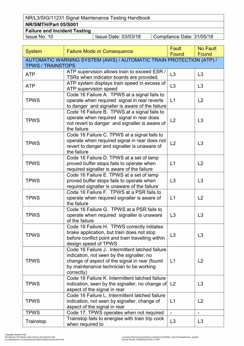
NR/L3/SIG/11231 Signal Maintenance Testing Handbook NR/SMTH/Part 05/S001 Failure and Incident Testing Issue No. 10 Issue Date: 03/03/18 Compliance Date: 31/05/18
System Failure Mode or Consequence Fault Found
No Fault Found
AUTOMATIC WARNING SYSTEM (AWS) / AUTOMATIC TRAIN PROTECTION (ATP) / TPWS / TRAINSTOPS
ATP ATP supervision allows train to exceed ESR / TSRs when indicator boards are provided. L3 L3
ATP ATP system displays train speed in excess of ATP supervision speed L3 L3
TPWS Code 16 Failure A. TPWS at a signal fails to operate when required signal in rear reverts to danger and signaller is aware of the failure
L1 L2
TPWS
Code 16 Failure B. TPWS at a signal fails to operate when required signal in rear does not revert to danger and signaller is aware of the failure
L2 L3
TPWS
Code 16 Failure C. TPWS at a signal fails to operate when required signal in rear does not revert to danger and signaller is unaware of the failure
L2 L3
TPWS Code 16 Failure D. TPWS at a set of lamp proved buffer stops fails to operate when required signaller is aware of the failure
L1 L2
TPWS Code 16 Failure E. TPWS at a set of lamp proved buffer stops fails to operate when required signaller is unaware of the failure
L3 L3
TPWS Code 16 Failure F. TPWS at a PSR fails to operate when required signaller is aware of the failure
L1 L2
TPWS Code 16 Failure G. TPWS at a PSR fails to operate when required signaller is unaware of the failure
L3 L3
TPWS
Code 16 Failure H. TPWS correctly initiates brake application, but train does not stop before conflict point and train travelling within design speed of TPWS
L3 L3
TPWS
Code 16 Failure J. Intermittent latched failure indication, not seen by the signaller, no change of aspect of the signal in rear (found by maintenance technician to be working correctly)
L1 L2
TPWS Code 16 Failure K Intermittent latched failure indication, seen by the signaller, no change of aspect of the signal in rear
L2 L3
TPWS Code 16 Failure L. Intermittent latched failure indication, not seen by signaller, change of aspect of the signal in rear
L1 L2
TPWS Code 17. TPWS operates when not required - -
Trainstop Trainstop fails to energise with train trip cock when required to L3 L3
Copyright Network Rail Provided by IHS Markit under license with Network Rail Licensee=Resourcing Solutions Limited /1121226001, User=Christopherson, Joseph
Not for Resale, 03/09/2018 03:56:27 MSTNo reproduction or networking permitted without license from IHS
--``,,``,`,,`,```,,``,,````,,,`,-`-`,,`,,`,`,,`---
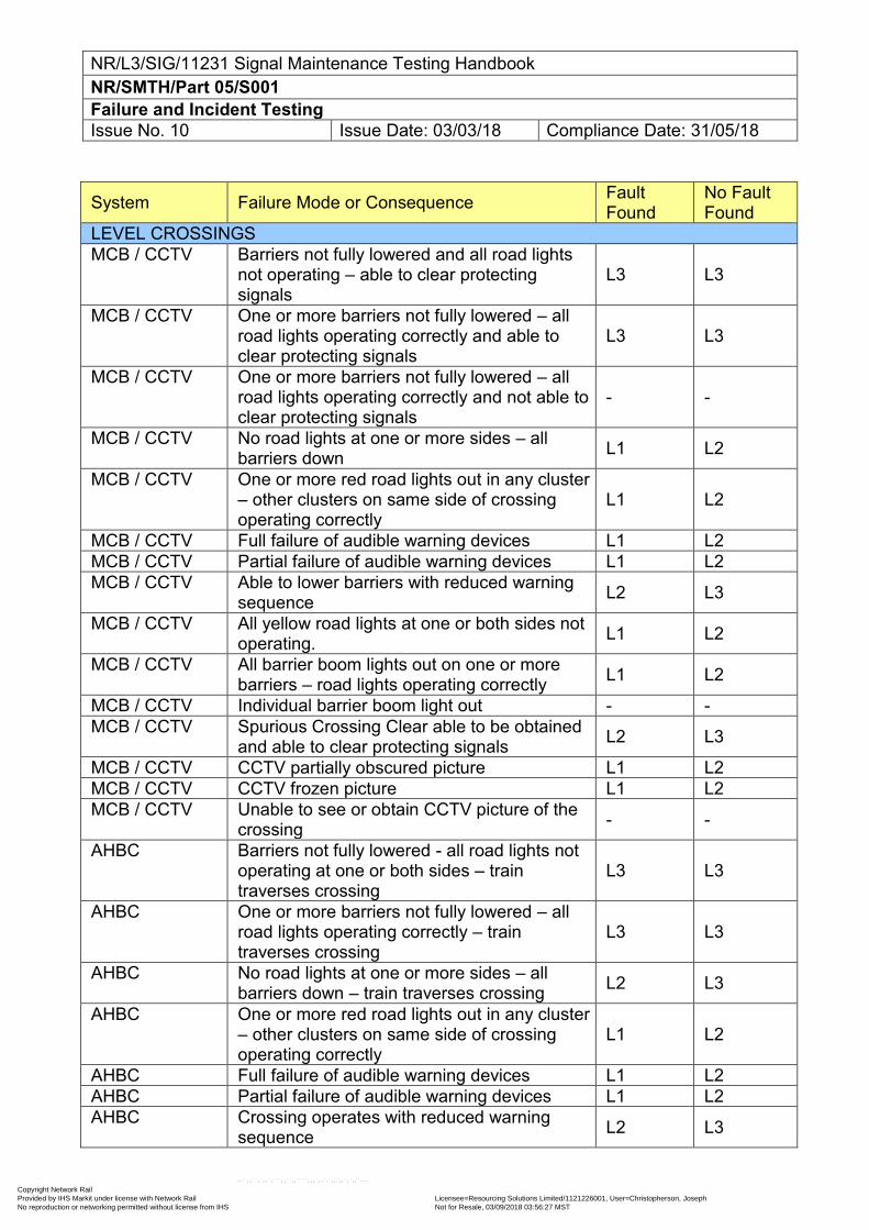
NR/L3/SIG/11231 Signal Maintenance Testing Handbook NR/SMTH/Part 05/S001 Failure and Incident Testing Issue No. 10 Issue Date: 03/03/18 Compliance Date: 31/05/18
System Failure Mode or Consequence Fault Found
No Fault Found
LEVEL CROSSINGS MCB / CCTV Barriers not fully lowered and all road lights
not operating – able to clear protecting signals
L3 L3
MCB / CCTV One or more barriers not fully lowered – all road lights operating correctly and able to clear protecting signals
L3 L3
MCB / CCTV One or more barriers not fully lowered – all road lights operating correctly and not able to clear protecting signals
- -
MCB / CCTV No road lights at one or more sides – all barriers down L1 L2
MCB / CCTV One or more red road lights out in any cluster – other clusters on same side of crossing operating correctly
L1 L2
MCB / CCTV Full failure of audible warning devices L1 L2 MCB / CCTV Partial failure of audible warning devices L1 L2 MCB / CCTV Able to lower barriers with reduced warning
sequence L2 L3
MCB / CCTV All yellow road lights at one or both sides not operating. L1 L2
MCB / CCTV All barrier boom lights out on one or more barriers – road lights operating correctly L1 L2
MCB / CCTV Individual barrier boom light out - - MCB / CCTV Spurious Crossing Clear able to be obtained
and able to clear protecting signals L2 L3
MCB / CCTV CCTV partially obscured picture L1 L2 MCB / CCTV CCTV frozen picture L1 L2 MCB / CCTV Unable to see or obtain CCTV picture of the
crossing - -
AHBC Barriers not fully lowered - all road lights not operating at one or both sides – train traverses crossing
L3 L3
AHBC One or more barriers not fully lowered – all road lights operating correctly – train traverses crossing
L3 L3
AHBC No road lights at one or more sides – all barriers down – train traverses crossing L2 L3
AHBC One or more red road lights out in any cluster – other clusters on same side of crossing operating correctly
L1 L2
AHBC Full failure of audible warning devices L1 L2 AHBC Partial failure of audible warning devices L1 L2 AHBC Crossing operates with reduced warning
sequence L2 L3
Copyright Network Rail Provided by IHS Markit under license with Network Rail Licensee=Resourcing Solutions Limited /1121226001, User=Christopherson, Joseph
Not for Resale, 03/09/2018 03:56:27 MSTNo reproduction or networking permitted without license from IHS
--``,,``,`,,`,```,,``,,````,,,`,-`-`,,`,,`,`,,`---
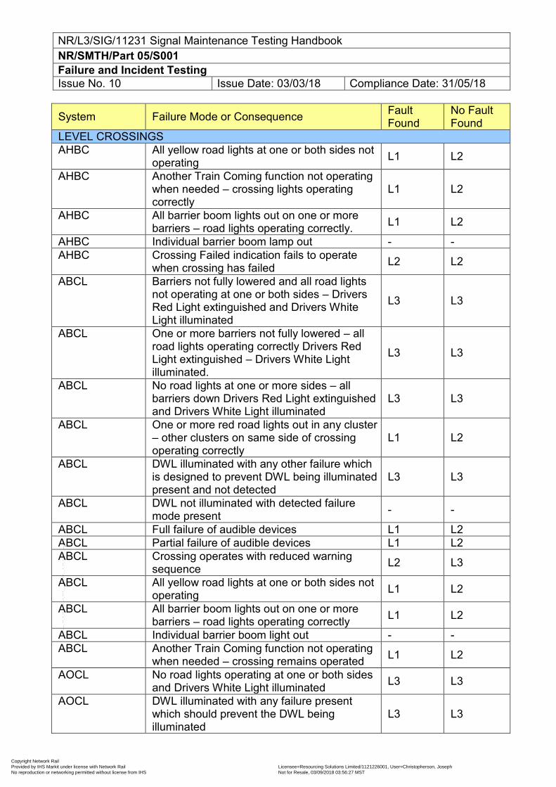
NR/L3/SIG/11231 Signal Maintenance Testing Handbook NR/SMTH/Part 05/S001 Failure and Incident Testing Issue No. 10 Issue Date: 03/03/18 Compliance Date: 31/05/18
System Failure Mode or Consequence Fault Found
No Fault Found
LEVEL CROSSINGS AHBC All yellow road lights at one or both sides not
operating L1 L2
AHBC Another Train Coming function not operating when needed – crossing lights operating correctly
L1 L2
AHBC All barrier boom lights out on one or more barriers – road lights operating correctly. L1 L2
AHBC Individual barrier boom lamp out - - AHBC Crossing Failed indication fails to operate
when crossing has failed L2 L2
ABCL Barriers not fully lowered and all road lights not operating at one or both sides – Drivers Red Light extinguished and Drivers White Light illuminated
L3 L3
ABCL One or more barriers not fully lowered – all road lights operating correctly Drivers Red Light extinguished – Drivers White Light illuminated.
L3 L3
ABCL No road lights at one or more sides – all barriers down Drivers Red Light extinguished and Drivers White Light illuminated
L3 L3
ABCL One or more red road lights out in any cluster – other clusters on same side of crossing operating correctly
L1 L2
ABCL DWL illuminated with any other failure which is designed to prevent DWL being illuminated present and not detected
L3 L3
ABCL DWL not illuminated with detected failure mode present - -
ABCL Full failure of audible devices L1 L2 ABCL Partial failure of audible devices L1 L2 ABCL Crossing operates with reduced warning
sequence L2 L3
ABCL All yellow road lights at one or both sides not operating L1 L2
ABCL All barrier boom lights out on one or more barriers – road lights operating correctly L1 L2
ABCL Individual barrier boom light out - - ABCL Another Train Coming function not operating
when needed – crossing remains operated L1 L2
AOCL No road lights operating at one or both sides and Drivers White Light illuminated L3 L3
AOCL DWL illuminated with any failure present which should prevent the DWL being illuminated
L3 L3
Copyright Network Rail Provided by IHS Markit under license with Network Rail Licensee=Resourcing Solutions Limited /1121226001, User=Christopherson, Joseph
Not for Resale, 03/09/2018 03:56:27 MSTNo reproduction or networking permitted without license from IHS
--``,,``,`,,`,```,,``,,````,,,`,-`-`,,`,,`,`,,`---
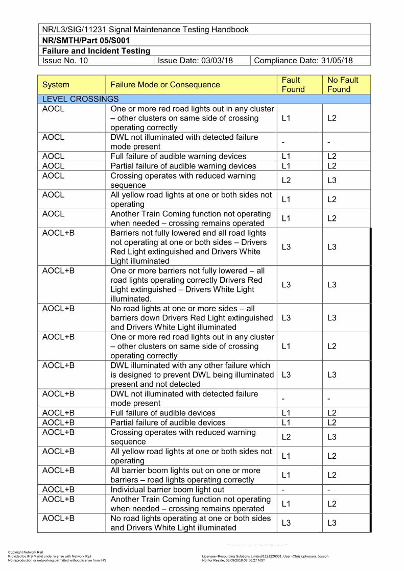
NR/L3/SIG/11231 Signal Maintenance Testing Handbook NR/SMTH/Part 05/S001 Failure and Incident Testing Issue No. 10 Issue Date: 03/03/18 Compliance Date: 31/05/18
System Failure Mode or Consequence Fault Found
No Fault Found
LEVEL CROSSINGS AOCL One or more red road lights out in any cluster
– other clusters on same side of crossing operating correctly
L1 L2
AOCL DWL not illuminated with detected failure mode present - -
AOCL Full failure of audible warning devices L1 L2 AOCL Partial failure of audible warning devices L1 L2 AOCL Crossing operates with reduced warning
sequence L2 L3
AOCL All yellow road lights at one or both sides not operating L1 L2
AOCL Another Train Coming function not operating when needed – crossing remains operated L1 L2
AOCL+B Barriers not fully lowered and all road lights not operating at one or both sides – Drivers Red Light extinguished and Drivers White Light illuminated
L3 L3
AOCL+B One or more barriers not fully lowered – all road lights operating correctly Drivers Red Light extinguished – Drivers White Light illuminated.
L3 L3
AOCL+B No road lights at one or more sides – all barriers down Drivers Red Light extinguished and Drivers White Light illuminated
L3 L3
AOCL+B One or more red road lights out in any cluster – other clusters on same side of crossing operating correctly
L1 L2
AOCL+B DWL illuminated with any other failure which is designed to prevent DWL being illuminated present and not detected
L3 L3
AOCL+B DWL not illuminated with detected failure mode present - -
AOCL+B Full failure of audible devices L1 L2 AOCL+B Partial failure of audible devices L1 L2 AOCL+B Crossing operates with reduced warning
sequence L2 L3
AOCL+B All yellow road lights at one or both sides not operating L1 L2
AOCL+B All barrier boom lights out on one or more barriers – road lights operating correctly L1 L2
AOCL+B Individual barrier boom light out - - AOCL+B Another Train Coming function not operating
when needed – crossing remains operated L1 L2
AOCL+B No road lights operating at one or both sides and Drivers White Light illuminated L3 L3
Copyright Network Rail Provided by IHS Markit under license with Network Rail Licensee=Resourcing Solutions Limited /1121226001, User=Christopherson, Joseph
Not for Resale, 03/09/2018 03:56:27 MSTNo reproduction or networking permitted without license from IHS
--``,,``,`,,`,```,,``,,````,,,`,-`-`,,`,,`,`,,`---
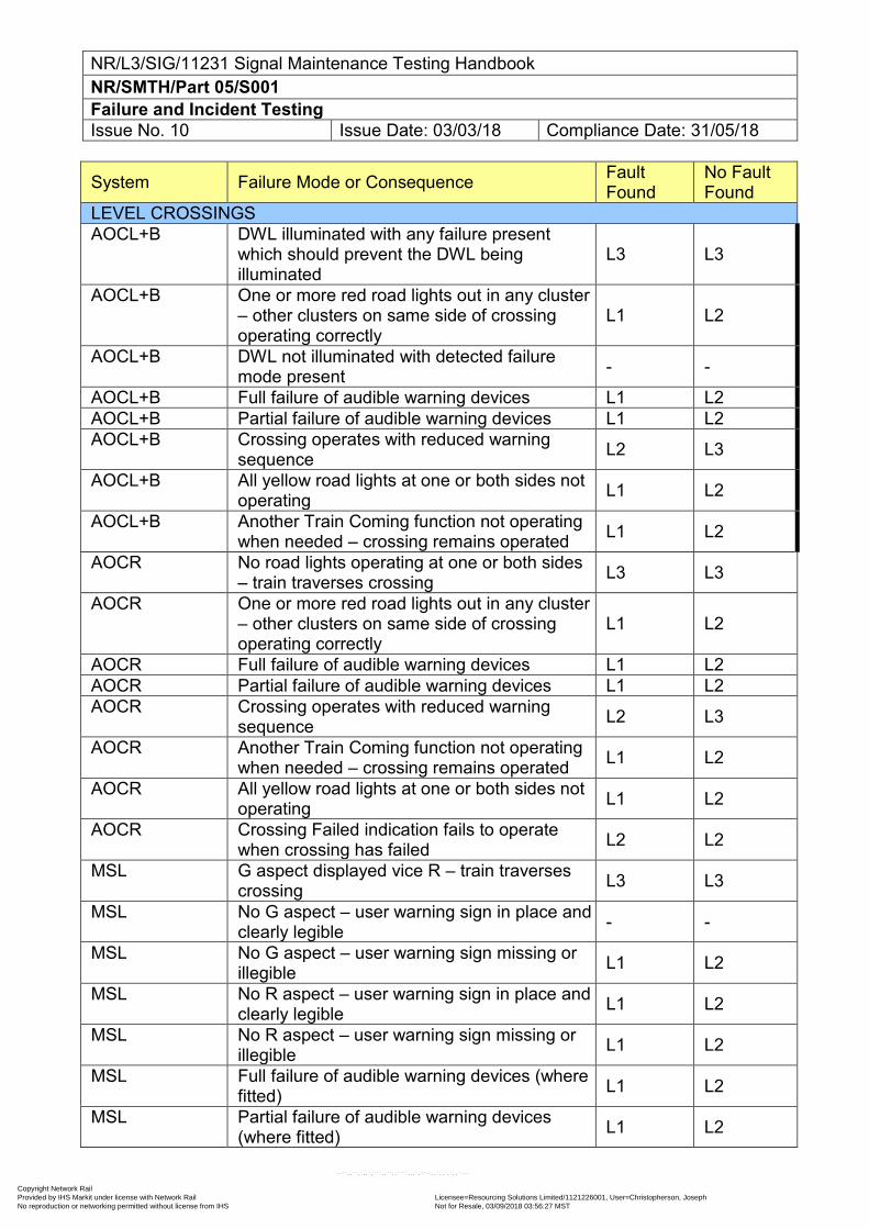
NR/L3/SIG/11231 Signal Maintenance Testing Handbook NR/SMTH/Part 05/S001 Failure and Incident Testing Issue No. 10 Issue Date: 03/03/18 Compliance Date: 31/05/18
System Failure Mode or Consequence Fault Found
No Fault Found
LEVEL CROSSINGS AOCL+B DWL illuminated with any failure present
which should prevent the DWL being illuminated
L3 L3
AOCL+B One or more red road lights out in any cluster – other clusters on same side of crossing operating correctly
L1 L2
AOCL+B DWL not illuminated with detected failure mode present - -
AOCL+B Full failure of audible warning devices L1 L2 AOCL+B Partial failure of audible warning devices L1 L2 AOCL+B Crossing operates with reduced warning
sequence L2 L3
AOCL+B All yellow road lights at one or both sides not operating L1 L2
AOCL+B Another Train Coming function not operating when needed – crossing remains operated L1 L2
AOCR No road lights operating at one or both sides – train traverses crossing L3 L3
AOCR One or more red road lights out in any cluster – other clusters on same side of crossing operating correctly
L1 L2
AOCR Full failure of audible warning devices L1 L2 AOCR Partial failure of audible warning devices L1 L2 AOCR Crossing operates with reduced warning
sequence L2 L3
AOCR Another Train Coming function not operating when needed – crossing remains operated L1 L2
AOCR All yellow road lights at one or both sides not operating L1 L2
AOCR Crossing Failed indication fails to operate when crossing has failed L2 L2
MSL G aspect displayed vice R – train traverses crossing L3 L3
MSL No G aspect – user warning sign in place and clearly legible - -
MSL No G aspect – user warning sign missing or illegible L1 L2
MSL No R aspect – user warning sign in place and clearly legible L1 L2
MSL No R aspect – user warning sign missing or illegible L1 L2
MSL Full failure of audible warning devices (where fitted) L1 L2
MSL Partial failure of audible warning devices (where fitted) L1 L2
Copyright Network Rail Provided by IHS Markit under license with Network Rail Licensee=Resourcing Solutions Limited /1121226001, User=Christopherson, Joseph
Not for Resale, 03/09/2018 03:56:27 MSTNo reproduction or networking permitted without license from IHS
--``,,``,`,,`,```,,``,,````,,,`,-`-`,,`,,`,`,,`---
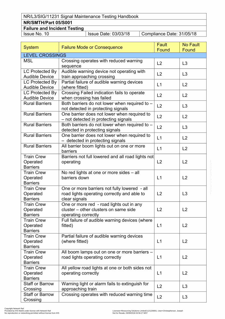
NR/L3/SIG/11231 Signal Maintenance Testing Handbook NR/SMTH/Part 05/S001 Failure and Incident Testing Issue No. 10 Issue Date: 03/03/18 Compliance Date: 31/05/18
System Failure Mode or Consequence Fault Found
No Fault Found
LEVEL CROSSINGS MSL Crossing operates with reduced warning
sequence L2 L3
LC Protected By Audible Device
Audible warning device not operating with train approaching crossing L2 L3
LC Protected By Audible Device
Partial failure of audible warning devices (where fitted) L1 L2
LC Protected By Audible Device
Crossing Failed indication fails to operate when crossing has failed L2 L2
Rural Barriers Both barriers do not lower when required to – not detected in protecting signals L2 L3
Rural Barriers One barrier does not lower when required to – not detected in protecting signals L2 L2
Rural Barriers Both barriers do not lower when required to – detected in protecting signals L2 L3
Rural Barriers One barrier does not lower when required to – detected in protecting signals L1 L2
Rural Barriers All barrier boom lights out on one or more barriers L1 L2
Train Crew Operated Barriers
Barriers not full lowered and all road lights not operating L2 L2
Train Crew Operated Barriers
No red lights at one or more sides – all barriers down L1 L2
Train Crew Operated Barriers
One or more barriers not fully lowered - all road lights operating correctly and able to clear signals
L2 L3
Train Crew Operated Barriers
One or more red - road lights out in any cluster – other clusters on same side operating correctly
L2 L2
Train Crew Operated Barriers
Full failure of audible warning devices (where fitted) L1 L2
Train Crew Operated Barriers
Partial failure of audible warning devices (where fitted) L1 L2
Train Crew Operated Barriers
All boom lamps out on one or more barriers – road lights operating correctly L1 L2
Train Crew Operated Barriers
All yellow road lights at one or both sides not operating correctly L1 L2
Staff or Barrow Crossing
Warning light or alarm fails to extinguish for approaching train L2 L3
Staff or Barrow Crossing
Crossing operates with reduced warning time L2 L3
Copyright Network Rail Provided by IHS Markit under license with Network Rail Licensee=Resourcing Solutions Limited /1121226001, User=Christopherson, Joseph
Not for Resale, 03/09/2018 03:56:27 MSTNo reproduction or networking permitted without license from IHS
--``,,``,`,,`,```,,``,,````,,,`,-`-`,,`,,`,`,,`---
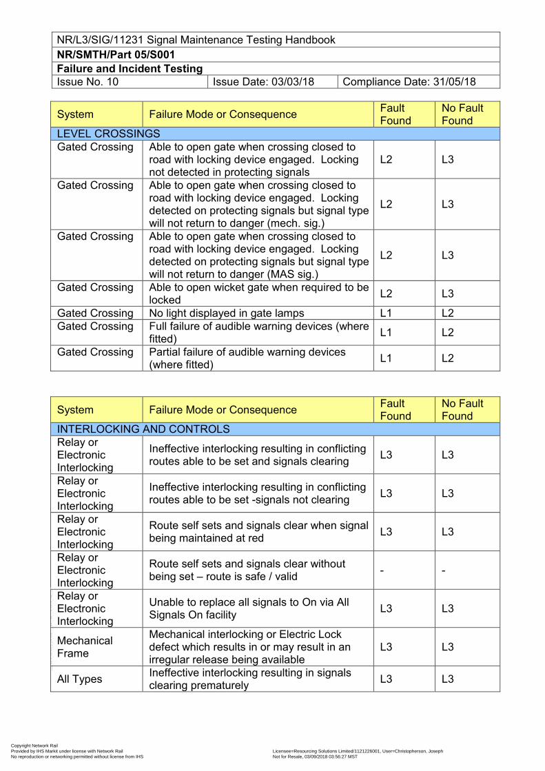
NR/L3/SIG/11231 Signal Maintenance Testing Handbook NR/SMTH/Part 05/S001 Failure and Incident Testing Issue No. 10 Issue Date: 03/03/18 Compliance Date: 31/05/18
System Failure Mode or Consequence Fault Found
No Fault Found
LEVEL CROSSINGS Gated Crossing Able to open gate when crossing closed to
road with locking device engaged. Locking not detected in protecting signals
L2 L3
Gated Crossing Able to open gate when crossing closed to road with locking device engaged. Locking detected on protecting signals but signal type will not return to danger (mech. sig.)
L2 L3
Gated Crossing Able to open gate when crossing closed to road with locking device engaged. Locking detected on protecting signals but signal type will not return to danger (MAS sig.)
L2 L3
Gated Crossing Able to open wicket gate when required to be locked L2 L3
Gated Crossing No light displayed in gate lamps L1 L2 Gated Crossing Full failure of audible warning devices (where
fitted) L1 L2
Gated Crossing Partial failure of audible warning devices (where fitted) L1 L2
System Failure Mode or Consequence Fault Found
No Fault Found
INTERLOCKING AND CONTROLS Relay or Electronic Interlocking
Ineffective interlocking resulting in conflicting routes able to be set and signals clearing L3 L3
Relay or Electronic Interlocking
Ineffective interlocking resulting in conflicting routes able to be set -signals not clearing L3 L3
Relay or Electronic Interlocking
Route self sets and signals clear when signal being maintained at red L3 L3
Relay or Electronic Interlocking
Route self sets and signals clear without being set – route is safe / valid - -
Relay or Electronic Interlocking
Unable to replace all signals to On via All Signals On facility L3 L3
Mechanical Frame
Mechanical interlocking or Electric Lock defect which results in or may result in an irregular release being available
L3 L3
All Types Ineffective interlocking resulting in signals clearing prematurely L3 L3
Copyright Network Rail Provided by IHS Markit under license with Network Rail Licensee=Resourcing Solutions Limited /1121226001, User=Christopherson, Joseph
Not for Resale, 03/09/2018 03:56:27 MSTNo reproduction or networking permitted without license from IHS
--``,,``,`,,`,```,,``,,````,,,`,-`-`,,`,,`,`,,`---
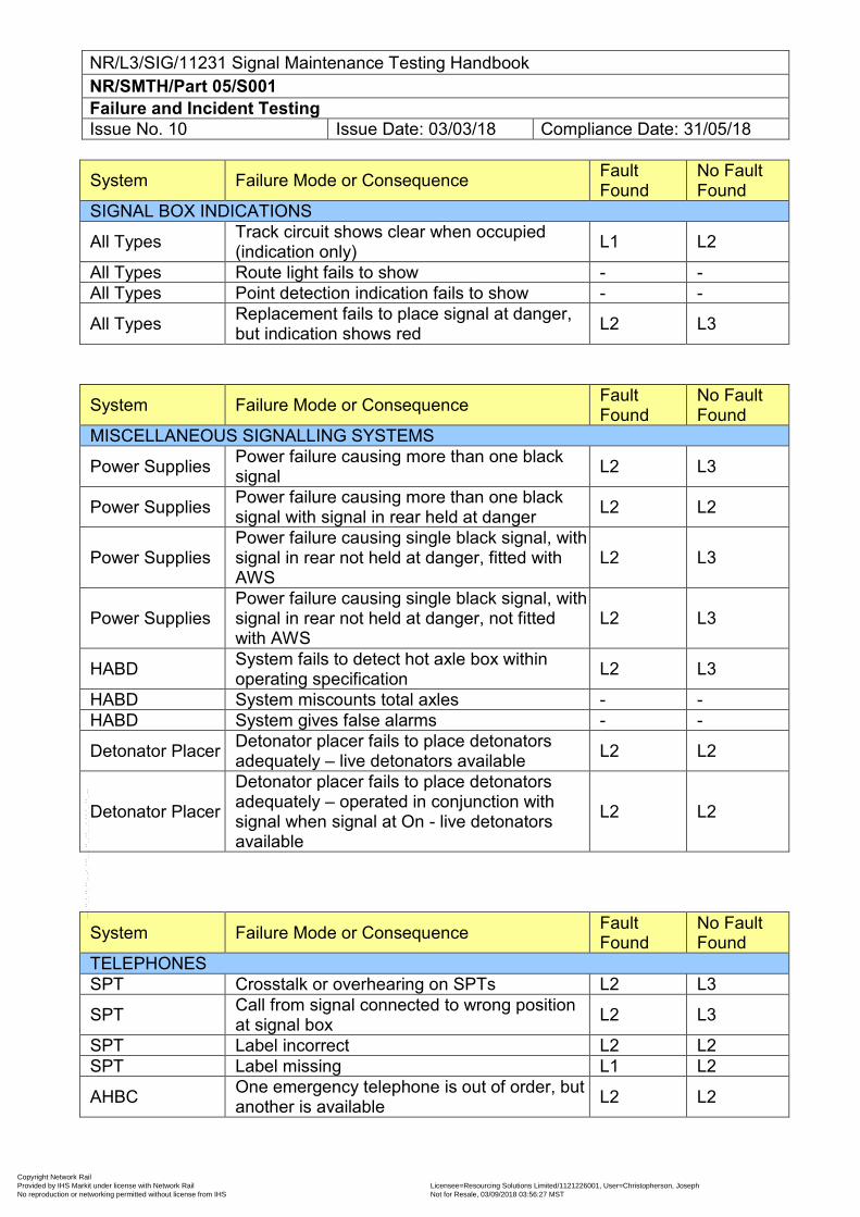
NR/L3/SIG/11231 Signal Maintenance Testing Handbook NR/SMTH/Part 05/S001 Failure and Incident Testing Issue No. 10 Issue Date: 03/03/18 Compliance Date: 31/05/18
System Failure Mode or Consequence Fault Found
No Fault Found
SIGNAL BOX INDICATIONS
All Types Track circuit shows clear when occupied (indication only) L1 L2
All Types Route light fails to show - - All Types Point detection indication fails to show - -
All Types Replacement fails to place signal at danger, but indication shows red L2 L3
System Failure Mode or Consequence Fault Found
No Fault Found
MISCELLANEOUS SIGNALLING SYSTEMS
Power Supplies Power failure causing more than one black signal L2 L3
Power Supplies Power failure causing more than one black signal with signal in rear held at danger L2 L2
Power Supplies Power failure causing single black signal, with signal in rear not held at danger, fitted with AWS
L2 L3
Power Supplies Power failure causing single black signal, with signal in rear not held at danger, not fitted with AWS
L2 L3
HABD System fails to detect hot axle box within operating specification L2 L3
HABD System miscounts total axles - - HABD System gives false alarms - -
Detonator Placer Detonator placer fails to place detonators adequately – live detonators available L2 L2
Detonator Placer
Detonator placer fails to place detonators adequately – operated in conjunction with signal when signal at On - live detonators available
L2 L2
System Failure Mode or Consequence Fault Found
No Fault Found
TELEPHONES SPT Crosstalk or overhearing on SPTs L2 L3
SPT Call from signal connected to wrong position at signal box L2 L3
SPT Label incorrect L2 L2 SPT Label missing L1 L2
AHBC One emergency telephone is out of order, but another is available L2 L2
Copyright Network Rail Provided by IHS Markit under license with Network Rail Licensee=Resourcing Solutions Limited /1121226001, User=Christopherson, Joseph
Not for Resale, 03/09/2018 03:56:27 MSTNo reproduction or networking permitted without license from IHS
--``,,``,`,,`,```,,``,,````,,,`,-`-`,,`,,`,`,,`---
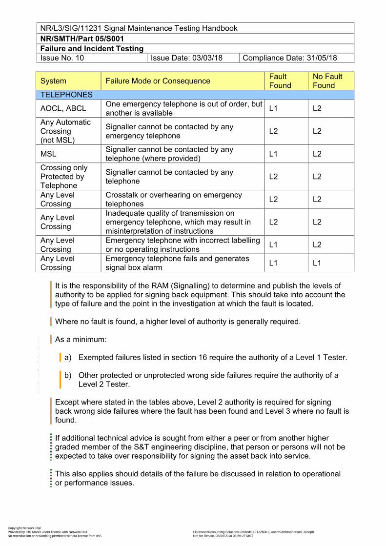
NR/L3/SIG/11231 Signal Maintenance Testing Handbook NR/SMTH/Part 05/S001 Failure and Incident Testing Issue No. 10 Issue Date: 03/03/18 Compliance Date: 31/05/18
System Failure Mode or Consequence Fault Found
No Fault Found
TELEPHONES
AOCL, ABCL One emergency telephone is out of order, but another is available L1 L2
Any Automatic Crossing (not MSL)
Signaller cannot be contacted by any emergency telephone L2 L2
MSL Signaller cannot be contacted by any telephone (where provided) L1 L2
Crossing only Protected by Telephone
Signaller cannot be contacted by any telephone L2 L2
Any Level Crossing
Crosstalk or overhearing on emergency telephones L2 L2
Any Level Crossing
Inadequate quality of transmission on emergency telephone, which may result in misinterpretation of instructions
L2 L2
Any Level Crossing
Emergency telephone with incorrect labelling or no operating instructions L1 L2
Any Level Crossing
Emergency telephone fails and generates signal box alarm L1 L1
It is the responsibility of the RAM (Signalling) to determine and publish the levels of authority to be applied for signing back equipment. This should take into account the type of failure and the point in the investigation at which the fault is located.
Where no fault is found, a higher level of authority is generally required.
As a minimum:
a) Exempted failures listed in section 16 require the authority of a Level 1 Tester. b) Other protected or unprotected wrong side failures require the authority of a
Level 2 Tester.
Except where stated in the tables above, Level 2 authority is required for signing back wrong side failures where the fault has been found and Level 3 where no fault is found. If additional technical advice is sought from either a peer or from another higher graded member of the S&T engineering discipline, that person or persons will not be expected to take over responsibility for signing the asset back into service.
This also applies should details of the failure be discussed in relation to operational or performance issues.
Copyright Network Rail Provided by IHS Markit under license with Network Rail Licensee=Resourcing Solutions Limited /1121226001, User=Christopherson, Joseph
Not for Resale, 03/09/2018 03:56:27 MSTNo reproduction or networking permitted without license from IHS
--``,,``,`,,`,```,,``,,````,,,`,-`-`,,`,,`,`,,`---
NR/L3/SIG/11231 Signal Maintenance Testing Handbook NR/SMTH/Part 05/S001 Failure and Incident Testing Issue No. 10 Issue Date: 03/03/18 Compliance Date: 31/05/18
19. Wrong Side Failures on Equipment in Service but before formal ‘take over’ by Maintenance Wrong side failures have been known to happen on newly commissioned equipment. Any wrong side failure on in-service equipment shall be investigated in accordance with the Signal Maintenance Testing Handbook. With the exception of exempted failures (see Section 16), details of wrong side failures of equipment that has been taken into operational use but have not been taken back into maintenance shall be advised to the project manager. This has normally been previously agreed between the project manager and the Maintenance organisation and documented in the Asset Management Plan. In office hours, this should be before completion of the immediate investigation. This should also apply to allegations, whether or not these are subsequently disproved. For the majority of wrong side failures, no formal action will be required from the project team in the immediate investigation of the failure. For certain complex failures, or failures requiring specialist equipment, or failures requiring specialist expertise to investigate them, the project team may supply suitable resources to work under the direction of the SFI testing team. In certain circumstances, such an involvement could be essential in order to adequately investigate what happened. In all cases of actual wrong side failure, the immediate cause of the fault shall be determined, and suitable mitigation applied where appropriate, in accordance with Signal Failure Investigation Test Guides.
END
Copyright Network Rail Provided by IHS Markit under license with Network Rail Licensee=Resourcing Solutions Limited /1121226001, User=Christopherson, Joseph
Not for Resale, 03/09/2018 03:56:27 MSTNo reproduction or networking permitted without license from IHS
--``,,``,`,,`,```,,``,,````,,,`,-`-`,,`,,`,`,,`---
NR/L3/SIG/11231 Signal Maintenance Testing Handbook NR/SMTH/Part 05/S002 Serious Incidents Including SPADs Issue No. 05 Issue Date: 05/03/11 Compliance Date: 03/09/11
Page 1 of 5
1. Incident Procedure
When a serious incident occurs, the rules of investigation and repair are changed, GE/RT8000 (Rule Book), and Railway Group Standard GO/RT3118 (Incident Response, Planning and Management) detail the requirements. GE/RT8000 Module M5 states that signalling equipment directly associated with a (serious) accident shall not be moved, even for testing purposes (unless it is essential to do so in order to protect the site).
A Rail Incident Officer (RIO) will be appointed by Network Rail to co-ordinate the overall recovery process and will be the single focus for dealing with other agencies involved such as emergency services and Office of the Rail Regulator (ORR).
No work on signalling or telecommunications equipment shall be attempted without specific authority from the RIO or someone to whom the RIO has delegated authority.
Staff called to the incident shall log actions and observations made during attendance. When recording notes, priority shall be given to equipment liable to be disturbed by traffic or by rescue/recovery services. The use of cameras for recording details shall be considered. Reports from train crews, signallers or another department’s personnel will normally be gathered from their respective management if they have arrived at the incident.
2. Rail Accident Investigation Board (RIAB) Liaison
Once notified of an incident by NR and agreement reached on the Schedule rating of the incident, RAIB may appoint an Accredited Agent (usually drawn from the NR pool of RIOs – note that an AA cannot also act as RIO) or elect to attend themselves. Regulation 6(1) applies. The scheduled events are shown in the 2.4.
Regulation 7(1) prohibits access to the signalling system for schedule 1 events without the consent of the RAIB or its Accredited Agent. Therefore every endeavour shall be made to contact RAIB or its Accredited Agent (via Infrastructure Control) to request permission to commence non-destructive testing prior to (probably independent) SMTH (SFI) testers arriving on site. The RAIB or its Accredited Agent may elect to prevent such testing from starting and instigate its own investigations. Note that RAIB duty controllers are available at all times.
NR/SMTH/Part 05 (Failure Investigation and Testing) S001 requires that non-destructive testing is always carried out before destructive testing is authorised by the Level 2 or 3 staff.
The Level 3 SFI tester shall ensure IFC is informed if a NR contracted agency is called out to assist on site. RAIB or its Accredited Agent will then be informed by Infrastructure Control.
2.1 Gathering evidence
If inspection activities by NR Signal Engineering staff have been allowed to commence before RAIB, its Accredited Agent or the RIO are on site, then the senior NR signal engineering qualified staff on site shall inform them as to how far the
Copyright Network Rail Provided by IHS Markit under license with Network Rail Licensee=Resourcing Solutions Limited /1121226001, User=Christopherson, Joseph
Not for Resale, 03/09/2018 03:56:27 MSTNo reproduction or networking permitted without license from IHS
--``,,``,`,,`,```,,``,,````,,,`,-`-`,,`,,`,`,,`---
NR/L3/SIG/11231 Signal Maintenance Testing Handbook NR/SMTH/Part 05/S002 Serious Incidents Including SPADs Issue No. 05 Issue Date: 05/03/11 Compliance Date: 03/09/11
Page 2 of 5
testing has proceeded and reach an agreement on the start of all subsequent steps. The RAIB or its Accredited Agent will always be given the opportunity to witness all tests.
No equipment will be removed from its operational position without RAIB or its Accredited Agent’s agreement – Regulation 9 applies. The RAIB or its Accredited Agent may wish to remove equipment for investigation to specialist laboratories. The RAIB or its Accredited Agent will always consult with the NR senior signal engineering staff on site before doing so and would normally expect NR staff to undertake the removal under SMTH and arrange packaging. Any application of scribe witness marks must only be undertaken with the agreement of the RAIB or its Accredited Agent. Any application of identification marks (e.g. bar codes) by RAIB or its Accredited Agent will only be made with the agreement of the senior NR Signal Engineer on site and will be applied to allow subsequent examination of the equipment without needing to remove the mark. In all cases agreement will be reached on site who will be responsible for continuity of protection of evidence.
Where the laboratory investigation requirements fall within the capability of the NR appointed agents then that agent is likely to be used. In this instance NR will be responsible for safe transportation of the equipment to the laboratory and for managing the activities of the agency. RAIB will always be given access to all steps of laboratory investigation and will be involved in any decision to move from the non-destructive phase to the destructive phase. In this case removing seals and covers from equipment is not considered to be destructive but RAIB must be consulted before doing so. If RAIB requires tests in addition to those instructed by NR then RAIB will fund and manage these tests. Reports produced by the NR agency will include NR and RAIB instructed work and will be transmitted to NR HQ and RAIB in parallel.
RAIB may well take witness statements from NR staff or contractor’s staff. Regulation 10(2) prevents disclosure of the contents of the interview without a court order or consent of the individual. Therefore NR cannot rely on such witness statements to further its investigation and will need to undertake its own interviews as necessary.
2.2 Use of Evidence
NR may disclose within NR any evidence jointly gathered, but any external release can only be made with the agreement of RAIB. Regulation 9(7) applies. In the case of Schedule 2 events then NR will normally be allowed to disclose externally. Therefore the issue of SINs or other notices to control or mitigate risks elsewhere is allowed.
2.3 Schedules of Reportable Events
2.3.1 Schedule 1 (report immediately)
1. An accident resulting in the death of a person or the serious injury of two or more persons.
2. An accident on a LC involving rolling stock, resulting in the death of a person or serious injury to a person.
Copyright Network Rail Provided by IHS Markit under license with Network Rail Licensee=Resourcing Solutions Limited /1121226001, User=Christopherson, Joseph
Not for Resale, 03/09/2018 03:56:27 MSTNo reproduction or networking permitted without license from IHS
--``,,``,`,,`,```,,``,,````,,,`,-`-`,,`,,`,`,,`---
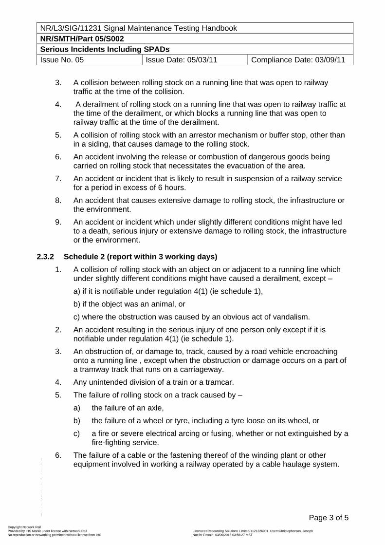
NR/L3/SIG/11231 Signal Maintenance Testing Handbook NR/SMTH/Part 05/S002 Serious Incidents Including SPADs Issue No. 05 Issue Date: 05/03/11 Compliance Date: 03/09/11
Page 3 of 5
3. A collision between rolling stock on a running line that was open to railway traffic at the time of the collision.
4. A derailment of rolling stock on a running line that was open to railway traffic at the time of the derailment, or which blocks a running line that was open to railway traffic at the time of the derailment.
5. A collision of rolling stock with an arrestor mechanism or buffer stop, other than in a siding, that causes damage to the rolling stock.
6. An accident involving the release or combustion of dangerous goods being carried on rolling stock that necessitates the evacuation of the area.
7. An accident or incident that is likely to result in suspension of a railway service for a period in excess of 6 hours.
8. An accident that causes extensive damage to rolling stock, the infrastructure or the environment.
9. An accident or incident which under slightly different conditions might have led to a death, serious injury or extensive damage to rolling stock, the infrastructure or the environment.
2.3.2 Schedule 2 (report within 3 working days)
1. A collision of rolling stock with an object on or adjacent to a running line which under slightly different conditions might have caused a derailment, except –
a) if it is notifiable under regulation 4(1) (ie schedule 1),
b) if the object was an animal, or
c) where the obstruction was caused by an obvious act of vandalism.
2. An accident resulting in the serious injury of one person only except if it is notifiable under regulation 4(1) (ie schedule 1).
3. An obstruction of, or damage to, track, caused by a road vehicle encroaching onto a running line , except when the obstruction or damage occurs on a part of a tramway track that runs on a carriageway.
4. Any unintended division of a train or a tramcar.
5. The failure of rolling stock on a track caused by –
a) the failure of an axle,
b) the failure of a wheel or tyre, including a tyre loose on its wheel, or
c) a fire or severe electrical arcing or fusing, whether or not extinguished by a fire-fighting service.
6. The failure of a cable or the fastening thereof of the winding plant or other equipment involved in working a railway operated by a cable haulage system.
Copyright Network Rail Provided by IHS Markit under license with Network Rail Licensee=Resourcing Solutions Limited /1121226001, User=Christopherson, Joseph
Not for Resale, 03/09/2018 03:56:27 MSTNo reproduction or networking permitted without license from IHS
--``,,``,`,,`,```,,``,,````,,,`,-`-`,,`,,`,`,,`---
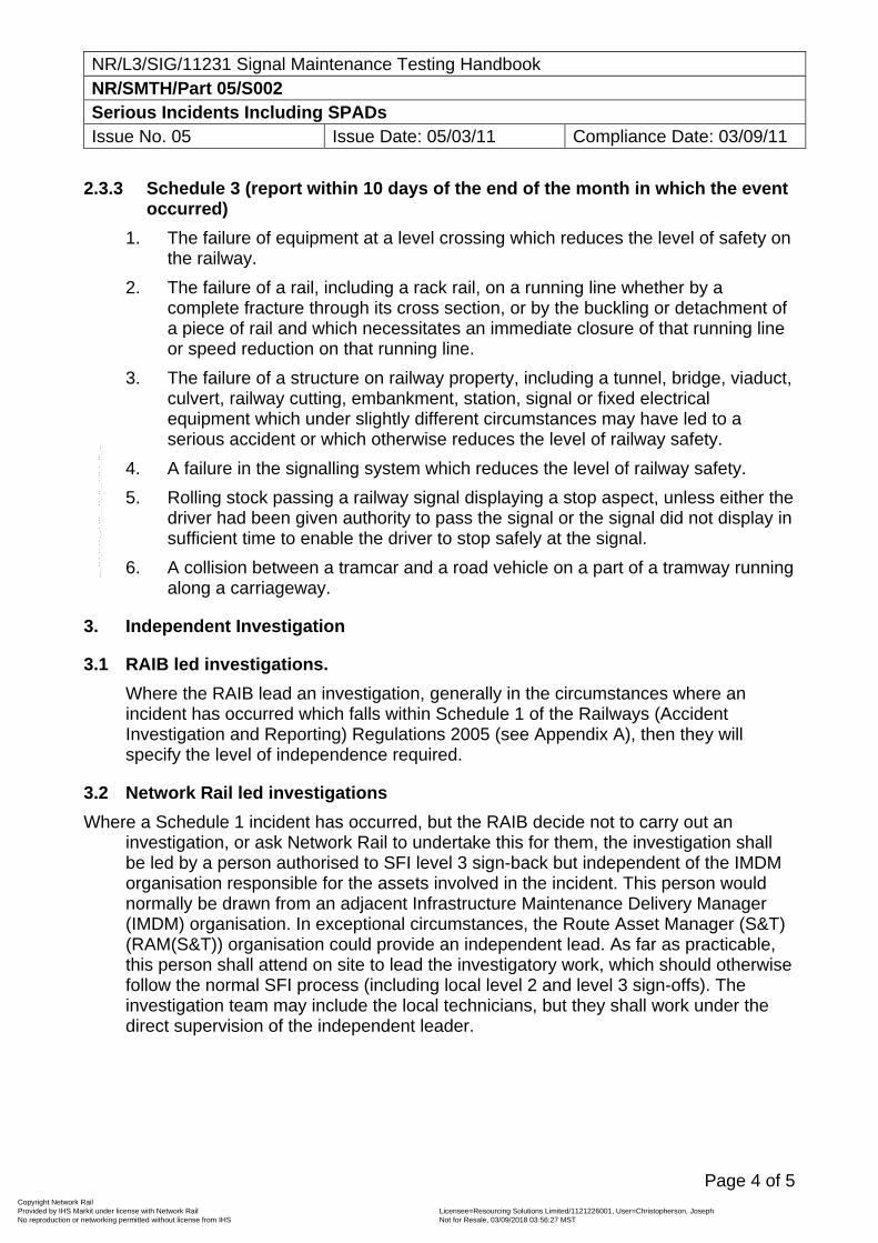
NR/L3/SIG/11231 Signal Maintenance Testing Handbook NR/SMTH/Part 05/S002 Serious Incidents Including SPADs Issue No. 05 Issue Date: 05/03/11 Compliance Date: 03/09/11
Page 4 of 5
2.3.3 Schedule 3 (report within 10 days of the end of the month in which the event occurred)
1. The failure of equipment at a level crossing which reduces the level of safety on the railway.
2. The failure of a rail, including a rack rail, on a running line whether by a complete fracture through its cross section, or by the buckling or detachment of a piece of rail and which necessitates an immediate closure of that running line or speed reduction on that running line.
3. The failure of a structure on railway property, including a tunnel, bridge, viaduct, culvert, railway cutting, embankment, station, signal or fixed electrical equipment which under slightly different circumstances may have led to a serious accident or which otherwise reduces the level of railway safety.
4. A failure in the signalling system which reduces the level of railway safety.
5. Rolling stock passing a railway signal displaying a stop aspect, unless either the driver had been given authority to pass the signal or the signal did not display in sufficient time to enable the driver to stop safely at the signal.
6. A collision between a tramcar and a road vehicle on a part of a tramway running along a carriageway.
3. Independent Investigation
3.1 RAIB led investigations.
Where the RAIB lead an investigation, generally in the circumstances where an incident has occurred which falls within Schedule 1 of the Railways (Accident Investigation and Reporting) Regulations 2005 (see Appendix A), then they will specify the level of independence required.
3.2 Network Rail led investigations
Where a Schedule 1 incident has occurred, but the RAIB decide not to carry out an investigation, or ask Network Rail to undertake this for them, the investigation shall be led by a person authorised to SFI level 3 sign-back but independent of the IMDM organisation responsible for the assets involved in the incident. This person would normally be drawn from an adjacent Infrastructure Maintenance Delivery Manager (IMDM) organisation. In exceptional circumstances, the Route Asset Manager (S&T) (RAM(S&T)) organisation could provide an independent lead. As far as practicable, this person shall attend on site to lead the investigatory work, which should otherwise follow the normal SFI process (including local level 2 and level 3 sign-offs). The investigation team may include the local technicians, but they shall work under the direct supervision of the independent leader.
Copyright Network Rail Provided by IHS Markit under license with Network Rail Licensee=Resourcing Solutions Limited /1121226001, User=Christopherson, Joseph
Not for Resale, 03/09/2018 03:56:27 MSTNo reproduction or networking permitted without license from IHS
--``,,``,`,,`,```,,``,,````,,,`,-`-`,,`,,`,`,,`---
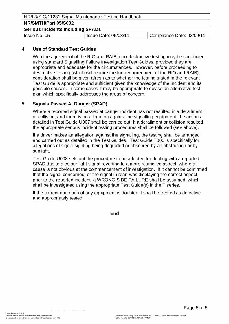
NR/L3/SIG/11231 Signal Maintenance Testing Handbook NR/SMTH/Part 05/S002 Serious Incidents Including SPADs Issue No. 05 Issue Date: 05/03/11 Compliance Date: 03/09/11
Page 5 of 5
4. Use of Standard Test Guides
With the agreement of the RIO and RAIB, non-destructive testing may be conducted using standard Signalling Failure Investigation Test Guides, provided they are appropriate and adequate for the circumstances. However, before proceeding to destructive testing (which will require the further agreement of the RIO and RAIB), consideration shall be given afresh as to whether the testing stated in the relevant Test Guide is appropriate and sufficient given the knowledge of the incident and its possible causes. In some cases it may be appropriate to devise an alternative test plan which specifically addresses the areas of concern.
5. Signals Passed At Danger (SPAD)
Where a reported signal passed at danger incident has not resulted in a derailment or collision, and there is no allegation against the signalling equipment, the actions detailed in Test Guide U007 shall be carried out. If a derailment or collision resulted, the appropriate serious incident testing procedures shall be followed (see above).
If a driver makes an allegation against the signalling, the testing shall be arranged and carried out as detailed in the Test Guides. Test Guide T006 is specifically for allegations of signal sighting being degraded or obscured by an obstruction or by sunlight.
Test Guide U008 sets out the procedure to be adopted for dealing with a reported SPAD due to a colour light signal reverting to a more restrictive aspect, where a cause is not obvious at the commencement of investigation. If it cannot be confirmed that the signal concerned, or the signal in rear, was displaying the correct aspect prior to the reported incident, a WRONG SIDE FAILURE shall be assumed, which shall be investigated using the appropriate Test Guide(s) in the T series.
If the correct operation of any equipment is doubted it shall be treated as defective and appropriately tested.
End
Copyright Network Rail Provided by IHS Markit under license with Network Rail Licensee=Resourcing Solutions Limited /1121226001, User=Christopherson, Joseph
Not for Resale, 03/09/2018 03:56:27 MSTNo reproduction or networking permitted without license from IHS
--``,,``,`,,`,```,,``,,````,,,`,-`-`,,`,,`,`,,`---
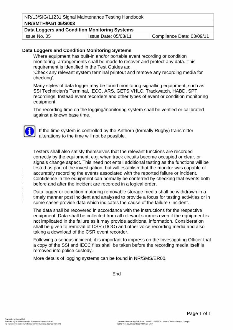
NR/L3/SIG/11231 Signal Maintenance Testing Handbook NR/SMTH/Part 05/S003 Data Loggers and Condition Monitoring Systems Issue No. 05 Issue Date: 05/03/11 Compliance Date: 03/09/11
Page 1 of 1
Data Loggers and Condition Monitoring Systems Where equipment has built-in and/or portable event recording or condition monitoring, arrangements shall be made to recover and protect any data. This requirement is identified in the Test Guides as: ‘Check any relevant system terminal printout and remove any recording media for checking’.
Many styles of data logger may be found monitoring signalling equipment, such as SSI Technician's Terminal, IECC, ARS, GETS VHLC, Trackwatch, HABD, SPT recordings, Instead event recorders and other types of event or condition monitoring equipment.
The recording time on the logging/monitoring system shall be verified or calibrated against a known base time.
If the time system is controlled by the Anthorn (formally Rugby) transmitter alterations to the time will not be possible.
Testers shall also satisfy themselves that the relevant functions are recorded correctly by the equipment, e.g. when track circuits become occupied or clear, or signals change aspect. This need not entail additional testing as the functions will be tested as part of the investigation, but will establish that the monitor was capable of accurately recording the events associated with the reported failure or incident. Confidence in the equipment can normally be conferred by checking that events both before and after the incident are recorded in a logical order.
Data logger or condition motoring removable storage media shall be withdrawn in a timely manner post incident and analysed to provide a focus for testing activities or in some cases provide data which indicates the cause of the failure / incident.
The data shall be recovered in accordance with the instructions for the respective equipment. Data shall be collected from all relevant sources even if the equipment is not implicated in the failure as it may provide additional information. Consideration shall be given to removal of CSR (DOO) and other voice recording media and also taking a download of the CSR event recorder.
Following a serious incident, it is important to impress on the Investigating Officer that a copy of the SSI and IECC files shall be taken before the recording media itself is removed into police custody.
More details of logging systems can be found in NR/SMS/ER00.
End
Copyright Network Rail Provided by IHS Markit under license with Network Rail Licensee=Resourcing Solutions Limited /1121226001, User=Christopherson, Joseph
Not for Resale, 03/09/2018 03:56:27 MSTNo reproduction or networking permitted without license from IHS
--``,,``,`,,`,```,,``,,````,,,`,-`-`,,`,,`,`,,`---
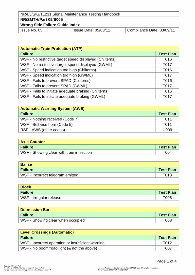
NR/L3/SIG/11231 Signal Maintenance Testing Handbook NR/SMTH/Part 05/S005 Wrong Side Failure Guide Index Issue No. 05 Issue Date: 05/03/11 Compliance Date: 03/09/11
Page 1 of 4
Automatic Train Protection (ATP) Failure Test Plan WSF - No restrictive target speed displayed (Chilterns) T016 WSF - No restrictive target speed displayed (GWML) T017 WSF - Speed indication too high (Chilterns) T016 WSF - Speed indication too high (GWML) T017 WSF - Fails to prevent SPAD (Chilterns) T016 WSF - Fails to prevent SPAD (GWML) T017 WSF - Fails to initiate adequate braking (Chilterns) T016 WSF - Fails to initiate adequate braking (GWML) T017
Automatic Warning System (AWS) Failure Test Plan WSF - Nothing received (Code 7) T011 WSF - Bell vice horn (Code 5) T011 RSF - AWS (other codes) U009
Axle Counter Failure Test Plan WSF - Showing clear with train in section T004
Balise Failure Test Plan WSF - Incorrect telegram emitted T018
Block Failure Test Plan WSF - Irregular release T005
Depression Bar Failure Test Plan WSF - Showing clear when occupied T003
Level Crossings (Automatic) Failure Test Plan WSF - Incorrect operation or insufficient warning T012 WSF - No boom/road light (& not the above) T007
Copyright Network Rail Provided by IHS Markit under license with Network Rail Licensee=Resourcing Solutions Limited /1121226001, User=Christopherson, Joseph
Not for Resale, 03/09/2018 03:56:27 MSTNo reproduction or networking permitted without license from IHS
--``,,``,`,,`,```,,``,,````,,,`,-`-`,,`,,`,`,,`---
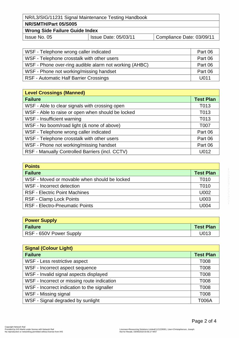
NR/L3/SIG/11231 Signal Maintenance Testing Handbook NR/SMTH/Part 05/S005 Wrong Side Failure Guide Index Issue No. 05 Issue Date: 05/03/11 Compliance Date: 03/09/11
Page 2 of 4
WSF - Telephone wrong caller indicated Part 06 WSF - Telephone crosstalk with other users Part 06 WSF - Phone over-ring audible alarm not working (AHBC) Part 06 WSF - Phone not working/missing handset Part 06 RSF - Automatic Half Barrier Crossings U011
Level Crossings (Manned) Failure Test Plan WSF - Able to clear signals with crossing open T013 WSF - Able to raise or open when should be locked T013 WSF - Insufficient warning T013 WSF - No boom/road light (& none of above) T007 WSF - Telephone wrong caller indicated Part 06 WSF - Telephone crosstalk with other users Part 06 WSF - Phone not working/missing handset Part 06 RSF - Manually Controlled Barriers (incl. CCTV) U012
Points Failure Test Plan WSF - Moved or movable when should be locked T010 WSF - Incorrect detection T010 RSF - Electric Point Machines U002 RSF - Clamp Lock Points U003 RSF - Electro-Pneumatic Points U004
Power Supply Failure Test Plan RSF - 650V Power Supply U013
Signal (Colour Light) Failure Test Plan WSF - Less restrictive aspect T008 WSF - Incorrect aspect sequence T008 WSF - Invalid signal aspects displayed T008 WSF - Incorrect or missing route indication T008 WSF - Incorrect indication to the signaller T008 WSF - Missing signal T008 WSF - Signal degraded by sunlight T006A
Copyright Network Rail Provided by IHS Markit under license with Network Rail Licensee=Resourcing Solutions Limited /1121226001, User=Christopherson, Joseph
Not for Resale, 03/09/2018 03:56:27 MSTNo reproduction or networking permitted without license from IHS
--``,,``,`,,`,```,,``,,````,,,`,-`-`,,`,,`,`,,`---
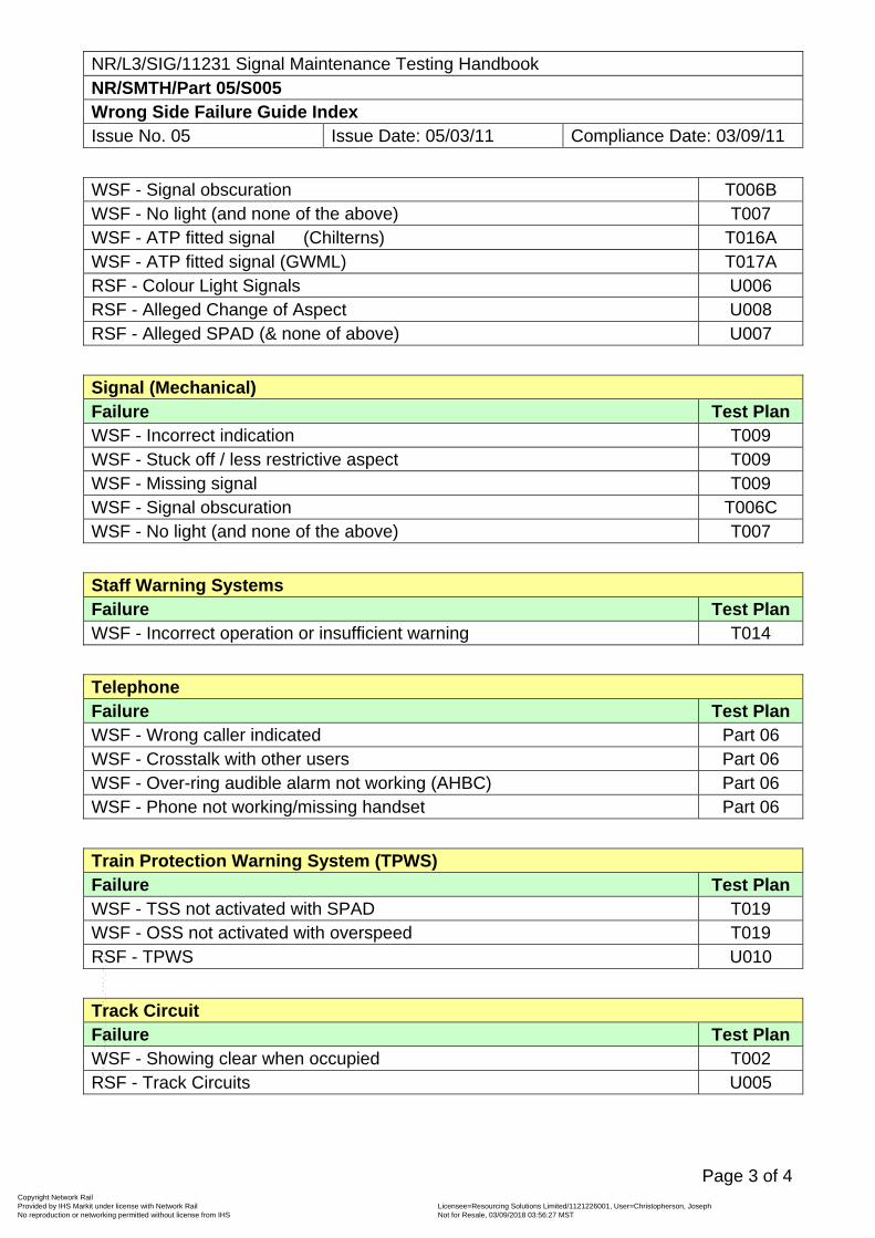
NR/L3/SIG/11231 Signal Maintenance Testing Handbook NR/SMTH/Part 05/S005 Wrong Side Failure Guide Index Issue No. 05 Issue Date: 05/03/11 Compliance Date: 03/09/11
Page 3 of 4
WSF - Signal obscuration T006B WSF - No light (and none of the above) T007 WSF - ATP fitted signal (Chilterns) T016A WSF - ATP fitted signal (GWML) T017A RSF - Colour Light Signals U006 RSF - Alleged Change of Aspect U008 RSF - Alleged SPAD (& none of above) U007
Signal (Mechanical) Failure Test Plan WSF - Incorrect indication T009 WSF - Stuck off / less restrictive aspect T009 WSF - Missing signal T009 WSF - Signal obscuration T006C WSF - No light (and none of the above) T007
Staff Warning Systems Failure Test Plan WSF - Incorrect operation or insufficient warning T014
Telephone Failure Test Plan WSF - Wrong caller indicated Part 06 WSF - Crosstalk with other users Part 06 WSF - Over-ring audible alarm not working (AHBC) Part 06 WSF - Phone not working/missing handset Part 06
Train Protection Warning System (TPWS) Failure Test Plan WSF - TSS not activated with SPAD T019 WSF - OSS not activated with overspeed T019 RSF - TPWS U010
Track Circuit Failure Test Plan WSF - Showing clear when occupied T002 RSF - Track Circuits U005
Copyright Network Rail Provided by IHS Markit under license with Network Rail Licensee=Resourcing Solutions Limited /1121226001, User=Christopherson, Joseph
Not for Resale, 03/09/2018 03:56:27 MSTNo reproduction or networking permitted without license from IHS
--``,,``,`,,`,```,,``,,````,,,`,-`-`,,`,,`,`,,`---
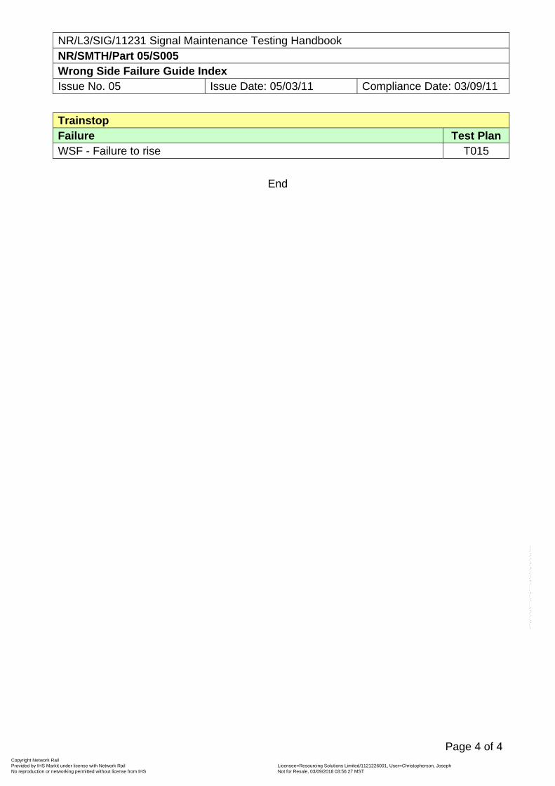
NR/L3/SIG/11231 Signal Maintenance Testing Handbook NR/SMTH/Part 05/S005 Wrong Side Failure Guide Index Issue No. 05 Issue Date: 05/03/11 Compliance Date: 03/09/11
Page 4 of 4
Trainstop Failure Test Plan WSF - Failure to rise T015
End
Copyright Network Rail Provided by IHS Markit under license with Network Rail Licensee=Resourcing Solutions Limited /1121226001, User=Christopherson, Joseph
Not for Resale, 03/09/2018 03:56:27 MSTNo reproduction or networking permitted without license from IHS
--``,,``,`,,`,```,,``,,````,,,`,-`-`,,`,,`,`,,`---
NR/L3/SIG/11231 Signal Maintenance Testing Handbook NR/SMTH/Part 05/T001 Signalling Failure and Incident Testing Guides Issue No. 01 Issue Date: 05/03/11 Compliance Date: 03/09/11
Page 1 of 1
1. Scope
These T series Fault Finding Guides have been introduced in the form of check lists to detail the suggested checks and tests which shall be carried out when investigating wrong side signalling failures and incidents.
Intermittent and obscure failures shall be investigated using the appropriate Test Guide(s) in the U series.
Further fault finding guidance can be found within the documents listed in Part 01/Appendix B, and in relevant Manufacturer's Documentation.
2. Fault Finding Guides
The Fault Finding Guides are presented in a similar style to the Test Plans, the appropriate guide being used when testing / checking on site to determine the potential cause of any failure.
The checks listed are not intended to be a comprehensive test sequence, or be in the correct order for every circumstance. Checks and tests considered most relevant to the reported failure shall be carried out first.
If no cause is apparent after these checks, advise your Section Manager (Signals) and seek type specific fault finding information from available sources.
3. Records
You shall complete the Signal Failure & Incident Testing checksheet in Part 05/Appendix 06. Any measurement results or test records shall be included or attached as appropriate.
If any item is replaced under NR/SMTH the SMTH logbook sheet shall also be included.
If you are investigating a SPAD, you shall also write down the results of each test that you complete and send it to your Section Manager (Signals). Remember to identify any root cause as well as the actual cause of the failure.
If operating staff decline access to equipment for test / check purposes, this fact shall be recorded on the SMTH logbook sheet and advised to your Section Manager (Signals).
End
Copyright Network Rail Provided by IHS Markit under license with Network Rail Licensee=Resourcing Solutions Limited /1121226001, User=Christopherson, Joseph
Not for Resale, 03/09/2018 03:56:27 MSTNo reproduction or networking permitted without license from IHS
--``,,``,`,,`,```,,``,,````,,,`,-`-`,,`,,`,`,,`---
NR/L3/SIG/11231 Signal Maintenance Testing Handbook NR/SMTH/Part 05/T002 Wrong Side Failure Test Guide: Track Circuits Issue No. 7 Issue Date: 03/03/18 Compliance Date: 31/05/18
Page 1 of 6
All test measurements shall be recorded on the appropriate NR/SMS record card together with the reason for the test.
NON-DESTRUCTIVE TESTS Signal Box N01 Note any relevant signal box indications. N02 Check the condition of lamps / other indicators. N03 Note the state of relevant train describer displays. N04 Note any unusual operating methods in place (hand-signalling, possessions,
single line working, etc.). N05 Note the nature of any work being done, or persons working in the area. N06 Note the time and type of train (including vehicle class or number), event or
operation that first caused the reported failure to become apparent, whether the train approach was particularly slow and whether any Track Circuit Actuator (TCA) was switched on.
N07 Note the time and type of operation last made, prior to the report, which used the
affected equipment. N08 Note any other train movements in the affected area. N09 Note any significant weather conditions in the area. Lineside Locations or Equipment Rooms N10 Check the rails for contamination. N11 Check that the cupboard or room is correctly locked or padlocked.
Copyright Network Rail Provided by IHS Markit under license with Network Rail Licensee=Resourcing Solutions Limited /1121226001, User=Christopherson, Joseph
Not for Resale, 03/09/2018 03:56:27 MSTNo reproduction or networking permitted without license from IHS
--``,,``,`,,`,```,,``,,````,,,`,-`-`,,`,,`,`,,`---
NR/L3/SIG/11231 Signal Maintenance Testing Handbook NR/SMTH/Part 05/T002 Wrong Side Failure Test Guide: Track Circuits Issue No. 7 Issue Date: 03/03/18 Compliance Date: 31/05/18
Page 2 of 6
N12 Check for damage. N13 Check any relevant system terminal printout and remove any recording media for
checking. N14 Check for signs of recent disturbances (wiring alterations, track maintenance or
renewals activity). N15 Check for security or tightness of equipment. N16 Check the position and correspondence of relevant relays (energised, de-
energised). Consider TR, TPR, TKR, etc. N17 Check for damage inside relays (cracked casing, internal moisture, insects, foreign
matter, contact arcing, internal cloudiness, strong smell, silver sulphide, metal flakes, bent or broken contact springs, or corroded terminals).
N18 Check that relays correspond to the wiring diagram (type and specification, pin code,
voltage, contact arrangement).
Record the last service date on the WSF form and forward to your Section Manager (Signals).
N19 Check that equipment and settings correspond to the wiring diagram (specification,
power, voltage rating, track capacitor, etc.). N20 Check the rear of relay bases for silver migration. N21 Check the equipment for short circuits (nuts, washers, solder, wire off-cuts,
conducting dust, etc.). N22 Check the equipment for any unusual amounts of moisture. N23 Test voltages, Record the results. N24 Earth Test (DC) [NR/SMTH/11231/Part03/TestB05] or Earth Test (AC)
[NR/SMTH/11231/Part03/TestB06] circuits and supplies.
Copyright Network Rail Provided by IHS Markit under license with Network Rail Licensee=Resourcing Solutions Limited /1121226001, User=Christopherson, Joseph
Not for Resale, 03/09/2018 03:56:27 MSTNo reproduction or networking permitted without license from IHS
--``,,``,`,,`,```,,``,,````,,,`,-`-`,,`,,`,`,,`---
NR/L3/SIG/11231 Signal Maintenance Testing Handbook NR/SMTH/Part 05/T002 Wrong Side Failure Test Guide: Track Circuits Issue No. 7 Issue Date: 03/03/18 Compliance Date: 31/05/18
Page 3 of 6
Track Equipment N25 Check for damage. N26 Check for signs of recent disturbances (wiring alterations, track maintenance or
renewals activity, no unused rails in any tuned zones). N27 Check the condition of any stainless steel strip. N28 Check that the track circuit bonding corresponds to the bonding diagram. N29 Check any insulated rail joint condition. N30 Check that the rail connections are properly insulated. N31 Check under the rails for short circuits. N32 Note the details of any H.T. electrical equipment nearby, associated with the track
circuit (BR Point switch heaters, BR shore electrical supplies, etc.). N33 Measure the track circuit length (staggered joints, minimum length, high or low
power settings versus length, etc.). N34 Test insulated rail joints. N35 Check any impedance bond phasing and connections. N36 Check any TCAIDs required are fitted and test they work. N37 Note the type of sleepers in use (timber, concrete, steel) with reference to high
residual voltages and TCAID malfunction. N38 Where Gatekeeper Device is fitted check for security/damage. N39 Where Gatekeeper Device is fitted check visible connections are properly insulated.
Copyright Network Rail Provided by IHS Markit under license with Network Rail Licensee=Resourcing Solutions Limited /1121226001, User=Christopherson, Joseph
Not for Resale, 03/09/2018 03:56:27 MSTNo reproduction or networking permitted without license from IHS
--``,,``,`,,`,```,,``,,````,,,`,-`-`,,`,,`,`,,`---
NR/L3/SIG/11231 Signal Maintenance Testing Handbook NR/SMTH/Part 05/T002 Wrong Side Failure Test Guide: Track Circuits Issue No. 7 Issue Date: 03/03/18 Compliance Date: 31/05/18
Page 4 of 6
N40 If a laptop is available, download the error log. (DIGITAL EBI TRACK 200 TI21 RX ONLY)
This can be done whilst the system is operational by connecting to the 9 way D-type port on the front of the Digital Rx, using a laptop and the required software.
DO NOT turn or remove the frequency key during this process. Cables and Bonds N41 Check the insulation of cables and wires at terminations. Check that adjacent
terminations are properly insulated from each other. N42 Remove covers from trunking and Check for Safe Insulation (chafing, scorched,
rodent damage). N43 Note any signs of obvious damage (fires, squashed cables, etc.). N44 Check for broken jumpers and broken or missing bonding. N45 Check that cables and jumpers comply with diagram. Miscellaneous N46 Check Special Inspection Notices (NR/SIN), Technical Instructions (NR/TI) or
Letters of Instruction (NR/BS/LI/) for any other relevant Non-Destructive tests. N47 Note any extraneous conditions or circumstances that could have an affect on the
failure. DESTRUCTIVE TESTS Track Equipment D01 Test drop shunt and pick-up shunt at rails, relay end.
Copyright Network Rail Provided by IHS Markit under license with Network Rail Licensee=Resourcing Solutions Limited /1121226001, User=Christopherson, Joseph
Not for Resale, 03/09/2018 03:56:27 MSTNo reproduction or networking permitted without license from IHS
--``,,``,`,,`,```,,``,,````,,,`,-`-`,,`,,`,`,,`---
NR/L3/SIG/11231 Signal Maintenance Testing Handbook NR/SMTH/Part 05/T002 Wrong Side Failure Test Guide: Track Circuits Issue No. 7 Issue Date: 03/03/18 Compliance Date: 31/05/18
Page 5 of 6
D02 Test drop shunt at all extremities of the track circuit. D03 Connect the minimum permissible drop shunt at intervals throughout the length of
the track circuit whilst observing the track relay. The normal interval is 15m but longer intervals are possible for plain line and long track circuits. The interval shall be agreed with the consulted Level 2 (or above) person.
D04 Test the track circuit for a residual voltage with the feed end isolated. D05 Test for the polarity or phase (stagger) of adjoining track circuits. D06 Check and Test the track circuits either side of the affected track circuit. Lineside Locations or Equipment Rooms D07 Wire Count the relevant equipment or circuits to the wiring diagram. D08 Test drop away and pick-up voltages at the relay. D09 Test the track circuit voltage at the Relay or Receiver whilst a train passes over the
length of the track circuit. D10 Check relay base front for silver migration, damage, spades pushed too far forward
or broken contact insulators. D11 Test any capacitor slug circuit that can prevent a relay from dropping for intermittent
high resistance faults, unless relay stick contacts are wired in series with the capacitor.
D12 Test common return, looping or spur circuits for intermittent high resistance faults. D13 Remove relays and check for damage inside relays (cracked casing, internal
moisture, insects, foreign matter, contact arcing, internal cloudiness, silver sulphide, metal flakes, bent or broken contact springs, or corroded terminals).
Copyright Network Rail Provided by IHS Markit under license with Network Rail Licensee=Resourcing Solutions Limited /1121226001, User=Christopherson, Joseph
Not for Resale, 03/09/2018 03:56:27 MSTNo reproduction or networking permitted without license from IHS
--``,,``,`,,`,```,,``,,````,,,`,-`-`,,`,,`,`,,`---
NR/L3/SIG/11231 Signal Maintenance Testing Handbook NR/SMTH/Part 05/T002 Wrong Side Failure Test Guide: Track Circuits Issue No. 7 Issue Date: 03/03/18 Compliance Date: 31/05/18
Page 6 of 6
Cables D14 CABLE FUNCTION TEST [NR/SMTH/11231/PART03/TESTB04] THE LINE
CIRCUITS. D15 INSULATION TEST [NR/SMTH/11231/PART03/TESTB03] all cables (tail, lineside,
rack to rack).
Tail cables connected to rails shall not normally be insulation tested. Miscellaneous D16 Where Gatekeeper Device is fitted carry out a MAINTENANCE FUNCTION TEST
(NR/SMS/TEST/279). D17 Check Special Inspection Notices (NR/SIN), Technical Instructions (NR/TI) or
Letters of Instruction (NR/BS/LI/) for any other relevant Destructive tests. OTHER CONSIDERATIONS 01 Possible remote control system failure. 02 Possible cathodic protection problems. 03 Possible invalid track circuit combination. 04 Possible design error. 05 Possible problem with train.
END
Copyright Network Rail Provided by IHS Markit under license with Network Rail Licensee=Resourcing Solutions Limited /1121226001, User=Christopherson, Joseph
Not for Resale, 03/09/2018 03:56:27 MSTNo reproduction or networking permitted without license from IHS
--``,,``,`,,`,```,,``,,````,,,`,-`-`,,`,,`,`,,`---
NR/L3/SIG/11231 Signal Maintenance Testing Handbook NR/SMTH/Part-05/T003 Wrong Side Failure Guide : Depression Bar Issue No. 5 Issue Date: 06/09/2014 Compliance Date: 07/03/2015
NON-DESTRUCTIVE TESTS
Signal Box N.1 Note relevant signal box indications.
N.2 Note the state of relevant train describer displays. N.3 Note any unusual operating methods in place (hand-signalling, possessions, single
line working, etc). N.4 Note the nature of any work being done, or persons working in the area. N.5 Note the time and type of train (including vehicle class or number), event or
operation that first caused the reported failure to become apparent. N.6 Note the time and type of operation last made, prior to the report, which used the
affected equipment.
N.7 Note any other train movements in the affected area.
Lineside Locations or Equipment Rooms N.8 Check that the cupboard or room is correctly locked or padlocked. N.9 Note any significant weather conditions in the area (cloud cover, position and
strength of sun and wind conditions).
N.10 Check for damage.
N.11 Check any relevant system terminal printout and remove any recording media for checking.
N.12 Check for signs of recent disturbances (wiring alterations, track maintenance or renewal activity).
N.13 Check for security or tightness of equipment.
N.14 Check the position of relevant relays (energised, de-energised).
N.15 Check for damage inside relays (cracked casing, internal moisture, insects, foreign matter, contact arcing, internal cloudiness, strong smell, silver sulphide, metal flakes, bent or broken contact springs, or corroded terminals).
N.16 Check that relays correspond to the wiring diagram (type and specification, pin code, voltage, contact arrangement).
Record the last service date on the WSF form and forward to your Section Manager (Signals).
Copyright Network Rail Provided by IHS Markit under license with Network Rail Licensee=Resourcing Solutions Limited /1121226001, User=Christopherson, Joseph
Not for Resale, 03/09/2018 03:56:27 MSTNo reproduction or networking permitted without license from IHS
--``,,``,`,,`,```,,``,,````,,,`,-`-`,,`,,`,`,,`---
NR/L3/SIG/11231 Signal Maintenance Testing Handbook NR/SMTH/Part-05/T003 Wrong Side Failure Guide : Depression Bar Issue No. 5 Issue Date: 06/09/2014 Compliance Date: 07/03/2015
N.17 Check that equipment and settings correspond to the wiring diagram (specification,
power, voltage rating, etc).
N.18 Check rear of relay bases for silver migration.
N.19 Check the equipment for possible short circuits (nuts, washers, solder, wire off-cuts, metallic dust, etc).
N.20 Check that cables and wires at terminations are properly isolated from each other.
N.21 Remove covers from trunking and check for safe insulation (chafing, scorched, rodent damage).
N.22 Test voltages, recording the results.
N.23 Earth Test (DC) [NR/SMTH/11231/Part03/TestB05] or Earth Test (AC) [NR/SMTH/11231/Part03/TestB06] circuits and supplies
N.24 Test voltage across relay coil or track circuit feed equipment with depression bar in normal position and with bar depressed by train.
Track Equipment N.25 Check for damage.
N.26 Check for signs of recent disturbances (wiring alterations, track maintenance or renewal activity).
N.27 Test height of depression bar from rail surface.
N.28 Check for security or tightness of equipment.
N.29 Check contact box interior for moisture, security and terminal insulation.
N.30 Check the contact box for possible short circuits (nuts, washers, solder, wire off-cuts, metallic dust, etc.).
N.31 Check for damage (fires, squashed cables, etc.).
Copyright Network Rail Provided by IHS Markit under license with Network Rail Licensee=Resourcing Solutions Limited /1121226001, User=Christopherson, Joseph
Not for Resale, 03/09/2018 03:56:27 MSTNo reproduction or networking permitted without license from IHS
--``,,``,`,,`,```,,``,,````,,,`,-`-`,,`,,`,`,,`---
NR/L3/SIG/11231 Signal Maintenance Testing Handbook NR/SMTH/Part-05/T003 Wrong Side Failure Guide : Depression Bar Issue No. 5 Issue Date: 06/09/2014 Compliance Date: 07/03/2015
Miscellaneous
N.32 Check SPECIAL INSPECTION NOTICES (SINs) and TECHNICAL INSTRUCTIONS (TIs) for any other relevant Non-Destructive tests.
DESTRUCTIVE TESTS
Lineside Locations or Equipment Rooms D.1 WIRE COUNT relevant equipment or circuits to the wiring diagram.
D.2 Remove relays and check for damage inside relays (cracked casing, internal moisture, insects, foreign matter, contact arcing, internal cloudiness, silver sulphide, metal flakes, bent or broken contact springs, or corroded terminals).
D.3 Check relay base front for silver migration, damage, spaded pushed too far forward or broken contact insulators.
D.4 Test current to relay coils or track circuit feed equipment with depression bar in normal position and with bar depressed by train.
Track Equipment
D.5 WIRE COUNT contact box to the wiring diagram.
Cables
D.6 Cable Function Test [NR/SMTH/11231/Part03/TestB04] the line circuits
D.7 Insulation Test [NR/SMTH/11231/Part03/TestB03] all cables (tail, lineside, rack to
rack)
Miscellaneous D.8 Check SPECIAL INSPECTION NOTICES (SINs) and TECHNICAL INSTRUCTIONS
(TIs) for any other relevant Destructive tests.
OTHER CONSIDERATIONS
1. Possible WSF of track circuit.
2. Possible design error.
3. .Possible problem with train e.g. wheel profile.
End
Copyright Network Rail Provided by IHS Markit under license with Network Rail Licensee=Resourcing Solutions Limited /1121226001, User=Christopherson, Joseph
Not for Resale, 03/09/2018 03:56:27 MSTNo reproduction or networking permitted without license from IHS
--``,,``,`,,`,```,,``,,````,,,`,-`-`,,`,,`,`,,`---
NR/L3/SIG/11231 Signal Maintenance Testing Handbook NR/SMTH/Part 05/T004 Wrong Side Failure Test Guide: Thales Axle Counters Issue No. 7 Issue Date: 03/03/18 Compliance Date: 31/05/18
Includes: Thales AzL systems Excludes: Any other axle counter system.
The permission of the signaller shall be obtained before any actions are taken that will affect the normal working of an axle counter section. The system shall not be restored to normal operation without permission of the signaller. On all systems, the signaller is responsible for ensuring an axle counter section is clear before a system restore can take place. General A system re-set (if provided) can take place to assist with fault finding, providing the system is isolated from the signalling equipment it feeds. (Disconnect TPR link or data output from the evaluator) All test measurements shall be recorded on the appropriate NR/SMS record card together with the reason for the test. For Further Information see SMS Appendix 15 – General Information on the Thales Axle Counter Systems
NON-DESTRUCTIVE TESTS Signal Box N01 Note the relevant signal box indications for the relevant section(s).
Later series of systems with ‘2 out of 3’ evaluators can have multiple detection points; the failure of one of these evaluators may affect more than one section.
N02 Note the state of any relevant train describer displays. N03 Note any unusual operating methods in place (hand-signalling, possessions, single
line working, etc). N04 Note if any persons were working/ patrolling/ examining in the area and, if working,
the nature of the work.
Any metallic object that is brought near to a rail contact will affect it. Mobile phones used near any EAK or evaluator may affect them.
N05 Note the time of the failure of the equipment and, if it occurred after the passage of
a train, the type of train (passenger, freight, light engine etc).
An object hanging from a train can strike and damage rail contacts.
Copyright Network Rail Provided by IHS Markit under license with Network Rail Licensee=Resourcing Solutions Limited /1121226001, User=Christopherson, Joseph
Not for Resale, 03/09/2018 03:56:27 MSTNo reproduction or networking permitted without license from IHS
--``,,``,`,,`,```,,``,,````,,,`,-`-`,,`,,`,`,,`---
NR/L3/SIG/11231 Signal Maintenance Testing Handbook NR/SMTH/Part 05/T004 Wrong Side Failure Test Guide: Thales Axle Counters Issue No. 7 Issue Date: 03/03/18 Compliance Date: 31/05/18
N06 If a failure occurred after a passage of a train, Note if there was anything unusual
about it (slow moving train, long time in the section, emergency non-signalled movement).
N07 Note any other train movements in the affected area. Lineside Locations or Equipment Rooms N08 Check that the room or case is securely locked. N09 If the evaluator equipment is located in a cubicle, Check this is securely locked. N10 On systems provided with a re-set button, Check that the button cover is securely
locked. N11 Check any site record cards or log books for relevant information. N12 Check for any signs of equipment damage. N13 Check the LED and other indications on the evaluator and associated cards and
PSUs [LED indications (SMS Appendix15)]. N14 If provided, Check any system logging or recording media for relevant information
(PC based logger, Instead event recorder, Trackwatch, etc.). N15 On systems provided with a diagnostic interface, Check using a suitable laptop PC
the stored historical data. (This includes the AzLM series). N16 Check for signs of any recent activity (new works, temporary wiring, diversion of
circuits, track maintenance activity). N17 Check the equipment for security. N18 Visually check any cables or connecting leads for security. N19 Record the evaluator indications. NR SMS Appendix 15 gives details of evaluator
indications. N20 Check the position and correspondence of relevant relays (energised, de-
energised). Relays include TSR, TZR, TPR, TKR, etc. N21 Check for damage or contamination on or inside relays (cracked casing, internal
moisture, insects, foreign matter, contact arcing, internal cloudiness, strong smell, silver sulphide, metal flakes, bent or broken contact springs, corroded terminals).
N22 Check that the relays correspond to the diagrams (type and specification, pin code,
voltage, contact arrangement, single/double wound coils).
Copyright Network Rail Provided by IHS Markit under license with Network Rail Licensee=Resourcing Solutions Limited /1121226001, User=Christopherson, Joseph
Not for Resale, 03/09/2018 03:56:27 MSTNo reproduction or networking permitted without license from IHS
--``,,``,`,,`,```,,``,,````,,,`,-`-`,,`,,`,`,,`---
NR/L3/SIG/11231 Signal Maintenance Testing Handbook NR/SMTH/Part 05/T004 Wrong Side Failure Test Guide: Thales Axle Counters Issue No. 7 Issue Date: 03/03/18 Compliance Date: 31/05/18
Record the last service date on the WSF form and forward to your Section Manager (Signals).
N23 Check that the equipment and settings correspond to the diagrams (specification,
power, voltage rating, etc). N24 Check for silver migration on the rear of relay bases. N25 Check the equipment and cards for any possible short circuits (nuts, washers,
solder, wire off-cuts, metallic dust, etc). N26 Check the room/case heating/cooling systems for correct operation.
Extremes of heat or cold can affect the operation of electronic equipment. N27 Check the equipment for any signs of moisture or water contamination (leaking
roofs, damaged or missing seals, flooding). N28 Check for possible radio interference (mobile phone masts, RETB aerials). N29 Test and Record relevant waveforms and line levels [line voltages
(NR/SMS/AX11,AX12 or AX15)]. N30 Earth Test (DC) SMTH Part03 Test B05 or Earth Test (AC) SMTH Part03 Test B06
circuits and supplies. Lineside Junction Box (EAK) N31 Check the EAK for damage. N32 Check the EAK cover is corrected fitted and secured. N33 Check that the earthing of the EAK is secure and effective. N34 Check the interior for signs of moisture. N35 Check the LED indications on the EAK cards [LED indications SMS Appendix 15]. N36 Check the equipment for possible short circuits (nuts, washers, solder, wire off-cuts,
metallic dust, moisture, etc). N37 Check for possible radio interference (mobile phone masts, RETB aerials). N38 Where applicable Check the ARD plug is installed correctly Rail Contacts N38 Check the rail contacts for damage.
Copyright Network Rail Provided by IHS Markit under license with Network Rail Licensee=Resourcing Solutions Limited /1121226001, User=Christopherson, Joseph
Not for Resale, 03/09/2018 03:56:27 MSTNo reproduction or networking permitted without license from IHS
--``,,``,`,,`,```,,``,,````,,,`,-`-`,,`,,`,`,,`---
NR/L3/SIG/11231 Signal Maintenance Testing Handbook NR/SMTH/Part 05/T004 Wrong Side Failure Test Guide: Thales Axle Counters Issue No. 7 Issue Date: 03/03/18 Compliance Date: 31/05/18
N39 Check that the rail contacts are secure [Rail contact fittings (NR/SMS/part Z03)]. N40 Check for any debris or rubbish, around the rail contacts. N41 Check for signs of any recent activity (new works, track maintenance, etc.). N42 Check surrounding area for any other equipment / rail contacts that could cause an
influence in some way. Cables & Wires N42 Check cables for damage (cables squashed by rails in the cess, fire damage, rodent
damage). N43 Check all cables and wires for Safe Insulation and Check that all terminations are
correctly insulated from each other.
Where cables or wires run in trunking or troughing, remove the covers to check. Miscellaneous N44 Check Special Inspection Notices (NR/SIN), Technical Instructions (NR/TI) or
Letters of Instruction (NR/BS/LI/) for any other relevant Non-Destructive tests. N45 Note any extraneous conditions or circumstances that could have an effect on the
failure. DESTRUCTIVE TESTS Lineside Locations or Equipment Rooms D01 Wire Count the relevant equipment or circuits to the wiring diagram, including
jumpers on cards and connecting leads/cables. D02 Remove relays and Check for damage or contamination on or inside relays
(cracked casing, internal moisture, insects, foreign matter, contact arcing, internal cloudiness, strong smell, silver sulphide, metal flakes, bent or broken contact springs, corroded terminals).
D03 Check relay base fronts for correct pin code, silver migration, damage, spades
pushed too far forward or broken contact insulators. D04 Check evaluator cards for damage (hair-line cracks, dry joints, damaged edge
connectors. D05 Check evaluator card slots for damage (damaged connectors in the card slots). D06 INSULATION TEST [NR/SMTH/11231/Part03/TestB03] relevant circuits to earth
and to other suspect circuits.
Copyright Network Rail Provided by IHS Markit under license with Network Rail Licensee=Resourcing Solutions Limited /1121226001, User=Christopherson, Joseph
Not for Resale, 03/09/2018 03:56:27 MSTNo reproduction or networking permitted without license from IHS
--``,,``,`,,`,```,,``,,````,,,`,-`-`,,`,,`,`,,`---
NR/L3/SIG/11231 Signal Maintenance Testing Handbook NR/SMTH/Part 05/T004 Wrong Side Failure Test Guide: Thales Axle Counters Issue No. 7 Issue Date: 03/03/18 Compliance Date: 31/05/18
Check electronic components are disconnected as the high voltages evolved in this test will damage them.
D07 Test for intermittent high resistance faults in any capacitor slug circuits unless relay
stick contacts are wired in series with the capacitor. D08 Test for intermittent high resistance faults in common return, looping or spur circuits. Cables D09 CABLE FUNCTION TEST [NR/SMTH/11231/Part03/TestB04] line circuits. D10 INSULATION TEST [NR/SMTH/11231/Part03/TestB03] all cables (tail, lineside,
rack to rack).
Check cables are totally disconnected for this test as the high voltages involved will damage electronic components.
Lineside Junction Boxes and Rail Contacts D11 Test the operation of the system by a dummy wheel test at the detection points for
the relevant section [Dummy wheel test (NR/SMSTest/042)] or [Dummy wheel test (NR/SMSTest/045)]. Observe the indications on the LEDs at both the relevant EAKs and evaluator during this test.
Miscellaneous D12 Check Special Inspection Notices (NR/SIN), Technical Instructions (NR/TI) or
Letters of Instruction (NR/BS/LI/) for any other relevant Destructive tests. D13 Undertake a Post Mortem analysis PMA for the ACE in question. OTHER CONSIDERATIONS 01 Possible remote control system fault/failure. 02 Possible design error. 03 Check compact flash / program plug against ISSR record
END
Copyright Network Rail Provided by IHS Markit under license with Network Rail Licensee=Resourcing Solutions Limited /1121226001, User=Christopherson, Joseph
Not for Resale, 03/09/2018 03:56:27 MSTNo reproduction or networking permitted without license from IHS
--``,,``,`,,`,```,,``,,````,,,`,-`-`,,`,,`,`,,`---
NR/L3/SIG/11231 Signal Maintenance Testing Handbook NR/SMTH/Part-05/T005 Wrong Side Failure Guide : Block Issue No. 5 Issue Date: 06/09/2014 Compliance Date: 07//03/2015
NON-DESTRUCTIVE TESTS
Signal Box N.1 Note relevant lever, switch or commutator positions. N.2 Note relevant signal box indications. N.3 Note any unusual operating methods in place (hand-signalling, possessions, single
line working, etc).
N.4 Note the nature of any work being done, or persons working in the area.
N.5 Note the time and type of train (including vehicle class or number), event or operation that first caused the reported failure to become apparent.
N.6 Note the time and type of operation last made, prior to the report, which used the
affected equipment.
N.7 Note any other train movements in the affected area.
N.8 Note whether the instrument is padlocked or not.
N.9 Check for dust or particles inside the instrument.
N.10 Check for wear or freedom of movement on
Lineside Locations or Equipment Rooms N.11 Check cupboard or room is correctly locked.
N.12 Check for any signs of equipment damage.
N.13 Check for signs of recent disturbances (wiring alterations, P Way activity).
N.14 Check for security or tightness of equipment (lever locks, circuit controllers, arm
repeaters, etc).
N.15 Check for broken/loose contacts, or excessive wear in moving parts.
N.16 Check the position of relevant relays (energised, de-energised).
N.17 Check for damage inside relays (cracked casing, internal moisture, insects, foreign matter, contact arcing, internal cloudiness, strong smell, silver sulphide, metal flakes, bent or broken contact springs, or corroded terminals).
Copyright Network Rail Provided by IHS Markit under license with Network Rail Licensee=Resourcing Solutions Limited /1121226001, User=Christopherson, Joseph
Not for Resale, 03/09/2018 03:56:27 MSTNo reproduction or networking permitted without license from IHS
--``,,``,`,,`,```,,``,,````,,,`,-`-`,,`,,`,`,,`---
NR/L3/SIG/11231 Signal Maintenance Testing Handbook NR/SMTH/Part-05/T005 Wrong Side Failure Guide : Block Issue No. 5 Issue Date: 06/09/2014 Compliance Date: 07//03/2015
N.18 Check that relays correspond to the wiring diagram (type and specification, pin
code, voltage, contact arrangement).
Record the last service date on the WSF form and forward to your Section Manager (Signals).
N.19 Check that equipment and settings correspond to the wiring diagram (specification,
power, voltage rating, etc).
N.20 Check rear of relay bases for silver migration.
N.21 Check the equipment for possible short circuits (nuts, washers, solder, wire off-cuts, metallic dust, etc).
N.22 Check that cables and wires at terminations are properly isolated from each other.
N.23 Test voltages, recording the results.
N.24 EARTH TEST (DC) [NR/SMTH/11231/Part03/TestB05] or EARTH TEST (AC) [NR/SMTH/11231/Part03/TestB06] circuits and supplies
Cables and Wires
N.25 Check for damage (fires, squashed cables etc).
N.26 Check the insulation of cables and wires at terminations. Ensure that adjacent terminations are properly isolated from each other.
N.27 Remove covers from trunking and check for safe insulation (chafing, scorched, rodent damage).
Miscellaneous N.28 Check SPECIAL INSPECTION NOTICES (SINs) and TECHNICAL INSTRUCTIONS
(TIs) for any other relevant Non-Destructive tests.
DESTRUCTIVE TESTS
Signal Box
D.1 BLOCK CONTROLS TEST [NR/SMTH/11231/Part03/TestB09] equipment.
D.2 BLOCK RECOVERY TEST [NR/SMTH/11231/Part03/TestB17] equipment.
Copyright Network Rail Provided by IHS Markit under license with Network Rail Licensee=Resourcing Solutions Limited /1121226001, User=Christopherson, Joseph
Not for Resale, 03/09/2018 03:56:27 MSTNo reproduction or networking permitted without license from IHS
--``,,``,`,,`,```,,``,,````,,,`,-`-`,,`,,`,`,,`---
NR/L3/SIG/11231 Signal Maintenance Testing Handbook NR/SMTH/Part-05/T005 Wrong Side Failure Guide : Block Issue No. 5 Issue Date: 06/09/2014 Compliance Date: 07//03/2015
D.3 Test block operation by creating the effect of a passing train.
Lineside Locations or Equipment Rooms
D.4 WIRE COUNT relevant equipment or circuits to the wiring diagram.
D.5 Remove relays and check for damage inside relays (cracked casing, internal moisture, insects, foreign matter, contact arcing, internal cloudiness, silver sulphide, metal flakes, bent or broken contact springs, or corroded terminals).
D.6 Check the relay base front for silver migration, damage, spades pushed too far forward or broken contact insulators.
D.7 Check any contact adjustment (lever bands, etc).
D.8 INSULATION TEST [NR/SMTH/11231/Part03/TestB03] relevant circuit to earth.
D.9 INSULATION TEST [NR/SMTH/11231/Part03/TestB03] relevant circuit to other suspect circuits.
D.10 INSULATION TEST [NR/SMTH/11231/Part03/TestB03] any lightning arrestors.
D.11 Test for intermittent high resistance faults that may prevent a relay from dropping in any capacitor slug circuit, unless relay stick contacts are wired in series with capacitor.
D.12 Test for intermittent high resistance faults in common return, looping or spur circuits.
Cables D.13 CABLE FUNCTION TEST [NR/SMTH/11231/Part03/TestB04] the line circuits
D.14 INSULATION TEST [NR/SMTH/11231/Part03/TestB03] all cables (tail, lineside, rack
to rack)
Miscellaneous
D.15 Check SPECIAL INSPECTION NOTICES (SINs) and TECHNICAL INSTRUCTIONS (TIs) for any other relevant Destructive tests.
Copyright Network Rail Provided by IHS Markit under license with Network Rail Licensee=Resourcing Solutions Limited /1121226001, User=Christopherson, Joseph
Not for Resale, 03/09/2018 03:56:27 MSTNo reproduction or networking permitted without license from IHS
--``,,``,`,,`,```,,``,,````,,,`,-`-`,,`,,`,`,,`---
NR/L3/SIG/11231 Signal Maintenance Testing Handbook NR/SMTH/Part-05/T005 Wrong Side Failure Guide : Block Issue No. 5 Issue Date: 06/09/2014 Compliance Date: 07//03/2015
OTHER CONSIDERATIONS
1. Possible WSF with treadle circuit.
2. Possible WSF of track circuit (Berth track).
3. Possible WSF of mechanical signal wire.
4. .Possible design error in block circuits.
End
Copyright Network Rail Provided by IHS Markit under license with Network Rail Licensee=Resourcing Solutions Limited /1121226001, User=Christopherson, Joseph
Not for Resale, 03/09/2018 03:56:27 MSTNo reproduction or networking permitted without license from IHS
--``,,``,`,,`,```,,``,,````,,,`,-`-`,,`,,`,`,,`---
NR/L3/SIG/11231 Signal Maintenance Testing Handbook NR/SMTH/Part 05/T006 Wrong Side Failure Test Guide: Obscured Signals Issue No. 06 Issue Date: 03/03/18 Compliance Date: 31/05/18
Page 1 of 4
*** ESCALATION EXEMPT ***
These Test Guides are specifically for allegations of signal sighting being degraded or obscured by an obstruction or by sunlight. They shall not be used for phantom aspect or multiple aspect allegations.
Failures resolved using these Test Guides only require Level 1 sign back. A separate Investigation Report will not be required unless additional tests or tests not defined in these Test Guides are required to resolve the failure. The following Test Guides are provided:
T006A Signal Colour Light - Degraded by Sunlight T006B Signal Colour Light - Obscured by Obstruction T006C Signal Mechanical - Obscured by Obstruction
T006A SIGNAL COLOUR LIGHT - DEGRADED BY SUNLIGHT
NON-DESTRUCTIVE TESTS
Signal Box N01 Note the time and type of train or operation that caused the failure to become
apparent. N02 Note relevant signal box indications. N03 Note relevant lever or switch positions. N04 Establish from signaller that the equipment operated normally and responded in the
manner expected. Note details.
Signal Equipment N05 Note any significant weather conditions in the area (cloud cover, position and
strength of sun). N06 Check signal sighting. N07 Note aspects displayed. N08 Check background for any possible distractions. Check signal backboard is matt
black and not discoloured or faded. Check other lighting factors with potential to contribute to confusion or degradation of aspect.
Copyright Network Rail Provided by IHS Markit under license with Network Rail Licensee=Resourcing Solutions Limited /1121226001, User=Christopherson, Joseph
Not for Resale, 03/09/2018 03:56:27 MSTNo reproduction or networking permitted without license from IHS
--``,,``,`,,`,```,,``,,````,,,`,-`-`,,`,,`,`,,`---
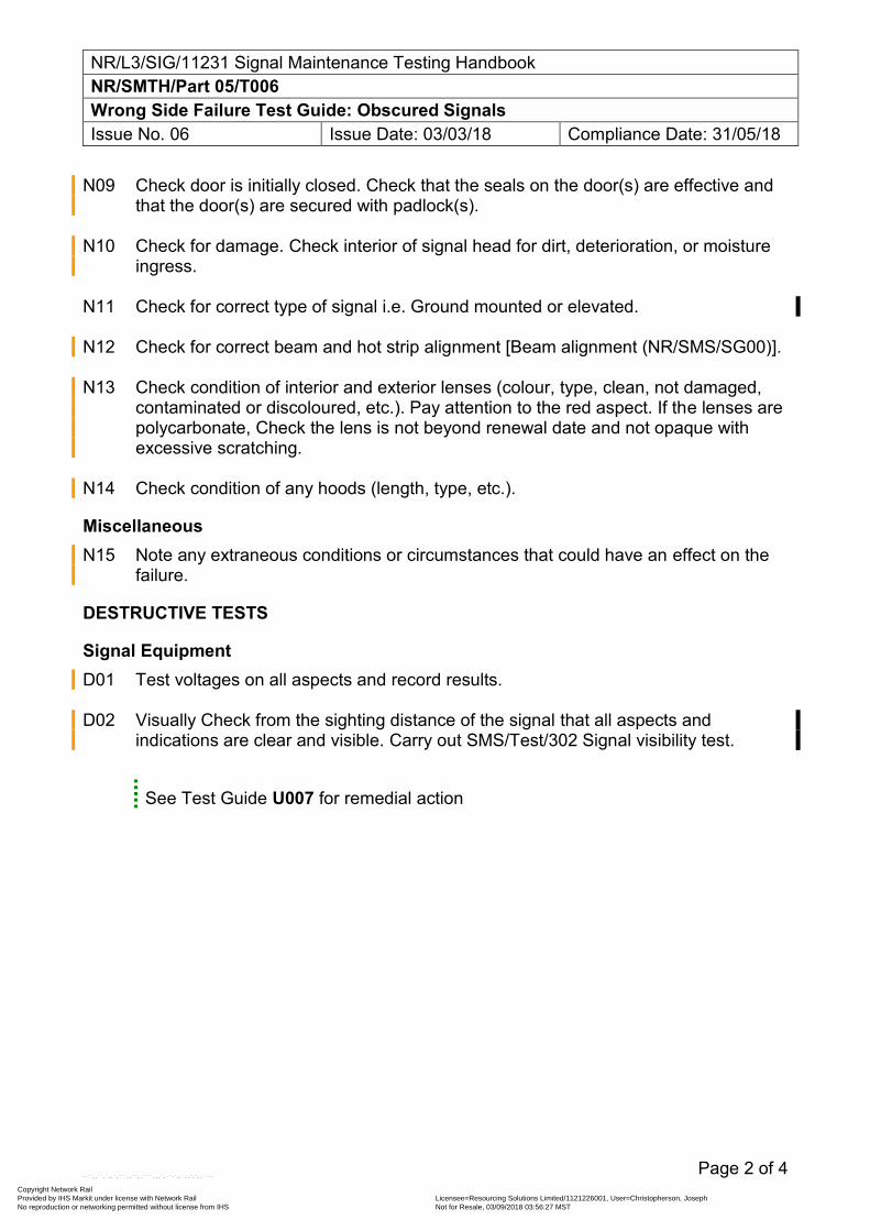
NR/L3/SIG/11231 Signal Maintenance Testing Handbook NR/SMTH/Part 05/T006 Wrong Side Failure Test Guide: Obscured Signals Issue No. 06 Issue Date: 03/03/18 Compliance Date: 31/05/18
Page 2 of 4
N09 Check door is initially closed. Check that the seals on the door(s) are effective and that the door(s) are secured with padlock(s).
N10 Check for damage. Check interior of signal head for dirt, deterioration, or moisture
ingress. N11 Check for correct type of signal i.e. Ground mounted or elevated. N12 Check for correct beam and hot strip alignment [Beam alignment (NR/SMS/SG00)]. N13 Check condition of interior and exterior lenses (colour, type, clean, not damaged,
contaminated or discoloured, etc.). Pay attention to the red aspect. If the lenses are polycarbonate, Check the lens is not beyond renewal date and not opaque with excessive scratching.
N14 Check condition of any hoods (length, type, etc.).
Miscellaneous N15 Note any extraneous conditions or circumstances that could have an effect on the
failure.
DESTRUCTIVE TESTS
Signal Equipment D01 Test voltages on all aspects and record results. D02 Visually Check from the sighting distance of the signal that all aspects and
indications are clear and visible. Carry out SMS/Test/302 Signal visibility test.
See Test Guide U007 for remedial action
Copyright Network Rail Provided by IHS Markit under license with Network Rail Licensee=Resourcing Solutions Limited /1121226001, User=Christopherson, Joseph
Not for Resale, 03/09/2018 03:56:27 MSTNo reproduction or networking permitted without license from IHS
--``,,``,`,,`,```,,``,,````,,,`,-`-`,,`,,`,`,,`---
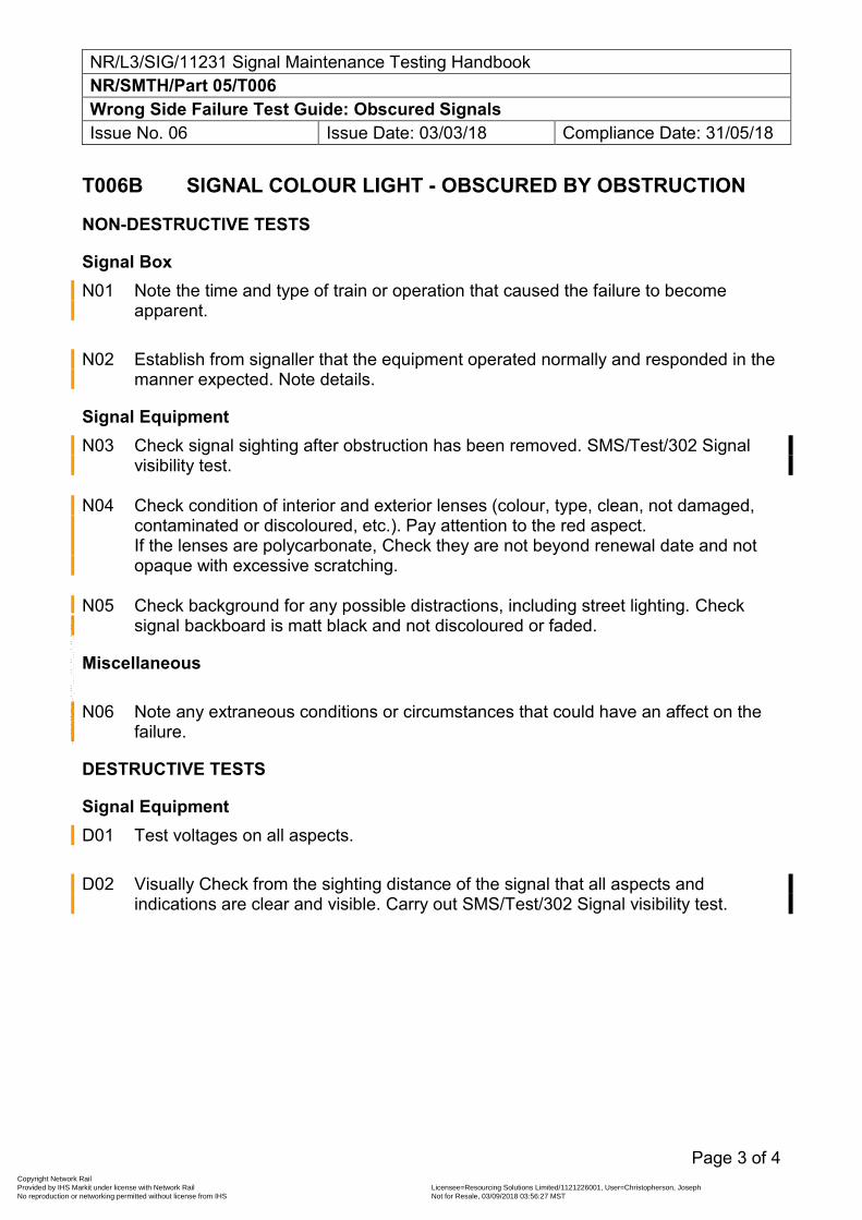
NR/L3/SIG/11231 Signal Maintenance Testing Handbook NR/SMTH/Part 05/T006 Wrong Side Failure Test Guide: Obscured Signals Issue No. 06 Issue Date: 03/03/18 Compliance Date: 31/05/18
Page 3 of 4
T006B SIGNAL COLOUR LIGHT - OBSCURED BY OBSTRUCTION
NON-DESTRUCTIVE TESTS
Signal Box N01 Note the time and type of train or operation that caused the failure to become
apparent. N02 Establish from signaller that the equipment operated normally and responded in the
manner expected. Note details.
Signal Equipment N03 Check signal sighting after obstruction has been removed. SMS/Test/302 Signal
visibility test. N04 Check condition of interior and exterior lenses (colour, type, clean, not damaged,
contaminated or discoloured, etc.). Pay attention to the red aspect. If the lenses are polycarbonate, Check they are not beyond renewal date and not opaque with excessive scratching.
N05 Check background for any possible distractions, including street lighting. Check
signal backboard is matt black and not discoloured or faded.
Miscellaneous N06 Note any extraneous conditions or circumstances that could have an affect on the
failure.
DESTRUCTIVE TESTS
Signal Equipment D01 Test voltages on all aspects. D02 Visually Check from the sighting distance of the signal that all aspects and
indications are clear and visible. Carry out SMS/Test/302 Signal visibility test.
Copyright Network Rail Provided by IHS Markit under license with Network Rail Licensee=Resourcing Solutions Limited /1121226001, User=Christopherson, Joseph
Not for Resale, 03/09/2018 03:56:27 MSTNo reproduction or networking permitted without license from IHS
--``,,``,`,,`,```,,``,,````,,,`,-`-`,,`,,`,`,,`---
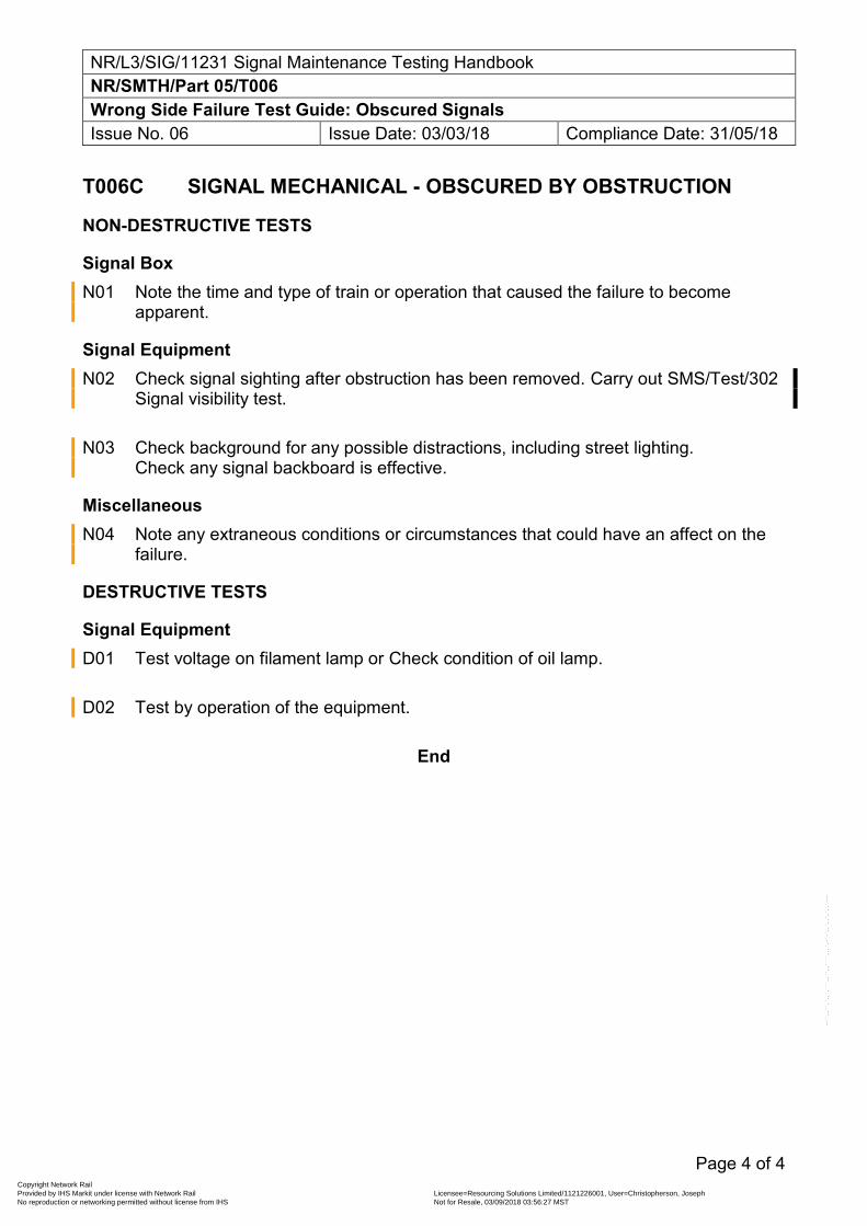
NR/L3/SIG/11231 Signal Maintenance Testing Handbook NR/SMTH/Part 05/T006 Wrong Side Failure Test Guide: Obscured Signals Issue No. 06 Issue Date: 03/03/18 Compliance Date: 31/05/18
Page 4 of 4
T006C SIGNAL MECHANICAL - OBSCURED BY OBSTRUCTION
NON-DESTRUCTIVE TESTS
Signal Box N01 Note the time and type of train or operation that caused the failure to become
apparent.
Signal Equipment N02 Check signal sighting after obstruction has been removed. Carry out SMS/Test/302
Signal visibility test. N03 Check background for any possible distractions, including street lighting.
Check any signal backboard is effective.
Miscellaneous N04 Note any extraneous conditions or circumstances that could have an affect on the
failure.
DESTRUCTIVE TESTS
Signal Equipment D01 Test voltage on filament lamp or Check condition of oil lamp. D02 Test by operation of the equipment.
End
Copyright Network Rail Provided by IHS Markit under license with Network Rail Licensee=Resourcing Solutions Limited /1121226001, User=Christopherson, Joseph
Not for Resale, 03/09/2018 03:56:27 MSTNo reproduction or networking permitted without license from IHS
--``,,``,`,,`,```,,``,,````,,,`,-`-`,,`,,`,`,,`---
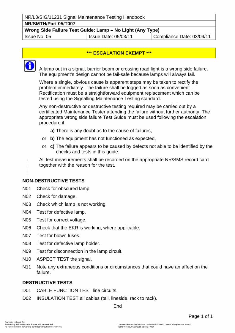
NR/L3/SIG/11231 Signal Maintenance Testing Handbook NR/SMTH/Part 05/T007 Wrong Side Failure Test Guide: Lamp – No Light (Any Type) Issue No. 05 Issue Date: 05/03/11 Compliance Date: 03/09/11
Page 1 of 1
*** ESCALATION EXEMPT ***
A lamp out in a signal, barrier boom or crossing road light is a wrong side failure. The equipment’s design cannot be fail-safe because lamps will always fail.
Where a single, obvious cause is apparent steps may be taken to rectify the problem immediately. The failure shall be logged as soon as convenient. Rectification must be a straightforward equipment replacement which can be tested using the Signalling Maintenance Testing standard.
Any non-destructive or destructive testing required may be carried out by a certificated Maintenance Tester attending the failure without further authority. The appropriate wrong side failure Test Guide must be used following the escalation procedure if:
a) There is any doubt as to the cause of failures,
or b) The equipment has not functioned as expected,
or c) The failure appears to be caused by defects not able to be identified by the checks and tests in this guide.
All test measurements shall be recorded on the appropriate NR/SMS record card together with the reason for the test.
NON-DESTRUCTIVE TESTS
N01 Check for obscured lamp.
N02 Check for damage.
N03 Check which lamp is not working.
N04 Test for defective lamp.
N05 Test for correct voltage.
N06 Check that the EKR is working, where applicable.
N07 Test for blown fuses.
N08 Test for defective lamp holder.
N09 Test for disconnection in the lamp circuit.
N10 ASPECT TEST the signal.
N11 Note any extraneous conditions or circumstances that could have an affect on the failure.
DESTRUCTIVE TESTS
D01 CABLE FUNCTION TEST line circuits.
D02 INSULATION TEST all cables (tail, lineside, rack to rack).
End
Copyright Network Rail Provided by IHS Markit under license with Network Rail Licensee=Resourcing Solutions Limited /1121226001, User=Christopherson, Joseph
Not for Resale, 03/09/2018 03:56:27 MSTNo reproduction or networking permitted without license from IHS
--``,,``,`,,`,```,,``,,````,,,`,-`-`,,`,,`,`,,`---
NR/L3/SIG/11231 Signal Maintenance Testing Handbook NR/SMTH/Part 05/T008 Wrong Side Failure Test Guide: Colour Light Signal Issue No. 07 Issue Date: 03/03/18 Compliance Date: 31/05/18
Page 1 of 6
NON-DESTRUCTIVE TESTS
Signal Box N01 Note any other train movements in the affected area. N02 Note relevant signal box indications. N03 Note relevant lever or switch positions. N04 Note the state of any relevant train describer displays. N05 Note any unusual operating methods in place (hand-signalling, possessions, single
line working, etc). N06 Check whether the signal was replaced in front of the train. N07 Note the nature of any work being done, or persons working in the area. N08 Note the time and type of train (including vehicle class or number), event or
operation that first caused the reported failure to become apparent. N09 Note the time and type of operation last made, prior to the report, which used the
affected equipment. N10 Check that lever locks are correctly padlocked. N11 Check that the signal can display the aspect reported, using any aspect sequence
chart, control table or diagram. Establishing that a signal could not have displayed the reported aspect does not mean that a wrong side failure did not occur.
Lineside Locations or Equipment Rooms N12 Check that the cupboard or room is correctly locked or padlocked. N13 Note the position of relevant relays (energised, de-energised). N14 Check for damage to equipment. N15 Check any relevant system terminal printout and remove any recording media for
checking.
Copyright Network Rail Provided by IHS Markit under license with Network Rail Licensee=Resourcing Solutions Limited /1121226001, User=Christopherson, Joseph
Not for Resale, 03/09/2018 03:56:27 MSTNo reproduction or networking permitted without license from IHS
--``,,``,`,,`,```,,``,,````,,,`,-`-`,,`,,`,`,,`---
NR/L3/SIG/11231 Signal Maintenance Testing Handbook NR/SMTH/Part 05/T008 Wrong Side Failure Test Guide: Colour Light Signal Issue No. 07 Issue Date: 03/03/18 Compliance Date: 31/05/18
Page 2 of 6
N16 Where an SSI Trackside Functional Module (TFM) operates an external function via an interface relay, Check the diagrams to ensure that the system actually proves the correct operation of the external function concerned. The diagrams should show an input to a TFM which proves the external function has responded correctly. It is not sufficient to prove simply that the interface relay has operated.
N17 Check the insulation of cables and wires at terminations. Check that adjacent
terminations are properly isolated from each other. N18 Check for signs of recent disturbances (wiring alterations, track maintenance or
renewal activity). N19 Check for equipment security or tightness. N20 Check for damage inside relays (cracked casing, internal moisture, insects, foreign
matter, contact arcing, internal cloudiness, strong smell, silver sulphide , metal flakes, bent or broken contact springs, or corroded terminals).
N21 Check that relays correspond to the wiring diagram (type and specification, pin
code, voltage, contact arrangement). Record the last service date on the WSF form and forward to your Section Manager (Signals).
N22 Check that equipment and settings correspond to the wiring diagram (specification,
power, voltage rating, etc). N23 Check rear of relay bases for silver migration. N24 Check equipment for possible short circuits (nuts, washers, solder, wire off-cuts,
metallic dust, etc). N25 Check equipment for any unusual amounts of moisture. N26 Test voltages, Record the results. N27 EARTH TEST (DC) and/or EARTH TEST (AC) circuits and supplies.
Signal Equipment N28 Note any significant weather conditions in the area (cloud cover, position and
strength of sun). N29 Note aspects displayed.
Copyright Network Rail Provided by IHS Markit under license with Network Rail Licensee=Resourcing Solutions Limited /1121226001, User=Christopherson, Joseph
Not for Resale, 03/09/2018 03:56:27 MSTNo reproduction or networking permitted without license from IHS
--``,,``,`,,`,```,,``,,````,,,`,-`-`,,`,,`,`,,`---
NR/L3/SIG/11231 Signal Maintenance Testing Handbook NR/SMTH/Part 05/T008 Wrong Side Failure Test Guide: Colour Light Signal Issue No. 07 Issue Date: 03/03/18 Compliance Date: 31/05/18
Page 3 of 6
A camera can be used to record the signal aspects, but it should be noted that because of the shutter speed it is possible to record the aspect flickering (LED Only). This flickering cannot be seen by the human eye.
N30 Check that equipment is correctly locked or padlocked. N31 Check background and any relevant street lighting. N32 Check for damage. Check interior of signal head for dirt, deterioration, or moisture
ingress. N33 Check for Safe Insulation of cables and wires at terminations. Check that adjacent
terminations are properly isolated from each other. N34 Check for signs of any recent disturbances (wiring alterations, track maintenance or
renewal activity). N35 Check for correct beam and hot strip alignment [Beam alignment (NR/SMS/SG00)]. N36 Check condition of interior and exterior lenses (colour, type, clean, not damaged,
contaminated or discoloured, etc.). Pay attention to the red aspect. If the lenses are polycarbonate, Check lens is not beyond renewal date and not opaque with excessive scratching.
N37 Check condition of any hoods (length, type, etc). N38 Check position of signals in sequence for possible reading through of aspects. N39 Note voltage of all aspects in the signal head whether lit or not. N40 Visually check from the sighting distance of the signal that all aspects and
indications are clear and visible. Part Z01 contains sighting distance details.
Cables N41 Check for damage to tail cables (fires, squashed cables, etc).
This includes fibre optic harnesses. N42 Remove covers from trunking and Check for Safe Insulation (chafing, scorched,
rodent damage).
Miscellaneous N43 Check Special Inspection Notices (NR/SIN), Technical Instructions (NR/TI) or
Letters of Instruction (NR/BS/LI/) for any other relevant Non-Destructive tests.
Copyright Network Rail Provided by IHS Markit under license with Network Rail Licensee=Resourcing Solutions Limited /1121226001, User=Christopherson, Joseph
Not for Resale, 03/09/2018 03:56:27 MSTNo reproduction or networking permitted without license from IHS
--``,,``,`,,`,```,,``,,````,,,`,-`-`,,`,,`,`,,`---
NR/L3/SIG/11231 Signal Maintenance Testing Handbook NR/SMTH/Part 05/T008 Wrong Side Failure Test Guide: Colour Light Signal Issue No. 07 Issue Date: 03/03/18 Compliance Date: 31/05/18
Page 4 of 6
N44 Note any extraneous conditions or circumstances that could have an affect on the failure.
DESTRUCTIVE TESTS
Signal Box D01 Check switch, button or circuit controller condition and security and look for signs of
metallic dust which could have caused a short circuit. D02 Check that any polarised needle type indicators operate in correspondence with any
polarised relays wired in series with the indicator.
Lineside Locations or Equipment Rooms D03 WIRE COUNT relevant equipment or circuits to the wiring diagram. D04 Check that latched relays will not unlatch when lightly tapped. D05 Test effectiveness of approach locking by recreating the effect of a train. D06 After clearing the suspect signal, Test for voltage at the final control relay, or
equivalent, whilst recreating the passage of a train on the section ahead from the entrance signal up to the end of the overlap of the exit signal.
When reproducing the effect of a passing train, the tests shall be carried out twice; once for a ‘light engine’ and once for the longest likely train.
D07 After clearing the suspect signal, Test for voltage at the final control relay, or
equivalent, whilst alternative overlaps are selected and occupied. D08 Test for voltage at the final control relay, or equivalent, with no route set forward
from the suspect signal while each point in the route ahead of the signal is operated (one at a time) to both reverse and normal.
D09 Remove relays and Check for damage inside relays (cracked casing, internal
moisture, insects, foreign matter, contact arcing, internal cloudiness, silver sulphide, metal flakes, bent or broken contact springs, or corroded terminals).
D10 Remove mechanical searchlight mechanism and Check for damage inside (cracked
casing, internal moisture, insects, foreign matter, contact arcing, internal cloudiness, silver sulphide, metal flakes, bent or broken contact springs, or corroded terminals).
D11 Check relay base for silver migration, damage, spades pushed too far forward or
broken contact insulators.
Copyright Network Rail Provided by IHS Markit under license with Network Rail Licensee=Resourcing Solutions Limited /1121226001, User=Christopherson, Joseph
Not for Resale, 03/09/2018 03:56:27 MSTNo reproduction or networking permitted without license from IHS
--``,,``,`,,`,```,,``,,````,,,`,-`-`,,`,,`,`,,`---
NR/L3/SIG/11231 Signal Maintenance Testing Handbook NR/SMTH/Part 05/T008 Wrong Side Failure Test Guide: Colour Light Signal Issue No. 07 Issue Date: 03/03/18 Compliance Date: 31/05/18
Page 5 of 6
D12 Check the contact adjustment or pressure of any relevant contacts (lever bands, circuit controllers, etc).
D13 Check for loose connections or crimps in any circuit affecting the reported signal. D14 CABLE FUNCTION TEST line circuits. D15 INSULATION TEST suspect circuit to earth. D16 INSULATION TEST suspect circuit to other relevant circuits. D17 INSULATION TEST all cables (tail, lineside, rack to rack). D18 Test the lamp circuit current, with lamp lit and with the lamp removed. D19 Check that the TFM current proving function is in use, by carrying out a LAMP
PROVING TEST for each current-proved output [Remove lamp test (NR/SMS/Test/022)] (ALSTOM Mk3, MOD STATE 4, SSI SIGNAL MODULE ONLY)
It is not necessary to carry out the first filament failure test, but only to confirm with the signaller that the lamp-out condition has been detected.
If the module fails to detect lamp out, current proving links in the 75-way plug coupler shall be verified by visually checking for correct position of the pins and measurement of electrical continuity. If the links and plug coupler are in place, the module itself shall be sent for investigation.
D20 Test the position light junction indicator transformer current with the indicator lamps
removed (where relays are used for lamp proving position light junction indicators fitted with transformers).
D21 Test for intermittent high resistance faults in common return, looping or spur
circuits.
Signal Equipment D22 Check signal post replacement switch condition. D23 Check that the lamp is securely held in the lamp holder. D24 Test and Note time of approach locking and Check that any indication of signal
being approach locked is effective to the signaller. D25 Test and Note time of any approach control. D26 ASPECT TEST the signal for the affected route while maintaining alternative exit
signals at their least restrictive aspect.
Copyright Network Rail Provided by IHS Markit under license with Network Rail Licensee=Resourcing Solutions Limited /1121226001, User=Christopherson, Joseph
Not for Resale, 03/09/2018 03:56:27 MSTNo reproduction or networking permitted without license from IHS
--``,,``,`,,`,```,,``,,````,,,`,-`-`,,`,,`,`,,`---
NR/L3/SIG/11231 Signal Maintenance Testing Handbook NR/SMTH/Part 05/T008 Wrong Side Failure Test Guide: Colour Light Signal Issue No. 07 Issue Date: 03/03/18 Compliance Date: 31/05/18
Page 6 of 6
It is not necessary to clear alternative exit shunt signals unless the suspect signal pre-sets the shunt signal.
D27 Check filament change-over relays for correct operation.
Miscellaneous D28 Check Special Inspection Notices (NR/SIN), Technical Instructions (NR/TI) or
Letters of Instruction (NR/BS/LI/) for any other relevant Destructive tests.
OTHER CONSIDERATIONS 01 Possible right side failure of signal in advance (masked by report of WSF to signal
in rear).
02 Possible WSF of signal in advance.
03 Possible remote control system failure.
04 Possible failure of track circuit.
05 Possible design error in signal circuits.
06 Possible WSF of AWS misleading driver into expecting a less restrictive aspect.
07 Possible WSF of interlocking.
08 Possible WSF of lever lock.
09 Possible WSF of block circuits.
10 Possible timing mismatch between SSI interlockings and conventional relay circuits.
End
Copyright Network Rail Provided by IHS Markit under license with Network Rail Licensee=Resourcing Solutions Limited /1121226001, User=Christopherson, Joseph
Not for Resale, 03/09/2018 03:56:27 MSTNo reproduction or networking permitted without license from IHS
--``,,``,`,,`,```,,``,,````,,,`,-`-`,,`,,`,`,,`---
NR/L3/SIG/11231 Signal Maintenance Testing Handbook NR/SMTH/Part 05/T009 Wrong Side Failure Test Guide: Mechanical Signal Issue No. 05 Issue Date: 05/03/11 Compliance Date: 03/09/11
Page 1 of 4
NON-DESTRUCTIVE TESTS
Signal Box
N01 Note relevant lever or switch positions.
N02 Note relevant signal box indications.
N03 Note the state of any relevant train describer displays.
N04 Note any unusual operating methods in place (hand-signalling, possessions, single line working, etc).
N05 Note the nature of any work being done, or persons working in the area.
N06 Note the time and type of train (including vehicle class or number), event or operation that first caused the reported failure to become apparent.
N07 Note the time and type of operation last made, prior to the report, which used the affected equipment.
N08 Note any other train movements in the affected area.
N09 Note any significant weather conditions in the area (cloud cover, position and strength of sun).
Lineside Locations or Equipment Rooms
N10 Check cupboard or room is correctly locked or padlocked.
N11 Check for damage.
N12 Check for signs of recent disturbances (wiring alterations, P Way activity).
N13 Check for security or tightness of equipment (lever locks, circuit controllers, arm repeaters, etc).
N14 Check the position of relevant relays (energised, de-energised).
N15 Check for damage (cracked casing, internal moisture, insects, foreign matter, contact arcing, internal cloudiness, strong smell, silver sulphide, metal flakes, bent or broken contact springs, or corroded terminals).
N16 Check that any relays correspond to the wiring diagram (type and specification, pin code, voltage, contact arrangement).
Record the last service date on the WSF form and forward to your Section Manager (Signals).
N17 Check that equipment and settings correspond to the wiring diagram (specification, power, voltage rating, etc).
N18 Check rear of relay bases for silver migration.
N19 Check equipment for possible short circuits (nuts, washers, solder, wire off-cuts, metallic dust, etc).
Copyright Network Rail Provided by IHS Markit under license with Network Rail Licensee=Resourcing Solutions Limited /1121226001, User=Christopherson, Joseph
Not for Resale, 03/09/2018 03:56:27 MSTNo reproduction or networking permitted without license from IHS
--``,,``,`,,`,```,,``,,````,,,`,-`-`,,`,,`,`,,`---
NR/L3/SIG/11231 Signal Maintenance Testing Handbook NR/SMTH/Part 05/T009 Wrong Side Failure Test Guide: Mechanical Signal Issue No. 05 Issue Date: 05/03/11 Compliance Date: 03/09/11
Page 2 of 4
N20 Check equipment for any unusual amounts of moisture.
N21 Test voltages, recording the results.
N22 EARTH TEST (DC) or EARTH TEST (AC) circuits and supplies.
Signal Equipment and Wire Run
N23 Check for any signs of equipment damage.
N24 Check for signs of any recent disturbances (wiring alterations, track maintenance or renewals activity).
N25 Check the signal’s position.
N26 Check background and any relevant street lighting.
N27 Check that the spindle is not seized or frozen.
N28 Check that the return weights are not missing.
N29 Check for any excessive vegetation holding signal arm off.
N30 Check for any mechanical detection holding signal arm off.
N31 Check for excessive wear in moving parts
N32 Check the counterweights and pulley wheels are not binding on adjacent weights and crank arms.
N33 Check the wire run for fouling objects.
N34 Check for wire caught in other wires or rods.
N35 Check that the wire is not frozen to the ballast, troughing or pipes.
N36 Check for correct regulation of the signal wire.
N37 Check cleanliness and state of lubrication.
Cables and Wires
N38 Check for damage (fires, squashed cables, etc).
N39 Check the insulation of cables and wires at terminations. Check that adjacent terminations are properly isolated from each other.
N40 Remove covers from trunking and Check for safe insulation (chafing, scorched, rodent damage).
Miscellaneous
N41 Check Special Inspection Notices (NR/SIN), Technical Instructions (NR/TI) or Letters of Instruction (NR/BS/LI/) for any other relevant Non-Destructive tests.
DESTRUCTIVE TESTS
Signal Box
D01 MECHANICAL LOCKING FUNCTION TEST affected levers.
Copyright Network Rail Provided by IHS Markit under license with Network Rail Licensee=Resourcing Solutions Limited /1121226001, User=Christopherson, Joseph
Not for Resale, 03/09/2018 03:56:27 MSTNo reproduction or networking permitted without license from IHS
--``,,``,`,,`,```,,``,,````,,,`,-`-`,,`,,`,`,,`---
NR/L3/SIG/11231 Signal Maintenance Testing Handbook NR/SMTH/Part 05/T009 Wrong Side Failure Test Guide: Mechanical Signal Issue No. 05 Issue Date: 05/03/11 Compliance Date: 03/09/11
Page 3 of 4
D02 Check that any polarised needle type indicators operate in correspondence with any polarised relays wired in series with the indicator.
D03 Test operation of signal by slowly returning the lever to the normal position in the frame whilst observing the movement of the signal arm or disk.
Lineside Locations or Equipment Rooms
D04 WIRE COUNT relevant equipment or circuits to the wiring diagram.
D05 Remove relays and Check for damage inside relays (cracked casing, internal moisture, insects, foreign matter, contact arcing, internal cloudiness, silver sulphide, metal flakes, bent or broken contact springs, or corroded terminals).
D06 Check relay base front for silver migration, damage, spades pushed too far forward or broken contact insulators.
D07 Check contact adjustment and pressure of any relevant contacts (lever bands, circuit controllers, etc).
D08 INSULATION TEST relevant circuit to earth.
D09 INSULATION TEST relevant circuit to other suspect circuits.
D10 Test for intermittent high resistance faults in any capacitor slug circuit, unless relay stick contacts are wired in series with capacitor.
D11 Test for intermittent high resistance faults in common return, looping or spur circuits.
Signal Equipment
D12 Check contact adjustment and pressure of any relevant contacts (Arm repeaters, point detection, etc).
D13 Test mechanical detection [Detection test (NR/SMS/Test/012)] and Record the test measurements on the appropriate NR/SMS record card, together with the reason for the test.
D14 Test electrical detection [Detection test (NR/SMS/Test/010, 011, 013)] and Record the test measurements on the appropriate NR/SMS record card, together with the reason for the test.
D15 Test the minimum ’hold off’ voltage of a motor operated signal.
D16 Check signal machine brake will freely release when de-energised (Motor operated signals).
Cables and Wires
D17 CABLE FUNCTION TEST line circuits.
D18 INSULATION TEST all cables (tail, lineside, rack to rack).
Copyright Network Rail Provided by IHS Markit under license with Network Rail Licensee=Resourcing Solutions Limited /1121226001, User=Christopherson, Joseph
Not for Resale, 03/09/2018 03:56:27 MSTNo reproduction or networking permitted without license from IHS
--``,,``,`,,`,```,,``,,````,,,`,-`-`,,`,,`,`,,`---
NR/L3/SIG/11231 Signal Maintenance Testing Handbook NR/SMTH/Part 05/T009 Wrong Side Failure Test Guide: Mechanical Signal Issue No. 05 Issue Date: 05/03/11 Compliance Date: 03/09/11
Page 4 of 4
Miscellaneous
D19 Check Special Inspection Notices (NR/SIN), Technical Instructions (NR/TI) or Letters of Instruction (NR/BS/LI/) for any other relevant Destructive tests.
OTHER CONSIDERATIONS
01 Possible WSF of treadle circuits.
02 Possible WSF of block circuits.
03 Possible WSF of track circuit.
End
Copyright Network Rail Provided by IHS Markit under license with Network Rail Licensee=Resourcing Solutions Limited /1121226001, User=Christopherson, Joseph
Not for Resale, 03/09/2018 03:56:27 MSTNo reproduction or networking permitted without license from IHS
--``,,``,`,,`,```,,``,,````,,,`,-`-`,,`,,`,`,,`---
NR/L3/SIG/11231 Signal Maintenance Testing Handbook NR/SMTH/Part 05/T010 Wrong Side Failure Test Guide: Points Issue No. 6 Issue Date: 06/09/2014 Compliance Date: 07/03/2015
Page 1 of 6
NON-DESTRUCTIVE TESTS Signal Box N01 Note relevant lever or switch positions. N02 Note relevant signal box indications. N03 Note the state of any relevant train describer displays. N04 Note any unusual operating methods in place (hand-signalling, possessions, single
line working, etc). N05 Note the nature of any work being done, or persons working in the area. N06 Note the time and type of train (including vehicle class or number), event or
operation that first caused the reported failure to become apparent. N07 Note the time and type of operation last made, prior to the report, which used the
affected equipment. N08 Note any other train movements in the affected area. N09 Note the condition of sealed releases. Lineside Locations or Equipment Rooms N10 Check that the cupboard or room is correctly locked or padlocked. N11 Check for damage. N12 Check any relevant system terminal printout and remove any recording media for
checking. N13 Where a SSI Trackside Functional Module (TFM) operates an external function via
an interface relay, Check the diagrams for the system to prove the correct operation of the external function concerned. The diagrams should show an input to a TFM which proves the external function has responded correctly. It is not sufficient to prove simply that the interface relay has operated.
N14 Check for signs of recent disturbances (wiring alterations, track maintenance or
renewals activity). N15 Check for security or tightness of equipment. N16 Check the position of relevant relays (energised, de-energised).
Copyright Network Rail Provided by IHS Markit under license with Network Rail Licensee=Resourcing Solutions Limited /1121226001, User=Christopherson, Joseph
Not for Resale, 03/09/2018 03:56:27 MSTNo reproduction or networking permitted without license from IHS
--``,,``,`,,`,```,,``,,````,,,`,-`-`,,`,,`,`,,`---
NR/L3/SIG/11231 Signal Maintenance Testing Handbook NR/SMTH/Part 05/T010 Wrong Side Failure Test Guide: Points Issue No. 6 Issue Date: 06/09/2014 Compliance Date: 07/03/2015
Page 2 of 6
N17 Check for damage inside relays (cracked casing, internal moisture, insects, foreign matter, contact arcing, internal cloudiness, strong smell, silver sulphide, metal flakes, bent or broken contact springs, or corroded terminals).
N18 Check that relays correspond to the wiring diagram (type and specification, pin
code, voltage, contact arrangement).
Record the last service date on the WSF form and forward to your Section Manager (Signals).
N19 Check that equipment and settings correspond to the wiring diagram (specification,
power, voltage rating, etc). N20 Check rear of relay bases for silver migration. N21 Check equipment for possible short circuits (nuts, washers, solder, wire off-cuts,
metallic dust, etc). N22 Check equipment for any unusual amounts of moisture. N23 Test voltages, recording the results. N24 EARTH TEST (DC) [NR/SMTH/11231/Part03/TestB05] or EARTH TEST (AC)
[NR/SMTH/11231/Part03/TestB06] circuits and supplies. On-Track Equipment N25 Check that the equipment is correctly locked or padlocked. N26 Check for damage. N27 Check for signs of any recent disturbances (wiring alterations, track maintenance or
renewals activity). N28 Check ECU is correct type (HPSS ONLY) N29 Check for excessive wear in moving parts. N30 Check that the points have not been run through. N31 Check that the machine casting is not broken or cracked. N32 Check for correct movement in mechanical detectors, rodding runs and
compensators. N33 Check security of fastenings and sole plate. N34 Check the reservoir oil level and for any leaks in the hydraulic system (clamp locks).
Copyright Network Rail Provided by IHS Markit under license with Network Rail Licensee=Resourcing Solutions Limited /1121226001, User=Christopherson, Joseph
Not for Resale, 03/09/2018 03:56:27 MSTNo reproduction or networking permitted without license from IHS
--``,,``,`,,`,```,,``,,````,,,`,-`-`,,`,,`,`,,`---
NR/L3/SIG/11231 Signal Maintenance Testing Handbook NR/SMTH/Part 05/T010 Wrong Side Failure Test Guide: Points Issue No. 6 Issue Date: 06/09/2014 Compliance Date: 07/03/2015
Page 3 of 6
N35 Check rail openings and Record any track defects. N36 Check for cracks in Mk1 clamp lock bodies, FPL castings and detector castings. N37 Check hollow steel bearers for cracks or damage. N38 Check torsion supplementary drive for cracks or damage. N39 Check the break-out devices have not been operated. (Hy-Drive System ONLY) N40 Check the by-pass valve has not been operated or damaged such as would cause
a loss of hydraulic pressure. (Hy-Drive System ONLY) N41 Check the plug/socket connectors are not damaged and that the connector plug has
been properly connected and locked in place. Do not disconnect at this stage. Cables N42 Check for damage (fires, squashed cables, etc). N43 Check for safe insulation of cables and wires at terminations. Check that adjacent
terminations are properly isolated from each other. N44 Remove covers from trunking and Check for Safe Insulation (chafing, scorched,
rodent damage). Miscellaneous N45 Check Special Inspection Notices (NR/SIN), Technical Instructions (NR/TI) or
Letters of Instruction (NR/BS/LI/) for any other relevant Non-Destructive tests.
DESTRUCTIVE TESTS Signal Box D01 Test that swinging overlaps can only be swung when alternative overlaps are free. D02 Test that points respond to their being called and that any FPL lever operation is
effective. D03 Check the independent point switch to confirm it is secure and that there are no
short circuits (e.g. metallic dust, wire strands) across the contacts. Lineside Locations or Equipment Rooms D04 Wire Count relevant equipment or circuits to the wiring diagram. D05 Check that latched point relays will not unlatch when lightly tapped.
Copyright Network Rail Provided by IHS Markit under license with Network Rail Licensee=Resourcing Solutions Limited /1121226001, User=Christopherson, Joseph
Not for Resale, 03/09/2018 03:56:27 MSTNo reproduction or networking permitted without license from IHS
--``,,``,`,,`,```,,``,,````,,,`,-`-`,,`,,`,`,,`---
NR/L3/SIG/11231 Signal Maintenance Testing Handbook NR/SMTH/Part 05/T010 Wrong Side Failure Test Guide: Points Issue No. 6 Issue Date: 06/09/2014 Compliance Date: 07/03/2015
Page 4 of 6
D06 Test that the route locking holds after the protecting signal is replaced to danger by
recreating the effect of a passing train and cancelling the route. D07 Test that occupying the berth track circuit of the protecting signal(s) correctly locks
the points for the designed time (where required by the control tables). D08 Remove relays and Check for damage inside relays (cracked casing, internal
moisture, insects, foreign matter, contact arcing, internal cloudiness, silver sulphide, metal flakes, bent or broken contact springs, or corroded terminals).
D09 Check relay base front for silver migration, damage, spades pushed too far forward
or broken contact insulators. D10 Check contact adjustment or pressure of any relevant contacts (lever bands, etc). D11 INSULATION TEST [NR/SMTH/11231/Part03/TestB03] relevant circuit to earth. D12 INSULATION TEST [NR/SMTH/11231/Part03/TestB03] relevant circuit to other
suspect circuits. D13 INSULATION TEST [NR/SMTH/11231/Part03/TestB03] motor in both normal and
reverse positions. D14 Test for intermittent high resistance faults in any capacitor slug circuit, unless relay
stick contacts are wired in series with capacitor. D15 Test for intermittent high resistance faults in common return, looping or spur
circuits. On-Track Equipment D16 Wire Count on-track point operating equipment to the wiring diagram. D17 Test effectiveness of power/manual selector switch interlock (clamp lock). D18 Check for any excessive point operation time. D19 Test and Note hydraulic pressure and that any pressure detection is effective, e.g.
train operated points. D20 Test that air has been excluded from the hydraulic system before continuing [Check
system for air (NR/SMS/Test/015)] (CLAMP LOCKS ONLY) D21 Check plug coupler condition and security, and look for signs of metallic dust which
could have caused a short circuit. D22 Check contact adjustment or pressure of any relevant contacts (drive, detection,
etc).
Copyright Network Rail Provided by IHS Markit under license with Network Rail Licensee=Resourcing Solutions Limited /1121226001, User=Christopherson, Joseph
Not for Resale, 03/09/2018 03:56:27 MSTNo reproduction or networking permitted without license from IHS
--``,,``,`,,`,```,,``,,````,,,`,-`-`,,`,,`,`,,`---
NR/L3/SIG/11231 Signal Maintenance Testing Handbook NR/SMTH/Part 05/T010 Wrong Side Failure Test Guide: Points Issue No. 6 Issue Date: 06/09/2014 Compliance Date: 07/03/2015
Page 5 of 6
D23 Check the clutch. D24 Test the time of motor cut-out when point movement is obstructed. D25 Point Detection and Correspondence Test [NR/SMTH/11231/Part03/TestB08]. D26 Test Facing point lock [Facing point lock test (NR/SMS/Test/001-005)] and Record
the test measurements on the appropriate NR/SMS record card, together with the reason for the test.
D27 Test for electrical leakage [BR998 detector test (NR/SMS/Test/010)]
(APPLICABLE BR998 DETECTORS ONLY) D28 Connect the HPSA Handset to the ECU. From the “Main Menu” select the “Get Log
Dump” function. Once the data has been transferred to the Handset (approx 2 minutes), select the “Get Status” function. Note the readings and report any discrepancies between the handset readings, the physical lie of the points and the number of LVDTs (Linear Variable Differential Transducer) installed (HPSS ONLY)
The Handset shall be sealed (e.g. by bagging) and advice sought on the facilities to interpret the data. The handset shall not be used on another ECU or the data will be lost. However, the same handset may be used to reset the HPSS datum on the ECU concerned.
D29 Check the brake torque (holding capability) is correct, testing each brake separately
[Brake torque test (NR/SMS/PC51)] (HPSS ONLY) D30 Manually release both brakes and attempt to bar the points to the opposite position
by applying force to the open switch rail. Repeat for the opposite lie of the points (this is to check the integrity of the Acme leadscrew, located in the gearbox, which performs the function of the FPL) (HPSS ONLY)
D31 Check each LVDT is working correctly by conducting the detection test [Detection
test (NR/SMS/Test/011)] (HPSS ONLY) D32 Where air is suspected in the system it should be bled by:
a) Opening the by-pass valve; b) Manually operating the points in only one direction for at least 90 seconds; c) And closing and locking the by-pass valve (Hy-Drive System ONLY)
D33 Check each SO Unit is working correctly by conducting the detection test [SMS Test
009] (Hy-Drive System ONLY) Cables D34 CABLE FUNCTION TEST [NR/SMTH/11231/Part03/TestB04] line circuits.
Copyright Network Rail Provided by IHS Markit under license with Network Rail Licensee=Resourcing Solutions Limited /1121226001, User=Christopherson, Joseph
Not for Resale, 03/09/2018 03:56:27 MSTNo reproduction or networking permitted without license from IHS
--``,,``,`,,`,```,,``,,````,,,`,-`-`,,`,,`,`,,`---
NR/L3/SIG/11231 Signal Maintenance Testing Handbook NR/SMTH/Part 05/T010 Wrong Side Failure Test Guide: Points Issue No. 6 Issue Date: 06/09/2014 Compliance Date: 07/03/2015
Page 6 of 6
D35 INSULATION TEST [NR/SMTH/11231/Part03/TestB03] all cables (tail, lineside, rack to rack).
Miscellaneous D36 Check Special Inspection Notices (NR/SIN), Technical Instructions (NR/TI) or
Letters of Instruction (NR/BS/LI/) for any other relevant Destructive tests. OTHER CONSIDERATIONS 01 Possible remote control system failure. 02 Possible WSF of track circuit. 03 Possible WSF of protecting signal. 04 Possible design error in point circuits. 05 Possible WSF of lever lock. 06 Possible timing mismatch between SSI interlockings and conventional relay circuits.
END
Copyright Network Rail Provided by IHS Markit under license with Network Rail Licensee=Resourcing Solutions Limited /1121226001, User=Christopherson, Joseph
Not for Resale, 03/09/2018 03:56:27 MSTNo reproduction or networking permitted without license from IHS
--``,,``,`,,`,```,,``,,````,,,`,-`-`,,`,,`,`,,`---
NR/L3/SIG/11231 Signal Maintenance Testing Handbook NR/SMTH/Part 05/T011 Wrong Side Failure Test Guide: Automatic Warning System (AWS) Issue No. 08 Issue Date: 03/03/18 Compliance Date: 31/05/18
All test measurements shall be recorded on the record card together with the reason for the test. NON-DESTRUCTIVE TESTS Signal Box N01 Note any unusual operating methods in place (hand-signalling, possessions, single
line working, etc). N02 Note the nature of any work being done, or persons working in the area. N03 Note the time and type of train (including vehicle class or number), event or
operation that first caused the reported failure to become apparent and whether the train approach was particularly slow.
Class 319 electric multiple units automatically sense the traction system, so will display to the driver if the traction is DC. The AWS setting defaults to standard strength and will remain so until the driver selects the extra-strength setting (for DC traction areas). If the driver does not correctly set the AWS system to the right sensitivity, the AWS might indicate a Code 5 WSF.
On routes operating class 377/2, 377/5, & 376/6 electric multiple units, confirm that the AWS receiver on the rail vehicle is operating in the correct mode of operation (AC or DC).
This is particularly applicable to failures on services that are operating on a route that has traversed an AC & DC electrified boundary.
N04 Note the time and type of operation last made, prior to the report, which used the
affected equipment. N05 Note any other train movements in the affected area. Lineside Locations or Equipment Rooms N06 Check that the cupboard or room is correctly locked. N07 Check for damage. N08 Check any relevant system terminal printout and remove any recording media for
checking. N09 Check for signs of recent disturbances (wiring alterations, track maintenance or
renewals activity). N10 Check for security or tightness of equipment.
Copyright Network Rail Provided by IHS Markit under license with Network Rail Licensee=Resourcing Solutions Limited /1121226001, User=Christopherson, Joseph
Not for Resale, 03/09/2018 03:56:27 MSTNo reproduction or networking permitted without license from IHS
--``,,``,`,,`,```,,``,,````,,,`,-`-`,,`,,`,`,,`---
NR/L3/SIG/11231 Signal Maintenance Testing Handbook NR/SMTH/Part 05/T011 Wrong Side Failure Test Guide: Automatic Warning System (AWS) Issue No. 08 Issue Date: 03/03/18 Compliance Date: 31/05/18
N11 Check the position of relevant relays (energised, de-energised). N12 Check for damage inside relays (cracked casing, internal moisture, insects, foreign
matter, contact arcing, internal cloudiness, strong smell, silver sulphide, metal flakes, bent or broken contact springs, or corroded terminals).
N13 Check that relays correspond to the wiring diagram (type and specification, pin
code, voltage, contact arrangement).
Record the last service date on the WSF form and forward to your SM(S)
N14 Check that equipment and settings correspond to the wiring diagram (specification,
power, voltage rating, etc.). N15 Check rear of relay bases for silver migration. N16 Check equipment for possible short circuits (nuts, washers, solder, wire off-cuts,
metallic dust, etc). N17 Check equipment for any unusual amounts of moisture. N18 Test voltages, recording the results. N19 EARTH TEST (DC) [NR/SMTH/11231/Part03/TestB05] or EARTH TEST (AC)
[NR/SMTH/11231/Part03/TestB06] circuits and supplies. On-Track Equipment N20 Check position of magnets (height, centre of track). Check equipment is Correct
Type (Standard - yellow or Extra-Strength - green). Check for other potential sources of magnetic field nearby (e.g. impedance bonds, DC traction cables).
Yardene Single Rail Temporary Magnets are not required to be height tested. Check that the calibration date of the Yardene Single Rail Temporary Magnet is in date.
N21 Check for correct operation of temporary speed restriction magnets and that they
are not closer than 183m (200 yards) to the AWS under investigation. N22 Check for damage. N23 Check for signs of any recent disturbances (wiring alterations, track maintenance or
renewals activity). N24 Check for track defects in the area of the inductors.
Copyright Network Rail Provided by IHS Markit under license with Network Rail Licensee=Resourcing Solutions Limited /1121226001, User=Christopherson, Joseph
Not for Resale, 03/09/2018 03:56:27 MSTNo reproduction or networking permitted without license from IHS
--``,,``,`,,`,```,,``,,````,,,`,-`-`,,`,,`,`,,`---
NR/L3/SIG/11231 Signal Maintenance Testing Handbook NR/SMTH/Part 05/T011 Wrong Side Failure Test Guide: Automatic Warning System (AWS) Issue No. 08 Issue Date: 03/03/18 Compliance Date: 31/05/18
N25 Check security of internal and external connections, in the inductor disconnection
box. N26 Check security of plug coupler. Cables N27 Check for damage (fires, squashed cables, etc). N28 Check the insulation of cables and wires at terminations if provided. Check that
adjacent terminations are properly isolated from each other. N29 Remove covers from trunking, and Check for safe insulation (chafing, scorched,
rodent damage). Miscellaneous N30 Check Special Inspection Notices (NR/SIN), Technical Instructions (NR/TI) or
Letters of Instruction (NR/BS/LI/) for any other relevant Non-Destructive tests. DESTRUCTIVE TESTS Excludes: Yardene Single Rail Temporary Magnets
Lineside Locations or Equipment Rooms D01 Wire Count relevant equipment or circuits to the wiring diagram. D02 Remove relays and Check for damage inside relays (cracked casing, internal
moisture, insects, foreign matter, contact arcing, internal cloudiness, silver sulphide, metal flakes, bent or broken contact springs, or corroded terminals).
D03 Check relay base front for silver migration, damage, spades pushed too far forward
or broken contact insulators. D04 Test current to inductor with signal at all possible aspects. D05 Test AWS diode if present [AWS diode test (NR/SMS/Test/024)] and Record the
test measurements on the record card.
Note: The Vortok AWS magnets are designed with spark quench diodes as part of their internal circuitry and there is no requirement to perform this test.
D06 Test that lamp proving relays function correctly when the lamps are disconnected. D07 INSULATION TEST [NR/SMTH/11231/Part03/TestB03] relevant circuit to earth. D08 INSULATION TEST [NR/SMTH/11231/Part03/TestB03] relevant circuit to other
suspect circuits. Copyright Network Rail Provided by IHS Markit under license with Network Rail Licensee=Resourcing Solutions Limited /1121226001, User=Christopherson, Joseph
Not for Resale, 03/09/2018 03:56:27 MSTNo reproduction or networking permitted without license from IHS
--``,,``,`,,`,```,,``,,````,,,`,-`-`,,`,,`,`,,`---
NR/L3/SIG/11231 Signal Maintenance Testing Handbook NR/SMTH/Part 05/T011 Wrong Side Failure Test Guide: Automatic Warning System (AWS) Issue No. 08 Issue Date: 03/03/18 Compliance Date: 31/05/18
D09 Test for intermittent high resistance faults in common return, looping or spur
circuits. On-Track Equipment
When testing a plug coupled unit you shall use a “Breakout box”. Do not use test equipment directly on the plug coupler pins and/or sockets.
D10 If provided, disconnect plug coupler and Check for damage (cracked casing,
internal moisture, foreign matter, contact arcing, metal flakes, bent or broken or corroded contacts) to either male or female contacts.
D11 Test resistance or impedance of inductor and compare with voltage and current
readings. D12 Test (for each aspect) the signal’s permanent and electro-magnets for correct
strength and polarity (using S&P meter). D13 Test voltage and polarity at the electro-magnet, recording the results. D14 Test (for each aspect) the signal’s electro-magnets for incorrect operation by any
adjacent signal (using S&P meter). D15 Test voltage and polarity at the electro-magnet for incorrect operation by any
adjacent signal at each of its aspects. Cables D16 CABLE FUNCTION TEST [NR/SMTH/11231/Part03/TestB04] line circuits. D17 INSULATION TEST [NR/SMTH/11231/Part03/TestB03] all cables (tail, lineside,
rack to rack). Miscellaneous D18 Check Special Inspection Notices (NR/SIN), Technical Instructions (NR/TI) or
Letters of Instruction (NR/BS/LI/) for any other relevant Destructive tests. OTHER CONSIDERATIONS 01 Possible right side failure of signal in advance of AWS. 02 Possible failure of train borne equipment. 03 Where suppression is switched by occupation of track circuit, joints could be too
close to suppressed inductor. They shall not be less than 40 metres.
Copyright Network Rail Provided by IHS Markit under license with Network Rail Licensee=Resourcing Solutions Limited /1121226001, User=Christopherson, Joseph
Not for Resale, 03/09/2018 03:56:27 MSTNo reproduction or networking permitted without license from IHS
--``,,``,`,,`,```,,``,,````,,,`,-`-`,,`,,`,`,,`---
NR/L3/SIG/11231 Signal Maintenance Testing Handbook NR/SMTH/Part 05/T011 Wrong Side Failure Test Guide: Automatic Warning System (AWS) Issue No. 08 Issue Date: 03/03/18 Compliance Date: 31/05/18
04 Possible WSF of track circuit where occupation of track circuit switches off
suppression or ISR circuit is involved. 05 Possible design error in AWS circuits.
End
Copyright Network Rail Provided by IHS Markit under license with Network Rail Licensee=Resourcing Solutions Limited /1121226001, User=Christopherson, Joseph
Not for Resale, 03/09/2018 03:56:27 MSTNo reproduction or networking permitted without license from IHS
--``,,``,`,,`,```,,``,,````,,,`,-`-`,,`,,`,`,,`---
NR/L3/SIG/11231 Signal Maintenance Testing Handbook NR/SMTH/Part 05/T012 Wrong Side Failure Test Guide: Automatic Level Crossings Issue No. 05 Issue Date: 05/03/11 Compliance Date: 03/09/11
Page 1 of 5
NON-DESTRUCTIVE TESTS
Signal Box
N01 Note relevant lever or switch positions, stopping or non-stopping selection.
At some sites the selection is controlled by the train describer and should be noted.
N02 Note relevant signal box indications.
N03 Note the state of any relevant train describer displays.
N04 Note any unusual operating methods in place (hand-signalling, possessions, single line working, etc).
N05 Note the nature of any work being done, or persons working in the area.
N06 Note the time and type of train (including vehicle class or number), event or operation that first caused the reported failure to become apparent and whether the train approach was particularly slow.
N07 Note the time and type of operation last made, prior to the report, which used the affected equipment.
N08 Note any other train movements in the affected area.
N09 Note any significant weather conditions in the area (cloud cover, position and strength of sun and wind conditions).
Lineside Locations or Equipment Rooms
N10 Check that the cupboard or room is correctly locked or padlocked.
N11 Check for damage.
N12 Check any relevant system terminal printout and remove any recording media for checking.
N13 Where a SSI Trackside Functional Module (TFM) operates an external function via an interface relay, check the diagrams to ensure that the system actually proves the correct operation of the external function concerned. The diagrams should show an input to a TFM which proves the external function has responded correctly. It is not sufficient to prove simply that the interface relay has operated.
N14 Check for signs of recent disturbances (wiring alterations, track maintenance or renewal activity).
N15 Check for security or tightness of equipment.
N16 Check the position of relevant relays (energised, de-energised).
N17 Check for damage inside relays (cracked casing, internal moisture, insects, foreign matter, contact arcing, internal cloudiness, strong smell, silver sulphide, metal flakes, bent or broken contact springs, or corroded terminals).
Copyright Network Rail Provided by IHS Markit under license with Network Rail Licensee=Resourcing Solutions Limited /1121226001, User=Christopherson, Joseph
Not for Resale, 03/09/2018 03:56:27 MSTNo reproduction or networking permitted without license from IHS
--``,,``,`,,`,```,,``,,````,,,`,-`-`,,`,,`,`,,`---
NR/L3/SIG/11231 Signal Maintenance Testing Handbook NR/SMTH/Part 05/T012 Wrong Side Failure Test Guide: Automatic Level Crossings Issue No. 05 Issue Date: 05/03/11 Compliance Date: 03/09/11
Page 2 of 5
N18 Check that relays correspond to the wiring diagram (type and specification, pin code, voltage, contact arrangement).
Record the last service date on the WSF form and forward to your Section Manager (Signals).
N19 Check that equipment and settings correspond to the wiring diagram (specification, power, voltage rating, etc).
N20 Check rear of relay bases for silver migration.
N21 Check the equipment for possible short circuits (nuts, washers, solder, wire off-cuts, metallic dust, etc).
N22 Check the equipment for any unusual amounts of moisture.
N23 Check the time clock setting.
N24 Check with diagrams, that vital relay contacts are not by-passed by non vital contacts.
N25 Check that a power off relay contact is in the driver’s white light (DWL) circuit.
N26 Test voltages, recording the results.
N27 Test voltages on Agastat relay coils.
N28 EARTH TEST (DC) or EARTH TEST (AC) circuits and supplies.
Crossing Equipment
N29 Check that the equipment is correctly locked or padlocked.
N30 Check for damage.
N31 Check for adequate clearance around the counterweight when the boom has risen.
N32 Check for signs of any recent disturbances (wiring alterations, track maintenance or renewals activity).
N33 Check aspects displayed, if showing.
If this step is carried out during the hours of darkness, it shall be repeated during daylight.
N34 Check for correct road lamp beam alignment.
N35 Check red road light flashing rates are correct.
N36 Observe road lights from road approaches and Check the background, any relevant side lighting and any obstructions such as fencing or vegetation.
N37 Measure sighting distance of road lights and signs.
N38 Measure sighting distance of any driver’s red and/or white light.
N39 Check any driver’s crossing indicator (DCI) signals for correct beam alignment.
Copyright Network Rail Provided by IHS Markit under license with Network Rail Licensee=Resourcing Solutions Limited /1121226001, User=Christopherson, Joseph
Not for Resale, 03/09/2018 03:56:27 MSTNo reproduction or networking permitted without license from IHS
--``,,``,`,,`,```,,``,,````,,,`,-`-`,,`,,`,`,,`---
NR/L3/SIG/11231 Signal Maintenance Testing Handbook NR/SMTH/Part 05/T012 Wrong Side Failure Test Guide: Automatic Level Crossings Issue No. 05 Issue Date: 05/03/11 Compliance Date: 03/09/11
Page 3 of 5
N40 Test voltages, recording the results.
N41 Check condition of any hoods (length, type, etc).
N42 Check that all lenses are correctly installed and in good condition (colour, type, correct way up, etc).
N43 Check the condition and colour of boom lights.
N44 Check the Local Control Switch position and connections.
N45 Check the oil level in the hydraulic system’s reservoir.
N46 Check security and tightness of circuit controllers.
N47 Check treadle interior for moisture, security and insulation of terminals.
N48 Test treadle [Arm clearances (NR/SMS/Test/044)] and Record the test measurements on the appropriate NR/SMS record card, together with the reason for the test.
Cables
N49 Check for damage (fires, squashed cables, etc).
N50 Check the insulation of cables and wires at terminations. Check that adjacent terminations are properly isolated from each other.
N51 Remove covers from trunking and Check for Safe Insulation (chafing, scorched, rodent damage).
Miscellaneous
N52 Check Special Inspection Notices (NR/SIN), Technical Instructions (NR/TI) or Letters of Instruction (NR/BS/LI/) for any other relevant Non-Destructive tests.
DESTRUCTIVE TESTS
When reproducing the effect of a passing train the tests shall be carried out twice; once for a ‘light engine’ and once for the longest likely train.
Lineside Locations or Equipment Rooms
D01 WIRE COUNT relevant equipment or circuits to the wiring diagram.
D02 Check that latched relays will not unlatch when lightly tapped.
D03 Test the effectiveness of the red road lamp proving.
D04 Test the effectiveness of comprehensive approach locking by recreating the effect of a train, to prove the locking.
D05 Test the time of approach locking of protecting signals.
D06 Test the time of approach control circuits.
Copyright Network Rail Provided by IHS Markit under license with Network Rail Licensee=Resourcing Solutions Limited /1121226001, User=Christopherson, Joseph
Not for Resale, 03/09/2018 03:56:27 MSTNo reproduction or networking permitted without license from IHS
--``,,``,`,,`,```,,``,,````,,,`,-`-`,,`,,`,`,,`---
NR/L3/SIG/11231 Signal Maintenance Testing Handbook NR/SMTH/Part 05/T012 Wrong Side Failure Test Guide: Automatic Level Crossings Issue No. 05 Issue Date: 05/03/11 Compliance Date: 03/09/11
Page 4 of 5
D07 Remove relays and Check for damage inside relays (cracked casing, internal moisture, insects, foreign matter, contact arcing, internal cloudiness, silver sulphide, metal flakes, bent or broken contact springs, or corroded terminals).
D08 Check relay base front for silver migration, damage, spades pushed too far forward or broken contact insulators.
D09 Check adjustment and any contamination of any relevant contacts (lever bands, etc). Check contactors for arc damage or evidence of welding.
D10 INSULATION TEST relevant circuit to earth.
D11 INSULATION TEST relevant circuit to other suspect circuits.
D12 Test current in relevant lamp feed circuits with and without lamp(s) lit (road lamps, boom lamps, driver indication lamps as appropriate).
D13 Test for intermittent high resistance faults in any capacitor slug circuit, unless relay stick contacts are wired in series with capacitor.
D14 Test for intermittent high resistance faults in common return, looping or spur circuits.
Crossing Equipment
D15 Check aspects if not showing.
If this step is carried out during the hours of darkness, it shall be repeated during daylight.
D16 Test time of warning light operation by recreating the effect of a passing train.
D17 Test audible warning operates correctly by recreating the effect of a passing train.
D18 Check that any driver’s white light operates correctly by recreating the effect of a passing train.
D19 Check that any floodlights operate, by recreating the effect of a passing train.
D20 Recreate the effect of a passing train over-running any protecting signals, and Check the warning sequence is initiated.
D21 Recreate the effect of an approaching train after the STOP and NON STOP switch is turned to the NON STOP position and Check that the earlier warning was given.
D22 Check that turning STOP or NON STOP switch back to STOP position does not reduce the warning time after the effect of a train strike in.
D23 Test by simulating the effect of the final approach track circuit clearing before the exit track circuit and any clearance treadle has been reached.
D24 Test treadle [Timing (NR/SMS/Test/044)] and Record the test measurements on the appropriate NR/SMS record card, together with the reason for the test.
D25 Test drop shunt and pick-up shunt of track circuits and test that repeat relays correspond with TRs.
Copyright Network Rail Provided by IHS Markit under license with Network Rail Licensee=Resourcing Solutions Limited /1121226001, User=Christopherson, Joseph
Not for Resale, 03/09/2018 03:56:27 MSTNo reproduction or networking permitted without license from IHS
--``,,``,`,,`,```,,``,,````,,,`,-`-`,,`,,`,`,,`---
NR/L3/SIG/11231 Signal Maintenance Testing Handbook NR/SMTH/Part 05/T012 Wrong Side Failure Test Guide: Automatic Level Crossings Issue No. 05 Issue Date: 05/03/11 Compliance Date: 03/09/11
Page 5 of 5
D26 Check adjustment of any contacts.
D27 Operate Local Control Switch and Check that AUTO position breaks all other contacts.
Cables
D28 CABLE FUNCTION TEST line circuits.
D29 INSULATION TEST all cables (tail, lineside, rack to rack).
Miscellaneous
D30 Check Special Inspection Notices (NR/SIN), Technical Instructions (NR/TI) or Letters of Instruction (NR/BS/LI/) for any other relevant Destructive tests.
OTHER CONSIDERATIONS
01 Possible WSF of track circuit.
02 Possible WSF of protecting signal reducing warning time.
03 Possible design error in crossing circuits.
04 Strike in point (treadle or track circuit) may not be far enough out for speed of route.
05 Train travelling over the speed limit.
06 Possible timing mismatch between SSI interlockings and conventional relay circuits.
End
Copyright Network Rail Provided by IHS Markit under license with Network Rail Licensee=Resourcing Solutions Limited /1121226001, User=Christopherson, Joseph
Not for Resale, 03/09/2018 03:56:27 MSTNo reproduction or networking permitted without license from IHS
--``,,``,`,,`,```,,``,,````,,,`,-`-`,,`,,`,`,,`---
NR/L3/SIG/11231 Signal Maintenance Testing Handbook NR/SMTH/Part 05/T013 Wrong Side Failure Test Guide: Manned Level Crossings Issue No. 05 Issue Date: 05/03/11 Compliance Date: 03/09/11
Page 1 of 5
NON-DESTRUCTIVE TESTS
Signal Box
N01 Note relevant lever or switch positions.
N02 Note relevant signal box indications.
N03 Note the state of any relevant train describer displays.
N04 Check picture quality on CCTV crossings. Look for any obstruction to view of crossing, such as fencing or vegetation.
N05 Check effectiveness of any floodlighting.
N06 Note any unusual operating methods in place (hand-signalling, possessions, single line working, etc).
N07 Note the nature of any work being done, or persons working in the area.
N08 Note the time and type of train (including vehicle class or number), event or operation that first caused the reported failure to become apparent and whether the train approach was particularly slow.
N09 Note the time and type of operation last made, prior to the report, which used the affected equipment.
N10 Note any other train movements in the affected area.
N11 Note any significant weather conditions in the area (cloud cover, position and strength of sun and wind conditions).
Lineside Locations or Equipment Rooms
N12 Check that the cupboard or room is correctly locked or padlocked.
N13 Check for damage.
N14 Check any relevant system terminal printout and remove any recording media for checking.
N15 Where a SSI Trackside Functional Module (TFM) operates an external function via an interface relay, Check the diagrams to ensure that the system actually proves the correct operation of the external function concerned. The diagrams should show an input to a TFM which proves the external function has responded correctly. It is not sufficient to prove simply that the interface relay has operated.
N16 Check for signs of recent disturbances (wiring alterations, track maintenance or renewals activity).
N17 Check for security or tightness of equipment.
N18 Check the position of relevant relays (energised, de-energised).
N19 Check for damage inside relays (cracked casing, internal moisture, insects, foreign matter, contact arcing, internal cloudiness, strong smell, silver sulphide, metal flakes, bent or broken contact springs, or corroded terminals).
Copyright Network Rail Provided by IHS Markit under license with Network Rail Licensee=Resourcing Solutions Limited /1121226001, User=Christopherson, Joseph
Not for Resale, 03/09/2018 03:56:27 MSTNo reproduction or networking permitted without license from IHS
--``,,``,`,,`,```,,``,,````,,,`,-`-`,,`,,`,`,,`---
NR/L3/SIG/11231 Signal Maintenance Testing Handbook NR/SMTH/Part 05/T013 Wrong Side Failure Test Guide: Manned Level Crossings Issue No. 05 Issue Date: 05/03/11 Compliance Date: 03/09/11
Page 2 of 5
N20 Check that relays correspond to the wiring diagram (type and specification, pin code, voltage, contact arrangement).
Record the last service date on the WSF form and forward to your Section Manager (Signals).
N21 Check that equipment and settings correspond to the wiring diagram (specification, power, voltage rating, etc).
N22 Check rear of relay bases for silver migration.
N23 Check equipment for possible short circuits (nuts, washers, solder, wire off-cuts, metallic dust, etc).
N24 Check equipment for any unusual amounts of moisture.
N25 Check time clock setting.
N26 Check with diagrams that vital relay contacts are not by-passed by non vital contacts.
N27 Test voltages, recording the results.
N28 Test voltages on Agastat relay coils.
N29 EARTH TEST (DC) or EARTH TEST (AC) circuits and supplies.
Crossing Equipment
N30 Check that the equipment is correctly locked.
N31 Check for damage.
N32 Check for signs of any recent disturbances (wiring alterations, track maintenance or renewals activity).
N33 Check aspects displayed if showing.
If this step is carried out during the hours of darkness, it shall be repeated during daylight.
N34 Check for correct road lamp beam alignment.
N35 Check red road light flashing rates are correct.
N36 Observe road lights from road approaches and Check the background, any relevant side lighting and any obstructions such as fencing or vegetation.
N37 Measure sighting distance of road lights and signs.
N38 Test voltages, recording the results.
N39 Check the condition of any hoods (length, type, etc).
N40 Check that all lenses are correctly installed and in good condition (colour, type, right way up, etc.,)
N41 Check condition and colour of boom lights.
Copyright Network Rail Provided by IHS Markit under license with Network Rail Licensee=Resourcing Solutions Limited /1121226001, User=Christopherson, Joseph
Not for Resale, 03/09/2018 03:56:27 MSTNo reproduction or networking permitted without license from IHS
--``,,``,`,,`,```,,``,,````,,,`,-`-`,,`,,`,`,,`---
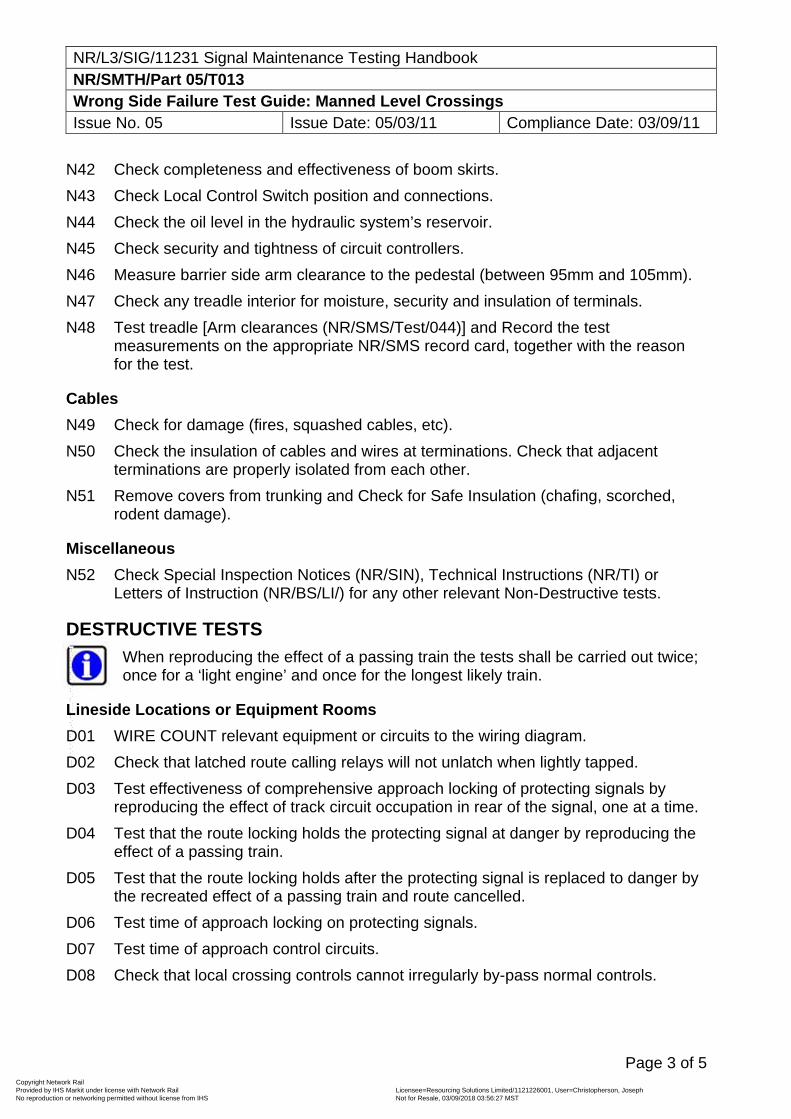
NR/L3/SIG/11231 Signal Maintenance Testing Handbook NR/SMTH/Part 05/T013 Wrong Side Failure Test Guide: Manned Level Crossings Issue No. 05 Issue Date: 05/03/11 Compliance Date: 03/09/11
Page 3 of 5
N42 Check completeness and effectiveness of boom skirts.
N43 Check Local Control Switch position and connections.
N44 Check the oil level in the hydraulic system’s reservoir.
N45 Check security and tightness of circuit controllers.
N46 Measure barrier side arm clearance to the pedestal (between 95mm and 105mm).
N47 Check any treadle interior for moisture, security and insulation of terminals.
N48 Test treadle [Arm clearances (NR/SMS/Test/044)] and Record the test measurements on the appropriate NR/SMS record card, together with the reason for the test.
Cables
N49 Check for damage (fires, squashed cables, etc).
N50 Check the insulation of cables and wires at terminations. Check that adjacent terminations are properly isolated from each other.
N51 Remove covers from trunking and Check for Safe Insulation (chafing, scorched, rodent damage).
Miscellaneous
N52 Check Special Inspection Notices (NR/SIN), Technical Instructions (NR/TI) or Letters of Instruction (NR/BS/LI/) for any other relevant Non-Destructive tests.
DESTRUCTIVE TESTS
When reproducing the effect of a passing train the tests shall be carried out twice; once for a ‘light engine’ and once for the longest likely train.
Lineside Locations or Equipment Rooms
D01 WIRE COUNT relevant equipment or circuits to the wiring diagram.
D02 Check that latched route calling relays will not unlatch when lightly tapped.
D03 Test effectiveness of comprehensive approach locking of protecting signals by reproducing the effect of track circuit occupation in rear of the signal, one at a time.
D04 Test that the route locking holds the protecting signal at danger by reproducing the effect of a passing train.
D05 Test that the route locking holds after the protecting signal is replaced to danger by the recreated effect of a passing train and route cancelled.
D06 Test time of approach locking on protecting signals.
D07 Test time of approach control circuits.
D08 Check that local crossing controls cannot irregularly by-pass normal controls.
Copyright Network Rail Provided by IHS Markit under license with Network Rail Licensee=Resourcing Solutions Limited /1121226001, User=Christopherson, Joseph
Not for Resale, 03/09/2018 03:56:27 MSTNo reproduction or networking permitted without license from IHS
--``,,``,`,,`,```,,``,,````,,,`,-`-`,,`,,`,`,,`---
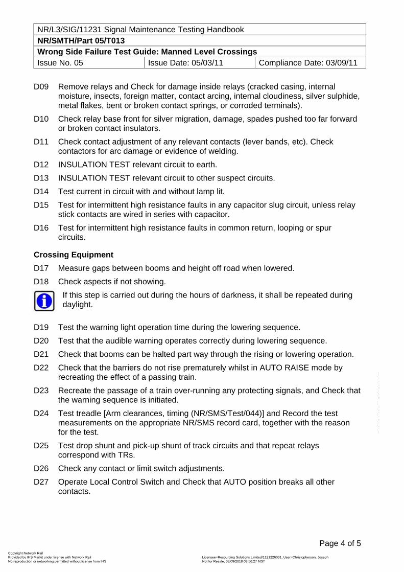
NR/L3/SIG/11231 Signal Maintenance Testing Handbook NR/SMTH/Part 05/T013 Wrong Side Failure Test Guide: Manned Level Crossings Issue No. 05 Issue Date: 05/03/11 Compliance Date: 03/09/11
Page 4 of 5
D09 Remove relays and Check for damage inside relays (cracked casing, internal moisture, insects, foreign matter, contact arcing, internal cloudiness, silver sulphide, metal flakes, bent or broken contact springs, or corroded terminals).
D10 Check relay base front for silver migration, damage, spades pushed too far forward or broken contact insulators.
D11 Check contact adjustment of any relevant contacts (lever bands, etc). Check contactors for arc damage or evidence of welding.
D12 INSULATION TEST relevant circuit to earth.
D13 INSULATION TEST relevant circuit to other suspect circuits.
D14 Test current in circuit with and without lamp lit.
D15 Test for intermittent high resistance faults in any capacitor slug circuit, unless relay stick contacts are wired in series with capacitor.
D16 Test for intermittent high resistance faults in common return, looping or spur circuits.
Crossing Equipment
D17 Measure gaps between booms and height off road when lowered.
D18 Check aspects if not showing.
If this step is carried out during the hours of darkness, it shall be repeated during daylight.
D19 Test the warning light operation time during the lowering sequence.
D20 Test that the audible warning operates correctly during lowering sequence.
D21 Check that booms can be halted part way through the rising or lowering operation.
D22 Check that the barriers do not rise prematurely whilst in AUTO RAISE mode by recreating the effect of a passing train.
D23 Recreate the passage of a train over-running any protecting signals, and Check that the warning sequence is initiated.
D24 Test treadle [Arm clearances, timing (NR/SMS/Test/044)] and Record the test measurements on the appropriate NR/SMS record card, together with the reason for the test.
D25 Test drop shunt and pick-up shunt of track circuits and that repeat relays correspond with TRs.
D26 Check any contact or limit switch adjustments.
D27 Operate Local Control Switch and Check that AUTO position breaks all other contacts.
Copyright Network Rail Provided by IHS Markit under license with Network Rail Licensee=Resourcing Solutions Limited /1121226001, User=Christopherson, Joseph
Not for Resale, 03/09/2018 03:56:27 MSTNo reproduction or networking permitted without license from IHS
--``,,``,`,,`,```,,``,,````,,,`,-`-`,,`,,`,`,,`---
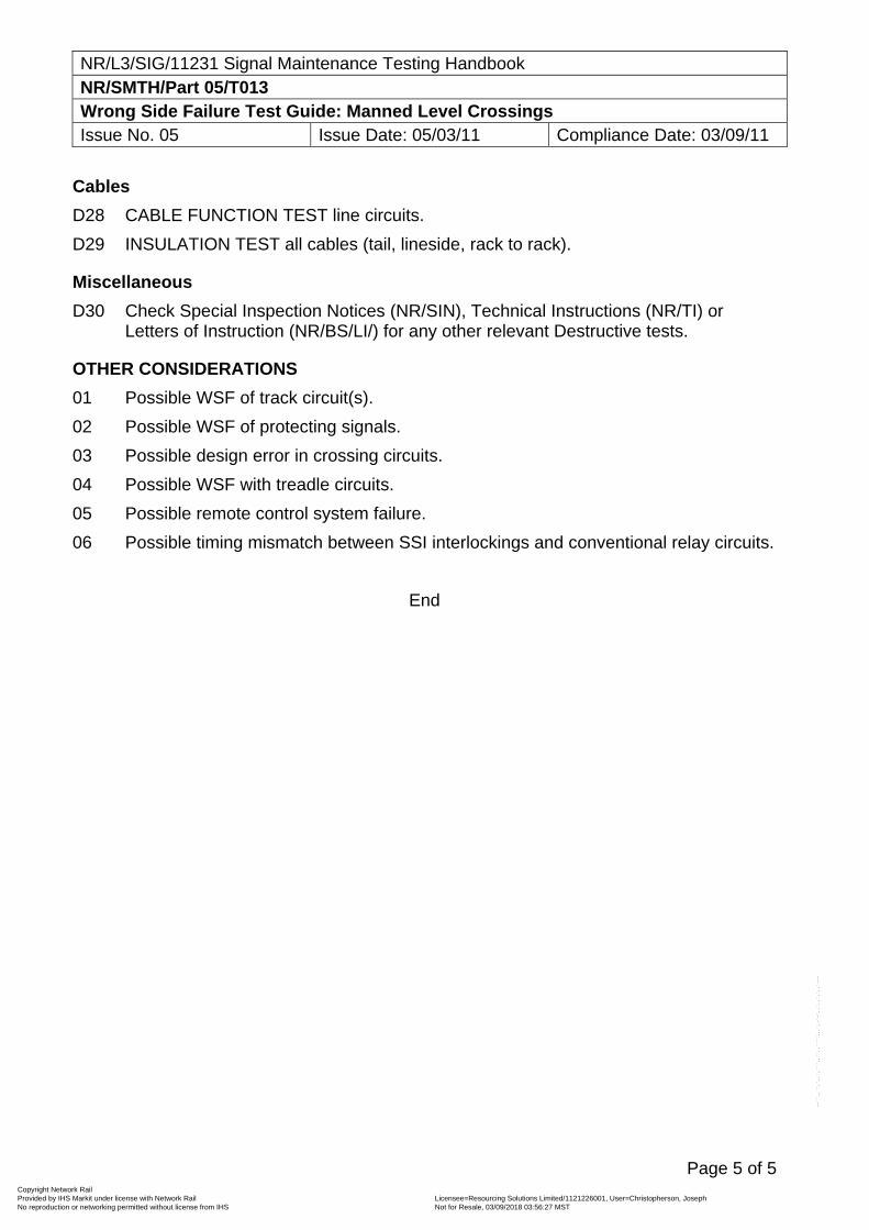
NR/L3/SIG/11231 Signal Maintenance Testing Handbook NR/SMTH/Part 05/T013 Wrong Side Failure Test Guide: Manned Level Crossings Issue No. 05 Issue Date: 05/03/11 Compliance Date: 03/09/11
Page 5 of 5
Cables
D28 CABLE FUNCTION TEST line circuits.
D29 INSULATION TEST all cables (tail, lineside, rack to rack).
Miscellaneous
D30 Check Special Inspection Notices (NR/SIN), Technical Instructions (NR/TI) or Letters of Instruction (NR/BS/LI/) for any other relevant Destructive tests.
OTHER CONSIDERATIONS
01 Possible WSF of track circuit(s).
02 Possible WSF of protecting signals.
03 Possible design error in crossing circuits.
04 Possible WSF with treadle circuits.
05 Possible remote control system failure.
06 Possible timing mismatch between SSI interlockings and conventional relay circuits.
End
Copyright Network Rail Provided by IHS Markit under license with Network Rail Licensee=Resourcing Solutions Limited /1121226001, User=Christopherson, Joseph
Not for Resale, 03/09/2018 03:56:27 MSTNo reproduction or networking permitted without license from IHS
--``,,``,`,,`,```,,``,,````,,,`,-`-`,,`,,`,`,,`---
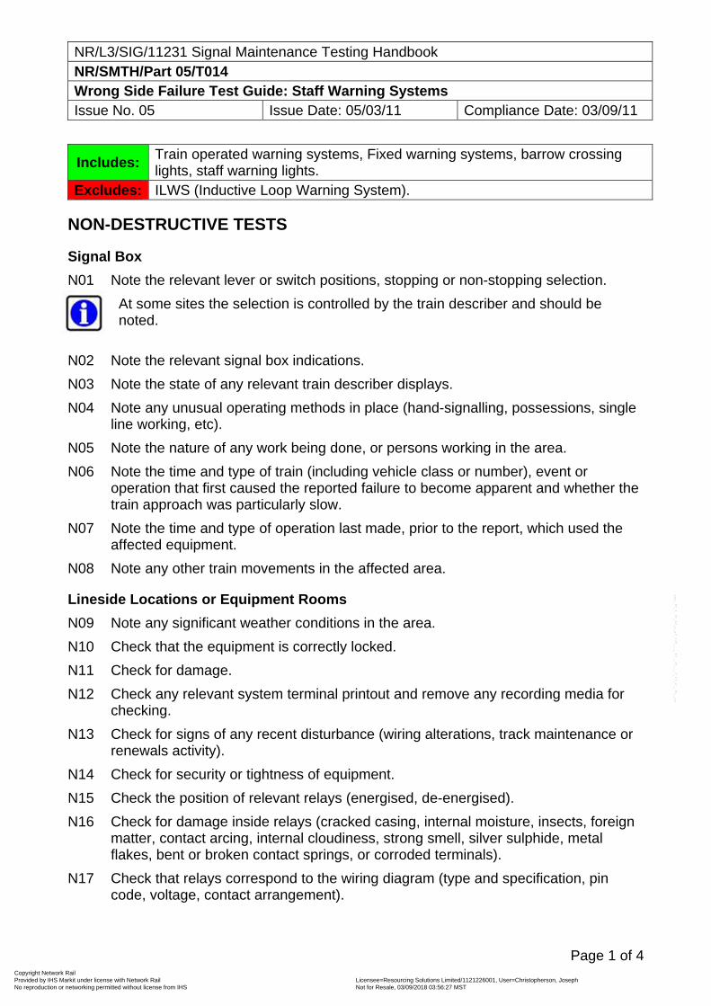
NR/L3/SIG/11231 Signal Maintenance Testing Handbook NR/SMTH/Part 05/T014 Wrong Side Failure Test Guide: Staff Warning Systems Issue No. 05 Issue Date: 05/03/11 Compliance Date: 03/09/11
Page 1 of 4
Includes: Train operated warning systems, Fixed warning systems, barrow crossing lights, staff warning lights.
Excludes: ILWS (Inductive Loop Warning System).
NON-DESTRUCTIVE TESTS
Signal Box
N01 Note the relevant lever or switch positions, stopping or non-stopping selection.
At some sites the selection is controlled by the train describer and should be noted.
N02 Note the relevant signal box indications.
N03 Note the state of any relevant train describer displays.
N04 Note any unusual operating methods in place (hand-signalling, possessions, single line working, etc).
N05 Note the nature of any work being done, or persons working in the area.
N06 Note the time and type of train (including vehicle class or number), event or operation that first caused the reported failure to become apparent and whether the train approach was particularly slow.
N07 Note the time and type of operation last made, prior to the report, which used the affected equipment.
N08 Note any other train movements in the affected area.
Lineside Locations or Equipment Rooms
N09 Note any significant weather conditions in the area.
N10 Check that the equipment is correctly locked.
N11 Check for damage.
N12 Check any relevant system terminal printout and remove any recording media for checking.
N13 Check for signs of any recent disturbance (wiring alterations, track maintenance or renewals activity).
N14 Check for security or tightness of equipment.
N15 Check the position of relevant relays (energised, de-energised).
N16 Check for damage inside relays (cracked casing, internal moisture, insects, foreign matter, contact arcing, internal cloudiness, strong smell, silver sulphide, metal flakes, bent or broken contact springs, or corroded terminals).
N17 Check that relays correspond to the wiring diagram (type and specification, pin code, voltage, contact arrangement).
Copyright Network Rail Provided by IHS Markit under license with Network Rail Licensee=Resourcing Solutions Limited /1121226001, User=Christopherson, Joseph
Not for Resale, 03/09/2018 03:56:27 MSTNo reproduction or networking permitted without license from IHS
--``,,``,`,,`,```,,``,,````,,,`,-`-`,,`,,`,`,,`---
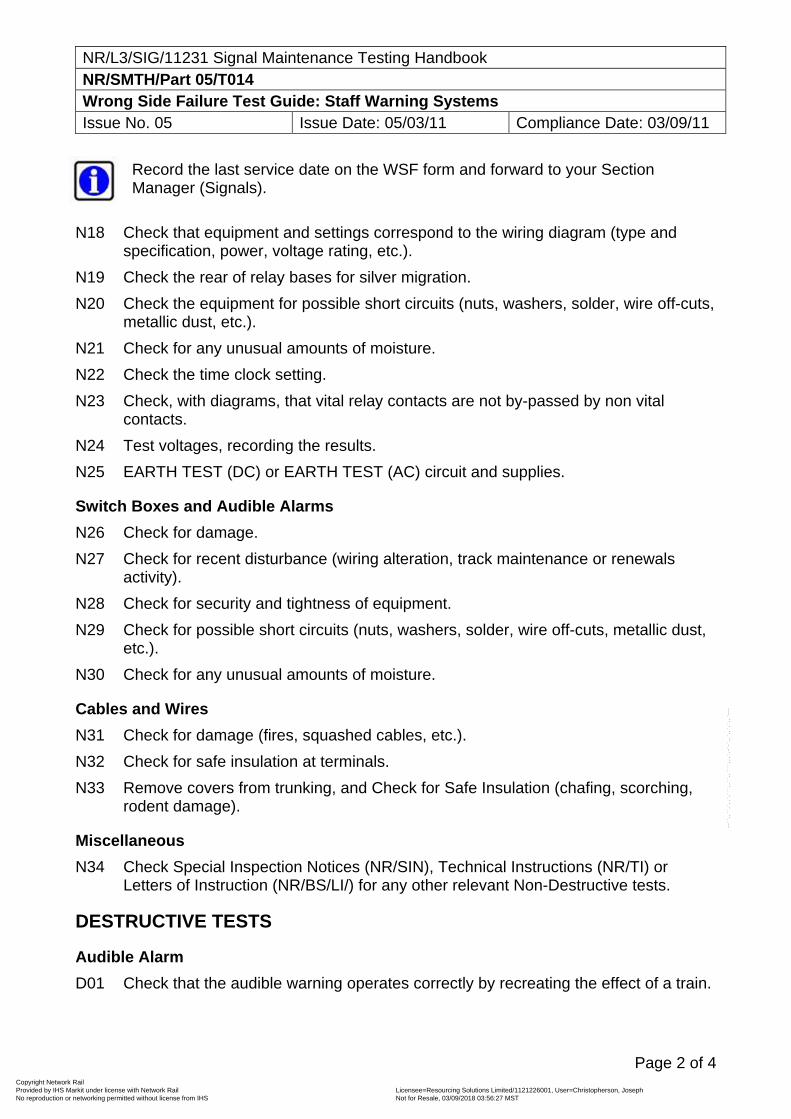
NR/L3/SIG/11231 Signal Maintenance Testing Handbook NR/SMTH/Part 05/T014 Wrong Side Failure Test Guide: Staff Warning Systems Issue No. 05 Issue Date: 05/03/11 Compliance Date: 03/09/11
Page 2 of 4
Record the last service date on the WSF form and forward to your Section Manager (Signals).
N18 Check that equipment and settings correspond to the wiring diagram (type and specification, power, voltage rating, etc.).
N19 Check the rear of relay bases for silver migration.
N20 Check the equipment for possible short circuits (nuts, washers, solder, wire off-cuts, metallic dust, etc.).
N21 Check for any unusual amounts of moisture.
N22 Check the time clock setting.
N23 Check, with diagrams, that vital relay contacts are not by-passed by non vital contacts.
N24 Test voltages, recording the results.
N25 EARTH TEST (DC) or EARTH TEST (AC) circuit and supplies.
Switch Boxes and Audible Alarms
N26 Check for damage.
N27 Check for recent disturbance (wiring alteration, track maintenance or renewals activity).
N28 Check for security and tightness of equipment.
N29 Check for possible short circuits (nuts, washers, solder, wire off-cuts, metallic dust, etc.).
N30 Check for any unusual amounts of moisture.
Cables and Wires
N31 Check for damage (fires, squashed cables, etc.).
N32 Check for safe insulation at terminals.
N33 Remove covers from trunking, and Check for Safe Insulation (chafing, scorching, rodent damage).
Miscellaneous
N34 Check Special Inspection Notices (NR/SIN), Technical Instructions (NR/TI) or Letters of Instruction (NR/BS/LI/) for any other relevant Non-Destructive tests.
DESTRUCTIVE TESTS
Audible Alarm
D01 Check that the audible warning operates correctly by recreating the effect of a train.
Copyright Network Rail Provided by IHS Markit under license with Network Rail Licensee=Resourcing Solutions Limited /1121226001, User=Christopherson, Joseph
Not for Resale, 03/09/2018 03:56:27 MSTNo reproduction or networking permitted without license from IHS
--``,,``,`,,`,```,,``,,````,,,`,-`-`,,`,,`,`,,`---
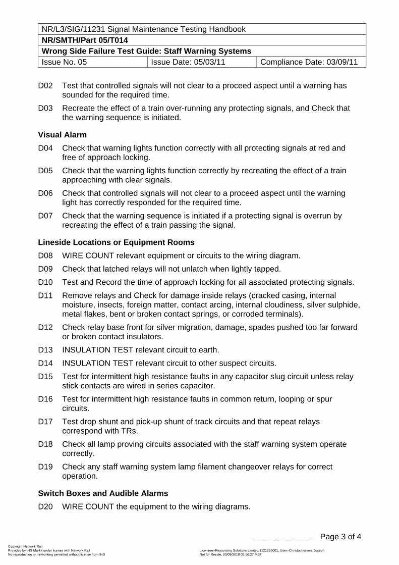
NR/L3/SIG/11231 Signal Maintenance Testing Handbook NR/SMTH/Part 05/T014 Wrong Side Failure Test Guide: Staff Warning Systems Issue No. 05 Issue Date: 05/03/11 Compliance Date: 03/09/11
Page 3 of 4
D02 Test that controlled signals will not clear to a proceed aspect until a warning has sounded for the required time.
D03 Recreate the effect of a train over-running any protecting signals, and Check that the warning sequence is initiated.
Visual Alarm
D04 Check that warning lights function correctly with all protecting signals at red and free of approach locking.
D05 Check that the warning lights function correctly by recreating the effect of a train approaching with clear signals.
D06 Check that controlled signals will not clear to a proceed aspect until the warning light has correctly responded for the required time.
D07 Check that the warning sequence is initiated if a protecting signal is overrun by recreating the effect of a train passing the signal.
Lineside Locations or Equipment Rooms
D08 WIRE COUNT relevant equipment or circuits to the wiring diagram.
D09 Check that latched relays will not unlatch when lightly tapped.
D10 Test and Record the time of approach locking for all associated protecting signals.
D11 Remove relays and Check for damage inside relays (cracked casing, internal moisture, insects, foreign matter, contact arcing, internal cloudiness, silver sulphide, metal flakes, bent or broken contact springs, or corroded terminals).
D12 Check relay base front for silver migration, damage, spades pushed too far forward or broken contact insulators.
D13 INSULATION TEST relevant circuit to earth.
D14 INSULATION TEST relevant circuit to other suspect circuits.
D15 Test for intermittent high resistance faults in any capacitor slug circuit unless relay stick contacts are wired in series capacitor.
D16 Test for intermittent high resistance faults in common return, looping or spur circuits.
D17 Test drop shunt and pick-up shunt of track circuits and that repeat relays correspond with TRs.
D18 Check all lamp proving circuits associated with the staff warning system operate correctly.
D19 Check any staff warning system lamp filament changeover relays for correct operation.
Switch Boxes and Audible Alarms
D20 WIRE COUNT the equipment to the wiring diagrams.
Copyright Network Rail Provided by IHS Markit under license with Network Rail Licensee=Resourcing Solutions Limited /1121226001, User=Christopherson, Joseph
Not for Resale, 03/09/2018 03:56:27 MSTNo reproduction or networking permitted without license from IHS
--``,,``,`,,`,```,,``,,````,,,`,-`-`,,`,,`,`,,`---
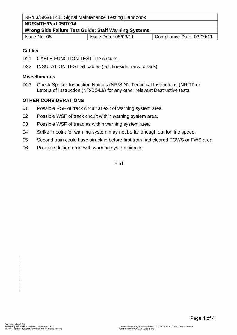
NR/L3/SIG/11231 Signal Maintenance Testing Handbook NR/SMTH/Part 05/T014 Wrong Side Failure Test Guide: Staff Warning Systems Issue No. 05 Issue Date: 05/03/11 Compliance Date: 03/09/11
Page 4 of 4
Cables
D21 CABLE FUNCTION TEST line circuits.
D22 INSULATION TEST all cables (tail, lineside, rack to rack).
Miscellaneous
D23 Check Special Inspection Notices (NR/SIN), Technical Instructions (NR/TI) or Letters of Instruction (NR/BS/LI/) for any other relevant Destructive tests.
OTHER CONSIDERATIONS
01 Possible RSF of track circuit at exit of warning system area.
02 Possible WSF of track circuit within warning system area.
03 Possible WSF of treadles within warning system area.
04 Strike in point for warning system may not be far enough out for line speed.
05 Second train could have struck in before first train had cleared TOWS or FWS area.
06 Possible design error with warning system circuits.
End
Copyright Network Rail Provided by IHS Markit under license with Network Rail Licensee=Resourcing Solutions Limited /1121226001, User=Christopherson, Joseph
Not for Resale, 03/09/2018 03:56:27 MSTNo reproduction or networking permitted without license from IHS
--``,,``,`,,`,```,,``,,````,,,`,-`-`,,`,,`,`,,`---
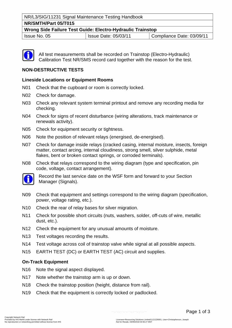
NR/L3/SIG/11231 Signal Maintenance Testing Handbook NR/SMTH/Part 05/T015 Wrong Side Failure Test Guide: Electro-Hydraulic Trainstop Issue No. 05 Issue Date: 05/03/11 Compliance Date: 03/09/11
Page 1 of 3
All test measurements shall be recorded on Trainstop (Electro-Hydraulic) Calibration Test NR/SMS record card together with the reason for the test.
NON-DESTRUCTIVE TESTS
Lineside Locations or Equipment Rooms
N01 Check that the cupboard or room is correctly locked.
N02 Check for damage.
N03 Check any relevant system terminal printout and remove any recording media for checking.
N04 Check for signs of recent disturbance (wiring alterations, track maintenance or renewals activity).
N05 Check for equipment security or tightness.
N06 Note the position of relevant relays (energised, de-energised).
N07 Check for damage inside relays (cracked casing, internal moisture, insects, foreign matter, contact arcing, internal cloudiness, strong smell, silver sulphide, metal flakes, bent or broken contact springs, or corroded terminals).
N08 Check that relays correspond to the wiring diagram (type and specification, pin code, voltage, contact arrangement).
Record the last service date on the WSF form and forward to your Section Manager (Signals).
N09 Check that equipment and settings correspond to the wiring diagram (specification, power, voltage rating, etc.).
N10 Check the rear of relay bases for silver migration.
N11 Check for possible short circuits (nuts, washers, solder, off-cuts of wire, metallic dust, etc.).
N12 Check the equipment for any unusual amounts of moisture.
N13 Test voltages recording the results.
N14 Test voltage across coil of trainstop valve while signal at all possible aspects.
N15 EARTH TEST (DC) or EARTH TEST (AC) circuit and supplies.
On-Track Equipment
N16 Note the signal aspect displayed.
N17 Note whether the trainstop arm is up or down.
N18 Check the trainstop position (height, distance from rail).
N19 Check that the equipment is correctly locked or padlocked.
Copyright Network Rail Provided by IHS Markit under license with Network Rail Licensee=Resourcing Solutions Limited /1121226001, User=Christopherson, Joseph
Not for Resale, 03/09/2018 03:56:27 MSTNo reproduction or networking permitted without license from IHS
--``,,``,`,,`,```,,``,,````,,,`,-`-`,,`,,`,`,,`---
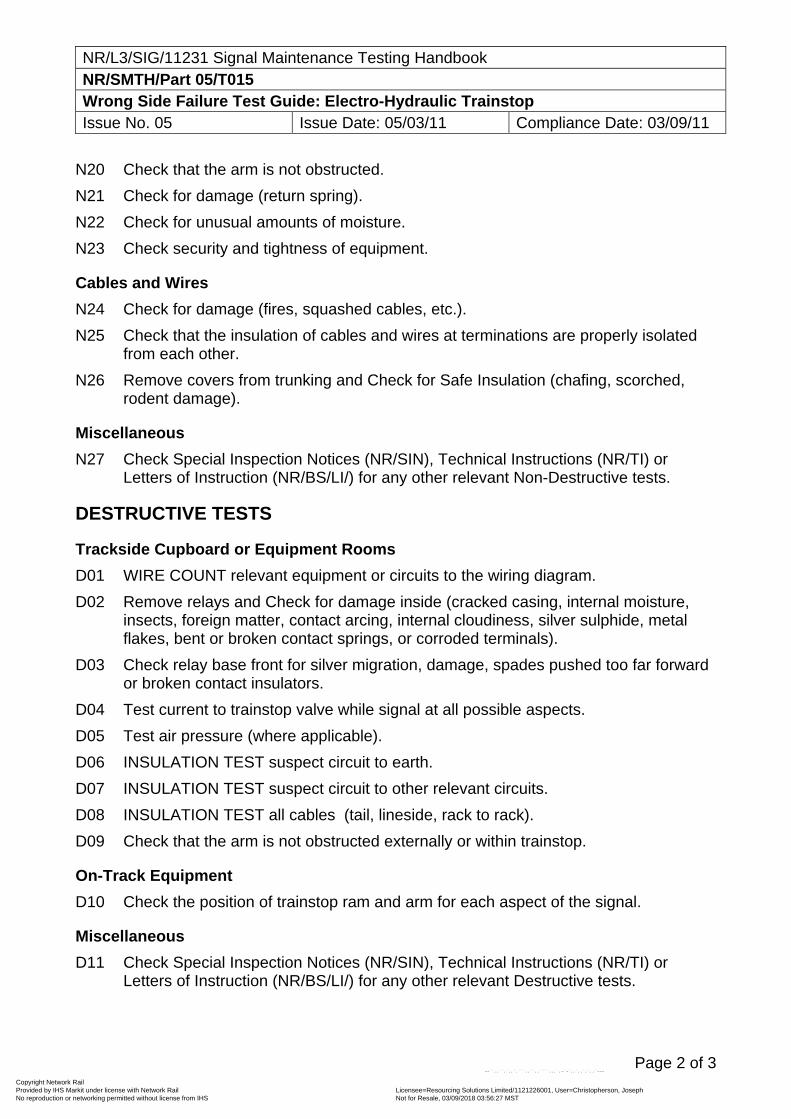
NR/L3/SIG/11231 Signal Maintenance Testing Handbook NR/SMTH/Part 05/T015 Wrong Side Failure Test Guide: Electro-Hydraulic Trainstop Issue No. 05 Issue Date: 05/03/11 Compliance Date: 03/09/11
Page 2 of 3
N20 Check that the arm is not obstructed.
N21 Check for damage (return spring).
N22 Check for unusual amounts of moisture.
N23 Check security and tightness of equipment.
Cables and Wires
N24 Check for damage (fires, squashed cables, etc.).
N25 Check that the insulation of cables and wires at terminations are properly isolated from each other.
N26 Remove covers from trunking and Check for Safe Insulation (chafing, scorched, rodent damage).
Miscellaneous
N27 Check Special Inspection Notices (NR/SIN), Technical Instructions (NR/TI) or Letters of Instruction (NR/BS/LI/) for any other relevant Non-Destructive tests.
DESTRUCTIVE TESTS
Trackside Cupboard or Equipment Rooms
D01 WIRE COUNT relevant equipment or circuits to the wiring diagram.
D02 Remove relays and Check for damage inside (cracked casing, internal moisture, insects, foreign matter, contact arcing, internal cloudiness, silver sulphide, metal flakes, bent or broken contact springs, or corroded terminals).
D03 Check relay base front for silver migration, damage, spades pushed too far forward or broken contact insulators.
D04 Test current to trainstop valve while signal at all possible aspects.
D05 Test air pressure (where applicable).
D06 INSULATION TEST suspect circuit to earth.
D07 INSULATION TEST suspect circuit to other relevant circuits.
D08 INSULATION TEST all cables (tail, lineside, rack to rack).
D09 Check that the arm is not obstructed externally or within trainstop.
On-Track Equipment
D10 Check the position of trainstop ram and arm for each aspect of the signal.
Miscellaneous
D11 Check Special Inspection Notices (NR/SIN), Technical Instructions (NR/TI) or Letters of Instruction (NR/BS/LI/) for any other relevant Destructive tests.
Copyright Network Rail Provided by IHS Markit under license with Network Rail Licensee=Resourcing Solutions Limited /1121226001, User=Christopherson, Joseph
Not for Resale, 03/09/2018 03:56:27 MSTNo reproduction or networking permitted without license from IHS
--``,,``,`,,`,```,,``,,````,,,`,-`-`,,`,,`,`,,`---
NR/L3/SIG/11231 Signal Maintenance Testing Handbook NR/SMTH/Part 05/T015 Wrong Side Failure Test Guide: Electro-Hydraulic Trainstop Issue No. 05 Issue Date: 05/03/11 Compliance Date: 03/09/11
Page 3 of 3
OTHER CONSIDERATIONS
01 Possible WSF of signal.
02 Possible WSF of track circuit if trainstop valve energised by track circuit occupied.
03 Possible failure of trainborne equipment.
04 Possible design error in trainstop valve circuit.
End
Copyright Network Rail Provided by IHS Markit under license with Network Rail Licensee=Resourcing Solutions Limited /1121226001, User=Christopherson, Joseph
Not for Resale, 03/09/2018 03:56:27 MSTNo reproduction or networking permitted without license from IHS
--``,,``,`,,`,```,,``,,````,,,`,-`-`,,`,,`,`,,`---
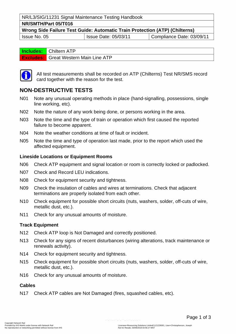
NR/L3/SIG/11231 Signal Maintenance Testing Handbook NR/SMTH/Part 05/T016 Wrong Side Failure Test Guide: Automatic Train Protection (ATP) (Chilterns) Issue No. 05 Issue Date: 05/03/11 Compliance Date: 03/09/11
Page 1 of 3
Includes: Chiltern ATP Excludes: Great Western Main Line ATP
All test measurements shall be recorded on ATP (Chilterns) Test NR/SMS record card together with the reason for the test.
NON-DESTRUCTIVE TESTS
N01 Note any unusual operating methods in place (hand-signalling, possessions, single line working, etc).
N02 Note the nature of any work being done, or persons working in the area.
N03 Note the time and the type of train or operation which first caused the reported failure to become apparent.
N04 Note the weather conditions at time of fault or incident.
N05 Note the time and type of operation last made, prior to the report which used the affected equipment.
Lineside Locations or Equipment Rooms
N06 Check ATP equipment and signal location or room is correctly locked or padlocked.
N07 Check and Record LEU indications.
N08 Check for equipment security and tightness.
N09 Check the insulation of cables and wires at terminations. Check that adjacent terminations are properly isolated from each other.
N10 Check equipment for possible short circuits (nuts, washers, solder, off-cuts of wire, metallic dust, etc.).
N11 Check for any unusual amounts of moisture.
Track Equipment
N12 Check ATP loop is Not Damaged and correctly positioned.
N13 Check for any signs of recent disturbances (wiring alterations, track maintenance or renewals activity).
N14 Check for equipment security and tightness.
N15 Check equipment for possible short circuits (nuts, washers, solder, off-cuts of wire, metallic dust, etc.).
N16 Check for any unusual amounts of moisture.
Cables
N17 Check ATP cables are Not Damaged (fires, squashed cables, etc).
Copyright Network Rail Provided by IHS Markit under license with Network Rail Licensee=Resourcing Solutions Limited /1121226001, User=Christopherson, Joseph
Not for Resale, 03/09/2018 03:56:27 MSTNo reproduction or networking permitted without license from IHS
--``,,``,`,,`,```,,``,,````,,,`,-`-`,,`,,`,`,,`---
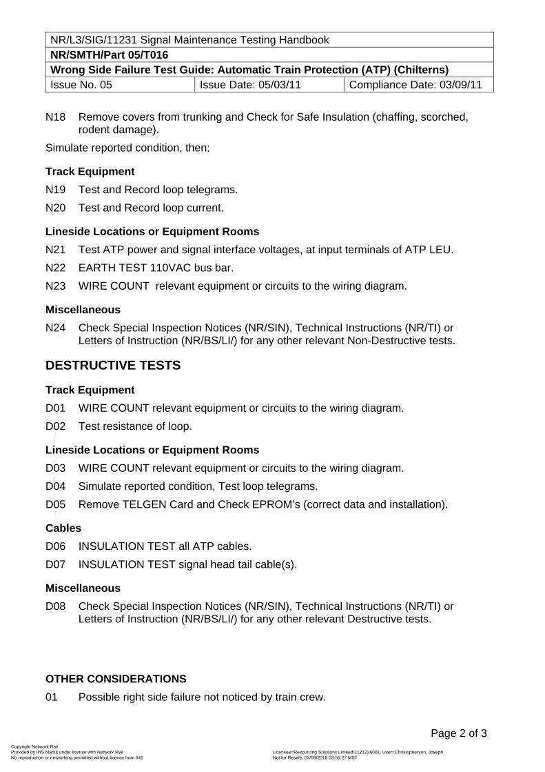
NR/L3/SIG/11231 Signal Maintenance Testing Handbook NR/SMTH/Part 05/T016 Wrong Side Failure Test Guide: Automatic Train Protection (ATP) (Chilterns) Issue No. 05 Issue Date: 05/03/11 Compliance Date: 03/09/11
Page 2 of 3
N18 Remove covers from trunking and Check for Safe Insulation (chaffing, scorched, rodent damage).
Simulate reported condition, then:
Track Equipment
N19 Test and Record loop telegrams.
N20 Test and Record loop current.
Lineside Locations or Equipment Rooms
N21 Test ATP power and signal interface voltages, at input terminals of ATP LEU.
N22 EARTH TEST 110VAC bus bar.
N23 WIRE COUNT relevant equipment or circuits to the wiring diagram.
Miscellaneous
N24 Check Special Inspection Notices (NR/SIN), Technical Instructions (NR/TI) or Letters of Instruction (NR/BS/LI/) for any other relevant Non-Destructive tests.
DESTRUCTIVE TESTS
Track Equipment
D01 WIRE COUNT relevant equipment or circuits to the wiring diagram.
D02 Test resistance of loop.
Lineside Locations or Equipment Rooms
D03 WIRE COUNT relevant equipment or circuits to the wiring diagram.
D04 Simulate reported condition, Test loop telegrams.
D05 Remove TELGEN Card and Check EPROM’s (correct data and installation).
Cables
D06 INSULATION TEST all ATP cables.
D07 INSULATION TEST signal head tail cable(s).
Miscellaneous
D08 Check Special Inspection Notices (NR/SIN), Technical Instructions (NR/TI) or Letters of Instruction (NR/BS/LI/) for any other relevant Destructive tests.
OTHER CONSIDERATIONS
01 Possible right side failure not noticed by train crew.
Copyright Network Rail Provided by IHS Markit under license with Network Rail Licensee=Resourcing Solutions Limited /1121226001, User=Christopherson, Joseph
Not for Resale, 03/09/2018 03:56:27 MSTNo reproduction or networking permitted without license from IHS
--``,,``,`,,`,```,,``,,````,,,`,-`-`,,`,,`,`,,`---
NR/L3/SIG/11231 Signal Maintenance Testing Handbook NR/SMTH/Part 05/T016 Wrong Side Failure Test Guide: Automatic Train Protection (ATP) (Chilterns) Issue No. 05 Issue Date: 05/03/11 Compliance Date: 03/09/11
Page 3 of 3
02 Possible wrong side failure of signal not noticed by train crew.
03 Possible that signal to signal distance is different from ATP design details.
04 Possible that PSRs/TSRs have changed without ATP modification.
T016A REPORTED WSF OF SIGNAL, NO ALLEGATION AGAINST ATP EQUIPMENT
Follow normal WSF investigation procedures, those covered by T007 or T008, with the addition of the following steps:
NON-DESTRUCTIVE TESTS
N01 Before any disconnections are made check and record ATP LEU indications.
N02 If LEU indications are not correct there may be an internal fault and after all relevant conditions have been simulated, SIGANP Card shall be renewed and original sent for investigation.
DESTRUCTIVE TESTS
D01 ATP cable from signal location to LEU will need to be INSULATION TESTED. This can be carried out in the normal way after disconnecting signal interface switches in signal location and disconnecting the cable at the LEU.
D02 After above tests, reconnect the LEU and signal interface switches. Check that LEU indications are working correctly.
End
Copyright Network Rail Provided by IHS Markit under license with Network Rail Licensee=Resourcing Solutions Limited /1121226001, User=Christopherson, Joseph
Not for Resale, 03/09/2018 03:56:27 MSTNo reproduction or networking permitted without license from IHS
--``,,``,`,,`,```,,``,,````,,,`,-`-`,,`,,`,`,,`---
NR/L3/SIG/11231 Signal Maintenance Testing Handbook NR/SMTH/Part 05/T017 Wrong Side Failure Test Guide: Automatic Train Protection (ATP) (GWML) Issue No. 05 Issue Date: 05/03/11 Compliance Date: 03/09/11
Page 1 of 3
Includes: Great Western Main Line ATP Excludes: Chiltern Line APT
All test measurements shall be recorded on ATP (GWML) Test NR/SMS record card together with the reason for the test.
NON-DESTRUCTIVE TESTS
General
N01 Note any unusual operating methods in place (hand-signalling, possessions, single line working, etc).
N02 Note the nature of any work being done, or persons working in the area.
N03 Note the time and the type of train or operation which first caused the reported failure to become apparent.
N04 Note the time and type of operation last made, prior to the report which used the affected equipment.
Lineside Locations or Equipment Rooms
N05 Check ATP enclosure and signal location or room is correctly locked or padlocked.
N06 Check and Record encoder indications.
N07 Check for equipment security and tightness.
N08 Check that equipment and settings correspond to the wiring diagram (specification, power, voltage rating, etc).
N09 Check the insulation of cables and wires at terminations. Check that adjacent terminations are properly isolated from each other.
N10 Check equipment for possible short circuits (nuts, washers, solder, off-cuts of wire, metallic dust, etc.).
N11 Check for any unusual amounts of moisture.
Track Equipment
N12 Check beacon is Not Damaged and is correctly positioned.
N13 Check that all ATP beacons in the area on the same line are correctly offset from the centre of the track.
N14 Check ATP loop is Not Damaged and correctly positioned.
N15 Check for any signs of recent disturbances (wiring alterations, track maintenance or renewals activity).
N16 Check for equipment security and tightness.
N17 Check that equipment and settings correspond to the wiring diagram (specification, power, voltage rating, etc).
Copyright Network Rail Provided by IHS Markit under license with Network Rail Licensee=Resourcing Solutions Limited /1121226001, User=Christopherson, Joseph
Not for Resale, 03/09/2018 03:56:27 MSTNo reproduction or networking permitted without license from IHS
--``,,``,`,,`,```,,``,,````,,,`,-`-`,,`,,`,`,,`---
NR/L3/SIG/11231 Signal Maintenance Testing Handbook NR/SMTH/Part 05/T017 Wrong Side Failure Test Guide: Automatic Train Protection (ATP) (GWML) Issue No. 05 Issue Date: 05/03/11 Compliance Date: 03/09/11
Page 2 of 3
N18 Check the insulation of cables and wires at terminations. Check that adjacent terminations are properly isolated from each other.
N19 Check equipment for possible short circuits (nuts, washers, solder, off-cuts of wire, metallic dust, etc.).
N20 Check for any unusual amounts of moisture.
Cables
N21 Check ATP cables are Not Damaged (fires, squashed cables, etc).
N22 Remove covers from trunking and Check for Safe Insulation (chaffing, scorched, rodent damage).
Simulate reported condition, then:
Track Equipment
N23 Test and Record beacon(s) telegram/message.
N24 Test and Record beacon(s) signal strength.
N25 Test and Record loop telegram/message.
N26 Test and Record loop signal strength.
N27 WIRE COUNT relevant equipment or circuits to the wiring diagram.
Lineside Locations or Equipment Rooms
N28 Test ATP and UT output voltage, at input terminals of ATP enclosure.
N29 Test ATP volts, level, etc.
N30 EARTH TEST 110V AC bus bar.
N31 WIRE COUNT relevant equipment or circuits to the wiring diagram.
Miscellaneous
N32 Check Special Inspection Notices (NR/SIN), Technical Instructions (NR/TI) or Letters of Instruction (NR/BS/LI/) for any other relevant Non-Destructive tests.
DESTRUCTIVE TESTS
Track Equipment
D01 WIRE COUNT relevant equipment or circuits to the wiring diagram.
D02 Test resistance of loop.
Lineside Locations or Equipment Rooms
D03 WIRE COUNT relevant equipment or circuits to the wiring diagram.
D04 Simulate reported condition, Test back-up BITE memory and Record results.
D05 Test ATP LIT and UT primary current.
Copyright Network Rail Provided by IHS Markit under license with Network Rail Licensee=Resourcing Solutions Limited /1121226001, User=Christopherson, Joseph
Not for Resale, 03/09/2018 03:56:27 MSTNo reproduction or networking permitted without license from IHS
--``,,``,`,,`,```,,``,,````,,,`,-`-`,,`,,`,`,,`---
NR/L3/SIG/11231 Signal Maintenance Testing Handbook NR/SMTH/Part 05/T017 Wrong Side Failure Test Guide: Automatic Train Protection (ATP) (GWML) Issue No. 05 Issue Date: 05/03/11 Compliance Date: 03/09/11
Page 3 of 3
Cables
D06 INSULATION TEST all ATP cables.
D07 INSULATION TEST signal head tail cable(s).
After reconnecting cables, Check encoder indications.
Miscellaneous
D08 Check Special Inspection Notices (NR/SIN), Technical Instructions (NR/TI) or Letters of Instruction (NR/BS/LI/) for any other relevant Destructive tests.
OTHER CONSIDERATIONS
01 Possible right side failure not noticed by train crew.
02 Possible wrong side failure of signal not noticed by train crew.
03 Possible that signal to signal distance is different from ATP design details.
04 Possible that PSRs/TSRs have changed without ATP modification.
T017A REPORTED WSF OF SIGNAL, NO ALLEGATION AGAINST ATP EQUIPMENT
Follow normal WSF investigation procedures, those covered by T007 or T008, with the addition of the following steps:
NON-DESTRUCTIVE TESTS
N01 Before any disconnections are made Check and Record ATP encoder indications. If they are working correctly, this can be taken as proof that there are no internal encoder faults which could affect signal head circuit.
N02 If encoder indications are not correct there may be an internal fault and after all relevant conditions have been simulated, encoder shall be renewed and original sent for investigation.
DESTRUCTIVE TESTS
D01 At some stage, signal tail cable will require an INSULATION TEST. This can be carried out in the normal way. ATP equipment will be disconnected from signal head circuit by disconnecting ATP LITS.
D02 ATP cable from signal location to encoder will require an INSULATION TEST. This can be carried out in the normal way after disconnecting ATP LITS in signal location and unplugging encoder.
D03 After above tests, plug-in encoder and re-connect signal and ATP LITS. Check encoder indications and Check they are working correctly.
End
Copyright Network Rail Provided by IHS Markit under license with Network Rail Licensee=Resourcing Solutions Limited /1121226001, User=Christopherson, Joseph
Not for Resale, 03/09/2018 03:56:27 MSTNo reproduction or networking permitted without license from IHS
--``,,``,`,,`,```,,``,,````,,,`,-`-`,,`,,`,`,,`---
NR/L3/SIG/11231 Signal Maintenance Testing Handbook NR/SMTH/Part 05/T018 Wrong Side Failure Test Guide: Balise (TASS) Issue No. 05 Issue Date: 05/03/11 Compliance Date: 03/09/11
Page 1 of 1
NON-DESTRUCTIVE TESTS
Signal Box
N01 Note any unusual operating methods in place (hand-signalling, possessions, single line working, etc).
N02 Note the nature of any work being done, or persons working in the area.
N03 Note the time and type of train (including vehicle class or number), event or operation that first caused the reported failure to become apparent and whether the train approach was particularly slow.
N04 Note the time and type of train or operation last made, prior to the report, which used the affected equipment.
N05 Note any other train movements in the affected area.
N06 Note any significant weather conditions in the area.
Balise
N07 Check for any signs of damage or missing equipment.
N08 Check for security or tightness of equipment.
N09 Check for signs of any recent disturbances (track maintenance or renewals activity, replacement mountings, equipment re-located).
N10 Check location of equipment in conjunction with Balise Positioning Form or other form of local record.
N11 Check that equipment is Correctly Installed and centrally mounted.
N12 Check the 14 character identifier is identical on both the balise and the mounting bracket assembly.
N13 Test the Balise telegram data through the air gap using a balise reading tool.
Miscellaneous
N14 Check Special Inspection Notices (NR/SIN), Technical Instructions (NR/TI) or Letters of Instruction (NR/BS/LI/) for any other relevant Non-Destructive tests.
OTHER CONSIDERATIONS
01 Possible design error in telegram data.
02 Possible design error in specifying balise position.
03 Possible failure of trainborne equipment.
End
Copyright Network Rail Provided by IHS Markit under license with Network Rail Licensee=Resourcing Solutions Limited /1121226001, User=Christopherson, Joseph
Not for Resale, 03/09/2018 03:56:27 MSTNo reproduction or networking permitted without license from IHS
--``,,``,`,,`,```,,``,,````,,,`,-`-`,,`,,`,`,,`---
NR/L3/SIG/11231 Signal Maintenance Testing Handbook NR/SMTH/Part 05/T019 Wrong Side Failure Test Guide: Train Protection Warning System (TPWS) Issue No. 07 Issue Date: 04/03/17 Compliance Date: 31/05/17
Page 1 of 5
All test measurements should be recorded on the appropriate record card together with the reason for the test. TPWS is not a ‘fail safe’ piece of equipment, because it requires energisation to stop trains. The failure to transmit when required is protected by the TPWS fault circuit (VCR), usually by replacing the signal in rear and indicating a lamp failure at the signal with the failed TPWS in the signal box. The signalling interface however, is designed such that any ‘right side’ failure will cause TPWS to transmit. This failure mode is generally not indicated by the TPWS fault circuit, and will instead be identified by TPWS fitted trains having an unwarranted emergency brake application. Where a TPWS failure is identified by either the stopping of a train, or the extinguishing of a lamp out indication or other means of TPWS failure reporting, any testing required may be carried out by a certified Maintenance Tester attending the failure without further authority. Where there is any doubt as to the cause of the failure, or where failure of TPWS to transmit is not reported correctly, or the speed of a train is not correctly reduced, the normal escalation procedures shall be followed. Fault finding flowcharts are provided in Part 05/FF12
NON-DESTRUCTIVE TESTS
General N01 Note the mechanism by which it was discovered that TPWS was not operating
correctly (maintenance testing, TPWS fitted train not stopped, lineside observation of loops active, SSI out of correspondence report, etc.).
Signal Box N02 Note the signal box indication for the relevant signal, the display of the relevant
TPWS failure indication. N03 Note the aspects displayed by signals approaching the failure and at the TPWS
fitted signal. N04 Note any unusual operating methods in place (hand-signalling, possessions, single
line working, etc.). N05 Note the nature of any work being done, or persons working in the area. N06 Note the time and type of train (including vehicle class or number), event or
operation that first caused the reported failure to become apparent and, where possible, the likely speed of the train on the approach to the signal, PSR or buffer stops. Note if the train was being propelled or not driven from the leading cab. If practicable arrange to have the train OTMR (On-Train Monitor and Recorder) downloaded and/or to interview the train crew.
N07 Note if the train had been fitted with TPWS, and if the train has a record of TPWS equipment failure or isolation.
Copyright Network Rail Provided by IHS Markit under license with Network Rail Licensee=Resourcing Solutions Limited /1121226001, User=Christopherson, Joseph
Not for Resale, 03/09/2018 03:56:27 MSTNo reproduction or networking permitted without license from IHS
--``,,``,`,,`,```,,``,,````,,,`,-`-`,,`,,`,`,,`---
NR/L3/SIG/11231 Signal Maintenance Testing Handbook NR/SMTH/Part 05/T019 Wrong Side Failure Test Guide: Train Protection Warning System (TPWS) Issue No. 07 Issue Date: 04/03/17 Compliance Date: 31/05/17
Page 2 of 5
N08 Note the distance past the signal the train came to a stand if the train passed the signal at danger.
N09 Note the time and type of any train movements made over the failed equipment immediately prior to the failure.
N10 Note any other train movements in the affected area at the time of the failure. N11 Note any specific control table requirements for the control or reporting of TPWS
failures at this installation.
Lineside Locations or Equipment Rooms N12 Check that the cupboard or room is correctly locked. N13 Note the date of the latest routine maintenance visit and any measurements taken. N14 Check for damage. N15 Check any relevant system terminal printout and remove any recording media for
checking. N16 Check for signs of recent disturbances (wiring alterations etc.). N17 Check for security or tightness of equipment. N18 Check the position of relevant relays (energised, de-energised) and the status of
LED indications on TPWS modules (lit, un-lit). N19 Check for visible damage inside relays (cracked casing, internal moisture, insects,
foreign matter, contact arcing, internal cloudiness, strong smell, silver sulphide, metal flakes, bent or broken contact springs, or corroded terminals).
N20 Check that relays and TPWS modules correspond to the wiring diagram (type and specification, part numbers, serial numbers, mod state, pin code, voltage, contact arrangement).
N21 Record the last service date on the WSF form and forward to your SM(S) N22 Check that any other equipment and settings correspond to the wiring diagram
(specification, power, voltage rating, etc.). N23 Check rear of relay and module bases, where accessible, for silver migration. N24 Check equipment for possible short circuits (nuts, washers, solder, wire off-cuts,
metallic dust, etc.). N25 Check equipment for any unusual amounts of moisture or dirt. N26 Check status of any ELDs or surge arrestor cartridges. N27 Test voltages, recording the results (in particular test power supply voltage, main
and suppression input voltages, voltage and frequency of the transmitter loop circuit at the TSS/OSS module output links).
N28 EARTH TEST (DC) or EARTH TEST (AC) circuits and supplies.
Copyright Network Rail Provided by IHS Markit under license with Network Rail Licensee=Resourcing Solutions Limited /1121226001, User=Christopherson, Joseph
Not for Resale, 03/09/2018 03:56:27 MSTNo reproduction or networking permitted without license from IHS
--``,,``,`,,`,```,,``,,````,,,`,-`-`,,`,,`,`,,`---
NR/L3/SIG/11231 Signal Maintenance Testing Handbook NR/SMTH/Part 05/T019 Wrong Side Failure Test Guide: Train Protection Warning System (TPWS) Issue No. 07 Issue Date: 04/03/17 Compliance Date: 31/05/17
Page 3 of 5
On-Track Equipment N29 Note the weather conditions at the time of investigation and those when the
reported failure occurred. N30 Check position of loops (centre line, height and distances between arming and
trigger loops). Check that the TPWS OSS/OSS+ positioned at correct distance from signal.
N31 Check for correct operation of any TPWS loops on the same track and in close proximity to the TPWS installation under investigation (note the separation distance, function and frequency of any other TPWS transmitter loops that are within 75 metres and on the same route as the loops under test.)
N32 Check for damage to on-track equipment (loops, plug couplers, disconnection boxes etc.).
N33 Check for any other signs of recent disturbances (track maintenance or renewals activity, etc.).
N34 Check security of internal and external connections in the disconnection boxes. N35 Note and record the presence of any significant metal objects lying on or near the
TPWS transmitter loops (i.e. within 3 metres). N36 Note the characteristics of the track associated with the loops e.g. tight horizontal
and vertical curves of the line, loops positioned within points or crossings, check rails, concrete slab track, steel bridges, wet track beds or poor track condition.
N37 Note the type of track circuits that the loops are installed on.
Cables N38 Check for damage (fires, squashed cables, etc.). N39 Check the insulation of cables and wires at terminations. Check that adjacent
terminations are properly isolated from each other. N40 Remove covers from trunking and Check for Safe Insulation (chafing, scorched,
rodent damage etc.).
Miscellaneous N41 Check Special Inspection Notices (NR/SIN), Technical Instructions (NR/TI) or
Letters of Instruction (NR/BS/LI/) for any other relevant Non-Destructive tests.
DESTRUCTIVE TESTS
Signal Box D01 Test the signal box failure indication of each relevant TPWS function by arranging
for each TPWS installation to be separately isolated using the 250 mA fuse on the Baseplate or Trackside Enclosure with the signal at danger.
Copyright Network Rail Provided by IHS Markit under license with Network Rail Licensee=Resourcing Solutions Limited /1121226001, User=Christopherson, Joseph
Not for Resale, 03/09/2018 03:56:27 MSTNo reproduction or networking permitted without license from IHS
--``,,``,`,,`,```,,``,,````,,,`,-`-`,,`,,`,`,,`---
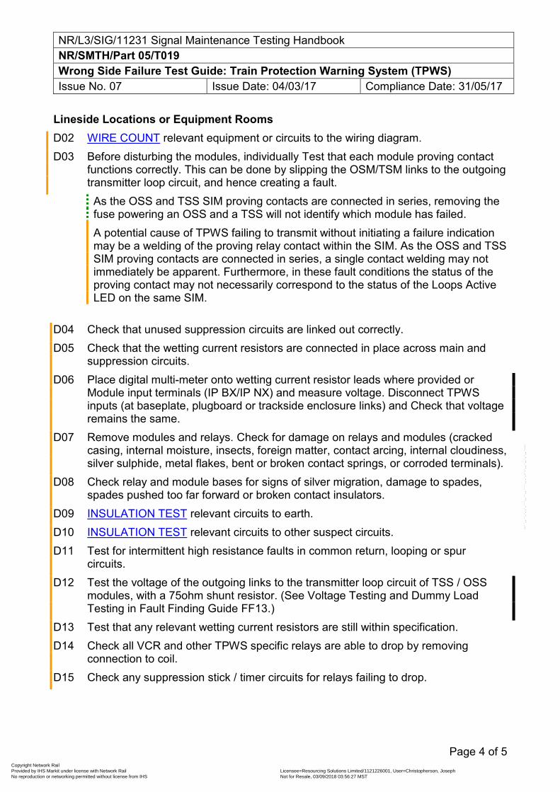
NR/L3/SIG/11231 Signal Maintenance Testing Handbook NR/SMTH/Part 05/T019 Wrong Side Failure Test Guide: Train Protection Warning System (TPWS) Issue No. 07 Issue Date: 04/03/17 Compliance Date: 31/05/17
Page 4 of 5
Lineside Locations or Equipment Rooms D02 WIRE COUNT relevant equipment or circuits to the wiring diagram. D03 Before disturbing the modules, individually Test that each module proving contact
functions correctly. This can be done by slipping the OSM/TSM links to the outgoing transmitter loop circuit, and hence creating a fault. As the OSS and TSS SIM proving contacts are connected in series, removing the fuse powering an OSS and a TSS will not identify which module has failed. A potential cause of TPWS failing to transmit without initiating a failure indication may be a welding of the proving relay contact within the SIM. As the OSS and TSS SIM proving contacts are connected in series, a single contact welding may not immediately be apparent. Furthermore, in these fault conditions the status of the proving contact may not necessarily correspond to the status of the Loops Active LED on the same SIM.
D04 Check that unused suppression circuits are linked out correctly. D05 Check that the wetting current resistors are connected in place across main and
suppression circuits. D06 Place digital multi-meter onto wetting current resistor leads where provided or
Module input terminals (IP BX/IP NX) and measure voltage. Disconnect TPWS inputs (at baseplate, plugboard or trackside enclosure links) and Check that voltage remains the same.
D07 Remove modules and relays. Check for damage on relays and modules (cracked casing, internal moisture, insects, foreign matter, contact arcing, internal cloudiness, silver sulphide, metal flakes, bent or broken contact springs, or corroded terminals).
D08 Check relay and module bases for signs of silver migration, damage to spades, spades pushed too far forward or broken contact insulators.
D09 INSULATION TEST relevant circuits to earth. D10 INSULATION TEST relevant circuits to other suspect circuits. D11 Test for intermittent high resistance faults in common return, looping or spur
circuits. D12 Test the voltage of the outgoing links to the transmitter loop circuit of TSS / OSS
modules, with a 75ohm shunt resistor. (See Voltage Testing and Dummy Load Testing in Fault Finding Guide FF13.)
D13 Test that any relevant wetting current resistors are still within specification. D14 Check all VCR and other TPWS specific relays are able to drop by removing
connection to coil. D15 Check any suppression stick / timer circuits for relays failing to drop.
Copyright Network Rail Provided by IHS Markit under license with Network Rail Licensee=Resourcing Solutions Limited /1121226001, User=Christopherson, Joseph
Not for Resale, 03/09/2018 03:56:27 MSTNo reproduction or networking permitted without license from IHS
--``,,``,`,,`,```,,``,,````,,,`,-`-`,,`,,`,`,,`---
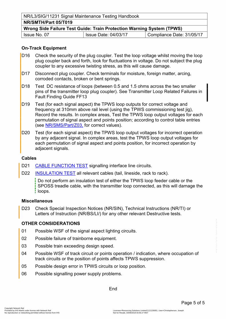
NR/L3/SIG/11231 Signal Maintenance Testing Handbook NR/SMTH/Part 05/T019 Wrong Side Failure Test Guide: Train Protection Warning System (TPWS) Issue No. 07 Issue Date: 04/03/17 Compliance Date: 31/05/17
Page 5 of 5
On-Track Equipment D16 Check the security of the plug coupler. Test the loop voltage whilst moving the loop
plug coupler back and forth, look for fluctuations in voltage. Do not subject the plug coupler to any excessive twisting stress, as this will cause damage.
D17 Disconnect plug coupler. Check terminals for moisture, foreign matter, arcing, corroded contacts, broken or bent springs.
D18 Test DC resistance of loops (between 0.5 and 1.5 ohms across the two smaller pins of the transmitter loop plug coupler). See Transmitter Loop Related Failures in Fault Finding Guide FF13
D19 Test (for each signal aspect) the TPWS loop outputs for correct voltage and frequency at 310mm above rail level (using the TPWS commissioning test jig), Record the results. In complex areas, Test the TPWS loop output voltages for each permutation of signal aspect and points position; according to control table entries (see NR/SMS/Part/Z03, for correct values).
D20 Test (for each signal aspect) the TPWS loop output voltages for incorrect operation by any adjacent signal. In complex areas, test the TPWS loop output voltages for each permutation of signal aspect and points position, for incorrect operation by adjacent signals.
Cables D21 CABLE FUNCTION TEST signalling interface line circuits. D22 INSULATION TEST all relevant cables (tail, lineside, rack to rack).
Do not perform an insulation test of either the TPWS loop feeder cable or the SPOSS treadle cable, with the transmitter loop connected, as this will damage the loops.
Miscellaneous D23 Check Special Inspection Notices (NR/SIN), Technical Instructions (NR/TI) or
Letters of Instruction (NR/BS/LI/) for any other relevant Destructive tests.
OTHER CONSIDERATIONS 01 Possible WSF of the signal aspect lighting circuits. 02 Possible failure of trainborne equipment. 03 Possible train exceeding design speed. 04 Possible WSF of track circuit or points operation / indication, where occupation of
track circuits or the position of points affects TPWS suppression. 05 Possible design error in TPWS circuits or loop position. 06 Possible signalling power supply problems.
End
Copyright Network Rail Provided by IHS Markit under license with Network Rail Licensee=Resourcing Solutions Limited /1121226001, User=Christopherson, Joseph
Not for Resale, 03/09/2018 03:56:27 MSTNo reproduction or networking permitted without license from IHS
--``,,``,`,,`,```,,``,,````,,,`,-`-`,,`,,`,`,,`---
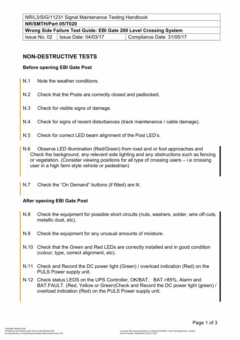
NR/L3/SIG/11231 Signal Maintenance Testing Handbook NR/SMTH/Part 05/T020 Wrong Side Failure Test Guide: EBI Gate 200 Level Crossing System Issue No. 02 Issue Date: 04/03/17 Compliance Date: 31/05/17
Page 1 of 3
NON-DESTRUCTIVE TESTS
Before opening EBI Gate Post N.1 Note the weather conditions.
N.2 Check that the Posts are correctly closed and padlocked.
N.3 Check for visible signs of damage.
N.4 Check for signs of recent disturbances (track maintenance / cable damage).
N.5 Check for correct LED beam alignment of the Post LED’s. N.6 Observe LED illumination (Red/Green) from road and or foot approaches and
Check the background, any relevant side lighting and any obstructions such as fencing or vegetation. (Consider viewing positions for all type of crossing users – i.e crossing user in a high farm style vehicle or pedestrian)
N.7 Check the “On Demand” buttons (if fitted) are lit.
After opening EBI Gate Post N.8 Check the equipment for possible short circuits (nuts, washers, solder, wire off-cuts,
metallic dust, etc).
N.9 Check the equipment for any unusual amounts of moisture.
N.10 Check that the Green and Red LEDs are correctly installed and in good condition (colour, type, correct alignment, etc).
N.11 Check and Record the DC power light (Green) / overload indication (Red) on the PULS Power supply unit.
N.12 Check status LEDS on the UPS Controller, OK/BAT, BAT.>85%, Alarm and BAT.FAULT. (Red, Yellow or Green)Check and Record the DC power light (green) / overload indication (Red) on the PULS Power supply unit.
Copyright Network Rail Provided by IHS Markit under license with Network Rail Licensee=Resourcing Solutions Limited /1121226001, User=Christopherson, Joseph
Not for Resale, 03/09/2018 03:56:27 MSTNo reproduction or networking permitted without license from IHS
--``,,``,`,,`,```,,``,,````,,,`,-`-`,,`,,`,`,,`---
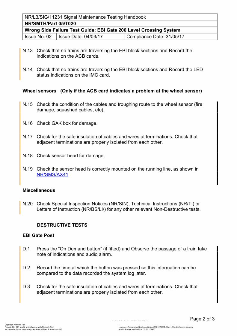
NR/L3/SIG/11231 Signal Maintenance Testing Handbook NR/SMTH/Part 05/T020 Wrong Side Failure Test Guide: EBI Gate 200 Level Crossing System Issue No. 02 Issue Date: 04/03/17 Compliance Date: 31/05/17
Page 2 of 3
N.13 Check that no trains are traversing the EBI block sections and Record the indications on the ACB cards.
N.14 Check that no trains are traversing the EBI block sections and Record the LED status indications on the IMC card.
Wheel sensors (Only if the ACB card indicates a problem at the wheel sensor) N.15 Check the condition of the cables and troughing route to the wheel sensor (fire
damage, squashed cables, etc).
N.16 Check GAK box for damage.
N.17 Check for the safe insulation of cables and wires at terminations. Check that adjacent terminations are properly isolated from each other.
N.18 Check sensor head for damage.
N.19 Check the sensor head is correctly mounted on the running line, as shown in NR/SMS/AX41
Miscellaneous N.20 Check Special Inspection Notices (NR/SIN), Technical Instructions (NR/TI) or
Letters of Instruction (NR/BS/LI/) for any other relevant Non-Destructive tests.
DESTRUCTIVE TESTS
EBI Gate Post D.1 Press the “On Demand button” (if fitted) and Observe the passage of a train take
note of indications and audio alarm.
D.2 Record the time at which the button was pressed so this information can be compared to the data recorded the system log later.
D.3 Check for the safe insulation of cables and wires at terminations. Check that adjacent terminations are properly isolated from each other.
Copyright Network Rail Provided by IHS Markit under license with Network Rail Licensee=Resourcing Solutions Limited /1121226001, User=Christopherson, Joseph
Not for Resale, 03/09/2018 03:56:27 MSTNo reproduction or networking permitted without license from IHS
--``,,``,`,,`,```,,``,,````,,,`,-`-`,,`,,`,`,,`---
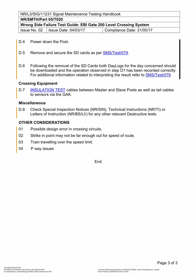
NR/L3/SIG/11231 Signal Maintenance Testing Handbook NR/SMTH/Part 05/T020 Wrong Side Failure Test Guide: EBI Gate 200 Level Crossing System Issue No. 02 Issue Date: 04/03/17 Compliance Date: 31/05/17
Page 3 of 3
D.4 Power down the Post.
D.5 Remove and secure the SD cards as per SMS/Test/079. D.6 Following the removal of the SD Cards both DayLogs for the day concerned should
be downloaded and the operation observed in step D1 has been recorded correctly. For additional information related to interpreting the result refer to SMS/Test/079.
Crossing Equipment D.7 INSULATION TEST cables between Master and Slave Posts as well as tail cables
to sensors via the GAK.
Miscellaneous D.8 Check Special Inspection Notices (NR/SIN), Technical Instructions (NR/TI) or
Letters of Instruction (NR/BS/LI/) for any other relevant Destructive tests.
OTHER CONSIDERATIONS 01 Possible design error in crossing circuits. 02 Strike in point may not be far enough out for speed of route. 03 Train travelling over the speed limit. 04 P way issues
End
Copyright Network Rail Provided by IHS Markit under license with Network Rail Licensee=Resourcing Solutions Limited /1121226001, User=Christopherson, Joseph
Not for Resale, 03/09/2018 03:56:27 MSTNo reproduction or networking permitted without license from IHS
--``,,``,`,,`,```,,``,,````,,,`,-`-`,,`,,`,`,,`---
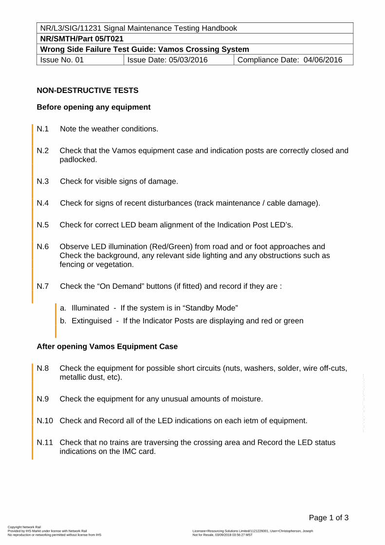
NR/L3/SIG/11231 Signal Maintenance Testing Handbook NR/SMTH/Part 05/T021 Wrong Side Failure Test Guide: Vamos Crossing System Issue No. 01 Issue Date: 05/03/2016 Compliance Date: 04/06/2016
Page 1 of 3
NON-DESTRUCTIVE TESTS
Before opening any equipment
N.1 Note the weather conditions.
N.2 Check that the Vamos equipment case and indication posts are correctly closed and padlocked.
N.3 Check for visible signs of damage.
N.4 Check for signs of recent disturbances (track maintenance / cable damage).
N.5 Check for correct LED beam alignment of the Indication Post LED’s.
N.6 Observe LED illumination (Red/Green) from road and or foot approaches and Check the background, any relevant side lighting and any obstructions such as fencing or vegetation.
N.7 Check the “On Demand” buttons (if fitted) and record if they are :
a. Illuminated - If the system is in “Standby Mode”
b. Extinguised - If the Indicator Posts are displaying and red or green
After opening Vamos Equipment Case
N.8 Check the equipment for possible short circuits (nuts, washers, solder, wire off-cuts, metallic dust, etc).
N.9 Check the equipment for any unusual amounts of moisture.
N.10 Check and Record all of the LED indications on each ietm of equipment.
N.11 Check that no trains are traversing the crossing area and Record the LED status indications on the IMC card.
Copyright Network Rail Provided by IHS Markit under license with Network Rail Licensee=Resourcing Solutions Limited /1121226001, User=Christopherson, Joseph
Not for Resale, 03/09/2018 03:56:27 MSTNo reproduction or networking permitted without license from IHS
--``,,``,`,,`,```,,``,,````,,,`,-`-`,,`,,`,`,,`---
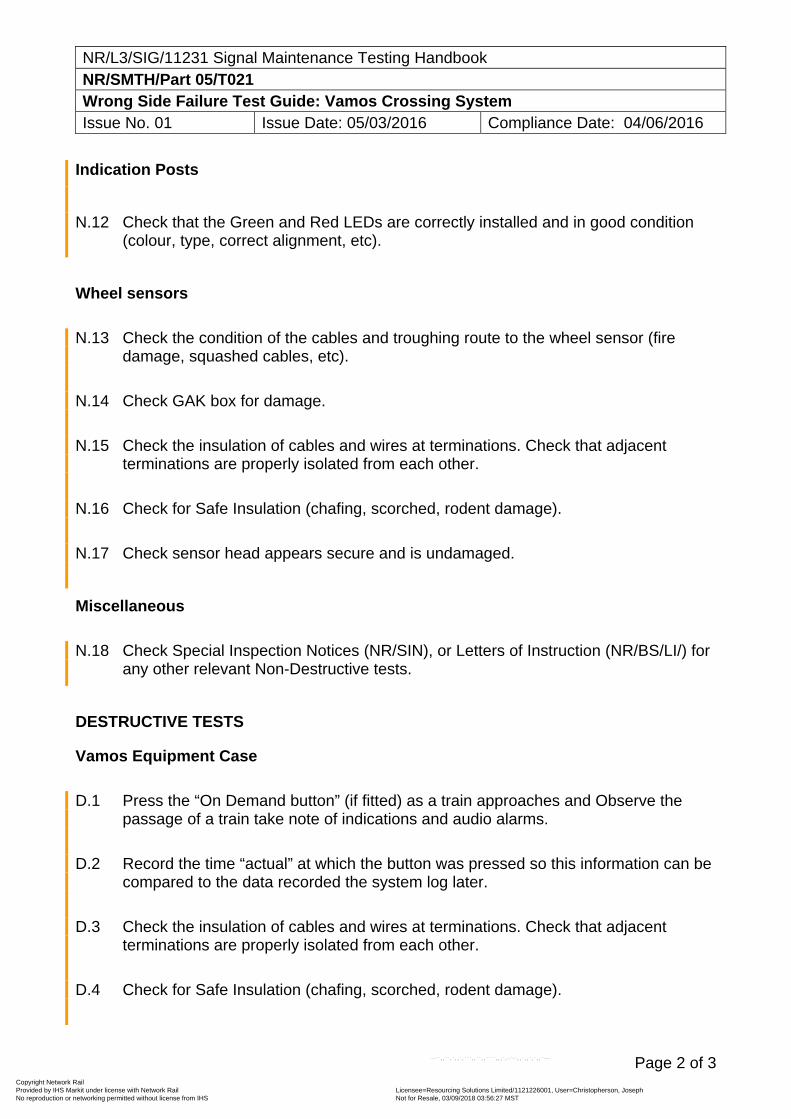
NR/L3/SIG/11231 Signal Maintenance Testing Handbook NR/SMTH/Part 05/T021 Wrong Side Failure Test Guide: Vamos Crossing System Issue No. 01 Issue Date: 05/03/2016 Compliance Date: 04/06/2016
Page 2 of 3
Indication Posts
N.12 Check that the Green and Red LEDs are correctly installed and in good condition (colour, type, correct alignment, etc).
Wheel sensors
N.13 Check the condition of the cables and troughing route to the wheel sensor (fire damage, squashed cables, etc).
N.14 Check GAK box for damage.
N.15 Check the insulation of cables and wires at terminations. Check that adjacent terminations are properly isolated from each other.
N.16 Check for Safe Insulation (chafing, scorched, rodent damage).
N.17 Check sensor head appears secure and is undamaged.
Miscellaneous
N.18 Check Special Inspection Notices (NR/SIN), or Letters of Instruction (NR/BS/LI/) for any other relevant Non-Destructive tests.
DESTRUCTIVE TESTS
Vamos Equipment Case
D.1 Press the “On Demand button” (if fitted) as a train approaches and Observe the passage of a train take note of indications and audio alarms.
D.2 Record the time “actual” at which the button was pressed so this information can be compared to the data recorded the system log later.
D.3 Check the insulation of cables and wires at terminations. Check that adjacent terminations are properly isolated from each other.
D.4 Check for Safe Insulation (chafing, scorched, rodent damage).
Copyright Network Rail Provided by IHS Markit under license with Network Rail Licensee=Resourcing Solutions Limited /1121226001, User=Christopherson, Joseph
Not for Resale, 03/09/2018 03:56:27 MSTNo reproduction or networking permitted without license from IHS
--``,,``,`,,`,```,,``,,````,,,`,-`-`,,`,,`,`,,`---
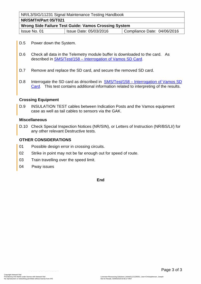
NR/L3/SIG/11231 Signal Maintenance Testing Handbook NR/SMTH/Part 05/T021 Wrong Side Failure Test Guide: Vamos Crossing System Issue No. 01 Issue Date: 05/03/2016 Compliance Date: 04/06/2016
Page 3 of 3
D.5 Power down the System.
D.6 Check all data in the Telemetry module buffer is downloaded to the card. As described in SMS/Test/158 – Interrogation of Vamos SD Card.
D.7 Remove and replace the SD card, and secure the removed SD card.
D.8 Interrogate the SD card as driscribed in SMS/Test/158 – Interrogation of Vamos SD Card. This test contains additional information related to interpreting of the results.
Crossing Equipment
D.9 INSULATION TEST cables between Indication Posts and the Vamos equipment case as well as tail cables to sensors via the GAK.
Miscellaneous
D.10 Check Special Inspection Notices (NR/SIN), or Letters of Instruction (NR/BS/LI/) for any other relevant Destructive tests.
OTHER CONSIDERATIONS
01 Possible design error in crossing circuits.
02 Strike in point may not be far enough out for speed of route.
03 Train travelling over the speed limit.
04 Pway issues
End
Copyright Network Rail Provided by IHS Markit under license with Network Rail Licensee=Resourcing Solutions Limited /1121226001, User=Christopherson, Joseph
Not for Resale, 03/09/2018 03:56:27 MSTNo reproduction or networking permitted without license from IHS
--``,,``,`,,`,```,,``,,````,,,`,-`-`,,`,,`,`,,`---
NR/L3/SIG/11231 Signal Maintenance Testing Handbook NR/SMTH/Part 05/T022 Wrong Side Failure Test Guide: Harmon Crossing Predictor HPX-3 Issue No. 01 Issue Date: 03/03/18 Compliance Date: 31/05/18
Page 1 of 8
NON-DESTRUCTIVE TESTS Signal box tests N.1 Note any relevant Signal Box indications.
N.2 Note any relevant switch or push button states. N.3 Note the state of any relevant train describer displays.
N.4 Note any unusual operating methods in place (possessions, single line working,
etc.) N.5 Note the nature of any work being done, or persons working in the area.
N.6 Note the time and type of train or operation that first caused the reported failure to
become apparent and whether the fault developed without train interference.
N.7 Note the time and type of train or operation last made prior to the report, which made use of the affected equipment.
N.8 Note any other train movements in the affected area. N.9 Note any significant weather conditions in the area.
N.10 Check that any signals or points that have been reported to be part of or connected
to any incident can display the aspect reported/move in the direction reported (i.e. not clipped and plugged).
Trackside cupboards or equipment rooms N.11 Check that the cupboard or room is correctly locked or padlocked.
N.12 Check for any signs of damage and or disturbance. N.13 Check for any signs of recent work (wiring alterations, stage work, etc.).
N.14 Check for security or tightness of equipment (modules, racking cable connectors,
etc.).
N.15 Check the position of any relevant relays (energised or de-energised). N.16 Check for any visual signs of damage.
N.17 Test voltages and record results
Copyright Network Rail Provided by IHS Markit under license with Network Rail Licensee=Resourcing Solutions Limited /1121226001, User=Christopherson, Joseph
Not for Resale, 03/09/2018 03:56:27 MSTNo reproduction or networking permitted without license from IHS
--``,,``,`,,`,```,,``,,````,,,`,-`-`,,`,,`,`,,`---
NR/L3/SIG/11231 Signal Maintenance Testing Handbook NR/SMTH/Part 05/T022 Wrong Side Failure Test Guide: Harmon Crossing Predictor HPX-3 Issue No. 01 Issue Date: 03/03/18 Compliance Date: 31/05/18
Page 2 of 8
HPX-3 specific tasks N.18 Check and record the RX value for each track using the IDK. N.19 Check and record the Track Circuit Phase angle (PHASE) value for each track
using the IDK.
N.20 Check that the Power LED on each module is on. If all Power LEDs are off, check the Master On/Off Switch is on and that the fuse is intact.
N.21 Check that the MDR LED is on, as this indicates the presence of MDR Drive voltage and hence that the problem is elsewhere in the equipment.
N.22 Check that the CWE1 LED is on for single track lines and that CWE1 and CWE2 LEDs are on for double track lines. If these LEDs are not lit, this indicates that the associated track is in Motion Detect mode - this causes warning times to be longer than expected
N.23 Check each TRM to see if the High Signal LED is on. This could be caused by an open track circuit.
N.24 Check for intermittent bond wire terminations or a defective insulated joint coupler.
N.25 Check for open termination shunts.
N.26 Check for open or defective insulated joint couplers.
N.27 Check for improper application of the Track frequency when overlapping with another HXP-3.
N.28 Check for defective sleepers, tie bars and point insulations. DESTRUCTIVE TESTS Common destructive tests D.1 Wire count relevant equipment or circuits and controls to the wiring diagrams.
HPX-3 Power Loss D.2 If some or all of the Power LEDs are not on, apply pressure to each module to make
sure that the DIN connectors are properly seated.
D.3 If the HXP-3 lost power while the Master On/Off switch was On and the fuse was intact, check to see if the AAR terminals N12 and B12 have 12 volts applied to them. If not, the problem can be related to the battery, battery buss, battery charger or Motion Detector Surge Arrester (MDSA).
Copyright Network Rail Provided by IHS Markit under license with Network Rail Licensee=Resourcing Solutions Limited /1121226001, User=Christopherson, Joseph
Not for Resale, 03/09/2018 03:56:27 MSTNo reproduction or networking permitted without license from IHS
--``,,``,`,,`,```,,``,,````,,,`,-`-`,,`,,`,`,,`---
NR/L3/SIG/11231 Signal Maintenance Testing Handbook NR/SMTH/Part 05/T022 Wrong Side Failure Test Guide: Harmon Crossing Predictor HPX-3 Issue No. 01 Issue Date: 03/03/18 Compliance Date: 31/05/18
Page 3 of 8
Diagnostic Codes D.4 Select SD on the IDK and analyse any self-diagnostic codes that have been stored
by the HXP-3, as described in SMS/PartC/IS30 appendix E . All codes are preceded by the date and time they were logged with the most recent entry being shown first.
LED Indications D.5 If any of the CWE1, CWE2, AUX, ISL1, ISL2, MDR, AX1, AX2 or AX3 LEDs are not
illuminated when they should be, check for a 12 Vdc current across the AAR terminals directly above the LED. If the correct voltage is present, the LED should be replaced.
D.6 Check that the ISL1 and ISL2 LEDs are illuminated. These correspond to the RSI
modules for tracks 1 and 2 respectively. If the RSI Modules are present and the equivalent ISL1 or ISL2 LEDs are not illuminated, check that the RSI Module is correctly adjusted and operating.
D.7 Check that the Stall Timer LED (located on the CPU module) is not illuminted. If it is illuminated or flashing, replace the CPU module.
D.8 If, after replacing the CPU, the Stall Timer LED is still flashing, replace the RYD Module.
D.9 If the ISL LED is not illuminated, check the RSI module to see if the (green) HIGH LED is on constantly. When the RSI Module detects a malfunction the (green) HIGH LEDs, (yellow) CALIBRATE LEDs and (red) LOW LEDs flash on and off in a distinct pattern. The pattern varies with the type of fault detected.
D.10 If a pattern is noticed check that the B12 voltage is between 10 and 14 Vdc. D.11 If the B12 voltage is correct, check the LOS jumpers. One mini shunt shall be
installed on LOS 0, LOS 1, and LOS 2. D.12 If the LOS jumpers are correct, check the fault jumpers. One mini shunt shall be
installed on FAULT 0 or FAULT 1.
D.13 If, after these checks, no correctable faults are detected and the fault remains, replace the RSI module.
High Signal (High Impedance or Open Track Circuit) D.14 Check the Ballast Compensation parameter (BC) using the IDK and adjust if
necessary as described in appendix B.
Copyright Network Rail Provided by IHS Markit under license with Network Rail Licensee=Resourcing Solutions Limited /1121226001, User=Christopherson, Joseph
Not for Resale, 03/09/2018 03:56:27 MSTNo reproduction or networking permitted without license from IHS
--``,,``,`,,`,```,,``,,````,,,`,-`-`,,`,,`,`,,`---
NR/L3/SIG/11231 Signal Maintenance Testing Handbook NR/SMTH/Part 05/T022 Wrong Side Failure Test Guide: Harmon Crossing Predictor HPX-3 Issue No. 01 Issue Date: 03/03/18 Compliance Date: 31/05/18
Page 4 of 8
D.15 Place a hard wire shunt, approximately 50% of the distance of the approach away from the crossing. If the value of RX decreases to approximately "50", there is an open circuit in the last 50% of the approach that was shunted. If the value of RX does not decrease to approximately "50" and the possibility of an incorrect Ballast Compensation setting has been eliminated, the open circuit is located between the hard wire shunt and the opposite approach termination. Continue moving the hard wire shunt until the open track circuit is located.
D.16 Check if the open circuit has been caused by a defective termination shunt. The three types of termination shunt are hard wire, wideband, and narrow band (NBS). To test an approach termination, connect a hard wire shunt where the approach termination is connected. Note the RX change on the HXP-3.
a) When the approach termination is of the hard wire type, no change should be seen.
b) When the approach termination is of the wideband type, RX should decrease
by no more than 2.
c) When the approach termination is of the narrow band (NBS) type RX can decrease by as much as 25. If RX increases when the hard wire shunt is connected at the termination, the NBS is defective and should be replaced.
D.17 Test for defective joint couplers using the following procedure.
a) Place a hard wire test shunt on the crossing side of the joint coupler.
b) Observe and record the drop in RX.
c) Remove the test shunt.
d) Place the hard wire test shunt on the termination side of the joint coupler.
e) Observe and record the drop in RX.
f) Remove the test shunt.
g) If the RX drop between the two values recorded was greater than 2, the joint couplers are defective and should be replaced.
Copyright Network Rail Provided by IHS Markit under license with Network Rail Licensee=Resourcing Solutions Limited /1121226001, User=Christopherson, Joseph
Not for Resale, 03/09/2018 03:56:27 MSTNo reproduction or networking permitted without license from IHS
--``,,``,`,,`,```,,``,,````,,,`,-`-`,,`,,`,`,,`---
NR/L3/SIG/11231 Signal Maintenance Testing Handbook NR/SMTH/Part 05/T022 Wrong Side Failure Test Guide: Harmon Crossing Predictor HPX-3 Issue No. 01 Issue Date: 03/03/18 Compliance Date: 31/05/18
Page 5 of 8
Low Phase (Phase angle <32°) D.18 Check that the Frequency is correct for the approach length using the table found in
SMS/PartZ/04 HPX-3.
D.19 If track conditions are extremely wet, especially in the Island circuit, carry out a Phase Compensation adjustment, as described in SMS/PartC/IS30 appendix B.
D.20 If the Phase angle has decreased to below 32 degrees and carrying out Phase
Compensation does not rectify the condition, it may be necessary to use a lower track frequency. Changing the termination shunts (if NBS) and selecting a new Track is sufficient to make a frequency change.
Open Track Tail Cables
D.21 An open Track tail cable does not always cause a high signal condition, but can
indicate a broken or high impedance Track tail cable condition, such as resistive Track wires, Track connections, or defective bonds in the Island circuit. A broken Transmitter tail cable can cause a high signal condition and code C527 for Track 1 or C547 for Track 2 to be displayed. A broken Receiver tail cable can cause condition code C620 for Track 1 or C630 for Track 2 to be displayed.
D.22 When an MDSA is used and an open condition has been narrowed to the Track tail
cable, the MDSA is a possible cause for the open circuit. The MDSA has a fusible link in series with each track tail cable: T1, T2, R1, and R2. Finding defects with these fuseable links is done by bypassing or jumpering around each of them. For example, to jumper around the T2 fuse link, connect a clip jumper from the T1 TRACK terminal to the T1 equipment terminal on the MDSA.
D.23 To make sure that no more than one Track tail cable fuse link is causing the open,
jumper around all four at one time. This should define whether the open is caused by the MDSA or some other portion of the track tail cable.
Rising RX on an Inbound Train D.24 A slight rise in RX can be seen with a shunt or train near the termination. For this
RX increase to occur the termination is usually a NBS and some HXP-3 signal is leaking past the termination creating this phenomenon. Poor ballast conditions or a defective NBS can also cause this.
D.25 Another NBS can be placed at the peak of the RX rise if desired, but this is not
necessary as long as the operation of the crossing is not affected by rising RX.
Tail Ringing
Copyright Network Rail Provided by IHS Markit under license with Network Rail Licensee=Resourcing Solutions Limited /1121226001, User=Christopherson, Joseph
Not for Resale, 03/09/2018 03:56:27 MSTNo reproduction or networking permitted without license from IHS
--``,,``,`,,`,```,,``,,````,,,`,-`-`,,`,,`,`,,`---
NR/L3/SIG/11231 Signal Maintenance Testing Handbook NR/SMTH/Part 05/T022 Wrong Side Failure Test Guide: Harmon Crossing Predictor HPX-3 Issue No. 01 Issue Date: 03/03/18 Compliance Date: 31/05/18
Page 6 of 8
D.26 Tail ringing is a term used in US applications to describe the re-activation of the crossing signals after the train has cleared the Island. This could happen with the HXP-3 if RX decreased as the train was travelling outbound or in association with a diagnostic code.
D.27 Analyse diagnostic codes as described in SMS/PartC/IS30 Appendix E.
D.28 If tail ringing was caused by RX decreasing as the train was travelling outbound;
this is usually an indication of a defective TJC.
Transfer Malfunctions Caused by the TLM D.29 If the TLM fails to transfer power after a fault is detected, check the position of the
NORMAL/AUTO/STANDBY switch on the TLM. If the switch is in the STANDBY position, the HXP-3 can not transfer power to the Normal System after a fault is detected in the Standby System. If the switch is in the NORMAL position, the HXP-3 will not transfer power to the Standby System after a fault is detected in the Normal System. Change the position of the switch for the type of set-up desired.
D.30 Check the fuses on the TLM. The HXP-3 can fail to transfer power to the redundant
system if the fuse for that system has failed.
D.31 Check the adjustment of the Minute Timeout switch on the TLM. If the time is set to
zero, the timer is disabled and the TLM will not transfer power when a system failure occurs. To do this, rotate the thumbwheel on the Minute Timeout switch to select the desired number of minutes. The current selection is indicated by a number displayed next to the thumbwheel on the front of the switch.
D.32 Check the position of the mini shunts on the W2 and W3 jumpers located on the
TLM. Mini shunts are installed on these jumpers to select the Enable or Disable mode for Islands 1 and 2 respectively. Island 2 is non-functional on the HXP-3R and shall always be disabled via the W3 jumper for correct operation.
D.33 Check the Receiver Current Level adjustments for the Island. The ISL1 Current
Adjust LED should be on when there are no trains in the Island. The ISL2 Current Adjust LED is non-functional on the HXP-3R and should always be off. On the HXP-3R2, the ISL2 Current Adjust LED should also be on when there are no trains in the Island.
D.34 Check the position of the mini shunt on the W1 jumper located on the TLM. The
HXP-3 will not transfer power from the Standby System back to the Normal System if the mini shunt on the W1 jumper is installed on pins 2 and 3.
D.35 If the fault is not corrected, replace the TLM.
Copyright Network Rail Provided by IHS Markit under license with Network Rail Licensee=Resourcing Solutions Limited /1121226001, User=Christopherson, Joseph
Not for Resale, 03/09/2018 03:56:27 MSTNo reproduction or networking permitted without license from IHS
--``,,``,`,,`,```,,``,,````,,,`,-`-`,,`,,`,`,,`---
NR/L3/SIG/11231 Signal Maintenance Testing Handbook NR/SMTH/Part 05/T022 Wrong Side Failure Test Guide: Harmon Crossing Predictor HPX-3 Issue No. 01 Issue Date: 03/03/18 Compliance Date: 31/05/18
Page 7 of 8
D.36 If the TLM transfers power without detecting a system failure check the adjustment of the Minute Timeout switch on the TLM. If the time selected is too short (2 minutes or less), the HXP-3 could transfer power while a train is on the approach.
D.37 Check the position of the mini shunts on the W2 and W3 jumpers located on the
TLM. Mini shunts are installed on these jumpers to select the Enable or Disable mode for Islands 1 or 2 respectively. Correct positioning of the mini shunts is based on whether an Island is installed or not. Island 2 is non-functional on the HXP-3R and shall always be disabled via the W3 jumper for correct operation.
D.38 Check the Receiver Current Level adjustments for the Island. The ISL1 Current
Adjust LED should be on when there are no trains in the Island. The ISL2 Current Adjust LED is non-functional on the HXP-3R and should always be off. On the HXP-3R2, the ISL2 Current Adjust LED should also be on when there are no trains in the Island.
D.39 If the fault is not corrected, replace the TLM. Transfer Malfunctions Caused by System Faults D.40 Check for CPU re-setting. D.41 Check for RSI failures. D.42 If system transfers occur continuously, check for the presence of one or more of the
following diagnostic codes and the required corrective action as described in SMS/PartC/IS30 appendix E.
F70 F71 F205 F247 C523 C531 C543 C551 C560 C600 C601 C602 C603 C610 C611 C612 C613 C620 C621 C622 C630 C631 C632 C640 C641 C660 C661 C670 C670 C700 C701 C713 C715 C716 C731 C732 C733
D.43 Check for Track faults. D.44 Confirm all AX Drives are energised. D.45 If TLM problems are suspected and none of the above checks identify the fault,
replace the TLM. D.46 Check for possible causes of a High Signal conditions. D.47 If a system transfer did not occur when it should have check for power failures. D.48 Check for miscellaneous system failures.
Copyright Network Rail Provided by IHS Markit under license with Network Rail Licensee=Resourcing Solutions Limited /1121226001, User=Christopherson, Joseph
Not for Resale, 03/09/2018 03:56:27 MSTNo reproduction or networking permitted without license from IHS
--``,,``,`,,`,```,,``,,````,,,`,-`-`,,`,,`,`,,`---
NR/L3/SIG/11231 Signal Maintenance Testing Handbook NR/SMTH/Part 05/T022 Wrong Side Failure Test Guide: Harmon Crossing Predictor HPX-3 Issue No. 01 Issue Date: 03/03/18 Compliance Date: 31/05/18
Page 8 of 8
D.49 If TLM problems are still suspected and none of the above checks identify the fault, replace the TLM.
End
Copyright Network Rail Provided by IHS Markit under license with Network Rail Licensee=Resourcing Solutions Limited /1121226001, User=Christopherson, Joseph
Not for Resale, 03/09/2018 03:56:27 MSTNo reproduction or networking permitted without license from IHS
--``,,``,`,,`,```,,``,,````,,,`,-`-`,,`,,`,`,,`---
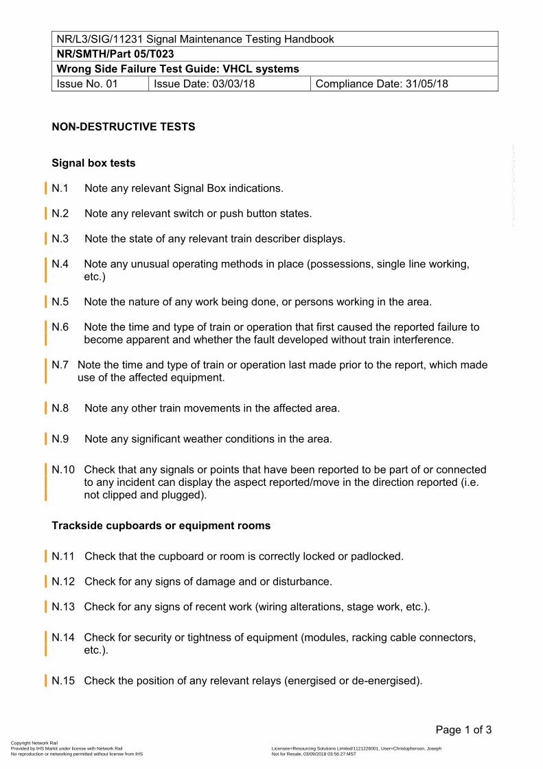
NR/L3/SIG/11231 Signal Maintenance Testing Handbook NR/SMTH/Part 05/T023 Wrong Side Failure Test Guide: VHCL systems Issue No. 01 Issue Date: 03/03/18 Compliance Date: 31/05/18
Page 1 of 3
NON-DESTRUCTIVE TESTS Signal box tests N.1 Note any relevant Signal Box indications.
N.2 Note any relevant switch or push button states.
N.3 Note the state of any relevant train describer displays.
N.4 Note any unusual operating methods in place (possessions, single line working,
etc.)
N.5 Note the nature of any work being done, or persons working in the area.
N.6 Note the time and type of train or operation that first caused the reported failure to become apparent and whether the fault developed without train interference.
N.7 Note the time and type of train or operation last made prior to the report, which made use of the affected equipment.
N.8 Note any other train movements in the affected area. N.9 Note any significant weather conditions in the area.
N.10 Check that any signals or points that have been reported to be part of or connected
to any incident can display the aspect reported/move in the direction reported (i.e. not clipped and plugged).
Trackside cupboards or equipment rooms N.11 Check that the cupboard or room is correctly locked or padlocked.
N.12 Check for any signs of damage and or disturbance.
N.13 Check for any signs of recent work (wiring alterations, stage work, etc.). N.14 Check for security or tightness of equipment (modules, racking cable connectors,
etc.).
N.15 Check the position of any relevant relays (energised or de-energised).
Copyright Network Rail Provided by IHS Markit under license with Network Rail Licensee=Resourcing Solutions Limited /1121226001, User=Christopherson, Joseph
Not for Resale, 03/09/2018 03:56:27 MSTNo reproduction or networking permitted without license from IHS
--``,,``,`,,`,```,,``,,````,,,`,-`-`,,`,,`,`,,`---
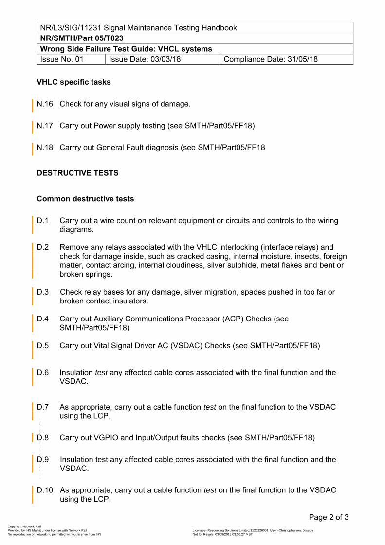
NR/L3/SIG/11231 Signal Maintenance Testing Handbook NR/SMTH/Part 05/T023 Wrong Side Failure Test Guide: VHCL systems Issue No. 01 Issue Date: 03/03/18 Compliance Date: 31/05/18
Page 2 of 3
VHLC specific tasks N.16 Check for any visual signs of damage. N.17 Carry out Power supply testing (see SMTH/Part05/FF18)
N.18 Carrry out General Fault diagnosis (see SMTH/Part05/FF18
DESTRUCTIVE TESTS Common destructive tests D.1 Carry out a wire count on relevant equipment or circuits and controls to the wiring
diagrams.
D.2 Remove any relays associated with the VHLC interlocking (interface relays) and check for damage inside, such as cracked casing, internal moisture, insects, foreign matter, contact arcing, internal cloudiness, silver sulphide, metal flakes and bent or broken springs.
D.3 Check relay bases for any damage, silver migration, spades pushed in too far or broken contact insulators.
D.4 Carry out Auxiliary Communications Processor (ACP) Checks (see SMTH/Part05/FF18)
D.5 Carry out Vital Signal Driver AC (VSDAC) Checks (see SMTH/Part05/FF18)
D.6 Insulation test any affected cable cores associated with the final function and the
VSDAC.
D.7 As appropriate, carry out a cable function test on the final function to the VSDAC
using the LCP.
D.8 Carry out VGPIO and Input/Output faults checks (see SMTH/Part05/FF18)
D.9 Insulation test any affected cable cores associated with the final function and the VSDAC.
D.10 As appropriate, carry out a cable function test on the final function to the VSDAC using the LCP.
Copyright Network Rail Provided by IHS Markit under license with Network Rail Licensee=Resourcing Solutions Limited /1121226001, User=Christopherson, Joseph
Not for Resale, 03/09/2018 03:56:27 MSTNo reproduction or networking permitted without license from IHS
--``,,``,`,,`,```,,``,,````,,,`,-`-`,,`,,`,`,,`---
NR/L3/SIG/11231 Signal Maintenance Testing Handbook NR/SMTH/Part 05/T023 Wrong Side Failure Test Guide: VHCL systems Issue No. 01 Issue Date: 03/03/18 Compliance Date: 31/05/18
Page 3 of 3
D.11 Carry out Vital Logic Processor (VLP) Checks (see SMTH/Part05/FF18)
D.12 Replacing a battery or 5VDC power supply (see SMTH/Part05/FF18)
End
Copyright Network Rail Provided by IHS Markit under license with Network Rail Licensee=Resourcing Solutions Limited /1121226001, User=Christopherson, Joseph
Not for Resale, 03/09/2018 03:56:27 MSTNo reproduction or networking permitted without license from IHS
--``,,``,`,,`,```,,``,,````,,,`,-`-`,,`,,`,`,,`---
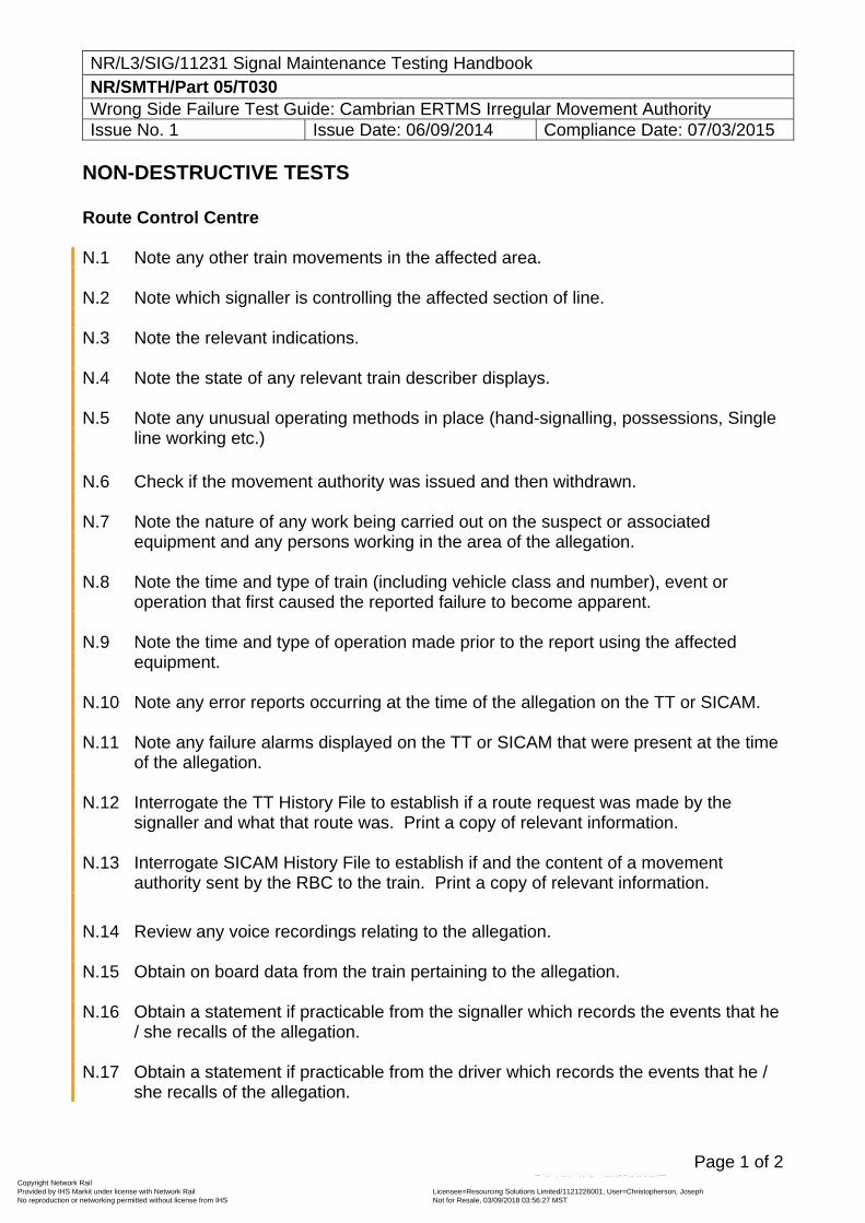
NR/L3/SIG/11231 Signal Maintenance Testing Handbook NR/SMTH/Part 05/T030 Wrong Side Failure Test Guide: Cambrian ERTMS Irregular Movement Authority Issue No. 1 Issue Date: 06/09/2014 Compliance Date: 07/03/2015
Page 1 of 2
NON-DESTRUCTIVE TESTS Route Control Centre N.1 Note any other train movements in the affected area. N.2 Note which signaller is controlling the affected section of line. N.3 Note the relevant indications. N.4 Note the state of any relevant train describer displays. N.5 Note any unusual operating methods in place (hand-signalling, possessions, Single
line working etc.) N.6 Check if the movement authority was issued and then withdrawn. N.7 Note the nature of any work being carried out on the suspect or associated
equipment and any persons working in the area of the allegation. N.8 Note the time and type of train (including vehicle class and number), event or
operation that first caused the reported failure to become apparent. N.9 Note the time and type of operation made prior to the report using the affected
equipment. N.10 Note any error reports occurring at the time of the allegation on the TT or SICAM. N.11 Note any failure alarms displayed on the TT or SICAM that were present at the time
of the allegation. N.12 Interrogate the TT History File to establish if a route request was made by the
signaller and what that route was. Print a copy of relevant information. N.13 Interrogate SICAM History File to establish if and the content of a movement
authority sent by the RBC to the train. Print a copy of relevant information.
N.14 Review any voice recordings relating to the allegation. N.15 Obtain on board data from the train pertaining to the allegation. N.16 Obtain a statement if practicable from the signaller which records the events that he
/ she recalls of the allegation. N.17 Obtain a statement if practicable from the driver which records the events that he /
she recalls of the allegation.
Copyright Network Rail Provided by IHS Markit under license with Network Rail Licensee=Resourcing Solutions Limited /1121226001, User=Christopherson, Joseph
Not for Resale, 03/09/2018 03:56:27 MSTNo reproduction or networking permitted without license from IHS
--``,,``,`,,`,```,,``,,````,,,`,-`-`,,`,,`,`,,`---
NR/L3/SIG/11231 Signal Maintenance Testing Handbook NR/SMTH/Part 05/T030 Wrong Side Failure Test Guide: Cambrian ERTMS Irregular Movement Authority Issue No. 1 Issue Date: 06/09/2014 Compliance Date: 07/03/2015
Page 2 of 2
N.18 Obtain a statement if practicable from any other person which records the events that he / she recalls of the allegation.
DESTRUCTIVE TESTS D.1 Down load an electronic copy of the TT and SICAM data pertaining to the
allegation, the copy should where possible start when the route against which the allegation is made was last used.
D.2 Recreate the situation that prevailed at the time of the allegation and record the
results.
END
Copyright Network Rail Provided by IHS Markit under license with Network Rail Licensee=Resourcing Solutions Limited /1121226001, User=Christopherson, Joseph
Not for Resale, 03/09/2018 03:56:27 MSTNo reproduction or networking permitted without license from IHS
--``,,``,`,,`,```,,``,,````,,,`,-`-`,,`,,`,`,,`---
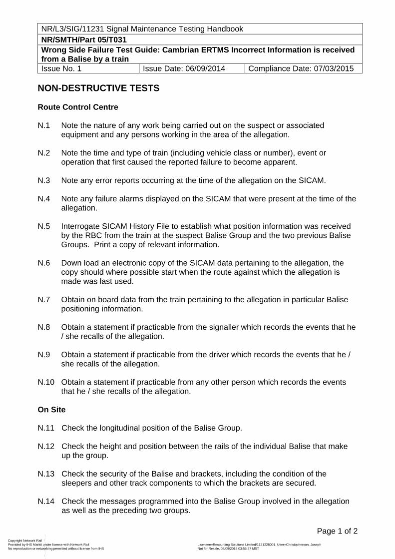
NR/L3/SIG/11231 Signal Maintenance Testing Handbook NR/SMTH/Part 05/T031 Wrong Side Failure Test Guide: Cambrian ERTMS Incorrect Information is received from a Balise by a train Issue No. 1 Issue Date: 06/09/2014 Compliance Date: 07/03/2015
Page 1 of 2
NON-DESTRUCTIVE TESTS Route Control Centre N.1 Note the nature of any work being carried out on the suspect or associated
equipment and any persons working in the area of the allegation. N.2 Note the time and type of train (including vehicle class or number), event or
operation that first caused the reported failure to become apparent. N.3 Note any error reports occurring at the time of the allegation on the SICAM. N.4 Note any failure alarms displayed on the SICAM that were present at the time of the
allegation. N.5 Interrogate SICAM History File to establish what position information was received
by the RBC from the train at the suspect Balise Group and the two previous Balise Groups. Print a copy of relevant information.
N.6 Down load an electronic copy of the SICAM data pertaining to the allegation, the
copy should where possible start when the route against which the allegation is made was last used.
N.7 Obtain on board data from the train pertaining to the allegation in particular Balise
positioning information. N.8 Obtain a statement if practicable from the signaller which records the events that he
/ she recalls of the allegation. N.9 Obtain a statement if practicable from the driver which records the events that he /
she recalls of the allegation. N.10 Obtain a statement if practicable from any other person which records the events
that he / she recalls of the allegation. On Site N.11 Check the longitudinal position of the Balise Group. N.12 Check the height and position between the rails of the individual Balise that make
up the group. N.13 Check the security of the Balise and brackets, including the condition of the
sleepers and other track components to which the brackets are secured. N.14 Check the messages programmed into the Balise Group involved in the allegation
as well as the preceding two groups.
Copyright Network Rail Provided by IHS Markit under license with Network Rail Licensee=Resourcing Solutions Limited /1121226001, User=Christopherson, Joseph
Not for Resale, 03/09/2018 03:56:27 MSTNo reproduction or networking permitted without license from IHS
--``,,``,`,,`,```,,``,,````,,,`,-`-`,,`,,`,`,,`---
NR/L3/SIG/11231 Signal Maintenance Testing Handbook NR/SMTH/Part 05/T031 Wrong Side Failure Test Guide: Cambrian ERTMS Incorrect Information is received from a Balise by a train Issue No. 1 Issue Date: 06/09/2014 Compliance Date: 07/03/2015
Page 2 of 2
DESTRUCTIVE TESTS D.1 Recreate the situation that prevailed at the time of the allegation and record the
results.
END
Copyright Network Rail Provided by IHS Markit under license with Network Rail Licensee=Resourcing Solutions Limited /1121226001, User=Christopherson, Joseph
Not for Resale, 03/09/2018 03:56:27 MSTNo reproduction or networking permitted without license from IHS
--``,,``,`,,`,```,,``,,````,,,`,-`-`,,`,,`,`,,`---
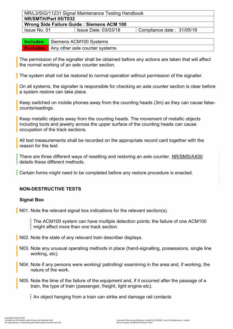
NR/L3/SIG/11231 Signal Maintenance Testing Handbook NR/SMTH/Part 05/T032 Wrong Side Failure Guide : Siemens ACM 100 Issue No. 01 Issue Date: 03/03/18 Compliance date : 31/05/18
Includes: Siemens ACM100 Systems Excludes: Any other axle counter systems
The permission of the signaller shall be obtained before any actions are taken that will affect the normal working of an axle counter section. The system shall not be restored to normal operation without permission of the signaller. On all systems, the signaller is responsible for checking an axle counter section is clear before a system restore can take place. Keep switched on mobile phones away from the counting heads (3m) as they can cause false-counts/readings. Keep metallic objects away from the counting heads. The movement of metallic objects including tools and jewelry across the upper surface of the counting heads can cause occupation of the track sections. All test measurements shall be recorded on the appropriate record card together with the reason for the test. There are three different ways of resetting and restoring an axle counter. NR/SMS/AX00 details these different methods. Certain forms might need to be completed before any restore procedure is enacted.
NON-DESTRUCTIVE TESTS Signal Box N01. Note the relevant signal box indications for the relevant section(s).
The ACM100 system can have multiple detection points; the failure of one ACM100 might affect more than one track section.
N02. Note the state of any relevant train describer displays. N03. Note any unusual operating methods in place (hand-signalling, possessions, single line
working, etc). N04. Note if any persons were working/ patrolling/ examining in the area and, if working, the
nature of the work. N05. Note the time of the failure of the equipment and, if it occurred after the passage of a
train, the type of train (passenger, freight, light engine etc).
An object hanging from a train can strike and damage rail contacts
Copyright Network Rail Provided by IHS Markit under license with Network Rail Licensee=Resourcing Solutions Limited /1121226001, User=Christopherson, Joseph
Not for Resale, 03/09/2018 03:56:27 MSTNo reproduction or networking permitted without license from IHS
--``,,``,`,,`,```,,``,,````,,,`,-`-`,,`,,`,`,,`---
NR/L3/SIG/11231 Signal Maintenance Testing Handbook NR/SMTH/Part 05/T032 Wrong Side Failure Guide : Siemens ACM 100 Issue No. 01 Issue Date: 03/03/18 Compliance date : 31/05/18
N06. If a failure occurred after a passage of a train, Note if there was anything unusual about it (slow moving train, long time in the section, emergency non-signalled movement).
N07. Note any other train movements in the affected area. Lineside Locations or Equipment Rooms N08. Check that the room or enclosure containing the ACM100 system is securely locked. N09. Check any site record cards or log books for relevant information. N10. Check for any signs of equipment damage. N11. Check and record the LEDs on the ACM100 system components.
The relevant SMS for the ACM100 system give some details of the equipment indications (NR/SMS/Appendix/13).
N12. If provided, check any system logging or recording media for relevant information. N13. Check the diagnostic web-site of the ACM100 system and record any details. N14. Check for signs of any recent activity (new works, temporary wiring, diversion of circuits,
track maintenance activity). N15. Check that all equipment covers are securely fitted with no sign of tampering or
attempted access to internal parts. N16. Visually inspect all cables or connecting leads are correctly inserted and secure. N17. Check the position and status of the reset relays (energised, de-energised). N18. Check for damage or contamination on or inside relays (cracked casing, internal
moisture, insects, foreign matter, contact arcing, internal cloudiness, strong smell, silver sulphide, metal flakes, bent or broken contact springs, corroded terminals).
N19. Check that the relays correspond to the diagrams (type and specification, pin code,
voltage, contact arrangement, single/double wound coils).
Record the last service date on the WSF form and forward to your SM(S). N20. Check that the equipment and settings correspond to the diagrams (specification, power,
voltage rating, etc). N21. Check for silver migration on the rear of relay bases. N22. Check the equipment for any possible short circuits (nuts, washers, solder, wire off-cuts,
metallic dust, etc).
Copyright Network Rail Provided by IHS Markit under license with Network Rail Licensee=Resourcing Solutions Limited /1121226001, User=Christopherson, Joseph
Not for Resale, 03/09/2018 03:56:27 MSTNo reproduction or networking permitted without license from IHS
--``,,``,`,,`,```,,``,,````,,,`,-`-`,,`,,`,`,,`---
NR/L3/SIG/11231 Signal Maintenance Testing Handbook NR/SMTH/Part 05/T032 Wrong Side Failure Guide : Siemens ACM 100 Issue No. 01 Issue Date: 03/03/18 Compliance date : 31/05/18
N23. If provided, Check the room/case heating/cooling systems for correct operation.
Extremes of heat or cold can affect the operation of electronic equipment. N24. Check the equipment for any signs of moisture or water contamination (leaking roofs,
damaged or missing seals, flooding). N25. Check for possible radio interference (mobile phone masts, RETB aerials). N26. Earth Test (DC) [NR/SMTH/11231/Part03/TestB05] or Earth Test (AC)
[NR/SMTH/11231/Part03/TestB06] circuits and supplies. Lineside Connection Box (DISBOX) N27. Check the DISBOX for damage. N28. Check the DISBOX cover is correctly fitted and secure. N29. If in an electrified area, check that the earthing of the DISBOX is secure and effective. N30. Check the interior for signs of moisture. N31. Check for any possible short circuits (nuts, washers, solder, wire off-cuts, metallic dust,
etc). N32. Check for possible radio interference (mobile phone masts, RETB aerials). Wheel Detectors N33. Check the wheel detectors for damage. N34. Check the wheel detectors are secure. N35. Check for any debris or rubbish around the wheel detectors, particular check for any
metal objects. N36. Check for signs of any recent activity (new works, track maintenance, etc.). Cables & Wires N37. Check the trackside cabling for signs of damage cables squashed by rails in the cess, fire
damage, rodent damage). N38. Check all cables and wires for Safe Insulation and Check that all terminations are
correctly insulated from each other.
Copyright Network Rail Provided by IHS Markit under license with Network Rail Licensee=Resourcing Solutions Limited /1121226001, User=Christopherson, Joseph
Not for Resale, 03/09/2018 03:56:27 MSTNo reproduction or networking permitted without license from IHS
--``,,``,`,,`,```,,``,,````,,,`,-`-`,,`,,`,`,,`---
NR/L3/SIG/11231 Signal Maintenance Testing Handbook NR/SMTH/Part 05/T032 Wrong Side Failure Guide : Siemens ACM 100 Issue No. 01 Issue Date: 03/03/18 Compliance date : 31/05/18
Miscellaneous N39. Check Special Inspection Notices (NR/SIN), Technical Instructions (NR/TI) or Letters of
Instruction (NR/BS/LI/) for any other relevant Non-Destructive tests. N40. Note any extraneous conditions or circumstances that could have an effect on the failure. DESTRUCTIVE TESTS Lineside Locations or Equipment Rooms D01. Wire count the relevant equipment or circuits to the wiring diagram and connecting
leads/cables. D02. Remove the relays and check for damage or contamination on or inside the relays
(cracked casing, internal moisture, insects, foreign matter, contact arcing, internal cloudiness, strong smell, silver sulphide, metal flakes, bent or broken contact springs, corroded terminals).
D03. Check relay plug board for correct pin code, silver migration, damage, spades pushed
too far forward or broken contact insulators. Cables D04. Cable Function Test [NR/SMTH/Part 03/Test B04] line circuits. D05. Insulation Test [NR/SMTH/Part 03/Test B03] all cables (tail, lineside, rack to rack).
Check cables are totally disconnected for this test as the high voltages involved will damage electronic components.
Lineside connection boxes and wheel detectors D06. Test the operation of the system by carrying out a test of the wheel detector at the
detection points for the relevant section [NR/SMS/Test/039]. Observe the indications on the LEDs at the relevant ACM100 during this test.
Miscellaneous D07. Check Special Inspection Notices (NR/SIN), Technical Instructions (NR/TI) or Letters of
Instruction (NR/BS/LI/) for any other relevant Destructive tests.
Copyright Network Rail Provided by IHS Markit under license with Network Rail Licensee=Resourcing Solutions Limited /1121226001, User=Christopherson, Joseph
Not for Resale, 03/09/2018 03:56:27 MSTNo reproduction or networking permitted without license from IHS
--``,,``,`,,`,```,,``,,````,,,`,-`-`,,`,,`,`,,`---
NR/L3/SIG/11231 Signal Maintenance Testing Handbook NR/SMTH/Part 05/T032 Wrong Side Failure Guide : Siemens ACM 100 Issue No. 01 Issue Date: 03/03/18 Compliance date : 31/05/18
OTHER CONSIDERATIONS 01 Possible remote control system fault/failure. 02 Possible design error.
End
Copyright Network Rail Provided by IHS Markit under license with Network Rail Licensee=Resourcing Solutions Limited /1121226001, User=Christopherson, Joseph
Not for Resale, 03/09/2018 03:56:27 MSTNo reproduction or networking permitted without license from IHS
--``,,``,`,,`,```,,``,,````,,,`,-`-`,,`,,`,`,,`---
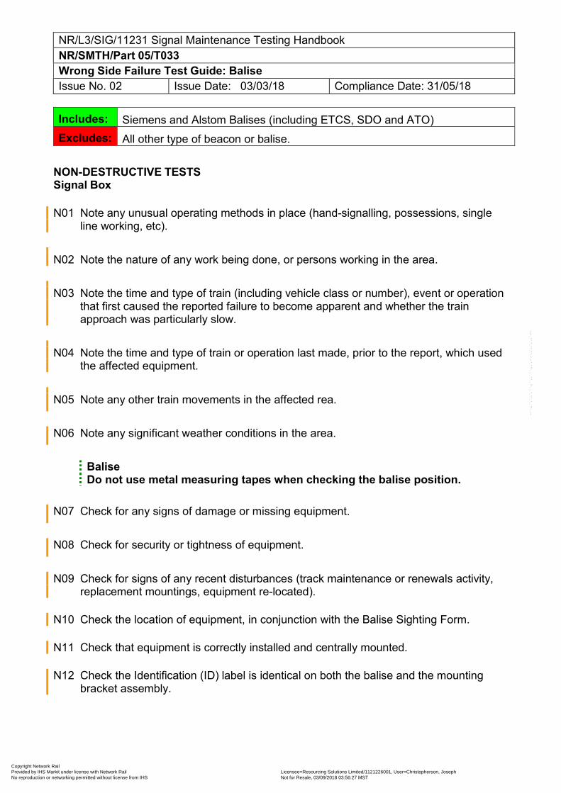
NR/L3/SIG/11231 Signal Maintenance Testing Handbook NR/SMTH/Part 05/T033 Wrong Side Failure Test Guide: Balise Issue No. 02 Issue Date: 03/03/18 Compliance Date: 31/05/18
Includes: Siemens and Alstom Balises (including ETCS, SDO and ATO) Excludes: All other type of beacon or balise.
NON-DESTRUCTIVE TESTS Signal Box N01 Note any unusual operating methods in place (hand-signalling, possessions, single
line working, etc).
N02 Note the nature of any work being done, or persons working in the area.
N03 Note the time and type of train (including vehicle class or number), event or operation that first caused the reported failure to become apparent and whether the train approach was particularly slow.
N04 Note the time and type of train or operation last made, prior to the report, which used the affected equipment.
N05 Note any other train movements in the affected rea. N06 Note any significant weather conditions in the area.
Balise Do not use metal measuring tapes when checking the balise position.
N07 Check for any signs of damage or missing equipment. N08 Check for security or tightness of equipment. N09 Check for signs of any recent disturbances (track maintenance or renewals activity,
replacement mountings, equipment re-located). N10 Check the location of equipment, in conjunction with the Balise Sighting Form. N11 Check that equipment is correctly installed and centrally mounted. N12 Check the Identification (ID) label is identical on both the balise and the mounting
bracket assembly.
Copyright Network Rail Provided by IHS Markit under license with Network Rail Licensee=Resourcing Solutions Limited /1121226001, User=Christopherson, Joseph
Not for Resale, 03/09/2018 03:56:27 MSTNo reproduction or networking permitted without license from IHS
--``,,``,`,,`,```,,``,,````,,,`,-`-`,,`,,`,`,,`---
NR/L3/SIG/11231 Signal Maintenance Testing Handbook NR/SMTH/Part 05/T033 Wrong Side Failure Test Guide: Balise Issue No. 02 Issue Date: 03/03/18 Compliance Date: 31/05/18
Some Testing and Programming Tools generated strong electromagnet fields during their use. These can interfere with cardiac pacemakers and can have long-term detrimental effects on health.
N13 Test the Balise telegram data through the air gap using the appropriate Testing and
Programming Tool. N14 Check Special Inspection Notices (NR/SIN), Technical Instructions (NR/TI) or Letters of
Instruction (NR/BS/LI/) for any other relevant Non-Destructive tests. OTHER CONSIDERATIONS 1 Possible design error in telegram data. 2 Possible design error in specifying balise position.
3 Possible failure of train-borne equipment.
End
Copyright Network Rail Provided by IHS Markit under license with Network Rail Licensee=Resourcing Solutions Limited /1121226001, User=Christopherson, Joseph
Not for Resale, 03/09/2018 03:56:27 MSTNo reproduction or networking permitted without license from IHS
--``,,``,`,,`,```,,``,,````,,,`,-`-`,,`,,`,`,,`---
NR/L3/SIG/11231 Signal Maintenance Testing Handbook NR/SMTH/Part 05/U001 Signalling Intermittent and Obscure Failure Guides Issue No. 05 Issue Date: 05/03/11 Compliance Date: 03/09/11
Page 1 of 1
Scope
These U series Fault Finding Guides have been introduced in the form of check lists to detail the suggested checks and tests which shall be carried out when investigating intermittent or repetitive failures or those failures where the root cause is not readily apparent, or where equipment is found to be working correctly upon arrival at the reported fault location.
Wrong Side Failures shall always be investigated using the appropriate Test Guide(s) in the T series.
Further fault finding guidance can be found within the documents listed in Part 01/Appendix B, and in relevant Manufacturer's Documentation.
Fault Finding Guides
The Fault Finding Guides are presented in a similar style to the Test Plans, the appropriate guide being used when testing / checking on site to determine the potential cause of any failure.
The checks listed are not intended to be a comprehensive test sequence, or be in the correct order for every circumstance. Checks and tests considered most relevant to the reported failure shall be carried out first.
If no cause is apparent after these checks, advise your Section Manager (Signals) and seek type specific fault finding information from available sources.
Records
You shall complete the Signalling Intermittent and Obscure Failure checksheet in Part 05/Appendix 07. Any measurement results or test records shall be included or attached as appropriate.
If any item is replaced under NR/SMTH the SMTH logbook sheet shall also be included.
If you are investigating a SPAD, you shall also write down the results of each test that you complete and send it to your Section Manager (Signals). Remember to identify any root cause as well as the actual cause of the failure.
If operating staff decline access to equipment for test / check purposes, this fact shall be recorded on the SMTH logbook sheet and advised to your Section Manager (Signals).
End
Copyright Network Rail Provided by IHS Markit under license with Network Rail Licensee=Resourcing Solutions Limited /1121226001, User=Christopherson, Joseph
Not for Resale, 03/09/2018 03:56:27 MSTNo reproduction or networking permitted without license from IHS
--``,,``,`,,`,```,,``,,````,,,`,-`-`,,`,,`,`,,`---
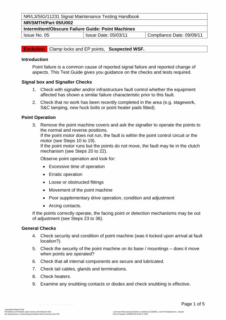
NR/L3/SIG/11231 Signal Maintenance Testing Handbook NR/SMTH/Part 05/U002 Intermittent/Obscure Failure Guide: Point Machines Issue No. 05 Issue Date: 05/03/11 Compliance Date: 09/09/11
Page 1 of 5
Excludes: Clamp locks and EP points, Suspected WSF.
Introduction
Point failure is a common cause of reported signal failure and reported change of aspects. This Test Guide gives you guidance on the checks and tests required.
Signal box and Signaller Checks
1. Check with signaller and/or infrastructure fault control whether the equipment affected has shown a similar failure characteristic prior to this fault.
2. Check that no work has been recently completed in the area (e.g. stagework, S&C tamping, new huck bolts or point heater pads fitted).
Point Operation
3. Remove the point machine covers and ask the signaller to operate the points to the normal and reverse positions. If the point motor does not run, the fault is within the point control circuit or the motor (see Steps 10 to 19). If the point motor runs but the points do not move, the fault may lie in the clutch mechanism (see Steps 20 to 22).
Observe point operation and look for:
Excessive time of operation
Erratic operation
Loose or obstructed fittings
Movement of the point machine
Poor supplementary drive operation, condition and adjustment
Arcing contacts.
If the points correctly operate, the facing point or detection mechanisms may be out of adjustment (see Steps 23 to 36).
General Checks
4. Check security and condition of point machine (was it locked upon arrival at fault location?).
5. Check the security of the point machine on its base / mountings – does it move when points are operated?
6. Check that all internal components are secure and lubricated.
7. Check tail cables, glands and terminations.
8. Check heaters.
9. Examine any snubbing contacts or diodes and check snubbing is effective.
Copyright Network Rail Provided by IHS Markit under license with Network Rail Licensee=Resourcing Solutions Limited /1121226001, User=Christopherson, Joseph
Not for Resale, 03/09/2018 03:56:27 MSTNo reproduction or networking permitted without license from IHS
--``,,``,`,,`,```,,``,,````,,,`,-`-`,,`,,`,`,,`---
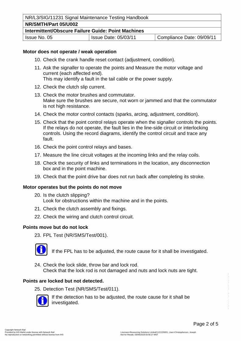
NR/L3/SIG/11231 Signal Maintenance Testing Handbook NR/SMTH/Part 05/U002 Intermittent/Obscure Failure Guide: Point Machines Issue No. 05 Issue Date: 05/03/11 Compliance Date: 09/09/11
Page 2 of 5
Motor does not operate / weak operation
10. Check the crank handle reset contact (adjustment, condition).
11. Ask the signaller to operate the points and Measure the motor voltage and current (each affected end). This may identify a fault in the tail cable or the power supply.
12. Check the clutch slip current.
13. Check the motor brushes and commutator. Make sure the brushes are secure, not worn or jammed and that the commutator is not high resistance.
14. Check the motor control contacts (sparks, arcing, adjustment, condition).
15. Check that the point control relays operate when the signaller controls the points. If the relays do not operate, the fault lies in the line-side circuit or interlocking controls. Using the record diagrams, identify the control circuit and trace any fault.
16. Check the point control relays and bases.
17. Measure the line circuit voltages at the incoming links and the relay coils.
18. Check the security of links and terminations in the location, any disconnection box and in the point machine.
19. Check that the point drive bar does not run back after completing its stroke.
Motor operates but the points do not move
20. Is the clutch slipping? Look for obstructions within the machine and in the points.
21. Check the clutch assembly and fixings.
22. Check the wiring and clutch control circuit.
Points move but do not lock
23. FPL Test (NR/SMS/Test/001).
If the FPL has to be adjusted, the route cause for it shall be investigated.
24. Check the lock slide, throw bar and lock rod. Check that the lock rod is not damaged and nuts and lock nuts are tight.
Points are locked but not detected.
25. Detection Test (NR/SMS/Test/011).
If the detection has to be adjusted, the route cause for it shall be investigated.
Copyright Network Rail Provided by IHS Markit under license with Network Rail Licensee=Resourcing Solutions Limited /1121226001, User=Christopherson, Joseph
Not for Resale, 03/09/2018 03:56:27 MSTNo reproduction or networking permitted without license from IHS
--``,,``,`,,`,```,,``,,````,,,`,-`-`,,`,,`,`,,`---
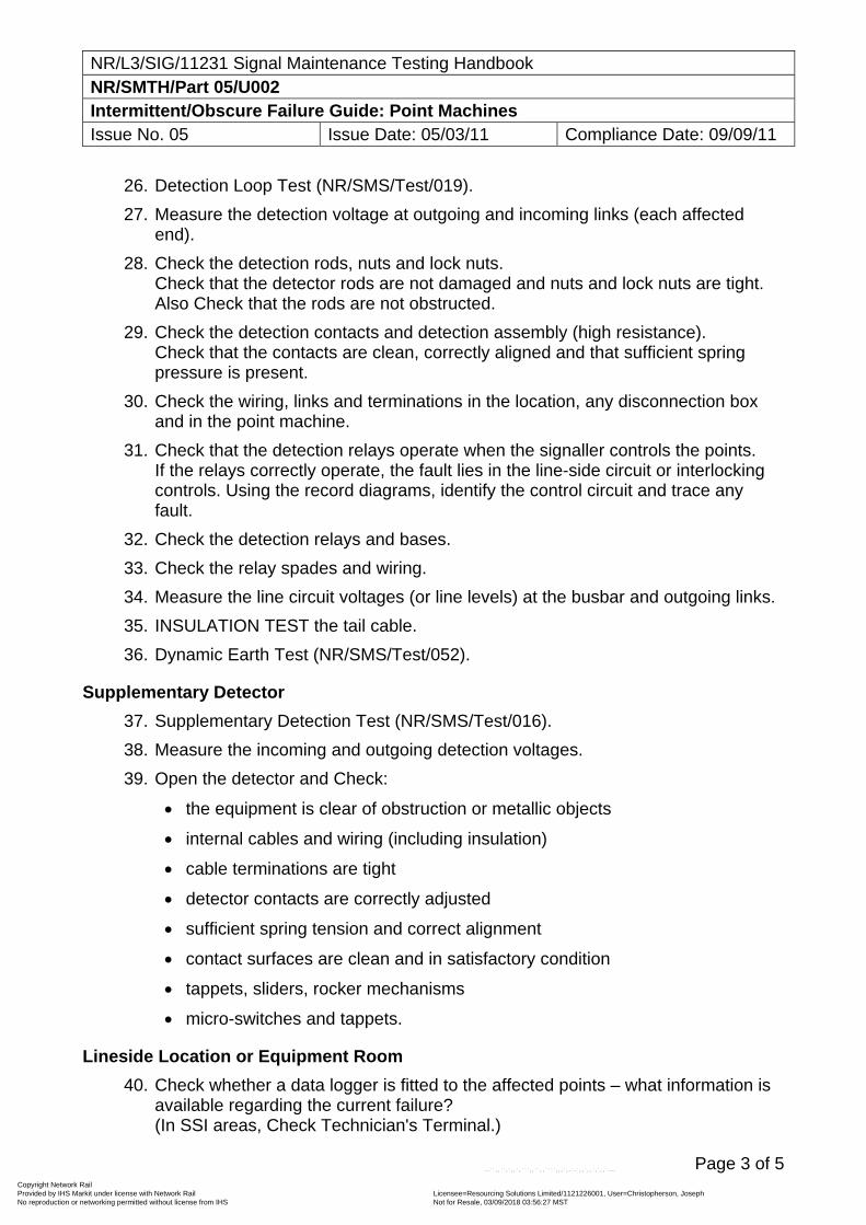
NR/L3/SIG/11231 Signal Maintenance Testing Handbook NR/SMTH/Part 05/U002 Intermittent/Obscure Failure Guide: Point Machines Issue No. 05 Issue Date: 05/03/11 Compliance Date: 09/09/11
Page 3 of 5
26. Detection Loop Test (NR/SMS/Test/019).
27. Measure the detection voltage at outgoing and incoming links (each affected end).
28. Check the detection rods, nuts and lock nuts. Check that the detector rods are not damaged and nuts and lock nuts are tight. Also Check that the rods are not obstructed.
29. Check the detection contacts and detection assembly (high resistance). Check that the contacts are clean, correctly aligned and that sufficient spring pressure is present.
30. Check the wiring, links and terminations in the location, any disconnection box and in the point machine.
31. Check that the detection relays operate when the signaller controls the points. If the relays correctly operate, the fault lies in the line-side circuit or interlocking controls. Using the record diagrams, identify the control circuit and trace any fault.
32. Check the detection relays and bases.
33. Check the relay spades and wiring.
34. Measure the line circuit voltages (or line levels) at the busbar and outgoing links.
35. INSULATION TEST the tail cable.
36. Dynamic Earth Test (NR/SMS/Test/052).
Supplementary Detector
37. Supplementary Detection Test (NR/SMS/Test/016).
38. Measure the incoming and outgoing detection voltages.
39. Open the detector and Check:
the equipment is clear of obstruction or metallic objects
internal cables and wiring (including insulation)
cable terminations are tight
detector contacts are correctly adjusted
sufficient spring tension and correct alignment
contact surfaces are clean and in satisfactory condition
tappets, sliders, rocker mechanisms
micro-switches and tappets.
Lineside Location or Equipment Room
40. Check whether a data logger is fitted to the affected points – what information is available regarding the current failure? (In SSI areas, Check Technician's Terminal.)
Copyright Network Rail Provided by IHS Markit under license with Network Rail Licensee=Resourcing Solutions Limited /1121226001, User=Christopherson, Joseph
Not for Resale, 03/09/2018 03:56:27 MSTNo reproduction or networking permitted without license from IHS
--``,,``,`,,`,```,,``,,````,,,`,-`-`,,`,,`,`,,`---
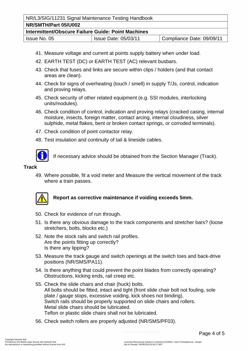
NR/L3/SIG/11231 Signal Maintenance Testing Handbook NR/SMTH/Part 05/U002 Intermittent/Obscure Failure Guide: Point Machines Issue No. 05 Issue Date: 05/03/11 Compliance Date: 09/09/11
Page 4 of 5
41. Measure voltage and current at points supply battery when under load.
42. EARTH TEST (DC) or EARTH TEST (AC) relevant busbars.
43. Check that fuses and links are secure within clips / holders (and that contact areas are clean).
44. Check for signs of overheating (touch / smell) in supply T/Js, control, indication and proving relays.
45. Check security of other related equipment (e.g. SSI modules, interlocking units/modules).
46. Check condition of control, indication and proving relays (cracked casing, internal moisture, insects, foreign matter, contact arcing, internal cloudiness, silver sulphide, metal flakes, bent or broken contact springs, or corroded terminals).
47. Check condition of point contactor relay.
48. Test insulation and continuity of tail & lineside cables.
If necessary advice should be obtained from the Section Manager (Track).
Track
49. Where possible, fit a void meter and Measure the vertical movement of the track where a train passes.
Report as corrective maintenance if voiding exceeds 5mm.
50. Check for evidence of run through.
51. Is there any obvious damage to the track components and stretcher bars? (loose stretchers, bolts, blocks etc.)
52. Note the stock rails and switch rail profiles. Are the points fitting up correctly? Is there any lipping?
53. Measure the track gauge and switch openings at the switch toes and back-drive positions (NR/SMS/PA11).
54. Is there anything that could prevent the point blades from correctly operating? Obstructions, kicking ends, rail creep etc.
55. Check the slide chairs and chair (huck) bolts. All bolts should be fitted, intact and tight (front slide chair bolt not fouling, sole plate / gauge stops, excessive voiding, kick shoes not binding). Switch rails should be properly supported on slide chairs and rollers. Metal slide chairs should be lubricated. Teflon or plastic slide chairs shall not be lubricated.
56. Check switch rollers are properly adjusted (NR/SMS/PF03).
Copyright Network Rail Provided by IHS Markit under license with Network Rail Licensee=Resourcing Solutions Limited /1121226001, User=Christopherson, Joseph
Not for Resale, 03/09/2018 03:56:27 MSTNo reproduction or networking permitted without license from IHS
--``,,``,`,,`,```,,``,,````,,,`,-`-`,,`,,`,`,,`---
NR/L3/SIG/11231 Signal Maintenance Testing Handbook NR/SMTH/Part 05/U002 Intermittent/Obscure Failure Guide: Point Machines Issue No. 05 Issue Date: 05/03/11 Compliance Date: 09/09/11
Page 5 of 5
57. Check the security of external mechanical fittings.
58. Check additional drive adjustment (5 – 8mm clearance).
59. If a supplementary drive is fitted:
Are cranks, fittings and “A” frames secure?
Does the heel of the switch meet the stock rail before the toe?
Does the heel of the switch prevent the toe from fitting up properly?
60. Check that back drive cranks are ‘in action’.
61. Check for excessive wear on the switch rail (if excessive, toe may be fitting under head of stock rail).
62. Check that any point machine or detector box stabilisation plates are secure and undamaged.
63. Check for lost motion / excessive wear in supplementary drives.
64. Check adjacent rail joints are adequately packed and free from excessive vertical movement.
End
Copyright Network Rail Provided by IHS Markit under license with Network Rail Licensee=Resourcing Solutions Limited /1121226001, User=Christopherson, Joseph
Not for Resale, 03/09/2018 03:56:27 MSTNo reproduction or networking permitted without license from IHS
--``,,``,`,,`,```,,``,,````,,,`,-`-`,,`,,`,`,,`---
NR/L3/SIG/11231 Signal Maintenance Testing Handbook NR/SMTH/Part 05/U003 Intermittent/Obscure Failure Guide: Rail Clamp Point Lock Issue No. 05 Issue Date: 05/03/11 Compliance Date: 03/09/11
Page 1 of 5
Includes: Mk 1 and Mk 2 clamp locks. Excludes: Suspected WSF.
Introduction
Point failure is a common cause of reported signal failure and reported change of aspects. This Test Guide gives you guidance on the checks and tests required.
Signal Box and Signaller Checks
1. Check with signaller and/or infrastructure fault control whether the equipment affected has shown a similar failure characteristic prior to this fault.
2. Check that no work has been recently completed in the area (e.g. stagework, S&C tamping, new huck bolts or point heater pads fitted).
Point Operation
3. Remove the lock body covers and ask the signaller to operate the points to the normal and reverse positions. Inspect pump unit. Look and listen for:
Hydraulic leaks
Unusual sounds.
Observe point operation and look for:
Excessive time of operation
Erratic operation
Loose or damaged lock bodies
Loose or damaged centre thrust bracket
Hydraulic leaks
Poor supplementary drive operation, condition and adjustment.
General Checks
4. Check security of points (were detector box and power pack lids locked upon arrival at fault location?).
5. Check security of lock bodies (do they move when points are operating?).
6. Check security of centre thrust bracket (does it move when points are operating?
7. Check for any obvious hydraulic pipe or cable damage.
8. Check that all internal components are secure and lubricated.
9. Check tail cables, glands and terminations.
Track
If necessary advice should be obtained from the Section Manager (Track).
Copyright Network Rail Provided by IHS Markit under license with Network Rail Licensee=Resourcing Solutions Limited /1121226001, User=Christopherson, Joseph
Not for Resale, 03/09/2018 03:56:27 MSTNo reproduction or networking permitted without license from IHS
--``,,``,`,,`,```,,``,,````,,,`,-`-`,,`,,`,`,,`---
NR/L3/SIG/11231 Signal Maintenance Testing Handbook NR/SMTH/Part 05/U003 Intermittent/Obscure Failure Guide: Rail Clamp Point Lock Issue No. 05 Issue Date: 05/03/11 Compliance Date: 03/09/11
Page 2 of 5
10. Where possible, fit a void meter and Measure the vertical movement of the track where a train passes.
Report as corrective maintenance if voiding exceeds 5mm.
11. Check for evidence of run through.
12. Is there any obvious damage to the track components or stretcher bars? (loose stretchers, bolts, blocks, etc.)
13. Measure the track gauge and switch openings at the switch toes and back-drive positions (NR/SMS/PA11).
14. Is there anything that could prevent the point blades from correctly operating? Obstructions, kicking ends, rail creep etc.
15. Check the slide chairs and chair (‘huck’) bolts. All bolts should be fitted, intact and tight (front slide chair bolt not fouling, sole plate / gauge stops, excessive voiding, kick shoes not binding). Switch rails should be properly supported on slide chairs or rollers. Metal slide chairs should be lubricated.
16. Check the profile of stock rails and switch rails. Are the points fitting up correctly? Is there any stock rail ‘lipping’?
17. Check adjacent rail joints are adequately packed and free from excessive vertical movement
18. If a supplementary drive is fitted:
Are cranks, ‘A’ frames and fittings secure?
Does the heel of the switch meet the stock rail before the toe?
Does the heel of the switch prevent the toe from fitting up properly?
Check additional drive adjustment (5 to 8mm clearance).
Tests
19. Facing Point Lock Test (NR/SMS/Test/003)
If the FPL or detection has to be adjusted, the route cause for it shall be investigated.
20. Detection Test (NR/SMS/Test/013)
21. Supplementary Detection Test (NR/SMS/Test/016)
22. Place an obstruction in the open switch and Test the operation of the cut-out.
Copyright Network Rail Provided by IHS Markit under license with Network Rail Licensee=Resourcing Solutions Limited /1121226001, User=Christopherson, Joseph
Not for Resale, 03/09/2018 03:56:27 MSTNo reproduction or networking permitted without license from IHS
--``,,``,`,,`,```,,``,,````,,,`,-`-`,,`,,`,`,,`---
NR/L3/SIG/11231 Signal Maintenance Testing Handbook NR/SMTH/Part 05/U003 Intermittent/Obscure Failure Guide: Rail Clamp Point Lock Issue No. 05 Issue Date: 05/03/11 Compliance Date: 03/09/11
Page 3 of 5
Supplementary Detector
23. Open the detector and Check
The equipment is clear of obstructions or metallic objects
Internal cables and wiring (including insulation)
Cable terminations are tight
Detector contacts are correctly adjusted sufficient spring tension and correct alignment
Contact surfaces are clean and in satisfactory condition
Tappets, sliders, rocker mechanisms
Micro-switches and tappets
24. Measure the incoming and outgoing detection voltages.
Lineside Location or Equipment Room
25. Check whether a data logger or remote condition monitoring is fitted to the affected points – what information is available regarding the current failure? (In SSI areas, Check Technician's Terminal.)
26. EARTH TEST (DC) or EARTH TEST (AC) the relevant busbars.
27. Detection Loop Test (NR/SMS/Test/019).
28. Measure incoming and outgoing line circuit voltages and remote control system levels. This may identify a problem in the line circuits. Consider repeating this test at the interlocking end of the circuit.
29. Measure voltage and current at points supply battery when under load.
30. Check condition of control, indication and proving relays (cracked casing, internal moisture, insects, foreign matter, contact arcing, internal cloudiness, silver sulphide, metal flakes, bent or broken contact springs, or corroded terminals). The relays should be secure and the correct retaining clips should be fitted. Look for signs of overheating or burned contacts.
31. Check condition of point contactor relay.
32. Check for signs of overheating (touch / smell) in supply T/Js, control, indication and proving relays.
33. Check security of other related equipment (e.g. SSI modules, interlocking units or modules).
34. Check the wiring and terminations. Use the record diagrams and check each wire termination. Look particularly for loose terminations, loose back nuts and spade connectors, and high resistance soldered joints.
Copyright Network Rail Provided by IHS Markit under license with Network Rail Licensee=Resourcing Solutions Limited /1121226001, User=Christopherson, Joseph
Not for Resale, 03/09/2018 03:56:27 MSTNo reproduction or networking permitted without license from IHS
--``,,``,`,,`,```,,``,,````,,,`,-`-`,,`,,`,`,,`---
NR/L3/SIG/11231 Signal Maintenance Testing Handbook NR/SMTH/Part 05/U003 Intermittent/Obscure Failure Guide: Rail Clamp Point Lock Issue No. 05 Issue Date: 05/03/11 Compliance Date: 03/09/11
Page 4 of 5
35. Check that fuses and links are correct rating, secure within clips / holders (and that contact areas are clean). Consider replacing the fuses.
36. INSULATION TEST the tail cables.
Pump Unit (see also NR/SMS/PB11)
37. Check the hydraulic fluid level and pressure.
38. Look for leaks in the hydraulic rams and hoses.
39. Test for air [Check system for air (NR/SMS/Test/015)] and top up fluid as necessary.
40. Check electrical terminations. Check for signs of weakness in the crimps.
41. Measure the motor voltage during operation.
42. Check the normal and reverse valves are not sticking.
43. Check the motor brushes and commutator (security, condition, wear).
44. Manually operate the pump unit and look for incorrect operation.
Lock and Detector Mechanisms
45. Check terminations and wiring. Check for signs of weakness in the crimps.
46. Measure the incoming and outgoing point detection voltage.
47. Check microswitches and tappet settings. Check microswitches are free to move and have a positive snap action (ITW type excepted). The cam follower tappet screws shall protrude no more than 25mm.
48. Check the bodies are secured to the stock rail. Fixing bolts 250Nm, locking piece bolts 60Nm.
49. Check for loose bolts or cracked bodies. Check that the body sideplates are not cracked using an approved method. (Mk 1s ONLY)
50. Check for excessive wear on mounting studs (Mk 1s ONLY)
51. Lock and Detection Test (NR/SMS/Test/014) as necessary.
52. Check that the drive lock slide travels fully.
53. Check the locking piece is tight.
Clamp Lock Mechanism (open switch)
54. Check the switch rail bracket assembly is tight (250Nm).
55. Check the lock arm is free on the pivot pin and the pivot pin is free to rotate. This proves the 3mm clearance between the lock arm and drive lock slide.
56. Check that the lock arm and detection arm are both free to move independently on the brass bush (Mk 2s ONLY)
Copyright Network Rail Provided by IHS Markit under license with Network Rail Licensee=Resourcing Solutions Limited /1121226001, User=Christopherson, Joseph
Not for Resale, 03/09/2018 03:56:27 MSTNo reproduction or networking permitted without license from IHS
--``,,``,`,,`,```,,``,,````,,,`,-`-`,,`,,`,`,,`---
NR/L3/SIG/11231 Signal Maintenance Testing Handbook NR/SMTH/Part 05/U003 Intermittent/Obscure Failure Guide: Rail Clamp Point Lock Issue No. 05 Issue Date: 05/03/11 Compliance Date: 03/09/11
Page 5 of 5
57. Check the lock slide cam is solid. If it is loose, check the Allen key on the underside of the drive lock slide
58. Look for wear on the cam follower and fixed cam.
59. Check the lock slide ‘Spirol’ pin is flush.
60. Lubricate as necessary.
Clamp Lock Mechanism (closed switch)
61. Check there is 4 to 12mm clearance between the top of the drive lock coupling and the bottom of the lock arm.
62. Check the drive lock slide is fully locked:
Mk 1 lock slide flush with the end of the body,
Mk 2 lock slide protrudes 25 to 30mm beyond the body.
Four Foot Fittings
63. Check the rams and hydraulic connections.
64. Check the tie bar is not fouling the thrust bracket assembly or rams (3mm clearance).
65. Check clearance between front stretcher bar and rail underside.
66. Check points / ram bay not obstructed by ballast / paper.
67. Check clearance between first P Way bolt and lock arm assembly mounting bolt.
68. Check all fittings are secure.
Final Test
69. Facing Point Lock Test (NR/SMS/Test/003).
End
Copyright Network Rail Provided by IHS Markit under license with Network Rail Licensee=Resourcing Solutions Limited /1121226001, User=Christopherson, Joseph
Not for Resale, 03/09/2018 03:56:27 MSTNo reproduction or networking permitted without license from IHS
--``,,``,`,,`,```,,``,,````,,,`,-`-`,,`,,`,`,,`---
NR/L3/SIG/11231 Signal Maintenance Testing Handbook NR/SMTH/Part 05/U004 Intermittent/Obscure Failure Guide: Electro-Pneumatic Points Issue No. 05 Issue Date: 05/03/11 Compliance Date: 03/09/11
Page 1 of 4
Excludes: Suspected WSF.
Introduction
Point failure is a common cause of reported signal failure and reported change of aspects. This Test Guide gives you guidance on the checks and tests required.
Signal Box and Signaller Checks
1. Check with signaller and/or infrastructure fault control whether the equipment affected has shown a similar failure characteristic prior to this fault.
2. Check that no work has been recently completed in the area (e.g. stagework, S&C tamping, new huck bolts or point heater pads fitted).
Point Operation 3. Remove the machine covers and ask the signaller to operate the points to the
normal and reverse positions. Inspect valve chest. Look and listen for:
Air leaks
Unusual sounds.
Observe point operation and look for:
Excessive time of operation
Erratic operation
Point drive running back after completing its stroke
Flashes or sparks from electrical contacts
Movement of the mechanism relative to the bearers
Poor supplementary drive operation, condition and adjustment.
General Checks
4. Check security and condition of point machine (was it locked upon arrival at fault location?).
5. Check the security of the point machine on its base / mountings – does it move when points are operated?
6. Check that all internal components are secure and lubricated.
7. Check tail cables, glands and terminations.
8. Check heaters.
Track
If necessary advice should be obtained from the Section Manager (Track).
Copyright Network Rail Provided by IHS Markit under license with Network Rail Licensee=Resourcing Solutions Limited /1121226001, User=Christopherson, Joseph
Not for Resale, 03/09/2018 03:56:27 MSTNo reproduction or networking permitted without license from IHS
--``,,``,`,,`,```,,``,,````,,,`,-`-`,,`,,`,`,,`---
NR/L3/SIG/11231 Signal Maintenance Testing Handbook NR/SMTH/Part 05/U004 Intermittent/Obscure Failure Guide: Electro-Pneumatic Points Issue No. 05 Issue Date: 05/03/11 Compliance Date: 03/09/11
Page 2 of 4
9. Where possible, fit a void meter and Measure the vertical movement of the track where a train passes.
Report as corrective maintenance if voiding exceeds 5mm.
10. Check for evidence of run through.
11. Is there any obvious damage to the track components or stretcher bars? (loose stretchers, bolts, blocks, etc.)
12. Measure the track gauge and switch openings at the switch toes and back-drive positions (NR/SMS/PA11).
13. Is there anything that could prevent the point blades from correctly operating? Obstructions, kicking ends, rail creep etc.
14. Check the slide chairs and chair (huck) bolts. All bolts should be fitted, intact and tight (front slide chair bolt not fouling, sole plate / gauge stops, excessive voiding, kick shoes not binding). Switch rails should be properly supported on slide chairs and rollers. Metal slide chairs should be lubricated.
15. Check the stock rails and switch rail profiles. Are the points fitting up correctly? Is there any stock rail lipping
16. Check adjacent rail joints are adequately packed and free from excessive vertical movement
17. If a supplementary drive is fitted:
Are cranks, ‘“A’ frames and fittings secure?
Does the heel of the switch meet the stock rail before the toe?
Does the heel of the switch prevent the toe from fitting up properly?
Check additional drive adjustment (5 to 8mm clearance).
Tests
18. Facing Point Lock Test (NR/SMS/Test/001)
If the FPL or detection has to be adjusted, the route cause for it shall be investigated.
19. Detection Test (NR/SMS/Test/011)
20. Supplementary Detection Test (NR/SMS/Test/016)
21. Place an obstruction in the open switch and test the operation of the cut-out.
Supplementary Detector
22. Open the detector and Check:
Copyright Network Rail Provided by IHS Markit under license with Network Rail Licensee=Resourcing Solutions Limited /1121226001, User=Christopherson, Joseph
Not for Resale, 03/09/2018 03:56:27 MSTNo reproduction or networking permitted without license from IHS
--``,,``,`,,`,```,,``,,````,,,`,-`-`,,`,,`,`,,`---
NR/L3/SIG/11231 Signal Maintenance Testing Handbook NR/SMTH/Part 05/U004 Intermittent/Obscure Failure Guide: Electro-Pneumatic Points Issue No. 05 Issue Date: 05/03/11 Compliance Date: 03/09/11
Page 3 of 4
The equipment is clear of obstructions or metallic objects
Internal cables and wiring (including insulation)
Cable terminations are tight
Detector contacts are correctly adjusted sufficient spring tension and correct alignment
Contact surfaces are clean and in satisfactory condition
Tappets, sliders, rocker mechanisms
Micro-switches and tappets.
23. Measure the incoming and outgoing detection voltages.
Lineside Location or Equipment Room
24. Check whether a data logger or remote condition monitoring is fitted to the affected points – what information is available regarding the current failure? (In SSI areas, Check Technician's Terminal.)
25. EARTH TEST (DC) or EARTH TEST (AC) the busbars.
26. Detection Loop Test (NR/SMS/Test/019).
27. Measure incoming and outgoing line circuit voltages and remote control system levels. This may identify a problem in the line circuits. Consider repeating this test at the interlocking end of the circuit.
28. Check condition of control, indication and proving relays (cracked casing, internal moisture, insects, foreign matter, contact arcing, internal cloudiness, silver sulphide, metal flakes, bent or broken contact springs, or corroded terminals). The relays should be secure and the correct retaining clips should be fitted. Look for signs of overheating or burned contacts.
29. Check for signs of overheating (touch / smell) in supply T/Js, control, indication and proving relays.
30. Check security of other related equipment (e.g. SSI modules, interlocking units or modules).
31. 31 Check the wiring and terminations. Use the record diagrams and check each wire termination. Look particularly for loose terminations, loose back nuts and spade connectors, and high resistance soldered joints.
32. Check that fuses and links are correct rating, secure within clips / holders (and that contact areas are clean). Consider replacing the fuses.
33. INSULATION TEST the tail cables.
Copyright Network Rail Provided by IHS Markit under license with Network Rail Licensee=Resourcing Solutions Limited /1121226001, User=Christopherson, Joseph
Not for Resale, 03/09/2018 03:56:27 MSTNo reproduction or networking permitted without license from IHS
--``,,``,`,,`,```,,``,,````,,,`,-`-`,,`,,`,`,,`---
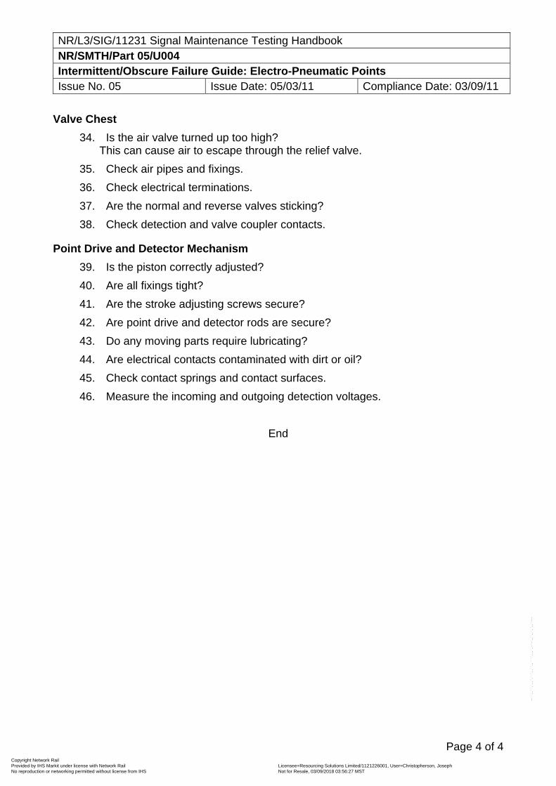
NR/L3/SIG/11231 Signal Maintenance Testing Handbook NR/SMTH/Part 05/U004 Intermittent/Obscure Failure Guide: Electro-Pneumatic Points Issue No. 05 Issue Date: 05/03/11 Compliance Date: 03/09/11
Page 4 of 4
Valve Chest
34. Is the air valve turned up too high? This can cause air to escape through the relief valve.
35. Check air pipes and fixings.
36. Check electrical terminations.
37. Are the normal and reverse valves sticking?
38. Check detection and valve coupler contacts.
Point Drive and Detector Mechanism
39. Is the piston correctly adjusted?
40. Are all fixings tight?
41. Are the stroke adjusting screws secure?
42. Are point drive and detector rods are secure?
43. Do any moving parts require lubricating?
44. Are electrical contacts contaminated with dirt or oil?
45. Check contact springs and contact surfaces.
46. Measure the incoming and outgoing detection voltages.
End
Copyright Network Rail Provided by IHS Markit under license with Network Rail Licensee=Resourcing Solutions Limited /1121226001, User=Christopherson, Joseph
Not for Resale, 03/09/2018 03:56:27 MSTNo reproduction or networking permitted without license from IHS
--``,,``,`,,`,```,,``,,````,,,`,-`-`,,`,,`,`,,`---
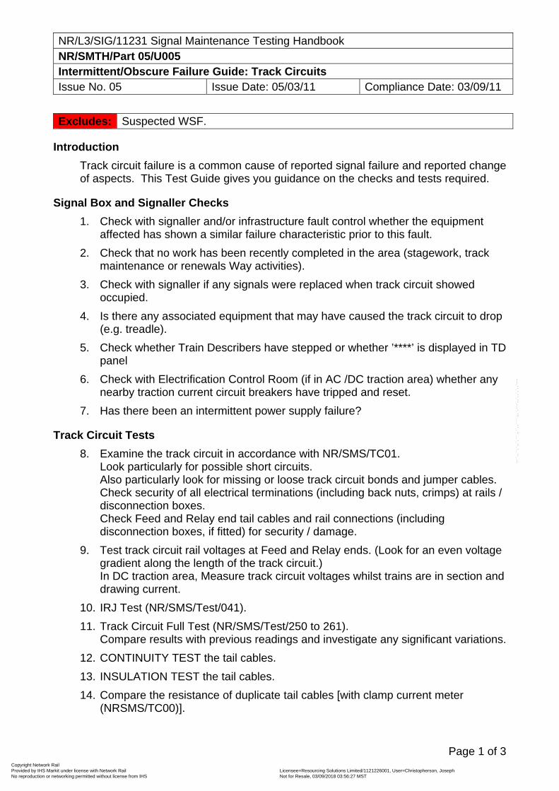
NR/L3/SIG/11231 Signal Maintenance Testing Handbook NR/SMTH/Part 05/U005 Intermittent/Obscure Failure Guide: Track Circuits Issue No. 05 Issue Date: 05/03/11 Compliance Date: 03/09/11
Page 1 of 3
Excludes: Suspected WSF.
Introduction
Track circuit failure is a common cause of reported signal failure and reported change of aspects. This Test Guide gives you guidance on the checks and tests required.
Signal Box and Signaller Checks
1. Check with signaller and/or infrastructure fault control whether the equipment affected has shown a similar failure characteristic prior to this fault.
2. Check that no work has been recently completed in the area (stagework, track maintenance or renewals Way activities).
3. Check with signaller if any signals were replaced when track circuit showed occupied.
4. Is there any associated equipment that may have caused the track circuit to drop (e.g. treadle).
5. Check whether Train Describers have stepped or whether ’****’ is displayed in TD panel
6. Check with Electrification Control Room (if in AC /DC traction area) whether any nearby traction current circuit breakers have tripped and reset.
7. Has there been an intermittent power supply failure?
Track Circuit Tests
8. Examine the track circuit in accordance with NR/SMS/TC01. Look particularly for possible short circuits. Also particularly look for missing or loose track circuit bonds and jumper cables. Check security of all electrical terminations (including back nuts, crimps) at rails / disconnection boxes. Check Feed and Relay end tail cables and rail connections (including disconnection boxes, if fitted) for security / damage.
9. Test track circuit rail voltages at Feed and Relay ends. (Look for an even voltage gradient along the length of the track circuit.) In DC traction area, Measure track circuit voltages whilst trains are in section and drawing current.
10. IRJ Test (NR/SMS/Test/041).
11. Track Circuit Full Test (NR/SMS/Test/250 to 261). Compare results with previous readings and investigate any significant variations.
12. CONTINUITY TEST the tail cables.
13. INSULATION TEST the tail cables.
14. Compare the resistance of duplicate tail cables [with clamp current meter (NRSMS/TC00)].
Copyright Network Rail Provided by IHS Markit under license with Network Rail Licensee=Resourcing Solutions Limited /1121226001, User=Christopherson, Joseph
Not for Resale, 03/09/2018 03:56:27 MSTNo reproduction or networking permitted without license from IHS
--``,,``,`,,`,```,,``,,````,,,`,-`-`,,`,,`,`,,`---
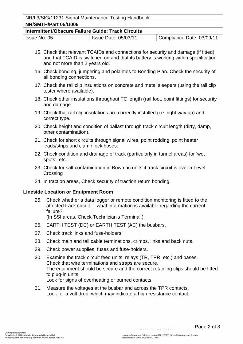
NR/L3/SIG/11231 Signal Maintenance Testing Handbook NR/SMTH/Part 05/U005 Intermittent/Obscure Failure Guide: Track Circuits Issue No. 05 Issue Date: 05/03/11 Compliance Date: 03/09/11
Page 2 of 3
15. Check that relevant TCAIDs and connections for security and damage (if fitted) and that TCAID is switched on and that its battery is working within specification and not more than 2 years old.
16. Check bonding, jumpering and polarities to Bonding Plan. Check the security of all bonding connections.
17. Check the rail clip insulations on concrete and metal sleepers (using the rail clip tester where available).
18. Check other insulations throughout TC length (rail foot, point fittings) for security and damage.
19. Check that rail clip insulations are correctly installed (i.e. right way up) and correct type.
20. Check height and condition of ballast through track circuit length (dirty, damp, other contamination).
21. Check for short circuits through signal wires, point rodding, point heater leads/strips and clamp lock hoses.
22. Check condition and drainage of track (particularly in tunnel areas) for ‘wet spots’, etc.
23. Check for salt contamination in Bowmac units if track circuit is over a Level Crossing
24. In traction areas, Check security of traction return bonding.
Lineside Location or Equipment Room
25. Check whether a data logger or remote condition monitoring is fitted to the affected track circuit – what information is available regarding the current failure? (In SSI areas, Check Technician's Terminal.)
26. EARTH TEST (DC) or EARTH TEST (AC) the busbars.
27. Check track links and fuse-holders.
28. Check main and tail cable terminations, crimps, links and back nuts.
29. Check power supplies, fuses and fuse-holders.
30. Examine the track circuit feed units, relays (TR, TPR, etc.) and bases. Check that wire terminations and straps are secure. The equipment should be secure and the correct retaining clips should be fitted to plug-in units. Look for signs of overheating or burned contacts
31. Measure the voltages at the busbar and across the TPR contacts. Look for a volt drop, which may indicate a high resistance contact.
Copyright Network Rail Provided by IHS Markit under license with Network Rail Licensee=Resourcing Solutions Limited /1121226001, User=Christopherson, Joseph
Not for Resale, 03/09/2018 03:56:27 MSTNo reproduction or networking permitted without license from IHS
--``,,``,`,,`,```,,``,,````,,,`,-`-`,,`,,`,`,,`---
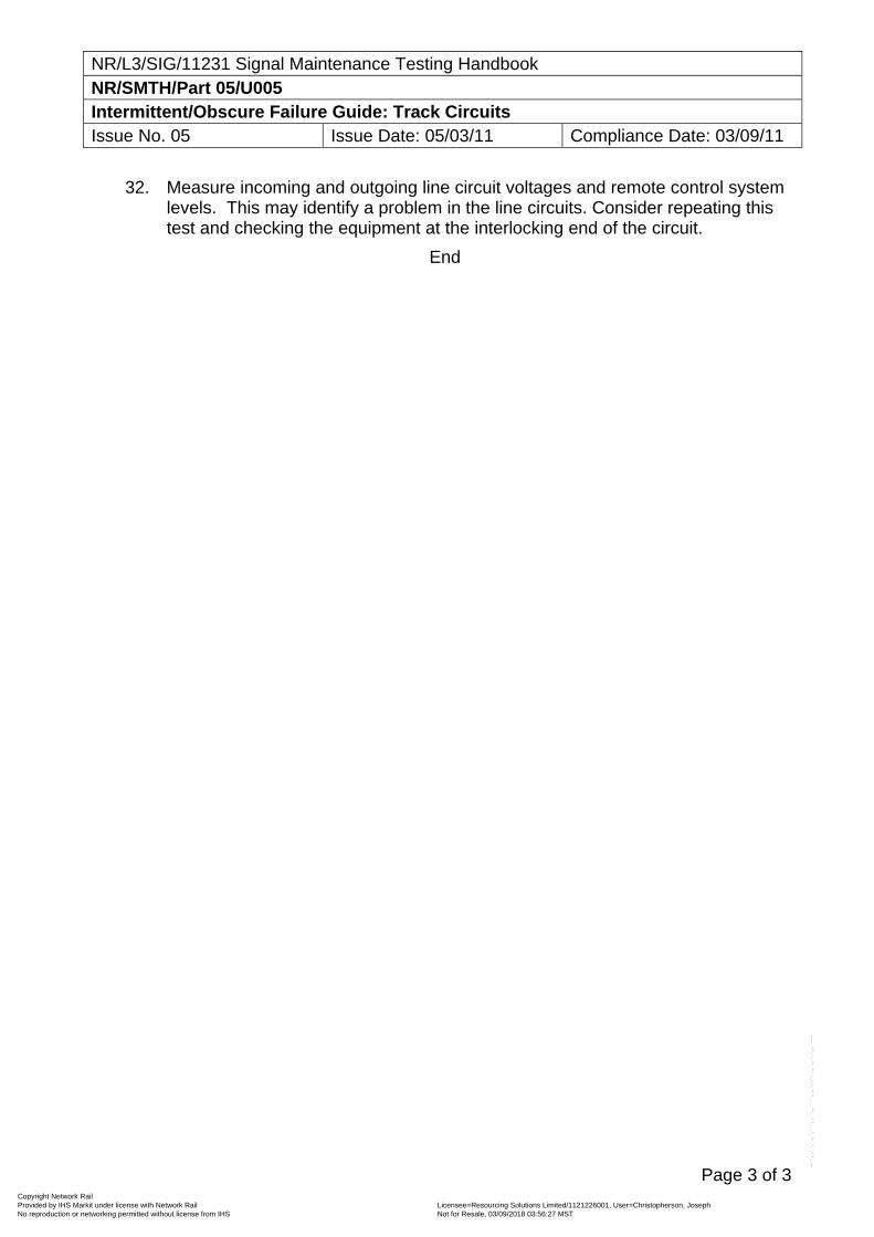
NR/L3/SIG/11231 Signal Maintenance Testing Handbook NR/SMTH/Part 05/U005 Intermittent/Obscure Failure Guide: Track Circuits Issue No. 05 Issue Date: 05/03/11 Compliance Date: 03/09/11
Page 3 of 3
32. Measure incoming and outgoing line circuit voltages and remote control system levels. This may identify a problem in the line circuits. Consider repeating this test and checking the equipment at the interlocking end of the circuit.
End
Copyright Network Rail Provided by IHS Markit under license with Network Rail Licensee=Resourcing Solutions Limited /1121226001, User=Christopherson, Joseph
Not for Resale, 03/09/2018 03:56:27 MSTNo reproduction or networking permitted without license from IHS
--``,,``,`,,`,```,,``,,````,,,`,-`-`,,`,,`,`,,`---
NR/L3/SIG/11231 Signal Maintenance Testing Handbook NR/SMTH/Part 05/U006 Intermittent/Obscure Failure Guide: Colour Light Signals Issue No. 05 Issue Date: 05/03/11 Compliance Date: 03/09/11
Page 1 of 2
Excludes: Alleged SPAD or change of aspect, Suspected WSF.
Introduction
This Test Guide gives you guidance on the checks and tests required, in the event of signal failure not associated with point, track circuit or barrier failure.
Signal Box and Signaller Checks
1. Check with signaller and/or infrastructure fault control whether the equipment affected has shown a similar failure characteristic prior to this fault.
2. Check that no work has been recently completed in the area (e.g. stagework).
3. Check with signaller if any other signals were replaced when signal failed.
Signal Head Checks
4. Measure signal lamp voltage, compare results with last reading on record card.
If the voltage has to be adjusted, the reason shall be determined.
5. Check security and condition of signal head (was it locked upon arrival at fault location?).
6. Check security of all electrical terminations (including back nuts, crimps) in signal head.
7. Check security of filament test crimps (if fitted).
8. Check the lamp is seated correctly in the lamp holder.
9. Check security of filament changeover relays (ERs) and that they are correctly fitted.
10. Check that all ER terminal pins are intact.
11. Check security and condition of lamp holders, contacts, base of lamps.
12. Check security and condition of signal head transformer.
13. Check for signs of overheating in ERs or head transformer.
14. If signal affected is an ‘auto’, Check Emergency Replacement Switch for correct operation.
15. Replace lamps and retain for investigation if required.
16. Replace ERs and retain for investigation if required.
17. Test lineside and tail cables for INSULATION / CONTINUITY.
18. ASPECT TEST signal.
19. Carry out Full Test to appropriate NR/SMS.
Copyright Network Rail Provided by IHS Markit under license with Network Rail Licensee=Resourcing Solutions Limited /1121226001, User=Christopherson, Joseph
Not for Resale, 03/09/2018 03:56:27 MSTNo reproduction or networking permitted without license from IHS
--``,,``,`,,`,```,,``,,````,,,`,-`-`,,`,,`,`,,`---
NR/L3/SIG/11231 Signal Maintenance Testing Handbook NR/SMTH/Part 05/U006 Intermittent/Obscure Failure Guide: Colour Light Signals Issue No. 05 Issue Date: 05/03/11 Compliance Date: 03/09/11
Page 2 of 2
Lineside Location or Equipment Room
20. Check whether a data logger or remote condition monitoring is fitted to the affected signal – what information is available regarding the current failure? (In SSI areas, Check Technician's Terminal.)
21. Measure ECR/HR/DR line voltages.
22. EARTH TEST (DC) or EARTH TEST (AC) relevant busbars.
23. Check security of all electrical connections (including back nuts / crimps) of internal wiring, tail and lineside cable connections.
24. Check that relevant fuse and links are secure within clips and holders, and that contact areas are clean.
25. If signal is fitted with flashing aspects, check condition of FECR.
26. Check condition of ECR/ECROJ/HR/DR/TPR and aspect proving relays.
27. Check for overheating (touch / smell) in ECR/ECROJ/HR/DR/TPR and aspect proving relays.
28. Check security of relays and plug-in units and that retaining clips are correctly fitted.
29. Check relay spade connectors are secure.
30. Check security of other related equipment (SSI Modules / Westpac units).
31. Check that ECROJ is correctly adjusted, if fitted.
32. Test Lineside and tail cables for Insulation / Continuity.
33. If signal is operated from a mechanical signal box, Check relevant circuit controller bands for security and condition.
34. Consideration shall also be given to checking the signal ahead of the one affected (e.g. for intermittent ECPR fault) and also any points in the route to the next signal for bobbing detection.
35. Look for possible read through, signals on adjacent lines or other possible sources of visual interference or distractions, e.g. traffic lights, street lamps or advertising hoardings.
End
Copyright Network Rail Provided by IHS Markit under license with Network Rail Licensee=Resourcing Solutions Limited /1121226001, User=Christopherson, Joseph
Not for Resale, 03/09/2018 03:56:27 MSTNo reproduction or networking permitted without license from IHS
--``,,``,`,,`,```,,``,,````,,,`,-`-`,,`,,`,`,,`---
NR/L3/SIG/11231 Signal Maintenance Testing Handbook NR/SMTH/Part 05/U007 Tests Following an Alleged Signal Passed at Danger (SPAD) Issue No. 06 Issue Date: 03/03/18 Compliance Date: 31/05/18
Page 1 of 3
Excludes: SPADs where obscuration or change of aspect is alleged, derailments or collisions. Suspected WSF.
Introduction This Test Guide sets out the procedure to be adopted for dealing with a reported SPAD where no allegation is made against the signalling system.
If the driver (or other responsible person riding in the cab) admits passing the signal at danger, staff shall attend to the signal and check or determine the following features (within 12 hours of the initial report), but the signal need not be treated as defective. Where remedial actions are taken, these shall be noted on the SMTH logbook sheet.
If the correct operation of any equipment is doubted it shall be treated as defective and appropriately tested.
Signal Not Alleged Defective 1. Where evidence of the SPAD may have been recorded on a data logger (see
Section S003), the recording shall be requested regardless of whether an allegation has been made against the signalling system.
2. Check the signal head is correctly aligned to the information on the signal head
record card, or the Signal Sighting Form, using the integral sighting device, if fitted (see Signal Sighting and Beam Alignment in NR/SMS/SG00). If misaligned, correct the adjustment.
3. Check the seal on the lamp holder is intact.
4. Further Check the signal is correctly aligned by viewing the signal from the track
or, if practicable, from the driving cab of a train.
5. Check the signal head, lens hoods, backgrounds and anti-vandal guards. Check the signal back board is matt black and not discoloured or faded.
6. Check backlights, where provided. Backlights on elevated position light signals
shall be blanked off.
7. Check all lenses/glasses are clean, both inside and out, not damaged or discoloured and not obstructed. Pay particular attention to the red aspect.
8. Check the close up segment is correctly aligned according to the position of the
signal.
9. Check if the lenses are polycarbonate. If so, they shall be in good condition i.e. not opaque or excessively scratched.
Copyright Network Rail Provided by IHS Markit under license with Network Rail Licensee=Resourcing Solutions Limited /1121226001, User=Christopherson, Joseph
Not for Resale, 03/09/2018 03:56:27 MSTNo reproduction or networking permitted without license from IHS
--``,,``,`,,`,```,,``,,````,,,`,-`-`,,`,,`,`,,`---
NR/L3/SIG/11231 Signal Maintenance Testing Handbook NR/SMTH/Part 05/U007 Tests Following an Alleged Signal Passed at Danger (SPAD) Issue No. 06 Issue Date: 03/03/18 Compliance Date: 31/05/18
Page 2 of 3
10. Check the interior of the signal head/indicator for deterioration, moisture ingress or contamination. Check that the seals on the door(s) are effective. Take remedial action if required.
11. Check on signal heads using filament SL35 lamps that they are all of the same
type (conventional or long life). However, SL35s fitted in position light junction indicators do not have to be the same as those fitted in the main aspect.
12. Check the signal/indicator lamp voltage is correct (main and auxiliary) and adjust
as necessary.
13. For semaphore signals, Check that the arm, spectacle and, if fitted, the sighting board are clean and fit for purpose. Where paraffin lit, Check the flame height is between the two lines marked on the lamp glass. Too low a flame will result in a poor light, too high will result in sooting of the pyrometer.
14. Note the permissible speed approaching the signal and carry out SMS/Test/302
Signal visibility check.
15. If the signal cannot be seen from the sighting distance, is there is a banner repeater or co-acting signal which can be seen from the sighting distance?
16. Check the signal is not interrupted from view by any obstructions within four
seconds running time at permissible speed. (Use the sighting distance chart in Figure 1.)
17. If an obstruction is found which is removable, e.g. vegetation growth, then
remove it. Note any material removed.
18. Check that the signal structure is sound and upright. Measure the height of the red aspect above rail level and its lateral displacement from the running edge.
19. Check all signal identification plates. These shall be secure, correctly aligned,
clean, legible and displaying the correct number.
20. If a digital camera is available, take a photograph of the signal from the AWS or the point of sighting if the AWS is not at a standard distance. A further photograph from the four second point and a final photograph from the signal, as near as possible to the sighting hole, looking along the track.
Other Considerations The rail head surface shall be examined from the AWS to the signal for contaminates such as leaf mulch or excessive grease from automatic grease applicators.
Copyright Network Rail Provided by IHS Markit under license with Network Rail Licensee=Resourcing Solutions Limited /1121226001, User=Christopherson, Joseph
Not for Resale, 03/09/2018 03:56:27 MSTNo reproduction or networking permitted without license from IHS
--``,,``,`,,`,```,,``,,````,,,`,-`-`,,`,,`,`,,`---
NR/L3/SIG/11231 Signal Maintenance Testing Handbook NR/SMTH/Part 05/U007 Tests Following an Alleged Signal Passed at Danger (SPAD) Issue No. 06 Issue Date: 03/03/18 Compliance Date: 31/05/18
Page 3 of 3
Low Sunlight If the driver alleges aspect degradation by sunlight, then Test Guide T006A shall be followed. If there is other reason to believe that low sun, or any other lighting interference, is a possibility, the following checks shall be performed:
a) As far as possible confirm that interference from the sun, or other light source is in fact the cause of the difficulty to read.
b) Carry out the checks in steps 1 to 20, above.
c) Then adjust the lamp voltage on the red aspect using a true RMS meter. Set
it at the maximum level that will just prevent 12.1V being exceeded at the time of day when the voltage is highest (when power demand is least). Record the details of the reason for lamp voltage adjustment on the appropriate NR/SMS signal record card to ensure the maintainer does not reduce it. (EXCLUDES LED SIGNALS.)
d) If the signal is one of a group of signals that are adjacent to each other (such
as on a gantry) then the red aspect voltage of all signals in the group are to be similarly adjusted. This is to avoid one signal appearing brighter than the others, which itself may cause misreading.
e) As soon as possible after the incident, fit long hoods to the main aspects
and any junction indicator which is read in conjunction with the main aspects.
Other Obscuration If the driver alleges other obscuration, then Test Guide T006B or T006C shall be followed. If there is other reason to believe that obscuration is a possibility, carry out the checks in steps 1 to 20, above. Under these circumstances, if it can be confirmed that the obscuration is partial (as is often the case in vegetation), then the signal need not be treated as defective, but the situation shall still be attended to as quickly as possible.
End
Copyright Network Rail Provided by IHS Markit under license with Network Rail Licensee=Resourcing Solutions Limited /1121226001, User=Christopherson, Joseph
Not for Resale, 03/09/2018 03:56:27 MSTNo reproduction or networking permitted without license from IHS
--``,,``,`,,`,```,,``,,````,,,`,-`-`,,`,,`,`,,`---
NR/L3/SIG/11231 Signal Maintenance Testing Handbook NR/SMTH/Part 05/U008 Tests Following an Alleged Change of Aspect (COA) Issue No. 05 Issue Date: 05/03/11 Compliance Date: 03/09/11
Page 1 of 4
Excludes: SPADs where no allegation is made against the signalling system, Suspected WSF.
Introduction
This Test Guide sets out the procedure to be adopted for dealing with a reported change of signal aspect (COA) or SPAD where a cause is not obvious at the commencement of investigation.
It applies when a colour light signal reverts to a more restrictive aspect, or a COA is observed by a driver or signaller, provided it can be confirmed that the signal concerned, or the signal in rear, was displaying the correct aspect prior to the reported incident (either by the signaller or by a data logger).
If this cannot be confirmed, or the signaller disputes the driver's alleged aspect sequence, a WRONG SIDE FAILURE shall be assumed, which shall be investigated using the appropriate Test Guide(s) in the T series.
Most signalling equipment failures have the potential to cause a COA. A SPAD is dependent on the position of trains at the time of the COA.
A SPAD is classified as Category B if a signal returns to danger in front of a train because of a signalling fault, and the train runs past the signal. Section S002 tells you how SPADs and COA failures are managed.
Records
Where a COA has resulted in a SPAD, you must write down the results of each test and send them to your section Manager (Signals). Remember to identify any root cause as well as the actual cause of the failure.
Signal Box and Signaller Checks
1. Check with signaller and/or infrastructure fault control whether there is a history of COAs or SPADs at this signal.
2. What signal aspect was displayed before the signal returned to danger?
3. Is this the aspect that should have been displayed? What was the aspect sequence leading up to this signal? If the signal aspect was less restrictive than it should have been, you shall report that a wrong side failure has occurred. You shall then apply testing in accordance with Part 05/Section T WSF test guides. If the train driver reported a change of aspect, you shall continue with this Test Guide.
4. Did the signaller control the signal to danger in front of the train? If yes, the SPAD shall be reported as a Category C or a non-technical Category B SPAD. You do not need to do any more testing.
5. Did the signaller receive any indication or information that could be the cause of the COA?
6. Check with signaller if any other signals were replaced when signal failed.
Copyright Network Rail Provided by IHS Markit under license with Network Rail Licensee=Resourcing Solutions Limited /1121226001, User=Christopherson, Joseph
Not for Resale, 03/09/2018 03:56:27 MSTNo reproduction or networking permitted without license from IHS
--``,,``,`,,`,```,,``,,````,,,`,-`-`,,`,,`,`,,`---
NR/L3/SIG/11231 Signal Maintenance Testing Handbook NR/SMTH/Part 05/U008 Tests Following an Alleged Change of Aspect (COA) Issue No. 05 Issue Date: 05/03/11 Compliance Date: 03/09/11
Page 2 of 4
7. Is there any evidence of an irregular train movement, which could have caused an irregular aspect sequence?
8. Check that no work has been recently completed in the area (e.g. stagework).
Signal Location or Equipment Room
Following a SPAD, the signal may have been signed out of use. You must be careful not to display an unauthorised ‘OFF’ aspect to the driver of a train, when you are carrying out tests.
9. Check whether a data logger or remote condition monitoring is fitted – what information is available regarding the current failure? (In SSI areas, Check Technician's Terminal.)
Where the data logger indicates a momentary failure of a relevant track circuit, or a loss of point detection, then the Test Plan for that equipment shall be used to find the cause of the intermittent failure.
10. Figure 01 provides a defined list of failure modes. Select the appropriate failure mode and then apply relevant checks.
11. EARTH TEST (DC) or EARTH TEST (AC) relevant busbars.
12. Using the signalling record diagrams, identify the signal control circuit.
13. Check relays and bases (secure spades, retaining clips in place). Look for damaged or burned contacts.
14. What is the position of the signal aspect controlling relay, i.e. DR (2 aspect), HR, GR, or UR, if reverting to red (HHR or DR, if reverting to yellow or double yellow)?
If the relay is energised and the signal is displaying more restrictive aspect, look for a fault in the signal aspect circuit (go to Step l).
If the controlling relay is energised and the signal is showing the correct OFF aspect, there may be an intermittent fault in the relay control circuitry.
This may include:
Low voltage in the line circuits,
Transmission system levels out of specification (FDM, TDM),
Loose wire termination (including back nuts),
High resistance termination point,
High resistance contact or spade,
Intermittent failure of:
Point detection (U002, U003, U004)
Track circuit (U005)
Copyright Network Rail Provided by IHS Markit under license with Network Rail Licensee=Resourcing Solutions Limited /1121226001, User=Christopherson, Joseph
Not for Resale, 03/09/2018 03:56:27 MSTNo reproduction or networking permitted without license from IHS
--``,,``,`,,`,```,,``,,````,,,`,-`-`,,`,,`,`,,`---
NR/L3/SIG/11231 Signal Maintenance Testing Handbook NR/SMTH/Part 05/U008 Tests Following an Alleged Change of Aspect (COA) Issue No. 05 Issue Date: 05/03/11 Compliance Date: 03/09/11
Page 3 of 4
Level crossing barrier detection (U012)
Any other controlling function.
If the aspect controlling relay is de-energised, when it should be energised, trace the circuit through to find the cause.
This may include:
Fuse failure (blown, loose, dirty),
Power supply failure (main, battery),
Lamp out in the signal ahead,
Disconnected cable core or wire,
High resistance or disconnected cable termination point,
High resistance or disconnected contact spade,
Relay or plug-in unit failure,
Failure of a controlling function (relay position).
In this case the cause of the failure may be indicated to the signaller (point detection, track circuit failure etc).
Signal Head
15. Cable insulation Test (NR/SMS/Test/054), the signal tail cable.
16. Are the signal lamps intact (both filaments) and correctly fitted to their lamp holders?
17. Are there any loose or disconnected wires or cable terminations? (internal and tail cables)
18. Is there anything that could have caused a short circuit?
19. Are there any signs of vandalism?
20. ASPECT TEST this signal and any related signals.
21. Filament Signal Lamp Tests (NR/SMS/Test/021). Including standing voltages on unlit aspects.
22. Signal Lamp and Light module Proving Tests (NR/SMS/Test/022).
23. Check the lamp filament proving relays (condition, security).
Copyright Network Rail Provided by IHS Markit under license with Network Rail Licensee=Resourcing Solutions Limited /1121226001, User=Christopherson, Joseph
Not for Resale, 03/09/2018 03:56:27 MSTNo reproduction or networking permitted without license from IHS
--``,,``,`,,`,```,,``,,````,,,`,-`-`,,`,,`,`,,`---
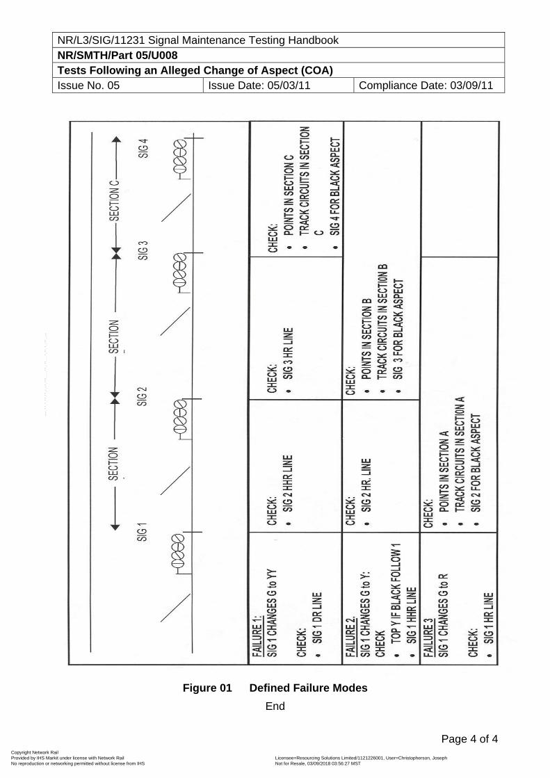
NR/L3/SIG/11231 Signal Maintenance Testing Handbook NR/SMTH/Part 05/U008 Tests Following an Alleged Change of Aspect (COA) Issue No. 05 Issue Date: 05/03/11 Compliance Date: 03/09/11
Page 4 of 4
Figure 01 Defined Failure Modes
End
Copyright Network Rail Provided by IHS Markit under license with Network Rail Licensee=Resourcing Solutions Limited /1121226001, User=Christopherson, Joseph
Not for Resale, 03/09/2018 03:56:27 MSTNo reproduction or networking permitted without license from IHS
--``,,``,`,,`,```,,``,,````,,,`,-`-`,,`,,`,`,,`---
NR/L3/SIG/11231 Signal Maintenance Testing Handbook NR/SMTH/Part 05/U009 Right Side Failure Test Guide: Automatic Warning System (AWS) Issue No. 06 Issue Date: 03/03/2018 Compliance Date: 31/05/18
Page 1 of 6
Excludes: Suspected WSF. AWS equipment shall be repaired as quickly as possible. AWS is a primary safety system.
Whilst AWS is repaired, signal aspects shall be restricted for a maximum of 48 hours if authorised by a Level 3 SFI Engineer.
If the apparatus cannot be restored to normal working within 48 hours, the issue shall be escalated to the Signal & Telecoms Maintenance Engineer.
The Signal & Telecoms Maintenance Engineer shall arrange that resources necessary to rectify the defect are given a high priority.
If AWS is unable to be repaired within 48 hours and cannot be fully functional for a period of time, the aspect shall be returned to normal operation and train drivers advised about the defective AWS by means of a published notice.
1. Introduction Figure 01 summarises the AWS Failure Codes that can be reported to Signalling Technicians. Codes 5 and 7 could be infrastructure related and are Wrong Side Failures. Testing required after report of Code 5 or 7 failure is covered in WSF Test Guide T011.
Copyright Network Rail Provided by IHS Markit under license with Network Rail Licensee=Resourcing Solutions Limited /1121226001, User=Christopherson, Joseph
Not for Resale, 03/09/2018 03:56:27 MSTNo reproduction or networking permitted without license from IHS
--``,,``,`,,`,```,,``,,````,,,`,-`-`,,`,,`,`,,`---
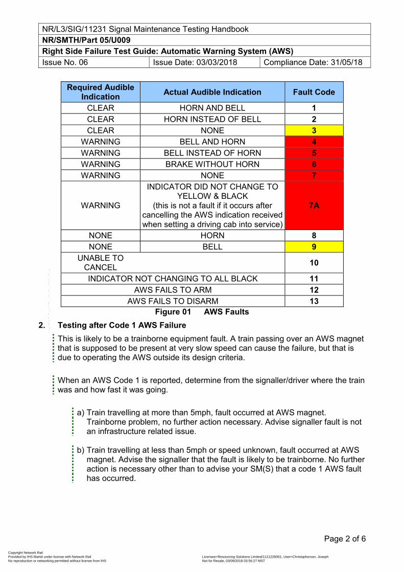
NR/L3/SIG/11231 Signal Maintenance Testing Handbook NR/SMTH/Part 05/U009 Right Side Failure Test Guide: Automatic Warning System (AWS) Issue No. 06 Issue Date: 03/03/2018 Compliance Date: 31/05/18
Page 2 of 6
Required Audible Indication Actual Audible Indication Fault Code
CLEAR HORN AND BELL 1 CLEAR HORN INSTEAD OF BELL 2 CLEAR NONE 3
WARNING BELL AND HORN 4 WARNING BELL INSTEAD OF HORN 5 WARNING BRAKE WITHOUT HORN 6 WARNING NONE 7
WARNING
INDICATOR DID NOT CHANGE TO YELLOW & BLACK
(this is not a fault if it occurs after cancelling the AWS indication received when setting a driving cab into service)
7A
NONE HORN 8 NONE BELL 9
UNABLE TO CANCEL
10
INDICATOR NOT CHANGING TO ALL BLACK 11 AWS FAILS TO ARM 12
AWS FAILS TO DISARM 13 Figure 01 AWS Faults
2. Testing after Code 1 AWS Failure This is likely to be a trainborne equipment fault. A train passing over an AWS magnet that is supposed to be present at very slow speed can cause the failure, but that is due to operating the AWS outside its design criteria.
When an AWS Code 1 is reported, determine from the signaller/driver where the train was and how fast it was going.
a) Train travelling at more than 5mph, fault occurred at AWS magnet.
Trainborne problem, no further action necessary. Advise signaller fault is not an infrastructure related issue.
b) Train travelling at less than 5mph or speed unknown, fault occurred at AWS
magnet. Advise the signaller that the fault is likely to be trainborne. No further action is necessary other than to advise your SM(S) that a code 1 AWS fault has occurred.
Copyright Network Rail Provided by IHS Markit under license with Network Rail Licensee=Resourcing Solutions Limited /1121226001, User=Christopherson, Joseph
Not for Resale, 03/09/2018 03:56:27 MSTNo reproduction or networking permitted without license from IHS
--``,,``,`,,`,```,,``,,````,,,`,-`-`,,`,,`,`,,`---
NR/L3/SIG/11231 Signal Maintenance Testing Handbook NR/SMTH/Part 05/U009 Right Side Failure Test Guide: Automatic Warning System (AWS) Issue No. 06 Issue Date: 03/03/2018 Compliance Date: 31/05/18
Page 3 of 6
3. Testing after Code 2 AWS Failure This could be an infrastructure failure or a trainborne equipment fault. This failure shall necessitate fault finding on site unless it is proven to be a trainborne fault (i.e. unit reports a string of code 2 failures at ‘clear’ signals (colour lights showing green or semaphore distant signals showing ‘off’). If it is decided not to go to site because the same unit has reported several AWS failures, advise the signaller that it is unlikely to be an infrastructure fault and request advice of further incidents.
If a site visit is required, undertake right side failure testing of the AWS installation, paying particular attention to the positioning, height and field strength (S&P meter) of the electro-magnet.
4. Testing after Code 3 AWS Failure
This could be infrastructure failure or a trainborne equipment fault. This failure shall necessitate fault finding on site unless it is proven to be a trainborne fault (i.e. unit reports a string of code 3 and 7 failures at ‘clear’ signals and signals displaying a caution/red aspect).
When an AWS Code 3 is reported, it could be a Code 7 failure waiting to happen. On arrival at site, concentrate on the permanent magnet. Determine whether the Permanent magnet is effective by undertaking WSF Test Guide T011 tests N01 to N05; N20 to N24. Test the Signal’s permanent magnet for correct strength and polarity using an S&P meter. If satisfied that everything is correct, this is likely to be a trainborne fault.
If the permanent magnet is a suppressor, and appears to be producing correct magnetic fields, undertake the remaining parts of T011. If nothing is found, Check that the electro magnet is correctly operating, then advise the signaller and offer the equipment back for service.
5. Testing after Code 4 AWS Failure
This is likely to be a trainborne equipment fault. It may be reported as either a bell and horn together or as a horn after bell – both are Code 4.
A train passing over an AWS magnet that is supposed to be present at very slow speed can cause the failure, but that is due to operating the AWS outside its design criteria.
When an AWS Code 4 is reported, determine from the signaller/driver where the train was and how fast it was going.
Copyright Network Rail Provided by IHS Markit under license with Network Rail Licensee=Resourcing Solutions Limited /1121226001, User=Christopherson, Joseph
Not for Resale, 03/09/2018 03:56:27 MSTNo reproduction or networking permitted without license from IHS
--``,,``,`,,`,```,,``,,````,,,`,-`-`,,`,,`,`,,`---
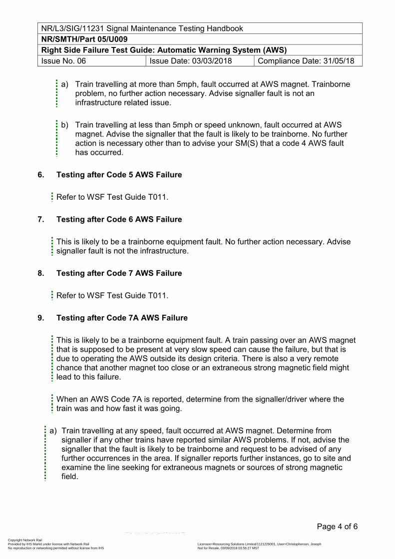
NR/L3/SIG/11231 Signal Maintenance Testing Handbook NR/SMTH/Part 05/U009 Right Side Failure Test Guide: Automatic Warning System (AWS) Issue No. 06 Issue Date: 03/03/2018 Compliance Date: 31/05/18
Page 4 of 6
a) Train travelling at more than 5mph, fault occurred at AWS magnet. Trainborne problem, no further action necessary. Advise signaller fault is not an infrastructure related issue.
b) Train travelling at less than 5mph or speed unknown, fault occurred at AWS
magnet. Advise the signaller that the fault is likely to be trainborne. No further action is necessary other than to advise your SM(S) that a code 4 AWS fault has occurred.
6. Testing after Code 5 AWS Failure
Refer to WSF Test Guide T011. 7. Testing after Code 6 AWS Failure
This is likely to be a trainborne equipment fault. No further action necessary. Advise signaller fault is not the infrastructure.
8. Testing after Code 7 AWS Failure
Refer to WSF Test Guide T011. 9. Testing after Code 7A AWS Failure
This is likely to be a trainborne equipment fault. A train passing over an AWS magnet that is supposed to be present at very slow speed can cause the failure, but that is due to operating the AWS outside its design criteria. There is also a very remote chance that another magnet too close or an extraneous strong magnetic field might lead to this failure.
When an AWS Code 7A is reported, determine from the signaller/driver where the train was and how fast it was going.
a) Train travelling at any speed, fault occurred at AWS magnet. Determine from
signaller if any other trains have reported similar AWS problems. If not, advise the signaller that the fault is likely to be trainborne and request to be advised of any further occurrences in the area. If signaller reports further instances, go to site and examine the line seeking for extraneous magnets or sources of strong magnetic field.
Copyright Network Rail Provided by IHS Markit under license with Network Rail Licensee=Resourcing Solutions Limited /1121226001, User=Christopherson, Joseph
Not for Resale, 03/09/2018 03:56:27 MSTNo reproduction or networking permitted without license from IHS
--``,,``,`,,`,```,,``,,````,,,`,-`-`,,`,,`,`,,`---
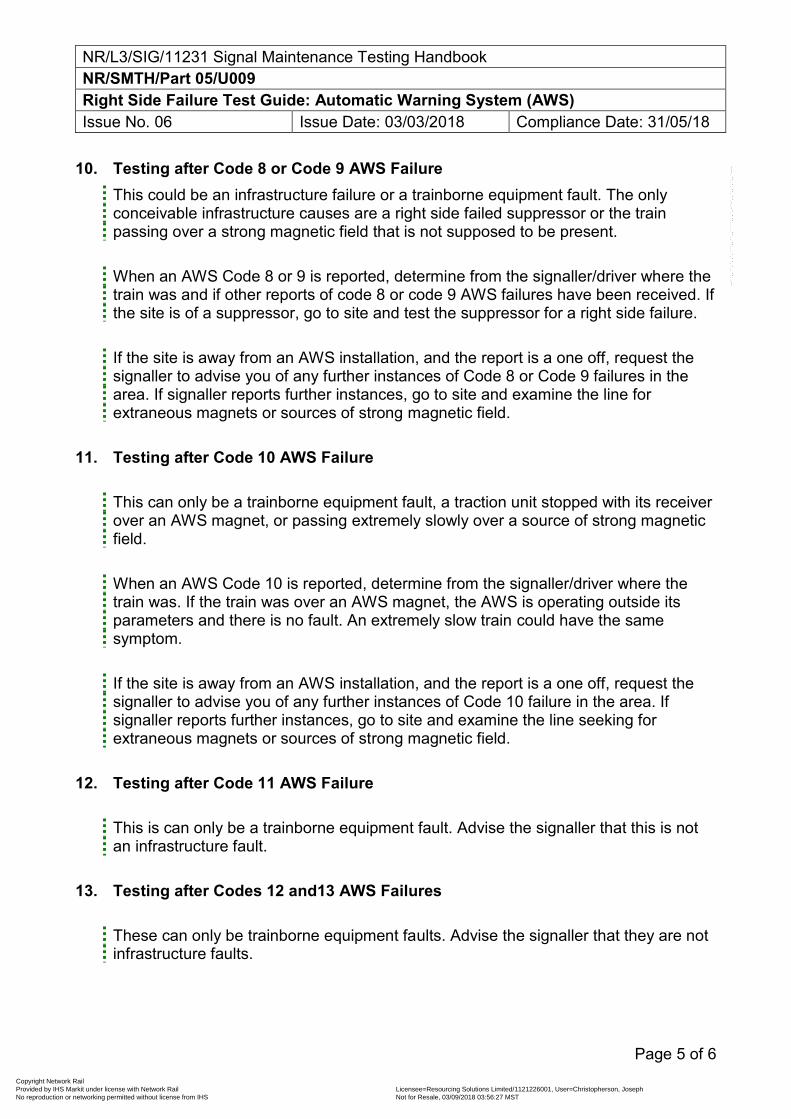
NR/L3/SIG/11231 Signal Maintenance Testing Handbook NR/SMTH/Part 05/U009 Right Side Failure Test Guide: Automatic Warning System (AWS) Issue No. 06 Issue Date: 03/03/2018 Compliance Date: 31/05/18
Page 5 of 6
10. Testing after Code 8 or Code 9 AWS Failure This could be an infrastructure failure or a trainborne equipment fault. The only conceivable infrastructure causes are a right side failed suppressor or the train passing over a strong magnetic field that is not supposed to be present.
When an AWS Code 8 or 9 is reported, determine from the signaller/driver where the train was and if other reports of code 8 or code 9 AWS failures have been received. If the site is of a suppressor, go to site and test the suppressor for a right side failure.
If the site is away from an AWS installation, and the report is a one off, request the signaller to advise you of any further instances of Code 8 or Code 9 failures in the area. If signaller reports further instances, go to site and examine the line for extraneous magnets or sources of strong magnetic field.
11. Testing after Code 10 AWS Failure
This can only be a trainborne equipment fault, a traction unit stopped with its receiver over an AWS magnet, or passing extremely slowly over a source of strong magnetic field.
When an AWS Code 10 is reported, determine from the signaller/driver where the train was. If the train was over an AWS magnet, the AWS is operating outside its parameters and there is no fault. An extremely slow train could have the same symptom.
If the site is away from an AWS installation, and the report is a one off, request the signaller to advise you of any further instances of Code 10 failure in the area. If signaller reports further instances, go to site and examine the line seeking for extraneous magnets or sources of strong magnetic field.
12. Testing after Code 11 AWS Failure
This is can only be a trainborne equipment fault. Advise the signaller that this is not an infrastructure fault.
13. Testing after Codes 12 and13 AWS Failures
These can only be trainborne equipment faults. Advise the signaller that they are not infrastructure faults.
Copyright Network Rail Provided by IHS Markit under license with Network Rail Licensee=Resourcing Solutions Limited /1121226001, User=Christopherson, Joseph
Not for Resale, 03/09/2018 03:56:27 MSTNo reproduction or networking permitted without license from IHS
--``,,``,`,,`,```,,``,,````,,,`,-`-`,,`,,`,`,,`---
NR/L3/SIG/11231 Signal Maintenance Testing Handbook NR/SMTH/Part 05/U009 Right Side Failure Test Guide: Automatic Warning System (AWS) Issue No. 06 Issue Date: 03/03/2018 Compliance Date: 31/05/18
Page 6 of 6
End
Copyright Network Rail Provided by IHS Markit under license with Network Rail Licensee=Resourcing Solutions Limited /1121226001, User=Christopherson, Joseph
Not for Resale, 03/09/2018 03:56:27 MSTNo reproduction or networking permitted without license from IHS
--``,,``,`,,`,```,,``,,````,,,`,-`-`,,`,,`,`,,`---
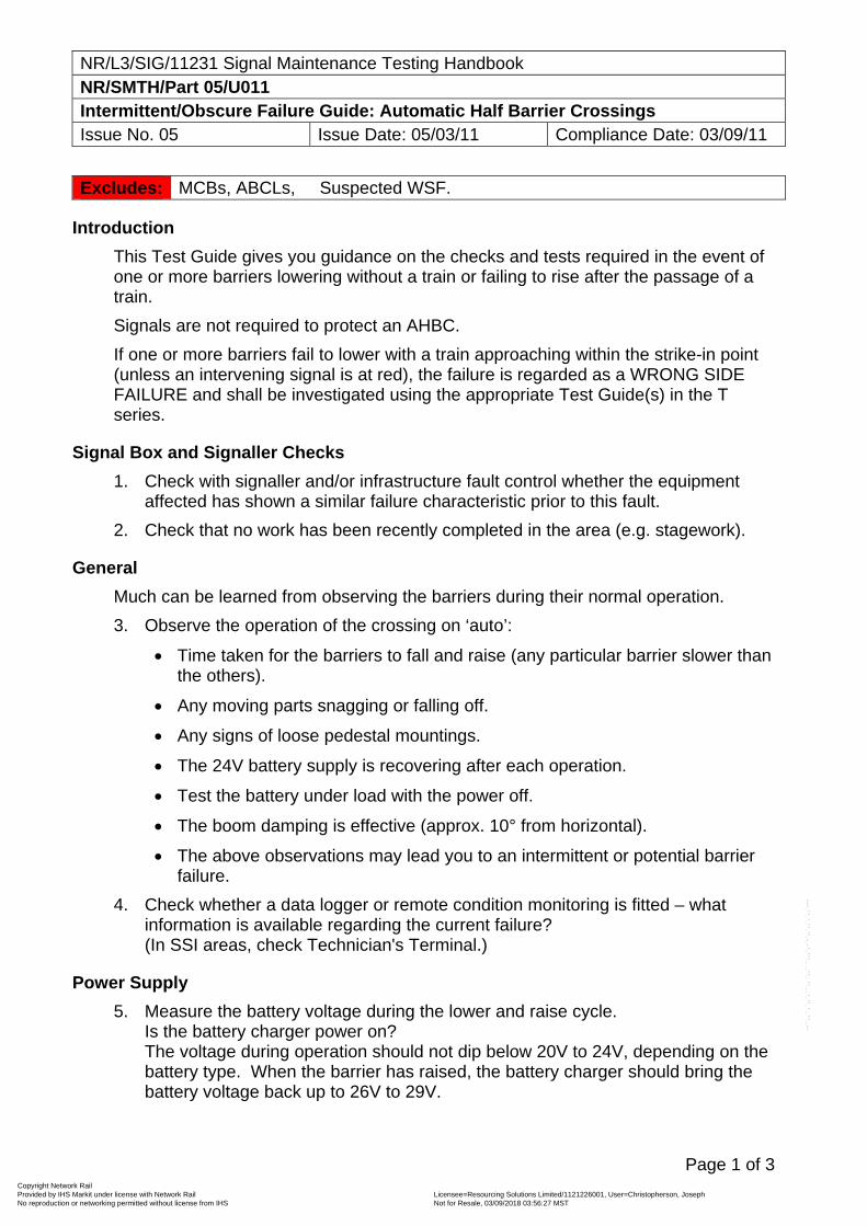
NR/L3/SIG/11231 Signal Maintenance Testing Handbook NR/SMTH/Part 05/U011 Intermittent/Obscure Failure Guide: Automatic Half Barrier Crossings Issue No. 05 Issue Date: 05/03/11 Compliance Date: 03/09/11
Page 1 of 3
Excludes: MCBs, ABCLs, Suspected WSF.
Introduction
This Test Guide gives you guidance on the checks and tests required in the event of one or more barriers lowering without a train or failing to rise after the passage of a train.
Signals are not required to protect an AHBC.
If one or more barriers fail to lower with a train approaching within the strike-in point (unless an intervening signal is at red), the failure is regarded as a WRONG SIDE FAILURE and shall be investigated using the appropriate Test Guide(s) in the T series.
Signal Box and Signaller Checks
1. Check with signaller and/or infrastructure fault control whether the equipment affected has shown a similar failure characteristic prior to this fault.
2. Check that no work has been recently completed in the area (e.g. stagework).
General
Much can be learned from observing the barriers during their normal operation.
3. Observe the operation of the crossing on ‘auto’:
Time taken for the barriers to fall and raise (any particular barrier slower than the others).
Any moving parts snagging or falling off.
Any signs of loose pedestal mountings.
The 24V battery supply is recovering after each operation.
Test the battery under load with the power off.
The boom damping is effective (approx. 10° from horizontal).
The above observations may lead you to an intermittent or potential barrier failure.
4. Check whether a data logger or remote condition monitoring is fitted – what information is available regarding the current failure? (In SSI areas, check Technician's Terminal.)
Power Supply
5. Measure the battery voltage during the lower and raise cycle. Is the battery charger power on? The voltage during operation should not dip below 20V to 24V, depending on the battery type. When the barrier has raised, the battery charger should bring the battery voltage back up to 26V to 29V.
Copyright Network Rail Provided by IHS Markit under license with Network Rail Licensee=Resourcing Solutions Limited /1121226001, User=Christopherson, Joseph
Not for Resale, 03/09/2018 03:56:27 MSTNo reproduction or networking permitted without license from IHS
--``,,``,`,,`,```,,``,,````,,,`,-`-`,,`,,`,`,,`---
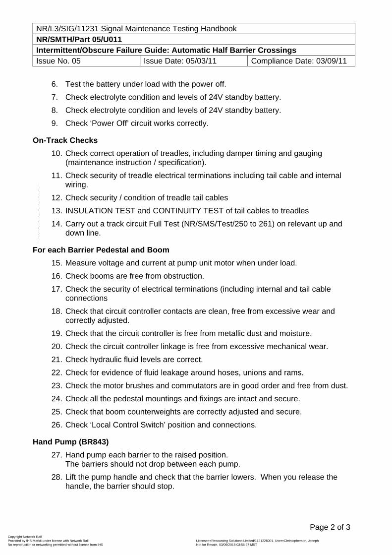
NR/L3/SIG/11231 Signal Maintenance Testing Handbook NR/SMTH/Part 05/U011 Intermittent/Obscure Failure Guide: Automatic Half Barrier Crossings Issue No. 05 Issue Date: 05/03/11 Compliance Date: 03/09/11
Page 2 of 3
6. Test the battery under load with the power off.
7. Check electrolyte condition and levels of 24V standby battery.
8. Check electrolyte condition and levels of 24V standby battery.
9. Check ‘Power Off’ circuit works correctly.
On-Track Checks
10. Check correct operation of treadles, including damper timing and gauging (maintenance instruction / specification).
11. Check security of treadle electrical terminations including tail cable and internal wiring.
12. Check security / condition of treadle tail cables
13. INSULATION TEST and CONTINUITY TEST of tail cables to treadles
14. Carry out a track circuit Full Test (NR/SMS/Test/250 to 261) on relevant up and down line.
For each Barrier Pedestal and Boom
15. Measure voltage and current at pump unit motor when under load.
16. Check booms are free from obstruction.
17. Check the security of electrical terminations (including internal and tail cable connections
18. Check that circuit controller contacts are clean, free from excessive wear and correctly adjusted.
19. Check that the circuit controller is free from metallic dust and moisture.
20. Check the circuit controller linkage is free from excessive mechanical wear.
21. Check hydraulic fluid levels are correct.
22. Check for evidence of fluid leakage around hoses, unions and rams.
23. Check the motor brushes and commutators are in good order and free from dust.
24. Check all the pedestal mountings and fixings are intact and secure.
25. Check that boom counterweights are correctly adjusted and secure.
26. Check ‘Local Control Switch’ position and connections.
Hand Pump (BR843)
27. Hand pump each barrier to the raised position. The barriers should not drop between each pump.
28. Lift the pump handle and check that the barrier lowers. When you release the handle, the barrier should stop.
Copyright Network Rail Provided by IHS Markit under license with Network Rail Licensee=Resourcing Solutions Limited /1121226001, User=Christopherson, Joseph
Not for Resale, 03/09/2018 03:56:27 MSTNo reproduction or networking permitted without license from IHS
--``,,``,`,,`,```,,``,,````,,,`,-`-`,,`,,`,`,,`---
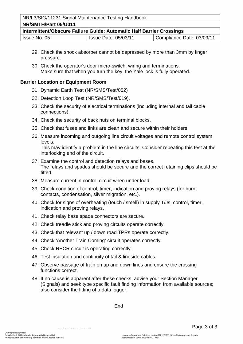
NR/L3/SIG/11231 Signal Maintenance Testing Handbook NR/SMTH/Part 05/U011 Intermittent/Obscure Failure Guide: Automatic Half Barrier Crossings Issue No. 05 Issue Date: 05/03/11 Compliance Date: 03/09/11
Page 3 of 3
29. Check the shock absorber cannot be depressed by more than 3mm by finger pressure.
30. Check the operator's door micro-switch, wiring and terminations. Make sure that when you turn the key, the Yale lock is fully operated.
Barrier Location or Equipment Room
31. Dynamic Earth Test (NR/SMS/Test/052)
32. Detection Loop Test (NR/SMS/Test/019).
33. Check the security of electrical terminations (including internal and tail cable connections).
34. Check the security of back nuts on terminal blocks.
35. Check that fuses and links are clean and secure within their holders.
36. Measure incoming and outgoing line circuit voltages and remote control system levels. This may identify a problem in the line circuits. Consider repeating this test at the interlocking end of the circuit.
37. Examine the control and detection relays and bases. The relays and spades should be secure and the correct retaining clips should be fitted.
38. Measure current in control circuit when under load.
39. Check condition of control, timer, indication and proving relays (for burnt contacts, condensation, silver migration, etc.).
40. Check for signs of overheating (touch / smell) in supply T/Js, control, timer, indication and proving relays.
41. Check relay base spade connectors are secure.
42. Check treadle stick and proving circuits operate correctly.
43. Check that relevant up / down road TPRs operate correctly.
44. Check ‘Another Train Coming’ circuit operates correctly.
45. Check RECR circuit is operating correctly.
46. Test insulation and continuity of tail & lineside cables.
47. Observe passage of train on up and down lines and ensure the crossing functions correct.
48. If no cause is apparent after these checks, advise your Section Manager (Signals) and seek type specific fault finding information from available sources; also consider the fitting of a data logger.
End
Copyright Network Rail Provided by IHS Markit under license with Network Rail Licensee=Resourcing Solutions Limited /1121226001, User=Christopherson, Joseph
Not for Resale, 03/09/2018 03:56:27 MSTNo reproduction or networking permitted without license from IHS
--``,,``,`,,`,```,,``,,````,,,`,-`-`,,`,,`,`,,`---
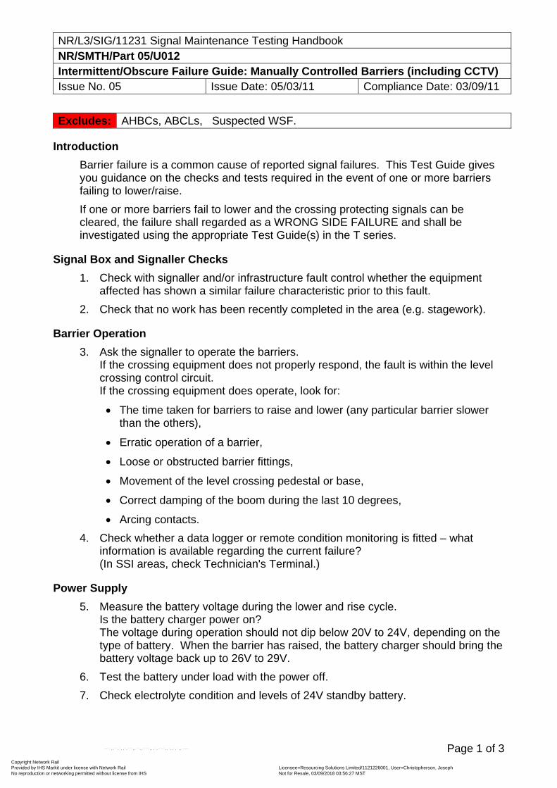
NR/L3/SIG/11231 Signal Maintenance Testing Handbook NR/SMTH/Part 05/U012 Intermittent/Obscure Failure Guide: Manually Controlled Barriers (including CCTV) Issue No. 05 Issue Date: 05/03/11 Compliance Date: 03/09/11
Page 1 of 3
Excludes: AHBCs, ABCLs, Suspected WSF.
Introduction
Barrier failure is a common cause of reported signal failures. This Test Guide gives you guidance on the checks and tests required in the event of one or more barriers failing to lower/raise.
If one or more barriers fail to lower and the crossing protecting signals can be cleared, the failure shall regarded as a WRONG SIDE FAILURE and shall be investigated using the appropriate Test Guide(s) in the T series.
Signal Box and Signaller Checks
1. Check with signaller and/or infrastructure fault control whether the equipment affected has shown a similar failure characteristic prior to this fault.
2. Check that no work has been recently completed in the area (e.g. stagework).
Barrier Operation
3. Ask the signaller to operate the barriers. If the crossing equipment does not properly respond, the fault is within the level crossing control circuit. If the crossing equipment does operate, look for:
The time taken for barriers to raise and lower (any particular barrier slower than the others),
Erratic operation of a barrier,
Loose or obstructed barrier fittings,
Movement of the level crossing pedestal or base,
Correct damping of the boom during the last 10 degrees,
Arcing contacts.
4. Check whether a data logger or remote condition monitoring is fitted – what information is available regarding the current failure? (In SSI areas, check Technician's Terminal.)
Power Supply
5. Measure the battery voltage during the lower and rise cycle. Is the battery charger power on? The voltage during operation should not dip below 20V to 24V, depending on the type of battery. When the barrier has raised, the battery charger should bring the battery voltage back up to 26V to 29V.
6. Test the battery under load with the power off.
7. Check electrolyte condition and levels of 24V standby battery.
Copyright Network Rail Provided by IHS Markit under license with Network Rail Licensee=Resourcing Solutions Limited /1121226001, User=Christopherson, Joseph
Not for Resale, 03/09/2018 03:56:27 MSTNo reproduction or networking permitted without license from IHS
--``,,``,`,,`,```,,``,,````,,,`,-`-`,,`,,`,`,,`---
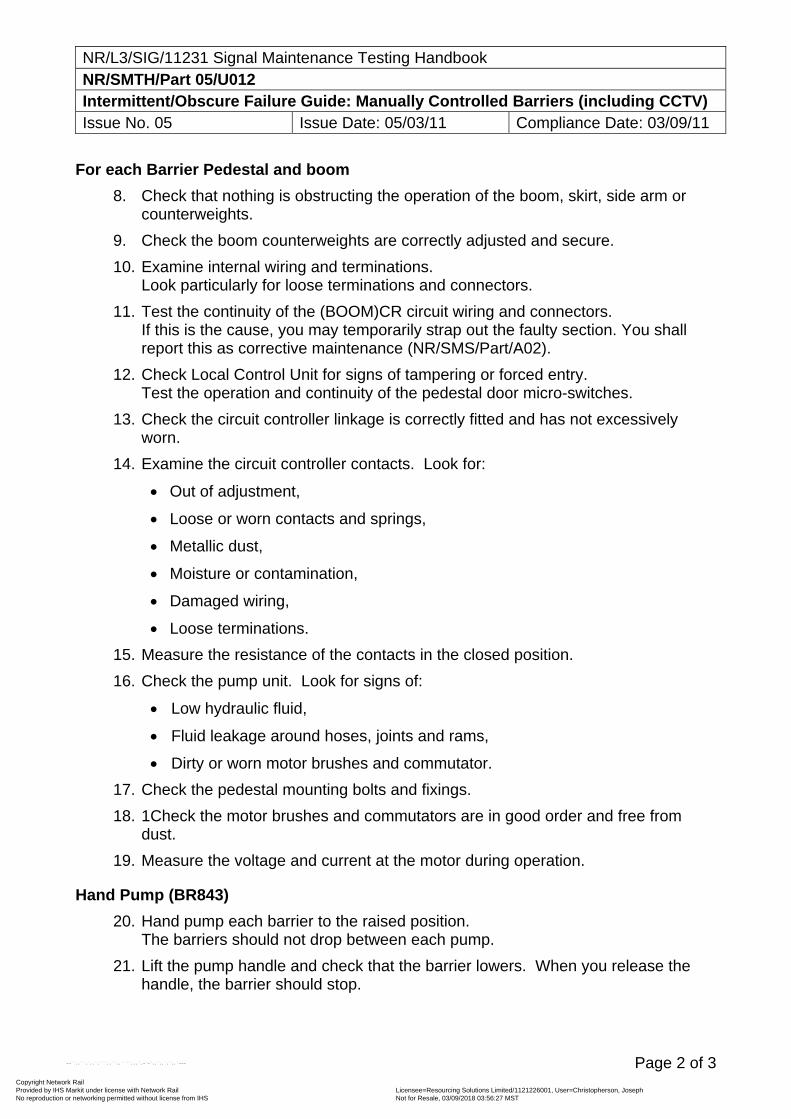
NR/L3/SIG/11231 Signal Maintenance Testing Handbook NR/SMTH/Part 05/U012 Intermittent/Obscure Failure Guide: Manually Controlled Barriers (including CCTV) Issue No. 05 Issue Date: 05/03/11 Compliance Date: 03/09/11
Page 2 of 3
For each Barrier Pedestal and boom
8. Check that nothing is obstructing the operation of the boom, skirt, side arm or counterweights.
9. Check the boom counterweights are correctly adjusted and secure.
10. Examine internal wiring and terminations. Look particularly for loose terminations and connectors.
11. Test the continuity of the (BOOM)CR circuit wiring and connectors. If this is the cause, you may temporarily strap out the faulty section. You shall report this as corrective maintenance (NR/SMS/Part/A02).
12. Check Local Control Unit for signs of tampering or forced entry. Test the operation and continuity of the pedestal door micro-switches.
13. Check the circuit controller linkage is correctly fitted and has not excessively worn.
14. Examine the circuit controller contacts. Look for:
Out of adjustment,
Loose or worn contacts and springs,
Metallic dust,
Moisture or contamination,
Damaged wiring,
Loose terminations.
15. Measure the resistance of the contacts in the closed position.
16. Check the pump unit. Look for signs of:
Low hydraulic fluid,
Fluid leakage around hoses, joints and rams,
Dirty or worn motor brushes and commutator.
17. Check the pedestal mounting bolts and fixings.
18. 1Check the motor brushes and commutators are in good order and free from dust.
19. Measure the voltage and current at the motor during operation.
Hand Pump (BR843)
20. Hand pump each barrier to the raised position. The barriers should not drop between each pump.
21. Lift the pump handle and check that the barrier lowers. When you release the handle, the barrier should stop.
Copyright Network Rail Provided by IHS Markit under license with Network Rail Licensee=Resourcing Solutions Limited /1121226001, User=Christopherson, Joseph
Not for Resale, 03/09/2018 03:56:27 MSTNo reproduction or networking permitted without license from IHS
--``,,``,`,,`,```,,``,,````,,,`,-`-`,,`,,`,`,,`---
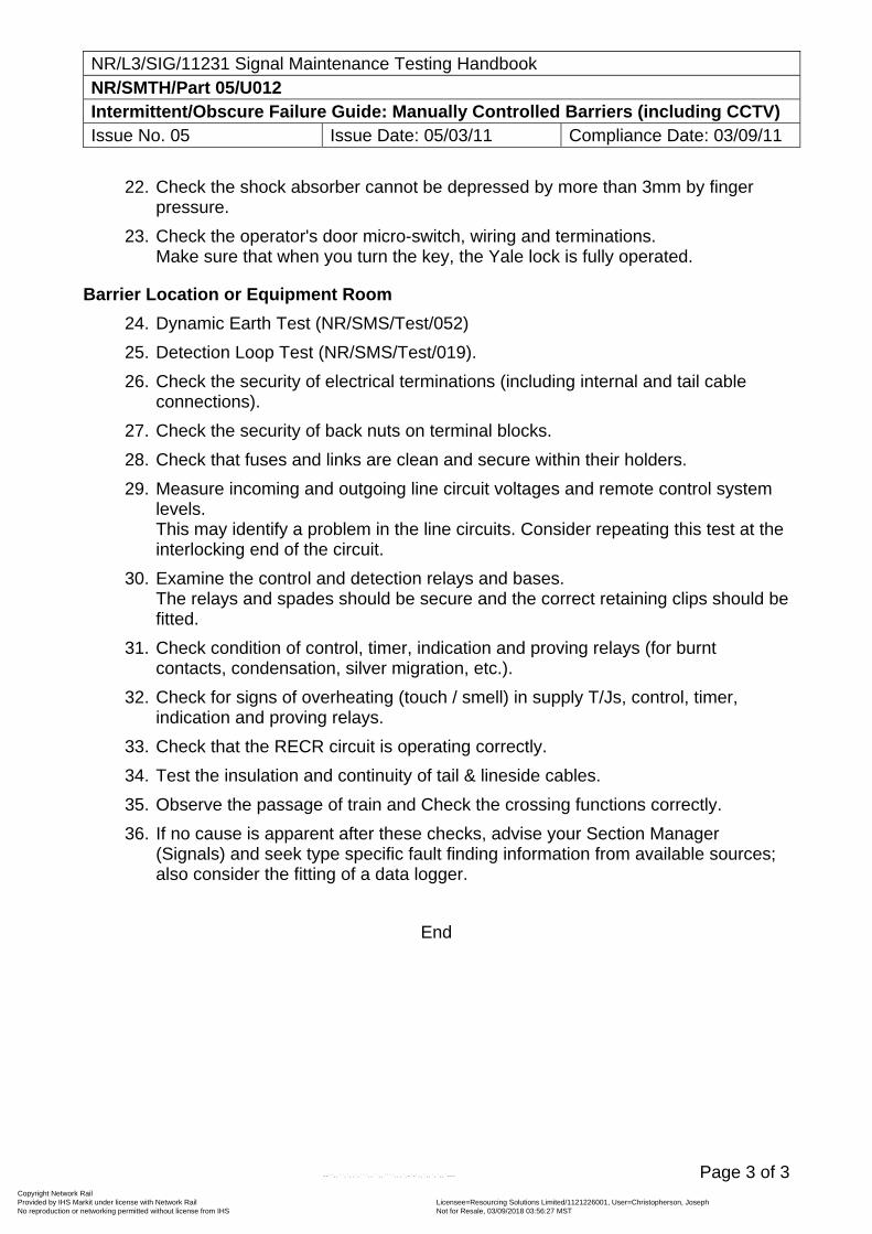
NR/L3/SIG/11231 Signal Maintenance Testing Handbook NR/SMTH/Part 05/U012 Intermittent/Obscure Failure Guide: Manually Controlled Barriers (including CCTV) Issue No. 05 Issue Date: 05/03/11 Compliance Date: 03/09/11
Page 3 of 3
22. Check the shock absorber cannot be depressed by more than 3mm by finger pressure.
23. Check the operator's door micro-switch, wiring and terminations. Make sure that when you turn the key, the Yale lock is fully operated.
Barrier Location or Equipment Room
24. Dynamic Earth Test (NR/SMS/Test/052)
25. Detection Loop Test (NR/SMS/Test/019).
26. Check the security of electrical terminations (including internal and tail cable connections).
27. Check the security of back nuts on terminal blocks.
28. Check that fuses and links are clean and secure within their holders.
29. Measure incoming and outgoing line circuit voltages and remote control system levels. This may identify a problem in the line circuits. Consider repeating this test at the interlocking end of the circuit.
30. Examine the control and detection relays and bases. The relays and spades should be secure and the correct retaining clips should be fitted.
31. Check condition of control, timer, indication and proving relays (for burnt contacts, condensation, silver migration, etc.).
32. Check for signs of overheating (touch / smell) in supply T/Js, control, timer, indication and proving relays.
33. Check that the RECR circuit is operating correctly.
34. Test the insulation and continuity of tail & lineside cables.
35. Observe the passage of train and Check the crossing functions correctly.
36. If no cause is apparent after these checks, advise your Section Manager (Signals) and seek type specific fault finding information from available sources; also consider the fitting of a data logger.
End
Copyright Network Rail Provided by IHS Markit under license with Network Rail Licensee=Resourcing Solutions Limited /1121226001, User=Christopherson, Joseph
Not for Resale, 03/09/2018 03:56:27 MSTNo reproduction or networking permitted without license from IHS
--``,,``,`,,`,```,,``,,````,,,`,-`-`,,`,,`,`,,`---
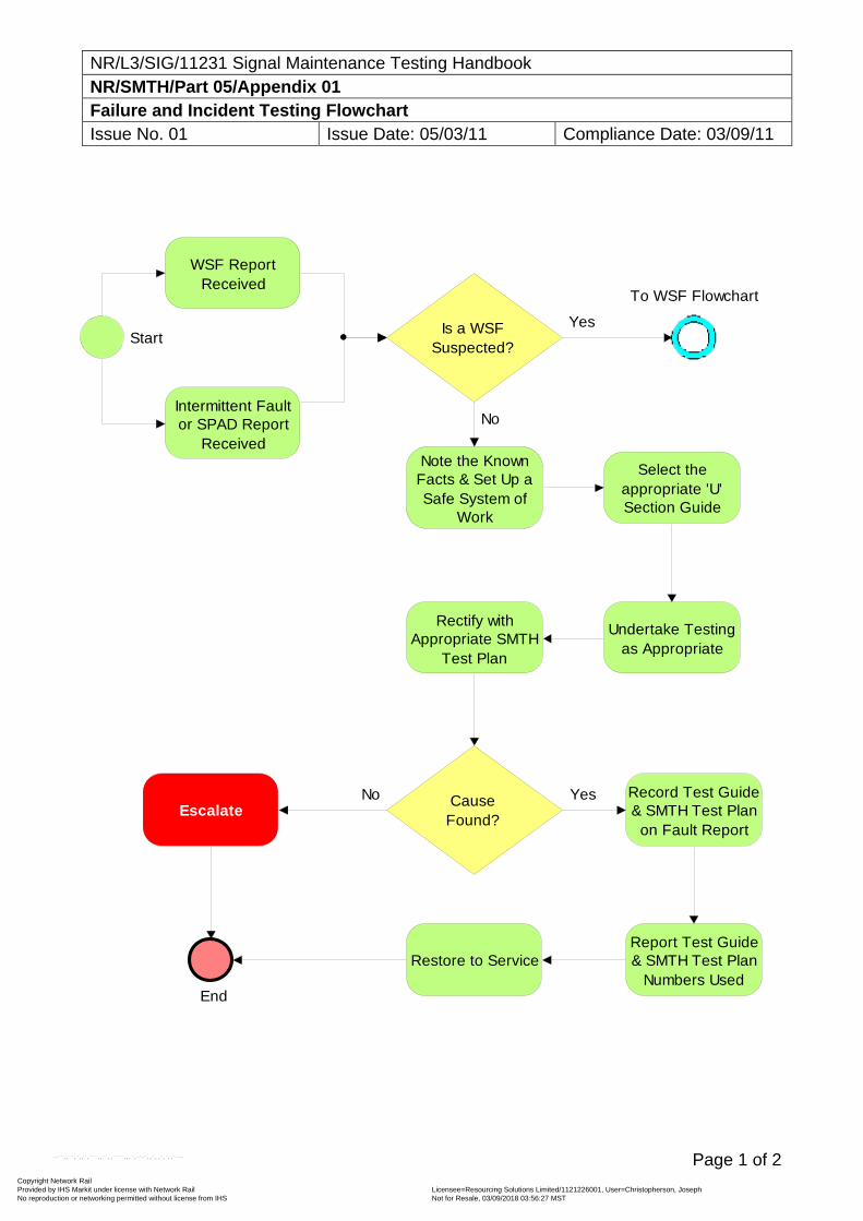
NR/L3/SIG/11231 Signal Maintenance Testing Handbook NR/SMTH/Part 05/Appendix 01 Failure and Incident Testing Flowchart Issue No. 01 Issue Date: 05/03/11 Compliance Date: 03/09/11
Page 1 of 2
Start
End
WSF Report Received
Intermittent Fault or SPAD Report
Received
Is a WSF Suspected?
To WSF Flowchart
Yes
Note the Known Facts & Set Up a Safe System of
Work
Select the appropriate 'U' Section Guide
Undertake Testing as Appropriate
Cause Found?
Escalate
Rectify with Appropriate SMTH
Test Plan
Record Test Guide & SMTH Test Plan
on Fault Report
Report Test Guide & SMTH Test Plan
Numbers Used
Restore to Service
No
YesNo
Copyright Network Rail Provided by IHS Markit under license with Network Rail Licensee=Resourcing Solutions Limited /1121226001, User=Christopherson, Joseph
Not for Resale, 03/09/2018 03:56:27 MSTNo reproduction or networking permitted without license from IHS
--``,,``,`,,`,```,,``,,````,,,`,-`-`,,`,,`,`,,`---
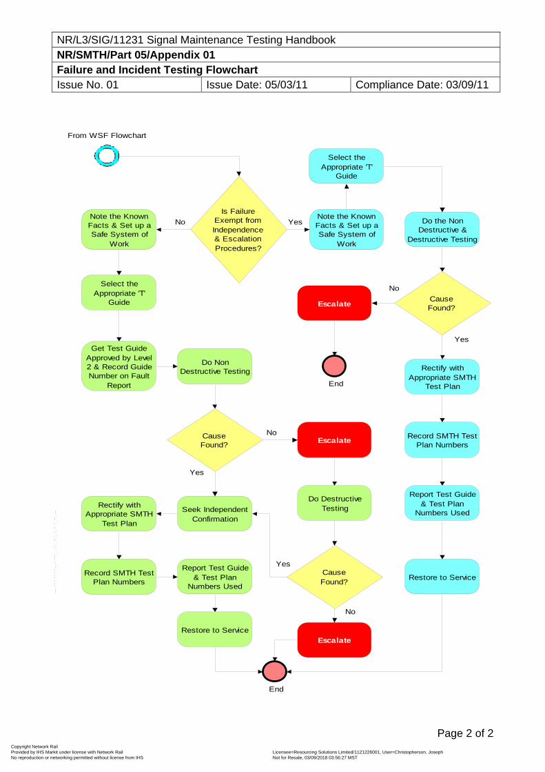
NR/L3/SIG/11231 Signal Maintenance Testing Handbook NR/SMTH/Part 05/Appendix 01 Failure and Incident Testing Flowchart Issue No. 01 Issue Date: 05/03/11 Compliance Date: 03/09/11
Page 2 of 2
End
From WSF Flowchart
Is Failure Exempt from Independence & Escalation Procedures?
Note the Known Facts & Set up a Safe System of
Work
Select the Appropriate 'T'
Guide
Get Test Guide Approved by Level 2 & Record Guide Number on Fault
Report
Do Non Destructive Testing
Cause Found?
Seek Independent Confirmation
Rectify with Appropriate SMTH
Test Plan
Record SMTH Test Plan Numbers
Report Test Guide & Test Plan
Numbers Used
Restore to Service
No
Yes
Escalate
Do Destructive Testing
Cause Found?
Escalate
No
Yes
No
Note the Known Facts & Set up a Safe System of
Work
Yes
Select the Appropriate 'T'
Guide
Do the Non Destructive &
Destructive Testing
Cause Found?
Escalate
Rectify with Appropriate SMTH
Test Plan
Record SMTH Test Plan Numbers
Report Test Guide & Test Plan
Numbers Used
Restore to Service
No
Yes
End
Copyright Network Rail Provided by IHS Markit under license with Network Rail Licensee=Resourcing Solutions Limited /1121226001, User=Christopherson, Joseph
Not for Resale, 03/09/2018 03:56:27 MSTNo reproduction or networking permitted without license from IHS
--``,,``,`,,`,```,,``,,````,,,`,-`-`,,`,,`,`,,`---
NR/L3/SIG/11231 Signal Maintenance Testing Handbook NR/SMTH/Part 05/Appendix 02 Instead Data Loggers Issue No. 01 Issue Date: 05/03/11 Compliance Date: 03/09/11
Page 1 of 7
1. Change a Disk in an Intead 3 or 64 Logger
1.1 Cautionary Notes
The unit depends on having a usable disk in the drive for correct operation. Recording always continues into the memory, even when there is not a disk in the drive. However, if the unit is left without a disk for a long time, the memory will eventually fill up. At this point, data will be lost. An ‘overrun’ error message will be added to the system event log if this happens.
Never eject the disk from the drive without first pressing the ‘Change Disk’ button and waiting for the unit’s instructions. The unit stores events in memory until it has stored 256 events, at which point it writes them to the disk. When ‘Change Disk’ is pressed, any events remaining in memory are written to the disk. If the disk is removed without pressing ‘Change Disk’ button, the last events will not be recorded. Also, the system event log will not be updated on the disk.
The unit may not respond immediately to your press of the ‘Change Disk’ button under the following conditions:
If it is currently writing to the disk, it will not respond until the disk write is completed. This may take up to 2 seconds.
If the unit is in menu mode, this must be exited before the disk can be changed. Keep pressing ‘No’ until the time is displayed, then press ‘Change Disk’ again.
If the modem link is in use, the unit will display “Logging out remote user - WAIT”. The remote user will be logged out at the end of their current operation. This may take some time.
1.2 Changing the Disk
A 720K formatted disk is required to replace the one which is currently in the unit. It does not necessarily have to be blank, but anything on it will be erased.
Before starting the disk changing procedure, the site name and the current date and time shall be written on the label of the new disk.
If the unit is in a location case, take care to avoid the ingress of moisture and dirt while the front door is open.
Open the transparent door on the front of the unit.
Press the ‘Change Disk’ button.
The unit will display:
Writing disk WAIT
Includes: Instead 3 or Instead 64 Data Logger Site Disk Excludes: Instead 64 Active. (See section 2)
Copyright Network Rail Provided by IHS Markit under license with Network Rail Licensee=Resourcing Solutions Limited /1121226001, User=Christopherson, Joseph
Not for Resale, 03/09/2018 03:56:27 MSTNo reproduction or networking permitted without license from IHS
--``,,``,`,,`,```,,``,,````,,,`,-`-`,,`,,`,`,,`---
NR/L3/SIG/11231 Signal Maintenance Testing Handbook NR/SMTH/Part 05/Appendix 02 Instead Data Loggers Issue No. 01 Issue Date: 05/03/11 Compliance Date: 03/09/11
Page 2 of 7
The unit is writing any left-over events from its memory onto the disk. After a second or so, the display will change to:
Remove disk now (Press no to cancel)
Press the eject button on the disk drive and remove the disk.
While there is no disk in the unit, it beeps quietly to remind you to put a new disk in. If you take more than 2 minutes to replace the disk, the beeping becomes more urgent. You may lose data if you leave the unit without a disk for too long.
The display now shows:
Disk removed insert new disk
Take the new disk and insert it into the drive, with the label facing towards the display. As soon as the disk clicks into the drive, the display will change to:
Checking Disk
The unit is now checking the disk to make sure it is correctly formatted, whether it has any data on it, and if there are any faults on it.
If the disk is OK and is blank, the unit will clear the screen and go back to normal, displaying the time and date.
Otherwise, you may get any of the following messages, depending on the results of the disk check.
1.3 Data on Disk
Disk is not Blank OK to Erase?
The disk has got some DOS or Windows data on it. Press ‘Yes’ to wipe the disk, or ‘No’ if you want to remove the disk and try another. If you do not respond at all, the unit will wipe the disk after 60 seconds.
Disk is from another logger, OK to erase?
The disk has previously been used in another Instead 3 unit and may have recorded events on it. If you press ‘Yes’, the unit will wipe the disk. If you press ‘No’, the unit will ask you to replace the disk with another one. If you do not respond at all, the unit will wipe the disk after 60 seconds.
Old disk from this logger, OK to erase?
The disk has previously been used in this Instead 3 unit and may have recorded events on it. If you press ‘Yes’, the unit will wipe the disk. If you press ‘No’, the unit will ask you to replace the disk with another one. If you do not respond at all, the unit will wipe the disk after 60 seconds.
INSTEAD data on disk, add data on to end?
Copyright Network Rail Provided by IHS Markit under license with Network Rail Licensee=Resourcing Solutions Limited /1121226001, User=Christopherson, Joseph
Not for Resale, 03/09/2018 03:56:27 MSTNo reproduction or networking permitted without license from IHS
--``,,``,`,,`,```,,``,,````,,,`,-`-`,,`,,`,`,,`---
NR/L3/SIG/11231 Signal Maintenance Testing Handbook NR/SMTH/Part 05/Appendix 02 Instead Data Loggers Issue No. 01 Issue Date: 05/03/11 Compliance Date: 03/09/11
Page 3 of 7
The disk has just been removed from this Instead 3 unit (the disk you have put in is the one that you just took out). If you press ‘Yes’, the unit will carry on recording on the same disk, adding new events onto the end of the previous ones. If you press ‘No’, the unit will ask whether you want to wipe the disk (press ‘9’) or replace it (remove the disk). If you do not respond at all, the unit will carry on using the disk, adding new events on the end of the file.
If you change your mind after removing a disk, or if your replacement disk turns out to be unsuitable, this option allows you to put the original disk back in. No data will be lost.
1.4 Disk not Usable
Disk is wrong format, please replace The disk is not 720K DOS formatted (it may be formatted at the wrong capacity or not formatted at all). The unit cannot use the disk, you must replace it. This message is accompanied by a fault indication, which is cancelled automatically when you remove the faulty disk.
Disk has bad sectors, please replace
The unit has detected some bad sectors on the surface of the disk. The unit cannot use the disk, you must replace it. This message is accompanied by a fault indication, which is cancelled automatically when you remove the faulty disk. Place the new disk into the drive, with the label towards the display. The display should clear, then show the current date and time. Recording should continue as normal.
1.5 After the Disk has been Changed
Write the current date and time on the disk, and ensure the site name is marked on it also. Close the front door of the unit.
2 Change an Instead 64 Active Data Logger Site Disk
Includes: Instead 64 Active Excludes: Instead 3 and Instead 64. (See Section 1)
2.1 Cautionary Notes
The unit depends on having a usable disk in the drive for correct operation. Recording always continues into the memory, even when there is not a disk in the drive. However, if the unit is left without a disk for a long time, the memory will eventually fill up. At this point, data will be lost. An overrun error message will be added to the system event log if this happens.
Never eject the disk from the drive without first pressing the ‘Change Disk’ button and waiting for the unit’s instructions. The unit stores events in memory until it has stored 256 events, at which point it writes them to the disk. When ‘Change Disk’ is pressed, any events remaining in memory are written to the disk. If the disk is removed without
Copyright Network Rail Provided by IHS Markit under license with Network Rail Licensee=Resourcing Solutions Limited /1121226001, User=Christopherson, Joseph
Not for Resale, 03/09/2018 03:56:27 MSTNo reproduction or networking permitted without license from IHS
--``,,``,`,,`,```,,``,,````,,,`,-`-`,,`,,`,`,,`---
NR/L3/SIG/11231 Signal Maintenance Testing Handbook NR/SMTH/Part 05/Appendix 02 Instead Data Loggers Issue No. 01 Issue Date: 05/03/11 Compliance Date: 03/09/11
Page 4 of 7
pressing ‘Change Disk’, the last events will not be recorded. Also, the system event log will not be updated on the disk.
The unit may not respond immediately to your press of the ‘Change Disk’ button under the following conditions:
If it is currently writing to the disk, it will not respond until the disk write is completed. This may take up to 2 seconds.
If the unit is in menu mode, this must be exited before the disk can be changed. Keep pressing ‘No’ until the time is displayed, then press ‘Change Disk’ again.
If the modem link is in use, the unit will display “Logging out remote user - WAIT”. The remote user will be logged out at the end of their current operation. This may take some time.
2.2 Changing the Disk
A 1.44MB formatted disk is required to replace the one which is currently in the unit. It does not necessarily have to be blank, but anything on it will be erased.
Before starting the disk changing procedure, the site name and the current date and time shall be written on the label of the new disk.
If the unit is in a location case, take care to avoid the ingress of moisture and dirt while the front door is open.
Open the transparent door on the front of the unit.
Press the ‘Change Disk’ button.
The unit will display:
Appending data
While saving any unrecorded events stored in memory to the data disk before the display shows:
Please remove disk
Press the eject button on the disk drive and remove the disk.
While there is no disk in the unit, it beeps quietly to remind you to put a new disk in. If you take more than 2 minutes to replace the disk, the beeping becomes more urgent. You may lose data if you leave the unit without a disk for too long.
The display now shows:
Insert formatted 1.44M disk
Place the new disk into the drive, with the label towards the display. As soon as the disk clicks into the drive, the display will change to:
Checking disk
Copyright Network Rail Provided by IHS Markit under license with Network Rail Licensee=Resourcing Solutions Limited /1121226001, User=Christopherson, Joseph
Not for Resale, 03/09/2018 03:56:27 MSTNo reproduction or networking permitted without license from IHS
--``,,``,`,,`,```,,``,,````,,,`,-`-`,,`,,`,`,,`---
NR/L3/SIG/11231 Signal Maintenance Testing Handbook NR/SMTH/Part 05/Appendix 02 Instead Data Loggers Issue No. 01 Issue Date: 05/03/11 Compliance Date: 03/09/11
Page 5 of 7
The unit will then check the disk to make sure it is correctly formatted, whether it has any data on it, and if there are any faults on it. If the disk is OK and is blank, the unit will clear the screen and go back to normal, displaying the time and date. Otherwise, any of the following messages may be displayed, depending on the results of the disk check.
2.3 Data on Disk
The disk contains DOS, Windows or unknown file(s). After 4 seconds the display will ask for removal of this disk.
New config on disk.Update my config?
The disk contains the same site and new site configuration details. Press ‘Yes’ to change the system configuration, or press ‘No’ to cancel. The unit will ask for confirmation and if there is no response within 30 seconds, the new system configuration will be loaded and used as the new default.
Old config on disk. Change my config?
The disk contains the same site and old site configuration details. Press ‘Yes’ to change the system configuration, or press ‘No’ to cancel. The unit will ask for confirmation and if there is no response within 30 seconds, the new system configuration will be loaded and used as the new default.
Change my config to Blank Site
The disk contains another site configuration details. Press ‘Yes’ to change the system configuration, or press ‘No’ to cancel. The unit will ask for confirmation and if there is no response within 30 seconds, the new system configuration will be loaded and used as the new default.
Use this disk as a data disk?
The disk contains the same site and new site configuration details. The unit then requires confirmation to use this system site configuration disk as a site data disk. Press ‘Yes’ to erase this disk and use it as a data disk, or press ‘No’ to cancel. The unit will ask for confirmation and if there is no response within 30 seconds, the unit will then examine the disk to determine what files are present and if any errors exist on the disk.
Data already on disk 9-Erase Y-Keep
The disk has previously been used in this Instead 64 Active unit and may have events on it. Pressing ‘9’ will erase the disk. By pressing ‘Yes’, the unit will append any events onto the end of the last event on the disk. If there is no response after 30 seconds, the unit will assume that ‘Yes’ was intended.
Erase all I64 files on disk?
This message requires confirmation before erasing a disk. Press ‘Yes’ to wipe this disk, or press ‘No’ to cancel, whereupon the unit will prompt for removal of the disk and then it will wait for the disk to be removed.
Copyright Network Rail Provided by IHS Markit under license with Network Rail Licensee=Resourcing Solutions Limited /1121226001, User=Christopherson, Joseph
Not for Resale, 03/09/2018 03:56:27 MSTNo reproduction or networking permitted without license from IHS
--``,,``,`,,`,```,,``,,````,,,`,-`-`,,`,,`,`,,`---
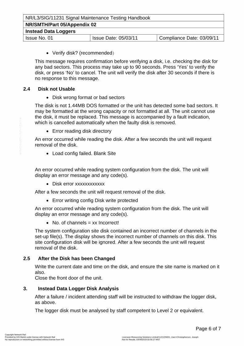
NR/L3/SIG/11231 Signal Maintenance Testing Handbook NR/SMTH/Part 05/Appendix 02 Instead Data Loggers Issue No. 01 Issue Date: 05/03/11 Compliance Date: 03/09/11
Page 6 of 7
Verify disk? (recommended)
This message requires confirmation before verifying a disk, i.e. checking the disk for any bad sectors. This process may take up to 90 seconds. Press ‘Yes’ to verify the disk, or press ‘No’ to cancel. The unit will verify the disk after 30 seconds if there is no response to this message.
2.4 Disk not Usable
Disk wrong format or bad sectors
The disk is not 1.44MB DOS formatted or the unit has detected some bad sectors. It may be formatted at the wrong capacity or not formatted at all. The unit cannot use the disk, it must be replaced. This message is accompanied by a fault indication, which is cancelled automatically when the faulty disk is removed.
Error reading disk directory
An error occurred while reading the disk. After a few seconds the unit will request removal of the disk.
Load config failed. Blank Site
An error occurred while reading system configuration from the disk. The unit will display an error message and any code(s).
Disk error xxxxxxxxxxxx
After a few seconds the unit will request removal of the disk.
Error writing config Disk write protected
An error occurred while reading system configuration from the disk. The unit will display an error message and any code(s).
No. of channels = xx Incorrect!
The system configuration site disk contained an incorrect number of channels in the set-up file(s). The display shows the incorrect number of channels on this disk. This site configuration disk will be ignored. After a few seconds the unit will request removal of the disk.
2.5 After the Disk has been Changed
Write the current date and time on the disk, and ensure the site name is marked on it also. Close the front door of the unit.
3. Instead Data Logger Disk Analysis
After a failure / incident attending staff will be instructed to withdraw the logger disk, as above.
The logger disk must be analysed by staff competent to Level 2 or equivalent.
Copyright Network Rail Provided by IHS Markit under license with Network Rail Licensee=Resourcing Solutions Limited /1121226001, User=Christopherson, Joseph
Not for Resale, 03/09/2018 03:56:27 MSTNo reproduction or networking permitted without license from IHS
--``,,``,`,,`,```,,``,,````,,,`,-`-`,,`,,`,`,,`---
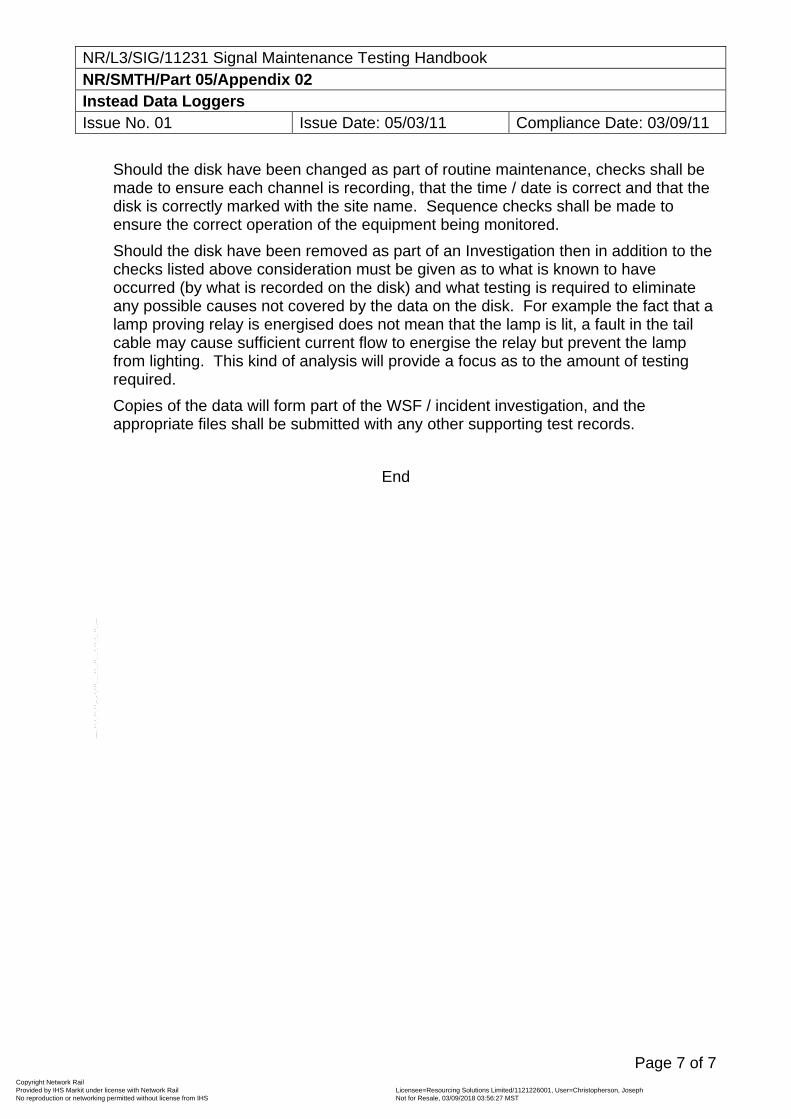
NR/L3/SIG/11231 Signal Maintenance Testing Handbook NR/SMTH/Part 05/Appendix 02 Instead Data Loggers Issue No. 01 Issue Date: 05/03/11 Compliance Date: 03/09/11
Page 7 of 7
Should the disk have been changed as part of routine maintenance, checks shall be made to ensure each channel is recording, that the time / date is correct and that the disk is correctly marked with the site name. Sequence checks shall be made to ensure the correct operation of the equipment being monitored.
Should the disk have been removed as part of an Investigation then in addition to the checks listed above consideration must be given as to what is known to have occurred (by what is recorded on the disk) and what testing is required to eliminate any possible causes not covered by the data on the disk. For example the fact that a lamp proving relay is energised does not mean that the lamp is lit, a fault in the tail cable may cause sufficient current flow to energise the relay but prevent the lamp from lighting. This kind of analysis will provide a focus as to the amount of testing required.
Copies of the data will form part of the WSF / incident investigation, and the appropriate files shall be submitted with any other supporting test records.
End
Copyright Network Rail Provided by IHS Markit under license with Network Rail Licensee=Resourcing Solutions Limited /1121226001, User=Christopherson, Joseph
Not for Resale, 03/09/2018 03:56:27 MSTNo reproduction or networking permitted without license from IHS
--``,,``,`,,`,```,,``,,````,,,`,-`-`,,`,,`,`,,`---
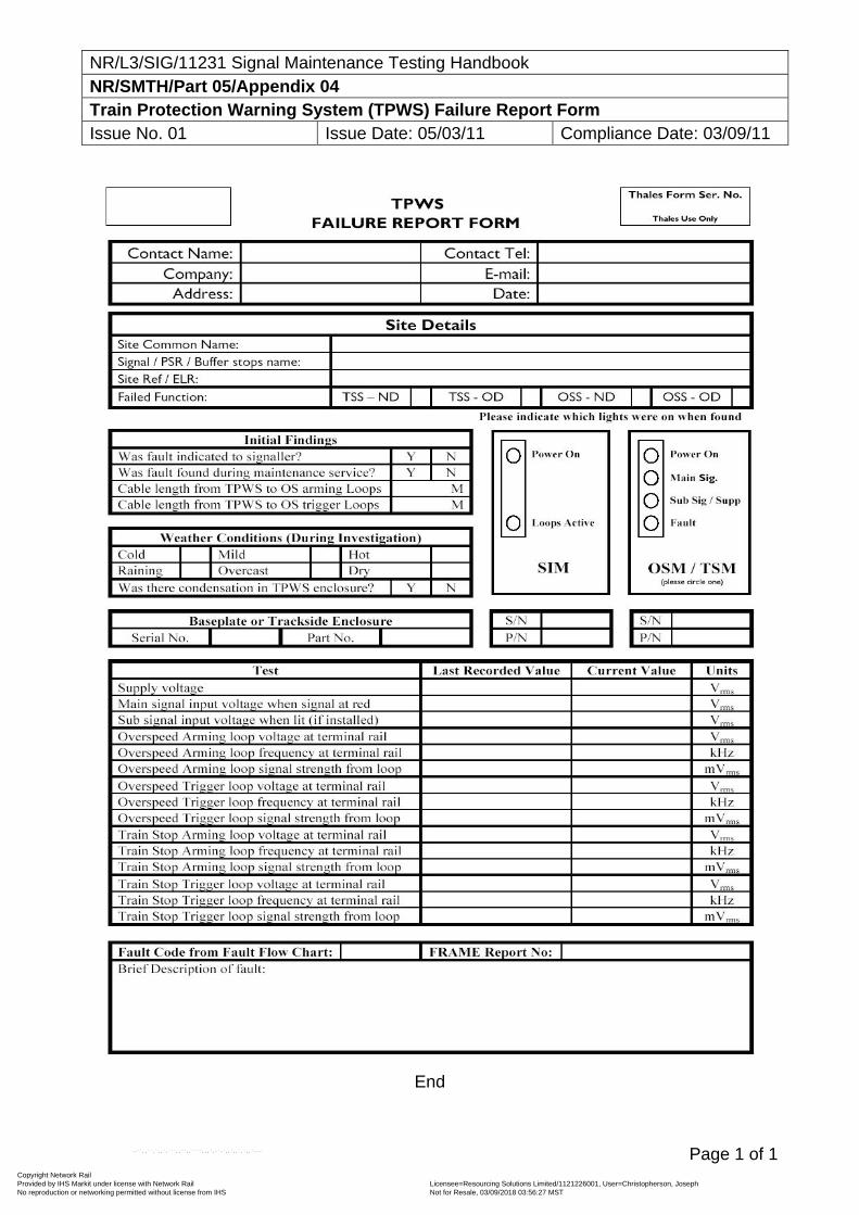
NR/L3/SIG/11231 Signal Maintenance Testing Handbook NR/SMTH/Part 05/Appendix 04 Train Protection Warning System (TPWS) Failure Report Form Issue No. 01 Issue Date: 05/03/11 Compliance Date: 03/09/11
Page 1 of 1
End
Copyright Network Rail Provided by IHS Markit under license with Network Rail Licensee=Resourcing Solutions Limited /1121226001, User=Christopherson, Joseph
Not for Resale, 03/09/2018 03:56:27 MSTNo reproduction or networking permitted without license from IHS
--``,,``,`,,`,```,,``,,````,,,`,-`-`,,`,,`,`,,`---
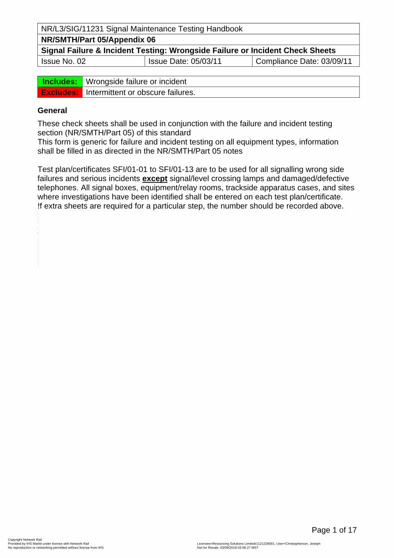
NR/L3/SIG/11231 Signal Maintenance Testing Handbook NR/SMTH/Part 05/Appendix 06 Signal Failure & Incident Testing: Wrongside Failure or Incident Check Sheets Issue No. 02 Issue Date: 05/03/11 Compliance Date: 03/09/11
Page 1 of 17
Includes: Wrongside failure or incident Excludes: Intermittent or obscure failures.
General
These check sheets shall be used in conjunction with the failure and incident testing section (NR/SMTH/Part 05) of this standard This form is generic for failure and incident testing on all equipment types, information shall be filled in as directed in the NR/SMTH/Part 05 notes Test plan/certificates SFI/01-01 to SFI/01-13 are to be used for all signalling wrong side failures and serious incidents except signal/level crossing lamps and damaged/defective telephones. All signal boxes, equipment/relay rooms, trackside apparatus cases, and sites where investigations have been identified shall be entered on each test plan/certificate. If extra sheets are required for a particular step, the number should be recorded above.
Copyright Network Rail Provided by IHS Markit under license with Network Rail Licensee=Resourcing Solutions Limited /1121226001, User=Christopherson, Joseph
Not for Resale, 03/09/2018 03:56:27 MSTNo reproduction or networking permitted without license from IHS
--``,,``,`,,`,```,,``,,````,,,`,-`-`,,`,,`,`,,`---
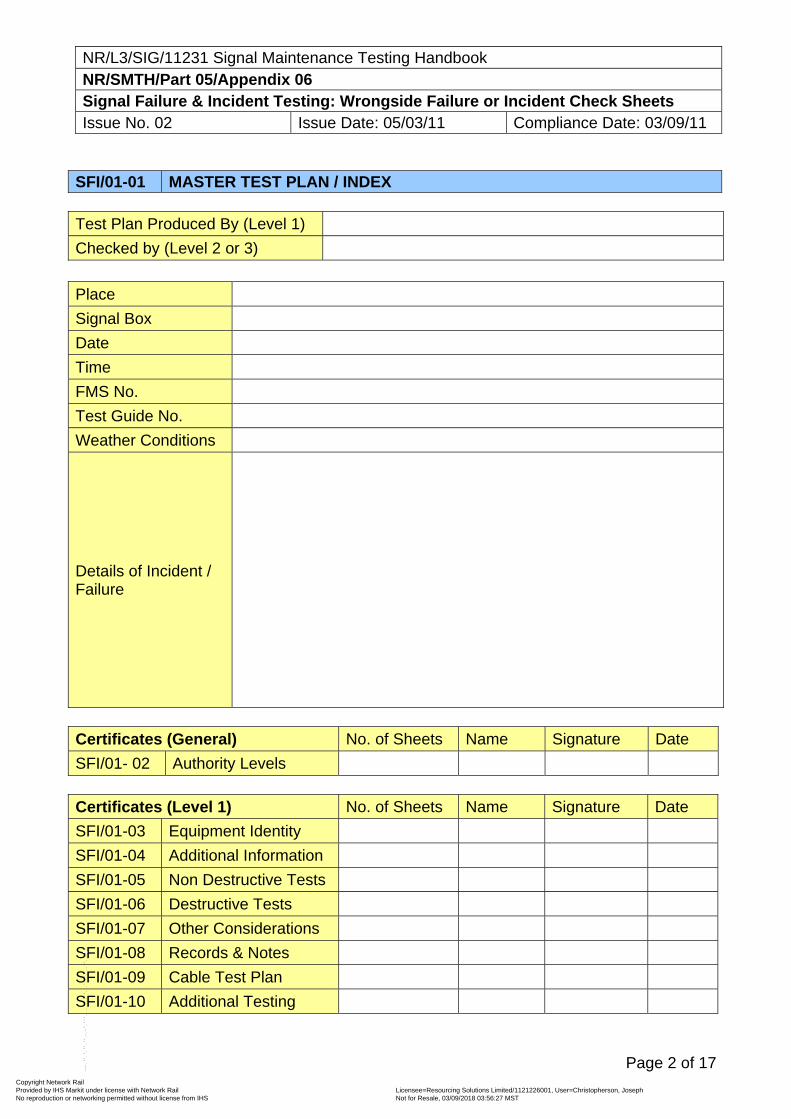
NR/L3/SIG/11231 Signal Maintenance Testing Handbook NR/SMTH/Part 05/Appendix 06 Signal Failure & Incident Testing: Wrongside Failure or Incident Check Sheets Issue No. 02 Issue Date: 05/03/11 Compliance Date: 03/09/11
Page 2 of 17
SFI/01-01 MASTER TEST PLAN / INDEX Test Plan Produced By (Level 1)
Checked by (Level 2 or 3)
Place
Signal Box
Date
Time
FMS No.
Test Guide No.
Weather Conditions
Details of Incident / Failure
Certificates (General) No. of Sheets Name Signature Date
SFI/01- 02 Authority Levels Certificates (Level 1) No. of Sheets Name Signature Date
SFI/01-03 Equipment Identity
SFI/01-04 Additional Information
SFI/01-05 Non Destructive Tests
SFI/01-06 Destructive Tests
SFI/01-07 Other Considerations
SFI/01-08 Records & Notes
SFI/01-09 Cable Test Plan
SFI/01-10 Additional Testing
Copyright Network Rail Provided by IHS Markit under license with Network Rail Licensee=Resourcing Solutions Limited /1121226001, User=Christopherson, Joseph
Not for Resale, 03/09/2018 03:56:27 MSTNo reproduction or networking permitted without license from IHS
--``,,``,`,,`,```,,``,,````,,,`,-`-`,,`,,`,`,,`---
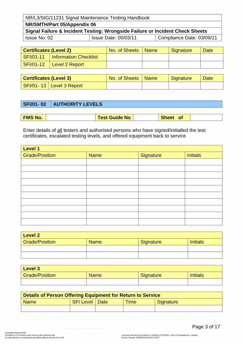
NR/L3/SIG/11231 Signal Maintenance Testing Handbook NR/SMTH/Part 05/Appendix 06 Signal Failure & Incident Testing: Wrongside Failure or Incident Check Sheets Issue No. 02 Issue Date: 05/03/11 Compliance Date: 03/09/11
Page 3 of 17
Certificates (Level 2) No. of Sheets Name Signature Date SFI/01-11 Information Checklist
SFI/01-12 Level 2 Report Certificates (Level 3) No. of Sheets Name Signature Date
SFI/01- 13 Level 3 Report SFI/01- 02 AUTHORITY LEVELS FMS No. Test Guide No Sheet of Enter details of all testers and authorised persons who have signed/initialled the test certificates, escalated testing levels, and offered equipment back to service Level 1 Grade/Position Name Signature Initials Level 2 Grade/Position Name Signature Initials Level 3 Grade/Position Name Signature Initials Details of Person Offering Equipment for Return to Service Name SFI Level Date Time Signature
Copyright Network Rail Provided by IHS Markit under license with Network Rail Licensee=Resourcing Solutions Limited /1121226001, User=Christopherson, Joseph
Not for Resale, 03/09/2018 03:56:27 MSTNo reproduction or networking permitted without license from IHS
--``,,``,`,,`,```,,``,,````,,,`,-`-`,,`,,`,`,,`---
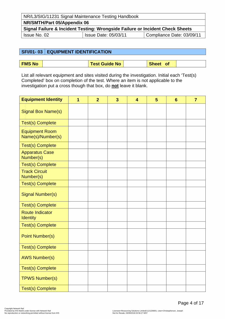
NR/L3/SIG/11231 Signal Maintenance Testing Handbook NR/SMTH/Part 05/Appendix 06 Signal Failure & Incident Testing: Wrongside Failure or Incident Check Sheets Issue No. 02 Issue Date: 05/03/11 Compliance Date: 03/09/11
Page 4 of 17
SFI/01- 03 EQUIPMENT IDENTIFICATION FMS No Test Guide No Sheet of List all relevant equipment and sites visited during the investigation. Initial each ‘Test(s) Completed’ box on completion of the test. Where an item is not applicable to the investigation put a cross though that box, do not leave it blank.
Equipment Identity 1 2 3 4 5 6 7
Signal Box Name(s)
Test(s) Complete
Equipment Room Name(s)/Number(s)
Test(s) Complete
Apparatus Case Number(s)
Test(s) Complete
Track Circuit Number(s)
Test(s) Complete
Signal Number(s)
Test(s) Complete
Route Indicator Identity
Test(s) Complete
Point Number(s)
Test(s) Complete
AWS Number(s)
Test(s) Complete
TPWS Number(s)
Test(s) Complete
Copyright Network Rail Provided by IHS Markit under license with Network Rail Licensee=Resourcing Solutions Limited /1121226001, User=Christopherson, Joseph
Not for Resale, 03/09/2018 03:56:27 MSTNo reproduction or networking permitted without license from IHS
--``,,``,`,,`,```,,``,,````,,,`,-`-`,,`,,`,`,,`---
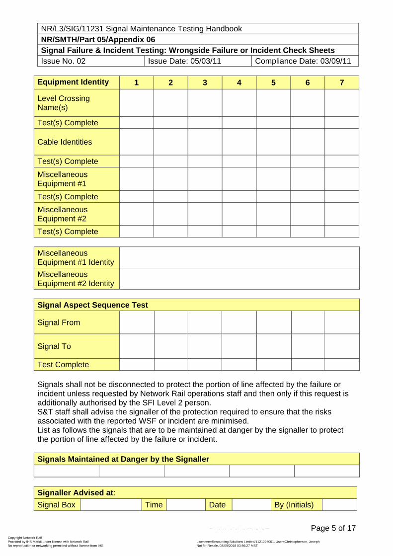
NR/L3/SIG/11231 Signal Maintenance Testing Handbook NR/SMTH/Part 05/Appendix 06 Signal Failure & Incident Testing: Wrongside Failure or Incident Check Sheets Issue No. 02 Issue Date: 05/03/11 Compliance Date: 03/09/11
Page 5 of 17
Equipment Identity 1 2 3 4 5 6 7
Level Crossing Name(s)
Test(s) Complete
Cable Identities
Test(s) Complete
Miscellaneous Equipment #1
Test(s) Complete
Miscellaneous Equipment #2
Test(s) Complete Miscellaneous Equipment #1 Identity
Miscellaneous Equipment #2 Identity
Signal Aspect Sequence Test
Signal From
Signal To
Test Complete Signals shall not be disconnected to protect the portion of line affected by the failure or incident unless requested by Network Rail operations staff and then only if this request is additionally authorised by the SFI Level 2 person. S&T staff shall advise the signaller of the protection required to ensure that the risks associated with the reported WSF or incident are minimised. List as follows the signals that are to be maintained at danger by the signaller to protect the portion of line affected by the failure or incident. Signals Maintained at Danger by the Signaller
Signaller Advised at:
Signal Box Time Date By (Initials)
Copyright Network Rail Provided by IHS Markit under license with Network Rail Licensee=Resourcing Solutions Limited /1121226001, User=Christopherson, Joseph
Not for Resale, 03/09/2018 03:56:27 MSTNo reproduction or networking permitted without license from IHS
--``,,``,`,,`,```,,``,,````,,,`,-`-`,,`,,`,`,,`---
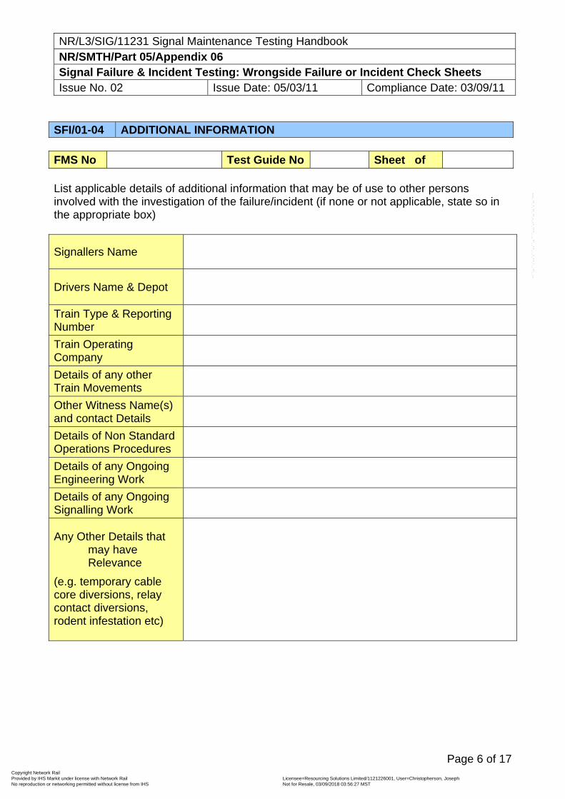
NR/L3/SIG/11231 Signal Maintenance Testing Handbook NR/SMTH/Part 05/Appendix 06 Signal Failure & Incident Testing: Wrongside Failure or Incident Check Sheets Issue No. 02 Issue Date: 05/03/11 Compliance Date: 03/09/11
Page 6 of 17
SFI/01-04 ADDITIONAL INFORMATION FMS No Test Guide No Sheet of List applicable details of additional information that may be of use to other persons involved with the investigation of the failure/incident (if none or not applicable, state so in the appropriate box)
Signallers Name
Drivers Name & Depot
Train Type & Reporting Number
Train Operating Company
Details of any other Train Movements
Other Witness Name(s) and contact Details
Details of Non Standard Operations Procedures
Details of any Ongoing Engineering Work
Details of any Ongoing Signalling Work
Any Other Details that may have Relevance
(e.g. temporary cable core diversions, relay contact diversions, rodent infestation etc)
Copyright Network Rail Provided by IHS Markit under license with Network Rail Licensee=Resourcing Solutions Limited /1121226001, User=Christopherson, Joseph
Not for Resale, 03/09/2018 03:56:27 MSTNo reproduction or networking permitted without license from IHS
--``,,``,`,,`,```,,``,,````,,,`,-`-`,,`,,`,`,,`---

NR/L3/SIG/11231 Signal Maintenance Testing Handbook NR/SMTH/Part 05/Appendix 06 Signal Failure & Incident Testing: Wrongside Failure or Incident Check Sheets Issue No. 02 Issue Date: 05/03/11 Compliance Date: 03/09/11
Page 7 of 17
Site Sketch
Copyright Network Rail Provided by IHS Markit under license with Network Rail Licensee=Resourcing Solutions Limited /1121226001, User=Christopherson, Joseph
Not for Resale, 03/09/2018 03:56:27 MSTNo reproduction or networking permitted without license from IHS
--``,,``,`,,`,```,,``,,````,,,`,-`-`,,`,,`,`,,`---
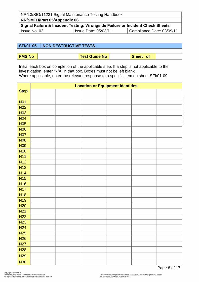
NR/L3/SIG/11231 Signal Maintenance Testing Handbook NR/SMTH/Part 05/Appendix 06 Signal Failure & Incident Testing: Wrongside Failure or Incident Check Sheets Issue No. 02 Issue Date: 05/03/11 Compliance Date: 03/09/11
Page 8 of 17
SFI/01-05 NON DESTRUCTIVE TESTS FMS No Test Guide No Sheet of Initial each box on completion of the applicable step. If a step is not applicable to the investigation, enter ‘N/A’ in that box. Boxes must not be left blank. Where applicable, enter the relevant response to a specific item on sheet SFI/01-09
Step Location or Equipment Identities
N01 N02 N03 N04 N05 N06 N07 N08 N09 N10 N11 N12 N13 N14 N15 N16 N17 N18 N19 N20 N21 N22 N23 N24 N25 N26 N27
N28
N29
N30
Copyright Network Rail Provided by IHS Markit under license with Network Rail Licensee=Resourcing Solutions Limited /1121226001, User=Christopherson, Joseph
Not for Resale, 03/09/2018 03:56:27 MSTNo reproduction or networking permitted without license from IHS
--``,,``,`,,`,```,,``,,````,,,`,-`-`,,`,,`,`,,`---
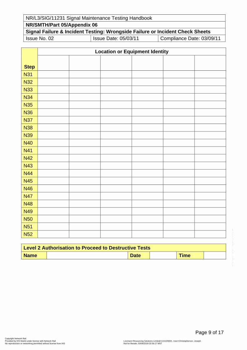
NR/L3/SIG/11231 Signal Maintenance Testing Handbook NR/SMTH/Part 05/Appendix 06 Signal Failure & Incident Testing: Wrongside Failure or Incident Check Sheets Issue No. 02 Issue Date: 05/03/11 Compliance Date: 03/09/11
Page 9 of 17
Step
Location or Equipment Identity
N31
N32
N33
N34
N35
N36
N37
N38
N39
N40
N41
N42
N43
N44
N45
N46
N47
N48
N49
N50
N51
N52 Level 2 Authorisation to Proceed to Destructive Tests
Name Date Time
Copyright Network Rail Provided by IHS Markit under license with Network Rail Licensee=Resourcing Solutions Limited /1121226001, User=Christopherson, Joseph
Not for Resale, 03/09/2018 03:56:27 MSTNo reproduction or networking permitted without license from IHS
--``,,``,`,,`,```,,``,,````,,,`,-`-`,,`,,`,`,,`---
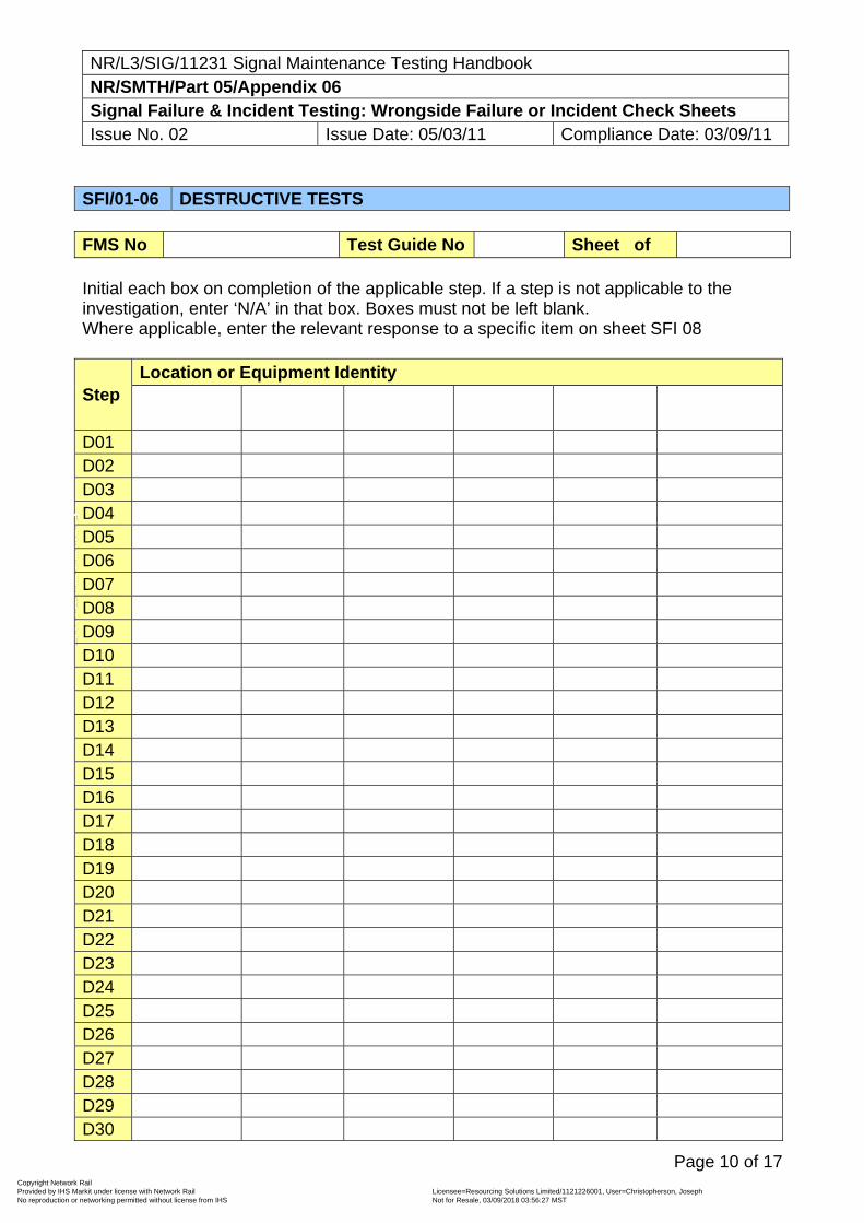
NR/L3/SIG/11231 Signal Maintenance Testing Handbook NR/SMTH/Part 05/Appendix 06 Signal Failure & Incident Testing: Wrongside Failure or Incident Check Sheets Issue No. 02 Issue Date: 05/03/11 Compliance Date: 03/09/11
Page 10 of 17
SFI/01-06 DESTRUCTIVE TESTS FMS No Test Guide No Sheet of Initial each box on completion of the applicable step. If a step is not applicable to the investigation, enter ‘N/A’ in that box. Boxes must not be left blank. Where applicable, enter the relevant response to a specific item on sheet SFI 08
Step Location or Equipment Identity
D01 D02 D03 D04 D05 D06 D07 D08 D09 D10 D11 D12 D13 D14 D15 D16 D17 D18 D19 D20 D21 D22 D23 D24 D25 D26 D27 D28 D29 D30
Copyright Network Rail Provided by IHS Markit under license with Network Rail Licensee=Resourcing Solutions Limited /1121226001, User=Christopherson, Joseph
Not for Resale, 03/09/2018 03:56:27 MSTNo reproduction or networking permitted without license from IHS
--``,,``,`,,`,```,,``,,````,,,`,-`-`,,`,,`,`,,`---
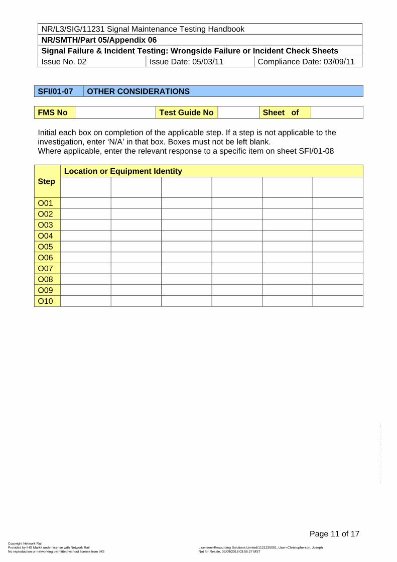
NR/L3/SIG/11231 Signal Maintenance Testing Handbook NR/SMTH/Part 05/Appendix 06 Signal Failure & Incident Testing: Wrongside Failure or Incident Check Sheets Issue No. 02 Issue Date: 05/03/11 Compliance Date: 03/09/11
Page 11 of 17
SFI/01-07 OTHER CONSIDERATIONS FMS No Test Guide No Sheet of Initial each box on completion of the applicable step. If a step is not applicable to the investigation, enter ‘N/A’ in that box. Boxes must not be left blank. Where applicable, enter the relevant response to a specific item on sheet SFI/01-08
Step Location or Equipment Identity
O01 O02 O03 O04 O05 O06 O07 O08 O09 O10
Copyright Network Rail Provided by IHS Markit under license with Network Rail Licensee=Resourcing Solutions Limited /1121226001, User=Christopherson, Joseph
Not for Resale, 03/09/2018 03:56:27 MSTNo reproduction or networking permitted without license from IHS
--``,,``,`,,`,```,,``,,````,,,`,-`-`,,`,,`,`,,`---
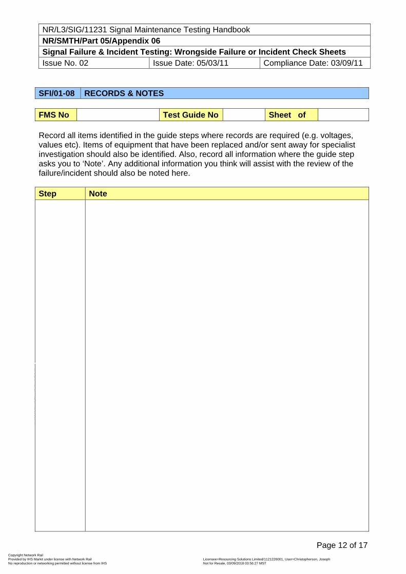
NR/L3/SIG/11231 Signal Maintenance Testing Handbook NR/SMTH/Part 05/Appendix 06 Signal Failure & Incident Testing: Wrongside Failure or Incident Check Sheets Issue No. 02 Issue Date: 05/03/11 Compliance Date: 03/09/11
Page 12 of 17
SFI/01-08 RECORDS & NOTES FMS No Test Guide No Sheet of Record all items identified in the guide steps where records are required (e.g. voltages, values etc). Items of equipment that have been replaced and/or sent away for specialist investigation should also be identified. Also, record all information where the guide step asks you to ‘Note’. Any additional information you think will assist with the review of the failure/incident should also be noted here. Step Note
Copyright Network Rail Provided by IHS Markit under license with Network Rail Licensee=Resourcing Solutions Limited /1121226001, User=Christopherson, Joseph
Not for Resale, 03/09/2018 03:56:27 MSTNo reproduction or networking permitted without license from IHS
--``,,``,`,,`,```,,``,,````,,,`,-`-`,,`,,`,`,,`---
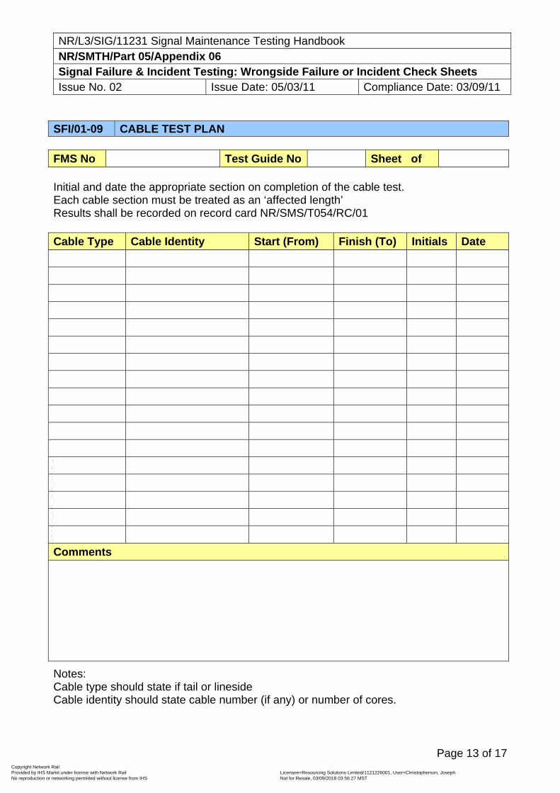
NR/L3/SIG/11231 Signal Maintenance Testing Handbook NR/SMTH/Part 05/Appendix 06 Signal Failure & Incident Testing: Wrongside Failure or Incident Check Sheets Issue No. 02 Issue Date: 05/03/11 Compliance Date: 03/09/11
Page 13 of 17
SFI/01-09 CABLE TEST PLAN FMS No Test Guide No Sheet of Initial and date the appropriate section on completion of the cable test. Each cable section must be treated as an ‘affected length’ Results shall be recorded on record card NR/SMS/T054/RC/01 Cable Type Cable Identity Start (From) Finish (To) Initials Date
Comments
Notes: Cable type should state if tail or lineside Cable identity should state cable number (if any) or number of cores.
Copyright Network Rail Provided by IHS Markit under license with Network Rail Licensee=Resourcing Solutions Limited /1121226001, User=Christopherson, Joseph
Not for Resale, 03/09/2018 03:56:27 MSTNo reproduction or networking permitted without license from IHS
--``,,``,`,,`,```,,``,,````,,,`,-`-`,,`,,`,`,,`---
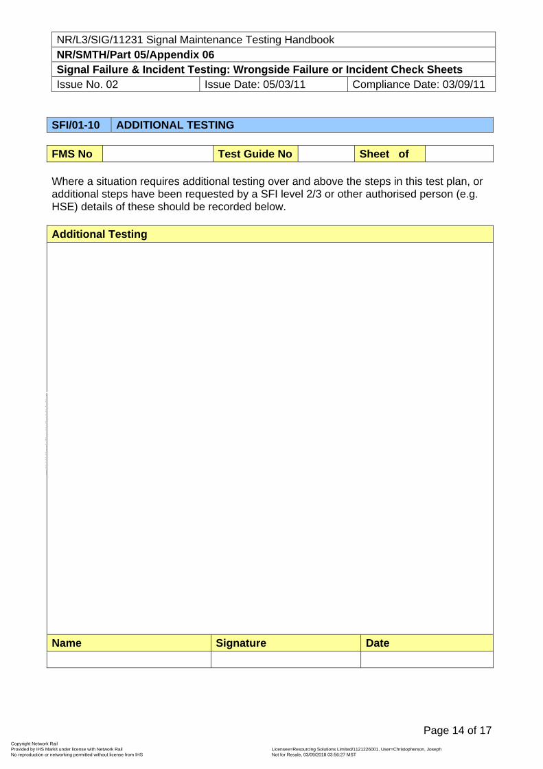
NR/L3/SIG/11231 Signal Maintenance Testing Handbook NR/SMTH/Part 05/Appendix 06 Signal Failure & Incident Testing: Wrongside Failure or Incident Check Sheets Issue No. 02 Issue Date: 05/03/11 Compliance Date: 03/09/11
Page 14 of 17
SFI/01-10 ADDITIONAL TESTING FMS No Test Guide No Sheet of Where a situation requires additional testing over and above the steps in this test plan, or additional steps have been requested by a SFI level 2/3 or other authorised person (e.g. HSE) details of these should be recorded below. Additional Testing
Name Signature Date
Copyright Network Rail Provided by IHS Markit under license with Network Rail Licensee=Resourcing Solutions Limited /1121226001, User=Christopherson, Joseph
Not for Resale, 03/09/2018 03:56:27 MSTNo reproduction or networking permitted without license from IHS
--``,,``,`,,`,```,,``,,````,,,`,-`-`,,`,,`,`,,`---
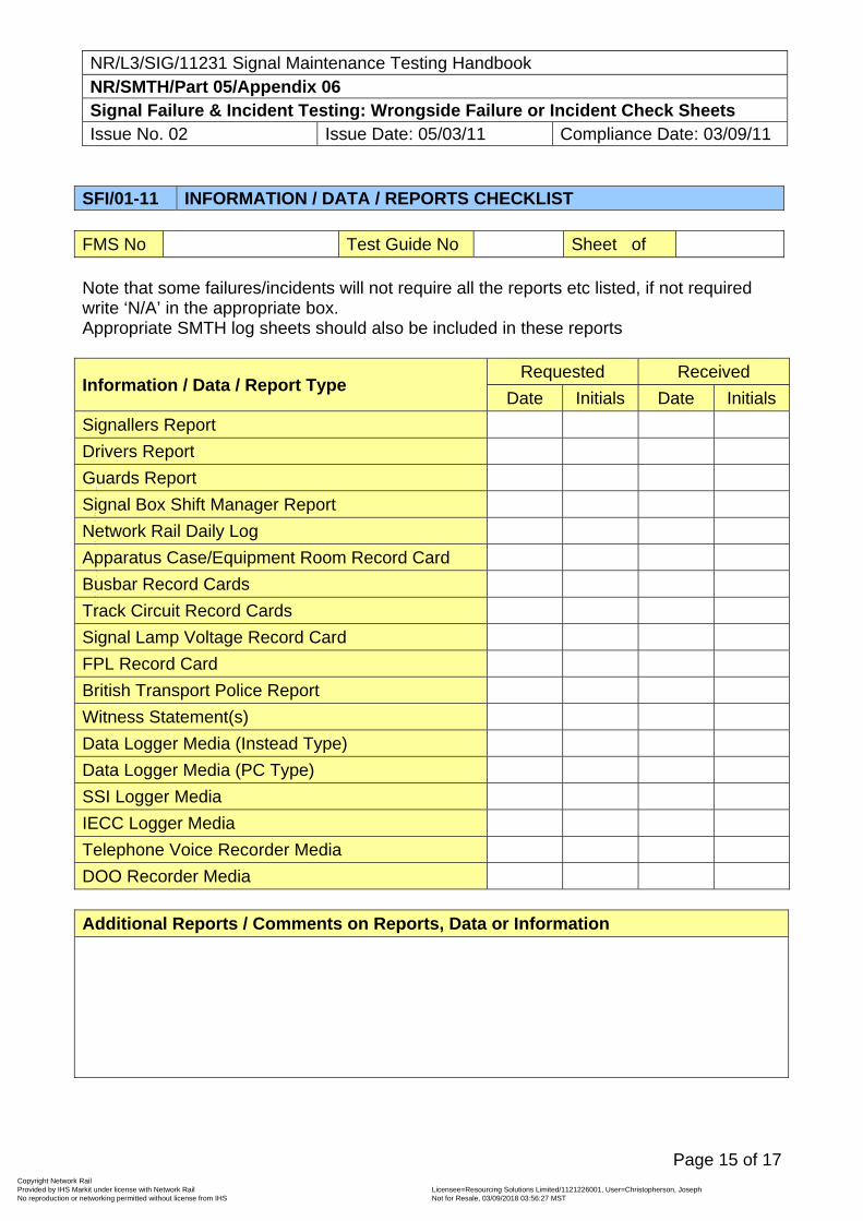
NR/L3/SIG/11231 Signal Maintenance Testing Handbook NR/SMTH/Part 05/Appendix 06 Signal Failure & Incident Testing: Wrongside Failure or Incident Check Sheets Issue No. 02 Issue Date: 05/03/11 Compliance Date: 03/09/11
Page 15 of 17
SFI/01-11 INFORMATION / DATA / REPORTS CHECKLIST FMS No Test Guide No Sheet of Note that some failures/incidents will not require all the reports etc listed, if not required write ‘N/A’ in the appropriate box. Appropriate SMTH log sheets should also be included in these reports
Information / Data / Report Type Requested Received
Date Initials Date Initials
Signallers Report
Drivers Report
Guards Report
Signal Box Shift Manager Report
Network Rail Daily Log
Apparatus Case/Equipment Room Record Card
Busbar Record Cards
Track Circuit Record Cards
Signal Lamp Voltage Record Card
FPL Record Card
British Transport Police Report
Witness Statement(s)
Data Logger Media (Instead Type)
Data Logger Media (PC Type)
SSI Logger Media
IECC Logger Media
Telephone Voice Recorder Media
DOO Recorder Media Additional Reports / Comments on Reports, Data or Information
Copyright Network Rail Provided by IHS Markit under license with Network Rail Licensee=Resourcing Solutions Limited /1121226001, User=Christopherson, Joseph
Not for Resale, 03/09/2018 03:56:27 MSTNo reproduction or networking permitted without license from IHS
--``,,``,`,,`,```,,``,,````,,,`,-`-`,,`,,`,`,,`---
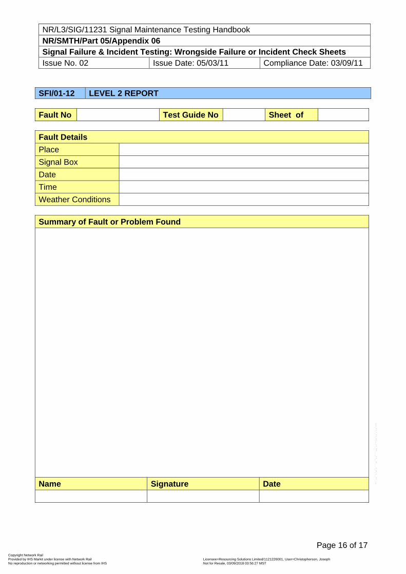
NR/L3/SIG/11231 Signal Maintenance Testing Handbook NR/SMTH/Part 05/Appendix 06 Signal Failure & Incident Testing: Wrongside Failure or Incident Check Sheets Issue No. 02 Issue Date: 05/03/11 Compliance Date: 03/09/11
Page 16 of 17
SFI/01-12 LEVEL 2 REPORT Fault No Test Guide No Sheet of Fault Details
Place
Signal Box
Date
Time
Weather Conditions Summary of Fault or Problem Found
Name Signature Date
Copyright Network Rail Provided by IHS Markit under license with Network Rail Licensee=Resourcing Solutions Limited /1121226001, User=Christopherson, Joseph
Not for Resale, 03/09/2018 03:56:27 MSTNo reproduction or networking permitted without license from IHS
--``,,``,`,,`,```,,``,,````,,,`,-`-`,,`,,`,`,,`---
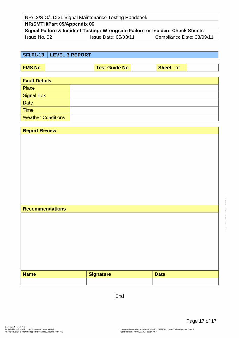
NR/L3/SIG/11231 Signal Maintenance Testing Handbook NR/SMTH/Part 05/Appendix 06 Signal Failure & Incident Testing: Wrongside Failure or Incident Check Sheets Issue No. 02 Issue Date: 05/03/11 Compliance Date: 03/09/11
Page 17 of 17
SFI/01-13 LEVEL 3 REPORT FMS No Test Guide No Sheet of Fault Details
Place
Signal Box
Date
Time
Weather Conditions Report Review
Recommendations
Name Signature Date
End
Copyright Network Rail Provided by IHS Markit under license with Network Rail Licensee=Resourcing Solutions Limited /1121226001, User=Christopherson, Joseph
Not for Resale, 03/09/2018 03:56:27 MSTNo reproduction or networking permitted without license from IHS
--``,,``,`,,`,```,,``,,````,,,`,-`-`,,`,,`,`,,`---
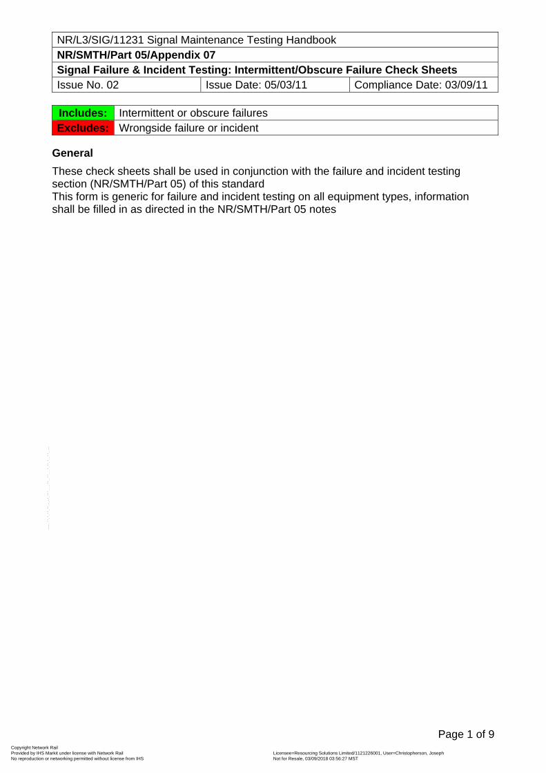
NR/L3/SIG/11231 Signal Maintenance Testing Handbook NR/SMTH/Part 05/Appendix 07 Signal Failure & Incident Testing: Intermittent/Obscure Failure Check Sheets Issue No. 02 Issue Date: 05/03/11 Compliance Date: 03/09/11
Page 1 of 9
Includes: Intermittent or obscure failures Excludes: Wrongside failure or incident
General
These check sheets shall be used in conjunction with the failure and incident testing section (NR/SMTH/Part 05) of this standard This form is generic for failure and incident testing on all equipment types, information shall be filled in as directed in the NR/SMTH/Part 05 notes
Copyright Network Rail Provided by IHS Markit under license with Network Rail Licensee=Resourcing Solutions Limited /1121226001, User=Christopherson, Joseph
Not for Resale, 03/09/2018 03:56:27 MSTNo reproduction or networking permitted without license from IHS
--``,,``,`,,`,```,,``,,````,,,`,-`-`,,`,,`,`,,`---
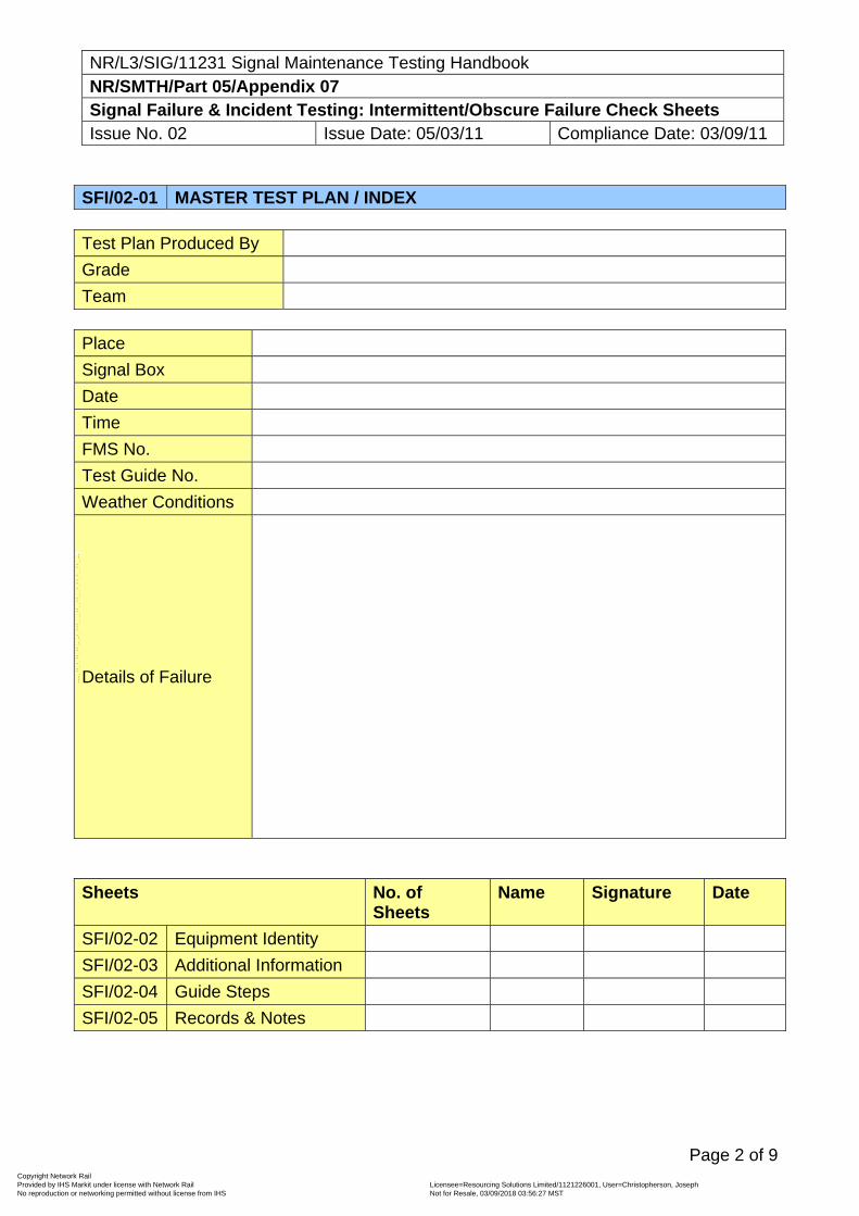
NR/L3/SIG/11231 Signal Maintenance Testing Handbook NR/SMTH/Part 05/Appendix 07 Signal Failure & Incident Testing: Intermittent/Obscure Failure Check Sheets Issue No. 02 Issue Date: 05/03/11 Compliance Date: 03/09/11
Page 2 of 9
SFI/02-01 MASTER TEST PLAN / INDEX Test Plan Produced By
Grade
Team Place
Signal Box
Date
Time
FMS No.
Test Guide No.
Weather Conditions
Details of Failure
Sheets No. of
Sheets Name Signature Date
SFI/02-02 Equipment Identity
SFI/02-03 Additional Information
SFI/02-04 Guide Steps
SFI/02-05 Records & Notes
Copyright Network Rail Provided by IHS Markit under license with Network Rail Licensee=Resourcing Solutions Limited /1121226001, User=Christopherson, Joseph
Not for Resale, 03/09/2018 03:56:27 MSTNo reproduction or networking permitted without license from IHS
--``,,``,`,,`,```,,``,,````,,,`,-`-`,,`,,`,`,,`---
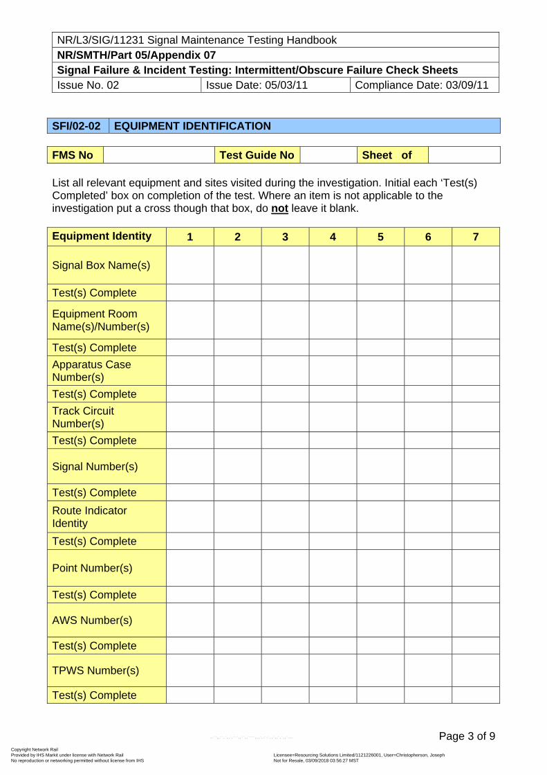
NR/L3/SIG/11231 Signal Maintenance Testing Handbook NR/SMTH/Part 05/Appendix 07 Signal Failure & Incident Testing: Intermittent/Obscure Failure Check Sheets Issue No. 02 Issue Date: 05/03/11 Compliance Date: 03/09/11
Page 3 of 9
SFI/02-02 EQUIPMENT IDENTIFICATION FMS No Test Guide No Sheet of List all relevant equipment and sites visited during the investigation. Initial each ‘Test(s) Completed’ box on completion of the test. Where an item is not applicable to the investigation put a cross though that box, do not leave it blank. Equipment Identity 1 2 3 4 5 6 7
Signal Box Name(s)
Test(s) Complete
Equipment Room Name(s)/Number(s)
Test(s) Complete
Apparatus Case Number(s)
Test(s) Complete
Track Circuit Number(s)
Test(s) Complete
Signal Number(s)
Test(s) Complete
Route Indicator Identity
Test(s) Complete
Point Number(s)
Test(s) Complete
AWS Number(s)
Test(s) Complete
TPWS Number(s)
Test(s) Complete
Copyright Network Rail Provided by IHS Markit under license with Network Rail Licensee=Resourcing Solutions Limited /1121226001, User=Christopherson, Joseph
Not for Resale, 03/09/2018 03:56:27 MSTNo reproduction or networking permitted without license from IHS
--``,,``,`,,`,```,,``,,````,,,`,-`-`,,`,,`,`,,`---
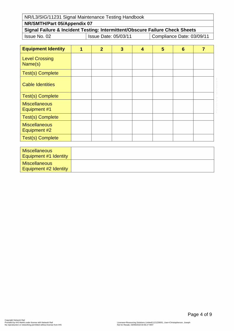
NR/L3/SIG/11231 Signal Maintenance Testing Handbook NR/SMTH/Part 05/Appendix 07 Signal Failure & Incident Testing: Intermittent/Obscure Failure Check Sheets Issue No. 02 Issue Date: 05/03/11 Compliance Date: 03/09/11
Page 4 of 9
Equipment Identity 1 2 3 4 5 6 7
Level Crossing Name(s)
Test(s) Complete
Cable Identities
Test(s) Complete
Miscellaneous Equipment #1
Test(s) Complete
Miscellaneous Equipment #2
Test(s) Complete Miscellaneous Equipment #1 Identity
Miscellaneous Equipment #2 Identity
Copyright Network Rail Provided by IHS Markit under license with Network Rail Licensee=Resourcing Solutions Limited /1121226001, User=Christopherson, Joseph
Not for Resale, 03/09/2018 03:56:27 MSTNo reproduction or networking permitted without license from IHS
--``,,``,`,,`,```,,``,,````,,,`,-`-`,,`,,`,`,,`---
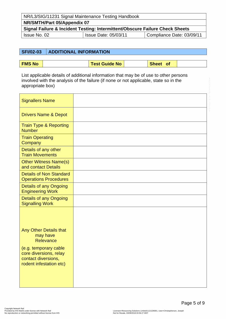
NR/L3/SIG/11231 Signal Maintenance Testing Handbook NR/SMTH/Part 05/Appendix 07 Signal Failure & Incident Testing: Intermittent/Obscure Failure Check Sheets Issue No. 02 Issue Date: 05/03/11 Compliance Date: 03/09/11
Page 5 of 9
SFI/02-03 ADDITIONAL INFORMATION FMS No Test Guide No Sheet of List applicable details of additional information that may be of use to other persons involved with the analysis of the failure (if none or not applicable, state so in the appropriate box)
Signallers Name
Drivers Name & Depot
Train Type & Reporting Number
Train Operating Company
Details of any other Train Movements
Other Witness Name(s) and contact Details
Details of Non Standard Operations Procedures
Details of any Ongoing Engineering Work
Details of any Ongoing Signalling Work
Any Other Details that may have Relevance
(e.g. temporary cable core diversions, relay contact diversions, rodent infestation etc)
Copyright Network Rail Provided by IHS Markit under license with Network Rail Licensee=Resourcing Solutions Limited /1121226001, User=Christopherson, Joseph
Not for Resale, 03/09/2018 03:56:27 MSTNo reproduction or networking permitted without license from IHS
--``,,``,`,,`,```,,``,,````,,,`,-`-`,,`,,`,`,,`---
NR/L3/SIG/11231 Signal Maintenance Testing Handbook NR/SMTH/Part 05/Appendix 07 Signal Failure & Incident Testing: Intermittent/Obscure Failure Check Sheets Issue No. 02 Issue Date: 05/03/11 Compliance Date: 03/09/11
Page 6 of 9
Site Sketch
Copyright Network Rail Provided by IHS Markit under license with Network Rail Licensee=Resourcing Solutions Limited /1121226001, User=Christopherson, Joseph
Not for Resale, 03/09/2018 03:56:27 MSTNo reproduction or networking permitted without license from IHS
--``,,``,`,,`,```,,``,,````,,,`,-`-`,,`,,`,`,,`---
NR/L3/SIG/11231 Signal Maintenance Testing Handbook NR/SMTH/Part 05/Appendix 07 Signal Failure & Incident Testing: Intermittent/Obscure Failure Check Sheets Issue No. 02 Issue Date: 05/03/11 Compliance Date: 03/09/11
Page 7 of 9
SFI/02-04 GUIDE STEPS FMS No Test Guide No Sheet of Initial each box on completion of the applicable step. If a step is not applicable to the investigation, enter ‘N/A’ in that box. Boxes must not be left blank. Where applicable, enter the relevant response to a specific item on sheet SFI/02-05
Step Location or Equipment Identity
01 02 03 04 05 06 07 08 09 10 11 12 13 14 15 16 17 18 19 20 21 22 23 24 25 26 27 28 29
Copyright Network Rail Provided by IHS Markit under license with Network Rail Licensee=Resourcing Solutions Limited /1121226001, User=Christopherson, Joseph
Not for Resale, 03/09/2018 03:56:27 MSTNo reproduction or networking permitted without license from IHS
--``,,``,`,,`,```,,``,,````,,,`,-`-`,,`,,`,`,,`---
NR/L3/SIG/11231 Signal Maintenance Testing Handbook NR/SMTH/Part 05/Appendix 07 Signal Failure & Incident Testing: Intermittent/Obscure Failure Check Sheets Issue No. 02 Issue Date: 05/03/11 Compliance Date: 03/09/11
Page 8 of 9
Step
Location or Equipment Identity
30
31
32
33
34
35
36
37
38
39
40
41
42
43
44
45
46
47
48
49
50
51
52
53
54
55
56
57
58
59
60
61
Copyright Network Rail Provided by IHS Markit under license with Network Rail Licensee=Resourcing Solutions Limited /1121226001, User=Christopherson, Joseph
Not for Resale, 03/09/2018 03:56:27 MSTNo reproduction or networking permitted without license from IHS
--``,,``,`,,`,```,,``,,````,,,`,-`-`,,`,,`,`,,`---
NR/L3/SIG/11231 Signal Maintenance Testing Handbook NR/SMTH/Part 05/Appendix 07 Signal Failure & Incident Testing: Intermittent/Obscure Failure Check Sheets Issue No. 02 Issue Date: 05/03/11 Compliance Date: 03/09/11
Page 9 of 9
62
63
64
65
66
67
68
69 SFI/02-05 RECORDS & NOTES FMS No Test Guide No Sheet of Record all items identified in the guide steps where records are required (e.g. voltages, values etc). Items of equipment that have been replaced and/or sent away for specialist investigation should also be identified. Also, record all information where the guide step asks you to ‘Note’. Any additional information you think will assist with the review of the failure/incident should also be noted here. Step Note
End
Copyright Network Rail Provided by IHS Markit under license with Network Rail Licensee=Resourcing Solutions Limited /1121226001, User=Christopherson, Joseph
Not for Resale, 03/09/2018 03:56:27 MSTNo reproduction or networking permitted without license from IHS
--``,,``,`,,`,```,,``,,````,,,`,-`-`,,`,,`,`,,`---