Embed Size (px)
Citation preview
Form Methods Syst DesDOI 10.1007/s10703-017-0281-z
Efficient verification of railway infrastructure designsagainst standard regulations
Bjørnar Luteberget1,2 · Christian Johansen2
© The Author(s) 2017. This article is an open access publication
Abstract In designing safety-critical infrastructures s.a. railway systems, engineers oftenhave to deal with complex and large-scale designs. Formal methods can play an importantrole in helping automate various tasks. For railway designs formal methods have mainly beenused to verify the safety of so-called interlockings through model checking, which deals withstate change and rather complex properties, usually incurring considerable computationalburden (e.g., the state-space explosion problem). In contrast, we focus on static infrastruc-ture models, and are interested in checking requirements coming from design guidelines andregulations, as usually given by railway authorities or safety certification bodies. Our goal isto automate the tedious manual work that railway engineers do when ensuring compliancewith regulations, through using software that is fast enough to do verification on-the-fly, thusbeing able to be included in the railway design tools, much like a compiler in an IDE. Inconsequence, this paper describes the integration into the railway design process of formalmethods for automatically extracting railway models from the CAD railway designs and fordescribing relevant technical regulations and expert knowledge as properties to be checkedon the models. We employ a variant of Datalog and use the standardized “railway markuplanguage” railML as basis and exchange format for the formalization. We developed a pro-totype tool and integrated it in industrial railway CAD software, developed under the nameRailCOMPLETE�. This on-the-fly verification tool is a help for the engineer while doingthe designs, and is not a replacement to other more heavy-weight software like for doinginterlocking verification or capacity analysis. Our tool, through the export into railML, can
This work was partially supported by the RailComplete AS company and the project RailCons funded by theNorwegian Research Council.
B Bjørnar [email protected]
Christian [email protected]
1 RailComplete AS (formerly Anacon AS), Sandvika, Norway
2 Department of Informatics, University of Oslo, Oslo, Norway
123
Form Methods Syst Des
be easily integrated with these other tools. We apply our tool chain in a Norwegian railwayproject, the upgrade of the Arna railway station.
Keywords Railway designs · Automation · Logic programming · Signalling · Railwayinfrastructure · railML · CAD · Datalog · Incremental verification
1 Introduction
Railway construction projects are heavy processes that integrate various fields, engineeringdisciplines, different companies, stakeholders, and regulatory bodies. When working outrailway designs a large part of the work is repetitive, involving routine checking of consis-tency with regulations, writing tables, and coordinating disciplines. Many of these manualchecks are simple enough to be automated. The repetition comes from the fact that evensmall changes in station layout and interlocking may require thorough (re-)investigation toprove that the designs remain internally consistent and still adhere to the rules and reg-ulations of the national (and international) rail administration agencies. Automating thesetypes of checks can eliminate a lot of the busywork required to make and change railwaydesigns, and helps with the cross-discipline coordination by allowing engineers from onediscipline to check that they are not violating other disciplines’ regulations when makingtheir changes.
With the purpose of increasing the degree of automation, we present results on integratingformal methods into the railway design process by the following means:
– Formalizing rules governing track and signalling layout, and interlocking.– Using the standardized “railway markup language” railML1 as representation basis and
exchange format for the formalization.– Modeling the concepts that describe a railwaydesign in the declarative logic programming
language Datalog; and using an appropriate off-the-shelve inference engine.– Developing an automated generation of the formalmodel from the railML representation.– Developing a prototype tool and integrating it in existing railway CAD software.
We illustrate the logical representation of signalling principles and show how they can beimplemented and solved efficiently using the Datalog style of logic programming [53].We also show the integration with existing railway engineering workflow by using CADmodels directly. This enables us to verify compliance with regulations continuously as thedesign process changes the station layout and interlocking. Based on railML [40] as inter-mediary language, our results can be easily adopted by anyone who uses this internationalstandard.
The approach presented in this paper could be applied also to other engineering disciplines,such as catenary power lines, track works, and others, which have similar design regulationsand often make use of a similar CAD environment. However, this paper uses the signallingand interlocking design process and shows how it can be improved by automation usingformal methods.
The work uses as case study the software and the design used in the Arna-Fløen upgradeproject,2 a major infrastructure activity of the Norwegian railway system, with plannedcompletion in 2020. The Arna train station is located on Northern Europe’s busiest single-track connection (between Arna and Bergen), which is being extended to a double-track
1 railML.org: https://www.railml.org/.2 http://www.jernbaneverket.no/Prosjekter/prosjekter/Arna---Bergen.
123
Form Methods Syst Des
connection. Thus, the train station is currently undergoing an extensive overhaul, includingsignificant new tunnel constructions and specifically a replacement of the entire signallingand control system. The case study is part of an ongoing project in Anacon AS (now mergedwith Norconsult AS), a Norwegian signalling design consultancy. It is used to illustrate theapproach, test the implementation, and to verify that the performance of our tool is acceptablefor interactive work within the railway engineers’ CAD software.
The paper is organized as follows. Section 2 presents aspects of the railway domainrelevant for this work. Section 3 presents our approach to extending CAD programs withdomain-specific data, in our case for railway signalling based on the railML format. Section 4presents our formalization of the rules and concepts of railway design as logical formulasamenable for the Datalog implementation and checking. Section 5 proposes a tool chain thatextends CAD with formal representations of signalling layout and interlocking. Section 6provides information about our tool implementation, including details about counterexamplepresentation and empirical evaluation using the case study. Section 7 describes our resultsof performing verification in an incremental manner to achieve faster running time and thusa more seamless integration with interactive design tools of the engineers. We conclude inSect. 8 with related and future work.
2 The railway signalling design process
Railways require thoroughly designed control systems to ensure safety and efficient operation.The railway signals are used to direct traffic, and the signalling component layout of a trainstation is crucial to its traffic capacity. Another central part of a railway infrastructure, e.g., ofa single railway station, is the so-called interlocking, which refers, generally speaking, to theensemble of systems tasked to establish safe, conflict-free routes of trains through stations.A more narrow interpretation of “interlocking” are the principles, the routes, the signallingand movements of trains have to follow to ensure safe operation (cf. [42]).
The signalling design process results in a set of documents which can be categorized into(a) track and signalling component layout, (b) interlocking specification, (c) automatic traincontrol specification. The first two categories are considered in this paper.
2.1 Track and signalling component layout
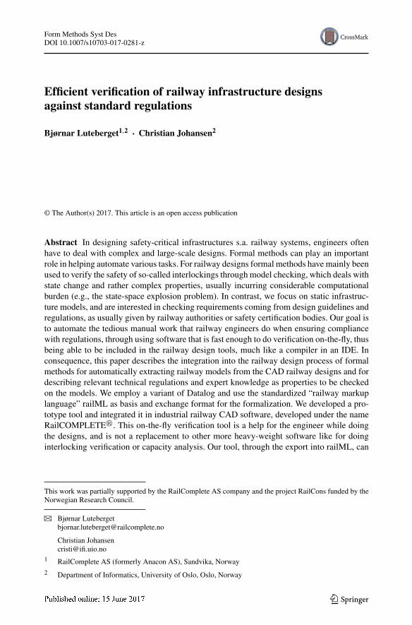
Railway construction projects rely heavily on computer aided design (CAD) tools to mapout railway station/infrastructure layouts. The various disciplines within a project, such ascivil works, track works, signalling, or catenary power lines, work with coordinated CADmodels. These CAD models contain a major part of the work performed by engineers, andare a collaboration tool for communication between disciplines. The signalling componentlayout is worked out by the signalling engineers as part of the design process. Signals, traindetectors, switches (also known as points), etc., are drawn using symbols in a 2DgeographicalCAD model. An example of a layout drawing made by Anacon AS engineers from a CADmodel is given in Fig. 1.
Track layout details, which are input for the signalling design, are often given by a separatedivision of the railway project. At an early stage and working at a low level of detail, thesignalling engineer may challenge the track layout design, and an iterative process may beinitiated.
123
Form Methods Syst Des
Sig. A Sig. C
Sig. E
Sig. B
Sig. D
Sig. F
12
3
4 6
5
Switch X Switch Y
(a)
(b)
Fig. 1 a Example of a schematic construction drawing. b Cut-out from a 2D geographical CAD model(construction drawing) of a preliminary design of the Arna station signalling
2.2 Interlocking specification
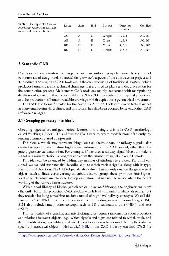
An interlocking is an interconnection of signals and switches to ensure that train move-ments are performed in a safe sequence [42]. Interlocking is performed electronically so that,e.g., a green light (or, more precisely, the proceed aspect) communicating the movementauthority required for a train to travel through a station can only be lit by the interlock-ing controller under certain conditions. Conditions and state are built into the interlockingby relay-based circuitry or by computers running interlocking software. Most interlockingspecifications use a route-based tabular approach, which means that a train station is dividedinto possible routes, which are paths that a train can take from one signal to another. Thesesignals are called the route entry signal and route exit signal, respectively. An elementaryroute contains no other signals in-between. The main part of the interlocking specifica-tion is to tabulate all possible routes and set conditions for their use. Typical conditionsinclude:
– Switches must be positioned to guide the train to a specified route exit signal.– Train detectors must show that the route is free of any other trains.– Conflicting routes, i.e., routes which share a track element, must not be in use (Table 1).
123
Form Methods Syst Des
Table 1 Example of a tabularinterlocking, showing availableroutes and their conditions
Route Start End Sw. pos Detectionsections
Conflicts
AC A C X right 1, 2, 4 AE, BF
AE A E X left 1, 2, 3 AC, BD
BF B F Y left 4, 5, 6 AC, BD
BD B D Y right 3, 5, 6 AE, BF
3 Semantic CAD
Civil engineering construction projects, such as railway projects, make heavy use ofcomputer-aided design tools to model the geometric aspects of the construction project andits product. The origins of CAD tools are in the computerizing of traditional drafting, whichproduces human-readable technical drawings that are used as plans and documentation forthe construction process. Mainstream CAD tools are mainly concerned with manipulatingdatabases of geometrical objects constituting 2D or 3D representations of spatial properties,and the production of human-readable drawings which depict these geometrical structures.
The DWG file format3 created for the Autodesk AutoCAD software is a de facto standardin many engineering disciplines, and this format has also been adopted by several other CADsoftware packages.
3.1 Grouping geometry into blocks
Grouping together several geometrical features into a single unit is in CAD terminologycalled “making a block”. This allows the CAD user to create models more efficiently, byreusing commonly used components.
The blocks, which may represent things such as chairs, doors, or railway signals, alsocreate the opportunity to store higher-level information in a CAD model, other than thepurely geometrical description. For example, if one uses a railway signal block to model asignal in a railway station, a program can count the number of signals in a CAD model.
This idea can be extended by adding any number of attributes to a block. For a railwaysignal, we can add attributes that describe, e.g., to which track it signals, along with its type,function, and direction. The CAD object database does then not only contain the geometricalobjects, such as lines, curves, triangles, cubes, etc., but groups these primitives into higher-level concepts which are closer to the representation that one uses to reason about the actualworking of the railway infrastructure.
With a good library of blocks (which we call a symbol library), the engineer can moreefficiently build the geometric CAD models which lead to human-readable drawings, butthey are also building a machine-readable model of high-level railway concepts. We call thissemantic CAD. While this concept is also a part of building information modeling (BIM),BIM also includes many other concepts such as 3D visualization, time (“4D”), and cost(“5D”).
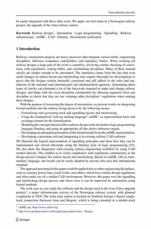
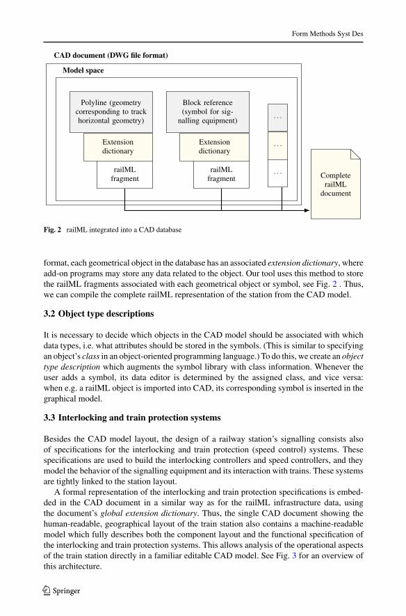
The verification of signalling and interlocking rules requires information about propertiesand relations between objects, e.g., which signals and signs are related to which track, andtheir identification, capabilities, and use. This information is better modelled by the railway-specific hierarchical object model railML [40]. In the CAD industry-standard DWG file
3 https://www.opendesign.com/files/guestdownloads/OpenDesign_Specification_for_.dwg_files.pdf.
123
Form Methods Syst Des
CAD document (DWG file format)
Model space
Polyline (geometrycorresponding to trackhorizontal geometry)
Block reference(symbol for sig-
nalling equipment)
Extensiondictionary
Extensiondictionary
CompleterailML
document
railMLfragment
railMLfragment
Fig. 2 railML integrated into a CAD database
format, each geometrical object in the database has an associated extension dictionary, whereadd-on programs may store any data related to the object. Our tool uses this method to storethe railML fragments associated with each geometrical object or symbol, see Fig. 2 . Thus,we can compile the complete railML representation of the station from the CAD model.
3.2 Object type descriptions
It is necessary to decide which objects in the CAD model should be associated with whichdata types, i.e. what attributes should be stored in the symbols. (This is similar to specifyingan object’s class in an object-oriented programming language.) To do this, we create an objecttype description which augments the symbol library with class information. Whenever theuser adds a symbol, its data editor is determined by the assigned class, and vice versa:when e.g. a railML object is imported into CAD, its corresponding symbol is inserted in thegraphical model.
3.3 Interlocking and train protection systems
Besides the CAD model layout, the design of a railway station’s signalling consists alsoof specifications for the interlocking and train protection (speed control) systems. Thesespecifications are used to build the interlocking controllers and speed controllers, and theymodel the behavior of the signalling equipment and its interaction with trains. These systemsare tightly linked to the station layout.
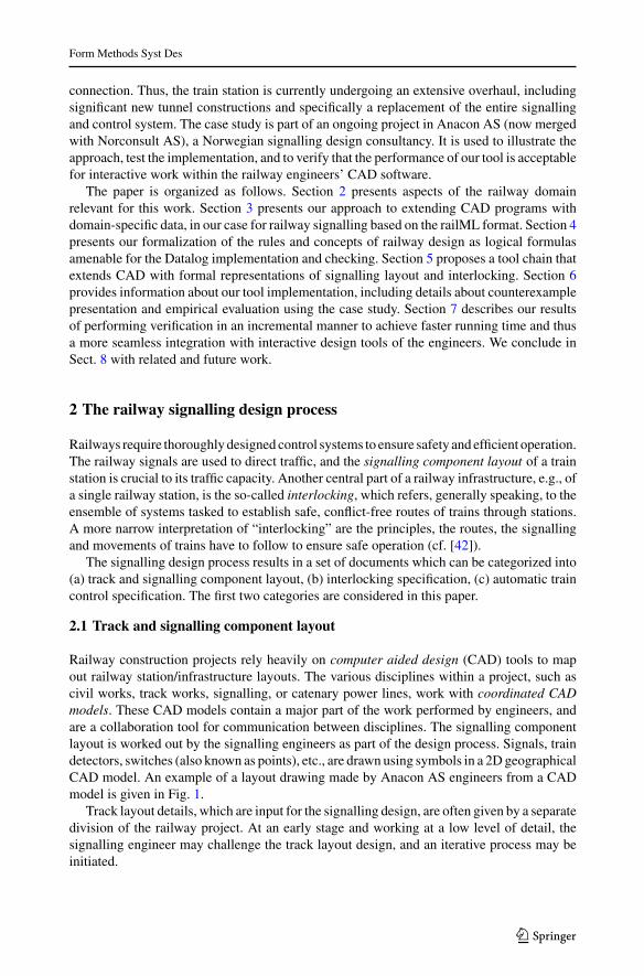
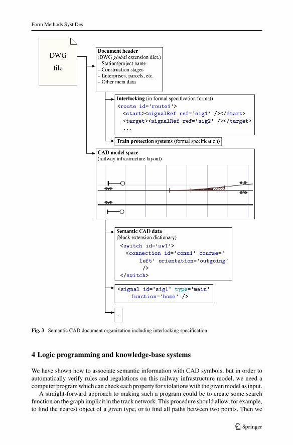
A formal representation of the interlocking and train protection specifications is embed-ded in the CAD document in a similar way as for the railML infrastructure data, usingthe document’s global extension dictionary. Thus, the single CAD document showing thehuman-readable, geographical layout of the train station also contains a machine-readablemodel which fully describes both the component layout and the functional specification ofthe interlocking and train protection systems. This allows analysis of the operational aspectsof the train station directly in a familiar editable CAD model. See Fig. 3 for an overview ofthis architecture.
123
Form Methods Syst Des
Fig. 3 Semantic CAD document organization including interlocking specification
4 Logic programming and knowledge-base systems
We have shown how to associate semantic information with CAD symbols, but in order toautomatically verify rules and regulations on this railway infrastructure model, we need acomputer programwhich can check each property for violationswith the givenmodel as input.
A straight-forward approach to making such a program could be to create some searchfunction on the graph implicit in the track network. This procedure should allow, for example,to find the nearest object of a given type, or to find all paths between two points. Then we
123
Form Methods Syst Des
would describe a checking procedure for each rule. Consider for example, the home signalregulation from Property 1, which says “A home main signal shall be placed at least 200min front of the first controlled, facing switch in the entry train path.”. Checking such aproperty can be done by iterating over tracks, locating station boundaries, starting a searchfunction to locate the relevant facing switches, starting another search backwards to checkthat there is a home signal, and so on. The amount of code required to do this in a mainstreamprogramming language can become large, and this code is often very specific to a givenrailway administration.
Better suited to manage the large amounts of code required for a large number of rules,is logic programming, which allows rule descriptions that are much closer to the originalspecifications than in a mainstream programming language.
4.1 Logic programming
Logic programming [41] is a family of programming languages based on formal logic. Logicprograms are declarative, i.e., they describe properties of the solution of a problem rather thana calculation procedure for finding the solution. This separates the concerns of expressingrules about railway systems from the algorithms required to do automatic analysis. Thisseparation allows one to systematically maintain a large set of rules, and decouple the toolimplementation from the set of concepts, rules and expert knowledge that is specific to arailway administration.
We have successfully used the Datalog language [53], a subset of the more well-knownProlog language, for verifyingmany properties given as technical rules and expert knowledge.It allows concise formulations of railway concepts, and queries can be efficiently calculated.
Ideally, we would like the railway engineers themselves, without much programmingeducation, to be able to create and maintain the set of rules which is used for the verification.This separation of logic and algorithm is a step in this direction, because non-IT expertscan work on the rules without considering how the calculations are implemented. However,the strict formalism and subtle semantics of logic programming are still a challenge foran inexperienced programmer. Still, some parts of the maintentance work on the railwayproperties can be performedwithout deep knowledge of logic programming, for the followingreasons:
1. The most basic concepts, such as connectedness, distances, directions, etc., rarely needto be redefined, and may be specified by an expert programmer, and then reused.
2. Naming or documenting the basic concepts in a way that is understandable by railwayengineers allows them to use these concepts without considering the actual definitions.
3. Rule formulations are often so succinct that they can be understood even without knowl-edge of the logic programming syntax.
4. Modification (updating) of rules, for example following a change in regulation from therailway administration, often preserves the structure of the specification, adding only asimilar clause or the change of a numeric constant.
5. Templates for common rule structures can be given, so that implementing some types ofrules becomes a matter of specifying e.g. only object types, directions, and distances.
We do, however, concede that Datalog programming in general (specifically, at the levelrequired for writing regulation properties from scratch) is outside the competence of a railwayengineer. A higher-level domain-specific language including relevant constructs for a railwaysignalling design knowledge base could improve the likelihood of railway engineers beingsuccessful in creating and maintaining the regulations. Even more, this language could allow
123
Form Methods Syst Des
each company and each engineer to experiment with encoding different design heuristics andexpert knowledge to see the effects on the verification and the design. Our planned futurework (see Sect. 8.2) includes defining such a language and also on using a controlled naturallanguage syntax to improve ease of comprehension [30].
We envision that a common rule base would be exchanged between all engineers workingwith a railway administration, and that the rule base would be worked out partly by softwareexperts, partly by railway experts. Also, the rule base should be fairly constant, like theregulations, requiring an update frequency of perhaps once per year.
4.2 Datalog
Declarative logic programming is a programming language paradigmwhich allows clean sep-aration of logic (meaning) and computation (algorithm). This section gives a short overviewof Datalog concepts. See [1,41,53] for more details. In its most basic form Datalog is adatabase query, as in the SQL language, over a finite set of atoms which can be combinedusing conjunctive queries, i.e. expressions in the fragment of first-order logic which includesonly conjunctions and existential quantification.
Conjunctive queries alone, however, cannot express the properties needed to verifyrailway signalling. For example, given the layout of the station with tracks representedas edges between signalling equipment nodes, graph reachability queries are requiredto verify some of the rules. This corresponds to computing the transitive closure ofthe graph adjacency relation, which is not expressible in first-order logic [28, Chap. 3].Extending conjunctive queries by allowing recursive predicate definitions is a commonway to mitigate the above problem while preserving decidability and polynomial timecomplexity.
The Datalog language is a fragment of first-order logic extended with recursive predicatedefinitions, which are evaluated by computing least fixed points. We define the Dataloglanguage as follows: Terms are either constants (atoms) or variables. Literals consist of apredicate p with a certain arity n, along with terms corresponding to the predicate arguments,forming an expression like p(−→a ), where −→a = (a1, a2, . . . , an). Clauses consist of a headliteral and one or more body literals, such that all variables in the head also appear in thebody. Clauses are written as
r0(−→x ) :– ∃−→y : r1(
−→x1 ,−→y1 ), r2(−→x2 ,−→y2 ), . . . , rk(
−→xk ,−→yk ),
with⋃
1≤i≤k−→xi = −→x and
⋃1≤i≤k
−→yi = −→y . Datalog uses the Prolog convention of inter-preting identifiers starting with a capital letter as variables, and other identifiers as constants,e.g., the clause
a(X, Y ) :– b(X, Z), c(Z , Y )
has the meaning of
∀x, y : ((∃z : (b(x, z) ∧ c(z, y))) → a(x, y)) .
Clauses without body, which cannot then contain any variables, are called facts, those withone or more literals in the body are called rules. No nesting of literals is allowed. However,recursive definitions of predicates are possible. For example, let edge(a, b) be a graph edgerelation between vertices a and b. Graph searches can now be encoded by making a transitiveclosure over the edge relation:
123
Form Methods Syst Des
path(a, b) :– edge(a, b).
path(a, b) :– edge(a, x), path(x, b).
In the railway domain, this can be used to define the connected predicate, which defineswhether two objects are connected by railway tracks:
directlyConnected(a, b) :– track(t), belongsTo(a, t), belongsTo(b, t).
connected(a, b) :– directlyConnected(a, b).
connected(a, b) :– directlyConnected(a, x), connection(x, c),
connected(c, b).
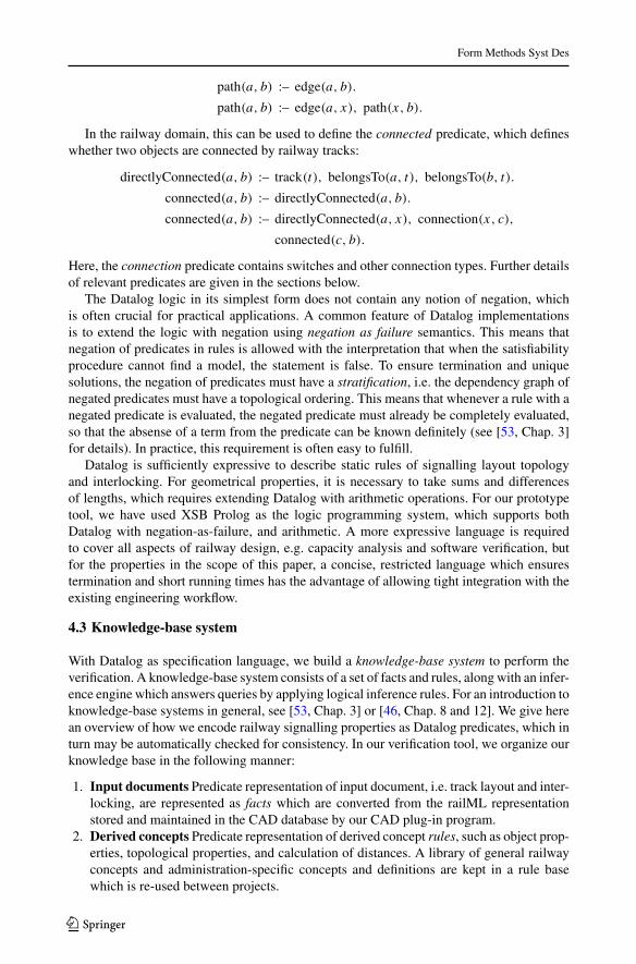
Here, the connection predicate contains switches and other connection types. Further detailsof relevant predicates are given in the sections below.
The Datalog logic in its simplest form does not contain any notion of negation, whichis often crucial for practical applications. A common feature of Datalog implementationsis to extend the logic with negation using negation as failure semantics. This means thatnegation of predicates in rules is allowed with the interpretation that when the satisfiabilityprocedure cannot find a model, the statement is false. To ensure termination and uniquesolutions, the negation of predicates must have a stratification, i.e. the dependency graph ofnegated predicates must have a topological ordering. This means that whenever a rule with anegated predicate is evaluated, the negated predicate must already be completely evaluated,so that the absense of a term from the predicate can be known definitely (see [53, Chap. 3]for details). In practice, this requirement is often easy to fulfill.
Datalog is sufficiently expressive to describe static rules of signalling layout topologyand interlocking. For geometrical properties, it is necessary to take sums and differencesof lengths, which requires extending Datalog with arithmetic operations. For our prototypetool, we have used XSB Prolog as the logic programming system, which supports bothDatalog with negation-as-failure, and arithmetic. A more expressive language is requiredto cover all aspects of railway design, e.g. capacity analysis and software verification, butfor the properties in the scope of this paper, a concise, restricted language which ensurestermination and short running times has the advantage of allowing tight integration with theexisting engineering workflow.
4.3 Knowledge-base system
With Datalog as specification language, we build a knowledge-base system to perform theverification. A knowledge-base system consists of a set of facts and rules, along with an infer-ence engine which answers queries by applying logical inference rules. For an introduction toknowledge-base systems in general, see [53, Chap. 3] or [46, Chap. 8 and 12]. We give herean overview of how we encode railway signalling properties as Datalog predicates, which inturn may be automatically checked for consistency. In our verification tool, we organize ourknowledge base in the following manner:
1. Input documents Predicate representation of input document, i.e. track layout and inter-locking, are represented as facts which are converted from the railML representationstored and maintained in the CAD database by our CAD plug-in program.
2. Derived concepts Predicate representation of derived concept rules, such as object prop-erties, topological properties, and calculation of distances. A library of general railwayconcepts and administration-specific concepts and definitions are kept in a rule basewhich is re-used between projects.
123
Form Methods Syst Des
3. Technical rules and expert knowledge Predicate representation of technical rules orexpert knowledge as logic programming rules, which encode the administration-specificrules and expert knowledge that is checked and errors reported to the user by the verifi-cation tool.
4. Inference engine A Datalog evaluation engine is used as inference engine; in our casethe XSB Prolog tabled logic programming system [52].
Each of these aspects are described in more detail below.
4.3.1 Input documents
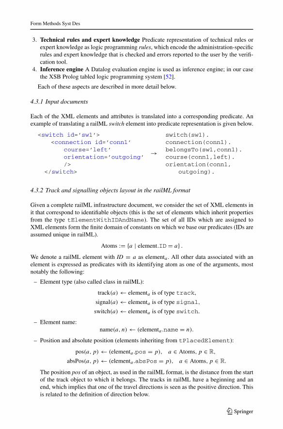
Each of the XML elements and attributes is translated into a corresponding predicate. Anexample of translating a railML switch element into predicate representation is given below.
<switch id=’sw1’><connection id=’conn1’
course=’left’orientation=’outgoing’/>
</switch>
→
switch(sw1).connection(conn1).belongsTo(sw1,conn1).course(conn1,left).orientation(conn1,
outgoing).
4.3.2 Track and signalling objects layout in the railML format
Given a complete railML infrastructure document, we consider the set of XML elements init that correspond to identifiable objects (this is the set of elements which inherit propertiesfrom the type tElementWithIDAndName). The set of all IDs which are assigned toXML elements form the finite domain of constants on which we base our predicates (IDs areassumed unique in railML).
Atoms := {a | element.ID = a} .We denote a railML element with ID = a as elementa . All other data associated with anelement is expressed as predicates with its identifying atom as one of the arguments, mostnotably the following:
– Element type (also called class in railML):
track(a) ← elementa is of type track,
signal(a) ← elementa is of type signal,
switch(a) ← elementa is of type switch.
– Element name:name(a, n) ← (elementa .name = n).
– Position and absolute position (elements inheriting from tPlacedElement):
pos(a, p) ← (elementa .pos = p), a ∈ Atoms, p ∈ R,
absPos(a, p) ← (elementa .absPos = p), a ∈ Atoms, p ∈ R.
The position pos of an object, as used in the railML format, is the distance from the startof the track object to which it belongs. The tracks in railML have a beginning and anend, which implies that one of the travel directions is seen as the positive direction. Thisis related to the definition of direction below.
123
Form Methods Syst Des
– Geographical coordinates (for elements inheriting from tPlacedElement):
geoCoords(a, q) ← (elementa .geoCoords = q), a ∈ Atoms, q ∈ R3.
– Direction (for elements inheriting from tOrientedElement):
dir(a, d) ← (elementa .dir = d), a ∈ Atoms, d ∈ Direction,
where Direction = {up, down, both, unknown}, indicating whether the object is visibleor functional in only one of the two possible travel directions, or both.The unknown value for the direction stems, in most contexts, from inconsistent or incom-plete data. Rules which disallow unknown direction can be used to indicate to the userthat their input document is invalid. For other uses of direction, such as in the definitionof the distance predicate below, we use instead the set of strict directions, as defined byrailML: StrictDirection = {up, down}.The up and down directions are defined by the positioning system of the track (see theposition predicates above). Objects in the up direction are relevant when the train istravelling in the direction of increasing pos, as defined above, which is determined by atrack’s beginning and end nodes, and correspondingly, the down direction is the directionof decreasing track position. These directions are typically related to some origin pointgiven by the infrastructure manager organization. For example, for Norwegian railways,the tunnel opening on track 7 ofOslo Central Station defines the origin point, and absolutepositions increase away from this point.
– Signal properties (for elements of type tSignal):
signalType(a, t) ← (elementa .type = t), t ∈ {main, distant, shunting, combined} ,signalFunction(a, f ) ← (elementa .function = f ),
a ∈ Atoms, f ∈ {home, intermediate, exit, blocking} .Consistency axioms would impose that predicates signalType and signalFunction beapplied only to signal elements:
signalType(a, t) ⇒ signal(a),
signalFunction(a, f ) ⇒ signal(a).
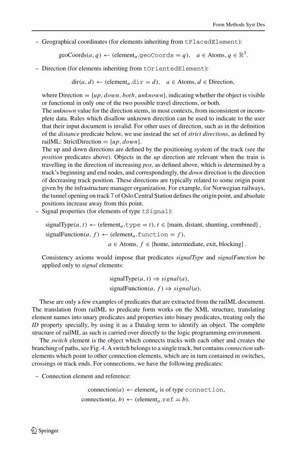
These are only a few examples of predicates that are extracted from the railML document.The translation from railML to predicate form works on the XML structure, translatingelement names into unary predicates and properties into binary predicates, treating only theID property specially, by using it as a Datalog term to identify an object. The completestructure of railML as such is carried over directly to the logic programming environment.
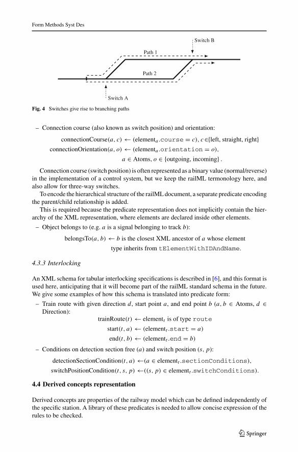
The switch element is the object which connects tracks with each other and creates thebranching of paths, see Fig. 4. A switch belongs to a single track, but contains connection sub-elements which point to other connection elements, which are in turn contained in switches,crossings or track ends. For connections, we have the following predicates:
– Connection element and reference:
connection(a) ← elementa is of type connection,
connection(a, b) ← (elementa .ref = b).
123
Form Methods Syst Des
Path 1
Path 2
Switch A
Switch B
Fig. 4 Switches give rise to branching paths
– Connection course (also known as switch position) and orientation:
connectionCourse(a, c) ← (elementa .course = c), c∈{left, straight, right}connectionOrientation(a, o) ← (elementa .orientation = o),
a ∈ Atoms, o ∈ {outgoing, incoming} .Connection course (switch position) is often represented as a binary value (normal/reverse)
in the implementation of a control system, but we keep the railML termonology here, andalso allow for three-way switches.
To encode the hierarchical structure of the railMLdocument, a separate predicate encodingthe parent/child relationship is added.
This is required because the predicate representation does not implicitly contain the hier-archy of the XML representation, where elements are declared inside other elements.
– Object belongs to (e.g. a is a signal belonging to track b):
belongsTo(a, b) ← b is the closest XML ancestor of a whose element
type inherits from tElementWithIDAndName.
4.3.3 Interlocking
An XML schema for tabular interlocking specifications is described in [6], and this format isused here, anticipating that it will become part of the railML standard schema in the future.We give some examples of how this schema is translated into predicate form:
– Train route with given direction d , start point a, and end point b (a, b ∈ Atoms, d ∈Direction):
trainRoute(t) ← elementt is of type route
start(t, a) ← (elementt .start = a)
end(t, b) ← (elementt .end = b)
– Conditions on detection section free (a) and switch position (s, p):
detectionSectionCondition(t, a) ←(a ∈ elementt .sectionConditions),
switchPositionCondition(t, s, p) ←((s, p) ∈ elementt .switchConditions).
4.4 Derived concepts representation
Derived concepts are properties of the railway model which can be defined independently ofthe specific station. A library of these predicates is needed to allow concise expression of therules to be checked.
123
Form Methods Syst Des
4.4.1 Object properties
Derivedobject properties are properties related to specific object typeswhich are not explicitlyrepresented in the layout description, such as whether a switch is facing in a given direction,i.e. if the path will branch when you pass it:
– Switch facing or trailing (a ∈ Atoms, d ∈ Direction):
switchFacing(a, d) ← ∃c, o : switch(a) ∧ switchConnection(a, c)∧switchOrientation(c, o) ∧ orientationDirection(o, d).
switchTrailing(a, d) ← ¬switchFacing(a, d)
4.4.2 Topological and geometric layout properties
Predicates describing the topological configuration of signalling objects and the traintravel distance between them are described by predicates for track connection (predicateconnected(a, b)), directed connection (predicate following(a, b, d)), distance (predicatedistance(a, b, d, l)), etc. The track connection predicate is defined as:
– There is a track connection between object a and b (a, b ∈ Atoms):
directlyConnected(a, b) ← ∃t :track(t) ∧ belongsTo(a, t) ∧ belongsTo(b, t),
connected(a, b) ←directlyConnected(a, b) ∨ (∃c1, c2 : connection(c1, c2)
∧ directlyConnected(a, c1) ∧ connected(c2, b)).
– There is a directed connection between object a and b (a, b ∈ Atoms, d ∈StrictDirection, pa, pb ∈ R):
directlyFollowing(a, b, d) ← directlyConnected(a, b)∧position(a, pa) ∧ position(b, pb)∧((d = up ∧ pa < pb) ∨ (d = down ∧ pa > pb))
following(a, b, d) ← directlyFollowing(a, b, d)∨∃c1, c2 : connection(c1, c2) ∧ directlyFollowing(a, c1, d)
∧ following(c2, b, d)
– The distance (along track) in a given direction between object a and b (a, b ∈ Atoms,d ∈ StrictDirection, pa, pb, l ∈ R):
directDistance(a, b, d, l) ← directlyFollowing(a, b, d)∧position(a, pa) ∧ position(b, pb)
∧ l = |pb − pa |distance(a, b, d, l) ← directDistance(a, b, d, l)∨
∃c1, c2, l1, l2 : connection(c1, c2)
∧ directDistance(a, c1, d, l1)
∧ distance(c2, b, d, l2) ∧ l = l1 + l2
The distance predicate represents a possible train movement and the corresponding trav-eling distance. This means that the distances should fulfill the following consistencyaxiom: Consider the solutions to distance(a, b, d1, l1)∧ distance(b, a, d2, l2). The set of
123
Form Methods Syst Des
distances l1 is equal to the set of distances l2, and the direction d1 is the opposite directionof d2.
– Object is located between a and b (a, x, b ∈ Atoms, d ∈ StrictDirection):
between(a, x, b, d) ← following(a, x, d) ∧ following(x, b, d)
between(a, x, b) ← ∃d : between(a, x, b, d)
– A path between a and b intersects a path between c and d (a, b, c, d ∈ Atoms), meaningthat some part of any path between a and b coincides with some part of any path betweenc and d:
intersect(a, b, c, d) ← ∃e : between(a, e, b) ∧ between(c, e, d)
4.4.3 Interlocking properties
Predicates such as existsPathWithoutSignal(a, b) which defines the method for finding ele-mentary routes, and existsPathWithDetector(a, b) for finding adjacent train detectors, willbe used as building blocks for the interlocking rules. We show here a recursive rule used forfinding elementary routes:
– Signals a and b have a path between them without any other signals in between:
existsPathWithoutSignal(a, b, d) ← following(a, b, d)∧(¬(∃x : signal(x) ∧ between(a, x, b))∨(∃x : between(a, x, b) ∧ existsPathWithoutSignal(a, x, d)∧existsPathWithoutSignal(x, b, d)).
4.5 Rule violations representation
With the input documents represented as facts, and a library of derived concepts, it remainsto define the technical rules to be checked. All technical rules presented herein are based onthe Norwegian infrastructure manager’s regulations.4
The goal of the consistency checking is to confirm that no inconsistencies exist, in whichcase no further information is required, or to find inconsistencies and present them in a waythat allows the user to understand the error and to adjust their design accordingly. Rules aretherefore expressed negatively, as rule violations, so that a query corresponding to the rule isempty whenever the rule is consistent with the design, or the query contains counterexamplesto the rule when they exist.
Some examples of technical rules representing conditions of the railway station layout aregiven below.
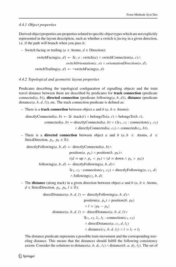
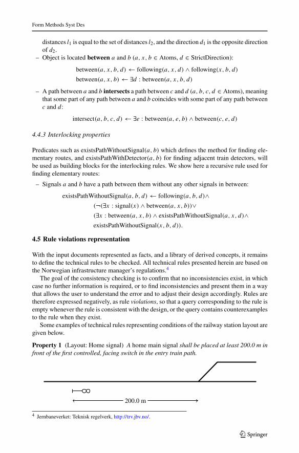
Property 1 (Layout: Home signal) A home main signal shall be placed at least 200.0 m infront of the first controlled, facing switch in the entry train path.
200.0 m
4 Jernbaneverket: Teknisk regelverk, http://trv.jbv.no/.
123
Form Methods Syst Des
Property 1 may be represented in the following way:
isFirstFacingSwitch(b, s) ← stationBoundary(b) ∧ facingSwitch(s)∧¬(∃x : facingSwitch(x) ∧ between(b, x, s)),
The stationBoundary predicate contains objectswhich represent the boundaries of a stationmodel. For models which contain a single station, which is the common use case for our CADprototype application, the stationBoundary can be taken to be the model boundary. Note thatthe station boundary is usually not the same as the station border, which is defined byregulations.
ruleViolation1(b, s) ← isFirstFacingSwitch(b, s)∧(¬(∃x : signalFunction(x, home) ∧ between(b, x, s))∨(∃x, d, l : signalFunction(x, home)∧∧ distance(x, s, d, l) ∧ l < 200.0).
Checking for rule violations can be expressed as:
∃b, s : ruleViolation1(b, s),
which in Datalog query format becomes ruleViolation1(B,S)?.
Property 2 (Layout: Minimum detection section length) No train detection section shall beshorter than 21.0 m. I.e., no train detectors should be separated with less than 21.0 m drivingdistance.
This property is represented as follows:
ruleViolation2(a, b) ←∃d, l : trainDetector(a) ∧ trainDetector(b)∧distance(a, b, d, l) ∧ l < 21.0.
Property 3 (Layout: Exitmain signal)An exit main signal shall be used to give the movementauthority to exit a station.
This property can be elaborated into the following rules:
– No path should have more than one exit signal:
ruleViolation3(s) ←∃d : signalType(s, exit) ∧ following(s, so, d)∧signalType(s0, exit).
– Station boundaries should be preceded by an exit signal:
exitSignalBefore(x, d) ←∃s : signalType(s, exit) ∧ following(s, x, d)
ruleViolation3(b) ←∃d : stationBoundary(b) ∧ ¬exitSignalBefore(b, d).
A basic property of tabular interlockings is that each consecutive pair of main signalsnormally has an elementary train route associated with it, i.e.:
Property 4 (Interlocking: Elementary routes) A pair of consecutive main signals should bepresent as a route in the interlocking.
123
Form Methods Syst Des
This can be represented as follows:
defaultRoute(a, b, d) ← signalType(a,main) ∧ signalType(b,main)∧direction(a, d) ∧ direction(b, d)∧following(a, b, d) ∧ existsPathWithoutSignal(a, b, d),
ruleViolation4(a, b, d) ← defaultRoute(a, b, d)∧¬(∃r : trainRoute(r) ∧ trainRouteStart(r, a) ∧ trainRouteEnd(r, b)).
This type of rule is not absolutely required for a railway signalling design to be valid andsafe. Some rules are hard constraints, where violations may be considered to be errors inthe design, while other rules are soft constraints, where violations may suggest that furtherinvestigation is recommended. This is relevant for the counterexample presentation sectionbelow.
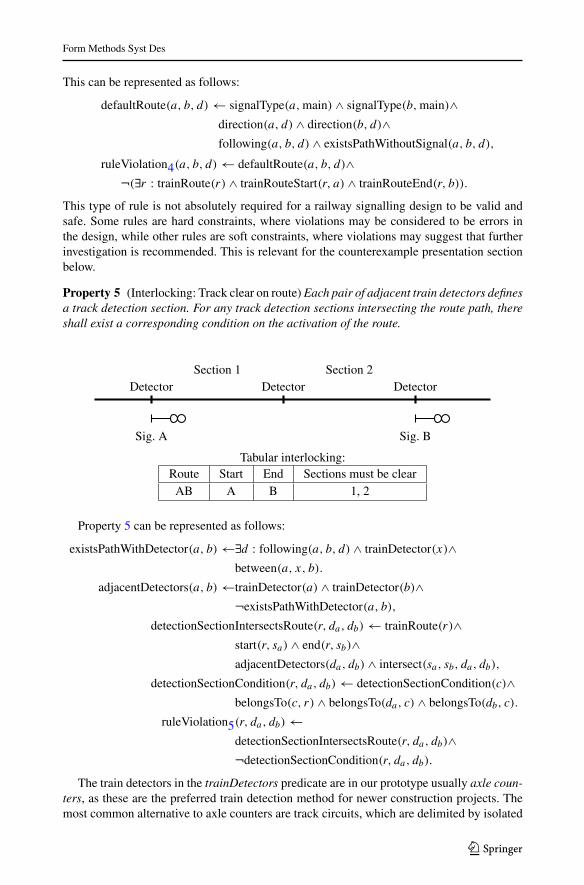
Property 5 (Interlocking: Track clear on route) Each pair of adjacent train detectors definesa track detection section. For any track detection sections intersecting the route path, thereshall exist a corresponding condition on the activation of the route.
Section 1 Section 2
Sig. A Sig. B
Detector Detector Detector
Tabular interlocking:Route Start End Sections must be clearAB A B 1, 2
Property 5 can be represented as follows:
existsPathWithDetector(a, b) ←∃d : following(a, b, d) ∧ trainDetector(x)∧between(a, x, b).
adjacentDetectors(a, b) ←trainDetector(a) ∧ trainDetector(b)∧¬existsPathWithDetector(a, b),
detectionSectionIntersectsRoute(r, da, db) ← trainRoute(r)∧start(r, sa) ∧ end(r, sb)∧adjacentDetectors(da, db) ∧ intersect(sa, sb, da, db),
detectionSectionCondition(r, da, db) ← detectionSectionCondition(c)∧belongsTo(c, r) ∧ belongsTo(da, c) ∧ belongsTo(db, c).
ruleViolation5(r, da, db) ←detectionSectionIntersectsRoute(r, da, db)∧¬detectionSectionCondition(r, da, db).
The train detectors in the trainDetectors predicate are in our prototype usually axle coun-ters, as these are the preferred train detection method for newer construction projects. Themost common alternative to axle counters are track circuits, which are delimited by isolated
123
Form Methods Syst Des
Route
Signal A Signal B
Signal C
Switch X
Switch Y
Flank
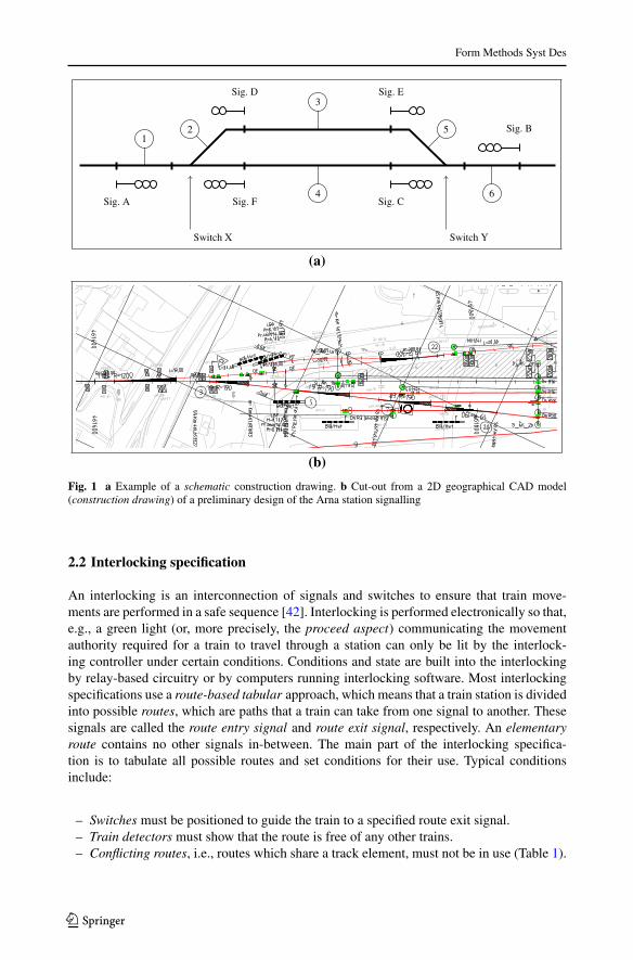
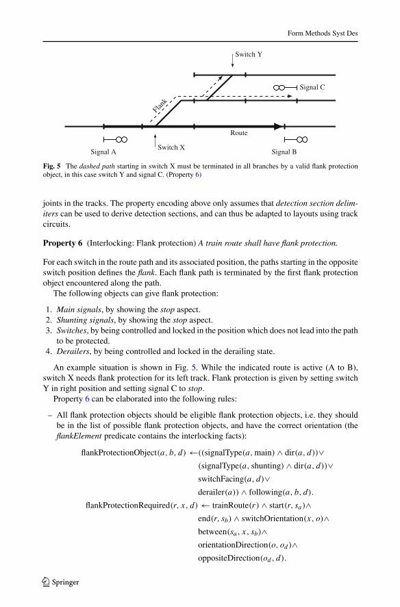
Fig. 5 The dashed path starting in switch X must be terminated in all branches by a valid flank protectionobject, in this case switch Y and signal C. (Property 6)
joints in the tracks. The property encoding above only assumes that detection section delim-iters can be used to derive detection sections, and can thus be adapted to layouts using trackcircuits.
Property 6 (Interlocking: Flank protection) A train route shall have flank protection.
For each switch in the route path and its associated position, the paths starting in the oppositeswitch position defines the flank. Each flank path is terminated by the first flank protectionobject encountered along the path.
The following objects can give flank protection:
1. Main signals, by showing the stop aspect.2. Shunting signals, by showing the stop aspect.3. Switches, by being controlled and locked in the position which does not lead into the path
to be protected.4. Derailers, by being controlled and locked in the derailing state.
An example situation is shown in Fig. 5. While the indicated route is active (A to B),switch X needs flank protection for its left track. Flank protection is given by setting switchY in right position and setting signal C to stop.
Property 6 can be elaborated into the following rules:
– All flank protection objects should be eligible flank protection objects, i.e. they shouldbe in the list of possible flank protection objects, and have the correct orientation (theflankElement predicate contains the interlocking facts):
flankProtectionObject(a, b, d) ←((signalType(a,main) ∧ dir(a, d))∨(signalType(a, shunting) ∧ dir(a, d))∨switchFacing(a, d)∨derailer(a)) ∧ following(a, b, d).
flankProtectionRequired(r, x, d) ← trainRoute(r) ∧ start(r, sa)∧end(r, sb) ∧ switchOrientation(x, o)∧between(sa, x, sb)∧orientationDirection(o, od)∧oppositeDirection(od , d).
123
Form Methods Syst Des
flankProtection(r, e) ←flankProtectionRequired(r, x, d)∧flankProtectionObject(e, x, d).
ruleViolation6(r, e) ←flankElement(r, e)∧¬flankProtection(r, e).
– There should be no path from a model/station boundary to the given switch, in the givendirection, that does not pass a flank protection object for the route:
existsPathWithFlankProtection(r, b, x, d) ←flankElement(r, e) ∧ flankProtectionElement(e, x, d)∧between(b, e, x).
existsPathWithoutFlankProtection(r, b, x, d) ←¬existsPathWithFlankProtection(r, b, x, d)∨(between(b, y, x) ∧ ¬flankProtectionElement(e, y, d)∧existsPathWithoutFlankProtection(r, b, y, d)∧existsPathWithoutFlankProtection(r, y, x, d)).
ruleViolation6(r, b, x) ← stationBoundary(b)∧flankProtectionRequired(r, x, d) ∧ following(b, x, d)∧existsPathWithoutFlankProtection(r, b, x, d).
5 Proposed railway signalling design tool chain
Next we describe the tool chain that we propose for automating the current manual tasksinvolved in the design of railway infrastructures (more details can be found in [31]). Inparticular, we are focused on integrating and automating those simple, yet tedious, rules andconditions usually used to maintain some form of consistency of the railway, and have thesechecks done automatically. Whenever the design is changed by an engineer working with theCAD program, our verification procedure would help, behind the scenes, verifying any smallchanges in the model and the output documents. Violations would either be automaticallycorrected, if possible, or highlighted to the engineer. Thus, we are focusing on solutionswith small computational overhead when working with CAD tools (running on standardcomputers).
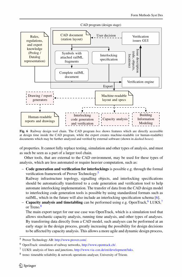
Figure 6 shows the overall tool chain. The software allows checking of rules and regu-lations of static infrastructure (described in this paper) inside the CAD environment, whilemore comprehensive verification and quality assurance can be performed by special-purposesoftware for other design and analysis activities.
Generally, analysis and verification tools for railway signalling designs can have complexinputs, they must account for a large variety of situations, and they usually require longrunning times. Therefore, we limit the verification inside the design environment to staticrules and expert knowledge, as these rules require less dynamic information (timetables,rolling stock, etc.) and less computational effort, while still offering valuable insights. Thissituation may be compared to the tool chain for writing computer programs. Static analysiscan be used at the detailed design stage (writing the code), but can only verify a limited set
123
Form Methods Syst Des
Rules,regulations,and expertknowledge(Prolog /Datalog
representation)
CAD program (design stage)
CAD document(station layout)
Verificationissues GUI
Symbols withattached railML
fragments
Interlockingspecification
Complete railMLdocument
Verification engine
User decision
Issuedescription
(rule,objects,
locations)
Human-readablereports and drawings
Machine-readablelayout and specs
Interlockingcode generationand verification
Capacity analysis
Drawing / reportgenerators
BuildingInformationModeling
Export
Fig. 6 Railway design tool chain. The CAD program box shows features which are directly accessibleat design time inside the CAD program, while the export creates machine-readable (or human-readable)documents which may be further analyzed and verified by external software (shown in dashed boxes)
of properties. It cannot fully replace testing, simulation and other types of analysis, and mustas such be seen as a part of a larger tool chain.
Other tools, that are external to the CAD environment, may be used for these types ofanalysis, which are less automated or require heavier computation, such as:
– Code generation and verification for interlockings is possible e.g. through the formalverification framework of Prover Technology.5
Railway infrastructure topology, signalling objects, and interlocking specificationsshould be automatically transferred to a code generation and verification tool to helpautomate interlocking implementation. The transfer of data from the CAD design modelto interlocking code generation tools is possible by using standardized formats such asrailML, which in the future will also include an interlocking specification schema [6].
– Capacity analysis and timetabling can be performed using e.g. OpenTrack,6 LUKS,7
or Treno.8
The main export target for our use case was OpenTrack, which is a simulation tool thatallows stochastic capacity analysis, running time analysis, and other types of analyses.By transferring data directly from a CAD model, such analyses can be performed at anearly stage in the design process, greatly increasing the possibility for design decisionsto be affected by capacity analysis. This allows a more agile and dynamic design process,
5 Prover Technology AB: http://www.prover.com/.6 OpenTrack: simulation of railway networks, http://www.opentrack.ch/.7 LUKS: analysis of lines and junctions, http://www.via-con.de/en/development/luks.8 treno: timetable reliability & network operations analyser, University of Trieste.
123
Form Methods Syst Des
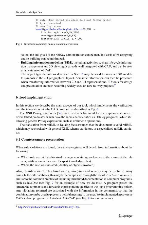
%| rule: Home signal too close to first facing switch.%| type: technical%| severity: errorhomeSignalBeforeFacingSwitchError(S,SW) :-
firstFacingSwitch(B,SW,DIR),homeSignalBetween(S,B,SW),distance(S,SW,DIR,L), L < 200.
Fig. 7 Structured comments on rule violation expression
so that the end goals of the railway administration can be met, and costs of re-designingand re-building can be minimized.
– Building information modeling (BIM), including activities such as life-cycle informa-tion management and 3D viewing, is already well integrated with CAD, and can be seenas an extension of CAD.The object type definitions described in Sect. 3 may be used to associate 3D modelsto symbols in the 2D geographical layout. Semantic information can then be preservedwhen transferring information between 2D and 3D representations. 3D tools for designand presentation are now becoming widely used on new railway projects.9
6 Tool implementation
In this section we describe the main aspects of our tool, which implements the verificationand the integration into the CAD program, as described in Fig. 6.
The XSB Prolog interpreter [52] was used as a back-end for the implementation as itoffers tabled predicates which have the same characteristics as Datalog programs, while stillallowing general Prolog expressions such as arithmetic operations.
The translation from railML to Datalog facts assumes that the document is valid railML,which may be checked with general XML schema validators, or a specialized railML valida-tor.
6.1 Counterexample presentation
When rule violations are found, the railway engineer will benefit from information about thefollowing:
– Which rule was violated (textual message containing a reference to the source of the ruleor a justification in the case of expert knowledge rules).
– Where the rule was violated (identity of objects involved).
Also, classification of rules based on e.g. discipline and severity may be useful in manycases. In the rule databases, thismaybe accomplished through the use of structured comments,similar to the common practice of including structured documentation in computer programs,such as JavaDoc (see Fig. 7 for an example of how we do this). A program parses thestructured comments and forwards corresponding queries to the logic programming solver.Any violations returned are associated with the information in the comments, so that thecombination can be used to present a helpfulmessage to the user.We implemented a prototypeCAD add-on program for Autodesk AutoCAD (see Fig. 8 for a screen-shot).
9 http://www.jernbaneverket.no/Prosjekter/Inter-City-/3d/.
123
Form Methods Syst Des
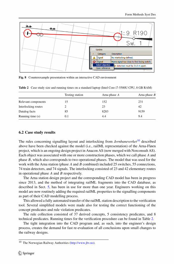
Fig. 8 Counterexample presentation within an interactive CAD environment
Table 2 Case study size and running times on a standard laptop (Intel Core i7-5500U CPU, 8 GB RAM)
Testing station Arna phase A Arna phase B
Relevant components 15 152 231
Interlocking routes 2 23 42
Datalog facts 85 8283 9159
Running time (s) 0.1 4.4 9.4
6.2 Case study results
The rules concerning signalling layout and interlocking from Jernbaneverket10 describedabove have been checked against the model (i.e., railML representation) of the Arna-Fløenproject, which is an ongoing design project in AnaconAS (nowmerged with Norconsult AS).Each object was associated with one or more construction phases, which we call phase A andphase B, which also corresponds to two operational phases. The model that was used for thework with the Arna station (phase A and B combined) included 25 switches, 55 connections,74 train detectors, and 74 signals. The interlocking consisted of 23 and 42 elementary routesin operational phase A and B respectively.
The Arna station design project and the corresponding CAD model has been in progresssince 2013, and the method of integrating railML fragments into the CAD database, asdescribed in Sect. 5, has been in use for more than one year. Engineers working on thismodel are now routinely adding the required railML properties to the signalling componentsas part of their CAD modelling process.
This allowed a fully automated transfer of the railML station description to the verificationtool. Several simplified models were made also for testing the correct functioning of theconcept predicates and rule violation predicates.
The rule collection consisted of 37 derived concepts, 5 consistency predicates, and 8technical predicates. Running times for the verification procedure can be found in Table 2.
The tight integration into the CAD program and, as such, into the engineer’s designprocess, creates the demand for fast re-evaluation of all conclusions upon small changes tothe railway designs.
10 The Norwegian Railway Authorities (http://www.jbv.no).
123
Form Methods Syst Des
Usually, engineers start with an empty or draft design and add/change one object at atime. The performance figures presented in Table 2 show that the current implementation iswell acceptable for “one-shot” validation even for realistic designs with running times in therange of seconds. However, it is not fast enough to smoothly and transparently be integratedsuch that it can automatically rerun the complete verification for each small change. Runningtimes below one second can change the user’s perception of the tool from being a separateverification process to a continuous background check. This level of performance requiresother measures to be taken, especially when considering that station models can be largerthan our case study, and that the regulations rule base would need to grow larger to becomemore useful.
An alternative approach that promises to be more efficient is incremental verification:instead of solving logic programs from scratch for each verification run, it tries to materializeall consequences of the base facts and thenmaintains this viewunder fact updates. Incrementalverification is further discussed in Sect. 7 below.
7 Incremental verification
While the static infrastructure verification process as developed so far in this text certainlycan improve on the current practice of railway signalling design as it is, the full potentialof a “light-weight” verification is still unused because of the perceived separation of designactivity and verification activity. A verification tool which runs invisibly alongside the design,giving feedback on the current state of the design at any time could have a higher impact onthe design process.
The common use case for running the railway design CAD tool in general is that oneperforms a series of small changes. Indeed, we have found in the collaborations with railwayengineers that large portions of the design phase have the goal of efficiently handling changesin track layouts, component capabilities, performance requirements, etc. The verificationcould, instead of being called whenever final version printouts are being made, instantlyreport potential problems in the design as soon as this information is available.
This requires lowering the running time of the verification, hopefully to less than onesecond, while keeping in mind that our prototype verification tool should eventually be ableto scale up to much larger stations, projects spanning several stations, and significantly largerknowledge bases. Exploiting the fact that the design work is incremental, also evaluating theDatalog programs incrementally seems to be a promising solution to this challenge.
Most railway regulations, also in the signalling discipline, are of a local character, meaningthat verification can be performed by looking only at data from a bounded radius around theobject which is being verified. This suggests that the details of object placement at one stationseldom influence the object placements at another station. Such locality of properties has beenearlier exploited by other railway verification approaches, e.g., [23] or [4]. Bonacchi et al.[4], in particular use locality to split model checking problems into smaller pieces, and usingtopology data to optimize variable ordering in BDD-based verification. For incrementalDatalog verification, locality of rules would mean that predicates which depend on graphconnectedness would have a bound on the search depth needed to update results after a singleobject’s change.
In this section we give an overview of approaches and algorithms for incremental Datalogand the tools that are available. We study these from the viewpoint of our application domainand evaluate initial performance on our case study.
123
Form Methods Syst Des
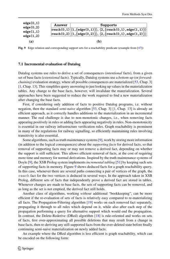
(a) (b)
Fig. 9 Edge relation and corresponding support sets for a reachability predicate (example from [47])
7.1 Incremental evaluation of Datalog
Datalog systems use rules to derive a set of consequences (intentional facts), from a givenset of base facts (extensional facts). Typically, Datalog systems use a bottom-up (or forward-chaining) evaluation strategy, where all possible consequences are materialized [53, Chap. 3][1, Chap. 13]. This simplifies query answering to just looking up values in the materializationtables. Any change to the base facts, however, will invalidate the materialization. Severalapproaches have been suggested to reduce the work required to find a new materializationafter changing the base facts.
First, if considering only addition of facts to positive Datalog programs, i.e. withoutnegation, then the standard semi-naive algorithm [53, Chap. 3] [1, Chap. 13] is already anefficient approach, as it correctly handles additions to the materialization in an incrementalmanner. The real challenge is due to non-monotonic changes, i.e., when removing factsappearing positively in rules or adding facts appearing negatively in rules. Non-monotonicityis essential in our railway infrastructure verification rules. Graph reachability is prominentin many of the regulations for railway signalling, so efficiently maintaining rules involvingtransitivity is also essential.
Somealgorithms, such as truthmaintenance systems [9],work by storingmore information(in addition to the logical consequences) about the supporting facts for derived facts, so thatremoval of supporting facts may or may not remove a derived fact, depending on whetherthe support is still sufficient. This allows efficient removal of facts, at the cost of requiringmore time and memory for normal derivations. Inspired by the truth maintenance systems ofDoyle [9], the XSB Prolog system implements incremental tabling [51] by keeping such setsof supporting facts in memory. Figure 9 shows deduced facts for a graph reachability query.In this case, whenever there are several paths connecting a pair of vertices of the graph, thereach fact for the two vertices is deduced in several ways. In the approach taken in XSBProlog, different sets of facts that independently prove a derived fact are stored in tables.Whenever changes are made to base facts, the sets of supporting facts can be removed, andas long as the set is not emptied, the derived fact still holds.
Another class of algorithms, working without additional “bookkeeping”, can be moreefficient if the re-evaluation of sets of facts is relatively easy compared to re-materializingall facts. The Propagation-Filtering algorithm [19] works on each removed fact separately,propagating it through to all rules which depend on it, while also after each step of thepropagation performing a query for alternative support which would end the propagation.In contrast, the Delete-Rederive (DRed) algorithm [18] is rule-oriented and works on setsof facts, first over-approximating all possible deletions that may result from a change inbase facts, then re-deriving any still-supported facts from the over-deleted state before finallycontinuing semi-naive materialization on newly added facts.
An example where the DRed algorithm is less efficient is graph reachability, which canbe encoded on the following form:
123
Form Methods Syst Des
(a) Edge relation visualized as arrows between ob-jects (each element is an arrow e(a b)).
(b) DRed algorithm: removing one edge (thick line)triggers re-evaluation of many dependent edges(dashed lines)
(c) FBF algorithm: removing one edge (thickline) causes re-evaluation of dependent edge (thickdashed line), but confirmation that this edge is stillvalid stops further propagation.
1
12 1
2
(d) Counting approach: removing one edge (thickline) causes re-evaluation of dependent edge (thickdashed line), but because this edge has multiplederivations, it is still valid, and propagation canstop. Note that a pure counting approach is not suf-ficient in this case because of the recursive reacha-bility rule.
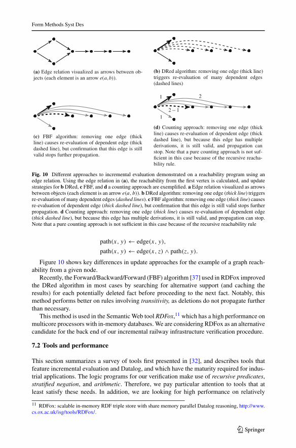
Fig. 10 Different approaches to incremental evaluation demonstrated on a reachability program using anedge relation. Using the edge relation in (a), the reachability from the first vertex is calculated, and updatestrategies for b DRed, c FBF, and d a counting approach are exemplified. a Edge relation visualized as arrowsbetween objects (each element is an arrow e(a, b)). bDRed algorithm: removing one edge (thick line) triggersre-evaluation of many dependent edges (dashed lines). c FBF algorithm: removing one edge (thick line) causesre-evaluation of dependent edge (thick dashed line), but confirmation that this edge is still valid stops furtherpropagation. d Counting approach: removing one edge (thick line) causes re-evaluation of dependent edge(thick dashed line), but because this edge has multiple derivations, it is still valid, and propagation can stop.Note that a pure counting approach is not sufficient in this case because of the recursive reachability rule
path(x, y) ← edge(x, y),
path(x, y) ← edge(x, z) ∧ path(z, y).
Figure 10 shows key differences in update approaches for the example of a graph reach-ability from a given node.
Recently, the Forward/Backward/Forward (FBF) algorithm [37] used in RDFox improvedthe DRed algorithm in most cases by searching for alternative support (and caching theresults) for each potentially deleted fact before proceeding to the next fact. Notably, thismethod performs better on rules involving transitivity, as deletions do not propagate furtherthan necessary.
This method is used in the Semantic Web tool RDFox,11 which has a high performance onmulticore processors with in-memory databases. We are considering RDFox as an alternativecandidate for the back end of our incremental railway infrastructure verification procedure.
7.2 Tools and performance
This section summarizes a survey of tools first presented in [32], and describes tools thatfeature incremental evaluation and Datalog, and which have the maturity required for indus-trial applications. The logic programs for our verification make use of recursive predicates,stratified negation, and arithmetic. Therefore, we pay particular attention to tools that atleast satisfy these needs. In addition, we are looking for high performance on relatively
11 RDFox: scalable in-memory RDF triple store with share memory parallel Datalog reasoning, http://www.cs.ox.ac.uk/isg/tools/RDFox/.
123
Form Methods Syst Des
small (in-memory) data sets, so light-weight library-style logic engines are preferred. High-performance distributed “big data” type of tools have less value in this context.
XSB Prolog, continuously developed since 1990, has constantly been pushing the state ofthe art in high-performance Prolog. XSB is especially known for its tabling support [52],which allows fast Datalog-like evaluation of logic programswithout restricting ISOPrologin any way. The tabling support was extended to allow incremental evaluation [47], andthese features have been under continued development and seem to have reached a maturestate [51]. For some applications, however, the additional memory usage for incrementaltabling can lead to a significant increase in the total memory needed.
RDFox is a multicore-scalable in-memory RDF triple store with Datalog reasoning. It readssemantic web formats (RDF/OWL) and stores RDF triples, but also includes a Datalog-like input language which can describe SWRL rules. This rule language has been extendedto include stratified negation and arithmetic. The RDFox system also implements the newFBF algorithm for incremental evaluation [37].RDFox stores internally only triples as in RDF (subject, predicate, and object), which, inDatalog, corresponds to only using unary and binary predicates. A method of reifying therules for higher-arity Datalog predicates into binary predicates allows RDFox to calculateany-arity Datalog programs. However, this requires separate rules for each component(argument) of the predicate, and when doing incremental evaluation, the FBF algorithm’sbackward chaining step then examines all combinations of components (arguments) poten-tially involved in such a higher-arity predicate. Because of this problem, using RDFoxincrementally did not improve running times in our case study, suggesting a need for nativesupport for n-ary predicates in RDFox.
LogicBlox is a programming platform [2] for combining transactions with analytics in enter-prise application areas including web-based retail planning and insurance. It uses a typed,Datalog-based custom language LogiQL and has a comprehensive development frame-work. It claims support for incremental verification, but we could not evaluate it on ourrailway example due to absence of freely downloadable distributions.
Dyna is a promising new Datalog-like language for modern statistical AI systems [11]. It hascurrently not matured sufficiently for our application, but its techniques are promising,and we hope to see it more fully developed in the future.
Many other Datalog tools are available (around 30), few of them supporting incrementalevaluation. An overview and our brief evaluation of them can be found in the technical report[34], and a more general overview of Datalog tools can be found in the Wikipedia page.12
7.3 Performance
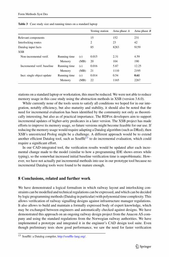
Table 3 compares the running time and memory usage for the verification case study of Arnastation presented in Sect. 6, extended to use the incremental capabilities of XSB Prolog.The extra bookkeeping required in XSB to prepare for incremental evaluation requires moretime and memory than non-incremental evaluation, so we include both non-incremental andfrom-scratch incremental evaluation in the table for comparison.We showhowupdates can becalculated faster than from-scratch evaluation by moving a single object (an axle counter) inand out of a disallowed area near another object (regulations require at least 21.0m separationbetween train detectors). XSB has a configurable mode for reducing the memory usage inits incremental tabling, by abstraction methods. Without using XSB’s abstraction methods,the case study verification uses over 2 GB of memory. So, for any hope of handling larger
12 https://en.wikipedia.org/wiki/Datalog#Systems_implementing_Datalog.
123
Form Methods Syst Des
Table 3 Case study size and running times on a standard laptop
Testing station Arna phase A Arna phase B
Relevant components 15 152 231
Interlocking routes 2 23 42
Datalog input facts 85 8283 9159
XSB
Non-incremental verif. Running time (s) 0.015 2.31 4.59
Memory (MB) 20 104 190
Incremental verif. baseline Running time (s) 0.016 5.87 12.25
Memory (MB) 21 1110 2195
Incr. single object update Running time (s) 0.014 0.54 0.61
Memory (MB) 22 1165 2267
stations on a standard laptop or workstation, this must be reduced.Wewere not able to reducememory usage in this case study using the abstraction methods in XSB (version 3.6.0).
While currently none of the tools seem to satisfy all conditions we hoped for in our inte-gration, notably efficiency, but also maturity and stability, it should also be noted that theneed for incremental evaluation has been identified by the community not only as theoreti-cally interesting, but also as of practical importance. The RDFox developers aim to supportincremental updates of higher-arity predicates in a later version. The XSB project has madeefforts to improve its memory usage, so future versions might become feasible for our use. Ifreducing thememory usage would require adapting a Datalog algorithm (such as DRed), thenXSB’s unrestricted Prolog might be a challenge. A different approach would be to extendanother efficient Datalog tool, such as Soufflé13 to do incremental evaluation, which couldrequire a significant effort.
In our CAD-integrated tool, the verification results would be updated after each incre-mental change made to the model (similar to how a programming IDE shows errors whiletyping), so the somewhat increased initial baseline verification time is unproblematic. How-ever, we have not actually put incremental methods into use in our prototype tool because noincremental Datalog tools were found to be mature enough.
8 Conclusions, related and further work
We have demonstrated a logical formalism in which railway layout and interlocking con-straints can bemodelled and technical regulations can be expressed, andwhich can be decidedby logic programmingmethods (Datalog in particular)with polynomial time complexity. Thisallows verification of railway signalling designs against infrastructure manager regulations.It also allows to build and maintain a formally expressed body of expert knowledge, whichmay be exchanged between engineers and automatically checked against designs. We havedemonstrated this approach on an ongoing railway design project from the Anacon AS com-pany and using the standard regulations from the Norwegian railway authorities. We haveimplemented a prototype and integrated it in the engineer’s CAD design tool suite. Eventhough preliminary tests show good performance, we saw the need for faster verification
13 Soufflé: a Datalog compiler, http://souffle-lang.org/.
123
Form Methods Syst Des
methods, and thus looked into incremental verification tools for Datalog. In this respect wepresented our summary of findings and our test results on our railway use case.
This paper is an extension and combination of three previous conference papers, i.e., weextended our initial results from [33] with more explanations and background material; wecombined and explained the logical work in more context, some of which was presented in[31] to the practitioners from the railway domain; we explained the need for incrementalverification and provided our findings and conclusions, part of which were presented in [32].This paper, thus, presents our results in a more uniform and integrated manner, giving a betterpicture of the overall tool chain and putting the problem well in context. Our future work isdetailed in the following.
8.1 Related work
Railway control systems and signalling designs are a fertile ground for formal methods. See[3,12] for an overview of various approaches and pointers to the literature, applying for-mal methods in various phases of railway design. For a slightly more dated state-of-the-artsurvey, see [22]. In particular, safety of interlockings has been intensively formalized andstudied, using for instance VDM [16] and the B-method, resp. Event-B [27]. Model checkinghas proved particularly attractive for tackling the safety of interlocking, and various modelcheckers and temporal logics have been used, see e.g. [7,10,17,35,43,56]. Critically eval-uating practicality, [13] investigated applicability of model checking for interlocking tablesusing NuSMV or Spin, two prominent representatives of BDD-based symbolic model check-ing, respectively explicit state model checking. The research shows that interlocking systemsof realistic size are currently out of reach for both flavors of general purpose model checkers.To mitigate the state-space explosion problem, [21] uses bounded model checking [8] forinterlockings. Instead of attempting an exhaustive coverage of the state-space, symbolicallyor explicitly, bounded model checking analyses (the behavior of) a given system only up to agiven bound (which is raised incrementally in case analyzing a problem instance is inconclu-sive). This restriction allows to use SAT solving techniques in the analysis. The paper uses avariant of linear temporal logic (LTL) for safety property specification and employs so-callk-induction. The work of [55] investigates how to exploit domain-specific knowledge aboutinterlocking verification to obtain good variable orderings when encoding the systems to beverified in a BDD-based symbolic model checker. An influential technology is the tool-basedsupport for verified code generation for railway interlockings from Prover AB Sweden [5].Prover is an automated theorem prover, using Stålmarck’smethod [50] of tautology checking.
Also logic (programming) languages, like Prolog or Datalog, have been used for repre-senting and checking various aspects of railway designs. For the verification of signalling ofan interlocking design [24] uses a Prolog database to represent the topology and the layout,where for the verification, the work uses a separate SAT solver. Similarly, the work of [38,39]uses logic programming for verification of interlocking systems. In particular, the work usesa specific version of so-called annotated logic, namely annotated logic programs with strongnegation (ALPSN). In general and beyond the railway system domain, recent times haveseen renewed research interest in Datalog, see for instance the collection [36]. Datalog has inparticular been used for formalizing and efficiently implementing program analyses [48,54],whereas [49] presents Doop, a context-sensitive points-to analysis framework for Java.
The mentioned works generally include dynamic aspects of the railway in their checking,like train positions and the interlocking state. This is in contrast to our work, which focuses onchecking against a formalization of the general design rules issued by the regulatory bodies,thus concentrating on static aspects such as the signalling layout. This makes the notorious
123
Form Methods Syst Des
state-space explosion problem less urgent and makes an integration into the standard designworkflow within the existing CAD tool practical.
Lodemann et al. [29] use semantic technologies to automate railway infrastructure veri-fication. Their scope is still wider than this paper in the computational sense, with the fullexpressive power of OWL ontologies, running times on the order of hours, and the use ofseparate interactive graphical user interfaces rather than integration with design tools.
The use of logic programming and knowledge-base systems has been explored in depth forrailway control systems, e.g. by Fringuelli et al. [14], who use logic programming to assist astation operator in performing local control actions on a railway station. The knowledge-basesystem that we presented has a similar encoding of static railway station layout, but with adifferent goal, namely to aid in designing the layout (static design) rather than executingcommands (dynamic control).
Haxthausen and Østergaard [20] perform static checking of interlockings using a DSL forspecifying network layout and interlocking specification, and a C++ program for performingthe checks. Their scope for static checking of interlockings is similar to ours, but their focusis on using this as a preparation step for model checking an interlocking implementation,while our focus is on allowing diverse extensions to the rule base and creating user-friendlyintegrated tools.
8.2 Future work
In the future work with RailComplete AS, we will focus on extending the rule base to containmore relevant signalling and interlocking regulations, and also on evaluating the performanceof our verification on a larger scale. Design information and rules about other railway con-trol systems, such as geographical interlockings and train protection systems could also beincluded. The current work is assuming Norwegian regulations, but the European Rail TrafficManagement System (ETCS/ERTMS) is expected to dominate in the future. The work onfurther developing our prototype verification tool in the context of the commercial RailCOM-PLETE CAD software would also need to extend the rule base to cover more of signallingregulations and extending also to other disciplines. In this process, ETCS/ERTMS regulationswould also be relevant.
Involving railway engineers in knowledge base development is somewhat hindered by thefact that Datalog and logic programming, though declarative and concise, are still program-ming languages, and a good intuition about language semantics is required for efficient andcorrect development. We have started developing a higher-level domain-specific languagewhich compiles to Datalog, for the purpose of including railway engineersmore closely in theknowledge base development. Using the techniques of controlled natural languages (CNL)[26], the language is formally defined and parsable, yet readable as natural language.Writingtext in a controlled natural language is a harder problem, as the formal grammar limits whatcan be expressed, and also how it is written. This problem can be mitigated by means ofspecialized text editors (e.g., as provided by the Grammatical Framework [44],[45, Chap. 7]or Attempto Controlled English [15,25]) which guide the user towards writing acceptablesentences. Adding specific language constructs for static infrastructure analysis of railwaydesigns ensures that the level of abstraction is close to the original regulation text. Our futurework will include testing this language with railway engineers and integrating knowledgebase development into the railway design tool chain. This preliminary work can be reachedthrough the technical report [30] which will be updated in the future.
Finally, we plan to extend from consistency checking to optimization of designs. Opti-mization goals for layout plans include (i) simplified capacity/perfomance metrics, such as
123
Form Methods Syst Des
train spacing time between stations, or train travel time between stations, (ii) safety metrics,such asminimizing the number of short safety zones (also called overlaps), which are allowedby regulation but undesirable, or (iii) component cost and complexity metrics, such as thetotal number of signals, detectors, etc. Optimization requires significantly larger computa-tional effort, and the relation between Datalog and more expressive logical programmingframeworks could become relevant.
Acknowledgements We are grateful to Claus Feyling from RailComplete AS and Martin Steffen from Uni-versity of Oslo for valuable inputs.
Open Access This article is distributed under the terms of the Creative Commons Attribution 4.0 Interna-tional License (http://creativecommons.org/licenses/by/4.0/), which permits unrestricted use, distribution, andreproduction in any medium, provided you give appropriate credit to the original author(s) and the source,provide a link to the Creative Commons license, and indicate if changes were made.
References
1. Abiteboul S, Hull R, Vianu V (eds) (1995) Foundations of databases, 1st edn. Addison-Wesley, Boston2. Aref M, ten Cate B, Green TJ, Kimelfeld B, Olteanu D, Pasalic E, Veldhuizen TL, Washburn G (2015)
Design and implementation of the LogicBlox system. In: Sellis TK, Davidson SB, Ives ZG (eds) The2015 ACM SIGMOD international conference on management of data, pp 1371–1382, ACM. doi:10.1145/2723372.2742796
3. Bjørner D (2003) New results and trends in formal techniques for the development of software in trans-portation systems. In: Tarnai G, Schnieder E (eds) Proceedings of the symposium on formal methods forrailway operation and control systems (FORMS’03), pp 1–20, L’Harmattan Hongrie
4. Bonacchi A, Fantechi A, Bacherini S, Tempestini M (2016) Validation process for railway interlockingsystems. Sci Comput Progr 128:2–21. doi:10.1016/j.scico.2016.04.004
5. Borälv A, Stålmarck G (1999) Prover technology in railways. In: HincheyMG, Bowen JP (eds) Industrial-strength formal methods, international series in formal methods. Springer, Berlin, pp 305–329
6. Bosschaart M, Quaglietta E, Janssen B, Goverde RMP (2015) Efficient formalization of railway inter-locking data in RailML. Inf Syst 49:126–141. doi:10.1016/j.is.2014.11.007
7. Busard S, Cappart Q, Limbrée C, Pecheur C, Schaus P (2015)Verification of railway interlocking systems.In: Pang J, Liu Y, Mauw S (eds) Proceedings 4th international workshop on engineering safety andsecurity systems, ESSS, Electronic Proceedings in Theoretical Computer Science, vol 184, pp 19–31.Open Publishing Association. doi:10.4204/EPTCS.184.2
8. Clarke EM, Biere A, Raimi R, Zhu Y (2001) Boundedmodel checking using satisfiability solving. FormalMethods Sys Des 19:7–34
9. Doyle J (1979) A truth maintenance system. Artif Intell 12(3):231–272. doi:10.1016/0004-3702(79)90008-0
10. Eisner C (1999) Using symbolic model checking to verify the railway stations of Hoorn-Kersenboogerdand Heerhuowaard. In: Pierre L, Kropf T (eds) 10th IFIPWG 10.5 advanced research working conferenceon correct hardware design and verification methods, CHARME ’99, Lecture Notes in Computer Science,vol 1703, pp 97–109. Springer
11. Eisner J, Filardo NW (2011) Dyna: extending datalog for modern AI. In: deMoor O, Gottlob G, Furche T,Sellers A (eds) Datalog reloaded. First international workshop 2010, Lecture notes in computer science,vol 6702. Springer, pp 181–220
12. Fantechi A, Fokkink W, Morzenti A (2012) Some trends in formal methods applications to railwaysignalling. In: Gnesi S, Margaria T (eds) Formal methods for industrial critical systems. Wiley, Hoboken,pp 61–84
13. Ferrari A, Magnani G, Grasso D, Fantechi A (2011) Model checking interlocking control tables. In:Schnieder E, Tarnai G (eds) 8th Symposium on formal methods for automation and safety in railway andautomotive systems (FORMS/FORMAT 2010), pp 107–115. Springer. doi:10.1007/978-3-642-14261-1
14. Fringuelli B, Lamma E, Mello P, Santocchia G (1992) Knowledge-based technology for controllingrailway stations. IEEE Expert 7(6):45–52. doi:10.1109/64.180408
15. Fuchs NE, Kaljurand K, Kuhn T (2008) Attempto controlled english for knowledge representation. In:Baroglio C, Bonatti P, Maluszynski J, Marchiori M, Polleres A, Schaffert S (eds) ReasoningWeb, LectureNotes in Computer Science, vol 5224, pp 104–124. Springer. doi:10.1007/978-3-540-85658-0_3
123
Form Methods Syst Des
16. Fukuda M, Hirao Y, Ogino T (2000) VDM specification of an interlocking system and a simulator for itsvalidation. In: Becker U, Schneider EL (eds) 9th IFAC symposium control in transportation systems, pp218–223. IFAC
17. Gnesi S, Lenzini G, Latella D, Abbaneo C, Amendola A, Marmo P (2000) Automatic spin validation ofa safety critical railway control system. In: IEEE conference on dependable systems and networks. IEEEComputer Society Press. pp 119–124
18. Gupta A,Mumick IS, Subrahmanian VS (1993)Maintaining views incrementally. In: Buneman P, JajodiaS (eds) SIGMOD international conference on management of data, SIGMOD ’93, pp 157–166. ACM.doi:10.1145/170035.170066
19. Harrison JV, Dietrich SW (1992) Maintenance of materialized views in a deductive database: an updatepropagation approach. In: Ramamohanarao K, Harland J, Dong G (eds) Proceedings of the workshopon deductive databases held in conjunction with the joint international conference and symposium onlogic programming, technical report, vol CITRI/TR-92-65, pp 56–65. Department of Computer Science,University of Melbourne
20. Haxthausen AE, Østergaard PH (2016) On the use of static checking in the verification of interlockingsystems. In:Margaria T, Steffen B (eds) 7th international symposium on leveraging applications of formalmethods, verification and validation (ISoLA), Lecture notes in computer science, vol 9953, pp 266–278.Springer. doi:10.1007/978-3-319-47169-3_19
21. Haxthausen AE, Peleska J, Pinger R (2014) Applied bounded model checking for interlocking systemdesigns. In: Counsell S, Núñez M (eds) Software engineering and formal methods collocated workshops.Lecture notes in computer science, vol 8368. Springer. pp 205–220
22. Hinchey MG, Bowen JP (eds) (1999) Industrial-strength formal methods. International series in formalmethods. Springer, Berlin
23. James P, Lawrence A, Moller F, Roggenbach M, Seisenberger M, Setzer A, Kanso K, Chadwick S (2013)Verification of solid state interlocking programs. In: Revised selected papers of the SEFM2013 collocatedworkshops on software engineering and formal methods. Lecture notes in computer science, vol 8368.Springer. pp 253–268. doi:10.1007/978-3-319-05032-4_19
24. KansoK,Moller F, Setzer A (2009)Automated verification of signalling principles in railway interlockingsystems. In: Miller A, Calder M (eds) Proceedings of the 8th international workshop on automatedverification of critical systems (AVoCS 2008), Electronic notes in theoretical computer science, vol 250.Elsevier. pp 19–31. doi:10.1016/j.entcs.2009.08.015
25. Kuhn T (2013) A principled approach to grammars for controlled natural languages and predictive editors.J Log Lang Inf 22(1):33–70. doi:10.1007/s10849-012-9167-z
26. Kuhn T (2014) A survey and classification of controlled natural languages. Comput Linguist 40(1):121–170. doi:10.1162/COLI_a_00168
27. Lecomte T, Burdy L, Leuschel M (2012) Formally checking large data sets in the railways. In: IshikawaF, Romanovsky A (eds) Advances in developing dependable systems in event-B. In conjunction withICFEM 2012, Technical Report. Newcastle University
28. Libkin L (2004) Elements of finite model theory. Texts in theoretical computer science. An EATCS series.Springer. doi:10.1007/978-3-662-07003-1
29. Lodemann M, Luttenberger N, Schulz E (2013) Semantic computing for railway infrastructure verifica-tion. In: 7th International conference on semantic computing (ICSC). IEEE. pp 371–376. doi:10.1109/ICSC.2013.69
30. Luteberget B, Camilleri JJ, Johansen C, Schneider G (2017) Participatory verification of railway infras-tructure regulations using RailCNL (long version). Technical report 465, University of Oslo. http://www.mn.uio.no/ifi/english/research/projects/railcons
31. Luteberget B, Feyling C (2016) Automated verification of rules and regulations compliance in CADmodels of railway signalling and interlocking. In: Brebbia C, Mera J, Tomii N, Tzieropoulos P (eds)Computers in railways, WIT Press. 15: 153–165
32. Luteberget B, Johansen C, Feyling C, Steffen M (2016) Rule-based incremental verification tools appliedto railway designs and regulations. In: Fitzgerald J, Heitmeyer C, Gnesi S, Philippou A (eds) 21st Inter-national symposium on formal methods (FM). Lecture notes in computer science, vol 9995. Springer. pp772–778. doi:10.1007/978-3-319-48989-6_49
33. Luteberget B, Johansen C, Steffen M (2016) Rule-based consistency checking of railway infrastructuredesigns. In: Ábrahám E, Huisman M (eds.) 12th International conference on integrated formal methods(iFM 2016). Lecture notes in computer science, vol 9681. Springer. pp 491–507. doi:10.1007/978-3-319-33693-0_31
34. Luteberget B, Johansen C, Steffen M (2016) Rule-based consistency checking of railway infrastructuredesigns (long version). Technical report 450, University of Oslo, Department of Informatics. http://www.ifi.uio.no/~msteffen/download/16/rulebasedconsistency-rep.pdf
123
Form Methods Syst Des
35. Mirabadi A, Yazdi MB (2009) Automatic generation and verification of railway interlocking tables usingFSM and NuSMV. Transp Probl: Int Sci J 4:103–110
36. de Moor O, Gottlob G, Furche T, Sellers A (eds) (2011) Datalog reloaded. In: 1st international workshop2010. Lecture notes in computer science, vol 6702. Springer
37. Motik B, Nenov Y, Piro REF, Horrocks I (2015) Incremental update of datalog materialisation: thebackward/forward algorithm. In: Bonet B, Koenig S (eds) 29th AAAI conference on artificial intelligence.AAAI Press. pp 1560–1568
38. Nakamatsu K, Kiuchi Y, Chen W, Chung S (2004) Intelligent railway interlocking safety verificationbased on annotated logic program and its simulator. In: IEEE international conference on networking,sensing and control, vol 1. IEEE. pp 694–699. doi:10.1109/ICNSC.2004.1297524
39. Nakamatsu K, Kiuchi Y, Suzuki A (2004) EVALPSN based railway interlocking simulator. In: NegoitaMG, Howlett RJ, Jain LC (eds) Knowledge-based intelligent information and engineering systems, Lec-ture notes in artificial intelligence, vol 3214. Springer. pp 961–967
40. Nash A, Huerlimann D, Schütte J (2004) RailML—a standard data interface for railroad applications. In:Allan J, Brebbia C, Hill R, Sciutto G, Sone S (eds) Comput Railw IX. WIT Press, Ashurst, pp 233–240
41. Nilsson U, Maluszynski J (1995) Logic, programming, and prolog, 2nd edn. Wiley, Hoboken42. Pachl J (2015) Railway operation and control. VTD Rail Publishing, Mountlake Terrace43. Pavlovic O, Ehrich H (2010) Model checking PLC software written in function block diagram. In: 3rd
International conference on software testing, verification and validation, ICST. IEEE. pp 439–44844. RantaA (2004)Grammatical framework. J Func Progr 14(2):145–189. doi:10.1017/S095679680300473845. Ranta A (2011) Grammatical framework programming with multilingual grammars. CSLI Publications,
Stanford46. Russell SJ, Norvig P (2003) Artificial intelligence: a modern approach, 2nd edn. Pearson Education,
Upper Saddle River47. Saha D, Ramakrishnan CR (2003) Incremental evaluation of tabled logic programs. In: Palamidessi C
(ed) 19th International conference on ICLPLogic programming. Lecture notes in computer science, vol2916. Springer. pp 392–406. doi:10.1007/978-3-540-24599-5_27
48. Smaragdakis Y, Bravenboer M (2011) Using Datalog for fast and easy program analysis. In: de Moor O,Gottlob G, Furche T, Sellers A (eds) Datalog reloaded. First international workshop 2010, Lecture notesin computer science, vol 6702. Springer, pp 245–251
49. Smaragdakis Y, Bravenboer M, Lhoták O (2011) Pick your contexts well: understanding context-sensitivity (the making of a precise and scalable pointer analysis). In: Ball T, Sagiv M (eds) 38th ACMSIGPLAN-SIGACT symposium on principles of programming languages (POPL). ACM. pp 17–30
50. Stalmårck G (1992) A system for determining logic theorems by applying values and rules to triplets thatare generated from a formula. Swedish Patent No. 467 076 (approved 1992), U.S. Patent No. 5 276 897(approved 1994), European Patent No. 0403 454 (approved 1995)
51. Swift T (2014) Incremental tabling in support of knowledge representation and reasoning. Theory PractLog Progr 14(4–5):553–567. doi:10.1017/S1471068414000209
52. Swift T, Warren DS (2012) XSB: Extending Prolog with tabled logic programming. Theory Pract LogProgr 12(1–2):157–187. doi:10.1017/S1471068411000500
53. Ullman JD (1988) Principles of database and knowledge-base systems (Volume 1 and 2). ComputerSociety Press, Hoboken
54. Whaley J, Avots D, Carbin M, LamMS (2005) Using Datalog with binary decision diagrams for programanalysis. In: Yi K (ed) 3rd Asian symposium on programming languages and systems (APLAS). Lecturenotes in computer science, vol 3780. Springer. pp 97–108
55. Winter K (2012) Optimising ordering strategies for symbolic model checking interlocking control tables.In:Margaria T, SteffenB (eds) 5th International symposiumon leveraging applications of formalmethods,verification, and validation (ISOLA’12), Part II. Lecture notes in computer science, vol 7610. Springer,pp 246–260
56. Winter K, Johnston W, Robinson P, Strooper P, van den Berg L (2006) Tool support for checking railwayinterlocking designs. In: Cant T (ed) Proceedings of the 10th Australian workshop on safety criticalsystems and software. ACM. pp 101–107
123