Embed Size (px)
Citation preview

NOVEMBER 2017 AISC

WHEN THE WORD “STEEL” is mentioned, its flexibility, durability and strength typically come to mind.
But what about its beauty? More and more designers are choosing to expose steel in their projects—not just out of a sense of practicality or functionality, but also for its aesthetic attributes. They do so because they realize that steel can do more than simply support a design; it can also become an integral part of it.
And in doing so, they often hold steel to as high a standard as any other fixture or finish. They aren’t just going for an industrial look. They’re elevating the material to a new level: architecturally exposed structural steel (AESS). So where to begin when considering AESS for your next project? Start with the Code.
The 2016 AISC Code of Standard Practice (ANSI/AISC 303-16) implements a defined approach to specifying AESS in the contract documents by using five categories—AESS 1, 2, 3, 4 and C—which differentiate levels of steel fabrica-tion and erection. As the numbers in this tiered system rise, the cost and time for fabrication and erection typically also increase. (A similar approach was adopted in the Canadian Code of Standard Practice in 2009 via the Canadian Institute of Steel Construction—CISC—Code of Standard Practice for Structural Steel, Seventh Edition.) Previous versions of the codes did not define the terms of AESS as distinctly, leav-ing room for interpretation and cost escalation, and this lat-est version of the AISC Code helps clear things up. The new guidelines establish the same level of expectations between designers, fabricators and erectors for the visual appearance of AESS. The category system provides architects with a method of articulating AESS in their projects with a much clearer understanding of deliverables.
Exposed or Architecturally Exposed? The AISC Code defines structural steel as elements that
are required to support the design loads of a building and fit within the components of a structural frame. For clar-ity, the AESS category system is typically only applied to fabricated structural steel as referenced in Section 2.1 of the Code: anchor rods, base plates, beams, bracing, canopy framing, columns, connection materials, crane stops, girders, lintels, posts, shear stud connectors, trusses, etc. Unfinished, reused, galvanized or weathering steel members may all be fabricated with AESS requirements.
AESS goes a step beyond standard fabrication and erec-tion. During fabrication, shipment and erection, extra care is taken to avoid blemishes and unwanted surface appearance when handling the steel and removing temporary braces or fixtures. For some categories, all backing and runoff tabs are removed, and welds are to be ground smooth for those areas. Basic unpainted steel must also be cleaned of oil, grease, dirt and loose mill.
There are “other steel, iron or metal items” that are not typically specified as AESS, though there may be exceptions depending on project requirements. Cables, castings, catwalks, chutes, cold-formed steel products, corner guards, flagpole supports, grating, handrails, ladders, ornamental metal, stacks, stairs, steel deck, open-web steel joists, joist girders and trench-es are examples of components that do not typically receive AESS identification (reference Section 2.2 of the AISC Code for the full list).
Everyone in the building industry is familiar with the phrase “location, location, location.” When architecturally exposing the structure as an integral part of the design intent, the following phrase comes into play: “coordination, coordination, coordina-tion.” While the architect chooses the locations of AESS in a project, the structural engineer should document it. According to Bill Andrews, SE, a principal at structural engineering firm Walter P Moore, fabricators and detailers will typically look to the structural drawings in the contract documents as the pri-mary source of information for structural steel, including AESS.
Modern STEEL CONSTRUCTION
A guide to understanding and specifying the various
categories of architecturally exposed structural steel (AESS).
MAXIMUM Exposure
Striking structural steel, exposed not only architecturally but also to the elements, lets Chicago’s newest transit station, the Washington/Wabash “L” station, take on its own unique look and feel. (See page 36 for more on this project, which opened this past summer.)

NOVEMBER 2017
Lighting typically has the greatest impact on interior AESS, whereas sight lines are the most important for AESS located on the exterior. Details are not as visible in high ceilings with low lighting, including shaded steel. However, when elements are brightly lit, they may tend to expose more texture and blemishes on the surface. The location and type of lighting with relation to AESS components should be determined prior to specifying the appropriate category.
Rya
n D
ravi
tz P
hoto
gra
phy
Rya
n D
ravi
tz P
hoto
gra
phy

This methodology saves time and cost during construction, with the intent of consolidating references to AESS as much as possible. It is of utmost importance that successful coor-dination between these disciplines takes place to ensure the contract documents are bid per the design intent.
Equally imperative is selecting the correct category for all AESS components in a project. Per the AISC Code, it is re-quired that all AESS is identified as Categories 1, 2, 3, 4 or C.
“This is a dramatic improvement over the previous code edi-tion [2010],” says Andrews, “in terms of better clarity, articu-lating expression... and giving everyone a better understand-ing of relative costs when choosing AESS and at what level.” Sufficient coordination and understanding of best practices are essential to keeping a project within budget and schedule.
ContextThere are many factors that influence the level of finish
and detailing on an exposed member. It is important to un-derstand the context surrounding the exposed steel before choosing an AESS category. The following explains which elements impact AESS and how it is perceived in the built environment: member visibility, viewing distance, location, lighting, coatings, style and adjacency.
Member visibility. Simply put, if it is not readily visible, there is no need to identify exposed steel as AESS. There are often conditions where one side of an exposed steel column or braced frame may be blocked from view by a wall or other component. It is possible to note a specific AESS category only on the side of an exposed member that is visible to view. Specifying AESS incurs more time and care during design, fabrication and erection and should only be spent on por-tions of the project that are visible and prominent. Identify-ing specific locations for AESS takes careful consideration, but thoughtful analysis can greatly reduce cost and time dur-ing construction.
Viewing distance. Details tend to disappear from the naked eye the further away they are located. When an object is beyond 20 ft away, the distinction between components is not as clearly seen as when it is within reach. Consider objects 100 ft away from the closest point of view, and the level of visible detail is even less distinct. The category sys-tem for AESS recognizes that viewing distance is critical to the level of fabrication and erection required for structural steel. The 20-ft viewing distance separates categories AESS 2 and AESS 3.
Location. Whether AESS is placed on the interior or exterior of a building has a significant impact on the type of coating and protection selected for the member, as well as how it is detailed. If placed on the exterior of a build-ing, the exposed steel must withstand more corrosive or harsh climate conditions. Additional surface preparation and protective coatings are often implemented to promote long-lasting AESS. Detailing at joints or connections must also take special care to keep water out to avoid corrosion of steel members.
Lighting. According to Steve Weiss, principal and founder of Weiss Architects, lighting typically has the great-est impact on interior AESS, whereas sight lines are the most important for AESS located on the exterior. Details are not as visible in high ceilings with low lighting, but when ele-
For AESS requiring fire protection, one option is to apply an intumescent coating. Note that the intumescent coating itself does not come in different colors; a separate paint is applied on top of the coating. And if an intumescent-coated piece of steel is placed next to an uncoated piece, the final paint colors will vary, as the intumescent coating acts as a different kind of primer.
AESS can also be galvanized. Design teams should be aware that galvanizing steel does not provide a “chrome” finish, and no two pieces of galvanized steel will look exactly the same.
Paint systems, typically consisting of a primer and one or more paint coats, are also widely used for AESS applications. Almost any color or finish can be used.
Modern STEEL CONSTRUCTION
Ron Blunt/EwingCole
Steinkamp Photography
Erik Hinote

NOVEMBER 2017
ments are brightly lit, they may tend to expose more texture and blemishes on the surface. The location and type of lighting with relation to AESS components should be determined prior to specifying the appropriate category.
Coatings. The selection of a coating, whether it be paint or in-tumescent fire protection, should be coordinated with the location and lighting intent for an AESS member. “Glossy coats tend to show every imperfection and surface variation,” says Larry Kloiber, PE, vice president with AISC member fabricator LeJeune Steel. A glossy coat combined with bright accent lighting within a close view range requires greater care and surface preparation for AESS. A thicker intumescent coating or matte finish tends to cover sur-face marks and blemishes, thereby reducing the need for certain characteristics of surface preparation to the steel. Kloiber stresses that it is always important to keep in mind how the material will be viewed, as it will impact the AESS category specified.
Style. There are two basic styles that govern the design in-tent with AESS: tectonic and plastic. A tectonic look is more expressive of the details that showcase the steel assembly and tends to emphasize bolted construction. A plastic aesthetic is uniform and smooth, using more welded or cast connections for a near-seamless appearance. The approach to the design style is an integral part of determining which AESS category is suitable based on the desired level of finish.
The 2016 AISC Code distinguishes between standard tolerances and tighter tolerances for the various AESS categories. The Anaheim Regional Transportation Intermodal Center (ARTIC) is a great example of a project with numerous tolerances coming together. Exposed tubular steel creates crisscrossing lines for the station’s dome, forming diamond shapes that are filled with ethylene tetrafluoroethylene (ETFE) plastic cushions to let in daylight.
Specifying a Mock-UpAESS 3, 4 and C all require mock-ups unless pro-viding one is impractical and other visual samples can suffice. “The key to a mock-up is to set expec-tations for shop work and fieldwork,” notes Steve Weiss of Weiss Architects, going on to say, “If an assembly is to be created in the field, then the mock-up should also take place in the field, with the same contractors doing it under the same field conditions.” Lighting and placement impact the ap-pearance of AESS, so similar conditions should be replicated when reviewing a mock-up for finish.
In general, as schedule and budget permit, mock-ups or visual samples are recommended for all categories. Shaina Saporta, PE, of Arup notes that majority of her projects involve AESS located in exterior conditions. Saporta typically specifies physical mock-ups for larger, more complicated projects, noting that not doing so may cost more in the long run. Visual samples are a broad category inclusive of full-scale mock-ups, mock-ups of con-nections only, finish samples, 3D renderings, pho-tographs representing built AESS categories and more. Babette Freund of AISC member fabricator Universal Steel of North Carolina suggests tours of existing AESS projects and visual examples as methods to help communicate expectations for de-livery of the desired finished product, noting that there are multiple approaches to establish a basis of expectations during construction.
Thornton Tomasetti

Modern STEEL CONSTRUCTION
Adjacency. Structural steel is an ideal material for achieving tight tolerances, as it is fabricated with great precision. The AISC Code distinguishes between standard tolerances and tighter tolerances with different AESS categories. De-pending on the composition of the structure, tighter tolerances may or may not be necessary.
Several factors have a direct impact on the selection of an AESS category. Coordination during the design phase can be better facilitated by understanding the context that surrounds the expression of steel.
AESS CategoriesThere are five categories under which AESS can fall:➤ AESS 1: Basic Elements➤ AESS 2: Feature Elements not in Close View➤ AESS 3: Feature Elements in Close View➤ AESS 4: Showcase Elements➤ AESS C: Custom ElementsMore requirements, and therefore typically greater costs, are inherent as the
AESS category number increases. AESS C is Custom and could require fewer levels of finish than Basic Elements in AESS 1, or go even further beyond what is included in Showcase Elements of AESS 4. When choosing AESS C, more information should be included in the drawings and specifications to clarify the intent. It is required that one or more of these five AESS categories be anno-tated in the contract documents when the AISC Code is referenced as a standard.
“Section 10 of the AISC Code provides specifiers with a much clearer roadmap to convey what they are looking for,” acknowledges Babette Freund with AISC member fabricator Universal Steel of North Carolina. Freund serves as chair of the Code of Standard Practice Committee to recognize and document stan-dards within the U.S. structural steel industry to help meet design expectations between fabricators and designers. Larry Kloiber, who serves on the commit-tee with Freund, encourages architects to consider the appearance they want to achieve for the design intent prior to selecting an AESS category.
AESS 1: BASIC ELEMENTS. By default, AESS 1 is the minimum treatment of exposed steel beyond standard fabrication of structural steel. This category typically incurs the lowest cost of all the AESS categories and also serves as a prerequisite for AESS categories 2, 3 and 4. There are aspects of AESS 1 that meet the same requirements of standard fabrication. For example, the toler-ances required for standard structural steel are the same for AESS 1 and can be referenced in the AISC Code.
Surface preparation in AESS 1 is different from standard fabrication, as the exposed steel must receive commercial blast cleaning to meet the provisions of SSPC SP-6: Commercial Blast Cleaning. The Society for Protective Coatings (SSPC) sets the standards for coatings and protection on structural steel. The SP-6 standard requires steel to be cleaned of oil, grease, dust, oxides, rust, etc. In order to complete this surface preparation, weld spatter and similar surface discontinuities must be removed and sharp edges ground smooth. Specifications for paint and coatings should be thoroughly reviewed for use with the required surface preparation of AESS members.
Consistency of appearance between components is also a key strategy when specifying AESS. The AESS 1 category requires that bolt heads be consistently located on the same side of a member as well as on adjacent steel members. The goal is to provide a uniform appearance beyond the standard requirements of structural steel.
When steel components are welded together, there may not always be a need for a continuous weld per the structural design. Visually, however, the appear-ance of a continuous weld is more desirable than intermittent welds. AESS 1 requires that all welds are to appear continuous and can be caulked, filled or ad-ditionally welded to achieve this look. The projection of welds can be no higher than 1⁄16 in. above the surface.
The Queen Richmond Centre West in Toronto (above) and San Francis-co’s Transbay Transit Center (below) are two projects featuring massive cast elements designated as AESS. Selection of the appropriate AESS Category should consider not only viewing distance but also the coating system to be implemented. In the case of the Queen Richmond Centre West, an intumescent coating has been applied to the steel. The Trans-bay Transit Center’s signature Light Column feature is comprised of steel castings and API pipe. AESS require-ments for this assembly range from AESS 2 to AESS 4 based on viewing distance. The Transbay Transit Cen-ter is scheduled to open next year; the Queen Richmond Centre West is already open.
Ad
amson A
ssociatesC
ourtesy of CA
ST CO
NN
EX; d
oublesp
ace photog
raphy

NOVEMBER 2017
AESS 2: FEATURE ELEMENTS NOT IN CLOSE VIEW. It is important to recognize that details are much less visible at 20 ft away as compared to an element 5 ft away. AESS 2 serves a level of fabrication and erection specific to structural steel elements viewed from a distance greater than 20 ft. The intent of creating such a distinction is to establish the same level of expectations for elements that are deemed as AESS but are located further away. The cost range is typically higher than AESS 1, as it builds on the characteristics of the basic elements in addition to meeting more requirements.
AESS 2 is more refined than AESS 1, as it mandates fabrica-tion tolerances for straightness to be half that of standard re-quirements. This is especially important when adjacent materi-als and components must closely integrate with steel members in a design.
During fabrication and erection, steel members are marked for inventory and tracking purposes. These numbers are visible on the steel even through certain coatings unless AESS 2 or a higher category is specified. The marks can either be ground out, filled or simply turned away from view.
Continuous welds are already included with AESS 1, but AESS 2 goes a step further by requiring greater consistency in the welding process. The latter expects additional care and re-finement during fabrication and erection. AESS 2 calls for uni-form and smooth welds, which entails a consistent appearance on all welds in view range but does not necessarily deem welds are to be ground smooth.
AESS 3: FEATURE ELEMENTS IN CLOSE VIEW. A higher level of fabrication and erection is provided as the AESS category number increases. AESS 3 represents the next level of characteristics, specifically for components within a viewing distance of 20 ft or less. This category includes all the requirements for AESS 1 and 2 along with a more specific attention to detail as exposed elements are visibly closer.
Steel is marked with slightly raised characters, called mill marks, when it is delivered to a fabricator from the mill. (Mill marks identify the steel mill at which the component was pro-duced.) A raised or depressed surface on structural steel mem-bers is also created with butt and plug welds. These marks and visible welds are deemed undesirable in AESS 3 and are required to be removed from view, typically by grinding them out or filling any depressions. Grind marks on exposed steel are easily visible. High-gloss paints should not be applied without additional surface preparation.
A weld seam is typically apparent when steel is joined to-gether by welding. Welds are required to be continuous and consistent in appearance, as noted in categories AESS 1 and 2. It is required that weld seams are to be less visible in AESS 3, as these elements are much closer in viewing range. Hollow struc-tural sections (HSS) often include visible weld seams as part of the manufacturing process. An option to reduce the visibility of seams is to simply orient them away from view. When such a strategy is not available, then aligning the seams in a consistent
Questions to ConsiderMIG Steel Fabrication (an AISC member) shares some questions and suggestions based on its first experience with a complex AESS project: the decorative Technology Tower on North Carolina State University’s campus in Raleigh, N.C.:
➤ Are the project specifications for AESS in alignment with Section 10 of the AISC Code? Do they clearly address requirements for special fabrication, handling and erection of AESS?
➤ What are the requirements for preinstallation conferences, mock-up procedures and testing? If these are not addressed in the specs, the fabricator should have recourse to include them in order to facilitate communication and address quality issues prior to installation.
➤ Will outside vendors be required to complete the AESS project? If so, are there clear protocols in place to reconcile quality issues if and when they arise?
➤ Include a budget for contingencies. Unforeseen challenges happen on every project, but AESS may require implementing completely unique solutions.
➤ Learn to be flexible. Thinking outside the box and meeting the challenges of a complex AESS project can reap great knowledge and experience dividends applicable to future projects.
Rob
ert
Ben
son
Phot
ogra
phy

NOVEMBER 2017
Making an (Exposed) ConnectionTerri Meyer Boake, an architecture professor at the Uni-versity of Waterloo in Waterloo, Ontario, has an eye for interesting and attractive exposed steel. Below are two exposed connections that she’s come across in her trav-els, highlighting impressive AESS detailing.
The connection on the left showcases a high level of thought in accommodating the transition from the small diameter of the cable to the attachment of about 20 plates to a mast. The thickness of the plate at the pin connection has been increased to resist pull-through forces. The thickened element tapers
down to meet the primary plate, whose purpose is to transfer loads to the mast. It widens to provide ade-quate transfer via its fillet welds. There is just enough room between the many plates to do the welding. On the right, the detailing of the large arched trusses that span the departures hall of this airport is playful. The members have been chosen to highlight their tensile versus compressive function. Pin connections are extensively used to attach the tension mem-bers, while plates inserted into the round tubes that comprise the compression members create a visual contrast.
An addition to Dickinson College’s Kline Center in Carlisle, Pa., features exposed steel throughout the building, but only select exposed structural members close to view were designated as AESS.
CannonDesign/Scott Frances
Terri Meyer Boake Terri Meyer Boake

Modern STEEL CONSTRUCTION
manner across all members is another solution. There are mul-tiple methods of fulfilling this requirement, some of which are less costly than others.
When two cross sections of steel come together, such as a column splice with connection plates, it is critical the sections align when in close viewing range. Lighting showcasing an AESS component can expose misaligned surfaces in an obvious and undesirable manner. AESS 3 specifically addresses components within range of touch or within closer viewing distances up to 20 ft away. Misalignments are not acceptable and require greater care in fabrication and erection to avoid these issues at cross-sectional surfaces that abut one another.
The tolerance for straightness must be tighter than the standard level, as noted under AESS 2. Tolerance require-ments in AESS 3 go further to minimize the gaps between the components that have bolted connections. Greater preci-sion during fabrication and erection is required so that these gaps are no greater than 1⁄8 in. and are uniform among all adjacent components.
Determining the style of aesthetic is a prerequisite for choosing the appropriate AESS category. Oftentimes, design-ers wish to expose their bolts for a more tectonic aesthetic. In cases where visible bolted connections aren’t desired or are challenging to access and tighten—e.g., when trying to achieve a seamless, plastic look—AESS 3 includes an option to use all-welded connections or reduce bolt usage. This can be achieved by coordinating the design intent with the struc-tural engineer to use only welds for a particular connection. An alternate solution may be to hide the bolts by placing cover
plates over them, a detail that should be clearly expressed in the contract documents.
AESS 4: SHOWCASE ELEMENTS. The sculptural nature of steel is meant to be the main focus when specifying AESS 4. This category draws inspiration from the expression of form as the featured aesthetic in a project. Making material connections appear seamless in a project can sometimes be the most chal-lenging ones to design and construct. The latter is also true of structure, especially when AESS is to have a very smooth and sleek finished appearance. It is generally understood that AESS 4 components may entail the highest premium over the previ-ous categories, not only per the desired “glove-smooth” finish, but more often due to the complexity of structural geometry. The design approach should be discussed between the archi-tect and structural engineer in advance of selecting the AESS category.
The characteristics of the previous categories, AESS 1, 2 and 3, are all included with the selection of AESS 4. In AESS 3, it is acceptable to reduce the visibility of weld seams. The glove- smooth finish desired for showcase elements in AESS 4 necessitates that weld seams are no longer visible. Certain structural steel shapes and sections, such as pipe or some types of HSS, lend themselves to having few or no seams. If at all possible, turn the seam away from view for the most cost-effective strategy.
The smooth and contoured appearance of welds enhances the style of the more plastic look of AESS 4 components. The majority of steel designs in this category focus less on bolted connections and implement more welded connections for
Different Viewing Levels, Different AESS LevelsSpaces like multilevel concourses provide the possibility for multiple AESS categories all in a single space and all visible at once. Kansas City’s Sprint Center was built before the current AESS categories were implemented, but in looking at the below photo of the space, you can see where various categories could have been implemented. With any area employing multiple categories, the architect should provide clear notes as to where each category should be used and coordinate this documentation with the structural engineer’s drawings and specifications.
AESS 1
AESS 2
AESS 3
Cop
yrig
ht B
ill C
obb
/kcp
hoto
.com
NOVEMBER 2017
a seamless aesthetic. There are cases where welds may show through the back face of an exposed steel element. Locations where welds show through to the other side of the AESS com-ponent must be addressed to reduce their undesirable appear-ance. Open holes placed in the steel members, often for the welding process, are to be closed off and smoothed out for a clean, finished surface.
More labor and time are often necessary during fabrication and erection to achieve the quality of AESS 4 compared to the previous categories. Surfaces that are in view range are to be free of imperfections. Filling any deviations with a body filler as well as sanding textured surfaces are methods of fabrication used in this category. This higher level of care and detail allows for glossy coats on steel to be a truly successful aesthetic in close view range.
AESS C: CUSTOM ELEMENTS. Any deviation from the requirements of AESS 1, 2, 3 and 4 falls under the Custom cat-egory, AESS C. Occasionally, there are situations when sharp edges do not need to be ground smooth or erection and painted marks are not required to be removed from view. Allowing this flexibility in choosing characteristics provides designers with greater freedom but also notifies steel fabricators and erectors that there is a noteworthy difference from the typical category requirements. Custom elements should be clearly defined in the contract documents with AESS C located as needed.
The AISC Code recommends using Table 10.1 (on the fol-lowing page), similar to the more comprehensive AESS Cat-egory Matrix (see last spread of this PDF), as a checklist for
architects to coordinate or customize AESS requirements with structural engineers. The matrix should be used to specify spe-cial requirements for AESS C in the contract documents.
The Last Piece The last portion of the AESS process is just as critical as
a well-coordinated design phase. The AISC Code addresses re-quirements for erection of AESS in Section 10. The higher-quality finish and treatment of AESS necessitates extra care and handling during transit and placement. The timeline for erec-tion may be slightly longer when AESS is specified on a project. Erectors are tasked with assembling the steel with careful plan-ning and methods to avoid damage to the finished product.
The decision to architecturally expose structural steel can add significant value to a building. Improvements in 2016 AISC Code satisfy the desire to create efficient and cost-effective mea-sures when implementing AESS on a project. The five categories (AESS 1, 2, 3, 4 and C) that distinguish AESS require sufficient evaluation and coordination in order to meet project expecta-tions within budget and schedule. Establishing the same level of expectations between owners, architects, engineers, general con-tractors, fabricators, detailers and erectors is critical to achieving the best end results for a project.
See the following pages for more on AESS, including the aforemen-tioned AESS Category Matrix and Table 10.1, a sample AESS speci-fication and a list of helpful resources.
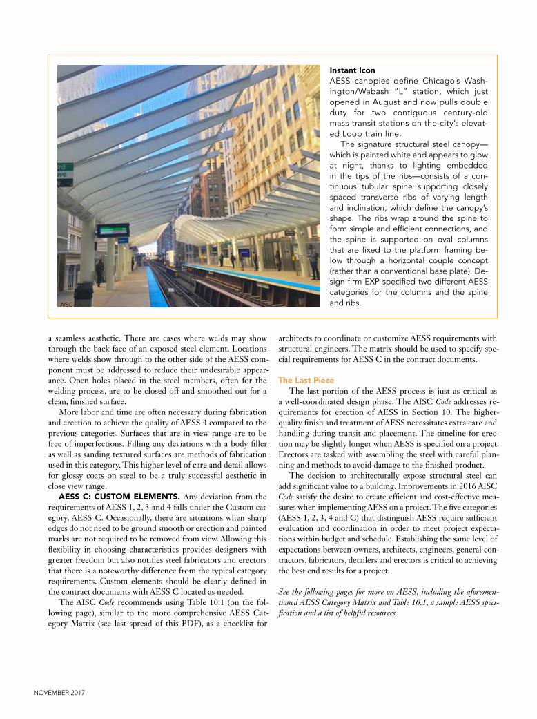
Instant IconAESS canopies define Chicago’s Wash-ington/Wabash “L” station, which just opened in August and now pulls double duty for two contiguous century-old mass transit stations on the city’s elevat-ed Loop train line.
The signature structural steel canopy—which is painted white and appears to glow at night, thanks to lighting embedded in the tips of the ribs—consists of a con-tinuous tubular spine supporting closely spaced transverse ribs of varying length and inclination, which define the canopy’s shape. The ribs wrap around the spine to form simple and efficient connections, and the spine is supported on oval columns that are fixed to the platform framing be-low through a horizontal couple concept (rather than a conventional base plate). De-sign firm EXP specified two different AESS categories for the columns and the spine and ribs.AISC

Modern STEEL CONSTRUCTION
Details tend to disappear from the naked eye the further away they are located. When an object is beyond 20 ft, the distinction between components is not as clearly seen as when it is within reach. For example, the residential project on the left allows people touch every element of the exposed structure, all of which is in close view. The exposed steel in the office building on the right is so high that only maintenance staff, and the occasional bird, will be able to see the level of fabrication.
TABLE 10.1: AESS Category MatrixCATEGORY AESS C AESS 4 AESS 3 AESS 2 AESS 1 SSS
I.D. CHARACTERISTICS CUSTOM ELEMENTS
SHOWCASE ELEMENTS
FEATURE ELEMENTS IN CLOSE VIEW
FEATURE ELEMENTS NOT IN CLOSE VIEW
BASIC ELEMENTS
STANDARD STRUCTURAL
STEEL1.1 Surface preparation to SSPC-SP 6 × × × ×1.2 Sharp edges ground smooth × × × ×1.3 Continuous weld appearance × × × ×1.4 Standard structural bolts × × × ×1.5 Weld spatters removed × × × ×
2.1 Visual Samples × × optional
2.2 One-half standard fabrication tolerances × × ×
2.3 Fabrication marks not apparent × × ×2.4 Welds uniform and smooth × × ×
3.1 Mill marks removed × ×3.2 Butt and plug welds ground
smooth and filled × ×
3.3 HSS weld seam oriented for reduced visibility × ×
3.4 Cross-sectional abutting surface aligned × ×
3.5 Joint gap tolerances minimized × ×3.6 All welded connections optional optional
4.1 HSS seam not apparent ×4.2 Welds contoured and blended ×4.3 Surfaces filled and sanded ×4.4 Weld show-through minimized ×
C.1
A matrix is provided in Section 10 of the AISC Code, outlining which fabrication processes are present within each category. And for exposed steel goals that don’t fit into categories AESS 1 through 4, a Custom category (C) and blank matrix space are available for teams to discuss and create their own unique guidelines.
Note: Descriptions of the I.D. characteristics can be found on the last page of this PDF, to the right of the AESS Category Matrix.
Paul
War
chol
Pho
tog
aphy
, Inc
.
Paul
War
chol
Pho
tog
aphy
, Inc
.

NOVEMBER 2017
Sample AESS SpecificationPrior to the publication of the 2016 AISC Code of Standard
Practice, the most frequently referenced resource used by de-signers in specifying architecturally exposed structural steel (AESS) was a sample specification and an accompanying cost matrix, both developed by the joint Steel Committee of the Rocky Mountain Steel Construction Association and the Struc-tural Engineers Association of Colorado and originally pub-lished as a supplement to the May 2003 issue of Modern Steel Construction. These resources were updated this year.
The below sample specification builds on the 2003 version, with the intent of allowing the specifier to more clearly identify the desired appearance requirements of a project’s AESS ele-ments. This is accomplished by including coordinated referenc-es to the AESS category system now adopted by the AISC Code. Also suggested in the sample specification are requirements for a mock-up demonstrating applicable AESS characteristics and/or physical samples to be fabricated and submitted. The 2016 Code requires that a mock-up be provided for all of the AESS categories, and this is repeated in the sample specification. For AESS Category 1 and 2 elements, the sample specification sug-gests that the specifier consider requiring either a full mock-up or samples of specific AESS characteristics. The sample speci-fication contains a list of nine suggested requirements for the mock-up, with the objective of ensuring that it will accurately represent the in-place AESS elements on a project.
The updated AESS Category Matrix uses the five new AESS categories (AESS 1, 2, 3, 4 and C—Custom) with sets of character-istics specific to each category. It also incorporates a range of esti-mated cost premiums for each category and characteristic within, which are based on a recent survey of participating fabricators.
To serve as visual examples of each AESS category, AISC has developed a set of five small connection sculptures. One sculpture demonstrates the characteristics of standard struc-tural steel, and the remaining four demonstrate the characteris-tics AESS 1-4. The sculptures allow invested parties to see the range of possible appearance levels corresponding to the char-acteristics of each AESS category. Standardized shop drawings for the sculptures have been developed by AISC, with the hope that professional organizations across the country will embrace the concept and fund fabrications that can be accessed locally. The sculptures were fabricated by Newport Industrial Fabrica-tion, and the drawings were produced by The Steel Detailers, Inc. (both are AISC members).
These resources have been developed with the goal of im-proving the AESS process from conception and design through fabrication and erection. The intent is that applicable combina-tion of the sample specification, category matrix, updated Code, model photos and the preceding article will provide insight regarding levels of achievable appearances, correlated with expected cost ranges, to help owners and architects make in-formed decisions; assist architects and engineers in identifying and coordinating expectations; and facilitate the preparation of contract documents that will clearly communicate desired appearances so that AESS elements can be accurately priced, detailed, fabricated and erected. —Robert V. Leberer, Anderson & Hastings Consultants, Inc.
Note that both the sample specification below and the cost matrix that follows (page 52) were produced by the Structural Engineers Associa-tion of Colorado and Rocky Mountain Steel Construction Association Steel Liaison Committee. They are not products of AISC.
Left: Standard structural steel (SSPC-SP2). Right: AESS 1 (SSPC-SP6).

Modern STEEL CONSTRUCTION
Sample Specification, Section 05 12 13 : Architecturally Exposed Structural Steel
PART 1 – GENERAL
1.1 RELATED DOCUMENTS
A. Drawings and general provisions of the Contract, including General and Supplementary Conditions and Division 1 Specification Sections, apply to the Section.
1.2 SUMMARY
Editor’s Note: It is critical to define to the bidders what members will be considered as Architecturally Exposed Structural Steel (AESS) and what category of AESS applies to each area. Furthermore, any variations to the requirements of the American Institute of Steel Construction (AISC) Code of Standard Practice for Steel Buildings and Bridges ANSI/AISC 303-16 (COSP) must be spelled out. Delete references to AESS categories not required for the project.
A. This Section includes requirements regarding the appearance and surface preparation of Architecturally Exposed Structural Steel (AESS). Refer to Division 5 Section “Structural Steel” for all other requirements regarding steel work not included in this Section. Requirements of Section 05 12 23 also apply to material covered under this Section.
This Section applies to any members noted on Architectural [and Structural] drawings as AESS 1, AESS 2, AESS 3, AESS 4 and AESS C; and in the areas defined as AESS below.
1. The following structural steel elements and connections are to be supplied and erected per AESS 1:
2. The following structural steel elements and connections are to be supplied and erected per AESS 2:
3. The following structural steel elements and connections are to be supplied and erected per AESS 3:
4. The following structural steel elements and connections are to be supplied and erected per AESS 4:
5. The following structural steel elements and connections are to be supplied and erected per AESS C:
Editor’s Note: Narratively describe the areas on the drawings that have been designated as AESS 1, AESS 2, AESS 3, AESS 4 and AESS C. Delete sentences where the AESS category is not used for the project. The specifier may consider using AESS C. Refer to the Editor’s Note to Section 1.3.
B. Related Sections: The following Sections contain requirements that relate to this Section:
1. Division 1
a. Section 01 22 00 “Submittal Procedures” for Fabrication Documents, Product Data, and Samples
b. Section 01 43 00”Quality Assurance” for fabricator and installer qualifications independent testing agency procedures and administrative requirements.
c. Section 01 45 00 “Quality Control” for Source and Field quality control requirements.
2. Division 5 Sections 05 12 00 “Structural Steel Framing “Sections 05 20 00 “Steel Joist Framing” for metal joist requirements.
Editor’s Note: Address alignment and location of bridging where joists are visible in Division 5 Section “Open Web Metal Joists.”
3. Division 5 Sections 05 30 00 “Metal Decking” for erection requirements relating to exposed steel decking and its connections
Editor’s Note: Address fastener spacing and weld show through in areas where decking is visible in the finished structure. Coordinate paint system requirements with that of AESS.
4. Division 5 Sections 05 50 00 “Metal Fabrications” for loose steel bearing plates and miscellaneous steel framing.
5. Division 9 Sections 09 97 00 “Special Coatings” for finish coat requirements and coordination with primer and surface preparation specified in this Section.
From left to right: Standard structural steel (SSS), AESS 1, AESS 2, AESS 3 and AESS 4.

NOVEMBER 2017
1.3 DEFINITIONS
A. Architecturally Exposed Structural Steel: Structural Steel conforming to one of the categories of Architecturally Exposed Structural Steel or AESS Refer to ANSI/AISC 303-16 Code of Standard Practice for Steel Buildings and Bridges.
B. AESS 1: Structural Steel designated as AESS 1 in the contract documents and conforming to ANSI/AISC 303-16, Chapter 10 definition of AESS1. These are basic elements with workmanship requirements exceeding those in non AESS construction.
C. AESS 2: Structural Steel designated as AESS 2 in the contract documents and conforming to ANSI/AISC 303-16, Chapter 10 definition of AESS2. These are feature elements viewed at a distance greater than 20 feet. The art of metalworking is intended to be visible to the viewer.
D. AESS 3: Structural Steel designated as AESS 3 in the contract documents and conforming to ANSI/AISC 303-16, Chapter 10 definition of AESS3. These are feature elements viewed at a distance less than 20 feet. The art of metalworking is intended to be visible to the viewer.
E. AESS 4: Structural Steel designated as AESS 4 in the contract documents and conforming to ANSI/AISC 303-16, Chapter 10 definition of AESS4. These are showcase elements with special surface and edge treatment beyond fabrication. The intent is the form is the only feature showing in an element.
F. AESS C: Structural Steel designated as AESS C in the contract documents and conforming to ANSI/AISC 303-16, Chapter 10 definition of AESS C. These are custom AESS elements with characteristics described in the contract documents.
Editor’s Note: The specifier may consider using AESS C. The AESS categories defined in the COSP provide steps in quality from one category to the next. The specifier may define a custom category by modification of one or more of the characteristics of the COSP defined AESS categories. For example: All steel on this project
designated as AESS C shall conform to the characteristics of AESS 3 except the SSPC SP-6 surface preparation is replaced with “surface preparation shall conform to the paint manufacturer’s minimum requirements. In this case paragraph 1.3 F and other appropriate following paragraphs would be modified accordingly. Consider each characteristic included in the COSP matrix when defining AESS C.
1.4 ACTION SUBMITTALS
A. General: Submit each item below according to the Conditions of the Contract and Division 1 Specification Sections.
B. Product Data for each type of product specified. Submit “Special Coatings” under Division 9.
C. Fabrication Documents: Detailing for fabrication of AESS components.
1. Provide erection documents clearly indicating which members are AESS members and the AESS category of each part.
2. Include details that clearly identify all the requirements listed in Sections 2.3 “Fabrication” and 3.3 “Erection” of this specification for each part. Provide connections for exposed AESS consistent with concepts shown on the architectural or structural drawings.
3. Indicate welds by standard AWS symbols, distinguishing between shop and field welds, and show size, length and type of each weld. Identify grinding, finish and profile of welds as defined herein.
4. Indicate orientation of HSS seams and mill marks (where applicable).
5. Indicate type, size, finish and length of bolts, distin-guishing between shop and field bolts. Identify high-strength bolted slip-critical, direct-tensioned shear/bearing connections. [Indicate which direction bolt heads should be oriented.]
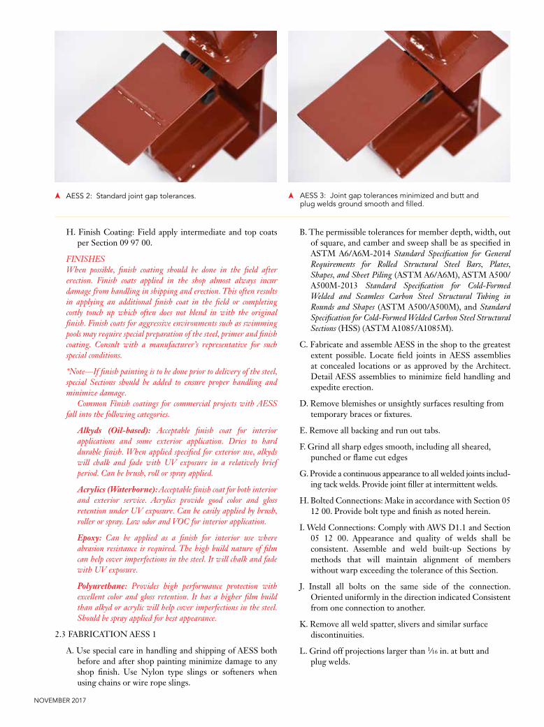
AESS 3: Joint gap tolerances minimized, butt and plug welds ground smooth and filled.
AESS 4: Surfaces filed and sanded.

Modern STEEL CONSTRUCTION
6. Clearly indicate which surfaces or edges are exposed and what class of surface preparation is being used.
7. Indicate special tolerances and erection requirements as noted on the drawings or defined herein.
8. Indicate vent or drainage holes for HSS members.
D. Mock Up: Provide mock ups of the nature and extent indicated on the contract documents.
1. Locate mockups on-site or in the fabricator’s shop as directed by Architect. Mockups shall be full size unless the Architect approves smaller models. Alternatively, when a mockup is not practical, the first piece of an element or connection can be used to determine acceptability.
2. Notify the Architect one week in advance of the dates and times when mockups will be available for review.
3. Demonstrate all applicable AESS characteristics for the specified category of AESS on the elements and joints in the mock up.
4. Build mockups using member sizes and materials indicated for final Work.
5. The mock up shall demonstrate weld quality and contouring of the welds at the aligned walls of the members.
6. The mock up shall demonstrate the specified surface preparation and finish coating.
7. HSS members shall extend at least 6 in. from the joint in the mock-up.
8. Obtain Architect’s written approval of mockups before starting fabrication
9. Retain and maintain mockups during construction in an undisturbed condition as a standard for judging the completed work.
a. Approved mockups in an undisturbed condition at the time of Substantial Completion may become part of the completed work.
Editor’s Note: The contract documents (architectural drawings) need to indicate the framing to be submitted as a mock up. The Architect must define the size and extent of the pieces required and what specific finishes must be demonstrated. The typical mock up is a standalone item that is not incorporated into the final work. However, the specifier may designate a larger mock up that is incorporated into the final work. This intent must be clearly indicated on the architectural drawings and the specifier should consult with the fabricator and contractor regarding the practicality and sequencing of incorporating a mock up into the final work.
Mock ups are only required for AESS 3, AESS 4 and AESS C. Delete “D” for AESS 1 and 2.
E. Samples: Provide samples of specific AESS characteristics Samples may be small size samples or components of conventional structural steel demonstrating the following specific AESS characteristics.
1. Continuous weld appearance
2. Sharp edges ground smooth
3. Surface preparation
4. Fabrication mark removal
5. Weld show through.
Editor’s Note: Delete samples for AESS 3, 4 and C where a mock up is used. Section E provides the editor with the option to obtain samples for AESS 1 and 2 without requirement for a full mock up. Delete Section E if samples are not desired. Consider expanding Section E to include AESS 3 and 4 characteristics if a full-scale mock up is not used for AESS 3 and 4.
SSS: Weld backing bar in place and non-uniform welds. AESS 1: Welds uniform and smooth and backing bars removed.

NOVEMBER 2017
1.5 INFORMATIONAL SUBMITTALS
A. General: Submit each item below according to the Condi-tions of the Contract and Division 1 Specification Sections.
B. Qualification data for firms and persons specified in the “Quality Assurance” Submittal to demonstrate their capabilities and experience. Include lists of completed projects names and address, names and addresses of architects and owners, and other information specified.
[For each project, submit photographs showing detail of installed AESS.]
1.6 QUALITY ASSURANCE
A. Fabricator Qualifications: In addition to those qualifica-tions listed in Division 5 Section “Structural Steel”, en-gage an AISC Certified Fabricator, experienced in fabri-cating AESS similar to that indicated for this Project with a record of successful in-service performance, as well as sufficient production capacity to fabricate AESS without delaying the Work.
B. Erector Qualifications: In addition to those qualifications listed in Division 5 Section “Structural Steel”, engage an AISC Certified Erector, experienced in erecting AESS work similar in material, design, and extent to that indicted for this Project and with a record of successful in-service performance.
C. Comply with applicable provisions of the following specifications and documents:
1. ANSI/AISC 303-16, Code of Standard Practice for Steel Buildings and Bridges, Section 10.
D. Pre-installation Conference: The General Contractor shall schedule and conduct conference at the project site to comply with requirements of Division 1 Section “Project Meetings.” As a minimum, the meeting shall include the General Contractor, Fabricator, Erector, the finish-painting subcontractor, and the Architect. Coordinate requirements for shipping, special handling, storage, attachment of safety cables and temporary erection bracing, final coating, touch up painting, mock
up coordination, architect’s observations, and other requirements for AESS.
1.7 DELIVERY, STORAGE, AND HANDLING
A. Deliver AESS to Project site in such quantities and at such times to ensure continuity of installation. All tie downs on loads shall be nylon straps or shall use softeners when using chains or wire rope slings to avoid damage to edges and surfaces of members. The standard for acceptance of delivered and erected members shall be equivalent to the standard employed at fabrication.
B. Store materials to permit easy access for inspection and identification. Keep steel members off ground by using pallets, platforms, or other supports. Protect steel members and packaged materials from erosion and deterioration. Use special care in handling to prevent twisting or warping of AESS members.
C. Handle finish pieces using nylon type slings, or chains with softeners, or wire ropes with softeners such that they are not damaged. Conform to ANSI/AISC 303-16 Sections 10.4, 10.5, and 10.6.
1.8 PROJECT CONDITIONS
A. Field Measurements: Where AESS is indicated to fit against walls and other construction, verify dimensions by field measurements before fabrication and indicate measurements on Fabrication Documents. Coordinate fabrication schedule with construction progress to avoid delaying the work.
1.9 COORDINATION
A. Coordinate installation of anchors for AESS members that connect to the work of other trades. Furnish setting drawings, templates, and directions for installing anchors, including sleeves, concrete inserts, anchor bolts, and items with integral anchors, that are to be embedded in concrete or masonry. Deliver such items to the project site in time for installation. Anchorage concepts shall be as indicated on drawings and approved on final Fabrication Documents.
SSS: Bolt head orientation not defined. AESS 1: Bolt head orientation defined, backing bar removed.

Modern STEEL CONSTRUCTION
PART 2 – PRODUCTS
2.1 MATERIALS
A. General: Meet requirements Division 5 Section ‘Structural Steel 05 12 23’ as amended below.
B. High-Strength Bolts, Nuts, and Washers: Per Section 05 12 23 heavy hex heads and nuts Provide [rounded bolt heads with twist off bolts] [Heavy Hex bolt heads with standard bolts]. Provide [standard carbon steel] [Cadmium plated] [Mechanically galvanized] finish.
2.2 PAINT SYSTEM
A. Compatibility: All components/procedures of the AESS paint system shall conform to the coating system specified, submitted, and approved per Division 9. As a minimum identify required surface preparation, primer, intermediate coat (if applicable), and finish coat. Primer, intermediate coating and finish coating shall be from a single manufacturer combined in a system documented by the manufacturer with adequate guidance for the fabricator to procure and execute.
B. Primer: As specified in 09 97 00 Special Coatings. Primer shall comply with all federal standards for VOC, lead and chromate levels
C. Primer: Acrylic water soluble shop coat with good resistance to normal atmospheric corrosion. Primer shall comply with all federal standards for VOC, lead and chromate levels.]
D. [Primer: Fast curing two-part epoxy. Primer shall comply with all federal standards for VOC, lead and chromate levels.]
E. [Primer: Organic, epoxy/zinc rich meeting class B surface requirements for slip critical connections. Primer shall comply with all federal standards for VOC, lead and chromate levels.]
F. [Primer: Inorganic zinc rich meeting class B surface requirements for slip critical connections. Primer shall comply with all federal standards for VOC, lead and chromate levels.]
G. Zinc Rich Primer: High-zinc-dust-content paint for galvanized steel, with dry film coating not less than 90 percent zinc dust by weight.
Editors’ Note: The primer specified in Section 05 12 13 must be a component of the finish coat system listed in Section 09 97 00 to ensure coating compatibility. Editor to select either C, D, E, F or G as required for compatibility with 09 97 00. Delete H if galvanizing is not used.
The use of the Federal Specification System (i.e. FS TT-P-6664) is obsolete since many of these specifications do not address current VOC regulations and other environmental standards such as lead and chromate’s. Primers for steel come in a variety of resins such as alkyd, waterborne epoxy, and zinc rich.
Acrylic Primer: Acrylic primers are corrosion resistant and water soluble often providing a lower VOC. They are available in shop coat quality up to a universal primer for use under high performance coatings such as epoxies and urethanes.
Epoxy Primer: Epoxy primers provide excellent corrosion protection for steel and can be top coated with a variety of finishes. Epoxy primers can be applied in the shop and typically have a high film build that will hide minor imperfections.
Zinc Rich Primer: Zinc rich primer provides superior corrosion protection by providing cathodic protection to the steel. Zinc rich coatings can be specified as either organic zinc or inorganic zinc. Both inorganic and organic will meet class B slip coefficients for bolted connections. In arid regions (such as the Rocky Mountain Region) organic epoxy/zinc primers should be specified, as they do not rely on an outside source (humidity) for cure. Inorganic zinc requires a constant humidity of no less than 40% RH for proper cure. If an intermediate and finish coat are to be completed in the shop, the lack of humidity can cause delays in both the painting process and project as the zinc must be cured prior to top-coating. Although a urethane finish coat may be applied directly over an organic zinc, it is suggested an intermediate epoxy coating be used to prevent “pin holing” in the urethane coating, promote adhesion of the system, and increase film build to hide imperfections in the steel. Alkyd finish coats should not be specified over zinc primers. For galvanizing repair, an organic zinc with not less than 90% zinc by weight in the dry film should be used for re-galvanizing welds and damaged due to erection.
SSS: Intermittent/stitch weld between bottom flange and cover plate.
AESS 1: Continuous weld appearance.
NOVEMBER 2017
H. Finish Coating: Field apply intermediate and top coats per Section 09 97 00.
FINISHESWhen possible, finish coating should be done in the field after erection. Finish coats applied in the shop almost always incur damage from handling in shipping and erection. This often results in applying an additional finish coat in the field or completing costly touch up which often does not blend in with the original finish. Finish coats for aggressive environments such as swimming pools may require special preparation of the steel, primer and finish coating. Consult with a manufacturer’s representative for such special conditions.
*Note—If finish painting is to be done prior to delivery of the steel, special Sections should be added to ensure proper handling and minimize damage.
Common Finish coatings for commercial projects with AESS fall into the following categories.
Alkyds (Oil-based): Acceptable finish coat for interior applications and some exterior application. Dries to hard durable finish. When applied specified for exterior use, alkyds will chalk and fade with UV exposure in a relatively brief period. Can be brush, roll or spray applied.
Acrylics (Waterborne): Acceptable finish coat for both interior and exterior service. Acrylics provide good color and gloss retention under UV exposure. Can be easily applied by brush, roller or spray. Low odor and VOC for interior application.
Epoxy: Can be applied as a finish for interior use where abrasion resistance is required. The high build nature of film can help cover imperfections in the steel. It will chalk and fade with UV exposure.
Polyurethane: Provides high performance protection with excellent color and gloss retention. It has a higher film build than alkyd or acrylic will help cover imperfections in the steel. Should be spray applied for best appearance.
2.3 FABRICATION AESS 1
A. Use special care in handling and shipping of AESS both before and after shop painting minimize damage to any shop finish. Use Nylon type slings or softeners when using chains or wire rope slings.
B. The permissible tolerances for member depth, width, out of square, and camber and sweep shall be as specified in ASTM A6/A6M-2014 Standard Specification for General Requirements for Rolled Structural Steel Bars, Plates, Shapes, and Sheet Piling (ASTM A6/A6M), ASTM A500/A500M-2013 Standard Specification for Cold-Formed Welded and Seamless Carbon Steel Structural Tubing in Rounds and Shapes (ASTM A500/A500M), and Standard Specification for Cold-Formed Welded Carbon Steel Structural Sections (HSS) (ASTM A1085/A1085M).
C. Fabricate and assemble AESS in the shop to the greatest extent possible. Locate field joints in AESS assemblies at concealed locations or as approved by the Architect. Detail AESS assemblies to minimize field handling and expedite erection.
D. Remove blemishes or unsightly surfaces resulting from temporary braces or fixtures.
E. Remove all backing and run out tabs.
F. Grind all sharp edges smooth, including all sheared, punched or flame cut edges
G. Provide a continuous appearance to all welded joints includ-ing tack welds. Provide joint filler at intermittent welds.
H. Bolted Connections: Make in accordance with Section 05 12 00. Provide bolt type and finish as noted herein.
I. Weld Connections: Comply with AWS D1.1 and Section 05 12 00. Appearance and quality of welds shall be consistent. Assemble and weld built-up Sections by methods that will maintain alignment of members without warp exceeding the tolerance of this Section.
J. Install all bolts on the same side of the connection. Oriented uniformly in the direction indicated Consistent from one connection to another.
K. Remove all weld spatter, slivers and similar surface discontinuities.
L. Grind off projections larger than 1∕16 in. at butt and plug welds.
AESS 2: Standard joint gap tolerances. AESS 3: Joint gap tolerances minimized and butt and plug welds ground smooth and filled.

Modern STEEL CONSTRUCTION
M. Continuous Weld Appearance: Where continuous welding is noted on the drawings, provide welds of a uniform size and profile
N. Seal Welds: Seal weld open ends of round and rectangular hollow structural Section with 3∕8 in. closure plates. Provide venting as required for galvanized members.
Editor’s Note: drainage and venting holes need to be coordinated to account for the galvanizing process and in-service drainage.
2.4 FABRICATION AESS 2
A. Fabricate to Requirements of 2.3 and as follows
B. The as-fabricated straightness tolerance shall be one-half of that specified in ASTM A6/A6M, ASTM A500/A500M, or ASTM A1085/A1085M.
C. For curved structural members, whether composed of a single standard structural shape or built-up, the as-fab-ricated variation from the theoretical curvature shall be equal to or less than the standard camber and sweep tol-erances permitted for straight members in the applicable ASTM standard.
D. The tolerance on overall profile dimensions of welded built-up members shall one-half of that specified in AWS D1.1/D1.1M: 2015 Structural Welding Code – Steel (AWS D1.1).
E. Provide hidden part marks or piece marks that may be fully removed after erection.
2.5 FABRICATION AESS 3
A. Fabricate to Requirements of 2.4 and as follows
B. Fabricate AESS with exposed surfaces smooth, square and of surface quality consistent with the approved mock up.
C. Grind projections at butt and plug welds to be smooth with the adjacent surface.
D. Orientation of HSS seams shall be as shown.
E. Copes, miters, and cuts in surfaces exposed to view shall have a maximum gap of 1∕8 in. in an open joint. If the gap is shown to be in contact, the contact shall be uniform within 1∕16 in.
F. Mill marks shall not be exposed to view. If it is not possible to hide mill marks, then the mill marks are to be removed by appropriate length cutting of mill material. If this is not possible, the fabricator shall remove the mill mark, grind, and fill the surface to be consistent with the approved mock up.
G. The matching of abutting cross Sections is required
2.6 FABRICATION AESS 4
A. Fabricate to the requirements of 2.5 and as follows.
B. Contouring and blending of welds: Where welds are indi-cated to be ground contoured, or blended, oversize welds as required and grind to provide a smooth transition and match profile on approved mock-up.
C. Minimize Weld Show Through: At locations where weld-ing on the opposite side of an exposed connection creates distortion, weld show through shall be minimized to con-form to the approved mock up.
D. Open holes shall be filled with weld metal or body filler and smoothed by grinding or filling to the standards ap-plicable to the shop fabrication of the materials.
2.7 FABRICATION AESS C
Editor’s Note: This Section is for customized projects, hence the lack of specific language.
A. X
B. X
C. X
Editor’s Note: Refer to the Editor’s Note to Paragraph 1.3
2.8 SHOP PRIMING
A. Provide surface preparations to SSPC-SP6. Coordinate the required surface profile with the approved paint submittal prior to beginning surface preparation. Prior to blasting remove any grease and oil using solvent cleaning to meet SSPC-SP 1. Weld spatter, slivers and similar surface discontinuities shall be removed. Sharp corners resulting from shearing, flame cutting or grinding shall be eased.
AESS 3: A contoured weld. AESS 4: In addition to a contoured and blended appearance, weld transitions also are contoured and blended.

NOVEMBER 2017
B. Shop prime steel surfaces, except the following:
1. Surfaces embedded in concrete or mortar. Extend priming of partially embedded members to a depth of 2 inches.
2. Surfaces to be field welded.
3. Surfaces to be high-strength bolted with slip-critical connections,
Editor’s Note: The default surface preparation for all AESS per the COSP is SSPC-SP-6. Consider if SSPC-SP6 is needed, or if a lower cost preparation will suffice. Many coatings can utilize SP2 or SP3 and the cost savings is significant. Refer to Section 1.1 in the COSP for instructions for the specification of alternatives to the COSP.
The level of surface preparation must be compatible with the specified coating system. It is important the correct level of surface preparation be specified in the contract documents to avoid change orders during construction and to ensure the performance of the paint system.
The most common levels of SSPC surface preparation specifications are listed below:
SSPC SP 1 – SSPC Surface Preparation Specification 1, Solvent Cleaning.
SSPC SP 2 – SSPC Surface Preparation Specification 2, Hand Tool Cleaning. (This level of surface preparation may not be adequate for various paint systems for AESS construction)
SSPC SP 3 – SSPC Surface Preparation Specification 3, Power Tool Cleaning. (This level of surface preparation is the minimum for most AESS projects. It may be acceptable for alkyd primers and acrylic or alkyd finish coats, particularly in interior applications.).
SSPC SP 6 – SSPC Surface Preparation Specification No. 6, Commercial Blast Cleaning. (This level of surface preparation adds significantly to the cost. It is required for epoxy primers for adequate bonding to the steel and recommended for locations where a rust inhibitive primer will be used in an exterior application. It is also required where polyurethane finish coats will be used over the primer.)
C. Priming: Immediately after surface preparation, apply primer according to manufacturer’s instructions to provide a dry film thickness of not less than 1.5 mils (0.038 mm). Use priming methods that result in full coverage of joints, corners, edges, and exposed surfaces.
1. Stripe paint corners, crevices, bolts, welds, and sharp edges.
2. Apply two coats of shop primer to surfaces that are inaccessible after assembly or erection.
Editor’s Note: Finish painting in the shop is not recommended by either the fabrication or painting community that contributed to this specification. If finish painting is to be done prior to delivery of the steel special paragraphs should be added here.
2.9 GALVANIZING
Editor’s Note: Galvanized steel should not be painted with alkyd top coats as loss of adhesion will occur. An intermediate coat of high build epoxy should be used if an alkyd paint is described as the finish coat. Zinc coatings produced by the hot dip galvanizing process are excellent corrosion protection systems but, when the coating becomes very thick or dull gray, the coating may not be suitable for architectural applications. The appearance can become blotchy with Sections of dull finish and Sections with bright finish. Almost all of these surface effects last for the first couple of years and then the coating becomes uniformly dull gray as the protective layer of corrosion products is formed on the surface of the galvanized steel.

Modern STEEL CONSTRUCTION
The cause of the irregular surface finishes is the variation in steel chemistry of the parts to be hot dip galvanized. ASTM A385/A385M – 2015 Standard Practice for Providing High-Quality Zinc Coatings (Hot-Dip) and ASTM A123/A123M– Standard Specification for Zinc (Hot Dip Galvanized) Coatings on Iron and Steel Products describe the effects of steel chemistry on the hot dip galvanized finish. The two elements with the most influence are silicon and phosphorus. If these elements are controlled to recommended levels, the finish will be bright and shiny. Many steel makers control the overall impurity content but not these two specific elements so there may be some parts that are bright and shiny and some that are dull gray. Care should be taken when hot dip galvanizing if an architectural finish is expected.
A. Hot-Dip Galvanized Finish: Apply zinc coating by the hot-dip process to AESS indicated for galvanizing according to ASTM A123/A123M – 2015 Standard Specification for Zinc (Hot-Dip Galvanized) Coatings on Iron and Steel Products. Fabricate such that all connections of assemblies are made in the field with bolted connections where possible.
2.10 FABRICATION QUALITY CONTROL AND QUALITY ASSURANCE AESS 1 AND 2
A. Structural requirements:
1. Conform to Quality Control requirements per ANSI/AISC 360-16 Specification for Structural Steel Buildings Chapter N and ANSI/AISC 303-16, Code of Standard Practice for Steel Buildings and Bridges, Section 10. Refer to Section 05 12 00 “Structural Steel” for additional requirements.
2. Owner will engage a Quality Assurance agency per the requirements of ANSI/AISC 360-16 Specification for Structural Steel Buildings Chapter N and ANSI/AISC 303-16, Code of Standard Practice for Steel Buildings and Bridges, Section 10
B. AESS acceptance: The Architect shall observe the AESS steel in the shop at a viewing distance consistent with the final installation and determine acceptability based on the qualification data and submittals. The Quality Assurance agency shall have no responsibility for enforcing the requirements of this Section.
2.11 FABRICATION QUALITY CONTROL AND QUALITY ASSURANCE AESS 3 AND 4
A. Conform to 2.10 and as follows.
B. AESS acceptance: The Architect shall observe the AESS steel in the shop at a viewing distance consistent with the final installation and determine acceptability based on the approved mock up. The Quality Assurance Agency shall have no responsibility for enforcing the requirements of this Section.
Editor’s Note: Consider if a shop visit by the architect is appropriate based on the scale and complexity of the project. Delete if not required.
PART 3 – EXECUTION
3.1 EXAMINATION
A. The erector shall check all AESS members upon delivery for twist, kinks, gouges or other imperfections which may result in rejection of the appearance of the member. Coordinate remedial action with fabricator prior to erecting steel.
3.2 PREPARATION
A. Provide connections for temporary shoring, bracing and supports only where noted on the approved Fabrication Documents. Temporary connections not shown shall be made at locations not exposed to view in the final structure or as approved by the Architect. Handle, lift and align pieces using nylon straps or chains with softeners required to maintain the appearance of the AESS through the process of erection.
Editor’s Note: The following is a list of special erection issues that may impact the final appearance of the AESS. Many of these items have cost premiums and should not be used indiscriminately. Refer to the AISC cost matrix for anticipated range of added cost associated with each line.
3.3 ERECTION AESS 1
A. Employ special care to handle and erect AESS. Erect finish pieces using nylon straps or chains with softeners such that they are not damaged.
These four (from left to right, AESS 1, 2, 3 and 4) allow invested parties to see the range of possible appearance levels cor-responding to the characteristics of each AESS Category. Standardized shop drawings for the sculptures have been developed by AISC, with the hope that professional organiza-tions across the country will embrace the concept and fund fabrications that can be accessed locally.

NOVEMBER 2017
B. Place weld tabs for temporary bracing and safety cabling at points concealed from view in the completed structure or where approved by the Architect during the pre-installation meeting. Methods of removing temporary erection devices and finishing the AESS members shall be approved by the Architect prior to erection.
C. AESS Erection tolerances: Erection tolerances shall meet the requirements of standard frame tolerances for struc-tural steel per Chapter 7 of ANSI/AISC 303-16.
Editor’s Note: ANSI/AISC 303-16 specifies that AESS 2 and above framing shall be fabricated to one-half the tolerance of typical structural steel frames. This requirement is intended to improve fit up when the exposed steel interfaces with other materials such as curtain wall masonry, etc. The variations permitted under the standard frame tolerances noted in Chapter 7 will typically be acceptable when viewed by eye (without instruments). Therefore, standard frame tolerances are allowed for Erection tolerances. Adjust if tighter tolerances are required.
D. Set AESS accurately in locations and to elevations indi-cated and according to AISC specifications referenced in this Section.
E. Remove blemishes or unsightly surfaces resulting from temporary braces or fixtures.
F. Remove all backing and run out tabs.
G. When temporary braces or fixtures are required to facili-tate erection, care shall be taken to avoid any blemishes, holes or unsightly surfaces resulting from the use or re-moval of such temporary elements.
H. Bolted Connections: Align bolt heads on the same side of the connection as indicated on the approved fabrication or erection documents.
I. Weld Connections: Comply with AWS D1.1 and Section 05 12 00. Appearance and quality of welds shall be consistent. Employ methods that will maintain alignment of members without warp exceeding the tolerance of this Section.
J. Remove all weld spatter exposed to view.
K. Grind off projections larger than 1∕16 in. at field butt and plug welds.
L. Continuous Welds: Where continuous welding is noted on the drawings, provide continuous welds of a uniform size and profile.
M. Do not enlarge holes in members by burning or by using drift pins. Ream holes that must be enlarged to admit bolts. Replace connection plates that are misaligned where holes cannot be aligned with acceptable final appearance.
N. Splice members only where indicated.
O. Obtain permission for any torch cutting or field fabri-cation from the Architect. Finish Sections thermally cut during erection to a surface appearance consistent with the mock up.
3.4 ERECTION AESS 2
A. Erect to the requirements of 3.3 and as follows.
B. AESS Erection Tolerances: Erect to standard frame tolerances for structural steel per Chapter 7 of ANSI/AISC 303-16.
3.5 ERECTION AESS 3
A. Erect to the requirements of 3.4 and as follows.
B. Field Welding: Weld profile, quality, and finish shall be consistent with mock-ups approved prior to fabrication.
C. Provide a continuous appearance to all welded joints including tack welds. Provide joint filler at intermittent welds.
3.6 ERECTION AESS 4
A. Erect to the requirements of 3.5 and as follows.
B. Welds ground smooth: Erector shall grind welds smooth.
C. Minimize Weld Show Through: At locations where welding on the far side of an exposed connection creates distortion, grind distortion and marking of the steel to a smooth profile with adjacent material.
AESS 2: HSS weld seam orientation not defined. AESS 3: HSS weld seam oriented for reduced visibility.

Modern STEEL CONSTRUCTION
D. Filling of weld access holes: Where holes must be cut in the web at the interSection with flanges on W shapes and structural tees to permit field welding of the flanges, they shall be filled with joint filler.
E. Where welds are indicated to be ground, contoured, or blended, oversize welds as required and grind to provide a smooth transition and match profile on approved mock-up.
3.7 ERECTION AESS C
Editor’s Note: This Section is for customized projects, hence the lack of specific language.
A. ….
B. …..
C. …..
3.8 FIELD QUALITY CONTROL AND QUALITY ASSURANCE AESS 1 and 2
C. Structural requirements:
3. Conform to Quality Control requirements per ANSI/AISC 360-16 Specification for Structural Steel Buildings Chapter N and ANSI/AISC 303-16, Code of Standard Practice for Steel Buildings and Bridges, Section 10. Refer to Section 05 12 00 “Structural Steel” for additional requirements.
4. Owner will engage a Quality Assurance agency per the requirements of ANSI/AISC 360-16 Specification for Structural Steel Buildings Chapter N and ANSI/AISC 303-16, Code of Standard Practice for Steel Buildings and Bridges, Section 10
D. AESS acceptance: The Architect shall observe the AESS steel in place and determine acceptability based on the qualification data and submittals. The Quality Assurance Agency shall have no responsibility for enforcing the requirements of this Section.
3.9 FIELD QUALITY CONTROL AESS 3, 4, and C
A. Conform to 3.7 and as follows.
B. AESS acceptance: The Architect shall observe the AESS steel in place and determine acceptability based on the approved mock up. The Quality Assurance Agency shall have no responsibility for enforcing the requirements of this Section.
3.10 ADJUSTING AND CLEANING
A. Touchup Painting: Cleaning and touchup painting of field welds, bolted connections, and abraded areas of shop paint shall be completed to blend with the adjacent surfaces of AESS. Such touch up work shall be done in accordance with manufacturer’s instructions and as specified in Division 9, Section “Painting.”
B. Galvanized Surfaces: Clean field welds, bolted connections, and abraded area. Any repairs to galvanized surfaces shall comply with ASTM A780/A780M – 2015 Standard Practice for Repair of Damaged and Uncoated Areas of Hot Dip Galvanized Coatings.
ResourcesVisit www.aisc.org/AESS to access a variety of AESS reources:
➤ The 2016 Code of Standard Practice for Steel Buildings and Bridges (ANSI/AISC 303-16) provides a framework for a common understanding of the acceptable standards when contracting for structural steel. Section 10 deals explicitly with AESS.
➤ The AESS sample specification (also on the preceding pages) is an editable sample spec that you can update and insert into your individual project specifications.
➤ The AESS Cost Matrix (also on the following page) is an editable matrix that you can update to anticipate cost implications by specifying various levels of AESS on your project.
➤ Shop drawings of the five AESS sculptures, which you can download and use to fabricate your own versions. Or reach out to the AISC Steel Solutions Center at [email protected] if you’d like us to put you in touch with a local fabricator to purchase your own sculptures!
You can also visit www.modernsteel.com to view articles on the photos and projects that appeared in this section:
➤ Terri Meyer Boake’s favorite exposed connections: “Fun is in the Details,” March 2016
➤ Kline Fitness Center addition at Dickinson College: “Squashing the Competition,” January 2016
➤ Technology Tower at North Carolina State University’s Talley Center: “Tower of Technology,” June 2015
➤ Anaheim Regional Transportation Intermodal Center (ARTIC): IDEAS2 Awards article, May 2015
➤ Denver Union Station: IDEAS2 Awards article, May 2015
➤ Landscape Evolution Observatory (LEO) at the University of Arizona’s Biosphere 2 research facility: “Under the Dome,” November 2014
➤ United Therapeutics Pedestrian Connector: IDEAS2 Awards article, May 2014
➤ Queen Richmond Centre West: “Jacks of All Trades,” March 2014
➤ Solar Canopy: IDEAS2 Awards article, May 2013
➤ National Geospatial-Intelligence Agency: IDEAS2 Awards article, May 2013
➤ The Tea House, “What’s Cool in Steel,” August 2012
➤ Sprint Center: “Bending Around (Sprint Center),” July 2008

NOVEMBER 2017
AESS CATEGORY MATRIX AESS C AESS 4 AESS 3
Identify AESS components specifically by category in the contract documentsCUSTOM
ELEMENTSSHOWCASE ELEMENTS
FEATURE ELEMENTS IN CLOSE VIEW
view distance < 20 ft
**Reference Table 10.1 of the 2016 AISC Code of Standard PracticeSPEC
SECTIONAISC COSP SECTION I.D. CATEGORY CHARACTERISTICS
2.8.A 10.4.11 1.1 Surface preparation to SSPC-SP 6 × ×2.3.F 10.4.11 1.2 Sharp edges ground smooth × ×2.3.M ** 1.3 Continuous weld appearance × ×2.3.J 10.6(f) 1.4 Standard structural bolts × ×2.3.K 10.4.8, 10.4.11 1.5 Weld spatters removed × ×
1.4.D, 1.4.E 10.1.1, 10.1.2 2.1 Visual Samples mock-up required mock-up required2.4.B 10.4.3(b), 10.4.5 2.2 One-half standard fabrication tolerances × ×2.4.E 10.4.1 2.3 Fabrication marks not apparent × ×
** ** 2.4 Welds uniform and smooth × ×
2.5.F ** 3.1 Mill marks removed × ×2.5.C 10.4.9 3.2 Butt and plug welds ground smooth and filled × ×2.5.D 10.4.12 3.3 HSS weld seam oriented per contract documents × ×2.5.G 10.4.3(a) 3.4 Cross-sectional abutting surface aligned × ×2.5.E 10.4.6 3.5 Joint gap tolerances minimized × ×
** ** 3.6 All welded connections optional optional
** 10.4.12 4.1 HSS seam not apparent ×2.6.B 10.4.8 4.2 Welds contoured and blended ×2.6.D 10.4.7, 10.6(g) 4.3 Surfaces filled and sanded ×2.6.C 10.4.10 4.4 Weld show-through minimized ×
10.1.1, 10.2(c ) C.1Additional characteristics may be added for custom elements. The AESS matrix included in Table 10.1 of the 2016 AISC Code of Standard Practice shall be used to specify the required treatment of the elements.
C.2C.3C.4C.5
1.7.B, 2.3.A, 3.3.A 10.5, 10.6 Special care in fabrication and erection × × ×
10.1 (commentary)
Estimated cost premium above standard structural steel low to high high moderate
Range in cost increase XX% to XX% 100% – 150% 40% – 75%
2.4.C 10.4.4 n/a CURVED STRUCTURAL MEMBERS
Camber and sweep tolerances shall be equal to or less than straight members XX% to XX% XX% to XX% XX% to XX%
PRIMER AND FINISH COATINGS
2.2, 2.8 Finish A: Interior Environment – low end finish2.2, 2.8 Finish B: Interior environment – high end finish2.2, 2.8 Finish C: Exterior environment – low end finish2.2, 2.8 Finish D: Exterior environment – high end finish
2.9 Finish E: Galvanizing
Range in cost increase above shop primed with no finish coat XX% to XX% XX% to XX% XX% to XX%
Accumulated range of cost increase XX% to XX% XX% to XX% XX% to XX%
Footnote A. Cost premium for SSPC-SP6 is included in values provided for Primer and Finish Coatings, Finish B through Finish D.Disclaimer: Cost premiums shown here are for informational purposes, and are not intended to be used for cost estimating purposes. Every project is unique, and budgeting must be performed on a project-by-project basis.

Modern STEEL CONSTRUCTION
I.D. CHARACTERISTICS DESCRIPTION1.1 Surface preparation to
SSPC-SP 6Grease, oil, weld spatter and surface discontinuities are removed
1.2 Sharp edges ground smooth
Rough surfaces are deburred and ground smooth. Sharp edges resulting from flame cutting, grinding and especially shearing are softened.
1.3 Continuous weld appearance
Intermittent welds are made to appear continuous, either with additional welding, caulking or body filler. For corrosive environments, all joints are seal welded. Seams of hollow structural sections are acceptable as produced.
1.4 Standard structural bolts All bolt heads in connections are on the same side, as specified, and consistent from one connection to another.
1.5 Weld spatters removed Weld spatter, slivers, surface discontinuities are removed. Weld projection up to 1⁄16 in. (2 mm) is acceptable for butt and plug welded joints.
2.1 Visual Samples Visual samples are either a 3D rendering, a physical sample, a first-off inspection, a scaled mock-up or a full-scale mock-up, as specified in the contract documents. Mock-ups are optional in AESS 2.
2.2 One-half standard fabrication tolerances
These tolerances are one-half of those for standard structural steel as specified in this Code.
2.3 Fabrication marks not apparent
Members markings during the fabrication and erection processes are not to be visible to view.
2.4 Welds uniform and smooth
Welds are to be uniform and smooth.
3.1 Mill marks removed Mill marks are to be removed from view.
3.2 Butt and plug welds ground smooth and filled
Caulking or body filler is acceptable.
3.3 HSS weld seam oriented per contract documents
Seams are oriented away from view or as indicated in the contract documents.
3.4 Cross sectional abutting surface aligned
The matching of abutting cross sections is required.
3.5 Joint gap tolerances minimized
This characteristic is similar to 2.2 above. A clear distance between abutting members of 1⁄8 in. (3 mm) is required.
3.6 All welded connections Hidden bolts may be considered.
4.1 HSS seam not apparent Seams on HSS members are treated so they are not apparent.
4.2 Welds contoured and blended
In addition to a contoured and blended appearance, welded transitions between members also are contoured and blended.
4.3 Surfaces filled and sanded
Surfaces are to be filled with weld metal or body filler, smoothed and sanded to achieve a smooth surface.
4.4 Weld show-through minimized
Weld show-through on the back side of a welded element can be minimized by hand grinding the back side surface. The degree of weld-through is a function of weld size and material.
C Custom elements Additional characteristics may be added for custom elements. The AESS matrix included in Table 10.1 of the 2016 AISC Code of Standard Practice shall be used to specify the required treatment of the elements.
AESS 2 AESS 1
FEATURE ELEMENTS NOT IN CLOSE VIEW
view distance > 20 ft
BASIC ELEMENTS
ADDED COST RANGE
TO AESS (Relative to non-AESS)
× × footnote A
× × 1% – 10%
× × 1% – 10%
× × 1% – 5%
× × 1% – 5%
optional 5% – 25%
× 5% – 15%
× 5% – 15%
× 5% – 15%
5% – 15%5% – 10%1% – 5%5% – 15%5% – 10%15% – 30%
5% – 20%25% – 40%30% – 50%5% – 20%
× × XX% to XX%
low to moderate low
25% – 35% 10% – 20%
XX% to XX% XX% to XX%
5% – 15%15% – 30%20% – 40%30% – 50%20% – 40%
XX% to XX% XX% to XX%
XX% to XX% XX% to XX%


![Weiss lab [autosaved]](https://img.pdfslide.us/doc/110x75/55d6ce3dbb61eb612b8b4694/weiss-lab-autosaved.jpg)