Embed Size (px)
Citation preview

November 15, 2010
The information contained in this document is confidential and is intended solely for the use of the individual or entity to which it wassent. You should not copy, disclose or distribute this document without the authority of Topcon Positioning Systems, Inc.

Page 2
© Topcon Positioning Systems, Inc., 2010
Table of Contents
Features and Changes 4 General 5 Installation Options 5 Main Menu 5 Connections Prompt 6 Discontinued Products 6 Equipment 8 Controllers 8 GPS 8 Optical 10 Configure 11 Coordinate Systems 11 Global 11 Codes 11 Stake Reports 12 Survey 13 Import/Export 15 Codes 15 Drawings 15 Machine Control 15 Roads 16 Stake Reports 16 Code Styles 17 Edit Job 18 Layer 18 Stake Reports 18 Edit Roads 20 Roads 20 Setup 22 Backsight 22 Localization 22 Resection 23 Start Base 24 COGO 25 Area 25 Volumes 25 Survey 27 User Interface - Survey 27 Monitoring 27 Scanning 28 Topo 28 Stake 29 User Interface - Stakeout 29 Stake Reports 31 Linework 32 Roads 33 Real-Time Roads 34 Stake Slope 35

Page 3
© Topcon Positioning Systems, Inc., 2010

Page 4
© Topcon Positioning Systems, Inc., 2010
Features and Changes

Page 5
© Topcon Positioning Systems, Inc., 2010
General
Installation Options During the installation process, the option to install support for the Import / Export of DWG 2008 and ESRI Shape File
formats must be manually selected (checked on).
These are optional formats that will increase the size of the TopSURV installation.
If memory on the target device is limited, do not install these libraries.
Main Menu OBS Mode is now Connections
The Connections icon displays the same dialog as the Connections Prompt.
This function has been updated to display the same dialog as the connection prompt, and allows the user to quicklychange between stored configurations.

Page 6
© Topcon Positioning Systems, Inc., 2010
Connections Prompt General Tab - Added To base/To rover connection option for GPS.
Network Tab - Added options for Auto-Connect. This option automatically connects to the last used mountpoint.
Network Tab - Added Auto-Disconnect from Mount Point on disconnection from receiver. With this option off, thereceiver will remain on the network, even if you disconnect from the serial connection.
Green arrow goes back to the Main Menu.
Discontinued ProductsTopSURV 8 no longer supports the following field controllers:
FC-100

Page 7
© Topcon Positioning Systems, Inc., 2010
FC-120
FC-2000
Juniper Allegro CX
TDS Recon
Note: Juniper Allegro MX users can download the Windows Mobile installation to use this product.

Page 8
© Topcon Positioning Systems, Inc., 2010
Equipment
Controllers Support for Getac PS236. Please use the Windows Mobile installation.
Support added for GRS-1 Barcode Reader.
We now have added support of camera on all Windows Mobile devices which have a camera using the Micorsoftcamera API.
GPS Support added for GR-5 receiver.
Network RTK with mmGPS for Hiper II is now supported.

Page 9
© Topcon Positioning Systems, Inc., 2010
Support added for Sokkia GNSS receivers.
o GNSS receivers: GSR2700ISX, GSR2700IS, GSR2600, GSR1700CSX and Radian IS.
o External UHF modem Satel 3Asd
o External GSM Modem Siemens MC35i (RTK CSD)
RH-1 Digital UHF can be configured as a transmitter over Bluetooth.
Digital UHF spacing option added.
Satel PCC mode option added.

Page 10
© Topcon Positioning Systems, Inc., 2010
Optical Added support for Topcon Digital Levels DL-502/503.

Page 11
© Topcon Positioning Systems, Inc., 2010
Configure
Coordinate Systems Irish Geoid (available during installation)
Romania coordinate system
French new altimetric grid RAF09, RAC09
Change transformation parameters of the "Arlon" zone in the TopSURV Belgium system
Added new zone projection "Bruxells" into the TopSURV Belgium system.
Supported localizations based on user-selected projection/datum.
Added SPHERE ellipsoid – this allows users to create custom datums based on an ideally spherical ellipsoid.
View of points in Denmark Coordinate system is now mirrored.
Global Go to Configure >> Global to restore the Connection Prompt if toggle off in the Connections dialog.
Codes Upon installing TopSURV 8 data collection software, a default Code Library file will automatically be installed. If an
existing library has not been previously selected in TopSURV 7, this library will be automatically selected in Configure>> Codes.
The default code library is set to be the Global Code library used during data collection.

Page 12
© Topcon Positioning Systems, Inc., 2010
If an end user does not want to use this default Code Library for their field work, they simply will have to remove andinstall (point to) their existing Code Library.
To remove, go to Configure >> Codes and either clear out the path within the Data Entry edit field or Browse to yourexisting Code Library file.
Configure when to Prompt for Code as needed
Stake Reports Routine specific configurations.
Point Used in staking routines that do not report stationing, or use surfaces, or roads.Line/Arc Used in staking routines that report stationing, but do not use a Road.Surface Used is the Stake DTM routine.Road Used in the Stake Road and Stake Real-TIme Road routines.Slope Used is the Slope Staking routine.
Unlimited configurations can be created.
Reports are completely customizable with the ability to define column order, headers, and display (on / off).

Page 13
© Topcon Positioning Systems, Inc., 2010
Survey NTRIP connection can be set up based on web address instead of IP Address for controller-side Internet connection
only.
Extended list of the Internet Providers for NTRIP connections.
An appropriate Virtual Radio Port is selected automatically, based on the receiver model.

Page 14
© Topcon Positioning Systems, Inc., 2010
Support added for setting the receiver in “Forest” mode. This feature is located in the Configuration setup wizard as"Canopy Environment".
Page 15
© Topcon Positioning Systems, Inc., 2010
Import/Export
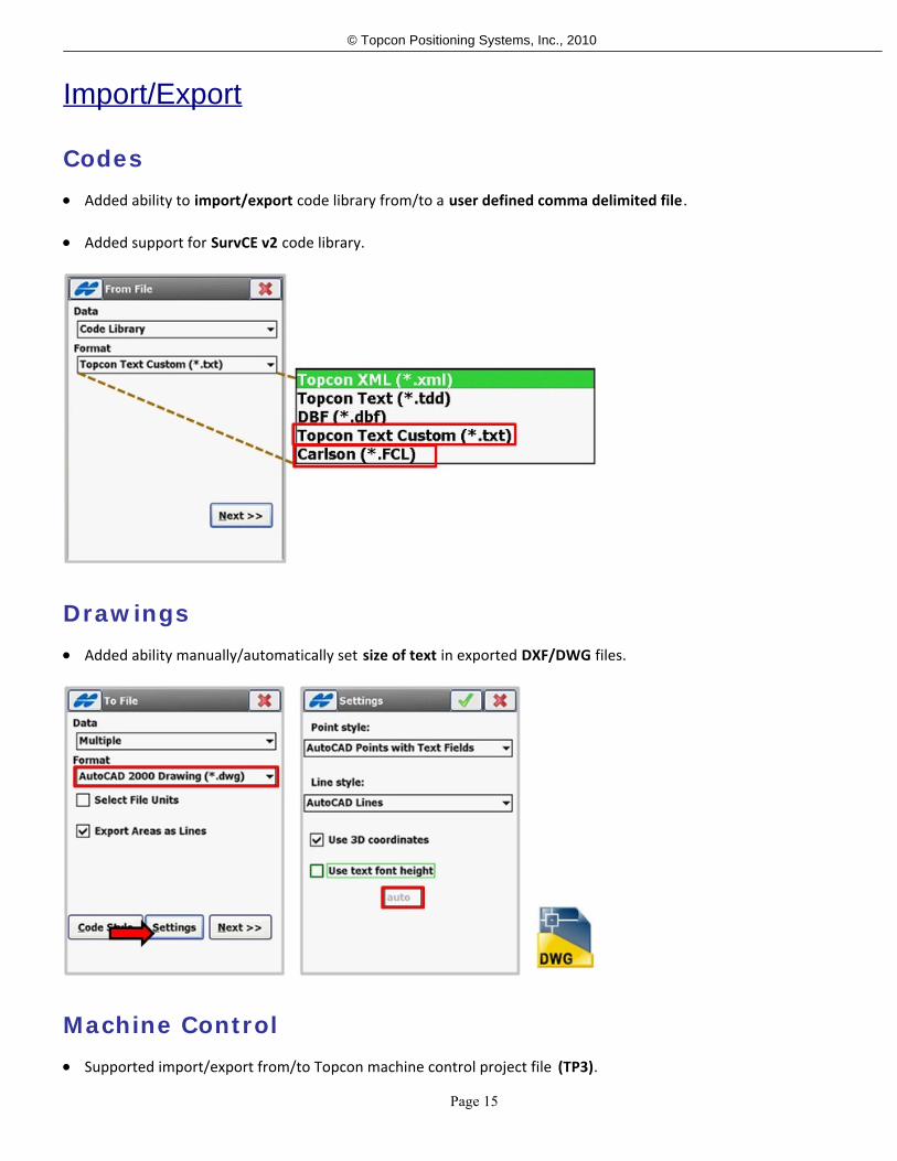
Codes Added ability to import/export code library from/to a user defined comma delimited file.
Added support for SurvCE v2 code library.
Drawings Added ability manually/automatically set size of text in exported DXF/DWG files.
Machine Control Supported import/export from/to Topcon machine control project file (TP3).

Page 16
© Topcon Positioning Systems, Inc., 2010
Roads Added support for Road String Sets between jobs.
Added support for Road String Sets between LandXML files.
Toggling on the option X-Sections include catch points adds the ability to detect template slopes and extract the slopevalues from the outer 2 points of the imported X-Sections.
Stake Reports After a staking project, reports can be exported directly from TopSURV. From main menu, go to Export >> To File and
select a Data export type of Stakeout Reports.
Stakeout Reports can be from any type of staking that was done (Point, Line / Arc, Roading, Surface, and Slope).

Page 17
© Topcon Positioning Systems, Inc., 2010
Resulting reports will be in the CSV (comma separated values) file format.
Code Styles Added support for Control Code aliases.
Add support for aliases for Code/String/ControlCode/Attribute Separators.
Unlimited export configurations can be saved to generate the deliverable that the receiving CAD product requires.
Code Styles is support in Export Multiple, Topcon Custom Text, and SurvCE, TDS, and SDR raw data formats.

Page 18
© Topcon Positioning Systems, Inc., 2010
Edit Job
Layer The Layers dialog has been updated to allow the ability to sort layers and define their drawing order or visual display.
Just click on the header of any column (Layer Number, Layer Name, or Layer Status) to sort by. The order, from top tobottom, is the order that items will be ordered / displayed in Map Views.
Stake Reports Multiple report can be created for each types of stake report (e.g. Point, Road, Slope, Line/Arc, Surface).
Up to five current reports can be set. This allows separate stake reports for each routine.
Spreadsheet viewer allows for clipboard-ease of viewing your report, configured the way you like to see it.

Page 19
© Topcon Positioning Systems, Inc., 2010

Page 20
© Topcon Positioning Systems, Inc., 2010
Edit Roads
Roads Added support for High/Low Positions to be computed for the Grade and Station option in Vertical Alignments
(Feature located in the Context Menu)
The segment points will now be stored by User Names instead of a Job Codes.
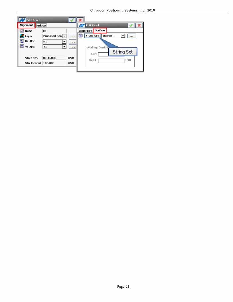
Added support for String Sets as an alternative method for defining the road’s surface. Note that any single string canhave gaps, as shown in the EPL example below.
String Sets can be created from a 3D polyline, horizontal & vertical alignment pairs, or mix a polyline's horizontalgeometry with a vertical alignment for defining a string from a 2D drawing and a manually entered profile.
The dialog for editing a road has been split in to two pages, Alignment and Surface.
Added support for Working Corridor.
Page 21
© Topcon Positioning Systems, Inc., 2010

Page 22
© Topcon Positioning Systems, Inc., 2010
Setup
Backsight Updated for a smoother workflow and layout that allows for more on-screen information during setups.
Localization Grid Localization is now possible for applying and shifting projections. This feature will perform a two-step operation
using the user selected projection and/or datum to localize to ground points. When importing ground control it isimportant to define the points as ground coordinates if they are going to be used in the localization.
Apply a projection in Configure >> Coord Sys to activate the new options in Localization shown below.
Select Setup >> Localization to view the new options shown below.

Page 23
© Topcon Positioning Systems, Inc., 2010
Resection Routine updated to include weighting options entered by the user.
Added Resection method 2D+H.
Start Base

Page 24
© Topcon Positioning Systems, Inc., 2010
Added a modem connection process bar.
Added an option to automatically startup the UHF radios after Start Base is selected.

Page 25
© Topcon Positioning Systems, Inc., 2010
COGO
Area Added the ability to select linework to compute an area.
Added support for areas with curves.
Volumes User can select two TN3 files and get a volume report.
Report can be saved to a text file.

Page 26
© Topcon Positioning Systems, Inc., 2010

Page 27
© Topcon Positioning Systems, Inc., 2010
Survey
User Interface - Survey Moving and Current Position indication
More map area throughout
Collapsible status and zoom toolbars
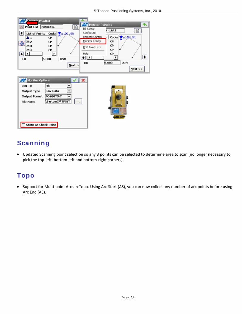
Monitoring Added Monitor Config to menu in the initial point list selection screen.
Added the option to store points as Check Shots.
Page 28
© Topcon Positioning Systems, Inc., 2010
Scanning Updated Scanning point selection so any 3 points can be selected to determine area to scan (no longer necessary to
pick the top-left, bottom-left and bottom-right corners).
Topo Support for Multi-point Arcs in Topo. Using Arc Start (AS), you can now collect any number of arc points before using
Arc End (AE).

Page 29
© Topcon Positioning Systems, Inc., 2010
Stake
User Interface - Stakeout Added support to use Alignments as the directional reference (e.g. To/Away CL).
Added availability of Stake Design offsets to all stake routines.
Each view mode (Interval/Real-Time/Slope/Offset/etc) will remember what values are shown for that particular mode.
HR is now available on the stakeout navigation screenTap and hold to call up the View Panel to easily switch to one ofthe 5 possible Stakeout views (Cross Section View only in Road and Slope Routines).
Can also access View Panel from Context Menu.

Page 30
© Topcon Positioning Systems, Inc., 2010
Four user definable labels
Tap any stakeout label to change displayed output
Recall in every routine
Updated the Store Point dialog prompt (optional in Configure >> Codes >> Prompt).

Page 31
© Topcon Positioning Systems, Inc., 2010
Interval Staking or Real-Time mode available in the context menu.
Stake Reports Each stake routine shows the current Stake Report
Each routine allows for easy selection and creation of stake reports using the ... button.

Page 32
© Topcon Positioning Systems, Inc., 2010
Access the Stake Report from the Context Menu
Linework Users can now stake either a line (polyline) or a job string.
Ability to stop at transition points.
Ability to add horizontal and vertical offsets
Ability to do interval or real-time stakeout of a linework.

Page 33
© Topcon Positioning Systems, Inc., 2010
Various stakeout options for curve points and angle points (e.g. Bisector or Radius Point).
Roads Allow for negative stations when staking out a Road.
o When beyond the vertical alignment, the design elevation with show an asterisk to alert the user that thegrade is being interpolated.
o When beyond the end of the horizontal alignment, the Road alignment will be extended by a tangentsegment .
Stake Road switches from real-time to interval when the user is in real-time mode and presses one of theprevious/next station buttons.
Added the ability to select up to 70 additional road surface segment, or point references for additional reporting.
Added the ability to Extend a cross section surface beyond the edge of the road.
Add the ability to extend a Surface Left/Right until beyond the next segment point.
Added the ability to stakeout the intersection of an offset segment where it intersects the cross section itself

Page 34
© Topcon Positioning Systems, Inc., 2010
(Intersect Left/Right)
Added ability to define vertical or perpendicular up/down offsets (Intersect Left/Right)
Real-Time RoadsTM
The cross section segment at the rod position is highlighted in real-time, and the routine can now report cut/fill to thesurface at the rod position, or the cut/fill and offset to the two segment points on either side of the current rodposition.
When the rod position is outside of the hinge point the routine automatically switches to slope staking with the samefeatures that Stakeout Slope has for setting offset stakes to the catch point.
Additional cross section segments and points can also be reported using the Set References option in the contextmenu.
The data labels can be user configured by clicking on them.
The design slope can now be defined by the template slope values, or user entered values.

Page 35
© Topcon Positioning Systems, Inc., 2010
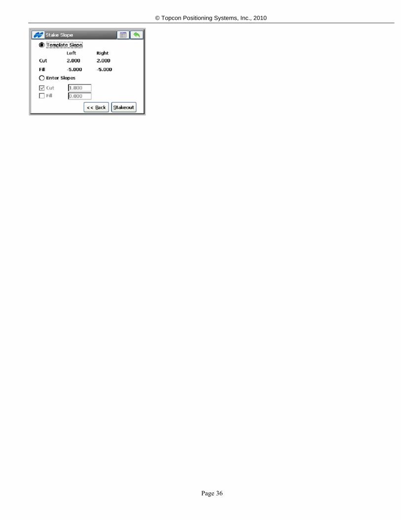
Stake Slope The hinge point can now be any segment point on the cross section.
The slope direction can now be right or left of the hinge point, regardless of the side of the road it is on.
The store point dialog now keeps track of each individual offset when staking multiple offsets to the catch point.
Offset to Catch Point is now selected on the Data tab when storing a Catch Point/Offset Point.
Stake Slope switches from real-time to interval when the user is in real-time mode and presses one of theprevious/next station buttons.
If the user is staking offsets to the catch point and they press one of the previous/next station buttons, the routine willautomatically advance and begin slope staking the next catch point.
The design slope can now be defined by the template slope values, or user entered values.
Page 36
© Topcon Positioning Systems, Inc., 2010