Embed Size (px)
Citation preview
Chemical Engineering Science 61 (2006) 5328–5333www.elsevier.com/locate/ces
Novel perovskite-based catalysts for autothermal JP-8 fuel reforming
Peter Erria, Peter Dinkab, Arvind Varmaa,∗aSchool of Chemical Engineering, Purdue University, West Lafayette, IN 47907, USA
bDepartment of Chemical and Biomolecular Engineering, University of Notre Dame, Notre Dame, IN 46556, USA
Received 27 September 2005; received in revised form 23 March 2006; accepted 24 March 2006Available online 30 March 2006
Abstract
Autothermal reforming is an attractive method for on-site production of hydrogen for use in proton exchange membrane (PEM) fuel cells. Theuse of liquid hydrocarbons as feedstock, however, remains a challenge as these fuels cause severe coking of the currently available catalysts. Inthis work, cerium- and nickel-substituted LaFeO3 perovskites were investigated as potential low cost coking resistant catalysts for autothermalreforming of a JP-8 fuel surrogate. The high surface area complex oxides were prepared using aqueous (solution) combustion synthesis atfuel-rich conditions and characterized by BET and XRD techniques. The catalysts exhibited excellent stability during autothermal reformingat 775 ◦C and 1 atm, with near-equilibrium hydrogen yield even at high GHSV values (130, 000 h−1). The addition of cerium significantlyimproved coking resistance, attributed to improved oxygen ion conductivity, resulting in carbon oxidation on the catalyst surface.� 2006 Elsevier Ltd. All rights reserved.
Keywords: Catalysis; Fouling; Fuel; Perovskites; Reforming; Sintering
1. Introduction
Steam and autothermal reforming of liquid hydrocarbons arereceiving increased attention as methods for the on-site pro-duction of hydrogen for use in proton exchange membrane(PEM) fuel cells. By producing the hydrogen as needed, manysafety concerns and logistical challenges associated with the useof hydrogen as an energy carrier can be eliminated (Praharsoet al., 2004). This is particularly important to the military whichplans to use fuel cells as portable electricity power sourcesto replace diesel generators. In this case, the hydrogen wouldbe produced from JP-8 fuel, an aromatics containing kerosenetype blend (Topal et al., 2004). The use of higher hydrocar-bons as reforming feedstock, however, poses problems as thelonger carbon chains enhance carbon build-up which increasesthe pressure drop within the reactor and/or causes catalyst de-activation (Rostrup-Nielsen et al., 1998).
One method to inhibit coking is by increasing the dissoci-ation of water on the catalyst support (Rostrup-Nielsen et al.,2002). This can be done in several ways, including using a high
∗ Corresponding author. Tel.: +1 765 494 4075; fax: +1 765 494 0805.E-mail address: [email protected] (A. Varma).
0009-2509/$ - see front matter � 2006 Elsevier Ltd. All rights reserved.doi:10.1016/j.ces.2006.03.046
H2O/C ratio (Sperle et al., 2005), doping with alkaline earths(Provendier et al., 2001) or adding air to the reactant mixture(Dias and Assaf, 2004) with the added benefit of decreasing thereaction endothermicity.
Autothermal reforming is the combination of two commonlyused hydrogen production reactions: steam reforming and par-tial oxidation. The former, shown below, has high hydrogenyield, but is highly endothermic and therefore less applicablefor portable reformers due to the large heating requirement:
CnHm +nH2O ↔ nCO+(n+ m
2
)H2; steam reforming (1)
Partial oxidation, on the other hand, is highly exothermic, butyields less hydrogen:
CnHm + n
2O2 ↔ nCO +
(m
2
)H2; partial oxidation. (2)
Autothermal reforming takes advantage of features from bothreactions, as the oxidation provides the energy required forthe higher hydrogen yielding steam reforming. Two additionalreactions occur in the reforming reactor, as shown below:
CO + H2O ↔ CO2 + H2; water-gas-shift, (3)
CO + 3H2 ↔ CH4 + H2O; methanation. (4)
P. Erri et al. / Chemical Engineering Science 61 (2006) 5328–5333 5329
In the present work, perovskites (ABO3) are examined as low-cost alternatives to the current proposed noble metal catalystsfor the autothermal reforming of a JP-8 fuel surrogate. Theseoxides have been studied previously for production of syngasfrom methane by Choudhary et al. (1996) and Provendier et al.(1998), and are attractive as the presence of two cation sitesallows for the combination of a number of elements, with theA-cations selected among the rare earths, while the B-cationsare transition metals. Also, the substitution of lower valence el-ements yields defects in the crystal structure, thus improvingoxygen ion mobility within the catalyst (Skinner and Kilner,2003). The latter has been shown to act as a cleaning mecha-nism, where the support can release oxygen ions to the activemetal, thus oxidizing carbon deposited on the surface (Wanget al., 2003). The investigated perovskites had the base compo-sition LaFeO3, with the following partial substitutions: ceriumwas added at the A-site to enhance oxygen ion mobility, whilenickel was added at the B-site to improve reforming activity.By varying the degree of substitution, the performance of var-ious catalyst compositions could be studied conveniently. Asdescribed later, these perovskites exhibit good catalytic activityalong with excellent coking resistance.
2. Experimental
2.1. Catalyst preparation
Substituted lanthanum iron perovskites were prepared usingaqueous (solution) combustion synthesis, as it provides a rapidand convenient method to produce high surface area oxides(Patil et al., 2002). Other advantages include reactant mixingat the molecular level, facile substitutions, and the simplicityof reactor set-up. A novel aspect of the technique is that thecomplexing agent, in this case glycine, acts as a fuel, providingthe energy required for product formation. The cation precur-sors are typically nitrates, which serve as oxidizers. The over-all reaction between the metal nitrates and the glycine fuel isrepresented below for the synthesis of LaFeO3:
La(NO3)3 +Fe(NO3)3 +3.33�H2N(CH2)CO2H
+ 7.5(� − 1)O2
→ LaFeO3(s) + �[6.67CO2 + 7.5H2O + 1.67N2]. (5)
Note that a fuel to oxidizer ratio (�) of unity signifies thatno ambient oxygen is needed for the combustion reaction. Allreactants for catalyst synthesis were obtained from Alfa Ae-sar (MA, USA), and details of the preparation method havebeen reported elsewhere (Deshpande et al., 2004). In summary,the nitrates in the required stoichiometric amounts were mixedalong with glycine in deionized water. The aqueous solutionwas then heated, causing the evaporation of water and, at acritical temperature, self-ignition and combustion of the re-maining viscous mixture, resulting in voluminous powders. Allcatalysts in this work were synthesized at � = 2. i.e., fuel-richconditions, which have been shown to yield high surface areaperovskites (Varma et al., 2004). The produced oxides werecalcined in air at 800 ◦C for two hours, to remove any residualcarbon remaining from the glycine fuel. The calcined powders
were pelletized in a hydraulic press, crushed, and sieved intoparticles with diameter 0.21–0.43 mm.
2.2. Catalyst characterization
The perovskites were characterized at various times: as-synthesized, after calcination, and after reaction. The spe-cific surface area was measured using BET (Quantachrome,Autosorb-1), while the crystallinity and phase compositionwere determined by XRD analysis (X1 Advanced diffractionsystem, Scintag Inc.). Finally, the carbon content was eval-uated by elemental combustion analysis (Costech AnalyticalTechnologies Inc.).
2.3. JP-8 surrogate fuel
The experiments were conducted with a hydrocarbon mix-ture based on the work of Montgomery et al. (Montgomery etal., 2002), who identified a JP-8 surrogate using computer aidedreduction method. This representative blend, in molar percent,contained dodecane (34.7%), 1-decene (32.6%), methylcyclo-hexane (16.7%) and tert-butyl benzene (16.0%). Using a modelfuel with a known composition enabled thermodynamic calcu-lations and thus proper evaluation of experimental results. It,also, did not contain impurities such as sulfur, so that any deac-tivation could be attributed to coking instead of fuel impurities.
2.4. Thermodynamic calculations
The thermodynamic equilibria for the reforming reactions(1)–(4) were calculated using Gibbs free energy minimizationin Aspen Plus 12.1 (Aspen Technology, Inc.) with the reactantratios fixed at H2O/C=3 and O2/C=0.364. These ratios wereselected to provide sufficient oxidation potential to inhibit cok-ing while oxygen addition also would ensure autothermal con-ditions in an adiabatic reactor. The calculations were performedfor varying temperatures and 1 atm pressure.
2.5. Catalyst activity measurements
The catalytic activity experiments were conducted in a fixed-bed set-up, shown schematically in Fig. 1. An electrically heatedfurnace maintained constant temperature in the quartz reactor(7 mm i.d.), controlled by a thermocouple-well located imme-diately downstream of the catalyst bed. Water and JP-8 surro-gate were supplied by syringe pumps to evaporators operatingat 260 ◦C and mixed with air at the reactor entrance to give thedesired GHSV. All gases were delivered using Unix mass flowcontrollers and all experiments were conducted at atmosphericpressure. Before catalyst testing, several blank runs were per-formed with the catalyst space filled with quartz wool to ensurethe absence of thermal cracking reactions.
The catalysts were activated by heating at 10 ◦C/ min to thereaction temperature of 775 ◦C under a flow of 8% hydrogenin nitrogen. The flow was maintained at this temperature fortwo hours and then the reaction was initiated by reactant
5330 P. Erri et al. / Chemical Engineering Science 61 (2006) 5328–5333
6
6
6
GC
H2O Fuel1 1
2 2
4
Air
H2
N2
1 - Evaporator
2 - Furnace
3 - Catalyst
4 - TC Well
5 - Condenser
6 - Mass FlowController
5
3
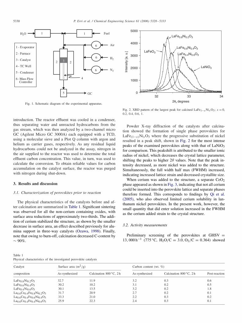
Fig. 1. Schematic diagram of the experimental apparatus.
introduction. The reactor effluent was cooled in a condenser,thus separating water and unreacted hydrocarbons from thegas stream, which was then analyzed by a two-channel microGC (Agilent Micro GC 3000A) each equipped with a TCD,using a molecular sieve and a Plot Q column with argon andhelium as carrier gases, respectively. As any residual liquidhydrocarbons could not be analyzed in the assay, nitrogen inthe air supplied to the reactor was used to determine the totaleffluent carbon concentration. This value, in turn, was used tocalculate the conversion. To obtain reliable values for carbonaccumulation on the catalyst surface, the reactor was purgedwith nitrogen during shut-down.
3. Results and discussion
3.1. Characterization of perovskites prior to reaction
The physical characteristics of the catalysts before and af-ter calcination are summarized in Table 1. Significant sinteringwas observed for all the non-cerium containing oxides, withsurface area reductions of approximately two-thirds. The addi-tion of cerium stabilized the structure, as shown by the smallerdecrease in surface area, an effect described previously for alu-mina support in three-way catalysts (Ozawa, 1998). Finally,note that owing to burn-off, calcination decreased C-content by∼ 90%.
Table 1Physical characteristics of the investigated perovskite catalysts
Catalyst Surface area (m2/g) Carbon content (wt. %)
composition As-synthesized Calcination 800 ◦C, 2 h As-synthesized Calcination 800 ◦C, 2 h Post-reaction
LaFe0.8Ni0.2O3 32.7 11.9 3.2 0.3 0.6LaFe0.6Ni0.4O3 30.2 10.2 3.1 0.2 0.5LaFe0.4Ni0.6O3 30.1 13.5 3.2 0.2 1.8La0.6Ce0.4Fe0.8Ni0.2O3 31.7 20.9 2.7 0.2 0.1La0.6Ce0.4Fe0.6Ni0.4O3 33.3 21.0 2.2 0.3 0.2La0.6Ce0.4Fe0.4Ni0.6O3 25.9 22.3 2.4 0.3 0.1
32 33 340
1000
2000
3000
4000
5000
LaFe0.4Ni0.6O3
LaNiO3
LaFe0.6Ni0.4O3
LaFe0.8Ni0.2O3
LaFeO3
Inte
nsity
[a. u
.]
2θ, , degrees
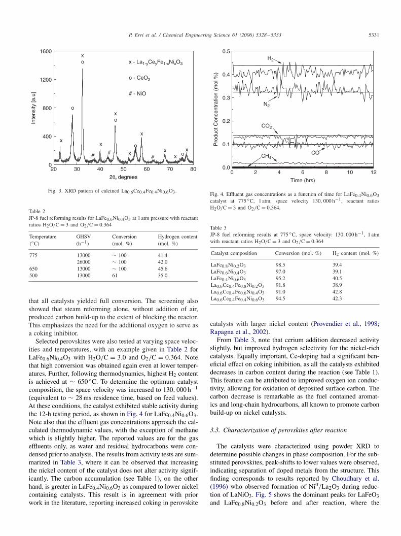
Fig. 2. XRD pattern of the largest peak for calcined LaFe1−xNixO3; x = 0,0.2, 0.4, 0.6, 1.
Powder X-ray diffraction of the catalysts after calcina-tion showed the formation of single phase perovskites forLaFe(1−x)NixO3 where the progressive substitution of nickelresulted in a peak shift, shown in Fig. 2 for the most intensepeaks of the examined perovskites along with that of LaNiO3for comparison. This peakshift is attributed to the smaller ionicradius of nickel, which decreases the crystal lattice parameter,shifting the peaks to higher 2� values. Note that the peak in-tensity decreased, as more nickel was added to the structure.Simultaneously, the full width half max (FWHM) increased,indicating increased lattice strain and decreased crystallite size.
When cerium was added to the structure, a separate CeO2phase appeared as shown in Fig. 3, indicating that not all ceriumcould be inserted into the perovskite lattice and separate phasestherefore formed. This corresponds to findings by Qi et al.(2005), who also observed limited cerium solubility in lan-thanum nickel perovskites. In the present work, however, thesmall quantity that did enter solution increased in the FWHMas the cerium added strain to the crystal structure.
3.2. Activity measurements
Preliminary screening of the perovskites at GHSV =13, 000 h−1 (775 ◦C, H2O/C = 3.0, O2/C = 0.364) showed
P. Erri et al. / Chemical Engineering Science 61 (2006) 5328–5333 5331
20 30 40 50 60 70 800
400
800
1200
1600
ox##
x - La1-yCeyFe1-xNixO3
o - CeO2
# - NiO
#o
o
xx
x
x
xo
x
xo
x
Inte
nsity
[a.u
]
2θ, , degrees
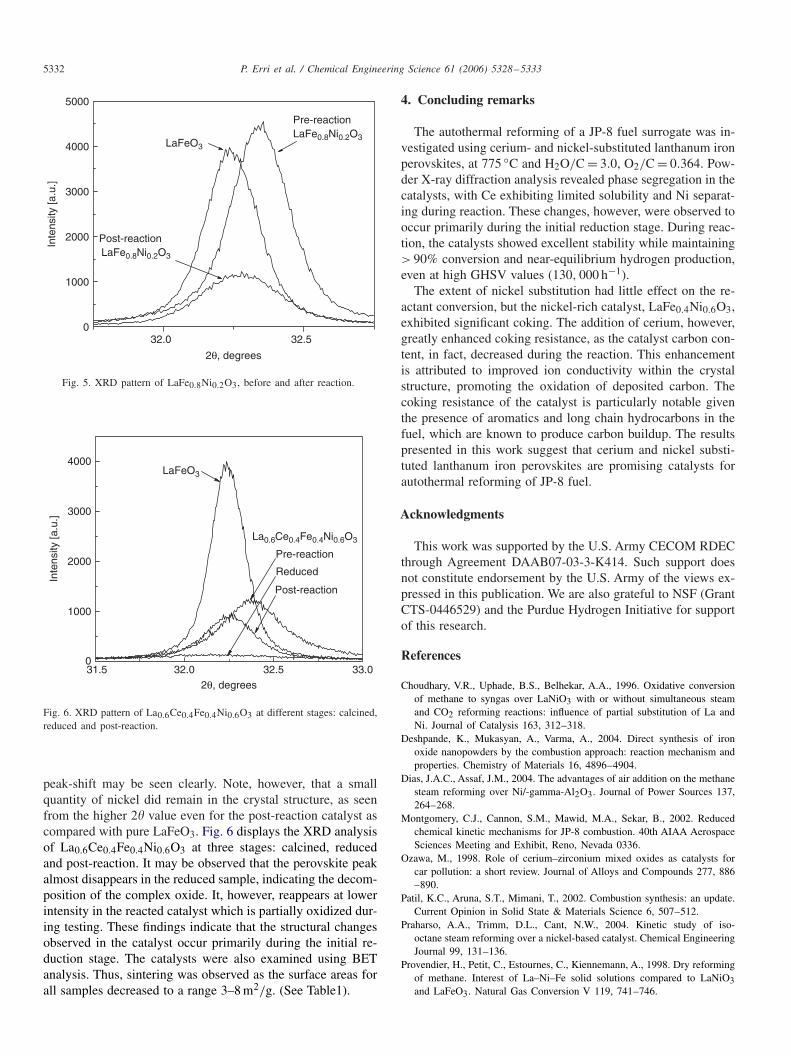
Fig. 3. XRD pattern of calcined La0.6Ce0.4Fe0.4Ni0.6O3.
Table 2JP-8 fuel reforming results for LaFe0.6Ni0.4O3 at 1 atm pressure with reactantratios H2O/C = 3 and O2/C = 0.364
Temperature GHSV Conversion Hydrogen content(◦C) (h−1) (mol. %) (mol. %)
775 13000 ∼ 100 41.426000 ∼ 100 42.0
650 13000 ∼ 100 45.6500 13000 61 35.0
that all catalysts yielded full conversion. The screening alsoshowed that steam reforming alone, without addition of air,produced carbon build-up to the extent of blocking the reactor.This emphasizes the need for the additional oxygen to serve asa coking inhibitor.
Selected perovskites were also tested at varying space veloc-ities and temperatures, with an example given in Table 2 forLaFe0.6Ni0.4O3 with H2O/C = 3.0 and O2/C = 0.364. Notethat high conversion was obtained again even at lower temper-atures. Further, following thermodynamics, highest H2 contentis achieved at ∼ 650 ◦C. To determine the optimum catalystcomposition, the space velocity was increased to 130, 000 h−1
(equivalent to ∼ 28 ms residence time, based on feed values).At these conditions, the catalyst exhibited stable activity duringthe 12-h testing period, as shown in Fig. 4 for LaFe0.4Ni0.6O3.Note also that the effluent gas concentrations approach the cal-culated thermodynamic values, with the exception of methanewhich is slightly higher. The reported values are for the gaseffluents only, as water and residual hydrocarbons were con-densed prior to analysis. The results from activity tests are sum-marized in Table 3, where it can be observed that increasingthe nickel content of the catalyst does not alter activity signif-icantly. The carbon accumulation (see Table 1), on the otherhand, is greater in LaFe0.4Ni0.6O3 as compared to lower nickelcontaining catalysts. This result is in agreement with priorwork in the literature, reporting increased coking in perovskite
0 6 8 10 120.0
0.1
0.2
0.3
0.4
0.5
Pro
duct
Con
cent
ratio
n (m
ol %
)
Time (hrs)
CH4
N2
H2
CO
CO2
2 4
Fig. 4. Effluent gas concentrations as a function of time for LaFe0.4Ni0.6O3catalyst at 775 ◦C, 1 atm, space velocity 130, 000 h−1, reactant ratiosH2O/C = 3 and O2/C = 0.364.
Table 3JP-8 fuel reforming results at 775 ◦C, space velocity: 130, 000 h−1, 1 atmwith reactant ratios H2O/C = 3 and O2/C = 0.364
Catalyst composition Conversion (mol. %) H2 content (mol. %)
LaFe0.8Ni0.2O3 98.5 39.4LaFe0.6Ni0.4O3 97.0 39.1LaFe0.4Ni0.6O3 95.2 40.5La0.6Ce0.4Fe0.8Ni0.2O3 91.8 38.9La0.6Ce0.4Fe0.6Ni0.4O3 91.0 42.8La0.6Ce0.4Fe0.4Ni0.6O3 94.5 42.3
catalysts with larger nickel content (Provendier et al., 1998;Rapagna et al., 2002).
From Table 3, note that cerium addition decreased activityslightly, but improved hydrogen selectivity for the nickel-richcatalysts. Equally important, Ce-doping had a significant ben-eficial effect on coking inhibition, as all the catalysts exhibiteddecreases in carbon content during the reaction (see Table 1).This feature can be attributed to improved oxygen ion conduc-tivity, allowing for oxidation of deposited surface carbon. Thecarbon decrease is remarkable as the fuel contained aromat-ics and long-chain hydrocarbons, all known to promote carbonbuild-up on nickel catalysts.
3.3. Characterization of perovskites after reaction
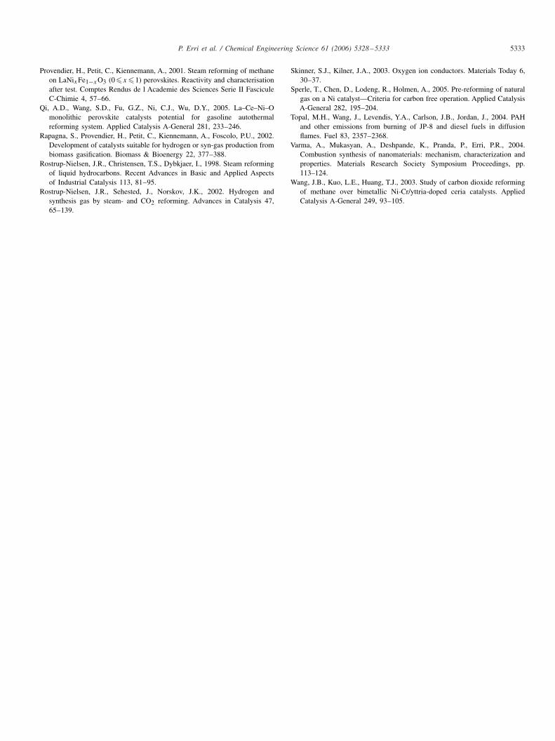
The catalysts were characterized using powder XRD todetermine possible changes in phase composition. For the sub-stituted perovskites, peak-shifts to lower values were observed,indicating separation of doped metals from the structure. Thisfinding corresponds to results reported by Choudhary et al.(1996) who observed formation of Ni0/La2O3 during reduc-tion of LaNiO3. Fig. 5 shows the dominant peaks for LaFeO3and LaFe0.8Ni0.2O3 before and after reaction, where the
5332 P. Erri et al. / Chemical Engineering Science 61 (2006) 5328–5333
32.0 32.50
1000
2000
3000
4000
5000
Post-reactionLaFe0.8Ni0.2O3
Pre-reactionLaFe0.8Ni0.2O3
LaFeO3
Inte
nsity
[a.u
.]
2θ, degrees
Fig. 5. XRD pattern of LaFe0.8Ni0.2O3, before and after reaction.
31.5 32.0 32.5 33.00
1000
2000
3000
4000LaFeO3
La0.6Ce0.4Fe0.4Ni0.6O3
Inte
nsity
[a.u
.]
2θ, degrees
Pre-reaction
Reduced
Post-reaction
Fig. 6. XRD pattern of La0.6Ce0.4Fe0.4Ni0.6O3 at different stages: calcined,reduced and post-reaction.
peak-shift may be seen clearly. Note, however, that a smallquantity of nickel did remain in the crystal structure, as seenfrom the higher 2� value even for the post-reaction catalyst ascompared with pure LaFeO3. Fig. 6 displays the XRD analysisof La0.6Ce0.4Fe0.4Ni0.6O3 at three stages: calcined, reducedand post-reaction. It may be observed that the perovskite peakalmost disappears in the reduced sample, indicating the decom-position of the complex oxide. It, however, reappears at lowerintensity in the reacted catalyst which is partially oxidized dur-ing testing. These findings indicate that the structural changesobserved in the catalyst occur primarily during the initial re-duction stage. The catalysts were also examined using BETanalysis. Thus, sintering was observed as the surface areas forall samples decreased to a range 3–8 m2/g. (See Table1).
4. Concluding remarks
The autothermal reforming of a JP-8 fuel surrogate was in-vestigated using cerium- and nickel-substituted lanthanum ironperovskites, at 775 ◦C and H2O/C = 3.0, O2/C = 0.364. Pow-der X-ray diffraction analysis revealed phase segregation in thecatalysts, with Ce exhibiting limited solubility and Ni separat-ing during reaction. These changes, however, were observed tooccur primarily during the initial reduction stage. During reac-tion, the catalysts showed excellent stability while maintaining> 90% conversion and near-equilibrium hydrogen production,even at high GHSV values (130, 000 h−1).
The extent of nickel substitution had little effect on the re-actant conversion, but the nickel-rich catalyst, LaFe0.4Ni0.6O3,exhibited significant coking. The addition of cerium, however,greatly enhanced coking resistance, as the catalyst carbon con-tent, in fact, decreased during the reaction. This enhancementis attributed to improved ion conductivity within the crystalstructure, promoting the oxidation of deposited carbon. Thecoking resistance of the catalyst is particularly notable giventhe presence of aromatics and long chain hydrocarbons in thefuel, which are known to produce carbon buildup. The resultspresented in this work suggest that cerium and nickel substi-tuted lanthanum iron perovskites are promising catalysts forautothermal reforming of JP-8 fuel.
Acknowledgments
This work was supported by the U.S. Army CECOM RDECthrough Agreement DAAB07-03-3-K414. Such support doesnot constitute endorsement by the U.S. Army of the views ex-pressed in this publication. We are also grateful to NSF (GrantCTS-0446529) and the Purdue Hydrogen Initiative for supportof this research.
References
Choudhary, V.R., Uphade, B.S., Belhekar, A.A., 1996. Oxidative conversionof methane to syngas over LaNiO3 with or without simultaneous steamand CO2 reforming reactions: influence of partial substitution of La andNi. Journal of Catalysis 163, 312–318.
Deshpande, K., Mukasyan, A., Varma, A., 2004. Direct synthesis of ironoxide nanopowders by the combustion approach: reaction mechanism andproperties. Chemistry of Materials 16, 4896–4904.
Dias, J.A.C., Assaf, J.M., 2004. The advantages of air addition on the methanesteam reforming over Ni/-gamma-Al2O3. Journal of Power Sources 137,264–268.
Montgomery, C.J., Cannon, S.M., Mawid, M.A., Sekar, B., 2002. Reducedchemical kinetic mechanisms for JP-8 combustion. 40th AIAA AerospaceSciences Meeting and Exhibit, Reno, Nevada 0336.
Ozawa, M., 1998. Role of cerium–zirconium mixed oxides as catalysts forcar pollution: a short review. Journal of Alloys and Compounds 277, 886–890.
Patil, K.C., Aruna, S.T., Mimani, T., 2002. Combustion synthesis: an update.Current Opinion in Solid State & Materials Science 6, 507–512.
Praharso, A.A., Trimm, D.L., Cant, N.W., 2004. Kinetic study of iso-octane steam reforming over a nickel-based catalyst. Chemical EngineeringJournal 99, 131–136.
Provendier, H., Petit, C., Estournes, C., Kiennemann, A., 1998. Dry reformingof methane. Interest of La–Ni–Fe solid solutions compared to LaNiO3and LaFeO3. Natural Gas Conversion V 119, 741–746.
P. Erri et al. / Chemical Engineering Science 61 (2006) 5328–5333 5333
Provendier, H., Petit, C., Kiennemann, A., 2001. Steam reforming of methaneon LaNixFe1−xO3 (0�x �1) perovskites. Reactivity and characterisationafter test. Comptes Rendus de l Academie des Sciences Serie II FasciculeC-Chimie 4, 57–66.
Qi, A.D., Wang, S.D., Fu, G.Z., Ni, C.J., Wu, D.Y., 2005. La–Ce–Ni–Omonolithic perovskite catalysts potential for gasoline autothermalreforming system. Applied Catalysis A-General 281, 233–246.
Rapagna, S., Provendier, H., Petit, C., Kiennemann, A., Foscolo, P.U., 2002.Development of catalysts suitable for hydrogen or syn-gas production frombiomass gasification. Biomass & Bioenergy 22, 377–388.
Rostrup-Nielsen, J.R., Christensen, T.S., Dybkjaer, I., 1998. Steam reformingof liquid hydrocarbons. Recent Advances in Basic and Applied Aspectsof Industrial Catalysis 113, 81–95.
Rostrup-Nielsen, J.R., Sehested, J., Norskov, J.K., 2002. Hydrogen andsynthesis gas by steam- and CO2 reforming. Advances in Catalysis 47,65–139.
Skinner, S.J., Kilner, J.A., 2003. Oxygen ion conductors. Materials Today 6,30–37.
Sperle, T., Chen, D., Lodeng, R., Holmen, A., 2005. Pre-reforming of naturalgas on a Ni catalyst—Criteria for carbon free operation. Applied CatalysisA-General 282, 195–204.
Topal, M.H., Wang, J., Levendis, Y.A., Carlson, J.B., Jordan, J., 2004. PAHand other emissions from burning of JP-8 and diesel fuels in diffusionflames. Fuel 83, 2357–2368.
Varma, A., Mukasyan, A., Deshpande, K., Pranda, P., Erri, P.R., 2004.Combustion synthesis of nanomaterials: mechanism, characterization andproperties. Materials Research Society Symposium Proceedings, pp.113–124.
Wang, J.B., Kuo, L.E., Huang, T.J., 2003. Study of carbon dioxide reformingof methane over bimetallic Ni-Cr/yttria-doped ceria catalysts. AppliedCatalysis A-General 249, 93–105.