Embed Size (px)
Citation preview
NOVEL METHODS OF RESTRAINING EMBEDDED RETAINING WALLS Abid Adekunte, Deep Foundations Specialists, Berkshire UK. Pat O’ Hara, Van Elle Limited, Limerick, Republic of Ireland. Austin Dennany, Dennany Reidy Associates, Limerick, Republic of Ireland.
Traditionally, designers and contractors provide additional external supports to retaining walls through the use of tie-back anchors or braces. Both approaches are known to have their shortcomings; braces limit working space within excavation areas, while tie-backs are seldom used in built-up areas where intrusion into adjacent property of non-cooperative owners has to be avoided or in situations where sensitive structures exist behind the wall. This paper focuses on the design, construction and monitoring of deep excavation support systems on two separate projects located in different ground conditions in the Republic of Ireland. On both projects, conventional ground anchorage and propping were inapplicable. This led to the development and application of two different novel solutions on both projects. Methods of wall performance monitoring on both sites also differ. Wall monitoring results show these innovative methods to be safe and effective. Advantages of the novel solutions over traditional approaches are highlighted.
INTRODUCTION Due to the current global economic climate, it is imperative that construction specialists adopt various means of offering competitive solutions to clients. Everyone employed in the construction industry has an obligation in this austere period to offer innovative, economical and safe solutions. In line with this notion, many geotechnical specialists now consider innovation and economy to be paramount in the areas of design and construction. In the area of embedded retaining wall design and construction, conventional methods of restraining walls (e.g. propping, tie-back anchorage) are well established and several publications on these abound in the literature e.g. Adekunte et al., 2007; Looby & Long, 2007; Loveridge, 2001; Batten & Powrie, 2000a & 2000b; Richards et al., 1999; Twine & Roscoe, 1999; Batten, 1998; Carder et al., 1997; Potts & Bond, 1994; Symons et al., 1987 and Milligan, 1983). However in recent years, engineers have had to deal with projects on which the applications of traditional propping and tie-backs are limited by site constraints. This has prompted a number of workers to concentrate on the development and application of alternative approaches to restraining embedded retaining walls e.g. Adekunte (2008), Deschamps et. al. (2008). The current study focuses on the design, construction and monitoring of contiguous pile
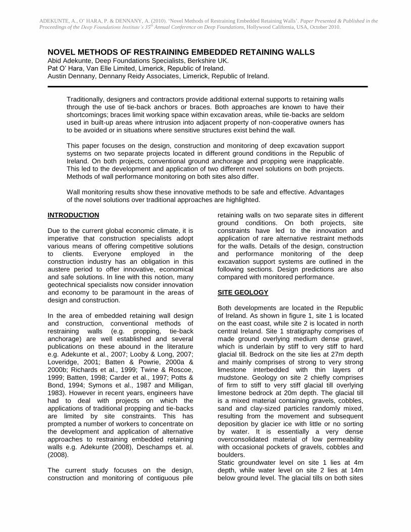
retaining walls on two separate sites in different ground conditions. On both projects, site constraints have led to the innovation and application of rare alternative restraint methods for the walls. Details of the design, construction and performance monitoring of the deep excavation support systems are outlined in the following sections. Design predictions are also compared with monitored performance. SITE GEOLOGY Both developments are located in the Republic of Ireland. As shown in figure 1, site 1 is located on the east coast, while site 2 is located in north central Ireland. Site 1 stratigraphy comprises of made ground overlying medium dense gravel, which is underlain by stiff to very stiff to hard glacial till. Bedrock on the site lies at 27m depth and mainly comprises of strong to very strong limestone interbedded with thin layers of mudstone. Geology on site 2 chiefly comprises of firm to stiff to very stiff glacial till overlying limestone bedrock at 20m depth. The glacial till is a mixed material containing gravels, cobbles, sand and clay-sized particles randomly mixed, resulting from the movement and subsequent deposition by glacier ice with little or no sorting by water. It is essentially a very dense overconsolidated material of low permeability with occasional pockets of gravels, cobbles and boulders. Static groundwater level on site 1 lies at 4m depth, while water level on site 2 lies at 14m below ground level. The glacial tills on both sites
ADEKUNTE, A., O’ HARA, P. & DENNANY, A. (2010). ‘Novel Methods of Restraining Embedded Retaining Walls’. Paper Presented & Published in the Proceedings of the Deep Foundations Institute’s 35th Annual Conference on Deep Foundations, Hollywood California, USA, October 2010.
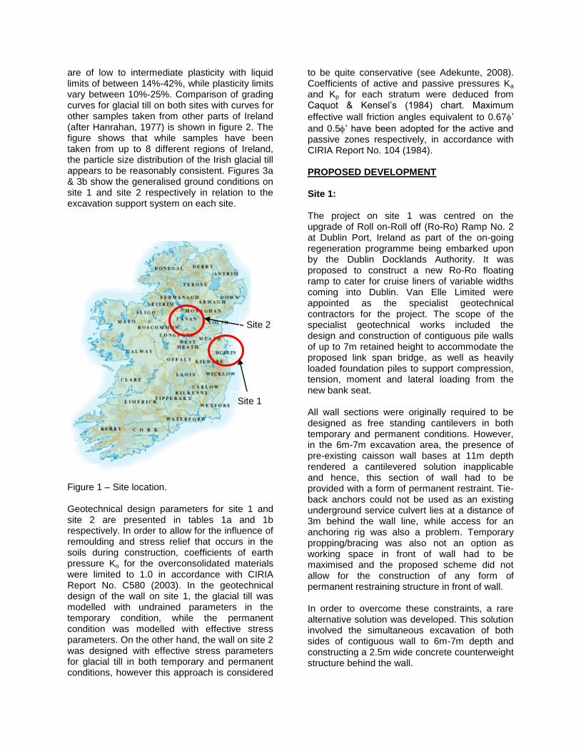
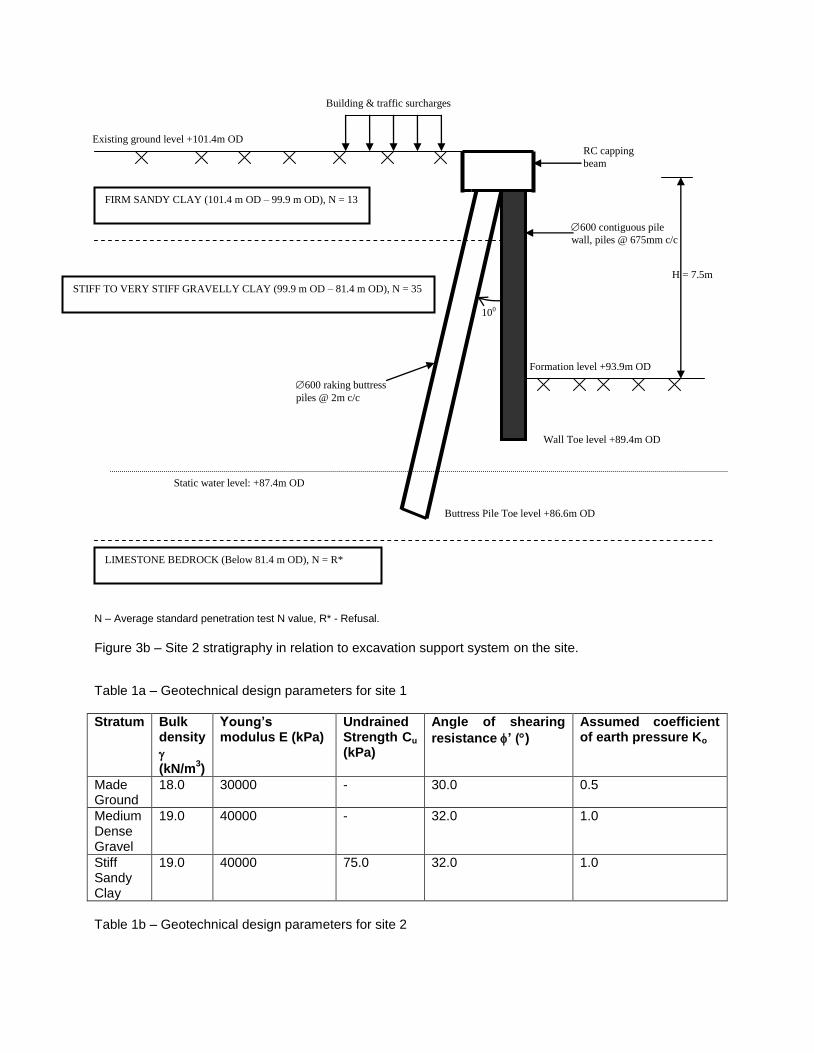
are of low to intermediate plasticity with liquid limits of between 14%-42%, while plasticity limits vary between 10%-25%. Comparison of grading curves for glacial till on both sites with curves for other samples taken from other parts of Ireland (after Hanrahan, 1977) is shown in figure 2. The figure shows that while samples have been taken from up to 8 different regions of Ireland, the particle size distribution of the Irish glacial till appears to be reasonably consistent. Figures 3a & 3b show the generalised ground conditions on site 1 and site 2 respectively in relation to the excavation support system on each site. Figure 1 – Site location. Geotechnical design parameters for site 1 and site 2 are presented in tables 1a and 1b respectively. In order to allow for the influence of remoulding and stress relief that occurs in the soils during construction, coefficients of earth pressure Ko for the overconsolidated materials were limited to 1.0 in accordance with CIRIA Report No. C580 (2003). In the geotechnical design of the wall on site 1, the glacial till was modelled with undrained parameters in the temporary condition, while the permanent condition was modelled with effective stress parameters. On the other hand, the wall on site 2 was designed with effective stress parameters for glacial till in both temporary and permanent conditions, however this approach is considered
to be quite conservative (see Adekunte, 2008). Coefficients of active and passive pressures Ka
and Kp for each stratum were deduced from Caquot & Kensel’s (1984) chart. Maximum
effective wall friction angles equivalent to 0.67’
and 0.5’ have been adopted for the active and passive zones respectively, in accordance with CIRIA Report No. 104 (1984). PROPOSED DEVELOPMENT Site 1: The project on site 1 was centred on the upgrade of Roll on-Roll off (Ro-Ro) Ramp No. 2 at Dublin Port, Ireland as part of the on-going regeneration programme being embarked upon by the Dublin Docklands Authority. It was proposed to construct a new Ro-Ro floating ramp to cater for cruise liners of variable widths coming into Dublin. Van Elle Limited were appointed as the specialist geotechnical contractors for the project. The scope of the specialist geotechnical works included the design and construction of contiguous pile walls of up to 7m retained height to accommodate the proposed link span bridge, as well as heavily loaded foundation piles to support compression, tension, moment and lateral loading from the new bank seat. All wall sections were originally required to be designed as free standing cantilevers in both temporary and permanent conditions. However, in the 6m-7m excavation area, the presence of pre-existing caisson wall bases at 11m depth rendered a cantilevered solution inapplicable and hence, this section of wall had to be provided with a form of permanent restraint. Tie-back anchors could not be used as an existing underground service culvert lies at a distance of 3m behind the wall line, while access for an anchoring rig was also a problem. Temporary propping/bracing was also not an option as working space in front of wall had to be maximised and the proposed scheme did not allow for the construction of any form of permanent restraining structure in front of wall. In order to overcome these constraints, a rare alternative solution was developed. This solution involved the simultaneous excavation of both sides of contiguous wall to 6m-7m depth and constructing a 2.5m wide concrete counterweight structure behind the wall.
Site 1
Site 2
0
20
40
60
80
100
120
0.001 0.01 0.1 1 10 100
Particle Size (mm)
Perc
en
tag
e F
iner
(%)
Cork
Claire
Cavan
Waterford
Meath
Site 1
Sligo
Site 2
0.063
Figure 2 - Comparison of grading curves for site 1 and site 2 with samples from other regions of Ireland
(after Hanrahan, 1977).
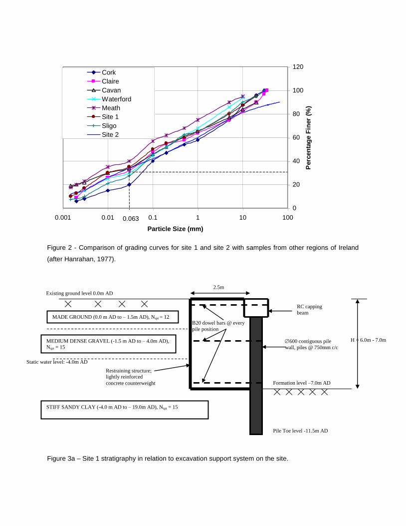
Figure 3a – Site 1 stratigraphy in relation to excavation support system on the site.
Static water level: -4.0m AD
2.5m
B20 dowel bars @ every
pile position
H = 6.0m - 7.0m
Formation level –7.0m AD
MADE GROUND (0.0 m AD to – 1.5m AD), Nspt = 12
MEDIUM DENSE GRAVEL (-1.5 m AD to – 4.0m AD), Nspt = 15
Existing ground level 0.0m AD
Pile Toe level -11.5m AD
RC capping
beam
600 contiguous pile
wall, piles @ 750mm c/c
Restraining structure; lightly reinforced
concrete counterweight
STIFF SANDY CLAY (-4.0 m AD to – 19.0m AD), Nspt = 15
N – Average standard penetration test N value, R* - Refusal.
Figure 3b – Site 2 stratigraphy in relation to excavation support system on the site.
Table 1a – Geotechnical design parameters for site 1
Stratum
Bulk density
(kN/m
3)
Young’s modulus E (kPa)
Undrained Strength Cu
(kPa)
Angle of shearing
resistance ’ ()
Assumed coefficient of earth pressure Ko
Made Ground
18.0 30000 - 30.0 0.5
Medium Dense Gravel
19.0 40000 - 32.0 1.0
Stiff Sandy Clay
19.0 40000 75.0 32.0 1.0
Table 1b – Geotechnical design parameters for site 2
Building & traffic surcharges
H = 7.5m
100
Formation level +93.9m OD
FIRM SANDY CLAY (101.4 m OD – 99.9 m OD), N = 13
STIFF TO VERY STIFF GRAVELLY CLAY (99.9 m OD – 81.4 m OD), N = 35
Existing ground level +101.4m OD
Wall Toe level +89.4m OD
RC capping
beam
600 contiguous pile
wall, piles @ 675mm c/c
LIMESTONE BEDROCK (Below 81.4 m OD), N = R*
600 raking buttress
piles @ 2m c/c
Static water level: +87.4m OD
Buttress Pile Toe level +86.6m OD
Stratum
Bulk
density (kN/m
3)
Young’s modulus E (kPa)
Angle of shearing
resistance ’ ()
Assumed coefficient of earth pressure Ko
Skin friction resistance fs (kPa)
Firm sandy clay
18.0 32000 30.0 1.0 50.0
Stiff to very stiff gravelly clay
20.0 87000 37.0 1.0 110.0
Site 2: The project on site 2 was a multi-storey commercial development comprising of single to triple level basement for underground parking and storage purposes. The site is bounded by existing properties and a national road. It was required to construct contiguous pile walls to enable the excavation and construction of the basement structure. Retained height varies between 4m-10.5m. While the wall sections in the single level basement area could be designed as free standing cantilevered structures, wall sections in the double-triple level basement area required additional supports for serviceability reasons. As it was the case with site 1, working space within the excavation area had to be maximised and hence, conventional propping was not applicable. In addition, the developers had difficulties in obtaining approval from owners of adjacent properties for the use of tie-back anchors. As an alternative, a rare wall restraining method was adopted. This involved buttressing the wall with 10
o raking piles at 2m intervals behind the
pile wall. The buttress piles were rigidly connected to the contiguous pile wall with a reinforced concrete capping beam. While the required wall restraint was solely provided by the raking buttress piles in the temporary condition, the basement and ground floor slabs offer additional propping effect to the wall in the permanent state. CONSTRUCTION PROCEDURE Stages involved in the construction of the deep excavation support systems on sites 1 & 2 are presented in tables 2a & 2b respectively. These sequences were followed in the analysis and design of the walls.
Site 1: Piles were installed by continuous flight auger (CFA) drilling with a SoilMec CM48 hydraulic piling rig. 600mm diameter piles were installed at 750mm c/c spacing to form the contiguous pile wall. Piles were cast with grade 35 concrete and reinforced with grade 500 steel. After wall installation, initial excavation was carried out at the front and back of wall to a depth of 750mm, so as to allow for the construction of the reinforced concrete capping beam. This was followed by the simultaneous excavation of both sides of wall to formation level. Behind the wall, excavation was only carried out over a width of 2.5m, while temporary shoring and formworks were put in place to allow for the construction of the permanent counterweight structure behind the wall. Concrete for the counterweight structure was poured in 3 stages over a 3-day period. Rapid hardening cement was used in order to limit active pressures from wet concrete placed behind the wall. Dowel bars were installed at capping beam level, mid-height and just above formation level. The dowel bars were installed at every pile position and acted to tie the counterweight structure to the piles as it was poured in stages. For safety reasons, the reinforcement for the counterweight was so designed as to allow the cages to be tied and lowered into the excavation behind the pile wall rather than requiring the steel fixers to enter the deep excavation. The counterweight structure was built to perform two main functions;
to provide additional gravitational support/restoring moment to contiguous pile wall;
to provide additional stiffness/flexural rigidity to the pile wall above formation level.
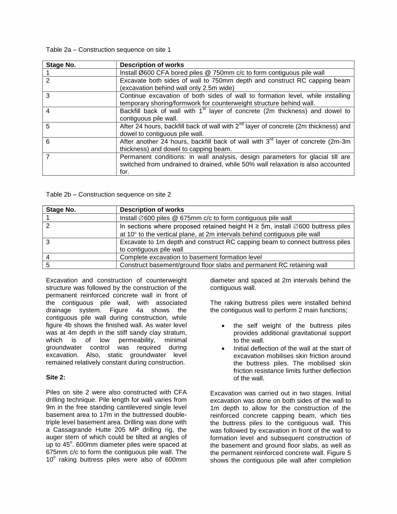
Table 2a – Construction sequence on site 1
Stage No. Description of works
1 Install Ø600 CFA bored piles @ 750mm c/c to form contiguous pile wall
2 Excavate both sides of wall to 750mm depth and construct RC capping beam (excavation behind wall only 2.5m wide)
3 Continue excavation of both sides of wall to formation level, while installing temporary shoring/formwork for counterweight structure behind wall.
4 Backfill back of wall with 1st layer of concrete (2m thickness) and dowel to
contiguous pile wall.
5 After 24 hours, backfill back of wall with 2nd
layer of concrete (2m thickness) and dowel to contiguous pile wall.
6 After another 24 hours, backfill back of wall with 3rd
layer of concrete (2m-3m thickness) and dowel to capping beam.
7 Permanent conditions: in wall analysis, design parameters for glacial till are switched from undrained to drained, while 50% wall relaxation is also accounted for.
Table 2b – Construction sequence on site 2
Stage No. Description of works
1 Install 600 piles @ 675mm c/c to form contiguous pile wall
2 In sections where proposed retained height H ≥ 5m, install 600 buttress piles
at 10 to the vertical plane, at 2m intervals behind contiguous pile wall
3 Excavate to 1m depth and construct RC capping beam to connect buttress piles to contiguous pile wall
4 Complete excavation to basement formation level
5 Construct basement/ground floor slabs and permanent RC retaining wall
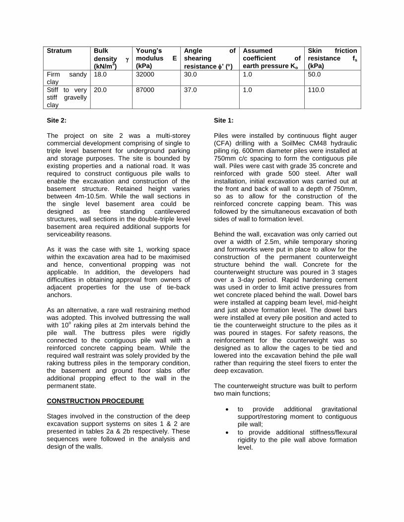
Excavation and construction of counterweight structure was followed by the construction of the permanent reinforced concrete wall in front of the contiguous pile wall, with associated drainage system. Figure 4a shows the contiguous pile wall during construction, while figure 4b shows the finished wall. As water level was at 4m depth in the stiff sandy clay stratum, which is of low permeability, minimal groundwater control was required during excavation. Also, static groundwater level remained relatively constant during construction. Site 2: Piles on site 2 were also constructed with CFA drilling technique. Pile length for wall varies from 9m in the free standing cantilevered single level basement area to 17m in the buttressed double-triple level basement area. Drilling was done with a Cassagrande Hutte 205 MP drilling rig, the auger stem of which could be tilted at angles of up to 45
o. 600mm diameter piles were spaced at
675mm c/c to form the contiguous pile wall. The 10
o raking buttress piles were also of 600mm
diameter and spaced at 2m intervals behind the contiguous wall. The raking buttress piles were installed behind the contiguous wall to perform 2 main functions;
the self weight of the buttress piles provides additional gravitational support to the wall.
Initial deflection of the wall at the start of excavation mobilises skin friction around the buttress piles. The mobilised skin friction resistance limits further deflection of the wall.
Excavation was carried out in two stages. Initial excavation was done on both sides of the wall to 1m depth to allow for the construction of the reinforced concrete capping beam, which ties the buttress piles to the contiguous wall. This was followed by excavation in front of the wall to formation level and subsequent construction of the basement and ground floor slabs, as well as the permanent reinforced concrete wall. Figure 5 shows the contiguous pile wall after completion
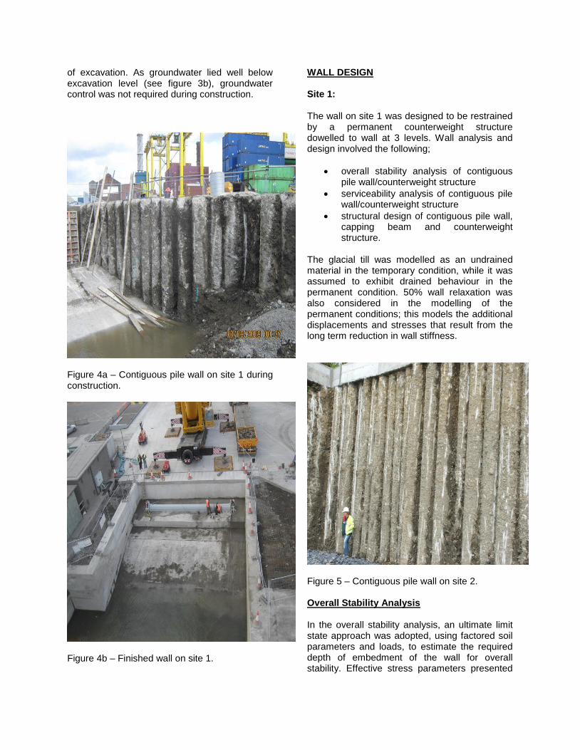
of excavation. As groundwater lied well below excavation level (see figure 3b), groundwater control was not required during construction.
Figure 4a – Contiguous pile wall on site 1 during construction.
Figure 4b – Finished wall on site 1.
WALL DESIGN Site 1: The wall on site 1 was designed to be restrained by a permanent counterweight structure dowelled to wall at 3 levels. Wall analysis and design involved the following;
overall stability analysis of contiguous pile wall/counterweight structure
serviceability analysis of contiguous pile wall/counterweight structure
structural design of contiguous pile wall, capping beam and counterweight structure.
The glacial till was modelled as an undrained material in the temporary condition, while it was assumed to exhibit drained behaviour in the permanent condition. 50% wall relaxation was also considered in the modelling of the permanent conditions; this models the additional displacements and stresses that result from the long term reduction in wall stiffness.
Figure 5 – Contiguous pile wall on site 2. Overall Stability Analysis In the overall stability analysis, an ultimate limit state approach was adopted, using factored soil parameters and loads, to estimate the required depth of embedment of the wall for overall stability. Effective stress parameters presented
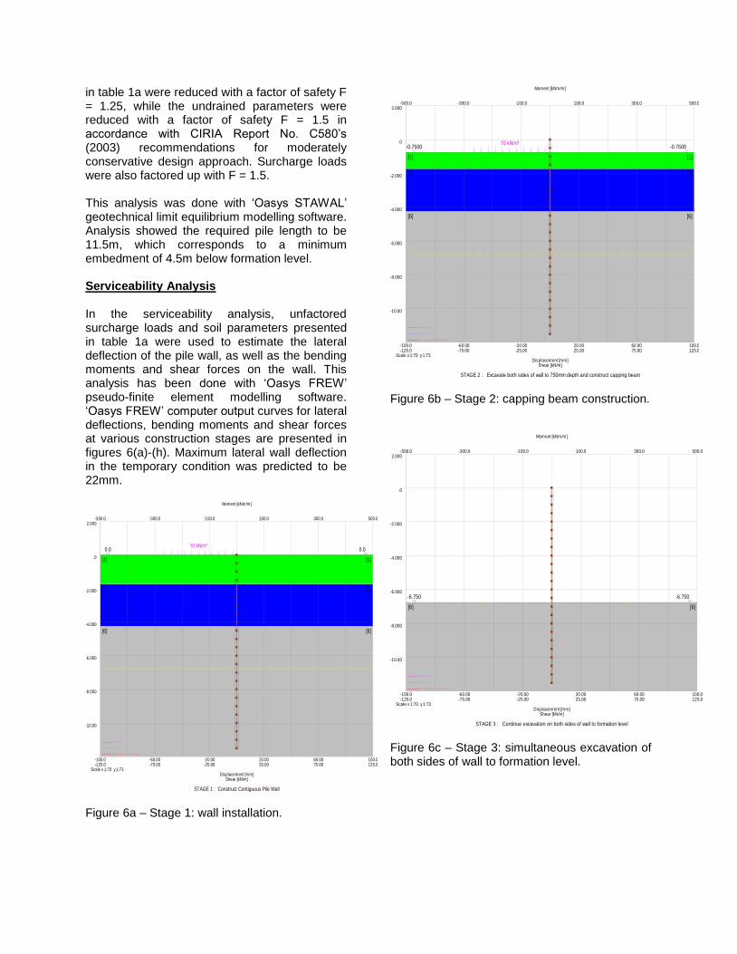
in table 1a were reduced with a factor of safety F = 1.25, while the undrained parameters were reduced with a factor of safety F = 1.5 in accordance with CIRIA Report No. C580’s (2003) recommendations for moderately conservative design approach. Surcharge loads were also factored up with F = 1.5. This analysis was done with ‘Oasys STAWAL’ geotechnical limit equilibrium modelling software. Analysis showed the required pile length to be 11.5m, which corresponds to a minimum embedment of 4.5m below formation level. Serviceability Analysis In the serviceability analysis, unfactored surcharge loads and soil parameters presented in table 1a were used to estimate the lateral deflection of the pile wall, as well as the bending moments and shear forces on the wall. This analysis has been done with ‘Oasys FREW’ pseudo-finite element modelling software. ‘Oasys FREW’ computer output curves for lateral deflections, bending moments and shear forces at various construction stages are presented in figures 6(a)-(h). Maximum lateral wall deflection in the temporary condition was predicted to be 22mm.
[1]
0.0
[1]
0.0
[2] [2]
[6] [6]
10 kN/m²
STAGE 1 : Construct Contiguous Pile Wall
D i s p l a c e m e n t s
M o m e n t
S h e a r
-100.0 -60.00 -20.00 20.00 60.00 100.0
-500.0 -300.0 -100.0 100.0 300.0 500.0
-125.0 -75.00 -25.00 25.00 75.00 125.0
Displacement [mm]
Moment [kNm/m]
Shear [kN/m]
Scale x 1:70 y 1:73
-10.00
-8.000
-6.000
-4.000
-2.000
.0
2.000
Figure 6a – Stage 1: wall installation.
[1]
-0.7500
[1]
-0.7500
[2] [2]
[6] [6]
10 kN/m²
STAGE 2 : Excavate both sides of wall to 750mm depth and construct capping beam
D i s p l a c e m e n t s
M o m e n t
S h e a r
-100.0 -60.00 -20.00 20.00 60.00 100.0
-500.0 -300.0 -100.0 100.0 300.0 500.0
-125.0 -75.00 -25.00 25.00 75.00 125.0
Displacement [mm]
Moment [kNm/m]
Shear [kN/m]
Scale x 1:70 y 1:73
-10.00
-8.000
-6.000
-4.000
-2.000
.0
2.000
Figure 6b – Stage 2: capping beam construction.
[6]
-6.750
[6]
-6.750
STAGE 3 : Continue excavation on both sides of wall to formation level
D i s p l a c e m e n t s
M o m e n t
S h e a r
-100.0 -60.00 -20.00 20.00 60.00 100.0
-500.0 -300.0 -100.0 100.0 300.0 500.0
-125.0 -75.00 -25.00 25.00 75.00 125.0
Displacement [mm]
Moment [kNm/m]
Shear [kN/m]
Scale x 1:70 y 1:73
-10.00
-8.000
-6.000
-4.000
-2.000
.0
2.000
Figure 6c – Stage 3: simultaneous excavation of both sides of wall to formation level.
[6] [6]
-6.750
[7]
-4.250
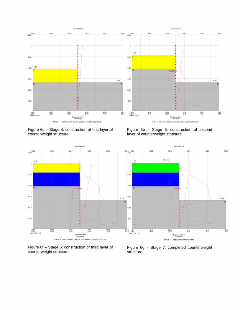
STAGE 4 : Pour 1st layer of lean mix concrete for counterweight structure
D i s p l a c e m e n t s
M o m e n t
S h e a r
-100.0 -60.00 -20.00 20.00 60.00 100.0
-500.0 -300.0 -100.0 100.0 300.0 500.0
-125.0 -75.00 -25.00 25.00 75.00 125.0
Displacement [mm]
Moment [kNm/m]
Shear [kN/m]
Scale x 1:70 y 1:73
-10.00
-8.000
-6.000
-4.000
-2.000
.0
2.000
Figure 6d – Stage 4: construction of first layer of counterweight structure.
[2]
[6]
[6]
-6.750
[7]
0.0
200.00 kN/m
STAGE 6 : Pour 3rd layer of lean mix concrete for counterweight structure
D i s p l a c e m e n t s
M o m e n t
S h e a r
-100.0 -60.00 -20.00 20.00 60.00 100.0
-500.0 -300.0 -100.0 100.0 300.0 500.0
-125.0 -75.00 -25.00 25.00 75.00 125.0
Displacement [mm]
Moment [kNm/m]
Shear [kN/m]
Scale x 1:70 y 1:73
-10.00
-8.000
-6.000
-4.000
-2.000
.0
2.000
Figure 6f – Stage 6: construction of third layer of counterweight structure.
[6]
[6]
-6.750
[7]
-1.750
100.00 kN/m
STAGE 5 : Pour 2nd layer of lean mix concrete for counterweight structure
D i s p l a c e m e n t s
M o m e n t
S h e a r
-100.0 -60.00 -20.00 20.00 60.00 100.0
-500.0 -300.0 -100.0 100.0 300.0 500.0
-125.0 -75.00 -25.00 25.00 75.00 125.0
Displacement [mm]
Moment [kNm/m]
Shear [kN/m]
Scale x 1:70 y 1:73
-10.00
-8.000
-6.000
-4.000
-2.000
.0
2.000
Figure 6e – Stage 5: construction of second layer of counterweight structure.
[1]
0.0
[2]
[6]
[6]
-6.750
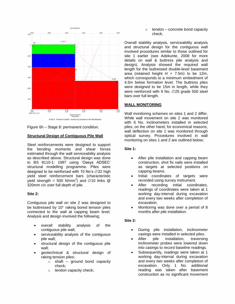
10 kN/m²
300.00 kN/m
STAGE 7 : Apply Full counterweight effect
D i s p l a c e m e n t s
M o m e n t
S h e a r
-100.0 -60.00 -20.00 20.00 60.00 100.0
-500.0 -300.0 -100.0 100.0 300.0 500.0
-125.0 -75.00 -25.00 25.00 75.00 125.0
Displacement [mm]
Moment [kNm/m]
Shear [kN/m]
Scale x 1:70 y 1:73
-10.00
-8.000
-6.000
-4.000
-2.000
.0
2.000
Figure 6g – Stage 7: completed counterweight structure.
[1]
0.0
[2]
[3]
[3]
-6.750
10 kN/m²
300.00 kN/m
STAGE 8 : Permanent Condition - Drained Clay Parameters & 50% Wall Relaxation
D i s p l a c e m e n t s
M o m e n t
S h e a r
-100.0 -60.00 -20.00 20.00 60.00 100.0
-500.0 -300.0 -100.0 100.0 300.0 500.0
-125.0 -75.00 -25.00 25.00 75.00 125.0
Displacement [mm]
Moment [kNm/m]
Shear [kN/m]
Scale x 1:70 y 1:73
-10.00
-8.000
-6.000
-4.000
-2.000
.0
2.000
Figure 6h – Stage 8: permanent condition. Structural Design of Contiguous Pile Wall Steel reinforcements were designed to support the bending moments and shear forces estimated through the wall serviceability analysis as described above. Structural design was done to BS 8110-1: 1997 using ‘Oasys ADSEC’ structural modelling programme. Piles were
designed to be reinforced with 10 No’s 32 high yield steel reinforcement bars (characteristic
yield strength = 500 N/mm2) and 10 links @
320mm c/c over full depth of pile. Site 2: Contiguous pile wall on site 2 was designed to
be buttressed by 10 raking bored tension piles connected to the wall at capping beam level. Analysis and design involved the following;
overall stability analysis of the contiguous pile wall;
serviceability analysis of the contiguous pile wall;
structural design of the contiguous pile wall;
geotechnical & structural design of raking tension piles;
o shaft – ground bond capacity check;
o tendon capacity check;
o tendon – concrete bond capacity check.
Overall stability analysis, serviceability analysis and structural design for the contiguous wall involved procedures similar to those outlined for site 1 earlier (see Adekunte, 2008 for more details on wall & buttress pile analysis and design). Analysis showed the required wall length for the buttressed double-level basement area (retained height H = 7.5m) to be 12m, which corresponds to a minimum embedment of 4.5m below formation level. The buttress piles were designed to be 15m in length, while they
were reinforced with 9 No. 25 grade 500 steel bars over full length. WALL MONITORING Wall monitoring schemes on sites 1 and 2 differ. While wall movement on site 2 was monitored with 6 No. inclinometers installed in selected piles, on the other hand, for economical reasons, wall deflection on site 1 was monitored through optical survey. Procedures involved in wall monitoring on sites 1 and 2 are outlined below; Site 1:
After pile installation and capping beam construction, shot fix nails were installed as targets at selected positions on capping beams.
Initial coordinates of targets were recorded using survey instrument.
After recording initial coordinates, readings of coordinates were taken at 1 working day-interval during excavation and every two weeks after completion of excavation.
Monitoring was done over a period of 8 months after pile installation.
Site 2:
During pile installation, inclinometer casings were installed in selected piles.
After pile installation, traversing inclinometer probes were lowered down into casings to record baseline readings.
Subsequently, readings were taken at 1 working day-interval during excavation and every two weeks after completion of excavation. Only 1 No. additional reading was taken after basement construction as no significant movement
was recorded once permanent slabs were put in place.
Monitoring was done over a period of 6 months after pile installation.
EXPERIMENTAL RESULTS & DISCUSSION Site 1: Wall monitoring data for site 1 are compared with design predictions in table 3. The table shows the bulk of wall movement to have occurred during the construction of counterweight structure (construction stages 4-7). Approximately 60% of total wall movement occurred during these stages. This is attributable to the active thrusts mobilised behind the wall as wet concrete was being poured to form the counterweight structure. Table 3 also shows predicted wall deflections for these stages to be higher than measured deflections; measured deflections were typically 27%-38% of estimated values. At design stage, the wet concrete had been modelled as a loose cohesionless material with effective stress parameters. However, the rapid hardening cement used may have allowed the concrete to behave as an undrained cohesive material and thus significantly reducing active pressures to values much lower than design estimates. After the counterweight structure had been constructed, an additional movement of only 5mm was recorded over a period of 7 months. Observations between the 5
th and 7
th months
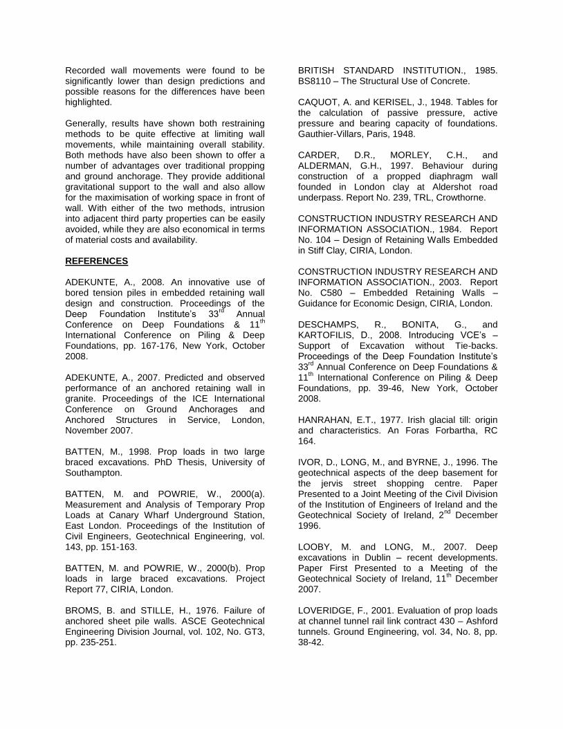
after counterweight construction showed no significant wall movement. Overall, a maximum wall deflection of 12mm was recorded over an 8 - month monitoring period. This falls well below the maximum allowable movement of 25mm specified by the supervising engineers for the project. It also shows the effectiveness of the novel wall restraining scheme in terms of serviceability and overall stability. Site 2: Observations of wall movement on site 2 have also shown design estimates of wall deflection to be conservative. This may be attributed to the numerical modelling of the glacial till at design stage. The glacial till had been modelled as a drained material with effective stress parameters, an approach taken after CIRIA Report No. C580 (2003), which considers the
use of undrained parameters for the design of walls embedded in clays to be associated with a degree of risk, especially when the wall is required for permanent retention. However Ivor et al. (1996) have suggested that negative pore pressures developed in Irish glacial till when unloaded, as well as their cohesion and cementation of soil grains, allow the material to behave as undrained, at least in the temporary condition. Ivor et al.’s (2007) assertion on the undrained behaviour of Irish glacial till has recently been supported by Looby & Long (2007). However, Looby & Long (2007) discounted the effect of soil matrix cementation and mainly attributed the undrained behaviour to negative excess pore pressure. Therefore, there is a possibility that actual active pressures mobilised behind the wall may have been over-estimated in serviceability analysis. Recorded deflections in the free standing cantilevered area (retained height H = 4m) are compared with measured movement in the wall section buttressed with raking bored tension piles (H = 7.5m) in figure 7. From figure 7, it is clear that despite the retained height in the buttressed section (H = 7.5m) being higher than that of the free standing cantilevered section (H = 4m), measured wall deflections in the buttressed section are much lower than wall movements in the free standing cantilevered area. Maximum lateral deflection in the buttressed section was 7mm, while maximum deflection in the free standing cantilevered section was 12mm. These observations show the unconventional wall restraint method to be quite effective at limiting wall movement, while maintaining overall stability. In general, wall monitoring results have shown that the novel wall restraint methods used on both sites have been effective and thus offer useful alternatives to contractors and designers whenever conventional methods are inapplicable. When compared with propping/bracing, both methods allow for the maximisation of working space in front of wall. Also, with either of the two methods, intrusion into third party properties adjacent to site boundary is more easily avoided, unlike tie-back anchorage. Unlike props and anchors, both novel solutions provide additional gravitational support to the wall.
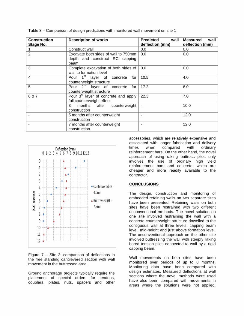
Table 3 – Comparison of design predictions with monitored wall movement on site 1
Construction Stage No.
Description of works Predicted wall deflection (mm)
Measured wall deflection (mm)
1 Construct wall 0.0 0.0
2 Excavate both sides of wall to 750mm depth and construct RC capping beam
0.0 0.0
3 Complete excavation of both sides of wall to formation level
0.0 0.0
4 Pour 1st layer of concrete for
counterweight structure 10.5 4.0
5 Pour 2nd
layer of concrete for counterweight structure
17.2 6.0
6 & 7 Pour 3rd
layer of concrete and apply full counterweight effect
22.3 7.0
- 3 months after counterweight construction
- 10.0
- 5 months after counterweight construction
- 12.0
- 7 months after counterweight construction
- 12.0
Figure 7 – Site 2: comparison of deflections in the free standing cantilevered section with wall movement in the buttressed area. Ground anchorage projects typically require the placement of special orders for tendons, couplers, plates, nuts, spacers and other
accessories, which are relatively expensive and associated with longer fabrication and delivery times when compared with ordinary reinforcement bars. On the other hand, the novel approach of using raking buttress piles only involves the use of ordinary high yield reinforcement bars and concrete, which are cheaper and more readily available to the contractor. CONCLUSIONS The design, construction and monitoring of embedded retaining walls on two separate sites have been presented. Retaining walls on both sites have been restrained with two different unconventional methods. The novel solution on one site involved restraining the wall with a concrete counterweight structure dowelled to the contiguous wall at three levels; capping beam level, mid-height and just above formation level. The unconventional approach on the other site involved buttressing the wall with steeply raking bored tension piles connected to wall by a rigid capping beam. Wall movements on both sites have been monitored over periods of up to 8 months. Monitoring data have been compared with design estimates. Measured deflections at wall sections where the novel methods were used have also been compared with movements in areas where the solutions were not applied.
Recorded wall movements were found to be significantly lower than design predictions and possible reasons for the differences have been highlighted. Generally, results have shown both restraining methods to be quite effective at limiting wall movements, while maintaining overall stability. Both methods have also been shown to offer a number of advantages over traditional propping and ground anchorage. They provide additional gravitational support to the wall and also allow for the maximisation of working space in front of wall. With either of the two methods, intrusion into adjacent third party properties can be easily avoided, while they are also economical in terms of material costs and availability. REFERENCES ADEKUNTE, A., 2008. An innovative use of bored tension piles in embedded retaining wall design and construction. Proceedings of the Deep Foundation Institute’s 33
rd Annual
Conference on Deep Foundations & 11th
International Conference on Piling & Deep Foundations, pp. 167-176, New York, October 2008. ADEKUNTE, A., 2007. Predicted and observed performance of an anchored retaining wall in granite. Proceedings of the ICE International Conference on Ground Anchorages and Anchored Structures in Service, London, November 2007. BATTEN, M., 1998. Prop loads in two large braced excavations. PhD Thesis, University of Southampton. BATTEN, M. and POWRIE, W., 2000(a). Measurement and Analysis of Temporary Prop Loads at Canary Wharf Underground Station, East London. Proceedings of the Institution of Civil Engineers, Geotechnical Engineering, vol. 143, pp. 151-163. BATTEN, M. and POWRIE, W., 2000(b). Prop loads in large braced excavations. Project Report 77, CIRIA, London. BROMS, B. and STILLE, H., 1976. Failure of anchored sheet pile walls. ASCE Geotechnical Engineering Division Journal, vol. 102, No. GT3, pp. 235-251.
BRITISH STANDARD INSTITUTION., 1985. BS8110 – The Structural Use of Concrete. CAQUOT, A. and KERISEL, J., 1948. Tables for the calculation of passive pressure, active pressure and bearing capacity of foundations. Gauthier-Villars, Paris, 1948. CARDER, D.R., MORLEY, C.H., and ALDERMAN, G.H., 1997. Behaviour during construction of a propped diaphragm wall founded in London clay at Aldershot road underpass. Report No. 239, TRL, Crowthorne. CONSTRUCTION INDUSTRY RESEARCH AND INFORMATION ASSOCIATION., 1984. Report No. 104 – Design of Retaining Walls Embedded in Stiff Clay, CIRIA, London. CONSTRUCTION INDUSTRY RESEARCH AND INFORMATION ASSOCIATION., 2003. Report No. C580 – Embedded Retaining Walls – Guidance for Economic Design, CIRIA, London. DESCHAMPS, R., BONITA, G., and KARTOFILIS, D., 2008. Introducing VCE’s – Support of Excavation without Tie-backs. Proceedings of the Deep Foundation Institute’s 33
rd Annual Conference on Deep Foundations &
11th International Conference on Piling & Deep
Foundations, pp. 39-46, New York, October 2008. HANRAHAN, E.T., 1977. Irish glacial till: origin and characteristics. An Foras Forbartha, RC 164. IVOR, D., LONG, M., and BYRNE, J., 1996. The geotechnical aspects of the deep basement for the jervis street shopping centre. Paper Presented to a Joint Meeting of the Civil Division of the Institution of Engineers of Ireland and the Geotechnical Society of Ireland, 2
nd December
1996. LOOBY, M. and LONG, M., 2007. Deep excavations in Dublin – recent developments. Paper First Presented to a Meeting of the Geotechnical Society of Ireland, 11
th December
2007. LOVERIDGE, F., 2001. Evaluation of prop loads at channel tunnel rail link contract 430 – Ashford tunnels. Ground Engineering, vol. 34, No. 8, pp. 38-42.
MILLIGAN, G.W.E., 1983. Soil deformations near anchored sheet pile walls. Geotechnique, vol. 33, No. 1, pp. 41-55. POTTS, D.M. and BOND, A.J., 1994. Calculation of structural forces for propped retaining walls. Proceedings of the International Conference on Soil Mechanics and Foundation Engineering 13, New Delhi, January 1994, vol. 2, pp. 823-826. RICHARDS, D.J., HOMES, G., and BEADMAN, D.R., 1999. Measurement of temporary prop loads at Mayfair car park. Proceedings of the Institution of Civil Engineers, Geotechnical Engineering, vol. 137, No. 3, pp.165-174. SYMONS, I.F., LITTLE, J.A., MCNULTY, T.A., CARDER, D.R., and WILLIAMS, S.G.O., 1987. Behaviour of a temporary anchored sheet pile wall on A1 (M) at hatfield. Research Report No. 99, TRL, Crowthorne. TWINE, D. and ROSCOE, H., 1999. Temporary propping of deep excavations – guidance on design. Publication C517, CIRIA, London.
ACKNOWLEDGEMENTS Special thanks to Ian Jones and Ian Waldron (both of Van Elle Limited), who successfully dealt with several difficulties encountered on the Dublin Port site (Site 1). Appreciation also goes to Mike Ellis and Richard Holmes for their contributions to the success of the project. The first author would also like to thank Trevor Rainsford and Andy Howard for always trying their very best to make him feel at home despite being thousands of miles away from home. Appreciation also goes to Darren Milo for being a wonderful colleague. The contributions of Quinn Piling Limited, who were the piling contractors for the project on site 2 is also acknowledged. And finally, the first author is grateful to his wife Adedoyin for always being a source of joy and for all her support during the preparation of this paper.