Embed Size (px)
Citation preview
Julkaisu 701 Publication 701
Kari Mäki
Novel Methods for Assessing the Protection Impacts of Distributed Generation in Distribution Network Planning
Tampere 2007

Tampereen teknillinen yliopisto. Julkaisu 701 Tampere University of Technology. Publication 701
Kari Mäki Novel Methods for Assessing the Protection Impacts of Distributed Generation in Distribution Network Planning Thesis for the degree of Doctor of Technology to be presented with due permission for public examination and criticism in Sähkötalo Building, Auditorium S1, at Tampere University of Technology, on the 5th of December 2007, at 12 noon. Tampereen teknillinen yliopisto - Tampere University of Technology Tampere 2007

ISBN 978-952-15-1884-3 (printed) ISBN 978-952-15-2737-1 (PDF) ISSN 1459-2045
i
ABSTRACT Recent developments in energy policies and prices have directed an increasing amount of interest at exploiting small energy resources. This small-scale power generation evidently needs to be connected to the present power distribution system with simple manners in order to be economically competitive. As the distribution system has initially been built for simple one-way power delivery, interconnecting small generators requires new thinking and new methods for operating the network. Small-scale generators located on the distribution level are generally referred to as distributed generation (DG). There are several clear consequences for locating DG in the distribution network that need to be taken into account. Probably the most critical concern is the operation of network protection. This can be stated as protection malfunctions can result in safety hazards. The presence of DG affects for instance short-circuit current amplitudes, which can further disturb the operation of feeder protection. DG may also result in failing reclosings or situations in which the DG unit maintains the voltage alone in the network. These situations must be avoided. This thesis focuses on the network protection impacts of DG. It aims to provide new tools and methods for including the impacts of DG correctly in network planning methods. This can be achieved by bringing the research observations towards the practical level of network planning. To help form a precise image on the subject, the typical DG-related protection problems are described and analysed. Simulation tools have been used to study the phenomena. A perspective of distribution network planning is maintained throughout the thesis. The information systems applied for planning purposes are also considered. Development needs created by DG are especially focused on. The most important observations of this thesis relate to the contradictions between protection selectivity and sensitivity; to the problematic nature of differentiating between faults that require rapid actions and other disturbances that should not result in any action. At the present situation, it may be possible to trip the DG units too sensitively in the name of network safety. However, as the DG becomes more significant for the power system, more coordination will be needed in the future. An efficient coordination of protection devices during all possible situations is beneficial to all parties. The thesis shows the significance of performing certain studies during the interconnection process of a new DG unit. The sequence of the studies performed can also be essential depending on the case. The thesis proposes a procedure for

ii
gathering the studies as one entity. A new approach for presenting protection requirements for the new DG unit is also presented. This method is intended especially for facilitating the dialogue between network utility and power producer. A new method for extending the short-circuit calculation of a typical planning system is also defined. This extension enables more accurate results. The ideas presented for integrating the DG impacts in planning systems and methods form the most important contribution of this thesis. The knowledge gathered and case studies conducted should also be useful for the interest groups of DG. According to many forecasts, the amount of DG will rapidly increase in the near future. At the same time, managing the DG impacts will become an essential question for the network utilities. It can be seen that the planning process for a new DG unit interconnection can become a part of daily network planning activities. Thereby it needs to be handled efficiently.

iii
PREFACE This work has been carried out during the years 2003-2007 in the Institute of Power Engineering at Tampere University of Technology (TUT). The supervisor of this thesis has been Professor Pertti Järventausta. I would like to express my gratitude to him for his support and guidance. I am also grateful to Sami Repo, Dr. Tech., for good advice and support. I would like to thank the personnel of the Institute of Power Engineering at TUT for a comfortable working environment. I especially want to thank my colleagues Anna Kulmala, M.Sc., and Jussi Antikainen, M.Sc., for collaboration and discussions. I would also like to thank Hannu Laaksonen, M.Sc., nowadays with University of Vaasa, for collaboration during the early stages of the research. A special word of thanks must be addressed to Merja Teimonen, institute secretary, for great arrangements. The research behind this thesis has been conducted under a few research projects in cooperation with the The Finnish Funding Agency for Technology and Innovation (Tekes), Fortum Sähkösiirto Oy, Vattenfall Verkko Oy, Rovakaira Oy, Kemijoki Oy, Fingrid Oyj, ABB Oy, Vamp Oy, Wärtsilä Finland Oy, Nokian Capacitors Oy, Cybersoft Oy, MX Electrix Oy, Koillis-Satakunnan Sähkö Oy, Tampereen Sähkölaitos and the Finnish Energy Industries Federation (Finergy). I would like to thank all project parties for a fruitful and interesting collaboration. The financial support provided by Tekniikan Edistämissäätiö and Walter Ahlström Foundation is gratefully acknowledged. I would like to thank my parents and my sister Sirpa for all the support and encouragement. I am also grateful to Sirpa for checking and improving my English. I want to thank Tiina, Roosa and Nero – my family – simply for everything. Finally, this thesis is dedicated to the loving memory of Jedi, a great small dog who supported and encouraged me more than most people can ever realise. You would have deserved so much more. Kangasala, November 2007 Kari Mäki
iv
TABLE OF CONTENTS
Abstract...................................................................................................................... i
Preface ..................................................................................................................... iii
Table of contents...................................................................................................... iv
Publications.............................................................................................................. vi
List of symbols and notations ................................................................................. vii
1 Introduction......................................................................................................1
1.1 Role of distributed generation....................................................................2
1.1.1 Motivation for DG propagation .....................................................2
1.1.2 Interest groups of DG ....................................................................4
1.1.3 Definition of DG............................................................................5
1.1.4 Present situation of DG protection.................................................6
1.2 Contribution and context of the thesis .......................................................8
1.2.1 Motivation and objectives..............................................................8
1.2.2 Outlining of the thesis....................................................................9
1.2.3 Publications and evolution of work ...............................................9
1.2.4 Structure of the thesis ..................................................................11
1.3 Terminology.............................................................................................12
2 Impacts of DG on distribution network protection ....................................16
2.1 Protection impacts....................................................................................17
2.1.1 Impact of generator type ..............................................................19
2.1.2 Impact on short-circuit currents...................................................20
2.1.3 Sensitivity problems ....................................................................21
2.1.4 Selectivity problems ....................................................................24
2.1.5 Failed reclosing............................................................................26
2.1.6 Loss-of-mains detection...............................................................28
2.1.7 Earth fault detection.....................................................................30
2.2 Aspects of network planning ...................................................................31
2.3 Research activities on DG protection impacts .........................................33

v
3 Network planning and calculation tools ......................................................38
3.1 Network information system as a practical-level planning tool ..............38
3.2 Dynamical simulation tools for research purposes ..................................41
3.3 Real-time systems for testing and simulating purposes...........................42
3.4 Development needs posed by DG in daily network planning .................43
4 Studies performed and methods developed.................................................47
4.1 Studies performed ....................................................................................48
4.1.1 Overview of simulation results ....................................................49
4.2 General protection planning procedure....................................................54
4.3 Protection requirement graph...................................................................55
4.4 Calculation extension for network information systems .........................56
4.5 Automating the methods in information systems ....................................57
4.6 Work to be done.......................................................................................57
5 Summary and discussion...............................................................................59
6 References.......................................................................................................62

vi
PUBLICATIONS The thesis consists of the following publications:
1. Mäki K., Järventausta P., Repo S., Protection Issues in Planning of Distribution Network including Dispersed Generation. CIGRE Symposium: Power Systems with Dispersed Generation, Athens, Greece, April 13-16, 2005, paper 1P-05, 8 p.
2. Mäki K., Repo S., Järventausta P., Protection Coordination to meet the Requirements of Blinding Problems caused by Distributed Generation. WSEAS Transactions on Circuits and Systems, Vol. 4, Issue 7, July 2005, pp. 674-683
3. Mäki K., Repo S., Järventausta P., Network Protection Impacts of Distributed Generation – A Case Study on Wind Power Integration. Nordic Wind Power Conference 2006, Espoo, Finland, May 22-23, 2006, 6 p.
4. Mäki K., Kulmala A., Repo S., Järventausta P., Problems related to Islanding Protection of Distributed Generation in Distribution Network. Power Tech 2007 conference, Lausanne, Switzerland, July 1-5, 2007, 6 p.
5. Mäki K., Repo S., Järventausta P., Impacts of Distributed Generation on Earth Fault Protection in Systems with Isolated Neutral. CIRED International Conference on Electricity Distribution 2007, Vienna, Austria, May 21-24, 2007, paper 0107, 4 p.
6. Mäki K., Kulmala A., Repo S., Järventausta P., Studies on Grid Impacts of Distributed Generation in a Combined Real-Time Simulation Environment. IPST International Conference on Power Systems Transients, Lyon, France, June 4-7, 2007, 6 p.
7. Mäki K., Repo S., Järventausta P., General Procedure of Protection Planning for Installation of Distributed Generation in Distribution Network. International Journal of Distributed Energy Resources, Vol. 2, No. 1, January-March 2006, pp. 1-23
8. Mäki K., Repo S., Järventausta P., Protection Requirement Graph for Interconnection of Distributed Generation on Distribution Level. International Journal of Global Energy Issues, Vol. 28, No. 1, 2007, pp. 47-64
9. Mäki K., Repo S., Järventausta P., New Methods for Studying the Protection Impacts of Distributed Generation in Network Planning Systems. 15th International Conference on Power System Protection, Bled, Slovenia, September 6-8, 2006, pp.128-133

vii
LIST OF SYMBOLS AND NOTATIONS CCT Critical clearing time CFP Common feed point CHP Combined heat and power DC Direct current DG Distributed generation DLC Distribution line carrier DMS Distribution management system DNO Distribution network operator FCL Fault current limiter IPP Independent power producer LV Low voltage MV Medium voltage NDZ Non-detection zone NIS Network information system PCC Point of common coupling RES Renewable energy source rms Root mean square ROCOF Rate of change of frequency RTDS Real Time Digital Simulator SCADA Supervisory control and data acquisition TCM Time coordination method THD Total harmonic distortion TUT Tampere University of Technology VS Vector shift

2
1
1 INTRODUCTION
Local power generation is not a new phenomenon at all. Actually, the initial forms of power systems comprised of local generation units, for instance hydro power, which were feeding local loads. As the amount of installations requiring electricity increased, a need for a more reliable and economical power delivery arose. Further, this led to a need for a wider power delivery system. As entire power networks were constructed, the power generation was concentrated in larger, centralized power plants. This centralized development absolved the customers of maintaining their own generation. Furthermore, larger generating unit sizes improved overall efficiencies. The present power systems are still mainly based on centralized power generation. This has been considered as the sole settlement, which has led to extending the electrical network in all areas with demand for electrical energy. Practically, this has resulted for instance in long transmission and distribution lines on rural areas with low demand. In the present situation the distribution network is truly extensive in the Nordic countries, which has actually led to concerns of maintaining the furthest parts of the networks. Changes in community structure have a significant impact on this issue; due to the migration towards cities, fewer and fewer customers remain in rural areas. Evidently, this results in reduced distribution incomes but does not absolve the distribution network operator (DNO) from its responsibilities in maintaining the network and assuring proper power quality. Recent developments have once again steered the public interest towards small-scale local generation of power and electricity. Environmental reasons and pursue for improved energy efficiency are typical reasons for this reversion. The centralized evolution described above is actually an enabling factor regarding the revival of local generation. This is because the density of the distribution network offers great possibilities for exploiting even small energy resources without major investments to the network.

2
1.1 Role of distributed generation
For a distribution network, the increase of distributed generation (DG) represents a need for reshaping the overall philosophy for planning and controlling the network. The situation may be problematic as the parties related to DG have different objectives and motives. In addition to the network company and the power producer there are many other parties that are very interested in DG at the moment. Actually there are lot of expectations and hopes regarding DG and future power production.
1.1.1 Motivation for DG propagation
There are certain drivers promoting a more wide-scale usage of DG in distribution networks. One major factor is that the some techniques suitable for DG units offer environmentally sound options for power production. This relates directly to the need for reducing greenhouse gases, to the emission rights and to the Kyoto protocol. DG does not automatically mean clean energy production, but it provides a possibility for utilizing local energy resources that would not be economically viable in greater scales. Thus DG is often associated with wind power, solar power, small-scale hydro power, bio-mass based production etc. Another significant driver is the increasing price of electricity. As electricity – as well as other forms of energy – becomes more expensive, small units utilizing local resources become more attractive. Typically, the source of primary energy is local and is not subject to rapid price variations or to unexpected availability problems of raw materials. Other economical drivers include short lead times of building processes and modularity of small units. In the case of multiple units (for instance a wind park) it may be possible to use the first unit for energy production while the other ones are still being built. Together with short lead times, this enables profit for the invested capital already in the early stage of the project. Further, it is often possible to add more DG units later to the site without significant investments to the infrastructure. The earlier listed environmental benefits of DG are often transformed to economical benefits through financial support, emission taxes, etc. The society plays an important role in this sense. Power production, network operation and energy retailing are separated in the present legislation with deregulated electricity markets. This means that parties investing in DG units are independent power producers (IPPs) who are usually not related to the local DNO. From the IPP’s point of view, the economical issues mentioned are the most important drivers. For the DNO, the possibilities of increasing network reliability and improving voltage profile at the network are the most desirable outcomes of DG.
3
DNO has typically no possibility of controlling the DG unit and, on the other hand, DNO can not act as a power producer on the liberalised energy market. Thereby DG units for increased reliability mean in many cases movable or immovable stand-by power units. These units do not run in parallel with the public network, which explicitly differentiates them from other forms of DG. The difference between stand-by power and independently running DG is essential, as it is explained later in this chapter. This thesis focuses on independent DG units. It can be said, that these units do not actually contribute to the network’s reliability as long as there are no contracts between the DNO and the IPP on running the units according to the network’s needs. On the contrary, they may reduce the reliability by increasing the number of interruptions and faults as it can be seen later. They may also result in an increased number of complaints on power quality as normal network level faults often cause harm to the IPP. At a more general level, including both economical and environmental aspects, it can be stated that power should always be produced where it can be done efficiently and economically. DG can help in achieving this goal by providing relatively dense distribution networks for power production. The idea of DG is based on a simple and inexpensive connection to the network, which evidently leads to small-scale units, which is further highly compatible with the transfer capacity of distribution networks. In the cases in which DG generates significant portions of the local consumption, it can reduce the need for a reliable distribution network. At its extreme, this can mean a local DG unit which feeds the load of the customer, hence leaving the network connection as backup only. On the other hand, if DG is apart from loading and the power is thereby transmitted longer distances, it further emphasizes the need for a reliable distribution network. Combined heat and power (CHP) production is an excellent example of what DG typically offers to the power system. It is practically always based on a customer or customer group requiring district heating, process steam, cooling, clean water, etc. This requirement is satisfied for instance by burning fossil fuels or biomass. Adding a turbine and a generator to this heating plant offers a cost-effective way of generating electrical power from the energy that would otherwise be lost. At the same time, the overall efficiency of the plant is increased significantly. On the other hand, the electrical power production is dominated by the needs of heating or other primary purpose of the unit. Only a limited possibility of controlling the electrical power produced can be achieved for instance by using heat accumulators. This can be made to optimize the income from the electric power produced. However, from the DNO’s point of view, the production is more or less intermittent. CHP fulfils thus the typical characteristics of DG; the energy resource is locally available, relatively small investments are needed and the main issue lies in integrating it efficiently with the electrical network. As a drawback, it

4
must be accepted, that the generation can not be controlled by the DNO, for instance according to the loading of the network. These issues are highly linked with the definition of DG, which is covered later in this chapter. As an addition to the CHP example, it must be noted that CHP is almost an ideal form of DG as it is, in addition to the mentioned characteristics, often located near to the customers and the electrical power consumption tends to follow the outdoor temperature at least in the Nordic countries. For instance wind power shares the other basic DG characteristics, but is typically located further from the customers and is less likely to follow loading of the distribution network.
1.1.2 Interest groups of DG
As it has already come up, there are several parties that relate closely to DG. The typical interest groups of DG are shown in figure 1.1. The most important player is the power producer, IPP, who has the initial motive to build the DG unit and to connect it to the distribution network. DNO has an essential role in providing the distribution network and assuring the safety and functionality of it, also after connecting DG. Safety of the network is typically assured by defining suitable requirements for the DG interconnection. Safety level has also been assured earlier with type and commissioning tests performed for each unit type. The manufacturer or supplier of the DG unit also has an important role. It is common that the supplier interacts directly with the DNO during the DG planning process. Special consultants can also be used to manage the planning and communication between the parties. The society is very interested in DG progress and is thus an important interest group. The most desired outcome from this point of view would be a rapid increase in environmentally friendly energy production – in other words, reduction of pollution and greenhouse gases. The society is also dealing with DG in the forms of legislation, environmental aspects, land ownership and allocation, construction permissions, taxation, electricity market regulation and so on. DG also offers new possibilities for different ancillary service providers. One important form is likely to be measuring services. DG always requires some basic measurements, whereas additional measurements could be very useful for both IPP and DNO. Power quality monitoring including analysis services is one form of ancillary services that relates closely to measurement services. Consultant services focusing on the studies needed for DG interconnection could find customers among both DNOs and IPPs. Service providers operating for instance in the areas of environmental planning or construction can also specialize in different forms of DG. Experts on taxation and subsidies are also needed when

5
considering the financing of a new DG unit. Also the financiers and investors form an important interest group. In the case of DG units running with biofuels, new possibilities have already been found in biomass harvesting and processing.
Distributedgeneration
Research anddevelopment
Distribution networkoperator
Powerproducer
Manufacturer
Financiers andinvestors
Society- Environmental possibilities
- Energy supply aspects- Permissions and
land allocation- Legislation- Taxation
- Market regulation
Service providers- Consultants
- Measurements- Construction- Fuel service
Figure 1.1. The interest groups of DG.
1.1.3 Definition of DG
The definition of DG is by no means an unambiguous issue. The definition can be made according to many different factors. The definition applied in this thesis is clearly based on the distribution network aspect, emphasizing thus the network connection instead of the primary energy resource. The definition stated hereafter is applied in this thesis and might differ from definitions given in other sources. DG is often defined through the scale of the generator units or the type of the primary energy resource. It is very common to define a certain power or voltage level limit, below which generation is defined as DG. It is also very common to list typical energy resources, for instance wind power, as forms of DG. However, as wind power is increasingly built in big wind parks that are connected to the transmission level, they can not be automatically defined as DG. Instead of the type of the generating unit, DG can be defined as a way of locating generation in the power system. This approach is applied in this thesis. DG is located in the network according to the primary energy resource and operates

6
independently regardless of the distribution network’s state when the network is available. DG is connected to a low or medium voltage network. DG is running in parallel with the network, which unambiguously separates it from the stand-by power units. DG may be located in the public network or in the customer’s own network. It may be connected directly or via a unit generator transformer. DG is not controlled by DNO and the location of new units can not be optimized on the grounds of network’s characteristics. The timing of the DG construction can neither be controlled by the DNO. Neither the size of the unit nor the primary energy resource is defined. In other words, the location of generation is much more essential than the actual energy form. It is also evident, that certain types of energy production are more suitable for DG applications than others. The transfer capacity of low and medium voltage distribution networks limits the generated power. As described above, the concept of DG is based on local energy resources. Thereby the typical DG resources include for instance wind, solar, hydro, CHP, diesel engines etc. However, the resource is not used as a definition in this thesis. According to the principles of liberalised energy markets, DG is assumed to be owned and driven by the IPP only. DNO can not own DG units and, especially, it can not locate them according to the network’s needs. Thereby the methods for optimizing the location of DG in the network are not considered in this thesis. The location of DG is assumed to be defined by other factors as explained later. The question of optimizing the DG location is relevant in areas where DNO can act as a power producer as well. In this case, building a new DG unit may even be used as an option to building new lines or reinforcing existing ones. Thus the planning tasks would change significantly, although the technical issues remain the same. Condensed, two essential points must be underlined. In this thesis:
• DG does not equal to renewable energy resources. • DG refers more to the way of locating generation in the distribution
network than to certain forms of power generation.
1.1.4 Present situation of DG protection
At the moment the rapid increase in the amount of installed DG units seems obvious. At the same time, the awareness of the grid impacts of DG is increasing. So far, most of the possible protection problems have not been checked during DG installations. On the other hand, most of the installations have never faced such problems as the problems usually require worst-case circumstances to occur. Presently, DNOs are facing problems especially with their first DG installations or in networks with high DG penetration levels. As the protection consequences

7
often relate to worst-case faults only, they may remain hidden in the network as long as such situation occurs. Thereby the need for extensive protection analysis during the DG interconnection process must be underlined. As DG has become more significant for the whole power system, the fault ride-through requirements have been introduced in order to maintain stability during different disturbances. From the protection perspective, these requirements may be problematic as they are driving the situation towards less sensitive protection in the point of common coupling (PCC). On the other hand, it is evident that it is beneficial for all parties to keep the DG unit in the network when there is no need for tripping it. Present methods lead easily to compromising between selectivity and sensitivity. Differentiating between faults requiring actions and other disturbances will be the essential question in the future. At the moment, a significant part of the new DG units are equipped with power electronic converters. A converter usually defines the operation of the DG unit during faults despite the source of primary energy. Converters are generally less problematic than the traditional generators, as they usually do not contribute to system short-circuits in as significant way as traditional generators do. The short-circuit contribution of a converter is often only a momentary peak, although it is possible to design a converter for feeding prolonged short-circuit currents as well. A converter is a complex component as its behaviour is strongly dependent on the design and is relatively unknown from the power system’s point of view. It can be seen, that the PCC protection is at the moment moving towards the converter instead of dedicated relays. The converter could be able to perform many of the same actions as the relay. The present converter installations already contain unnecessary overlapping, for instance in the form of measurements. Thus economical advantages are observable, but from the DNO’s point of view the reliability of such configuration is difficult to evaluate. Using a converter for fault detection and tripping would naturally require commissioning tests similar to the ones performed on new relay types. However, the general accessibility and, for instance, the possibility of modifying the operation values of a protection system integrated to the converter could be considered problematic from the DNO’s point of view. Generally, the situation seems more or less confusing with different requirements, grid codes, new techniques, unsolved problems (i.e. loss-of-mains) and so on. The fault ride-through requirements are complicating the situation. The practices applied in different countries vary quite a lot [1]. In the practical DG planning actions, uniform procedures may be rare even within one DNO, not to mention the whole distribution network sector. Development is definitely needed.

8
1.2 Contribution and context of the thesis
The purpose of this thesis is investigating the network protection impacts of DG and developing methods for assessing them as a part of the practical-level network planning activities. The objectives of the research are focused on usage of advanced network information systems. The point of view applied is clearly on the power system’s and DNO’s side.
1.2.1 Motivation and objectives
The studies performed have been especially motivated by two facts: • It can be seen that managing the protection impacts of DG will play an
essential role in the near future considering the propagation of DG. The minimum requirements will be to assure that the distribution network is used safely and that the protection will not form obstacles before the progress of DG.
• The knowledge on DG interaction among DNOs is more or less superficial. This is natural as the DG interconnections are individual cases at the moment. Similarly, the present planning systems do not support the DG studies as they could do. DNOs will be facing the DG interconnection studies more and more often in the near future. Efficient methods and tools will be needed.
Due to the above mentioned facts, the protection impacts of DG units must be included in the daily network planning and operation activities instead of performing only case-specific studies. The aim of the thesis can be condensed as follows:
• To provide information and knowledge on coordinating the protection system in the presence of DG. This means correct co-operation of feeder relays and DG protection during different faults and disturbances. Nuisance tripping avoidance is an essential part of this objective.
• To provide methods for developing the present network planning systems to better support the planning process. This requires for instance development of generator modelling in present systems.
• To introduce practical-level planning rules and principles. This means bringing the research observations closer to the network planning activities.

9
1.2.2 Outlining of the thesis
As a definition of this thesis, an exclusionary border could be drawn in the connection point of the DG unit. This thesis studies the power system side and does not commit to the primary energy resource nor the control system applied in the DG unit. The internal protection and control systems of the DG unit are not considered either. On the other hand, the protection at the DG connection point is of great interest. Further, the thesis does not intend to propose new protection techniques or to offer protection relay development. On the contrary, it intends to cover the possibilities of applying present commonly used techniques in the presence of DG. The studies presented are performed primarily in a typical Nordic distribution network. This means a medium voltage (MV), symmetrically loaded three-phase radial system with isolated or compensated neutral. The studies presented are performed mainly in 20 kV distribution network. The studied networks consist mainly of overhead lines and are equipped with feeder-dedicated protection relays located at the primary substation. These relays are usually overcurrent relays operated with definite time characteristics. Time-dependent operation is, however, included in the developed methods. No additional relays, breakers or fuses are located along the feeders, but otherwise the grade of automation is high with a lot of remotely controlled switches, measurements etc. The feeders studied include both generation and loading, which has been the case so far in most installations in Finland. Dedicated feeders for connecting the DG unit to the substation have thus not been considered in detail. Technically, the observations made apply to these dedicated feeders as well, but they are far easier to handle as the feeder protection can be adjusted according to the requirements of the DG unit. Many of the observations made can be directly generalized to other network types, whereas some (especially earth fault issues) may depend strongly on the type of the network.
1.2.3 Publications and evolution of work
The research work behind this thesis has evolved from determining the protection impacts of DG to offering general planning principles through many case-studies, simulations and calculations. The publications on these subjects are included in this thesis. Figure 1.2 illustrates the evolution of the research work.

10
Figure 1.2. Position of publications in the research context. The thesis includes nine international publications:
• Publication 1 discusses the general planning perspective of the issue. Some studies comparing dynamical simulation tools with practical network planning systems are performed.
• Publication 2 covers the protection blinding phenomenon. Theoretical background of blinding is discussed. Principles for assessing the intensity of blinding are presented. Results for example studies are presented.
• Publication 3 focuses on a case study of relatively small-scale wind power units in a realistic network. The main emphasis is on voltage dips during different faults and on the possibility of nuisance trippings of the units.
• Publication 4 focuses on islanding detection problems. Reasoning as well as fundamental problems of islanding are explained. The operation of different protection methods during difficult islanding conditions is studied. The need for coordination to avoid unnecessary trippings is highlighted again. However, new protection methods are not pursued.
• Publication 5 studies the earth fault situations. Especially the needs and possibilities for detecting the system earth faults at the DG unit’s connection point are discussed. Faults on the adjacent feeders and their potential for nuisance trippings are also studied. Specific new protection methods are not proposed.
11
• Publication 6 presents the integrated research environment for power system studies. As an example, the system is used for studying the basic protection impacts of DG. Typical phenomena are observed, although the studied case is not very problematic.
• Publication 7 introduces the procedure for protection planning during DG interconnection process. It seeks to include all necessary studies in correct sequence. The iterative nature of the studies needed is an essential characteristic of the procedure. The procedure is linked with the methods presented in publications 8 and 9.
• Publication 8 proposes a novel method of presenting the protection requirements for a new DG unit. The graphical approach presented is based on calculations of network information systems. The method has been designed for providing an output of the procedure of publication 7.
• Publication 9 presents an idea for expanding the short-circuit calculation of typical network planning systems. The method is based on iterative looping of typical calculations. Comparisons are made between a typical information system calculation and the expanded one. The ideas presented are meant to support the studies needed in the methods presented in publications 7 and 8.
The author of this thesis is the corresponding author of all nine original publications. The author has contributed in all publications in the form of literature surveys, calculations, modelling, simulations, analysis and reporting. All results presented are based on author’s original work. The planning methods developed are totally based on author’s original ideas and development work. All publications have been written in collaboration with Dr.Tech Sami Repo, whose contribution has been mainly in comments supervising the research. Some of the simulation models applied in the studies of publication 3 were based on HElib Model Library created by VTT and University of Vaasa. Simulations using the combination of Real Time Digital Simulator (RTDS) and dSPACE that are presented in publication 6 have been performed in collaboration with M.Sc. Anna Kulmala and personnel of the Institute of Power Electronics at TUT. Professor Pertti Järventausta contributed to all the publications by supervising the research.
1.2.4 Structure of the thesis
Chapter 2 presents the network protection impacts related to the integration of DG units. After introducing the impacts from the DNO’s point of view, chapter 2 discusses the planning aspects focusing on how the impacts presented should be taken into account in practical network planning. Chapter 3 presents different tools for studying the phenomena of chapter 2. Typical practical-level planning

12
tools as well as purely research-intended tools are introduced. As the most important part, possibilities of importing new features to the planning systems according to experiences in research environments are discussed. Chapter 4 presents the methods developed during research actions. An overview of performed simulations is given. Future work is also ideated. Chapter 5 draws a summary and concludes the contents of this thesis.
1.3 Terminology
Most of the technical terms used in this thesis comply with the IEC Vocabulary. Terms that are not defined in the vocabulary are defined in this chapter. Some of the definitions may differ from definitions given in other sources, but they are applied throughout this thesis. Anti-islanding protection The power system can be used as an island when a part of the network remains energized by local generation without connection to the main system. The transition to the island is called islanding. The term anti-islanding protection refers to the detection and tripping of unintended islanding. However, the term is somewhat misleading as the island is to be prevented, not the islanding itself. Instead, islanding has to be detected in order to prevent sustained islands. More precise terms loss-of-mains protection and islanding detection have been used throughout the introductory part, whereas the term anti-islanding has also been used in the publications included. Blinding ratio Blinding ratio is a term defined by the author in order to illustrate the intensity of the blinding effect. The ratio is calculated according to the proportion of impedances between the common feed point and the fault point, DG unit and the feeding substation, respectively. The calculation method is presented in publication 2. Block transformer The term block transformer refers to the transformer used to connect the DG unit to the medium-voltage network. This transformer is used only for transforming the voltage of the unit to the network voltage; hence no load demand is fed by the transformer. The more precise term unit generator transformer is used throughout the introductory part, whereas the term block transformer has been used in publications included.

13
Common feed point Common feed point is a term defined by the author to illustrate the theory of the blinding effect. Common feed point is the point closest to the fault that is yet fed in parallel by the DG unit and the feeding substation. Thus the location of the common feed point is unique for each fault studied. The most important purpose of the concept of common feed point is to clarify the calculation of blinding impact. The calculation can be initiated by finding the common feed point for the fault studied. Directional relay Directional relay is a feeder relay, which is able to recognize the direction of the current and to operate differently according to this direction. Practically, the operation of relay is allowed for one current direction only. Distribution management system Distribution management system is an information system for on-line monitoring of the medium-voltage distribution network. Network components can be measured and controlled via SCADA system. The system includes load data and it is hence used for distribution network state estimation. Other features for supporting the network operations such as fault location, switching planning and network optimization are also included. Among others, these features differentiate the distribution management system from a SCADA system. Fast or instantaneous autoreclosing Terms fast autoreclosing and instantaneous autoreclosing have been used in some of the publications included. These terms equal to the more precise term high speed automatic reclosing, which is used throughout the introductory part. Fault-ride-through Fault-ride-through means a situation, in which the DG unit surmounts the fault or disturbance without getting disconnected and without losing its stability, thus supporting the network. Fault-ride-through requirements define the most severe disturbance conditions, during which the DG unit must support the network. Typically these requirements are given for voltage dips as graphs that state the required on-time as a function of voltage dip depth. The origin of fault-ride-through requirements is on the transmission network level, but they are increasingly applied on distribution network level as DG becomes more significant.

14
Grid code Grid codes define the practical requirements for the interconnection of DG unit to the network. Network operators often define their own grid codes according to their own network and needs. Grid codes usually include practical requirements regarding for instance protection devices or voltage control methods. Fault-ride-through requirements are typically included in grid codes. Loss-of-mains Loss-of-mains equals to islanding which has been explained earlier in this chapter. Loss-of-mains refers to the moment during which the connection to the main public system is lost and the island is thus formed. Network information system Network information system is a system for managing the data of the distribution network as well as for calculating and planning the network. The system data includes for instance network components, load curves, customer data etc. An essential basis is the combination of technical and economical studies for finding optimal solutions. Network calculation features are integrated to the system. The data structure is often based on databases. Non-detection zone An operational area within which the relay is not able to detect the events. In other words, the area within the thresholds of normal operation. In the case of DG unit protection the non-detection zone is often formed by the thresholds of voltage and frequency protection. Point of common coupling Point of common coupling is understood to be located at the point where the DG unit connects to the public power system. In the context of protection issues this is located at the same point with the breaker or switch used for disconnecting the DG unit from the public system. Thus multiple DG units may share the point of common coupling if they have a common protection system. Real-time simulation system Real-time simulation system is a system operating in a realistic time-scale with a certain time-step. It typically comprises of physical devices and processors for performing the demanding calculation task. The most essential feature is the possibility of using real devices as a part of the simulations due to the realistic time-scale.

15
SCADA system A SCADA (Supervisory control and data acquisition) system is a system for controlling the network equipment. The control is performed through communication channels using various techniques. The control system is typically combined with a data acquisition system that uses the same communication channels for acquiring information from the equipment. This acquired information can be used for state monitoring as well as for statistical purposes. Stand-by power unit A stand-by power unit is a generator unit for supplying stand-by power during interruptions. Stand-by power unit is not used in parallel with the network and is often equipped with a two-way switch which physically opens the connection to the public system while running the stand-by unit. The missing possibility of running in parallel with the network is the factor that differentiates stand-by power units from DG. However, DG can act as stand-by power when designed for this purpose. Zero voltage protection The term zero voltage protection refers practically to the operation of zero sequence voltage relay, which is in this context located on the utility side of the unit generator transformer. Due to the transformer connection in the studied system, the relay can not be located on the generator side of the transformer. This protection detects the displacement of neutral voltage and disconnects the DG unit from the network.

16
2 IMPACTS OF DG ON DISTRIBUTION NETWORK PROTECTION
The present-day philosophy of planning and controlling a radial distribution network is based on the assumption of unidirectional power flow. The power is assumed to be fed to the network from higher voltage levels and distributed further to the customers. Short circuit currents are assumed to behave similarly. At the same time, it becomes assumed that the network does not include significant rotating machines, which should otherwise be taken into account. These assumptions enable relatively simple and economical schemes for achieving a selective operation of protection system with suitable gradation settings. [2], [3] According to the principles of selectivity [4], only the protective device closest to the fault must operate to disconnect the fault. Thus the rest of the network can be maintained energized. The propagation of DG on medium voltage and low voltage (LV) levels changes this fundamental basis. The power flows and short circuit currents may even have upstream directions or at least their amplitudes will change due to presence of DG. [5] Thereby the initial schemes applied for instance for feeder protection may become inoperative or less efficient. A typical distribution network has simply not been designed for power generation units with upstream contribution, which may result in problems. [3], [6] The whole distribution system becomes more active as both loading and generation affect the state of the network continuously [7]. One complicating fact is formed by uncertainties related to DG. DG units may remain connected or disconnected depending on different factors. The protection system – as well as the whole network control system – must operate correctly regardless of the state of the DG units. DNO may also be totally unaware of the state of the small DG units. In addition to protection impacts, DG has other influences on the usage and performance of the distribution system. The most important of these is probably the impact on voltage levels. The modified power flows relate closely to voltage levels. DG can also affect the power quality and overall network reliability. The

17
transient stability of the system may also be an issue. These considerations must also be included in the DG interconnection studies, although this thesis is focusing on protection impacts only.
2.1 Protection impacts
“Protective relaying is the term used to signify the science as well as the operation of protective devices, within a controlled strategy,
to maximize service continuity and minimize damage to property and personnel due to system abnormal behavior.”
P.M.Anderson: Power System Protection [4]
When considering a distribution network with installed DG units, the main concern is the correct co-operation of protection devices during all possible faults. Network feeders are typically equipped with dedicated protection relays for managing short-circuits and earth faults. The feeding substation is usually equipped with protection for busbar faults, which also acts as a back-up protection for the feeder protection. The DG connection point is equipped with similar relays with dedicated operation characteristics. The most traditional protection devices of DG connection point are voltage and frequency relays. They are used for detecting abnormalities in the connection point state, which are caused by network faults or other disturbances. Their operation is determined by imbalances of active and reactive power. [8] Their sensitivity and operation times can be adjusted freely. Especially the voltage protection is often set with operation time steps for fast and delayed tripping. The DG connection point is also equipped with overcurrent protection. However, plain overcurrent is not considered a reliable protection factor due to the behaviour of different generator types as explained later. Thus the overcurrent protection often acts as a protection against DG unit’s internal faults and short circuit faults near the DG unit. In many cases it is implemented with LV fuses instead of relays. Over-/undervoltage, over-/underfrequency and overcurrent functions form the elementary protection of the DG unit. Additionally, the connection point is nowadays usually equipped with loss-of-mains protection, which is often necessary for avoiding situations, in which the DG unit maintains the voltage in the part of the network while the connection to the main system is lost. This is above all a safety issue. A dedicated earth fault relay may also be necessary depending on the network circumstances.
18
Coordinating the operation of DG and feeder protection during different faults is definitely a challenging task. A relatively common practice prefers disconnecting the DG unit during the fault to provide the feeder protection with a normal radial fault situation to be cleared. [3] This is highly required in cases in which DG may actually disturb the operation of feeder protection. Even if the DG unit can not disturb the feeder protection, it will need to disconnect immediately after the feeder breaker operation to avoid islanding situation. Thereby it is a good basic rule to disconnect the DG unit in all cases that require action from the feeder it is connected to. It must be kept in mind, that the protection devices protect also the DG unit against unusual situations. The previous rule leads us to another problem related to the protection coordination. The DG unit has very minor possibilities to differentiate faults requiring action from those that are, for instance, located on other feeders fed by the same substation. If we consider a short-circuit or an earth fault occurring near the substation on the DG feeder and on the adjacent feeder, it is practically impossible to differentiate these situations from the DG unit’s point of view. So far, a quite general solution has been to simply adjust the DG unit to trip during all network faults, thus assuring the safety of the network. In other words, unnecessary trippings of DG units have been allowed in the name of safety. As the amount of DG increases, it will also have more significance during disturbances regarding the frequency and voltages of the network. Fault-ride-through requirements provide that the DG unit must remain stable and thus support the network even during severe disturbances for certain times. However, these fault-ride-through requirements relate only to properties of the DG unit generator operation. The fault-time performance can thus be substantially limited by the PCC protection settings. The question is, whether the connection point protection allows the fault-ride-through when adjusted to assure the network safety? In the network protection philosophy the safety of the network always comes first, and there is no need to redefine this principle due to the DG. An optimal solution would assure the safety of the network, yet maintaining the DG units in the network as long as possible. This requires coordination methods. Another factor to be kept in mind is the expense of the protection system. Achieving a totally extensive protection system without any gaps may be truly expensive and practically impossible in some cases.

19
2.1.1 Impact of generator type
The generator type has an essential impact on the DG unit’s behaviour during faults and disturbances. When considering protection, the generator type is far more crucial than the primary energy resource. Traditionally, the generators are divided into synchronous and induction generators. When applying the power system viewpoint, power electronic converter interface can be considered as a third ‘generator type’ although it is not generator at all. This is as the converter defines the operation of the unit. The converter can be fed by different generators or direct current (DC) sources. Converters are applied especially for exploiting variable power output of primary energy source or for converting DC current to AC. Due to their control possibilities, converters resemble synchronous generators from the network point of view during normal operation conditions. Among the ones listed, new generator techniques are emerging rapidly at the moment. Many of these relate to wind power or other RES (renewable energy source) applications and use power electronic components for control. All new techniques have not been covered in this thesis. However, each one of them can be modelled in the methods presented later. The most essential difference in fault-time behaviour is the short-circuit current contribution. Traditional synchronous generator is able to feed prolonged short-circuit current. The current contribution is likely to decay after the first cycles, but is often boosted up again by the field forcing. [7] The operation of the field forcing feature is dependent on the generator excitation system. The prolonged contribution can be considered problematic as it may disturb the power system, but the situation is also easy to detect due to the current contribution. At its extreme, the short-circuit currents may constrain the amount of DG units with synchronous generator to be installed in the network. [9], [10] Induction generation may feed an initial short-circuit current that is even greater than the one fed by a synchronous generator. However, the current may decay rapidly during symmetrical short-circuit faults as the excitation is lost. This makes the situation difficult to detect at the PCC of DG. In the case of self-excited induction generator or during unsymmetrical short-circuits, prolonged currents are also possible. [7], [9], [11] Power electronic converter is probably the most complex component as its behaviour depends strongly on the control system design and on the dimensioning of the converter hardware. The most typical assumption is that the short-circuit current contribution is a current peak with amplitude of nominal current multiplied by certain factor. These factors vary between 1…3 depending on the source and the device considered. [7], [12], [13] It has also been observed, that the short-circuit current contribution of converter-equipped generator is between

20
10…20 per cent of that of a similar synchronous generator. [14] In some context, the converter has been proposed to be calculated similarly to the induction generator [13]. Typically the current feed is restricted by the internal protection of the converter bridge. The equipment can also be designed to feed prolonged short-circuit currents. This is not usual at the moment for cost reasons, but it has been proposed to become a requirement. However, no development towards this direction has been reported lately. From the network planning perspective, the lack of general models for the operation of converter devices can be considered problematic.
2.1.2 Impact on short-circuit currents
“In particular, the presence of rotating generators in the distribution network can significantly alter the flow of
fault currents and so needs careful attention.” Jenkins, Allan, Crossley, Kirschen, Strbac: Embedded Generation [7]
An important impact of DG is caused by the increasing short-circuit currents. As the DG unit contributes to short-circuits, the overall short-circuit currents near the fault point will evidently rise. Problematically high short-circuit currents can also be expected in the vicinity of the DG unit. These currents may result in exceeding the thermal limits of network components. Further, heating impacts or electromagnetic forces may cause damages. [15] As it will be explained later, DG can also delay the operation of feeder protection. Delayed relay operation together with increased short-circuit current is very likely to cause problems. The possibility of failing reclosing explained later is also closely connected to the thermal problems as longer periods with fault on line can be expected. It is possible to define the DG capacity that can be installed to the network through the network fault current levels. In these general methods the permissible DG capacity is stated as a percentage of the three-phase fault current level at the PCC of DG. These restrictions usually relate to voltage level issues although they are exploiting the fault current levels. [16] Especially cable connections, transformers or switchgear equipment can be considered problematic with increased fault currents. In [10] it is noticed, that short-circuit current levels may be as high as 90 percent of the switchgear rating prior the interconnection of DG. Also [17] states that devices may often be already at their limits prior the integration of DG. Thus DG installation may require costly upgrades. The capability of the circuit-breaker to interrupt the increased short-circuit current may also become a limiting factor. [18] According to [19], DG can also increase the DC component seen during the breaker opening,

21
which should also be taken into account for checking the capability of switchgear. It must also be noted, that the network reinforcements that are sometimes needed for DG interconnection to keep the voltage levels proper will evidently lead to higher short-circuit currents as well. In addition to component upgrades, short-circuit current related problems can be handled by other methods. One way of decreasing short-circuit currents is splitting the network in smaller pieces. This has power quality consequences [15] and is not possible in all networks. It is also possible to dimension the transformer values so that the short-circuit currents are reduced. Use of fault current limiters (FCL) offers a more sophisticated solution. The operation of FCL can be divided in three groups [15]:
1. Fast interrupting devices interrupt the fault current instantly 2. Fault current limiting devices limit the current to a safe level 3. Fault current limiting and interrupting devices are a combination of the
previous techniques. Current is limited but also becomes interrupted after a certain time.
Typically the operation is based on increasing the impedance of the FCL significantly during the fault, thereby decreasing the flow of current. The transition is achieved for instance by controlled switches or superconducting materials. The operation of FCL has an impact on voltage dips in the network; dips can be reduced significantly by applying FCL. [20] FCLs can be installed in substation busbar, outgoing feeders or, in the case of DG, in the PCC. [18], [20] Limiting the short-circuit current contribution of DG can help to use the present network equipment without damages.
2.1.3 Sensitivity problems
“Sensitivity in protective systems is the ability of the system to identify abnormal condition that exceeds a nominal “pickup” or
detection threshold value and which initiates protective action when the sensed quantities exceed that threshold.”
P.M.Anderson: Power System Protection [4]
Sensitivity problems are possible in cases in which the initial feeder relay settings are not checked as DG is installed in the network. Sensitivity problem means a fault that is not detected at all or is tripped slower than in the initial scheme. It is obvious that this may result in severe safety problems. Additionally, relay operation delays may result in exceeding the thermal limits of network components. It is essential to note, that the overall short-circuit currents will
22
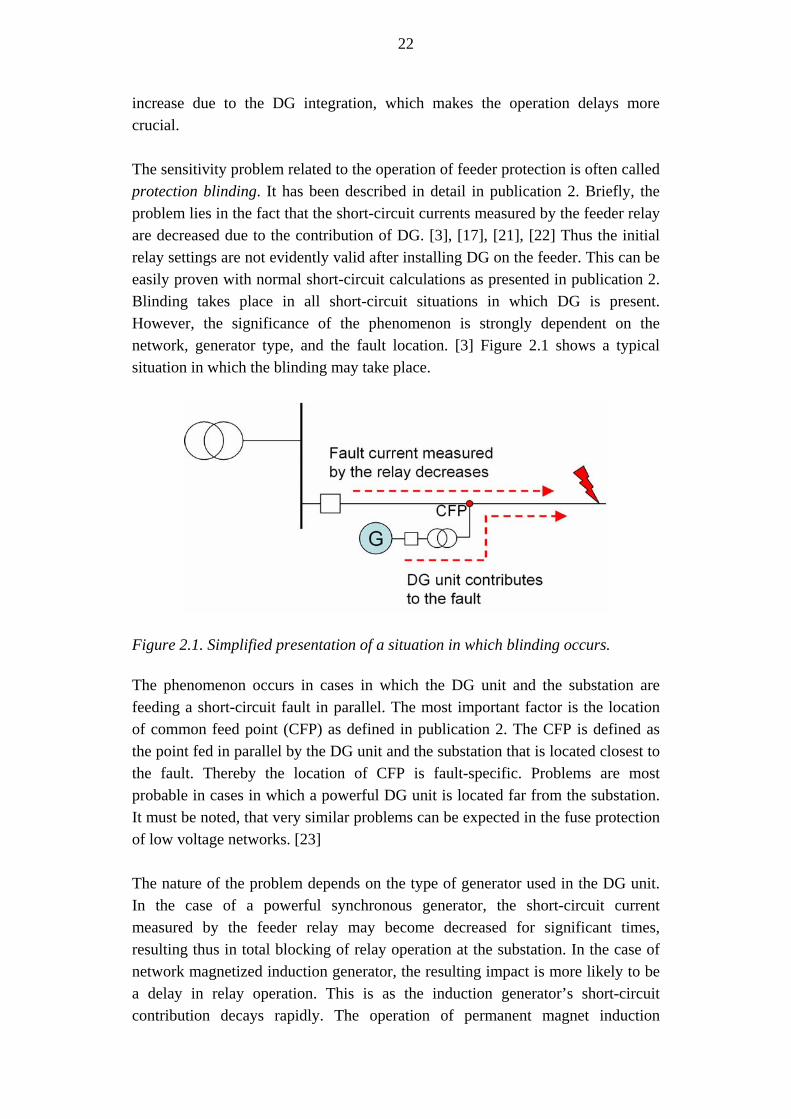
increase due to the DG integration, which makes the operation delays more crucial. The sensitivity problem related to the operation of feeder protection is often called protection blinding. It has been described in detail in publication 2. Briefly, the problem lies in the fact that the short-circuit currents measured by the feeder relay are decreased due to the contribution of DG. [3], [17], [21], [22] Thus the initial relay settings are not evidently valid after installing DG on the feeder. This can be easily proven with normal short-circuit calculations as presented in publication 2. Blinding takes place in all short-circuit situations in which DG is present. However, the significance of the phenomenon is strongly dependent on the network, generator type, and the fault location. [3] Figure 2.1 shows a typical situation in which the blinding may take place.
Figure 2.1. Simplified presentation of a situation in which blinding occurs. The phenomenon occurs in cases in which the DG unit and the substation are feeding a short-circuit fault in parallel. The most important factor is the location of common feed point (CFP) as defined in publication 2. The CFP is defined as the point fed in parallel by the DG unit and the substation that is located closest to the fault. Thereby the location of CFP is fault-specific. Problems are most probable in cases in which a powerful DG unit is located far from the substation. It must be noted, that very similar problems can be expected in the fuse protection of low voltage networks. [23] The nature of the problem depends on the type of generator used in the DG unit. In the case of a powerful synchronous generator, the short-circuit current measured by the feeder relay may become decreased for significant times, resulting thus in total blocking of relay operation at the substation. In the case of network magnetized induction generator, the resulting impact is more likely to be a delay in relay operation. This is as the induction generator’s short-circuit contribution decays rapidly. The operation of permanent magnet induction

23
generator might be similar to that of a synchronous generator. DG units equipped with power electronic converters are least likely to cause problems as they usually do not contribute to network short-circuit faults. On the other hand, the behavior of converter applications depends strongly on their design and can thus not be generalized to a high degree. A converter can also be designed to feed a prolonged short-circuit current even at amplitudes greater than the nominal and may thus also be problematic regarding blinding. Another factor influencing the nature of the sensitivity problems is the operation characteristics of the feeder relays. Specified-time relays are more probable to face total blockings if the tripping threshold is not exceeded any more. The limit distance at which the short-circuit results in delayed or fast operation on the feeder may be moved, which is not problematic in most cases. Dependent-time measuring relays face delayed operation theoretically in all short-circuits. The significance of the delay is strongly case-dependent as described earlier. The dependent-time measuring relay is not likely to face total operation blockings. However, even the operation delays are problematic in many cases as the thermal limits of the network components as well as the safety requirements are calculated according to certain operation times. It must be noted that the contribution of DG often leads to small rise of voltage levels in the network. A higher pre-fault voltage results evidently in higher short-circuit currents. In the studies performed in publication 2, this impact was observed to compensate the blinding impact only in the short-circuits closest to the substation. During short-circuits in the tail parts of the feeder, the blinding impact was much more significant. However, the voltage rise phenomenon was observed to reduce the blinding problem in all short-circuits to some extent. If the DG unit participates in voltage control or other measures are applied to keep the voltage rise in minimum, the blinding impact occurs more severely. This issue has been considered in publication 2. A direct consequence of blinding which may be considered very problematic in many cases is the impact on fault location algorithms. If the measured short-circuit current modified by DG is not taken into account, the fault distances will be miscalculated. Similarly to blinding, the impact is minor between the substation and the DG unit, but increases significantly beyond the CFP point. Due to the DG, faults are calculated to locate further than they actually do. This has been discussed for instance in [24]. In many cases where blinding is not problematic in the form of undetected faults, it may cause problems with fault location. One fact further complicating the situation is that the DG unit may be connected or disconnected depending on the moment, even without the DNO knowing the state of the unit. In the case of bigger units this is typically not a

24
problem, whereas small units are often not monitored by the DNO and may thereby cause problems. The aggregate impact of small units can be significant. Hence definite corrections in location algorithms are not suitable in all situations. Another area of sensitivity problems are the DG unit’s problems with detecting network faults. In some cases, short-circuit or earth faults occurring on the medium voltage level are difficult to detect from the low voltage side of the DG unit’s transformer. The most problematic issues are loss-of-mains detection and earth fault detection, which are considered later in separate chapters. Problems are also possible during faults that occur far from both the DG unit and the feeding substation.
2.1.4 Selectivity problems
“Selectivity in a protective system refers to the overall design of protective strategy wherein only those protective devices
closest to a fault will operate to remove the faulted component.” P.M.Anderson: Power System Protection [4]
DG-related selectivity issues include two typical problems; the possibility of unnecessarily disconnecting the DG feeder (also called sympathetic tripping) and the possibility of nuisance tripping of DG units. Neither of these events causes an actual safety hazard, but they are of great harm to both producer and network operator. In both cases, IPP suffers a certain amount of energy not produced due to the missing network connection. In the case of sympathetic tripping, the customers of the whole feeder experience a totally unnecessary interruption, which results in reduced reliability from the DNO’s point of view. Also the nuisance tripping of DG results in voltage variations and reduced quality of power supply. The theory behind sympathetic tripping is extremely simple. A short-circuit fault occurs on another feeder that is fed from the same substation with the DG feeder. DG contributes to the fault by feeding a short-circuit current upwards towards the substation and further towards the fault. If the feeder relay does not detect the direction of current, it may become nuisance tripped if the current amplitude exceeds the relay threshold. [17], [22], [25] Directional overcurrent relay offers a straightforward solution for this problem. On the other hand, the existing equipment is usually of a non-directional type. Allocating the costs of equipment replacements may be problematic and may constrain the economical viability of DG. It must be noted, that relay upgrading can also offer other benefits apart from the DG-related ones, for instance faster feeder protection. A typical situation during which sympathetic tripping is possible is shown in figure 2.2.

25
Figure 2.2. Upstream contribution of DG and the possibility of tripping non-directional relay.
Sympathetic tripping can also be avoided by coordinating the operation times of feeder relays. If the faulted adjacent feeder is tripped faster than the DG feeder, the sympathetic tripping should not occur. Presently a quite common practice is to apply same overcurrent protection characteristics on similar adjacent feeders. This could enable the possibility of sympathetic tripping. It is not always possible to modify the relay operation times in order to avoid sympathetic tripping as other factors may constrain this possibility. Nuisance tripping of DG unit can occur under similar circumstances as sympathetic tripping. Fault can be located on adjacent feeder, on higher voltage level or at the substation. Due to the protection operation times for these fault locations, short-circuit on adjacent feeder is most likely to cause problems. The deviation of voltage or frequency at the PCC may be great enough to trip the DG unit. [17] Thus the DG protection settings should be assessed for the worst-case faults outside the DG feeder. These faults can be found near the substation but also in areas where the operation of feeder relay with specified-time operation characteristics shifts from one operation mode to another. Sensitivity problems described in the previous chapter may be in conflict with the nuisance tripping problems as they may require opposed protection setting modifications.

26
2.1.5 Failed reclosing
“Automatic reclosing is a control scheme for quickly reclosing breakers after clearing a fault in order to restore
the system to normal as quickly as possible” P.M.Anderson: Power System Protection [4]
Automatic reclosing is generally applied in distribution networks for clearing temporary short-circuits or earth faults. Practically it means opening the feeder breaker for a short period, during which the arc at the fault point can decay or the fault may become otherwise cleared. For instance a falling branch of a tree causes a momentary short-circuit fault which may be cleared during the automatic reclosing sequence. According to statistics [26], 90 per cent of all faults were cleared by automatic reclosings on feeders where they were applied. Similar values have also been presented in [27], [28]. If the DG unit is not disconnected properly during the reclosing sequence, it may be able to maintain the voltage in the network and feed a fault current in the case of short circuits. This may further maintain the arc in the fault point. As a result, the fault seems permanent when reconnection is performed. Figure 2.3 shows a situation during which the reclosing may fail.
Figure 2.3. Failing reclosing due to the DG unit. Failed reclosing has significant consequences. First of all, it reduces the reliability of the network as the high speed automatic reclosing is not adequate and a longer interruption with delayed automatic reclosing is needed. This increases the interruption times experienced by customers. [3], [29] It also results in increased amounts of voltage dips and disturbances elsewhere in the network as more breaker operations are needed. The second reclosing performed stresses the substation transformer and other substation equipment. [17] The fault arc that continues to burn can also cause damage to conductors and insulators, resulting possibly in failures in the long term. [17]

27
Apart from system-wide influences, failed reclosing may also result in severe stresses of the DG unit and its equipment. [30] This may occur as the speed of the DG unit may change during the reclosing, resulting in an asynchronous reconnection with the public system. An asynchronous reconnection is also likely to disturb other customers in the network as the transients occurring will result in voltage dips. Due to the reasons mentioned, it is important to disconnect the DG unit from the network during the autoreclosure open time. This requirement relates directly to the operation of loss-of-mains protection, which is covered in the following chapter. DG unit may become disconnected directly due to the initial fault, but at latest the loss-of-mains protection must operate during the islanding caused by the reclosing. It may also be necessary to increase the open time of the reclosing to assure the disconnection. It has even been proposed, that high speed automatic reclosings should not be used at all in the presence of DG. [11] Failed reclosing may be a problem especially during earth faults, as they are difficult to detect from the DG unit’s point of view. While the voltage returns to the network, the DG unit must not become immediately reconnected automatically. This is because it is possible that the voltage returns due to a new reclosing, trial switching or temporary back-up feed connection which has not been dimensioned for accommodating DG. The automatic reconnection can be performed within suitable time, which is typically about ten minutes. Manual reconnection can also be performed earlier when considered possible. The reconnection of multiple DG units must be made one by one in order to avoid serious switching transients. The reconnection time of each unit must be coordinated with others to achieve this. While the operation of DG protection during reclosings is an important issue, it is also difficult to assess from the DNO’s point of view. Dynamic simulations would be needed to assure the correct operation of DG protection. In practice it is often stated in interconnection terms that the DG unit must be disconnected within the autoreclosure open time of reclosing. However, the operation is seldom checked before first problems are faced. It can be thought that performing a simple reclosing without fault on the DG feeder could provide information on the behaviour of DG unit. A case of reclosing without an actual fault would be the most difficult one to detect by the PCC protection. Thereby such a commissioning test could be included in the DG interconnection process. On the other hand, the behaviour during the reclosing depends strongly on the momentary power balance of the feeder, which reduces the reliability of such test.

28
2.1.6 Loss-of-mains detection
“In most situations, the risk of the embedded generator continuing to operate without a grid connection is low,
but it is not zero.” Jenkins, Allan, Crossley, Kirschen, Strbac: Embedded Generation [7]
Loss-of-mains detection – also known as islanding detection – is the subject drawing the most research interest in the area of DG protection at the moment. Increasing amount of DG together with more efficient control system makes unintended islandings more probable. [31], [32], [33] During islanded operation, the DG unit remains feeding a part of the network alone without connection to the public system. It can be seen that islanding detection problems are highly linked to reclosing problems discussed in previous chapter. An island can be formed through fault or any breaker or switch operation. Basically, unintended islandings must always be prevented. The most important reason for this is assuring the safety of the network. The network must not be energized by the DG unit when it is assumed to be de-energized from the system’s side. This could result in severe safety hazards to the network personnel. Another reason relates to the fact that DG units are typically not planned for operating the network in island. Thus the quality of power during the islanded operation can not be guaranteed. Deviations may result in damage to the network equipment as well as to consumer equipment. Asynchronous reconnection during the reconnection to the main grid may result in exactly the same problems as in the case of failed automatic reclosings. [32] It must be noted that while unintended islandings must be prevented, intentionally islanding a part of the network represents totally new possibilities for improving the reliability of the distribution network. During longer interruptions the duration of service interruption experienced by the customer could be decreased by operating the network as an island. During the intended islanded operation more allowable power quality limits or protection settings can be applied. However, the safety of the network must not be endangered. As the islanded operation practically not allowed at the moment, this thesis focuses on problems related to detecting and avoiding all possible island situations. Traditionally, the islandings have been managed with voltage and frequency relays located in the PCC of DG unit. In the typical situation, the DG unit is not able to feed the loading of the island, voltage and frequency collapse and the unit becomes disconnected by PCC protection. The power fed by the DG unit may also be greater than the loading, which results in a similar outcome with rising

29
variables. If the loading matches the generation relatively well, frequency and voltage will overrun their thresholds slowly or – in the worst case – not at all. This feature is called non-detection zone (NDZ). Mismatch in active power results in frequency variations and reactive power in voltage variations, respectively. [8] Power variations that are too small remain inside NDZ. Generally, loss-of-main detection techniques can be divided to three groups according to their operation principles:
• Passive methods are based on measuring the state of the PCC. Certain characteristics are monitored and used to detect the islanding. Voltage and frequency relays are the most typical examples of passive operation. [34], [35], [36]
• Active methods are constantly trying to force the state of the PCC outside its normal operation area. This is conducted by continuously making small changes in the PCC state and monitoring the response. During islanding, the response will be greater and thereby detectable. [34], [35], [36]
• Communication methods are based on communication between the DG unit and the power system. As the island is practically always formed by an operation of breaker or switch, the formation of the island could be deduced by the network control system and the state information could be sent further to the DG unit. [37], [38], [39]
Several new methods have been developed to reduce the NDZ of traditional protection. The most utilized ones are rate of change of frequency (ROCOF) and vector shift (VS) methods. Both methods offer more sensitivity and smaller NDZ areas. On the other hand, the theoretical case of perfectly matching load-generation combination remains undetected by these methods as well. [40], [41] However, the enhancement of islanding detection when compared to traditional methods is significant. These new methods may also be prone to nuisance trippings when adjusted for high islanding detection sensitivity. [31], [41], [42] Finding suitable settings for safe but reliable operation leads to a trade-off situation which can be difficult to solve as described in publication 4. As the theoretical worst-case can still not be detected, there is a need to find proper compromise settings. It is not reasonable to use too strict settings and trip the DG unit repeatedly for other disturbances. Similarly to reclosing problems, islanding protection is difficult to assess from the DNO’s point of view. The phenomena related as well as the operation of modern protection methods would require dynamic studies. Thus islanding protection equipment and suitable settings are usually defined in interconnection terms but they are typically not checked unless problems are faced.

30
2.1.7 Earth fault detection
The impact of DG on system earth fault performance is a difficult issue as it depends strongly on the network type and earthing methods applied. Studies performed by the author so far consider the typical Nordic network with isolated neutral. A delta-wye unit generator transformer is used to connect the DG unit to the network. The wye is earthed from the generator side. In such a case, the zero sequence network is cut at the transformer. Thus it is difficult to detect system earth faults from the LV side of the transformer. [43], [44], [45] At the same time, this network configuration means that DG does not contribute to earth faults as actively as it does in the case of short circuits. Thereby no problems related to selectivity or sensitivity of feeder earth fault protection are expected. However, the problem of failing automatic reclosings remains as explained earlier. The traditional way to carry out the DG earth fault protection is to consider it as a loss-of-mains situation. Since the feeder earth fault protection is not harmed by the presence of DG, it will operate during the fault, after which the DG is operating islanded and should become disconnected by its dedicated protection. In such a situation, the voltage remains longer in the network due to the DG, which can result in touch and step voltages that do not meet the electrical safety requirements [43]. As it was mentioned earlier, islanding detection can not be considered absolutely reliable in all situations, which enables the possibility of sustained earth fault situations. It is also important to notice that even a correct operation of loss-of-mains protection reduces safety, as it prolongs the earth fault situation by the operation time of DG protection. This can be significant in some cases. One special situation may occur in a centrally compensated network during the earth fault. As the feeder earth fault protection operates and opens the feeder breaker, the connection to the arc suppression coil located at the substation will be lost. When the DG unit maintains a voltage on the feeder, the network actually operates like an isolated one. The earth fault current is not compensated. Thus the touch voltages can even rise when the feeder breaker opens. A reliable loss-of-mains protection is needed in the situation described. [43], [45] As a solution to these problems, a zero sequence voltage relay located on the MV level of the DG unit generator transformer can be used. [7], [44] The zero sequence voltage relay is energized via voltage transformers from the MV level. [7], [46] System earth faults can be detected by such configuration. There are some drawbacks for this method. First of all, it can not be easily implemented on systems where DG is connected directly to the LV level with longer distances from the MV/LV transformer. The measurement can only be made on the MV
31
level, after which the possibilities include disconnecting the whole LV network or transmitting the information to the DG unit otherwise. While the first one is not allowable in most cases with multiple customers on the LV level, the latter one can be expensive and may still face some problems with operation delays. As another drawback, the zero sequence voltage protection sees the earth faults occurring in the network similarly despite their location. Zero sequence voltage thereby requires careful operation time coordination in order to avoid nuisance trippings, as it has been described in publication 5.
2.2 Aspects of network planning
So far, the installation cases of new DG units have been relatively rare in Finland and have thus been handled as individual cases. In many cases, the DNO has contracted the required studies out to consultant companies or research parties. If the amount of DG increases as forecasted, the planning task of DG unit interconnection will become more of a daily activity. It can be seen that the DNO must be able to manage the DG planning process itself as a certain level of DG propagation is exceeded. This would ensure efficiency of planning and uniform methods for handling the DG units. More importantly, the DNO must have the knowledge of adverse impacts of DG as it is responsible for the safety and reliability of the network. To better handle the impacts of DG, they should become integrated to normal network planning activities. Besides the studies needed for DG interconnection, this means including the effect of DG in regularly performed studies, for instance protection analysis, power flow calculations and thermal limit checking. While modifying the network topology, studies similar to the planning stage are needed. For instance, when network extensions or renewals are planned, DG must definitely be taken into account. The possible future DG installations should also be considered as far as possible. Similarly, when using the network temporarily through backup connection or with otherwise exceptional topology, the impact of DG must be taken into account. It should at least be studied beforehand, whether it is possible to use DG unit during the most typical backup supply situations. In this sense, the issues covered in this thesis also relate to the control center operation and distribution management systems (DMS) as it will be discussed in chapter 3. Typical planning and control center systems perform these kinds of studies automatically. Hence the key point is in including the DG and its impacts properly in these calculations.

32
The principles for dimensioning and planning the distribution network remain the same despite the propagation of DG. The network must be operated safely and efficiently maintaining an adequate quality of supply and balanced economy. The technical studies needed still include for instance voltage levels and protection analysis. However, new kinds of approaches may be needed. Voltage levels form an excellent example of this; the traditional studies consider the voltage drop along distribution lines and focus on determining the lowest voltage at the network, whereas DG can turn this issue into a voltage rise problem in which the voltage can rise too high in the vicinity of the DG unit. Voltage must remain within its limits, but the voltage rise must be assessed as well as voltage drop. It must also be noted that the voltage drop can still be the limiting factor while the DG unit is disconnected from the network. From the DNO’s point of view, the technical requirements set for the DG unit are of great importance. They define the required operation of the DG unit under abnormal conditions. DNO must decide whether it wants to set requirements only on the installed equipment or also on the actual setting values applied. The protection requirements are especially important as the relay settings require very accurate operation values. Finding the optimal settings may be problematic in many cases. The settings should be restrictive enough to assure safety in all situations. Practically this means strict enough PCC protection settings. On the other hand, repeated unnecessary trippings of the DG unit are detrimental to all parties. For the DNO, they are likely to cause more severe voltage dips during remote faults. For the IPP, they result in loss of energy produced (unless it can not be stored for a short period). Repeated interruptions due to wrong operation of DG protection are likely to result in IPP’s complaints about the quality of supply. Thereby the DNO is meeting a sort of trade-off situation while determining the protection requirements for new DG unit. The requirements set for the IPP must be presented in a way as unambiguous as possible. This may be problematic in many cases as the viewpoints and objectives of IPP and DNO can be very different. The DNO is interested in keeping its network in control, whereas the IPP is interested in inexpensive network connection offering a reliable transfer of energy produced. For instance, if DNO considers an additional relay for islanding protection necessary, IPP considers it mainly as an additional cost. Thereby DNO must also prepare to give reasons for the requirements set as they may face objection. A special attention must be paid to communication between the parties during the planning and installation process.
33
2.3 Research activities on DG protection impacts
Since the extensive propagation of DG is a relatively new subject, most of the research performed applies modern dynamical simulation tools. This is vital for gathering new knowledge on the subject. Dynamic simulation studies on the subject have been presented in several publications by various authors. Publication [47] focuses on transient stability of wind generators during short circuits. The significance of pitch control system for the transient stability is underlined. In [48], operation of wind turbines during different fault situations is simulated. The focus is on comparing different simulation tools. In [14], the typical protection problems are observed to be less problematic in the case of inverter-interfaced DG. Source [9] covers the problems related to unnecessary disconnections during system disturbances. Cases in which the faults are located outside the DG feeder can be avoided. The significance of rapid disconnection of DG during automatic reclosings is stressed. Publication [49] presents typical dynamic studies for the wind generator connection in PSCAD environment. In [2], the aspect of critical clearing time (CCT) is applied. CCTs of typical DG units are observed to be insufficient when compared to typical fault clearing times. More general calculation methods are discussed much more sparsely, for instance in [50] and [51]. In [50] it is stated that the short circuit capacities of present distribution networks are close to design maximums. The importance of accurate and reliable fault calculations is thus emphasized. The steady-state calculation methods applied in planning systems have been covered for instance in [52] and [53]. Publication [52] describes the steady-state modelling in DNO’s information systems through some component examples. In [53], the propagation of research-level observations in commercial information systems is studied. A considerable gap is observed between scientific publications and commercially applied methods. Typical network protection problems related to DG have been studied in various publications. In [3] it becomes concluded, that the existing infrastructure is based too much on simple protection schemes and DG should thereby adapt to the network’s needs. Publication [23] focuses on low voltage networks and shows the appearance of typical problems on these voltage levels as well. The importance of islanding detection is underlined and a communication method for islanding detection is described. The report of a working group on the subject is given in [17]. The observations are in line with the ones presented in this thesis. Interesting conclusions are drawn especially regarding the increasing short-circuit currents, arcs and possible component damages. In [21], the typical protection problems are discussed. Special attention is paid to reclosings and islanding protection. Publication [22] gives a relatively compact review of the most typical problems.
34
The most important characteristic of the studies is the usage of fuses and line reclosers according to American practices. Thus the problems get a somewhat different nature, although the theoretical background is exactly the same. Publication [54] discusses the typical problems in an Italian network. The coordination of relay operation is especially covered. In [55], some general rules for fuse-relay coordination in the presence of DG are presented. These publications mentioned cover the typical problems, for instance blinding, reclosing and islanding problems. Same issues have already been discussed in the 80’s for instance in [56], [57]. In this sense, described problems are not new at all. However, they become rapidly more general as the amount of DG increases. This explains why much more research effort is put on the subject at the moment. Several case studies reveal possible problems related to DG. In [10], increased short-circuit currents are considered as especially problematic. A need for reviewing the protection schemes due to DG installations is also observed. In [58], the low short-circuit powers of the feeders are considered problematic. Publication [59] identified serious problems with the stability of small hydroelectric generators during faults. The fault clearing times applied in the network were considered too great. Additional protective equipment was proposed to the PCC. Publication [60] reports problems especially with one-phase reclosers. On the other hand, cases without significant problems have also been published. In [61], studies for connecting diesel generation at a substation are conducted. The fault contributions of DG as well as blinding and sympathetic tripping are checked. The possibility of islanding is also acknowledged; hence direct transfer trip commands are used to disconnect the units. Voltage check relays are also included to prevent reclosing to a live feeder. The units are located at a small substation; thus the problems are minor and measurements and direct tripping can be easily implemented. In [62], the interconnection of photovoltaic generation is studied. The problems are mainly avoided because of the limited fault current contribution of the inverter. The ability of the inverter to detect disturbances is also considered. The reclosing problems have been studied separately in [29]. Arc voltage as well as phase difference during the reclosing open time are discussed in detail. Suitable solutions are proposed and the importance of fast and reliable islanding detection is underlined. Similar results are also presented in [30]. The earth fault performance of a power system including DG has not been studied as much as short circuit faults or islanding problems. One reason for this may be that the behaviour is strongly dependent on neutral treatment, which varies in different networks. In [43], isolated neutral and compensated distribution
35
networks are studied. It is observed that a resonant earthed network may face special problems as the earth fault currents may increase due to the loss of connection to the suppression coil during feeder tripping. This may further require very rapid tripping of DG in order to fulfil the safety requirements. The importance of islanding detection is thus underlined. In [63], the possibilities for reducing nuisance trips during different unsymmetrical faults are discussed. Publication [44] discusses the possibilities of detecting earth faults in an American grounded network. While some publications focusing on feeder protection impacts were already mentioned, another important subject is the protection of the DG unit’s PCC. At the moment the research actions seem to be focusing on PCC protection instead of wider protection system coordination. This is primarily due to the acute need of new islanding protection methods. Publication [31] illustrates the problematic nature of islanding protection with an analogy to a mechanical system. The different cases during the island formation have been clearly explained in [8]. Publications [34] and [36] give good summaries on the available islanding protection techniques. Publication [1] indicates how the possibility of islanding is presently managed in various countries. Islanding protection is covered also in numerous other publications. For instance [32] presents studies in a real LV network with inverter-based DG. Studies are based on measurements. Key factors determining the possibility of islanding conditions are also enumerated. Publication [64] presents slightly similar studies in which a small-scale static converter is modelled and used. The importance of the balances of active and reactive power is emphasized. Steady islands are, however, not observed with the converter equipment. Publication [42] focuses on PCC frequency measurement for islanding detection. Accuracy of frequency sensor is tested and some improvements are achieved through signal pre-processing. Publication [65] presents an interesting approach on coordinating the islanding protection. The approach is based on the concept of application region. The objective is on adjusting the frequency-based protection to fulfil the islanding detection and frequency protection requirements simultaneously. As mentioned above, a need for more reliable islanding detection methods is evident at the moment. Some new protection techniques have already been developed to avoid these problems. A lot of research action has been focusing on comparing different islanding detection methods. In [33], effectiveness of VS relays is assessed. In publication [40], ROCOF and VS methods are compared in different situations. The studies show that ROCOF is able to detect somewhat smaller variations during the islanding. At the same ROCOF is observed to be more prone to nuisance trippings. Publication [66] also compares ROCOF to VS.

36
The possibility of nuisance tripping of ROCOF relay is observed in these studies as well. Totally new islanding detection methods are proposed frequently with simulation results proving their efficiency. Publication [67] applies rate of change of voltage together with power factor changes, both measured at the PCC. The method presented in [68] is based on voltage magnitude variation. The method makes repetitive small variations in the voltage magnitude of the PCC and monitors the system response. The method presented in [69] is based on system impedance monitoring at the PCC. Publication [70] proposes a method based on total harmonic distortion (THD) and voltage unbalance. The method is intended for usage with converter applications. The performed simulations show the efficiency of the method. The method is also shown to be steady during other disturbances. However, a commercial method for managing the most difficult islanding situations is still missing. Another interesting option is applying a line carrier signal for islanding detection. Studies have been presented for instance in [37], [38]. The method is based on high-frequency Distribution Line Carrier (DLC) signal. According to the studies, a repeater will be necessary after a certain distance in order to assure the performance of the DLC signal. This method uses high frequencies at the level of 70 kHz, whereas another similar method has been proposed on low frequency level in [23]. According to the results, a low frequency signal passes the network more easily and could thereby reach the low voltage network as well. It is important to notice that where unintended islanding has to be prevented under all conditions, an intended islanding presents a totally new possibility of improving the reliability of distribution networks. The possibility of utilizing DG during longer interruptions is a subject that gains an increasing amount of interest at the moment. Managing the protection in the island requires special actions which are not considered in this thesis. Usually it is also necessary to detect the islanding similarly to undesired islandings in order to change the control mode of the DG units. The possibilities of intended islandings have been studied increasingly lately. In [71], control strategies for islanded operation are covered. Publications [72] and [73] address the possibility of reliability enhancement by the means of intentional islanding of DG. Especially during long interruptions the impact of DG on reliability can be significant. Publication [74] presents case studies on intentional islanded operation in Thailand’s power system. Needs for protection setting modifications are observed. As the most important modification, an adaptive protection system with dedicated protection settings for island mode and normal operation is required. This may be difficult to implement with present islanding detection techniques. Publication [75] focuses specially on

37
inverter applications. A new control strategy for islanded operation is developed. The transition to the island control strategy requires islanding detection similarly to the protection purposes. In the paper, THD together with voltage measurement is applied for detecting the islanding. Whereas the phenomena related to DG are covered quite well in literature, they have not been applied in planning systems or processed to planning methods as extensively. Some coordination principles have been given in different publications. In [76], the most typical coordination needed is presented on the relay operation characteristic level. The coordination is presented in relay operation graph level, which is very illustrative. Publication [5] focuses on fuse coordination and on the operation of cascaded relays on feeder. This is an important issue on areas where such equipment is applied. Publication [77] focuses on industrial power system with local generation, which contains many similarities to typical public power system installations. A table calculation method is presented. In [78], the coordination of DG in a ring-fed network is considered. The relay coordination is based on Time Coordination Method (TCM). The results show that the proposed TCM method can be used to increase reliability. It is also proposed, that the relay coordination actions could be made automatically for instance when the topology of the network changes. Publication [79] discusses the coordination of voltage and overcurrent protection of the DG unit. Fuses are included in the studies. Some more modern methods applying artificial intelligence have also been proposed. Methods presented in [80] and [81] are based on multi-agent techniques. An agent means an autonomous computer system which performs actions according to its design objectives. [82] applies the TCM method already mentioned for improving the coordination of protection relays. Although much research is targeting the impacts of DG and numerous references have been given above, publications focusing on more practical-level planning methods do practically not exist at the moment. Different coordination and optimization methods are usually implemented in Matlab or equivalent calculation environments. However, the observations and ideas are not transferred to the planning tools very efficiently. This has been observed problematic also earlier in [53]. In this sense, the work presented in this thesis can be considered advantageous to parties interested in DG, especially to the network utilities. It could also be stated, that while much of the ongoing research focuses on the characteristics of the DG unit and on the operation of generator and converter equipment, studies conducted clearly from the network’s point of view are a bit rare and thereby anticipated among DNOs.
38
3 NETWORK PLANNING AND CALCULATION TOOLS
Distribution networks are analysed with numerous tools nowadays. The choice of the tool applied depends on the study objectives. Accurate results and design details are anticipated on research and development level. More general level results may be adequate for network planning and operation purposes when sufficient margins are maintained. However, these results must be reliable enough for making correct decisions. Network data used as initial data must be reliable and extensive enough. Depending on the tool, the calculation results are presented in a suitable form. One important distinctive factor between different systems is formed by economical issues; whether they are included in the studies or not. However, regardless of the user’s objective, a need for reliable and correct results remains unquestionable.
3.1 Network information system as a practical-level planning tool
A typical Nordic DNO applies a network information system (NIS) or equivalent system for planning and maintaining its distribution network. NIS is a graphically controlled system which integrates network data with calculation functionalities for network planning, maintenance and statistical condition monitoring purposes. Geographical maps are often used as a background to illustrate the network. The most important objective of such system is to find the optimum between technical and financial matters. Calculations are typically performed in steady-state with results presented in rms (root mean square) values. [28], [52] The short-circuit and earth fault analysis are typically performed as calculations covering the whole network and the results are presented as listings or graphically on a map. The system is usually based on database architecture. NIS is typically applied to all network planning tasks. The network data is maintained in one database in commensurable form. Other data includes for instance the load type curves used for estimating the loading of the network.

39
Reports and analysis needed are easily available for the network planning personnel. Automated functionalities ease the planning process. The analysis tools include typical fault and power flow calculations. Reliability indices and figures can also be calculated. The network planning functionalities include network configuration planning, construction planning and investment planning. Plans created can typically be saved and loaded later again for further actions. The state of the network can be monitored with dedicated tools, which exploit the analysis tools. The state of the network can be optimized for instance by modifying the switching state of the network. Planned topology changes can also be checked in beforehand. The actual on-line network state monitoring is a functionality of distribution management system (DMS) instead of NIS. In NIS, the state monitoring refers more to long-time monitoring and monitoring calculations performed with suitable intervals. The condition of the network is also managed often with NIS. This includes monitoring the aging of the components and managing the maintenance and renovation actions. Figure 3.1 illustrates the functionalities of a modern NIS.
NetworkInformation
System
Analysis tools
Faultcalculations Load flows
Reliability
Documentation
Network data
Load typecurves
Network statemonitoring
Topologychanges
Optimizations
Monitoringcalculations
Reporting
Networkplanning
Construction
Configuration
InvestmentsCondition
management
Figure 3.1. Functionalities of modern network information systems. In Nordic thinking, NIS is integrated with other systems to a high degree. In addition to network data and geographical information, calculation functionalities are included. The DMS enables the connection to SCADA (Supervisory Control And Data Acquisition), which is used to control the network equipment. NIS is also linked with other data systems like a customer information system and a material information system. NIS and DMS often share functionalities for

40
instance for network calculation. DMS is intended for control centre usage whereas NIS is generally used for off-line planning and data management purposes. [52], [53] Figure 3.2 presents the linkage of NIS to other systems as it is understood in this thesis.
Figure 3.2. Overview of NIS and other related information systems. Views different to the one described above consider NIS functionalities mainly as network data management combined with location information and graphical map presentation. In some cases, no calculation tools are included at all. Still, it is evident that the required analyses are performed despite the type of the system. In such a system, the calculation and planning actions are typically performed in separate programs. This requires more from the interfaces between the systems but also offers some flexibility regarding the choice of tools. In studying the protection impacts of DG, the most critical issue is the modelling of different generator types in NIS environment. Presently, depending on the system, the generator may be modelled as a constant short-circuit current source or it may be totally ignored in the short-circuit calculations. There are practically no other methods in the present steady-state calculations. Constant short-circuit current may be considered adequate for modelling larger synchronous generators, but other generator types are difficult to study with this kind of modelling. On the other hand it can be thought, that this constant current approach represents a worst-case in most of the studies also for other generator types. Thus such approach gives too pessimistic results, which is always better option than too optimistic results or totally ignoring the impact of DG.
DMS SCADA
Network data
Planning, calculation etc. modules
NIS User interface
Distribution process
41
Traditionally - at least in Finland - NIS calculation methods have been designed for radial networks. This has been adequate in most cases as networks have been used mainly in radial configurations. Developments have been made for ring network calculation. [83] As a network including DG forms practically a ring-operated network, these developments already enable some of the DG-related studies.
3.2 Dynamical simulation tools for research purposes
Present research actions are strongly focusing on simulating the phenomena related to DG in dynamical simulation environments. These studies give vital knowledge on the subject. Another important research area is the building of new models enabling more accurate studies. Dynamical simulation tools provide time domain studies, accurate modelling of components, free presentation of results etc. Thus they are very suitable for research intentions. One problematic issue regarding simulation studies is the modelling of new generator and converter types. At the present situation, manufacturers are more or less hiding the technical details of their new solutions. While manufacturers are holding the information for accurate modelling, research parties are building their own models for the newest devices. Some overlapping can be seen in this sense. On the other hand, it is evident that the manufacturer wants to protect new products and results gained through research and development actions. It can also be thought that modelling for research purposes increases knowledge on the subject. However, more cooperation could be beneficial for the whole research area. From the DNO’s point of view, dynamical simulation tools are not very suitable for daily network planning purposes. Modelling the whole network of a DNO is difficult in most cases. Thereby it is not possible to perform quick studies on certain area of the network. Simulations would require modelling the required part of the network leaving the rest of the network on simplifications and assumptions. This can easily lead to inaccurate results. It must be noted that same applies to research based studies; simplifications are practically always needed when modelling the network. Case studies for research purposes are, however, aiming more at general-level results rather than solving one particular case. It would also be difficult to maintain an up-to-date network data and topology in a simulation environment as small modifications are made constantly. On the other hand, some kind of data interface could be used to acquire network data from NIS to the dynamical simulation environment. The adequacy of NIS data for accurate simulations regarding more complex components would be one question.

42
The most important thing is that many DNOs are quite reluctant to use dynamical tools as they are expensive, difficult to use and reserve human resources. It can be said that at the present situation, a typical DNO wants to remain on steady-state calculation level in planning and leave the time-domain for case studies which are often executed in collaboration with consultants and research parties in dedicated projects. It is common to perform simulations after observing certain problems. It is also possible to use measurements instead of simulations where problems are faced. This might even be an easier and more accurate method compared to simulations. On the other hand, measurements require a new event to occur and to be measured properly.
3.3 Real-time systems for testing and simulating purposes
Real-time systems can be considered as an expansion of dynamical simulations for including external signals and testing systems in real time. Typically a real-time system is a physical device which includes dedicated calculation processors for performing the simulation. The realistic time-scale is the key factor as it enables usage of real devices as a part of the simulation without modifications. Such environments are applied for instance for RES studies ([84], [85]), for testing devices ([86], [87]) and for educational purposes ([88]). For studying the protection impacts of DG, real-time simulation offers suitable environment for using actual protection relays as a part of the simulations. An idea of combined research environment has evolved during studies performed with RTDS system, which is regularly used in the Institute of Power Engineering at Tampere University of Technology (TUT). RTDS is power system simulator for real-time studies. Analogue and digital signals can be used for connecting to external devices and using them as a part of the simulations. The Institute of Power Electronics at TUT also uses a real time simulator called dSPACE. dSPACE is a simulation and testing tool for control systems of power electronic applications. It operates combined with Matlab and is suitable for modelling for instance power electronic control blocks. Combining the two described systems could result in a more wide-scale research environment, in which the interactions between power system and power electronic application could be studied in detail. At the present situation, for instance the converters applying lot of power electronic equipment are often simulated with ideal voltage source or very simplified network. Similarly, when studying the power system operation, the control level of generators and converters is left on simplifications and general models. With successfully

43
integrated systems, it could be possible to decrease the amount of simplifications significantly. Another pro that is at least as important as the previous one is the possibility of using predefined model libraries and building new models in the most suitable environment. At the same time, the calculation resources can be saved as the calculation is divided between two systems, which further enables modelling more complex systems. Such system reserves both separate systems for performing one combined study. At least some knowledge is needed on both systems for performing successful studies. The combined research environment has been built, tested and used for DG related studies during the work presented in this thesis. Results and experiences have been covered in publication 6 of this thesis and also in [89]. In the future, the environment enables using actual protection relays as a part of the simulations, for instance in the PCC, together with RTDS and dSPACE.
3.4 Development needs posed by DG in daily network planning
At the moment, the steady-state calculation methods form the most important obstacle in the way of studying the impacts of DG in NIS systems reliably. As the phenomena are strongly dynamic, they are difficult to present in steady-state. On the other hand, it is obvious that the elementary calculation methods of NIS should not be totally changed for the purpose of DG calculations. The present methods are reliable and they are suitable for use with database structures. So far there has been no need for a NIS system operating on momentary value level. The assumption that there is a need to maintain the basic structure of a NIS system leads us to the question of the proper level of modelling the network and the DG units. Four levels of modelling have been presented in publication [90]: steady state, quasi-steady state, dynamic and transient studies. It is proposed that short-circuits can be managed on quasi-steady state level. Dynamic and transient level modelling would be needed for studying system stability, transients and non-linear components. [90] The quasi-steady state approach means practically applying the time variable for instance for relay operation times, still maintaining the steady state calculation methods. A typical NIS calculation is actually a kind of a quasi-steady state solution. Generally, an adequate accuracy must be achieved, yet with simple enough models. Simulations, calculations and measurements can be used to find reasonable simplifications.

44
One approach that came up during the studies is the possibility of applying a dynamical simulator as a calculation motor of a NIS system. This would evidently require building an interface between NIS and the simulator environment. Slightly similar interfaces are already used in present systems for using an external calculation motor and might thereby be exploitable. However, interfaces between dynamical simulator and NIS have not been reported so far. The major problems could lie in the content of network data and calculation results. The data models applied in NIS would not be suitable for dynamic modelling. The format of the data would be different and the data would also be insufficient for dynamical studies. On the other hand, the data could be converted to proper format in the system interface. Some additional data would be needed in this phase to complete the NIS data. Similarly, transferring the results obtained from the dynamical calculation would be problematic. There is no way of presenting or using a dynamical result data in NIS. On the other hand, modifying the results to steady-state values at the dynamical simulator level or at the interface would offer no additional value compared to normal steady-state calculation. At its best, such configuration could provide user with informative graphs to support the NIS calculation results. This would probably not be worth the system integration efforts. Building a one-way conversion interface for transferring the data only from NIS to a simulation environment could be a more realistic idea. As the network data is maintained very up to date in NIS, there is no point in maintaining the same data in the dynamical simulation environment. Only the data regarding the studied area could be converted when needed. On the other hand, this would again highlight the issue of simplifications and accuracy as discussed in chapter 3.2. The required studies would be performed in the simulation program. No results would be transferred back to NIS. This kind of system could be used to assist during the most difficult DG installation cases which can not be studied with NIS reliably. However, such a conversion system does not seem very suitable for the practical planning usage. For general planning purposes, a more viable approach seems to be extending the steady-state calculation as much as possible. One idea emerged during the studies is to perform the fault calculations in steps. As one fault calculation procedure does not require much calculation power or time, it could be possible to loop this calculation for several times. Between the loops, the electrical values of the generator would be modified in order to emulate the actual dynamic behaviour. With this method, a stepped behaviour could be achieved and could be further used to assess for instance the operation times of relays. Interpolation could be used to achieve estimates between the time steps. This could help in assessing for

45
instance the operation delays of relays more accurately. The method is described in more detail in chapter 4.3 and in publication 9 of this thesis. To make the planning process for a new DG unit more efficient, much of the studies could be integrated to one function of the planning system. This function would then automatically check necessary studies and propose modifications where needed. One possible procedure is presented in chapter 4.1 and in publication 7. As described earlier in chapter 2.1.3, the blinding effect caused by the presence of DG can lead to inaccurate results with present fault location methods. If the blinding can be calculated in the DMS system, it could also be possible to improve the fault location algorithm for cases in which the DG units are present. However, the state information for the DG unit should be available in the DMS system in order to perform the right analysis. This is not evident among smaller DG units at the moment. Considering planning objects that are not related to network protection, DG sets certain new requirements as well. Probably the most important one is the possibility of studying different combinations of load and generation. At the present situation, the calculations are often based on maximum loading, which sets requirements for instance for voltage levels and component capacity. So far this has been adequate, as it presents the most difficult circumstances for the network. If the constraints are not exceeded during this worst case situation, they are presumably not exceeded in other situations either. However, for the DG propagation the maximum loading can actually be the easiest situation. For instance voltages are easier to maintain on acceptable levels in the vicinity of the DG unit. Thereby it is necessary to be able to study other loading situations as well. The different combinations of minimum and maximum load and generation should be easily achievable. Further, regarding certain forms of DG, it would be useful to be able to set the actual calculation moment freely. This should be implemented relatively simply in calculation methods based on loading curves. It would also be useful to obtain generation curves for DG units similar to load curves for consumers. These curves could be based on hourly measurements or on purely statistical methods in cases in which the DG output is dependent on certain factor, for instance weather conditions. For certain types of DG, for instance industry-based CHP, relatively accurate generation curves could be applied. Generating customers are presently often managed similarly to consumer customers.

46
One further requirement would be to include more data about the network components to NIS database. This relates especially to DG units’ generator values. This would enable more flexible connection to other calculation tools when they are considered necessary.
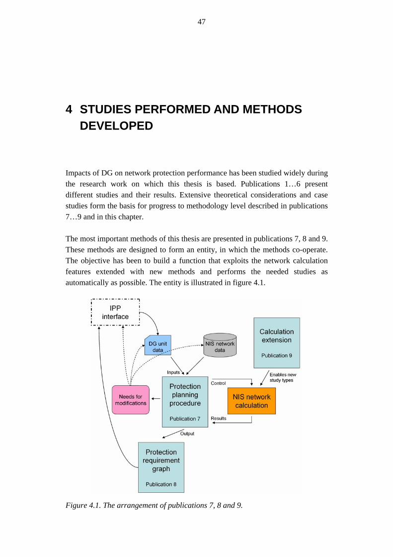
47
4 STUDIES PERFORMED AND METHODS DEVELOPED
Impacts of DG on network protection performance has been studied widely during the research work on which this thesis is based. Publications 1…6 present different studies and their results. Extensive theoretical considerations and case studies form the basis for progress to methodology level described in publications 7…9 and in this chapter. The most important methods of this thesis are presented in publications 7, 8 and 9. These methods are designed to form an entity, in which the methods co-operate. The objective has been to build a function that exploits the network calculation features extended with new methods and performs the needed studies as automatically as possible. The entity is illustrated in figure 4.1.
Figure 4.1. The arrangement of publications 7, 8 and 9.

48
4.1 Studies performed
The studies performed have started with defining the elementary problems and evolved towards more detailed information on the phenomena and possible solutions for the problems. The studies have been aimed at developing planning level tools and methods instead of new relays or protection techniques. The study subjects have considered different DG protection problems from the DNO’s point of view. For instance blinding, sympathetic trippings, nuisance trippings, automatic reclosings, earth faults and loss-of-mains problems have been encompassed. These issues have been approached from the protection coordination perspective. Further, studies have also covered fault calculations, planning aspects and DG protection requirements, which have been studied from the NIS application perspective. Figure 4.2 presents the progress of the work.
Survey of phenomena related to protection impacts of DG
Studies in NIS environment
Verification of theoretical problems with examples
Studies in dynamical simulation environments (PSCAD)
Comparison PSCAD/NIS
Simulations with realdevices (RTDS)
Planningprocess
development
NISdevelopment
New methodsand solutions
Figure 4.2. Progress of studies Several variables have been changed during the studies. While most of the studies consider a radial distribution network, ring operation issues have also been covered in [91]. The first studies were based on a synchronous generator, for instance [92]. Other generator types and converter applications have been added for in publications 2, 3, 6, and 9 included in this thesis. While short-circuit protection has mostly been in focus, earth faults have also been covered in publication 5. Different network configurations have been studied by using realistic network cases that have been available through project partners in publication 3 and in [91], [92]. Own network models incorporating typical characteristics of Nordic networks have also been used for instance in publication 4.

49
One essential variable is the tool applied in the studies. In the first ones ([91], [92], [93]), studies were performed with typical NIS calculations. Studies were expanded to dynamical simulation level with PSCAD as a primary tool in publications 3, 4 and 5. At the same time, the calculations of NIS and PSCAD for DG planning were compared as presented in publication 1 and ideas for developing the NIS calculation did also emerge. These ideas were discussed for instance in publication 9 and in [94]. One step further, real-time simulation tool RTDS has been exploited for building more wide-scale research environments in publication 6 and in [89].
4.1.1 Overview of simulation results
During the progress of the studies, simulations performed in PSCAD and RTDS environments have had a vital role in providing new information on the subject. One aim of the studies was to gather new knowledge on the subject. Simulation results are thereby important although this thesis focuses mainly on NIS-based planning method development. In the following, an overview of the simulation results is given. The studies are presented in the publications in more detail. This chapter seeks to highlight some typical and important results and conclusions. At the same, couple of possible confusions related to the publications will be explained in more detail. Publication 3 presents simulations in a realistic network with relatively small-scale wind power units. In this study, the network was quite strong and no significant problems were thereby observed. The traditional induction generators that were used in wind power units also influenced the results. On the other hand, all the data used was real and the results were thereby of great interest. The blinding phenomenon was observed, but it can not result in feeder protection problems as the difference in short-circuit current is minor. This can be seen in figure 4.3. Similarly, upstream short-circuit contributions were not observed to cause sympathetic trippings. Much more interesting observations were made regarding short-circuits occurring on the adjacent feeder. Short-circuits closest to the substation were observed to trip the wind power units without actual need. Short-circuits with a distance of 5 and 15 kilometres from the substation trip the DG unit with the operation time of 0.1 seconds as the voltage decays below the fast tripping limit as shown figure 4.4. Short-circuits with longer distances result in voltage dips that are not great enough to cause unnecessary trippings. The slow operation time of voltage protection is set at 10 seconds, which does not relate to voltage dips caused by short-circuits.

50
Blinding
0
50
100
150
200
250
300
350
1.9 1.95 2 2.05 2.1 2.15 2.2 2.25 2.3 2.35 2.4
time [s]
curr
ent [
A]
Initial
Wind pow er installed
Figure 4.3. Blinding observations of publication 3.The impact is not critical although clearly observable.
Connection point voltage
0
0.1
0.2
0.3
0.4
0.5
0.6
0.7
0.8
0.9
1
1.9 2.1 2.3 2.5 2.7 2.9Time [s]
Volta
ge [k
V]
5 km15 km30 km50 kmslow trippingfast tripping
Figure 4.4. Connection point voltage during short-circuit faults with varying location on adjacent feeder in the studies of publication 3. The unnecessary trippings can be seen during closest faults after 0.15 and 0.2 seconds. Fault occurs at 2.0 seconds and is cleared by feeder protection after 0.8 seconds.

51
PCC Frequency
47
48
49
50
51
52
53
4 4.5 5 5.5 6 6.5 7 7.5 8
t [s]
f [H
z]
ROCOF operation
0
1
2
3
4
5
6
4.4 4.6 4.8 5 5.2 5.4 5.6
t [s]
dF/d
t [H
z/s]
Loss-of-mains protection was also studied in the publication 3. It becomes stated that problems related to operation during automatic reclosings are not expected. However, these deductions are partly misleading. During short-circuit faults and resulting high speed automatic reclosings the DG units are tripped quickly enough. This is due to the easy detection of the preceding fault. However, when no detectable fault precedes the automatic reclosing, the situation is much more difficult. Without a dedicated relay, an earth fault can be undetectable from the DG connection point and it is thus the most important case. As it can be seen in figure 7 of the publication 3, DG units are disconnected only after a time varying from 0.45 seconds to 0.65 seconds during an islanding depending on the loading of the network. This is not adequate for the autoreclosure open time of 0.3 seconds applied presently. It must also be noted that the operation times presented in table VII of publication 3 stand for relay operation times, not total tripping times from fault to tripping. This can be easily misunderstood. Thus the performance of automatic reclosing during earth faults can actually be problematic in the case studied. On the other hand, the operation of protection is adequate regarding longer islandings. Thereby an additional relay located on the MV level for detecting earth faults could be beneficial. The operation of islanding protection has also been studied in publication 4. A simple example network was formed to study the islanding detection under worst case circumstances – that is, with perfect load balance during the islanding. The insufficiency of traditional voltage and frequency protection were observed when the load/generation balance was adjusted to a level above 90 per cent. However, the ROCOF method offered a reliable detection in these cases. This is illustrated in figure 4.5.
Figure 4.5. On the left, the frequency protection fails to detect the islanding. On
the right, the ROCOF method offers reliable detection. It is important to note the scales on x-axis. It takes more than three seconds for the frequency to decay below 48 Hz, which is a typical tripping limit value.

52
The most problematic issues were – once again – observed during short-circuits as well as earth faults on adjacent feeder. The ROCOF operation gets significant values during these faults. On the other hand, ROCOF relay should be adjusted to be very sensitive in order to detect the most difficult islandings. Still, the theoretical worst case can not be detected. Thereby an obvious trade-off situation between islanding detection and selective operation was observed. Publication 5 covers the problems of detecting earth faults from the DG connection point. From the LV side of the delta-wye connected unit generator transformer, the system earth fault is very difficult to detect. The simulations made confirmed this. The possibility of measuring zero sequence voltage from the MV side in the PCC is also simulated and is observed to be a suitable solution. However, zero sequence voltage protection may also be prone to nuisance trippings as all earth faults occurring in the network look similar according to zero sequence voltage measurement. However, the different decay rate of the earth faults depending on their location could be exploited to coordinate the operation of protection devices. This is presented in figure 4.6.
Figure 4.6. Zero sequence voltages measured in the studies of publication 5. During the earth fault the PCC zero sequence voltage is similar regardless of the location of the fault. As the feeder protection operates, the slower zero sequence voltage decay could be used to differentiate the fault locations. For a fault occurring on DG feeder, the zero sequence voltage decays slower.
The statements made in publications 4 and 5 regarding the possibility of detecting system earth fault from the LV side of the DG transformer may seem conflicting. In publication 5, it is presented that such earth fault can not be detected by relays on LV level and that the loss-of-mains protection offers no new possibilities in this sense. On the other hand, publication 4 shows that the ROCOF protection can actually become nuisance tripped during an earth fault in the network. Further simulations have proved that the earth fault may truly result in frequency

53
variations that can further result in high ROCOF values. Other protection factors such as voltage and frequency do not vary enough for detection. However, the resulting ROCOF values are strongly dependent on the network topology, line types and distances. Thereby the initial conclusions are entirely correct. The ROCOF method can not be used for detecting system earth faults as most of these faults do not result in great enough ROCOF values. On the other hand, ROCOF relay may become tripped under suitable circumstances. This makes the coordination task during earth faults even more difficult. Publication 6 presents real-time simulations, in which the combined simulation environment consisting of RTDS and dSPACE systems is used. In comparison to the earlier results, the most important new information relates to the behaviour of the converter during short-circuits and earth faults. The dSPACE system was used to model the converter equipment for wind power usage. Blinding is observed, but it is not considered a problem. During faults elsewhere in the network, similar issues with ROCOF sensitivity and selectivity are observed as in publication 4. These observations are less probable to cause actual problems. Different forms of upstream short-circuit currents are seen between a converter application and an induction generator as shown in figure 4.7. However, amplitudes are not great enough to cause sympathetic trippings.
Upstream feeder currents
0
5
10
15
20
25
30
35
40
0.5 1 1.5 2 2.5 3 3.5 4
time [s]
curr
ent [
A]
Ind genSync conv
Figure 4.7. The upstream short-circuit currents of induction generator and converter in the studies of publication 6. The currents are not great enough to trip the feeder protection. The short-circuit occurs at 1.0 seconds and is cleared at 1.5 seconds. Transients are observed when the fault is cleared.

54
The islanding of converter application is observed to be potentially problematic. The load/generation –balance is not perfect, but the loading matches the generation fairly well. The voltage remains close to normal value, whereas the frequency grows slowly towards tripping limits. With frequency protection the islanded operation could sustain for more than 2 seconds, which could be unallowable in many cases. The problem with the ROCOF operation is that fast detection requires quite sensitive settings which could further result in nuisance trippings during other faults and disturbances.
4.2 General protection planning procedure
The general protection planning procedure presented in publication 7 seeks to present all protection studies needed for installing a new DG unit to the network. The idea is to advance from the initial data given as input to assessing the operation of feeder protection and setting requirements for DG connection point protection. The most important point of attention is the iterative nature of the procedure. The process itself involves two or more feeders, of which at least one hosts DG. The studies performed can easily lead to situation in which the operation characteristics of relays are modified. This may further result in problems which were already examined in earlier studies. As it may be difficult to evaluate the need of repeating studies after relay operation modifications, the studies are processed again in all cases as values are modified. As an input the procedure requires data and location of the planned DG unit. All network data as well as load data are available from the NIS system. As an output, the procedure proposes possibly required modifications to the network or the DG unit when required. If the installation does not face problems requiring this kind of modifications, it can produce protection requirement graphs for the IPP as described in publication 8 and in the following chapter. In some situations this approach evidently leads to choosing between tight protection requirements and network investments. These situations must be solved case-specifically. The procedure is planned to be automated as a function of a modern NIS system. This would be beneficial as the procedure includes point-by-point calculations with iterative loops. This kind of processing could be easily implemented as a feature of NIS. The planning functions themselves that are performed by the procedure are normal and present functions of NIS which takes into account the contribution of DG generator. Thus the implementation would actually not require major modifications. The extension of calculation could offer more accuracy as described in publication 9 and in chapter 4.4. Regardless of its close relation with
55
the NIS system, the procedure can also be applied as a manual guideline for performing the necessary studies in correct order.
4.3 Protection requirement graph
Publication 8 presents a novel way of presenting the requirements for the protection of a new DG unit in graphical form. Such presentation could be useful in defining the requirements for the IPP. It defines the area within which the DG protection must remain, but it does not actually propose or require certain characteristics. An unambiguous and simple way of setting the requirements is often anticipated in the discussions between DNO and IPP. The requirement graph is planned to be an output of the planning procedure described in the previous chapter. The idea is based on a normal short-circuit calculation of the NIS system. The process of providing a requirements graph begins with short-circuit calculations for faults on DG feeder as well as faults on adjacent feeders. For a typical short-circuit protection, the operation times of feeder relays can be obtained according to the short-circuit currents. On the other hand, the short-circuit contribution of DG unit through the PCC is also calculated. By presenting the operation times of feeder relays as a function of PCC current it is possible to evaluate the co-operation of relays. For the DG feeder faults, the DG unit needs to disconnect rapidly, preferably before the DG feeder. For adjacent feeder faults, DG must not disconnect faster than the faulted feeder but must, on the other hand, disconnect faster than the DG feeder for the upstream short-circuit current. By drawing these characteristics onto one graph, a requirement area for DG protection can be found. The voltage drop at the PCC during different faults can also be estimated [95], which enables the coordination of voltage protection. As the most important drawback, such method applied in the NIS environment can not be easily applied for frequency, ROCOF or other more sophisticated protection methods. Overcurrent is actually seldom used as primary DG protection factor. It is, instead, often used as a backup protection implemented with fuses. Voltage is perhaps the most important protection factor at the PCC, but at least frequency operation would be required to complete the graphical presentation. Regarding the voltage protection, it is also possible to include the reclosing settings in the graph.

56
4.4 Calculation extension for network information systems
Publication 9 presents ideas for extending the short-circuit calculation of a NIS system. At the present state, the steady state calculation forms a significant obstacle against DG studies in NIS systems. The main problem is that the highly dynamic behaviour of DG units can not be modelled in the NIS calculations, which leads to drastic simplifications and further to inaccurate results and wrong conclusions. In the case of synchronous generator, the steady-state approach could be considered adequate, but for other generator types it is not acceptable. The approach chosen is based on “stretching” the steady state calculation instead of altering the whole calculation basis, which has been observed to be reliable and suitable for NIS purposes. As one fault calculation loop does not require much computational power, it could be possible to loop the calculation automatically for a few times. Between these loops, the electrical values of DG unit could be modified to imitate the behaviour of the generator. Other components could still be modelled with steady state values as earlier, which would be acceptable bearing in mind the NIS environment and planning purposes. The key point in such a method is the modification of generator values between the loops. So far, simple factors based on IEC standards [13], [51], [96], [97] have been used. The idea exploited is meant for calculating the symmetrical breaking current at certain moment after the initiation of the short-circuit. The standard [13] presents factors for calculating the current with four time steps. On the other hand, these factors used could be easily changed to adjust the model to correspond with actual behaviour. Thereby modification factors could also be defined by the DNO together with the IPP. It could be said, that the factors themselves are not essential in the method development stage, but they will eventually define the accuracy of the system. Considering new generator techniques emerging regularly, this kind of approach could be beneficial, as it enables simple supplements of new generator types by the DNO. According to example studies made, such an extension could provide a solution for assessing the dynamical level phenomena while preserving the simplicity of NIS calculation tools. Even a step-type approach, in which the electrical values are steady within one loop, enables for instance assessment of relay operation delays. With an interpolated approach, results could be estimated more accurately. The typical protection analysis of NIS definitely needs to be modified for utilizing the calculation extension. Calculation results of each loop must be saved for analysis purposes. As all loops have been passed, the operation sequence and operation times of protection devices could be evaluated.

57
4.5 Automating the methods in information systems
The methods described in previous chapters have been planned for implementation in a NIS system. They are exploiting existing features of NIS and the most important novelty value is in using these features in the correct sequence to better study the impacts of DG. Thus they should be suitable for implementation in a real NIS system. Together they could comprise a new functionality for DG planning. It must be kept in mind, that such feature should also include other impacts of DG, although this thesis focuses on protection issues. These issues include for instance voltage levels, load flows, power quality and reliability studies. An essential part of the fault analysis needed while planning the interconnection of new DG unit could be automated. Required studies practically include fault calculations performed point-by-point, which is very suitable for an automated function. Such functionality would require data and the location of the DG unit as an input from the end user. Network data would be extensively available from the NIS network databases. Although much deduction can be made automatically during the process, the actual decision making must be left for the end user for instance in the case of required network investments. Further, it is important to maintain an adequate transparency of the planning function; in other words the end user must be able to follow the deduction process and find reasoning for proposed measures. The procedure must thus not appear as a “black box” function to the user. In a more wide-scale perspective, the studies can also be automated with DMS and SCADA systems for changing the actual relay settings and, especially, for managing network topology changes and exceptional feed situations. In daily operation control activities this could be very beneficial as the system could check the consequences of topology modifications. Even a properly planned DG interconnection may turn into a problematic one as a result of a small change in network topology.
4.6 Work to be done
Despite the effort put in the protection planning procedure and in the calculation extension method supporting it, there is still much to be done before such system could assist the DNO in a planning situation. The procedure now covers different short-circuit faults, but still lacks the earth faults. Earth faults are usually more common in a distribution network and would thereby deserve more attention. On the other hand, the earth fault performance is strongly dependent on the type of

58
the network and on the earthing methods applied. Under Nordic circumstances, earth faults relate closely to loss-of-mains protection and automatic reclosing issues. Thereby they require dynamical studies and are not very suitable to be studied in a NIS environment. Thus the development work has been launched with short-circuit faults. Earth faults must in any case be included in the methods in the future. It is possible, that they are included more as general planning rules than in the calculation functionalities due to their dynamical nature. The practical implementation of the methods in NIS environment is the most important future task. There are already preliminary plans for piloting such functionalities in a commercial NIS in co-operation with a system vendor. The calculation extension idea is probably the most challenging one to implement as it involves a new kind of fault analysis. The accuracy of NIS calculation methods regarding for instance blinding and sympathetic tripping must also be verified. However, as the phenomena can be studied with normal fault current calculations, these DG impacts should appear correctly when the unit is modelled properly and included in the calculation.

59
5 SUMMARY AND DISCUSSION
The topic covered in this thesis is very current. The amount of DG will evidently increase and will thus require new thinking among DNOs. Problems are generally faced in daily actions in areas with high DG levels worldwide, also in the Nordic countries. On the other hand, as the DG densities are still minor in many areas, further attention is only seldom paid to the subject on these areas. At the present situation in Finnish networks, it would be possible to prepare the planning systems and methods in advance for the more extensive propagation of DG. The protection sensitivity problems consider the possibility of faults that are not detected or are detected with delay due to the presence of DG. Selectivity problems consider cases in which the DG unit or the whole DG feeder becomes tripped unnecessarily. These feeder protection related problem types are often contradictory. They are not very common with present DG levels, but especially the possibility of undetected faults represents a severe safety hazard. The increased short-circuit current levels in the network can also be problematic as the network components may become overstressed during faults. PCC protection related problems, mainly loss-of-mains and earth fault detection, can also present safety issues in the form of fault-time voltages and instable island operations. Automatic reclosing problems are more likely to result in increased amounts of interruptions but also in damages to the DG unit itself. These potential problems must be checked when planning the interconnection of a new DG unit. This should be done in all cases as the possibility of such problems may be difficult to evaluate. The ideas presented in this thesis propose new methods for including the protection impacts of DG in planning systems. Most of the developments are based on modern information systems. The proposed procedure exploits typical calculation functionalities and the most important novelty value is in the sequence of the studies. The generally applied steady-state approach of NIS systems forms the greatest challenge of applying present systems for DG studies. As described, some of the phenomena could be studied by extending the calculations with proposed methods, but the dynamical level events would still remain difficult to assess by a NIS. Unfortunately, probably the most

60
problematic issue at the moment, loss-of-mains protection, is not very suitable for NIS applications. Thus it will not be justified to assume, that NIS could be used as the only tool in all DG installations. More complicated situations and problems faced definitely require accurate simulations. However, it is also not justified to assume, that a dynamical simulation tool could be used for interconnection planning among DNOs in the future world in which the DG interconnection is much more common than today. Thereby the basic DG planning evidently needs to be included in the NIS or other system applied for planning. Efficient planning and uniform procedures would be the most important outcome. Table 5.1 draws a summary of the studies covered in this thesis and their significance. The suitable tool for each study task is also proposed. Studies are very case-specific and more accurate tools could thereby be needed in cases with special characteristics. The term Extended NIS in the table refers to a modern NIS extended with the methods presented in this thesis. Table 5.1. Summary of studies for the interconnection of new DG unit.
Study subject Study type Significance Adequate tool for DG planning purposes
General possibility of DG interconnection
Calculation of power limit based on short-circuit power of the connection point
Basic information on interconnection possibilities
NIS
Thermal limits of network components
Automated or manual checking of lines and components; impact of DG on short-circuit currents included
Possible component damages
NIS
Protection sensitivity: Blinding
Study of short-circuits on DG feeder with lowest possible fault currents
Possible safety hazards, possible component damages
Extended NIS
Protection selectivity: sympathetic tripping
Calculation of upstream currents on DG feeder during short-circuits on adjacent feeders and on higher voltage levels
Possible system-level service interruptions
Extended NISIncreasing complexity of studies
Protection selectivity: DG nuisance tripping
Operation of DG protection during different faults on adjacent feeders and on higher voltages
Possible DG production interruptions
Extended NIS
Automatic reclosings Analysis of co-operation of reclosing sequence with other protection devices
Possible system-level service interruptions
Extended NIS to fair extent
Unintended islandings Study on the possibility of prolonged islanded operation
Possible safety hazards, possible component damages
Extended NIS to some extent, dynamical studies needed for more accurate results
Earth fault protection Study on the operation of DG protection during system earth faults
Possible safety hazards Extended NIS to some extent, dynamical studies needed for more accurate results
61
In addition to the protection perspective presented in this thesis, a proper DG planning procedure also requires functions for other impacts of DG. These include for instance voltage control, power flows, reliability impacts and so on. The results presented in this thesis have been based on a typical Nordic distribution network and on the Nordic understanding on the NIS functionalities. Many of the results can be directly generalized in other circumstances as well. However, basic structure differences such as cascaded protection devices, fuse protection systems or different neutral treatment methods require attention while imposing these results. The major contributions of this thesis can be condensed as follows:
• The protection impacts related to DG have been covered and analyzed. • The coordination of protective devices during different situations has been
considered. • Novel methods for assessing the studied impacts on network planning level
have been proposed. • The protection planning procedure presents an approach that can be
automated as a function of NIS but can also be used as a manual reference during DG interconnection studies.
• Development needs and possibilities for present network planning systems have been considered and ideated.

62
6 REFERENCES
[1] CIGRE Task Force C6.04.01. Connection criteria at the distribution network for distributed generation. CIGRE 2007. 195 p.
[2] Salman S.K., Rida M. Investigating the Impact of Embedded Generation on Relay Settings of Utilities’ Electrical Feeders. IEEE Transactions on Power Delivery, Vol. 16, No.2, April 2001, pp. 246-251
[3] Dugan R.C., McDermott T.E. Distributed Generation: Operation Conflicts of Distributed Generation interconnected with Utility Distribution Systems. IEEE Industry Applications Magazine, March/April 2002. pp.19-25
[4] Anderson P.M., Power System Protection. McGraw-Hill, 1999. 1307 p [5] Girgis A., Brahma S. Effect of Distributed Generation on Protective
Device Coordination in Distribution System. LESCOPE 01 Conference on Large Engineering Systems, Halifax, USA, July 11-13, 2001. pp. 115-119
[6] Scheepers M., van Werven M., Mutale J., Strbac G., Porter D. Distributed Generation in Electricity Markets, its Impact on Distribution System Operators, and the role of Regulatory and Commercial Arrangements. International Journal of Distributed Energy Resources, Vol.2, No.1, January-March 2006, pp. 35-58
[7] Jenkins N., Allan R., Crossley P., Kirschen D., Strbac G. Embedded Generation. IEE Power and Energy series 31, London, UK, 2000. 273 p.
[8] Hartmann W.G. How to Nuisance Trip Distributed Generation. Rural Electric Power Conference 2003, Raleigh-Durham, NC, USA, May 2003. pp. C5-1 – C5-11
[9] Gatta F.M., Iliceto F., Lauria S., Masato P. Modelling and Computer Simulation of Dispersed Generation in Distribution Networks. Measures to prevent disconnection during system disturbances. IEEE PowerTech Conference, Bologna, Italy, June 23-26, 2003. 10 p.
[10] Chin Koon L. Interconnection of Embedded Generation: The Malaysian Experience. CIRED 18th International Conference on Electricity Distribution, Turin, Italy, June 6-9, 2005. 5 p.
[11] Kojovic L.A., Willoughby R.D. Integration of Distributed Genration in a Typical USA Distribution System. CIRED 16th International Conference on Electricity Distribution, Amsterdam, The Netherlands, June 18-21, 2001. 5 p.

63
[12] Consortium for Electric Reliability Technology Solutions. Integration of Distributed Energy Resources: The CERTS MicroGrid Concept. Rep. LBNL-50829, April 2002.
[13] Short-circuit currents in three-phase a.c. systems – Calculation of currents. IEC Standard 60909-0, 2001.
[14] Borghetti A., Caldon R., Guerrieri S., Rossetto F. Dispersed Generators Interfaced with Distribution Systems: Dynamic Response to Faults and Perturbations. IEEE PowerTech Conference, Bologna, Italy, June 23-26, 2003. 6 p.
[15] Putrus G.A., Ahmed M.M.R., Ran L., Chu K.R., Funabashi T. Integration of Fault Current Limiters in Power Distribution Networks. The Eighth International Conference on Developments in Power System Protection, Amsterdam, Netherlands, April 2004. pp. 311-314
[16] van Zyl S., Gaunt G.T. The use of Fault Level Data to gauge DG Penetration Limits. Cigrè SC-C6 Colloquium, Cape Town, South Africa, 2005. pp. 26-27
[17] Walling R.A., Saint R., Dugan R.C., Burke J., Kojovic L.A. Summary on Distributed Resources Impact on Power Delivery Systems. Working Group on Distributed Generation Integration. Article accepted for publication in IEEE Transactions on Power Delivery. Paper no. TPWRD-00342-2007. 9 p.
[18] CIGRE WG A3.10. Fault Current Limiters – Application, principles and testing. ELECTRA, No. 211, December 2003. pp. 47-57
[19] Jhutty A.S. Embedded Generation and the Public Electricity System. IEE Colloquium on System Implications of Embedded Generation and its Protection and Control, Birmingham, UK, February 1998. pp. 9/1-9/14
[20] Iioka D., Shimizu H., Yokomizu Y., Goto M., Matsumura T. Effect of Fault Current Limiter Installed in Customer System on Suppression of Fault Current and Voltage Sag. IEEE PowerTech Conference, Bologna, Italy, June 23-26, 2003. 6 p.
[21] Kaur G., Mohammad Vaziri Y. Effects of Distributed Generation (DG) Inteconnection on Protection of Distribution Feeders, IEEE Power Engineering Society General Meeting, Sacramento, CA, USA, June 18-22, 2006. 8 p.
[22] Doyle M.T. Reviewing the Impacts of Distributed Generation on Distribution Systems. IEEE Power Engineering Society Summer Meeting, Fort Worth, TX, USA, 2002. pp. 103-105.
[23] Kumpulainen L., Kauhaniemi K. New requirements for system protection caused by distributed generation. CIRED 18th International Conference on Electricity Distribution, Turin, Italy, June 6-9, 2005. 4 p.
[24] Marvik J.I., Petterteig A., Hoidalen H.K. Analysis of Fault Detection and Location in Medium Voltage Radial Networks with Distributed Generation. PowerTech Conference 2007, Lausanne, Switzerland, July 2007. 6 p.

64
[25] Hadjsaid N., Canard J-F, Dumas F. Dispersed generation increases the complexity of controlling, protecting and maintaining the distribution systems. IEEE Computer Applications in Power, Vol. 12, No. 2, April 1999, pp. 23-28
[26] Keskeytystilasto 2003. Finergy ry, Helsinki, Finland 2004. (Finnish interruption statistics 2003, in Finnish).
[27] Application Guide for Distributed Generation Interconnection: 2003 Update – The NRECA Guide to IEEE 1547. Resource Dynamics Corporation. April 2003.
[28] Lakervi E., Holmes E.J. Electricity distribution network design. IEE Power Engineering Series 21, Peter Peregrinus Ltd., Exeter, UK, 1998. 325 p.
[29] Kumpulainen L., Kauhaniemi K. Distributed Generation and Reclosing Coordination. NORDAC 2004 – Nordic Distribution and Asset Management Conference, Espoo, Finland, August 23-24, 2004. 12 p.
[30] Kumpulainen L., Kauhaniemi K. Analysis of the impact of distributed generation on automatic reclosing. IEEE Power System Conference & Exposition, New York, USA, October 10-13, 2004. 6 p.
[31] Guillot M., Collombet C., Bertrand P., Gotzig B. Protection of Embedded Generation Connected to a Distribution Network and Loss of Mains Detection. CIRED 16th International Conference on Electricity Distribution, Amsterdam, The Netherlands, June 18-21, 2001. 5 p.
[32] Bründlinger R., Bletterie B. Unintentional islanding in distribution grids with a high penetration of inverter-based DG: Probability for islanding and protection methods. PowerTech Conference 2005, St. Petersburg, Russia, June 2005. 7 p.
[33] Freitas W., Huang Z., Xu W. A Practical Method for Assessing the Effectiveness of Vector Surge Relays for Distributed Generation Applications. IEEE Transactions on Power Delivery, Vol. 20, No. 1, January 2005. pp. 57-63
[34] Beltran H., Gimeno F., Sequi-Chilet S., Torrelo J.M. Review of the Islanding Phenomenon for Connection of Renewable Energy Systems. International Conference on Renewable Energies and Power Quality, Palma de Mallorca, Spain, April 2006. Paper no. 201, 7 p.
[35] Zeineldin H.H., El-Saadany E.F., Salama M.M.A. Impact of DG Interface Control on Islanding Detection and Nondetection Zones, IEEE Transactions on Power Delivery, Vol.21, No. 3, July 2006. pp. 1515-1523
[36] Bründlinger R., Mayr C., Causebrook A., Dahmani J., Nestle D., Belhomme R., Duvauchelle C., Lefebvre D. State of the art solutions and new concepts for islanding protection, DISPOWER project Deliverable 2.2., February 2006, 262 p.
[37] Benato R., Caldon R., Cesena F. Application of Distribution Line Carrier-based protection to prevent DG islanding: an investigating procedure. IEEE PowerTech Conference, Bologna, Italy, June 23-26, 2003. 7 p.

65
[38] Benato R., Caldon R., Cesena F. Carrier Signal-based Protection to Prevent Dispersed Generation Islanding on MV Systems. CIRED 17th International Conference on Electricity Distribution, Barcelona, Spain, May 12-15, 2003. 6 p.
[39] Kumpulainen L., Ristolainen I., Kauhaniemi K. Loss-of-Mains Protection – Still an Issue with Distributed Generation. CIRED 198th International Conference on Electricity Distribution, Vienna, Austria, May 21-24, 2007. 4 p.
[40] Freitas W., Xu W., Affonso C.M., Huang Z. Comparative Analysis Between ROCOF and Vector Surge Relays for Distributed Generation Applications. IEEE Transactions on Power Delivery, Vol. 20, No. 2, April 2005. pp. 1315-1324
[41] Ding X., Crossley P.A., Morrow D.J. Protection and Control of Networks with Distributed Generators Capable of Operating in Islanded Mode. IEE International Conference on Developments in Power System Protection, Amsterdam, The Netherlands, April 5-8, 2004. pp. 567-570
[42] Salman S.K., King D.J. Monitoring Changes in System Variables Due to Islanding Condition and Those Due to Disturbances at the Utilitie’s Network. IEEE Transmission and Distribution Conference, New Orleans, USA, April 1999. pp. 460-465.
[43] Kumpulainen L.K., Kauhaniemi K.T. Aspects of the Effects of Distributed Generation in Single-Line-to-Earth Faults. International Conference on Future Power Systems, Amsterdam, The Netherlands, November 2005. 5 p.
[44] Powell L.J. An Industrial View of Utility Cogeneration Protection Requirements. IEEE Transactions on Industry Applications, Vol. 24, No.1, Jan/Feb 1988. pp. 75-81
[45] Nikander A. Aspects of connecting a Small-scale Hydroelectric Power Plant in an MV Distribution Network – a Simulation Study. CIRED International Conference on Electricity Distribution 2007, Vienna, Austria, May 21-24, 2007, paper 0600, 4 p.
[46] BC Hydro. 35 kV and Below Interconnection Requirements for Power Generators. November 2006, 49 p.
[47] Tamura J., Yamazaki T., Ueno M., Matsumura Y. Transient Stability Simulation of Power System Including Wind Generator by PSCAD/EMTDC. 2001 IEE Porto Power Tech Conference, Porto, Portugal, September 10-13, 2001. 5 p.
[48] Lund T., Eek J., Uski S., Perdana A. Dynamic fault simulation of wind turbines using commercial simulation tools. 5th International Workshop on Large-Scale Integration of Wind Power and Transmission Networks for Offshore Wind Farms, Glasgow, UK, April 7-8, 2005. 9 p.
[49] González Rodríguez A.G., Burgos Payán M., Izquierdo Mitchell C. PSCAD Based Simulation of the Connection of a Wind Generator to the Network. 2001 IEE Porto Power Tech Conference, Porto, Portugal, September 10-13, 2001. 6 p.

66
[50] Boutsika T.H., Papathanassiou S., Drossos N. Calculation of the fault level contribution of distributed generation according to IEC standard 60909. CIGRE symposium: Power Systems with Dispersed Generation, Athens, Greece, April 2005. 8 p.
[51] Kasikci I., Short Circuits in Power Systems: A Practical Guide to IEC 60909. Wiley-VCH, Wienheim, Germany, 2002. 262 p.
[52] Pohjanheimo P., Lakervi E. Steady state modeling of custom power components in power distribution networks. Power Engineering Society Winter Meeting, 2000. IEEE Volume 4, pp. 2949-2954
[53] Lakervi E., Nurmi M. Present status in applying mathematical planning tools in AM/FM-GIS systems, CIRED International Conference on Electricity Distribution, 1997. pp. 6.24.1-6.24.5.
[54] Ardito D., Conti S., Messina N., Nicotra S. Impact of Distributed Generation on Italian Distribution Network Protection. WSEAS International Conference on Power Systems and Electromagnetic Compatibility, Corfu, Greece, August 23-25, 2005. pp. 478-482
[55] Baghzouz Y. Some General Rules for Distributed Generation – Feeder Interaction. IEEE Power Engineering Society General Meeting, Las Vegas, NV, USA, June 18-22, 2006. 4 p.
[56] Patton J.B., Curtice D. Analysis of Utility Protection Problems associated with Small Wind Turbine Interconnections. IEEE Transactions on Power Apparatus and Systems, Vol. PAS-101, No. 10, October 1982. pp. 3957-3966
[57] Dugan R.C., Rizy D.T. Electric Distribution Protection Problems associated with the Interconnection of Small, Dispersed Generation Devices. IEEE Transactions on Power Apparatus and Systems, Vol. PAS-103, No. 6, June 1984. pp. 1121-1127
[58] Andrieu C., Caire R., Tran-Quoc T., Retiere N., Hadjsaid N., Martino S. Case Studies on the Operating of 20 kV Distribution Network with Large-scale Low-voltage Dispersed Generators. CIRED 17th International Conference on Electricity Distribution, Barcelona, Spain, May 12-15, 2003. 6 p.
[59] Bizjak G., Zvikart D. Behavior of Small Hydroelectric Power Plant Generators During the Fault in Distribution Network (Digital Simulation Study). Transmission and Distribution Conference and Exposition, Atlanta, USA, October 28-November 2, 2001. pp. 481-485
[60] Kundu D., Neudorf E.G., Perris N., Szeto L.M., Krause D.V. Electrical impact of a NUG under 5 MW rating when connected to a distribution feeder with various transformer connections. Industrial and Commercial Power Systems Technical Conference, Irvine, USA, May 1994. pp. 273-284
[61] Barker P.P., Bui B., Hirayama A. Application of Diesel Generation at Hawaian Electric Substations for Power System Support. IEEE Power Engineering Society Meeting, June 18-22, 2006. 7 p.
[62] Baghzouz Y. Voltage Regulation and Overcurrent Protection Issues in Distribution Feeders with Distributed Generation – A Case Study. HICSS ’05 Hawaii International Conference on System Sciences, Big Island, Hawaii, January 3-6, 2005. 7 p.

67
[63] Alshamali M., Fox B. Unsymmetrical faults and their potential for nuisance tripping of embedded generation. IEE Conference on Developments in Power System Protection, Amsterdam, The Netherlands, April 9-12, 2001. pp. 238-241
[64] Jones R.A., Sims T.R., Imece A.F. Investigation of potential islanding of a self-commutated static power converter in photovoltaic systems. IEEE Transactions on Energy Conversion, Vol. 5, No. 4, December 1990. pp. 624-631
[65] Vieira J.C.M, Freitas W., Xu W., Morelato A. Efficient Coordination of ROCOF and Frequency Relays for Distributed Generation Protection by Using the Application Reqion, IEEE Transactions on Power Delivery, Vol. 21, No. 4, October 2006. pp. 1878-1884
[66] Bugdal R., Dysko A., Burt G.M., McDonald J.R. Performance analysis of the ROCOF and Vector Shift methods using a dynamic protection modeling approach. 15th International Conference on Power System Protection, Bled, Slovenia, September 5-8, 2006. pp. 139-144
[67] Salman S.K., King D.J., Weller G. New Loss of Mains Detection Algorithm for Embedded Generation using Rate of Change of Voltage and Changes in Power Factors. IEE Conference on Developments in Power System Protection, Amsterdam, The Netherlands, April 9-12, 2001. pp. 82-85
[68] Kim J.E., Hwang J.S. Islanding Detection Method of Distributed Generation Units Connected To Power Distribution System. PowerCon International Conference on Power System Technology, Perth, Austaralia, December 4-7, 2000. pp. 643-647
[69] O’Kane P., Fox B. Loss of Mains Detection for Embedded Generation by System Impedance Monitoring. IEE Conference on Developments in Power System Protection, March 25-27, 1997. pp. 95-98
[70] Jang S-I., Kim K-H. An Islanding Detection Method for Distributed Generatios Using Voltage Unbalance and Total Harmonic Distortion of Current. IEEE Transactions on Power Delivery, Vol. 19, No. 2, April 2004. pp. 745-752
[71] Zeineldin H., El-Saadany E.F., Salama M.M.A. Intentional Islanding of Distributed Generation. IEEE Power Engineering Society General Meeting 2005, June 12-16, 2005. pp. 1496-1502
[72] Nigim K.A., Hegazy Y.G. Intention Islanding of Distributed Generation for Reliability Enhancement. International Symposium on Quality and Security of Electric Power Delivery Systems, October 8-10, 2003. pp. 208-213
[73] Celli G., Ghiani E., Mocci S., Pilo F. Distributed Generation and Intentional Islanding: Effects on Reliability in Active Networks. CIRED 18th International Conference on Electricity Distribution, Turin, Italy, June 6-9, 2005. 5 p.
[74] Fuangfoo P., Lee W-J., Kuo M-T. Impact Study on Intentional Islanding of Distributed Generation Connected to Radial Subtransmission System in Thailand's Electric Power System. Industry Applications Conference, Tampa, USA, October 8-12, 2006. pp. 1140-1147

68
[75] Zeineldin H., Marei M.I., El-Saadany E.F., Salama M.M.A. Safe Controlled Islanding of Inverter Based Distributed Generation. IEEE Power Electronics Specialists Conference, Aachen, Germany, 2004. pp. 2515-2520
[76] Elkateb M.M., Fielding G. Coordinating protection and control of dispersed generation. Developments on Power System Protection, York, USA, 1993. pp. 131-135
[77] Sutherland P.E. Protective Device Coordination in an Industrial Power System with Multiple Sources. IEEE Transactions on Industry Applications, Vol. 33, No. 4, July-August 1997. pp. 1096-1103
[78] So C.W., Li K.K. Protection Relay Coordination on Ring-Fed Distribution Network with Distributed Generation. TENCON ’02 Conference on Computers, Communications, Control and Power Engineering, Beijing, China, October 28-31, 2002. pp. 1885-1888
[79] Carlos Gómez J., Morcos M.M. Coordination of Voltage Sag and Overcurrent Protection in DG Systems. IEEE Transactions on Power Delivery, Vol.20, No. 1, January 2005. pp. 214-218
[80] Xiangjun Z., Li K.K., Chan W.L. Sheng S. Multi-Agents Based Protection for Distributed Generation Systems. DPRT2004 Conference on Electric Utility Deregulation, Restructuring and Power Technologies, Hong Kong, April 2004. pp. 393-397
[81] Wan H., Li K.K., Wong K.P. Multi-agent application of substation protection coordination with distributed generators. European Transactions on Electrical Power, No. 16, 2006. pp. 495-506
[82] So C.W., Li K.K. Intelligent Method for Protection Coordination. DPRT2004 Conference on Electric Utility Deregulation, Restructuring and Power Technologies, Hong Kong, April 2004. pp. 378-382
[83] Salomaa T. Silmukoidun jakeluverkon laskenta-algoritmit (Algorithms for looped network calculation). Diploma thesis, Tampere University of Technogy, Tampere, Finland, 1999. (in finnish)
[84] van Vliet I.J., van Voorden A.M., Schavemaker P.H., Paap G.C., van der Sluis L. Real-Time Simulation to Study the Impact of Renewable Energy in Power Systems. International Conference on Future Power Systems, Amsterdam, The Netherlands, November 2005.
[85] Park M., Yu I-K. A Novel Real-Time Simulation Technique of Photovoltaic Generation Systems Using RTDS. IEEE Transactions on Energy Conversion, Vol. 19, No. 1, March 2004. pp. 164-169
[86] Forsyth P., Maguire T., Kuffel R. Real Time Digital Simulation for Control and Protection System Testing. IEEE Power Electronics Specialists Conference, Aachen, Germany, 2004. pp. 329-335
[87] Steurer M., Li H., Woodruff S., Shi K., Zhang D. Development of a Unified Design, Test, and Research Platform for Wind Energy Systems based on Hardware-In-the-Loop Real Time Simulation. IEEE Power Electronics Specialists Conference, Aachen, Germany, 2004. pp. 3604-3608

69
[88] Jackson G., Annakkage U.D., Gole A.M., Lowe D., McShane M.P. A Real-Time Platform for Teaching Power System Control Design. International Conference on Power System Transients, Montreal, Canada, June 2005. paper no. IPST05-169
[89] Mäki K., Partanen A., Rauhala T., Repo S., Järventausta P., Parkatti P., Tuusa H. Real-time simulation environment for power system studies using RTDS and dSPACE simulators. Nordic Workshop on Power and Industrial Electronics, Lund, Sweden, June 2006. paper no. 034
[90] Kojovic L.A. Modeling techniques for Studying DG Interconnections to Distribution Systems. CIRED 18th International Conference on Electricity Distribution, Turin, Italy, June 6-9, 2005. 4 p.
[91] Mäki K., Repo S., Järventausta P. Protection Issues Related to Distributed Generation in a Distribution Network Using Ring Operation Mode. NWPC2004 Nordic Wind Power Conference, Gothenburg, Sweden, March 2004
[92] Mäki K., Repo S., Järventausta P. Effect of wind power based distributed generation on protection of distribution network. The Eighth International Conference on Developments in Power System Protection, Amsterdam, Netherlands, April 2004. pp. 327-330
[93] Mäki K., Repo S., Järventausta P. Blinding of feeder protection caused by distributed generation in distribution network. 5th WSEAS International Conference on Power Systems and Electromagnetic Compatibility, Corfu, Greece, August 2005. pp. 377-382
[94] Mäki K., Repo S., Järventausta P. Studying the protection impacts of distributed generation using network planning systems. Nordic Workshop on Power and Industrial Electronics, Lund, Sweden, June 2006. paper no. 014
[95] Martinez-Velasco J.A., Martin-Arnedo J. EMTP Model for Analysis of Distributed Generation Impact on Voltage Sags. IPST International Conference on Power System Transients, Lyon, France, June 4-7, 2007. 8 p.
[96] Short-circuit currents in three-phase a.c. systems – Factors for the calculation of short-circuit currents according to IEC 60909-0. IEC Standard 60909-1, 2002.
[97] Short-circuit currents in three-phase a.c. systems – Examples for the calculation of short-circuit currents. IEC Standard 60909-4, 2000.

1
Publication 1 Mäki K., Järventausta P., Repo S., Protection Issues in Planning of Distribution
Network including Distributed Generation. CIGRE Symposium: Power Systems
with Dispersed Generation, Athens, Greece, April 13-16, 2005, paper 1P-05, 8 p.
© 2005 CIGRE. Reprinted with permission of CIGRE.

2
Publication 2 Mäki K., Repo S., Järventausta P., Protection Coordination to meet the
Requirements of Blinding Problems caused by Distributed Generation. WSEAS
Transactions on Circuits and Systems, Vol. 4, Issue 7, July 2005, pp. 674-683
© 2005 WSEAS. Reprinted with permission of WSEAS.

3
Publication 3 Mäki K., Repo S., Järventausta P., Network Protection Impacts of Distributed
Generation – Case Study on Wind Power Integration. Nordic Wind Power
Conference 2006, Espoo, Finland, May 22-23, 2006, 6 p.
© 2006 NWPC. Reprinted with permission of NWPC 2006 Organising Committee.

4
Publication 4 Mäki K., Kulmala A., Repo S., Järventausta P., Problems Related to Islanding
Protection of Distributed Generation in Distribution Network. IEEE PowerTech
2007 Conference, Lausanne, Switzerland, July 1-5, 2007, 6 p.
© 2007 PowerTech. Reprinted with permission of the organising committee.

5
Publication 5 Mäki K., Repo S., Järventausta P., Impacts of Distributed Generation on Earth
Fault Protection in Systems with Isolated Neutral. CIRED International
Conference on Electricity Distribution 2007, Vienna, Austria, May 21-24, 2007, 4
p.
Presented at the 19th Electricity Distribution Conference CIRED - Vienna, May 2007 - www.cired.net © 2007 CIRED. Reprinted with permission of the organising committee.

6
Publication 6 Mäki K., Kulmala A., Repo S., Järventausta P., Studies on Grid Impacts of
Distributed Generation in a Combined Real-Time Simulation Environment. IPST
2007 International Conference on Power System Transients, Lyon, France, June
4-7, 2007, 6 p.
© 2007 IPST. Published in IPST 2007 proceedings.

7
Publication 7 Mäki K., Repo S., Järventausta P., General Procedure of Protection Planning for
Installation of Distributed Generation in Distribution Network. International
Journal of Distributed Energy Resources, Vol. 2, No. 1, January-March 2006, pp.
1-23
© 2006 Technology & Science Publishers. Reprinted with permission of the publisher.

8
Publication 8 Mäki K., Repo S., Järventausta P., Protection requirement graph for
interconnection of distributed generation on distribution level. International
Journal of Global Energy Issues, Vol. 28, No. 1, 2007, pp. 47-64
© 2007 Inderscience Enterprises Ltd. – www.inderscience.com/IJGEI - Reprinted according to the permission of the publisher.

9
Publication 9 Mäki K., Repo S., Järventausta P., New Methods for Studying the Protection
Impacts of Distributed Generation in Network Planning Systems. PSP2006
International Conference on Power System Protection, Bled, Slovenia, September
6-8, 2006, pp. 128-133.
© 2006 Faculty of Electrical Engineering, University of Ljubljana. Reprinted with permission of the publisher.