Embed Size (px)
Citation preview

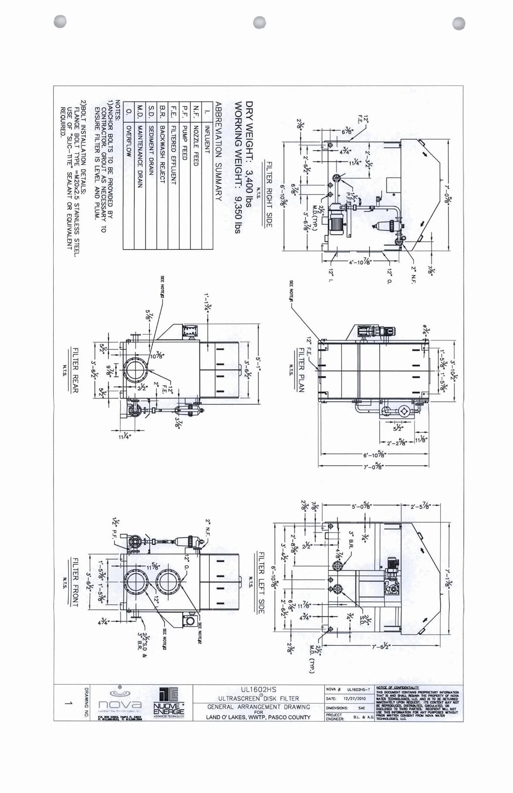
Trailer Mounted NOVA Disk Filter
Date:
Nova Water Technologies
Ultrascreen® Disk Filter
To:
For:
Trailer Mounted NOVA Disk Filter
Represented by:
Pasco County
3/14/2011
Carter & VerPlanck, Inc.Dave Hartwig
813-240-1199
1 of 6

Trailer Mounted NOVA Disk Filter
Date:
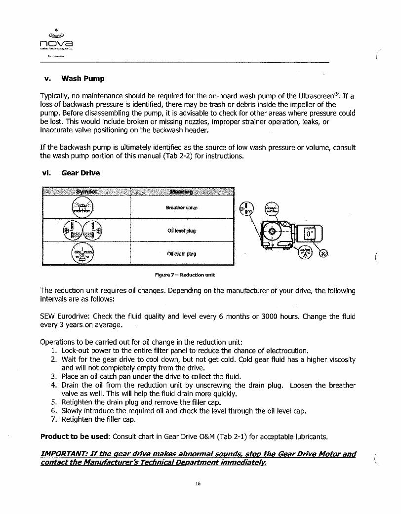
1.0 Introduction
2.0 Principle of Operation
Static Filtration – Particle Path Dynamic Tangential Filtration – Particle Path
The disks are always in slow rotation during normal operation. The water with TSS is fed at angles less than
90º, which is the basis for “dynamic tangential filtration.” The rotation allows use of precision woven wire
Stainless Steel micronic mesh, with micron ratings typically between 15 and 25 microns. The disk rotation
presents these openings as if they were actually smaller than in a static orientation. This allows for the
removal of particles smaller than 10 micron, while requiring minimal water for cleaning. This allows the unit to
operate at higher loading rates and achieve equivalent effluent quality compared to static disk filters. This
same principle has been proven consistently in the operation of rotatory drum screens, as on example.
NOVA Water Technologies is pleased to offer equipment and services in accordance with our standard
features. The basis of this proposal is compliant with the standard NOVA Water performance specifications
and materials in 304SS stainless steel. This proposal uses our Model UL1602HS disk filter.
3/14/2011
2 of 6
Trailer Mounted NOVA Disk Filter
Date:
3.0 Mechanical Principles
The feed to the disks is introduced into a zone between, or “inside”, each set of disks (see Figure No. 1
below). Each disk is sealed to the walls of the tank by long lasting EPDM rubber seals to maintain filtration
integrity and to prevent any short-circuiting. The feed passes through the filter mesh and freely falls into the
filtrate zone below (Figure No. 2) and flows out of the effluent outlet. As TSS is captured the liquid level in the
feed zone rises until it reaches a pre-set level. A sensor then initiates operation of the wash water pump and
the back of the screen mesh is sprayed by low pressure water at 2 to 4 bar for typically one minute. Once the
mesh is cleaned the level in the feed zone recedes to another pre-set level where a second level sensor
deactivates the wash water pump. All of the solids cleaned from the fine filtration mesh are collected in a
simple trough between the disks and leaves the filter under gravity flow. The reject troughs are connected to a
common outlet and the concentrated wash water (reject) is sent for further treatment.
Figure No. 1
3/14/2011
The filtration disks are arranged in pairs as show above
3 of 6
Trailer Mounted NOVA Disk Filter
Date:
The graphic below represents the typical flow condition during operation.
A level sensor will send a signal to the control panel when a high level condition or overflow situation occurs.
A situation such as this may occur when there is a significant upset in the plant or during a power outage.
Figure No. 2
Improved filter design hydraulics results in significant increases in capacity
The level sensor is also used for turning the filter itself on and off. At low level the filter is de-energized and
allowed to remain in a “filter ready” idle mode. This may occur in smaller plants during low flow periods of time.
Once flow resumes the idle filter is energized and the normal filtration and wash cycles resume.
3/14/2011
4 of 6
Trailer Mounted NOVA Disk Filter
Date:
4.0 Plant Design Information
The filter is to be sized for:
GPM (MGD)
4.1 Design Information for Filter: UL1602HS
sq.ft.
sq.ft.
gpm/sq ft
gpm/sq ft
hp
hp
gpm/unit
bar max
%
inches
4.2 Filter Performance Characteristics:
Maximum Head requirement
Avg. mg/L Avg. mg/LTSS
1389
Number of filters
7.89
15.78
0.5 - 1.0
4
Total reject backwash wash water as
% of the influent feed rate
Filter Drive
Wash Water pump
(1) 3
2.0
29.0Instantaneous Wash Water demand
(1.00)
(2.00)
1
Number of disks per filter
Wash water pressure
Method of feeding filter
Area per disk
Total area per filter
Loading rate at peak per filter
Loading rate at avg per filter
4
22.0
25.6
By Gravity or Pumped
Influent Effluent
3/14/2011
Average Daily Flow 694
88.0
Peak Daily Flow
5 of 6

Trailer Mounted NOVA Disk Filter
Date:
5.0 Scope of Supply: UL1602HS
Spare Parts: (8) Filter Panels, (1) par of Seals, (1) external bearings, (8) nozzles, (1) Basket
Qty (1) Trailer per spec: Bid No. IFB-KB-10-028, section: 6.1.2 "Trailer Unit"
6.0 Equipment Cost
Price for the scope of equipment as shown above is USD
Any taxes or fees are not included.
7.0 Typical Drawings: See attached
Equipment freight to the jobs site, engineering submittals, and start-up services are included in the pricing.
Price is valid for 60 days.
206,800$
Hollow Shaft drive system
Filter Level Control Sensor as required
304SS covers with two handles per section for easy removal
Qty (1) year manufacturer's standard warranty
Qty (1) Automatic sludge valve
316L stainless steel filter mesh
Qty (1) backwash pump (2 hp)
Internal spray wash piping and nozzles
Image of Four (4) Model UL-1606-CS shown
304 stainless steel tank
Ball valves and gauges as required
NEMA compliant control panel with SS enclosure, 480 VAC, 3 Phase, 60 Hz
3/14/2011
304/304L stainless steel filter disks
Qty (1) UL1602HS Ultrascreen® Disk Filter
6 of 6

nova water tednd- LLc.
SUBMIlTAL FOR LAND 0' LAKES. PASCO COUNTY
NOVA MODEL UL1602HS ULTRASCREEN TRAILER MOUNTED DISK FILTER
TABLE OF CONTENTS
SECTION 1
SECTION 2
SECTION 3
SECTION 4
SECTION 5
SECTION 6
ultrascreen@ Brochure Process Design Statement
ultrascreen@ Submittal Manual - Conditions for Proper Operation - Working Principle - Technical Description - Filter Installation - Pre-Starting Operations - Systgp Operation - Technical Characteristics of Seals - Special Tools
ultrascreen@ Mechanical Drawings Peripheral Components
1 - SEW Eurodrive Gear Drive/Motor 2 - Goulds Backwash Pump/Baldor Motor 3 - Amiad Strainer 4 - SKF Shaft Bearings 5 - EIM / Bray Sludge Valve 6 - KPSI Pressure Transducer 7 - Sta-Con Emergency Stop Junction Box
Rolls-Rite Trailer
Control panel / Emergency Stop data Electrical diagrams
Mechanical Warranty
6
P. 0. Box 23523, Tampa, FL 33623 w
P.813.288.0533 F.813.289.3566


nova
SUBMIITAL MANUAL
7 ULTRASCREEN@ DISK FILTER
Rev. 10/20/10 DCP
P. 0. Box 23523 Tampa, FL - 33623 P. 813.288.0533 F. 813.289.3566 www.novewt.mm

6
Ccw)
nova h-J=
MANDATORY CONDITIONS FOR PROPER OPERATION .................................................................. pW.3
.......................................................................................................... 1 . WORKING PRINCIPLE page.4
2 -TECHNICAL DESCRIPTION ................... .. ............................................................................ ~age.6 2.1 - Identification of components ........................................................................................ pW.6 2.2 - Hydraulic arcuit ......................................................................................................... page-8
3 . INSTALLING THE DISK FILTER ............................................................................................. pages9 3.1 . Unloading and handling .......................................................................................... page.9 3.2 . Positioning ................ .. .......................................................................................... page.10
4 . SYSTEM PRE-STARTING OPERATIONS ................................................................................. page . 11 4.1 - Feed water connection ............................................................................................... page.11 4.2 - Filtered liquid discharge connection ......................................................................... page . 12 4.3 - Overflow discharge connection .................................................................................... page.12 4.4 - Concentrate discharge connection ............................................................................... page.12 4.5 - Sediment valve pipe connection ............................................................................... page.12 4.6 - Wash pipe connection ............................................................................................. page.13 4.7 - Electrical Connection ................................................................................................. page.13
5 . SYSTEM OPERATION ................................................................................................... page . 14 5.1 . Operating Summary ................................................................................................ page.14 5.2 - Description of Components ........................................................................................ page.18 5.3 - Description of Operating Cycles ................................................................................... page.19 5.4 - System Start Up Details .............................................................................................. page.20 5.5 - Operator Controls ...................................................................................................... page.21 5.6 -System Alarms ........................................................................................................ page.21 5.7 - Glossary of Terms ...................................................................................................... page.22
6 . SEAL PROPERTIES .......................................................................................................... page.23
7 . SPECIAL TOOLS ............................................................................................................... page.24
nova L---bdrdDplJ=
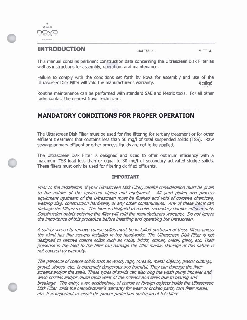
INTRODUCTION u ‘tc .- cr -- A
This manual contains pertinent construction data concerning the Ultrascreen Disk Filter as well as instructions for assembly, operation, and maintenance.
Failure to comply with the conditions set forth by Nova for assembly and use of the Ultrascreen Disk Filter will void the manufacturer's warranty. ;j- . .. Routine maintenance can be performed with standard SAE and Metric tools. For all other tasks contact the nearest Nova Technician.
m a . - el'; . , L.&& pjr(s\li*d A L * & i k 4 , < ,!..A; i&m .t.: ,.I
MANDATORY CONDITIONS FOR PROPER OPERATION
The Ultrascreen Disk Filter must be used for fine filtering for tertiary treatment or for other effluent treatment that contains less than 50 mg/l of total suspended solids (TSS). Raw sewage primary effluent or other process liquids are not to be applied.
The Ultrascreen Disk Filter is designed and sized to offer optimum efficiency with a maximum TSS load less than or equal to 30 mg/l of secondary activated sludge solids. These filters must only be used for filtering clarified effluents.
IMPORTANT
Prior to the installation of your Ultrascreen Disk filteer, wreful consideration must be given to the nature of the upstream piping and equipment. A// yard piping and process equipment upstmm of the Ultrascreen must be flushed and void of corosive chemicals, weldihg slag, constructsn hardware, or any other contaminants. Any of these items can damage the Ultrascreen, The fillter is designed to receive secondary darifier eeffluent only. Con&rucf-/bn debris entering the liter will mid tf7e manufacturers warmnty, Do not ignore the imporfance of this procedure betbre instalng and operating the Ultrascreen.
A safety screen to remove warse soids must be installed upsham of ti?ese filters unless the phnt has fine screens instaled in the headmrks. The Ultrascreen Disk Rlter is not desbned to remove coarse solids such as rocks/ bricksI stones, met24 ghss, etc Their presence in the ked to the filter can damage the filter media. Damage of this nature is not covered by warranty
The presence of cvarse solids such as wm$ rags, threads, metal objectc, plastic cumngs, gravel, stones, etc.., is extremely dangerous and harmful. They can damage the fiter s m n s and/or the seals. The= vpes of solids can also clog the wash pump impeller and wash nozzles and/or muse rapid wear of b?e screens and seals due to teanhg and breakage. The entry, een acc~'den~Iy, of w r s e or foreign objed3 inside the Uhscreen Disk Filter voids the manufacturer's w a n i y for wear or b&n parts/ tom filter media, etc. It is imptiant to install the proper protection upstream of this filter.
w nova --k
I - WORKING PRINCIPLE
The ultrascreen@ Disk Filter operates on the principle of progressive fouling, i.e., the filter meshes become dogged until the minimum water flow is reached, which corresponds to a pre-set elevation of the water level in the feed compartment of the filtering disks. The filter meshes are then cleaned by wash cycles (regeneration of the filtering medium) operated automatically, that utilize a portion of the filtrate from the filtrate well compartment below the filtering zone (or plant reuse water).
The Ultrascreen Disk Filter is designed for continuous, unattended operation using level probes to operate (and subsequently interrupt operation of) the wash water pump, in relation to load conditions (TSS, flow rate, etc) of influent waste water. This gives the machine considerable operating flexibility, enabling both constant and variable/intermittent flows to be treated. Key filter items are listed below:
Figure 1 - Wodcing prindple 4
1 1 12 13 14 15 16
Chemical Injection Port I
Solenoid Valve Isolation Back Wash Pump Isolation Back Wash Pump Drain Port Sampling Point .
6 w
nova --k -- The sizing of the Ultrascreen Disk Filter generally provides for wash phases lasting approximately 10% (or less) of the total filtering time, with an average consumption of wash water in those conditions of approximately 0.1% to 0.5% of the average influent rate to the filter. The operating margin is very wide, which allows the filter to handle increased flows and solids loading (TSS, gpm, etc.) and in the most critical cases can operate continuously washing with a total wash water reflux equal to approximately 2 to 4% of the feed, depending upon the model of the filter being used. Wash water m n s u m p Q ~ f i r e d l y related to the concentration of solids to be removed.
?=l
The Ultrascreen Disk Filter is equipped with an actuator-operated valve for discharging sedimentation from the bottom of the filtering chamber. Even in the presence of turbulence during filtration, the heaviest micro partides tend to settle and deposit on the bottom of the filtering chamber. By means of a timer, the discharge valve allows the bottom of the filtering chamber to be cleaned automatically. This exclusive feature of the Ultrascreen Disk Filter allows the filtering zone to remain free of accumulated solids.

nova --k
2 - TECHNICAL DESCRIPTION
2.1 - Identification of components
The Ultrascreen Disk Filter consists primarily of a stainless steel tank (Position 1) provided with covers that are equipped with handles (Position 5). The casing is comprised of an inlet section (Position 2) for the liquid to be filtered, and an outlet section (Position 4) for the filtrate. The inlet sections of the tank are baffled with stainless steel partitions.
Figure 2 - Identification of units
6
w nova -bd-d=a-J=
The disks (Item 6) are equipped with filtering screens (Item 71, that are able to retain the suspended solids in the liquid. These segments are bolted to the disk wheels, which are attached to the shaft and driven by a variable speed wr drive (Item 12). The seals between the disk wheels and the circular cradle in the tank use high strength flexible silicon rubber gaskets (Item 13).
The liquid to be filtered is introduced between the disks via the feed ducts and then deposits the solid material on the filtering screens. The solid materials are then removed by pressure washing and conveyed to the outside through a dud and finally to a flange (Item 15,8), and sent in the form of a ancentrated liquid to the head of the treatment plant or other location designated by the owner.
The backwash system consists of header pipes (Item 11) equipped with multiple spray nozzles, which clean the filtering screens using pressurized water. A centrifugal pump (Item 10) feeds the backwash pipes with filtered water from the dearwell.
The backwash piping assembly is also provided with a connection (Item 16) for the mainlplant water supply line. This allows the wash water to be available from both plant water and the local backwash pump as a redundant source.
A sediment discharge valve (Item 9) is installed on an outlet that is connected to the bottom of the cradle inside the filtering disks. This actuator is operated by a timer and when actuated removes any sediment that may have accumulated at the bottom of the filtering zone.
An electrical panel (not shown, remotely mounted) controls and commands the electrical and control functions of the machine.
nova & t-. .k
2.2 - Hydraulic circuit
(Figure 3) shows the hydraulic circuit for washing the screens of the ultrascreen@ Disk Filter. The pressurized plant water supply line can be used with the arrangement shown below, by installing a solenoid valve and wiring it directly into the filter control panel.
Figure 3 - Backwash Circuit *The solenoid valve (Item 6, Figure 3) is fw automatic operation wi?h pressurized internal plant water
. 13 14 15
Bung far optional chemical feed Hose Bib for samplinq Pump sunIrain shield
6
w nova b-.k
3 - INSTALLING THE ULTRASCREEN@ DISK FILTER 1 d';. .. : .&h -Lj;rb.'-- .. . : w ,#,t'k
3.1 - Unloading and han-_ing
A nENnON: The Ultrscreen Disk Filter a n present an untralanced load, if the weight is not evenly distributed Speual attention must be paid as to not damage items that project from the sides of the unit such as the backwash pump or gear drive.
Operations to be carried out when using a crane truck with handling lifting beam: - Unscrew the bolts attaching the covers and remove them - Fix the eyebolts to the filter chassis (Item 2), and suitably tighten them. - Connect the eyebolts to the lifting beam and then to the crane with lifting chains or
ropes of adequate length. - Make sure the ropes or chains do not touch anv art of the filter i
- Carefully lift and position the machine law) - Take care to avoid damaging items that project from the side of the unit.
i
L. MIN 7
Figure 4 - Handling of ULTRASCREEN' Dlsk Filter
IMPORTANTI. The covers can be refitted in the machine starting phase. In the meantime they must be placed in a safe place to prevent damage. Table 2 gives the minimum required lengths of the beam for lifting the ULTRASCREEN@ Disk Filter:
Table 2. - Minimum length of iffting beam (position 1)

6
w nova -----IC
3.2 - Positioning
IMPORTANT Prior to the installation of your Ultrascreen Dbk Filter, careful consideration must be given to the nature of the upsfrem piping and equipment. At/ yard piping and process equipment upstream of the Ultrascreen must & flushed and void of corosive chemicalk, weluhg slag, construction hardware, or any other contaminants. Any of these ikms can damage the Ultrascreen Disk F i t e ~ The filter is designed to mieve sewndaty clarifier efnuent only. Construction debris entering the filter will void the manuhdurem warranfy.
The ULTRASCREEN Disk Filter is delivered fully assembled and ready for installation. The surface on which the ULTRASCREEN Disk Filter is to be installed must be level, plumb, and of even elevation throughout and arranged to take the weight of the machine during its operation (with the load of water to be filtered inside). After positioning the ULTRASCREEN Disk Filter the unit must be level, confirm using a normal spirit level (bubble level).
A free space of at least three feet must be left around the sides of the machine for maintenance. The dimensions and weights of the ULTRASCREEN Disk Filter are given under BLUE TAB 3 - Ultrascreen Mechanical Drawings.
nova
4 - SYSTEM PRE-STARTING OPERATIONS
4.1 - Feed water connection - Pump Feed
The Ultrascreen Disk Filter can be gravity fed or fed by pump, regardless of feed method, there must be sufficient head to allow filling of the filter chamber. I f the system is designed for pump feed, the feed piping should ideally be connected to the inlet section of the Disk Filter using a stainless-disc butterfly valve to regulate the flow (Item 2).
5 Concentrate discharge 6 Main/Plant water supply line
I 7 Wash water pump ,
I
8 MairiJRant water.-%
Figure 5 - Hydraulic connection of ULTRA SCREEN^ Disk FHter
nova Lllbr *-. lC
4.2 - Filtered liquid discharge
The filtrate exits the ultrascreen@' Disk Filter through the outlet section (Figure 5 - Item 3).
4.3 - Overflow discharge connection
I f the ultrascreen@ Disk Filter is unable to filter the entire quantity of inlet water in the feed chamber, the excess feed will exit the machine through the overflow section, and combine with the concentrate discharge.
4.4 - Concentrate discharge connection
The solids retained on the filter meshes are discharged from the filter through a collection dud (Item 5) and along with the wash water that is used to wash these solids off the disks.
The discharged liquid can be sent to the headworks of the wastewater treatment plant for reprocessing, or elsewhere depending upon the specific needs of the owner and/or operator.
4.5 - Sediment discharge connection
All ultrascreen@ Disk Filters are equipped with a discharge pipe hydraulically connected to the lowest point inside the cradle of the central zone where the filtering disks are located. This discharge pipe is connected to a motor-operated valve (Item 4) which is activated by means of an actuator. The operation of this "sediment dischage valve" is controlled from the main control panel by means of an adjustable timer.
Adjustment of the timing of the sediment discharge valve opening must only be made aRer wreful tes~ng and considerat-/bn of the frequency at which sediment should be removed from inside the filteing disk, It should be opened only as frequently as needed.

6
' s s a
nova --.I=
4.6 - Washing piping connection
Connection to the wash piping is carried out according to the diagram in Figure 6. A
Model II -= -icn-
1 ; T T Backwash pump
Fwure 6 - Badcwash piping connection and pressure-flow at nodes (flow measured in US GPM)
It is advised to conned the main plant utility water supply to the Ultrascreen Backwash System (Item 1). If plant utility water is available at a temperature higher than ambient (higher than approximately 150 Celsius/600 Fahrenheit) it should be used, especially in plants that have a high grease and oil load in the influent. Cleaning the filter mesh with warm water is more effective than cold water.
IMPORTANT: To avoid damage or tearing of the filter mesh, the working pressure of the spray water must not be higher than 65 psig. IMPORTANT: To avoid any damage to the lateral seals the temperature of the wash water must not exceed 700 Celsius/1580 Fahrenheit.
JMPORTANT: A local y-strainer is required on the main water supply to prevent particles from clogging the wash water nozzles. This strainer will be provided by the manufacturer.
The recommended connection to the main plant utilitv water s u ~ p l v line is 2" diameter as well as should be the diameter of the solenoid valve.
4.7 - Connection to the electrical grid
The connections to the electrical srid must be carried out in strict accordance with all local and national electrical codes and safetv practices. The Ultrascreen Disk Filter is supplied with an electrical panel to which the filter controls - and motors are interlocked.
nova --.LC
5 - SYSTEM STARTING OPERATIONS
5.1 - OPERATING SUMMARY
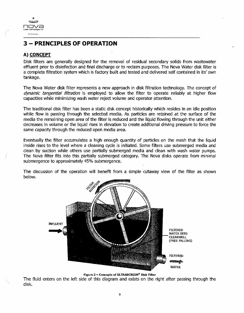
Disk filters are generally designed for the removal of residual secondary solids from wastewater effluent prior to disinfection and final discharge or to reclaim purposes. The Nova Water disk filter is a complete filtration system which is factory built and tested and delivered self contained in its' own tankage.
The Nova Water disk filter represents a new approach in disk filtration technology. The concept of dynamic tangential filtration is employed to allow the filter to operate reliably at high flow capaaties while minimizing wash water reject volume and operator attention.
The traditional disk filter has been a static disk concept historically which resides in an idle position while flow is passing through the selected media. As particles are retained at the surface of the media the remaining open area of the filter is reduced and the liquid flowing through the unit either decreases in volume or the liquid rises in elevation to create additional driving pressure to force the same capacity through the reduced open media area.
Eventually the filter accumulates enough particles on the mesh that the liquid inside raises to the level where a cleaning cycle is initiated. Some filters use submerged media and clean by suction while others use partially submerged media and clean with wash water pumps. The Nova filter fits into this partially submerged category. The Nova disks operate from minimal submergence to approximately 45% submergence.
The Nova disk filter uses continuously rotating disks that backwash periodically (and if need be, continuously) pass filtrate even when the wash cycle is being performed. The concept of dynamic tangential filtration is accomplished using a simple principle that a particle of one size can pass through an opening of approximately equal size but it can not pass through that same sized opening if the opening is in motion. The analogy of attempting to throw a snowball through the window of a moving car has been used to describe this concept. The faster the car is moving the less likely the chance the snowball will make it through the window.
The Nova filter disk uses woven stainless steel media that has approximately 25 micron cross sectional openings and when operated in a dynamic rotational motion the snowball effect results in the filter capturing many particles much smaller than the actual opening size. Particles of 10 micron and below are successfully retained in this tangential filtration operation and then washed off the filter for return to the treatment plant as appropriate.
nova ud.r-=
The number of particles in an effluent stream is highly variable, so the benefit of dynamic filtration versus static filtration will be that as the disk rotates it captures many partides smaller than the size of the openings in the media while allowing the water to pass through the openings at higher capacity. The media is gradually collecting particles and thus fouling during this normal operating cycle. Eventually the disk has collected enough retained particles that a cleaning cycle needs to be initiated.
As is similar with static disk filters the water in the Nova filter that is waiting to pass through the media will gradually rise in level until a level sensor detects the maximum
0 normal high water level and initiates a motor starter which energizes the backwash pump. The washing action involves the portion of the disk above the water level only and
L .
because the disk is in motion the washing cycle is brief and very effective.
The solids in the water waiting to be filtered then begin to once again accumulate on the surface and in the voids of the media as it rotates. This coating effect quickly decreases the number of open voids in the media and helps to capture ever smaller particles as the filter cycle phases from washing (clean), to seasoned (coated), eventually to sufficiently fouled, requiring another cleaning cycle.
The water to be filtered enters the unit and is directed to the area between the disks, passes through the disks (inside disk surface to outside) leaving the captured particles on the two disk surfaces (inside) that face each other. Using a simple backwash header arrangement with typical nozzles the disks are washed in the opposite direction from outside back to the inside. A small trough rests between the disks and collects the dirty water. The disks themselves rotate on a simple center shaft or axle.
The washing water is obtained from water that has previously passed through the filter media. Small filters use an on board pump while larger systems with multiple filters can use manifold piping to feed many filters from one single pressurized water source.
6
w nova --J=
The discussion of the operation will benefit from a simple cutaway view of the filter as shown below.
INFLUENT I
FILTERED WATER INTO - CLEARWELL
WATER
The fluid enters on the left side of this diagram and exists on the right after passing through the disk.
- The water being filtered passes through both disks from inside to outside.
w nova b-&
a,"-
The filter operation sequence begins with the filter in the idle position (no disk rotation), Water is allowed to flow into the filter and when the liquid level reaches the filter "Drive On" level, the drive unit will energize. IMPORTANT - DO NOT ROTATE THE FILTER DISKS WITH THE UNIT DRY, THIS CAN DAMAGE THE SEALS
The filter also has a low level limit that will shut the "Drive Off" i f the screen has inadequate water being fed to keep the disks properly wetted. The disk seal that prevents passing of dirty water to the clean water side of the filter.~.ggJs to be w~L- friction wear.
Once the screen is in normal operation and filtration is continuous the ~ i q u i d ~ ~ l k h r r i s e in the filter feed well and eventually reach the "Wash Water On" level. This will energize the backwash pump or main solenoid valve if the system is connected to a pressurized manifold system.
Once the disk media washing function is completed the liquid level in the filter will decrease and the "Wash Water Off" level will be reached. This will discontinue the backwash function.
A representation of the level probe control positions is shown below. Note that elevations are not to scale, they are provided to represent the relative positions within the filter.
Lastly, note that if your Ultrascreen is outfitted with a pressure transducer for level sensing control, the drawing below indicates the approximate heights at which control functions are performed during operation.
Drive OIT I Disk motor deactivation level probe
Wash Off Motor pump deactivation level probe Wash On Motor pump activation level probe
1 Overflow 1 Overflow level probe 1
d
w nova --.LE
The function of the filter under normal conditions will be completely automatic. Some heavier particles may settle to the bottom of the inlet feed area between the disks, which will be flushed out via opening and dosing of the sediment discharge valve. This valve can be set to open with varying frequency and duration of time open. This allows the bottom of the filter to be kept free of solids accumulation. Because the nature of the solids to be filtered is very application-specific, this function is set during start up and after a week or more of typical filter operation, the frequency can be re-evaluated to determine the appropriate cycle times needed.
5.2 - DESCRIPTION OF COMPONENTS
Filter Tank - Holds the filter disks, seals, wash water collection trough and wash water headers.
Media - Woven stainless steel fabric attached to the rotating disks.
Disks - The actual rotating wheels that hold the filtering media fabric.
Center Shaft - The axle the disk wheels are attached to.
Gear Drive - The motor, reducer and gearbox that turns the center shaft.
Backwash Pump - The pump used for washing the media.
Sediment Valve - A simple timer operated valve for draining accumulated solids from the bottom of the filter inlet feed well.
Disk Seals - The silicon rubber seals located at the interface of the disk and the inlet filter feed well that prevent dirty water from passing to the clean water side of the unit.
6 w
nova -t-.tc
5.3 - DESCRIPTION OF OPERATING CYCLES
Idle Cyde - The filter has no flow and the gear drive is not energized.
Filling Cycle - Inlet flow has been initiated and the filter drive unit is energized by the rising water reaching the "Drive On" level. s m %5) Ill
.Ai -4 I.u...-h.
Continuous Filtering Cycle - The inlet feed rate is continuous (steady or variable flow) and the disks are in mnstant rotation. The liquid level is now rising based on the media capturing particles.
%!! .@z th a' Backwash In--- tion - The "Wash Water On" level is reached by the ris~ng wa r In e h inlet feed well and energizes the wash water pump (or the solenoid valve if the plant water pressure manifold is used) which then supplies filtered water for washing the disk media. --.,.- Backwash Duration - The washing of the disks will continue until the water level esJPbLI.7 decreases to the point where it reaches the 'Wash Water OfF" level, but not for less than a duration of one minute. At this point the wash pump will de-energize.
Normal Operation - The backwash cyde will repeat as required based on the rise and fall of the inlet feed well liquid level. The filter is designed to run continuously from this time forward with the exception of maintenance functions. iE@K Sediment Discharge/Drain - The sediment discharge valve can be programmed with a timer function to open and close on a preset basis. This function is variable for frequencyzd and duration and is set at start up for each project.
bid.3 '
Filtering Cycle Complete - In the event the feed to the filter is interrupted the filter will continue operation until the "Drive Off" level is reached and then the drive will de- energize. The filter will remain idk until the inlet feed is once again resumed. Flow interruptions can be the result of various events including lack of flow at the plant during late night and early morning hours. ' :
Overflow Mode - It is possible to feed the filter with more flow than it can pass throua.,, the disks. I f this event occurs the excess water will leave via the ovetflow to the next -
process as the yard piping directs it. An alarm will activate to alert the plant staff. Lm 7; dq
IMPORTANT - THE DISK SEALS CAN BE DAMAGED IF THE FILTER IS ALLOWED TO OPERATE IN A DRY CONDITION. ,
nova *-.k
5.4 - SYSTEM START UP DETAILS
The filter will be supplied factory built with all components installed and tested prior to delivery to the job site.
FILTER INSTALLATION - The filter needs to be installed on a level concrete slab and secured to the floor with proper anchors. All dirt, construction debris, and trash must be removed from the filter piping connections. Make sure filter is level and plumb before and after making the final anchor tightening.
PIPING - The inlet feed piping must be flushed before connecting to the filter to ensure that all construction residuals, pipe scale, tools and any foreign materials are removed before flow is initiated to the filter. Inlet and outlet piping should be level, plumb and adequately braced and supported so the weight of the piping is not transferred to the inlet or outlet fittings of the filter box.
ELECTRICAL CONTROLS - Test the incoming proper power for voltage and phasing. Pump and Gear Drive rotation and Sediment Valve function will be verified by the factory technician during the preliminary equipment checkout.
TRIAL RUN - Once the filter has been checked for preliminary mechanical, electrical and hydraulic compliance the filter will be test run for a brief period with plant water, secondary effluent or other suitable water source.
I f all systems check out OK the screen will be operated for a period of 24 hours under normal loading and the Sediment Valve cycle time will be assessed.
Current readings will be taken for the Gear Drive motor and Backwash Pump motor and recorded in the start up log.
ON BOARD SYSTEMS - The Gear Drive will be demonstrated to operate from minimum to maximum RPM range. The Backwash Pump (and or manifold) pressure will be verified for the proper operating pressure. All spray nozzles will be verified to be clear of obstructions and providing proper spray patterns. Wash water pressure should be 60 psi maximum available at the wash water spray header gauge.
REJECT DISPOSAL - The dirty wash water drain line will be verified for proper slope and flow capacity.
COVER ALIGNMENT - The filter covers will be checked for alignment and verified to be free of leaks at the gasketed mating surfaces. IMPORTANT - NEVER OPERATE THE FILTER WITH THE COVERS REMOVED FOR ANY REASON.
4
w nova &-&I&
FINAL START UP AND COMMISSIONING - Once the above checks and reviews have been completed the filter can be placed into normal full time operation. The flow rate to the filter should be accurately measured at this time and recorded.
- The backwash duration should be recorded at this time.
- The time duration between wash cycles should be recorded.
- The drive unit speed should be recorded.
5.5 - OPERATOR CONTROLS
FLOW RATE - The filter inlet feed rate in gpm is the single most important factor in disk filter operation. Operate filter within design flow rate parameters, at all times.
DRIVE UNIT SPEED - The disks can operate at variable speeds typically ranging from 3 RPM to 15 RPM depending on the model of filter supplied. The operator can increase the speed of the unit at higher flow rates and/or TSS loadings and then reduce the speed at low flow rates and/or lower TSS concentrations.
SEDIMENT DISCHARGEIDRAIN - The frequency and duration of valve operation is a variable that can be adjusted periodically by the operator via the timer inside the control panel. THE POWER MUST BE OFF TO PERFORM THIS ADJUSTMENT.
5.6 - SYSTEM ALARMS
The following scenarios will initiate an alarm signal:
Drive Unit - Fail to Run Wash Pump - Fail to Run Bottom Drain - Fail to Open Bottom Drain - Fail to Close High Level Overflow
6
nova &--k
el--
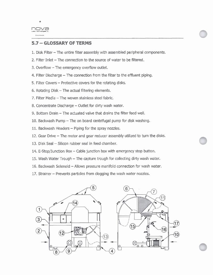
5.7 - GLOSSARY OF TERMS
1. Disk Filter - The entire filter assembly with assembled peripheral components.
2. Filter Inlet - The connection to the source of water to be filtered.
3. Overflow - The emergency overflow outlet.
4. Filter Discharge - The connection from the filter to the effluent piping.
5. Filter Covers - Protective covers for the rotating disks.
6. Rotating Disk - The actual filtering elements.
7. Filter Media - The woven stainless steel fabric.
8. Concentrate Discharge - Outlet for dirty wash water.
9. Bottom Drain - The actuated valve that drains the filter feed well.
10. Backwash Pump - The on board centrifugal pump for disk washing.
11. Backwash Headers - Piping for the spray nozzles.
12. Gear Drive - The motor and gear reducer assembly utilized to turn the disks.
13. Disk Seal - Silicon rubber seal in feed chamber.
14. E-Stop/Junction Box - Cable junction box with emergency stop button.
15. Wash Water Trough - The capture trough for collecting dirty wash water.
16. Backwash Solenoid - Allows pressure manifold connection for wash water.
17. Strainer - Prevents partides from clogging the wash water nozzles.

nova ..-.--lE
6 - SEAL PROPERTIES
Main properties
Min. duty temperature: -68OFj-20°C Max. duty temperature: 2120F/+100°C
AmEN77ON: 7he above values are based on the properties of the seal material, Since the seals may be subjected to harmful chemicals and mechaniml frictr'on during operation of the ULTRASCREE@ Disk Filter, it is important to make sure the water to be filtered does not exceed the temperature of 1580F/70OC.
Physical characte!ristics:
- Mechanical properties (elongationjtear strength): good/excel len t - Resik&nce to permanent delbrmation from goodjexcellent - Abrasion resistance good
Other characteristics:
- Flameresistancepracticallynil - Highly impermeable to air and gas - Excellent dielectric properties - Exceptional resistance to UV radiation
Chemical reactivity:
More than satisfactory for use with: - water and steam up to 2120F/100°C, seawater, saline solutions, strong mineral bases
and solutions - glycols and related brake fluids - alcohols, ketones and other oxygenated solvents, ozone and other atmospheric
agents
Satisfactory for use with : - strong mineral acids and their solutions - vegetable or animals oils and fats - hydraulic fluids based on phosphoric esters
NO1 SATIS/AAC;TORY FOR USE WITH: - miners/ oils and fa& (aliphati~j ammatic and chlorinated hydmwhons
silimn este~based hydraulic fluids; non-polar liquids in general)
6
w nova -,-LC
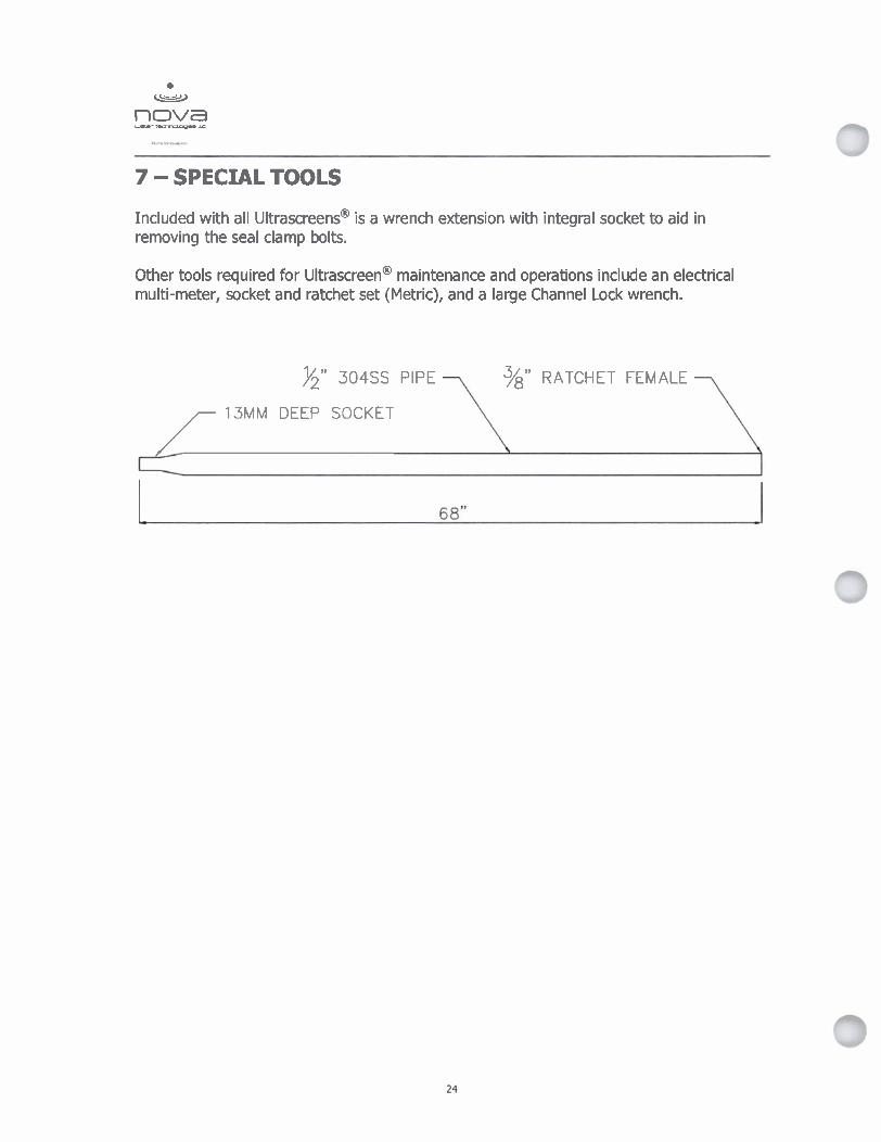
7 - SPECIAL TOOLS
Included with all ultrascreens@ is a wrench extension with integral socket to aid in removing the seal clamp bolts.
Other tools required for ~ltrascreen@ maintenance and operations include an electrical multi-meter, socket and ratchet set (Metric), and a large Channel Lock wrench.
%" 304SS PIPE 3/8" RATCHET FEMALE
/ 13MM DEEP SOCKET
Mounting Position
KA 37-157 . . - - .. ..
I I I I I
#@ I I I 1 I
011 drain plug
--------------A------&--- .-A
I . . . . . . . . . . . . . . . , . . -1
Fig. I : MOVIMO~@ ((inwterj unit structure
I. IdentiRcation of the circuit type 2. Terminal box 3. Connection plug between Eonnec&n unitand inverter 4. Connection box w r with I ~ ~ r and heat sink 5. Connedion unit wlfh termirwls 6. Electronics terminal &rip X2 7. Connection of bralce dl MI: in mvtm without brake: Connection of internal braking resistor BW. . . -
(standard) 8. Mains connection L1. L2. L3 8131 (suitable for 2 x 4 mm2\ , . 9. screws for PE Q ' 10. Cable screw Wnga 11. Eladronics nameplate 12. Safety hood for inverter slgotronios 13. Setpaint ~ t c ~ r f l (rat visible), accessible through a screw fitting on the top of the c o n n e b box cover 14.Setpdntswitchf2 (gram) 15. Switch t l for generetar ramp (whlte) 16. DIP switch Sl for W'ng MB bus Wres, mator protection, DC braking, PWM frequency 17. Status LED (visible from the top of- wnnection box caver, see &on 7.1)
Mechanical Installation Before you begin M O V I M O ~ may not be installed unless:
the entries on the nameplate of the drive match the voltage supply system,
the drive is undamaged (no damage caused by transport or storage) and
it is certain that the following requirements have been fulfilled:
- Ambient temperatures between -25 "C and +40 "C (remember that the temperature range of the gear unit may be restricted + operating instructions for the gear unit)
- No oil, acid, gas, vapors, radiation, etc. - Installation altitude max. 1000 m above sea level
Installation tolerances
+ " M O V I M O ~ Geared Motors" catalog, "Notes Appertaining to the Dimension Sheets" section.
Mounting MOVIMOP
Shaft end - - 4 ~
-L
Diametric tolerance in accordance with DIN 748 IS0 k6 at 0 150mm IS0 m6 at 0 > 50mm (Center bore in accordance with DIN 332, shape DR)
The MOVIMOT@ may only be mounted or installed in the specified mounting position on a level, vibration-proof and torsionally rigid support structure.
Flanges - l. . -
Centering shoulder tolerance in accordance with DIN 42948 IS0 j6 at 0 S 230 mm IS0 h6 at 0 > 230 mm
Thoroughly remove anti-corrosion agents from the shaft extensions (use a commercially available solvent). Do not allow the solvent to penetrate the bearings and shaft seals -this could cause material damage!
Carefully align MOVIMO~@ and the driven machine to avoid placing any unacceptable strain on the motor shafts (observe permissible overhung load and axial thrust data!).
Do not butt or hammer the shaft end.
Use an appropriate cover to protect motors in vertical mounting positions from objects or fluids entering!
Ensure an unobstructed cooling air supply and that air heated by other apparatus cannot be drawn in or reused.
Balance components for subsequent mounting on the shaft with a half key (output shafts are balanced with a half key).
Any condensation drain holes are closed with plastic plugs and must not be opened unless needed.
Do not leave any condensation drain holes open, since this defeats higher enclosure ratings.
Installation in Use suitable screwed cable glands for the supply leads (use reducing adapters if damp areas or in necessary). the open air Coat the threads of cable screw fittings and pocket caps with sealant and tighten
them well -then coat them again. Seal the cable entry well.
Clean the sealing faces of the connection box cover well before re-assembly.
Restore the anticorrosive coating if necessary.
Check the type of enclosure is authorized (refer to the nameplate).
Screwing on the Tighten the screws for the connection box cover to maximum 2.5 Nrn. COnnectionbox The connection box cover may be deformed and damaged if it is tightened to a cover higher torque value.
d MOVIMOT@ connection
Functions of terminals R n and L 0 with binary control:
Rotation CW active
Rotation CCW active
f .Functions of terminals fllf2: TI e
Setpoint f l active Setpoint f2 active
Functions of terminals R(S and L O with control via RS-485 interface I fietdbus:
24 v,, supply external or MLU..IMLG.. option
Brake resistor BW. (in MOVIMOTQ without mechanical brake only)
Only CW rotation is enabled
g m t z y : w . - n
Only CCW rotation is enabled set,,, sdections, ,, rotation result In standstill of drive
Drive Is Mocked or brought to standstill

/ MBGllA option connection
MBGl1A option connection
MBGIIA
MBGllA
$ + & ' h PI
1) with integrated dynamic terminating resistor
cc
MBGIIA option
- . . , > . . \ . . , I _ . .
1 24 VDc I : \-
@A
Part number
Input voltage
Current consumption
Setpoint resolution
Serlal interface')
Enclosure
823 547 8
24 VDC e5 %
approx. 70 mA
1 %
RS-485 for connecting max. 31 M O V I M O ~ inverters (max. 200 m, 9600 baud)
IP 65

Startup- with MBGJIA-
1. Check MOVIMO~@ is connected correctly (see section 5).
2. Set DIP switch S l l l (on MOVIMOT@) to ON (= address 1).
3. Check the setting for 4Q operation (DIP switch S116 = OFF).
Fig. 9: Setting DIP switches
4. Set the minimum frequency fmi, with switch f2.
5. Set the ramp time with switch t l (ramp times in relation to a setpoint step change of 50 Hz).
'm&h f2 - C
I I -
7. Put on fhZ)
Detent position
Minimum frequencyf* [Hz1
2 5 7 10 12
0 1 2 3 4 5 6 7 8 9 1 0
15 20 25 30 35 40

Startup with MBGllA
8. Set the required maximum speed using setpoint potentiometer f l .
Fig. 10: Setting the second speed
9. Make sure the retaining screw of the cover has a seal and fit it back in.
10.Switch on the voltage.
Operating MBGllA
-
Operatirrg MRG41A and MLG..A opttans
Display Negatlve display value e.g. = Counterclockwise
Positive display value e..
@ k w h
The displaydvalue relates to e spe &s&g setpoint potenfomefer fl. For example: Display "50" = 50 % of the speed set using the setpoint potentiometer. Important: If the display is "O", the drive is turning at fd,.
Increase the speed If clockwise: If counterclockwise:
Reduce the speed If clockwise: If counterclockwise:
Inhibit MOWMOT@ Press the following keys simuItaneousIy: Display = bFI
Enable MOWMOT@
Or ail Important: MOVIMOF accelerates to the previously stored value after enable
Change in direction of until display shows rotation from CW to CCW #&-& $&,
ilgiiE :*th?W & . I 2. Press agai. to change the dirkbbn of rotatiin from CW to CCW
~ , ~ & d d & G .
- - - - - . . - - -
again to change the direction of rotatkn- 1 Memory function After the supply system has been switched off and on again, the value last set is retained
provided the 24 V supply was present for at least 4 seconds following the most recent setpoint change.
LED
Meaning of the The 3-color LED signals the operating and fault states. status LED states
L ~ D color
Yellow
Yellow
Green1 yellow
Green
Green
Red
Red
Red
Red
Red
Red
~ k ~ s f a t u s -
Off
Steady flashing
Steady light
Flashing with alternating adom
Steady light
Steady, fast flashing
Steady light
2 x flash, pause
3 x flash, pause
4 x flash, pause
5 x flash, pause
6 x flash, pause
'bpbtSflona1 Stgfus
--- - Not ready
Not ready
Ready but unit inhibited
Ready, but timeout
Unit enabled
Current limit active
Not ready
Fault 07
Fault 11
Fault 84
Fault 89
Fault 06
D e s e r l m * I - + . p,$,r~ti - .i-j , +
No 24 V power supply
Self-test phase active or 24 V power supply present but supply voltage not OK
24 V power supply and supply voltage OK, but no enable signal
Communication via R8-485 disrupted
Motor operating
Drive has reached the current limit
Check the 24 Vw supply Make sure that there is a smoothing DC voltage with a low ripple (residual ripple max. 13 %) present
DC link voltage too high
Excessive temperature in output stage
Excessive temperature in motor Assignment of motor to frequency inverter incorrect
Excessive temperature in brake Assignment of motor to frequency inverter incorrect
Mains phase fault

Inspection and maintenance work, motor
a
1 Cirdip 2 Oil flinger 3 Oil seal 4 Screw plug 5 Drive end bearing end
shleld
6 Circlip 7 Ball bearing 8 Circlip 9 Rotor
10 Nllos ring
11 Ball bearing 16 V-ring 12 Equalizing ring 17 Fan 13 Stator 18 Circlip 14 Nondrive end bearing end 19 Fan guard
shield 20 Housing s c w 15 Hex head screw

Technical Data
1) Factory setting 2) 16 kHz PWM frequency (low noise) When DIP SWITCH S i n = ON, the units operate with a 16 kHz PWM frequency (low noise) and
switch back in steps to lower switching frequencies depending on the heat sink temperature. 3) Ext. control or MBGIIA, MWA21A or MLG..A option 4) Transmission rate 31250 baud is detected automatically when operating with fieldbus interface MF ...
I 1 MM 11B- 503-00
823 025 0
2.2kVA
'9
MOWMOP type MM 03B- 50340
823 022 6
1.1kVA
Part number
Output power at V,, = 380 - 500 VAC
MM 15B- 50350
823 028 9
2.8kVA
3 x 380 VAc I 400 VAc 141 5 V , = 380 VAc -1 0 % ... 500
C
PN
Connection voltages Permitted range
MM O5B- 503-00
823 023 4
1.4kVA
v,n
MM O7B- WWO
823 024 2
1.8kVA
f
MM 22B- ' 50340
822 953 8
3.8kVA
MM 30B- 50340
822 954 6
5.1kVA
5.8 AAc
7.3 AAc
3.7 kW 5 HP
I 4.3 AAc
5.5 AAc
2.2 kW 3.0 HP 1
Supply frequency
Rated system current (at Vin = 460 VAC)
Output voltage
Output frequency Resolution Operating point
Output rated current
Motor power
PWM frequency
Current llmltation
External braking resistor
Interference lmmunlty
Interference emlsslon
Ambient temperature
Enclosure
Operating mode
Type of cooling (DIN 41 751)
Altitude
Ext. power supply to electronics
Binary inputs
Signal level
Control functions
Output relay Contact data
Slgnallng function
Serlal Interface
V,,
fm
lrated
PmOt
lmax
Rm~n
gamb
TI. 24 V
TI. R n TI. L 0 TI. flm TI. K l a TI. K lb
TI. RS+TI. RS-
41)18/121162)k~z \ 1 motor: 160 %with Y regenerative: 160 %with Y
200 R I 100 R
Complies with EN 50082 - Parts 1+2
In accordance with limit value class A to EN 55011 and EN 55014, complies with EN 50081 - Part 2
-25 O C - 40 OC (Pmted reduction: 3 % Imed per K to max. 60 "C)
1P54, IP55, IP65 (options, specify when ordering)
DB (EN 60149-1-1 and 1-3)
Self-cooling
h 5 1000 m (P,,4 reduction: 1 % per 100 m up to max. 2000 m)
V = +24 V + 25 IIn 5 250 mA
Isolated by opto-coupler, PLC-compatible (EN 61131-2) R, = 3.0 kQ IE -10 mA, sampling interval 9 5 ms
+I3 V ... +30 V = "1" = Contact made 3 V ... +5 V = "0" = Contact not made
CWISTOP CCWISTOP "0" = Setpoint 1 I "I" = Setpoint 2
Response time 9 10 ms 24 V,: 10.6 bc I DCl l to IEC 337-1
Nomally open contact for ready signal
RS-485 (to EIA standard) Max. 32 stations (1 bus master) + 31 MOVIMOT@ units) Max. cable length: 200 m (for transmission rate: 9600 baud) 30 m (for transmission rate: 31250 baud 4))
I 1.7 AAc I 2.1 AAc ( 3.0 AAc
I I O...V,,
2 ... 100 Hz O.01Hz 460 V at 60 Hz
1.6 AAC
0.37 kW 0.5 HP
2.0 AAC
0.55 kW 0.75 HP
2.5 AAC
0.75 kW 1.0 HP
3.2 AAC
1.1 kW 1.5 HP
4.0 AAC
1.5 kW 2 HP
r ) Design and Operating Notes
Lubricants General Information Unless a special arrangement is made, SEW suppiles 1 rnves witn a lu~ricant fill specifically for the gear unit and mounting position. The decisive factor is the mountlng position i... . - M6, Refer to "Mounting Positions" on page 52) specified when ordering the drive. You must adapt the lubricant fill to any subsequent changes made to the mounting position. Refer to ~ubricant fUi quantities on page 78. . I Anti-frlction bearing greases The anti-friction bearings in SEW gear units are given recommends regreasing anti-friction bearings witha greasg,fU timi as changiw the dl.
Biodegradable oil ,so ~q.-.&g pc Lubricant for Food Processing Industry I '& eGh,~ 1 , KlOber ~ l ~ b e r b h k(929a
. ~ * l , -.: 5, ole-I' ' < t .
8 - I ,, 1.8
The following grease quantities are required:
barrels one third full with grease. . ' " *,,
- p$, ~oi&'h-dnnhg bearlngg(in gear un s an gear unk output end): Fill the cavities between the
. + rpll barrels two thirds full with

Lubricant table
The lubricanttable above shows the permitted lubricants for SEW gear units. Please note the following key to the lubricant table.
Key to the lubricant table CLP = Mineral oil
CLP PG = Polyglycol (W gear unlts, conforms to USDA-Hi) CLP HC = Synthetic hydrocarbons
E = Ester oil (water pollution danger category WGK 1) HCE =Synthetic hydrocarbons + ester oil (USDA - H I certification)
HLP = Hydraulic oil
= Synthetic lubricant (= synlhetlc-based and-frlction bearing grease)
= ~ 1 ~ ~ ~ ~ l lubricant (= mineral-base~ antl-fmbn bearing grease)
1) Helical-worm gear units wkh PG oil: Please contact SEW
2) Special lubricanl for ~plroplan" gear units only
3) Recommendation: Select SEW f, r 1.2
4) Note critical starling behavior at low temperatures1
5) Low-vlscoslty grease
6) Ambient temperature
7 ) Lubricant for Me food processing industry
8) (Iubrimnt for use in fJgflwlture, forestry and water

Troubleshooting. Gear unit I
Troubleshooting
Potential damage to property
.. -
noise
1 Knocking noise: Irregularity in the gearing Contact customer service
I Unuwal irregular running I Foreign bodies in the oil $=;GI <, I Check the oil I
From the motor flange or ""cl I
From the motor oil seal . From ,he gear ~ flange From the output side oil ' A,. ., seal - *.< >
. , Oil leaking from breather Too much dl . . -'Correct the oil quantity, see 'Ins
Cnance for the .par unit" (sea page 84)
Drive operated in incorred mounting position Pmpedy adjust the breather valve $
I I Correct the oil level il I Frequent cdd starts (oil foams) and/or high oil Use an oil expansion tank
- - . level
I ' Output shaft does not turn Conndon between shaft and hub i nea r unit .-Send in the gear unit/gearm@fw~-.- althouah the motor is run- intem~ted
i. [Wt 2 F . a x & ,.. 6. - . .
7 - ... ' . 1) Short-t*r&se ~akage at the oil seal pb*bte In the p ~ s e (48 h d k knning h e ) . -.- --- - - - . 7
M WIWT@ Troubleshooting
Note: If yau reqaire ~ ~ ~ ~ ~ ~ o r n ' a a t duGto'fpTeP service staff, please state the following: Data on the nameplate Type and extent of the fault Time and peripheral drcumstances af the fault Presumed cause
Faults
Communication timeout (motor stops, wlthout fault code)
DC link voltage too low, supply system off detected (motor stops, without fault code)
Faultcode06 Phase fault
Fault code 07 DC link voltage too high
Fault code 11 Thermal overload of the output stage or Internal unit fault
Fault code 84 Thermal overload of motor
Fault code 89 Thermal overload of brake coil or brake coil defective
, . G&mls@uttan ? A 'I ,
A No connection I, RS+, R S between M O V I M O ~ and RS-485 master. Check the connection, in particular the ground, and repair.
B EM interference. Check the shielding of the data cables and improve if necessary. C Incorrect type (cyclical) in acydical pmtoGol
Time between the individual telegrams > 1 s for protocol type "cyclical". Shorten telegram cycle or select "acyclical".
Check supply system leads and supply voltage for interruption. Motor restarts automatically as soon as the supply voltage reaches normal values.
Check the supply system leads for phase fault. Reset the fault by switching off the 24 VDc supply voltage or use MOVILINP. A Ramp time too short + Increase ramp time B Faulty connection between brake coil and braking resistor + Check the
connection between the braking resistor and the brake coil. Correct if necessary. C lncorrec! internal resistance brake coil I braking resistor + Check the internal
resistance of the brake coil / braking resistor (see chapter 9.6) D Thermal overload in braking resistor + Wrong size of braking resistor selected
Reset the fault by switching off the 24 VDc supply voltage or use MOVILINK@.
Clean the heat sink * Reduce the ambient temperature
Prevent heat accumulation Reduce the load on the drive
Reset the fault by switching off the 24 VDc supply voltage or use MOVILINK@.
Reduce the ambient temperature Prevent heat accumulation Reduce the load on the motor lncrease the speed
Check the combination of the drive and MOVIMOT@ frequency inverter if the fault is signaled shortly after the first release. Reset the fault by switching off the 24 Vm supply voltage or use MOVILINK@.
Extend the set ramp time Brake inspection (see chapter 8.3) Contact SEW service
Check the combination of the drive and M O V I M O ~ frequency inverter if the fault is signaled shortly ai?er the first release. Reset the fault by switching off the 24 VDc supply voltage or use MOVILINK@.
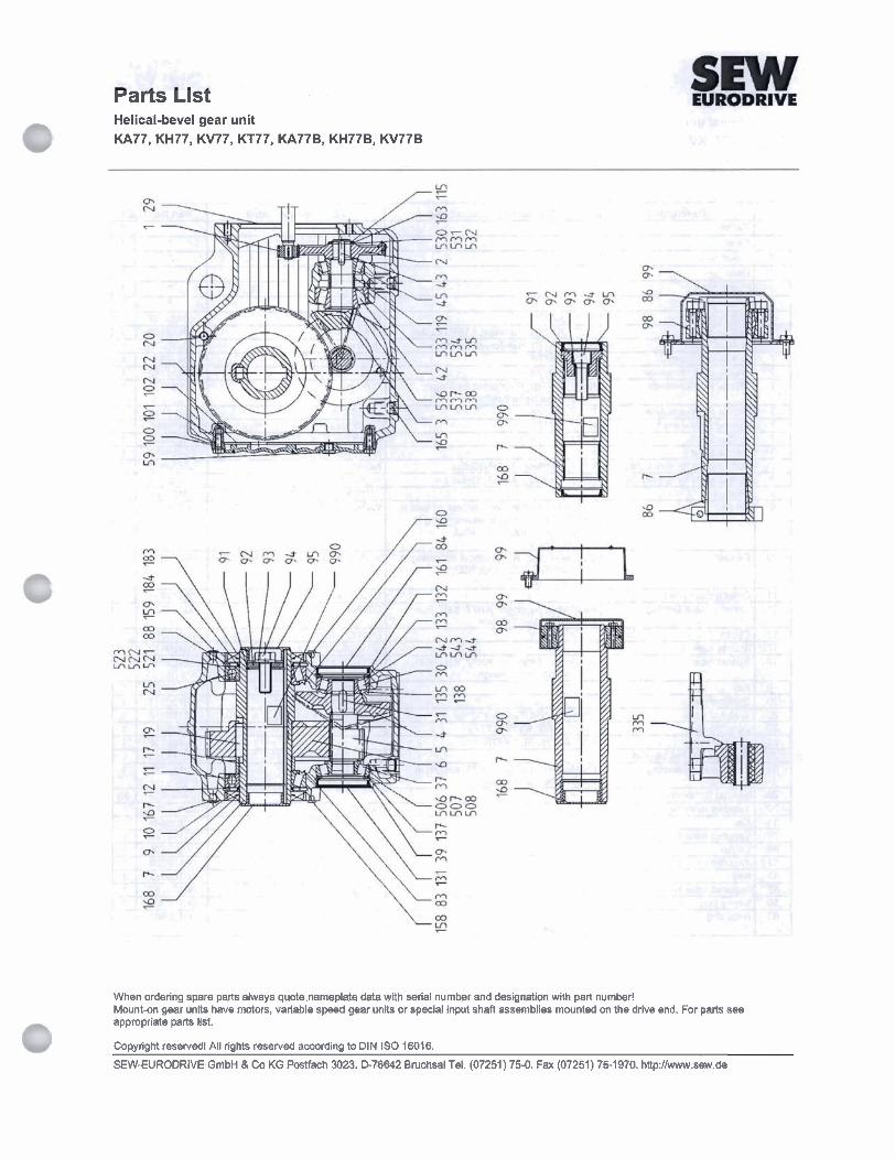
rarts ~ 1 s t Helical-bevel gear unit KA77, KH77, KV77, KT77, KA77B, KH77B, KV77B
When ordering spare parts always quote nameplate data with serial number and designation with part number! Mountan gear units have motors, variable speed gear units or special input shaft assemblies mounted on the drive end. For parts see appropriate parts list.
CopyrigM reservedl All rights reserved according to DIN IS0 16016.
SEW-EURODRIVE GmbH 8 Co KG Posffich m23. I375642 B~chsal Tel. (07251) 75-0. Fax (07251) 75-1970. http:/lwww.sew.de
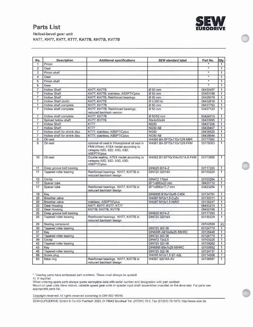
Parts List Helical-bevel gear unit KA77, KH77, KV77, KT77, KA776, KH77B, KV77B
Gearing parts have embossed part numbers. These must always be quoted! X) if required When ordering spare parts always quote nameplate data with serial number and designation with part number! Mount-on gear units have moton, variable speed gear units or special input shaft assemblies mounted on the drive end. For parts see appropriate parts list.
Copyright resewed! All rights resewed according to DIN IS0 16016.
SEW-EURODRIVE GmbH & Co KG Postfach 3023. D-76642 Bruchsal Tel. (07251) 750. Fax (07251) 751970. http://www.sew.de

Parts List Helical-bevel gear unit KA77, KH77, KV77, KT77, KA77B, KH776, KV77B
When ordering spare parts always quote nameplate data with serial number and designation with part number! Mountdn gear units have motors, variable speed gear units or special input shaft assemblies mounted on the drive end. For parts see appropriate parts list.
CopyrigM reserved! All rights reserved according to DIN IS0 16016.
SEW-EURODRIVE GmbH & Co KG Postfach 3023. a76642 Bruchsal Tel. (07251) 75-0. Fax (07251) 761970. http:lAww.sew.de

Parts List Helical-bevel gear unit KA77, KH77, KV77, KT77, KA77B, KH77B, KV77B
1 - - 1 EURODRIVE
M (Viton); ATEX model according to egory 112G. 1120, 113G, 1130;
G, 112D, 113G, 1130;
X) if required When ordering spare parts always quote nameplate data with serial number and Wination with part number! Mounton gear units have motors, variable speed gear units or special input shaft assemblies mounted on the drive end. For parts see appropriate parts list.
Copyright resewed! All rights reserved according to DIN IS0 16016.
SEWIURODRIVE GmbH & Co KG Postfach 3023. D-76642 Bruchsal Tel. (07251) 75-0. Fax (07251) 75-1970. http:llwww.sew.de

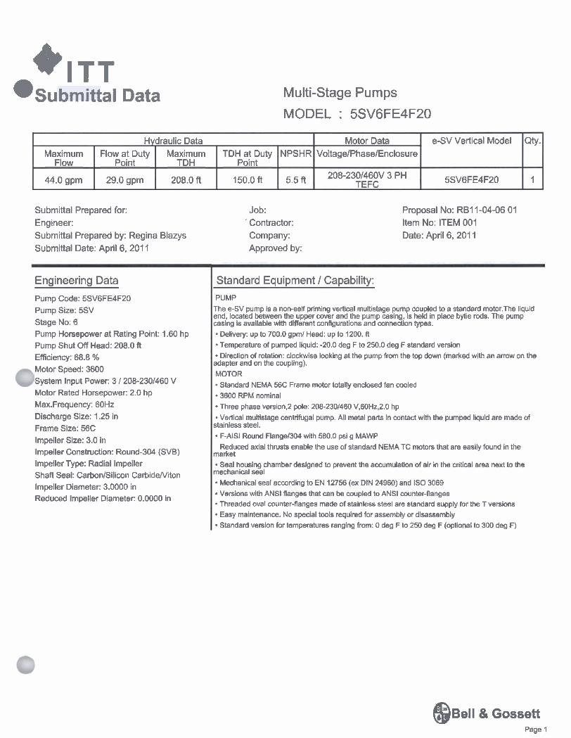
Proposal No: RB 1 1-04-06 0 1 Item No: ITEM 00 1
Series: e-SV Size: 5SV QTY: 1 Stage No: 6 Operating conditions SERVICE LIQUID CAPACIT Y 29.0 gpm HEAD 150.0 (f€)
Performance at 3 500 RPM PUBLISHED EFFY 68.8% (CDS) RATED EFFY 68.8% RATED POWER 1.60 hp (Run out 2.0 hp) NPSHR 5.5 f€ DISCHARGE PRESSURE 73.5 psi g (90.0 psi g @ Shut off) Based on 0.0 psi g Suc.press PERF. CURVE 5SV-3600-0 SHUT OFF HEAD 208.0 ft
Quoted Features
m E E t : E L L Round-304 (SVB) Carbon/Silicon CarbideNiton
Driver : Electric motor Manufacturer : Factory Choice FURNISHED BY MOUNTED BY RAT1 NG 2.0 hp (1.5 KW) ENCLOSURE TEFC PHASEIFREQNOLTS 3/60 W208-2301460 SPEED 3600 RPM INSULATIONISF FRAME 56C
April 6, 201 1
& Gossett Page 1
*ITT submi t ta l Data Multi-Stage Pumps
MODEL : 5SV6FE4F20
Submittal Prepared for: Engineer: Submittal Prepared by: Regina Blazys Submittal Date: April 6,201 1
Job: ' Contractor: Company: Approved by:
Proposal No: RBI 1-04-06 01 Item No: ITEM 001 Date: April 6, 201 1
e-SV Vertical Model
5SV6FE4F20
Motor Data VoltagelPhaselEnclosure
208-2301460V 3 PH TEFC
Hydraulic Data
-
Engineering Data
Pump Code: 5SV6FE4F20 Pump Size: 5SV Stage No: 6 Pump Horsepower at Rating Point: 1.60 hp Pump Shut Off Head: 208.0 ft Efficiency: 68.8 % Motor Speed: 3600 System Input Power: 3 / 208-2301460 V Motor Rated Horsepower: 2.0 hp Max.Frequency: 60Hz Discharge Size: 1.25 in Frame Size: 56C lmpeller Size: 3.0 in lmpeller Construction: Round304 (SVB) lmpeller Type: Radial lmpeller Shaft Seal: CarbonlSilicon CarbideNiton lmpeller Diameter: 3.0000 in Reduced lmpeller Diameter: 0.0000 in
Qty.
1
Standard Equipment / Capability:
Maximum Flow
44.0 gpm
PUMP
TDH at Duty Point
150.0 ft
The eSV pump is a non-self priming vertical multistage pump coupled to a standard motor.The liquid :nd, located between the upper cover and the pump casing, is held in place bytie rods. The pump asing is available with diierent configurations and connection types.
NPSHR
5.5 ft
Flow at Duty Point
29.0 gpm
Delivety: up to 700.0 gprnl Head: up to 1200. R
Maximum TDH
208.0 ft
Temperature of pumped liquid: -20.0 deg F to 250.0 deg F standard version Direction of rotation: clockwise looking at the pump from the top down (marked with an arrow on the
~dapter and on the coupling). MOTOR Standard NEMA 56C Frame motor totally enclosed fan cooled 3600 RPM nominal Three phase version,2 pole: 208-2301460 V,60Hz,2.0 hp Vertical multistage centrifugal pump. All metal parts in contact with the pumped liquid are made of
btainless steel. F-AISI Round Flange1304 with 580.0 psi g MAWP Reduced axial thrusts enable the use of standard NEMA TC motors that are easily found in the
narket Seal housing chamber designed to prevent the accumulation of air in the critical area next to the
nechanical seal Mechanical seal according to EN 12756 (ex DIN 24960) and IS0 3069 Versions with ANSl flanges that can be coupled to ANSl counter-flanges Threaded oval counter-flanges made of stainless steel are standard supply for the T versions Easy maintenance. No special tools required for assembly or disassembly Standard version for temperatures ranging from: 0 deg F to 250 deg F (optional to 300 deg F)
e ~ e l l & Gossett Page 1

*ITT @unit Dimensions Multi-Stage Pumps
MODEL : 5SV6FE4F20
Submittal Prepared for: Engineer: Submittal Prepared by: Regina Blazys Submittal Date: April 6,201 1
Job: Contractor: Company: Approved by:
Qty.
1
Proposal No: RBI 1-04-06 01 Item No: ITEM 001 Date: April 6, 201 1
Hydraulic Data
- 5 74-
T- -b-d 7.09 1: - -.- -ILI b.
I ' -3 - .
0.51 L- ' 3.94
3.88 B.C. 0.75-4 t HOLES
Motor Data VoltagelPhaselEnclosure
208-2301460V 3 PH TEFC
Maximum Flow
44.0 gpm
Dimensions are subject to change. Not to be used for construction purposes unless certified
e-SV Vertical Model
5SV6FE4F20
ell 8 Gossett Page 1
Flow at Duty Point
29.0 gpm
Maximum TDH
208.0 ft
TDH at Duty Point
150.0 ft
NPSHR
5.5 ft
fPerformance Data Multi-Stage Pumps
MODEL: 5SV6FE4F20
Hydraulic Data Motor Data e-SV Vertical Model Qty. Maximum Flow at Duty Maximum TDH at Duty NPSHR VoltagelPhaselEnclosure
Flow Point TDH Point
44.0 gpm 29.0 gpm 208.0 ft 150.0 ft 5.5 ft 5SV6FE4F20 1 208-2301460V 3 PH TEFC
Submittal Prepared for: Engineer: Submittal Prepared by: Regina Blazys Submittal Date: April 6, 201 1
Job: Contractor: Company: Approved by:
Proposal No: RBI 1-04-06 01 Item No: ITEM 001 Date: April 6, 201 1
ell 8 Gossett Page 1
Multi-Stage Pumps
MODEL: 5SV6FE4F20
Submittal Prepared for: Engineer: Submittal Prepared by: Regina Blazys Submittal Date: April 6,201 1
Job: Contractor: Company: Approved by:
Hydraulic Data
Proposal No: RB11-04-06 01 Item No: ITEM 001 Date: April 6, 201 1
Motor Data Voltage/Phase/Enclosure
208-2301460V 3 PH TEFC
Maximum Flow
44.0 gpm
- ..*.+t- d--
Bell & Gossett @ Page 1
e-SV Vertical Model
5SV6FE4F20
Flow at Duty Point
29.0 gpm
Qty.
1
Maximum TDH
208.0 ft
TDH at Duty Point
150.0 ft
NPSHR
5.5 ft

Power
1.5 I
1 -0.5
0.5
OO 5 10 15 20 25 30 35 40 45 glPm 0
Purchaser End User Item No. ITEM 001 Service
Certified By
o 2 i 6 a Capacity Q
Model e-SV Speed Variable
Liquid Nom. Temperature 70.0 deg F Spec. Gravity 1.000 Viscocity 1 .OOO cp Vapor Press Solids% I Size
Size 5SV Frequency 60Hz
Date 04/06/2011 Issued by: Regina Blazys Quotation No. RBI 1-04-06 01 Job/lnq.No. Order No.
Rated Operating Point
Capacity 29.0 gpm Head 150.0 ft NPSHa NPSHr 5.5 ft Rated Efficiency 68.8 % Suction Spec. Speed 5,069 gprn(US) rt
Notes:
Power - Pump 1.60 hp
Power - Others Power - Totals 1.60 hp Power - max. 2.0 hp
No. of Stages 6 Imp. Dia. 1st Stg: 17.9528 in Imp. Dia. Adl Stg: Min. Hydraulic Flow 7.0 gpm Min. Thermal Flow N/A
Model e-SV 1 Soeed Variable 1 sire ~ S V Freauencv 60Hz
I Certified Bv
)
Purchaser End User Item No. ITEM 001 Service
Liquid Nom. Temperature 70.0 deg F Spec. Gravity 1.000 Viscocity 1 .OOO cp Vapor Press Solids% I Size
0 2 4 6 8 Capacity Q
Date 04/06/2011 Issued by: Regina Blazys Quotation No. RBI 1-04-06 01 Job1lnq.No. Order No.
Rated Operating Point
Capacity 29.0 gpm Head 150.0 ft NPSHa NPSHr 5.5 ft Rated Efficiency 68.8 % Suction Spec. Speed 5,069 gpm(us) r
Notes:
Power - Pump 1.60 hp
Power - Others Power - Totals I .60 hp Power - max. 2.0 hp
No. of Stages 6 Imp. Dia. 1st Stg: 17.9528 in Imp. Dia. Adl Stg: Min. Hydraulic Flow 7.0 gpm Min. Thermal Flow NIA

A MEMBER OF THE ABB ROUP 1 *.'4$. .,
Product Information Packet
Copyright O All product information within this document is subject to Baldor Electric Company copyright O protection, unless otherwise noted.

a -Om RIUANCEB Product Information Packet: VM3555 - 2HP,3450RPM,3PH,60HZ,56C,3428MlTEFC,F1

-
-Om RELIANCEB Product Information Packet: VM3555 - ~ H P , ~ ~ ~ o R P M , ~ P H , ~ o H Z , ~ ~ C , ~ ~ ~ ~ M , T E F C , F ~
Page 3 of 10
34FN3002A01 SP 51XW1032A06 34CB4517 34GS1031A01 5 1 XW0832A07 HW2501 D13SP 34FH4002AOlSP HA7000A04 MG1000G27 1 OXF044OS02 HA3 1 00A45 LB5040 LB1125CO1
EXTERNAL FAN. PLASTIC. .637/.639 HUB Wl 10-32 X .38, TAPTITE II, HEX WSHR SLTD S CB LID 4 MTG HOLES .22 DIA STAMPED, FOR GASKET, FLAT CONDUIT BOX LID (LEXIDE) 8-32 X .44, TAPTITE II, HEX WSHR SLTD SE KEY, 311 6 SQ X 1.375 IEC FH NO GREASER KEY RETAINER 0.625 DIA SHAFTS PAINT- S9282E CHARCOAL GREY 04-40 X 118 TYPE F HEX HD STAINLESS STlC THRUBOLT 10-32 X 8.875 INSTRUCTION TAG, AC & DC STD (STOCK) CARTON LABEL BALDOR WITH FLA
1 .OOO EA 3.000 EA 1 .OOO EA 1 .OOO EA 4.000 EA 1 .OOO EA 1 .OOO EA 1 .OOO EA 0.014 GA 2.000 EA 4.000 EA 1 .OOO EA 1 .OOO EA

RELIANCEB Product Information Packet: VM3555 RPM,3PH,60HZ,56C,3428M,TEFC,FI
Parts List (continued)
Page 4 of 10
ParZ NumE LC0005EO NP1256L 34PA1005
De9cr, m CONN.DIA,MIARNING LABEL (LC00051LB1119) ALUM. UL CSA CC, WIO THERMAL, LASER PACKING GROUP. BALDOR
Quantity 1 .OOO EA 1 .OOO EA 1 .OOO EA

-OR RELIANCE@ Product Information Packet: VM3555 - 2HP.3450RPM.3PH.60HZ.56C.3428M.TEFC.FI
Performance Graph at 460V, 60Hz, 2.OHP Typical performance - Not guaranteed values
BALDOU ELECTRIC COMPANY WDlNC if 34WC0284 2HP 3W 60HZ 3450RPM 460Y 342BM
Tvpid pehmance -nor guanawd dues. T ( W ( ~ : P P l 2 PU=10.6 I.bl3.4 UU=20.8 l m c - - - - - - - - - - - - - - 1YI------
mQm ,QF QS-FIJ w W A ~ AM IIY- - - - - - - - - - - - Pi
1 0 0 ~
95
90:
85
80
75
70
65
60
55
50
45
40
R 4,000:
3,800:
3.600:
3,400
3,200:
3,000:
2.800
35
30
25
20
15
10
5
0
10.0:
: 9.5
9.0
: 8.5
: 8.0:
: 7.5:
: 7.0
: 6.5
: 6.0
: 5.5
: 5.0
: 4.5
:
1
:
-
3,600:
: 3,550:
: 3,500:
: 3,450:
3,400.-
3,350:
: 3,300:
: 3,250:
: 3,200:
: 3,150
: 3,100:
: 3,050:
Page 6 of 10
:
: 3.0:
: 2.5:
: 2.0
: 1.5:
: 1.0:
: 0.5
- 0.0-
2.600
2,400:
: 2,200
2,000:
1.800
:
:
: , .. . .. .. . . . . .. . . /.', . . . .. .
t C * a t 4 m l l - , & I U I
2,900
2,850
: 2,800:
2,750:
2,700:
: 2,650:
2,600:
: 1,200
: 1,000
800:
600:
400:
200:
0
:
:
-