Embed Size (px)
Citation preview
NOTICE OF CHANGE NOT MEASUREMENT SENSITIVEMIL-STD-188-198A
NOTICE 31 March 2001
DEPARTMENT OF DEFENSEINTERFACE STANDARD
JOINT PHOTOGRAPHIC EXPERTS GROUP (JPEG) IMAGE COMPRESSION FORTHE NATIONAL IMAGERY TRANSMISSION FORMAT STANDARD
TO ALL HOLDERS OF MIL-STD-188-198A:
1. THE FOLLOWING PAGES OF MIL-STD-188-198A HAVE BEEN REVISED AND SUPERSEDE THEPAGES LISTED:
NEW PAGE DATE SUPERSEDED PAGE DATECover 14 March 1997 Cover reprinted without change
ii 14 March 1997 ii - Of Notice 2 1 March 2001vi 14 March 1997 vi - Of Notice 2 1 March 20011 12 October 1994 1 - Of Notice 1 1 March 20013 12 October 1994 3 - Of Notice 1 1 March 2001
51 12 October 1994 51 - Of Notice 1 1 March 200152 12 October 1994 52 - Of Notice 1 1 March 200153 15 December 1993 53 1 March 200154 15 December 1993 54 reprinted without change55 15 December 1993 55 1 March 200156 15 December 1993 56 1 March 200157 15 December 1993 57 reprinted without change58 15 December 1993 58 1 March 200158a new page not applicable 1 March 200159 12 October 1994 59 - Of Notice 1 reprinted without change60 12 October 1994 60 - Of Notice 1 1 March 200160a 14 March 1997 60a - Of Notice 2 1 March 200160b 14 March 1997 60b - Of Notice 2 1 March 200161 14 March 1997 61 - Of Notice 2 1 March 2001
61b 14 March 1997 61b - Of Notice 2 1 March 2001DD 1426 14 March 1997 DD 1426 1 March 2001
2. RETAIN THIS NOTICE AND INSERT BEFORE TABLE OF CONTENTS.
3. Holders of MIL-STD-188-198A will verify that the page changes and additions indicated above have beenentered. This notice page will be retained as a check sheet. This issuance, together with appended pages, is aseparate publication. Each notice is to be retained by stocking points until the military standard is completelyrevised or canceled.
Custodians: Preparing Activity:Army – SC NIMA - MPNavy – OM (Project TCSS 0055)Air force –90
MISC – DC4
REPRINTED WITHOUT CHANGE
NOT MEASUREMENTSENSITIVE
MIL-STD-188-198A15 December 1992SUPERSEDINGMIL-STD-188-19818 June 1993
DEPARTMENT OF DEFENSEINTERFACE STANDARD
JOINT PHOTOGRAPHIC EXPERTS GROUP (JPEG) IMAGE COMPRESSIONFOR THE
NATIONAL IMAGERY TRANSMISSION FORMAT STANDARD
AMSC N/A AREA TCSS
MIL-STD-188-198ANOTICE 3
SUPERSEDES PAGE ii OF MIL-STD-188-198A, NOTICE 2.ii
FOREWORD
1. The National Imagery Transmission Format Standard (NITFS) is the standard for formatting digital imageryand imagery-related products and exchanging them among members of the Intelligence Community (IC), as definedby Executive Order 12333, and other departments and agencies of the United States Government, as governed byMemoranda of Agreement (MOA) with those departments and agencies.
2. The National Imagery Transmission Format Standard Technical Board (NTB) developed this standard basedupon currently available technical information.
3. The Department of Defense (DOD) and other members of the IC are committed to interoperability ofsystems used for formatting, transmitting, receiving, and processing imagery and imagery-related information. Thisstandard describes the Joint Photographic Experts Group (JPEG) compression algorithm and establishes itsapplication within the NITFS.
4. Beneficial comments (recommendations, additions, deletions) and other pertinent data which may be of usein improving this document should be addressed to the National Imagery and Mapping Agency (NIMA), 12310Sunrise Valley, Reston II Building, Mailstop P24, Reston, VA 20191-3449 by using the Standardization DocumentImprovement Proposal (DD Form 1426) appearing at the end of this document or by letter.
5. Portions of this document were reproduced from the Draft CCITT Recommendation T.81 (1992) with priorauthorization from the copyright holder, International Telecommunications Union (ITU). DOD takes soleresponsibility for the selection of portions from the ITU document for reproduction, with subsequent additionsor changes, which should not be attributed to the ITU. In 1994, Draft CCITT RecommendationT.81(1992) became the final international standards, ITU-T T.81(1994) and ISO/IEC 10918-1:1994.
MIL-STD-188-198ANOTICE 3
SUPERSEDES PAGE vi OF MIL-STD-188-198A, NOTICE 2.vi
CONTENTSPARAGRAPH PAGE5.2.2.4 Quantization tables ................................................................................... 395.2.2.4.1 Default quantization tables.......................................................................... 395.2.2.4.2 Custom quantization tables ......................................................................... 395.2.2.5 Entropy encoder/decoder ........................................................................... 395.2.2.5.1 Huffman coding ...................................................................................... 395.2.2.5.1.1 Coding models for Huffman coding............................................................... 395.2.2.5.1.2 Forming the DC symbol ............................................................................ 395.2.2.5.1.3 Encoding the DIFF value ........................................................................... 405.2.2.5.1.4 Forming the AC symbol ............................................................................ 425.2.2.5.1.5 Encoding the AC coefficient values ............................................................... 435.2.2.5.1.6 Huffman codes........................................................................................ 435.2.2.5.1.7 Huffman table generation ........................................................................... 435.2.2.5.1.8 Default BITS and HUFFVAL tables .............................................................. 445.2.2.5.1.9 Custom BITS and HUFFVAL tables.............................................................. 445.2.2.5.1.10 Building the Huffman coding tables............................................................... 445.2.2.5.1.11 Huffman encoding ................................................................................... 445.2.2.5.1.12 Huffman decoding ................................................................................... 445.2.2.5.2 Arithmetic coding .................................................................................... 465.2.3 Compressed data interchange format.............................................................. 465.2.3.1 Marker codes ......................................................................................... 465.2.3.2 Byte stuffing .......................................................................................... 475.2.3.3 Format of a JPEG compressed image within an NITF file .................................... 485.2.3.3.1 Single block JPEG compressed format ........................................................... 485.2.3.3.1.1 Single block image data format .................................................................... 485.2.3.3.1.2 Frame format ......................................................................................... 485.2.3.3.1.3 Scan format ........................................................................................... 485.2.3.3.1.4 Restart intervals ...................................................................................... 495.2.3.3.1.5 Byte alignment........................................................................................ 495.2.3.3.2 Multiple block JPEG compressed format......................................................... 495.2.3.3.2.1 Multiple block image data format (IMODE=B or P) .......................................... 515.2.3.3.2.2 Multiple block image data format (IMODE=S) ................................................ 515.2.3.3.3 JPEG Multispectral compressed format .......................................................... 515.2.3.3.3.1 Multispectral compressed format (IMODE=B) ................................................. 515.2.3.3.3.2 Multispectral compressed format (IMODE)=S) ................................................ 515.2.3.3.4 Frame header ......................................................................................... 515.2.3.3.5 Scan header ........................................................................................... 535.2.3.3.6 Table-specification and miscellaneous marker segments....................................... 555.2.3.3.6.1 Quantization table-specification .................................................................... 555.2.3.3.6.2 Huffman table-specification ........................................................................ 575.2.3.3.6.3 Restart interval definition ........................................................................... 585.2.3.3.6.4 Comment segment ................................................................................... 585.2.3.3.6.5 Application data segment ........................................................................... 595.2.3.3.6.5.1 NITF APP6 application data segment ............................................................. 595.2.3.3.6.5.2 NITF APP7 directory segments .................................................................... 615.2.3.3.6.5.3 NITF AAP6/(extension NITF0001) imge block minimum value ............................. 61a5.2.3.3.6.5.4 NITF APP6 (Extension NITF0002) Forward Error Correction (FEC) code ............... 61c5.2.4 Encoding procedure with marker codes .......................................................... 625.2.5 Decoding procedure with marker codes .......................................................... 625.2.5.1 Quantization tables ................................................................................... 625.2.5.2 Huffman tables ....................................................................................... 625.3 Progressive DCT-based JPEG mode .............................................................. 625.4 Hierarchical JPEG mode............................................................................ 62
MIL-STD-188-198ANOTICE 3
SUPERSEDED PAGE 1 OF MIL-STD-188-198A NOTICE 1
1
1. SCOPE
1.1 Scope. This standard establishes the requirements to be met by systems complying withNITFS when image data are compressed using the JPEG image compression algorithm as describedin DIS 10918-1, Digital Compression and Coding of Continuous-tone Still Images.
1.2 Content. This standard provides technical detail of the NITFS compression algorithmdesignated by the code C3 in the Image Compression field of the National Imagery TransmissionFormat (NITF) file image subheader, JPEG, for both eight- and 12-bit gray scale imagery and 24-bitcolor imagery. It also provides the required default quantization tables for use in Secondary ImageryDissemination Systems (SIDS) complying with NITFS.
1.3 Applicability. This standard is applicable to the Intelligence Community and the Departmentof Defense. It is mandatory for all Secondary Imagery Dissemination Systems in accordance withthe memorandum by the Assistant Secretary of Defense for Command, Control, Communications,and Intelligence ASD(C3I) Subject: National Imagery Transmission Format Standard (NITFS), 12August 1991. This standard shall be implemented in accordance with the National ImageryTransmission Format Standard (NITFS) Standards Compliance and Interoperability Test andEvaluation Program Plan (N-0105/98) and MIL-HDBK-1300. New equipment and systems, thoseundergoing major modification, or those capable of rehabilitation shall conform to this standard.
1.4 Tailoring task, method, or requirement specifications. The minimum compliancerequirements for implementation of this compression algorithm are defined in NITFS StandardsCompliance and Interoperability Test and Evaluation Program Plan (N-0105/98).
1.5 Types of operation. This standard establishes the requirements for the communication orstorage for interchange of image data in compressed form. Each type of operation defined by thisstandard consists of three parts:
a. The compressed data interchange format (which defines the image data field of theNITF file format).
b. The encoder.
c. The decoder.
MIL-STD-188-198ANOTICE 3
SUPERSEDED PAGE 3 OF MIL-STD-188-198A NOTICE 1
3
2. APPLICABLE DOCUMENTS
2.1 Government documents.
2.1.1 Specifications, standards, and handbooks. The following specifications, standards, andhandbooks form a part of this document to the extent specified herein. Unless otherwise specified,the issues of these documents are those listed in the issue of the Department of Defense Index ofSpecifications and Standards (DODISS) and supplements thereto, cited in the solicitation.
STANDARDS
FEDERAL
FED-STD-1037B - Telecommunications: Glossary ofTelecommunication Terms, 3 June 1991.
MILITARY
MIL-STD-2500 - National Imagery Transmission Format(NITF) for the National Imagery TransmissionFormat Standard (NITFS).
HANDBOOKS
MIL-HDBK-1300 - National Imagery Transmission FormatStandard (NITFS).
(Unless otherwise indicated, copies of federal and military specifications, standards, andhandbooks are available from the Standardization Documents Order Desk, 700 Robbins Avenue,Building #4, Section D, Philadelphia, PA 19111-5094.)
2.1.2 Other Government documents, drawings, and publications. The following otherGovernment documents form a part of this document to the extent specified herein. Unless otherwisespecified, the issues of these documents are those cited in the solicitation.
NITFS Standards Complianceand Interoperability Test and - NITFS Certification Test and EvaluationEvaluation Program Plan (N-0105/98) Program Plan
(Copies of NITFS Standards Compliance and Interoperability Test and Evaluation Program Plan (N-0105/98) may be obtained from DISA/JIEO/JITC/TCBD, Fort Huachuca, AZ 85613-7020.)
MIL-STD-188-198ANOTICE 3
SUPERSEDED PAGE 51 OF MIL-STD-188-198A NOTICE 151
5.2.3.3.2.1 Multiple block image data format (IMODE=B or P). The top level of figure 20 specifies that theJPEG compressed data is contained in the Image Data Field of the NITF file. The second level of figure 20 specifiesthat this multiple block image format shall begin with the compressed data for the first image block and shall befollowed by the compressed data for each image block, one after the other, left to right, top to bottom. The thirdlevel of figure 20 specifies that each compressed block shall begin with an SOI marker, shall contain one frame, andshall end with an EOI marker. The format below this level is identical to the single block case previously describedin 5.2.3.3.1.
5.2.3.3.2.2 Multiple block image data format (IMODE=S). The use of this IMODE requires that the imagecontain multiple blocks and multiple bands, otherwise IMODE shall be set to B or P. The top level of figure 21specifies that the JPEG compressed data is contained in the Image Data Field of the NITF file. The second level offigure 21 specifies that this multiple block image format shall begin with the compressed data for the first imageband and shall be followed by the compressed data for each image band, one after the other, first to last. The thirdlevel of figure 21 specifies that each compressed image band shall consist of the compressed data (for that band) foreach image block, one after the other, left to right, top to bottom. The fourth level of figure 21 specifies that eachcompressed block shall begin with an SOI marker, shall contain one frame, and shall end with an EOI marker. Theformat below this level is identical to the single block case previously described in 5.2.3.3.1 with each framecontaining only one scan that contains the compressed data from only one band.
5.2.3.3.3 JPEG Multispectral compressed format. Multispectral image data may be compressed as eitherIMODE B or S. Consideration must be given to the number of components each IMODE will allow and how toidentify these components in the Frame and Scan headers.
5.2.3.3.3.1 Multispectral compressed format (IMODE=B). The JPEG format has a limit of 255 componentswhen compressing multi component imagery with IMODE=B, for both single block and multiple block cases.Components shall be identified by the values placed in the “component number” and matching “Scan componentselector” fields. This value shall start at zero (0x00) and increase monotonically to 254 (0xFE). These fields arecontained in the Frame header and Scan header. Their format is shown in tables IV and VI respectively.
5.2.3.3.3.2 Multispectral compressed format (IMODE=S). The JPEG format has no upper limit with regard tothe number of components that can be compressed with IMODE=S. Components shall be identified by the valuesplaced in the “component number” and matching “Scan component selector” fields. NITF implementations mayidentify compressed components with any number (0x00 through 0xFF). Implementations may also numbercompressed components in any order, as long as the order of the compressed components matches the order of thecomponents found in the source image. Implementations may also identify components using the sameidentification number. For example, all of the compressed components could be identified with the number 0x01.Despite the free use of the component identification fields, implementations are strongly encouraged tomonotonically number the compressed components, starting with 0x00. If the number of components exceeds 256,the identification value should roll over to 0x00 and start the sequence again.
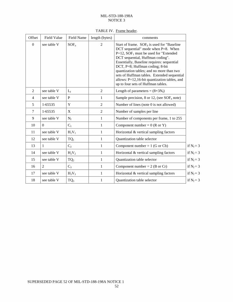
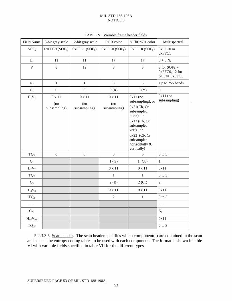
5.2.3.3.4 Frame header. The frame header specifies the source image characteristics, the components in theframe, the sampling factors for each component, and selects the quantization table to be used with each component.The format is shown in table IV with variable fields specified in table V for the different image types.
MIL-STD-188-198ANOTICE 3
SUPERSEDED PAGE 52 OF MIL-STD-188-198A NOTICE 152
TABLE IV. Frame header.
Offset Field Value Field Name length (bytes) comments
0 see table V SOFn 2 Start of frame. SOF0 is used for "BaselineDCT sequential" mode when P=8. WhenP=12, SOF1 must be used for "ExtendedDCT sequential, Huffman coding".Essentially, Baseline requires: sequentialDCT, P=8; Huffman coding; 8-bitquantization tables; and no more than twosets of Huffman tables. Extended sequentialallows: P=12,16-bit quantization tables, andup to four sets of Huffman tables.
2 see table V Lf 2 Length of parameters = (8+3Nf)
4 see table V P 1 Sample precision, 8 or 12, (see SOFn note)
5 1-65535 Y 2 Number of lines (note 0 is not allowed)
7 1-65535 X 2 Number of samples per line
9 see table V Nf 1 Number of components per frame, 1 to 255
10 0 C1 1 Component number = 0 (R or Y)
11 see table V H1V1 1 Horizontal & vertical sampling factors
12 see table V TQ1 1 Quantization table selector
13 1 C2 1 Component number = 1 (G or Cb) if Nf = 3
14 see table V H2V2 1 Horizontal & vertical sampling factors if Nf = 3
15 see table V TQ2 1 Quantization table selector if Nf = 3
16 2 C3 1 Component number = 2 (B or Cr) if Nf = 3
17 see table V H3V3 1 Horizontal & vertical sampling factors if Nf = 3
18 see table V TQ3 1 Quantization table selector if Nf = 3
MIL-STD-188-198ANOTICE 3
SUPERSEDED PAGE 53 OF MIL-STD-188-198A53
TABLE V. Variable frame header fields.
Field Name 8-bit gray scale 12-bit gray scale RGB color YCbCr601 color Multispectral
SOFa 0xFFC0 (SOF0) 0xFFC1 (SOF1) 0xFFC0 (SOF0) 0xFFC0 (SOF0) 0xFFC0 or0xFFC1
Lf 11 11 17 17 8 + 3 Nf
P 8 12 8 8 8 for SOFa =0xFFC0, 12 forSOFa= 0xFFC1
Nf 1 1 3 3 Up to 255 bands
C1 0 0 0 (R) 0 (Y) 0
H1V1 0 x 11
(nosubsampling)
0 x 11
(nosubsampling)
0 x 11
(nosubsampling)
0x11 (nosubsampling), or0x21(Cb, Crsubsampledhoriz), or0x12 (Cb, Crsubsampledvert)., or0x22 (Cb, Crsubsampledhorizontally &vertically)
0x11 (nosubsampling) .
TQ1 0 0 0 0 0 to 3
C2 1 (G) 1 (Cb) 1
H2V2 0 x 11 0 x 11 0x11
TQ2 1 1 0 to 3
C3 2 (B) 2 (Cr) 2
H3V3 0 x 11 0 x 11 0x11
TQ3 2 1 0 to 3
. . . . . .
CNf Nf
HNfVNf 0x11
TQNf 0 to 3
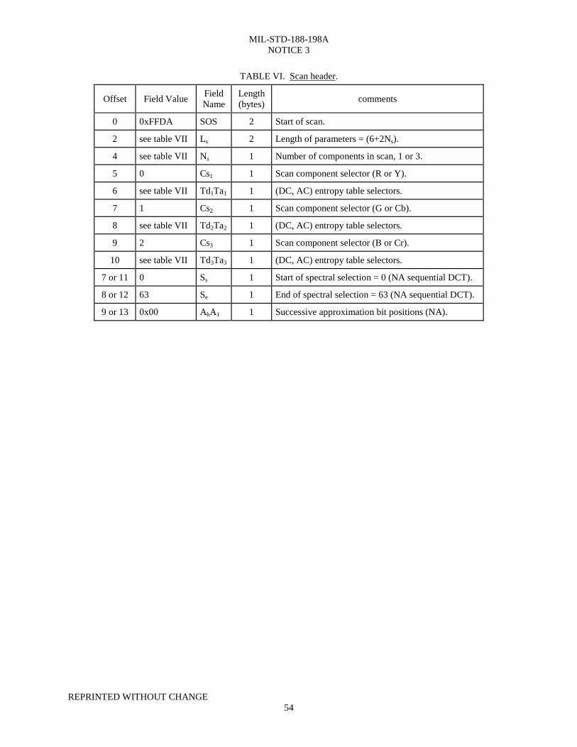
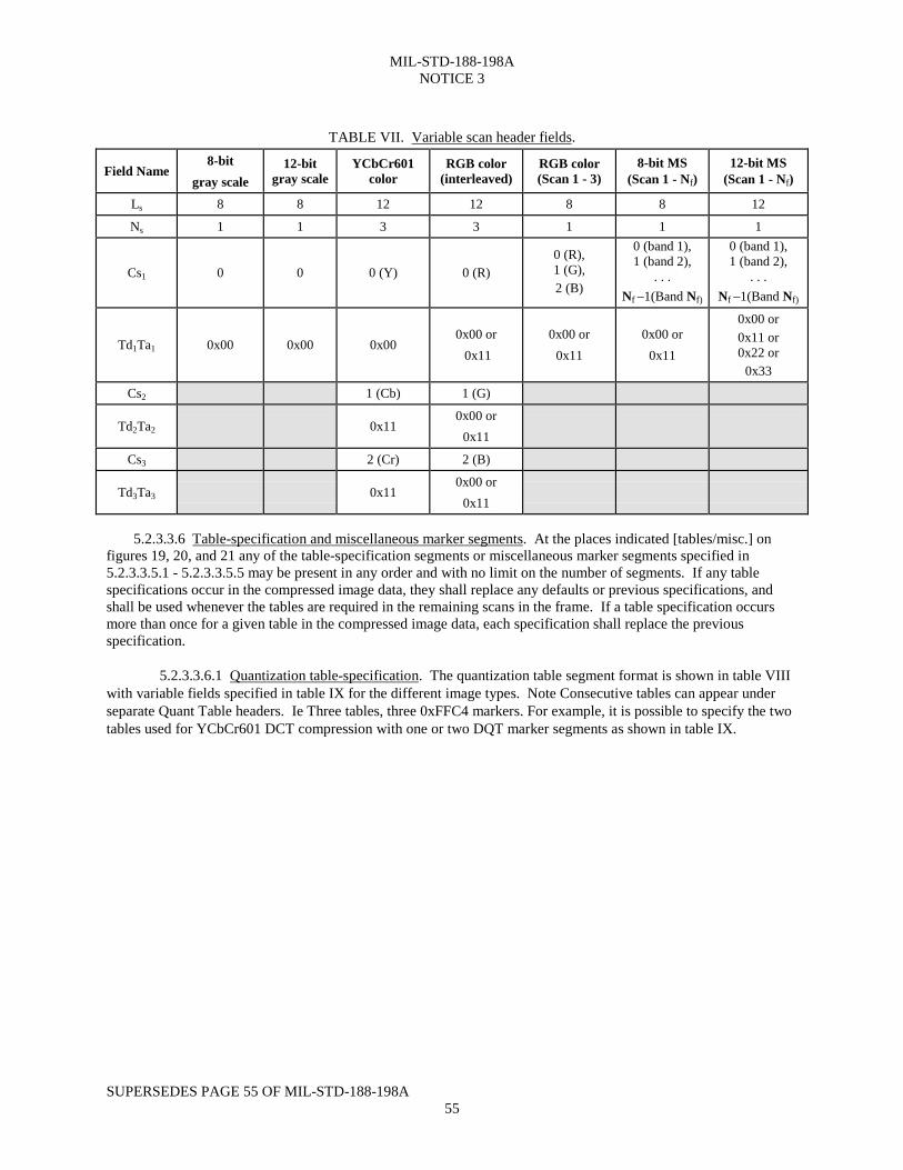
5.2.3.3.5 Scan header. The scan header specifies which component(s) are contained in the scanand selects the entropy coding tables to be used with each component. The format is shown in tableVI with variable fields specified in table VII for the different types.
MIL-STD-188-198ANOTICE 3
REPRINTED WITHOUT CHANGE54
TABLE VI. Scan header.
Offset Field Value FieldName
Length(bytes) comments
0 0xFFDA SOS 2 Start of scan.
2 see table VII Ls 2 Length of parameters = (6+2Ns).
4 see table VII Ns 1 Number of components in scan, 1 or 3.
5 0 Cs1 1 Scan component selector (R or Y).
6 see table VII Td1Ta1 1 (DC, AC) entropy table selectors.
7 1 Cs2 1 Scan component selector (G or Cb).
8 see table VII Td2Ta2 1 (DC, AC) entropy table selectors.
9 2 Cs3 1 Scan component selector (B or Cr).
10 see table VII Td3Ta3 1 (DC, AC) entropy table selectors.
7 or 11 0 Ss 1 Start of spectral selection = 0 (NA sequential DCT).
8 or 12 63 Se 1 End of spectral selection = 63 (NA sequential DCT).
9 or 13 0x00 AhA1 1 Successive approximation bit positions (NA).
MIL-STD-188-198ANOTICE 3
SUPERSEDES PAGE 55 OF MIL-STD-188-198A55
TABLE VII. Variable scan header fields.
Field Name8-bit
gray scale12-bit
gray scaleYCbCr601
colorRGB color
(interleaved)RGB color(Scan 1 - 3)
8-bit MS(Scan 1 - Nf)
12-bit MS(Scan 1 - Nf)
Ls 8 8 12 12 8 8 12
Ns 1 1 3 3 1 1 1
Cs1 0 0 0 (Y) 0 (R)0 (R),1 (G),2 (B)
0 (band 1),1 (band 2),
. . .Nf –1(Band Nf)
0 (band 1),1 (band 2),
. . .Nf –1(Band Nf)
Td1Ta1 0x00 0x00 0x000x00 or 0x11
0x00 or0x11
0x00 or0x11
0x00 or0x11 or0x22 or
0x33
Cs2 1 (Cb) 1 (G)
Td2Ta2 0x110x00 or
0x11
Cs3 2 (Cr) 2 (B)
Td3Ta3 0x110x00 or
0x11
5.2.3.3.6 Table-specification and miscellaneous marker segments. At the places indicated [tables/misc.] onfigures 19, 20, and 21 any of the table-specification segments or miscellaneous marker segments specified in5.2.3.3.5.1 - 5.2.3.3.5.5 may be present in any order and with no limit on the number of segments. If any tablespecifications occur in the compressed image data, they shall replace any defaults or previous specifications, andshall be used whenever the tables are required in the remaining scans in the frame. If a table specification occursmore than once for a given table in the compressed image data, each specification shall replace the previousspecification.
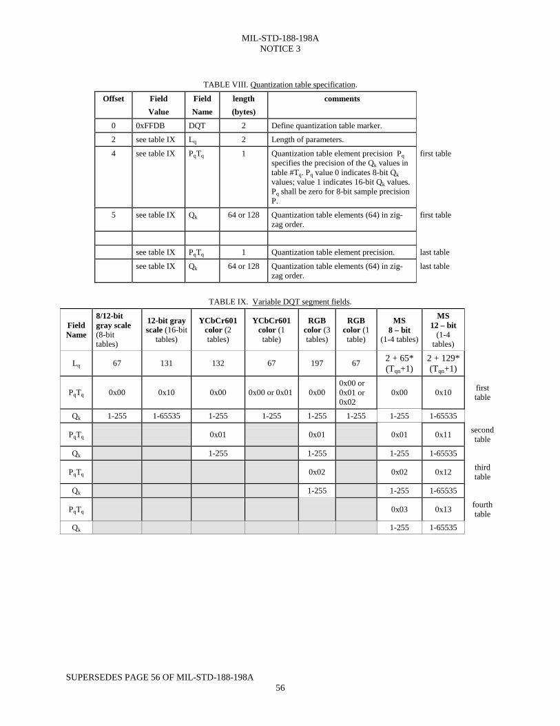
5.2.3.3.6.1 Quantization table-specification. The quantization table segment format is shown in table VIIIwith variable fields specified in table IX for the different image types. Note Consecutive tables can appear underseparate Quant Table headers. Ie Three tables, three 0xFFC4 markers. For example, it is possible to specify the twotables used for YCbCr601 DCT compression with one or two DQT marker segments as shown in table IX.
MIL-STD-188-198ANOTICE 3
SUPERSEDES PAGE 56 OF MIL-STD-188-198A56
TABLE VIII. Quantization table specification.
Offset FieldValue
FieldName
length(bytes)
comments
0 0xFFDB DQT 2 Define quantization table marker.
2 see table IX Lq 2 Length of parameters.
4 see table IX PqTq 1 Quantization table element precision Pqspecifies the precision of the Qk values intable #Tq. Pq value 0 indicates 8-bit Qkvalues; value 1 indicates 16-bit Qk values.Pq shall be zero for 8-bit sample precisionP.
first table
5 see table IX Qk 64 or 128 Quantization table elements (64) in zig-zag order.
first table
see table IX PqTq 1 Quantization table element precision. last table
see table IX Qk 64 or 128 Quantization table elements (64) in zig-zag order.
last table
TABLE IX. Variable DQT segment fields.
FieldName
8/12-bitgray scale(8-bittables)
12-bit grayscale (16-bit
tables)
YCbCr601color (2tables)
YCbCr601color (1table)
RGBcolor (3tables)
RGBcolor (1table)
MS8 – bit
(1-4 tables)
MS12 – bit
(1-4tables)
Lq 67 131 132 67 197 67 2 + 65*(Tqn+1)
2 + 129*(Tqn+1)
PqTq 0x00 0x10 0x00 0x00 or 0x01 0x000x00 or0x01 or0x02
0x00 0x10 firsttable
Qk 1-255 1-65535 1-255 1-255 1-255 1-255 1-255 1-65535
PqTq 0x01 0x01 0x01 0x11 secondtable
Qk 1-255 1-255 1-255 1-65535
PqTq 0x02 0x02 0x12 thirdtable
Qk 1-255 1-255 1-65535
PqTq 0x03 0x13 fourthtable
Qk 1-255 1-65535
MIL-STD-188-198ANOTICE 3
SUPERSEDES PAGE 57 OF MIL-STD-188-198A57
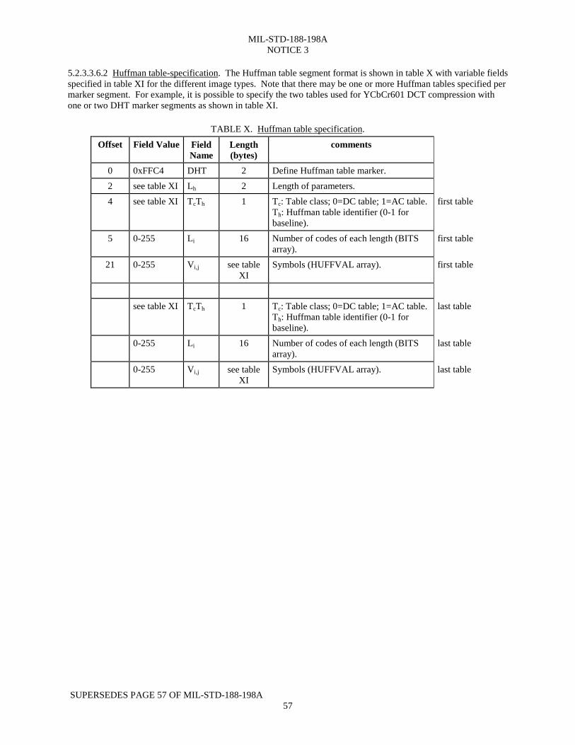
5.2.3.3.6.2 Huffman table-specification. The Huffman table segment format is shown in table X with variable fieldsspecified in table XI for the different image types. Note that there may be one or more Huffman tables specified permarker segment. For example, it is possible to specify the two tables used for YCbCr601 DCT compression withone or two DHT marker segments as shown in table XI.
TABLE X. Huffman table specification.
Offset Field Value FieldName
Length(bytes)
comments
0 0xFFC4 DHT 2 Define Huffman table marker.2 see table XI Lh 2 Length of parameters.4 see table XI TcTh 1 Tc: Table class; 0=DC table; 1=AC table.
Th: Huffman table identifier (0-1 forbaseline).
first table
5 0-255 Li 16 Number of codes of each length (BITSarray).
first table
21 0-255 Vi,j see tableXI
Symbols (HUFFVAL array). first table
see table XI TcTh 1 Tc: Table class; 0=DC table; 1=AC table.Th: Huffman table identifier (0-1 forbaseline).
last table
0-255 Li 16 Number of codes of each length (BITSarray).
last table
0-255 Vi,j see tableXI
Symbols (HUFFVAL array). last table
MIL-STD-188-198ANOTICE 3
NEW PAGE58
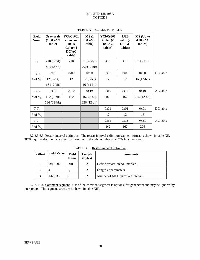
TABLE XI. Variable DHT fields.
FieldName
Gray scale(1 DC/AC
table)
YCbCr601color or
RGBColor (1DC/ACtable)
MS (1DC/ACtable)
YCbCr601Color (2DC/ACtables)
RGBcolor (2DC/ACtables)
MS (Up to4 DC/AC
tables)
Lh 210 (8-bit)
278(12-bit)
210 210 (8-bit)
278(12-bit)
418 418 Up to 1106
TcTh 0x00 0x00 0x00 0x00 0x00 0x00 DC table
# of Vi,j 12 (8-bit)
16 (12-bit)
12 12 (8-bit)
16 (12-bit)
12 12 16 (12-bit)
TcTh 0x10 0x10 0x10 0x10 0x10 0x10 AC table
# of Vi,j 162 (8-bit)
226 (12-bit)
162 162 (8-bit)
226 (12-bit)
162 162 226 (12-bit)
TcTh 0x01 0x01 0x01 DC table
# of Vi,j 12 12 16
TcTh 0x11 0x11 0x11 AC table
# of Vi,j 162 162 226
5.2.3.3.6.3 Restart interval definition. The restart interval definition segment format is shown in table XII.NITF requires that the restart interval be no more than the number of MCUs in a block-row.
TABLE XII. Restart interval definition.
Offset Field Value FieldName
Length(bytes)
comments
0 0xFFDD DRI 2 Define restart interval marker.
2 4 Lr 2 Length of parameters.
4 1-65535 Ri 2 Number of MCU in restart interval.
5.2.3.3.6.4 Comment segment. Use of the comment segment is optional for generators and may be ignored byinterpreters. The segment structure is shown in table XIII.
MIL-STD-188-198ANOTICE 3
NEW PAGE58a
This Page Intentially Left Blank
MIL-STD-188-198ANOTICE 3
SUPERSEDES PAGE 59 OF MIL-STD-188-198A NOTICE 159
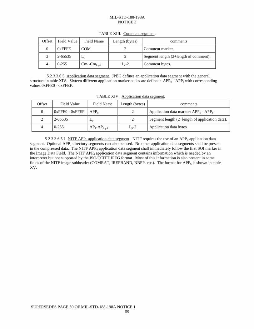
TABLE XIII. Comment segment.
Offset Field Value Field Name Length (bytes) comments
0 0xFFFE COM 2 Comment marker.
2 2-65535 Lc 2 Segment length (2+length of comment).
4 0-255 Cm1-CmLc-2 Lc-2 Comment bytes.
5.2.3.3.6.5 Application data segment. JPEG defines an application data segment with the generalstructure in table XIV. Sixteen different application marker codes are defined: APP0 - APPf with correspondingvalues 0xFFE0 - 0xFFEF.
TABLE XIV. Application data segment.
Offset Field Value Field Name Length (bytes) comments
0 0xFFE0 - 0xFFEF APPn 2 Application data marker: APP0 - APPF.
2 2-65535 Lp 2 Segment length (2+length of application data).
4 0-255 AP1-APLp-2 Lp-2 Application data bytes.
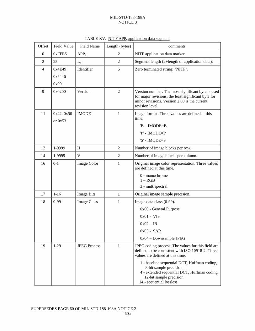
5.2.3.3.6.5.1 NITF APP6 application data segment. NITF requires the use of an APP6 application datasegment. Optional APP7 directory segments can also be used. No other application data segments shall be presentin the compressed data. The NITF APP6 application data segment shall immediately follow the first SOI marker inthe Image Data Field. The NITF APP6 application data segment contains information which is needed by aninterpreter but not supported by the ISO/CCITT JPEG format. Most of this information is also present in somefields of the NITF image subheader (COMRAT, IREPBAND, NBPP, etc.). The format for APP6 is shown in tableXV.
MIL-STD-188-198ANOTICE 3
SUPERSEDES PAGE 60 OF MIL-STD-188-198A NOTICE 260a
TABLE XV. NITF APP6 application data segment.
Offset Field Value Field Name Length (bytes) comments
0 0xFFE6 APP6 2 NITF application data marker.
2 25 Lp 2 Segment length (2+length of application data).
4 0x4E49
0x5446
0x00
Identifier 5 Zero terminated string: "NITF".
9 0x0200 Version 2 Version number. The most significant byte is usedfor major revisions, the least significant byte forminor revisions. Version 2.00 is the currentrevision level.
11 0x42, 0x50
or 0x53
IMODE 1 Image format. Three values are defined at thistime.
'B' - IMODE=B
'P' - IMODE=P
'S' - IMODE=S
12 1-9999 H 2 Number of image blocks per row.
14 1-9999 V 2 Number of image blocks per column.
16 0-1 Image Color 1 Original image color representation. Three valuesare defined at this time.
0 - monochrome 1 – RGB 3 - multispectral
17 1-16 Image Bits 1 Original image sample precision.
18 0-99 Image Class 1 Image data class (0-99).
0x00 - General Purpose
0x01 - VIS
0x02 - IR
0x03 - SAR
0x04 – Downsample JPEG
19 1-29 JPEG Process 1 JPEG coding process. The values for this field aredefined to be consistent with ISO 10918-2. Threevalues are defined at this time.
1 - baseline sequential DCT, Huffman coding, 8-bit sample precision 4 - extended sequential DCT, Huffman coding, 12-bit sample precision 14 - sequential lossless
MIL-STD-188-198ANOTICE 3
SUPERSEDES PAGE 60 OF MIL-STD-188-198A NOTICE 260b
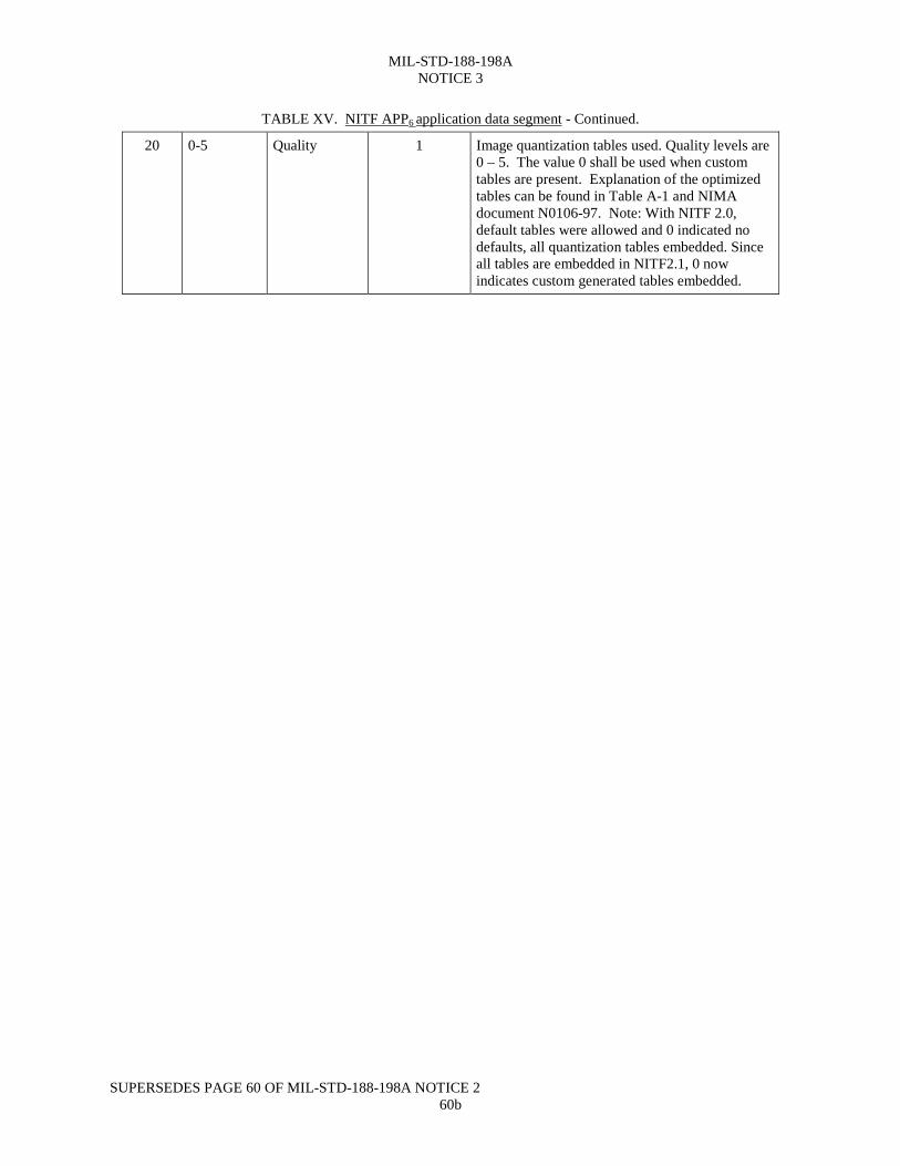
TABLE XV. NITF APP6 application data segment - Continued.
20 0-5 Quality 1 Image quantization tables used. Quality levels are0 – 5. The value 0 shall be used when customtables are present. Explanation of the optimizedtables can be found in Table A-1 and NIMAdocument N0106-97. Note: With NITF 2.0,default tables were allowed and 0 indicated nodefaults, all quantization tables embedded. Sinceall tables are embedded in NITF2.1, 0 nowindicates custom generated tables embedded.
MIL-STD-188-198ANOTICE 3
SUPERSEDES PAGE 61OF MIL-STD-188-198A NOTICE 261
TABLE XV. NITF APP6 application data segment - Continued.Offset Field Value Field Name Length (bytes) comments
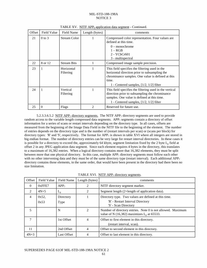
21 0 to 3 Stream Color 1 Compressed color representation. Four values aredefined at this time. 0 – monochrome 1 – RGB 2 - YCbCr601 3 - multispectral
22 8 or 12 Stream Bits 1 Compressed image sample precision.23 1 Horizontal
Filtering1 This field specifies the filtering used in the
horizontal direction prior to subsampling thechrominance samples. One value is defined at thistime. 1 - Centered samples, [1/2, 1/2] filter
24 1 VerticalFiltering
1 This field specifies the filtering used in the verticaldirection prior to subsampling the chrominancesamples. One value is defined at this time. 1 - Centered samples, [1/2, 1/2] filter
25 0 Flags 2 Reserved for future use.
5.2.3.3.6.5.2 NITF APP7 directory segments. The NITF APP7 directory segments are used to providerandom access to the variable length compressed data segments. APP7 segments contain a directory of offsetinformation for a series of scans or restart intervals depending on the directory type. In all cases, offsets aremeasured from the beginning of the Image Data Field in the NITF file to the beginning of the element. The numberof entries depends on the directory type and is the number of (restart intervals per scan) or (scans per block) fordirectory types: 'R' and 'S', respectively. The format for APP7 is shown in table XVI where all integers are stored inbig endian format. The number of directory entries can be very large for restart interval directories. In these cases itis possible for a directory to exceed the, approximately 64 kbyte, segment limitation fixed by the 2 byte Lp field atoffset 2 in any JPEG application data segment. Since each element requires 4 bytes in the directory, this translatesto a maximum of 16,382 entries. When a logical directory contains more that 16,382 elements, they must be splitbetween more that one physical directory. In this case, multiple APP7 directory segments must follow each otherwith no other intervening data and they must be of the same directory type (restart interval). Each additional APP7directory contains those elements, in the same order, that would have been present in the directory had there been nosize limitation.
TABLE XVI. NITF APP7 directory segments.Offset Field Value Field Name Length (bytes) comments
0 0xFFE7 APP7 2 NITF directory segment marker.
2 4N+5 Lp 2 Segment length (2+length of application data).4 0x52,
0x53DirectoryType
1 Directory type. Two values are defined at this time. 'R' - Restart Interval Directory 'S' - Scan Directory
5 N 2 Number of directory entries. Note 0 is not allowed. Maximumvalue of N (16,382) maximizes Lp at 65533.
7 1st Offset 4 Offset to first element in this directory. (restart interval, scan).
11 2nd Offset 4 Offset to second element in this directory.4N+3 Last Offset 4 Offset to last element in this directory.
MIL-STD-188-198ANOTICE 3
SUPERCEDES PAGE 61b of MIL-STD-188-198A NOTICE 2
61b
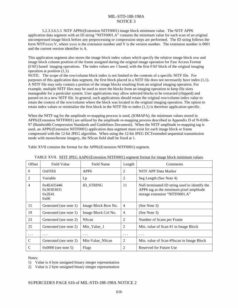
5.2.3.3.6.5.3 NITF APP6/(Extension NITF0001) image block minimum value. The NITF APP6application data segment with an ID string “NITF0001.A” contains the minimum value for each scan of an originaluncompressed image block before any preprocessing or compression steps are performed. The ID string follows theform NITFxxxx.V, where xxxx is the extension number and V is the version number. The extension number is 0001and the current version identifier is A.
This application segment also stores the image block index values which specify the relative image block row andimage block column position of the frame assigned during the original image operation for Fast Access Format(FAF) based imaging operations. The index values are 1 based, with the first FAF block of the original imagingoperation at position (1,1).NOTE: The scope of the row/column block index is not limited to the contents of a specific NITF file. Forpurposes of this application data segment, the first block placed in a NITF file does not necessarily have index (1,1).A NITF file may only contain a portion of the image blocks resulting from an original imaging operation. Forexample, multiple NITF files may be used to store the blocks from an imaging operation to keep file sizesmanageable for a particular system. User applications may allow selected blocks to be extracted (chipped) andpassed on in a new NITF file. In general, such applications should retain the original row/column index value toretain the context of the row/column where the block was located in the original imaging operation. The option toretain index values or reinitialize the first block in the NITF file to index (1,1) is therefore application specific.
When the NITF tag for the amplitude re-mapping process is used, (IOMAPA), the minimum values stored inAPP6/(Extension NITF0001) are utilized by the amplitude re-mapping process described in Appendix D of N-0106-97 (Bandwidth Compression Standards and Guidelines Document). When the NITF amplitude re-mapping tag isused, an APP6/(Extension NITF0001) application data segment must exist for each image block or framecompressed with the 12-bit JPEG algorithm. When using the 12-bit JPEG DCTextended sequential transmissionmode with monochrome imagery, the NScan field shall be fixed at 1.
Table XVII contains the format for the APP6/(Extension NITF0001) segment.
TABLE XVII. NITF JPEG AAP6/(Extension NITF0001) segment format for image block minimum values.
Offset Field Value Field Name Length Comments
0 OxFFE6 APP6 2 NITF APP Data Marker
2 Variable Lp 2 Seg Length (See Note 4)
4 0x4E4354460x303030310x2E410x00
ID_STRING 11 Null terminated ID string used to identify theAPP6 tag as the minimum pixel amplitudestorage extension “NITF0001.A”
15 Generated (see note 1) Image Block Row No. 4 (See Note 3)
19 Generated (see note 1) Image Block Col No. 4 (See Note 3)
23 Generated (see note 2) NScan 2 Number of Scans per Frame
25 Generated (see note 2) Min_Value_1 2 Min. value of Scan #1 in Image Block
. . . . . . . . . . . . . . .
C Generated (see note 2) Min-Value_NScan 2 Min. value of Scan #Nscan in Image Block
C 0x0000 (see note 5) Flags 2 Reserved for Future Use
Notes:1) Value is 4 byte unsigned binary integer representation2) Value is 2 byte unsigned binary integer representation
MIL-STD-188-198ANOTICE 3
SUPERCEDES PAGE 61c OF MIL-STD-188-198A NOTICE 261c
3) Image block index relative to the transmitted image. The top left image block is indexed (row, column) - >(1,1)
4) Length Lp = 25 + (2*NScan)5) The offset label of C is used for the conditional offsets dependent on the value of the NScan field.
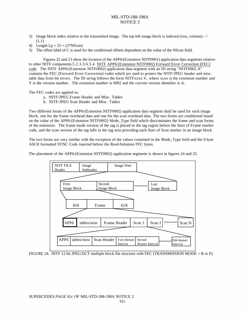
Figures 22 and 23 show the location of the APP6/(Extension NITF0001) application data segments relativeto other NITF components.5.2.3.3.6.5.4 NITF APP6/(Extension NITF0002) Forward Error Correction (FEC)code. The NITF APP6/(Extension NITF0002) application data segment with an ID string "NITF0002.A"contains the FEC (Forward Error Correction) codes which are used to protect the NITF/JPEG header and misc.table data from bit errors. The ID string follows the form NITFxxxx.V, where xxxx is the extension number andV is the version number. The extension number is 0002 and the current version identifier is A.
The FEC codes are applied to:a. NITF/JPEG Frame Header and Misc. Tablesb. NITF/JPEG Scan Header and Misc. Tables
Two different forms of the APP6/(Extension NITF0002) application data segment shall be used for each imageblock, one for the frame overhead data and one for the scan overhead data. The two forms are conditional basedon the value of the APP6/(Extension NITF0002) Mode_Type field which discriminates the frame and scan formsof the extension. The frame mode version of the tag is placed in the tag region before the Start of Frame markercode, and the scan version of the tag falls in the tag area preceding each Start of Scan marker in an image block.
The two forms are very similar with the exception of the values contained in the Mode_Type field and the 8 byteASCII formatted SYNC Code inserted before the Reed-Solomon FEC bytes.
The placement of the APP6/(Extension NITF0002) application segments is shown in figures 24 and 25.
APP6 tables/misc Frame Header Scan 1 Scan 2 Scan N
Nth RestartInterval
APP6 tables/misc Scan Header First Restart Second Interval Restart Interval
SOI Frame EOI
First SecondImage Block Image Block
LastImage Block
NITF FILE Image Image DateHeader Subheader
FIGURE 24. NITF 12 bit JPEG/DCT multiple block file structure with FEC (TRANSMISSION MODE = B or P).
STANDARDIZATION DOCUMENT IMPROVEMENT PROPOSALINSTRUCTIONS
1. The preparing activity must complete blocks 1,2, 3, and 8. In block 1, both the document number and revision letter should be given. 2. The submitter of this form must complete blocks 4, 5, 6, and 7. 3. The preparing activity must provide a reply within 30 days from receipt of the form.
NOTE: This form may not be used to request copies of documents, nor to request waivers, or clarification of requirements on current contracts. Comments submitted on this form do not constitute or imply authorization to waive any portion of the referenced document(s) or to amend contractual requirements.
I RECOMMEND A CHANGE:1. DOCUMENT NUMBERMIL-STD-188-198A
2. DOCUMENT DATE (YYMMDD)931215
3. DOCUMENT TITLEJoint Photographic Experts Group (JPEG) Imagery Compression for the National Imagery Transmission FormatStandard4. NATURE OF CHANGE (Identify paragraph number and include proposed rewrite, if possible. Attach extra sheets as needed.)
5. REASON FOR RECOMMENDATION
6. SUBMITTER
a. NAME (Last, First, Middle Initial) b. ORGANIZATION
c. ADDRESS (Include Zip Code) d. TELEPHONE (Include Area Code)(1) Commercial
(2) AUTOVON (If applicable)
7. DATESUBMITTED(YYMMDD)
8. PREPARING ACTIVITYNATIONAL IMAGERY AND MAPPING AGENCY (NIMA)a. NAMENATIONAL IMAGERY AND MAPPING AGENCY
b. TELEPHONE (Include Area Code)(1) Commercial (703) 262-4416 (2) AUTOVON
c. ADDRESS (Include Zip Code)12310 Sunrise ValleyReston II Building, Mailstop P24,Reston, VA 20191-3449
IF YOU DO NOT RECEIVE A REPLY WITHIN 45 DAYS,CONTACT: Defense Quality and Standardization Office 5203 Leesburg Pike, Suite 1403, Falls Church, VA 22041-3466 Telephone (703) 756-2340 AUTOVON 289-2340
DD Form 1426, OCT 89 Previous editions are obsolete. 198/290