Embed Size (px)
Citation preview
—- 1NOT MEASUREMENTSENSITIVE I
MI L–STD–540015 JUNE 1992
MILITARY STANDARDELECTRONIC EQUfPMENT, AIRBORNE,
GENERAL REQUIREMENTS FOR
L
., ,Wsc Np4 AREA GDRQ~Q!STRfBUTION STATEMENT A. Approved for public release; distribution is unlimited.
Downloaded from http://www.everyspec.com
MIL-STD-5400
-
FOREUORD
1. This military standard Is approved for use by all Departments andAgencies of the Department of Defense.
2. Beneficial conanents (recomnendatfons, additions, delettons) and anypertinent data which may be of use in iaaproving this document should beaddressed to: Conanancilng Officer, Naval Air Uarfare Center Aircraft DivisionLakehurst, Code SR3, Lakehurst, NJ 08733-5100, by using the self-addressedStandardization Document Improvement Proposal (DD Form 1426) appearing at theend of thts document or by letter.
3. This standard implements and tailors those requirements and documentscontained in MIL-STD-454 Standard General Requirements for Electronic Equip-ment, whld have appl~cability W the design and prduction of el=twnicequipment for airborne applications. Included in this standard are referencesto the applicable requirements, an index of applicable documents, and a guidefor tailoring and application of those requirements and documents in conjunc-tion with the various equipment design, development and production phases.
ii
Downloaded from http://www.everyspec.com
?41L-STD-5400
CONTENTS
-.
PARAGRAPH
::11.1.11.1.21.21.2.1
2.2.1
;:;
3.
u3.33.43.53.63.73.8
Ho3.113.123.133.143.15
4.
::i.14.1.2
4.1.3
::;.14.2.24.2.34.2.44.2.54.2.64.2.74.2.7.14.2.7.24.2.8
SCOPE . . . . . . . . . . . . . . . . . . . . . . . . . . . . . . . . . . . . . . . . . . . . . . . . .Scope . . . . . . . . . . . . . . . . . . . . . . . . . . . . . . . . . . . . . . . . . . . . . . .Appl i cat ion . . . . . . . . . . . . . . . . . . . . . . . . . . . . . . . . . . . . . . . ● *Tailoring . . . . . . . . . . . . . . . . . . . . . . . . . . . . . . . . . . . . . . . . . . .Classification . . . . . . . . . . . . . . . . . . . . . . . . . . . . ..- . . . . . . .External cool ing . . . . . . . . . . . . . . . . ● . . . . . . . . . . . . . . . . . . .
APPLICABLE DOCIMENTS . . . . . . . . . . . . . . . . . . . . . . . . . . . . . . . . . .Documents . . . . . . . . . . . . . . . . . . . . . . . . . . . . . . . . . . . . . . . . . . .~$~~;abl e issues . . . . . . . . . . . . ...*.. . . . . . . . . . . . . . . . . .
. . . . . . . . . . . . . . . . . . . . . . . . . . . . . . . . . . . . . . . . . . . . . .
DEFINITIONS . . . . . . . . . . . . . . . . . . . . . . . . . . . . . . . . . . . . . . . . . . .Untitled . . . . . . . . . . . . . . . . . . . . . . . . . . . . . . . . . . . . . . . . . . . .Accessory . . . . . . . . . . . . . . . . . . . . . . . . . . . . . . . . . . . . . . . . . . .Equipment ● . . . . . . . . . . . . . . . . . . . . . . . . . . . . . . . . . . . . . . . . . .Complete operating equipment . . . . . . . . . . . . . . . . . . . . . . . .Instal 1 at ion (complete equipment) . . . . . . . . . . . . . . . . . . .Permanent y i nstal 1 ed part . . . . . . . . . . . . . . . . . . . . . . . . . .Removable assembly . . . . . . . . . . . . . . . . . . . . . . . . . . . . . . . . . .Electronics . . . . . . . . . . . . . . . . . . . . . . . . . . . . . . . . . . . . . . . . .Hermetic seal ing . . . . . . . . . . . . . . . . . . . . . . . . . . . . . . . . . . . .Performance requirements of the equipment . . . . . . . . . . .Intermittent and short time operation . . . . . . . . . . . . . . .Reordered production equipment . . . . . . . . . . . . . . . . . . . . . .Acquisition activity . . . . . . . . . . . . . . . . . . . . . . . . . . . . . . . .Airborne . . . . . . . . . . . . . . . . . . . . . . . . . . . . . . . . . . . . . . . . . . . .Detail equipment specification . . . . . . . . . . . . . . . . . . . . . .
GENERAL REQUIREMENTS . . . . . . . . . . . . . . . . . . . . . . . . . . . . . . . . . .Untitled . . . . . . . . . . . . . . . ...* ● ..*...... . . . . . . . . . . . . . . .Tailoring of MI L-STD-454 requirements . . . . . . . . . . . . . . .Standard hardware acquisition and reliability
program (SHARP) . . . . . . . . . . . . . . . . . . . . . . . . . . . . . . . . . . .Requirements, tables and figures . . . . . . . . . . . . . . . . . . . .Design and construction . . . . . . . . . . . . . . . . . . . . . . . . . . . . .Untitled . . . . . . . . . . . . . . . . . . . . . . . . . . . . . . . . . . . . . . . . . . . .Accessibility . . . . . . . . . . . . . . . . . . . . . . . . . . . . . . . . . . . . . . .Anti -janmning . . . . . . . . . . . . . . ...*.. ● . . . . . . . . . . . . . . ...* ●
Castings, metal . . . . ...*. . . ...0... . ..**.... . . . . . . . . . .Corona and electrical breakdown prevention . . . . . . . . . .Derating . . . . . . . . . . . . . . . . . . . . . . . . . . . . . . . . . . . . . . . . . . . . .Electrical overload protection . . . . . . . . . . . . . . . . . . . . . .Resettable circuit protectors ● . **..**.*. . . . . . . . . . . .,Spare fuses . . . . . . . . . . . . . . . . . . . . . . . . . . . . . . . . . . . . . . . . .Electrical power . . . . . . . . . . . . . . . . . . . . . . . . . . . . . . . . . . . .
-
.
iii
Downloaded from http://www.everyspec.com
.4. ,,
MIL-STD-5400
CONTENTS (continued)
PARAGRAPH
4.2.8.14.2.8.24.2.94.2.9.14.2.104.2.114.2.11.14.2.11.24.2.124.2.134.2.144.2.154.2.15.14.2.15.24.2.15.34.2.164.2.174.2.17.14.2.17.24.2.17.34.2.184.2.194.2.204.2.214.2.224.2.234.2.23.14.2.23.24.2.23.34.2.244.2.254.2.264.2.274.2.27.14.2.27.24.2.284.2.28.14.2.28.24.2.28.34.2.294.2.304.2.30.14.2.314.2.31.14.2.31.24.2.31.34.2.32
Harm-up time . . . . . . . . . . . . . . . . . . . . . . . . . . . . . . . . . . . . . . . .Untitled . . ● ● . . . . ● . . . . . . . . . . . . . . . . . . . . . . . . . . . . . . . . . . .Electromagnetic interference control ● . . . . . . . . . . . . . . .Radar equipment . . . . . . . . . . . . . . . . . . . . . . . . . . . . . . . . . . . . .Electrostatic discharge control . . . . . . . . . . . . . . . . . . . . .Enclosures . . . . . . . . . . . . . . . . . . . . . . . . . . . . . . . . . . . . . . . . . .Standardized avionics enclosures . . . . . . . . . . . . . . . . . . . .Other enclosures . . . . . . . . . . . . . . . . . . . . . . . . . . . . . . . . . . . .Fabrication . . . . . . . . . . . . . . . . . . . . . . . . . . . . . . . . . . . . . - . - .Grounding, bonding and shielding . . . . . . . . . . . . . . . . . . . .Human engineering . . . . . . . . . . . . . . . . . . . . . . . . . . . . . . . . . . .Interchangeability . . . . . . . . . . . . . . . . . . . . . . . . . . . . . . . . . .Untitled . . . . . . . . . . . . . . . . . . . . . . . . . . . . . . . . . . . . . . . . . . . .Untitled . . . . . . . . . . . . . . . . . . . . . . . . . . . . . . . . . . . . . . . . . . . .Interchangeability of reordered equipment . . . . . . . . . . .Maintainability . . . . . . . . . . . . . . . . . . . . . . . . . . . . . . . . . . . . .Marking . . . . . . . . . . . . . . . . . . . . . . . . . . . . . . . . . . . . . . . . . . . . .Labels . . . . . . . . . . . . . . . . . . . . . . . . . . . . . . . . . . . . . . . . . . . . . .Wire coding for identification . . . . . . . . . . . . . . . . . . . . . .Operational program marking . . . . . . . . . . . . . . . . . . . . . . . . .Microphonics . . . . . . . . . . . . . . . . . . . . . . . . . . . . . . . . . . . . . . . .Moisture pockets . . . . . . . . . . . . . . . . . . . . . . . . . . . . . . . . . . . .Multiplexing . . . . . . . . . . . . . . . . . . . . . . . . . . . . . . . . . . . . . . . .Nomenclature assignment . . . . . . . . . . . . . . . . . . . . . . . . . . . . .Orientation . . . . . . . . . . . . . . . . . . . . ...* . . . . . . . . . . . . . . . . .Panels . . . . . . . . . . . . . . . . . . . . . . . . . . . . . . . . . . . . . . . . . . . . . .Control panels . . . . . . . . . . . . . . . . . . . . . . . . . . . . . . . . . . . . . .Electroluminescent panels . . . . . . . . . . . . . . . . . . . . . . . . . . .Ranges of adjustable parts . . . . . . . . . . . . . . . . . . . . . . . . . .Pressurization . . . . . . . . . . . . . . . . . . . . . . . . . . . . . . . . . . . . . .Reliability . . . . . . . . . . . . . . . . . . . . . . . . . . . . . . . . . . . . . . . . .Repairability . . . . . . . . . . . . . . . . . . . . . . . . . . . . . . . . . . . . . . .Safety . . . . . . . . . . . . . . . . . . . . . . . . . . . . . . . . . . . . . - . . . . . . . .System safety . . . . . . . . . . ...* . . . . . . . . . . . . . . . . . . . . . . . . .Personnel safety . . . . . . . . . . . . . . . . . . . . . . . . . . . . . . . . . . . .Test provisions . . . . . . . . . . . . . . . . . . . . . . . . . . . . . . . . . . . . .Built-in test devices . . . . . . . . . . . . . . . . . . . . . . . . . . . . . . .External test points . . . . . . . . . . . . . . . . . . . . . . . . . . . . . . . .Failure effect . . . . . . . . . . . . . . . . . . . . . . . . . . . . . . . . . . . . . .Testability program . . . . . . . . . . . . . . . . . . . . . . . . . . . . . . . . .Thermal design . . . . . . . . . . . . . . . . . . . . . . . . . . . . . . . . . . . . . .Cooling design data . . . . . .. . . . . . . . . . . . . . . . . . . . . . . . . . . .Tool S . . . . . . . . . . . . . . . . . . . . . . . . . . . . . . . . . . . . . . . . . . . . . . .Setscrew wrenches . ● . . . . . . . . . . . . . ● . . . . . . . . . . . . . . . . . . .Special tools . . . . . . . . . . . . . . . . . . . . . . . . . . . . . . . . . . . . . . .Furnishing and stowing . . . . . . . . . . . . . . . . . . . . . . . . . . . . . .Standardized power supplies . . . . . . . . . . . . . . . . . . . . . . . . .
7
;
:888888999
;999
1: -10101010101010
:!12
:;
;:1212121212
;:1313131313
iv
Downloaded from http://www.everyspec.com
MIL-STD-5400
--
II
--
PA~GRA HP
4.2.33
&4.3.1.14.3.24.3.34.3.44.3.4.14.3.4.2
4.3.4.34.3.4.3.14.3.4.44.3.4.54.3.54.3.64.3.74.3.84.3.8.14.3.8.24.3.94.3.9.14.3.9.24.3.9.34.3.104.3.10.14.3.10.24.3.10.34.3.114.3.124.3.134.3.144.3.154.3.164.3.174.3.17.14.3.17.24.3.17.34.3.184.3.18.14.3.18.24.3.18.34.3.18.44.3.18.54.3.18.64.3.19
CONTENTS (continued)
Workmanship . . . . . . . . . . . . . . . . . . . . . . . . . . . . . . . . . . . . . . . . .Parts selection . . . . . . . . . .*. . . . . . . . . . . . . . . ● . . . . . . ● . . .Government furnished baseline (GFB) . . . . . . . . . . . . . . . . .Choice of parts . . . . . . . . ● . ● . . . . . . . . . . . . . . . . . . . . . . . . . .Nonstandard parts . . . . . . . . . . . . ● .*. . .*. .*. . . . . . . . . . . . .Parts control program . . . . . . . . . . . . . . . . . . . . . . . . . . . . . . .Approval of parts . . . . . . . . . . . . . . . . . . . . . . . . . . . . . . . . . . .Contracts under category I . . . . . . . . . . . . . . . . . . . . . . . . . .Contracts for equipment which fall under categories
II and 111 . . . . . . . . . . . . . . ● ● . . . . . . . . . . . . . . . . . . . . . . . .Reordered production equipment . . . . . . . . . . . . . . . . . . . . . .Continuation of production . . . . . . . . .’. . . . . . . . . . . . - . . . .Replacing of approved parts . . . . . . . . . . . . . . . . . . . . . . . . .Equipment performance . . . . . . . . . ● . ● . . . . . . . . . . . . . . . . . . .Substitution of parts . . . . . . . . . ● . . . . . . . . . . . . . . . . . . . . .Batteries . . . . . . . . . . . . . . . . . . . . . . . . . . . . ..-- .. . . . . . .. . .Bearings . . . . . . . . . . . . . . . . . . . . . . . . . . . . . . . . . . . . . . . . . . . .Capacitors . . . . . . . . . . . . . . . . . . . . . . . . . . . . . . . . . . . . . . . . . .Fixed, tantalum, electrolytic . . . . . . . . . . . . . . . . . . ..o”.Aluminum electrolytic . . . . . . . . . . . . .- . . . ..= . . . . . . . . . . .Circuit breakers . . . . . . . . . . . . . . . . . . . . . . . . . . . . . . . . . . . .Manual operation . . . . . . . . . . . . . . . . . . . . . . . . . . . . . . . . . . . .Position identification . . . . . ., . . . . . . . . . . . . . . . . . . . . . .Orientation . . . . . . . . . . . . . . . . . ...* . . . . . . . . . . . . . . . . . . . .Connectors, electrical . . . . . . . . . . . . . . . . . . . . . . . . . . . . ..Mounting of electrical receptacles . . . . . . . . . . . . . . . . . .Adjacent locations . . ...*. . . . . . . . . . . . . . . . . . . . . . . . . . . .Jacks . . . . . . . . . . . . . . . . . . . . . . . . . . . . . . . . . . . . . . . . . . . . . . .Controls (knobs, handles, dials) . . . . . . . . . . . . . . . . . . . .Crystals (quartz and oscillator) . ...0.. . . . . . . . . . . . . .Fastener hardware . . . . . . . . . . . . . . . . . . . . . . . . . . . . . . . . . . .Filters, electrical . . . . . . . . . . . . . . . . . . . . . . . . . . . . . . . . .Fuses, fuseholders and associated hardware . . . . . . . . . .Gears . . . . . . . . . . . . . . . . . . . . . . . . . . . . . . . . . . . . . . . . . . . . . . .Hydraulics . . . . . . . . . . . . . . . . . . . . . . . . . . . . . . . . . . . . . . . . . .A#rcraft . . . . . . . . . . . . . . . . . . . . . . . . . . . . . . . . . . . . . . . . . . . .Missiles . . . . . . . . . . . . . . . . . .* . . . . . . . . . . . . . . . . . . . . . . . . .Untitled . . . . . . . . . . . . . . . . . . . . . . - . . . . . . . . . . . . . . . . . . . . .Lights and associated items . . . . . . . . . . . . . . . . . . . . . . . . .Indicator 1 ights . . . . . . . . . . . . . . . . . . . . . . . . . . . . . . . . . . . .Press to test indicator lights . . . . . . . . . . . . . . . . . . ...”Instrument lights . . . . . .d. . . . . . . . . . . . . . . . . . . . . . . . . . . .Lamps . . . . . . . . . . . . . . . . . . . . . . . . . . . . . . . . . . . . . . . . . . . .. . .Visual display and legend 1 ights . . . . . . . . . . . . . . . . . . . .Night vision compatibility . . . . . .* . . . . . . . . . . . ● . . . . . . .Meters . . . . . . . . . . . . . . . . . . . . . . . . . . . . . . . . . . . . . ..-.”...”
1313
;:15151515
15161616161616
::
::1617
:;171717171717171818181818
;;1818181818183919
.
Downloaded from http://www.everyspec.com
—_
MI L-STD-5400
?~RAGRAp~
4.3.204.3.214.3.21.14.3.21.24.3.224.3.22.14.3.22.24.3.234.3.244.3.254.3.264.3.274.3.27.14.3.27.24.3.27.34.3.284.3.294.3.304.3.30.14.3.30.1.14.3.30.1.24.3.314.3.31.14.3.31.24.3.324.3.334.3.344.3.354.3.35.]4.3.35.24.3.35.34.3.35.44.3.35.54.44.4.14.4.24.4.34.4.44.4.4.14.4.54.4.64.4.74.4.84.4.94.4.104.4.11
CONTENTS (continued)
Microelectronic devices . . . . . . . . . . . . . . . . . . . . . . . . . . . . . 19
Motors . . . . . . . . . . ...0 . . . . . . . . . . . . . . . . . . . . . . . . . . . . . . . . 19
Motors, alternating current . . . . . . . ● . . . . . . . . . . . . . . . . . 19
Motors, direct current . . . . . . . ..**... . . . . . . . . . . . . . . . .Readouts and displays . . . . . . . . . . . . . . . . . . . . . . . . . . . . . . . :;
Readouts . . . . . . . . . . . . . . . . . . . . . . . . . . . . . . . . . . . . . . . . . . . . 19
Displays . . . . . . . . . . . . . . . . . . . . . . . . . . . . . . . . . . . . . . . . . . . . 19
Relays . . . . . . . . . . . . . . . . . . . . . . . . . . . . . . . . . . . . . . . . . . . . . . 19
Resistors . . . . . . . ● . . . . . . . . . . . . . . . . . . . . . . . . . . . . . . . . . . . 19
Semiconductor devices . . . . . . . . . . . . . . . . . ..--” ~”o.. “.”” 19Servodevices, rota~y ● . . . . . . . . . . . . . . . . . . . . . . . . . . . . . . . 19
=~, shields and mounting pads . . . . . . . . . . . . . . . . .- 2020. . . . . . . . . . . . . . . . . -. . . . . . .- . . .. . . ● . . . . -. “- . ““-
Shields . . . . . . . . . . . . . . . . . . . . . . . . . . . .................. $:Mounting pads . . . . . . . . . . . . . . . . . . . . . . . . . . . - . . . . . . . . . . .Springs . . . . . . . . . . . . . . . . . . . ...-0900. .-. .- . . . -”-”----- ~~Standard electronic modules (SEMS) . . . . . . . . . . . . . . . . . .Switches . . . . . . . . . . . . . . . . . . . . . . . . . . ......”.”..”....”. ~~Mounting . . . . . . . . . . . . . . . . . . . . . . . . . . . . . . . . . . . . . . . . . . . .Rotary switches 20. . . . . . . . . . . . . . . . . . . . . . . ..-.$ . ..*.”. ..Toggle switches . . . . . . . . . . . . . . . . . . . . . . . . . . . . . --- - “ . . . 20Terminations . . . . . . . . . . . . . . . . . . .=...”..” “--.-””..”.”- 20 -Number of wires per terminal or lug . . . . . . . . . . . . . . . . .Number of lugs per terminal . . . . . . . . . . . . . . . . . . . . . . . . . E
Transformers, inductors and coils . . . . . . . . . . . . . . . . . . . 21Tubes, electron . . . . . . . . ...*.. . . . ..-. . . . . . . . . . . . . . . .. 21
Maveguides and related items . . . . . . . . . . . . . . . . . . . . . . . . 21Uire and cable . . . . . . . . . . . . . . . . . . ...”=””-- “..”..”...” 21Wire and cable, internal . . . . . . . . . . . . . . . . . . . . . . . . . . . . 21
Wiring practices, internal . . . . . . . . . . . . . . . . . . . . . . . . .. 21
Hire and cable, external interconnection . . . . . . . . . . . . 21Cable, coaxial (RF) . . . . . . . . . . . . . . . . . . . . . . . . . . . . . . . . .Printed wiring . . . . . . . . . . . . . . . . . . . . . . . . . . . . . . . ● . . . . . . :;
Material selection . . . . . . . . . . . . . . . . . . . . . . . . . . . . . .. . . “ 22
Choice of materials . . . . . . . . . . ...* . . . . ..- . . . . . . . . . . . . 22
Polyvinyl chloride (PVC) materials ..0 . . . . . . . . . . . . . . . 22
Standard materials . . . . . . . . . . . . . . . . . . . . . . 22. . . . . . . . . . . .Nonstandard materials . . . . . . . . . . . . . . . . . . . . . 22. . . . . . . . . .Approval of nonstandard materials . . . . . . . . . . . . . . . . . . . ~~Adhesives . . . . . . . . . . . . . . . . . . . . . . . . . . . . . . . . . . . . . . . . . . .
Arc-resistant materials . . . . . . . . . . . . . . . . . . . . . . . . . . . . . 23
Conformal coating . . . . . . . . . . . . . . . . . . . . . . . . . . . . . . . . . . 23
Dissimilar materials . . .. ~ . . . . . . . . . . . . . . . . . . . . . . . . . . .Encapsulation and embedment materials . . . . . . . . . . . . . . . &
Fibrous material, organic . . . . . . . . . . . . . . . . . . . . . . . . . . . 23Flanmnability of materials . . . . . . . . . . . . . . . . . . . . . . . . . . . 23
vi
Downloaded from http://www.everyspec.com
>.
.-..
,. .. ... . . . . ,. .,, ,, ..., ,,..,,, . . .<.,.,, .
MIL-STI)-5400
CONTENTS (continued)
PARAG RAPH
4.4.124.4.134.4.144.4.154.54.5.14.5.1.14.5.1.24.5.1.2.14.5.1.2.24.5.1.2.34.5.24.5.34.5.44.5.4.14.5.4.24.5.4.34.64.6.14.6.1.14.6.24.6.2.14.6.2.1.14.6.2.1.24.6.2.24.6.2.34.6.2.44s6.2.54.6.2.5.14.6.2.5.1.1
4,6.2.5.1.24.6.2.5.1.34.6.2.5.1.44.6.2.64.6.2.6.14.6.2.6.24.6.2.6.34.6.2.74.6.2.84.6.2.94.6.2.10
h5.2
Fungus-inert materials . . . . . . . . . . . . . . . . . . . . . . . . . . . . . .losul~tors, Insulating ●nd dielectric materials. . . . .Lubricants . . . . . . . . . ● . . . . . . . . . . . . . . . . ● . . . . . . . . . . . . . . .14etals, corrosion resistant . . . . . . . . . . . . . . . . . . . . . . . . .Processes and finishes . . . . . . .* . . . . . . . . . . . . . . -- .* . ● **Protective platings and coatings . . . . . . . . . . . . . . . . . . . .Materials . . . . . . . . . . . . . . . . . ...* . . . . . . . . . . . . . . . . . . . . . .Aluminum alloy . . . . . . . . . . . . . . . . . . . . . . . . . . . . . . . . . . . . . .Surface, general . . . . . . . . . . . . . ● . . . . . . . . . . . . ● . . . . . . . . .Surfaces, bonded and grounded ● . . . . . . . . . . . - . . . . . . . . . .Surfaces, extreme wear-resistant . . . . . . -. . . . . . . . . . . . .Magnesium and magnesium alloys . . . . . . . . . . . . . . . . . . . . . .Zinc and zinc-plated parts . . . . . . . . . . . . . . . . . . . . . . . . . .Finishes . . . . . . . . . . . . . . . . . . . . . . . . . . . . ..-.- .-.- ..”s.s.Cases and front panels . . . . . . . . . . . . . . . . . . . . . . . . . . . . . .Fasteners and assembly screws . . . . . . . ..*. . . . . . . . . . . . .Other standard finishes . . . . . . . . . . . . . . . . . . . . . . . . . . . . .Environmental service requirements . . . . . . . . . . . . . . . . . .HIL-STD-81O environmental tests . . . . . . . . . . . . . . . . . . . . .Untitled . . . . . . . . . . . . . . . . . . . . . . . . . . . . . . . . . - . -.”.””.””Equipment operational requirements . . . . . . . . . . . . . . . . . .Temperature . . . . . . . . . . . . . . . . . . . . . . . . . . . . . . ● . . . .. . . ● * .operating . . . . . . . . . . . . . . . . . . - . . . . . . . . . . . . . . . . . . . . . . . .Nonoperating . . . . . . . . . . . . . . . . . . . . . . . . . . - . . - . . . . .- . . . .Altitude . . . . . . . . . . . . . . . . . . . . . . . . . . . . . . . . . . . . . . . . . . . .Temperature-altitude combination . . . . . . . . . . . . . . . . . . . .Humidity . . . . . . . . . . . . , . . . . . . . . . . . . . . . . . . . . . . . . . . . . . . .V!bration . . . . . . . . . . . . . . . . . . . . . . . . . . . . . . . . . . . . . . . . . . .Equipment nomnally mounted . . . . . . . . . . . . . . . . . . . . . . . . . .Equipment designed for installation in propeller
aircraft . . . . . . . . . . . . . . . . . . . . . . . . . . . . . . . . . . . . . . . . . .Equipment designed for installation in jet aircraft .Equipment designed for installation in helicopters . .Minimum integrity test . . . . . . . . . . . . . . . . . . . . . . . . . . . . . .Shock . . . . . . . . . . . . . . . . . . . . . . . . . . . . . . . . . . . . . . . . . . . . . . .Equipment ,. . . . . . . . . . . . . . . . . . . . . . . . . . . . . . . . . . . ● . . . . ● .Mount i ng base (crash safety) . . . . . . . . . . . . . . . . . . . . . . . .Bench handling . . . . .*O . . ● . . . ● . ● * ● . . ● . . . . * . . .. . . . . “ . . . .Sand and dust . . . . . . . . . . ● . . . . . . . . . . . . . . . . . . . . . . . . . . . .Fungus . . . . . . . . . . . . . . . . . . . . . . . . . . . . . . . . . . . . . . . . . . . . . .Salt atmosphere . . . . . . . . . . . . . . . . . . . . . . . . . . . . . . . . . . . . .Explosive conditions . . . ● .,.. . . . . . . . . . . . . . . . . . . . . . . . . .
DETAIL REQUIREMENTS . . . . . . . . . . . . . . . . . . . . . . . . . . . . . . . . . . .Detailed mechanical and electrical design . . . . . . . . . . .Technical data . ...*... . . . . . . . . . . . . . . . . . . . . . . . . . . . . . .
. ..... . .
;:
E242424
!:2424242424
;:26262626
:;27272727273333
%3333333334
::343434
35
::---
vii
Downloaded from http://www.everyspec.com
MIL-STD-5400
GRA HP
::;.15.3.25.3.35.3.45.3.55.3.65.3.6.15.3.75.3.85.4
6.6.16.2
:::6.5
~
1
2
3
4
IABIE.s
LIIIIVv
APPENDIX AAPPENOIX B
CONTENTS (continued)
Quality assurance . . . . . . . . . . . . . . .. - . . ..-- -.”.”” ““”-.”Responsibility for tests and inspections . . . . . . . . . . . .Government verification . . . . . . . . . . . . . . .. * ”{ . . . . . . . . . .Failure criteria . . . . . . . . . . . . . . . . . . . . ...-”.” .......”.Problem/failure reporting and corrective action . . . . .Design qualification tests . . . . . . . . . 0 . . . . . . . . . . . . . . . .First article tests . . . . . . . . . . . . . . . . ● . . . . . . . . . . .* . . . .Scope of tests . . . . . . . . . . . . . . . . . . . . . . . . . . . . . . . . . . . . . .Quality conformance tests . . . . . . . . . . . . . . . . .- -..”..-..Rejection and retest . . . . . . . . . . . . . . . . . . . . . . . . . . . . . . . .Preparation for delivery . . . . . . . . . . . . . . . . . . . . . . . . . . . .
NOTES . . . . . . . . . . . . . . . . . . . . . . . . . . . . . -..~...””....””.”...Intended use . . . . . . . . . . . . . . . . . . . . . . . . . . . . . . . .”-”-.-”.Details for inclusion in equipment specifications
and contracts . . . . . . . . . . . . . . . . . . . . . . . . . . . . . . . . . . . . .Use of helium . . . . . . . . . . . . . . . . . . . . . . . . . . . . . . . . . ...”..Publications . . . . . . . . . . . . . . . . . . . . . . . ..- .......””...””Subject term (keyword) listing . . . . . . . . . . . . . . . . . . . . . .
Operationalequipment
Operationalequipment
Operationalequipment
Operationalequipment
—
35353535
::3636363637
3737
3738
;:
requirements for class 1 airborne electronic(temperatures altitude) . . . . . . . . . . . . . . . . . . 29requirements for class 2 airborne electronic(temperatures altitude) . . . . . . . . . . . . . . . . . 30requirements for class 3 airborne electronic(temperature vs altitude) . . . . . . . . . . . . . . . . . 31
requirements for class 4 airborne electronic(temperature vs altitude) . . . . . . . . . . . . . . . . . 32
General design and construction . . . . . . . . . . . . . . . . . . . . . . .Parts selection . . . . . . . . . . . . . . . . . . . . . . . . . . . . . . . . . . . . . . . 1:Materials selection . . . . . . . . . . . . . . . . . . . . . . . . . . . . . . . . - . . 22Processes and finishes . . . . . . . . . . . . . . . . . . . . . . . . . . . .=-.. 25Environmental conditions . . . . . . . . . . . . . . . . . . . . . . . . . . . . . . 28
APPLICABLE DOCUMENTS . . . . . . . . . . . . . . . . . . . . . . . . . . . . . . . . . . A-lSAMPLE TAILORING GUIDE . . . . . . . . . . . . . . . . . . ...”..””.”””.. B-l
INDEX . . . . . . . . . . . . . . . . . . . . . . . . . . . . . . . . . . . :.........”....-....””-.”.”.- 1-1
viii
Downloaded from http://www.everyspec.com
MIL-STD-5400
.,.,
----
i1. SCOPE
1.1 scoDe. This standard covers the general requirements for electronicequipment for operation in piloted aircraft and helicopters, missiles,boosters and a?lied vehicles. Detatl electrical and mechanical design,performance and test requirements shall be as specified in the detailequipment speclftcation or contract.
1.1.1 D~ icatio~ This standard should not be invoked on a blanketbasts; however, each requirement should be ●ssessed in terms of need. Thisstandard Is a compendium of general requirnnts, the majority of which havebeen selected from MIL-STll-454, for specific applicability to airborneelectronic equipment. Individual detail equipment specifications or contractshould invoke only those requirements which are applicable and necessary tothat specific equipment.
1.1.2 Tailorinq A tailoring guide, Appendix 8, is included to assistthe acquisition activity and the contractor to appJy only minimal essentialrequirements relative to the various phases of equipment design, developmentand production.
1.2 ~lassification. The electronic equipment for which the generalrequirements for design and manufacture are outlined shall be of the followingclasses, as specified (see 6.2).
Class 1 -
‘Class 1A -
Class 16 -
Class 2 -
Class 3 -
Equipment designed for 15.20 km (50,000 feet) altitudeand continuous sea level operation over the temperaturerange of -54” to +55-C (+71°C intermittent operation).
Equipment designed for 9.12 km (30,000 feet) altitudeand continuous sea level operation over the temperaturerange of -54° to +55-C (+71-C intermittent operation).
Equipment designed for 4.56 km (15,000 feet) altitudeand continuous sea level operation over the temperaturerange of -40” to +55-C {+71*C intermittent operation).
Equipment designed for 21.28 km (70,000 feet) altitudeand continuous sea level operation over the temperaturerange of -54” to +71-C (+95°C intermittent operation).
Equipment designed for 30.40 km (100,000 feet) altitudeand continuous sea level operation over the temperaturerange of -54” to +95-C (+125-C intermittent operation).
-.
Downloaded from http://www.everyspec.com
MIL-STD-5400
Class 4 - Equipment designed for 30.40 km (100,000 feet) altitudeand continuous sea level operation over the temperaturerange of -54* to +125°C (+150”C intermittent operation).
Class 5 - Equipment designed for altitudes greater than 30.40 km(100,000 feet) for periods of time not exceeding 6 hoursand continuous sea level operation over the temperaturerange of -54” to +95°C (+125-C intermittent operation).
1.2.1 External cool Inq.
. The addition of the letter “X” after the classnumber, e.g., (Class 2X), will identify the equipment as operating in theambient environment of that class, but requiring cooling from a sourceexternal to the equipment.
2. APPLICABLE DOCUMENTS
2.i ~. The documents listed in Appendix A form a part of thisstandard to the extent specified herein. Requirements of MIL-STD-454 invokedby this standard are limited to those documents listed in Appendix A.
2.2 cable issues. Unless otherwise specified, the applicableissues of documents listed in Appendix A shall be those listed in the Depart-ment of Defense Index of Specifications and Standards (DODISS) specified inthe solicitation. The applicable issue of nongovernment documents not listedin the DODISS shall be the issue specified in the solicitation.
2.3 CoDieS. Copies of specifications, standards, drawings andpublications required by contractors in connection with specific acquisitionfunctions should be obtained from the acquisition activity or as directed bythe contracting officer.
2
Downloaded from http://www.everyspec.com
HIL-STD-5400
I._
3. DEFINITIONS
3.1 For definitionsand models, 141L-STD-280 w<
of part, subassembly, assembly, unit, set, system11 apply.
3.2 Acc essorve An accessory is an assembly of a group of parts or aunit which is not always required for the operation of a set or unit asoriginally designed but serves to extend the functions or capabilities of theset, such as headphones for a radio set supplied with a loudspeaker, avibratory power unit for use with a set having a built-in power supply, or aremote control unit for use with a set having integral controls.
3.3 fauiDm ent. Equipment is a general term characterizing the broadcategory of electronic items (units, subsystems, systems, etc.).
3.4 $oum@& one-a ea~. .
A complete operating equipment isdefined as an equipment, together with”the necessary detail parts, accessoriesand components, or any combination thereof, required for the performance of aspecified operational function. Certain equipments may be complete withinthemselves and not require the addition of detail parts, accessories orcomponents to perform a specified operational function.
3.5 Installation {com~lete ewiDmentl. An installation (completeequipment) is defined as a combination of assemblies, accessories and detailparts required to make one complete operating equipment. An installationcomprises a group of permanently installed parts and a group of removableassemblies.
3.6 Permanent v Installed D1 t A permanently installed part is definedas a detail part or assembly whic~ri~ permanently installed as a part of thevehicle. Examples: Rigid or whip antenna, bracket, cable assembly, fairlead,mounting and plug.
3.7 -vable ass-. A removable assembly is defined as an assemblywhich is easily removable from the vehicle. Examples: Dynamotor unit,indicator unit, radio receiver and radio transmitter.
3.8 rlectroni~. The term ‘electronics” is defined as a system orequipment, the primary purpose of which is the transmission or reception ofintelligence. This includes or comprises communications or signal equipment,radio, radar, radiation, radio-controlling devices, meteorological, firecontrol, bombing, flight and navigational instruments, powerplant controls,synchronizers, photographic and test equipment, when such portions employcircuits which utilize a combination of electrical or electronic devices togenerate, control, indicate or record any form of alternating or directcurrents, or both. I
3.9 Hermetic sealinq. Hermetic sealing is the process by which an itemis totally enclosed by a suitable metal structure or case by fusion ofmetallic or ceramic materials. This includes the fusion of metals by welding,brazing or soldering; the fusion of ceramic materials under heat or pressure;and the fusion of ceramic materials into a metallic support.
3
Downloaded from http://www.everyspec.com
MIL-STD-5400
-
3.10 Perfo-e re~ of the e~.
Uherever referenced inthis document, the “performance requirements of the equipment” is to beunderstood to mean the satisfactory performance of all electrical andmechanical characteristics perfomd under the ‘condition,” “destructive,” and‘accelerated life” tests described in the detail equipment specification forthe purpose of simulating anticipated field service damands as closely aspossible.
3.11 termltwt @ short-time oDeration.
. Intermittent and short-timeoperations are the alternating periods of operation for the specified timeafter which the equipment shall be required to remain operational followingthe high temperature transient.
3.12 Reord ered Drodu ction eauiomen~. Reordered production equipment isequipment acquired on each contract after the original Category III contractfor the equipment, regardless of the contractor, e.g., if contractor “X” isgranted the original production, then the equipment acquired on a second orsubsequent contract is considered reordered production equipment, whether itis acquired from contractor “X’ or a new contractor.
3.13 Acquisition activitv. The military or federal agency contractingfor equipment.
3.14 flirborne. For purposes of this standard, the term “airborne”combines applications of electronic equipment within aircraft, helicopters, -missiles, boosters and allied vehicles as defined and limited by the classifi-cations and requirements contained herein.
3.15 tai 1 ea imnent sDeci f ic at ion For purposes of this standard, theterm “detail equipme~t specification” is defined as the document whichdescribes and controls the detail features of a specific equipment foracquisition by the Government. These details include, but are not limited to,such features as mechanical and electrical design parameters, quality andreliability requirements, performance and environmental requirements. Thedetail equipment specification may be prepared by the Government, the equip-ment manufacturer for the Government, or the prime vehicle contractor. Thepreparing activity of the detail equipment specification should utilize theapplicable general and detail requirements of this standard in the preparationof that specification.
4
Downloaded from http://www.everyspec.com
I
MIL-STD-5400-.
!4. GENERAL REQUIREMENTS
4.1 This section contains general requirements for coaanon application toall airborne electronic equipment design and construction. Also included inthis section are requirements for the design selection and application ofparts, materials and processes, selected primarily from MIL-STD-454 asapplicable to airborne electronic equfpment.
4.1.1 Iai~ori~ of MIL-STD -454 reauir- The requirements ofMIL-STD-454 have been tailored for inclusion in this standard, and thosedocuments applicable to airborne electronic equipment extracted and specifiedherein. Appendix A of this document lists those documents extracted fromFiIL-STD-454 determined to be suitable for airborne electronic equipmentapplications. The extent of applicability of any individual MIL-STD-454requirement is Iiaited to only those documents extracted and listed inAppendix A. Where reference is made to a complete MIL-STD-454 requirement,all documents listed in that requirement are considered applicable unlessothemise supplemented or restricted herein or in i41L-STD-454.
4.1.2 $~~e acauis~tion ad.
nd reliability nroaram {SHARP).This standard is intended primarily for use in the design of militarizeddevelopmental electronic equipment for airborne applications. However, theuse of militarized non-developmental items (NDI), standardized under SHARP forairborne electronics, shall be utilized to the maximum extent possible. SHARPLdeveloped hardware includes standard electronic modules (SE14S), standardenclosure systems (SES), standard power supply systems (SPS), and standardbattery systems (S8S). SEMS shall be implemented in accordance withMIL-STD-1378, SES in accordance with MIL-STD-2200, and SPS in accordance withMIL-STD-2038. Non-use of SHARP requires approval of the acquisition activity..
4.1.3 &qgirements. tables and fiaures Tables I through IV containreference to subject matter cross-referenced-to the applicable HIL-STD-454requirement or MIL-STD-5400 paragraph number. Table V provides across-reference of temperature and altitude ranges to the applicable class ofequipment for tests under operating and nonoperating conditions. Figures 1through 4 provide operational (temperature vs altitude) requirements for thevarious classes of equipment.
Reauire ment m
4.2 General Design and Construction I4.3 Parts Selection4.4 Materials Selection r::4.5 Processes and Finishes IV4.6 Environmental Service Requirements v
Figure 1 - Operational Requirements - Class 1, 1A, lBFigure 2 - Operational Requirements - Class 2Figure 3 - Operational Requirements - Class 3, 5Figure 4 - Operational Requirements - Class 4
‘._
5
Downloaded from http://www.everyspec.com
MIL-STD-5400
4.2 Desian and cons truction.
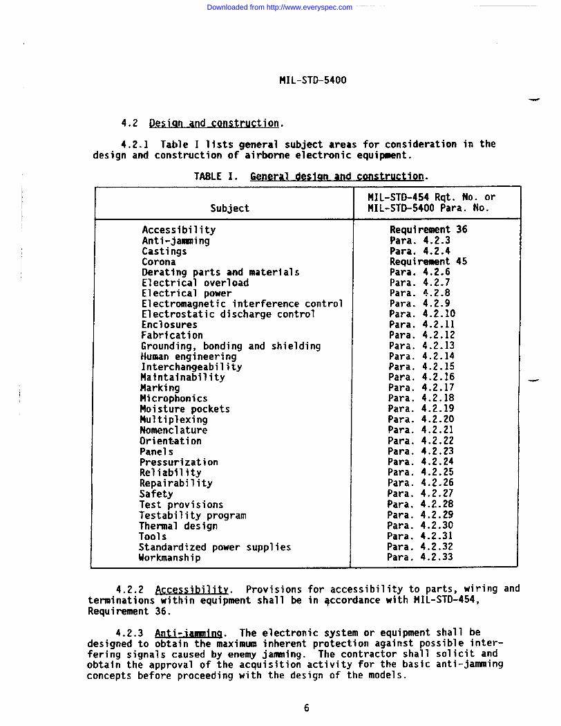
4.2.1 Table I lists general subject areas for consideration in thedesign and construction of airborne electronic equipment.
TA8LEI. General deslan an d construction n.
MIL-STD-454 Rqt. No. orSubject MIL-STD-5400 Para. No.
Accessibility Requirement 36Anti-jananing Para. 4.2.3Castings Para. 4.2.4Corona Requirement 45Deratlng parts and materials Para. 4.2.6Electrical overload Para. 4.2.7Electrical power Para. 4.2.8Electromagnetic interference control Para. 4.2.9Electrostatic discharge control Para. 4.2.10Enclosures Para. 4.2.11Fabrication Para. 4.2.12Grounding, bonding and shielding Para. 4.2.13Human engineering Para. 4.2.14Interchangeability Para. 4.2.15Maintainability Para. 4.2.16Marking Para. 4.2.17Microphonics Para. 4.2.18Moisture pockets Para. 4.2.19Multiplexing Para. 4.2.20Nomenclature Para. 4.2.21Orientation Para. 4.2.22Panels Para. 4.2.23Pressurization Para. 4.2.24Reliability Para. 4.2.25Repairability Para. 4.2.26Safety Para. 4.2.27Test provisions Para. 4.2.28Testability program Para. 4.2.29Thermal design Para. 4.2.30Tool S Para. 4.2.31Standardized power supplies Para. 4.2.32Workmanship Para. 4.2.33
4.2.2 -ibilit~ Provisions for accessibility to parts, wiring andterminations within equipknt shall be in accordance with MIL-STD-454,Requirement 36.
4.2.3 ~nti-.iaaaninq The electronic system or equipment shall bedesigned to obtain the m~ximum inherent protection against possible inter-fering signals caused by enemy januning. The contractor shall solicit andobtain the approval of the acquisition activity for the basic anti-januningconcepts before proceeding with the design of the models.
6
-
-
Downloaded from http://www.everyspec.com
,.
IMIL-STD-5400
4.2.4 J&&inas. metal Metal castings shall be designed, classified,inspected and repaired in a~cordance with ?41L-STD-2175. Porous nonferrouscastings shall be impregnated in accordance with HIL-STD-276. Refer toMIL-STD-454, Requirement 21 for guidance in the choice of casting process andrepairs to castings.
4.2.5 breakdown meygntlo~.
al Provisions for theprotection of equipment against corona and electrical breakdown shall be inaccordance with MIL-STD-454, Requirement 45.
4.2.6 @ratinq. In the application of electronic parts and materials,the parts and materials selected shall be used within their electrical ratingsand environmental capabilities (e.g., any ambient or hot spot temperatures,voltage, current, or power dissipation). Derating shall be accomplished asnecessary to assure the required equipment reliability within the specifiedoperating conditions. Derating should be accomplished based upon coolingconditions (either ambient or forced air) applied to the equipment whsninstalled in the vehicle.
4.2.7 ~lectrical overl d D~ tect” n Current overload protection forthe equipment shall be provi%d by fuse;”o~ circuit breakers. Circuttbreakers shall not be used as switches unless such breakers have beenspecifically designed and tested for that type service. Protective devicesemployed in the equipment should be in a readily accessible, safe location.
\4.2.7.1 settable c?rcu it m-otecto rs. Circuit breakers or other
resettable devices should be used to protect critical circuits, or wherepredictable overloads or surges occur because of peculiar equipment functionsor operator effects which are unavoidable.
4.2.7.2 SDar fus When fuses are used, a minimum of one spare fusefor each size and ~atin~sbut a quantity of not less than 10 percent of thetotal shall be incorporated in the equipment and shall be contained in thesame compartment.
4.2.8 Electrical rower. The equipment shall be designed to operate frompower sources in accordance with MIL-STD-704.
4.2.8.1 uam-uD time. Warm-up time shall be such as to provide thespecified performance within a period as specified by the detail equipmentspecification. Unless otherwise specified, the warm-up time at temperaturesdown to -54°C shall not exceed 2 minutes for equipment essential to fli ht
fsafety, and shall not exceed 5 minutes for equipment not essential to f ightsafety.
4.2.8.2 Electronic equipment which will require shipboard alternatingcurrent (at) power to be supplied for purposes of test or aircraft servicingshall have electrical interface characteristics compatible with the applicablepower system classification of MIL-STD-1399, Section 300.
4.2.9 fl ec-anetlc Interfere. .
nce control. Electromagnetic inter-%.ference requirements shall be as specified in MIL-STD-461. Tests and testmethods shall be as specified in MIL-STD-462. For other than Air Forceapplications, MIL-STD-469 shall also apply for radar equipment and systems.
7
Downloaded from http://www.everyspec.com
t41L-sTD-5400
4.2.9.1.
awe t Radar systems and equipment shall also conformto the provisions ~fesectio~ 5.3 of NTIA ?lanual as specified in the contractand to MIL-STD-469 except that P!IL-STD-469 shall not be used for Air Forceapplications. In the event of conflict, the following descending order ofprecedence shall prevail: NTIA Manual, MIL-STD-469, MIL-STD-461.
4.2.10 ~. Rewi-nts for theestablishment and implementation of an electrostatic discharge control programin accordance with MIL-STD-1686, including its deliverable data requirements,shall be tailored for applicability to equipment and specified directly in thecontract or detail equipment specification. DOD-HDBK-263 provides guidancefor the implementation of an ESD control program. Refer to MIL-STD-454,Requirement 75, for additional guidance in this area.
4.2.11.1 Standardl zed a.
vionics enclosures As an integral part of theSHARP program (see 4.1.2), the selection of sta~dardized enclosure systemsshall be as specified in MIL-STD-2200. Enclosures confoming to MIL-E-85726and racks conforming to NIL-R-85725 are examples of standard~zed hardwarewhich are avai?able for use as conforming to the requirements of t41L-STD-2200.
4.2.11.2 Other enclosu reS. Requirements for the design and constructionof other equipment enclosures (e.g., consoles, cabinets, cases), shall be inaccordance with MIL-STD-454, Requirement 55, except that performance formounting bases shall be met at the same vibration test frequencies and energy -density levels as required for the specific equipment. Mounts ●nd vibrationisolators, whether integral or not, shall be subject to approval of theacquisition activity. Positive self-locking case mounting fasteners shall beused on all mountings. The fasteners chosen shall be of a size specified forthe weight of the equipment unit.
4.2.12 Fabrication. Boxes, cases, shields and compartment walls shallbe made by casting, drawing or bending, and welding, brazing or adhesivebonding except when ease of servicing of the equipment requires that aremovable panel construction be used. When the applied stresses dictate theuse of a strong aluminum alloy which does not provide a good weld or braze,riveting or bolting may be used.
4.2.13 Ins. bondlna and shieldinq Grwnding, bonclingtandshielding interface and installation requirements shall be in accordance withMIL-B-5087. MIL-HDBK-274 provides guidance information relative to groundingpractices for aircraft.
4.2.14 Hu man enaineerinq. Requirements for human engineering inaccordance with MIL-H-46855 shall be tailored for applicability to the equip-ment and specified directly in the contract or detail equipment specifica-tion. !41L-STD-1472 provides design criteria which may be selectively appliedas requirements or guidance.
Downloaded from http://www.everyspec.com
MIL-sTr)-5400
.—
---
4.2.15 ~nte chan~eabr ilitv.
4.2.15.1 Design tolerances shall permit parts, subassemblies andassemblies to be used in their parent assemblies without regard to the sourceof supply or manufacturer. Parts, subassemblies and assemblies having thefull range of dimensions and characteristics permitted by the governingspecification shall be usable as replacement items without selection ordeparture from the specified performance requirements of the parent items.
4.2.15.2 When permission is granted to use a nonstandard part ormaterial because the existing standard part or material is not available, theequipment shall be so designed that the nonstandard part or material and thestandard part or material are interchangeable. When the specification for thepart or material contains substitutability or supersession information, thedesign shall permit the substitute or superseding parts or materials to beused interchangeably.
4.2.15.3 terchanaeabilitv o f reordered eouiome n~. For reorderedequipment, interchangeability shall exist between units and all replaceableassemblies, subassemblies and parts of a designated model of any previouslymanufactured equipment supplied or designated by the acquisition activity.
4.2.16 Maintainability. Requirements for the establishment of a main-tainability program (maintainability program tasks, quantitative requirements,and verification or demonstration requirements) in accordance with MIL-STD-470shall be tailored for applicability to the equipment and program phase, andspecified directly in the contract or detail equipment specification. Othermaintainability documents which may be invoked through MIL-STD-470 or whichmay be cited directly as a basis for contract requirements includeMIL-STD-4?l, MIL-STD-721 and MIL-HDBI(-472.
4.2.17 Marking. Items shall be marked in accordance with MIL-STD=454,Requirement 67. Marking shall not adversely affect the leakage path betweenconductors or any other factor of equipment perfonaance.
4.2.17.1 Labels. Labels showing wiring and schematic diagrams of parts,lubricating and operating instructions, safety notices, list of tools, list ofcontents and similar information shall be provided where space pem?its.Labels shall be designed to remain legible and affixed for the service life ofthe equipment on which they are mounted.
4.2.17.2 Jlire codina for identification Hookup wires in the equipmentshall be dist~nctly coded by color or numbers: insofar as practicable. Codesshall be in accordance with MIL-STD-681, unless otherwise specified. Shorthookup wire, 1501mn or less in length between termination points, need not bemarked if the path of the wire can be easi]y and visually traced. Numbersshall not be used where they would be difficult to read or trace. Flat cableconductors may be identified at termination points. The outer conductor of aflat multiconductor cable should be coded continuously for identification andorientation. Hot or cold stamping shall be allowed only on insulated wirewhich will not accept ink. Marking shall not be used on wires where thedielectric capability of the wire is reduced by such marking. Wire used forexternal wiring between units shall be coded in accordance with MIL-l&5088.
9
Downloaded from http://www.everyspec.com
MIL-STD-5400-
4.2.17.3 9~er ational Dro warn ma rkinq. Operationally prograuaed unitsshall provide a means to identify the software part number for the version inaccordance with MIL-STD-454, Requirement 67.
4.2.18 ~icr~. Microphonics effects shall not be detrimental toequipment perfo~ance.
4.2.19 Hois ture Dockets. Pockets, wells, traps, and the like in whichwater or condensate could collect when the equipment is in normal positionshould be avotded. Where moisture pockets are unavoidable in unsealed equip-ment, provision shall be made for drainage of such pockets. Desiccants ormofsture-absorbent materials shall not be used within moisture pockets. Insealed equipment or assemblies such as waveguides, the use of desiccants orother methods, such as gas purging, is permitted.
4.2.20 NUlt iDlexinq Unless otherwise specified, multiplexing shall beused to transmit bilevel ~ignals for logic functions for ON-OFF, interlockingand proportional control of utilization equipments and components. Themultiplex data bus system shall be in accordance with HIL-STD-1553.MIL-HDBK-1553 provides guidance information for implementation ofMIL-STD-15S3.
4.2.21 Nomenclature assicmment. Nomenclature assignment shall be inaccordance with MIL-STD-196, along with HIL-N-18307 for the Navy, MIL-N-7513for the Air Force, and the contract for the Army.
4.2.22 Orientation. Normal installation position or range of positionsshall be as specified in the detail equipment specification. The equipmentshall operate within specified limits in any position specified in the detailequipment specification.
4.2.23 Panels.
4.2.23.1 Lontro 1 ua el Console and rack mounted control panels shallconform to MIL-C-6781 andnMI~~C-81774. Control panels shall be integrallyilluminated and conform to the requirements of MIL-P-7788.
4.2.23.2 ~lectrohescent r)anels.
The use of electroluminescentpanels shall require approval of the acq~isition activity.
4.2.23.3 Ranaes o.
ad.lustab e Darts The electronic circuitry shall bedesigned to provide a r~serve in ~he adju~tment range from the normal adjust-ment setting of all variable parts that require adjustment during operation ormaintenance. This adjustment range shall be sufficient to compensate forcomposite variations which may develop in-the associated circuitry because ofnormal changes in part values during the specified life cycle of the equip-ment. The adjustment range shall also be capable of compensating for varia-tions resulting from replacement with parts within the tolerances specified.
4.2.24 Pressu iTar tion. Whenever pressurization of the electronic equip-ment is required, or is utilized to meet specification requirements, thefollowing provisions shall be met:
10
Downloaded from http://www.everyspec.com
FiIL”sTD-5400
.—
---
a.
b.
c.
d.
e.
f.
9.
h.
i.
The case shall withstand a positive or negative 5 psi pressuredifference over the applicable pressure range.
The case shall be of a type that will permit ready opening andclearing for access to the equipment for repair and maintenance. Ifpracticable, the equipment shall be c~letely operable afterremoval from the case, and alignment shall be unaffected byreplacement in the case.
When possible and advantageous, external points shall be providedfor check without removal from the case.
A means shall be provtded for determining the effectiveness of theseal. This may consist of an automobile-tire-type valve stemfittinq to
!emit the use of an air pump for ~ncreasing the pressure
approximate y 5 psi above sea level pressure. Measurement of thepressure by means of a Schrader type 3715 gage, or equivalent, shallbe pos~ible.
Sealing instructions shall be placed on one side of the case, ifpracticable.
Those parts of an equipment, including transmission lines, that arepressurized shall be capable of withstanding any pressures developedunder the required external operation conditions, after having beenpressurized inttially on the ground to not more than 5 psi gage at-20” to +50°C, to such an extent that no arcing or loss of powercaused by corona occurs that would not occur at atmospheric pressureon the ground. Nor shall leakage be such as to permit the entrance
‘of moisture or air to an extent that permanent damage or impairedoperation occurs under any of the required operating conditions.Vacuum relief valves shall be provided.
Unless specified or permitted in the detail equipment specifi-cation, pressure shall be maintained without the use or need of apressurization pump. Uhen a pressurization pump is required,redundant barostatic switches, or similar automatic means, shall beprovided to assure equipment is pressurized during flight, eventhough it is not being operated. The switch or automatic meansshall be energized from a common point and shall be energized aspart of the take-off procedure.
The equipment shall maintain pressure to accommodate the maximumoperating time; in addition, and where applicable for captive andnonoperating flight, the equipment shall maintain operating pressurefor periods up to 24 hours. Unl?ss otherwise determined assatisfactory, the loss of pressure shall not exceed 5 pounds in a24-hour period at the altitude and temperature specified in thedetail equipment specification.
If required, a desiccant shall be provided within the case.
Downloaded from http://www.everyspec.com
MIL-STD-5400
j. Parts used in pressurized container shall meet the requirements ofthis standard, except that the altitude requirements may differ.
4.2.25 Jteli-. Requirements for the establislmnt of a reliabilityprogram (reliability engineering ●nd accounting tasks, quantitative require-ments, and verlflcatlon or demonstration requirements) shall be tailored forapplicability to the equipaent and program phase in accordance withHIL-STD-785, and specified directly in the contract or detail equipmentspecification. Other reliability documents which may be invoked throughMIL-STO-785 or which may be cited directly as a basis for contract require-ments include MIL-STD-721, MIL-STD-756, MIL-STD-781, MIL-STD-1629 andMI L-HDBK-217 .
4.2.26 ReDairabilitv!. Repairability shall be determined in terms ofwarranties, mean time to repair (MTTR), stocking spare replaceemt parts andidentifying procedures and personnel for the repair of the speclfted equip-ment. The detail equipment specification shall specify the #ITTR formilitarized equipment, not to exceed thirty (30) minutes. Level of repairguidance is provided in 141L-STD-1390, and should be evaluated when makingRepairability and Training decisions.
4.2.27 Safety.
4.2.27.1 ~. Requirements for the development and imple-mentation of a system safety program shall be tailored for applicability tothe equipment and acquisition phase in accordance with MIL-STD-882, andspecified directly in the contract or detail equipment specification.
4.2.27.2 Per onnel safety Provisions for safety of personnel duringinstallation, oper~tion, mainte~ance and repair shall be in accordance withMIL-STD-454, Requirement 1.
4.2.28 ~ ions. Test provisions to provide means for monitoringperformance, calibration and fault isolation shall be in accordance withMIL-STD-415.
4.2.28.1 ~u.lt-in test de ic s Built-in test devices shall maintaintheir accuracy un~er all operat~ngeconditions required by the equipment undertest. These devices shall be provided with connections or access for theiroperational ckc.kout or calibration.
4.2.28.2 ernal test Doin ts_. Protection shall be provided in the testpoint circuitry to prevent equipment damage caused by the external groundingof test points.
4.2.28.3 Mhmuff@. Unless othqrwise specified, provisions fortesting shall be so designed that any failure of built-in test devices willnot degrade equipment operation or cause equipment shutdown.
4.2.29 Testab.litv r)roq a Requirements for the development andimplementation of a’testabili~ymprogram (program planning, design, prediction,demonstration, data, and review) shall be tailored for applicability to the
Downloaded from http://www.everyspec.com
—.
..
I!
I -_I
MIL-STO-5400
equipment and program phase in accordance with MIL-STD-2165, and specifieddirectly in the contract or detail equipment specification.
4.2.30 ml desl~. Requirements and guidance for thermal designshall be in accordance with MIL-STD-454, Requirement 52.
4.z.30.1 miumwmm. Cooling design data shall be developed assoon as possible after major circuit parameters have been established.Initially, this data shall include calculations, drawings and other inform-ation related to the choice of a particular cooling system conf~guratlon. Aspart of this initial data, the first set of applicable thermal design evalua-tion data shall be developed, based on preliminary calculations at thespecified operating conditions. The approval of the cooling system will bebased upon consideration of this information. Applicable part temperaturesfrom these calculations should be utilized in the reliability predictionanalyses. As equipment development proceeds, this data should become morefinal and should be based on more actual thermal test results. Uponcompletion of the engineering development or preproduction models, and whenrequired by the contract, a thermal evaluation test program shall beconducted.
4.2.31 ~.
4.2.31.1 sets crew wrenches. One wrench for each size and type setscrew.-. head employed for operational adjustments shall be securely mounted within the
equipment in a readily accessible location. Each wrench shall be processed toresist corrosion.
4.2.31.2 SQec ial tools. Special tools include jigs, fixtures, stands,and templates not listed in the Federal Supply Catalog, and require approvalof the acquiring activity for use. The design of equipment should be suchthat the need for special tools for tuning, adjustment, maintenance, replace-ment, and installation is kept to a minimum. Only when the required functioncannot be provided by an existing standard tool should special tools beconsidered. Necessary tools should be identified as early as possible.
4.2.31.3 ~urnishina and sto winq. Special tools needed for operation andorganization level maintenance shall be furnished by the contractor exceptthat the contractor shall not mount tools in the equipment or make spaceprovisions therefore, unless required by the detail equipment specification orcontract.
4,2.32 Standa d ized Dower SUDD1 ies. As an integral part of the WARPprogram (see 4.1.2): the selection of standardized power supplies for airborneapplications shall be as specified in MIL-STD-2038. Power supplies confo~ingto MIL-P-29590 shall be of primary consideration for airborne applications.
4.2.33 Iiorkmans hit). Workmanship for mechanical assembly shall be inaccordance with MIL-STD-454, Requirement 9. Workmanship forelectrical/electronic assembly shall be in accordance with MIL-STD-2000.
13
Downloaded from http://www.everyspec.com
MIL-STD-5400
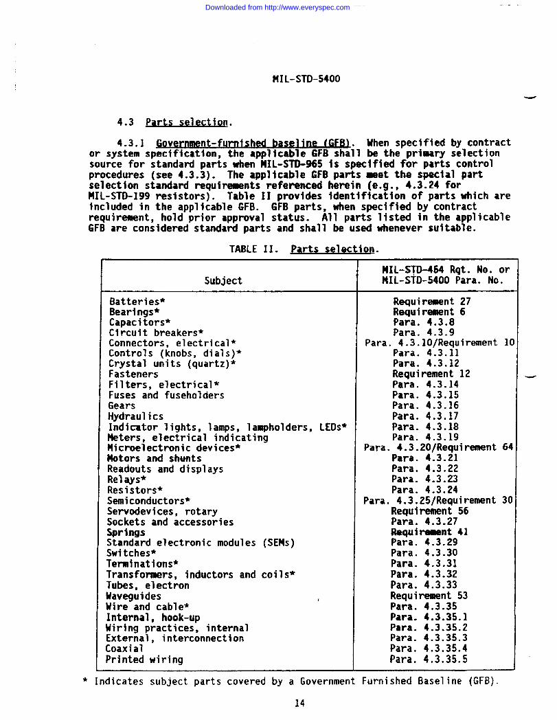
4.3 Parts selec tjon.
4.3.1 nt-furnished baseline (G FB).. When specified by contractor system specification, the ●pplicable 6FB shall be the primary selectionsource for standard parts when HIL-STD-%5 is specified for parts controlprocedures (see 4.3.3). The applicable GFB parts meet the special partselection standard requirements referenced herein (e.g., 4.3.24 forMIL-STD-199 resistors). Table II provides identification of parts which areincluded in the applicable GFB. GFB parts, when specified by contractrequirement, hold prior approval status. All parts listed in the applicableGFB are considered standard parts and shall be used whenever suitable.
TABLE II. parts sele ction.
MXL-STD-454 Rqt. No. orSubject MIL-STD-5400 Para. No.
Batteries* Requirement 27Bearings* Requirement 6Capacitors* Para. 4.3.8Circuit breakers* Para. 4.3.9Connectors, electrical* Para. 4.3.10/Requirement 10Controls (knobs, dials)* Para. 4.3.11Crystal units (quartz)* Para. 4.3.12Fasteners Requirement 12Filters, electrical* Para. 4.3.14Fuses and fuseholders Para. 4.3.15Gears Para. 4.3.16Hydraulics Para. 4.3.17Indicator lights, lamps, lampholders, LEDs* Para. 4.3.18Meters, electrical indicating Para. 4.3.19Microelectronic devices* Para. 4.3.20/Requirement 64Notors and shunts Para. 4.3.21Readouts and displays Para. 4.3.22Relays* Para. 4.3.23Resistors* Para. 4.3.24Semiconductors* Para. 4.3.25/Requirement 30Servodevices, rotary Requirement 56Sockets and accessories Para. 4.3.27Springs Requimnt 41Standard electronic modules (SEMS) Para. 4.3.29Switches* Para. 4.3.30Terminations* Para. 4.3.31Transformers, inductors and coils~ Para. 4.3.32Tubes, electron Para. 4.3.33Uaveguides : Requirement 53Uire and cable* Para. 4.3.35Internal, hook-up Para. 4.3.35.1Hiring practices, internal Para. 4.3.35.2External, interconnection Para. 4.3.35.3Coaxial Para. 4.3.35.4Printed wiring Para. 4.3.35.S
* Indicates subject parts covered by a Government Furnished Baseline (GFB).
14
Downloaded from http://www.everyspec.com
/.,I
MIL-STD-5400
4.3.1.1 choice of Darts Uhenever the applicable selection standard,GFB or spectflcatlon provides”swltiple characters or tolerances on items, theequipment manufacturers shall consider the use of the broadest characteristicsarid greatest allowable tolerances to fulfill the overall requirement. Themanufacturer shall also consider limiting the variety of part types and reviewthe system Program Parts Selection List (PPSL) for candidates prior toreaching a part decision. All new equipment shall be designed to accommodatethe maximum envelope dimensions specified in the military part specification.
4.3.2 l!onstanda d Darttr Uhen the applicable GFB fails to provide anapplicable part or Appendix A“does not provide an applicable part standard orspecification, the contractor shall select a part from other establishedspecifications or standatis in accordance with hiIL-STD-970. Nonstandard partsmust be equivalent to or better than similar standard parts and must becompliant with applicable contract requirements. Each vendor source fornonstandard parts documented by a source control drawing requires approval ofthe acquisition activity.
4.3.3 .Parts control Droara Requirements for the implementationcontractor parts control programm~n accordance with PIIL-STD-965, includparts approval by the acquisition activity, shall be directly specifieddetail equipment specification or contract. Refer to MIL-STD-454, Requ”22 and MIL-HDBK-402 for guidance in this area.
of angin therement
%- NOTE: MIL-STD-965 is a “Parts Control Program” and requires the approval andlisting of all parts in a PPSL unless the requirements have been other-wise tailored.
4.3.4 Aoo roval of Darts. In considering the approval of parts,contracts-for electronic equipment are divided into the following categories:
Category I: Contracts which are fundamentally for the purpose ofinvestigation or study and not for the fabrication ofequipment.
Category 11: Contracts for one or more models of equipment designed tomeet the performance requirements of a specification or toestablish technical requirements for production equipment.This category includes contracts for models to be used fortest under service conditions for the evaluation of theirsuitability and performance.
Category III: Contracts for production equipment. These contracts willusually include requirements for a prototype or firstarticle model.
4.3.4.1 Contracts under cateaorv L ‘Approval of parts shall not berequired under contracts or orders which-fall under Category 1. General partsinformation is available upon request to the Military Parts Control AdvisoryGroups (MPCAGS).
..-
15
Downloaded from http://www.everyspec.com
MIL-STD-5400
-
4.3.4.2 Contracts for eaufmaent which fal.
l~r~lIandIILFor a single contract covering like equipments which fall in both Categories
●
11 and 111, parts approval shall be required only for those items used inCategory 11 equipments, and any new item sources or new nonstandard items usedIn Category 111 equipment. As s eclfied by contract, approval of all parts
Eused In the equipment shall be o tained by the contractor pr~or to delivary ofany equipment required by the contract.
4.3.4.3 Beordered Production eaulm.
. A design review directed towardreplacement of nonstandard parts with standard parts shall be performed oncontracts for reordered equipment, whether reordered from the originalcontractor or from a different contractor. Uhere applicable, the PPSL 1 istiagshall be utilized for the review function by the MPCA6S under MIL-STD-W!i.Changes must conform to interchangeability requirements. The original partprocured from the same source, uhen required by interchangeability or Iackofa standerd replacement part, may be used without reapproval.
4.3.4.3.1 ~tion ofm-~ . In those cases wherein thereordered production equipment represents continuous production by the samecontractor, a review directed toward nonstandard parts replacement withstandard parts shall not be required.
4.3.4.4 R o~a i Q ~ oved Dartsof Uhenever permission is sought bythe contractor ;O u~enan item ~hat is not-the part approved for use in thesystem/equipment, the procedure used shall be a “Request for Deviation” in _accordance with the applicable configuration management requirements of thecontract. The startdard/approved item shall be listed in technical manuals,parts lists, etc.
4.3.4.5 ~auioment Derforman ce. The requirements of this standard withregard to the use of parts, either standard or approved nonstandard, shall notrelieve the contractor of the responsibility for complying with all equipmentperformance and other requirements set forth in the detail equipment spec-ification or contract. Approvals for nonstandard parts are contingent onsubsequent satisfactory performance during required equipment tests.
4.3.5 Sub titut ion of Dart The selection and application ofsubstitute part: shall be in acc~~dance with MIL-STD-454, Requirement 72.
4.3.6 Batteries. The use of batteries requires approval of theacquisition activity. Batteries shall be selected and applied in accordancewith MIL-STII-454, Requirement 27.
4.3.7 ~earina$. Bearings shall be selected and applied in accordancewith PiIL-STO-454, Requirement 6.
4.3.8 CaDacito Capacitors shall be selected and applied inaccordance with MIL-;;D-198.
4.3.8.1 fixed. tantalum electrolytic For Naval Air Systems Comnand,the use of wet slug tantalum capacitors (e~cept tantalum-cased units inaccordance with MIL-C-39006/22 and MIL-C-39006/25) requires the approvalthe acquisition activity, and silver-cased tantalum capacitors shall notused.
ofbe
16
Downloaded from http://www.everyspec.com
I
MI L-STD-5400
4.3.8.2 ~electrolvtic . Aluminum electrolytic capacitors shallnot be used in airborne electronic equipment applications.
4.3.9 Circuit breake s Circuit breakers shall be selected and appliedin accordance with HIL-STD~1498. Trip-free circuit breakers shall be used.Nontrlp-free circuit breakers shall be used only when the application requiresoverriding of the tripping mechanism for emergency use.
4.3.9.1.
ration Circuit breakers shall be capable of beingmanually operated to the ON and OFF positions. Circuit breakers shall not beused as ON-OFF switches unless such breakers have been specifically designedand tested for that type of service.
4.3.9.2 Position iden tification. Circuit breakers shall have easilyidentified ON, OFF and TRIPPED positions except that the TRIPPED position maybe the same as the OFF position with no differentiation between OFF andTRIPPED being required.
4.3.9.3 9rientat ion. Circuit breakers shall operate when permanentlyinclined in any direction up to 30 degrees from the nonal vertical or normalhorizontal position. The trip point of an inclined unit shall not vary morethan *5 percent of the current specified for normal position mounting.Circuit breakers used on flight equipment shall operate within the limits ofthe detail equipment specification when the equipment is in any position orrotation about its three principal axes.>.-
4.3.10 Connectors, electrical. Electrical connectors shall be selectedand applied in accordance with MIL-STD-1353. Additional selection andapplication requirements are specified in MIL-STD-454, Requirement 10.
4.3.10.1 ~untinu of electrical recer.)tacl~ . Where practical, whenreceptacles are mounted on a vertical surface the largest polarizing or primekey or keyway of the receptacle shall be at the top center of the shell of thereceptacle. Mounting connectors on a top horizontal surface should beavoided, in order to prevent pooling of moisture in the connector.
4.3.10.2 &Lia cent locations. The use of identical connectors inadjacent locations shall be avoided. When the use of connectors of the sameshell size in adjacent locations cannot be avoided, differences in keyingarrangement shall be used to prevent mismating.
4.3.10.3 w. Microphone jacks shall be type M641/5-l and headsetjacks shall be type M641/6-l conforming to MIL-J-641. Use of these jacks forother than microphone and headset use is prohibited in areas accessible toflight personnel.
4.3-11 ~- control knobs shall beselected and applied in accordance with MIL-K-25049. Handles shall beselected and applied in accordance with MIL-H-881O. Multiturn counter controldials shall be selected and applied in accordance with t41L-D-28728.Additional application requirements are specified in MIL-STD-454, Requirement
k. 28.
17
Downloaded from http://www.everyspec.com
HIL-STD-5400
-
4.3.12 $rYsta s iauartz and oscil atorl1 1 Quartz crystal units shall beselected and aDD~ied in accordance with MIL-S~D-683. Crystal oscillator unitsshall be in ac~ordance with MIL-O-5531O.
4.3.13 fastener ha~wa e Fastener hardware shall be in accordance withthe applicable fastener spec~f~cation specified in NIL-STO-454, Requirement12. Additional guidance information on mounting methods and techniques isprovided in 141L-STO-454, Requirement 12.
4.3.14 Filters. electrical. Electrical filters shall be selected andapplied in accordance with MIL-STD-1395.
4.3.15 Fuses. fuseholders and associated hard a e Fuses, fuseholdersand associated hardware shall be selected and appli~drin accordance withMIL-STD-1360. Additional guidance information is provided in MIL-STO-454,Requirement 39.
4.3.16 $ears. Gears shall be designated, dimensioned, tolerance andinspected in accordance with applicable specifications of the American GearManufacturers Association (AGW). Gears not operating in a lubricant bathshall be made of a corrosion resistant material. Gears operating In alubricant bath containing a corrosive inhibiting additive may be made of non-corrosive resistant material. Planetary gearing is preferred to worm gearing.Non-metallic gears may be used when they meet the load, life and environmentalrequirements of the applicable specification.
4.3.17 hvdraul ics . Hydraulic systems which function as an integral partof an electronic system shall be as follows:
4.3.+7.1 fiircraft. The designaircraft shall be in accordance withMI L-H-5440.
4.3.17.2 llissil~. The designmissiles shall be in accordance withMIL-H-25475.
and installation of hydraulic systems forthe applicable type, class or system of
and installation of hydraulic systems forthe applicable type, class or system of
4.3.17.3 Additional guidance information and document references areprovided in MIL-STD-454, Requirement 49.
4.3.18 l-iaht$ a nd associated items.
4.3.18.1 Indicator liahts. Indicator lights, light housings, lamp-holders and lenses shall be selected and applied in accordance withMIL-L-3661.
4.3.18.2 Press to test indicator liclhts. Press to test indicator lightsshall be selected and applied in accordance with MIL-L-7961.
4.3.18.3 .Jnstr~n t Iiahts Instrument lighting shall be integral redin accordance with MIL-I-25467, or integral white in accordance withMIL-L-27160, as required. The use of non-integral lighting requires approvalof the acquisition activity, and when approved shall be in accordance withMIL-L-5057.
18
Downloaded from http://www.everyspec.com
I
HIL-STD-5400
I
II
4.3.18.4 m. Incandescent lamps shall be selected and applied inaccordance with HIL-L-6363 When used as indicator lights, light emittingdiodes (LEDs) shall be selected and applied in accordance with MIL-S-19500.
4.3.18.5 Visual disD~av and lemnd li~h s Visual display and legendlights shall comply with the requirements h k-STf)-1472.
4.3.18.6 Niciht vision comatibillty Uhen compatibility of equipment isrequired for night vision imaging, the requirements of NIL-L-85762 shallapply.
4.3.19 Meters. Panel type electrical indicating meters shall beselected and applied in accordance with MIL-M-103O4 (color schemes W, B, Y, Fand P). Time totalizing meters shall be selected and applied in accordancewith HIL-H-7793. Uhen required, external meter shunts shall conform toMIL-S-61 or )41L-I-1361.
4.3.20 14icroelectronic devices. Microelectronic devices, includinghybrids, shall be selected and applied in accordance with MIL-STD-454,Requirement 64. Devices selected shall be connected by means of soldering,welding, or the use of shape memory metal alloy connectors.
4.3.21 ~otors.
4.3.21.1 Noto s. alternatlna CU rent.
Alternating current motors (400Hz, 115/200 volt) s~all be in accorda~ce with MIL-M-7969, except that motorsused with a miniature blower for cooling electronic equipment shall be inaccordance with MIL-B-23071.
4.3.23.2 Motors. direct current. Direct current motors (28 volt) shallbe in accordance-with MIL-M-8609.
4.3.22 Readouts and disDlavs.
4.3.22.1 Readouts. Readouts shall be selected and applied in accordancewith MIL-R-28803.
4.3.22.2 ~isr)lavS. Light emitting diode (LED) displays shall beselected and applied in accordance with MIL-D-87157, quality level A or B.Liquid crystal displays (LCDS) exhibit limited operation of temperatureextremes, and require acquisition activity approval for use in airborneelectronic equipment.
4.3.23 J?elav~. Relays shall be selected and applied in accordance withM2L-STD-1346. Hermetically sealed types only shall be used. Reed relaysshall be in accordance with MIL-R-83516, an# require acquisition activityapproval for use in airborne electronic equipment.
4.3.24 Resistors. Resistors shall be selected and applied in accordancewith MIL-STD-199. Thermistors shall be in accordance with MIL-T-23648.
4.3,25 Semiconductor devices. Semiconductor devices shall be selectedand applied In accordance with MIL-STD-701, subject to the order of precedenceand restrictions specified in MIL-STD-454, Requirement 30.
19
Downloaded from http://www.everyspec.com
MIL-STD-5400
-
4.3.26 Serodev ces.1 ota Y Rotary servodevices shall be selected andapplied in acco~ance with ~IL-[T&454, Requirement 56.
4.3.27 Sockets. shields and mountina Dads.
4.3.27.1 sockets. Sockets for plug-in electronic parts shall be of thesingle unit type and shall conform to MIL-S-12883, ?411-S-83502 or MIL-S-83734.The use of sockets for microcircuits requires approval of the acquisitionactivity.
4.3.27.2 Shields. Heat dissipating tube shields shall conform toMIL-S-24251.
4.3.27.3 flountina Da s Hhere mounting pads are required for use withsmall electrical or electr~n~c devices, they shall conform to MIL-H-38527.
4.3.28 Sorinas. Springs and spring material shall be selected andapplied in accordance with MIL-STO-454, Requirement 41.
4.3.29 $ta ndard electronic modules (SEf4sl As an integral part of theSHARP program (see 4.1.2), standard electronic &dules (SEMS) conforming toMIL-M-28787 shall be utilized to the maximum extent possible. Requirementsfor the design of SEMS shall be in accordance with MIL-STD-1389. Requirementsfor the application of SEMS shall be in accordance with MIL-STD-1378.Guidance information for the SEMS program is contained in MIL-HDBK-246. _
4.3.30 Switches. Switches and associated hardware shall be selected andapplied in accordance with MIL-STD-1132. Toggle switches shall be selectedand applied in accordance with MIL-S-83731.
4.3.30.1 .fiount inq.
4.3.30.1.1 Rotary switches. Rotary switches with thru-panel shaftsshall be mounted to the panel by means of a single threaded bushing concentricwith the shaft. A positive mechanical means, in addition to lock washers,shall be provided to prevent rotation of the switch body.
4.3.30.1.2 Toua e swltck1 The mounting of toggle switches shall besuch that the handle of the swit~h operates in a vertical direction. The“off” position shall be in the center position on three-position switches andin the bottom position on two-position switches. Uhen clarification of acontrol function or convenience of operation would result (for example, a“left-right” function control), toggle switches may be so mounted that thehandle of the switch operates in a horizontal direction.
4.3.31 Terminations. The selection ~f stud terminals, lug terminals,feed-thru terminals, binding posts, terminal boards, terminal junction systemsand splices shall be in accordance with MIL-STD-1277.
4.3.31.1 !Jumber of wires Der terminal or luq. The number of wiresterminated in an individual terminal or lug shall not be greater than three.Multisection turret, bifurcated, or multi-hole lug terminals shall have not -more than three wires per section, tong, or hole. In no case shall the totalcross sectional area of the terminated wires exceed the cross sectional area
20
Downloaded from http://www.everyspec.com
------
MIL-STD-5400
capacity of the terminal or lug. If a greater number ofthan those specified hereinobtained.
, approval of the acquisitionwires is requiredactivity shall be
4.3.31.2 flu~be~ o f Iuqs De r terminal , The maximum numberof lugs to beconnected to any one terminal on a terminal board shall be two for screw-typeterminal boards covered by MIL-T-55164 and as spectfied in the detailspecification sheets for stud-type terminal boards. Not more than four lugsshall be connected to any one terminal of a board covered by MS27212. Acces-sories such as stud connectors, straddle plates, jumpers and terminal boardlugs shall be counted as lugs for this purpose.
4.3.32 Transformers. inductors and co il$. The selection and applicationof transformers, inductors and coils shall be in accordance with ?41L-STD-1286.Variable transformers shall conform to MIL-T-83721, and intermediate radiofrequency and discriminator transformers shall conform to !41L-T-55631, Grade1, 2or4. Grade 3 transformers shall be limited to hermetically sealed orencapsulated assemblies.
4.3.33 Tubes. electron. Electron tubes shall be selected and applied inaccordance with MIL-STO-200.
4.3.34 Maveauides and related i terns Waveguides and related items shallbe selected and applied in accordance with MIL-STD-454, Requirement 53.
4.3.35 Yire a d cn able. Wire and cable having polyvinyl chloride (PVC)or FEP/polyiaJide (K.apton) insulating material shall not be used in airborneelectronic equipment applications.
4.3.35.1 Mire and cabl internal. Internal hookup wires conforming toHIL-U-22739 and MIL-M-81044 ~re preferred for use within the equipment. Otherwire types are subject to the above restrictions and those of MIL-STD-454,Recwirement 20. t4ulticonductor cables conforming to MIL-C-7078 andMIL-C-27500 and utilizing the above specified wi~e types are pref~within the equipment. Other cable types are subject to the aboveand those of MIL-STD-454, Requirement 66.
4.3.35.2 Nirina Dractices. lnte.
rnal . Internal wiring pract”wiring devices shall conform to MIL-STD-454, Requirement 69.
rred for userestrictions
ces and
4.3.35.3 &ire and cab e. external inte=necti~1 Hires conforming toNIL-U-22759 and MIL-H-81044 and cables conforming to MI~-C-7078 andHIL-C-27500 which utilize the above specified wire types are preferred per usefor external interconnections between units. Other wire and cable types aresubject to the above restrictions and those of 141L-STD-454, Requirement 71 andMI1.-W-5O88, as applicable.
4.3.35.4 $able. coax ial (RF). Coaxial cables (RF) shall be inaccordance with MIL-C-17, MIL-L-3890, MIL-C-22931, or PiIL-C-23806.
4.3.35.5 Printed w irinq Printed wiring boards, assemblies, cards andassociated hardware shall be in accordance with MIL-STO-1861. Printed wiringboards shall be connected into the equipment by means of connectors. Printedwiring boards utilizing the conductor pattern as the direct contact with themating connector shall not be used.
21
Downloaded from http://www.everyspec.com
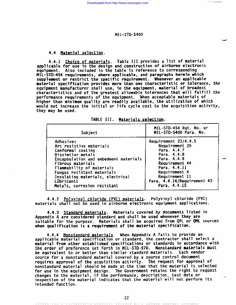
MIL-STO-5400
4.4 Mater ial selection.
4.4.1 Choice of materials.
.applicable for use in the designequipment. Also included in the
Table 111 provides a list of materialand construction of airborne electronictable is reference to corresponding
MIL-STD-454 requirements, where applicable, and paragraphs herein whichsupplement or restrict the specific requirement. Uhenever ●n ●pplicablematerial specification provides more than one characteristic or tolerance, theequipment manufacturer shall use, in the equipment, material of broadestcharacteristics and of the greatest allowable tolerances that will fulfill theperformance requirements of the equipment. 14henacceptable materials ofhigher than minimum quality are readily available, the utilization of whichwould not increase the initial or life cycle cost to the acquisition activity,they may be used.
TABLE 111. Plater ials selection.
Subject
AdhesivesArc resistive materialsCortformal coatingDissimilar metalsEncapsulation and embedment materialsFibrous materialsFlanunability of materialsFungus resistant materialsInsulating materials. electrical
MIL-STD-454 Rqt. No. orMIL-STD-5400 Para. No.
Requirement 23/4.4.5Requirement 26Para. 4.4.7Para. 4.4.8Para. 4.4.9Requirement 44Para. 4.4.11Requirement 4Requirement 11
Liibricant~,
I Para. 4.4.14/Requirement 43Metals, corrosion resistant Para. 4.4.15
J.4.2 Poln’invl chloride (PVC) material~. Polyvinyl chloride (PVC)materials shall not be used in airborne electronic equipment applications.
4.4.3 Standard materials. Materials covered by documents listed inAmendix A are considered standard and shall be used whenever they ares~’itable for the purpose. Materials shall be acquired from QPL o; QML sourceswhen qualification is a requirement of the material specification.
4.4.4 Nonsta dard UIaterials. Uhen Appendix A fails to provide anapplicable materia~ specification or standard, the contractor shall select amaterial from other established specifications or standards in accordance withthe order of preference set forth in MIL-STD-970. Nonstandard material$ Ustbe equivalent to or better than similar standard materials. Each vendorsource for a nonstandard material covered by a source control documentrequires approval of the acquisition activity. The request for approval ofnonstandard material should be made at the time that the material is selectedfor use in the equipment design. The Government retains the right to requestchanges to the material, if the performance, description, test data orinspection of the material indicates that the material will not perform its —intended function.
22
Downloaded from http://www.everyspec.com
—
I
MIL-STD-5400
4.4.4.1 ADvro val of nonstan dard mater ialS. Requirements for theacquisition activity approval of nonstandard materials shall be specified inthe detail equipment specification or contract.
4.4.5 Adhes ives. Adhesives shall be selected and applied in accordancewith tIIIL-STD-454, Requirement 23. The use of adhesives in electrical applica-tions requires the approval of the acquisition activity.
4.4.6 Arc-resistant mater ials. Arc-resistant materials shall beselected and applied in accordance with MIL-STD-454, Requirement 26.
4.4.7 Conformal co atinq. Conformal coating for use with rigid printedcircuit assemblies shall conform to MIL-I-46058.
4.4.8 Dissimilar metals. Selection ●nd protection of dissimilar metalcombinations shall be in accordance with t41L-STD-889. The use of dissimilarmetals shall be limited to applications where similar metals cannot be useddue to peculiar design requirements.
4.4.9 &ncaDsu lation and embed ment materials. Encapsulation and embed-ment materials shall be of a nonreversion type and shall be selected from thefollowing specifications: MIL-S-8516, MIL-I-16923, t41L-S-23586, MIL-M-24041,and MIL-I-81550. The materials selected shall be capable of filling all voidsand air spaces in and around the items being encased. Refer to MIL-STD-454,Requirement 47 for additional guidance information.
4.4.10 Fibrous material. orqanic. Organic fibrous material shall beselected and applied in accordance with MIL-STD-454, Requirement 44.
4.4.11 ~ r Materials used in military equipmentshall, in the end item configuration, &e noncombustible or fire retardant inthe most hazardous conditions of atmosphere, pressure, and temperature to beexpected in the application. Fire retardant additives may be used providedthey do not adversely affect the specified performance requirements of thebasic materials. Fire retardance shall not be achieved by use of nonpermanentadditives to the basic material. Refer to MIL-STD-454, Requirement 3 foradditional guidance information on the testing of material to determine itsflammability characteristics.
4.4.12 ~unaus-inert materials. The selection and application offungus-inert and fungicide treated materials shall be in accordance withMIL-STD-454, Requirement 4.
4.4.13 ~ul ato rs. insulating and dielect ri c mater ials. The selectionand application of insulators, insulating and dielectric materials shall be inaccordance with MIL-STD-454, Requirement 11,
4.4.14 Lubricants. The selection and application of lubricants forairborne electronic equipment shall be in accordance with MIL-STD-838.Standard lubricants shall be limited to those specified in MIL-STD-454,Requirement 43. Refer to MIL-HDBK-275 for guidance relative to application-and limitations of specific lubricants.
23
Downloaded from http://www.everyspec.com
MIL-STD-5400
-
4.4.15 tals. co rrosion reslstanii . Metals shall be corrosion resistantor shall be coated or metallurgically processed to resist corrosion.Materials and processes for metallic parts shall conform to applicablerequirements of MIL-STD-889 and MIL-STD-1516. Coatings shall be selected fromMIL-STD-1516.
4.5 Processes and fin ishe~ Processes and finishes, except painting,shall be in accordance with Tabl~ IV and, where applicable, the referencedMIL-STD-454 requirement or supplemental paragraph herein. Melding and brazingshall be accomplished by certified operators in accordance with the require-ments of MIL-STD-248 or MIL-STD-1595, as applicable.
4.5.1 fh-otective ~latinas and coat~ . A protective plating or coatingshall be applied to all metals which are not corrosion-resistant, except asfollows:
4.5.1.1 Materials. Gold, nickel, chromium, rhodium, tin, lead-tinalloys, or sufficiently thick platings of these metals, are satisfactory with-out additional protection or treatment other than buffing or cleaning.
4.=2 ~.
4.5.1.2.1 Surface. ae neral . Parts fabricated from aluminum 1100, alloys3003, 5052, 6053, 6061, 6063 or 7072 shall be cleaned with a deoxidizingsolution, other than an uninhibited caustic dip, and may be used with or with- _out other surface treatment. Other aluminum alloys shall be anodized inaccordance with NIL-A-8625 or be given a chemical treatment in accordance withMIL-C-5541.
4.5.3-.2.2 Surfaces. bonded and mounde d. Where bonding or grounding isnecessary, alumi-num 1100, alloys 3003, 5052, 6053, 6061, 6063, 7072, orequally corrosion-resistant alloys, shall be used. They may be used withoutother surface treatment.
4.5.1.2.3 ~. wherebondin9or gr”u”dingis not necessary, hard anod~c finish conforming to number E514 of HIL-F-14072may be applied to obtain extreme wear-resistant surfaces under Type II(MIL-F-14072) exposure on desired areas of aluminum alloys not subject torepeated high tensile stresses.
4.5.2 Hacmesium and maanesium alloys. Magnesium and magnesium alloysshall not be used except when approved or specified by the acquisitionactivity. The request for use of magnesium and its alloys should include thetotal environment exposure, the weight reduction and other advantagesachieved, the proposed surface treatatent and the application details.
4.5.3 ~“nc dz.
-~lated Darts. Z~nc and zinc-plated parts shall begiven a (tIchrkat;ntre;kt in accordance with ASTM 8633.
4.5.4 Finishes. Unless contained in a hermetically sealed unit, partfinishes (including hardware items of equipment not covered by subsidiaryspecifications) shall be resistant to corrosion. Finishes shall be capable of –withstanding a 48-hour Salt Spray (Fog) test in accordance with MIL-STD-81O,
24
Downloaded from http://www.everyspec.com
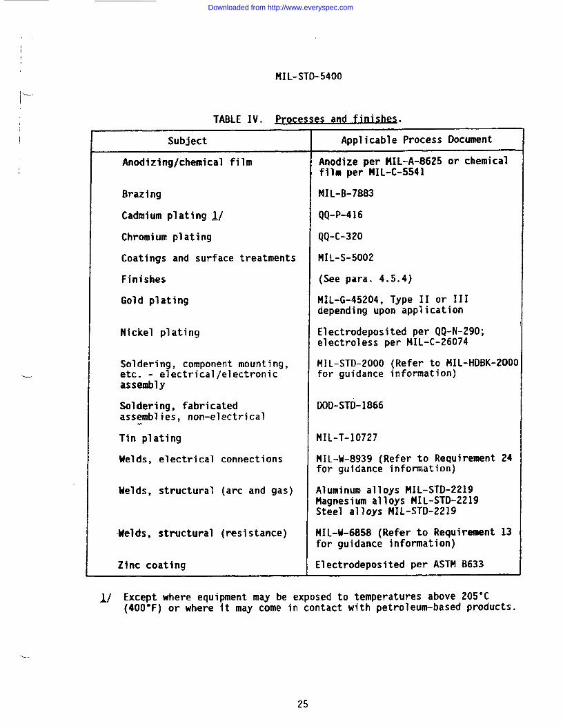
,,
IMIL-STD-5400
TABLE IV. Processes and f 1n-. .
.I
-------
Subject Applicable Process Document
Anodizing/chemical film Anodize per MIL-A-8625 or chemicalfilm per MIL-C-SS41
Brazing MIL-B-7883
Cadmium plating ~/ QQ-P-416
Chromium plating QQ-C-320
Coatings and surface treatments MIL-S-5002
Finishes (See para. 4.5.4)
Gold plating MIL-G-45204, Type II or 111depending upon application
Nickel plating Electrodeposited per QQ-N-290;electroless per MIL-C-26074
Soldering, component mounting, MIL-STD-2000 (Refer to MIL-HDBK-2000etc. - electrical/electronic for guidance information)assembly
Soldering, fabricated DOD-STD-1866assemblies, non-electrical.
Tin plating MIL-T-10727
Welds, electrical connections MIL-M-8939 (Refer to Requirement 24for guidance information)
Welds, structural (arc and gas) Aluminum alloys MIL-STD-2219Magnesium alloys MIL-STD-2219Steel alloys MIL-STD-2219
lieIds, structural (resistance) MIL-U-6858 (Refer to Requirement 13for guidance information)
Zinc coating Electrodeposited per ASTM B633
1/ Except where equipment may be exposed to temperatures above 205°C(400-F) or where it may come in contact with petroleum-based products.
----
25
Downloaded from http://www.everyspec.com
MrL-sTo-5400
Method 509, Procedure I, without showing signs of corrosion beyond thoseestablished for the particular part, material or finish specification. Uhereapplicable, these parts shall have finishes prov~ding suitable rates of heatlubricated condition. Lusterless finishes shall be used on all surfacesvisible to operating personnel. Where cleaning operations on metal parts arenot specified In detail, they shall be in accordance with MIL-S-5002. It isnot the intent that parts acquired to the specifications listed in Appendix Amust be refinished.
4.5.4.1 Cases and front Danels. Equipment installed in the cockpit areashall be Lusterless Black, Color No. 37038, in accordance with FED-STD-595.Unless otherwise specified, finish of all other equipment shall be LusterlessGray, Color No. 36231, in accordance with FED-STD-595.
4.5.4.2 Fas teners and assemblv ,~ Exposed surfaces of externalfasteners and assembly screws used in areas”other than the cockpit which aremanipulated, loosened, or removed in the normal processes of servicing andinstalling the equipment shall be finished, preferably in a noncorrosive blackor bright finish, so as to provide strong contrast with the color of thesurface upon which they appear. Exposed surfaces of external fasteners andassembly screws used in the aircraft cockpit shall be finished in accordancewith 4.5.4.1. Other external fasteners and assembly screws used for securingthe internal parts to the chassis shall be similar in color to the surfaceupon which they appear.
4.5.4.3 Other standa rd finishes. Type I finshes in accordance with -MIL-F-14072 are approved as alternates to any differing requirements specifiedunder the paragraphs on finishes, except that colors specified shall be used.
4.6.1 MI L-STD-81O environmental tests. The contractual use ofMIL-STD-81O for environmental testing requires the development of environ-mental management and test plans and engineering tasks to adequately tailorthe specific test procedures, test conditions, variations, and limits for thelife cycle environmental conditions which the equipment will realisticallyencounter. MIL-STD-81O provides details of these data requirements andreports and identifies the Data Item Descriptions (DIDs) which must bespecified in the contract. Each specific test method required must beassessed for tts applicability to the equipment deployment. The test methodmust be tailored for the selection of appropriate test procedure, test dura-tion, variations, limits, tolerances, etc., and invoked directly in the detailequipment specification or contract. The services of an environmentalspecialist may be required to effectively tailor and apply MIL-STO-81Ointothe detail equipment specification or contract.
4.6.1.1 The following list of MIL-STD-81O tests and test method numbersis provided for reference only. Specific methods, test procedures and varia-tions, and limits must be selected and stated directly in the detail equipmentspecification or contract for the proper performance of these tests.
26
Downloaded from http://www.everyspec.com
MIL-STD-5400
Low TemperatureHigh TemperatureAltitudeTemperature ShockShockVibrationFungusSalt FogHumidityBench HandlingSand and DustExplosive Atmosphere
Hethod No.
502501500503516514508509507516510511
4.6.2 ~rationa 1 result-- The equipment shall be sodesigned and constructed that no fixed part or-assembly shall become loose, nomoving or movable part or control be shifted in setting, position, or adjust-ment, and no degradation be caused in the performance beyond that specified inthe detail equipment specification during operation or after storage inambient conditions, as follows:
4.6.2.1 er ature. The equipment shall be exposed to the temperatureconditions for the applicable class shown in table V. The ambient temperature
=--- within the specified temperature ranges may remain constant for long periodsand may vary at a rate as high as 1 degree per second.
4.6.2.1.1 QQQIWJM. The equipment shall operate under the conditionsfor the applicable class and within the ranges listed in columns I, 11, 111and VII of itable V.
4.6.2.1.2 NonoDeratinq. The equipment in a nonoperating condition shallwithstand long periods of exposure to the temperature extremes and shock aslisted in table V.
4.6.2.2 Altitude. The equipment shall meet the altitude conditions, forthe applicable class, listed in column VIII of table V, both for continuousoperation and exposure in a nonoperating condition. The altitude may rmainconstant for long periods and vary at a rate as high as 0.5 inch of mercuryper second.
4.6.2.3.
inat~ The equipment shall operateunder the applicable temperature-altitude combinations shown on figures 1through 4, as applicable.
4.6.2.4 ~umidity. The equipment shal,l withstand the effects ofhumid~ties up to 100 percent, including conditions wherein condensation takesplace in and on the equipment. The equipment shall withstand the aboveconditions during operating and nonoperating conditions. Fogging on theinside of the cover glass of instruments shall not occur.
27
Downloaded from http://www.everyspec.com
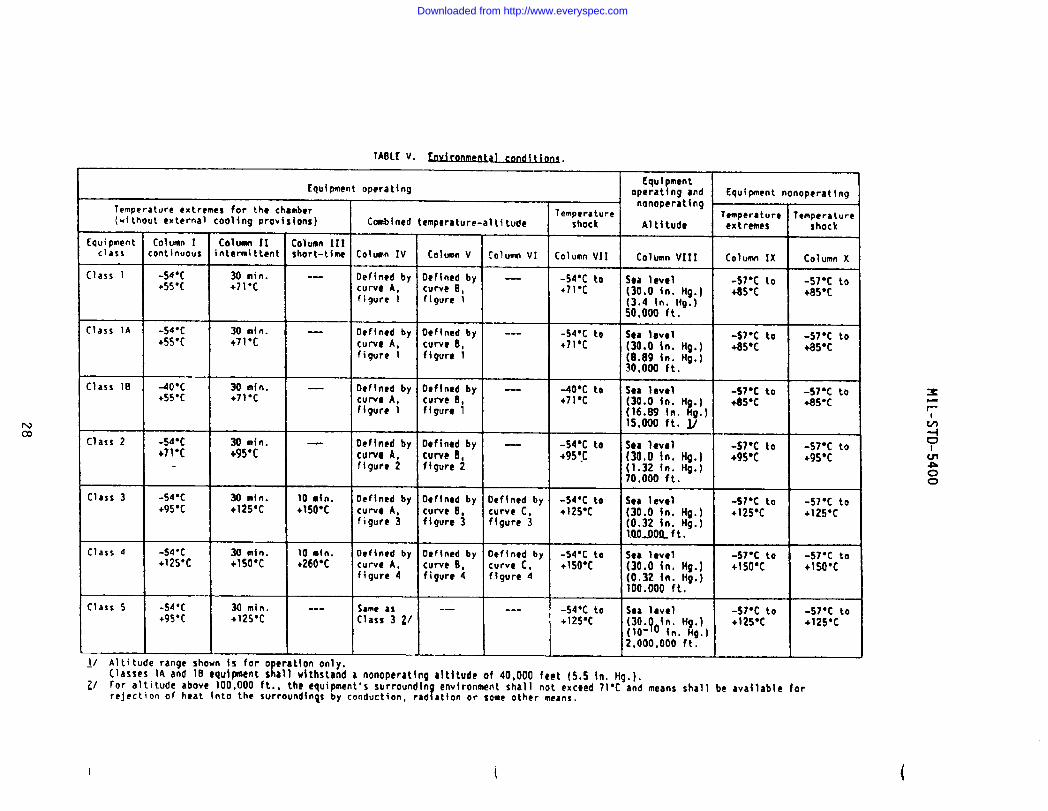
u
28
Downloaded from http://www.everyspec.com
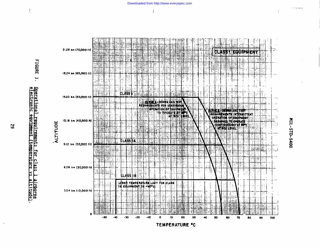
HIL-STD-5400
.-.
t?..
.7.
..
.-,.
-:.:...
1.
-.1..
...
.—
...
—-
9—
-.—,
-i—..
..;A
r-.:
:-
.......
1I.-.:.
=k=l=lj--.j~
—..J
!7-3
*::,1:,:-1,::.;.
I:
$
..............
...
...
,1
a.0
I.
,.-.L.
..
..
..
..
..
..
..
/._.I.....
—
.I
>.be
.!17=
.1!..l.,.:~
1
$?
.f .--.
...i..’.l
....l.
l...,-.
.,.
..
..
..
...-&...-
0
FIGU
RE
1.O
perationalrea
uirem
entsfor
class1
airborneelectronic
eoulmnent
(temperature
vsaltitude}.
29
Downloaded from http://www.everyspec.com
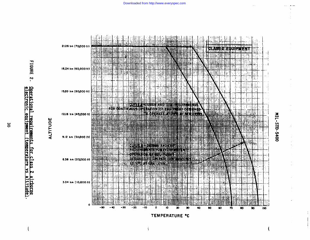
!..
jj9“
0
FIGU
RE
2.9D
eration
alreau
hm
mts
forc1
ass2
airbor~electron
Iceauimnent
(emt
eraturew
altitude\.
30
Downloaded from http://www.everyspec.com
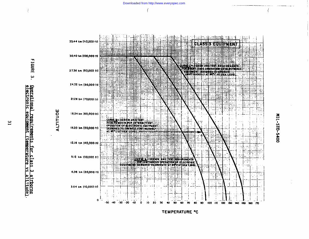
IM
IL-STK)-5400
I>.
1I
..
E.E
EE
.M
*
000-
0=
3anAlllv
FIGU
RE
3.erat
ional
reaui
rements
forcl
ass3
alrborn~elect
roniceauim
nentem
oeratureVs
altitude~.
0
31
Downloaded from http://www.everyspec.com
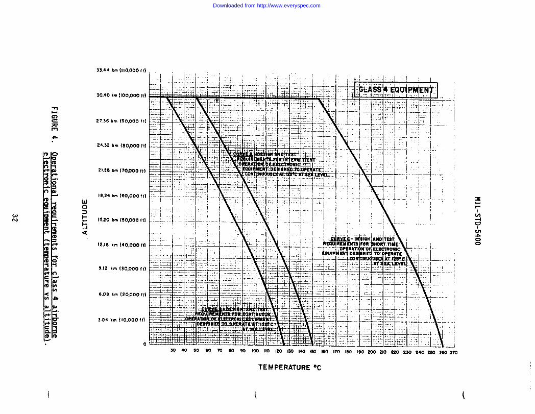
MIL-STD-5400
o00.
0=
o00-
gE.
Q
0000-3E.N
E.
000-
0=
0
-
+-
FIGU
RE
4.O
Deratonal
reaulrements
.i
forc
lass4
airborneelectronic
eautmne
..
nt(tgglQ
Qra
vltitude
.
32
Downloaded from http://www.everyspec.com
II
I MIL-STD-5400
----
4.6.2.5 Vibration.
4.6.2.5.1 ~ normal 1v mounted. Uhen normally mounted (withvibration isolators in place, if any), the equipment shall not suffer damageor fail to meet specified performance when subjected to the applicable vibra-tion environment detailed herein or as specified in the detail equipmentspecification or contract. Selection of the applicable vibration environment(type of exci tat ion, frequency range and energy density level as a function ofaircraft and application location) shall be detemnined using the followingcriteria.
4.6.2.5.1.1 iment desi aned for installation in moDeller a.
cra ft.Equipment of this type shall withstand random excitation over the fr~~uencyrange of 15 to 500 Hz with energy density levels specified by the appropriatefigure and table of NIL-STO-81O, Method 514.
4.6.2.5.1.2 Eauimnent des ianed for installation in .iet aircraft. Equip-ment of this type shall withstand random excitation over the frequency rangeof 15 to 2000 Hz with energy density levels specified by the appropriatefigure and table of MIL-STO-810, Method 514.
4.6.2.5.1.3 Ea uiment desiuned for installation in helic opterS. Equip-ment of this type shall withstand random excitation over the frequency rangeof 5 to 500 Hz with energy density levels specified by the appropriate figureand table of MIL-STO-810, Method 514.L In addition, equipment of this typeshall withstand random excitation over the frequency range of 5 to 2000 Hz forthe purposes of environmental stress screening (ESS).
4.6.2.5.1.4 Minimum intearitv test. Equipment normally mounted onIsolators,. but wfth isolators removed, shall be capable of meeting specifiedperformance without suffering equipment damage, when subjected to a minimumintegrity test within the vibration levels specified by the applicable figuresand tables of ?4IL-STD-81O, Method 514. The minimum integrity test should beapplied as a basic test for items which are not designed for any of the othervibration environments cited above. The vibration levels and durations arenot based on application environments, but provide reasonable assurance thatthe equipment will withstand operations and handling during field installa-tion, removal, and repair. The test exposures are based on “typical”electronic boxes and the maximum weight of the test item or subassembly shouldnot exceed approximately 36 kilograms (80 pounds).
4.6.2.6 Shock.
4.6.2.6.1 EauiDm~. Equipment (with vibration isolators in place, ifany) shall not suffer damage or subsequently fail to provide the performancespecified in the detail equipment specification when subjected to 18 impactshocks of 20g, consisting of 3 shocks in opposite directions along each 3mutually perpendicular axes, each shock impulse having a time duration of 6 to9 milliseconds. The “g” value shall be within ~10 percent when measured witha 0.2 to 250 Hz filter.
.-.4.6.2.6.2 untina base (crash safety). Uith excursion stops or bumpers
in place and with maximum rated load applied in a normal manner, the mounting
33
Downloaded from http://www.everyspec.com
MIL-STD-5400
base, individual isolators, or other attaching devices shall withstand atleast 12 impact shocks of 40g, consisting of 2 shocks ~n opposite directionsalong each of 3 mutually perpendicular axes. Each shock impulse shall havetime duration of 6 to 9 milliseconds. The “g” value shall be within *1Opercent when measured with a 0.2 to 250 Hz filter. Bending and distortionshall be permitted; however, there shall be no failure to the attachingjoints, and the equipment or duany load shall remain in place.
4.6.2.6.3 Pent h handlinq. The equipment shall withstand the shockenvironment encountered during servicing.
4.6.2.7 Sand and dust. The equipment shall withstand, in both anoperating and nonoperating condition, exposure to sand and dust particles asencountered in operational areas of the world.
4.6.2.8 Funaus. The equipment shall withstand, In both an operating andnonoperating condition, exposure to fungus growth as encountered in tropicalclimates. In no case shall overall spraying of the equipment be necessary tomeet this requirement.
4.6.2.9 Salt atmos~here. The equipment shall withstand, in both anoperating and nonoperating condition, exposure to salt-sea atmosphere.
4.6.2.10 @~losive con ditiow. The equipment shall not cause ignitionof an ambient-explosive-gaseous mixture with air when operating in such anatmosphere.
34
Downloaded from http://www.everyspec.com
PIIL-sTD-5400
--r-
5. DETAIL REQUIREMENTS
5.1 @tailed mechan ical and elect ical desia~ Specific requirementsfor individual equipment shall be as sp~cified in the detail equipmentspecification or contract. The detailed mechanical and electrical design ofspecific equipment shall be accomplished by the contractor, subject to therequirements of this standard and any detail equipment specification to whichit is subsidiary. The requirements of this standard are detailed only to theextent considered necessary to obtain the desired mechanical and electricalcharacteristics, performance and permanence of the same. The design layoutand assembly of the units and their component parts shall be such as tofacilitate quantity production and to result in minimum size and weight.
5.2 Techn ical data. The requirements for the preparation and managementof technical data during the various e uipment design, development and
2production phases shall be selected an tailored from MIL-~-31000 andspecified in the contract. MIL-T-31OOO defines the various types of drawings,associated lists and reports, along with the applicable Data Item Descriptions(DIDs) for listing in the Contract Oata Requirements List (CDRL, 00 Form1423) .
5.3 Quality assurance.
5.3.1responsibleherein and ‘
5.3.2
Be sDonsibility for t@sts and inspections. The contractor isfor the performance of all tests and inspections as specifiedn the detail equipment specification or contract.
Government verification. All quality and safety assurance opera-tions performed by the contractor will be subject to Government verificationat any-time. Verification will consist of (a) surveillance of the operationsto determine that practice, methods, and procedures of the quality and safetyprogram requirements are being properly applied, (b) Government productinspection to measure quality and safety of product to be offered foracceptance, and (c) Government inspection of delivered items to assurecompliance with the detail equipment specification or contract.
5.3.3 Fa ilure criteriq. Unless otherwise specified in the detail equip-ment specification or contract, the equipment, or portions thereof, shall beconsidered to have failed the prescribed tests and inspections when any of thefollowing conditions occur:
a. Equipment fails to meet the specified performance parameters, orfails within specified limits.
b. Structural failure or distortion.
c. Any condition that results in hazard to personnel or equipmentsafety.
d. Process control deficiencies.
e. Inspection and test procedure deficiencies.
f. Improper labeling, handling and packaging.
35
Downloaded from http://www.everyspec.com
MIL-STD-5400
5.3.4 Pr oblemffailure reDor tina and corrective action. Problem/failurereporting and corrective action of any failure occurring as a result of testsperformed during incoming inspection shall be in accordance with MIL-STD-785.The contractor shall also determine and report the yield or percentage offailures that occurred for each level of hardware. For correction, considera-tion should be paid to GIDEP data utilization in MIL-STD-1556.
5.3.5 Resicln a ualification tests Design qualification testing shall beperformed prior to commitment to produ~tion. The requirements for designqualification of the equipment shall be tailored from Task 301 of MIL-STD-781and specified in the contract. The requirement for environmental stressscreening (ESS), Task 401 of MIL-STD-781, shall also be applied in conjunctionwith Task 301. These tasks identify the details to be specified by theacquisition activity and the applicable Data Item Descriptions (DIDs) forincorporation into the CDRL (LIDForm 3423).
5.3.6 First article testq. The first article tests shall be performedin conjunction with production contracts only. The requirement for theperformance of first article tests shall be specified in the detail equipmentspecification or contract. First article tests are those tests to be per-formed on one (1) or more equipments (as required by the detail specificationor contract) representative of production equipment to be supplied on contractor order.
5.3.6.1 ScoDe of test~. The requirement for first article tests shallinclude a?l tests deemed necessary by the acquiring activity to determine thatthe equipment meets all of the requirements specified in the detail equipmentspecification or contract. These tests shall include environmental tests inaccordance with the test methods and procedures of MIL-STD-81O. Electro-magnetic Interference tests and test methods shall be in accordance withMIL-STD-461.
5.3.7 Qual itv conform ce tests. The requirement for the performance ofquality conformance tests s~~ll be specified in the detai? equipment spec-ification or contract. Quality conformance tests are those tests deemednecessary to determine that the equipments submitted for acceptance under thecontract are equivalent in performance and construction to the approved firstarticle equipment. Quality conformance tests shall consist of the following:
a. Individual tests to be performed on each equipment submitted foracceptance under the contract. These tests should includeenvironmental stress screening (ESS) or burn-in.
b. Production reliability acceptance tests in accordance with Task 302of MIL-STD-781. Task 302 identifies those details to be specifiedby the acquisition activity, including test plan, sampling Plan,environmental test conditions, performance requirements, and theapplicable Data Item Descriptions (OIDS) for incorporation into theCDRL (DD Form 1423).
36
Downloaded from http://www.everyspec.com
MIL-STD-5400
-----
5.4 Pre~aration for de1ivery Requirements for packaging, packing andmarking for shipment of equipment ~hall be submitted in the detail equipmentspecification or contract.
6. NOTES
(This section contains information of a general or explanatory nature whichmay be helpful, but is not mandatory.)
6.1 Jntended use. This standard is intended as a general design guidefor use in the development and preparation of detail equipment specificationsand contracts for airborne electronic equipment to specify those requirementsapplicable to the specific equipment.
6.2 Details for inclusion in ecmic)ment SDedifications and contracts.Since this standard covers only general requirements, the detail equipmentspecification (as prepared either by the Government, the eqUiPment manu-facturer for the Government, or the prime vehicle contractor) or contract mustspecify actual requirements from the multiple choices, tailoring, or
-- exceptions available in the following paragraphs:
a. Classification requirements (see 1.2, 1.2.1).
b. Tailoring requirements (see 1.2 and Appendix B).
c. Warmup time (see 4.2.8.1).
d. Electromagnetic interference characteristics (see 4.2.9).
e. Electrostatic discharge control program (see 4.2.10).
f. Human engineering requirements (see 4.2.14).
9. Maintainability program requirements (see 4.2.16).
h. Equipment orientation (see 4.2.22).
i. Pressure and altitude requirements for specifying air leakage (see4.2.24(g) and (h)).
j. Reliability program requirements ~see 4.2.25).
k. Repairability requirements (see 4.2.26).
---
1. System safety program requirements (see 4.2.27.1).
m. Testability program requirements (see 4.2.29).
37
Downloaded from http://www.everyspec.com
-
n.
0.
P-
q.
r.
s.
t.
u.
v.
w.
x.
Y.
z.
MIL-STD-5400
Thermal design requirements (see 4.2.30 and 4.2.30.1).
Special tools (see 4.2.31.2).
Parts control program requirements and GFB (see 4.3.1 thru 4.3.3).
Samples for nonstandard parts and material approval, if required.
Nonstandard material approval (see 4.4.4.1).
Environmental test methods, procedures, limits, etc. (see 4.6 thru4.6.10).
Detail equipment design (see 5.1).
Technical data (see 5.2).
Equipment design qualification tests (see 5.3.5).
First article tests and sample (see 5.3.6, 5.3.6.1).
Accessory material and data to perform tests, if required.
Quality conformance requirements and tests (see 5.3.7).
Packaging requirements (see 5.4).
6.3 Use of helium. Helium should not be used as a pressurizing gas insealed units containing electron tubes. When it is necessary to use heliumfor leak detection inn-Doses. exDosure should be limited to the time necessaryfor
shou
he test, fullowed’by thorough purging.
6.4 Publications. In the design of electronic equipment, considerationd be given to the information contained in the following publications:
a. Handbook, Preferred Circuits Navy Aeronautical ElectronicNAVAIR-16-1-519, Volume 2 Equipment.
6.5 Sub.iect term (kevword) listinq.
ClassificationDesign and constructionEnvironmental requirementsMaterial selectionMilitary standardParts selectionProcesses and finishesTailoring requirements
Downloaded from http://www.everyspec.com
MIL-STD-5400
Custodians:Army - CRNavy - ASAir Force - 11
Reviewer activities:Am - MI, AR, AVNavy - ECAir Force - 15, 17, 99DLA - ES
Preparing activity:Navy - AS
(Pro ject GORQ-O1O2)
39
Downloaded from http://www.everyspec.com
MIL-STD-5400-—
APPENDIX A
APPLICABLE DOCUMENTS
10. SCOPE
10.1 SCODQ. THIS APPENDIX IS A MANDATORY PART OF THIS STANDARD. THEINFORMATION CONTAINED HEREIN IS INTENDED FOR COMPLIANCE.
10.2 This appendix lists specifications, standards, handbooks and otherpublicat~ons selected for their applicability in the design and constructionof airborne electronic equipment. Those parts and materials covered bydocuments listed in this appendix will be considered standard items. Uhenpart selection standards are referenced, the documents listed in the selectionstandard have the same status as those listed directly in this appendix andthe parts they cover are also considered standard (unless otherwise restrictedor banned for airborne applications).
10.3 selection of documents for nonstandard Darts and materials. WhenAppendix A does not provide a document suitable for the design requirement,selection of specifications and standards for nonstandard parts and materialsshall be made in accordance with the order of preference contained inMIL-STD-970, unless otherwise specified herein or in referenced MIL-STD-454requirements.
20. APPLICABLE DOCUMENTS
20.1 The documents listed in this appendix are applicable to the extentspecified directly herein or in the referenced MIL-STD-454 requirements.
20.2 ADD licable issues Unless otherwise specified, the issues of thesedocuments ”%re those listed in the issue of the Department of Defense Index ofSpecifications and Standards (DDDISS) and supplement thereto, cited in thesolicitation. Later revisions, amendments and documents superseding thoselisted in Appendix A may be used when preferred by the contractor. When alater issue is used, all applicable requirements of the later revision shallbe used.
20.3 CoDies. Unless otherwise indicated, copies of federal and militaryspecifications, standards and handbooks are available from the DODSSPStandardization Document Order Desk, 700 Robbins Avenue, Building 4D,Philadelphia, PA 19111-5094. Addresses for ordering copies of non-governmentdocuments are listed on the following page.
30. APPLICATION OF SELECTED DOCUMENTS
30.1 It is not the intent that all ciocuwents listed in this appendixapply to all contracts, or that those that do apply necessarily apply in full.Before proceeding with the application of any document, all contractualspecifications and requirements should be reviewed by the contractor, and theextent of applicability to the specific equipment design be determined.
A-l
Downloaded from http://www.everyspec.com
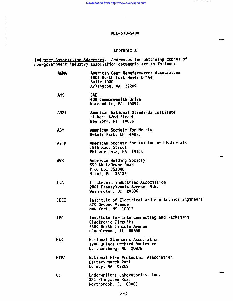
MIL-STD-5400
APPENDIX A
~ndustry ASSO ciation Addresses. Addresses for obtaining copies ofnon-government industry association documents are as follows:
AMA Anerjcan Gear 14anufacturers Association1901 North Fort Neyer DriveSuite 1000Arlington, VA 22209
Am
ANSI
ASM
ASTM
AM
EIA
IEEE
I PC
NAS
NFPA
UL
SAE400 Conmaonwealth DriveUarrendale, PA 15096
I!merican National Standards Institute11 Uest 42nd StreetNew York, NY 10036
American Society for MetalsMetals Park, ON 44073
American Society for Testing and Materials1916 Race StreetPhiladelphia, PA 19103
American Melding Society550 NU LeJeune RoadP.O. Box 351040Miami, FL 33135
Electronic Industries Association2001 Pennsylvania Avenue, N.U.Washington, DC 20006
Institute of Electrical and Electronics Engineers820 Second AvenueNew York, NY 10017
Institute for Interconnecting and PackagingElectronic Circuits7380 North Lincoln AvenueLincolnwood, IL 60646
National Standards Association1200 Quince Orchard BoulevardGaithersburg, ND ~0878
National Fire Protection AssociationBattery march ParkQuincy, MA 02269
Underwriters Laboratories, Inc.333 Pfingsten RoadNorthbrook, IL 60062
-
A-2
Downloaded from http://www.everyspec.com
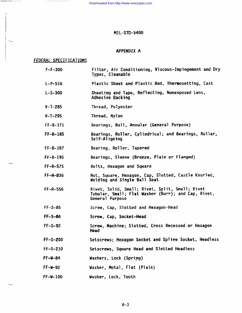
I .._MIL-STD-5400
APPENDIX A
FEDERAL SPECI FICATIONS
F-F-300
L-P-516
L-S-300
V-T-285
V-T-295
FF-B-171
FF-B-185
FF-B-187
FF-B-195
FF-B-575
FF-N-836
FF-R-556
FF-S-85
FF-S-86
FF-S-92
FF-S-200
FF-S-21O
FF-U-84
FF+-92
FF-W-1OO
Filter, Air Conditioning, Viscous-Impingement and DryTypes, Cleanable
Plastic Sheet and Plastic Rod, Thennosetting, Cast
Sheeting and Tape, Reflecting, Nonexposed Lens,Adhesive Backing
Thread, Polyester
Thread, Nylon
Bearings, Ball, Annular (General Purpose)
Bearings, Roller, Cylindrical; and Bearings, Roller,Self-Aligning
Bearing, Roller, Tapered
Bearings, Sleeve (Bronze, Plain or Flanged)
Bolts, Hexagon and Square
Nut, Square, Hexagon, Cap, Slotted, Castle Knurled,Welding and S~ngle Ball Seat
Rivet, Solid, Small; Rivet, Split, Small; RivetTubular, Small; Flat Uasher (Burr); and Cap, Rivet,General Purpose
Screw, Cap, Slotted and Hexagon-Head
Screw, Cap, Socket-Head
Screw, Machine; Slotted, Cross Recessed or HexagonHead
Setscrews; Hexagon Socket and Spline Socket, Headless
Setscrews, Square Head and Slotted Headless
Mashers, Lock (Spripg)
Washer, Metal, Flat (Plain)
Washer, Lock, Tooth
A-3
Downloaded from http://www.everyspec.com
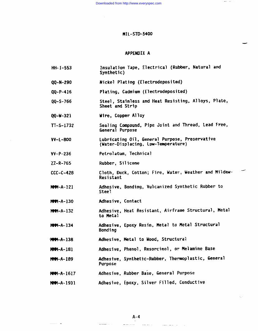
MXL-STD-5400
-
tifi-I-553
QQ-N-290
QQ-P-416
QQ-S-766
QQ-M-321
‘I-T-S-1732
VV-L-800
VV-P-236
ZZ-R-765
CCC-C-428
M-A-121
~-A-130
IW4-A-132
M-A-134
I#W#-A-138
MMI-A- 181
MNN-A- 189
MM-A-1617
?4NM-A-1931
APPENDIX A
Insulation Tape, Electrical (Rubber, Natural andSynthetic)
Nickel Plating (Electrodeposited)
Plating, Cadmium (Electrodeposited)
Steel, Stainless and Heat Resisting, Alloys, Plate,Sheet and Strip
Hire, Copper Alloy
Sealing Compound, Pipe Joint and Thread, Lead Free,General Purpose
Lubricating Oil, General Purpose, preservative(Uater-Displacing, Low-Temperature)
Petrolatum, Technical
Rubber, Silicone
Cloth, Duck, Cotton; Fire, Mater, Ueather and Mildew- -Resistant
Adhesive, Bonding, Vulcanized Synthetic RubberSteel
Adhesive, Contact
Adhesive, Heat Resistant, Airframe Structural,to Metal
to
Metal
Adhesive, Epoxy Resin, Metal to Metal StructuralBond ing
Adhesive, Metal to Uood, Structural
Adhesive, Phenol, Resorcinol, or Melamine Base
Adhesive, Synthetic-Rubber, Thermoplastic, GeneralPurpose
Adhesive, Rubber Bake, General Purpose
Adhesive, Epoxy, Silver Filled, Conductive
A-4
Downloaded from http://www.everyspec.com
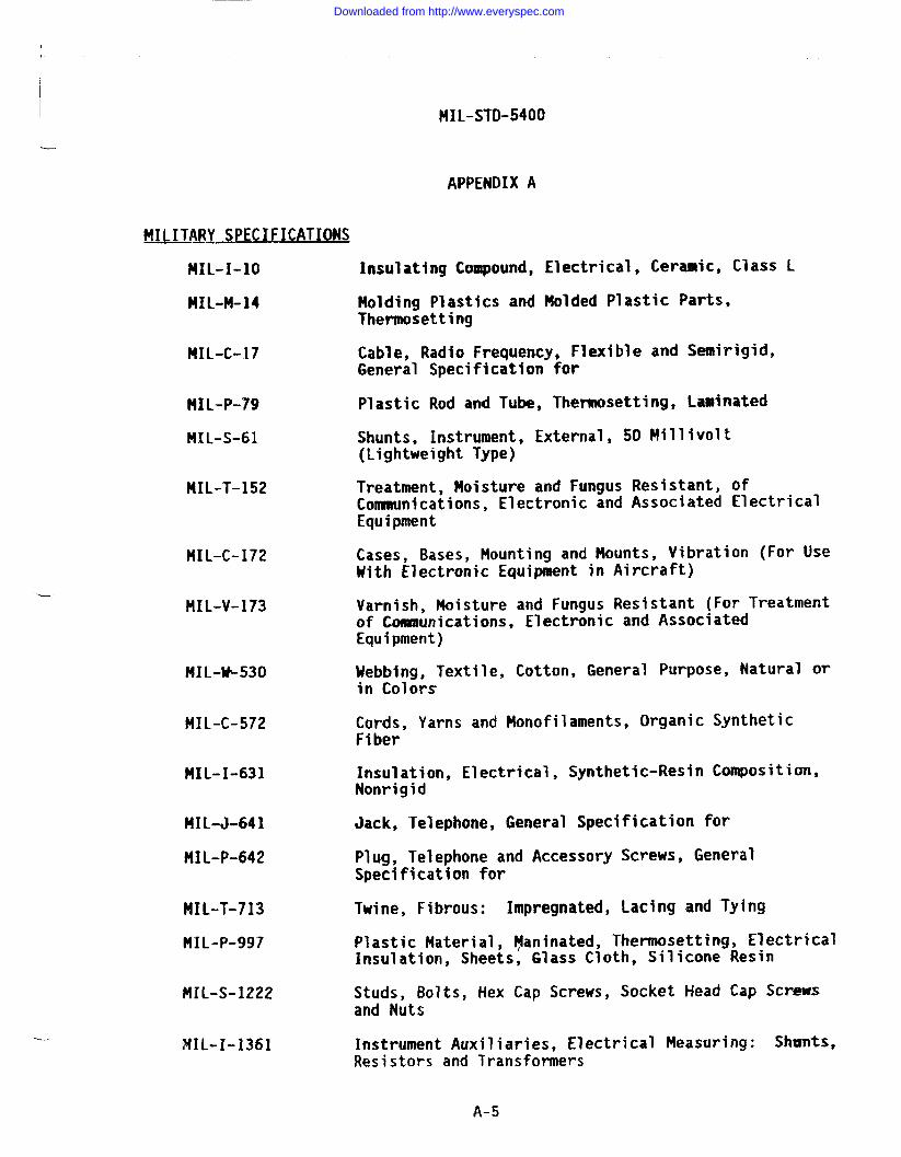
IMIL-STD-5400
APPENDIX A
MILITARY SPECIFICA TIONS
HIL-I-1O
MIL-M-14
NIL-C-17
HIL-P-79
MXL-S-61
MIL-T-152
HIL-C-172
NIL-V-173
MIL+-530
MIL-C-572
MIL-I-631
MIL-J-641
MIL-P-642
MIL-T-713
MIL-P-997
MIL-S-1222
MIL-r-1361
Insulating Compound, Electrical, Ceramic, Class L
Molding Plastics and Molded Plastic Parts,Thermosetting
Cable, Radio Frequency, Flexible and Semirigid,General Specification for
Plastic Rod and Tube, Thermosetting, Laminated
Shunts, Instrument, External, 50 Millivolt(Lightweight Type)
Treatment, Moisture and Fungus Resistant, ofConmnunications, Electronic and Associated ElectricalEquipment
Cases, Bases, Mounting and Mounts, Vibration (For useWith Electronic Equipment in Aircraft)
Varnish, Moisture and Fungus Resistant (For Treatmentof Communications, Electronic and AssociatedEquipment)
Webbing, Textile, Cotton, General Purpose, Natural orin Colors
Cords, Yarns and Monofilament, Organic SyntheticFiber
Insulation, Electrical, Synthetic-Resin Composition,Nonrigid
Jack, Telephone, General Specification for
Plug, Telephone and Accessory Screws, GeneralSpecification for
Twine, Fibrous: Impregnated, Lacing and Tying
Plastic Material, l$aninated, Thermosetting, ElectricalInsulation, Sheets, Glass Cloth, Silicone Resin
Studs, Bolts, Hex Cap Screws, Socket Head Cap Scr=Sand Nuts
Instrument Auxiliaries, Electrical Measuring: Shunts,Resistors and Transformers
A-5
Downloaded from http://www.everyspec.com
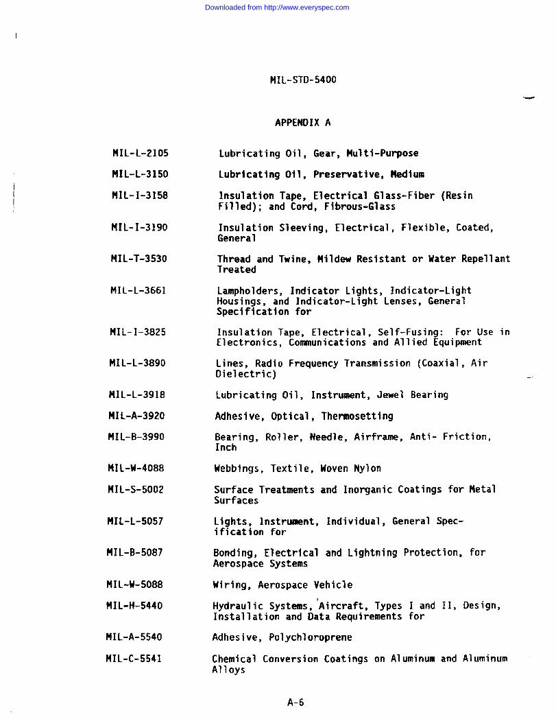
MIL-STD-5400
-
APPENDIX A
MIL-L-2105
MIL-L-3150
MIL-I-3158
MIL-I-3190
MIL-T-3530
MIL-L-3661
MIL-I-3825
MIL-L-3890
MIL-L-3918
MIL-A-3920
HIL-B-3990
MIL-U-4088
MIL-S-5002
HIL-L-5057
MIL-B-5087
MIL-W-5088
MIL-H-5440
MIL-A-5540
f41L-C-5541
Lubricating Oil, Gear, Multi-Purpose
Lubricating Oil, Preservative, Nedium
Insulation Tape, Electrical Glass-Fiber (ResinFilled); and Cord, Fibrous-Glass
Insulation Sleeving, Electrical, Flexible, Coated,General
Thread and Twine, Mildew Resistant or Uater RepellantTreated
Lampholders, Indicator Lights, Indicator-LightHousings, and Indicator-Light Lenses, GeneralSpecification for
Insulation Tape, Electrical, Self-Fusing: For Use inElectronics, Communications and Allied Equipment
Lines, Radio Frequency Transmission (Coaxial, AirDielectric)
Lubricating Oil, Instrument, Jewel Bearing
Adhesive, Optical, Thennosetting
Bearing, Roller, Needle, Airframe, Anti- Friction,Inch
Webbings, Textile, Hoven Nylon
Surface Treatments and Inorganic Coatings for MetalSurfaces
Lights, Instrument, Individual, General Spec-ification for
Bonding, Electrical and Lightning Protection, forAerospace Systems
Wiring, Aerospace Vehicle
Hydraulic Systems, ‘Aircraft, Types I and II, Design,Installation and Data Requirements for
Adhesive, Polychloroprene
Chemical Conversion Coatings on Aluminum and Aluminum ‘-Alloys
A-6
Downloaded from http://www.everyspec.com
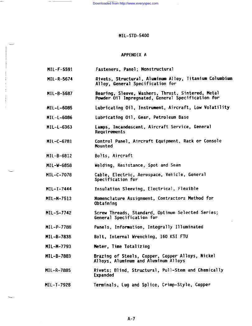
-.
-----
MIL-F-5591
MIL-R-5674
MIL-B-5687
MIL-L-6085
MIL-L-6086
MIL-L-6363
MIL-C-6781
MIL-B-6812
MIL-U-6858
MIL-C-7078
MIL-I-7444
MIL-N-7513
MIL-S-7742
MIL-P-7788
MIL-B-7838
MIL-M-7793
MIL-B-7883
MIL-R-7885
MIL-T-7928
‘MIL-STD-5400
APPENDIX A
Fasteners, Panel; Nonstructural
Rivets, Structural, Aluminum Alloy, Titanium ColumbiumAlloy, General Specification for
Bearina. Sleeve. Washers, Thrust, Sintered, MetalPowder-Oil Impregnated, General Specification
Lubricating Oil, Instrument, Aircraft, Low Vo’
Lubricating Oil, Gear, Petroleum Base
Lamps, Incandescent, Aircraft Service, Genera”Requirements
for
atility
Control Panel, Aircraft Equipment, Rack or ConsoleMounted
Bolts, Aircraft
Uelding, Resistance, Spot and Seam
Cable, Electric, Aerospace, Vehicle, GeneralSpecification for
Insulation Sleeving, Electrical, Flexible
Nomenclature Assignment, Contractors Method forObtaining
Screw Threads, Standard, Optimum Selected Series;General Specification for
Panels$ Information, Integrally Illuminated
Bolt, Internal Wrenching, 160 KSI FTU
Meter, Time Totalizing
Brazing of Steels, Copper, Copper Alloys, NickelAlloys, Aluminum and Aluminum Alloys
Rivets; Blind, Strutural, Pull-Stem and ChemicallyExpanded
Terminals, Lug and Splice, Crimp-Style, Copper
---
A-7
Downloaded from http://www.everyspec.com
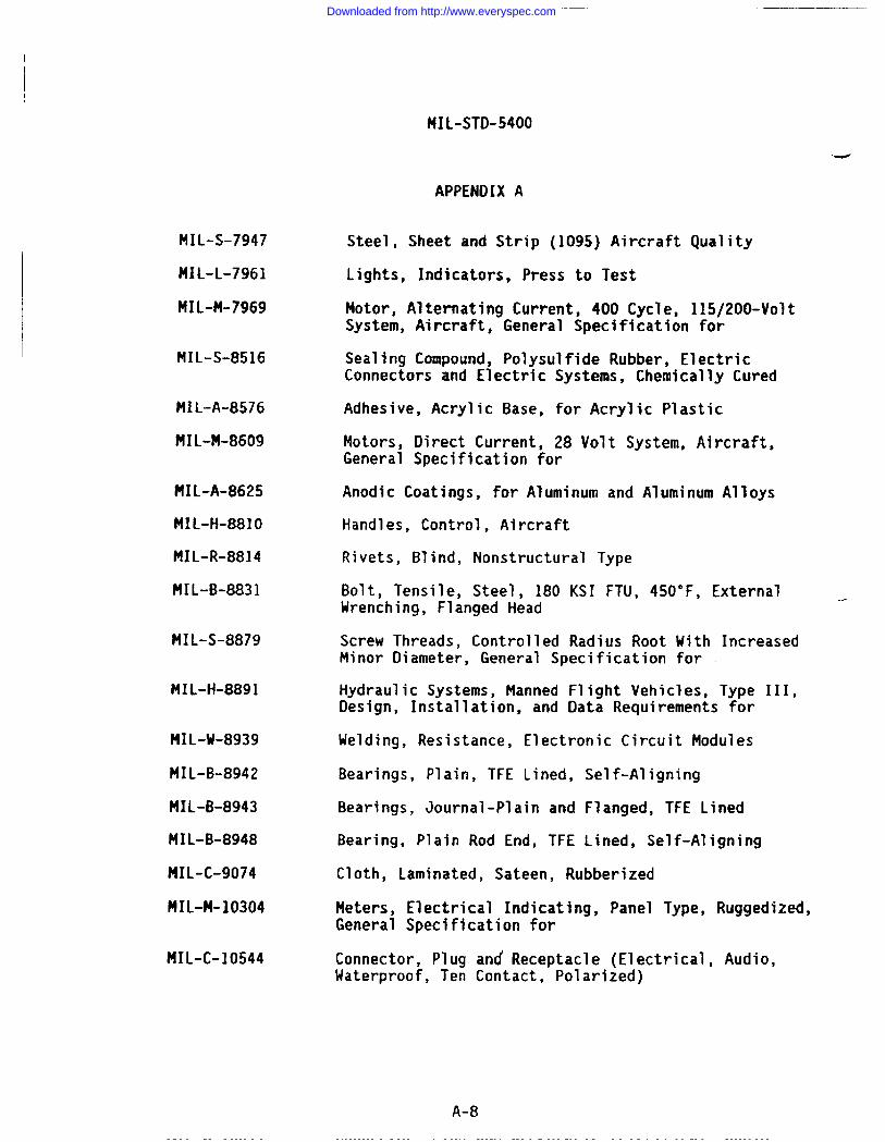
MIL”STD-5400
-
APPENDIX A
MIL-S-7947
HIL-L-7961
HIL-M-7969
MIL-S-8516
MIL-A-8576
MIL-M-8609
MIL-A-8625
MIL-H-8810
MIL-R-8814
MIL-B-8831
MIL-S-8879
NIL-H-8891
MIL-W-8939
MIL-B-8942
MIL-B-8943
MIL-B-8948
MIL-C-9074
MIL-?4-103O4
MIL-C-10544
Steel, Sheet and Strip (1095) Aircraft Quality
Lights, Indicators, Press to Test
Motor, Alternating Current, 400 Cycle, 115/200-VoltSystem, Aircraft, General Specification for
Sealing Compound, Polysulfide Rubber, ElectricConnectors and Electric Systems, Chemically Cured
Adhesive, Acrylic Base, for Acrylic Plastic
Motors, Direct Current, 28 Volt System, Aircraft,General Specification for
Anodic Coatings, for Aluminum and Aluminum Alloys
Handles, Control, Aircraft
Rivets, Blind, Nonstructural Type
Bolt, Tensile, Steel, 180 KSI FTU, 450”F, External ._Wrenching, Flanged Head
Screw Threads, Controlled Radius Root With IncreasedMinor Diameter, General Specification for
Hydraulic Systems, Manned Flight Vehicles, Type III,Design, Installation, and Data Requirements for
Welding, Resistance, Electronic Circuit Modules
Bearings, Plain, TFE Lined, Self-Aligning
Bearings, Journal-Plain and Flanged, TFE Lined
Bearing, Plain Rod End, TFE Lined, Self-Aligning
Cloth, Laminated, Sateen, Rubberized
Meters, Electrical Indicating, Panel Type, Ruggedized,General Specification for
Connector, Plug and Receptacle (Electrical, Audio,Waterproof, Ten Contact, Polarized)
A-8
Downloaded from http://www.everyspec.com
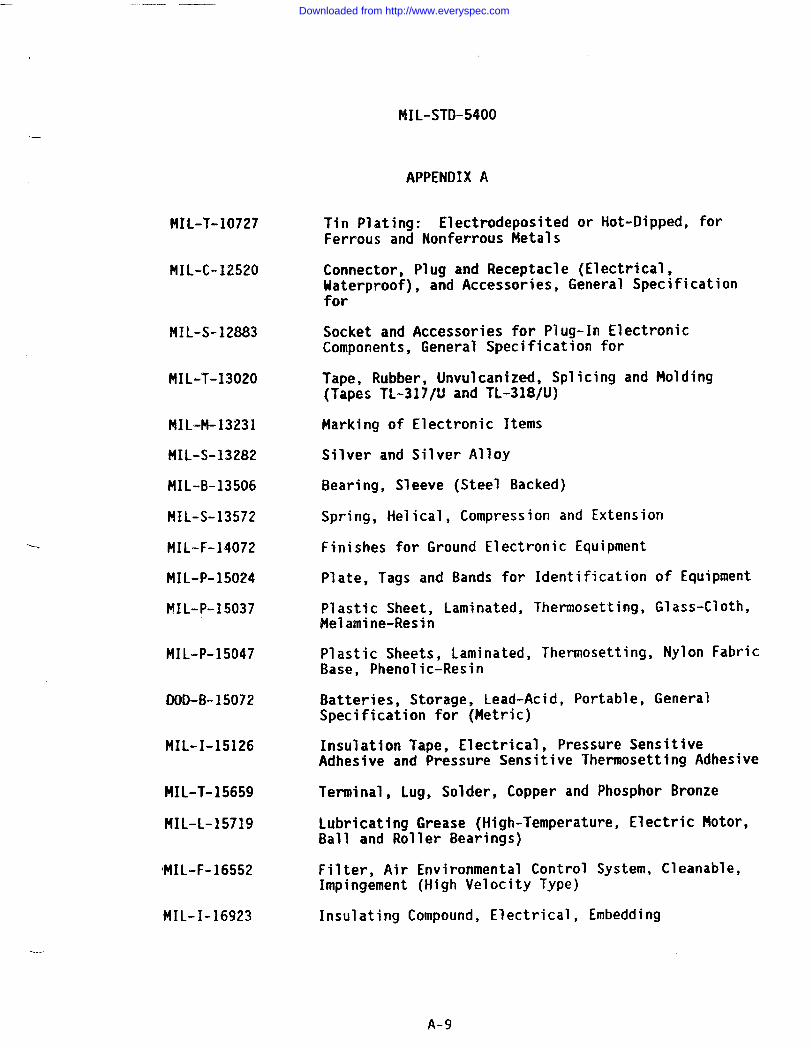
MIL-STD-5400.—
APPENDIX A
MIL-T-10727
MIL-C-12520
MIL-S-12883
MIL-T-13020
MIL-M-13231
MIL-S-13282
141L-B-13506
MIL-S-13572
MIL-F-14072
MIL-P-15024
MIL-P-15037
MIL-P-15047
DOD-B-15072
MIL-I-15126
MIL-T-15659
MIL-L-15719
IMIL-F-16552
MIL-I-16923
Tin Plating: Electrodeposited or Hot-Dipped, forFerrous and Nonferrous Metals
Connector, Plug and Receptacle (Electrical,Waterproof), and Accessories, General Specificationfor
Socket and Accessories for Plug-In ElectronicComponents, General Specification for
Tape, Rubber, Unvulcanized, Splicing and Molding(Tapes TL-317/U and TL-318/U)
Marking of Electronic Items
Silver and Silver Alloy
Bearing, Sleeve (Steel Backed)
Spring, Helical, Compression and Extension
Finishes for Ground Electronic Equipment
Plate, Tags and Bands for Identification of Equipment
Plastic Sheet, Laminated, Thermosetting, Glass-Cloth,Melamine-Resin
Plastic Sheets, Laminated, Thermosetting, Nylon FabricBase, Phenolic-Resin
Batteries, Storage, Lead-Acid, Portable, GeneralSpecification for (Metric)
Insulation Tape, Electrical, Pressure SensitiveAdhesive and Pressure Sensitive Thermosetting Adhesive
Terminal, Lug, Solder, Copper and Phosphor Bronze
Lubricating Grease (High-Temperature, Electric Motor,Ball and Roller Bearings)
Filter, Air Environmental Control System, Cleanable,Impingement (High Velocity Type)
Insulating Compound, Electrical, Embedding
. ..
A-9
Downloaded from http://www.everyspec.com
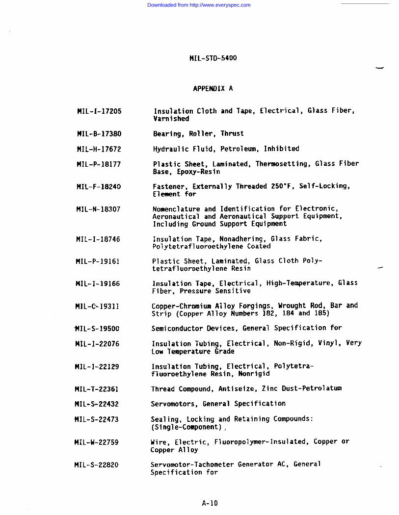
MIL-STO-5400-
APPENDIX A
MIL-I-17205
MIL-B-17380
HIL-H-17672
MIL-P-18177
MIL-F-18240
MIL-N-18307
MIL-I-18746
HIL-P-19161
MIL-I-19166
MIL-C--19311
tiIL-s-19500
MIL-I-22076
MIL-I-22129
MIL-T-22361
MIL-S-22432
MIL-S-22473
MIL-U-22759
MIL-S-22820
Insulation Cloth and Tape, Electrical, Glass Fiber,Varnished
Bearing, Roller, Thrust
Hydraulic Fluid, Petroleum, Inhibited
Plastic Sheet, Laminated, Thenaosetting, Glass FiberBase, Epoxy-Resin
Fastener, Externally Threaded 250”F, Self-Locking,Element for
Nomenclature and Identification for Electronic,Aeronautical and Aeronautical Support Equipment,Including Ground Support Equipment
Insulation Tape, Nonadhering, Glass Fabric,Polytetrafluoroethylene Coated
Plastic Sheet, Laminated, Glass Cloth Poly-tetrafluoroethylene Resin .
Insulation Tape, Electrical, High-Temperature, GlassFiber, Pressure Sensitive
Copper-Chromium Alloy Forgings, Wrought Rod, Bar andStrip (Copper Alloy Numbers 182, 184 and 185)
Semiconductor Devices, General Specification for
Insulation Tubing, Electrical, Non-Rigid, Vinyl, VeryLow Temperature Grade
Insulation Tubing, Electrical, Polytetra-fluoroethylene Resin, Nonrigid
Thread Compound, Antiseize, Zinc Dust-Petrolatum
Servomotors, General Specification
Sealing, Locking and Retaining Compounds:(Single-Component) ,
Wire, Electric, Fluoropolymer-Insulated, Copper orCopper Alloy
Servomotor-Tachometer Generator AC, GeneralSpecification for
A-10
Downloaded from http://www.everyspec.com
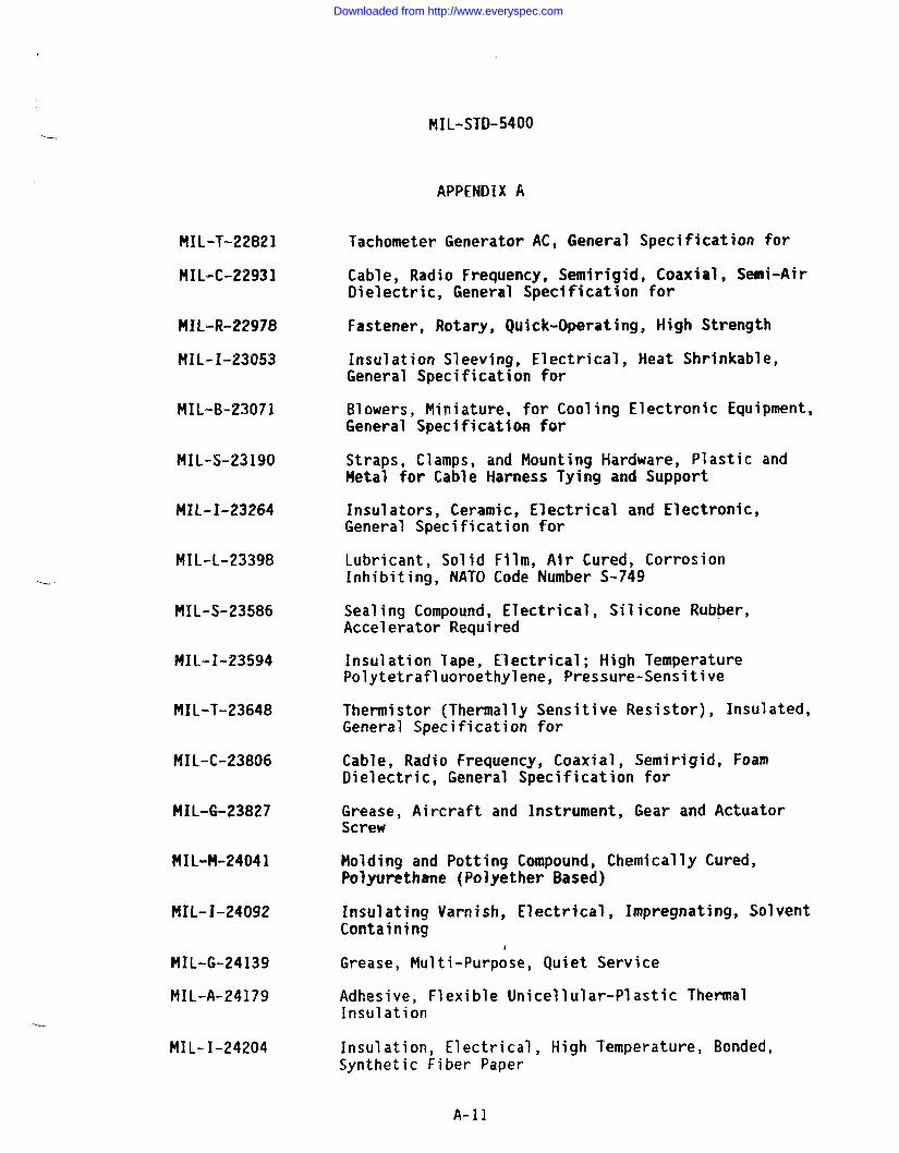
MIL-STD-5400
APPENDIX A
Tachometer Generator AC, General Specification forMIL-T-22821
NIL-C-22931 Cable, Radio Frequency, Semirigid, Coaxial, Semi-AirDielectric, General Specification for
Fastener, Rotary, Quick-Operating, High StrengthMIL-R-22978
PIIL-I-23053 Insulation Sleeving, Electrical, Heat Shrinkable,General Specification for
MIL-B-2307.I Blowers, Miniature, for Cooling Electronic Equipment,General Specification for
MIL-S-23190 Straps, Clamps, and Mounting Hardware, Plastic andMetal for Cable Harness Tying and Support
MIL-I-23264 Insulators, Ceramic, Electrical and Electronic,General Specification for
MIL-L-23398 Lubricant, Solid Film, Air Cured, CorrosionInhibiting, NATO Code Number S-749
MIL-S-23586 Sealing Compound, Electrical, Silicone Rubber,Accelerator Required
MIL”=I-23594 Insulation Tape, Electrical; High TemperaturePolytetrafluoroethylene, Pressure-Sensitive
MIL-T-23648 Thermistor (Thermally Sensitive Resistor), Insulated,General Specification for
MIL-C-23806 Cable, Radio Frequency, Coaxial, Semirigid, FoamDielectric, General Specification for
MIL-G-23827 Grease, Aircraft and Instrument, Gear and ActuatorScrew
MIL-M-24041 Molding and Potting Compound, Chemically Cured,Polyurethane (Polyether Based)
MIL-I-24092 Insulating Varnish, Electrical, Impregnating, SolventContaining
MIL-G-24139
MIL-A-24179
Grease, Multi-Purpose, Quiet Service
Adhesive, Flexible Unicellular-Plastic ThermalInsulation
...
MIL-I-24204 Insulation, Electrical, High Temperature, Bonded,Synthetic Fiber Paper
A-l]
Downloaded from http://www.everyspec.com
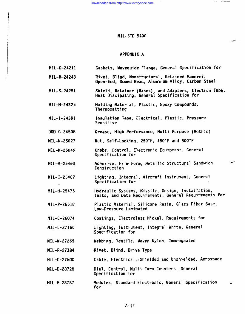
t!IL-sTD-5400
APPENDIX A
HIL-G-24211
MIL-R-24243
MIL-S-24251
HIL-M-24325
MIL-I-24391
DOD-G-24508
MIL-N-25027
MIL-K-25049
MIL-A-25463
HIL-I-25467
.
HIL-H-25475
MIL-P-25518
MIL-C-26074
HIL-L-27160
MIL-U-27265
MIL-R-27384
MIL-C-27500
MIL-D-28728
MIL-M-28787
Gaskets, Uaveguide Flange, General Specification for
Rivet, Blind, Nonstructural, Retained Mandrel,Open-End, Domed Head, Aluminum Alloy, Carbon Steel
Shield, Retainer (Bases), and Adapters, Electron Tube,Heat Dissipating, General Specification for
Molding Material, Plastic, Epoxy Compounds,Thermosetting
Insulation Tape, Electrical, Plastic, PressureSensitive
Grease, High Performance, Multi-Purpose (Metric)
Nut, Self-Locking, 250”F, 450”F and 800”F
Knobs, Control, Electronic Equipment, GeneralSpecification for
Adhesive, Film Form, Metallic Structural Sandwich -Construction
Lighting, Integral, Aircraft Instrument, GeneralSpecification for
Hydraulic Systems, Missile, Design, Installation,Tests, and Data Requirements, General Requirements for
Plastic Material, Silicone Resin, Glass Fiber Base,Low-Pressure Laminated
Coatings, Electroless Nickel, Requirements for
Lighting, Instrument, Integral White, GeneralSpecification for
Webbing, Textile, Woven Nylon, Impregnated
Rivet, Blind, Drive Type
Cable, Electrical, lShielded and Unshielded, Aerospace
Dial, Control, Multi-Turn Counters, GeneralSpecification for
Modules, Standard Electronic, General Specification —for
A-12
Downloaded from http://www.everyspec.com
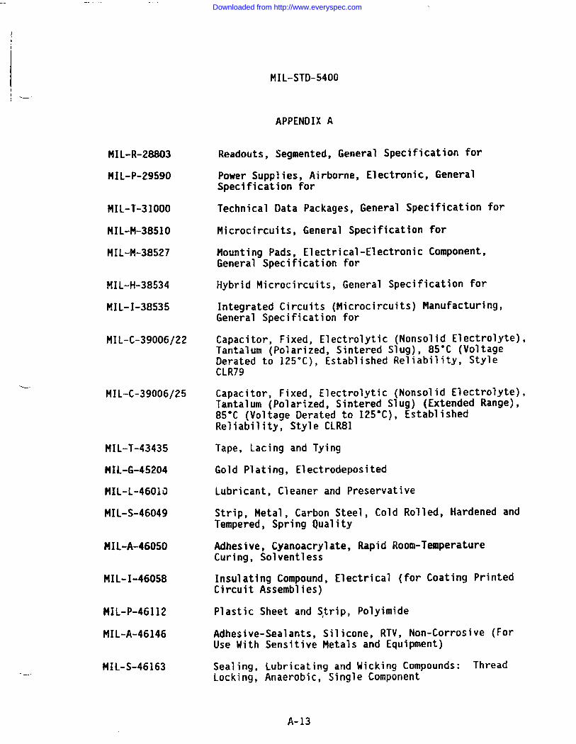
.-
MIL-STD-5400
----
-—
MIL-R-28803
MIL-P-29590
MIL-T-31OOO
MIL-M-3851O
MIL-Pl-38527
MIL-H-38534
MIL-I-38535
MIL-C-39006/22
MIL-C-39006/25
MIL-T-43435
MIL-G-45204
MIL-L-4601O
MIL-S-46049
PIIL-A-46050
MIL-I-46058
MIL-P-46112
MIL-A-46146
MIL-S-46163
APPENDIX A
Readouts, Segmented, General Specification for
Power Supplies, Airborne, Electronic, GeneralSpecification for
Technical Data Packages, General Specification for
Microcircuits, General Specification for
Mounting Pads, Electr’General Specification
Hybrid Microcircuits,
cal-Electronic Component,for
General Specification for
Integrated Circuits (Microcircuits) Manufacturing,General Specification for
Capacitor, Fixed, Electrolytic (Nonsolid Electrolyte),Tantalum (Polarized, Sintered Slug), 85°C (VoltageDerated to 125°C), Established Reliability, StyleCLR79
Capacitor, Fixed, Electrolytic (Nonsolid Electrolyte),Tantalum (Polarized, Sintered Slug) (Extended Range),85°C (Voltage Derated to 125°C), EstablishedReliability, Style CLR81
Tape, Lacing and Tying
Gold Plating, Electrodeposited
Lubricant, Cleaner and Preservative
Strip, Metal, Carbon Steel, Cold Rolled, Hardened andTempered, Spring Quality
Adhesive, Cyanoacrylate, Rapid Room-TemperatureCuring, Solventless
Insulating Compound, Electrical (for Coating PrintedCircuit Assemblies)
Plastic Sheet and S}rip, Polyimide
Adhesive-Sealants, Silicone, RTV, Non-Corrosive (ForUse With Sensitive Metals and Equipment)
Sealing, Lubricating and Wicking Compounds: ThreadLocking, Anaerobic, Single Component
A-13
Downloaded from http://www.everyspec.com
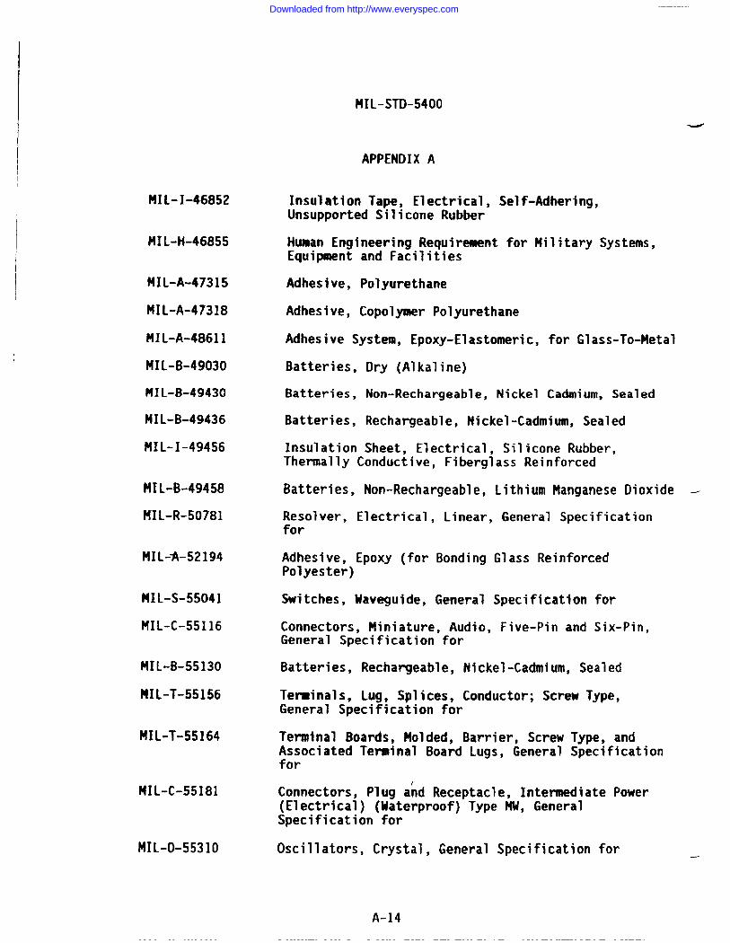
MIL-STD-5400
APPENDIX A
HIL-I-46852
MIL-H-46855
MIL-A-47315
MIL-A-47318
MIL-A-48611
MIL-B-49030
MIL-B-49430
MIL-B-49436
f41L-I-49456
MIL-B-49458
MIL-R-50781
MIL-fi-52194
MIL-S-55041
MIL-C-55116
MIL-B-55130
MIL-T-55156
MIL-T-55164
MIL-C-55181
MIL-O-5531O
Insulation Tape, Electrical, Self-Adhering,Unsupported Silicone Rubber
Human Engineering Requirement for Hilitary Systems,Equipment and Facilities
Adhesive, Polyurethane
Adhesive, Copolymer Polyurethane
Adhesive System, Epoxy-Elastomeric, for Glass-To-Metal
Batteries, Dry (Alkaline)
Batteries, Non-Rechargeable, Nickel Cadmium, Sealed
Batteries, Rechargeable, Nickel-Cadmium, Sealed
Insulation Sheet, Electrical, Silicone Rubber,Thermally Conductive, Fiberglass Reinforced
Batteries, Non-Rechargeable, Lithium Manganese Dioxide -
Resolver, Electrical, Linear, General Specificationfor
Adhesive, Epoxy (for Bonding Glass ReinforcedPolyester)
Switches, Uuveguide, General Specification for
Connectors, Miniature, Audio, Five-Pin and Six-Pin,General Specification for
Batteries, Rechargeable, Nickel-Cadmium, Sealed
Terminals, Lug, Splices, Conductor; Screw Type,General Specification for
Terminal Boards, Molded, Barrier, Screw Type, andAssociated Terminal Board Lugs, General Specificationfor
Connectors, Plug and Receptacle, Intermediate Power(Electrical) (Waterproof) Type HU, GeneralSpecification for
Oscillators, Crystal, General Specification for —
A-14
Downloaded from http://www.everyspec.com
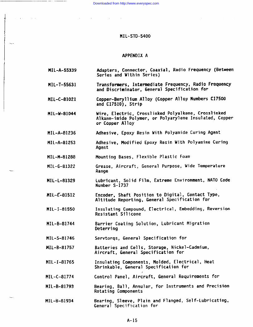
,,,
+.
MIL-STD-5400
APPENDIX A
Adapters, Connector, Coaxial, Radio Frequency (BetweenSeries and Within Series)
MIL-A-55339
Transformers, Intermediate Frequency, Radio Frequencyand Discriminator, General Specification for
MIL-T-55631
Copper-Beryllium Alloy (Copper Alloy Numbers C17500and C1751O), Strip
MIL-C-81021
Wire, Electric, Crosslinked Polyalkene, CrosslinkedAlkane-imide Polymer, or Polyarylene Insulated, Copperor Copper Alloy
MIL-M-81044
MIL-A-81236
MIL-A-81253
Adhesive, Epoxy Resin With Polyamide Curing Agent
Adhesive, Modified Epoxy Resin With Polyamine CuringAgent
Mounting Bases, Flexible Plastic FoamMIL-M-81288
MIL-G-81322 Grease, Aircraft, General Purpose, Wide TemperatureRange
MIL-L-81329 Lubricant, Solid Film, Extreme Environment, NATO CodeNumber S-1737
MIL-E~81512 Encoder, Shaft Position to Digital, Contact Type,Altitude Reporting, General Specification for
MIL-I-81550 Insulating Compound, Electrical, Embedding, ReversionResistant Silicone
MIL-B-81744 Barrier Coating Solution, Lubricant MigrationDeterring
Servtorqs, General Specification forMIL-S-81746
MIL-B-81757 Batteries and Cells, Storage, Nickel-Cadmium,Aircraft, General Specification for
MIL-I-81765 Insulating Components, Molded, Electrical, HeatShrinkable, General Specification for
Control Panel, Aircraft, General Requirements forMIL-C-81774
MIL-B-81793 Bearing, Ball, Annular, for Instruments and PrecisionRotating Components
MIL-B-81934 Bearing, Sleeve, Plain and Flanged, Self-Lubricating.General Specification for
A-15
Downloaded from http://www.everyspec.com
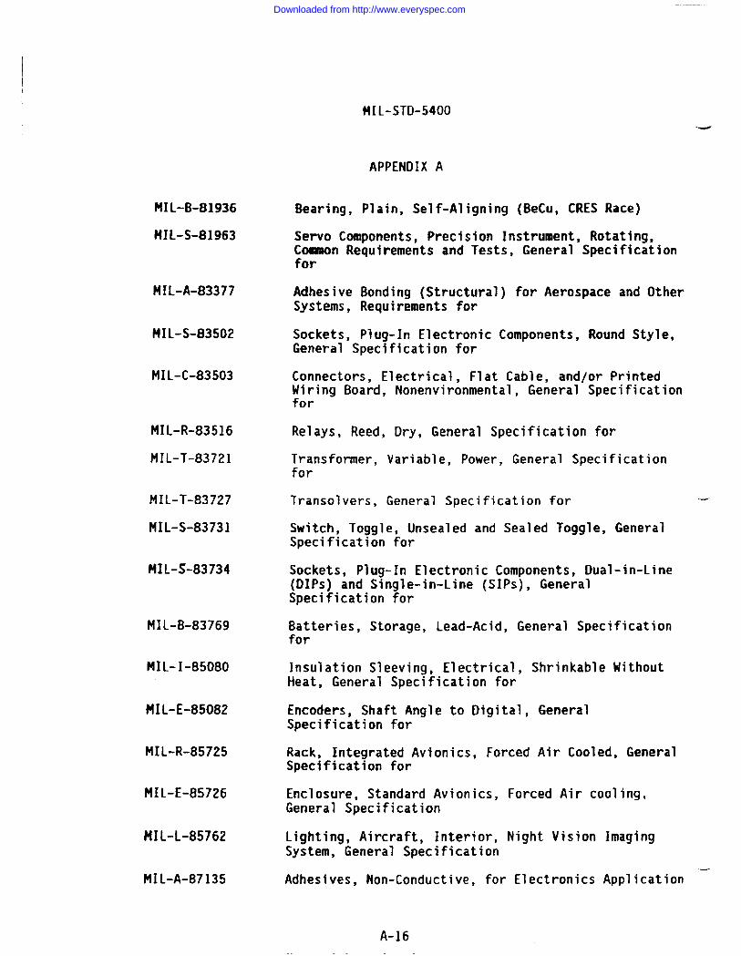
MIL-STD-5400
APPENDIX A
MIL-B-81936
MIL-S-81963
MIL-A-83377
MIL-S-83502
MIL-C-83503
MIL-R-83516
MIL-T-83721
MIL-T-83727
MIL-S-83731
MIL-S-83734
MIL-B-83769
MIL-I-85080
MIL-E-85082
MIL-R-85725
MIL-E-85726
MIL-L-85762
MIL-A-87135
Bearing, Plain, Self-Aligning (f3eCu,CRES Race)
Servo Components, Precision Instrument, Rotating,Conmaon Requirements and Tests, General Specificationfor
Adhesive Bonding (Structural) for Aerospace and OtherSystems, Requirements for
Sockets, Plug-In Electronic Components, Round Style,General Specification for
Connectors, Electrical, Flat Cable, and/or PrintedWiring Board, Nonenvironmental, General Specificationfor
Relays, Reed, Dry, General Specification for
Transformer, Variable, Power, General Specificationfor
Transolvers, General Specification for
Switch, Toggle, Unsealed and Sealed Toggle, GeneralSpecification for
Sockets, Plug-In Electronic Components, Dual-in-Line(DIPs) and Single-in-Line (SIPS), GeneralSpecification for
Batteries, Storage, Lead-Acid, General Specificationfor
Insulation Sleeving, Electrical, Shrinkable WithoutHeat, General Specification for
Encoders, Shaft Angle to Digital, GeneralSpecification for
Rack, Integrated Avionics, Forced Air Cooled, GeneralSpecification for
Enclosure, Standard Avionics, Forced Air cooling,General Specification
Lighting, Aircraft, Interior, Night Vision ImagingSystem, General Specification
Adhesives, Non-Conductive, for Electronics Application –
A-16
Downloaded from http://www.everyspec.com
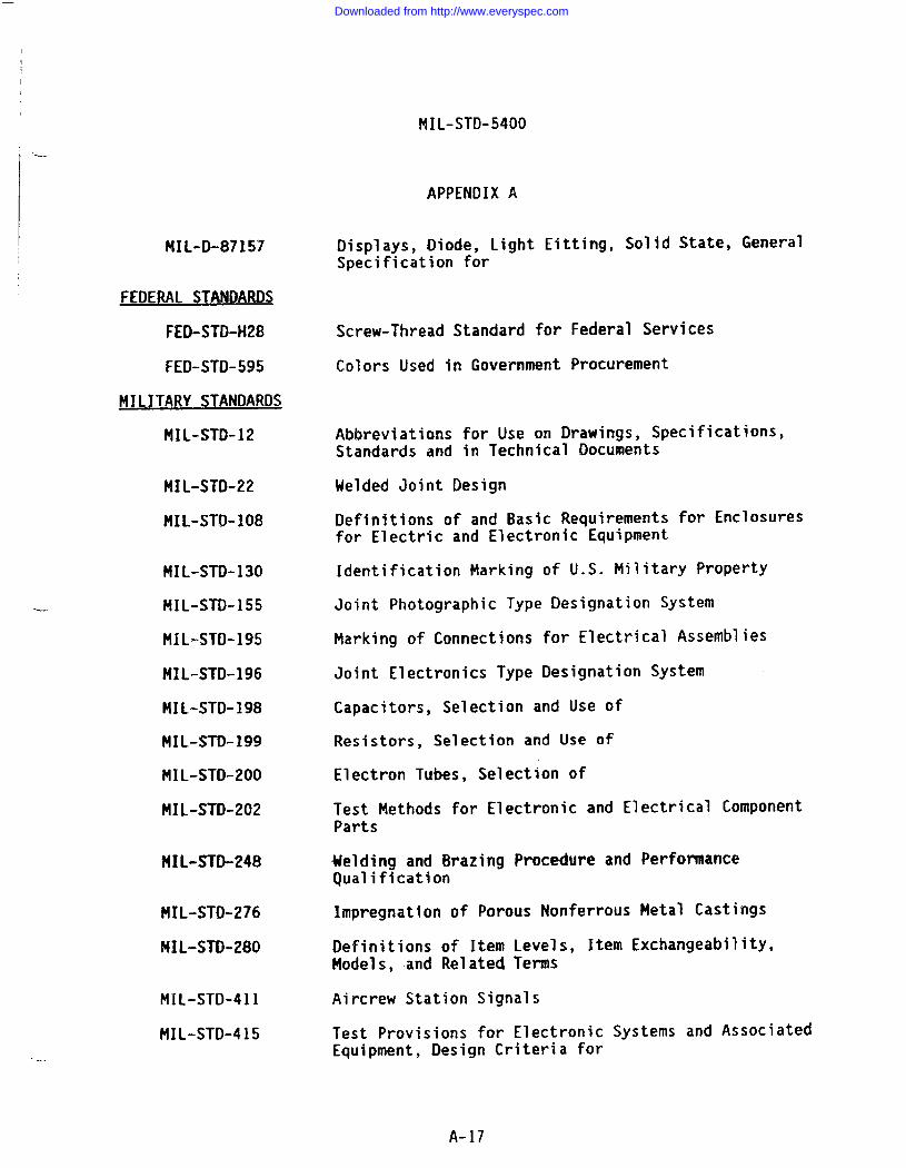
MIL-STD-5400
, ----
IAPPENDIX A
MIL-D-87157
FEDERAL STANDARDS
FEO-STD-H28
FED-STK)-595
MILITARY STANDARDS
MIL-STD-12
MIL-STD-22
MIL-STO-1O8
MIL-STD-130
MIL-STD-155
141L-STD-195
MIL-STD-196
MIL-STD-198
MIL-STO-199
MIL-STD-200
MIL-STD-202
MIL-STO-248
MIL-STO-276
MIL-STO-280
MIL-STD-411
MIL-STD-415
Displays, Diode, Light Eitting, Solid State, GeneralSpecification for
Screw-Thread Standard for Federal Services
Colors Used in Government Procurement
Abbreviations for Use on Drawings, Specifications,Standards and in Technical Documents”
Welded Joint Design
Definitions of and Basic Requirementsfor Electric and Electronic Equipment
for Enclosures
Identification Marking of U.S. Military Property
Joint Photographic Type Designation System
Marking of Connections for Electrical Assemblies
Joint Electronics Type Designation System
Capacitors, Selection and Use of
Resistors, Selection and Use of
Electron Tubes, Selection of
Test Methods for Electronic and Electrical ComponentParts
Welding and Brazing Procedure and PerformanceQualification
Impregnation of Porous Nonferrous Metal Castings
Definitions of Item Levels, Item Exchangeability,Models, and Relatecl Terms
Aircrew Station Signals
Test Provisions for Electronic Systems and AssociatedEquipment, Design Criteria for
A-17
Downloaded from http://www.everyspec.com
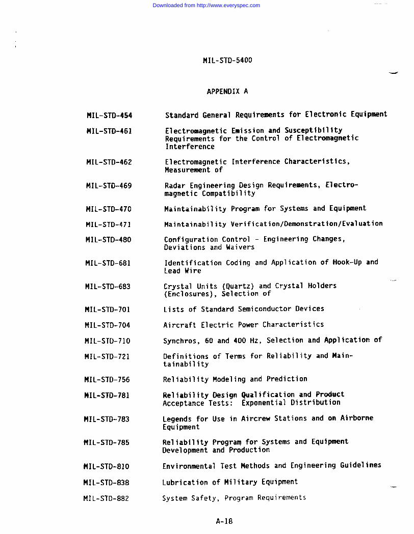
MIL-STD-454
HIL-STO-461
MIL-STD-462
MIL-STD-469
141L-STD-470
MIL-STD-471
MIL-STD-480
MIL-STD-681
MIL-STD-683
MIL-STD-701
MIL-STD-704
MIL-STD-71O
MIL-STD-721
MIL-STD-756
HIL-STD-781
MIL-STD-783
MIL-STD-785
MIL-STD-81O
MIL-STD-838
MIL-STD-882
FIIL-STD-5400
APPENDIX A
Standard General Requirements for Electronic Equipment
Electromagnetic Emission and SusceptibilityRequirements for the Control of ElectromagneticInterference
Electromagnetic Interference Characteristics,Measurement of
Radar Engineering Design Requirements, Electro-magnetic Compatibility
Maintainability Program for Systems and Equipment
Maintainability Verification/Demonstration/Eval uation
Configuration Control - Engineering!Deviations and Waivers
Identification Coding and Applicat’Lead Wire
Crystal Units (Quartz) and Crystal(Enclosures), Selection of
Changes,
on of Hook-Up and
Holders
Lists of Standard Semiconductor Devices
Aircraft Electric Power Characteristics
Synchros, 60 and 400 Hz, Selection and Application of
Definitions of Terms for Reliability and Main-tainability
Reliability Modeling and Prediction
Reliability Design Qualification and ProductAcceptance Tests: Exponential Distribution
Legends for Use in Aircrew Stations and on AirborneEquipment
Reliability Program for Systems and EquipmentDevelopment and Production
Environmental Test Methods and Engineering Guidelines
Lubrication of Military Equipment .—
System Safety, Program Requirements
A-18
Downloaded from http://www.everyspec.com
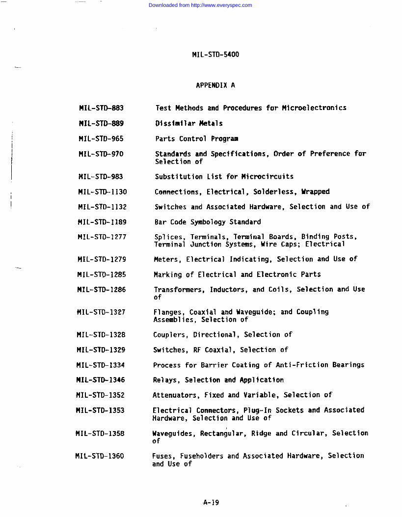
HIL-STD-5400
APPENDIX A
-.
MI1.-sTD-883
MIL-STD-889
MIL-STD-965
MIL-STD-970
MIL-STD-983
NIL-STD-1130
MIL-STD-1132
MIL-STD-1]89
?41L-STD-1277
MIL-STD-1279
MIL-STK)-1285
MIL-STD-1286
MIL-STK)-1327
MIL-STD-1328
MIL-STD-1329
MIL-STD-1334
141L-STD-1346
HIL-STD-1352
MIL-STD-1353
MIL-STD-1358
MIL-STD-1360
Test Methods and Procedures for Microelectronics
Dlsslmllar Metals
Parts Control Program
Standards and Specifications, Order of Preference forSelection of
Substitution List for Microcircuits
Connections, Electrical, Solderless, Urapped
Switches and Associated Hardware, Selection and Use of
Bar Code Symbology Standard
Splices, Terminals, Terminal Boards, Binding Posts,Terminal Junction Systems, Uire Caps; Electrical
Meters, Electrical Indicating, Selection and Use of
Marking of Electrical and Electronic Parts
Transformers, Inductors, and Coils, Selection and Useof
Flanges, Coaxial and Maveguide; and CouplingAssemblies, Selection of
Couplers, Directional, Selection of
Switches, RF Coaxial, Selection of
Process for Barrier Coating of Anti-Friction Bearings
Relays, Selection and Appl~catfon
Attenuators, Fixed and Variable, Selection of
Electrical Connectors, Plug-In Sockets and AssociatedHardware, Selection and Use of
Itaveguides, Rectangular, Ridge and Circular, Selectionof
Fuses, Fuseholders and Associated Hardware, Selectionand Use of
A-19
Downloaded from http://www.everyspec.com
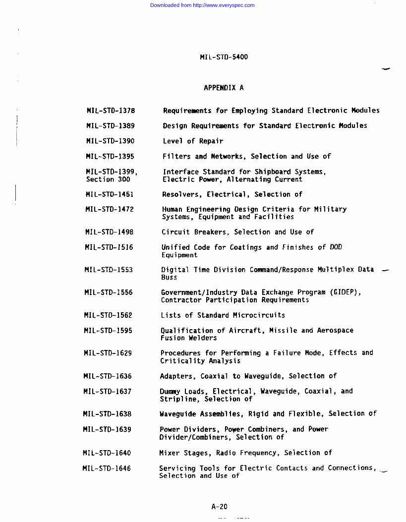
MIL-STD-5400
APPENDIX A
MIL-STD-1378
MIL-STD-1389
MIL-STD-1390
MIL-STD-1395
MIL-STD-1399,Section 300
MIL-STO-1451
MIL-STD-1472
MIL-STD-1498
MIL-STO-1516
MIL-STD-1553
MIL-STD-1556
MIL-STD-1562
MIL-STO-1595
MIL-STD-1629
MIL-STO-1636
MIL-STD-1637
MIL-STD-1638
HIL-STD-1639
MIL-STD-1640
MIL-STD-1646
Requirements for Employing Standard Electronic Modules
Design Requirements for Standard Electronic Modules
Level of Repair
Filters and Networks, Selection and Use of
Interface Standard for Shipboard Systems,Electric Power, Alternating Current
Resolvers, Electrical, Selection of
Human Engineering Design Criteria for MilitarySystems, Equipment and Facilities
Circuit Breakers, Selection and Use of
Unified Code for Coatings and Finishes of ODDEquipment
Digital Time Oivision Command/Response Multiplex Data -Buss
Government/Industry Data Exchange Program (GIDEP),Contractor Participation Requirements
Lists of Standard Microcircuits
Qualification of Aircraft, Missile and AerospaceFusion welders
Procedures for Performing a Failure Mode, Effects andCriticality Analysis
Adapters, Coaxial to Uaveguide, Selection of
Dummy Loads, Electrical, Waveguide, Coaxial, andStripTine, Selection of
Waveguide Assemblies, Rigid and Flexible, Selection of
Power Dividers, Poyer Combiners, and PowerOivider/Combiners, Selection of
Mixer Stages, Radio Frequency, Selection of
Servicing Tools for Electric Contacts and Connections, ._Selection and Use of
A-20
Downloaded from http://www.everyspec.com
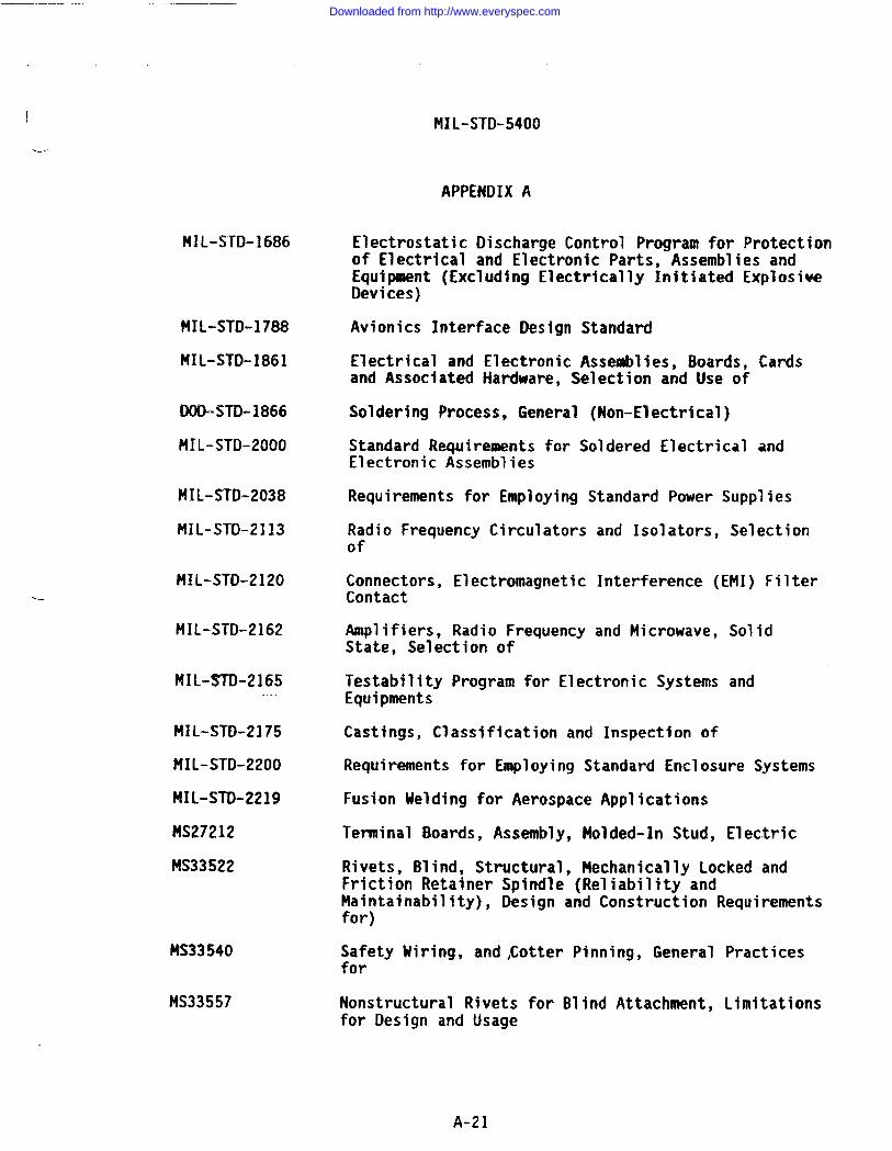
—
I
\-
MIL-STD-1686
MIL-STD-1788
MIL-STD-1861
DOD-STD-1866
MIL-STK)-2000
MIL-STD-2038
MIL-STD-2113
MIL-STD-2120
MIL-STD-2162
MIL-STD-2165.
MIL-STD-2175
MIL-STD-2200
MIL-STD-2219
MS27212
MS33522
MS33540
MS33557
‘MXL-STD-5400
APPENDIX A
Electrostatic Discharge Control Program for Protectionof Electrical and Electronic Parts, Assemblies andEquipment (Excludlng Electrically Initiated ExplosiveDevices)
Avionics Interface Design Standard
Electrical and Electronic Assemblies, Boards, Cardsand Associated Hardware, Selection and Use of
Soldering Process, General (Non-Electrical)
Standard Requirements for Soldered Electrical andElectronic Assemblies
Requirements for Employing Standard Power Supplies
Radio Frequency Circulatorsof
Connectors, ElectromagneticContact
Amplifiers, Radio FrequencyState, Selection of
and Isolators, Selection
Interference (EMI) Filter
and Microwave,
Testability Program for Electronic SystemsEquipments
Castings, Classification and Inspection of
Solid
and
Requirements for Employing Standard Enclosure Systems
Fusion Uelding for Aerospace Applications
Terminal Boards, Assembly, Molded-In Stud, Electric
Rivets, Blind, Structural, Piechanically Locked andFriction Retainer Spindle (Reliability andMaintainability), Design and Construction Requirementsfor)
Safety Uiring, and,Cotter Pinning, General Practicesfor
Nonstructural Rivets for Blind Attachment, Limitationsfor Design and Usage
A-21
Downloaded from http://www.everyspec.com
MIL-STD-5400
-
APPENDIX A
HILIT Ry HAND8~KA s
MIL-HDBK-5
MIL-tiDBK-216
MIL-HDBK-217
t41L-HDBK-218
HIL-HDBK-225
MIL-H38K-231
MIL-HDBK-246
MIL-HDBK-248
t41L-HDBK-251
HIL-HDBK-253
MIL-HDBK-263
HIL-HDBK-274
MIL-HDBK-275
MIL-HOBK-402
HIL-HDBK-419
MIL-HDBK-472
MIL-HDBK-660
MIL-HDBK-691
MIL-HDBK-730
Metallic 14aterials and Elements for Aerospace VehicleStructures
RF Transmission Lines and Fittings
Reliability Prediction of Electronic Equipment
Application of Electrical Resolvers
Synchros, Descriptions and Operation
Encoder, Shaft Angle to Digital
Program t4anagers Guide for the Standard ElectronicModules Program
Acquisition Streamlining
Reliability/Design, Thermal Applications
Guidance for the Design and Test of Systems protected _Against the Effects of Electromagnetic Energy
Electrostatic Discharge Control Handbook forProtection of Electrical and Electronics Parts,Assemblies, and Equipment (Excluding ElectricallyInitiated Explosive Devices)
Electrical Grounding for Aircraft Safety
Guide for the Selection of Lubricant Fluids andCompounds for Use in Flight Vehicles and Components
Guidelines for Implementation of DDD Parts ControlProgram
Ground, Bonding and Shielding for ElectronicEquipments
Maintainability Prediction
Fabrication of Rigi,dUaveguide Assemblies (Sweep Iand Twists)
Adhesive Bonding
Military Standardization Handbook on Materials Jo’
ends
ning+
A-22
Downloaded from http://www.everyspec.com
I
MIL-STD-5400
APPENI)IX A
MIL-HDBK-1553 Multiplex Application Handbook
MIL-HOBK-2000 Soldering of Electrical and Electronic Assemblies
OTHER GOVERNMENT DOCUMENTS
HIL-BUL-103 List of Standardized Military Drawings (SNDS)
NAVAIR-16-I-519, Handbook, Preferred Circuits Navy Aeronauticalvol. 2 Electronic Equipment
10 CFR 20 Code of Federal Regulations, Title 10, Chapter I, Part20
21 CFR 1000-1050 Code of Federal Regulations, Title 21, Chapter I,Parts 1000-1050
29 CFR 1910 Code of Federal Regulations, Title 29, Chapter XVII,Part 1910
NTIA Manual National Teleconanunications and InformationAdministration Manual of Regulations and Proceduresfor Radio Frequency Management
VHSIC Interoperabi?ity Standards. Includes specifications for theTM-bus, ETM bus, Pi bus, and VtfSIC Electrical Specification. (Copiesavai~able from Naval Research Laboratory, Code 5305, Washington, DC20375-5000.)
Tester Independent Support Software System (TISSS) Specifications (Copiesavailable from TISSS Program Office, RADC/RBR, Griffiss Air Force Base,NY 13441-5700).
10+GovWtlEN T DOCUMENT5
ANS 3638E Plastic Tubing, Electrica7 Insulation, IrradiatedPolyolefin, Pigmented, Semi-Rigid, Heat-Shrinkable 2to 1 Shrink Ratio
AIR 3653D Tubing, Electrical Insulation, Standard Hall, ExtrudedPolytetrafluoroethylene (PTFE)
ANS 36548 Tubing, Electrical,Insulation, Light Wall, ExtrudedPolytetrafluoroethylene (PTFE)
AMS 3655A Tubing, Electrical Insulation, Thin Mall, ExtrudedPolytetrafluoroethylene (PTFE)
ASTM A29/A29M Steel Bars, Carbon and Alloy, Hot !drought and ColdFinished, General Requirements for
A-23
Downloaded from http://www.everyspec.com
HIL-STD-5400
APPENDIX A
ASTM A228/A228M
ASTN A313
ASTM A588/A558M
ASTM A682
ASTN A684/A684t4
ASTM B194
ASTM B196/B196M
ASTM B197/B197M
ASTM B522
ASTM B633
ASTH 0495
ASTM 0568
ASTM D635
ASTM D1OOO
ASTM D3295
ANSI/IPC-D322
ANSI C95.1
ANSI C95.2
Steel Uire, t4usic Spring Quality
Chromi-llickel Stainless and Heat Resisting SteelSpring Wire
High Strength Low Alloy Structural Steel Mith 50 KSIMinimum Yield to 4 Inch Thick
Steel, Strip, High Carbon, Cold Rolled, SpringQuality, General Requirements for
Steel, Strip, High Carbon, Cold Rolled
Copper-Beryllium Alloy Plate, Sheet, Strip, and RolledBar
Copper-Beryllium Alloy Rod and Bar
Copper-Beryllium Alloy Hire
Gold-Silver-Platinum Electrical Contact Alloy,Specification -<
Electrodeposited Coatings of Zinc on Iron and Steel,Standard Specification for
Standard Method of Test for High-Voltage, Low-CurrentDry Arc Resistance of Solid Electrical InsulationMaterials
Rate of Burning and/or Extent and Time of Burning ofFlexible Plastics in a Vertical Position, Test Methodfor
Rate of Burning and/or Extent and Time of Burning ofSelf-Supporting Plastics in a Horizontal Position,Test Method for
Pressure-Sensitive Adhesive Coated Tapes Used forElectrical Insulation, Methods of Testing
PTFE Tubing, Specification for
Guidelines for Selecttng Printed Wiring Board SizesUsing Standard Panel Sizes
Safety Levels Uith Respect to Human Exposure to RadioFrequency Electromagnetic Fields, 300 KHz to 100 GHz ._
Radio Frequency Radiation Hazard Warning Symbol
A-24
Downloaded from http://www.everyspec.com
MIL-STD-5400
APPENDIX A
-
ANSI N2.1 Radiation Symbol
MS] 235.1 Accident Prevention Signs
ANSI 253.1 Marking Physical Hazards, Safety Color Code for
EIA-297-A Cable Connectors for Audio Facilities for RadioBroadcasting
EIA RS-31O-C Racks, Panels and Associated Equipment
IEEE 200 Electrical and Electronic Parts and Equipments,Reference Designations for
IEEE 1076 VHSIC Hardware Description Language (VHDL)
NAS498 Bolts, Shear, 95 KSU FSU
NAS547 Fastener, Rotary, Quick-Operating, High Strength
NASI 686 Rivet, Blind, Aluminum Sleeve, Mechanically Locked,Spindle, Bulbed
NAS1687 Rivet, Blind, Monel and Inconel Sleeve, MechanicallyLocked Spindle, Bulbed
NFPA 70 National Electrical Code
UL 94 Standard for Tests for Flannnability of PlasticMaterials for Parts in Devices and Appliances
Metals Handbook (Vol I) (ASM)
American Gear Manufacturers Association (AGMA)
A-25
Downloaded from http://www.everyspec.com
MIL-STD-5400
I k.
APPENDIX B
SANPLE TAILORING GUIDE
10. SCOPE
10.1 ScoDe. THIS APPENDIX PROVIDES GUIDANCE INFORMATION ONLY AND IS NOTINTENDED TO BE INVOKED AS A CDNTRACTURAL REQUIREMENT.
10.2 This appendix provides a sample tailoring guide for HIL-STD-5400based on the relationship of tailoring specific requirements during variousdevelopment and production phases as defined in MIL-HDBK-248. This guide isnot intended to be restrictive as to the methods/factors to be considered fortailoring applications. Examples of other methods/factors concerned withtailoring of MIL-STD-5400 requirwnts are shown in paragraph 40.
20. APPLICABLE DOCUNENTS (Reference Only)
MIL-HDBK-248Acquisition Streamlining
30. APPLICATION OF SAMPLE TAILORING GUIDE
30.1 The sample tailoring guide contained herein cross-referencesindications of tailoring applicability for HIL-STK)-5400 requirements tovarious phases of item development and production as defined in MIL-HDBK-248.Codes and abbreviations used in the sample tailoring guide table are asfollows:
Tailoring Requirements
+4- Not applicable this phaseA- Applicable this phaseT- Essentially a “tailoring” paragraphG- General statement - tailoring not required
Program Phases
CON- Conceptual (Research)DhV- Demonstration & ValidationFSED- Full Scale Engineering DevelopmentPROD- Production
30.2 Guide for the extent of tailoring to be effected during programphases.
Conceptual (Research) -.Specifications and standards requirements shouldbe tailored and limited to minimum technical design objectives and broadbasic performance and functional requirements. Application of “costdriver” requirements should be very limited.
B-1
Downloaded from http://www.everyspec.com
MI L-STD-5400
-
APPENDIX B
Demonstration & validation - Specifications and standards requirementsshould be tailored again to upgrade and more clearly define the technicalobjectives relating to design, performance and functional demonstrationrequirements for the prototype Item. Consideration of “cost driver”requirements should be expanded.
Full scale engineering development - Specifications and standardsrequirements should be tailored for maximum compatibility of the ultimateengineering design with the operational system requirements. Theapplication of “cost driver” requirements such as configuration control,qualfty assurance, rellabilfty, data and documentation, packaging,packing, preservation and transportation should be given specialconsideration and definition in anticipation of future procurement.Pertinent general ❑ilitary design requirements should be criticallytailored for each application. A tailored configuration and productbaseline should be established prior to entering the production phase.
Production - Proper application of tailored requirements during theengineering design/prototype phase should preclude the necessity forapplication of additional military requirements and tailoring during theproduction phase, except for possible refinement of some requirements.
40. OTHER CONSIDERATIONS FOR TAILORING
40.1 This appendix is limited to guidance for tailoring MIL-STD-5400requirements to the development and production phases of a program. Thereare, however, many other factors which can provide the basis for tailoring tomodify, l%nit, combine, or eliminate specific requirements consistent with theminimum level necessary to provide cost effective system performance andprogram management. Below is a list of some other areas which may providebasis for tailoring of specific requirements relative to those areas ofconsideration. Refer to MIL-HDBK-248 for additional guidance relative toacquisition streamlining and tailoring of requirements.
Uission requirementsEquipment applicationEnvironmental/test requirementsInterface requirwnts with other systems/equipmentOperational/logistics requirementsSoftware and technical data requirementsHuman factors requirementsConfiguration management requirementsReliability/maintainability requirementsQuality assurance requirementsPackaging, packing, handling, storage ’and transportation requirements
B-2
Downloaded from http://www.everyspec.com
MIL-STSI-5400
-----
I
I
1::.14.1.2
4.1.34.24.2.1TA8LE I4.2.24.2.34.2.44.2.54.2.64.2.74.2.7.14.2.7.24.2.84.2.8.14.2.8.24.2.94.2.9.14.2.104.2.114.2.11.14.2.11.24.2.124.2.134.2.144.2.154.2.15.14.2.15.24.2.15.34s2.164.2.174.2.17.14.2.17.24.2.17.34.2.184.2.194.2.204.2.214.2.224.2.234.2.23.14.2.23.24.2.23.34.2.244.2.25
APPENDIX B
MIL-STD-5400 Paragraph Numberand Description
UntitledTailoring of MIL-STD-454 requirementsStandard hardware acquisition and
reliability program (SHARP)Requirements, tables and figuresDesign and constructionUntitledGeneral design and constructionAccessibilityAnti-jammingCastings, metalCorona and electrical breakdown preventionIleratingElectrical overload protectionResettable circuit protectorsSpare fusesElectrical powerWarm-up timeUntitledElectromagnetic interference controlRadar equipmentElectrostatic discharge controlEnclosuresStandardized avionics enclosuresOther enclosuresFabricationGrounding, bonding and shieldingHuman engineeringInterchangeabilityUntitledUntitledInterchangeability of reordered equipmentMaintainabilityMarkingLabelsWire coding for identificationOperational program markingMicrophonicsMoisture pocketsMultiplexingNomenclature assignmentOrientationPanelsControl panelsElectroluminescent panelsRanges of adjustable partsPressurizationReliability
B-3
I
Downloaded from http://www.everyspec.com
MIL-STD-5400-
APPENDIX B
4.2.264.2.274.2.27.14.2.27.24.2.284.2.28.14.2.28.24.2.28.34.2.294.2.304.2.30.14.2.314.2.31.14.2.31.24.2.31.34.2.324.2.334.34.3,14.3.1.14.3.24.3.34.3.44.3.4.14.3.4.2
4.3.4.34.3.4.3.14.3.4.44.3.4.5TABLE II4.3.54.3.64.3.74.3.84.3.8.14.3.8.24.3.94.3.9.14.3.9.24.3.9.34.3.104.3.10.14.3.10.24.3.10.34.3.11
141L-STD-5400 Paragraph Numberand Description
RepairabilitySafetySystem safetyPersonnel SafetyTest provisionBuilt-in test devicesExternal test pointsFailure effectTestability programThermal designCooling design dataTool S
Setscrew wrenchesSpecial toolFurnishing and stowingStandardized power suppliesWorkmanshipParts selectionGovernment-furnished baseline (GFB)Choice of partsNonstandard partsParts control programApproval of partsContracts under category IContracts for equipment which fall under
categories II and 111Reordered production equipmentContinuation of productionReplacing of approved partsEquipment performanceParts selectionSubstitution partsBatteriesBearingsCapacitorsFixed, tantalum electrolyticAluminum electrolyticCircuit breakersManual operationPosition identification ,OrientationConnectors, electricalMounting of electrical receptaclesAdjacent locationsJacksControls (knobs, handles, dials)
B-4
CON
NGGAN
INNNNNNNNNNN
;NNNT
TT
iG
;NNNNNN
:NNNNN
D&V
NGGANNNNNNNNNN
[NAAAAAA-r
TTTAG
:NAAAAAANNN
!!A
FSED
AGGAAAAAAAANNNAAAAAAAAAT
TT-rAG
AAAAAAAA
tANNAA
PROD
AGGAAAAAAAAAAA
:AAA-AAA
?
TTTAG
;AAAAAA
:AAAAA-
Downloaded from http://www.everyspec.com
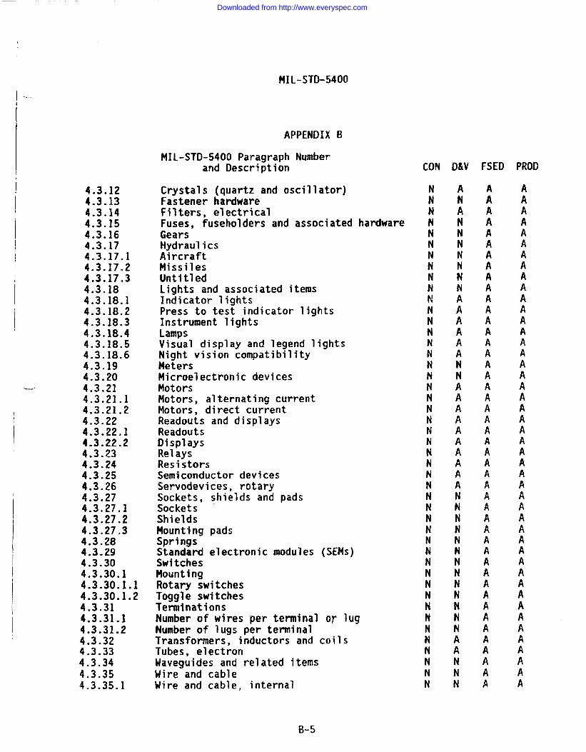
MIL-STD-5400
I ---
APPENDIX El
I
I
4.3.124.3.134.3.144.3.154.3.164.3.1’74.3.17.14.3.17.24.3.17.34.3.184.3.18.14.3.18.24.3.18.34.3.18.44.3.18.54.3.18.64.3.194.3.204.3.214.3.21.14.3.21.24.3.224.3.22.14.3.22.24.3.234.3.244.3.254.3.264.3.274.3.27.14.3.27.24.3.27.34.3.284.3.294.3.304.3.30.14.3.30.1.14.3.30.1.24.3.314.3.31.14.3.31.24.3.324.3.334.3.344.3.354.3.35.1
MIL-STD-5400 Paragraph Numberand Description
Crystals (quartz and oscillator)Fastener hardwareFilters, electricalFuses, fuseholders and associated hardwareGearsHydraulicsAircraftMissilesUntitledLights and associated itemsIndicator lightsPress to test indicator lightsInstrument lightsLampsVisual display and legend lightsNight vision compatibilityMetersMicroelectronic devicesMotorsMotors, alternating currentMotors, direct currentReadouts and displaysReadoutsDisplaysRelaysResistorsSemiconductor devicesServodevices, rotarySockets, shields and padsSocketsShieldsMounting padsSpringsStandard electronic modules (SEMS)SwitchesMountingRotary switchesToggle switchesTerminationsNumber of wires per terminal OY lugNumber of lugs per terminalTransformers, inductors and coilsTubes, electronWaveguides and related itemsWire and cableWire and cable, internal
CON
INNN
[NNNt’!N
:NN
:NNNNNNNN
:
IINNN
:N
:NNNNNN
II
B-5
Downloaded from http://www.everyspec.com
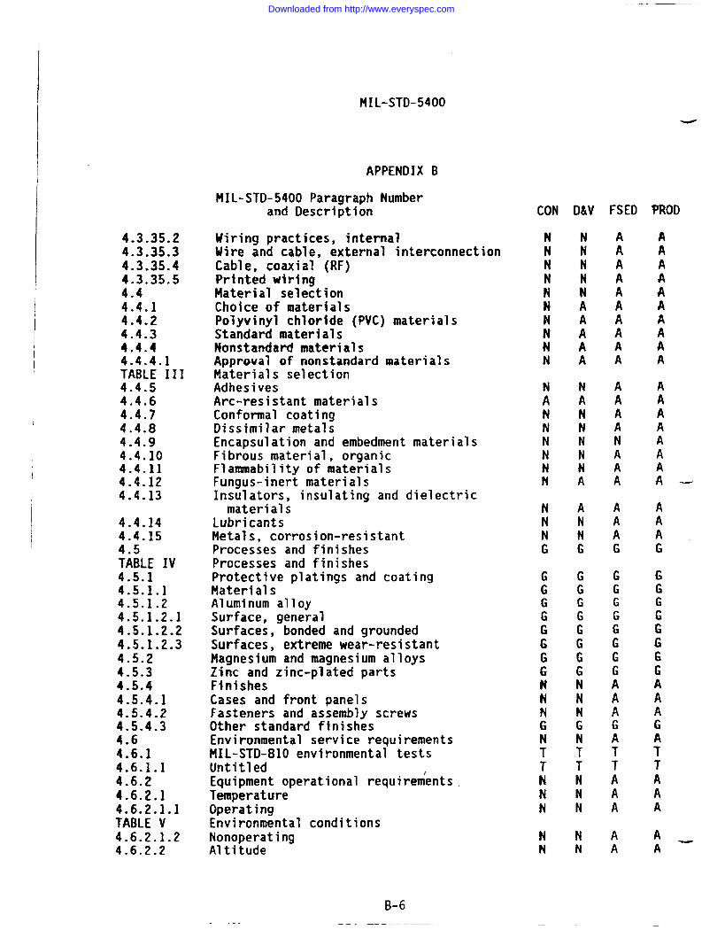
MIL-STD-5400-
4.3.35.24.3.35.34.3.35.44.3.35.54.44.4.14.4.24.4.34.4.44.4.4.1TABLE 1114.4.54.4.64.4.74.4.84.4.94.4.104.4.114.4.124.4.13
4.4.144.4.15
$AiLE IV4.5.14.5.1.14.5.1.24.5.1.2.14.5.1.2.24.5.1.2.34.5.24.5.34.5.44.5.4.14.5.4.24.5.4.34.64.6.14.6.1.14.6.24.6.2.14.6.2.1.1TABLE V4.6.2.1.24.6.2.2
-—
APPENDIX B
MIL-STD-5400 Paragraph Numberand Description
Hiring practices, internalWire and cable, external interconnectionCable, coaxial (RF)Printed wiringMaterial selectionChoice of materialsPolyvinyl chloride (PVC) materialsStandard materialsNonstandard materialsApproval of nonstandard materialsMaterials selectionAdhesivesArc-resistant materialsConformal coatingDissimilar metalsEncapsulation and embedment materialsFibrous material, organicFlannnability of materialsFungus-inert materialsInsulators, insulating and dielectricmaterials
LubricantsMetals, corrosion-resistantProcesses and finishesProcesses and finishesProtective platings and coatingMaterialsAluminum alloySurface, generalSurfaces, bonded and groundedSurfaces, extreme wear-resistantMagnesium and magnesium alloysZinc and zinc-plated partsFinishesCases and front panelsFasteners and assembly screwsOther standard finishesEnvironmental service requirementsMIL-STD-81O environmental testsUntitledEquipment operational requirementsTemperatureOperatingEnvironmental conditionsNonoperatingAltitude
B-6
CON
NNNNNN
IINN
:N
1!NNN
;NG
GGG
:GG
iN
?NTTNNN
NN
FSED
AAAA
:
;AA
AAAANA
:
AAAG
GGG
:GG
:AAGATTAAA
AA
Downloaded from http://www.everyspec.com
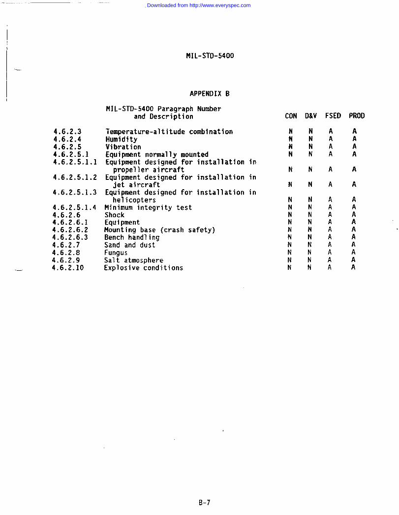
--
.
4.6.2.34.6.2.44.6.2.54.6.2.5.14.6.2.5.1.1
4.6,2.5.1.2
4.6.2.5.1.3
4.6.2.5.1.44.6.2.64.6.2.6.14.6.2.6.24.6.2.6.34.6.2.74.6.2.84.6.2.94.6.2.10
MIL-STD-5400
APPENDIX B
MIL-STD-5400 Paragraph Numberand Description
Temperature-altitude combinationHumidityVibrationEquipment normally mountedEquipment designed for installation inpropeller aircraft
Equipment designed for installation injet aircraft
Equipment designed for installation inhelicopters
Minimum integrity testShockEquipmentMounting base (crash safety)Bench handlingSand and dustFungusSalt atmosphereExplosive conditions
CON D&V FSED PROD
NNAAN AAN I ANN ;A
NNAA
NNAA
NNANNANNANNANNNN :N A
!iA; AN !A
B-7
Downloaded from http://www.everyspec.com
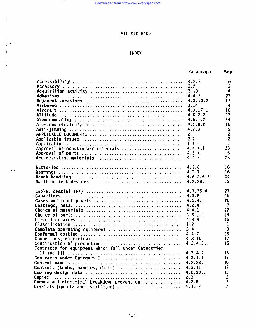
MIL-STD-5400
-
INDEX
Accessibility ............................................Accessory ................................................Acquisition activity .....................................Adhesives ................................................Adjacent locations .......................................Airborne .................................................Aircraft .................................................Altitude .................................................Aluminum alloy ...........................................Aluminum electrolytic .......................=... .........Anti-jamming .............................................APPLICABLE DOCUMENTS .....................................Applicable issues ........................................Application ..............................................Approval of nonstandard materials ........................Approval of parts ........................................Arc-resistant materials ..................................
Batteries ................................................Bearings .................................................Bench handling ...........................................Built-in test devices ....................................
Cable, coaxial (RF) ......................................Capacitors ...............................................Cases and front panelsCastings, metal ......Choice of materials ..Choice of parts ......Circuit breakers .....Classification .......Complete oDeratina eou<
. . . . . . . . . . . . . . . . . . . . . . . . . . . . . . . . . . .
. . . . . . . . . . . . . . . . . . . . . . . . . . . . . . . . . . .
. . . . . . . . . . . . . . . . . . . . . . . . . . . . . . . . . . .
. . . . . . . . . . . . . . . . . . . . . . . . . . . . . . . . . . .
. . . . . . . . . . . . . . . . . . . . . . . . . . . . . . . . . . .
. . . . . . . . . . . . . . . . . . . . . . . . . . . . . . . . . . .Dment .............................
Conformal coating-. ..’..;..................................Connectors, electrical ...................................Continuation of production ...............................Contracts for equipment which fall under Categories
Iland IIl .............................................Contracts under Category I .....=.........................Control panels ...........................................Controls (knobs, handles, dials) .........................Cooling design data
I......................................
Copies ...................................................Corona and electrical breakdown prevention ...............Crystals (quartz and oscillator) .........................
Paragraph
4.2.23.23.134.4.54.3.10.23.144.3.17.14.6.2.24.5.1.24.3.8.24.2.3
::21.1.14.4.4.14.3.44.4.6
4.3.64.3.74.6.2.6.34.2.28.1
4.3.35.44.3.84.5.4.14.2.44.4.14.3.1.14.3.91.23.44.4.74.3.104.3.4.3.)
4.3.4.24.3.4.14.2.23.14.3.114.2.30.12.34.2.54.3.12
Page
63
2:174
;;24166
:1
231523
16163412
211626
2;141613
231716
1515
:;132717
Downloaded from http://www.everyspec.com
MIL-STD-5400
INDEX (continued)
Paragraph
DEFINITIONS ..............................................Derating .................................................Design and construction ..................................Design qualification tests ...............................Detailed mechanical and electrical design ................Detail equipment specification ...........................DETAIL REQUIREMENTS ......................................Details for inclusion in equipment specifications and
contracts ..............................................Dissimilar metals ........................................Documents ................................................
Electrical overload protection ...........................Electrical power .........................................Electroluminescent panels ................................Electromagnetic interference control .....................Electrostatic discharge control ..........................Electronics ..............................................Encapsulation and embedment materials ....................Enclosures ...............................................Environmental service requirements .......................Environment conditions ...................................Equipment ................................................Equipment ................................................Equipment designed for installation in helicopters .......EquipmentAesigned for installation in jet aircraft ......Equipment designed for installation in propeller
aircraft ...............................................Equipment normally mounted ...............................Equipment operational requirements .......................Equipment performance ....................................Explosive conditions .....................................External cooling .........................................External test points .....................................Failure criteria .........................................Failure effect ...........................................Fastener hardware ........................................Fasteners and assembly screws ............................Fibrous material, organic ................................Filters, electrical ......................................Finishes ..........................................-.-....First article tests .......................................Fixed tantalum, electronic ...............................Flananability of materials ................................Fungus ...................................................Fungus-inert materials ...................................Furnishing and stowing ...................................Fuses, fuseholders and associated hardware ...............
Paragraph
3.4.2.64.25.3.55.13.155.
4.2.74.2.84.2.23.24.2.94.2.103.84.4.94.2.114.6TABLE V3.34.6.2.6.14.6.2.5.1.34.6.2.5.1.2
4.6.2.5.1.14.6.2.5.14.6.24.3.4.54.6.2.101.2.14.2.28.25.3.34.2.28.34.3.134.5.4.24.4.104.3.144.5.45.3.64.3.8.14.4.114.6.2.84.4.124.2.31.34.3.15
I-2
Downloaded from http://www.everyspec.com
MIL-STD-5400
INDEX (continued)
-----
L
Paragraph Paragraph Page
Gears .................................................... 4.3.16 18General design and construction .......................... TA8LE i 6GENERAL REQUIREMENTS ............................... 5Government-furnished baseline (GFB)
............................ ::3.1
Government verification ................... ● .............. 5.3.2 ;:Grounding, bonding and shielding ......................... 4.2.13 8
Hermetic sealing ......................................... 3.9 3Human engineering ........................................ 4.2.14Humidity ................................................. 4.6.2.4 2;Hydraulics ............................................... 4.3.17 18
Indicator lights ......................................... 4.3.18.1Installation (complete equipment) ........................ 3.5Instrument lights ........................................ 4.3.18.3Insulators, insulating and dielectric materials .......... 4.4.13Intended use ............................................. 6.1Interchangeability ....................................... 4.2.15Interchangeability of reordered equipment ................ 4.2.15.3Intermittent and short-time operation .................... 3.11
Jacks .................................................... 4.3.10.3 17
Labels .............................,**... ................ 4.2.17.1 9Lamps .*..*.. ............................................. 4.3.18.4 18Lights and associated items .............................. 4.3.18Lubricants ................................................. 4.4.14 ;:
Magnesium and magnesium alloys ...........................Maintainability ..........................................Manual operation .........................................Marking ..................................................Materials ................................................Material selection .......................................Materials selection ......................................Metals, corrosion resistant .............● ................Neters ................ ● ,..........● ....● ..● ..............Microelectronics devices .................................Microphones ..............................................HIL-STD-810 environmental tests ........... ● ..............Minimum integrity test ....................,.,..,.........Missiles ........................*... .....................Moisture pockets 8.........................................Motors ...................................................Motors, alternating current ..............................Motors, direct current ...................................Mounting .................................................Mounting base (crash safety) .............................
4.5.2 244.2.164.3.9.1 1?4.2.174.5.1.1 2:4.4 22TABLE III 224.4.15 244.3.194.3.20 ;:4.2.18 104.6.14.6.2.5.1.4 ::4.3.17.2 184.2.194.3.21 /:4.3.21.14.3.21.2 :;4.3.30.1 204.6.2.6.2 33
I-3
Downloaded from http://www.everyspec.com
MIL-STD-5400
INDEX (continued)
Paragraph
Mounting of electrical receptacles .......................Mounting pads ............................................!4ultiplexing .............................................
Night vision compatibility ...............................Nomenclature assignment ..................................Nonoperating .............................................Nonstandard materials ....................................Nonstandard parts ........................................NOTES .................................................-..Number of lugs per terminal ..............................Number of wires per terminal or lug ......................
Operating ................................................Operational program marking ..............................Operational requirements for class 1 airborne electronic
equipment (temperature vs altitude) ....................Operational requirements for class 2 airborne electronic
equipment (temperature vs altitude) ....................Operational requirements for class 3 airborne electronic
equipment (temperature vs altitude) ....................Operational requirements for class 4 airborne electronic
equipment (temperature vs altitude) ....................Orientation ..............................................Orientation ..............................................Other enclosures .........................................Other staadard finishes ..................................
Panels ...................................................Parts control program ....................................Parts selection ..........................................Parts selection ..........................................Performance requirements of the equipment ................Permanently installed part ...............................Personnel safety .........................................Polyvinyl chloride (PVC) materials .......................Position identification ..................................Preparation for delivery .................................Press to test indicator lights ...........................Pressurization .........................● .................Printed wiring ................● .................● ........Problem/failure reporting and corrective action ..........Processes and finishes ...................................Processes and finishes
1...................................
Protective platings and coating ..........................Publications .............................................
Paragraph
4.3.10.14.3.27.34.2.20
4.3.18.64.2.214.6.2.1.24.4.44.3.26.4.3.31.24.3.31.1
4.6.2.1.14.2.17.3
FIGURE 1
FIGURE 2
FIGURE 3
FIGURE 44.2.224-3.9.34.2.11.24.5.4.3
4.2.234.3.3
!A;LE II3.103.64.2.27.24.4.24.3.9.2
~:~.18.24.2.244.3*35.55.3.4
+A;LE IV4.5.16.4
Page
;;10
19
;;221538
;:
2710
29
30
31
32 -10178
26
1015
;:
:
:;1737
;:2136
::2438
I-4
Downloaded from http://www.everyspec.com
MIL-STD-5400
INDEX (continued)
Paragraph Page
,.-
.-.
Quality assurance .,...................................... 5.3 35Quality conformance tests ................................ 5.3.7 36
Radar equipment ..........................................Ranges of adjustable parts ...............................Readouts and displays ....................................Readouts .................................................Rejection and retest .....................................Relays ...................................................Reliability ..............................................Removable assembly .......................................Reordered production equipment ...........................Reordered production equipment ...........................Repairability ............................................Replacing of approved parts ..............................Requirements, tables ancl figures .........................Resettable circuit protectors ............................Resistors ................................................Responsibility for tests and inspections .................Rotary switches ..........................................
Safety .................=.................................Salt atmosphere ..........................................Sand and dust ............................................SCOPE ....................................................Scope ....................................................Scope oftqsts ...........................................Semiconductor devices ....................................Servodevices, rotary .....................................Setscrew wrenches ........................................Shields ..................................................Shock ....................................................Sockets ....=... ..........................................Sockets, shields and mounting pads .......................Spare fuses .................................s............Special tools ............................................Springs ..................................................Standard electronic modules (SEMS) .......................Standard hardware acquisition and reliability program
(SHARP) ................................................Standardized avionics enclosures .........................Standardized power supplies ..............................Standard materials .......................................Subject term (keyword) listing ............)...............Substitution of parts ....................................Surface general ..........................................Surfaces, bonded and grounded ............................Surfaces, extreme wear-resistant .........................Switches .................................................System safety ............................................
4.2.9.14.2.23.34.3.224.3.22.15.3.84.3.234.2.253.73.124.3.4.34.2.264.3.4.44.1.34.2.7.14.3.245.3.14.3.30.1.1
4.2.274.6.2.94.6.2.71.
;:;.6.14.3.254.3.264.2.31.14.3.27.24.6.2.64.3.27.14.3.274.2.7.24.2.31.24.3.284.3.29
4.1.24.2.11.14.2.324.4.36.54.3.54.5.1.2.14.5.1.2.24.5.1 .2.34.3.304.2.27.1
810
E36191234161216
;
::20
123434
:36191913
::2020
7
;:20
:13223816
::242012
I-5
Downloaded from http://www.everyspec.com
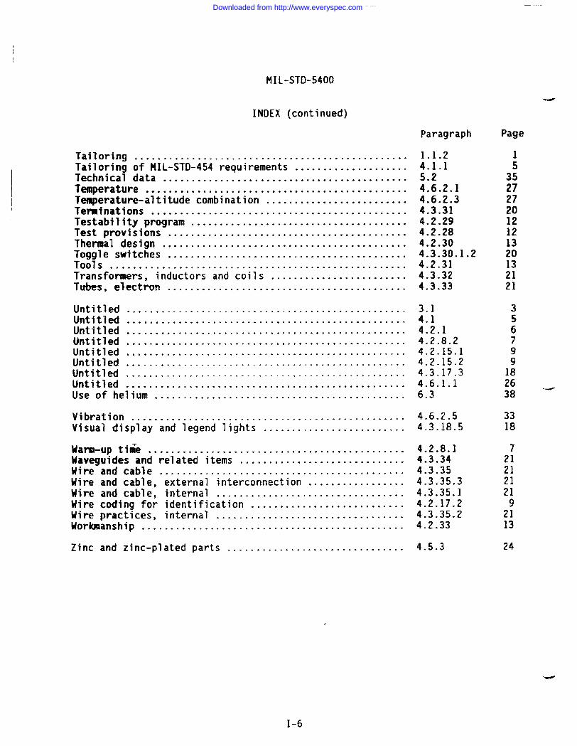
INDEX (continued)
Tailoring ................................................Tailoring of MIL-STD-454 requirements ....................Technicai data ..........Temperature ...........0.Temperature-altitude combTeninations ............Testability program .....
. . . . . . . . . . . . . . . . . . . . . . . . . . . . . . . .
. . . . . . . . . . . . . . . . . . . . . . . . . . . . . . . .nation .......................... . . . . . . . . . . . . . . . . . . . . . . . . . . . . . . .. . . . . . . . . . . . . . . . . . . . . . . . . . . . . . . .
Test provisions- ..........................................Thermal design ...........................................Toggle switches ..........................................Tools ....................................................Transformers, inductors and coils ........................Tubes, electron ..........................................
Untitled .................................................Untitled .................................................Untitled .................................................Untitled .................................................Untitled .................................................Untitled .................................................Untitled .................................................Untitled .................................................Use of helium ............................................
Vibration ................................................Visual display ancflegendl ights .........................
Uarm-up time .............................................Maveguides and related items .............................Wire and cable ...........................................Uire and cable, external interconnection .................Wire and cable, internal .................................Uirecoding for identification ...........................Wire practices, internal .................................Workmanship ..............................................
Zinc and zinc-plated parts ...............................
Paragraph
1.1.24.1.1
%2.14.6.2.34.3.314.2.294.2.284.2.304.3.30.1.24.2.314.3.324.3.33
3.14.14.2.14.2.8.24.2.15.14.2.15.24.3.17.34.6.1.16.3
4.6.2.54.3.18.5
4.2.8.14.3.344,3.354.3.35.34.3.35.14.2. 17.24.3.35.24.2.33
4.5.3
Page
;35272720iz121320132121
2638 ‘-
3318
7212121219
2113
24
1-6
Downloaded from http://www.everyspec.com
STANDARDIZATION DOCUMENT IMPROVEMENT PROPOSAL
lNSIRUC?lOIV$1. The preparing activity must complete blocks 1, 2, 3 and 6. In block 1, both the document number and revision
letter shouldbe ~iven.
2. The submitter of this form must complete blocks 4,5,6, and 7.
3. The preparingactivity must provide a reply within 30 days from receipt of the form.
NOTE: Thisform may not be used to request copies of documents, nor to request waivers, d~ clarification ofrequirements on current contiacts.Comments submitted on this form do not constitute or imply ●uthorizationtewaiveany poti”onofthereferenceddocument(s)or to amend contractual requirements.
‘a ‘OcuMfNT ‘UMBER2. 00 CUMENT DATE (YYMA4DDJ
,.,. .. . . ..... .
3 . DOCUMftIJT TITLE ELECTRONIC EQUIPMENT, AIRBORNE 9
GENERAL REQUIREMENTS FOR .4 , RArLJRL OF CNANGE (ldwwj paragraph number and inc!ude proposed rewrii< if ~ble. Attach ●xlra dIeQfS 4S *eded)
..”
[5. REASON FOR RECOMMENDATION
I
/._j:~ $uBMl~[R ‘: . :’:,A ,“,: :::” ::: :,. ;,;.:<,,;,..; +,..,, ., ,’, ,., , ., ., ,, *,:.:,7 &:~**+:,;*;,#$~:~”.<$.; .++:::::~~+.*.:.3 *:*.-,, ,; .;. ,..,<=&& ; ;,;:,,,..:*.< .. :::. ... ..,~~$+,f? ,- W::W(*$2+
t. PRCPARING ACllVI~WAKCOMMANDING OFFICER, NAVAL AIR b. TELEPHONE {tide A/w Code)
I
AARFARE CENTER AIRCRAFT DIVISION LAKEHURST (1)Commercial (2) AuTOVON
SYSTEMS REQUIREMENTS DEPARTMENT (908 ) 323-7488 624-7488.-. . . .,.,, A~~Rfss (hchdr ZtP Code)
CODE SR3IF YOU DO MOT XECIIVE A RIPLY WTHIN 45 DAYS, CONTA~:
Defense Quality ●nd St#ndardixation Office! LAKEHURST, NJ 08733-5100 S203 LeesburgPike. Suite 1403, Falls Church, VA Z204 ~-3466 “ :
Tetephon@ (703) 7$6-2340 AIJ’TOVON 209-2340I 1
-in c-r- qAx nrr 00 -. –...-. . . . . .-. “..
Downloaded from http://www.everyspec.com