Embed Size (px)
DESCRIPTION
Cracked and uncracked concrete design
Citation preview
DraftDRAFT
Lecture Notes in:
Mechanics and Design of
REINFORCED CONCRETE
Victor E. SaoumaDept. of Civil Environmental and Architectural Engineering
University of Colorado, Boulder, CO 80309-0428
Draft
Contents
1 INTRODUCTION 131.1 Material . . . . . . . . . . . . . . . . . . . . . . . . . . . . . . . . . . . . . . . . . 13
1.1.1 Concrete . . . . . . . . . . . . . . . . . . . . . . . . . . . . . . . . . . . . 131.1.1.1 Mix Design . . . . . . . . . . . . . . . . . . . . . . . . . . . . . . 13
1.1.1.1.1 Constituents . . . . . . . . . . . . . . . . . . . . . . . . 131.1.1.1.2 Preliminary Considerations . . . . . . . . . . . . . . . . 171.1.1.1.3 Mix procedure . . . . . . . . . . . . . . . . . . . . . . . 171.1.1.1.4 Mix Design Example . . . . . . . . . . . . . . . . . . . 20
1.1.1.2 Mechanical Properties . . . . . . . . . . . . . . . . . . . . . . . . 221.1.2 Reinforcing Steel . . . . . . . . . . . . . . . . . . . . . . . . . . . . . . . . 26
1.2 Design Philosophy, USD . . . . . . . . . . . . . . . . . . . . . . . . . . . . . . . . 271.3 Analysis vs Design . . . . . . . . . . . . . . . . . . . . . . . . . . . . . . . . . . . 281.4 Basic Relations and Assumptions . . . . . . . . . . . . . . . . . . . . . . . . . . . 281.5 ACI Code . . . . . . . . . . . . . . . . . . . . . . . . . . . . . . . . . . . . . . . . 29
2 FLEXURE 312.1 Uncracked Section . . . . . . . . . . . . . . . . . . . . . . . . . . . . . . . . . . . 31
E 2-1 Uncracked Section . . . . . . . . . . . . . . . . . . . . . . . . . . . . . . . 322.2 Section Cracked, Stresses Elastic . . . . . . . . . . . . . . . . . . . . . . . . . . . 33
2.2.1 Basic Relations . . . . . . . . . . . . . . . . . . . . . . . . . . . . . . . . . 332.2.2 Working Stress Method . . . . . . . . . . . . . . . . . . . . . . . . . . . . 34E 2-2 Cracked Elastic Section . . . . . . . . . . . . . . . . . . . . . . . . . . . . 35E 2-3 Working Stress Design Method; Analysis . . . . . . . . . . . . . . . . . . . 36E 2-4 Working Stress Design Method; Design . . . . . . . . . . . . . . . . . . . 37
2.3 Cracked Section, Ultimate Strength Design Method . . . . . . . . . . . . . . . . . 382.3.1 Whitney Stress Block . . . . . . . . . . . . . . . . . . . . . . . . . . . . . 382.3.2 Balanced Design . . . . . . . . . . . . . . . . . . . . . . . . . . . . . . . . 402.3.3 Review . . . . . . . . . . . . . . . . . . . . . . . . . . . . . . . . . . . . . 412.3.4 Design . . . . . . . . . . . . . . . . . . . . . . . . . . . . . . . . . . . . . . 41
2.4 Practical Design Considerations . . . . . . . . . . . . . . . . . . . . . . . . . . . . 422.4.1 Minimum Depth . . . . . . . . . . . . . . . . . . . . . . . . . . . . . . . . 422.4.2 Beam Sizes, Bar Spacing, Concrete Cover . . . . . . . . . . . . . . . . . . 432.4.3 Design Aids . . . . . . . . . . . . . . . . . . . . . . . . . . . . . . . . . . . 43
2.5 USD Examples . . . . . . . . . . . . . . . . . . . . . . . . . . . . . . . . . . . . . 45E 2-5 Ultimate Strength; Review . . . . . . . . . . . . . . . . . . . . . . . . . . 45E 2-6 Ultimate Strength; Design I . . . . . . . . . . . . . . . . . . . . . . . . . . 46E 2-7 Ultimate Strength; Design II . . . . . . . . . . . . . . . . . . . . . . . . . 47
DraftCONTENTS 5
6 SERVICEABILITY 1036.1 Control of Cracking . . . . . . . . . . . . . . . . . . . . . . . . . . . . . . . . . . 103
E 6-1 Crack Width . . . . . . . . . . . . . . . . . . . . . . . . . . . . . . . . . . 1056.2 Deflections . . . . . . . . . . . . . . . . . . . . . . . . . . . . . . . . . . . . . . . 105
6.2.1 Short Term Deflection . . . . . . . . . . . . . . . . . . . . . . . . . . . . . 1066.2.2 Long Term Deflection . . . . . . . . . . . . . . . . . . . . . . . . . . . . . 107E 6-2 Deflections . . . . . . . . . . . . . . . . . . . . . . . . . . . . . . . . . . . 109
7 APPROXIMATE FRAME ANALYSIS 1117.1 Vertical Loads . . . . . . . . . . . . . . . . . . . . . . . . . . . . . . . . . . . . . . 1117.2 Horizontal Loads . . . . . . . . . . . . . . . . . . . . . . . . . . . . . . . . . . . . 114
7.2.1 Portal Method . . . . . . . . . . . . . . . . . . . . . . . . . . . . . . . . . 114E 7-1 Approximate Analysis of a Frame subjected to Vertical and Horizontal Loads116
8 COLUMNS 131
9 COLUMNS 1339.1 Introduction . . . . . . . . . . . . . . . . . . . . . . . . . . . . . . . . . . . . . . . 133
9.1.1 Types of Columns . . . . . . . . . . . . . . . . . . . . . . . . . . . . . . . 1339.1.2 Possible Arrangement of Bars . . . . . . . . . . . . . . . . . . . . . . . . . 134
9.2 Short Columns . . . . . . . . . . . . . . . . . . . . . . . . . . . . . . . . . . . . . 1349.2.1 Concentric Loading . . . . . . . . . . . . . . . . . . . . . . . . . . . . . . . 1349.2.2 Eccentric Columns . . . . . . . . . . . . . . . . . . . . . . . . . . . . . . . 134
9.2.2.1 Balanced Condition . . . . . . . . . . . . . . . . . . . . . . . . . 1359.2.2.2 Tension Failure . . . . . . . . . . . . . . . . . . . . . . . . . . . . 1379.2.2.3 Compression Failure . . . . . . . . . . . . . . . . . . . . . . . . . 138
9.2.3 ACI Provisions . . . . . . . . . . . . . . . . . . . . . . . . . . . . . . . . . 1399.2.4 Interaction Diagrams . . . . . . . . . . . . . . . . . . . . . . . . . . . . . . 1399.2.5 Design Charts . . . . . . . . . . . . . . . . . . . . . . . . . . . . . . . . . 139E 9-1 R/C Column, c known . . . . . . . . . . . . . . . . . . . . . . . . . . . . . 139E 9-2 R/C Column, e known . . . . . . . . . . . . . . . . . . . . . . . . . . . . . 141E 9-3 R/C Column, Using Design Charts . . . . . . . . . . . . . . . . . . . . . . 1459.2.6 Biaxial Bending . . . . . . . . . . . . . . . . . . . . . . . . . . . . . . . . 146E 9-4 Biaxially Loaded Column . . . . . . . . . . . . . . . . . . . . . . . . . . . 149
9.3 Long Columns . . . . . . . . . . . . . . . . . . . . . . . . . . . . . . . . . . . . . 1509.3.1 Euler Elastic Buckling . . . . . . . . . . . . . . . . . . . . . . . . . . . . . 1509.3.2 Effective Length . . . . . . . . . . . . . . . . . . . . . . . . . . . . . . . . 1519.3.3 Moment Magnification Factor; ACI Provisions . . . . . . . . . . . . . . . 153E 9-5 Long R/C Column . . . . . . . . . . . . . . . . . . . . . . . . . . . . . . . 155E 9-6 Design of Slender Column . . . . . . . . . . . . . . . . . . . . . . . . . . . 157
10 PRESTRESSED CONCRETE 15910.1 Introduction . . . . . . . . . . . . . . . . . . . . . . . . . . . . . . . . . . . . . . . 159
10.1.1 Materials . . . . . . . . . . . . . . . . . . . . . . . . . . . . . . . . . . . . 15910.1.2 Prestressing Forces . . . . . . . . . . . . . . . . . . . . . . . . . . . . . . . 16210.1.3 Assumptions . . . . . . . . . . . . . . . . . . . . . . . . . . . . . . . . . . 16210.1.4 Tendon Configuration . . . . . . . . . . . . . . . . . . . . . . . . . . . . . 16210.1.5 Equivalent Load . . . . . . . . . . . . . . . . . . . . . . . . . . . . . . . . 162
Victor Saouma Mechanics and Design of Reinforced Concrete
Draft
List of Figures
1.1 Schematic Representation of Aggregate Gradation . . . . . . . . . . . . . . . . . 141.2 MicroCracks in Concrete under Compression . . . . . . . . . . . . . . . . . . . . 231.3 Concrete Stress Strain Curve . . . . . . . . . . . . . . . . . . . . . . . . . . . . . 231.4 Modulus of Rupture Test . . . . . . . . . . . . . . . . . . . . . . . . . . . . . . . 241.5 Split Cylinder (Brazilian) Test . . . . . . . . . . . . . . . . . . . . . . . . . . . . 241.6 Biaxial Strength of Concrete . . . . . . . . . . . . . . . . . . . . . . . . . . . . . 251.7 Time Dependent Strains in Concrete . . . . . . . . . . . . . . . . . . . . . . . . . 26
2.1 Strain Diagram Uncracked Section . . . . . . . . . . . . . . . . . . . . . . . . . . 312.2 Transformed Section . . . . . . . . . . . . . . . . . . . . . . . . . . . . . . . . . . 322.3 Stress Diagram Cracked Elastic Section . . . . . . . . . . . . . . . . . . . . . . . 332.4 Desired Stress Distribution; WSD Method . . . . . . . . . . . . . . . . . . . . . . 342.5 Cracked Section, Limit State . . . . . . . . . . . . . . . . . . . . . . . . . . . . . 392.6 Whitney Stress Block . . . . . . . . . . . . . . . . . . . . . . . . . . . . . . . . . 402.7 Bar Spacing . . . . . . . . . . . . . . . . . . . . . . . . . . . . . . . . . . . . . . . 452.8 T Beams . . . . . . . . . . . . . . . . . . . . . . . . . . . . . . . . . . . . . . . . . 502.9 T Beam as Rectangular Section . . . . . . . . . . . . . . . . . . . . . . . . . . . . 502.10 T Beam Strain and Stress Diagram . . . . . . . . . . . . . . . . . . . . . . . . . . 512.11 Decomposition of Steel Reinforcement for T Beams . . . . . . . . . . . . . . . . . 512.12 Doubly Reinforced Beams; Strain and Stress Diagrams . . . . . . . . . . . . . . . 562.13 Different Possibilities for Doubly Reinforced Concrete Beams . . . . . . . . . . . 572.14 Strain Diagram, Doubly Reinforced Beam; is As Yielding? . . . . . . . . . . . . . 572.15 Strain Diagram, Doubly Reinforced Beam; is A′
s Yielding? . . . . . . . . . . . . . 582.16 Summary of Conditions for top and Bottom Steel Yielding . . . . . . . . . . . . . 592.17 Bending of a Beam . . . . . . . . . . . . . . . . . . . . . . . . . . . . . . . . . . . 642.18 Moment-Curvature Relation for a Beam . . . . . . . . . . . . . . . . . . . . . . . 642.19 Bond and Development Length . . . . . . . . . . . . . . . . . . . . . . . . . . . . 652.20 Actual Bond Distribution . . . . . . . . . . . . . . . . . . . . . . . . . . . . . . . 672.21 Splitting Along Reinforcement . . . . . . . . . . . . . . . . . . . . . . . . . . . . 672.22 Development Length . . . . . . . . . . . . . . . . . . . . . . . . . . . . . . . . . . 672.23 Development Length . . . . . . . . . . . . . . . . . . . . . . . . . . . . . . . . . . 682.24 Hooks . . . . . . . . . . . . . . . . . . . . . . . . . . . . . . . . . . . . . . . . . . 692.25 Bar cutoff requirements of the ACI code . . . . . . . . . . . . . . . . . . . . . . . 712.26 Standard cutoff or bend points for bars in approximately equal spans with uniformly distributed load 722.27 Moment Capacity Diagram . . . . . . . . . . . . . . . . . . . . . . . . . . . . . . 73
3.1 Principal Stresses in Beam . . . . . . . . . . . . . . . . . . . . . . . . . . . . . . . 75
DraftLIST OF FIGURES 9
9.3 Possible Bar arrangements . . . . . . . . . . . . . . . . . . . . . . . . . . . . . . . 1349.4 Sources of Bending . . . . . . . . . . . . . . . . . . . . . . . . . . . . . . . . . . . 1359.5 Load Moment Interaction Diagram . . . . . . . . . . . . . . . . . . . . . . . . . . 1359.6 Strain and Stress Diagram of a R/C Column . . . . . . . . . . . . . . . . . . . . 1369.7 Column Interaction Diagram . . . . . . . . . . . . . . . . . . . . . . . . . . . . . 1409.8 Failure Surface of a Biaxially Loaded Column . . . . . . . . . . . . . . . . . . . . 1469.9 Load Contour at Plane of Constant Pn, and Nondimensionalized Corresponding plots1479.10 Biaxial Bending Interaction Relations in terms of β . . . . . . . . . . . . . . . . . 1489.11 Bilinear Approximation for Load Contour Design of Biaxially Loaded Columns . 1489.12 Euler Column . . . . . . . . . . . . . . . . . . . . . . . . . . . . . . . . . . . . . . 1509.13 Column Failures . . . . . . . . . . . . . . . . . . . . . . . . . . . . . . . . . . . . 1519.14 Critical lengths of columns . . . . . . . . . . . . . . . . . . . . . . . . . . . . . . 1529.15 Effective length Factors Ψ . . . . . . . . . . . . . . . . . . . . . . . . . . . . . . . 1539.16 Standard Alignment Chart (ACI) . . . . . . . . . . . . . . . . . . . . . . . . . . . 1549.17 Minimum Column Eccentricity . . . . . . . . . . . . . . . . . . . . . . . . . . . . 1549.18 P-M Magnification Interaction Diagram . . . . . . . . . . . . . . . . . . . . . . . 155
10.1 Pretensioned Prestressed Concrete Beam, (?) . . . . . . . . . . . . . . . . . . . . 16010.2 Posttensioned Prestressed Concrete Beam, (?) . . . . . . . . . . . . . . . . . . . . 16010.3 7 Wire Prestressing Tendon . . . . . . . . . . . . . . . . . . . . . . . . . . . . . . 16110.4 Alternative Schemes for Prestressing a Rectangular Concrete Beam, (?) . . . . . 16310.5 Determination of Equivalent Loads . . . . . . . . . . . . . . . . . . . . . . . . . . 16310.6 Load-Deflection Curve and Corresponding Internal Flexural Stresses for a Typical Prestressed Concrete Beam, (?)16410.7 Flexural Stress Distribution for a Beam with Variable Eccentricity; Maximum Moment Section and Support Section, (?)16510.8 Walnut Lane Bridge, Plan View . . . . . . . . . . . . . . . . . . . . . . . . . . . . 16910.9 Walnut Lane Bridge, Cross Section . . . . . . . . . . . . . . . . . . . . . . . . . . 170
Victor Saouma Mechanics and Design of Reinforced Concrete
Draft
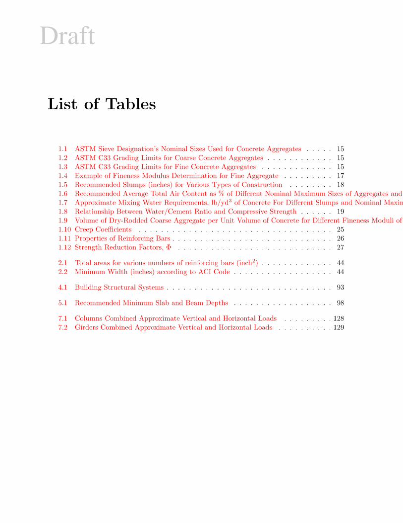
List of Tables
1.1 ASTM Sieve Designation’s Nominal Sizes Used for Concrete Aggregates . . . . . 151.2 ASTM C33 Grading Limits for Coarse Concrete Aggregates . . . . . . . . . . . . 151.3 ASTM C33 Grading Limits for Fine Concrete Aggregates . . . . . . . . . . . . . 151.4 Example of Fineness Modulus Determination for Fine Aggregate . . . . . . . . . 171.5 Recommended Slumps (inches) for Various Types of Construction . . . . . . . . 181.6 Recommended Average Total Air Content as % of Different Nominal Maximum Sizes of Aggregates and Levels of Exposure 181.7 Approximate Mixing Water Requirements, lb/yd3 of Concrete For Different Slumps and Nominal Maximum Sizes of Aggregates 191.8 Relationship Between Water/Cement Ratio and Compressive Strength . . . . . . 191.9 Volume of Dry-Rodded Coarse Aggregate per Unit Volume of Concrete for Different Fineness Moduli of Sand 201.10 Creep Coefficients . . . . . . . . . . . . . . . . . . . . . . . . . . . . . . . . . . . 251.11 Properties of Reinforcing Bars . . . . . . . . . . . . . . . . . . . . . . . . . . . . . 261.12 Strength Reduction Factors, Φ . . . . . . . . . . . . . . . . . . . . . . . . . . . . 27
2.1 Total areas for various numbers of reinforcing bars (inch2) . . . . . . . . . . . . . 442.2 Minimum Width (inches) according to ACI Code . . . . . . . . . . . . . . . . . . 44
4.1 Building Structural Systems . . . . . . . . . . . . . . . . . . . . . . . . . . . . . . 93
5.1 Recommended Minimum Slab and Beam Depths . . . . . . . . . . . . . . . . . . 98
7.1 Columns Combined Approximate Vertical and Horizontal Loads . . . . . . . . . 1287.2 Girders Combined Approximate Vertical and Horizontal Loads . . . . . . . . . . 129
Draft
Chapter 1
INTRODUCTION
1.1 Material
1.1.1 Concrete
This section is adapted from Concrete by Mindess and Young, Prentice Hall, 1981
1.1.1.1 Mix Design
1.1.1.1.1 Constituents
1 Concrete is a mixture of Portland cement, water, and aggregates (usually sand and crushedstone).
2 Portland cement is a mixture of calcareous and argillaceous materials which are calcined ina kiln and then pulverized. When mixed with water, cement hardens through a process calledhydration.
3 Ideal mixture is one in which:
1. A minimum amount of cement-water paste is used to fill the interstices between theparticles of aggregates.
2. A minimum amount of water is provided to complete the chemical reaction with cement.Strictly speaking, a water/cement ratio of about 0.25 is needed to complete this reaction,but then the concrete will have a very low “workability”.
In such a mixture, about 3/4 of the volume is constituted by the aggregates, and the remaining1/4 being the cement paste.
4 Smaller particles up to 1/4 in. in size are called fine aggregates, and the larger ones beingcoarse aggregates.
5 Portland Cement has the following ASTM designation
I Normal
II Moderate sulfate resistant, moderate heat of hydration
III High early strength (but releases too much heat)
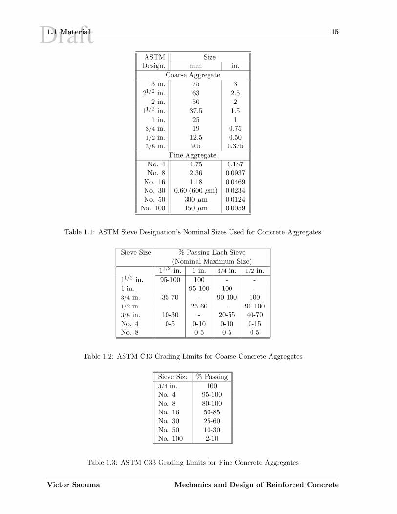
Draft1.1 Material 15
ASTM SizeDesign. mm in.
Coarse Aggregate
3 in. 75 3
21/2 in. 63 2.52 in. 50 2
11/2 in. 37.5 1.51 in. 25 1
3/4 in. 19 0.751/2 in. 12.5 0.503/8 in. 9.5 0.375
Fine Aggregate
No. 4 4.75 0.187No. 8 2.36 0.0937
No. 16 1.18 0.0469No. 30 0.60 (600 µm) 0.0234No. 50 300 µm 0.0124
No. 100 150 µm 0.0059
Table 1.1: ASTM Sieve Designation’s Nominal Sizes Used for Concrete Aggregates
Sieve Size % Passing Each Sieve(Nominal Maximum Size)
11/2 in. 1 in. 3/4 in. 1/2 in.
11/2 in. 95-100 100 - -1 in. - 95-100 100 -3/4 in. 35-70 - 90-100 1001/2 in. - 25-60 - 90-1003/8 in. 10-30 - 20-55 40-70No. 4 0-5 0-10 0-10 0-15No. 8 - 0-5 0-5 0-5
Table 1.2: ASTM C33 Grading Limits for Coarse Concrete Aggregates
Sieve Size % Passing
3/4 in. 100No. 4 95-100No. 8 80-100No. 16 50-85No. 30 25-60No. 50 10-30No. 100 2-10
Table 1.3: ASTM C33 Grading Limits for Fine Concrete Aggregates
Victor Saouma Mechanics and Design of Reinforced Concrete
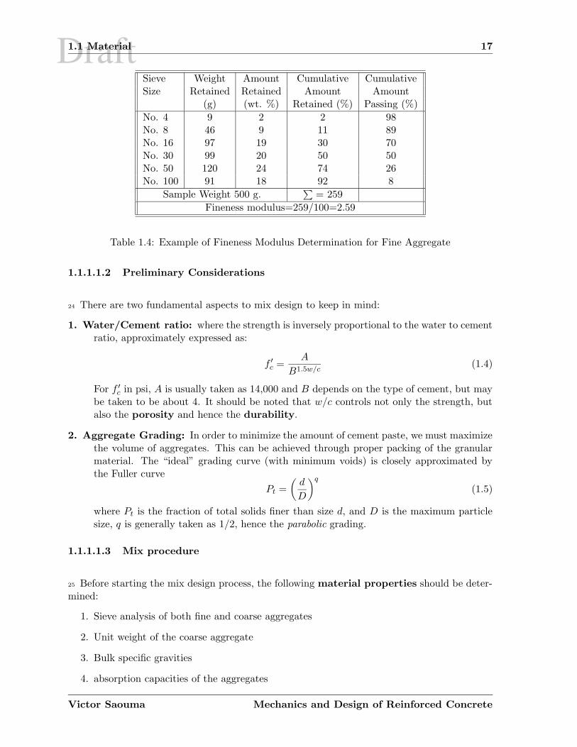
Draft1.1 Material 17
Sieve Weight Amount Cumulative CumulativeSize Retained Retained Amount Amount
(g) (wt. %) Retained (%) Passing (%)
No. 4 9 2 2 98No. 8 46 9 11 89No. 16 97 19 30 70No. 30 99 20 50 50No. 50 120 24 74 26No. 100 91 18 92 8
Sample Weight 500 g.∑
= 259
Fineness modulus=259/100=2.59
Table 1.4: Example of Fineness Modulus Determination for Fine Aggregate
1.1.1.1.2 Preliminary Considerations
24 There are two fundamental aspects to mix design to keep in mind:
1. Water/Cement ratio: where the strength is inversely proportional to the water to cementratio, approximately expressed as:
f ′
c =A
B1.5w/c(1.4)
For f ′
c in psi, A is usually taken as 14,000 and B depends on the type of cement, but maybe taken to be about 4. It should be noted that w/c controls not only the strength, butalso the porosity and hence the durability.
2. Aggregate Grading: In order to minimize the amount of cement paste, we must maximizethe volume of aggregates. This can be achieved through proper packing of the granularmaterial. The “ideal” grading curve (with minimum voids) is closely approximated bythe Fuller curve
Pt =
(d
D
)q
(1.5)
where Pt is the fraction of total solids finer than size d, and D is the maximum particlesize, q is generally taken as 1/2, hence the parabolic grading.
1.1.1.1.3 Mix procedure
25 Before starting the mix design process, the following material properties should be deter-mined:
1. Sieve analysis of both fine and coarse aggregates
2. Unit weight of the coarse aggregate
3. Bulk specific gravities
4. absorption capacities of the aggregates
Victor Saouma Mechanics and Design of Reinforced Concrete
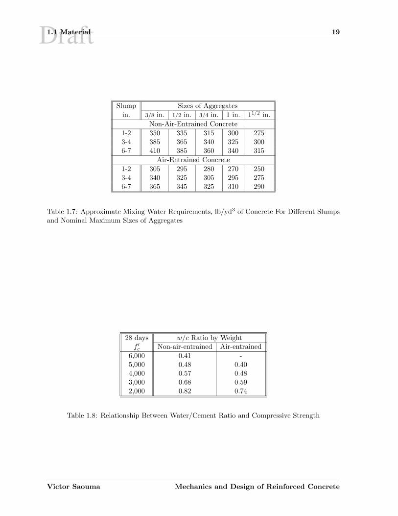
Draft1.1 Material 19
Slump Sizes of Aggregates
in. 3/8 in. 1/2 in. 3/4 in. 1 in. 11/2 in.
Non-Air-Entrained Concrete
1-2 350 335 315 300 2753-4 385 365 340 325 3006-7 410 385 360 340 315
Air-Entrained Concrete
1-2 305 295 280 270 2503-4 340 325 305 295 2756-7 365 345 325 310 290
Table 1.7: Approximate Mixing Water Requirements, lb/yd3 of Concrete For Different Slumpsand Nominal Maximum Sizes of Aggregates
28 days w/c Ratio by Weightf ′
c Non-air-entrained Air-entrained
6,000 0.41 -5,000 0.48 0.404,000 0.57 0.483,000 0.68 0.592,000 0.82 0.74
Table 1.8: Relationship Between Water/Cement Ratio and Compressive Strength
Victor Saouma Mechanics and Design of Reinforced Concrete
Draft1.1 Material 21
Fine Aggregates: Bulk specific gravity (SSD) = 2.65; absorption capacity = 1.3 %; Totalmoisture content=5.5%; fineness modulus = 2.70
The sieve analyses of both the coarse and fine aggregates fall within the specified limits. Withthis information, the mix design can proceed:
1. Choice of slump is consistent with Table 1.5.
2. Maximum aggregate size (3/4 in) is governed by reinforcing details.
3. Estimation of mixing water: Because water will be exposed to freeze and thaw, it mustbe air-entrained. From Table 1.6 the air content recommended for extreme exposure is6.0%, and from Table 1.7 the water requirement is 280 lb/yd3
4. From Table 1.8, the water to cement ratio estimate is 0.4
5. Cement content, based on steps 4 and 5 is 280/0.4=700 lb/yd3
6. Coarse aggregate content, interpolating from Table 1.9 for the fineness modulus ofthe fine aggregate of 2.70, the volume of dry-rodded coarse aggregate per unit volume ofconcrete is 0.63. Therefore, the coarse aggregate will occupy 0.63 × 27 = 17.01 ft3/yd3.The OD weight of the coarse aggregate is 17.01 ft3/yd3, × 100 lbs/ft3=1,701 lb. The SSDweight is 1,701 × 1.01=1,718 lb.
7. Fine aggregate content Knowing the weights and specific gravities of the water, cement,and coarse aggregate, and knowing the air volume, we can calculate the volume per yd3
occupied by the different ingredients.
Water 280/62.4 = 4.49 ft3
Cement 700/(3.15)(62.4) = 3.56 ft3
Coarse Aggregate (SSD) 1,718/(2.70)(62.4) = 1.62 ft3
Air (0.06)(27) = 1.62 ft3
19.87 ft3
Hence, the fine aggregate must occupy a volume of 27.0 − 19.87 = 7.13 ft3. The requiredSSD weight of the fine aggregate is 7.13 ft3 (2.65)(62.4)lb/ft3 =1,179 lbs lb.
8. Adjustment for moisture in the aggregate. Since the aggregate will be neither SSD orOD in the field, it is necessary to adjust the aggregate weights for the amount of watercontained in the aggregate. Only surface water need be considered; absorbed water doesnot become part of the mix water. For the given moisture contents, the adjusted aggre-gate weights become:
Coarse aggregate (wet)=1,718(1.025-0.01) = 1,744 lb/yd3 of dry coarseFine aggregate (wet)=1,179(1.055-0.013) = 1,229 lb/yd3 of dry fine
Surface moisture contributed by the coarse aggregate is 2.5-1.0 = 1.5%; by the fine ag-gregate: 5.5-1.3 = 4.2%; Hence we need to decrease water to280-1,718(0.015)-1,179(0.042) = 205 lb/yd3.
Thus, the estimated batch weight per yd3 are
Victor Saouma Mechanics and Design of Reinforced Concrete
Draft
Chapter 2
FLEXURE
1 This is probably the longest chapter in the notes, we shall cover in great details flexuraldesign/analysis of R/C beams starting with uncracked section to failure conditions.
1. Uncracked elastic (uneconomical)
2. cracked elastic (service stage)
3. Ultimate (failure)
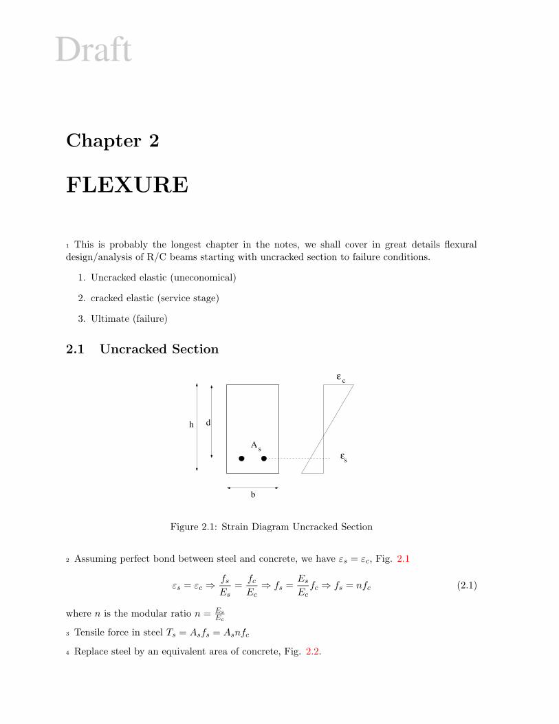
2.1 Uncracked Section
h d
b
A
ε
ε
c
ss
Figure 2.1: Strain Diagram Uncracked Section
2 Assuming perfect bond between steel and concrete, we have εs = εc, Fig. 2.1
εs = εc ⇒fs
Es=
fc
Ec⇒ fs =
Es
Ecfc ⇒ fs = nfc (2.1)
where n is the modular ratio n = Es
Ec
3 Tensile force in steel Ts = Asfs = Asnfc
4 Replace steel by an equivalent area of concrete, Fig. 2.2.
Draft2.2 Section Cracked, Stresses Elastic 33
fct =Mc
I=
(540, 000) lb.in(25 − 13.2) in
(14, 722) in4= 433 psi < 475 psi
√(2.3-h)
fs = nMc
I= (8)
(540, 000)(23 − 13.2) in
(14, 722)= 2, 876 psi (2.3-i)
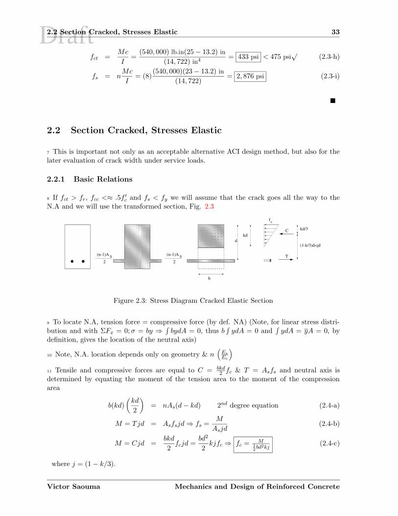
2.2 Section Cracked, Stresses Elastic
7 This is important not only as an acceptable alternative ACI design method, but also for thelater evaluation of crack width under service loads.
2.2.1 Basic Relations
8 If fct > fr, fcc <≈ .5f ′
c and fs < fy we will assume that the crack goes all the way to theN.A and we will use the transformed section, Fig. 2.3
S(n-1)A
2S(n-1)A
2
C
T
f
����������������������������������������������������������������������������������������������������������������������������������������
����������������������������������������������������������������������������������������������������������������������������������������
�������������������������������������������������������������������������������������������������������������������������������������������������������������������������������������������������������������������������������������������������������������������������������������������������������������������������������������������������������������������������������������������������������������������������������������������������������������������������������������������������������������������������������������������������������������������������������������
���������������������������������������������������������������������������������������������������������������������������������������������������������������������������������������������������������������������������������������������������������������������������������������������������������������������������������������������������������������������������������������������������������������������������������������������������������������������������������������������������������������
b
dkd
c
kd/3
(1-k/3)d=jd
Figure 2.3: Stress Diagram Cracked Elastic Section
9 To locate N.A, tension force = compressive force (by def. NA) (Note, for linear stress distri-bution and with ΣFx = 0; σ = by ⇒
∫bydA = 0, thus b
∫ydA = 0 and
∫ydA = yA = 0, by
definition, gives the location of the neutral axis)
10 Note, N.A. location depends only on geometry & n(
Es
Ec
)
11 Tensile and compressive forces are equal to C = bkd2 fc & T = Asfs and neutral axis is
determined by equating the moment of the tension area to the moment of the compressionarea
b(kd)
(kd
2
)
= nAs(d − kd) 2nd degree equation (2.4-a)
M = Tjd = Asfsjd ⇒ fs =M
Asjd(2.4-b)
M = Cjd =bkd
2fcjd =
bd2
2kjfc ⇒ fc = M
1
2bd2kj
(2.4-c)
where j = (1 − k/3).
Victor Saouma Mechanics and Design of Reinforced Concrete
Draft2.2 Section Cracked, Stresses Elastic 35
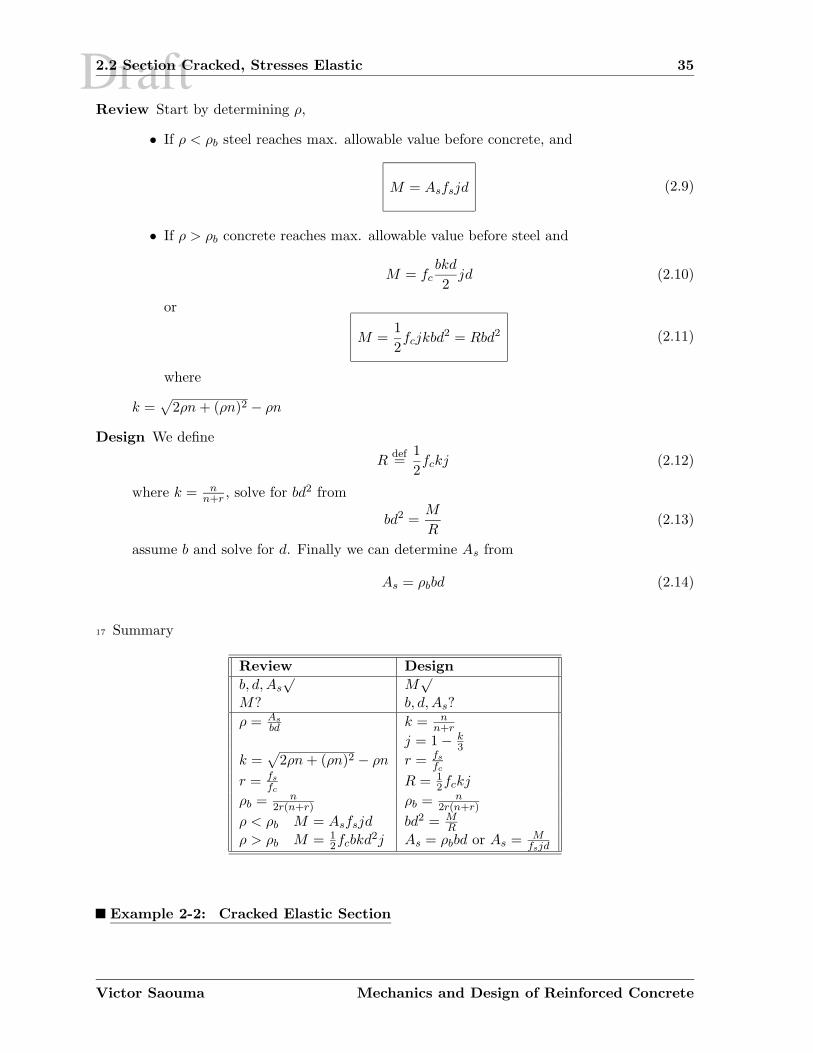
Review Start by determining ρ,
• If ρ < ρb steel reaches max. allowable value before concrete, and
M = Asfsjd (2.9)
• If ρ > ρb concrete reaches max. allowable value before steel and
M = fcbkd
2jd (2.10)
or
M =1
2fcjkbd2 = Rbd2 (2.11)
where
k =√
2ρn + (ρn)2 − ρn
Design We define
Rdef=
1
2fckj (2.12)
where k = nn+r , solve for bd2 from
bd2 =M
R(2.13)
assume b and solve for d. Finally we can determine As from
As = ρbbd (2.14)
17 Summary
Review Design
b, d, As√
M√
M? b, d, As?
ρ = As
bd k = nn+r
j = 1 − k3
k =√
2ρn + (ρn)2 − ρn r = fs
fc
r = fs
fcR = 1
2fckj
ρb = n2r(n+r) ρb = n
2r(n+r)
ρ < ρb M = Asfsjd bd2 = MR
ρ > ρb M = 12fcbkd2j As = ρbbd or As = M
fsjd
Example 2-2: Cracked Elastic Section
Victor Saouma Mechanics and Design of Reinforced Concrete
Draft2.2 Section Cracked, Stresses Elastic 37
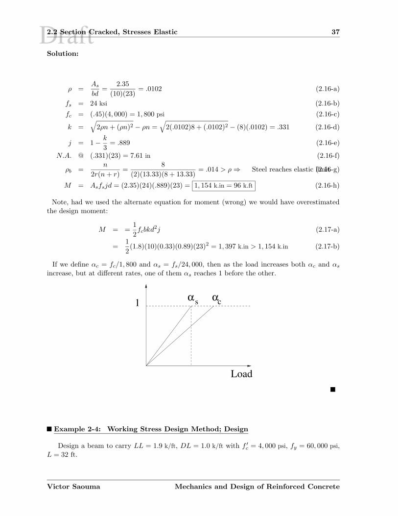
Solution:
ρ =As
bd=
2.35
(10)(23)= .0102 (2.16-a)
fs = 24 ksi (2.16-b)
fc = (.45)(4, 000) = 1, 800 psi (2.16-c)
k =√
2ρn + (ρn)2 − ρn =√
2(.0102)8 + (.0102)2 − (8)(.0102) = .331 (2.16-d)
j = 1 − k
3= .889 (2.16-e)
N.A. @ (.331)(23) = 7.61 in (2.16-f)
ρb =n
2r(n + r)=
8
(2)(13.33)(8 + 13.33)= .014 > ρ ⇒ Steel reaches elastic limit(2.16-g)
M = Asfsjd = (2.35)(24)(.889)(23) = 1, 154 k.in = 96 k.ft (2.16-h)
Note, had we used the alternate equation for moment (wrong) we would have overestimatedthe design moment:
M = =1
2fcbkd2j (2.17-a)
=1
2(1.8)(10)(0.33)(0.89)(23)2 = 1, 397 k.in > 1, 154 k.in (2.17-b)
If we define αc = fc/1, 800 and αs = fs/24, 000, then as the load increases both αc and αs
increase, but at different rates, one of them αs reaches 1 before the other.
Load
1 α αs c
Example 2-4: Working Stress Design Method; Design
Design a beam to carry LL = 1.9 k/ft, DL = 1.0 k/ft with f ′
c = 4, 000 psi, fy = 60, 000 psi,L = 32 ft.
Victor Saouma Mechanics and Design of Reinforced Concrete
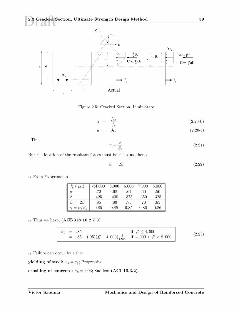
Draft2.3 Cracked Section, Ultimate Strength Design Method 39
b
dh
A
a= cc
ε
C= f’abC= f’cb γ c
c f’γ
α
Actual
cβ
ε
σ
c
s
1β
sfsf
c
βa/2 = c
Figure 2.5: Cracked Section, Limit State
α =fav
f ′
c
(2.20-b)
a = β1c (2.20-c)
Thusγ =
α
β1(2.21)
But the location of the resultant forces must be the same, hence
β1 = 2β (2.22)
21 From Experiments
f ′
c ( psi) <4,000 5,000 6,000 7,000 8,000
α .72 .68 .64 .60 .56β .425 .400 .375 .350 .325
β1 = 2β .85 .80 .75 .70 .65γ = α/β1 0.85 0.85 0.85 0.86 0.86
22 Thus we have, (ACI-318 10.2.7.3):
β1 = .85 if f ′
c ≤ 4, 000= .85 − (.05)(f ′
c − 4, 000) 11,000 if 4, 000 < f ′
c < 8, 000(2.23)
23 Failure can occur by either
yielding of steel: εs = εy; Progressive
crushing of concrete: εc = .003; Sudden; (ACI 10.3.2).
Victor Saouma Mechanics and Design of Reinforced Concrete
Draft2.3 Cracked Section, Ultimate Strength Design Method 41
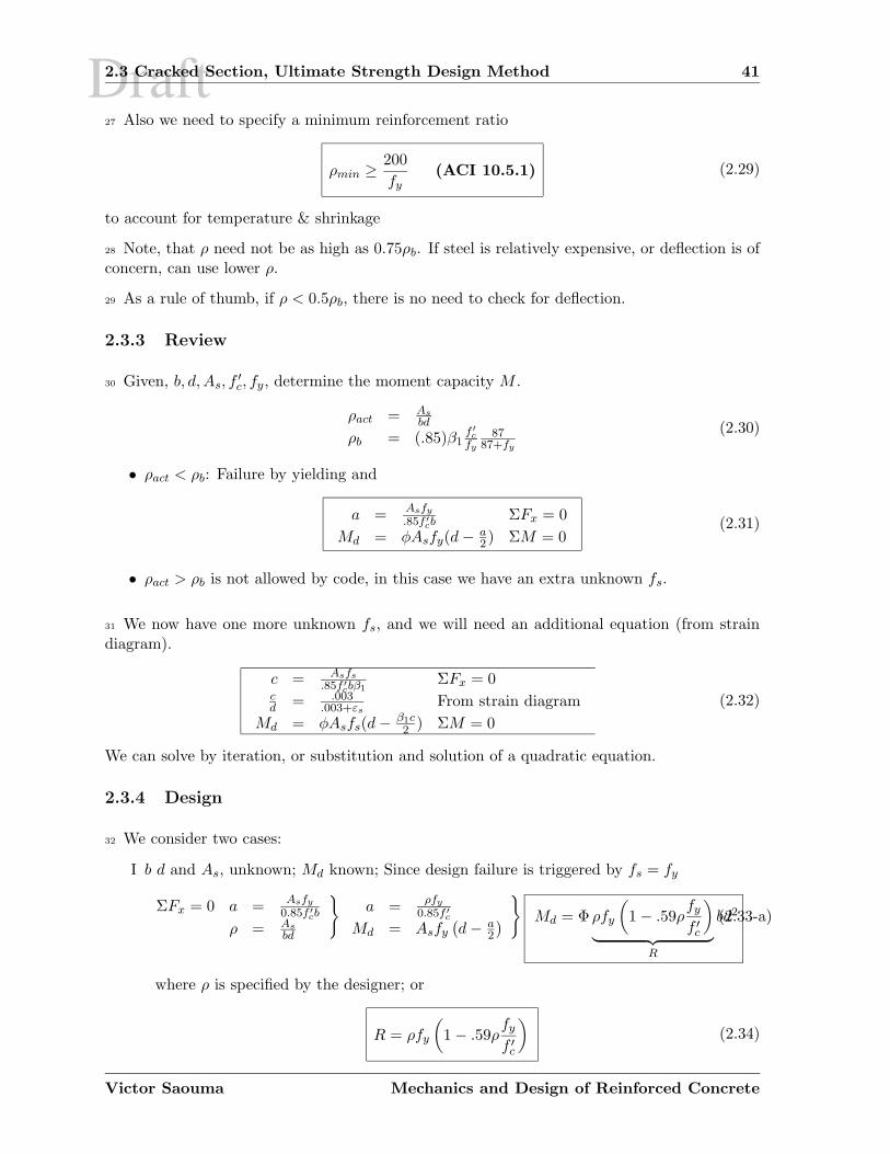
27 Also we need to specify a minimum reinforcement ratio
ρmin ≥ 200
fy(ACI 10.5.1) (2.29)
to account for temperature & shrinkage
28 Note, that ρ need not be as high as 0.75ρb. If steel is relatively expensive, or deflection is ofconcern, can use lower ρ.
29 As a rule of thumb, if ρ < 0.5ρb, there is no need to check for deflection.
2.3.3 Review
30 Given, b, d, As, f′
c, fy, determine the moment capacity M .
ρact = As
bd
ρb = (.85)β1f ′
c
fy
8787+fy
(2.30)
• ρact < ρb: Failure by yielding and
a =Asfy
.85f ′
cb ΣFx = 0
Md = φAsfy(d − a2 ) ΣM = 0
(2.31)
• ρact > ρb is not allowed by code, in this case we have an extra unknown fs.
31 We now have one more unknown fs, and we will need an additional equation (from straindiagram).
c = Asfs
.85f ′
cbβ1ΣFx = 0
cd = .003
.003+εsFrom strain diagram
Md = φAsfs(d − β1c2 ) ΣM = 0
(2.32)
We can solve by iteration, or substitution and solution of a quadratic equation.
2.3.4 Design
32 We consider two cases:
I b d and As, unknown; Md known; Since design failure is triggered by fs = fy
ΣFx = 0 a =Asfy
0.85f ′
cb
ρ = As
bd
}
a =ρfy
0.85f ′
c
Md = Asfy(d − a
2
)
}
Md = Φ ρfy
(
1 − .59ρfy
f ′
c
)
︸ ︷︷ ︸
R
bd2(2.33-a)
where ρ is specified by the designer; or
R = ρfy
(
1 − .59ρfy
f ′
c
)
(2.34)
Victor Saouma Mechanics and Design of Reinforced Concrete
Draft2.4 Practical Design Considerations 43
2.4.2 Beam Sizes, Bar Spacing, Concrete Cover
35 Beam sizes should be dimensioned as
1. Use whole inches for overall dimensions, except for slabs use 12 inch increment.
2. Ideally, the overall depth to width ratio should be between 1.5 to 2.0 (most economical).
3. For T beams, flange thickness should be about 20% of overall depth.
36 Reinforcing bars
1. Minimum spacing between bars, and minimum covers are needed to
(a) Prevent Honeycombing of concrete (air pockets)
(b) Concrete (usually up to 3/4 in MSA) must pass through the reinforcement
(c) Protect reinforcement against corrosion and fire
2. Use at least 2 bars for flexural reinforcement
3. Use bars #11 or smaller for beams.
4. Use no more than two bar sizes and no more than 2 standard sizes apart (i.e #7 and #9acceptable; #7 and #8 or #7 and #10 not).
5. Use no more than 5 or 6 bars in one layer.
6. Place longest bars in the layer nearest to face of beam.
7. Clear distance between parallel bars not less that db (to avoid splitting cracks) nor 1 in.(to allow concrete to pass through).
8. Clear distance between longitudinal bars in columns not less that 1.5db or 1.5 in.
9. Minimum cover of 1.5 in.
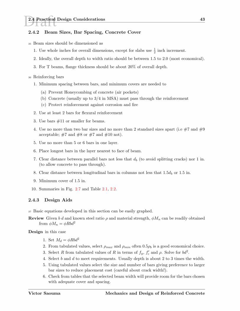
10. Summaries in Fig. 2.7 and Table 2.1, 2.2.
2.4.3 Design Aids
37 Basic equations developed in this section can be easily graphed.
Review Given b d and known steel ratio ρ and material strength, φMn can be readily obtainedfrom φMn = φRbd2
Design in this case
1. Set Md = φRbd2
2. From tabulated values, select ρmax and ρmin often 0.5ρb is a good economical choice.
3. Select R from tabulated values of R in terms of fy, f ′
c and ρ. Solve for bd2.
4. Select b and d to meet requirements. Usually depth is about 2 to 3 times the width.
5. Using tabulated values select the size and number of bars giving preference to largerbar sizes to reduce placement cost (careful about crack width!).
6. Check from tables that the selected beam width will provide room for the bars chosenwith adequate cover and spacing.
Victor Saouma Mechanics and Design of Reinforced Concrete
Draft2.5 USD Examples 45
Figure 2.7: Bar Spacing
2.5 USD Examples
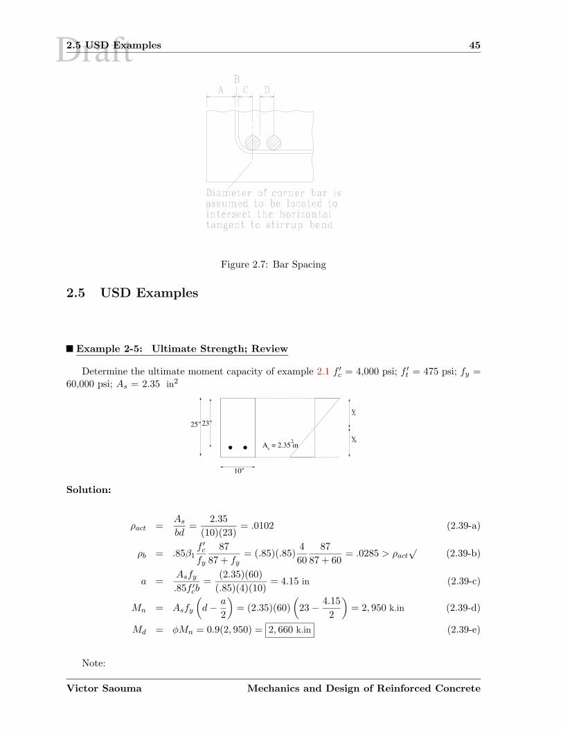
Example 2-5: Ultimate Strength; Review
Determine the ultimate moment capacity of example 2.1 f ′
c = 4,000 psi; f ′
t = 475 psi; fy =60,000 psi; As = 2.35 in2
s2
t
bA = 2.35 in
25"23"
10"
y
y
Solution:
ρact =As
bd=
2.35
(10)(23)= .0102 (2.39-a)
ρb = .85β1f ′
c
fy
87
87 + fy= (.85)(.85)
4
60
87
87 + 60= .0285 > ρact
√(2.39-b)
a =Asfy
.85f ′
cb=
(2.35)(60)
(.85)(4)(10)= 4.15 in (2.39-c)
Mn = Asfy
(
d − a
2
)
= (2.35)(60)
(
23 − 4.15
2
)
= 2, 950 k.in (2.39-d)
Md = φMn = 0.9(2, 950) = 2, 660 k.in (2.39-e)
Note:
Victor Saouma Mechanics and Design of Reinforced Concrete

Draft2.5 USD Examples 47
Example 2-7: Ultimate Strength; Design II
Design a R/C beam for b = 11.5 in; d = 20 in; f ′
c = 3 ksi; fy = 40 ksi; Md = 1, 600 k.in
Solution:
Assume a = d5 = 20
5 = 4 in
As =Md
φfy(d − a2 )
=(1, 600)
(.9)(40)(20 − 42)
= 2.47 in2 (2.42)
check assumption,
a =Asfy
(.85)f ′
cb=
(2.47)(40)
(.85)(3)(11.5)= 3.38 in (2.43)
Thus take a = 3.3 in.
As =(1, 600)
(.9)(40)(20 − 3.32 )
= 2.42 in2 (2.44-a)
⇒ a =(2.42)(40)
(.85)(3)(11.5)= 3.3 in
√(2.44-b)
ρact =2.42
(11.5)(20)= .011 (2.44-c)
ρb = (.85)(.85)3
40
87
87 + 40= .037 (2.44-d)
ρmax = .75ρb = .0278 > ρact√
(2.44-e)
Example 2-8: Exact Analysis
As an Engineer questioning the validity of the ACI equation for the ultimate flexural capacityof R/C beams, you determined experimentally the following stress strain curve for concrete:
σ =2 f ′
c
εmaxε
1 +(
εεmax
)2 (2.45)
where f ′
c corresponds to εmax.
1. Determine the exact balanced steel ratio for a R/C beam with b = 10”, d = 23”, f ′
c =4, 000 psi, fy = 60 ksi, εmax = 0.003.
(a) Determine the equation for the exact stress distribution on the section.
(b) Determine the total compressive force C, and its location, in terms of the locationof the neutral axis c.
Victor Saouma Mechanics and Design of Reinforced Concrete
Draft
Chapter 3
SHEAR
3.1 Introduction
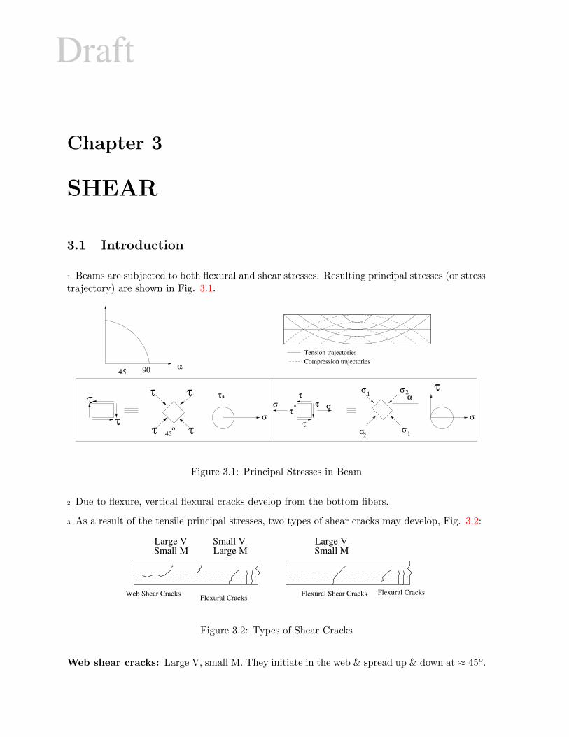
1 Beams are subjected to both flexural and shear stresses. Resulting principal stresses (or stresstrajectory) are shown in Fig. 3.1.
Compression trajectoriesTension trajectories
τ α
2
21
1σ
σσ
σ
σσ τ
ττ
ττ
τττ
τ τ
σο
45
9045α
τ
σ
Figure 3.1: Principal Stresses in Beam
2 Due to flexure, vertical flexural cracks develop from the bottom fibers.
3 As a result of the tensile principal stresses, two types of shear cracks may develop, Fig. 3.2:
Flexural Shear Cracks Flexural CracksWeb Shear CracksFlexural Cracks
Small MLarge VSmall V
Large MSmall MLarge V
Figure 3.2: Types of Shear Cracks
Web shear cracks: Large V, small M. They initiate in the web & spread up & down at ≈ 45o.
Draft3.2 Shear Strength of Uncracked Section 77
3. Compute the principal stresses
4. Equate principal tensile stress to the tensile strength
10 Using a semi-analytical approach
1. Assume that fc is directly proportional to steel stress
fc = α fs
n
Mn = Asfsjd ⇒ fs = Mn
Asjd
fc = α Mn
nAsjd
ρ = As
bd
}
fc =αMn
nρjbd2= F1
Mn
ρnbd2(3.1)
2. Shear stress
vn = F2Vn
bd(3.2)
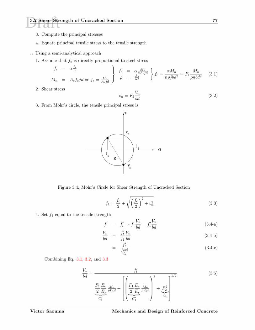
3. From Mohr’s circle, the tensile principal stress is
R
1
τ
σf
vn
vn
cf
Figure 3.4: Mohr’s Circle for Shear Strength of Uncracked Section
f1 =fc
2+
√(
fc
2
)2
+ v2n (3.3)
4. Set f1 equal to the tensile strength
f1 = f ′
t ⇒ f1Vn
bd= f ′
t
Vn
bd(3.4-a)
Vn
bd=
f ′
t
f1
Vn
bd(3.4-b)
=f ′
tf1bdVn
(3.4-c)
Combining Eq. 3.1, 3.2, and 3.3
Vn
bd=
f ′
t
F1
2
Ec
Es︸ ︷︷ ︸
C′
1
Mn
ρVnd +
F1
2
Ec
Es︸ ︷︷ ︸
C′
1
Mn
ρVnd
2
+ F 22
︸︷︷︸
C′
2
1/2(3.5)
Victor Saouma Mechanics and Design of Reinforced Concrete


![IntermittentbehaviourofaCrackedRotorin theresonanceregionference between the cracked and uncracked rotors can appear in the region of internal or combination resonances [5,6]. One](https://img.pdfslide.us/doc/110x75/5f63af0fff6bdb53b8325e82/intermittentbehaviourofacrackedrotorin-theresonanceregion-ference-between-the-cracked.jpg)