Embed Size (px)
Citation preview
Cons
truct
ion
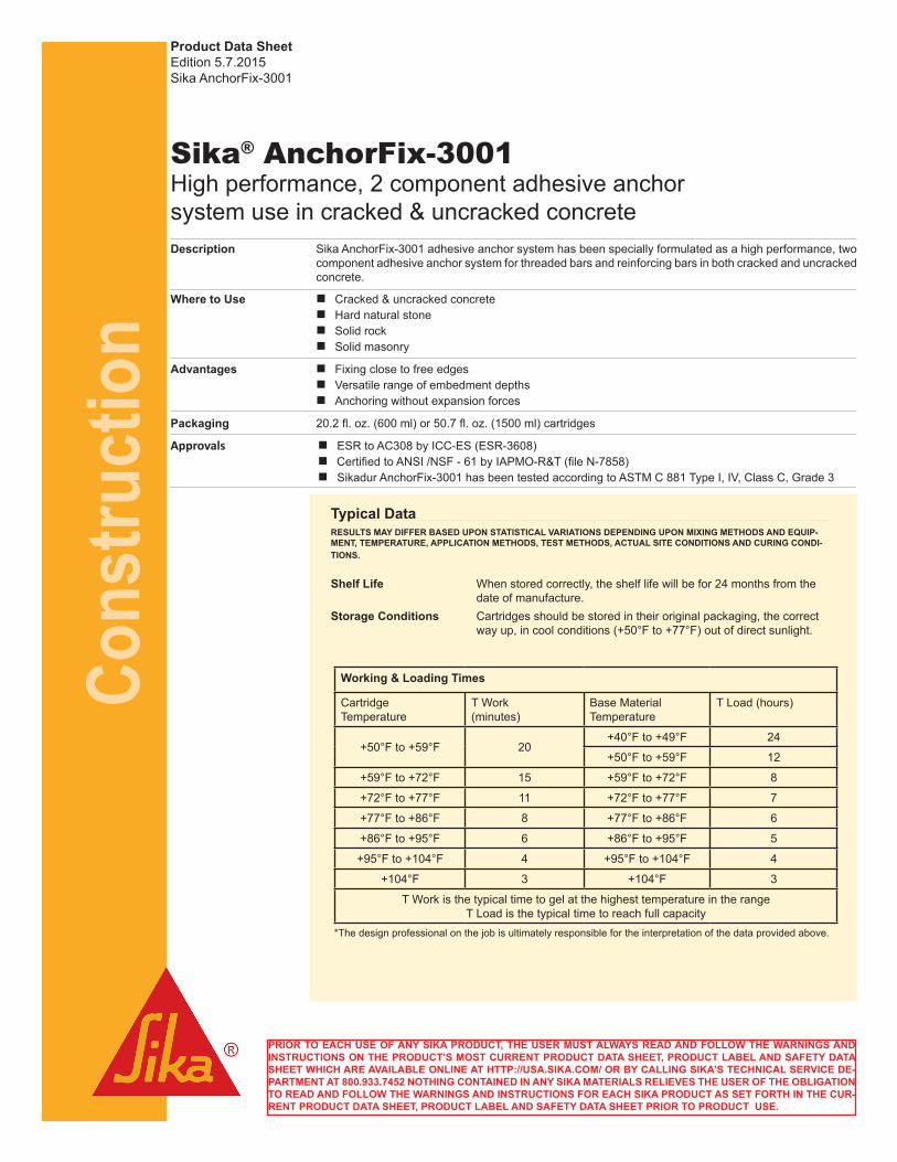
Sika® AnchorFix-3001High performance, 2 component adhesive anchor system use in cracked & uncracked concreteDescription Sika AnchorFix-3001 adhesive anchor system has been specially formulated as a high performance, two
component adhesive anchor system for threaded bars and reinforcing bars in both cracked and uncracked concrete.
Where to Use n Cracked & uncracked concrete n Hard natural stone n Solid rock n Solid masonry
Advantages n Fixing close to free edges n Versatile range of embedment depths n Anchoring without expansion forces
Packaging 20.2 fl. oz. (600 ml) or 50.7 fl. oz. (1500 ml) cartridges
Approvals n ESR to AC308 by ICC-ES (ESR-3608) n Certified to ANSI /NSF - 61 by IAPMO-R&T (file N-7858) n Sikadur AnchorFix-3001 has been tested according to ASTM C 881 Type I, IV, Class C, Grade 3
Product Data SheetEdition 5.7.2015Sika AnchorFix-3001
Typical DataRESULTS MAY DIFFER BASED UPON STATISTICAL VARIATIONS DEPENDING UPON MIXING METHODS AND EQUIP-MENT, TEMPERATURE, APPLICATION METHODS, TEST METHODS, ACTUAL SITE CONDITIONS AND CURING CONDI-TIONS.
Shelf Life When stored correctly, the shelf life will be for 24 months from the date of manufacture.
Storage Conditions Cartridges should be stored in their original packaging, the correct way up, in cool conditions (+50°F to +77°F) out of direct sunlight.
Working & Loading Times
Cartridge Temperature
T Work (minutes)
Base Material Temperature
T Load (hours)
+50°F to +59°F 20 +40°F to +49°F 24
+50°F to +59°F 12
+59°F to +72°F 15 +59°F to +72°F 8
+72°F to +77°F 11 +72°F to +77°F 7
+77°F to +86°F 8 +77°F to +86°F 6
+86°F to +95°F 6 +86°F to +95°F 5
+95°F to +104°F 4 +95°F to +104°F 4
+104°F 3 +104°F 3
T Work is the typical time to gel at the highest temperature in the range T Load is the typical time to reach full capacity
*The design professional on the job is ultimately responsible for the interpretation of the data provided above.
PRIOR TO EACH USE OF ANY SIKA PRODUCT, THE USER MUST ALWAYS READ AND FOLLOW THE WARNINGS AND INSTRUCTIONS ON THE PRODUCT’S MOST CURRENT PRODUCT DATA SHEET, PRODUCT LABEL AND SAFETY DATA SHEET WHICH ARE AVAILABLE ONLINE AT HTTP://USA.SIKA.COM/ OR BY CALLING SIKA’S TECHNICAL SERVICE DE-PARTMENT AT 800.933.7452 NOTHING CONTAINED IN ANY SIKA MATERIALS RELIEVES THE USER OF THE OBLIGATION TO READ AND FOLLOW THE WARNINGS AND INSTRUCTIONS FOR EACH SIKA PRODUCT AS SET FORTH IN THE CUR-RENT PRODUCT DATA SHEET, PRODUCT LABEL AND SAFETY DATA SHEET PRIOR TO PRODUCT USE.
Cons
truct
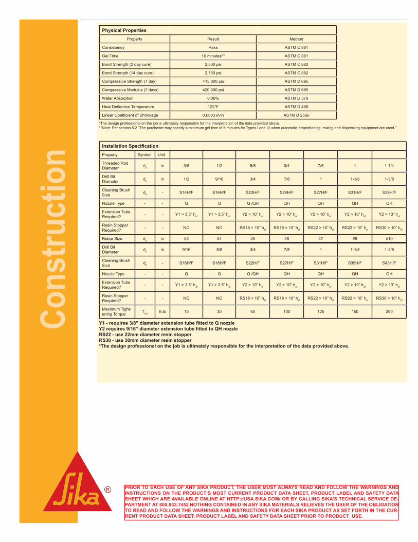
ion Installation Specification
Property Symbol Unit
Threaded Rod Diameter da in 3/8 1/2 5/8 3/4 7/8 1 1-1/4
Drill Bit Diameter do in 1/2 9/16 3/4 7/8 1 1-1/8 1-3/8
Cleaning Brush Size db - S14H/F S16H/F S22H/F S24H/F S27H/F S31H/F S38H/F
Nozzle Type - - Q Q Q /QH QH QH QH QH
Extension Tube Required? - - Y1 > 3.5” hef Y1 > 3.5” hef Y2 > 10” hef Y2 > 10” hef Y2 > 10” hef Y2 > 10” hef Y2 > 10” hef
Resin Stopper Required? - - NO NO RS18 > 10” hef RS18 > 10” hef RS22 > 10” hef RS22 > 10” hef RS30 > 10” hef
Rebar Size da in #3 #4 #5 #6 #7 #8 #10
Drill Bit Diameter do in 9/16 5/8 3/4 7/8 1 1-1/8 1-3/8
Cleaning Brush Size db - S16H/F S18H/F S22H/F S27H/F S31H/F S35H/F S43H/F
Nozzle Type - - Q Q Q /QH QH QH QH QH
Extension Tube Required? - - Y1 > 3.5” hef Y1 > 3.5” hef Y2 > 10” hef Y2 > 10” hef Y2 > 10” hef Y2 > 10” hef Y2 > 10” hef
Resin Stopper Required? - - NO NO RS18 > 10” hef RS18 > 10” hef RS22 > 10” hef RS22 > 10” hef RS30 > 10” hef
Maximum Tight-ening Torque Tinst ft.lb 15 30 60 100 125 150 200
Y1 - requires 3/8” diameter extension tube fitted to Q nozzle Y2 requires 9/16” diameter extension tube fitted to QH nozzle RS22 - use 22mm diameter resin stopper RS30 - use 30mm diameter resin stopper *The design professional on the job is ultimately responsible for the interpretation of the data provided above.
Physical Properties
Property Result Method
Consistency Pass ASTM C 881
Gel Time 10 minutes** ASTM C 881
Bond Strength (2 day cure) 2,500 psi ASTM C 882
Bond Strength (14 day cure) 2,700 psi ASTM C 882
Compressive Strength (7 day) >13,000 psi ASTM D 695
Compressive Modulus (7 days) 420,000 psi ASTM D 695
Water Absorption 0.08% ASTM D 570
Heat Deflection Temperature 122°F ASTM D 468
Linear Coefficient of Shrinkage 0.0003 in/in ASTM D 2566
*The design professional on the job is ultimately responsible for the interpretation of the data provided above. **Note: Per section 5.2 “The purchaser may specify a minimum gel time of 5 minutes for Types I and IV when automatic proportioning, mixing and dispensing equipment are used.”
PRIOR TO EACH USE OF ANY SIKA PRODUCT, THE USER MUST ALWAYS READ AND FOLLOW THE WARNINGS AND INSTRUCTIONS ON THE PRODUCT’S MOST CURRENT PRODUCT DATA SHEET, PRODUCT LABEL AND SAFETY DATA SHEET WHICH ARE AVAILABLE ONLINE AT HTTP://USA.SIKA.COM/ OR BY CALLING SIKA’S TECHNICAL SERVICE DE-PARTMENT AT 800.933.7452 NOTHING CONTAINED IN ANY SIKA MATERIALS RELIEVES THE USER OF THE OBLIGATION TO READ AND FOLLOW THE WARNINGS AND INSTRUCTIONS FOR EACH SIKA PRODUCT AS SET FORTH IN THE CUR-RENT PRODUCT DATA SHEET, PRODUCT LABEL AND SAFETY DATA SHEET PRIOR TO PRODUCT USE.
Cons
truct
ion
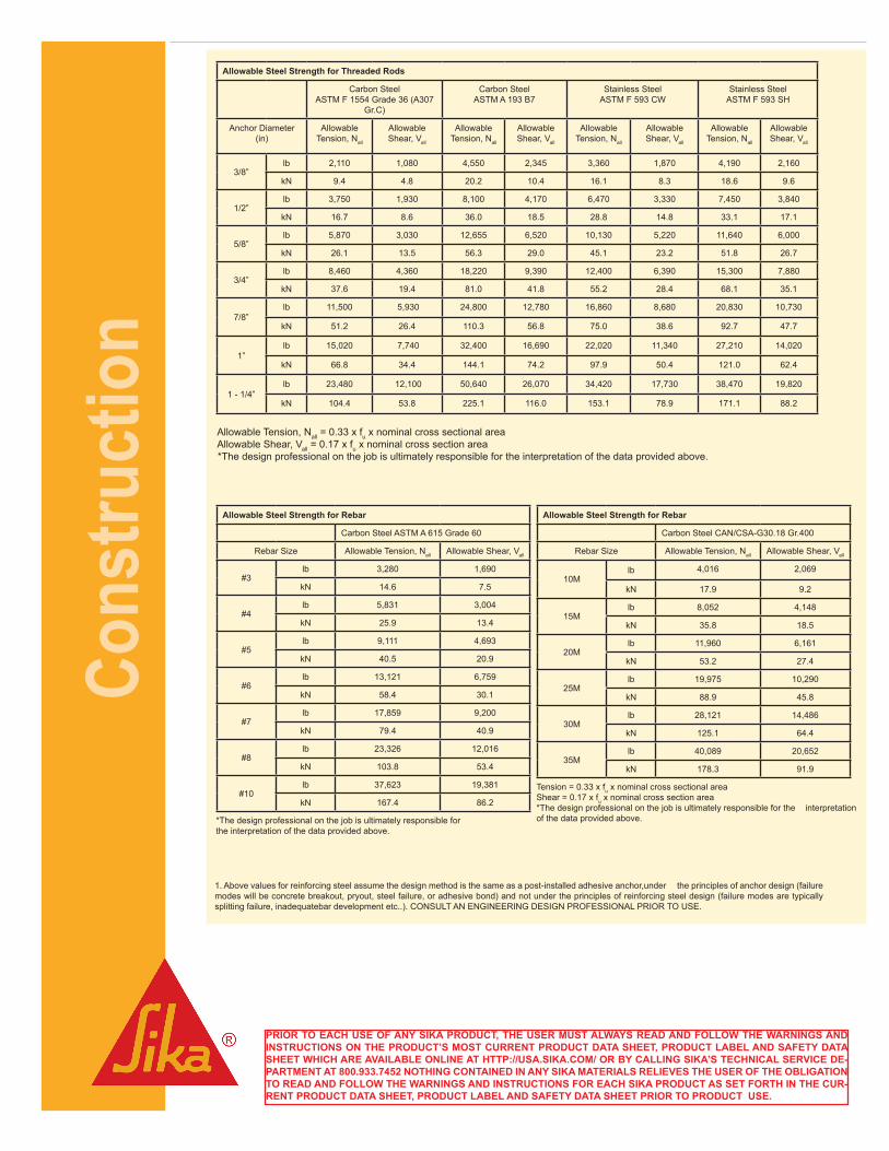
Allowable Tension, Nall = 0.33 x fu x nominal cross sectional area Allowable Shear, Vall = 0.17 x fu x nominal cross section area *The design professional on the job is ultimately responsible for the interpretation of the data provided above.
Allowable Steel Strength for Rebar
Carbon Steel ASTM A 615 Grade 60
Rebar Size Allowable Tension, Nall Allowable Shear, Vall
#3 lb 3,280 1,690
kN 14.6 7.5
#4 lb 5,831 3,004
kN 25.9 13.4
#5 lb 9,111 4,693
kN 40.5 20.9
#6 lb 13,121 6,759
kN 58.4 30.1
#7 lb 17,859 9,200
kN 79.4 40.9
#8 lb 23,326 12,016
kN 103.8 53.4
#10 lb 37,623 19,381
kN 167.4 86.2
*The design professional on the job is ultimately responsible for the interpretation of the data provided above.
Allowable Steel Strength for Rebar
Carbon Steel CAN/CSA-G30.18 Gr.400
Rebar Size Allowable Tension, Nall Allowable Shear, Vall
10Mlb 4,016 2,069
kN 17.9 9.2
15Mlb 8,052 4,148
kN 35.8 18.5
20Mlb 11,960 6,161
kN 53.2 27.4
25Mlb 19,975 10,290
kN 88.9 45.8
30Mlb 28,121 14,486
kN 125.1 64.4
35Mlb 40,089 20,652
kN 178.3 91.9
Tension = 0.33 x fu x nominal cross sectional area Shear = 0.17 x fu x nominal cross section area*The design professional on the job is ultimately responsible for the interpretation of the data provided above.
1. Above values for reinforcing steel assume the design method is the same as a post-installed adhesive anchor,under the principles of anchor design (failure modes will be concrete breakout, pryout, steel failure, or adhesive bond) and not under the principles of reinforcing steel design (failure modes are typically splitting failure, inadequatebar development etc..). CONSULT AN ENGINEERING DESIGN PROFESSIONAL PRIOR TO USE.
Allowable Steel Strength for Threaded Rods
Carbon Steel ASTM F 1554 Grade 36 (A307
Gr.C)
Carbon Steel ASTM A 193 B7
Stainless Steel ASTM F 593 CW
Stainless Steel ASTM F 593 SH
Anchor Diameter (in)
Allowable Tension, Nall
Allowable Shear, Vall
Allowable Tension, Nall
Allowable Shear, Vall
Allowable Tension, Nall
Allowable Shear, Vall
Allowable Tension, Nall
Allowable Shear, Vall
3/8” lb 2,110 1,080 4,550 2,345 3,360 1,870 4,190 2,160
kN 9.4 4.8 20.2 10.4 16.1 8.3 18.6 9.6
1/2” lb 3,750 1,930 8,100 4,170 6,470 3,330 7,450 3,840
kN 16.7 8.6 36.0 18.5 28.8 14.8 33.1 17.1
5/8” lb 5,870 3,030 12,655 6,520 10,130 5,220 11,640 6,000
kN 26.1 13.5 56.3 29.0 45.1 23.2 51.8 26.7
3/4” lb 8,460 4,360 18,220 9,390 12,400 6,390 15,300 7,880
kN 37.6 19.4 81.0 41.8 55.2 28.4 68.1 35.1
7/8” lb 11,500 5,930 24,800 12,780 16,860 8,680 20,830 10,730
kN 51.2 26.4 110.3 56.8 75.0 38.6 92.7 47.7
1” lb 15,020 7,740 32,400 16,690 22,020 11,340 27,210 14,020
kN 66.8 34.4 144.1 74.2 97.9 50.4 121.0 62.4
1 - 1/4” lb 23,480 12,100 50,640 26,070 34,420 17,730 38,470 19,820
kN 104.4 53.8 225.1 116.0 153.1 78.9 171.1 88.2
PRIOR TO EACH USE OF ANY SIKA PRODUCT, THE USER MUST ALWAYS READ AND FOLLOW THE WARNINGS AND INSTRUCTIONS ON THE PRODUCT’S MOST CURRENT PRODUCT DATA SHEET, PRODUCT LABEL AND SAFETY DATA SHEET WHICH ARE AVAILABLE ONLINE AT HTTP://USA.SIKA.COM/ OR BY CALLING SIKA’S TECHNICAL SERVICE DE-PARTMENT AT 800.933.7452 NOTHING CONTAINED IN ANY SIKA MATERIALS RELIEVES THE USER OF THE OBLIGATION TO READ AND FOLLOW THE WARNINGS AND INSTRUCTIONS FOR EACH SIKA PRODUCT AS SET FORTH IN THE CUR-RENT PRODUCT DATA SHEET, PRODUCT LABEL AND SAFETY DATA SHEET PRIOR TO PRODUCT USE.
Cons
truct
ion
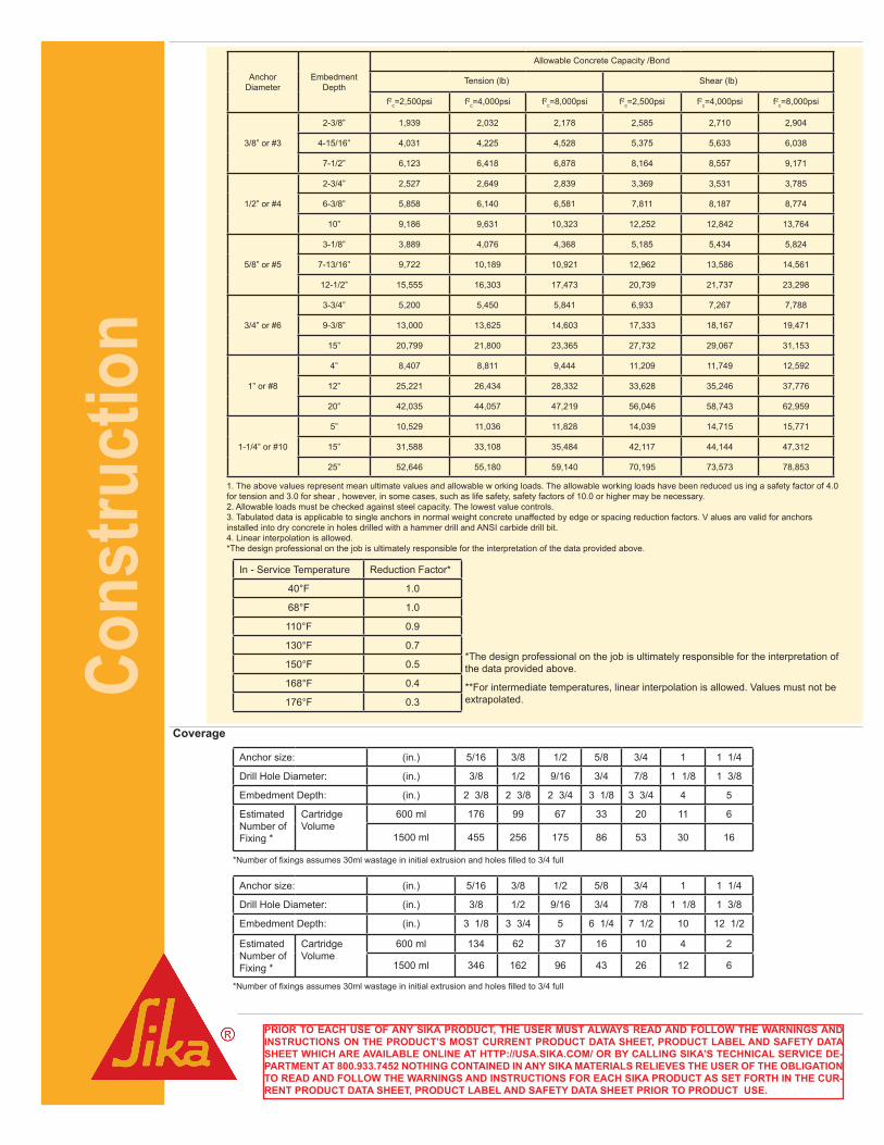
In - Service Temperature Reduction Factor*
40°F 1.0
68°F 1.0
110°F 0.9
130°F 0.7
150°F 0.5
168°F 0.4
176°F 0.3
*The design professional on the job is ultimately responsible for the interpretation of the data provided above.
**For intermediate temperatures, linear interpolation is allowed. Values must not be extrapolated.
Coverage
Anchor size: (in.) 5/16 3/8 1/2 5/8 3/4 1 1 1/4
Drill Hole Diameter: (in.) 3/8 1/2 9/16 3/4 7/8 1 1/8 1 3/8
Embedment Depth: (in.) 2 3/8 2 3/8 2 3/4 3 1/8 3 3/4 4 5
Estimated Number of Fixing *
Cartridge Volume
600 ml 176 99 67 33 20 11 6
1500 ml 455 256 175 86 53 30 16
*Number of fixings assumes 30ml wastage in initial extrusion and holes filled to 3/4 full
Anchor size: (in.) 5/16 3/8 1/2 5/8 3/4 1 1 1/4
Drill Hole Diameter: (in.) 3/8 1/2 9/16 3/4 7/8 1 1/8 1 3/8
Embedment Depth: (in.) 3 1/8 3 3/4 5 6 1/4 7 1/2 10 12 1/2
Estimated Number of Fixing *
Cartridge Volume
600 ml 134 62 37 16 10 4 2
1500 ml 346 162 96 43 26 12 6
*Number of fixings assumes 30ml wastage in initial extrusion and holes filled to 3/4 full
AnchorDiameter
EmbedmentDepth
Allowable Concrete Capacity /Bond
Tension (lb) Shear (lb)
f2c=2,500psi f2
c=4,000psi f2c=8,000psi f2
c=2,500psi f2c=4,000psi f2
c=8,000psi
3/8” or #3
2-3/8” 1,939 2,032 2,178 2,585 2,710 2,904
4-15/16” 4,031 4,225 4,528 5,375 5,633 6,038
7-1/2” 6,123 6,418 6,878 8,164 8,557 9,171
1/2” or #4
2-3/4” 2,527 2,649 2,839 3,369 3,531 3,785
6-3/8” 5,858 6,140 6,581 7,811 8,187 8,774
10” 9,186 9,631 10,323 12,252 12,842 13,764
5/8” or #5
3-1/8” 3,889 4,076 4,368 5,185 5,434 5,824
7-13/16” 9,722 10,189 10,921 12,962 13,586 14,561
12-1/2” 15,555 16,303 17,473 20,739 21,737 23,298
3/4” or #6
3-3/4” 5,200 5,450 5,841 6,933 7,267 7,788
9-3/8” 13,000 13,625 14,603 17,333 18,167 19,471
15” 20,799 21,800 23,365 27,732 29,067 31,153
1” or #8
4” 8,407 8,811 9,444 11,209 11,749 12,592
12” 25,221 26,434 28,332 33,628 35,246 37,776
20” 42,035 44,057 47,219 56,046 58,743 62,959
1-1/4” or #10
5” 10,529 11,036 11,828 14,039 14,715 15,771
15” 31,588 33,108 35,484 42,117 44,144 47,312
25” 52,646 55,180 59,140 70,195 73,573 78,853
1. The above values represent mean ultimate values and allowable w orking loads. The allowable working loads have been reduced us ing a safety factor of 4.0 for tension and 3.0 for shear , however, in some cases, such as life safety, safety factors of 10.0 or higher may be necessary. 2. Allowable loads must be checked against steel capacity. The lowest value controls. 3. Tabulated data is applicable to single anchors in normal weight concrete unaffected by edge or spacing reduction factors. V alues are valid for anchors installed into dry concrete in holes drilled with a hammer drill and ANSI carbide drill bit. 4. Linear interpolation is allowed. *The design professional on the job is ultimately responsible for the interpretation of the data provided above.
PRIOR TO EACH USE OF ANY SIKA PRODUCT, THE USER MUST ALWAYS READ AND FOLLOW THE WARNINGS AND INSTRUCTIONS ON THE PRODUCT’S MOST CURRENT PRODUCT DATA SHEET, PRODUCT LABEL AND SAFETY DATA SHEET WHICH ARE AVAILABLE ONLINE AT HTTP://USA.SIKA.COM/ OR BY CALLING SIKA’S TECHNICAL SERVICE DE-PARTMENT AT 800.933.7452 NOTHING CONTAINED IN ANY SIKA MATERIALS RELIEVES THE USER OF THE OBLIGATION TO READ AND FOLLOW THE WARNINGS AND INSTRUCTIONS FOR EACH SIKA PRODUCT AS SET FORTH IN THE CUR-RENT PRODUCT DATA SHEET, PRODUCT LABEL AND SAFETY DATA SHEET PRIOR TO PRODUCT USE.
Cons
truct
ion
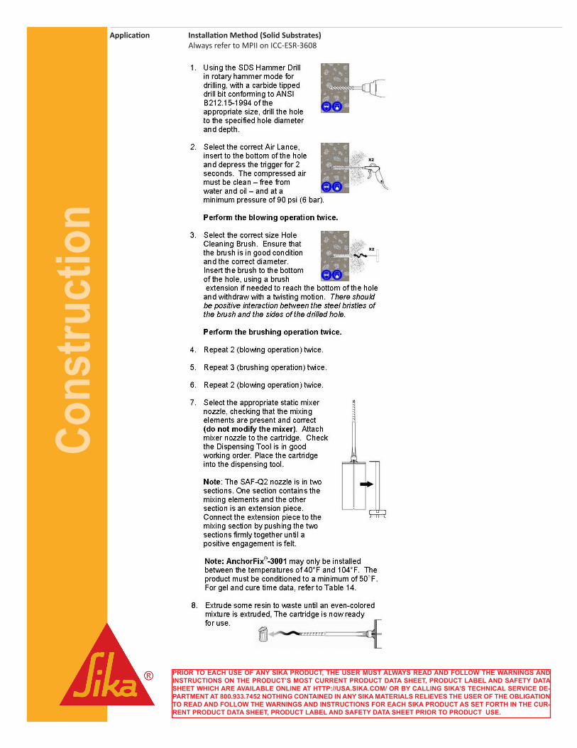
Application Installation Method (Solid Substrates) Always refer to MPII on ICC-ESR-3608
PRIOR TO EACH USE OF ANY SIKA PRODUCT, THE USER MUST ALWAYS READ AND FOLLOW THE WARNINGS AND INSTRUCTIONS ON THE PRODUCT’S MOST CURRENT PRODUCT DATA SHEET, PRODUCT LABEL AND SAFETY DATA SHEET WHICH ARE AVAILABLE ONLINE AT HTTP://USA.SIKA.COM/ OR BY CALLING SIKA’S TECHNICAL SERVICE DE-PARTMENT AT 800.933.7452 NOTHING CONTAINED IN ANY SIKA MATERIALS RELIEVES THE USER OF THE OBLIGATION TO READ AND FOLLOW THE WARNINGS AND INSTRUCTIONS FOR EACH SIKA PRODUCT AS SET FORTH IN THE CUR-RENT PRODUCT DATA SHEET, PRODUCT LABEL AND SAFETY DATA SHEET PRIOR TO PRODUCT USE.
Cons
truct
ion
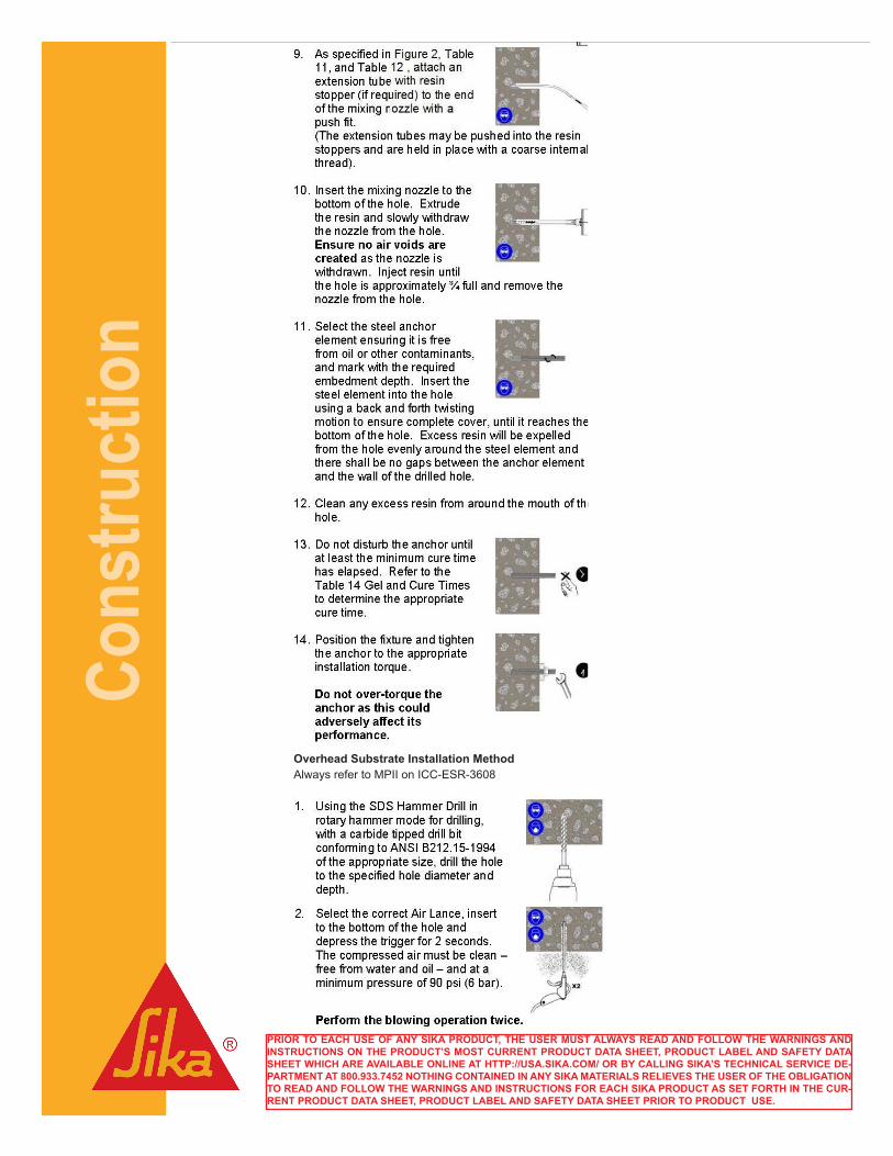
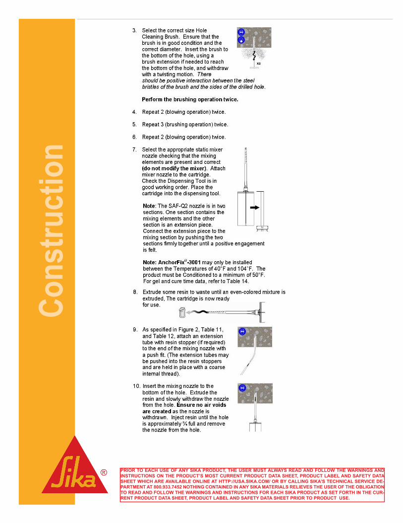
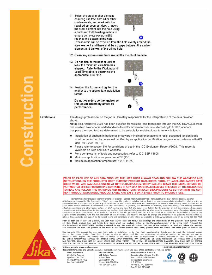
Overhead Substrate Installation Method Always refer to MPII on ICC-ESR-3608
PRIOR TO EACH USE OF ANY SIKA PRODUCT, THE USER MUST ALWAYS READ AND FOLLOW THE WARNINGS AND INSTRUCTIONS ON THE PRODUCT’S MOST CURRENT PRODUCT DATA SHEET, PRODUCT LABEL AND SAFETY DATA SHEET WHICH ARE AVAILABLE ONLINE AT HTTP://USA.SIKA.COM/ OR BY CALLING SIKA’S TECHNICAL SERVICE DE-PARTMENT AT 800.933.7452 NOTHING CONTAINED IN ANY SIKA MATERIALS RELIEVES THE USER OF THE OBLIGATION TO READ AND FOLLOW THE WARNINGS AND INSTRUCTIONS FOR EACH SIKA PRODUCT AS SET FORTH IN THE CUR-RENT PRODUCT DATA SHEET, PRODUCT LABEL AND SAFETY DATA SHEET PRIOR TO PRODUCT USE.
Cons
truct
ion
Visit our website at www.sikausa.com 1-800-933-SIKA NATIONWIDERegional Information and Sales Centers. For the location of your nearest Sika sales office, contact your regional center.
Sika Corporation Sika Canada Inc. Sika Mexicana S.A. de C.V. 201 Polito Avenue 601 Delmar Avenue Carretera Libre Celaya Km. 8.5Lyndhurst, NJ 07071 Pointe Claire Fracc. Industrial BalvaneraPhone: 800-933-7452 Quebec H9R 4A9 Corregidora, QueretaroFax: 201-933-6225 Phone: 514-697-2610 C.P. 76920 Fax: 514-694-2792 Phone: 52 442 2385800
Fax: 52 442 2250537
ISO 9001Certificate # FM 69711
RC 14001Certificate # RC 510999
KEEP CONTAINER TIGHTLY CLOSED • KEEP OUT OF REACH OF CHILDREN • NOT FOR INTERNAL CONSUMPTION • FOR INDUSTRIAL USE ONLY • FOR PROFESSIONAL USE ONLYAll information provided by Sika Corporation (“Sika”) concerning Sika products, including but not limited to, any recommendations and advice relating to the ap-plication and use of Sika products, is given in good faith based on Sika’s current experience and knowledge of its products when properly stored, handled and ap-plied under normal conditions in accordance with Sika’s instructions. In practice, the differences in materials, substrates, storage and handling conditions, actual site conditions and other factors outside of Sika’s control are such that Sika assumes no liability for the provision of such information, advice, recom-mendations or instructions related to its products, nor shall any legal relationship be created by or arise from the provision of such information, advice, recom-mendations or instructions related to its products. The user of the Sika product(s) must test the product(s) for suitability for the intended application and purpose before proceeding with the full application of the product(s). Sika reserves the right to change the properties of its products without notice. All sales of Sika product(s) are subject to its current terms and conditions of sale which are available at http://www.sikausa.com/ or by calling 800-933-7452.
Prior to each use of any Sika product, the user must always read and follow the warnings and instructions on the product’s most current Prod-uct Data Sheet, product label and Safety Data Sheet which are available online at http://www.sikausa.com/ or by calling Sika’s Technical Ser-vice Department at 800-933-7452. Nothing contained in any Sika materials relieves the user of the obligation to read and follow the warnings and instruction for each Sika product as set forth in the current Product Data Sheet, product label and Safety Data Sheet prior to product use.
Sika warrants this product for one year from date of installation to be free from manufacturing defects and to meet the technical proper-ties on the current Product Data Sheet if used as directed within shelf life. User determines suitability of product for intended use and as-sumes all risks. Buyer’s sole remedy shall be limited to the purchase price or replacement of product exclusive of labor or cost of labor.NO OTHER WARRANTIES EXPRESS OR IMPLIED SHALL APPLY INCLUDING ANY WARRANTY OF MERCHANTABILITY OR FITNESS FOR A PARTICU-LAR PURPOSE. SIKA SHALL NOT BE LIABLE UNDER ANY LEGAL THEORY FOR SPECIAL OR CONSEQUENTIAL DAMAGES. SIKA SHALL NOT BE RESPON-SIBLE FOR THE USE OF THIS PRODUCT IN A MANNER TO INFRINGE ON ANY PATENT OR ANY OTHER INTELLECTUAL PROPERTY RIGHTS HELD BY OTHERS.
Limitations The design professional on the job is ultimately responsible for the interpretation of the data provided above. Note: Sika AnchorFix-3001 has been qualified for resisting long-term leads through the ICC-ES AC308 creep test for which an anchor is loaded and monitored for movement over time. According to AC308, anchors that pass the creep test are determined to be suitable for resisting long- term tensile loads.
n Installation of anchors in horizontal or upwardly inclined orientations to resist sustained tension loads shall be performed by personnel certified by an application certification program in accordance with ACI 318 D.9.2.2 or D.9.2.3 n Please refer to section 5.0 for conditions of use in the ICC Evaluation Report #3608. This report is
available on Sika and ICC’s websites. n For a complete list of tools and accessories, refer to ICC ESR #3608 n Minimum application temperature: 40°F (4°C) n Maximum application temperature: 104°F (40°C)
PRIOR TO EACH USE OF ANY SIKA PRODUCT, THE USER MUST ALWAYS READ AND FOLLOW THE WARNINGS AND INSTRUCTIONS ON THE PRODUCT’S MOST CURRENT PRODUCT DATA SHEET, PRODUCT LABEL AND SAFETY DATA SHEET WHICH ARE AVAILABLE ONLINE AT HTTP://USA.SIKA.COM/ OR BY CALLING SIKA’S TECHNICAL SERVICE DE-PARTMENT AT 800.933.7452 NOTHING CONTAINED IN ANY SIKA MATERIALS RELIEVES THE USER OF THE OBLIGATION TO READ AND FOLLOW THE WARNINGS AND INSTRUCTIONS FOR EACH SIKA PRODUCT AS SET FORTH IN THE CUR-RENT PRODUCT DATA SHEET, PRODUCT LABEL AND SAFETY DATA SHEET PRIOR TO PRODUCT USE.