Embed Size (px)
Citation preview
LED Light Tape Installation GuideNOTE: This guide is intended for installation PL-XX#-YYO-Z-WWWW series LEDs. These products Class 2 LED Modules, designated as PL-XX#-YYO-Z-WWWW Series where XX may be replaced with LT (Light Tape) or LE (Light Edge); # may be replaced with any numeric character 0 to 9; YY may be replaced with any combination of alpha character AA to ZZ; O may be replaced with any numeric character 0 to 9; Z may be replaced with letter N or P; and WWWW may be any combination of alphanumeric characters.
1.These products are only intended for use and connection to a Class 2 power source rated 12 Volt DC or less. 2.When these units are connected to a Class 2 circuit, they are not to draw a total wattage of greater than the secondary or output rating of the Class 2 supply. 3.These products are suitable for use in dry, damp and wet locations. 4.These products are not required to be enclosed or protected from the weather in the end product. 5.These products may be secured in place in the end product by any means available.
Troubleshooting:1. Check primary power power to sign.2. Check power connection to the LED Class 2 power supply.3. Check polarity on the DC side (Black+ Red-)4. Check wire or jumper connections to module (make sure connections ate + to + and – to -) – reseat if needed.5. If solder joint breaks to the input module or there is a bad connection, all modules after the bad connection
will not light.
P-LED.com | [email protected] | 325.227.4577
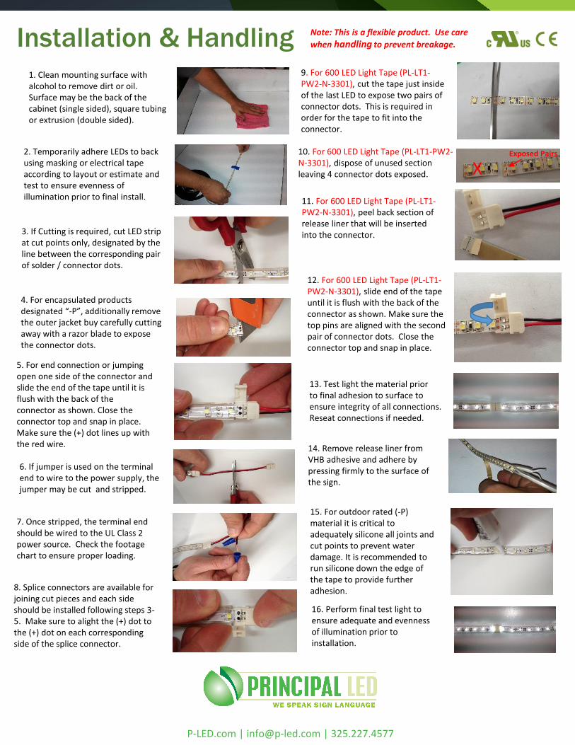
Installation & Handling Note: This is a flexible product. Use care
when handling to prevent breakage.
1. Clean mounting surface withalcohol to remove dirt or oil.Surface may be the back of thecabinet (single sided), square tubingor extrusion (double sided).
2. Temporarily adhere LEDs to backusing masking or electrical tapeaccording to layout or estimate andtest to ensure evenness ofillumination prior to final install.
3. If Cutting is required, cut LED stripat cut points only, designated by theline between the corresponding pairof solder / connector dots.
4. For encapsulated productsdesignated “-P”, additionally removethe outer jacket buy carefully cuttingaway with a razor blade to exposethe connector dots.
5. For end connection or jumpingopen one side of the connector andslide the end of the tape until it isflush with the back of theconnector as shown. Close theconnector top and snap in place.Make sure the (+) dot lines up withthe red wire.
6. If jumper is used on the terminalend to wire to the power supply, thejumper may be cut and stripped.
8. Splice connectors are available forjoining cut pieces and each sideshould be installed following steps 3-5. Make sure to alight the (+) dot tothe (+) dot on each correspondingside of the splice connector.
13. Test light the material priorto final adhesion to surface toensure integrity of all connections.Reseat connections if needed.
15. For outdoor rated (-P)material it is critical toadequately silicone all joints andcut points to prevent waterdamage. It is recommended torun silicone down the edge ofthe tape to provide furtheradhesion.
16. Perform final test light toensure adequate and evennessof illumination prior toinstallation.
14. Remove release liner fromVHB adhesive and adhere bypressing firmly to the surface ofthe sign.
7. Once stripped, the terminal endshould be wired to the UL Class 2power source. Check the footagechart to ensure proper loading.
9. For 600 LED Light Tape (PL-LT1-PW2-N-3301), cut the tape just insideof the last LED to expose two pairs ofconnector dots. This is required inorder for the tape to fit into theconnector.
X10. For 600 LED Light Tape (PL-LT1-PW2-N-3301), dispose of unused sectionleaving 4 connector dots exposed.
11. For 600 LED Light Tape (PL-LT1-PW2-N-3301), peel back section ofrelease liner that will be insertedinto the connector.
12. For 600 LED Light Tape (PL-LT1-PW2-N-3301), slide end of the tapeuntil it is flush with the back of theconnector as shown. Make sure thetop pins are aligned with the secondpair of connector dots. Close theconnector top and snap in place.
Exposed Pairs
P-LED.com | [email protected] | 325.227.4577