Embed Size (px)
Citation preview

1
Project
Hydro Kurri Kurri site redevelopment project
From
Bridie Halse
Subject Community Reference Group Meeting Tel 1800 066 243
Venue/Date/Time Thursday 15 June 2017
Hydro Aluminium
Kurri Kurri
6.00pm – 7:30pm
Job No 21/23175
Copies to All committee members
Attendees Mr Andrew Walker – Hydro Kurri Kurri Project Manager
Mr Gareth Curtis - Director of Planning and Environment, Cessnock City Council
Clr Darrin Gray – Cessnock City Council
Mrs Kerry Hallett – Hunter BEC
Mr Kerry McNaughton – Environmental Officer, Hydro Kurri Kurri
Mr Ian Shillington – Manager Urban Growth, Maitland City Council
Mr Alan Gray – Community representative
Mr Michael Ulph – CRG Chair, GHD
Ms Bridie Halse – Minutes, GHD
Guests/observers Mr David Barrett - Containment Cell Designer - GHD Central Coast
Apologies Clr Arch Humphery – Maitland City Council
Mr Toby Thomas – Community representative
Ms Debra Ford - Community representative
Mr Richard Brown – Managing Director, Hydro Kurri Kurri
Mr Rod Doherty – Kurri Kurri Business Chamber
Not present Mr Bill Metcalfe – Community representative
Mr Brad Wood – Community representative
Note that minutes are paraphrased to an extent and may not match actual statements exactly.

2
Table of Contents
1 Welcome and Acknowledgement of Country ................................................................................... 3
2 Meeting agenda...................................................................................................................................... 4
3 Welcome and meeting opening ........................................................................................................... 4
4 Last meeting minutes............................................................................................................................ 5
5 Project update........................................................................................................................................ 6
6 Containment cell design ....................................................................................................................... 8
7 Project update continued ...................................................................................................................23
8 CRG membership & TORs Review .................................................................................................25
9 Questions and Answers from the CRG/General Business............................................................25
10 Meeting close........................................................................................................................................26

3
Notes Action
1 Welcome and Acknowledgement of Country
Meeting commenced at 6:00 pm
Michael Ulph (Chair)
Acknowledgement of country.

4
Notes Action
2 Meeting agenda
Welcome and meeting opening
Apologies
Acceptance of minutes from the last meeting
Project update
Containment cell design
CRG questions and answers / All other business
CRG membership & Terms of Reference review
Next meeting / Meeting close
3 Welcome and meeting opening
Michael Ulph welcomes the committee and notes apologies.
Introduction of David Barrett from the Tuggerah office of GHD,
who will be talking about containment cell design. Introduction
of Bridie Halse from GHD.
Around the room introductions.
Provided draft guidelines in relation to pecuniary interest and
discussed the need for people to indicate if they have a
pecuniary interest (e.g. engaged to be there). (appended to
meeting minutes).
Michael Ulph: Is anyone in any doubt about having a conflict
of interest in a meeting such as this and what it means? I will
ask people to acknowledge if they have a conflict at all.
I will declare a conflict, my employer is paying for my
attendance here tonight therefore I have an interest in being
here. Would anybody else like to declare interest?
Michael Ulph and Bridie Halse as Hydro contracted staff
declared interest.
Hydro staff as representatives of the owners of the land
declared an interest.

5
Notes Action
4 Last meeting minutes
Michael Ulph requested a motion that the minutes be accepted
as a true and correct record of the last meeting.
Moved: Darrin Gray
Seconded: Kerry Hallett
Michael Ulph: Were there any actions from the last meeting?
I will note that there was mention about sending out more
information about the project. The latest newsletter, which we
have been preparing, is completed and will be emailed out
and posted out to those who we do not have an email address
for. If there is any questions about this, please feel free to
contact us. [Copies provided to CRG members]

6
5 Project update
Andrew Walker: Preparation for demolition has begun. The
demolition contractor has mobilised to the site and demolition
will be ready to start very soon.
We have been working on completing isolations for the 11 KV
cables around site, which leave the switchyard and distribute
around the site. We have been working on water and sewer
systems, isolating those and decommissioning the fire systems
of buildings that are earmarked for demolition. We have four
service transformers in the switchyard. Although the cables have
been isolated, the switchyard is still energised.
We are also isolating low voltage cables. Low voltage control
cables including alarm cables, sirens and emergency stops go
out into the potlines and connect through to the tunnel boards in
the main control room for the switchyard called 29 A/C switch
room. We have been working in the tunnel boards isolating 415
and 240 V cables. This work is nearly complete.
We are in a handover process to CMA the demolition contractor,
and as we sign off that the power, natural gas and water have
been isolated. Any hazardous material like asbestos is noted in
the handover process. Fire systems have been isolated
progressively. Inergen and other inert gases that are used for
fire suppression are being decommissioned and transported off
site.
Half of the site is now handed over to CMA contracting. The cast
house, the three potlines and the bath crushing plant. The
carbon plant, central workshops, SPL sheds and front office area
is still under Hydro control. CMA are now the principal contractor
for their area. A contract was awarded to CMA on the 13th of
April, they presented at the last CRG meeting, over that period
they’ve been mobilising people and equipment to site. They’ve
got three large excavators here ready to start demolition.
A site meeting was held with Safework NSW to go through the
demolition methodology, explaining the DRAW process, which
stands for ‘demolition risk assessment workshop’. WorkCover
were happy with this process. The first DRAW was on site
establishment on the 8th of May. The handover occurred on the
16th of May, and on the 17th of May we met with Cessnock City
Council staff to discuss management plans and CMA made a
presentation outlining demolition methodology. Management
plans were submitted to the council on the 26th of May, with a

7
Notes Action
two to three-week turn-around, we are hoping that these will be
approved in the next week. The second DRAW was held to plan
the methodology of the demolition of the first structures.
Demolition is planned to commence in the next couple of weeks.
Michael Ulph: Are there any questions around Andrew’s
presentation?
Alan Gray: Lime will be put in the septic tanks, are these
hooked up to the sewerage?
Andrew Walker: Yes it is. There is a pumping station near the
central workshops. The septic tanks around the potlines on
CMA’s site are being shut down. Small shallow tanks that are
less than 1.5 m deep are being removed, which would have to
be removed as part of Stage 2 Demolition. Standard procedure
is to pump them out, coat them with lime, then smash them in
and fill them with earth and clean soil, which has been done.
This will make it safe for a machine to drive over it. This concrete
will be removed later as a part of the demolition process.
Alan Gray: I’m more interested in whether other companies that
come on site will have access to the sewerage.
Andrew Walker: We are looking to keep it. The sewer line runs
along the main road and off to a 45-degree angle through the
bush and under the expressway into the bush to the sewerage
treatment works on the other side of the expressway.

8
6 Containment cell design
David Barrett: First, I will run through an overview of the
containment cell design. I will give you a summary of the design
to date and key parameters which we want to achieve in the
design. The key components to discuss tonight are the life of
liner, the leachate gas and then we’ll move onto constructability.
Questions are invited throughout the presentation.
We are planning to build a containment cell to hold the contents
of the capped waste stockpile and various waste items from the
demolition. When we began, we looked at the NSW Guidelines
for landfill, which had only been re-issued in 2016. The basis of
what they are looking for is:
- a leachate barrier system to prevent contamination to
surface water and groundwater;
- to be able to collect the leachate and store it on site in a
dam structure reducing any in-cell storage;
- to ensure untreated leachate could not be disposed of
offsite or on the land, including use for dust suppression;
- controls for surface water between swales and dams
preventing sediment laden water discharge.
- gas management practices to be put in place are
appropriate to the waste generated.
- waste to be covered regularly, during daily operations. In
a putrescible landfill you would usually have a 100 mm
of clean fill placed over to stop waste being blown
around etc. On a site like this we would probably use
tarp controls which makes it easier for the operator to
get it on and off without using too much clean fill.
Michael Ulph: So do “daily operations” refer to the construction
of the cell?
David Barrett: This contract will require a contractor to build, fill,
cap and maintain the cell for a period of 52 weeks. The
operations phase in this instance is during the deposition of
waste within the cell.
- All cells to be capped and revegetated as soon as
possible
- The final capping to account for less than 5% ingress of
the annual [rainfall].

9
Notes Action
While this is within the guidelines, we are aiming to design a “dry
tomb”. We have used similar concepts in Queensland, where we
extract the leachate during deposition phase of the waste, install
a cap that will prevent ingress of water to achieve a dry tomb.
The reduction of leachate production assists in reducing
degradation on the liner systems and reduces future gas
production. Granted that on this site there isn’t really any gas
production, very little.
These are the key design parameters:
A minimum design life of about 100 years, which we weren’t
really concerned about. We wanted four stages of construction
to give one large bowl, broken into quarters so that we could
stage the capping.
Darrin Gray: Minimum design life is 100 years but the cell will
be managed in perpetuity, shouldn’t the life of the cell be
indefinite?
David Barrett: Yes. The life of the liner will be discussed about
halfway through the presentation, but consider that the liner is
one aspect of the system. The system is in perpetuity. I’ll
demonstrate this and ask as many questions as you want.
I’ll also give a ‘show and tell’ of various liner types, what we’ve
tested, and so on.
There will be four stages, capacity requirement is for just under
350,000 cubic metres, expected to excavate about 100,000
cubic metres out of the area, which will be used in the
infrastructure itself.
Michael Ulph: Just for your benefit David, most people here,
would understand where the clay borrow pit is.
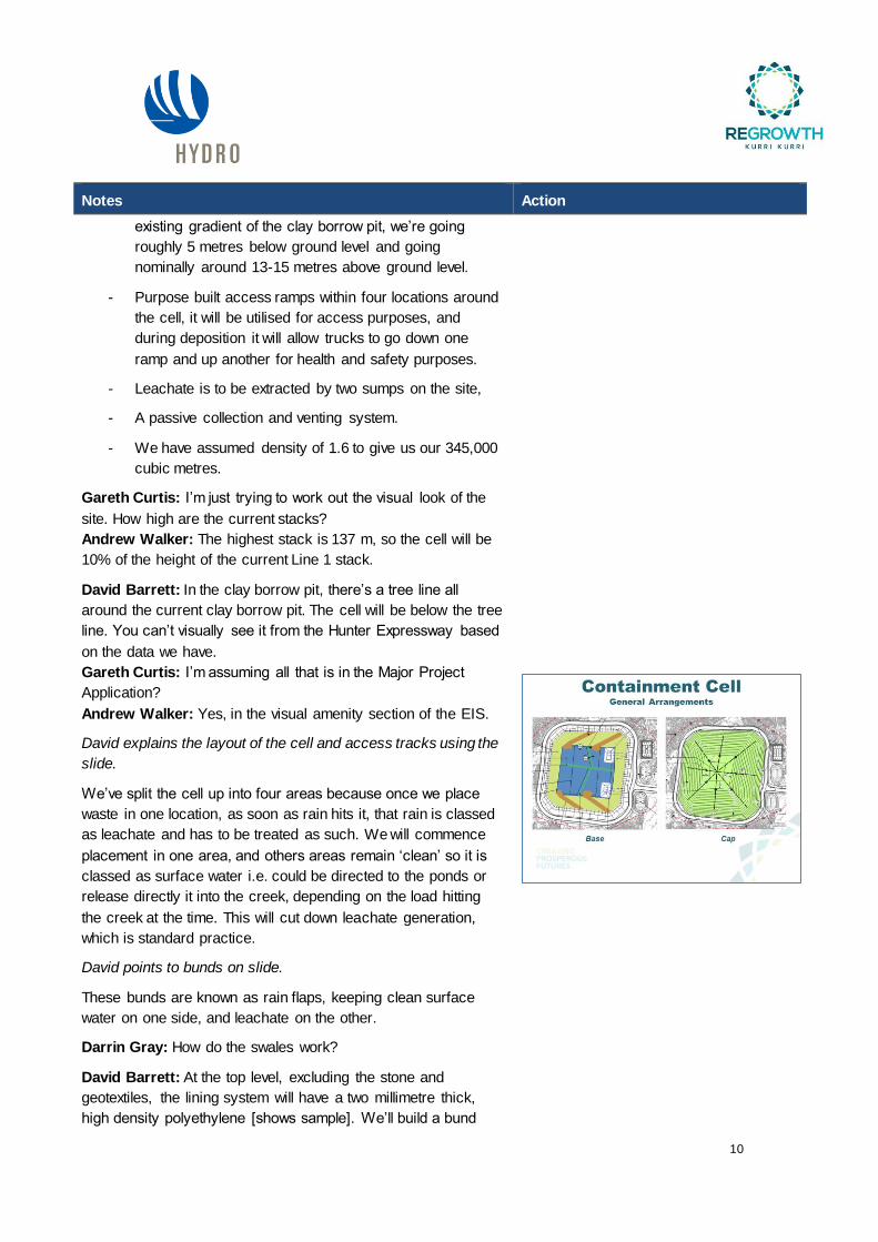
David skips forward a slide to a layout of the site, describes the
area, proposed access tracks and proposed cell area.
David Barrett: The clay burrow pit is located on the western
side of the site. New culverts and a new bridge will create
access to what I have been referring to as the “cell”, or the clay
borrow pit.
- Internal batter slopes, we have gone with one in four - a
very low gradient. Everything we have put into the
design has been an enhancement of what the guidelines
require. This is what we call a turkey’s nest, half of it is
below ground and half of it is above ground, in this case
the majority of it is above ground. This is due to the
10
Notes Action
existing gradient of the clay borrow pit, we’re going
roughly 5 metres below ground level and going
nominally around 13-15 metres above ground level.
- Purpose built access ramps within four locations around
the cell, it will be utilised for access purposes, and
during deposition it will allow trucks to go down one
ramp and up another for health and safety purposes.
- Leachate is to be extracted by two sumps on the site,
- A passive collection and venting system.
- We have assumed density of 1.6 to give us our 345,000
cubic metres.
Gareth Curtis: I’m just trying to work out the visual look of the
site. How high are the current stacks?
Andrew Walker: The highest stack is 137 m, so the cell will be
10% of the height of the current Line 1 stack.
David Barrett: In the clay borrow pit, there’s a tree line all
around the current clay borrow pit. The cell will be below the tree
line. You can’t visually see it from the Hunter Expressway based
on the data we have.
Gareth Curtis: I’m assuming all that is in the Major Project
Application?
Andrew Walker: Yes, in the visual amenity section of the EIS.
David explains the layout of the cell and access tracks using the
slide.
We’ve split the cell up into four areas because once we place
waste in one location, as soon as rain hits it, that rain is classed
as leachate and has to be treated as such. We will commence
placement in one area, and others areas remain ‘clean’ so it is
classed as surface water i.e. could be directed to the ponds or
release directly it into the creek, depending on the load hitting
the creek at the time. This will cut down leachate generation,
which is standard practice.
David points to bunds on slide.
These bunds are known as rain flaps, keeping clean surface
water on one side, and leachate on the other.
Darrin Gray: How do the swales work?
David Barrett: At the top level, excluding the stone and
geotextiles, the lining system will have a two millimetre thick,
high density polyethylene [shows sample]. We’ll build a bund

11
Notes Action
that will be lined with the same lining system used everywhere
else on the site. That will basically maintain clean surface water
on one side, separated from the waste. Before waste is moved
into the cell, any water present is pumped out prior to placing the
the waste. If the bunds didn’t exist, the amount of leachate in the
cell would double. Leachate should be minimised. Waste
shouldn’t be deposited when it is expected to rain. The last thing
you want is to start in a new cell and have an April storm hit.
You’d probably delay going into it.
On the other side is the cap, the cap system is simple for easy
maintenance, with a low gradient running off and a much flatter
area on top. The black lines (on slide) are the spiders, which are
the lateral lines for gas extraction points. These will facilitate the
gas going to one central location for extraction. These ones here
are below the cap, into the waste and they facilitate getting the
gas to the surface.
In relation to stormwater, when waste deposition begins, we’ll
come across Unnamed Creek, into the cell, down through the
access ramps.
David points to sediment ponds on slide.
These are sediment ponds, they’re going to be utilised for
stormwater control and to separate out sediment laden water.
There are drains going around the cell to control water around
the cell and into a sediment pond, prior to discharge to the
creek. The northern pond is a leachate pond for buffer storage,
which we will cover off at the back end. Around the perimeter of
the site, there is standard surface water controls, which basically
separates the clean from the dirty, and prevents water getting
into the site and becoming leachate.
David points at slide, explains the containment system, and
passes around samples of the liner.
The HDPE liners are the products that have been tested.
Below the landfill is clay rich, we will take about 300 mm of that
and condition it, re-compact it down to build a good foundation
for the cell. The next step is to put a groundwater drainage
geocomposite in. There is no groundwater that we are worried
about, but this will prevent any possible issues in the future.
We’ll be putting in something very similar to these products,
[David hands out geocomposite samples], which facilitate water
flow. There are different types.

12
Notes Action
Above the geocomposite (GC), we will be putting in geosynthetic
clay liner, which is similar to an underlay for carpet, and needle
punched with bentonite. Once bentonite touches the soil, it will
pull moisture out of it. The product will swell up, and is self-
healing, so if a slight hole appears, it will repair itself. After this, it
becomes impermeable in the region of one by ten to the power
of minus 11. This is two magnitudes greater than the guidelines
for a clay barrier.
Above that, a 2 mm HDPE liner will be put in, this is known as
the secondary liner, it is not your containment system, it is just a
contingency liner. Above that is a sand drainage layer, then
another GCL layer, so another layer of ten to the power of minus
11. On top of this to form intimate contact there will be another
2mm HDPE liner. Above that is more geotextile. This is a
protection geotextile as it protects HDPE from damage from the
300 mm of stone that is placed on top of it. This stone facilitates
conveyance of leachate to the sump for extraction. On top of that
is a separation geotextile, which is to prevent fines coming into
the stone and blocking it up.
A very similar design goes up the side slopes. The only
difference in the side slopes is not installing the sand drainage
layer. However we are bringing in a drainage geocomposite,
similar to the ones that are on the site, to facilitate getting any
liquid into the sand layer below.
Each side of the site will be drained from their corresponding
sump. Each sump has three parts, three extraction points, all to
the top of the slope. Each pipe will extract a different product,
when and if needed. What we have in the plan view is three
sumps - one is free to bleed out into the environment and into
the groundwater, as it is the groundwater sump, used to redirect
any groundwater or surface water that has hit the liner, so we
don’t end up with pressure on the liner, or a floating liner. There
is another sump in the sand layer, which is known as the leak
detection sump. The third sump is the leachate sump.
Looking at the groundwater sump and layer, a pipe system will
be installed to extract it if need be. This is a precautionary
inclusion in case it is needed in the future, but we don’t expect to
be using it at all.
The leak detection sump will extract any leaks that go through
the primary liner into the sand layer, so they can be extracted
and either put back into the cell, put into the buffer pond or taken
off site by a third party.

13
Notes Action
Finally, the leachate riser will allow for extraction to the leachate
pond or extraction to a third party.
Each sump is independent and in no way linked.
On the top is the cap system. This is double what is normally
required. This is to maintain the “dry tomb”, which means no
leachate. We extract it during the construction phase, we extract
it during the deposition of waste phase, we extract it for a period
of time after we have finished the construction of the cap, and
eventually it is just dry. We can dip the pipes to make sure. The
cap system placed on the waste product will comprise a
foundation layer (or a seal bearing layer). The clay from existing
capped waste stockpile will hopefully be used in this layer, which
is achieving 1 x 10⁻⁹ and 1x 10⁻¹⁰ at the moment, on top of that, a
linear low-density polyethylene. This is about one mm of what
you have there, so that it is much more flexible, giving the same
permeability, but a higher flexibility as it will be used on the cap.
Above that, there is a drainage layer for any surface water, and
then a standard cap system which is sub-soils, soils and
vegetation.
Michael and David discuss the difference in normal municipal
waste systems and this “dry tomb” system.
David Barrett: The HDPE and LLDPE are then welded and
sealed, sealing the extracted product inside. The only exit point
is the one vent pipe to facilitate any gas that may come out.
The key design considerations are:
- Liner design. Standard in putrescible because there is
so much of it, we know its proprietary and that it will
withstand a lot. There was no dedicated site specific
testing, so we designed the liner specific to be used on
this site. We took the leachate in the current capped
waste stockpile, sent them to Excelplas laboratories in
Melbourne. We wanted to prove the 100 year life span
of the liner material through scientific testing.
- Leachate management. The options considered were
whether it will be treated on site by setting up a
treatment plant, whether it will be pumped directly into
the sewer system under a trade waste agreement,
whether it is was treated on site and irrigated, or
whether it will be taken off site by a third party. We used
a multi criteria analysis to investigate all these options.
14
Notes Action
- Gas management. This consideration is unusual
because we aren’t generating gas. The stockpile as it
stands has been monitored on a monthly basis and
there is little or no flow of gas. While the capped waste
stockpile has multiple exit points, we’re going to connect
exit points all underground and just have one vent pipe.
This exit point or vent would be built in an area where
we could increase the cap depth, and small trees could
be planted around it.
The liner design went through a comprehensive selection
process, where candidate liner types were assessed. These
were listed based on our experience, industry experience and
talking to the manufacturers around the world. We took these
liner types and undertook accelerated aging tests to predict the
liner life in a leachate that was generated in the capped waste
stockpile on this site.
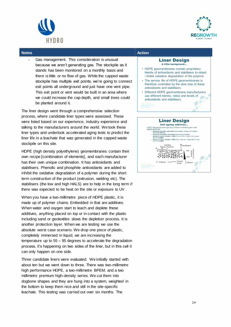
HDPE (high density polyethylene) geomembranes contain their
own recipe [combination of elements], and each manufacturer
has their own unique combination. It has antioxidants and
stabilisers. Phenolic and phosphite antioxidants are added to
inhibit the oxidative degradation of a polymer during the short
term construction of the product (extrusion, welding etc). The
stabilisers (the low and high HALS) are to help in the long term if
there was expected to be heat on the site or exposure to UV .
When you have a two-millimetre piece of HDPE plastic, it is
made up of polymer chains. Embedded in that are additives.
When water and oxygen start to leach and deplete these
additives, anything placed on top or in contact with the plastic
including sand or geotextiles slows the depletion process. It is
another protection layer. When we are testing we use the
absolute worst case scenario. We drop one piece of plastic,
completely immersed in liquid, we are increasing the
temperature up to 55 – 95 degrees to accelerate the degradation
process, it’s happening on two sides of the liner, but in this cell it
can only happen on one side.
Three candidate liners were evaluated. We initially started with
about ten but we went down to three. There was two-millimetre
high performance HDPE, a two-millimetre BPEM, and a two
millimetre premium high-density series. We cut them into
dogbone shapes and they are hung into a system, weighted in
the bottom to keep them nice and still in the site-specific
leachate. This testing was carried out over six months. The

15
Notes Action
manufacturer tells us how long it will last. We initially carry out
testing to verify that the manufacturer was telling the truth. The
manufacturer had actually underestimated the product.
We immersed it in a liquid at a few different temperatures,
carried the testing out after three months and six months. These
results were extrapolated to come up with a service life.
There are three stages to the aging process. A, B and C. Stage
A is the antioxidants and stabilisers. They deplete the quickest
and are there during the extrusion, manufacturing and
installation processes. They are not a long-term requirement.
Stage B. is the induction time after the antioxidants and
stabilisers have been depleted. There is still no depletion of the
mechanical properties of the liner, they are still doing what they
were designed to do. Stage C is the final stage where the
mechanical properties start dropping. Once they have dropped
by 50%, that’s the shut off period.
We test for S-OIT and HP-OIT to look to determine the time it
takes for the liner to age. S-OIT reflects the antioxidant levels in
the short term, and HP-OIT tests for the stabilisers, which is in
the long term. We take the three stages and we can estimate the
life of the liner.
In our [chosen] product, stage A is double due to the exposure of
only one side of the liner, stage B and C is based on years of
research. This gives us the overall life- stage B is 25 years,
stage C is 100 years, and stage A is 49, 38 and 28 years based
on the product tested. Due to the many layers, these numbers
are increased still. The life of the liners were between 181 and
223 years. This should be taken into account that this liner is
only one part of the whole product.
David briefly lists the layers previously stated to explain how the
liners life is extended by them.
We only test the top liner.
Darrin Gray: So this will degrade in 300 or 400 years?
David Barrett: No it will reduce down to its mechanical
properties and sit there. It rarely ever goes below that. What is
causing the oxidation is leachate. Because we have a dry tomb,
there won’t be contact with leachate or oxygen and water.
Leachate management was the next key consideration, down to
what makes up the leachate. We sampled the stockpile, which is
what will be going into the cell. We carried out a full suite of

16
Notes Action
analysis in the laboratory- every component was looked at to
see if there was any concerning elements. Option one was to
treat on site and use for irrigation and dust purposes. We looked
at everything in the treatment option including reverse osmosis,
membranes etc. the second option was to treat on site and then
discharge into the sewer system. At this stage you put it straight
into the system and pay for the wastewater treatment plant to
take it. Option three is to store and mechanically evaporate in a
pond. This is where you force the liquid out through a very small
valve and it evaporates immediately. This is very successful at a
site north of here. Option four is the use of a third party, where a
third party comes onto site and tankers it off site. This wouldn’t
normally be the most attractive option however you wouldn’t be
trying to create a dry tomb or close it as rapidly as this site is
trying to do.
Within leachate management we also considered
- health and safety risk,
- ability to meet water quality,
- environmental impact and risk associated with it,
- total cost,
- cost sensitivity based on total leachate volume, i.e. the
rainfall events, how long we’ll be operating the cell, how
long until we can cap certain sections.
- Social e.g. noise and odour, and;
- the people required to run it. If there is a highly technical
operation on site, then we need a highly technical
person to run it properly.
What we proposed was option four - the third party. Mainly
because we are going to close the site so quickly, this is the
most viable option. We looked at three contractors, got the
leachate delivered to them, they analysed the leachate and see
no issue with the treatment they proposed. Some of the are
going to be doing trade waste, some will do ocean outfall. We
need to discuss the approach with the EPA, prepare a
preliminary design for the infrastructure, option four requires the
least amount of infrastructure. It will require things like a
concrete pad beside the leachate pond for the truck to back up
on. The concrete pad will be bunded back to the pond in the
case of any leakages. The pumping systems aren’t going to be
permanent due to the dry tomb. Everything to do with leachate

17
Notes Action
will be temporary. Two concrete pads will be constructed at the
top of the pad just below the sumps. The leachate pond won’t be
needed at the end of the project as there will only be small
amounts of leachate left in the cell. Tender specification will be
dictating the terms to which the third party is chosen.
How it operates is very simple. We take the leachate form the
sump, we have in cell storage, containment outside for storage,
the contractor will reverse up here or here (points to buffer
storage diagram) to take it out. After about 20 months, we will
decommission the leachate pond and store the liner, into the cell
and start extracting the remaining leachate directly from the
cells. At that stage we’ve achieved the dry tomb. This should
occur around 24 months. If we double that, i.e. 44 months, which
is less than 10% of the stage A time period.
The other item is gas management. The design intent is to
collect and extract any gas that is generated. The basis comes
from what’s happening on site, as we have been monitoring it
every month. We have looked at the flow and the composition,
and these have helped us determine whether we need to suck it
out i.e. put it under negative pressure to encourage it to come
out, whether we would be required to flare it or put it into an
engine. In this case, there is low volumes and quantities of
methane and carbon doxide of no value. What will happen is
we’ll increase the production of gas in the excavation of cap
waste stock during the transportation of the cap waste stock into
the cell. This will happen, as we will be exposing it to air.
Stabilisation will occur within 18-24 months, bringing it back to
the levels it is now, which is little or none. We’ll install eight pipes
under the cap, even though there is only one exit as gas will find
the easiest path to flow into. Rather than putting in nothing, the
gas will find the cap and the design will facilitate it.
In relation to the extraction method, these black lines (points to
slide) will be below the cap surface. They are gas trenches
made of aggregate or crushed concrete to facilitate movement.
Inside it, 160 perforated pipes to facilitate the gas.
David points at vertical and vent diagram- these here can be
sealed with the LLDPE within the cap system. They can be built
above, or below, right underneath the waste. LLDPE is used in
putrescible landfill as there is expected to be movement within
the cell and it allows for this.
Darrin Gray: will there be any waste settlement on this site?
David Barrett: the only settlement on this site that will occur is

18
Notes Action
during the construction phase as we will be compacting it into
place. There will be no significant long term settlement. We
won’t get the long term settlement as seen in putrescible landfills
as there are no organics i.e. nothing is degrading.
Darrin Gray: Will the pipes and other materials from the
demolition waste have the potential to settle?
David Barrett: Everything will be compacted during the
deposition process. The contractors on site will be concerned
about getting as much per cubic metre out of the cell design as
they can, so they will be making sure it is compacted fully.
David reiterates that the waste won’t degrade, and will not cause
settlement issues for this reason.
Andrew Walker: As we are filling the cell, we will be driving over
the waste compacting it and spreading it. This will be done in
such a way that doesn’t damage the liner material. By the time
the cell is capped, the waste will be fairly well compacted.
David Barrett: There will be a landfill roller going over the waste
in a region of about maybe three and a half metres of waste in
the bottom, once that is placed and compacted, you can drive
straight over it. This first lift takes a bit of time and dedication,
and include using contaminated soils. Depth of a layer of waste
is usually nominally three metres, with construction and
demolition it gets a little higher and with putrescible waste, it gets
a little lower. We place those lifts as we go. The contractor will
do it properly to prevent leachate issues, otherwise it will slow
their work down. The lifts are placed properly so that voids don’t
occur and this will actually save time in the long run.
Darrin Gray: Will there be anyone on site to conduct
independent monitoring?
Andrew Walker: We’re currently in discussions with the EPA,
this has not been approved yet but we have meetings coming up
to discuss our proposal. Once we get through the approval of the
EIS, we start the process of actually talking to the EPA’s
technical people, who specialise in designs for landfill and
containment cells.
David Barrett: The EPA don’t rely just on the contractor or the
client to deliver a cell. They rely on a construction quality
assurance engineer. Materials come with their own materials
quality assurance, which is then tested in a laboratory to make
sure this is accurate. Everything gets tested to ensure their
quality.

19
Notes Action
David hands out “wedge welds” and “extrusion” samples.
Wedge welds are two pieces that have been welded with an air
pocket between them. The seam was proven stronger than the
parent material itself. This air pocket is tested under pressure to
confirm the quality of the seam. This is done by blocking the
seam at one end and putting an air needle at the other end and
testing the bar pressure. The other method of welding is known
as extrusion. This is adding a molten product to join two pieces
of liner together. It is tested through a vacuum process, by
covering it with a soapy water, subjecting it to vacuum pressure
and watching for any escaping air bubbles. The extrusion weld is
more expensive than the wedge weld for a contractor to place in,
so the ideal system is for everything to get wedge welded, which
we want. T joints where liners meet are all extruded. Every 150
m of continuous seam, or part thereof, we cut it out and send it
to a laboratory for it to be tested. They get repaired with a new
patch with an extrusion weld around it. If the installer is not going
to use the vacuum box system, they would install copper wire
down the centre and carry out a spark test, which is a brush with
electricity in it that you brush along, if it sparks, there is a failure.
This is very expensive and time consuming. The wedge welders
are tested every four hours or whenever the temperature
changes by five degrees, to make sure that the speed of the
wedge welder is not too slow or too fast. Too slow, there is too
much heat and stage A happens quicker, too fast and it won’t
adhere. Every single seam is signed off by a CQA engineer. On
top of that, the lining product gets sent off to a laboratory to
verify that each batch we get sent is exactly what we’ve been
issued. The same rule applies for the GCL and geotextiles.
These are glued / stitched together. The drainage geocomposite
won’t be seamed together because it is just for water flow so it
doesn’t matter as much. They’re also overlapped by about 300
mm. The CQA engineer also looks at the width.
Each batch is monitored to verify its quality. From a batch of
liner, 50 rolls out of 100 may get used.
Ian Shillington: So this is as you’re constructing the cell, what
about throughout the life of it?
Andrew Walker: we have to agree a long-term management
plan. We’ve put forward a proposal which is being discussed
with the department of planning and the EPA. The testing we’ve
done on the liner is assuming its in constant contact with the
leachate, but as there is two layers of HDPE, two layers of GCL,

20
Notes Action
its on a site where the groundwater is five or 10 metres below
the cell, above clay that has very high permeability. The data is
showing 223 years for one layer if it’s fully immersed in leachate,
but this is dry so the life is exponentially longer.
Discussion about liner research and lifetime.
Stage one of constructability is not only about building the cell
and liner types, but also how to get the least amount of
environmental issues. This includes the access routes,
temporary set down areas, storage areas. Stage two is to
relocate the stockpiles that are in the future position of the cell.
Stage three is excavation and stockpiling of the material from the
cell. Stage four is to construct the actual lining system itself,
normally in a landfill we would finish stage four and start bringing
in waste. We would use these small bones to control everything.
But at this site we will build everything. Stage five is the
placement of demolition and external stockpiles within the
containment cell. Stage 6 is the removal and stockpiling of
capped waste stockpile capping material, so we will take it away
and use it as a new cap as it is very good quality material. Stage
7 is placement of capped waste stockpile within the containment
cell, bear in mind stage 5, the stockpiles are already on site. This
and stage 7 will happen simultaneously because we’ll utilise the
existing stockpiles to protect liner, and then we will bring in some
waste.
Darrin Gray: Will contaminated soil come out of the demolition?
Andrew Walker: There will be some asbestos. We know there
is asbestos still in the basement of line 1 underneath the
basement slab in the fume duct trench. There will be possibly
some small amount of fluoride laden alumina which will be
stored in the back furnace area under cover. There will also be
scrubber bags which contain a small amount of fluoride. We’re
intending to keep all that waste under cover, out of the weather.
Once this goes into the cell, any leachate that comes off it will be
treated on site or offsite.
David Barrett: Even with the capped waste stockpile, for
constructability, you look at them as individual stages. The entire
cap won’t be stripped off, they’ll do it in very small portions to
reduce leachate generation.
Michael Ulph: is the pot lining out of the weather and will it be
recycled?

21
Notes Action
Andrew Walker: It is covered in a building until it will be
recycled. That building won’t be demolished until it’s all been
recycled.
Allen Gray: Will there be any pot liner being put in?
Andrew Walker: No.
David Barrett: Stage 8 is the replacement of capped waste
stockpile material. Stage 9 is the replacement of stockpile
materials back into the containment cell. Stage 10 is the
placement of final cap for containment cell followed by stage 11-
the removal of haul roads and surfacing of access roads.
Michael Ulph: Are there any questions for David?
Ian Shillington: There needs to be an access road, doesn’t
there?
David Barrett: There will still be a sealed access road in and
around the site. It’s just the temporary roads that will be
surfaced. There will be removal of concrete pads by the leachate
pond, the concrete pads at the sumps will be left but everything
else will be gotten rid of.
Andrew Walker: The whole road between the cap waste
stockpile and the containment cell will be scraped in case of any
leachate spill which has seeped into the surface of the road.
Michael Ulph: You mentioned stopping work if there is rain
planned, so do you have an estimated time frame from stage 1
to stage 11?
Andrew Walker: Time frame is estimated to be 46 weeks is the
critical phase for the period where the cap waste is exposed and
waste is transported to the new cell. This should be minimised to
reduce the chance of a major storm event occurring.
David Barrett: Everything including the access roads and the
bridge across unnamed creek has been built for very large
trucks, which will accelerate the process, and then it’s all about
how much we can operate safely.
Darrin Gray: Is there anything keeping community members,
motorbikes out?
Andrew Walker: There will be a long term maintenance plan for
the site which will involve security. The cell should not be
damaged by anybody getting into the site. There would be 1.5
metres of soil before you get to a liner.
Michael Ulph: What angle is the external slope of the cell?

22
Notes Action
David Barrett: One in five, to one in twenty.
Michael Ulph: It’s a pretty gentle slope.
The group discusses the potential future use of the site and site
access.

23
7 Project update
Andrew Walker: We mentioned at the last CRG meeting that
because the main issues with the EIS and the State Significant
Development are around remediation. We decided to take the
demolition out of the main project and go for a separate approval
with Cessnock Council and that’s so that we can get on with
demolition. Otherwise, there will be a big delay in the demolition
of buildings. We want to get on with stage 1 and stage 2 and we
have engaged a contractor and we do not want to have to
demobilise and remobilise.
We have just received the Secretary’s Environmental
Assessment Requirements (SEARS) back from the Department
of Planning and we’ll be starting to work on an EIS which will
cover stage 2 demolition. The scope of stage 2 involves
explosive demolition of concrete structures - the three stacks
and the water tower. Demolition of foundations and services to
one and a half metres below ground level and demolition of any
storage buildings storing SPL, after we’ve recycled the SPL.
Kerry Hallett: Have you organised the recycling through request
for tender or expressions of interest?
Andrew Walker: We’re still working through that commercial
process but we’re getting very close to moving forwards.
Part of the approval will be for a mobile crushing plant with the
capacity of up to 1,000 tonnes a day to crush all the concrete
from the demolition. That is designated development so we need
to do an EIS for that.
In response to the main EIS, that is covering the remediation,
we’re working on the response to submissions which should be
ready in the next few weeks. We’re still waiting to get some
information back from one of our consultants with modelling from
our floodwater study.
Michael Ulph: Is this flood study the same as the one used for
rezoning?
Andrew Walker: No this is not the same one, this is mainly to
do with the Unnamed Creek and making sure the site where the
cell will be built is well above the height of probable maximum
flood level.
We are also doing a site water balance to make sure that during
the remediation, we can contain all the stormwater within the
existing stormwater management system. This is also taking into

24
Notes Action
account the input of water from rainfall and the use of water on
site, like having water carts taking water from the north dam and
using it for dust suppression on site. This is being modelled at
the moment.
The spent pot lining recycling is getting very close. We are still
working through commercial processes, waiting for contractors
to get back to us with quotes. We are hoping to get something
going very soon. The rezoning hasn’t changed since the last
meeting.
Gareth Curtis: Can I just mention, that Maitland Council got
onto that flood modelling as quickly as you possibly could. Flood
studies can take years. It might sound like a long time, but
getting that done by the end of 2017 is actually not bad.
Ian Shillington: Yes there are a lot of stages and processes to
go through.
Gareth Curtis: That process with the rezoning is progressing
quite well.
Andrew Walker: We are also working on a process to get a
party interested in purchasing the site after the demolition and
remediation has finished.

25
Notes Action
8 CRG membership & TORs Review
This item was moved to next meeting due to time constraints.
Michael Ulph: This item will be held over until the next meeting
unless there is anything pressing. I guess the previous action
was asking whether other people should be represented here.
The Mindaribba Land Council will hopefully be represented at
the next meeting. Tara Dever, the new CEO has shown interest,
but was in Tamworth today.
9 Questions and Answers from the CRG/General
Business
Michael Ulph: Now time for questions; has there been any
Questions from community members?
Alan Gray: The containment cell should serve the community,
the community will be cautious about what happens on site. The
first question the community will have will be about spent pot
liner disposal. The community wants to know about recycling of
the spent pot liner.
Darrin Gray: Distributing newsletters to put in front of the
community is a good idea, for cell design for example.
Kerry Hallett: How long from demolition to development are we
looking at?
Andrew Walker: I would say a minimum of five years to get
through demolition and remediation, before anything else can
occur on site.
Kerry McNaughton: A Site Developer is likely to come on board
a lot sooner than the demolition/remediation time frame. A
number of potential developers have expressed interest in the
site and dialogue is continuing.

26
Notes Action
10 Meeting close
Meeting closed: 7:55 pm
Next meeting: Thursday, 17th August 2017 6:00 pm to 7:30 pm