Embed Size (px)
DESCRIPTION
FIZIK SPM - ELEKTRONIK
Citation preview

Transistors
1. A transistor is a double p-n junction semiconductor with three terminals,
a. the emitter (e),
b. the base (b)
c. the collector (c).
2. Figure 1 below shows the illustration of a transistor. It looks like a combination of 2
p-n junction diodes.
(Figure 1)
3. In a transistor, the emitter emits charge carriers (free electrons or holes).
4. The charge carriers move towards the base.
5. Under certain condition, large amount of the charge carriers will pass through the
thin base layer and to be collected by the collector.
Types of the Transistors
1. There are 2 types of transistors:
a. npn transistor
b. pnp transistor
2. Figure 2 below shows the illustration of the npn and pnp transistor and Figure 3
below shows the symbol of both npn and pnp transistor.
3. For the symbol of the transistor, the arrow shows the direction of current. Take
note that, for the emitter and base, the current always flow from the positive
terminal to the negative terminal.
(Figure 2: Illustration of the npn and pnp transistor)
(Figure 3: Symbol of the npn and pnp transistor)
How a Transistor Work?

(Figure 4)
1. In the Figure 4 above, there are 2 circuits in the connection:
a. the base circuit
b. the collector circuit
2. The base circuit is forward bias whereas the collector circuit is reverse bias (This
will be discuss in "The Connection of a Transistor").
3. Table below shows the response of bulb 1 (B1) and bulb 2 (B2) when switch 1 (S1)
and switch 2 (S2) are closed.
S1 S2 B1 B2
Open Open Does not light up Does not light up
Close Open Light up Does not light up
Open Close Does not light up Does not light up
Close Close Light up Light up
3. From the table, we can see that, the collector circuit is controlled by the base
circuit.
4. Current will flow in collector circuit only when the base circuit is closed

Connection of Transistor
1. The terminals of a transistor must be connected to the terminals of a cell correctly
to avoid damaging the transistor.
2. Transistor should be connected in such a way that
a. the emitter-base circuit is forward bias
b. the collector-base circuit is reverse bias.
Example:
Emitter-Base: Forward Bias
Collector-Base: Reverse Bias
Connection: CORRECT
Example:

Emitter-Base: Forward Bias
Collector-Base: Reverse Bias
Connection: CORRECT
Example:
Emitter-Base: Forward Bias
Collector-Base: Forward Bias

Connection: INCORRECT
Example:
Emitter-Base: Forward Bias
Collector-Base: Forward Bias
Connection: INCORRECT
Current in a Transistor
1. The current flows in the base, emitter and collector is called the base current (IB),
the emitter current(IE) and the collector current(IC) respectively.
2. Figure below shows the direction of the current in an npn transistor.

3. In general, IE is related to IB and IC through the formula
IE = IB + IC
Another thing that you need to know about the 3 currents is
IE > IC > IB
Transistor as an Amplifier
1. The major application of a transistor is as a current amplifier.
2. A transistor can be used to amplify ('magnify') current changes because a small
change in base current produces a large change in collector current.
3. A simple transistor amplifier circuit is shown in Figure 1 below.

(Figure 1)
4. The graph in Figure 2 below shows the relationship between the base current and
the collector current. From the graph, we can conclude that, the collector current is
directly proportional to the base current.
(Figure 2: The collector current is directly proportional to the emitter
current)
5. Since the small change in the base current IB results in a big change in the
collector current, IC, the transistor therefore function as a current amplifier.
6. The ratio IC/IB is called the amplification factor.
Amplification Factor=ICIB
7. Figure 3 below shows another amplification circuit. In this case however, the base
current is varying because of the small alternating voltage produced by the
microphone.
(Figure 3)
8. The small changes in base current cause much larger changes in collector
current.
9. The collector circuit includes an earphone through which you would hear an
amplified version of the original sound.
10.The input capacitor passes on current changes from the microphone but blocks
the steady current which might otherwise flow through the microphone from the
potential divider. Such a current would upset the biasing effect of the potential
divider.
The Transistor as an Automatic Switch
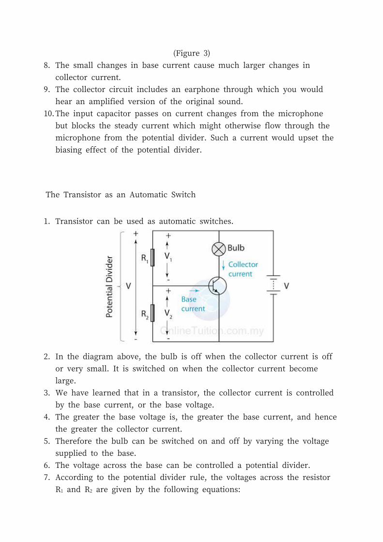
1. Transistor can be used as automatic switches.
2. In the diagram above, the bulb is off when the collector current is off or very small.
It is switched on when the collector current become large.
3. We have learned that in a transistor, the collector current is controlled by the base
current, or the base voltage.
4. The greater the base voltage is, the greater the base current, and hence the
greater the collector current.
5. Therefore the bulb can be switched on and off by varying the voltage supplied to
the base.
6. The voltage across the base can be controlled a potential divider.
7. According to the potential divider rule, the voltages across the resistor R1 and
R2 are given by the following equations:

V1=R1R1+R2×V
and
V2=R2R1+R2×V
8. Therefore, by varying the resistance of R1 and R2, we can control the voltage
across the base V2, and hence switch the bulb on and off.
The LDR
1. A light-dependent resistor (LDR), or photoresistor, is a resistor sensitive to light.
2. In darkness, the LDR has a resistance about 1 million Ohm.
3. In bright light however, the resistance of the LDR falls to only a few hundred
Ohms.
Light Operating Switch
1. In a light operating switch, we connect an LDR to the potential divider.
2. As a result, the voltage across the base vary according to the presence or
absence of light.
3. Example 1 and 2 below shows how the resistance of the LDR, the base voltage,
the base current and the collector current change in different conditions.
Example 1
Bright Surrounding:Resistance of LDR: LowBase voltage: High
Dark SurroundingResistance of LDR: HighBase voltage: Low

Base current: High
Collector current: HighBulb: ON
Base current: Low
Collector current: LowBulb: OFF
Conclusion
The bulb will be switched on when the surrounding is bright and switched off when
the surrounding is dark.
Example 2
Bright Surrounding:Resistance of LDR: LowBase voltage: LowBase current: Low
Collector current: LowBulb: OFF
Dark SurroundingResistance of LDR: HighBase voltage: HighBase current: Low
Collector current: HighBase current: ON
Conclusion
The bulb will be switched on when the surrounding is dark and switched off when the
surrounding is bright.
Thermistor
1. In a heat operated switch, the LDR is replaced by a thermistor.
2. A thermistor is a resistor which its resistance changes as the temperature
changes.
3. There are 2 types of thermistor:
a. The positive temperature coefficient (PTC) thermistor

b. The negative temperature coefficient (NTC) thermistor
4. For the PTC thermistor, the resistance of the thermistor increases as the
temperature increases whereas for the NTC thermistor, the resistance of the
thermistor decreases as the temperature increases.
5. In SPM, we assume all the thermistor used is the NTC thermistor, unless it is
stated otherwise.
Heat Operated Switch
1. The circuit of a heat operated switch is similar to the light operated switch, except
that the LDR is replaced by an NTC thermistor.
2. If heat is applied to the thermistor, its resistance drops. As a result, the base
voltage will increase and the transistor is switched on and the bulb lights.
Sound Controlled Switch

1. Figure above shows the circuit design of a sound controlled switch.
2. The microphone is used to convert sound to electric current.
3. The variable resistor is adjusted as such that the transistor is switched on when
sound is detected by the microphone.
4. The function of the capacitor is to prevent the direct current from the cell to flow in
the base circuit.