Embed Size (px)
Citation preview

NORTHERN MINERALS LTDBROWNS RANGE RARE EARTH PROJECT
PREPARED FOR:
Northern Minerals Ltd Level 1, 675 Murray St West Perth, 6872
PE801-00241_01 Rev 1 June 12, 2014
TAILINGS STORAGE FACILITY SUMMARY
Knight Piésoldwww.knightpiesold .com
C O N S U L T I N G
PREPARED BY:
Knight Piésold Pty LimitedLevel 1, 184 Adelaide Terrace
East Perth, WA 6004, AUSTRALIA p. +61 9223 6300 • f. +61 9223 6399

DOCUMENT CONTROL PAGE
NORTHERN MINERALS LTD
BROWNS RANGE RARE EARTHS
PROJECT
TAILINGS STORAGE FACILITY
SUMMARY REPORT
KP Job No. PE801-00241/01
CONTRACT
PROJECT CONTRACT
DOCUMENT INFORMATION REV DESCRIPTION PREPARED REVIEW KNIGHT PIESOLD
APPROVAL DATE
0 Issued as final DSS
BAS
DJTM
11/04/2014
1 Issued with amendments
DJTM
12/06/2014
DOCUMENT DISTRIBUTION
REV DESTINATION HARD COPY ELECTRONIC COPY
0 LEVEL 1, 675 MURRAY ST, WEST PERTH - 1
1 LEVEL 1, 675 MURRAY ST, WEST PERTH 1

CONTENTS PAGE
PE801-00241_01 TSF Summary Report Rev 1
1. INTRODUCTION 1
2. DESIGN CRITERIA 2
3. SITE DESCRIPTION 5 3.1 SITE LOCATION AND TOPOGRAPHY 5
3.2 CLIMATE 5
3.3 WIND 6
3.4 SEISMICITY 6
3.5 HYDROLOGY 6
3.6 HYDROGEOLOGY 7
3.7 REGIONAL AND LOCAL GEOLOGY 7
3.8 FLORA AND FAUNA 7
3.9 HERITAGE 7
4. OPTION STUDIES 8 4.1 SITE SELECTION 8
4.2 TAILINGS THICKENING CRITERIA 8
5. HAZARD CLASSIFICATION 10 5.1 DMP HAZARD RATING 10
5.2 ANCOLD CONSEQUENCE CATEGORY 10
6. SITE INVESTIGATION 12
7. TAILINGS CHARACTERISTICS 13 7.1 GENERAL 13
7.2 GROUNDWATER CONDITION 13
7.3 TAILINGS PHYSICAL PROPERTIES 14
7.4 GEOCHEMICAL AND RADIOLOGICAL PROPERTIES 14
7.5 SUMMARY OF TAILINGS ASSESSMENT 15
8. FACILITY DESCRIPTION 1716
9. WATER MANAGEMENT 1918 9.1 WATER BALANCE 1918
9.2 STORM EVENT STORAGE CAPACITY AND SPILLWAY 1918
9.3 SURFACE WATER 1918
10. CONSTRUCTION 2019

CONTENTS PAGE
PE801-00241_01 TSF Summary Report Rev 1
11. OPERATION 2221 11.1 DEPOSITION OBJECTIVES 2221
11.2 DEPOSITION TECHNIQUES 2221
12. MONITORING 2423
13. REHABILITATION AND CLOSURE 2524
14. REFERENCES 2625 FIGURES DRAWINGS

1
1. INTRODUCTION The Tailings Storage Facility (TSF) and associated infrastructure for the Browns Range
Project will form an Integrated Waste Landform (IWL) with the mine waste from open
pits. The TSF will contain the comingled tailings from the beneficiation and
hydrometallurgical processing plant at an approximately 90% to 10% split respectively.
The location and embankment alignment of the proposed facility has been selected to
make efficient use of natural topography and local mine waste availability while
remaining remote from the majority of mining infrastructure.
Over the life of the operation, a total of approximately 6.3 Mt of tailings is expected to
be produced over 10 years. The tailings will be thickened and then transferred via
slurry pipeline at a range of 50 – 55% solids. Tailings will be deposited into the
purpose built two celled paddock TSF where the solids will settle out, and excess water
expelled during settling and rainfall runoff will be returned to the process plant for reuse
subject to suitability of water quality. The facility will contain the 1 in 100 year Average
Return Interval (ARI) 72 hour rainfall event with the decant not operational and still
maintain adequate freeboard. The facility will be built in stages with the first stage
designed to contain 1 year of tailings production at an embankment level of 455 m RL
or approximately 8 m high. Future raises will be performed on a yearly or two yearly
cycle to the final elevation of 470 m RL or 23 m high (similar to the maximum height of
the natural topography on the south side). The TSF is classified as having a “Medium”
hazard rating according to the Department of Mines and Petroleum (DMP) Code of
Practice and was defined as Category 1 due to the maximum embankment height in
accordance with the DMP Code of Practice – Tailings Storages in Western Australia
(DMP, 2013). The TSF is classified as being a “High C” Consequence Category
according to the ANCOLD Guidelines on Tailings Dams (May 2012).

2
PE801-00241_01 TSF Summary Report Rev 1
2. DESIGN CRITERIA The design objectives for the TSF are as follows:
• Permanent and secure containment of all solid waste materials.
• Maximisation of tailings densities using sub-aerial deposition.
• Removal and reuse of free water.
• Minimisation of seepage.
• Containment of extreme storm events within the TSF.
• Ease of operation.
• Rapid and effective rehabilitation.
A summary of the key policies and guidance documents used for the design of the TSF
are summarised as follows:
• DME (now DMP) Guidelines on the Safe Design and Operating Standards for
Tailings Storage, May 1999;
• DME (now DMP) Guidelines on the Development of an Operating Manual for
Tailings Storage, October 1998;
• ANCOLD Guidelines on Tailings Dams, Planning, Design, Construction,
Operation and Closure. May 2012;
• ANCOLD Guidelines on The Consequence Categories for Dams. October 2012;
• DMP Code of Practice – Tailings Storage Facilities in Western Australia 2013.
Design criteria and parameters adopted for the study are summarised in Table 2.1.

3
PE801-00241_01 TSF Summary Report Rev 1
Table 2.1: TSF design criteria DESIGN STANDARDS Storm Events: Design Application 1:2 yr Temporary diversion structures during construction.
100 yr/72 hr Diversion channel erosion protection.
100 yr/72 hr Diversion channel capacity.
100 yr/72 hr in addition to the maximum operating volumes for average climatic conditions
TSF stormwater storage capacity.
1:10,000 yr/72 hr storm event Emergency spillway, if required.
A PMP intensity and 72 hr volume TSF permanent spillway structure at closure.
EMBANKMENT STABILITY/EARTHQUAKE CRITERIA Earthquake Loading
- Operating Basis Earthquake (OBE)
- Maximum Design Earthquake (MDE)
• 0.03g (500yr event)
• Maximum Credible Earthquake (MCE)
Stability Factors of Safety
- Static
- Seismic (OBE)
- Seismic (MDE)
• 1.5 (minimum) (ANCOLD Guidelines (2012))
• 1.1 (minimum) (ANCOLD Guidelines (2012))
• Damage and deformation allowed (<freeboard allowance) - No release of tailings or water
WATER MANAGEMENT Supernatant Pond • Minimum operating pond (target pond size) of 10,000 m3
• TSF not designed to accommodate external water flows. Any additional flows require review of water management impacts prior to discharge.
OPERATIONS Capacity - Final
- Starter
6.3 Mt of dry tails over 10 years.
0.63 Mt of dry tails – 12 months initial capacity.
Production Rate 0.63 Mtpa.
Production Days/Year 7800 hr/yr (89% availability).
Slurry Characteristics 50% - 55% solids by weight
SG = 2.7.
Final slurry settled density = 1.4 t/m3.
Permeability of: 1 x 10⁻⁷ m/s.
Facility Description Two Cell facility (approximately 14 Ha per cell crest to crest) located at Site Option 4.
Fluid Management Basin underdrainage system reports (via gravity) into a collection sump, pumped to supernatant pond. Decant tower removal of supernatant solution and surface runoff via pipeline to a tank at the plant. Rate of water return will depend on water quality to ensure that plant performance not affected. Decant tower located in centre of each basin area. A temporary decant tower may be located in the basin to expedite process water recycle during the first year of operation.

4
PE801-00241_01 TSF Summary Report Rev 1
Table 2.1 (cont): TSF Design Criteria DESIGN STANDARDS
EMBANKMENTS (both cells)
Construction Upstream cut-off trench and toe drain.
Zoned starter embankment constructed of mine waste and local borrow (sourced from within TSF basin where possible) with low permeability zone on upstream face.
8 m typical crest width (8 m for Stage 1).
Construction Materials Remove unsuitable foundation soils from entire embankment footprint for use as embankment fill (if suitable).
Low permeability material (Zone A) from borrow areas located within TSF basin where possible. Zone C from mine waste.
Erosion Protection (Zone E) and coarse rockfill (Decant Zone G) may be sourced from screening of mine waste stockpiles. Other drainage material (e.g. filter sand (Zone F)) imported from off site.
TAILINGS BASIN
Basin Liner Geosynthetic Liner over entire TSF basin, to achieve overall average target seepage rate of less than 4 kL/ha/day for average operating conditions. Liner comprises the following:
Compacted soil subgrade, comprising primarily in situ soils, scarified and re-compacted throughout the basin area to form a 150 mm thick soil subgrade. Where in-situ materials are unsuitable for subgrade, low permeability material (Zone A) will be won from basin area to provide the soil subgrade.
1.5 mm smooth HDPE geomembrane liner installed throughout the basin area to achieve overall seepage performance of less than 4kL/ha/day.
Tailings Underdrainage System Main collector drains, branch drains and finger drains throughout TSF basin area, will collect seepage water from the tailings mass and discharge it to a lined collection sump to be pumped to the supernatant pond.
Main Collector Drains - Corrugated, perforated tubing (with filter sock), surrounded by sand (Zone F1), wrapped in geotextile (continuously seamed or heat welded).
Branch Drains - Corrugated, perforated tubing (with filter sock), surrounded by sand (Zone F1) and wrapped in geotextile (continuously seamed or heat welded).
Operation Discharge from main embankment to form supernatant pond centrally.
Recycle rate of supernatant water subject to water quality being suitable for plant operation. Excess supernatant water to be evaporated within TSF basin or used for other operational purpose where suitable.
Underdrainage recovery pumped to tailings surface or operational purpose where suitable to improve tailings consolidation.
Monitoring Monitoring bores downstream of embankment to monitor groundwater level and quality.
Piezometers in embankments to monitor stability.
Closure Tailings surface to be designed as store and release cover.
Embankments to be progressively rehabilitated.
Permanent structure designed to accommodate PMP event.

5
PE801-00241_01 TSF Summary Report Rev 1
3. SITE DESCRIPTION The following sections describe the site characteristics of the area with a focus on
items which influence TSF site selection, design, operation and closure.
3.1 SITE LOCATION AND TOPOGRAPHY
The topography of the site comprises a series of sharply rising ridges and rock
outcrops within an otherwise gently sloping area of approximately 1% gradient. The
location of the proposed TSF slopes down gently from the east to the west and is
remote from any distinct drainage features. Topography ranges from the lower flatter
areas at R.L. 445 m up to localised peaks around R.L. 470 m. The proposed TSF is
located in close proximity to the ore bodies, the process plant and proposed camp sites
with a facility centroid of approximately latitude 18.90°S, longitude 128.95°E.
3.2 CLIMATE
Climate information for the project was obtained from a previous study report by Golder
Associates. The site is located in a semi-arid climate with monsoonal influence being
approximately 430 km inland from the coast. Rainfall is highly variable due to the
influence of periodic summer cyclones but is on average 410 mm per annum. Peak
rainfall occurs in the summer months of December to March with about 80% of the
annual rainfall occurring. The highest annual rainfall recorded was 1107 mm and a
minimum of 101 mm.
Short term intensity-frequency-duration (IFD) relationships for the location were
obtained using the online model developed by Australian Bureau of Meteorology
(BOM) and are a function of latitude and longitude. The rainfall from 100 year ARI 24
hour and 72 hour events were calculated as 210 mm and 291 mm respectively. A full
data set is provided in Figure 3.1
The estimation of Probable Maximum Precipitation (PMP) at the site location and
specific for the TSF catchment size was developed from publications produced by
BOM. The PMP event is greater than a 1 in 100,000 year event. The rainfall for PMP
24 hour and 72 hour events were calculated as 1,037 mm and 1,888 mm respectively.
Evaporation isopleth maps of Australia are provided by BOM for both annual and
monthly average evaporation. The data were interpolated from gauging stations with
more than 10 years of record of Class A evaporation pan data.
The average annual and monthly rainfall and evaporation used in the design are
presented in Table 3.1 and presented graphically in Figure 3.1. The data indicate that
the site is water negative at all times of the year.

6
PE801-00241_01 TSF Summary Report Rev 1
Table 3.1: Rainfall and evaporation data. Month Mean monthly
rainfall (mm) Mean monthly
evaporation (mm) January 98.4 278.6 February 112.0 225.6 March 55.8 241.7 April 14.7 224.7 May 10.0 189.1 June 5.3 157.8 July 5.9 174.0 August 3.1 218.9 September 3.6 269.1 October 14.8 320.2 November 26.3 314.5 December 60.3 301.2 Total 410.2 2915.4
3.3 WIND
The wind frequency analysis of the site based on the BOM station at Halls Creek
Airport (station number 02012) shows a prevailing wind direction from the east. Design
wind speeds for the area were estimated from AS1170.2 Structural Design Actions -
Wind Actions based on location and wind direction. The Browns Range area is
categorised as Region A4 (AS 1170.2 Figure 3.1) with resulting wind speeds based on
a 3 second gust of 40.8 m/s.
3.4 SEISMICITY
The selected design peak horizontal ground acceleration adopted for the study at this
stage was based on the 2012 Australian Earthquake Hazard Map developed from
Geoscience Australia. The site is located in an area of low seismicity as shown in
Figure 3.2. The assigned OBE value for seismic acceleration coefficient applicable to
the site is approximately 0.03 g for a return period of 500 years. A general site
assessment will be conducted in the next phase of design to determine the Maximum
Design Earthquake (MDE) for closure and long term stability requirements.
3.5 HYDROLOGY
The project area is characterised by several small ephemeral streams that form part of
the Sturt Creek drainage system. The Sturt Creek catchment ultimately drains into the
Lake Gregory system located approximately 220 km south-west of the project.
Streamflows in the region are generally ephemeral which are highly dominated by wet

7
PE801-00241_01 TSF Summary Report Rev 1
season storm flows with dry season flows contributing little to no flow to annual
volumes. No significant drainage paths were identified for the TSF as it will be located
at the head of the catchments with minor perimeter drainage required to manage sheet
flow around the toe of the facility.
3.6 HYDROGEOLOGY
A groundwater study of the area was conducted by Klohn Crippen Berger (KCB). No
groundwater was reported in the shallow testpits conducted as part of the site
investigation by Golder. KCB indicated that groundwater levels around the Gambit Pits
(east, central and west) located slightly to the north of the TSF range from R.L. 422 m
to R.L. 448 m (depth from natural surface to groundwater level is typically 7 – 14 m with
some areas at depths of up to 28 m).
3.7 REGIONAL AND LOCAL GEOLOGY
The Gordon Downs sheet of the 1:250,000 Geological Series published by the
Geological Survey of Western Australia describes the geology surrounding the Browns
Range site. The map indicates that the site is underlain by meta-arkoses and meta-
sandstones of the Archaean-Early Proterozoic age as well as granitic gneisses and
muscovite schists. Ultramafic intrusions are understood to occur within the
metamorphic rocks. The map also indicates that the lower topography areas of the site
are generally described as:
• Sand and silt, mainly aeolian and sheet wash deposits;
• Alluvium comprising sand, silt, gravel and clay in channels and on flood plains.
3.8 FLORA AND FAUNA
The vegetation in the region is mostly open grassy woodlands comprising Spinifex
grassland, sparse bush and small trees. Vegetation becomes denser around drainage
lines and creeks. The Lake Gregory system is located approximately 220 km south-
west of the project and contains wetlands of national importance and is a significant
site for domestic and migratory waterbird species.
3.9 HERITAGE
Two surveys have been conducted across the general area to date, primarily targeting
areas associated with exploration activity for Browns Range. A detailed heritage survey
of the area will be conducted prior to construction and the TSF will avoid “no-go” areas
identified in consultation with the traditional land owners.

8
4. OPTION STUDIES
4.1 SITE SELECTION
A site selection study for the TSF was undertaken by Golder Associates in April 2013.
A number of potential TSF sites were considered, taking into account existing
infrastructure, lease boundaries and environmentally sensitive areas. The tailings
disposal options considered:
• Paddock disposal on relatively flat areas;
• Side valley disposal in topographically appropriate valleys and ridgelines;
• Central thickened discharge on relatively flat areas.
In pit storage of tailings was not considered viable at this stage as the mineralisation
continues below the current pit depths.
For the site selection study, four sites were evaluated as shown in Figure 4.1. Site 4
was selected as the preferred area for the TSF. This was based on consideration of
surface conditions, haulage and pumping distance from the plant, constructability,
proximity to other proposed infrastructure (while remaining downstream from a dam
break perspective), wind direction and potential for expansion.
The location of the embankments is proposed to be optimised within the Site 4 area to
form an integrated waste landform (IWL) with the local waste dumps and to avoid the
rock outcrops on the southern extents of Site 4. As a result, a fully downstream
embankment configuration was selected for the study with 3 sides buttressed against
waste dumps. A nominal offset of 500 m from pits has been assigned for both blasting
and stability purposes, while also remaining close enough for construction material
sources and providing a localised sink for any groundwater seepage.
4.2 TAILINGS THICKENING CRITERIA
As discussed in the tailings characterisation section, various degrees of thickening of

9
PE801-00241_01 TSF Summary Report Rev 1
• Paste tailings. Dewatered in a deep cone thickener to produce a “non bleeding”
paste and transported with displacement pumps.
The paste option was eliminated due to both high capital costs and high operating
costs as well as requiring a much larger footprint area to manage the deposition and
surface water runoff control in the TSF. The embankment layouts, infrastructure and
cost difference between conventional thickening and ultra-thickening was marginal,
however conventional thickened tailings was the selected option due to more
operational flexibility. An operational range of 50 – 55 % solids was selected.

10
PE801-00241_01 TSF Summary Report Rev 1
5. HAZARD CLASSIFICATION As part of the calculation of the hazard/consequence category of any facility, an
assessment of the Population at Risk (PAR) needs to be undertaken for the selected
location (ANCOLD, May 2012). There are a number of factors impacting the PAR
calculation from water storage potential, tailings capacity, downstream topography,
structures and their frequency of usage. A high level PAR value was determined for
the selected location based on proximity of pits, plant site and village and a nominal
dam break direction downstream. A PAR range of >1 to 10 was selected on the basis
that only the proposed Gambit West Pit would be in the potential flow path from a dam
break, but it would be protected by mining waste.
5.1 DMP HAZARD RATING
The TSF classification was assessed by the methods set out in the DMP Code of
Practice for Tailings Storage Facilities in Western Australia (2013) to determine the
category of the facility over the life of the project. The storage category was
determined as >15m as the maximum final embankment height is 23 m, as a result, the
facility is considered a “Category 1” facility.
5.2 ANCOLD CONSEQUENCE CATEGORY
An assessment was made of the severity level of impacts from a large scale failure of
the facility. The severity table is obtained from ANCOLD (2012 Table 1) and presented
in Table 5.1.
Table 5.1: ANCOLD Guideline on Severity Level Damage Type Severity Level
Infrastructure Medium
Business Importance Major
Public Health Minor
Social Dislocation Minor
Impact Area Medium
Impact Duration Medium
Impact on Natural Environment
Medium

11
PE801-00241_01 TSF Summary Report Rev 1
Based on the PAR of >1 to 10 and the ‘Major” severity level, the facility would be rated
as High C. The PAR may need to be reassessed if the project design and construction
develops to incorporate any new infrastructure or highly trafficked roads located
downstream.

12
PE801-00241_01 TSF Summary Report Rev 1
6. SITE INVESTIGATION The subsurface conditions of the proposed TSF site were investigated as part of a site
wide investigation presented in Golder Associates’ report “Preliminary Geotechnical
Investigation Report – Stage 1” Feb 2014. During the geotechnical investigation, a
total of 5 test pits were excavated within the footprint of the proposed TSF location of
which 3 were tested for soil properties. A summary of the test locations and laboratory
results are presented in table 6.1.
Table 6.1: TSF Test Pit Laboratory Data. Testpit ID Sample
Depth (m) Soil
Description USCS Particle Size Distribution (%) Atterberg Limits
Gravel Sand Fines LL (%) PI (%) TSF4TP-01 1.0 – 1.5 Clayey SAND SC 0 74 26 15 8 TSF4TP-17 0.7 – 1.2 Clayey SAND SC 0 70 30 17 9 TSF4TP-26 1.0 – 1.5 Clayey SAND SC 31 44 25 23 13
The subsurface conditions can generally be summarised as follows:
• Silty SAND (SM) – fine to coarse grained, approximately 20% liquid limit from
the ground surface to about 0.2m depth;
• Clayey SAND (SC) – fine to coarse grained, low plasticity clay, generally
becoming weakly iron cemented with depth. Medium dense to very dense
extending to depths ranging from 0.9 m to 2.1 m;
• GRAVEL/Sandy Clayey GRAVEL (GP/GC) – not encountered in all test pits.
Fine to coarse grained low plasticity weakly to moderately cemented, very dense
extending to a maximum depth investigated of 2.0 m.

13
PE801-00241_01 TSF Summary Report Rev 1
7. TAILINGS CHARACTERISTICS
7.1 GENERAL
Preliminary physical and geochemical test work of tailings samples have been
undertaken with the results reported in the following documents:
• “Browns Range Project – Preliminary Geochemical Assessment & Tailings” June
2014, Golder Associates;
• “Browns Range Project – Tailings Management Concepts * - Appendix B - *
Tailings Geotechnical and Rheological Laboratory Testing“ Dec 2013, Golder
Associates.
The following interpretation of the tailings properties and associated liner requirements
are based on the test data provided in these reports.
7.2 GROUNDWATER CONDITION
Information on groundwater water quality was obtained from boreholes in the site area.
The water quality measurements are from sampling in 2013.
A comparison of the groundwater movements to Australian drinking water and stock
water standards was made. Table 7.1 lists groundwater elements which exceed
drinking water and/or stock water standards.
Table 7.1: Groundwater quality
Element
Average Value (mg/L)
Times Level of Exceedance
Average Median
Drinking Water Stock Water
Average Median Average Median
TDS 2130 790 3.6 1.3* 0.54 0.20
Sulphate 367 79 1.5 0.3 -
Aluminium 0.61 0.11 3.1 0.5 -
Iron 0.96 0.31 3.2 1.03 -
Manganese 0.16 0.020 1.6 0.20 -
Uranium 0.023 0.003 1.8 0.15 -
*Exceedance compared to median value.
Thus the average groundwater quality exceeds drinking water standards for 6 elements
but only TDS is slightly exceeded for stock water standards.
The ground water quality assessment is that the ground water is generally suitable for
ANZECC beef cattle standards but the quality does not meet drinking water standards.

14
PE801-00241_01 TSF Summary Report Rev 1
7.3 TAILINGS PHYSICAL PROPERTIES
The tailings will consist of 90% flotation tailings and 10% hydromet tailings. Physical
testing of a combined sample was undertaken by Golder (December, 2013). The
testing included:
• Particle size distribution;
• Specific gravity;
• Settling tests;
• Air drying tests;
• Viscosity and thickening tests.
The sample was tested at 45% solids. The current disposal option is to discharge the
tailings slurry at 50-55%% solids and where required the parameters have been
adjusted.
The results used for design are summarised in Table 7.2.
Table 7.2: Tailings Physical Characteristics (at 51-53% solids) Property Estimated / Measured Value
SG solids ( combined tailings) 2.67
P80 Flotation Tailings Hydromet Tailings
31 µm 68 µm
Plasticity Index ( Combined Tailings) 14%
Supernatant Production (%) - Average - Range
15
9 - 26
Maximum Underdrainage (%) 25
Achieved Density in Facility (t/m3) - Drying Beach
- Under Pond Area 1.40 1.0
Permeabilities (m/s) - Dry Beach - Pond Area
1 x 10⁻⁸
1 x 10⁻⁷
7.4 GEOCHEMICAL AND RADIOLOGICAL PROPERTIES
Geochemical and radioactivity measurements were evaluated separately for the
flotation and hydromet samples. The primary results are as follows:

15
PE801-00241_01 TSF Summary Report Rev 1
The geochemistry of the tailings was tested by Golder Associates (June 2014). The data was reviewed and demonstrates that:
i. The mixed tailings is not likely to be acid generating.
ii. The tailings solids have some elevated element concentrations.
iii. The tailings liquor is marginally poorer than ANZECC livestock standards.
On the basis of these points, it is concluded that the mixed tailings liquor may cause a
marginal deterioration in the overall groundwater quality if released to the environment.
Measurements of radioactivity for various radionuclides were undertaken by ANSTO
and assessed by JRHC. A summary of the radionuclide concentrations in the tailings
solids are provided in Table 7.3.
Table 7.3: Radioactivity assessment – Solids (Bq/g)
Radionuclides Calculated Bene Tailings Value
Calculated Hydromet
Tailings Value
Combined (Ratio 90:10)
*
Radioactive Classification
Criteria **
Uranium 238 0.3 0.6 0.3 1
Thorium 230 0.3 1.9 0.4
Radium 226 0.3 3.1 0.6
Lead 210 0.3 3.1 0.6
Thorium 232 0.1 0.3 0.1
Radium 228 0.1 0.6 0.1
Thorium 228 0.1 0.3 0.1
Uranium 235 0.02 0.02 0.02
* Refers to a final tailings mixture of 90% beneficiation (bene) tailings and 10% hydrometallurgical plant
tailings.
** Note that for a material to be classified as “radioactive”, the combined head of chain activity (Uranium
238, Thorium 232 and uranium 235) must exceed 1Bq/g. Where material is not in secular equilibrium, a
mixture method is recommended by ARPANSA. The classification criteria shown here refers to the head of
chain criterion.
The combined tailings stream does not exceed the criterion for being defined as a
radioactive material and is therefore classified as not radioactive.
7.5 SUMMARY OF TAILINGS ASSESSMENT
On the basis of the tailings properties the tailings facility should be design to achieve
an overall seepage rate of 4 kL/ha/day or less. In order to achieve this performance
standard it is envisaged that the insitu soils will be scarified and recompacted to form a
150 mm thick liner subgrade. HDPE liner will be installed above the soil liner

16
PE801-00241_01 TSF Summary Report Rev 1
throughout the basin area and underdrains will be constructed within the basin area so
that the overall seepage performance standard is achieved.
At closure a suitable cover will be required to prevent loss of solids.

17
PE801-00241_01 TSF Summary Report Rev 1
8. FACILITY DESCRIPTION The TSF will be combined with waste rock from some of the open pits to form an
integrated waste landform (IWL). The facility will consist of a two cell multi-zoned
downstream perimeter embankment, forming a total footprint area of approximately
28.0 ha for the Stage 1 TSF increasing to 36.4 ha for the final TSF (internal crest area
of 23.5 ha Stage 1 to 30.1 ha Final TSF). General arrangements for the TSF (Stage 1
and Final) are shown on Drg. No. 801-241-C001-006 Rev A.
The facility will comprise of two square shaped paddock storage cells located on a
naturally sloping basin. The Stage 1 embankment and subsequent stages will be
constructed downstream with 3 embankments located against mine waste dumps. The
embankments will be zoned with an upstream low permeability zone and downstream
structural zone.
The Stage 1 embankment will provide for 1 year of deposition between two cells, and
the embankments will typically be raised every year or two years depending on mine
waste production.
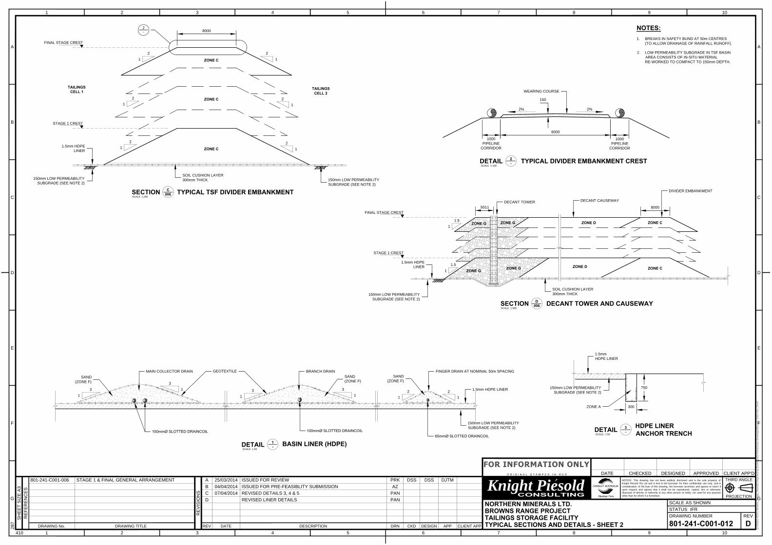
The embankment will have an 8 m crest, upstream slope of 1V:2H and a downstream
slope of 1V:3H. The zones in the embankment consist of an upstream low permeability
zone (Zone A) and a downstream structural zone (Zone C). The design is based on
Zone C being placed directly from the open pit mining operations. For Zone A, lifts will
be constructed out of local borrow, winning from mine waste stockpile or utilising mine
waste directly.
A soil subgrade will be constructed over the entire TSF basin area comprising insitu
soils scarified and recompacted. An HDPE geomembrane liner will be installed in the
basin area to meet the overall seepage rate objective. The low permeability soil liner
will comprise 150 mm depth of low permeability soil (reworked in-situ material). The
liner system will be constructed to achieve a target seepage rate of less than
4 kL/ha/day.
The design incorporates a basin underdrainage system over the entire TSF basin to
reduce pressure head acting on the basin liner, reduce seepage, increase tailings
densities, and improve the geotechnical stability of the facility. The underdrainage
system comprises a network of finger, branch and collector drains. The underdrainage
system drains by gravity to a collection sump.
Some supernatant water will be removed from the TSF by natural evaporation or via
submersible pumps located within the decant tower (constructed and raised during
operation). Solution recovered from the decant system will be pumped back to the

18
PE801-00241_01 TSF Summary Report Rev 1
plant for re-use in the process circuits, subject to process water quality requirements.
The rate of removal will be controlled to ensure it is suitable for the plant and excess
water will be evaporated from the TSF.

19
PE801-00241_01 TSF Summary Report Rev 1
9. WATER MANAGEMENT A high level water balance was conducted to demonstrate the facility remains in
negative balance and that the facility is designed to contain the 100 year ARI 72 hour
rainfall event without the risk of overtopping.
9.1 WATER BALANCE
The process plant requires approximately 72.7 tph of makeup water in order to
generate the tailings slurry to 52% solids w/w. Of this, approximately 15% of the water
in the slurry reporting to the TSF is expected to be released and available for recycle
back to the plant. An average decant rate of 11 tph is expected with higher values
experienced during the wet season and potentially zero return in the dry season. On a
monthly basis, the evaporation potential exceeds rainfall by at least double, indicating
only short term storm events with the decant not operational will cause a short term
increase in the supernatant pond.
A design storm of 100 year ARI and 72 hour duration results in approximately
44,000 m3 of runoff in each cell. The storage capacity on the tailings surface for each
cell ranges from 70,000 m3 in stage 1 to 90,000 m3 in the final stage as the facility
increases in size. The storm storage assessment assumes the waste dump does not
contribute runoff to the TSF.
9.2 STORM EVENT STORAGE CAPACITY AND SPILLWAY
During operation sufficient freeboard will be provided to hold the PMP 24 hour event.
Thus no operational spillway is required.
After closure and placement of the cover layers the facilities will operate with a store
and release cover. A PMF capacity spillway will be provided to discharge any longer
duration events or longer term accumulation of water either to the environment or to the
open pits.
9.3 SURFACE WATER
The TSF is located to ensure that no upstream ponding will occur due to natural creek
flow or surface water runoff from the hills to the south. Runoff will be channelled along
the southern embankment to discharge into the original catchment to ensure minimal
disruption to total flows downstream.

20
PE801-00241_01 TSF Summary Report Rev 1
10. CONSTRUCTION Construction for each stage of the embankment will be conducted by a dedicated
earthworks contractor and will utilise mining operations for material source and
delivery. A dedicated construction management team, technical supervision and
quality assurance/quality control (QA/QC) will be carried out for each stage of
construction to ensure the facility is constructed as the design intent and in accordance
with DMP requirements. The construction materials required are summarised in
Table 10.1.
Table 10.1: Summary of Construction Materials TYPICAL ZONE SPECIFICATION SUMMARY
ZONE TYPE ZONE DESCRIPTION COMPACTION SPECIFICATION
ZONE A LOW PERMEABILITY FILL FROM BASIN OR MINE WASTE
98% SMDD -2% <OMC < +3%
150 - 300mm LAYERS
ZONE B TRANSITION FILTER ZONE (IF REQUIRED BETWEEN A
AND C)
95% SMDD -2% <OMC < +2%
300mm LAYERS
ZONE C MINE WASTE 95% SMDD -2% <OMC < +2% 500 mm LAYERS
ZONE D RANDOM FILL 92% SMDD 700mm LAYERS
ZONE E EROSION PROTECTION DMAX = 300mm % FINES <5
ZONE F(SAND) DRAINAGE MEDIUM (SAND OR FINE GRAVEL)
UNIFORM DENSITY FREE FROM CAVITIES
ZONE G SELECTED ROCKFILL DMAX = 500mm % FINES < 5 DAVG = 50 mm
CLEAN GRAVEL SELECTED FILL DMAX = 50mm % FINES < 5
EMBANKMENT FOUNDATION
IN-SITU MATERIAL AS APPROVED BY THE
ENGINEER
95% SMDD -1% <OMC < +3%
WEARING COURSE SELECTED GRAVEL 95% SMDD -3% <OMC < +2% 150mm LAYERS
BASIN SOIL SUBGRADE LOW PERMEABILITY FILL FROM BASIN AREA
98% SMDD -2% <OMC < +3%
150 - 300mm
The majority of Zone A low permeability material will be sourced from the basin or
delivered to a stockpile from the open pit mine waste. Zone C material will be hauled
directly from the open pit to the embankment by the mining fleet. A summary of the
construction sequence is:

21
PE801-00241_01 TSF Summary Report Rev 1
• Zone A will be used for the embankment cutoff trench backfill and TSF
perimeter embankment upstream low permeability zone. Material will be
paddock dumped by the mining fleet and spread, moisture conditioned and
compacted by the TSF construction civil contractor or won from
borrow/stockpiles.
• TSF basin low permeability subgrade will be scarified, moisture conditioned and
re-compacted basin material by the TSF construction civil contractor.
• TSF decant materials will be stockpiled by the mining fleet as close as possible
to the final locations, and won, placed, spread, moisture conditioned and
compacted by the TSF construction civil contractor.
• Zone C will be paddock dumped, spread and traffic compacted by the mining
fleet, with a compactor used within the 20 m width directly adjacent to Zone A.

22
PE801-00241_01 TSF Summary Report Rev 1
11. OPERATION
11.1 DEPOSITION OBJECTIVES
The tailings deposition strategy is designed and will be managed throughout the life of
the facility to meet the following objectives:
• Maintenance of freeboard against the upstream embankment face;
• Deposition to improve sub-aerial deposition and consolidation of tailings;
• Deposition to effectively utilise the net available storage capacity;
• Effective management of the size and location of the supernatant pond;
• Reduce the volume of water stored on the facility at any time;
• Reduce the operating costs of the tailings distribution system;
• Reduce down time by providing operational flexibility;
• Facilitate the implementation of the storage closure strategy;
• Reduce potential for dust generation.
11.2 DEPOSITION TECHNIQUES
The deposition of tailings into the facility will be sub-aerially from the perimeter
embankments into two facility cells. The tailings delivery pipeline will run from the Plant
Site to the TSF perimeter embankment crest in a bunded trench. Deposition will occur
from multiple spigots inserted along the tailings line. The deposition location(s) will be
moved progressively along the delivery line as required to control the location of the
supernatant ponds. After initial establishment of the tailings beaches, a suitable cycle
time will be determined in order to evenly deposit the tailings around the facility,
thereby maintaining the supernatant ponds at the decant tower.
A degree of segregation of the tailings will occur against the embankment, promoting
de-watering of the tailings through the toe drain and thus enhancing stability,
consolidation and reducing basin drainage. Tailings deposition will then be moved
either side of this initial point to line the basin area whilst controlling the location of the
supernatant pond.
The proposed tailings deposition method is the sub-aerial technique. Sub-aerial
deposition allows for the maximum amount of water removal from the facility by the
formation of a large beach for drying and draining. Together with keeping the pond
size small, sub-aerial deposition should increase the settled density of the tailings, and
hence improve the storage potential and efficiency of the facility.
The tailings will generally be deposited from along the distribution pipeline in such a
way as to encourage the formation of beaches over which the slurry will flow in a
23
PE801-00241_01 TSF Summary Report Rev 1
laminar non-turbulent manner. The solids will settle as deposition continues and water
will be released to form a thin film on the surface of the tailings.
Deposition of the tailings will be conducted on a cyclic basis with the tailings being
deposited over one area of the storage until the required layer thickness has been built
up. Deposition will then be moved to an adjacent part of the storage to allow the
deposition layer to dry and consolidate, thus facilitating maximum storage to be
achieved over the entire area.

24
PE801-00241_01 TSF Summary Report Rev 1
12. MONITORING Monitoring will be conducted during operations in accordance with a documented
tailings operation strategy. This monitoring will comprise three basic types. These are:
• Operation monitoring/ planned observations.
This will include items such as spigot offtake location, whether pipe joints are leaking,
supernatant pond location etc. This monitoring is directed at ensuring that the facility is
operating smoothly.
• Compliance monitoring.
This includes items such as checking survey pins for movement, monitoring bores for
contamination, piezometer levels etc. This monitoring is required to ensure that the
project is meeting all its commitments in regard to a safe and secure operation.
• Performance monitoring.
This will include items such as tailings level surveys, all critical flow measurements,
water balance calibrations etc. This monitoring is necessary to assess the
performance of the facility and refine future embankment lift levels and final extents.
As per Western Australian regulation, the facility will require annual audits by a suitably
qualified geotechnical engineer to ensure that the facility is operating in a safe and
efficient manner. The audit should include a review of the above monitoring
compliance and compare them to the design to ensure selected parameters are
validated during operation.

25
PE801-00241_01 TSF Summary Report Rev 1
13. REHABILITATION AND CLOSURE At the end of the operation of the TSF, the downstream faces of the TSF perimeter
embankment will have a maximum slope of 3H:1V (18°). The adopted downstream
profile will be geotechnically stable under both normal and seismic loading conditions,
will provide a stable drainage system, and will allow for re-vegetation.
During the operation, deposition will occur from the perimeter embankments with the
low point on the tailings surface being at the centre of each cell at the decant location.
After decommissioning the operating plant the underdrainage system will need to
continue to operate for some time to drain excess water from the tailings deposit. The
quantity of water recovered from the underdrainage system will reduce with time and
experience with similar facilities suggests that water recovery may continue for a period
of several years following closure. During this time, water from the underdrainage will
be pumped back onto the tailings surface for evaporation.
The final shape of the tailings surface will be two conical depressions. It is envisaged
that the cover design will comprise a store and release cover underlain, if required, by
a capillary break. The proposed capping configuration will be reviewed during
operation based on the in-situ tailings characteristics and available materials on site.
The nominal design of the cover is as follows:
• A base layer placed to facilitate access to the surface. For the bulk of the
tailings surface it is anticipated that when fully dried the tailings will have
sufficient strength to support equipment over this cushion layer. A nominal
allowance of 500 mm of clayey sand material has been assumed;
• A capillary break layer of coarse gravel / rockfill material to block migration of
any salts etc from the tailings into the upper layer of the cover. If the grading of
the base layer is suitable this layer could work as a capillary break.
• A store and release layer. Based on the low rainfall and high evaporation a
relatively thin store and release layer will be required. Thus an allowance of
between 500 mm and 1000 mm is considered suitable. Suitable mine waste will
be selected which is both erosion resistant and provides suitable storage
characteristics;
• A growth medium surface layer. The upper 150 mm would be lightly ripped
topsoil reclaimed from stockpiles to form a rock mulch and promote vegetation
growth.

26
PE801-00241_01 TSF Summary Report Rev 1
14. REFERENCES 1. Browns Range Project – Preliminary Geotechnical Investigation Report –
Stage 1” February 2014, Golder Associates.
2. Browns Range Project – Tailings Management Concepts, February 2014
Golder Associates.
3. Browns Range Project – Tailings Geotechnical and Rheological Laboratory
Testing, December 2013, Golder Associates.
4. Institute of Engineers Australia – National Committee for Water Engineering.
“Australian Rainfall and Runoff – A Guide to Flood Estimation”, Volume 1 and
2, 1987.
5. Guidelines on the Safe Design and Operating Standards for Tailings Storage -
DME, May 1999
6. Guidelines on the Development of an Operating Manual for Tailings Storage -
DME, October 1998
7. Guidelines on Tailings Dams, Planning, Design, Construction, Operation and
Closure – ANCOLD, May 2012
8. Guidelines on The Consequence Categories for Dams – ANCOLD , October
2012

FIGURES

DRAWINGS

49
32
50
mE
49
32
50
mE
49
35
00
mE
49
35
00
mE
49
37
50
mE
49
37
50
mE
49
40
00
mE
49
40
00
mE
7912500mN 7912500mN
7912750mN 7912750mN
7913000mN 7913000mN
7913250mN 7913250mN
49
32
50
mE
49
32
50
mE
49
35
00
mE
49
35
00
mE
49
37
50
mE
49
37
50
mE
49
40
00
mE
49
40
00
mE
7912500mN 7912500mN
7912750mN 7912750mN
7913000mN 7913000mN
7913250mN 7913250mN
Q:\P
E8
01
-0
02
41
B
ro
wn
s_
Ra
ng
e_
Ra
re
\0
0-E
ng
in
ee
rin
g D
ra
win
gs\0
1-P
re
lim
in
ary D
ra
win
gs\8
01
-2
41
-C
00
1-0
06
_R
evE
RE
FE
RE
NC
ES
SH
EE
T S
IZ
E A
3
RE
VIS
IO
NS
SCALE
REV
STATUS
DRAWING NUMBER
REV DRNDATE DESCRIPTION CKD APP
1 2 3 4 5 6 7 8 9 10410
28
7
1 2 3 4 5 6 7 8 9 10
A
B
C
D
E
F
G
A
B
C
D
E
F
G
Knight Piesold NOTICE: This drawing has not been publicly disclosed and is the sole property of
Knight Piesold Pty Ltd and is lent to the borrower for their confidential use only, and in
consideration of the loan of this drawing, the borrower promises and agrees to return it
upon request and agrees that it shall not be reproduced, copied, lent or otherwise
disposed of directly or indirectly to any other person or entity, nor used for any purpose
other than for which it is furnished.
DESIGN CLIENT APP
DATE CHECKED DESIGNED APPROVED CLIENT APP'D
DRAWING No. DRAWING TITLE
THIRD ANGLE
PROJECTION
NORTHERN MINERALS LTD.
BROWNS RANGE PROJECT
TAILINGS STORAGE FACILITY
STAGE 1 AND FINAL GENERAL ARRANGEMENT
801-241-C001-006 E
IFR
1:10,000
A 25/03/2014 ISSUED FOR REVIEW PRK DSS DSS DJTM
B 04/04/2014 ADDED LABELS, REVISED TSF PAN DSS DSS DJTM
C 06/04/2014 REVISED TSF DRAINS PAN DSS DSS DJTM
D 07/04/2014 REVISED TSF AND WASTE DUMP EXTENT JJT DSS DSS BAS
E REVISED NOTES PAN
801-241-C0001-011 TYPICAL SECTIONS AND DETAILS - SHEET 1
801-241-C0001-012 TYPICAL SECTIONS AND DETAILS - SHEET 2
GAMBIT
WASTE DUMP
TSF
CELL 1
TSF
CELL 2
STAGE 1 GENERAL ARRANGEMENT
SCALE 1:5,000
FINAL STAGE GENERAL ARRANGEMENT
SCALE 1:5,000
TSF
CELL 1
TSF
CELL 2
NOTES:
1. PRELIMINARY SITE LAYOUT PROVIDED BY NML SHOWN AND IS
SUBJECT TO CHANGE.
2. UNDERDRAINAGE LAYOUT INDICATIVE ONLY.
3. 1m CONTOUR INTERVALS SHOWN. CONTOURS PROVIDED BY NML.
C
012
D
012
A
011
B
011
UNDERDRAINAGE
SUMP
UNDERDRAINAGE
SUMP
B
011
A
011
DECANT
TOWER
DECANT
CAUSEWAY
LEGEND:
TOE DRAIN
MAIN COLLECTOR
BRANCH DRAIN
FINGER DRAINS
TAILINGS BEACH CONTOURS
SUPERNATANT POND
SURFACE WATER BUND
DIVIDER
EMBANKMENT
B
011
EXTENT OF
WASTE DUMP FILL
DIVERSION BUND
SCALE
SECTION
D
006
1:500
DECANT TOWER AND CAUSEWAY
DECANT CAUSEWAY
DECANT TOWER
1.5
1
1.5
1
STAGE 1 CREST
FINAL STAGE CREST
ZONE G
ZONE G
ZONE G
ZONE G
ZONE D
ZONE D
Q:\P
E8
01
-0
02
41
B
ro
wn
s_
Ra
ng
e_
Ra
re
\0
0-E
ng
in
ee
rin
g D
ra
win
gs\0
1-P
re
lim
in
ary D
ra
win
gs\8
01
-2
41
-C
00
1-0
12
_R
evD
RE
FE
RE
NC
ES
SH
EE
T S
IZ
E A
3
RE
VIS
IO
NS
SCALE
REV
STATUS
DRAWING NUMBER
REV DRNDATE DESCRIPTION CKD APP
1 2 3 4 5 6 7 8 9 10410
28
7
1 2 3 4 5 6 7 8 9 10
A
B
C
D
E
F
G
A
B
C
D
E
F
G
Knight Piesold NOTICE: This drawing has not been publicly disclosed and is the sole property of
Knight Piesold Pty Ltd and is lent to the borrower for their confidential use only, and in
consideration of the loan of this drawing, the borrower promises and agrees to return it
upon request and agrees that it shall not be reproduced, copied, lent or otherwise
disposed of directly or indirectly to any other person or entity, nor used for any purpose
other than for which it is furnished.
DESIGN CLIENT APP
DATE CHECKED DESIGNED APPROVED CLIENT APP'D
DRAWING No. DRAWING TITLE
THIRD ANGLE
PROJECTION
NORTHERN MINERALS LTD.
BROWNS RANGE PROJECT
TAILINGS STORAGE FACILITY
TYPICAL SECTIONS AND DETAILS - SHEET 2
801-241-C001-012 D
IFR
AS SHOWN
A 25/03/2014 ISSUED FOR REVIEW PRK DSS DSS DJTM
B 04/04/2014 ISSUED FOR PRE-FEASIBLITY SUBMISSION AZ
C 07/04/2014 REVISED DETAILS 3, 4 & 5 PAN
D REVISED LINER DETAILS PAN
801-241-C001-006 STAGE 1 & FINAL GENERAL ARRANGEMENT
DIVIDER EMBANKMENT
ZONE C
ZONE C
1.5mm HDPE LINER
150mm LOW PERMEABILITY
SUBGRADE (SEE NOTE 2)
SCALE
DETAIL
1
-
1:50
BASIN LINER (HDPE)
SCALE
SECTION
C
006
1:250
TYPICAL TSF DIVIDER EMBANKMENT
8000
2
1
2
1
2
-
2%
WEARING COURSE
TYPICAL DIVIDER EMBANKMENT CREST
SCALE
DETAIL
2
-
1:100
1000
PIPELINE
CORRIDOR
6000
1000
PIPELINE
CORRIDOR
STAGE 1 CREST
FINAL STAGE CREST
ZONE C
ZONE C
ZONE C
2
1
2
1
2
1
2
1
2%
150
TAILINGS
CELL 1
TAILINGS
CELL 2
150mm LOW PERMEABILITY
SUBGRADE (SEE NOTE 2)
150mm LOW PERMEABILITY
SUBGRADE (SEE NOTE 2)
NOTES:
1. BREAKS IN SAFETY BUND AT 50m CENTRES
(TO ALLOW DRAINAGE OF RAINFALL RUNOFF).
2. LOW PERMEABILITY SUBGRADE IN TSF BASIN
AREA CONSISTS OF IN-SITU MATERIAL
RE-WORKED TO COMPACT TO 150mm DEPTH.
80005011
65mmØ SLOTTED DRAINCOIL
SAND
(ZONE F)
2
1
2
1
FINGER DRAIN AT NOMINAL 50m SPACING
SCALE
DETAIL
3
-
1:50
300
750
HDPE LINER
ANCHOR TRENCH
150mm LOW PERMEABILITY
SUBGRADE (SEE NOTE 2)
1.5mm
HDPE LINER
ZONE A
BRANCH DRAIN
100mmØ SLOTTED DRAINCOIL
100mmØ SLOTTED DRAINCOIL
MAIN COLLECTOR DRAINGEOTEXTILE
SAND
(ZONE F)
SAND
(ZONE F)
3
1
3
1
3
1
3
1
1.5mm HDPE
LINER
SOIL CUSHION LAYER
300mm THICK
1.5mm HDPE
LINER
SOIL CUSHION LAYER
300mm THICK
150mm LOW PERMEABILITY
SUBGRADE (SEE NOTE 2)

49
30
00
mE
49
30
00
mE
49
40
00
mE
49
40
00
mE
49
50
00
mE
49
50
00
mE
7912000mN 7912000mN
7913000mN 7913000mN
7914000mN 7914000mN
Q:\P
E8
01
-0
02
41
B
ro
wn
s_
Ra
ng
e_
Ra
re
\0
0-E
ng
in
ee
rin
g D
ra
win
gs\0
1-P
re
lim
in
ary D
ra
win
gs\8
01
-2
41
-C
00
1-0
08
_R
evC
RE
FE
RE
NC
ES
SH
EE
T S
IZ
E A
3
RE
VIS
IO
NS
SCALE
REV
STATUS
DRAWING NUMBER
REV DRNDATE DESCRIPTION CKD APP
1 2 3 4 5 6 7 8 9 10410
28
7
1 2 3 4 5 6 7 8 9 10
A
B
C
D
E
F
G
A
B
C
D
E
F
G
Knight Piesold NOTICE: This drawing has not been publicly disclosed and is the sole property of
Knight Piesold Pty Ltd and is lent to the borrower for their confidential use only, and in
consideration of the loan of this drawing, the borrower promises and agrees to return it
upon request and agrees that it shall not be reproduced, copied, lent or otherwise
disposed of directly or indirectly to any other person or entity, nor used for any purpose
other than for which it is furnished.
DESIGN CLIENT APP
DATE CHECKED DESIGNED APPROVED CLIENT APP'D
DRAWING No. DRAWING TITLE
THIRD ANGLE
PROJECTION
NORTHERN MINERALS LTD.
BROWNS RANGE PROJECT
TAILINGS STORAGE FACILITY
CLOSURE GENERAL ARRANGEMENT
801-241-C001-008 C
IFR
AS SHOWN
A 25/03/2014 ISSUED FOR REVIEW PRK DSS DSS DJTM
B 04/04/2014 ADDITIONAL LABELS PAN DSS DSS DJTM
C 06/04/2014 REVISED TSF AND WASTE DUMP EXTENT JJT DSS DSS BAS
NOTES:
1. PRELIMINARY SITE LAYOUT SHOWN AND IS SUBJECT TO CHANGE.
GAMBIT
WASTE DUMP
GAMBIT
PIT
GAMBIT
PIT
GAMBIT
PIT
TSF
CELL 1
TSF
CELL 2
MINING OFFICE
AND WORKSHOP
ROM PAD
PROCESS PLANT
WASTE DUMP
GAMBIT
WASTE DUMP
CLOSURE SPILLWAY
CUT THROUGH
WASTE DUMP
150
1000
500
TYPICAL CLOSURE CAPPING
SCALE 1:100
VEGETATION
TOPSOIL
WASTE ROCK
FINALTAILINGS
SURFACE
BASE LAYER
(CLAYEY SAND MATERIAL)
CLOSURE
SURFACE
PROFILE
CLOSURE
SURFACE
PROFILE
STORE AND RELEASE LAYER
PIT EASEMENT


![Kennedy (2008) [ppt] why rare earth minerals matter](https://img.pdfslide.us/doc/110x75/554c2022b4c905e7568b55a4/kennedy-2008-ppt-why-rare-earth-minerals-matter.jpg)