Embed Size (px)
Citation preview
GBX Response to REX-009.Attachment 04
NORTHERN AREA WESTERN CONFERENCE February 15-18,201 0 • Calgary, Alberta Going for GOLD in Corrosion Preventidn
PIPELINE AC MITIGATION MISCONCEPTIONS
R.A. Gummow, P. Eng. S.M. Segall, P. Eng. W. Fieltsch, P. Eng.
Correng Consulting Service Inc. (A subsidiary of Corrosion Service Company Limited)
205 Riviera Drive Marl<ham, ON, Canada L3R 5J8
Copyright 2010 NACE International
~?? Exhibit No. b '3c) Data'"'¢-\'\ Repo11er ¥5-File NoS?-\\ - g o\'-\. - C> e7-u 1
Requests for permission to publish this manuscript in any form, in part or in whole must be in writing to NACE International, Publications Division, 1440 South Creek Drive, Houston, Texas 77084-4906.
The material presented and the views expressed in this paper are solely those of the author(s) and not necessarily endorsed by the Association. Printed in Canada
FILED December 5, 2014
Data Center Missouri Public
Service Commission
GBX Response to REX-009.Attachment 04
ABSTRACT
Mitigation of AC voltages on pipelines, subjected to induced AC, has been required by CSA (CAN/ CSA-C22.3 No. 6-M91) and NACE standards (SP0177-2007) to protect personnel from electrical shock hazards for many years. However, reducing the steady state induced AC voltage to only 15V can leave the pipe susceptible to AC corrosion when the soil resistivity is less than 15,000 Ohm-em. As AC corrosion is a function of the AC current density and the geometry of the coating holiday, it is necessary to select an acceptable AC current density threshold in order to design an effective mitigation system.
Although the safety of personnel is paramount, the pipeline coating and pipe wall must also be protected from damage that can be caused by powerline fault currents. Many AC mitigation designs utilize a zinc ribbon or a bare copper cable installed alongside the pipeline to protect the pipe from exceeding certain threshold voltages, such as those stated in NACE SP0177 -2007. Unfortunately, most of the available calculation programs do not clearly differentiate between the various pipe voltages that are relevant in AC mitigation (i.e. pipe to remote earth voltage, pipe to close earth voltage, pipe to high voltage tower voltage, transferred voltage, etc.), resulting often in a very conservative mitigation design. Furthermore, the coating stress limits stated in the NACE standard appear to be conservative, even for long time exposure, let alone for a transient AC fault condition. Accordingly, AC mitigation systems incorporating a continuous grounding conductor installed alongside the pipeline, for the full length of parallelism with the AC powerline, are unnecessary in many instances. Less expensive distributed grounding can be equally effective at a fraction of the cost.
Keywords: AC mitigation, AC corrosion, AC current density, resistive coupling, induced voltage, pipeline coating, coating voltage stress, fault current, ground potential rise, dielectric breakdown voltage.
MITIGATION OF STEADY STATE INDUCED AC VOLTAGE
The primary focus of most AC mitigation is to reduce the AC steady state induced voltage at above grade appurtenances to 15V (RMS), in accordance with NACE SP0177-2007 standard.l11
The 15V shock hazard was derived from a maximum steady state current of 1 OmA passing through a body having a resistance or 1,500 Ohms, where a 1 OmA current was considered the absolute maximum let-go current. The NACE standard also cautions that "Prudent design would suggest an even lower value under certain circumstances".l11 In low resistivity soils this goal is relatively easy to achieve with a modest amount of grounding, but may be impossible to achieve in very high resistivity soil. In the former case, the successful reduction of the induced voltage to 15V or less is often mistakenly considered the end of the mitigation design process under steady state conditions.
Mitigation of Induced AC Voltage to Prevent AC Corrosion
The assumption that mitigating the AC voltage to 15V is sufficient can have serious AC corrosion consequences for pipelines that are otherwise adequately protected to NACE S PO 169-2007 standard.l21 The probability of AC corrosion is primarily a function of the AC current density

GBX Response to REX-009.Attachment 04
at the steel/earth interfacel31 and is delineated with regard to the following current density thresholds:
• AC-induced corrosion does not occur at AC densities less than 20 A/m2 (2 A/If); _ • AC-corrosion is unpredictable for AC densities between 20 to 100 A/m2 (2 to 9 A/ft2);
• AC corrosion occurs at current densities greater than 100 A/m2 (9 A!tt2)
Furthermore, these German laboratory studies, from which the foregoing data was derived, also concluded that the highest corrosion rates occur at holidays with a surface area between 100 and 300 mm2 (0.2 and 0.5 in2
). For a circular coating holiday the AC current density is related to the induced AC voltage by the following equation:
where;
. 8VAc l=--
pml
i = AC current density VAc = induced AC voltage with respect to remote earth p = soil resistivity at steel/earth interface d = diameter of circular holiday
(1)
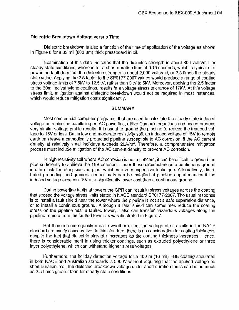
Therefore, mitigation of the pipeline induced voltage should not be based solely on the 15V criterion but also on AC corrosion thresholds. To calculate the current density, the soil resistivity must also be determined along the pipeline route. An example of the results from a series of these calculations is shown in Figure 1.
This figure displays three AC current densities versus the induced voltage and soil resistivity. It is apparent from the 20A/m2 threshold line, above which AC corrosion can occur, that AC corrosion is possible at an induced voltage of 15V if the soil resistivity is less than 15,000 Q-cm. Moreover, if the soil resistivity is 1000 0-cm, an induced voltage of less than 1 volt is required to reduce the AC current density to less than 20A/m2
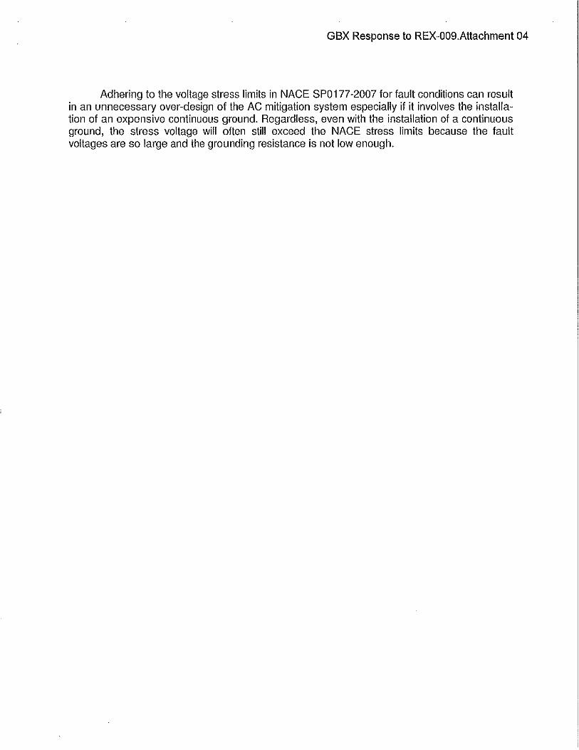
. As a 'rule-of-thumb', if the induced AC voltage, expressed in mV, is numerically greater than the soil resistivity, expressed in 0-cm, then additional AC voltage mitigation may be required to prevent AC corrosion. This requirement can significantly affect the mitigation design as is illustrated by the AC voltage and current density profiles in Figures 2 & 3.
The resistivity value, used in the previous equation to calculate the current density on a 1 cm2 circular holiday, is the resistivity of the earth at the holiday/earth interface, which is assumed to be the bulk soil resistivity. The application of cathodic protection can change the resistivity and therefore the spread resistance of the holiday. Nielsen141 has reported that, in a 0.01 M NaCI solution, the spread resistance decreases with the application of cathodic protection current due to the production of OH- ions in the reduction reaction at the steel/earth interface. This effect can increase the corrosion rate because the AC current density will increase. However, if the increase in pH results in the formation of a calcareous deposit, as would be expected in many soils, the spread resistance will increase and the AC corrosion rate will decrease.
GBX Response to REX-009.Attachment 04
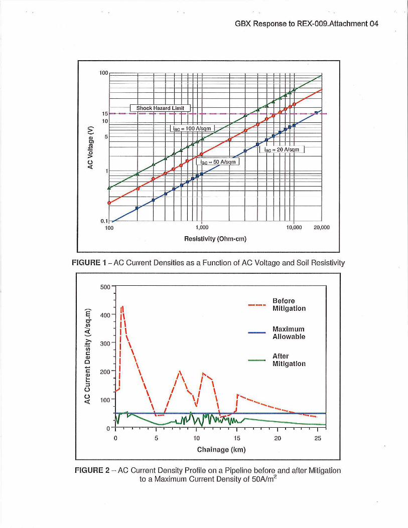
Note in this example, that to limit the calculated AC current density to 50A/m2 (5mA/cm2),
the induced voltage had to be well below 15V for most of the 25km length.
Mitigation of Induced AC Voltage in High Resistivity Soil
In high resistivity soil AC corrosion is less of a concern, but reducing the AC voltage to 15V can be very difficult, sometimes requiring a continuous ground which can be very expensive (e.g. $20/m installed during pipe installation or $1 00/m when retrofitted on an existing pipeline) Alternatively, gradient control mats can be installed at locations where the pipe or its appurtenances can be contacted by persons. GSA Standard C22.3l5l states that "permanent gradient control mats shall be used at all above-ground metal pipeline appurtenances, except test lead stations, if the touch voltage exceeds 15V". Installation of voltage gradient control mats can preclude the need for continuous grounding in favour of periodic grounding. The touch voltage on below grade piping does not need to be reduced to 15V. Neither the GSA standard nor the NACE standard stipulates a voltage limit on buried pipe. In Europe most national regulations require mitigation measures only when the voltage exceeds 50 to 65V under steady state conditions, depending on the country.l61 Allowing a pipeline in high resistivity soil to operate at these higher induced voltages can significantly reduce the cost of the mitigation system.
MITIGATING THE EFFECTS OF RESISTIVE COUPLING
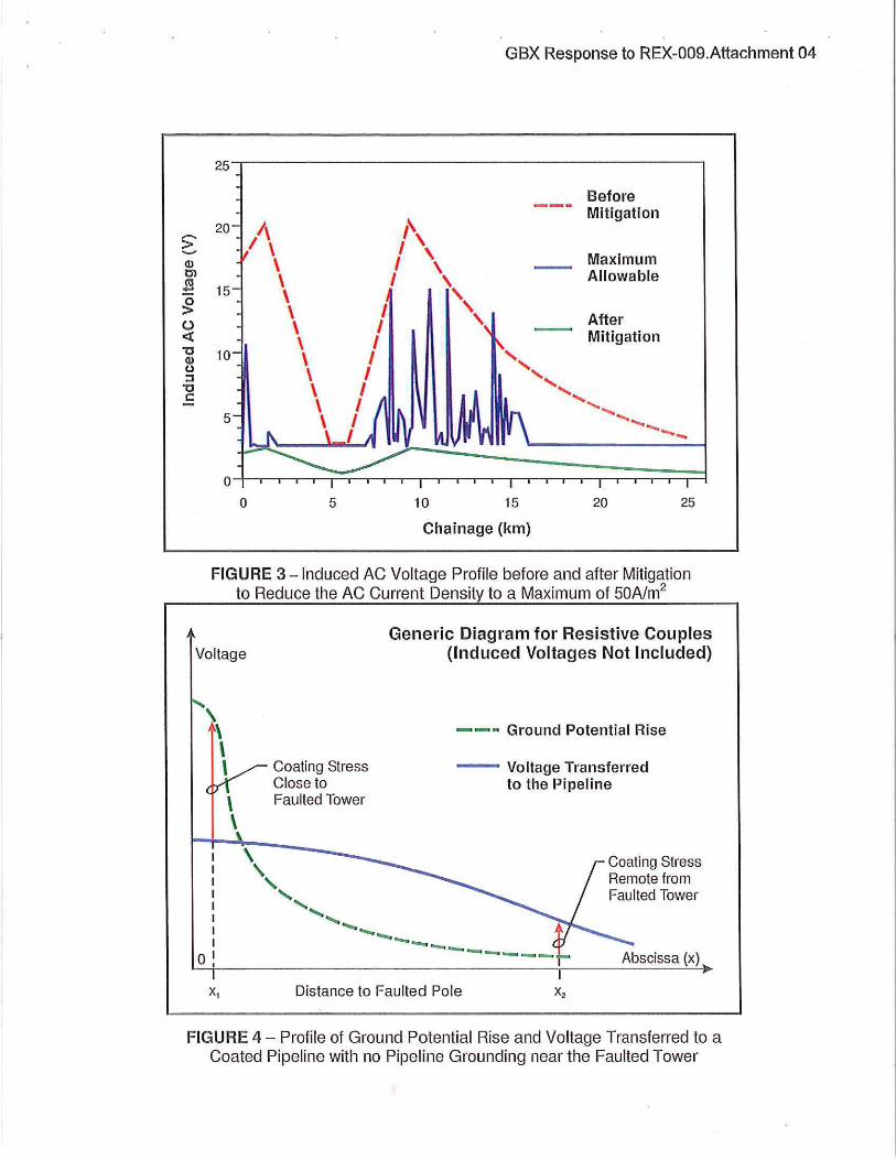
Powerline faults, although relatively rare, typically occur at towers and can introduce large fault currents into the earth, in the order of tens of kilo-amperes, which can cause damage to a nearby pipeline. This damage may be as severe as melting of the pipe wall as a result of an electrical arc or as mild as localized damage to the coating due to voltage stress. During a powerline fault there is an immediate ground potential rise (GPR) at the tower, which dissipates with distance from the tower and, which results in a voltage being transferred to the pipeline, as shown in Figure 4.
The voltage stress across the coating near to the tower, if the separation distance is 'x1 ', is the difference between the GPR and the voltage transferred to the pipeline. This stress voltage diminishes with distance remote from the tower. If the pipeline runs parallel to the powerline the induced voltage during the fault is typically opposite in phase to the GPR which increases the voltage stress across the coating.
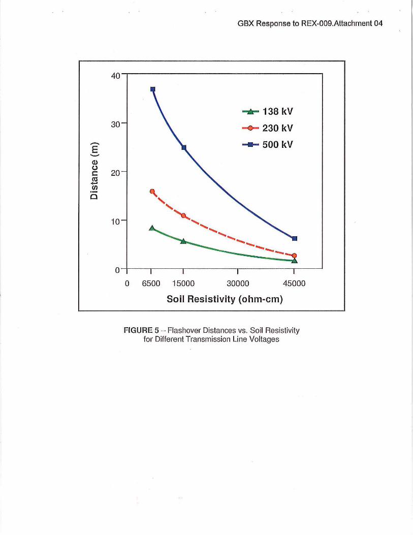
The best mitigation practice is to place the pipe a safe separation distance from the tower footing. The safe separation distance between a pipe and a powerline tower footing is a function of the powerline voltage rating and the soil resistivity as shown in Figure s.l7l
The safe separation distances are extrapolated values based on "a flashover initiated by lightning and sustained by the system voltage" and are considered conservative. To effectively apply this information requires a detailed soil resistivity survey along the route and calculation of the actual voltage rise near the tower.
Where a safe separation distance can not be maintained, the CEA report recommends that a fault shield, consisting of packaged galvanic anodes, be installed horizontally one meter from the pipeline on the tower side of the pipeline. Installing a linear grounding conductor parallel to the pipeline is often considered sufficient mitigation, giving more justification for the use of a continuous ground wire connected to the pipe through DC decouplers. However, there is a
GBX Response to REX-009.Attachment 04
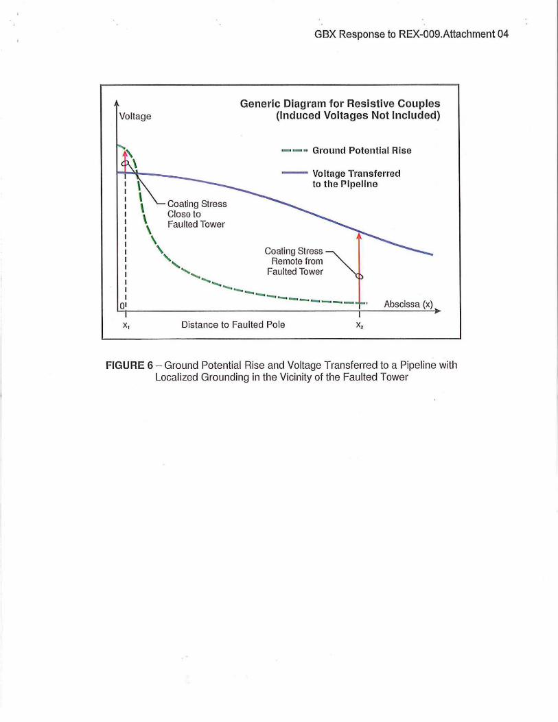
hazardous downside to this practice that is not widely recognized. That is; lowering the pipe-toground resistance of the pipe near the tower transfers hazardous voltages remote from the fault location as depicted in Figure 6.
Extensive grounding close to the faulted tower could bring the transferred voltage close to the GPR but significant coating stress and safety risl<s are transferred along the pipeline to locations remote from the faulted tower. Ideally the mitigation system should prevent arc damage to the pipeline and reduce the voltage stress across the coating on the pipeline near the tower, while not exceeding the voltage stress limits on the pipeline coating and not transmitting a shock hazard remote from the faulted tower. This ideal is elusive.
VOLTAGE STRESS LIMITS ON PIPELINE COATINGS
The voltage stress limit on a coating refers to the dielectric strength of the coating material and the voltage gradient that can cause a breakdown of its properties and cause a rupture of the coating. NACE Standard SP0177-2007 states the coating stress voltage limits "to be in the range of up to 2kV for tape wraps and coal tar enamels and 3 to 5 kV for fusion-bonded epoxy (FBE) and polyethylene coatings for short duration fault". Unfortunately, there is no literature reference for these values nor is there any clarification on whether they are for a short duration fault. Furthermore, there is some conflicting information which suggests that, these voltage limits are too conservative which then results in the design and installation of continuous grounding in an attempt to satisfy these overly conservative fault voltage limits.
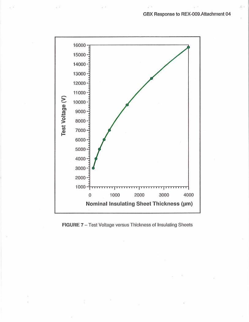
The Australian standard181 for the high voltage inspection of coatings recommends a voltage dependent on the coating thicl<ness as illustrated in Figure 7. For a 400 1-1m (16 mil) thick FBE coating the testing voltage is 5kV, but this is not a short duration applied voltage.
Dielectric Breakdown Voltage versus Coating Thickness
NACE standard on holiday detection of pipeline coatings191 gives the following equation for the minimum voltage for the inspection of pipeline coatings.
Testing Voltage = I ,250 ..J T (2)
where;
T = coating thickness in mils
Although this equation does not apply to very thin film coatings, at a coating thickness of 16 mils (400 1-1m) the minimum testing voltage is 5,000V which agrees with the Australian standard. There is no limit in the application time during inspection which therefore suggests that a steady state application of 5,000V would not cause a dielectric breakdown. This tends to indicate that the values in the SP0177- 2007 standard are more likely applicable to steady state conditions and not short term faults. Moreover, some pipe coating systems, such as extruded polythene or three layer polyethylene, have coating thicknesses of about 30 mils (0.75 mm). For these polyethylene coating thicknesses, based on the foregoing equation, a steady state testing voltage of 6,800 volts would not cause dielectric breakdown. Therefore, in choosing coating systems for pipelines that will be passing powerline towers, thicker coatings will provide extra dielectric strength and greater tolerance to stress from fault voltages.
GBX Response to REX-009.Attachment 04
Dielectric Breakdown Voltage versus Time
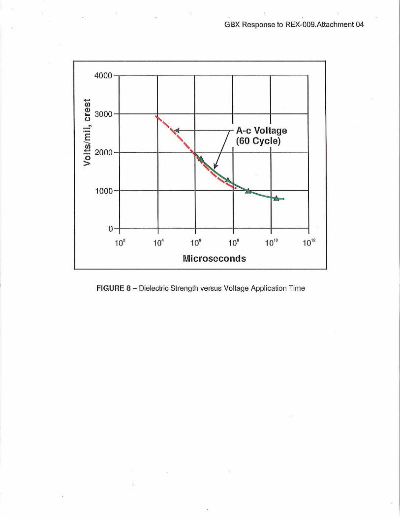
Dielectric breakdown is also a function of the time of application of the voltage as shown in Figure 8 for a 32 mil (800 !Jm) thick pressboard in oil.
Examination of this data indicates that the dielectric strength is about 800 volts/mil for steady state conditions, whereas for a short duration time of 0.15 seconds, which is typical of a powerline fault duration, the dielectric strength is about 2,000 volts/mil, or 2.5 times the steady state value. Applying the 2.5 factor to the SP0177-2007 values would produce a range of coating stress voltage limits of 7.5kV to 12.5kV, rather than 3kV to 5kV. Moreover, applying the 2.5 factor to the 30mil polyethylene coatings, results in a voltage stress tolerance of 17kV. At this voltage stress limit, mitigation against dielectric breakdown would not be required in most instances, which would reduce mitigation costs significantly.
SUMMARY
Most commercial computer programs, that are used to calculate the steady state induced voltage on a pipeline paralleling an AC powerline, utilize Carson's equations and hence produce very similar voltage profile results. It is usual to ground the pipeline to reduce the induced voltage to 15V or less. But in low and moderate resistivity soil, an induced voltage of 15V to remote earth can leave a cathodically protected pipeline susceptible to AC corrosion, if the AC current density at relatively small holidays exceeds 20Nm2
• Therefore, a comprehensive mitigation process must include mitigation of the AC current density to prevent AC corrosion.
In high resistivity soil where AC corrosion is not a concern, it can be difficult to ground the pipe sufficiently to achieve the 15V criterion. Under these circumstances a continuous ground is often installed alongside the pipe, which is a very expensive technique. Alternatively, distributed grounding and gradient control mats can be installed at pipeline appurtenances if the induced voltage exceeds 15V at a significantly lower cost than a continuous ground.
During powerline faults at towers the GPR can result in stress voltages across the coating that exceed the voltage stress limits stated in NACE standard SP0177-2007. The usual response is to install a fault shield near the tower where the pipeline is not at a safe separation distance, or to install a continuous ground. Although a fault shield can sometimes reduce the coating stress on the pipeline near a faulted tower, it also can transfer hazardous voltages along the pipeline remote from the faulted tower as was illustrated in Figure 7.
But there is some question as to whether or not the voltage stress limits in the NACE standard are overly conservative. In this standard, there is no consideration for coating thickness, despite the fact that dielectric strength increases as the coating thickness increases. Hence, there is considerable merit in using thicker coatings, such as extruded polyethylene or three layer polyethylene, which can withstand higher stress voltages.
Furthermore, the holiday detection voltage for a 400 m (16 mil) FBE coating stipulated in both NACE and Australian standards is 5000V without requiring that the applied voltage be short duration. Yet, the dielectric breakdown voltage under short duration faults can be as much as 2.5 times greater than for steady state conditions.
GBX Response to REX-009.Attachment 04
Adhering to the voltage stress limits in NACE SP0177-2007 for fault conditions can result in an unnecessary over-design of the AC mitigation system especially if it involves the installation of an expensive continuous ground. Regardless, even with the installation of a continuous ground, the stress voltage will often still exceed the NACE stress limits because the fault voltages are so large and the grounding resistance is not low enough.
-> -<1.1 C)
~ ~ u <(
GBX Response to REX-009.Attachment 04
100
/
~ L v ...-1~ Shock Hazard Limit L ~ 15
10
5
/
/ /
./ v /
0.1 100
/~
iac
~
v ...(~
...
__, / _....V' /
100A/sqm
./ t':
...cV / v ; I iac - 20 Alsqm [
~~ iac = 50 Als< m I L
.....
1,000 10,000 20,000
Resistivity (Ohm-em)
FIGURE 1-AC Current Densities as a Function of AC Voltage and Soil Resistivity
500
Before ........ ,, Mitigation E 400 1\ 0" 1\ (/)
Maximum -- I \ <( Allowable .......
I \ >- 300 .t:: I \ (/)
c I \ After Q) I \ 0 Mitigation .... I \ c 200 I \ ,, ... Q) .... I \ \ I ' ....
::s I \ I \ (.)
\ I ' I (.) 100 \ I \1 t ..... .....
<( \ I ~ J ..... ..... ..... __
-· 0
0 5 10 15 20 25
Chainage (km)
FIGURE 2 - AC Current Density Profile on a Pipeline before and after Mitigation to a Maximum Current Density of 50A/m2
-> -(!) Cl (lj
.:!:: 0 > (.) <(
"0 (!) (l ::::J "0 c
GBX Response to REX-009.Attachment 04
25
Before
1\ Mitigation
20 ,, I \ I \ I \ Maximum \
\ I \\ Allowable 15 \ ' ' \ I
\ I ' After
\ I Mitigation 10 \ I ..........
\ I .......... \ I ..... ..... \ I ..........
5 \ I ,, I ' ..... ..._
0 0 5 10 15 20 25
Chainage (km)
FIGURE 3 -Induced AC Voltage Profile before and after Mitigation to Reduce the AC Current Density to a Maximum of 50Nm2
Voltage Generic Diagram for Resistive Couples
(Induced Voltages Not Included)
I I I I I I I I
ol I
x,
\ \
\
Coating Stress Close to Faulted Tower
' ' ,, ..... , .......... --
--.. Ground Potential Rise
- Voltage Transferred to the Pipeline
------------
Coating Stress Remote from Faulted Tower
Distance to Faulted Pole
FIGURE 4 - Profile of Ground Potential Rise and Voltage Transferred to a Coated Pipeline with no Pipeline Grounding near the Faulted Tower
-E ..._ C1) (.) c m +"' (/) ·-c
GBX Response to REX-009.Attachment 04
40~-----------------------------------,
30
20
10
0 6500 15000
....... 138 kV
-<>- 230 kV
- 500 kV
30000 45000
Soil Resistivity (ohm-em)
FIGURE 5 - Flashover Distances vs. Soil Resistivity for Different Transmission Line Voltages
Voltage
\ \ \ \ \ \
Coating Stress Close to Faulted Tower
', ,, 0
............ ............
GBX Response to REX-009.Attachment 04
Generic Diagram for Resistive Couples (Induced Voltages Not Included)
--- Ground Potential Rise
- Voltage Transferred to the Pipeline
Coating Stress Remote from
Faulted Tower
------___ ..._ __ Abscissa (x)
Distance to Faulted Pole
FIGURE 6 - Ground Potential Rise and Voltage Transferred to a Pipeline with Localized Grounding in the Vicinity of the Faulted Tower
·'·.
GBX Response to REX-009.Attachment 04
16000
15000
14000
13000
12000
11000 -> 10000 .......... Q) C')
9000 cu --0 8000 > -tn 7000 ~
6000
5000
4000
3000
2000
1000
0 1000 2000 3000 4000
Nominal Insulating Sheet Thickness (Jlm)
FIGURE 7- Test Voltage versus Thickness of Insulating Sheets
4000
.... (J)
~ 3000 ... -
E -(J)
::: 2000 0 >
1000
0
GBX Response to REX-009.Attachment 04
~.\
' v j A-c Voltage
' (60 Cycle) ' ... ~
' ~ -......._ ......
Microseconds
FIGURE 8- Dielectric Strength versus Voltage Application Time
GBX Response to REX-009.Attachment 04
REFERENCES
1. Mitigation of Alternating Current and Lightning Effects on Metallic Structures and Corrosion control Systems, NACE International, Houston, Item No. 21021, 2007, p i
2. Control of External Corrosion on Underground or Submerged Metallic Piping Systems, NACE International, SP0169-2007, Section 6
3. 'AC Corrosion State-of-the-Art; Corrosion Rate, Mechanism, Mitigation Requirements', NACE International Technical Report, 2009
4. Nielsen, LV., Role of Alkalization in AC Induced Corrosion of Pipelines and Consequences Hereof in Relation to CP Requirements, NACE International, Corrosion 2005, Paper #188, March 2005
5. Principles and Practices of Electrical Coordination between Pipelines and Electric Supply Lines, CAN/GSA- C22.3 No.6 -M91, p14
6. Guide on the Influence of High Voltage AC Power Systems on Metallic Pipelines, CIGRE Working Group 36.02,1995, p19
7. 'Powerline Ground Fault Effects on Pipelines', CEA report# 239T817, Dec 1994, p59
8. Site Testing of Protective Coatings. Method 1 -Non-conductive Coatings- Continuity Testing- High Voltage (brush) Method, Australian Standard AS 3894.1-2002
9. High Voltage Electrical Inspection of Pipeline Coatings, NACE International SP0274-2004, Item #21010, p1