Embed Size (px)
Citation preview
North Korean Long-range Missile Debris Survey
January 18, 2013
Ministry of Defense
(English translation by D. Wright, revised 1/27/13)
□ General ○ Period: December 14, 2012 – January 9, 2013 ○ Venue: Agency for Defense Development (Daejeon) ○ Participants (52): From Intelligence HQ and agencies, Agency for Defense Development, KARI, and other relevant agencies ○ Debris studied: first stage engine, fuel tanks and 10 items ○ Galaxy-3 structure and principles
Intermediate stage
Oxidizer tank
Fuel tank
Engine
Stage 1
Stage 2
Stage 3
Satellite compartment
Oxidizer inlet
Fuel dispenser
Turbo pump to inject oxidizer
Turbo pump to inject fuel
Connecting parts
Diameter of stage 1: 2.4m Gross weight: 91 tons (estimated), including 48 tons of oxidize * Dimensions of stages 2, 3, and satellite compartment are estimated
□ Findings ○ Engine System
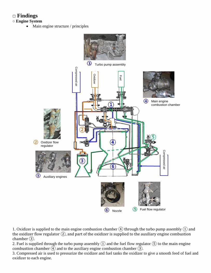
• Main engine structure / principles
1. Oxidizer is supplied to the main engine combustion chamber ④ through the turbo pump assembly ① and the oxidizer flow regulator ②, and part of the oxidizer is supplied to the auxiliary engine combustion chamber ③. 2. Fuel is supplied through the turbo pump assembly ① and the fuel flow regulator ⑤ to the main engine combustion chamber ④ and to the auxiliary engine combustion chamber ③. 3. Compressed air is used to pressurize the oxidizer and fuel tanks the oxidizer to give a smooth feed of fuel and oxidizer to each engine.
Turbo pump assembly
Main engine combustion chamber
Oxidizer flow regulator
Auxiliary engines
Nozzle Fuel flow regulator
Com
pressed air
Oxidizer
Fuel
Com
pressed air
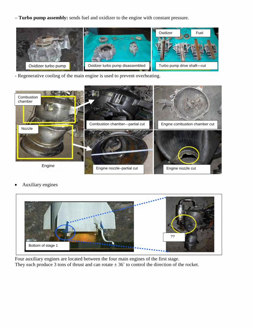
– Turbo pump assembly: sends fuel and oxidizer to the engine with constant pressure.
- Regenerative cooling of the main engine is used to prevent overheating.
• Auxiliary engines
Four auxiliary engines are located between the four main engines of the first stage. They each produce 3 tons of thrust and can rotate ± 36˚ to control the direction of the rocket.
Oxidizer turbo pump Oxidizer turbo pump disassembled Turbo pump drive shaft—cut
Combustion chamber
Nozzle
Engine
Combustion chamber—partial cut
Engine nozzle–partial cut
Engine combustion chamber cut
Engine nozzle cut
Bottom of stage 1
??
Oxidizer Fuel
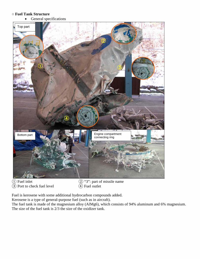
○ Fuel Tank Structure • General specifications
① Fuel inlet ② “3”: part of missile name ③ Port to check fuel level ④ Fuel outlet Fuel is kerosene with some additional hydrocarbon compounds added. Kerosene is a type of general-purpose fuel (such as in aircraft). The fuel tank is made of the magnesium alloy (AlMg6), which consists of 94% aluminum and 6% magnesium. The size of the fuel tank is 2/3 the size of the oxidizer tank.
Top part
Bottom part Engine compartment connecting ring
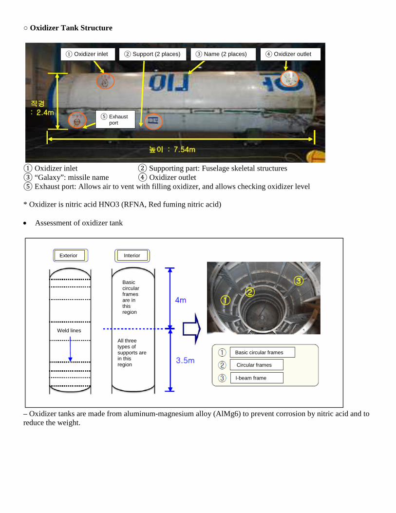
○ Oxidizer Tank Structure
① Oxidizer inlet ② Supporting part: Fuselage skeletal structures ③ “Galaxy”: missile name ④ Oxidizer outlet ⑤ Exhaust port: Allows air to vent with filling oxidizer, and allows checking oxidizer level * Oxidizer is nitric acid HNO3 (RFNA, Red fuming nitric acid) • Assessment of oxidizer tank
– Oxidizer tanks are made from aluminum-magnesium alloy (AlMg6) to prevent corrosion by nitric acid and to reduce the weight.
① Oxidizer inlet ② Support (2 places) ③ Name (2 places) ④ Oxidizer outlet
⑤ Exhaust port
Exterior Interior
Weld lines
Basic circular frames are in this region
All three types of supports are in this region
Basic circular frames
Circular frames
I-beam frame
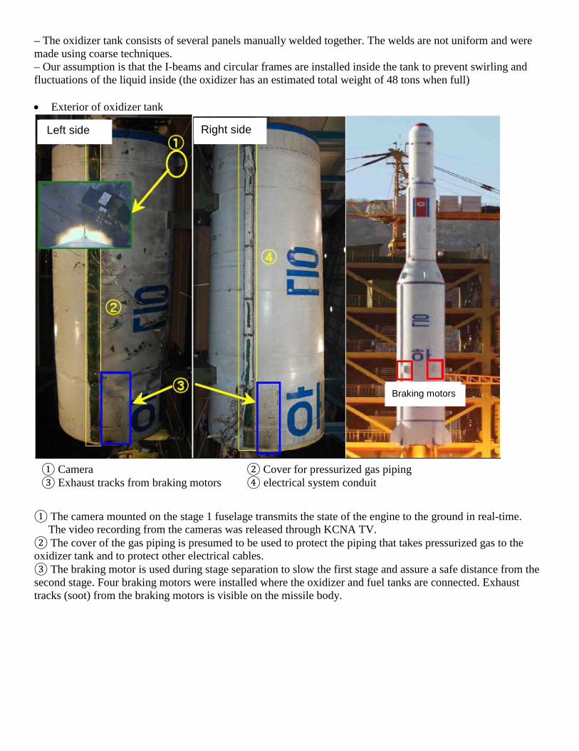
– The oxidizer tank consists of several panels manually welded together. The welds are not uniform and were made using coarse techniques. – Our assumption is that the I-beams and circular frames are installed inside the tank to prevent swirling and fluctuations of the liquid inside (the oxidizer has an estimated total weight of 48 tons when full) • Exterior of oxidizer tank
① The camera mounted on the stage 1 fuselage transmits the state of the engine to the ground in real-time. The video recording from the cameras was released through KCNA TV. ② The cover of the gas piping is presumed to be used to protect the piping that takes pressurized gas to the oxidizer tank and to protect other electrical cables. ③ The braking motor is used during stage separation to slow the first stage and assure a safe distance from the second stage. Four braking motors were installed where the oxidizer and fuel tanks are connected. Exhaust tracks (soot) from the braking motors is visible on the missile body.
① Camera ② Cover for pressurized gas piping ③ Exhaust tracks from braking motors ④ electrical system conduit
Left side Right side
Braking motors
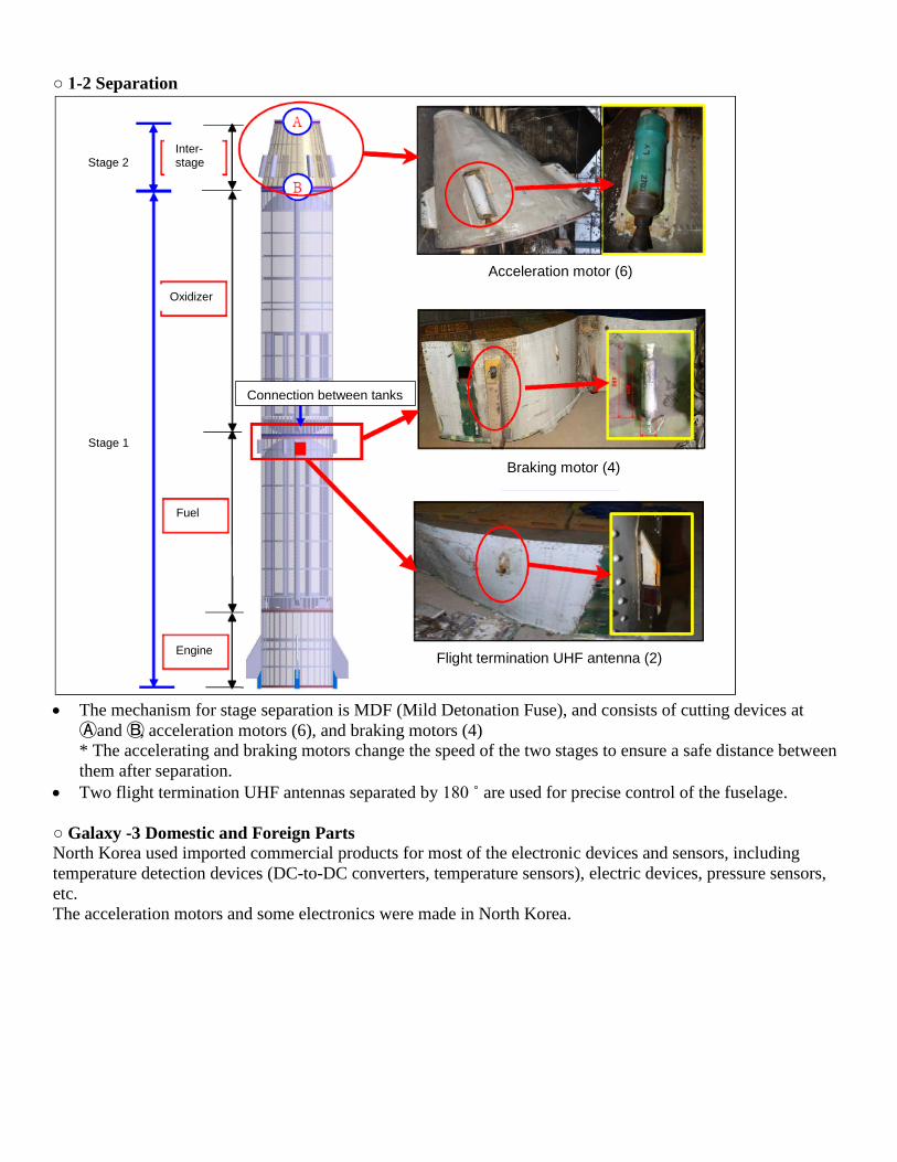
○ 1-2 Separation
• The mechanism for stage separation is MDF (Mild Detonation Fuse), and consists of cutting devices at
Ⓐ and Ⓑ, acceleration motors (6), and braking motors (4) * The accelerating and braking motors change the speed of the two stages to ensure a safe distance between them after separation.
• Two flight termination UHF antennas separated by 180 ˚ are used for precise control of the fuselage.
○ Galaxy -3 Domestic and Foreign Parts North Korea used imported commercial products for most of the electronic devices and sensors, including temperature detection devices (DC-to-DC converters, temperature sensors), electric devices, pressure sensors, etc. The acceleration motors and some electronics were made in North Korea.
Acceleration motor (6)
Braking motor (4)
Flight termination UHF antenna (2)
Connection between tanks
Inter-stage
Oxidizer
Fuel
Engine
Stage 2
Stage 1
Comprehensive Assessments ① Galaxy 3 used four 27-ton Nodong missile engines as expected, and uses four auxiliary engines each with 3 tons of thrust, for a total of 120-tons of thrust for the engine. The auxiliary engines enhance the thrust and control the direction of the rocket. ② The oxidizer and fuel tanks had the expected structure. They are confirmed to be made of lightweight aluminum-magnesium alloys to prevent corrosion by HNO3 and reduce the weight. ③ Temperature detection devices (DC-to-DC converters, temperature sensors), pressure sensors, and some electronic devices and wires are commercial imported products, but we presume a majority of the other parts were made by North Korea. ④ Despite the limits on North Korea’s procurement of advanced technology and parts due to sanctions by the international community, we assess that through experimentation and experience they enhanced the capability of their long-range missile.