Embed Size (px)
Citation preview
PERMIT BOOK STATE OF MISSOURI
~~j DEPARTMENT OF NATURAL RESOURCES
MISSOURI AIR CONSERVATION COMMISSION
PERMIT TO CONSTRUCT Under the authority of RSMo 643 and the Federal Clean Air Act the applicant is authorized to construct the air contaminant source(s) described below, in accordance with the laws, rules and conditions as set forth herein.
Permit Number: 08 2 0 1 0 - 0 03 Project Number: 2008-09-024
Parent Company: Noranda. Inc.
Parent Company Address: 1 Brentwood Commons, Suite 175-250 Old Hickory Road, Brentwood, TN 37027
Installation Name: Noranda Aluminum, Inc.
Installation Address: #1 Robbins Road, St. Jude Industrial Park, P.O. Box 70, New Madrid, MO 63869
Location Information: New Madrid County. S32, T22N, R14E
Application for Authority to Construct was made for: Increase aluminum production to 650,000,000 pounds per year at an existing primary aluminum reduction plant in New Madrid, Missouri. This review was conducted in accordance with Section (8), Missouri State Rule 10 CSR 10-6.060, Construction Permits Required.
D Standard Conditions (on reverse) are applicable to this permit.
[l1'~tandard Conditions (on reverse) and Special Conditions are applicable to this permit.
AUG - 4 2010
EFFECTIVE DATE OR OR DESIGNEE RTMENT OF NATURAL RESOUR

STANDARD CONDITIONS: Permission to construct may be revoked if you fail to begin construction or modification within 18 months from the effective date of this permit. Permittee should notify the Air Pollution Control Program if construction or modification is not started within 18 months after the effective date of this permit, or if construction or modification is suspended for one year or more.
You will be in violation of 10 CSR 10-6.060 if you fail to adhere to the specifications and conditions listed in your application, this permit and the project review. In the event that there is a discrepancy between the permit application and this permit, the conditions of this permit shall take precedence. Specifically, all air contaminant control devises shall be operated and maintained as specified in the application, associated plans and specifications.
You must notify the departments’ Air Pollution Control Program of the anticipated date of start up of this (these) air contaminant sources(s). The information must be made available not more than 60 days but at least 30 days in advance of this date. Also, you must notify the Department of Natural Resources Regional office responsible for the area within which you are located within 15 days after the actual start up of this (these) air contaminant source(s). A copy of this permit and permit review shall be kept at the installation address and shall be made available to Department of Natural Resources’ personnel upon request. You may appeal this permit or any of the listed special conditions to the Administrative Hearing Commission (AHC), P.O. Box 1557, Jefferson City, MO 65102, as provided in RSMo 643.075.6 and 621.250.3. If you choose to appeal, you must file a petition with the AHC within 30 days after the date this decision was mailed or the date it was delivered, whichever date was earlier. If any such petition is sent by registered mail or certified mail, it will be deemed filed on the date it is mailed. If it is sent by any method other than registered mail or certified mail, it will be deemed filed on the date it is received by the AHC. If you choose not to appeal, this certificate, the project review and your application and associated correspondence constitutes your permit to construct. The permit allows you to construct and operate your air contaminant sources(s), but in no way relieves you of your obligation to comply with all applicable provisions of the Missouri Air Conservation Law, regulations of the Missouri Department of Natural Resources and other applicable federal, state and local laws and ordinances. The Air Pollution Control Program invites your questions regarding this air pollution permit. Please contact the Construction Permit Unit at (573) 751-4817. If you prefer to write, please address your correspondence to the Missouri Department of Natural Resources, Air Pollution Control Program, P.O. Box 176, Jefferson City, MO 65102-0176, attention: Construction Permit Unit.

Page No. 3 Permit No. Project No. 2008-09-024
SPECIAL CONDITIONS:
The permittee is authorized to construct and operate subject to the following special conditions:
The special conditions listed in this permit were included based on the authority granted the Missouri Air Pollution Control Program by the Missouri Air Conservation Law (specifically 643.075) and by the Missouri Rules listed in Title 10, Division 10 of the Code of State Regulations (specifically 10 CSR 10-6.060). For specific details regarding conditions, see 10 CSR 10-6.060 paragraph (12)(A)10. “Conditions required by permitting authority.” Noranda Aluminum, Inc. New Madrid County, S32, T22N, R14E 1. Superseding Condition
The conditions of this permit supersede all special conditions found in the previously issued construction permit (Permit Number 102004-001) and associated amendments from the Air Pollution Control Program if the project authorized by this permit goes forward. If the project authorized by this permit is cancelled or otherwise does not go forward then the provisions of Permit Number 102004-001 (as amended) shall continue to apply.
2. Best Available Control Technology (BACT) Emission Limitation for Sulfur Oxide
(SOx) A. Noranda Aluminum, Inc. shall not discharge SOx emissions into the
atmosphere in excess of 6,077 tons per year from the entire installation (refer to Appendix E for a list of emission units) in any consecutive 12-month period.
B. Noranda Aluminum, Inc. shall not exceed the following SOX limitations:
i) 405.17 pound per hour for all three Carbon Bake Furnaces, combined
ii) 428.6 pound per hour for the Potline 1 iii) 430.1 pound per hour for the Potline 2 iv) 256.0 pound per hour for the Potline 3 East v) 256.0 pound per hour for the Potline 3 West
C. Noranda Aluminum, Inc. shall not use coke with a sulfur content greater
than 3.0% or pitch with a sulfur content greater than 0.8%
D. Noranda Aluminum, Inc. shall maintain a record of the sulfur content of the alumina, pitch and coke used as raw materials, and the baked anode produced from the carbon bake furnaces. The sulfur contents must be tested according to Special Condition 15. The sulfur contents must be used in determining SOX emissions from the carbon bake furnaces and potlines.

Page No. 4 Permit No. Project No. 2008-09-024
SPECIAL CONDITIONS:
The permittee is authorized to construct and operate subject to the following special conditions:
E. Noranda Aluminum, Inc. shall determine compliance with the limit established in Special Condition 2.A. using the mass balance methodology found in Appendix A.
F. Attachment A and Attachment B or equivalent forms approved by the Air
Pollution Control Program shall be used to demonstrate compliance with Special Conditions 2(A) and 2(B). A copy of any sulfur content verification documentation shall be kept with Attachment A.
3. BACT Emission Limitation for Potline 1 and Potline 2
A. Particulate Matter (PM) and Particulate Matter less than 10 microns in diameter (PM10) (filterable and condensable) [BACT] i) Noranda Aluminum, Inc. shall not exceed the following PM grain
loading annual rates: a) 0.0018 grains per dry standard cubic feet (gr/dscf) for Potline
1 Monitor (EP59), b) 0.0018 gr/dscf for Potline 2 Monitor (EP60), and c) 0.01 gr/dscf for Potline 1 & 2 Stack (EP61).
ii) Noranda Aluminum, Inc. shall not exceed the following BACT limitations for PM10 (filterable and condensable): a) 52.68 pounds per hour and 4.59 pound per ton Al produced
for Potline 1 Monitor (EP59), b) 33.54 pounds per hour and 2.71 pound per ton Al produced
for Potline 2 Monitor (EP60), and c) 56.69 pounds per hour and2.01 pound per ton Al produced
for Potline 1 & 2 Stack (EP61). iii) Noranda Aluminum, Inc. shall not exceed the following annual PM10
(filterable and condensable) limitations: a) 136.3 tons per any 12-month consecutive period for Potline
2 Monitor (EP60), and b) 202.5 tons per any 12-month consecutive period for Potline
1 & 2 Stack (EP61) c) Noranda Aluminum, Inc. shall develop an emission factor
(pound/ton aluminum) that shall be used in conjunction with Attachment C or equivalent forms approved by the Air Pollution Control Program to demonstrate compliance with Special Conditions 3(A)(iii)(a) and (b).
d) An annual average of results from all testing required in Special Condition 16 during a 12-month calendar period shall be used to establish the emission factor.
B. Particulate Matter less than 2.5 microns in diameter (PM2.5) [BACT]
Page No. 5 Permit No. Project No. 2008-09-024
SPECIAL CONDITIONS:
The permittee is authorized to construct and operate subject to the following special conditions:
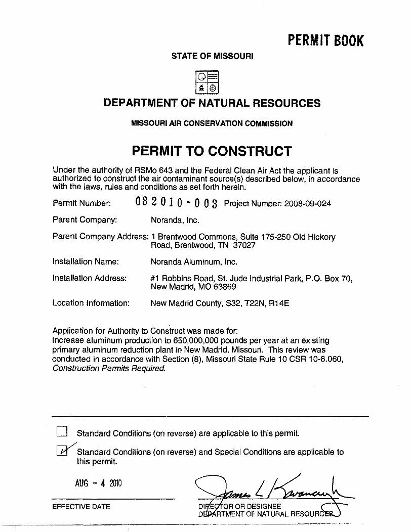
i) Potline 1 Monitor (EP59) emissions shall not exceed the BACT limitation for PM2.5 of 25.43 pounds per hour.
ii) Potline 2 Monitor (EP60) emissions shall not exceed the BACT limitation for PM2.5 of 16.19 pounds per hour.
iii) Potline 1 & 2 Stack (EP61) emissions shall not exceed the BACT limitation for PM2.5 of 27.37 pounds per hour.
C. Carbon Monoxide (CO) [BACT]
i) Potline 1 Monitor (EP59) emissions shall not exceed the BACT limitation for CO of 110 pounds per hour and 9.58 pound per ton Al produced.
ii) Potline 2 Monitor (EP60) emissions shall not exceed the BACT limitation for CO of 110 pounds per hour and 9.58 pound per ton Al produced.
iii) Noranda Aluminum, Inc. shall not exceed the BACT limitation for CO of 5,520 pounds per hour and 240.4 pound per ton Al produced from Potline 1 &2 Stack (EP61).
D. Fluorides [BACT]
i) Noranda Aluminum, Inc. shall not exceed the BACT limitation for combined fluorides of 1.9 pounds per ton of aluminum produced from Potline 1 Monitor (EP59) and Potline 1 & 2 Stack (EP61).
ii) Noranda Aluminum, Inc. shall not exceed the BACT limitation for combined fluorides of 1.9 pounds per tons of aluminum produced from Potline 2 Monitor (EP60) and Potline 1 & 2 Stack (EP61).
4. BACT Emission Limitation for Potline 3 (East and West)
A. PM/PM10 (filterable and condensable) [BACT] i) Noranda Aluminum, Inc. shall not exceed the following PM grain
loading annual rates: a) 0.00075 gr/dscf for Potline 3 Monitor (EP64) b) 0.01 gr/dscf for Potline 3 East Stack (EP62), and c) 0.01 gr/dscf for Potline 3 West Stack (EP63).
ii) Noranda Aluminum, Inc. shall not exceed the following BACT limitations for PM10(filterable and condensable): a) 25.77 pounds per hour and 1.82 pound per ton Al produced
for Potline 3 Monitor (EP64), b) 16.59 pounds per hour and 2.04 pound per ton Al produced
from Potline 3 East Stack (EP62), and c) 16.59 pounds per hour and 2.04 pound per ton Al produced
from Potline 3 West Stack (EP63). iii) Noranda Aluminum, Inc. shall not exceed the following annual PM10
Page No. 6 Permit No. Project No. 2008-09-024
SPECIAL CONDITIONS:
The permittee is authorized to construct and operate subject to the following special conditions:
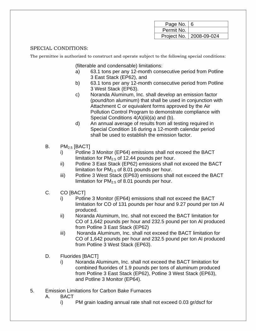
(filterable and condensable) limitations: a) 63.1 tons per any 12-month consecutive period from Potline
3 East Stack (EP62), and b) 63.1 tons per any 12-month consecutive period from Potline
3 West Stack (EP63). c) Noranda Aluminum, Inc. shall develop an emission factor
(pound/ton aluminum) that shall be used in conjunction with Attachment C or equivalent forms approved by the Air Pollution Control Program to demonstrate compliance with Special Conditions 4(A)(iii)(a) and (b).
d) An annual average of results from all testing required in Special Condition 16 during a 12-month calendar period shall be used to establish the emission factor.
B. PM2.5 [BACT]
i) Potline 3 Monitor (EP64) emissions shall not exceed the BACT limitation for PM2.5 of 12.44 pounds per hour.
ii) Potline 3 East Stack (EP62) emissions shall not exceed the BACT limitation for PM2.5 of 8.01 pounds per hour.
iii) Potline 3 West Stack (EP63) emissions shall not exceed the BACT limitation for PM2.5 of 8.01 pounds per hour.
C. CO [BACT]
i) Potline 3 Monitor (EP64) emissions shall not exceed the BACT limitation for CO of 131 pounds per hour and 9.27 pound per ton Al produced.
ii) Noranda Aluminum, Inc. shall not exceed the BACT limitation for CO of 1,642 pounds per hour and 232.5 pound per ton Al produced from Potline 3 East Stack (EP62)
iii) Noranda Aluminum, Inc. shall not exceed the BACT limitation for CO of 1,642 pounds per hour and 232.5 pound per ton Al produced from Potline 3 West Stack (EP63).
D. Fluorides [BACT]
i) Noranda Aluminum, Inc. shall not exceed the BACT limitation for combined fluorides of 1.9 pounds per tons of aluminum produced from Potline 3 East Stack (EP62), Potline 3 West Stack (EP63), and Potline 3 Monitor (EP64).
5. Emission Limitations for Carbon Bake Furnaces
A. BACT i) PM grain loading annual rate shall not exceed 0.03 gr/dscf for
Page No. 7 Permit No. Project No. 2008-09-024
SPECIAL CONDITIONS:
The permittee is authorized to construct and operate subject to the following special conditions:
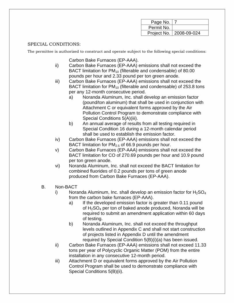
Carbon Bake Furnaces (EP-AAA). ii) Carbon Bake Furnaces (EP-AAA) emissions shall not exceed the
BACT limitation for PM10 (filterable and condensable) of 80.00 pounds per hour and 2.33 pound per ton green anode.
iii) Carbon Bake Furnaces (EP-AAA) emissions shall not exceed the BACT limitation for PM10 (filterable and condensable) of 253.8 tons per any 12-month consecutive period. a) Noranda Aluminum, Inc. shall develop an emission factor
(pound/ton aluminum) that shall be used in conjunction with Attachment C or equivalent forms approved by the Air Pollution Control Program to demonstrate compliance with Special Conditions 5(A)(iii).
b) An annual average of results from all testing required in Special Condition 16 during a 12-month calendar period shall be used to establish the emission factor.
iv) Carbon Bake Furnaces (EP-AAA) emissions shall not exceed the BACT limitation for PM2.5 of 66.9 pounds per hour.
v) Carbon Bake Furnaces (EP-AAA) emissions shall not exceed the BACT limitation for CO of 270.69 pounds per hour and 10.9 pound per ton green anode.
vi) Noranda Aluminum, Inc. shall not exceed the BACT limitation for combined fluorides of 0.2 pounds per tons of green anode produced from Carbon Bake Furnaces (EP-AAA).
B. Non-BACT
i) Noranda Aluminum, Inc. shall develop an emission factor for H2SO4 from the carbon bake furnaces (EP-AAA). a) If the developed emission factor is greater than 0.11 pound
of H2SO4 per ton of baked anode produced, Noranda will be required to submit an amendment application within 60 days of testing.
b) Noranda Aluminum, Inc. shall not exceed the throughput levels outlined in Appendix C and shall not start construction of projects listed in Appendix D until the amendment required by Special Condition 5(B)(i)(a) has been issued.
ii) Carbon Bake Furnaces (EP-AAA) emissions shall not exceed 11.33 tons per year of Polycyclic Organic Matter (POM) from the entire installation in any consecutive 12-month period.
iii) Attachment D or equivalent forms approved by the Air Pollution Control Program shall be used to demonstrate compliance with Special Conditions 5(B)(ii).

Page No. 8 Permit No. Project No. 2008-09-024
SPECIAL CONDITIONS:
The permittee is authorized to construct and operate subject to the following special conditions:
6. Non-BACT Emission Limits for Carbon Bake Furnaces and Potlines A. Noranda Aluminum, Inc. shall develop an emission factor for VOC and
NOX from the Carbon Bake Furnaces and the Potlines. i) Noranda Aluminum, Inc. shall submit a comparison of the tested
emission factors to the emission factors submitted in the application within 60 days of testing for approval.
ii) If the developed emission factor results in emission rates greater than those submitted in the original application, Noranda will be required to submit an amendment application within 60 days of submitting the comparison report.
iii) Noranda Aluminum, Inc. shall not exceed the throughput levels outlined in Appendix C and shall not start construction of projects listed in Appendix D until the amendment has been issued.
B. Noranda Aluminum, Inc. shall determine the conversion of SO2 into
Carbonyl Sulfide (COS) and develop an emission factor for COS through testing required in Special Condition 16.
C. Noranda Aluminum, Inc. shall not discharge COS emissions into the
atmosphere in excess of 219.4 tons per year from the entire installation (refer to Appendix E for a list of emission units) in any consecutive 12-month period.
D. Attachment E or equivalent forms approved by the Air Pollution Control
Program shall be used to demonstrate compliance with Special Conditions 6(C).
E. Noranda Aluminum, Inc. shall verify the beryllium, manganese, and nickel
content of coke and alumina by testing: i) The beryllium concentration in alumina shall not exceed 4 parts per
million (ppm); ii) The manganese content in alumina shall not exceed 0.001% by
weight; iii) The nickel concentration in coke shall not exceed 0.023 ppm; and iv) The nickel content in alumina shall not exceed 0.002% by weight.
F. The testing required in Special Condition 6(E) shall be conducted on a
sample of coke and alumina at least once every year. Noranda Aluminum, Inc. shall maintain a record of all test results.
7. BACT Control Equipment Requirements – PM10, PM2.5 and Fluoride Emissions
A. Noranda Aluminum, Inc. shall control emissions from Potlines 1, 2 & 3 and

Page No. 9 Permit No. Project No. 2008-09-024
SPECIAL CONDITIONS:
The permittee is authorized to construct and operate subject to the following special conditions:
all three carbon bake furnaces using a dry alumina scrubber connected to baghouses as specified in the permit application to achieve BACT.
B. The dry alumina scrubbers and baghouses must be in use at all times
when the aluminum potlines or the carbon bake furnaces are in operation. The dry alumina scrubber and baghouse shall be operated and maintained in accordance with the manufacturer’s specifications.
C. The baghouses associated with the dry alumina scrubber shall be
equipped with a gauge or meter, which indicates the pressure drop across the control device. These gauges or meters shall be located such that the DNR employees may easily observe them. Replacement filters for the baghouses shall be kept on hand at all times. The bags shall be made of fibers appropriate for operating conditions expected to occur (i.e. temperature limits, acidic and alkali resistance, and abrasion resistance).
D. Each dry alumina scrubber shall be equipped with a flow meter that
indicates the fresh alumina flow through the scrubber. These gauges and meters shall be located in such a way they may be easily observed by Department of Natural Resources’ personnel
E. Noranda Aluminum, Inc. shall monitor and record the pressure drop
through the baghouse and the fresh alumina flow rate through the scrubber at least once every twenty-four (24) hours. The pressure drop through the baghouse and the fresh alumina flow rate shall be maintained within the design conditions specified by the manufacturer’s performance warranty and/or testing conditions.
F. Noranda Aluminum, Inc. shall maintain an operating and maintenance log
for the control systems (scrubber with baghouse) for a period of (60) sixty months which shall include the following: i) Incidents of malfunction, with impact on emissions, duration of
event, probable cause, and corrective actions; and ii) Maintenance activities, with inspection schedule, repair actions, and
replacements, etc. iii) A written record of regular inspection schedule, the date and results
of all inspections including any actions or maintenance activities that result from that inspection.
8. BACT Capture Equipment Requirements – Potline PM10, PM2.5 and Fluoride
Page No. 10 Permit No. Project No. 2008-09-024
SPECIAL CONDITIONS:
The permittee is authorized to construct and operate subject to the following special conditions:
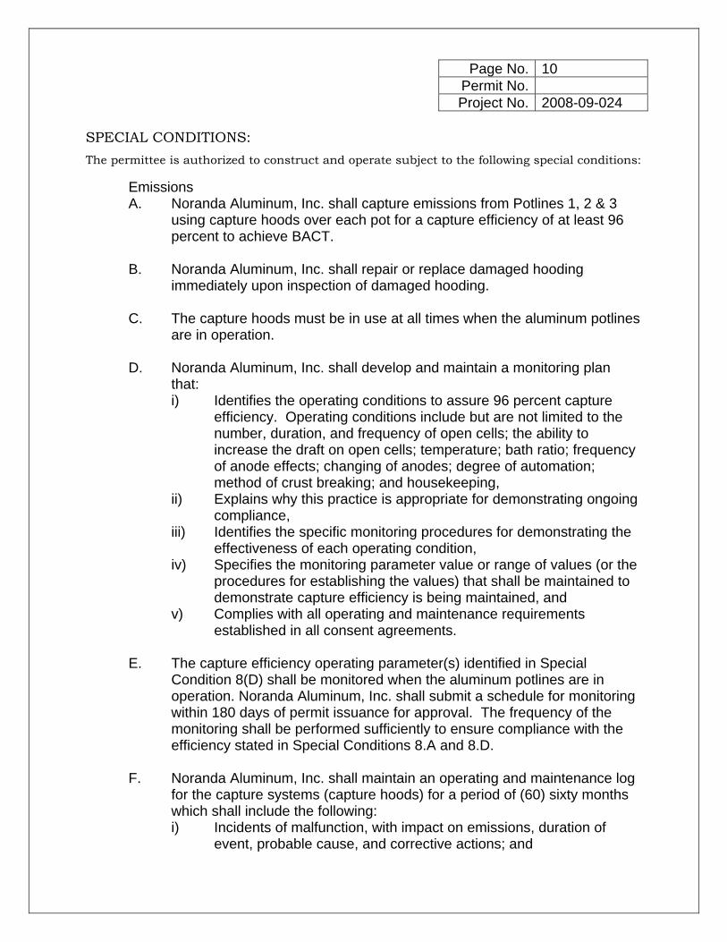
Emissions A. Noranda Aluminum, Inc. shall capture emissions from Potlines 1, 2 & 3
using capture hoods over each pot for a capture efficiency of at least 96 percent to achieve BACT.
B. Noranda Aluminum, Inc. shall repair or replace damaged hooding
immediately upon inspection of damaged hooding.
C. The capture hoods must be in use at all times when the aluminum potlines are in operation.
D. Noranda Aluminum, Inc. shall develop and maintain a monitoring plan
that: i) Identifies the operating conditions to assure 96 percent capture
efficiency. Operating conditions include but are not limited to the number, duration, and frequency of open cells; the ability to increase the draft on open cells; temperature; bath ratio; frequency of anode effects; changing of anodes; degree of automation; method of crust breaking; and housekeeping,
ii) Explains why this practice is appropriate for demonstrating ongoing compliance,
iii) Identifies the specific monitoring procedures for demonstrating the effectiveness of each operating condition,
iv) Specifies the monitoring parameter value or range of values (or the procedures for establishing the values) that shall be maintained to demonstrate capture efficiency is being maintained, and
v) Complies with all operating and maintenance requirements established in all consent agreements.
E. The capture efficiency operating parameter(s) identified in Special
Condition 8(D) shall be monitored when the aluminum potlines are in operation. Noranda Aluminum, Inc. shall submit a schedule for monitoring within 180 days of permit issuance for approval. The frequency of the monitoring shall be performed sufficiently to ensure compliance with the efficiency stated in Special Conditions 8.A and 8.D.
F. Noranda Aluminum, Inc. shall maintain an operating and maintenance log
for the capture systems (capture hoods) for a period of (60) sixty months which shall include the following: i) Incidents of malfunction, with impact on emissions, duration of
event, probable cause, and corrective actions; and

Page No. 11 Permit No. Project No. 2008-09-024
SPECIAL CONDITIONS:
The permittee is authorized to construct and operate subject to the following special conditions:
ii) Maintenance activities, with inspection schedule, repair actions, and replacements, etc.
iii) A written record of regular inspection schedule, the date and results of all inspections including any actions or maintenance activities that result from that inspection.
9. BACT Control Requirements – CO Emissions
A. Noranda Aluminum, Inc. shall use good design and operation practices at all times in order to meet BACT for the aluminum potlines.
B. Noranda Aluminum, Inc. shall use low energy burner technology at all
times in order to meet BACT for the carbon bake furnaces. 10. Non-BACT Capture Equipment Requirements
A. The material storage, handling and process equipment, listed in Appendix E, shall be enclosed by ductwork or located in a building. The enclosures/buildings shall be maintained under negative pressure and exhausted to baghouses.
B. Noranda Aluminum, Inc. shall demonstrate negative pressure by using visual indicators, such as negative pressure gauges, at each openings of the enclosure. Visual indicators other than a negative pressure gauge must be approved prior to use.
C. Noranda Aluminum, Inc. shall perform a visual indicator check for each emission point at least once in every 24-hour period while the material handling, storage, and processing equipment are in operation.
D. Noranda Aluminum, Inc. shall maintain an operating and maintenance log for the material storage, handling equipment and process equipment which shall include the following: i) Incidents of malfunction, with impact on emissions, duration of
event, probable cause, and corrective actions. ii) Maintenance activities, with inspection schedule, repair actions, and
replacements, etc. iii) A record of regular inspection schedule, the date and results of all
inspections, including any actions or maintenance activities that result from the inspections. Either paper copy or electronic formats are acceptable.

Page No. 12 Permit No. Project No. 2008-09-024
SPECIAL CONDITIONS:
The permittee is authorized to construct and operate subject to the following special conditions:
11. Fuel Usage Restrictions A. Noranda Aluminum, Inc. shall not combust natural gas in an amount
greater than 832 million cubic feet (MMCF) from the entire installation (refer to Appendix E for a list of emission units) less the carbon bake furnaces during any 12-month consecutive period.
B. Attachment G or equivalent forms approved by the Air Pollution Control
Program shall be used to demonstrate compliance with Special Conditions 11(A).
C. Noranda Aluminum, Inc. shall combust propane only during times of
natural gas curtailment. D. A report must be submitted to the Air Pollution Control Program within 15
days of the use of propane. The report shall included at a minimum: i) Reasons for the natural gas curtailment, ii) Duration of propane usage, iii) Amount of propane used, and iv) Emissions calculations associated with the combustion of the
propane. 12. Haul Road Requirements
A. Noranda Aluminum, Inc. shall limit its daily haul road emissions to 38.8 pounds per day and annual haul road emissions to 2.9 tons per any 12-month consecutive period.
B. Noranda Aluminum, Inc. shall submit a compliance demonstration plan
within 90 days of issuance of this construction permit. The plan will contain at the least: i) daily recordkeeping of the weight (tons) of materials received and
shipped by truck per day, and number of trucks. In determining actual emissions, an average truck weight may be used in determining compliance. Attachment F, or equivalent form(s), shall be used for this purpose.
ii) silt loading of the haul road iii) the emissions equation from AP-42 used in calculating actual
emissions iv) length of the haul road v) a Fugitive Dust Control Plan (FDCP) to control emissions from haul
roads. Noranda Aluminum, Inc. must also provide details on how the plan will be maintained and implemented.
Page No. 13 Permit No. Project No. 2008-09-024
SPECIAL CONDITIONS:
The permittee is authorized to construct and operate subject to the following special conditions:
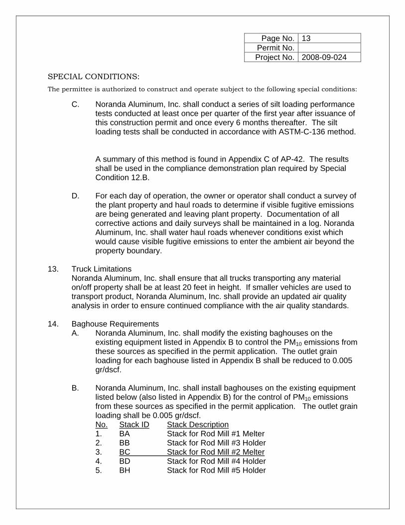
C. Noranda Aluminum, Inc. shall conduct a series of silt loading performance tests conducted at least once per quarter of the first year after issuance of this construction permit and once every 6 months thereafter. The silt loading tests shall be conducted in accordance with ASTM-C-136 method. A summary of this method is found in Appendix C of AP-42. The results shall be used in the compliance demonstration plan required by Special Condition 12.B.
D. For each day of operation, the owner or operator shall conduct a survey of
the plant property and haul roads to determine if visible fugitive emissions are being generated and leaving plant property. Documentation of all corrective actions and daily surveys shall be maintained in a log. Noranda Aluminum, Inc. shall water haul roads whenever conditions exist which would cause visible fugitive emissions to enter the ambient air beyond the property boundary.
13. Truck Limitations
Noranda Aluminum, Inc. shall ensure that all trucks transporting any material on/off property shall be at least 20 feet in height. If smaller vehicles are used to transport product, Noranda Aluminum, Inc. shall provide an updated air quality analysis in order to ensure continued compliance with the air quality standards.
14. Baghouse Requirements
A. Noranda Aluminum, Inc. shall modify the existing baghouses on the existing equipment listed in Appendix B to control the PM10 emissions from these sources as specified in the permit application. The outlet grain loading for each baghouse listed in Appendix B shall be reduced to 0.005 gr/dscf.
B. Noranda Aluminum, Inc. shall install baghouses on the existing equipment
listed below (also listed in Appendix B) for the control of PM10 emissions from these sources as specified in the permit application. The outlet grain loading shall be 0.005 gr/dscf. No. Stack ID Stack Description 1. BA Stack for Rod Mill #1 Melter 2. BB Stack for Rod Mill #3 Holder 3. BC Stack for Rod Mill #2 Melter 4. BD Stack for Rod Mill #4 Holder 5. BH Stack for Rod Mill #5 Holder

Page No. 14 Permit No. Project No. 2008-09-024
SPECIAL CONDITIONS:
The permittee is authorized to construct and operate subject to the following special conditions:
C. The baghouses specified by Special Condition 14.A, and 14.B. must be in use at all times when the associated piece of equipment is in operation, and shall be operated and maintained in accordance with the manufacturer's specifications. These baghouses shall be equipped with a gauge or meter, which indicates the pressure drop across the control
device. These gauges or meters shall be located such that the Department of Natural Resources’ employees may easily observe them.
D. Noranda Aluminum, Inc. shall monitor and record the operating pressure drop across the baghouses specified by Special Condition 14.A, and 14.B. at least once in every 24-hour period when the associated equipment is in operation.
E. Appropriate replacement filters identified in the Baghouse Compliance Plan in Special Condition 20 for each baghouse specified by Special Condition 14.A, and 14.B. shall be kept on hand at all times. These replacement filters shall be made of fibers appropriate for operating conditions expected to occur (i.e. temperature limits, acidic and alkali resistance, and abrasion resistance).
F. Noranda Aluminum, Inc. shall maintain an operating and maintenance log for each baghouse indicated by Special Condition 14.A, and 14.B. which shall include the following: i) Incidents of malfunction(s) including the date(s) and duration of the
event, the probable cause, any corrective actions taken and the impact on emissions due to the malfunction,
ii) Any maintenance activities conducted on the unit, such as parts replacement, replacement of equipment, etc., and
iii) A written record of regular inspection schedule, the date and results of all inspections including any actions or maintenance activities that result from that inspection.
15. Determination of Sulfur Content A. Alumina (raw alumina and reacted alumina) and Baked Anode
i) Alumina and baked anode sulfur content shall be determined by daily alumina and baked anode sampling. The alumina sample shall be taken from the conveyor immediately preceding the entrance to and upon exiting the carbon bake scrubbers. a) Testing of the daily samples must be performed individually
within 7 days of collection. b) If a sample cannot be collected on Saturday and/or Sunday,
Noranda Aluminum, Inc. may substitute the highest sulfur

Page No. 15 Permit No. Project No. 2008-09-024
SPECIAL CONDITIONS:
The permittee is authorized to construct and operate subject to the following special conditions:
content test results from another sample collected during the same collection week. For Saturday, the substitute sample must be the sample with the highest sulfur content collected within the previous 5 days. For Sunday, the substitute sample must be the sample with the highest sulfur content collected within the following 5 days.
ii) After twelve months of operation, Noranda Aluminum, Inc. may submit a variability analysis on the sulfur content to Director of the Air Pollution Control Program. Substituted samples may not be removed from the analysis. Upon approval by the Director, periodic sampling may be used in place of daily sampling. Periodic sample will consist of a single sample taken to represent a seven-day or less interval.
iii) For this special condition, a deviation is considered to be two consecutive samples whose alumina or baked anode sulfur analysis reveals percent-by-weight data that differ by more than plus or minus 0.1%. In the event of a deviation, periodic sampling will be replaced by daily samples until there are 30 days of sampling with no deviations.
iv) For daily and periodic (i.e. 1 sample for every 7 days) sampling, the facility will report any changes from the required sampling frequency. Noranda Aluminum, Inc. shall not have a sampling database of less than 80% of valid samples for each running 30-day average.
v) Invalid samples are daily samples that are missed, lost, or otherwise corrupted during testing. These samples will be substituted with the average of the previous quality assured daily sample and the following quality assured daily sample.
vi) Periodic samples that are missed, lost, or otherwise corrupted during testing will be re-sampled and tested in duplicate within the 7 day period.
B. Pitch and Coke Noranda Aluminum, Inc. shall analyze the sulfur content of the pitch and coke by taking a weekly representative sample of pitch and coke from the storage tanks or by using analytical results for each shipment from the fuel vendor.
16. Compliance Testing Requirements A. Stack tests shall be performed to verify that the emission limitations set in
Special Conditions 2, 3, 4, 5, 6 and 14 are not exceeded. These tests shall
Page No. 16 Permit No. Project No. 2008-09-024
SPECIAL CONDITIONS:
The permittee is authorized to construct and operate subject to the following special conditions:
be performed as specified in the Stack Test Procedures outlined in Special Condition 17.
B. The potlines will be tested to determine the ratio of emissions between the
roof monitors and the potline stacks. In order to determine the ratio of emissions between the roof monitors and the potline stacks, Noranda will be required to test the stacks and roof monitors from each potline group.
C. Noranda Aluminum, Inc. shall conduct performance testing on the
equipment listed in Appendix B sufficient to quantify the emission rates of PM10 from these sources as specified in Special Condition 14. In addition, Noranda Aluminum, Inc. shall quantify the emission rates of PM2.5 from these sources. This testing may be limited to conducting tests on a representative piece(s) of each type of equipment upon approval by the Director.
D. An alternate method(s) of quantifying the emission rates of PM10 and PM2.5
from these sources may be used in place of the above testing requirement if requested by Noranda Aluminum, Inc. and approved by the Director. Noranda Aluminum, Inc. shall test a minimum of 20% of the baghouses with at least one test performed on each flow rate range, baghouse type, and process type. i) Noranda Aluminum, Inc. must submit a list of all baghouses
separated into appropriate flow rate ranges, baghouse types, and process types. Justification for the proposed listing must accompany the submittal for approval.
ii) After initial testing, each subsequent testing may not be performed on the same baghouse used in the previous year’s test, unless approved by the Air Pollution Control Program.
E. Performance tests shall be performed within 180 days after issuance of
this construction permit. For equipment subject to Special Condition 20, performance tests shall be performed within 180 days after completion of changes required by the plan. For equipment subject to Special Condition 21, performance tests shall be performed within 180 days after completion of changes required by that condition. Performance tests shall be performed once every subsequent calendar year.
F. These tests shall be performed according to the requirements found at 40
CFR Part 63 Subpart LL and Subpart RRR and 40 CFR Part 60 Subpart S, as applicable. These performance testing will be supplemented with the appropriate PM2.5, PM10, CO, SOx, COS, H2SO4, POM, VOC, NOX and

Page No. 17 Permit No. Project No. 2008-09-024
SPECIAL CONDITIONS:
The permittee is authorized to construct and operate subject to the following special conditions:
fluoride test methods to demonstrate compliance with Special Conditions 2, 3, 4, 5, 6 and 14. These performance tests shall comply with Special Condition 17.
G. In lieu of performance testing every year as required per Special Condition
16.E, Noranda Aluminum, Inc. may reduce testing to once every five years for SOx, CO, COS, H2SO4, POM, VOC and NOX, if at least 3 consecutive years of test results demonstrate that emissions are less than 75% of the associated limit(s). If subsequent testing results do not remain below 75% of the associated limit(s), Noranda Aluminum, Inc. shall return to the annual testing schedule until 3 consecutive years of test results demonstrate that emissions are less than 75% of the associated limit(s).
17. Proposed Test Plan
A. The date on which the initial performance tests are conducted must be pre-arranged with the Air Pollution Control Program a minimum of 30-days prior to the proposed test date so that this Program may arrange a pretest meeting, if necessary, and assure that the test date is acceptable for an observer to be present. A completed Proposed Test Plan form (copy enclosed) may serve the purpose of notification and must be approved by the Air Pollution Control Program prior to conducting the required emission testing.
B. Two copies of a written report of the performance test results shall be
submitted to the Director of the Air Pollution Control Program within 30-days of completion of any required testing. The report must include legible copies of the raw data sheets, analytical instrument laboratory data and complete sample calculations from the required EPA Method for at least one sample run.
C. The test report is to fully account for all operational and emission
parameters addressed both in the permit conditions as well as in any other applicable state or federal rules or regulations.
D. If the performance testing required by Special Conditions 16 of this permit
indicate that any of the emission rates or control efficiencies specified in Special Conditions 2, 3, 4, 5, 6 and 14 are being exceeded, Noranda Aluminum, Inc. must propose a plan to the Air Pollution Control Program within thirty (30) days of submitting the performance test results. This plan must demonstrate how Noranda Aluminum, Inc. will reduce the emission rates below those stated in Special Condition 2, 3, 4, 5, 6 and 14. Noranda
Page No. 18 Permit No. Project No. 2008-09-024
SPECIAL CONDITIONS:
The permittee is authorized to construct and operate subject to the following special conditions:
Aluminum, Inc. shall implement any such plan immediately upon its approval by the Director.
18. PM10, Fluoride and SOx Monitoring Requirements
A. Noranda Aluminum, Inc. shall install, operate and maintain a system of ambient air monitoring stations for PM10, PM2.5, Fluoride and SOx. Noranda Aluminum, Inc. shall submit a Quality Assurance Project Plan (QAPP) for PM10, PM2.5, Fluoride and SOx within 180 days of issuance of this construction permit. Noranda Aluminum, Inc. shall install, operate and maintain these ambient PM10, PM2.5, Fluoride and SOx monitoring networks within 360 days of issuance of this construction permit, according to the following specifications.
B. The initial PM10, PM2.5, and SOx monitoring network approved under this
permit shall consist of up to three (3) continuous SOx monitors, two (2) continuous PM10 monitors and one (1) continuous PM2.5 monitor.
C. The initial Fluoride monitoring network approved under this permit shall
consist of up to seven (7) monitors.
D. Noranda Aluminum, Inc. will conduct meteorological monitoring in conjunction with the PM10, PM2.5, Fluoride and SOx monitoring plan. This meteorological monitoring will occur at a minimum of one (1) site as described by an approved Quality Assurance Project Plan (QAPP) for meteorological data and continue for the duration of the PM10, PM2.5, Fluoride or SOx monitoring.
E. Noranda Aluminum, Inc. shall locate all PM10, PM2.5, Fluoride and SOx
monitors such that the monitors will measure ambient air quality for each pollutant in all areas of maximum impact, as approved by the department.
F. Noranda Aluminum, Inc. shall report the data collected in accord with this
special condition to the department on a quarterly basis. G. If concentrations are monitored that exceed a National Ambient Air Quality
Standard (NAAQS), Noranda Aluminum, Inc. shall report the monitored information (the beginning and ending date and time, and the value for the applicable standard time period) within seven (7) days of the event.
H. Concentrations resulting from this monitoring greater than the NAAQS or
RAL and attributed to operations permitted herein represent cause for reopening this permit. Noranda Aluminum, Inc. shall:

Page No. 19 Permit No. Project No. 2008-09-024
SPECIAL CONDITIONS:
The permittee is authorized to construct and operate subject to the following special conditions:
i) conduct a comprehensive review of the results and develop a correction plan;
ii) submit the corrective action plan to the permitting authority for approval; and,
iii) implement the corrective action plan immediately upon department approval.
I. Noranda Aluminum, Inc. shall submit a QAPP for PM10, PM2.5, Fluoride
and SOx for department approval within 180 days of issuance of this construction permit. The QAPP will contain the specifications of the monitoring program noted above and include: i) the conditions under which the monitoring may be discontinued; ii) date sampling will commence. Sampling will begin no later than the
commencing of operation; and, iii) the nature of the information to be reported (e.g. hourly
concentrations).
J. In conjunction with the PM10, PM2.5, Fluoride and SOx monitoring program above, Noranda Aluminum, Inc. shall keep records of the daily hours of operation, the amount of raw materials received and aluminum produced by plant operations. This includes road activity associated with the plant. Noranda Aluminum, Inc. shall record this information for the duration of the PM10, PM2.5, Fluoride and SOx monitoring program. Noranda Aluminum, Inc. shall submit this information quarterly to the department.
19. Restriction of Public Access
A. Noranda Aluminum, Inc. shall preclude all public access to property that is considered within the non-ambient air zone, according to U.S. EPA's definitions of ambient air (40 CFR 50.1(e)) and later related EPA determinations, with respect to the air quality impact analysis conducted for this permit. This area would include the railroad right-of-way. Installation and maintenance of a fence or other physical barrier shall be the means to preclude public access. A map showing property boundary (precluded areas) can be found Ambient Air Quality Impact Analysis (AAQIA) for Noranda Aluminum, Inc. (Noranda)-Prevention of Significant Deterioration (PSD) Modeling—September 9, 2008 Submittal.
B. Noranda Aluminum, Inc. shall complete construction of the physical barrier
to enclose the area prior to increasing the throughput of any equipment contained in this permit.
Page No. 20 Permit No. Project No. 2008-09-024
SPECIAL CONDITIONS:
The permittee is authorized to construct and operate subject to the following special conditions:
20. Requirement for Baghouse Compliance Plan A. Noranda Aluminum, Inc. shall submit a complete plan to the Air Pollution
Control Program detailing the actions Noranda Aluminum, Inc. will take to reduce the outlet grain loading to 0.005 gr/dscf in the baghouses listed in Appendix B. Noranda Aluminum, Inc. must provide specific details on the type of bags being used, the flow rate through the baghouse, etc.
B. Noranda Aluminum, Inc. shall submit the plan within 120 days of issuance
of this construction permit. C. The Air Pollution Control Program will have 30 days from receipt of the
plan to evaluate the effects, if any, of the plan on the permit review of this construction permit. The Air Pollution Control Program may require an amendment to this construction permit if the permit review is affected.
D. The changes outlined in the plan must be complete within 180 days of
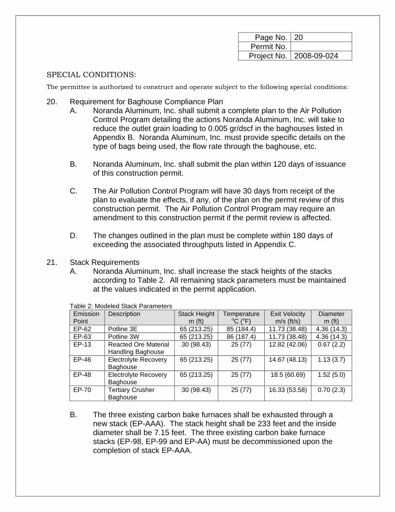
exceeding the associated throughputs listed in Appendix C. 21. Stack Requirements
A. Noranda Aluminum, Inc. shall increase the stack heights of the stacks according to Table 2. All remaining stack parameters must be maintained at the values indicated in the permit application.
Table 2: Modeled Stack Parameters Emission Point
Description Stack Height m (ft)
Temperature oC (oF)
Exit Velocity m/s (ft/s)
Diameter m (ft)
EP-62 Potline 3E 65 (213.25) 85 (184.4) 11.73 (38.48) 4.36 (14.3) EP-63 Potline 3W 65 (213.25) 86 (187.4) 11.73 (38.48) 4.36 (14.3) EP-13 Reacted Ore Material
Handling Baghouse 30 (98.43) 25 (77) 12.82 (42.06) 0.67 (2.2)
EP-46 Electrolyte Recovery Baghouse
65 (213.25) 25 (77) 14.67 (48.13) 1.13 (3.7)
EP-48 Electrolyte Recovery Baghouse
65 (213.25) 25 (77) 18.5 (60.69) 1.52 (5.0)
EP-70 Tertiary Crusher Baghouse
30 (98.43) 25 (77) 16.33 (53.58) 0.70 (2.3)
B. The three existing carbon bake furnaces shall be exhausted through a
new stack (EP-AAA). The stack height shall be 233 feet and the inside diameter shall be 7.15 feet. The three existing carbon bake furnace stacks (EP-98, EP-99 and EP-AA) must be decommissioned upon the completion of stack EP-AAA.
Page No. 21 Permit No. Project No. 2008-09-024
SPECIAL CONDITIONS:
The permittee is authorized to construct and operate subject to the following special conditions:
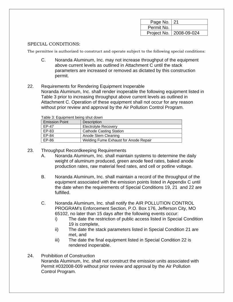
C. Noranda Aluminum, Inc. may not increase throughput of the equipment above current levels as outlined in Attachment C until the stack parameters are increased or removed as dictated by this construction permit.
22. Requirements for Rendering Equipment Inoperable
Noranda Aluminum, Inc. shall render inoperable the following equipment listed in Table 3 prior to increasing throughput above current levels as outlined in Attachment C. Operation of these equipment shall not occur for any reason without prior review and approval by the Air Pollution Control Program. Table 3: Equipment being shut down Emission Point Description EP-47 Electrolyte Recovery EP-83 Cathode Casting Station EP-84 Anode Stem Cleaning EP-86 Welding Fume Exhaust for Anode Repair
23. Throughput Recordkeeping Requirements
A. Noranda Aluminum, Inc. shall maintain systems to determine the daily weight of aluminum produced, green anode feed rates, baked anode production rates, raw material feed rates, and cell or potline voltage.
B. Noranda Aluminum, Inc. shall maintain a record of the throughput of the
equipment associated with the emission points listed in Appendix C until the date when the requirements of Special Conditions 19, 21 and 22 are fulfilled.
C. Noranda Aluminum, Inc. shall notify the AIR POLLUTION CONTROL
PROGRAM’s Enforcement Section, P.O. Box 176, Jefferson City, MO 65102, no later than 15 days after the following events occur: i) The date the restriction of public access listed in Special Condition
19 is complete, ii) The date the stack parameters listed in Special Condition 21 are
met, and iii) The date the final equipment listed in Special Condition 22 is
rendered inoperable. 24. Prohibition of Construction
Noranda Aluminum, Inc. shall not construct the emission units associated with Permit #032008-009 without prior review and approval by the Air Pollution Control Program.

Page No. 22 Permit No. Project No. 2008-09-024
SPECIAL CONDITIONS:
The permittee is authorized to construct and operate subject to the following special conditions:
25. Operational Limitations A. Noranda Aluminum, Inc. shall limit the daily hours of operation as listed in
Table 4.
Table 4: Daily Hourly Restrictions Emission Point
Description Daily Hours of Operation
EP-46 Electrolyte Recovery 18 EP-48 Electrolyte Recovery 18 EP-50 Electrolyte Recovery 18 EP-58 Electrolyte Recovery 18 EP-68 Primary Crusher (North) 16 EP-69 Primary Crusher (South) 12 EP-70 Tertiary Crusher 16 EP-82 Anode Stem Cleaning (Phase I) 10 EP-DW Potline Crusher 12
B. To show compliance with Special Condition 25.A. Noranda Aluminum, Inc.
shall keep a written or electronic daily record of the number of hours of operation of the equipment listed in Table 4. Attachment H, or equivalent form(s), shall be used for daily record keeping.
26. Reporting Requirements
Noranda Aluminum, Inc. shall report to the Air Pollution Control Program’s Compliance/Enforcement Section (P. O. Box 176, Jefferson City, MO 65102) no later than ten (10) days after the end of the month during which the records required by the special conditions of this construction permit show that the limitations of this permit have been exceeded.
27. Record Keeping Requirements
All records required by this construction permit shall be kept onsite for no less than five (5) years and shall be made available to any Department of Natural Resources’ personnel upon request.
- 23 -
REVIEW OF APPLICATION FOR AUTHORITY TO CONSTRUCT AND OPERATE SECTION (8) REVIEW
Project Number: 2008-09-024 Installation ID Number: 143-0008
Permit Number:
Noranda Aluminum, Inc. Complete: February 2, 2010 #1 Robbins Road St. Jude Industrial Park P.O. Box 70 New Madrid, MO 63869 Parent Company: Noranda, Inc. 1 Brentwood Commons Suite 175-250 Old Hickory Road Brentwood, TN 37027 New Madrid County, S32, T22N, R14E
REVIEW SUMMARY Noranda Aluminum, Inc. has applied for authority to increase aluminum production
to 650,000,000 pounds per year at an existing primary aluminum reduction plant in New Madrid, MO.
Hazardous Air Pollutant (HAP) emissions are expected from the proposed
equipment. HAPs of concern from this process are hydrogen fluoride, carbonyl sulfide, and beryllium.
Subpart S of the New Source Performance Standards (NSPS) applies to potroom
groups and anode bake plants at this primary aluminum reduction plant. The Maximum Achievable Control Technology (MACT) standard, 40 CFR Part 63,
Subpart LL, National Emission Standards for Primary Aluminum Reduction Plants, and Subpart RRR, National Emission Standards for Secondary Aluminum Production applies to the installation.
The National Emission Standards for Hazardous Air Pollutants: Area Source
Standards for Aluminum, Copper, and Other Nonferrous Foundries, Subpart ZZZZZZ, does not apply to this installation. The definition of aluminum foundries does not include primary or secondary metal producers that cast molten aluminum to produce simple shapes such as sows, ingots, bars, rods, or billets.
Baghouses are being used to control PM10 emissions from the material handling
operations.
- 24 -
Dry alumina scrubbers are used to control PM10 and fluoride emissions from the carbon bake furnaces.
PM10 and fluoride emissions from the aluminum reduction process are controlled by
enclosed hoods exhausted to dry alumina scrubbers. The Best Available Control Technology (BACT) requirements apply to SOx, CO,
PM10, PM2.5 and fluoride. BACT requirements include the following: Emission limits for PM10, PM2.5, fluorides and CO on the potline and carbon bake
furnace operations; Operational procedures and work practices for the reduction of overall emissions;
and Good design and operating techniques for CO.
The increase in the potential emissions of SOx, CO, PM10, PM2.5 and fluoride are
above de minimis levels, and the existing installation is considered to be a major source. Therefore, this review was conducted in accordance with Section (8) of Missouri State Rule 10 CSR 10-6.060, Construction Permits Required.
This installation is located in New Madrid County, an attainment area for all criteria
air pollutants. This installation is on the List of Named Installations [10 CSR 10-6.020(3)(B), Table
2, Number 6 Primary Aluminum Ore Reduction Plants]. Ambient air quality modeling was performed to determine the ambient impact of SOx,
CO, PM10, fluoride, and HAPs. Emissions testing is required for the source. Revision to Noranda’s Part 70 Operating Permit renewal application is required for
this installation within 1 year of permit issuance. Approval of this permit is recommended with special conditions.
INSTALLATION DESCRIPTION Noranda Aluminum, Inc. operates a primary aluminum reduction plant in New Madrid County. The company is an existing primary aluminum reduction installation with existing secondary aluminum production operations. Alumina (Al2O3) is received at the plant and undergoes electrolytic reduction, known as the Hall-Heroult process, to produce aluminum. The electrolytic reduction takes place in shallow carbon-lined steel shells called pots. The anodes are carbon electrodes extending into the pot, and the cathode is the carbon lining within the pot. Noranda’s pots are housed in six potrooms, four of Kaiser pot technology and two of
- 25 -
Alcoa technology. There are 348 Kaiser pots divided equally among four rooms (i.e. 87 pots per room). These are named Potline 1 and Potline 2 (i.e. two potrooms per potline). Potline 3 contains 160 Alcoa pots in the remaining two potrooms. Aluminum originates as an oxide called alumina. Deposits of bauxite ore are mined and refined into alumina for processing into aluminum metal. Alumina is combined in a pot with a molten electrolyte called cryolite, and direct current electricity is applied to the consumable carbon anode, dividing the aluminum oxide into molten aluminum metal and carbon-dioxide. In the reduction of alumina, carbon, in the form of an anode, is negatively charged to react with the alumina. The anode, also called green anode, is continuously depleted until it is a stub. Anodes are large carbon blocks which act as electrical conductors, allowing the smelting process to take place. These anodes are prepared with calcined petroleum coke mixed with coal tar pitch binder to make a paste. Anode butts returned from the smelting process are also recycled in the process. The coke is crushed, ground, and screened before being mixed with the pitch binder. The paste is heated, then vibrated and compacted into anode blocks of two sizes: the Kaiser anode and the Alcoa anode. The “green blocks” are baked in the carbon bake furnace to a temperature of 1150 degrees Celsius over 28 hours. The baking process bakes the pitch in the mix to form a solid block of carbon that can withstand the extreme conditions inside the smelting pots. Because the crushed, recycled anode component of a new anode has taken up fluorides during its life in the pot environment, this gives rise to a potential emission of fluorides to air during the baking process. Scrubbing equipment traps these additional fluorides for return to the smelting process. The baked anodes are cooled, cleaned and conveyed to the rodding area where they are secured to steel rod assemblies with molten cast iron before being transported to the potrooms. The carbon anodes have a life span of approximately 22-24 days in the reduction pots. The electrolyte used in the pots is molten cryolite (Na3AlF6), which also serves as the solvent for alumina. The electrolytic reduction of alumina by the carbon from the electrode forms elemental aluminum and carbon dioxide (CO2). The aluminum is deposited around the carbon-lined steel shell, where it remains as a molten metal below the surface of the cryolitic bath. Using a vacuum siphon, the molten aluminum is removed from the pots every 24 to 48 hours and transferred to crucibles. From there, the crucibles of molten aluminum are transported to reverberatory holding furnaces called melters and holders where the aluminum is alloyed and processed into rods, billets or ingots. The secondary aluminum operations include aluminum alloying, casting and auxiliary operations. Noranda Aluminum, Inc. is considered a major source under construction and operating permits. An operating permit renewal application has been submitted and is currently under review. The following permits have been issued to Noranda Aluminum, Inc. from the Air Pollution Control Program.

- 26 -
Table 5: Air permits issued to Noranda Permit Number Description
0679-008 Potline I 0679-009 Alumina handling facilities associated with potline III 0679-010 Potline III 0679-011 Carbon baking furnace for potline III
1282-007A Dross cooling system 1288-003A Dross cooling system 0990-013 Additional melting furnace 0194-008 Reverberatory melting furnace 0894-022 Filtered exhaust system
OP2001-066 Part 70 Operating Permit Primary Aluminum Reduction Facility OP2001-032 Part 70 Operating Permit Primary Aluminum Reduction Facility OP2001-062 Part 70 Operating Permit Primary Aluminum Reduction Facility OP2001-033 Part 70 Operating Permit Primary Aluminum Reduction Facility
0298-001 Replacement of existing batch mixers for anode paste with continuous mixer and the replacement of the existing hydraulic press anode mold with a turntable vibratory anode former to produce a larger single piece anode
0799-017 Addition of a downdraft welding table 082001-005 Installation of two 80,000 pound holding furnaces, 20 MMBTU per hour each 102004-001 PSD permit for the increase in aluminum production 122007-005 Installation of two (2) additional 80,000 pound rectangular holding furnaces in
the rod mill department, to supply the Number 2 Rod Mill (Properzi) 032008-009 Installation of a new 125 ton alumina storage bin (EP-115) and activation of
shut down equipment which includes delivery systems and four 19 ton day tanks (EP-51, 52, 53 and 54). These tanks will sit on top of each pot room for storage of cover material that has an approximate composition of 56% alumina and 44% bath.
OP2000-033A Responsible Official Change OP2001-066A Responsible Official Change OP2001-062A Responsible Official Change OP2001-032A Responsible Official Change
The equipment associated with Permit 032008-009 was not constructed prior to issuance of this construction permit. Noranda does not anticipate constructing these emission units within the allowable time limits of the permit. Therefore, these emission points were not included in the final modeling exercise provided with this new source review. If Noranda decides to proceed with the construction of these equipment, Noranda must submit a new permit application for review and approval by the Air Pollution Control Program.
PROJECT DESCRIPTION
Noranda Aluminum, Inc. has applied for authority to increase aluminum production at their existing installation from 588 MMlbs/yr (294,000 tpy) to 650 MMlbs/yr (325,000 tpy). To increase the production of aluminum, Noranda is proposing a series of projects that will increase the amperage to the aluminum production pots and increase the overall efficiency of the aluminum production process.
The following is a list of projects associated with this construction permit:
Increased Rectification Capacity External Cell Resistance Reduction Cathode BUSS leaf Addition
- 27 -
Off-Line Reduction Cell Building Anode Cover Anode Rod/Stub/Yoke Assembly Green Anode Density Cell Thermal Insulation Additional Cells in Pot Lines
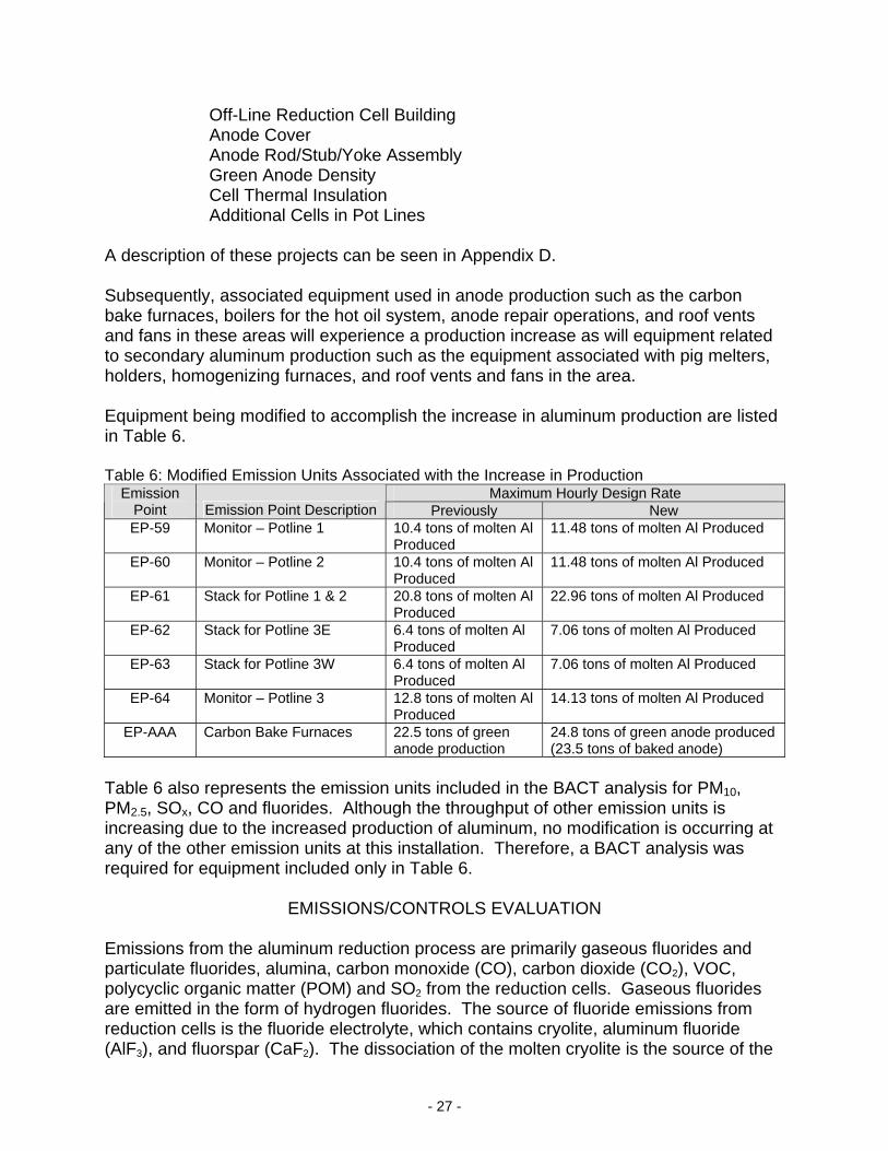
A description of these projects can be seen in Appendix D. Subsequently, associated equipment used in anode production such as the carbon bake furnaces, boilers for the hot oil system, anode repair operations, and roof vents and fans in these areas will experience a production increase as will equipment related to secondary aluminum production such as the equipment associated with pig melters, holders, homogenizing furnaces, and roof vents and fans in the area. Equipment being modified to accomplish the increase in aluminum production are listed in Table 6. Table 6: Modified Emission Units Associated with the Increase in Production
Maximum Hourly Design Rate Emission Point Emission Point Description Previously New EP-59 Monitor – Potline 1 10.4 tons of molten Al
Produced 11.48 tons of molten Al Produced
EP-60 Monitor – Potline 2 10.4 tons of molten Al Produced
11.48 tons of molten Al Produced
EP-61 Stack for Potline 1 & 2 20.8 tons of molten Al Produced
22.96 tons of molten Al Produced
EP-62 Stack for Potline 3E 6.4 tons of molten Al Produced
7.06 tons of molten Al Produced
EP-63 Stack for Potline 3W 6.4 tons of molten Al Produced
7.06 tons of molten Al Produced
EP-64 Monitor – Potline 3 12.8 tons of molten Al Produced
14.13 tons of molten Al Produced
EP-AAA Carbon Bake Furnaces 22.5 tons of green anode production
24.8 tons of green anode produced (23.5 tons of baked anode)
Table 6 also represents the emission units included in the BACT analysis for PM10, PM2.5, SOx, CO and fluorides. Although the throughput of other emission units is increasing due to the increased production of aluminum, no modification is occurring at any of the other emission units at this installation. Therefore, a BACT analysis was required for equipment included only in Table 6.
EMISSIONS/CONTROLS EVALUATION Emissions from the aluminum reduction process are primarily gaseous fluorides and particulate fluorides, alumina, carbon monoxide (CO), carbon dioxide (CO2), VOC, polycyclic organic matter (POM) and SO2 from the reduction cells. Gaseous fluorides are emitted in the form of hydrogen fluorides. The source of fluoride emissions from reduction cells is the fluoride electrolyte, which contains cryolite, aluminum fluoride (AlF3), and fluorspar (CaF2). The dissociation of the molten cryolite is the source of the

- 28 -
perfluorinated carbon compounds tetrafluoromethane (CF4) and hexafluoroethane (C2F6), which are produced as a result of an anode effect. Particulate emissions occur from the reduction cells and include alumina and carbon from anode dusting, cryolite, aluminum fluoride, calcium fluoride, and ferric oxide. The primary source of the CO and CO2 emissions is the carbon in the anodes from the petroleum coke. PM/PM10/PM2.5 Emissions The annual baseline emissions were determined using EIQ data for the years 2001-2002, unless otherwise stated. Potline Monitor Particulate emissions from the potlines include alumina and carbon from anode dusting, and cryolite, aluminum fluoride, calcium fluoride and ferric oxide. Representative size distributions for particulate emissions were taken from AP-42 Section 12.1 Primary Aluminum Production (2/98) Table 12.1-2. PM10 emissions from potline monitors can be determined by assuming 58% of the PM emissions are PM10. Similarly, PM2.5 emissions from potline monitors can be determined by assuming 28% of the PM emissions are PM2.5. The short-term future actual PM10 emissions are based on BACT limits proposed by Noranda. On an annual basis the emission rate for Potline 2 Monitor (EP-60) is lower than the annual rate using the short-term hourly limits and 8760 hours of operation. Therefore, annual limits were applied to this emission point. A PM2.5 limit was extrapolated using the ratios described above. The annual baseline emissions were determined using EIQ data for the years 2001-2002. The annual emission rate on an hourly basis for Potline Monitor 1 (EP-59) exceeded the 2004 PSD limit for this emission point. Therefore the 2004 PSD limit was used as the hourly emission rate for determining the annual baseline emissions in lieu of the value stated in the EIQs for those years. The short-term baseline emissions were determined using the average emission rates as determined by stack tests from the baseline period of 2001-2002. The test results were expressed as PM emission, and when converted to PM10, the emission rates were higher than the 2004 PSD limit for Potline Monitor 1 (EP-59) and Potline Monitor 2 (EP-60). Therefore the 2004 PSD limit was used as the baseline short-term emission rates for these emission points. Potline Stack PM10 emissions from potline stacks can be determined by assuming 58% of the PM emissions are PM10. Similarly, PM2.5 emissions from potline monitors can be determined by assuming 28% of the PM emissions are PM2.5. The annual future actual emissions were based on the grain loading determined by BACT. The Potline 1 and 2 stack maximum flow rate is based on a maximum of 40 Line 1&2 scrubbers operating. Since Noranda typically operates 36 scrubbers at an annual average flow rate of 836,888 scfm, this flow rate was scaled up by 40/36 to account for

- 29 -
the operation of all scrubbers. The Potline 3E and 3W stacks maximum flow rates are based on a maximum of 8 scrubbers operating (8 on 3E and 8 on 3W). Since Noranda typically operates 7 scrubbers on 3E and 7 scrubbers on 3W at an annual average flow rate of 253,661 scfm, this flow rate was scaled up by 8/7 to account for the operation of all scrubbers. On an annual basis the emission rate for the potline stacks is lower than the annual rate using the short-term hourly limits and 8760 hours of operation. Therefore, annual limits were applied to these emission points. The annual future actual PM2.5 emissions limit was extrapolated from the PM10 limit using the ratios discussed above. Carbon Bake Furnaces The EPA document, AIRS Facility Subsystem Source Classification Codes and Emission Factor Listing for Criteria Air Pollutants, March 1990, provides an emission factor for PM and PM10 from anode baking furnaces. Based on the ratio of these emission factors, Noranda concluded that PM10 emissions from the carbon bake furnaces could be determined by taking 93.33% of the PM emissions. However, this document does not address PM2.5 emissions. Therefore, the particle distribution tables found in AP-42 Table B.2-1 and B.2.2 were used to determine the percentage attributed to PM2.5 emissions. Based on the category listing for anode baking furnaces at primary aluminum production plants, 78% of total particulate emissions are considered to be PM2.5 emissions. The short-term future actual PM10 emissions are based on BACT limits proposed by Noranda. On an annual basis the emission rate for the carbon bake furnaces is lower than the annual rate using the short-term hourly limits and 8760 hours of operation. Therefore, annual limits were applied to this emission point. The annual future actual PM2.5 emissions limit was extrapolated from the PM10 limit using the ratios discussed above. The short-term baseline PM10 emissions were determined using the average emission rates as determined by stack tests from the baseline period of 2001-2002. The tests produced PM data, which was converted to PM10 and PM2.5 data. Melter and Holder The melters and holders have emissions due to the aluminum refining process itself and emissions from the combustion of natural gas for the operation of the equipment. These emissions were calculated separately and only the process emissions are discussed in this section. Future actual emissions from the process were based on PM emissions determined during testing of the equipment at the maximum hourly design rate of the equipment. To determine PM10 emissions from the melter and holders, 60% of the PM emissions was used as stated in AP-42 Section 12.8 Secondary Aluminum Operations for refining. For PM2.5 emissions, 50% of the PM emissions were taken. Raw Material Handling There are several handling operations for various materials such as raw alumina, reacted alumina, electrolytes, petroleum coke, and pitch. The pollutant from these emission units is PM10, and each emission unit is controlled by an existing baghouse. Particle distributions are not available for these emission units, therefore, all PM10
- 30 -
emissions are assumed to also be PM2.5 emissions. As a part of this project, Noranda is proposing to improve the efficiency of the baghouses by decreasing the outlet grain loading of the baghouses from 0.01 gr/dscf to 0.005 gr/dscf. At the time of permit issuance, Noranda was unclear on what changes to the baghouses would be needed to decrease the outlet grain loading. Therefore, a special condition has been included with this construction permit that requires a documentation of compliance with the new outlet grain loading within 120 days of the issuance of this construction permit. Since this information was relied upon to estimate the potential emissions for the project, Special Condition 14 has been included that sets an emissions limitation on all material handling operations. Noranda Aluminum, Inc. is required to demonstrate compliance with the limitations by periodically testing emissions from these operations. Testing of these baghouses will be categorized into flow rate range, baghouse type, and process type. Noranda will be required to submit a listing of the baghouses in each category for approval prior to testing. Baghouse types may include reverse air baghouses, mechanical shakers, pulse jet, etc. Process types may be separated based on the type of material being processed or what kind of process equipment is being controlled. An example of how the baghouses may be listed is presented in Appendix F. It is not the intention of the condition to allow one baghouse to represent more than one category. If a baghouse is chosen to represent a particular flow rate range, it cannot also be used to represent a process type. In addition, each subsequent testing event must use a different baghouse than the previous testing event to represent each category listing. Haul Roads The emissions from the haul roads are PM10, which were calculated using the Paved Haul Road equations. Particle distributions are not available for these emission units, therefore, all PM10 emissions are assumed to also be PM2.5 emissions. Pitch and coke are not typically hauled in by trucks. However, the aluminum product is shipped by truck. In the past, it was thought that the silt loading on the paved haul road at Noranda’s facility was zero based on the material being hauled in the trucks (i.e. no spillage from the aluminum product). However, according to AP-42 Section 13.2.1, particulate emissions from the paved haul roads originate from vehicles in the form of exhaust, brake wear and tire wear emissions and resuspension of loose material on the road surface. Therefore, Noranda was required to calculate haul road emissions as part of this project. Baseline emissions for the haul roads were calculated assuming a silt loading of 2.5%. The future amount hauled was estimated by Noranda based on future production proposals. Future actual emissions were calculated based on a lower silt loading as a result of sweeping the roads and a controlled number of trucks traveling on the roads. Consequently, a special condition limiting the amount of truck traffic is included with this construction permit. In addition, the silt loading of the haul road will be tested to demonstrate compliance with the silt loading requirements of the haul road. SOx Emissions As part of this project’s application, Noranda proposed the use of a new calculation methodology to determine SOx emissions from the carbon bake furnaces and potlines.

- 31 -
This new calculation methodology affected the emission rates submitted in previous EIQs, including those used in the determination of the SOx limit in the previously issued construction permit. As a result (upon request by the Air Pollution Control Program), Noranda has amended the SOx emission limit in Permit #102004-001 to reflect the newly proposed calculation methodology. The request for revision to the SOx calculations for the third time in five years brings the validity of the calculation method into question. Based on past SOx modeling exercises in the area, there is concern over the possibility of exceedances of the NAAQS standard. Therefore, additional information on the SO2 emissions from the plant is necessary to obtain an accurate portrayal of Noranda’s impact on the NAAQS standard. Since the bulk of the SO2 emissions originate with the coke and pitch, and subsequently the baked anode, determining the sulfur content of these materials is essential to assessing final emissions. In addition, the presence of sulfur in reacted alumina has been indicated as a significant contributor of sulfur emissions at primary aluminum plants in other states. Therefore testing the sulfur content of the alumina has also been determined to be necessary. Additional stack testing is required to verify hourly emission rates are not being exceeded. The project emissions are based on the potential of the project minus the baseline SO2 actual emissions. In this case the baseline years are 2002 and 2003. Carbon Bake Furnaces The total amount of sulfur from fresh pitch and coke and recycled scraps from the process is calculated as the amount processed into the carbon bake furnaces. The total amount of sulfur emissions from the carbon bake process is determined using the percent reduction in the bake furnace and the percent sulfur of the baked anodes. The baseline emissions were recalculated using this new method. However, since the carbon bake stacks will be combined into a common stack as part of this project, there was no need to determine the distribution of emissions among the three existing carbon bake stacks. Future actual emissions were calculated in a similar manner using 2.3% sulfur content for coke.
Potline Stacks and Monitors The total amount of sulfur processed into the potlines is determined by accounting for any baked blocks, scraps or butts removed from or added to the potlines. The sulfur content of the baked anodes is determined through testing at the facility. It is assumed that all sulfur into the process is emitted as SOx. The baseline emissions were also recalculated using the new method. The emissions were distributed among the three lines (Potline 1& 2, Potline 3E and Potline 3W) using the production data for each line and applying the production ratio to the emission rates.
When the new methodology was approved for the use in the 2004 PSD construction permit, Noranda used the new methodology to demonstrate compliance with an installation wide limitation. At the time, there was no need to evaluate the fluctuation in emissions from the carbon bake furnaces and potlines. The limitation only applied to the total amount of sulfur emitted from the entire installation.
The current project requires an ambient air quality analysis for SOx. Since a mass
- 32 -
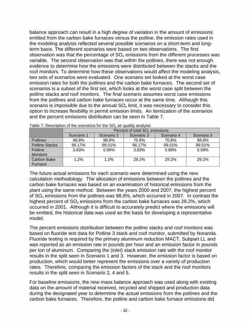
balance approach can result in a high degree of variation in the amount of emissions emitted from the carbon bake furnaces versus the potline, the emission rates used in the modeling analysis reflected several possible scenarios on a short-term and long-term basis. The different scenarios were based on two observations. The first observation was that the percentage of SOx emissions from the different processes was variable. The second observation was that within the potlines, there was not enough evidence to determine how the emissions were distributed between the stacks and the roof monitors. To determine how these observations would affect the modeling analysis, two sets of scenarios were evaluated. One scenario set looked at the worst case emission rates for both the potlines and the carbon bake furnaces. The second set of scenarios is a subset of the first set, which looks at the worst case split between the potline stacks and roof monitors. The final scenario assumes worst case emissions from the potlines and carbon bake furnaces occur at the same time. Although this scenario is impossible due to the annual SOx limit, it was necessary to consider this option to increase flexibility in permit emission limits. An itemization of the scenarios and the percent emissions distribution can be seen in Table 7. Table 7: Description of the scenarios for the SOx air quality analysis
Percent of total SOx emissions Scenario 1 Scenario 2 Scenario 3 Scenario 4 Scenario 5
Potlines 98.8% 98.8% 70.8% 70.8% 98.8% Potline Stacks 96.17% 99.01% 96.17% 99.01% 99.01% Potline Monitors
3.83% 0.99% 3.83% 0.99% 0.99%
Carbon Bake Furnace
1.2% 1.2% 29.2% 29.2% 29.2%
The future actual emissions for each scenario were determined using the new calculation methodology. The allocation of emissions between the potlines and the carbon bake furnaces was based on an examination of historical emissions from the plant using the same method. Between the years 2000 and 2007, the highest percent of SOx emissions from the potlines was 98.8%, which occurred in 2007. In contrast the highest percent of SOx emissions from the carbon bake furnaces was 29.2%, which occurred in 2001. Although it is difficult to accurately predict where the emissions will be emitted, the historical data was used as the basis for developing a representative model.
The percent emissions distribution between the potline stacks and roof monitors was based on fluoride test data for Potline 3 stack and roof monitor, submitted by Noranda. Fluoride testing is required by the primary aluminum reduction MACT, Subpart LL and was reported as an emission rate in pounds per hour and an emission factor in pounds per ton of aluminum. Comparing the (inlet) stack emission rate with the roof monitor results in the split seen in Scenario 1 and 3. However, the emission factor is based on production, which would better represent the emissions over a variety of production rates. Therefore, comparing the emission factors of the stack and the roof monitors results in the split seen in Scenario 2, 4 and 5.
For baseline emissions, the new mass balance approach was used along with existing data on the amount of material received, recycled and shipped and production data during the designated year to determine the actual emissions from the potlines and the carbon bake furnaces. Therefore, the potline and carbon bake furnace emissions did
- 33 -
not change in each of the scenarios. However, since the percent emissions distribution between the potline stacks and roof monitors is unverified, the baseline emissions for the potline stacks and roof monitors varied dependent upon the scenario. The percent emissions distribution is expected to remain constant during normal operation.
The potlines will be tested to determine the ratio of emissions between the roof monitors and the potline stacks. In order to determine the ratio of emissions between the roof monitors and the potline stacks, Noranda will be required to test the stacks and roof monitors from each potline group.
Natural Gas Noranda is proposing a limit on the future actual natural gas usage to an amount equivalent to the 2002-2003 natural gas usage. Therefore, a natural gas limit has been set forth in this construction permit that will limit the installation-wide use of natural gas. However, although the carbon bake furnaces use natural gas, natural gas combustion emissions from the carbon bake furnaces are not included in these calculations. It is assumed that they are regulated by limits set forth on the carbon bake furnace emissions.
For SOx, there is no increase in emissions based on the SOx baseline year 2002-3. For PM10, however, since the natural gas usage for the PM10 baseline years, 2001-2, is lower than the 2002-3 natural gas usage, the PM10 emissions increase was set to zero instead of indicating a negative emissions increase.
Natural gas emissions were based on a maximum future usage of 832 mmcf per year. To determine the future actual usage of each piece of equipment on an annual basis, the total future actual usage was divided among all of the combustion equipment at the facility based on the percent usage of the equipment. Some equipment, such as space heaters, were not assigned individual emission descriptions, but were grouped into one category labeled “miscellaneous”. These miscellaneous sources were treated as one combustion unit per department and modeled similar to other combustion sources in their same departments. On a short-term basis, the maximum hourly design rate of the combustion equipment was used to determine the worst-case hourly emission rates. Propane was discussed as back-up fuel for the equipment at the installation. Noranda does not anticipate using the propane unless natural gas becomes unavailable. Therefore, the potential emissions of propane combustion were not evaluated for this project. A special condition has been added to this construction permit that will restrict the combustion of propane to those periods of natural gas curtailment. CO Emissions The annual baseline emissions for CO were determined from the EIQ data for the years 2006-2007. CO emissions are generated by the carbon bake furnaces due to the incomplete combustion of volatile organic compounds contained in the coal tar pitch. The emission factor that has been used to estimate CO emissions from the carbon bake furnaces was 66 pounds CO per ton aluminum produced and was obtained from the EPA document, AIRS Facility Subsystem Source Classification Codes and Emission Factor Listing for

- 34 -
Criteria Air Pollutants, March 1990. Based on stack testing with a portable flue gas monitor, Noranda proposed to use an emission factor of 6 pounds CO per ton aluminum to estimate the baseline actual emissions. Noranda updated the EIQs for the years 2000-2007 to account for the change in the emission factor. However, the future actual emissions were based on a more conservative emission factor of 7.3 pounds per ton because only a single test had been performed to characterize the CO emissions. Testing will be required to verify the change in the emission factor. CO emissions from the potlines are generated in a reaction between aluminum and carbon dioxide resulting in oxidized aluminum and CO. This reaction reduces aluminum production efficiency which is an undesirable outcome. Therefore, Noranda is able to minimize the CO emissions from the potlines by maximizing aluminum production efficiency. The emission factor used to estimate emissions of CO was determined through stack testing. The future actual emissions of CO were determined by scaling up the BACT limits from the amendment to the 2004 PSD permit based on the proportionate increase in aluminum production. The emission factors for natural gas combustion were taken from AP-42. Fluorides Fluoride emissions occur from the reaction of cryolite in the pots. The dry alumina scrubbers remove a portion of the fluorides by adsorbing the fluoride to the alumina, and the reacted alumina is recycled into the smelting process. Used anode butts are crushed and recycled into the production of new anodes. This recycled component carries fluorides taken up during its life in the pot environment and gives rise to a potential emission of fluorides to air during the baking process. The definition of the PSD regulated pollutant fluoride specifically excludes hydrogen fluoride from consideration. However, Noranda has conservatively estimated fluoride emission using total fluoride emission data. Since hydrogen fluorides are considered HAPS, a separate analysis was performed for hydrogen fluorides. NOx, VOC The emissions of NOx are attributed to two sources: the combustion of natural gas and the potlines. The emission factors for natural gas combustion were taken from AP-42. The potline emissions were calculated based on an emission factor taken from EPA’s WebFIRE program under the SCC 30300101. This emission factor (0.0030 pound NOX per ton aluminum produced) was rated as “Unrated” under the emission factor rating system. No other emission factors were found that identified NOx as emissions from the carbon bake and potline processes. However, based on a permit issued in Kentucky, NOX emissions may be emitted from both the potline and carbon bake furnaces. Therefore, emission testing is required to verify the emissions of NOx from the carbon bake and potline processes and preclude the applicability of PSD. The emissions of VOC occur at the potlines and carbon bake furnaces, and from natural gas combustion and the tanks. The VOC emission factor for the potlines (0.1 pound VOC per ton aluminum produced) and the carbon bake furnaces (1 pound
- 35 -
VOC per ton aluminum produced) was found in EPA document AIRS Facility Subsystem Source Classification Codes and Emission Factor Listing for Criteria Air Pollutants. VOC emission limits in the Kentucky permit mentioned above were higher than those using the AIRs emission factors. Therefore, emission testing is required to verify the emissions of VOC from the carbon bake and potline processes and preclude the applicability of PSD. VOC emissions from the combustion of natural gas were taken from AP-42. VOC emissions from the tanks were calculated using the emission factors from the FIRE database. Sulfuric Acid Mist The emission of sulfuric acid (H2SO4) from primary or secondary aluminum operations is not discussed in AP-42 or AIRS. However, at a primary aluminum plant in Kentucky, stack testing was conducted in June 2006 that demonstrated sulfuric acid as being a pollutant of concern from the carbon bake furnaces. The resulting emission factor was 0.11 pounds of H2SO4 per ton anode produced. Noranda will be required to test the carbon bake furnace emissions to verify the emission factor used in this analysis is accurate. HAPs The HAPs of concern from the proposed project are nickel, manganese, beryllium, polycyclic organic matter (POM), hydrogen chloride, carbonyl sulfide (COS), and hydrogen fluoride. Beryllium and manganese are trace metals that occur in the alumina. Nickel occurs in both the alumina and coke. The quantity of these trace metals were based on a composition analysis of the coke and alumina. It was assumed that these metals were completely emitted into the atmosphere. POM emissions are a result of the calcinations of the pitch in the carbon bake furnaces. Noranda is taking a self-imposed annual limit on the emissions of POM from the carbon bake furnaces to demonstrate that there is no increase in POM emissions. Therefore, a limit equivalent to the baseline emission rate is set forth in this construction permit. Noranda currently operates under the MACT Subpart LL limit of 0.18 pounds per ton of green anode produced. Hydrogen chloride emissions are a result of the metal fluxing that occurs in the metal products holders and the rod mill melters and holders.
Although COS has not been considered a HAP of concern from this plant in previous permits, there have been indications at primary aluminum plants in other states that SO2 further reacts to form COS. In order to determine the rate of conversion, Noranda will be required to test the conversion rate of SO2 to COS. In addition, an annual limit is being imposed to ensure the ambient air quality is not being affected.
Hydrogen fluoride is the gaseous component of the total fluoride emissions that occur at the potlines and the carbon bake furnaces. Gaseous fluoride emissions can vary considerably based on the process as seen in testing results for total fluorides submitted by Noranda. Using these results, the average percent that is gaseous was determined for each emission process to calculate future actual emissions. The average percentages varied between 49% and 72%.

- 36 -
Gaseous HAPs, such as hydrogen fluoride and polycyclic organic matter, are limited under the MACT standard Subpart LL and are not subject to the requirements of 10 CSR 10-6.060(9).
Potential emissions of the application represent the potential of the new equipment, assuming continuous operation (8760 hours per year). Existing actual emissions were taken from the installation’s 2008 Emissions Inventory Questionnaire (EIQ). The following table provides an emissions summary for this project. Table 8: Emissions Summary (tons per year)
Pollutant Regulatory De Minimis
Levels*
Existing Potential
Emissions
Existing Actual
Emissions (2008 EIQ)
Potential Emissions
of the Application
New Installation Conditioned
Potential
PM10 15.0 major 567.8 501 1,141.4
PM2.5 25.0 N/D 257.0 322 722.7
SOx 40.0 major 4688.1 573 6,077.7
NOx 40.0 major 36.2 0.89 42.1
VOC 40.0 major 239.4 34 262.5
CO 100.0 major 24770.8 2841 22,351.5
Fluorides 3.0 major N/D 177 344.6
Beryllium 10.0 N/D N/D 0.02 0.12
Carbonyl Sulfide
10.0 N/D N/D 25.83 219
Hydrogen Chloride
10.0 N/D N/D 2.17 2.74
Hydrogen Fluoride
10.0 N/D N/D 99.37
Manganese 10.0 N/D N/D 0.04 0.30
Nickel 10.0 N/D N/D 0.08 0.6
Polycyclic Organic Matter
10.0 N/D N/D 0.0 11.3
N/A = Not Applicable; N/D = Not Determined
BACT ANALYSIS Any source subject to Missouri State Rule 10 CSR 10-6.060, Construction Permits Required, Section (8) must conduct a Best Available Control Technology (BACT) analysis on any pollutant emitted in greater than de minimis levels. The BACT requirement is detailed in Section 165(a)(4) of the Clean Air Act, at 40 CFR 52.21 and 10 CSR 10-0.60(8)(A). The proposed construction is subject to the PSD regulations, which mandate that case-by-case BACT analyses be performed. As a consequence, BACT demonstrations are presented for SOx, CO, PM10, PM2.5 and fluoride. The general principles of the top-down approach were used in the selection of BACT. Emission sources considered in the BACT analysis include the carbon bake furnaces,
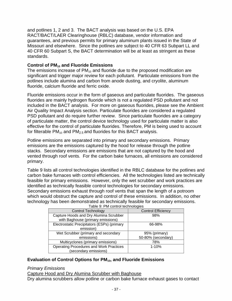
- 37 -
and potlines 1, 2 and 3. The BACT analysis was based on the U.S. EPA RACT/BACT/LAER Clearinghouse (RBLC) database, vendor information and guarantees, and previous permits for primary aluminum plants issued in the State of Missouri and elsewhere. Since the potlines are subject to 40 CFR 63 Subpart LL and 40 CFR 60 Subpart S, the BACT determination will be at least as stringent as these standards.
Control of PM10 and Fluoride Emissions The emissions increase of PM10 and fluoride due to the proposed modification are significant and trigger major review for each pollutant. Particulate emissions from the potlines include alumina and carbon from anode dusting, and cryolite, aluminum fluoride, calcium fluoride and ferric oxide.
Fluoride emissions occur in the form of gaseous and particulate fluorides. The gaseous fluorides are mainly hydrogen fluoride which is not a regulated PSD pollutant and not included in the BACT analysis. For more on gaseous fluorides, please see the Ambient Air Quality Impact Analysis section. Particulate fluorides are considered a regulated PSD pollutant and do require further review. Since particulate fluorides are a category of particulate matter, the control device technology used for particulate matter is also effective for the control of particulate fluorides. Therefore, PM is being used to account for filterable PM10 and PM2.5 and fluorides for this BACT analysis.
Potline emissions are separated into primary and secondary emissions. Primary emissions are the emissions captured by the hood for release through the potline stacks. Secondary emissions are emissions that are not captured by the hood and vented through roof vents. For the carbon bake furnaces, all emissions are considered primary.
Table 9 lists all control technologies identified in the RBLC database for the potlines and carbon bake furnaces with control efficiencies. All the technologies listed are technically feasible for primary emissions. However, only the wet scrubber and work practices are identified as technically feasible control technologies for secondary emissions. Secondary emissions exhaust through roof vents that span the length of a potroom which would obstruct the capture and control of these emissions. In addition, no other technology has been demonstrated as technically feasible for secondary emissions.
Table 9: PM control technologies Control Technology Control Efficiency
Capture Hoods and Dry Alumina Scrubber with Baghouse (primary emissions)
98%
Electrostatic Precipitators (ESPs) (primary emission)
66-98%
Wet Scrubber (primary and secondary emissions)
95% (primary) 50-80% (secondary)
Multicyclones (primary emissions) 78% Operating Procedures and Work Practices
(secondary emissions) 1-10%
Evaluation of Control Options for PM10, and Fluoride Emissions
Primary Emissions Capture Hood and Dry Alumina Scrubber with Baghouse Dry alumina scrubbers allow potline or carbon bake furnace exhaust gases to contact

- 38 -
alumina ore. The gaseous pollutants adsorb onto the alumina allowing the gaseous pollutants to be treated as particulate matter. The spent alumina along with particulate fluorides are then removed from the exhaust stream through a baghouse. Noranda currently utilizes a capture hood over each pot which directs primary emissions to a fluidized bed dry alumina scrubber. Gases are passed through an expanded bed of alumina, fluidizing the bed and removing the gaseous pollutants. The reacted alumina is returned to the potline feed system for processing in the potlines. Similarly, the carbon bake furnace emissions are vented through a fluidized bed dry alumina scrubber prior to entering the atmosphere. The applicant has chosen the top control alternative. Therefore, no further analysis was conducted for the remaining primary emissions control options.
Secondary Emissions Wet Scrubbers Wet scrubbers are considered the most effective control technology for control of secondary emissions. Wet scrubbers are in use at primary aluminum facilities in the United States making this option technically feasible. Subsequently, an economic evaluation must be performed to determine if this option is economically feasible.
An economic evaluation of this technology is based on data reported in the EPA document Basis and Purpose Document for the Development of Proposed Standards for the Primary Aluminum Industry, Appendix C, where the economic viability of wet roof scrubbers is evaluated. The data did not include costs for retrofitting a prebake facility so the average total annualized cost for the installation and operation of a wet roof scrubber was estimated at $27.60 per ton of annual capacity. Based on this estimate and Noranda’s increased aluminum production rate, the cost would total $9,067,500 per year. At a removal rate of 55%, as stated in the document, this is equivalent to:
$41,441/ton PM removed for Roof Monitor 1, $70,149/ton PM removed for Roof Monitor 2, and $84,716/ton PM removed for Roof Monitor 3.
For fluorides, the removal efficiency increases to 80%, but the removal cost increases using the same values as above:
$132,537/ton total fluoride removed for Roof Monitor 1, $132,537/ton total fluoride removed for Roof Monitor 2, and $107,702/ton total fluoride removed for Roof Monitor 3.
Based on the cost per ton of pollutant removed for either PM or fluorides, wet roof scrubbers are not economically feasible. Operating Procedures and Work Practices By improving operating procedures, secondary emissions are reduced as a direct result of the decrease in primary emissions.
Suppression of Anode Effects Anode effects are believed to occur when the alumina content of the bath falls and a film of carbon tetrafluoride (CF4) gas collects under the anode, causing a high electrical
- 39 -
resistance which increases the power input to the cell. The power increase is converted into heat thus raising the temperature of the cell. At the higher cell temperature, fluorine evolution is increased. Replenishing the alumina content of the electrolyte before it creates an anode effect can reduce the frequency of the events.
Bath Temperature and Bath Ratio At higher the bath temperatures, bath salts will vaporize and become part of the emissions. Under normal operating conditions, operators monitor bath temperatures and bath ratios (ratio of sodium fluoride to aluminum fluoride) to prevent the cell from becoming too cold or too hot. When a cell is not crusted over, the molten electrolyte is exposed to the air and there is a large increase in fluoride in the cell off-gases. Operating conditions that destroy the ability of the bath to crust over and carry a cover of alumina may result in a net increase in cell emissions. The alumina cover prevents the escape of fluoride from the molten bath.
Hood Maintenance and Operation 100% hooding efficiency is not achievable under the present design due to the requirement of opening for cell working, for anode replacement and for metal tapping. In order to improve pollution control, operators must pay careful attention to keeping shields in good condition and open or remove them no more than necessary. The number of hoods or shields completely or partially open and the duration of opening greatly affect the capture efficiency and the quantity of secondary emissions that eventually escape through the roof. These factors can for the most part be controlled by the plant operator. Some potlines are equipped with the means of increasing the air flow into a primary collection system at individual cells when hoods need to be opened. This contributes to higher collection efficiencies thus reducing secondary emissions. Work practice programs, inspection procedures, and maintenance programs for the repair or replacement of damaged hoods and seals are viable control options for secondary emissions. Improving the control program for secondary emissions increases the capture of the primary system, thus reducing overall emissions. The improved or enhanced program for secondary emissions includes optimizing work practices and following written procedures; inspections to assess equipment condition and adherence to work practices; and repair of hoods, seals, and other parts of the primary collection system as needed. The range for capture for this type of equipment is 90-99%. Noranda’s current operations include capture hoods over each pot. In the current permit application, Noranda has indicated a 96% capture efficiency for these capture hoods. In order to obtain this amount of capture, Noranda will be required to maintain an inspection and maintenance program to repair or replace damaged hoods and seals. In addition, Noranda will be required to maintain operating procedures and work practices used at the plant to reduce overall cell emissions. Selection PM10 and Fluoride Control Technology In conclusion, for the primary emissions of the aluminum potlines, BACT for the control of PM10 and fluoride is the use of capture hoods, with a capture efficiency of 96%, vented to dry alumina scrubbers connected to a baghouse. For secondary emissions of the potlines, BACT for the control of PM10 and fluoride is good work practices. For the carbon bake furnaces, BACT for the control of PM10 and fluoride is dry alumina

- 40 -
scrubbers connected to a baghouse. Table 10 outlines the emission rates associated with this BACT analysis.
Unit ID Emission Unit Description PM10 Fluorides EP-59 Potline 1 Monitor 0.0018 gr/dscf (annual average)
52.68 lb/hr 4.59 lb/ton Al produced
1.9 lb/ton Al produced
EP-60 Potline 2 Monitor 0.0018 gr/dscf (annual average) 33.54 lb/hr 2.71 lb/ton Al produced
1.9 lb/ton Al produced
EP-61 Potline 1&2 Stack 0.01 gr/dscf (annual average) 56.69 lb/hr 2.01 lb/ton Al produced
1.9 lb/ton Al produced
EP-62 Potline 3 East Stack 0.01 gr/dscf (annual average) 16.59 lb/hr 2.04 lb/ton Al produced
1.9 lb/ton Al produced
EP-63 Potline 3 West Stack 0.01 gr/dscf (annual average) 16.59 lb/hr 2.04 lb/ton Al produced
1.9 lb/ton Al produced
EP-64 Potline 3 Monitor 0.00075 gr/dscf (annual average) 25.77 lb/hr 1.82 lb/ton Al produced
1.9 lb/ton Al produced
EP-AAA Carbon Bake Furnaces 0.03 gr/dscf (annual average) 80.0 lb/hr 2.33 lb/ton green anode
0.2 lb/ton green anode
Control of PM2.5 Emissions The emissions increase of PM2.5 due to the proposed modification are significant and trigger major review. As stated in the previous section, particulate emissions from the potlines include alumina and carbon from anode dusting, and cryolite, aluminum fluoride, calcium fluoride and ferric oxide. PM2.5 emissions consist of condensable and filterable components. In the evaluation of filterable PM2.5 emissions, the selected BACT for PM10 and fluorides was evaluated to determine the effectiveness of a dry scrubber with baghouse on filterable PM2.5 emissions. Based on the control efficiencies listed in AP-42, Appendix B.2, a fabric filter is as effective for controlling PM10 and as it is for controlling PM2.5, with both control efficiencies at 99% or higher. This indicates that the baghouse determined to be BACT for PM10 and fluorides in the previous analysis should be as effective for controlling filterable PM2.5 emissions. Therefore, the conclusion reached in the BACT analysis for PM10 and fluorides should serve as the most effective control for filterable PM2.5 emissions. Condensable PM2.5 emissions include condensable inorganic particulate matter and POM. Condensable inorganic particulate matter in this case is thought to be mainly sulfates occurring from the aluminum and anode production process. In the potline, there are very little VOC or NOx emissions and no sulfuric acid emissions to contribute to the condensable emissions. In the carbon bake furnace, however, there are considerably more VOC and sulfuric acid emissions, which may be considered condensable. When evaluating the potline emissions, only primary emissions were considered. According to Noranda, potline roof vents are emitted at ambient temperatures. By the nature of condensable emissions any condensable matter should condense by the time

- 41 -
it is emitted from the vents, rendering the condensable matter filterable. Since the BACT for PM10 and fluoride includes filterable matter, secondary PM2.5 emissions are not discussed further in this section. Primary potline and carbon bake furnace emissions were the focus of this PM2.5 BACT analysis. Several databases including the RBLC database were searched to identify control technologies for condensable PM2.5. However, PM2.5 was not addressed in any of these databases. Noranda has compiled a list of possible control technologies based on their knowledge of control equipment applications. A cursory search of the internet did not provide any additional controls. Control technologies that were identified for condensable PM2.5 emissions from the potlines and carbon bake furnaces are listed in Table 11.
Table 11: PM2.5 control technologies for potlines and carbon bake furnace Control Technology
Dry Alumina Scrubber with Baghouse Exhaust Cooling with Dry ESPs Quench Cooling with Wet ESPs
Quench Cooling with Wet Scrubbers Thermal Oxidation Catalytic Oxidation
Evaluation of Control Options for PM2.5 Emissions There is no current data that has accurately quantified control efficiencies for these control technologies. Therefore, the effectiveness of each of these control technologies can only be evaluated on the basis of technical and economical feasibility. Dry alumina scrubber with baghouse This technology is currently being applied for the control of fluoride, POM and PM10 emissions from the potlines and carbon bake furnaces at Noranda. Although a control efficiency is not defined, this control technology is expected to provide some control of condensable emissions. The alumina serves as a condensation point for condensable compounds as they adsorb to the alumina for removal in the baghouse. Exhaust Cooling with dry ESPs This control technology consists of two parts: the cooling of the exhaust air and the collection of the condensed matter. The first part would require the use of a large heat exchanger to reduce the temperature of the exhaust stream and drop out the condensable matter. Acid gases in the exhaust stream could result in corrosion issues. Fouling of the heat exchanger is likely as the condensable matter sticks to the heat exchanger surfaces. Similarly condensable matter may stick to the ESP collection plates, reducing the efficiency of the ESP and causing a fire hazard for both components. Based on the possibility of a diminishing control efficiency and fire hazard issues with this control technology, this method of control was eliminated from further review. Quench cooling with wet ESPs Quench cooling consists of spraying the gases with excess water until evaporation cools

- 42 -
the gas stream to saturation. Similar to exhaust cooling, acid gases in the exhaust stream could result in corrosion issues. The wet ESP uses high voltage electrodes to negatively charge particles which are then attracted and deposited onto the positively charged collecting surface. However, since a water mist is used to periodically clean the ESP surfaces, the voltage used to charge the particles is lowered, and the wet ESP has a lower removal efficiency than the dry ESP. In addition, similar to the dry ESP, fouling of the collection plates is likely and will reduce the efficiency of the control device and cause a fire hazard. Based on the possibility of a diminishing control efficiency and fire hazard issues with this control technology, this method of control was eliminated from further review. Quench cooling with wet scrubbers Wet scrubbers are considered an effective control method for sulfur emissions (see Control of SOx Emissions), which are considered a component of condensable PM2.5
emissions. As such, it is considered a technically feasible option. However, an economic evaluation of wet scrubber use resulted in a cost per ton of removal exceeding $50,000 per ton removal, assuming the complete removal of PM2.5. This analysis is based on the cost estimates found in the economic evaluation for SOx emissions. Therefore, wet scrubbers were rejected due to economic infeasibility. Thermal oxidation Regenerative Thermal Oxidizers (RTO) are designed to use warm ceramic beds to pre-heat exhaust gases prior to their entry into a combustion chamber. Once in the combustion chamber, natural gas burners are used to combust exhaust streams in the temperature range of 1,400 to 2,000 ºF. The heat from the combusted exhaust stream is recovered by additional ceramic beds used to start the cycle for preheating the entry exhaust gas stream. RTO is not a demonstrated technology for controlling PM2.5 emissions from aluminum potlines because the PM in the exhaust gas may coat the ceramic beds and interfere with the pre-heat operation. For regenerative thermal oxidizers, the ceramic bed used to recover waste gas energy is comprised primarily of alumina and silica. The alumina and silica would be susceptible to corrosion by HF present in the potline and carbon bake furnace exhaust streams. In addition, inorganic materials in the exhaust stream will not be oxidized and would reduce the efficiency of the recovery beds. Lastly, the exhaust stream exits at a temperature much lower than required for a RTO. Additional fuel would be required to heat the combustion chamber to the desired temperature, creating additional criteria pollutants. For these processes, the burning of additional fuel for the control of PM2.5 emissions alone is considered counterproductive as the increased fuel combustion would result in the undesirable increase in other products of combustion; including NOX and SOX. Therefore, this method of control was eliminated from further review. Catalytic oxidation Similar to thermal oxidation, catalytic oxidation requires an exhaust temperature that is greater than the exiting temperature of the potlines and carbon bake furnaces. As a result, the exhaust streams would require heating through the combustion of additional fuel, creating additional emissions. Furthermore, due to the sulfur and fluoride

- 43 -
emissions from the potlines and carbon bake furnaces, the oxidation catalyst would be subject to a higher degree of catalyst poisoning or deactivation, reducing the efficiency of this control method. As such, this method of control was eliminated from further review. Selection PM2.5 Control Technology In conclusion, dry alumina scrubbers and baghouses are selected as BACT for PM2.5
emissions from the potlines and carbon bake furnaces. Table 12 outlines the emission rates associated with this BACT conclusion. Table 12 outlines the emission rates associated with this BACT analysis.
Unit ID Emission Unit Description PM2.5 EP-59 Potline 1 Monitor 25.43 lb/hr EP-60 Potline 2 Monitor 16.19 lb/hr EP-61 Potline 1&2 Stack 22.37 lb/hr EP-62 Potline 3 East Stack 8.01 lb/hr EP-63 Potline 3 West Stack 8.01 lb/hr EP-64 Potline 3 Monitor 12.44 lb/hr EP-AAA Carbon Bake Furnaces 66.86 lb/hr
Control of SOx Emissions The net emissions increase of SOx due to the proposed modification is significant and triggers major review for SOx. The oxidation of the sulfur in both the petroleum coke and pitch, used as raw materials in the formation of anodes, generate sulfur oxides. The anode baking processes result in SO2 emissions as the coke and pitch are heated. Sulfur oxide emissions originating in the potlines are a result of the release of sulfur during the consumption of anodes in the electrolytic reduction of alumina to aluminum. In both processes, the quantity of SO2 emitted is a direct function of the sulfur content in the coal tar pitch and the coke. It should be noted that dry alumina scrubbers are currently installed as control devices for the carbon bake furnaces and potlines. A dry alumina scrubber is a common pollution control device applied at aluminum production facilities for the control of fluoride compounds and POM. In the primary aluminum industry, alumina is used as the sorbent in dry scrubbers for the elimination of fluoride and POM emissions. While it is possible for SO2 to be removed in a dry scrubber using alumina as the sorbent, it provides little or no control of SO2 emissions. The reacted alumina from the scrubbers is recycled into the aluminum reduction process, therefore, re-releasing the sulfur emissions into air at the potline cells. No reduction of the overall SO2 emissions from the plant is accomplished. Table 13 lists all potential control technologies identified in the RBLC database for the potlines and carbon bake furnaces with control efficiencies.
Table 13: SOx control technologies Control Technology Control Efficiency
Wet Scrubbers 93% Dry or Semi-Dry Scrubbers 50-90%
Low Sulfur Content and Good Operating Procedures and Work Practices Undefined Low Coke and Pitch Sulfur Content Undefined
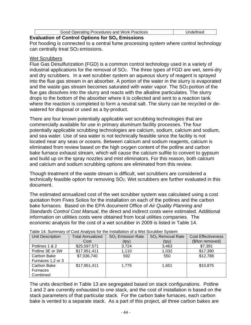
- 44 -
Good Operating Procedures and Work Practices Undefined
Evaluation of Control Options for SOx Emissions Pot hooding is connected to a central fume processing system where control technology can centrally treat SO2 emissions.
Wet Scrubbers Flue Gas Desulfurization (FGD) is a common control technology used in a variety of industrial applications for the removal of SO2. The three types of FGD are wet, semi-dry and dry scrubbers. In a wet scrubber system an aqueous slurry of reagent is sprayed into the flue gas stream in an absorber. A portion of the water in the slurry is evaporated and the waste gas stream becomes saturated with water vapor. The SO2 portion of the flue gas dissolves into the slurry and reacts with the alkaline particulates. The slurry drops to the bottom of the absorber where it is collected and sent to a reaction tank where the reaction is completed to form a neutral salt. The slurry can be recycled or de-watered for disposal or used as a by-product.
There are four known potentially applicable wet scrubbing technologies that are commercially available for use in primary aluminum facility processes. The four potentially applicable scrubbing technologies are calcium, sodium, calcium and sodium, and sea water. Use of sea water is not technically feasible since the facility is not located near any seas or oceans. Between calcium and sodium reagents, calcium is eliminated from review based on the high oxygen content of the potline and carbon bake furnace exhaust stream, which will cause the calcium sulfite to convert to gypsum and build up on the spray nozzles and mist eliminators. For this reason, both calcium and calcium and sodium scrubbing options are eliminated from this review.
Though treatment of the waste stream is difficult, wet scrubbers are considered a technically feasible option for removing SO2. Wet scrubbers are further evaluated in this document.
The estimated annualized cost of the wet scrubber system was calculated using a cost quotation from Fives Solios for the installation on each of the potlines and the carbon bake furnaces. Based on the EPA document Office of Air Quality Planning and Standards Control Cost Manual, the direct and indirect costs were estimated. Additional information on utilities costs were obtained from local utilities companies. The economic analysis for the cost of a wet scrubber in 2009 is listed in Table 14. Table 14: Summary of Cost Analysis for the Installation of a Wet Scrubber System Unit Description Total Annualized
Cost SO2 Emission Rate
(tpy) SO2 Removal Rate
(tpy) Cost Effectiveness
($/ton removed) Potlines 1 & 2 $25,597,571 3,724 3,463 $7,391 Potline 3E or 3W $17,951,411 1,110 1,032 $17,390 Carbon Bake Furnaces 1,2 or 3
$7,036,740 592 550 $12,788
Carbon Bake Furnaces Combined
$17,951,411 1,775 1,651 $10,875
The units described in Table 13 are segregated based on stack configurations. Potline 1 and 2 are currently exhausted to one stack, and the cost of installation is based on the stack parameters of that particular stack. For the carbon bake furnaces, each carbon bake is vented to a separate stack. As a part of this project, all three carbon bakes are

- 45 -
being vented to one stack. However, for purposes of this cost analysis, both the separate stack and single stack scenarios were evaluated. The emission rates for each unit were based on the worst case emissions expected from each process. For example, the SO2 emission rate listed for Potlines 1 & 2 assumes 98.8% of the SO2 emissions are attributed to the potline process and 99.01% of those emissions were emitted through the stacks (Scenario 2). The resulting cost effectiveness for each case was $7,000-$17,000 per ton of SO2 removed. Based on this economic analysis, the wet scrubber was eliminated from further review.
Dry or Semi-Dry Scrubbers Dry scrubbing for SO2 control typically involves the injection of a powdered sorbent, which is usually a calcium or sodium based alkaline reagent, into the flue gas. There, it reacts with SO2 to form calcium or sodium sulfate solids. The dry by-product is then removed in a particulate collection device located downstream, typically a baghouse. Semi-dry scrubbing involves the injection of an aqueous slurry into the hot flue gas. The aqueous sorbent is released as an atomized spray directly into the flue gas exhaust stream where it absorbs SO2 and dries. The dried particulates are collected downstream in the exhaust by an ESP or baghouse.
Dry scrubbing systems are typically less efficient than wet scrubbing systems focused on SO2 removal. Additionally, the temperature of the exhaust stream for both the dry and semi-dry systems must be at least 300 degrees Fahrenheit in order for the SO2 emissions to adsorb to the reagent. For the semi-dry system especially, the exhaust temperature must be high enough to allow the wet spray to be completely dried before being captured downstream in the exhaust as a particulate. The temperature of the exhaust stream for the potlines and carbon bake furnaces is below this absorption reaction temperature making the absorbent ineffective. Given that the temperature of the exhaust is too cool for effective use of an SO2 scrubber sorbent, and, as noted in earlier BACT analysis, heating the exhaust gas to the appropriate temperature would require combustion of additional fuel, creating additional pollutants. As such, this method of control was eliminated from further review.
Low Sulfur Content and Good Operating Procedures and Work Practices As mentioned previously, sulfur oxides originate from sulfur in the petroleum coke and coal tar pitch used in the formation of carbon anodes. By reducing the quantity of sulfur in the anode coke and pitch, the overall generation of SO2 in all areas of the process is reduced. Noranda currently obtains these raw materials from outside vendors. Although Noranda is unable to directly control the sulfur content of the raw materials, they are able to control which vendor will supply them with the raw materials. The coke and pitch supplies must have needed fuel characteristics while also being consistently available and economically reasonable to obtain. Utilizing low sulfur content anode coke and pitch is a technically feasible option for reducing SO2 levels.
Similar to the work practice and operating procedures control option discussed in the PM10 BACT analysis section, overall SOx emissions can also be reduced by optimizing operating procedures and work practices, such as the suppression of anode effects, monitoring bath temperatures and bath ratios, and proper hood maintenance.

- 46 -
The utilization of these control techniques in combination will have increased control effectiveness than individually. Therefore, this control method is considered BACT for SOx. Selection SOx Control Technology In conclusion, BACT for the control of SOx is low sulfur content, and good operating procedures and work practices. Noranda shall not exceed 6,078 tons per year from the entire installation in any consecutive 12-month period. In addition, the sulfur content of coke shall not exceed 3.0% and sulfur content of pitch shall not exceed 0.8%.
Control of CO Emissions The emissions increase of CO due to the proposed modification of the potlines and the carbon bake furnaces is significant and triggers major review. As with the BACT analysis for PM2.5, several databases including the RBLC database were searched to identify control technologies for CO. However, no technically feasible add-on control technologies for the potlines or the carbon bake furnaces were identified. The only control strategy for CO emissions currently employed by other primary aluminum production facilities is Pollution Prevention through Good Design and Operation. Noranda has compiled a list of possible control technologies based on potential control equipment in other industrial applications. Control technologies that were identified for CO emissions from the potlines and carbon bake furnaces are listed in Table 15.
Table 15: CO control technologies for potlines and carbon bake furnace Control Technology Thermal Oxidation Catalytic Oxidation
Low-Energy Burner Technology* Good Operating Practices
*Carbon bake furnace only
Evaluation of Control Options for CO Emissions The PM2.5 BACT analysis presented earlier in this document discusses both the thermal oxidation and catalytic oxidation control technologies as they pertain to the reduction of PM2.5 emissions. Those same arguments of technical feasibility are also applicable for the determination of BACT for CO emissions. The alumina and silica ceramic beds, typically used in an RTO, are susceptible to corrosion by hydrogen fluoride emissions present in the exhaust from the potlines and the carbon bake furnaces. Catalyst poisoning and catalyst de-activation is a concern in catalytic oxidation since both the potlines and the carbon bake furnaces have high concentrations of particulate matter, sulfur oxides, fluorides and metals in the exhaust streams. In both control options, the exhaust temperatures from the potlines and the carbon bake furnaces are too low for proper oxidation. Both of these options are not considered further as viable CO control technologies.
Low Energy Burner Technology For Noranda’s carbon bake furnaces, an advanced firing system, referred to as a low energy burner, has been identified as BACT. A low energy burner requires less fuel (coke) to achieve the desired pitch burn rate which results in reduced CO emissions. As Noranda already utilizes an advanced firing system in the Carbon Bake Furnaces 1, 2, and 3, Noranda’s CO emissions from the combined stack (EP-AAA) should be less than 271 pounds per hour.

- 47 -
Good Design and Operation According to the RBLC database, no other primary aluminum production facility has employed add-on controls for the reduction of CO emissions. For Noranda’s potlines, good design and operation resulting in maximum operating efficiencies has been identified as BACT. Noranda has installed electronic monitoring and controls to achieve optimal efficiency. Therefore, CO emissions from Noranda’s Potline stacks should be less than 5,520 pounds per hour from Potline 1 & 2 Stack (EP-61) and less than 1,642 pounds per hour each from Potline 3 East Stack (EP-62) and Potline 3 West Stack (EP-63). The fugitive CO emissions from Noranda’s Potline roof vents should be less than 110 pounds per hour from Potline 1 & 2 roof vents (EP-59 and EP-60) and less than 131 pounds per hour from Potline 3 roof vents (EP-64). Selection CO Control Technology In conclusion, BACT for the control of CO from the aluminum potlines is the use of good design and operation and BACT for the control of CO from the carbon bake furnaces is the use of low energy burner technology. Therefore, Noranda is required to meet the emission rates indicated in Table 16 below. Table 16: Summary of the BACT Emission Rates for CO Emission Point Description Emission Rate
EP-59 Potline 1 Roof Vent 110.0 lb/hr 9.58 lb/ton Al produced
EP-60 Potline 2 Roof Vent 110.0 lb/hr 9.58 lb/ton Al produced
EP-61 Potlines 1 & 2 Stack 5,520.0 lb/hr 240.4 lb/ton Al produced
EP-62 Potline 3 East Stack 1,642.0 lb/hr 232.5 lb/ton Al produced
EP-63 Potline 3 West Stack 1,642.0 lb/hr 232.5 lb/ton Al produced
EP-64 Potline 3 Roof Vent 131.0 lb/hr 9.27 lb/ton Al produced
EP-AAA Carbon Bake Furnaces 1, 2, & 3 (Combined) Stack 271.0 lb/hr 10.9 lb/ton green anode produced
PERMIT RULE APPLICABILITY
This review was conducted in accordance with Section (8) of Missouri State Rule 10 CSR 10-6.060, Construction Permits Required. Potential emissions of SOx, CO, PM10, PM2.5 and fluoride are above significance levels.
APPLICABLE REQUIREMENTS
Noranda Aluminum, Inc. shall comply with the following applicable requirements. The Missouri Air Conservation Laws and Regulations should be consulted for specific record keeping, monitoring, and reporting requirements. Compliance with these emission standards, based on information submitted in the application, has been verified at the time this application was approved. For a complete list of applicable requirements for your installation, please consult your operating permit.

- 48 -
GENERAL REQUIREMENTS
Submission of Emission Data, Emission Fees and Process Information, 10 CSR 10-6.110 The emission fee is the amount established by the Missouri Air Conservation Commission annually under Missouri Air Law 643.079(1). Submission of an Emissions Inventory Questionnaire (EIQ) is required June 1 for the previous year's emissions.
Operating Permits, 10 CSR 10-6.065
Restriction of Particulate Matter to the Ambient Air Beyond the Premises of Origin, 10 CSR 10-6.170
Restriction of Emission of Visible Air Contaminants, 10 CSR 10-6.220
Restriction of Emission of Odors, 10 CSR 10-3.090
SPECIFIC REQUIREMENTS
Restriction of Emission of Particulate Matter From Industrial Processes, 10 CSR 10-6.400
New Source Performance Regulations, 10 CSR 10-6.070 – New Source Performance Standards (NSPS) for Primary Aluminum Reduction Plants, 40 CFR Part 60, Subpart S
Maximum Achievable Control Technology (MACT) Regulations, 10 CSR 10-6.075, National Emission Standards for Primary Aluminum Reduction Plants, 40 CFR Part 63, Subpart LL
Maximum Achievable Control Technology (MACT) Regulations, 10 CSR 10-6.075, National Emission Standards for Secondary Aluminum Production, 40 CFR Part 63, Subpart RRR
Restriction of Emission of Sulfur Compounds, 10 CSR 10-6.260
Maximum Allowable Emissions of Particulate Matter From Fuel Burning Equipment Used for Indirect Heating, 10 CSR 10-3.060
AMBIENT AIR QUALITY IMPACT ANALYSIS
An ambient air quality impact analysis (AAQIA) was performed to determine the impact of PM10, SO2, CO, fluorides and HAP emissions at or beyond the property boundary of the Noranda Aluminum, Inc. facility. Additional impacts on visibility, growth, soils, plants and animals were also evaluated within the Class II area surrounding the facility. For complete modeling information refer to the February 5, 2010 memorandum from Dawn Froning entitled, “Ambient Air Quality Impact Analysis (AAQIA) for Noranda Aluminum, Inc. (Noranda)-Prevention of Significant Deterioration (PSD) Modeling—September 9, 2008 Submittal”.
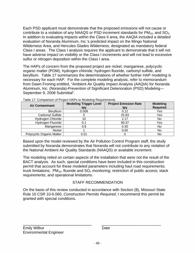
- 49 -
Each PSD applicant must demonstrate that the proposed emissions will not cause or contribute to a violation of any NAAQS or PSD increment standards for PM10, and SO2. In addition to evaluating impacts within the Class II area, the AAQIA included a detailed evaluation of Noranda Aluminum, Inc.’s predicted impact on the Mingo National Wilderness Area, and Hercules Glades Wilderness, designated as mandatory federal Class I areas. The Class I analysis requires the applicant to demonstrate that it will not have adverse impact on visibility or the Class I increments and will not lead to excessive sulfur or nitrogen deposition within the Class I area.
The HAPs of concern from the proposed project are nickel, manganese, polycyclic organic matter (POM), hydrogen chloride, hydrogen fluoride, carbonyl sulfide, and beryllium. Table 17 summarizes the determinations of whether further HAP modeling is necessary for each HAP. For the complete modeling analysis, refer to memorandum from Dawn Froning entitled, “Ambient Air Quality Impact Analysis (AAQIA) for Noranda Aluminum, Inc. (Noranda)-Prevention of Significant Deterioration (PSD) Modeling—September 9, 2008 Submittal”. Table 17: Comparison of Project HAPs to Modeling Requirements
Air Contaminant Modeling Trigger Level
tpy Project Emission Rate
tpy Modeling Required
Beryllium 0.008 0.12 Yes Carbonyl Sulfide 5 25.83 Yes
Hydrogen Chloride 10 2.17 No Hydrogen Fluoride 0.1 99.37 Yes
Manganese 0.8 0.30 No Nickel 1 0.60 No
Polycyclic Organic Matter 0.01 0 No
Based upon the model reviewed by the Air Pollution Control Program staff, the study submitted by Noranda demonstrates that Noranda will not contribute to any violation of the National Ambient Air Quality Standards (NAAQS) or available increment.
The modeling relied on certain aspects of the installation that were not the result of the BACT analysis. As such, special conditions have been included in this construction permit that account for these modeled parameters including haul road requirements; truck limitations; PM10, fluoride and SOx monitoring; restriction of public access; stack requirements; and operational limitations.
STAFF RECOMMENDATION
On the basis of this review conducted in accordance with Section (8), Missouri State Rule 10 CSR 10-6.060, Construction Permits Required, I recommend this permit be granted with special conditions.
____________________________ Emily Wilbur Date Environmental Engineer

- 50 -
PERMIT DOCUMENTS The following documents are incorporated by reference into this permit: The Application for Authority to Construct form, dated September 3, 2008, received September 12,
2008, designating Noranda, Inc. as the owner and operator of the installation. U.S. EPA document AP-42, Compilation of Air Pollutant Emission Factors, Fifth Edition. Southeast Regional Office Site Survey, dated October 16, 2008. PM2.5 BACT analysis submitted by Trinity Consultants through email November 13, 2009 EPA document Basis and Purpose Document for the Development of Proposed Standards for the
Primary Aluminum Industry dated July 19, 1996 EPA document Primary Aluminum Industry: Technical Support Document for Proposed MACT
Standards dated July 1996 EPA document Air Pollution Control Technology Fact Sheet EPA-452/F-03-034 EPA document Office of Air Quality Planning and Standards Control cost Manual 6th Edition
EPA/452/B-02-001 EPA document, AIRS Facility Subsystem Source Classification Codes and Emission Factor Listing for
Criteria Air Pollutants, EPA 450/4-09-003 dated March 1990 WebFIRE Last updated on Tuesday, December 22nd, 2009
http://cfpub.epa.gov/oarweb/index.cfm?action=fire.main Internal Memo from Dawn Froning, Ambient Air Quality Impact Analysis (AAQIA) for Noranda
Aluminum, Inc. (Noranda)-Prevention of Significant Deterioration (PSD) Modeling—September 9, 2008 Submittal
Test results for gaseous fluorides received via email November 4, 2008 Letter from Trinity titled SO2 Emissions Explanation for PSD Application, received via email December
15, 2008 Supplemental project descriptions received via email January 7, 2009 SO2 calculation discussions received via email January 14, 2009 PM10 BACT limit discussions received via email February 26, 2009 Carbon monoxide BACT limit discussions received via email April 13, 2009 Discussions on natural gas usage and the proposed limit received via email September 29, 2009 Trace element composition of coke and pitch document and material handling baghouse stack testing
results received via email October 29, 2009 Proposed changes to existing equipment required to show compliance with modeling, received via
email November 23, 2009

- 51 -
Responses to questions on proposed changes to existing equipment required to show compliance with modeling, received via email December 2, 2009
Responses to questions regarding haul roads received via email December 4, 2009 Discussions on emission points not included in the original application and modeling via email
received January 7, 2010 and via conference call on January 7, 2010 Reponses to questions on emission points not included in the original application and modeling via
email received January 14, 2010 Correction to POM emission rates received via email January 22, 2010 Culpability analysis discussions for HF received via email January 28, 2010 and February 1, 2010 Capture efficiency discussions received via email February 1, 2010 and February 2, 2010
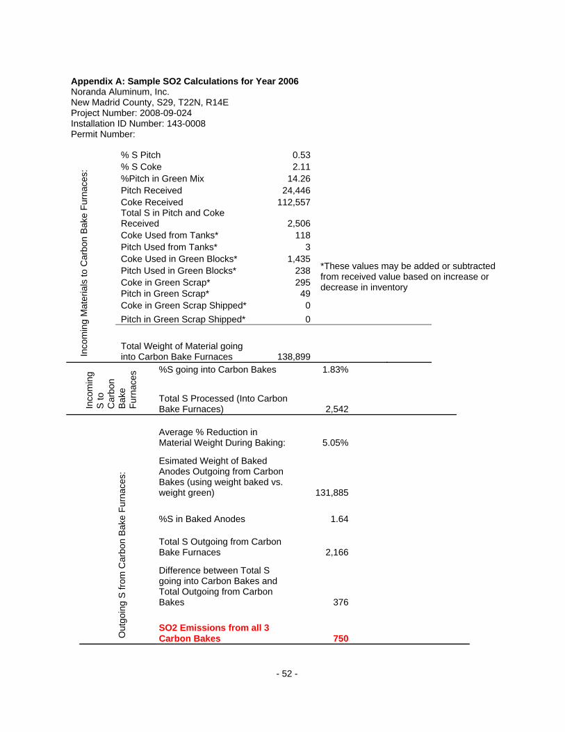
- 52 -
Appendix A: Sample SO2 Calculations for Year 2006 Noranda Aluminum, Inc. New Madrid County, S29, T22N, R14E Project Number: 2008-09-024 Installation ID Number: 143-0008 Permit Number:
% S Pitch 0.53 % S Coke 2.11 %Pitch in Green Mix 14.26 Pitch Received 24,446 Coke Received 112,557 Total S in Pitch and Coke Received 2,506 Coke Used from Tanks* 118Pitch Used from Tanks* 3Coke Used in Green Blocks* 1,435Pitch Used in Green Blocks* 238Coke in Green Scrap* 295Pitch in Green Scrap* 49Coke in Green Scrap Shipped* 0
Pitch in Green Scrap Shipped* 0
*These values may be added or subtracted from received value based on increase or decrease in inventory
Inco
min
g M
ater
ials
to C
arbo
n B
ake
Fur
nace
s:
Total Weight of Material going into Carbon Bake Furnaces 138,899
%S going into Carbon Bakes 1.83%
Inco
min
g S
to
Car
bon
Bak
e F
urna
ces
Total S Processed (Into Carbon Bake Furnaces) 2,542
Average % Reduction in Material Weight During Baking: 5.05%
Esimated Weight of Baked Anodes Outgoing from Carbon Bakes (using weight baked vs. weight green) 131,885
%S in Baked Anodes 1.64
Total S Outgoing from Carbon Bake Furnaces 2,166
Difference between Total S going into Carbon Bakes and Total Outgoing from Carbon Bakes 376
Out
goin
g S
from
Car
bon
Bak
e F
urna
ces:
SO2 Emissions from all 3 Carbon Bakes 750

- 53 -
Coke in Addt'l Baked Blocks* 252
Pitch in Addt'l Baked Blocks* Assume no pitch here
Coke in Butts,Rodding&Baked Scrap* 794Pitch in Butts,Rodding&Baked Scrap*
Assume no pitch here
Coke in Butts&Carbon Shipped* 5,383
Pitch in Butts&Carbon Shipped* Assume no pitch here
*These values may be added or subtracted from incoming value based on increase or decrease in inventory
Sulfur in fresh alumina This item will be based on testing results
Inco
min
g M
ater
ials
to P
otlin
es:
Sulfur in reacted alumina This item will be based on testing results
Weight of Baked Anodes into Potlines 125,960
Total Weight of S Anodes Processed into Potlines 2,041
Out
goin
g S
from
P
otlin
es:
SO2 Emissions from all 3 Potlines 4,078
SO2 Emissions from Natural Gas Sources 0.26
Total SO2 Emissions from Entire Installation* 4,829
*For a list of all emission points associated with the entire installation, see Table A.1
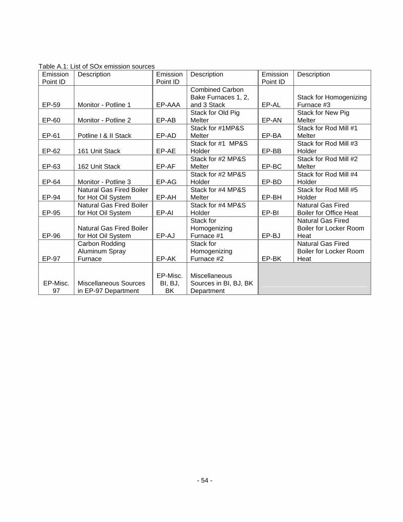
- 54 -
Table A.1: List of SOx emission sources Emission Point ID
Description Emission Point ID
Description Emission Point ID
Description
EP-59 Monitor - Potline 1 EP-AAA
Combined Carbon Bake Furnaces 1, 2, and 3 Stack EP-AL
Stack for Homogenizing Furnace #3
EP-60 Monitor - Potline 2 EP-AB Stack for Old Pig Melter EP-AN
Stack for New Pig Melter
EP-61 Potline I & II Stack EP-AD Stack for #1MP&S Melter EP-BA
Stack for Rod Mill #1 Melter
EP-62 161 Unit Stack EP-AE Stack for #1 MP&S Holder EP-BB
Stack for Rod Mill #3 Holder
EP-63 162 Unit Stack EP-AF Stack for #2 MP&S Melter EP-BC
Stack for Rod Mill #2 Melter
EP-64 Monitor - Potline 3 EP-AG Stack for #2 MP&S Holder EP-BD
Stack for Rod Mill #4 Holder
EP-94 Natural Gas Fired Boiler for Hot Oil System EP-AH
Stack for #4 MP&S Melter EP-BH
Stack for Rod Mill #5 Holder
EP-95 Natural Gas Fired Boiler for Hot Oil System EP-AI
Stack for #4 MP&S Holder EP-BI
Natural Gas Fired Boiler for Office Heat
EP-96 Natural Gas Fired Boiler for Hot Oil System EP-AJ
Stack for Homogenizing Furnace #1 EP-BJ
Natural Gas Fired Boiler for Locker Room Heat
EP-97
Carbon Rodding Aluminum Spray Furnace EP-AK
Stack for Homogenizing Furnace #2 EP-BK
Natural Gas Fired Boiler for Locker Room Heat
EP-Misc. 97
Miscellaneous Sources in EP-97 Department
EP-Misc. BI, BJ,
BK
Miscellaneous Sources in BI, BJ, BK Department
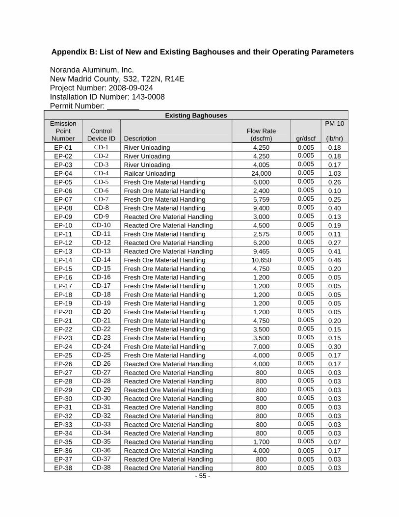
- 55 -
Appendix B: List of New and Existing Baghouses and their Operating Parameters Noranda Aluminum, Inc. New Madrid County, S32, T22N, R14E Project Number: 2008-09-024 Installation ID Number: 143-0008 Permit Number:
Existing Baghouses Emission
Point Number
Control Device ID Description
Flow Rate (dscfm) gr/dscf
PM-10
(lb/hr) EP-01 CD-1 River Unloading 4,250 0.005 0.18 EP-02 CD-2 River Unloading 4,250 0.005 0.18 EP-03 CD-3 River Unloading 4,005 0.005 0.17 EP-04 CD-4 Railcar Unloading 24,000 0.005 1.03 EP-05 CD-5 Fresh Ore Material Handling 6,000 0.005 0.26 EP-06 CD-6 Fresh Ore Material Handling 2,400 0.005 0.10 EP-07 CD-7 Fresh Ore Material Handling 5,759 0.005 0.25 EP-08 CD-8 Fresh Ore Material Handling 9,400 0.005 0.40 EP-09 CD-9 Reacted Ore Material Handling 3,000 0.005 0.13 EP-10 CD-10 Reacted Ore Material Handling 4,500 0.005 0.19 EP-11 CD-11 Fresh Ore Material Handling 2,575 0.005 0.11 EP-12 CD-12 Reacted Ore Material Handling 6,200 0.005 0.27 EP-13 CD-13 Reacted Ore Material Handling 9,465 0.005 0.41 EP-14 CD-14 Fresh Ore Material Handling 10,650 0.005 0.46 EP-15 CD-15 Fresh Ore Material Handling 4,750 0.005 0.20 EP-16 CD-16 Fresh Ore Material Handling 1,200 0.005 0.05 EP-17 CD-17 Fresh Ore Material Handling 1,200 0.005 0.05 EP-18 CD-18 Fresh Ore Material Handling 1,200 0.005 0.05 EP-19 CD-19 Fresh Ore Material Handling 1,200 0.005 0.05 EP-20 CD-20 Fresh Ore Material Handling 1,200 0.005 0.05 EP-21 CD-21 Fresh Ore Material Handling 4,750 0.005 0.20 EP-22 CD-22 Fresh Ore Material Handling 3,500 0.005 0.15 EP-23 CD-23 Fresh Ore Material Handling 3,500 0.005 0.15 EP-24 CD-24 Fresh Ore Material Handling 7,000 0.005 0.30 EP-25 CD-25 Fresh Ore Material Handling 4,000 0.005 0.17 EP-26 CD-26 Reacted Ore Material Handling 4,000 0.005 0.17 EP-27 CD-27 Reacted Ore Material Handling 800 0.005 0.03 EP-28 CD-28 Reacted Ore Material Handling 800 0.005 0.03 EP-29 CD-29 Reacted Ore Material Handling 800 0.005 0.03 EP-30 CD-30 Reacted Ore Material Handling 800 0.005 0.03 EP-31 CD-31 Reacted Ore Material Handling 800 0.005 0.03 EP-32 CD-32 Reacted Ore Material Handling 800 0.005 0.03 EP-33 CD-33 Reacted Ore Material Handling 800 0.005 0.03 EP-34 CD-34 Reacted Ore Material Handling 800 0.005 0.03 EP-35 CD-35 Reacted Ore Material Handling 1,700 0.005 0.07 EP-36 CD-36 Reacted Ore Material Handling 4,000 0.005 0.17 EP-37 CD-37 Reacted Ore Material Handling 800 0.005 0.03 EP-38 CD-38 Reacted Ore Material Handling 800 0.005 0.03

- 56 -
EP-39 CD-39 Reacted Ore Material Handling 800 0.005 0.03 EP-40 CD-40 Reacted Ore Material Handling 800 0.005 0.03 EP-41 CD-41 Reacted Ore Material Handling 800 0.005 0.03 EP-42 CD-42 Reacted Ore Material Handling 800 0.005 0.03 EP-43 CD-43 Reacted Ore Material Handling 800 0.005 0.03 EP-44 CD-44 Reacted Ore Material Handling 800 0.005 0.03 EP-45 CD-45 Reacted Ore Material Handling 1,700 0.005 0.07 EP-46 CD-46/A Electrolyte Recovery 30,500 0.005 0.98 EP-47 CD-47 Electrolyte Recovery 150,000 0.005 0.00 EP-48 CD-48 Electrolyte Recovery 71,500 0.005 2.30 EP-49 CD-49 Electrolyte Recovery 2,800 0.005 0.12 EP-50 CD-50 Electrolyte Recovery 23,000 0.005 0.74 EP-55 CD-55 Electrolyte Recovery 2,800 0.005 0.12 EP-56 CD-56 Electrolyte Recovery 2,800 0.005 0.12 EP-57 CD-57 Fresh Ore Material Handling 6,000 0.005 0.26 EP-58 CD-58 Electrolyte Recovery 12,000 0.005 0.39 EP-65 CD-65 Petroleum Coke Handling 4,000 0.005 0.17 EP-66 CD-66 Petroleum Coke Handling 4,000 0.005 0.17 EP-67 CD-67 Petroleum Coke Handling 1,500 0.005 0.06 EP-68 CD-68 Primary Crusher (North) 10,000 0.005 0.29 EP-69 CD-69 Primary Crusher (South) 16,000 0.005 0.34 EP-70 CD-70 Tertiary Crusher 13,950 0.005 0.40 EP-71 CD-71 Anode Paste Production 1,500 0.005 0.06 EP-72 CD-72 Anode Paste Production 4,000 0.005 0.17 EP-73 CD-73 Anode Paste Production 17,620 0.005 0.76 EP-74 CD-74 Anode Paste Production 2,600 0.005 0.11 EP-79 CD-79 Anode Cleaning System 5,000 0.005 0.21 EP-80 CD-80 Fresh Ore Handling 2,400 0.005 0.10 EP-81 CD-81 Fresh Ore Handling 325 0.005 0.01 EP-82 CD-82 Anode Stem Cleaning (Phase I) 8,960 0.005 0.16 EP-83 CD-83 Cathode Casting Station 6,050 0.005 0.00 EP-84 CD-84 Anode Stem Cleaning 5,390 0.005 0.00
EP-DW CD-DW Potline Crusher 43,800 0.005 0.94 EP-100 CD-100 Carbon Dry Scrubber 12,000 0.005 0.51 EP-101 CD-101 Fraction Handling 7,000 0.005 0.30 EP-102 CD-102 Proportioning System 4,700 0.005 0.20 EP-108 CD-108 Brush Station 1,000 0.005 0.04
EP-109 CD-109 Brush Station 1,000 0.005 0.04
EP-110 CD-110 KHD ANODE CRUSHER 60,000 0.005 2.57
EP-111 CD-111 Grooved Anode Saw Dust Collector 10,000 0.005 0.43
New Baghouses Emission
Point Number
Control Device ID Description
Flow Rate (dscfm) gr/scf
PM-10
(lb/hr)
EP-BA CD-BA Stack for Rod Mill #1 Melter 387 (1,126 acfm) 0.005 0.0166
EP-BB CD-BB Stack for Rod Mill #3 Holder 151 (382 acfm) 0.005 0.0065
EP-BC CD-BC Stack for Rod Mill #2 Melter 387 (1,126 acfm) 0.005 0.0166
EP-BD CD-BD Stack for Rod Mill #4 Holder 151 (382 acfm) 0.005 0.0065
EP-BH CD-BH Stack for Rod Mill #5 Holder 6 (18.6 acfm) 0.005 0.0003

- 57 -
Appendix C: Existing Throughput of Emission Units Noranda Aluminum, Inc. New Madrid County, S32, T22N, R14E Project Number: 2008-09-024 Installation ID Number: 143-0008 Permit Number:
Emission Point Number `Description Throughput (tpy) EP-01 RIVER UNLOADING 26,091.61 EP-02 RIVER UNLOADING 26,091.61 EP-03 RIVER UNLOADING 24,587.50 EP-04 RIVER UNLOADING 5,781.80 EP-05 FRESH ORE MATERIAL HANDLING 36,835.21 EP-06 FRESH ORE MATERIAL HANDLING 14,734.09 EP-07 FRESH ORE MATERIAL HANDLING 35,355.67 EP-08 FRESH ORE MATERIAL HANDLING 57,708.50 EP-09 REACTED ORE MATERIAL HANDLING 35,334.78 EP-10 REACTED ORE MATERIAL HANDLING 53,002.16 EP-11 FRESH ORE MATERIAL HANDLING 15,808.45 EP-12 REACTED ORE MATERIAL HANDLING 73,025.20 EP-13 REACTED ORE MATERIAL HANDLING 115,426.94 EP-14 FRESH ORE MATERIAL HANDLING 65,382.50 EP-15 FRESH ORE MATERIAL HANDLING 29,161.21 EP-16 FRESH ORE MATERIAL HANDLING 7,367.04 EP-17 FRESH ORE MATERIAL HANDLING 7,367.04 EP-18 FRESH ORE MATERIAL HANDLING 7,367.04 EP-19 FRESH ORE MATERIAL HANDLING 7,367.04 EP-20 FRESH ORE MATERIAL HANDLING 7,367.04 EP-21 FRESH ORE MATERIAL HANDLING 29,161.21 EP-22 FRESH ORE MATERIAL HANDLING 21,487.21 EP-23 FRESH ORE MATERIAL HANDLING 21,487.21 EP-24 FRESH ORE MATERIAL HANDLING 42,974.41 EP-25 FRESH ORE MATERIAL HANDLING 24,556.81 EP-26 REACTED ORE MATERIAL HANDLING 47,113.04 EP-27 REACTED ORE MATERIAL HANDLING 9,422.61 EP-28 REACTED ORE MATERIAL HANDLING 9,422.61 EP-29 REACTED ORE MATERIAL HANDLING 9,422.61 EP-30 REACTED ORE MATERIAL HANDLING 9,422.61 EP-31 REACTED ORE MATERIAL HANDLING 9,422.61 EP-32 REACTED ORE MATERIAL HANDLING 9,422.61 EP-33 REACTED ORE MATERIAL HANDLING 9,422.61 EP-34 REACTED ORE MATERIAL HANDLING 9,422.61 EP-35 REACTED ORE MATERIAL HANDLING 20,023.04 EP-36 REACTED ORE MATERIAL HANDLING 47,113.04 EP-37 REACTED ORE MATERIAL HANDLING 9,422.61 EP-38 REACTED ORE MATERIAL HANDLING 9,422.61 EP-39 REACTED ORE MATERIAL HANDLING 9,422.61 EP-40 REACTED ORE MATERIAL HANDLING 9,422.61 EP-41 REACTED ORE MATERIAL HANDLING 9,422.61 EP-42 REACTED ORE MATERIAL HANDLING 9,422.61 EP-43 REACTED ORE MATERIAL HANDLING 9,422.61
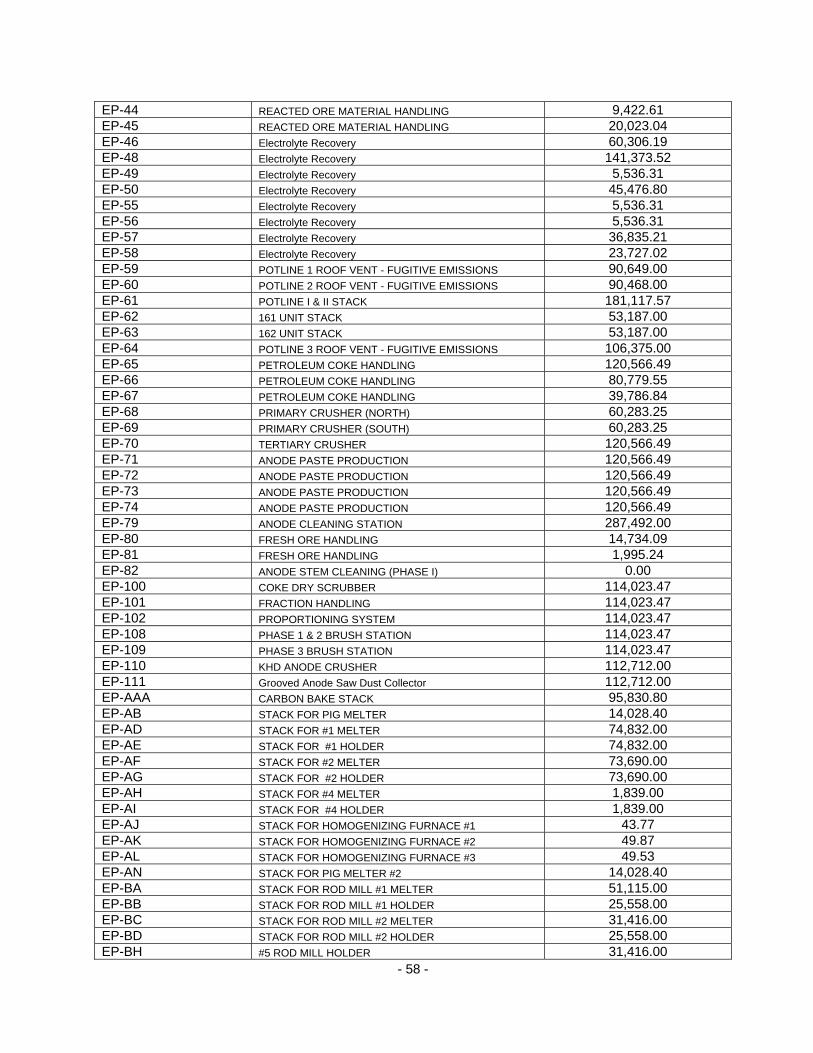
- 58 -
EP-44 REACTED ORE MATERIAL HANDLING 9,422.61 EP-45 REACTED ORE MATERIAL HANDLING 20,023.04 EP-46 Electrolyte Recovery 60,306.19 EP-48 Electrolyte Recovery 141,373.52 EP-49 Electrolyte Recovery 5,536.31 EP-50 Electrolyte Recovery 45,476.80 EP-55 Electrolyte Recovery 5,536.31 EP-56 Electrolyte Recovery 5,536.31 EP-57 Electrolyte Recovery 36,835.21 EP-58 Electrolyte Recovery 23,727.02 EP-59 POTLINE 1 ROOF VENT - FUGITIVE EMISSIONS 90,649.00 EP-60 POTLINE 2 ROOF VENT - FUGITIVE EMISSIONS 90,468.00 EP-61 POTLINE I & II STACK 181,117.57 EP-62 161 UNIT STACK 53,187.00 EP-63 162 UNIT STACK 53,187.00 EP-64 POTLINE 3 ROOF VENT - FUGITIVE EMISSIONS 106,375.00 EP-65 PETROLEUM COKE HANDLING 120,566.49 EP-66 PETROLEUM COKE HANDLING 80,779.55 EP-67 PETROLEUM COKE HANDLING 39,786.84 EP-68 PRIMARY CRUSHER (NORTH) 60,283.25 EP-69 PRIMARY CRUSHER (SOUTH) 60,283.25 EP-70 TERTIARY CRUSHER 120,566.49 EP-71 ANODE PASTE PRODUCTION 120,566.49 EP-72 ANODE PASTE PRODUCTION 120,566.49 EP-73 ANODE PASTE PRODUCTION 120,566.49 EP-74 ANODE PASTE PRODUCTION 120,566.49 EP-79 ANODE CLEANING STATION 287,492.00 EP-80 FRESH ORE HANDLING 14,734.09 EP-81 FRESH ORE HANDLING 1,995.24 EP-82 ANODE STEM CLEANING (PHASE I) 0.00 EP-100 COKE DRY SCRUBBER 114,023.47 EP-101 FRACTION HANDLING 114,023.47 EP-102 PROPORTIONING SYSTEM 114,023.47 EP-108 PHASE 1 & 2 BRUSH STATION 114,023.47 EP-109 PHASE 3 BRUSH STATION 114,023.47 EP-110 KHD ANODE CRUSHER 112,712.00 EP-111 Grooved Anode Saw Dust Collector 112,712.00 EP-AAA CARBON BAKE STACK 95,830.80 EP-AB STACK FOR PIG MELTER 14,028.40 EP-AD STACK FOR #1 MELTER 74,832.00 EP-AE STACK FOR #1 HOLDER 74,832.00 EP-AF STACK FOR #2 MELTER 73,690.00 EP-AG STACK FOR #2 HOLDER 73,690.00 EP-AH STACK FOR #4 MELTER 1,839.00 EP-AI STACK FOR #4 HOLDER 1,839.00 EP-AJ STACK FOR HOMOGENIZING FURNACE #1 43.77 EP-AK STACK FOR HOMOGENIZING FURNACE #2 49.87 EP-AL STACK FOR HOMOGENIZING FURNACE #3 49.53 EP-AN STACK FOR PIG MELTER #2 14,028.40 EP-BA STACK FOR ROD MILL #1 MELTER 51,115.00 EP-BB STACK FOR ROD MILL #1 HOLDER 25,558.00 EP-BC STACK FOR ROD MILL #2 MELTER 31,416.00 EP-BD STACK FOR ROD MILL #2 HOLDER 25,558.00 EP-BH #5 ROD MILL HOLDER 31,416.00

- 59 -
EP-DW POTLINE CRUSHING 5,895.00

- 60 -
Appendix D: Project Descriptions Noranda Aluminum, Inc. New Madrid County, S32, T22N, R14E Project Number: 2008-09-024 Installation ID Number: 143-0008 Permit Number:
Increased Rectification Capacity Install one additional rectifier/transformer for each line to allow operation at increased amperages at N-1 operation. Currently Lines 1 & 2 each have 7 rectifiers, Line 3 has 6 rectifiers. The current substation equipment is only capable of supporting production at 588 million pounds per year if ALL rectification equipment remains in operation at full capacity, meaning “N” operation. However, if a rectifier is taken off-line for preventive maintenance or breakdown reasons, the remaining rectifiers (N-1 operation) will not be able to support the operating rate. External Cell Resistance Reduction Replace 32,000 steel stubs on anode rods with larger diameter stubs. The larger diameter stubs reduce electrical resistance allowing operation at higher current efficiencies (CE) and lower voltages. Higher CE operation produces more aluminum per operation cell, and lower voltages allow more cells to operate at the same power consumption rates. Cathode BUSS leaf Addition Install an additional aluminum buss bar leaf to the downstream side buss bar on all 348 cells in Lines 1 and 2. The additional leaf increases the effective cross-sectional area of the buss, reducing its electrical resistance. The lower resistance reduces voltage, allowing operation of the cells at higher amperages at the same power consumption rates. Off-Line Reduction Cell Building Install crane to allow removal of out pots without digging and building cells off-line. Current crane limitations in the pot room prevent removing out cells or installing completely rebuilt cells. This project would result in a quicker turnaround time for a cell, from the time it went out until anew pot was started, increasing average number of operating pots. Anode Cover This project provides an alumina-bath mix for anode cover to all lines which will improve protection of the anode from air burn, improve pot stability, and increase heat loss from the top of the anode. The anode cover will occur in the pots and any additional emissions due to the alumina-bath mix will be incorporated into the potline emissions and governed by BACT limits and requirements.
- 61 -
Anode Rod/Stub/Yoke Assembly Install Rod Straighten Equipment to maintain the straightness of anode assemblies. This will reduce rework of assemblies in the Rodding Department and reduce voltage drop in the pot room, improving pot stability and production. No additional emissions are expected from this equipment. Green Anode Density “Dry” anode ingredients (petroleum coke, recycled scrap anodes, and spent anode butts) are first prepared by crushing and screening. They are segregated into size fractions (fine, medium and coarse) which are then blended together in a certain ratio. The dry blend is heated and mixed with the “wet” liquid coal tar pitch to make the final anode paste that will be formed into an anode block. Those blending ratios, along with temperatures of the various material streams, cycle times of equipment, forming pressures and anode block dimensions, are a few of the categories of parameters that will be optimized. One of the more critical parameters involves the size distribution of the fines fraction of the dry material. The fines fraction is produced when some of the dry material is passed through a special grinding circuit that utilizes a ball mill. Determining the optimum size distribution of this fines fraction and the best blend ratio of this fraction to the other dry carbon fractions will be a major focus for the process improvement team. Knowing the optimum parameters is not sufficient for increased, optimized production. The process equipment must operate both consistently and reliably. A second major emphasis for the improvement team is eliminating unexpected process excursions and downtimes. Although the entire Green Mill operations are included in the scope of the reliability initiative, a special area of emphasis will be the ball mill circuit. The team will need to improve the operation of the ball mill circuit to allow it to reliably produce the optimum fines fraction. The expectation for both of these efforts is to achieve them through improvement of operating and maintenance procedures, rather than through a process redesign program. It is believed the current equipment will be capable once optimized for the higher production level. The only new equipment expected under this project is the installation of a granulation scale (a Blaine machine) for measurement of the fines fraction sample. No additional emissions are expected from this equipment. Cell Thermal Insulation Modify the cell cathode design package including the use of 100% graphite cathodes and forced convection cooling. Currently, cathodes are 70% carbon and 30% graphite. This modification will not include the installation of new equipment. Additional Cells in Pot Lines Construction of 4 additional cells (Pots) in each pot line. The cells would be subject to the same requirements as the existing cells in each potline (i.e. BACT limits and control requirements). Currently, Lines 1 & 2 each have 174 cells, Line 3 has 160 cells.

- 62 -
Appendix E: Capture Equipment listed by Emission Units Noranda Aluminum, Inc. New Madrid County, S32, T22N, R14E Project Number: 2008-09-024 Installation ID Number: 143-0008 Permit Number:
Emission Point
ID Emission Point Description
Emission Unit ID
Emission Unit Description Capture Equipment
Control Device ID
EP-01 River Unloading EU0010 Vacuum Unloader Enclosed/Aspiration CD-1 EP-02 River Unloading EU0020 Vacuum Unloader Enclosed/Aspiration CD-2
EU0030 Airslide Enclosed/Aspiration EU0040 Airslide Enclosed/Aspiration EU0050 Airslide Enclosed/Aspiration EU0060 Airslide Enclosed/Aspiration EU0070 Airslide Enclosed/Aspiration EU0080 Airslide Enclosed/Aspiration EU0090 Airslide Enclosed/Aspiration
EP-03 River Unloading
EU0100 Airslide Enclosed/Aspiration
CD-3
EU0110 Vibrating Feeder Enclosed/Aspiration EU0120 Vibrating Feeder Enclosed/Aspiration EU0130 Vibrating Feeder Enclosed/Aspiration EU0140 Screw Conveyor Enclosed/Aspiration
EP-04 Railcar Unloading
EU0150 Car Shaker Enclosed/Aspiration
CD-4
EU0160 Bucket Elevator Enclosed/Aspiration EU0170 Bucket Elevator Enclosed/Aspiration EU0180 Airslide Enclosed/Aspiration EU0190 Airslide Enclosed/Aspiration EU0200 Airslide Enclosed/Aspiration EU0210 Airslide Enclosed/Aspiration EU0220 Airslide Enclosed/Aspiration EU0230 Airslide Enclosed/Aspiration EU0240 Airslide Enclosed/Aspiration
EP-05 Fresh Ore Material Handling
EU0250 Airslide Enclosed/Aspiration
CD-5
EP-06 Fresh Ore Material Handling
EU0260 Airslide Enclosed/Aspiration CD-6
EU0270 Belt Conveyor Enclosed/Aspiration EU0280 Screening Machine Enclosed/Aspiration EU0290 Air Gravity Conveyor Enclosed/Aspiration EU0300 Air Gravity Conveyor Enclosed/Aspiration EU0310 Air Gravity Conveyor Enclosed/Aspiration EU0320 Air Gravity Conveyor Enclosed/Aspiration EU0330 Air Gravity Conveyor Enclosed/Aspiration EU0350 Fan Enclosed/Aspiration EU0360 Fan Enclosed/Aspiration
EP-07 Fresh Ore Material Handling
EU0370 Lift Tower Enclosed/Aspiration
CD-7

- 63 -
Emission Point
ID Emission Point Description
Emission Unit ID
Emission Unit Description Capture Equipment
Control Device ID
EU0380 Lift Tower Enclosed/Aspiration
EU0390 Blower with filters and Motor
Enclosed/Aspiration
EU0400 Blower with filters and Motor
Enclosed/Aspiration
EU0410 Blower with filters and Motor
Enclosed/Aspiration
EU0430 Airslide Enclosed/Aspiration EU0440 Lift Tower Enclosed/Aspiration EU0450 Lift Tower Enclosed/Aspiration EU0460 Airslide Enclosed/Aspiration
EU0480 Blower with filters and Motor
Enclosed/Aspiration
EU0490 Blower with filters and Motor
Enclosed/Aspiration
EU0500 Blower with filters and Motor
Enclosed/Aspiration
EU0510 Fan Enclosed/Aspiration EU0520 Fan Enclosed/Aspiration EU0530 Air Gravity Conveyor Enclosed/Aspiration EU0540 Air Gravity Conveyor Enclosed/Aspiration EU0550 Air Gravity Conveyor Enclosed/Aspiration EU0560 Air Gravity Conveyor Enclosed/Aspiration EU0570 Air Gravity Conveyor Enclosed/Aspiration EU0580 Screening Machine Enclosed/Aspiration
EP-08 Fresh Ore Material Handling
EU0590 Belt Conveyor Enclosed/Aspiration
CD-8
EU0600 Airslide Enclosed/Aspiration EU0610 Airslide Enclosed/Aspiration EU0620 Airslide Enclosed/Aspiration EU0630 Airslide Enclosed/Aspiration
EP-09 Reacted Ore Material Handling
EU0640 Belt Conveyor Enclosed/Aspiration
CD-9
EP-10 Reacted Ore Material Handling
EU0650 Belt Conveyor Enclosed/Aspiration CD-10
EU0660 Belt Conveyor Enclosed/Aspiration EU0670 Flow Control Gate Enclosed/Aspiration EU0680 Flow Control Gate Enclosed/Aspiration EU0690 Flow Control Gate Enclosed/Aspiration EU0700 Airslide Enclosed/Aspiration EU0710 Airslide Enclosed/Aspiration EU0720 Airslide Enclosed/Aspiration EU0730 Airslide Enclosed/Aspiration EU0740 Airslide Enclosed/Aspiration EU0750 Airslide Enclosed/Aspiration EU0760 Airslide Enclosed/Aspiration EU0770 Airslide Enclosed/Aspiration
EP-11 Fresh Ore Material Handling
EU0780 Airslide Enclosed/Aspiration
CD-11
EP-12 Reacted Ore Material EU0790 Belt Conveyor Enclosed/Aspiration CD-12

- 64 -
Emission Point
ID Emission Point Description
Emission Unit ID
Emission Unit Description Capture Equipment
Control Device ID
EU0800 Airslide Enclosed/Aspiration Handling
EU0810 Airslide Enclosed/Aspiration EU0820 Side Discharge Gate Enclosed/Aspiration EU0830 Belt Conveyor Enclosed/Aspiration EU0840 Belt Conveyor Enclosed/Aspiration EU0850 Airslide Enclosed/Aspiration EU0860 Airslide Enclosed/Aspiration EU0870 Airslide Enclosed/Aspiration
EP-13 Reacted Ore Material Handling
EU0880 Bucket Elevator Enclosed/Aspiration
CD-13
EU0890 Belt Conveyor Enclosed/Aspiration EU0900 Airslide Enclosed/Aspiration EP-14
Fresh Ore Material Handling
EU0910 Airslide Enclosed/Aspiration CD-14
EU0920 Blower with filters and Motor
Enclosed/Aspiration
EU0950 Air Gravity Conveyor Enclosed/Aspiration EU0960 Air Gravity Conveyor Enclosed/Aspiration EU0970 Air Gravity Conveyor Enclosed/Aspiration EU0980 Air Gravity Conveyor Enclosed/Aspiration EU0990 Air Gravity Conveyor Enclosed/Aspiration EU1000 Air Gravity Conveyor Enclosed/Aspiration EU1010 Air Gravity Conveyor Enclosed/Aspiration EU1020 Airslide Enclosed/Aspiration EU1030 Airslide Enclosed/Aspiration EU1040 Airslide Enclosed/Aspiration
EP-15 Fresh Ore Material Handling
EU1050 Airslide Enclosed/Aspiration
CD-15
EP-16 Fresh Ore Material Handling
EU1060 Air Gravity Conveyor Enclosed/Aspiration CD-16
EP-17 Fresh Ore Material Handling
EU1070 Air Gravity Conveyor Enclosed/Aspiration CD-17
EP-18 Fresh Ore Material Handling
EU1080 Air Gravity Conveyor Enclosed/Aspiration CD-18
EP-19 Fresh Ore Material Handling
EU1090 Air Gravity Conveyor Enclosed/Aspiration CD-19
EP-20 Fresh Ore Material Handling
EU1100 Air Gravity Conveyor Enclosed/Aspiration CD-20
EP-21 Fresh Ore Material Handling
EU1110 Air Gravity Conveyor Enclosed/Aspiration CD-21
EU1120 Air Gravity Conveyor Enclosed/Aspiration EU1130 Air Gravity Conveyor Enclosed/Aspiration EU1140 Air Gravity Conveyor Enclosed/Aspiration EU1150 Air Gravity Conveyor Enclosed/Aspiration EU1160 Air Gravity Conveyor Enclosed/Aspiration EU1170 Air Gravity Conveyor Enclosed/Aspiration EU1180 Air Gravity Conveyor Enclosed/Aspiration
EP-22 Fresh Ore Material Handling
EU1190 Air Gravity Conveyor Enclosed/Aspiration
CD-22
EU1200 Screw Conveyor Enclosed/Aspiration EP-23 Fresh Ore Material Handling EU1210 Screw Conveyor Enclosed/Aspiration
CD-23
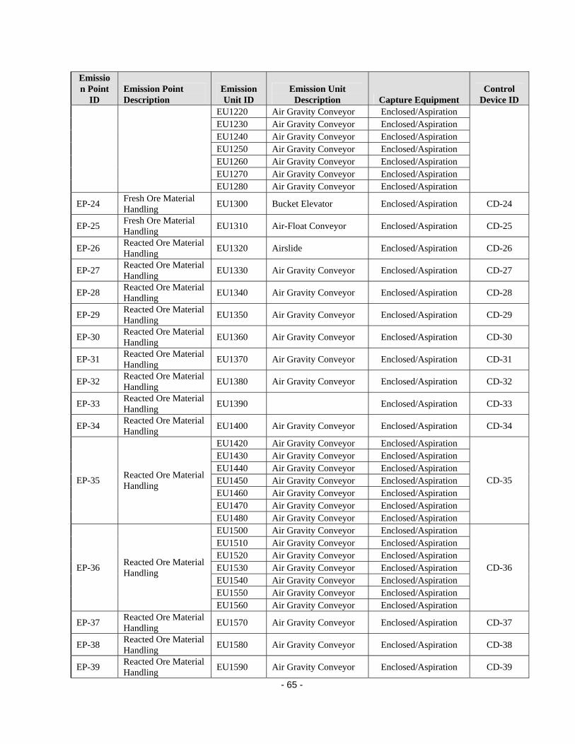
- 65 -
Emission Point
ID Emission Point Description
Emission Unit ID
Emission Unit Description Capture Equipment
Control Device ID
EU1220 Air Gravity Conveyor Enclosed/Aspiration EU1230 Air Gravity Conveyor Enclosed/Aspiration EU1240 Air Gravity Conveyor Enclosed/Aspiration EU1250 Air Gravity Conveyor Enclosed/Aspiration EU1260 Air Gravity Conveyor Enclosed/Aspiration EU1270 Air Gravity Conveyor Enclosed/Aspiration EU1280 Air Gravity Conveyor Enclosed/Aspiration
EP-24 Fresh Ore Material Handling
EU1300 Bucket Elevator Enclosed/Aspiration CD-24
EP-25 Fresh Ore Material Handling
EU1310 Air-Float Conveyor Enclosed/Aspiration CD-25
EP-26 Reacted Ore Material Handling
EU1320 Airslide Enclosed/Aspiration CD-26
EP-27 Reacted Ore Material Handling
EU1330 Air Gravity Conveyor Enclosed/Aspiration CD-27
EP-28 Reacted Ore Material Handling
EU1340 Air Gravity Conveyor Enclosed/Aspiration CD-28
EP-29 Reacted Ore Material Handling
EU1350 Air Gravity Conveyor Enclosed/Aspiration CD-29
EP-30 Reacted Ore Material Handling
EU1360 Air Gravity Conveyor Enclosed/Aspiration CD-30
EP-31 Reacted Ore Material Handling
EU1370 Air Gravity Conveyor Enclosed/Aspiration CD-31
EP-32 Reacted Ore Material Handling
EU1380 Air Gravity Conveyor Enclosed/Aspiration CD-32
EP-33 Reacted Ore Material Handling
EU1390 Enclosed/Aspiration CD-33
EP-34 Reacted Ore Material Handling
EU1400 Air Gravity Conveyor Enclosed/Aspiration CD-34
EU1420 Air Gravity Conveyor Enclosed/Aspiration EU1430 Air Gravity Conveyor Enclosed/Aspiration EU1440 Air Gravity Conveyor Enclosed/Aspiration EU1450 Air Gravity Conveyor Enclosed/Aspiration EU1460 Air Gravity Conveyor Enclosed/Aspiration EU1470 Air Gravity Conveyor Enclosed/Aspiration
EP-35 Reacted Ore Material Handling
EU1480 Air Gravity Conveyor Enclosed/Aspiration
CD-35
EU1500 Air Gravity Conveyor Enclosed/Aspiration EU1510 Air Gravity Conveyor Enclosed/Aspiration EU1520 Air Gravity Conveyor Enclosed/Aspiration EU1530 Air Gravity Conveyor Enclosed/Aspiration EU1540 Air Gravity Conveyor Enclosed/Aspiration EU1550 Air Gravity Conveyor Enclosed/Aspiration
EP-36 Reacted Ore Material Handling
EU1560 Air Gravity Conveyor Enclosed/Aspiration
CD-36
EP-37 Reacted Ore Material Handling
EU1570 Air Gravity Conveyor Enclosed/Aspiration CD-37
EP-38 Reacted Ore Material Handling
EU1580 Air Gravity Conveyor Enclosed/Aspiration CD-38
EP-39 Reacted Ore Material Handling
EU1590 Air Gravity Conveyor Enclosed/Aspiration CD-39

- 66 -
Emission Point
ID Emission Point Description
Emission Unit ID
Emission Unit Description Capture Equipment
Control Device ID
EP-40 Reacted Ore Material Handling
EU1600 Air Gravity Conveyor Enclosed/Aspiration CD-40
EP-41 Reacted Ore Material Handling
EU1610 Air Gravity Conveyor Enclosed/Aspiration CD-41
EP-42 Reacted Ore Material Handling
EU1620 Air Gravity Conveyor Enclosed/Aspiration CD-42
EP-43 Reacted Ore Material Handling
EU1630 Air Gravity Conveyor Enclosed/Aspiration CD-43
EP-44 Reacted Ore Material Handling
EU1640 Air Gravity Conveyor Enclosed/Aspiration CD-44
EP-45 Reacted Ore Material Handling
EU1650 Air Gravity Conveyor Enclosed/Aspiration CD-45
EU1660 Power and Free Enclosed/Aspiration CD-46/46A EU1670 Bath Chipping Station Capture Hood/Building CD-46/46A EP-46 Electrolyte Recovery EU1680 Butt Blowoff Cabinet Enclosed/Aspiration CD-46/46A
EP-47 Electrolyte Recovery EU1690 Butt Cooling Bays Removed Per S.C.
EP-48 Electrolyte Recovery EU1700 Vibrating Screen Enclosed/Aspiration CD-48 EU1710 Belt Conveyor Enclosed/Aspiration EU1720 Roll Crusher Enclosed/Aspiration EU1730 Bucket Elevator Enclosed/Aspiration EU1740 Bucket Elevator Enclosed/Aspiration EU1750 Screw Conveyor Enclosed/Aspiration EU1760 Screw Conveyor Enclosed/Aspiration EU1770 Screw Conveyor Enclosed/Aspiration EU1780 Screw Conveyor Enclosed/Aspiration EU1790 Screw Conveyor Enclosed/Aspiration EU1800 Screw Feeder Enclosed/Aspiration EU1810 Screw Feeder Enclosed/Aspiration EU1820 Vibrating Screen Enclosed/Aspiration
EU1830 Bath, Dense Phase Pump
Enclosed/Aspiration
EU1840 Bath, Dense Phase Pump
Enclosed/Aspiration
EP-49 Electrolyte Recovery
EU1850 Crucible Cleaning Machine
Capture Hood/Building
CD-49
EU1860 Vibrating Feeder Enclosed/Aspiration EU1870 Magnetic Separator Enclosed/Aspiration EP-50 Electrolyte Recovery EU1880 Rotary Breaker Capture Hood/Building
CD-50
EP-55 Electrolyte Recovery EU1930 Air Slide Enclosed/Aspiration CD-55 EP-56 Electrolyte Recovery EU1940 Air Slide Enclosed/Aspiration CD-56
EP-57 Fresh Ore Material Handling
EU1950 Air Receiver Enclosed/Aspiration CD-57
EP-58 Electrolyte Recovery EU1960 Butt Blast Cleaning Machine
Enclosed/Aspiration CD-58
EP-59 Monitor - Potline 1 EU1970 Potline 1 (secondary emissions-roof vents)
N/A
EP-60 Monitor - Potline 2 EU1980 Potline 2 (secondary emissions-roof vents)
N/A

- 67 -
Emission Point
ID Emission Point Description
Emission Unit ID
Emission Unit Description Capture Equipment
Control Device ID
EU1990 Potline 1 (primary emissions - stack)
Capture Hoods 20 of CD-
61/61A EP-61 Potline I & II Stack
EU2000 Potline 2 (primary emissions - stack)
Capture Hoods 20 of CD-
61/61A
EU2010 Potline 3 (primary emissions-161 unit stack)
Capture Hoods EP-62 161 Unit Stack
EU1690 Butt Cooling Bays Enclosed/Aspiration
8 of CD-62
EU2030 Potline 3 (primary emissions-162 unit stack)
Capture Hoods EP-63 162 Unit Stack
EU1690 Butt Cooling Bays Enclosed/Aspiration
8 of CD-63
EP-64 Monitor - Potline 3 EU2050 Potline 3 (secondary emissions-roof vent fugitives)
N/A
EU2060 Belt Conveyor Enclosed/Aspiration EU2070 Belt Conveyor Enclosed/Aspiration EU2080 Belt Conveyor Enclosed/Aspiration EU2090 Belt Conveyor Enclosed/Aspiration
EP-65 Petroleum Coke Handling
EU2100 Belt Conveyor Enclosed/Aspiration
CD-65
EU2110 Belt Conveyor Enclosed/Aspiration EU2120 Screw Conveyor Enclosed/Aspiration EP-66
Petroleum Coke Handling
EU2130 Screw Conveyor Enclosed/Aspiration CD-66
EU2140 Screw Conveyor Enclosed/Aspiration EU2150 Screw Conveyor Enclosed/Aspiration EP-67
Petroleum Coke Handling
EU2160 Screw Conveyor Enclosed/Aspiration CD-67
EU2220 Harley Station 34047 & 34048
Capture Hood/Building
EU2210 Vibrating Feeder Enclosed/Aspiration EP-68 Primary Crusher (North)
ND 52 Belt 34052 Enclosed/Aspiration
CD-68
EU2260 Phase 3 West Stripper 34212 (EU2260)
Capture Hood/Building
EU2260 Phase 3 East Stripper 34215 (EU2260)
Capture Hood/Building
EU2230 Feeder 34161 (EU2230)
Enclosed/Aspiration
EU2240 Feeder 34163 (EU2240)
Enclosed/Aspiration
EU2300 Feeder 34177 (EU2300)
Enclosed/Aspiration
EU2310 Feeder 34179 (EU2310)
Enclosed/Aspiration
EU2280 291 Reverse Belt 34291 (EU2280)
Enclosed/Aspiration
EU2190
Phase 3 Primary Williams Crusher 34224 (EU2190)
Capture Hood/Building
EP-69 Primary Crusher (South)
ND Phase 3 240 Feeder 34240
Enclosed/Aspiration
CD-69
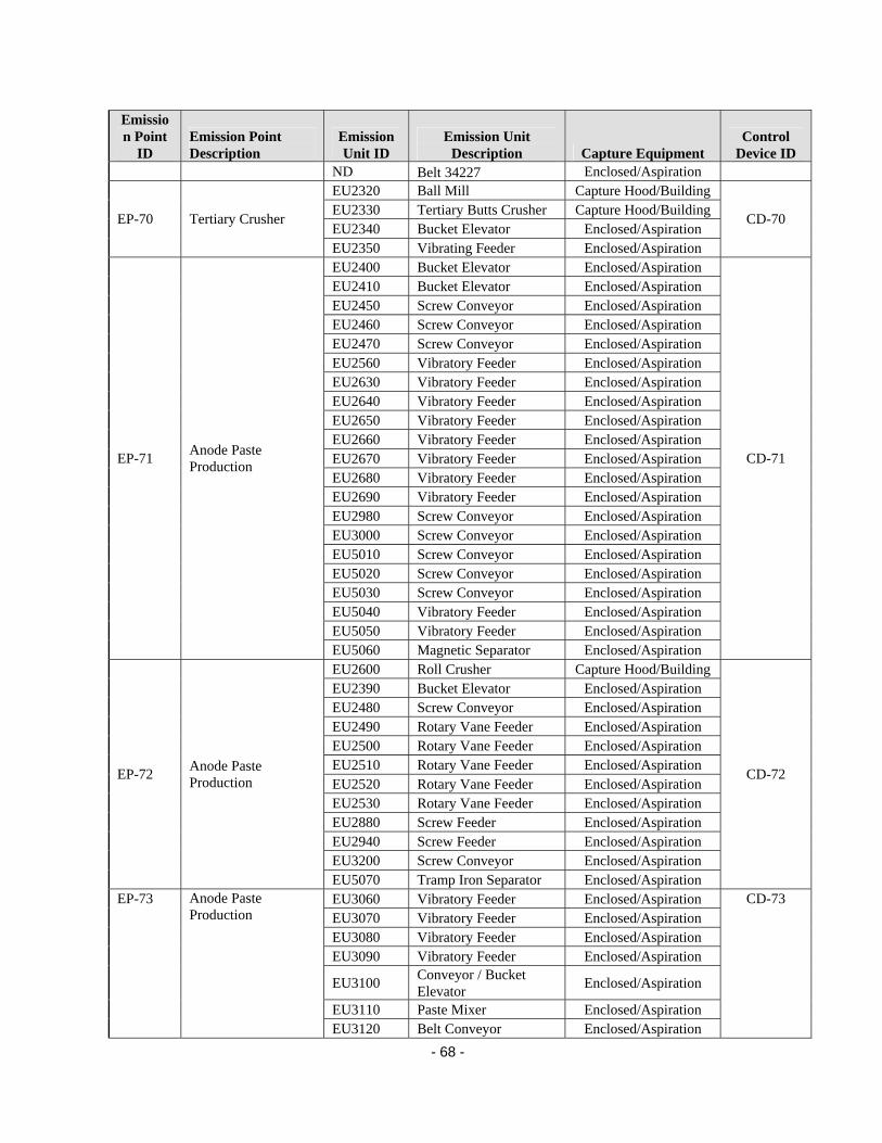
- 68 -
Emission Point
ID Emission Point Description
Emission Unit ID
Emission Unit Description Capture Equipment
Control Device ID
ND Belt 34227 Enclosed/Aspiration EU2320 Ball Mill Capture Hood/Building EU2330 Tertiary Butts Crusher Capture Hood/Building EU2340 Bucket Elevator Enclosed/Aspiration
EP-70 Tertiary Crusher
EU2350 Vibrating Feeder Enclosed/Aspiration
CD-70
EU2400 Bucket Elevator Enclosed/Aspiration EU2410 Bucket Elevator Enclosed/Aspiration EU2450 Screw Conveyor Enclosed/Aspiration EU2460 Screw Conveyor Enclosed/Aspiration EU2470 Screw Conveyor Enclosed/Aspiration EU2560 Vibratory Feeder Enclosed/Aspiration EU2630 Vibratory Feeder Enclosed/Aspiration EU2640 Vibratory Feeder Enclosed/Aspiration EU2650 Vibratory Feeder Enclosed/Aspiration EU2660 Vibratory Feeder Enclosed/Aspiration EU2670 Vibratory Feeder Enclosed/Aspiration EU2680 Vibratory Feeder Enclosed/Aspiration EU2690 Vibratory Feeder Enclosed/Aspiration EU2980 Screw Conveyor Enclosed/Aspiration EU3000 Screw Conveyor Enclosed/Aspiration EU5010 Screw Conveyor Enclosed/Aspiration EU5020 Screw Conveyor Enclosed/Aspiration EU5030 Screw Conveyor Enclosed/Aspiration EU5040 Vibratory Feeder Enclosed/Aspiration EU5050 Vibratory Feeder Enclosed/Aspiration
EP-71 Anode Paste Production
EU5060 Magnetic Separator Enclosed/Aspiration
CD-71
EU2600 Roll Crusher Capture Hood/Building EU2390 Bucket Elevator Enclosed/Aspiration EU2480 Screw Conveyor Enclosed/Aspiration EU2490 Rotary Vane Feeder Enclosed/Aspiration EU2500 Rotary Vane Feeder Enclosed/Aspiration EU2510 Rotary Vane Feeder Enclosed/Aspiration EU2520 Rotary Vane Feeder Enclosed/Aspiration EU2530 Rotary Vane Feeder Enclosed/Aspiration EU2880 Screw Feeder Enclosed/Aspiration EU2940 Screw Feeder Enclosed/Aspiration EU3200 Screw Conveyor Enclosed/Aspiration
EP-72 Anode Paste Production
EU5070 Tramp Iron Separator Enclosed/Aspiration
CD-72
EU3060 Vibratory Feeder Enclosed/Aspiration EU3070 Vibratory Feeder Enclosed/Aspiration EU3080 Vibratory Feeder Enclosed/Aspiration EU3090 Vibratory Feeder Enclosed/Aspiration
EU3100 Conveyor / Bucket Elevator
Enclosed/Aspiration
EU3110 Paste Mixer Enclosed/Aspiration
EP-73 Anode Paste Production
EU3120 Belt Conveyor Enclosed/Aspiration
CD-73

- 69 -
Emission Point
ID Emission Point Description
Emission Unit ID
Emission Unit Description Capture Equipment
Control Device ID
EU3130 Apron Conveyor Enclosed/Aspiration EU3140 Screw Conveyor Enclosed/Aspiration EU3150 Screw Conveyor Enclosed/Aspiration EU3160 Screw Conveyor Enclosed/Aspiration EU3170 Screw Conveyor Enclosed/Aspiration EU3180 Screw Conveyor Enclosed/Aspiration EU3190 Screw Conveyor Enclosed/Aspiration EU3210 Screw Conveyor Enclosed/Aspiration EU3220 Screw Conveyor Enclosed/Aspiration
EP-74 Anode Paste Production
EU3230 Screw Conveyor Enclosed/Aspiration
CD-74
EP-79 Anode Cleaning System
EU3620 Anode Cleaning Station Enclosed/Aspiration CD-79
EP-80 Fresh Ore Handling EU3630 Air-Float Conveyor Enclosed/Aspiration CD-80 EP-81 Fresh Ore Handling EU3640 Air-Float Conveyor Enclosed/Aspiration CD-81
EP-82 Anode Stem Cleaning (Phase I)
EU3650 Stub and Rod Cleaner Enclosed/Aspiration CD-82
EP-83 Cathode Casting Station
EU3660 Collector Bar Cleaner Removed per S.C.
EP-84 Anode Stem Cleaning EU3670 Rod and Stub Cleaner Removed per S.C
EP-86
Welding Fume Exhaust for Anode Repair
EU3680 Electric Welder Removed per S.C
EP-87
Welding Fume Exhaust for Shield Repair
ND N/A
EP-91 Vent for Pitch Day Tank
ND N/A
EP-94
Natural Gas Fired Boiler for Hot Oil System
EU3730 Natural Gas Fired Boiler for Hot Oil System
N/A
EP-95
Natural Gas Fired Boiler for Hot Oil System
EU3740 Natural Gas Fired Boiler for Hot Oil System
N/A
EP-96
Natural Gas Fired Boiler for Hot Oil System
EU3750 Natural Gas Fired Boiler for Hot Oil System
N/A
EP-97
Carbon Rodding Aluminum Spray Furnace
EU3760 Carbon Rodding Aluminum Spray Furnace
N/A
EU5100 Rotary Lobe Blower Enclosed/Aspiration EU5110 Air Veyor Enclosed/Aspiration
EU5120 Turntable Vibrating Compactor
Enclosed/Aspiration
EU5130 Kneader Enclosed/Aspiration
EP-100 Anode Paste Process
EU5140 Pitch Weigh Pot Enclosed/Aspiration
CD-100

- 70 -
Emission Point
ID Emission Point Description
Emission Unit ID
Emission Unit Description Capture Equipment
Control Device ID
EU5150 Pitch Pump Enclosed/Aspiration EU5160 Pitch Pump Enclosed/Aspiration EU5200 Slide Gate Enclosed/Aspiration EU5210 Screw Conveyor Enclosed/Aspiration EU5220 Screw Conveyor Enclosed/Aspiration EU5230 Screw Conveyor Enclosed/Aspiration EU5240 Screw Conveyor Enclosed/Aspiration EU5250 Screw Conveyor Enclosed/Aspiration EU5260 Screw Conveyor Enclosed/Aspiration
EP-101 Fraction Handling
EU5270 Air Veyor Enclosed/Aspiration
CD-101
EU5300 Screw Conveyor Enclosed/Aspiration EU5310 Screw Conveyor Enclosed/Aspiration EU5320 Bucket Elevator Enclosed/Aspiration EP-102 Proportioning System
EU5330 Preheating Screw Conveyor
Enclosed/Aspiration
CD-102
EP-108 Phase 1 & 2 Rod Brush Station
EU5400 Rod Brush Station Capture Hood/Building CD-108
EP-109 Phase 3 Rod Brush Station
EU5410 Rod Brush Station Capture Hood/Building CD-109
EU2180 Phase 1 West Stripper 345001 (EU2180)
Capture Hood/Building
EU2180 Phase 1 East Stripper 345002 (EU2180)
Capture Hood/Building
ND 21 Belt 345021 Enclosed/Aspiration ND 22 Belt 345022 Enclosed/Aspiration ND Flop Gate 34.20.06 Enclosed/Aspiration ND 23 Belt 345023 Enclosed/Aspiration ND 24 Belt 345024 Enclosed/Aspiration
ND P1 KHD Crusher 345110
Capture Hood/Building
ND Manual Scrap Charging Vibrating Feeder 345030
Capture Hood/Building
ND 25 Belt 345025 Enclosed/Aspiration
EP110
ND 29 Belt 345029 Enclosed/Aspiration
CD-110
EU3760 Roll Conveyor (carbon bake)
Enclosed/Aspiration
EU3770 Roll Conveyor (carbon bake)
Enclosed/Aspiration
EU3780 Roll Conveyor (carbon bake)
Enclosed/Aspiration
EU3790 Roll Conveyor (carbon bake)
Enclosed/Aspiration
EU3800 Roller Flight Conveyor (carbon bake)
Enclosed/Aspiration
EU3810 Belt Conveyor (carbon bake)
Enclosed/Aspiration
EP-AAA Carbon Bake Furnaces
EU3820 Belt Conveyor (carbon bake)
Enclosed/Aspiration
4 OF CD-AAA
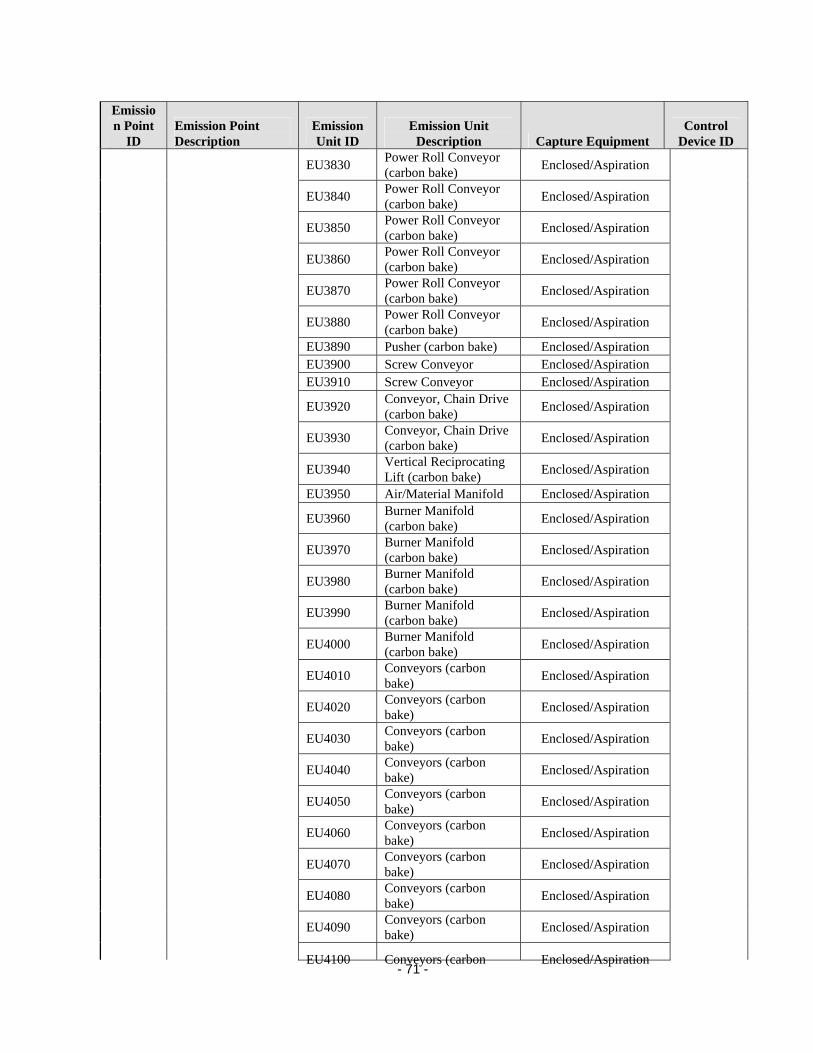
- 71 -
Emission Point
ID Emission Point Description
Emission Unit ID
Emission Unit Description Capture Equipment
Control Device ID
EU3830 Power Roll Conveyor (carbon bake)
Enclosed/Aspiration
EU3840 Power Roll Conveyor (carbon bake)
Enclosed/Aspiration
EU3850 Power Roll Conveyor (carbon bake)
Enclosed/Aspiration
EU3860 Power Roll Conveyor (carbon bake)
Enclosed/Aspiration
EU3870 Power Roll Conveyor (carbon bake)
Enclosed/Aspiration
EU3880 Power Roll Conveyor (carbon bake)
Enclosed/Aspiration
EU3890 Pusher (carbon bake) Enclosed/Aspiration EU3900 Screw Conveyor Enclosed/Aspiration EU3910 Screw Conveyor Enclosed/Aspiration
EU3920 Conveyor, Chain Drive (carbon bake)
Enclosed/Aspiration
EU3930 Conveyor, Chain Drive (carbon bake)
Enclosed/Aspiration
EU3940 Vertical Reciprocating Lift (carbon bake)
Enclosed/Aspiration
EU3950 Air/Material Manifold Enclosed/Aspiration
EU3960 Burner Manifold (carbon bake)
Enclosed/Aspiration
EU3970 Burner Manifold (carbon bake)
Enclosed/Aspiration
EU3980 Burner Manifold (carbon bake)
Enclosed/Aspiration
EU3990 Burner Manifold (carbon bake)
Enclosed/Aspiration
EU4000 Burner Manifold (carbon bake)
Enclosed/Aspiration
EU4010 Conveyors (carbon bake)
Enclosed/Aspiration
EU4020 Conveyors (carbon bake)
Enclosed/Aspiration
EU4030 Conveyors (carbon bake)
Enclosed/Aspiration
EU4040 Conveyors (carbon bake)
Enclosed/Aspiration
EU4050 Conveyors (carbon bake)
Enclosed/Aspiration
EU4060 Conveyors (carbon bake)
Enclosed/Aspiration
EU4070 Conveyors (carbon bake)
Enclosed/Aspiration
EU4080 Conveyors (carbon bake)
Enclosed/Aspiration
EU4090 Conveyors (carbon bake)
Enclosed/Aspiration
EU4100 Conveyors (carbon Enclosed/Aspiration
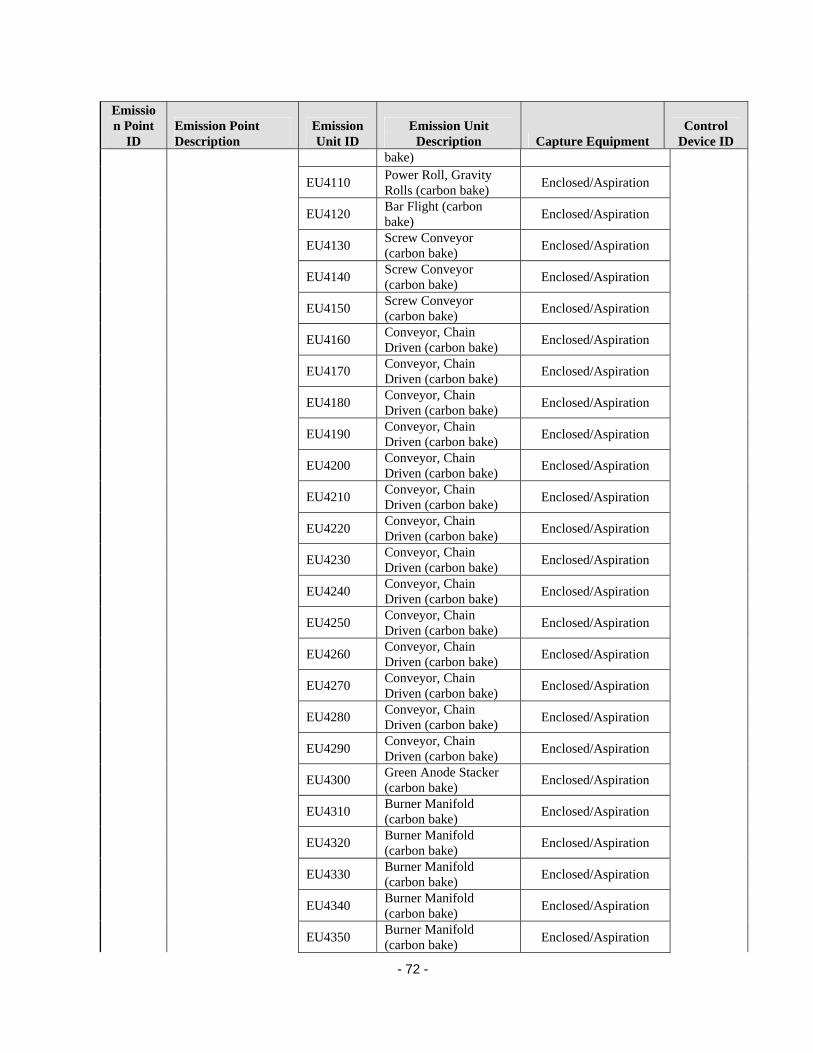
- 72 -
Emission Point
ID Emission Point Description
Emission Unit ID
Emission Unit Description Capture Equipment
Control Device ID
bake)
EU4110 Power Roll, Gravity Rolls (carbon bake)
Enclosed/Aspiration
EU4120 Bar Flight (carbon bake)
Enclosed/Aspiration
EU4130 Screw Conveyor (carbon bake)
Enclosed/Aspiration
EU4140 Screw Conveyor (carbon bake)
Enclosed/Aspiration
EU4150 Screw Conveyor (carbon bake)
Enclosed/Aspiration
EU4160 Conveyor, Chain Driven (carbon bake)
Enclosed/Aspiration
EU4170 Conveyor, Chain Driven (carbon bake)
Enclosed/Aspiration
EU4180 Conveyor, Chain Driven (carbon bake)
Enclosed/Aspiration
EU4190 Conveyor, Chain Driven (carbon bake)
Enclosed/Aspiration
EU4200 Conveyor, Chain Driven (carbon bake)
Enclosed/Aspiration
EU4210 Conveyor, Chain Driven (carbon bake)
Enclosed/Aspiration
EU4220 Conveyor, Chain Driven (carbon bake)
Enclosed/Aspiration
EU4230 Conveyor, Chain Driven (carbon bake)
Enclosed/Aspiration
EU4240 Conveyor, Chain Driven (carbon bake)
Enclosed/Aspiration
EU4250 Conveyor, Chain Driven (carbon bake)
Enclosed/Aspiration
EU4260 Conveyor, Chain Driven (carbon bake)
Enclosed/Aspiration
EU4270 Conveyor, Chain Driven (carbon bake)
Enclosed/Aspiration
EU4280 Conveyor, Chain Driven (carbon bake)
Enclosed/Aspiration
EU4290 Conveyor, Chain Driven (carbon bake)
Enclosed/Aspiration
EU4300 Green Anode Stacker (carbon bake)
Enclosed/Aspiration
EU4310 Burner Manifold (carbon bake)
Enclosed/Aspiration
EU4320 Burner Manifold (carbon bake)
Enclosed/Aspiration
EU4330 Burner Manifold (carbon bake)
Enclosed/Aspiration
EU4340 Burner Manifold (carbon bake)
Enclosed/Aspiration
EU4350 Burner Manifold (carbon bake)
Enclosed/Aspiration
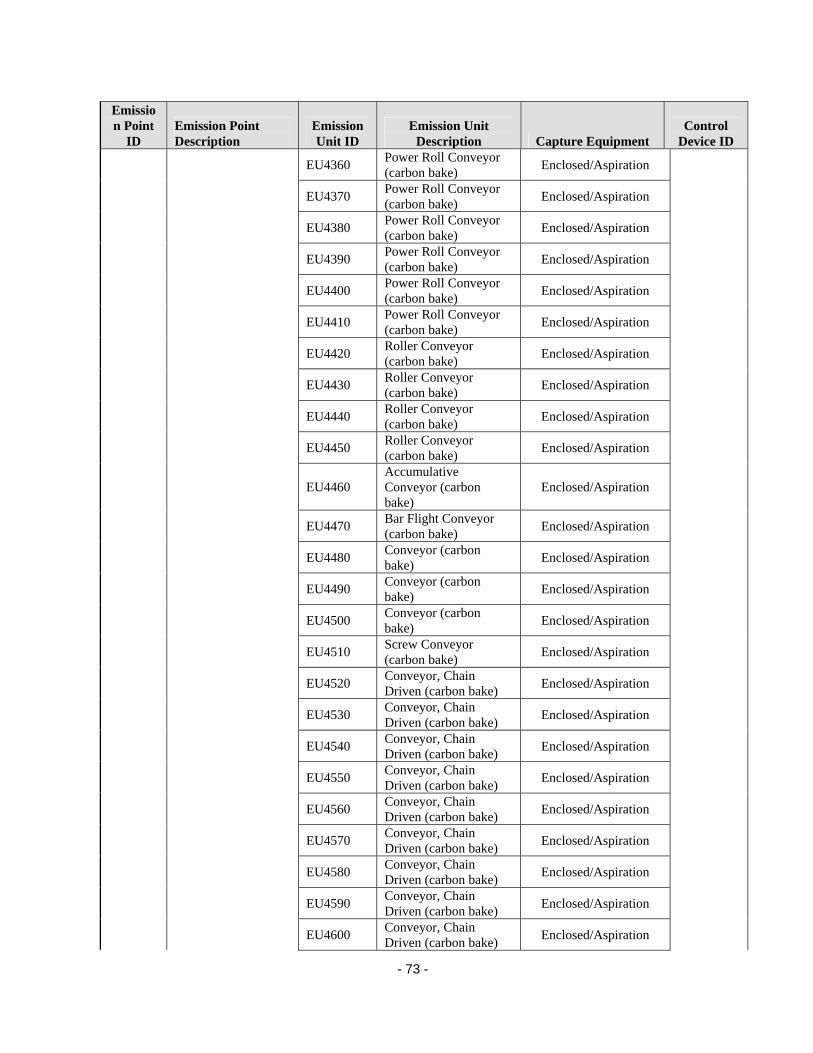
- 73 -
Emission Point
ID Emission Point Description
Emission Unit ID
Emission Unit Description Capture Equipment
Control Device ID
EU4360 Power Roll Conveyor (carbon bake)
Enclosed/Aspiration
EU4370 Power Roll Conveyor (carbon bake)
Enclosed/Aspiration
EU4380 Power Roll Conveyor (carbon bake)
Enclosed/Aspiration
EU4390 Power Roll Conveyor (carbon bake)
Enclosed/Aspiration
EU4400 Power Roll Conveyor (carbon bake)
Enclosed/Aspiration
EU4410 Power Roll Conveyor (carbon bake)
Enclosed/Aspiration
EU4420 Roller Conveyor (carbon bake)
Enclosed/Aspiration
EU4430 Roller Conveyor (carbon bake)
Enclosed/Aspiration
EU4440 Roller Conveyor (carbon bake)
Enclosed/Aspiration
EU4450 Roller Conveyor (carbon bake)
Enclosed/Aspiration
EU4460 Accumulative Conveyor (carbon bake)
Enclosed/Aspiration
EU4470 Bar Flight Conveyor (carbon bake)
Enclosed/Aspiration
EU4480 Conveyor (carbon bake)
Enclosed/Aspiration
EU4490 Conveyor (carbon bake)
Enclosed/Aspiration
EU4500 Conveyor (carbon bake)
Enclosed/Aspiration
EU4510 Screw Conveyor (carbon bake)
Enclosed/Aspiration
EU4520 Conveyor, Chain Driven (carbon bake)
Enclosed/Aspiration
EU4530 Conveyor, Chain Driven (carbon bake)
Enclosed/Aspiration
EU4540 Conveyor, Chain Driven (carbon bake)
Enclosed/Aspiration
EU4550 Conveyor, Chain Driven (carbon bake)
Enclosed/Aspiration
EU4560 Conveyor, Chain Driven (carbon bake)
Enclosed/Aspiration
EU4570 Conveyor, Chain Driven (carbon bake)
Enclosed/Aspiration
EU4580 Conveyor, Chain Driven (carbon bake)
Enclosed/Aspiration
EU4590 Conveyor, Chain Driven (carbon bake)
Enclosed/Aspiration
EU4600 Conveyor, Chain Driven (carbon bake)
Enclosed/Aspiration

- 74 -
Emission Point
ID Emission Point Description
Emission Unit ID
Emission Unit Description Capture Equipment
Control Device ID
EU4610 Conveyor, Chain Driven (carbon bake)
Enclosed/Aspiration
EU4620 Conveyor, Chain Driven (carbon bake)
Enclosed/Aspiration
EU4630 Conveyor, Chain Driven (carbon bake)
Enclosed/Aspiration
EU4640 Conveyor, Chain Driven (carbon bake)
Enclosed/Aspiration
EU4650 Burner Manifold (carbon bake)
Enclosed/Aspiration
EU4660 Burner Manifold (carbon bake)
Enclosed/Aspiration
EU4670 Burner Manifold (carbon bake)
Enclosed/Aspiration
EU4680 Burner Manifold (carbon bake)
Enclosed/Aspiration
EU4690 Burner Manifold (carbon bake)
Enclosed/Aspiration
EU4700 Burner Manifold (carbon bake)
Enclosed/Aspiration
EP-AB Stack for Pig Melter EU4710 #3 Melting Furnace-Pig (Metal Products)
N/A
EP-AD Stack for #1 Melter EU4730 #1 Melting Furnace (Metal Products)
N/A
EP-AE Stack for #1 Holder EU4740 #1 Holding Furnace (Metal Products)
N/A
EP-AF Stack for #2 Melter EU4750 #2 Melting Furnace (Metal Products)
N/A
EP-AG Stack for #2 Holder EU4760 #2 Holding Furnace (Metal Products)
N/A
EP-AH Stack for #4 Melter EU4770 #4 Melting Furnace (Metal Products)
N/A
EP-AI Stack for #4 Holder EU4780 #4 Holding Furnace (Metal Products)
N/A
EP-AJ Stack for Homogenizing Furnace #1
EU4790 Homogenizing Furnace #1
N/A
EP-AK Stack for Homogenizing Furnace #2
EU4800 Homogenizing Furnace #2
N/A
EP-AL Stack for Homogenizing Furnace #3
EU4810 Homogenizing Furnace #3
N/A
EP-AN Stack for Pig Melter #2
EU4830 #5 Pig Melter (Metal Products)
N/A
EP-BA Stack for Rod Mill #1 Melter
EU4840 #1 Charge Furnace (Rod Mill)
N/A
EP-BB Stack for Rod Mill #1 Holder
EU4850 #3 Holding Furnace (Rod Mill)
N/A
EP-BC Stack for Rod Mill #2 Melter
EU4860 #2 Charge Furnace (Rod Mill)
N/A
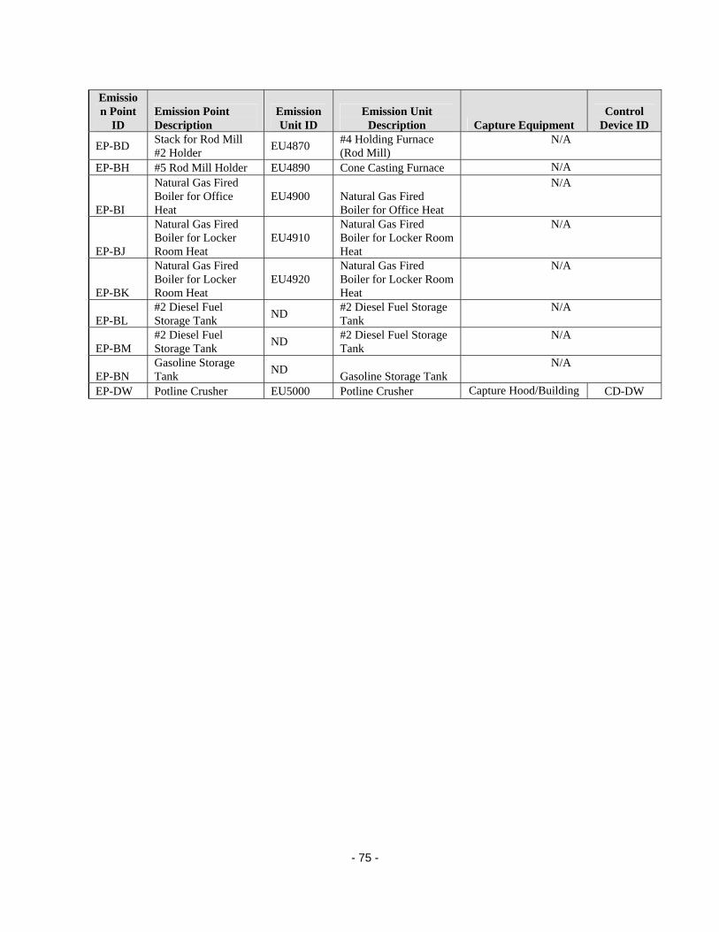
- 75 -
Emission Point
ID Emission Point Description
Emission Unit ID
Emission Unit Description Capture Equipment
Control Device ID
EP-BD Stack for Rod Mill #2 Holder
EU4870 #4 Holding Furnace (Rod Mill)
N/A
EP-BH #5 Rod Mill Holder EU4890 Cone Casting Furnace N/A
EP-BI
Natural Gas Fired Boiler for Office Heat
EU4900 Natural Gas Fired Boiler for Office Heat
N/A
EP-BJ
Natural Gas Fired Boiler for Locker Room Heat
EU4910 Natural Gas Fired Boiler for Locker Room Heat
N/A
EP-BK
Natural Gas Fired Boiler for Locker Room Heat
EU4920 Natural Gas Fired Boiler for Locker Room Heat
N/A
EP-BL #2 Diesel Fuel Storage Tank
ND #2 Diesel Fuel Storage Tank
N/A
EP-BM #2 Diesel Fuel Storage Tank
ND #2 Diesel Fuel Storage Tank
N/A
EP-BN Gasoline Storage Tank
ND Gasoline Storage Tank
N/A
EP-DW Potline Crusher EU5000 Potline Crusher Capture Hood/Building CD-DW

- 76 -
Appendix F: Example of Flow Rate Categories for Special Condition 16.D.
Emission Point Number Description
Flow Rate (dscfm)
Emission Point Number Description
Flow Rate (dscfm)
Emission Point Number Description
Flow Rate (dscfm)
EP-81 Fresh Ore Handling 325 EP-108 Brush Station 1,000 EP-56 Electrolyte Recovery 2,800
EP-27 Reacted Ore Material Handling 800 EP-109 Brush Station 1,000 EP-09
Reacted Ore Material Handling 3,000
EP-28 Reacted Ore Material Handling 800 EP-16
Fresh Ore Material Handling 1,200 EP-22
Fresh Ore Material Handling 3,500
EP-29 Reacted Ore Material Handling 800 EP-17
Fresh Ore Material Handling 1,200
Gro
up 3
EP-23 Fresh Ore Material Handling 3,500
EP-30 Reacted Ore Material Handling 800 EP-18
Fresh Ore Material Handling 1,200 EP-25
Fresh Ore Material Handling 4,000
EP-31 Reacted Ore Material Handling 800 EP-19
Fresh Ore Material Handling 1,200 EP-26
Reacted Ore Material Handling 4,000
EP-32 Reacted Ore Material Handling 800 EP-20
Fresh Ore Material Handling 1,200 EP-36
Reacted Ore Material Handling 4,000
EP-33 Reacted Ore Material Handling 800 EP-67
Petroleum Coke Handling 1,500 EP-65
Petroleum Coke Handling 4,000
EP-34 Reacted Ore Material Handling 800 EP-71
Anode Paste Production 1,500 EP-66
Petroleum Coke Handling 4,000
EP-37 Reacted Ore Material Handling 800 EP-35
Reacted Ore Material Handling 1,700 EP-72
Anode Paste Production 4,000
EP-38 Reacted Ore Material Handling 800
Gro
up 2
EP-45 Reacted Ore Material Handling 1,700 EP-03 River Unloading 4,005
EP-39 Reacted Ore Material Handling 800 EP-06
Fresh Ore Material Handling 2,400 EP-01 River Unloading 4,250
EP-40 Reacted Ore Material Handling 800 EP-80 Fresh Ore Handling 2,400 EP-02 River Unloading 4,250
EP-41 Reacted Ore Material Handling 800 EP-11
Fresh Ore Material Handling 2,575 EP-10
Reacted Ore Material Handling 4,500
EP-42 Reacted Ore Material Handling 800 EP-74
Anode Paste Production 2,600 EP-102
Proportioning System 4,700
EP-43 Reacted Ore Material Handling 800 EP-49 Electrolyte Recovery 2,800 EP-15
Fresh Ore Material Handling 4,750
Gro
up 1
EP-44 Reacted Ore Material Handling 800
Gro
up 3
EP-55 Electrolyte Recovery 2,800
Gro
up 4
EP-21 Fresh Ore Material Handling 4,750
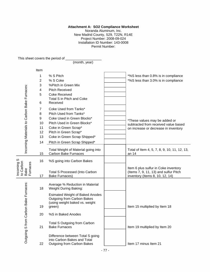
- 77 -
Attachment A: SO2 Compliance Worksheet Noranda Aluminum, Inc.
New Madrid County, S29, T22N, R14E Project Number: 2008-09-024
Installation ID Number: 143-0008 Permit Number:
This sheet covers the period of ___________________ (month, year)
Item
1 % S Pitch *%S less than 0.8% is in compliance 2 % S Coke *%S less than 3.0% is in compliance 3 %Pitch in Green Mix 4 Pitch Received 5 Coke Received
6 Total S in Pitch and Coke Received
7 Coke Used from Tanks*
8 Pitch Used from Tanks*
9 Coke Used in Green Blocks*
10 Pitch Used in Green Blocks*
11 Coke in Green Scrap*
12 Pitch in Green Scrap*
13 Coke in Green Scrap Shipped*
14 Pitch in Green Scrap Shipped*
*These values may be added or subtracted from received value based on increase or decrease in inventory
Inco
min
g M
ater
ials
to C
arbo
n B
ake
Fur
nace
s:
15 Total Weight of Material going into Carbon Bake Furnaces
Total of Item 4, 5, 7, 8, 9, 10, 11, 12, 13, an 14
16 %S going into Carbon Bakes
Inco
min
g S
to
Car
bon
Bak
e F
urna
ces
17 Total S Processed (Into Carbon Bake Furnaces)
Item 6 plus sulfur in Coke inventory (Items 7, 9, 11, 13) and sulfur Pitch inventory (Items 8, 10, 12, 14)
18 Average % Reduction in Material Weight During Baking:
19
Esimated Weight of Baked Anodes Outgoing from Carbon Bakes (using weight baked vs. weight green) Item 15 multiplied by Item 18
20 %S in Baked Anodes
21 Total S Outgoing from Carbon Bake Furnaces Item 19 multiplied by Item 20
Out
goin
g S
from
Car
bon
Bak
e F
urna
ces:
22
Difference between Total S going into Carbon Bakes and Total Outgoing from Carbon Bakes Item 17 minus Item 21
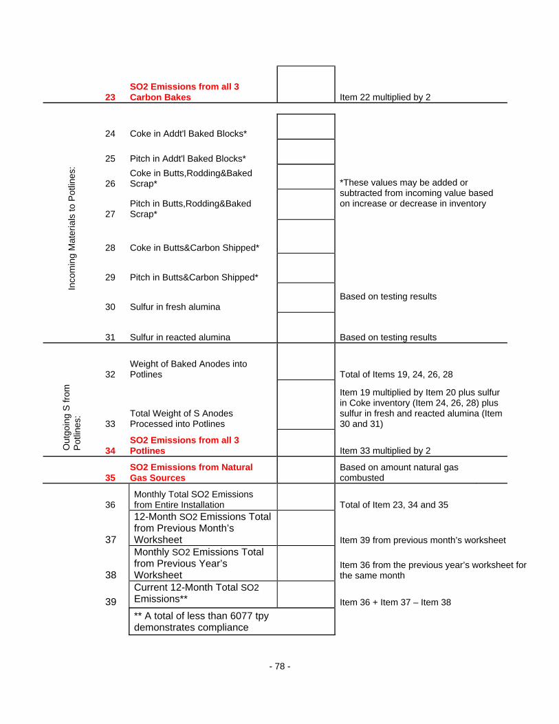
- 78 -
23 SO2 Emissions from all 3 Carbon Bakes Item 22 multiplied by 2
24 Coke in Addt'l Baked Blocks*
25 Pitch in Addt'l Baked Blocks*
26 Coke in Butts,Rodding&Baked Scrap*
27 Pitch in Butts,Rodding&Baked Scrap*
28 Coke in Butts&Carbon Shipped*
29 Pitch in Butts&Carbon Shipped*
*These values may be added or subtracted from incoming value based on increase or decrease in inventory
30 Sulfur in fresh alumina Based on testing results
Inco
min
g M
ater
ials
to P
otlin
es:
31 Sulfur in reacted alumina Based on testing results
32 Weight of Baked Anodes into Potlines Total of Items 19, 24, 26, 28
33 Total Weight of S Anodes Processed into Potlines
Item 19 multiplied by Item 20 plus sulfur in Coke inventory (Item 24, 26, 28) plus sulfur in fresh and reacted alumina (Item 30 and 31)
Out
goin
g S
from
P
otlin
es:
34 SO2 Emissions from all 3 Potlines Item 33 multiplied by 2
35 SO2 Emissions from Natural Gas Sources
Based on amount natural gas combusted
36 Monthly Total SO2 Emissions from Entire Installation Total of Item 23, 34 and 35
37
12-Month SO2 Emissions Total from Previous Month’s Worksheet Item 39 from previous month’s worksheet
38
Monthly SO2 Emissions Total from Previous Year’s Worksheet
Item 36 from the previous year’s worksheet for the same month
39
Current 12-Month Total SO2 Emissions** Item 36 + Item 37 – Item 38
** A total of less than 6077 tpy demonstrates compliance

- 79 -
Attachment B – Hourly SOx Emission Worksheet Noranda Aluminum, Inc. New Madrid County, S32, T22N, R14E Project Number: 2008-09-024 Installation ID Number: 143-0008 Permit Number: This sheet covers the period of for . (month, year) (Emission Point Description)
1 SO2 Emissions from all 3 Potlines Item 32 from Attachment A
2 Total Aluminum Production from all 3 Potlines
3 Potline 1 Production Rate
4 Percent of Total Attributed to Potline 1 Item 3 divided by Item 2
5 SO2 Emission from Potline 1 Item 4 multiplied by Item 1
6 Hour of Operation of Potline 1 7 Total Hourly SO2 Emissions from Potline 1
*An emission rate less than 428.6 lb/hr demonstrates compliance.
Item 5 divided by Item 6
8 Potline 2 Production Rate
9 Percent of Total Attributed to Potline 2 Item 8 divided by Item 2
10 SO2 Emission from Potline 2 Item 9 multiplied by Item 1
11 Hour of Operation of Potline 2 12 Total Hourly SO2 Emissions from Potline 2
*An emission rate less than 430.1 lb/hr demonstrates compliance.
Item 10 divided by Item 11
13 Potline 3 East Production Rate
14 Percent of Total Attributed to Potline 3 East Item 13 divided by Item 2
15 SO2 Emission from Potline 3 East Item 14 multiplied by Item 1
16 Hour of Operation of Potline 3 East 17 Total Hourly SO2 Emissions from Potline 3 East
*An emission rate less than 256.0 lb/hr demonstrates compliance.
Item 15 divided by Item 16
18 Potline 3 West Production Rate
19 Percent of Total Attributed to Potline 3 West Item 18 divided by Item 2
20 SO2 Emission from Potline 3 West Item 19 multiplied by Item 1
21 Hour of Operation of Potline 3 West 22 Total Hourly SO2 Emissions from Potline 3 West
*An emission rate less than 256.0 lb/hr demonstrates compliance.
Item 20 divided by Item 21
23 SO2 Emissions from all 3 Carbon Bakes Item 23 from Attachment A
24 Hours of Operation 25 Total Hourly SO2 Emissions from Carbon Bakes
*An emission rate less than 405.2 lb/hr demonstrates compliance.
Item 23 divided by Item 24
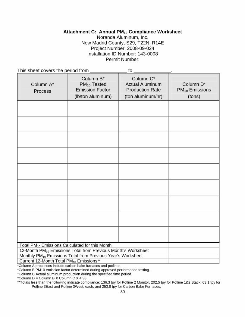
- 80 -
Attachment C: Annual PM10 Compliance Worksheet Noranda Aluminum, Inc.
New Madrid County, S29, T22N, R14E Project Number: 2008-09-024
Installation ID Number: 143-0008 Permit Number:
This sheet covers the period from to .
Column A*
Process
Column B*
PM10 Tested Emission Factor
(lb/ton aluminum)
Column C* Actual Aluminum Production Rate
(ton aluminum/hr)
Column D*
PM10 Emissions (tons)
Total PM10 Emissions Calculated for this Month
12-Month PM10 Emissions Total from Previous Month’s Worksheet
Monthly PM10 Emissions Total from Previous Year’s Worksheet
Current 12-Month Total PM10 Emissions**
*Column A processes include carbon bake furnaces and potlines *Column B PM10 emission factor determined during approved performance testing. *Column C Actual aluminum production during the specified time period. *Column D = Column B X Column C X 4.38 ** Totals less than the following indicate compliance: 136.3 tpy for Potline 2 Monitor, 202.5 tpy for Potline 1&2 Stack, 63.1 tpy for
Potline 3East and Potline 3West, each, and 253.8 tpy for Carbon Bake Furnaces.
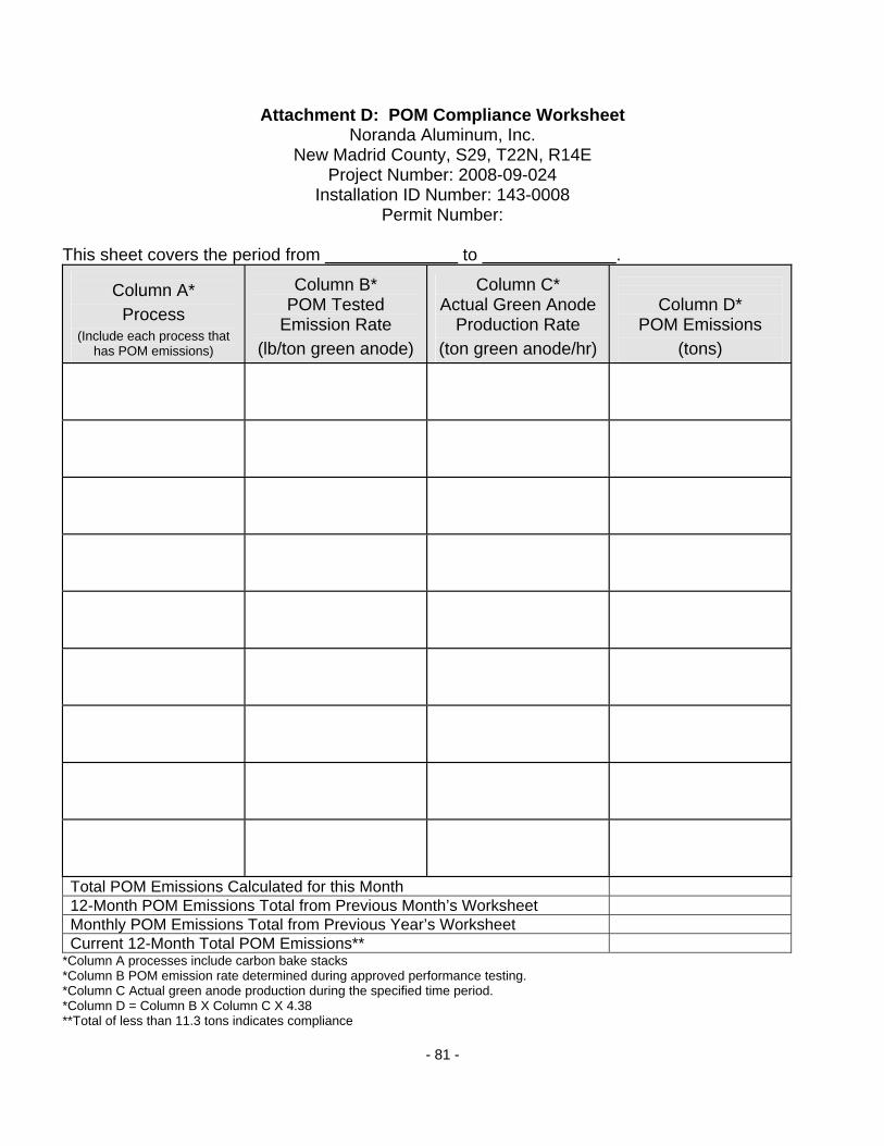
- 81 -
Attachment D: POM Compliance Worksheet Noranda Aluminum, Inc.
New Madrid County, S29, T22N, R14E Project Number: 2008-09-024
Installation ID Number: 143-0008 Permit Number:
This sheet covers the period from to .
Column A*
Process (Include each process that
has POM emissions)
Column B*
POM Tested Emission Rate
(lb/ton green anode)
Column C* Actual Green Anode
Production Rate (ton green anode/hr)
Column D*
POM Emissions (tons)
Total POM Emissions Calculated for this Month
12-Month POM Emissions Total from Previous Month’s Worksheet
Monthly POM Emissions Total from Previous Year’s Worksheet
Current 12-Month Total POM Emissions**
*Column A processes include carbon bake stacks *Column B POM emission rate determined during approved performance testing. *Column C Actual green anode production during the specified time period. *Column D = Column B X Column C X 4.38 ** Total of less than 11.3 tons indicates compliance
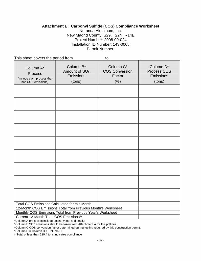
- 82 -
Attachment E: Carbonyl Sulfide (COS) Compliance Worksheet Noranda Aluminum, Inc.
New Madrid County, S29, T22N, R14E Project Number: 2008-09-024
Installation ID Number: 143-0008 Permit Number:
This sheet covers the period from to .
Column A*
Process (Include each process that
has COS emissions)
Column B*
Amount of SO2 Emissions
(tons)
Column C* COS Conversion
Factor (%)
Column D*
Process COS Emissions
(tons)
Total COS Emissions Calculated for this Month
12-Month COS Emissions Total from Previous Month’s Worksheet
Monthly COS Emissions Total from Previous Year’s Worksheet
Current 12-Month Total COS Emissions**
*Column A processes include potline vents and stacks *Column B SO2 emissions should be taken from Attachment A for the potlines. *Column C COS conversion factor determined during testing required by this construction permit. *Column D = Column B X Column C ** Total of less than 219.4 tons indicates compliance

- 83 -
Attachment F: Haul Road Compliance Worksheet Noranda Aluminum, Inc.
New Madrid County, S29, T22N, R14E Project Number: 2008-09-024
Installation ID Number: 143-0008 Permit Number:
This sheet covers the period from to .
Date*
Weight of Hauled Material
Number of Trucks** Silt Loading***
Emission Factor**** (lb/VMT)
Haul Road Emissions (pounds)
Total Haul Road Emissions Calculated for this Month
12-Month Haul Road Emissions Total from Previous Month’s Worksheet
Monthly Haul Road Emissions Total from Previous Year’s Worksheet
Current 12-Month Total Haul Road Emissions***** * A daily emission rate of 38.8 pounds per day is in compliance. ** Trucks traveled and weight of material will be used in the emission factor equation *** Silt loading is determined through testing. **** Emission factor based on AP-42 haul road equation

- 84 -
***** A 12 month Total less than 2.9 tons demonstrates compliance

- 85 -
Attachment G: Natural Gas Usage Compliance Worksheet Noranda Aluminum, Inc.
New Madrid County, S29, T22N, R14E Project Number: 2008-09-024
Installation ID Number: 143-0008 Permit Number:
This sheet covers the period from to .
Date Emission Point and Description
Actual Amount
Natural Gas Combusted (mmcf)
Total Natural Gas Usage Calculated for this Month
12-Month Natural Gas Usage Total from Previous Month’s Worksheet
Monthly Natural Gas Usage Total from Previous Year’s Worksheet
Current 12-Month Total Natural Gas Usage *
* A 12 month Total of less than 832 mmcf indicates compliance
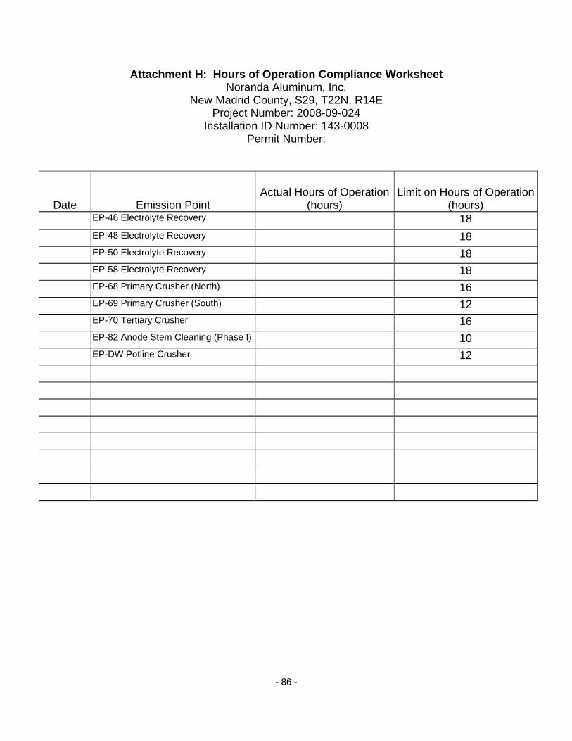
- 86 -
Attachment H: Hours of Operation Compliance Worksheet Noranda Aluminum, Inc.
New Madrid County, S29, T22N, R14E Project Number: 2008-09-024
Installation ID Number: 143-0008 Permit Number:
Date Emission Point Actual Hours of Operation
(hours) Limit on Hours of Operation
(hours) EP-46 Electrolyte Recovery 18
EP-48 Electrolyte Recovery 18
EP-50 Electrolyte Recovery 18
EP-58 Electrolyte Recovery 18
EP-68 Primary Crusher (North) 16
EP-69 Primary Crusher (South) 12
EP-70 Tertiary Crusher 16
EP-82 Anode Stem Cleaning (Phase I) 10
EP-DW Potline Crusher 12