Embed Size (px)
Citation preview

This program is funded by California utility customers under the auspices of the California Public Utilities Commission and in support of the California Energy Commission.
2013 Title 24, Part 6 Energy Standards
Brief Overview of 2013 Nonresidential Changes to Energy Standards: Mechanical Systems
Gina RoddaGabel Associates, LLCCEA, CEPE, LEED AP / [email protected] ext. 204
California Statewide Codes & Standards.
This program is funded by California utility customers under
the auspices of the California Public Utilities Commission and in
support of the California Energy Commission.
Here to help you meet the requirements of Title 24, Part 6
We offer FREE:
Trainings
Tools
Resources
All designed to improve compliance with the state’s building energy code and aimed at locking in long-term energy savings.
We Are….
2
3
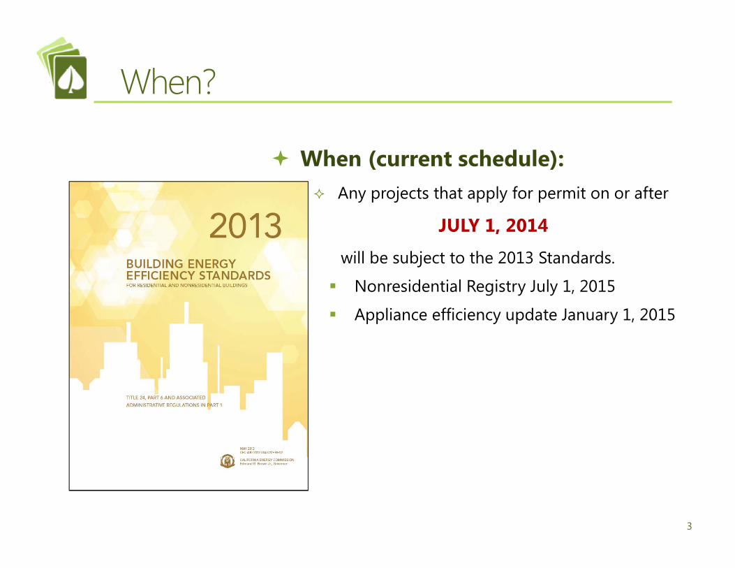
When (current schedule): Any projects that apply for permit on or after
JULY 1, 2014
will be subject to the 2013 Standards.
Nonresidential Registry July 1, 2015
Appliance efficiency update January 1, 2015
When?

4
Where can you find? CEC website
http://www.energy.ca.gov/title24/2013standards/index.html
Where Can You Find?

5
California’s Goal (AB 32):
Net Zero goals: Residential: 2020 Nonresidential: 2030
Rosenfeld Effect
Why?

6
CEC Documents

CEC Blueprint
7

Application of Standards (Table 100.0-A)
8
Number system has changed by adding decimal: 100.1 was 101
New sections
110.1: “Solar Ready” buildings
120.6: NR: “Covered Processes” instead of “Refrigerated Warehouses”
120.7: NR “Mandatory Insulation Requirements”
120.8: NR “Building Commissioning”
120.9: NR “Mandatory Requirements for Commercial Boilers
130.5: NR “Electrical Power Distribution Systems”
140.9: NR “Prescriptive Requirements For Covered Processes”
141.1: NR “Requirements For Covered Processes In Additions, Alterations To Existing Buildings That Will Be Nonresidential, High-Rise Residential, And Hotel/Motel Occupancies”

Forms

Non Residential Certificate of Compliance Submitted and included in plans set for building
permit Includes “Field Inspector” Checkboxes
Title 24 Part 6 Forms (2013)
NRCC-MCH
Non Residential Certificate of Installation Filled out and signed by installing contractor Reviewed by “Field Inspector”
NRCI-MCH
Non Residential Certificate of Acceptance Filled out and signed by Certified Test Field
TechnicianNRCA-MCH
Non Residential Certificate of Verification Filled out and signed by HERS raterNRCV-MCH
10

Nonresidential Forms: Certificate of Compliance
11
Form Name Use DescriptionDesign Review (NEW)NRCC-CXR-01-E Design Review Design Review Kickoff (completed at schematic design)NRCC-CXR-02-E Design Review Construction documents - general
NRCC-CXR-03-E Design Review Construction documents – simple HVAC systems
NRCC-CXR-04-E Design Review Construction documents – complex HVAC systems
NRCC-CXR-05-E Design Review Design review signature page (completed at design stage)
Performance ApproachNRCC-PRF-01 New Construction, addition, alterations,
E+A, E+A+APerformance documentation
Form Name Use DescriptionElectrical (NEW)NRCC-ELC-01-E Electrical Disaggregation of electric circuitsMechanicalNRCC-MCH-01-E Mechanical Declarations and Field inspection listNRCC-MCH-02-E Mechanical Requirements – Dry and wet systemsNRCC-MCH-03-E Mechanical Mechanical ventilation and reheatNRCC-MCH-04-E Mechanical Declarations – single zone systemsNRCC-MCH-05-E Mechanical Requirements – single zone systems
Worksheets – mechanical (NEW)NRCC-MCH-06-E Mechanical Max. cycles of concentration worksheet for cooling towersPlumbing (NEW)NRCC-PLB-01-E Plumbing Water heating systemsSolar – (NEW)NRCC-STH-01-E Solar – thermal heating OG-100 worksheetNRCC-SRA-01-E Solar – ready area Solar radiation availability
Worksheets – solar ready (NEW)NRCC-SRA-02-E Solar – ready area Minimum solar zone area worksheet

Nonresidential Forms: Certificate of Compliance
12
Form Name Use DescriptionProcess (many are NEW)NRCC-PRC-01-E Process Covered processNRCC-PRC-02-E Process Garage exhaustNRCC-PRC-03-E Process Commercial kitchensNRCC-PRC-04-E Process Data CentersNRCC-PRC-05-E Process Refrigeration – Performance or prescriptiveNRCC-PRC-06-E Process Refrigerated warehousesNRCC-PRC-07-E Process Refrigerated warehouse – 3,000 sf or greaterNRCC-PRC-08-E Process Refrigerated warehouse – 3,000 sf or greater and served by
same refrigeration systemNRCC-PRC-09-E Process Laboratory exhaustNRCC-PRC-10-E Process Compressed air systemsNRCC-PRC-11-E Process Process boilers
-E: Enforcement (building department) -F: Field technician (installing contractor) -A: Acceptance test technician (or installing contracting until adopted by CEC) -H: HERS rater

Nonresidential Forms: Certificate of Installation
13
Form Name Use DescriptionElectrical (NEW)NRCI-ELC-01-E Electrical Power distributionMechanicalNRCI-MCH-01-E Mechanical ValidationPlumbingNRCI-PLB-01-E Plumbing Water heating systems validationNRCI-PLB-02-E Plumbing Single dwelling unit hot water systems distributionNRCI-PLB-03-E Plumbing – non HERS Multifamily central hot water systems distributionNRCI-PLB-21-H (HERS) Plumbing –HERS Water heating systems distribution verified by HERSProcessNRCI-PRC-01-E Process Refrigerated warehouseSolarNRCI-SPV-01-E Solar – photovoltaic ValidationNRCI-STH-01-E Solar – Thermal heating Validation

Nonresidential Forms: Certificate of Acceptance
14
Form Name Use DescriptionMechanicalNRCA-MCH-02-A (ACCEPT) Mechanical Outdoor airNRCA-MCH-03-A (ACCEPT) Mechanical Constant volume singe zone HVACNRCA-MCH-04-H (HERS) Mechanical Air distribution duct leakage verified by HERSNRCA-MCH-05-A (ACCEPT) Mechanical Air economizer controlsNRCA-MCH-06-A (ACCEPT) Mechanical Demand control ventilation controlsNRCA-MCH-07-A (ACCEPT) Mechanical Supply fan variable flow controlsNRCA-MCH-08-A (ACCEPT) Mechanical Valve leakage testNRCA-MCH-09-F Mechanical Supply water temperature reset controlsNRCA-MCH-10-A (ACCEPT) Mechanical Hydronic system variable flow controlsNRCA-MCH-11-A (ACCEPT) Mechanical Automatic demand shed controlsNRCA-MCH-12-F Mechanical Fault detection & Diagnostic for DX unitsNRCA-MCH-13-F Mechanical Fault detection & Diagnostics for air handling and zone
terminal unitsNRCA-MCH-14-F Mechanical Distributed energy storage DX AC systems testNRCA-MCH-15-F Mechanical Thermal energy storage systemsNRCA-MCH-16-F Mechanical Supply air temperature reset controlsNRCA-MCH-17-F Mechanical Condenser water temperature reset controlsNRCA-MCH-18-F Mechanical Energy management control system

Nonresidential Forms: Certificate of Acceptance
15
**New qualifications requiredAcceptance Test Lighting Technician (to take effect when CEC believes there are enough people trained per their requirements)Acceptance Test Mechanical Technician (to take effect when CEC believes there are enough people trained per their requirements)
HERS VerificationNRCI-LTI-05: Power Adjustment FactorsNRCI-PLB-21: Water heating distributionNRCA-MCH-05: Duct leakage testingNRCV-MCH: Duct leakageNRCV-PLB: Domestic hot water distribution
Form Name Use DescriptionProcessNRCA-PRC-01-F Process Compressed airNRCA-PRC-02-F Process Commercial kitchen exhaustNRCA-PRC-03-F Process Parking garage exhaustNRCA-PRC-04-F Process Refrigerated warehouse – Evaporator fan motor controlsNRCA-PRC-05-F Process Refrigerated warehouse – Evaporative condenser controlsNRCA-PRC-06-F Process Refrigerated warehouse – Air cooled condenser controlsNRCA-PRC-07-F Process Refrigerated warehouse – variable speed compressorNRCA-PRC-08-F Process Refrigerated warehouse – electric resistance underslab
heating

— Air-cooled
The Energy Commission will determine whether in their entirety reasonable access to certification is provided by considering factors such as certification costs commensurate with the complexity of the training being provided, certification marketing materials, prequalification criteria, class availability, and curriculum.
Acceptance Test Technician Certification Providers (ATTCP)
16
Current ATTCP grandfathered in for 6 months

Number of Certified Acceptance Test Technicians. There shall be no less than 300 Acceptance Test Technicians certified to perform the acceptance tests in Building Energy Efficiency Standards, Section 120.5. The number of certified Acceptance Test Technicians shall be demonstrated by Certification Provider-prepared reports submitted to the Energy Commission.
NA7.5.1 Outdoor Air Ventilation Systems
NA7.5.2 Constant Volume, Single Zone Unitary Air Conditioners and Heat Pumps
NA7.5.4 Air Economizer Controls
NA7.5.5 Demand Control Ventilation Systems
NA 7.5.6 Supply Fan Variable Flow Controls
NA7.5.7, NA7.5.9 Hydronic System Variable Flow Controls
NA7.5.10 Automatic Demand Shed Controls
Industry Coverage by Certification Provider(s). The Certification Provider(s) approved by the Energy Commission, in their entirety, shall provide reasonable access to certification for technicians representing the majority of the following industry groups:
Professional engineers, HVAC installers, mechanical contractors, TAB certified technicians, controls installation and startup contractors and certified commissioning professionals who have verifiable training, experience and expertise in HVAC systems.
Certified Acceptance Test Technicians (CATT)

Nonresidential Forms: Certificate of Verification (HERS)
18
Three HERS Providers in California:
CalCerts www.CalCerts.com
CHEERS www.CHEERS.org
USERA www.usenergyraters.com
Form Name Use DescriptionMechanical (NEW)NRCV-MCH-04a-H (HERS) Mechanical Duct leakage testing – new systemNRCV-MCH-04c-H (HERS) Mechanical Duct leakage testing – Low leakage air handling unitsNRCV-MCH-04d-H (HERS) Mechanical Duct leakage testing – Altered systemsNRCV-MCH-04e-H (HERS) Mechanical Duct leakage testing – Sealing of all accessible leaksPlumbing (NEW)NRCV-PLB-21-H (HERS) Plumbing Verification of domestic hot water distribution (HR multi
family central system)NRCV-PLB-22-H (HERS) Plumbing Verification of domestic hot water distribution (HR single
dwelling unit)

19
Owner’s project requirements (OPR)
Basis of design (BOD)
Design Phase Design Review
Schematic design: Design Review Kickoff Certificate (DESC-1C) on submitted plans
Construction Documents Design Review Checklist Certificate form(s) (DESC-2C through DESC-5C) checked during construction, and included in “Compliance documentation” (register after 1/1/2015 to data registry)
Commissioning measures shown on construction documents
Commissioning plan
Functional performance testing
Documentation and training
Moved from Calgreen Title 24 Part 11 to Part 6
NRCC-CXR-01-E: Commissioning

NRCC-CXR-02-E: All HVAC Systems
20

NRCC-CXR-03-E: Simple HVAC Systems
21

NRCC-CXR-04-E: Complex Mechanical Systems
22

NRCC-CXR-05-E: Design Review
23

Solar Ready

Covered occupancy: Hotel/motel and high rise residential: 11 stories or
more All other nonresidential: 4 or more stories Roof used for vehicular traffic parking, heliport
PV system = 1 watt per sq. ft. of roof area Solar hot water system with solar savings fraction:
20% = CZ1 through 9 35% = CZ 10-16
50% potential solar zone area provided High Rise Residential:
Demand response thermostats High efficacy lights at kitchen, bathrooms (with
vacancy sensor), utility rooms, garages and outside (with occupancy and photo sensor)
Every room has a switched receptacle
Nonresidential: Solar Ready
15% of total roof area excluding skylights,
EXCEPT:
25

Mandatory Measures
Prescriptive Approach
No tradeoffs betweenENV, MECH, and LTG
Performance Approach
Two Ways to Comply with the Standards
ENVsome
tradeoff
MECH no
tradeoff
LTG some
tradeoff
Standard Design
Proposed Design
Mandatory Measures
Tradeoffs
ENV MECH LTG *
* See notes for restrictions

Complex Mechanical Systems are systems that include: 1) fan systems each serving multiple
thermostatically controlled zones, or 2) built-up air handler systems (non-unitary
or nonpackaged HVAC equipment), or 3) hydronic or steam heating systems, or 4) hydronic cooling systems.
Complex systems are NOT the following: unitary or packaged equipment listed in Tables 110.2-A (unitary AC), 110.2-B (heat pumps), 110.2-C (gas-engine heat pumps), and 110.2-E (PTAC), that each serve one
zone, or two-pipe, heating only systems serving
one or more zones.
Complex Vs. Simple Mechanical Systems
Simple Versus Complex HVAC System
27

28
Title 20 efficiencies to be updated 1/1/2015. Many added and updated equipment types.
If using in performance calculations, must meet HERS verification requirements.
Required in:Multipurpose rooms less than 1,000 sf, classrooms greater than 750 sf, conference, convention, auditorium and meeting centers greater than 750 sf.
VAV systems: dynamic controls to maintain outside air rates within 10% of required rate at full and reduced supply airflow conditions.Constant volume: measured outside air rates within 10% of required outside air.
Features added: Facility operators can disable, and manually control adjustment of set points globally from singe point in EMCS, and upon receipt of a demand response signal conduct a centralized demand shed.
Air cooled unitary DX units with economizers and cooling capacity 54,000 BTUH or higher, must include fault detection and diagnostic system.
HVAC system with DDC to the zone level , must have thermostat must comply with JA5 (automatic demand shed controls)
NRCC-MCH-02-E: Dry Systems

29
What’s New: Dry System HVAC MeasuresMeasure T‐24
Section New ChangedNotes
Mandatory MeasuresHeating Equipment Efficiency 110.1 or
110.2(a)No
5/1/20131/1/20151/1/20151/1/2015
Gas Furnace (not including mobile home or oil):Non‐weatherized (residential): 80% AFUE or higher; Weatherized: 81% AFUE or higher
Split heat pump: 8.2 HSPF or higherPackaged heat pump : 8.0 HSPF or higherAll others: See Table(s) 110.2
Cooling Equipment Efficiency 110.1 or 110.2(a)
No 1/1/2015
1/1/2015
Split: <45,000 Btuh = 14 SEER or higher/12.2 EER or higher; ≥45,000 Btuh = 14 SEER/11.7 EER or higherPackaged: 14 SEER / 11.0 EERAll others: See Table(s) 110.
HVAC or Heat Pump Thermostats 110.2(b), 110.2(c)
No No
Furnace Standby Loss Control 110.2(d) No NoLow Leakage AHU’s 110.2(f) Yes 110.2(f) If using in performance calculations, must meet HERS verification requirements.
Ventilation (design requirements) 120.1(b) No Exception #5 Occupant Sensor Ventilation Controls an alternative if space 1,500 ft2
Demand Control Ventilation (DCV) 120.1(c)4 No No
Occupant Sensor Ventilation Controls
120.1(c)5, 120.2(e)3
Yes Multipurpose rooms 1,000 ft2
Classrooms > 750 ft2
Conference, convention, auditorium and meeting centers >750 ft2
Exception: Demand control ventilationShutoff and Reset Controls (New: occupancy sensors)
120.2(e) No 120.2(e)3 Occupancy sensors that automatically setup the operating cooling and heating temperature by 2 in the following spaces:
Multipurpose rooms 1,000 ft2
Classrooms > 750 ft2
Conference, convention, auditorium and meeting centers >750 ft2
Exceptions: Dusts/fumes/vapors/gasses present, 24 hour facility, will not decrease overall energy use, systems ≤2 kW with shut‐off switch, DCV
Outdoor Air and Exhaust Damper Control
120.2(f) No No
Isolation Zones 120.2(g) No NoAutomatic Demand Shed Controls 120.2(h) No 120.2(h)5 Added features to controls for facility operators and that demand shed control are automated upon signal from
utilities, not manual.Economizer FDD 120.2(i) Yes 120.2(i) Air cooled unitary DX units with economizers and cooling capacity 54,000 BTUH or higher, must include fault
detection and diagnostic system.
Duct Insulation 120.4 No No

30No Change from 2008 to 2013 standards Changed from 2008 to 2013 standards Brand new with 2013 standards
What’s New: Complex HVAC Systems
Measure T‐24 Sections
New Changed Notes
Mandatory MeasuresHeating hot water, cooling chilled and condenser water equipment efficiency
110.1 No
Open and closed circuit cooling towers:Conductivity or flow‐based controls
110.2(e)1 YesOpen and closed circuit cooling towers have conductivity or flow‐based controls and are equipped with a Flow Meter, Overflow Alarm and Efficient Drift Eliminators.
Max. achievable cycles of concentration 110.2(e)2
Determine maximum cycles based on a Langelier Saturation Index (LSI) of 2.5 or less. Building owner shall document maximum cycles of concentration on the mechanical compliance form which shall be reviewed and signed by the Professional Engineer (P.E.) of Record.
Flow meter and analog output
110.2(e)3 Be equipped with a Flow Meter with an analog output for flow either hardwired or available through a gateway on the makeup water line.
Overflow alarm 110.2(e)4 Be equipped with an Overflow Alarm to prevent overflow of the sump in case of makeup water valve failure. Overflow alarm shall send an audible signal or provide an alert via the Energy Management Control System to the tower operator in case of sump overflow.
Efficient Drift Eliminators 110.2(e)5 Be equipped with Efficient Drift Eliminators that achieve drift reduction to 0.002 percent of the circulated water volume for counter‐flow towers and 0.005 percent for cross‐flow towers.
Pipe Insulation 120.3 Yes See updated Table 120.3‐ACommercial Boilers 120.9 Yes Boilers meet the requirements of this section, as required: (a) combustion air positive shut‐off
for boilers with input capacity of 2.5 MMBtu/y and above, (b) combustion air fan motors 10 hp or larger have variable speed drive or controls to limit fan motor demand to no more than 30% of total design wattage at 50% of design air volume, and (c) boilers with input capacity of 5 MMBtu/h and greater maintain excess oxygen concentrations at less than or equal to 5.0%.Prescriptive Measures
Cooling TowersFan Controls
140.4(h)2 140.4(h)5
No
Flow Controls 140.4(h)3 Yes Open cooling towers with multiple condenser water pumps are designed so that all cells can run in parallel with the larger of A) flow this is produced by the smallest pump or B) 50% of the design flow for the cell.
Centrifugal Fan Cooling Towers 140.4(h)4 Yes Revised Table 110.2‐G performance requirements.
Minimum Chiller Efficiency 140.4(i) Yes Chillers shall meet or exceed Path B from TABLE 110.2‐D
Air‐Cooled Chiller Limitations 140.4(j) Yes Chilled water plants shall not have more than 300 tons provided by air cooled chillers.
Hydronic System Measures 140.4(k) No

31
New Mandatory: Over 150 tons. Documentation of max. achievable cycles of concentration with calculator approved by CEC, then approved and signed by P.E. of record.
NRCC-MCH-02-E: Wet Systems

Prescriptive Measures
Prescriptive Approach
No tradeoffs betweenENV, MECH, and LTG
Performance Approach
Two Ways to Comply with the Standards
ENVsome
tradeoff
MECH no
tradeoff
LTG some
tradeoff
Standard Design
Proposed Design
Mandatory Measures
Tradeoffs
ENV MECH LTG *
* See notes for restrictions

Prescriptive requirements based on climate zone
Climate Zone
33

34
These motors shall have the means to adjust motor speed for either balancing or remote control. Belt-driven fans may use sheave adjustments for airflow balancing in lieu of a varying motor speed.
NRCC-MCH-02-E: Dry Systems
Required when total cooling capacity over 54,000 BTUH (Or trade off with higher efficiency per Table 140-1-A, which is 65% for CZ4).
Dew Point, Fixed Enthalpy, Electronic Enthalpy and Differential Enthalpy Controls not allowed (only Fixed and Differential Dry Bulb and Fixed Enthalpy+drybulb) .
Air Economizer ConstructionIf cooling fan system over 45,000 BTUH, factory warranty, testing, minimized air and return damper leakage, fixed controls to have adjustable setpoint , calibration, high limit sensor location correct, relief air to not over-pressurize building.
Minimum compressor unloading100% open for mechanical cooling, not close until leaving temp less than 45FDX Constant volume system: 2 stage control ≥75,000 BTUHDX Variable volume system: 3 stage control ≥65,000 & 240,000 BTUH
4 stage control ≥240,000 BTUH

35
What’s New: HVAC “Dry System” Measures
MeasureT‐24
Sections New Changed NotesPrescriptive Measures
Equipment is sized in conformance with 140.4 (a & b)
140.4(a & b) No
Supply Fan Pressure Control 140.4 (c ) 140.4(c )4 These motors shall have the means to adjust motor speed for either balancing or remote control. Belt‐driven fans may use sheave adjustments for airflow balancing in lieu of a varying motor speed.
Simultaneous Heat/Cool 140.4(d) 140.4(d)A.iii and iv
First and second stage of heating dead band
Economizer 140.4(e) Yes Required when total cooling capacity over 54,000 BTUH (Or trade off with higher efficiency per Table 140‐1‐A).
Dew Point, Fixed Enthalpy, Electronic Enthalpy and Differential Enthalpy Controls not allowed (only Fixed and Differential Dry Bulb and Fixed Enthalpy+drybulb) .Air Economizer ConstructionIf cooling fan system over 45,000 BTUH, factory warranty, testing, minimized air and return damper leakage, fixed controls to have adjustable setpoint , calibration, high limit sensor location correct, relief air to not over‐pressurize building.Minimum compressor unloading100% open for mechanical cooling, not close until leaving temp less than 45FDX Constant volume system: 2 stage control ≥75,000 BTUHDX Variable volume system: 3 stage control ≥65,000 & 240,000 BTUH
4 stage control ≥240,000 BTUHHeat and Cool Air Supply Reset 140.4(f) No
Electric Resistance Heating 140.4(g) No
Duct Leakage Sealing and Testing 140.4 (l) New vs. altered New (tested at 6%): ≥75% duct work replacedOnly if the reused parts are accessible and can be sealed to prevent leakage.New air handler and ≥75% altered ducts is a New/Replacement HVAC system.
Altered (tested at 15%): 75% duct work replacedAltered ducts must meet BOTH the less than 15% of system fan flow leakage rate AND less than 10% leakage to outside (instead of either/or).Complying by reducing duct leakage by more than 60% no longer will be an option.
Indoor Fan Airflow Control 140.4(m) Yes 140.4(m) Indoor Fan Airflow Control (variable speed drive):DX Cooling: ≥75,000 BTUH; ≥65,000 BTUH after 1/1/2016
No Change from 2008 to 2013 standards Changed from 2008 to 2013 standards Brand new with 2013 standards

Connected to constant volume, single zone, air conditioners, heat pumps or furnaces; and
Serves floor area of < 5,000 sq ft ; and Has >25% duct surface area located in one or more of these spaces:
Outdoors; or Directly under a roof where U-factor of roof is >U-factor of ceiling; or Directly under a roof in which the U-factor does not meet prescriptive
requirements and insulation not in contact with continuous roof or drywall ceiling; or
Directly under a roof with fixed vents or openings to outside or unconditioned spaces; or
Unconditioned crawlspace; or other unconditioned spaces.
HERS Duct Testing All new ducts (75% or more of new)
sealed to a leakage rate not to exceed 6% of fan flow Existing ducts (less than 75% of new ducts)
Sealed to a leakage rate not to exceed 15% of fan flow

37No Change from 2008 to 2013 standards Changed from 2008 to 2013 standards Brand new with 2013 standards
What’s New: Complex HVAC Systems
Measure T‐24 Sections
New Changed Notes
Mandatory MeasuresHeating hot water, cooling chilled and condenser water equipment efficiency
110.1 No
Open and closed circuit cooling towers:Conductivity or flow‐based controls
110.2(e)1 YesOpen and closed circuit cooling towers have conductivity or flow‐based controls and are equipped with a Flow Meter, Overflow Alarm and Efficient Drift Eliminators.
Max. achievable cycles of concentration 110.2(e)2
Determine maximum cycles based on a Langelier Saturation Index (LSI) of 2.5 or less. Building owner shall document maximum cycles of concentration on the mechanical compliance form which shall be reviewed and signed by the Professional Engineer (P.E.) of Record.
Flow meter and analog output
110.2(e)3 Be equipped with a Flow Meter with an analog output for flow either hardwired or available through a gateway on the makeup water line.
Overflow alarm 110.2(e)4 Be equipped with an Overflow Alarm to prevent overflow of the sump in case of makeup water valve failure. Overflow alarm shall send an audible signal or provide an alert via the Energy Management Control System to the tower operator in case of sump overflow.
Efficient Drift Eliminators 110.2(e)5 Be equipped with Efficient Drift Eliminators that achieve drift reduction to 0.002 percent of the circulated water volume for counter‐flow towers and 0.005 percent for cross‐flow towers.
Pipe Insulation 120.3 Yes See updated Table 120.3‐ACommercial Boilers 120.9 Yes Boilers meet the requirements of this section, as required: (a) combustion air positive shut‐off
for boilers with input capacity of 2.5 MMBtu/y and above, (b) combustion air fan motors 10 hp or larger have variable speed drive or controls to limit fan motor demand to no more than 30% of total design wattage at 50% of design air volume, and (c) boilers with input capacity of 5 MMBtu/h and greater maintain excess oxygen concentrations at less than or equal to 5.0%.Prescriptive Measures
Cooling TowersFan Controls
140.4(h)2 140.4(h)5
No
Flow Controls 140.4(h)3 Yes Open cooling towers with multiple condenser water pumps are designed so that all cells can run in parallel with the larger of A) flow this is produced by the smallest pump or B) 50% of the design flow for the cell.
Centrifugal Fan Cooling Towers 140.4(h)4 Yes Revised Table 110.2‐G performance requirements.
Minimum Chiller Efficiency 140.4(i) Yes Chillers shall meet or exceed Path B from TABLE 110.2‐D
Air‐Cooled Chiller Limitations 140.4(j) Yes Chilled water plants shall not have more than 300 tons provided by air cooled chillers.
Hydronic System Measures 140.4(k) No

38
Both full load (EER) and IPLV minimums required.• New Mandatory efficiency requirements:
• Path B
Min. Chiller Efficiencies: Table 110.2-D
Both full load (EER) and IPLV minimums required.• New Prescriptive efficiency requirements:
• Path A

Covered Processes
3/13/2014

40
CEC Blueprint

41
Coolers are defined as refrigerated spaces cooled between 32 degree F (0 oC) and 55 degree F (13 oC).
Freezers are defined as refrigerated spaces cooled below 32 oF (0 oC).
The 2008 Title 24 Building Energy Efficiency Standards do not address walk-in refrigerators and freezers, as these are covered by the Title 20 Appliance Efficiency Regulations. A walk-in refrigerator or freezer is defined as a refrigerated space less than 3000 ft2 in floor area.
Refrigerated Warehouses: Mandatory

42
What’s New: Covered Processes (Refrigerated Warehouse)
Measure T‐24 Section
New Changed
Notes
MandatoryRefrigerated Warehouse
Insulation 120.6(a)1 Yes Table 120.6‐AUnderslab Heating
120.6(a)2 No
Evaporators 120.6(a)3 Yes A. Single phase fan motors less than 1 hp and less than 460 Volts in newly installed evaporators shall be electronically commutated motors or shall have a minimum motor efficiency of 70 percent when rated in accordance with NEMA Standard MG 1‐2006 at full load rating conditions.
B. Evaporator fans served either by a suction group with multiple compressors, or by a single compressor with variable capacity capability shall be variable speed and the speed shall be controlled in response to space temperature or humidity.
C. Evaporator fans served by a single compressor that does not have variable capacity shall utilize controls to reduce airflow by at least 40 percent for at least 75 percent of the time when the compressor is not running.Exceptions may apply
Condensers 120.6(a)4 Yes New language:E. Condensing temperature reset. The condensing temperature set point of systems served by air‐cooled condensers shall
be reset in response to ambient drybulb temperature. The condensing temperature set point of systems served by evaporative‐cooled condensers or water‐cooled condensers (via cooling towers or fluid coolers) shall be reset in response to ambient wetbulb temperatures.
F. Fan‐powered condensers shall meet the condenser efficiency requirements listed in TABLE 120.6‐B. Condenser efficiency is defined as the Total Heat of Rejection (THR) capacity divided by all electrical input power including fan power at 100 percent fan speed, and power of spray pumps for evaporative condensers.
G. Air‐cooled condensers shall have a fin density no greater than 10 fins per inch.Exceptions may apply
Compressors 120.6(a)5 Yes New language:B. New open‐drive screw compressors in new refrigeration systems with a design saturated suction temperature (SST) of
28°F or lower that discharges to the system condenser pressure shall control compressor speed in response to the refrigeration load.
C. New screw compressors with nominal electric motor power greater than 150 HP shall include the ability to automatically vary the compressor volume ratio (Vi) in response to operating pressures.Exceptions may apply
Infiltration Barriers
120.6(a)6 Yes Passageways between freezers and higher‐temperature spaces, and passageways between coolers and nonrefrigerated spaces, shall have an infiltration barrier consisting of strip curtains, an automatically‐closing door, or an air curtain designed by the manufacturer for use in the passageway and temperature for which it is applied.
Exceptions may applyRefrigeration System Acceptance
120.6(a)7 Yes Before an occupancy permit is granted for a new refrigerated warehouse, or before a new refrigeration system serving a refrigerated warehouse is operated for normal use, the following equipment and systems shall be certified as meeting the Acceptance Requirements for Code Compliance.

43
Retail food stores with 8,000 sq. ft. or more of conditioned area:
Fan Powered condensers meet requirements of 120.6(b)1
Compressors meet requirements of 120.6(b)2
Lighting in refrigerated display cases and lights on glass doors (120.6(b)3)
Automatic time switch controls to turn off lights during non-business hours
Motion sensor controls on each case that reduce lighting power by at least 50% within 30 minutes after the area near the case is vacated
Refrigeration heat recovery per 120.6(b)4
Refrigeration: Mandatory

44
What’s New: Covered Processes (Retail Stores)Measure T‐24
SectionNew Notes
MandatoryRetail Stores with Commercial Refrigeration
120.6(b) Yes Retail food stores with 8,000 square feet or more of conditioned area, and that utilize either: refrigerated display cases, or walk‐in coolers or freezers connected to remote compressor units or condensing units, shall meet the requirements of Subsections 1 through 4.
Exceptions may applyCondensers serving refrigeration systems.
A. All condenser fans for air‐cooled condensers, evaporative‐cooled condensers, air or water‐cooled fluid coolers or cooling towers shall be continuously variable speed, with the speed of all fans serving a common condenser high side controlled in unison.
B. The refrigeration system condenser controls for systems with air‐cooled condensers shall use variablesetpoint control logic to reset the condensing temperature setpoint in response to ambient drybulb temperature.
C. The refrigeration system condenser controls for systems with evaporative‐cooled condensers shall use variable‐setpoint control logic to reset the condensing temperature setpoint in response to ambient wetbulb temperature.
D. The minimum condensing temperature setpoint shall be less than or equal to 70°F.E. Fan‐powered condensers shall meet the specific efficiency requirements listed in Table 120.6‐C.F. Air‐cooled condensers shall have a fin density no greater than 10 fins per inch.
Compressor Systems.
A. Compressors and multiple‐compressor suction groups shall include control systems that use floating suction pressure logic to reset the target saturated suction temperature based on the temperature requirements of the attached refrigeration display cases or walk‐ins.
B. Liquid subcooling shall be provided for all low temperature compressor systems with a design cooling capacity equal or greater than 100,000 Btu/hr with a design saturated suction temperature of ‐10°F or lower, with the subcooled liquid temperature maintained continuously at 50°F or less at the exit of the subcooler, using compressor economizer port(s) or a separate medium or high temperature suction group operating at a saturated suction temperature of 18°F or higher.
Refrigerated Display Cases.
Lighting in refrigerated display cases, and lights on glass doors installed on walk‐in coolers and freezers shall be controlled by one of the following:
A. Automatic time switch controls to turn off lights during nonbusiness hours. Timed overrides for any line‐up or walk‐in case may only be used to turn the lights on for up to one hour. Manual overrides shall time‐out automatically to turn the lights off after one hour.
B. Motion sensor controls on each case that reduce display case lighting power by at least 50 percent within 30 minutes after the area near the case is vacated.
Refrigeration Heat Recovery.
A. HVAC systems shall utilize heat recovery from refrigeration system(s) for pace heating, using no less than 25 percent of thesum of the design Total Heat of Rejection of all refrigeration systems that have individual Total Heat of Rejection values of150,000 Btu/h or greater at design conditions.
B. The increase in hydrofluorocarbon refrigerant charge associated with refrigeration heat recovery equipment and piping shall be no greater than 0.35 lbs per 1,000 Btu/h of heat recovery heating capacity.
No Change from 2008 to 2013 standards Changed from 2008 to 2013 standards Brand new with 2013 standards

45
HVAC1. Automatically detect contaminant levels and stage fans or modulate fan airflow rates to
50% or less of design capacity provided acceptable contaminant levels are maintained.2. Have controls and/or devices that will result in fan motor demand of no more than 30%
of design wattage at 50% of design airflow.3. CO sensor for every 5,000 sf, at least 2 sensors per proximity zone.4. CO concentration maintained at 25 ppm or less at all times.5. Ventilation rate be at least 0.15 cfm/sf when garage occupied.6. System shall maintain the garage at negative or neutral pressure relative to other
occupied spaces when garage occupied.
Lighting1. General lighting to be controlled by
occupancy sensing controls having atleast one control step between 20%and 50% of design lighting power.
2. Combined total of 36 sf or moreopenings, luminaires for generallighting in primary and secondarysidelite zones to be controlledindependently by multi level(continuous dimming or on/off)automatic controls.
3. When primary sidelit zone illuminancelevel greater than 150% of thatprovided by electric lighting, controlsmust reduce controlled power to zero.
Parking Garage: Mandatory

46
What’s New: Covered Processes (Parking Garage)Measure T‐24
SectionNew Changed Notes
MandatoryGarage Exhaust:
Exhaust Fan Control
120.6(c)1&2Yes
Automatically detect contaminant levels and stage fans or modulate fan airflow rates to 50 percent or less of design capacity provided acceptable contaminant levels are maintained. Have controls and/or devices that will result in fan motor demand of no more than 30 percent of design wattage at 50 percent of design airflow.
CO Sensor Location
120.2(c)3 CO shall be monitored with at least one sensor per 5,000 square feet, with the sensor located in the highest expected concentration locations, with at least two sensors per proximity zone. A proximity zone is defined as an area that is isolated from other areas either by floor or other impenetrable obstruction.
CO Senor Setpoint
120.2(c)4 CO concentration at all sensors is maintained at 25 ppm or less at all times.
Min. Ventilation
120.2(c)5 The ventilation rate shall be at least 0.15 cfm/ft2 when the garage is scheduled to be occupied.
Garage Pressurization
120.2(c)6 The system shall maintain the garage at negative or neutral pressure relative to other occupiable spaces when the garage is scheduled to be occupied.
CO Sensor Requirements
120.2(c)7 CO sensors shall be certified by the manufacturer to be accurate within plus or minus 5 percent of measurement, factory calibrated, and certified by the manufacturer to drift no more than 5 percent per year, certified by the manufacturer to require calibration no more frequently than once a year, monitored by a control system.
Ventilation Acceptance Testing
120.2(c)8 A Certificate of Acceptance shall be submitted to the enforcement agency that certifies that the equipment and systems meet the acceptance requirements specified in NA7.12.
No Change from 2008 to 2013 standards Changed from 2008 to 2013 standards Brand new with 2013 standards

47
3. Newly installed process boilers with an input capacity of 5 MMBtu/h (5,000,000 Btu/h) to 10 MMBtu/h (10,000,000 Btu/h) shall maintain excess (stack-gas) oxygen concentrations at less than or equal to 5.0 percent by volume on a dry basis over firing rates of 20 percent to 100 percent.
4. Newly installed process boilers with an input capacity greater than 10 MMBtu/h (10,000,000 Btu/h) shall maintain excess (stack-gas) oxygen concentrations at less than or equal to 3.0 percent by volume on a dry basis over firing rates of 20 percent to 100 percent.
1. Combustion air positive shut-off shall be provided on all newly installed process boilers as follows:
A. All process boilers with an input capacity of 2.5 MMBtu/h (2,500,000 Btu/h) and above, in which the boiler is designed to operate with a non-positive vent static pressure.
B. All process boilers where one stack serves two or more boilers with a total combined input capacity per stack of 2.5 MMBtu/h (2,500,000 Btu/h).
2. Process boiler combustion air fans with motors 10 horsepower or larger shall meet one of the following for newly installed boilers:
A. The fan motor shall be driven by a variable speed drive; orB. The fan motor shall include controls that limit the fan motor
demand to no more than 30 percent of the total design wattage at 50 percent of design air volume.
Process Boilers: Mandatory

48
Controls of combined system with a hp rating of more than 100 hp have specific control requirements per 120.6 (e) 2
A certificate of acceptance submitted to building inspector that certifies that the equipment and systems meet the acceptance requirements of NA7.13 before occupancy permit granted.
All new compressed air systems where total combined online horsepower of the compressor is 25 hp or more:
Equipped with appropriate sized trim compressor and primary storage to provide acceptable performance across the range of the systems and to avoid control gaps One or more variable speed drive compressors per
120.6(e) 1A Include a compressors or set of compressors with
total effective trim capacity at least the size of the largest net capacity increment between combinations of compressors, or the size of the smallest compressor, whichever is larger per 12.6 (e) 1B
Compressed Air: Mandatory

49
What’s New: Covered Processes (Boilers & Compressed Air)
Measure T‐24 Section
New Changed Notes
MandatoryProcess Boilers
Combustion air
120.2(d)1 Yes Combustion air positive shut‐off shall be provided on all newly installed process boilers as follows:A. All process boilers with an input capacity of 2.5 MMBtu/h (2,500,000 Btu/h) and above, in which the
boiler is designed to operate with a non‐positive vent static pressure.B. B. All process boilers where one stack serves two or more boilers with a total combined input capacity
per stack of 2.5 MMBtu/h (2,500,000 Btu/h).
Fan Motors 120.2(d)2 Process boiler combustion air fans with motors 10 horsepower or larger shall meet one of the following fornewly installed boilers:A. The fan motor shall be driven by a variable speed drive; orB. B. The fan motor shall include controls that limit the fan motor demand to no more than 30 percent
of the total design wattage at 50 percent of design air volume.
Stackgas Oxygen Concentrations
120.2(d)3,4 Newly installed process boilers with an input capacity of 5 MMBtu/h (5,000,000 Btu/h) to 10 MMBtu/h (10,000,000 Btu/h) shall maintain excess (stackgas) oxygen concentrations at less than or equal to 5.0 percent by volume on a dry basis over firing rates of 20 percent to 100 percent. Combustion air volume shall be controlled with respect to firing rate or measured flue gas oxygen concentration. Use of a common gas and combustion air control linkage or jack shaft is prohibited.Newly installed process boilers with an input capacity greater than 10 MMBtu/h (10,000,000 Btu/h) shall maintain excess (stack‐gas) oxygen concentrations at less than or equal to 3.0 percent by volume on a dry basis over firing rates of 20 percent to 100 percent. Combustion air volume shall be controlled with respect to measured flue gas oxygen concentration. Use of a common gas and combustion air control linkage or jack shaft is prohibited.
Compressed Air 120.2(e) Yes All new compressed air systems, and all additions or alterations of compressed air systems where the total combined online horsepower (hp) of the compressor(s) is 25 horsepower or more shall meet the requirements of Subsections 1 through 3. These requirements apply to the compressors and related controls that provide compressed air and do not apply to any equipment or controls that use or process the compressed air.
No Change from 2008 to 2013 standards Changed from 2008 to 2013 standards Brand new with 2013 standards

50
2. Reheat: Controls that prevent reheating, recooling, and simultaneous provisions of heatingand cooling to the same zone.
3. Humidification: Non-adiabatic humidification (steam, infrared) prohibited. Only adiabatichumidification permitted (direct evaporation, ultrasonic)
4. Fan power: Not to exceed 27 w/kBtuh of net sensible cooling capacity.5. Fan control: 2-speed or variable sped control that will result in fan motor demand of no
more than 50% of design wattage at 66% of design fan speed.6. Containment: if air-cooled, design load exceeding 175 kW/room, air barriers to prevent
discharge air to recirculate back to computer inlets through cooling system.
EconomizersA. Integrated air economizer
capable of providing 100% ofthe expected system coolingload at outside temperatures of55F and below; OR
B. Integrated water economizercapable of providing 100% ofthe expected system coolingload at outside temperatures of40F and below.
Exception: Individual computer room under5 tons in a building that has noeconomizers.
Computer Rooms: Prescriptive

3/13/2014Course Title 51
Requirements for Commercial Kitchens.1. Kitchen exhaust systems.
a. Replacement air introduced directly into the hood cavity of kitchen exhaust hoods shall not exceed 10percent of the hood exhaust airflow rate.
b. For kitchen/dining facilities having total Type I and Type II kitchen hood exhaust airflow rates greater than 5,000 cfm, each Type I hood shall have an exhaust rate that complies with TABLE 140.9-A. If a single hood or hood section is installed over appliances with different duty ratings, then the maximum allowable flow rate for the hood or hood section shall not exceed the TABLE 140.9-A values for the highest appliance duty rating under the hood or hood section. Refer to ASHRAE Standard 154-2011 for definitions of hood type, appliance duty and next exhaust flow rate.
EXCEPTION 1 to Section 140.9(b)1B: 75 percent of the total Type I and Type II exhaust replacement airis transfer air that would otherwise be exhausted.EXCEPTION 2 to Section 140.9(b)1B: Existing hoods not being replaced as part of an addition oralteration.
Kitchen Exhaust: Prescriptive

3/13/2014Course Title 52
2. Kitchen ventilation.A. Mechanically cooled or heated makeup air delivered to any space with a kitchen hood shall not exceed the greater of:
i. The supply flow required to meet the space heating and cooling load; orii. The hood exhaust flow minus the available transfer air from adjacent spaces. Available transfer air is that portion of outdoor ventilation air serving adjacent spaces not required to satisfy other exhaust needs, such as restrooms, not required to maintain pressurization of adjacent spaces, and that would otherwise be relieved from the building.
EXCEPTION to Section 140.9(b)2A: Existing kitchen makeup air units not being replaced as part of an addition or alteration.B. A kitchen/dining facility having a total Type I and Type II kitchen hood exhaust airflow rate greater than 5,000 cfm shall have one of the following:
i. At least 50 percent of all replacement air is transfer air that would otherwise be exhausted; orii. Demand ventilation system(s) on at least 75 percent of the exhaust air. Such systems shall:
a. Include controls necessary to modulate airflow in response to appliance operation and to maintain full capture and containment of smoke, effluent and combustion products during cooking and idle; andb. Include failsafe controls that result in full flow upon cooking sensor failure; andc. Include an adjustable timed override to allow occupants the ability to temporarily override the system to full flow; andd. Be capable of reducing exhaust and replacement air system airflow rates to the larger of:(i) 50 percent of the total design exhaust and replacement air system airflow rates; or (ii) The ventilation rate required per Section 120.1.
iii. Listed energy recovery devices with a sensible heat recovery effectiveness of not less than 40 percent on at least 50 percent of the total exhaust airflow; andiv. A minimum of 75 percent of makeup air volume that is:
a. Unheated or heated to no more than 60°F; andb. Uncooled or cooled without the use of mechanical cooling.EXCEPTION to Section 140.9(b)2B: Existing hoods not being replaced as part of an addition or alteration.
Kitchen Ventilation: Prescriptive

53
What’s New: Covered Processes (Kitchen)Measure T‐24
SectionNew Changed Notes
Prescriptive MeasuresCommercial Kitchen:
Bypass Hood Exhaust and MAU
140.9(b)1A YesReplacement air introduced directly into the hood cavity of kitchen exhaust hoods shall not exceed 10% of the hood exhaust airflow rate.
Type I/II Hood Exhaust
140.9(b)1B For kitchen/dining facilities having total Type I and Type II kitchen hood exhaust airflow rates greater than 5,000 cfm, each Type I hood shall have an exhaust rate that complies with TABLE 140.9‐A.
Mechanically heated or cooled make up air
140.9(b)2A Mechanically cooled or heated makeup air delivered to any space with a kitchen hood shall not exceed the greater of: i. The supply flow required to meet the space heating and cooling load; or ii. The hood exhaust flow minus the available transfer air from adjacent spaces.
Demand Ventilations Systems
140.9(b)2Bii Demand ventilation system(s) on at least 75 percent of the exhaust air. Such systems shall:a. Include controls necessary to modulate airflow in response to appliance operation and to maintain full capture and containment of smoke, effluent and combustion products during cooking and idle; andb. Include failsafe controls that result in full flow upon cooking sensor failure; andc. Include an adjustable timed override to allow occupants the ability to temporarily override the system to full flow; and d. Be capable of reducing exhaust and replacement air system airflow rates to the larger of:
(i) 50 percent of the total design exhaust and replacement air system airflow rates; or(ii) The ventilation rate required per Section 120.1.
Energy Recovery Systems
120.9(b)2Biii Listed energy recovery devices with a sensible heat recovery effectiveness of not less than 40 percent on at least 50 percent of the total exhaust airflow.
Tempered/Non Mechanical Cooling Air Systems
140.9(b)2Biv A minimum of 75 percent of makeup air volume that is: a. Unheated or heated to no more than 60°F; and b. Uncooled or cooled without the use of mechanical cooling.EXCEPTION to Section 140.9(b)2B: Existing hoods not being replaced as part of an addition or alteration.
No Change from 2008 to 2013 standards Changed from 2008 to 2013 standards Brand new with 2013 standards

3/13/2014Course Title 54
Requirements for Laboratory exhaust systems. For buildings with laboratory exhaust systems where the minimum circulation rate to comply with code or accreditation standards is 10 ACH or less, the design exhaust airflow shall be capable of reducing zone exhaust and makeup airflow rates to the regulated minimum circulation rate, or the minimum required to maintain pressurization requirements, whichever is larger. Variable exhaust and makeup airflow shall be coordinated to achieve the required space pressurization at varied levels of demand and fan system capacity.
EXCEPTION 1 to Section 140.9(c): Laboratory exhaust systems serving zones where constant volume is required by the Authority Having Jurisdiction, facility Environmental Health & Safety department or other applicable code.EXCEPTION 2 to Section 140.9(c): New zones on an existing constant volume exhaust
Laboratory Exhaust: Prescriptive

55
What’s New: Covered Processes (Computer Rooms)Measure T‐24
SectionNew Changed Notes
Prescriptive MeasuresComputer Rooms
Economizers 140.9(a)1Yes Each individual cooling system primarily serving computer room(s) shall include either:
A. An integrated air economizer capable of providing 100 percent of the expected system cooling load B. An integrated water economizer capable of providing 100 percent of the expected system cooling load
Exceptions may applyReheat 140.9(a)2 Each computer room zone shall have controls that prevent reheating, recooling and simultaneous
provisions of heating and cooling to the same zone, such as mixing or simultaneous supply of air that has been previously mechanically heated and air that has been previously cooled, either by cooling equipment or by economizer systems.
Humidification 140.9(a)3 Nonadiabatic humidification (e.g. steam, infrared) is prohibited. Only adiabatic humidification (e.g. direct evaporative, ultrasonic) is permitted.
Fan Power 140.9(a)4 The total fan power at design conditions of each fan system shall not exceed 27 W/kBtu∙h of net sensible cooling capacity.
Fan Control 140.9(a)5 Each unitary air conditioner with mechanical cooling capacity exceeding 60,000 Btu/hr and each chilled water fan system shall be designed to vary the airflow rate as a function of actual load and shall have controls and/or devices (such as two‐speed or variable speed control) that will result in fan motor demand of no more than 50 percent of design wattage at 66 percent of design fan speed.
Containment 140.9(a)6 Computer rooms with air‐cooled computers in racks and with a design load exceeding 175 kW/room shall include air barriers such that there is no significant air path for computer discharge air to recirculate back to computer inlets without passing through a cooling system. Exceptions may apply
No Change from 2008 to 2013 standards Changed from 2008 to 2013 standards Brand new with 2013 standards

Electrical
3/13/2014

Service Metering
57
Projects are required to provide an electric meter that permits the building owner or manager to read the instantaneous power in kilowatts being used by the building, and to be able to reset and measure energy use in kilowatt-hours over a period of his own choosing. Minimum metering requirements per Table 130.5-A.

58
Disaggregation

Power Distribution Voltage Drop
59
Voltage Drop
The recommended voltage drop limits from the California Electrical Code (Title 24 Part 3) become mandatory.
The voltage drop in feeders is limited to 2% of design load; andThe voltage drop in branch circuits is limited to 3% of design load.Emergency power circuits are exempt.
Suggested Calculation Approach
Voltage drop calculations are of two principal types:•Voltage drop in feeders, which are conductors carrying current from one switchboard or panelboard to another; and•Voltage drop in branch circuits, which are conductors carrying current from a switchboard or panelboard to one or more connected loads.

Circuit Control
60

Energy Code Ace
New Website!

62
One-Stop Shop♠ Tools♠ Resources♠ Learning Portal♠ News &
Information♠ Recognition
Opportunities
Personalized♠ Recommendations♠ Engaging “Point
Tracking” E-mail lists
www.EnergyCodeAce.com

Stack your deck with
Fact Sheets – Summaries of key requirements, definitions and resources useful for Title 24, Part 6 implementation
Trigger Sheets – Summaries of sections of Title 24, Part 6 that are triggered based on project scope.
Checklists – Coming Soon! FAQs – Coming Soon! Useful Links – Coming Soon!
Traditional Classroom Courses –Offered at utility training centers and on-site in local jurisdictions – we’ll come to you!
Virtual Classroom Courses –Interactive instructor-led online classes
Online Self-Studies – Take them when and where you like at your own pace
“Decoding” Talk Series –Facilitated online discussions for Building Inspectors
Aids in determining which compliance forms are applicable to your specific project
Helps you navigate the Standards using key word search capabilities, hyperlinked tables and related sections
A “field guide” to assist you in identifying proper installation techniques - Coming Soon!
All tools, training and resources are offered free of charge
Workshop packages to help Building Departments facilitate trainings for local installation contractors

New Series Free, 90-minute, online discussion on a specific topic for Building
Department Personnel Designed to offer and gather information on technical aspects of
the code, “best practices” and challenges Code experts guide a discussion based on the answers building
department personnel give to questions asked at registration Sample subjects:
♠ “Let’s Talk Nonresidential Indoor Mandatory Lighting Controls for Building Inspectors”♠ “Let’s Talk Residential HVAC Changeouts for Building Inspectors”♠ “Let’s Talk Residential Insulation for Building Inspectors”
64

Thank youStatewide Compliance Improvement Team:
Jill Marver, PG&EJavier Mariscal, SCEGary Shushnar, SCEAdrian Salas, SDG&E
Phil Pratt, So Cal Gas Co.
65
Contact Role Email PhoneGina Rodda Presenter [email protected] (510) 428-0803 ext 204CEC Hotline [email protected] (800) 822-6228Jill Marver PG&E Course Manager [email protected] (925) 415-6844
S E PTEMBER -‐ O CTOBER 2 013
The 2013 Standards Will Go Into Effect January 1, 2014
The Blueprint is your guide to information, training and resources for the 2013 Building Energy Efficiency Standards. The California Energy Commission has partnered with the Statewide Codes & Standards Program to provide training and resources for building officials. California’s building energy code can help save energy, keep our air cleaner and offset the need to build new power plants. We understand it can be quite technical and difficult to navigate new standards, especially when time and resources are limited.
The Statewide Codes & Standards Program offers free energy code training, tools and resources for building department personnel, as well as others who need to understand and meet the requirements of Title 24, Part 6. Designed to improve compliance with the state’s building energy code, the program aims to
advance the adoption and effective implementation of energy efficiency measures and building practices to lock in long-‐term energy savings. The program recognizes that codes and standards are one of the most effective pathways to ensuring sustained market transformation. The key to making them work well is found in the enforcement efforts of building department professionals. Program offerings are designed for counter staff, plans examiners, field inspectors and building officials.
The California Statewide Codes & Standards Program is funded by California utility customers under the auspices of the California Public Utilities Commission and implemented by Pacific Gas and Electric Company, San Diego Gas and Electric, Southern California Edison and Southern California Gas, in support of the California Energy Commission.
Fall 2013 Classroom Trainings Offered Title 24 Residential or Nonresidential Standards Essentials for Plans Examiners & Building Inspectors Residential Lighting: Title 24 & Technology Update Retail Lighting: Title 24 and Technology Update Title 24 Standards Essentials for Supermarket Refrigeration Title 24 Standards Essentials for Residential AC Quality Installation Contractors Title 24 Standards Essentials for Small Commercial AC Quality Installation Contractors
Courses are offered at utility energy training centers and at special locations upon request. For more information please email [email protected]. For scheduled classes, check these energy center websites to register:
http://www.pge.com/pec http://www.sdge.com/eic http://www.socalgas.com/innovation/energy-‐resource-‐center https://www.sce.com/wps/portal/home/business/consulting-‐services/energy-‐education-‐centers

CALIFORNIA ENERGY COMMISSION • PAGE 2
Decoding: Let’s Talk Series for Building Officials Utilize these FREE 90-‐minute interactive online events to discuss and decode Title 24 Part 6 Nonresidential Indoor Mandatory Lighting Controls. These webinars will help you with Field Inspection preparation, time management, and dealing with non-‐compliant projects.
Decoding Lighting: Let’s Talk Nonresidential Indoor Mandatory Lighting Controls for Building Inspectors
November 12, 8:00am – 9:30am http://t24.cc/DecodeLightingNov12AM
November 12, 3:00pm – 4:30pm http://t24.cc/DecodeLightingNov12PM
November 13, 8:00am – 9:30am http://t24.cc/DecodeLightingNov13AM
November 13, 3:00pm – 4:30pm http://t24.cc/DecodeLightingNov13PM
November 14, 8:00am – 9:30am http://t24.cc/DecodeLightingNov1
For more information on the Statewide Codes and Standards Program, please contact Jill Marver at [email protected].
Free Tools and ResourcesIn addition to trainings, the program provides free tools and resources to help make complying with Title 24 easier and more efficient. These can be found at www.t24ace.com and include:
Fact Sheets & Trigger Sheets -‐ Residential HVAC Changeouts, Cool Roofs Residential Re-‐Roofing, Residential Fenestration, and Commercial HVAC Alterations
Reference Ace -‐ helps you navigate the Title 24, Part 6 Standards documents using key word search capabilities along with hyperlinked tables and related sections. 2008 available now, 2013 coming soon!
Forms Ace – aids in determining which Title 24, Part 6 Forms are applicable to your specific projects using a series of questions in order to determine the appropriate forms. 2008 beta available now, 2013 coming soon! Feedback encouraged – let us know what you think.
Installation Ace (Coming Soon) – a “field guide” to assist you in identifying proper installation techniques related to Title 24, Part 6 components and includes visual aids for some components that are commonly improperly installed.
2013 Energy Standards documents are available online at www.energy.ca.gov/title24/2013standards/supporting_docs.html

CALIFORNIA ENERGY COMMISSION • PAGE 3
What's New for 2013 Non-‐Residential The process to develop the 2013 Standards began with a call for ideas in winter of 2010, moved through a series of IOU sponsored stakeholder meetings throughout the state, Energy Commission staff workshops and Energy Commission hearings in 2011 through 2012 and concluded at the adoption hearing on May 23, 2012. Energy Commission staff, contractors, utilities and many others participated in the process. The following paragraphs summarize the principle changes that resulted.
All Buildings Revisions to the administrative §10-‐103 sets the format and informational order for electronic compliance document registration and submittal and for electronic retention of compliance documentation, including the nonresidential forms, for future use and clarifies the roles and responsibilities of the documentation author and the responsible person.
1. §10-‐109 describes the rules for approving compliance software, alternative component packages, exceptional methods, data registries and related data input software, or electronic document repositories.
2. §10-‐111 describes the rules for reporting fenestration U-‐factor, SHGC, and VT.
3. §110.3(c)5 explains the requirements for the water heating recirculation loops serving multiple dwelling units, high-‐rise residential, hotel/motel, and nonresidential occupancies.
4. Revisions to §110.9 now covers ballasts and luminaires and residential vacancy sensors.
Non-‐Residential Buildings Envelope
1. Increased low-‐slope cool roof requirements (increase reflectance from 0.55 to 0.63 for new construction and alterations). (§140.3(a)1Aia1)
2. Established a maximum air leakage rate (0.04 cfm/sf) except in mild climate zones. (§140.3(a)9B)
3. Increased fenestration requirements to reduce solar gains and increase visual transmittance for daylighting; 0.36 U-‐factor, 0.25 SHGC, VT 0.42 for fixed windows; the numbers are different for operable windows and skylights. (§140.3(a)5B,C & D)
4. Fenestration. The Standards now include Dynamic Glazing, Window Films and new maximum values for Visible Transmittance (VT). New Dynamic Glazing, Window Films requirements and changes are in the Reference Nonresidential Appendix NA6 and NA7.4
5. Added mandatory Roof insulation requirements and minimum insulation for demising walls. (§110.8(e) & (f))
Lighting
1. Clarification and simplification of existing language; removing exceptions no longer relevant. (§130.0-‐130.5, 140.6-‐140.8)
2. Lighting control devices moving from Title 24 Part 6 to Title 20; lighting control systems shall now be acceptance tested for Title 24. (§110.9(b) & §130.4(a))
3. Nonresidential indoor lighting, advanced multi-‐level lighting controls (controllable ballasts) increased in granularity (in addition to ON/OFF, increasing from one intermediate level to three intermediate levels or continuous dimming), favoring dimmable ballasts for linear fluorescent lighting systems. These controls will allow precise and non-‐interruptive adjustment of lighting to match the available daylighting, and provide dimming and demand response function

CALIFORNIA ENERGY COMMISSION • PAGE 4
throughout the building. (§130.1(a) 2C) & §130.1(b)
4. Enhancing, modifying, and adding to the prescriptive and mandatory daylighting control requirements; daylighting language significantly simplified. (§130.1(d) & (§140.6(d))
5. Requirements for demand responsive reduction of lighting power being applied to smaller spaces. (§130.1(e))
6. Mandatory Automated Lighting Controls and Switching Requirements in Warehouses and Libraries -‐ Require the installation of occupancy sensors in warehouse aisle ways and open spaces, and library stack aisles. (§130.1(c)6A & B)
7. Mandatory automated lighting controls and switching requirements for hotels and multifamily building corridors -‐ Require the installation of occupancy sensors in corridors and stairwells in lodging and multifamily buildings. (§130.1(c)6C)
8. New mandatory occupancy sensor and daylighting controls in parking garage spaces. (§130.1(d)3)
9. Increased requirements for multi-‐level lighting controls for nonresidential outdoor lighting. (§130.2(c)3B)
10. Alternate path to comply with existing outdoor lighting cutoff (shielding) requirements, phasing in the new Backlight, Uplight, Glare (BUG) requirements. (§130.2(b))
11. Reduction of allowed lighting power density for some nonresidential indoor and outdoor lighting applications. (§140.6(c) and §140.7(d))
12. Tailored lighting revisions -‐ Reduce the allowed LPD for Floor Display, Wall Display, and Ornamental Lighting under the Tailored Compliance. §140.6(c)3I, J & K)
13. Plug Load Circuit Controls -‐ requiring automatic shut-‐off controls of electric circuits that serve plug loads, including task lightings, in office buildings. (§130.5(d)1)
14. Hotel/Motel Guest Room Occupancy Controls for HVAC and lighting systems -‐ would require installation of occupancy controls for HVAC equipment, and all lighting fixtures in hotel/motel guest rooms, including plug-‐in lighting. (§120.2(e)4 & §130.1(c)8)
15. Reduction of threshold when lighting alterations must comply with the Standards, from when 50% of the luminaires are replaced, to when 10% of the luminaires are replaced. Consistent with proposed changes to ASHRAE 90.1-‐ 2010. (§141.0(b)2I & J)
Mechanical
1. Added requirements for Fan Control and Integrated Economizers. Packaged units down to 6 tons must be VAV with the ability to modulate cooling capacity to 20% of maximum. Economizers must also be able to modulate cooling capacity to match VAV units. (§140.4(c) & (e))
2. Reduced ability for HVAC systems to reheat conditioned air. (§140.4(d))
3. Increased chiller efficiency requirements, consistent with ASHRAE 90.1-‐2010. (§140.4(i))
4. Increased cooling tower energy efficiency and WATER Savings. (§140.4(k)2)
5. Added requirements for commercial boiler combustion controls. (§140.4(k)3)
6. Added acceptance tests for HVAC sensors and controls, including those for demand controlled ventilation. (§120.5(a))
7. Added efficiency requirements for small motors. (§140.4(c)4)
8. Added credit for evaporative systems that meet the Western Cooling Efficiency Challenge (WCEC program to acknowledge high energy and water efficiency in evaporative systems).
9. Moving Fault Detection and Diagnostics (FDD) protocols for air temperature, economizers, damper modulation, and excess outdoor air to mandatory measures from the current compliance option. (§120.2(i))

CALIFORNIA ENERGY COMMISSION • PAGE 5
2013 Energy Standards documents are available online at www.energy.ca.gov/title24/2013standards/supporting_docs.html Electrical
1. Added mandatory requirement for receptacle controls in private offices, open office areas, reception lobbies, conference rooms, kitchens, and copy rooms to automatically shut off task lighting and other plug loads when the area is not occupied. (§130.5(d))
2. Added mandatory requirement for electrical panels to be isolated by energy end use (e.g. lighting, HVAC, plug loads). (§130.5(b)2)
Covered Processes
The 2013 Standards now cover some specific process energy applications, such as supermarket refrigeration, refrigerated warehouses, commercial kitchen ventilation requirements, laboratory exhaust, parking garage ventilation, compressed air, and computer rooms.
Definitions for Covered Processes and Exempt Processes were added. Covered Processes are defined as processes for which there are listed requirements. All other processes are Exempt Processes. Specific requirements for Covered Processes are in separate sections (§120.6 Mandatory and §140.9 Prescriptive). It should be noted that the HVAC equipment efficiencies in §110.1 and §110.2 also apply to Covered Processes. In the 2013 Standards, the Covered Processes include:
1. Increased mandatory requirements for refrigerated warehouses. (§120.6(a))
2. Added mandatory requirements for commercial supermarket refrigeration. (§120.6(b))
3. Added mandatory ventilation control requirements for parking garages. (§120.6(c))
4. Added mandatory requirements for process boilers. (§120.6(d))
5. Added mandatory requirements for storage and unloading for compressed air systems (§120.6(e)) Added prescriptive requirements for HVAC systems serving computer rooms. (§140.9(a)
6. Added prescriptive ventilation control requirements for commercial kitchens. (§140.9(b))
7. Added prescriptive requirements for variable air volume for laboratory exhaust systems. (§140.9(c))
Solar Ready
1. Added mandatory requirements for nonresidential buildings (3 stories or less) to make provisions to more easily enable the future addition of solar electric or solar water heating systems. (§110.10(a)4)
Commissioning 1. Moved Part 11 commissioning requirements to
Part 6 for energy-‐related building components. (§120.8)
2. Added mandatory requirements for design-‐phase commissioning, which includes an early review of design intent documents and highlighting efficiency specifications in both construction documents and Standards compliance forms. (§120.8(d))
Compliance Option
Hybrid Evaporative Cooling Systems in Nonresidential Buildings

CALIFORNIA ENERGY COMMISSION • PAGE 6
What's New for 2013 Residential All compliance approaches 1. Revisions to the administrative section §10-‐103 sets the format and informational order for electronic
compliance document registration and submittal and for electronic retention of compliance documentation for future use and clarifies the roles and responsibilities of the documentation author and the responsible person; §10-‐109 describes the rules for approving compliance software, alternative component packages, exceptional methods, data registries and related data input software, or electronic document repositories. §10-‐111 describes the rules for reporting fenestration U-‐factor, SHGC, and VT.
2. §110.3(c)5 explains the requirements for the water heating recirculation loops serving multiple dwelling units, high-‐rise residential, hotel/motel, and nonresidential occupancies.
3. Revisions to §110.9 now covers ballasts and luminaires and residential vacancy sensors.
Mandatory Measures
1. Duct sealing in all climate zones (CZs). (Section 150.0(m)11)
2. Return duct design or fan power, airflow testing, and grill sizing requirements (Residential HVAC Quality Installation Improvements). (Section150.0(m)13)
3. Lighting – Improving and clarifying the mandatory lighting requirements for all residential buildings including kitchens, bathrooms, dining rooms, utility rooms, garages, hall ways, bedrooms, and outdoor lighting. (Section150.0(k)
4. New luminaire efficacy levels in Table 150.0-‐B
5. Hot water pipe insulation -‐ Requires insulation on pipes ¾ inch and larger. (Section150.0(j)2Aii)
6. Solar Ready Measure – 250 square feet of solar ready zone on single family roofs in subdivisions of 10 or more swelling units. (Section150.0(r))
7. Walls with 2x6 framing and larger must have at least R-‐19 insulation. (Section 150.0(c)2)
8. New mandatory U-‐factor of 0.58 for vertical fenestrations products and skylights. (Section 150.0(q))
9. New third party HERS verifications requirement for Ventilation for Indoor Air Quality, ASHRAE 62.2 requirements. (Section 150.0(o))
Prescriptive Compliance
1. High Performance Windows – Reducing the U-‐Factor to 0.32 and SHGC to 0.25 in most climate zones. (Section 150.1(c)3A)
2. Duct Insulation – Raise minimum from R-‐4.2 to R-‐6.0 in climate zones 6, 7, and 8. (Section 150.1(c)9)
3. Night Ventilation – Whole house fan required to be installed in climate zones 8 through 14; a Smart Vents and Night Breeze allowed as performance path alternatives. (Section 150.1(c)12)
4. Expand the Radiant Barrier requirements to climate zones 3, and 5 through 7. (Section 150.1(c)2)
5. Refrigerant charge and verification now expanded to include ducted package units, mini-‐splits, and other units. (Section 150.1(c)7)
6. Increase wall insulation to R15+4 in all CZs. (Section 150.1(c)1B)

CALIFORNIA ENERGY COMMISSION • PAGE 7
Performance Compliance
The modeling procedures and requirements for compliance software have been significantly modified for the 2013 Standards. All compliance software vendors must use a single modeling approach and a single interpretation of the performance compliance rules. This “Compliance Manager” software will be integrated into vendor-‐supplied compliance software that is certified by the Energy Commission. More information is available in the 2013 Residential ACM Approval Manual and the 2013 Residential ACM Reference Manual.
Additions and Alterations
1. Simplified Compliance documentation requirements for small additions and alteration projects that do not involve a HERS measure. (Section 10-‐103(a)1C and Section 10-‐103(a)3C)
2. Simplified rules for both the prescriptive and performance paths for additions, alterations, and existing plus additions plus alterations. (Section 150.2(a) and (b))
The California Energy Commission welcomes your feedback on the Blueprint. Please contact Daniel Johnson at (916) 651-‐3746 or [email protected].
Edmund G. Brown Jr. Governor Robert B. Weisenmiller Chairman Karen Douglas David Hochschild Andrew McAllister Janea A. Scott Commissioners
CALIFORNIA ENERGY COMMISSION Standards Implementation Office 1516 Ninth St, MS-‐26 Sacramento, CA 95814-‐5512 (916) 654-‐4064
Need Help? Energy Standards Hotline (800) 772-‐3300 (toll-‐free in CA) CEC-‐400-‐2013-‐011