Embed Size (px)
Citation preview
EARTHQUAKE ENGINEERING AND STRUCTURAL DYNAMICS
Earthquake Engng. Struct. Dyn. 28, 655}670 (1999)
NON-MONOTONIC OPTIMAL DAMPER PLACEMENTVIA STEEPEST DIRECTION SEARCH
IZURU TAKEWAKI1,*,?, SHINTA YOSHITOMI1,-,A, KOJI UETANI1,B AND MASAAKI TSUJI2,E
1Department of Architecture and Architectural Systems, Kyoto University, Sakyo, Kyoto 606-8501, Japan2Department of Architecture and Design, Kyoto Institute of Technology, Sakyo, Kyoto 606, Japan
SUMMARY
An e$cient and systematic procedure is proposed for "nding the optimal damper positioning to minimizethe dynamic compliance of a 3-D shear building model. The dynamic compliance is expressed in terms of thetransfer function amplitudes of the local interstorey drifts evaluated at the undamped fundamental naturalfrequency. The dynamic compliance is minimized subject to a constraint on the sum of the dampingcoe$cients of added dampers. Optimality criteria are derived and the optimal damper positioning isdetermined via an original steepest direction search algorithm. This algorithm enables one to "nd anoptimal damper positioning sequentially for gradually increasing damper capacity levels. A non-monotonicdesign path with respect to the total damper capacity level often appears in the application of this algorithm.A new augmented algorithm via parameter switching is devised to "nd this non-monotonic design path.Copyright ( 1999 John Wiley & Sons, Ltd.
KEY WORDS: optimal damper placement; passive control; dynamic compliance; transfer function; non-proportional damping; design sensitivity analysis; non-monotonic path
1. INTRODUCTION
The problem treated in the present paper is to "nd the optimal damper positioning to minimizethe dynamic compliance of a 3-D shear building model. The dynamic compliance is de"ned as thesum of the transfer function amplitudes of the local interstorey drifts evaluated at the undampedfundamental natural frequency of the shear building model. Such objective function is minimizedsubject to a constraint on the sum of the damper capacities. An e$cient and systematic algorithmis proposed for the optimal damper positioning. The features of the present formulation are as
*Correspondence to: Izuru Takewaki, Department of Architecture and Architectural Systems, Kyoto University, Sakyo,Kyoto 606-8501, Japan. E-mail: [email protected] ProfessorsCurrently at Obayashi CorporationAGraduate StudentBProfessorE Research Associate
Contract/grant sponsor: Ministry of Education, Science and Culture of Japan; Contract/grant numbers: 07650659,10555201, 10650562
CCC 0098}8847/99/060655}16$17)50 Received 15 June 1998Copyright ( 1999 John Wiley & Sons, Ltd. Revised 1 December 1998
follows: to deal with any damping system, e.g. Voigt-type or Maxwell-type, proportional ornon-proportional, to treat any structural system so far as it can be modelled with "nite-elementsystems and to consist of a systematic algorithm without any inde"nite iterative operation. Whilea di!erent algorithm was devised and a variation from a uniform storeywise distribution of addeddampers was considered in the former paper,1 a variation from the null state is treated in thepresent paper. This path helps designers to understand simultaneously which position would bethe best and what capacity of dampers would be required to attain a series of desired responseperformance levels. In the fundamental algorithm proposed here, sometimes negative dampingcoe$cients are required to satisfy the optimality conditions. To avoid this unrealistic situation,a new augmented algorithm via parameter switching is presented.
While research on active and passive control is being conducted extensively,2}6 research onoptimal passive damper placement is very limited. Comprehensive reviews for this problem areprovided.3}6 The following studies may be relevant to the present paper. Constantinou andTadjbakhsh7 derived the optimum damping coe$cient for a damper placed on the "rst storey ofa shear building subjected to horizontal random earthquake motions. Gurgoze and Muller8 pre-sented a numerical method for "nding the optimal placement and the optimal damping coe$-cient for a single viscous damper in a prescribed linear multi-degree-of-freedom system. Zhangand Soong9 proposed a seismic design method to "nd the optimal con"guration of viscousdampers for a building with speci"ed storey sti!nesses. While their method is based upona heuristic criterion that an additional damper should be placed sequentially on the storey withthe maximum interstorey drift, it is simple, realistic and pioneering. Hahn and Sathiavagees-waran10 performed several parametric studies on the e!ects of damper distribution on theearthquake response of shear buildings, and showed that, for a building with uniform storeysti!nesses, dampers should be added to the lower half-#oors of the building. De Silva11 presenteda gradient algorithm for the optimal design of discrete passive dampers in the vibration control ofa class of #exible systems. Inaudi and Kelly12 proposed a procedure for "nding the optimalisolation damping for minimum acceleration response of base-isolated structures subjected tostationary random excitation. Tsuji and Nakamura13 proposed an algorithm to "nd both theoptimal storey sti!ness distribution and the optimal damper distribution for a shear buildingmodel subjected to a set of spectrum-compatible earthquakes. Moreover, Tsuji and Nakamura14proposed a method for taking into account the support-member #exibility in the sti!ness designof a shear building model with added viscous dampers. Masri et al.15 presented a simple yete$cient optimum active control method for reducing the oscillations of distributed parametersystems subjected to arbitrary deterministic or stochastic excitations. While they deal with activecontrol, the result is informative to the development in passive optimal control theories.
2. PROBLEM OF OPTIMAL DAMPER POSITIONING FOR 3-D SHEAR BUILDINGMODELS
2.1. Modelling of a structure
Consider a three-dimensional (3-D) n-storey shear building model as shown in Figure 1. Forsimplicity of presentation, this model is assumed to have mono-eccentricity, and the lateral-torsional vibration only in the x-direction is considered. This model consists of m planar frames.It is assumed that added viscous dampers can be installed in all the storeys in every frame. The
656 I. TAKEWAKI E¹ A¸.
Copyright ( 1999 John Wiley & Sons, Ltd. Earthquake Engng. Struct. Dyn. 28, 655}670 (1999)
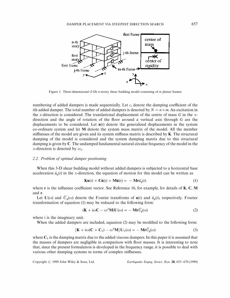
Figure 1. Three-dimensional (3-D) n-storey shear building model consisting of m planar frames
numbering of added dampers is made sequentially. Let cidenote the damping coe$cient of the
ith added damper. The total number of added dampers is denoted by N"n]m. An excitation inthe x-direction is considered. The translational displacement of the centre of mass G in the x-direction and the angle of rotation of the #oor around a vertical axis through G are thedisplacements to be considered. Let u(t) denote the generalized displacements in the systemco-ordinate system and let M denote the system mass matrix of the model. All the membersti!nesses of the model are given and its system sti!ness matrix is described by K. The structuraldamping of the model is considered and the system damping matrix due to this structuraldamping is given by C. The undamped fundamental natural circular frequency of the model in thex-direction is denoted by u
1.
2.2. Problem of optimal damper positioning
When this 3-D shear building model without added dampers is subjected to a horizontal baseacceleration u(
'(t) in the x-direction, the equation of motion for this model can be written as
Ku(t)#Cu5 (t)#MuK (t)"!Mru('(t) (1)
where r is the in#uence coe$cient vector. See Reference 16, for example, for details of K, C, Mand r.
Let U(u) and ;$'(u) denote the Fourier transforms of u(t) and u(
'(t), respectively. Fourier
transformation of equation (1) may be reduced to the following form:
(K#iuC!u2M)U(u)"!Mr;$'(u) (2)
where i is the imaginary unit.When the added dampers are included, equation (2) may be modi"ed to the following form:
MK#iu(C#CV)!u2MNUV(u)"!Mr;$'(u) (3)
where CV is the damping matrix due to the added viscous dampers. In this paper it is assumed thatthe masses of dampers are negligible in comparison with #oor masses. It is interesting to notethat, since the present formulation is developed in the frequency range, it is possible to deal withvarious other damping systems in terms of complex sti!nesses.
DAMPER PLACEMENT VIA STEEPEST DIRECTION SEARCH 657
Copyright ( 1999 John Wiley & Sons, Ltd. Earthquake Engng. Struct. Dyn. 28, 655}670 (1999)
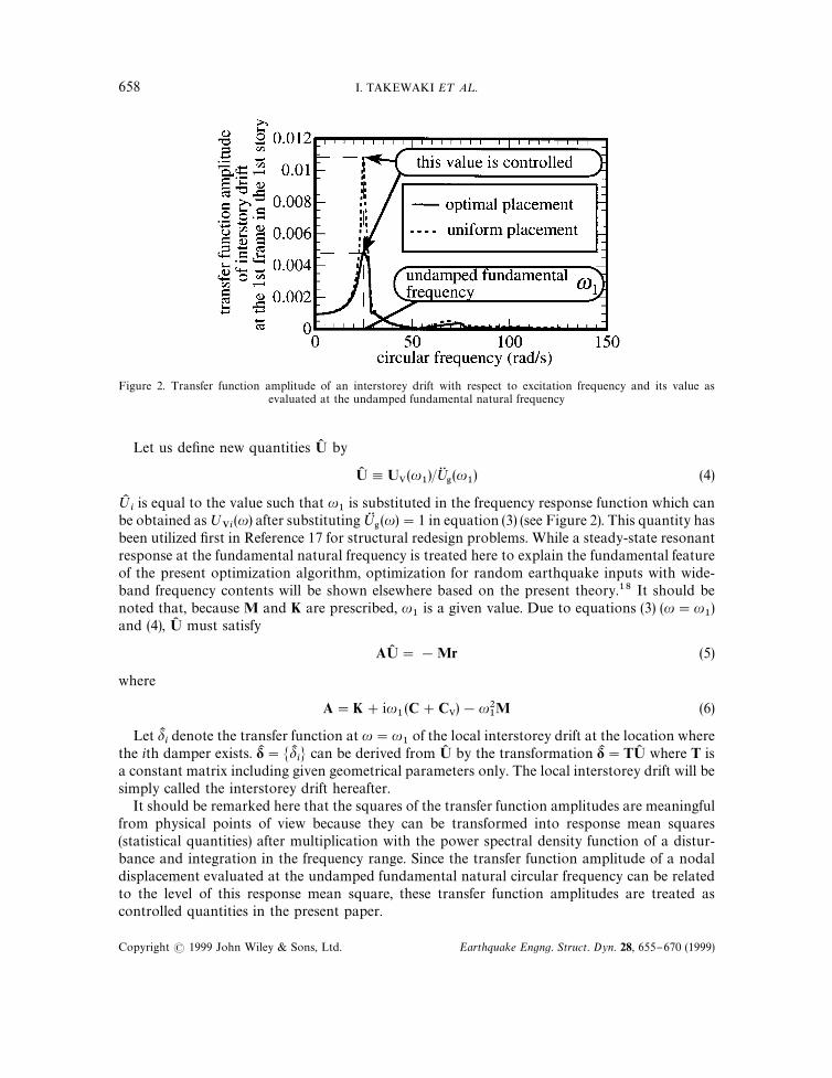
Figure 2. Transfer function amplitude of an interstorey drift with respect to excitation frequency and its value asevaluated at the undamped fundamental natural frequency
Let us de"ne new quantities U) by
U) ,UV(u1)/;G
'(u
1) (4)
;Kiis equal to the value such that u
1is substituted in the frequency response function which can
be obtained as;Vi
(u) after substituting;$'(u)"1 in equation (3) (see Figure 2). This quantity has
been utilized "rst in Reference 17 for structural redesign problems. While a steady-state resonantresponse at the fundamental natural frequency is treated here to explain the fundamental featureof the present optimization algorithm, optimization for random earthquake inputs with wide-band frequency contents will be shown elsewhere based on the present theory.18 It should benoted that, because M and K are prescribed, u
1is a given value. Due to equations (3) (u"u
1)
and (4), U) must satisfy
AU) "!Mr (5)
where
A"K#iu1(C#CV)!u2
1M (6)
Let dKidenote the transfer function at u"u
1of the local interstorey drift at the location where
the ith damper exists. dK "MdKiN can be derived from U) by the transformation dK "TU) where T is
a constant matrix including given geometrical parameters only. The local interstorey drift will besimply called the interstorey drift hereafter.
It should be remarked here that the squares of the transfer function amplitudes are meaningfulfrom physical points of view because they can be transformed into response mean squares(statistical quantities) after multiplication with the power spectral density function of a distur-bance and integration in the frequency range. Since the transfer function amplitude of a nodaldisplacement evaluated at the undamped fundamental natural circular frequency can be relatedto the level of this response mean square, these transfer function amplitudes are treated ascontrolled quantities in the present paper.
658 I. TAKEWAKI E¹ A¸.
Copyright ( 1999 John Wiley & Sons, Ltd. Earthquake Engng. Struct. Dyn. 28, 655}670 (1999)
The problem of optimal damper positioning for a 3-D shear building model may be describedas follows:
Problem PODPT: Find the damping coe$cients c"MciN of added dampers which minimize the
sum of the transfer function amplitudes of the interstorey drifts evaluated at the undampedfundamental natural circular frequency u
1
f (c)"N+i/1
DdKi(c)D (7)
subject to a constraint on the sum of the damping coe$cients of added dampers
N+i/1
ci"=M (=M : speci"ed value) (8a)
and to constraints on the damping coe$cients of added dampers
0)ci)cN
i(i"1,2 ,N) (8b)
where cNiis the upper bound of the damping coe$cient of the ith added damper.
The generalized Lagrangian ¸ for Problem PODPT may be expressed in terms of Lagrangemultipliers j, l"Mk
iN, m"Ml
iN.
¸(c, j, l, m)"f (c)#jAN+i/1
ci!=1 B#
N+i/1
ki(0!c
i)#
N+i/1
li(c
*!c6
i) (9)
For simplicity of expression argument (c) will be omitted hereafter.
2.3. Optimality criteria
The principal optimality criteria for Problem PODPT without active upper and lower boundconstraints on damping coe$cients may be derived from stationarity conditions of the general-ized Lagrangian ¸ (l"0, m"0) with respect to c and j.
f,j#j"0 for 0(c
j(cN
j( j"1,2 , N) (10)
N+i/1
ci!=M "0 (11)
Here and in the following ( ),j
denotes the partial di!erentiation with respect to cj. If constraints
(8b) are active, equation (10) must be modi"ed into the following forms:
f,j#j*0 for c
j"0 (12a)
f,j#j)0 for c
j"cN
j(12b)
2.4. Solution algorithm
In the proposed procedure the model without added dampers, i.e. cj"0 ( j"1,2, N), is
employed as the initial model. The damping coe$cients of added dampers are increased gradually
DAMPER PLACEMENT VIA STEEPEST DIRECTION SEARCH 659
Copyright ( 1999 John Wiley & Sons, Ltd. Earthquake Engng. Struct. Dyn. 28, 655}670 (1999)
via a new steepest direction search algorithm. Let *ciand *=M denote the increment of the damp-
ing coe$cient of the ith added damper and the increment of the sum of the damping coe$cients ofadded dampers, respectively. Given *=M , the problem is to determine the e!ective position andamount of the increments of the damping coe$cients of added dampers. To develop thisalgorithm, the "rst- and second-order sensitivities of the objective function with respect toa design variable are derived in the following.
Di!erentiation of equation (5) with respect to a design variable cjprovides
A,jU) #AU)
,j"0 (13)
From equation (6), A,jmay be expressed as follows:
A,j"iu
1CV,j
(14)
Since A is regular, the "rst-order sensitivities of U) are derived from equation (13) as
U),j"!A21A,
jU) (15a)
The "rst-order sensitivities of the interstorey drift dK are then expressed as
dK,j"TU)
,j"!TA21A,
jU) (15b)
The quantity dKimay be rewritten formally as
dKi"Re[dK
i]#i Im[dK
i] (16)
where Re[ ] and Im[ ] indicate the real and imaginary parts, respectively, of a complex number.The "rst-order sensitivity of dK
imay be formally expressed as
dKi,j"(Re[dK
i])
,j#i(Im[dK
i])
,j(17)
The absolute value of dKiis de"ned by
DdKiD"J(Re[dK
i])2#(Im[dK
i])2 (18)
The "rst-order sensitivity of DdKiD may then be expressed as
DdKiD,j"
1
DdKiDMRe[dK
i](Re[dK
i])
,j#Im[dK
i](Im[dK
i])
,jN (19)
where (Re[dKi])
,jand (Im[dK
i])
,jare calculated from equations (15b) and (17).
A general expression DdKiD,jl
is derived here for the purpose of developing a solution procedure forProblem PODPT. Di!erentiation of equation (19) with respect to c
lleads to
DdKiD,jl"
1
DdKiD2
(DdKiDM(Re[dK
i])
,l(Re[dK
i])
,j#Re[dK
i](Re[dK
i])
,jl#(Im[dK
i])
,l(Im[dK
i])
,j
#Im[dKi](Im[dK
i])
,jlN!DdK
iD,lMRe[dK
i](Re[dK
i])
,j#Im[dK
i](Im[dK
i])
,jN) (20)
660 I. TAKEWAKI E¹ A¸.
Copyright ( 1999 John Wiley & Sons, Ltd. Earthquake Engng. Struct. Dyn. 28, 655}670 (1999)
(Re[dKi])
,jland (Im[dK
i])
,jlin equation (20) are found from
dK,jl"TA~1(A,
lA~1A,
jU) !A,
jU)
,l) (21)
which is derived by di!erentiating equation (15b) with respect to cl
and using the relationA~1
,l"!A~1A,
lA~1. Substitution of equation (15a) into (21) leads to the following form:
dK,jl"TA21(A,
lA21A,
j#A,
jA21A,
l)U) (22)
The derivatives DdKiD,jl
are derived from equation (20). (Re[dKi])
,jand (Im[dK
i])
,jin equation (20) are
calculated from equation (15b) and (Re[dKi])
,jland (Im[dK
i])
,jlin equation (20) are found from
equation (22).The fundamental solution algorithm in the case of c
j(cN
jfor all j may be summarized as
follows:
Step 0: Initialize all the added dampers as cj"0 ( j"1,2, N). In the initial state the damping
considered is the structural damping alone in the model. Assume *=M .Step 1: Compute f
,iby equation (19).
Step 2: Find the index k such that
!f,k"max
i
M!f,iN (23)
Step 3: Update f by f#f,k*c
kwhere *c
k"*=M .
Step 4: Update f,i
by f,i#f
,ik*c
kusing equation (20).
Step 5: If in Step 4 there exists a damper of an index j such that the following condition issatis"ed
!f,k"max
j,jOk
M!f,jN (24)
then stop tentatively. Compute the corresponding *cJkand update f
,iby f
,i#f
,ik*cJ
kusing equa-
tion (20).Step 6: Repeat Steps 2}5 until the constraint (8a), i.e. +N
i/1ci"=M , is satis"ed.
The schematic diagram for this fundamental solution algorithm is shown in Figure 3. Therelation between the "rst derivatives of the objective function and the damping coe$cients isexplained there in detail. Once the "rst derivative of the objective function starts to attain themaximum absolute value, the corresponding damper begins possessing a non-zero value. Thedampers begin possessing non-zero damping coe$cients in the order of c
1, c
4, c
2, c
3in Figure 3.
In Steps 2 and 3 in the aforementioned algorithm, the direction which reduces the objectivefunction most e!ectively under the condition +N
i/1*c
i"*=M is found and the design is updated
in that direction. It is therefore appropriate to call the present algorithm 'the steepest directionsearch algorithm'. This algorithm may be similar to the well-known steepest descent method inthe mathematical programming. However, while the conventional steepest descent method usesthe gradient vector itself of the objective function as the direction and does not utilize optimalitycriteria, the present algorithm takes full advantage of the newly derived optimality criteria (10),(12a), (12b) and does not adopt the gradient vector as the direction. In other words, the steepest
DAMPER PLACEMENT VIA STEEPEST DIRECTION SEARCH 661
Copyright ( 1999 John Wiley & Sons, Ltd. Earthquake Engng. Struct. Dyn. 28, 655}670 (1999)
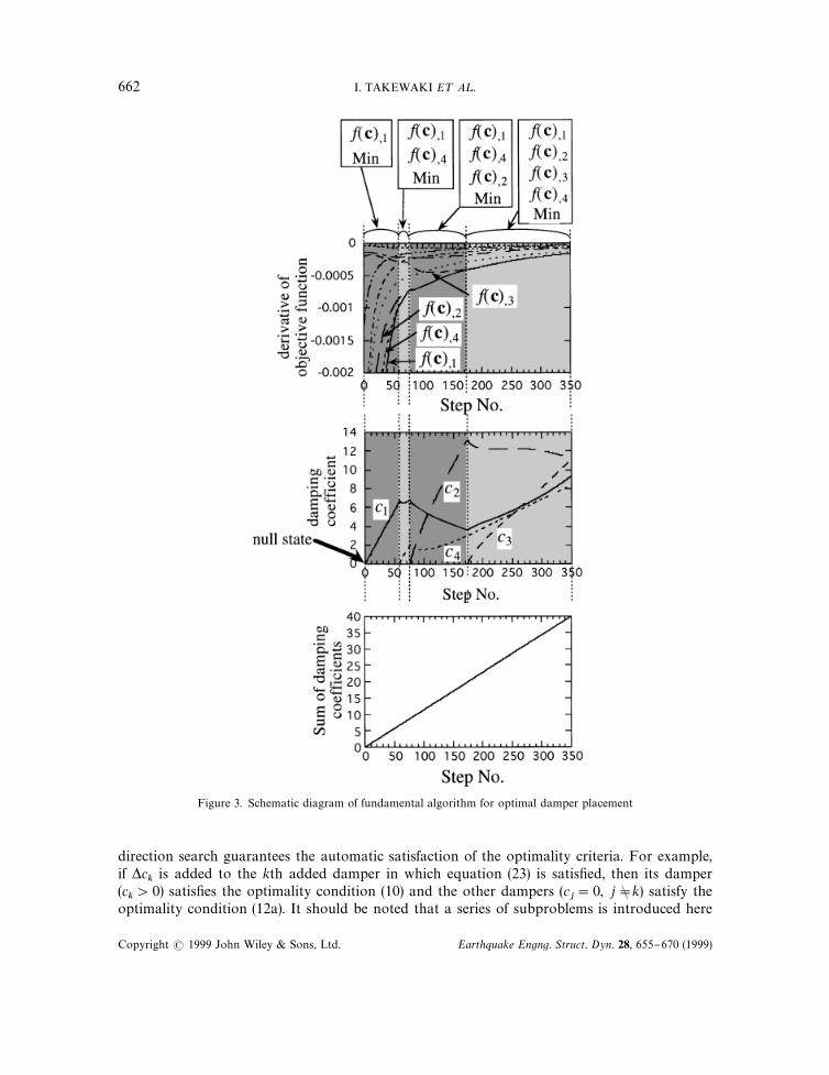
Figure 3. Schematic diagram of fundamental algorithm for optimal damper placement
direction search guarantees the automatic satisfaction of the optimality criteria. For example,if *c
kis added to the kth added damper in which equation (23) is satis"ed, then its damper
(ck'0) satis"es the optimality condition (10) and the other dampers (c
j"0, j"C k) satisfy the
optimality condition (12a). It should be noted that a series of subproblems is introduced here
662 I. TAKEWAKI E¹ A¸.
Copyright ( 1999 John Wiley & Sons, Ltd. Earthquake Engng. Struct. Dyn. 28, 655}670 (1999)
tentatively in which the damper level =M is increased gradually by *=M from zero through thespeci"ed value.
If there exist multiple indices k1,2, k
pin Step 2, f and f
,jhave to be updated by
fPf#kp+i/k1
f,i*c
i(25a)
f,jPf
,j#
kp+
l/k1
f,jl
*cl
(25b)
Furthermore the index k in Step 5 has to be replaced by the indices k1,2 , k
p. The ratios among
the magnitudes *cimust be determined so that the following relations are satis"ed:
f,k1#
kp+
i/k1
f,k1i
*ci"2" f
,kp#
kp+i/k1
f,kpi
*ci
(26)
Equation (26) requires that the optimality condition (10) continues to be satis"ed in the damperswith the indices k
1,2 , k
p.
In the case where the damping coe$cients of some added dampers attain their upper bounds,such constraints must be incorporated in the aforementioned algorithm. In that case the incre-ment *c
kis added subsequently to the damper in which !f
,kattains the maximum among all the
dampers except those attaining the upper bound.
3. NON-MONOTONIC PATH WITH RESPECT TO DAMPER LEVEL
In most cases, the increase of member sti!nesses reduces the response of a structure underdisturbances with a wide-band frequency content. On the other hand, increase of dampingcoe$cient of added dampers does not necessarily lead to the reduction of the response because ofcomplicated damping characteristics. Non-proportional damping may cause further complicatedphenomena. It has been found through numerical experiments that the algorithm mentionedabove can lead to the appearance of negative damping coe$cients. In the real world, negativedamping coe$cients are di$cult to be understood and this situation is excluded with theconstraints (8b). In this section a new method is proposed for preventing from appearance ofnegative damping coe$cients and "nding a path continuously within such complex designregions.
Figure 4(a) shows a situation at which a damping coe$cient of a speci"cally added damperc2starts to attain a negative value. At this stage, the proposed augmented algorithm recommends
to change the signs of the damping coe$cients of the dampers satisfying the optimality condition(10). In the following step, the design parameter is switched from the total damper capacity level(sum of the damping coe$cients) to the damping coe$cient of that damper c
2. In this range, the
sum of the damping coe$cients begins decreasing and afterwards begins to increase. It is notedthat, while the increment of the sum of the damping coe$cients has been speci"ed in therange without the emergence of negative damping coe$cients, it is obtained for a speci"edincrement of the damping coe$cient of that damper c
2. The validity of this treatment is shown in
the sequel.
DAMPER PLACEMENT VIA STEEPEST DIRECTION SEARCH 663
Copyright ( 1999 John Wiley & Sons, Ltd. Earthquake Engng. Struct. Dyn. 28, 655}670 (1999)
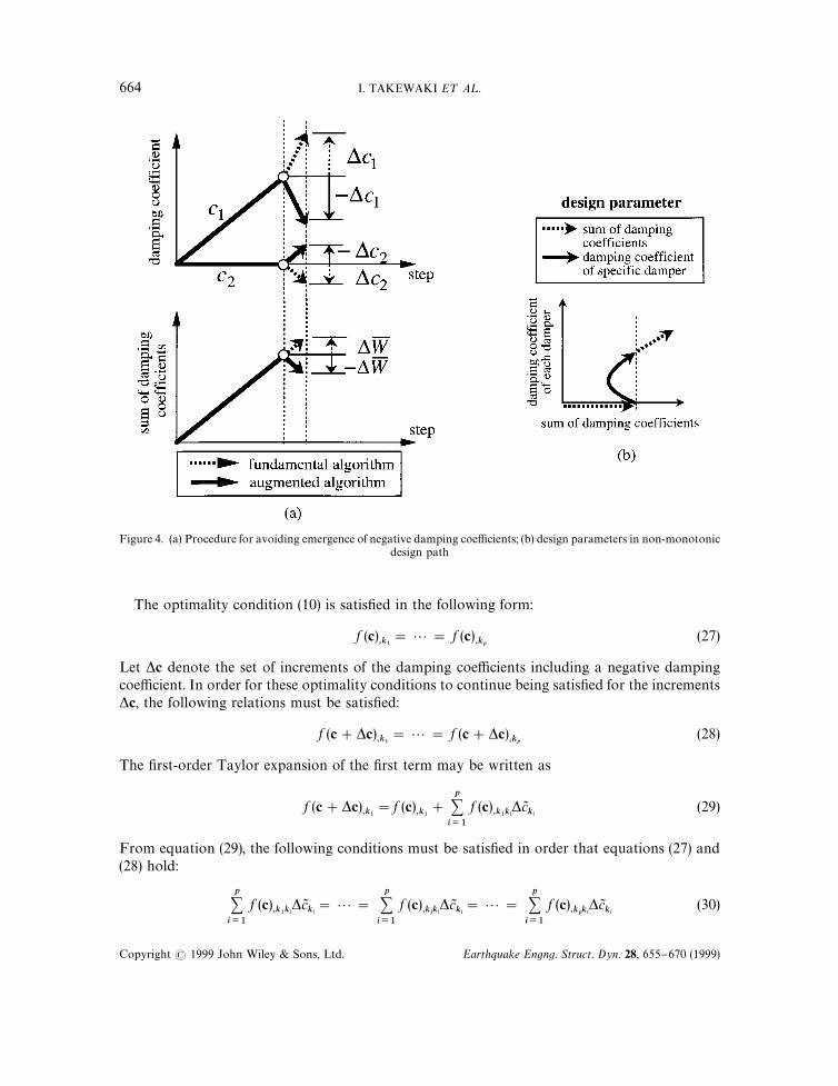
Figure 4. (a) Procedure for avoiding emergence of negative damping coe$cients; (b) design parameters in non-monotonicdesign path
The optimality condition (10) is satis"ed in the following form:
f (c),k1"2" f (c)
,kp(27)
Let *c denote the set of increments of the damping coe$cients including a negative dampingcoe$cient. In order for these optimality conditions to continue being satis"ed for the increments*c, the following relations must be satis"ed:
f (c#*c),k1"2" f (c#*c)
,kp(28)
The "rst-order Taylor expansion of the "rst term may be written as
f (c#*c),k1"f (c)
,k1#
p+i/1
f (c),k1ki
*cJki
(29)
From equation (29), the following conditions must be satis"ed in order that equations (27) and(28) hold:
p+i/1
f (c),k1ki
*cJki"2"
p+i/1
f (c),kjki
*cJki"2"
p+i/1
f (c),kpki
*cJki
(30)
664 I. TAKEWAKI E¹ A¸.
Copyright ( 1999 John Wiley & Sons, Ltd. Earthquake Engng. Struct. Dyn. 28, 655}670 (1999)
It should be noted that, if the damping coe$cients of the dampers except a speci"c damperwith a negative damping coe$cient in the fundamental algorithm are relatively large, a newset c!*c does not include any negative damping coe$cient. In order that the optimalityconditions are satis"ed for the newly designed variables c!*c, the following relation musthold:
f (c!*c),k1"2"f (c!*c)
,kp(31)
The "rst-order Taylor expansion of the "rst term may be written as
f (c!*c),k1"f (c)
,k1!
p+i/1
f (c),k1ki
*cJki
(32)
From equations (27), (30) and (32), it is apparent that equations (31) hold. This guarantees thevalidity of the proposed new algorithm for avoiding negative damping coe$cients.
After the sum of the damping coe$cients returns to a value from which the damping co-e$cient of a speci"c damper starts to attain a negative value, the design parameter is re-switchedfrom the damping coe$cient of that damper to the sum of the damping coe$cients (seeFigure 4(b)).
4. NUMERICAL EXAMPLES
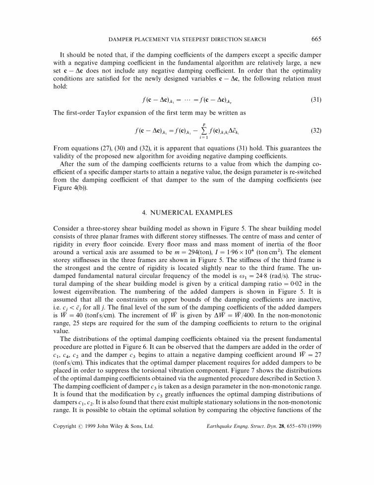
Consider a three-storey shear building model as shown in Figure 5. The shear building modelconsists of three planar frames with di!erent storey sti!nesses. The centre of mass and center ofrigidity in every #oor coincide. Every #oor mass and mass moment of inertia of the #ooraround a vertical axis are assumed to be m"294(ton), I"1)96]104 (ton cm2). The elementstorey sti!nesses in the three frames are shown in Figure 5. The sti!ness of the third frame isthe strongest and the centre of rigidity is located slightly near to the third frame. The un-damped fundamental natural circular frequency of the model is u
1"24)8 (rad/s). The struc-
tural damping of the shear building model is given by a critical damping ratio"0)02 in thelowest eigenvibration. The numbering of the added dampers is shown in Figure 5. It isassumed that all the constraints on upper bounds of the damping coe$cients are inactive,i.e. c
j(cN
jfor all j. The "nal level of the sum of the damping coe$cients of the added dampers
is =M "40 (tonf s/cm). The increment of =M is given by *=M "=M /400. In the non-monotonicrange, 25 steps are required for the sum of the damping coe$cients to return to the originalvalue.
The distributions of the optimal damping coe$cients obtained via the present fundamentalprocedure are plotted in Figure 6. It can be observed that the dampers are added in the order ofc1, c
4, c
2and the damper c
3begins to attain a negative damping coe$cient around =M "27
(tonf s/cm). This indicates that the optimal damper placement requires for added dampers to beplaced in order to suppress the torsional vibration component. Figure 7 shows the distributionsof the optimal damping coe$cients obtained via the augmented procedure described in Section 3.The damping coe$cient of damper c
3is taken as a design parameter in the non-monotonic range.
It is found that the modi"cation by c3
greatly in#uences the optimal damping distributions ofdampers c
1, c
2. It is also found that there exist multiple stationary solutions in the non-monotonic
range. It is possible to obtain the optimal solution by comparing the objective functions of the
DAMPER PLACEMENT VIA STEEPEST DIRECTION SEARCH 665
Copyright ( 1999 John Wiley & Sons, Ltd. Earthquake Engng. Struct. Dyn. 28, 655}670 (1999)
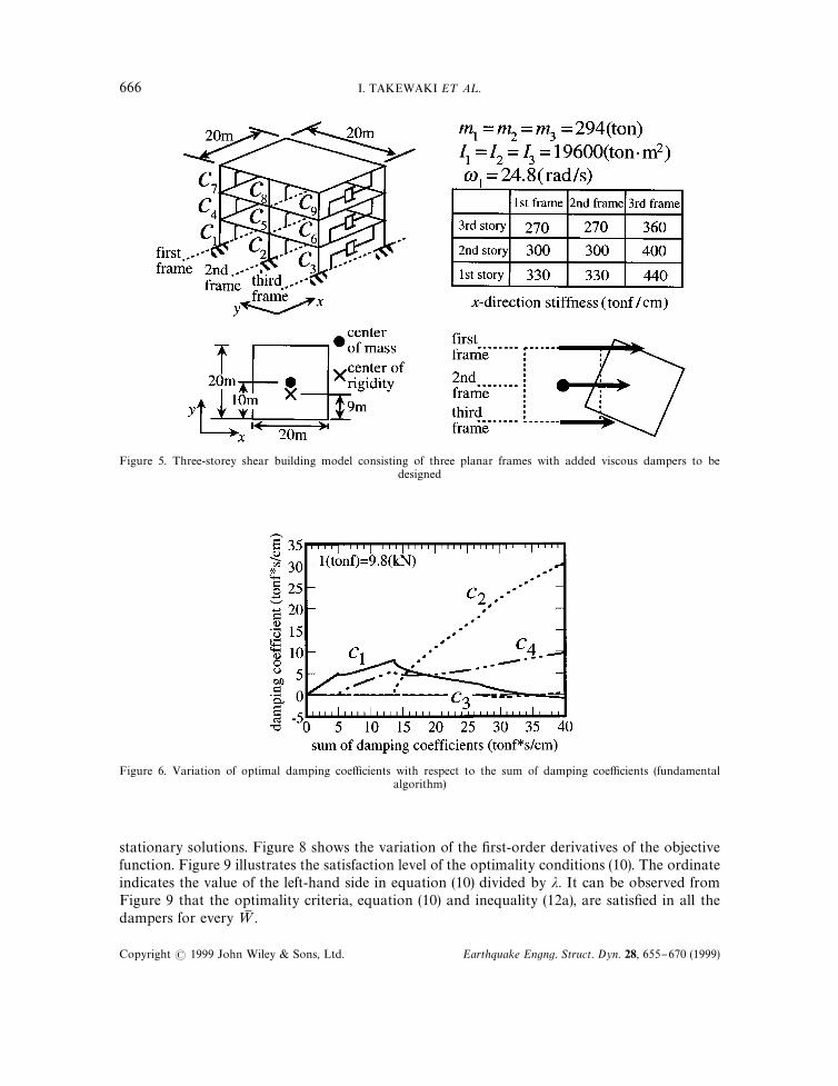
Figure 5. Three-storey shear building model consisting of three planar frames with added viscous dampers to bedesigned
Figure 6. Variation of optimal damping coe$cients with respect to the sum of damping coe$cients (fundamentalalgorithm)
stationary solutions. Figure 8 shows the variation of the "rst-order derivatives of the objectivefunction. Figure 9 illustrates the satisfaction level of the optimality conditions (10). The ordinateindicates the value of the left-hand side in equation (10) divided by j. It can be observed fromFigure 9 that the optimality criteria, equation (10) and inequality (12a), are satis"ed in all thedampers for every =M .
666 I. TAKEWAKI E¹ A¸.
Copyright ( 1999 John Wiley & Sons, Ltd. Earthquake Engng. Struct. Dyn. 28, 655}670 (1999)
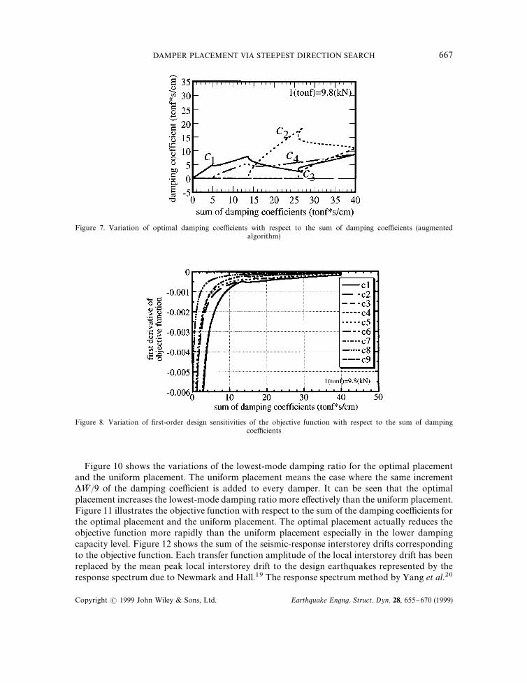
Figure 7. Variation of optimal damping coe$cients with respect to the sum of damping coe$cients (augmentedalgorithm)
Figure 8. Variation of "rst-order design sensitivities of the objective function with respect to the sum of dampingcoe$cients
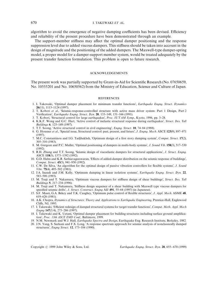
Figure 10 shows the variations of the lowest-mode damping ratio for the optimal placementand the uniform placement. The uniform placement means the case where the same increment*=M /9 of the damping coe$cient is added to every damper. It can be seen that the optimalplacement increases the lowest-mode damping ratio more e!ectively than the uniform placement.Figure 11 illustrates the objective function with respect to the sum of the damping coe$cients forthe optimal placement and the uniform placement. The optimal placement actually reduces theobjective function more rapidly than the uniform placement especially in the lower dampingcapacity level. Figure 12 shows the sum of the seismic-response interstorey drifts correspondingto the objective function. Each transfer function amplitude of the local interstorey drift has beenreplaced by the mean peak local interstorey drift to the design earthquakes represented by theresponse spectrum due to Newmark and Hall.19 The response spectrum method by Yang et al.20
DAMPER PLACEMENT VIA STEEPEST DIRECTION SEARCH 667
Copyright ( 1999 John Wiley & Sons, Ltd. Earthquake Engng. Struct. Dyn. 28, 655}670 (1999)
Figure 9. Satisfaction level of optimality conditions, equation (10) and inequality (12a)
Figure 10. Variation of the lowest-mode damping ratio with respect to the sum of damping coe$cients (optimalplacement and uniform placement)
for a non-proportional damping has been employed to estimate the mean peak local interstoreydrift. It can be found from Figure 12 that in a certain narrow range, the seismic response of themodel designed optimally for the steady-state resonant response becomes larger than that for theuniform placement. Higher-mode e!ects on seismic responses to wide-band inputs and non-proportional damping e!ects may be a cause of this phenomenon. Direct introduction of theseismic response into the objective function (7) and the application of the random vibrationtheories in the seismic response evaluation may lead to a more realistic optimal damperplacement.18 Numerical integration in the frequency range and sensitivity expressions of fre-quency response functions will be required in the computation. However, this treatment mayrequire unrealistic computational resources.
668 I. TAKEWAKI E¹ A¸.
Copyright ( 1999 John Wiley & Sons, Ltd. Earthquake Engng. Struct. Dyn. 28, 655}670 (1999)
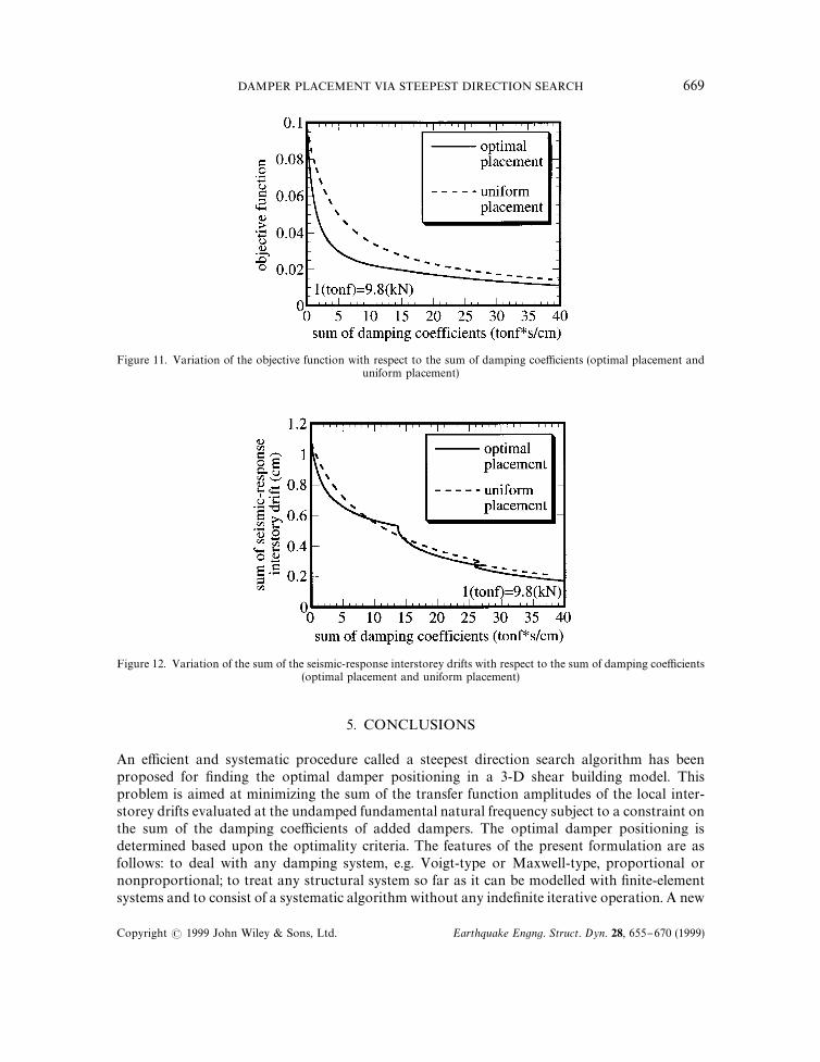
Figure 11. Variation of the objective function with respect to the sum of damping coe$cients (optimal placement anduniform placement)
Figure 12. Variation of the sum of the seismic-response interstorey drifts with respect to the sum of damping coe$cients(optimal placement and uniform placement)
5. CONCLUSIONS
An e$cient and systematic procedure called a steepest direction search algorithm has beenproposed for "nding the optimal damper positioning in a 3-D shear building model. Thisproblem is aimed at minimizing the sum of the transfer function amplitudes of the local inter-storey drifts evaluated at the undamped fundamental natural frequency subject to a constraint onthe sum of the damping coe$cients of added dampers. The optimal damper positioning isdetermined based upon the optimality criteria. The features of the present formulation are asfollows: to deal with any damping system, e.g. Voigt-type or Maxwell-type, proportional ornonproportional; to treat any structural system so far as it can be modelled with "nite-elementsystems and to consist of a systematic algorithm without any inde"nite iterative operation. A new
DAMPER PLACEMENT VIA STEEPEST DIRECTION SEARCH 669
Copyright ( 1999 John Wiley & Sons, Ltd. Earthquake Engng. Struct. Dyn. 28, 655}670 (1999)
algorithm to avoid the emergence of negative damping coe$cients has been devised. E$ciencyand reliability of the present procedure have been demonstrated through an example.
The support-member sti!ness may a!ect the optimal damper positioning and the responsesuppression level due to added viscous dampers. This sti!ness should be taken into account in thedesign of magnitude and the positioning of the added dampers. The Maxwell-type damper-springmodel, a proper model for a damper-support member system, would be treated adequately by thepresent transfer function formulation. This problem is open to future research.
ACKNOWLEDGEMENTS
The present work was partially supported by Grant-in-Aid for Scienti"c Research (No. 07650659,No. 10555201 and No. 10650562) from the Ministry of Education, Science and Culture of Japan.
REFERENCES
1. I. Takewaki, &Optimal damper placement for minimum transfer functions', Earthquake Engng. Struct. Dynamics26(11), 1113}1124 (1997).
2. T. Kobori et al., &Seismic-response-controlled structure with active mass driver system: Part 1 Design, Part 2Veri"cation', Earthquake Engng. Struct. Dyn. 20, 133}149, 151}166 (1991).
3. T. Kobori, &Structural control for large earthquakes', Proc. I;¹AM Symp., Kyoto, 1996, pp. 3}28.4. K.K.F. Wong and G.C. Hart, &Active control of inelastic structural response during earthquakes', Struct. Des. ¹all
Buildings 6, 125}149 (1997).5. T.T. Soong, &Active structural control in civil engineering', Engng. Struct. 10, 74}84 (1988).6. G. Housner et al., &Special issue, Structural control: past, present, and future', J. Engng. Mech. ASCE 123(9), 897}971
(1997).7. M.C. Constantinou and I.G. Tadjbakhsh, &Optimum design of a "rst story damping system', Comput. Struct. 17(2),
305}310 (1983).8. M. Gurgoze and P.C. Muller, &Optimal positioning of dampers in multi-body systems', J. Sound <ib. 158(3), 517}530
(1992).9. R.H. Zhang and T.T. Soong, &Seismic design of viscoelastic dampers for structural applications', J. Struct. Engng.
ASCE 118(5), 1375}1392 (1992).10. G.D. Hahn and K.R. Sathiavageeswaran, &E!ects of added-damper distribution on the seismic response of buildings',
Comput. Struct. 43(5), 941}950 (1992).11. C.W. De Silva, &An algorithm for the optimal design of passive vibration controllers for #exible systems', J. Sound<ibr. 75(4), 495}502 (1981).
12. J.A. Inaudi and J.M. Kelly, &Optimum damping in linear isolation systems', Earthquake Engng. Struct. Dyn. 22,583}598 (1993).
13. M. Tsuji and T. Nakamura, &Optimum viscous dampers for sti!ness design of shear buildings', Struct. Des. ¹allBuildings 5, 217}234 (1996).
14. M. Tsuji and T. Nakamura, &Sti!ness design sequence of a shear building with Maxwell type viscous dampers forspeci"ed seismic drifts', J. Struct. Construct. Engng AIJ 491, 55}64 (1997) (in Japanese).
15. S.F. Masri, G.A. Bekey and T.K. Caughey, &Optimum pulse control of #exible structures', J. Appl. Mech. ASME 48,619}626 (1981).
16. A.K. Chopra, Dynamics of Structures: ¹heory and Applications to Earthquake Engineering, Prentice-Hall, EnglewoodCli!s, NJ, 1995.
17. I. Takewaki, &E$cient redesign of damped structural systems for target transfer functions', Comput. Meth. Appl. MechEngng 147(3/4), 275}286 (1997).
18. I. Takewaki and K. Uetani, &Optimal damper placement for building structures including surface ground ampli"ca-tion', Proc. 13th ASCE EMD Conf., Baltimore, 1999.
19. N.M. Newmark and W.J. Hall, Earthquake Spectra and Design, Earthquake Eng. Research Institute, Berkeley, 1982.20. J.N. Yang, S. Sarkani and F.X. Long, &A response spectrum approach for seismic analysis of nonclassically damped
structures', Engng Struct. 12, 173}184 (1990).
670 I. TAKEWAKI E¹ A¸.
Copyright ( 1999 John Wiley & Sons, Ltd. Earthquake Engng. Struct. Dyn. 28, 655}670 (1999)


![ACATacat.or.th/download/acat_or_th/journal-4/04 - 04.pdf · APmin APmax Appendix G [1] AP APmax Overpressure Relief Damper Damper 12 Relief Damper Relief Damper (Vent) Fire Damper](https://img.pdfslide.us/doc/110x75/5f7cb481641db55595223717/-04pdf-apmin-apmax-appendix-g-1-ap-apmax-overpressure-relief-damper-damper.jpg)