Embed Size (px)
Citation preview

NONLINEAR SEISMIC ANALYSIS OF A REACTOR STRUCTURE
WITH IMPACT BETWEEN CORE COMPONENTS
Ronald G. Hill
Hanford Engineering Development Laboratory*
SUMMARY
i The seismic analysis of the FFTF-PIOTA (Fast Flux Test Facility-Postirrad-
ation Open Test Assembly), subjected to a horizontal DBE (Design Base Earth-
uake) is presented. The PIOTA is the first in a set of open test assemblies
o be designed for the FFTF. Employing the direct method of transient analysis,
he governing differential equations describing the motion of the system are setjp directly and are implicitly integrated numerically in time. A simple lumped-
lass beam model of the FFTF which includes small clearances between core com-Ponents is used as a "driver" for a fine mesh model of the PIOTA. The nonlinear
;orces due to the impact of the core components and their effect on the PIOTA
ire computed.
INTRODUCTION
The reactor core of the FFTF**is designed to accommodate bowing of fuel
Issemblies which is caused by the core's neutronic and thermal environment.
"he individual fuel assemblies have a floating collar design at the above core
load pad where adjacent assemblies contact to take into account the deforma-
:ions of the core components. During certain periods of the reactor cycle
;mall clearances may exist between core components; hence, it is important to
_etermine the effect of design impact loads between these structural components
_o preclude unacceptable stress levels and fai lures.i
The topic of impact is the subject of numerous studies. Special purpose"omputer program solutions have been developed for analysis of impact of reactor
internal structures by Bohm and Nahavandi, reference l, using explicit inte-
gration procedures. The analysis reported in this paper uses implicit inte-
gration procedures through the transfer function capabilities of the general
)urpose computer program NASTRAN to solve for the nonlinear loads due to impact)etween structural members.L
*The Hanford Engineering Development Laboratory is a United States Energy
Research and Development Administration Laboratory. HEDL is operated by
the Westinghouse Hanford Company.**See Nomenclature Table.
39?
https://ntrs.nasa.gov/search.jsp?R=19750023435 2018-05-25T16:14:33+00:00Z
FFTF-PIOTA
DBE
NASTRAN
OTA
DOF
BANDIT
PWR
IVHM
HEDL
CYBER
TRD
DMAP
PNDL
MSC
INFONET
COSMIC
I/O
CPU
SDRC
CYBERNET
*In order of use.
398
NOMENCLATURE*
Fast Flux Test Facility-PostirradiationOpen Test Assembly
Design Base Earthquake
N_AASAST__RRUCTURALANALYSlS
Open Test Assembly
Degrees of Freedom
Computer Program -- to determine minimumbandwidth
Pressurized Water Reactor
In-Vessel Fuel Handling Machine
Hanford Engineering DevelopmentLaboratory
HEDL Computer-Control Data CorporationModel 74-18
Transient Response Displacement
Direct Matrix Abstraction Program
A DMAP Module
McNeal Schwendler Corporation
Computer Sciences Corporation ComputerNetwork System
Agency for United States Government Releaseof Computer Programs
Input/Output Units
Central Processing Units
Structural Dynamics Research Corporation
Control Data Corporation Computer Network System
SYMBOLS
1
43
l(t)
F(n)
damping matrix
stiffness matrix
mass matrix
a set of coordinates expressed as a column
matrix of two terms for each grid point;
y, oz (see figure 3)
pivotal frequency
seismic forcing function
nonlinear impact load
percent critical damping
MODELING PROCEDURES
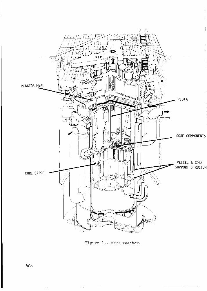
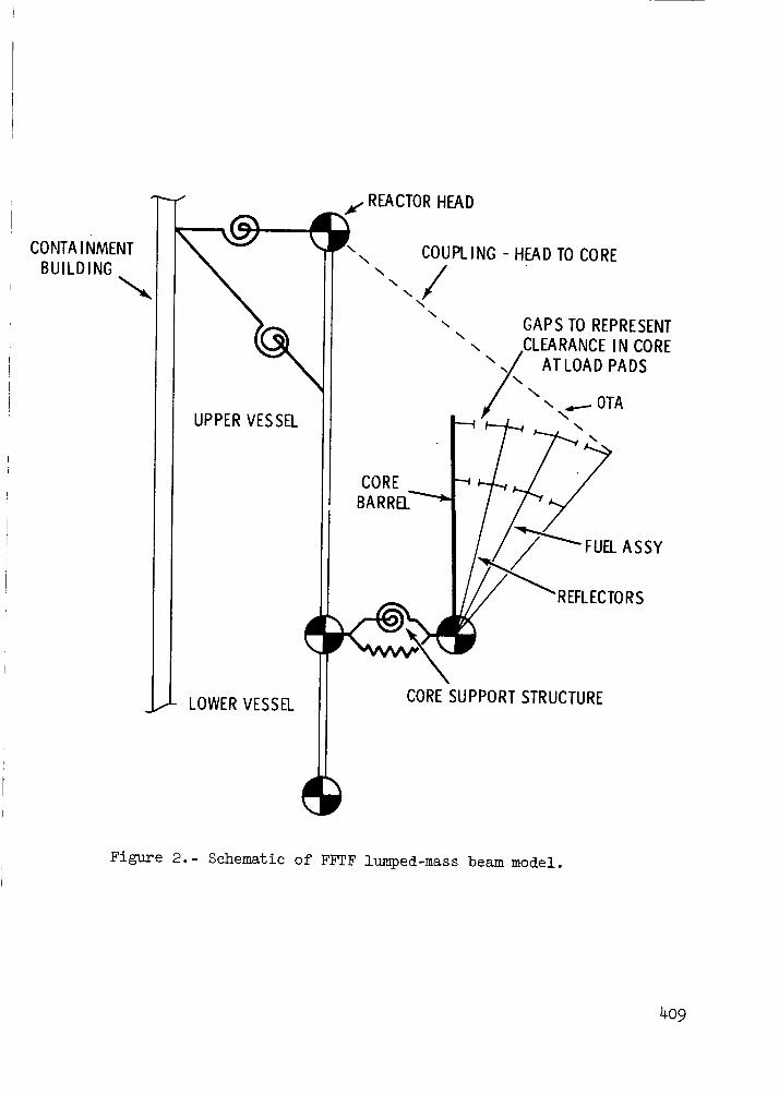
Figures l and 2 portray the salient points of the FFTF reactor. The
reactor is idealized with lumped-mass, spring, gap and beam elements for trans-
lation and rotational motion. The DBE, a translational input is applied dir-ectly to the reactor head. The core components, fuel assemblies, etc., are
pinned at the core barrel and lateral support is provided at the pad locations
_y the gap elements. The core components, if permitted to rotate, may be con-
idered as inverted pendulums. The core components (reflector, fuel assembly,
TA), figure 3, are expanded horizontally until a return is made to the core
barrel, for an enclosed representation of the FFTF core.
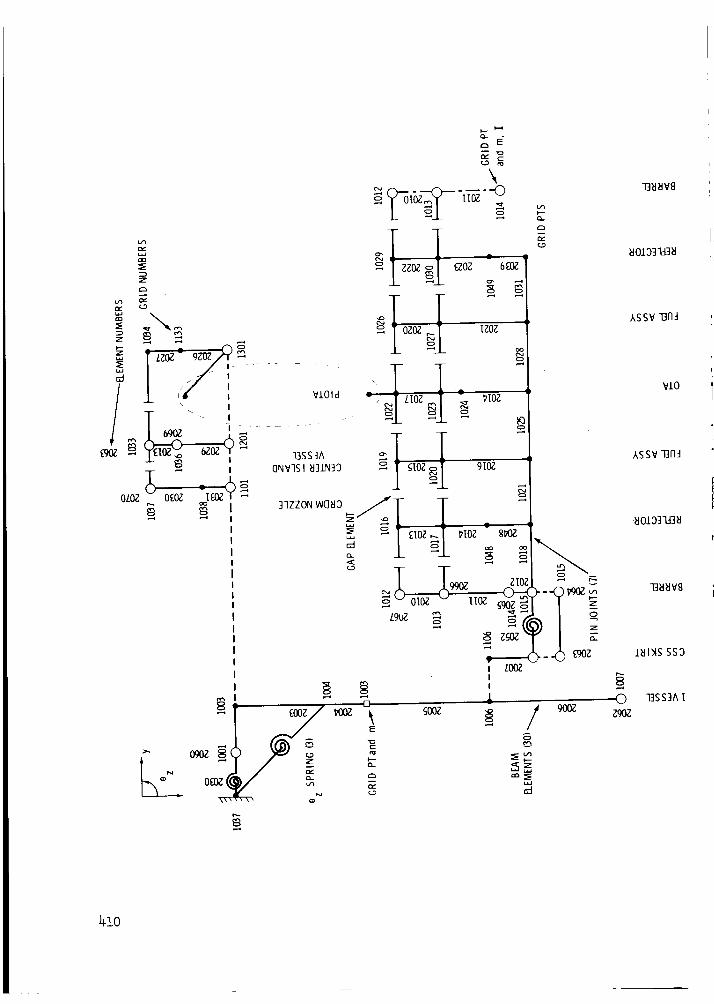
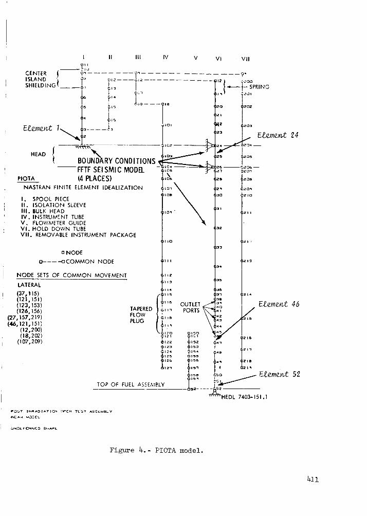
Figures 3 and 4 show the grid point and finite element notation for the_ourse FFTF reactor model and the fine mesh PIOTA model. A fine mesh was used
to model the PIOTA, figure 4, because of the boundary conditions between the
PIOTA's components, the close coupling of its natural frequencies, and the
predicted critical stress area at the PIOTA's outlet ports. The coarse reactor
model is numbered in the lO00 series of grid points and 2000 for the element
numbers. The model parameters such as size, mass, stiffness, and damping values
are described for the respective models in references 2 and 3. The coarse
reactor model is like the FFTF systems model used for both SCRAM and nonlinear
seismic analysis, reference 2, with the exception that certain reactor
components are not included in the subject model; i.e., Instrument Tree,
IVHM, etc. The SCRAM and nonlinear seismic analysis, reference 2, was per-
formed using proprietary (Westinghouse Advanced Reactor Division) special
purpose computer programs.
The set of equations used to determine the seismic response is
[Maa] {Ua} + [Baa] {Ua} + [Kaa] {Ua} : {f(t)} + {f(n)}
399
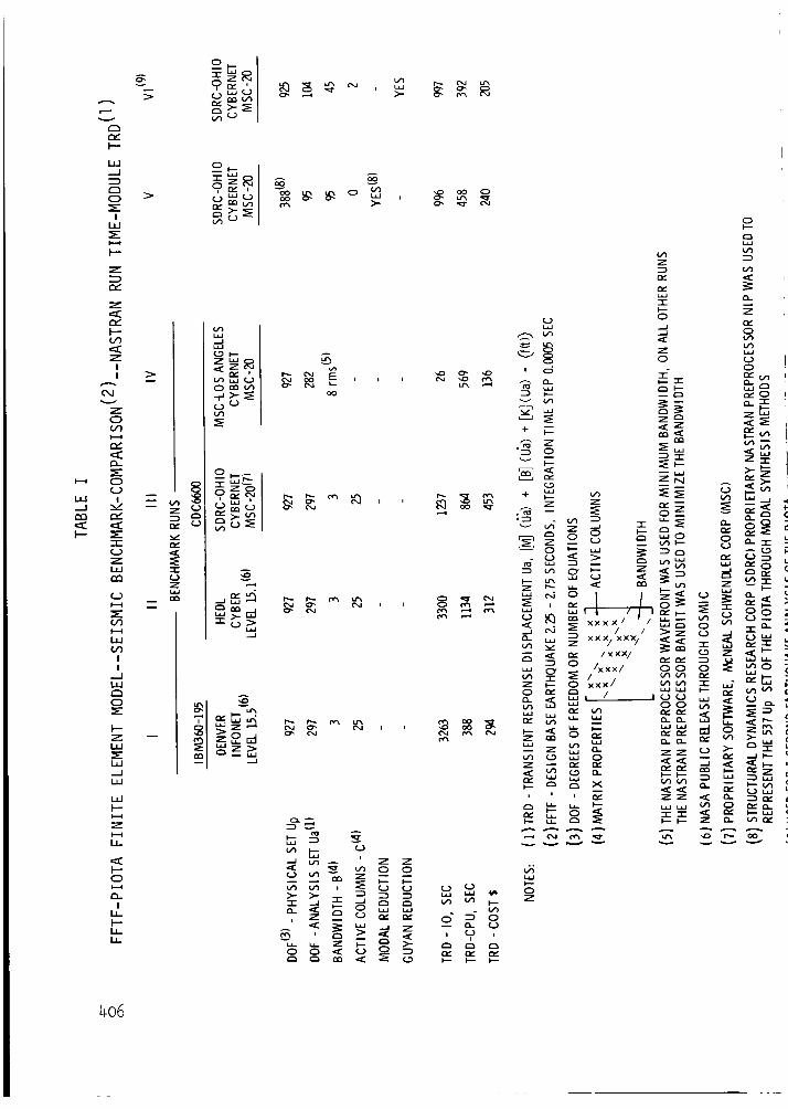
The physical set of equations for the models shownin figures 3 and 4 has927 DOF,of which 537 belong to the PIOTA. The DOFafter reduction forcoordinates y and Oz, boundary conditions, constraints, etc., is 297. Thisproblem size (297 DOF,time step increment of 0.0005 second and a 5 secondearthquake) involves a sizeable computation investment, approximately 3 x lO6iterations. Hence, further reduction of the problem was desirable. Of the
three reduction methods considered, substructuring, modal synthesis and Guyan,
the Guyan method was found best for minimum loss of accuracy in conjunction
with nonlinear dynamic analysis. Its basis is that fewer DOF are needed to
describe the inertia of a structure than are needed to describe its elasticity
with comparable accuracy. In using the Guyan method NASTRAN recovers directly
displacements, accelerations, etc., for the coordinates used in the reduction
process. The Guyan reduction method was used to reduce the 297 DOF to an
analysis set of I04 DOF. The Guyan reduction process increased the bandwidthfrom 3 to 45; however, the run time was reduced by 65% based on CPU, see
table I. The preprocessor BANDIT was used to reduce the bandwidth for the
PIOTA model, figure 4. BANDIT was not applied to the FFTF model, figure 3,
because of the gap elements and the straightforwardness of the model.
NONLINEAR TRANSIENT ANALYSIS
In this transient solution, the coupled equations of motion are inte-
grated directly without any uncoupling by modal methods, Rigid Format No. 9.
The two basic methods used for direct numerical integration are explicit
integration in time and implicit integration in time. Difference formulasthat relate the accelerations, velocities and displacements are used in both
the explicit and implicit integration methods. NASTRAN (reference 4) uses a
form of the Newmark Beta Method, implicit integration in time, that yields an
unconditionally stable solution for a wide range of transient dynamic problem.(
The stability limit is a function of the period of the highest vibration mode
of the system. Though the implicit integration method is not as fast per
time step as the explicit method, the unconditional stability permits the use
of large time steps. A time step of 0.0005 second was selected for the runsdescribed herein and no numerical stability problem was encountered. The
introduction of nonlinearities in the implicit method of integration may caus(
numerical stability problems in addition to those mentioned above. These proL
lems are due to the inconsistent definition of displacement and velocity
between linear and nonlinear forces and may result in the presence of a para-
sitic mass on the coordinates to which nonlinear forces are applied. The
remedy is to add sufficient mass to the coordinate directly or to reduce the
time step of integration so that the parasitic mass effect is negligible in
40o
!
omparison to the nodal mass. A time step of 0.005 secondwas used_.oobtain a linear solution for the model shownin figure 3.!his is the same time interval as the input acceleration-time history. With:he addition of gap elements to the model, figure 3, the time step was reduced_o 0.0005 second through the above parasitic mass consideration.I
r In NASTRAN, the nonlinear effects (gap elements) are treated through the
Jse of an additional applied load vector. The gap element and the respective
ipplied load vector are user-created by means of transfer functions. Gap
_.lements similar to the ones shown in figure 3 are described in reference 5
_ith transfer function and nonlinear load card images.
DAMPING AND THE GAP ELEMENT
Two forms of damping* are used in this seismic analysis, structural and
impact. In both forms, assumptions concerning the effects of damping on the
lodal coordinates are based on a viscous model in which the energy dissipated
per cycle is proportional to frequency. A uniform structural damping of 2%of the critical for the DBE was input to the model (figure 2) in terms of_tiffness, as follows:
[Baa] : 2g [Kaa]W3
This method, reference 4, of inputting equivalent viscous damping is an approx-
imation, since the viscous damping forces are larger at higher frequencies and
smaller at lower frequencies. The structural damping, Baa, has small effect,
or is of no effect, on the response of the model. This is due to the over-
ruling effect and nature of impact damping (I0% vs 2% of the critical).
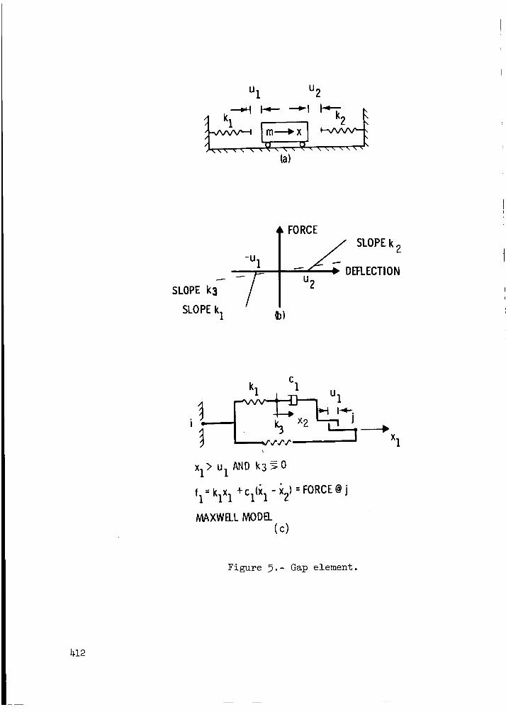
The impact damping is related to the nonlinearities of the gap element.
The impact damping and stiffness, c and k, figure 5, are based on a coefficient
restitution method (rebound) and the Hertz theory of impact of two solids,
i.e., an elastic statical consideration. The relationship between coefficient
of restitution and critical damping is derived in reference 2 and is shown in
ithis report as figure 6. An impact damping value of I0% of the critical was_used in this analysis. This represents high viscous damping. Impact damping
values for FFTF reflector and fuel assemblies have not been measured exper-
iimentally. However, there are data available from PWR fuel assemblies tests,
reference 2, and from a FFTF IVHM test, reference 5, to corroborate the high
impact damping value. Figure 6 shows a comparison of these impact dampingvalues, 19% for PWR fuel assemblies and 15% for the vertical IVHM test. The
*Structural - hys tereti c damping
Impact - Maxwell representation of viscous damping
4Ol

IVHM 15% value was determined from the rate of decay of successive re-
bounds. Therefore, the I0% of the critical damping is considered conser-
vative for these analyses.
The vertical drop IVHM test, reference 5, affords a means to assess the
validity of the NASTRAN gap element. In comparing the experimental results
with those computed from the simple scalar lumped-mass NASTRAN model, there
was close agreement. The free fall times and displacements for this test and
model were readily calculated by hand methods.
The general form of the gap element used in this analysis is shown in
figure 5(a). Gaps in positive and negative directions (for example, theboundary conditions of a rod moving within a tube), can be represented by
this element. A gap element with closing capability only (i.e., that portion Iof the force deflection curve shown in the third quadrant, figure 5(b), and the[
analogous mechanical model shown in figure 5(c)), was used to represent theclearances between the core components, at twelve places (figure 3). The ex-
panded representation of the core with the gap closure described above, yieldsa closed core configuration for impact analysis of individual core components.
Figure 5(c) shows the mechanical model where the impact spring and gap are
accompanied by energy dissipation, and viscous damping. Functionally, the
viscous damper, ci should act only when the gap is closed, x I >u 1. At thetime these seismic analyses were performed, a switchable, viscous damper had
not been verified for use in NASTRAN. A pseudo Maxwell model, figure 5(c), was
used in this analysis; the Maxwell model does not necessitate a switchable
damper, since the damper ci is in series with the impact spring ki. The
linear spring k3, which was small compared with ki, improved the stability of
the numerical solution, i.e., a larger time step was used.
SEISMIC TIME HISTORY
The input to the FFTF seismic model, Grid Point lOOl, figure 3, consistedof an acceleration time history with data points at 0.005 second intervals.
This seismic transient is the singular output at the concrete ledge from a
two-dimensional finite element soil interaction model of the containment
building (reference 6). The dynamic coupling between the containment building
and the reactor vessel is assumed to be negligible.
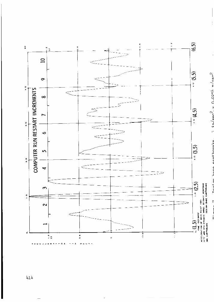
A DBE with 2% of the critical damping, and a duration of 20 seconds was
specified (reference 6). Previous investigations (reference 2) revealed that
only the accelerations from 1.5 seconds to 6.5 seconds were significant; thisthen is the seismic transient that was used for the PIOTA analysis (figure 7).
The DBE earthquake was divided into ten increments, as shown in figure 7, for
computer restart advantage and clarity of output. The printout time interval
was ten times the integration time step, or 0.005 seconds. The analysis was
started at 1.5 seconds; thus, there is a 1.5 second time shift in the output
response, see figure 7.
402
SOFTWARE AND COMPUTER FACILITIES COMPARISON
This section compares the off-load* results with those obtained on theIEDL-CYBER for a 0.5 second DBE input to the FFTF-PIOTA model. The CYBERras not available to perform the 5 second DBE due to other commitments.
In performing the CYBER and off-load benchmark runs we found that the_OSMIC version of NASTRAN, Level 15.5, computed incorrect nonlinear loads.ihe nonlinear load computations were evaluated by the IVHM model describedn reference 5; the results for the IVHM model can readily be checked by
land methods. The IVHM evaluation revealed that the PNLD module in NASTRAN;evel 15.5 was not functioning correctly. DMAP instruction number 139,IASTRAN Rigid Format No. 9 gives the relationship of the PNLD module to theomputations of TRD. The source language for NASTI_AN is essentially writtenn FORTRAN IV; the DMAP instructions are a compilation of this sourceanguage. The IVHM analysis was successfully performed in 1972 on theNIVAC 1108 using Level 15.1, hence a CDC 6600 version of NASTRAN Level 15.1as installed on the CYBER and used for the CYBER computations described in
_his report.
Benchmark runs were performed at the four computing facilities shown on;able I. The CYBER run was used as a reference for evaluating the off-load_esults. The reference run column II, table I, is identical to the FFTF-_IOTA runs described herein with the exception of the OMIT 1 cards. The)MIT bulk data cards are used to achieve the Guyan reduction described)reviously in this report. It is difficult to compare results from dis-imilar computing facilities because of timing algorithms, input-output
variances, system dependent software, etc. These problems were alleviatedn the FFTF-PIOTA evaluation by comparing the run time required for the TRDodule, see table I; this module uses the majority of the central processing
time needed for direct transient analyses.
Table I, columns III through VI, show that the MSC version of NASTRANgives significant reductions in run time when compared to the HEDL or INFONETCOSMIC version of NASTRAN. The benchmark run that the MSC performed inLos Angeles, column IV, had two alterations, the transfer functions used for
ithe gap elements were replaced by multipoint constraint equations to utilizerthe more efficient symmetric matrix decomposition rather than unsymmetricdecomposition, and certain data that was transferred to peripheral storage inLevel 15.1 was held in main core in MSC-20, thus eliminating peripheral
Iprocessing-calls The above alterations account for the reduction in I/0time of 1237 to 26 seconds and CPU reduction of 864 to 569 seconds. The MSC-
Los Angeles results shown in column IV were obtained subsequent to theanalyses described in this report.
*Off-load -- Computer facilities other than available at HEDL-CYBER
4o3

The deck used by SDRCin their benchmark run was identical to the CYBERrun, columns II and III, table I. The improvement in run time, I/O 3300versus 1237 seconds and CPUI134 versus 864 seconds, is due primarily to theversion of NASTRANutilized, COSMICLevel 15.1 versus MSC-20; the operatingsystems, CYBERand CYBERNET,are similar, both are basically CDC6600 machinesThe solution for the SDRCbenchmark run was identical to the CYBERresults,columns II and Ill. Therefore, as a result of these benchmarkevaluationsand the need for off-load capability, the SDRCfacilities at Cincinnati, Ohio,NASTRANMSC-20and the CYBERNEToperating system were used to perform the5 second earthquake run described in this report, see column VI, table I.
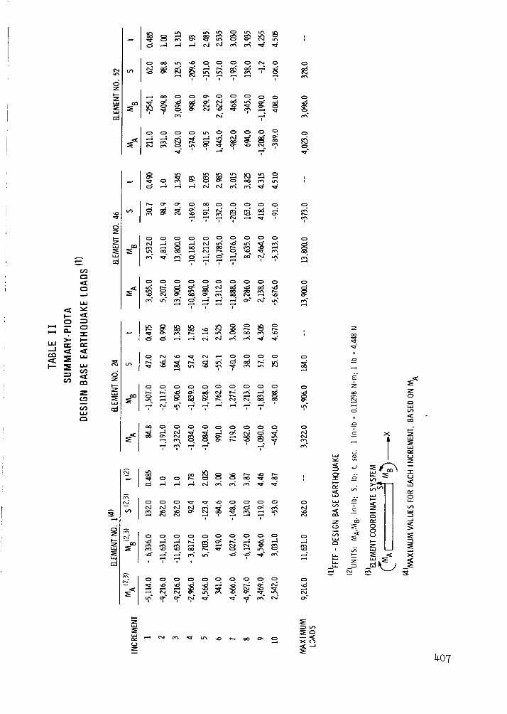
RESULTS
NASTRAN, as a large, general-purpose, structural-analysis program, has
features, through checkpoint and restart, to recover and compute element
stresses, forces and moments for each of the elements shown in figures 3
and 4. Output for this analysis was restricted to bending moment and shears
for the boundary-adjacent elements numbers l, 24 and 52, and for element
number 46, a reduced section on the output port of the holddown tube,
figure 4. Tabulated peak values for each increment are shown in table II.
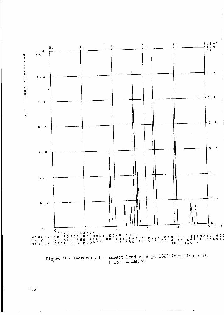
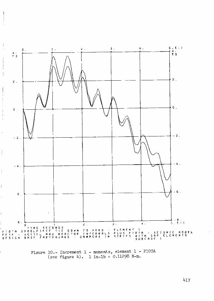
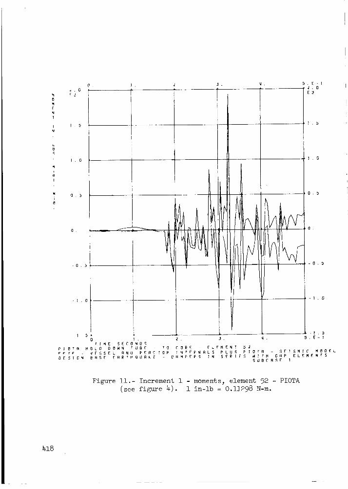
Figures 8 through II show typical load versus time plots. The amplitude of
these PIOTA loads are largely dependent on the nonlinear loads caused by
impact between core components, see figure 9. The effect of the impactload on the wave form of the element loads can be seen by noting that core
impacting at Grid Point I022 does not occur until 0.18 seconds, figure 9;
the corresponding loads in Element 52, figure II, are very low until this
time. The wave form of the PIOTA loads at the head, figure lO, is not
directly influenced by the impacting of core components, the PIOTA acts as amechanical filter.
CONCLUDING REMARKS
A seismic analysis of a reactor internal component with impact between
core components has been performed. From this effort, it can be concluded
that NASTRAN has good nonlinear transient analysis capabilities. At the
present time, solutions are relatively expensive from a computational stand-
point when compared with solutions from special purpose computer programs.However, with the efficiencies projected for Level 16 and the use of certain
operating system and modeling procedures noted in this report, NASTRAN can
effectively be used for nonlinear seismic analysis.
In using NASTRAN's nonlinear features, it is suggested that one beginwith small sample problems with known solutions. The setup of nonlinearelements using NASTRAN's transfer function capabilities is a user-orientedfunction which presents opportunities for data errors; data checking byNASTRAN is minimal since the nonlinear features are mathematical abstractions.
The design of the PIOTA was found to be structurally adequate for the DBE.
404

ACKNOWLEDGEMENTS
The principal collaborators in these analyses were L. K. Severud,J. M. Anderson, R. A. Lujan, HEDL Engineering Department; W. A. McClelland,_DRC, and J. A. Joseph, MSC.
REFERENCES
Bohm, George J., and Nahavandi, Amir N.: Dynamic Analysis ofReactor Internal Structures with Impact Between Components, NuclearScience and Engineering, Vol. 47, 1972.
Morrone, A.: FFTF Scram and Nonlinear Reactor System Seismic Analysis,FRA-I074, October 1973.
Anderson, J. M., and Lujan, R. A.:Assembly Design Support Document:HEDL-SR2, September 21, 1973.
FFTF -Post Irradiation Open TestPreliminary Stress Analysis,
The NASTRAN Theoretical Manual, NASA SP-221, 1969.
Hill, R. G.: Transient Analysis of an IVHM Grapple Impact Test. NASTRAN:Users' Experiences, NASA TM X-2637, 1972, pp. 161-178.
Final Seismic Analysis Report for the FFTF: (Bechtel Report)BR-5853-C-2, January 18, 1974.
409
v
v
l---
ILl,._
0
I
I_I_I
l--
z_D
Z
zI
I
z
I.=.=I
I
-r-
ZILl
r_
t_I--I
I
I
0
Z
I,I
.--I
I.I
ILl
I.I-
I
LI_
i,I.L
8
Z _
v"
"I-
L:.J(__
0m
(,_, LL,J
,.,q,
0 A
A
-.-1
A
n .-.I
_._, __
oo
r-.-r--- r,_
A
_ _ ' Z Z_ _ 0 0 U_
I-*
406
A
I-- eli
I-- _ u,J
z
dZ
Z
A
dZ
i
i i i i
0 00_00000
iiii
i i i
o
,'_ _ _ -7' "7' "_ _-, _, _,
_- _- _ ,_- , _- ,
_ O O O O O O O O
Z
O
O
O
O
_qo
o
o
o
o
o
o
N
z
Fz
Z
._ x z
Z
N -"
407
REACTORHEAD
COREBARREL
.:!,<.-.
PIOTA
CORE COMPONENTC
VESSEL & CORE
SUPPORT STRUCTUI
Figure i.- FFTF reactor.
CONTAINMENT
BUILDING
UPPER VESSEL
/ LOWER VESSEL
REACTOR HEAD
\
- /\
\
\
COUPLING - HEAD TO CORE
\
\
GAPS TO REPRESENT
EARANCE IN CORE
AT LOAD PADS
\\ _ OTA
\
CORE
BARREL
FUEL ASSY
"REFLECTORS
II CORE SUPPORT STRUCTURE
Figure 2.- Schematic of FFfF lumped-mass beam model.
409
Z
Z
N
I
_ _- VlOId
'\ I
/
_ 13SS3A
OLOZ 0£0_
\__ __--?---_-tZ__ I
_L _J_
-°io+o,_i.,+_-T\
: ' _IOZ
=I I_I+,o+_1+,o,
L9_
e_
o
E
o:
+]
+_"+%|_ +I LOOZI!
gOOZ
_,.z
0_90Z
_V8
_0193-B3_
ASSV _nJ
VlO
,,,SSV -13nJ
_019]]J3_
1_I_S SS3
BSS]A I
_i0
CENTERISLANDSHIELDING_
Element I_
HEAD I T-_,_BOUN_DARYCONDITIONS
-- FFTF SEI SMI C MODEPIOTA (4PLACES)
NASTRAN FINITE ELEMENT IDEALIZATION
I. SPOOL PIECE
II. ISOLATION SLEEVE
III. BULK HEAD
IV. INSTRUMENT TUBEV. FLOWMETER GUIDE
Vl. HOLD DOWN TUBE
VII. REMOVABLE INSTRUMENT PACKAGE
o NODE
O----.-o COMMON NODE
IV V Vl
Ill
Element 24
)Z| !
IZ13
/ I
NODE SETS OF COMMON MOVEMENT 1,z _J l
LATERAL _,_ __.3s !I 14 36
(37, 115) _ ,s _-, z,_
(121,151) _1_ _8 Elemen_ 46(123,153) OUTLET
TAPEREDPORTS L/"(27,157,219) FLOW(46,121,151) PLUG _J8 \1.,_ z_
(12,200) ira ,_,._o "_
(107,209) ,zz *sz .,'1
123 153 Z "1
|2a 154 415
125 155
:_:_,_ {]_o _ Element 52|
TOP OF FUEL ASSEh_,BLY .as_' .... _-----
....... HEDL 7403-151 .1
P_jT If'_/l'OIATl(:}, TM C_'_EN TEST ASg_M_L'Y
_JNDE r L-_M_- {:) S£_APE
Figure 4.- PIOTA model.
411
u I u2
_K_..., m--_x
(a)
SLOPE k3
SLOPE kI
-uI
FORCE
SLOPE:k2
.,L-, -" "- DEFLECTION
u2
Q))
Ck I
,,--,_v",/',/' '"
x1> u I AND k3 _-0
= klXl + ci()_I - {(2)= FORCE @ jfl
MAXWELLMODEL(c)
x1
Figure 5.- Gap element.
412

1.0
0.9
o,8
0.7
0.6
0.5
0.4E
O.3
0.2
0.1
0.00
VALUEUSEDIN THIS ANALYSIS
- _/ HEDLIVHM IMPACTTEST
r-\
I iI I I
10 20 30 40 50
%CRITICAL DAMPING
Figure 6.- Coefficient of restitution vs percent of
critical damping at impact.
413
o. N
- w 0
©
o
T
o T
A
o
o
C
N
Q
0
_, w w IS_ ,r
o "Iu w
__:
_o_
10 _o
J w
414

' G
r
C B
0 G
O 4
G 2
-G. i
E SIGN
r _-F _
E STGN
0 .
tl,
/
L0. ] . 2 .
T ]ME SECONDSB_ SE _R r_ OU_[E I NPd TVESSEL _NO _E_C TO_ I NTE_NBLSBOSE EA_r OUNCE - Oq MP_5 ! N
°
5.E-!* f G
E2
i ° .
/
Figure 8.- Increment i - acceleration input (see figure 7).
i in/sec 2 = 0.0254 m/sec 2.
J ,
] . 2. L .
G
G
'9T I ME _ECSN05
N O N L ] N E Fli_ P" 0 i_ C E. R T H O L 0 0 0 W N T U B E; F !" F" V E S S E L R N 0 I_ E R E T O I_ I N T E _: N R L 50 E S : C N B R 5 E E f::l E r H O dR K E 0 R H P E E 5 T N
I_ •
&
AA
5.F-1
E4
1 :2
1 G
0 6
0 E;
0 "4
0 2,
PLUS P lOT@ - SE] 5_IC H5 £E [ E5 H _ FM G_P ELERE N
5UBCRSE !
Figure 9.- Increment i - impact load grid pt 1022 (see figure 3).i ib = 4. 448 N.
416
F3
G .
O. ] . _ . 3.
J
-G.
-6 .
P : o'r@
rF TF" -
OES]GN
] . 2 . J._"I ME S E C 0 N0 S
S P 0 0 L P ] _ C E r } E 0 {]H N T O I',ER 0 E"L F M E N T 1
Q. 5.E-}
E3
G ,
-6.
-- B .
,_. 5.E-]
V E S S E L R N _ _ E R C T 0 _ I N r E _ _ @ L 5 P L U 5 P _r0 T FI - 5 E I S M I C M L_ D E LB A S E F A _ T N Q,J@IC E 0 @ 14P E _ S I _I 5 EI_ I E S H _ T H G R P EL E M E N T S
SUBCASE ]
Figure i0.- Increment i - moments, element i - PIOTA(see figure 4). i in-lb = 0.11298 N-re.
417
•_. 0
F_
]. 0
0
0
PI _rFl
_F T _"
DESIGN
- I . 0
m f
5. E-!
E3
O.
rIME SEC
HOLO 08WN
CESSEL _N
BRSF FARE
IE
I
i
k
N'OS
T B_" r(]
i_EAC roi_
H UAKE -
2 .
CORE
TNrF_N@LS
OAMPE@S IN
'IIvI'
] . 5
I . 0
O. _
0 .
-0. _
-1.0
-I . 5
5, E-I
E_FMENT 52
P LU5 P I OT@ ST I 5M I C MSDELSERIES W I TH GAP ELEMENTS
5UBCBSE I
Figure ii.- Increment i - moments_ element 52 - PIOTA
(see figure 4). i in-lb = 0.11298 N-m.
418