Embed Size (px)
Citation preview

Jordan Journal of Civil Engineering, Volume 10, No. 1, 2016
- 93 - © 2016 JUST. All Rights Reserved.
Nonlinear Analysis of Reinforced Concrete Beams Strengthened by
Prestressed CFRP Sheets under Static Loads
Qassim M. Shaker 1) and Hayder H. H. Kamonna 2)
1) University of Kufa, College of Engineering, Civil Engineering Department. E-Mail: [email protected] 2) University of Kufa, College of Engineering, Civil Engineering Department. E-Mail: [email protected]
ABSTRACT
A nonlinear finite element study has been conducted to evaluate the efficiency of the technique of
strengthening reinforced concrete beams under static loads. No time-dependent effects (creep and shrinkage...
etc.) are considered in this work. This concept is based on prestressing of CFRP sheets.
In this research program, four reinforced concrete beams were tested to investigate the feasibility of such
concept for flexural strengthening. One of the beams was retrofitted with non-prestressed CFRP sheet which
was used as the control beam. The rest were retrofitted with prestressed CFRP sheet with three levels of
prestressing. The static load was applied at the instant of full prestress load application. Prestress losses were
ignored here.
CFRP sheets have been simulated using two types of element (SHELL41 and LINK8). Prestressing effects
have been represented using two models; the application as axial load and initial axial strain. The results
showed that there is a good enhancement in performance of the beams strengthened using the prestressing
technique in terms of the cracking loads and deflection occurs at such level of loading. The application of
prestressing forces of 9 kN, 16 kN and 22 kN, was found to increase the cracking load by 57%, 106% and
170%, respectively.
KEYWORDS: Carbon fiber, Reinforced concrete, Nonlinear analysis, Finite element, Prestress.
INTRODUCTION
The aging or deterioration of existing reinforced
concrete structures is one of the major problems that
civil engineers have to face. If strength of a structure is
(or becomes) insufficient to maintain its service loads,
strengthening (or upgrading) becomes necessary. The
first use of external steel tendons in rehabilitation and
upgrading area backs already to the 1950s. To date,
externally fixed steel plates/bars have been used to
strengthen concrete members (Nordin, 2003).
However, there may be a problem with corrosion in
steel that forces the use of steel protection on the
external tendons (ACI-440, 2007). This drawback has
been overcome using FRP materials. Thus, research in
this area has been conducted since the 1970s (Clarke,
1993).
The main advantages of the externally bonded FRP
system include: light weight, being noncorrosive and
high tensile strength of the FRP. These in turn provide
a more flexible and economical technique than
traditional steel-plate/jacket techniques, particularly in
the areas with limited access (Nordin, 2003; ACI-440,
2007). Other advantages of using FRPs are: improved
fire resistance, reduced risk of freeze-and-thaw and
damage which reduce construction period (Hollaway Accepted for Publication on 22/10/2014.
Nonlinear Analysis of … Qassim M. Shaker and Hayder H. H. Kamonna
- 94 -
and Leeming, 2001).
Most of the investigations used the non-prestressed
method by gluing or bolting the FRPs to the members’
surfaces. But, this method has a common problem of
de-bonding or de-lamination. Hence, it could not fully
utilize the full tensile strength of the FRP, nor it could
increase the members’ flexural stiffness; being
therefore not economical (Shang et al., 2005).
Since non-prestressed FRP sheets support only the
additional live loads applied to a structure and can not
support existing dead loads, the strengthened or
rehabilitated beam may violate the deflection
requirements. In other words, beams strengthened with
FRP sheets can not deal with the existing deflections
caused by the dead load. With addition to live loads,
the total deflection may be too large. The prestressed
plates will cause a camber after the prestress is
transferred to the reinforced concrete members. This
phenomenon will help solve the deflection problem. In
some cases, the camber can give the beams larger load-
carrying capacities. This means that prestressing could
be applied, strengthening material can be better utilized
and better strengthening results can be achieved.
Therefore, the use of FRP as prestressed reinforcement
for concrete structure has increased over the past two
decades (Nordin, 2003).
Research has shown that small prestress loss (5%-
7%) may be experienced due to long-term corrosion in
the composite (Nordin, 2003). However, the linear
elastic behavior of the FRP material up to failure
requires special design considerations to ensure a safe
construction due to possible brittle failure (Gangarao,
2007). External prestressed cables of CFRP materials
have shown to be an alternative to installing steel plates
or external prestressing cables (Peter and Kanstad,
2002). Good durability properties and a first-rate
behavior in creep and relaxation have given very good
results so far (Hollaway, 2001).
Material Constitutive Relations
Concrete in Compression
The behavior of concrete in compression can be
simulated in ANSYS program by an elasto-plastic
hardening model followed by a perfectly plastic
response which is terminated at the onset of crushing.
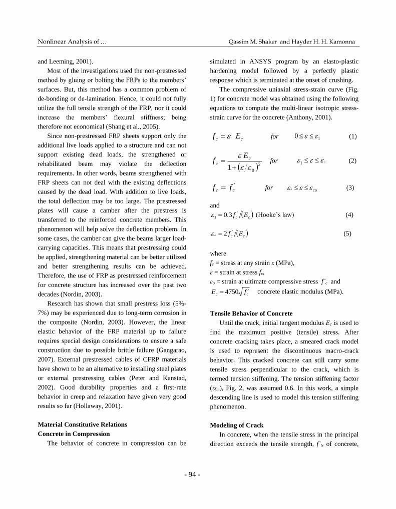
The compressive uniaxial stress-strain curve (Fig.
1) for concrete model was obtained using the following
equations to compute the multi-linear isotropic stress-
strain curve for the concrete (Anthony, 2001).
cc Ef for 10 (1)
2
01
c
c
Ef for 1 (2)
'
cc ff for cu (3)
and
cc Ef '
1 3.0 (Hooke’s law) (4)
cc Ef '2 (5)
where
fc = stress at any strain ε (MPa),
ε = strain at stress fc,
εo = strain at ultimate compressive stress f`c and
cc fE 4750
concrete elastic modulus (MPa).
Tensile Behavior of Concrete
Until the crack, initial tangent modulus Ec is used to
find the maximum positive (tensile) stress. After
concrete cracking takes place, a smeared crack model
is used to represent the discontinuous macro-crack
behavior. This cracked concrete can still carry some
tensile stress perpendicular to the crack, which is
termed tension stiffening. The tension stiffening factor
(m), Fig. 2, was assumed 0.6. In this work, a simple
descending line is used to model this tension stiffening
phenomenon.
Modeling of Crack
In concrete, when the tensile stress in the principal
direction exceeds the tensile strength, f`t, of concrete,
Jordan Journal of Civil Engineering, Volume 10, No. 1, 2016
- 95 -
(Desai et al., 2002)
the tensile failure would occur (Desai et al., 2002).
After the crack forms, both normal and shear stiffness
are reduced.
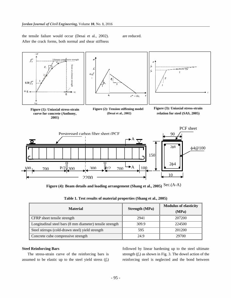
Figure (4): Beam details and loading arrangement (Shang et al., 2005)
Table 1. Test results of material properties (Shang et al., 2005)
Material Strength (MPa) Modulus of elasticity
(MPa)
CFRP sheet tensile strength 2941 207200
Longitudinal steel bars (8 mm diameter) tensile strength 309.9 224500
Steel stirrups (cold-drawn steel) yield strength 595 201200
Concrete cube compressive strength 24.9 29700
Steel Reinforcing Bars
The stress-strain curve of the reinforcing bars is
assumed to be elastic up to the steel yield stress (fy)
followed by linear hardening up to the steel ultimate
strength (fu) as shown in Fig. 3. The dowel action of the
reinforcing steel is neglected and the bond between
mf*
t
*t
Figure (2): Tension stiffening model Figure (3): Uniaxial stress-strain
relation for steel (SAS, 2005) Figure (1): Uniaxial stress-strain
curve for concrete (Anthony,
2001)
Strain
at ultim
ate streng
th
Ultimate compressive strength
A
A
2200
P/2 P/2 700 700 300 300 100 100
Prestressed carbon fiber sheet (PCF
sheet) 90
28
24
4@100
150
10
0
PCF sheet
Sec.(A-A)
Nonlinear Analysis of … Qassim M. Shaker and Hayder H. H. Kamonna
- 96 -
steel and concrete is assumed to remain perfect.
Experimental Program
Five beams, four with prestressed-CFRP sheet and
one non-prestressed-CFRP were constructed and tested
by Shang et al. Two of them were tested at the same
level of prestress (16 kN) which yielded similar
behavior (so, in the present work only one of them is
considered). All beams have the same dimensions of
100 150 2200 mm (width depth length) as
shown in Fig. 4. The span of the beams was 2000 mm.
The steel reinforcement ratio was 0.67%. The CFRP
sheet used was 90 mm wide with an average thickness
of 0.167 mm. One layer of CFRP was applied to the
reinforced concrete beams. The properties of the
concrete and steel obtained from tests are summarized
in Table (1). Also, prestressing details for all beams are
shown in Table (2).
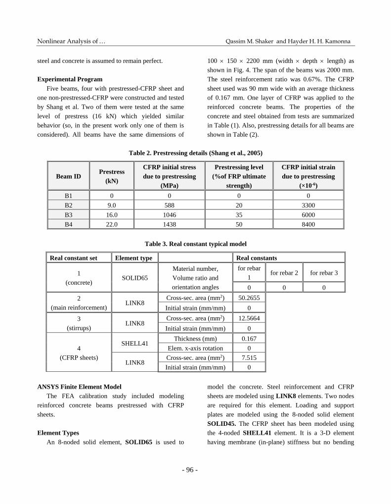
Table 2. Prestressing details (Shang et al., 2005)
Beam ID Prestress
(kN)
CFRP initial stress
due to prestressing
(MPa)
Prestressing level
(%of FRP ultimate
strength)
CFRP initial strain
due to prestressing
(×10-6)
B1 0 0 0 0
B2 9.0 588 20 3300
B3 16.0 1046 35 6000
B4 22.0 1438 50 8400
Table 3. Real constant typical model
Real constant set Element type Real constants
1
(concrete) SOLID65
Material number,
Volume ratio and
orientation angles
for rebar
1 for rebar 2 for rebar 3
0 0 0
2
(main reinforcement) LINK8
Cross-sec. area (mm2) 50.2655
Initial strain (mm/mm) 0
3
(stirrups) LINK8
Cross-sec. area (mm2) 12.5664
Initial strain (mm/mm) 0
4
(CFRP sheets)
SHELL41 Thickness (mm) 0.167
Elem. x-axis rotation 0
LINK8 Cross-sec. area (mm2) 7.515
Initial strain (mm/mm) 0
ANSYS Finite Element Model
The FEA calibration study included modeling
reinforced concrete beams prestressed with CFRP
sheets.
Element Types
An 8-noded solid element, SOLID65 is used to
model the concrete. Steel reinforcement and CFRP
sheets are modeled using LINK8 elements. Two nodes
are required for this element. Loading and support
plates are modeled using the 8-noded solid element
SOLID45. The CFRP sheet has been modeled using
the 4-noded SHELL41 element. It is a 3-D element
having membrane (in-plane) stiffness but no bending
Jordan Journal of Civil Engineering, Volume 10, No. 1, 2016
- 97 -
(out-of-plane) stiffness. Each node of all adopted
elements has three degrees of freedom, translations in
x, y, and z directions (SAS, 2005).
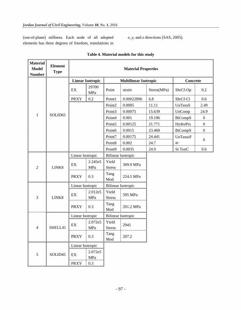
Table 4. Material models for this study
Material
Model
Number
Element
Type Material Properties
1 SOLID65
Linear Isotropic Multilinear Isotropic Concrete
EX 29700
MPa Point strain Stress(MPa) ShrCf-Op 0.2
PRXY 0.2 Point1 0.00022896 6.8 ShrCf-Cl 0.6
Point2 0.0005 11.11 UnTensS 2.49
Point3 0.00075 15.639 UnComp 24.9
Point4 0.001 19.196 BiCompS 0
Point5 0.00125 21.771 HydroPrs 0
Point6 0.0015 23.468 BiCompS 0
Point7 0.00175 24.441 UnTensrF
ac 0
Point8 0.002 24.7
Point9 0.0035 24.9 St TenC 0.6
2 LINK8
Linear Isotropic Bilinear Isotropic
EX 2.245e5
MPa
Yield
Stress 309.9 MPa
PRXY 0.3 Tang
Mod 224.5 MPa
3 LINK8
Linear Isotropic Bilinear Isotropic
EX 2.012e5
MPa
Yield
Stress 595 MPa
PRXY 0.3 Tang
Mod 201.2 MPa
4 SHELL41
Linear Isotropic Bilinear Isotropic
EX 2.072e5
MPa
Yield
Stress 2941
PRXY 0.3 Tang
Mod 207.2
5 SOLID45
Linear Isotropic
EX 2.072e5
MPa
PRXY 0.3

Nonlinear Analysis of … Qassim M. Shaker and Hayder H. H. Kamonna
- 98 -
Real Constants
The real constants needed for this model are shown
in Table 3. It can be noted that the individual elements
may contain different real constants. No real constant
set exists for the SOLID45 element.
Real constant set 1 is used for the SOLID65
element. It requires real constants for rebar assuming a
smeared model, then, values for material number,
volume ratio and orientation angles for three directions
may be entered. In the present study, the steel in beams
is modeled using discrete model. Therefore, a value of
zero was entered for all real constants which turned the
smeared reinforcement capability of the SOLID65
element off.
Real constant sets 2 and 3 are defined for the
LINK8 element. Set 4 refers to the CFRP sheets
modeled using SHELL41 element. Also, an alternative
LINK8 element has been assumed to study the
difference between the two models.
Material Properties
Parameters used to define the material models are
listed in Table (4). It is clear that there are multiple
parts of the material model for each element. The first
material model refers to the SOLID65 element. It
requires linear isotropic and multi-linear isotropic
material properties to properly model concrete. The
multi-linear isotropic material uses the von-Mises
failure criterion along with the (William and Warnke,
1974) model to define the failure of the concrete.
Material model numbers 2 to 4 refer to the LINK8 and
SHELL41 elements which are assumed to be bilinear
isotropic material based on the von-Mises failure
criterion. Material model number 5 refers to the
SOLID45-element, that is modeled as a linear isotropic
element.
Modeling Methodology
By taking advantage of the symmetry of the beams,
a quarter of the full beams are used for modeling with
proper boundary conditions, Fig. 5. However, in this
study, perfect bond between materials is assumed. The
mesh was set up such that square or rectangular
elements were created to obtain good results when
using the SOLID65 element (SAS, 2005).
The boundary conditions are shown in Fig. 6. The
models adopted in the present work to simulate CFRP
sheets are shown in Fig. 7.These are the bar model
using LINK8 element and the sheet model using
SHELL41 element.
Load-Deflection Relationships
The load-midspan deflection relationships of the
tested beams are shown in Figs. 8 to 11. Figures reveal
Face of symmetry (z=0)
Face of symmetry (x=0)
Roller support
Figure (6): Boundary conditions
Figure (5): Mesh of concrete, steel plate and steel support
Concrete elements (solid 65)
Loading plate (solid 45)
Bottom steel bars (LINK8)
Supporting plate (SOLID
45)
Top steel bars (LINK8)
Stirrups reinf. (LINK8)

Jordan Journal of Civil Engineering, Volume 10, No. 1, 2016
- 99 -
that the experimental behavior is stiffer than that
obtained by numerical analysis. It can be seen that the
beams with higher levels of prestress reach their
ultimate loads with lesser amount of deformation.
Figure (7): CFRP reinforcement modeling
b) Sheet model (SHELL41 element)
model,(S41)element
a) Bar model (LINK8 element)
0 -10 -20 -30 -40
Deflection(mm)
0
5
10
15
20
25
Lo
ad
(kN
)
Link8 model
Shell41 model
Experimental work
Figure (8): Load - deflection curves for beam B1
0 -10 -20 -30
Deflection(mm)
0
5
10
15
20
25
Load
(kN
)
Link8 model
Shell41 model
Experimental work
Figure (9): Load - deflection curves for beam B2

Nonlinear Analysis of … Qassim M. Shaker and Hayder H. H. Kamonna
- 100 -
In general, good agreement can be seen for most of
the path of load-deflection curves for beams B1, B2
and B3, Figs. 8 to 10. For beam B4, this agreement
continued up to the instant of carbon sheet cut-off
(which occurred experimentally at a load of 25 kN)
giving a deflection of 16 mm, Fig. 11. In contrast, the
numerical analysis continued beyond this point with an
ultimate deflection of 24 mm (no cut-off). This can be
attributed to the fact of gradual yielding of SHELL41
element without cut- off and the failure is indicated by
the high strain value that results in divergence in the
numerical solution (SAS, 2005). The deflection values
versus cracking loads and ultimate loads for theoretical
and experimental results are listed in Table (5).
Table 5. Comparison of deflections, cracking loads and ultimate loads for theoretical and experimental results
Beam no. Def. at load 17kN(mm) Ultimate def. mid-span (mm) Cracking load (kN) Ultimate load (kN)
Exp. Theor. Exp. Theor. Exp. Theor. Exp. Theor.
B1 15.65 13.50 28.71 32.00 4.00 3.50 22.50 22.80
B2 9.26 9.30 24.28 25.00 5.00 5.50 21.50 22.40
B3 7.60 7.50 28.84 32.40 8.00 7.20 28.00 28.00
B4 4.70 6.00 16.00 24.00 11.00 9.50 25.00 27.00
It is obvious that with the increase of prestress,
there will be some increase in cracking load. Table (5)
shows the values of cracking load relative to the non-
prestressed beam. It is found that some increase of
cracking load has been obtained for beams B2, B3 and
B4 which amounted to 57%, 106% and 171%,
respectively. This means that the application of
prestress results in the development of the stiffness of
beam and hence, the advantage of adopting the
principle of prestress seems to be clear.
Figure (11): Load-deflection curves for beam B4
0 -5 -10 -15 -20 -25
Deflection(mm)
0
10
20
30
Load
(kN
)
Link8 model
Shell41 model
Experimenal work
0 -10 -20 -30 -40
Deflection(mm)
0
10
20
30
Load
(kN
)
Lin8 model
Shell41 model
Experimental work
Figure (10): Load-deflection curves for beam B3
Jordan Journal of Civil Engineering, Volume 10, No. 1, 2016
- 101 -
0 -10 -20 -30 -40
Deflection(mm)
0
10
20
30
Load
(kN
)
intial force model
Experimental work
Line/Scatter Plot 4
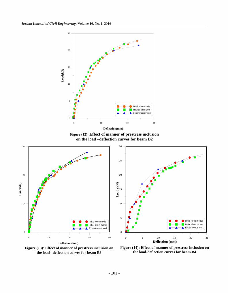
Figure (13): Effect of manner of prestress inclusion on
the load –deflection curves for beam B3
Figure (14): Effect of manner of prestress inclusion on
the load-deflection curves for beam B4
0 -5 -10 -15 -20 -25Deflection(mm)
0
5
10
15
20
25
30
Lo
ad
(kN
)
initial force model
initial strain model
Experimental work
0 -5 -10 -15 -20 -25Deflection(mm)
0
5
10
15
20
25
30
Lo
ad
(kN
)
initial force model
initial strain model
Experimental work
Deflection (mm)
Load
(k
N)
0 -10 -20 -30
Deflection(mm)
0
5
10
15
20
25
Load
(kN
)
initial force model
intial strain model
Experimental work
Figure (12): Effect of manner of prestress inclusion
on the load –deflection curves for beam B2
Nonlinear Analysis of … Qassim M. Shaker and Hayder H. H. Kamonna
- 102 -
It can also be seen that no significant difference
was found in the ultimate load stage for the tested
beams. This may be due to the small amount of CFRP
ratio used in the experimental work leading to a failure
of sheets by similar levels of vertical loading. Also, it
is clear that adopting any method of simulation for the
CFRP elements has no significant effect on the results;
thus one can simulate the CFRP sheet as LINK8
element for simplicity and reduced time of building of
the model.
Prestress Effect Simulation
The analysis is performed using two load steps. The
first one includes the application of prestress force.
Then, the static load is applied as a second step. The
prestress effect on the CFRP sheet has been expressed
in two manners. In the first manner, the prestress is
simulated by equally distributed axial load which in
turn may be substepped. The other one is represented
as an initial axial strain.
The difference in the results obtained due to
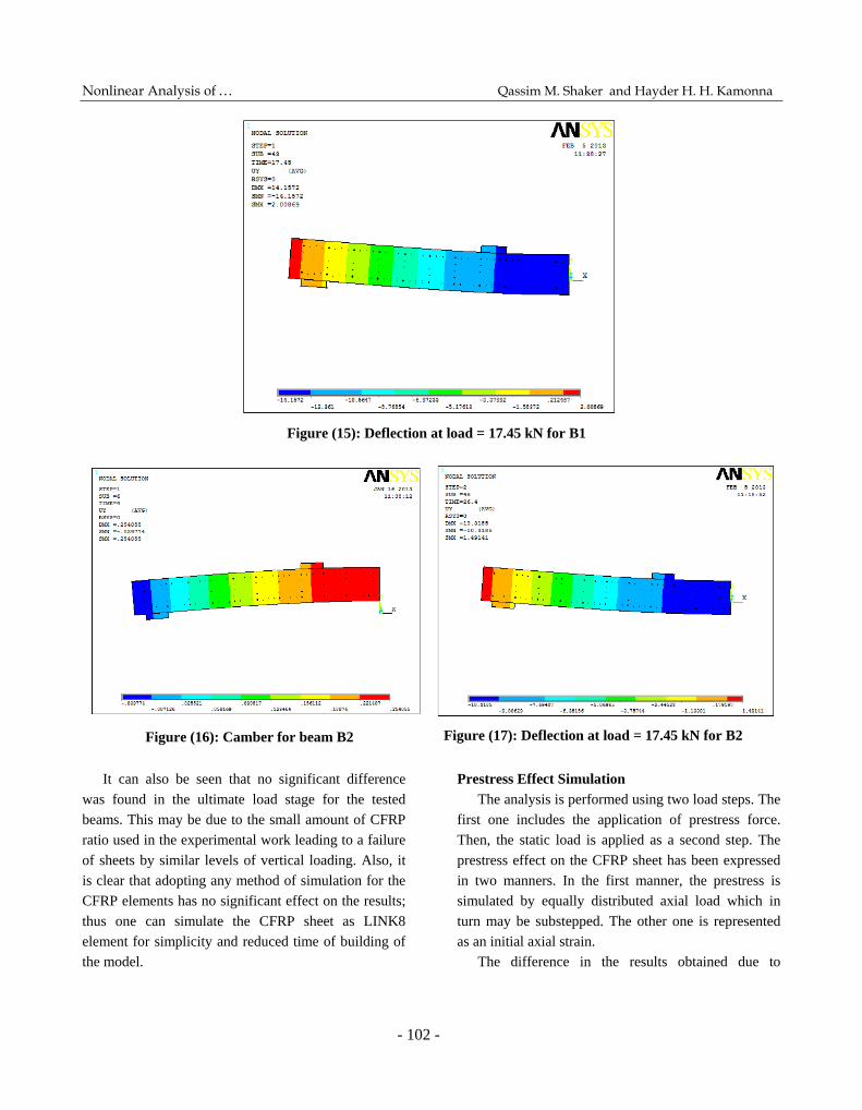
Figure (15): Deflection at load = 17.45 kN for B1
Figure (17): Deflection at load = 17.45 kN for B2
Figure (16): Camber for beam B2

Jordan Journal of Civil Engineering, Volume 10, No. 1, 2016
- 103 -
adopting the methods of the prestress effect simulations
can be clearly seen. It is obvious that for low levels of
prestress, good agreement with the experimental work
can be seen when adopting any one of the two methods
as shown in Figs. 12 and 13. However, Fig. 14 reveals
that for relatively higher prestress level, some
divergence may be obtained in the initial stages of
loading when adopting the initial strain model.
The divergent solution for beam B4 in the early
stage of loading may be attributed to that the
application of a large amount of strain (which may not
be accommodated by the structure immediately) may
result in some inaccurate results (instability in the
numerical solution). This inaccuracy in results cannot
be seen obviously with relatively lower levels of initial
strain (beams B2 and B3).
Figure (19): Deflection at load = 17.41 kN for B3 Figure (18): Camber for beam B3
Figure (20): Camber for beam B4 Figure (21): Deflection at load = 17.41 kN for B4
Nonlinear Analysis of … Qassim M. Shaker and Hayder H. H. Kamonna
- 104 -
Effect of Prestress on Deflection and Crack
Propagation
The effect of prestress value on response in terms
of mid-span deflection and crack propagation has been
studied, and the results are shown in Figs. 15 to 25. A
vertical load level of about 17.45 kN has been chosen
(the yield load of the control beam B1) to compare the
results obtained from the numerical analysis for all
beams.
For the deformed shape of the control beam B1,
Fig. 15, the maximum mid-span deflection is 13.5 mm,
whereas the corresponding value for beam B2, Fig. 17,
is 9.3 mm. A reduction of about 31% can be noticed.
This may be attributed to the camber (max. value is
0.25 mm) for beam B2 which occurred at the instant of
prestressing, Fig. 16.
For beam B3, the effect of prestress can be seen
more obviously. A mid-span camber of about 0.42 mm,
Fig. 18, has been obtained. The deformed shape shown
in Fig. 19 reveals that the mid-span deflection is
reduced by 44% relative to the control beam.
A similar conclusion can be drawn for beam B4.
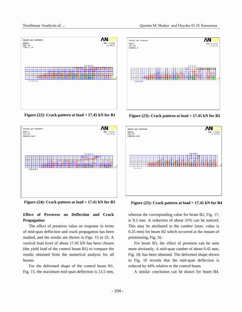
Figure (23): Crack pattern at load = 17.45 kN for B2 Figure (22): Crack pattern at load = 17.45 kN for B1
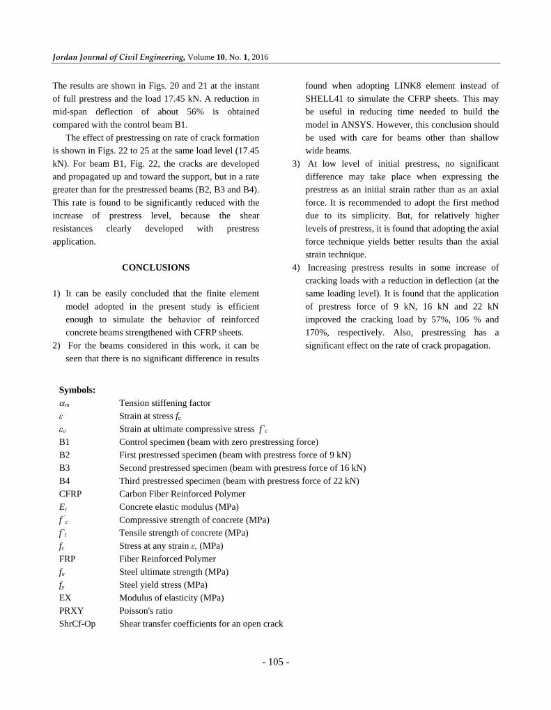
Figure (24): Crack pattern at load = 17.41 kN for B3 Figure (25): Crack pattern at load = 17.41 kN for B4
Jordan Journal of Civil Engineering, Volume 10, No. 1, 2016
- 105 -
The results are shown in Figs. 20 and 21 at the instant
of full prestress and the load 17.45 kN. A reduction in
mid-span deflection of about 56% is obtained
compared with the control beam B1.
The effect of prestressing on rate of crack formation
is shown in Figs. 22 to 25 at the same load level (17.45
kN). For beam B1, Fig. 22, the cracks are developed
and propagated up and toward the support, but in a rate
greater than for the prestressed beams (B2, B3 and B4).
This rate is found to be significantly reduced with the
increase of prestress level, because the shear
resistances clearly developed with prestress
application.
CONCLUSIONS
1) It can be easily concluded that the finite element
model adopted in the present study is efficient
enough to simulate the behavior of reinforced
concrete beams strengthened with CFRP sheets.
2) For the beams considered in this work, it can be
seen that there is no significant difference in results
found when adopting LINK8 element instead of
SHELL41 to simulate the CFRP sheets. This may
be useful in reducing time needed to build the
model in ANSYS. However, this conclusion should
be used with care for beams other than shallow
wide beams.
3) At low level of initial prestress, no significant
difference may take place when expressing the
prestress as an initial strain rather than as an axial
force. It is recommended to adopt the first method
due to its simplicity. But, for relatively higher
levels of prestress, it is found that adopting the axial
force technique yields better results than the axial
strain technique.
4) Increasing prestress results in some increase of
cracking loads with a reduction in deflection (at the
same loading level). It is found that the application
of prestress force of 9 kN, 16 kN and 22 kN
improved the cracking load by 57%, 106 % and
170%, respectively. Also, prestressing has a
significant effect on the rate of crack propagation.
Symbols:
m Tension stiffening factor
ε Strain at stress fc
εo Strain at ultimate compressive stress f`c
B1 Control specimen (beam with zero prestressing force)
B2 First prestressed specimen (beam with prestress force of 9 kN)
B3 Second prestressed specimen (beam with prestress force of 16 kN)
B4 Third prestressed specimen (beam with prestress force of 22 kN)
CFRP Carbon Fiber Reinforced Polymer
Ec
Concrete elastic modulus (MPa)
f `c Compressive strength of concrete (MPa)
f`t Tensile strength of concrete (MPa)
fc Stress at any strain ε, (MPa)
FRP Fiber Reinforced Polymer
fu Steel ultimate strength (MPa)
fy Steel yield stress (MPa)
EX Modulus of elasticity (MPa)
PRXY Poisson's ratio
ShrCf-Op Shear transfer coefficients for an open crack
Nonlinear Analysis of … Qassim M. Shaker and Hayder H. H. Kamonna
- 106 -
ShrCf-Cl Shear transfer coefficients for a closed crack
UnTensS Uniaxial tensile cracking stress (MPa)
UnComp Uniaxial crushing stress (MPa)
BiCompS Biaxial crushing stress (MPa)
HydroPrs Uniaxial crushing stress under the ambient hydrostatic stress state (MPa)
UnTensrFac Uniaxial crushing stress under the ambient hydrostatic stress state (MPa)
St TenC Stiffness multiplier for cracked tensile condition
Tang Mod Tangent modulus (MPa)
REFERENCES
ACI 440 (American Concrete Institute Committee 440).
(2002). "Guide for the design and construction of
externally bonded FRP systems for strengthening
concrete structures". American Concrete Institute
Committee 440, Farmington Hills, Michigan, 45 pages.
Anthony, J., and Wolanski, B.S. (2004). “Flexural behavior
of reinforced and prestressed concrete beams using
finite element analysis”. M.Sc. Thesis, 57 pages.
Clarke, J.L. (1993). “Alternative materials for the
reinforcement and prestressing of concrete”. Blackie
Academic and Professional (An Imprint of Chapman
and Hall).
Desai, Y.M., Mufti, A.A., and Tadros, G. (2002). "User
manual for FEM PUNCH, version 2.0". ISIS Canada.
Gangarao, H.V.S., Taly, N., and Vijay, P.V. (2007).
“Reinforced concrete design with FRP composites”.
CRC Press, 382 pages.
Hollaway, L.C., and Leeming, M.B. (2001).
“Strengthening of reinforced concrete structures using
externally-bonded FRP composites in structural and
civil engineering”. CRC Press.
Nordin, H. (2003). ”Flexural strength of concrete strength
with prestressed near surface mounted CFRP rods”.
Licentaite Thesis, Lulea University of Technology,
Sweden, 57 pages.
Peter F. Takács, and Kanstad, J. (2002). ”Strengthening
prestressed concrete beams with carbon fiber reinforced
polymer plates”. NTNU Report R-9-00, Trondheim,
Norway.
SAS ANSYS 10.0. (2005). “Finite Element Analysis
System”. SAS IP, Inc., U.S.A.
Shang, S., Zou, P.X.W., Peng, H., and Wang, H. (2005).
”Avoiding de-bonding in FRP strengthened reinforced
concrete beams using prestressing techniques”.
Proceedings of the International Symposium on Bond
Behavior of FRP in Structures (BBFS 2005).
Willam, K.J., and Warnke, E.P. (1974). "Constitutive
model for triaxial behaviour of concrete”. Seminar on
Concrete Structures Subject to Triaxial Stresses,
International Association of Bridge and Structural
Engineering Conference, Bergamo, Italy, 174 pages.