Embed Size (px)
Citation preview
11th World Congress on Computational Mechanics (WCCM XI) 5th European Conference on Computational Mechanics (ECCM V)
6th European Conference on Computational Fluid Dynamics (ECFD VI) E. Oñate, J. Oliver and A. Huerta (Eds)
NONLINEAR ANALYSIS OF R/C SHEAR WALLS SUBJECTED TO CYCLIC LOADINGS
ROBERTO SCOTTA†, PAOLO GIORGI †, LEOPOLDO TESSER° and
DIEGO A. TALLEDO *
† Department of Civil, Environmental and Architectural Engineering (DICEA) University of Padova
Via Marzolo 9, 35131 Padova, Italy e-mail: [email protected], www.dicea.unipd.it
° Géodynamique et Structure
157, rue des Blains, Bagneux, France e-mail: [email protected]
*Department of Architecture Construction Conservation (DACC)
University IUAV of Venice Campus Terese, Dorsoduro 2206, 30123, Venice, Italy
e-mail: [email protected] Key Words: R/C panels, shear walls, nonlinear analysis, damage model. Abstract. A numerical model for the nonlinear analysis of R/C shear walls under cyclic seismic loadings has been proposed by some of the authors. It is here validated by comparison with three experimental tests taken from literature on R/C complex shear walls. The finite element numerical models consider both in-plane loaded membrane elements and out-of-plane loaded plate elements. Reinforcing bars are modelled as multiple smeared steel layers for which uniaxial stress-strain relation with isotropic hardening according to the Menegotto-Pinto constitutive model was adopted. The concrete material description is based on continuum damage mechanics and uses two independent scalar damage parameters to describe inelastic response of the material. At this stage of the research the bond-slip between concrete and rebars is not taken into account. Two of the experimental tests considered for the validation were conducted at the NEES MUST-SIM Facility - University of Illinois and concern both planar and coupled complex wall systems. The third experimental program was conducted at ELSA Laboratory (JRC Ispra) within the framework of TMR-ICONS TOPIC 5 program on an U-shaped wall cyclically loaded along two orthogonal directions. All tests were carried out in quasi-static conditions. The good fitting of the numerical results with the experimental ones demonstrates the robustness and efficacy of the proposed numerical model in reproducing the cyclic behaviour of R/C members on both two-dimensional and three-dimensional problems.
R. Scotta, P. Giorgi, L. Tesser and D.A. Talledo
2
1 INTRODUCTION
Reinforced concrete (R/C) panels are commonly used in the lateral force resisting system of structures in seismic risk zones for serviceability, ultimate strength and ductility considerations. They are either used alone or are coupled with moment resisting frames to resist the lateral forces.
The inelastic response of R/C panels and shear walls is determined by the combinations of several complex physical mechanisms, e.g. stress transmission across the cracks, that make their simulation quite challenging. This aspect has been the spur for plentiful theoretical and experimental research on R/C panels subjected to shear [1-4].
Commendable achievements have been obtained in developing sophisticated numerical models that enlighten several aspects of the multi-axial R/C membrane behaviour under cyclic loadings [5-8].
Most of the cited works are based on the definition of uniaxial stress-strain relation for concrete in tension and in compression separately with the lack of unambiguous material limit state functions. With the aim of correcting the concrete biaxial behaviour best-fitting procedures have been often adopted to provide empirical formula such as those reducing the uniaxial compressive strength as a function of: the transverse tensile strain [3-6], [8], the anisotropic reinforcement producing a crack rotation [5-6], the maximum occurred compression strain in the transverse direction for load reversals [6].
Furthermore the shear stress-strain relationship can be either based on pure empirical formula [3], [8], or on empirical evolution laws of the anisotropic Possion’s ratios [6-7].
These considerations seem to outline a gap between the available R/C membrane models and the sophisticated three-dimensional material constitutive laws, e.g. [9-10].
In order to overcome this drawback some of the authors have developed a R/C membrane model based on a sound plastic-damage model for concrete that has been shown to be reliable and efficient [11]. Moreover they have extended the mentioned membrane model for nonlinear cyclic analysis of R/C plate and shear walls having generic cross section [12]. Plates elements are based on the superposition of concrete and reinforcing steel membrane models.
The purpose of the present study is to extend the validation of the mentioned R/C membrane and plate model by comparison with several experimental results on R/C panels and shear walls from the literature. The chosen examples demonstrate the ability of the model in reproducing both in-plane loaded membrane elements and out-of-plane loaded plate elements. The tests are carried out in quasi-static conditions. The accuracy of the model in reproducing the cyclic behaviour of R/C members on both two-dimensional and three-dimensional problems is notable.
2 BRIEF DESCRIPTION OF THE NUMERICAL MODEL
Readers can refer to the works by Faria et al. [13], Scotta et al. [14] and Tesser et al. [11-12] for an exhaustive explanation of the basic isotropic plastic-damage model formulation and notations. The straightforward definition of the R/C membrane and plate elements based on the superposition of concrete and reinforcing steel membrane models are briefly recalled.
The three-dimensional constitutive model for concrete considers a unique plastic-damage surface so that the development of material damaging occurs simultaneously with the accumulation of irreversible strains for all the stress states. Additional details on the material
R. Scotta, P. Giorgi, L. Tesser and D.A. Talledo
3
model and the integration algorithm can be found in Tesser et al. 2011 [11]. This constitutive law is constrained to plane stress to represent the behaviour of concrete panels.
The reinforcing bars are modelled as multiple smeared steel layers with uniaxial stress-strain response following an embedded approach. In the present work the Menegotto-Pinto law with the isotropic hardening introduced by Filippou et al. [15] has been profitably selected for its ability to evaluate precisely the hysteretic behaviour of the reinforcing steel. The two materials are superimposed considering the equivalence of strains, to comply with the membrane kinematics. At present state of the research, the bond-slip between concrete and rebars is not taken into account. An important benefit of the membrane model is the possibility to reproduce the most common reinforcement configurations by simply adding the appropriate number of layers. It is worth noting that the membrane model can be applied to any two-dimensional finite element.
For the R/C plate model, the three-dimensional constitutive law represents the behaviour of concrete plates by condensing the out-of-plane normal stress. The section solicitations are obtained via numerical integration over the depth. The reinforcing bars are modelled by steel membranes that have exactly the same definition of those used for the R/C membranes and are placed at appropriate location representing additional integration points. The model can be applied to different plate finite elements. In this work, the 4-node MITC element [16] has been selected due to the absence of out-of-plane shear locking and excellent performances shown in geometrically nonlinear analysis [17].
3 QUASI-STATIC EXAMPLES FOR THE R/C MEMBRANE MODEL
The R/C membrane model has been validated by comparison with two experimental results on R/C panels conducted at NEES MUST-SIM (Multi-Axial Full-Scale Sub-structured Testing and Simulation) Facility - University of Illinois. Detailed documentation of the design, testing and preliminary results of the planar wall test program of the project “Behaviour, analysis and Design of Complex Wall Systems” (joint effort between the university of Washington and the University of Illinois) can be found in [18-19]. In the experimental part of the project, large-scale wall sub-assemblages were tested to improve the understanding of seismic behaviour of walls in modern buildings. Equipment at the Facility allowed for testing of the sub-assemblages with force and displacement control in six-degrees of freedom. This allowed for the testing of large-scale (1/3 scale of prototype walls) in that axial load, lateral load and overturning moment could be applied to the top of the specimens in a manner such that the base reactions were equivalent to that of a much taller wall with a specified lateral load distribution. The actual specimens represented the bottom three stories of a ten story prototype wall. The full experimental test program consisted of five specimens: four planar (or rectangular) walls and one coupled wall.
3.1 First validation: Planar Wall Test
The numerical validation has been conducted only referring to the first planar wall tested (PW1). Readers can refer to [18] for information about design of the specimens, construction drawings and details on construction of the specimen, material properties, experimental test set-up, applications of loads and basic experimental results for the tests.
Use of facility at the University of Illinois allowed collection of high resolution data to assist in characterizing the performance of walls and to use as support in numerical modelling.
R. Scotta, P. Giorgi, L. Tesser and D.A. Talledo
4
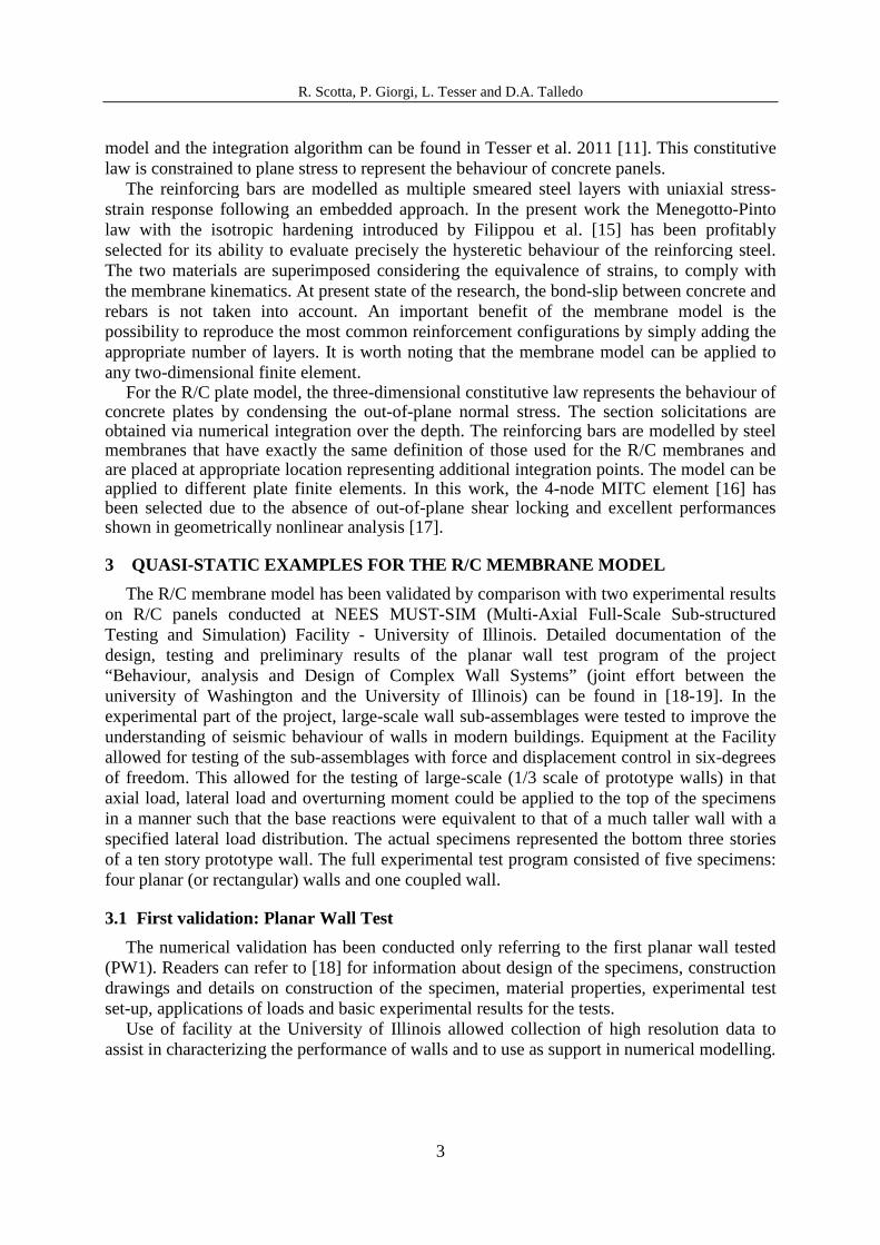
Figure 1: Planar Wall Test (PW1) [18]
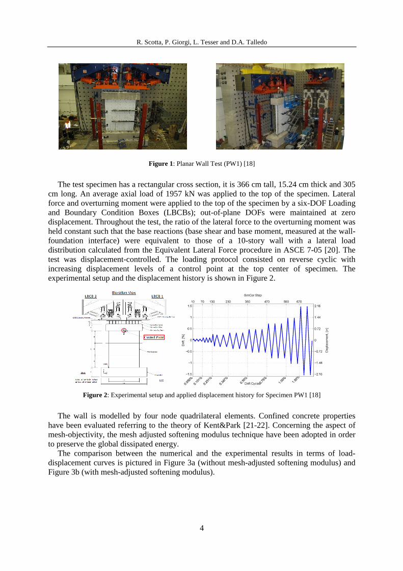
The test specimen has a rectangular cross section, it is 366 cm tall, 15.24 cm thick and 305 cm long. An average axial load of 1957 kN was applied to the top of the specimen. Lateral force and overturning moment were applied to the top of the specimen by a six-DOF Loading and Boundary Condition Boxes (LBCBs); out-of-plane DOFs were maintained at zero displacement. Throughout the test, the ratio of the lateral force to the overturning moment was held constant such that the base reactions (base shear and base moment, measured at the wall-foundation interface) were equivalent to those of a 10-story wall with a lateral load distribution calculated from the Equivalent Lateral Force procedure in ASCE 7-05 [20]. The test was displacement-controlled. The loading protocol consisted on reverse cyclic with increasing displacement levels of a control point at the top center of specimen. The experimental setup and the displacement history is shown in Figure 2.
Figure 2: Experimental setup and applied displacement history for Specimen PW1 [18]
The wall is modelled by four node quadrilateral elements. Confined concrete properties have been evaluated referring to the theory of Kent&Park [21-22]. Concerning the aspect of mesh-objectivity, the mesh adjusted softening modulus technique have been adopted in order to preserve the global dissipated energy.
The comparison between the numerical and the experimental results in terms of load-displacement curves is pictured in Figure 3a (without mesh-adjusted softening modulus) and Figure 3b (with mesh-adjusted softening modulus).
R. Scotta, P. Giorgi, L. Tesser and D.A. Talledo
5
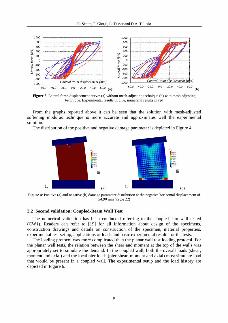
(a) (b)
Figure 3: Lateral force-displacement curve: (a) without mesh-adjusting technique (b) with mesh adjusting technique. Experimental results in blue, numerical results in red
From the graphs reported above it can be seen that the solution with mesh-adjusted softening modulus technique is more accurate and approximates well the experimental solution.
The distribution of the positive and negative damage parameter is depicted in Figure 4.
(a) (b)
Figure 4: Positive (a) and negative (b) damage parameter distribution at the negative horizontal displacement of 54.90 mm (cycle 22)
3.2 Second validation: Coupled-Beam Wall Test
The numerical validation has been conducted referring to the couple-beam wall tested (CW1). Readers can refer to [19] for all information about design of the specimens, construction drawings and details on construction of the specimen, material properties, experimental test set-up, applications of loads and basic experimental results for the tests.
The loading protocol was more complicated than the planar wall test loading protocol. For the planar wall tests, the relation between the shear and moment at the top of the walls was appropriately set to simulate the demand. In the coupled wall, both the overall loads (shear, moment and axial) and the local pier loads (pier shear, moment and axial) must simulate load that would be present in a coupled wall. The experimental setup and the load history are depicted in Figure 6.
-1000
-800
-600
-400
-200
0
200
400
600
800
1000
-60.0 -40.0 -20.0 0.0 20.0 40.0 60.0
La
tera
l fo
rce [k
N]
Control Point displacement [mm] -1000
-800
-600
-400
-200
0
200
400
600
800
1000
-60.0 -40.0 -20.0 0.0 20.0 40.0 60.0
La
tera
l fo
rce [k
N]
Control Point displacement [mm]

R. Scotta, P. Giorgi, L. Tesser and D.A. Talledo
6
Figure 5: Coupled-Beam Wall Test (CW1) [19]
Figure 6: Experimental setup and applied displacement history for specimen CW1 [19]
The comparison between the numerical and the experimental results in terms of load-displacement curves is pictured in .
The distribution of the concrete negative damage parameter accumulated when the model reached the positive maximum displacement of 20 mm is depicted in Figure 8.
Figure 7: Lateral force-displacement curve: experimental results in blue, numerical results in red
-1000
-800
-600
-400
-200
0
200
400
600
800
1000
-90.0 -70.0 -50.0 -30.0 -10.0 10.0 30.0 50.0 70.0 90.0
La
tera
l fo
rce [k
N]
Control Point displacement [mm]

R. Scotta, P. Giorgi, L. Tesser and D.A. Talledo
7
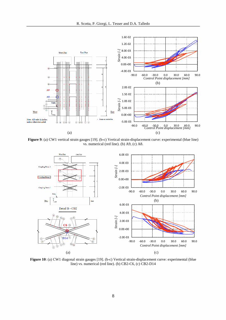
In order to further investigate the local response of the numerical model, numerical and experimental strains in both vertical and diagonal bars were compared. The coupled wall specimen was heavily instrumented with over 200 strain gauges located on the reinforcing bars embedded in the wall piers and coupling beams. As an example some comparative results are depicted in figures 9 and 10.
(a) (b)
Figure 8: (a) Specimen CW1 (-2.27% drift) [19]. (b) Negative damage parameter for the middle plate sections at the negative horizontal displacement of 88.80 mm (cycle 16)
4 QUASI-STATIC EXAMPLES FOR THE R/C PLATE MODEL
The R/C plate model has been validated by comparison with the experimental tests on U-shaped reinforced concrete wall conduced at the reaction wall facility of the ELSA laboratory (JRC Ispra, Italy) within the framework of TMR-ICONS TOPIC 5 program. Detailed documentation of the design, testing and preliminary results of the U-shaped wall test program can be found in [23-25].
4.1 Third validation: U-Shaped Wall Test
The numerical validation has been conduced only referring to the first U-Shaped wall tested (UW1). The readers can refer to Pégon et al. [23-25] for all information about design of the specimens, constructions drawings and details on construction of the specimen, material properties, experimental test set-up, applications of loads and basic experimental results for the tests.
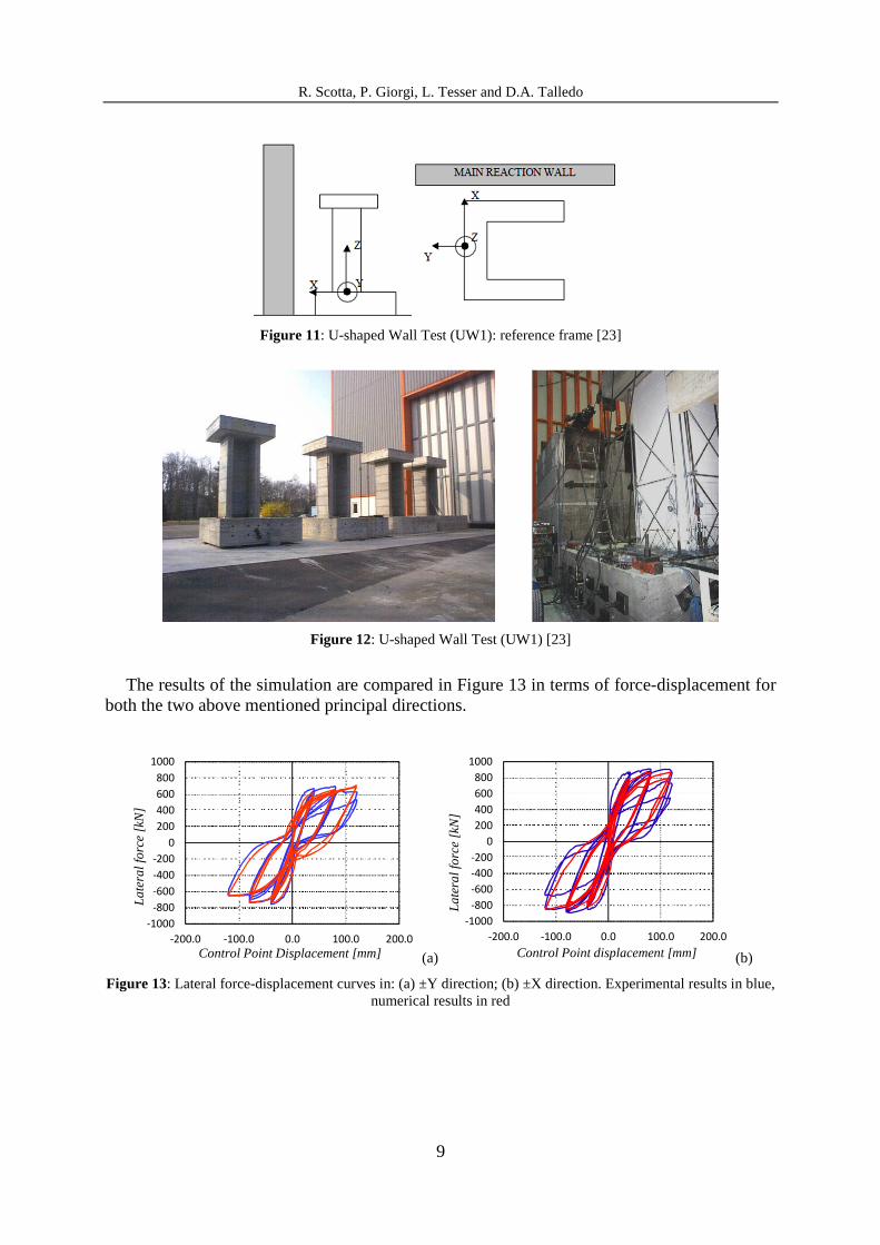
The height of the wall is 360 cm while the U section is square with side size of 112.5 cm and thickness of 25 cm. The top section ends in a transversal plate 60 cm thick with twist constrained. In Figure 11 is reported an illustration of the specimen with the reference system. Figure 12 shows two pictures of the built specimens.
The U-shaped shear wall tested is simulated by the R/C plate model. It concerns a quasi-static test carried out by imposing top cyclic displacements in the two principal directions of the U section: ±Y and ±X.
R. Scotta, P. Giorgi, L. Tesser and D.A. Talledo
8
(b)
(a) (c)
Figure 9: (a) CW1 vertical strain gauges [19]. (b-c) Vertical strain-displacement curve: experimental (blue line) vs. numerical (red line). (b) A9, (c) A8.
(b)
(a) (c)
Figure 10: (a) CW1 diagonal strain gauges [19]. (b-c) Vertical strain-displacement curve: experimental (blue line) vs. numerical (red line). (b) CB2-C6, (c) CB2-D14
-4.0E-03
0.0E+00
4.0E-03
8.0E-03
1.2E-02
1.6E-02
-90.0 -60.0 -30.0 0.0 30.0 60.0 90.0
Str
ain
[-]
Control Point displacement [mm]
-5.0E-03
0.0E+00
5.0E-03
1.0E-02
1.5E-02
2.0E-02
-90.0 -60.0 -30.0 0.0 30.0 60.0 90.0
Str
ain
[-]
Control Point displacement [mm]
-2.0E-03
0.0E+00
2.0E-03
4.0E-03
6.0E-03
-90.0 -60.0 -30.0 0.0 30.0 60.0 90.0
Str
ain
[-]
Control Point displacement [mm]
-2.0E-03
0.0E+00
2.0E-03
4.0E-03
6.0E-03
-90.0 -60.0 -30.0 0.0 30.0 60.0 90.0
Str
ain
[-]
Control Point displacement [mm]
R. Scotta, P. Giorgi, L. Tesser and D.A. Talledo
9
Figure 11: U-shaped Wall Test (UW1): reference frame [23]
Figure 12: U-shaped Wall Test (UW1) [23]
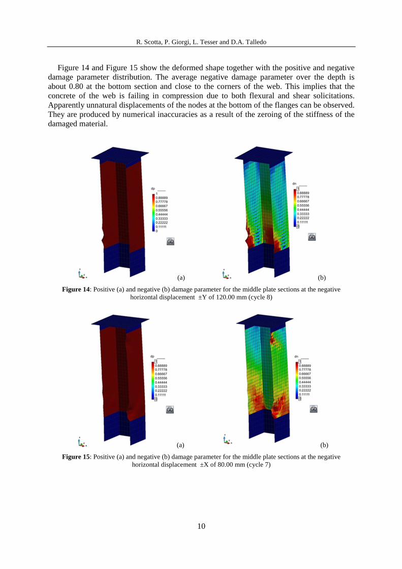
The results of the simulation are compared in Figure 13 in terms of force-displacement for both the two above mentioned principal directions.
(a) (b)
Figure 13: Lateral force-displacement curves in: (a) ±Y direction; (b) ±X direction. Experimental results in blue, numerical results in red
-1000
-800
-600
-400
-200
0
200
400
600
800
1000
-200.0 -100.0 0.0 100.0 200.0
La
tera
l fo
rce [k
N]
Control Point Displacement [mm]
-1000
-800
-600
-400
-200
0
200
400
600
800
1000
-200.0 -100.0 0.0 100.0 200.0
La
tera
l fo
rce [k
N]
Control Point displacement [mm]
R. Scotta, P. Giorgi, L. Tesser and D.A. Talledo
10
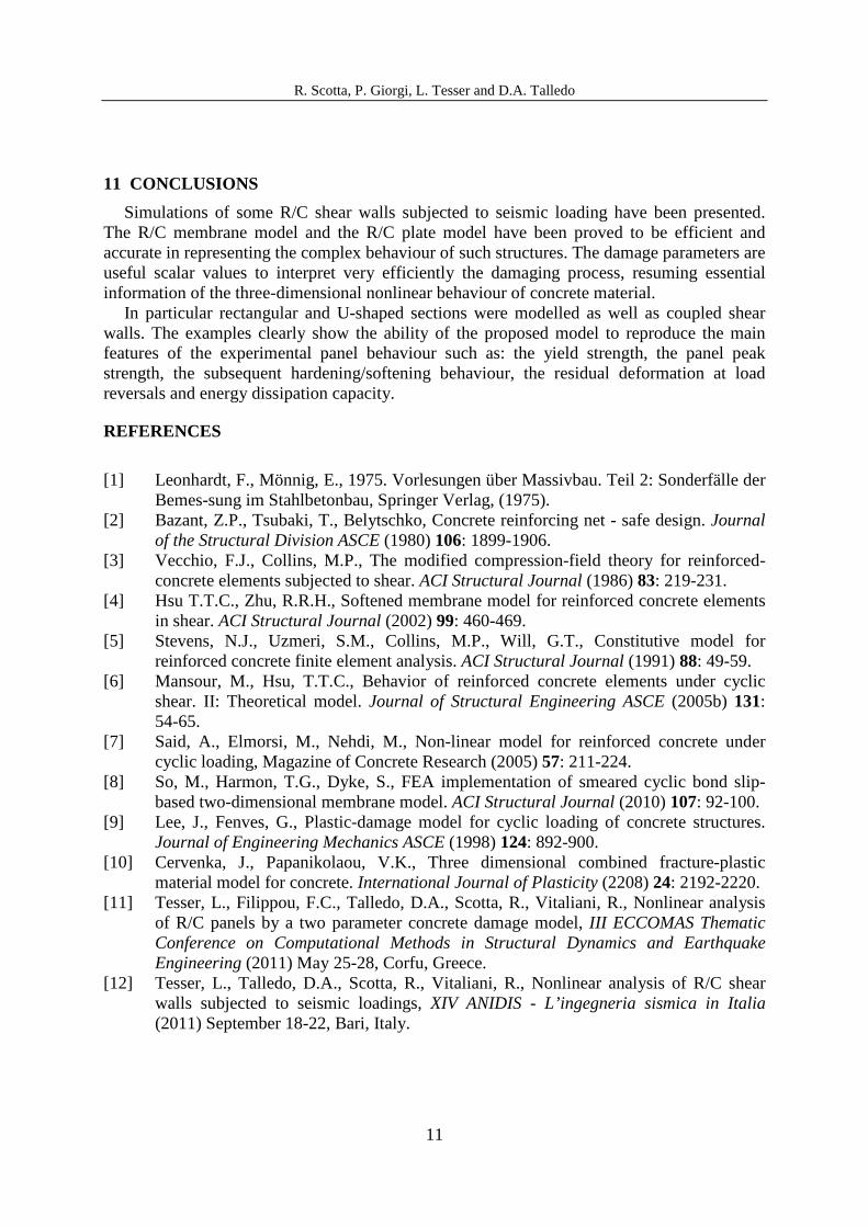
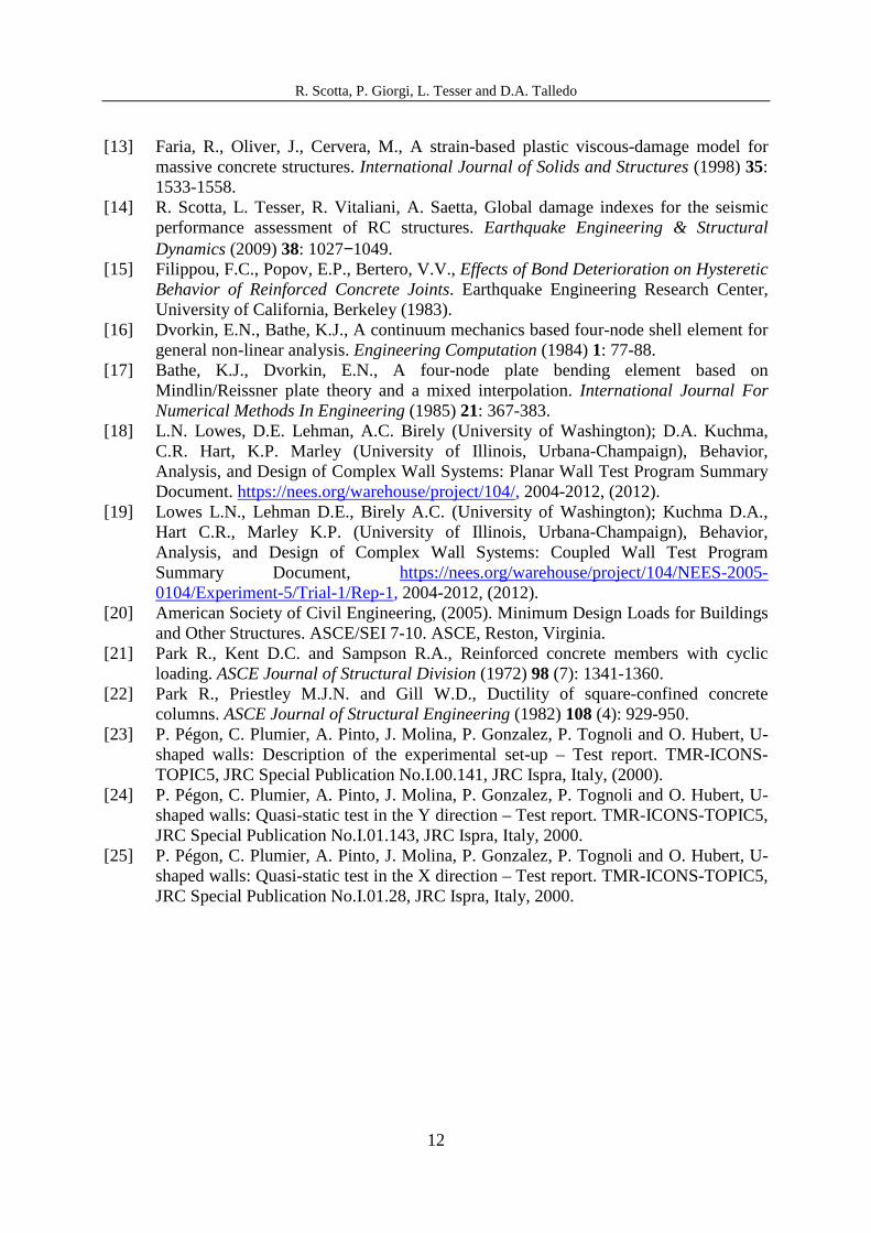
Figure 14 and Figure 15 show the deformed shape together with the positive and negative damage parameter distribution. The average negative damage parameter over the depth is about 0.80 at the bottom section and close to the corners of the web. This implies that the concrete of the web is failing in compression due to both flexural and shear solicitations. Apparently unnatural displacements of the nodes at the bottom of the flanges can be observed. They are produced by numerical inaccuracies as a result of the zeroing of the stiffness of the damaged material.
(a) (b)
Figure 14: Positive (a) and negative (b) damage parameter for the middle plate sections at the negative horizontal displacement ±Y of 120.00 mm (cycle 8)
(a) (b)
Figure 15: Positive (a) and negative (b) damage parameter for the middle plate sections at the negative horizontal displacement ±X of 80.00 mm (cycle 7)
R. Scotta, P. Giorgi, L. Tesser and D.A. Talledo
11
11 CONCLUSIONS
Simulations of some R/C shear walls subjected to seismic loading have been presented. The R/C membrane model and the R/C plate model have been proved to be efficient and accurate in representing the complex behaviour of such structures. The damage parameters are useful scalar values to interpret very efficiently the damaging process, resuming essential information of the three-dimensional nonlinear behaviour of concrete material.
In particular rectangular and U-shaped sections were modelled as well as coupled shear walls. The examples clearly show the ability of the proposed model to reproduce the main features of the experimental panel behaviour such as: the yield strength, the panel peak strength, the subsequent hardening/softening behaviour, the residual deformation at load reversals and energy dissipation capacity.
REFERENCES
[1] Leonhardt, F., Mönnig, E., 1975. Vorlesungen über Massivbau. Teil 2: Sonderfälle der
Bemes-sung im Stahlbetonbau, Springer Verlag, (1975). [2] Bazant, Z.P., Tsubaki, T., Belytschko, Concrete reinforcing net - safe design. Journal
of the Structural Division ASCE (1980) 106: 1899-1906. [3] Vecchio, F.J., Collins, M.P., The modified compression-field theory for reinforced-
concrete elements subjected to shear. ACI Structural Journal (1986) 83: 219-231. [4] Hsu T.T.C., Zhu, R.R.H., Softened membrane model for reinforced concrete elements
in shear. ACI Structural Journal (2002) 99: 460-469. [5] Stevens, N.J., Uzmeri, S.M., Collins, M.P., Will, G.T., Constitutive model for
reinforced concrete finite element analysis. ACI Structural Journal (1991) 88: 49-59. [6] Mansour, M., Hsu, T.T.C., Behavior of reinforced concrete elements under cyclic
shear. II: Theoretical model. Journal of Structural Engineering ASCE (2005b) 131: 54-65.
[7] Said, A., Elmorsi, M., Nehdi, M., Non-linear model for reinforced concrete under cyclic loading, Magazine of Concrete Research (2005) 57: 211-224.
[8] So, M., Harmon, T.G., Dyke, S., FEA implementation of smeared cyclic bond slip-based two-dimensional membrane model. ACI Structural Journal (2010) 107: 92-100.
[9] Lee, J., Fenves, G., Plastic-damage model for cyclic loading of concrete structures. Journal of Engineering Mechanics ASCE (1998) 124: 892-900.
[10] Cervenka, J., Papanikolaou, V.K., Three dimensional combined fracture-plastic material model for concrete. International Journal of Plasticity (2208) 24: 2192-2220.
[11] Tesser, L., Filippou, F.C., Talledo, D.A., Scotta, R., Vitaliani, R., Nonlinear analysis of R/C panels by a two parameter concrete damage model, III ECCOMAS Thematic Conference on Computational Methods in Structural Dynamics and Earthquake Engineering (2011) May 25-28, Corfu, Greece.
[12] Tesser, L., Talledo, D.A., Scotta, R., Vitaliani, R., Nonlinear analysis of R/C shear walls subjected to seismic loadings, XIV ANIDIS - L’ingegneria sismica in Italia (2011) September 18-22, Bari, Italy.
R. Scotta, P. Giorgi, L. Tesser and D.A. Talledo
12
[13] Faria, R., Oliver, J., Cervera, M., A strain-based plastic viscous-damage model for massive concrete structures. International Journal of Solids and Structures (1998) 35: 1533-1558.
[14] R. Scotta, L. Tesser, R. Vitaliani, A. Saetta, Global damage indexes for the seismic performance assessment of RC structures. Earthquake Engineering & Structural Dynamics (2009) 38: 1027−1049.
[15] Filippou, F.C., Popov, E.P., Bertero, V.V., Effects of Bond Deterioration on Hysteretic Behavior of Reinforced Concrete Joints. Earthquake Engineering Research Center, University of California, Berkeley (1983).
[16] Dvorkin, E.N., Bathe, K.J., A continuum mechanics based four-node shell element for general non-linear analysis. Engineering Computation (1984) 1: 77-88.
[17] Bathe, K.J., Dvorkin, E.N., A four-node plate bending element based on Mindlin/Reissner plate theory and a mixed interpolation. International Journal For Numerical Methods In Engineering (1985) 21: 367-383.
[18] L.N. Lowes, D.E. Lehman, A.C. Birely (University of Washington); D.A. Kuchma, C.R. Hart, K.P. Marley (University of Illinois, Urbana-Champaign), Behavior, Analysis, and Design of Complex Wall Systems: Planar Wall Test Program Summary Document. https://nees.org/warehouse/project/104/, 2004-2012, (2012).
[19] Lowes L.N., Lehman D.E., Birely A.C. (University of Washington); Kuchma D.A., Hart C.R., Marley K.P. (University of Illinois, Urbana-Champaign), Behavior, Analysis, and Design of Complex Wall Systems: Coupled Wall Test Program Summary Document, https://nees.org/warehouse/project/104/NEES-2005-0104/Experiment-5/Trial-1/Rep-1, 2004-2012, (2012).
[20] American Society of Civil Engineering, (2005). Minimum Design Loads for Buildings and Other Structures. ASCE/SEI 7-10. ASCE, Reston, Virginia.
[21] Park R., Kent D.C. and Sampson R.A., Reinforced concrete members with cyclic loading. ASCE Journal of Structural Division (1972) 98 (7): 1341-1360.
[22] Park R., Priestley M.J.N. and Gill W.D., Ductility of square-confined concrete columns. ASCE Journal of Structural Engineering (1982) 108 (4): 929-950.
[23] P. Pégon, C. Plumier, A. Pinto, J. Molina, P. Gonzalez, P. Tognoli and O. Hubert, U-shaped walls: Description of the experimental set-up – Test report. TMR-ICONS-TOPIC5, JRC Special Publication No.I.00.141, JRC Ispra, Italy, (2000).
[24] P. Pégon, C. Plumier, A. Pinto, J. Molina, P. Gonzalez, P. Tognoli and O. Hubert, U-shaped walls: Quasi-static test in the Y direction – Test report. TMR-ICONS-TOPIC5, JRC Special Publication No.I.01.143, JRC Ispra, Italy, 2000.
[25] P. Pégon, C. Plumier, A. Pinto, J. Molina, P. Gonzalez, P. Tognoli and O. Hubert, U-shaped walls: Quasi-static test in the X direction – Test report. TMR-ICONS-TOPIC5, JRC Special Publication No.I.01.28, JRC Ispra, Italy, 2000.