Embed Size (px)
Citation preview

Non-Uniform Power Access in Large Caches with Low-Swing Wires
Aniruddha N. Udipi
with Naveen Muralimanohar*,
Rajeev Balasubramonian
University of Utah and *HP Labs

University of Utah 2
Motivation
• Future CMPs likely to be power-limited
• Growing gap between processor and main memory performance – the Bandwidth Wall
– Large caches required to alleviate this problem– Nehalem already has 8MB of last-level cache
• These large caches contribute significantly to energy consumption
– They are often the cache coherence interface in CMPs– Cache energy contribution likely to rise as core energy reduces with
simpler and more efficient cores

University of Utah 3
Executive Summary
• H-tree identified as energy bottleneck within large cache banks
• Study various techniques to introduce low-swing wiring to address this bottleneck
• Non-Uniform Power Access to allow access to different regions of cache at different energies
• Architectural mechanisms to increase fraction of accesses hitting in the low-power region
• Significant cache energy reductions at very modest performance penalties

University of Utah 4
Outline
• Cache design background• Technique I – Single low-swing bus• Technique II – Multiple low-swing buses• Technique III – Fully-pipelined low-swing bus• Technique IV – Non-Uniform Power Access• Technique V – Architectural mechanisms• Evaluation• Conclusion

NUCA design
• Increasing disparity in access delays to different parts of the cache
• Non-Uniform Cache Access– Divide large cache into multiple “banks”
– On-chip network connects these banks and transfers address and data
– Bank count and size of each bank determined by relative contribution of banks and network to total energy/delay
– Per CACTI 6.0, even a 64MB NUCA cache likely to have large 2 or 4MB banks
University of Utah 5
Interconnect
Cache
Core
Cache
Core
Cache
Core
Cache
Core

Bank design basics
University of Utah 6
Input address
Dec
oderWordline
Bitlines
Tag
arr
ay
Dat
a ar
ray
Column muxesSense Amps
Comparators
Mux drivers
Data output
Output driver

Bank design considerations
• Naïve implementation would take the form of a single array of memory cells with centralized control logic, but such a design would not scale
– Wordlines (area considerations) and bitlines (differential signaling) cannot be repeated – delay increase with cache size
– Cache bandwidth is a function of cycle time – single array would have small bandwidth
• Performance limited by wordline/bitline length– Divide into multiple segments called “subarrays”– Subarrays connected by an internal network
University of Utah 7

Bank organization
• Bank organization determined by NDWL,NDBL
• Fewer subarrays gives increased area efficiency, but larger delay due to longer wordlines/bitlines
University of Utah 8
NDWL = 4
ND
BL =
4
H-TREE
SUBARRAY
Interconnect
Cache
Core
Cache
Core
Cache
Core
Cache
Core

Bank Energy Consumption
H-tree is clearly the dominant component of energy consumption
University of Utah 9

Low-swing wires
• High power dissipation in global wires due to full swing requirement imposed by repeaters
• Use low-voltage swing differential signaling– Two wires per signal– Voltage swing as low as 100mV– Approx. 10X energy savings compared to full swing wires– Increased delay, cannot be used over long distances– Non-trivial pipelining costs
• What is the best way to use low-swing wires to build the H-tree?
University of Utah 10

University of Utah 11
Outline
• Cache design background• Technique I – Single low-swing bus• Technique II – Multiple low-swing buses• Technique III – Fully-pipelined low-swing bus• Technique IV – Non-Uniform Power Access• Technique V – Architectural mechanisms• Evaluation• Conclusion

Single low-swing bus
• Simplest solution, simply build entire H-tree with low-swing wires
• Best energy savings
• Significant performance drops– Cycle time becomes equal to access time
– Increased contention
• Not worth considering unless energy is considerably more important than performance
University of Utah 12

University of Utah 13
Outline
• Cache design background• Technique I – Single low-swing bus• Technique II – Multiple low-swing buses• Technique III – Fully-pipelined low-swing bus• Technique IV – Non-Uniform Power Access• Technique V – Architectural mechanisms• Evaluation• Conclusion

Multiple low-swing buses
• Spread contention around
• Fast vertical bus, tristate buffers at intersections
• Energy overhead modeled accurately
University of Utah 14
LOW-SWING BUS
TRI-STATE BUFFERS

University of Utah 15
Outline
• Cache design background• Technique I – Single low-swing bus• Technique II – Multiple low-swing buses• Technique III – Fully-pipelined low-swing bus• Technique IV – Non-Uniform Power Access• Technique V – Architectural mechanisms• Evaluation• Conclusion

Fully-pipelined low-swing bus
• Pipelining low-swing wires is non-trivial
• Differential transmitter and receiver required at every pipeline stage
• Amortized over 1mm, every transceiver is a 58% energy overhead
• Performance improves compared to non-pipelined low-swing
University of Utah 16

University of Utah 17
Outline
• Cache design background• Technique I – Single low-swing bus• Technique II – Multiple low-swing buses• Technique III – Fully-pipelined low-swing bus• Technique IV – Non-Uniform Power Access• Technique V – Architectural mechanisms• Evaluation• Conclusion

Non-Uniform Power Access
University of Utah 18
LOW-SWING H-TREE TRUNK
DEFAULT FULL-SWING H-TREE
LOW-POWER REGION
HIGH-POWER REGION
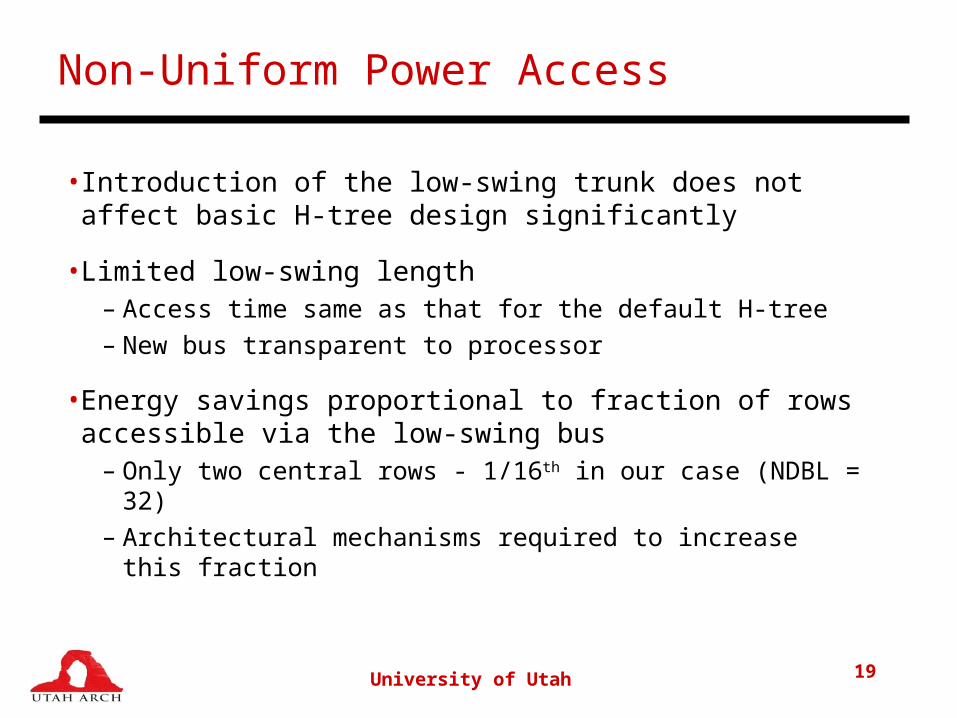
Non-Uniform Power Access
• Introduction of the low-swing trunk does not affect basic H-tree design significantly
• Limited low-swing length– Access time same as that for the default H-tree– New bus transparent to processor
• Energy savings proportional to fraction of rows accessible via the low-swing bus
– Only two central rows - 1/16th in our case (NDBL = 32)– Architectural mechanisms required to increase this
fraction
University of Utah 19

University of Utah 20
Outline
• Cache design background• Technique I – Single low-swing bus• Technique II – Multiple low-swing buses• Technique III – Fully-pipelined low-swing bus• Technique IV – Non-Uniform Power Access• Technique V – Architectural mechanisms• Evaluation• Conclusion

Exploiting Non-Uniform Power Access
• Increase fraction of accesses served by the “low-power region”
• Assign a fraction of the ways of the set to the “low-power region (LP)” and the rest of the ways to the “high-power region (HP)”
• On every access, check all tags in parallel, if it hits in the LP region, it is a low-power access
• If not, bring the line into the low-power region at this point
– the next use will then likely be a low-power access
University of Utah 21

Swap scheme
• Bring block into low-power region on first-touch• The block currently in LRU position in that set is swapped out into the high-power region
– Most recently used (MRU) ways of every set are in the LP region
• Every low-power fetch incurs a swap which costs two low-power and two high-power accesses
• For Swap to consume less energy than baseline with N accesses
– N * H > 2 * H + (N+1) * L
– N > 2.5
University of Utah 22

Duplicate scheme
• Bring block into low-power and high-power region on first touch
• Block currently in LRU position in low-power region is– Simply dropped if clean – better than Swap– Written back to high-power region if dirty – same as Swap
• Every L2 miss results in one additional HP access initially
• Forming equations similar to Swap– Nclean > 1.16
– Ndirty > 2.6
University of Utah 23

Dynamic Reconfiguration
• Good energy savings if a modestly high hit-rate in the low-power region
• Below a certain threshold, extra energy required to move blocks between LP and HP region overshadows savings
• Track average reuse count and turn-off architectural mechanisms in bad phases, operate like default cache
– Single five bit saturating counter for entire cache
– Increment counter on hit in LP region, decrement on miss
University of Utah 24

Comparison to L2/L3 or Filter Cache
• Data placement and mapping schemes do bear resemblance to L2/L3 hierarchy or filter cache
– our approach is orthogonal to the hierarchy and can continue to be used for the largest last-level cache
– need for interconnects between multiple physical cache structures eliminated
– Non-uniform access model 25% more efficient than a filter cache model with similar capacities
University of Utah 25

University of Utah 26
Outline
• Cache design background• Technique I – Single low-swing bus• Technique II – Multiple low-swing buses• Technique III – Fully-pipelined low-swing bus• Technique IV – Non-Uniform Power Access• Technique V – Architectural mechanisms• Evaluation• Conclusion

University of Utah 27
Methodology
• SimpleScalar 3.0 OOO-simulator
• CACTI 6.0 for cache energy/delay computation
• 32nm process, 5GHz clock
• 32K each I- and D-L1, 2-way
• Unified 4MB L2 cache, 16-way
• 300 cycle main memory latency
• SPEC2k benchmark suite

Low-swing design points - Energy
University of Utah 28

Low-swing design points - IPC
University of Utah 29

Low-swing design points
• Clearly a trade-off between energy savings and performance drops
• ED2 metric– Non-uniform model gives 5% improvement over
baseline
– Pipelined low-swing model is next best, with a 3% improvement over baseline
– These are the two most compelling design points
University of Utah 30

Architectural mechanisms
University of Utah 31

Dynamic reconfiguration
University of Utah 32

Sensitivity to cache size
University of Utah 33

University of Utah 34
Outline
• Cache design background• Technique I – Single low-swing bus• Technique II – Multiple low-swing buses• Technique III – Fully-pipelined low-swing bus• Technique IV – Non-Uniform Power Access• Technique V – Architectural mechanisms• Evaluation• Conclusion

University of Utah 35
Related Work
• Low-swing wires– “Smart memories” project, CACTI 6.0
• Cache access energy– Drowsy cache, gated-ground cache, L0 instruction
cache, non-uniformity in number of ways per set
• Ours is the first work to optimize the internal structure of the cache, and propose non-uniform power access within a cache bank

Key Contributions
• Study of the internal organization of large cache banks,
identification of bottleneck
• Exploration the design space of low-swing wiring within
large caches
• Introduction of the notion of Non-Uniform Power Access
– Definition of the architectural mechanisms required to
maximize the energy-saving potential of low-swing wires
University of Utah 36

University of Utah 37
Thank you..
• Questions?


![[XLS] · Web viewGangapur Indore Udipi Bangalore Rural Bathinda Imphal East Paschim Medinipur Kollam Amritsar Tamenglong Chingamakha Kaikamba Chikkaballapura Surat Nandurbar Rajasthan](https://img.pdfslide.us/doc/110x75/5acd3f607f8b9a6a678d4bb2/xls-viewgangapur-indore-udipi-bangalore-rural-bathinda-imphal-east-paschim-medinipur.jpg)