Embed Size (px)
Citation preview
NON-LINEAR PROPERTIES OF PVC-COATED FABRICS
USED IN TENSAIRITY STRUCTURES
C. Galliot, R.H. Luchsinger
Center for Synergetic Structures
EMPA, Swiss Federal Laboratories for Materials Testing and Research
Ueberlandstrasse 129, CH-8600 Duebendorf, Switzerland
SUMMARY
The yarn-parallel and shear behaviour of PVC-coated polyester fabric is investigated.
From biaxial tensile test results a simple material model is proposed and included as a
Usermat in ANSYS. It is used for the finite element analysis of a 5 meter long
Tensairity girder under bending load.
Keywords: Tensairity, coated fabric, biaxial testing, non-linear behaviour, finite
element analysis
INTRODUCTION
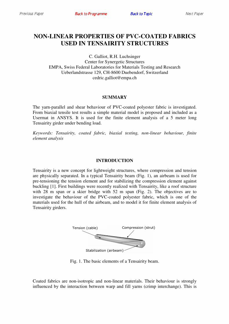
Tensairity is a new concept for lightweight structures, where compression and tension
are physically separated. In a typical Tensairity beam (Fig. 1), an airbeam is used for
pre-tensioning the tension element and for stabilizing the compression element against
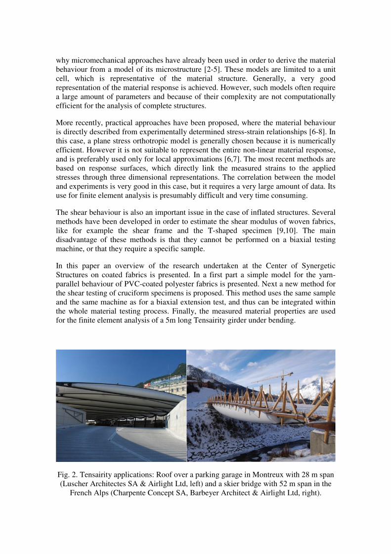
buckling [1]. First buildings were recently realized with Tensairity, like a roof structure
with 28 m span or a skier bridge with 52 m span (Fig. 2). The objectives are to
investigate the behaviour of the PVC-coated polyester fabric, which is one of the
materials used for the hull of the airbeam, and to model it for finite element analysis of
Tensairity girders.
Fig. 1. The basic elements of a Tensairity beam.
Coated fabrics are non-isotropic and non-linear materials. Their behaviour is strongly
influenced by the interaction between warp and fill yarns (crimp interchange). This is
why micromechanical approaches have already been used in order to derive the material
behaviour from a model of its microstructure [2-5]. These models are limited to a unit
cell, which is representative of the material structure. Generally, a very good
representation of the material response is achieved. However, such models often require
a large amount of parameters and because of their complexity are not computationally
efficient for the analysis of complete structures.
More recently, practical approaches have been proposed, where the material behaviour
is directly described from experimentally determined stress-strain relationships [6-8]. In
this case, a plane stress orthotropic model is generally chosen because it is numerically
efficient. However it is not suitable to represent the entire non-linear material response,
and is preferably used only for local approximations [6,7]. The most recent methods are
based on response surfaces, which directly link the measured strains to the applied
stresses through three dimensional representations. The correlation between the model
and experiments is very good in this case, but it requires a very large amount of data. Its
use for finite element analysis is presumably difficult and very time consuming.
The shear behaviour is also an important issue in the case of inflated structures. Several
methods have been developed in order to estimate the shear modulus of woven fabrics,
like for example the shear frame and the T-shaped specimen [9,10]. The main
disadvantage of these methods is that they cannot be performed on a biaxial testing
machine, or that they require a specific sample.
In this paper an overview of the research undertaken at the Center of Synergetic
Structures on coated fabrics is presented. In a first part a simple model for the yarn-
parallel behaviour of PVC-coated polyester fabrics is presented. Next a new method for
the shear testing of cruciform specimens is proposed. This method uses the same sample
and the same machine as for a biaxial extension test, and thus can be integrated within
the whole material testing process. Finally, the measured material properties are used
for the finite element analysis of a 5m long Tensairity girder under bending.
Fig. 2. Tensairity applications: Roof over a parking garage in Montreux with 28 m span
(Luscher Architectes SA & Airlight Ltd, left) and a skier bridge with 52 m span in the
French Alps (Charpente Concept SA, Barbeyer Architect & Airlight Ltd, right).
YARN PARALLEL BEHAVIOUR
Experiments
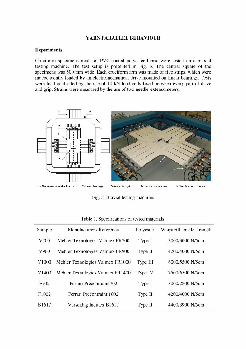
Cruciform specimens made of PVC-coated polyester fabric were tested on a biaxial
testing machine. The test setup is presented in Fig. 3. The central square of the
specimens was 500 mm wide. Each cruciform arm was made of five strips, which were
independently loaded by an electromechanical drive mounted on linear bearings. Tests
were load-controlled by the use of 10 kN load cells fixed between every pair of drive
and grip. Strains were measured by the use of two needle-extensometers.
Fig. 3. Biaxial testing machine.
Table 1. Specifications of tested materials.
Sample Manufacturer / Reference Polyester Warp/Fill tensile strength
V700 Mehler Texnologies Valmex FR700 Type I 3000/3000 N/5cm
V900 Mehler Texnologies Valmex FR900 Type II 4200/4000 N/5cm
V1000 Mehler Texnologies Valmex FR1000 Type III 6000/5500 N/5cm
V1400 Mehler Texnologies Valmex FR1400 Type IV 7500/6500 N/5cm
F702 Ferrari Précontraint 702 Type I 3000/2800 N/5cm
F1002 Ferrari Précontraint 1002 Type II 4200/4000 N/5cm
B1617 Verseidag Indutex B1617 Type II 4400/3900 N/5cm
Specimens were first loaded at pre-stress level and then from pre-stress up to maximum
test stress. Strains were set to be equal to zero at pre-stress. The maximum test stress
was set to one fifth of the tensile strength in order to avoid tearing of the fabric. The
pre-stress was set to one fifth of the maximum test stress. Each loading/unloading was
repeated five times in order to remove residual strains. Only the last load cycle was used
to determine the material properties. Seven materials were selected from different
manufacturers, representing a wide range of mechanical behaviour. Their main
properties are listed in Table 1.
Stress reduction factor
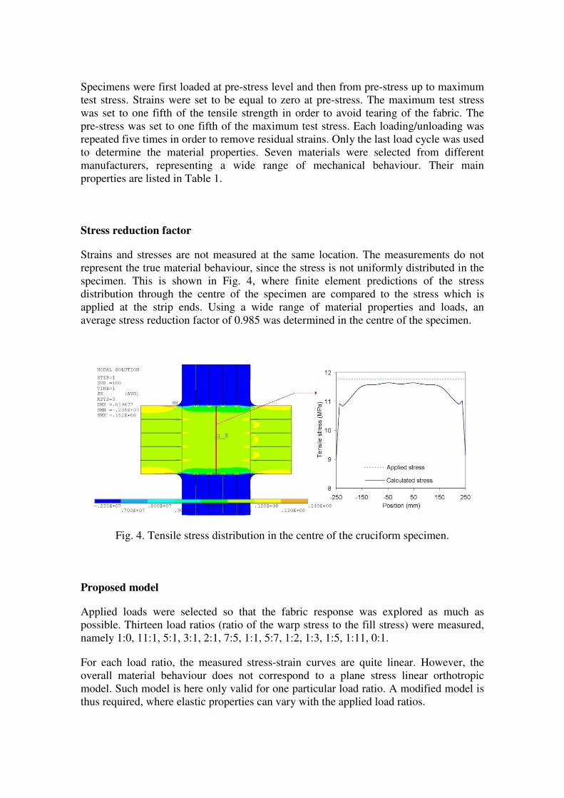
Strains and stresses are not measured at the same location. The measurements do not
represent the true material behaviour, since the stress is not uniformly distributed in the
specimen. This is shown in Fig. 4, where finite element predictions of the stress
distribution through the centre of the specimen are compared to the stress which is
applied at the strip ends. Using a wide range of material properties and loads, an
average stress reduction factor of 0.985 was determined in the centre of the specimen.
Fig. 4. Tensile stress distribution in the centre of the cruciform specimen.
Proposed model
Applied loads were selected so that the fabric response was explored as much as
possible. Thirteen load ratios (ratio of the warp stress to the fill stress) were measured,
namely 1:0, 11:1, 5:1, 3:1, 2:1, 7:5, 1:1, 5:7, 1:2, 1:3, 1:5, 1:11, 0:1.
For each load ratio, the measured stress-strain curves are quite linear. However, the
overall material behaviour does not correspond to a plane stress linear orthotropic
model. Such model is here only valid for one particular load ratio. A modified model is
thus required, where elastic properties can vary with the applied load ratios.
Based on the experimental results, a non-linear model was proposed [11], as presented
in Fig. 5. A linear relationship was found between the material elastic moduli and the
normalized load ratios. The material model has five parameters: Ew1:1
and Ef1:1
are the
reference values of warp and fill Young’s moduli given for the 1:1 load ratio, ∆Ew and
∆Ef represent the variation of warp and fill Young’s moduli on the whole range of load
ratios (0≤γw,f≤1), and νwf is the Poisson’s ratio. Material parameters were determined by
a least square fit minimizing the deviation of experimental and modelled strains.
Fig. 5. Proposed non-linear model with stress-dependent moduli.
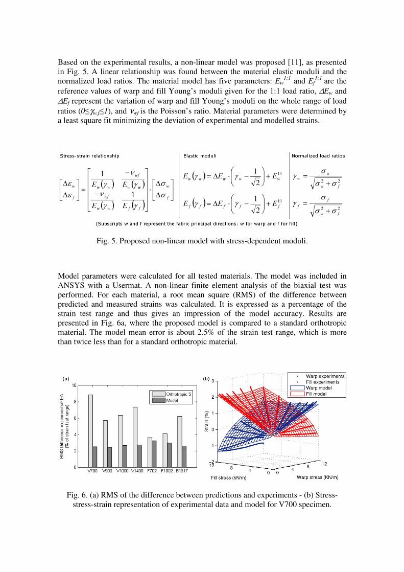
Model parameters were calculated for all tested materials. The model was included in
ANSYS with a Usermat. A non-linear finite element analysis of the biaxial test was
performed. For each material, a root mean square (RMS) of the difference between
predicted and measured strains was calculated. It is expressed as a percentage of the
strain test range and thus gives an impression of the model accuracy. Results are
presented in Fig. 6a, where the proposed model is compared to a standard orthotropic
material. The model mean error is about 2.5% of the strain test range, which is more
than twice less than for a standard orthotropic material.
Fig. 6. (a) RMS of the difference between predictions and experiments - (b) Stress-
stress-strain representation of experimental data and model for V700 specimen.
On Fig. 6b the model predictions (surfaces) are superimposed with experimental data
(dots). It clearly appears that the experimental curves do not lie all on a plane and thus
linear models have limited capabilities. For the proposed non-linear model, a curved
surface enables a better representation of the experimental material characteristics.
SHEAR BEHAVIOUR
Experiments
The membrane shear modulus should be measured under biaxial loading in order to be
consistent with the material use. It should be initially pre-stressed in both directions to
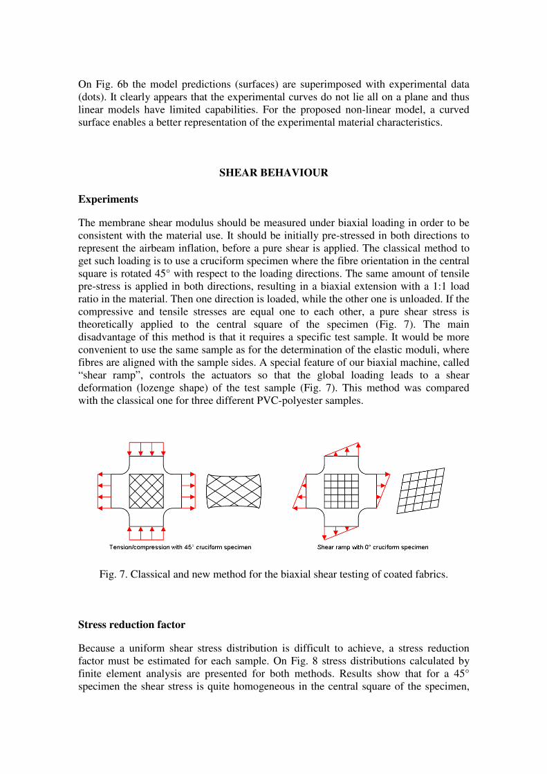
represent the airbeam inflation, before a pure shear is applied. The classical method to
get such loading is to use a cruciform specimen where the fibre orientation in the central
square is rotated 45° with respect to the loading directions. The same amount of tensile
pre-stress is applied in both directions, resulting in a biaxial extension with a 1:1 load
ratio in the material. Then one direction is loaded, while the other one is unloaded. If the
compressive and tensile stresses are equal one to each other, a pure shear stress is
theoretically applied to the central square of the specimen (Fig. 7). The main
disadvantage of this method is that it requires a specific test sample. It would be more
convenient to use the same sample as for the determination of the elastic moduli, where
fibres are aligned with the sample sides. A special feature of our biaxial machine, called
“shear ramp”, controls the actuators so that the global loading leads to a shear
deformation (lozenge shape) of the test sample (Fig. 7). This method was compared
with the classical one for three different PVC-polyester samples.
Fig. 7. Classical and new method for the biaxial shear testing of coated fabrics.
Stress reduction factor
Because a uniform shear stress distribution is difficult to achieve, a stress reduction
factor must be estimated for each sample. On Fig. 8 stress distributions calculated by
finite element analysis are presented for both methods. Results show that for a 45°
specimen the shear stress is quite homogeneous in the central square of the specimen,
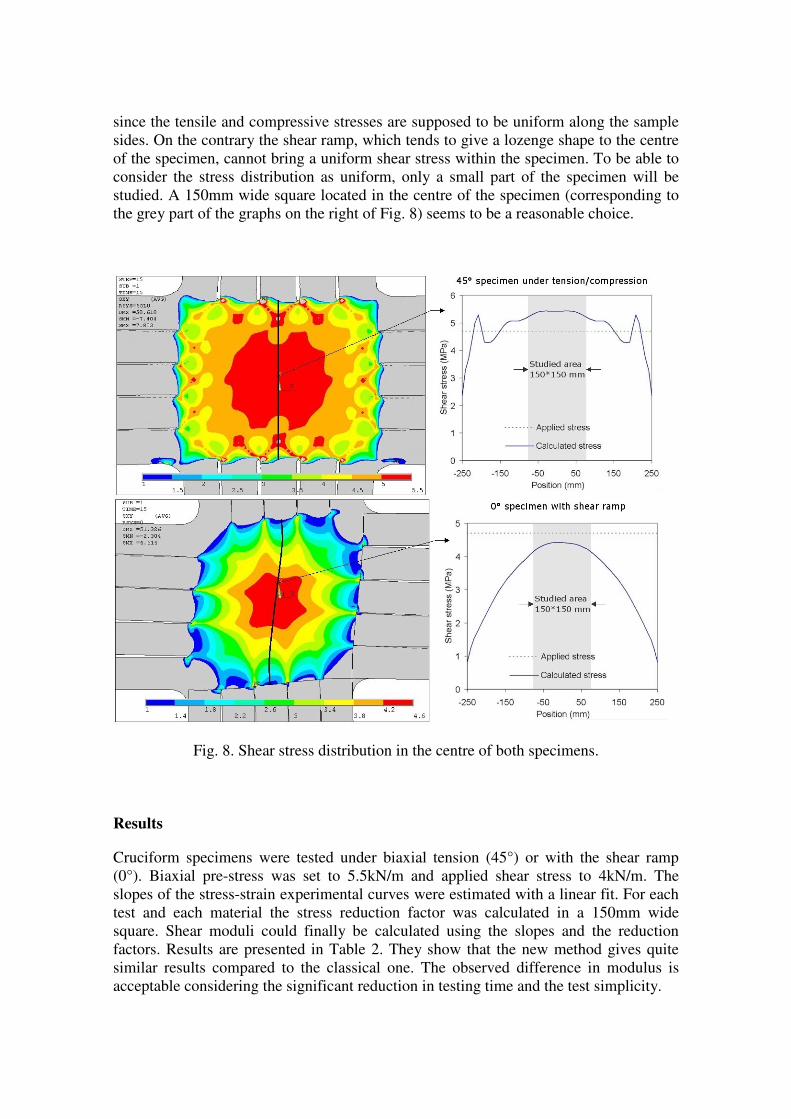
since the tensile and compressive stresses are supposed to be uniform along the sample
sides. On the contrary the shear ramp, which tends to give a lozenge shape to the centre
of the specimen, cannot bring a uniform shear stress within the specimen. To be able to
consider the stress distribution as uniform, only a small part of the specimen will be
studied. A 150mm wide square located in the centre of the specimen (corresponding to
the grey part of the graphs on the right of Fig. 8) seems to be a reasonable choice.
Fig. 8. Shear stress distribution in the centre of both specimens.
Results
Cruciform specimens were tested under biaxial tension (45°) or with the shear ramp
(0°). Biaxial pre-stress was set to 5.5kN/m and applied shear stress to 4kN/m. The
slopes of the stress-strain experimental curves were estimated with a linear fit. For each
test and each material the stress reduction factor was calculated in a 150mm wide
square. Shear moduli could finally be calculated using the slopes and the reduction
factors. Results are presented in Table 2. They show that the new method gives quite
similar results compared to the classical one. The observed difference in modulus is
acceptable considering the significant reduction in testing time and the test simplicity.
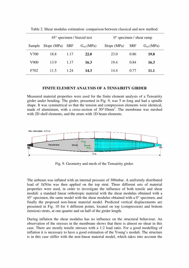
Table 2. Shear modulus estimation: comparison between classical and new method.
45° specimen / biaxial test 0° specimen / shear ramp
Sample Slope (MPa) SRF Gwf (MPa) Slope (MPa) SRF Gwf (MPa)
V700 18.8 1.17 22.0 23.0 0.86 19.8
V900 13.9 1.17 16.3 19.4 0.84 16.3
F702 11.5 1.24 14.3 14.4 0.77 11.1
FINITE ELEMENT ANALYSIS OF A TENSAIRITY GIRDER
Measured material properties were used for the finite element analysis of a Tensairity
girder under bending. The girder, presented in Fig. 9, was 5 m long and had a spindle
shape. It was symmetrical so that the tension and compression elements were identical,
made of aluminium, with a cross-section of 30*10mm2. The membrane was meshed
with 2D shell elements, and the struts with 1D beam elements.
Fig. 9. Geometry and mesh of the Tensairity girder.
The airbeam was inflated with an internal pressure of 300mbar. A uniformly distributed
load of 1kN/m was then applied on the top strut. Three different sets of material
properties were used, in order to investigate the influence of both tensile and shear
moduli: a standard linear orthotropic material with the shear modulus obtained with a
45° specimen, the same model with the shear modulus obtained with a 0° specimen, and
finally the proposed non-linear material model. Predicted vertical displacements are
presented in Fig. 10 for 4 different points, located on top (compression) and bottom
(tension) struts, at one quarter and on half of the girder length.
During inflation the shear modulus has no influence on the structural behaviour. An
observation of the stresses in the membrane shows that there is almost no shear in this
case. There are mostly tensile stresses with a 1:2 load ratio. For a good modelling of
inflation it is necessary to have a good estimation of the Young’s moduli. The structure
is in this case stiffer with the non-linear material model, which takes into account the
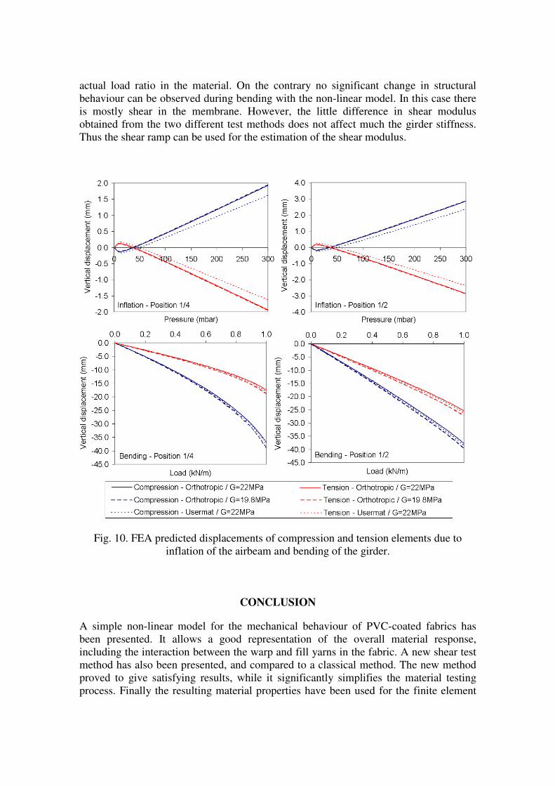
actual load ratio in the material. On the contrary no significant change in structural
behaviour can be observed during bending with the non-linear model. In this case there
is mostly shear in the membrane. However, the little difference in shear modulus
obtained from the two different test methods does not affect much the girder stiffness.
Thus the shear ramp can be used for the estimation of the shear modulus.
Fig. 10. FEA predicted displacements of compression and tension elements due to
inflation of the airbeam and bending of the girder.
CONCLUSION
A simple non-linear model for the mechanical behaviour of PVC-coated fabrics has
been presented. It allows a good representation of the overall material response,
including the interaction between the warp and fill yarns in the fabric. A new shear test
method has also been presented, and compared to a classical method. The new method
proved to give satisfying results, while it significantly simplifies the material testing
process. Finally the resulting material properties have been used for the finite element
analysis of a Tensairity girder. Numerical predictions show that the choice of a material
model does not significantly influence the structural response under bending. However,
the non-linear model can be interesting for the simulation of the inflation because it can
take into account the actual load ratio in the membrane.
References
1. Luchsinger RH, Pedretti A, Steingruber P, Pedretti M. The new structural
concept Tensairity: Basic principles. Progress in Structural Engineering,
Mechanics and Computations, London: A.A. Balkema Publishers; 2004.
2. Pargana JB, Lloyd-Smith D, Izzuddin BA. Advanced material model for coated
fabrics used in tensioned fabric structures. Engineering Structures
2007;29:1323-1336.
3. Cavallaro PV, Johnson ME, Sadegh AM. Mechanics of plain-woven fabrics for
inflated structures. Composite Structures 2003;61:375-393.
4. Whitcomb J, Woo K. Enhanced direct stiffness method for finite element
analysis of textile composites. Composite Structures 1994;28:385-390.
5. Bigaud D, Hamelin P. Mechanical properties prediction of textile-reinforced
composite materials using a multiscale energetic approach. Composite
Structures 1997;38:361-371.
6. Bögner-Balz H, Blum R. The mechanical behaviour of coated fabrics used in
prestressing textile engineering structures: theory, simulation and numerical
analysis to be used in a FEM-model. Journal of the IASS 2008;49(1):39-47.
7. Minami H. A multi-step approximation method for nonlinear analysis of stress
and deformation of coated plain-weave fabric. Journal of Textile Engineering
2006;52(5):189-195.
8. Bridgens BN, Gosling PD. Direct stress-strain representation for coated woven
fabrics. Computer & Structures 2004;82:1913-1927.
9. Launay J, Hivet G, Duong AV, Boisse P. Experimental analysis of the influence
of tensions on in plane shear behaviour of woven composite reinforcements.
Composites Science and Technology 2008;68:506-515.
10. Vysochina K, Gabor A, Bigaud D, Ronel-Idrissi S. Identification of Shear
Stiffness of Soft Orthotropic Textile Composites: Part I – Development of a
Mixed Method for Shear Elastic Constant Identification. Journal of Industrial
Textiles 2005;35(2):137-155.
11. Galliot C, Luchsinger RH. A simple model describing the non-linear biaxial
tensile behaviour of PVC-coated polyester fabrics for use in finite element
analysis. Composite Structures 2009. DOI: 10.1016/j.compstruct.2009.04.016