Embed Size (px)
Citation preview

Conduit - Flat & Curved WallF-05 / 07 / 10-Retrofit-S & S-RND
Fiberglass Pipe - Flat & Curved WallF-20 / 30 / 40-Retrofit-S & S-RND
BUILT LIKE
A TANKHigh-end materials match UST spec UL1316 to
ensure longevity and fuel compatibility
LCX Fiberglass Pipe - Flat & Curved WallF-20 / 30 / 40-Retrofit-S-LCX & S-LCX-RND
F-SERIES RETROFIT-SINSTALLATION INSTRUCTIONSBRAVO FIBERGLASS RETROFIT-S SERIES FOR SINGLE WALL FRP SUMPS ONLY
FOR RETROFITTING ALL FLEXIBLE ENTRY BOOTSFIBERGLASS PIPE, GALVANIZED CONDUIT or PVC-COATED CONDUIT ONLY
1 ii-F-Series-Retrofit-S-12ANote: Actual products may vary in appearance
from illustrations in this manual
S. Bravo Systems, Inc. - The Leader in Secondary Containment323-888-41332929 Vail Ave. Commerce, CA FAX: 323-888-4123 www.sbravo.com
READ THIS MANUAL
FRONT TO BACK
11A

TABLE OF CONTENTS Fitting Warnings, Requirements & Warranty Terms...................................... p. 3Fitting Specifications and part numbers........................................................p. 4Fitting Components and Tools...................................................................... p. 5INSTALLATION SUMMARY......................................................................... p. 6Step 1 Fitting rules, sump evaluation and cleanup......................................p. 7Step 2 Removing the existing fitting on the interior..................................... p. 7Step 3 Wrapping pipe with rubber strip....................................................... p. 8Step 4 Cutting down fitting bolts and wall preparation.................................p. 8Step 5 Dry-fitting and outlining fitting position with marker..........................p. 8PREPARING YOUR PIPE BY HAND SANDING......................................... p. 9MIXING YOUR ADHESIVE - CRITICAL STEP............................................ p. 10WINTER WARNING INSERTStep 6 Gluing and Installing curved flange to wall.......................................p. 11Step 7 Gluing and Installing fitting body.......................................................p. 12Step 8 Aligning and tightening clamp on fitting body................................... p. 13Step 9 Securing fitting to wall via pusher clamp and beading adhesive..... p. 13Step 10 Lake testing (Water testing) your Installation................................. p. 13
LIMITED WARRANTYProducts sold by S. Bravo Systems, Inc. are warranted to be free from defects in material and workmanship for a period of one yearfrom date of purchase. This warranty will be limited to the repair and replacement of Bravo parts only and will exclude all claims forlabor or consequential damage. No other express warranties are given and no affirmation of S. Bravo Systems, Inc., or its agentsand/or representatives, by words or action, will constitute a warranty. IT IS EXPRESSLY AGREED THAT THIS WARRANTY WILLBE IN LIEU OF ALL WARRANTIES OF FITNESS AND IN LIEU OF THE WARRANTY OF MERCHANTABILITY.
This warranty is void if there is any evidence of modification, abuse, negligence, or improper installation - including but not limited toinstallation or maintenance by a Non-Specialist Certified individual. If any fittings or components, other than S. Bravo Systemsapproved fittings or components, are used in conjunction with any S. Bravo Systems product, the warranty pertaining to these products is immediately void.
2 ii-F-Series-Retrofit-S-12A
The F-Series Singlewall Retrofit-S Fittings from S. Bravo Systems, Inc. MUST beinstalled by a Bravo Retrofit-Certified Installer. The Retrofit Test must be
completed at www.sbravo.com/cert
You must also be Confined-Space Certified when working within Tank Sumps.
If you have any problems with Bravo Systems components or accessories, Contact Bravo Systems Immediately:
1-800-28-BRAVO 1-323-888-4133 [email protected]
COMPLETE KEEP TRACK of your job by taking advantage of the“Complete” checkboxes paired with each major step.

A) NOT Installing an F-Series Retrofit-S fitting with Bravo ADHESIVE-RETROFIT-EPOXY-KIT.
B) Installing a F-Series Retrofit-S fitting with adhesives that are not specified in this manual.
C) F-Series Retrofit-S Fittings are NOT installed by a Bravo Certified Contractor.
WARRANTY IS VOIDOR YOUR CERTIFIED STATUSWILL BE REVOKED:
IF ANY OF THE FOLLOWING OCCUR
VENTILATE YOURAREA. WEAR MASK,SAFETY GLASSES,
GLOVES AND OTHERPROTECTION
> ELECTRIC TOOLS> IGNITION SOURCESNO
3 ii-F-Series-Retrofit-S-12A
D) Installing a F-Series Retrofit-S fitting on Polyethylene sumps or flex pipe.
Ensure that the workspace is operating belowthe LEL (lower explosive limit). Test regularlyor monitor continuously.
E) Installing a F-Series Retrofit-S fitting without monitoring lower explosive limit.
NOTE: BRAVO RECOMMENDS THAT AT A MINIMUM, all flexible entry fittings on a sump are retrofit with the F-Series Retrofit-S fitting. Having every entry fittingsealed with fuel-compatible adhesive will ensure thebest lake test results.
4 ii-F-Series-Retrofit-S-12A
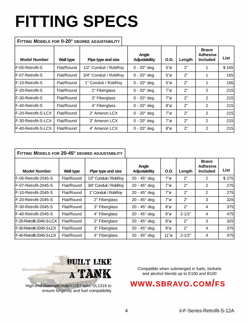
FITTING SPECS
BUILT LIKE
A TANKHigh-end materials match UST spec UL1316 to
ensure longevity and fuel compatibilityWWW.SBRAVO.COM/FS
Compatible when submerged in fuels, biofuelsand alcohol blends up to E100 and B100
Model Number Wall type Pipe type and sizeAngle
Adjustability O.D. Length
BravoAdhesive Included List
F-05-Retrofit-2045-S Flat/Round 1/2” Conduit / RobRoy 20 - 45° deg. 7”ø 2” 2 $ 275
F-07-Retrofit-2045-S Flat/Round 3/4” Conduit / RobRoy 20 - 45° deg. 7”ø 2” 2 275
F-10-Retrofit-2045-S Flat/Round 1” Conduit / RobRoy 20 - 45° deg. 7”ø 2” 2 275
F-20-Retrofit-2045-S Flat/Round 2” Fiberglass 20 - 45° deg. 7”ø 2” 3 325
F-30-Retrofit-2045-S Flat/Round 3” Fiberglass 20 - 45° deg. 8”ø 2” 4 375
F-40-Retrofit-2045-S Flat/Round 4” Fiberglass 20 - 45° deg. 9”ø 2-1/2” 4 475
F-20-Retrofit-2045-S-LCX Flat/Round 2” Fiberglass 20 - 45° deg. 8”ø 2” 3 325
F-30-Retrofit-2045-S-LCX Flat/Round 3” Fiberglass 20 - 45° deg. 9”ø 2” 4 375
F-40-Retrofit-2045-S-LCX Flat/Round 4” Fiberglass 20 - 45° deg. 11”ø 2-1/2” 4 475
Model Number Wall type Pipe type and sizeAngle
Adjustability O.D. Length
BravoAdhesive Included List
F-05-Retrofit-S Flat/Round 1/2” Conduit / RobRoy 0 - 20° deg. 5”ø 2” 1 $ 165
F-07-Retrofit-S Flat/Round 3/4” Conduit / RobRoy 0 - 20° deg. 5”ø 2” 1 165
F-10-Retrofit-S Flat/Round 1” Conduit / RobRoy 0 - 20° deg. 5”ø 2” 1 165
F-20-Retrofit-S Flat/Round 2” Fiberglass 0 - 20° deg. 7”ø 2” 2 215
F-30-Retrofit-S Flat/Round 3” Fiberglass 0 - 20° deg. 7”ø 2” 2 215
F-40-Retrofit-S Flat/Round 4” Fiberglass 0 - 20° deg. 8”ø 2” 2 215
F-20-Retrofit-S-LCX Flat/Round 2” Ameron LCX 0 - 20° deg. 7”ø 2” 2 215
F-30-Retrofit-S-LCX Flat/Round 3” Ameron LCX 0 - 20° deg. 7”ø 2” 2 215
F-40-Retrofit-S-LCX Flat/Round 4” Ameron LCX 0 - 20° deg. 8”ø 2” 2 215
FITTING MODELS FOR 0-20° DEGREE ADJUSTABILITY
FITTING MODELS FOR 20-45° DEGREE ADJUSTABILITY

5 ii-F-Series-Retrofit-S-12A
F-Series Retrofit-SCOMPONENTSIncluded Parts (Per fitting)
A) 1x Fiberglass Retrofit-S Body (two halves) with SS Pipe ClampB) 1x Loose Fiberglass Flange for curved walls (two halves) with 2 Zip-TiesC) Bravo ADHESIVE-RETROFIT-EPOXY-KIT: (quantity chart on page 4)
1x Bravo Epoxy Adhesive Can 6oz1x Bravo Epoxy Catalyst bottle 1oz2x Pair of Industrial Nitrile gloves (Large)1x Stir stick1x 1” chip brush
D) 1x 60 grit emery cloth stripE) 1x 80 grit sheet of sandpaperF) 1x 3-bolt compression clampG) 1x 15” long Rubber Strip
USE ONLY BRAVO SYSTEMS ADHESIVE WHEN INSTALLINGTHIS FITTING TO FIBERGLASS PIPE OR CONDUIT
DO NOT SUBSTITUTE ADHESIVES, MIX THEM OR ADD LIQUIDS SUCH AS WATER OR ANOTHER RESIN. DO NOT USE
ANOTHER CATALYST OTHER THAN WHAT IS PROVIDED.
A Confined-spaceCertification is required
when installing this fittinginside Tank Sumps
REQUIRED TOOLS(NOT PROVIDED)
Air Sander and Air DrillSteel Stator Mixer
Eye protectionRespiratory protection
Approved Bonding Adhesive:Bravo “ADHESIVE-RETROFIT-EPOXY-KIT”

Summary of InstallationThese steps are not a substitute for the detailed
installation steps contained in the following pages.DO NOT ATTEMPT TO INSTALL THIS PRODUCT BASED
ONLY ON THE SUMMARIZED STEPS LISTED ON THIS PAGE
1) Evaluate the sump, ensure sump material is FRP, and the piping is FRP or conduit.
2) Remove any necessary components that will obstruct your access to the Interior sump wall.
3) Clean interior and bottom of each sump. Remove all fuel, contaminants, water and debris.
4) Ensure each sump will be completely dry during all installation steps.
5) Remove the interior boot and any gaskets or seals from the wall.
6) Protect the pipe with the provided rubber strip and cut and grind down any bolts until just under flush with the fiberglass wall.
7) Clean and abrade the fiberglass wall in preparation of gluing.
8) Prepare the conduit or fiberglass pipe by removing excess adhesive, contaminants, coatings or fuel oils with hand tools or solvents and abrade.
9) Clean, dry and rough up pipe or conduit surface in preparation for gluing.
10) Dry-fit your angle flange and/or body for correct fit and mark a stripe acrossall assembled fitting components and the wall with a permanent marker. If installing the body only outline position with marker.
11) Glue and assemble curved flange to wall (only for curved walls).
12) Glue fitting body to wall, keeping fitting within the marked outline.
13) Clamp fitting to the wall with provided pusher clamp.
14) Finger-bead adhesive on every joint and seam.
15) Allow fitting installation to fully cure without being disturbed.
16) Water test per all local regulations. 6 ii-F-Series-Retrofit-S-12A

READ THIS ENTIRE MANUAL FRONT TOBACK BEFORE BEGINNING INSTALLATION
BEFORE BEGINNING WORK ON YOUR JOBSITE. YOU MUST EVALUATE THE EXISTINGSUMPS, PIPE, CONDUIT AND FLEXIBLE ENTRY BOOTS YOU WILL BE RETROFITING.FOLLOW THESE RULES:
A) Ensure the sump material is fiberglass only.B) Ensure the piping is fiberglass, galvanized steel or PVC coated steel only. C) If the PVC coated conduit is Ocal-Blue brand, you must strip the PVC away from the
fitting area and rough up the steel conduit beneath.D) Ensure that the conduit has not rusted through. This fitting should not be bonded with any
adhesive to a corroded or partially corroded conduit line. You must replace the conduit.
WHEN READY, BEGIN WORK ON YOUR JOBSITE BY ENTERING ALL THE SUMPS YOU WILLBE INSTALLING THE F-SERIES RETROFIT-S FITTING IN AND REMOVE:
E) Any components that will obstruct your access to the sump wall.F) Any and all fuel, oils, contaminants, water or debris. Dispose of HAZMAT per local codes.
7 ii-F-Series-Retrofit-S-12A
VENTILATE YOUR AREAWEAR SAFETY PROTECTION
> ELECTRIC TOOLS> IGNITION SOURCESNO
Ensure that the workspace is operating belowthe LEL (lower explosive limit) before startingwork. Test regularly or monitor continuously
A Confined-space Certification is requiredwhen installing this fitting inside Tank Sumps
STEP 2Before starting work, ensure all fuelsand flammbles have been removed.Test/monitor your LEL’s and ventilate.
Remove interior boot from the wall toexpose the fitting interior and bolts. DO NOT USE TOOLS THATCAN DAMAGE THE PIPE.Use a protractor or other measurementtool to measure piping angles.
Interior Boot
Interior Bolts
COMPLETE
STEP 1

8 ii-F-Series-Retrofit-S-12A
STEP 3Cutting downthe bolts
COMPLETE
pipe wrappedwith providedrubber strip
Before starting work, ensure all fuelsand flammbles have been removed.Test/monitor your LEL’s and ventilate.
Wrap the provided rubber strip aroundyour pipe or conduit to prevent damageto it during the grinding step. Securewith zip-tie or strong tape.
This will protect the pipe from cuttingand grinding operations.
3”
3”
COMPLETE
ABRADEWrap the provided rubber strip aroundyour pipe or conduit. Secure with zip-tieor strong tape.
Cut away and grind down any exposedbolts so that they are just under-flushwith the wall.
Proceed to grind your walls clean of anypaint, gel-coat, adhesives or sealantsuntil open fiberglass is clearly visible3 INCHES AWAY FROM THE HOLE.
STEP 4
STEP 5STABILIZE YOUR CONDUITS BYBRACKETING OR SECURING TO
EACH OTHER OR THE RISER. DO NOT SECURE CONDUITS TO
ANY OTHER COMPONENTSFLAT WALLS: Dry fit the body on your pipe anduse a marker to outline the fittings position on thewall. The curved flange will not be used.
CURVED WALLS: Dry fit the body and the curvedflange and use a marker to mark a large stripeacross the sump wall, body and flange. Also outline the fittings position.
STRIPE MARKmark across the
wall and allcomponents
COMPLETE
DRY FITONLY

Your pipe mustbe hand roughedin preparation for
Gluing
ROUGHING-UP YOUR FRP PIPEWITH SAND STRIP
DO NOT USEANY POWERTOOLS ON
PIPE, EVER!
DO NOT USEANY POWERTOOLS ON
PIPE, EVER!
9 ii-F-Series-Retrofit-S-12A

10 ii-F-Series-Retrofit-S-12A
ADHESIVE HAS AN ACTIVE COLORANT
ADD CATALYST TO ADHESIVE AND MIX THOROUGHLY UNTILTHE COLOR IS EVEN AND CONSISTENT WITH NO SWIRLS
MIXING YOUR ADHESIVENOTMIXED
-N
OT
MIX
ED
- NOT MIXED - NOTM
IXED-
NOTMIXED- THOROUGHLY
MIX
ED-
THOROUGHLY MIXED
-TH
OR
OUG
HLYMIXED-
Your adhesive should be stored in a cool place until ready to be mixed. You should warm your adhesive and fiberglass fitting components if the ambient temperature is below 70°F.
DO NOT MIX MORE THAN ONE CAN AT A TIMEDO NOT ATTEMPT TO MIX HALF A CAN
ONLY USE 1 BOTTLE OF CATALYST PER ADHESIVE CAN
USE ONLY BRAVO SYSTEMS ADHESIVE WHEN INSTALLINGTHIS FITTING TO FIBERGLASS PIPE OR CONDUIT
DO NOT SUBSTITUTE ADHESIVES, MIX THEM OR ADD LIQUIDS SUCH AS WATER OR ANOTHER RESIN. DO NOT USE
ANOTHER CATALYST OTHER THAN WHAT IS PROVIDED.

CAUTIONWINTER WARNING
FOR COLD WEATHER AT 50°F DEGREES OR LESS:OBSERVE AND FOLLOW THE WARNINGS BELOW
BRAVO SYSTEMS FF-SERIES FLANGE FITTINGS AND F-SERIESFITTINGS ARE THICKER THAN THE TYPICAL FIBERGLASS CLAMSHELLS
COMMONLY INSTALLED IN FIBERGLASS PIPING APPLICATIONS.YOU MUST APPLY ADEQUATE HEAT TO THE PARTS AND BONDING
ADHESIVES TO ALLOW A FULL CURE TIME DURING EXTREME COLDTEMPERATURES. FAILING TO ALLOW THE INSTALLATION TO FULLYCURE MAY CAUSE THE ADHESIVE BOND TO THE FITTING TO FAIL.
JUST BEFORE EACH ADHESIVE APPLICATIONDRY FIT YOUR COMPONENTS ONE LAST TIME
1) PRE-HEAT THE SUMP TO NO MORE THAN 150°F TO ELIMINATE MOISTURE.
2) PRE-HEATING COMPONENTS IN EXTREME COLD WEATHER IS CRITICAL:> PRE-HEAT THE FIBERGLASS FITTING THOROUGHLY TO ~100°F> PRE-HEAT THE ADHESIVE TO ~80°F. DO NOT HEAT CATALYST!!
3) DO NOT ASSUME THE ADHESIVE IS CURED BECAUSE IT HAS HARDENED ON THEEXTERIOR. IT MAY ONLY BE A CURED “CRUST” IN THIS TEMPERATURE AND ANYMOVEMENT OR WATER TESTING MAY CAUSE DELAMINATION AND TOTAL FAILUREOF THE BOND.
4) DO NOT ADJUST, MOVE, SHIFT OR OTHERWISE DISTURB THESUMP, FITTINGS OR PIPING DURING THE CURING PROCESS.
5) YOU MUST ENSURE A FULL CURE BEFORE WATER TESTING. FOLLOWYOUR ADHESIVE INSTRUCTIONS FOR TEMPERATURE GUIDELINES.

FOR CURVED WALLS OR ADD-ON WEDGES:Apply your reinforced adhesive to all Contact Surfaces; between both halves of the curved flange or wedge where they contact each other, the pipe, the wall,and the face of the flange that will contact the wall. Stick this assembly to thewall by applying manual pressure. Make sure to align the marked stripe. Useprovided zip-tie to lock these halves together tightly. In weather below 90°F thisshould remain in place without any assistance while you prepare the body forgluing.
STEP 6 COMPLETE
ADHESIVE APPLIED TOALL CONTACT SURFACES
11 ii-F-Series-Retrofit-S-12A
USE ONLY BRAVO SYSTEMS ADHESIVE WHEN INSTALLINGTHIS FITTING TO FIBERGLASS PIPE OR CONDUIT

When only installing the body on flat walls, apply adhesive generously to allcontact surfaces (including any flanges already on the wall), the pipe, interiorof the fitting body, the surfaces of the fitting halves that will meet each otherand the face of the body that will contact the curved flange or bare wall. Begenerous on the interior, this is an area where a large amount of adhesive iscritical.
ADHESIVE SHOULD BE PACKED HEAVY ON THE INTERIOR !ENSURE THAT YOU HAVE FULL ADHESIVE CONTACT !
STEP 7 COMPLETE
12 ii-F-Series-Retrofit-S-12A
USE ONLY BRAVO SYSTEMS ADHESIVE WHEN INSTALLINGTHIS FITTING TO FIBERGLASS PIPE OR CONDUIT
ADHESIVE APPLIED TOALL CONTACT SURFACES
PACK INTERIOR OF FITTINGHEAVILY WITH ADHESIVE
APPLY ADHESIVE TO THESURFACES THAT CONTACTEACH OTHER

13 ii-F-Series-Retrofit-S-12A
STEP 8Assemble the two halves of thebody to the wall, aligning themarked stripe and/or positioningthe fitting within the outlinemarked on the wall. and securewith the pipe clamp provided forthe body.
Adhesive should ooze from thefitting as you clamp it together. Finger-bead the adhesive aroundall seams so it is thick and heavy.
COMPLETE
PIPE CLAMPSEAL YOUR FITTING
BODY TOGETHER.
STEP 9Use provided pusher clamp to hold the fitting against the wall while it cures.First clamp to the pipe, then turn eachbolt to put even force on the fitting.
Finger-bead adhesive so it is visiblybuilt up on all joints. Do not use a paintbrush to brush seams clean.
It is OK to coat the zip-tie(s) and the SSPipe Clamp. Make sure that the seamsbetween all halves are coated generously.
CLEAN UP: You can use acetone toclean up the adhesive while it is wet tocreate a clean and picture perfect install.
BEAD ADHESIVEHEAVILY ON ALL SEAMS
360° DEGREESAROUND FITTING
COMPLETE
CLAMP THE FITTINGSECURELY TO THE
WALL WHILE THEADHESIVE CURES
STEP 10: LAKE TESTING (Water Testing): After the F-Series Retrofit-S Fittings are installed and have fully cured, water level test to amaximum of 2” above the highest penetration fitting on the sump. Follow local regulations.
ALLOW A FULL CURE PER THE INSTRUCTIONS ON THE ADHESIVE CAN.After a full cure, remove the 3-bolt clamp and re-apply adhesive where necessary.