Embed Size (px)
Citation preview
1, 5 Universidade Federal do Pampa, Curso de Engenharia Civil, Av. Tiarajú, 810, Alegrete, RS, Brasil. [email protected] Universidade Federal de Santa Maria, Departamento de Construção Civil, [email protected] Universidade do Minho, Departamento de Engenharia Civil, 4800-058 Guimarães, Portugal. [email protected] Universidade Federal de Santa Catarina, Departamento de Engenharia Civil. 88040-900, Florianópolis, SC, Brasil
Non Linear Analysis With Interface Elements of Concrete BlockMasonry Under Compression
Gihad Mohamad1
Eduardo Rizzatti2
Paulo Brandão Lourenço3
Humberto Ramos Roman4
Almir Barros da Silva Santos Neto5
Abstract
The main goal of this study is to evaluate a numerical model to simulate the compression testfor concrete block prisms, through a constitutive model using the theory of plasticity and compare itsresults with those of experimental tests. For the numerical determination of the axial and lateral stressand strain of the prisms, the non linearities of the materials and the interfaces between them wereconsidered. The numerical simulation was carried out comparing two mortar mixes, with displacementcontrol, as in the experimental tests. For the concrete which comprised the block and the mortar of thejoint a non linear material model offered by the Diana program was used, where the plasticity limitconditions are established by the combined criterion of Rankine and Drucker-Prager. This criterion iscommonly employed for quasi-fragile isotropic materials, since it allows adequate representation ofcracking by traction and crushing by compression. The post-peak behavior of the material undertensile followed an exponential law and, under compression, a parabolic criterion was specified for theascendant and descendent parts of the stress diagram and the hardening parameter. The mortar wasconnected to the block by the interface, for which the discrete model was employed, where thecracking occurred when the normal traction exceeded the tensile strength of the material.
Keywords: Concrete blocks, structural masonry, failure mode, behavior under compression.
1 Introduction
The main deformation modes of an interface arerelated to kinematic phenomena, such as: localizeddeformation, sliding, opening and dilatance. Therefore,a greater understanding regarding the loading in failuremechanisms of masonry is required, considering acohesive interface (before the strength peak) and asingle friction model (post-peak), where the shearstresses produce geometric simulation.
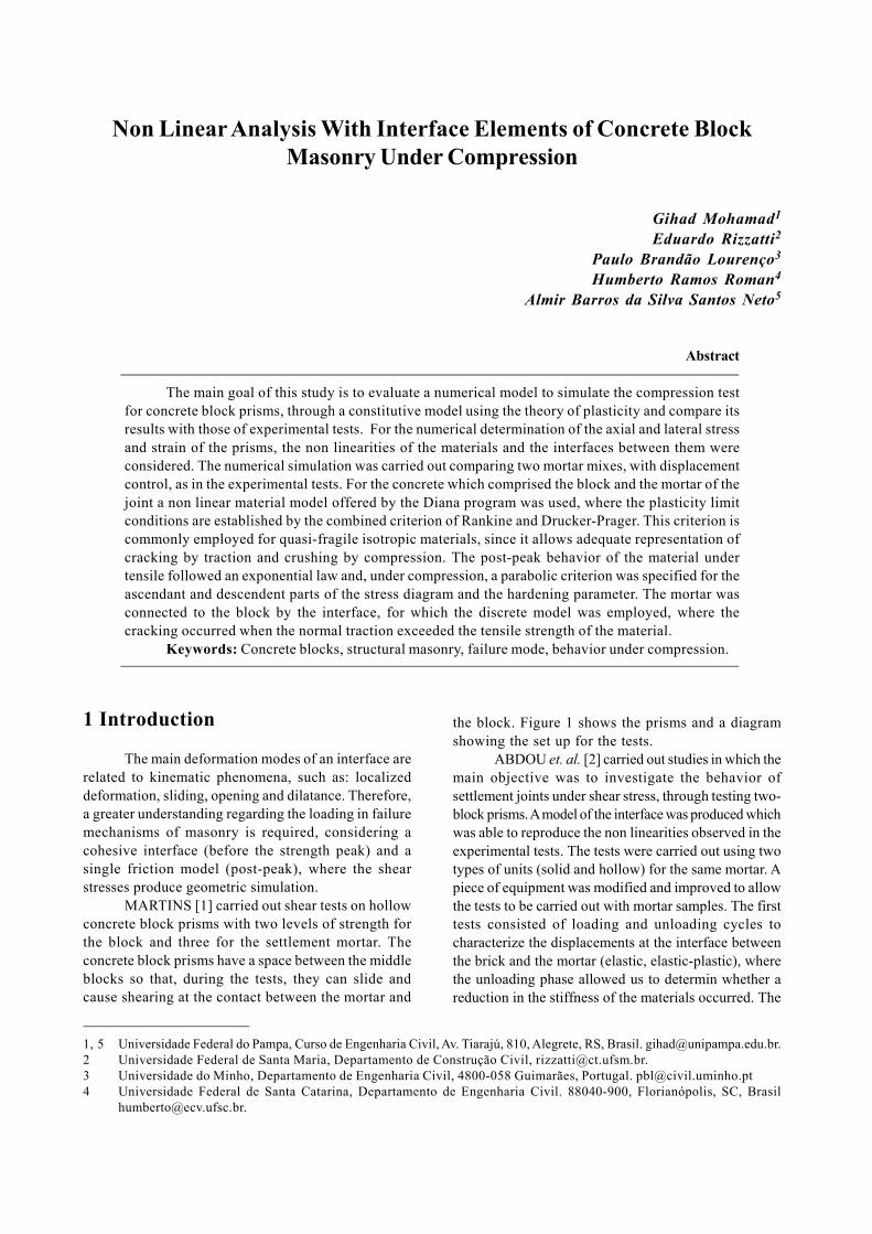
MARTINS [1] carried out shear tests on hollowconcrete block prisms with two levels of strength forthe block and three for the settlement mortar. Theconcrete block prisms have a space between the middleblocks so that, during the tests, they can slide andcause shearing at the contact between the mortar and
the block. Figure 1 shows the prisms and a diagramshowing the set up for the tests.
ABDOU et. al. [2] carried out studies in which themain objective was to investigate the behavior ofsettlement joints under shear stress, through testing two-block prisms. A model of the interface was produced whichwas able to reproduce the non linearities observed in theexperimental tests. The tests were carried out using twotypes of units (solid and hollow) for the same mortar. Apiece of equipment was modified and improved to allowthe tests to be carried out with mortar samples. The firsttests consisted of loading and unloading cycles tocharacterize the displacements at the interface betweenthe brick and the mortar (elastic, elastic-plastic), wherethe unloading phase allowed us to determin whether areduction in the stiffness of the materials occurred. The
Gihad Mohamad, Eduardo Rizzatti, Paulo Brandão Lourenço, Humberto Ramos Roman, Almir Barros da Silva Santos Neto
Engenharia Estudo e Pesquisa. Santa Maria, v. 10 - n. 1 - p. 81-86 - jan./jun. 201082
tests also allowed the verification of a relation betweenan increase in vertical stress and the shear stress, as wellas whether the behavior of the interface changes withthe type of unit. The authors state that the failure modeof the masonry could occur in the brick (distributedcracks), in the mortar (crushing) or at the interfacebetween the two materials. At the brick-mortar interfacetwo failure modes are possible: failure by tensile (inducesan opening of the joint) and shearing (sliding betweenthe surfaces with friction). The values obtained in theexperimental tests are summarized in Table 1.
Table 1 – Proportion by volume of cement, limestoneand sand in the mortar mixes.
Brick Characteristics Last(Peak Values)
Solid Cohesion (MPa) c=1.58Friction Angle tan (ϕ)=1.01
Hollow Cohesion (MPa) c=1.27Friction Angle tan (ϕ)=1.01
GIAMBANCO & GATI [3] worked with a modelfor the cohesive interface of masonry blocks. Thissurface is bilinear, obeys the Coulomb Law and has atensile stress as a limit. The limit functions, obtainedin the stress space, are presented in Eqs. (1) and (2).
( ) ( )1 , . tan 0n n cφ σ β τ σ ϕ β= + − = (1)
( ) ( )2 , 0n sφ σ β σ β= − = (2)
where ϕ is the internal friction angle of the material,
s( β ) and c( β ) are the values for tensile strength and
cohesion, and β is an internal variable which quantifiesthe inelastic behavior.
2 Simulation of Non Linear Behaviorof Prisms
The adoption of the numerical model isgenerally based on the consideration that its resultsare deterministic and non probabilistic, that is, themechanical properties are taken as averages, withoutconsidering the variability. The aim of this study isto obtain a model able to simulate numerically theprism compression tests, through a constitutivemodel using the theory of plasticity. Figure 2 showsa diagram of a quadrangular mesh of elements witheight nodes, submitted to a plane state of stress,displacement restrictions and loadings using thenumerical model.
Figure 2 – Geometrical characteristics of theblock-mortar set.
The linear and non-linear mechanicalcharacteristics of the materials used in the simulationare shown in Table 2 and Table 3 ([4, 5 and 6]). Theywere simulated with only two mortar mixes since, inthe experimental results, no differences were observedin the strength and failure mode of the prisms
Figure 1 – Block prisms for the shear tests with and without lateral stress and a diagram of the test carriedout by Martins (2001).
Non Linear Analysis With Interface Elements of Concrete Block Masonry Under Compression
Engenharia Estudo e Pesquisa. Santa Maria, v. 10 - n. 1 - p. 81-86 - jan./jun. 2010 83
constructed with the mortar mixes II and III. Theexperimental results for the prisms were used, namedI-1, I-2, II-1 and II-2. The properties of the materialswere adjusted in each simulation. The mechanicalproperties of the mortars with mixes I and II wereestablished considering the stress state in which theywere found, that is, using as a reference the triaxialcompression strength envelopes, the increase in theelasticity modulus of the confined mortar (Ec) and thedecrease in the Poisson ratio (ν) due to the lateralconfinement [7].
Table 2 – Linear mechanical characteristics of thematerials.
Component Ec (MPa) ν kn ks(MPa/mm) (MPa/mm)
Block 16000 0.19 – –Mortar - I 18000 0.10 – –Mortar - II 14250 0.10 – –Interface – – 81 33
3 Numerical Results
3.1 Experimental results for type A prisms
The main objective of this simulation is toevaluate the axial and lateral deformability of blockprisms, resulting from a change in the mortar mix (mixesI and II). The values for the elasticity modulus andPoisson ratio of the mortar given in Table 2 wereobtained considering the increase in the axial and lateralstiffness due to confinement.
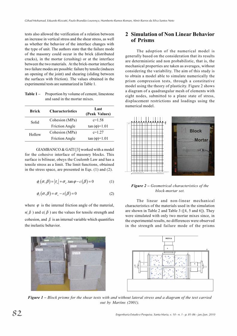
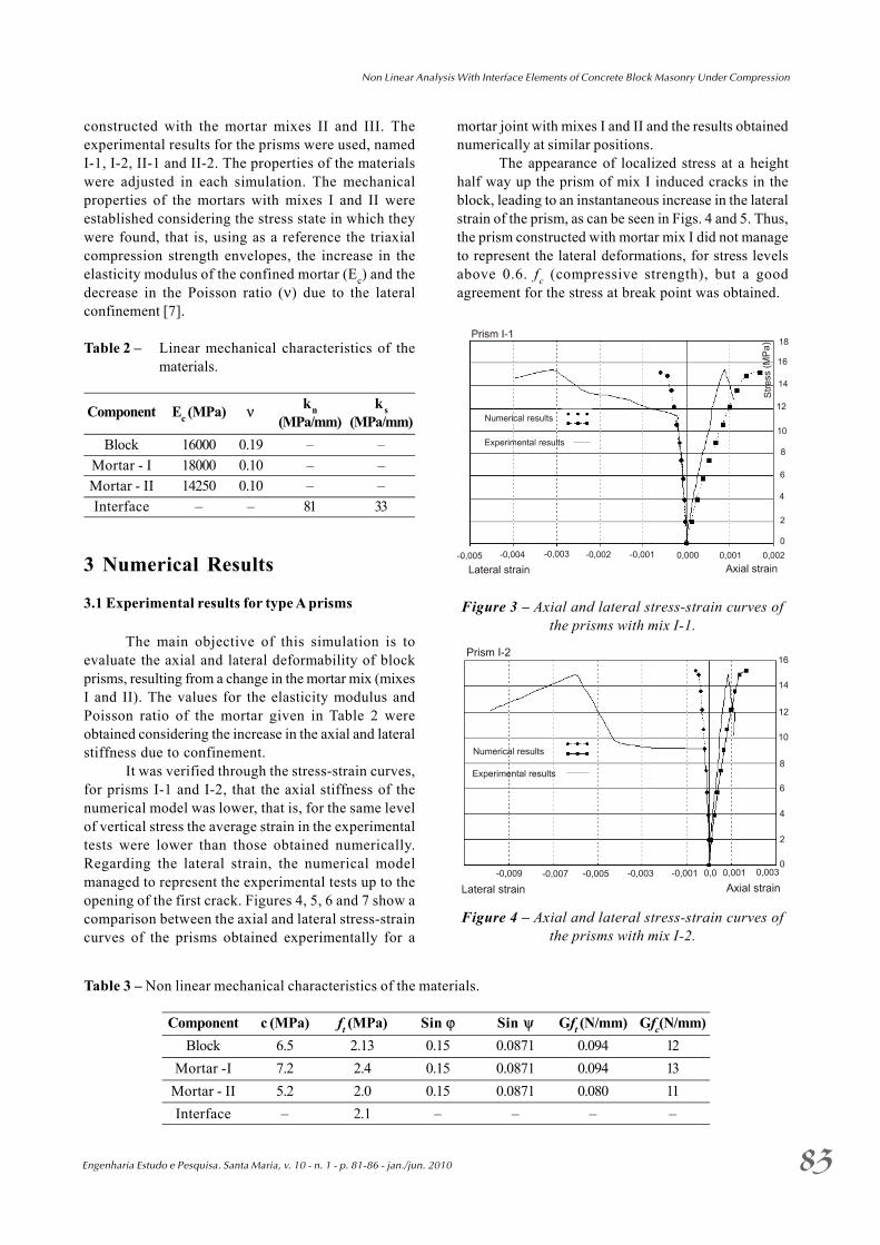
It was verified through the stress-strain curves,for prisms I-1 and I-2, that the axial stiffness of thenumerical model was lower, that is, for the same levelof vertical stress the average strain in the experimentaltests were lower than those obtained numerically.Regarding the lateral strain, the numerical modelmanaged to represent the experimental tests up to theopening of the first crack. Figures 4, 5, 6 and 7 show acomparison between the axial and lateral stress-straincurves of the prisms obtained experimentally for a
mortar joint with mixes I and II and the results obtainednumerically at similar positions.
The appearance of localized stress at a heighthalf way up the prism of mix I induced cracks in theblock, leading to an instantaneous increase in the lateralstrain of the prism, as can be seen in Figs. 4 and 5. Thus,the prism constructed with mortar mix I did not manageto represent the lateral deformations, for stress levelsabove 0.6. fc (compressive strength), but a goodagreement for the stress at break point was obtained.
Figure 3 – Axial and lateral stress-strain curves ofthe prisms with mix I-1.
Figure 4 – Axial and lateral stress-strain curves ofthe prisms with mix I-2.
Table 3 – Non linear mechanical characteristics of the materials.
Component c (MPa) ft (MPa) Sin ϕ Sin ψ Gft (N/mm) Gfc(N/mm)Block 6.5 2.13 0.15 0.0871 0.094 12
Mortar -I 7.2 2.4 0.15 0.0871 0.094 13Mortar - II 5.2 2.0 0.15 0.0871 0.080 11Interface – 2.1 – – – –
Gihad Mohamad, Eduardo Rizzatti, Paulo Brandão Lourenço, Humberto Ramos Roman, Almir Barros da Silva Santos Neto
Engenharia Estudo e Pesquisa. Santa Maria, v. 10 - n. 1 - p. 81-86 - jan./jun. 201084
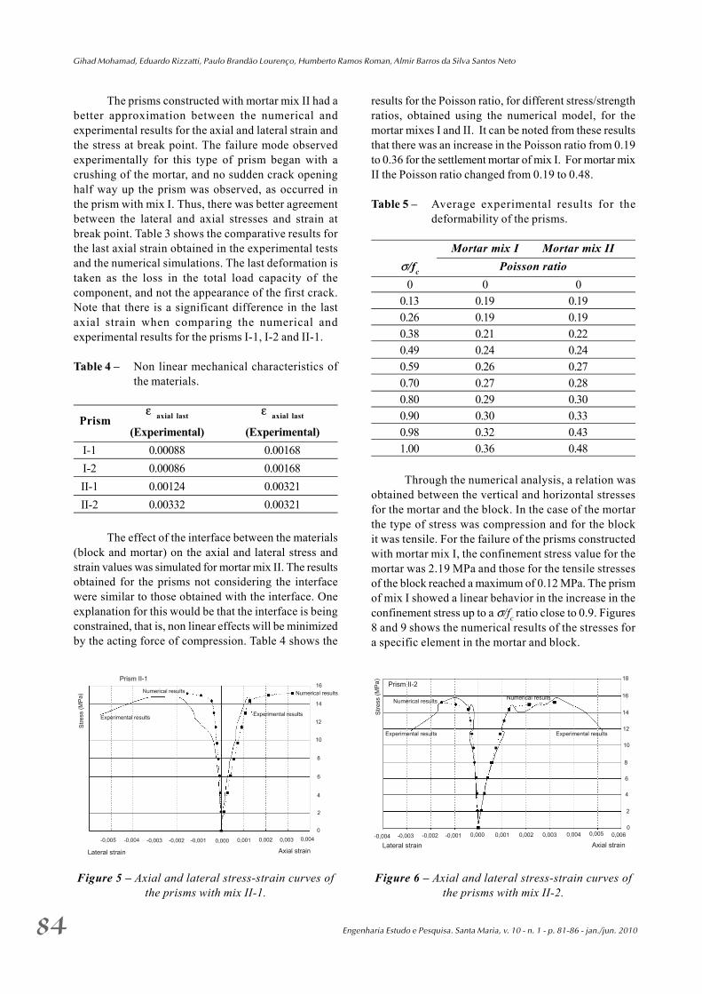
The prisms constructed with mortar mix II had abetter approximation between the numerical andexperimental results for the axial and lateral strain andthe stress at break point. The failure mode observedexperimentally for this type of prism began with acrushing of the mortar, and no sudden crack openinghalf way up the prism was observed, as occurred inthe prism with mix I. Thus, there was better agreementbetween the lateral and axial stresses and strain atbreak point. Table 3 shows the comparative results forthe last axial strain obtained in the experimental testsand the numerical simulations. The last deformation istaken as the loss in the total load capacity of thecomponent, and not the appearance of the first crack.Note that there is a significant difference in the lastaxial strain when comparing the numerical andexperimental results for the prisms I-1, I-2 and II-1.
Table 4 – Non linear mechanical characteristics ofthe materials.
Prismε axial last ε axial last
(Experimental) (Experimental) I-1 0.00088 0.00168 I-2 0.00086 0.00168 II-1 0.00124 0.00321 II-2 0.00332 0.00321
The effect of the interface between the materials(block and mortar) on the axial and lateral stress andstrain values was simulated for mortar mix II. The resultsobtained for the prisms not considering the interfacewere similar to those obtained with the interface. Oneexplanation for this would be that the interface is beingconstrained, that is, non linear effects will be minimizedby the acting force of compression. Table 4 shows the
results for the Poisson ratio, for different stress/strengthratios, obtained using the numerical model, for themortar mixes I and II. It can be noted from these resultsthat there was an increase in the Poisson ratio from 0.19to 0.36 for the settlement mortar of mix I. For mortar mixII the Poisson ratio changed from 0.19 to 0.48.
Table 5 – Average experimental results for thedeformability of the prisms.
Mortar mix I Mortar mix IIσ/fc Poisson ratio
0 0 00.13 0.19 0.190.26 0.19 0.190.38 0.21 0.220.49 0.24 0.240.59 0.26 0.270.70 0.27 0.280.80 0.29 0.300.90 0.30 0.330.98 0.32 0.431.00 0.36 0.48
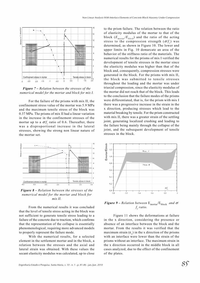
Through the numerical analysis, a relation wasobtained between the vertical and horizontal stressesfor the mortar and the block. In the case of the mortarthe type of stress was compression and for the blockit was tensile. For the failure of the prisms constructedwith mortar mix I, the confinement stress value for themortar was 2.19 MPa and those for the tensile stressesof the block reached a maximum of 0.12 MPa. The prismof mix I showed a linear behavior in the increase in theconfinement stress up to a σ/fc ratio close to 0.9. Figures8 and 9 shows the numerical results of the stresses fora specific element in the mortar and block.
Figure 5 – Axial and lateral stress-strain curves ofthe prisms with mix II-1.
Figure 6 – Axial and lateral stress-strain curves ofthe prisms with mix II-2.
Non Linear Analysis With Interface Elements of Concrete Block Masonry Under Compression
Engenharia Estudo e Pesquisa. Santa Maria, v. 10 - n. 1 - p. 81-86 - jan./jun. 2010 85
Figure 7 – Relation between the stresses of thenumerical model for the mortar and block for mix I.
For the failure of the prisms with mix II, theconfinement stress value of the mortar was 5.9 MPaand the maximum tensile stress of the block was0.37 MPa. The prisms of mix II had a linear variationin the increase in the confinement stresses of themortar up to a σ/fc ratio of 0.6. Thereafter, therewas a disproport ional increase in the lateralstresses, showing the strong non linear nature ofthe mortar set.
Figure 8 – Relation between the stresses of thenumerical model for the mortar and block for
mix II.
From the numerical results it was concludedthat the level of tensile stress acting in the block wasnot sufficient to generate tensile stress leading to afailure of the concrete due to traction, which confirmsthat the representation of the collapse is essentiallyphenomenological, requiring more advanced modelsto properly represent the failure mode.
With the numerical results, for a selectedelement in the settlement mortar and in the block, arelation between the stresses and the axial andlateral strain was obtained. With these values thesecant elasticity modulus was calculated, up to close
to the prism failure. The relation between the ratioof elasticity modulus of the mortar to that of theblock (Emortar/Eblock) and the ratio of the actingstress to the compression strength (σ / f c) wasdetermined, as shown in Figure 10. The lower andupper limits in Fig. 10 demarcate an area of thebehavior of the stiffness ratio of the materials. Thenumerical results for the prisms of mix I verified thedevelopment of tensile stresses in the mortar sincethe elasticity modulus was higher than that of theblock and, consequently, compression stresses weregenerated in the block. For the prisms with mix II,the b lock was submit ted to tens i le s t ressesthroughout the loading and the mortar was undertriaxial compression, since the elasticity modulus ofthe mortar did not reach that of the block. This leadsto the conclusion that the failure modes of the prismswere differentiated, that is, for the prism with mix Ithere was a progressive increase in the strain in thex direction, producing stresses which lead to thematerial breaking by tensile. For the prism constructedwith mix II, there was a greater strain of the settlingjoint, generating localized crushing and leading tothe failure being mainly through the collapse of thejoint, and the subsequent development of tensilestresses in the block.
Figure 9 – Relation between Emortar/Eblock and σ/fc ratio.
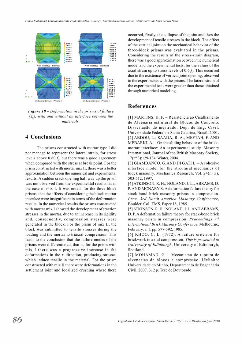
Figure 11 shows the deformations at failurein the x direction, considering the presence orabsence of an interface between the block and themortar. From the results it was verified that themaximum strain (εx) in the x direction of the prismswith an interface were lower than the strain of theprisms without an interface. The maximum strain inthe x direction occurred in the middle block in allcases analyzed, due to the effect of the confinementof the plates.
Gihad Mohamad, Eduardo Rizzatti, Paulo Brandão Lourenço, Humberto Ramos Roman, Almir Barros da Silva Santos Neto
Engenharia Estudo e Pesquisa. Santa Maria, v. 10 - n. 1 - p. 81-86 - jan./jun. 201086
Figure 10 – Deformation in the prisms at failure(εx), with and without an interface between the
materials.
4 Conclusions
The prisms constructed with mortar type I didnot manage to represent the lateral strain, for stresslevels above 0.60.fc, but there was a good agreementwhen compared with the stress at break point. For theprism constructed with mortar mix II, there was a betterapproximation between the numerical and experimentalresults. A sudden crack opening half way up the prismwas not observed from the experimental results, as inthe case of mix I. It was noted, for the three-blockprisms, that the effects of considering the block-mortarinterface were insignificant in terms of the deformationresults. In the numerical results the prisms constructedwith mortar mix I showed the development of tractionstresses in the mortar, due to an increase in its rigidityand, consequently, compression stresses weregenerated in the block. For the prism of mix II, theblock was submitted to tensile stresses during theloading and the mortar to triaxial compression. Thisleads to the conclusion that the failure modes of theprisms were differentiated, that is, for the prism withmix I there was a progressive increase in thedeformations in the x direction, producing stresseswhich induce tensile in the material. For the prismconstructed with mix II there were deformations in thesettlement joint and localized crushing where there
occurred, firstly, the collapse of the joint and then thedevelopment of tensile stresses in the block. The effectof the vertical joint on the mechanical behavior of thethree-block prisms was evaluated in the prisms.Considering the results of the stress-strain diagram,there was a good approximation between the numericalmodel and the experimental tests, for the values of theaxial strain up to stress levels of 0.6.fc. This occurreddue to the existence of vertical joint opening, observedin the experiments with the prisms. The lateral strain ofthe experimental tests were greater than those obtainedthrough numerical modeling.
References
[1] MARTINS, H. F. – Resistência ao Cisalhamentode Alvenaria estrutural de Blocos de Concreto.Dissertação de mestrado. Dep. de Eng. Civil.Universidade Federal de Santa Catarina, Brasil, 2001.[2] ABDOU, L.; SAADA, R. A., MEFTAH, F. ANDMEBARKI, A. – On the sliding behavior of the brick-mortar interface: An experimental study. MasonryInternational, Journal of the British Masonry Society,17(no 3):129-134, Winter, 2004.[3] GIAMBANCO, G. AND DI GATI L. – A cohesiveinterface model for the strcutural mechanics ofblock masonry. Mechanics Research. Vol. 24(no 5),503-512, 1997.[4] ATKINSON, R. H.; NOLAND, J. L., ABRAMS, D.P. AND MCNARY S. A deformation failure theory forstack-bond brick masonry prisms in compression.Proc. 3rd North America Masonry Conference,Boulder, Col.,TMS, Paper 18, 1985.[5] ATKINSON, R. H.; NOLAND, J. L. AND ABRAMS,D. P. A deformation failure theory for stack-bond brickmasonry prism in compression. Proceedings 7th
International Brick Masonry Conference, Melbourne,February, v. 1, pp. 577-592, 1985.[6] KHOO, C. L. (1972). A failure criterion forbrickwork in axial compression. Thesis presented toUniversity of Edinburgh, University of Edinburgh,Scotland.[7] MOHAMAD, G. – Mecanismo de ruptura dealvenarias de blocos a compressão. UMinho:Universidade do Minho, Departamento de EngenhariaCivil, 2007. 312 p. Tese de Doutorado.
With interface - Prisma I With interface - Prisma II
Without interface - Prisma I Without interface - Prisma II