Embed Size (px)
Citation preview
White paper
2020: Beyond 4GRadio Evolution for the Gigabit Experience
Contents
3 Mobile networks face a decade of change
4 Continued global effort will be vital 5 State of the art LTE-Advanced
6 Significant potential for further Radio Evolution
9 Beyond 4G: The technical cornerstones 13 Techno-Economical aspects
14 Worldwide collaboration on standardization
14 Nokia Siemens Networks research leads the way 15 Conclusion: Delivering the gigabit experience
2 Beyond 4G
Maintaining the pace of radio access evolution This White Paper describes how the underlying radio access technologies will develop further by another factor of 100 over the next 10 years, ensuring that there is no slowdown in the evolution of radio capabilities. Nokia Siemens Networks is actively engaged in collecting requirements and viewpoints as well as shaping this development. We are researching advanced radio network solutions to support up to 1000 times higher traffic volumes compared to 2010 traffic levels.
Welcome to the next evolutionary stage of the mobile experience – Beyond 4G.
Executive summary
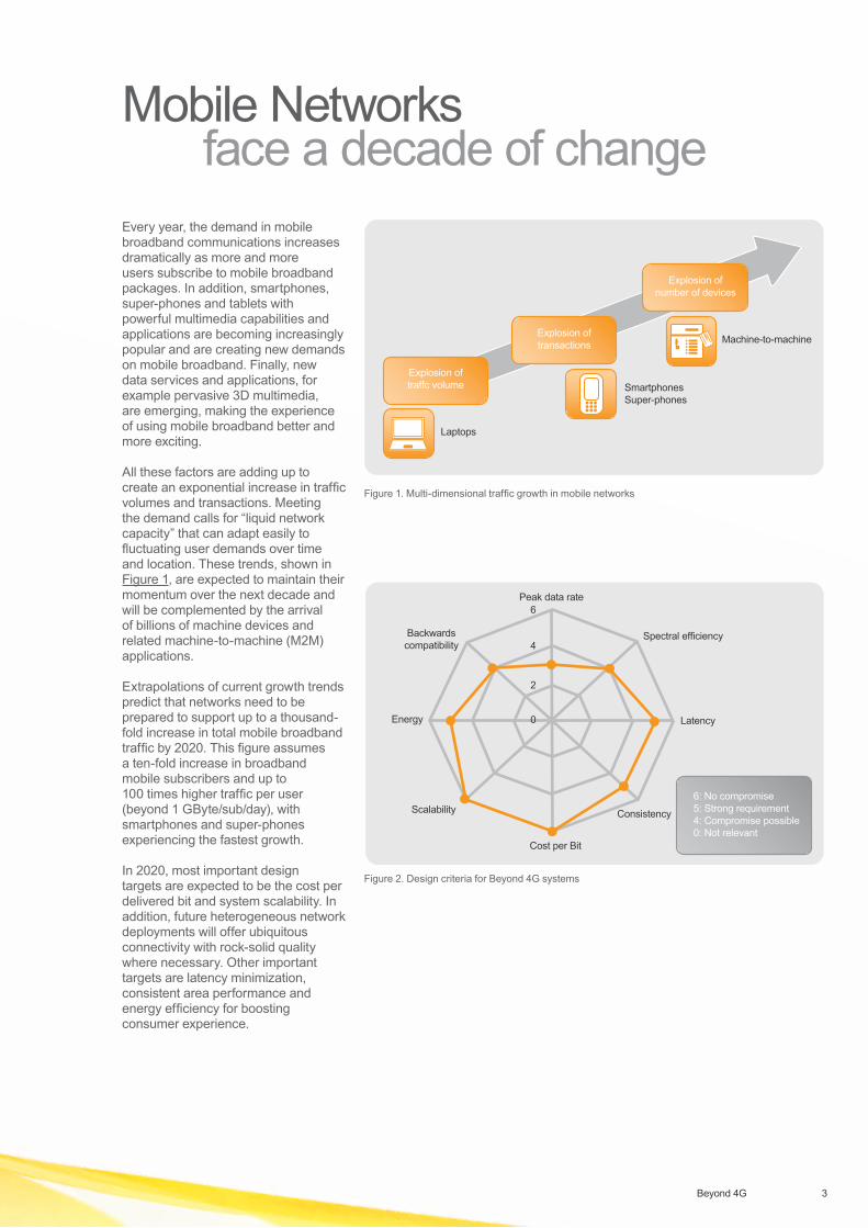
Every year, the demand in mobile broadband communications increases dramatically as more and more users subscribe to mobile broadband packages. In addition, smartphones, super-phones and tablets with powerful multimedia capabilities and applications are becoming increasingly popular and are creating new demands on mobile broadband. Finally, new data services and applications, for example pervasive 3D multimedia, are emerging, making the experience of using mobile broadband better and more exciting.
All these factors are adding up to create an exponential increase in traffic volumes and transactions. Meeting the demand calls for “liquid network capacity” that can adapt easily to fluctuating user demands over time and location. These trends, shown in Figure 1, are expected to maintain their momentum over the next decade and will be complemented by the arrival of billions of machine devices and related machine-to-machine (M2M) applications.
Extrapolations of current growth trends predict that networks need to be prepared to support up to a thousand-fold increase in total mobile broadband traffic by 2020. This figure assumes a ten-fold increase in broadband mobile subscribers and up to 100 times higher traffic per user (beyond 1 GByte/sub/day), with smartphones and super-phones experiencing the fastest growth.
In 2020, most important design targets are expected to be the cost per delivered bit and system scalability. In addition, future heterogeneous network deployments will offer ubiquitous connectivity with rock-solid quality where necessary. Other important targets are latency minimization, consistent area performance and energy efficiency for boosting consumer experience.
Mobile Networks face a decade of change
3Beyond 4G
Release 5
2100 MHz
2100 MHz
2100 MHz
Handoversbetween
LTE and HSPA
Passive RAN/ sitebased sharing
Active RAN sharing
Passive RAN/ sitebased sharing Roaming based sharingActive RAN sharing
Roaming based sharing
MOBSS for GSM (dedicated frequencies)MOCN for GSM (Shared spectrum)
MORAN for (I-) HSPA (dedicated frequencies)MOCN for (I-) HSPA (Shared spectrum)
MOCN for LTE (Shared spectrum)
HLR MSS/SGSN/GGSN/SAE/MME
Core Network and OSS
BSC/RNC
MOBSS/MOCN for GSMMORAN/MOCN for 3G
GSM/3G/LTE
Radio Access Network
MOCN for LTE
Purple indicates shared infrastructure CSP A CSP B
Shared RAN with MOCN
MOCN enables sharing a 1+1+1 site for up to 4 CSPsMOCN-UE selects CSP autonomouslyLegacy UE is routed by RNC algorithm
F1 (CSP A & B)
In MORAN, each CSP keeps own cellsSpectrum is not sharedMore independence but minimum base station configis 2 frequencies, eg 2+2+2
F1, CSP A
Shared RAN with MORAN
F2, CSP B
CSP A
CSP B
F (CSP A & B)20 MHz MME/SAE GW
MME/SAE GW
Shared RAN with MOCN
Explosion oftraffc volume
Explosion oftransactions
Explosion ofnumber of devices
Laptops
SmartphonesSuper-phones
Machine-to-machine
Figure 1. Multi-dimensional traffic growth in mobile networks
Release 5
2100 MHz
2100 MHz
2100 MHz
Handoversbetween
LTE and HSPA
Passive RAN/ sitebased sharing
Active RAN sharing
Passive RAN/ sitebased sharing Roaming based sharingActive RAN sharing
Roaming based sharing
MOBSS for GSM (dedicated frequencies)MOCN for GSM (Shared spectrum)
MORAN for (I-) HSPA (dedicated frequencies)MOCN for (I-) HSPA (Shared spectrum)
MOCN for LTE (Shared spectrum)
HLR MSS/SGSN/GGSN/SAE/MME
Core Network and OSS
BSC/RNC
MOBSS/MOCN for GSMMORAN/MOCN for 3G
GSM/3G/LTE
Radio Access Network
MOCN for LTE
Purple indicates shared infrastructure CSP A CSP B
Shared RAN with MOCN
MOCN enables sharing a 1+1+1 site for up to 4 CSPsMOCN-UE selects CSP autonomouslyLegacy UE is routed by RNC algorithm
F1 (CSP A & B)
In MORAN, each CSP keeps own cellsSpectrum is not sharedMore independence but minimum base station configis 2 frequencies, eg 2+2+2
F1, CSP A
Shared RAN with MORAN
F2, CSP B
CSP A
CSP B
F (CSP A & B)20 MHz MME/SAE GW
MME/SAE GW
Shared RAN with MOCN
Peak data rate
Cost per Bit
Latency
Spectral efficiency
Energy
Scalability
0
2
4
6
6: No compromise5: Strong requirement4: Compromise possible0: Not relevant
Consistency
Backwards compatibility
Figure 2. Design criteria for Beyond 4G systems
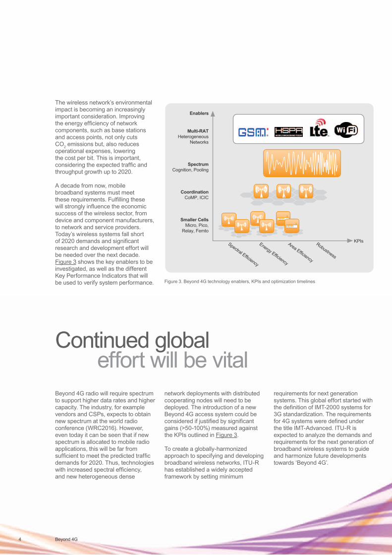
The wireless network’s environmental impact is becoming an increasingly important consideration. Improving the energy efficiency of network components, such as base stations and access points, not only cuts CO2 emissions but, also reduces operational expenses, lowering the cost per bit. This is important, considering the expected traffic and throughput growth up to 2020.
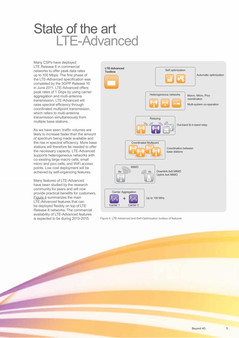
A decade from now, mobile broadband systems must meet these requirements. Fulfilling these will strongly influence the economic success of the wireless sector, from device and component manufacturers, to network and service providers. Today’s wireless systems fall short of 2020 demands and significant research and development effort will be needed over the next decade. Figure 3 shows the key enablers to be investigated, as well as the different Key Performance Indicators that will be used to verify system performance.
4 Beyond 4G
Continued global effort will be vitalBeyond 4G radio will require spectrum to support higher data rates and higher capacity. The industry, for example vendors and CSPs, expects to obtain new spectrum at the world radio conference (WRC2016). However, even today it can be seen that if new spectrum is allocated to mobile radio applications, this will be far from sufficient to meet the predicted traffic demands for 2020. Thus, technologies with increased spectral efficiency, and new heterogeneous dense
network deployments with distributed cooperating nodes will need to be deployed. The introduction of a new Beyond 4G access system could be considered if justified by significant gains (>50-100%) measured against the KPIs outlined in Figure 3.
To create a globally-harmonized approach to specifying and developing broadband wireless networks, ITU-R has established a widely accepted framework by setting minimum
requirements for next generation systems. This global effort started with the definition of IMT-2000 systems for 3G standardization. The requirements for 4G systems were defined under the title IMT-Advanced. ITU-R is expected to analyze the demands and requirements for the next generation of broadband wireless systems to guide and harmonize future developments towards ‘Beyond 4G’.
Release 5
2100 MHz
2100 MHz
2100 MHz
Handoversbetween
LTE and HSPA
Passive RAN/ sitebased sharing
Active RAN sharing
Passive RAN/ sitebased sharing Roaming based sharingActive RAN sharing
Roaming based sharing
MOBSS for GSM (dedicated frequencies)MOCN for GSM (Shared spectrum)
MORAN for (I-) HSPA (dedicated frequencies)MOCN for (I-) HSPA (Shared spectrum)
MOCN for LTE (Shared spectrum)
HLR MSS/SGSN/GGSN/SAE/MME
Core Network and OSS
decade - Spectrum
months/y - Invest
min/h - SON
ms – RRM, Scheduling
Spectral Efficiency
Energy Efficiency
Area Efficiency
Robustness
BSC/RNC
MOBSS/MOCN for GSMMORAN/MOCN for 3G
GSM/3G/LTE
Radio Access Network
MOCN for LTE
Purple indicates shared infrastructure CSP A CSP B
Shared RAN with MOCN
MOCN enables sharing a 1+1+1 site for up to 4 CSPsMOCN-UE selects CSP autonomouslyLegacy UE is routed by RNC algorithm
F1 (CSP A & B)
In MORAN, each CSP keeps own cellsSpectrum is not sharedMore independence but minimum base station configis 2 frequencies, eg 2+2+2
F1, CSP A
Shared RAN with MORAN
F2, CSP B
CSP A
CSP B
F (CSP A & B)20 MHz MME/SAE GW
MME/SAE GW
Shared RAN with MOCN
6: No compromise5: Strong requirement4: Compromise possible0: Not relevant
KPIs
Multi-RATHeterogeneous
Networks
SpectrumCognition, Pooling
CoordinationCoMP, ICIC
Smaller CellsMicro, Pico,
Relay, Femto
Time
Enablers
Figure 3. Beyond 4G technology enablers, KPIs and optimization timelines
5Beyond 4G
Many CSPs have deployed LTE Release 8 in commercial networks to offer peak data rates up to 100 Mbps. The first phase of the LTE-Advanced specification was completed by the 3GPP Release 10 in June 2011. LTE-Advanced offers peak rates of 1 Gbps by using carrier aggregation and multi-antenna transmission. LTE-Advanced will raise spectral efficiency through coordinated multipoint transmission, which refers to multi-antenna transmission simultaneously from multiple base stations.
As we have seen, traffic volumes are likely to increase faster than the amount of spectrum being made available and the rise in spectral efficiency. More base stations will therefore be needed to offer the necessary capacity. LTE-Advanced supports heterogeneous networks with co-existing large macro cells, small micro and pico cells, and WiFi access points. Low cost deployment will be achieved by self-organizing features.
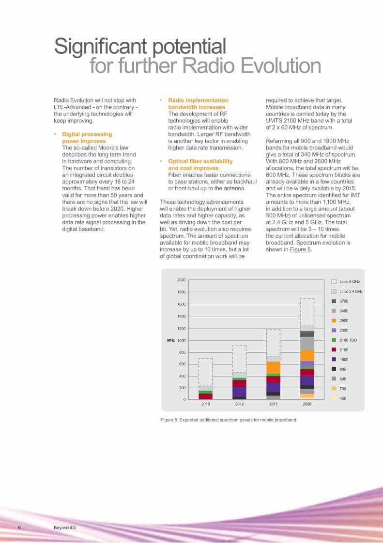
Many features of LTE-Advanced have been studied by the research community for years and will now provide practical benefits for customers. Figure 4 summarizes the mainLTE-Advanced features that can be deployed flexibly on top of LTE Release 8 networks. The commercial availability of LTE-Advanced features is expected to be during 2013-2015.
Automatic optimization
LTE-AdvancedToolbox Self optimization
Release 5
2100 MHz
2100 MHz
2100 MHz
Handoversbetween
LTE and HSPA
Passive RAN/ sitebased sharing
Active RAN sharing
Passive RAN/ sitebased sharing Roaming based sharingActive RAN sharing
Roaming based sharing
MOBSS for GSM (dedicated frequencies)MOCN for GSM (Shared spectrum)
MORAN for (I-) HSPA (dedicated frequencies)MOCN for (I-) HSPA (Shared spectrum)
MOCN for LTE (Shared spectrum)
HLR MSS/SGSN/GGSN/SAE/MME
Core Network and OSS
BSC/RNC
MOBSS/MOCN for GSMMORAN/MOCN for 3G
GSM/3G/LTE
Radio Access Network
MOCN for LTE
Purple indicates shared infrastructure CSP A CSP B
Shared RAN with MOCN
MOCN enables sharing a 1+1+1 site for up to 4 CSPsMOCN-UE selects CSP autonomouslyLegacy UE is routed by RNC algorithm
F1 (CSP A & B)
In MORAN, each CSP keeps own cellsSpectrum is not sharedMore independence but minimum base station configis 2 frequencies, eg 2+2+2
F1, CSP A
Shared RAN with MORAN
F2, CSP B
CSP A
CSP B
F (CSP A & B)20 MHz MME/SAE GW
MME/SAE GW
Shared RAN with MOCN
Out-band & in-band relay
Relaying
Downlink 8x8 MIMOUplink 4x4 MIMO
MIMO8x 4x
Up to 100 MHz
Carrier Aggregation
Carrier 1 Carrier 2
+
Macro, Micro, Pico coordination
Multi-system co-operation
Heterogeneous networks
Coordination between base stations
Coordinated Multipoint
Figure 4. LTE-Advanced and Self-Optimization toolbox of features
State of the art LTE-Advanced
Radio Evolution will not stop with LTE-Advanced - on the contrary - the underlying technologies will keep improving.
• Digital processing power improves The so-called Moore’s law
describes the long term trend in hardware and computing. The number of transistors on an integrated circuit doubles approximately every 18 to 24 months. That trend has been valid for more than 50 years and there are no signs that the law will break down before 2020. Higher processing power enables higher data rate signal processing in the digital baseband.
• Radio implementation bandwidth increases
The development of RF technologies will enable radio implementation with wider bandwidth. Larger RF bandwidth is another key factor in enabling higher data rate transmission.
• Optical fiber availabilityand cost improves
Fiber enables faster connections to base stations, either as backhaul or front-haul up to the antenna.
These technology advancements will enable the deployment of higher data rates and higher capacity, as well as driving down the cost per bit. Yet, radio evolution also requires spectrum. The amount of spectrum available for mobile broadband may increase by up to 10 times, but a lot of global coordination work will be
required to achieve that target. Mobile broadband data in many countries is carried today by the UMTS 2100 MHz band with a total of 2 x 60 MHz of spectrum.
Refarming all 900 and 1800 MHz bands for mobile broadband would give a total of 340 MHz of spectrum. With 800 MHz and 2600 MHz allocations, the total spectrum will be 600 MHz. These spectrum blocks are already available in a few countries and will be widely available by 2015. The entire spectrum identified for IMT amounts to more than 1,100 MHz, in addition to a large amount (about 500 MHz) of unlicensed spectrum at 2.4 GHz and 5 GHz. The total spectrum will be 3 – 10 times the current allocation for mobile broadband. Spectrum evolution is shown in Figure 5.
MHz
2000
1800
1600
1400
1200
1000
800
600
400
200
2010 2012 2015 2020
Unlic 5 GHz
Unlic 2.4 GHz
3700
3400
2600
2300
2100 TDD
2100
1800
900
800
700
4500
MHz
2000
1800
1600
1400
1200
1000
800
600
400
200
2010 2012 2015 2020
Unlic 5 GHz
Unlic 2.4 GHz
3700
3400
2600
2300
2100 TDD
2100
1800
900
800
700
4500
Figure 5. Expected additional spectrum assets for mobile broadband
6 Beyond 4G
Significant potential for further Radio Evolution
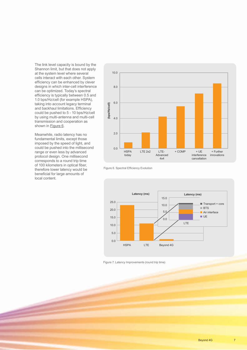
The link level capacity is bound by the Shannon limit, but that does not apply at the system level where several cells interact with each other. System efficiency can be enhanced by clever designs in which inter-cell interference can be optimized. Today’s spectral efficiency is typically between 0.5 and 1.0 bps/Hz/cell (for example HSPA), taking into account legacy terminal and backhaul limitations. Efficiency could be pushed to 5 - 10 bps/Hz/cell by using multi-antenna and multi-cell transmission and cooperation as shown in Figure 6.
Meanwhile, radio latency has no fundamental limits, except those imposed by the speed of light, and could be pushed into the millisecond range or even less by advanced protocol design. One millisecond corresponds to a round trip time of 100 kilometers in optical fiber, therefore lower latency would be beneficial for large amounts of local content.
7Beyond 4G
2100 MHz
2100 MHz
Handoversbetween
LTE and HSPA
2100 MHz
Latency (ms)
25.0
20.0
15.0
10.0
5.0
0.0HSPA LTE
Latency (ms)15.0
10.0
5.0
0.0LTE
Transport + coreBTSAir interfaceUE
Beyond 4G
Figure 7. Latency Improvements (round trip time)
2100 MHz
2100 MHz
Handoversbetween
LTE and HSPA
2100 MHz(b
ps/H
z/ce
ll) 6.0
8.0
10.0
4.0
2.0
0.0HSPA today
LTE 2x2 LTE-Advanced
4x4
+ COMP + UEinterference cancellation
+ Further innovations
10x
Spectral efficiency (bps/Hz/cell)
6.0
8.0
4.0
2.0
0.0HSPA today
LTE 2x2
LTE-Advanced
4x4
+ CoMP + UE interference cancellation
+ further innovations
10x
Figure 6. Spectral Efficiency Evolution
8 Beyond 4G
Release 5
2100 MHz
2100 MHz
2100 MHz
Handoversbetween
LTE and HSPA
Passive RAN/ sitebased sharing
Active RAN sharing
Passive RAN/ sitebased sharing Roaming based sharingActive RAN sharing
Roaming based sharing
MOBSS for GSM (dedicated frequencies)MOCN for GSM (Shared spectrum)
MORAN for (I-) HSPA (dedicated frequencies)MOCN for (I-) HSPA (Shared spectrum)
MOCN for LTE (Shared spectrum)
HLR MSS/SGSN/GGSN/SAE/MME
Core Network and OSS
BSC/RNC
MOBSS/MOCN for GSMMORAN/MOCN for 3G
GSM/3G/LTE
Radio Access Network
MOCN for LTE
Purple indicates shared infrastructure CSP A CSP B
Shared RAN with MOCN
MOCN enables sharing a 1+1+1 site for up to 4 CSPsMOCN-UE selects CSP autonomouslyLegacy UE is routed by RNC algorithm
F1 (CSP A & B)
In MORAN, each CSP keeps own cellsSpectrum is not sharedMore independence but minimum base station configis 2 frequencies, eg 2+2+2
F1, CSP A
Shared RAN with MORAN
F2, CSP B
CSP A
CSP B
F (CSP A & B)20 MHz MME/SAE GW
MME/SAE GW
Shared RAN with MOCN
Explosion of traffc volume
Explosion of transactions
Explosion of number of devices
SmartphonesSuperphones
Machine-to-machine
5 Mio
2010 2020
50 Mio
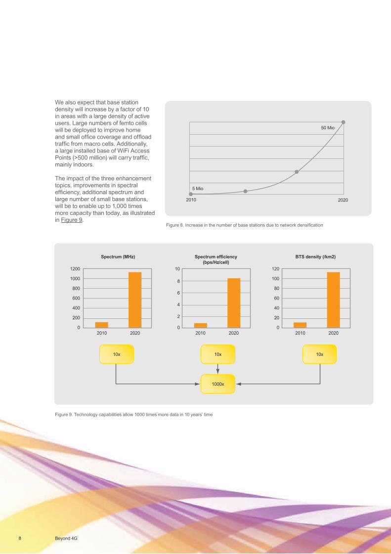
Figure 8. Increase in the number of base stations due to network densification
Figure 9. Technology capabilities allow 1000 times more data in 10 years’ time
2100 MHz
2100 MHz
Handoversbetween
LTE and HSPA
2100 MHz
OPEX OPEX savings
34% CAPEX Savings 85,9m EUR(Over 6 years)
0
20
40
60
80
100
120
CAPEX CAPEX savings
Rad
io
Cor
e
OSS
Site
Con
stru
ctio
n
I&C
Spar
es
Mic
row
ave
46% OPEX Savings 186,7 Mio EUR(Over 6 years)
0,0
50,0
100,0
150,0
200,0
Fiel
d Se
rvic
e
Softw
are
rele
ase
and
licen
se
Ener
gy
Site
Ren
tal
Back
haul
ing
Net
wor
k O
pera
tions
(NO
C)
Adm
inis
tratio
n &
Man
agem
ent
Equi
pmen
t & In
fra
mai
nten
ance
10x
1200
Spectrum (MHz) Spectrum efficiency(bps/Hz/cell)
BTS density (/km2)
1000
800
600
400
2010 2020 2010 2020 2010 2020
200
0
120
100
80
60
40
20
0
10
8
6
4
2
0
1000x
10x 10x10x
We also expect that base station density will increase by a factor of 10 in areas with a large density of active users. Large numbers of femto cells will be deployed to improve home and small office coverage and offload traffic from macro cells. Additionally, a large installed base of WiFi Access Points (>500 million) will carry traffic, mainly indoors.
The impact of the three enhancement topics, improvements in spectral efficiency, additional spectrum and large number of small base stations, will be to enable up to 1,000 times more capacity than today, as illustrated in Figure 9.
9Beyond 4G
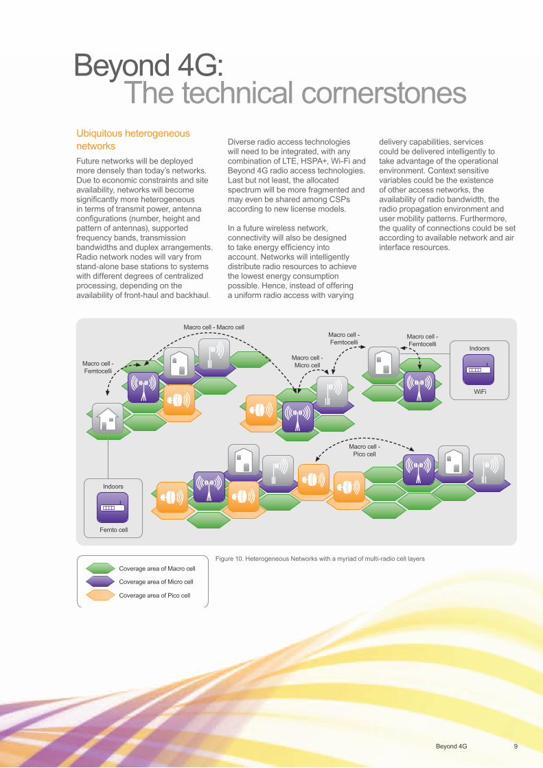
Ubiquitous heterogeneous networksFuture networks will be deployed more densely than today’s networks. Due to economic constraints and site availability, networks will become significantly more heterogeneous in terms of transmit power, antenna configurations (number, height and pattern of antennas), supported frequency bands, transmission bandwidths and duplex arrangements. Radio network nodes will vary from stand-alone base stations to systems with different degrees of centralized processing, depending on the availability of front-haul and backhaul.
Diverse radio access technologies will need to be integrated, with any combination of LTE, HSPA+, Wi-Fi and Beyond 4G radio access technologies. Last but not least, the allocated spectrum will be more fragmented and may even be shared among CSPs according to new license models.
In a future wireless network, connectivity will also be designed to take energy efficiency into account. Networks will intelligently distribute radio resources to achieve the lowest energy consumption possible. Hence, instead of offering a uniform radio access with varying
delivery capabilities, services could be delivered intelligently to take advantage of the operational environment. Context sensitive variables could be the existence of other access networks, the availability of radio bandwidth, the radio propagation environment and user mobility patterns. Furthermore, the quality of connections could be set according to available network and air interface resources.
Beyond 4G: The technical cornerstones
Release 5
2100 MHz
2100 MHz
2100 MHz
Handoversbetween
LTE and HSPA
Passive RAN/ sitebased sharing
Active RAN sharing
Passive RAN/ sitebased sharing Roaming based sharingActive RAN sharing
Roaming based sharing
MOBSS for GSM (dedicated frequencies)MOCN for GSM (Shared spectrum)
MORAN for (I-) HSPA (dedicated frequencies)MOCN for (I-) HSPA (Shared spectrum)
MOCN for LTE (Shared spectrum)
HLR MSS/SGSN/GGSN/SAE/MME
Core Network and OSS
BSC/RNC
MOBSS/MOCN for GSMMORAN/MOCN for 3G
GSM/3G/LTE
Radio Access Network
MOCN for LTE
Purple indicates shared infrastructure CSP A CSP B
Shared RAN with MOCN
MOCN enables sharing a 1+1+1 site for up to 4 CSPsMOCN-UE selects CSP autonomouslyLegacy UE is routed by RNC algorithm
F1 (CSP A & B)
In MORAN, each CSP keeps own cellsSpectrum is not sharedMore independence but minimum base station configis 2 frequencies, eg 2+2+2
F1, CSP A
Shared RAN with MORAN
F2, CSP B
CSP A
CSP B
F (CSP A & B)20 MHz MME/SAE GW
MME/SAE GW
Shared RAN with MOCN
Indoors
Coverage area of Macro cell
Macro cell - Femtocelli
Macro cell - Femtocelli
Macro cell - Femtocelli
Macro cell - Pico cell
Macro cell - Macro cell
Macro cell - Micro cell
Coverage area of Micro cell
Coverage area of Pico cell
Femto cell
Indoors
WiFi
Figure 10. Heterogeneous Networks with a myriad of multi-radio cell layers
10 Beyond 4G
Extreme automation by self-organization and cognitionThe management of heterogeneous networks needs to be fundamentally redesigned for simplicity and efficiency. This calls for coordinated dimensioning of quantitative parameters, the ratio between large and small cells, form factors, multi-vendor domains and backhaul options. The exploitation of cloud technologies, virtualization, resource pooling and increased degrees of coordination are key technologies to reduce the cost of transmission sites for antenna clusters.
The dilemma in radio network management is the balance between centralized and distributed control. In future, the increasing number of small cells with fiber backhaul will drive the need for locally centralized small cell clusters capable of global optimization.
Future networks will be populated with various kinds of devices with wireless access. Some devices will need high bandwidth (HDTV or 3D video streaming/download), some will have stringent latency requirements (VoIP or gaming), while others will need a maximized robustness and reliability (e-Health, Car2x Communication). Moreover, a much greater variety of devices, M2M, notebooks and smartphones will demand network flexibility. A vital future technology is Cognitive Radio Networks (CRN) - the next evolution of Self-Organizing Networks (SON). CRN will enable flexible spectrum management, device-to-device networking and wideband software-defined radio.
The air interface
The air interface is the foundation of all wireless communication infrastructures. The properties and interoperability of different air-interfaces, physical layer, protocol layer, retransmission, critically affect the QoS, spectral efficiency, energy efficiency, robustness and flexibility of the entire radio system. The evolution of the air interface will be driven by small cell dominated architectures. Consequently, relevant aspects, such as propagation and interference conditions need to be developed carefully.
The LTE air interface is optimized for the wide area environment where the transmit power difference between the device and base station is relatively large (up to 25 dB). Consequently, both the modulation scheme (SC-FDMA vs. OFDMA) and the physical channel structure differ significantly between the uplink (UL) and downlink (DL). The UL has been designed to maximize the link budget for control and data channels.
For example, given the similar uplink and downlink transmit powers and limited coverage area required for indoor access points, maximizing the similarities between UL and DL is sensible. Similar multiple access schemes could be used in both directions, simplifying system design and hardware implementation and providing better support for D2D communications. Thus, a similar air interface in UL and DL would enable new use cases and gain mechanisms, especially in the TDD mode, which is
one of the focus areas for the Beyond 4G air interface studies.
SC-FDMA used in the LTE uplink maximizes coverage by maintaining a low peak to average power ratio to support efficient power amplifiers in devices. However, there is room for further coverage and/or power efficiency enhancements, for example high UL bandwidths (100 MHz) and carrier aggregation.
User plane latency is the measure of the end-to-end performance of many applications. The minimum round trip time (RTT) of LTE is around 10 ms (Figure 7). It is generally accepted that latency must decrease in line with the increase in data rates. Hence, an RTT of the order of 0.1 – 1 ms needs to be considered as the initial target for a Beyond 4G system. It is obvious that if the radio can provide very small latency (such as 0.1 ms), that is only beneficial for content that is very close to the point of use.
It is difficult to make major improvements in latency without impacting the air interface. The components of latency, such as frame structure, control signal timing, and HARQ, form the key building blocks of the air interface. Therefore, major improvements in U-plane latency imply considerable changes in the air interface. For example, an RTT requirement of 0.1 ms interprets to TTI lengths down to 10-25 μs. This cannot be achieved with the current LTE-Advanced OFDMA numerology, but requires a more versatile approach.
11Beyond 4G
The link performance in today’s mobile broadband systems is often limited by interference from other elements of the system. Relatively primitive means to suppress such interference at the receiver side have already been introduced in state-of-the-art wireless-communication systems (e.g. HSPA+ 3i receiver). However, the increasing level of computationally-intensive signal processing, even in hand-held terminals, opens up the possibility of more advanced methods of interference suppression/elimination.
An even more disruptive, but very challenging, technology step would be to extend current multi-antenna schemes, typically comprising just a few antenna ports at each node, to massive multi-antenna configurations. In an extreme case, this could consist of a myriad of cooperating antenna ports (for example in a much more distributed manner also known as “immersed radio”). Inter-cell interference cancellation and coordination can increase average data rates, but even better, these solutions can improve cell edge data rates.
Requirements for devicesIn the smartphones and super-phones of today, radio is only a small part of device capability. Enhanced user experience is central and CSPs advertise innovative plans for the services and applications that a phone can support. In essence, the major selling point in the new wireless device is no longer radio, but undeniably, ubiquitous radio access remains the essential backbone for supporting new applications and services.
The next generation wireless device will support a vast number of services with a powerful and complex communications engine. Radios in devices already support cellular, WiFi, GPS and Bluetooth. Additionally, international roaming requires devices to support a variety of radios/bands because globally available frequency bands are not consistent. As a result, the RF complexity in the device will increase drastically, requiring radios to support multiple bands and duplexing methods (FDD & TDD).
In future, the radios in the device will perform local radio resource management and assist with network resource management. Device support for carrier aggregation and heterogeneous networks could enable simultaneous communication over multiple radio access technologies. The wireless device may also be a gateway for a multitude of sensors and machine type devices. It will perform spectrum sensing for capturing and analyzing the radio environment.
The optimization of device power consumption is important in current devices and will remain a key factor in the future. Battery capacity improves very slowly compared to the evolution of other technologies.
12 Beyond 4G
2100 MHz
2100 MHz
Handoversbetween
LTE and HSPA
2100 MHz
Past (2010) Future (2020)
Large macro cells Wide scale small cell(heterogeneous) deployments
Limited backhaul capacity Fiber availability and new wirelessbackhaul solutions applied
Inter-cell interference limits capacity Fast interference coordinationand cancellation
Stationary network configurationand spectrum
Cognitive Radio Networks (CRN)Small cell configuration andoptimization is complex
Self Organizing Networks (SON)
Two branch antennas Multi-branch and multi-siteantenna transmission
Today Future (2020)
Large macro cells <10 BTS / km2 Wide scale small cell dense deployments >100 BTS / km2
Limited backhaul capacity <50 Mbps / BTS Abdundant Fiber and new wireless backhaul solutions
>5 Gbps / BTS
Inter-cell interference limits capacity Capacity 25% x peak rate Fast interference coordinationand cancellation
Capacity >50% xpeak rate
Stationary network configurationand spectrum
Fixed BTS parameters Flexible cognitive networks Dynamic BTSparameters
Network configuration andoptimization complex
>1000 EUR/BTS / year Self Organizing Networks <100 EUR/BTS/year
Two branch antennas 2...8 branches Immersed RadioMassive MIMO
Myriad of antennas
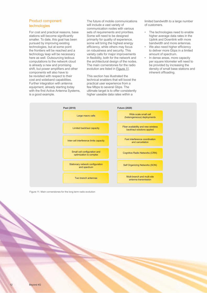
Figure 11. Main cornerstones for the long term radio evolution
Product component technologiesFor cost and practical reasons, base stations will become significantly smaller. To date, this goal has been pursued by improving existing technologies, but at some point the frontiers will be reached and a technology leap will be necessary here as well. Outsourcing tedious computations to the network cloud is already a new and promising shift, but power amplifiers and other components will also have to be revisited with respect to their cost and wideband capabilities. Further integration with antenna equipment, already starting today with the first Active Antenna Systems, is a good example.
The future of mobile communications will include a vast variety of communication nodes with various sets of requirements and priorities. Some will need to be designed primarily for quality of experience, some will bring the highest energy efficiency, while others may focus on robustness and security. This variety calls for major improvements in flexibility, both for the network and the architectural design of the nodes. The main cornerstones for the radio evolution are listed in Figure 11.
This section has illustrated the technical enablers that will boost the practical user experience from a few Mbps to several Gbps. The ultimate target is to offer consistently higher useable data rates within a
limited bandwidth to a large number of customers.
• The technologies need to enable higher average data rates in the Uplink and Downlink with more bandwidth and more antennas.
• We also need higher efficiency to deliver more Gbps in a limited amount of spectrum.
• In dense areas, more capacity per square kilometer will need to be provided by increasing the density of small base stations and inherent offloading.
13Beyond 4G
Figure 13. Techno-Economic balance
2100 MHz
2100 MHz
Handoversbetween
LTE and HSPA
2100 MHz
1200
Spectrum efficiency[bps/Hz/cell]
BTS density [/km2]
1000
800
600
400
2010 2020 2010 2020 2010 2020
200
0
1200
1000
800
600
400
200
0
10
8
6
4
2
0
1000x
10x 10x10x
1000x cost reduction: 10x BTS bandwidth 10x spectral efficiency 10x smaller BTS
Up to 1000xTraffic growth
Flat TCO
Flattish Revenue Growth
1000x capacity gain: 10x more BTS 10x spectral efficiency 10x spectrum
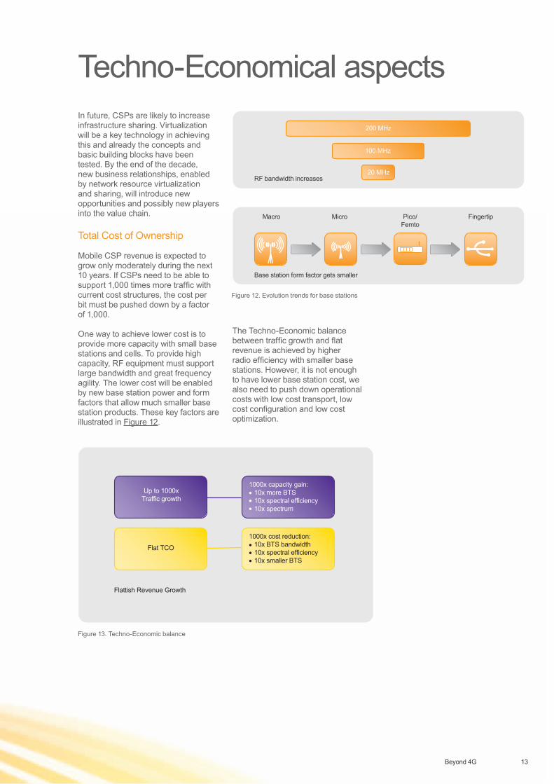
Techno-Economical aspectsIn future, CSPs are likely to increase infrastructure sharing. Virtualization will be a key technology in achieving this and already the concepts and basic building blocks have been tested. By the end of the decade, new business relationships, enabled by network resource virtualization and sharing, will introduce new opportunities and possibly new players into the value chain.
Total Cost of Ownership
Mobile CSP revenue is expected to grow only moderately during the next 10 years. If CSPs need to be able to support 1,000 times more traffic with current cost structures, the cost per bit must be pushed down by a factor of 1,000.
One way to achieve lower cost is to provide more capacity with small base stations and cells. To provide high capacity, RF equipment must support large bandwidth and great frequency agility. The lower cost will be enabled by new base station power and form factors that allow much smaller base station products. These key factors are illustrated in Figure 12.
The Techno-Economic balance between traffic growth and flat revenue is achieved by higher radio efficiency with smaller base stations. However, it is not enough to have lower base station cost, we also need to push down operational costs with low cost transport, low cost configuration and low cost optimization.
Figure 12. Evolution trends for base stations
Release 5
2100 MHz
2100 MHz
2100 MHz
Handoversbetween
LTE and HSPA
Passive RAN/ sitebased sharing
Active RAN sharing
Passive RAN/ sitebased sharing Roaming based sharingActive RAN sharing
Roaming based sharing
MOBSS for GSM (dedicated frequencies)MOCN for GSM (Shared spectrum)
MORAN for (I-) HSPA (dedicated frequencies)MOCN for (I-) HSPA (Shared spectrum)
MOCN for LTE (Shared spectrum)
HLR MSS/SGSN/GGSN/SAE/MME
Core Network and OSS
BSC/RNC
MOBSS/MOCN for GSMMORAN/MOCN for 3G
GSM/3G/LTE
Radio Access Network
MOCN for LTE
Purple indicates shared infrastructure CSP A CSP B
Shared RAN with MOCN
MOCN enables sharing a 1+1+1 site for up to 4 CSPsMOCN-UE selects CSP autonomouslyLegacy UE is routed by RNC algorithm
F1 (CSP A & B)
In MORAN, each CSP keeps own cellsSpectrum is not sharedMore independence but minimum base station configis 2 frequencies, eg 2+2+2
F1, CSP A
Shared RAN with MORAN
F2, CSP B
CSP A
CSP B
F (CSP A & B)20 MHz MME/SAE GW
MME/SAE GW
Shared RAN with MOCN
Macro Micro Pico/Femto
Fingertip
RF bandwidth increases
Base station form factor gets smaller
20 MHz
100 MHz
200 MHz
14 Beyond 4G
Consolidated efforts are necessary from all players in academia and industry to develop innovative technologies and deployment options that meet the demands of mobile broadband wireless in 2020. As well as the focus on evolutionary enhancements, the mid-term and long-term research must also identify possible technology leaps.
Nokia Siemens Networks conducts leading research activities in radio, with thousands of contributions to
the 3GPP LTE standard, numerous publications and books, collaboration in international research projects (WINNER+, SOCRATES, MEVICO and ARTIST4G), strategic cooperation with key universities, joint research work with leading CSPs, Smartlab activities with all leading smartphone vendors, and research teams in multiple continents. Nokia Siemens Networks emphasizes the importance of open standards and sharing research results in white papers, publications and books.
Nokia Siemens Networks research leads the way
It is likely that ITU-R will look into possible requirements for Beyond 4G systems, as well as preparing for WRC2016 to identify new spectrum for wireless communication.
Collaborative research projects, for example within the Framework Programs (e.g. FP7 and 8) of the European Union, will play an important role to share the Beyond 4G research workload among the main players in industry, academia and CSPs and lay the groundwork for subsequent standardization.
The 3GPP success stories of HSPA and LTE show that worldwide collaborative specification work among partners is the only way to achieve large economies of scale, therefore we expect that this community will play its role when the real specification work for Beyond 4G begins. We should not forget that existing 4G technologies will further evolve by adding new capabilities from ongoing research and specification work.
Worldwide collaboration on standardization
15Beyond 4G
2100 MHz
2100 MHz
Handoversbetween
LTE and HSPA
2100 MHz
1000x capacity gain:- 10x more BTS- 10x spectral efficiency- 10x spectrum
1000x cost reduction:- 10x BTS bandwidth- 10x spectral efficiency- 10x smaller BTS
Up to 1000xTraffic growth
Flat TCO
Flattish Revenue Growth
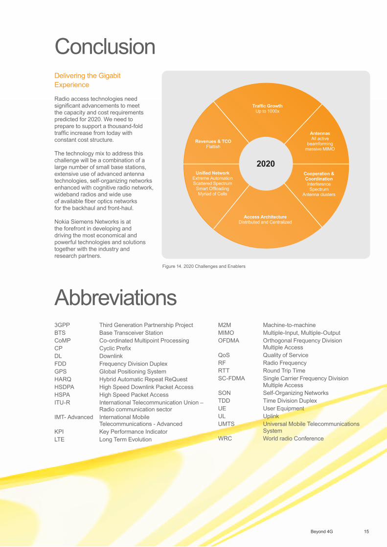
Traffic GrowthUp to 1000x
Revenues & TCOFlattish
Unified NetworkExtreme AutomationScattered Spectrum
Smart OffloadingMyriad of Cells
Cooperation &CoordinationInterferenceSpectrum
Antenna clusters
Access ArchitectureDistributed and Centralized
2020
AntennasAll active
beamformingmassive MIMO
Figure 14. 2020 Challenges and Enablers
Delivering the Gigabit Experience
Radio access technologies need significant advancements to meet the capacity and cost requirements predicted for 2020. We need to prepare to support a thousand-fold traffic increase from today with constant cost structure.
The technology mix to address this challenge will be a combination of a large number of small base stations, extensive use of advanced antenna technologies, self-organizing networks enhanced with cognitive radio network, wideband radios and wide use of available fiber optics networks for the backhaul and front-haul.
Nokia Siemens Networks is at the forefront in developing and driving the most economical and powerful technologies and solutions together with the industry and research partners.
Conclusion
Abbreviations3GPP Third Generation Partnership ProjectBTS Base Transceiver StationCoMP Co-ordinated Multipoint ProcessingCP Cyclic PrefixDL DownlinkFDD Frequency Division DuplexGPS Global Positioning SystemHARQ Hybrid Automatic Repeat ReQuestHSDPA High Speed Downlink Packet AccessHSPA High Speed Packet AccessITU-R International Telecommunication Union –
Radio communication sectorIMT- Advanced International Mobile
Telecommunications - AdvancedKPI Key Performance IndicatorLTE Long Term Evolution
M2M Machine-to-machineMIMO Multiple-Input, Multiple-OutputOFDMA Orthogonal Frequency Division
Multiple AccessQoS Quality of ServiceRF Radio FrequencyRTT Round Trip TimeSC-FDMA Single Carrier Frequency Division
Multiple AccessSON Self-Organizing NetworksTDD Time Division DuplexUE User EquipmentUL UplinkUMTS Universal Mobile Telecommunications
SystemWRC World radio Conference
Nokia Siemens Networks CorporationP.O. Box.1FI-020022 NOKIA SIEMENS NETWORKSFinland
Visiting addressKaraportti 3, ESPOO, Finland
Switchboard +358 71 400 4000
Product code: C401-00722-WP-201106-1-EN
Copyright © 2011 Nokia Siemens Networks.All rights reserved.
A license is hereby granted to download and print a copy of this document for personal use only. No other license to any other intellectual property rights is granted herein. Unless expressly permitted herein, reproduction, transfer, distribution or storage of part or all of the contents in any form without the prior written permission of Nokia Siemens Networks is prohibited.
The content of this document is provided “AS IS”, without warranties of any kind with regards its accuracy or reliability, and specifically excluding all implied warranties, for example of merchantability, fitness for purpose, title and non-infringement. In no event shall Nokia Siemens Networks be liable for any special, indirect or consequential damages, or any damages whatsoever resulting form loss of use, data or profits, arising out of or in connection with the use of the document. Nokia Siemens Networks reserves the right to revise the document or withdraw it at any time without prior notice.
Nokia is a registered trademark of Nokia Corporation, Siemens is a registered trademark of Siemens AG.The wave logo is a trademark of Nokia Siemens Networks Oy. Other company and product names mentioned in this document may be trademarks of their respective owners, and they are mentioned for identification purposes only.
www.nokiasiemensnetworks.com