Embed Size (px)
Citation preview
8/11/2019 NOKIA Flexi TRCM
http://slidepdf.com/reader/full/nokia-flexi-trcm 1/183
Nokia Siemens Networks Flexi
BSC, S14, Site Documentation
for TCSM3i, issue 06
Cabling Instructions for TCSM3i
DN0577759
Issue 3-0
8/11/2019 NOKIA Flexi TRCM
http://slidepdf.com/reader/full/nokia-flexi-trcm 2/183
2 DN0577759
Issue 3-0
Cabling Instructions for TCSM3i
Id:0900d8058061e151
The information in this document is subject to change without notice and describes only the
product defined in the introduction of this documentation. This documentation is intended for the
use of Nokia Siemens Networks customers only for the purposes of the agreement under whichthe document is submitted, and no part of it may be used, reproduced, modified or transmitted
in any form or means without the prior written permission of Nokia Siemens Networks. The
documentation has been prepared to be used by professional and properly trained personnel,
and the customer assumes full responsibility when using it. Nokia Siemens Networks welcomes
customer comments as part of the process of continuous development and improvement of the
documentation.
The information or statements given in this documentation concerning the suitability, capacity,
or performance of the mentioned hardware or software products are given "as is" and all liability
arising in connection with such hardware or software products shall be defined conclusively and
finally in a separate agreement between Nokia Siemens Networks and the customer. However,
Nokia Siemens Networks has made all reasonable efforts to ensure that the instructions
contained in the document are adequate and free of material errors and omissions. Nokia
Siemens Networks will, if deemed necessary by Nokia Siemens Networks, explain issues which
may not be covered by the document.
Nokia Siemens Networks will correct errors in this documentation as soon as possible. IN NO
EVENT WILL Nokia Siemens Networks BE LIABLE FOR ERRORS IN THIS DOCUMENTA-
TION OR FOR ANY DAMAGES, INCLUDING BUT NOT LIMITED TO SPECIAL, DIRECT, INDI-
RECT, INCIDENTAL OR CONSEQUENTIAL OR ANY LOSSES, SUCH AS BUT NOT LIMITED
TO LOSS OF PROFIT, REVENUE, BUSINESS INTERRUPTION, BUSINESS OPPORTUNITY
OR DATA,THAT MAY ARISE FROM THE USE OF THIS DOCUMENT OR THE INFORMATION
IN IT.
This documentation and the product it describes are considered protected by copyrights and
other intellectual property rights according to the applicable laws.
The wave logo is a trademark of Nokia Siemens Networks Oy. Nokia is a registered trademark
of Nokia Corporation. Siemens is a registered trademark of Siemens AG.
Other product names mentioned in this document may be trademarks of their respectiveowners, and they are mentioned for identification purposes only.
Copyright © Nokia Siemens Networks 2010/4/1. All rights reserved
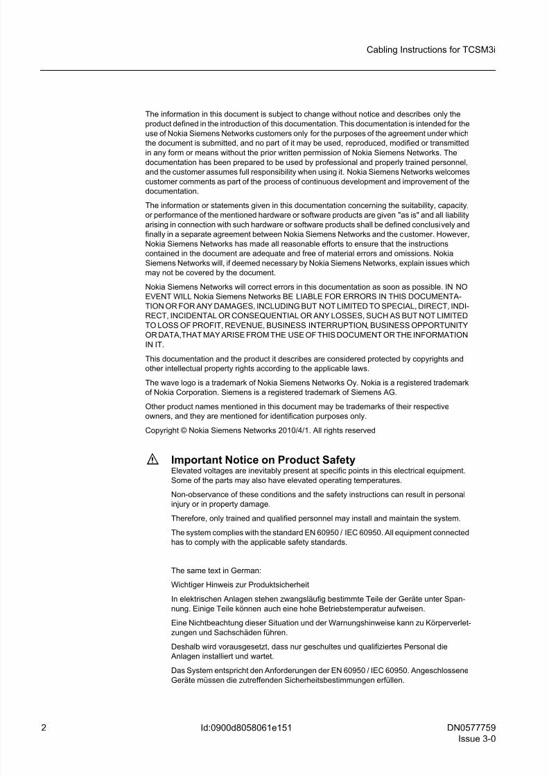
f Important Notice on Product SafetyElevated voltages are inevitably present at specific points in this electrical equipment.
Some of the parts may also have elevated operating temperatures.
Non-observance of these conditions and the safety instructions can result in personal
injury or in property damage.
Therefore, only trained and qualified personnel may install and maintain the system.
The system complies with the standard EN 60950 / IEC 60950. All equipment connected
has to comply with the applicable safety standards.
The same text in German:
Wichtiger Hinweis zur Produktsicherheit
In elektrischen Anlagen stehen zwangsläufig bestimmte Teile der Geräte unter Span-
nung. Einige Teile können auch eine hohe Betriebstemperatur aufweisen.
Eine Nichtbeachtung dieser Situation und der Warnungshinweise kann zu Körperverlet-
zungen und Sachschäden führen.
Deshalb wird vorausgesetzt, dass nur geschultes und qualifiziertes Personal die
Anlagen installiert und wartet.
Das System entspricht den Anforderungen der EN 60950 / IEC 60950. Angeschlossene
Geräte müssen die zutreffenden Sicherheitsbestimmungen erfüllen.
8/11/2019 NOKIA Flexi TRCM
http://slidepdf.com/reader/full/nokia-flexi-trcm 3/183
DN0577759
Issue 3-0
3
Cabling Instructions for TCSM3i
Id:0900d8058061e151
Table of ContentsThis document has 183 pages.
Summary of changes. . . . . . . . . . . . . . . . . . . . . . . . . . . . . . . . . . . . . . . 13
1 Overview of cabling instructions for TCSM3i. . . . . . . . . . . . . . . . . . . . . 14
2 Identifying cartridges, connectors, and cables. . . . . . . . . . . . . . . . . . . . 15
2.1 Numbering system of the cartridge shelves and cable connectors . . . . 15
2.1.1 2 mm hard metric cartridges . . . . . . . . . . . . . . . . . . . . . . . . . . . . . . . . . 15
2.1.2 Euroconnector cartridges. . . . . . . . . . . . . . . . . . . . . . . . . . . . . . . . . . . . 16
2.1.3 Locking pegs . . . . . . . . . . . . . . . . . . . . . . . . . . . . . . . . . . . . . . . . . . . . . 18
2.1.4 Cable Supporting Shelves CSS9 and CSS1 . . . . . . . . . . . . . . . . . . . . . 18
2.2 Categories of cables . . . . . . . . . . . . . . . . . . . . . . . . . . . . . . . . . . . . . . . 19
2.2.1 Interconnection cables. . . . . . . . . . . . . . . . . . . . . . . . . . . . . . . . . . . . . . 19
2.2.2 External cables . . . . . . . . . . . . . . . . . . . . . . . . . . . . . . . . . . . . . . . . . . . 20
2.3 Identifying cables. . . . . . . . . . . . . . . . . . . . . . . . . . . . . . . . . . . . . . . . . . 20
2.4 Cabling lists . . . . . . . . . . . . . . . . . . . . . . . . . . . . . . . . . . . . . . . . . . . . . . 22
3 Routing principles and securing cables . . . . . . . . . . . . . . . . . . . . . . . . . 25
3.1 General routing principles . . . . . . . . . . . . . . . . . . . . . . . . . . . . . . . . . . . 25
3.1.1 Intracabinet cables. . . . . . . . . . . . . . . . . . . . . . . . . . . . . . . . . . . . . . . . . 25
3.1.2 Intercabinet cables. . . . . . . . . . . . . . . . . . . . . . . . . . . . . . . . . . . . . . . . . 26
3.2 Securing the cables . . . . . . . . . . . . . . . . . . . . . . . . . . . . . . . . . . . . . . . . 27
4 Intracabinet cabling of TCSA cabinet. . . . . . . . . . . . . . . . . . . . . . . . . . . 29
4.1 Power supply cables . . . . . . . . . . . . . . . . . . . . . . . . . . . . . . . . . . . . . . . 29
4.2 Alarm, timing, and changeover (AL/CLK and AL and AL/CGS) cables . 30
4.3 Internal synchronisation cables . . . . . . . . . . . . . . . . . . . . . . . . . . . . . . . 32
4.4 PCM cables . . . . . . . . . . . . . . . . . . . . . . . . . . . . . . . . . . . . . . . . . . . . . . 33
4.5 External ET interface related cables . . . . . . . . . . . . . . . . . . . . . . . . . . . 35
5 S14 combined BSC/TCSM cabling of TCSA cabinet and BSC3i or upgrad-
ed Flexi BSC as BSC-part . . . . . . . . . . . . . . . . . . . . . . . . . . . . . . . . . . . 39
5.1 SBUS cables . . . . . . . . . . . . . . . . . . . . . . . . . . . . . . . . . . . . . . . . . . . . . 39
5.2 Timing bus cables . . . . . . . . . . . . . . . . . . . . . . . . . . . . . . . . . . . . . . . . . 43
5.3 Timing loop cables. . . . . . . . . . . . . . . . . . . . . . . . . . . . . . . . . . . . . . . . . 46
5.4 2N Compare test cables . . . . . . . . . . . . . . . . . . . . . . . . . . . . . . . . . . . . 47
5.5 Synchronisation signal cables . . . . . . . . . . . . . . . . . . . . . . . . . . . . . . . . 48
5.6 8M PCM cables . . . . . . . . . . . . . . . . . . . . . . . . . . . . . . . . . . . . . . . . . . . 52
5.6.1 8M control PCM cables . . . . . . . . . . . . . . . . . . . . . . . . . . . . . . . . . . . . . 53
5.6.2 8M Ater and A-interface cables . . . . . . . . . . . . . . . . . . . . . . . . . . . . . . . 56
5.7 Hotlink cables . . . . . . . . . . . . . . . . . . . . . . . . . . . . . . . . . . . . . . . . . . . . 58
5.7.1 Ater Hotlink cables. . . . . . . . . . . . . . . . . . . . . . . . . . . . . . . . . . . . . . . . . 58
5.7.2 A-interface Hotlink cables . . . . . . . . . . . . . . . . . . . . . . . . . . . . . . . . . . . 66
5.8 External STM-1/OC-3 interface related cables . . . . . . . . . . . . . . . . . . . 68
6 S14 combined BSC/TCSM cabling of TCSA cabinet and first-delivery Flexi
BSC as BSC-part . . . . . . . . . . . . . . . . . . . . . . . . . . . . . . . . . . . . . . . . . . 69
6.1 SBUS cables . . . . . . . . . . . . . . . . . . . . . . . . . . . . . . . . . . . . . . . . . . . . . 696.2 Timing bus cables . . . . . . . . . . . . . . . . . . . . . . . . . . . . . . . . . . . . . . . . . 71
8/11/2019 NOKIA Flexi TRCM
http://slidepdf.com/reader/full/nokia-flexi-trcm 4/183
4 DN0577759
Issue 3-0
Cabling Instructions for TCSM3i
Id:0900d8058061e151
6.3 Timing loop cables . . . . . . . . . . . . . . . . . . . . . . . . . . . . . . . . . . . . . . . . . 72
6.4 2N Compare test cables . . . . . . . . . . . . . . . . . . . . . . . . . . . . . . . . . . . . . 73
6.5 Synchronisation signal cables. . . . . . . . . . . . . . . . . . . . . . . . . . . . . . . . . 74
6.6 8M PCM cables. . . . . . . . . . . . . . . . . . . . . . . . . . . . . . . . . . . . . . . . . . . . 766.6.1 8M control PCM cables. . . . . . . . . . . . . . . . . . . . . . . . . . . . . . . . . . . . . . 77
6.6.2 8M Ater and A-interface cables. . . . . . . . . . . . . . . . . . . . . . . . . . . . . . . . 78
6.7 Hotlink cables . . . . . . . . . . . . . . . . . . . . . . . . . . . . . . . . . . . . . . . . . . . . . 80
6.7.1 Ater Hotlink cables . . . . . . . . . . . . . . . . . . . . . . . . . . . . . . . . . . . . . . . . . 80
6.7.2 A-interface Hotlink cables . . . . . . . . . . . . . . . . . . . . . . . . . . . . . . . . . . . . 84
6.8 External STM-1/OC-3 or Ethernet/IP interface related cables . . . . . . . . 86
7 S14 combined BSC/TCSM cabling of extension cabinets and BSC3i or up-
graded Flexi BSC as BSC-part . . . . . . . . . . . . . . . . . . . . . . . . . . . . . . . . 87
7.1 SBUS cables. . . . . . . . . . . . . . . . . . . . . . . . . . . . . . . . . . . . . . . . . . . . . . 87
7.2 Timing bus cables. . . . . . . . . . . . . . . . . . . . . . . . . . . . . . . . . . . . . . . . . . 91
7.3 Timing loop cables . . . . . . . . . . . . . . . . . . . . . . . . . . . . . . . . . . . . . . . . . 95
7.4 2N Compare test cables . . . . . . . . . . . . . . . . . . . . . . . . . . . . . . . . . . . . . 96
7.5 Synchronisation signal cables. . . . . . . . . . . . . . . . . . . . . . . . . . . . . . . . . 97
7.6 8M PCM cables. . . . . . . . . . . . . . . . . . . . . . . . . . . . . . . . . . . . . . . . . . . 102
7.6.1 8M control PCM cables. . . . . . . . . . . . . . . . . . . . . . . . . . . . . . . . . . . . . 102
7.6.2 8M Ater and A-interface cables. . . . . . . . . . . . . . . . . . . . . . . . . . . . . . . 107
7.7 Hotlink cables . . . . . . . . . . . . . . . . . . . . . . . . . . . . . . . . . . . . . . . . . . . . 108
7.7.1 Ater Hotlink cables . . . . . . . . . . . . . . . . . . . . . . . . . . . . . . . . . . . . . . . . 108
7.7.2 A-interface Hotlink cables. . . . . . . . . . . . . . . . . . . . . . . . . . . . . . . . . . . 117
7.8 External STM-1/OC-3 interface related cables . . . . . . . . . . . . . . . . . . . 118
8 S14 combined BSC/TCSM cabling of extension cabinets and first-deliveryFlexi BSC as BSC-part . . . . . . . . . . . . . . . . . . . . . . . . . . . . . . . . . . . . . 119
8.1 SBUS cables. . . . . . . . . . . . . . . . . . . . . . . . . . . . . . . . . . . . . . . . . . . . . 119
8.2 Timing bus cables. . . . . . . . . . . . . . . . . . . . . . . . . . . . . . . . . . . . . . . . . 121
8.3 Timing loop cables . . . . . . . . . . . . . . . . . . . . . . . . . . . . . . . . . . . . . . . . 123
8.4 2N Compare test cables . . . . . . . . . . . . . . . . . . . . . . . . . . . . . . . . . . . . 123
8.5 Synchronisation signal cables. . . . . . . . . . . . . . . . . . . . . . . . . . . . . . . . 124
8.6 8M PCM cables. . . . . . . . . . . . . . . . . . . . . . . . . . . . . . . . . . . . . . . . . . . 127
8.6.1 8M control PCM cables. . . . . . . . . . . . . . . . . . . . . . . . . . . . . . . . . . . . . 127
8.6.2 8M Ater and A-interface cables. . . . . . . . . . . . . . . . . . . . . . . . . . . . . . . 130
8.7 Hotlink cables . . . . . . . . . . . . . . . . . . . . . . . . . . . . . . . . . . . . . . . . . . . . 131
8.7.1 Ater Hotlink cables . . . . . . . . . . . . . . . . . . . . . . . . . . . . . . . . . . . . . . . . 132
8.7.2 A-interface Hotlink cables. . . . . . . . . . . . . . . . . . . . . . . . . . . . . . . . . . . 136
8.8 External STM-1/OC-3 or Ethernet/IP interface related cables . . . . . . . 137
9 S13 combined BSC/TCSM cabling of extension cabinets and BSC3i 1000
as BSC-part . . . . . . . . . . . . . . . . . . . . . . . . . . . . . . . . . . . . . . . . . . . . . 138
9.1 SBUS cables. . . . . . . . . . . . . . . . . . . . . . . . . . . . . . . . . . . . . . . . . . . . . 138
9.2 Timing bus cables. . . . . . . . . . . . . . . . . . . . . . . . . . . . . . . . . . . . . . . . . 140
9.3 Timing loop cables . . . . . . . . . . . . . . . . . . . . . . . . . . . . . . . . . . . . . . . . 142
9.4 2N Compare test cables . . . . . . . . . . . . . . . . . . . . . . . . . . . . . . . . . . . . 143
9.5 Synchronisation signal cables. . . . . . . . . . . . . . . . . . . . . . . . . . . . . . . . 144
9.6 8M PCM cables. . . . . . . . . . . . . . . . . . . . . . . . . . . . . . . . . . . . . . . . . . . 146
8/11/2019 NOKIA Flexi TRCM
http://slidepdf.com/reader/full/nokia-flexi-trcm 5/183
DN0577759
Issue 3-0
5
Cabling Instructions for TCSM3i
Id:0900d8058061e151
9.6.1 8M control PCM cables . . . . . . . . . . . . . . . . . . . . . . . . . . . . . . . . . . . . 147
9.6.2 8M Ater and A-interface cables . . . . . . . . . . . . . . . . . . . . . . . . . . . . . . 148
9.7 Hotlink cables . . . . . . . . . . . . . . . . . . . . . . . . . . . . . . . . . . . . . . . . . . . 149
9.7.1 Ater Hotlink cables. . . . . . . . . . . . . . . . . . . . . . . . . . . . . . . . . . . . . . . . 1499.7.2 A-interface Hotlink cables . . . . . . . . . . . . . . . . . . . . . . . . . . . . . . . . . . 153
9.8 External STM-1/OC-3 interface related cables . . . . . . . . . . . . . . . . . . 154
10 S12 and S13 combined BSC/TCSM cabling of TCSA cabinet and BSC3i
1000/2000 as BSC-part . . . . . . . . . . . . . . . . . . . . . . . . . . . . . . . . . . . . 155
10.1 SBUS cables . . . . . . . . . . . . . . . . . . . . . . . . . . . . . . . . . . . . . . . . . . . . 155
10.2 Timing bus cables . . . . . . . . . . . . . . . . . . . . . . . . . . . . . . . . . . . . . . . . 159
10.3 Timing loop cables. . . . . . . . . . . . . . . . . . . . . . . . . . . . . . . . . . . . . . . . 162
10.4 2N Compare test cables . . . . . . . . . . . . . . . . . . . . . . . . . . . . . . . . . . . 164
10.5 Synchronisation signal cables . . . . . . . . . . . . . . . . . . . . . . . . . . . . . . . 166
10.6 8M PCM cables . . . . . . . . . . . . . . . . . . . . . . . . . . . . . . . . . . . . . . . . . . 170
10.6.1 8M control PCM cables . . . . . . . . . . . . . . . . . . . . . . . . . . . . . . . . . . . . 170
10.6.2 8M Ater and A-interface cables . . . . . . . . . . . . . . . . . . . . . . . . . . . . . . 173
10.7 Hotlink cables . . . . . . . . . . . . . . . . . . . . . . . . . . . . . . . . . . . . . . . . . . . 174
10.7.1 Ater Hotlink cables. . . . . . . . . . . . . . . . . . . . . . . . . . . . . . . . . . . . . . . . 174
10.7.2 A-interface Hotlinks . . . . . . . . . . . . . . . . . . . . . . . . . . . . . . . . . . . . . . . 180
11 Stowing away supplementary cable length . . . . . . . . . . . . . . . . . . . . . 182
11.1 Factors determining cable length. . . . . . . . . . . . . . . . . . . . . . . . . . . . . 182
11.2 Attaching supplementary cable length. . . . . . . . . . . . . . . . . . . . . . . . . 182

8/11/2019 NOKIA Flexi TRCM
http://slidepdf.com/reader/full/nokia-flexi-trcm 6/183
6 DN0577759
Issue 3-0
Cabling Instructions for TCSM3i
Id:0900d8058061e151
List of FiguresFigure 1 Connector numbering (2 mm hard metric cartridges), an example. . . . . 16
Figure 2 Connector numbering (Euroconnector cartridges) . . . . . . . . . . . . . . . . . 17
Figure 3 Equipping the cable supporting shelves . . . . . . . . . . . . . . . . . . . . . . . . . 18
Figure 4 Marking system for the cables . . . . . . . . . . . . . . . . . . . . . . . . . . . . . . . . 21
Figure 5 The basic principles of cabling in TCSA . . . . . . . . . . . . . . . . . . . . . . . . . 26
Figure 6 Attaching the cables to the side of the cabinet . . . . . . . . . . . . . . . . . . . . 28
Figure 7 Power supply cabling routes. . . . . . . . . . . . . . . . . . . . . . . . . . . . . . . . . . 30
Figure 8 Alarm, timing, and changeover cabling routes . . . . . . . . . . . . . . . . . . . . 31
Figure 9 Synchronisation cabling routes . . . . . . . . . . . . . . . . . . . . . . . . . . . . . . . . 33
Figure 10 PCM cabling routes. . . . . . . . . . . . . . . . . . . . . . . . . . . . . . . . . . . . . . . . . 35
Figure 11 Cabling cabinet cable routes. . . . . . . . . . . . . . . . . . . . . . . . . . . . . . . . . . 37
Figure 12 Cables going to cabling cabinet . . . . . . . . . . . . . . . . . . . . . . . . . . . . . . . 38
Figure 13 Cabling of SBUS cables when the BSC-part is BSC3i 1000 or one-cabinetupgraded Flexi BSC . . . . . . . . . . . . . . . . . . . . . . . . . . . . . . . . . . . . . . . . 41
Figure 14 Cabling of SBUS cables when the BSC-part is BSC3i 2000 or two-cabinet
upgraded Flexi BSC . . . . . . . . . . . . . . . . . . . . . . . . . . . . . . . . . . . . . . . . 43
Figure 15 Cablling of timing bus cables when the BSC-part is BS3Ci 1000 or one-
cabinet upgraded Flexi BSC . . . . . . . . . . . . . . . . . . . . . . . . . . . . . . . . . . 45
Figure 16 Cabling of timing bus cables when the BSC-part is BS3Ci 2000 or two-cab-
inet upgraded Flexi BSC. . . . . . . . . . . . . . . . . . . . . . . . . . . . . . . . . . . . . 46
Figure 17 Cabling of timing loop cables in the TCSA cabinet when the BSC-part is
BSC3i or upgraded Flexi BSC . . . . . . . . . . . . . . . . . . . . . . . . . . . . . . . . 47
Figure 18 Cabling of 2N Compare test cables in the TCSA cabinet when the BSC-part
is BSC3i or upgraded Flexi BSC. . . . . . . . . . . . . . . . . . . . . . . . . . . . . . . 48
Figure 19 Cabling of synchronisation signal cables when the BSC-part is BSC3i 1000
or one-cabinet upgraded Flexi BSC . . . . . . . . . . . . . . . . . . . . . . . . . . . . 50
Figure 20 Cabling of synchronisation signal cables when the BSC-part is BSC3i 2000
or two-cabinet upgraded Flexi BSC . . . . . . . . . . . . . . . . . . . . . . . . . . . . 52
Figure 21 Cabling of 8M control PCM cables when the BSC-part is BSC3i 1000 or
one-cabinet upgraded Flexi BSC . . . . . . . . . . . . . . . . . . . . . . . . . . . . . . 54
Figure 22 Cabling of 8M Control PCM cables when the BSC-part is BSC3i 2000 or
two-cabinet upgraded Flexi BSC . . . . . . . . . . . . . . . . . . . . . . . . . . . . . . 56
Figure 23 Cabling of 8M Ater and A-interface cables in the TCSA cabinet when the
BSC-part is BSC3i or upgraded Flexi BSC . . . . . . . . . . . . . . . . . . . . . . . 57
Figure 24 Cabling Ater Hotlinks when the BSC-part is BSC3i 1000 or one-cabinet up-
graded Flexi BSC and the TCSA cabinet is equipped on the left side of theBSCC cabinet (seen from the front) . . . . . . . . . . . . . . . . . . . . . . . . . . . . 60
Figure 25 Cabling Ater Hotlinks when the BSC-part is BSC3i 1000 or one-cabinet up-
graded Flexi BSC and the TCSA cabinet is equipped on the right side of
the BSCC cabinet (seen from the front) . . . . . . . . . . . . . . . . . . . . . . . . . 62
Figure 26 Cabling Ater Hotlinks when the BSC-part is BSC3i 2000 or two-cabinet up-
graded Flexi BSC and the TCSA cabinet is beside the BSCD cabinet. . 65
Figure 27 Cabling Ater Hotlinks when the BSC-part is BSC3i 2000 or two-cabinet up-
graded Flexi BSC and the TCSA cabinet is equipped beside the BSCC
cabinet . . . . . . . . . . . . . . . . . . . . . . . . . . . . . . . . . . . . . . . . . . . . . . . . . . 66
Figure 28 Cabling A-interface Hotlink cables in the TCSA cabinet when the BSC-part
is BSC3i or upgraded Flexi BSC. . . . . . . . . . . . . . . . . . . . . . . . . . . . . . . 67
Figure 29 Cabling SBUS cables when the BSC-part is first-delivery Flexi BSC and the
8/11/2019 NOKIA Flexi TRCM
http://slidepdf.com/reader/full/nokia-flexi-trcm 7/183
DN0577759
Issue 3-0
7
Cabling Instructions for TCSM3i
Id:0900d8058061e151
TCSA cabinet is equipped on the right side or on the left side of the BSCC
cabinet (seen from the rear). . . . . . . . . . . . . . . . . . . . . . . . . . . . . . . . . . 70
Figure 30 Cabling of timing bus cables when the BSC-part is first-delivery Flexi BSC
and the TCSA cabinet is equipped on the right side or on the left side of the
BSCC cabinet (seen from the rear) . . . . . . . . . . . . . . . . . . . . . . . . . . . . 72
Figure 31 Cabling timing loop cables in the TCSA cabinet when the BSC-part is first-
delivery Flexi BSC . . . . . . . . . . . . . . . . . . . . . . . . . . . . . . . . . . . . . . . . . 73
Figure 32 Cabling 2N compare test cables in the TCSA cabinet when the BSC-part is
first-delivery Flexi BSC. . . . . . . . . . . . . . . . . . . . . . . . . . . . . . . . . . . . . . 74
Figure 33 Cabling synchronisation signal cables when the BSC-part is first-delivery
Flexi BSC and the TCSA cabinet is equipped on the right side or on the left
side of the BSCC cabinet (seen from the rear) . . . . . . . . . . . . . . . . . . . 76
Figure 34 Cabling 8M Control PCM cables when the BSC-part is first-delivery Flexi
BSC and the TCSA cabinet is equipped on the right side or on the left side
of the BSCC cabinet (seen from the rear) . . . . . . . . . . . . . . . . . . . . . . . 78
Figure 35 Cabling 8M Ater and A-interface cables in the TCSA cabinet when theBSC-part is first-delivery Flexi BSC. . . . . . . . . . . . . . . . . . . . . . . . . . . . 80
Figure 36 Cabling Ater Hotlinks when the BSC-part is first-delivery Flexi BSC and the
TCSA cabinet is equipped on the right side of the BSCC cabinet (front and
rear view) . . . . . . . . . . . . . . . . . . . . . . . . . . . . . . . . . . . . . . . . . . . . . . . . 83
Figure 37 Cabling Ater Hotlinks when the BSC-part is first-delivery Flexi BSC and the
TCSA cabinet is equipped on the left side of the BSCC cabinet (front and
rear view) . . . . . . . . . . . . . . . . . . . . . . . . . . . . . . . . . . . . . . . . . . . . . . . . 84
Figure 38 Cabling A-interface Hotlink cables in the TCSA cabinet when the BSC-part
is first-delivery Flexi BSC. . . . . . . . . . . . . . . . . . . . . . . . . . . . . . . . . . . . 86
Figure 39 Cabling of SBUS cables when the BSC-part is BS3Ci 1000 or one-cabinet
upgraded Flexi BSC and extension cabinets are equipped on the right side
of the BSCC cabinet (seen from the rear) . . . . . . . . . . . . . . . . . . . . . . . 88Figure 40 Cabling of SBUS cables when the BSC-part is BS3Ci 1000 or one-cabinet
upgraded Flexi BSC and extension cabinets are equipped on the left side
of the BSCC cabinet (seen from the rear) . . . . . . . . . . . . . . . . . . . . . . . 89
Figure 41 Cabling of SBUS cables when the BSC-part is two-cabinet upgraded Flexi
BSC and extension cabinets are equipped on the right side of the BSCC
cabinet (seen from the rear). . . . . . . . . . . . . . . . . . . . . . . . . . . . . . . . . . 90
Figure 42 Cabling of SBUS cables when the BSC-part is two-cabinet upgraded Flexi
BSC and extension cabinets are equipped on the left side of the BSCC cab-
inet (seen from the rear) . . . . . . . . . . . . . . . . . . . . . . . . . . . . . . . . . . . . 90
Figure 43 Cabling of timing bus cables when the BSC-part is BS3Ci 1000 or one-cab-
inet upgraded Flexi BSC and the extension cabinets are on the right side
of the BSCC cabinet (seen from the rear) . . . . . . . . . . . . . . . . . . . . . . . 92
Figure 44 Cabling of timing bus cables when the BSC-part is BS3Ci 1000 or one-cab-
inet upgraded Flexi BSC and the extension cabinets are on the left side of
the BSCC cabinet (seen from the rear) . . . . . . . . . . . . . . . . . . . . . . . . . 93
Figure 45 Cabling of timing bus cables when the BSC-part is two-cabinet upgraded
Flexi BSC and the extension cabinets are on the right side of the BSCC
cabinet (seen from the rear). . . . . . . . . . . . . . . . . . . . . . . . . . . . . . . . . . 94
Figure 46 Cabling of timing bus cables when the BSC-part is two-cabinet upgraded
Flexi BSC and the extension cabinets are on the left side of the BSCD cab-
inet (seen from the rear) . . . . . . . . . . . . . . . . . . . . . . . . . . . . . . . . . . . . 95
Figure 47 Cabling of timing loop cables in the TCSA cabinet when the BSC-part is
BSC3i or upgraded Flexi BSC . . . . . . . . . . . . . . . . . . . . . . . . . . . . . . . . 96Figure 48 Cabling of 2N Compare test cables in the TCSA cabinet when the BSC-part
8/11/2019 NOKIA Flexi TRCM
http://slidepdf.com/reader/full/nokia-flexi-trcm 8/183
8 DN0577759
Issue 3-0
Cabling Instructions for TCSM3i
Id:0900d8058061e151
is BSC3i or upgraded Flexi BS . . . . . . . . . . . . . . . . . . . . . . . . . . . . . . . . 97
Figure 49 Cabling of synchronisation signal cables when the BSC-part is BSC3i 1000
or one-cabinet upgraded Flexi BSC and the extension cabinet are
equipped on the right side of the BSCC cabinet (seen from the rear) . . 99
Figure 50 Cabling of synchronisation signal cables when the BSC-part is BSC3i 1000
or one-cabinet upgraded Flexi BSC and the extension cabinet are
equipped on the left side of the BSCC cabinet (seen from the rear) . . 100
Figure 51 Cabling of synchronisation signal cables when the BSC-part is two-cabinet
upgraded Flexi BSC and the extension cabinets are equipped to the right
side of the BSCC cabinet (seen from the rear) . . . . . . . . . . . . . . . . . . . 101
Figure 52 Cabling of synchronisation signal cables when the BSC-part is two-cabinet
upgraded Flexi BSC and the extension cabinets are equipped to the left
side of the BSCD cabinet (seen from the rear) . . . . . . . . . . . . . . . . . . . 102
Figure 53 Cabling of 8M Control PCM cables when the BSC-part is BSC3i 1000 or
one-cabinet upgraded Flexi BSC and the extension cabinets are on the
right side of the BSCC cabinet (seen from the rear) . . . . . . . . . . . . . . . 104Figure 54 Cabling of 8M Control PCM cables when the BSC-part is BSC3i 1000 or
one-cabinet upgraded Flexi BSC and the extension cabinets are on the left
side of the BSCC cabinet (seen from the rear) . . . . . . . . . . . . . . . . . . . 105
Figure 55 Cabling of 8M Control PCM cables when the BSC-part is two-cabinet up-
graded Flexi BSC and the extension cabinets are on the right side of the
BSCC cabinet (seen from the rear). . . . . . . . . . . . . . . . . . . . . . . . . . . . 106
Figure 56 Cabling of 8M Control PCM cables when the BSC-part is two-cabinet up-
graded Flexi BSC and the extension cabinets are on the left side of the
BSCD cabinet (seen from the rear). . . . . . . . . . . . . . . . . . . . . . . . . . . . 107
Figure 57 Cabling of 8M Ater and A-interface cables in the extension cabinets when
the BSC-part is BSC3i 1000 or one- or two-cabinet upgraded Flexi BSC .
108Figure 58 Cabling Ater Hotlinks when the BSC-part is BSC3i 1000 or one-cabinet up-
graded Flexi BSC and the extension cabinets are equipped on the right
side of the BSCC cabinet (seen from the front) . . . . . . . . . . . . . . . . . . 111
Figure 59 Cabling Ater Hotlinks when the BSC-part is BSC3i 1000 or one-cabinet up-
graded Flexi BSC and the extension cabinets are equipped on the left side
of the BSCC cabinet (seen from the front) . . . . . . . . . . . . . . . . . . . . . . 112
Figure 60 Cabling Ater Hotlinks when the BSC-part is two-cabinet upgraded Flexi
BSC and the extension cabinets are equipped on the right side of the
BSCD cabinet (seen from the front) . . . . . . . . . . . . . . . . . . . . . . . . . . . 115
Figure 61 Cabling Ater Hotlinks when the BSC-part is BSC3i two-cabinet upgraded
Flexi BSC and the extension cabinets are equipped on the left side of the
BSCC cabinet (seen from the front) . . . . . . . . . . . . . . . . . . . . . . . . . . . 116
Figure 62 Cabling A-interface Hotlink cables in the TCSA cabinet when the BSC-part
is BSC3i 1000 or one- or two-cabinet upgraded Flexi BSC . . . . . . . . . 118
Figure 63 Cabling SBUS cables when the BSC-part is first-delivery Flexi BSC and the
extension cabinets are equipped on the right side of the BSCC cabinet
(seen from the rear) . . . . . . . . . . . . . . . . . . . . . . . . . . . . . . . . . . . . . . . 120
Figure 64 Cabling SBUS cables when the BSC-part is first-delivery Flexi BSC and the
extension cabinets are equipped on the left side of the BSCC cabinet (seen
from the rear) . . . . . . . . . . . . . . . . . . . . . . . . . . . . . . . . . . . . . . . . . . . . 120
Figure 65 Cabling of timing bus cables when the BSC-part is first-delivery Flexi BSC
and the extension cabinets are equipped on the right side of the BSCC cab-
inet (seen from the rear) . . . . . . . . . . . . . . . . . . . . . . . . . . . . . . . . . . . . 122
Figure 66 Cabling of timing bus cables when the BSC-part is first-delivery Flexi BSC
8/11/2019 NOKIA Flexi TRCM
http://slidepdf.com/reader/full/nokia-flexi-trcm 9/183
8/11/2019 NOKIA Flexi TRCM
http://slidepdf.com/reader/full/nokia-flexi-trcm 10/183
10 DN0577759
Issue 3-0
Cabling Instructions for TCSM3i
Id:0900d8058061e151
Figure 90 Ater Hotlinks when TCSA cabinets are on the left side of the BSCC cabinet
152
Figure 91 Ater Hotlinks when TCSA cabinets are on the right side of the BSCC cabi-
net . . . . . . . . . . . . . . . . . . . . . . . . . . . . . . . . . . . . . . . . . . . . . . . . . . . . . 153
Figure 92 A-interface Hotlink cables . . . . . . . . . . . . . . . . . . . . . . . . . . . . . . . . . . . 154
Figure 93 SBUS cables when BSC-part is BSC3i 1000 . . . . . . . . . . . . . . . . . . . . 157
Figure 94 SBUS cables when BSC-part is BSC3i 2000 . . . . . . . . . . . . . . . . . . . . 158
Figure 95 Timing bus cables when BSC-part is BSC3i 1000 . . . . . . . . . . . . . . . . 160
Figure 96 Timing Bus cables when BSC-part is BSC3i 2000 . . . . . . . . . . . . . . . . 161
Figure 97 Timing loop cables when BSC-part is BSC3i 1000. . . . . . . . . . . . . . . . 163
Figure 98 Timing loop cables when BSC-part is BSC3i 2000. . . . . . . . . . . . . . . . 164
Figure 99 2N compare test cables when BSC-part is BSC3i 1000. . . . . . . . . . . . 165
Figure 100 2N Compare test cables when BSC-part is BSC3i 2000 . . . . . . . . . . . 166
Figure 101 Synchronisation signal cables when BSC-part is BSC3i 1000 . . . . . . . 168
Figure 102 Synchronisation signal cables when BSC-part is BSC3i 2000 . . . . . . . 169Figure 103 8M Control PCM cables when BSC-part is BSC3i 1000. . . . . . . . . . . . 171
Figure 104 8M Control PCM cables when BSC-part is BSC3i 2000. . . . . . . . . . . . 172
Figure 105 8M Ater and A-interface PCM cables . . . . . . . . . . . . . . . . . . . . . . . . . . 173
Figure 106 Ater Hotlinks cables when BSC-part is BSC3i 1000, row layout alternative 1
175
Figure 107 Ater Hotlinks cables when BSC-part is BSC3i 1000, row layout alternative 2
177
Figure 108 Ater Hotlink cables when BSC-part is BSC3i 2000 and TCSA cabinet is
equipped beside BSCD cabinet . . . . . . . . . . . . . . . . . . . . . . . . . . . . . . 179
Figure 109 Ater Hotlink cables when BSC-part is BSC3i 2000 and TCSA cabinet is
equipped beside BSCC cabinet . . . . . . . . . . . . . . . . . . . . . . . . . . . . . . 180Figure 110 A-interface Hotlink cables . . . . . . . . . . . . . . . . . . . . . . . . . . . . . . . . . . . 181
Figure 111 Attaching supplementary cable length in loops. . . . . . . . . . . . . . . . . . . 183
8/11/2019 NOKIA Flexi TRCM
http://slidepdf.com/reader/full/nokia-flexi-trcm 11/183
DN0577759
Issue 3-0
11
Cabling Instructions for TCSM3i
Id:0900d8058061e151
List of TablesTable 1 Coding system for connectors to 2 mm hard metric cartridges . . . . . . . 15
Table 2 Coding system of connectors to Euroconnector cartridges . . . . . . . . . 16
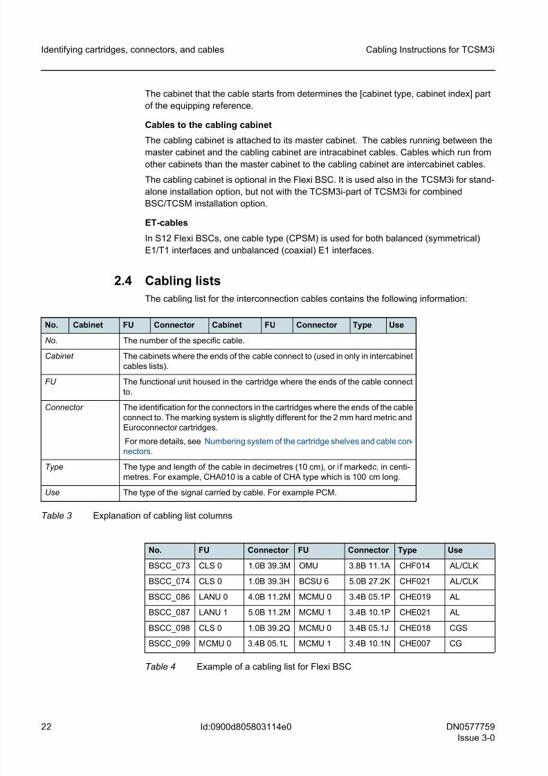
Table 3 Explanation of cabling list columns . . . . . . . . . . . . . . . . . . . . . . . . . . . . 22
Table 4 Example of a cabling list for Flexi BSC . . . . . . . . . . . . . . . . . . . . . . . . . 22
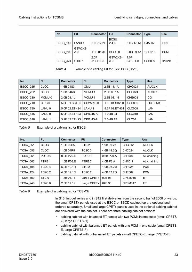
Table 5 Example of a cabling list for BSC3i . . . . . . . . . . . . . . . . . . . . . . . . . . . . 23
Table 6 Example of a cabling list for TCSM3i . . . . . . . . . . . . . . . . . . . . . . . . . . 23
8/11/2019 NOKIA Flexi TRCM
http://slidepdf.com/reader/full/nokia-flexi-trcm 12/183
12 DN0577759
Issue 3-0
Cabling Instructions for TCSM3i
Id:0900d8058061e151
8/11/2019 NOKIA Flexi TRCM
http://slidepdf.com/reader/full/nokia-flexi-trcm 13/183
DN0577759
Issue 3-0
13
Cabling Instructions for TCSM3i Summary of changes
Id:0900d8058061e1af
Summary of changesChanges between document issues are cumulative. Therefore, the latest document
issue contains all changes made to previous issues.
Changes between issues 2-1 and 3-0
Updated to S14 level. The following new sections added:
– S14 combined BSC/TCSM cabling of TCSA cabinet and BSC3i or upgraded Flexi
BSC as BSC-part
– S14 combined BSC/TCSM cabling of TCSA cabinet and first-delivery Flexi BSC as
BSC-part
– S14 combined BSC/TCSM cabling of extension cabinets and BSC3i or upgraded
Flexi BSC as BSC-part
– S14 combined BSC/TCSM cabling of extension cabinets and first-delivery Flexi
BSC as BSC-part The titles of the following sections modified:
– TCSM3i interconnection cabling changed to Intracabinet cabling of TCSA cabinet
– Combined BSC3i/TCSM3i installation-specific cabling on S13 level changed to S13
combined BSC/TCSM cabling of extension cabinets and BSC3i 1000 as BSC-part
– Combined BSC3i/TCSM3i installaiton-specific cabling on S13 and S12 level
changed to S12 and S13 combined BSC/TCSM cabling of TCSA cabinet and BSC3i
1000/2000 as BSC-part
Editorial changes made throughout the document.
Changes between issues 2-0 and 2-1
Information on CPETx modified. Editorial changes made.
Changes between issues 1-0 and 2-0
Updated to S13 level. Information on TCSA extension cabinets and new CPETx panels
added; information on cabling cabinet updated.
Information on related topics modified in Overview of cabling instructions for TCSM3i,.
Combined BSC3i/TCSM3i installation-specific cabling on S13 level added.
The title of S12-level Combined BSC3i/TCSM3i installation-specific cabling changed to
Combined BSC3i/TCSM3i installation-specific cabling on S13 and S12 level. Editorial
changes made.
Editorial changes made also in:
– Identifying cartridges, connectors, and cables
– Routing principles and securing cables
– TCSM3i interconnection cabling
– Stowing away supplementary cable length
Changes for issue 1-0
This is the first issue of Cabling Instructions for TCSM3i.
8/11/2019 NOKIA Flexi TRCM
http://slidepdf.com/reader/full/nokia-flexi-trcm 14/183
14 DN0577759
Issue 3-0
Cabling Instructions for TCSM3i
Id:0900d80580622c39
Overview of cabling instructions for TCSM3i
1 Overview of cabling instructions for TCSM3iInterconnection cabling comprise intracabinet and intercabinet cables. The intracabinet
cables connect plug-units located inside one cabinet, and the intercabinet cables
connect plug-in units located inside different cabinets.
The Cabling Instructions for TCSM3i describes the basic principles of routing intracabi-
net and intercabinet cables in the TCSM3i (M98-mechanics) and provides examples of
the different types of cables and give instructions on how to install each cable type most
efficiently. The following items are discussed:
• Numbering system of the cartridge shelves and cable connectors
• Categories of cable
• Identifying cables
• Cabling lists
• General routing principles
• Cabling instructions for intracabinet cables
• Cabling instructions for intercabinet cables
• Stowing away supplementary cable length
Related topics
Installation Site Requirements for Base Station Controller and Transcoder (releases
prior to S14), Installation Site Requirements for Flexi BSC3i and TCSM3i (S14 release)
and Engineering for TCSM3i give more specific information on the equipment room
layout, cabling and installation of the cabinet rows and cable conduits.
The Interconnection Cables in TCSM3i included in the Site Documents gives more
specific information about cabling lists and how to read cartridge and connector posi-
tions from them, that is, all necessary information for connecting the cables.
8/11/2019 NOKIA Flexi TRCM
http://slidepdf.com/reader/full/nokia-flexi-trcm 15/183
DN0577759
Issue 3-0
15
Cabling Instructions for TCSM3i Identifying cartridges, connectors, and cables
Id:0900d805803114e0
2 Identifying cartridges, connectors, and
cables
This section gives basic information on how to identify cartridge shelves and cable con-nectors, and how to identify cables and read cabling lists. It also describes the different
categories of cables.
2.1 Numbering system of the cartridge shelves and cable con-
nectors
☞ The positions of all connectors are numbered using the coordinate system.
The equipment cabinets, cartridge shelves and cable connectors in the cartridges have
individual coordinate systems to facilitate the installation of cartridges and the connec-
tion of cables. The shelf levels of the cabinet are numbered vertically from 0 to 5. Thenumber 0 is reserved for the top part of the cabinet where the Power Distribution/Fuse
Panel units are located and the numbers 1 to 5 for the cartridge shelves - from top down.
The shelves are numbered horizontally from 0 to 10, from right to left, when seen from
the rear. The numbers indicate the position of the right hand side of the installed car-
tridge from the rear side.
☞ The numbers that indicate the position of the cartridge shelves (in the vertical direc-
tion) are not marked on the side beams of the Cabinet Frames.
The cartridge shelves are marked with numbers that indicate the coordinates in the
horizontal direction.
As shown in the following sections, the numbering system for the connector on a car-
tridge is slightly different for 2 mm hard metric cartridges and Euroconnector cartridges.
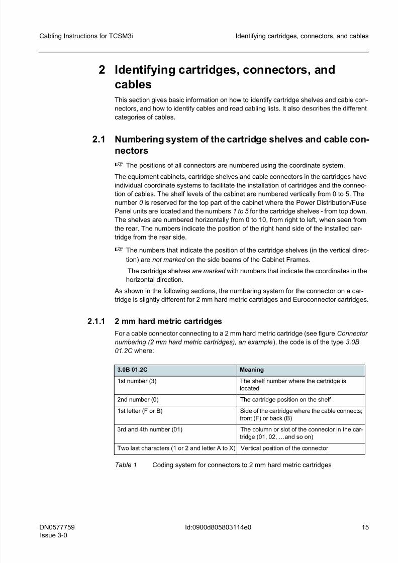
2.1.1 2 mm hard metric cartridges
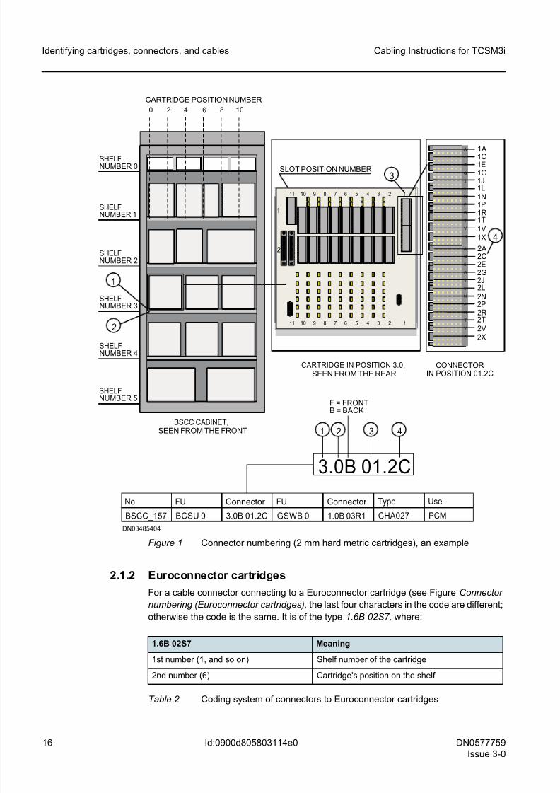
For a cable connector connecting to a 2 mm hard metric cartridge (see figure Connector
numbering (2 mm hard metric cartridges), an example), the code is of the type 3.0B
01.2C where:
3.0B 01.2C Meaning
1st number (3) The shelf number where the cartridge is
located
2nd number (0) The cartridge position on the shelf
1st letter (F or B) Side of the cartridge where the cable connects;
front (F) or back (B)
3rd and 4th number (01) The column or slot of the connector in the car-
tridge (01, 02, …and so on)
Two last characters (1 or 2 and letter A to X) Vertical position of the connector
Table 1 Coding system for connectors to 2 mm hard metric cartridges
8/11/2019 NOKIA Flexi TRCM
http://slidepdf.com/reader/full/nokia-flexi-trcm 16/183
16 DN0577759
Issue 3-0
Cabling Instructions for TCSM3i
Id:0900d805803114e0
Identifying cartridges, connectors, and cables
Figure 1 Connector numbering (2 mm hard metric cartridges), an example
2.1.2 Euroconnector cartridges
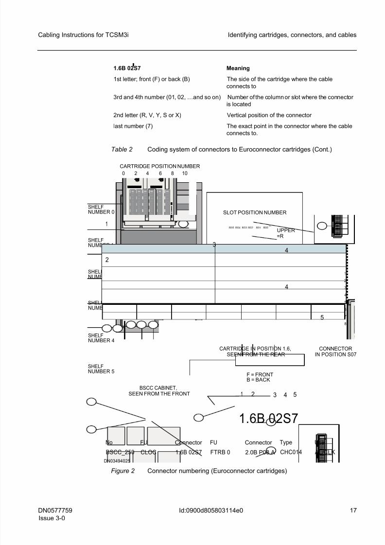
For a cable connector connecting to a Euroconnector cartridge (see Figure Connector
numbering (Euroconnector cartridges), the last four characters in the code are different;
otherwise the code is the same. It is of the type 1.6B 02S7, where:
SHELFNUMBER 0
SHELFNUMBER 1
SHELFNUMBER 2
SHELFNUMBER 3
SHELFNUMBER 4
SHELFNUMBER 5
DN03485404
CONNECTORIN POSITION 01.2C
CARTRIDGE IN POSITION 3.0,SEEN FROM THE REAR
SLOT POSITION NUMBER
0 2 4 6 8 10
BSCC CABINET,SEEN FROM THE FRONT
CARTRIDGE POSITION NUMBER
3.0B 01.2C
F = FRONTB = BACK
No
BSCC_157
FU
BCSU 0
Connector
3.0B 01.2C
FU
GSWB 0
Connector
1.0B 03R1
Type
CHA027
Use
PCM
2
1
1 2 3 4
11 9 8 7 6 5 4 3 2 110
11 9 8 7 6 5 4 3 2 110
2
1
C
E
G
J
L
N
P
R
T
V
X
A
C
E
G
J
L
N
P
R
T
V
X
A
1A1C1E1G1J1L1N1P1R1T1V1X
2A2C2E2G2J2L2N2P2R2T2V2X
4
3
1.6B 02S7 Meaning
1st number (1, and so on) Shelf number of the cartridge
2nd number (6) Cartridge's position on the shelf
Table 2 Coding system of connectors to Euroconnector cartridges
8/11/2019 NOKIA Flexi TRCM
http://slidepdf.com/reader/full/nokia-flexi-trcm 17/183
DN0577759
Issue 3-0
17
Cabling Instructions for TCSM3i Identifying cartridges, connectors, and cables
Id:0900d805803114e0
Figure 2 Connector numbering (Euroconnector cartridges)
1st letter; front (F) or back (B) The side of the cartridge where the cable
connects to
3rd and 4th number (01, 02, …and so on) Number of the column or slot where the connectoris located
2nd letter (R, V, Y, S or X) Vertical position of the connector
last number (7) The exact point in the connector where the cable
connects to.
1.6B 02S7 Meaning
Table 2 Coding system of connectors to Euroconnector cartridges (Cont.)
CONNECTORIN POSITION S07
CARTRIDGE IN POSITION 1.6,SEEN FROM THE REAR
SHELFNUMBER 0
SHELFNUMBER 1
SHELFNUMBER 2
SHELFNUMBER 3
SHELFNUMBER 4
SHELFNUMBER 5
0 2 4 6 8 10
BSCC CABINET,SEEN FROM THE FRONT
CARTRIDGE POSITION NUMBER
1.6B 02S7
F = FRONT
B = BACK
DN03494025
No
BSCC_250
FU
CLOC
Connector
1.6B 02S7
FU
FTRB 0
Connector
2.0B P08.A
Type
CHC014
Use
AL/CLK
1 2 3 4
R03 R02 R01 R00R05 R04
S03 S02 S01 S00S05 S04
D0V
PP2 PP1
W1W2
W3
R
S
XB0V
W4
UB
B0V
UB
D0V
3
UPPER=R
LOWER=S
4
4
3
SLOT POSITION NUMBER
5
2
1
1
2
3
4
5
6
7
8
5
8/11/2019 NOKIA Flexi TRCM
http://slidepdf.com/reader/full/nokia-flexi-trcm 18/183
18 DN0577759
Issue 3-0
Cabling Instructions for TCSM3i
Id:0900d805803114e0
Identifying cartridges, connectors, and cables
2.1.3 Locking pegs
Each connector has locking devices (for example locking pegs or screws) that fasten the
cable connector securely to the cartridge.
The connector locking pegs are placed in the same positions in each cartridge type,
regardless of the cartridge position in a given cabinet. Supplementary locking pegs can
be used as spare parts.
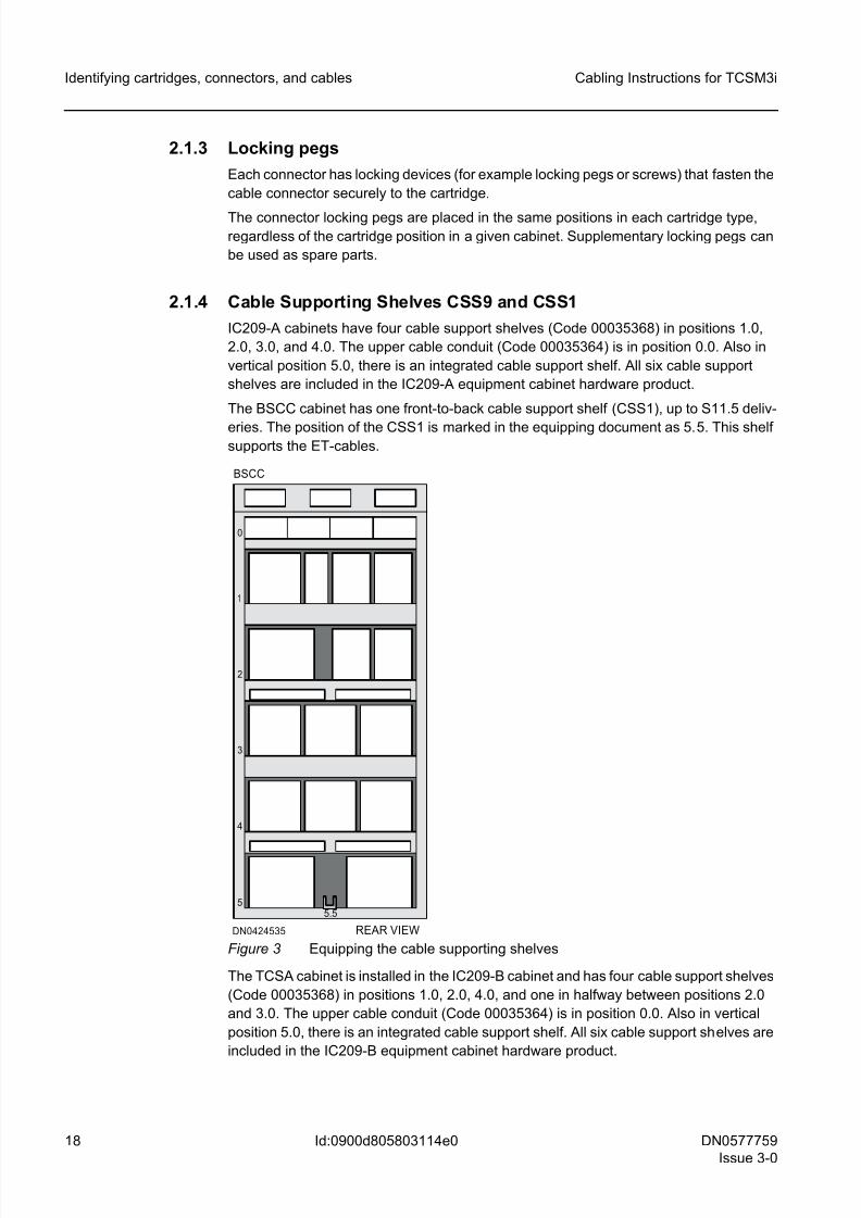
2.1.4 Cable Supporting Shelves CSS9 and CSS1
IC209-A cabinets have four cable support shelves (Code 00035368) in positions 1.0,
2.0, 3.0, and 4.0. The upper cable conduit (Code 00035364) is in position 0.0. Also in
vertical position 5.0, there is an integrated cable support shelf. All six cable support
shelves are included in the IC209-A equipment cabinet hardware product.
The BSCC cabinet has one front-to-back cable support shelf (CSS1), up to S11.5 deliv-
eries. The position of the CSS1 is marked in the equipping document as 5.5. This shelfsupports the ET-cables.
Figure 3 Equipping the cable supporting shelves
The TCSA cabinet is installed in the IC209-B cabinet and has four cable support shelves
(Code 00035368) in positions 1.0, 2.0, 4.0, and one in halfway between positions 2.0
and 3.0. The upper cable conduit (Code 00035364) is in position 0.0. Also in vertical
position 5.0, there is an integrated cable support shelf. All six cable support shelves are
included in the IC209-B equipment cabinet hardware product.
DN0424535
5.5
BSCC
5
4
3
2
1
0
REAR VIEW
8/11/2019 NOKIA Flexi TRCM
http://slidepdf.com/reader/full/nokia-flexi-trcm 19/183
DN0577759
Issue 3-0
19
Cabling Instructions for TCSM3i Identifying cartridges, connectors, and cables
Id:0900d805803114e0
2.2 Categories of cables
The cabling of a network element consists of interconnection cables (intermediate
cables) and external cables (outgoing cables).
2.2.1 Interconnection cables
The interconnection cables comprise all the cables inside one cabinet and between
cabinets that form a single network element. The interconnection cables are cut to
length and equipped with connectors. They include:
• Power distribution cables
• Message bus (not in TCSM3i)
• SCSI bus (not in TCSM3i)
• Timing signal (CLK) distribution cables (also in TCSM3i for combined BSC/TCSM
installation option)
• Supervision bus (also in TCSM3i for combined BSC/TCSM installation option)
• Alarm collection cables
• Changeover signal cables (and 2N cables in TCSM3i for combined BSC/TCSM
installation option)
• Control cables including PCM control cables (ETS2 in BSC and TCSM3i)
• Additional wirings such as PCMC and SBCON
• LAN cables
• Hotlink cables (also in TCSM3i for combined BSC/TCSM installation option)
• X.25 cables (analog X.25 up to S11.5 deliveries)
• synchronisation cables (in TCSM3i for combined BSC/TCSM installation option
only) • Timing bus cables
• Timing loop cables (also in TCSM3i for combined BSC/TCSM installation option)
• ET panel cables
Intracabinet cables
The interconnection cables between different cartridges located in the same cabinet are
intracabinet cables. Intracabinet cables run from one cartridge to another along the walls
and cabling shelves. When intracabinet cables need to run from the backside to the front
side of the cabinet (or other way round), both cartridge shelf openings and opening of
the air guide upper can be used.
Intracabinet cables are delivered completely installed in the cabinets, but they are notconnected on the front side of the cabinet.
Intercabinet cables
The interconnection cables that run from one cabinet to another are intercabinet cables.
Intercabinet cables are led directly from one cabinet to another on cable shelves located
behind the cabinets, in the cable trough at the sides of the cabinets to the cable conduits.
When intercabinet cables need to be run from the backside to the front side (or the other
way round) of the cabinet, both cartridge shelf openings and opening of the air guide
upper can be used. Intercabinet cables are installed at the site. The interconnection
cables are delivered as prefabricated cable sets.
8/11/2019 NOKIA Flexi TRCM
http://slidepdf.com/reader/full/nokia-flexi-trcm 20/183
20 DN0577759
Issue 3-0
Cabling Instructions for TCSM3i
Id:0900d805803114e0
Identifying cartridges, connectors, and cables
2.2.2 External cables
The external (outgoing) cables are all the cables that leave the network element. They
include:
• PCM trunk circuit cables
• external alarm cables (not in stand-alone TCSM3i installation option)
• power supply cables
• grounding cables
• I/O cables (not in stand-alone TCSM3i installation option)
• LAN/Ethernet cables (not in stand-alone TCSM3i installation option)
• STM-1/OC-3
In Flexi BSC, STM-1/OC-3 interface cables are routed through CPGO at the cabinet top.
The external cables (external alarm cables, synchronisation cables, LAN cables, serial
interface cables, and ET16-related trunk circuit cables) are attached to the connector
panel(s) at the cabinet top to the connector panels in the optional cabling cabinet (exter-nal ET16-related trunk circuit cables). ET2 and ET4 related external trunk circuit cables
(in BSC3i 660), X.25 cables (in BSC3i 660 up to S11.5 release), and alternative external
alarm input cables are routed through CPGO at the cabinet top. These cables are
installed at site.
In TCSM3i, STM-1/OC-3 cables are routed through CPGO at teh cabinet top. PCM trunk
circuit cables (ET) are routed through the CPETx panels (CPETS-H, CPETS-F or
CPETC-F) in the cabling cabinet.
g The external cables are not delivered in sets and vary in length. They are designed
and ordered separately for each delivery. External cables are not included in the
standard documentation.
2.3 Identifying cables
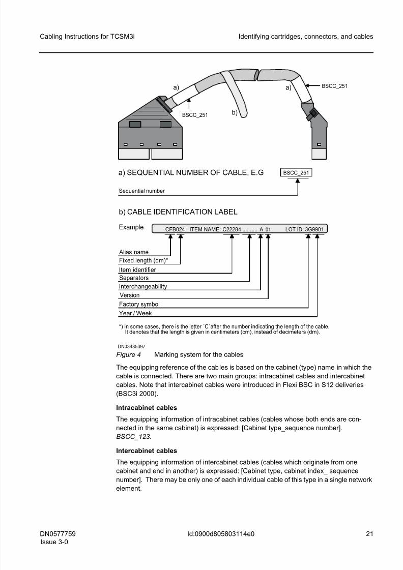
The cable identification label gives information about the cable (b in Figure Marking
system for the cables).
The first part of the equipping reference (a in the figure) specifies the appropriate cable
list where the cable is mentioned. The second part gives the sequence number within
that list.
8/11/2019 NOKIA Flexi TRCM
http://slidepdf.com/reader/full/nokia-flexi-trcm 21/183
DN0577759
Issue 3-0
21
Cabling Instructions for TCSM3i Identifying cartridges, connectors, and cables
Id:0900d805803114e0
Figure 4 Marking system for the cables
The equipping reference of the cables is based on the cabinet (type) name in which the
cable is connected. There are two main groups: intracabinet cables and intercabinet
cables. Note that intercabinet cables were introduced in Flexi BSC in S12 deliveries
(BSC3i 2000).
Intracabinet cables
The equipping information of intracabinet cables (cables whose both ends are con-
nected in the same cabinet) is expressed: [Cabinet type_sequence number].
BSCC_123.
Intercabinet cables
The equipping information of intercabinet cables (cables which originate from one
cabinet and end in another) is expressed: [Cabinet type, cabinet index_ sequence
number]. There may be only one of each individual cable of this type in a single network
element.
a) a)
b)
DN03485397
b) CABLE IDENTIFICATION LABEL
*) In some cases, there is the letter ´C´after the number indicating the length of the cable.It denotes that the length is given in centimeters (cm), instead of decimeters (dm).
Example
a) SEQUENTIAL NUMBER OF CABLE, E.G
Sequential number
ITEM NAME:CFB024 LOT ID: 3G9901
Alias name
Fixed length (dm)*
Item identifier
Separators
Version
Factory symbol
Interchangeability
C22284 ..........
BSCC_251
A 01
Year / Week
BSCC_251
BSCC_251
8/11/2019 NOKIA Flexi TRCM
http://slidepdf.com/reader/full/nokia-flexi-trcm 22/183
8/11/2019 NOKIA Flexi TRCM
http://slidepdf.com/reader/full/nokia-flexi-trcm 23/183
8/11/2019 NOKIA Flexi TRCM
http://slidepdf.com/reader/full/nokia-flexi-trcm 24/183
24 DN0577759
Issue 3-0
Cabling Instructions for TCSM3i
Id:0900d805803114e0
Identifying cartridges, connectors, and cables
Note, however, that only two large CPETx panels are used in the cabling cabinet con-
nected to the TCSM3i for stand-alone installation option. Instead of small CPETx
panels, there are three blank panels (CPBP).
8/11/2019 NOKIA Flexi TRCM
http://slidepdf.com/reader/full/nokia-flexi-trcm 25/183
DN0577759
Issue 3-0
25
Cabling Instructions for TCSM3i Routing principles and securing cables
Id:0900d8058047c7df
3 Routing principles and securing cablesInterconnection cables comprise intracabinet cables and intercabinet cables. The intra-
cabinet cables connect plug-in units located inside one cabinet, and the intercabinet
cables connect plug-in units located inside different cabinets.
3.1 General routing principles
All interconnection cabling is done on site.
This section describes the general principles of efficient routing of cables
• inside the TCSA cabinets, that is, intracabinet cabling
• between the TCSA and BSCC or the TCSA and BSCD cabinets, that is, intercabinet
cabling
3.1.1 Intracabinet cables
Intracabinet cables connect plug-in units located inside the same cabinet.
Most intracabinet cables are equipped on the left-hand side of the cabinet, viewed from
the rear. However, there are some exceptions, such as
• Cables running between plug-in units located on the same shelf
• Power Supply cables
Some intracabinet cables may also be connected so that either one cable end or on both
cable ends are connected to the front panels of the plug-in units. These cables can be
equipped either from the left-hand side or from the right-hand side of the cabinet. It is
also possible that one cable end is on the other side of the cabinet (rear or front).
Front side of cabinet
1. Connect the cable to the first functional unit on the cabling list.
2. Run the cable from the first unit either to the left or to the right side of the cabinet.
3. Take the cable to the height of the shelf, where the second cartridge on the cabling
list is located.
4. Laying the cable on the cabling area of the marking strip holder of the lower level
cartridge, take it to the second cartridge.
5. Connect the cable to the second functional unit on the cabling list.
Rear side of the cabinet
1. Connect the cable to the first functional unit on the cabling list.
2. Run the cable from the first unit to the left side of the cabinet.
3. Take the cable to the height of the shelf, where the second cartridge on the cabling
list is located.
4. Laying the cable on the shelf, take it to the second cartridge.
5. Connect the cable to the second functional unit on the cabling list.
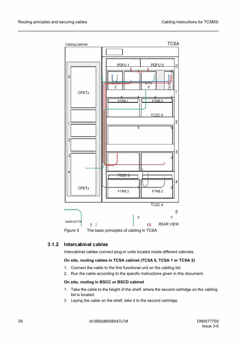
The following figure shows the basic principles of cabling in TCSA.
8/11/2019 NOKIA Flexi TRCM
http://slidepdf.com/reader/full/nokia-flexi-trcm 26/183
26 DN0577759
Issue 3-0
Cabling Instructions for TCSM3i
Id:0900d8058047c7df
Routing principles and securing cables
Figure 5 The basic principles of cabling in TCSA
3.1.2 Intercabinet cables
Intercabinet cables connect plug-in units located inside different cabinets.
On site, routing cables in TCSA cabinet (TCSA 0, TCSA 1 or TCSA 2)
1. Connect the cable to the first functional unit on the cabling list.
2. Run the cable according to the specific instructions given in this document.
On site, routing in BSCC or BSCD cabinet
1. Take the cable to the height of the shelf, where the second cartridge on the cabling
list is located.
2. Laying the cable on the shelf, take it to the second cartridge.
REAR VIEWDN05187778
5
4
3
2
06 0
0
06
1
6 3 0
6 0
TCSA
0
CPETx
Cabling cabinet
CPETx
PDFU 1 PDFU 0
0
1
2
3
4
6
9
TC2C 0
TC2C 3
TC2C 4
FTRB 2FTRB 3
C L O C ETC
2ETC
0
FTRB 1 FTRB 0
8/11/2019 NOKIA Flexi TRCM
http://slidepdf.com/reader/full/nokia-flexi-trcm 27/183
DN0577759
Issue 3-0
27
Cabling Instructions for TCSM3i Routing principles and securing cables
Id:0900d8058047c7df
3. Connect the cable to the second functional unit on the cabling list.
3.2 Securing the cables
Attaching the cables
1. Group the cables according to their function (see the column titled Use in the cabling
list).
2. After connecting the cables, tie the cables together with cable ties into bundles.
Bundles take less space inside the cabinet and they are less likely to be pulled loose
or damaged during later installations than individual cables.
3. Attach the bundles to the cable shelves or the walls of the cabinet.
Optical cable-specific principles
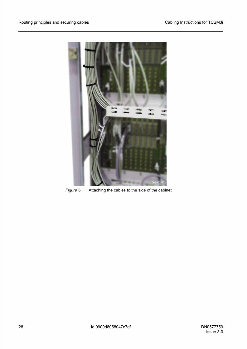
4. To keep cables out of the way of later installations, secure them as far inside as
possible when running them vertically along the left wall of the cabinet to reach
shelves.
5. Attach the bundled cables to the stamped-out metal loops on the walls of the
cabinet. Do not attach the bundles to the ends of the cable shelves.
If the intracabinet cables have been attached as far inside the cabinet as possible,
it is easier to pass the intercabinet cables installed later (especially PCM cables)
through the cabling path openings in the walls of the cabinets.
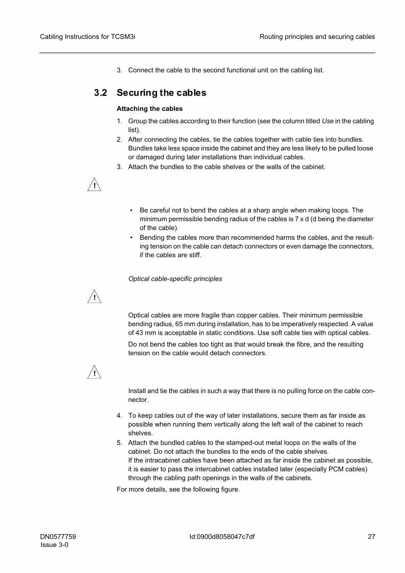
For more details, see the following figure.
!
• Be careful not to bend the cables at a sharp angle when making loops. The
minimum permissible bending radius of the cables is 7 x d (d being the diameter
of the cable).
• Bending the cables more than recommended harms the cables, and the result-
ing tension on the cable can detach connectors or even damage the connectors,
if the cables are stiff.
!
Optical cables are more fragile than copper cables. Their minimum permissible
bending radius, 65 mm during installation, has to be imperatively respected. A value
of 43 mm is acceptable in static conditions. Use soft cable ties with optical cables.
Do not bend the cables too tight as that would break the fibre, and the resulting
tension on the cable would detach connectors.
!
Install and tie the cables in such a way that there is no pulling force on the cable con-
nector.
8/11/2019 NOKIA Flexi TRCM
http://slidepdf.com/reader/full/nokia-flexi-trcm 28/183
28 DN0577759
Issue 3-0
Cabling Instructions for TCSM3i
Id:0900d8058047c7df
Routing principles and securing cables
Figure 6 Attaching the cables to the side of the cabinet
8/11/2019 NOKIA Flexi TRCM
http://slidepdf.com/reader/full/nokia-flexi-trcm 29/183
DN0577759
Issue 3-0
29
Cabling Instructions for TCSM3i Intracabinet cabling of TCSA cabinet
Id:0900d805806229ea
4 Intracabinet cabling of TCSA cabinetIntracabinet cables connect plug-in units located inside one cabinet. This section
describes the routing of intracabinet cables inside the TCSA cabinet.
☞ Routing of the intracabinet cables of the TCSA cabinet is done at the factory.
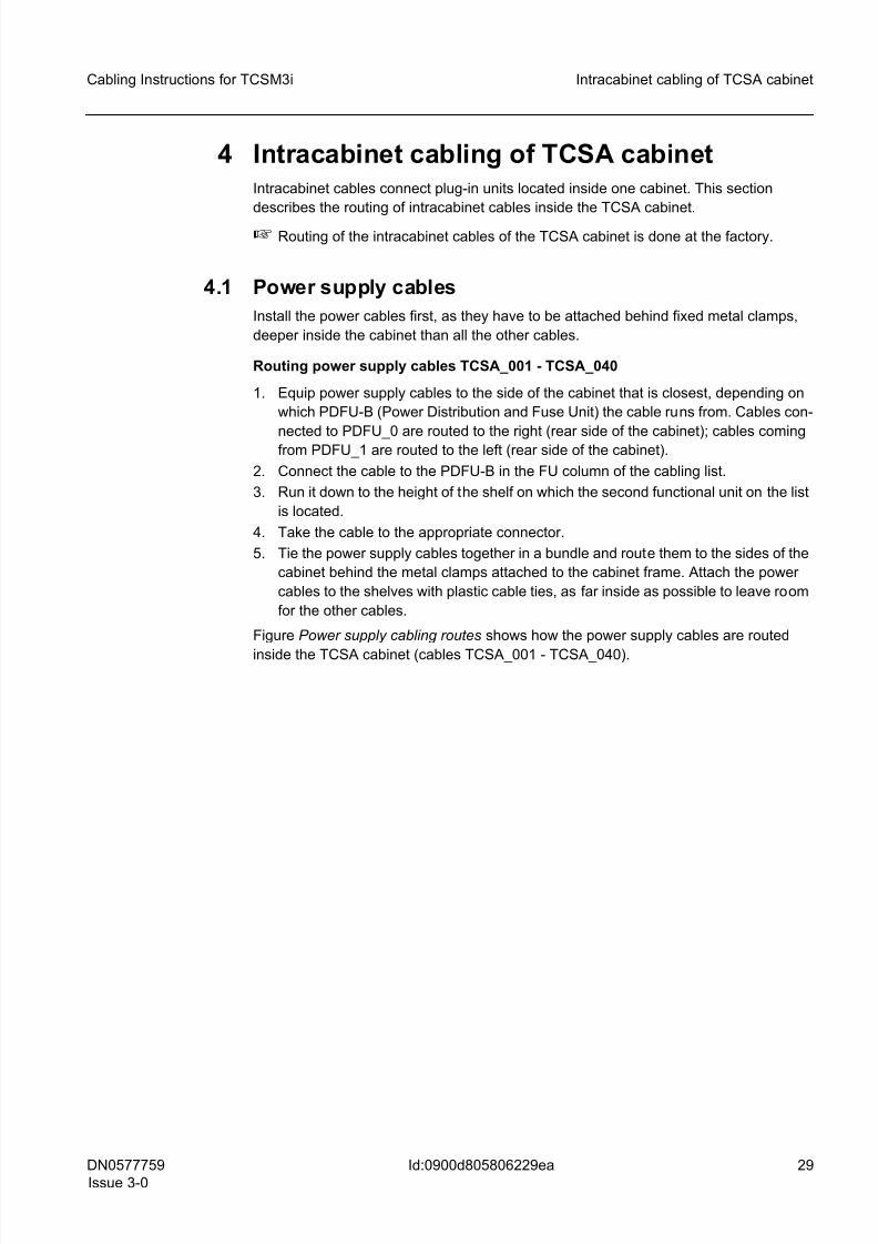
4.1 Power supply cables
Install the power cables first, as they have to be attached behind fixed metal clamps,
deeper inside the cabinet than all the other cables.
Routing power supply cables TCSA_001 - TCSA_040
1. Equip power supply cables to the side of the cabinet that is closest, depending on
which PDFU-B (Power Distribution and Fuse Unit) the cable runs from. Cables con-
nected to PDFU_0 are routed to the right (rear side of the cabinet); cables comingfrom PDFU_1 are routed to the left (rear side of the cabinet).
2. Connect the cable to the PDFU-B in the FU column of the cabling list.
3. Run it down to the height of the shelf on which the second functional unit on the list
is located.
4. Take the cable to the appropriate connector.
5. Tie the power supply cables together in a bundle and route them to the sides of the
cabinet behind the metal clamps attached to the cabinet frame. Attach the power
cables to the shelves with plastic cable ties, as far inside as possible to leave room
for the other cables.
Figure Power supply cabling routes shows how the power supply cables are routed
inside the TCSA cabinet (cables TCSA_001 - TCSA_040).
8/11/2019 NOKIA Flexi TRCM
http://slidepdf.com/reader/full/nokia-flexi-trcm 30/183
30 DN0577759
Issue 3-0
Cabling Instructions for TCSM3i
Id:0900d805806229ea
Intracabinet cabling of TCSA cabinet
Figure 7 Power supply cabling routes
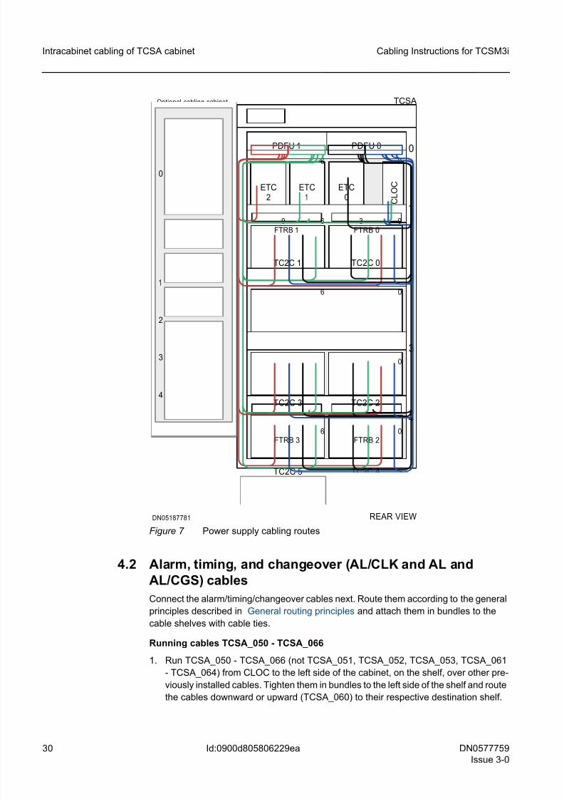
4.2 Alarm, timing, and changeover (AL/CLK and AL andAL/CGS) cables
Connect the alarm/timing/changeover cables next. Route them according to the general
principles described in General routing principles and attach them in bundles to the
cable shelves with cable ties.
Running cables TCSA_050 - TCSA_066
1. Run TCSA_050 - TCSA_066 (not TCSA_051, TCSA_052, TCSA_053, TCSA_061
- TCSA_064) from CLOC to the left side of the cabinet, on the shelf, over other pre-
viously installed cables. Tighten them in bundles to the left side of the shelf and route
the cables downward or upward (TCSA_060) to their respective destination shelf.
REAR VIEWDN05187781
5
4
3
2
06 0
0
06
1
6 3 0
6 0
TCSA
0
PDFU 1 PDFU 0
6
9
TC2C 0
TC2C 3
TC2C 4
FTRB 2FTRB 3
C L O C ETC
2ETC
0
FTRB 1 FTRB 0
TC2C 5
TC2C 2
TC2C 1
ETC1
Optional cabling cabinet
0
1
2
3
4
8/11/2019 NOKIA Flexi TRCM
http://slidepdf.com/reader/full/nokia-flexi-trcm 31/183
DN0577759
Issue 3-0
31
Cabling Instructions for TCSM3i Intracabinet cabling of TCSA cabinet
Id:0900d805806229ea
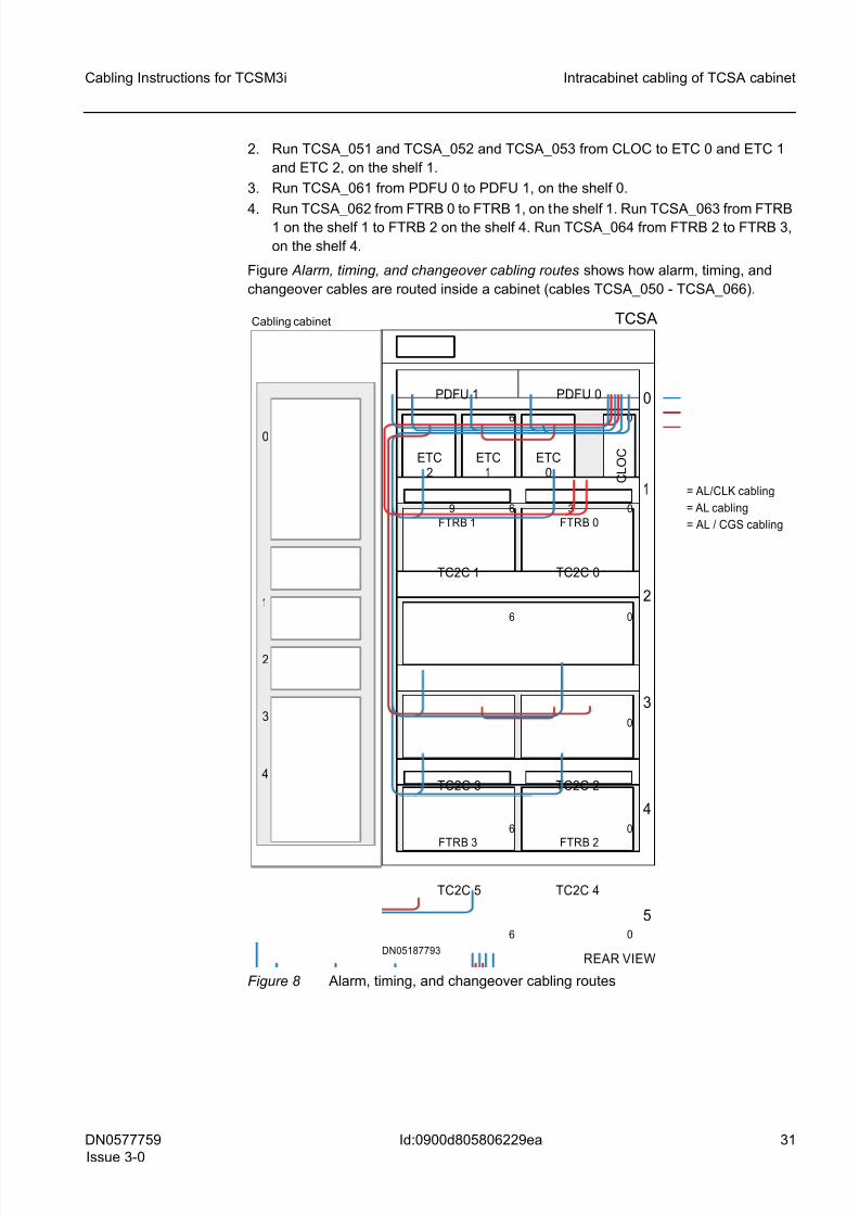
2. Run TCSA_051 and TCSA_052 and TCSA_053 from CLOC to ETC 0 and ETC 1
and ETC 2, on the shelf 1.
3. Run TCSA_061 from PDFU 0 to PDFU 1, on the shelf 0.
4. Run TCSA_062 from FTRB 0 to FTRB 1, on the shelf 1. Run TCSA_063 from FTRB1 on the shelf 1 to FTRB 2 on the shelf 4. Run TCSA_064 from FTRB 2 to FTRB 3,
on the shelf 4.
Figure Alarm, timing, and changeover cabling routes shows how alarm, timing, and
changeover cables are routed inside a cabinet (cables TCSA_050 - TCSA_066).
Figure 8 Alarm, timing, and changeover cabling routes
REAR VIEWDN05187793
TCSA
5
4
3
2
06 0
0
06
1
6 3 0
6 0
0
PDFU 1 PDFU 0
6
9
TC2C 0
TC2C 3
TC2C 4
FTRB 2FTRB 3
C L O C ETC
2ETC
0
FTRB 1 FTRB 0
TC2C 5
TC2C 2
TC2C 1
ETC1
= AL/CLK cabling
= AL cabling
= AL / CGS cabling
Cabling cabinet
0
1
2
3
4

8/11/2019 NOKIA Flexi TRCM
http://slidepdf.com/reader/full/nokia-flexi-trcm 32/183
32 DN0577759
Issue 3-0
Cabling Instructions for TCSM3i
Id:0900d805806229ea
Intracabinet cabling of TCSA cabinet
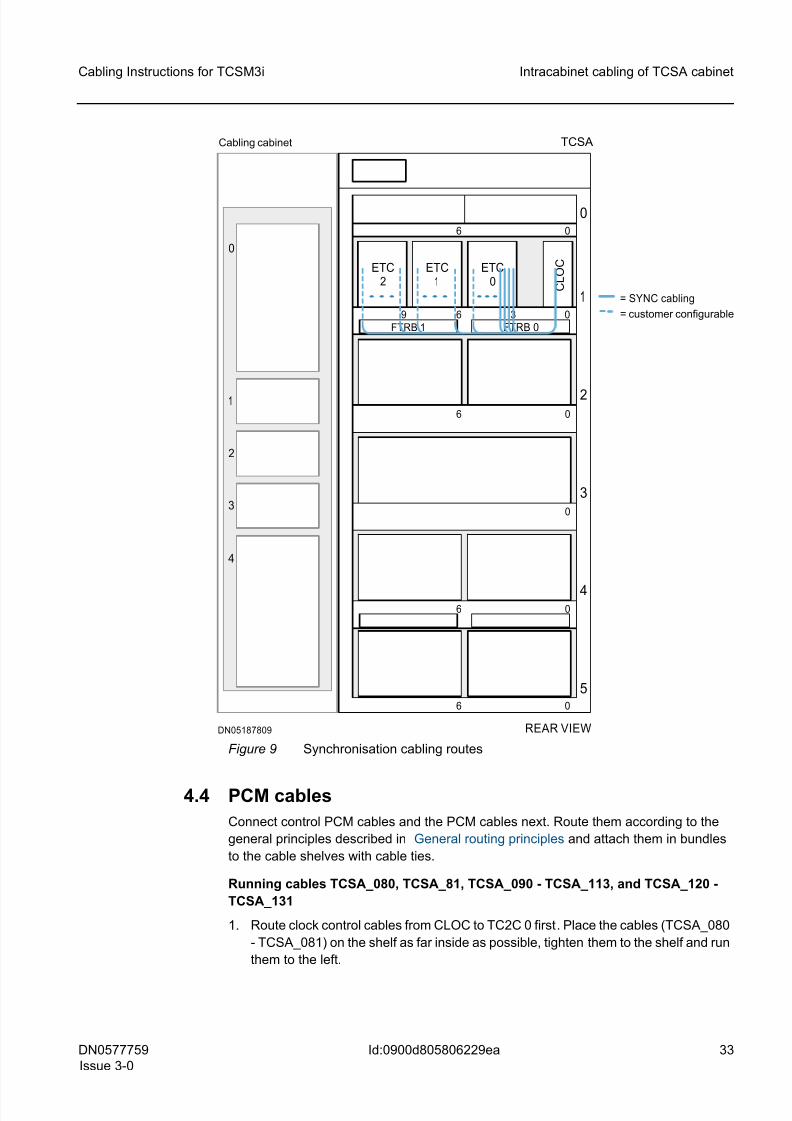
4.3 Internal synchronisation cables
Connect internal synchronisation cables (TCSA_070 - TCSA_073) next. Route them
according to the general principles described in General routing principles and attach
them in bundles to the cable shelves with cable ties.
☞ You can configure internal synchronisation cables. The cables can be routed as indi-
cated in the following figure, but they can also be plugged wherever needed in the
ETC x (all ET16 slots), as specified in the equipping document.
Cabling internal synchronisation cables
1. Route TCSA_070 - TCSA_073 from CLOC to ETC 0 on shelf 1.
2. Tighten them all along the way, and connect them to the default positions according
to Interconnection Cables in TCSM3i .
The figure Synchronisation cable routesshows how synchronisation cables are routed
inside the TCSA cabinet (cables TCSA_070 - TCSA_073).
8/11/2019 NOKIA Flexi TRCM
http://slidepdf.com/reader/full/nokia-flexi-trcm 33/183
DN0577759
Issue 3-0
33
Cabling Instructions for TCSM3i Intracabinet cabling of TCSA cabinet
Id:0900d805806229ea
Figure 9 Synchronisation cabling routes
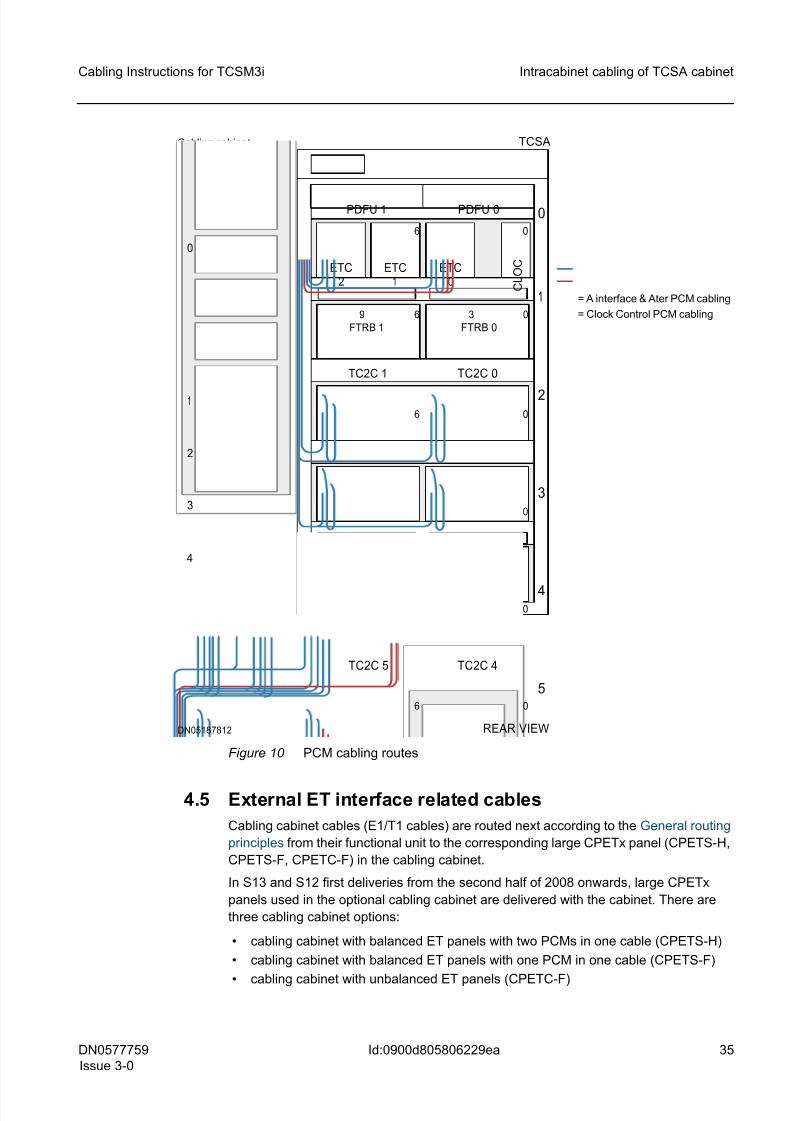
4.4 PCM cables
Connect control PCM cables and the PCM cables next. Route them according to the
general principles described in General routing principles and attach them in bundles
to the cable shelves with cable ties.
Running cables TCSA_080, TCSA_81, TCSA_090 - TCSA_113, and TCSA_120 -
TCSA_131
1. Route clock control cables from CLOC to TC2C 0 first. Place the cables (TCSA_080
- TCSA_081) on the shelf as far inside as possible, tighten them to the shelf and run
them to the left.
REAR VIEWDN05187809
TCSA
5
4
3
2
06 0
0
06
1
6 3 0
6 0
0
6
9
C L O C ETC
2ETC
0
FTRB 1 FTRB 0
ETC1
= SYNC cabling
= customer configurable
Cabling cabinet
0
1
2
3
4
8/11/2019 NOKIA Flexi TRCM
http://slidepdf.com/reader/full/nokia-flexi-trcm 34/183
8/11/2019 NOKIA Flexi TRCM
http://slidepdf.com/reader/full/nokia-flexi-trcm 35/183
DN0577759
Issue 3-0
35
Cabling Instructions for TCSM3i Intracabinet cabling of TCSA cabinet
Id:0900d805806229ea
Figure 10 PCM cabling routes
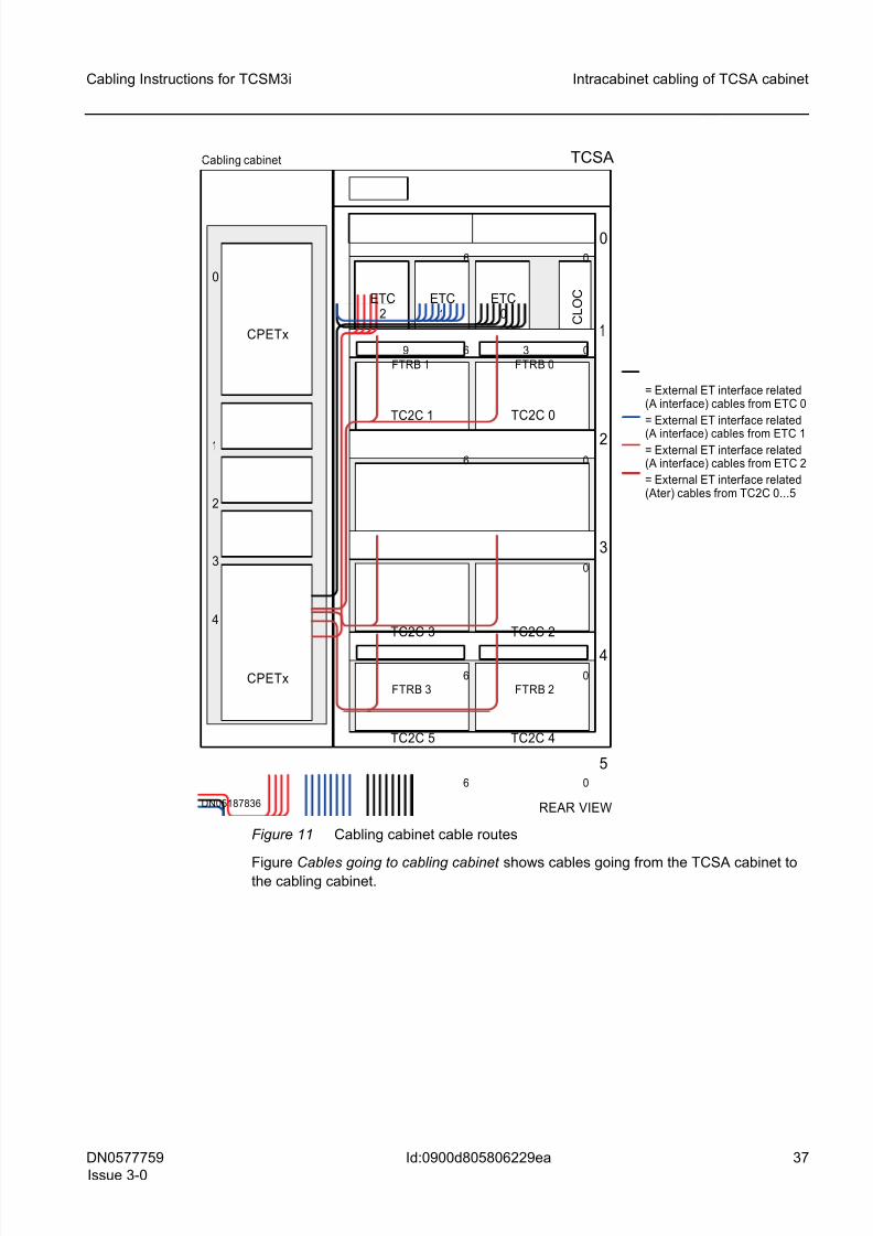
4.5 External ET interface related cables
Cabling cabinet cables (E1/T1 cables) are routed next according to the General routing
principles from their functional unit to the corresponding large CPETx panel (CPETS-H,
CPETS-F, CPETC-F) in the cabling cabinet.
In S13 and S12 first deliveries from the second half of 2008 onwards, large CPETx
panels used in the optional cabling cabinet are delivered with the cabinet. There are
three cabling cabinet options:
• cabling cabinet with balanced ET panels with two PCMs in one cable (CPETS-H)
• cabling cabinet with balanced ET panels with one PCM in one cable (CPETS-F)
• cabling cabinet with unbalanced ET panels (CPETC-F)
REAR VIEWDN05187812
TCSA
5
4
3
2
06 0
0
06
1
6 3 0
6 0
0
PDFU 1 PDFU 0
6
9
TC2C 0
TC2C 3
TC2C 4
FTRB 2FTRB 3
C L O C ETC
2ETC
0
FTRB 1 FTRB 0
TC2C 5
TC2C 2
TC2C 1
ETC1
= A interface & Ater PCM cabling
= Clock Control PCM cabling
Cabling cabinet
0
1
2
3
4
8/11/2019 NOKIA Flexi TRCM
http://slidepdf.com/reader/full/nokia-flexi-trcm 36/183
8/11/2019 NOKIA Flexi TRCM
http://slidepdf.com/reader/full/nokia-flexi-trcm 37/183
DN0577759
Issue 3-0
37
Cabling Instructions for TCSM3i Intracabinet cabling of TCSA cabinet
Id:0900d805806229ea
Figure 11 Cabling cabinet cable routes
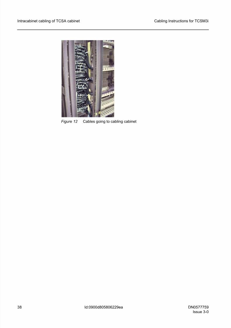
Figure Cables going to cabling cabinet shows cables going from the TCSA cabinet tothe cabling cabinet.
REAR VIEWDN05187836
5
4
3
2
06 0
0
06
1
6 3 0
6 0
TCSA
0
CPETx
Cabling cabinet
CPETx
0
1
2
3
4
6
9
TC2C 0
TC2C 3
TC2C 4
FTRB 2FTRB 3
C L O C ETC
2ETC
0
FTRB 1 FTRB 0
ETC1
TC2C 1
TC2C 2
TC2C 5
= External ET interface related(A interface) cables from ETC 0
= External ET interface related
(A interface) cables from ETC 1= External ET interface related(A interface) cables from ETC 2
= External ET interface related(Ater) cables from TC2C 0...5
8/11/2019 NOKIA Flexi TRCM
http://slidepdf.com/reader/full/nokia-flexi-trcm 38/183
38 DN0577759
Issue 3-0
Cabling Instructions for TCSM3i
Id:0900d805806229ea
Intracabinet cabling of TCSA cabinet
Figure 12 Cables going to cabling cabinet
8/11/2019 NOKIA Flexi TRCM
http://slidepdf.com/reader/full/nokia-flexi-trcm 39/183
DN0577759
Issue 3-0
39
Cabling Instructions for TCSM3i S14 combined BSC/TCSM cabling of TCSA cabinetand BSC3i or upgraded Flexi BSC as BSC-part
Id:0900d8058061e166
5 S14 combined BSC/TCSM cabling of TCSA
cabinet and BSC3i or upgraded Flexi BSC as
BSC-part☞ The TCSA cabinet can be equipped either on the right side or on the left side of the
BSCC cabinet.
Routing of combined BSC/TCSM installation-specific cables is done on site.
All cabling (except AL and AL/CGS cables TCSA_065 & TCSA_066, Internal synchro-
nisation cables TCSA_070 - TCSA_073, External ET interface related cables
TCSA_150 - TCSA_269, Control PCM cables TCSA_080 & TCSA_081, and PCM
cables TCSA_090 - TCSA_131) presented in Intracabinet cabling of TCSA cabinet is
common to both TCSM3i for stand-alone installation option and TCSM3i for combined
BSC/TCSM installation option.
The following subsections show the cabling of one TCSM cabinet when the BSC-part is
BSC3i 1000/2000 or upgraded Flex BSC.They provide the most efficient routing of
SBUS cables, Timing bus cables, Timing loop cables, 2N Compare test cables, Syn-
chronisation signal cables, 8M PCM cables and Hotlink cables.
5.1 SBUS cables
Run supervision bus (SBUS) cables TCSA 0_001 & TCSA 0_002 from CLAC 1 in the
TCSA cabinet to CLAC 0 in the BSCC cabinet - when the BSC-part is BSC3i 1000 or
one-cabinet upgraded Flex BSC.
Run supervision bus (SBUS) cables TCSA 0_001 & TCSA 0_002 from CLAC 2 in theTCSA cabinet to CLAC 1 in the BSCD cabinet - when the BSC-part is BSC3i 2000 or
two-cabinet upgraded Flex BSC.
Routing SBUS cables on site in TCSA cabinet
1. Connect the cable to the first functional unit (FU) in the cabling list. For more infor-
mation, see the separate document Interconnection Cables in TCSM3i.
2. When the BSC-part is BSC3i 1000 or one-cabinet upgraded Flexi BSC, run SBUS
cables to the left or to the right on shelf 1, depending on which side of the BSCC
cabinetc the TCSA cabinet is equipped at. Use then the left or the right side of the
TCSA cabinet for running them down to the level of cabling shelf 5 - and through the
cabling cabinet if the TCSA cabinet is equipped on the left side of the BSCC cabinet.
3. When the BSC-part is BSC3i 2000 or two-cabinet upgraded Flex BSC, run the
SBUS cables to the right or to the left depending on which side of the BSCC or
BSCD cabinet the TCSA cabinet is equipped on.
Routing SBUS cables on site in BSCC cabinet when BSC-part is BSC3i 1000 or
one-cabinet upgraded Flexi BSC
1. When the BSC-part is BSC3i 1000 or one-cabinet upgraded Flexi BSC and the
TCSA cabinet is on the right side of the BSCC cabinet, run the SBUS cables to the
left inside the BSCC cabinet on cabling shelf 5.
2. When the BSC-part is BSC3i 1000 or one-cabinet upgraded Flexi BSC and the
TCSA cabinet is on the left side of the BSCC cabinet, run the SBUS cables to the
right inside the BSCC cabinet on cabling shelf 5.
8/11/2019 NOKIA Flexi TRCM
http://slidepdf.com/reader/full/nokia-flexi-trcm 40/183
40 DN0577759
Issue 3-0
Cabling Instructions for TCSM3i
Id:0900d8058061e166
S14 combined BSC/TCSM cabling of TCSA cabinetand BSC3i or upgraded Flexi BSC as BSC-part
☞ It is possible that an optional cabling cabinet is not included in the hardware con-
figuration of the BSC-part. The cabling cabinet is not used, if:
– the number of external PCM interfaces is 1 to 48, that is, normal E1 or T1
ETs are used – the STM-1/OC-3 interfaces are used as external trunk connections, that is,
normal E1 or T1 ETs are not used.
3. Connect the cable to the second functional unit (FU) mentioned in the cabling list.
For more information, see the separate document Interconnection Cables in
TCSM3i.
The following figure shows how SBUS cables are run when the BSC-part is BSC3i 1000
or one-cabinet upgraded Flexi BSC (cables TCSA 0_001 & TCSA 0_002).
8/11/2019 NOKIA Flexi TRCM
http://slidepdf.com/reader/full/nokia-flexi-trcm 41/183
DN0577759
Issue 3-0
41
Cabling Instructions for TCSM3i S14 combined BSC/TCSM cabling of TCSA cabinetand BSC3i or upgraded Flexi BSC as BSC-part
Id:0900d8058061e166
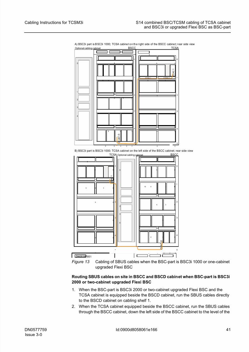
Figure 13 Cabling of SBUS cables when the BSC-part is BSC3i 1000 or one-cabinet
upgraded Flexi BSC
Routing SBUS cables on site in BSCC and BSCD cabinet when BSC-part is BSC3i
2000 or two-cabinet upgraded Flexi BSC
1. When the BSC-part is BSC3i 2000 or two-cabinet upgraded Flexi BSC and the
TCSA cabinet is equipped beside the BSCD cabinet, run the SBUS cables directly
to the BSCD cabinet on cabling shelf 1.
2.When the TCSA cabinet equipped beside the BSCC cabinet, run the SBUS cablesthrough the BSCC cabinet, down the left side of the BSCC cabinet to the level of the
1
2
3
4
0
Optional cabling cabinet
1
2
3
4
0
5
0
0
0
06
0
48
6
48
8 3
3
BSCC
06
C L A C 0
249
10
FTRB 1 FTRB 0 1
2
3
4
0
5
0
0
0
0
6
0
6
9
06
C L A C 1
6
36
8
TCSA
A) BSC3i part is B SC3i 1000; TCSA cabine t o n th e r ight side of the BSCC cabine t; r ear side view
1
2
3
4
0
Optional cabling cabinet
1
2
3
4
0
5
0
0
0
0
06
0
48
6
48
8 3
3
BSCC
06
C L A C 0
249
10
1
2
3
4
0
5
0
0
0
0
6
0
6
9
06
C L A C 1
6
36
8
TCSA
B) BSC3i part is BSC3i 1000; TCSA cabinet on the left side of the BSCC cabinet; rear side view
DN05187851
8/11/2019 NOKIA Flexi TRCM
http://slidepdf.com/reader/full/nokia-flexi-trcm 42/183
42 DN0577759
Issue 3-0
Cabling Instructions for TCSM3i
Id:0900d8058061e166
S14 combined BSC/TCSM cabling of TCSA cabinetand BSC3i or upgraded Flexi BSC as BSC-part
lower edge of the CPETx connector panel in the cabling cabinet (if there is one),
through the cabling cabinet to the BSCD cabinet. In the BSCD cabinet, run the
cables up the right side of the cabinet to the level of shelf 1, then to the left on shelf
1 to CLAC 1.
☞ It is possible that an optional cabling cabinet is not included in the hardware con-
figuration of the BSC-part. The cabling cabinet is not used, if:
– the number of external PCM interfaces is 1 to 48, that is, normal E1 or T1
ETs are used
– the STM-1/OC-3 interfaces are used as external trunk connections, that is,
normal E1 or T1 ETs are not used.
3. Connect the cable to the second functional unit (FU) mentioned in the cabling list.
For more information, see the separate document Interconnection Cables in
TCSM3i.
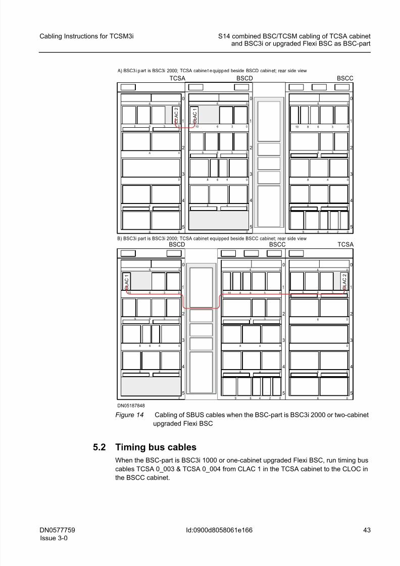
The following figure show s how SBUS cables are run when the BSC-part is BSC3i 2000
or two-cabinet upgraded Flexi BSC (cables TCSA 0_001 & TCSA 0_002).
8/11/2019 NOKIA Flexi TRCM
http://slidepdf.com/reader/full/nokia-flexi-trcm 43/183
DN0577759
Issue 3-0
43
Cabling Instructions for TCSM3i S14 combined BSC/TCSM cabling of TCSA cabinetand BSC3i or upgraded Flexi BSC as BSC-part
Id:0900d8058061e166
Figure 14 Cabling of SBUS cables when the BSC-part is BSC3i 2000 or two-cabinet
upgraded Flexi BSC
5.2 Timing bus cables
When the BSC-part is BSC3i 1000 or one-cabinet upgraded Flexi BSC, run timing bus
cables TCSA 0_003 & TCSA 0_004 from CLAC 1 in the TCSA cabinet to the CLOC in
the BSCC cabinet.
DN05187848
5
4
3
2
06 0
0
06
1
6 3 0
6 0
0
6
9
TCSA
5
4
3
2
06 0
48 0
3 06
1
8 6 3 010
6 4 2 09
48 0
BSCC
BSCD
5
4
3
2
1
06 0
0
48 0
48 0
3 06
10 6 3 0
9
6
5
4
3
2
06 0
0
06
1
6 3 0
6 0
0
6
9
TCSA
5
4
3
2
06 0
48 0
3 06
1
8 6 3 010
6 4 2 09
48 0
BSCC
BSCD
5
4
3
2
1
06 0
0
48 0
48 0
3 06
10 6 3 0
9
6
A) BSC3 i p art is BSC3i 2000; TCSA cabine t e quipp ed beside BSCD cabin et; rear side view
B) BSC3i part is BSC3i 2000; TCSA cabinet equipped beside BSCC cabinet; rear side view
C L A
C
2
C L A
C
1
C L A
C
1
C L A
C
2
8/11/2019 NOKIA Flexi TRCM
http://slidepdf.com/reader/full/nokia-flexi-trcm 44/183
44 DN0577759
Issue 3-0
Cabling Instructions for TCSM3i
Id:0900d8058061e166
S14 combined BSC/TCSM cabling of TCSA cabinetand BSC3i or upgraded Flexi BSC as BSC-part
When the BSC-part is BSC3i 2000 or two-cabinet upgraded Flexi BSC, run timing bus
cables TCSA 0_003 & TCSA 0_004 from CLAC 2 in the TCSA cabinet to the CLOC in
the BSCC cabinet.
Routing timing bus cables on site in TCSA cabinet
1. Connect the cable to the first functional unit (FU) in the cabling list. For more infor-
mation, see the separate document Interconnection Cables in TCSM3i.
2. When the BSC-part is BSC3i 1000 or one-cabinet upgraded Flexi BSC, run the
timing bus cables to the left or to the right on cabling shelf 1, depending on whether
the TCSA cabinet is equipped on the right side or on the left side of the BSCC
cabinet. And if the TCSA cabinet is on the left side of the BSCC cabinet, run the
cables also through the cabling cabinet.
3. When the BSC-part is BSC3i 2000 or two-cabinet upgraded Flexi BSC, run the
timing bus cables to the right or to the left, depending on where the TCSA cabinet is
equipped - beside the BSCD cabinet or beside the BSCC cabinet.
Routing timing bus cables on site in BSCC cabinet when BSC-part is BSC3i 1000
or one-cabinet upgraded Flexi BSC
1. When the TCSA cabijnet is on the right side of the BSCC cabinet, run the timing bus
cables to the left on cabling shelf 1 to the CLOC.
2. When the TCSA cabinet is on the left side of the BSCC cabinet, run the timing bus
cables to the right on cabling shelf 1 to the CLOC.
☞ It is possible that an optional cabling cabinet is not included in the hardware con-
figuration of the BSC-part. The cabling cabinet is not used, if:
– the number of external PCM interfaces is 1 to 48, that is, normal E1 or T1
ETs are used
– the STM-1/OC-3 interfaces are used as external trunk connections, that is,
normal E1 or T1 ETs are not used.
3. Connect the cable to the second functional unit (FU) mentioned in the cabling list.
For more information, see the separate document Interconnection Cables in
TCSM3i.
Routing timing bus cables on site in BSCD and BSCC cabinet when BSC-part is
BSC3i 2000 or two-cabinet upgraded Flexi BSC
1. When TCSA cabinet equipped beside the BSCD cabinet, run the timing bus cables
down on the right side of the BSCD to the level of the lower edge of the CPETx con-
nector panel in the cabling cabinet, through the cabling cabinet to the BSCC cabinet.
In the BSCC, run the cables up the left side of the cabinet to the level of shelf 1, thento the right to the CLOC.
☞ It is possible that an optional cabling cabinet is not included in the hardware con-
figuration of the BSC-part. The cabling cabinet is not used, if:
– the number of external PCM interfaces is 1 to 48, that is, normal E1 or T1
ETs are used
– the STM-1/OC-3 interfaces are used as external trunk connections, that is,
normal E1 or T1 ETs are not used.
2. When the TCSA cabinet equipped beside the BSCC cabinet, run the timing bus
cables in the BSCC cabinet on cabling shelf 1 to the CLOC.
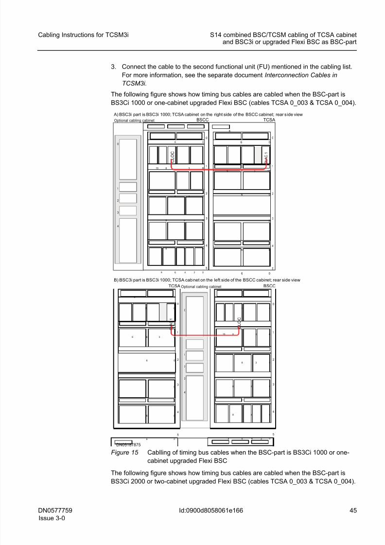
8/11/2019 NOKIA Flexi TRCM
http://slidepdf.com/reader/full/nokia-flexi-trcm 45/183
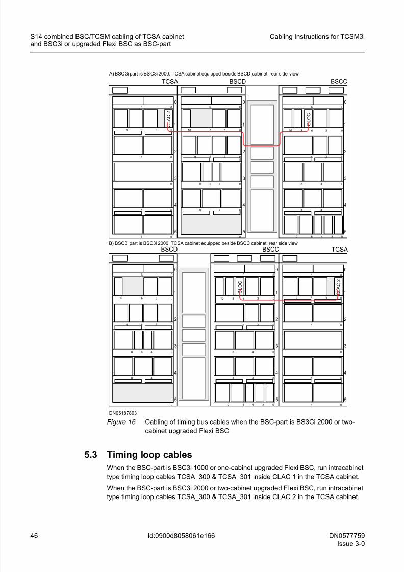
8/11/2019 NOKIA Flexi TRCM
http://slidepdf.com/reader/full/nokia-flexi-trcm 46/183
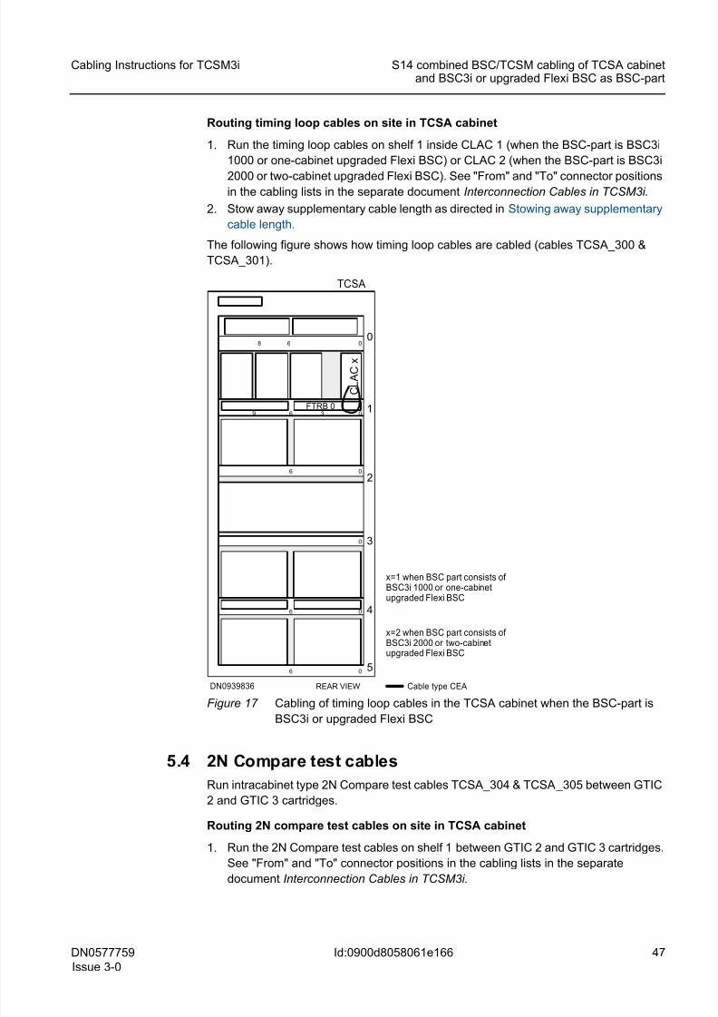
8/11/2019 NOKIA Flexi TRCM
http://slidepdf.com/reader/full/nokia-flexi-trcm 47/183
DN0577759
Issue 3-0
47
Cabling Instructions for TCSM3i S14 combined BSC/TCSM cabling of TCSA cabinetand BSC3i or upgraded Flexi BSC as BSC-part
Id:0900d8058061e166
Routing timing loop cables on site in TCSA cabinet
1. Run the timing loop cables on shelf 1 inside CLAC 1 (when the BSC-part is BSC3i
1000 or one-cabinet upgraded Flexi BSC) or CLAC 2 (when the BSC-part is BSC3i
2000 or two-cabinet upgraded Flexi BSC). See "From" and "To" connector positionsin the cabling lists in the separate document Interconnection Cables in TCSM3i.
2. Stow away supplementary cable length as directed in Stowing away supplementary
cable length.
The following figure shows how timing loop cables are cabled (cables TCSA_300 &
TCSA_301).
Figure 17 Cabling of timing loop cables in the TCSA cabinet when the BSC-part is
BSC3i or upgraded Flexi BSC
5.4 2N Compare test cables
Run intracabinet type 2N Compare test cables TCSA_304 & TCSA_305 between GTIC
2 and GTIC 3 cartridges.
Routing 2N compare test cables on site in TCSA cabinet
1. Run the 2N Compare test cables on shelf 1 between GTIC 2 and GTIC 3 cartridges.
See "From" and "To" connector positions in the cabling lists in the separate
document Interconnection Cables in TCSM3i.
FTRB 0 1
2
3
4
0
5
0
0
0
0
6
0
6
9
06
6
36
8
C L A C
x
REAR VIEW
TCSA
DN0939836
x=1 when BSC part consists of BSC3i 1000 or one-cabinetupgraded Flexi BSC
Cable type CEA
x=2 when BSC part consists of BSC3i 2000 or two-cabinetupgraded Flexi BSC
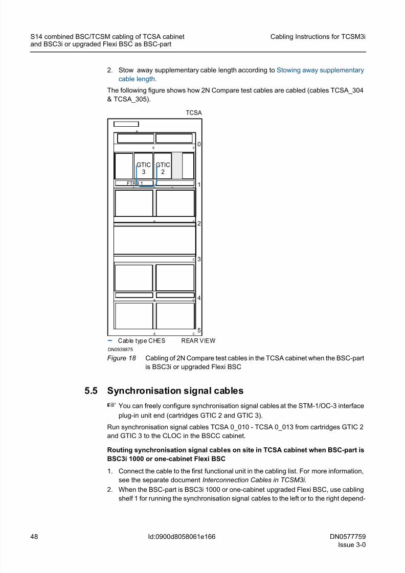
8/11/2019 NOKIA Flexi TRCM
http://slidepdf.com/reader/full/nokia-flexi-trcm 48/183
48 DN0577759
Issue 3-0
Cabling Instructions for TCSM3i
Id:0900d8058061e166
S14 combined BSC/TCSM cabling of TCSA cabinetand BSC3i or upgraded Flexi BSC as BSC-part
2. Stow away supplementary cable length according to Stowing away supplementary
cable length.
The following figure shows how 2N Compare test cables are cabled (cables TCSA_304
& TCSA_305).
Figure 18 Cabling of 2N Compare test cables in the TCSA cabinet when the BSC-part
is BSC3i or upgraded Flexi BSC
5.5 Synchronisation signal cables
☞ You can freely configure synchronisation signal cables at the STM-1/OC-3 interface
plug-in unit end (cartridges GTIC 2 and GTIC 3).
Run synchronisation signal cables TCSA 0_010 - TCSA 0_013 from cartridges GTIC 2
and GTIC 3 to the CLOC in the BSCC cabinet.
Routing synchronisation signal cables on site in TCSA cabinet when BSC-part is
BSC3i 1000 or one-cabinet Flexi BSC
1. Connect the cable to the first functional unit in the cabling list. For more information,
see the separate document Interconnection Cables in TCSM3i.
2. When the BSC-part is BSC3i 1000 or one-cabinet upgraded Flexi BSC, use cabling
shelf 1 for running the synchronisation signal cables to the left or to the right depend-
FTRB 1 1
2
3
4
0
5
0
0
0
0
6
0
6
9
06
6
36
8
Cable type CHES REAR VIEW
TCSA
GTIC3
GTIC2
DN0939875
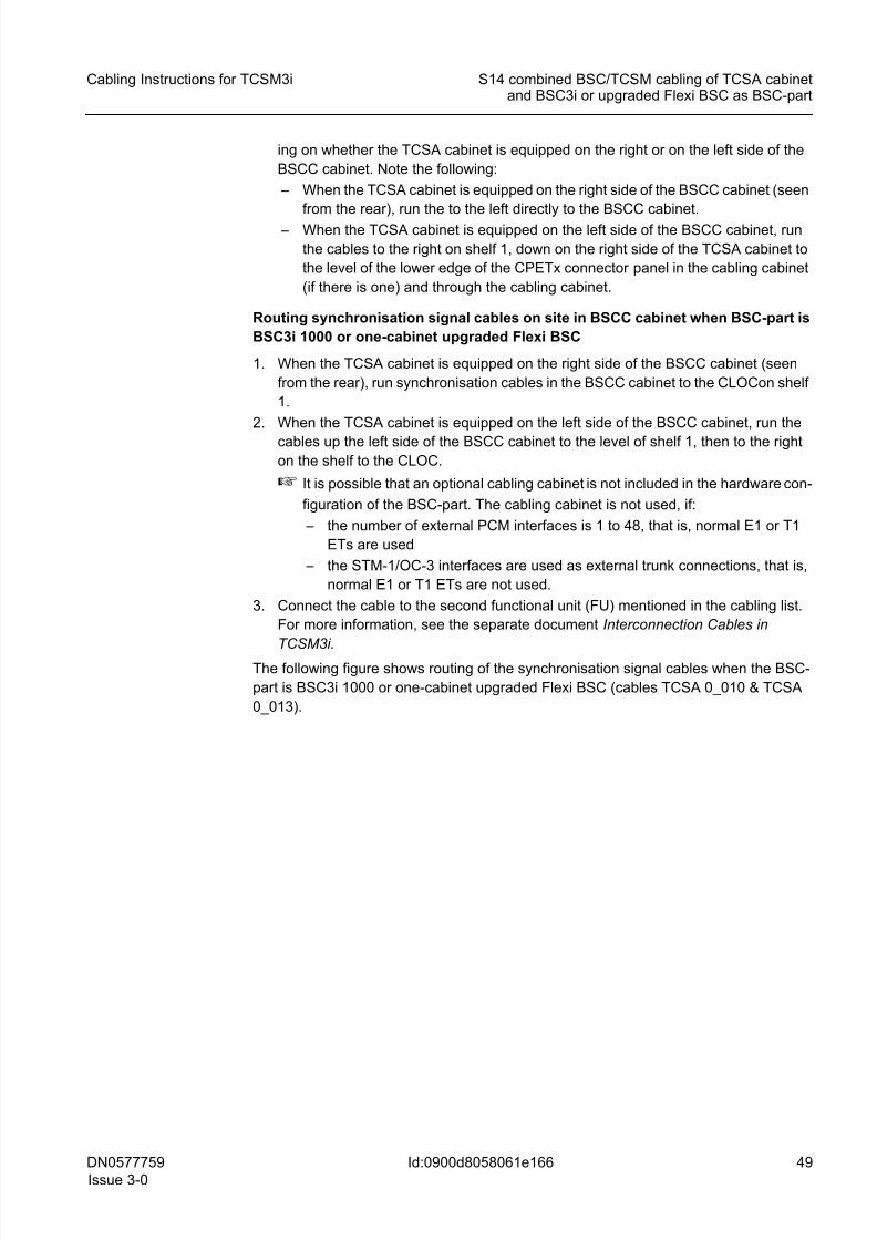
8/11/2019 NOKIA Flexi TRCM
http://slidepdf.com/reader/full/nokia-flexi-trcm 49/183
DN0577759
Issue 3-0
49
Cabling Instructions for TCSM3i S14 combined BSC/TCSM cabling of TCSA cabinetand BSC3i or upgraded Flexi BSC as BSC-part
Id:0900d8058061e166
ing on whether the TCSA cabinet is equipped on the right or on the left side of the
BSCC cabinet. Note the following:
– When the TCSA cabinet is equipped on the right side of the BSCC cabinet (seen
from the rear), run the to the left directly to the BSCC cabinet.
– When the TCSA cabinet is equipped on the left side of the BSCC cabinet, run
the cables to the right on shelf 1, down on the right side of the TCSA cabinet to
the level of the lower edge of the CPETx connector panel in the cabling cabinet
(if there is one) and through the cabling cabinet.
Routing synchronisation signal cables on site in BSCC cabinet when BSC-part is
BSC3i 1000 or one-cabinet upgraded Flexi BSC
1. When the TCSA cabinet is equipped on the right side of the BSCC cabinet (seen
from the rear), run synchronisation cables in the BSCC cabinet to the CLOCon shelf
1.
2. When the TCSA cabinet is equipped on the left side of the BSCC cabinet, run the
cables up the left side of the BSCC cabinet to the level of shelf 1, then to the right
on the shelf to the CLOC.
☞ It is possible that an optional cabling cabinet is not included in the hardware con-
figuration of the BSC-part. The cabling cabinet is not used, if:
– the number of external PCM interfaces is 1 to 48, that is, normal E1 or T1
ETs are used
– the STM-1/OC-3 interfaces are used as external trunk connections, that is,
normal E1 or T1 ETs are not used.
3. Connect the cable to the second functional unit (FU) mentioned in the cabling list.
For more information, see the separate document Interconnection Cables in
TCSM3i.
The following figure shows routing of the synchronisation signal cables when the BSC-
part is BSC3i 1000 or one-cabinet upgraded Flexi BSC (cables TCSA 0_010 & TCSA
0_013).
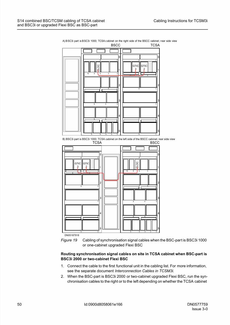
8/11/2019 NOKIA Flexi TRCM
http://slidepdf.com/reader/full/nokia-flexi-trcm 50/183
50 DN0577759
Issue 3-0
Cabling Instructions for TCSM3i
Id:0900d8058061e166
S14 combined BSC/TCSM cabling of TCSA cabinetand BSC3i or upgraded Flexi BSC as BSC-part
Figure 19 Cabling of synchronisation signal cables when the BSC-part is BSC3i 1000
or one-cabinet upgraded Flexi BSC
Routing synchronisation signal cables on site in TCSA cabinet when BSC-part is
BSC3i 2000 or two-cabinet Flexi BSC
1. Connect the cable to the first functional unit in the cabling list. For more information,
see the separate document Interconnection Cables in TCSM3i.
2. When the BSC-part is BSC3i 2000 or two-cabinet upgraded Flexi BSC, run the syn-
chronisation cables to the right or to the left depending on whether the TCSA cabinet
5
4
3
2
06 0
0
06
1
6 3 0
6 0
0
6
9
TCSA
5
4
3
2
06 0
48 0
3 06
1
8 6 3 010
6 4 2 09
48 0
BSCC
A) B SC3i part is B SC3i 1000; TCSA c abinet on the right side of the BSCC cabinet ; r ear side view
B) BSC3i part is BSC3i 1000; TCSA cabinet on the left side of the BSCC cabinet; rear side view
5
4
3
2
06 0
48 0
3 06
1
8 6 3 010
6 4 2 09
48 0
BSCC
5
4
3
2
06 0
0
06
1
6 3 0
6 0
0
6
9
TCSA
C L O C GTIC
2GTIC
3
GTIC2
GTIC3
C L O C
DN05187918
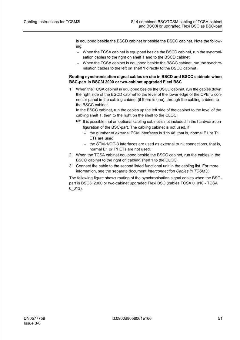
8/11/2019 NOKIA Flexi TRCM
http://slidepdf.com/reader/full/nokia-flexi-trcm 51/183
DN0577759
Issue 3-0
51
Cabling Instructions for TCSM3i S14 combined BSC/TCSM cabling of TCSA cabinetand BSC3i or upgraded Flexi BSC as BSC-part
Id:0900d8058061e166
is equipped beside the BSCD cabinet or beside the BSCC cabinet. Note the follow-
ing:
– When the TCSA cabinet is equipped beside the BSCD cabinet, run the syncroni-
sation cables to the right on shelf 1 and to the BSCD cabinet.
– When the TCSA cabinet is equipped beside the BSCC cabinet, run the synchro-
nisation cables to the left on shelf 1 directly to the BSCC cabinet.
Routing synchronisation signal cables on site in BSCD and BSCC cabinets when
BSC-part is BSC3i 2000 or two-cabinet upgraded Flexi BSC
1. When the TCSA cabinet is equipped beside the BSCD cabinet, run the cables down
the right side of the BSCD cabinet to the level of the lower edge of the CPETx con-
nector panel in the cabling cabinet (if there is one), through the cabling cabinet to
the BSCC cabinet.
In the BSCC cabinet, run the cables up the left side of the cabinet to the level of the
cabling shelf 1, then to the right on the shelf to the CLOC.
☞ It is possible that an optional cabling cabinet is not included in the hardware con-
figuration of the BSC-part. The cabling cabinet is not used, if:
– the number of external PCM interfaces is 1 to 48, that is, normal E1 or T1
ETs are used
– the STM-1/OC-3 interfaces are used as external trunk connections, that is,
normal E1 or T1 ETs are not used.
2. When the TCSA cabinet equipped beside the BSCC cabinet, run the cables in the
BSCC cabinet to the right on cabling shelf 1 to the CLOC.
3. Connect the cable to the second listed functional unit in the cabling list. For more
information, see the separate document Interconnection Cables in TCSM3i.
The following figure shows routing of the synchronisation signal cables when the BSC-part is BSC3i 2000 or two-cabinet upgraded Flexi BSC (cables TCSA 0_010 - TCSA
0_013).
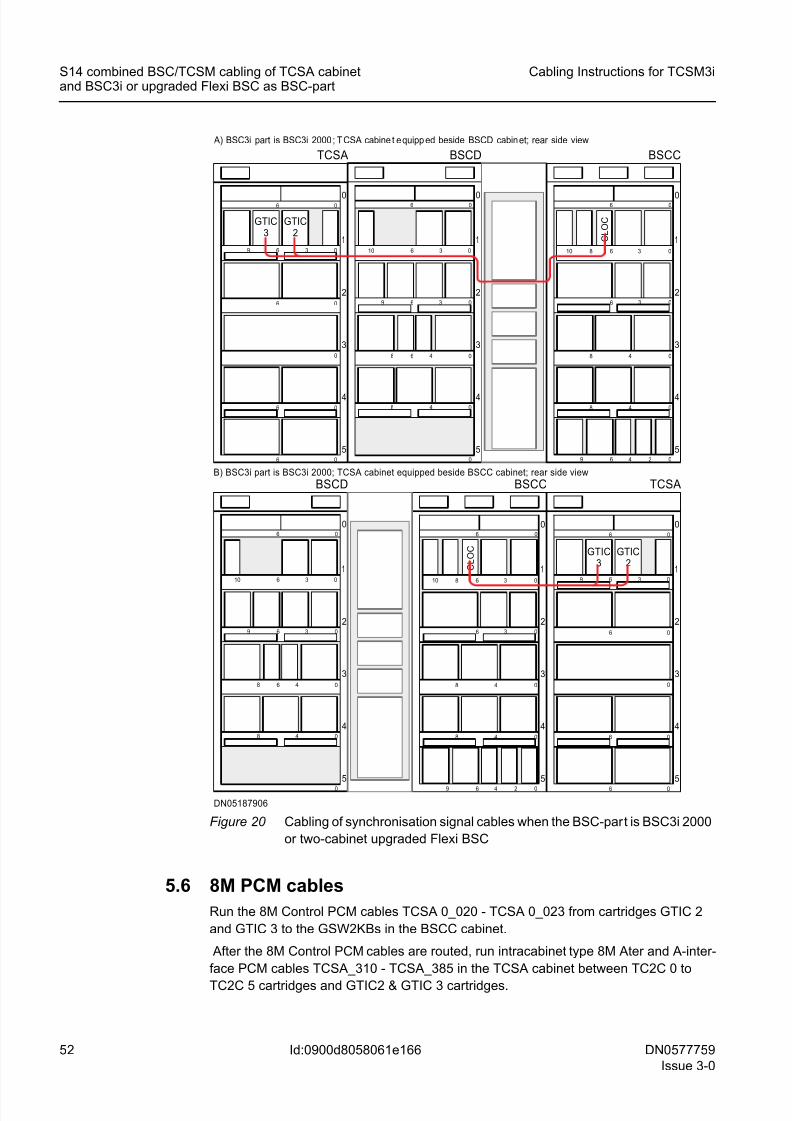
8/11/2019 NOKIA Flexi TRCM
http://slidepdf.com/reader/full/nokia-flexi-trcm 52/183
52 DN0577759
Issue 3-0
Cabling Instructions for TCSM3i
Id:0900d8058061e166
S14 combined BSC/TCSM cabling of TCSA cabinetand BSC3i or upgraded Flexi BSC as BSC-part
Figure 20 Cabling of synchronisation signal cables when the BSC-part is BSC3i 2000
or two-cabinet upgraded Flexi BSC
5.6 8M PCM cables
Run the 8M Control PCM cables TCSA 0_020 - TCSA 0_023 from cartridges GTIC 2
and GTIC 3 to the GSW2KBs in the BSCC cabinet.
After the 8M Control PCM cables are routed, run intracabinet type 8M Ater and A-inter-
face PCM cables TCSA_310 - TCSA_385 in the TCSA cabinet between TC2C 0 to
TC2C 5 cartridges and GTIC2 & GTIC 3 cartridges.
DN05187906
5
4
3
2
06 0
0
06
1
6 3 0
6 0
0
6
9
TCSA
5
4
3
2
06 0
48 0
3 06
1
8 6 3 010
6 4 2 09
48 0
BSCC
BSCD
5
4
3
2
1
06 0
0
48 0
48 0
3 06
10 6 3 0
9
6
5
4
3
2
06 0
0
06
1
6 3 0
6 0
0
6
9
TCSA
5
4
3
2
06 0
48 0
3 06
1
8 6 3 010
6 4 2 09
48 0
BSCC
BSCD
5
4
3
2
1
06 0
0
48 0
48 0
3 06
10 6 3 0
9
6
A) BSC3i part is BSC3i 2000 ; T CSA cabine t e quipp ed beside BSCD cabin et; rear side view
B) BSC3i part is BSC3i 2000; TCSA cabinet equipped beside BSCC cabinet; rear side view
GTIC3
GTIC2
C L
O C
C L
O C GTIC
3GTIC
2
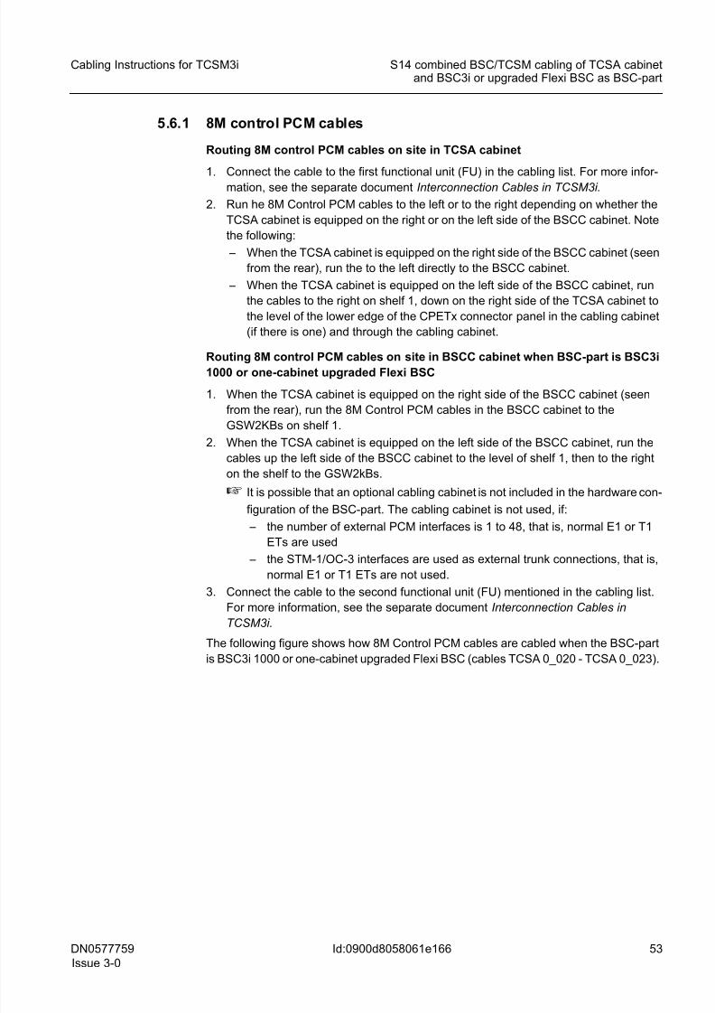
8/11/2019 NOKIA Flexi TRCM
http://slidepdf.com/reader/full/nokia-flexi-trcm 53/183
DN0577759
Issue 3-0
53
Cabling Instructions for TCSM3i S14 combined BSC/TCSM cabling of TCSA cabinetand BSC3i or upgraded Flexi BSC as BSC-part
Id:0900d8058061e166
5.6.1 8M control PCM cables
Routing 8M control PCM cables on site in TCSA cabinet
1.Connect the cable to the first functional unit (FU) in the cabling list. For more infor-mation, see the separate document Interconnection Cables in TCSM3i.
2. Run he 8M Control PCM cables to the left or to the right depending on whether the
TCSA cabinet is equipped on the right or on the left side of the BSCC cabinet. Note
the following:
– When the TCSA cabinet is equipped on the right side of the BSCC cabinet (seen
from the rear), run the to the left directly to the BSCC cabinet.
– When the TCSA cabinet is equipped on the left side of the BSCC cabinet, run
the cables to the right on shelf 1, down on the right side of the TCSA cabinet to
the level of the lower edge of the CPETx connector panel in the cabling cabinet
(if there is one) and through the cabling cabinet.
Routing 8M control PCM cables on site in BSCC cabinet when BSC-part is BSC3i1000 or one-cabinet upgraded Flexi BSC
1. When the TCSA cabinet is equipped on the right side of the BSCC cabinet (seen
from the rear), run the 8M Control PCM cables in the BSCC cabinet to the
GSW2KBs on shelf 1.
2. When the TCSA cabinet is equipped on the left side of the BSCC cabinet, run the
cables up the left side of the BSCC cabinet to the level of shelf 1, then to the right
on the shelf to the GSW2kBs.
☞ It is possible that an optional cabling cabinet is not included in the hardware con-
figuration of the BSC-part. The cabling cabinet is not used, if:
– the number of external PCM interfaces is 1 to 48, that is, normal E1 or T1ETs are used
– the STM-1/OC-3 interfaces are used as external trunk connections, that is,
normal E1 or T1 ETs are not used.
3. Connect the cable to the second functional unit (FU) mentioned in the cabling list.
For more information, see the separate document Interconnection Cables in
TCSM3i.
The following figure shows how 8M Control PCM cables are cabled when the BSC-part
is BSC3i 1000 or one-cabinet upgraded Flexi BSC (cables TCSA 0_020 - TCSA 0_023).
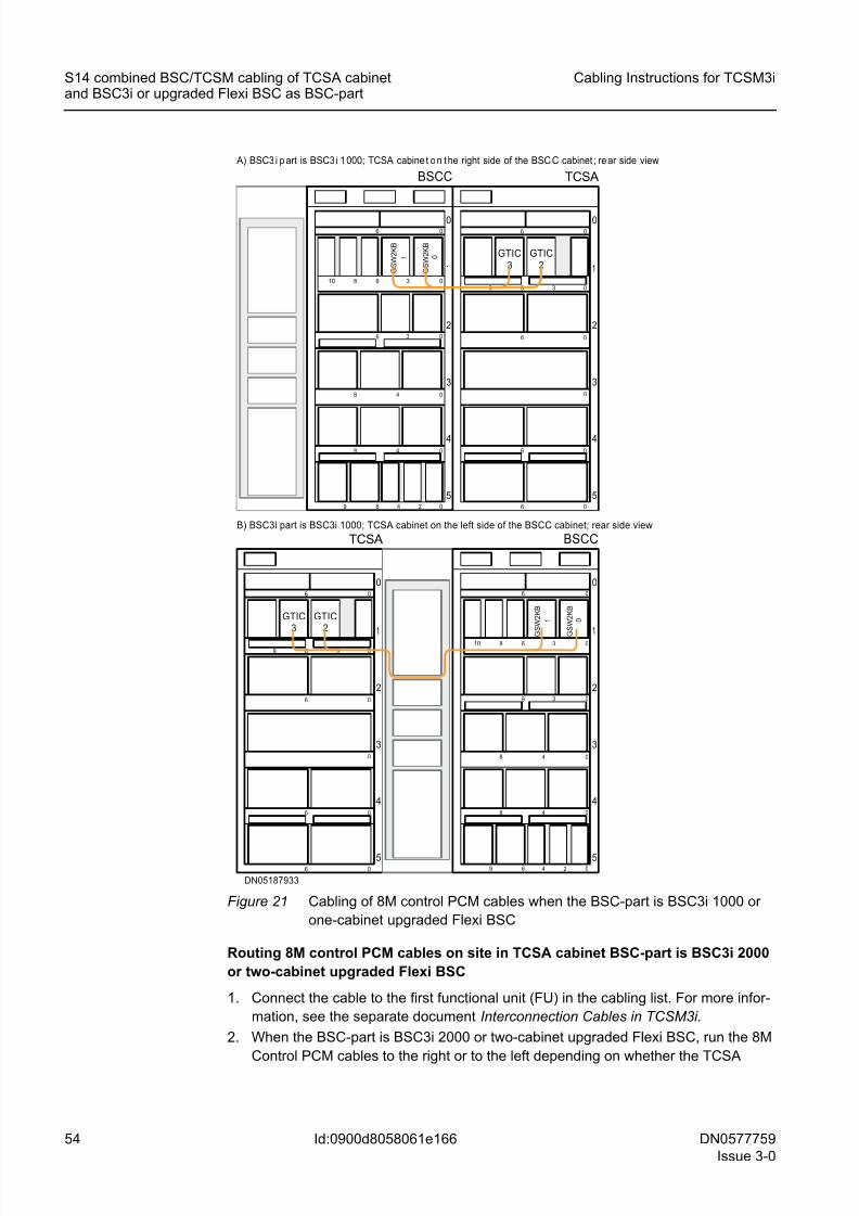
8/11/2019 NOKIA Flexi TRCM
http://slidepdf.com/reader/full/nokia-flexi-trcm 54/183
54 DN0577759
Issue 3-0
Cabling Instructions for TCSM3i
Id:0900d8058061e166
S14 combined BSC/TCSM cabling of TCSA cabinetand BSC3i or upgraded Flexi BSC as BSC-part
Figure 21 Cabling of 8M control PCM cables when the BSC-part is BSC3i 1000 or
one-cabinet upgraded Flexi BSC
Routing 8M control PCM cables on site in TCSA cabinet BSC-part is BSC3i 2000
or two-cabinet upgraded Flexi BSC
1. Connect the cable to the first functional unit (FU) in the cabling list. For more infor-
mation, see the separate document Interconnection Cables in TCSM3i.
2. When the BSC-part is BSC3i 2000 or two-cabinet upgraded Flexi BSC, run the 8M
Control PCM cables to the right or to the left depending on whether the TCSA
DN05187933
5
4
3
2
06 0
0
06
1
6 3 0
6 0
0
6
9
TCSA
5
4
3
2
06 0
48 0
3 06
1
8 6 3 010
6 4 2 09
48 0
BSCC
A) BSC3 i p art is BSC3 i 1 000; TCSA cabine t o n t he right side of the BSC C cabinet ; re ar side view
B) BSC3i part is BSC3i 1000; TCSA cabinet on the left side of the BSCC cabinet; rear side view
5
4
3
2
06 0
48 0
3 06
1
8 6 3 010
6 4 2 09
48 0
BSCC
5
4
3
2
06 0
0
06
1
6 3 0
6 0
0
6
9
TCSA
GTIC2
GTIC3
GTIC2
GTIC3
G S W 2 K B
1
G S W 2 K B
0
G S W 2 K B
1
G S W 2 K B
0
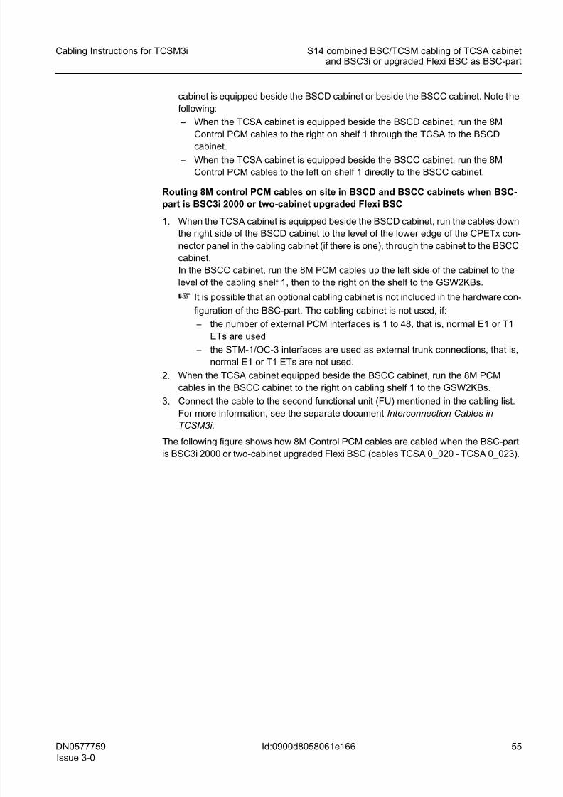
8/11/2019 NOKIA Flexi TRCM
http://slidepdf.com/reader/full/nokia-flexi-trcm 55/183
DN0577759
Issue 3-0
55
Cabling Instructions for TCSM3i S14 combined BSC/TCSM cabling of TCSA cabinetand BSC3i or upgraded Flexi BSC as BSC-part
Id:0900d8058061e166
cabinet is equipped beside the BSCD cabinet or beside the BSCC cabinet. Note the
following:
– When the TCSA cabinet is equipped beside the BSCD cabinet, run the 8M
Control PCM cables to the right on shelf 1 through the TCSA to the BSCD
cabinet.
– When the TCSA cabinet is equipped beside the BSCC cabinet, run the 8M
Control PCM cables to the left on shelf 1 directly to the BSCC cabinet.
Routing 8M control PCM cables on site in BSCD and BSCC cabinets when BSC-
part is BSC3i 2000 or two-cabinet upgraded Flexi BSC
1. When the TCSA cabinet is equipped beside the BSCD cabinet, run the cables down
the right side of the BSCD cabinet to the level of the lower edge of the CPETx con-
nector panel in the cabling cabinet (if there is one), through the cabinet to the BSCC
cabinet.
In the BSCC cabinet, run the 8M PCM cables up the left side of the cabinet to the
level of the cabling shelf 1, then to the right on the shelf to the GSW2KBs.
☞ It is possible that an optional cabling cabinet is not included in the hardware con-
figuration of the BSC-part. The cabling cabinet is not used, if:
– the number of external PCM interfaces is 1 to 48, that is, normal E1 or T1
ETs are used
– the STM-1/OC-3 interfaces are used as external trunk connections, that is,
normal E1 or T1 ETs are not used.
2. When the TCSA cabinet equipped beside the BSCC cabinet, run the 8M PCM
cables in the BSCC cabinet to the right on cabling shelf 1 to the GSW2KBs.
3. Connect the cable to the second functional unit (FU) mentioned in the cabling list.
For more information, see the separate document Interconnection Cables in
TCSM3i.
The following figure shows how 8M Control PCM cables are cabled when the BSC-part
is BSC3i 2000 or two-cabinet upgraded Flexi BSC (cables TCSA 0_020 - TCSA 0_023).
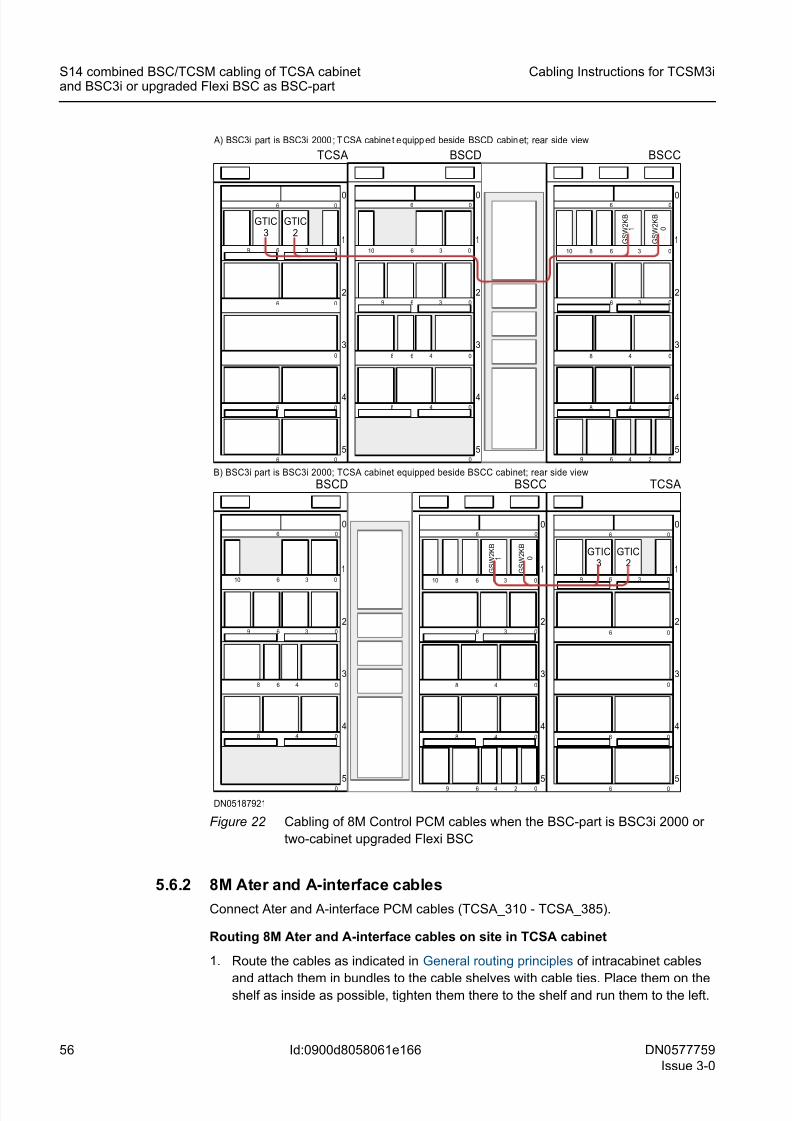
8/11/2019 NOKIA Flexi TRCM
http://slidepdf.com/reader/full/nokia-flexi-trcm 56/183
56 DN0577759
Issue 3-0
Cabling Instructions for TCSM3i
Id:0900d8058061e166
S14 combined BSC/TCSM cabling of TCSA cabinetand BSC3i or upgraded Flexi BSC as BSC-part
Figure 22 Cabling of 8M Control PCM cables when the BSC-part is BSC3i 2000 or
two-cabinet upgraded Flexi BSC
5.6.2 8M Ater and A-interface cables
Connect Ater and A-interface PCM cables (TCSA_310 - TCSA_385).
Routing 8M Ater and A-interface cables on site in TCSA cabinet
1. Route the cables as indicated in General routing principles of intracabinet cables
and attach them in bundles to the cable shelves with cable ties. Place them on theshelf as inside as possible, tighten them there to the shelf and run them to the left.
DN05187921
5
4
3
2
06 0
0
06
1
6 3 0
6 0
0
6
9
TCSA
5
4
3
2
06 0
48 0
3 06
1
8 6 3 010
6 4 2 09
48 0
BSCC
BSCD
5
4
3
2
1
06 0
0
48 0
48 0
3 06
10 6 3 0
9
6
5
4
3
2
06 0
0
06
1
6 3 0
6 0
0
6
9
TCSA
5
4
3
2
06 0
48 0
3 06
1
8 6 3 010
6 4 2 09
48 0
BSCC
BSCD
5
4
3
2
1
06 0
0
48 0
48 0
3 06
10 6 3 0
9
6
A) BSC3i part is BSC3i 2000 ; T CSA cabine t e quipp ed beside BSCD cabin et; rear side view
B) BSC3i part is BSC3i 2000; TCSA cabinet equipped beside BSCC cabinet; rear side view
GTIC3
GTIC2
GTIC3
GTIC2
G S W 2 K B
1
G S W 2 K B
0
G S W 2 K B
1
G S W 2 K B
0
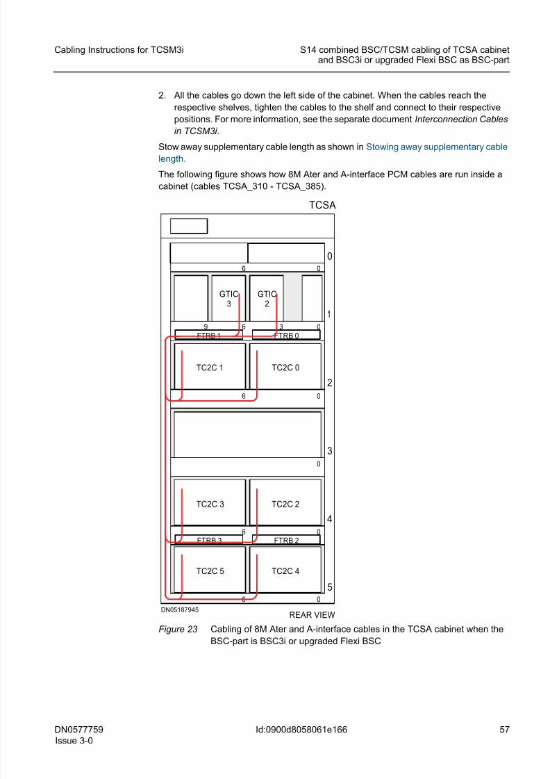
8/11/2019 NOKIA Flexi TRCM
http://slidepdf.com/reader/full/nokia-flexi-trcm 57/183
DN0577759
Issue 3-0
57
Cabling Instructions for TCSM3i S14 combined BSC/TCSM cabling of TCSA cabinetand BSC3i or upgraded Flexi BSC as BSC-part
Id:0900d8058061e166
2. All the cables go down the left side of the cabinet. When the cables reach the
respective shelves, tighten the cables to the shelf and connect to their respective
positions. For more information, see the separate document Interconnection Cables
in TCSM3i .
Stow away supplementary cable length as shown in Stowing away supplementary cable
length.
The following figure shows how 8M Ater and A-interface PCM cables are run inside a
cabinet (cables TCSA_310 - TCSA_385).
Figure 23 Cabling of 8M Ater and A-interface cables in the TCSA cabinet when the
BSC-part is BSC3i or upgraded Flexi BSC
REAR VIEWDN05187945
TCSA
5
4
3
2
06 0
0
06
1
6 3 0
6 0
0
6
9
TC2C 0
TC2C 3
TC2C 4
FTRB 2FTRB 3
GTIC2
FTRB 1 FTRB 0
TC2C 5
TC2C 2
TC2C 1
GTIC3
8/11/2019 NOKIA Flexi TRCM
http://slidepdf.com/reader/full/nokia-flexi-trcm 58/183
8/11/2019 NOKIA Flexi TRCM
http://slidepdf.com/reader/full/nokia-flexi-trcm 59/183
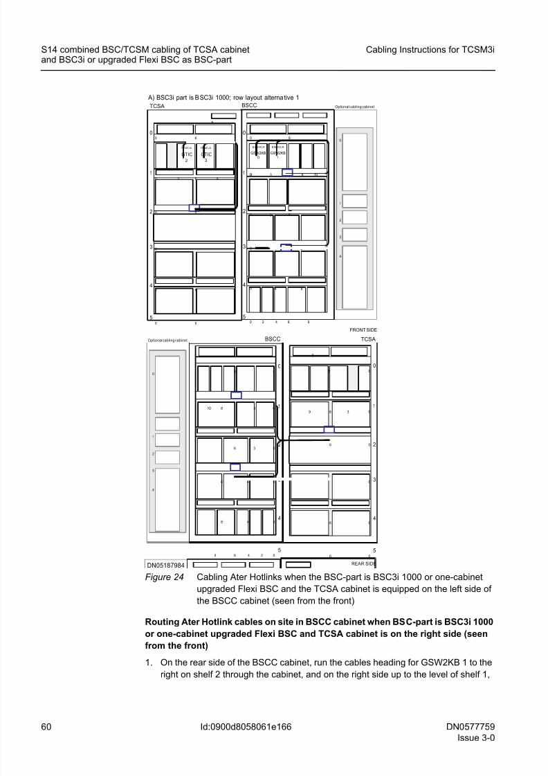
8/11/2019 NOKIA Flexi TRCM
http://slidepdf.com/reader/full/nokia-flexi-trcm 60/183
60 DN0577759
Issue 3-0
Cabling Instructions for TCSM3i
Id:0900d8058061e166
S14 combined BSC/TCSM cabling of TCSA cabinetand BSC3i or upgraded Flexi BSC as BSC-part
Figure 24 Cabling Ater Hotlinks when the BSC-part is BSC3i 1000 or one-cabinet
upgraded Flexi BSC and the TCSA cabinet is equipped on the left side of
the BSCC cabinet (seen from the front)
Routing Ater Hotlink cables on site in BSCC cabinet when BSC-part is BSC3i 1000
or one-cabinet upgraded Flexi BSC and TCSA cabinet is on the right side (seen
from the front)
1. On the rear side of the BSCC cabinet, run the cables heading for GSW2KB 1 to the
right on shelf 2 through the cabinet, and on the right side up to the level of shelf 1,
1
2
3
4
0
Optional cabling cabinet
FRONT SIDE
1
0
S W10C- A S W10C-A
GSW2KB0
GSW2KB1
0
0
0
0 83
BSCC
0 6
84
84
0 632
3
4
5
10
0 2 4 6 9
1
2
3
4
0
5
0
0
0
0
6
0
6
9
0 6
6
3
GT4C-A
GTIC
2
6
GT4C-A
GTIC
3
8
TCSA
1
2
3
4
0
Optional cabling cabinet
1
2
3
4
0
5
0
0
0
0
06
0
48
6
48
8 3
3
BSCC
06
249
10 1
2
3
4
0
5
0
0
0
0
6
0
6
9
06
6
36
8
TCSA
REAR SIDE
A) BSC3i part is B SC3i 1000; row layout alterna tive 1
DN05187984
8/11/2019 NOKIA Flexi TRCM
http://slidepdf.com/reader/full/nokia-flexi-trcm 61/183
DN0577759
Issue 3-0
61
Cabling Instructions for TCSM3i S14 combined BSC/TCSM cabling of TCSA cabinetand BSC3i or upgraded Flexi BSC as BSC-part
Id:0900d8058061e166
then to the left on shelf 1. Pass them through the opening in the middle of shelf 1
from back to front.
2. On the rear side of the BSCC cabinet, run the cables heading for GSW2KB 0 to the
right on shelf 3 and pass them from back to front through the opening in the middle
of shelf 3.
3. On the front side of the BSCC cabinet, run the cables to the right and on the right
side of the cabinet to the level of front cabling shelves of the topmost cartridge shelf
and from there to the front panel interfaces of SW256B plug-in units in the GSW2KB
0 and GSW2KB 1 cartridges.
4. Connect the cable to the second functional unit (FU) mentioned in the cabling list.
For more information, see the separate document Interconnection Cables in
TCSM3i.
The following figure shows how Ater Hotlinks are cabled when the BSC-part is BSC3i
1000 or one-cabinet upgraded Flexi BSC and the TCSA cabinet is equipped on the right
side of the BSCC cabinet (cables TCSA 0_030 - TCSA 0_033)
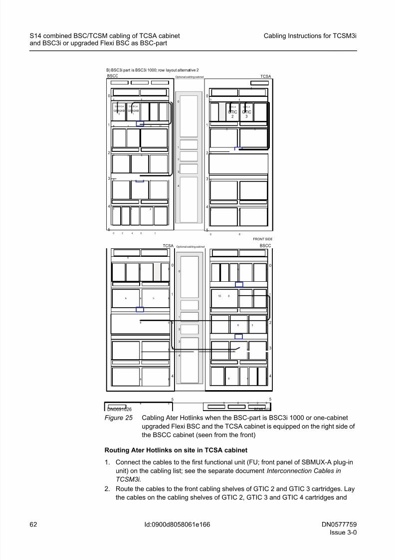
8/11/2019 NOKIA Flexi TRCM
http://slidepdf.com/reader/full/nokia-flexi-trcm 62/183
62 DN0577759
Issue 3-0
Cabling Instructions for TCSM3i
Id:0900d8058061e166
S14 combined BSC/TCSM cabling of TCSA cabinetand BSC3i or upgraded Flexi BSC as BSC-part
Figure 25 Cabling Ater Hotlinks when the BSC-part is BSC3i 1000 or one-cabinet
upgraded Flexi BSC and the TCSA cabinet is equipped on the right side of
the BSCC cabinet (seen from the front)
Routing Ater Hotlinks on site in TCSA cabinet
1. Connect the cables to the first functional unit (FU; front panel of SBMUX-A plug-in
unit) on the cabling list; see the separate document Interconnection Cables in
TCSM3i.
2. Route the cables to the front cabling shelves of GTIC 2 and GTIC 3 cartridges. Laythe cables on the cabling shelves of GTIC 2, GTIC 3 and GTIC 4 cartridges and
1
2
3
4
0
Optional cabling cabinet
FRONT SIDE
1
0
S W10C- A S W10C-A
GSW2KB0
GSW2KB1
0
0
0
0 83
BSCC
0 6
84
84
0 632
3
4
5
10
0 2 4 6 9
1
2
3
4
0
5
0
0
0
0
6
0
6
9
0 6
6
3
GT4C-A
GTIC2
6
GT4C-A
GTIC3
8
TCSA
1
2
3
4
0
Optional cabling cabinet
1
2
3
4
0
5
0
0
0
0
06
0
48
6
48
8 3
3
BSCC
06
249
101
2
3
4
0
5
0
0
0
0
6
0
6
9
06
6
36
8
TCSA
B) BSC3i part is BSC3i 1000; row layout alternative 2
REAR SIDEDN0691026
8/11/2019 NOKIA Flexi TRCM
http://slidepdf.com/reader/full/nokia-flexi-trcm 63/183
DN0577759
Issue 3-0
63
Cabling Instructions for TCSM3i S14 combined BSC/TCSM cabling of TCSA cabinetand BSC3i or upgraded Flexi BSC as BSC-part
Id:0900d8058061e166
route them to the right side of the TCSA cabinet (seen from the front). Run them to
the level of the shelf 2. Pass them from front to back through the opening in the
middle of shelf 2.
3. Route the cables on the cabling shelf 2 to the right side or to the left side (seen from
rear) of the cabinet, depending on whether the TCSA cabinet is equipped beside the
BSCD cabinet or beside the BSCC cabinet. Note the following:
– When the TCSA cabinet is on the right side of the BSCC cabinet, that is, beside
the BSCD cabinet (seen from the front), and the cables have been passed
through the cabinet, run the cables to the right on shelf 2. On the right side of the
TCSA cabinet, divide the Hotlink into two groups of two cables: cables heading
for GSW2KB 0 (TCSA 0_030 & TCSA 0_031) to one group and cables heading
for GSW2KB 1 (TCSA 0_032 & TCSA 0_033) to another.
– When the TCSA cabinet is on the left side of the BSCC cabinet (seen from the
front), and the cables have been passed through the cabinet, run the cables to
the left on shelf 2 to the BSCC cabinet.
Routing Ater Hotlink cables on site in BSCD and BSCC cabinets when BSC-part
is BSC3i 2000 or two-cabinet upgraded Flexi BSC and TCSA cabinet is beside the
BSCD cabinet
1. In BSCD cabinet, Run the Hotlink cables heading for GSW2KB 0 to the level of shelf
3 and run the Hotlink cables heading for GSW2KB 1 on the shelf 2. Run all Hotlink
cables heading for the BSCC cabinet through the BSCD cabinet and the cabling
cabinet.
☞ It is possible that an optional cabling cabinet is not included in the hardware con-
figuration of the BSC-part. The cabling cabinet is not used, if:
– the number of external PCM interfaces is 1 to 48, that is, normal E1 or T1
ETs are used
– the STM-1/OC-3 interfaces are used as external trunk connections, that is,
normal E1 or T1 ETs are not used.
2. On rear side of the BSCC cabinet, pass the Hotlink cables heading for GSW2KB 0
from back to front through the opening in the middle of shelf 3, and Hotlink cables
heading for GSW2KB 1 from back to front through the opening in the middle of shelf
1.
3. On the front side of the BSCC cabinet, use the right side of the cabinet and run all
Hotlink cables to the level of front cabling shelves of the topmost cartridge shelf and
from there to the front panel interfaces of SW256B plug-in units in the GSW2KB 0
and GSW2KB 1 cartridges.
4. Connect the cable to the second functional unit (FU) mentioned in the cabling list.
For more information, see the separate document Interconnection Cables in
TCSM3i.
Routing Ater Hotlink cables on site in BSCD and BSCC cabinets when BSC-part
is BSC3i 2000 or two-cabinet upgraded Flexi BSC and TCSA cabinet is beside the
BSCC cabinet
1. When the TCSA cabinet equipped beside the BSCC cabinet, divide the Hotlink
cables into two groups of two cables on the right side of the BSCC cabinet: cables
heading for GSW2KB 0 (TCSA 0_030 & TCSA 0_031) to one group and cables
heading for GSW2KB 1 (TCSA 0_032 & TCSA 0_033) to another.
8/11/2019 NOKIA Flexi TRCM
http://slidepdf.com/reader/full/nokia-flexi-trcm 64/183
64 DN0577759
Issue 3-0
Cabling Instructions for TCSM3i
Id:0900d8058061e166
S14 combined BSC/TCSM cabling of TCSA cabinetand BSC3i or upgraded Flexi BSC as BSC-part
2. Run the Hotlink cables heading for GSW2KB 0 to the level of shelf 3 and run the
Hotlink cables heading for GSW2KB 1 to the level of shelf 1. Run the cables to the
left and to the middle of their respective shelves.
3.Pass Hotlink cables heading for GSW2KB 0 from back to front through the openingin the middle of shelf 3 and Hotlink cables heading for GSW2KB 1 from back to front
through the opening in the middle of shelf 1.
4. On the front side of the BSCC cabinet, use the right side of the cabinet and run all
Hotlink cables to the level of front cabling shelves of the topmost cartridge shelf and
from there to the front panel interfaces of SW256B plug-in units in the GSW2KB 0
and GSW2KB 1 cartridges.
5. Connect the cable to the second functional unit (FU) mentioned in the cabling list.
For more information, see the separate document Interconnection Cables in
TCSM3i.
The following figure shows how Ater Hotlinks are cabled when the BSC-part is BSC3i
2000 or two-cabinet upgraded Flexi BSC and the TCSA cabinet is equipped beside theBSCD cabinet (TCSA 0_030 - TCSA 0_033).
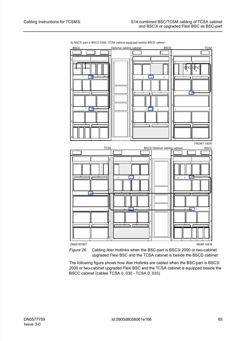
8/11/2019 NOKIA Flexi TRCM
http://slidepdf.com/reader/full/nokia-flexi-trcm 65/183
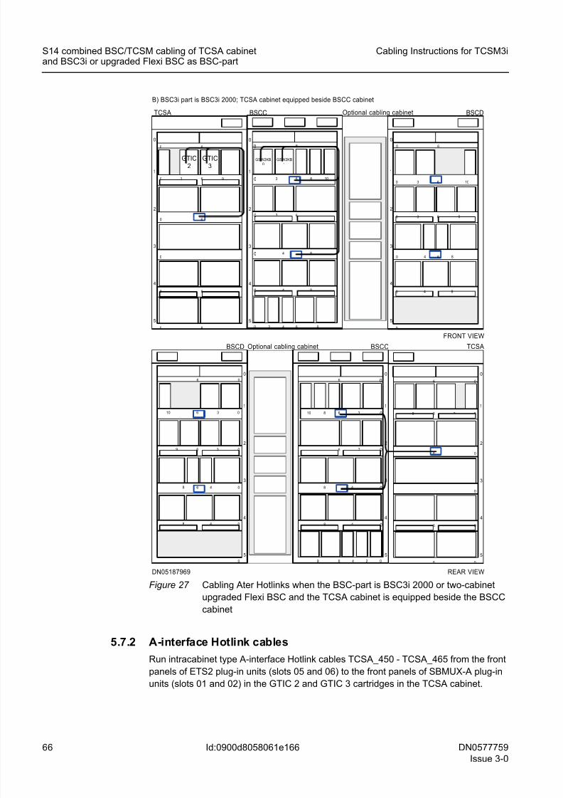
8/11/2019 NOKIA Flexi TRCM
http://slidepdf.com/reader/full/nokia-flexi-trcm 66/183
66 DN0577759
Issue 3-0
Cabling Instructions for TCSM3i
Id:0900d8058061e166
S14 combined BSC/TCSM cabling of TCSA cabinetand BSC3i or upgraded Flexi BSC as BSC-part
Figure 27 Cabling Ater Hotlinks when the BSC-part is BSC3i 2000 or two-cabinet
upgraded Flexi BSC and the TCSA cabinet is equipped beside the BSCC
cabinet
5.7.2 A-interface Hotlink cables
Run intracabinet type A-interface Hotlink cables TCSA_450 - TCSA_465 from the front
panels of ETS2 plug-in units (slots 05 and 06) to the front panels of SBMUX-A plug-in
units (slots 01 and 02) in the GTIC 2 and GTIC 3 cartridges in the TCSA cabinet.
DN05187969
B) BSC3i part is BSC3i 2000; TCSA cabinet equipped beside BSCC cabinet
FRONT VIEW
TCSA
5
4
3
2
060
0
0 6
1
630
60
0
6
9
GTIC2
GTIC3
BSCC
5
4
3
2
060
4 80
30 6
1
8630 10
6420 9
4 80
GSW2KB0
GSW2KB1
BSCD
5
4
3
2
1
060
0
4 80
4 80
30 6
10630
9
6
5
4
3
2
0
6 0
0
06
1
6 3 0
6 0
0
6
9
TCSABSCD
5
4
3
2
1
0
6 0
0
48 0
48 0
3 06
10 6 3 0
9
6
5
4
3
2
0
6 0
48 0
3 06
1
8 6 3 010
6 4 2 09
48 0
BSCC
REAR VIEW
Optional cabling cabinet
Optional cabling cabinet
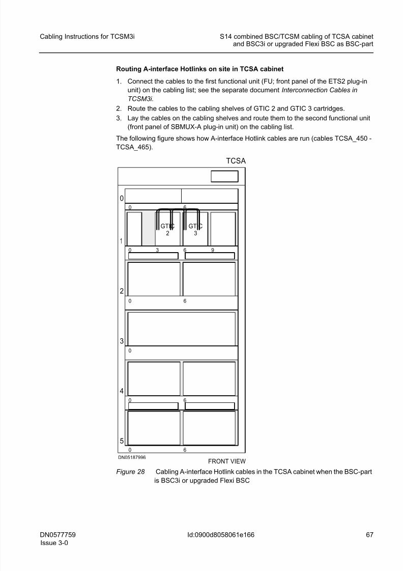
8/11/2019 NOKIA Flexi TRCM
http://slidepdf.com/reader/full/nokia-flexi-trcm 67/183
DN0577759
Issue 3-0
67
Cabling Instructions for TCSM3i S14 combined BSC/TCSM cabling of TCSA cabinetand BSC3i or upgraded Flexi BSC as BSC-part
Id:0900d8058061e166
Routing A-interface Hotlinks on site in TCSA cabinet
1. Connect the cables to the first functional unit (FU; front panel of the ETS2 plug-in
unit) on the cabling list; see the separate document Interconnection Cables in
TCSM3i.2. Route the cables to the cabling shelves of GTIC 2 and GTIC 3 cartridges.
3. Lay the cables on the cabling shelves and route them to the second functional unit
(front panel of SBMUX-A plug-in unit) on the cabling list.
The following figure shows how A-interface Hotlink cables are run (cables TCSA_450 -
TCSA_465).
Figure 28 Cabling A-interface Hotlink cables in the TCSA cabinet when the BSC-part
is BSC3i or upgraded Flexi BSC
FRONT VIEWDN05187996
TCSA
5
4
3
2
060
0
0 6
1
630
60
0
6
9
GTIC2
GTIC3
8/11/2019 NOKIA Flexi TRCM
http://slidepdf.com/reader/full/nokia-flexi-trcm 68/183
68 DN0577759
Issue 3-0
Cabling Instructions for TCSM3i
Id:0900d8058061e166
S14 combined BSC/TCSM cabling of TCSA cabinetand BSC3i or upgraded Flexi BSC as BSC-part
5.8 External STM-1/OC-3 interface related cables
External STM-1/OC-3 interface cables are not included in the delivery.
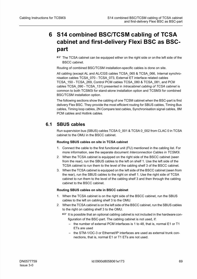
8/11/2019 NOKIA Flexi TRCM
http://slidepdf.com/reader/full/nokia-flexi-trcm 69/183
DN0577759
Issue 3-0
69
Cabling Instructions for TCSM3i S14 combined BSC/TCSM cabling of TCSA cabinetand first-delivery Flexi BSC as BSC-part
Id:0900d8058061e173
6 S14 combined BSC/TCSM cabling of TCSA
cabinet and first-delivery Flexi BSC as BSC-
part☞ The TCSA cabinet can be equipped either on the right side or on the left side of the
BSCC cabinet.
Routing of combined BSC/TCSM installation-specific cables is done on site.
All cabling (except AL and AL/CGS cables TCSA_065 & TCSA_066, Internal synchro-
nisation cables TCSA_070 - TCSA_073, External ET interface related cables
TCSA_150 - TCSA_269, Control PCM cables TCSA_080 & TCSA_081, and PCM
cables TCSA_090 - TCSA_131) presented in Intracabinet cabling of TCSA cabinet is
common to both TCSM3i for stand-alone installation option and TCSM3i for combined
BSC/TCSM installation option.
The following sections show the cabling of one TCSM cabinet when the BSC-part is first
delivery Flex BSC. They provide the most efficient routing for SBUS cables, Timing Bus
cables, Timing loop cables, 2N Compare test cables, Synchronisation signal cables, 8M
PCM cables and Hotlink cables.
6.1 SBUS cables
Run supervision bus (SBUS) cables TCSA 0_001 & TCSA 0_002 from CLAC 0 in TCSA
cabinet to the OMU in the BSCC cabinet.
Routing SBUS cables on site in TCSA cabinet
1. Connect the cable to the first functional unit (FU) mentioned in the cabling list. For
more information, see the separate document Interconnection Cables in TCSM3i.
2. When the TCSA cabinet is equipped on the right side of the BSCC cabinet (seen
from the rear), run the SBUS cables to the left on shelf 1. Use the left side of the
TCSA cabinet to run them to the level of the cabling shelf 3 of the BSCC cabinet.
3. When the TCSA cabinet is equipped on the left side of the BSCC cabinet (seen from
the rear), run the SBUS cables to the right on shelf 1. Use the right side of TCSA
cabinet to run them to the level of the cabling shelf 3 and then through the cabling
cabinet to the BSCC cabinet.
Routing SBUS cables on site in BSCC cabinet
1. When the TCSA cabinet is on the right side of the BSCC cabinet, run the SBUScables to the left on cabling shelf 3 to the OMU.
2. When the TCSA cabinet is on the left side of the BSCC cabinet, run the SBUS cables
to the right on cabling shelf 3 to the OMU.
☞ It is possible that an optional cabling cabinet is not included in the hardware con-
figuration of the BSC-part. The cabling cabinet is not used, if:
– the number of external PCM interfaces is 1 to 48, that is, normal E1 or T1
ETs are used
– the STM-1/OC-3 or Ethernet/IP interfaces are used as external trunk con-
nections, that is, normal E1 or T1 ETs are not used.
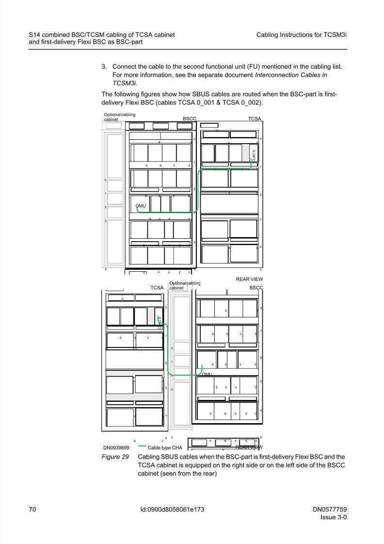
8/11/2019 NOKIA Flexi TRCM
http://slidepdf.com/reader/full/nokia-flexi-trcm 70/183
70 DN0577759
Issue 3-0
Cabling Instructions for TCSM3i
Id:0900d8058061e173
S14 combined BSC/TCSM cabling of TCSA cabinetand first-delivery Flexi BSC as BSC-part
3. Connect the cable to the second functional unit (FU) mentioned in the cabling list.
For more information, see the separate document Interconnection Cables in
TCSM3i.
The following figures show how SBUS cables are routed when the BSC-part is first-delivery Flexi BSC (cables TCSA 0_001 & TCSA 0_002).
Figure 29 Cabling SBUS cables when the BSC-part is first-delivery Flexi BSC and the
TCSA cabinet is equipped on the right side or on the left side of the BSCC
cabinet (seen from the rear)
4
0
1
2
3
4
0
1
2
3
REAR VIEW
1
2
3
4
0
5
0
0
0
0
6
0
6
9
06
6
36
8
BSCC TCSA
C L A C
0
5
4
3
2
1
006
3 09 6
48 0
0249 6
OMU
3 09 6
6
0249 6
Optional cablingcabinet
REAR VIEW
1
2
3
4
0
5
0
0
0
0
6
0
6
9
06
6
36
8
BSCCTCSA
C L A C
0
Cable type CHA
5
4
3
2
1
006
3 09 6
48 0
0249 6
OMU
3 09 6
6
0249 6
DN0939899
Optional cablingcabinet
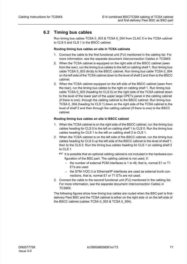
8/11/2019 NOKIA Flexi TRCM
http://slidepdf.com/reader/full/nokia-flexi-trcm 71/183
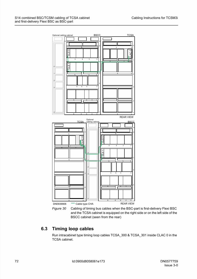
8/11/2019 NOKIA Flexi TRCM
http://slidepdf.com/reader/full/nokia-flexi-trcm 72/183
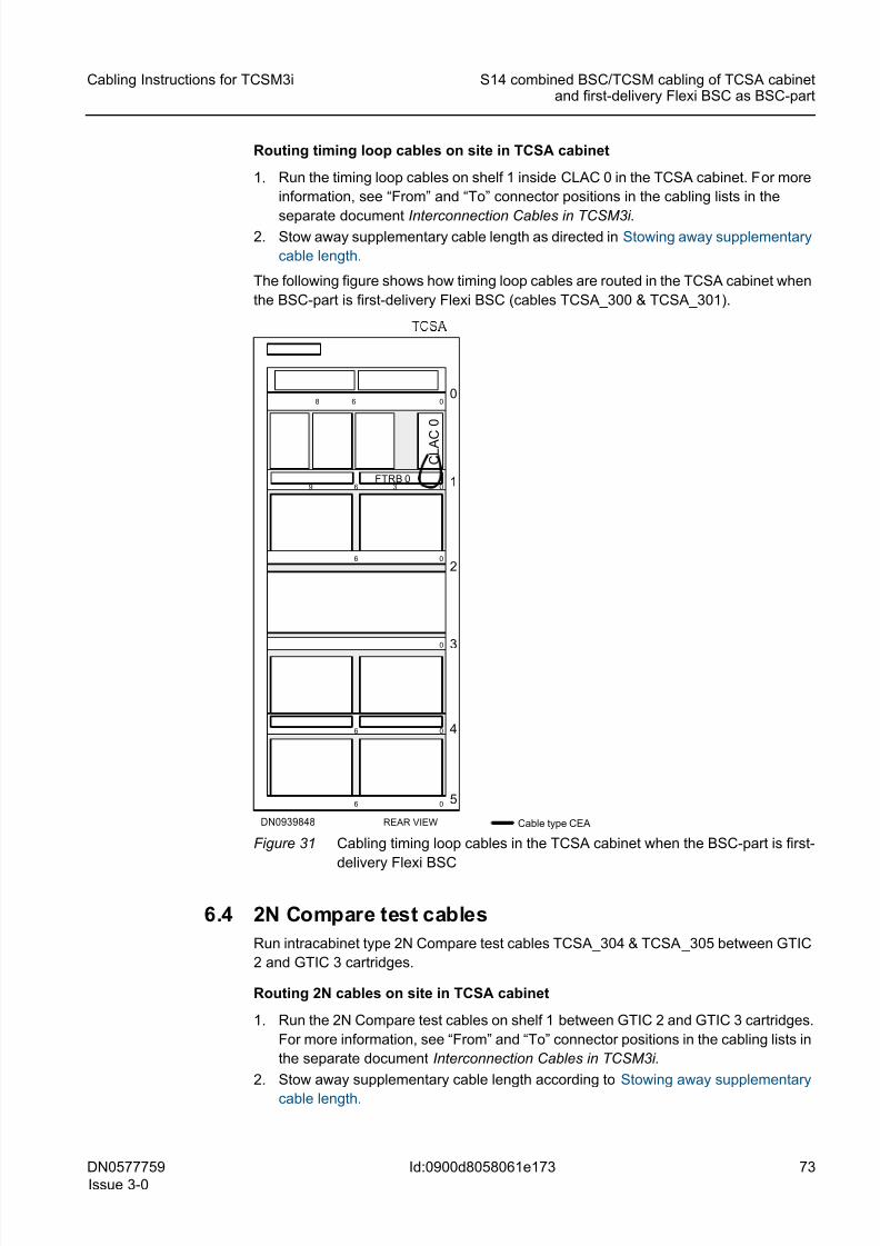
8/11/2019 NOKIA Flexi TRCM
http://slidepdf.com/reader/full/nokia-flexi-trcm 73/183
DN0577759
Issue 3-0
73
Cabling Instructions for TCSM3i S14 combined BSC/TCSM cabling of TCSA cabinetand first-delivery Flexi BSC as BSC-part
Id:0900d8058061e173
Routing timing loop cables on site in TCSA cabinet
1. Run the timing loop cables on shelf 1 inside CLAC 0 in the TCSA cabinet. For more
information, see “From” and “To” connector positions in the cabling lists in the
separate document Interconnection Cables in TCSM3i.2. Stow away supplementary cable length as directed in Stowing away supplementary
cable length.
The following figure shows how timing loop cables are routed in the TCSA cabinet when
the BSC-part is first-delivery Flexi BSC (cables TCSA_300 & TCSA_301).
Figure 31 Cabling timing loop cables in the TCSA cabinet when the BSC-part is first-
delivery Flexi BSC
6.4 2N Compare test cables
Run intracabinet type 2N Compare test cables TCSA_304 & TCSA_305 between GTIC
2 and GTIC 3 cartridges.
Routing 2N cables on site in TCSA cabinet
1. Run the 2N Compare test cables on shelf 1 between GTIC 2 and GTIC 3 cartridges.
For more information, see “From” and “To” connector positions in the cabling lists in
the separate document Interconnection Cables in TCSM3i.
2. Stow away supplementary cable length according to Stowing away supplementary
cable length.
FTRB 0 1
2
3
4
0
5
0
0
0
0
6
0
6
9
06
6
36
8
C L A C
0
DN0939848 REAR VIEW Cable type CEA
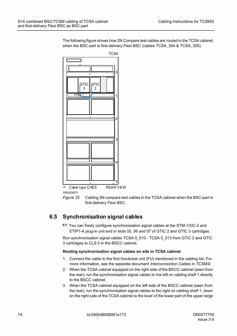
8/11/2019 NOKIA Flexi TRCM
http://slidepdf.com/reader/full/nokia-flexi-trcm 74/183
74 DN0577759
Issue 3-0
Cabling Instructions for TCSM3i
Id:0900d8058061e173
S14 combined BSC/TCSM cabling of TCSA cabinetand first-delivery Flexi BSC as BSC-part
The following figure shows how 2N Compare test cables are routed in the TCSA cabinet
when the BSC-part is first-delivery Flexi BSC (cables TCSA_304 & TCSA_305).
Figure 32 Cabling 2N compare test cables in the TCSA cabinet when the BSC-part is
first-delivery Flexi BSC
6.5 Synchronisation signal cables
☞ You can freely configure synchronisation signal cables at the STM-1/OC-3 and
ETIP1-A plug-in unit end in slots 05, 06 and 07 of GTIC 2 and GTIC 3 cartridges.
Run synchronisation signal cables TCSA 0_010 - TCSA 0_013 from GTIC 2 and GTIC
3 cartridges to CLS 0 in the BSCC cabinet.
Routing synchronisation signal cables on site in TCSA cabinet
1. Connect the cable to the first functional unit (FU) mentioned in the cabling list. For
more information, see the separate document Interconnection Cables in TCSM3i.
2. When the TCSA cabinet equipped on the right side of the BSCC cabinet (seen from
the rear), run the synchronisation signal cables to the left on cabling shelf 1 directly
to the BSCC cabinet.
3. When the TCSA cabinet equipped on the left side of the BSCC cabinet (seen from
the rear), run the synchronisation signal cables to the right on cabling shelf 1, down
on the right side of the TCSA cabinet to the level of the lower part of the upper large
FTRB 1 1
2
3
4
0
5
0
0
0
0
6
0
6
9
06
6
36
8
Cable type CHES REAR VIEW
TCSA
GTIC3
GTIC2
DN0939875
8/11/2019 NOKIA Flexi TRCM
http://slidepdf.com/reader/full/nokia-flexi-trcm 75/183
DN0577759
Issue 3-0
75
Cabling Instructions for TCSM3i S14 combined BSC/TCSM cabling of TCSA cabinetand first-delivery Flexi BSC as BSC-part
Id:0900d8058061e173
CPETx panel in the cabling cabinet (if there is one), through the cabling cabinet to
the BSCC cabinet.
Routing synchronisation signal cables on site in BSCC cabinet
1. When the TCSA cabinet equipped on the right side of the BSCC cabinet, run the
synchronisation signal cables on shelf 1 to CLS 0.
2. When the TCSA cabinet equipped on the left side of the BSCC cabinet, run the syn-
chronisation signal cables up the left side of the BSCC cabinet to the level of shelf
1 and to CLS 0.
☞ It is possible that an optional cabling cabinet is not included in the hardware con-
figuration of the BSC-part. The cabling cabinet is not used, if:
– the number of external PCM interfaces is 1 to 48, that is, normal E1 or T1
ETs are used
– the STM-1/OC-3 or Ethernet/IP interfaces are used as external trunk con-
nections, that is, normal E1 or T1 ETs are not used.3. Connect the cable to the second functional unit (FU) mentioned in the cabling list.
For more information, see the separate document Interconnection Cables in
TCSM3i.
The following figures show how the synchronisation signal cables are routed when the
BSC-part is first-delivery Flexi BSC (cables TCSA 0_010 - TCSA 0_013).
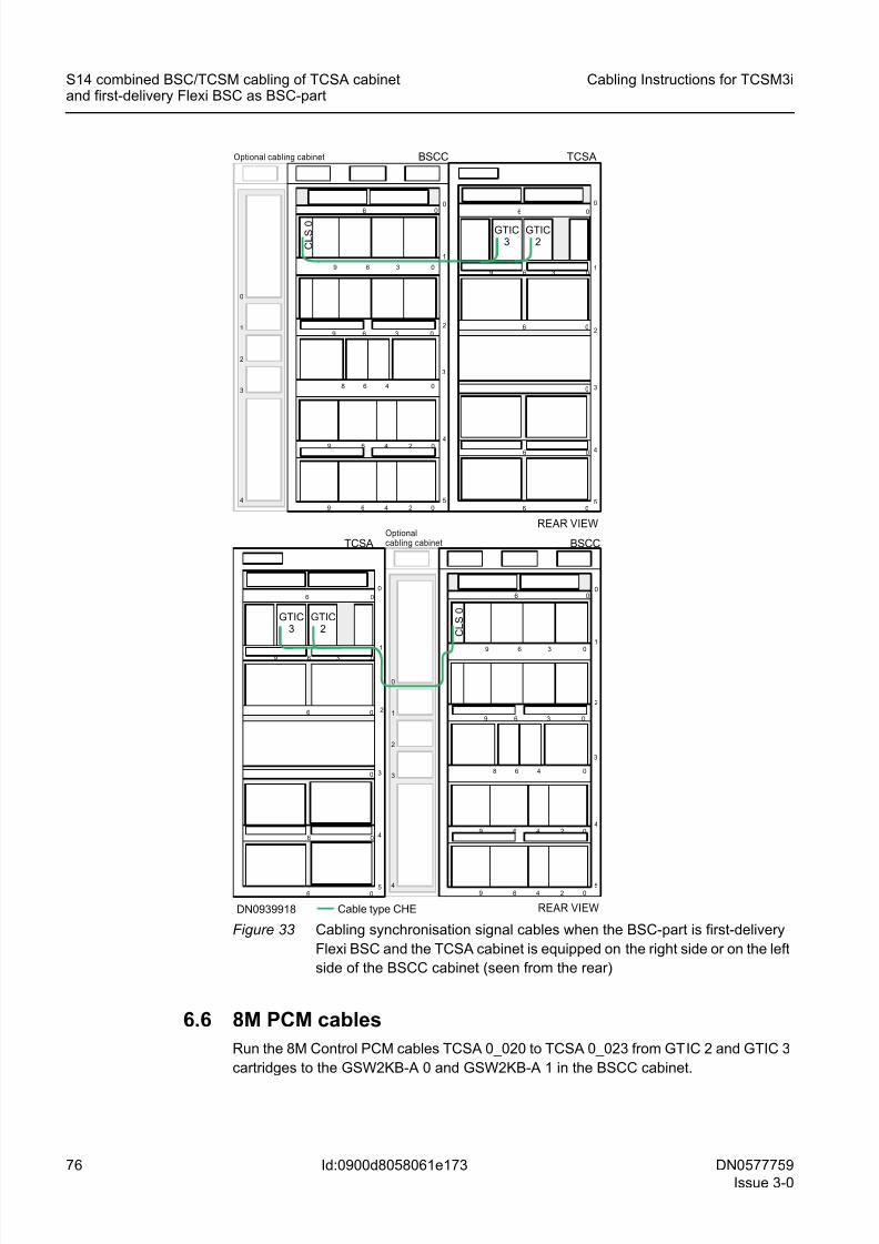
8/11/2019 NOKIA Flexi TRCM
http://slidepdf.com/reader/full/nokia-flexi-trcm 76/183
76 DN0577759
Issue 3-0
Cabling Instructions for TCSM3i
Id:0900d8058061e173
S14 combined BSC/TCSM cabling of TCSA cabinetand first-delivery Flexi BSC as BSC-part
Figure 33 Cabling synchronisation signal cables when the BSC-part is first-delivery
Flexi BSC and the TCSA cabinet is equipped on the right side or on the left
side of the BSCC cabinet (seen from the rear)
6.6 8M PCM cables
Run the 8M Control PCM cables TCSA 0_020 to TCSA 0_023 from GTIC 2 and GTIC 3
cartridges to the GSW2KB-A 0 and GSW2KB-A 1 in the BSCC cabinet.
4
0
1
2
3
4
0
1
2
3
1
2
3
4
0
5
0
0
0
0
6
0
6
9
06
6
36
BSCC TCSA
5
4
3
1
006
3 09 6
48 0
0249 6
GTIC3
3 09 6
6
0249 6
REAR VIEW
1
3
4
0
5
0
0
0
0
6
0
6
9
06
6
36
BSCCTCSA
Cable type CHE
5
4
3
2
1
006
3 09 6
48 0
0249 6
3 09 6
6
0249 6
DN0939918
2
Optional cabling cabinet
Optionalcabling cabinet
C L S
0
C L S
0
2
GTIC2
GTIC2
GTIC3
REAR VIEW
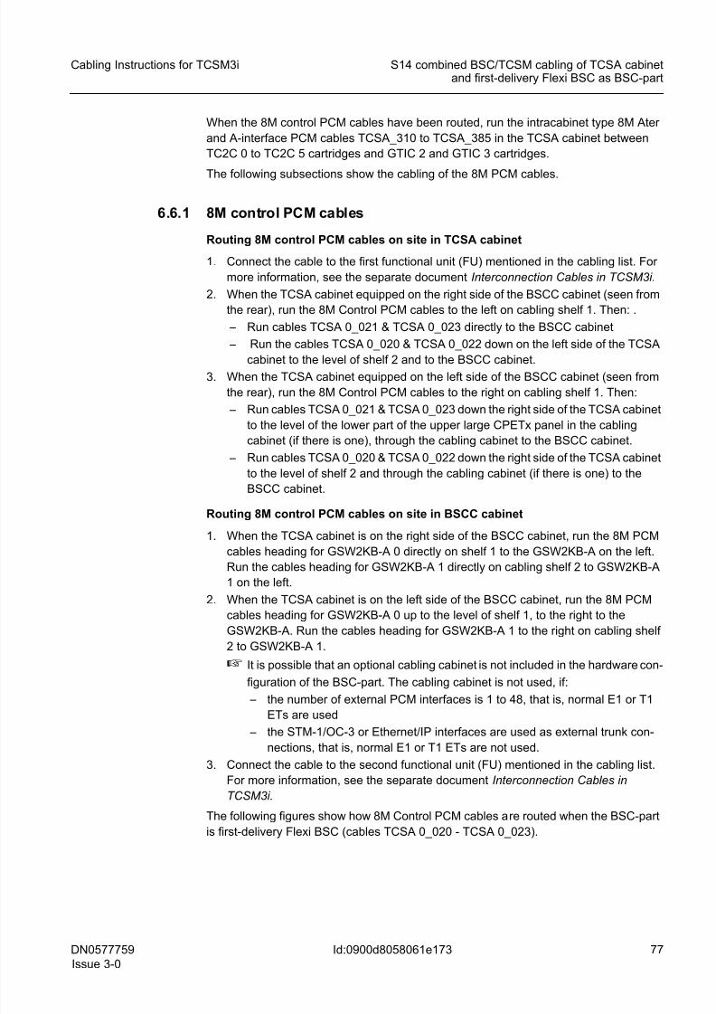
8/11/2019 NOKIA Flexi TRCM
http://slidepdf.com/reader/full/nokia-flexi-trcm 77/183
DN0577759
Issue 3-0
77
Cabling Instructions for TCSM3i S14 combined BSC/TCSM cabling of TCSA cabinetand first-delivery Flexi BSC as BSC-part
Id:0900d8058061e173
When the 8M control PCM cables have been routed, run the intracabinet type 8M Ater
and A-interface PCM cables TCSA_310 to TCSA_385 in the TCSA cabinet between
TC2C 0 to TC2C 5 cartridges and GTIC 2 and GTIC 3 cartridges.
The following subsections show the cabling of the 8M PCM cables.
6.6.1 8M control PCM cables
Routing 8M control PCM cables on site in TCSA cabinet
1. Connect the cable to the first functional unit (FU) mentioned in the cabling list. For
more information, see the separate document Interconnection Cables in TCSM3i.
2. When the TCSA cabinet equipped on the right side of the BSCC cabinet (seen from
the rear), run the 8M Control PCM cables to the left on cabling shelf 1. Then: .
– Run cables TCSA 0_021 & TCSA 0_023 directly to the BSCC cabinet
– Run the cables TCSA 0_020 & TCSA 0_022 down on the left side of the TCSA
cabinet to the level of shelf 2 and to the BSCC cabinet.
3. When the TCSA cabinet equipped on the left side of the BSCC cabinet (seen from
the rear), run the 8M Control PCM cables to the right on cabling shelf 1. Then:
– Run cables TCSA 0_021 & TCSA 0_023 down the right side of the TCSA cabinet
to the level of the lower part of the upper large CPETx panel in the cabling
cabinet (if there is one), through the cabling cabinet to the BSCC cabinet.
– Run cables TCSA 0_020 & TCSA 0_022 down the right side of the TCSA cabinet
to the level of shelf 2 and through the cabling cabinet (if there is one) to the
BSCC cabinet.
Routing 8M control PCM cables on site in BSCC cabinet
1. When the TCSA cabinet is on the right side of the BSCC cabinet, run the 8M PCMcables heading for GSW2KB-A 0 directly on shelf 1 to the GSW2KB-A on the left.
Run the cables heading for GSW2KB-A 1 directly on cabling shelf 2 to GSW2KB-A
1 on the left.
2. When the TCSA cabinet is on the left side of the BSCC cabinet, run the 8M PCM
cables heading for GSW2KB-A 0 up to the level of shelf 1, to the right to the
GSW2KB-A. Run the cables heading for GSW2KB-A 1 to the right on cabling shelf
2 to GSW2KB-A 1.
☞ It is possible that an optional cabling cabinet is not included in the hardware con-
figuration of the BSC-part. The cabling cabinet is not used, if:
– the number of external PCM interfaces is 1 to 48, that is, normal E1 or T1
ETs are used
– the STM-1/OC-3 or Ethernet/IP interfaces are used as external trunk con-
nections, that is, normal E1 or T1 ETs are not used.
3. Connect the cable to the second functional unit (FU) mentioned in the cabling list.
For more information, see the separate document Interconnection Cables in
TCSM3i.
The following figures show how 8M Control PCM cables are routed when the BSC-part
is first-delivery Flexi BSC (cables TCSA 0_020 - TCSA 0_023).
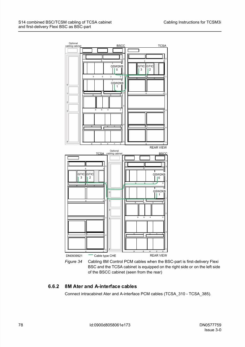
8/11/2019 NOKIA Flexi TRCM
http://slidepdf.com/reader/full/nokia-flexi-trcm 78/183
78 DN0577759
Issue 3-0
Cabling Instructions for TCSM3i
Id:0900d8058061e173
S14 combined BSC/TCSM cabling of TCSA cabinetand first-delivery Flexi BSC as BSC-part
Figure 34 Cabling 8M Control PCM cables when the BSC-part is first-delivery Flexi
BSC and the TCSA cabinet is equipped on the right side or on the left side
of the BSCC cabinet (seen from the rear)
6.6.2 8M Ater and A-interface cables
Connect intracabinet Ater and A-interface PCM cables (TCSA_310 - TCSA_385).
4
0
1
2
3
4
0
1
2
3
1
2
3
4
0
5
0
0
0
0
6
0
6
9
06
6
36
BSCC TCSA
5
4
3
1
0
06
3 09 6
48 0
0249 6
GTIC3
3 09 6
6
0249 6
REAR VIEW
1
3
4
0
5
0
0
0
0
6
0
6
9
06
6
36
BSCCTCSA
Cable type CHE
5
4
3
2
1
006
3 09 6
48 0
0249 6
3 09 6
6
0249 6
DN0939921
2
Optionalcabling cabinet
Optionalcabling cabinet
2
GTIC2
GTIC2
GTIC3
GSW2KB0
GSW2KB1
GSW2KB0
GSW2KB1
REAR VIEW
8/11/2019 NOKIA Flexi TRCM
http://slidepdf.com/reader/full/nokia-flexi-trcm 79/183
DN0577759
Issue 3-0
79
Cabling Instructions for TCSM3i S14 combined BSC/TCSM cabling of TCSA cabinetand first-delivery Flexi BSC as BSC-part
Id:0900d8058061e173
Routing 8M Ater and A-interface cables on site in TCSA cabinet
1. Route the cables as indicated in General routing principles of intracabinet cables
and attach them in bundles to the cable shelves with cable ties. Lay them on the
shelf as inside as possible, tighten them there to the shelf and run them to the left.2. All the cables go down the left side of the cabinet (seen from the rear). When the
cables reach the respective shelves, tighten the cables to the shelf and connect to
their respective positions as shown in Interconnection Cables in TCSM3i .
3. Stow away supplementary cable length as shown in Stowing away supplementary
cable length.
The following figure shows how 8M Ater and A-interface PCM cables are routed inside
the TCSA cabinet (cables TCSA_310 - TCSA_385) when the BSC-part is first-delivery
Flexi BSC.
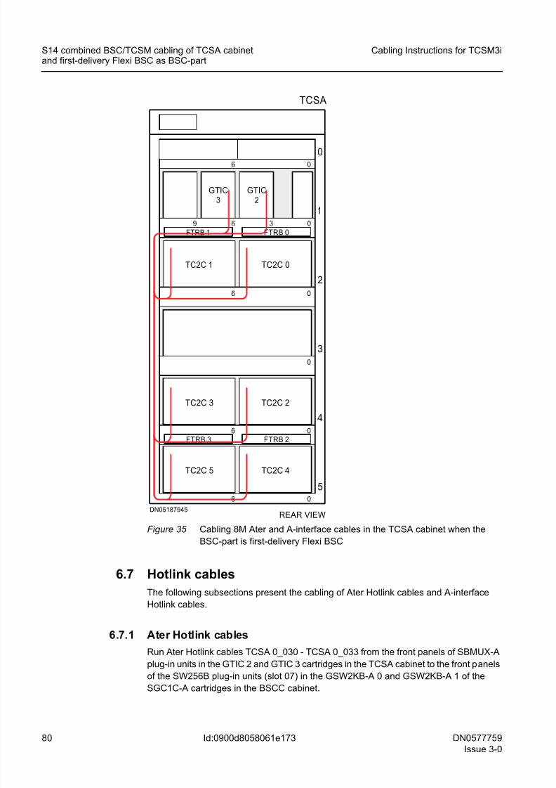
8/11/2019 NOKIA Flexi TRCM
http://slidepdf.com/reader/full/nokia-flexi-trcm 80/183
80 DN0577759
Issue 3-0
Cabling Instructions for TCSM3i
Id:0900d8058061e173
S14 combined BSC/TCSM cabling of TCSA cabinetand first-delivery Flexi BSC as BSC-part
Figure 35 Cabling 8M Ater and A-interface cables in the TCSA cabinet when the
BSC-part is first-delivery Flexi BSC
6.7 Hotlink cables
The following subsections present the cabling of Ater Hotlink cables and A-interface
Hotlink cables.
6.7.1 Ater Hotlink cables
Run Ater Hotlink cables TCSA 0_030 - TCSA 0_033 from the front panels of SBMUX-A
plug-in units in the GTIC 2 and GTIC 3 cartridges in the TCSA cabinet to the front panels
of the SW256B plug-in units (slot 07) in the GSW2KB-A 0 and GSW2KB-A 1 of the
SGC1C-A cartridges in the BSCC cabinet.
REAR VIEWDN05187945
TCSA
5
4
3
2
06 0
0
06
1
6 3 0
6 0
0
6
9
TC2C 0
TC2C 3
TC2C 4
FTRB 2FTRB 3
GTIC2
FTRB 1 FTRB 0
TC2C 5
TC2C 2
TC2C 1
GTIC3
8/11/2019 NOKIA Flexi TRCM
http://slidepdf.com/reader/full/nokia-flexi-trcm 81/183
DN0577759
Issue 3-0
81
Cabling Instructions for TCSM3i S14 combined BSC/TCSM cabling of TCSA cabinetand first-delivery Flexi BSC as BSC-part
Id:0900d8058061e173
Routing Ater Hotlinks on site in TCSA cabinet
1. Connect the cables to the first functional unit (FU; front panels of SBMUX-A plug-in
units) on the cabling list; see the separate document Interconnection Cables in
TCSM3i.2. The TCSA cabinet can be equipped either on the right side or on the left side of the
BSCC cabinet (seen from the front), but the routing of the Ater Hotlink cables is the
same in the TCSA cabinet. Route the cables to the right on the front cabling shelves
of GTIC 2 and GTIC 3 cartridges, lay them on the cabling shelves of GTIC 2, GTIC
3 and GTIC 4 cartridges and route them to the right side of the TCSA cabinet (seen
from the front). Run the cables down to the level of the shelf 2, route them to the left
and pass them from front to back through the opening in the middle of shelf 2.
3. When the TCSA cabinet is equipped on the left side of the BSCC cabinet (seen from
the rear - with an optional cabling cabinet between the equipment cabinets), run the
cables that have been passed through the cabinet to the right on cabling shelf 2.
Divide the cables to two groups of cables: one heading for GSW2KB-A 0 (TCSA0_030 & TCSA 0_031) and the other heading for GSW2KB-A 1 (TCSA 0_032 &
TCSA 0_033).
Run the group of cables heading for GSW2KB-A 0 to the right directly through the
cabling cabinet (if there is one) to the BSCC cabinet.
Run the group of cables heading for GSW2KB-A 1 down on the right side of the
TCSA cabinet to the level of shelf 3 and through the cabling cabinet (if there is one)
to the BSCC cabinet.
4. When the TCSA cabinet is equipped on the right side of the BSCC cabinet (seen
from the rear), run the cables that have been passed through the cabinet to the left
on cabling shelf 2 directly to the BSCC cabinet.
Routing Ater Hotlink cables on site in BSCC cabinet
1. When the TCSA cabinet is equipped on the left side of the BSCC cabinet (seen from
the rear - with an optional cabling cabinet between the equipment cabinets), run the
cables heading for GSW2KB-A 0 to the right on shelf 2, up the right side of the BSCC
cabinet to the level of shelf 1, then to the left. Pass them from back to front through
the opening in middle of shelf 1. Run the cables heading for GSW2KB-A 1 to the
right on shelf 3. Pass them from back to front through the opening in middle of shelf
3.
2. When the TCSA cabinet is equipped on the right side of the BSCC cabinet (seen
from the rear), divide the cables to two groups of cables: one heading for GSW2KB-
A 0 (TCSA 0_030 & TCSA 0_031) and the other heading for GSW2KB-A 1 (TCSA
0_032 & TCSA 0_033). Run the cables heading for GS2W2KB-A 0 up the right sideof the BSCC cabinet up to the level of shelf 1 and to the left on shelf 1. Pass the
cables from back to front through the opening in the middle of shelf 1. Run the cables
heading for GSW2KB-A 1 to the left on shelf 3. Pass them from back to front through
the opening in middle of shelf 3.
3. When the TCSA cabinet is equipped either on the right side or on the left side of the
BSCC cabinet (seen from the front), run the cables as follows:
– Run the cables heading for GSW2KB-A 0 to the right on shelf 1, up the right side
of the BSCC cabinet to the level of cabling shelf of the upper SGC1C-A cartridge
and to the front panel interfaces of SW256B plug-in units in the GSW2KB-A 0
part.
– Run the cables heading for GSW2KB-A 1 to the right on shelf 3, up the right sideof the BSCC cabinet to the level of cabling shelf of the lower SGC1C-A cartridge
8/11/2019 NOKIA Flexi TRCM
http://slidepdf.com/reader/full/nokia-flexi-trcm 82/183
82 DN0577759
Issue 3-0
Cabling Instructions for TCSM3i
Id:0900d8058061e173
S14 combined BSC/TCSM cabling of TCSA cabinetand first-delivery Flexi BSC as BSC-part
and to the front panel interfaces of SW256B plug-in units in the GSW2KB-A 1
part.
4. Connect the cable to the second functional unit (FU) mentioned in the cabling list.
For more information, see the separate document Interconnection Cables in
TCSM3i.
The following figures show how Ater Hotlinks are routed when the BSC-part is first-
delivery Flexi BSC (cables TCSA 0_030 - TCSA 0_033).
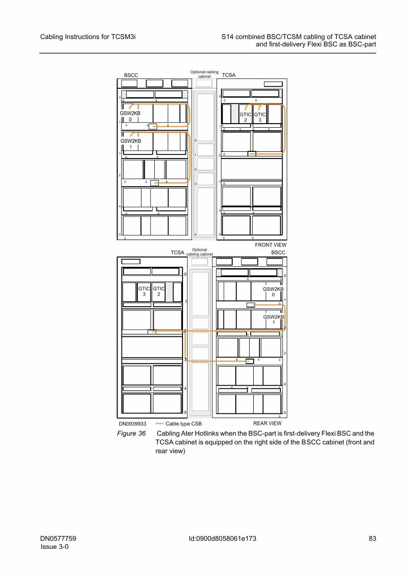
8/11/2019 NOKIA Flexi TRCM
http://slidepdf.com/reader/full/nokia-flexi-trcm 83/183
DN0577759
Issue 3-0
83
Cabling Instructions for TCSM3i S14 combined BSC/TCSM cabling of TCSA cabinetand first-delivery Flexi BSC as BSC-part
Id:0900d8058061e173
Figure 36 Cabling Ater Hotlinks when the BSC-part is first-delivery Flexi BSC and the
TCSA cabinet is equipped on the right side of the BSCC cabinet (front and
rear view)
4
0
1
2
3
1
2
3
4
0
5
0
0
0 6
0 9
0 6
3 6
BSCC TCSA
5
4
3
1
0
0 6
4 80
0
GTIC2
0 6
0 6
REAR VIEW
BSCCTCSA
Cable type CSB
5
4
3
1
006
0
0
0
06
09 6
DN0939933
2
Optional cablingcabinet
Optionalcabling cabinet
GTIC3
GTIC2
GTIC3
GSW2KB0
GSW2KB1
0 6
4 80
GSW2KB0
GSW2KB1
FRONT VIEW
2
48
1
3
4
0
5
2
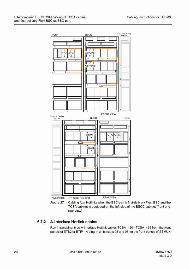
8/11/2019 NOKIA Flexi TRCM
http://slidepdf.com/reader/full/nokia-flexi-trcm 84/183
84 DN0577759
Issue 3-0
Cabling Instructions for TCSM3i
Id:0900d8058061e173
S14 combined BSC/TCSM cabling of TCSA cabinetand first-delivery Flexi BSC as BSC-part
Figure 37 Cabling Ater Hotlinks when the BSC-part is first-delivery Flexi BSC and the
TCSA cabinet is equipped on the left side of the BSCC cabinet (front and
rear view)
6.7.2 A-interface Hotlink cables
Run intracabinet type A-interface Hotlink cables TCSA_450 - TCSA_465 from the front
panels of ETS2 or ETIP1-A plug-in units (slots 05 and 06) to the front panels of SBMUX-
1
3
4
0
5
TCSA
Cable type CSB
2
GTIC3
GTIC2
4
0
1
2
3
1
2
3
4
0
5
0
0
0 6
0 9
0 6
3 6
BSCCTCSA
5
4
3
1
0
0 6
4 80
0
GTIC2
0 6
0 6
REAR VIEW
BSCC
5
4
3
1
006
0
0
0
06
09 6
DN0939945
2
GTIC3
GSW2KB0
GSW2KB1
0 6
4 80
GSW2KB0
GSW2KB1
FRONT VIEW
2
48
Optional cablingcabinet
Optional cablingcabinet
8/11/2019 NOKIA Flexi TRCM
http://slidepdf.com/reader/full/nokia-flexi-trcm 85/183
DN0577759
Issue 3-0
85
Cabling Instructions for TCSM3i S14 combined BSC/TCSM cabling of TCSA cabinetand first-delivery Flexi BSC as BSC-part
Id:0900d8058061e173
A plug-in units (slots 01 and 02) in the GTIC 2 and GTIC 3 cartridges of the TCSA
cabinet.
Routing A-interface Hotlinks on site in TCSA cabinets
1. Connect the cables to the first functional unit (FU, front panel of the ETS2 or the
ETIP1-A plug-in unit) on the cabling list; see the separate document Interconnection
Cables in TCSM3i.
2. Route the cables to the cabling shelves of GTIC 2 and GTIC 3 cartridges.
3. Lay the cables on the cabling shelves and route them to the second functional unit
(FU; front panel of SBMUX-A plug-in unit) mentioned in the cabling list; see the
separate document Interconnection Cables in TCSM3i.
The following figure shows how A-interface Hotlink cables are routed in the TCSA
cabinet when the BSC-part is first-delivery Flexi BSC (cables TCSA_450 - TCSA_465).
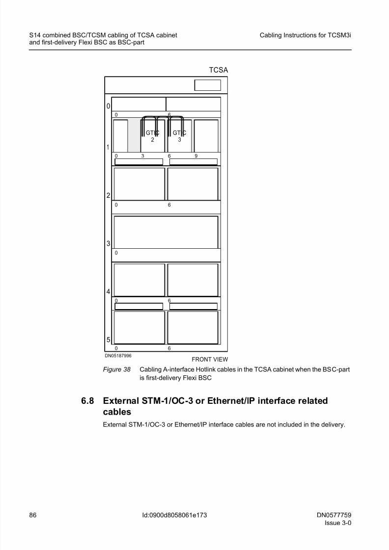
8/11/2019 NOKIA Flexi TRCM
http://slidepdf.com/reader/full/nokia-flexi-trcm 86/183
86 DN0577759
Issue 3-0
Cabling Instructions for TCSM3i
Id:0900d8058061e173
S14 combined BSC/TCSM cabling of TCSA cabinetand first-delivery Flexi BSC as BSC-part
Figure 38 Cabling A-interface Hotlink cables in the TCSA cabinet when the BSC-part
is first-delivery Flexi BSC
6.8 External STM-1/OC-3 or Ethernet/IP interface related
cables
External STM-1/OC-3 or Ethernet/IP interface cables are not included in the delivery.
FRONT VIEWDN05187996
TCSA
5
4
3
2
060
0
0 6
1
630
60
0
6
9
GTIC2
GTIC3
8/11/2019 NOKIA Flexi TRCM
http://slidepdf.com/reader/full/nokia-flexi-trcm 87/183
DN0577759
Issue 3-0
87
Cabling Instructions for TCSM3i S14 combined BSC/TCSM cabling of extension cabi-nets and BSC3i or upgraded Flexi BSC as BSC-part
Id:0900d8058061e17d
7 S14 combined BSC/TCSM cabling of exten-
sion cabinets and BSC3i or upgraded Flexi
BSC as BSC-part☞ This section is applied to upgrading extension cabinets (TCSA 1 and TCSA 2) from
the TCSA base cabinet.
☞ The extension cabinets can be equipped either on the right side or on the left side
of the BSCC cabinet.
Routing of combined BSC/TCSM installation-specific cables is done on site.
All cabling (except AL and AL/CGS cables TCSA_065 & TCSA_066, Internal synchro-
nisation cables TCSA_070 - TCSA_073, External ET interface related cables
TCSA_150 - TCSA_269, Control PCM cables TCSA_080 & TCSA_081, and PCM
cables TCSA_090 - TCSA_131) presented in Intracabinet cables in TCSA cabinet iscommon to both TCSM3i for stand-alone installation option and TCSM3i for combined
BSC/TCSM installation option.
The following sections show the cabling of extension cabinets (TCSA 1 and TCSA 2)
when the BSC-part is BSC3i 1000 or one- or two-cabinet upgraded Flexi BSC. They
provide the most efficient routing of SBUS cables, Timing bus cables, Timing loop
cables, 2N Compare test cables, Synchronisation signal cables, 8M PCM cables and
Hotlink cables.
7.1 SBUS cables
Run supervision bus (SBUS) cables TCSA 1_001 & TCSA 1_002 from CLAC 2 / CLAC3 in the TCSA 1 cabinet to CLAC 1 / CLAC 2 in the TCSA 0 cabinet - when TCSA 1
cabinet is in question and the BSC-part is either one-cabinet or two-cabinet configura-
tion.
Run supervision bus (SBUS) cables TCSA 2_001 & TCSA 2_002 from from CLAC 3 /
CLAC 4 in the TCSA 2 cabinet to CLAC 2 / CLAC 3 in the TCSA 1 cabinet - when TCSA
2 cabinet is in question and theBSC-part is either one-cabinet or two-cabinet configura-
tion.
Routing SBUS cables on site in extension cabinets when BSC-part is BSC3i or
upgraded Flexi BSC and extension cabinets are equipped either on the right side
or on the left side of BSCC cabinet
☞ When the BSC-part is BSC3i 1000 or one-cabinet upgraded Flexi BSC, the exten-
sion cabinets can be equipped on the right or left side of the BSCC cabinet (seen
from the rear); when the BSC-part is two-cabinet upgraded Flexi BSC, the extension
cabinets can be equipped either beside the BSCC or beside the BSCD cabinet.
1. Connect the cable to the first functional unit (FU) mentioned in the cabling list. For
more information, see the separate document Interconnection Cables in TCSM3i.
2. When the extension cabinets are equipped on the right side of the BSCC cabinet,
run the SBUS cables to the left on cabling shelf 1. Then:
– If TCSA 1 cabinet is in question, run the cables from CLAC 2 on cabling shelf 1
to CLAC 3 in TCSA 0 cabinet.
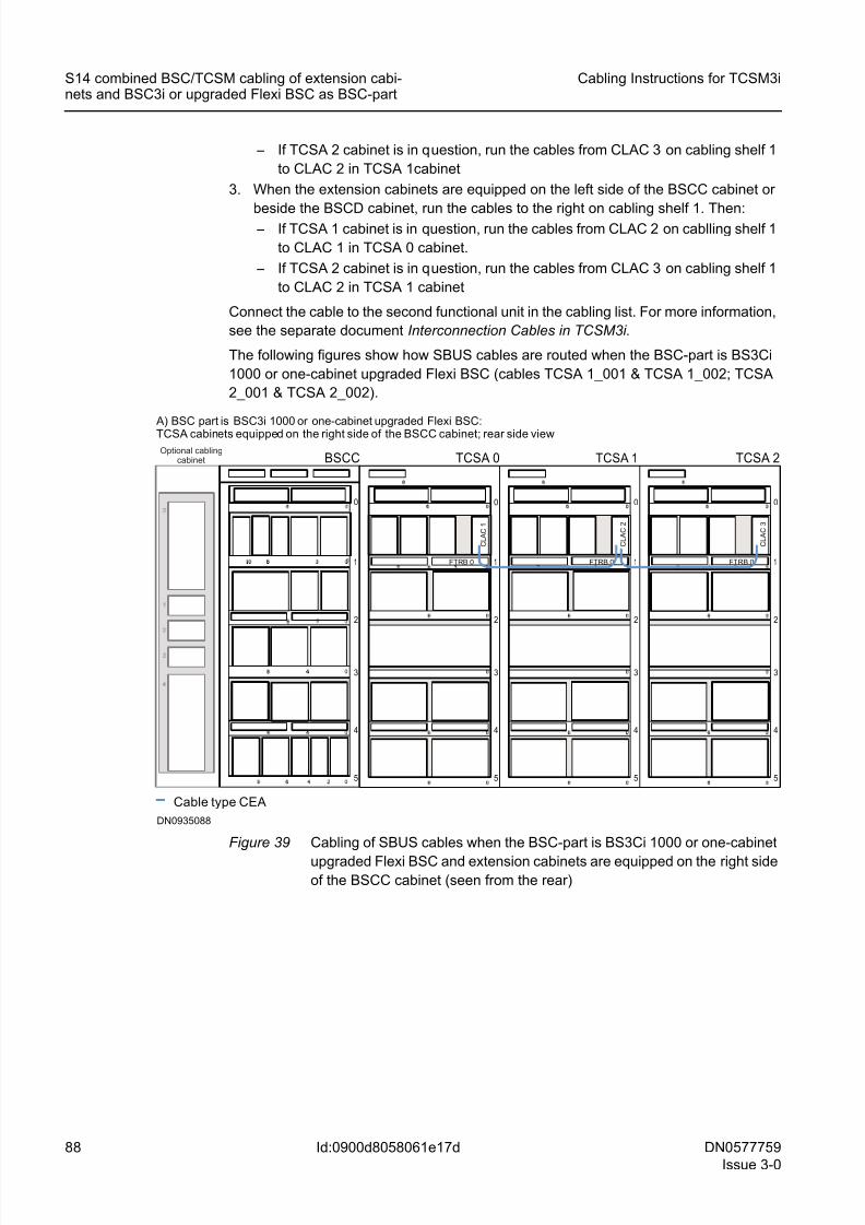
8/11/2019 NOKIA Flexi TRCM
http://slidepdf.com/reader/full/nokia-flexi-trcm 88/183
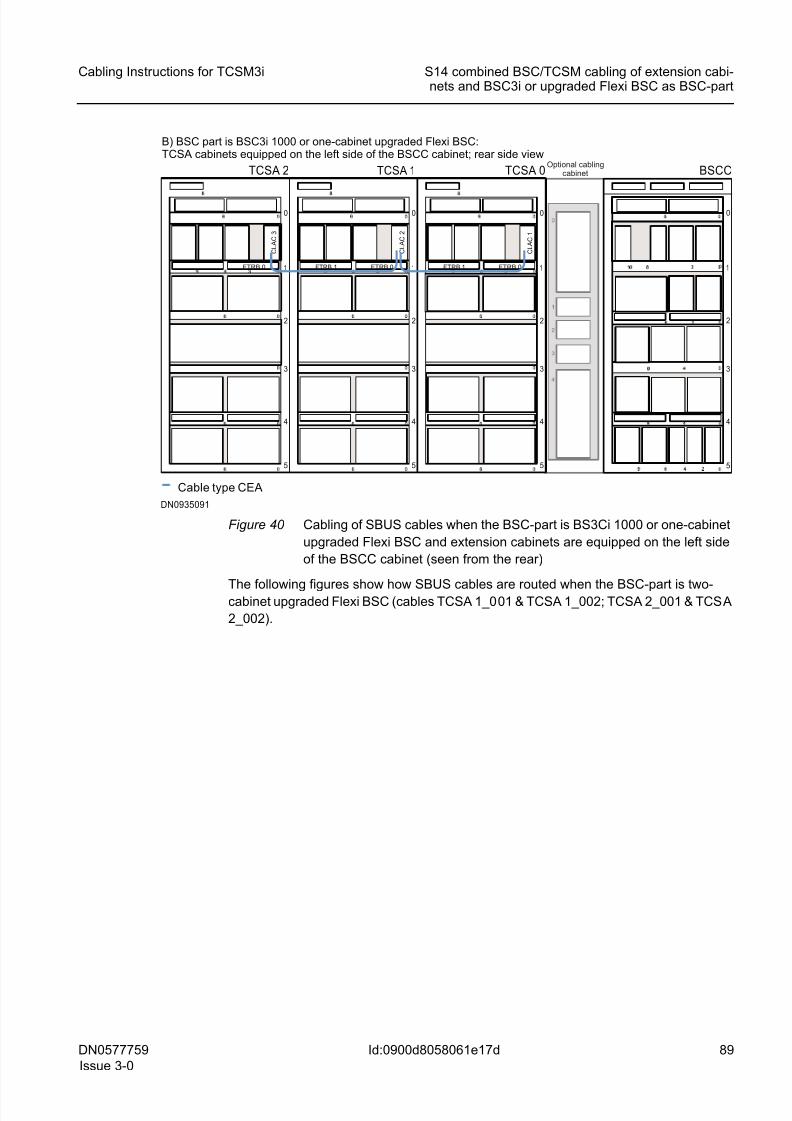
8/11/2019 NOKIA Flexi TRCM
http://slidepdf.com/reader/full/nokia-flexi-trcm 89/183
DN0577759
Issue 3-0
89
Cabling Instructions for TCSM3i S14 combined BSC/TCSM cabling of extension cabi-nets and BSC3i or upgraded Flexi BSC as BSC-part
Id:0900d8058061e17d
Figure 40 Cabling of SBUS cables when the BSC-part is BS3Ci 1000 or one-cabinet
upgraded Flexi BSC and extension cabinets are equipped on the left side
of the BSCC cabinet (seen from the rear)
The following figures show how SBUS cables are routed when the BSC-part is two-cabinet upgraded Flexi BSC (cables TCSA 1_001 & TCSA 1_002; TCSA 2_001 & TCSA
2_002).
1
2
3
4
0
5
0
BSCC
FTRB 0 1
2
3
4
0
5
TCSA 2
Cable type CEA
C L A C 3
FTRB 1 FTRB 0 1
2
3
4
0
5
C L A C 2
FTRB 1 FTRB 0 1
2
3
4
0
5
C L A C 1
TCSA 1 TCSA 0
DN0935091
B) BSC part is BSC3i 1000 or one-cabinet upgraded Flexi BSC:TCSA cabinets equipped on the left side of the BSCC cabinet; rear side view
Optional cablingcabinet
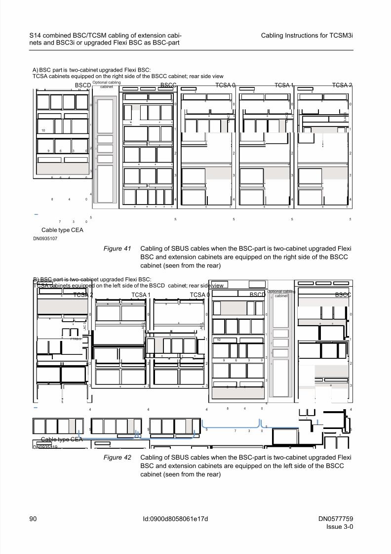
8/11/2019 NOKIA Flexi TRCM
http://slidepdf.com/reader/full/nokia-flexi-trcm 90/183
90 DN0577759
Issue 3-0
Cabling Instructions for TCSM3i
Id:0900d8058061e17d
S14 combined BSC/TCSM cabling of extension cabi-nets and BSC3i or upgraded Flexi BSC as BSC-part
Figure 41 Cabling of SBUS cables when the BSC-part is two-cabinet upgraded Flexi
BSC and extension cabinets are equipped on the right side of the BSCC
cabinet (seen from the rear)
Figure 42 Cabling of SBUS cables when the BSC-part is two-cabinet upgraded Flexi
BSC and extension cabinets are equipped on the left side of the BSCC
cabinet (seen from the rear)
1
2
3
4
0
5
BSCC
1
2
3
4
0
5
TCSA 0
Cable type CEA
1
2
3
4
0
5
0 1
2
3
4
0
5
6
TCSA 1 TCSA 2
FTRB 0 FTRB 0 FTRB 0
C L A C
1
C L A C
2
C L A C
3
DN0935107
A) BSC part is two-cabinet upgraded Flexi BSC:TCSA cabinets equipped on the right side of the BSCC cabinet; rear side view
BSCD
5
4
3
2
1
0
06
3
10
48 0
48 0
0
3 069
6
7
Optional cablingcabinet
5
4
3
2
1
0
06
3
10
48 0
48 0
0
3 069
6
7
BSCC
FTRB 0 1
2
3
4
0
5
TCSA 2
Cable type CEA
1
2
3
4
0
5
0
C L A C
3
FTRB 1 FTRB 0 1
2
3
4
0
5
C L A C
2
FTRB 1 FTRB 0 1
2
3
4
0
5
C L A C
1
TCSA 1 TCSA 0
DN0935119
B) BSC part is two-cabinet upgraded Flexi BSC:TCSA cabinets equipped on the left side of the BSCD cabinet; rear side view
BSCD Optional cablingcabinet
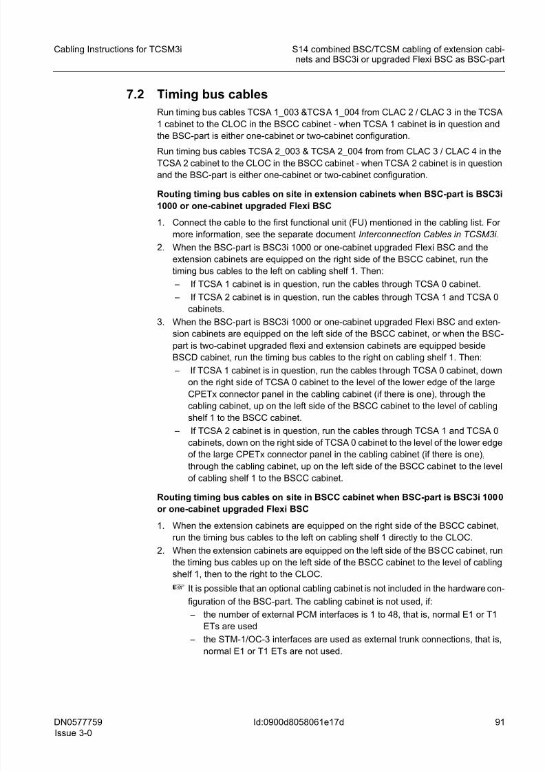
8/11/2019 NOKIA Flexi TRCM
http://slidepdf.com/reader/full/nokia-flexi-trcm 91/183
DN0577759
Issue 3-0
91
Cabling Instructions for TCSM3i S14 combined BSC/TCSM cabling of extension cabi-nets and BSC3i or upgraded Flexi BSC as BSC-part
Id:0900d8058061e17d
7.2 Timing bus cables
Run timing bus cables TCSA 1_003 &TCSA 1_004 from CLAC 2 / CLAC 3 in the TCSA
1 cabinet to the CLOC in the BSCC cabinet - when TCSA 1 cabinet is in question and
the BSC-part is either one-cabinet or two-cabinet configuration.
Run timing bus cables TCSA 2_003 & TCSA 2_004 from from CLAC 3 / CLAC 4 in the
TCSA 2 cabinet to the CLOC in the BSCC cabinet - when TCSA 2 cabinet is in question
and the BSC-part is either one-cabinet or two-cabinet configuration.
Routing timing bus cables on site in extension cabinets when BSC-part is BSC3i
1000 or one-cabinet upgraded Flexi BSC
1. Connect the cable to the first functional unit (FU) mentioned in the cabling list. For
more information, see the separate document Interconnection Cables in TCSM3i.
2. When the BSC-part is BSC3i 1000 or one-cabinet upgraded Flexi BSC and the
extension cabinets are equipped on the right side of the BSCC cabinet, run the
timing bus cables to the left on cabling shelf 1. Then: – If TCSA 1 cabinet is in question, run the cables through TCSA 0 cabinet.
– If TCSA 2 cabinet is in question, run the cables through TCSA 1 and TCSA 0
cabinets.
3. When the BSC-part is BSC3i 1000 or one-cabinet upgraded Flexi BSC and exten-
sion cabinets are equipped on the left side of the BSCC cabinet, or when the BSC-
part is two-cabinet upgraded flexi and extension cabinets are equipped beside
BSCD cabinet, run the timing bus cables to the right on cabling shelf 1. Then:
– If TCSA 1 cabinet is in question, run the cables through TCSA 0 cabinet, down
on the right side of TCSA 0 cabinet to the level of the lower edge of the large
CPETx connector panel in the cabling cabinet (if there is one), through the
cabling cabinet, up on the left side of the BSCC cabinet to the level of cablingshelf 1 to the BSCC cabinet.
– If TCSA 2 cabinet is in question, run the cables through TCSA 1 and TCSA 0
cabinets, down on the right side of TCSA 0 cabinet to the level of the lower edge
of the large CPETx connector panel in the cabling cabinet (if there is one),
through the cabling cabinet, up on the left side of the BSCC cabinet to the level
of cabling shelf 1 to the BSCC cabinet.
Routing timing bus cables on site in BSCC cabinet when BSC-part is BSC3i 1000
or one-cabinet upgraded Flexi BSC
1. When the extension cabinets are equipped on the right side of the BSCC cabinet,
run the timing bus cables to the left on cabling shelf 1 directly to the CLOC.2. When the extension cabinets are equipped on the left side of the BSCC cabinet, run
the timing bus cables up on the left side of the BSCC cabinet to the level of cabling
shelf 1, then to the right to the CLOC.
☞ It is possible that an optional cabling cabinet is not included in the hardware con-
figuration of the BSC-part. The cabling cabinet is not used, if:
– the number of external PCM interfaces is 1 to 48, that is, normal E1 or T1
ETs are used
– the STM-1/OC-3 interfaces are used as external trunk connections, that is,
normal E1 or T1 ETs are not used.
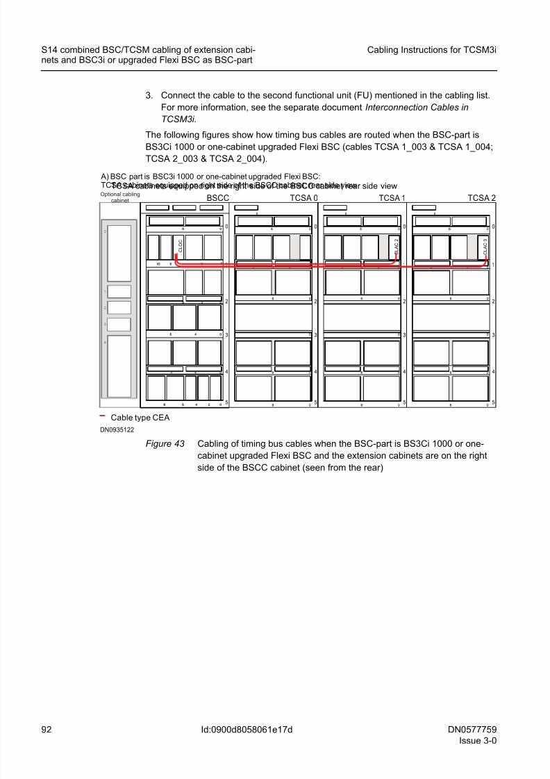
8/11/2019 NOKIA Flexi TRCM
http://slidepdf.com/reader/full/nokia-flexi-trcm 92/183
92 DN0577759
Issue 3-0
Cabling Instructions for TCSM3i
Id:0900d8058061e17d
S14 combined BSC/TCSM cabling of extension cabi-nets and BSC3i or upgraded Flexi BSC as BSC-part
3. Connect the cable to the second functional unit (FU) mentioned in the cabling list.
For more information, see the separate document Interconnection Cables in
TCSM3i.
The following figures show how timing bus cables are routed when the BSC-part isBS3Ci 1000 or one-cabinet upgraded Flexi BSC (cables TCSA 1_003 & TCSA 1_004;
TCSA 2_003 & TCSA 2_004).
Figure 43 Cabling of timing bus cables when the BSC-part is BS3Ci 1000 or one-
cabinet upgraded Flexi BSC and the extension cabinets are on the right
side of the BSCC cabinet (seen from the rear)
1
2
3
4
0
5
00
8
BSCC
1
2
3
4
0
5
8
TCSA 0
TCSA cabinets equipped on the right side of the BSCC cabinet; rear side view
Cable type CEA
1
2
3
4
0
5
8
1
2
3
4
0
5
6
8
TCSA 1 TCSA 2
C L A C 2
C L A C 3
C L O C
DN0935122
A) BSC part is BSC3i 1000 or one-cabinet upgraded Flexi BSC:TCSA cabinets equipped on right side of the BSCC cabinet; rear side viewOptional cabling
cabinet
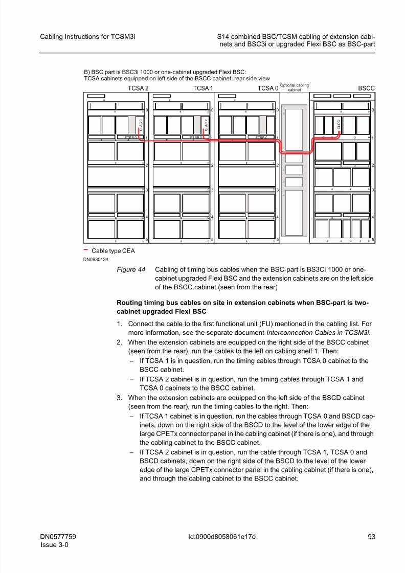
8/11/2019 NOKIA Flexi TRCM
http://slidepdf.com/reader/full/nokia-flexi-trcm 93/183
DN0577759
Issue 3-0
93
Cabling Instructions for TCSM3i S14 combined BSC/TCSM cabling of extension cabi-nets and BSC3i or upgraded Flexi BSC as BSC-part
Id:0900d8058061e17d
Figure 44 Cabling of timing bus cables when the BSC-part is BS3Ci 1000 or one-
cabinet upgraded Flexi BSC and the extension cabinets are on the left side
of the BSCC cabinet (seen from the rear)
Routing timing bus cables on site in extension cabinets when BSC-part is two-cabinet upgraded Flexi BSC
1. Connect the cable to the first functional unit (FU) mentioned in the cabling list. For
more information, see the separate document Interconnection Cables in TCSM3i.
2. When the extension cabinets are equipped on the right side of the BSCC cabinet
(seen from the rear), run the cables to the left on cabling shelf 1. Then:
– If TCSA 1 is in question, run the timing cables through TCSA 0 cabinet to the
BSCC cabinet.
– If TCSA 2 cabinet is in question, run the timing cables through TCSA 1 and
TCSA 0 cabinets to the BSCC cabinet.
3. When the extension cabinets are equipped on the left side of the BSCD cabinet
(seen from the rear), run the timing cables to the right. Then:
– If TCSA 1 cabinet is in question, run the cables through TCSA 0 and BSCD cab-
inets, down on the right side of the BSCD to the level of the lower edge of the
large CPETx connector panel in the cabling cabinet (if there is one), and through
the cabling cabinet to the BSCC cabinet.
– If TCSA 2 cabinet is in question, run the cable through TCSA 1, TCSA 0 and
BSCD cabinets, down on the right side of the BSCD to the level of the lower
edge of the large CPETx connector panel in the cabling cabinet (if there is one),
and through the cabling cabinet to the BSCC cabinet.
1
2
3
4
0
5
00
BSCC
FTRB 0 1
2
3
4
0
5
TCSA 2
B) BSC part is BSC3i 1000 or one-cabinet upgraded Flexi BSC:TCSA cabinets equipped on left side of the BSCC cabinet; rear side view
Cable type CEA
FTRB 0 1
2
3
4
0
5
FTRB 0 1
2
3
4
0
5
TCSA 1 TCSA 0
C L A C 3
C L A C 2
C L O C
DN0935134
Optional cablingcabinet
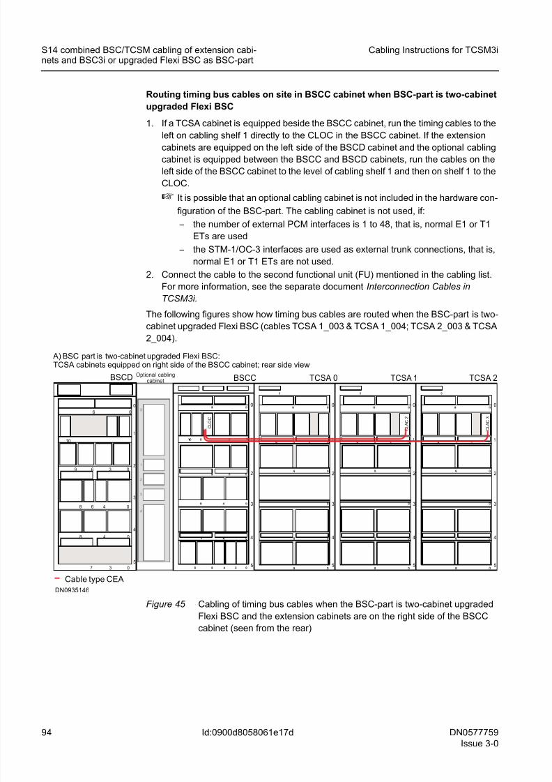
8/11/2019 NOKIA Flexi TRCM
http://slidepdf.com/reader/full/nokia-flexi-trcm 94/183
94 DN0577759
Issue 3-0
Cabling Instructions for TCSM3i
Id:0900d8058061e17d
S14 combined BSC/TCSM cabling of extension cabi-nets and BSC3i or upgraded Flexi BSC as BSC-part
Routing timing bus cables on site in BSCC cabinet when BSC-part is two-cabinet
upgraded Flexi BSC
1. If a TCSA cabinet is equipped beside the BSCC cabinet, run the timing cables to the
left on cabling shelf 1 directly to the CLOC in the BSCC cabinet. If the extensioncabinets are equipped on the left side of the BSCD cabinet and the optional cabling
cabinet is equipped between the BSCC and BSCD cabinets, run the cables on the
left side of the BSCC cabinet to the level of cabling shelf 1 and then on shelf 1 to the
CLOC.
☞ It is possible that an optional cabling cabinet is not included in the hardware con-
figuration of the BSC-part. The cabling cabinet is not used, if:
– the number of external PCM interfaces is 1 to 48, that is, normal E1 or T1
ETs are used
– the STM-1/OC-3 interfaces are used as external trunk connections, that is,
normal E1 or T1 ETs are not used.
2. Connect the cable to the second functional unit (FU) mentioned in the cabling list.For more information, see the separate document Interconnection Cables in
TCSM3i.
The following figures show how timing bus cables are routed when the BSC-part is two-
cabinet upgraded Flexi BSC (cables TCSA 1_003 & TCSA 1_004; TCSA 2_003 & TCSA
2_004).
Figure 45 Cabling of timing bus cables when the BSC-part is two-cabinet upgraded
Flexi BSC and the extension cabinets are on the right side of the BSCC
cabinet (seen from the rear)
1
2
3
4
0
5
00
8
BSCC
1
2
3
4
0
5
8
TCSA 0
Cable type CEA
1
2
3
4
0
5
8
1
2
3
4
0
5
6
8
TCSA 1 TCSA 2
C L A C
2
C L A C
3
C L O C
DN0935146
A) BSC part is two-cabinet upgraded Flexi BSC:TCSA cabinets equipped on right side of the BSCC cabinet; rear side view
BSCD
5
4
3
2
1
0
06
3
10
48 0
48 0
0
3 069
6
7
Optional cablingcabinet
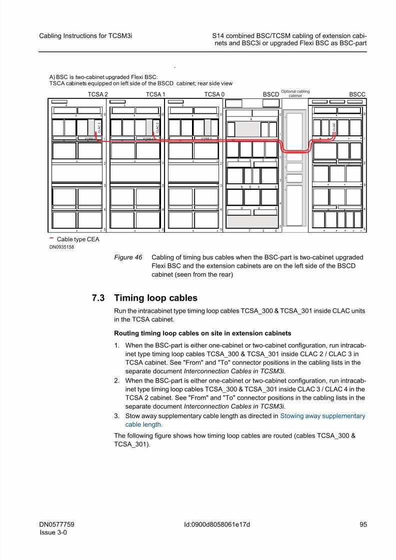
8/11/2019 NOKIA Flexi TRCM
http://slidepdf.com/reader/full/nokia-flexi-trcm 95/183
DN0577759
Issue 3-0
95
Cabling Instructions for TCSM3i S14 combined BSC/TCSM cabling of extension cabi-nets and BSC3i or upgraded Flexi BSC as BSC-part
Id:0900d8058061e17d
Figure 46 Cabling of timing bus cables when the BSC-part is two-cabinet upgraded
Flexi BSC and the extension cabinets are on the left side of the BSCD
cabinet (seen from the rear)
7.3 Timing loop cables
Run the intracabinet type timing loop cables TCSA_300 & TCSA_301 inside CLAC units
in the TCSA cabinet.
Routing timing loop cables on site in extension cabinets
1. When the BSC-part is either one-cabinet or two-cabinet configuration, run intracab-
inet type timing loop cables TCSA_300 & TCSA_301 inside CLAC 2 / CLAC 3 in
TCSA cabinet. See "From" and "To" connector positions in the cabling lists in the
separate document Interconnection Cables in TCSM3i.
2. When the BSC-part is either one-cabinet or two-cabinet configuration, run intracab-
inet type timing loop cables TCSA_300 & TCSA_301 inside CLAC 3 / CLAC 4 in theTCSA 2 cabinet. See "From" and "To" connector positions in the cabling lists in the
separate document Interconnection Cables in TCSM3i.
3. Stow away supplementary cable length as directed in Stowing away supplementary
cable length.
The following figure shows how timing loop cables are routed (cables TCSA_300 &
TCSA_301).
5
4
3
2
1
0
06
3
10
48 0
48 0
0
3 069
6
7
FTRB 0 1
2
3
4
0
5
TCSA 2
A) BSC is two-cabinet upgraded Flexi BSC:TSCA cabinets equipped on left side of the BSCD cabinet; rear side view
Cable type CEA
FTRB 0 1
2
3
4
0
5
FTRB 0 1
2
3
4
0
5
TCSA 1 TCSA 0
C L A C
3
C L A C
2
DN0935158
BSCD BSCCOptional cabling
cabinet
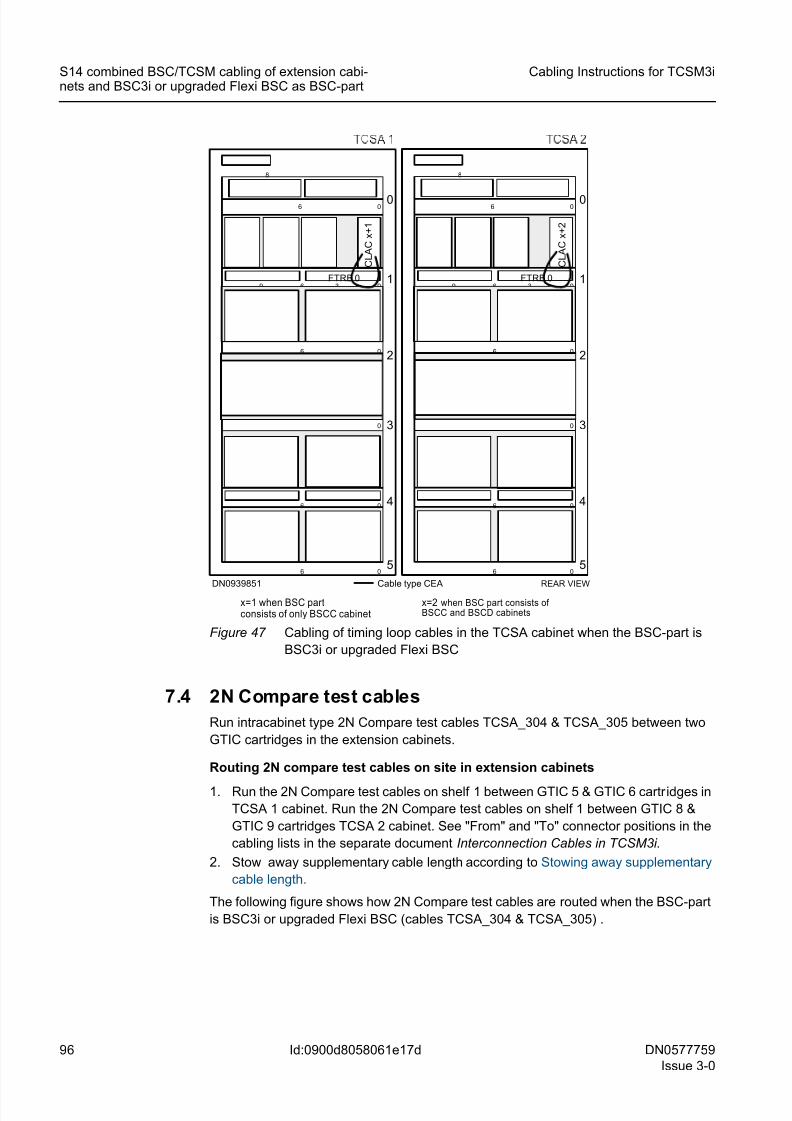
8/11/2019 NOKIA Flexi TRCM
http://slidepdf.com/reader/full/nokia-flexi-trcm 96/183
96 DN0577759
Issue 3-0
Cabling Instructions for TCSM3i
Id:0900d8058061e17d
S14 combined BSC/TCSM cabling of extension cabi-nets and BSC3i or upgraded Flexi BSC as BSC-part
Figure 47 Cabling of timing loop cables in the TCSA cabinet when the BSC-part is
BSC3i or upgraded Flexi BSC
7.4 2N Compare test cables
Run intracabinet type 2N Compare test cables TCSA_304 & TCSA_305 between two
GTIC cartridges in the extension cabinets.
Routing 2N compare test cables on site in extension cabinets
1. Run the 2N Compare test cables on shelf 1 between GTIC 5 & GTIC 6 cartridges in
TCSA 1 cabinet. Run the 2N Compare test cables on shelf 1 between GTIC 8 &
GTIC 9 cartridges TCSA 2 cabinet. See "From" and "To" connector positions in the
cabling lists in the separate document Interconnection Cables in TCSM3i.
2. Stow away supplementary cable length according to Stowing away supplementary
cable length.
The following figure shows how 2N Compare test cables are routed when the BSC-part
is BSC3i or upgraded Flexi BSC (cables TCSA_304 & TCSA_305) .
REAR VIEWCable type CEA
FTRB 0 1
2
3
4
0
5
0
0
0
0
6
0
6
9
06
6
36
8
FTRB 0 1
2
3
4
0
5
0
0
0
0
6
0
6
9
06
6
36
8
DN0939851
C L A C
x + 1
C L A C
x + 2
x=1 when BSC partconsists of only BSCC cabinet
x=2 when BSC part consists of BSCC and BSCD cabinets
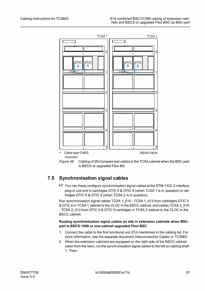
8/11/2019 NOKIA Flexi TRCM
http://slidepdf.com/reader/full/nokia-flexi-trcm 97/183
DN0577759
Issue 3-0
97
Cabling Instructions for TCSM3i S14 combined BSC/TCSM cabling of extension cabi-nets and BSC3i or upgraded Flexi BSC as BSC-part
Id:0900d8058061e17d
Figure 48 Cabling of 2N Compare test cables in the TCSA cabinet when the BSC-part
is BSC3i or upgraded Flexi BS
7.5 Synchronisation signal cables
☞ You can freely configure synchronisation signal cables at the STM-1/OC-3 interface
plug-in unit end in cartridges GTIC 5 & GTIC 6 (when TCSA 1 is in question) or car-
tridges GTIC 8 & GTIC 9 (when TCSA 2 is in question).
Run synchronisation signal cables TCSA 1_010 - TCSA 1_013 from cartridges GTIC 5
& GTIC 6 in TCSA 1 cabinet to the CLOC in the BSCC cabinet, and cables TCSA 2_010
- TCSA 2_013 from GTIC 8 & GTIC 9 cartridges in TCSA 2 cabinet to the CLOC in the
BSCC cabinet.
Routing synchronisation signal cables on site in extension cabinets when BSC-
part is BSC3i 1000 or one-cabinet upgraded Flexi BSC
1. Connect the cable to the first functional unit (FU) mentioned in the cabling list. For
more information, see the separate document Interconnection Cables in TCSM3i.
2. When the extension cabinets are equipped on the right side of the BSCC cabinet
(seen from the rear), run the synchronisation signal cables to the left on cabling shelf
1. Then:
Cable type CHES
FTRB 1 1
2
3
4
0
5
0
0
0
0
6
0
6
9
06
6
36
8
FTRB 1 1
2
3
4
0
5
0
0
0
0
6
0
6
9
06
6
36
8
REAR VIEW
GTIC6
GTIC5
GTIC9
GTIC8
DN0939887
8/11/2019 NOKIA Flexi TRCM
http://slidepdf.com/reader/full/nokia-flexi-trcm 98/183
98 DN0577759
Issue 3-0
Cabling Instructions for TCSM3i
Id:0900d8058061e17d
S14 combined BSC/TCSM cabling of extension cabi-nets and BSC3i or upgraded Flexi BSC as BSC-part
– If TCSA 1 is in question, run the synchronisation signal cables to the left from
GTIC 5 & GTIC 6, through TCSA 0 to the BSCC cabinet.
– If TCSA 2 is in question, run the synchronisation signal cables to the left from
GTIC 8 & GTIC 9, through TCSA 1 and TCSA 0 cabinets to the BSCC cabinet.3. When the extension cabinets are equipped on the left side of the BSCC cabinet
(seen from the rear), run the synchronisation cables to the right on cabling shelf 1.
Then:
– If TCSA 1 is in question, run the synchronisation signal cables to the right from
GTIC 5 & GTIC 6, through TCSA 0, down the right side of TCSA 0 to the level
of the lower edge of the large CPETx connector panel in the cabling cabinet (if
there is one), through the cabling cabinet to the BSCC cabinet.
– If TCSA 2 is in question, run the synchronisation signal cables to the right from
GTIC 8 & GTIC 9, through TCSA 1 and TCSA 0 cabinets, down the right side of
TCSA 0 to the level of the lower edge of the large CPETx connector panel in the
cabling cabinet (if there is one), through the cabling cabinet to the BSCC
cabinet.
Routing synchronisation signal cables on site in BSCC cabinet when BSC-part is
BSC3i 1000 or one-cabinet upgraded Flexi BSC
1. When the extension cabinets are equipped on the right side of the BSCC cabinet
(seen from the rear), run the synchronisation signal cables to the left on shelf 1
directly to the CLOC.
2. When the extension cabinets are equipped on the left side of the BSCC cabinet
(seen from the rear), run the synchronisation signal cables up on the left side of the
BSCC cabinet to the level of cabling shelf 1, then to the right to the CLOC.
☞ It is possible that an optional cabling cabinet is not included in the hardware con-
figuration of the BSC-part. The cabling cabinet is not used, if:
– the number of external PCM interfaces is 1 to 48, that is, normal E1 or T1
ETs are used
– the STM-1/OC-3 interfaces are used as external trunk connections, that is,
normal E1 or T1 ETs are not used.
3. Connect the cable to the second functional unit (FU) mentioned in the cabling list.
For more information, see the separate document Interconnection Cables in
TCSM3i.
The following figures show how the synchronisation signal cables are rouited when the
BSC-part is BSC3i 1000 or one-cabinet upgraded Flexi BSC and the extension cabinets
are equipped on the right side of the BSCC cabinet (cables TCSA 1_010 - TCSA 1_013and TCSA 2_010 - TCSA 2_013).
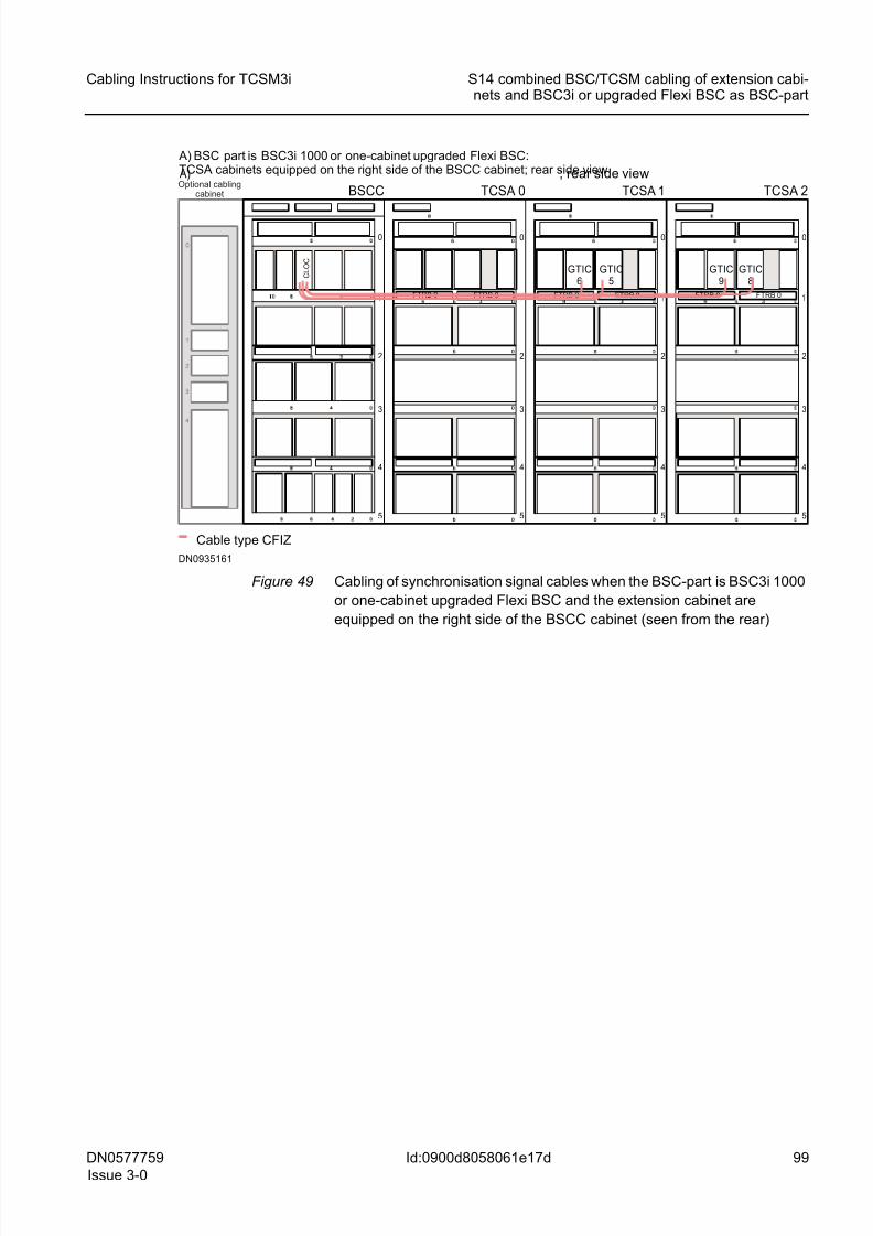
8/11/2019 NOKIA Flexi TRCM
http://slidepdf.com/reader/full/nokia-flexi-trcm 99/183
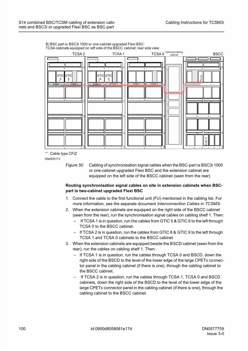
8/11/2019 NOKIA Flexi TRCM
http://slidepdf.com/reader/full/nokia-flexi-trcm 100/183
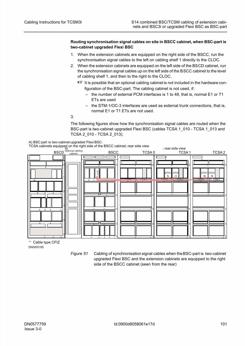
8/11/2019 NOKIA Flexi TRCM
http://slidepdf.com/reader/full/nokia-flexi-trcm 101/183
DN0577759
Issue 3-0
101
Cabling Instructions for TCSM3i S14 combined BSC/TCSM cabling of extension cabi-nets and BSC3i or upgraded Flexi BSC as BSC-part
Id:0900d8058061e17d
Routing synchronisation signal cables on site in BSCC cabinet, when BSC-part is
two-cabinet upgraded Flexi BSC
1. When the extension cabinets are equipped on the right side of the BSCC, run the
synchronisation signal cables to the left on cabling shelf 1 directly to the CLOC.2. When the extension cabinets are equipped on the left side of the BSCD cabinet, run
the synchronisation signal cables up on the left side of the BSCC cabinet to the level
of cabling shelf 1, and then to the right to the CLOC.
☞ It is possible that an optional cabling cabinet is not included in the hardware con-
figuration of the BSC-part. The cabling cabinet is not used, if:
– the number of external PCM interfaces is 1 to 48, that is, normal E1 or T1
ETs are used
– the STM-1/OC-3 interfaces are used as external trunk connections, that is,
normal E1 or T1 ETs are not used.
3.
The following figures show how the synchronisation signal cables are routed when the
BSC-part is two-cabinet upgraded Flexi BSC (cables TCSA 1_010 - TCSA 1_013 and
TCSA 2_010 - TCSA 2_013).
Figure 51 Cabling of synchronisation signal cables when the BSC-part is two-cabinet
upgraded Flexi BSC and the extension cabinets are equipped to the right
side of the BSCC cabinet (seen from the rear)
1
2
3
4
0
5
00
BSCC
1
2
3
4
0
5
TCSA 0 A) ; rear side view
Cable type CFIZ
1
2
3
4
0
5
1
2
3
4
0
5
TCSA 1 TCSA 2
FTRB 0
C L O C
GTIC6
GTIC5
GTIC9
GTIC8
DN0935185
A) BSC part is two-cabinet upgraded Flexi BSC:TCSA cabinets equipped on the right side of the BSCC cabinet; rear side view
FTRB 0FTRB 0FTRB 0FTRB 0FTRB 0
BSCD
5
4
3
2
1
0
06
3
10
48 0
48 0
0
3 069
6
7
Optional cablingcabinet
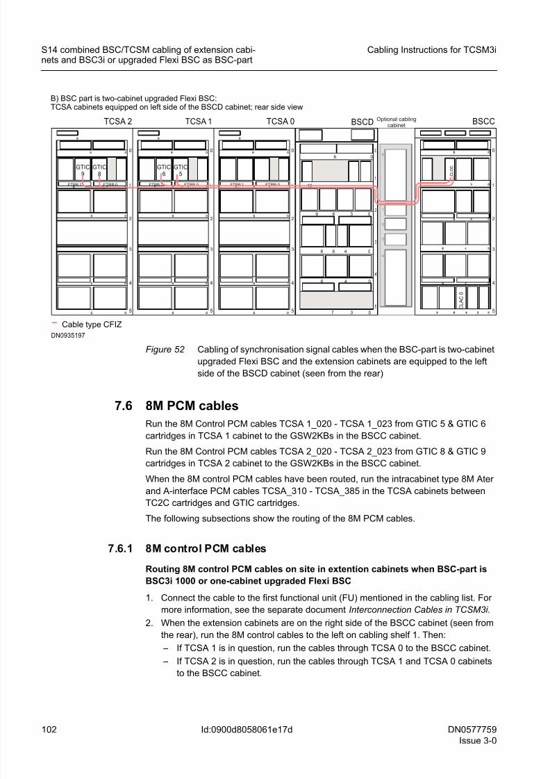
8/11/2019 NOKIA Flexi TRCM
http://slidepdf.com/reader/full/nokia-flexi-trcm 102/183
8/11/2019 NOKIA Flexi TRCM
http://slidepdf.com/reader/full/nokia-flexi-trcm 103/183
DN0577759
Issue 3-0
103
Cabling Instructions for TCSM3i S14 combined BSC/TCSM cabling of extension cabi-nets and BSC3i or upgraded Flexi BSC as BSC-part
Id:0900d8058061e17d
3. When the extension cabinets are on the left side of the BSCC (seen from the rear),
run the 8M control cables to the right on cabling shelf 1. Then:
– If TCSA 1 is in question, run the cables through TCSA 0, down the right side of
TCSA 0 to the level of the lower edge of the large CPETx connector panel in thecabling cabinet (if there is one), through the cabling cabinet and to the BSCC
cabinet.
– If TCSA 2 is in question, run the cables through TCSA 1 and TCSA 0 cabinets,
down the right side of TCSA 0 to the level of the lower edge of the large CPETx
connector panel in the cabling cabinet (if there is one), through the cabling
cabinet and to the BSCC cabinet.
Routing 8M control PCM cables on site in BSCC cabinet when BSC-part is BSC3i
1000 or one-cabinet upgraded Flexi BSC
1. When the extension cabinets are on the right side of the BSCC cabinet (seen from
the rear), run the 8M control cables to the left on shelf 1 directly to the GSW2KBs.
2. When the extension cabinets are on the left side of the BSCC cabinet, run the
cables up the left side of the BSCC cabinet to the level of cabling shelf 1 and then
on shelf 1 to the GSW2KBs.
☞ It is possible that an optional cabling cabinet is not included in the hardware con-
figuration of the BSC-part. The cabling cabinet is not used, if:
– the number of external PCM interfaces is 1 to 48, that is, normal E1 or T1
ETs are used
– the STM-1/OC-3 interfaces are used as external trunk connections, that is,
normal E1 or T1 ETs are not used.
3. Connect the cable to the second functional unit (FU) mentioned in the cabling list.
For more information, see the separate document Interconnection Cables inTCSM3i.
The following figure shows how 8M Control PCM cables are routed when the BSC-part
is BSC3i 1000 or one-cabinet upgraded Flexi BSC and the extension cabinets are
equipped on the right side of the BSCC cabinet (cables TCSA 1_020 - TCSA 1_023;
TCSA 2_020 - TCSA 2_023).
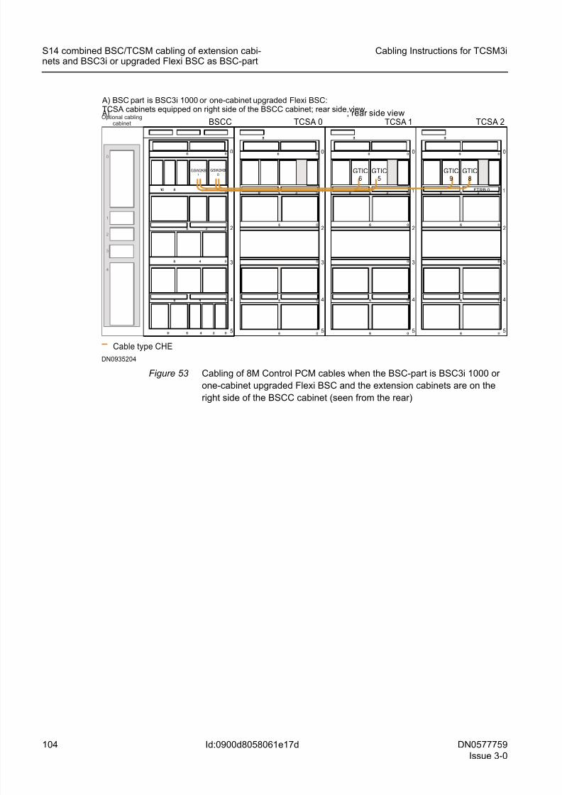
8/11/2019 NOKIA Flexi TRCM
http://slidepdf.com/reader/full/nokia-flexi-trcm 104/183
104 DN0577759
Issue 3-0
Cabling Instructions for TCSM3i
Id:0900d8058061e17d
S14 combined BSC/TCSM cabling of extension cabi-nets and BSC3i or upgraded Flexi BSC as BSC-part
Figure 53 Cabling of 8M Control PCM cables when the BSC-part is BSC3i 1000 or
one-cabinet upgraded Flexi BSC and the extension cabinets are on the
right side of the BSCC cabinet (seen from the rear)
1
2
3
4
0
5
00
BSCC
1
2
3
4
0
5
TCSA 0 A) ; rear side view
Cable type CHE
1
2
3
4
0
5
1
2
3
4
0
5
TCSA 1 TCSA 2
GSW2KB1
GSW2KB0
GTIC6
GTIC5
GTIC9
GTIC8
DN0935204
FTRB 0
A) BSC part is BSC3i 1000 or one-cabinet upgraded Flexi BSC:TCSA cabinets equipped on right side of the BSCC cabinet; rear side viewOptional cabling
cabinet
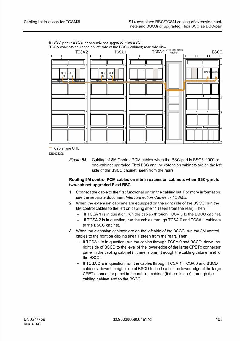
8/11/2019 NOKIA Flexi TRCM
http://slidepdf.com/reader/full/nokia-flexi-trcm 105/183
DN0577759
Issue 3-0
105
Cabling Instructions for TCSM3i S14 combined BSC/TCSM cabling of extension cabi-nets and BSC3i or upgraded Flexi BSC as BSC-part
Id:0900d8058061e17d
Figure 54 Cabling of 8M Control PCM cables when the BSC-part is BSC3i 1000 or
one-cabinet upgraded Flexi BSC and the extension cabinets are on the left
side of the BSCC cabinet (seen from the rear)
Routing 8M control PCM cables on site in extension cabinets when BSC-part istwo-cabinet upgraded Flexi BSC
1. Connect the cable to the first functional unit in the cabling list. For more information,
see the separate document Interconnection Cables in TCSM3i.
2. When the extension cabinets are equipped on the right side of the BSCC, run the
8M control cables to the left on cabling shelf 1 (seen from the rear). Then:
– If TCSA 1 is in question, run the cables through TCSA 0 to the BSCC cabinet.
– If TCSA 2 is in question, run the cables through TCSA 0 and TCSA 1 cabinets
to the BSCC cabinet.
3. When the extension cabinets are on the left side of the BSCC, run the 8M control
cables to the right on cabling shelf 1 (seen from the rear). Then:
– If TCSA 1 is in question, run the cables through TCSA 0 and BSCD, down the
right side of BSCD to the level of the lower edge of the large CPETx connector
panel in the cabling cabinet (if there is one), through the cabling cabinet and to
the BSCC.
– If TCSA 2 is in question, run the cables through TCSA 1, TCSA 0 and BSCD
cabinets, down the right side of BSCD to the level of the lower edge of the large
CPETx connector panel in the cabling cabinet (if there is one), through the
cabling cabinet and to the BSCC.
1
2
3
4
0
5
00
BSCC
FTRB 1 FTRB 0 1
2
3
4
0
5
09 36
TCSA 2
Cable type CHE
FTRB 1 FTRB 0 1
2
3
4
0
5
09 36FTRB 1 FTRB 0 1
2
3
4
0
5
09 36
TCSA 1 TCSA 0
GTIC9
GTIC8
GTIC6
GTIC5
DN0935228
part s or one-ca net upgra e ex :TCSA cabinets equipped on left side of the BSCC cabinet; rear side view
Optional cablingcabinet
GSW2KB1
GSW2KB0
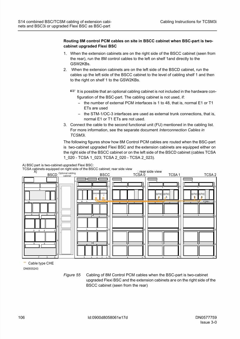
8/11/2019 NOKIA Flexi TRCM
http://slidepdf.com/reader/full/nokia-flexi-trcm 106/183
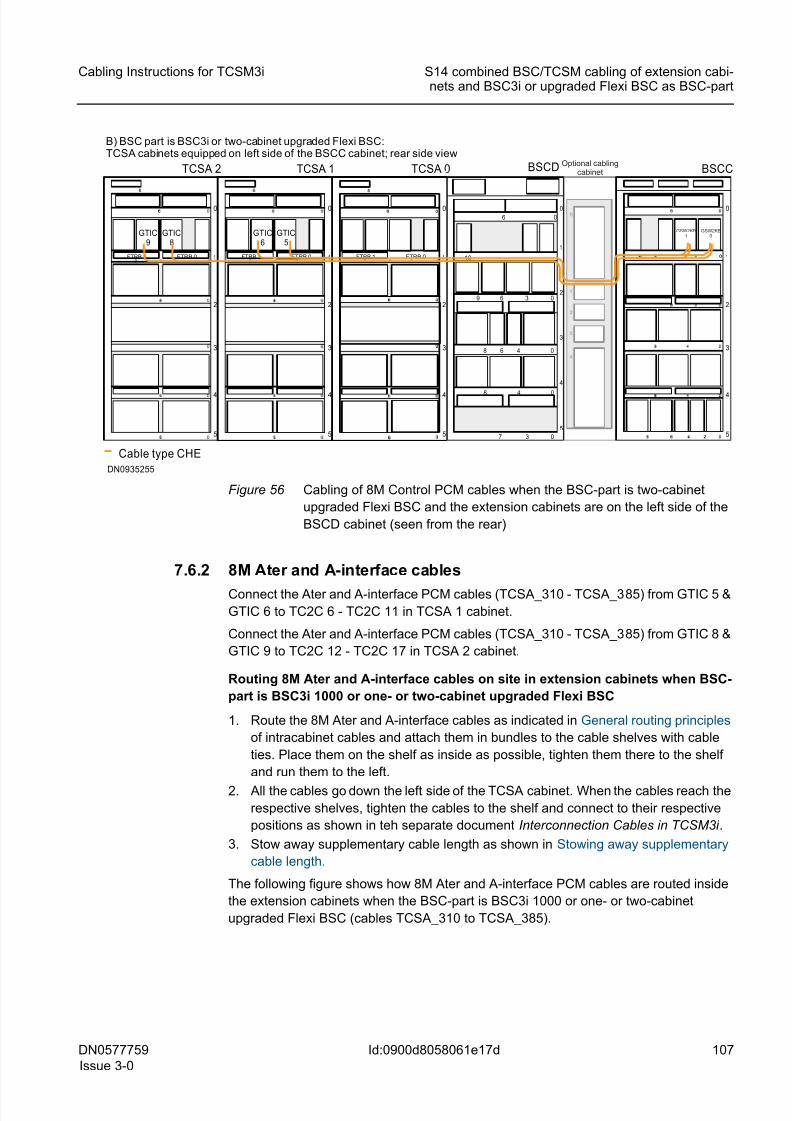
8/11/2019 NOKIA Flexi TRCM
http://slidepdf.com/reader/full/nokia-flexi-trcm 107/183
DN0577759
Issue 3-0
107
Cabling Instructions for TCSM3i S14 combined BSC/TCSM cabling of extension cabi-nets and BSC3i or upgraded Flexi BSC as BSC-part
Id:0900d8058061e17d
Figure 56 Cabling of 8M Control PCM cables when the BSC-part is two-cabinet
upgraded Flexi BSC and the extension cabinets are on the left side of the
BSCD cabinet (seen from the rear)
7.6.2 8M Ater and A-interface cables
Connect the Ater and A-interface PCM cables (TCSA_310 - TCSA_385) from GTIC 5 &
GTIC 6 to TC2C 6 - TC2C 11 in TCSA 1 cabinet.
Connect the Ater and A-interface PCM cables (TCSA_310 - TCSA_385) from GTIC 8 &
GTIC 9 to TC2C 12 - TC2C 17 in TCSA 2 cabinet.
Routing 8M Ater and A-interface cables on site in extension cabinets when BSC-
part is BSC3i 1000 or one- or two-cabinet upgraded Flexi BSC
1. Route the 8M Ater and A-interface cables as indicated in General routing principles
of intracabinet cables and attach them in bundles to the cable shelves with cable
ties. Place them on the shelf as inside as possible, tighten them there to the shelf
and run them to the left.
2. All the cables go down the left side of the TCSA cabinet. When the cables reach the
respective shelves, tighten the cables to the shelf and connect to their respective
positions as shown in teh separate document Interconnection Cables in TCSM3i .
3. Stow away supplementary cable length as shown in Stowing away supplementary
cable length.
The following figure shows how 8M Ater and A-interface PCM cables are routed inside
the extension cabinets when the BSC-part is BSC3i 1000 or one- or two-cabinet
upgraded Flexi BSC (cables TCSA_310 to TCSA_385).
5
4
3
2
1
0
06
3
10
48 0
48 0
0
3 069
6
7
1
2
3
4
0
5
00
BSCC
FTRB 1 FTRB 0 1
2
3
4
0
5
09 36
TCSA 2
Cable type CHE
FTRB 1 FTRB 0 1
2
3
4
0
5
09 36FTRB 1 FTRB 0 1
2
3
4
0
5
09 36
TCSA 1 TCSA 0
GTIC9
GTIC8
GTIC6
GTIC5
DN0935255
B) BSC part is BSC3i or two-cabinet upgraded Flexi BSC:TCSA cabinets equipped on left side of the BSCC cabinet; rear side view
BSCD Optional cablingcabinet
GSW2KB1
GSW2KB0
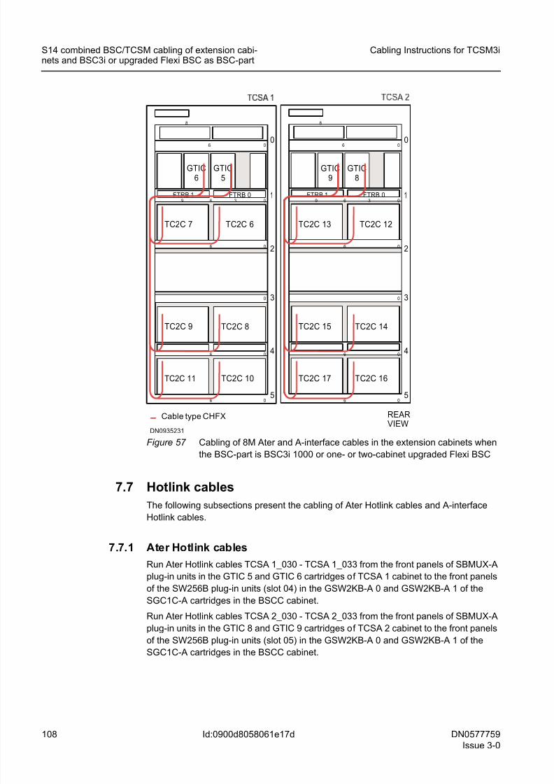
8/11/2019 NOKIA Flexi TRCM
http://slidepdf.com/reader/full/nokia-flexi-trcm 108/183
108 DN0577759
Issue 3-0
Cabling Instructions for TCSM3i
Id:0900d8058061e17d
S14 combined BSC/TCSM cabling of extension cabi-nets and BSC3i or upgraded Flexi BSC as BSC-part
Figure 57 Cabling of 8M Ater and A-interface cables in the extension cabinets when
the BSC-part is BSC3i 1000 or one- or two-cabinet upgraded Flexi BSC
7.7 Hotlink cables
The following subsections present the cabling of Ater Hotlink cables and A-interface
Hotlink cables.
7.7.1 Ater Hotlink cablesRun Ater Hotlink cables TCSA 1_030 - TCSA 1_033 from the front panels of SBMUX-A
plug-in units in the GTIC 5 and GTIC 6 cartridges of TCSA 1 cabinet to the front panels
of the SW256B plug-in units (slot 04) in the GSW2KB-A 0 and GSW2KB-A 1 of the
SGC1C-A cartridges in the BSCC cabinet.
Run Ater Hotlink cables TCSA 2_030 - TCSA 2_033 from the front panels of SBMUX-A
plug-in units in the GTIC 8 and GTIC 9 cartridges of TCSA 2 cabinet to the front panels
of the SW256B plug-in units (slot 05) in the GSW2KB-A 0 and GSW2KB-A 1 of the
SGC1C-A cartridges in the BSCC cabinet.
Cable type CHFX
DN0935231
FTRB 1 FTRB 0 1
2
3
4
0
5
0
0
0
0
6
0
6
9
06
6
36
8
GTIC6
GTIC5
TC2C 7 TC2C 6
TC2C 9 TC2C 8
TC2C 11 TC2C 10
FTRB 1 FTRB 0 1
2
3
4
0
5
0
0
0
0
6
0
6
9
06
6
36
8
REARVIEW
GTIC9
GTIC8
TC2C 13 TC2C 12
TC2C 15 TC2C 14
TC2C 17 TC2C 16
8/11/2019 NOKIA Flexi TRCM
http://slidepdf.com/reader/full/nokia-flexi-trcm 109/183
DN0577759
Issue 3-0
109
Cabling Instructions for TCSM3i S14 combined BSC/TCSM cabling of extension cabi-nets and BSC3i or upgraded Flexi BSC as BSC-part
Id:0900d8058061e17d
Routing Ater Hotlink cables on site in extension cabinets when BSC-part is BSC3i
1000 or one-cabinet upgraded Flexi BSC
1. Connect the cables to the first functional unit (FU; front panel of SBMUX-A plug-in
unit) on the cabling list; see the separate document Interconnection Cables inTCSM3i.
2. When extension cabinets are equipped on the right side of the BSCC cabinet (seen
from the front), in TCSA 1 cabinet, route the cables to the front cabling shelves of
GTIC 5 and GTIC 6 cartridges; in TCSA 2 cabinet, route the cables to the front
cabling shelves of GTIC 8 and GTIC 9 cartridges.
Lay the cables on the cabling shelves and route them to the right side of the TCSA
cabinet (seen from the front). Run the cables to the level of shelf 2 and pass them
from front to back through the opening in the middle of cabling shelf 2.
3. After the cables have been passed from front to back, route the cables on cabling
shelf 2 to the right side of the cabinet (seen from the rear), on the right side up to the
level of cabling shelf 0. Then: – If TCSA 1 cabinet is in question, run the cables through TCSA 0 on shelf 0 and
then through cabling cabinet (if there is one) to BSCC cabinet. Pass the cables
from back to front through the cabling hole on the left side of the Upper Air Guide
(seen from the rear).
– If TCSA 2 cabinet is in question, run the cables through TCSA 1 and TCSA 0
on shelf 0 and then through the cabling cabinet (if there is one) to the BSCC
cabinet. Pass the cables from back to front through the cabling hole on the left
side of the Upper Air Guide (seen from the rear).
4. When extension cabinets are equipped on the left side the BSCC cabinet (seen from
the front), in TCSA 1 cabinet, route the cables to the front cabling shelves of GTIC
5 and GTIC 6 cartridges; in TCSA 2 cabinet, route the cables to the front cabling
shelves of GTIC 8 and GTIC 9 cartridges.
Lay the cables on the cabling shelves and route them to the right side of the TCSA
cabinet (seen from the front). Run the cables to the level of shelf 2 and pass them
from front to back through the opening in the middle of cabling shelf 2.
5. After the cables have been passed from front to back, route the cables on cabling
shelf 2 to the left side of the cabinet (seen from the rear) and to the level of cabling
shelf 0. Then:
– If TCSA 1 cabinet is in question, run the cables through TCSA 0 on shelf 0 to
the BSCC cabinet. Pass the cables from back to front through the cabling hole
on the right side of the Upper Air Guide (seen from the rear).
– If TCSA 2 cabinet is in question, run the cables through TCSA1 and TCSA0 on
shelf 0 to the BSCC cabinet. Pass the cables from back to front through the
cabling hole on the right side of the Upper Air Guide (seen from the rear).
Routing Ater Hotlink cables on site in BSCC cabinet when BSC-part is BSC3i 1000
or one-cabinet upgraded Flexi BSC
1. When the extension cabinets are on the right side of the BSCC cabinet (as seen
from the front), and the cables have been passed through the cabinet from back to
front, run the Ater Hotlink cables to the left on the front cabling shelves to the
GSW2KBs.
2. When the extension cabinets are on the left side of the BSCC cabinet (as seen from
the front), and the cables have been passed through the cabinet from back to front,
run the Ater Hotlink cables to the right on the front cabling shelves to the GSW2KBs.
8/11/2019 NOKIA Flexi TRCM
http://slidepdf.com/reader/full/nokia-flexi-trcm 110/183
110 DN0577759
Issue 3-0
Cabling Instructions for TCSM3i
Id:0900d8058061e17d
S14 combined BSC/TCSM cabling of extension cabi-nets and BSC3i or upgraded Flexi BSC as BSC-part
3. Connect the cable to the second functional unit (FU) mentioned in the cabling list.
For more information, see the separate document Interconnection Cables in
TCSM3i.
The following figures show how Ater Hotlinks are routed when the BSC-part is BSC3i1000 or one-cabinet upgraded Flexi BSC and the extension cabinets are equipped
either on the right side or on the left side of the BSCC cabinet (cables TCSA 1_030 -
TCSA 1_033; TCSA 2_030 - TCSA 2_033)
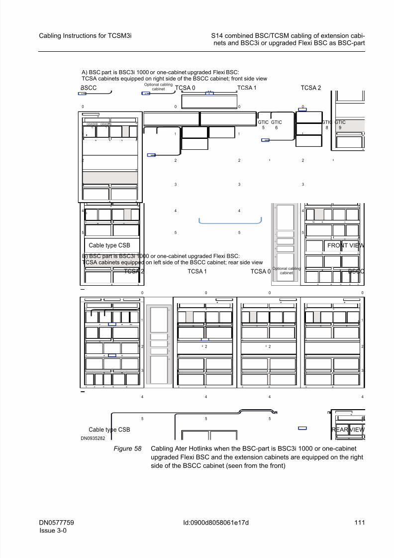
8/11/2019 NOKIA Flexi TRCM
http://slidepdf.com/reader/full/nokia-flexi-trcm 111/183
DN0577759
Issue 3-0
111
Cabling Instructions for TCSM3i S14 combined BSC/TCSM cabling of extension cabi-nets and BSC3i or upgraded Flexi BSC as BSC-part
Id:0900d8058061e17d
Figure 58 Cabling Ater Hotlinks when the BSC-part is BSC3i 1000 or one-cabinet
upgraded Flexi BSC and the extension cabinets are equipped on the right
side of the BSCC cabinet (seen from the front)
1
2
3
4
0
5
00
BSCC
1
2
3
4
0
5
0
TCSA 2
Cable type CSB
1
2
3
4
0
5
0
1
2
3
4
0
5
0
TCSA 1 TCSA 0
DN0935282
REAR VIEW
B) BSC part is BSC3i 1000 or one-cabinet upgraded Flexi BSC:TCSA cabinets equipped on left side of the BSCC cabinet; rear side view
1
2
3
4
0
5
0
0
0
BSCC
1
2
3
4
0
5
6
TCSA 2
Cable type CSB
1
2
3
4
0
5
6
1
2
3
4
0
5
TCSA 1TCSA 0
GTIC5
GTIC6
GTIC8
GTIC9
FRONT VIEW
A) BSC part is BSC3i 1000 or one-cabinet upgraded Flexi BSC:TCSA cabinets equipped on right side of the BSCC cabinet; front side view
GSW2KB0
GSW2KB1
Optional cablingcabinet
Optional cablingcabinet
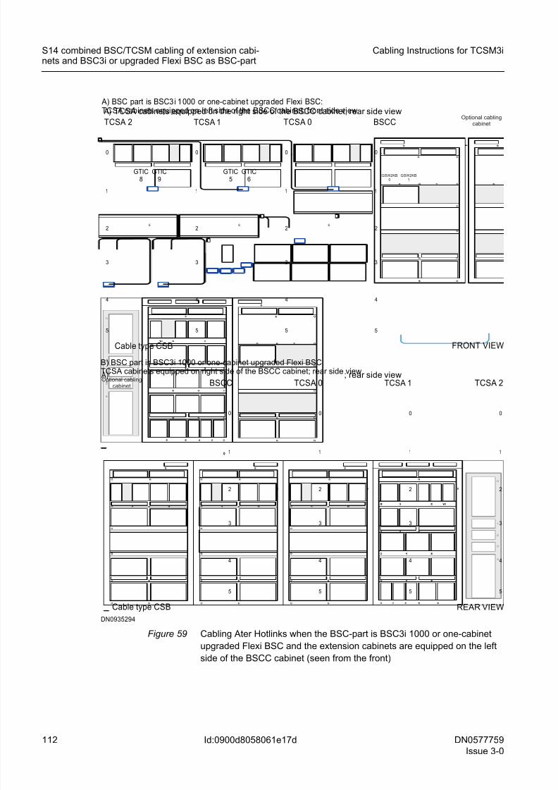
8/11/2019 NOKIA Flexi TRCM
http://slidepdf.com/reader/full/nokia-flexi-trcm 112/183
112 DN0577759
Issue 3-0
Cabling Instructions for TCSM3i
Id:0900d8058061e17d
S14 combined BSC/TCSM cabling of extension cabi-nets and BSC3i or upgraded Flexi BSC as BSC-part
Figure 59 Cabling Ater Hotlinks when the BSC-part is BSC3i 1000 or one-cabinet
upgraded Flexi BSC and the extension cabinets are equipped on the left
side of the BSCC cabinet (seen from the front)
1
2
3
4
0
5
00
BSCC
1
2
3
4
0
5
6
TCSA 0 A) ; rear side view
Cable type CSB
1
2
3
4
0
5
6
1
2
3
4
0
5
6
TCSA 1 TCSA 2
REAR VIEW
DN0935294
B) BSC part is BSC3i 1000 or one-cabinet upgraded Flexi BSC:TCSA cabinets equipped on right side of the BSCC cabinet; rear side view
1
2
3
4
0
5
BSCC
0
1
2
3
4
0
5
6
0
TCSA 0
A) TCSA cabinets equipped on the right side of the BSCC cabinet; rear side view
Cable type CSB
1
2
3
4
0
5
6
1
2
3
4
0
5
6
TCSA 1TCSA 2
GTIC8
GTIC9
GTIC5
GTIC6
FRONT VIEW
A) BSC part is BSC3i 1000 or one-cabinet upgraded Flexi BSC:TCSA cabinets equipped on left side of the BSCC cabinet; front side view
Optional cablingcabinet
Optional cablingcabinet
GSW2KB0
GSW2KB1
8/11/2019 NOKIA Flexi TRCM
http://slidepdf.com/reader/full/nokia-flexi-trcm 113/183
DN0577759
Issue 3-0
113
Cabling Instructions for TCSM3i S14 combined BSC/TCSM cabling of extension cabi-nets and BSC3i or upgraded Flexi BSC as BSC-part
Id:0900d8058061e17d
Routing Ater Hotlink cables on site in extension cabinets when BSC-part is two-
cabinet upgraded Flexi BSC
1. Connect the cables to the first functional unit (FU, front panel of SBMUX-A plug-in
unit) on the cabling list; see the separate document Interconnection Cables inTCSM3i.
2. When extension cabinets are equipped on the right side of the BSCD cabinet (seen
from the front), in TCSA 1 cabinet, route the cables to the front cabling shelves of
GTIC 5 and GTIC 6 cartridges; in TCSA 2 cabinet, route the cables to the front
cabling shelves of GTIC 8 and GTIC 9 cartridges.
Lay the cables on the cabling shelves and route them to the right side of the TCSA
cabinet (seen from the front). Run the cables down to the level of shelf 2, run them
to the left on shelf 2 and pass them from front to back through the opening in the
middle of cabling shelf 2.
3. After the cables have been passed from front to back, route the cables on cabling
shelf 2 to the right (seen from the rear), on the right side of the cabinet up to the levelof cabling shelf 0. Then:
– If TCSA 1 cabinet is in question, run the cables through TCSA 0 and BSCD
cabinets on shelf 0 and then through cabling cabinet (if there is one) to the BSCC
cabinet. Pass the cables from back to front through the cabling hole on the left
side of the Upper Air Guide (seen from the rear).
– If TCSA 2 cabinet is in question, run the cables through TCSA 1, TCSA 0 and
BSCD cabinets on shelf 0 and then through the cabling cabinet (if there is one)
to the BSCC cabinet. Pass the cables from back to front through the cabling hole
on the left side of the Upper Air Guide (seen from the rear).
4. When extension cabinets are equipped on the left side of the BSCC cabinet (seen
from the front), in TCSA 1 cabinet, route the cables to the front cabling shelves of
GTIC 5 and GTIC 6 cartridges; in TCSA 2 cabinet, route the cables to the front
cabling shelves of GTIC 8 and GTIC 9 cartridges.
Lay the cables on the cabling shelves and route them to the right side of the TCSA
cabinet (seen from the front). Run the cables down to the level of shelf 2, run them
to the left on the shelf 2 and pass them from front to back through the opening in the
middle of cabling shelf 2.
5. After the cables have been passed from front to back, route the cables on cabling
shelf 2 to the left side of the cabinets (seen from the rear), and up to the level of
cabling shelf 0. Then:
– If TCSA 1 cabinet is in question, run the cables through TCSA 0 on shelf 0 to the
BSCC cabinet. Pass the cables from back to front through the cabling hole on
the right side of the Upper Air Guide (seen from the rear).
– If TCSA 2 cabinet is in question, run the cables through TCSA 1 and TCSA 0 on
shelf 0 to the BSCC cabinet. Pass the cables from back to front through the
cabling hole on the right side of the Upper Air Guide (seen from the rear).
Routing Ater Hotlink cables on site in BSCC cabinet when BSC-part is two-cabinet
upgraded Flexi BSC
1. When the extension cabinets are on the right side of the BSCC cabinet (seen from
the front), and the cables have been passed through the cabinet from back to front,
run the Ater Hotlink cables to the left on the front cabling shelves and to the front
panel interfaces of SW256B plug-in units in the GSW2KB 0 and GSW2KB 1 car-
tridges
8/11/2019 NOKIA Flexi TRCM
http://slidepdf.com/reader/full/nokia-flexi-trcm 114/183
114 DN0577759
Issue 3-0
Cabling Instructions for TCSM3i
Id:0900d8058061e17d
S14 combined BSC/TCSM cabling of extension cabi-nets and BSC3i or upgraded Flexi BSC as BSC-part
2. When the extension cabinets are on the left side of the BSCC cabinet (seen from the
front), and the cables have been passed through the cabinet from back to front, run
the Ater Hotlink cables to the right on the front cabling shelves and to the front panel
interfaces of SW256B plug-in units in the GSW2KB 0 and GSW2KB 1 cartridges.
3. Connect the cable to the second functional unit (FU) mentioned in the cabling list.
For more information, see the separate document Interconnection Cables in
TCSM3i.
The following figures show how Ater Hotlinks are routed when the BSC-part is two-
cabinet upgraded Flexi BSC and the extension cabinets are equipped either on the right
side of the BSCD cabinet or on the left side of the BSCC cabinet (cables TCSA 1_030 -
TCSA 1_033; TCSA 2_030 - TCSA 2_033).
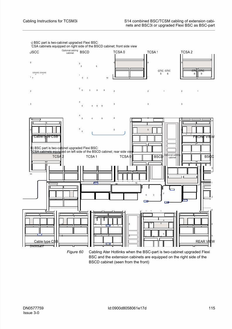
8/11/2019 NOKIA Flexi TRCM
http://slidepdf.com/reader/full/nokia-flexi-trcm 115/183
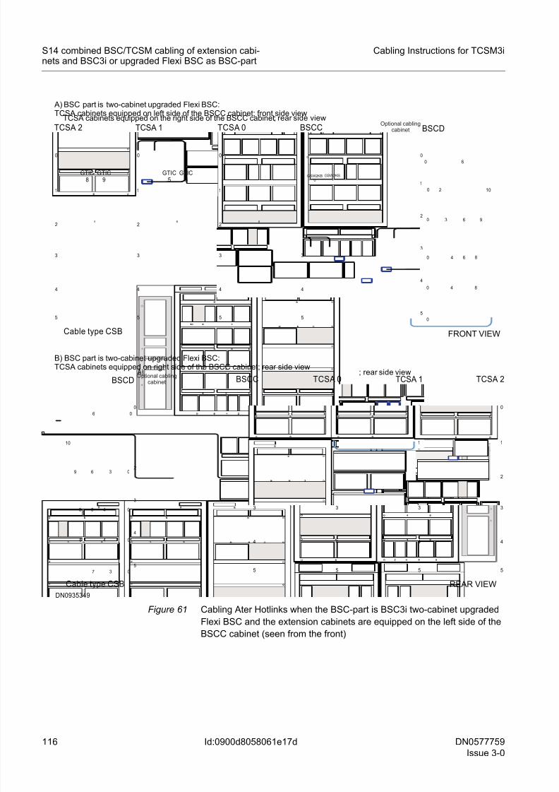
8/11/2019 NOKIA Flexi TRCM
http://slidepdf.com/reader/full/nokia-flexi-trcm 116/183
116 DN0577759
Issue 3-0
Cabling Instructions for TCSM3i
Id:0900d8058061e17d
S14 combined BSC/TCSM cabling of extension cabi-nets and BSC3i or upgraded Flexi BSC as BSC-part
Figure 61 Cabling Ater Hotlinks when the BSC-part is BSC3i two-cabinet upgraded
Flexi BSC and the extension cabinets are equipped on the left side of the
BSCC cabinet (seen from the front)
1
2
3
4
0
5
00
BSCC
1
2
3
4
0
5
6
TCSA 0 A) ; rear side view
Cable type CSB
1
2
3
4
0
5
6
TCSA 1 TCSA 2
REAR VIEW
1
2
3
4
0
5
6
DN0935349
B) BSC part is two-cabinet upgraded Flexi BSC:TCSA cabinets equipped on right side of the BSCC cabinet; rear side view
BSCD
5
4
3
2
1
0
06
3
10
48 0
48 0
0
3 069
6
7
1
2
3
4
0
5
BSCC
0
1
2
3
4
0
5
6
0
TCSA 0TCSA cabinets equipped on the right side of the BSCC cabinet; rear side view
Cable type CSB
1
2
3
4
0
5
6
1
2
3
4
0
5
6
TCSA 1TCSA 2
GTIC8
GTIC9
GTIC5
GTIC6
FRONT VIEW
A) BSC part is two-cabinet upgraded Flexi BSC:TCSA cabinets equipped on left side of the BSCC cabinet; front side view
5
4
3
2
1
0
0 6
2 10
4 80
4 80
0
30 6 9
6
BSCD
0
Optional cablingcabinet
Optional cablingcabinet
GSW2KB0
GSW2KB1
8/11/2019 NOKIA Flexi TRCM
http://slidepdf.com/reader/full/nokia-flexi-trcm 117/183
DN0577759
Issue 3-0
117
Cabling Instructions for TCSM3i S14 combined BSC/TCSM cabling of extension cabi-nets and BSC3i or upgraded Flexi BSC as BSC-part
Id:0900d8058061e17d
7.7.2 A-interface Hotlink cables
In TCSA 1 cabinet, run intracabinet type A-interface Hotlink cables TCSA_450 -
TCSA_465 from the front panels of ETS2 plug-in units (slots 05 and 06) to the front
panels of SBMUX-A plug-in units (slots 01 and 02) in GTIC 5 and GTIC 6 cartridges.
In TCSA 2 cabinet, run intracabinet type A-interface Hotlink cables TCSA_450 -
TCSA_465 from the front panels of ETS2 plug-in units (slots 05 and 06) to the front
panels of SBMUX-A plug-in units (slots 01 and 02) in GTIC 8 and GTIC 9 cartridges.
Routing A-interface Hotlink cables on site in extension cabinets when BSC-part is
BSC3i 1000 or one- or two-cabinet upgraded Flexi BSC
1. Connect the cables to the first functional unit (FU; front panel of the ETS2 plug-in
unit) on the cabling list; see the separate document Interconnection Cables in
TCSM3i.
2. Route the cables to the cabling shelves of GTIC 5 & GTIC 6 cartridges in TCSA 1
cabinet.3. Route the cables to the cabling shelves of GTIC 8 & GTIC 9 cartridges in TCSA 2
cabinet.
4. Lay the cables on the cabling shelves and route them to the second functional unit
(front panel of SBMUX-A plug-in unit) on the cabling list.
The following figure shows how A-interface Hotlink cables are routed when the BSC-part
is BSC3i 1000 or one- or two-cabinet upgraded Flexi BSC (cables TCSA_450 -
TCSA_465).
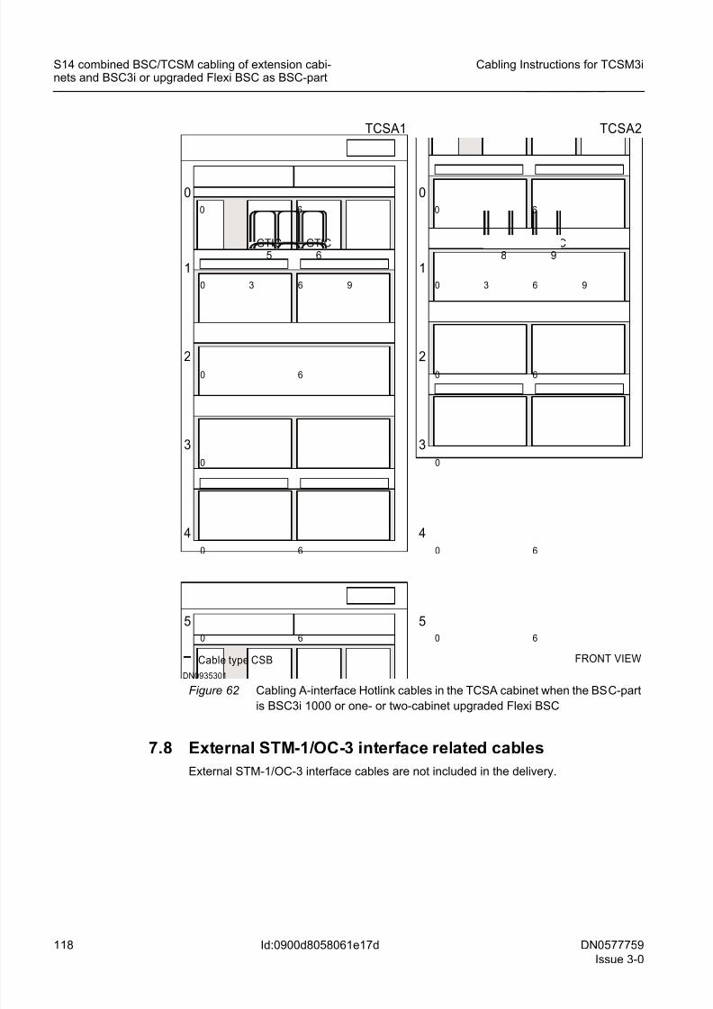
8/11/2019 NOKIA Flexi TRCM
http://slidepdf.com/reader/full/nokia-flexi-trcm 118/183
118 DN0577759
Issue 3-0
Cabling Instructions for TCSM3i
Id:0900d8058061e17d
S14 combined BSC/TCSM cabling of extension cabi-nets and BSC3i or upgraded Flexi BSC as BSC-part
Figure 62 Cabling A-interface Hotlink cables in the TCSA cabinet when the BSC-part
is BSC3i 1000 or one- or two-cabinet upgraded Flexi BSC
7.8 External STM-1/OC-3 interface related cables
External STM-1/OC-3 interface cables are not included in the delivery.
FRONT VIEW
DN0935301
TCSA1
5
4
3
2
060
0
0 6
1
630
60
0
6
9
GTIC5
GTIC6
TCSA2
5
4
3
2
060
0
0 6
1
630
60
0
6
9
GTIC8
GTIC9
Cable type CSB
8/11/2019 NOKIA Flexi TRCM
http://slidepdf.com/reader/full/nokia-flexi-trcm 119/183
DN0577759
Issue 3-0
119
Cabling Instructions for TCSM3i S14 combined BSC/TCSM cabling of extension cabi-nets and first-delivery Flexi BSC as BSC-part
Id:0900d8058061e183
8 S14 combined BSC/TCSM cabling of exten-
sion cabinets and first-delivery Flexi BSC as
BSC-part☞ This section is applied to upgrading the extension cabinets (TCSA 1 and TCSA 2)
from the TCSA base cabinet.
☞ The extension cabinets can be equipped either on the right side or on the left side
of the BSCC cabinet.
Routing of combined BSC/TCSM installation-specific cables is done on site.
All cabling (except AL and AL/CGS cables TCSA_065 & TCSA_066, Internal synchro-
nisation cables TCSA_070 - TCSA_073, External ET interface related cables
TCSA_150 - TCSA_269, Control PCM cables TCSA_080 & TCSA_081, and PCM
cables TCSA_090 - TCSA_131) presented in Intracabinet cabling of TCSA cabinet iscommon to both TCSM3i for stand-alone installation option and TCSM3i for combined
BSC/TCSM installation option.
The following sections show the cabling of the extension cabinets (TCSA 1 and TCSA
2) when the BSC-part is first delivery Flex BSC. They provide the most efficient routing
for SBUS cables, Timing bus cables, Timing loop cables, 2N Compare test cables, Syn-
chronisation signal cables, 8M PCM cables and Hotlink cables.
8.1 SBUS cables
Run supervision bus (SBUS) cables TCSA 1_001 & TCSA 1_002 from CLAC 1 of TCSA
1 cabinet to CLAC 0 of TCSA 0 cabinet.
Run supervision bus (SBUS) cables TCSA 2_001 & TCSA 2_002 from CLAC 2 of TCSA
2 cabinet to CLAC1 of TCSA 1 cabinet.
Routing SBUS cables on site in extension cabinets
1. Connect the cable to the first functional unit (FU) mentioned in the cabling list. For
more information, see the separate document Interconnection Cables in TCSM3i.
2. Run the SBUS cables to the left or to the right on shelf 1 depending on which side
of the BSCC cabinet the extension cabinets are equipped (seen from the rear).
When they are on the right side of the BSCC cabinet, run the cables to the left on
shelf 1 and when they are on the left side of the BSCC cabinet, run the cables to the
right on shelf 1. Then: – If TCSA 1 cabinet is in question, run the cables from CLAC 1 to CLAC 0 in the
TCSA 0 cabinet.
– If TCSA 2 cabinet is in question, run the cables from CLAC 2 to CLAC 1 in the
TCSA 1 cabinet.
3. Connect the cable to the second functional unit in the cabling list. For more informa-
tion, see the separate document Interconnection Cables in TCSM3i.
The following figures show how SBUS cables are routed when the BSC-part is first-
delivery Flexi BSC (cables TCSA 1_001 & TCSA 1_002, and TCSA 2_001 & TCSA
2_002 ).
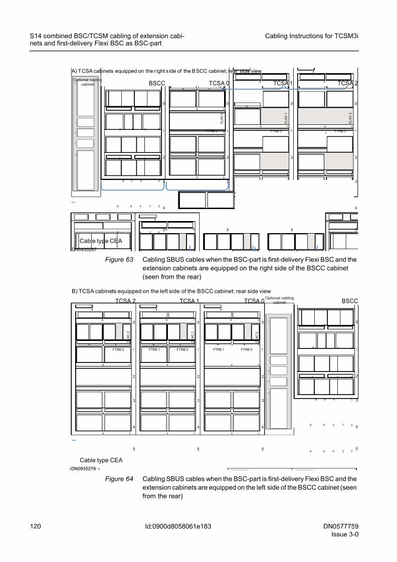
8/11/2019 NOKIA Flexi TRCM
http://slidepdf.com/reader/full/nokia-flexi-trcm 120/183
120 DN0577759
Issue 3-0
Cabling Instructions for TCSM3i
Id:0900d8058061e183
S14 combined BSC/TCSM cabling of extension cabi-nets and first-delivery Flexi BSC as BSC-part
Figure 63 Cabling SBUS cables when the BSC-part is first-delivery Flexi BSC and the
extension cabinets are equipped on the right side of the BSCC cabinet
(seen from the rear)
Figure 64 Cabling SBUS cables when the BSC-part is first-delivery Flexi BSC and the
extension cabinets are equipped on the left side of the BSCC cabinet (seen
from the rear)
BSCC TCSA 0
Cable type CEA
1
2
3
4
0
5
0 1
2
3
4
0
5
6
TCSA 1 TCSA 2
FTRB 0 FTRB 01
2
3
4
0
5
FTRB 0
C L A C 0
C L A C 1
C L A C 2
A) T CSA cabinets equipped on the r ight s ide of the BSCC cabinet; rear side view
DN0935267
Optional cablingcabinet
06
3 09 6
48 0
0249 6
3 09 6
6
0249 6
1
2
3
4
0
5
BSCC
FTRB 0 1
2
3
4
0
5
TCSA 2
Cable type CEA
C L A C 2
FTRB 1 FTRB 0 1
2
3
4
0
5
C L A C 1
FTRB 1 FTRB 0 1
2
3
4
0
5
C L A C 0
TCSA 1 TCSA 0
DN0935279
B) TCSA cabinets equipped on the left side of the BSCC cabinet; rear side viewOptional cabling
cabinet
06
3 09 6
48 0
0249 6
3 09 6
6
0249 6
1
2
3
4
0
5
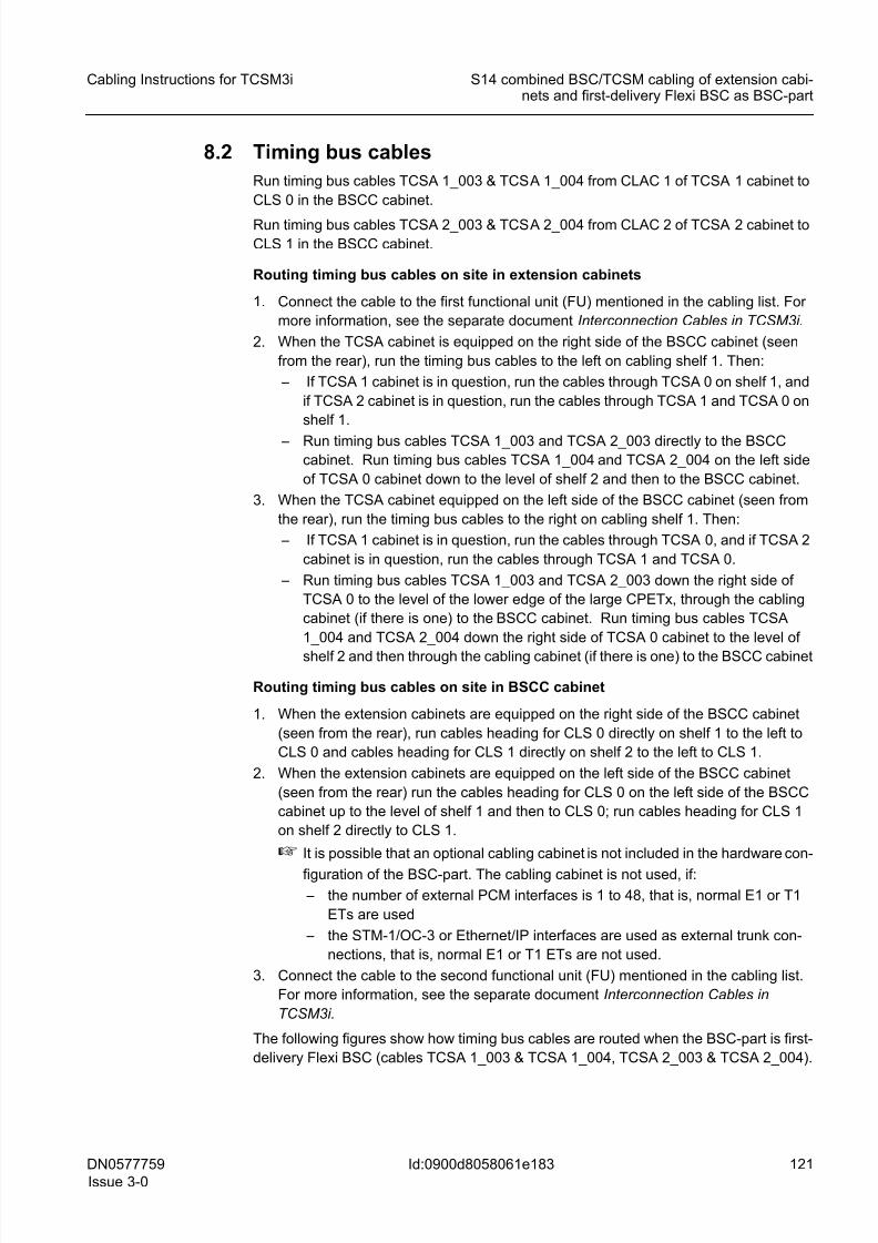
8/11/2019 NOKIA Flexi TRCM
http://slidepdf.com/reader/full/nokia-flexi-trcm 121/183
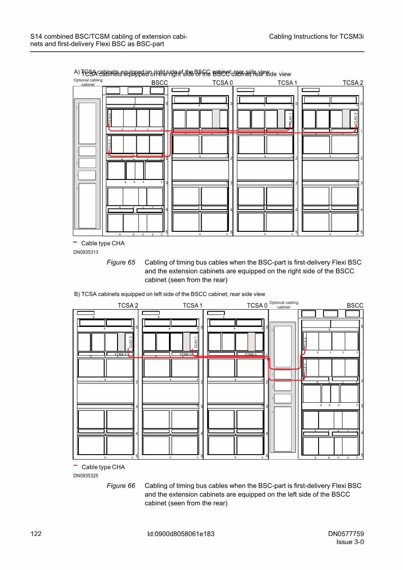
8/11/2019 NOKIA Flexi TRCM
http://slidepdf.com/reader/full/nokia-flexi-trcm 122/183
122 DN0577759
Issue 3-0
Cabling Instructions for TCSM3i
Id:0900d8058061e183
S14 combined BSC/TCSM cabling of extension cabi-nets and first-delivery Flexi BSC as BSC-part
Figure 65 Cabling of timing bus cables when the BSC-part is first-delivery Flexi BSC
and the extension cabinets are equipped on the right side of the BSCC
cabinet (seen from the rear)
Figure 66 Cabling of timing bus cables when the BSC-part is first-delivery Flexi BSC
and the extension cabinets are equipped on the left side of the BSCC
cabinet (seen from the rear)
BSCC
1
2
3
4
0
5
8
TCSA 0
TCSA cabinets equipped on the right side of the BSCC cabinet; rear side view
Cable type CHA
1
2
3
4
0
5
8
1
2
3
4
0
5
6
8
TCSA 1 TCSA 2
C L A C 1
C L A C 2
DN0935313
A) TCSA cabinets equipped on right side of the BSCC cabinet; rear side view
Optional cablingcabinet
06
3 09 6
48 0
0249 6
3 09 6
6
0249 6
1
2
3
4
0
5
C L S 0
C L S 1
06
3 09 6
48 0
0249 6
3 09 6
6
0249 6
1
2
3
4
0
5
C L S 0
C L S 1
BSCC
FTRB 0 1
2
3
4
0
5
TCSA 2
B) TCSA cabinets equipped on left side of the BSCC cabinet; rear side view
Cable type CHA
FTRB 0 1
2
3
4
0
5
FTRB 0 1
2
3
4
0
5
TCSA 1 TCSA 0
C L A C 2
C L A C 1
DN0935325
Optional cablingcabinet
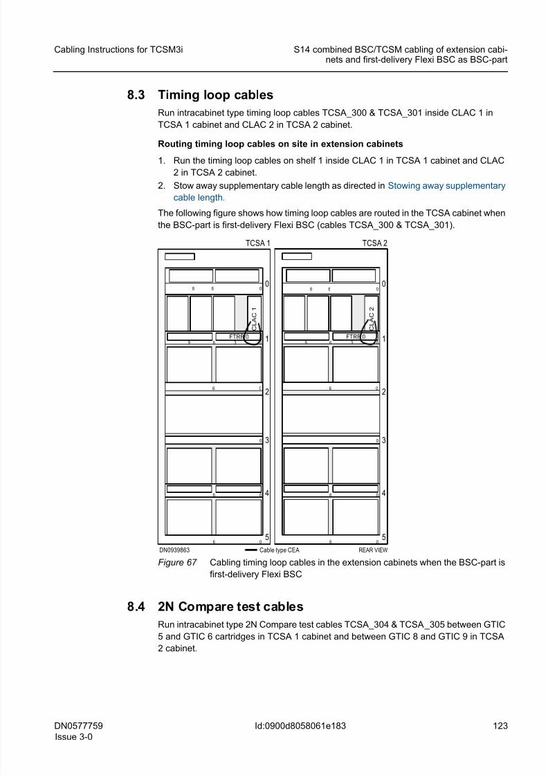
8/11/2019 NOKIA Flexi TRCM
http://slidepdf.com/reader/full/nokia-flexi-trcm 123/183
DN0577759
Issue 3-0
123
Cabling Instructions for TCSM3i S14 combined BSC/TCSM cabling of extension cabi-nets and first-delivery Flexi BSC as BSC-part
Id:0900d8058061e183
8.3 Timing loop cables
Run intracabinet type timing loop cables TCSA_300 & TCSA_301 inside CLAC 1 in
TCSA 1 cabinet and CLAC 2 in TCSA 2 cabinet.
Routing timing loop cables on site in extension cabinets
1. Run the timing loop cables on shelf 1 inside CLAC 1 in TCSA 1 cabinet and CLAC
2 in TCSA 2 cabinet.
2. Stow away supplementary cable length as directed in Stowing away supplementary
cable length.
The following figure shows how timing loop cables are routed in the TCSA cabinet when
the BSC-part is first-delivery Flexi BSC (cables TCSA_300 & TCSA_301).
Figure 67 Cabling timing loop cables in the extension cabinets when the BSC-part is
first-delivery Flexi BSC
8.4 2N Compare test cables
Run intracabinet type 2N Compare test cables TCSA_304 & TCSA_305 between GTIC
5 and GTIC 6 cartridges in TCSA 1 cabinet and between GTIC 8 and GTIC 9 in TCSA
2 cabinet.
REAR VIEWCable type CEA
FTRB 0 1
2
3
4
0
5
0
0
0
0
6
0
6
9
06
6
36
8
FTRB 0 1
2
3
4
0
5
0
0
0
0
6
0
6
9
06
6
36
8
TCSA 1 TCSA 2
DN0939863
C L A C
1
C L A C
2
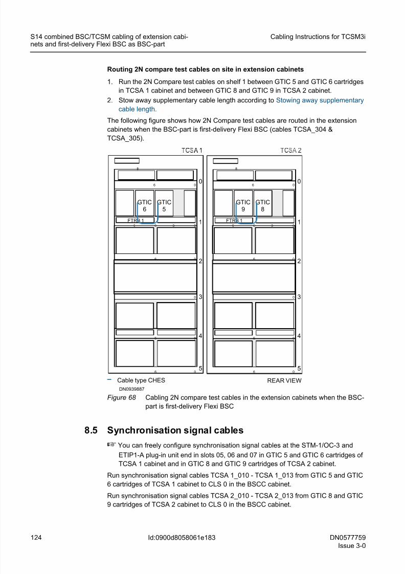
8/11/2019 NOKIA Flexi TRCM
http://slidepdf.com/reader/full/nokia-flexi-trcm 124/183
124 DN0577759
Issue 3-0
Cabling Instructions for TCSM3i
Id:0900d8058061e183
S14 combined BSC/TCSM cabling of extension cabi-nets and first-delivery Flexi BSC as BSC-part
Routing 2N compare test cables on site in extension cabinets
1. Run the 2N Compare test cables on shelf 1 between GTIC 5 and GTIC 6 cartridges
in TCSA 1 cabinet and between GTIC 8 and GTIC 9 in TCSA 2 cabinet.
2. Stow away supplementary cable length according to Stowing away supplementarycable length.
The following figure shows how 2N Compare test cables are routed in the extension
cabinets when the BSC-part is first-delivery Flexi BSC (cables TCSA_304 &
TCSA_305).
Figure 68 Cabling 2N compare test cables in the extension cabinets when the BSC-
part is first-delivery Flexi BSC
8.5 Synchronisation signal cables
☞ You can freely configure synchronisation signal cables at the STM-1/OC-3 and
ETIP1-A plug-in unit end in slots 05, 06 and 07 in GTIC 5 and GTIC 6 cartridges of
TCSA 1 cabinet and in GTIC 8 and GTIC 9 cartridges of TCSA 2 cabinet.
Run synchronisation signal cables TCSA 1_010 - TCSA 1_013 from GTIC 5 and GTIC
6 cartridges of TCSA 1 cabinet to CLS 0 in the BSCC cabinet.
Run synchronisation signal cables TCSA 2_010 - TCSA 2_013 from GTIC 8 and GTIC
9 cartridges of TCSA 2 cabinet to CLS 0 in the BSCC cabinet.
Cable type CHES
FTRB 1 1
2
3
4
0
5
0
0
0
0
6
0
6
9
06
6
36
8
FTRB 1 1
2
3
4
0
5
0
0
0
0
6
0
6
9
06
6
36
8
REAR VIEW
GTIC6
GTIC5
GTIC9
GTIC8
DN0939887
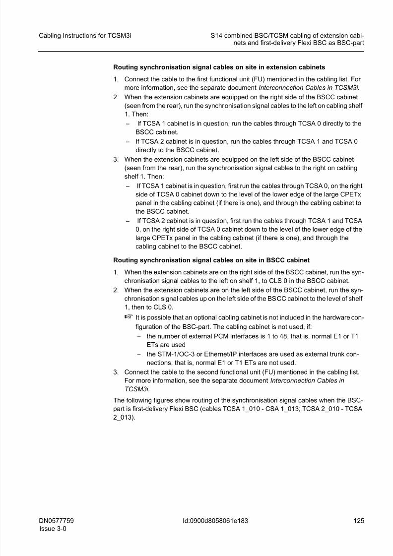
8/11/2019 NOKIA Flexi TRCM
http://slidepdf.com/reader/full/nokia-flexi-trcm 125/183
DN0577759
Issue 3-0
125
Cabling Instructions for TCSM3i S14 combined BSC/TCSM cabling of extension cabi-nets and first-delivery Flexi BSC as BSC-part
Id:0900d8058061e183
Routing synchronisation signal cables on site in extension cabinets
1. Connect the cable to the first functional unit (FU) mentioned in the cabling list. For
more information, see the separate document Interconnection Cables in TCSM3i.
2. When the extension cabinets are equipped on the right side of the BSCC cabinet(seen from the rear), run the synchronisation signal cables to the left on cabling shelf
1. Then:
– If TCSA 1 cabinet is in question, run the cables through TCSA 0 directly to the
BSCC cabinet.
– If TCSA 2 cabinet is in question, run the cables through TCSA 1 and TCSA 0
directly to the BSCC cabinet.
3. When the extension cabinets are equipped on the left side of the BSCC cabinet
(seen from the rear), run the synchronisation signal cables to the right on cabling
shelf 1. Then:
– If TCSA 1 cabinet is in question, first run the cables through TCSA 0, on the right
side of TCSA 0 cabinet down to the level of the lower edge of the large CPETxpanel in the cabling cabinet (if there is one), and through the cabling cabinet to
the BSCC cabinet.
– If TCSA 2 cabinet is in question, first run the cables through TCSA 1 and TCSA
0, on the right side of TCSA 0 cabinet down to the level of the lower edge of the
large CPETx panel in the cabling cabinet (if there is one), and through the
cabling cabinet to the BSCC cabinet.
Routing synchronisation signal cables on site in BSCC cabinet
1. When the extension cabinets are on the right side of the BSCC cabinet, run the syn-
chronisation signal cables to the left on shelf 1, to CLS 0 in the BSCC cabinet.
2. When the extension cabinets are on the left side of the BSCC cabinet, run the syn-chronisation signal cables up on the left side of the BSCC cabinet to the level of shelf
1, then to CLS 0.
☞ It is possible that an optional cabling cabinet is not included in the hardware con-
figuration of the BSC-part. The cabling cabinet is not used, if:
– the number of external PCM interfaces is 1 to 48, that is, normal E1 or T1
ETs are used
– the STM-1/OC-3 or Ethernet/IP interfaces are used as external trunk con-
nections, that is, normal E1 or T1 ETs are not used.
3. Connect the cable to the second functional unit (FU) mentioned in the cabling list.
For more information, see the separate document Interconnection Cables in
TCSM3i.
The following figures show routing of the synchronisation signal cables when the BSC-
part is first-delivery Flexi BSC (cables TCSA 1_010 - CSA 1_013; TCSA 2_010 - TCSA
2_013).
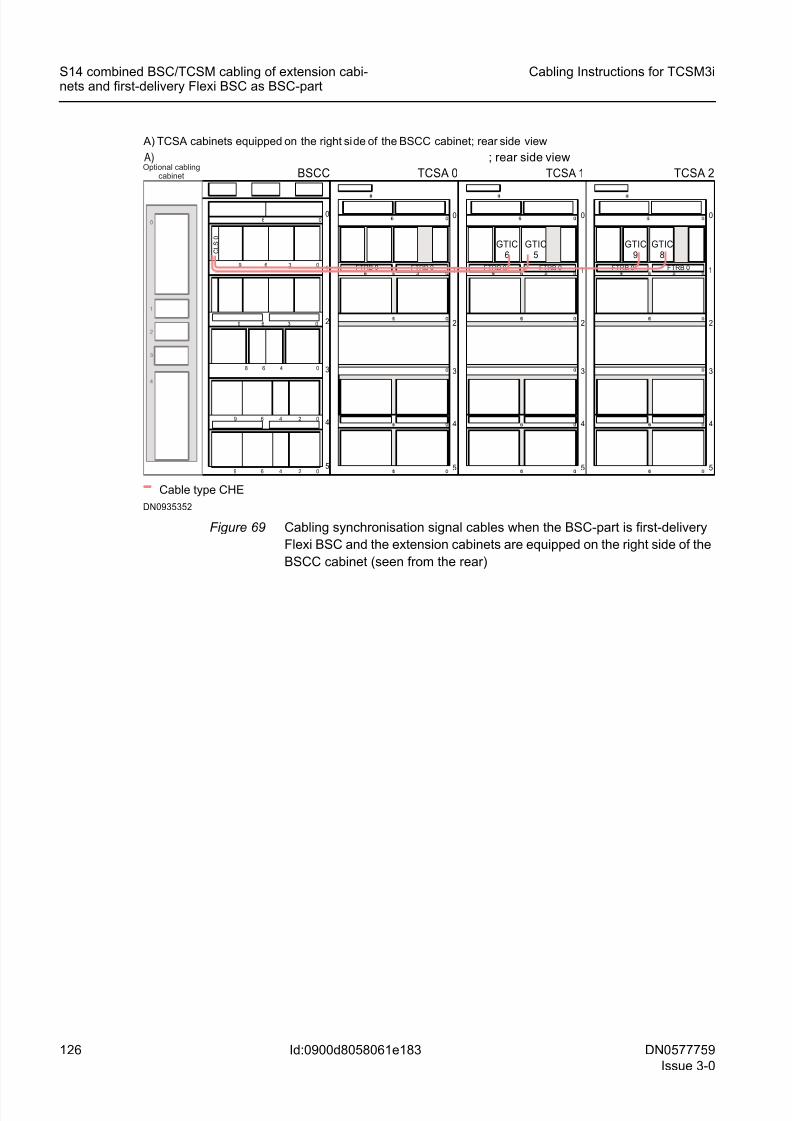
8/11/2019 NOKIA Flexi TRCM
http://slidepdf.com/reader/full/nokia-flexi-trcm 126/183
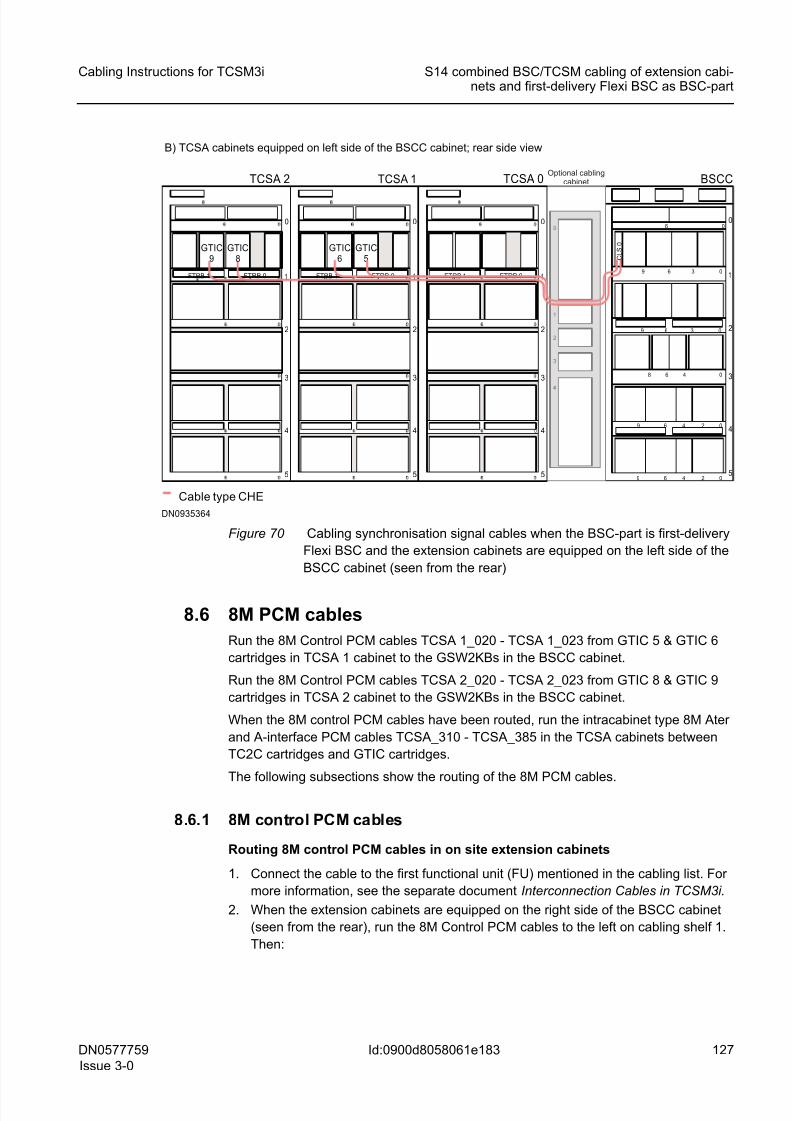
8/11/2019 NOKIA Flexi TRCM
http://slidepdf.com/reader/full/nokia-flexi-trcm 127/183
8/11/2019 NOKIA Flexi TRCM
http://slidepdf.com/reader/full/nokia-flexi-trcm 128/183
128 DN0577759
Issue 3-0
Cabling Instructions for TCSM3i
Id:0900d8058061e183
S14 combined BSC/TCSM cabling of extension cabi-nets and first-delivery Flexi BSC as BSC-part
– If TCSA 1 cabinet is in question, run cables TCSA 1_021 & TCSA 1_023
heading for GSW2KB-A 0 directly through TCSA 0 cabinet to the BSCC cabinet.
Run cables TCSA 1_020 & TCSA 1_022 heading for GSW2KB-A 1 through
TCSA 0 cabinet to the left side of the cabinet. Run the cables down to the level
of cabling shelf 2 and then to the BSCC cabinet.
– If TCSA 2 cabinet is in question, run cables TCSA 2_021 & TCSA 2_023
heading for GSW2KB-A 0 directly through TCSA 1 and TCSA 0 cabinets to the
BSCC cabinet.
Run cables TCSA 2_020 & TCSA 2_022 heading for GSW2KB-A 1 through
TCSA 1 and TCSA 0 cabinets to the left side of TCSA 0 cabinet. Run the cables
down to the level of cabling shelf 2 and then to the BSCC cabinet.
3. When the extension cabinets are equipped on the left side of the BSCC cabinet
(seen from the rear), run the 8M Control PCM cables to the right on cabling shelf 1.
Then:
– If TCSA 1 cabinet is in question, run cables TCSA 1_021 & TCSA 1_023 through
TCSA 0 cabinet, down the right side to the level of the lower edge of the large
CPETx panel in the cabling cabinet (if there is one), through the cabling cabinet
to the BSCC cabinet. Run cables TCSA 1_020 & TCSA 1_022 through TCSA 0
cabinet to the right side of the TCSA 0 cabinet and from there down to the level
of shelf 2 and through the cabling cabinet (if there is one) to the BSCC cabinet.
– If TCSA 2 cabinet is in question, run cables TCSA 2_021 & TCSA 2_023
through TCSA 1 and TCSA 0 cabinets, down the right side of TCSA 0 to the level
of the lower edge of the large CPETx panel in the cabling cabinet (if there is one)
and through the cabling cabinet to the BSCC cabinet. Run cables TCSA 2_020
& TCSA 2_022 through TCSA 1 and TCSA 0 cabinets, to the right side of the
TCSA 0 cabinet and from there down to the level of shelf 2 and through the
cabling cabinet (if there is one) to the BSCC cabinet
Routing 8M control PCM cables on site in BSCC cabinet
1. When the extension cabinets are equipped on the right side of the BSCC cabinet
(seen from the rear), run the 8M PCM cables heading for GSW2KB-A 0 to the left
on shelf 1 directly to GSW2KB-A 0 and the cables heading for GSW2KB-A 1 to the
left on shelf 2 directly to GSW2KB-A 1.
2. When the extension cabinets are equipped on the left side of the BSCC cabinet
(seen from the rear), run the 8M PCM cables heading for GSW2KB-A 0 up to the
level of shelf 1 in the BSCC cabinet, to the right on cabling shelf 1. Run the 8M PCM
cables heading for GSW2KB-A 1 to the right on cabling shelf 2.
☞ It is possible that an optional cabling cabinet is not included in the hardware con-figuration of the BSC-part. The cabling cabinet is not used, if:
– the number of external PCM interfaces is 1 to 48, that is, normal E1 or T1
ETs are used
– the STM-1/OC-3 or Ethernet/IP interfaces are used as external trunk con-
nections, that is, normal E1 or T1 ETs are not used.
3. Connect the cable to the second functional unit (FU) mentioned in the cabling list.
For more information, see the separate document Interconnection Cables in
TCSM3i.
The following figures show how 8M Control PCM cables are routed when the BSC-part
is first-delivery Flexi BSC (cables TCSA 1_020 - TCSA 1_023; TCSA 2_020 - TCSA
2_023).
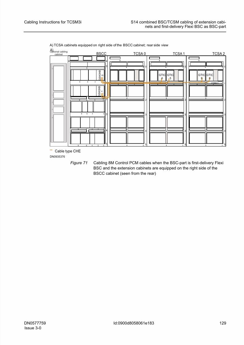
8/11/2019 NOKIA Flexi TRCM
http://slidepdf.com/reader/full/nokia-flexi-trcm 129/183
DN0577759
Issue 3-0
129
Cabling Instructions for TCSM3i S14 combined BSC/TCSM cabling of extension cabi-nets and first-delivery Flexi BSC as BSC-part
Id:0900d8058061e183
Figure 71 Cabling 8M Control PCM cables when the BSC-part is first-delivery Flexi
BSC and the extension cabinets are equipped on the right side of the
BSCC cabinet (seen from the rear)
06
3 09 6
48 0
0249 6
3 09 6
6
0249 6
1
2
3
4
0
5
BSCC
1
2
3
4
0
5
TCSA 0 A)
Cable type CHE
1
2
3
4
0
5
1
2
3
4
0
5
TCSA 1 TCSA 2
GTIC6
GTIC5
GTIC9
GTIC8
DN0935376
FTRB 0
A) TCSA cabinets equipped on right side of the BSCC cabinet; rear side view
Optional cablingcabinet
G S W 2 K B
1
G S W 2 K B
0

8/11/2019 NOKIA Flexi TRCM
http://slidepdf.com/reader/full/nokia-flexi-trcm 130/183
130 DN0577759
Issue 3-0
Cabling Instructions for TCSM3i
Id:0900d8058061e183
S14 combined BSC/TCSM cabling of extension cabi-nets and first-delivery Flexi BSC as BSC-part
Figure 72 Cabling 8M Control PCM cables when the BSC-part is first-delivery Flexi
BSC and the extension cabinets are equipped on the left side of the BSCC
cabinet (seen from the rear)
8.6.2 8M Ater and A-interface cables
When the 8M Control PCM cables have been routed, run intracabinet type 8M Ater and
A-interface PCM cables TCSA_310 - TCSA_385 between TC2C 6 to TC2C 11 car-
tridges and GTIC 5 and GTIC 6 cartridges of TCSA 1 cabinet and between TC2C 12 to
TC2C 17 cartridges and GTIC 8 and GTIC 9 cartridges of TCSA 2 cabinet, respectively.
Routing 8M Ater and A-interface cables on site in extension cabinets
1. Route the cables as indicated in General routing principles of intracabinet cables
and attach them in bundles to the cable shelves with cable ties. Lay them on the
shelf as inside as possible, tighten them there to the shelf and run them to the left.
2. All the cables go down the left side of the cabinet. When the cables reach therespective shelves, tighten the cables to the shelf and connect to their respective
positions as shown in the Interconnection Cables in TCSM3i .
3. Stow away supplementary cable length as shown in Stowing away supplementary
cable length.
The following figure shows how 8M Ater and A-interface PCM cables are run inside the
extension cabinets when the BSC-part is first-delivery Flexi BSC (cables TCSA_310 -
TCSA_385).
06
3 09 6
48 0
0249 6
3 09 6
6
0249 6
1
2
3
4
0
5
BSCC
FTRB 1 FTRB 0 1
2
3
4
0
5
09 36
TCSA 2
Cable type CHE
FTRB 1 FTRB 0 1
2
3
4
0
5
09 36FTRB 1 FTRB 0 1
2
3
4
0
5
09 36
TCSA 1 TCSA 0
GTIC9
GTIC8
GTIC6
GTIC5
DN0935388
B) TCSA cabinets equipped on left side of the BSCC cabinet; rear side viewOptional cabling
cabinet
G S W 2 K B
0
G S W 2 K B
1
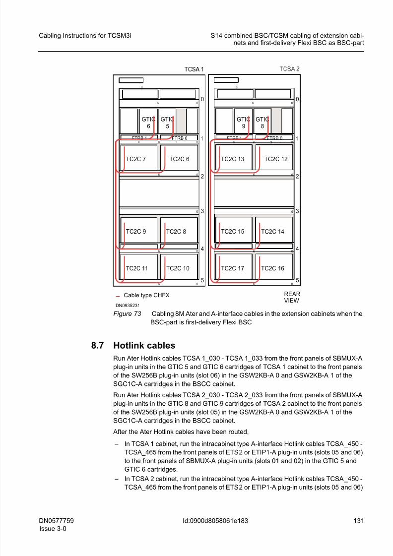
8/11/2019 NOKIA Flexi TRCM
http://slidepdf.com/reader/full/nokia-flexi-trcm 131/183
DN0577759
Issue 3-0
131
Cabling Instructions for TCSM3i S14 combined BSC/TCSM cabling of extension cabi-nets and first-delivery Flexi BSC as BSC-part
Id:0900d8058061e183
Figure 73 Cabling 8M Ater and A-interface cables in the extension cabinets when the
BSC-part is first-delivery Flexi BSC
8.7 Hotlink cables
Run Ater Hotlink cables TCSA 1_030 - TCSA 1_033 from the front panels of SBMUX-A
plug-in units in the GTIC 5 and GTIC 6 cartridges of TCSA 1 cabinet to the front panels
of the SW256B plug-in units (slot 06) in the GSW2KB-A 0 and GSW2KB-A 1 of the
SGC1C-A cartridges in the BSCC cabinet.
Run Ater Hotlink cables TCSA 2_030 - TCSA 2_033 from the front panels of SBMUX-A
plug-in units in the GTIC 8 and GTIC 9 cartridges of TCSA 2 cabinet to the front panels
of the SW256B plug-in units (slot 05) in the GSW2KB-A 0 and GSW2KB-A 1 of the
SGC1C-A cartridges in the BSCC cabinet.
After the Ater Hotlink cables have been routed,
– In TCSA 1 cabinet, run the intracabinet type A-interface Hotlink cables TCSA_450 -
TCSA_465 from the front panels of ETS2 or ETIP1-A plug-in units (slots 05 and 06)
to the front panels of SBMUX-A plug-in units (slots 01 and 02) in the GTIC 5 and
GTIC 6 cartridges.
– In TCSA 2 cabinet, run the intracabinet type A-interface Hotlink cables TCSA_450 -
TCSA_465 from the front panels of ETS2 or ETIP1-A plug-in units (slots 05 and 06)
Cable type CHFX
DN0935231
FTRB 1 FTRB 0 1
2
3
4
0
5
0
0
0
0
6
0
6
9
06
6
36
8
GTIC6
GTIC5
TC2C 7 TC2C 6
TC2C 9 TC2C 8
TC2C 11 TC2C 10
FTRB 1 FTRB 0 1
2
3
4
0
5
0
0
0
0
6
0
6
9
06
6
36
8
REARVIEW
GTIC9
GTIC8
TC2C 13 TC2C 12
TC2C 15 TC2C 14
TC2C 17 TC2C 16
8/11/2019 NOKIA Flexi TRCM
http://slidepdf.com/reader/full/nokia-flexi-trcm 132/183
8/11/2019 NOKIA Flexi TRCM
http://slidepdf.com/reader/full/nokia-flexi-trcm 133/183
DN0577759
Issue 3-0
133
Cabling Instructions for TCSM3i S14 combined BSC/TCSM cabling of extension cabi-nets and first-delivery Flexi BSC as BSC-part
Id:0900d8058061e183
1_033, TCSA 2_032 & TCSA 2_033) along the right side of the cabinet to the level
of cartridge shelf 1, lay the cables on the front cabling shelves of the cartridges and
run the cables to the front panel interfaces of SW256B plug-in units.
2. When the extension cabinets are equipped on the left side (seen from the front) and
the cables have been passed from back to front through the cabling hole on the left
side of the Upper Air Guide of the BSCC cabinet (seen from the front), route Hotlink
cables heading for GSW2KB-A 0 (TCSA 1_030 & TCSA 1_031, TCSA 2_030 &
TCSA 2_031) to the topmost cartridge shelf and lay the cables on the front cabling
shelf of the cartridge and run the cables to the front panel interfaces of SW256B
plug-in units. Run cables heading for GSW2KB-A 1 (TCSA 1_032 & TCSA 1_033,
TCSA 2_032 & TCSA 2_033) along the left side of the cabinet to the level of car-
tridge shelf 1, lay the cables on the front cabling shelf of the cartridge and run the
cables to the front panel interfaces of SW256B plug-in units.
3. Connect the cable to the second functional unit (FU) mentioned in the cabling list.
For more information, see the separate document Interconnection Cables in
TCSM3i.
The following figures show how Ater Hotlinks are routed when the BSC-part is first-
delivery Flexi BSC (cables TCSA 1_030 - TCSA 1_033; TCSA 2_030 - TCSA 2_033).
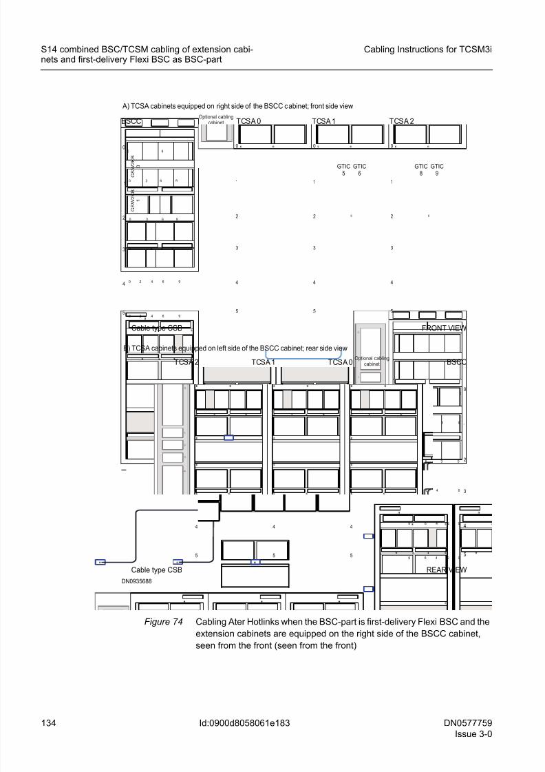
8/11/2019 NOKIA Flexi TRCM
http://slidepdf.com/reader/full/nokia-flexi-trcm 134/183
134 DN0577759
Issue 3-0
Cabling Instructions for TCSM3i
Id:0900d8058061e183
S14 combined BSC/TCSM cabling of extension cabi-nets and first-delivery Flexi BSC as BSC-part
Figure 74 Cabling Ater Hotlinks when the BSC-part is first-delivery Flexi BSC and the
extension cabinets are equipped on the right side of the BSCC cabinet,
seen from the front (seen from the front)
0 6
30 96
4 80
0 2 4 96
30 96
6
0 2 4 96
1
2
3
4
0
5
06
3 09 6
48 0
0249 6
3 09 6
6
0249 6
1
2
3
4
0
5
BSCC
1
2
3
4
0
5
0
TCSA 2
Cable type CSB
1
2
3
4
0
5
0
1
2
3
4
0
5
0
TCSA 1 TCSA 0
DN0935688
REAR VIEW
B) TCSA cabinets equipped on left side of the BSCC cabinet; rear side view
BSCC
1
2
3
4
0
5
6
TCSA 2
Cable type CSB
1
2
3
4
0
5
6
1
2
3
4
0
5
TCSA 1TCSA 0
GTIC5
GTIC6
GTIC8
GTIC9
FRONT VIEW
A) TCSA cabinets equipped on right side of the BSCC cabinet; front side view
Optional cablingcabinet
Optional cablingcabinet
G S W 2 K B
0
G S W 2 K B
1
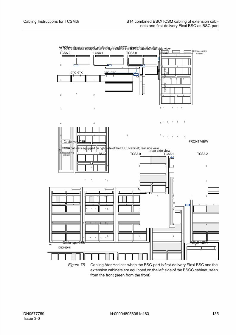
8/11/2019 NOKIA Flexi TRCM
http://slidepdf.com/reader/full/nokia-flexi-trcm 135/183
DN0577759
Issue 3-0
135
Cabling Instructions for TCSM3i S14 combined BSC/TCSM cabling of extension cabi-nets and first-delivery Flexi BSC as BSC-part
Id:0900d8058061e183
Figure 75 Cabling Ater Hotlinks when the BSC-part is first-delivery Flexi BSC and the
extension cabinets are equipped on the left side of the BSCC cabinet, seen
from the front (seen from the front)
06
3 09 6
48 0
0249 6
3 09 6
6
0249 6
1
2
3
4
0
5
0 6
30 96
4 80
0 2 4 96
30 96
6
0 2 4 96
1
2
3
4
0
5
BSCC
1
2
3
4
0
5
6
TCSA 0 A) ; rear side view
Cable type CSB
1
2
3
4
0
5
6
1
2
3
4
0
5
6
TCSA 1 TCSA 2
REAR VIEW
DN0935691
B) TCSA cabinets equipped on right side of the BSCC cabinet; rear side view
BSCC
1
2
3
4
0
5
6
0
TCSA 0
A) TCSA cabinets equipped on the right side of the BSCC cabinet; rear side view
Cable type CSB
1
2
3
4
0
5
6
1
2
3
4
0
5
6
TCSA 1TCSA 2
GTIC8
GTIC9
GTIC5
GTIC6
FRONT VIEW
A) TCSA cabinets e quipped on left side of the BSCC cabinet; front side viewOptional cabling
cabinet
Optional cablingcabinet
G S W 2 K B
0
G S W 2 K B
1
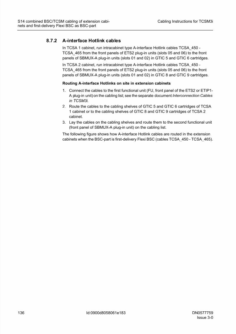
8/11/2019 NOKIA Flexi TRCM
http://slidepdf.com/reader/full/nokia-flexi-trcm 136/183
136 DN0577759
Issue 3-0
Cabling Instructions for TCSM3i
Id:0900d8058061e183
S14 combined BSC/TCSM cabling of extension cabi-nets and first-delivery Flexi BSC as BSC-part
8.7.2 A-interface Hotlink cables
In TCSA 1 cabinet, run intracabinet type A-interface Hotlink cables TCSA_450 -
TCSA_465 from the front panels of ETS2 plug-in units (slots 05 and 06) to the front
panels of SBMUX-A plug-in units (slots 01 and 02) in GTIC 5 and GTIC 6 cartridges.
In TCSA 2 cabinet, run intracabinet type A-interface Hotlink cables TCSA_450 -
TCSA_465 from the front panels of ETS2 plug-in units (slots 05 and 06) to the front
panels of SBMUX-A plug-in units (slots 01 and 02) in GTIC 8 and GTIC 9 cartridges.
Routing A-interface Hotlinks on site in extension cabinets
1. Connect the cables to the first functional unit (FU, front panel of the ETS2 or ETIP1-
A plug-in unit) on the cabling list; see the separate document Interconnection Cables
in TCSM3i.
2. Route the cables to the cabling shelves of GTIC 5 and GTIC 6 cartridges of TCSA
1 cabinet or to the cabling shelves of GTIC 8 and GTIC 9 cartridges of TCSA 2
cabinet.3. Lay the cables on the cabling shelves and route them to the second functional unit
(front panel of SBMUX-A plug-in unit) on the cabling list.
The following figure shows how A-interface Hotlink cables are routed in the extension
cabinets when the BSC-part is first-delivery Flexi BSC (cables TCSA_450 - TCSA_465).
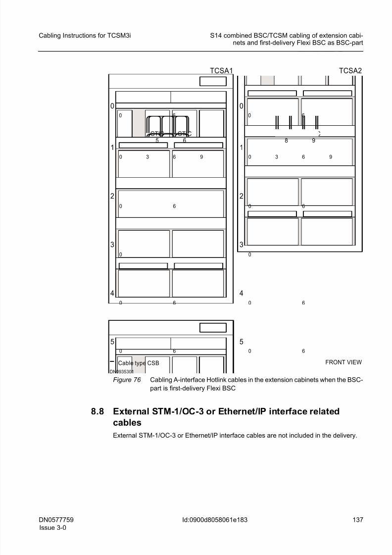
8/11/2019 NOKIA Flexi TRCM
http://slidepdf.com/reader/full/nokia-flexi-trcm 137/183
DN0577759
Issue 3-0
137
Cabling Instructions for TCSM3i S14 combined BSC/TCSM cabling of extension cabi-nets and first-delivery Flexi BSC as BSC-part
Id:0900d8058061e183
Figure 76 Cabling A-interface Hotlink cables in the extension cabinets when the BSC-
part is first-delivery Flexi BSC
8.8 External STM-1/OC-3 or Ethernet/IP interface related
cables
External STM-1/OC-3 or Ethernet/IP interface cables are not included in the delivery.
FRONT VIEW
DN0935301
TCSA1
5
4
3
2
060
0
0 6
1
630
60
0
6
9
GTIC5
GTIC6
TCSA2
5
4
3
2
060
0
0 6
1
630
60
0
6
9
GTIC8
GTIC9
Cable type CSB
8/11/2019 NOKIA Flexi TRCM
http://slidepdf.com/reader/full/nokia-flexi-trcm 138/183
138 DN0577759
Issue 3-0
Cabling Instructions for TCSM3i
Id:0900d80580622125
S13 combined BSC/TCSM cabling of extension cabi-nets and BSC3i 1000 as BSC-part
9 S13 combined BSC/TCSM cabling of exten-
sion cabinets and BSC3i 1000 as BSC-part
When installing and cabling S13 level combined BSC/TCSM installation option, exten-sion cabinets (TCSA 1 and TCSA 2) can be used only when BSC3i 1000 is the BSC-
part.
Routing of combined BSC/TCSM installation-specific cables is done on site.
All cabling (except AL and AL/CGS cables TCSA_065 and TCSA_066, Internal synchro-
nisation cables TCSA_070...TCSA_073, External ET interface related cables
TCSA_150...TCSA_269, Control PCM cables TCSA_080 and TCSA_081, and PCM
cables TCSA_090...TCSA_131) presented in Intracabinet cabling of TCSA cabinet is
common to both TCSM3i for stand-alone installation option and TCSM3i for combined
BSC/TCSM installation option.
The following subsecrions describe the most efficient routing of intercabinet cables(cables between plug-in units located inside TCSA and BSCC cabinets) as well as
combined BSC/TCSM installation-specific intracabinet cabling (timing loop cables, 2N
compare test cables, 8M Ater and A-interface PCM cables, and A-interface Hotlink
cables). However, it includes only cable routings for the base TCSA cabinet upgrade to
TCSA 0, TCSA 1 and TCSA 2 cabinet in the combined BSC/TCSM installation option
when BSC3i 1000 is the BSC-part.
Cable routings for the TCSA cabinet upgrade when BSC3i 2000 is the BSC-part are
found in S12 and S13 combined BSC/TCSM cabling of TCSA cabinet and BSC3i
1000/2000 as BSC-part .
9.1 SBUS cablesRun supervision bus (SBUS) cables in the following way:
• cables TCSA 0_001 and TCSA 0_002 from CLAC 1 in the TCSA 0 cabinet to CLAC
0 in the BSCC cabinet
• cables TCSA 1_001 and TCSA 1_002 from CLAC 2 in the TCSA 1 cabinet to CLAC
1 in the TCSA 0 cabinet
• cables TCSA 2_001 and TCSA 2_002 from CLAC 3 in the TCSA 2 cabinet to CLAC
2 in the TCSA 1 cabinet
Routing SBUS cables on site in extension cabinets when the cabinets are
equipped on either side of the BSCC cabinet, seen from the rear
1. Connect the cable to the first functional unit in the cabling list, see the separate
document Interconnection cables in TCSM3i.
2. On shelf 1, run the SBUS cables to the right side or to the left side of the cabinet
(depending on which side of the BSCC cabinet the TCSA cabinet is (or cabinets are)
equipped). For cabinet-specific instructions, note the following:
• When cabling TCSA 0 cabinet, use the right side or the left side of TCSA 0
cabinet and run cables to the level of the fifth cabling shelf (where CLAC 0 car-
tridge is equipped in the BSCC cabinet).
• When cabling TCSA 1 cabinet, run cables to TCSA 0 cabinet using shelf 1.
• When cabling TCSA 2 cabinet, run cables to TCSA 1 cabinet using shelf 1.
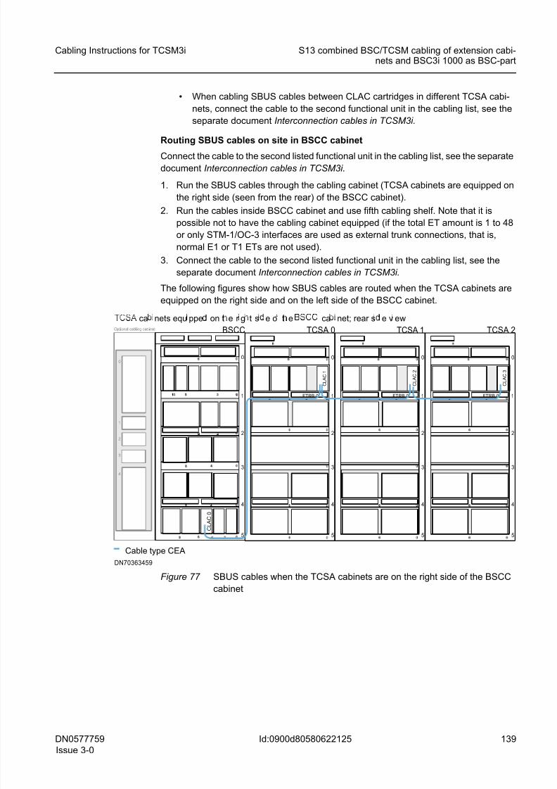
8/11/2019 NOKIA Flexi TRCM
http://slidepdf.com/reader/full/nokia-flexi-trcm 139/183
DN0577759
Issue 3-0
139
Cabling Instructions for TCSM3i S13 combined BSC/TCSM cabling of extension cabi-nets and BSC3i 1000 as BSC-part
Id:0900d80580622125
• When cabling SBUS cables between CLAC cartridges in different TCSA cabi-
nets, connect the cable to the second functional unit in the cabling list, see the
separate document Interconnection cables in TCSM3i.
Routing SBUS cables on site in BSCC cabinet
Connect the cable to the second listed functional unit in the cabling list, see the separate
document Interconnection cables in TCSM3i.
1. Run the SBUS cables through the cabling cabinet (TCSA cabinets are equipped on
the right side (seen from the rear) of the BSCC cabinet).
2. Run the cables inside BSCC cabinet and use fifth cabling shelf. Note that it is
possible not to have the cabling cabinet equipped (if the total ET amount is 1 to 48
or only STM-1/OC-3 interfaces are used as external trunk connections, that is,
normal E1 or T1 ETs are not used).
3. Connect the cable to the second listed functional unit in the cabling list, see the
separate document Interconnection cables in TCSM3i.The following figures show how SBUS cables are routed when the TCSA cabinets are
equipped on the right side and on the left side of the BSCC cabinet.
Figure 77 SBUS cables when the TCSA cabinets are on the right side of the BSCC
cabinet
1
2
3
4
0
5
0
BSCC
C L A C 0
1
2
3
4
0
5
TCSA 0
Cable type CEA
1
2
3
4
0
5
0 1
2
3
4
0
5
6
TCSA 1 TCSA 2
FTRB 0 FTRB 0 FTRB 0
C L A C 1
C L A C 2
C L A C 3
DN70363459
ca nets equ ppe on t e r g t s e o t e ca net; rear s e v ew
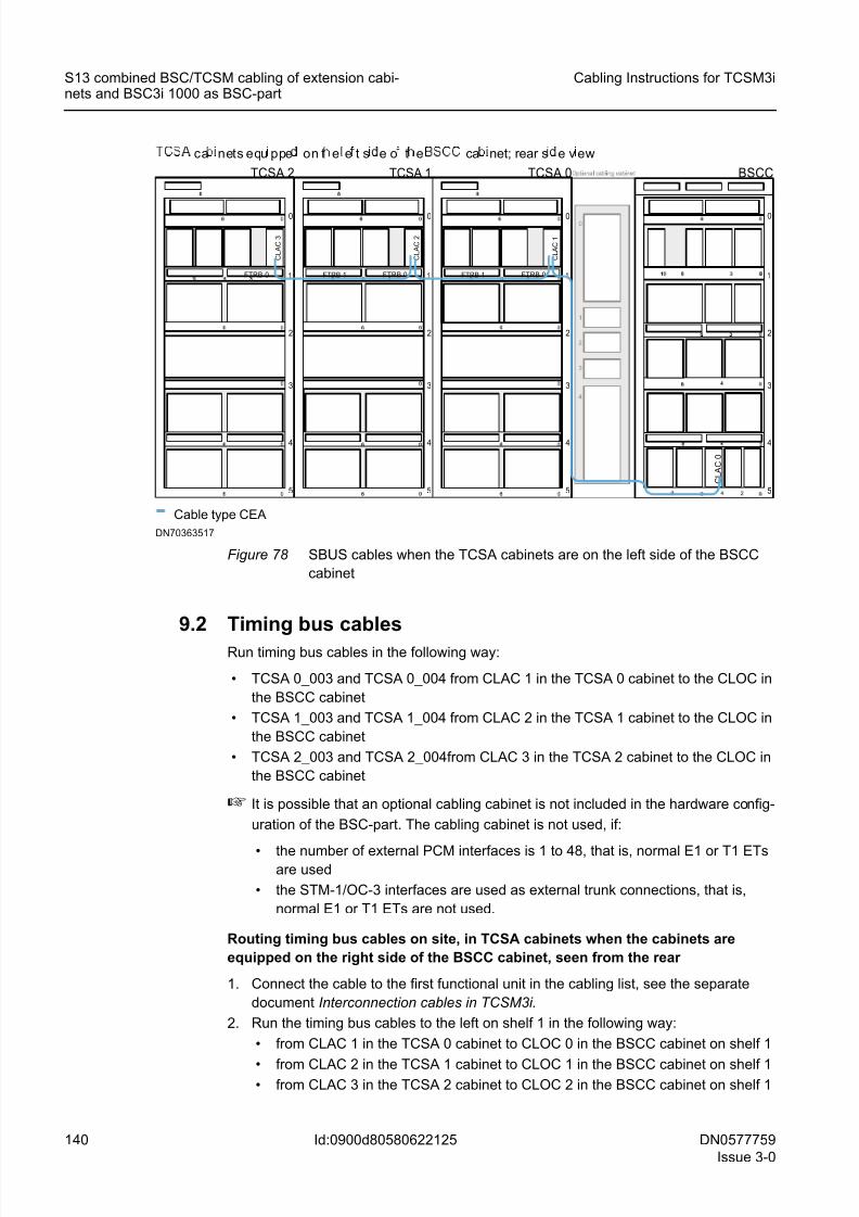
8/11/2019 NOKIA Flexi TRCM
http://slidepdf.com/reader/full/nokia-flexi-trcm 140/183
140 DN0577759
Issue 3-0
Cabling Instructions for TCSM3i
Id:0900d80580622125
S13 combined BSC/TCSM cabling of extension cabi-nets and BSC3i 1000 as BSC-part
Figure 78 SBUS cables when the TCSA cabinets are on the left side of the BSCC
cabinet
9.2 Timing bus cables
Run timing bus cables in the following way:
• TCSA 0_003 and TCSA 0_004 from CLAC 1 in the TCSA 0 cabinet to the CLOC in
the BSCC cabinet
• TCSA 1_003 and TCSA 1_004 from CLAC 2 in the TCSA 1 cabinet to the CLOC in
the BSCC cabinet
• TCSA 2_003 and TCSA 2_004from CLAC 3 in the TCSA 2 cabinet to the CLOC in
the BSCC cabinet
☞ It is possible that an optional cabling cabinet is not included in the hardware config-
uration of the BSC-part. The cabling cabinet is not used, if:
• the number of external PCM interfaces is 1 to 48, that is, normal E1 or T1 ETsare used
• the STM-1/OC-3 interfaces are used as external trunk connections, that is,
normal E1 or T1 ETs are not used.
Routing timing bus cables on site, in TCSA cabinets when the cabinets are
equipped on the right side of the BSCC cabinet, seen from the rear
1. Connect the cable to the first functional unit in the cabling list, see the separate
document Interconnection cables in TCSM3i.
2. Run the timing bus cables to the left on shelf 1 in the following way:
• from CLAC 1 in the TCSA 0 cabinet to CLOC 0 in the BSCC cabinet on shelf 1
• from CLAC 2 in the TCSA 1 cabinet to CLOC 1 in the BSCC cabinet on shelf 1 • from CLAC 3 in the TCSA 2 cabinet to CLOC 2 in the BSCC cabinet on shelf 1
1
2
3
4
0
5
0
BSCC
C L A C 0
FTRB 0 1
2
3
4
0
5
TCSA 2
Cable type CEA
C L A C 3
FTRB 1 FTRB 0 1
2
3
4
0
5
C L A C 2
FTRB 1 FTRB 0 1
2
3
4
0
5
C L A C 1
TCSA 1 TCSA 0
DN70363517
ca nets equ ppe on t e e t s e o t e ca net; rear s e v ew
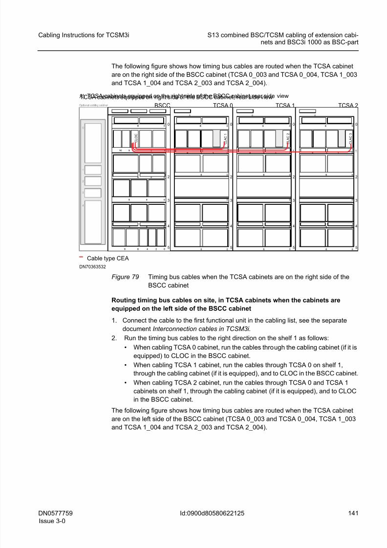
8/11/2019 NOKIA Flexi TRCM
http://slidepdf.com/reader/full/nokia-flexi-trcm 141/183
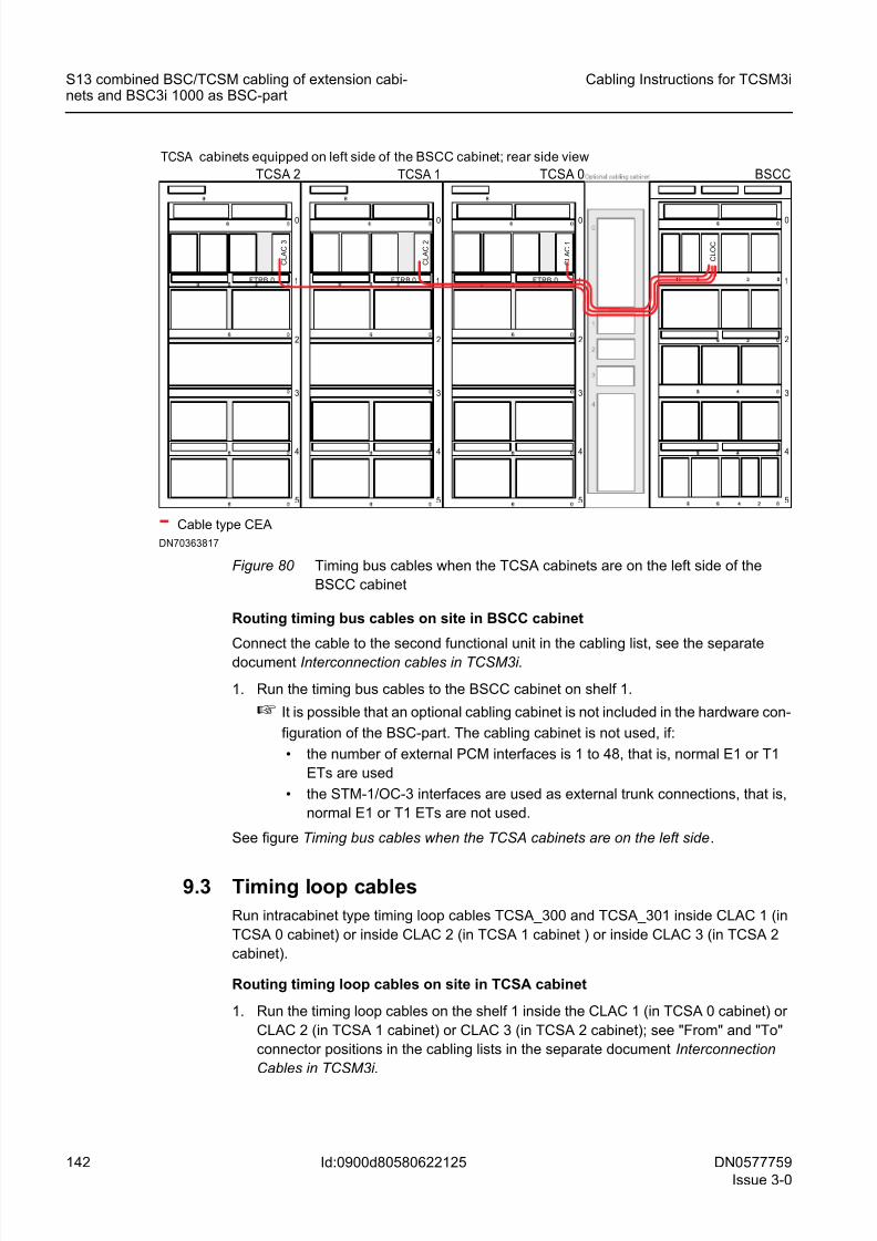
8/11/2019 NOKIA Flexi TRCM
http://slidepdf.com/reader/full/nokia-flexi-trcm 142/183
142 DN0577759
Issue 3-0
Cabling Instructions for TCSM3i
Id:0900d80580622125
S13 combined BSC/TCSM cabling of extension cabi-nets and BSC3i 1000 as BSC-part
Figure 80 Timing bus cables when the TCSA cabinets are on the left side of the
BSCC cabinet
Routing timing bus cables on site in BSCC cabinet
Connect the cable to the second functional unit in the cabling list, see the separate
document Interconnection cables in TCSM3i.
1. Run the timing bus cables to the BSCC cabinet on shelf 1.
☞ It is possible that an optional cabling cabinet is not included in the hardware con-
figuration of the BSC-part. The cabling cabinet is not used, if:
• the number of external PCM interfaces is 1 to 48, that is, normal E1 or T1
ETs are used
• the STM-1/OC-3 interfaces are used as external trunk connections, that is,
normal E1 or T1 ETs are not used.
See figure Timing bus cables when the TCSA cabinets are on the left side.
9.3 Timing loop cables
Run intracabinet type timing loop cables TCSA_300 and TCSA_301 inside CLAC 1 (in
TCSA 0 cabinet) or inside CLAC 2 (in TCSA 1 cabinet ) or inside CLAC 3 (in TCSA 2
cabinet).
Routing timing loop cables on site in TCSA cabinet
1. Run the timing loop cables on the shelf 1 inside the CLAC 1 (in TCSA 0 cabinet) or
CLAC 2 (in TCSA 1 cabinet) or CLAC 3 (in TCSA 2 cabinet); see "From" and "To"
connector positions in the cabling lists in the separate document Interconnection
Cables in TCSM3i.
1
2
3
4
0
5
00
BSCC
FTRB 0 1
2
3
4
0
5
TCSA 2
TCSA cabinets equipped on left side of the BSCC cabinet; rear side view
Cable type CEA
FTRB 0 1
2
3
4
0
5
FTRB 0 1
2
3
4
0
5
TCSA 1 TCSA 0
C L A C 3
C L A C 2
C L A C 1
C L O C
DN70363817
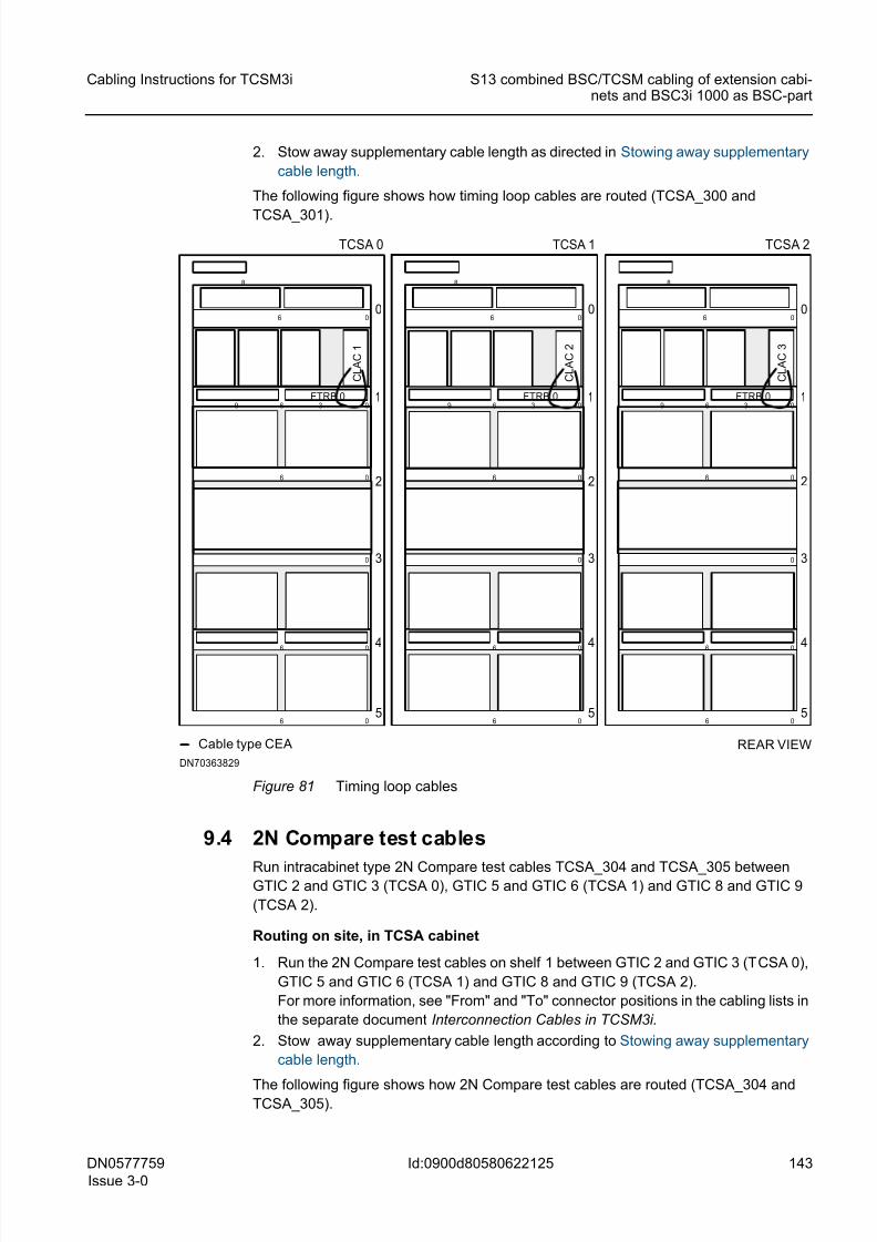
8/11/2019 NOKIA Flexi TRCM
http://slidepdf.com/reader/full/nokia-flexi-trcm 143/183
DN0577759
Issue 3-0
143
Cabling Instructions for TCSM3i S13 combined BSC/TCSM cabling of extension cabi-nets and BSC3i 1000 as BSC-part
Id:0900d80580622125
2. Stow away supplementary cable length as directed in Stowing away supplementary
cable length.
The following figure shows how timing loop cables are routed (TCSA_300 and
TCSA_301).
Figure 81 Timing loop cables
9.4 2N Compare test cables
Run intracabinet type 2N Compare test cables TCSA_304 and TCSA_305 betweenGTIC 2 and GTIC 3 (TCSA 0), GTIC 5 and GTIC 6 (TCSA 1) and GTIC 8 and GTIC 9
(TCSA 2).
Routing on site, in TCSA cabinet
1. Run the 2N Compare test cables on shelf 1 between GTIC 2 and GTIC 3 (TCSA 0),
GTIC 5 and GTIC 6 (TCSA 1) and GTIC 8 and GTIC 9 (TCSA 2).
For more information, see "From" and "To" connector positions in the cabling lists in
the separate document Interconnection Cables in TCSM3i.
2. Stow away supplementary cable length according to Stowing away supplementary
cable length.
The following figure shows how 2N Compare test cables are routed (TCSA_304 andTCSA_305).
FTRB 0 1
2
3
4
0
5
0
0
0
0
6
0
6
9
06
6
36
8
C L A C 1
Cable type CEA
FTRB 0 1
2
3
4
0
5
0
0
0
0
6
0
6
9
06
6
36
8
C L A C 2
FTRB 0 1
2
3
4
0
5
0
0
0
0
6
0
6
9
06
6
36
8
C L A C 3
REAR VIEW
TCSA 0 TCSA 1 TCSA 2
DN70363829
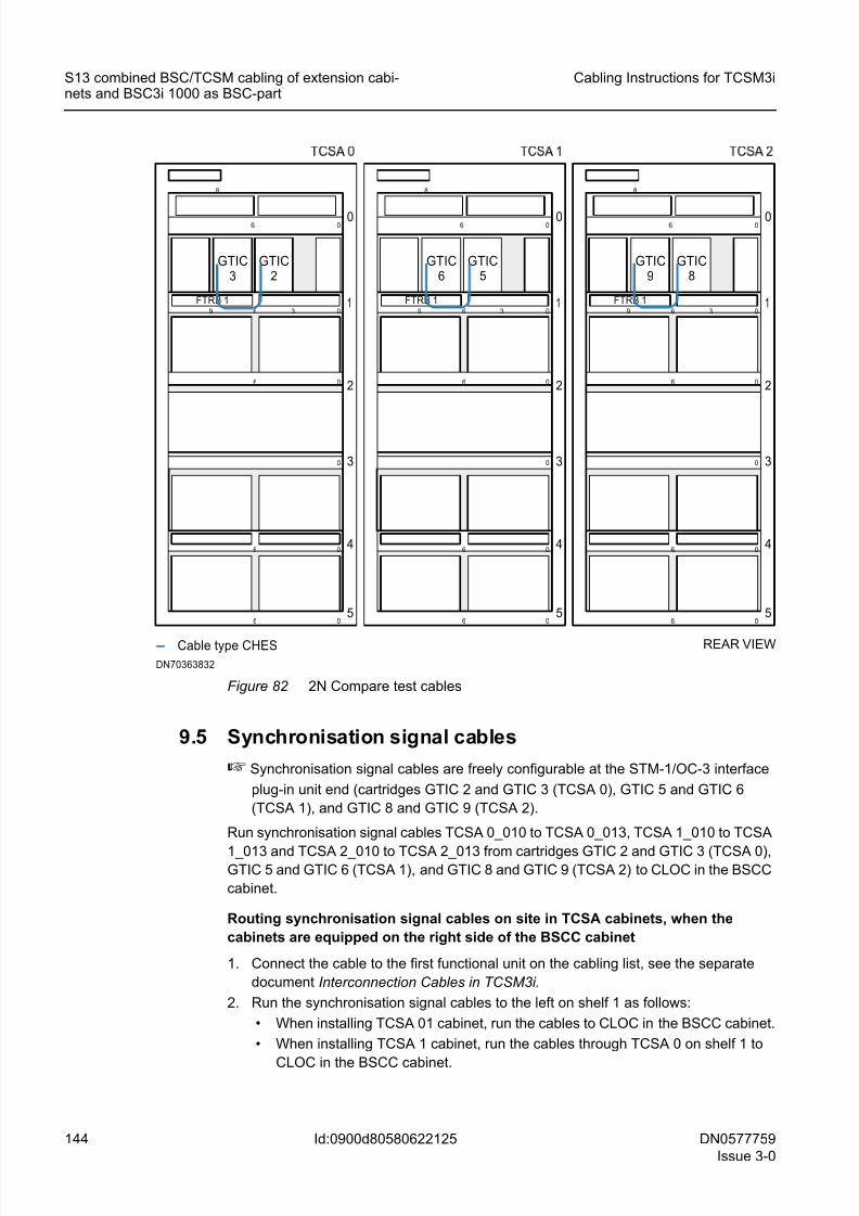
8/11/2019 NOKIA Flexi TRCM
http://slidepdf.com/reader/full/nokia-flexi-trcm 144/183
144 DN0577759
Issue 3-0
Cabling Instructions for TCSM3i
Id:0900d80580622125
S13 combined BSC/TCSM cabling of extension cabi-nets and BSC3i 1000 as BSC-part
Figure 82 2N Compare test cables
9.5 Synchronisation signal cables
☞ Synchronisation signal cables are freely configurable at the STM-1/OC-3 interface
plug-in unit end (cartridges GTIC 2 and GTIC 3 (TCSA 0), GTIC 5 and GTIC 6
(TCSA 1), and GTIC 8 and GTIC 9 (TCSA 2).
Run synchronisation signal cables TCSA 0_010 to TCSA 0_013, TCSA 1_010 to TCSA
1_013 and TCSA 2_010 to TCSA 2_013 from cartridges GTIC 2 and GTIC 3 (TCSA 0),GTIC 5 and GTIC 6 (TCSA 1), and GTIC 8 and GTIC 9 (TCSA 2) to CLOC in the BSCC
cabinet.
Routing synchronisation signal cables on site in TCSA cabinets, when the
cabinets are equipped on the right side of the BSCC cabinet
1. Connect the cable to the first functional unit on the cabling list, see the separate
document Interconnection Cables in TCSM3i.
2. Run the synchronisation signal cables to the left on shelf 1 as follows:
• When installing TCSA 01 cabinet, run the cables to CLOC in the BSCC cabinet.
• When installing TCSA 1 cabinet, run the cables through TCSA 0 on shelf 1 to
CLOC in the BSCC cabinet.
FTRB 1 1
2
3
4
0
5
0
0
0
0
6
0
6
9
06
6
36
8
Cable type CHES
FTRB 1 1
2
3
4
0
5
0
0
0
0
6
0
6
9
06
6
36
8
FTRB 1 1
2
3
4
0
5
0
0
0
0
6
0
6
9
06
6
36
8
REAR VIEW
GTIC3
GTIC2
GTIC6
GTIC5
GTIC9
GTIC8
DN70363832
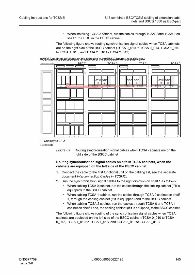
8/11/2019 NOKIA Flexi TRCM
http://slidepdf.com/reader/full/nokia-flexi-trcm 145/183
DN0577759
Issue 3-0
145
Cabling Instructions for TCSM3i S13 combined BSC/TCSM cabling of extension cabi-nets and BSC3i 1000 as BSC-part
Id:0900d80580622125
• When installing TCSA 2 cabinet, run the cables through TCSA 0 and TCSA 1 on
shelf 1 to CLOC in the BSCC cabinet.
The following figure shows routing synchronisation signal cables when TCSA cabinets
are on the right side of the BSCC cabinet (TCSA 0_010 to TCSA 0_013, TCSA 1_010to TCSA 1_013, and TCSA 2_010 to TCSA 2_013).
Figure 83 Routing synchronisation signal cables when TCSA cabinets are on the
right side of the BSCC cabinet
Routing synchronisation signal cables on site in TCSA cabinets, when the
cabinets are equipped on the left side of the BSCC cabinet
1. Connect the cable to the first functional unit on the cabling list, see the separate
document Interconnection Cables in TCSM3i.
2. Run the synchronisation signal cables to the right direction on shelf 1 as follows:
• When cabling TCSA 0 cabinet, run the cables through the cabling cabinet (if it is
equipped) to the BSCC cabinet.
• When cabling TCSA 1 cabinet, run the cables through TCSA 0 cabinet on shelf1, through the cabling cabinet (if it is equipped) and to the BSCC cabinet.
• When cabling TCSA 2 cabinet, run the cables through TCSA 0 and TCSA 1
cabinet on shelf 1 and, the cabling cabinet (if it is equipped) to the BSCC cabinet.
The following figure shows routing of the synchronisation signal cables when TCSA
cabinets are equipped on the left side of the BSCC cabinet (TCSA 0_010 to TCSA
0_013, TCSA 1_010 to TCSA 1_013, and TCSA 2_010 to TCSA 2_013).
1
2
3
4
0
5
00
BSCC
1
2
3
4
0
5
TCSA 0
A) TCSA cabinets equipped on the right side of the BSCC cabinet; rear side view
Cable type CFIZ
1
2
3
4
0
5
1
2
3
4
0
5
TCSA 1 TCSA 2
FTRB 0
C L O C
GTIC3
GTIC2
GTIC6
GTIC5
GTIC9
GTIC8
DN70363844
TCSA cabinets equipped on the right side of the BSCC cabinet; rear side view
FTRB 0FTRB 0FTRB 0FTRB 0FTRB 0
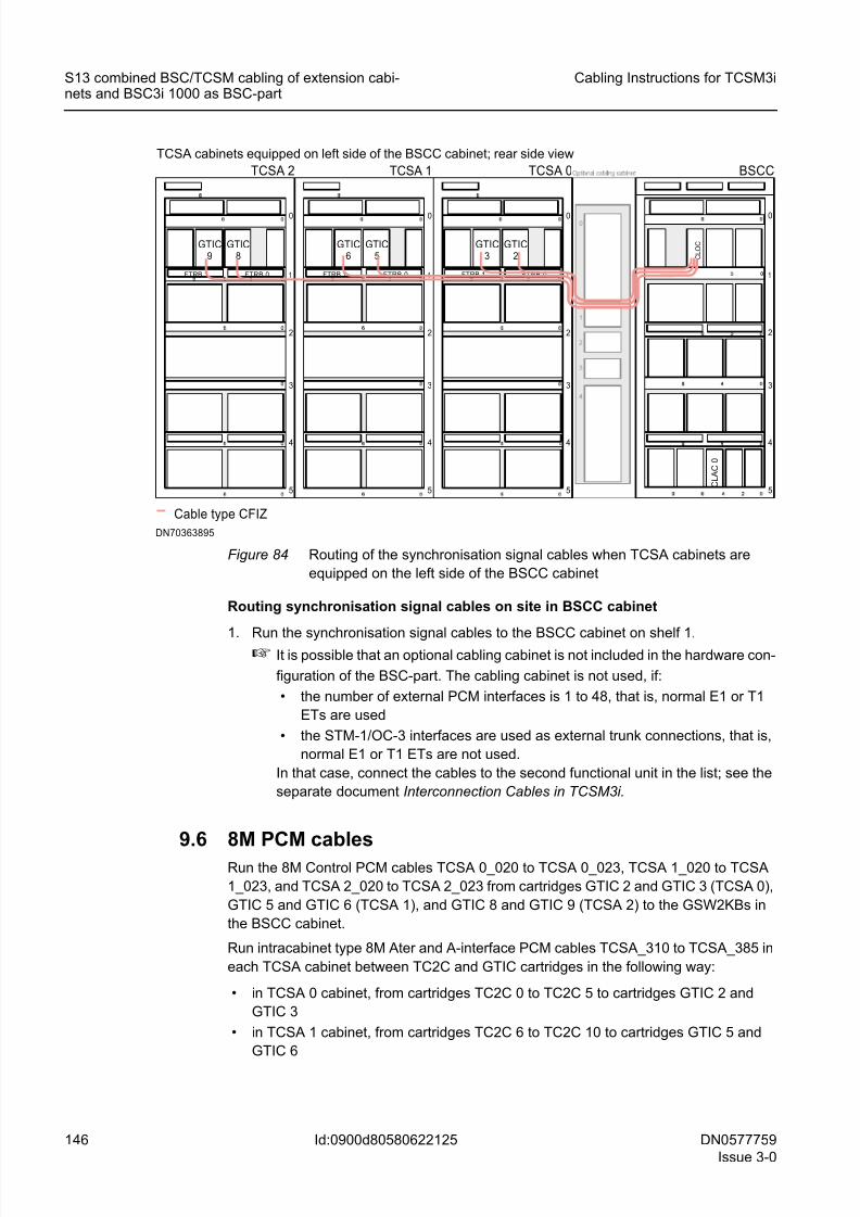
8/11/2019 NOKIA Flexi TRCM
http://slidepdf.com/reader/full/nokia-flexi-trcm 146/183
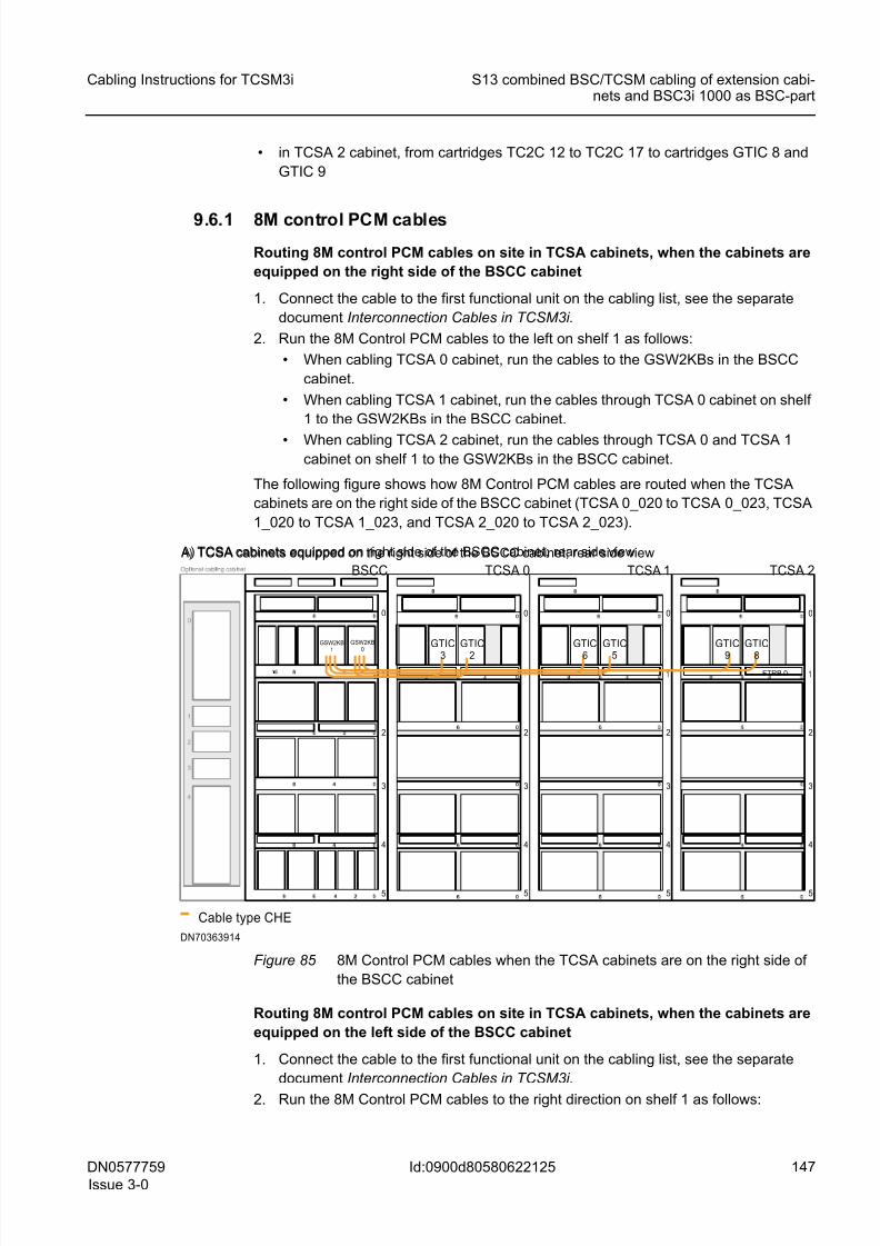
8/11/2019 NOKIA Flexi TRCM
http://slidepdf.com/reader/full/nokia-flexi-trcm 147/183
DN0577759
Issue 3-0
147
Cabling Instructions for TCSM3i S13 combined BSC/TCSM cabling of extension cabi-nets and BSC3i 1000 as BSC-part
Id:0900d80580622125
• in TCSA 2 cabinet, from cartridges TC2C 12 to TC2C 17 to cartridges GTIC 8 and
GTIC 9
9.6.1 8M control PCM cables
Routing 8M control PCM cables on site in TCSA cabinets, when the cabinets are
equipped on the right side of the BSCC cabinet
1. Connect the cable to the first functional unit on the cabling list, see the separate
document Interconnection Cables in TCSM3i.
2. Run the 8M Control PCM cables to the left on shelf 1 as follows:
• When cabling TCSA 0 cabinet, run the cables to the GSW2KBs in the BSCC
cabinet.
• When cabling TCSA 1 cabinet, run the cables through TCSA 0 cabinet on shelf
1 to the GSW2KBs in the BSCC cabinet.
• When cabling TCSA 2 cabinet, run the cables through TCSA 0 and TCSA 1cabinet on shelf 1 to the GSW2KBs in the BSCC cabinet.
The following figure shows how 8M Control PCM cables are routed when the TCSA
cabinets are on the right side of the BSCC cabinet (TCSA 0_020 to TCSA 0_023, TCSA
1_020 to TCSA 1_023, and TCSA 2_020 to TCSA 2_023).
Figure 85 8M Control PCM cables when the TCSA cabinets are on the right side of
the BSCC cabinet
Routing 8M control PCM cables on site in TCSA cabinets, when the cabinets are
equipped on the left side of the BSCC cabinet
1. Connect the cable to the first functional unit on the cabling list, see the separate
document Interconnection Cables in TCSM3i.
2. Run the 8M Control PCM cables to the right direction on shelf 1 as follows:
1
2
3
4
0
5
00
BSCC
1
2
3
4
0
5
TCSA 0
A) TCSA cabinets equipped on the right side of the BSCC cabinet; rear side view
Cable type CHE
1
2
3
4
0
5
1
2
3
4
0
5
TCSA 1 TCSA 2
GSW2KB1
GSW2KB0
GTIC
3
GTIC
2
GTIC
6
GTIC
5
GTIC
9
GTIC
8
DN70363914
FTRB 0
A) TCSA cabinets equipped on right side of the BSCC cabinet; rear side view
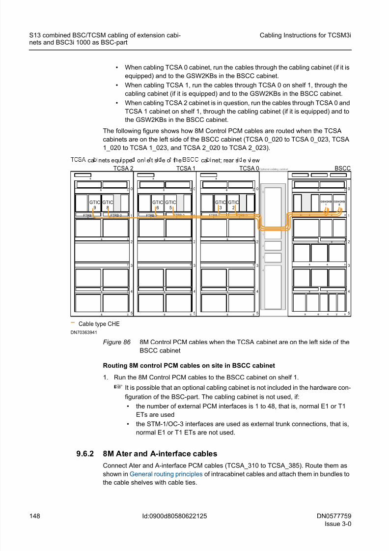
8/11/2019 NOKIA Flexi TRCM
http://slidepdf.com/reader/full/nokia-flexi-trcm 148/183
148 DN0577759
Issue 3-0
Cabling Instructions for TCSM3i
Id:0900d80580622125
S13 combined BSC/TCSM cabling of extension cabi-nets and BSC3i 1000 as BSC-part
• When cabling TCSA 0 cabinet, run the cables through the cabling cabinet (if it is
equipped) and to the GSW2KBs in the BSCC cabinet.
• When cabling TCSA 1, run the cables through TCSA 0 on shelf 1, through the
cabling cabinet (if it is equipped) and to the GSW2KBs in the BSCC cabinet. • When cabling TCSA 2 cabinet is in question, run the cables through TCSA 0 and
TCSA 1 cabinet on shelf 1, through the cabling cabinet (if it is equipped) and to
the GSW2KBs in the BSCC cabinet.
The following figure shows how 8M Control PCM cables are routed when the TCSA
cabinets are on the left side of the BSCC cabinet (TCSA 0_020 to TCSA 0_023, TCSA
1_020 to TCSA 1_023, and TCSA 2_020 to TCSA 2_023).
Figure 86 8M Control PCM cables when the TCSA cabinet are on the left side of the
BSCC cabinet
Routing 8M control PCM cables on site in BSCC cabinet
1. Run the 8M Control PCM cables to the BSCC cabinet on shelf 1.
☞ It is possible that an optional cabling cabinet is not included in the hardware con-
figuration of the BSC-part. The cabling cabinet is not used, if:
• the number of external PCM interfaces is 1 to 48, that is, normal E1 or T1
ETs are used
• the STM-1/OC-3 interfaces are used as external trunk connections, that is,
normal E1 or T1 ETs are not used.
9.6.2 8M Ater and A-interface cables
Connect Ater and A-interface PCM cables (TCSA_310 to TCSA_385). Route them as
shown in General routing principles of intracabinet cables and attach them in bundles to
the cable shelves with cable ties.
1
2
3
4
0
5
00
BSCC
FTRB 1 FTRB 0 1
2
3
4
0
5
09 36
TCSA 2
Cable type CHE
FTRB 1 FTRB 0 1
2
3
4
0
5
09 36FTRB 1 FTRB 0 1
2
3
4
0
5
09 36
TCSA 1 TCSA 0
GTIC9
GTIC8
GTIC6
GTIC5
GTIC3
GTIC2
DN70363941
ca nets equ ppe on e t s e o t e ca net; rear s e v ew
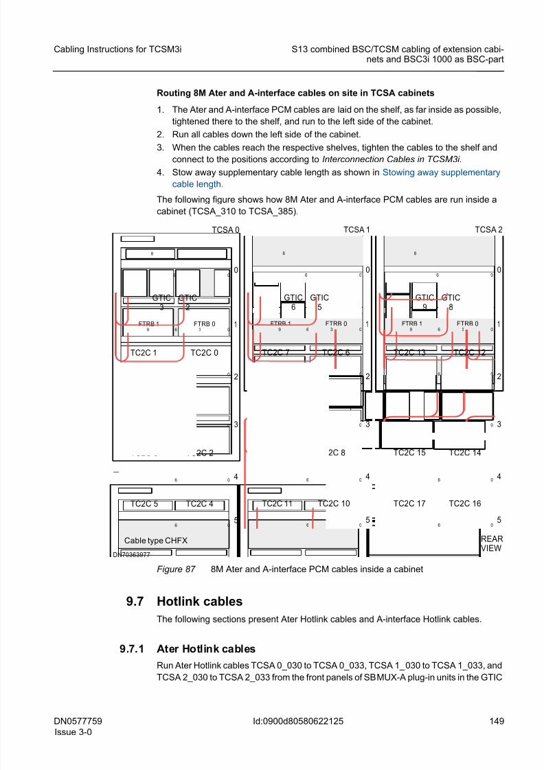
8/11/2019 NOKIA Flexi TRCM
http://slidepdf.com/reader/full/nokia-flexi-trcm 149/183
DN0577759
Issue 3-0
149
Cabling Instructions for TCSM3i S13 combined BSC/TCSM cabling of extension cabi-nets and BSC3i 1000 as BSC-part
Id:0900d80580622125
Routing 8M Ater and A-interface cables on site in TCSA cabinets
1. The Ater and A-interface PCM cables are laid on the shelf, as far inside as possible,
tightened there to the shelf, and run to the left side of the cabinet.
2. Run all cables down the left side of the cabinet.3. When the cables reach the respective shelves, tighten the cables to the shelf and
connect to the positions according to Interconnection Cables in TCSM3i.
4. Stow away supplementary cable length as shown in Stowing away supplementary
cable length.
The following figure shows how 8M Ater and A-interface PCM cables are run inside a
cabinet (TCSA_310 to TCSA_385).
Figure 87 8M Ater and A-interface PCM cables inside a cabinet
9.7 Hotlink cables
The following sections present Ater Hotlink cables and A-interface Hotlink cables.
9.7.1 Ater Hotlink cables
Run Ater Hotlink cables TCSA 0_030 to TCSA 0_033, TCSA 1_030 to TCSA 1_033, and
TCSA 2_030 to TCSA 2_033 from the front panels of SBMUX-A plug-in units in the GTIC
FTRB 1 FTRB 0 1
2
3
4
0
5
0
0
0
0
6
0
6
9
06
6
36
8
Cable type CHFX
TCSA 0
GTIC3
GTIC2
TC2C 1 TC2C 0
TC2C 3 TC2C 2
TC2C 5 TC2C 4
DN70363977
FTRB 1 FTRB 0 1
2
3
4
0
5
0
0
0
0
6
0
6
9
06
6
36
8
TCSA 1
GTIC6
GTIC5
TC2C 7 TC2C 6
TC2C 9 TC2C 8
TC2C 11 TC2C 10
FTRB 1 FTRB 0 1
2
3
4
0
5
0
0
0
0
6
0
6
9
06
6
36
8
REARVIEW
TCSA 2
GTIC9
GTIC8
TC2C 13 TC2C 12
TC2C 15 TC2C 14
TC2C 17 TC2C 16
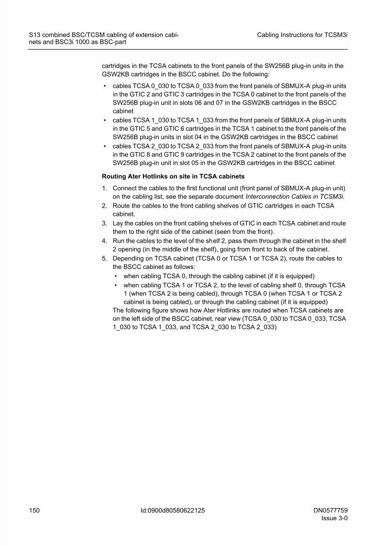
8/11/2019 NOKIA Flexi TRCM
http://slidepdf.com/reader/full/nokia-flexi-trcm 150/183
150 DN0577759
Issue 3-0
Cabling Instructions for TCSM3i
Id:0900d80580622125
S13 combined BSC/TCSM cabling of extension cabi-nets and BSC3i 1000 as BSC-part
cartridges in the TCSA cabinets to the front panels of the SW256B plug-in units in the
GSW2KB cartridges in the BSCC cabinet. Do the following:
• cables TCSA 0_030 to TCSA 0_033 from the front panels of SBMUX-A plug-in units
in the GTIC 2 and GTIC 3 cartridges in the TCSA 0 cabinet to the front panels of theSW256B plug-in unit in slots 06 and 07 in the GSW2KB cartridges in the BSCC
cabinet
• cables TCSA 1_030 to TCSA 1_033 from the front panels of SBMUX-A plug-in units
in the GTIC 5 and GTIC 6 cartridges in the TCSA 1 cabinet to the front panels of the
SW256B plug-in units in slot 04 in the GSW2KB cartridges in the BSCC cabinet
• cables TCSA 2_030 to TCSA 2_033 from the front panels of SBMUX-A plug-in units
in the GTIC 8 and GTIC 9 cartridges in the TCSA 2 cabinet to the front panels of the
SW256B plug-in unit in slot 05 in the GSW2KB cartridges in the BSCC cabinet
Routing Ater Hotlinks on site in TCSA cabinets
1.Connect the cables to the first functional unit (front panel of SBMUX-A plug-in unit)on the cabling list, see the separate document Interconnection Cables in TCSM3i.
2. Route the cables to the front cabling shelves of GTIC cartridges in each TCSA
cabinet.
3. Lay the cables on the front cabling shelves of GTIC in each TCSA cabinet and route
them to the right side of the cabinet (seen from the front).
4. Run the cables to the level of the shelf 2, pass them through the cabinet in the shelf
2 opening (in the middle of the shelf), going from front to back of the cabinet.
5. Depending on TCSA cabinet (TCSA 0 or TCSA 1 or TCSA 2), route the cables to
the BSCC cabinet as follows:
• when cabling TCSA 0, through the cabling cabinet (if it is equipped)
• when cabling TCSA 1 or TCSA 2, to the level of cabling shelf 0, through TCSA1 (when TCSA 2 is being cabled), through TCSA 0 (when TCSA 1 or TCSA 2
cabinet is being cabled), or through the cabling cabinet (if it is equipped)
The following figure shows how Ater Hotlinks are routed when TCSA cabinets are
on the left side of the BSCC cabinet, rear view (TCSA 0_030 to TCSA 0_033, TCSA
1_030 to TCSA 1_033, and TCSA 2_030 to TCSA 2_033)
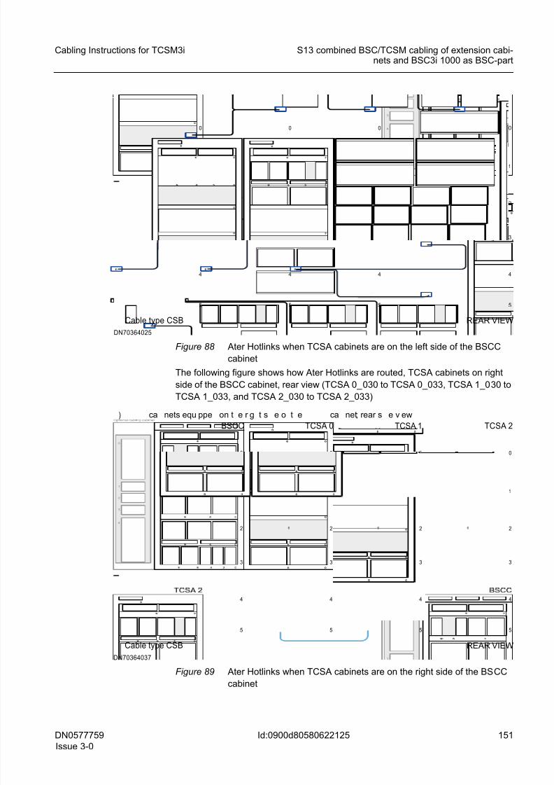
8/11/2019 NOKIA Flexi TRCM
http://slidepdf.com/reader/full/nokia-flexi-trcm 151/183
DN0577759
Issue 3-0
151
Cabling Instructions for TCSM3i S13 combined BSC/TCSM cabling of extension cabi-nets and BSC3i 1000 as BSC-part
Id:0900d80580622125
Figure 88 Ater Hotlinks when TCSA cabinets are on the left side of the BSCC
cabinet
The following figure shows how Ater Hotlinks are routed, TCSA cabinets on right
side of the BSCC cabinet, rear view (TCSA 0_030 to TCSA 0_033, TCSA 1_030 to
TCSA 1_033, and TCSA 2_030 to TCSA 2_033)
Figure 89 Ater Hotlinks when TCSA cabinets are on the right side of the BSCC
cabinet
1
2
3
4
0
5
001
2
3
4
0
5
0
Cable type CSB
1
2
3
4
0
5
0
1
2
3
4
0
5
0
DN70364025
REAR VIEW
1
2
3
4
0
5
00
BSCC
1
2
3
4
0
5
6
TCSA 0) ca nets equ ppe on t e r g t s e o t e ca net; rear s e v ew
Cable type CSB
1
2
3
4
0
5
6
1
2
3
4
0
5
6
TCSA 1 TCSA 2
REAR VIEW
DN70364037
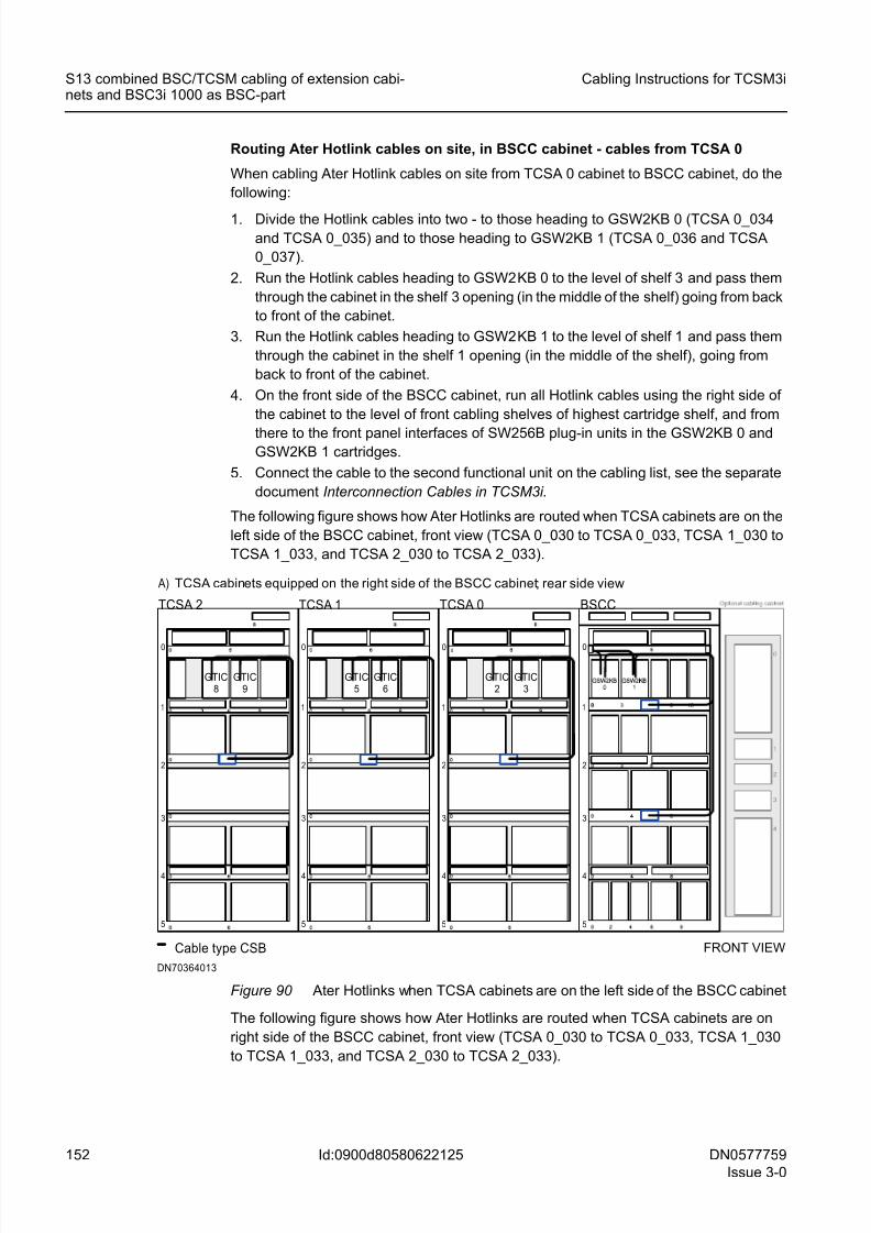
8/11/2019 NOKIA Flexi TRCM
http://slidepdf.com/reader/full/nokia-flexi-trcm 152/183
152 DN0577759
Issue 3-0
Cabling Instructions for TCSM3i
Id:0900d80580622125
S13 combined BSC/TCSM cabling of extension cabi-nets and BSC3i 1000 as BSC-part
Routing Ater Hotlink cables on site, in BSCC cabinet - cables from TCSA 0
When cabling Ater Hotlink cables on site from TCSA 0 cabinet to BSCC cabinet, do the
following:
1. Divide the Hotlink cables into two - to those heading to GSW2KB 0 (TCSA 0_034and TCSA 0_035) and to those heading to GSW2KB 1 (TCSA 0_036 and TCSA
0_037).
2. Run the Hotlink cables heading to GSW2KB 0 to the level of shelf 3 and pass them
through the cabinet in the shelf 3 opening (in the middle of the shelf) going from back
to front of the cabinet.
3. Run the Hotlink cables heading to GSW2KB 1 to the level of shelf 1 and pass them
through the cabinet in the shelf 1 opening (in the middle of the shelf), going from
back to front of the cabinet.
4. On the front side of the BSCC cabinet, run all Hotlink cables using the right side of
the cabinet to the level of front cabling shelves of highest cartridge shelf, and from
there to the front panel interfaces of SW256B plug-in units in the GSW2KB 0 andGSW2KB 1 cartridges.
5. Connect the cable to the second functional unit on the cabling list, see the separate
document Interconnection Cables in TCSM3i.
The following figure shows how Ater Hotlinks are routed when TCSA cabinets are on the
left side of the BSCC cabinet, front view (TCSA 0_030 to TCSA 0_033, TCSA 1_030 to
TCSA 1_033, and TCSA 2_030 to TCSA 2_033).
Figure 90 Ater Hotlinks when TCSA cabinets are on the left side of the BSCC cabinet
The following figure shows how Ater Hotlinks are routed when TCSA cabinets are on
right side of the BSCC cabinet, front view (TCSA 0_030 to TCSA 0_033, TCSA 1_030
to TCSA 1_033, and TCSA 2_030 to TCSA 2_033).
1
2
3
4
0
5
BSCC
0
1
2
3
4
0
5
6
0
TCSA 0
A) TCSA cabinets equipped on the right side of the BSCC cabinet; rear side view
Cable type CSB
1
2
3
4
0
5
6
1
2
3
4
0
5
6
TCSA 1TCSA 2
GTIC8
GTIC9
GTIC5
GTIC6
GTIC2
GTIC3
FRONT VIEW
DN70364013
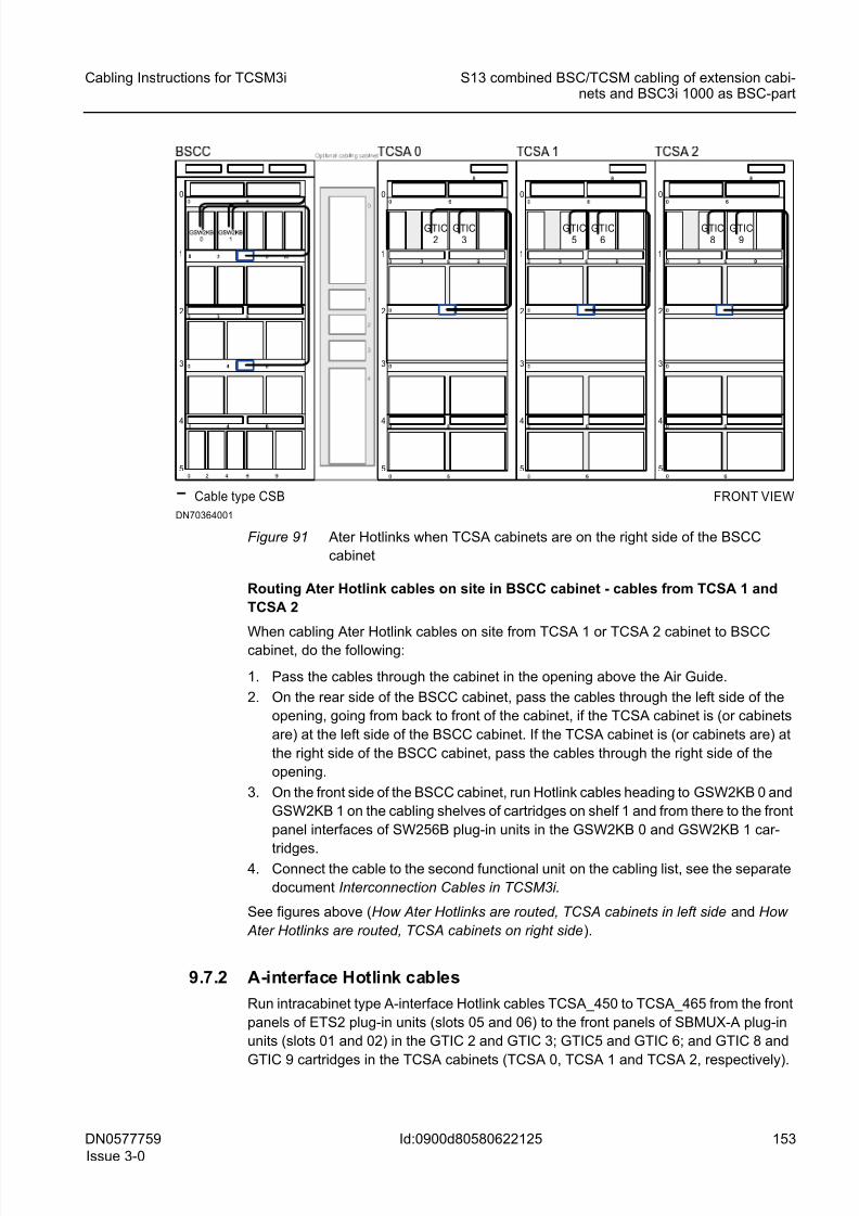
8/11/2019 NOKIA Flexi TRCM
http://slidepdf.com/reader/full/nokia-flexi-trcm 153/183
DN0577759
Issue 3-0
153
Cabling Instructions for TCSM3i S13 combined BSC/TCSM cabling of extension cabi-nets and BSC3i 1000 as BSC-part
Id:0900d80580622125
Figure 91 Ater Hotlinks when TCSA cabinets are on the right side of the BSCC
cabinet
Routing Ater Hotlink cables on site in BSCC cabinet - cables from TCSA 1 and
TCSA 2
When cabling Ater Hotlink cables on site from TCSA 1 or TCSA 2 cabinet to BSCCcabinet, do the following:
1. Pass the cables through the cabinet in the opening above the Air Guide.
2. On the rear side of the BSCC cabinet, pass the cables through the left side of the
opening, going from back to front of the cabinet, if the TCSA cabinet is (or cabinets
are) at the left side of the BSCC cabinet. If the TCSA cabinet is (or cabinets are) at
the right side of the BSCC cabinet, pass the cables through the right side of the
opening.
3. On the front side of the BSCC cabinet, run Hotlink cables heading to GSW2KB 0 and
GSW2KB 1 on the cabling shelves of cartridges on shelf 1 and from there to the front
panel interfaces of SW256B plug-in units in the GSW2KB 0 and GSW2KB 1 car-
tridges.4. Connect the cable to the second functional unit on the cabling list, see the separate
document Interconnection Cables in TCSM3i.
See figures above (How Ater Hotlinks are routed, TCSA cabinets in left side and How
Ater Hotlinks are routed, TCSA cabinets on right side).
9.7.2 A-interface Hotlink cables
Run intracabinet type A-interface Hotlink cables TCSA_450 to TCSA_465 from the front
panels of ETS2 plug-in units (slots 05 and 06) to the front panels of SBMUX-A plug-in
units (slots 01 and 02) in the GTIC 2 and GTIC 3; GTIC5 and GTIC 6; and GTIC 8 and
GTIC 9 cartridges in the TCSA cabinets (TCSA 0, TCSA 1 and TCSA 2, respectively).
1
2
3
4
0
5
0
0
0 1
2
3
4
0
5
6
Cable type CSB
1
2
3
4
0
5
6
1
2
3
4
0
5
GTIC2
GTIC3
GTIC5
GTIC6
GTIC8
GTIC9
DN70364001
FRONT VIEW
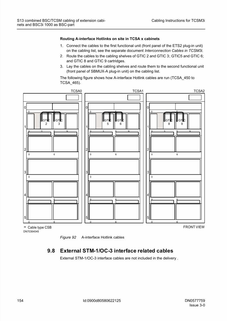
8/11/2019 NOKIA Flexi TRCM
http://slidepdf.com/reader/full/nokia-flexi-trcm 154/183
154 DN0577759
Issue 3-0
Cabling Instructions for TCSM3i
Id:0900d80580622125
S13 combined BSC/TCSM cabling of extension cabi-nets and BSC3i 1000 as BSC-part
Routing A-interface Hotlinks on site in TCSA x cabinets
1. Connect the cables to the first functional unit (front panel of the ETS2 plug-in unit)
on the cabling list, see the separate document Interconnection Cables in TCSM3i.
2. Route the cables to the cabling shelves of GTIC 2 and GTIC 3; GTIC5 and GTIC 6;and GTIC 8 and GTIC 9 cartridges.
3. Lay the cables on the cabling shelves and route them to the second functional unit
(front panel of SBMUX-A plug-in unit) on the cabling list.
The following figure shows how A-interface Hotlink cables are run (TCSA_450 to
TCSA_465).
Figure 92 A-interface Hotlink cables
9.8 External STM-1/OC-3 interface related cables
External STM-1/OC-3 interface cables are not included in the delivery .
FRONT VIEW
DN70364049
TCSA1
5
4
3
2
0
60
0
0 6
1
630
60
0
6
9
GTIC5
GTIC6
TCSA2
5
4
3
2
0
60
0
0 6
1
630
60
0
6
9
GTIC8
GTIC9
TCSA0
5
4
3
2
0
60
0
0 6
1
630
60
0
6
9
GTIC2
GTIC3
Cable type CSB
8/11/2019 NOKIA Flexi TRCM
http://slidepdf.com/reader/full/nokia-flexi-trcm 155/183
DN0577759
Issue 3-0
155
Cabling Instructions for TCSM3i S12 and S13 combined BSC/TCSM cabling of TCSAcabinet and BSC3i 1000/2000 as BSC-part
Id:0900d805806229a4
10 S12 and S13 combined BSC/TCSM cabling of
TCSA cabinet and BSC3i 1000/2000 as BSC-
partInformation on TCSM3i for combined BSC/TCSM installation option with BSC3i 2000 as
the BSC-part is valid on S13 level first deliveries when one TCSA cabinet (TCSA) is con-
nected to the BSC-part.
All the cabling (except AL and AL/CGS cables TCSA_065 and TCSA_066, Internal syn-
chronisation cables TCSA_070 to TCSA_073, External ET interface related cables
TCSA_150 to TCSA_269, Control PCM cables TCSA_080 and TCSA_081, and PCM
cables TCSA_090 to TCSA_131) presented inIntracabinet cabling in TCSA cabinet is
common to both TCSM3i for stand-alone installation option and TCSM3i for combined
BSC/TCSM installation option.
Intercabinet cables connect plug-in units located inside different cabinets. This sectiondescribes the efficient routing of cables between TCSA and BSCC and BSCD cabinets.
This section also describes Combined BSC/TCSM installation-specific intracabinet
cabling (timing loop cables, 2N compare test cables, 8M Ater and A-interface PCM
cables, and A-interface Hotlink cables).
☞ Routing of Combined BSC/TCSM installation-specific cables is done on site.
10.1 SBUS cables
Run supervision bus (SBUS) cables from TCSA cabinet to BSCC cabinet (when BSC-
part is BSC3i 1000) or to BSCD cabinet (when BSC-part is BSC3i 2000) as follows:
• From CLAC 1 in the TCSA cabinet to CLAC 0 in the BSCC cabinet (BSC3i 1000); or
• From CLAC 2 in the TCSA cabinet to CLAC 1 in the BSCD cabinet (BSC3i 2000).
☞ It is possible that an optional cabling cabinet is not included in the hardware config-
uration of the BSC-part. The cabling cabinet is not used, if:
• The number of external PCM interfaces is 1 to 48, that is, normal E1 or T1 ETs
are used
• The STM-1/OC-3 interfaces are used as external trunk connections, that is,
normal E1 or T1 ETs are not used.
Routing SBUS cables on site in TCSA cabinet
1. Connect the cable to the first functional unit on the cabling list.
2. If the BSC-part is BSC3i 1000, run the SBUS cables to the left direction on the shelf
1, then using the left side of TCSA cabinet run them to the level of the fifth cabling
shelf (where the other end cartridge in BSCC cabinet is equipped). See figure SBUS
cables when BSC-part is BSC3i 1000 .
3. If the BSC-part is BSC3i 2000, run the SBUS cables to the left or to the right depend-
ing whether TCSA cabinet is equipped beside BSCD cabinet or beside BSCC
cabinet. See figure SBUS cables when BSC-part is BSC3i 2000 .
8/11/2019 NOKIA Flexi TRCM
http://slidepdf.com/reader/full/nokia-flexi-trcm 156/183
156 DN0577759
Issue 3-0
Cabling Instructions for TCSM3i
Id:0900d805806229a4
S12 and S13 combined BSC/TCSM cabling of TCSAcabinet and BSC3i 1000/2000 as BSC-part
Routing SBUS cables on site in BSCC cabinet (BSC-part is BSC3i 1000)
When the BSC-part in the combined BSC/TCSM installation option is BSC3i 1000, do
the following:
1. If TCSA cabinet is situated on the left side of BSCC cabinet (seen from front) run theSBUS cables from the right side of BSCC cabinet on the cabling shelf 5.
2. If TCSA cabinet is situated on the left side of the BSCC cabinet (seen from rear) run
the SBUS cables to the level of cabling shelf 5 in TCSA cabinet and then trough the
cabling cabinet to the BSCC cabinet and there using shelf 5.
3. Connect the cable to the second functional unit on the cabling list in the saparate
document Interconnection Cables in TCSM3i .
The following figure shows how SBUS cables are routed when BSC-part is BSC3i 1000
(TCSA 0_001 to TCSA 0_002).
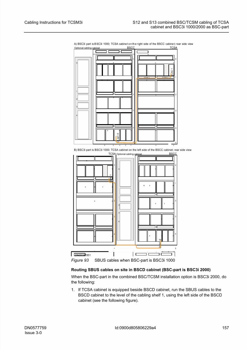
8/11/2019 NOKIA Flexi TRCM
http://slidepdf.com/reader/full/nokia-flexi-trcm 157/183
DN0577759
Issue 3-0
157
Cabling Instructions for TCSM3i S12 and S13 combined BSC/TCSM cabling of TCSAcabinet and BSC3i 1000/2000 as BSC-part
Id:0900d805806229a4
Figure 93 SBUS cables when BSC-part is BSC3i 1000
Routing SBUS cables on site in BSCD cabinet (BSC-part is BSC3i 2000)
When the BSC-part in the combined BSC/TCSM installation option is BSC3i 2000, do
the following:
1. If TCSA cabinet is equipped beside BSCD cabinet, run the SBUS cables to the
BSCD cabinet to the level of the cabling shelf 1, using the left side of the BSCD
cabinet (see the following figure).
1
2
3
4
0
Optional cabling cabinet
1
2
3
4
0
5
0
0
0
06
0
48
6
48
8 3
3
BSCC
06
C L A C 0
249
10
FTRB 1 FTRB 0 1
2
3
4
0
5
0
0
0
0
6
0
6
9
06
C L A C 1
6
36
8
TCSA
A) BSC3i part is B SC3i 1000; TCSA cabine t o n th e r ight side of the BSCC cabine t; r ear side view
1
2
3
4
0
Optional cabling cabinet
1
2
3
4
0
5
0
0
0
0
06
0
48
6
48
8 3
3
BSCC
06
C L A C 0
249
10
1
2
3
4
0
5
0
0
0
0
6
0
6
9
06
C L A C 1
6
36
8
TCSA
B) BSC3i part is BSC3i 1000; TCSA cabinet on the left side of the BSCC cabinet; rear side view
DN05187851
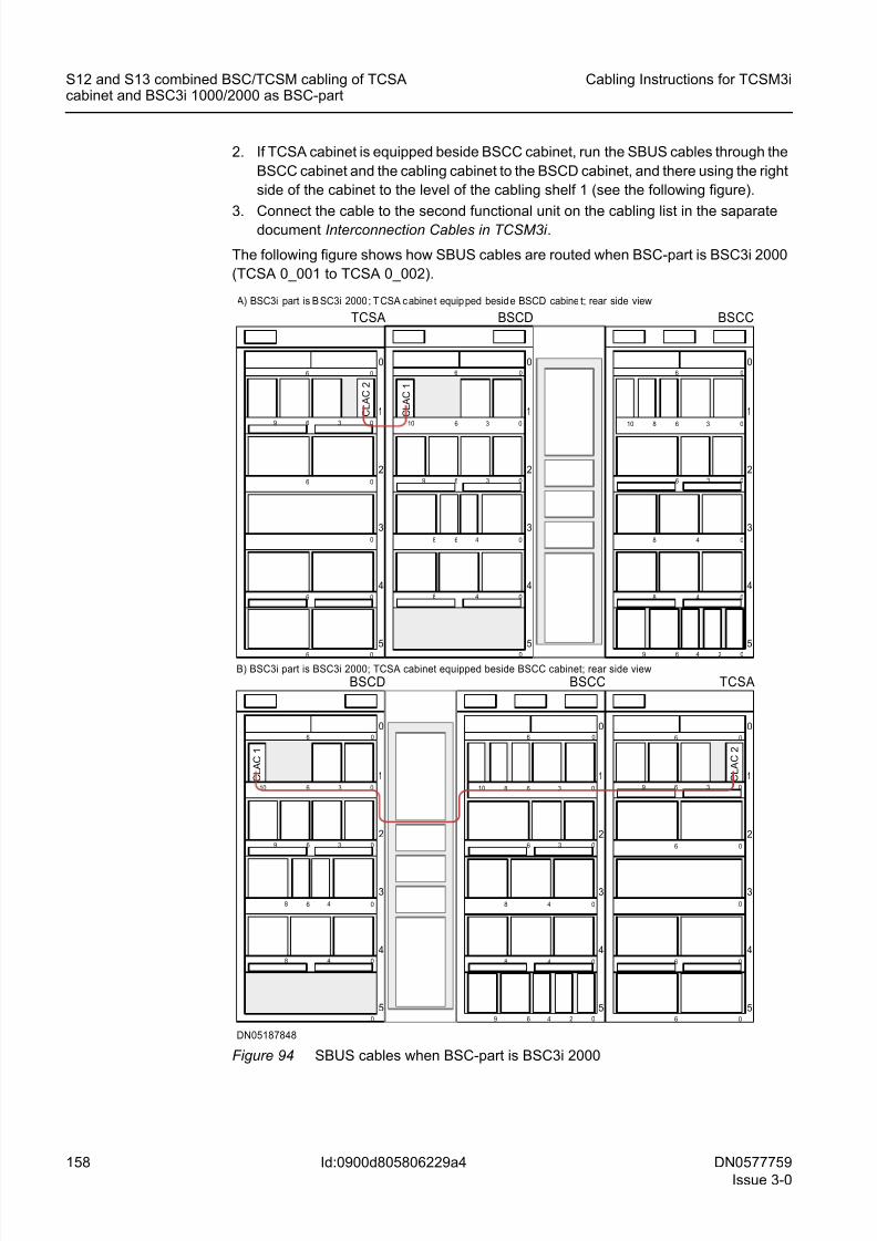
8/11/2019 NOKIA Flexi TRCM
http://slidepdf.com/reader/full/nokia-flexi-trcm 158/183
158 DN0577759
Issue 3-0
Cabling Instructions for TCSM3i
Id:0900d805806229a4
S12 and S13 combined BSC/TCSM cabling of TCSAcabinet and BSC3i 1000/2000 as BSC-part
2. If TCSA cabinet is equipped beside BSCC cabinet, run the SBUS cables through the
BSCC cabinet and the cabling cabinet to the BSCD cabinet, and there using the right
side of the cabinet to the level of the cabling shelf 1 (see the following figure).
3.Connect the cable to the second functional unit on the cabling list in the saparatedocument Interconnection Cables in TCSM3i .
The following figure shows how SBUS cables are routed when BSC-part is BSC3i 2000
(TCSA 0_001 to TCSA 0_002).
Figure 94 SBUS cables when BSC-part is BSC3i 2000
DN05187848
5
4
3
2
06 0
0
06
1
6 3 0
6 0
0
6
9
TCSA
5
4
3
2
06 0
48 0
3 06
1
8 6 3 010
6 4 2 09
48 0
BSCC
BSCD
5
4
3
2
1
06 0
0
48 0
48 0
3 06
10 6 3 0
9
6
5
4
3
2
06 0
0
06
1
6 3 0
6 0
0
6
9
TCSA
5
4
3
2
06 0
48 0
3 06
1
8 6 3 010
6 4 2 09
48 0
BSCC
BSCD
5
4
3
2
1
06 0
0
48 0
48 0
3 06
10 6 3 0
9
6
A) BSC3i part is B SC3i 2000 ; T CSA c abine t equip ped besid e BSCD cabine t; rear side view
B) BSC3i part is BSC3i 2000; TCSA cabinet equipped beside BSCC cabinet; rear side view
C L A
C
2
C L A
C
1
C L A
C
1
C L A
C
2
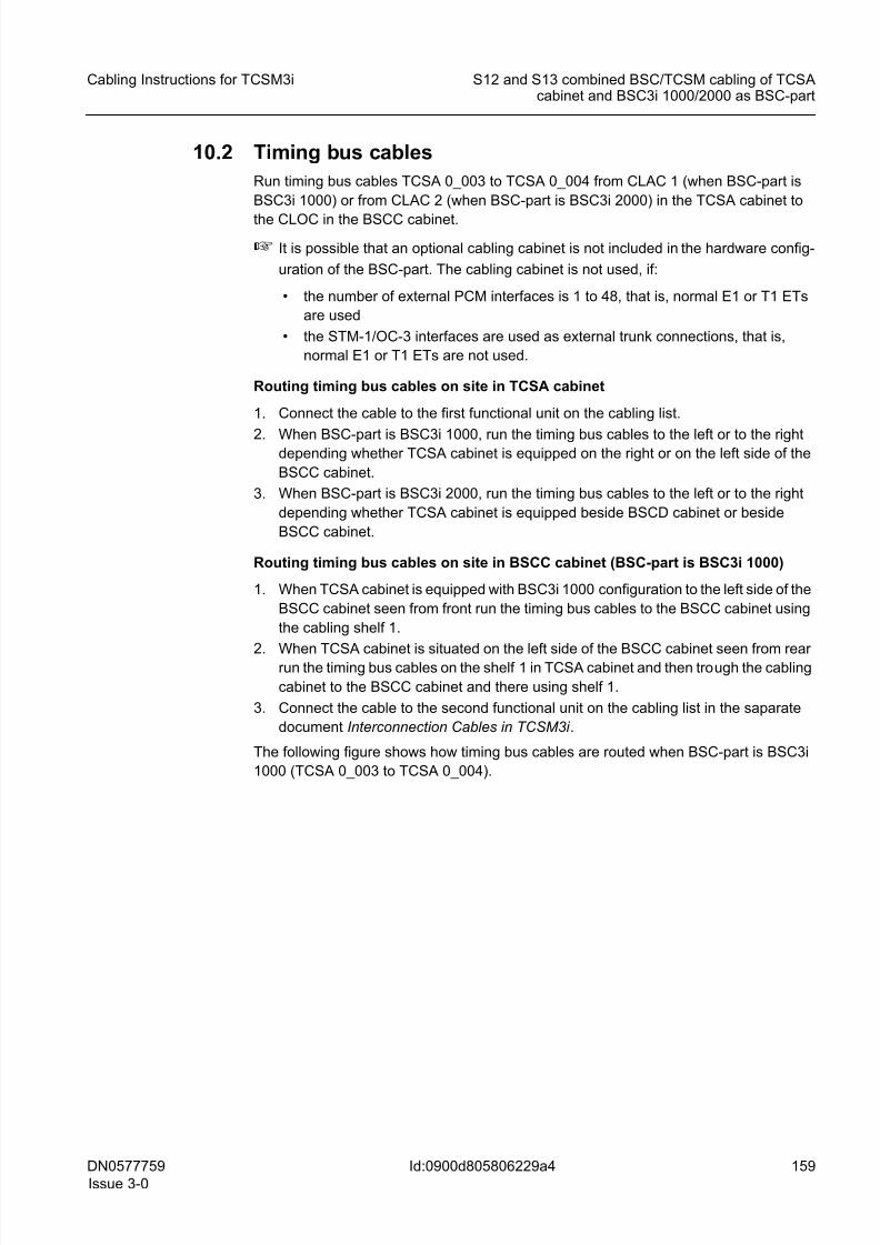
8/11/2019 NOKIA Flexi TRCM
http://slidepdf.com/reader/full/nokia-flexi-trcm 159/183
DN0577759
Issue 3-0
159
Cabling Instructions for TCSM3i S12 and S13 combined BSC/TCSM cabling of TCSAcabinet and BSC3i 1000/2000 as BSC-part
Id:0900d805806229a4
10.2 Timing bus cables
Run timing bus cables TCSA 0_003 to TCSA 0_004 from CLAC 1 (when BSC-part is
BSC3i 1000) or from CLAC 2 (when BSC-part is BSC3i 2000) in the TCSA cabinet to
the CLOC in the BSCC cabinet.
☞ It is possible that an optional cabling cabinet is not included in the hardware config-
uration of the BSC-part. The cabling cabinet is not used, if:
• the number of external PCM interfaces is 1 to 48, that is, normal E1 or T1 ETs
are used
• the STM-1/OC-3 interfaces are used as external trunk connections, that is,
normal E1 or T1 ETs are not used.
Routing timing bus cables on site in TCSA cabinet
1. Connect the cable to the first functional unit on the cabling list.
2. When BSC-part is BSC3i 1000, run the timing bus cables to the left or to the rightdepending whether TCSA cabinet is equipped on the right or on the left side of the
BSCC cabinet.
3. When BSC-part is BSC3i 2000, run the timing bus cables to the left or to the right
depending whether TCSA cabinet is equipped beside BSCD cabinet or beside
BSCC cabinet.
Routing timing bus cables on site in BSCC cabinet (BSC-part is BSC3i 1000)
1. When TCSA cabinet is equipped with BSC3i 1000 configuration to the left side of the
BSCC cabinet seen from front run the timing bus cables to the BSCC cabinet using
the cabling shelf 1.
2.When TCSA cabinet is situated on the left side of the BSCC cabinet seen from rearrun the timing bus cables on the shelf 1 in TCSA cabinet and then trough the cabling
cabinet to the BSCC cabinet and there using shelf 1.
3. Connect the cable to the second functional unit on the cabling list in the saparate
document Interconnection Cables in TCSM3i .
The following figure shows how timing bus cables are routed when BSC-part is BSC3i
1000 (TCSA 0_003 to TCSA 0_004).
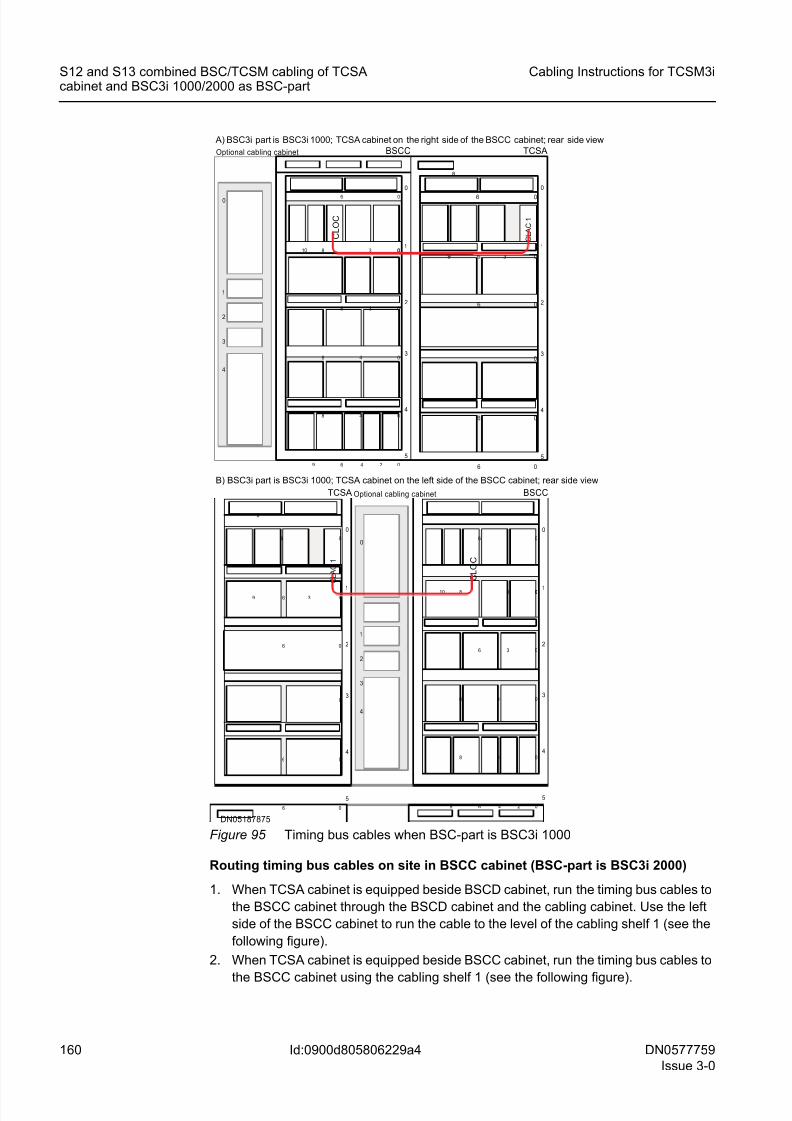
8/11/2019 NOKIA Flexi TRCM
http://slidepdf.com/reader/full/nokia-flexi-trcm 160/183
160 DN0577759
Issue 3-0
Cabling Instructions for TCSM3i
Id:0900d805806229a4
S12 and S13 combined BSC/TCSM cabling of TCSAcabinet and BSC3i 1000/2000 as BSC-part
Figure 95 Timing bus cables when BSC-part is BSC3i 1000
Routing timing bus cables on site in BSCC cabinet (BSC-part is BSC3i 2000)
1. When TCSA cabinet is equipped beside BSCD cabinet, run the timing bus cables to
the BSCC cabinet through the BSCD cabinet and the cabling cabinet. Use the left
side of the BSCC cabinet to run the cable to the level of the cabling shelf 1 (see the
following figure).
2. When TCSA cabinet is equipped beside BSCC cabinet, run the timing bus cables to
the BSCC cabinet using the cabling shelf 1 (see the following figure).
1
2
3
4
0
Optional cabling cabinet
1
2
3
4
0
5
C L O C
0
0
0
0
06
0
48
6
48
8 3
3
BSCC
06
249
10 1
2
3
4
0
5
0
0
0
0
6
0
6
9
06
C L A C 1
6
36
8
TCSA
A) BSC3i part is BSC3i 1000; TCSA cabinet on the right side of the BSCC cabinet; rear side view
1
2
3
4
0
Optional cabling cabinet
1
2
3
4
0
5
C L O C
0
0
0
0
06
0
48
6
48
8 3
3
BSCC
06
249
101
2
3
4
0
5
0
0
0
0
6
0
6
9
06
C L A C 1
6
36
8
TCSA
B) BSC3i part is BSC3i 1000; TCSA cabinet on the left side of the BSCC cabinet; rear side view
DN05187875
8/11/2019 NOKIA Flexi TRCM
http://slidepdf.com/reader/full/nokia-flexi-trcm 161/183
DN0577759
Issue 3-0
161
Cabling Instructions for TCSM3i S12 and S13 combined BSC/TCSM cabling of TCSAcabinet and BSC3i 1000/2000 as BSC-part
Id:0900d805806229a4
3. Connect the cable to the second functional unit on the cabling list in the saparate
document Interconnection Cables in TCSM3i .
The following figure shows how timing bus cables are routed when BSC-part is BSC3i
2000 (TCSA 0_003 to TCSA 0_004).
Figure 96 Timing Bus cables when BSC-part is BSC3i 2000
DN05187863
5
4
3
2
06 0
0
06
1
6 3 0
6 0
0
6
9
TCSA
5
4
3
2
06 0
48 0
3 06
1
8 6 3 010
6 4 2 09
48 0
BSCC
BSCD
5
4
3
2
1
06 0
0
48 0
48 0
3 06
10 6 3 0
9
6
5
4
3
2
06 0
0
06
1
6 3 0
6 0
0
6
9
TCSA
5
4
3
2
06 0
48 0
3 06
1
8 6 3 010
6 4 2 09
48 0
BSCC
BSCD
5
4
3
2
1
06 0
0
48 0
48 0
3 06
10 6 3 0
9
6
A) BS C3i part is BSC3i 2000; TCSA cabinet equipped beside BSCD cabinet; rear side view
B) BSC3i part is BSC3i 2000; TCSA cabinet equipped beside BSCC cabinet; rear side view
C L A
C
2
C L A
C
2
C L
O C
C L
O C
8/11/2019 NOKIA Flexi TRCM
http://slidepdf.com/reader/full/nokia-flexi-trcm 162/183
162 DN0577759
Issue 3-0
Cabling Instructions for TCSM3i
Id:0900d805806229a4
S12 and S13 combined BSC/TCSM cabling of TCSAcabinet and BSC3i 1000/2000 as BSC-part
10.3 Timing loop cables
Run intracabinet type timing loop cables TCSA_300 to TCSA_301 inside the CLAC 1
(when BSC-part is BSC3i 1000) or the CLAC 2 (when BSC-part is BSC3i 2000) in the
TCSA cabinet.
Routing timing loop cables on site in TCSA cabinet
1. Run the timing loop cables on the shelf 1 inside the CLAC 1 (when BSC-part is
BSC3i 1000, see the following figure) or the CLAC 2 (when BSC-part is BSC3i 2000,
see the following figure). See "From" and "To" connector positions in the cabling list
in the saparate document Interconnection Cables in TCSM3i .
2. Stow away supplementary cable length as shown in Stowing away supplementary
cable length.
The following figure shows how timing loop cables are routed when BSC-part is BSC3i
1000 (TCSA_300 to TCSA_301).
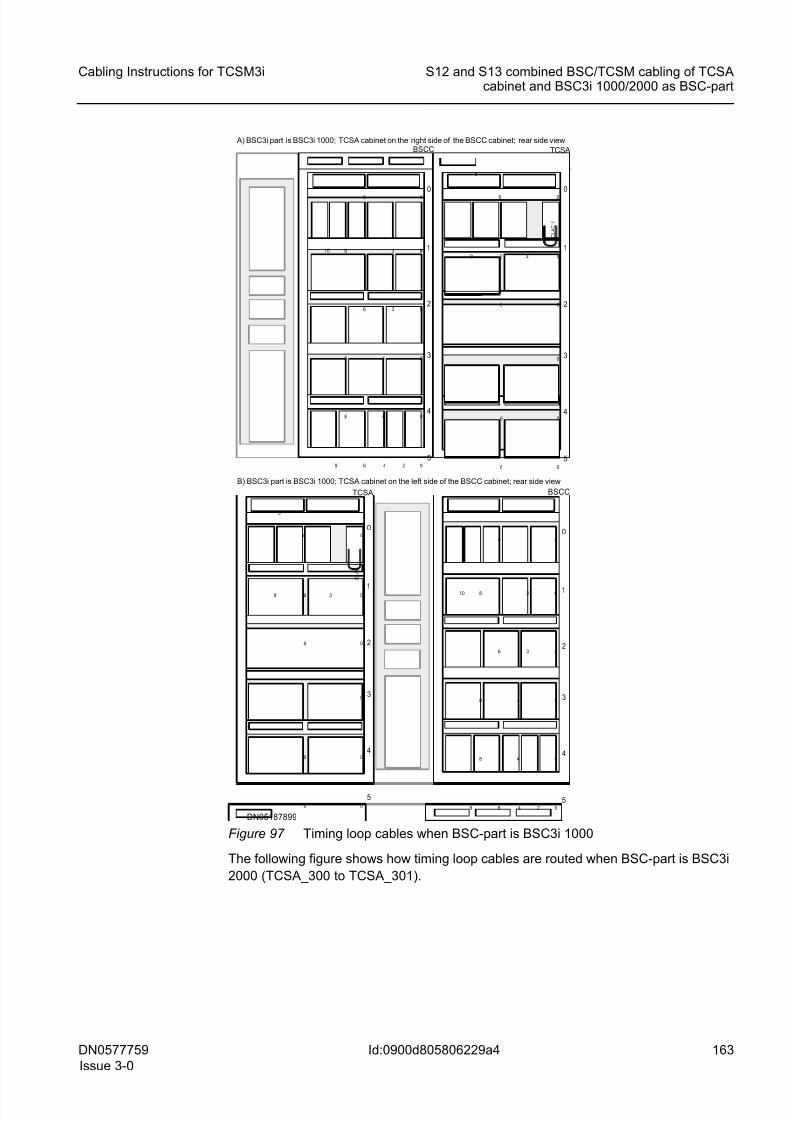
8/11/2019 NOKIA Flexi TRCM
http://slidepdf.com/reader/full/nokia-flexi-trcm 163/183
DN0577759
Issue 3-0
163
Cabling Instructions for TCSM3i S12 and S13 combined BSC/TCSM cabling of TCSAcabinet and BSC3i 1000/2000 as BSC-part
Id:0900d805806229a4
Figure 97 Timing loop cables when BSC-part is BSC3i 1000
The following figure shows how timing loop cables are routed when BSC-part is BSC3i
2000 (TCSA_300 to TCSA_301).
1
2
3
4
0
5
0
0
0
0
06
0
48
6
48
8 3
3
BSCC
06
249
10 1
2
3
4
0
5
0
0
0
0
6
0
6
9
06
C L A C
1
6
36
8
TCSA
A) BSC3i part is BSC3i 1000; TCSA cabinet on the right side of the BSCC cabinet; rear side view
BSCC
1
2
3
4
0
5
0
0
0
0
06
0
48
6
48
8 3
3
06
249
10
1
2
3
4
0
5
0
0
0
0
6
0
6
9
06
C L A C
1
6
36
8
TCSA
B) BSC3i part is BSC3i 1000; TCSA cabinet on the left side of the BSCC cabinet; rear side view
DN05187899
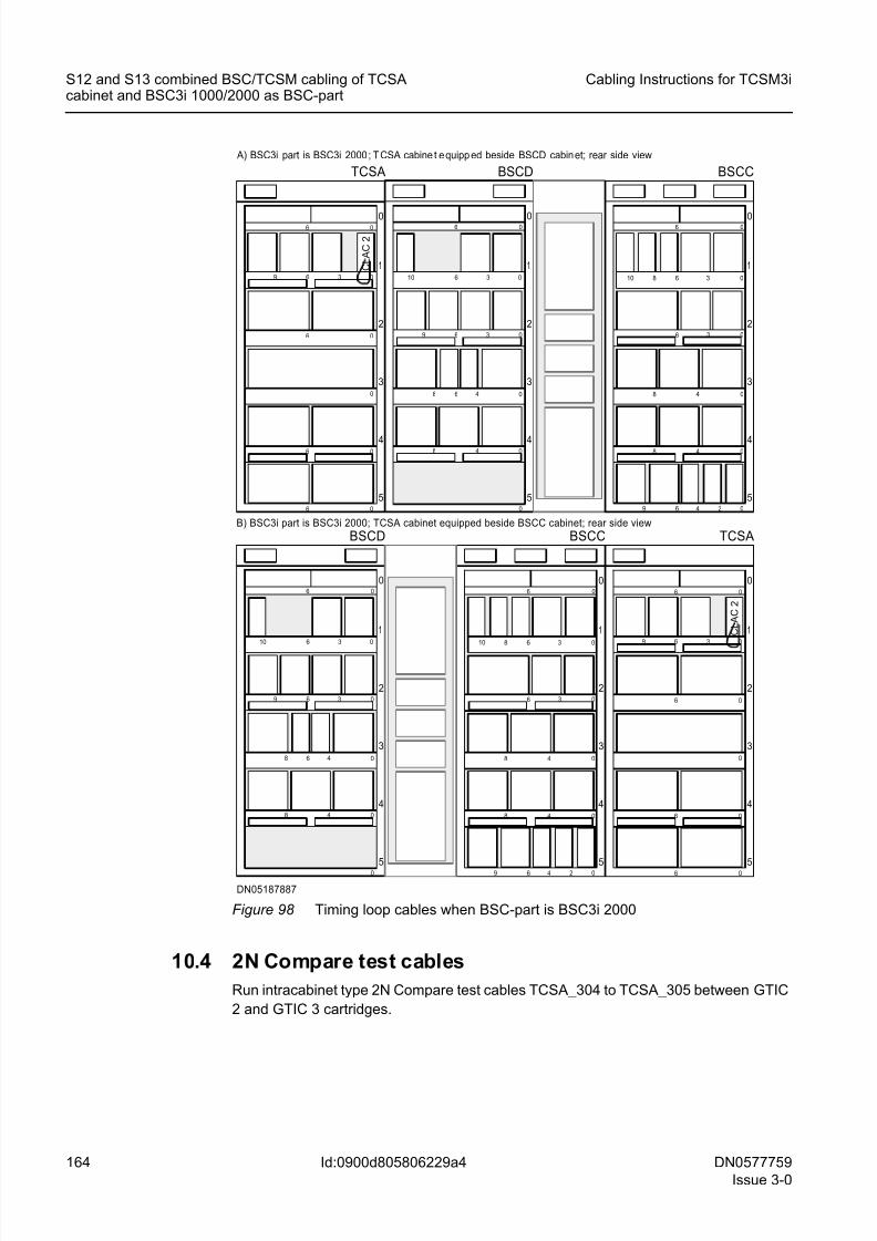
8/11/2019 NOKIA Flexi TRCM
http://slidepdf.com/reader/full/nokia-flexi-trcm 164/183
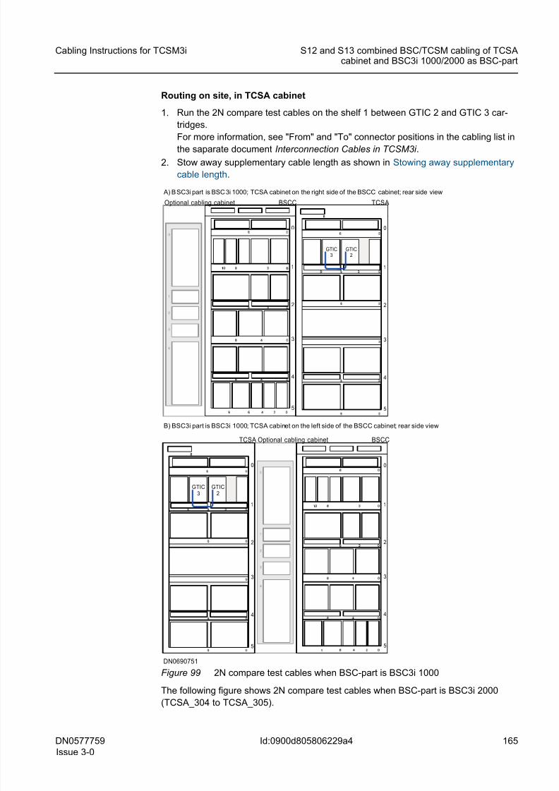
8/11/2019 NOKIA Flexi TRCM
http://slidepdf.com/reader/full/nokia-flexi-trcm 165/183
DN0577759
Issue 3-0
165
Cabling Instructions for TCSM3i S12 and S13 combined BSC/TCSM cabling of TCSAcabinet and BSC3i 1000/2000 as BSC-part
Id:0900d805806229a4
Routing on site, in TCSA cabinet
1. Run the 2N compare test cables on the shelf 1 between GTIC 2 and GTIC 3 car-
tridges.
For more information, see "From" and "To" connector positions in the cabling list inthe saparate document Interconnection Cables in TCSM3i .
2. Stow away supplementary cable length as shown in Stowing away supplementary
cable length.
Figure 99 2N compare test cables when BSC-part is BSC3i 1000
The following figure shows 2N compare test cables when BSC-part is BSC3i 2000(TCSA_304 to TCSA_305).
A) B SC3i part is BSC 3i 1000; TCSA cabinet on the right side of the BSCC cabinet; rear side view
Optional cabling cabinet
1
2
3
4
0
5
0
BSCC
1
2
3
4
0
5
TCSA
B) BSC3i part is BSC3i 1000; TCSA cabinet on the left side of the BSCC cabinet; rear side view
Optional cabling cabinet
1
2
3
4
0
5
BSCC
9
1
2
3
4
0
5
TCSA
GTIC3
GTIC2
GTIC3
GTIC2
DN0690751
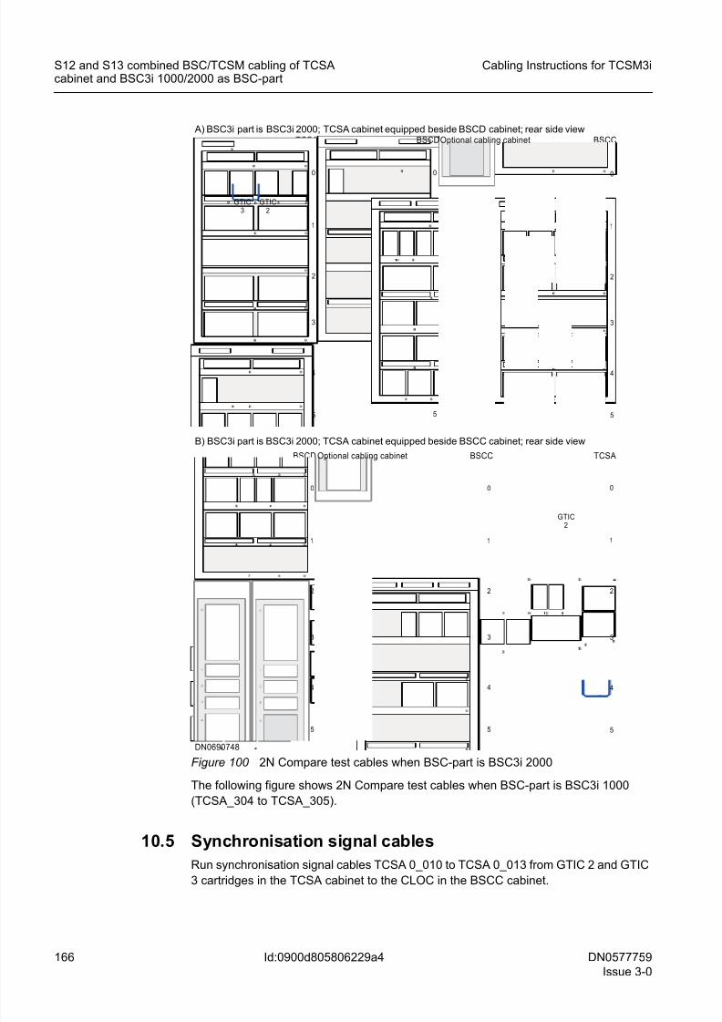
8/11/2019 NOKIA Flexi TRCM
http://slidepdf.com/reader/full/nokia-flexi-trcm 166/183
166 DN0577759
Issue 3-0
Cabling Instructions for TCSM3i
Id:0900d805806229a4
S12 and S13 combined BSC/TCSM cabling of TCSAcabinet and BSC3i 1000/2000 as BSC-part
Figure 100 2N Compare test cables when BSC-part is BSC3i 2000
The following figure shows 2N Compare test cables when BSC-part is BSC3i 1000
(TCSA_304 to TCSA_305).
10.5 Synchronisation signal cables
Run synchronisation signal cables TCSA 0_010 to TCSA 0_013 from GTIC 2 and GTIC
3 cartridges in the TCSA cabinet to the CLOC in the BSCC cabinet.
BSCD
1
2
3
4
0
5
0
BSCCTCSA
A) BSC3i part is BSC3i 2000; TCSA cabinet equipped beside BSCD cabinet; rear side view
BSCD
1
2
3
4
0
5
BSCC
1
2
3
4
0
5
GTIC3
TCSA
1
2
3
4
0
5
1
2
3
4
0
5
0
Optional cabling cabinet
Optional cabling cabinet
1
2
3
4
0
5
GTIC3
GTIC2
B) BSC3i part is BSC3i 2000; TCSA cabinet equipped beside BSCC cabinet; rear side view
GTIC2
DN0690748
8/11/2019 NOKIA Flexi TRCM
http://slidepdf.com/reader/full/nokia-flexi-trcm 167/183
DN0577759
Issue 3-0
167
Cabling Instructions for TCSM3i S12 and S13 combined BSC/TCSM cabling of TCSAcabinet and BSC3i 1000/2000 as BSC-part
Id:0900d805806229a4
☞ Synchronisation signal cables are freely configurable on the STM-1/OC-3 interface
plug-in unit end (GTIC 2 and GTIC 3 slots 5 and 6).
☞ It is possible that an optional cabling cabinet is not included in the hardware config-
uration of the BSC-part. The cabling cabinet is not used, if:
• the number of external PCM interfaces is 1 to 48, that is, normal E1 or T1 ETs
are used
• the STM-1/OC-3 interfaces are used as external trunk connections, that is,
normal E1 or T1 ETs are not used.
Routing synchronisation signal cables on site in TCSA cabinet
1. Connect the cable to the first functional unit on the cabling list.
2. When BSC-part is BSC3i 1000, run the synchronisation signal cables to the left on
the shelf 1.
3.When BSC-part is BSC3i 2000, run the synchronisation signal cables to the left orto the right, depending whether TCSA cabinet is equipped beside BSCD cabinet or
beside BSCC cabinet.
Routing synchronisation signal cables on site in BSCC cabinet (BSC-part is
BSC3i 1000)
1. When TCSA cabinet is situated on the left side of the BSCC cabinet seen from front,
run the synchronisation signal cables to the BSCC cabinet using the cable shelf 1.
2. When TCSA cabinet is situated on the left side of the BSCC cabinet seen from rear
run the synchronisation signal cables on the shelf 1 in TCSA cabinet and then trough
the cabling cabinet to the BSCC cabinet and there using shelf 1.
3. Connect the cable to the second functional unit on the cabling list.
The following figure shows how synchronisation signal cables are routed when BSC-
part is BSC3i 1000 (TCSA 0_010 to TCSA 0_013).
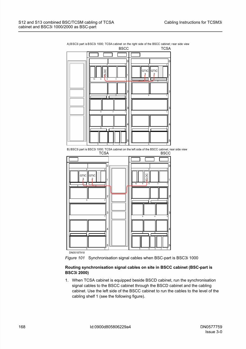
8/11/2019 NOKIA Flexi TRCM
http://slidepdf.com/reader/full/nokia-flexi-trcm 168/183
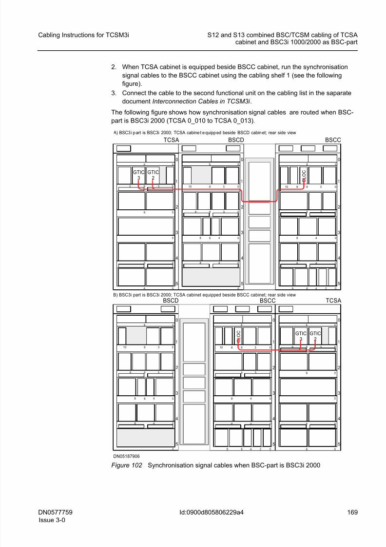
8/11/2019 NOKIA Flexi TRCM
http://slidepdf.com/reader/full/nokia-flexi-trcm 169/183
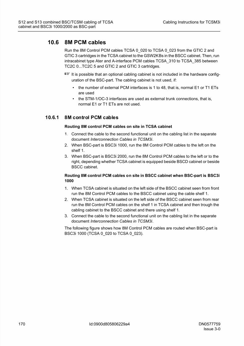
8/11/2019 NOKIA Flexi TRCM
http://slidepdf.com/reader/full/nokia-flexi-trcm 170/183
170 DN0577759
Issue 3-0
Cabling Instructions for TCSM3i
Id:0900d805806229a4
S12 and S13 combined BSC/TCSM cabling of TCSAcabinet and BSC3i 1000/2000 as BSC-part
10.6 8M PCM cables
Run the 8M Control PCM cables TCSA 0_020 to TCSA 0_023 from the GTIC 2 and
GTIC 3 cartridges in the TCSA cabinet to the GSW2KBs in the BSCC cabinet. Then, run
intracabinet type Ater and A-interface PCM cables TCSA_310 to TCSA_385 betweenTC2C 0...TC2C 5 and GTIC 2 and GTIC 3 cartridges.
☞ It is possible that an optional cabling cabinet is not included in the hardware config-
uration of the BSC-part. The cabling cabinet is not used, if:
• the number of external PCM interfaces is 1 to 48, that is, normal E1 or T1 ETs
are used
• the STM-1/OC-3 interfaces are used as external trunk connections, that is,
normal E1 or T1 ETs are not used.
10.6.1 8M control PCM cables
Routing 8M control PCM cables on site in TCSA cabinet
1. Connect the cable to the second functional unit on the cabling list in the saparate
document Interconnection Cables in TCSM3i .
2. When BSC-part is BSC3i 1000, run the 8M Control PCM cables to the left on the
shelf 1.
3. When BSC-part is BSC3i 2000, run the 8M Control PCM cables to the left or to the
right, depending whether TCSA cabinet is equipped beside BSCD cabinet or beside
BSCC cabinet.
Routing 8M control PCM cables on site in BSCC cabinet when BSC-part is BSC3i
1000
1. When TCSA cabinet is situated on the left side of the BSCC cabinet seen from front
run the 8M Control PCM cables to the BSCC cabinet using the cable shelf 1.
2. When TCSA cabinet is situated on the left side of the BSCC cabinet seen from rear
run the 8M Control PCM cables on the shelf 1 in TCSA cabinet and then trough the
cabling cabinet to the BSCC cabinet and there using shelf 1.
3. Connect the cable to the second functional unit on the cabling list in the saparate
document Interconnection Cables in TCSM3i .
The following figure shows how 8M Control PCM cables are routed when BSC-part is
BSC3i 1000 (TCSA 0_020 to TCSA 0_023).
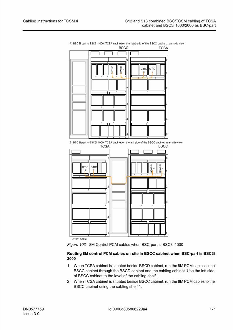
8/11/2019 NOKIA Flexi TRCM
http://slidepdf.com/reader/full/nokia-flexi-trcm 171/183
DN0577759
Issue 3-0
171
Cabling Instructions for TCSM3i S12 and S13 combined BSC/TCSM cabling of TCSAcabinet and BSC3i 1000/2000 as BSC-part
Id:0900d805806229a4
Figure 103 8M Control PCM cables when BSC-part is BSC3i 1000
Routing 8M control PCM cables on site in BSCC cabinet when BSC-part is BSC3i
2000
1. When TCSA cabinet is situated beside BSCD cabinet, run the 8M PCM cables to the
BSCC cabinet through the BSCD cabinet and the cabling cabinet. Use the left side
of BSCC cabinet to the level of the cabling shelf 1.
2. When TCSA cabinet is situated beside BSCC cabinet, run the 8M PCM cables to the
BSCC cabinet using the cabling shelf 1.
DN05187933
5
4
3
2
06 0
0
06
1
6 3 0
6 0
0
6
9
TCSA
5
4
3
2
06 0
48 0
3 06
1
8 6 3 010
6 4 2 09
48 0
BSCC
A) BSC 3i part is BSC3 i 1000; TCSA cabine t o n the right side of the BSCC cabine t; r ear side view
B) BSC3i part is BSC3i 1000; TCSA cabinet on the left side of the BSCC cabinet; rear side view
5
4
3
2
06 0
48 0
3 06
1
8 6 3 010
6 4 2 09
48 0
BSCC
5
4
3
2
06 0
0
06
1
6 3 0
6 0
0
6
9
TCSA
GTIC2
GTIC3
GTIC2
GTIC3
G S W 2 K B
1
G S W 2 K B
0
G S W 2 K B
1
G S W 2 K B
0
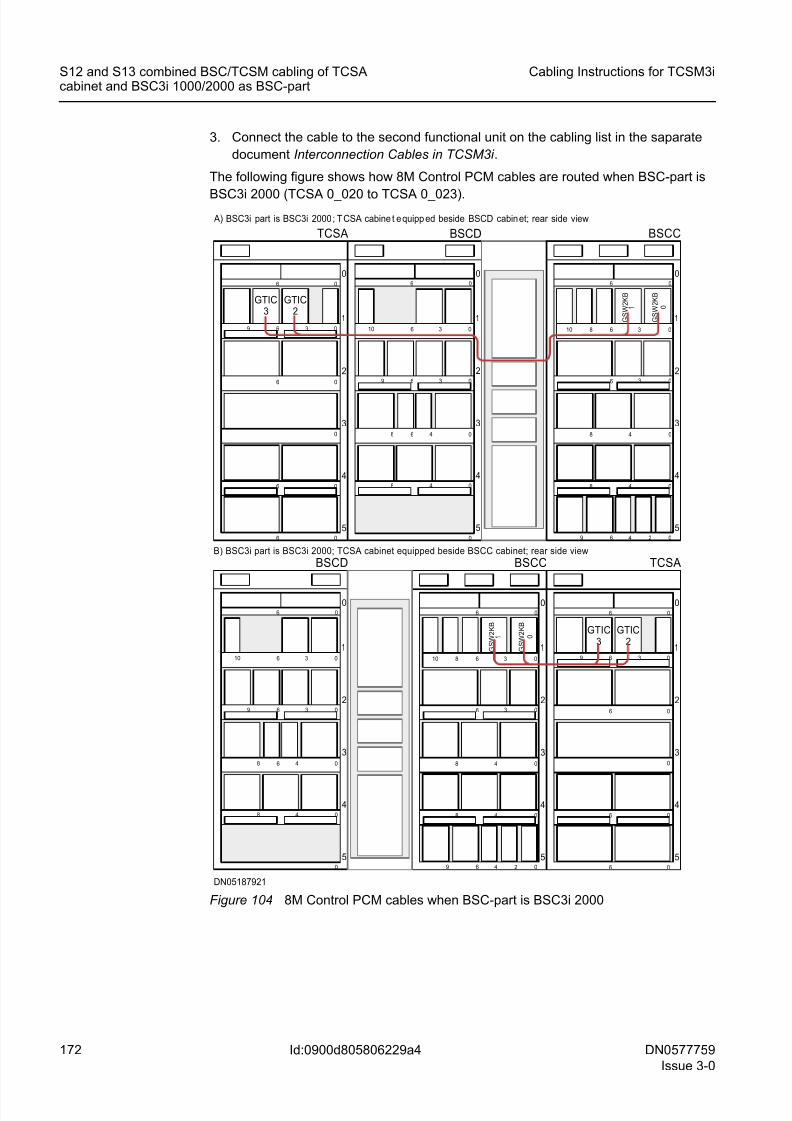
8/11/2019 NOKIA Flexi TRCM
http://slidepdf.com/reader/full/nokia-flexi-trcm 172/183
172 DN0577759
Issue 3-0
Cabling Instructions for TCSM3i
Id:0900d805806229a4
S12 and S13 combined BSC/TCSM cabling of TCSAcabinet and BSC3i 1000/2000 as BSC-part
3. Connect the cable to the second functional unit on the cabling list in the saparate
document Interconnection Cables in TCSM3i .
The following figure shows how 8M Control PCM cables are routed when BSC-part is
BSC3i 2000 (TCSA 0_020 to TCSA 0_023).
Figure 104 8M Control PCM cables when BSC-part is BSC3i 2000
DN05187921
5
4
3
2
06 0
0
06
1
6 3 0
6 0
0
6
9
TCSA
5
4
3
2
06 0
48 0
3 06
1
8 6 3 010
6 4 2 09
48 0
BSCC
BSCD
5
4
3
2
1
06 0
0
48 0
48 0
3 06
10 6 3 0
9
6
5
4
3
2
06 0
0
06
1
6 3 0
6 0
0
6
9
TCSA
5
4
3
2
06 0
48 0
3 06
1
8 6 3 010
6 4 2 09
48 0
BSCC
BSCD
5
4
3
2
1
06 0
0
48 0
48 0
3 06
10 6 3 0
9
6
A) BSC3i part is BSC3i 2000 ; T CSA cabine t e quipp ed beside BSCD cabin et; rear side view
B) BSC3i part is BSC3i 2000; TCSA cabinet equipped beside BSCC cabinet; rear side view
GTIC3
GTIC2
GTIC3
GTIC2
G S W 2 K B
1
G S W 2 K B
0
G S W 2 K B
1
G S W 2 K B
0
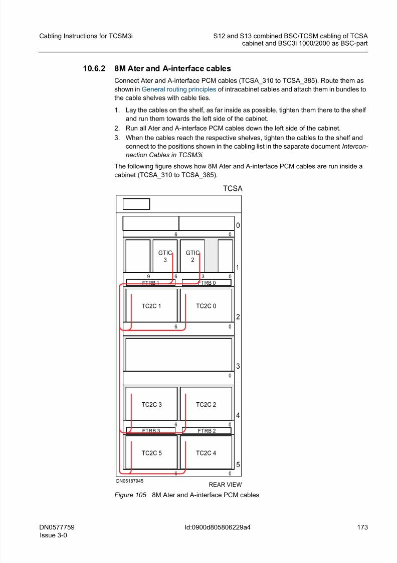
8/11/2019 NOKIA Flexi TRCM
http://slidepdf.com/reader/full/nokia-flexi-trcm 173/183
DN0577759
Issue 3-0
173
Cabling Instructions for TCSM3i S12 and S13 combined BSC/TCSM cabling of TCSAcabinet and BSC3i 1000/2000 as BSC-part
Id:0900d805806229a4
10.6.2 8M Ater and A-interface cables
Connect Ater and A-interface PCM cables (TCSA_310 to TCSA_385). Route them as
shown in General routing principles of intracabinet cables and attach them in bundles to
the cable shelves with cable ties.
1. Lay the cables on the shelf, as far inside as possible, tighten them there to the shelf
and run them towards the left side of the cabinet.
2. Run all Ater and A-interface PCM cables down the left side of the cabinet.
3. When the cables reach the respective shelves, tighten the cables to the shelf and
connect to the positions shown in the cabling list in the saparate document Intercon-
nection Cables in TCSM3i.
The following figure shows how 8M Ater and A-interface PCM cables are run inside a
cabinet (TCSA_310 to TCSA_385).
Figure 105 8M Ater and A-interface PCM cables
REAR VIEWDN05187945
TCSA
5
4
3
2
06 0
0
06
1
6 3 0
6 0
0
6
9
TC2C 0
TC2C 3
TC2C 4
FTRB 2FTRB 3
GTIC2
FTRB 1 FTRB 0
TC2C 5
TC2C 2
TC2C 1
GTIC3
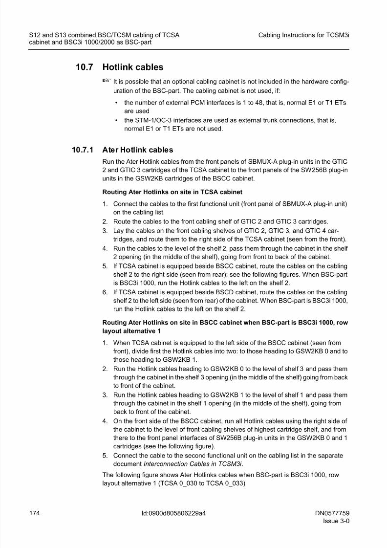
8/11/2019 NOKIA Flexi TRCM
http://slidepdf.com/reader/full/nokia-flexi-trcm 174/183
174 DN0577759
Issue 3-0
Cabling Instructions for TCSM3i
Id:0900d805806229a4
S12 and S13 combined BSC/TCSM cabling of TCSAcabinet and BSC3i 1000/2000 as BSC-part
10.7 Hotlink cables
☞ It is possible that an optional cabling cabinet is not included in the hardware config-
uration of the BSC-part. The cabling cabinet is not used, if:
• the number of external PCM interfaces is 1 to 48, that is, normal E1 or T1 ETs
are used
• the STM-1/OC-3 interfaces are used as external trunk connections, that is,
normal E1 or T1 ETs are not used.
10.7.1 Ater Hotlink cables
Run the Ater Hotlink cables from the front panels of SBMUX-A plug-in units in the GTIC
2 and GTIC 3 cartridges of the TCSA cabinet to the front panels of the SW256B plug-in
units in the GSW2KB cartridges of the BSCC cabinet.
Routing Ater Hotlinks on site in TCSA cabinet
1. Connect the cables to the first functional unit (front panel of SBMUX-A plug-in unit)
on the cabling list.
2. Route the cables to the front cabling shelf of GTIC 2 and GTIC 3 cartridges.
3. Lay the cables on the front cabling shelves of GTIC 2, GTIC 3, and GTIC 4 car-
tridges, and route them to the right side of the TCSA cabinet (seen from the front).
4. Run the cables to the level of the shelf 2, pass them through the cabinet in the shelf
2 opening (in the middle of the shelf), going from front to back of the cabinet.
5. If TCSA cabinet is equipped beside BSCC cabinet, route the cables on the cabling
shelf 2 to the right side (seen from rear); see the following figures. When BSC-part
is BSC3i 1000, run the Hotlink cables to the left on the shelf 2.
6. If TCSA cabinet is equipped beside BSCD cabinet, route the cables on the cabling
shelf 2 to the left side (seen from rear) of the cabinet. When BSC-part is BSC3i 1000,
run the Hotlink cables to the left on the shelf 2.
Routing Ater Hotlinks on site in BSCC cabinet when BSC-part is BSC3i 1000, row
layout alternative 1
1. When TCSA cabinet is equipped to the left side of the BSCC cabinet (seen from
front), divide first the Hotlink cables into two: to those heading to GSW2KB 0 and to
those heading to GSW2KB 1.
2. Run the Hotlink cables heading to GSW2KB 0 to the level of shelf 3 and pass them
through the cabinet in the shelf 3 opening (in the middle of the shelf) going from back
to front of the cabinet.
3. Run the Hotlink cables heading to GSW2KB 1 to the level of shelf 1 and pass them
through the cabinet in the shelf 1 opening (in the middle of the shelf), going from
back to front of the cabinet.
4. On the front side of the BSCC cabinet, run all Hotlink cables using the right side of
the cabinet to the level of front cabling shelves of highest cartridge shelf, and from
there to the front panel interfaces of SW256B plug-in units in the GSW2KB 0 and 1
cartridges (see the following figure).
5. Connect the cable to the second functional unit on the cabling list in the saparate
document Interconnection Cables in TCSM3i .
The following figure shows Ater Hotlinks cables when BSC-part is BSC3i 1000, row
layout alternative 1 (TCSA 0_030 to TCSA 0_033)
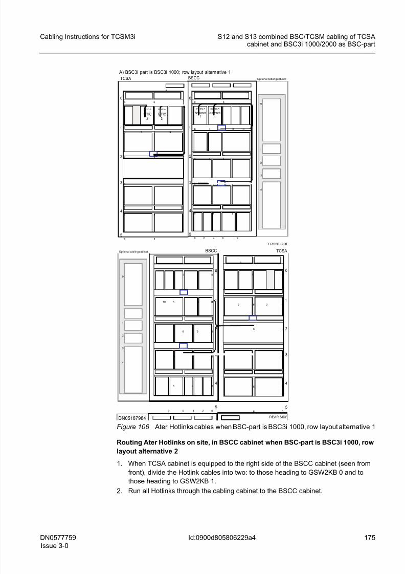
8/11/2019 NOKIA Flexi TRCM
http://slidepdf.com/reader/full/nokia-flexi-trcm 175/183
8/11/2019 NOKIA Flexi TRCM
http://slidepdf.com/reader/full/nokia-flexi-trcm 176/183
176 DN0577759
Issue 3-0
Cabling Instructions for TCSM3i
Id:0900d805806229a4
S12 and S13 combined BSC/TCSM cabling of TCSAcabinet and BSC3i 1000/2000 as BSC-part
3. Run the Hotlink cables heading to GSW2KB 0 to the level of shelf 3 and pass them
through the cabinet in the shelf 3 opening (in the middle of the shelf) going from back
to front of the cabinet.
4.Run the Hotlink cables heading to GSW2KB 1 to the right side of the BSCC cabinet(seen from rear) and there to the level of shelf 1 and pass them through the cabinet
in the shelf 1 opening (in the middle of the shelf), going from back to front of the
cabinet.
5. On the front side of the BSCC cabinet, run all Hotlink cables using the right side of
the cabinet to the level of front cabling shelves of highest cartridge shelf, and from
there to the front panel interfaces of SW256B plug-in units in the GSW2KB 0 and 1
cartridges (see the following figure).
6. Connect the cable to the second functional unit on the cabling list in the saparate
document Interconnection Cables in TCSM3i .
The following figure shows Ater Hotlinks cables when BSC-part is BSC3i 1000, row
layout alternative 2 (TCSA 0_030 to TCSA 0_033)
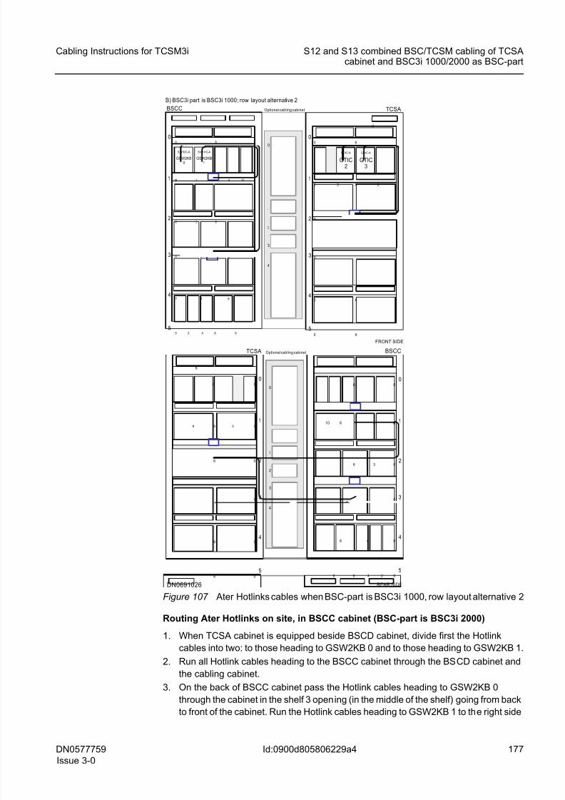
8/11/2019 NOKIA Flexi TRCM
http://slidepdf.com/reader/full/nokia-flexi-trcm 177/183
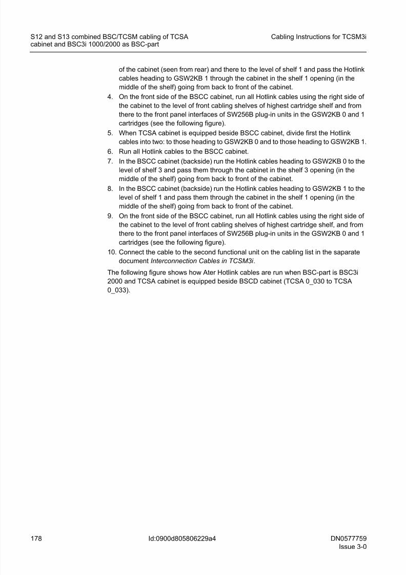
8/11/2019 NOKIA Flexi TRCM
http://slidepdf.com/reader/full/nokia-flexi-trcm 178/183
178 DN0577759
Issue 3-0
Cabling Instructions for TCSM3i
Id:0900d805806229a4
S12 and S13 combined BSC/TCSM cabling of TCSAcabinet and BSC3i 1000/2000 as BSC-part
of the cabinet (seen from rear) and there to the level of shelf 1 and pass the Hotlink
cables heading to GSW2KB 1 through the cabinet in the shelf 1 opening (in the
middle of the shelf) going from back to front of the cabinet.
4. On the front side of the BSCC cabinet, run all Hotlink cables using the right side of
the cabinet to the level of front cabling shelves of highest cartridge shelf and from
there to the front panel interfaces of SW256B plug-in units in the GSW2KB 0 and 1
cartridges (see the following figure).
5. When TCSA cabinet is equipped beside BSCC cabinet, divide first the Hotlink
cables into two: to those heading to GSW2KB 0 and to those heading to GSW2KB 1.
6. Run all Hotlink cables to the BSCC cabinet.
7. In the BSCC cabinet (backside) run the Hotlink cables heading to GSW2KB 0 to the
level of shelf 3 and pass them through the cabinet in the shelf 3 opening (in the
middle of the shelf) going from back to front of the cabinet.
8. In the BSCC cabinet (backside) run the Hotlink cables heading to GSW2KB 1 to the
level of shelf 1 and pass them through the cabinet in the shelf 1 opening (in the
middle of the shelf) going from back to front of the cabinet.
9. On the front side of the BSCC cabinet, run all Hotlink cables using the right side of
the cabinet to the level of front cabling shelves of highest cartridge shelf, and from
there to the front panel interfaces of SW256B plug-in units in the GSW2KB 0 and 1
cartridges (see the following figure).
10. Connect the cable to the second functional unit on the cabling list in the saparate
document Interconnection Cables in TCSM3i .
The following figure shows how Ater Hotlink cables are run when BSC-part is BSC3i
2000 and TCSA cabinet is equipped beside BSCD cabinet (TCSA 0_030 to TCSA
0_033).
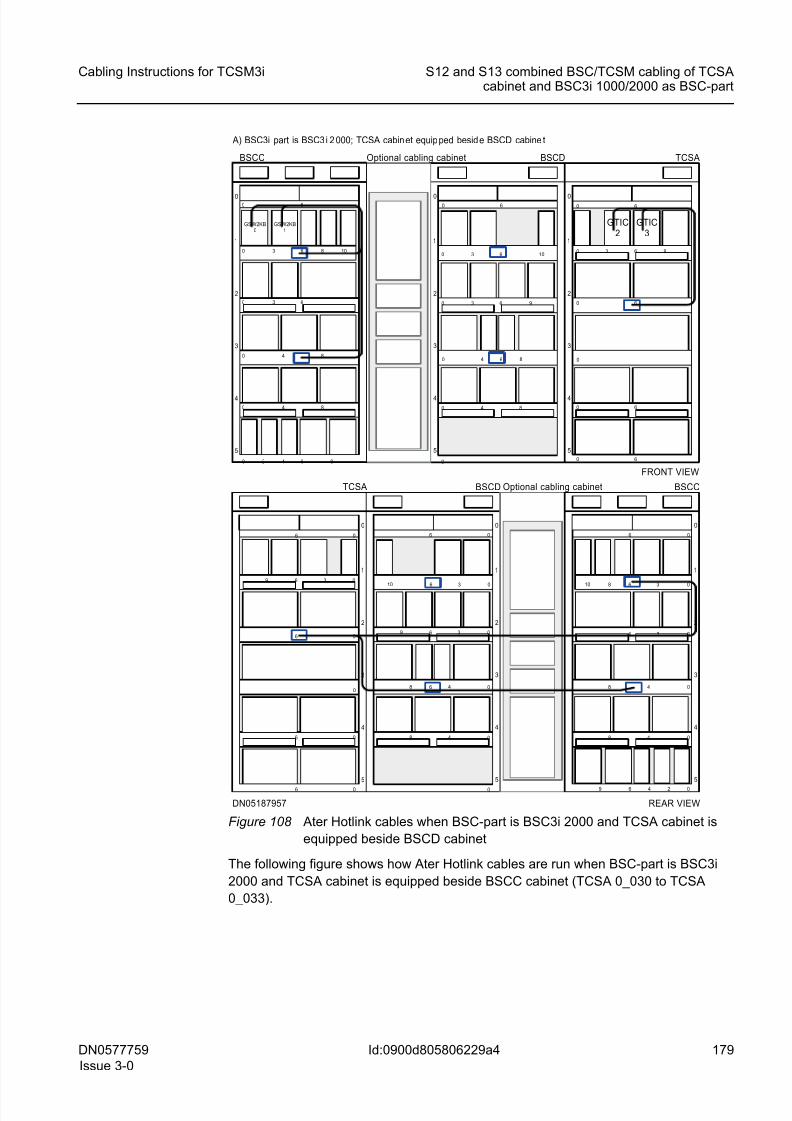
8/11/2019 NOKIA Flexi TRCM
http://slidepdf.com/reader/full/nokia-flexi-trcm 179/183
DN0577759
Issue 3-0
179
Cabling Instructions for TCSM3i S12 and S13 combined BSC/TCSM cabling of TCSAcabinet and BSC3i 1000/2000 as BSC-part
Id:0900d805806229a4
Figure 108 Ater Hotlink cables when BSC-part is BSC3i 2000 and TCSA cabinet is
equipped beside BSCD cabinet
The following figure shows how Ater Hotlink cables are run when BSC-part is BSC3i
2000 and TCSA cabinet is equipped beside BSCC cabinet (TCSA 0_030 to TCSA
0_033).
DN05187957
BSCD
5
4
3
2
1
060
0
4 80
4 80
30 6
10630
9
6
A) BSC3i part is BSC3 i 2 000; TCSA cabin et equip ped besid e BSCD cabine t
BSCD
5
4
3
2
1
0
6 0
0
48 0
48 0
3 06
10 6 3 0
9
6
5
4
3
2
0
6 0
0
06
1
6 3 0
6 0
0
6
9
TCSA
5
4
3
2
0
6 0
48 0
3 06
1
8 6 3 010
6 4 2 09
48 0
BSCC
FRONT VIEW
TCSA
5
4
3
2
060
0
0 6
1
630
60
0
6
9
GTIC2
GTIC3
BSCC
5
4
3
2
060
4 80
30 6
1
8630 10
6420 9
4 80
GSW2KB0
GSW2KB1
REAR VIEW
Optional cabling cabinet
Optional cabling cabinet
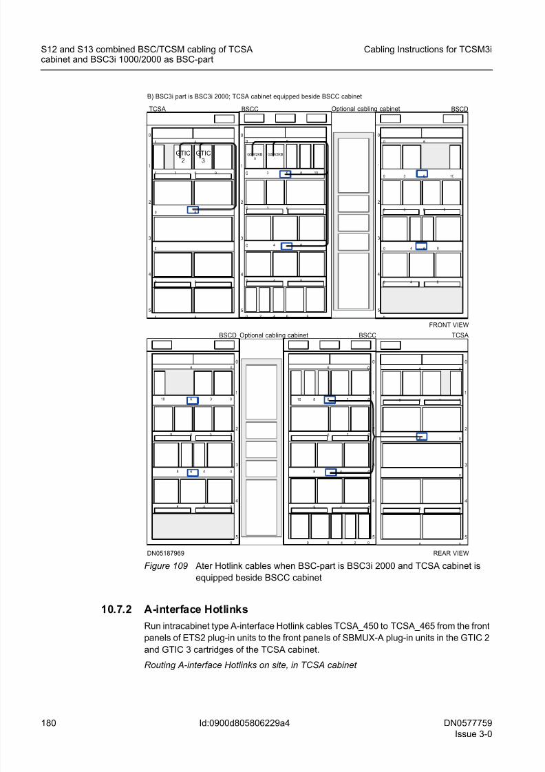
8/11/2019 NOKIA Flexi TRCM
http://slidepdf.com/reader/full/nokia-flexi-trcm 180/183
180 DN0577759
Issue 3-0
Cabling Instructions for TCSM3i
Id:0900d805806229a4
S12 and S13 combined BSC/TCSM cabling of TCSAcabinet and BSC3i 1000/2000 as BSC-part
Figure 109 Ater Hotlink cables when BSC-part is BSC3i 2000 and TCSA cabinet is
equipped beside BSCC cabinet
10.7.2 A-interface Hotlinks
Run intracabinet type A-interface Hotlink cables TCSA_450 to TCSA_465 from the front
panels of ETS2 plug-in units to the front panels of SBMUX-A plug-in units in the GTIC 2
and GTIC 3 cartridges of the TCSA cabinet.
Routing A-interface Hotlinks on site, in TCSA cabinet
DN05187969
B) BSC3i part is BSC3i 2000; TCSA cabinet equipped beside BSCC cabinet
FRONT VIEW
TCSA
5
4
3
2
060
0
0 6
1
630
60
0
6
9
GTIC2
GTIC3
BSCC
5
4
3
2
060
4 80
30 6
1
8630 10
6420 9
4 80
GSW2KB0
GSW2KB1
BSCD
5
4
3
2
1
060
0
4 80
4 80
30 6
10630
9
6
5
4
3
2
0
6 0
0
06
1
6 3 0
6 0
0
6
9
TCSABSCD
5
4
3
2
1
0
6 0
0
48 0
48 0
3 06
10 6 3 0
9
6
5
4
3
2
0
6 0
48 0
3 06
1
8 6 3 010
6 4 2 09
48 0
BSCC
REAR VIEW
Optional cabling cabinet
Optional cabling cabinet
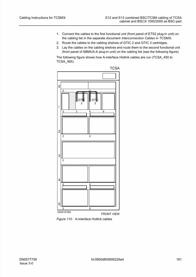
8/11/2019 NOKIA Flexi TRCM
http://slidepdf.com/reader/full/nokia-flexi-trcm 181/183
DN0577759
Issue 3-0
181
Cabling Instructions for TCSM3i S12 and S13 combined BSC/TCSM cabling of TCSAcabinet and BSC3i 1000/2000 as BSC-part
Id:0900d805806229a4
1. Connect the cables to the first functional unit (front panel of ETS2 plug-in unit) on
the cabling list in the saparate document Interconnection Cables in TCSM3i .
2. Route the cables to the cabling shelves of GTIC 2 and GTIC 3 cartridges.
3. Lay the cables on the cabling shelves and route them to the second functional unit(front panel of SBMUX-A plug-in unit) on the cabling list (see the following figure).
The following figure shows how A-interface Hotlink cables are run (TCSA_450 to
TCSA_465).
Figure 110 A-interface Hotlink cables
FRONT VIEWDN05187996
TCSA
5
4
3
2
060
0
0 6
1
630
60
0
6
9
GTIC2
GTIC3
8/11/2019 NOKIA Flexi TRCM
http://slidepdf.com/reader/full/nokia-flexi-trcm 182/183
182 DN0577759
Issue 3-0
Cabling Instructions for TCSM3i
Id:0900d8058032d746
Stowing away supplementary cable length
11 Stowing away supplementary cable lengthThis section describes the basic rules of efficiently dealing with supplementary cable
length.
11.1 Factors determining cable length
In Flexi BSC product family and TCSM3i network elements, the length of the cables is
usually appropriate. However, AL/CLK cables connected to the computer units must all
be of the same length, independent of where they connect inside the cabinet. Timing
loop cables and the corresponding timing bus cables must also be of the same length.
For this reason, many of them are too long.
11.2 Attaching supplementary cable lengthAttaching supplementary cable length
1. Attach any supplementary lengths of cable in loops and coils on the cable shelves.
Copper cables
Bending the cables more than recommended harms the cables.
Optical cables
Optical cables are more fragile than the copper cables and need to be handled care-
fully. Their self-bending radius must be respected. Do not therefore bend the cables
too tight when making the loops.
2. Within these limits, attach the cables in such a way as to minimise the area insidethe loop to prevent it from creating EMC disturbances, and if possible, attach the
loops horizontally on the cabling shelf.
!
Overbending the cables damages the cables and can detach or damage the con-
nectors. Do not bend cables to a radius smaller than the minimum radius of 7 x d
(where d is the diameter of the cable).
!
Do not overbend optical cables. The minimum bending radius for the cables is 65
mm (2.56 inches) during installation and 43 mm (1.69 inches) in static conditions.
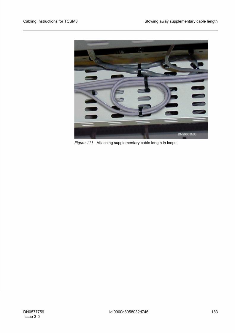
8/11/2019 NOKIA Flexi TRCM
http://slidepdf.com/reader/full/nokia-flexi-trcm 183/183
Cabling Instructions for TCSM3i Stowing away supplementary cable length
Figure 111 Attaching supplementary cable length in loops


![28662557 Nokia Flexi WCDMA Base Station Alarms and Troubleshooting BTS SW WN3 3[1]](https://img.pdfslide.us/doc/110x75/54faf26c4a795956048b4e7e/28662557-nokia-flexi-wcdma-base-station-alarms-and-troubleshooting-bts-sw-wn3-31.jpg)