Embed Size (px)
Citation preview
Student Guide
Noise, Vibration, and HarshnessNVH
SAFETY NOTICE
warnings cautions notes
warnings cautions
Notes
Cautions warnings
���������� �����������������

Noise, Vibration, and Harshness i
TABLE OF CONTENTSINTRODUCTION 1
OBJECTIVES 1
ACRONYMS 2
LESSON 1 EVALUATING NVH CONCERNS 5PRELIMINARY INFORMATION 5
Pre-road Test Inspection 7
Vehicle Road Test 8
Road Test Methods 9
Diagnostic Worksheet Page 1 10
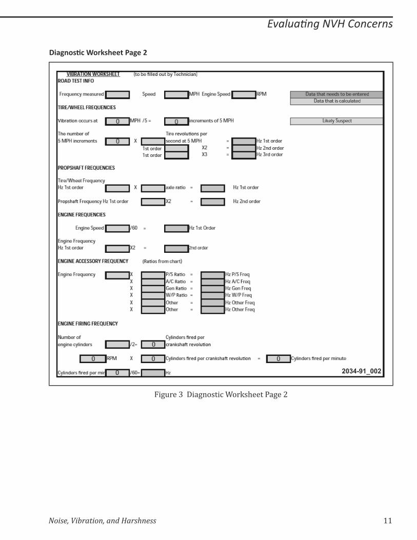
Diagnostic Worksheet Page 2 11
LESSON 2 DIAGNOSING WHEEL AND TIRE VIBRATION 13WHEELS AND TIRES 13
NVH TERMS AND THEORY 14
Vibration Order 15
Cycle 16
Frequency 17
Amplitude 18
Resonance 19
NVH MEASURING TOOLS 20
Sirometer 20
Electronic Vibration Analyzer (EVA) 21
MTS 4100 22
ROAD TESTING FOR RESULTS 23
Slow Acceleration Test 23
Neutral Coast Down Speed Test 23
Calculating Wheel and Tire Frequency 24
Frequency Related Component Group 25
Wheel and Tire Balance 26
Radial Force 27
Radial Force Variation 28
MEASURING WHEEL AND TIRE RUNOUT 29
System Radial Runout 30
Radial Runout 31
Lateral Tire Runout 32
������������������ ����������������������� ����� 35����������������� �������� ��� 35
Road Testing 36
ii Noise, Vibration, and Harshness
Slow Acceleration and Neutral Coast Down 36
Driveline Vibrations 37
Propeller Shafts 38
Propeller Shaft Runout 39
Calculating the Propeller Shaft Frequency 40
Driveline Operating Angles 42
Propeller Shaft Operating Angle 43
Measuring Operating Angles 44
Transmission Yoke Measurement 45
Propeller Shaft Measurement 46
Pinion Flange Measurement 47
�������������� �������� ��� 48
Engine-Speed Vibration 48
Engine Frequency Formula 49
First- and Second-order Engine Vibration 50
First-order Vibration 50
Torque Converter 50
Second-order Vibration 51
Half-order Engine Vibration 51
Engine Firing Frequency 51
Compelling Force of Exhaust 52
Engine Accessory Vibration 53
Calculating Engine Accessory Frequency 54
LESSON 4 DIAGNOSING NOISE 57GENERATION OF NOISE 57
Droning Noise 57
Tire Noise 58
Differential Noise 59
Growl Noise 60
Howl Noise 61
Road Testing 62
Telegraphing 63
Using the ChassisEAR 64
Attaching the Sensors 65
LESSON 5 HARSHNESS 67HARSHNESS 67
Suspension Components 67
������������������ 69

Noise, Vibration, and Harshness iii
GLOSSARY 71
������ 75�������� � ������ ��� 75
ROAD TEST METHODS 76
Road Test Tips 76
ROAD TESTING 76
Slow Acceleration Test 77
Neutral Coast Down Speed Test 77
Downshift Speed Test 77
Torque Converter Test 78
Steering Input Test 1 78
Steering Input Test 2 78
Neutral Run-up Test 79
Engine Loaded Test 79
Engine Accessory Test 80
���� �!������������!�������� 81
�����!������������!�������� 82
�������������� ������"#����� 84
Engine-speed Frequency 84
Engine Frequency 84
Engine Accessory Frequency 84
��!������������ ������"#����� 85
Vehicle Speed Frequency 85
Tire and Wheel Group 85
Propeller Shaft Group 86
Propeller Shaft Balancing 87
COMPLETE FORMULAS 88
Engine Vibration Formula 88
Engine Accessory Formula 88
Engine Firing Frequency Formula 88
Propeller Shaft Frequency Formula 88
SHORT FORMULAS 89
Engine Vibration Formula 89
Engine Accessory Formula 89
Engine Firing Frequency Formula 89
Propeller Shaft Frequency Formula 89

iv Noise, Vibration, and Harshness
Notes:
Noise, Vibration, and Harshness 1
INTRODUCTION
This training course focuses on how to use a systematic approach to diagnose and repair the root
cause of vehicle noise, vibration, and harshness (NVH) concerns.
$���%�&����'��*������'�%���%����+�����%�/��$����&����������&:���$������!�%��%����;�������������
problems to certain component groups. This course also provides the ability to apply the theory of
NVH to isolate a component as the cause.
The primary sources of NVH concerns are generated by the following component groups:
=� Tire and wheel
=� Driveline
=� Engine and torque converter
OBJECTIVES
Upon completion of this course, you will be able to:
=� Perform a pre-road test inspection
=� Identify road test methods
=� Identify NVH diagnostic tools
=� Apply diagnostic methods
=� Classify the symptoms of NVH concerns
=� Calculate component frequencies
=� ������>?����'�%���%�%�/'������
=� Troubleshoot and repair NVH concerns
=� Diagnose and repair wheel and tire vibrations
=� Diagnose and repair driveline-related vibrations
=� Diagnose and repair engine-related vibrations
2 Noise, Vibration, and Harshness
ACRONYMS
The following is a list of acronyms used throughout this publication:
=� ABS Anti-lock Brake System
=� AC Alternating Current
=� CPS Cycle per Second
=� CV Constant Velocity
=� DRBIII Diagnostic Readout Box Third Generation
=� DTC Diagnostic Trouble Code
=� EVA Electronic Vibration Analyzer
=� Hz Hertz
=� NVH Noise, Vibration, and Harshness
=� RFV Radial Force Variation
=� RPM Revolutions per Minute
=� SAE Society of Automotive Engineers
=� SB Service Bulletin

Noise, Vibration, and Harshness 3
Notes:

4 Noise, Vibration, and Harshness
Notes:

Noise, Vibration, and Harshness 5
������ ��������������
LESSON 1 EVALUATING NVH CONCERNS
PRELIMINARY INFORMATION
�������%$��%���;��$���������$��+�?�&��$�&����������%%&�����?������'�����$����>��/��������%������:?�
�$�����*�%��@�����J��*�������+�����+��$����!�%��%���K�� $�����*�%��@�����J��*�����/&���+������
/&%$���>��/���������'����:���>��/��$��%&���/��K���������/'����������Q��@��>��$��%��%�������%��������
��������/������;����@��������$��%����������&�����@$�%$��$���?/'��/���%%&�K��
=� ����$��%��%���������������*�$�%����'���;���+�����'���;�@���$��;������/'����&��X�
=� ������$��%��%�����%%&��@$����$��*�$�%������������;�������*��������'����%&�����&�>�%�X
$���/�?���Z&�������Q��+�����$�����*�%��@�����J��*��������J�����*��@��+��$�����*�%��$�����?��>�
�$��*�$�%�����������/�����>���?���$�����'�����@����'��>��/���>�����/������?/'��/�K����*��@���?�
��*�%���&��������[��\���������/�����>���?������������$���?/'��/�����%��:���:?��$��%&���/��K
��@�?���&'��%�����$��%��%����:�>��������/'���+����%����%����K���>�����&'��%����+��$��%&���/���
%��%����?�&�/&���*���>?��$��%��%����������������/���/�����>��'�������K��

6 Noise, Vibration, and Harshness
Notes:
Noise, Vibration, and Harshness 7
������ ��������������
����������� ��������
2034-91_092
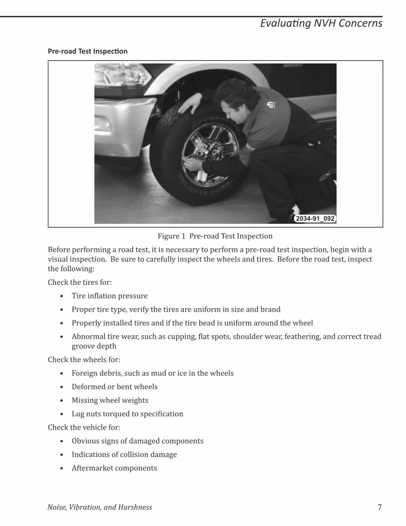
��+&���]�����^����� �������'�%����
��>����'��>��/��+������������;���������%�����?����'��>��/���'��^�������������'�%����;�:�+���@��$���
*��&������'�%����K������&������%���>&��?����'�%���$��@$��������������K����>�����$�����������;����'�%��
�$��>����@��+_
�$�%Q��$��������>��_
=� ��������������'����&��
=� ���'���������?'�;�*���>?��$������������&��>��/������`������:����
=� ���'���?����������������������>��$�������:�������&��>��/����&����$��@$���
=� �:���/��������@���;��&%$����%&''��+;�������'���;��$�&�����@���;�>���$����+;�����%����%��������
+���*����'�$
�$�%Q��$��@$�����>��_
=� �����+����:���;��&%$����/&������%������$��@$�����
=� ��>��/������:����@$����
=� j�����+�@$����@��+$��
=� �&+��&������Z&�������'�%���%�����
�$�%Q��$��*�$�%���>��_
=� �:*��&����+����>���/�+���%�/'������
=� ����%��������>�%�����������/�+�
=� �>���/��Q���%�/'������

8 Noise, Vibration, and Harshness
������ ��������������
Vehicle Road Test
�������������$�&���:��'��>��/������%�����/��$��%&���/���%��%���K���:���*���$��>����@��+�
+&���������@$���'��'����+�>����$�����������_
=� �$�%Q��$����'����������:�>����:�+�����+��$�����������K���������/'����������Q��@�@$�%$�
�'�%���%�%��%�����$��%&���/���$���@��$��$����*�$�%��K��
=� ���{��:��/������:?��$����'��������%�������>��$�����������*�:�������:�%�&����$��%�&���/�?�
�%�&���?�:���������$���������>��$��*�$�%��K
=� $��*�:�����+�%�/'������/�?����?�+�����������/����*�:�������:&���$����/����*�:�������/�?�
%�&��������+���*�:�����������������&�����%����%��@��$���$���%�/'������K
=� ����&%���$�����������������Z&�����������@$������>��?��&'��%����+��$�����������*�:����������
'����:��K�� $��������������+���&����������'��;���@����>��%�����K
=� ���/&���:��'����:�������'�������$��*�$�%�������$���'�������@$�%$��$��%����������%%&��K
=� &����$�������;��J�;�����$������:��@����>>�&�������$��%��%�������?��%%&���@$����$�������;�
�J�;����$�����������K
=� �����/����@$�%$�������Z&�'/���;��>���?;�����������>����$�����������K
=� ����%����@���$���%��/����;����@������%��%���:���$��%�&����>�������%�/'������K
=�
Noise, Vibration, and Harshness 9
������ ��������������
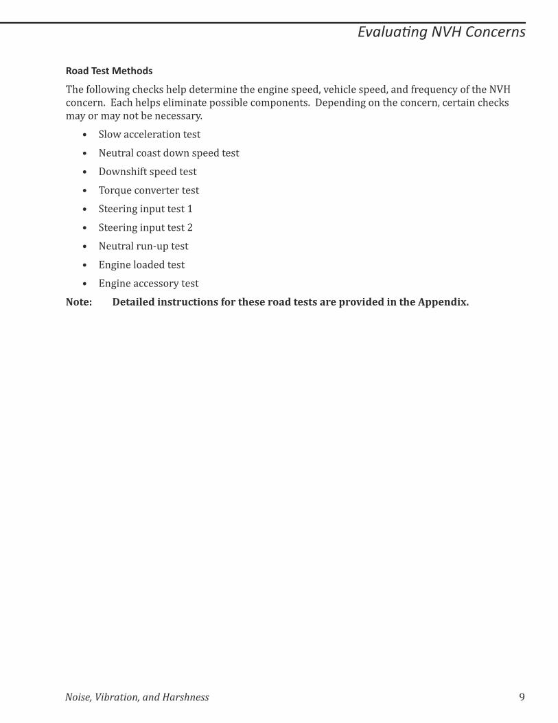
Road Test Methods
$��>����@��+�%$�%Q��$��'������/�����$����+�����'���;�*�$�%����'���;�����>��Z&��%?��>��$����!�
%��%���K����%$�$��'�����/������'����:���%�/'������K����'�����+�����$��%��%���;�%�������%$�%Q��
/�?����/�?�����:����%�����?K
=� ��@��%%��������������
=� ��&�����%�������@���'��������
=� ��@��$�>���'��������
=� ��Z&��%��*����������
=� ������+���'&�������]
=� ������+���'&�������|
=� ��&������&�^&'�����
=� ��+���������������
=� ��+�����%%�����?�����
Note: Detailed instructions for these road tests are provided in the Appendix.
]} Noise, Vibration, and Harshness
������ ��������������
�����������������������
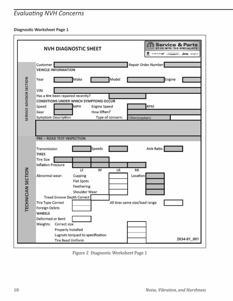
2034-91_001
��+&���|�����+�����%����Q�$������+��]
Noise, Vibration, and Harshness� ]]
������ ��������������
�����������������������
2034-91_002
��+&���~�����+�����%����Q�$������+��|

]| Noise, Vibration, and Harshness
Notes:
Noise, Vibration, and Harshness 13
����������������������������� ��
LESSON 2 DIAGNOSING WHEEL AND TIRE VIBRATION
WHEELS AND TIRES
Wheel-and tire-related vibrations occur at a relatively low frequency, typically 10–15 Hz. This can
result in a vibration experienced at speeds usually above 40 mph. Even a small amount of wheel
imbalance can translate into a vibration problem.
Tires wear faster than other components; as a result customers frequently replace original tires
with different types and sizes. When the tires are replaced, the wrong tire might be selected.
Some of the contributing factors to wheel and tire vibration can be:
=� Quality
=� Excessive runout
=� Non-uniformity
There are many sources of wheel and tire vibration some of the major sources are:
=� Wheel and tire imbalance
=� Condition of the wheels and tires
=� Foreign debris in wheel
=� Uniformity
=� Tire dimensions
=� Conicity
=� Radial force variation
=� Brake rotor
=� Constant velocity (CV) shaft
=� Hub
14 Noise, Vibration, and Harshness
����������������������������� ��
NVH TERMS AND THEORY
When diagnosing a vehicle with a vibration concern, you must be able to obtain the frequency
of the vibration. Diagnostic equipment is necessary to diagnose and repair NVH concerns. A
technician must be able to measure the frequency of the vibration, and relate the frequency of a
���������*�:�������������'�%���%�%�/'�����K��
In addition to using the diagnostic equipment, it is important that a technician clearly recognize
NVH theory and how it can be applied to identify the cause of a customer concern.
There are common characteristics of noise and vibration used to diagnose NVH concerns. The
following terms and graphics help explain how the frequency of a noise or vibration is used to
��������$�����������*�:�������������'�%���%�%�/'�����_
=� Order
=� Cycle
=� Frequency
=� Amplitude
=� Resonance
– Source
– Transfer path
– Responder
Noise, Vibration, and Harshness 15
����������������������������� ��
�������������
1
2
2034-91-003
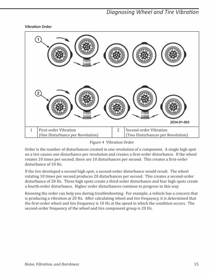
1 First-order Vibration
(One Disturbance per Revolution)
2 Second-order Vibration
(Two Disturbances per Revolution)
Figure 4 Vibration Order
Order is the number of disturbances created in one revolution of a component. A single high spot
����������%�&������������&�:��%��'�����*��&���������%��������������^����������&�:��%�K���>��$��@$����
��������]}���/���'�����%���;��$��������]}�����&�:��%���'�����%���K�� $���%��������������^������
disturbance of 10 Hz.
If the tire developed a second high spot, a second-order disturbance would result. The wheel
rotating 10 times per second produces 20 disturbances per second. This creates a second-order
disturbance of 20 Hz. Three high spots create a third-order disturbance and four high spots create
a fourth-order disturbance. Higher order disturbances continue to progress in this way.
Knowing the order can help you during troubleshooting. For example, a vehicle has a concern that
is producing a vibration at 20 Hz. After calculating wheel and tire frequency, it is determined that
�$�������^������@$�������������>��Z&��%?����]}�!`�����$���'�������@$�%$��$��%����������%%&��K�� $��
second-order frequency of the wheel and tire component group is 20 Hz.
16 Noise, Vibration, and Harshness
����������������������������� ��
�����
1 Cycle 2 Cycles 3 Cycles
1 Second
2034-91_004
Figure 5 Cycle
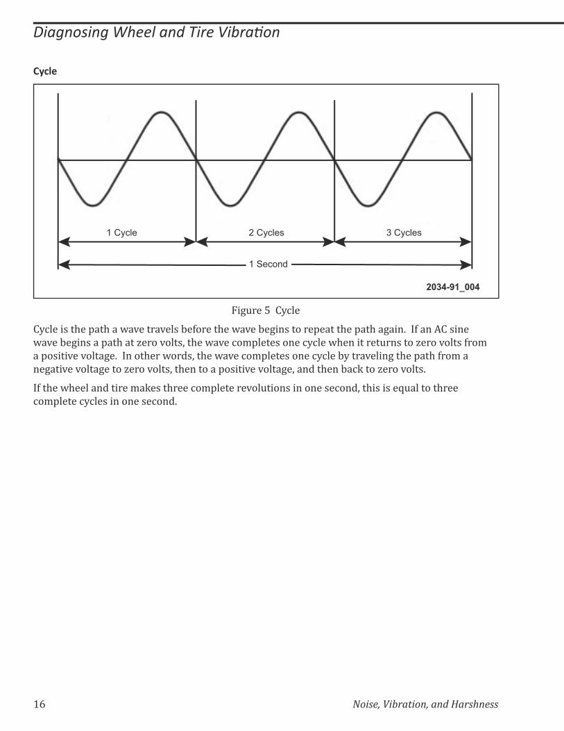
Cycle is the path a wave travels before the wave begins to repeat the path again. If an AC sine
wave begins a path at zero volts, the wave completes one cycle when it returns to zero volts from
a positive voltage. In other words, the wave completes one cycle by traveling the path from a
negative voltage to zero volts, then to a positive voltage, and then back to zero volts.
If the wheel and tire makes three complete revolutions in one second, this is equal to three
complete cycles in one second.
Noise, Vibration, and Harshness 17
����������������������������� ��
!��"#����
1 Second
1 2 3 4 5 6
2034-91_005
Figure 6 Frequency
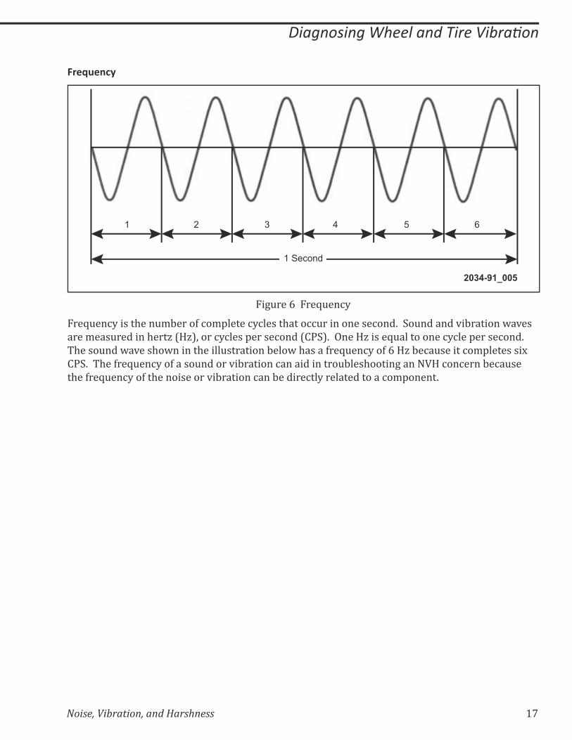
Frequency is the number of complete cycles that occur in one second. Sound and vibration waves
are measured in hertz (Hz), or cycles per second (CPS). One Hz is equal to one cycle per second.
The sound wave shown in the illustration below has a frequency of 6 Hz because it completes six
CPS. The frequency of a sound or vibration can aid in troubleshooting an NVH concern because
the frequency of the noise or vibration can be directly related to a component.

18 Noise, Vibration, and Harshness
����������������������������� ��
$%����#��
LowAmplitude
HighAmplitude
2034-91_006
Figure 7 Amplitude
Amplitude refers to the vertical measurement between the top and the bottom of a wave. Two
waves can have the same frequency, but differ in amplitude. Amplitude is the quantity or amount
of energy produced by a vibrating component. Amplitude determines how loud a noise is, or how
strong a vibration is.

Noise, Vibration, and Harshness 19
����������������������������� ��
&��������
6 7
45
1
2
3
2034-91_0070
5
10
15
20
20 40 60 80 100
1 Transfer Path 5 Compelling Force
2 Responder 6 Suspension Frequency
3 Source 7 Point of Resonance
4 Vibration Speed
Figure 8 Resonance
&��������
Resonance is the tendency of a system to respond to a compelling force oscillating at, or near, the
natural frequency of the system. All objects have natural frequencies and experience maximum
response at the point of resonance.
The natural frequency of a typical automotive front suspension is in the 10–15 Hz range. This
�������+����>������������$������+�%�������������K��������������$����+&��;��$���&�'������{�����&����
frequency is the same no matter what the vehicle speed. As the tire speed increases, along with
the vehicle speed, the disturbance created by the unbalanced tire increases in frequency.
Eventually, the frequency of the unbalanced tire intersects with the natural frequency of the
suspension, causing the suspension to vibrate. This intersection point is called the point of
resonance.
20 Noise, Vibration, and Harshness
����������������������������� ��
NVH MEASURING TOOLS
A technician must be able to use diagnostic equipment in order to measure the frequency of
a noise or vibration. A sirometer and several electronic tools are available for measuring and
recording noises and vibrations. Some of these tools have multiple vibration and noise inputs, as
well as recording and graphing capabilities.
'���%����
2034-91_008
Figure 9 Sirometer
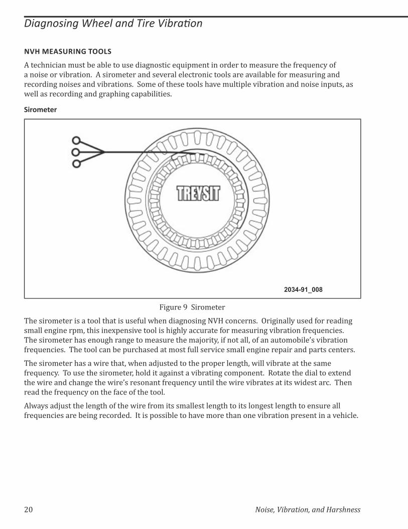
The sirometer is a tool that is useful when diagnosing NVH concerns. Originally used for reading
small engine rpm, this inexpensive tool is highly accurate for measuring vibration frequencies.
$������/�����$������&+$����+�����/���&����$��/������?;��>��������;��>�����&��/�:���{��*�:�������
frequencies. The tool can be purchased at most full service small engine repair and parts centers.
The sirometer has a wire that, when adjusted to the proper length, will vibrate at the same
frequency. To use the sirometer, hold it against a vibrating component. Rotate the dial to extend
�$��@��������%$��+���$��@���{�����������>��Z&��%?�&������$��@����*�:�������������@��������%K�� $���
read the frequency on the face of the tool.
Always adjust the length of the wire from its smallest length to its longest length to ensure all
frequencies are being recorded. It is possible to have more than one vibration present in a vehicle.

Noise, Vibration, and Harshness 21
����������������������������� ��
(�����������������$����)��*(�$+
2
37
6
54
9
8
1
2034-91_009
1 12V Power Extension 6 EVA
2 Power Supply 7 Strobe Light
3 Vibration Sensors 8 Inductive Pickup
4 Software Cartridge 9 Holding Strap
5 Magnet
Figure 10 EVA
The EVA allows for a systematic collection of information that is necessary to accurately
diagnose and repair NVH problems. The tool uses an electronic pick-up that measures vibration
frequency and amplitude. An additional pick-up can be added and two sources of vibrations can
be compared. The pick-ups can be placed anywhere on the vehicle. By placing the pick-up on
��>>�������������>��$��*�$�%�������%�/'����+��$��*�:������{���/'���&��;�������'��?�������$���%����;�
the source of the vibration can be located by the highest amplitude. If the steering wheel or
'�����+��{����������*�:�����+;��$��'�%Q^&'�%���:��'��%����$�������/���&����$��*�:������K
The EVA can record snapshots during a road test and the data replayed to determine the vibration
frequency. This is useful for intermittent or short duration vibrations.
$������$�����>���&������&���������&%��*��'�%Q^&'���/��+���+$�����*��&���?�����$���*�:�������
frequency. The operation manual for the tool describes how to use this feature to help in
���+�����+��$����%�������>���*�:������{����&�%�K�� $������$��+���/��+���+$��%���:��&�������:����%��
propeller shafts.

22 Noise, Vibration, and Harshness
����������������������������� ��
MTS 4100
1 2 3 4
5
6
789
11
10
2034-91_010
1 Photo Tachometer 7 AC/DC Adapter
2 Microphone 8 DC Power Cable
3 Microphone 9 RS 232 Cable
4 Accelerometer 10 MTS 4100
5 Accelerometer 11 Timing Light
6 OBDII Cable
Figure 11 MTS 4100
The MTS 4100 NVH Analyzer can help identify, isolate, and repair NVH concerns.
=� ���%�/'����������>��/�����������*�:���������������@��$�������:�������>��/��$��*�$�%��{��
engine and transmission controllers to match the vibrations or noises with their possible
sources.
=� It also includes a propeller shaft balancing function to assist in the repair phase of these
vehicles.
=� You can also use the MTS 4100 to record and replay test results both before and after
diagnostic procedures.

Noise, Vibration, and Harshness 23
����������������������������� ��
ROAD TESTING FOR RESULTS
To properly diagnose and repair NVH concerns, the concern will need to be duplicated during a
road test. The symptoms and facts surrounding the concern should be documented on the NVH
Diagnostic Worksheet. Proper questioning of the customer by service writer/advisor will usually
provide the information necessary to duplicate the concern.
Determine which test equipment is needed for the road test. If utilizing test equipment during a
road test, it is a best practice to have an assistant drive while the equipment is being monitored
and the results recorded on the NVH Diagnostic Worksheet.
WARNING: DURING A ROAD TEST, AN ASSISTANT SHOULD DRIVE WHILE THE EQUIPMENT IS BEING MONITORED AND THE RESULTS RECORDED ON THE NVH DIAGNOSTIC WORKSHEET.
WARNING: DO NOT SHUT THE ENGINE OFF DURING A ROAD TEST. THIS WILL CAUSE LOSS OF STEERING CONTROL AND BRAKING.
'��,$�������������
$�����@��%%�������������������$��������*�$�%���%$�%Q���������/�����$���'�������@$�%$������������
vibration occur. The steps of the slow acceleration test are:
1. Slowly accelerate the vehicle to the speed in which the problem occurs.
2. Note the vehicle speed and the engine rpm.
3. If possible, determine the frequency of the noise or vibration.
4. Record all results on the NVH Diagnostic Worksheet.
5. Classify the noise or vibration.
-�#�����������,�'�������
The neutral coast down speed test divides the possible causes of the noise or vibration into two
categories:
=� Vehicle-speed-related
=� Engine-speed-related
The steps of the neutral coast down speed test are:
1. Drive the vehicle at a speed higher than the speed in which the noise or vibration was
obvious in the slow acceleration test.
2. Place the vehicle in neutral and coast down through the speed where the concern occurs.
3. Classify the NVH concern as either vehicle-speed-related or engine-speed-related.
=� If the noise or vibration exists, then the concern is vehicle-speed-related. This eliminates
the engine and torque converter as possible causes.
=� If the NVH concern did not occur during the neutral coast down speed test, perform a
��@��$�>���'������������%�����/��$��%��%���������+���^�'���^�������K
24 Noise, Vibration, and Harshness
����������������������������� ��
����#����������������!��"#����
The NVH Diagnostic Worksheet contains the formulas required to calculate the frequencies for the
following component groups:
=� Wheel and tire
=� Driveline
=� Engine
=� Engine accessory
The NVH Diagnostic Worksheet will perform all the necessary calculations.
The formula and the steps required to calculate wheel and tire frequency manually is listed below.
8 km/h (5 mph) increments = vehicle speed/5
You can calculate wheel and tire frequency manually by performing the following steps:
1. Divide the vehicle speed by 5.
=� The resulting number indicates the number of 8 km/h (5 mph) increments
2. Obtain the corresponding tire size frequency at 8 km/h (5 mph).
=� This information is in a standard tire revolution chart located in the Appendix
3. Multiply the 8 km/h (5 mph) increment by the revolutions per second at 8 km/h (5 mph).
=� Wheel and tire frequency = tire size frequency x number of 8 km/h (5 mph) increments
Noise, Vibration, and Harshness 25
����������������������������� ��
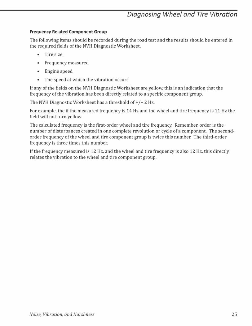
!��"#����&��������%������.��#�
The following items should be recorded during the road test and the results should be entered in
�$����Z&�������������>��$����!����+�����%����Q�$���K
=� Tire size
=� Frequency measured
=� Engine speed
=� The speed at which the vibration occurs
�>���?��>��$�������������$����!����+�����%����Q�$��������?����@;��$�������������%�������$����$��
>��Z&��%?��>��$��*�:�������$���:��������%��?���������������'�%���%�%�/'������+��&'K
The NVH Diagnostic Worksheet has a threshold of +/– 2 Hz.
For example, the if the measured frequency is 14 Hz and the wheel and tire frequency is 11 Hz the
������@���������&���?����@K
$��%��%&������>��Z&��%?�����$�������^������@$�������������>��Z&��%?K����/�/:��;�����������$��
number of disturbances created in one complete revolution or cycle of a component. The second-
order frequency of the wheel and tire component group is twice this number. The third-order
frequency is three times this number.
If the frequency measured is 12 Hz, and the wheel and tire frequency is also 12 Hz, this directly
relates the vibration to the wheel and tire component group.

26 Noise, Vibration, and Harshness
����������������������������� ��
�����������/������
2034-91_011
Figure 12 Wheel and Tire Balance
A wheel and tire that is out of balance will cause a vibration.
=� $���������/�+������$�����&���������:���@���'���������$����%�������>��$��@��+$�������$��@$����
and tire as it rotates
=� The second image represents how an imbalance will cause the wheel to wobble, which
can cause ride disturbances, usually vertical and lateral vibrations; it can also result in a
wobbling of the steering wheel
=� The third image demonstrates how ride disturbance usually increases with speed
Wheel and tire related vibrations are also caused by:
=� A wheel or tire that is out of round
=� �������>��%��*����������[���>>��'��������$������{������@���\�
=� Drive axle problems
=� Condition of the wheels and tires
=� Brake rotor or brake drum imbalance
=� Excessive hub runout
Noise, Vibration, and Harshness 27
����������������������������� ��
&�����!����
2034-91_012
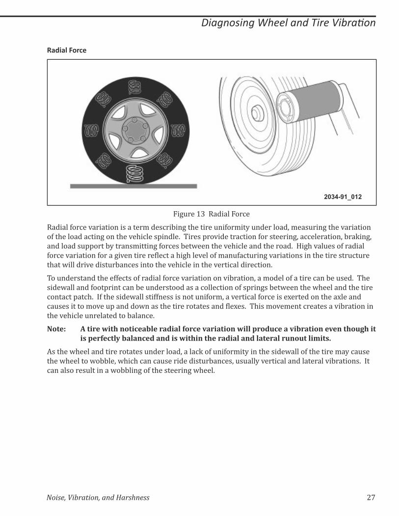
Figure 13 Radial Force
Radial force variation is a term describing the tire uniformity under load, measuring the variation
of the load acting on the vehicle spindle. Tires provide traction for steering, acceleration, braking,
and load support by transmitting forces between the vehicle and the road. High values of radial
>��%��*���������>�����+�*�������������%����$�+$���*����>�/��&>�%�&���+�*��������������$����������&%�&���
that will drive disturbances into the vehicle in the vertical direction.
To understand the effects of radial force variation on vibration, a model of a tire can be used. The
sidewall and footprint can be understood as a collection of springs between the wheel and the tire
contact patch. If the sidewall stiffness is not uniform, a vertical force is exerted on the axle and
%�&����������/�*��&'�������@������$�������������������������K�� $���/�*�/����%���������*�:����������
the vehicle unrelated to balance.
Note: A tire with noticeable radial force variation will produce a vibration even though it is perfectly balanced and is within the radial and lateral runout limits.
As the wheel and tire rotates under load, a lack of uniformity in the sidewall of the tire may cause
the wheel to wobble, which can cause ride disturbances, usually vertical and lateral vibrations. It
can also result in a wobbling of the steering wheel.
28 Noise, Vibration, and Harshness
����������������������������� ��
&�����!������������
2034-91_013
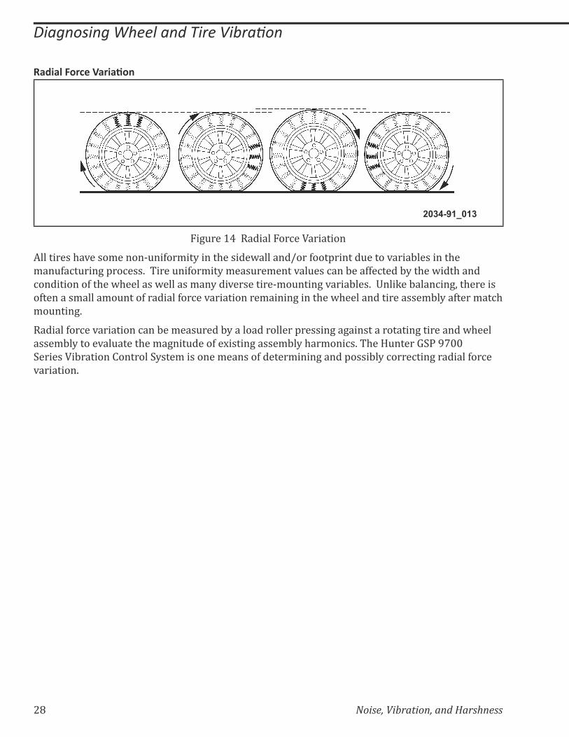
Figure 14 Radial Force Variation
All tires have some non-uniformity in the sidewall and/or footprint due to variables in the
manufacturing process. Tire uniformity measurement values can be affected by the width and
condition of the wheel as well as many diverse tire-mounting variables. Unlike balancing, there is
often a small amount of radial force variation remaining in the wheel and tire assembly after match
mounting.
Radial force variation can be measured by a load roller pressing against a rotating tire and wheel
assembly to evaluate the magnitude of existing assembly harmonics. The Hunter GSP 9700
Series Vibration Control System is one means of determining and possibly correcting radial force
variation.
Noise, Vibration, and Harshness 29
����������������������������� ��
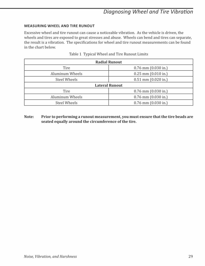
MEASURING WHEEL AND TIRE RUNOUT
Excessive wheel and tire runout can cause a noticeable vibration. As the vehicle is driven, the
wheels and tires are exposed to great stresses and abuse. Wheels can bend and tires can separate,
�$�����&��������*�:������K�� $���'�%���%�������>���@$��������������&��&��/���&��/�����%���:��>�&���
in the chart below.
Table 1 Typical Wheel and Tire Runout Limits
Radial RunoutTire 0.76 mm (0.030 in.)
Aluminum Wheels 0.25 mm (0.010 in.)
Steel Wheels 0.51 mm (0.020 in.)
Lateral RunoutTire 0.76 mm (0.030 in.)
Aluminum Wheels 0.76 mm (0.030 in.)
Steel Wheels 0.76 mm (0.030 in.)
Note: Prior to performing a runout measurement, you must ensure that the tire beads are seated equally around the circumference of the tire.
30 Noise, Vibration, and Harshness
����������������������������� ��
'����%&�����&#��#�
2034-91_014
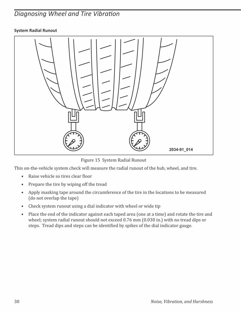
Figure 15 System Radial Runout
This on-the-vehicle system check will measure the radial runout of the hub, wheel, and tire.
=� ������*�$�%������������%����������
=� Prepare the tire by wiping off the tread
=� Apply masking tape around the circumference of the tire in the locations to be measured
(do not overlap the tape)
=� Check system runout using a dial indicator with wheel or wide tip
=� Place the end of the indicator against each taped area (one at a time) and rotate the tire and
wheel; system radial runout should not exceed 0.76 mm (0.030 in.) with no tread dips or
���'�K�� �������'���������'��%���:�������������:?��'�Q����>��$�����������%�����+�&+�K��
Noise, Vibration, and Harshness 31
����������������������������� ��
&�����&#��#�
21
3
2034-91_015
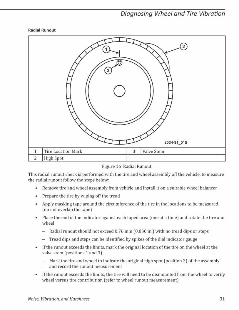
1 Tire Location Mark 3 Valve Stem
2 High Spot
Figure 16 Radial Runout
This radial runout check is performed with the tire and wheel assembly off the vehicle, to measure
the radial runout follow the steps below:
=� Remove tire and wheel assembly from vehicle and install it on a suitable wheel balancer
=� Prepare the tire by wiping off the tread
=� Apply masking tape around the circumference of the tire in the locations to be measured
(do not overlap the tape)
=� Place the end of the indicator against each taped area (one at a time) and rotate the tire and
wheel
– Radial runout should not exceed 0.76 mm (0.030 in.) with no tread dips or steps
– �������'���������'��%���:�������������:?��'�Q����>��$�����������%�����+�&+�
=� If the runout exceeds the limits, mark the original location of the tire on the wheel at the
valve stem (positions 1 and 3)
– Mark the tire and wheel to indicate the original high spot (position 2) of the assembly
and record the runout measurement
=� If the runout exceeds the limits, the tire will need to be dismounted from the wheel to verify
wheel versus tire contribution (refer to wheel runout measurement)
32 Noise, Vibration, and Harshness
����������������������������� ��
3���������&#��#�
2034-91_041
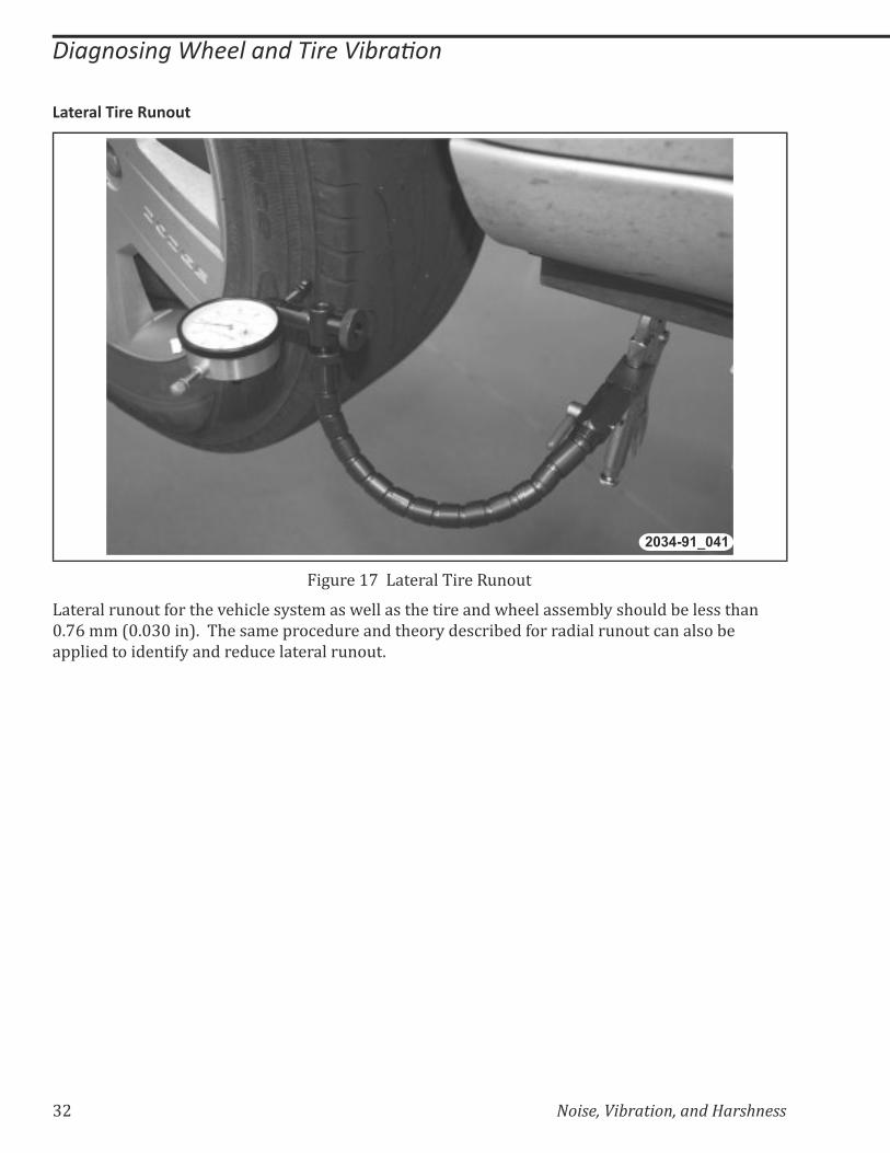
Figure 17 Lateral Tire Runout
Lateral runout for the vehicle system as well as the tire and wheel assembly should be less than
0.76 mm (0.030 in). The same procedure and theory described for radial runout can also be
applied to identify and reduce lateral runout.
Noise, Vibration, and Harshness 33
����������������������������� ��
�����&#��#�
2034-91_016
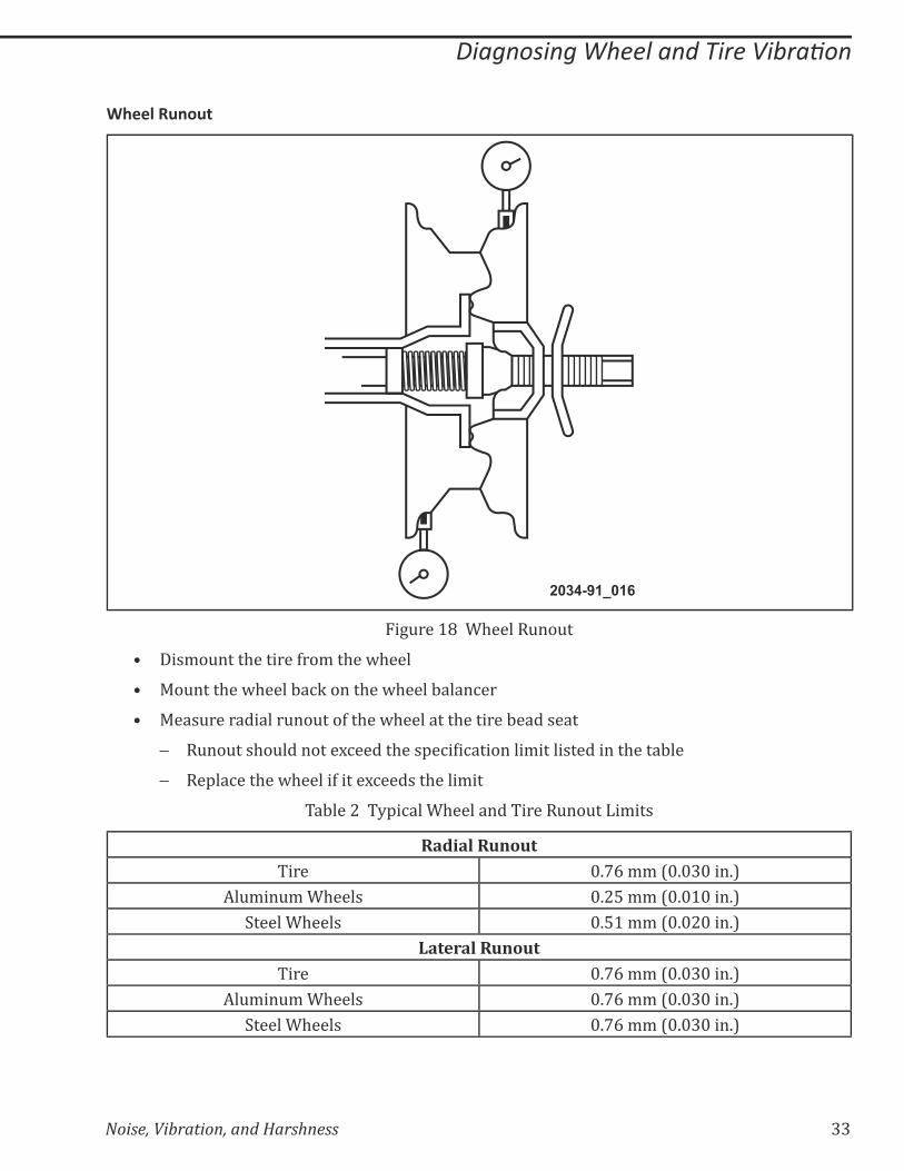
Figure 18 Wheel Runout
=� Dismount the tire from the wheel
=� Mount the wheel back on the wheel balancer
=� Measure radial runout of the wheel at the tire bead seat
– �&��&���$�&���������%�����$���'�%���%��������/��������������$����:��
– Replace the wheel if it exceeds the limit
Table 2 Typical Wheel and Tire Runout Limits
Radial RunoutTire 0.76 mm (0.030 in.)
Aluminum Wheels 0.25 mm (0.010 in.)
Steel Wheels 0.51 mm (0.020 in.)
Lateral RunoutTire 0.76 mm (0.030 in.)
Aluminum Wheels 0.76 mm (0.030 in.)
Steel Wheels 0.76 mm (0.030 in.)

34 Noise, Vibration, and Harshness
Notes:
Noise, Vibration, and Harshness 35
������������������������������������������ ���
LESSON 3 � $.-�' -.�& �(3 -(6$-�(-. -(6'�((�� /&$ �-'
�& �(3 -(6'�((�6&(3$(�� /&$ �-'
The process to diagnose and repair NVH concerns is consistent regardless of the component group
involved.
In this lesson we will focus on the following component groups:
=� Driveline
=� Engine
=� Engine accessory
Noise and vibration that occur during driving have various sources. During the initial vehicle road
test, different road test procedures are used to relate the symptoms into two groups. The two
groups are:
=� Engine-speed-related
=� Vehicle-speed-related
Using the frequency of the vibration and mathematical formulas, the cause of the noise or
vibration can be isolated into the following component groups:
=� Driveline
=� Wheel and tire
=� Engine
=� Engine accessory
36 Noise, Vibration, and Harshness
������������������������������������������ ���
&��������
��%$�����������'��%��&���%������/������'����:���%�/'�������������������$���?/'��/��������'�%���%�
component group. Depending on the concern, different road test procedures can be used to load
or unload the engine, torque converter, suspension, driveline, and wheel bearings. Depending on
the concern, certain checks may or may not be necessary.
Different road test procedures are used determine the conditions under which a noise or vibration
occurs. The following items should be monitored and recorded on the NVH diagnostic sheet.
=� Engine speed
=� Vehicle speed
=� Frequency of the noise or vibration
'��,$�������������-�#�����������,�
Slowly accelerate the vehicle to identify the speed at which a noise or vibration occurs. Continue
by using the neutral coast down to divide the possible causes of the noise or vibration into two
categories.
=� Vehicle-speed-related
=� Engine-speed-related
�>�����$��%��%���������������������:���+�*�$�%��^�'���^�������;��$��>��Z&��%?����+���>��$��*�:�������
can be used to relate the possible cause to the driveline or wheel and tire component group.
Noise, Vibration, and Harshness 37
������������������������������������������ ���
���7��������������
2034-91-017
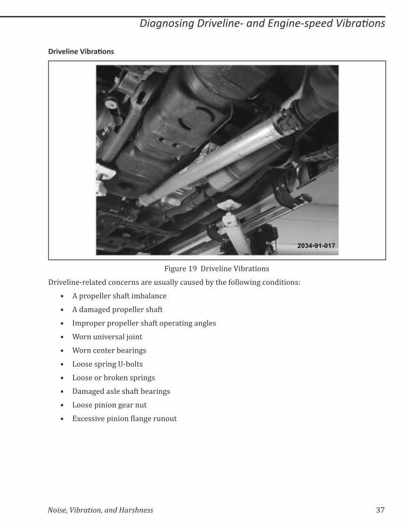
Figure 19 Driveline Vibrations
Driveline-related concerns are usually caused by the following conditions:
=� A propeller shaft imbalance
=� A damaged propeller shaft
=� Improper propeller shaft operating angles
=� Worn universal joint
=� Worn center bearings
=� Loose spring U-bolts
=� Loose or broken springs
=� Damaged axle shaft bearings
=� Loose pinion gear nut
=� ��%����*��'����������+���&��&�
38 Noise, Vibration, and Harshness
������������������������������������������ ���
���������'��8�
2034-91_018
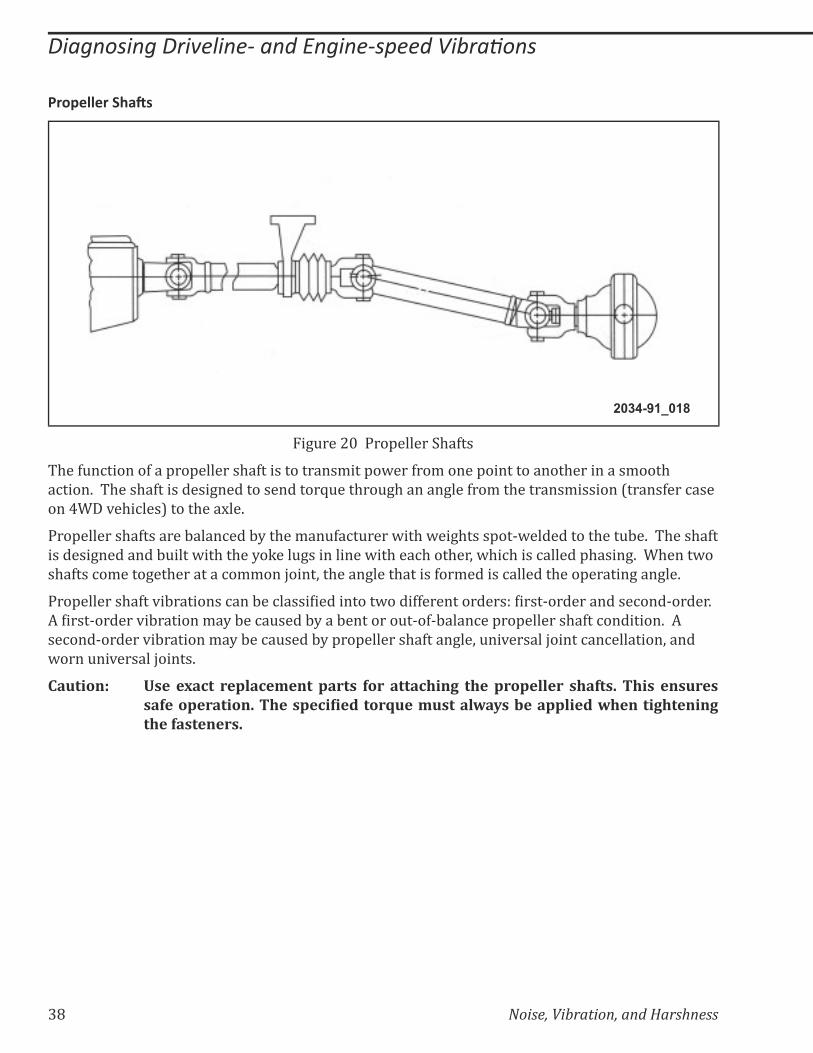
Figure 20 Propeller Shafts
The function of a propeller shaft is to transmit power from one point to another in a smooth
action. The shaft is designed to send torque through an angle from the transmission (transfer case
on 4WD vehicles) to the axle.
Propeller shafts are balanced by the manufacturer with weights spot-welded to the tube. The shaft
is designed and built with the yoke lugs in line with each other, which is called phasing. When two
shafts come together at a common joint, the angle that is formed is called the operating angle.
���'�������$�>��*�:��������%���:��%����������������@����>>������������_������^������������%���^�����K��
�������^������*�:�������/�?�:��%�&����:?���:��������&�^�>^:����%��'��'�������$�>��%��������K����
second-order vibration may be caused by propeller shaft angle, universal joint cancellation, and
worn universal joints.
Caution: Use exact replacement parts for attaching the propeller shafts. This ensures �����������������������!�"��#����$%��&%����'*�+��-�����'��#�*������0������0�the fasteners.
Noise, Vibration, and Harshness 39
������������������������������������������ ���
���������'��8&#��#�
1 2 32034-91_019
1 Front Measurement 3 Rear Measurement
2 Center Measurement
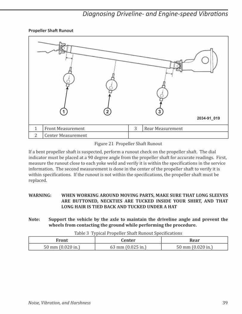
Figure 21 Propeller Shaft Runout
If a bent propeller shaft is suspected, perform a runout check on the propeller shaft. The dial
indicator must be placed at a 90 degree angle from the propeller shaft for accurate readings. First,
/���&����$���&��&��%����������%$�?�Q��@��������*���>?�������@��$����$���'�%���%�����������$�����*�%��
information. The second measurement is done in the center of the propeller shaft to verify it is
@��$����'�%���%������K���>��$���&��&���������@��$����$���'�%���%������;��$��'��'�������$�>��/&���:��
replaced.
WARNING: WHEN WORKING AROUND MOVING PARTS, MAKE SURE THAT LONG SLEEVES ARE BUTTONED, NECKTIES ARE TUCKED INSIDE YOUR SHIRT, AND THAT LONG HAIR IS TIED BACK AND TUCKED UNDER A HAT
����9�� �%������ ���� ;���!'�� -+� ���� �<'�� ��� &�������� ���� #��;�'���� ��0'�� ��#� ���;���� ����*���'�����&�!����!���0�����0��%�#�*��'��������&��0��������!�#%���
Table 3 ?'�%������'������$�>���&��&��'�%���%������
Front Center Rear50 mm (0.020 in.) 63 mm (0.025 in.) 50 mm (0.020 in.)

40 Noise, Vibration, and Harshness
������������������������������������������ ���
����#�����������������'��8!��"#����
The frequency range of a propeller shaft is usually 3 to 4 times the frequency of a component in
the wheel and tire component group. CV shafts and half shafts revolve at the same frequency as
the wheels and tires, which is usually in the range of 10–15 Hz at highway speeds. The frequency
of a propeller shaft vibration is usually in the range of 30–60 Hz at highway speeds.
Knowing the wheel and tire frequency allows for easy calculation of propeller shaft frequency.
The propeller shaft drives the tires through the rear axle. Therefore, to determine propeller shaft
frequency, multiply the wheel and tire frequency by the ratio of the rear axle.
The NVH diagnostic sheet will perform at the necessary calculations to determine the propeller
shaft frequency. Propeller shaft frequency can also be calculated manually by using the
mathematical formula below.
�����''������������$%��!+�>�����?*���'����$%��!+�<��<'�������
Calculate propeller shaft frequency by performing the following steps:
1. Obtain the axle ratio (the axle ratio can always be found on the VIP report)
2. Multiply the wheel and tire frequency by the rear axle ratio
For example:
Using the following information, we can calculate the propeller shaft frequency
=� A vehicle has a vibration concern when driving 40 mph
=� The rear axle ratio is 4.0:1
=� The wheel and tire frequency is 10 Hz
Multiply the wheel and tire frequency (10 Hz) with rear axle the ratio (4.0), the result is a
calculated frequency of 40 Hz.
Propeller shaft concerns can be in one of the following areas:
=� Damaged propeller shafts
=� Missing weights
=� Transmission or transfer case output shafts
=� �����������+���&��&�
=� Pinion bearing or pinion gear problems
=� Worn universal joints
=� Loose pinion gear nut
=� Improper operating angles
=� Pitch line runout

Noise, Vibration, and Harshness
Diagnosing Driveline- and Engine-speed Vibra ons
1
2034-91 091
42 Noise, Vibration, and Harshness
������������������������������������������ ���
���7�������������$�����
Driveline operating angle refers to the angle that is formed by the intersection of two shafts. The
procedure for measuring and correcting driveline operating angles depends on whether the
vehicle is equipped with a one- or two-piece propeller shaft.
Procedures for the one-piece systems should be understood before attempting to correct a
two-piece system. An inclinometer (Miller Tool # 7663) will be necessary to perform these
measurements.
The operating angle of a universal joint is the difference between the angles formed when two
shafts intersect. In a one-piece propeller shaft system, there are two operating angles present: the
front and the rear.
�����$��&��*����������������'��>��/�'��'���?;��$���'������+���+�����$�&���������%�����'�%���%������K��
Operating angles should not be equal to zero. With a zero operating angle, the needle bearings
within a universal joint will not rotate, causing brinelling and premature wear of the universal
joint.
����9�� �'*�+��&�@��&���%��&��������&�����������������#����&�������&����#���������;���!'��
Noise, Vibration, and Harshness 43
������������������������������������������ ���
���������'��8��������$����
21
2034-91_020
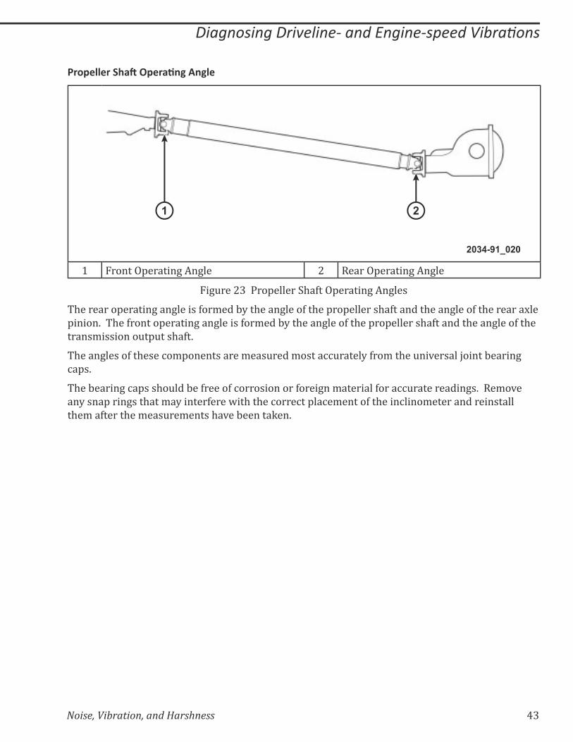
1 Front Operating Angle 2 Rear Operating Angle
Figure 23 Propeller Shaft Operating Angles
The rear operating angle is formed by the angle of the propeller shaft and the angle of the rear axle
pinion. The front operating angle is formed by the angle of the propeller shaft and the angle of the
transmission output shaft.
The angles of these components are measured most accurately from the universal joint bearing
caps.
The bearing caps should be free of corrosion or foreign material for accurate readings. Remove
any snap rings that may interfere with the correct placement of the inclinometer and reinstall
them after the measurements have been taken.
44 Noise, Vibration, and Harshness
������������������������������������������ ���
9���#������������$�����
23
45
1
2034-91_021
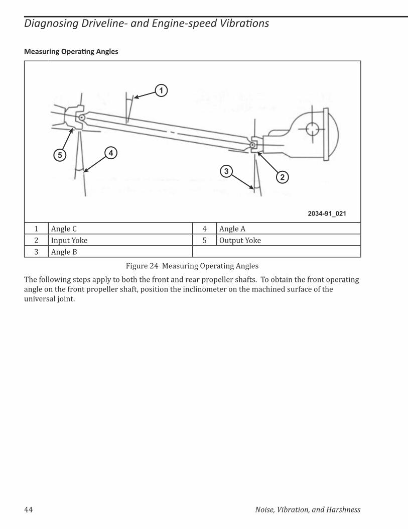
1 Angle C 4 Angle A
2 Input Yoke 5 Output Yoke
3 Angle B
Figure 24 Measuring Operating Angles
The following steps apply to both the front and rear propeller shafts. To obtain the front operating
angle on the front propeller shaft, position the inclinometer on the machined surface of the
universal joint.
Noise, Vibration, and Harshness 45
������������������������������������������ ���
����%������:���9���#��%���
2034-91_0022
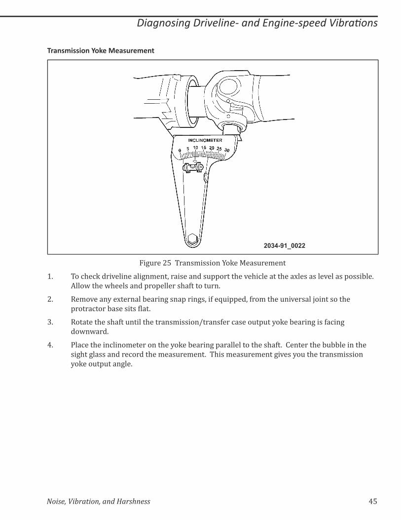
Figure 25 Transmission Yoke Measurement
1. To check driveline alignment, raise and support the vehicle at the axles as level as possible.
Allow the wheels and propeller shaft to turn.
2. Remove any external bearing snap rings, if equipped, from the universal joint so the
'�����%����:�������������K
3. Rotate the shaft until the transmission/transfer case output yoke bearing is facing
downward.
4. Place the inclinometer on the yoke bearing parallel to the shaft. Center the bubble in the
sight glass and record the measurement. This measurement gives you the transmission
yoke output angle.

46 Noise, Vibration, and Harshness
������������������������������������������ ���
���������'��89���#��%���
2034-91_0023
Figure 26 Propeller Shaft Measurement
5. Rotate the propeller shaft 90 degrees and place the inclinometer on the yoke bearing
parallel to the shaft. Center the bubble in the sight glass and record the measurement. This
measurement can also be taken at the rear of the shaft. This measurement gives you the
propeller shaft angle.
Noise, Vibration, and Harshness 47
������������������������������������������ ���
������!�����9���#��%���
2034-91_0024
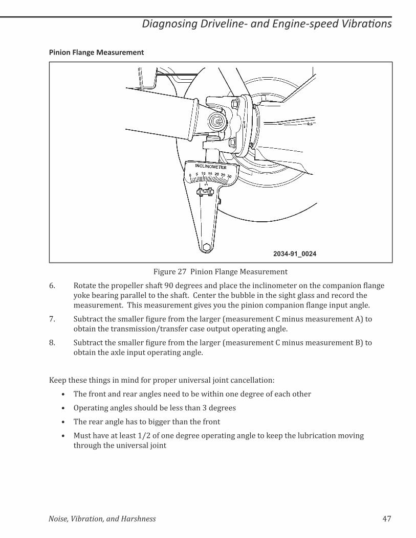
Figure 27 Pinion Flange Measurement
6. ��������$��'��'�������$�>���}���+���������'��%���$����%����/���������$��%�/'����������+��
yoke bearing parallel to the shaft. Center the bubble in the sight glass and record the
/���&��/���K�� $���/���&��/����+�*���?�&��$��'������%�/'����������+����'&����+��K
7. &:���%���$���/��������+&���>��/��$�����+���[/���&��/������/��&��/���&��/�����\����
obtain the transmission/transfer case output operating angle.
8. &:���%���$���/��������+&���>��/��$�����+���[/���&��/������/��&��/���&��/�����\����
obtain the axle input operating angle.
Keep these things in mind for proper universal joint cancellation:
=� The front and rear angles need to be within one degree of each other
=� Operating angles should be less than 3 degrees
=� The rear angle has to bigger than the front
=� Must have at least 1/2 of one degree operating angle to keep the lubrication moving
through the universal joint

48 Noise, Vibration, and Harshness
������������������������������������������ ���
(-. -(6'�((�6&(3$(�� /&$ �-'
(������'������������
2034-91_0025
Figure 28 Engine-speed Vibration
Engine-speed-related vibrations are caused by a component that is driven by the engine. These
components may be part of the engine assembly or an engine accessory.
Using the frequency of the vibration and mathematical formulas, the noise or vibration can be
isolated into these component groups:
=� Engine
=� Engine accessory
Noise, Vibration, and Harshness 49
������������������������������������������ ���
(�����!��"#����!��%#��
2034-91-026
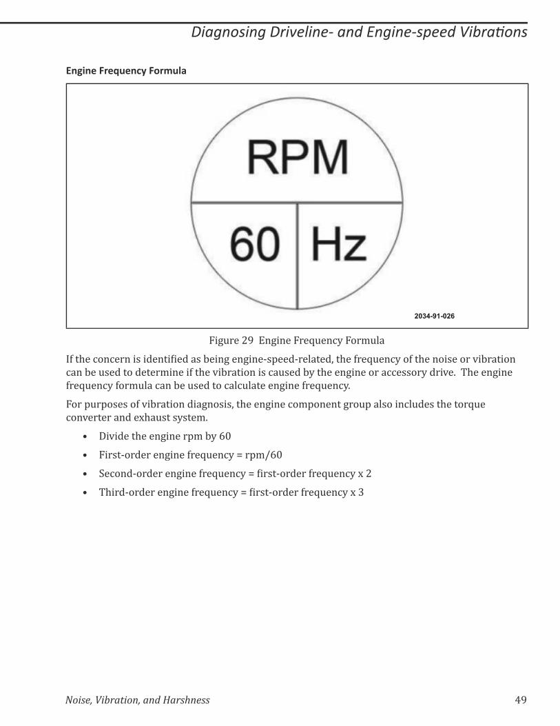
Figure 29 Engine Frequency Formula
�>��$��%��%���������������������:���+���+���^�'���^�������;��$��>��Z&��%?��>��$�����������*�:�������
can be used to determine if the vibration is caused by the engine or accessory drive. The engine
frequency formula can be used to calculate engine frequency.
For purposes of vibration diagnosis, the engine component group also includes the torque
converter and exhaust system.
=� Divide the engine rpm by 60
=� First-order engine frequency = rpm/60
=� �%���^��������+����>��Z&��%?��������^������>��Z&��%?���|
=� $���^��������+����>��Z&��%?��������^������>��Z&��%?���~
50 Noise, Vibration, and Harshness
������������������������������������������ ���
!��������'�����������(�������������
First- and second-order engine noise and vibration is generated by the reciprocating motion of the
pistons and the rotating mass of other engine components.
Some of the causes of these normal noises and vibrations include:
=� Combustion
=� Friction
Noises and vibrations are generated by the impact between reciprocating components. As the
pistons reciprocate, the clearance between parts is repeatedly pulled in alternating directions.
Noise and vibration are created as the gap between the moving parts cycle between tension and
compression. First- and second-order engine vibrations are usually detected during the neutral
run-up test.
!������������������
First-order vibration is created when any component that rotates at crankshaft speed is out
�>�:����%�����$�����%����*���&��&�K�����/'����������?@$����������Z&��%��*�������/:����%������
cylinder-to-cylinder mass differences. In rare cases, the crankshaft itself may be imbalanced.
Balancing the component or correcting the runout may bring the vibration to an acceptable level.
��"#����7�����
The torque converter frequency is the same as the engine frequency. The torque converter can
be suspected as the cause of noise or vibration when an NVH concern is torque sensitive. The
vibration may appear or disappear at different vehicle speeds, but may be present at the same
engine rpm.
For example, if a vehicle has a noise or vibration at 25 mph, 40 mph, and 65 mph, but is worse at
a particular speed, the NVH concern is probably torque sensitive because the condition occurs at
the same engine rpm but in a different gear. Use the torque converter test to determine how the
torque converter contributes to an engine-speed-related condition.

Noise, Vibration, and Harshness 51
������������������������������������������ ���
'�������������������
Second-order vibration is caused by the up-and-down motion of the pistons. This reversal of mass
and motion creates a natural vibration.
Symptoms of engine imbalance include:
=� A low-speed shake felt between 480 and 1,200 rpm that has a frequency of 8 to 20 Hz
=� A roughness sometimes felt and heard between 1,200 to 3,000 rpm at a frequency of 20 to
50 Hz
;��<������(�������������
A half-order engine vibration is created when any component that rotates at half the crankshaft
speed is out-of-balance or has excessive runout. An example of this is camshaft imbalance.
Balancing the component or correcting the runout may bring the vibration to an acceptable level.
(�����!�����!��"#����
�����+�>��Z&��%?���>��������$��>��%��%�������:?��$����+������%$���/����%?������������K�� $��>��%��
�>��$��%�/:&������%�����������'&���;�����@��$��$��%?�������������+���������;������&����*�:�������
���%������K�� $��$�+$����$������������+�������&����;��$��/����'��/�������$�������+�>��Z&��%?�
becomes. Vibrations also increase when the engine has a problem that interferes with the normal
combustion cycle.
��+���������+�>��Z&��%����%���%�&���%�/'�����������������������*�:����K�� $��*�:��������/'���&���
may increase with the accessories loaded. For example: if the engine mount is grounded, the
engine mount will create a transfer path for noise and vibration.
�>������!�%��%��������>>�%����:?������+�>��Z&��%?;����/�?�%�&����������%���������$���%�/'������
@$������'�%���%��'/�������%$��K�������+�>��Z&��%?�%��%�����&�&���?�$�*���������@��'/����+�K�� ��
'��*�����$��*�:��������%�������:?������+�'&�����>��/�:�%�/��+������!�%��%���;��$��*�:�������/&���
be isolated. Motor mounts are designed to minimize the amount of vibration that reaches the
passenger compartment.
?/'��/���>������+�>��Z&��%?���!�%��%�������%�&��_
=� Sensitivity to engine rpm
=� Sensitivity to torque
=� Sensitivity to engine load
=� Droning
52 Noise, Vibration, and Harshness
������������������������������������������ ���
��%�������!�����<(=��#��
2034-91_027
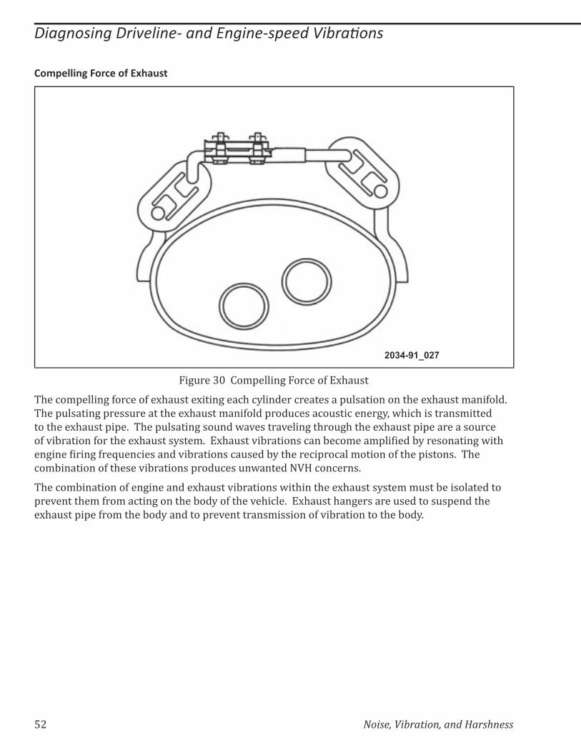
Figure 30 Compelling Force of Exhaust
The compelling force of exhaust exiting each cylinder creates a pulsation on the exhaust manifold.
The pulsating pressure at the exhaust manifold produces acoustic energy, which is transmitted
to the exhaust pipe. The pulsating sound waves traveling through the exhaust pipe are a source
�>�*�:�������>����$����$�&����?���/K����$�&���*�:��������%���:�%�/���/'�������:?����������+�@��$�
��+���������+�>��Z&��%��������*�:��������%�&����:?��$����%�'��%���/�������>��$��'������K�� $��
combination of these vibrations produces unwanted NVH concerns.
The combination of engine and exhaust vibrations within the exhaust system must be isolated to
prevent them from acting on the body of the vehicle. Exhaust hangers are used to suspend the
exhaust pipe from the body and to prevent transmission of vibration to the body.
Noise, Vibration, and Harshness 53
������������������������������������������ ���
(�����$����������������
2034-91-028
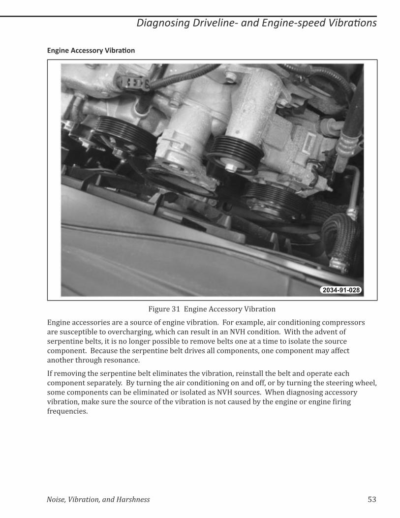
Figure 31 Engine Accessory Vibration
Engine accessories are a source of engine vibration. For example, air conditioning compressors
are susceptible to overcharging, which can result in an NVH condition. With the advent of
serpentine belts, it is no longer possible to remove belts one at a time to isolate the source
component. Because the serpentine belt drives all components, one component may affect
another through resonance.
If removing the serpentine belt eliminates the vibration, reinstall the belt and operate each
component separately. By turning the air conditioning on and off, or by turning the steering wheel,
some components can be eliminated or isolated as NVH sources. When diagnosing accessory
*�:������;�/�Q���&����$����&�%���>��$��*�:��������������%�&����:?��$����+���������+���������+�
frequencies.
54 Noise, Vibration, and Harshness
������������������������������������������ ���
����#�����(�����$��������!��"#����
Engine accessories produce vibrations at different frequencies than the engine itself. This is
because the drive ratio created by the different sized pulleys causes them to rotate at different
speeds. Accessory pulley misalignment or faulty components can also cause vibrations.
Determining engine accessory frequency is comparable to calculating driveline frequency.
The NVH diagnostic sheet contains the formula and will perform the necessary calculations to
determine the engine accessory frequency. Engine accessory frequency can also be calculated
using the mathematical formula below.
�!!�����+����$%��!+�>��!!�����+���&?XZ
Calculate engine accessory frequency by performing the following steps:
=� Determine the pulley ratio between the accessory pulley and the crankshaft pulley
=� Multiply the engine rpm where the NVH condition occurs by the pulley ratio
– Accessory rpm = engine rpm x pulley ratio
=� Divide the accessory rpm by 60 (the number of seconds in a minute)

Noise, Vibration, and Harshness 55
Notes:

56 Noise, Vibration, and Harshness
Notes:
Noise, Vibration, and Harshness 57
Diagnosing Noise
LESSON 4 DIAGNOSING NOISE
GENERATION OF NOISE
Whenever a vehicle is in motion, the driveline produces sounds that can be a normal part of
operation. A vehicle may also produce sounds that may indicate a repair may be required.
�&���/����%�����/���/���������$����&�����:��%�����:��;���+���������>�@$��$�����������$����������
abnormal condition. Some of the different types of noises are:
=� Road noise
=� ������+
=� ���@�
=� Whine
=� !�@�
Droning Noise
������+�%����%%&��@$����%%��������+;���%��������+;�������*��+������%���������'���;�:&��/�����>����
�%%&���@$����%%��������+K��������+�&�&���?�����''������������'�%���%���+�����'�������*�$�%����'���K��
�$��������������+���*�$�%���@��$���������+�%��%���;��$��������/�?��%%&��������'�%���%�*�$�%���
�'���;������+�����'/;�?�&��$�&���%$��+��*�$�%����'����*��?����@�?K���$��+��+�*�$�%����'����
Z&�%Q�?�/�Q��������>��%&������%$�%Q��$��������+�:�%�&�����+�����'����'�������$��&+$��$���'�%���%�
���+������Z&�%Q�?K
#�'��������������+�%����%%&��@$�����+�����������*������*�:�����������������/����������$��:��?�
�>��$��*�$�%���%�&���+���������������K������%������;���������Q�;�������$�&����������%���%�/:��������
%�&���������+�����$��'�����+���%�/'���/���K��
A drone noise can be caused by a transfer path created by:
=� ��������+��&������&����+����/�&���
=� ����/�+������+��&������&����$�&����?���/
A drone noise can also be caused by:
=� Imbalanced or bent propeller shaft
58 Noise, Vibration, and Harshness
Diagnosing Noise
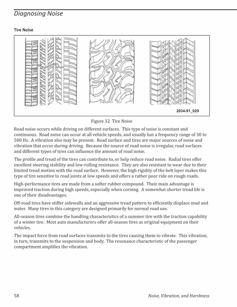
Tire Noise
2034-91_029
��+&���~|��Tire Noise
������������%%&���@$�������*��+������>>�������&�>�%��K�� $����?'���>����������%������������
%�����&�&�K�������������%����%%&���������*�$�%����'����;�����&�&���?�$�����>��Z&��%?����+���>�~}����
�}}�!`K����*�:������������/�?�:��'������K��������&�>�%����������������/�������&�%����>�����������
*�:��������$����%%&���&���+����*��+K����%�&����$����&�%���>�������������������+&���;�������&�>�%���
������>>�������?'����>�������%�������&��%���$���/�&����>�����������K��
$��'������������������>��$��������%���%�����:&�����;����$��'����&%������������K����������������>>���
��%��������������+����:����?�������@^������+���������%�K�� $�?�����������������������@�����&������$����
��/�����������/������@��$��$��������&�>�%�K��!�@�*��;��$��$�+$���+����?��>��$��:������?���/�Q����$���
�?'���>�������������*����������������������@��'����������>>���������$���'��������������&+$������K��
!�+$^'��>��/��%������������/����>��/�����>�����&::���%�/'�&��K�� $����/������*����+�����
�/'��*������%������&���+�$�+$��'����;���'�%����?�@$���%�����+K������/�@$����$��������������>�����
�����>��$���������*����+��K
�>>^�����������$�*�����>>�������@�������������++�����*��������'�����������>��%�����?����'��%��/&������
@����K��j��?�����������$���%���+��?���������+����'��/����?�>������/��������&��K��
���^�������������%�/:�����$��$������+�%$���%�������%���>����&//��������@��$��$�����%�����%�'�:����?�
�>���@����������K��j�����&���/��&>�%�&������>>������^�������������������+������Z&�'/��������$����
vehicles.
$���/'�%��>��%��>��/�������&�>�%��������/��������$��������%�&���+��$�/����*�:����K�� $���*�:������;�
����&��;������/��������$���&�'�����������:��?K�� $���������%��%$���%�������%��>��$��'�����+���
%�/'���/�����/'��������$��*�:������K
Noise, Vibration, and Harshness 59
Diagnosing Noise
��>�������-����
����>>���������'���&%�����%��������/�&����>������K���������/'��;� ���^�����������/�?�'���&%����
���+$��%$�������&���+���@��'�����&���;�@$�%$�������$��+�/�����$����$��%�&�%$�������+��$������:K�����
������+�@��$��$����%��%����;��������/'����������&���������������/���%���������������'������������$��
customer in terms they can understand.
$���������$����/�����?'����>�����������_�
=� !�@�
=� ���@�
=� Whine
��%$��?'���>���������������������%$�%Q��+���>>�������$��+�K��
��/'���������$����$����$�������%���%�&�����������$���/�?����/�����$����>>�������������$��%�&��;�
�&%$�����$��������$�����*�����;��$����+���;���$�&��;��&�'������;�:��?;�������$���K��������/'����>�
�$��������$�&��������;�@$�%$�%��������?�:��%��>&����@��$�+����@$���;�:&��%���:��$�����@$�����$��
*�$�%���������������?K�����/����%����;���$�@������$����+���>����&��&��%��%��������������+�%�/'������;�
��+��@��/�?�'����������:���:�����+;�������@$��������%�������+�������&�K
��>>���������������/�?�:������%��������>>������*�$�%��������+�����'����K������������������/�?������
�%%&���&���+���>>�����������������+�%���������;�>������/'��_
=� ��+$�����*��+
=� !��*?����*��+
=� Cruise
=� Coast
Note: It is important to understand that all gears make noise. Axle noises are inherent. When a noise is perceived as a concern, by the customer, it becomes an issue that requires further investigation.

�} Noise, Vibration, and Harshness
Diagnosing Noise
.��,�-����
2034-91_030
��+&���~~�������������+�
�>���+��@�����������+���������:?��$������;����/�?�:��%�&����:?��$��%����%���&�>�%���>��$��:�����+��
@��$����$����>>��������K�� $��������/�?��%%&��@$����$���&�>�%���>��$�������:�����+�����$����%��
:�%�/�����&+$K����+��@��������@��������������%����������$���������/'����&�������������/�?���%������
����$��:�����+�%$��+����*�����/�K����+��@������������>������@����>��Z&��%?�����%�������������������?K��
��+��@��������@�����%%&���$��&+$������'�������+��K���/���>��$��%�/'��������$���/�?�+����������
+��@�����������_
=� ��>>���������%����:�����+�
=� �������:�����+�
=� �&����������$�>��:�����+�
���>��/��+�*����&���&���;��%%��������+;������%��������+��&���+��$���������������������$����>>������
:�����+��/�?��������������+�����+��$��%�&����>��$��%��%���K��
Noise, Vibration, and Harshness 61
Diagnosing Noise
;�,�-����
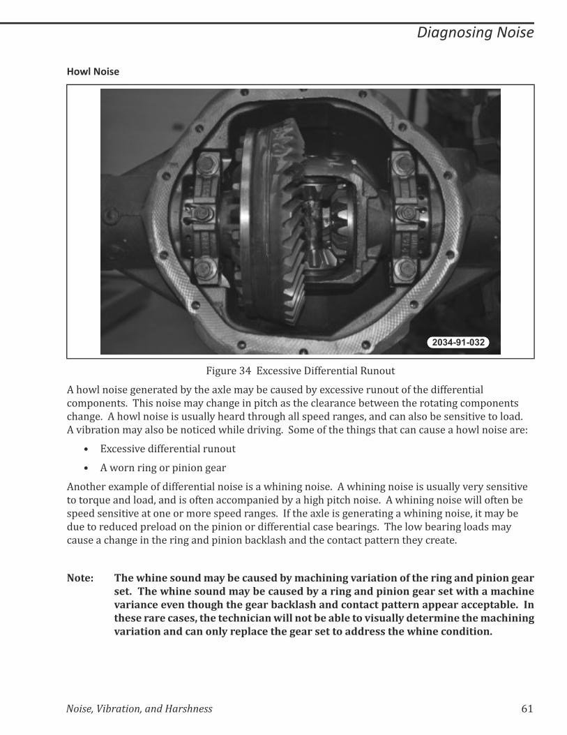
2034-91-032
��+&���~�����%����*����>>����������&��&�
��$�@��������+���������:?��$�������/�?�:��%�&����:?���%����*���&��&���>��$����>>���������
%�/'������K�� $���������/�?�%$��+�����'��%$�����$��%������%��:��@�����$���������+�%�/'�������
%$��+�K����$�@�����������&�&���?�$������$��&+$������'�������+��;�����%��������:���������*���������K��
��*�:�������/�?������:������%���@$�������*��+K���/���>��$���$��+���$���%���%�&�����$�@�����������_
=� ��%����*����>>����������&��&��
=� ��@�������+����'������+���
����$������/'����>���>>��������������������@$����+������K����@$����+����������&�&���?�*��?��������*��
������Z&����������;���������>�����%%�/'������:?���$�+$�'��%$������K����@$����+�������@�����>����:��
�'�����������*������������/�����'�������+��K���>��$����������+��������+���@$����+������;����/�?�:��
�&��������&%���'�����������$��'�����������>>���������%����:�����+�K�� $����@�:�����+�������/�?�
%�&�����%$��+������$�����+�����'������:�%Q���$������$��%����%��'��������$�?�%�����K��
Note: The whine sound may be caused by machining variation of the ring and pinion gear set. The whine sound may be caused by a ring and pinion gear set with a machine variance even though the gear backlash and contact pattern appear acceptable. In these rare cases, the technician will not be able to visually determine the machining variation and can only replace the gear set to address the whine condition.
�| Noise, Vibration, and Harshness
Diagnosing Noise
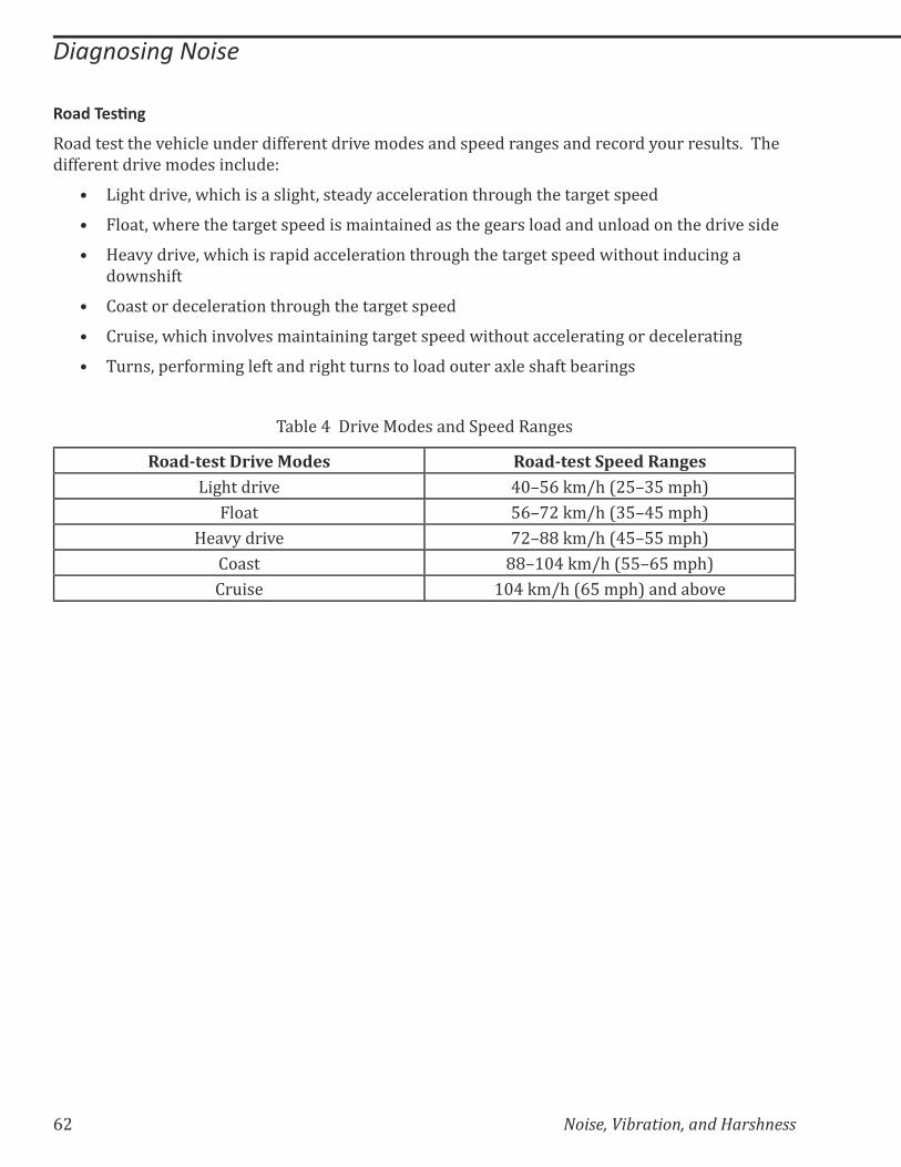
&��������
�����������$��*�$�%���&�������>>���������*��/����������'�������+���������%����?�&�����&���K�� $��
different drive modes include:
=� ��+$�����*�;�@$�%$���������+$�;������?��%%�����������$��&+$��$�����+����'���
=� �����;�@$�����$�����+����'�������/��������������$��+��������������&����������$�����*������
=� !��*?����*�;�@$�%$������'����%%�����������$��&+$��$�����+����'����@��$�&�����&%��+���
��@��$�>�
=� �����������%�����������$��&+$��$�����+����'����
=� ��&���;�@$�%$���*��*���/���������+����+����'����@��$�&���%%��������+������%��������+
=� &���;�'��>��/��+���>��������+$���&�������������&����������$�>��:�����+�
�:���������*��j���������'�������+��
Road-test Drive Modes Road-test Speed Ranges��+$�����*� �}����Q/J$�[|��~��/'$\
Float ����|�Q/J$�[~�����/'$\
Heavy drive �|����Q/J$�[������/'$\
Coast ���]}��Q/J$�[������/'$\
Cruise ]}��Q/J$�[���/'$\������:�*�

Noise, Vibration, and Harshness� �~
Diagnosing Noise
�����������
$����������/���@$�������������&��������$�&+$�������%�/��+�>��/���������;�@$����������%�&���?�
produced by a component in a different area of the vehicle.
$����*���'/�����>����/��������������������+���������:�+����@$�����*�:��������>�����%�/'������
%�/������%����%��@��$�����$���%�/'�����K���$����$���$�''���;�����������>�%&�������@$�����$��
�����+���*�:�����������������%%&���@$�����$���������&�%���>������%�'�������%�K��
$���$���������%�����������%$��%��������>>�%��*��?����+������$�����?'����>�%��%����K���������/'����
����%$��%����%�������%$������>��$��%��/'�������>&�������;��������%���;������$��>&������������$��������>�
�$��*�$�%��K�� $��������%�&����:?��$������%�����������+��'$����$��&+$��$��>&�������;�:&�������&��������
�$������%���K�� $���$�������������@������%$��%��������@��%$�:��@���������$����%$�����������������>?�
�$��>&�������%��������$����&�%���>��$�������K
�� Noise, Vibration, and Harshness
Diagnosing Noise
?��������������($&
2034-91_033
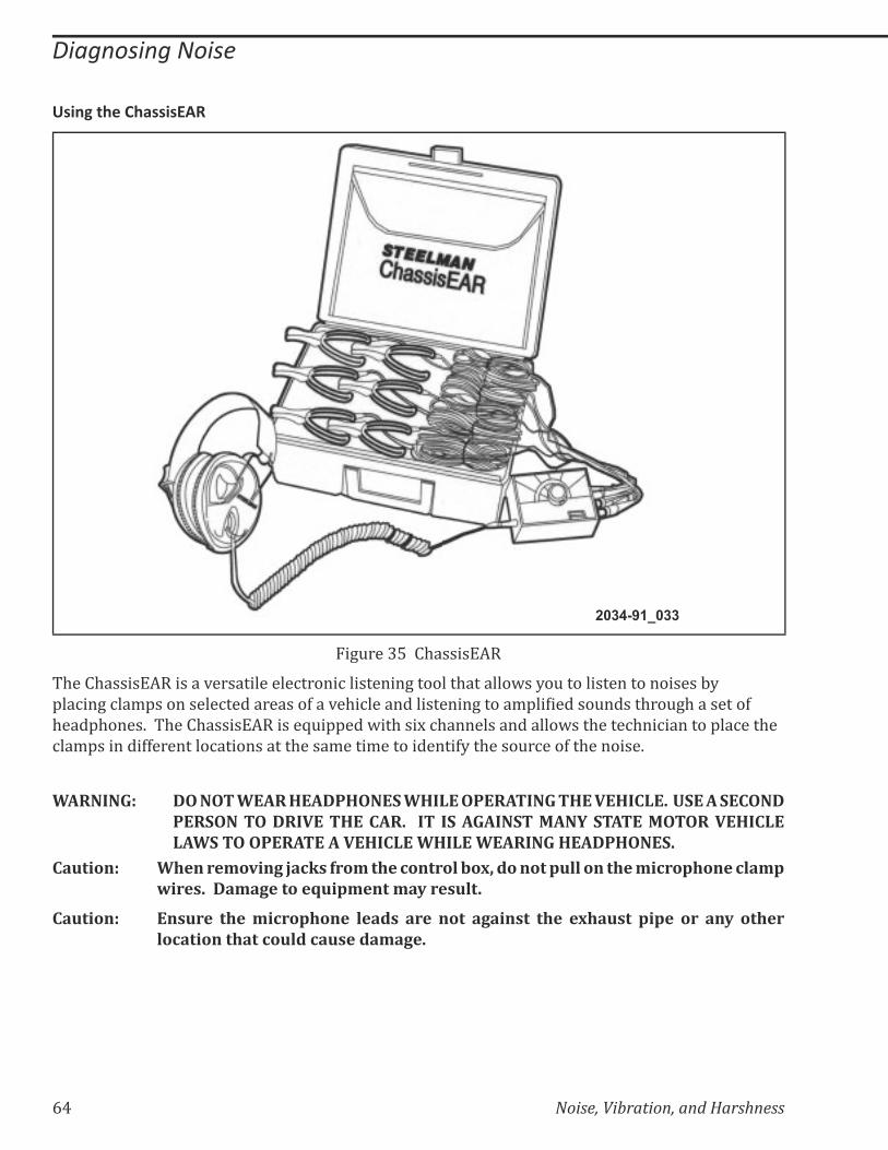
��+&���~���ChassisEAR
$���$��������������*������������%�����%���������+�������$�������@��?�&���������������������:?�
'��%��+�%��/'���������%�����������>���*�$�%���������������+�����/'���������&�����$��&+$��������>�
$���'$����K�� $���$�������������Z&�''���@��$�����%$���������������@���$����%$��%�������'��%���$��
clamps in different locations at the same time to identify the source of the noise.
WARNING: DO NOT WEAR HEADPHONES WHILE OPERATING THE VEHICLE. USE A SECOND PERSON TO DRIVE THE CAR. IT IS AGAINST MANY STATE MOTOR VEHICLE LAWS TO OPERATE A VEHICLE WHILE WEARING HEADPHONES.
Caution: When removing jacks from the control box, do not pull on the microphone clamp wires. Damage to equipment may result.
Caution: Ensure the microphone leads are not against the exhaust pipe or any other location that could cause damage.
Noise, Vibration, and Harshness 65
Diagnosing Noise
$@���������'������
����%$/�����>��$��������������%�����������%$��%���������%����/��?���>��%&��^��^���+�����
%�/'������K���&���+������������;�/��?�%�/'��������������/�Q���$����/������������@$����$��
*�$�%�����������$����K�� ���%%&�����?����+��������&����^*�$�%���'��:��/;��'�������$��*�$�%�������$��
@$���������:�����+������&�����>&�������K��
Some of these components include:
=� �$����:�����+�
=� ���Q��%���'���
=� ���������
=� ���>�����%�����'���+�
=� Differential
=� Transmission
=� �&�������%����
=� Generator
=� Water pump
=� ��@����������+�'&/'
=� �J��%�/'�������

66 Noise, Vibration, and Harshness
Notes:
Noise, Vibration, and Harshness 67
Harshness
LESSON 5 HARSHNESS
HARSHNESS
Suspension Components
2034-91-034
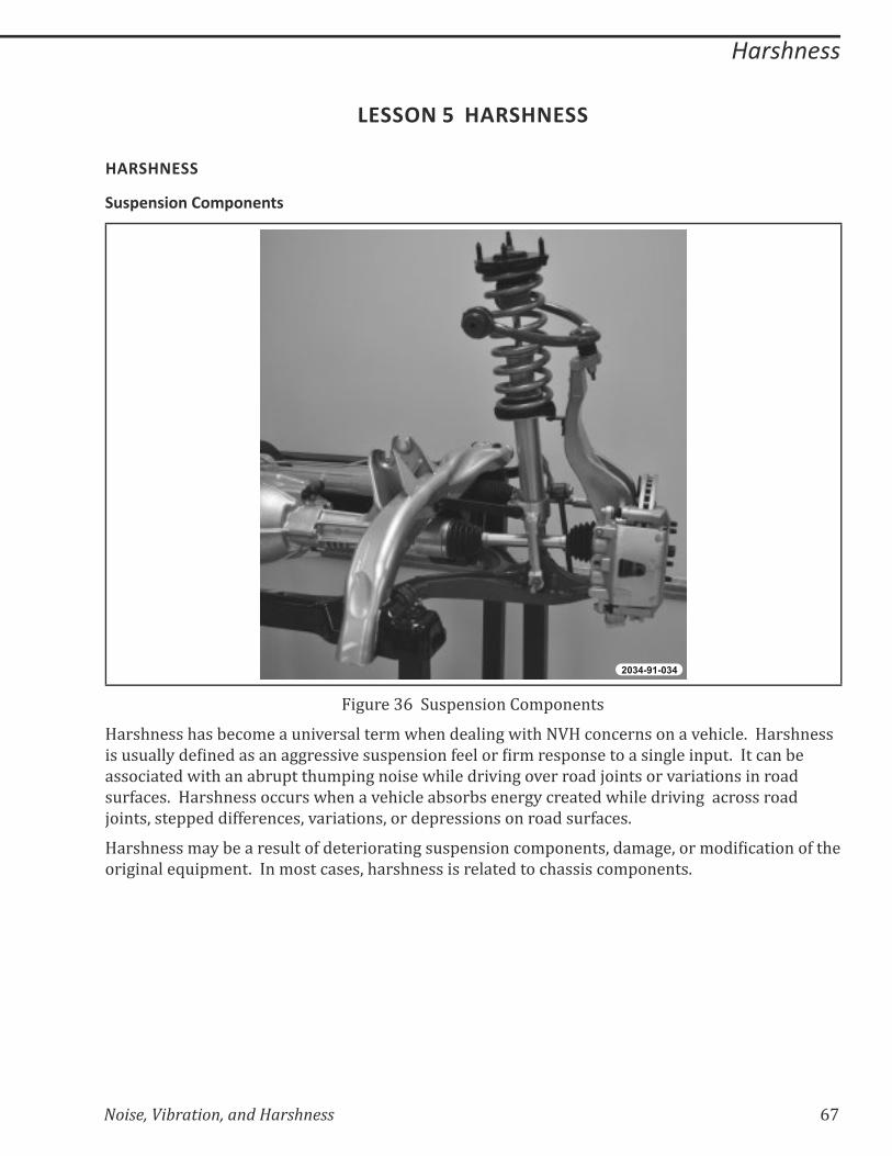
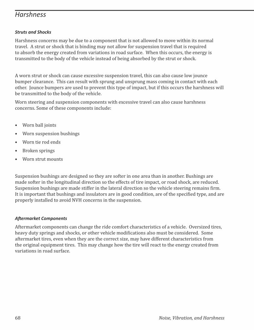
Figure 36 Suspension Components
Harshness has become a universal term when dealing with NVH concerns on a vehicle. Harshness
���&�&���?����������������++�����*���&�'�������>����������/����'�������������+�����'&�K�����%���:��
associated with an abrupt thumping noise while driving over road joints or variations in road
�&�>�%��K��!���$������%%&���@$�����*�$�%����:���:������+?�%�������@$�������*��+���%����������
������;����''�����>>����%��;�*���������;������'������������������&�>�%��K��
!���$�����/�?�:�������&����>�������������+��&�'�������%�/'������;���/�+�;����/�����%�������>��$��
���+������Z&�'/���K�����/����%����;�$���$�������������������%$������%�/'������K
68 Noise, Vibration, and Harshness
Harshness
Struts and Shocks
Harshness concerns may be due to a component that is not allowed to move within its normal
���*��K�������&������$�%Q��$������:�����+�/�?���������@�>����&�'����������*����$��������Z&�����
����:���:��$������+?�%�������>��/�*�������������������&�>�%�K���$����$����%%&��;��$������+?����
�����/����������$��:��?��>��$��*�$�%������������>�:���+��:���:���:?��$�����&������$�%QK
A worn strut or shock can cause excessive suspension travel, this can also cause low jounce
bumper clearance. This can result with sprung and unsprung mass coming in contact with each
��$��K����&�%��:&/'��������&�������'��*�����$����?'���>��/'�%�;�:&���>��$����%%&����$��$���$�����@����
:�������/����������$��:��?��>��$��*�$�%��K��
������������+������&�'�������%�/'�������@��$���%����*�����*���%��������%�&���$���$�����
%��%����K��/���>��$����%�/'���������%�&��_
=� �����:����������
=� ������&�'�������:&�$��+�
=� ������������������
=� ���Q����'���+�
=� ��������&��/�&���
&�'�������:&�$��+����������+��������$�?�������>�����������������$����������$��K��&�$��+������
/������>��������$�����+��&����������%���������$���>>�%����>�������/'�%�;����������$�%Q;��������&%��K�
&�'�������:&�$��+������/�������>>�������$��������������%���������$��*�$�%����������+���/��������/K�
�������/'��������$���:&�$��+���������&��������������+����%��������;������>��$���'�%�������?'�;���������
properly installed to avoid NVH concerns in the suspension.
������������ �����
�>���/��Q���%�/'�������%���%$��+���$�������%�/>����%$���%�������%���>���*�$�%��K���*����`��������;�
$��*?��&�?��'���+�������$�%Q�;������$���*�$�%���/�����%������������/&���:��%���������K���/��
�>���/��Q��������;��*���@$����$�?������$��%����%����`�;�/�?�$�*����>>������%$���%�������%��>��/�
�$�����+������Z&�'/���������K�� $���/�?�%$��+��$�@��$�������@�������%������$������+?�%�������>��/�
*�������������������&�>�%�K��
Noise, Vibration, and Harshness 69
Harshness
������� �Q����
2034-91-035
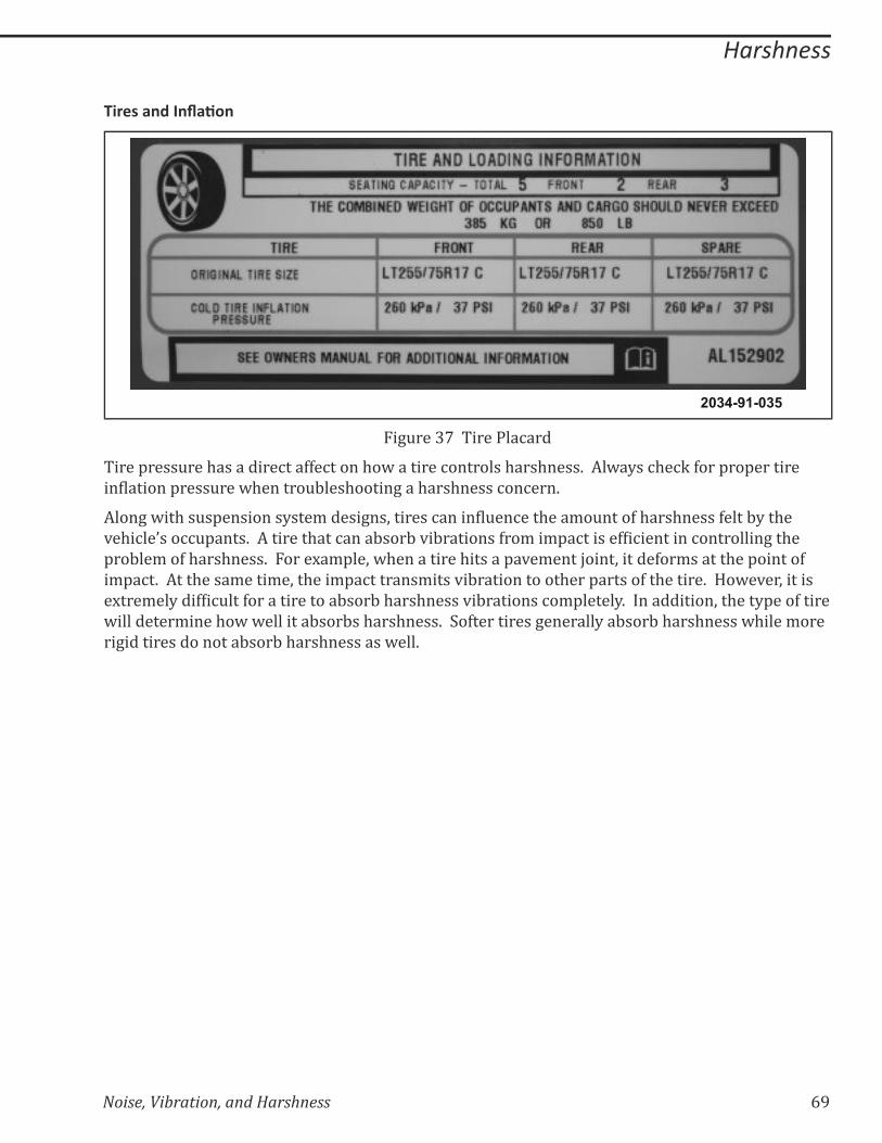
Figure 37 Tire Placard
����'����&���$���������%���>>�%�����$�@��������%��������$���$����K����@�?��%$�%Q�>���'��'��������
����������'����&���@$������&:���$�����+���$���$�����%��%���K
����+�@��$��&�'��������?���/�����+��;�������%�������&��%���$���/�&����>�$���$�����>����:?��$��
*�$�%��{���%%&'����K����������$���%����:���:�*�:��������>��/��/'�%������>��%��������%���������+��$��
'��:��/��>�$���$����K���������/'��;�@$����������$������'�*�/���������;������>��/������$��'������>�
�/'�%�K������$����/����/�;��$���/'�%�������/����*�:������������$���'������>��$������K��!�@�*��;�������
�����/��?���>��%&���>��������������:���:�$���$�����*�:��������%�/'�����?K�������������;��$���?'���>������
@���������/����$�@�@��������:���:��$���$����K���>����������+�������?��:���:�$���$�����@$����/����
rigid tires do not absorb harshness as well.

70 Noise, Vibration, and Harshness
Notes:

Noise, Vibration, and Harshness 71
GLOSSARYamplitude The vertical measurement between the top and bottom of a wave
audible range of sound Sound that is in the range of 20 to 20,000 Hz
beat An NVH concern produced by two sounds that is most noticeable
when the frequency difference is 1 to 6 Hz
brake shudder Vibration that causes the instrument panel, steering wheel, and
sometimes the entire body to vibrate vertically and back-and-forth
during braking; it also may result in brake pedal pulsation related to
wheel rotation
brake squeal A high pitched brake noise that can be short in duration if it is due to
dampness
ChassisEAR A versatile electronic listening tool that allows the user to listen to
�/'���������&�����$��&+$���'��>��������������>�$���'$����
compelling force An exciting force acting upon an object that causes it to vibrate
cycle The path a wave travels before the wave begins to repeat the path
again
downshift speed test $��*�$�%���%$�%Q��$���$��'�����%�����/��$����!�%��%���������+���^
speed-related
StarSCAN Chrysler’s latest generation, hand-held diagnostic scan tool
droning, high-speed A long duration, non-directional humming noise that is uncomfortable
to the ears and has a range of 80.5 km/h (50 mph) and up
droning, low-speed A long duration, low-pitched noise that is non-directional and has a
range of up to 48 km/h (30 mph)
droning, middle-speed A long duration, low-pitched noise that is non-directional and has a
range of 48–80.5 km/h (30–50 mph)
electronic vibration
analyzer (EVA)
An NVH diagnostic tool that measures frequency and amplitude
engine accessory test The vehicle check that helps locate faulty belts and accessories that
are causing engine speed-related NVH concerns
engine loaded test The vehicle check that helps to reproduce engine speed-related
concerns not evident with the neutral run up or neutral coast down
speed tests; it also identifies noise and vibration sensitive to engine
load or torque
frequency The number of complete cycles that occurs in a given period of time
harshness An aggressive suspension feel or lack of “give” in response to a single
input
intensity The physical quality of sound that relates to the amount and direction
of the flow of acoustic energy at a given speed
72 Noise, Vibration, and Harshness
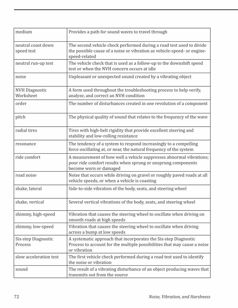
medium Provides a path for sound waves to travel through
neutral coast down
speed test
The second vehicle check performed during a road test used to divide
the possible cause of a noise or vibration as vehicle-speed- or engine-
speed-related
neutral run-up test The vehicle check that is used as a follow-up to the downshift speed
test or when the NVH concern occurs at idle
noise Unpleasant or unexpected sound created by a vibrating object
NVH Diagnostic
Worksheet
A form used throughout the troubleshooting process to help verify,
analyze, and correct an NVH condition
order The number of disturbances created in one revolution of a component
pitch The physical quality of sound that relates to the frequency of the wave
radial tires Tires with high-belt rigidity that provide excellent steering and
stability and low-rolling resistance
resonance The tendency of a system to respond increasingly to a compelling
force oscillating at, or near, the natural frequency of the system
ride comfort A measurement of how well a vehicle suppresses abnormal vibrations;
poor ride comfort results when sprung or unsprung components
become worn or damaged
road noise Noise that occurs while driving on gravel or roughly paved roads at all
vehicle speeds, or when a vehicle is coasting
shake, lateral Side-to-side vibration of the body, seats, and steering wheel
shake, vertical Several vertical vibrations of the body, seats, and steering wheel
shimmy, high-speed Vibration that causes the steering wheel to oscillate when driving on
smooth roads at high speeds
shimmy, low-speed Vibration that causes the steering wheel to oscillate when driving
across a bump at low speeds
Six-step Diagnostic
Process
A systematic approach that incorporates the Six-step Diagnostic
Process to account for the multiple possibilities that may cause a noise
or vibration
slow acceleration test $��������*�$�%���%$�%Q�'��>��/����&���+�������������&�������������>?�
the noise or vibration
sound The result of a vibrating disturbance of an object producing waves that
transmits out from the source
Noise, Vibration, and Harshness 73
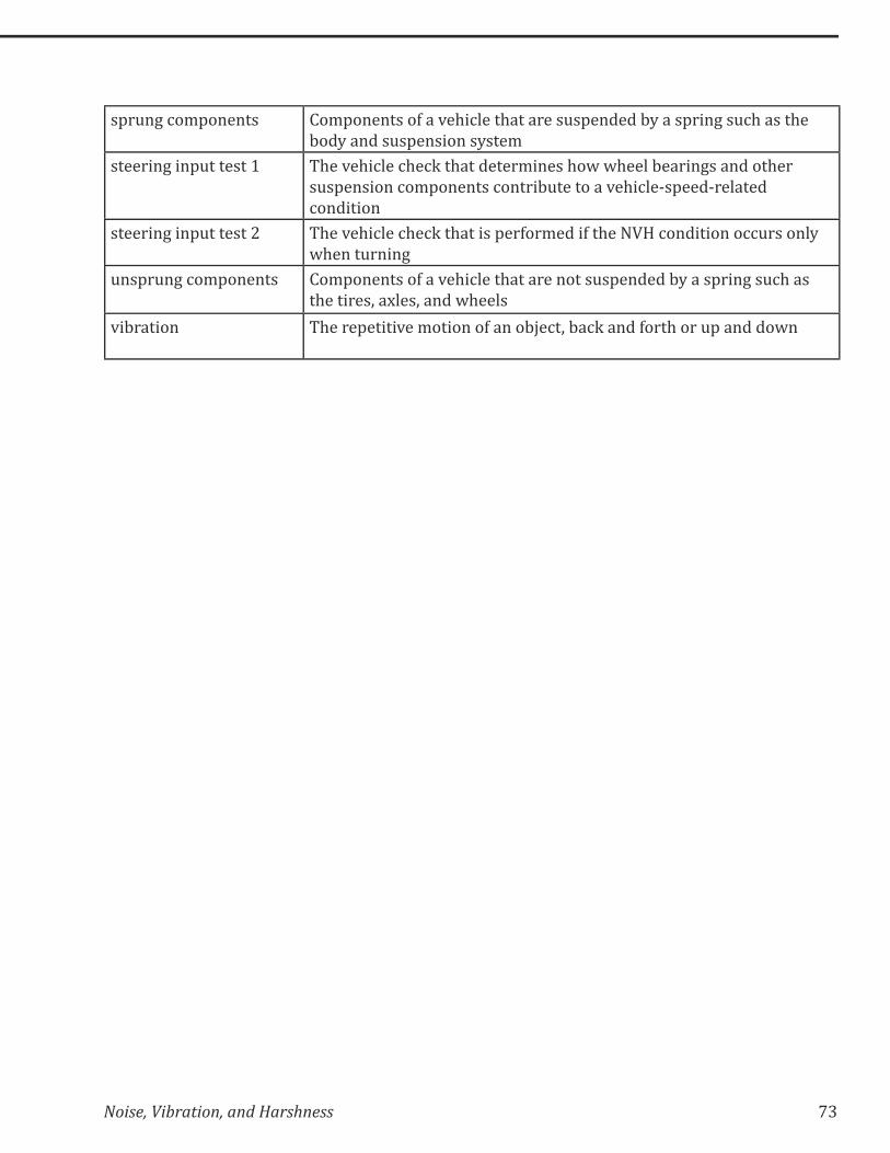
sprung components Components of a vehicle that are suspended by a spring such as the
body and suspension system
steering input test 1 The vehicle check that determines how wheel bearings and other
suspension components contribute to a vehicle-speed-related
condition
steering input test 2 The vehicle check that is performed if the NVH condition occurs only
when turning
unsprung components Components of a vehicle that are not suspended by a spring such as
the tires, axles, and wheels
vibration The repetitive motion of an object, back and forth or up and down

74 Noise, Vibration, and Harshness
Notes:

Noise, Vibration, and Harshness 75
APPENDIX
�&(6&�$�(' -'�(� �-
Begin checking the vehicle with a visual inspection. Be sure to carefully inspect
the tires and wheel assemblies, unless the NVH concern only occurs at a standstill.
Before the road test, inspect the following:
Check the tires for:
=� ��������������'����&��
=� Proper tire type, verify the tires are uniform in size and brand
=� Properly installed tires and if the tire bead is uniform around the wheel
=� �:���/��������@���;��&%$����%&''��+;�������'���;��$�&�����@���;�>���$����+;�����%����%��������
groove depth
Check the wheels for:
=� Foreign debris, such as mud or ice in the wheels
=� Deformed or bent wheels
=� Missing wheel weights
=� �&+��&������Z&�������'�%���%�����
Check the vehicle for:
=� Obvious signs of damaged components
=� Indications of collision damage
=� Aftermarket components

76 Noise, Vibration, and Harshness
&�$�('9(;��'
&���������
Observe the following guidelines when preparing for the road test:
=� Check the customer repair order before beginning the road test
– �������/'����������Q��@�@$�%$��'�%���%�%��%�����$��%&���/���$���@��$��$��*�$�%��
– This prevents correcting the wrong concern and increasing the cost of the repair
=� Don’t be misled by the reported location of the noise or vibration
– The cause may actually be some distance away
=� Remember that the vibrating body may generate a small vibration only
– This small vibration in turn may cause a larger vibration or noise due to the vibrating
body’s contact with other components
=� Conduct the road test on a quiet street where safely duplicating the noise or vibration is
possible
– $��������������+���&����������'��;���@����>��%�����
– It must be possible to operate the vehicle at the speed in which the condition occurs
=� Turn the radio, A/C, and heater blower off unless the concern only occurs when the radio,
A/C, or heater is on
=� Determine which test equipment, if any, is needed for the road test
=� For cold weather climates, snow and ice can be the cause of noise complaints
&�$�(' -.
The following checks help determine the engine-speed, vehicle speed, and frequency of the NVH
concern. Each helps eliminate possible components. Depending on the concern, certain checks
may or may not be necessary.
=� Slow acceleration test
=� Neutral coast down speed test
=� Downshift speed test
=� Torque converter test
=� Steering input test 1
=� Steering input test 2
=� Neutral run-up test
=� Engine loaded test
=� Engine accessory test
Noise, Vibration, and Harshness 77
'��,$�������������
$��������*�$�%���%$�%Q���������/���������������?/'��/��>������!�%��%���K�� $�����@��%%����������
test is used to identify the noise or vibration if a road test with the customer is not possible. The
steps of the slow acceleration test are:
=� Slowly accelerate the vehicle to the speed in which the problem occurs
=� Note the vehicle speed and the engine rpm
=� If possible, determine the frequency of the noise or vibration
=� Classify the noise or vibration
-�#�����������,�'�������
The neutral coast down speed test divides the possible causes of the noise or vibration into two
categories:
=� Vehicle-speed-related
=� Engine-speed-related
The steps of the neutral coast down speed test are:
1. Drive the vehicle at a speed higher than the speed in which the noise or vibration was
obvious in the slow acceleration test.
2. Place the vehicle in neutral and coast down through the speed where the concern occurs.
3. Classify the NVH concern as either vehicle-speed-related or engine-speed-related.
=� If the noise or vibration exists, then the concern is vehicle-speed-related. This eliminates
the engine and torque converter as possible causes.
=� If the NVH concern did not occur during the neutral coast down speed test, perform a
��@��$�>���'������������%�����/��$��%��%���������+���^�'���^�������K
��,����8'�������
$����@��$�>���'���������$��'�����%�����/��$����!�%��%���������+���^�'���^�������K
1. Stop the vehicle and place the transmission in a lower gear.
2. Drive the vehicle at the engine rpm in which the noise or vibration occurs.
=� If the noise or vibration exists, then the concern is engine-speed-related (this eliminates
tires, wheels, brakes, and suspension components)
=� �>���%�����?;���'�����$�������&���+���$���+�����������&��������%�����/��$�����&���

78 Noise, Vibration, and Harshness
��"#����7��������
The torque converter test determines how the torque converter contributes to an engine-speed-
related condition. The steps of the torque converter test are:
1. Drive the vehicle at the speed in which the NVH concern exists.
2. Operate the torque converter by taking it in and out of lock-up by lightly depressing the
brake pedal, while maintaining vehicle speed.
3. Check for noise when the torque converter is not locked up.
'������� ��#�����
The steering input test 1 determines how wheel bearings and other suspension components
contribute to a vehicle-speed-related condition. The steps of the steering input test 1 are:
1. Drive the vehicle at the speed in which the NVH concern exists.
2. Make wide sweeping turns in both directions.
=� If the concern goes away or gets worse, wheel bearings, hubs, universal joints, and tire
tread wear may be the cause of the concern
=� If the noise or vibration exists, then the concern is engine-speed-related (this eliminates
tires, wheels, brakes, driveline, and suspension components as the cause)
'������� ��#�����
Perform the steering input test 2 if the NVH condition occurs only when turning. The steps of
steering input test 2 are:
1. Drive the vehicle at a speed higher than the speed in which the noise or vibration occurs.
2. Place the vehicle in neutral and coast down through the speed where the NVH concern is
obvious, while making wide sweeping turns in both directions.
=� If the concern exists, check for worn wheel bearings, suspension bushings, and universal
joints (contained in the axles of 4WD applications)
=� If the vibration does not occur, stop the vehicle and engage the transmission or transaxle;
alternately accelerate and decelerate through the speed where the NVH concern appears,
while making wide sweeping turns in both directions
=� If the concern returns, then the cause is dependent upon engine load; the probable causes
are constant velocity (CV) boots, CV joints, universal joints (contained in the axles of 4WD
applications) and loose or missing lug nuts
=� If the noise is a clunking sound, engine and transaxle mounts, suspension bushings, and
universal joints are probable causes
Noise, Vibration, and Harshness 79
-�#����&#��#����
Perform the neutral run-up test if the NVH concern is engine-speed-related. Use the neutral run-
up test as a follow-up to the downshift test or when the NVH concern occurs at idle. The steps of
the neutral run-up test are:
1. Increase the engine rpm while in park on front-wheel drive vehicles or neutral on rear-
wheel drive vehicles.
2. If necessary, make note of the rpm and frequency of the NVH concern.
(�����3��������
Perform the engine loaded test if the NVH concern is engine-speed-related. This test may help
reproduce engine-speed-related concerns not evident with the neutral run-up or neutral coast
��@�������K�� $����+������������������������������������������*�:��������������*�������+������������
torque. These NVH concerns often appear during heavy acceleration or when climbing a hill.
WARNING: BLOCK THE FRONT AND BACK WHEELS OR INJURY TO PERSONNEL MAY RESULT. DO NOT PERFORM THE ENGINE LOADED TEST FOR MORE THAN FIVE SECONDS OR DAMAGE TO THE TRANSMISSION/TRANSAXLE MAY RESULT.
The steps of the engine loaded test are:
1. Block the front and back wheels.
2. Apply the parking and service brakes.
3. Put the transmission in drive while keeping the brakes applied.
4. Increase the engine speed to the rpm in which the NVH concern occurred (if necessary,
make note of the rpm and frequency of the NVH concern).
5. Put the transmission in reverse while keeping the brakes applied.
6. Increase the engine speed to the rpm in which the NVH concern occurred (if necessary,
make note of the rpm and frequency of the NVH concern).
=� �>��$��%��%����������������?���+���^�'���^�������;�'��>��/��$����+�����%%�����?���������
narrow down the possible sources of the concern
80 Noise, Vibration, and Harshness
(�����$�����������
Perform the engine accessory test if the NVH concern is engine-speed-related. This test helps
locate faulty belts and accessories that are causing engine-speed-related NVH concerns.
The steps of the engine accessory test are:
1. Block the front and back wheels.
2. Apply the parking and service brakes.
3. Remove the accessory drive belt(s).
4. Increase engine speed to the rpm in which the NVH concern occurred.
=� If the vibration occurs, the belts and accessories are not the source of the concern
=� If the belts and accessories are the source of the NVH concern, continue to add or remove
�'�%���%��%%�����?�:����������%�����$��%��%���
Caution: Do not run the engine accessory test for more than a few minutes or the engine may overheat.
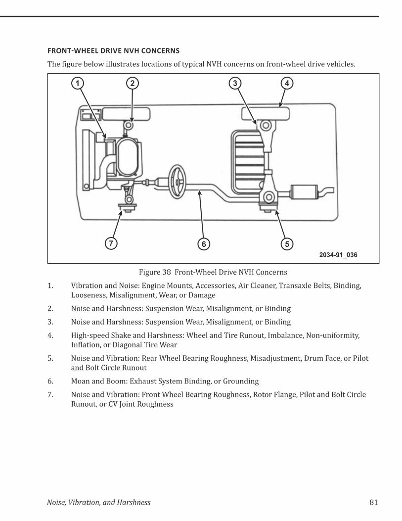
Noise, Vibration, and Harshness 81
!&�-6�;((3�& �(-�;��-�(&-'
$����+&���:���@����&����������%��������>��?'�%�����!�%��%��������>����^@$�������*��*�$�%���K
43
567
21
2034-91_036
Figure 38 Front-Wheel Drive NVH Concerns
1. Vibration and Noise: Engine Mounts, Accessories, Air Cleaner, Transaxle Belts, Binding,
Looseness, Misalignment, Wear, or Damage
2. Noise and Harshness: Suspension Wear, Misalignment, or Binding
3. Noise and Harshness: Suspension Wear, Misalignment, or Binding
4. High-speed Shake and Harshness: Wheel and Tire Runout, Imbalance, Non-uniformity,
���������;�������+����� ��������
5. Noise and Vibration: Rear Wheel Bearing Roughness, Misadjustment, Drum Face, or Pilot
and Bolt Circle Runout
6. Moan and Boom: Exhaust System Binding, or Grounding
7. Noise and Vibration: Front Wheel Bearing Roughness, Rotor Flange, Pilot and Bolt Circle
Runout, or CV Joint Roughness
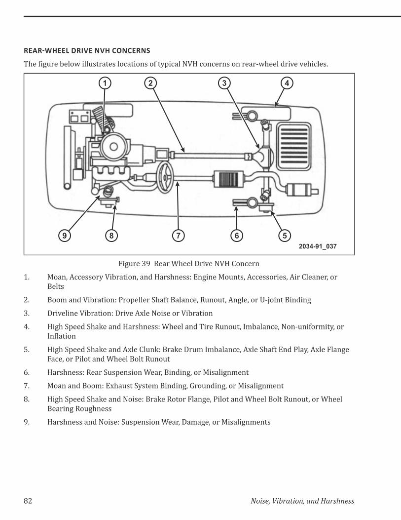
82 Noise, Vibration, and Harshness
&($&6�;((3�& �(-�;��-�(&-'
$����+&���:���@����&����������%��������>��?'�%�����!�%��%������������^@$�������*��*�$�%���K
3 421
9 8 7 6 52034-91_037
Figure 39 Rear Wheel Drive NVH Concern
1. Moan, Accessory Vibration, and Harshness: Engine Mounts, Accessories, Air Cleaner, or
Belts
2. Boom and Vibration: Propeller Shaft Balance, Runout, Angle, or U-joint Binding
3. Driveline Vibration: Drive Axle Noise or Vibration
4. High Speed Shake and Harshness: Wheel and Tire Runout, Imbalance, Non-uniformity, or
���������
5. High Speed Shake and Axle Clunk: Brake Drum Imbalance, Axle Shaft End Play, Axle Flange
Face, or Pilot and Wheel Bolt Runout
6. Harshness: Rear Suspension Wear, Binding, or Misalignment
7. Moan and Boom: Exhaust System Binding, Grounding, or Misalignment
8. High Speed Shake and Noise: Brake Rotor Flange, Pilot and Wheel Bolt Runout, or Wheel
Bearing Roughness
9. Harshness and Noise: Suspension Wear, Damage, or Misalignments
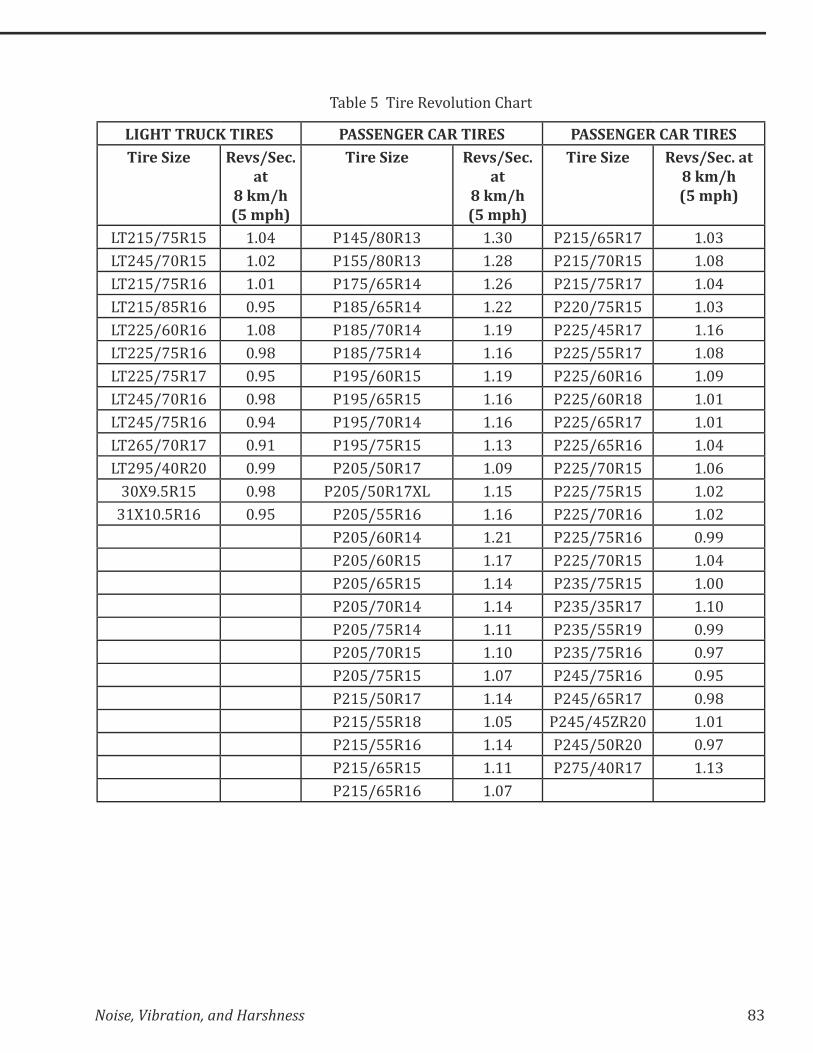
Noise, Vibration, and Harshness 83
Table 5 Tire Revolution Chart
LIGHT TRUCK TIRES PASSENGER CAR TIRES PASSENGER CAR TIRESTire Size Revs/Sec.
at 8 km/h (5 mph)
Tire Size Revs/Sec. at
8 km/h (5 mph)
Tire Size Revs/Sec. at 8 km/h (5 mph)
LT215/75R15 1.04 P145/80R13 1.30 P215/65R17 1.03
LT245/70R15 1.02 P155/80R13 1.28 P215/70R15 1.08
LT215/75R16 1.01 P175/65R14 1.26 P215/75R17 1.04
LT215/85R16 0.95 P185/65R14 1.22 P220/75R15 1.03
LT225/60R16 1.08 P185/70R14 1.19 P225/45R17 1.16
LT225/75R16 0.98 P185/75R14 1.16 P225/55R17 1.08
LT225/75R17 0.95 P195/60R15 1.19 P225/60R16 1.09
LT245/70R16 0.98 P195/65R15 1.16 P225/60R18 1.01
LT245/75R16 0.94 P195/70R14 1.16 P225/65R17 1.01
LT265/70R17 0.91 P195/75R15 1.13 P225/65R16 1.04
LT295/40R20 0.99 P205/50R17 1.09 P225/70R15 1.06
30X9.5R15 0.98 P205/50R17XL 1.15 P225/75R15 1.02
31X10.5R16 0.95 P205/55R16 1.16 P225/70R16 1.02
P205/60R14 1.21 P225/75R16 0.99
P205/60R15 1.17 P225/70R15 1.04
P205/65R15 1.14 P235/75R15 1.00
P205/70R14 1.14 P235/35R17 1.10
P205/75R14 1.11 P235/55R19 0.99
P205/70R15 1.10 P235/75R16 0.97
P205/75R15 1.07 P245/75R16 0.95
P215/50R17 1.14 P245/65R17 0.98
P215/55R18 1.05 P245/45ZR20 1.01
P215/55R16 1.14 P245/50R20 0.97
P215/65R15 1.11 P275/40R17 1.13
P215/65R16 1.07

84 Noise, Vibration, and Harshness
(-. -(6'�((�6&(3$(�!&(Z?(-� ('
(�����������!��"#����
Many NVH concerns are related to the engine systems. The operation of the engine creates a
natural vibration. If any one component is slightly out of balance, the natural vibration of the
engine is compounded. Engine vibration is generally caused by any of the following:
=� First- and second-order engine imbalance
=� ��+���������+�>��Z&��%?
=� Engine mounts
=� Engine accessories
(�����!��"#����
Use the engine rpm where the NVH symptom occurs to determine engine frequency. Calculate
engine frequency by performing the following step:
=� Divide the engine rpm by 60 (the number of seconds in a minute)
– Engine frequency = rpm/60
$��%��%&������>��Z&��%?�����$�������^��������+����>��Z&��%?K�� $����%���^������>��Z&��%?��>��$��
engine is twice this number. Engine vibrations may also have half-order frequencies.
(�����$��������!��"#����
Belt-driven engine accessories often produce vibrations at different frequencies than the engine
itself. This is because the drive ratio created by the different size pulleys causes them to rotate at
different speeds. Determining engine accessory frequency is comparable to calculating driveline
frequency. Calculate engine accessory frequency by performing the following steps:
1. Determine the size ratio between the accessory pulley and the crankshaft pulley.
=� Pulley ratio = crankshaft pulley diameter/accessory pulley diameter
2. Multiply the engine rpm where the NVH condition occurs by the number of times the
accessory pulley is rotating per crankshaft revolution.
=� Accessory rpm = engine rpm x pulley ratio
3. Divide the accessory rpm by 60 (the number of seconds in a minute).
=� Accessory frequency = accessory rpm/60
Noise, Vibration, and Harshness 85
�(; �3(6'�((�6&(3$(�!&(Z?(-� ('
�������'����!��"#����
Noise and vibration that occur during driving have various sources. The major sources are the
following:
=� Rough or irregular road surfaces
=� Condition of the tires and wheels
�/'�%��>��%����������������/����������$��������%�&���+��$�/����*�:����K�� $���%$���%�������%���'��������
the close relationship that exists between the tire and road surface. Tires, just like the suspension,
body, and other components, are designed to minimize noise and vibration. The unique aspect of
tires is that they wear faster than other components. This is a contributing factor to wheel and
tire noise and vibration. Additionally, owners frequently replace original tires with different types.
This can result in tire and wheel imbalance, runout, or non-uniformity.
�����������.��#�
Use the vehicle speed in which the NVH symptom occurs to determine tire/wheel frequency.
Calculate tire/wheel frequency by performing the following steps:
1. Divide the vehicle speed by 5. The resulting number indicates the number of 8 km/h (5
mph) increments.
=� 8km/h (5 mph) increments = vehicle speed/5
2. Obtain the corresponding tire size frequency at 8 km/h (5 mph). This information is in a
standard tire revolution chart.
3. Multiply the 8 km/h (5 mph) increment by the revolutions per second at 8 km/h (5 mph).
=� Tire/Wheel frequency = tire size frequency x number of 8 km/h (5 mph) increments
$��%��%&������>��Z&��%?�����$�������^����������J@$����>��Z&��%?K����/�/:��;�����������$���&/:���
of disturbances created in one revolution of a component. The second-order frequency of the
wheel and tire assemblies is twice this number. The third-order frequency is three times this
�&/:��K���>��$����!�%��%����$�����>��Z&��%?��$���/��%$����$�������^;���%���^;�����$���^������
frequency, the cause of the problem can possibly be in the wheel and tire area.
86 Noise, Vibration, and Harshness
���������'��8.��#�
Knowing the tire/wheel frequency allows for easy calculation of propeller shaft frequency. The
propeller shaft drives the tires through the rear axle. Therefore, to determine propeller shaft
frequency, multiply tire/wheel frequency by the ratio of the rear axle. Calculate propeller shaft
frequency by performing the following steps:
1. Obtain the axle ratio from the metal tag on the differential cover.
2. Multiply the tire/wheel frequency with the rear axle ratio.
=� Propeller shaft frequency = tire frequency x axle ratio
$��%��%&������>��Z&��%?�����$�������^������'��'�������$�>��>��Z&��%?K�� $����%���^������>��Z&��%?�
of the propeller shaft is twice this number.
It is important to remember the difference between propeller shaft and half shaft frequencies. The
frequency of propeller shaft concerns are high since they rotate approximately four times that of
the tire and wheel assemblies. Half shaft concerns are low frequency because they rotate at tire
and wheel speed.
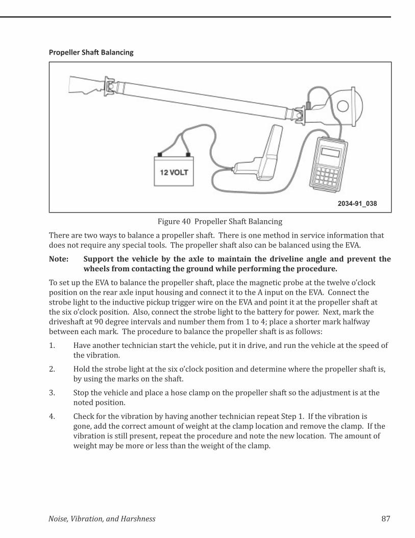
Noise, Vibration, and Harshness 87
���������'��8/��������
2034-91_038
Figure 40 Propeller Shaft Balancing
There are two ways to balance a propeller shaft. There is one method in service information that
does not require any special tools. The propeller shaft also can be balanced using the EVA.
Note: Support the vehicle by the axle to maintain the driveline angle and prevent the wheels from contacting the ground while performing the procedure.
To set up the EVA to balance the propeller shaft, place the magnetic probe at the twelve o’clock
position on the rear axle input housing and connect it to the A input on the EVA. Connect the
strobe light to the inductive pickup trigger wire on the EVA and point it at the propeller shaft at
the six o’clock position. Also, connect the strobe light to the battery for power. Next, mark the
driveshaft at 90 degree intervals and number them from 1 to 4; place a shorter mark halfway
between each mark. The procedure to balance the propeller shaft is as follows:
1. Have another technician start the vehicle, put it in drive, and run the vehicle at the speed of
the vibration.
2. Hold the strobe light at the six o’clock position and determine where the propeller shaft is,
by using the marks on the shaft.
3. Stop the vehicle and place a hose clamp on the propeller shaft so the adjustment is at the
noted position.
4. Check for the vibration by having another technician repeat Step 1. If the vibration is
gone, add the correct amount of weight at the clamp location and remove the clamp. If the
vibration is still present, repeat the procedure and note the new location. The amount of
weight may be more or less than the weight of the clamp.
88 Noise, Vibration, and Harshness
��9�3((!�&9?3$'
(�������������!��%#��
=� Divide the engine rpm by 60 (the number of seconds in a minute)
=� Engine frequency = rpm/60
=� �%���^�������������^��������|
=� $���^�������������^��������~
=� !��>^�������������^�����J|
(�����$��������!��%#��
=� Pulley ratio = crankshaft pulley diameter/accessory pulley diameter
=� Accessory rpm = engine rpm x pulley ratio
=� Accessory frequency = accessory rpm/60
(�����!�����!��"#����!��%#��
=� Divide the engine rpm in which the vibration occurs by 60
=� Multiply that number by the number of cylinders in the engine
=� j&���'�?��$����&/:���:?�}K��>����$����+���������+�>��Z&��%?
=� Hz = 0.5 [(engine-speed/60) x number of cylinders]
���������'��8!��"#����!��%#��
=� Propeller shaft frequency = tire/wheel frequency x axle ratio

Noise, Vibration, and Harshness 89
';�&!�&9?3$'
(�������������!��%#��
=� Engine frequency = rpm/60
(�����$��������!��%#��
=� Pulley ratio = crankshaft pulley diameter/accessory pulley diameter
=� Accessory frequency = engine frequency x pulley ratio
(�����!�����!��"#����!��%#��
=� Divide the engine rpm in which the vibration occurs by 60
=� Multiply that number by half the number of cylinders in the engine
=� ��+���������+�>��Z&��%?�����+����>��Z&��%?���$��>��&/:����>�%?�������
���������'��8!��"#����!��%#��
Propeller shaft frequency = tire/wheel frequency x axle ratio

90 Noise, Vibration, and Harshness
Notes:
NOISE, VIBRATION, AND HARSHNESS
ACTIVITY PACK0030708

Noise, Vibration, and Harshness
Causes of NVH Concerns
ACTIVITY 1 CAUSES OF NVH CONCERNS
2 Noise, Vibration, and Harshness
Causes of NVH Concerns
Notes:
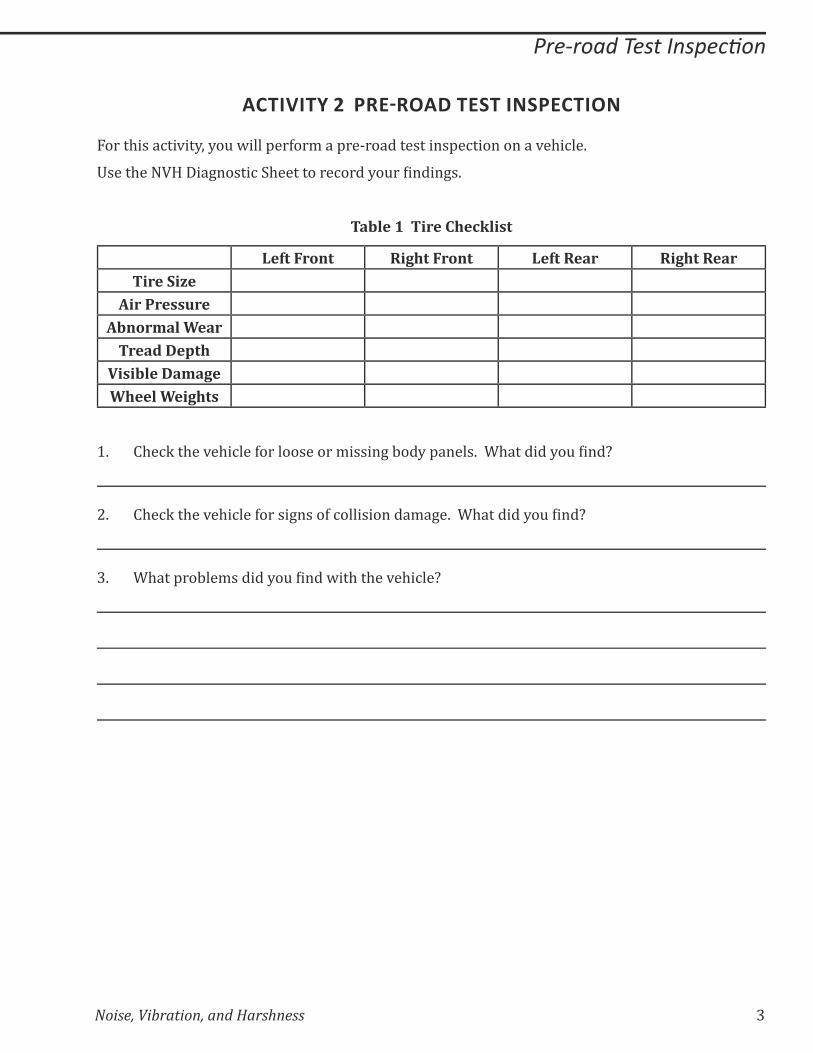
Noise, Vibration, and Harshness 3
��������������!����� ��
ACTIVITY 2 �&(6&�$�(' -'�(� �-
For this activity, you will perform a pre-road test inspection on a vehicle.
#����$����!����+�����%�$���������%����?�&��������+�K
Table 1 Tire Checklist
Left Front Right Front Left Rear Right RearTire Size
Air PressureAbnormal Wear
Tread DepthVisible DamageWheel Weights
1. �$�%Q��$��*�$�%���>������������/�����+�:��?�'�����K���$�������?�&�����X
2. �$�%Q��$��*�$�%���>�����+����>�%�����������/�+�K���$�������?�&�����X
3. �$���'��:��/������?�&������@��$��$��*�$�%��X
4 Noise, Vibration, and Harshness
��������������!����� ��
Notes:
Noise, Vibration, and Harshness 5
Using the Sirometer
ACTIVITY 3 USING THE SIROMETER
The objective of this activity is to demonstrate the proper use of NVH diagnostic tools to analyze
the source of the concern.
Use the sirometer to determine the vibration frequency of the following items (If available).
WARNING: WEAR SAFETY GLASSES AND KEEP LOOSE OBJECTS AWAY FROM THE ROTATING OBJECTS.
1. What is the vibration frequency of a bench grinder?
2. What is the vibration frequency of a hand drill?
3. What is the vibration frequency of an idling engine?
4. What is the vibration frequency of a wheel balancer?
Pick two other items and measure the frequency for the two following questions.
5. What is the vibration frequency of _____________________________?
6. What is the vibration frequency of _____________________________?
6 Noise, Vibration, and Harshness
Using the Sirometer
Notes:
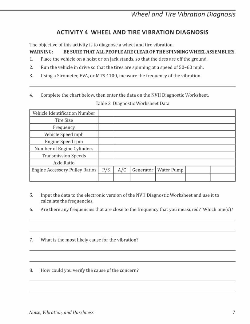
Noise, Vibration, and Harshness 7
������������������ ������������
ACTIVITY 4 WHEEL AND TIRE VIBRATION DIAGNOSIS
The objective of this activity is to diagnose a wheel and tire vibration.
WARNING: BE SURE THAT ALL PEOPLE ARE CLEAR OF THE SPINNING WHEEL ASSEMBLIES.1. Place the vehicle on a hoist or on jack stands, so that the tires are off the ground.
2. Run the vehicle in drive so that the tires are spinning at a speed of 50–60 mph.
3. Using a Sirometer, EVA, or MTS 4100, measure the frequency of the vibration.
4. Complete the chart below, then enter the data on the NVH Diagnostic Worksheet.
Table 2 Diagnostic Worksheet Data
��$�%�����������%�������&/:��
Tire Size
Frequency
Vehicle Speed mph
Engine Speed rpm
Number of Engine Cylinders
Transmission Speeds
Axle Ratio
Engine Accessory Pulley Ratios P/S A/C Generator Water Pump
5. Input the data to the electronic version of the NVH Diagnostic Worksheet and use it to
calculate the frequencies.
6. Are there any frequencies that are close to the frequency that you measured? Which one(s)?
7. What is the most likely cause for the vibration?
8. How could you verify the cause of the concern?
8 Noise, Vibration, and Harshness
������������������ ������������
Notes:
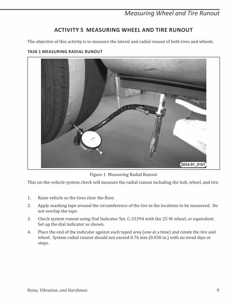
Noise, Vibration, and Harshness 9
Measuring Wheel and Tire Runout
ACTIVITY 5 MEASURING WHEEL AND TIRE RUNOUT
The objective of this activity is to measure the lateral and radial runout of both tires and wheels.
TASK 1 MEASURING RADIAL RUNOUT
2034-91_0101
Figure 1 Measuring Radial Runout
This on-the-vehicle system check will measure the radial runout including the hub, wheel, and tire.
1. ������*�$�%�������$��������%������$�������K��
2. Apply masking tape around the circumference of the tire in the locations to be measured. Do
not overlap the tape.
3. Check system runout using Dial Indicator Set, C-3339A with the 25-W wheel, or equivalent.
Set up the dial indicator as shown.
4. Place the end of the indicator against each taped area (one at a time) and rotate the tire and
wheel. System radial runout should not exceed 0.76 mm (0.030 in.) with no tread dips or
steps.
10 Noise, Vibration, and Harshness
Measuring Wheel and Tire Runout
5. �������'���������'��%���:�������������:?��'�Q����>��$�����������%�����+�&+�K
=� �������'���%���:�������������:?�����'�����%�������$�����%������������������%�����������+�
over 101.6 mm (4.0 in.) of tread circumference.
=� ��������'���%���:�������������:?�����'�����%�����������%������������������%�����������+��*���
101.6 mm (4.0 in.) of tread circumference.
6. What is the system radial runout?
Table 3 ��������&��&��'�%���%������
Radial RunoutTire 0.76 mm (0.030 in.)
Aluminum Wheels 0.25 mm (0.010 in.)
Steel Wheels 0.51 mm (0.020 in.)
7. ��/'�����$����������&��&���+�������$���'�%���%������>��/��:�*�K���$�������?�&�����X

Noise, Vibration, and Harshness 11
Measuring Wheel and Tire Runout
TASK 2 MEASURING LATERAL RUNOUT
2034-91_0102
1. Set up the dial indicator as shown.
2. Be sure to place the roller tip on an area that is smooth all around the tire.
3. Rotate the wheel and note the reading on the dial indicator. What is the lateral runout on this
tire?
Table 4 ���������&��&��'�%���%������
Lateral RunoutTire 0.76 mm (0.030 in.)
Aluminum Wheels 0.76 mm (0.030 in.)
Steel Wheels 0.76 mm (0.030 in.)
4. ������$���@$������%�����$���'�%���%�����X

12 Noise, Vibration, and Harshness
Measuring Wheel and Tire Runout
Notes:

Noise, Vibration, and Harshness 13
�������������� ������������
ACTIVITY 6 DRIVELINE VIBRATION DIAGNOSIS
The objective of this activity is to diagnose a driveline vibration.
WARNING: WEAR SAFETY GLASSES AND KEEP A SAFE DISTANCE FROM SPINNING WHEELS AND PROPELLER SHAFT ASSEMBLIES WHEN PERFORMING NVH DIAGNOSTIC TESTS.
1. With the vehicle on a hoist and the wheels off the ground, run the vehicle in drive at 35-50
mph.
2. Does the vehicle have a vibration?
3. Using a sirometer, EVA, or MTS 4100, measure the frequency of the vibration.
Table 5 Diagnostic Worksheet Data
��$�%�����������%�������&/:��
Tire Size
Frequency
Vehicle Speed mph
Engine Speed rpm
Number of Engine Cylinders
Transmission Speeds
Axle Ratio
Engine Accessory Pulley
Ratios
P/S A/C Generator Water Pump
4. Enter the required data on the NVH Diagnostic Worksheet to calculate the frequencies.
5. What was the frequency that you measured?
6. What is the most likely cause?
14 Noise, Vibration, and Harshness
�������������� ������������
Notes:
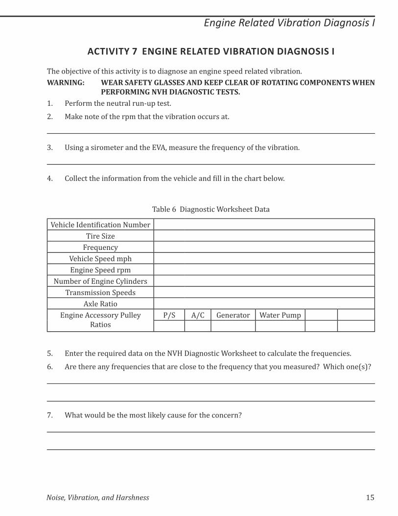
Noise, Vibration, and Harshness 15
�������"���������� �������������!
ACTIVITY 7 ENGINE RELATED VIBRATION DIAGNOSIS I
The objective of this activity is to diagnose an engine speed related vibration.
WARNING: WEAR SAFETY GLASSES AND KEEP CLEAR OF ROTATING COMPONENTS WHEN PERFORMING NVH DIAGNOSTIC TESTS.
1. Perform the neutral run-up test.
2. Make note of the rpm that the vibration occurs at.
3. Using a sirometer and the EVA, measure the frequency of the vibration.
4. �����%���$����>��/������>��/��$��*�$�%����������������$��%$����:���@K
Table 6 Diagnostic Worksheet Data
��$�%�����������%�������&/:��
Tire Size
Frequency
Vehicle Speed mph
Engine Speed rpm
Number of Engine Cylinders
Transmission Speeds
Axle Ratio
Engine Accessory Pulley
Ratios
P/S A/C Generator Water Pump
5. Enter the required data on the NVH Diagnostic Worksheet to calculate the frequencies.
6. Are there any frequencies that are close to the frequency that you measured? Which one(s)?
7. What would be the most likely cause for the concern?

16 Noise, Vibration, and Harshness
�������"���������� �������������!
Notes:
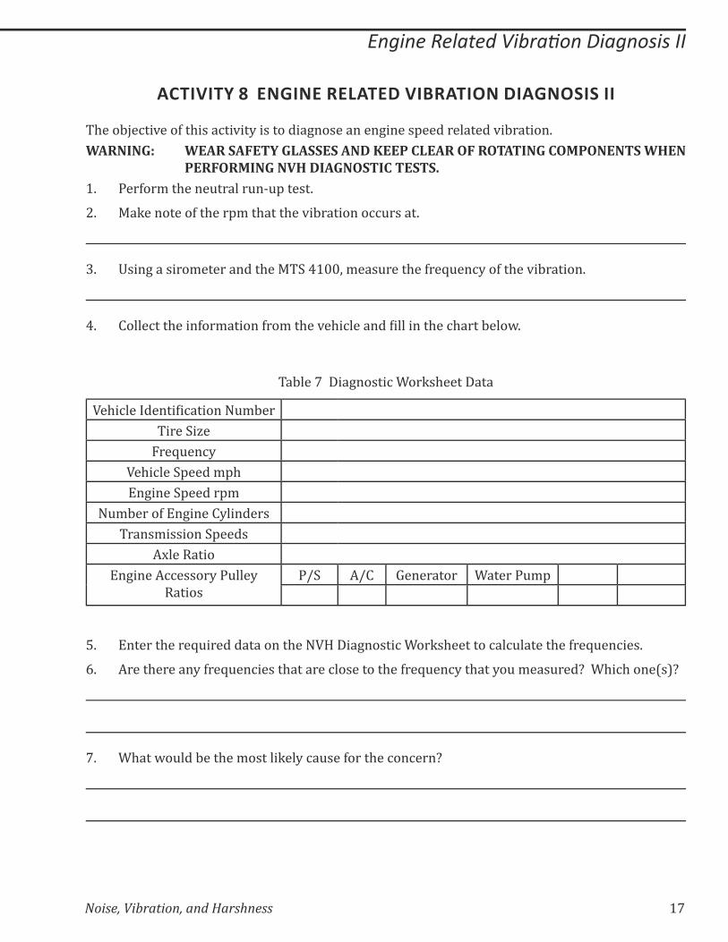
Noise, Vibration, and Harshness 17
�������"���������� �������������!!
ACTIVITY 8 ENGINE RELATED VIBRATION DIAGNOSIS II
The objective of this activity is to diagnose an engine speed related vibration.
WARNING: WEAR SAFETY GLASSES AND KEEP CLEAR OF ROTATING COMPONENTS WHEN PERFORMING NVH DIAGNOSTIC TESTS.
1. Perform the neutral run-up test.
2. Make note of the rpm that the vibration occurs at.
3. Using a sirometer and the MTS 4100, measure the frequency of the vibration.
4. �����%���$����>��/������>��/��$��*�$�%����������������$��%$����:���@K
Table 7 Diagnostic Worksheet Data
��$�%�����������%�������&/:��
Tire Size
Frequency
Vehicle Speed mph
Engine Speed rpm
Number of Engine Cylinders
Transmission Speeds
Axle Ratio
Engine Accessory Pulley
Ratios
P/S A/C Generator Water Pump
5. Enter the required data on the NVH Diagnostic Worksheet to calculate the frequencies.
6. Are there any frequencies that are close to the frequency that you measured? Which one(s)?
7. What would be the most likely cause for the concern?
18 Noise, Vibration, and Harshness
�������"���������� �������������!!
Notes:

Noise, Vibration, and Harshness 19
#�������������������$��%�&��������'������ ��
ACTIVITY 9 MEASURING PROPELLER SHAFT ANGLES DEMONSTRATION
WARNING: WEAR SAFETY GLASSES AND KEEP CLEAR OF ROTATING COMPONENTS WHEN PERFORMING NVH DIAGNOSTIC TESTS.
2034-91_0103
1. j���&����$����+��������@������$�/�����$����+&����:�*�K�� $������@����$��Z&��������&���+��$��
formulas, and determine the universal joint operating angles and driveline cancellation angle.
2. What is the transmission output shaft angle?
3. What is the axle input angle?
4. What is the propeller shaft angle?
5. What is the propeller shaft cancellation angle?
20 Noise, Vibration, and Harshness
#�������������������$��%�&�������'������ ���
Notes:
Noise, Vibration, and Harshness 21
��������&"���'������ ��
ACTIVITY 10 CHASSISEAR DEMONSTRATION
Observe the instructor’s demonstration on the use of the ChassisEAR and answer the following
questions.
1. What do you hear when listening to the fuel injector through the ChassisEAR?
2. What do you hear when listening to the fuel line through the ChassisEAR?
3. What do you hear when listening to the rear axle through the ChassisEAR?
4. Do you think there is an excessive amount of whining noise from the rear axle? Why or why
not?
5. What do you hear when listening to the generator through the ChassisEAR?
6. Do you think there is an excessive amount of whining noise coming from the generator?
Why? or Why not?

���������� �����������������
Copyright 2012 Chrysler Group LLC. All rights reserved.
UNITED STATES AND CANADA
MILLER SPECIAL TOOLSBosch Automo ve Service Solu ons
MILLER SPECIAL TOOLSINTERNATIONAL
Bosch Automo ve Service Solu ons655 Eisenhower DriveOwatonna, MN 55060, U.S.A.Tel: 1-507-455-7320Fax: 1-507-455-7063
BOSCH AUTOMOTIVE SERVICESOLUTIONS Pty Limited
(Australia)300 Wellington RoadMulgrave Victoria 3170Tel: 61-3-9544-6222Fax: 61-3-9544-5222
BOSCH AUTOMOTIVE SERVICESOLUTIONS (UK)
Ironstone WayBrixworth, Northants, NN6 9UDTel: + 44-1327-303-400Fax: + 44-1327-871-625
Shinagawa-ku, Tokyo, 141-0032
Miyako Gotanda BuildingWest Tower 8th Floor5-6-2 Osaki
Tel: +81-3-5436-3610Fax: +81-3-5436-3621
Mitla No. 442Col. Ver z Narvarte03600 Mexico D.F.Tel: (52)55-25-95-16-30Fax: (52)55-25-95-16-39
BOSCH AUTOMOTIVE SERVICESOLUTIONS Corpora on (Japan)
BOSCH AUTOMOTIVE SERVICESOLUTIONS MEXICO
SPX CHINA
333 Fuquan Road North IBPChangning DistrictShanghai 200335 P.R. ChinaTel: +86 21 2218 2758Fax: +86 21 2218 2667
Av. Maria Coelho de Aguiar,573 - G10 Cj. DSão Paulo, Brazil 05805-000Tel: 55 11 5853 7477Fax: 55 11 5853 7489
BOSCH AUTOMOTIVE SERVICESOLUTIONS BRAZIL

81-699-11054
2011
No part of this publica on may be reproduced, stored in a retrievalsystem or transmi ed, in any form or by any means, electronic, mechanical, photocopying, recording, or otherwise, without the prior wri en permission of Chrysler Group LLC.
Chrysler Group LLCCopyright