Embed Size (px)
Citation preview
Inter-noise 2014 Page 1of 8
Noise associated with the ground water systems serving residential
geothermal heat pumps
Jeffrey L. FULLERTON1
Acentech Incorporated, United States
ABSTRACT
Geothermal heat pumps are an energy efficient option for many residences as an alternative to more
conventional gas or oil fueled residential HVAC systems. This paper continues discussions about the
noise and vibration issues from these residential geothermal systems that have been presented in prior
papers by this author. In this paper, the noise contributions of two components of the ground water
system will be discussed. First, the paper will discuss the influence of noise from the control system
that regulates the ground water flow. A comparison of the noises from a simple pressure switch system
versus a variable speed controller will be discussed. Second, the ground water system includes zone
control valves to manage the water flow for the different systems. These valves can contribute to the
noise generated by the system when it operates. Two types of valves will be discussed, which have
dramatically different designs and different sound emissions. The paper concludes with
recommendations for achieving a low noise ground water system to serve the geothermal heat pumps.
Keywords: Geothermal, valves, noise I-INCE Classification of Subjects Numbers: 12.4.3, 11.3.1
1. INTRODUCTION
In the past decade, geothermal heat pump systems have become a more popular choice for heating
and cooling buildings. In particular, the advancements in refrigerant compressor technology, interest
in sustainable living and desire to reduce heating and cooling costs have made these systems attractive
for residential applications. Typically, the benefits of the geothermal systems for residents are a very
economical system with environmental benefits and lower operating costs that traditional petroleum
fueled systems.
As explained in previous papers (1, 2), geothermal heat pump systems can generate noise and
vibration to the interior of the residential building. These systems use ground water for the source of
heating and cooling and the systems are primarily installed indoors. In these conditions, there are no
exterior sound emissions from the operation of the system to the environment, which might be a very
useful feature for applications where exterior noise emissions are a concern. However, depending on
how the systems are installed, the noise and vibration generated by these systems could adversely
impact the occupied spaces within buildings they serve. Previous papers discussed the issues with
noise and vibration transmission from the system via the plumbing to the building structure and the
importance of compressor isolation for minimizing the noise and vibration of the system.
This paper will focus on the noise associated with the components for an open loop ground water
system that supplies the water to the heat pump. These types of systems are similar to traditional
artesian well systems. Different variations of these open loop ground water systems and their
associated noise and vibration are discussed below.
2. OPEN LOOP GROUND WATER SYSTEM COMPONENTS
This paper will focus on the components associated with open loop ground water systems. These
systems consist of numerous components; however, the components that significantly affect the noise
and vibration include the submerged well pump, the well pump control system and zone control valves.
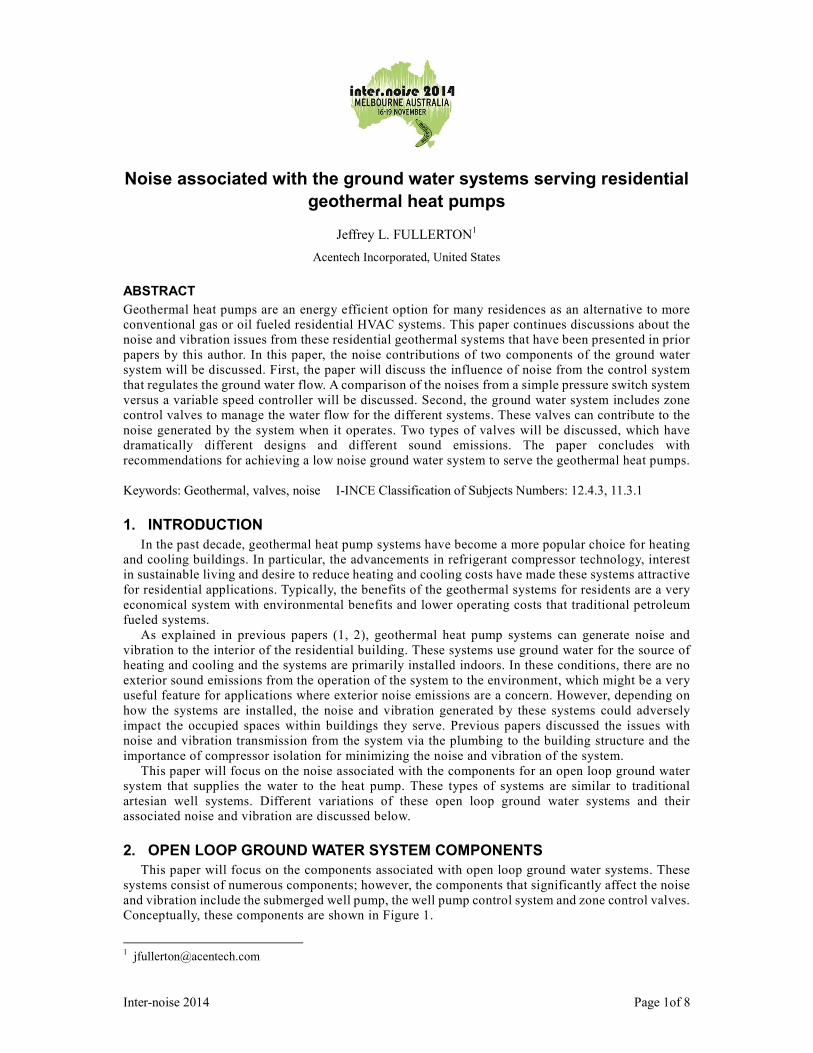
Conceptually, these components are shown in Figure 1.
Page 2 of 8
Figure 1 –Schematic diagram of the ground water system
2.1 Well pump
After the well has been drilled and water has
the well. The pump is plumbed and wired vertically in the well feeding the supplied water to the
building through horizontally routed unground piping.
through the foundation and is routed to
2.2 Well Pump Control System
There are several methods for how the operation of the well pump is controlled.
discuss two options; the first being a
while the second consists of a pressure sensor and
these two setups are discussed below.
2.2.1 Pressure Switch and Single Speed Pump ControllerThe pressure switch method has been used for many years for controlling these types of
systems. This type of control system
single speed pump controller. The switch
When the heat pump is not running, a set pressure
in the ground water system. After
pressure switch senses when the water pressure in the system drops below a set pressure, at which time
the switch activates a relay that provides a signal to the single speed pump controller that the pump
should operate. The pressure at which the switch activates the relay is
pressure, which turns the pump on. After the heat pump turns off
Zone Valve
Geothermal
Heat Pump
Pump Controller
Inter
ground water system components for a geothermal heat pump
After the well has been drilled and water has been found, a submersible well pump is lowered into
The pump is plumbed and wired vertically in the well feeding the supplied water to the
building through horizontally routed unground piping. Typically, the piping enters into the building
h the foundation and is routed to a pressurized water storage tank.
Control System
There are several methods for how the operation of the well pump is controlled. This paper will
discuss two options; the first being a traditional pressure switch with a single speed pump controller
consists of a pressure sensor and a variable speed pump controller. The differences of
these two setups are discussed below.
and Single Speed Pump Controller as been used for many years for controlling these types of
system is a standard diaphragm pressure switch that is connected to a
The switch is used to sense the pressure in the ground
When the heat pump is not running, a set pressure is maintained in the pressurized water storage tank
fter the heat pump is activated and the zone control valve
pressure switch senses when the water pressure in the system drops below a set pressure, at which time
tivates a relay that provides a signal to the single speed pump controller that the pump
at which the switch activates the relay is referred to as the “cut in”
on. After the heat pump turns off and the zone control valve closes
Well Pump
Pressurized
Storage Tank
Pressure Sensor
Inter-noise 2014
heat pump system.
been found, a submersible well pump is lowered into
The pump is plumbed and wired vertically in the well feeding the supplied water to the
Typically, the piping enters into the building
This paper will
with a single speed pump controller,
he differences of
as been used for many years for controlling these types of well pump
is connected to a
pressure in the ground water system.
pressurized water storage tank
and the zone control valve opens, the
pressure switch senses when the water pressure in the system drops below a set pressure, at which time
tivates a relay that provides a signal to the single speed pump controller that the pump
referred to as the “cut in”
and the zone control valve closes, the
Inter-noise 2014
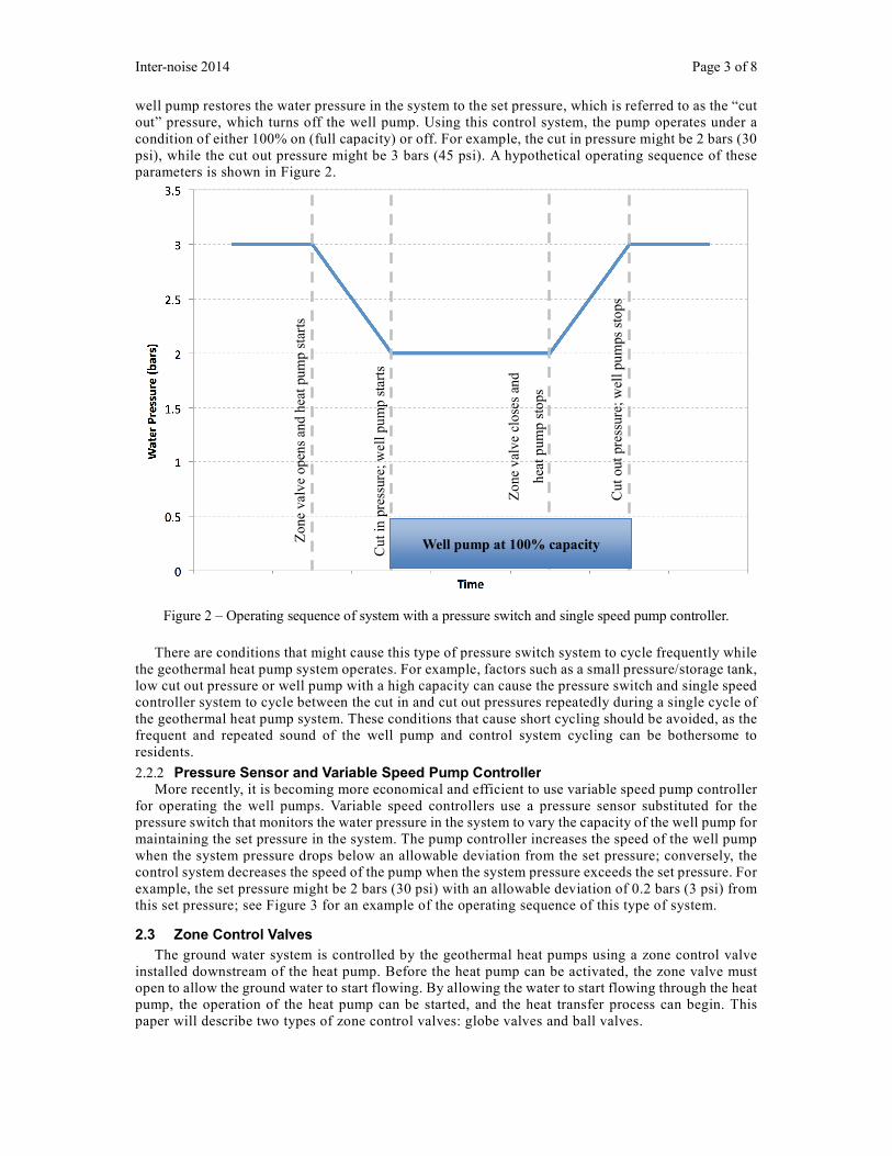
well pump restores the water pressure in the system to the set pressure, which is referred to as the
out” pressure, which turns off the well pump
condition of either 100% on (full capacity) or off
psi), while the cut out pressure might be
parameters is shown in Figure 2.
Figure 2 – Operating sequence of system with a pressure switch and single speed
There are conditions that might cause this type of pressure switch system to cycle frequently while
the geothermal heat pump system operates. For example, factors such as a small pressure/storage tank,
low cut out pressure or well pump with a
controller system to cycle between the cut in and cut out pressures
the geothermal heat pump system. These conditions that cause short cycling should be avoided, as the
frequent and repeated sound of the well pump and control system cycling can be bothersome to
residents.
2.2.2 Pressure Sensor and Variable Speed Pump ControllerMore recently, it is becoming more economical and efficient to use
for operating the well pumps. Variable speed
pressure switch that monitors the water
maintaining the set pressure in the system. The
when the system pressure drops below
control system decreases the speed of the pump when the system pressure exceeds the set pressure.
example, the set pressure might be 2 bars (30 psi)
this set pressure; see Figure 3 for an example of the operating sequence of this type of system.
2.3 Zone Control Valves
The ground water system is controlled by the geothermal heat pumps using a
installed downstream of the heat pump. Before the heat pump can be
open to allow the ground water to start flowing. By allowing the water to start flowing through the heat
pump, the operation of the heat pump can be started,
paper will describe two types of zone
Zone
val
ve
open
s an
d h
eat
pum
p s
tart
s
well pump restores the water pressure in the system to the set pressure, which is referred to as the
, which turns off the well pump. Using this control system, the pump operates under a
condition of either 100% on (full capacity) or off. For example, the cut in pressure might be
the cut out pressure might be 3 bars (45 psi). A hypothetical operating sequence of these
Operating sequence of system with a pressure switch and single speed pump
There are conditions that might cause this type of pressure switch system to cycle frequently while
system operates. For example, factors such as a small pressure/storage tank,
with a high capacity can cause the pressure switch and single speed
to cycle between the cut in and cut out pressures repeatedly during a single cycle of
These conditions that cause short cycling should be avoided, as the
sound of the well pump and control system cycling can be bothersome to
Variable Speed Pump Controller it is becoming more economical and efficient to use variable speed pump controller
umps. Variable speed controllers use a pressure sensor substituted for the
water pressure in the system to vary the capacity of the
set pressure in the system. The pump controller increases the speed of the
em pressure drops below an allowable deviation from the set pressure; conversely, the
control system decreases the speed of the pump when the system pressure exceeds the set pressure.
2 bars (30 psi) with an allowable deviation of 0.2 bars (3 psi) from
this set pressure; see Figure 3 for an example of the operating sequence of this type of system.
ground water system is controlled by the geothermal heat pumps using a zone
at pump. Before the heat pump can be activated, the zone
open to allow the ground water to start flowing. By allowing the water to start flowing through the heat
the heat pump can be started, and the heat transfer process can begin.
zone control valves: globe valves and ball valves.
Cu
t in
pre
ssure
; w
ell
pu
mp s
tart
s
Zo
ne
val
ve
close
s an
d
hea
t p
um
p s
tops
Cut
out
pre
ssure
; w
ell
pu
mps
sto
ps
Well pump at 100% capacity
Page 3 of 8
well pump restores the water pressure in the system to the set pressure, which is referred to as the “cut
Using this control system, the pump operates under a
, the cut in pressure might be 2 bars (30
operating sequence of these
pump controller.
There are conditions that might cause this type of pressure switch system to cycle frequently while
system operates. For example, factors such as a small pressure/storage tank,
and single speed
during a single cycle of
These conditions that cause short cycling should be avoided, as the
sound of the well pump and control system cycling can be bothersome to
pump controller
substituted for the
pressure in the system to vary the capacity of the well pump for
the speed of the well pump
the set pressure; conversely, the
control system decreases the speed of the pump when the system pressure exceeds the set pressure. For
deviation of 0.2 bars (3 psi) from
this set pressure; see Figure 3 for an example of the operating sequence of this type of system.
zone control valve
zone valve must
open to allow the ground water to start flowing. By allowing the water to start flowing through the heat
at transfer process can begin. This
Page 4 of 8
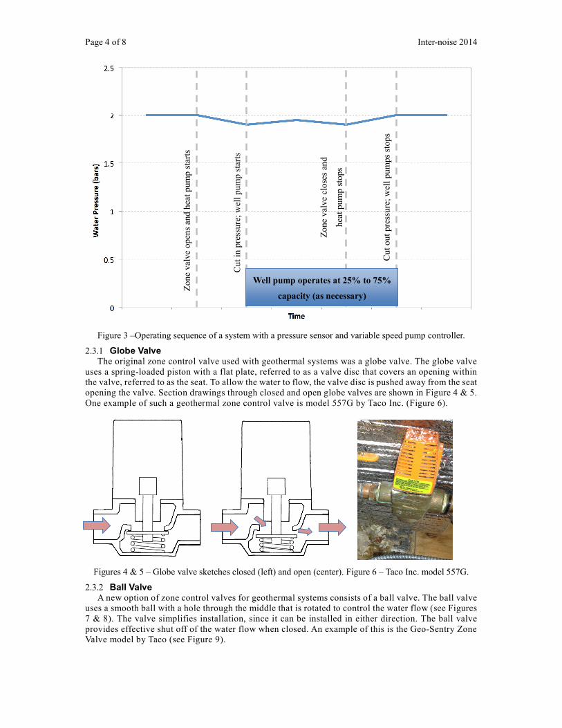
Figure 3 –Operating sequence of a
2.3.1 Globe Valve The original zone control valve used with geothe
uses a spring-loaded piston with a flat pla
the valve, referred to as the seat. To allow
opening the valve. Section drawings through closed and open globe valve
One example of such a geothermal zone control valve is model 557G by Taco
Figures 4 & 5 – Globe valve sketche
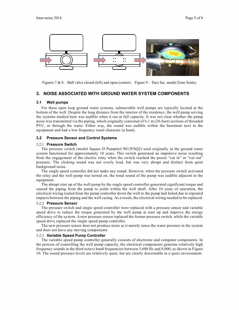
2.3.2 Ball Valve A new option of zone control valve
uses a smooth ball with a hole through the middle that is rotated to control the water flow
7 & 8). The valve simplifies installation, since it can be installed
provides effective shut off of the water flow when closed. An example of this is
Valve model by Taco (see Figure 9).
Zo
ne
val
ve
open
s an
d h
eat
pum
p s
tart
s
Inter
a system with a pressure sensor and variable speed pump
The original zone control valve used with geothermal systems was a globe valve. The globe valve
loaded piston with a flat plate, referred to as a valve disc that covers an opening within
o allow the water to flow, the valve disc is pushed away from the seat
s through closed and open globe valves are shown in Fig
One example of such a geothermal zone control valve is model 557G by Taco Inc. (Figure 6
sketches closed (left) and open (center). Figure 6 – Taco Inc. model 557G.
valves for geothermal systems consists of a ball valve. The ball valve
uses a smooth ball with a hole through the middle that is rotated to control the water flow
. The valve simplifies installation, since it can be installed in either direction.
provides effective shut off of the water flow when closed. An example of this is the Geo
).
Well pump operates at 25% to 75%
capacity (as necessary)
Cu
t in
pre
ssure
; w
ell
pu
mp s
tart
s
Zo
ne
val
ve
close
s an
d
hea
t p
um
p s
tops
Cut
out
pre
ssure
; w
ell
pum
ps
stop
s
Inter-noise 2014
pump controller.
The globe valve
that covers an opening within
pushed away from the seat
shown in Figure 4 & 5.
Inc. (Figure 6).
Taco Inc. model 557G.
a ball valve. The ball valve
uses a smooth ball with a hole through the middle that is rotated to control the water flow (see Figures
The ball valve
Geo-Sentry Zone
Inter-noise 2014 Page 5 of 8
Figures 7 & 8 – Ball valve closed (left) and open (center). Figure 9 – Taco Inc. model Zone Sentry.
3. NOISE ASSOCIATED WITH GROUND WATER SYSTEM COMPONENTS
3.1 Well pumps
For these open loop ground water systems, submersible well pumps are typically located at the
bottom of the well. Despite the long distance from the interior of the residence, the well pump serving
the systems studied here was audible when it ran at full capacity. It was not clear whether the pump
noise was transmitted via the piping, which originally consisted of 6.1 m (20-foot) sections of threaded
PVC, or through the water. Either way, the sound was audible within the basement next to the
equipment and had a low frequency tonal character (a hum).
3.2 Pressure Sensor and Control Systems
3.2.1 Pressure Switch The pressure switch (model Square D Pumptrol 9013FSQ2) used originally in the ground water
system functioned for approximately 10 years. This switch generated an impulsive noise resulting
from the engagement of the electric relay when the switch reached the preset “cut in” or “cut out”
pressure. The clicking sound was not overly loud, but was very abrupt and distinct from quiet
background noise.
The single speed controller did not make any sound. However, when the pressure switch activated
the relay and the well pump was turned on, the tonal sound of the pump was audible adjacent to the
equipment.
The abrupt start up of the well pump by the single speed controller generated significant torque and
caused the piping from the pump to jostle within the well shaft. After 10 years of operation, the
electrical wiring routed from the pump controller down the well to the pump had failed due to repeated
impacts between the piping and the well casing. As a result, the electrical wiring needed to be replaced.
3.2.2 Pressure Sensor The pressure switch and single speed controller were replaced with a pressure sensor and variable
speed drive to reduce the torque generated by the well pump at start up and improve the energy
efficiency of the system. A new pressure sensor replaced the former pressure switch, while the variable
speed drive replaced the single speed pump controller.
The new pressure sensor does not produce noise as it merely sense the water pressure in the system
and does not have any moving components.
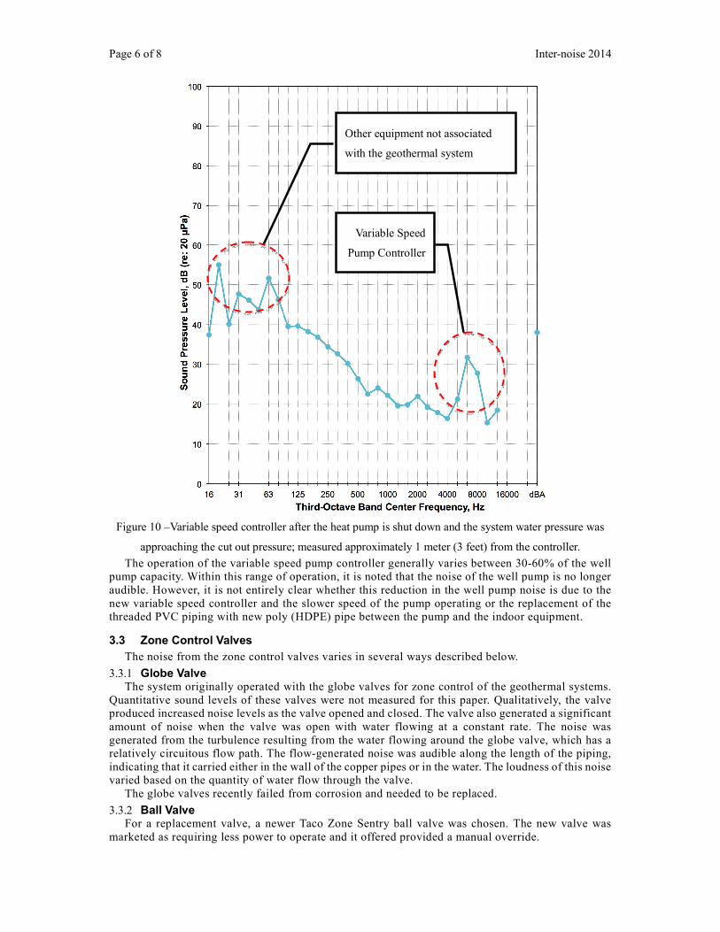
3.2.3 Variable Speed Pump Controller The variable speed pump controller generally consists of electronic and computer components. In
the process of controlling the well pump capacity, the electrical components generate relatively high
frequency sounds in the third octave band frequencies between 5,600 Hz and 8,000, as shown in Figure
10. The sound pressure levels are relatively quiet, but are clearly discernable in a quiet environment.
Page 6 of 8
Figure 10 –Variable speed controller after the heat pump is shut down and the
approaching the cut out pressure; measured
The operation of the variable speed pump controller generally varies between 30
pump capacity. Within this range of operation, it is noted that the noise of the well pump is no longer
audible. However, it is not entirely clear whether
new variable speed controller and the slower speed of the pump o
threaded PVC piping with new poly (HDPE) pipe
3.3 Zone Control Valves
The noise from the zone control valves varies in several ways described below
3.3.1 Globe Valve The system originally operated with the globe valves for zone c
Quantitative sound levels of these
produced increased noise levels as the valve
amount of noise when the valve was open
generated from the turbulence resulting from
relatively circuitous flow path. The
indicating that it carried either in the wall of the copper pipes or in the water.
varied based on the quantity of water flow through the valve.
The globe valves recently failed from corrosion and needed to be replaced.
3.3.2 Ball Valve For a replacement valve, a new
marketed as requiring less power to operate and
Inter
Variable speed controller after the heat pump is shut down and the system water pressure
approaching the cut out pressure; measured approximately 1 meter (3 feet) from the controller.
The operation of the variable speed pump controller generally varies between 30-60%
Within this range of operation, it is noted that the noise of the well pump is no longer
audible. However, it is not entirely clear whether this reduction in the well pump noise is due to the
and the slower speed of the pump operating or the replacement of the
threaded PVC piping with new poly (HDPE) pipe between the pump and the indoor equipment
The noise from the zone control valves varies in several ways described below.
The system originally operated with the globe valves for zone control of the geothermal systems.
Quantitative sound levels of these valves were not measured for this paper. Qualitatively, the valve
increased noise levels as the valve opened and closed. The valve also generated
when the valve was open with water flowing at a constant rate. The noise was
resulting from the water flowing around the globe valve
he flow-generated noise was audible along the length of the piping,
in the wall of the copper pipes or in the water. The loudness of this noise
based on the quantity of water flow through the valve.
he globe valves recently failed from corrosion and needed to be replaced.
newer Taco Zone Sentry ball valve was chosen. The new valve was
ss power to operate and it offered provided a manual override.
Variable Speed
Pump Controller
Other equipment not associated
with the geothermal system
Inter-noise 2014
water pressure was
controller.
60% of the well
Within this range of operation, it is noted that the noise of the well pump is no longer
this reduction in the well pump noise is due to the
or the replacement of the
equipment.
ontrol of the geothermal systems.
were not measured for this paper. Qualitatively, the valve
generated a significant
The noise was
the water flowing around the globe valve, which has a
generated noise was audible along the length of the piping,
loudness of this noise
The new valve was
a manual override.
Inter-noise 2014
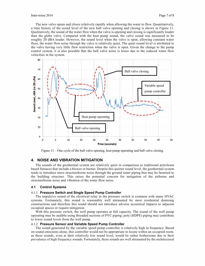
The new valve opens and closes
a time history of the sound level of the
Qualitatively, the sound of the water flow when the valve is
than the globe valve. Compared with the heat pump sound, the valve sound was measur
roughly 20 dBA louder. However,
floor, the water flow noise through the valve
the valve having very little flow restriction when the valve is open
control system, it is also possible that the
velocities in the system.
Figure 11 – One cycle of the ball valve opening, heat pump operating and ball valve closing.
4. NOISE AND VIBRATION
The sounds of the geothermal system are relatively quiet in comparison to traditional petroleum
based furnaces that include a blower or burner. Despite this quieter sound level, the geothermal system
tends to introduce more structureborne noise through the
the building structure. This raises the potential concern for
structureborne noise and vibration of the water flow noise.
4.1 Control Systems
4.1.1 Pressure Switch and Single Speed Pump ContrThe impulsive sound of the electrical
systems. Fortunately, this sound is reasonably well attenuated by most residential demising
constructions and therefore this sound should not introduce advers
occupied spaces or require mitigation
With this pressure switch, the well pump operates at full capacity. The sound of the well pump
operating may be audible using threaded sections of PVC piping; poly (HDPE) piping may co
to lower sound levels from the well pump.
4.1.2 Pressure Sensor and Variable Speed Pump ControllerThe sound generated by the variable speed pump controller is relatively high in frequency
on sound emissions alone, this controller would not be ap
as these sounds, even at their relatively low sound level, would be rather bothersome due to their
prevalence of high frequency sounds
Ball valve opening
relatively rapidly when allowing the water to flow. Quantitatively,
vel of the new ball valve opening and closing is shown in Figure
sound of the water flow when the valve is opening and closing is significantly louder
Compared with the heat pump sound, the valve sound was measur
However, the sound level when the valve is open, allowing constant water
floor, the water flow noise through the valve is relatively quiet. The quiet sound level
the valve having very little flow restriction when the valve is open. Given the change to the
control system, it is also possible that the ball valve noise is lower due to the reduced
One cycle of the ball valve opening, heat pump operating and ball valve closing.
AND VIBRATION MITIGATION
The sounds of the geothermal system are relatively quiet in comparison to traditional petroleum
based furnaces that include a blower or burner. Despite this quieter sound level, the geothermal system
more structureborne noise through the ground water piping that may be fastened to
the building structure. This raises the potential concern for mitigation of the airborne and
noise and vibration of the water flow noise.
and Single Speed Pump Controller electrical relay in the pressure switch is common with many HVAC
systems. Fortunately, this sound is reasonably well attenuated by most residential demising
constructions and therefore this sound should not introduce adverse acoustical impacts to adjacent
or require mitigation.
With this pressure switch, the well pump operates at full capacity. The sound of the well pump
operating may be audible using threaded sections of PVC piping; poly (HDPE) piping may co
to lower sound levels from the well pump.
Variable Speed Pump Controller The sound generated by the variable speed pump controller is relatively high in frequency
on sound emissions alone, this controller would not be appropriate to locate within an occupied room,
as these sounds, even at their relatively low sound level, would be rather bothersome due to their
prevalence of high frequency sounds. Fortunately, these sounds are well attenuated by the architectural
Ball valve opening
Ball valve closing
Variable speed
pump controller
Heat pump operating
Page 7 of 8
flow. Quantitatively,
valve opening and closing is shown in Figure 11.
opening and closing is significantly louder
Compared with the heat pump sound, the valve sound was measured to be
, allowing constant water
is attributed to
. Given the change to the pump
he reduced water flow
One cycle of the ball valve opening, heat pump operating and ball valve closing.
The sounds of the geothermal system are relatively quiet in comparison to traditional petroleum
based furnaces that include a blower or burner. Despite this quieter sound level, the geothermal system
ground water piping that may be fastened to
mitigation of the airborne and
with many HVAC
systems. Fortunately, this sound is reasonably well attenuated by most residential demising
e acoustical impacts to adjacent
With this pressure switch, the well pump operates at full capacity. The sound of the well pump
operating may be audible using threaded sections of PVC piping; poly (HDPE) piping may contribute
The sound generated by the variable speed pump controller is relatively high in frequency. Based
propriate to locate within an occupied room,
as these sounds, even at their relatively low sound level, would be rather bothersome due to their
e well attenuated by the architectural
Variable speed
pump controller
Page 8 of 8 Inter-noise 2014
Page 8 of 8 Inter-noise 2014
demising constructions that are typically used in residences and should not introduce acoustical
impacts to adjacent occupied spaces.
4.2 Zone Control Valves
The selection of the type of zone control valve plays an important factor in the potential sound
impacts of the ground water systems. These are discussed below.
4.2.1 Globe Valve Subjectively, the globe valve generated sound levels that were audible, but did not have significant
variation over the course of the valve operation. The valve produces somewhat more noise when it is
fully open and allowing the water flow to occur. The globe valve has less substantial noise when the
valve is opened and closed. Airborne noise mitigation of this valve may be possible using typical
residential demising constructions. Mitigation of the structureborne noise and vibration should be
handled with resilient plumbing clamps for supporting the associated piping in which the valve is
installed.
4.2.2 Ball Valve The ball valve generates significant noise for the 1-2 seconds while the ball opens and closes.
After the valve is opened, the water flow noise through the valve is minimal. Where possible, the
location of valve should be selected to avoid placing the valves near noise sensitive spaces within
residences. Airborne noise mitigation of the valve noise may be possible with typical residential
demising constructions. The mitigation of the structureborne noise and vibration should be handled by
using resilient plumbing clamps once a less intrusive valve location has been determined.
5. CONCLUSIONS
The modifications to the ground water system serving the geothermal heat pumps has resulted in
both somewhat lower and somewhat higher sound levels from the system under different operating
conditions. The substitution of the pressure switch with the pressure sensor removed the impulsive
noise generated by the electric relay as the switch engages or disengages the well pump controller. The
new variable speed drive reduced the noise of the well pump, by operating the well pump at a lower
capacity, but introduced new high frequency noises associated with the controller’s electronics, which
modulate the pump capacity. The substitution of the original globe valve with the new ball valve
reduced the sound levels when the valve is open and water is flowing, but significantly increased the
sound when the ball valve opens and closes. In many situations, these changes many have little to no
impact for residences, particularly where living spaces are distant from where the equipment is located
in the residence, typical residential demising constructions are used and the piping is resiliently
supported from the building structure.
REFERENCES
1. Fullerton, J.L., Noise and vibration control for a residential geothermal heat pump installation. Proc. of
NoiseCon08; July 28-30, 2008; Dearborn, MI, pp. 1037-1044.
2. Fullerton, J.L., Geothermal heat pump noise and vibration control (cont.): It is all in the details!. Proc.
of NoiseCon10; April 19-21, 2010; Baltimore, MD, pp. 1180-1185.


![The relationship between aircraft sound levels, noise ... more associated with noise annoyance than with objectively assessed sound levels [2, 8]. For aircraft noise, covariations](https://img.pdfslide.us/doc/110x75/5e1303ce8ced1307a64e7605/the-relationship-between-aircraft-sound-levels-noise-more-associated-with-noise.jpg)