Embed Size (px)
Citation preview
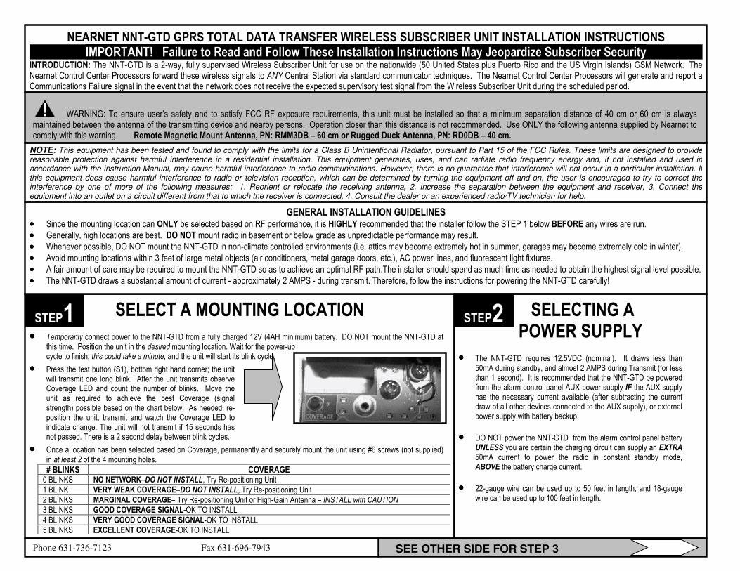
SELECT A MOUNTING LOCATION
•••• Temporarily connect power to the NNT-GTD from a fully charged 12V (4AH minimum) battery. DO NOT mount the NNT-GTD at this time. Position the unit in the desired mounting location. Wait for the power-up cycle to finish, this could take a minute, and the unit will start its blink cycle.
•••• Press the test button (S1), bottom right hand corner; the unit will transmit one long blink. After the unit transmits observe Coverage LED and count the number of blinks. Move the unit as required to achieve the best Coverage (signal strength) possible based on the chart below. As needed, re-position the unit, transmit and watch the Coverage LED to indicate change. The unit will not transmit if 15 seconds has not passed. There is a 2 second delay between blink cycles.
•••• Once a location has been selected based on Coverage, permanently and securely mount the unit using #6 screws (not supplied) in at least 2 of the 4 mounting holes. # BLINKS COVERAGE
0 BLINKS NO NETWORK–DO NOT INSTALL, Try Re-positioning Unit
1 BLINK VERY WEAK COVERAGE–DO NOT INSTALL, Try Re-positioning Unit
2 BLINKS MARGINAL COVERAGE– Try Re-positioning Unit or High-Gain Antenna – INSTALL with CAUTION
3 BLINKS GOOD COVERAGE SIGNAL-OK TO INSTALL
4 BLINKS VERY GOOD COVERAGE SIGNAL-OK TO INSTALL
5 BLINKS EXCELLENT COVERAGE-OK TO INSTALL
NEARNET NNT-GTD GPRS TOTAL DATA TRANSFER WIRELESS SUBSCRIBER UNIT INSTALLATION INSTRUCTIONS IMPORTANT! Failure to Read and Follow These Installation Instructions May Jeopardize Subscriber Security
INTRODUCTION: The NNT-GTD is a 2-way, fully supervised Wireless Subscriber Unit for use on the nationwide (50 United States plus Puerto Rico and the US Virgin Islands) GSM Network. The Nearnet Control Center Processors forward these wireless signals to ANY Central Station via standard communicator techniques. The Nearnet Control Center Processors will generate and report a Communications Failure signal in the event that the network does not receive the expected supervisory test signal from the Wireless Subscriber Unit during the scheduled period.
GENERAL INSTALLATION GUIDELINES •••• Since the mounting location can ONLY be selected based on RF performance, it is HIGHLY recommended that the installer follow the STEP 1 below BEFORE any wires are run.
•••• Generally, high locations are best. DO NOT mount radio in basement or below grade as unpredictable performance may result.
•••• Whenever possible, DO NOT mount the NNT-GTD in non-climate controlled environments (i.e. attics may become extremely hot in summer, garages may become extremely cold in winter).
•••• Avoid mounting locations within 3 feet of large metal objects (air conditioners, metal garage doors, etc.), AC power lines, and fluorescent light fixtures.
•••• A fair amount of care may be required to mount the NNT-GTD so as to achieve an optimal RF path.The installer should spend as much time as needed to obtain the highest signal level possible.
•••• The NNT-GTD draws a substantial amount of current - approximately 2 AMPS - during transmit. Therefore, follow the instructions for powering the NNT-GTD carefully!
SELECTING A POWER SUPPLY
•••• The NNT-GTD requires 12.5VDC (nominal). It draws less than 50mA during standby, and almost 2 AMPS during Transmit (for less than 1 second). It is recommended that the NNT-GTD be powered from the alarm control panel AUX power supply IF the AUX supply has the necessary current available (after subtracting the current draw of all other devices connected to the AUX supply), or external power supply with battery backup.
•••• DO NOT power the NNT-GTD from the alarm control panel battery UNLESS you are certain the charging circuit can supply an EXTRA 50mA current to power the radio in constant standby mode, ABOVE the battery charge current.
•••• 22-gauge wire can be used up to 50 feet in length, and 18-gauge wire can be used up to 100 feet in length.
SEE OTHER SIDE FOR STEP 3 Phone 631-736-7123 Fax 631-696-7943
STEP1 STEP2
WARNING: To ensure user’s safety and to satisfy FCC RF exposure requirements, this unit must be installed so that a minimum separation distance of 40 cm or 60 cm is always maintained between the antenna of the transmitting device and nearby persons. Operation closer than this distance is not recommended. Use ONLY the following antenna supplied by Nearnet to comply with this warning. Remote Magnetic Mount Antenna, PN: RMM3DB – 60 cm or Rugged Duck Antenna, PN: RD0DB – 40 cm.
NOTE: This equipment has been tested and found to comply with the limits for a Class B Unintentional Radiator, pursuant to Part 15 of the FCC Rules. These limits are designed to provide reasonable protection against harmful interference in a residential installation. This equipment generates, uses, and can radiate radio frequency energy and, if not installed and used in accordance with the instruction Manual, may cause harmful interference to radio communications. However, there is no guarantee that interference will not occur in a particular installation. If this equipment does cause harmful interference to radio or television reception, which can be determined by turning the equipment off and on, the user is encouraged to try to correct the interference by one of more of the following measures: 1. Reorient or relocate the receiving antenna, 2. Increase the separation between the equipment and receiver, 3. Connect the equipment into an outlet on a circuit different from that to which the receiver is connected, 4. Consult the dealer or an experienced radio/TV technician for help.
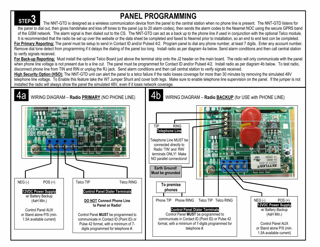
PANEL PROGRAMMING The NNT-GTD is designed as a wireless communication device from the panel to the central station when no phone line is present. The NNT-GTD listens for
the panel to dial out, then gives handshake and kiss off tones to the panel (up to 20 alarm codes), then sends the alarm codes to the Nearnet NOC using the secure GPRS band of the GSM network. The alarm signal is then dialed out to the CS. The NNT-GTD can act as a back up to the phone line if used in conjunction with the optional Telco module. It is recommended that the radio be set up over the website or the data sheet be completed and faxed to Nearnet prior to installation, so an end to end test con be completed.
For Primary Reporting: The panel must be setup to send in Contact ID and/or Pulsed 4/2. Program panel to dial any phone number, at least 7 digits. Enter any account number. Remove dial tone detect from programming if it delays the dialing of the panel too long. Install radio as per diagram 4a below. Send alarm conditions and then call central station to verify signals received. For Back-up Reporting: Must install the optional Telco Board just above the terminal strip onto the J2 header on the main board. The radio will only communicate with the panel when phone line voltage is not present due to a line cut. The panel must be programmed for Contact ID and/or Pulsed 4/2. Install radio as per diagram 4b below. To test radio, disconnect phone line from TIN and RIN or unplug the RJ jack. Send alarm conditions and then call central station to verify signals received. High Security Option (HSO): The NNT-GTD unit can alert the panel to a telco failure if the radio losses coverage for more than 30 minutes by removing the simulated 48V telephone line voltage. To Enable this feature take the W7 Jumper Shunt and cover both legs. Make sure to enable telephone line supervision on the panel. If the jumper is not installed the radio will always show the panel the simulated 48V, even if it loses network coverage.
STEP3
4a WIRING DIAGRAM – Radio PRIMARY (NO PHONE LINE)
NEG (-) POS (+)
12VDC Power Supply w/ Battery Backup
(4aH Min.)
Control Panel AUX or Stand alone P/S (min. 1.5A available current)
Telco TIP Telco RING
Control Panel Dialer Terminals
DO NOT Connect Phone Line to Panel or Radio!
Control Panel MUST be programmed to communicate in Contact ID (Point ID) or Pulse 42 format, with a minimum of 7-digits programmed for telephone #.
4b WIRING DIAGRAM – Radio BACKUP (for USE with PHONE LINE)
Phone TIP Phone RING Telco TIP Telco RING
Control Panel Dialer Terminals Control Panel MUST be programmed to
communicate in Contact ID (Point ID) or Pulse 42 format, with a minimum of 7-digits programmed for
telephone #.
NEG (-) POS (+) 12VDC Power Supply
w/ Battery Backup (4aH Min.)
Control Panel AUX
or Stand alone P/S (min. 1.5A available current)
Earth Ground! Must be grounded
To premise phones
TIP RING Telephone Line
Telephone Line MUST be
connected directly to Radio ‘TIN’ and ‘RIN’
terminals ONLY! Make NO parallel connections!