Embed Size (px)
Citation preview
NMS Operation Manual
1
NMS Web 2.0 NMS Operation Manual
2018
NMS Operation Manual
2
Introduction NMS Web 2.0, researched and developed by BDCOM, is a multi-platform network
management system supporting several protocols, such as SNMP, HTTP, CLI. It contains
abundant tools to monitor network performance, amicable interface display for customers,
all-sided but simple functions of network configuration and so on. It is helpful for NMS to
immensely improve the efficiency of network operation. NMS has the ability to real time monitor
the whole network, helping Administrator realize centralized management in LAN.
NMS Web Operation Manual is a brief but detailed manual aiming at NMS. Through this
manual, network administrator can get details in all management functions and operation
approaches of NMS.

NMS Operation Manual
3
Table of Contents
1 Home .............................................................................................................................................. 8
1.1 Statistics .............................................................................................................................. 8
1.2 Quick Search ....................................................................................................................... 9
2 Network Elements ........................................................................................................................ 10
2.1 Discovery Node ................................................................................................................. 10
2.1.1 RealTime Discovery Logs ...................................................................................... 11
2.1.2 Save Discovery Node and Load History Record .................................................... 11
2.2 Discovery Net ................................................................................................................... 12
2.3 Log Search ........................................................................................................................ 13
2.4 Caution .............................................................................................................................. 13
3 Management Element .................................................................................................................. 14
3.1 Page Refresh Config ......................................................................................................... 14
3.2 advanced search ................................................................................................................ 15
3.3 Modify DisplayName ........................................................................................................ 16
3.4 Update Status .................................................................................................................... 16
3.5 Delete OLT ........................................................................................................................ 17
3.6 Chassis .............................................................................................................................. 17
3.7 Config ............................................................................................................................... 17
3.8 Alarms ............................................................................................................................... 18
3.9 Basic Info .......................................................................................................................... 18
3.10 Check Onus ..................................................................................................................... 18
3.11 PSG Info .......................................................................................................................... 21
3.12 Save Config ..................................................................................................................... 22
3.13 Http To Device ................................................................................................................ 22
3.14 Https To Device ............................................................................................................... 22
3.15 Telnet To Device ............................................................................................................. 22
3.16 ONU Hand in Hand Info ................................................................................................. 22
3.17 Reboot Device ................................................................................................................. 22
3.18 CPU Performance Collection .......................................................................................... 22
3.19 Memory Usage Collection .............................................................................................. 23
3.20 Device List Sort Node ..................................................................................................... 23
3.21 AC/AP ............................................................................................................................. 24
3.21.1 AC ........................................................................................................................ 24
3.21.2 AP ......................................................................................................................... 27
4 Topo Display ................................................................................................................................ 29
4.1 Select map ......................................................................................................................... 29
4.2 Search Device ................................................................................................................... 30
4.3 Select Layout..................................................................................................................... 31
4.4 Refresh .............................................................................................................................. 31
4.5 Save ................................................................................................................................... 32
4.6 Select Belongs Role and Area ........................................................................................... 32
4.7 Create Map ........................................................................................................................ 32
NMS Operation Manual
4
4.8 Add Map Symbol .............................................................................................................. 34
4.9 Add MapLink .................................................................................................................... 36
4.10 Edit .................................................................................................................................. 37
4.11 Delete User Define Topo elements 自定义拓扑图删除元素 ......................................... 38
4.12 Select the saving location 自定义拓扑图保存位置 ....................................................... 38
4.13 Delete the User Define Topo 自定义拓扑图删除 .......................................................... 38
5 Fault Management........................................................................................................................ 39
5.1 Events ................................................................................................................................ 39
5.1.1 Search ..................................................................................................................... 40
5.1.2 Delete ..................................................................................................................... 40
5.1.3 Detail ...................................................................................................................... 40
5.1.4 Export Current Page Event & Export All Event ..................................................... 40
5.2 Alarms ............................................................................................................................... 40
5.2.1 Search ..................................................................................................................... 41
5.2.2 Delete ..................................................................................................................... 41
5.2.3 Detail ...................................................................................................................... 41
5.2.4 Sure Select .............................................................................................................. 42
5.2.5 Export Current Page Alert & Export All Alert ....................................................... 42
5.3 Fault Maintenance ............................................................................................................. 42
5.3.1 Trap Category ......................................................................................................... 42
5.3.2 Trap Level .............................................................................................................. 43
5.3.3 Trap Host ................................................................................................................ 44
6 Config Management ..................................................................................................................... 45
6.1 Switch Device ................................................................................................................... 45
6.1.1 Managed Object Attribute ...................................................................................... 45
6.1.2 Vlan Management .................................................................................................. 46
6.1.3 Batch Telnet Community Set ................................................................................. 51
6.1.4 Switch PON Port Monitor ...................................................................................... 51
6.1.5 Storm Control ......................................................................................................... 52
6.1.6 Port General Control .............................................................................................. 52
6.1.7 Transmission Rate Monitor .................................................................................... 54
6.1.8 Port Protect Group.................................................................................................. 54
6.1.9 ACL Config And Application ................................................................................. 55
6.1.10 QoS Queue and Scheduling Mode config ............................................................ 60
6.1.11 QoS Strategy Config ............................................................................................ 62
6.1.12 QoS Port ............................................................................................................... 63
6.1.13 STP Config ........................................................................................................... 64
6.1.14 Syslog Server Config ........................................................................................... 64
6.1.15 Static Route Config .............................................................................................. 65
6.2 EPON Device .................................................................................................................... 66
6.2.1 Managed Object Attribute ...................................................................................... 66
6.2.2 Vlan Management .................................................................................................. 66
6.2.3 OLT PON Optical Power Batch Set ....................................................................... 66
6.2.4 Batch Telnet Community Set ................................................................................. 66
NMS Operation Manual
5
6.2.5 Storm Control ......................................................................................................... 66
6.2.6 MultiCast ................................................................................................................ 66
6.2.7 PortControl ............................................................................................................. 68
6.2.8 PON Power Limit ................................................................................................... 68
6.2.9 QoS Global Cos And Bandwidth ........................................................................... 69
6.2.10 QoS Strategy Config ............................................................................................ 69
6.2.11 PonPortQosApply ................................................................................................. 69
6.2.12 ONU Auth Mode .................................................................................................. 69
6.2.13 ACL Config And Application ............................................................................... 73
6.2.14 ONU Global Vlan Config Template ..................................................................... 73
6.2.15 GIS Config ........................................................................................................... 76
6.2.16 Static Route Config .............................................................................................. 76
6.2.17 PON Port Cleft Grafting ....................................................................................... 76
6.2.18 OLT Encryption Config ........................................................................................ 76
6.2.19 Switch PON Port Monitor .................................................................................... 77
6.2.20 STP Config ........................................................................................................... 77
6.2.21 OLT Port Mirror ................................................................................................... 77
6.2.22 DBA Config ......................................................................................................... 78
6.2.23 Syslog Server Config ........................................................................................... 79
6.2.24 ONU Configure Template .................................................................................... 79
6.2.25 ONU Bind PON ................................................................................................... 80
6.2.26 Port Protect Group................................................................................................ 81
6.2.27 ONU Managed Object Attribute .......................................................................... 81
6.2.28 ONU Ranging ...................................................................................................... 81
6.2.29 ONU Optical Power Set ....................................................................................... 81
6.2.30 ONU Vlan Management ....................................................................................... 82
6.2.31 ONU Loop Test .................................................................................................... 82
6.2.32 ONU QoS Config ................................................................................................. 82
6.2.33 ONU UNI Port Limit Rate ................................................................................... 83
6.2.34 Serial Server Config ............................................................................................. 84
6.2.35 EPON ONU Multicast Config.............................................................................. 85
6.3 GPON Config .................................................................................................................... 85
6.3.1 Managed Object Attribute ...................................................................................... 85
6.3.2 Vlan Management .................................................................................................. 85
6.3.3 GPON-Set Sfp Values ............................................................................................ 86
6.3.4 Storm Control ......................................................................................................... 86
6.3.5 GPON MultiCast .................................................................................................... 86
6.3.6 Batch Telnet Community Set ................................................................................. 87
6.3.7 Port Rate Limit ....................................................................................................... 87
6.3.8 GIS Config ............................................................................................................. 87
6.3.9 GPON ONU Register ............................................................................................. 87
6.3.10 ACL Config And Application ............................................................................... 90
6.3.11 GPON ONU Configure Template ........................................................................ 91
6.3.12 Syslog Server Config ........................................................................................... 91
NMS Operation Manual
6
6.3.13 QoS Queue and Scheduling Mode Config ........................................................... 91
6.3.14 QoS Strategy Config ............................................................................................ 91
6.3.15 QoS Port ............................................................................................................... 91
6.3.16 Static Route Config .............................................................................................. 91
6.3.17 STP Config ........................................................................................................... 91
6.3.18 OLT Port Mirror ................................................................................................... 91
6.3.19 Port Protect Group................................................................................................ 91
6.3.20 ONU Managed Object Attribute .......................................................................... 91
6.3.21 GPON ONU Flow Control ................................................................................... 92
6.3.22 GPON ONU OptValue ......................................................................................... 93
6.3.23 GPON ONU Multicast ......................................................................................... 94
6.3.24 GPON ONU VirPortManage ................................................................................ 95
6.3.25 GPON ONU UNIConfig ...................................................................................... 96
6.3.26 GPON ONU Bandwidth Config ........................................................................... 97
6.3.27 GPON ONU Vlan .............................................................................................. 100
6.3.28 ONU Loop Test .................................................................................................. 101
7 Performance Collect ................................................................................................................... 102
7.1 Common Collection ........................................................................................................ 102
7.1.1 Eth Collection ...................................................................................................... 102
7.1.2 CPU Performance Collection ............................................................................... 105
7.1.3 Memory Usage Collection ................................................................................... 108
7.2 EPON Collection ............................................................................................................. 109
7.2.1 EPON PON Collection ......................................................................................... 109
7.2.2 EPON 15mOr24h ................................................................................................. 110
7.2.3 EPON ONU UNI.................................................................................................. 112
7.2.4 EPON ONU Serial ............................................................................................... 115
7.3 GPON Collection ............................................................................................................ 115
7.3.1 GPON PON Collection ........................................................................................ 115
7.3.2 GPON 15mOr24h................................................................................................. 116
7.3.3 GPON ONU UNI ................................................................................................. 116
7.3.4 GPON ONU Virtual ............................................................................................. 117
7.3.5 GPON ONU UNI 15m ......................................................................................... 117
7.3.6 GPON ONU Virtual 15m ..................................................................................... 118
7.4 AC/AP Collection ............................................................................................................ 118
7.5 Timing Collection ........................................................................................................... 120
7.6 History Collect ................................................................................................................ 122
8 Schedule Task ............................................................................................................................ 124
8.1 Create Task ...................................................................................................................... 124
8.1.1 Create Backup Task .............................................................................................. 125
8.1.2 Create Upgrade Task ............................................................................................ 130
8.1.3 System Task ......................................................................................................... 131
8.2 Task List .......................................................................................................................... 132
8.3 Execute Logs ................................................................................................................... 133
9 Business Management ................................................................................................................ 134
NMS Operation Manual
7
9.1 Active EPON ONU ......................................................................................................... 134
9.2 EPON Business Type Management ................................................................................ 134
9.3 Active GPON ONU ......................................................................................................... 134
9.4 App Download ................................................................................................................ 136
10 System Management ................................................................................................................ 137
10.1 System Logs .................................................................................................................. 137
10.2 Users And Permissions .................................................................................................. 137
10.2.1 Add NMSUser .................................................................................................... 137
10.2.2 Role Management .............................................................................................. 138
10.3 Area Scope Authorize .................................................................................................... 139
10.3.1 Create Area ......................................................................................................... 139
10.3.2 GrantToArea ....................................................................................................... 140
10.3.3 GrantToRole ....................................................................................................... 140
10.3.4 Edit ..................................................................................................................... 141
10.4 Tools .............................................................................................................................. 142
10.4.1 Server Ping ......................................................................................................... 142
10.4.2 Mo Name BackUp.............................................................................................. 143
10.4.3 Mo Name Restore .............................................................................................. 146
10.4.4 MO log Delete .................................................................................................... 147
10.4.5 Business Log Delete ........................................................................................... 147
10.4.6 Area Device Statistics......................................................................................... 148
10.4.7 Client Statistics ................................................................................................... 148
10.4.8 New Register ONU ............................................................................................ 149
10.4.9 Terminal Query By Mac ..................................................................................... 149
10.4.10 Batch Issue Config Order ................................................................................. 150
10.4.11 Alarm Monitor .................................................................................................. 150
10.4.12 EMAIL Config ................................................................................................. 151
10.4.13 LLDP Table ...................................................................................................... 152
10.4.14 MAC Address Table ......................................................................................... 153
10.4.15 Download Files ................................................................................................ 153
10.4.16 SNMP Search ................................................................................................... 154
10.5 About ............................................................................................................................. 155
10.6 Caution .......................................................................................................................... 155
11 root ........................................................................................................................................... 156
11.1 Show Real Alarms On/Off ............................................................................................ 156
11.2 Help/Support ................................................................................................................. 156
11.3 Change Password .......................................................................................................... 156
11.4 Log Out ......................................................................................................................... 157
NMS Operation Manual
8
1 Home
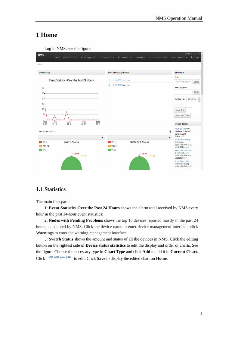
Log in NMS, see the figure.
1.1 Statistics
The main four parts:
1: Event Statistics Over the Past 24 Hours shows the alarm total received by NMS every
hour in the past 24-hour event statistics;
2: Nodes with Pending Problems shows the top 10 devices reported mostly in the past 24
hours, as counted by NMS. Click the device name to enter device management interface; click
Warnings to enter the warning management interface.
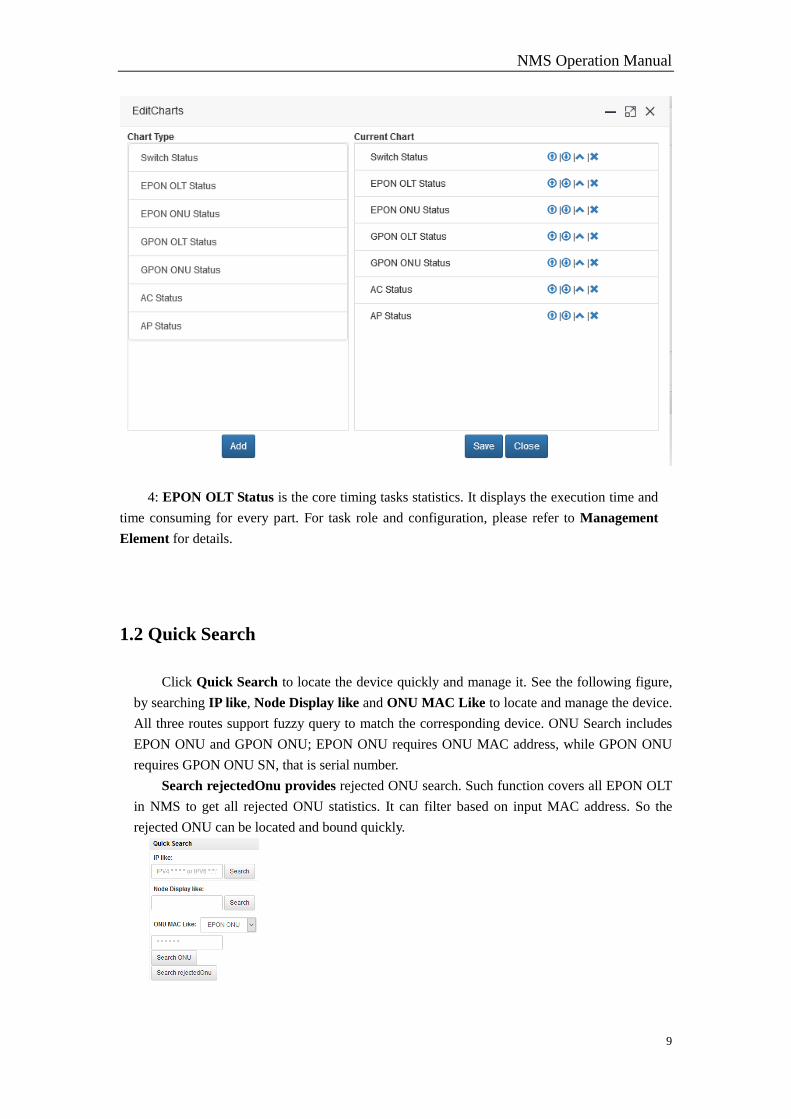
3: Switch Status shows the amount and status of all the devices in NMS. Click the editing
button on the rightest side of Device status statistics to edit the display and order of charts. See
the figure. Choose the necessary type in Chart Type and click Add to add it in Current Chart.
Click to edit. Click Save to display the edited chart on Home.
NMS Operation Manual
9
4: EPON OLT Status is the core timing tasks statistics. It displays the execution time and
time consuming for every part. For task role and configuration, please refer to Management
Element for details.
1.2 Quick Search
Click Quick Search to locate the device quickly and manage it. See the following figure,
by searching IP like, Node Display like and ONU MAC Like to locate and manage the device.
All three routes support fuzzy query to match the corresponding device. ONU Search includes
EPON ONU and GPON ONU; EPON ONU requires ONU MAC address, while GPON ONU
requires GPON ONU SN, that is serial number.
Search rejectedOnu provides rejected ONU search. Such function covers all EPON OLT
in NMS to get all rejected ONU statistics. It can filter based on input MAC address. So the
rejected ONU can be located and bound quickly.
NMS Operation Manual
10
2 Network Elements
Discovery and Management offers management portal to devices, an entry for all managed
devices. After input, the devices will be differentiated by NMS automatically according to the type,
condition and so on. The system provides appropriate management methods for all different
devices. NMS receives basic data of devices and saves all such data in background database.
Meanwhile, based on different types, all devices will be displayed on relevant interfaces.
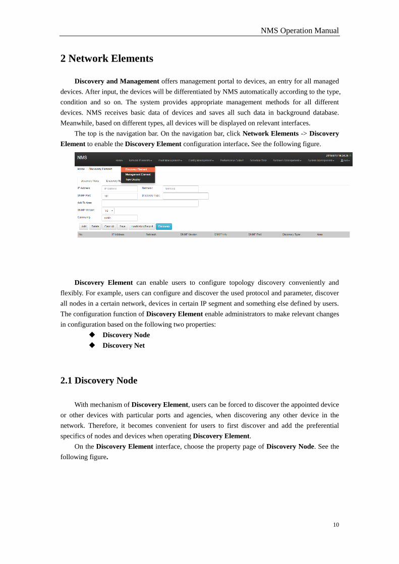
The top is the navigation bar. On the navigation bar, click Network Elements -> Discovery
Element to enable the Discovery Element configuration interface. See the following figure.
Discovery Element can enable users to configure topology discovery conveniently and
flexibly. For example, users can configure and discover the used protocol and parameter, discover
all nodes in a certain network, devices in certain IP segment and something else defined by users.
The configuration function of Discovery Element enable administrators to make relevant changes
in configuration based on the following two properties:
Discovery Node
Discovery Net
2.1 Discovery Node
With mechanism of Discovery Element, users can be forced to discover the appointed device
or other devices with particular ports and agencies, when discovering any other device in the
network. Therefore, it becomes convenient for users to first discover and add the preferential
specifics of nodes and devices when operating Discovery Element.
On the Discovery Element interface, choose the property page of Discovery Node. See the
following figure.
NMS Operation Manual
11
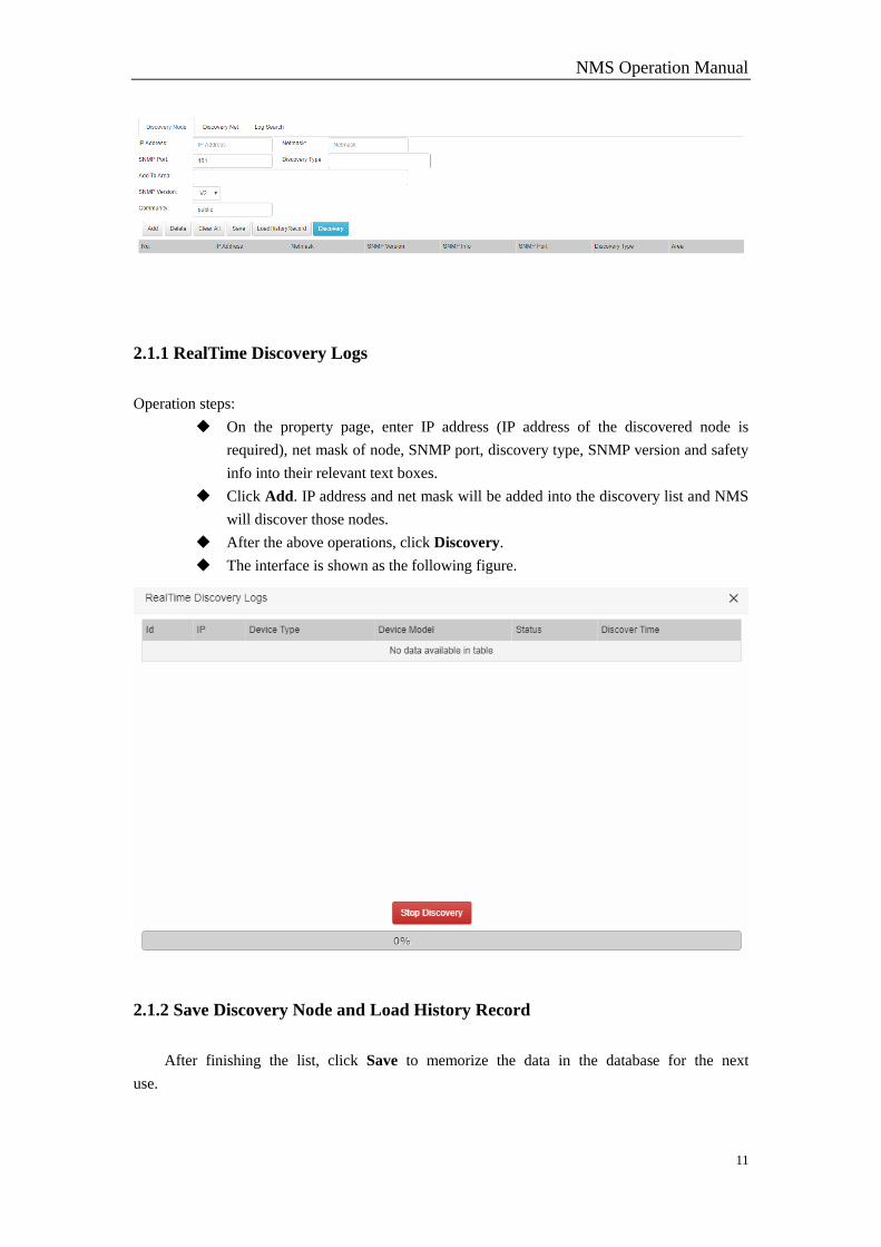
2.1.1 RealTime Discovery Logs
Operation steps:
On the property page, enter IP address (IP address of the discovered node is
required), net mask of node, SNMP port, discovery type, SNMP version and safety
info into their relevant text boxes.
Click Add. IP address and net mask will be added into the discovery list and NMS
will discover those nodes.
After the above operations, click Discovery.
The interface is shown as the following figure.
2.1.2 Save Discovery Node and Load History Record
After finishing the list, click Save to memorize the data in the database for the next
use.
NMS Operation Manual
12
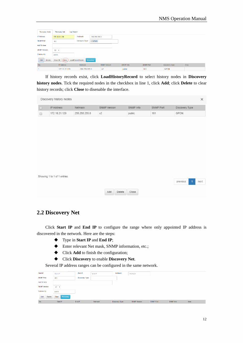
If history records exist, click LoadHistoryRecord to select history nodes in Discovery
history nodes. Tick the required nodes in the checkbox in line 1, click Add; click Delete to clear
history records; click Close to disenable the interface.
2.2 Discovery Net
Click Start IP and End IP to configure the range where only appointed IP address is
discovered in the network. Here are the steps:
Type in Start IP and End IP;
Enter relevant Net mask, SNMP information, etc.;
Click Add to finish the configuration;
Click Discovery to enable Discovery Net.
Several IP address ranges can be configured in the same network.
NMS Operation Manual
13
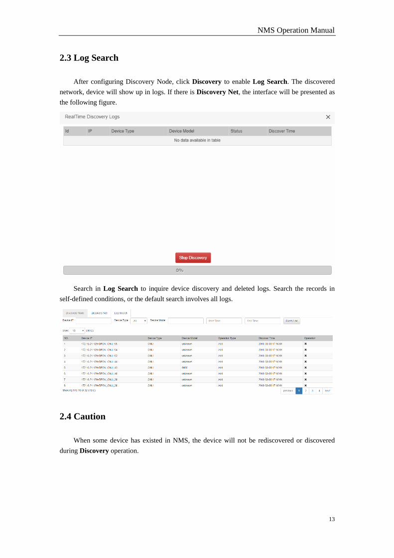
2.3 Log Search
After configuring Discovery Node, click Discovery to enable Log Search. The discovered
network, device will show up in logs. If there is Discovery Net, the interface will be presented as
the following figure.
Search in Log Search to inquire device discovery and deleted logs. Search the records in
self-defined conditions, or the default search involves all logs.
2.4 Caution
When some device has existed in NMS, the device will not be rediscovered or discovered
during Discovery operation.
NMS Operation Manual
14
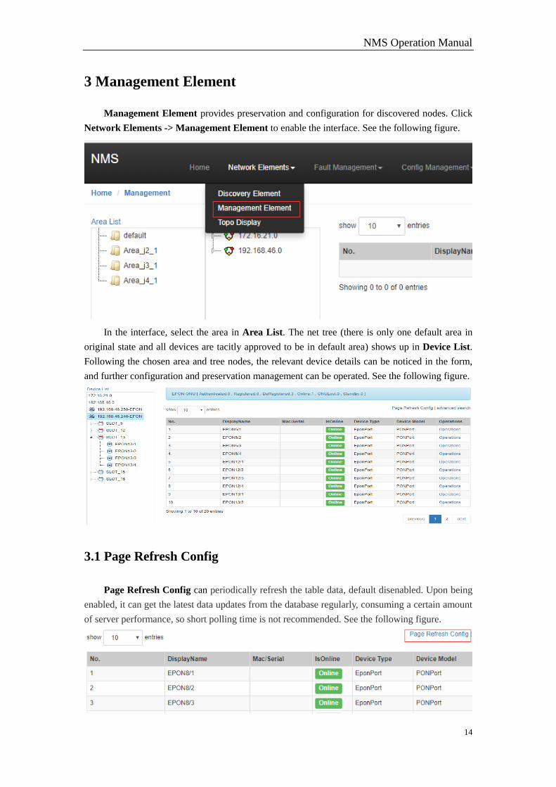
3 Management Element
Management Element provides preservation and configuration for discovered nodes. Click
Network Elements -> Management Element to enable the interface. See the following figure.
In the interface, select the area in Area List. The net tree (there is only one default area in
original state and all devices are tacitly approved to be in default area) shows up in Device List.
Following the chosen area and tree nodes, the relevant device details can be noticed in the form,
and further configuration and preservation management can be operated. See the following figure.
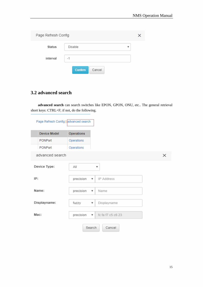
3.1 Page Refresh Config
Page Refresh Config can periodically refresh the table data, default disenabled. Upon being
enabled, it can get the latest data updates from the database regularly, consuming a certain amount
of server performance, so short polling time is not recommended. See the following figure.
NMS Operation Manual
15
3.2 advanced search
advanced search can search switches like EPON, GPON, ONU, etc.. The general retrieval
short keys: CTRL+F; if not, do the following.
NMS Operation Manual
16
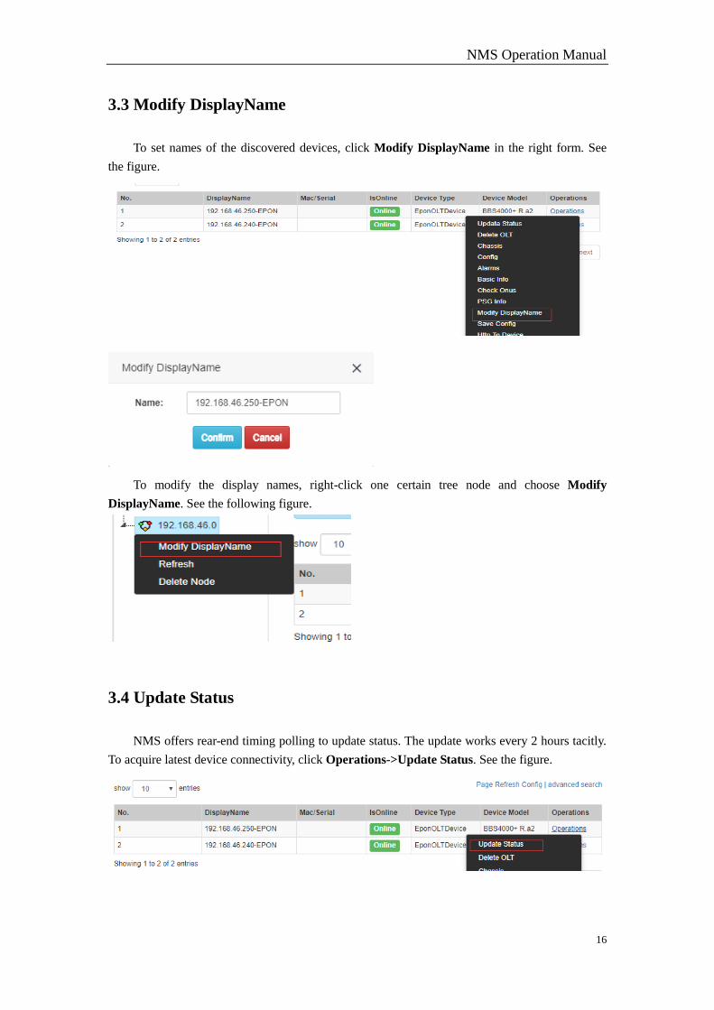
3.3 Modify DisplayName
To set names of the discovered devices, click Modify DisplayName in the right form. See
the figure.
To modify the display names, right-click one certain tree node and choose Modify
DisplayName. See the following figure.
3.4 Update Status
NMS offers rear-end timing polling to update status. The update works every 2 hours tacitly.
To acquire latest device connectivity, click Operations->Update Status. See the figure.
NMS Operation Manual
17
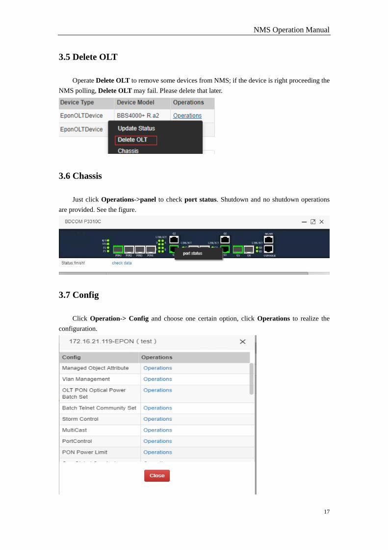
3.5 Delete OLT
Operate Delete OLT to remove some devices from NMS; if the device is right proceeding the
NMS polling, Delete OLT may fail. Please delete that later.
3.6 Chassis
Just click Operations->panel to check port status. Shutdown and no shutdown operations
are provided. See the figure.
3.7 Config
Click Operation-> Config and choose one certain option, click Operations to realize the
configuration.
NMS Operation Manual
18
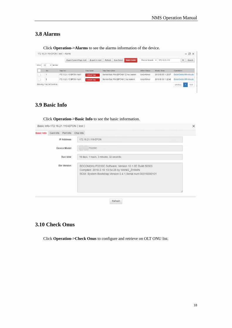
3.8 Alarms
Click Operation->Alarms to see the alarms information of the device.
3.9 Basic Info
Click Operation->Basic Info to see the basic information.
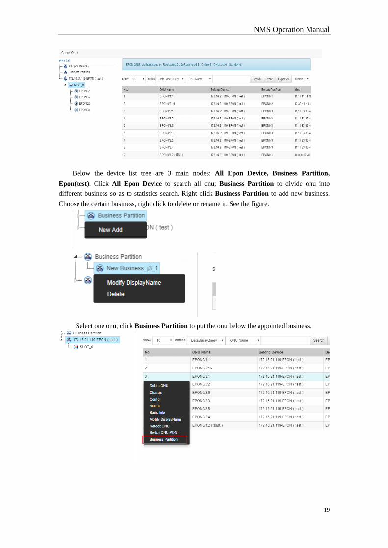
3.10 Check Onus
Click Operation->Check Onus to configure and retrieve on OLT ONU list.
NMS Operation Manual
19
Below the device list tree are 3 main nodes: All Epon Device, Business Partition,
Epon(test). Click All Epon Device to search all onu; Business Partition to divide onu into
different business so as to statistics search. Right click Business Partition to add new business.
Choose the certain business, right click to delete or rename it. See the figure.
Select one onu, click Business Partition to put the onu below the appointed business.
NMS Operation Manual
20
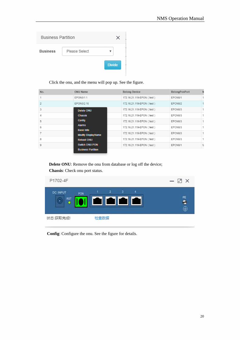
Click the onu, and the menu will pop up. See the figure.
Delete ONU: Remove the onu from database or log off the device;
Chassis: Check onu port status.
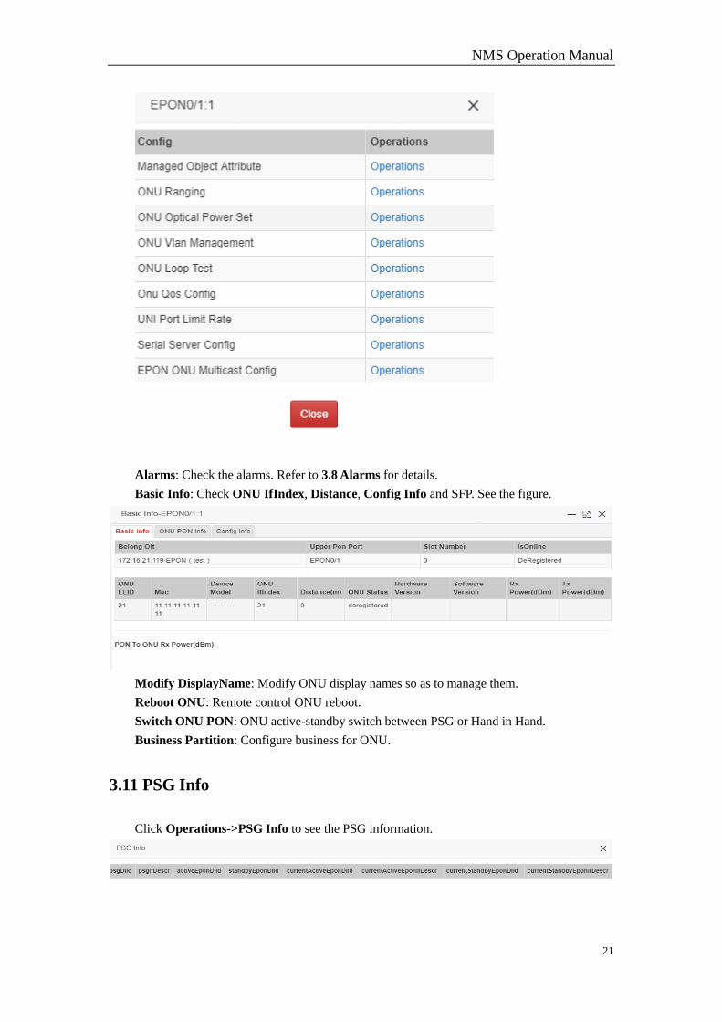
Config: Configure the onu. See the figure for details.
NMS Operation Manual
21
Alarms: Check the alarms. Refer to 3.8 Alarms for details.
Basic Info: Check ONU IfIndex, Distance, Config Info and SFP. See the figure.
Modify DisplayName: Modify ONU display names so as to manage them.
Reboot ONU: Remote control ONU reboot.
Switch ONU PON: ONU active-standby switch between PSG or Hand in Hand.
Business Partition: Configure business for ONU.
3.11 PSG Info
Click Operations->PSG Info to see the PSG information.
NMS Operation Manual
22
3.12 Save Config
Click Operations->Save Config to save the operation.
3.13 Http To Device
Click Operations->Http To Device to log in to the device.
3.14 Https To Device
Click Operations->Https To Device to log in to the device.
3.15 Telnet To Device
Click Operations->Telnet To Device to log in to the device.
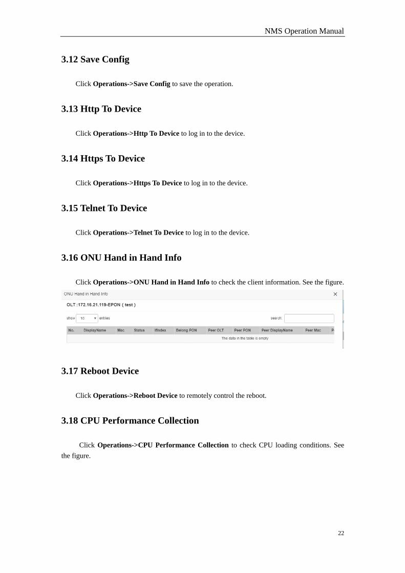
3.16 ONU Hand in Hand Info
Click Operations->ONU Hand in Hand Info to check the client information. See the figure.
3.17 Reboot Device
Click Operations->Reboot Device to remotely control the reboot.
3.18 CPU Performance Collection
Click Operations->CPU Performance Collection to check CPU loading conditions. See
the figure.
NMS Operation Manual
23
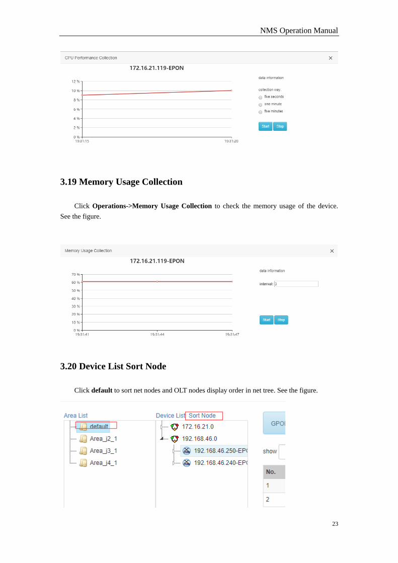
3.19 Memory Usage Collection
Click Operations->Memory Usage Collection to check the memory usage of the device.
See the figure.
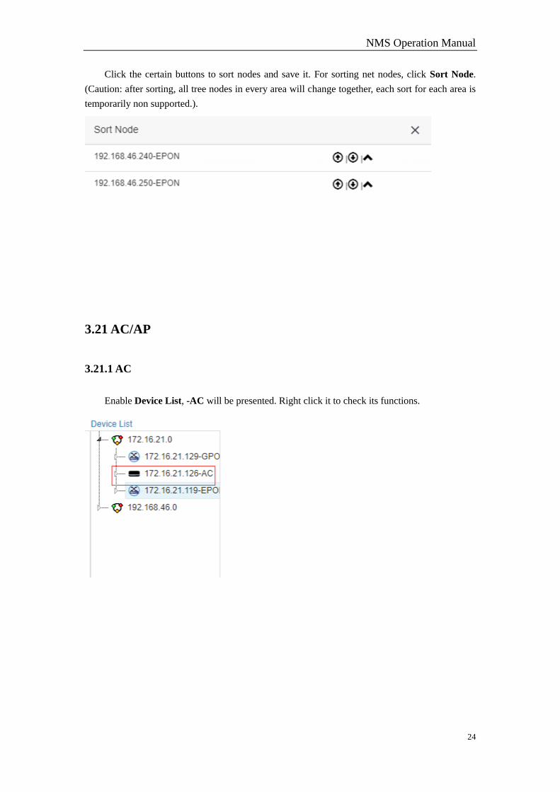
3.20 Device List Sort Node
Click default to sort net nodes and OLT nodes display order in net tree. See the figure.
NMS Operation Manual
24
Click the certain buttons to sort nodes and save it. For sorting net nodes, click Sort Node.
(Caution: after sorting, all tree nodes in every area will change together, each sort for each area is
temporarily non supported.).
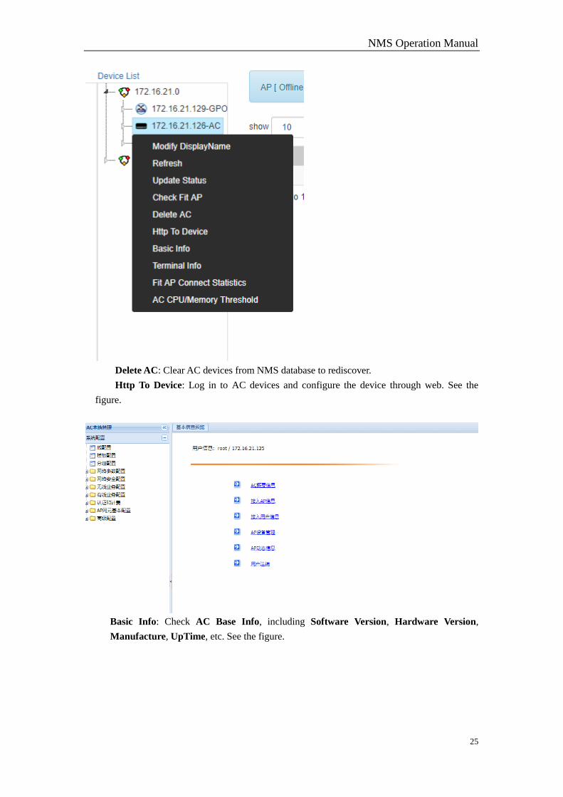
3.21 AC/AP
3.21.1 AC
Enable Device List, -AC will be presented. Right click it to check its functions.
NMS Operation Manual
25
Delete AC: Clear AC devices from NMS database to rediscover.
Http To Device: Log in to AC devices and configure the device through web. See the
figure.
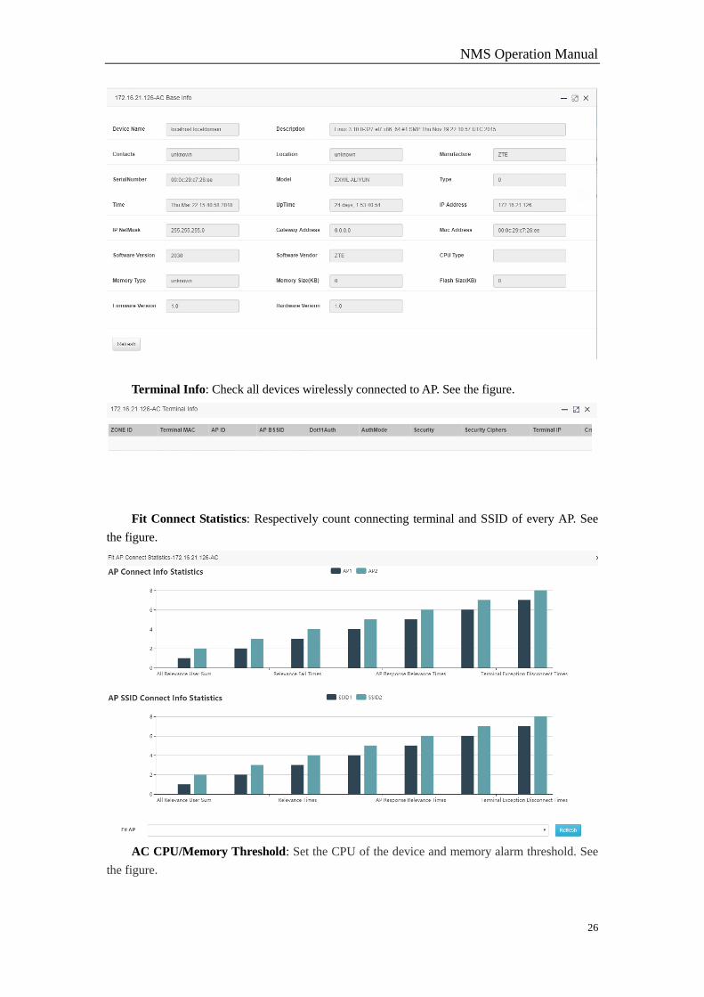
Basic Info: Check AC Base Info, including Software Version, Hardware Version,
Manufacture, UpTime, etc. See the figure.
NMS Operation Manual
26
Terminal Info: Check all devices wirelessly connected to AP. See the figure.
Fit Connect Statistics: Respectively count connecting terminal and SSID of every AP. See
the figure.
AC CPU/Memory Threshold: Set the CPU of the device and memory alarm threshold. See
the figure.
NMS Operation Manual
27
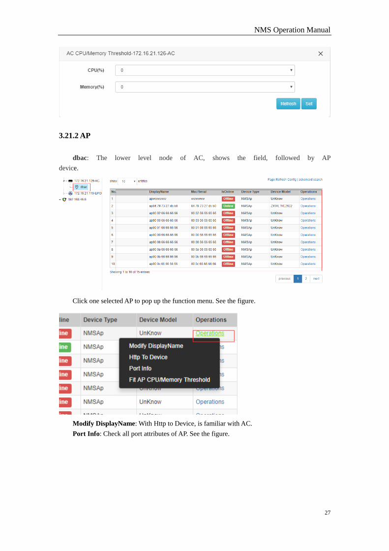
3.21.2 AP
dbac: The lower level node of AC, shows the field, followed by AP
device.
Click one selected AP to pop up the function menu. See the figure.
Modify DisplayName: With Http to Device, is familiar with AC.
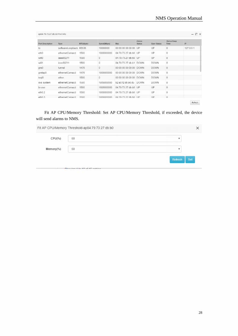
Port Info: Check all port attributes of AP. See the figure.
NMS Operation Manual
28
Fit AP CPU/Memory Threshold: Set AP CPU/Memory Threshold, if exceeded, the device
will send alarms to NMS.
NMS Operation Manual
29
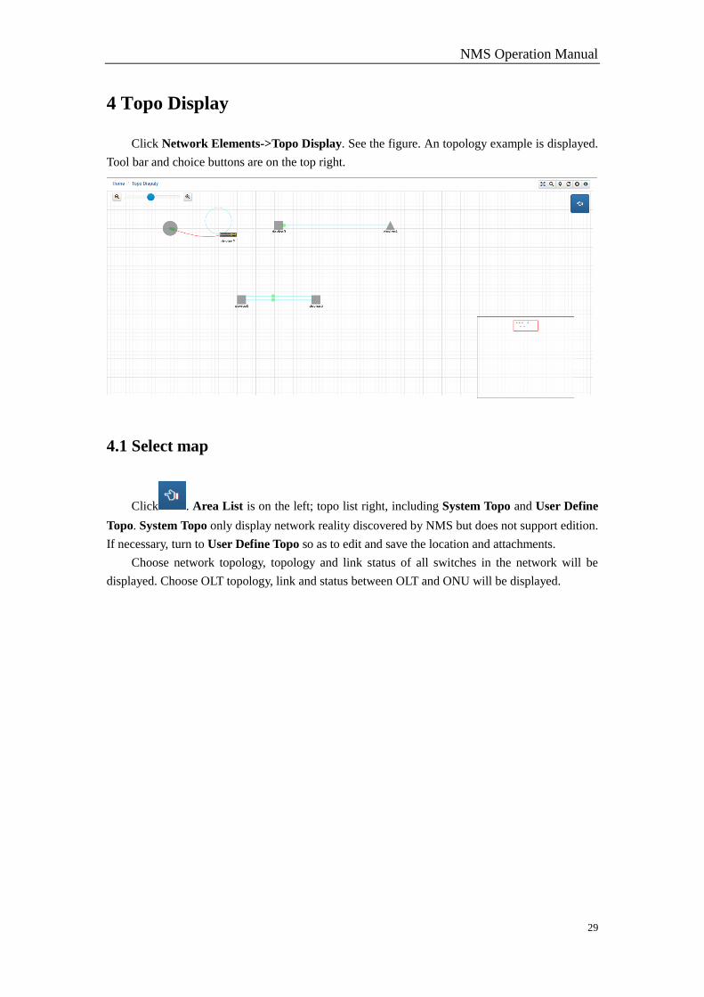
4 Topo Display
Click Network Elements->Topo Display. See the figure. An topology example is displayed.
Tool bar and choice buttons are on the top right.
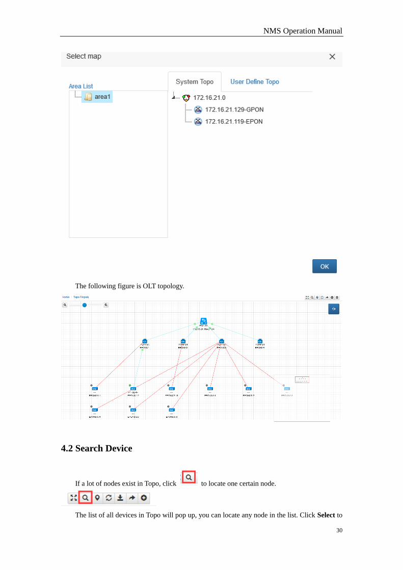
4.1 Select map
Click . Area List is on the left; topo list right, including System Topo and User Define
Topo. System Topo only display network reality discovered by NMS but does not support edition.
If necessary, turn to User Define Topo so as to edit and save the location and attachments.
Choose network topology, topology and link status of all switches in the network will be
displayed. Choose OLT topology, link and status between OLT and ONU will be displayed.
NMS Operation Manual
30
The following figure is OLT topology.
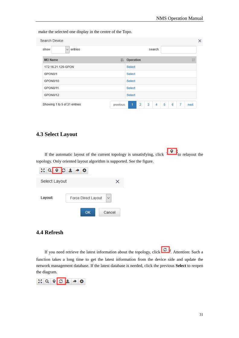
4.2 Search Device
If a lot of nodes exist in Topo, click to locate one certain node.
The list of all devices in Topo will pop up, you can locate any node in the list. Click Select to
NMS Operation Manual
31
make the selected one display in the centre of the Topo.
4.3 Select Layout
If the automatic layout of the current topology is unsatisfying, click to relayout the
topology. Only oriented layout algorithm is supported. See the figure.
4.4 Refresh
If you need retrieve the latest information about the topology, click . Attention: Such a
function takes a long time to get the latest information from the device side and update the
network management database. If the latest database is needed, click the previous Select to reopen
the diagram.
NMS Operation Manual
32
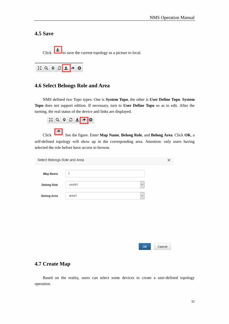
4.5 Save
Click to save the current topology as a picture to local.
4.6 Select Belongs Role and Area
NMS defined two Topo types: One is System Topo, the other is User Define Topo. System
Topo does not support edition. If necessary, turn to User Define Topo so as to edit. After the
turning, the real status of the device and links are displayed.
Click . See the figure. Enter Map Name, Belong Role, and Belong Area. Click OK, a
self-defined topology will show up in the corresponding area. Attention: only users having
selected the role before have access to browse.
4.7 Create Map
Based on the reality, users can select some devices to create a user-defined topology
operation.
NMS Operation Manual
33
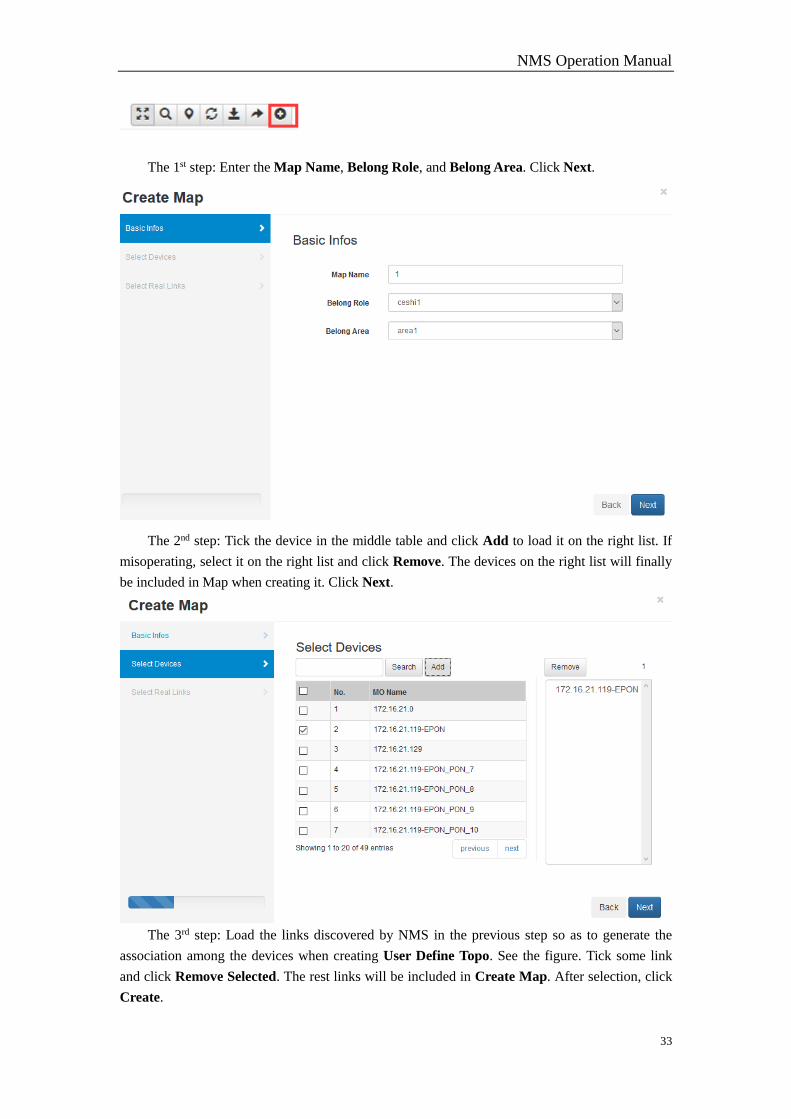
The 1st step: Enter the Map Name, Belong Role, and Belong Area. Click Next.
The 2nd step: Tick the device in the middle table and click Add to load it on the right list. If
misoperating, select it on the right list and click Remove. The devices on the right list will finally
be included in Map when creating it. Click Next.
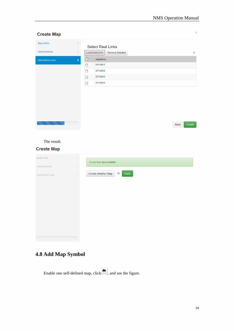
The 3rd step: Load the links discovered by NMS in the previous step so as to generate the
association among the devices when creating User Define Topo. See the figure. Tick some link
and click Remove Selected. The rest links will be included in Create Map. After selection, click
Create.
NMS Operation Manual
34
The result.
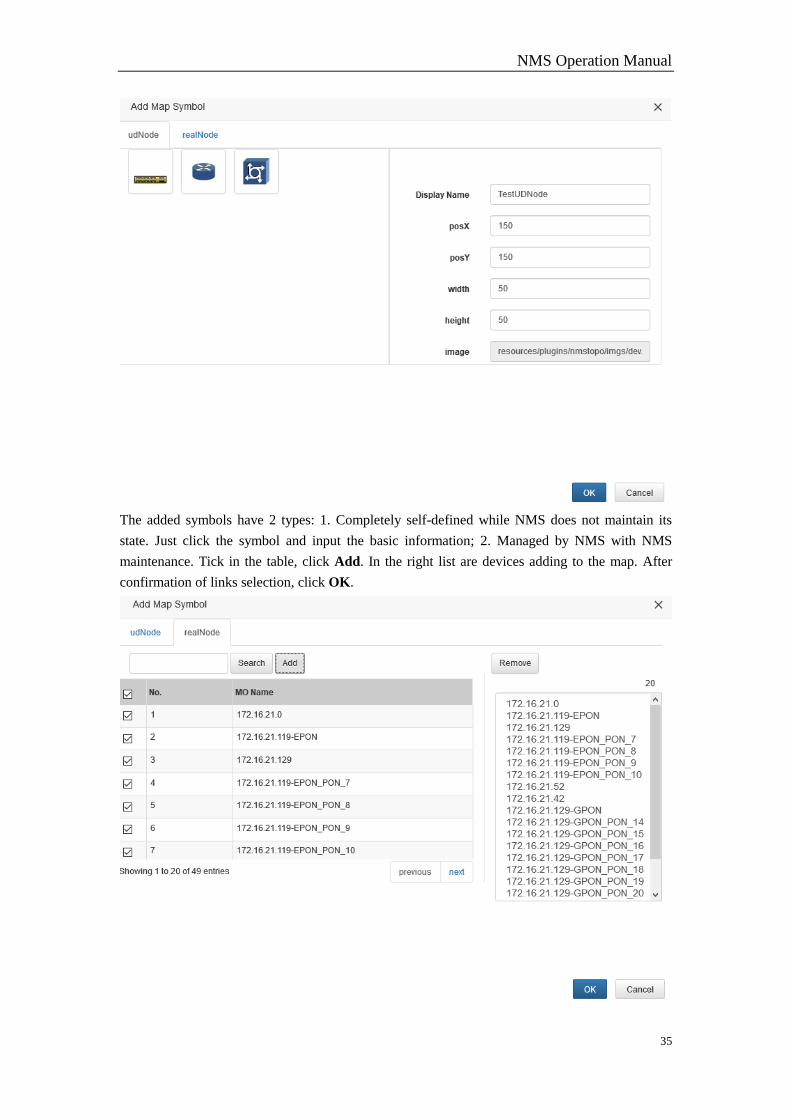
4.8 Add Map Symbol
Enable one self-defined map, click , and see the figure.
NMS Operation Manual
35
The added symbols have 2 types: 1. Completely self-defined while NMS does not maintain its
state. Just click the symbol and input the basic information; 2. Managed by NMS with NMS
maintenance. Tick in the table, click Add. In the right list are devices adding to the map. After
confirmation of links selection, click OK.
NMS Operation Manual
36
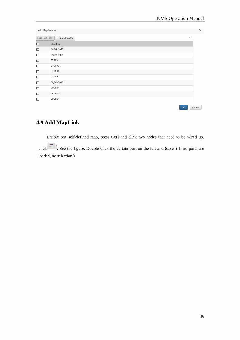
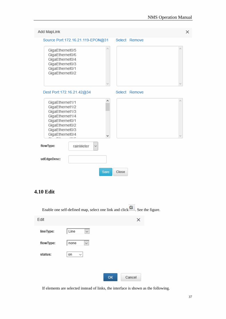
4.9 Add MapLink
Enable one self-defined map, press Ctrl and click two nodes that need to be wired up.
click . See the figure. Double click the certain port on the left and Save. ( If no ports are
loaded, no selection.)
NMS Operation Manual
37
4.10 Edit
Enable one self-defined map, select one link and click . See the figure.
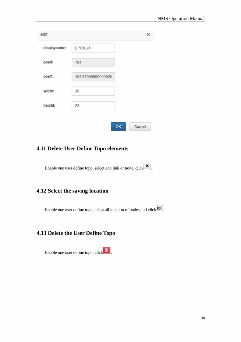
If elements are selected instead of links, the interface is shown as the following.
NMS Operation Manual
38
4.11 Delete User Define Topo elements
Enable one user define topo, select one link or node, click .
4.12 Select the saving location
Enable one user define topo, adapt all location of nodes and click .
4.13 Delete the User Define Topo
Enable one user define topo, click .
NMS Operation Manual
39
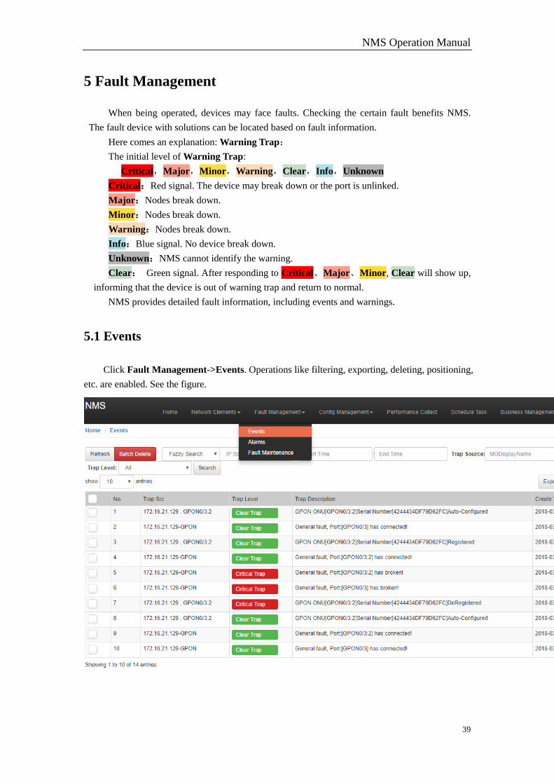
5 Fault Management
When being operated, devices may face faults. Checking the certain fault benefits NMS.
The fault device with solutions can be located based on fault information.
Here comes an explanation: Warning Trap:
The initial level of Warning Trap:
Critical,Major,Minor,Warning,Clear,Info,Unknown
Critical:Red signal. The device may break down or the port is unlinked.
Major:Nodes break down.
Minor:Nodes break down.
Warning:Nodes break down.
Info:Blue signal. No device break down.
Unknown:NMS cannot identify the warning.
Clear: Green signal. After responding to Critical、Major、Minor, Clear will show up,
informing that the device is out of warning trap and return to normal.
NMS provides detailed fault information, including events and warnings.
5.1 Events
Click Fault Management->Events. Operations like filtering, exporting, deleting, positioning,
etc. are enabled. See the figure.

NMS Operation Manual
40
5.1.1 Search
You can search in precise and fuzzy conditions. Fill in the conditions and click Search.
5.1.2 Delete
Tick in the Alarms table, click Batch Delete for batch deletion or just click Delete in entry
operation bar for single deletion.
5.1.3 Detail
Click the hyperlink in eventDetail to display the event details. See the figure.
Click the hyperlink in Events to display Management. See the figure.
5.1.4 Export Current Page Event & Export All Event
Click Export Current Page Event and the information will be saved in Excel format. Click
All Event to export all event information to local.
5.2 Alarms
Click Fault Management->Alarms to enable the interface. Operations like filtering,
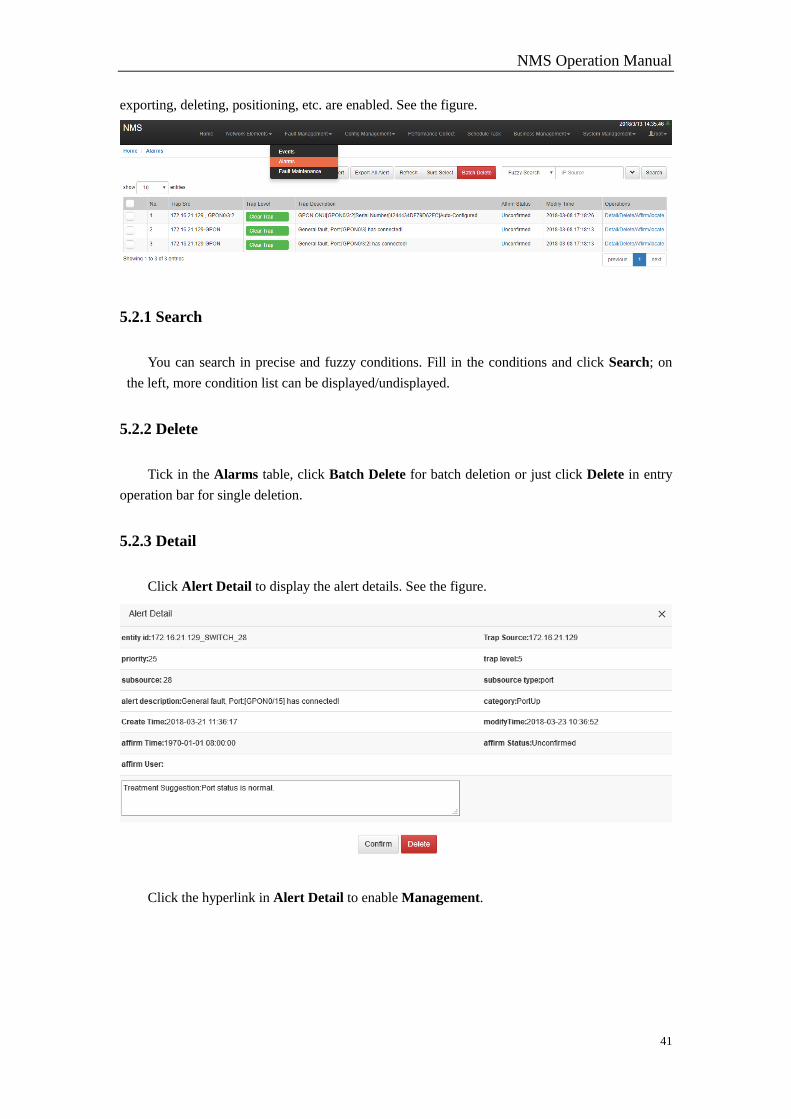
NMS Operation Manual
41
exporting, deleting, positioning, etc. are enabled. See the figure.
5.2.1 Search
You can search in precise and fuzzy conditions. Fill in the conditions and click Search; on
the left, more condition list can be displayed/undisplayed.
5.2.2 Delete
Tick in the Alarms table, click Batch Delete for batch deletion or just click Delete in entry
operation bar for single deletion.
5.2.3 Detail
Click Alert Detail to display the alert details. See the figure.
Click the hyperlink in Alert Detail to enable Management.
NMS Operation Manual
42
5.2.4 Sure Select
Tick alerts in entry check box, and click Batch Affirm for batch affirmation; click Affirm for
single affirmation.
5.2.5 Export Current Page Alert & Export All Alert
Click Export Current Page Alert and the information will be saved in Excel format. Click
All Alert to export all alert information to local.
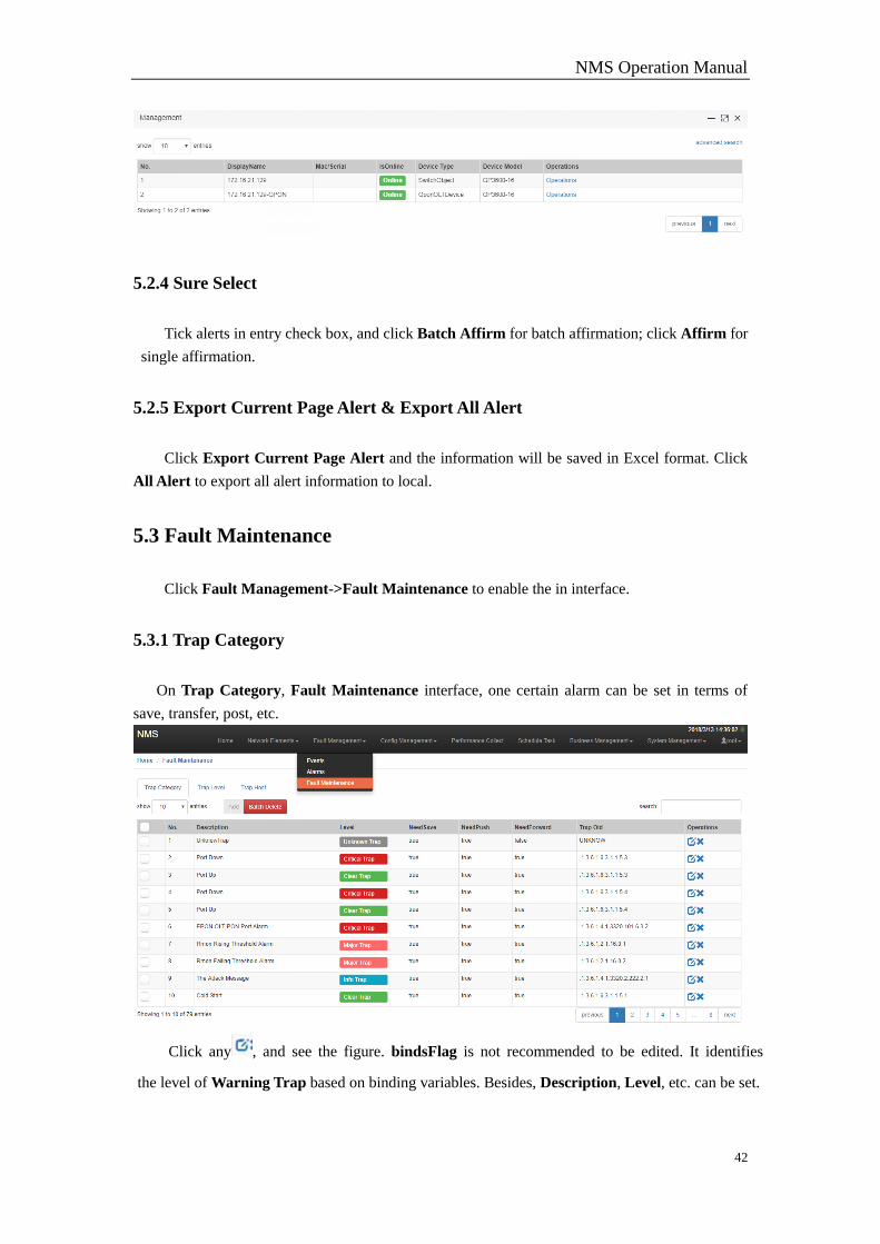
5.3 Fault Maintenance
Click Fault Management->Fault Maintenance to enable the in interface.
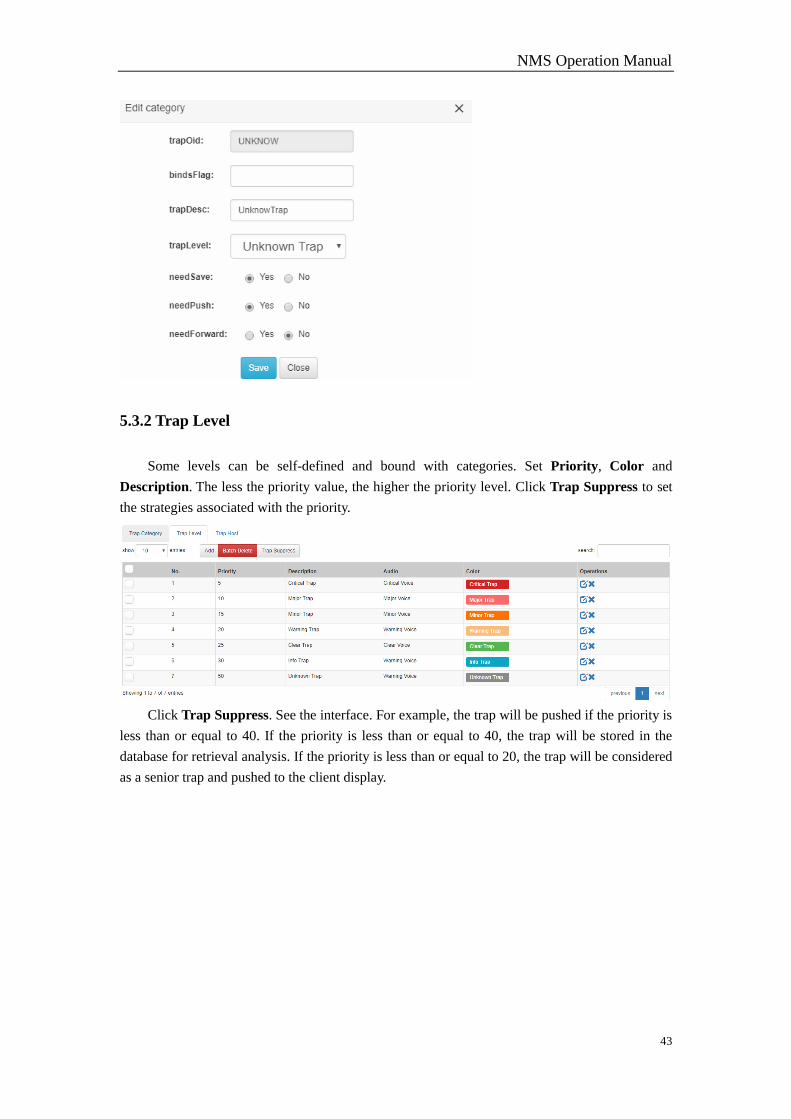
5.3.1 Trap Category
On Trap Category, Fault Maintenance interface, one certain alarm can be set in terms of
save, transfer, post, etc.
Click any , and see the figure. bindsFlag is not recommended to be edited. It identifies
the level of Warning Trap based on binding variables. Besides, Description, Level, etc. can be set.
NMS Operation Manual
43
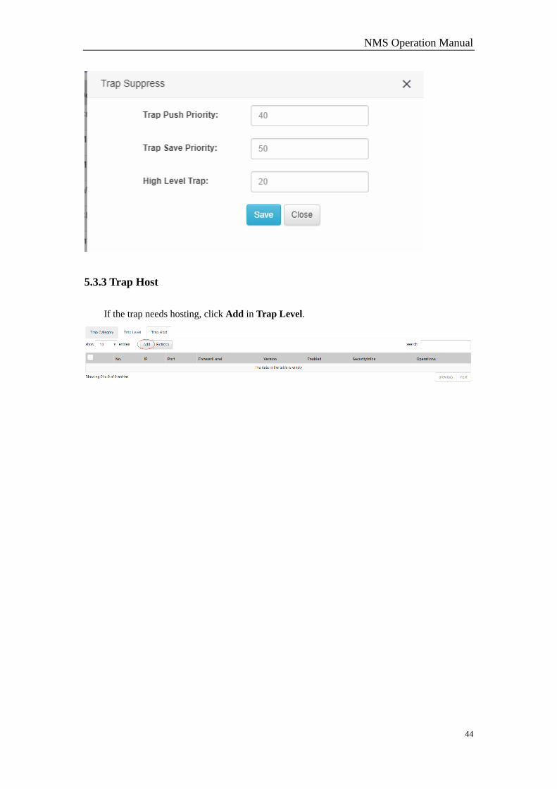
5.3.2 Trap Level
Some levels can be self-defined and bound with categories. Set Priority, Color and
Description. The less the priority value, the higher the priority level. Click Trap Suppress to set
the strategies associated with the priority.
Click Trap Suppress. See the interface. For example, the trap will be pushed if the priority is
less than or equal to 40. If the priority is less than or equal to 40, the trap will be stored in the
database for retrieval analysis. If the priority is less than or equal to 20, the trap will be considered
as a senior trap and pushed to the client display.
NMS Operation Manual
44
5.3.3 Trap Host
If the trap needs hosting, click Add in Trap Level.
NMS Operation Manual
45
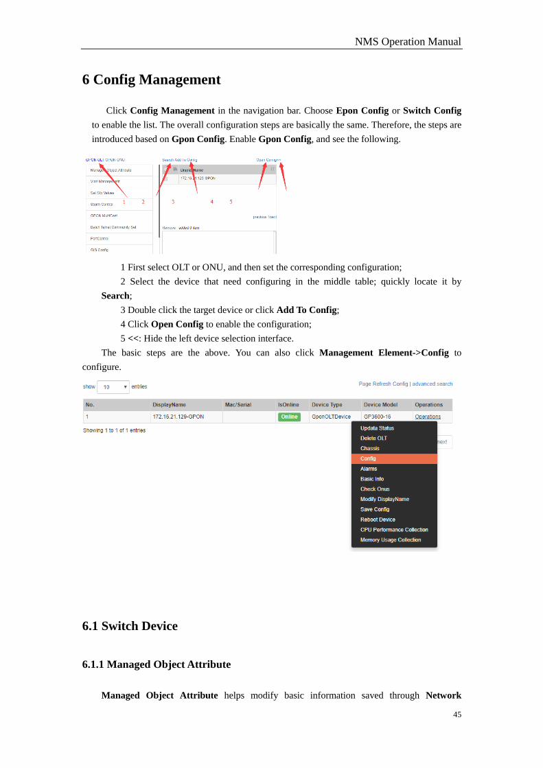
6 Config Management
Click Config Management in the navigation bar. Choose Epon Config or Switch Config
to enable the list. The overall configuration steps are basically the same. Therefore, the steps are
introduced based on Gpon Config. Enable Gpon Config, and see the following.
1 First select OLT or ONU, and then set the corresponding configuration;
2 Select the device that need configuring in the middle table; quickly locate it by
Search;
3 Double click the target device or click Add To Config;
4 Click Open Config to enable the configuration;
5 <<: Hide the left device selection interface.
The basic steps are the above. You can also click Management Element->Config to
configure.
6.1 Switch Device
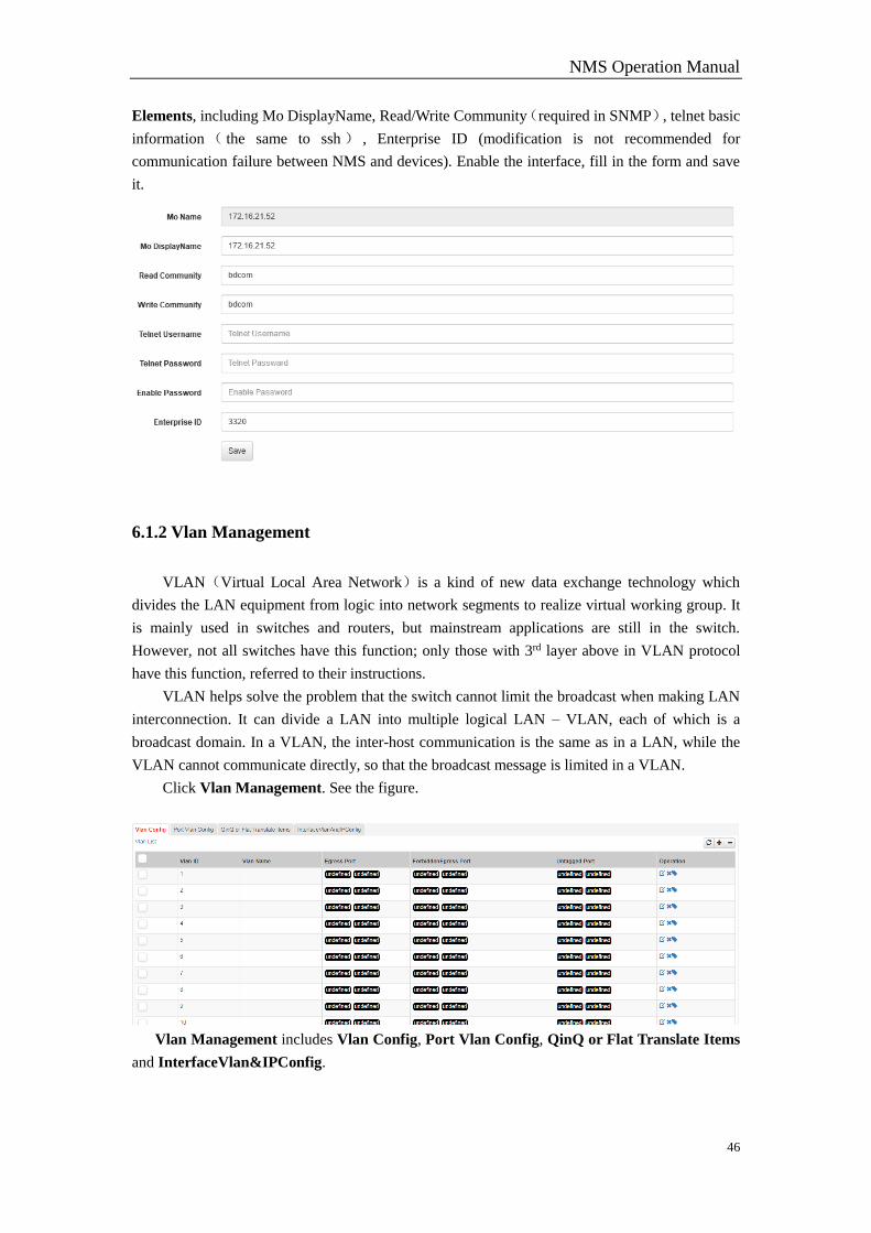
6.1.1 Managed Object Attribute
Managed Object Attribute helps modify basic information saved through Network
NMS Operation Manual
46
Elements, including Mo DisplayName, Read/Write Community(required in SNMP), telnet basic
information ( the same to ssh ) , Enterprise ID (modification is not recommended for
communication failure between NMS and devices). Enable the interface, fill in the form and save
it.
6.1.2 Vlan Management
VLAN(Virtual Local Area Network)is a kind of new data exchange technology which
divides the LAN equipment from logic into network segments to realize virtual working group. It
is mainly used in switches and routers, but mainstream applications are still in the switch.
However, not all switches have this function; only those with 3rd layer above in VLAN protocol
have this function, referred to their instructions.
VLAN helps solve the problem that the switch cannot limit the broadcast when making LAN
interconnection. It can divide a LAN into multiple logical LAN – VLAN, each of which is a
broadcast domain. In a VLAN, the inter-host communication is the same as in a LAN, while the
VLAN cannot communicate directly, so that the broadcast message is limited in a VLAN.
Click Vlan Management. See the figure.
Vlan Management includes Vlan Config, Port Vlan Config, QinQ or Flat Translate Items
and InterfaceVlan&IPConfig.
NMS Operation Manual
47
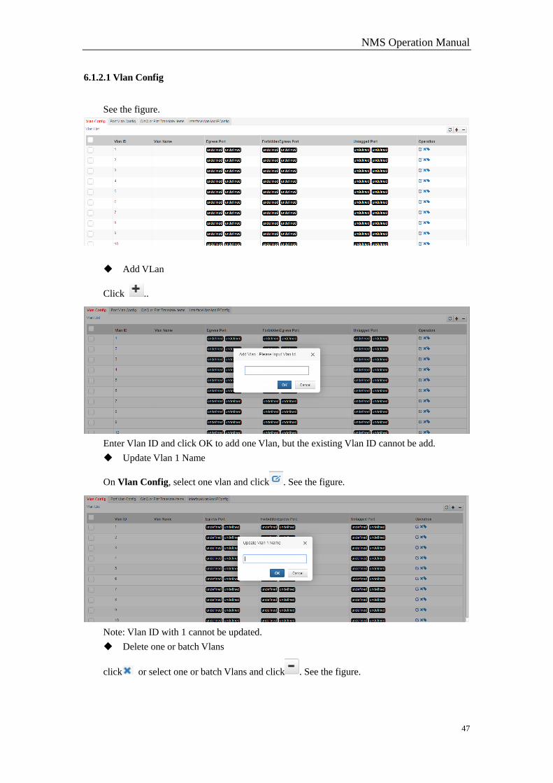
6.1.2.1 Vlan Config
See the figure.
Add VLan
Click ..
Enter Vlan ID and click OK to add one Vlan, but the existing Vlan ID cannot be add.
Update Vlan 1 Name
On Vlan Config, select one vlan and click . See the figure.
Note: Vlan ID with 1 cannot be updated.
Delete one or batch Vlans
click or select one or batch Vlans and click . See the figure.
NMS Operation Manual
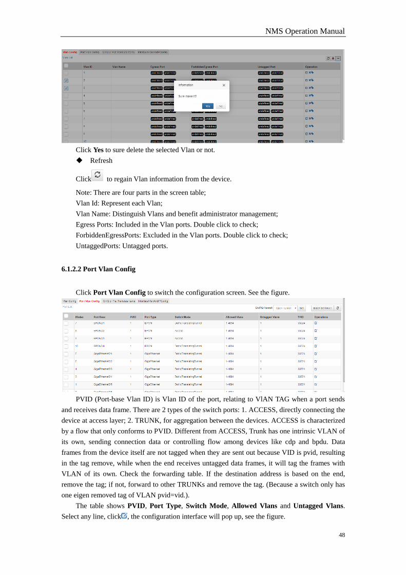
48
Click Yes to sure delete the selected Vlan or not.
Refresh
Click to regain Vlan information from the device.
Note: There are four parts in the screen table;
Vlan Id: Represent each Vlan;
Vlan Name: Distinguish Vlans and benefit administrator management;
Egress Ports: Included in the Vlan ports. Double click to check;
ForbiddenEgressPorts: Excluded in the Vlan ports. Double click to check;
UntaggedPorts: Untagged ports.
6.1.2.2 Port Vlan Config
Click Port Vlan Config to switch the configuration screen. See the figure.
PVID (Port-base Vlan ID) is Vlan ID of the port, relating to VlAN TAG when a port sends
and receives data frame. There are 2 types of the switch ports: 1. ACCESS, directly connecting the
device at access layer; 2. TRUNK, for aggregation between the devices. ACCESS is characterized
by a flow that only conforms to PVID. Different from ACCESS, Trunk has one intrinsic VLAN of
its own, sending connection data or controlling flow among devices like cdp and bpdu. Data
frames from the device itself are not tagged when they are sent out because VID is pvid, resulting
in the tag remove, while when the end receives untagged data frames, it will tag the frames with
VLAN of its own. Check the forwarding table. If the destination address is based on the end,
remove the tag; if not, forward to other TRUNKs and remove the tag. (Because a switch only has
one eigen removed tag of VLAN pvid=vid.).
The table shows PVID, Port Type, Switch Mode, Allowed Vlans and Untagged Vlans.
Select any line, click , the configuration interface will pop up, see the figure.

NMS Operation Manual
49
Only when Switch Mode: Trunk, to configure Allowed Vlan and Untagged Vlan is
accessible. Input value: 1,3,5,7 or 1,3-5,7 or 1-7. The specific operation is as follows.
Allowed Vlan 1-9: set the allowed vlans as vlan1-vlan9
Allowed Vlan add 1-9: add the allowed vlans, vlan1-vlan9
Allowed Vlan except 1-9: except vlan1-vlan9, the rest are allowed vlans
Allowed Vlan remove 1-9: delete allowed vlans from vlan1-vlan9
Allowed Vlan all: set vlan1-vlan4094 as allowed vlans
Allowed Vlan none: no allowed vlans
The same operations to Untagged Vlan.
Batch Set Mode allows batch set mode. See the figure.
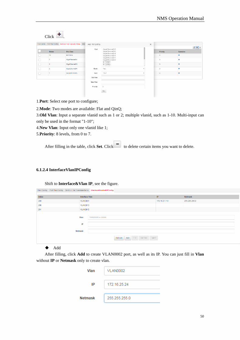
6.1.2.3 QinQ or Flat Translate Items
Shift to QinQ or Flat Translate Items and see the figure.
Add
NMS Operation Manual
50
Click .
1.Port: Select one port to configure;
2.Mode: Two modes are available: Flat and QinQ;
3.Old Vlan: Input a separate vlanid such as 1 or 2; multiple vlanid, such as 1-10. Multi-input can
only be used in the format "1-10";
4.New Vlan: Input only one vlanid like 1;
5.Priority: 8 levels, from 0 to 7.
After filling in the table, click Set. Click to delete certain items you want to delete.
6.1.2.4 InterfaceVlanIPConfig
Shift to Interface&Vlan IP, see the figure.
Add
After filling, click Add to create VLAN0002 port, as well as its IP. You can just fill in Vlan
without IP or Netmask only to create vlan.
NMS Operation Manual
51
Edit
Click any column in InterfaceVlanAndIPConfig to edit IP snd Netmask. Click Edit to
save.
Delete
1.Del Vlan
Select any column on Interface Vlan. Click Del Vlan to delete Vlan and IP
2.Del IP
Select any column on Interface Vlan. Click Del IP to delete IP and netmask except Vlan.
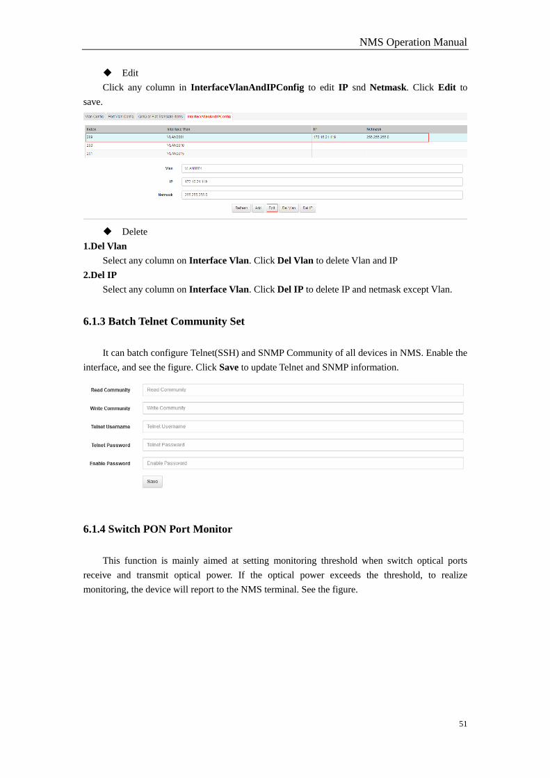
6.1.3 Batch Telnet Community Set
It can batch configure Telnet(SSH) and SNMP Community of all devices in NMS. Enable the
interface, and see the figure. Click Save to update Telnet and SNMP information.
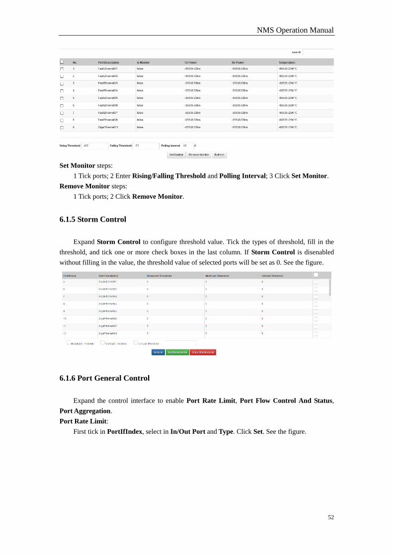
6.1.4 Switch PON Port Monitor
This function is mainly aimed at setting monitoring threshold when switch optical ports
receive and transmit optical power. If the optical power exceeds the threshold, to realize
monitoring, the device will report to the NMS terminal. See the figure.
NMS Operation Manual
52
Set Monitor steps:
1 Tick ports; 2 Enter Rising/Falling Threshold and Polling Interval; 3 Click Set Monitor.
Remove Monitor steps:
1 Tick ports; 2 Click Remove Monitor.
6.1.5 Storm Control
Expand Storm Control to configure threshold value. Tick the types of threshold, fill in the
threshold, and tick one or more check boxes in the last column. If Storm Control is disenabled
without filling in the value, the threshold value of selected ports will be set as 0. See the figure.
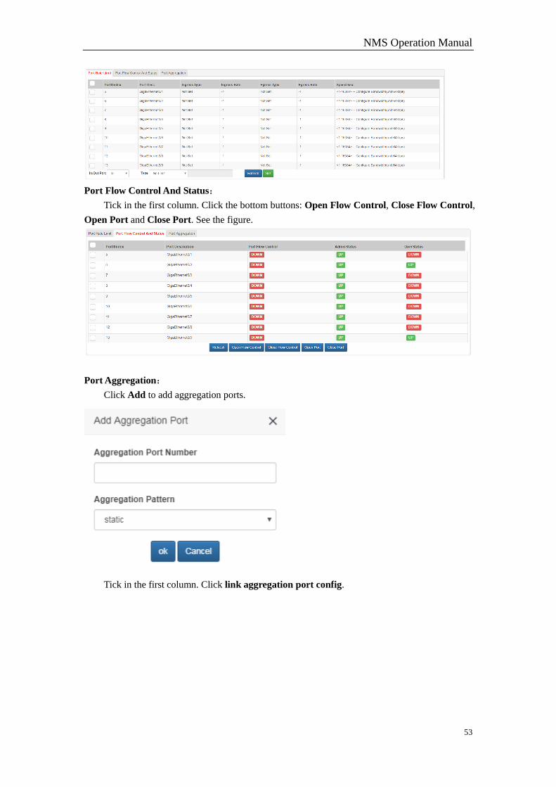
6.1.6 Port General Control
Expand the control interface to enable Port Rate Limit, Port Flow Control And Status,
Port Aggregation.
Port Rate Limit:
First tick in PortIfIndex, select in In/Out Port and Type. Click Set. See the figure.
NMS Operation Manual
53
Port Flow Control And Status:
Tick in the first column. Click the bottom buttons: Open Flow Control, Close Flow Control,
Open Port and Close Port. See the figure.
Port Aggregation:
Click Add to add aggregation ports.
Tick in the first column. Click link aggregation port config.
NMS Operation Manual
54
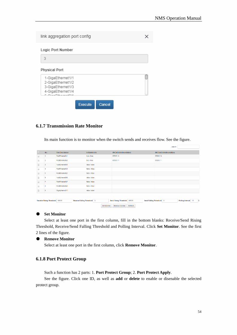
6.1.7 Transmission Rate Monitor
Its main function is to monitor when the switch sends and receives flow. See the figure.
● Set Monitor
Select at least one port in the first column, fill in the bottom blanks: Receive/Send Rising
Threshold, Receive/Send Falling Threshold and Polling Interval. Click Set Monitor. See the first
2 lines of the figure.
● Remove Monitor
Select at least one port in the first column, click Remove Monitor.
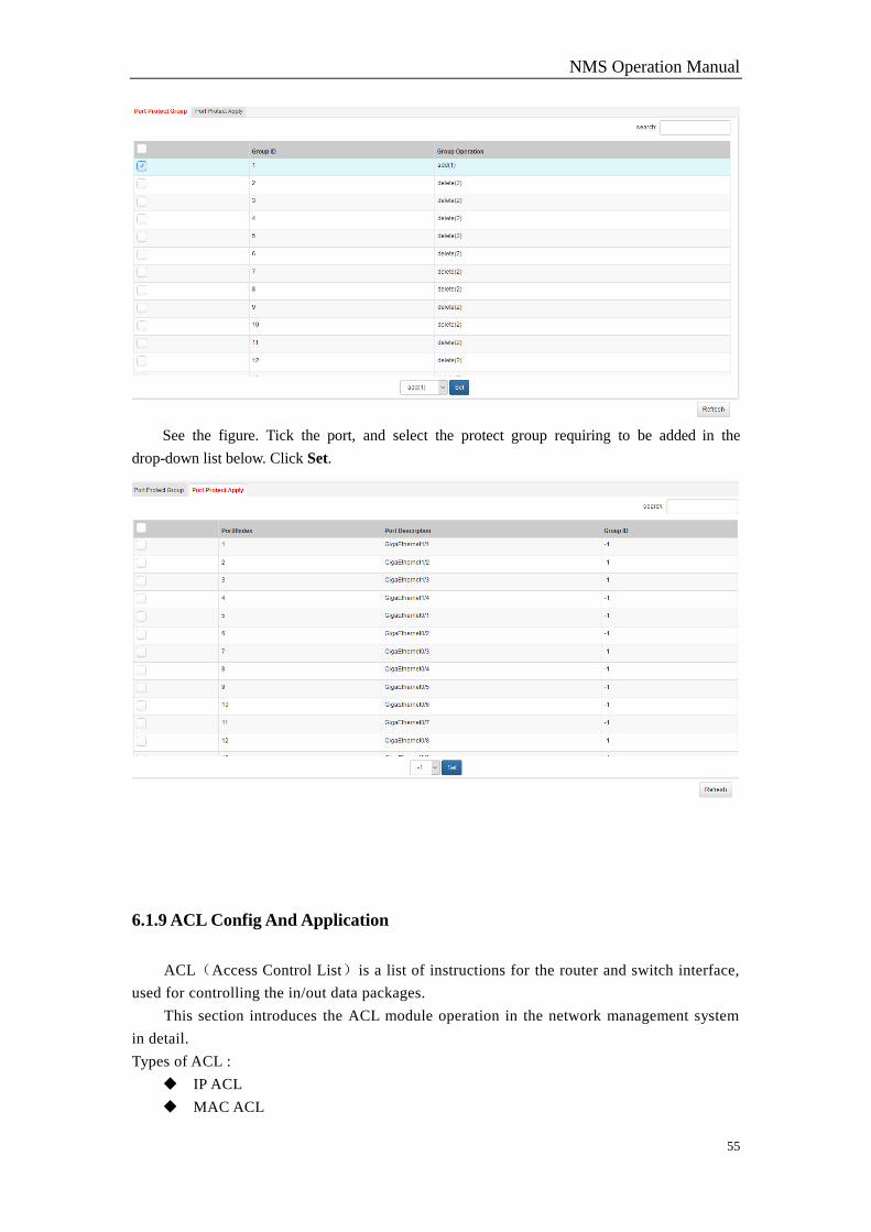
6.1.8 Port Protect Group
Such a function has 2 parts: 1. Port Protect Group; 2. Port Protect Apply.
See the figure. Click one ID, as well as add or delete to enable or disenable the selected
protect group.
NMS Operation Manual
55
See the figure. Tick the port, and select the protect group requiring to be added in the
drop-down list below. Click Set.
6.1.9 ACL Config And Application
ACL(Access Control List)is a list of instructions for the router and switch interface,
used for controlling the in/out data packages.
This section introduces the ACL module operation in the network management system
in detail.
Types of ACL :
IP ACL
MAC ACL
NMS Operation Manual
56
Based on operation, types of ACL:
New ACL
Rules for configuring ACL
Apply ACL:
Issued to PON
Issued llid
Issued ONU
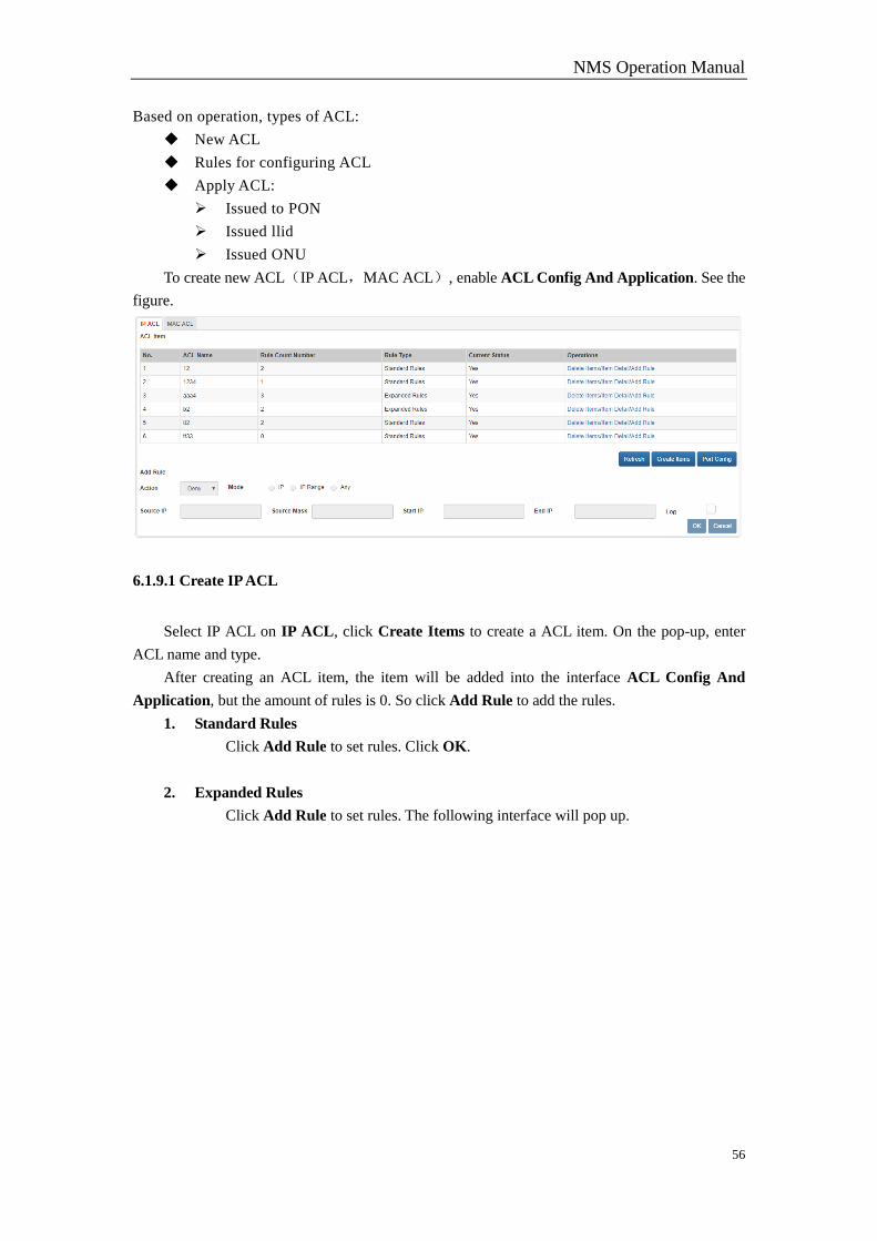
To create new ACL(IP ACL,MAC ACL), enable ACL Config And Application. See the
figure.
6.1.9.1 Create IP ACL
Select IP ACL on IP ACL, click Create Items to create a ACL item. On the pop-up, enter
ACL name and type.
After creating an ACL item, the item will be added into the interface ACL Config And
Application, but the amount of rules is 0. So click Add Rule to add the rules.
1. Standard Rules
Click Add Rule to set rules. Click OK.
2. Expanded Rules
Click Add Rule to set rules. The following interface will pop up.
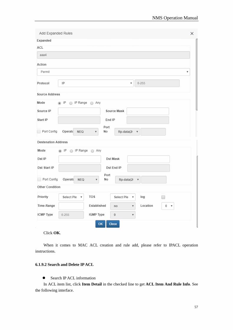
NMS Operation Manual
57
Click OK.
When it comes to MAC ACL creation and rule add, please refer to IPACL operation
instructions.
6.1.9.2 Search and Delete IP ACL
Search IP ACL information
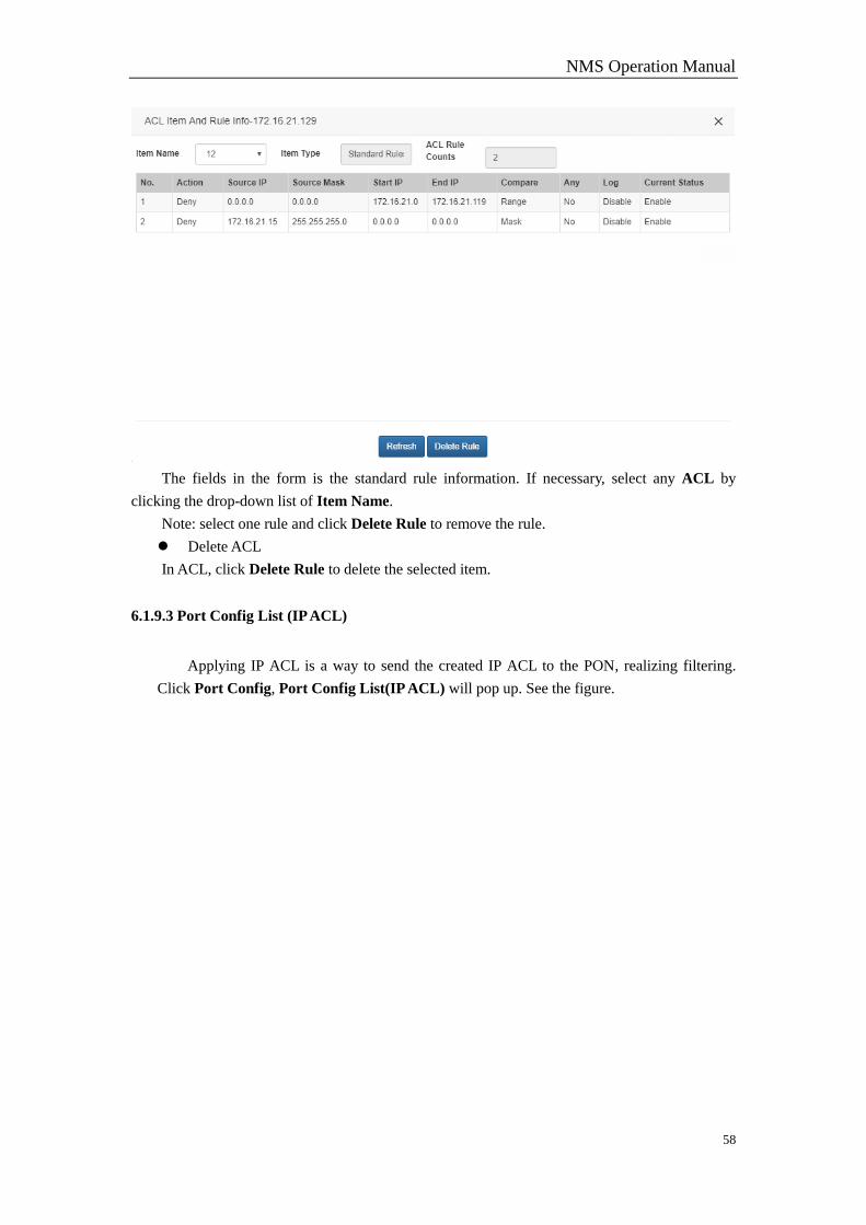
In ACL item list, click Item Detail in the checked line to get ACL Item And Rule Info. See
the following interface.
NMS Operation Manual
58
The fields in the form is the standard rule information. If necessary, select any ACL by
clicking the drop-down list of Item Name.
Note: select one rule and click Delete Rule to remove the rule.
Delete ACL
In ACL, click Delete Rule to delete the selected item.
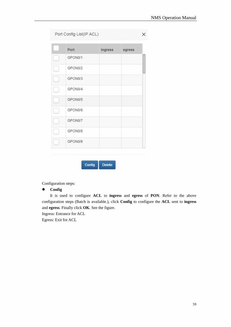
6.1.9.3 Port Config List (IP ACL)
Applying IP ACL is a way to send the created IP ACL to the PON, realizing filtering.
Click Port Config, Port Config List(IP ACL) will pop up. See the figure.
NMS Operation Manual
59
Configuration steps:
Config
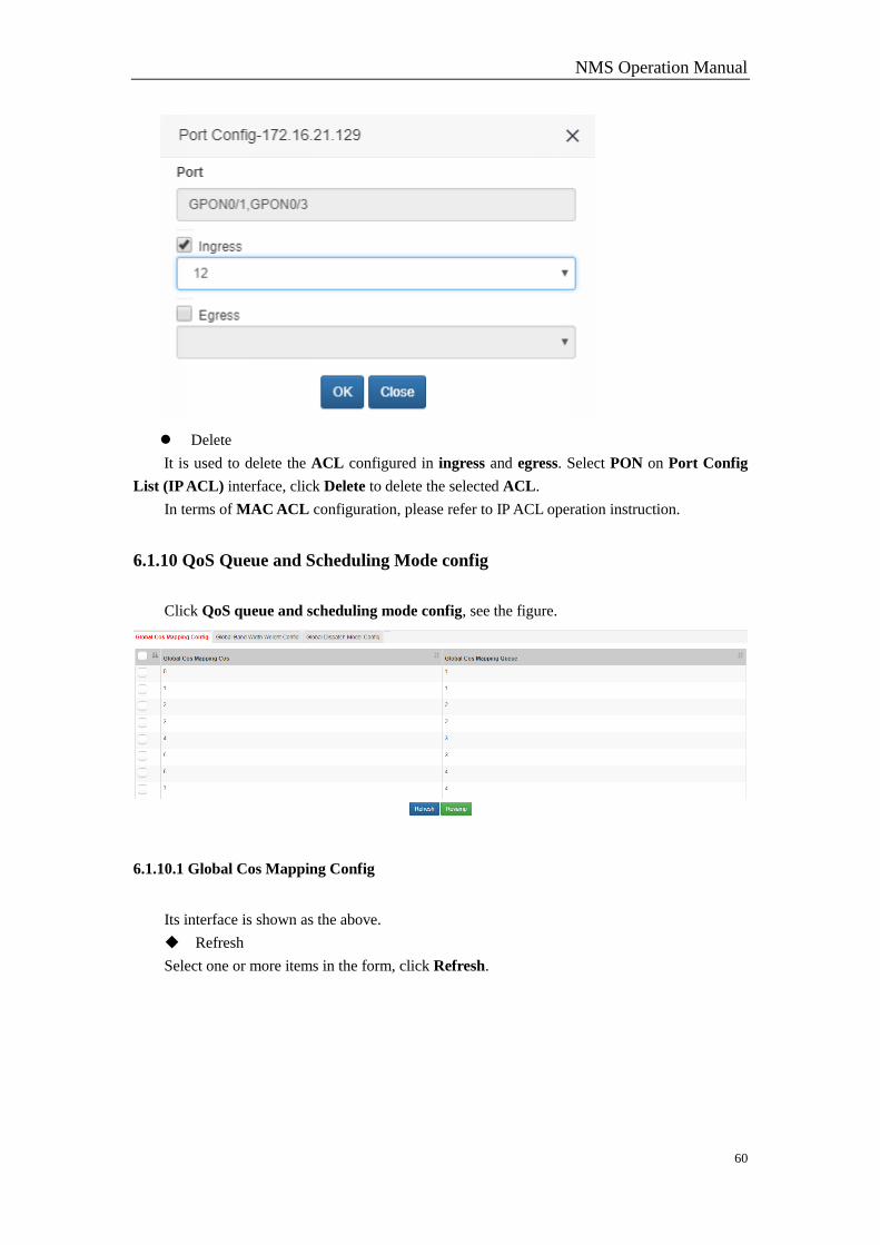
It is used to configure ACL to ingress and egress of PON. Refer to the above
configuration steps (Batch is available.), click Config to configure the ACL sent to ingress
and egress. Finally click OK. See the figure.
Ingress: Entrance for ACL
Egress: Exit for ACL
NMS Operation Manual
60
Delete
It is used to delete the ACL configured in ingress and egress. Select PON on Port Config
List (IP ACL) interface, click Delete to delete the selected ACL.
In terms of MAC ACL configuration, please refer to IP ACL operation instruction.
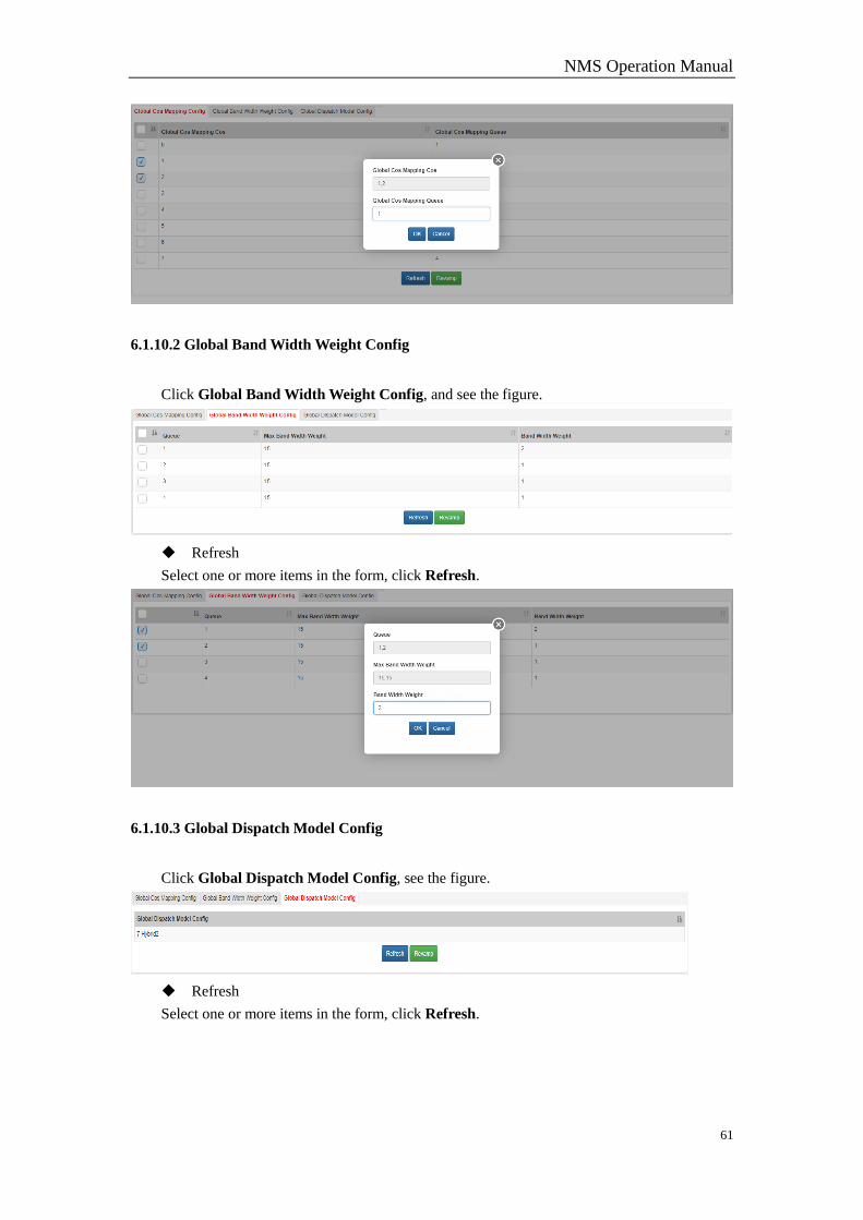
6.1.10 QoS Queue and Scheduling Mode config
Click QoS queue and scheduling mode config, see the figure.
6.1.10.1 Global Cos Mapping Config
Its interface is shown as the above.
Refresh
Select one or more items in the form, click Refresh.
NMS Operation Manual
61
6.1.10.2 Global Band Width Weight Config
Click Global Band Width Weight Config, and see the figure.
Refresh
Select one or more items in the form, click Refresh.
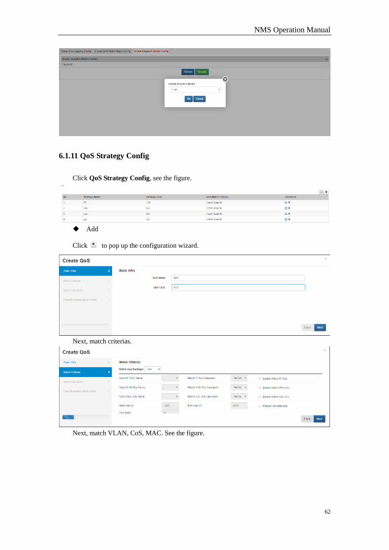
6.1.10.3 Global Dispatch Model Config
Click Global Dispatch Model Config, see the figure.
Refresh
Select one or more items in the form, click Refresh.
NMS Operation Manual
62
6.1.11 QoS Strategy Config
Click QoS Strategy Config, see the figure.
Add
Click to pop up the configuration wizard.
Next, match criterias.
Next, match VLAN, CoS, MAC. See the figure.
NMS Operation Manual
63
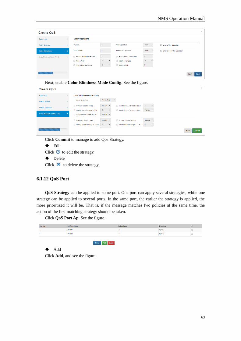
Next, enable Color Blindness Mode Config. See the figure.
Click Commit to manage to add Qos Strategy.
Edit
Click to edit the strategy.
Delete
Click to delete the strategy.
6.1.12 QoS Port
QoS Strategy can be applied to some port. One port can apply several strategies, while one
strategy can be applied to several ports. In the same port, the earlier the strategy is applied, the
more prioritized it will be. That is, if the message matches two policies at the same time, the
action of the first matching strategy should be taken.
Click QoS Port Ap. See the figure.
Add
Click Add, and see the figure.
NMS Operation Manual
64
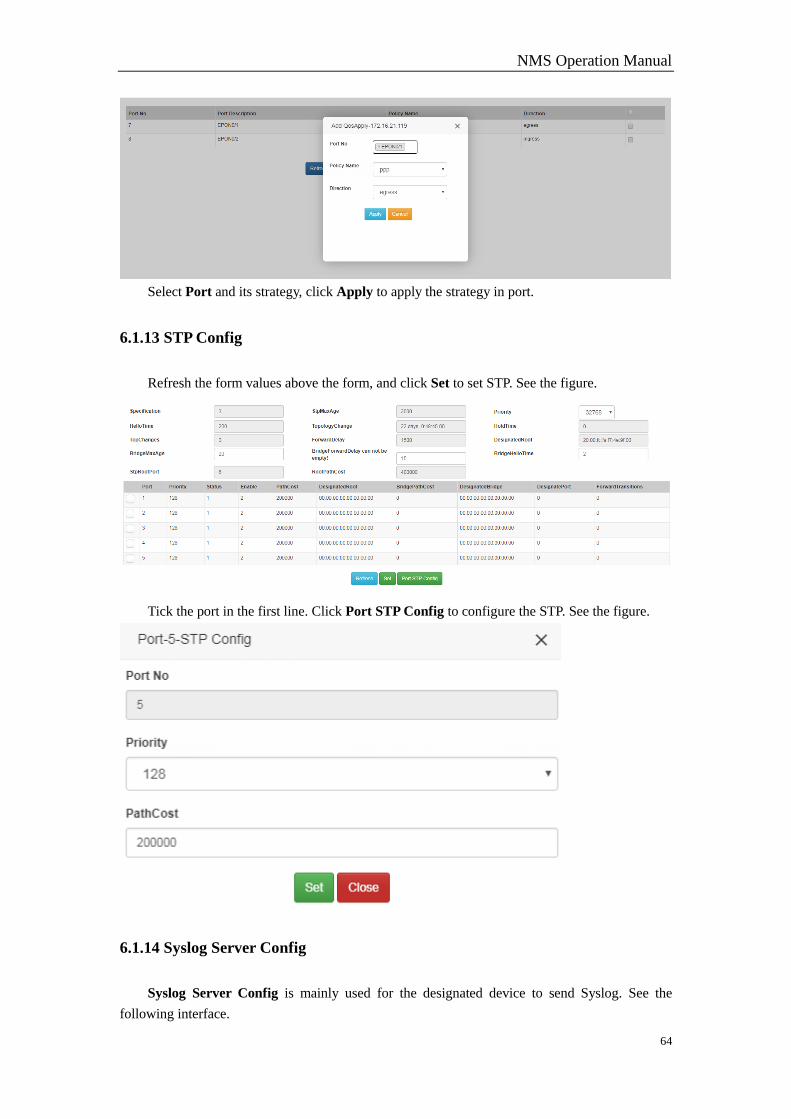
Select Port and its strategy, click Apply to apply the strategy in port.
6.1.13 STP Config
Refresh the form values above the form, and click Set to set STP. See the figure.
Tick the port in the first line. Click Port STP Config to configure the STP. See the figure.
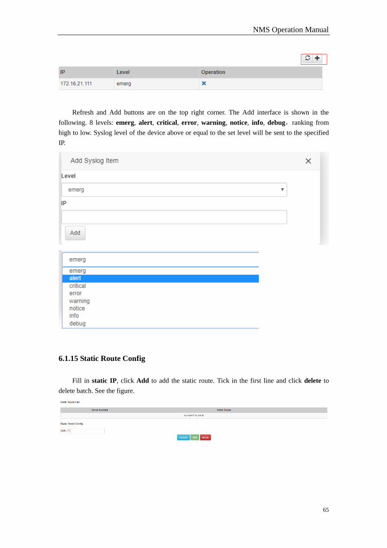
6.1.14 Syslog Server Config
Syslog Server Config is mainly used for the designated device to send Syslog. See the
following interface.
NMS Operation Manual
65
Refresh and Add buttons are on the top right corner. The Add interface is shown in the
following. 8 levels: emerg, alert, critical, error, warning, notice, info, debug,ranking from
high to low. Syslog level of the device above or equal to the set level will be sent to the specified
IP.
6.1.15 Static Route Config
Fill in static IP, click Add to add the static route. Tick in the first line and click delete to
delete batch. See the figure.
NMS Operation Manual
66
6.2 EPON Device
6.2.1 Managed Object Attribute
Please refer to section 6.1.1.
6.2.2 Vlan Management
Please refer to section 6.1.2.
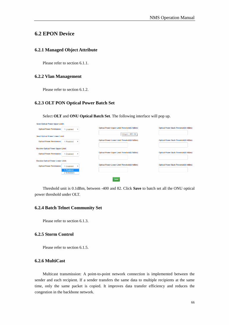
6.2.3 OLT PON Optical Power Batch Set
Select OLT and ONU Optical Batch Set. The following interface will pop up.
Threshold unit is 0.1dBm, between -400 and 82. Click Save to batch set all the ONU optical
power threshold under OLT.
6.2.4 Batch Telnet Community Set
Please refer to section 6.1.3.
6.2.5 Storm Control
Please refer to section 6.1.5.
6.2.6 MultiCast
Multicast transmission: A point-to-point network connection is implemented between the
sender and each recipient. If a sender transfers the same data to multiple recipients at the same
time, only the same packet is copied. It improves data transfer efficiency and reduces the
congestion in the backbone network.

NMS Operation Manual
67
IGMP runs between the host and the multicast router directly connected to the host. The host
uses IGMP to tell the local router that it wants to join and receive information about a particular
multicast group, while the router periodically queries the members of a given group within the
LAN whether it is active(that is, whether the network still has members belonging to a multicast
group), realizing the collection and maintenance of network group membership. 3 IGMP versions:
IGMPv1, IGMPv2, IGMPv3.
OLT multicast configuration is the configuration of some global attributes for OLT group.
Click Multicast Set, and see the figure.
Note: The gray part on the left cannot be modified.
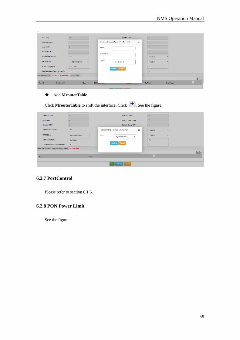
Add MulticastVlanTable
Click , see the figure.
Add MulticastForwardTable
Click MulticastForwardTable to shift the interface. Click .
NMS Operation Manual
68
Add MrouterTable
Click MrouterTable to shift the interface. Click . See the figure.
6.2.7 PortControl
Please refer to section 6.1.6.
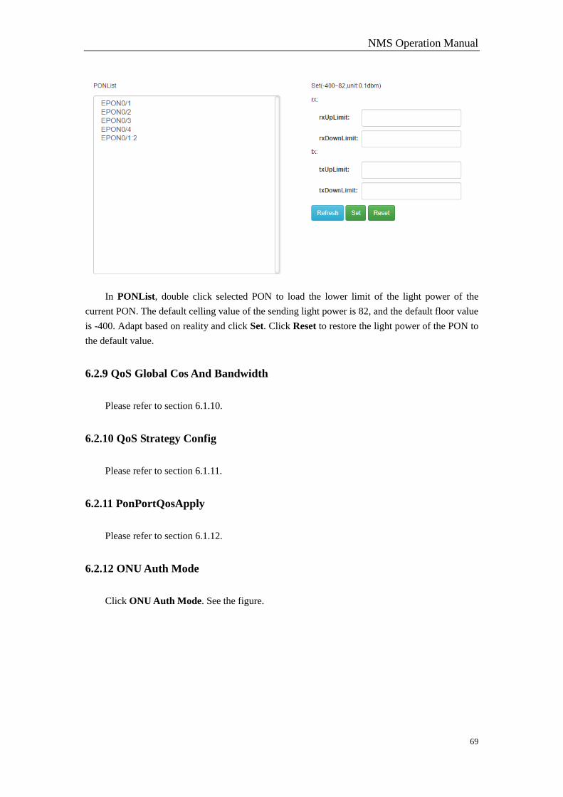
6.2.8 PON Power Limit
See the figure.
NMS Operation Manual
69
In PONList, double click selected PON to load the lower limit of the light power of the
current PON. The default celling value of the sending light power is 82, and the default floor value
is -400. Adapt based on reality and click Set. Click Reset to restore the light power of the PON to
the default value.
6.2.9 QoS Global Cos And Bandwidth
Please refer to section 6.1.10.
6.2.10 QoS Strategy Config
Please refer to section 6.1.11.
6.2.11 PonPortQosApply
Please refer to section 6.1.12.
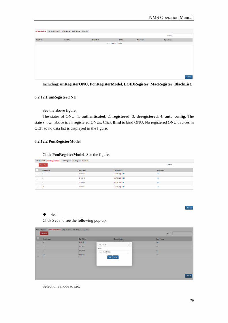
6.2.12 ONU Auth Mode
Click ONU Auth Mode. See the figure.
NMS Operation Manual
70
Including: unRegisterONU, PonRegisterModel, LOIDRegister, MacRegister, BlackList.
6.2.12.1 unRegisterONU
See the above figure.
The states of ONU: 1: authenticated, 2: registered, 3: deregistered, 4: auto_config. The
state shown above is all registered ONUs. Click Bind to bind ONU. No registered ONU devices in
OLT, so no data list is displayed in the figure.
6.2.12.2 PonRegisterModel
Click PonRegsiterModel. See the figure.
Set
Click Set and see the following pop-up.
Select one mode to set.
NMS Operation Manual
71
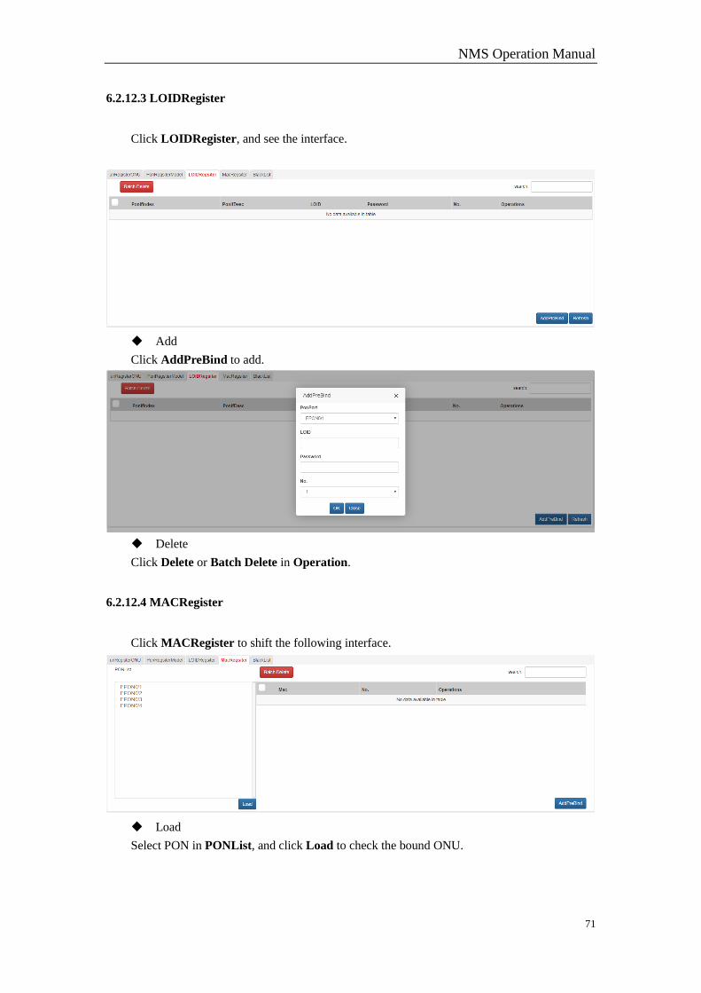
6.2.12.3 LOIDRegister
Click LOIDRegister, and see the interface.
Add
Click AddPreBind to add.
Delete
Click Delete or Batch Delete in Operation.
6.2.12.4 MACRegister
Click MACRegister to shift the following interface.
Load
Select PON in PONList, and click Load to check the bound ONU.
NMS Operation Manual
72
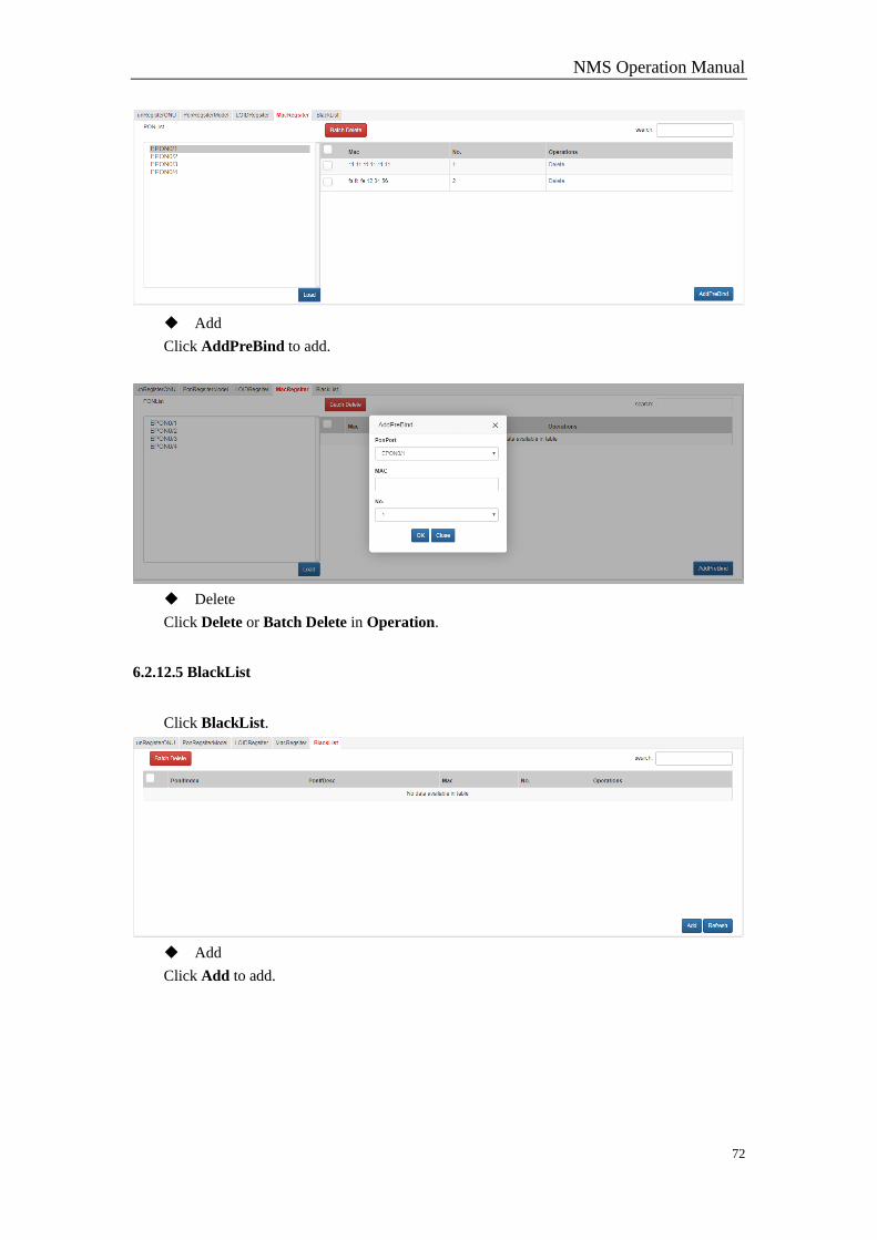
Add
Click AddPreBind to add.
Delete
Click Delete or Batch Delete in Operation.
6.2.12.5 BlackList
Click BlackList.
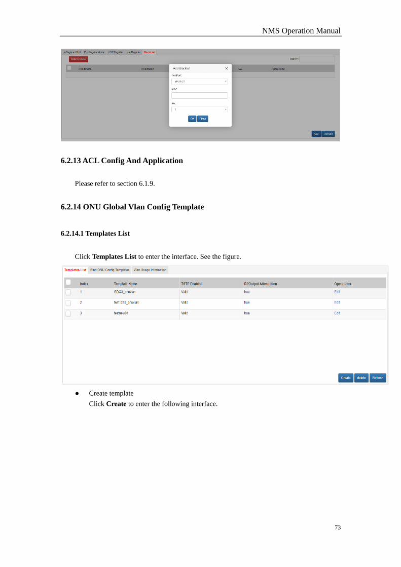
Add
Click Add to add.
NMS Operation Manual
73
6.2.13 ACL Config And Application
Please refer to section 6.1.9.
6.2.14 ONU Global Vlan Config Template
6.2.14.1 Templates List
Click Templates List to enter the interface. See the figure.
● Create template
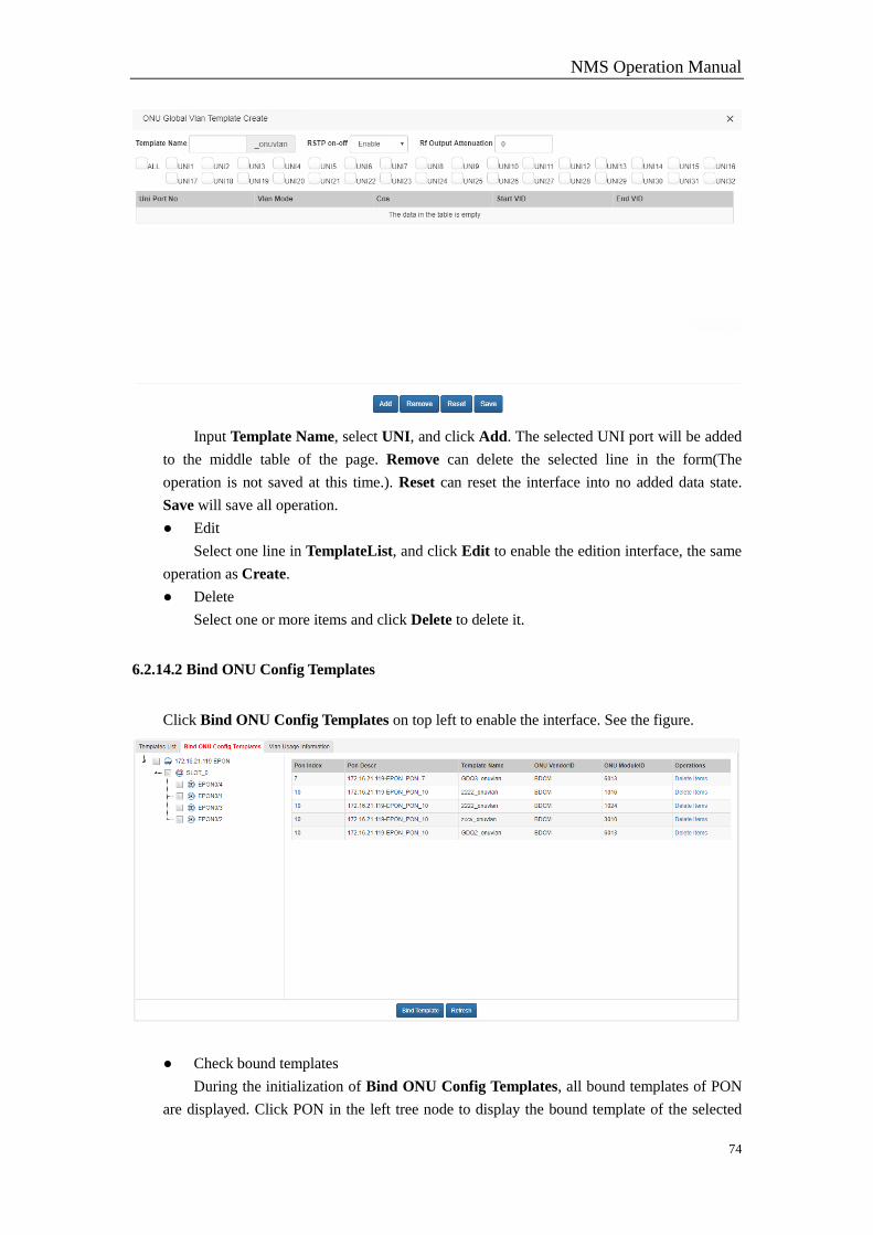
Click Create to enter the following interface.
NMS Operation Manual
74
Input Template Name, select UNI, and click Add. The selected UNI port will be added
to the middle table of the page. Remove can delete the selected line in the form(The
operation is not saved at this time.). Reset can reset the interface into no added data state.
Save will save all operation.
● Edit
Select one line in TemplateList, and click Edit to enable the edition interface, the same
operation as Create.
● Delete
Select one or more items and click Delete to delete it.
6.2.14.2 Bind ONU Config Templates
Click Bind ONU Config Templates on top left to enable the interface. See the figure.
● Check bound templates
During the initialization of Bind ONU Config Templates, all bound templates of PON
are displayed. Click PON in the left tree node to display the bound template of the selected
NMS Operation Manual
75
PON.
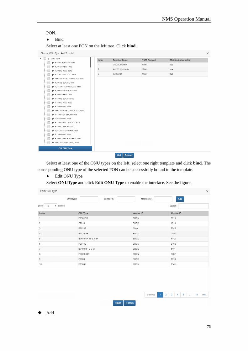
● Bind
Select at least one PON on the left tree. Click bind.
Select at least one of the ONU types on the left, select one right template and click bind. The
corresponding ONU type of the selected PON can be successfully bound to the template.
● Edit ONU Type
Select ONUType and click Edit ONU Type to enable the interface. See the figure.
◆ Add
NMS Operation Manual
76
Enter ONUType, Vendor ID, Module ID and click Add.
◆ Delete
Select the ONU type to be deleted(ctrl+left-click to select more) and click Delete.
6.2.14.3 Vlan Usage Information
Click Vlan Usage Information to enable the interface to check the bound templates.
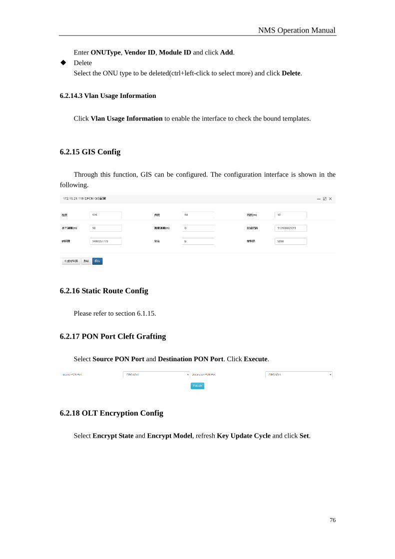
6.2.15 GIS Config
Through this function, GIS can be configured. The configuration interface is shown in the
following.
6.2.16 Static Route Config
Please refer to section 6.1.15.
6.2.17 PON Port Cleft Grafting
Select Source PON Port and Destination PON Port. Click Execute.
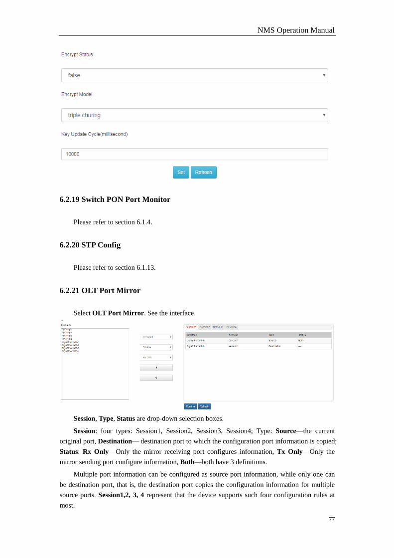
6.2.18 OLT Encryption Config
Select Encrypt State and Encrypt Model, refresh Key Update Cycle and click Set.
NMS Operation Manual
77
6.2.19 Switch PON Port Monitor
Please refer to section 6.1.4.
6.2.20 STP Config
Please refer to section 6.1.13.
6.2.21 OLT Port Mirror
Select OLT Port Mirror. See the interface.
Session, Type, Status are drop-down selection boxes.
Session: four types: Session1, Session2, Session3, Session4; Type: Source—the current
original port, Destination— destination port to which the configuration port information is copied;
Status: Rx Only—Only the mirror receiving port configures information, Tx Only—Only the
mirror sending port configure information, Both—both have 3 definitions.
Multiple port information can be configured as source port information, while only one can
be destination port, that is, the destination port copies the configuration information for multiple
source ports. Session1,2, 3, 4 represent that the device supports such four configuration rules at
most.
NMS Operation Manual
78
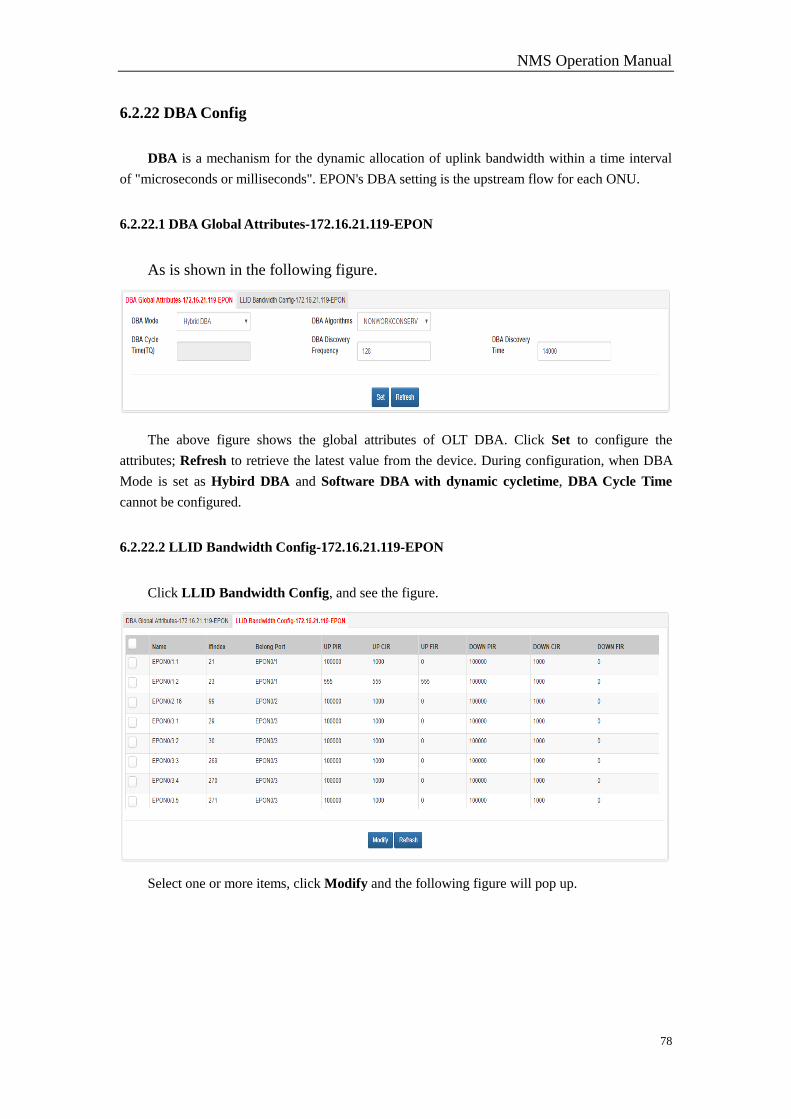
6.2.22 DBA Config
DBA is a mechanism for the dynamic allocation of uplink bandwidth within a time interval
of "microseconds or milliseconds". EPON's DBA setting is the upstream flow for each ONU.
6.2.22.1 DBA Global Attributes-172.16.21.119-EPON
As is shown in the following figure.
The above figure shows the global attributes of OLT DBA. Click Set to configure the
attributes; Refresh to retrieve the latest value from the device. During configuration, when DBA
Mode is set as Hybird DBA and Software DBA with dynamic cycletime, DBA Cycle Time
cannot be configured.
6.2.22.2 LLID Bandwidth Config-172.16.21.119-EPON
Click LLID Bandwidth Config, and see the figure.
Select one or more items, click Modify and the following figure will pop up.

NMS Operation Manual
79
Bandwidth Type, CIR and FIR can be modified. If DBA Mode is Hardware DBA, FIR
cannot be modified. Select Bandwidth Type: Up Bandwidth/Down Bandwidth. Click Set.
Normally, the interface will be shut down.
6.2.23 Syslog Server Config
Please refer to section 6.1.14.
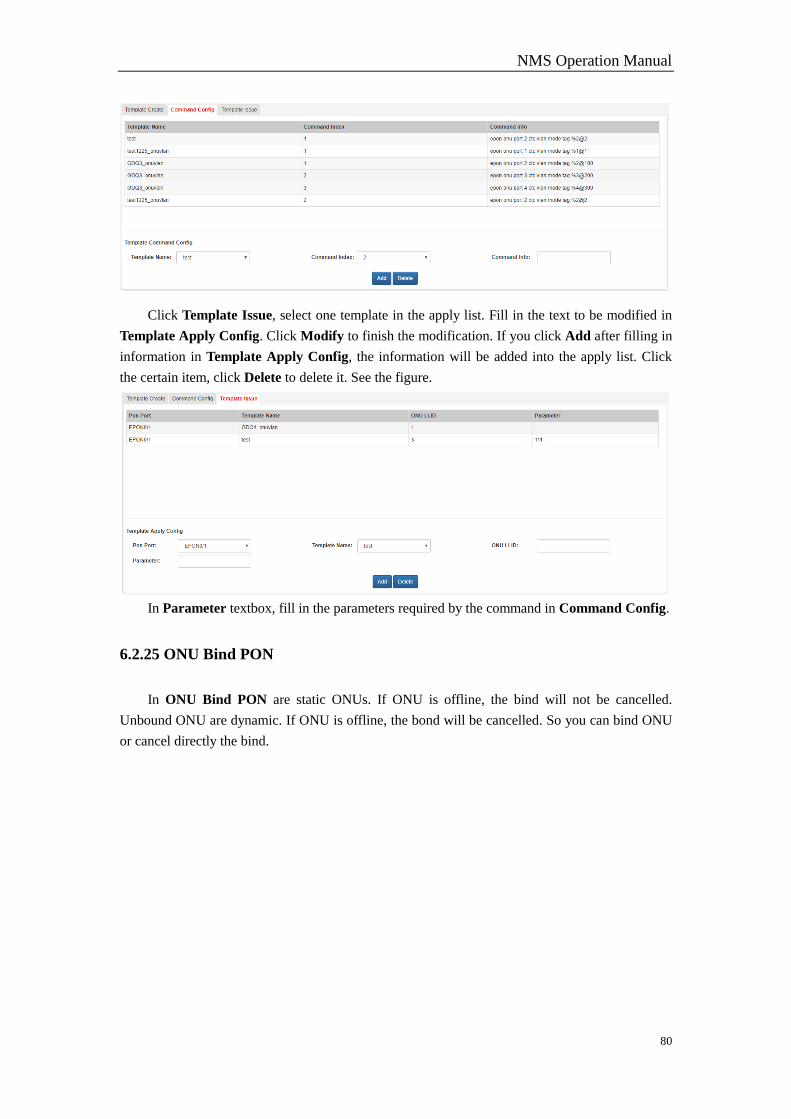
6.2.24 ONU Configure Template
Click ONU Configure Template, and select Template Create. Set Template Name as test,
click Add to add the template to the list. Select the test template line and click delete to delete the
template. See the figure.
Click Command Config, select test in the Template Name drop-down selection box, fill in
the command in Template textbox. Click Add to add the command into the list. Select the item
and click Delete. See the following figure.
NMS Operation Manual
80
Click Template Issue, select one template in the apply list. Fill in the text to be modified in
Template Apply Config. Click Modify to finish the modification. If you click Add after filling in
information in Template Apply Config, the information will be added into the apply list. Click
the certain item, click Delete to delete it. See the figure.
In Parameter textbox, fill in the parameters required by the command in Command Config.
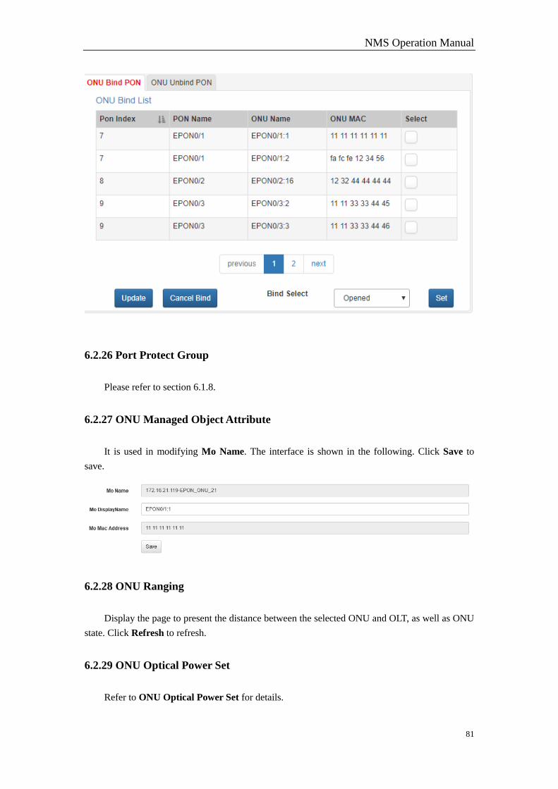
6.2.25 ONU Bind PON
In ONU Bind PON are static ONUs. If ONU is offline, the bind will not be cancelled.
Unbound ONU are dynamic. If ONU is offline, the bond will be cancelled. So you can bind ONU
or cancel directly the bind.
NMS Operation Manual
81
6.2.26 Port Protect Group
Please refer to section 6.1.8.
6.2.27 ONU Managed Object Attribute
It is used in modifying Mo Name. The interface is shown in the following. Click Save to
save.
6.2.28 ONU Ranging
Display the page to present the distance between the selected ONU and OLT, as well as ONU
state. Click Refresh to refresh.
6.2.29 ONU Optical Power Set
Refer to ONU Optical Power Set for details.
NMS Operation Manual
82
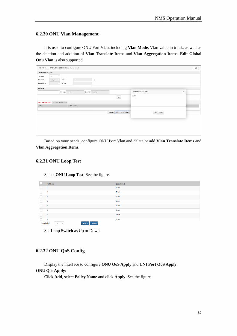
6.2.30 ONU Vlan Management
It is used to configure ONU Port Vlan, including Vlan Mode, Vlan value in trunk, as well as
the deletion and addition of Vlan Translate Items and Vlan Aggregation Items. Edit Global
Onu Vlan is also supported.
Based on your needs, configure ONU Port Vlan and delete or add Vlan Translate Items and
Vlan Aggregation Items.
6.2.31 ONU Loop Test
Select ONU Loop Test. See the figure.
Set Loop Switch as Up or Down.
6.2.32 ONU QoS Config
Display the interface to configure ONU QoS Apply and UNI Port QoS Apply.
ONU Qos Apply:
Click Add, select Policy Name and click Apply. See the figure.
NMS Operation Manual
83
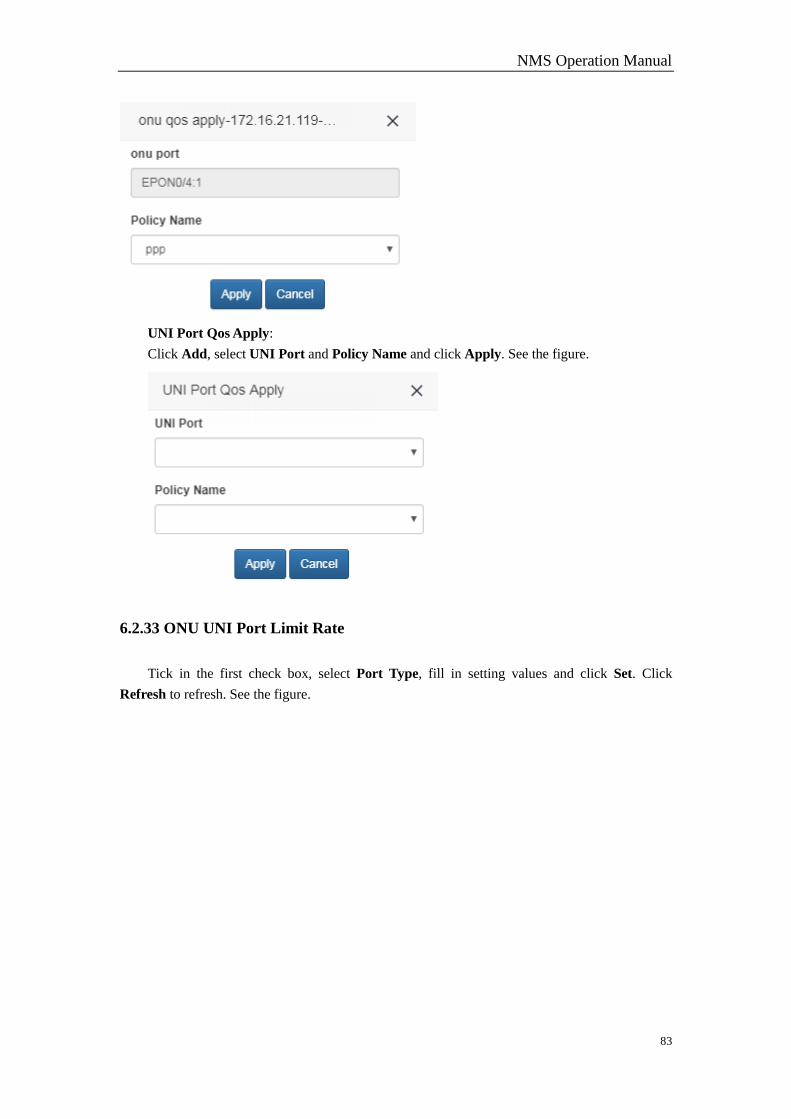
UNI Port Qos Apply:
Click Add, select UNI Port and Policy Name and click Apply. See the figure.
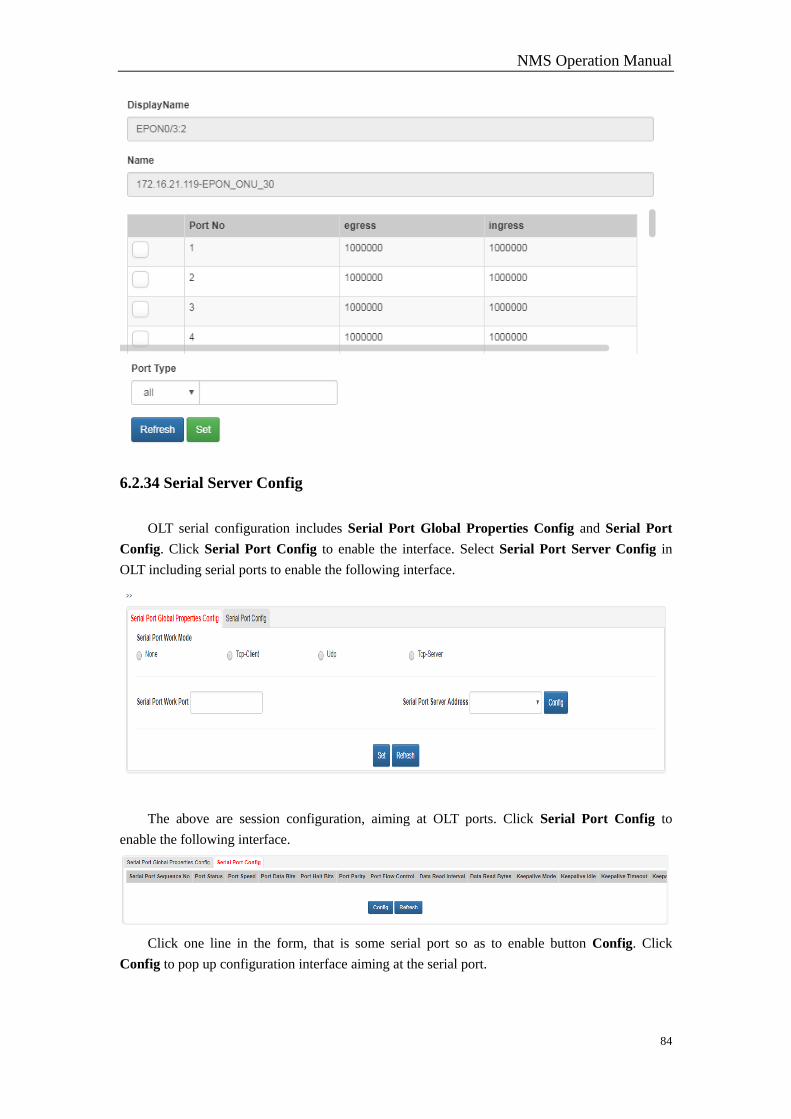
6.2.33 ONU UNI Port Limit Rate
Tick in the first check box, select Port Type, fill in setting values and click Set. Click
Refresh to refresh. See the figure.
NMS Operation Manual
84
6.2.34 Serial Server Config
OLT serial configuration includes Serial Port Global Properties Config and Serial Port
Config. Click Serial Port Config to enable the interface. Select Serial Port Server Config in
OLT including serial ports to enable the following interface.
The above are session configuration, aiming at OLT ports. Click Serial Port Config to
enable the following interface.
Click one line in the form, that is some serial port so as to enable button Config. Click
Config to pop up configuration interface aiming at the serial port.
NMS Operation Manual
85
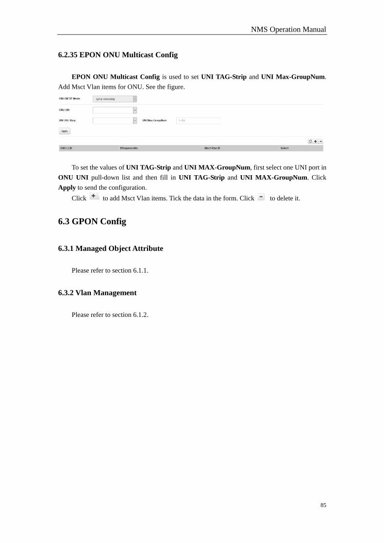
6.2.35 EPON ONU Multicast Config
EPON ONU Multicast Config is used to set UNI TAG-Strip and UNI Max-GroupNum.
Add Msct Vlan items for ONU. See the figure.
To set the values of UNI TAG-Strip and UNI MAX-GroupNum, first select one UNI port in
ONU UNI pull-down list and then fill in UNI TAG-Strip and UNI MAX-GroupNum. Click
Apply to send the configuration.
Click to add Msct Vlan items. Tick the data in the form. Click to delete it.
6.3 GPON Config
6.3.1 Managed Object Attribute
Please refer to section 6.1.1.
6.3.2 Vlan Management
Please refer to section 6.1.2.
NMS Operation Manual
86
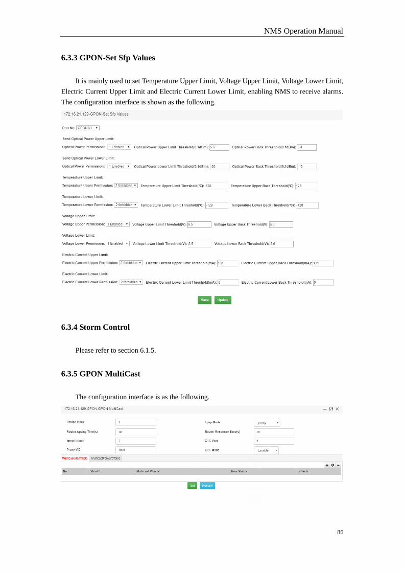
6.3.3 GPON-Set Sfp Values
It is mainly used to set Temperature Upper Limit, Voltage Upper Limit, Voltage Lower Limit,
Electric Current Upper Limit and Electric Current Lower Limit, enabling NMS to receive alarms.
The configuration interface is shown as the following.
6.3.4 Storm Control
Please refer to section 6.1.5.
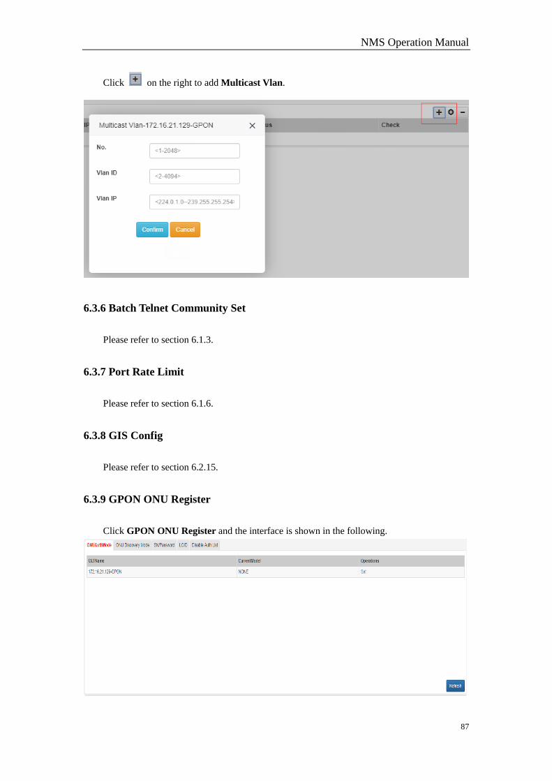
6.3.5 GPON MultiCast
The configuration interface is as the following.
NMS Operation Manual
87
Click on the right to add Multicast Vlan.
6.3.6 Batch Telnet Community Set
Please refer to section 6.1.3.
6.3.7 Port Rate Limit
Please refer to section 6.1.6.
6.3.8 GIS Config
Please refer to section 6.2.15.
6.3.9 GPON ONU Register
Click GPON ONU Register and the interface is shown in the following.
NMS Operation Manual
88
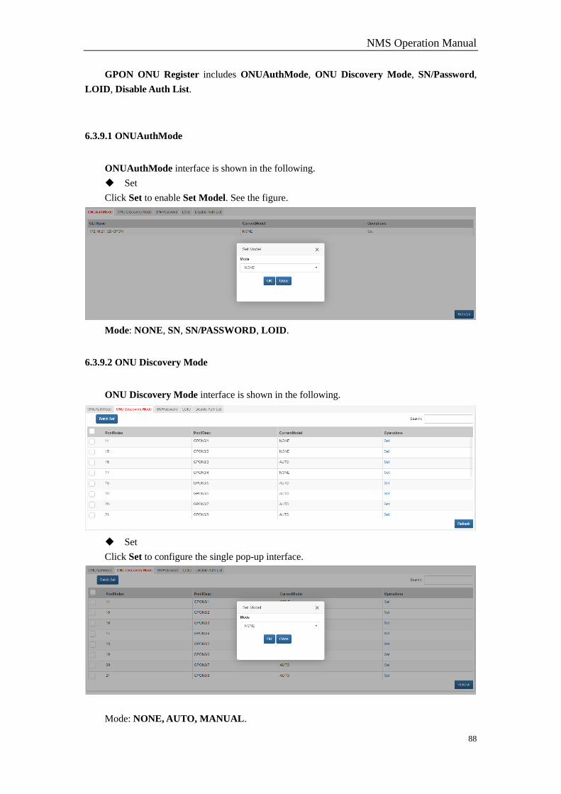
GPON ONU Register includes ONUAuthMode, ONU Discovery Mode, SN/Password,
LOID, Disable Auth List.
6.3.9.1 ONUAuthMode
ONUAuthMode interface is shown in the following.
Set
Click Set to enable Set Model. See the figure.
Mode: NONE, SN, SN/PASSWORD, LOID.
6.3.9.2 ONU Discovery Mode
ONU Discovery Mode interface is shown in the following.
Set
Click Set to configure the single pop-up interface.
Mode: NONE, AUTO, MANUAL.
NMS Operation Manual
89
Batch Set
Tick multiple lines, click Batch Set.
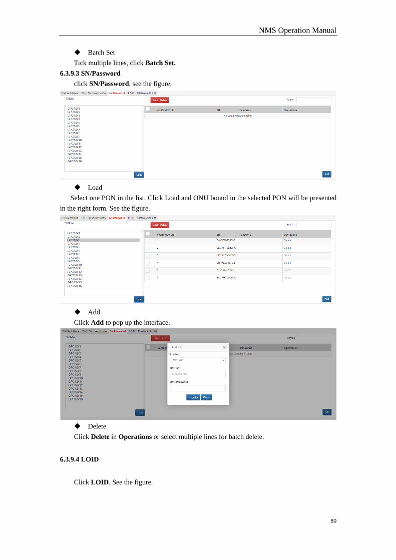
6.3.9.3 SN/Password
click SN/Password, see the figure.
Load
Select one PON in the list. Click Load and ONU bound in the selected PON will be presented
in the right form. See the figure.
Add
Click Add to pop up the interface.
Delete
Click Delete in Operations or select multiple lines for batch delete.
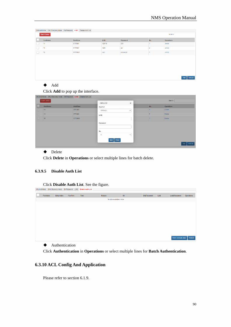
6.3.9.4 LOID
Click LOID. See the figure.
NMS Operation Manual
90
Add
Click Add to pop up the interface.
Delete
Click Delete in Operations or select multiple lines for batch delete.
6.3.9.5 Disable Auth List
Click Disable Auth List. See the figure.
Authentication
Click Authentication in Operations or select multiple lines for Batch Authentication.
6.3.10 ACL Config And Application
Please refer to section 6.1.9.
NMS Operation Manual
91
6.3.11 GPON ONU Configure Template
Please refer to section 6.2.24.
6.3.12 Syslog Server Config
Please refer to 6.1.14.
6.3.13 QoS Queue and Scheduling Mode Config
Please refer to section 6.1.10.
6.3.14 QoS Strategy Config
Please refer to section 6.1.11.
6.3.15 QoS Port
Please refer to section 6.1.12.
6.3.16 Static Route Config
Please refer to section 6.1.15.
6.3.17 STP Config
Please refer to section 6.1.13.
6.3.18 OLT Port Mirror
Please refer to section 6.2.21.
6.3.19 Port Protect Group
Please refer to section 6.1.8.
6.3.20 ONU Managed Object Attribute
Please refer to section 6.2.27.
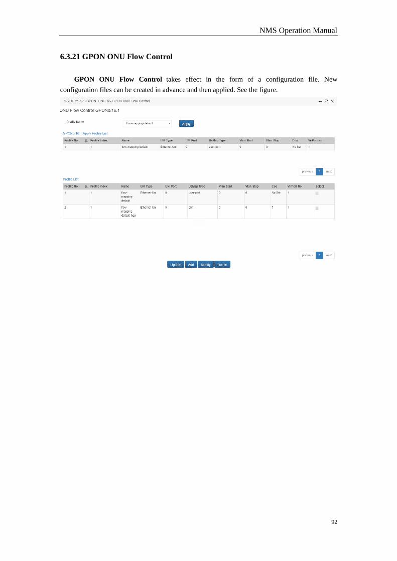
NMS Operation Manual
92
6.3.21 GPON ONU Flow Control
GPON ONU Flow Control takes effect in the form of a configuration file. New
configuration files can be created in advance and then applied. See the figure.
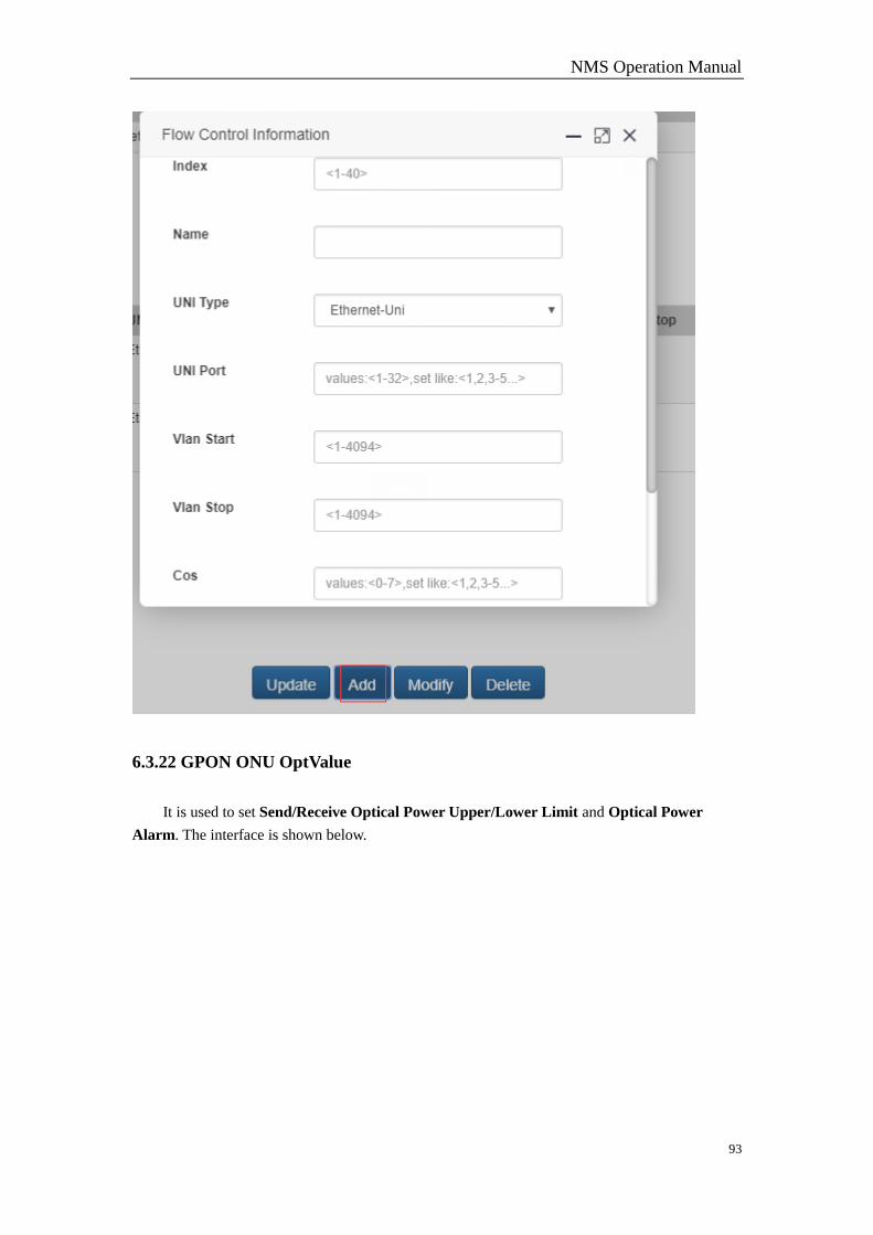
NMS Operation Manual
93
6.3.22 GPON ONU OptValue
It is used to set Send/Receive Optical Power Upper/Lower Limit and Optical Power
Alarm. The interface is shown below.
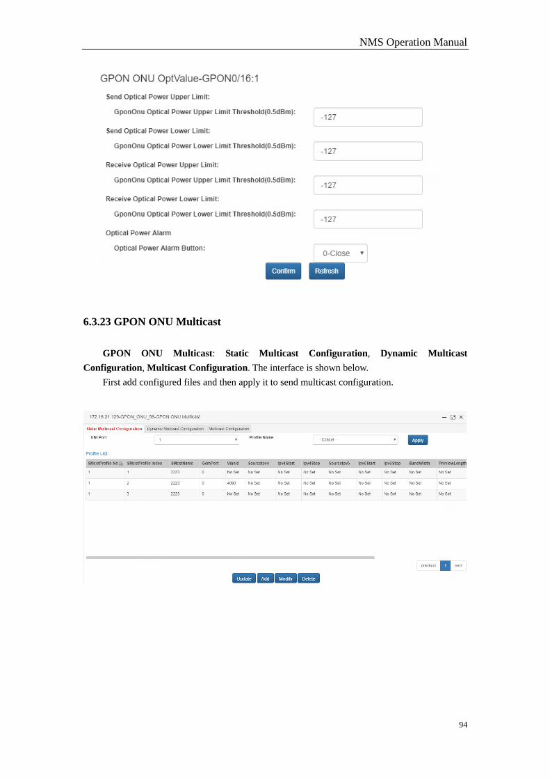
NMS Operation Manual
94
6.3.23 GPON ONU Multicast
GPON ONU Multicast: Static Multicast Configuration, Dynamic Multicast
Configuration, Multicast Configuration. The interface is shown below.
First add configured files and then apply it to send multicast configuration.

NMS Operation Manual
95
6.3.24 GPON ONU VirPortManage
GPON ONU VirPortManage includes ONU Virtual Port Manage and Virtual PORT
Vlan Translate.
6.3.24.1 ONU Virtual Port Manage
ONU Virtual Port Manage interface is shown below.
Select Port No. and set Vitual Port Manage Status as no-shutdown-unlocks/shutdown-locks.
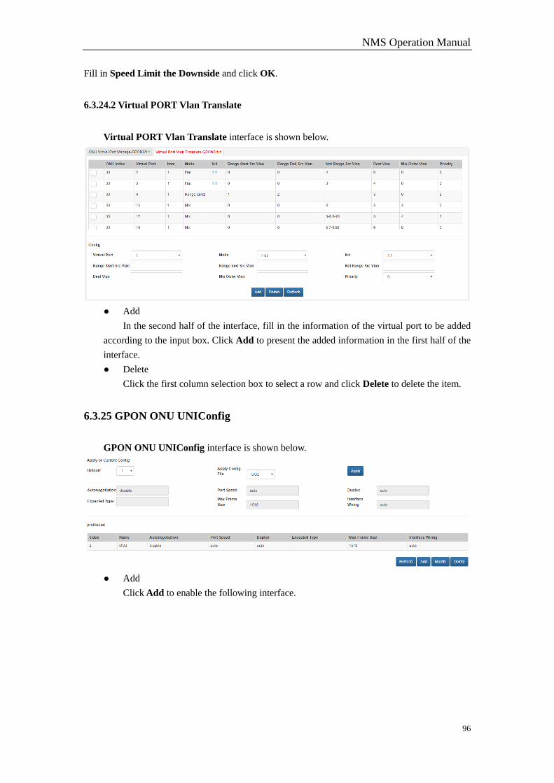
NMS Operation Manual
96
Fill in Speed Limit the Downside and click OK.
6.3.24.2 Virtual PORT Vlan Translate
Virtual PORT Vlan Translate interface is shown below.
● Add
In the second half of the interface, fill in the information of the virtual port to be added
according to the input box. Click Add to present the added information in the first half of the
interface.
● Delete
Click the first column selection box to select a row and click Delete to delete the item.
6.3.25 GPON ONU UNIConfig
GPON ONU UNIConfig interface is shown below.
● Add
Click Add to enable the following interface.
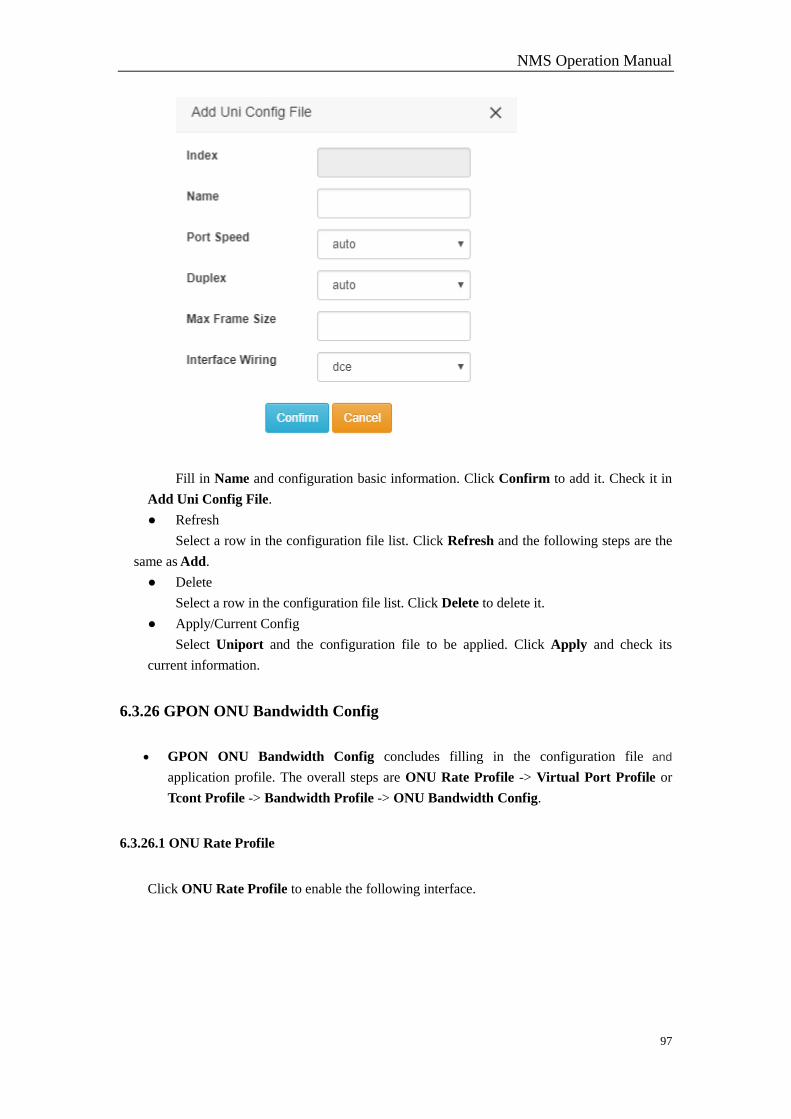
NMS Operation Manual
97
Fill in Name and configuration basic information. Click Confirm to add it. Check it in
Add Uni Config File.
● Refresh
Select a row in the configuration file list. Click Refresh and the following steps are the
same as Add.
● Delete
Select a row in the configuration file list. Click Delete to delete it.
● Apply/Current Config
Select Uniport and the configuration file to be applied. Click Apply and check its
current information.
6.3.26 GPON ONU Bandwidth Config
GPON ONU Bandwidth Config concludes filling in the configuration file and
application profile. The overall steps are ONU Rate Profile -> Virtual Port Profile or
Tcont Profile -> Bandwidth Profile -> ONU Bandwidth Config.
6.3.26.1 ONU Rate Profile
Click ONU Rate Profile to enable the following interface.
NMS Operation Manual
98
● Add
Fill in Name in the second half of the interface. And set the rate to ensure the bandwidth and
the rate peak bandwidth(Ensure that the bandwidth is not greater than the peak bandwidth.). Cick
Add and it will be shown in the first half.
● Delete
Click the selected row in the list, and click Delete to delete it.
6.3.26.2 Virtual Port Profile
Click Virtual Port Profile to enable the following interface.
● Add
Fill in Name in the second half of the interface. Select the configuration items to configure
the completed ONU rate profile. Click Add.
● Delete
Click the selected row in the list and click Delete.
6.3.26.3 Tcont Profile
Click Tcont Profile to enable the interface.

NMS Operation Manual
99
● Add
Fill in Name in the second half of the interface. Select Tcont Type (Different Tcont Type can
be configured with different types of bandwidth). Click Add to add it and it will show up in the
first half.
● Delete
Click the selected row in the list and click Delete.
6.3.26.4 Bandwidth Profile
Click Bandwidth Profile to enable the interface.
● Add
Fill in Name, select Index, fill in Tcont Id (1-8) and select Tcont Profile and Virtual Port
Profile. Click Add to apply it in Bandwidth Profile.
6.3.26.5 ONU Bandwidth Config
Click ONU Bandwidth Config to enable the interface below.
NMS Operation Manual
100
● Apply Profile
Select a bandwidth profile in the top Apply Profile selection box and click Apply. You can
check the state in Current Config.
● Bandwidth Profile Table
In Bandwidth Profile Table, each bandwidth profile and virtual port Index will be presented.
Click one line to check the detailed configuration of virtual port in the current profile.
● Add
Click Add to enable Bandwidth Config.
6.3.27 GPON ONU Vlan
Vlan Configuration takes effect when applying template. First add the template and apply itto
ONU UNI port.
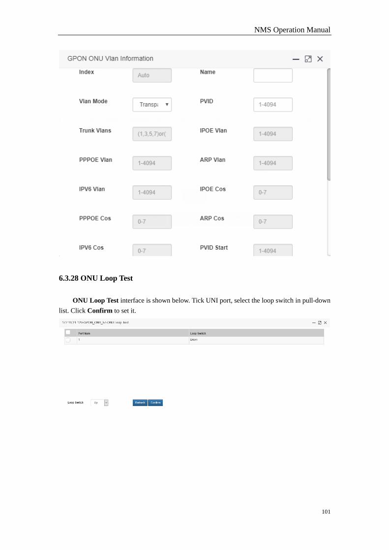
NMS Operation Manual
101
6.3.28 ONU Loop Test
ONU Loop Test interface is shown below. Tick UNI port, select the loop switch in pull-down
list. Click Confirm to set it.
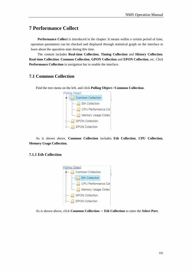
NMS Operation Manual
102
7 Performance Collect
Performance Collect is introduced in the chapter. It means within a certain period of time,
operation parameters can be checked and displayed through statistical graph on the interface to
learn about the operation state during this time.
The content includes Real-time Collection, Timing Collection and History Collection.
Real-time Collection: Common Collection, GPON Collection and EPON Collection, etc. Click
Performance Collection in navigation bar to enable the interface.
7.1 Common Collection
Find the tree menu on the left, and click Polling Object->Common Collection.
As is shown above, Common Collection includes Eth Collection, CPU Collection,
Memory Usage Collection.
7.1.1 Eth Collection
As is shown above, click Common Collection -> Eth Collection to enter the Select Port.
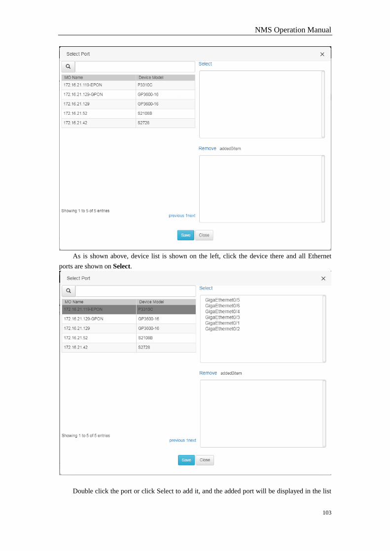
NMS Operation Manual
103
As is shown above, device list is shown on the left, click the device there and all Ethernet
ports are shown on Select.
Double click the port or click Select to add it, and the added port will be displayed in the list
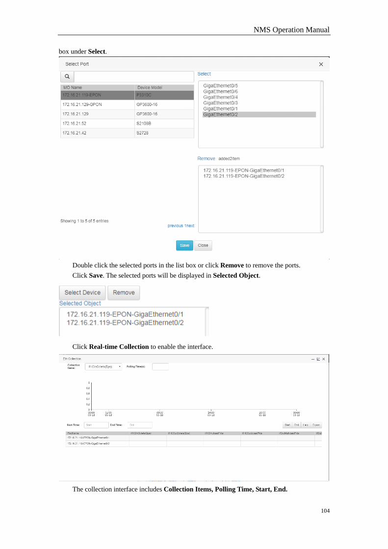
NMS Operation Manual
104
box under Select.
Double click the selected ports in the list box or click Remove to remove the ports.
Click Save. The selected ports will be displayed in Selected Object.
Click Real-time Collection to enable the interface.
The collection interface includes Collection Items, Polling Time, Start, End.
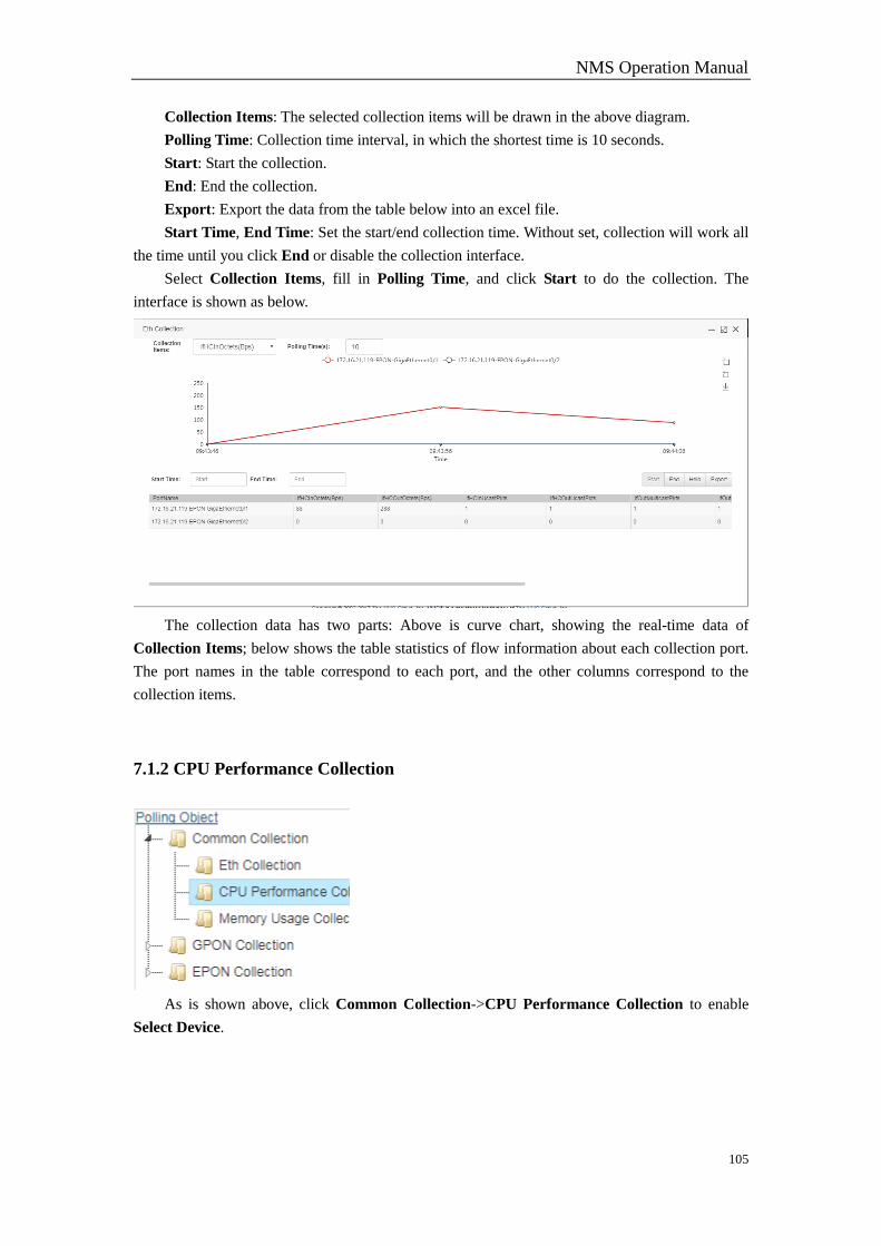
NMS Operation Manual
105
Collection Items: The selected collection items will be drawn in the above diagram.
Polling Time: Collection time interval, in which the shortest time is 10 seconds.
Start: Start the collection.
End: End the collection.
Export: Export the data from the table below into an excel file.
Start Time, End Time: Set the start/end collection time. Without set, collection will work all
the time until you click End or disable the collection interface.
Select Collection Items, fill in Polling Time, and click Start to do the collection. The
interface is shown as below.
The collection data has two parts: Above is curve chart, showing the real-time data of
Collection Items; below shows the table statistics of flow information about each collection port.
The port names in the table correspond to each port, and the other columns correspond to the
collection items.
7.1.2 CPU Performance Collection
As is shown above, click Common Collection->CPU Performance Collection to enable
Select Device.
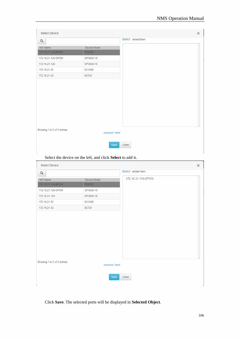
NMS Operation Manual
106
Select the device on the left, and click Select to add it.
Click Save. The selected ports will be displayed in Selected Object.
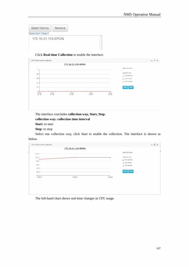
NMS Operation Manual
107
Click Real-time Collection to enable the interface.
The interface concludes collection way, Start, Stop.
collection way: collection time interval
Start: to start
Stop: to stop
Select one collection way, click Start to enable the collection. The interface is shown as
below.
The left-hand chart shows real-time changes in CPU usage.
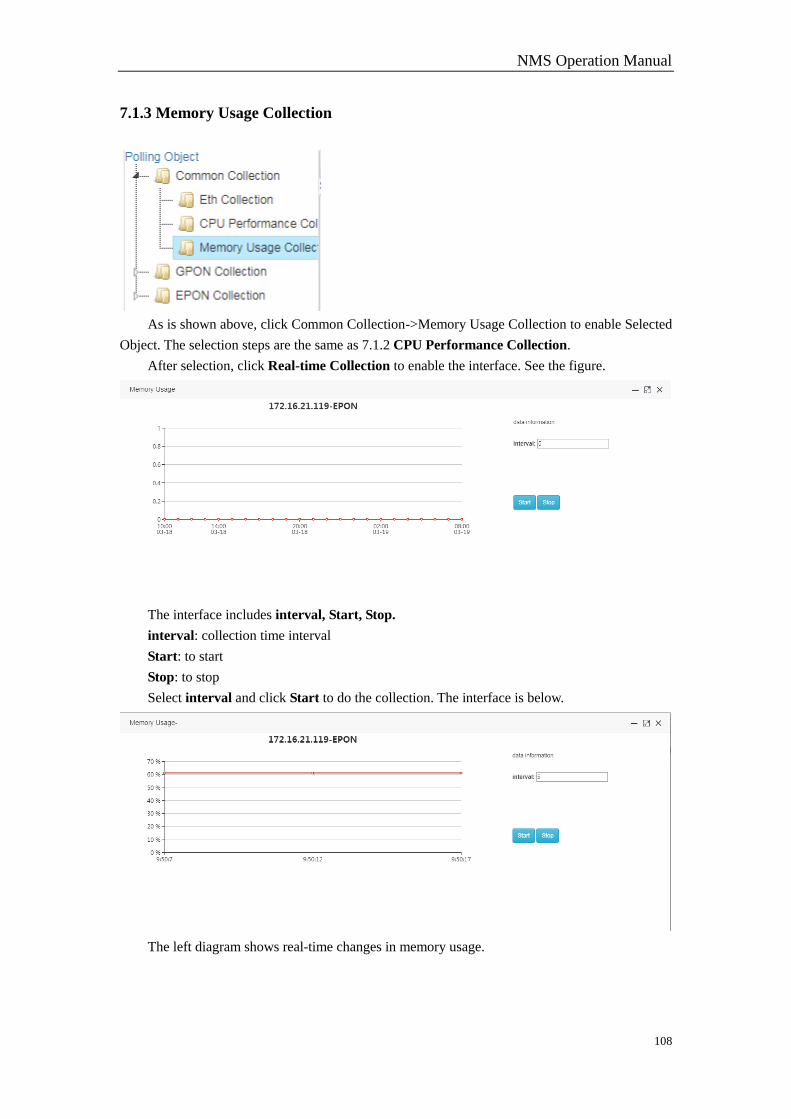
NMS Operation Manual
108
7.1.3 Memory Usage Collection
As is shown above, click Common Collection->Memory Usage Collection to enable Selected
Object. The selection steps are the same as 7.1.2 CPU Performance Collection.
After selection, click Real-time Collection to enable the interface. See the figure.
The interface includes interval, Start, Stop.
interval: collection time interval
Start: to start
Stop: to stop
Select interval and click Start to do the collection. The interface is below.
The left diagram shows real-time changes in memory usage.
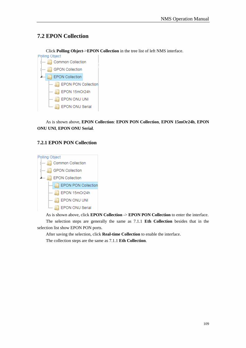
NMS Operation Manual
109
7.2 EPON Collection
Click Polling Object->EPON Collection in the tree list of left NMS interface.
As is shown above, EPON Collection: EPON PON Collection, EPON 15mOr24h, EPON
ONU UNI, EPON ONU Serial.
7.2.1 EPON PON Collection
As is shown above, click EPON Collection -> EPON PON Collection to enter the interface.
The selection steps are generally the same as 7.1.1 Eth Collection besides that in the
selection list show EPON PON ports.
After saving the selection, click Real-time Collection to enable the interface.
The collection steps are the same as 7.1.1 Eth Collection.
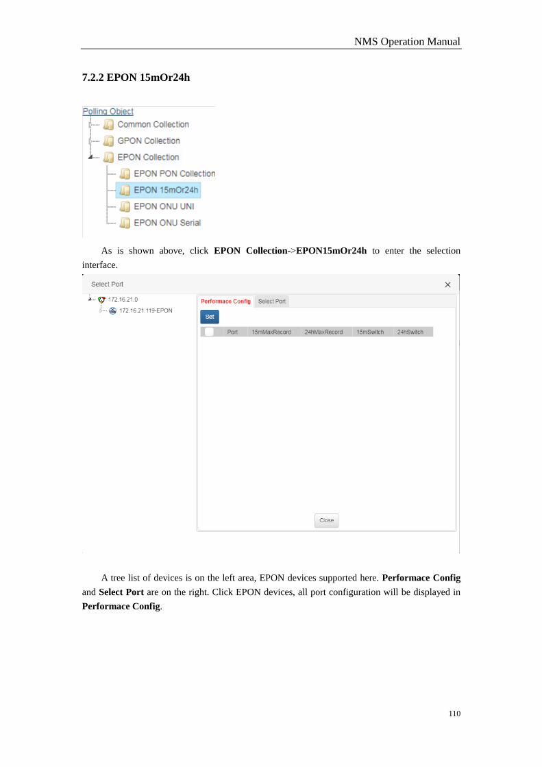
NMS Operation Manual
110
7.2.2 EPON 15mOr24h
As is shown above, click EPON Collection->EPON15mOr24h to enter the selection
interface.
A tree list of devices is on the left area, EPON devices supported here. Performace Config
and Select Port are on the right. Click EPON devices, all port configuration will be displayed in
Performace Config.
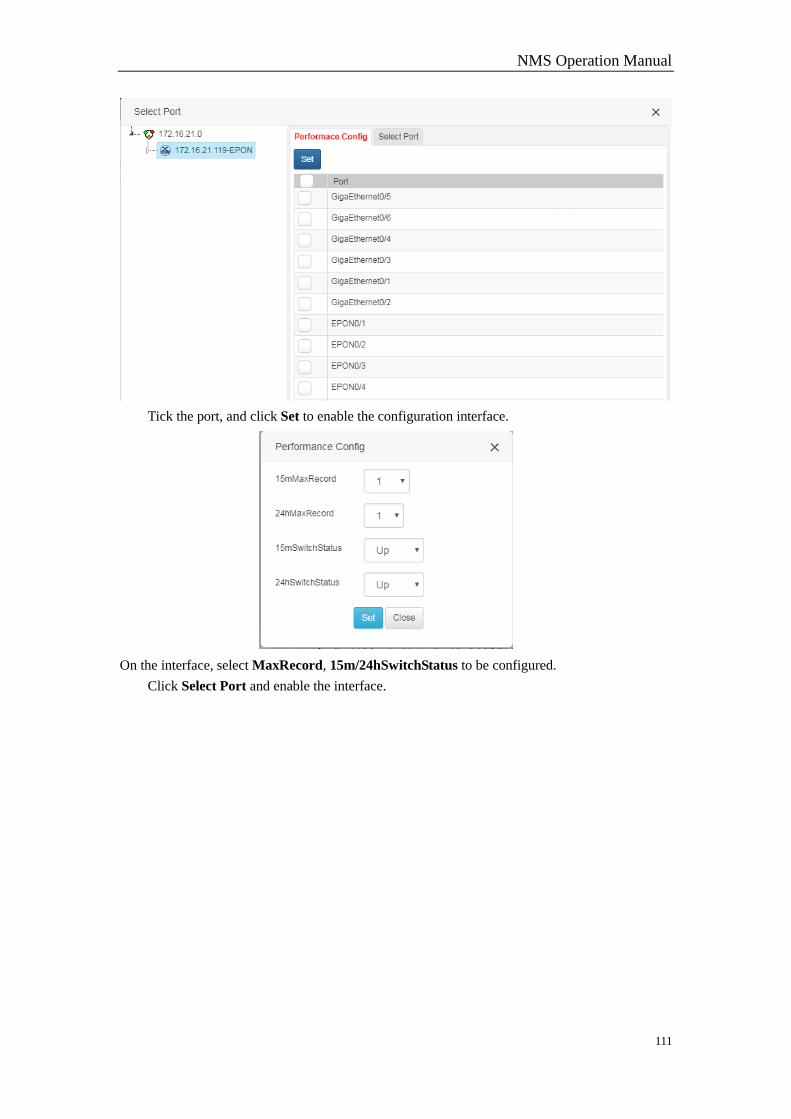
NMS Operation Manual
111
Tick the port, and click Set to enable the configuration interface.
On the interface, select MaxRecord, 15m/24hSwitchStatus to be configured.
Click Select Port and enable the interface.
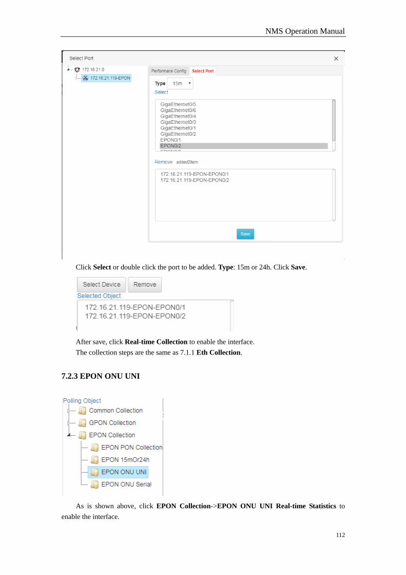
NMS Operation Manual
112
Click Select or double click the port to be added. Type: 15m or 24h. Click Save.
After save, click Real-time Collection to enable the interface.
The collection steps are the same as 7.1.1 Eth Collection.
7.2.3 EPON ONU UNI
As is shown above, click EPON Collection->EPON ONU UNI Real-time Statistics to
enable the interface.
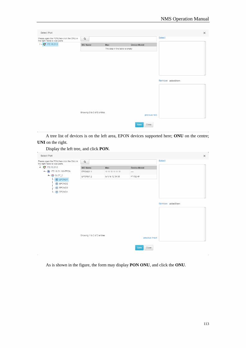
NMS Operation Manual
113
A tree list of devices is on the left area, EPON devices supported here; ONU on the centre;
UNI on the right.
Display the left tree, and click PON.
As is shown in the figure, the form may display PON ONU, and click the ONU.
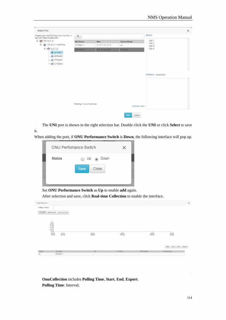
NMS Operation Manual
114
The UNI port is shown in the right selection bar. Double click the UNI or click Select to save
it.
When adding the port, if ONU Performance Switch is Down, the following interface will pop up.
Set ONU Performance Switch as Up to enable add again.
After selection and save, click Real-time Collection to enable the interface.
OnuCollection includes Polling Time, Start, End, Export.
Polling Time: Interval;
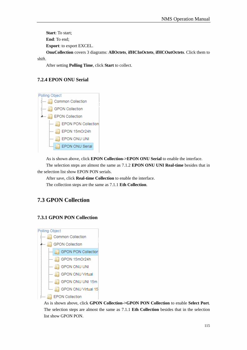
NMS Operation Manual
115
Start: To start;
End: To end;
Export: to export EXCEL.
OnuCollection covers 3 diagrams: AllOctets, ifHCInOctets, ifHCOutOctets. Click them to
shift.
After setting Polling Time, click Start to collect.
7.2.4 EPON ONU Serial
As is shown above, click EPON Collection->EPON ONU Serial to enable the interface.
The selection steps are almost the same as 7.1.2 EPON ONU UNI Real-time besides that in
the selection list show EPON PON serials.
After save, click Real-time Collection to enable the interface.
The collection steps are the same as 7.1.1 Eth Collection.
7.3 GPON Collection
7.3.1 GPON PON Collection
As is shown above, click GPON Collection->GPON PON Collection to enable Select Port.
The selection steps are almost the same as 7.1.1 Eth Collection besides that in the selection
list show GPON PON.
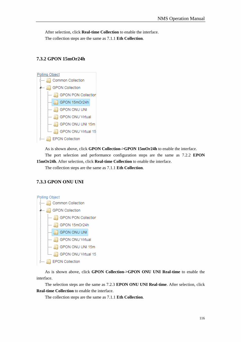
NMS Operation Manual
116
After selection, click Real-time Collection to enable the interface.
The collection steps are the same as 7.1.1 Eth Collection.
7.3.2 GPON 15mOr24h
As is shown above, click GPON Collection->GPON 15mOr24h to enable the interface.
The port selection and performance configuration steps are the same as 7.2.2 EPON
15mOr24h. After selection, click Real-time Collection to enable the interface.
The collection steps are the same as 7.1.1 Eth Collection.
7.3.3 GPON ONU UNI
As is shown above, click GPON Collection->GPON ONU UNI Real-time to enable the
interface.
The selection steps are the same as 7.2.3 EPON ONU UNI Real-time. After selection, click
Real-time Collection to enable the interface.
The collection steps are the same as 7.1.1 Eth Collection.
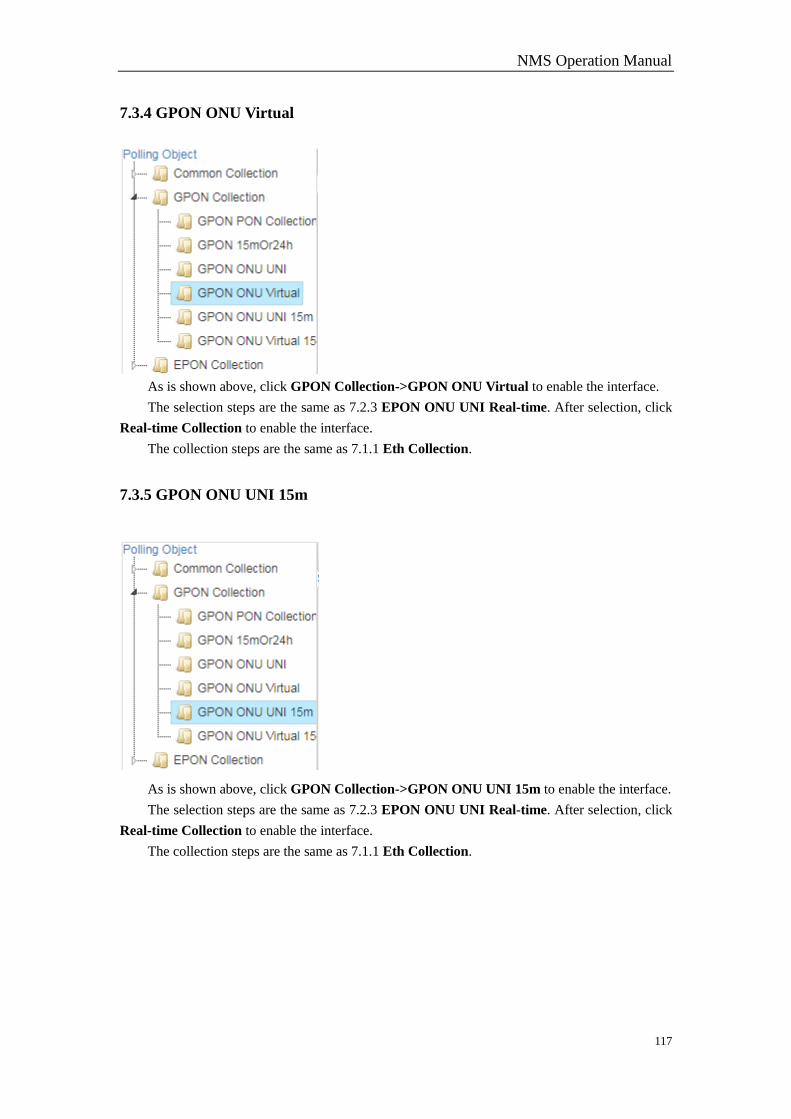
NMS Operation Manual
117
7.3.4 GPON ONU Virtual
As is shown above, click GPON Collection->GPON ONU Virtual to enable the interface.
The selection steps are the same as 7.2.3 EPON ONU UNI Real-time. After selection, click
Real-time Collection to enable the interface.
The collection steps are the same as 7.1.1 Eth Collection.
7.3.5 GPON ONU UNI 15m
As is shown above, click GPON Collection->GPON ONU UNI 15m to enable the interface.
The selection steps are the same as 7.2.3 EPON ONU UNI Real-time. After selection, click
Real-time Collection to enable the interface.
The collection steps are the same as 7.1.1 Eth Collection.
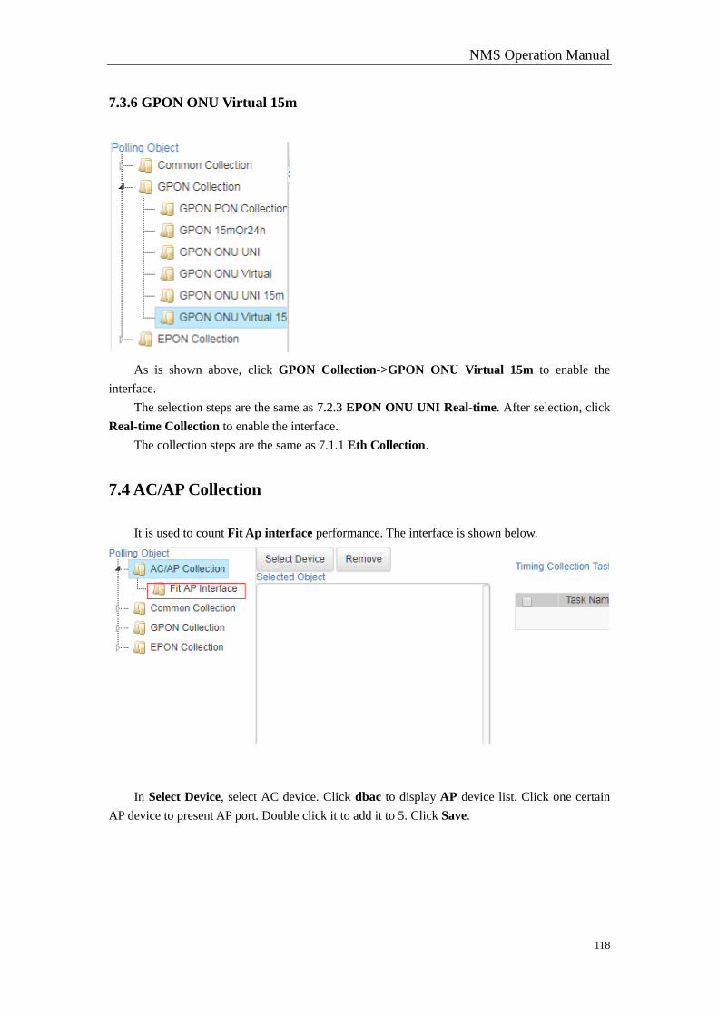
NMS Operation Manual
118
7.3.6 GPON ONU Virtual 15m
As is shown above, click GPON Collection->GPON ONU Virtual 15m to enable the
interface.
The selection steps are the same as 7.2.3 EPON ONU UNI Real-time. After selection, click
Real-time Collection to enable the interface.
The collection steps are the same as 7.1.1 Eth Collection.
7.4 AC/AP Collection
It is used to count Fit Ap interface performance. The interface is shown below.
In Select Device, select AC device. Click dbac to display AP device list. Click one certain
AP device to present AP port. Double click it to add it to 5. Click Save.
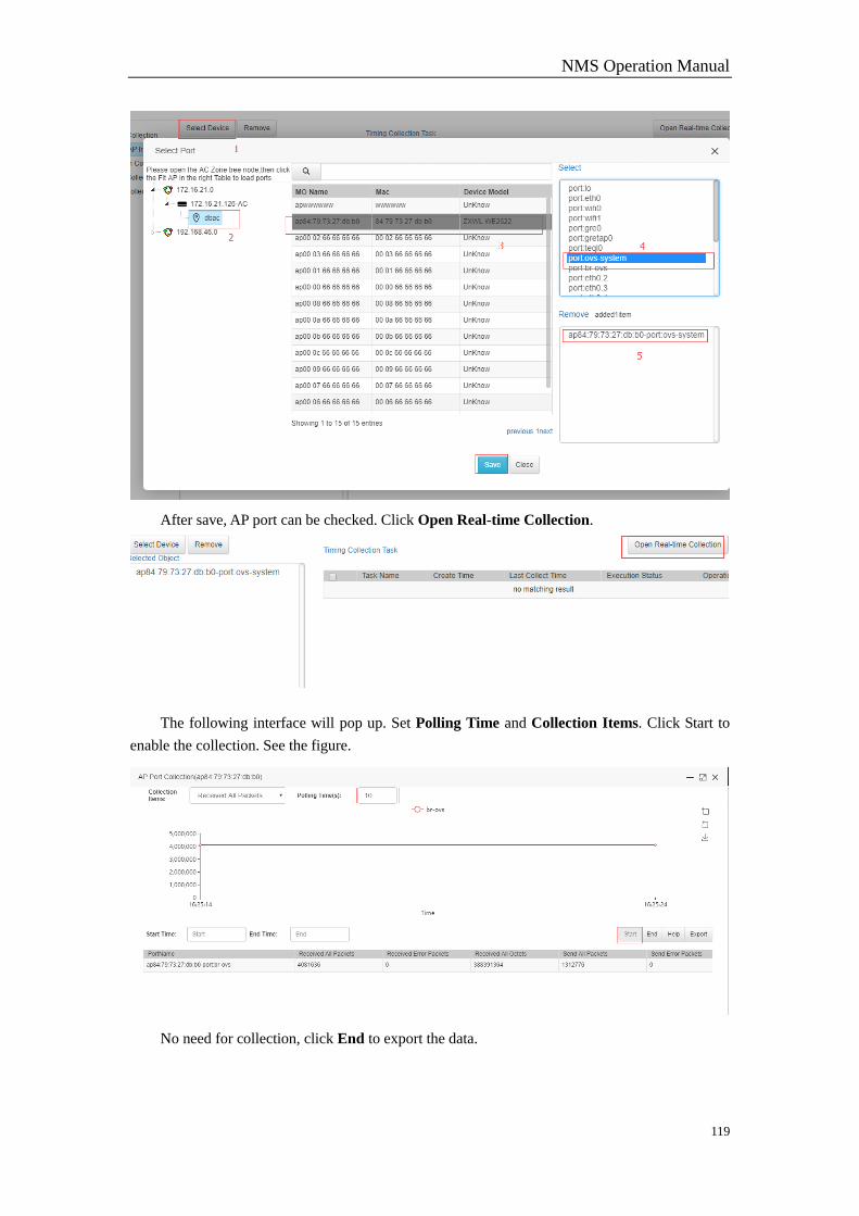
NMS Operation Manual
119
After save, AP port can be checked. Click Open Real-time Collection.
The following interface will pop up. Set Polling Time and Collection Items. Click Start to
enable the collection. See the figure.
No need for collection, click End to export the data.
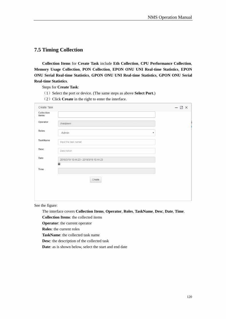
NMS Operation Manual
120
7.5 Timing Collection
Collection Items for Create Task include Eth Collection, CPU Performance Collection,
Memory Usage Collection, PON Collection, EPON ONU UNI Real-time Statistics, EPON
ONU Serial Real-time Statistics, GPON ONU UNI Real-time Statistics, GPON ONU Serial
Real-time Statistics.
Steps for Create Task:
(1)Select the port or device. (The same steps as above Select Port.)
(2)Click Create in the right to enter the interface.
See the figure:
The interface covers Collection Items, Operator, Roles, TaskName, Desc, Date, Time.
Collection Items: the collected items
Operator: the current operator
Roles: the current roles
TaskName: the collected task name
Desc: the description of the collected task
Date: as is shown below, select the start and end date
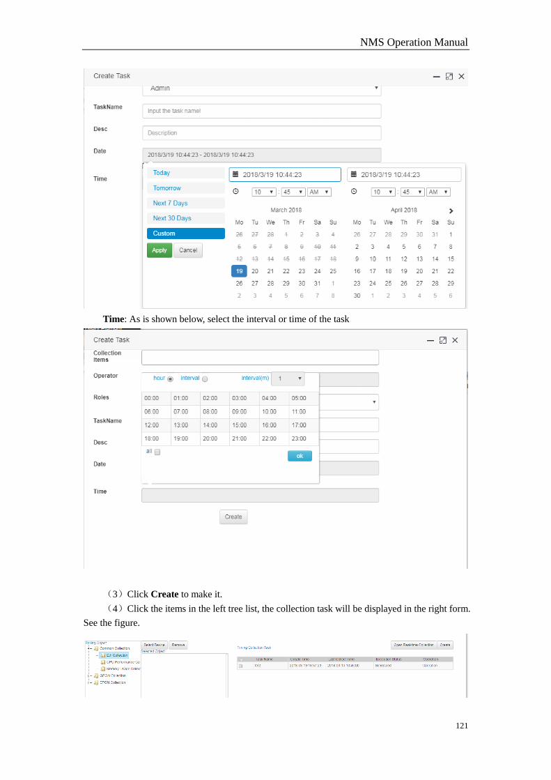
NMS Operation Manual
121
Time: As is shown below, select the interval or time of the task
(3)Click Create to make it.
(4)Click the items in the left tree list, the collection task will be displayed in the right form.
See the figure.
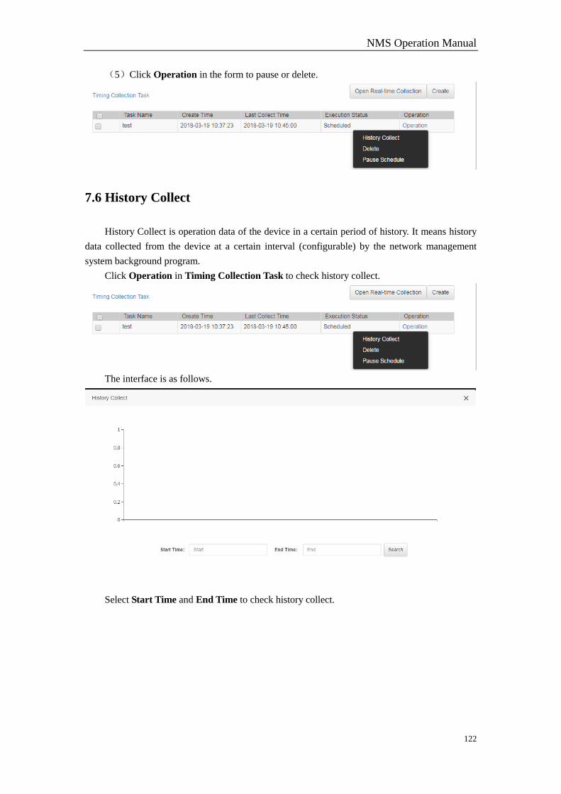
NMS Operation Manual
122
(5)Click Operation in the form to pause or delete.
7.6 History Collect
History Collect is operation data of the device in a certain period of history. It means history
data collected from the device at a certain interval (configurable) by the network management
system background program.
Click Operation in Timing Collection Task to check history collect.
The interface is as follows.
Select Start Time and End Time to check history collect.

NMS Operation Manual
123
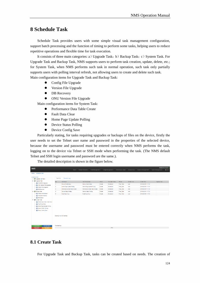
NMS Operation Manual
124
8 Schedule Task
Schedule Task provides users with some simple visual task management configuration,
support batch processing and the function of timing to perform some tasks, helping users to reduce
repetitive operations and flexible time for task execution.
It consists of three main categories: a)Upgrade Task;b)Backup Task;c)System Task. For
Upgrade Task and Backup Task, NMS supports users to perform task creation, update, delete, etc.;
for System Task, when NMS performs such task in normal operation, such task only partially
supports users with polling interval refresh, not allowing users to create and delete such task.
Main configuration items for Upgrade Task and Backup Task:
Config File Upgrade
Version File Upgrade
DB Recovery
ONU Version File Upgrade
Main configuration items for System Task:
Performance Data Table Create
Fault Data Clear
Home Page Update Polling
Device Status Polling
Device Config Save
Particularly stating, for tasks requiring upgrades or backups of files on the device, firstly the
user needs to set the Telnet user name and password in the properties of the selected device,
because the username and password must be entered correctly when NMS performs the task,
logging on to the device via Telnet or SSH mode when performing the task. (The NMS default
Telnet and SSH login username and password are the same.).
The detailed description is shown in the figure below.
8.1 Create Task
For Upgrade Task and Backup Task, tasks can be created based on needs. The creation of
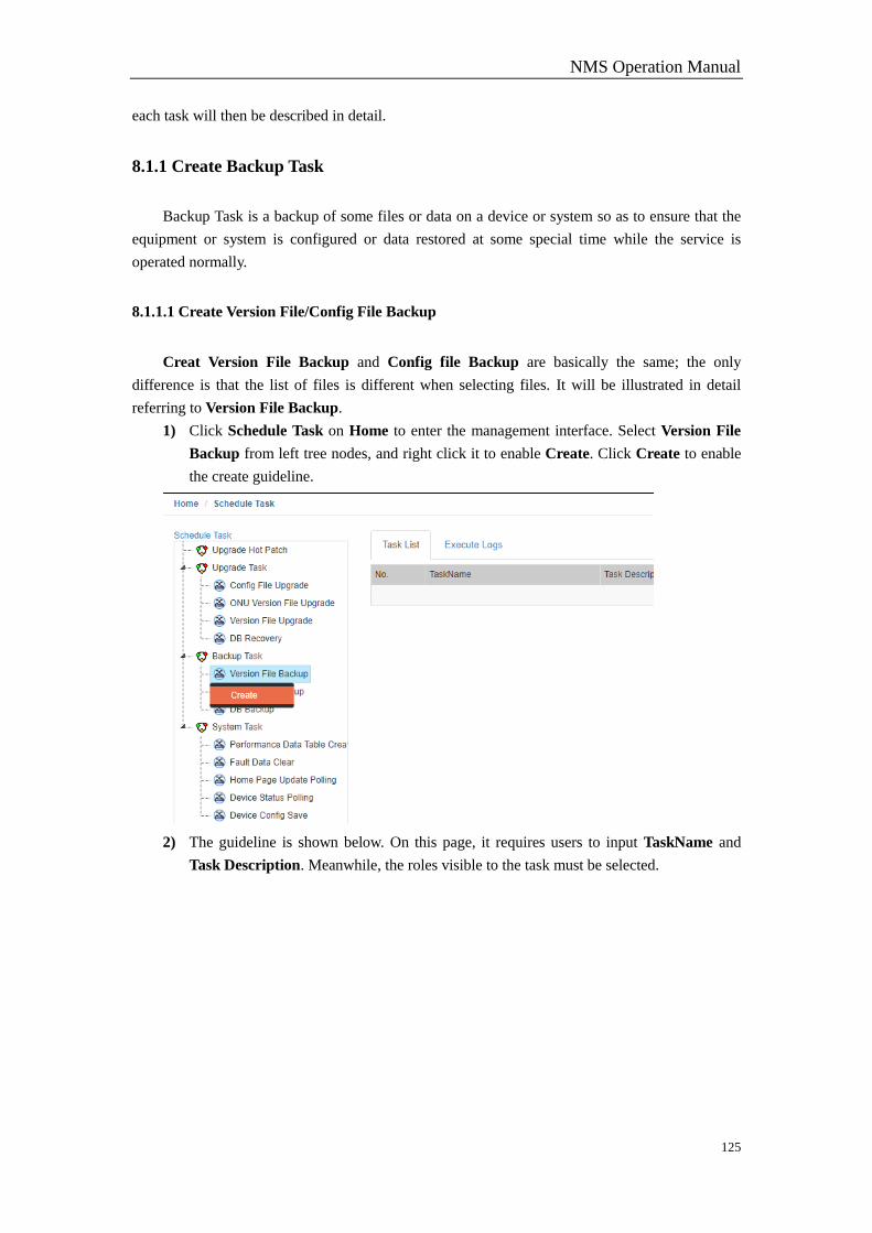
NMS Operation Manual
125
each task will then be described in detail.
8.1.1 Create Backup Task
Backup Task is a backup of some files or data on a device or system so as to ensure that the
equipment or system is configured or data restored at some special time while the service is
operated normally.
8.1.1.1 Create Version File/Config File Backup
Creat Version File Backup and Config file Backup are basically the same; the only
difference is that the list of files is different when selecting files. It will be illustrated in detail
referring to Version File Backup.
1) Click Schedule Task on Home to enter the management interface. Select Version File
Backup from left tree nodes, and right click it to enable Create. Click Create to enable
the create guideline.
2) The guideline is shown below. On this page, it requires users to input TaskName and
Task Description. Meanwhile, the roles visible to the task must be selected.
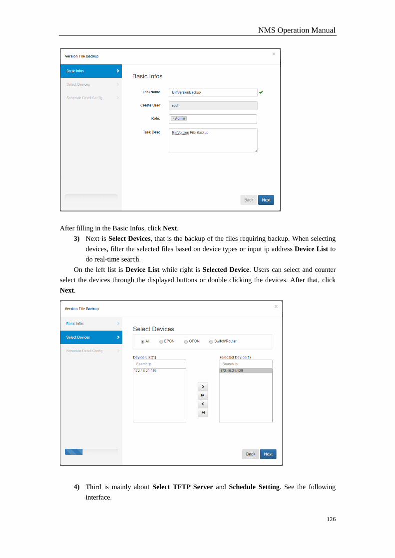
NMS Operation Manual
126
After filling in the Basic Infos, click Next.
3) Next is Select Devices, that is the backup of the files requiring backup. When selecting
devices, filter the selected files based on device types or input ip address Device List to
do real-time search.
On the left list is Device List while right is Selected Device. Users can select and counter
select the devices through the displayed buttons or double clicking the devices. After that, click
Next.
4) Third is mainly about Select TFTP Server and Schedule Setting. See the following
interface.
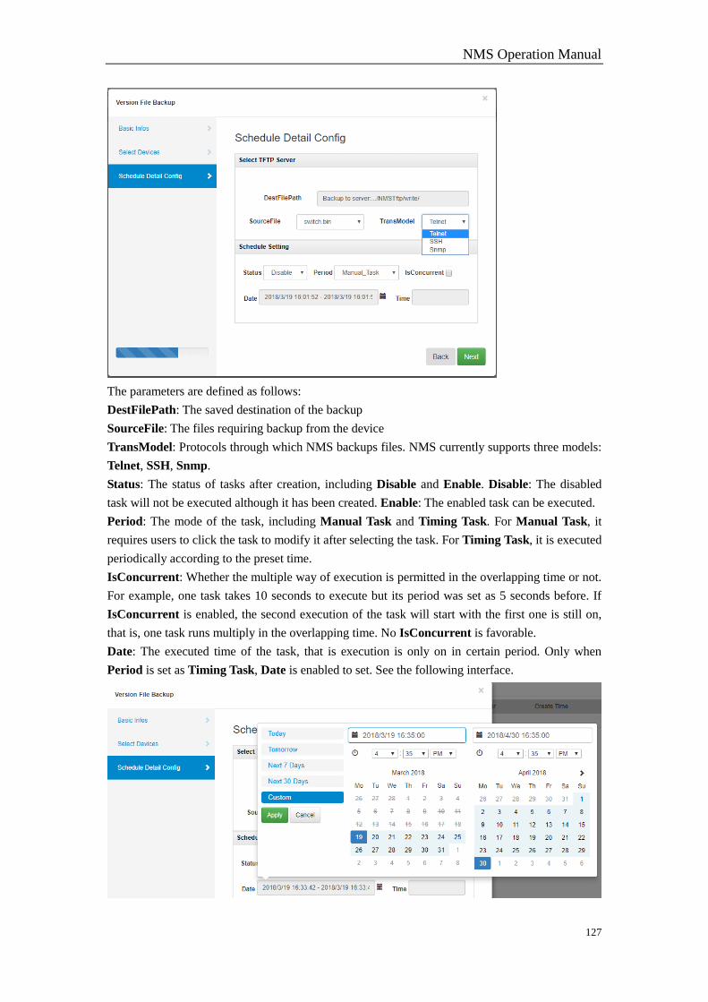
NMS Operation Manual
127
The parameters are defined as follows:
DestFilePath: The saved destination of the backup
SourceFile: The files requiring backup from the device
TransModel: Protocols through which NMS backups files. NMS currently supports three models:
Telnet, SSH, Snmp.
Status: The status of tasks after creation, including Disable and Enable. Disable: The disabled
task will not be executed although it has been created. Enable: The enabled task can be executed.
Period: The mode of the task, including Manual Task and Timing Task. For Manual Task, it
requires users to click the task to modify it after selecting the task. For Timing Task, it is executed
periodically according to the preset time.
IsConcurrent: Whether the multiple way of execution is permitted in the overlapping time or not.
For example, one task takes 10 seconds to execute but its period was set as 5 seconds before. If
IsConcurrent is enabled, the second execution of the task will start with the first one is still on,
that is, one task runs multiply in the overlapping time. No IsConcurrent is favorable.
Date: The executed time of the task, that is execution is only on in certain period. Only when
Period is set as Timing Task, Date is enabled to set. See the following interface.

NMS Operation Manual
128
Select the start and end of time, and click Apply. Or select Next 7 Days, Next 30 Days, etc. to do
quick set.
Time: The executed period of the task. Only when Period is set as Timing Task, Time is enabled.
See the figure.
The modes of interval: 1. Execute at the appointed hours; 2. Execute every few minutes. In
the above figure is displayed the execution at 8 am and 4 pm. If the interval needs setting, click
interval first, then specific minutes. See the figure.
5) After setting, click Next to check whether the task is created successfully or not. See the
figure.
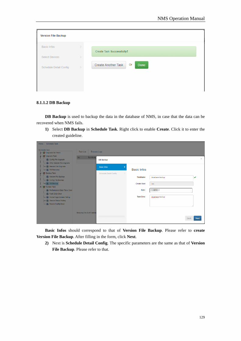
NMS Operation Manual
129
8.1.1.2 DB Backup
DB Backup is used to backup the data in the database of NMS, in case that the data can be
recovered when NMS fails.
1) Select DB Backup in Schedule Task. Right click to enable Create. Click it to enter the
created guideline.
Basic Infos should correspond to that of Version File Backup. Please refer to create
Version File Backup. After filling in the form, click Next.
2) Next is Schedule Detail Config. The specific parameters are the same as that of Version
File Backup. Please refer to that.
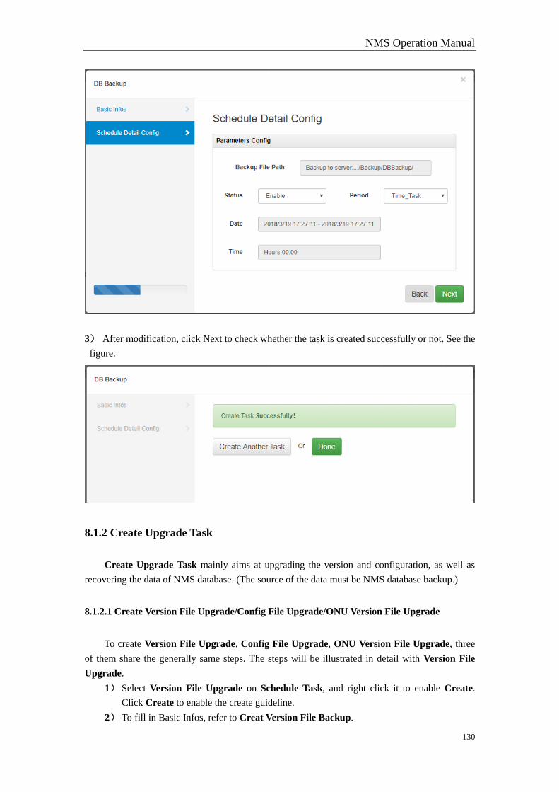
NMS Operation Manual
130
3) After modification, click Next to check whether the task is created successfully or not. See the
figure.
8.1.2 Create Upgrade Task
Create Upgrade Task mainly aims at upgrading the version and configuration, as well as
recovering the data of NMS database. (The source of the data must be NMS database backup.)
8.1.2.1 Create Version File Upgrade/Config File Upgrade/ONU Version File Upgrade
To create Version File Upgrade, Config File Upgrade, ONU Version File Upgrade, three
of them share the generally same steps. The steps will be illustrated in detail with Version File
Upgrade.
1) Select Version File Upgrade on Schedule Task, and right click it to enable Create.
Click Create to enable the create guideline.
2) To fill in Basic Infos, refer to Creat Version File Backup.

NMS Operation Manual
131
3) To select the device, refer to Creat Version File Backup.
4) To modify Schedule Setting, here introduce in detail some specific parameters. refer to
Creat Version File Backup for general parameters.
Source File Path: Due to the upgrade here, it requires users to upload version files.
Click on the input box to select the version file, and click Upload to upload user’s file to NMS
server. It is Bin file that upgrade uses it when the task is executed.
DestFileName: The file to be upgraded. When execution is on, the file will be replaced by the
uploaded file.
5) After configuring scheduling parameters, click Next to check whether the task is created
successfully or not.
8.1.3 System Task
System Task means a series of default tasks created by NMS to support the normal operation
of NMS, not supporting users to create or delete any of them but refresh the polling time of some
task based on some needs. It will be illustrated in detail with Fault Data Clear.
Select Fault Data Clear in Task List. Right click it to pop up the menu list, which includes
Upgrade Task, Start Execute Task, and Pause Schedule. See the figure.
The three operations are explained in detail below.
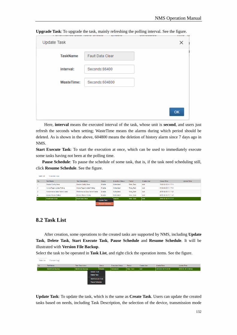
NMS Operation Manual
132
Upgrade Task: To upgrade the task, mainly refreshing the polling interval. See the figure.
Here, interval means the executed interval of the task, whose unit is second, and users just
refresh the seconds when setting; WasteTime means the alarms during which period should be
deleted. As is shown in the above, 604800 means the deletion of history alarm since 7 days ago in
NMS.
Start Execute Task: To start the execution at once, which can be used to immediately execute
some tasks having not been at the polling time.
Pause Schedule: To pause the schedule of some task, that is, if the task need scheduling still,
click Resume Schedule. See the figure.
8.2 Task List
After creation, some operations to the created tasks are supported by NMS, including Update
Task, Delete Task, Start Execute Task, Pause Schedule and Resume Schedule. It will be
illustrated with Version File Backup.
Select the task to be operated in Task List, and right click the operation items. See the figure.
Update Task: To update the task, which is the same as Create Task. Users can update the created
tasks based on needs, including Task Description, the selection of the device, transmission mode
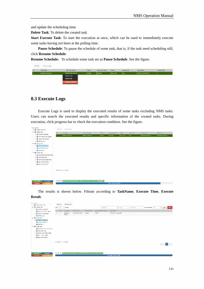
NMS Operation Manual
133
and update the scheduling time.
Delete Task: To delete the created task
Start Execute Task: To start the execution at once, which can be used to immediately execute
some tasks having not been at the polling time.
Pause Schedule: To pause the schedule of some task, that is, if the task need scheduling still,
click Resume Schedule.
Resume Schedule:To schedule some task set as Pause Schedule. See the figure.
8.3 Execute Logs
Execute Logs is used to display the executed results of some tasks excluding NMS tasks.
Users can search the executed results and specific information of the created tasks. During
execution, click progress bar to check the execution condition. See the figure.
The results is shown below. Filtrate according to TaskName, Execute Time, Execute
Result.
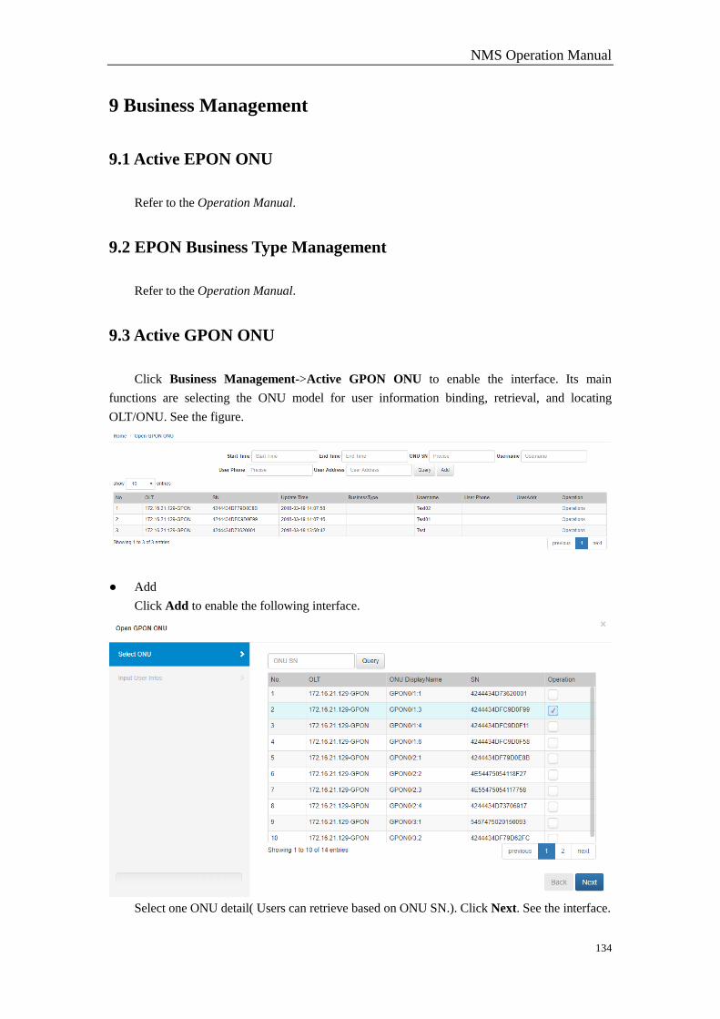
NMS Operation Manual
134
9 Business Management
9.1 Active EPON ONU
Refer to the Operation Manual.
9.2 EPON Business Type Management
Refer to the Operation Manual.
9.3 Active GPON ONU
Click Business Management->Active GPON ONU to enable the interface. Its main
functions are selecting the ONU model for user information binding, retrieval, and locating
OLT/ONU. See the figure.
● Add
Click Add to enable the following interface.
Select one ONU detail( Users can retrieve based on ONU SN.). Click Next. See the interface.
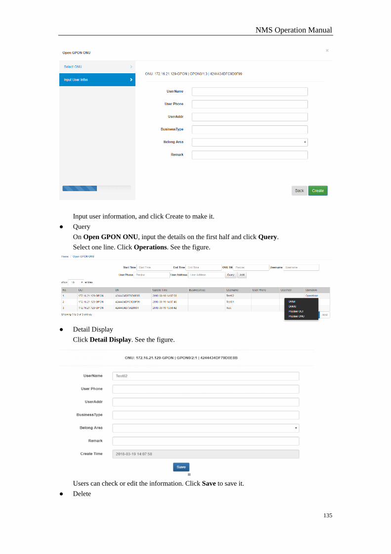
NMS Operation Manual
135
Input user information, and click Create to make it.
● Query
On Open GPON ONU, input the details on the first half and click Query.
Select one line. Click Operations. See the figure.
● Detail Display
Click Detail Display. See the figure.
Users can check or edit the information. Click Save to save it.
● Delete

NMS Operation Manual
136
Click Delete to delete the open information.
● Locate OLT
Click Locate OLT to enable the OLT management interface.
● Locate ONU
Click Locate ONU to enable the ONU management interface.
9.4 App Download
Refer to Operation Manual.
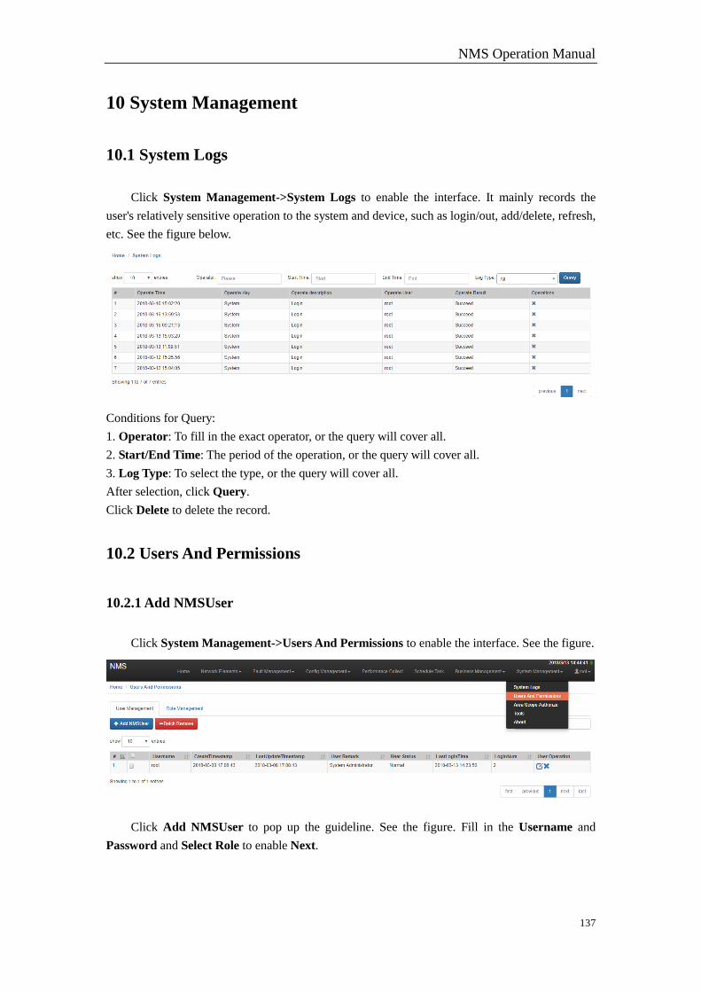
NMS Operation Manual
137
10 System Management
10.1 System Logs
Click System Management->System Logs to enable the interface. It mainly records the
user's relatively sensitive operation to the system and device, such as login/out, add/delete, refresh,
etc. See the figure below.
Conditions for Query:
1. Operator: To fill in the exact operator, or the query will cover all.
2. Start/End Time: The period of the operation, or the query will cover all.
3. Log Type: To select the type, or the query will cover all.
After selection, click Query.
Click Delete to delete the record.
10.2 Users And Permissions
10.2.1 Add NMSUser
Click System Management->Users And Permissions to enable the interface. See the figure.
Click Add NMSUser to pop up the guideline. See the figure. Fill in the Username and
Password and Select Role to enable Next.
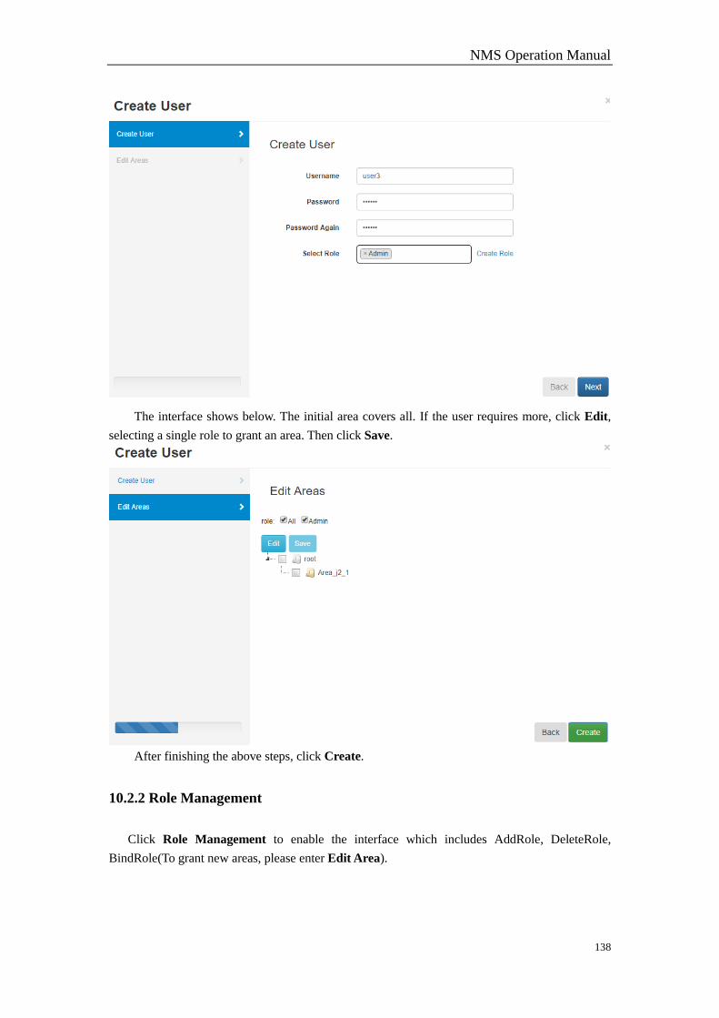
NMS Operation Manual
138
The interface shows below. The initial area covers all. If the user requires more, click Edit,
selecting a single role to grant an area. Then click Save.
After finishing the above steps, click Create.
10.2.2 Role Management
Click Role Management to enable the interface which includes AddRole, DeleteRole,
BindRole(To grant new areas, please enter Edit Area).
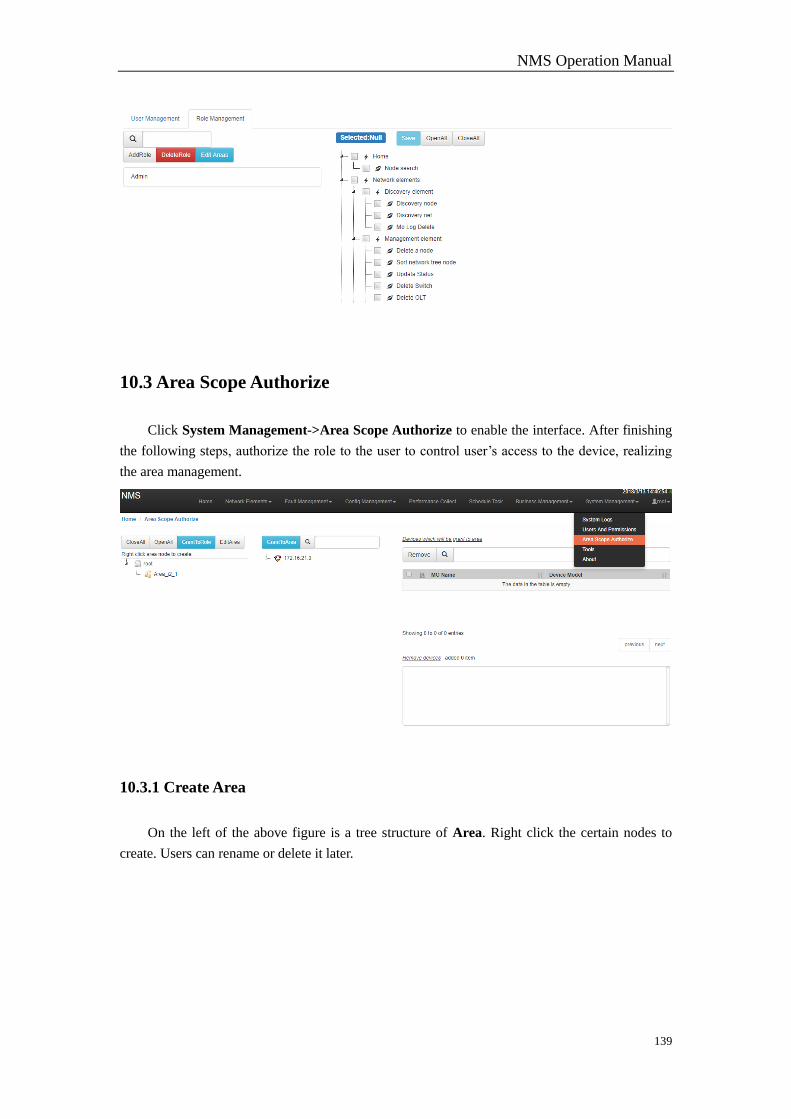
NMS Operation Manual
139
10.3 Area Scope Authorize
Click System Management->Area Scope Authorize to enable the interface. After finishing
the following steps, authorize the role to the user to control user’s access to the device, realizing
the area management.
10.3.1 Create Area
On the left of the above figure is a tree structure of Area. Right click the certain nodes to
create. Users can rename or delete it later.
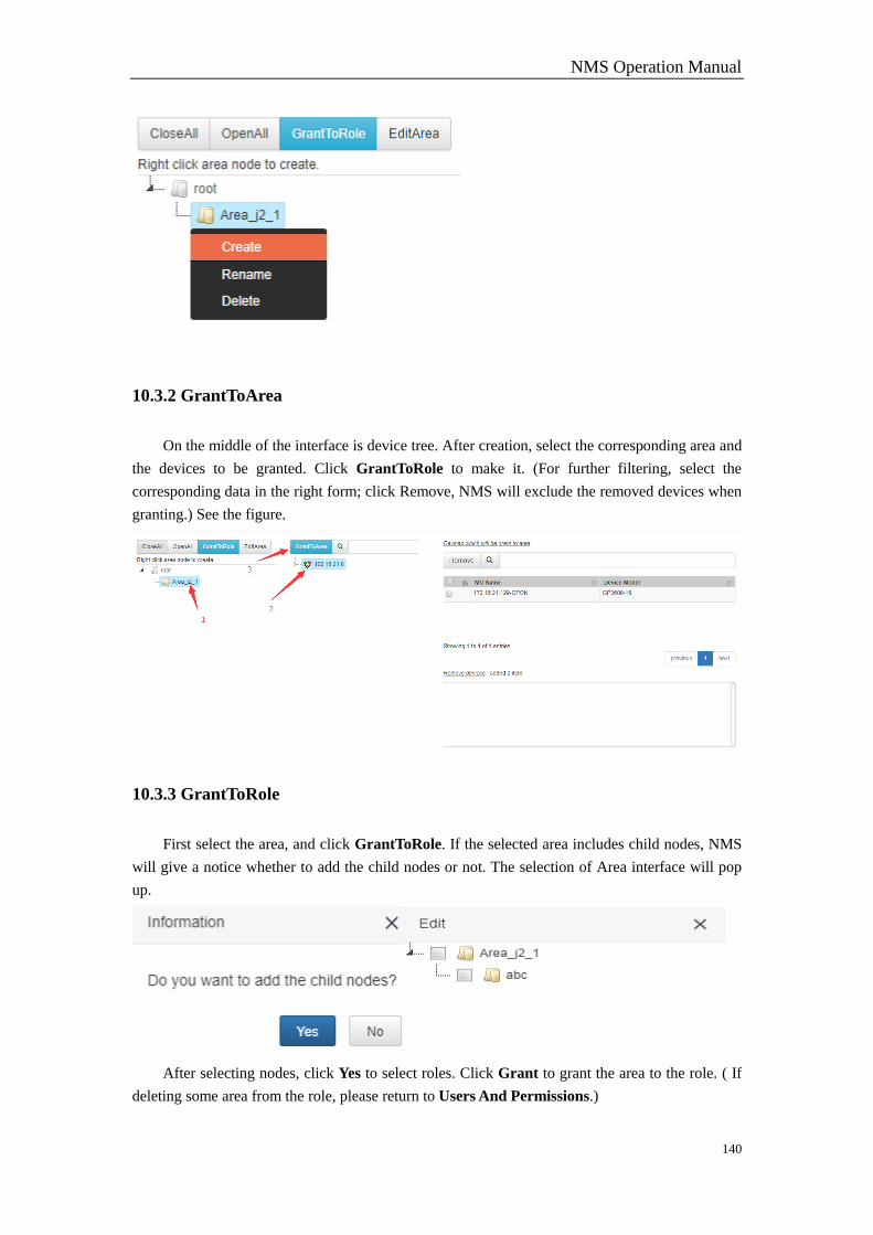
NMS Operation Manual
140
10.3.2 GrantToArea
On the middle of the interface is device tree. After creation, select the corresponding area and
the devices to be granted. Click GrantToRole to make it. (For further filtering, select the
corresponding data in the right form; click Remove, NMS will exclude the removed devices when
granting.) See the figure.
10.3.3 GrantToRole
First select the area, and click GrantToRole. If the selected area includes child nodes, NMS
will give a notice whether to add the child nodes or not. The selection of Area interface will pop
up.
After selecting nodes, click Yes to select roles. Click Grant to grant the area to the role. ( If
deleting some area from the role, please return to Users And Permissions.)
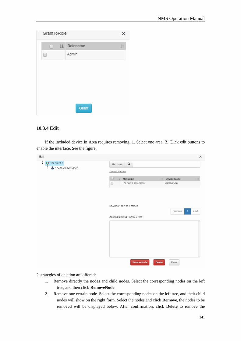
NMS Operation Manual
141
10.3.4 Edit
If the included device in Area requires removing, 1. Select one area; 2. Click edit buttons to
enable the interface. See the figure.
2 strategies of deletion are offered:
1. Remove directly the nodes and child nodes. Select the corresponding nodes on the left
tree, and then click RemoveNode.
2. Remove one certain node. Select the corresponding nodes on the left tree, and their child
nodes will show on the right form. Select the nodes and click Remove, the nodes to be
removed will be displayed below. After confirmation, click Delete to remove the
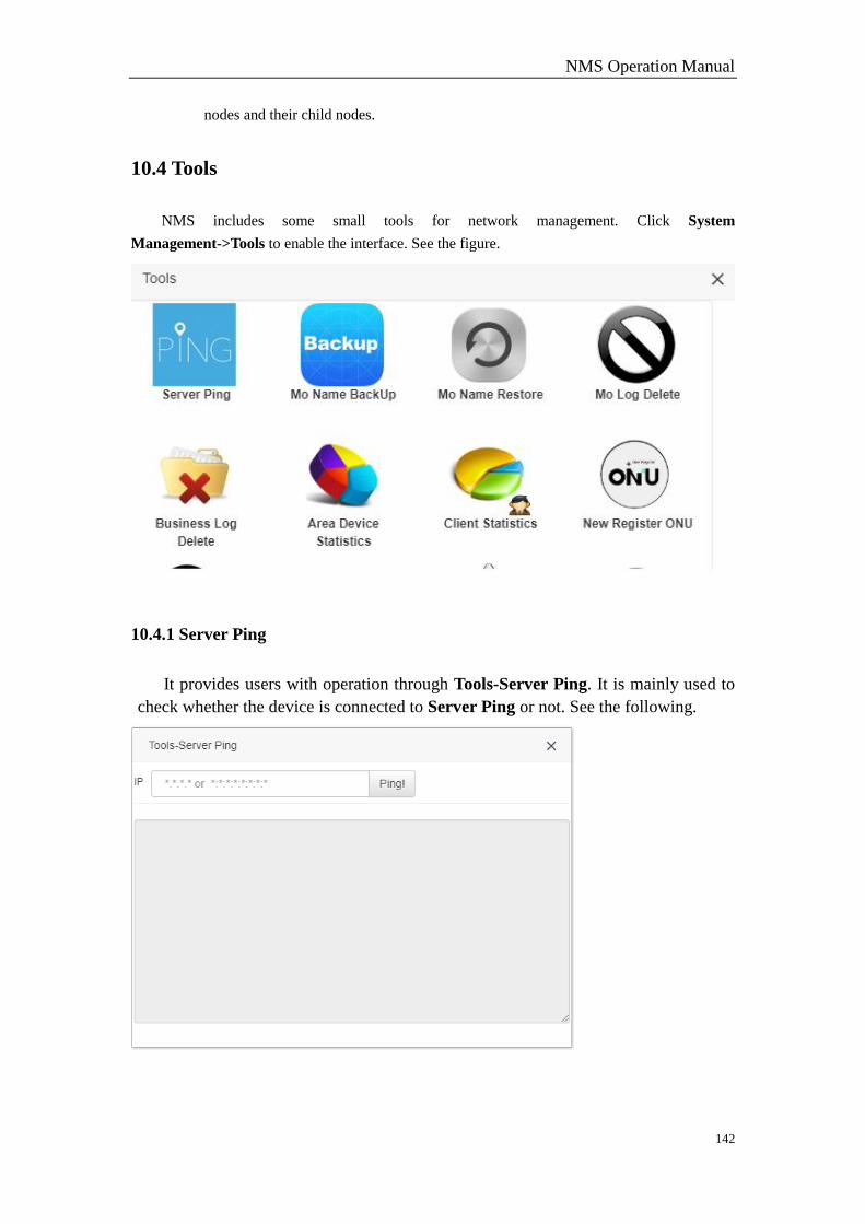
NMS Operation Manual
142
nodes and their child nodes.
10.4 Tools
NMS includes some small tools for network management. Click System
Management->Tools to enable the interface. See the figure.
10.4.1 Server Ping
It provides users with operation through Tools-Server Ping. It is mainly used to
check whether the device is connected to Server Ping or not. See the following.
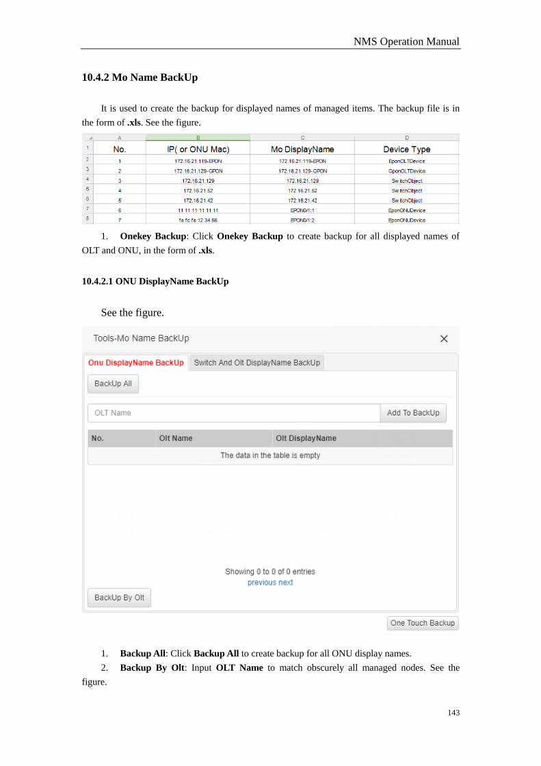
NMS Operation Manual
143
10.4.2 Mo Name BackUp
It is used to create the backup for displayed names of managed items. The backup file is in
the form of .xls. See the figure.
1. Onekey Backup: Click Onekey Backup to create backup for all displayed names of
OLT and ONU, in the form of .xls.
10.4.2.1 ONU DisplayName BackUp
See the figure.
1. Backup All: Click Backup All to create backup for all ONU display names.
2. Backup By Olt: Input OLT Name to match obscurely all managed nodes. See the
figure.
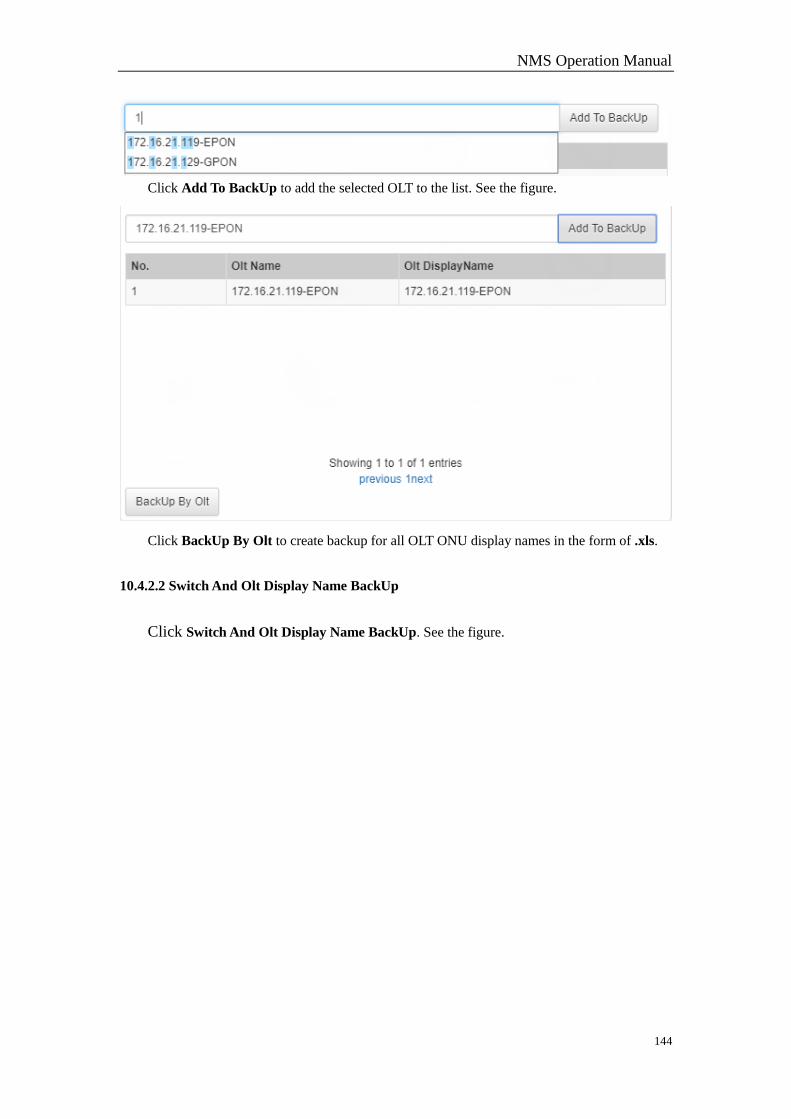
NMS Operation Manual
144
Click Add To BackUp to add the selected OLT to the list. See the figure.
Click BackUp By Olt to create backup for all OLT ONU display names in the form of .xls.
10.4.2.2 Switch And Olt Display Name BackUp
Click Switch And Olt Display Name BackUp. See the figure.
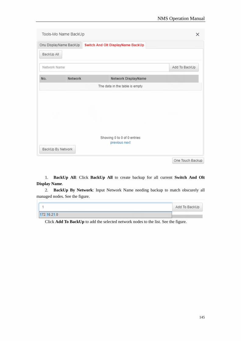
NMS Operation Manual
145
1. BackUp All: Click BackUp All to create backup for all current Switch And Olt
Display Name.
2. BackUp By Network: Input Network Name needing backup to match obscurely all
managed nodes. See the figure.
Click Add To BackUp to add the selected network nodes to the list. See the figure.
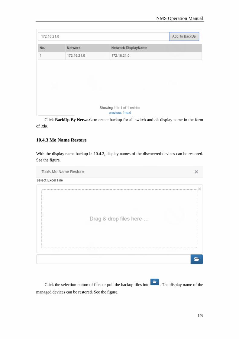
NMS Operation Manual
146
Click BackUp By Network to create backup for all switch and olt display name in the form
of .xls.
10.4.3 Mo Name Restore
With the display name backup in 10.4.2, display names of the discovered devices can be restored.
See the figure.
Click the selection button of files or pull the backup files into . The display name of the
managed devices can be restored. See the figure.
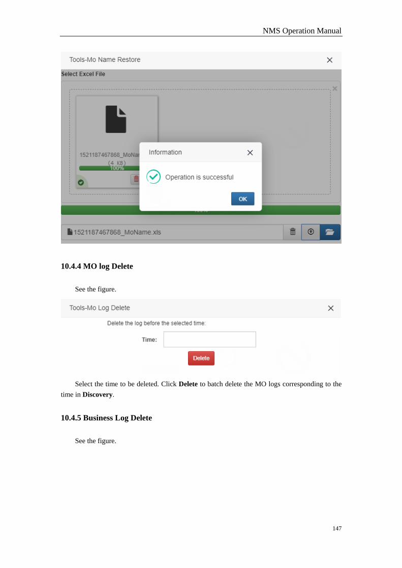
NMS Operation Manual
147
10.4.4 MO log Delete
See the figure.
Select the time to be deleted. Click Delete to batch delete the MO logs corresponding to the
time in Discovery.
10.4.5 Business Log Delete
See the figure.
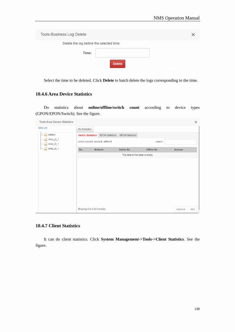
NMS Operation Manual
148
Select the time to be deleted. Click Delete to batch delete the logs corresponding to the time.
10.4.6 Area Device Statistics
Do statistics about online/offline/switch count according to device types
(GPON/EPON/Switch). See the figure.
10.4.7 Client Statistics
It can do client statistics. Click System Management->Tools->Client Statistics. See the
figure.
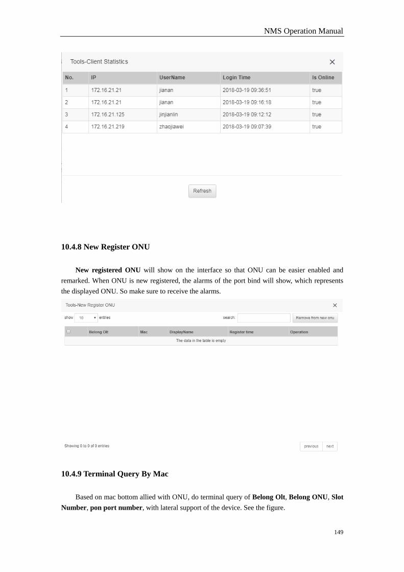
NMS Operation Manual
149
10.4.8 New Register ONU
New registered ONU will show on the interface so that ONU can be easier enabled and
remarked. When ONU is new registered, the alarms of the port bind will show, which represents
the displayed ONU. So make sure to receive the alarms.
10.4.9 Terminal Query By Mac
Based on mac bottom allied with ONU, do terminal query of Belong Olt, Belong ONU, Slot
Number, pon port number, with lateral support of the device. See the figure.
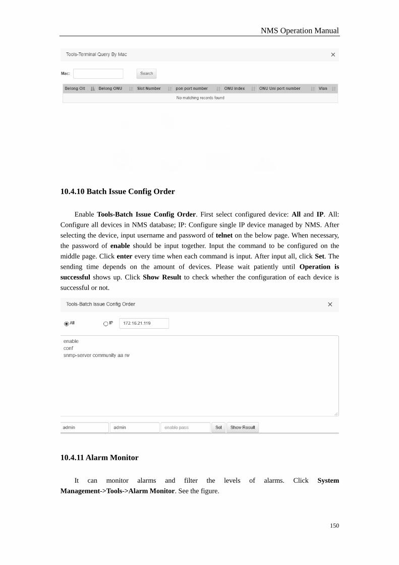
NMS Operation Manual
150
10.4.10 Batch Issue Config Order
Enable Tools-Batch Issue Config Order. First select configured device: All and IP. All:
Configure all devices in NMS database; IP: Configure single IP device managed by NMS. After
selecting the device, input username and password of telnet on the below page. When necessary,
the password of enable should be input together. Input the command to be configured on the
middle page. Click enter every time when each command is input. After input all, click Set. The
sending time depends on the amount of devices. Please wait patiently until Operation is
successful shows up. Click Show Result to check whether the configuration of each device is
successful or not.
10.4.11 Alarm Monitor
It can monitor alarms and filter the levels of alarms. Click System
Management->Tools->Alarm Monitor. See the figure.
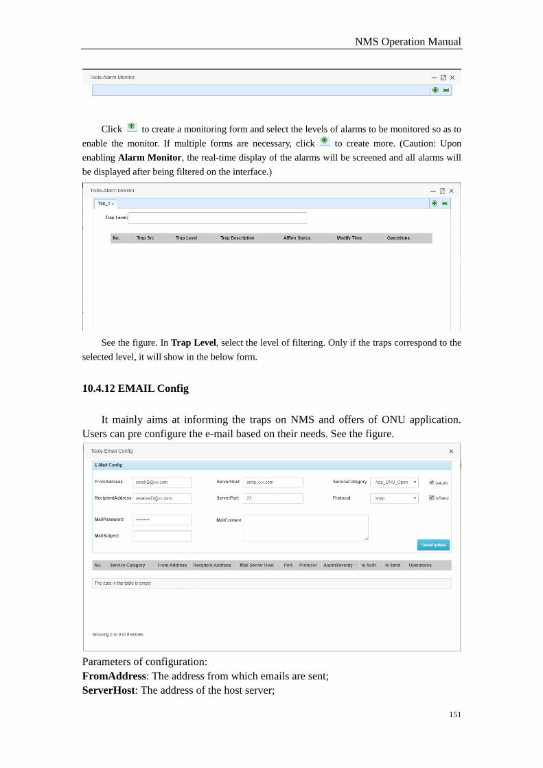
NMS Operation Manual
151
Click to create a monitoring form and select the levels of alarms to be monitored so as to
enable the monitor. If multiple forms are necessary, click to create more. (Caution: Upon
enabling Alarm Monitor, the real-time display of the alarms will be screened and all alarms will
be displayed after being filtered on the interface.)
See the figure. In Trap Level, select the level of filtering. Only if the traps correspond to the
selected level, it will show in the below form.
10.4.12 EMAIL Config
It mainly aims at informing the traps on NMS and offers of ONU application.
Users can pre configure the e-mail based on their needs. See the figure.
Parameters of configuration:
FromAddress: The address from which emails are sent;
ServerHost: The address of the host server;
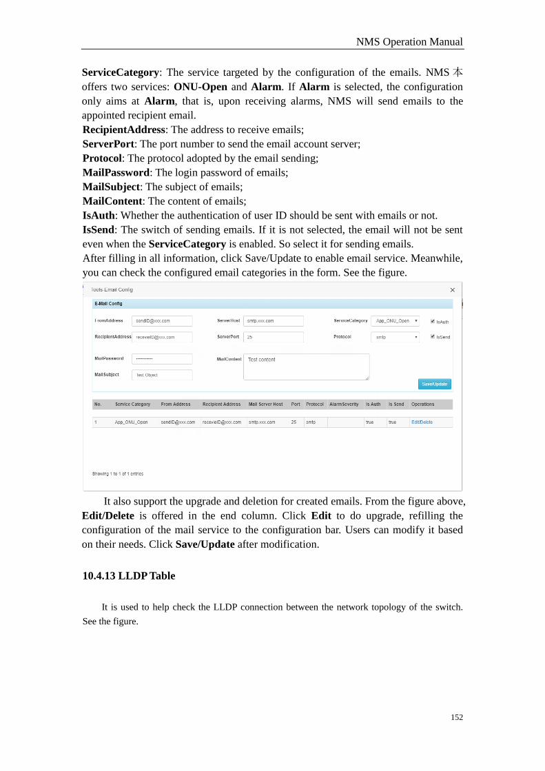
NMS Operation Manual
152
ServiceCategory: The service targeted by the configuration of the emails. NMS 本
offers two services: ONU-Open and Alarm. If Alarm is selected, the configuration
only aims at Alarm, that is, upon receiving alarms, NMS will send emails to the
appointed recipient email.
RecipientAddress: The address to receive emails;
ServerPort: The port number to send the email account server;
Protocol: The protocol adopted by the email sending;
MailPassword: The login password of emails;
MailSubject: The subject of emails;
MailContent: The content of emails;
IsAuth: Whether the authentication of user ID should be sent with emails or not.
IsSend: The switch of sending emails. If it is not selected, the email will not be sent
even when the ServiceCategory is enabled. So select it for sending emails.
After filling in all information, click Save/Update to enable email service. Meanwhile,
you can check the configured email categories in the form. See the figure.
It also support the upgrade and deletion for created emails. From the figure above,
Edit/Delete is offered in the end column. Click Edit to do upgrade, refilling the
configuration of the mail service to the configuration bar. Users can modify it based
on their needs. Click Save/Update after modification.
10.4.13 LLDP Table
It is used to help check the LLDP connection between the network topology of the switch.
See the figure.
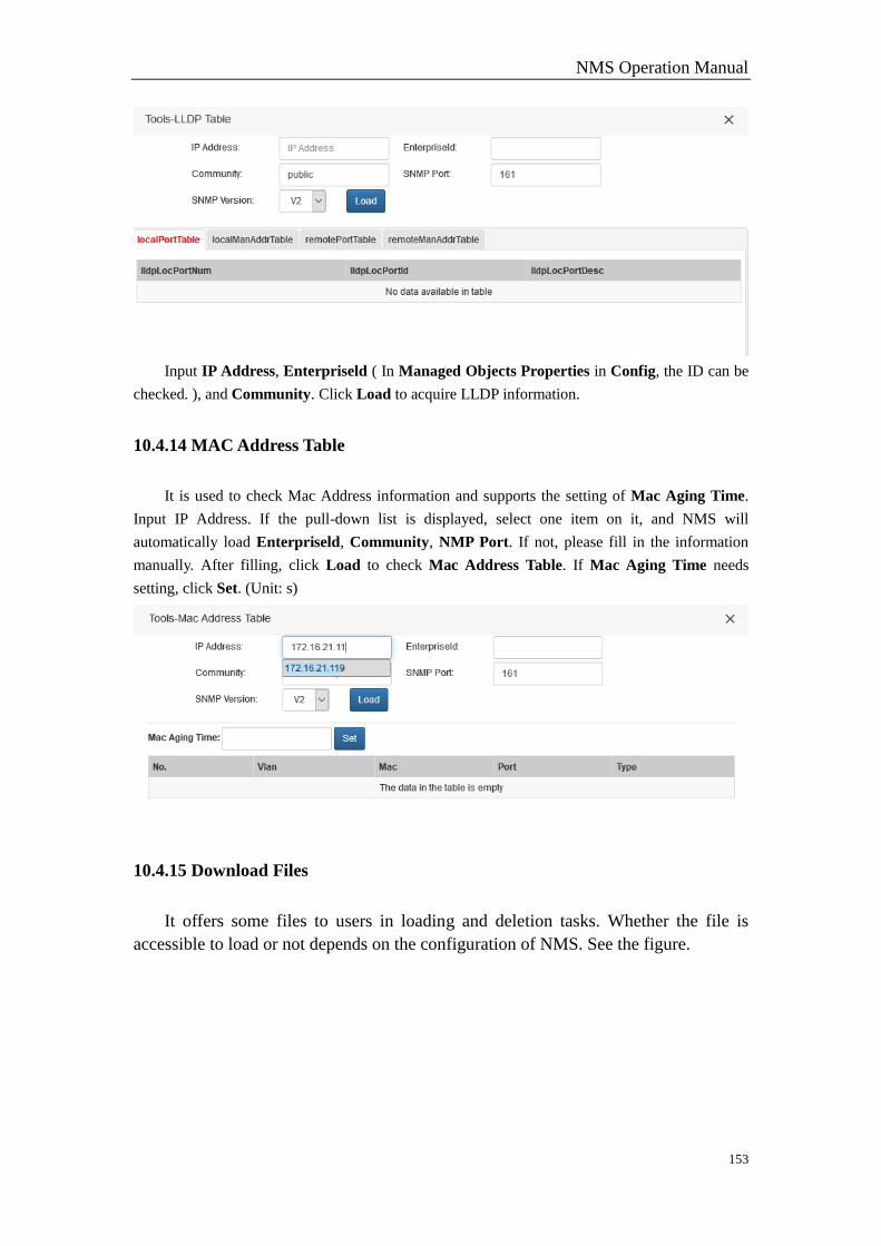
NMS Operation Manual
153
Input IP Address, Enterpriseld ( In Managed Objects Properties in Config, the ID can be
checked. ), and Community. Click Load to acquire LLDP information.
10.4.14 MAC Address Table
It is used to check Mac Address information and supports the setting of Mac Aging Time.
Input IP Address. If the pull-down list is displayed, select one item on it, and NMS will
automatically load Enterpriseld, Community, NMP Port. If not, please fill in the information
manually. After filling, click Load to check Mac Address Table. If Mac Aging Time needs
setting, click Set. (Unit: s)
10.4.15 Download Files
It offers some files to users in loading and deletion tasks. Whether the file is
accessible to load or not depends on the configuration of NMS. See the figure.

NMS Operation Manual
154
From the figure, the interface is displayed in the form of tree graph. Click the
folder in the first column to display the files. It only support one single file to be
downloaded instead of the folder. But the folder can be downloaded after
compression.
10.4.16 SNMP Search
It can help search and assign the nodes or lines of mib. Click System
Management->Tools->SNMP to enable the interface. See the figure.
Search steps:
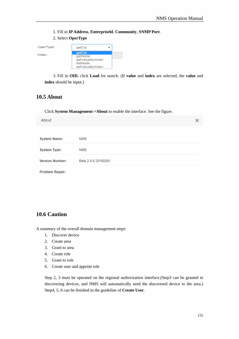
NMS Operation Manual
155
1. Fill in IP Address, Enterpriseld, Community, SNMP Port.
2. Select OperType
3. Fill in OID, click Load for search. (If value and index are selected, the value and
index should be input.)
10.5 About
Click System Management->About to enable the interface. See the figure.
10.6 Caution
A summary of the overall domain management steps:
1. Discover device
2. Create area
3. Grant to area
4. Create role
5. Grant to role
6. Create user and appoint role
Step 2, 3 must be operated on the regional authorization interface.(Step3 can be granted in
discovering devices, and NMS will automatically send the discovered device to the area.)
Step4, 5, 6 can be finished in the guideline of Create User.
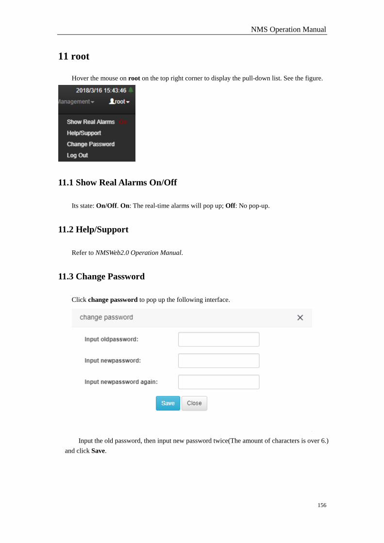
NMS Operation Manual
156
11 root
Hover the mouse on root on the top right corner to display the pull-down list. See the figure.
11.1 Show Real Alarms On/Off
Its state: On/Off. On: The real-time alarms will pop up; Off: No pop-up.
11.2 Help/Support
Refer to NMSWeb2.0 Operation Manual.
11.3 Change Password
Click change password to pop up the following interface.
Input the old password, then input new password twice(The amount of characters is over 6.)
and click Save.

NMS Operation Manual
157
11.4 Log Out
Click Log out to exit the system. Return to the login interface.