Embed Size (px)
Citation preview

Part 2: Test Report Format
NMI M 6-2 Electricity Meters
ii
© Commonwealth of Australia 2010
First edition — September 2010
National Measurement Institute Bradfield Road, Lindfield, NSW 2070 PO Box 264, Lindfield, NSW 2070
T (61 2) 8467 3600 F (61 2) 8467 3610 W www.measurement.gov.au

iii
CONTENTS 1. Test Information ............................................................................................................................................... 1 2. Meter Information and Specifications .............................................................................................................. 1 3. Requirements.................................................................................................................................................... 2 4. Maximum Permissible Errors........................................................................................................................... 4
4.1 Direct-connected Meters with Balanced Loads ..................................................................................... 4 4.2 Transformer-operated Meters with Balanced Loads.............................................................................. 4 4.3 Polyphase Direct-connected Meters....................................................................................................... 5 4.4 Polyphase Transformer-operated Meters ............................................................................................... 5
5. Influence Factors and Disturbances.................................................................................................................. 6 5.1 Voltage Variation................................................................................................................................... 6 5.2 Frequency Variation .............................................................................................................................. 8 5.3 Harmonic Components in the Current and Voltage Circuits ................................................................. 9 5.4 Reversed Phase Sequence...................................................................................................................... 9 5.5 Voltage Unbalance............................................................................................................................... 10 5.6 Auxiliary Voltage ±15%...................................................................................................................... 10 5.7 DC Component in the AC Circuit........................................................................................................ 10 5.8 Continuous Magnetic Induction of External Origin............................................................................. 10 5.9 Magnetic Induction of External Origin 0.5 mT ................................................................................... 11 5.10 Electromagnetic RF Fields................................................................................................................... 11 5.11 Conducted RF Fields ........................................................................................................................... 11 5.12 Fast Transient Bursts ........................................................................................................................... 12 5.13 Variations due to Short-time Overcurrents .......................................................................................... 12 5.14 Operation of Accessories ..................................................................................................................... 13 5.15 Sub-harmonics in the AC Circuit......................................................................................................... 13 5.16 Odd Harmonics in the AC Circuit ....................................................................................................... 13 5.17 Tilt at 3° in any Direction from the Vertical ........................................................................................ 13 5.18 Current Coil Self-heating..................................................................................................................... 14 5.19 Alternative Usage and Phase Reversal (Balanced Two-element Driven) ............................................ 14 5.20 Alternative Usage and Phase Reversal (Single-element Driven)......................................................... 14 5.21 Register Friction .................................................................................................................................. 15 5.22 Register Changeover............................................................................................................................ 15 5.23 Shock ................................................................................................................................................... 15
6. Ambient Temperature Variation..................................................................................................................... 16 6.1 Direct-connected Meters...................................................................................................................... 16 6.2 Transformer-operated Meters .............................................................................................................. 17
7. Internal Clocks ............................................................................................................................................... 17 7.1 Mains Supply ....................................................................................................................................... 17 7.2 Operational Reserve............................................................................................................................. 18 7.3 High Temperature ................................................................................................................................ 18 7.4 Low Temperature................................................................................................................................. 18
8. Performance Tests .......................................................................................................................................... 18 8.1 Optical Port Requirements................................................................................................................... 18 8.2 Dry Heat Test....................................................................................................................................... 18 8.3 Cold Test.............................................................................................................................................. 19 8.4 Damp Heat Cyclic Test........................................................................................................................ 19 8.5 Solar Radiation Test............................................................................................................................. 20 8.6 Dust Test.............................................................................................................................................. 20 8.7 Vibration (Sinusoidal) Test.................................................................................................................. 20 8.8 Mechanical Shock Test ........................................................................................................................ 21 8.9 Radiated Electromagnetic Radiofrequency Fields Test without Current ............................................. 21 8.10 Electrostatic Discharge Test ................................................................................................................ 21 8.11 Voltage Dips and Short-term Interruptions Test .................................................................................. 22 8.12 Impulse Voltage Test ........................................................................................................................... 22 8.13 AC Voltage Test .................................................................................................................................. 22

iv
PREFACE
This document provides a test report format for the pattern approval and verification of active-energy static electricity meters of classes 0.2, 0.5, 1 and 1.5 covered by NMI M 6-1 Electricity Meters. Part 1: Metrological and Technical Requirements. It may clarify NMI M 6-1, but it does not add to or alter any requirements.
The test reports should make testing more efficient and consistent, and if testing has been conducted against other standards, the test reports may be used as a checklist to determine what further testing and information is required.
Please note that not all tests apply to all meter.

09/2010 NMI M 6-2 1
1. TEST INFORMATION
Test Report
Report reference number
Date of issue
Date of testing
Laboratory details
Name
Address
Contact details
Test specification
Standard NMI M 6-1
Client details
Applicant
Address
2. METER INFORMATION AND SPECIFICATIONS
Manufacturer
Model
Accuracy class
Temperature ranges
Specified operating range
Limit range of operation
Storage and transportation
Number of phases
Number of elements
Number of wires
Connection type
Design type (e.g. solid state, induction)
Reference frequency
Reference voltage
Basic current (direct-connected)
Rated current (transformer-operated)
Rated maximum current
Clock type
Enclosure type
Protective class
Software/firmware version

09/2010 NMI M 6-2 2
3. REQUIREMENTS
Clause number and requirement (from NMI M 6-1) Value / Remark Result Units of measurement 3 Valid units of measurement used Minimum measured quantity 4.1 Has the form 1 × 10n authorised units of energy, where n is an integer
Maximum permissible variation between indicators 4.2 No indicated difference between indications of same quantity on different indicators
Calculated quantities Indicated quantity equals value obtained using indicated values with applicable rounding
4.3
If rounding applied it is 0.5 minimum measured quantity
Meter constant 4.6 No error in relationship between test output and indication on display
Class indices (accuracy class) 4.7 Meter classified as one of 0.2, 0.5, 1 or 1.5 Maximum permissible error 4.8 Percentage errors do not exceed the relevant values specified in tables 1, 2 and 3 due to variations in current
(see results below)
Temperature range (ranges shall comply with the minimum acceptable ranges in Table 5) Specified operating range Limit range of operation
5.2
Storage and transportation
Initial start up of the meter 5.7.2 Time to start – shall be functional within 5 s
Running with no load Test voltage Test current Test period Test output pulses – shall be no more than one
5.7.3
Rotor revolutions – may start but shall not complete a revolution
Starting Test current Meter starts and continues to register
5.7.4
Rotor revolutions – shall start and complete at least one revolution
Acting upon significant faults (static meters only) Has capability to detect, log and communicate significant faults
7.2
Logged data kept in permanent record with date and time stamp

09/2010 NMI M 6-2 3
Clause number and requirement (from NMI M 6-1) Value / Remark Result Display Meter has a display which is legible whilst operating Visible to consumer in normal installation position There is a procedure to show all relevant elements of indicator display, with sufficient time to check them
Able to display quantity of energy corresponding to Imax for at least 4 000 h without returning to same index
Calculated value (energy at Imax for 4 000 h)
7.3
Number of display digits Auxiliary devices interface 7.4 Interface shall be sealed if parameters can be altered by instructions or data introduced through interface
Information to be displayed on meter exterior Manufacturer’s name or mark Model designation Serial number NMI certificate of approval number (space for) Number of phases, number of wires Reference frequency Specified operating temperature limits (if more restrictive than –10°C to +60°C)
Meter constant Rated voltage Rated currents
8.1
Class index
Notices 8.2 Any special notices or limitations of use shall be clearly marked or provided in manual
Verification mark Easily affixed without affecting metrological properties of the meter
Visible without moving or dismantling the meter when in use
Part where mark is located shall not be removable with damage to mark
9.1
Sufficient space (≥ 200 mm2) Sealing Access to protected parameters protected Access to protected parameters recorded Records readily accessible Record easily identifiable (not confused) Reference record marked on meter
9.2
Record shall not repeat in a sequence of less than 99 alterations; record shall persist reliably for at least 2 years and persist through influence and disturbance tests

09/2010 NMI M 6-2 4
4. MAXIMUM PERMISSIBLE ERRORS
Refer to NMI M 6-1, clause 4.8 (Tables 1 to 3). Mandatory test currents are shown. Extra test points should be included where appropriate for the particular meter.
4.1 Direct-connected Meters with Balanced Loads
Limit (±%) for class Current (A) Power factor Percentage error
1 1.5 0.05 Ib 1.5 1.5 0.1 Ib 0.2 Ib
Ib Imax
1
1.0 1.5
0.1 Ib 1.5 1.5 0.2 Ib
Ib Imax
0.5 inductive
1.0 1.5
0.1 Ib 1.5 0.2 Ib
Ib Imax
0.8 capacitive
1.0
4.2 Transformer-operated Meters with Balanced Loads
Limit (±%) for class Current (A) Power factor Percentage error
0.2 0.5 1 0.01 In 0.02 In
0.4 1.0 1.5
0.05 In 0.1 In
In Imax
1
0.2 0.5 1.0
0.02 In 0.05 In
0.5 1.0 1.5
0.1 In In
Imax
0.5 inductive
0.3 0.6 1.0
0.02 In 0.05 In
0.5 1.0 1.5
0.1 In In
Imax
0.8 capacitive
0.3 0.6 1.0

09/2010 NMI M 6-2 5
4.3 Polyphase Direct-connected Meters
Limit (±%) for class Phase Current (A) Power factor Percentage error
1 1.5 0.1 Ib 0.2 Ib
Ib Imax
1
2.0 2.5
0.2 Ib Ib
Phase 1
Imax 0.5 inductive
2.0 2.5
0.1 Ib 0.2 Ib
Ib Imax
1
2.0 2.5
0.2 Ib Ib
Phase 2
Imax 0.5 inductive
2.0 2.5
0.1 Ib 0.2 Ib
Ib Imax
1
2.0 2.5
0.2 Ib Ib
Phase 3
Imax 0.5 inductive
2.0 2.5
4.4 Polyphase Transformer-operated Meters
Limit (±%) for class Phase Current (A) Power factor Percentage error
0.2 0.5 1 0.05 In 0.1 In
In Imax
1
0.3 0.6 2.0
0.1 In In
Phase 1
Imax 0.5 inductive
0.4 1.0 2.0
0.05 In 0.1 In
In Imax
1
0.3 0.6 2.0
0.1 In In
Phase 2
Imax 0.5 inductive
0.4 1.0 2.0
0.05 In 0.1 In
In Imax
1
0.3 0.6 2.0
0.1 In In
Phase 3
Imax 0.5 inductive
0.4 1.0 2.0

09/2010 NMI M 6-2 6
5. INFLUENCE FACTORS AND DISTURBANCES
5.1 Voltage Variation
Refer to NMI M 6-1, Table 4 and A.2.12. For three phase mains power, voltage variations shall apply for each phase successively.
5.1.1 Direct-connected Meters, Classes 1 and 1.5
Limit of variation (%) by classVoltage variation (% from Unom)
Current (A) Power factor Variation in
error (%) 1 1.5 0.05 Ib
Ib Imax
1
0.7 1.0
0.1 Ib Ib
+10
Imax
0.5 inductive
1.0 1.0
0.05 Ib Ib
Imax
1
0.7 1.0
0.1 Ib Ib
–10
Imax
0.5 inductive
1.0 1.0
0.05 Ib Ib
Imax
1
2.1 3.0
0.1 Ib Ib
+15
Imax
0.5 inductive
3.0 3.0
0.05 Ib Ib
Imax
1
2.1 3.0
0.1 Ib Ib
–20
Imax
0.5 inductive
3.0 3.0
0.05 Ib Ib
Imax
1
0.1 Ib
Ib
–50
Imax
0.5 inductive
–100 to +10
09/2010 NMI M 6-2 7
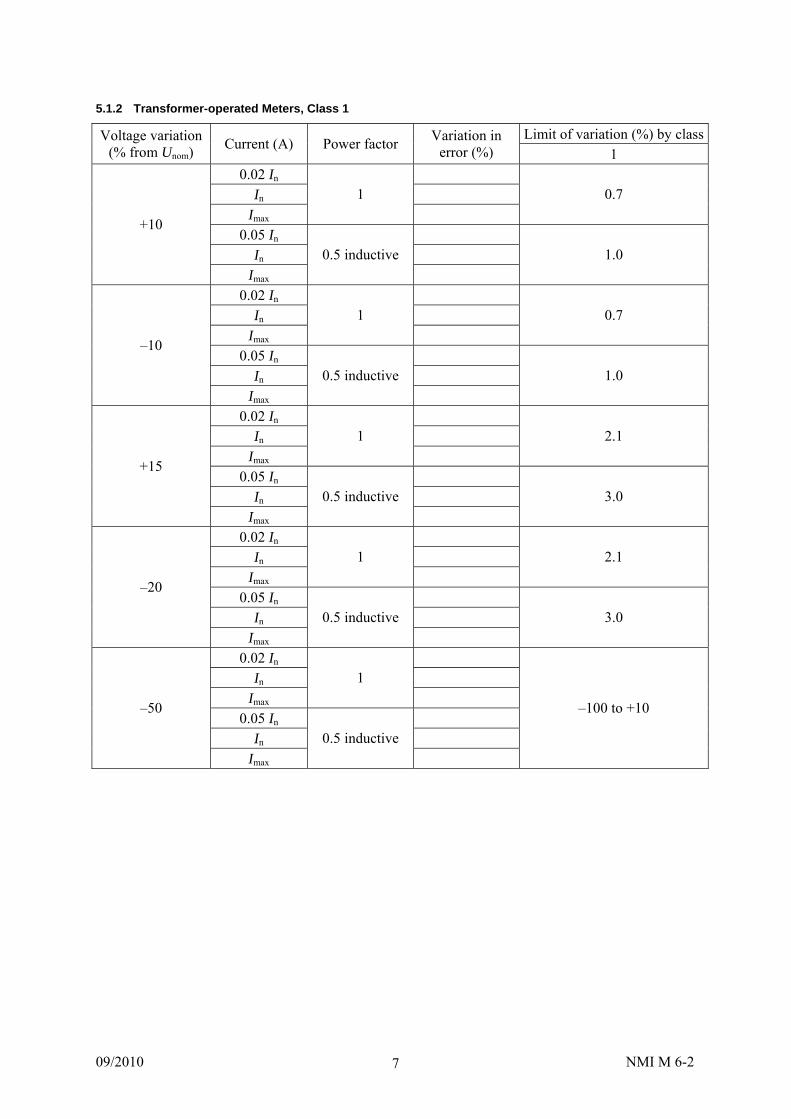
5.1.2 Transformer-operated Meters, Class 1
Limit of variation (%) by classVoltage variation (% from Unom)
Current (A) Power factor Variation in
error (%) 1 0.02 In
In Imax
1
0.7
0.05 In In
+10
Imax
0.5 inductive
1.0
0.02 In In
Imax
1
0.7
0.05 In In
–10
Imax
0.5 inductive
1.0
0.02 In In
Imax
1
2.1
0.05 In In
+15
Imax
0.5 inductive
3.0
0.02 In In
Imax
1
2.1
0.05 In In
–20
Imax
0.5 inductive
3.0
0.02 In In
Imax
1
0.05 In
In
–50
Imax
0.5 inductive
–100 to +10

09/2010 NMI M 6-2 8
5.1.3 Transformer-operated Meters, Classes 0.2 and 0.5
Limit of variation (%) by classVoltage variation (% from Unom)
Current (A) Power factor Variation in
error (%) 0.2 0.5 0.05 In
In Imax
1
0.1 0.2
0.1 In In
+10
Imax 0.5 inductive
0.2 0.4
0.05 In In
Imax 1
0.1 0.2
0.1 In In
–10
Imax 0.5 inductive
0.2 0.4
0.05 In In
Imax 1
0.3 0.6
0.1 In In
+15
Imax 0.5 inductive
0.6 1.2
0.05 In In
Imax 1
0.3 0.6
0.1 In In
–20
Imax 0.5 inductive
0.6 1.2
0.05 In In
Imax 1
0.1 In
In
–50
Imax 0.5 inductive
–100 to +10
5.2 Frequency Variation
Refer to NMI M 6-1, Table 4 and A.2.13.
5.2.1 Direct-connected meters, Classes 1 and 1.5
Limit of variation (%) by classFrequency variation (% from fnom)
Current (A) Power factor Variation in
error (%) 1 1.5 0.05 Ib
Ib Imax
1
0.5 1.0
0.1 Ib Ib
+2
Imax 0.5 inductive
0.7 1.0
0.05 Ib Ib
Imax 1
0.5 1.0
0.1 Ib Ib
–2
Imax 0.5 inductive
0.7 1.0

09/2010 NMI M 6-2 9
5.2.2 Transformer-operated Meters, Class 1
Limit of variation (%) by classFrequency variation (% from fnom)
Current (A) Power factor Variation in
error (%) 1 0.02 In
In Imax
1
0.5
0.05 In In
+2
Imax 0.5 inductive
0.7
0.02 In In
Imax 1
0.5
0.05 In In
–2
Imax 0.5 inductive
0.7
5.2.3 Transformer-operated Meters, Classes 0.2 and 0.5
Limit of variation (%) by classFrequency variation (% from fnom)
Current (A) Power factor Variation in
error (%) 0.2 0.5 0.05 In
In Imax
1
0.1 0.2
0.1 In In
+2
Imax
0.5 inductive
0.1 0.2
0.05 In In
Imax
1
0.1 0.2
0.1 In In
–2
Imax
0.5 inductive
0.1 0.2
5.3 Harmonic Components in the Current and Voltage Circuits
Refer to NMI M 6-1, Table 4. The variation in percentage error shall be measured under the most unfavourable phase displacement of the fifth harmonic in the current compared with the fundamental error.
Percentage error Limit of variation (%) by class Current (A)
Power factor fnom fnom + harmonics
Variation in error (%) 0.2 0.5 1 1.5
0.5 Imax 1 0.4 0.5 0.8 1.0
5.4 Reversed Phase Sequence
Refer to NMI M 6-1, Table 4. Polyphase (three-phase four wire) meters shall measure and register within the limits of variation in percentage error if any one or two phases of the three phase network are interrupted.
Percentage error Limit of variation (%) by class Current (A)
Power factor ABC CBA
Variation in error (%) 0.2 0.5 1 1.5
0.1 Ib (0.1 In) 1 0.05 0.1 1.5 1.5
09/2010 NMI M 6-2 10
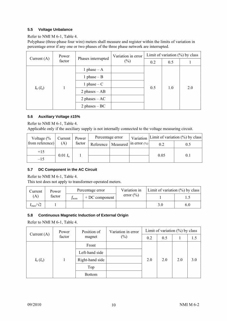
5.5 Voltage Unbalance
Refer to NMI M 6-1, Table 4. Polyphase (three-phase four wire) meters shall measure and register within the limits of variation in percentage error if any one or two phases of the three phase network are interrupted.
Limit of variation (%) by class Current (A)
Power factor
Phases interrupted Variation in error
(%) 0.2 0.5 1
1 phase – A
1 phase – B
1 phase – C
2 phases – AB
2 phases – AC
Ib (In) 1
2 phases – BC
0.5 1.0 2.0
5.6 Auxiliary Voltage ±15%
Refer to NMI M 6-1, Table 4. Applicable only if the auxiliary supply is not internally connected to the voltage measuring circuit.
Percentage error Limit of variation (%) by classVoltage (% from reference)
Current (A)
Power factor Reference Measured
Variation in error (%) 0.2 0.5
+15
–15 0.01 In 1
0.05 0.1
5.7 DC Component in the AC Circuit
Refer to NMI M 6-1, Table 4. This test does not apply to transformer-operated meters.
Percentage error Limit of variation (%) by classCurrent (A)
Power factor fnom + DC component
Variation in error (%)
1 1.5
Imax/√2 1 3.0 6.0
5.8 Continuous Magnetic Induction of External Origin
Refer to NMI M 6-1, Table 4.
Limit of variation (%) by class Current (A)
Power factor
Position of magnet
Variation in error (%) 0.2 0.5 1 1.5
Front
Left-hand side
Right-hand side
Top
Ib (In) 1
Bottom
2.0 2.0 2.0 3.0

09/2010 NMI M 6-2 11
5.9 Magnetic Induction of External Origin 0.5 mT
Refer to NMI M 6-1, Table 4. A magnetic induction of external origin of 0.5 mT produced by a current of the same frequency as that of the voltage applied to the meter and under the most unfavourable conditions of phase and direction shall not cause a variation in the percentage error of the meter exceeding the values shown. The magnetic induction shall be obtained by placing the meter in the centre of a circular coil, 1 m in mean diameter, of square section and of small radial thickness relative to the diameter, and having 400 At.
Limit of variation (%) by class Current (A)
Power factor
Variation in error (%) 0.2 0.5 1 1.5
Ib (In) 1 0.5 1.0 2.0 – Ib (0.5 In) 1 – – – 2.0
5.10 Electromagnetic RF Fields
Refer to NMI M 6-1, Table 4 and A.2.9 (test with current test). Meters constructed with passive elements only, including electromechanical meters, are exempt from this test. Frequency range: 0 to 2 400 MHz Modulation: 80% AM, 1kHz sine wave Field strength: 10 V/m
Limit of variation (%) by class Current (A)
Power factor
Polarisation Facing meter
Variation in error (%) 0.2 0.5 1 1.5
Front Right Left
Vertical
Rear Front Right Left
Ib (In) 1
Horizontal
Rear
1.0 2.0 2.0 3.0
Requirement Remark Result During the test, the behaviour of the meter shall not be perturbed
5.11 Conducted RF Fields
Refer to NMI M 6-1, Table 4 and A.2.10. Meters constructed with passive elements only, including electromechanical meters, are exempt from this test. RF amplitude (50 Ω): 10 V (e.m.f.) Modulation: 80% AM, 1 kHz sine wave Frequency range: 0.15 to 80 MHz
Limit of variation (%) by class Current (A)
Power factor
Power port or I/O port Variation in
error (%) 0.2 0.5 1 1.5
Ib (In) 1
1.0 2.0 2.0 3.0
Requirement Remark Result During the test, the behaviour of the meter shall not be perturbed

09/2010 NMI M 6-2 12
5.12 Fast Transient Bursts
Refer to NMI M 6-1, Table 4 and A.2.15. Meters constructed with passive elements only, including electromechanical meters, are exempt from this test. During the test, a temporary degradation or loss of function or performance is acceptable.
Limit of variation (%) by classCurrent (A)
Power factor
Circuit Voltage
peak (kV) Polarity
(60 s at each)
Variation in error
(%) 0.2 0.5 1 1.5
Positive Voltage
Negative
Positive Current
4
Negative
Positive Auxiliary circuit Negative
Positive
Ib (In) 1
Auxiliary circuit
2
Negative
1.0 2.0 4.0 6.0
5.13 Variations due to Short-time Overcurrents
Refer to NMI M 6-1, Table 4 and A.2.16. The test shall be performed for polyphase meters phase-by-phase.
Limit of variation (%) by class Current
(A) Power factor
Test Over-current
value (A) Duration
(ms) Phase
Variation in error (%)
0.2 0.5 1 1.5
1
2 Ib 1 A 30 Imax 10
3
– – 1.5 1.5
1
2 In 1 B 20 Imax 500
3
0.05 0.05 0.5 –
1
2 Ib 1 C 7000 60
3
1
2 In 1 D 250 60
3
1
2 In 1 E 50 60
3
Requirement Meter shall not
cause damage to surrounding equipment
Requirement Remark Result
For tests C, D and E the meter shall not cause damage to surrounding equipment
09/2010 NMI M 6-2 13
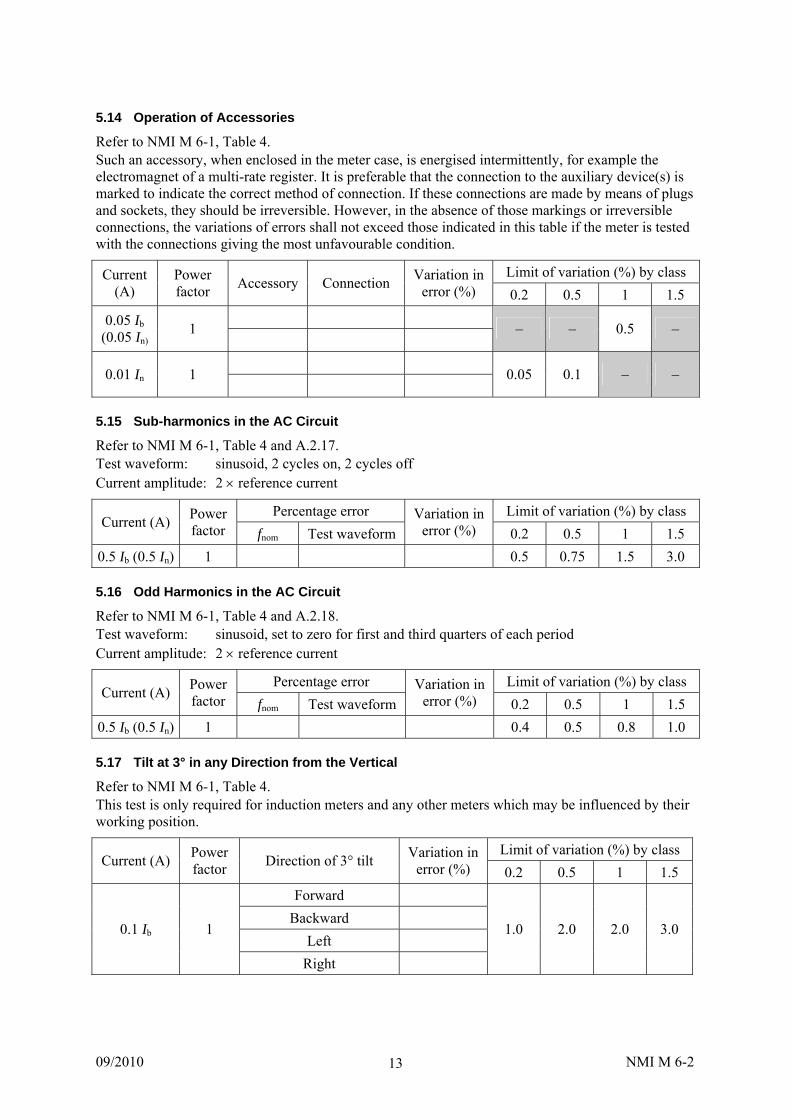
5.14 Operation of Accessories
Refer to NMI M 6-1, Table 4. Such an accessory, when enclosed in the meter case, is energised intermittently, for example the electromagnet of a multi-rate register. It is preferable that the connection to the auxiliary device(s) is marked to indicate the correct method of connection. If these connections are made by means of plugs and sockets, they should be irreversible. However, in the absence of those markings or irreversible connections, the variations of errors shall not exceed those indicated in this table if the meter is tested with the connections giving the most unfavourable condition.
Limit of variation (%) by class Current (A)
Power factor
Accessory Connection Variation in
error (%) 0.2 0.5 1 1.5
0.05 Ib (0.05 In)
1
– – 0.5 –
0.01 In 1
0.05 0.1 – –
5.15 Sub-harmonics in the AC Circuit
Refer to NMI M 6-1, Table 4 and A.2.17. Test waveform: sinusoid, 2 cycles on, 2 cycles off Current amplitude: 2 reference current
Percentage error Limit of variation (%) by class Current (A)
Power factor fnom Test waveform
Variation in error (%) 0.2 0.5 1 1.5
0.5 Ib (0.5 In) 1 0.5 0.75 1.5 3.0
5.16 Odd Harmonics in the AC Circuit
Refer to NMI M 6-1, Table 4 and A.2.18. Test waveform: sinusoid, set to zero for first and third quarters of each period Current amplitude: 2 reference current
Percentage error Limit of variation (%) by class Current (A)
Power factor fnom Test waveform
Variation in error (%) 0.2 0.5 1 1.5
0.5 Ib (0.5 In) 1 0.4 0.5 0.8 1.0
5.17 Tilt at 3° in any Direction from the Vertical
Refer to NMI M 6-1, Table 4. This test is only required for induction meters and any other meters which may be influenced by their working position.
Limit of variation (%) by class Current (A)
Power factor
Direction of 3° tilt Variation in
error (%) 0.2 0.5 1 1.5
Forward
Backward
Left 0.1 Ib 1
Right
1.0 2.0 2.0 3.0

09/2010 NMI M 6-2 14
5.18 Current Coil Self-heating
Refer to NMI M 6-1, Table 4. This test is only required for induction meters and any other meters which may be influenced by their working position. Initial error: determine for each load while current coil is still unheated Precondtioning: 1 h with voltage circuit at Unom, current circuit with zero current Test: continue until error becomes constant
Percentage error Limit of variation
(%) by class Current (A)
Power factor Coil unheated (initial error)
Coil heated
Variation in error (%)
1.5
Imax 1 1.0
Imax 0.5 inductive 1.0
5.19 Alternative Usage and Phase Reversal (Balanced Two-element Driven)
Refer to NMI M 6-1, Table 4. This test is only required for induction meters and any other meters which may be influenced by their working position.
Limit of variation (%) by class Current (A)
Power factor
Phase sequence Percentage
error Variation in
error (%) 1.5
A1 leading A2 by 180°
A1 leading A2 by 120° 0.05 Ib 1
A2 leading A1 by 120° 1.0
A1 leading A2 by 180°
A1 leading A2 by 120° Ib 1
A2 leading A1 by 120° 0.5
5.20 Alternative Usage and Phase Reversal (Single-element Driven)
Refer to NMI M 6-1, Table 4. This test is only required for induction meters and any other meters which may be influenced by their working position.
Limit of variation (%) by class Current (A)
Power factor
Phase sequence Percentage
error Variation in
error (%) 1.5
A1 leading A2 by 180°
A1 leading A2 by 120° 0.1 Ib 1
A2 leading A1 by 120° 1.0
A1 leading A2 by 180°
A1 leading A2 by 120° 2 Ib 1
A2 leading A1 by 120° 0.5

09/2010 NMI M 6-2 15
5.21 Register Friction
Refer to NMI M 6-1, Table 4. This test is only required for induction meters and any other meters which may be influenced by their working position. For a multi-rate meter, the changeover device shall be in each operating condition in turn.
Rotor Speed Limit of variation
(%) by class Current (A)
Power factor
Changeover device operating condition Heaviest
load Register
disengaged
Variation in error (%)
1.5
0.05 Ib 1
0.5
5.22 Register Changeover
Refer to NMI M 6-1, Table 4. This test is only required for induction meters and any other meters which may be influenced by their working position.
Limit of variation (%) by class Current
(A) Power factor
Changeover device operating condition
Rotor Speed Variation in
error (%) 1.5
0.05 Ib 1
0.4*
* An additional variation of 0.5% may be permitted for certain multiple-element meters (refer to AS 1284.1, clause 4.3.15).
5.23 Shock
Refer to NMI M 6-1, Table 4. This test is only required for induction meters and any other meters which may be influenced by their working position. Initial error: determine for each load prior to subjecting to shock
Limit of variation (%) by class Current
(A) Power factor
Initial error (before shock)
After shock testVariation in
error (%) 1.5
0.05 Ib 1 0.5
Ib 1 0.3
Ib 0.5 inductive 0.3
09/2010 NMI M 6-2 16
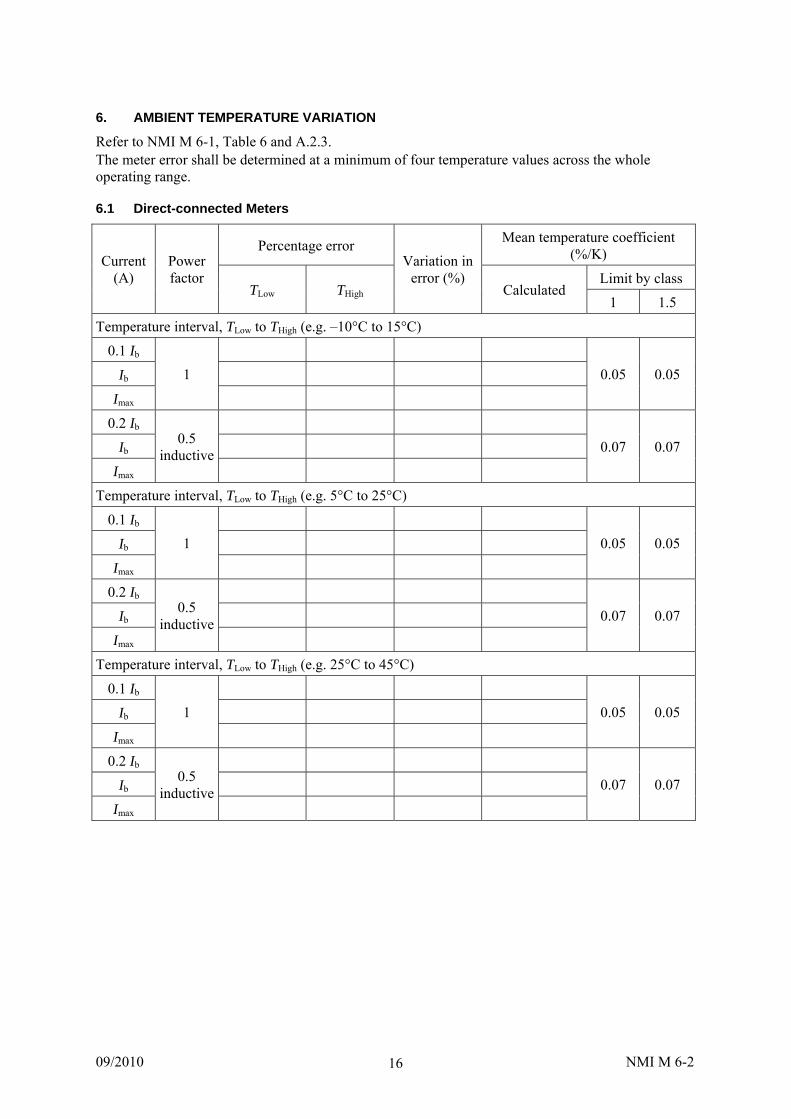
6. AMBIENT TEMPERATURE VARIATION
Refer to NMI M 6-1, Table 6 and A.2.3. The meter error shall be determined at a minimum of four temperature values across the whole operating range.
6.1 Direct-connected Meters
Percentage error Mean temperature coefficient
(%/K)
Limit by class Current
(A) Power factor
TLow THigh
Variation in error (%)
Calculated 1 1.5
Temperature interval, TLow to THigh (e.g. –10°C to 15°C)
0.1 Ib
Ib
Imax
1
0.05 0.05
0.2 Ib
Ib
Imax
0.5 inductive
0.07 0.07
Temperature interval, TLow to THigh (e.g. 5°C to 25°C)
0.1 Ib
Ib
Imax
1
0.05 0.05
0.2 Ib
Ib
Imax
0.5 inductive
0.07 0.07
Temperature interval, TLow to THigh (e.g. 25°C to 45°C)
0.1 Ib
Ib
Imax
1
0.05 0.05
0.2 Ib
Ib
Imax
0.5 inductive
0.07 0.07
09/2010 NMI M 6-2 17
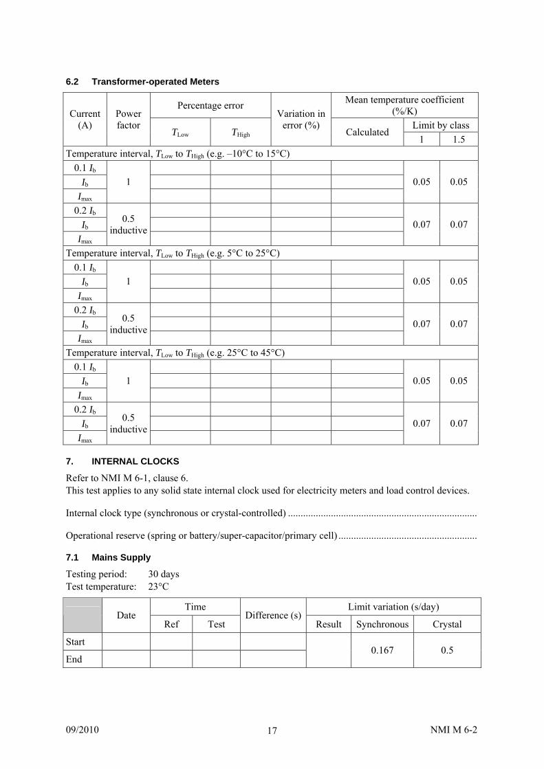
6.2 Transformer-operated Meters
Percentage error Mean temperature coefficient
(%/K)
Limit by class Current
(A) Power factor
TLow THigh
Variation in error (%)
Calculated 1 1.5
Temperature interval, TLow to THigh (e.g. –10°C to 15°C)
0.1 Ib
Ib
Imax
1
0.05 0.05
0.2 Ib
Ib
Imax
0.5 inductive
0.07 0.07
Temperature interval, TLow to THigh (e.g. 5°C to 25°C)
0.1 Ib
Ib
Imax
1
0.05 0.05
0.2 Ib
Ib
Imax
0.5 inductive
0.07 0.07
Temperature interval, TLow to THigh (e.g. 25°C to 45°C)
0.1 Ib
Ib
Imax
1
0.05 0.05
0.2 Ib
Ib
Imax
0.5 inductive
0.07 0.07
7. INTERNAL CLOCKS
Refer to NMI M 6-1, clause 6. This test applies to any solid state internal clock used for electricity meters and load control devices.
Internal clock type (synchronous or crystal-controlled) ...........................................................................
Operational reserve (spring or battery/super-capacitor/primary cell) .......................................................
7.1 Mains Supply
Testing period: 30 days Test temperature: 23°C
Time Limit variation (s/day) Date
Ref Test Difference (s)
Result Synchronous Crystal
Start
End 0.167 0.5

09/2010 NMI M 6-2 18
7.2 Operational Reserve
Testing period: 36 h Test temperature: 23°C
Time Limit variation (s/day) Synchronous Date
Ref Test Difference (s)
Result Spring Battery
Crystal
Start End
120 1 1
7.3 High Temperature
Testing period: 24 h Test temperature: 45°C
Time Limit variation (s/day) Date
Ref Test Difference (s)
Result Crystal Start End
0.15
7.4 Low Temperature
Testing period: 24 h Test temperature: –10°C
Time Limit variation (s/day) Date
Ref Test Difference (s)
Result Crystal Start End
0.15
8. PERFORMANCE TESTS
8.1 Optical Port Requirements
Refer to NMI M 6-1, A.1.3.
Requirement Remark Result Environmental lighting condition Transmission speed
8.2 Dry Heat Test
Refer to NMI M 6-1, A.2.1. Duration: 72 h Meter/EUT: In operating condition except whilst temperature is lowered or raised. High temperature: ...................... (maximum specified operating temperature)
Percentage error MPE by class Current
(A) Power factor At reference
before heat At high temperature
after 72 h Reference after
recovery 0.2 0.5 1 1.5
Ib (In) 1 0.2 0.5 1 1.5
Requirement Remark Result
No damage to meter
No change of information

09/2010 NMI M 6-2 19
8.3 Cold Test
Refer to NMI M 6-1, A.2.2. Duration: 72 h Meter/EUT: in operating condition except whilst temperature is lowered or raised. Low temperature: ...................... (minimum specified operating temperature)
Percentage error MPE by class Current
(A) Power factor At reference
before heat At low temperature
after 72 h Reference after
recovery 0.2 0.5 1 1.5
Ib (In) 1 0.2 0.5 1 1.5
Requirement Remark Result
No damage to meter
No change of information
8.4 Damp Heat Cyclic Test
Refer to NMI M 6-1, A.2.4. Duration (cycles): 6 24 h cycles Meter/EUT: non-operating condition Low temperature: 25°C High temperature: ...................... (maximum specified operating temperature)
Requirement Remark Result
No trace of corrosion likely to affect the functional properties of the EUT shall be present
24 h after the end of this test, submit the EUT to the following tests: AC voltage test (NMI M 6-1, A.2.20) — refer to clause 8.13. impulse voltage test (NMI M 6-1, A.2.19, except 0.8 of impulse voltage, i.e. 9.6 kV +0%, –15%)
Impulse voltage test
Percentage error Current (A)
Power factor Before After
Variation in error (%)
Limit
Ib (In) 1 (uncertainty of measurement)
Requirement Remark Result
During the test, no flashover, disruptive discharge or puncture shall occur
After the test, no mechanical damage to the EUT

09/2010 NMI M 6-2 20
8.5 Solar Radiation Test
Refer to NMI M 6-1, A.2.5. UV lamp output: 21 750 lm to 27 000 lm Duration: 48 h and distance of 250 mm Meter/EUT: non-operating condition
MPE by class Current (A) Power factor Percentage error
0.2 0.5 1 1.5
Ib (In) 1 0.2 0.5 1 1.5
Requirement Remark Result
For transparent parts – no noticeable deterioration or loss in transparency
For non-transparent parts – no noticeable effect
The function of the meter shall not be impaired (see error above)
8.6 Dust Test
Refer to NMI M 6-1, A.2.6. Enclosure category: 2 Duration: 8 h Meter/EUT: non-operating condition
MPE by class Current (A) Power factor Percentage error
0.2 0.5 1 1.5 Ib (In) 1 0.2 0.5 1 1.5
Requirement Remark Result No dust accumulation which could affect meter operation or safety
No dust deposition that could lead to tracking along creepage distances
The function of the meter shall not be impaired (see error above)
8.7 Vibration (Sinusoidal) Test
Refer to NMI M 6-1, A.2.7. Severity level: 2 Frequency range: 10 to 150 Hz Max acceleration level: 10 m/s2 No sweep cycles per axis: 10 Meter/EUT: non-operating condition
MPE by class Current (A) Power factor Percentage error
0.2 0.5 1 1.5 Ib (In) 1 0.2 0.5 1 1.5
Requirement Remark Result No damage to meter No change of information Meter shall operate correctly (see error above)

09/2010 NMI M 6-2 21
8.8 Mechanical Shock Test
Refer to NMI M 6-1, A.2.8. Severity level: 1 Pulse shape: half-sine Peak acceleration: 200 m/s2 Pulse duration: 18 ms Meter/EUT: non-operating condition, without packing
MPE by class Current (A) Power factor Percentage error
0.2 0.5 1 1.5 Ib (In) 1 0.2 0.5 1 1.5
Requirement Remark Result No damage to meter No change of information Meter shall operate correctly (see error above)
8.9 Radiated Electromagnetic Radiofrequency Fields Test without Current
Refer to NMI M 6-1, A.2.9. Frequency range: 80 to 2400 MHz (continuous) Modulation: 80% AM, 1 kHz sine wave Field strength: 30 V/m Meter/EUT: in operating condition, reference voltage, current terminal open-circuit
Requirement Remark Result
The behaviour of the equipment shall not be perturbed
8.10 Electrostatic Discharge Test
Refer to NMI M 6-1, A.2.11. Number of discharges: at least 10 Polarity of discharges: the most sensitive polarity Severity level: 4 Meter/EUT: in operating condition, reference voltage, current terminal open-circuit
Change in Application (direct/indirect)
Coupling plane
Discharge mode(contact/air)
Test voltage (kV) Register Test output
Limit, x(kW·h)
Direct –
Indirect Horizontal Contact 15
Indirect Vertical Contact 15
MPE by class Current (A) Power factor Percentage error
0.2 0.5 1 1.5
Ib (In) 1 0.2 0.5 1 1.5
Requirement Remark Result
Meter shall operate correctly (see error above)

09/2010 NMI M 6-2 22
8.11 Voltage Dips and Short-term Interruptions Test
Refer to NMI M 6-1, A.2.14. Meter/EUT: in operating condition, reference voltage, no current
Dips/interruptions Change in Voltage dip or interruption U Duration
Number Time between Register Test output Limit, x(kW·h)
Dip 50% 1 min 1 –
Interruption 100% 1 s 3 50 ms
Interruption 100% 20 ms 1 –
8.12 Impulse Voltage Test
Refer to NMI M 6-1, A.2.19. Impulse voltage: 12 kV +0%, –15% Source capacitance: 0.125 μF Source impedance: 40 Ω ± 5 Ω Stored energy: 9.0 J ± 1.0 J Impulse waveform at no load: 1.2/50 impulse Meter/EUT: non-operating condition
Percentage error Current (A)
Power factor Before After
Variation in error (%)
Limit
Ib (In) 1 (uncertainty of measurement)
Requirement Remark Result
During the test, no flashover, disruptive discharge or puncture shall occur
After the test, no mechanical damage to the EUT
8.13 AC Voltage Test
Refer to NMI M 6-1, A.2.20. This test shall be performed as part of the damp heat cyclic test (refer to NMI M 6-1, A.2.4).
Percentage error Current (A)
Power factor Before After
Variation in error (%)
Limit
Ib (In) 1 (uncertainty of measurement)
Requirement Remark Result
2 kV: during the test, no flashover, disruptive discharge or puncture shall occur
4 kV: during the test, no flashover, disruptive discharge or puncture shall occur
40 V: during the test, no flashover, disruptive discharge or puncture shall occur
After the test, no mechanical damage to the EUT