Embed Size (px)
Citation preview

NK Series Compact Routers User Guide
Thank You for Choosing RossYou've made a great choice. We expect you will be very happy with your purchase of Ross Technology.
Our mission is to:
1. Provide a Superior Customer Experience
• offer the best product quality and support
2. Make Cool Practical Technology
• develop great products that customers love
Ross has become well known for the Ross Video Code of Ethics. It guides our interactions and empowers our employees. I hope you enjoy reading it below.
If anything at all with your Ross experience does not live up to your expectations be sure to reach out to us at [email protected].
David RossCEO, Ross [email protected]
Ross Video Code of EthicsAny company is the sum total of the people that make things happen. At Ross, our employees are a special group. Our employees truly care about doing a great job and delivering a high quality customer experience every day. This code of ethics hangs on the wall of all Ross Video locations to guide our behavior:
1. We will always act in our customers’ best interest.
2. We will do our best to understand our customers’ requirements.
3. We will not ship crap.
4. We will be great to work with.
5. We will do something extra for our customers, as an apology, when something big goes wrong and it's our fault.
6. We will keep our promises.
7. We will treat the competition with respect.
8. We will cooperate with and help other friendly companies.
9. We will go above and beyond in times of crisis. If there's no one to authorize the required action in times of company or customer crisis - do what you know in your heart is right. (You may rent helicopters if necessary.)

NK Series · User Guide• Ross Part Number: 9807DR-0100-03
• Release Date: December 4, 2017.
The information contained in this Guide is subject to change without notice or obligation.
Copyright
©2017 Ross Video Limited, Ross®, and any related marks are trademarks or registered trademarks of Ross Video Limited. All other trademarks are the property of their respective companies. PATENTS ISSUED and PENDING. All rights reserved. No part of this publication may be reproduced, stored in a retrieval system, or transmitted in any form or by any means, mechanical, photocopying, recording or otherwise, without the prior written permission of Ross Video. While every precaution has been taken in the preparation of this document, Ross Video assumes no responsibility for errors or omissions. Neither is any liability assumed for damages resulting from the use of the information contained herein.
Patents
Patent numbers US 7,034,886; US 7,508,455; US 7,602,446; US 7,802,802 B2; US 7,834,886; US 7,914,332; US 8,307,284; US 8,407,374 B2; US 8,499,019 B2; US 8,519,949 B2; US 8,743,292 B2; GB 2,419,119 B; GB 2,447,380 B; and other patents pending.
Notice
The material in this manual is furnished for informational use only. It is subject to change without notice and should not be construed as commitment by Ross Video Limited. Ross Video Limited assumes no responsibility or liability for errors or inaccuracies that may appear in this manual.
Trademarks• Microsoft, Encarta, MSN, and Windows are either registered trademarks or trademarks of Microsoft Corporation
in the United States and/or other countries.
• Oracle and Java are registered trademarks of Oracle and/or its affiliates. Other names may be trademarks of their respective owners.
• All other product names and any registered and unregistered trademarks mentioned in this guide are used for identification purposes only and remain the exclusive property of their respective owners.
Safety Notices
Refer to the “Important Regulatory and Safety Notices” document that accompanied your product.
Statement of Compliance
This product has been determined to be compliant with the applicable standards, regulations, and directives for the countries where the product is marketed.
Compliance documentation, such as certification or Declaration of Compliance for the product is available upon request by contacting [email protected]. Please include the product; model number identifiers and serial number and country that compliance information is needed in request.

EMC Notices
US FCC Part 15
This equipment has been tested and found to comply with the limits for a class A Digital device, pursuant to part 15 of the FCC Rules. These limits are designed to provide reasonable protection against harmful interference when the equipment is operated in a Commercial environment. This equipment generates, uses, and can radiate radio frequency energy and, if not installed and used in accordance with the instruction manual, may cause harmful interference to radio communications. Operation of this equipment in a residential area is likely to cause harmful interference in which case the user will be required to correct the interference at his own expense.
Canada
This Class A device complies with Canadian ICES-003 rules.
Cet appariel numerique de la classe “A” est conforme a la norme NMB-003 du Canada.
European Union
This equipment is in compliance with the essential requirements and other relevant provisions established under regulation (EC) No 765/2008 and Decision No 768/2008/EC referred to as the “New Legislative Framework”.
Australia/New Zealand
This equipment is in compliance with the provisions established under the Radiocommunications Act 1992 and Radiocommunications Labeling (Electromagnetic Compatibility) Notice 2008.
Korea
This equipment is in compliance with the provisions established under the Radio Waves Act.
Class A equipment (Broadcasting and communications service for business use).
This device is a business-use (Class A) EMC-compliant device. The seller and user are advised to be aware of this fact. This device is intended for use in areas outside home.
International
This equipment has been tested under the requirements of CISPR 22:2008 or CISPR 32:2015 and found to comply with the limits for a Class A Digital device.
Notice — Changes or modifications to this equipment not expressly approved by Ross Video Limited could void the user’s authority to operate this equipment.
Warning — This equipment is compliant with Class A of CISPR 32. In a residential environment this equipment may cause radio interference.
Notice — This is a Class A product. In domestic environments, this product may cause radio interference, in which case the user may have to take adequate measures.
Type of Equipment User’s Guide
A
( )
Class A Equipment
(Industrial Broadcasting &
Communication Equipment)
(A )
,
.
This equipment is Industrial (Class A) electromagnetic wave suitability equipment and
seller or user should take notice of it, and this
equipment is to be used in the places except for home.

Warranty and Repair Policy
The NK Series system is backed by a comprehensive one-year warranty on all components.
If an item becomes defective within the warranty period Ross will repair or replace the defective item, as determined solely by Ross.
Warranty repairs will be conducted at Ross, with all shipping FOB Ross dock. If repairs are conducted at the customer site, reasonable out-of-pocket charges will apply. At the discretion of Ross, and on a temporary loan basis, plug in circuit boards or other replacement parts may be supplied free of charge while defective items undergo repair. Return packing, shipping, and special handling costs are the responsibility of the customer.
This warranty is void if products are subjected to misuse, neglect, accident, improper installation or application, or unauthorized modification.
In no event shall Ross Video Limited be liable for direct, indirect, special, incidental, or consequential damages (including loss of profit). Implied warranties, including that of merchantability and fitness for a particular purpose, are expressly limited to the duration of this warranty.
This warranty is TRANSFERABLE to subsequent owners, subject to Ross’ notification of change of ownership.
Extended Warranty
For customers that require a longer warranty period, Ross offers an extended warranty plan to extend the standard warranty period by one year increments. For more information, contact your regional sales manager.
Environmental Information
The equipment may contain hazardous substances that could impact health and the environment.
To avoid the potential release of those substances into the environment and to diminish the need for the extraction of natural resources, Ross Video encourages you to use the appropriate take-back systems. These systems will reuse or recycle most of the materials from your end-of-life equipment in an environmentally friendly and health conscious manner.
The crossed-out wheeled bin symbol invites you to use these systems.
If you need more information on the collection, reuse, and recycling systems, please contact your local or regional waste administration. You can also contact Ross Video for more information on the environmental performances of our products.

Company Address
Ross Video Limited
8 John StreetIroquois, OntarioCanada, K0E 1K0
Ross Video Incorporated
P.O. Box 880Ogdensburg, New YorkUSA 13669-0880
General Business Office: (+1) 613 652 4886
Fax: (+1) 613 652 4425
Technical Support: (+1) 613 652 4886
After Hours Emergency: (+1) 613 349 0006
E-mail (Technical Support): [email protected]
E-mail (General Information): [email protected]
Website: http://www.rossvideo.com

NK Series User Guide (v3.0) Contents • i
Contents
Introduction 11Related Publications ...............................................................................................................................................11Documentation Conventions ..................................................................................................................................12
Interface Elements ...............................................................................................................................................12User Entered Text ...............................................................................................................................................12Referenced Guides ..............................................................................................................................................12Menu Sequences ..................................................................................................................................................12Important Instructions .........................................................................................................................................12
Contacting Technical Support ................................................................................................................................12
Getting Started 13NK-16, NK-32, and NK-34 Series Routers ...........................................................................................................13NK-64 and NK-72 Router Formats ........................................................................................................................14Possible Matrices ...................................................................................................................................................14NK Series Power Supplies .....................................................................................................................................15
Routers Hardware Overview 17Front Panel .............................................................................................................................................................17NK-16, NK-32, and NK-34 Rear Panels ................................................................................................................17
AES/EBU Digital Audio Level ...........................................................................................................................18Analog Video Level ............................................................................................................................................19Stereo Analog Audio Level .................................................................................................................................20Machine Control/Data Level ...............................................................................................................................21
NK-64 and NK-72 Router Formats ........................................................................................................................21NK-S, NK-MD, and NK-3G Series ....................................................................................................................21AES/EBU Digital Audio Level ...........................................................................................................................22Stereo Analog Audio Level .................................................................................................................................23
Control Panel Hardware Overview 25RCP-NK1 ...............................................................................................................................................................25RCP-NKM .............................................................................................................................................................26RCP-NKQ ..............................................................................................................................................................27
Interfaces and Connectivity 29Communication Interfaces .....................................................................................................................................29
T-Bus Control System .........................................................................................................................................29DashBoard Overview ..........................................................................................................................................29Walkabout Overview ..........................................................................................................................................29
NK Series Communication Devices ......................................................................................................................29NK-VRC .............................................................................................................................................................29NK-IPS ................................................................................................................................................................30NK-HUB .............................................................................................................................................................30NK-3RD ..............................................................................................................................................................31NK-SCP Series ....................................................................................................................................................31NK-GPI ...............................................................................................................................................................31
Physical Installation 33Before You Begin ..................................................................................................................................................33Unpacking and Pre-installation ..............................................................................................................................33Connecting NK Components Overview ................................................................................................................33
ii • Contents NK Series User Guide (v3.0)
Linking the Components .....................................................................................................................................33Power ......................................................................................................................................................................35Video Referencing ..................................................................................................................................................36Connecting the NK-SCP/A ....................................................................................................................................37Connecting the NK-SCP/K2 ..................................................................................................................................37Parallel to Serial Converter ....................................................................................................................................37Connecting the NK-GPI .........................................................................................................................................38
Pinouts .................................................................................................................................................................39Connecting GPI Inputs ........................................................................................................................................39Connecting GPI Outputs .....................................................................................................................................39
Customizing RCP-NK1 Control Panels .................................................................................................................40Localizing the Panel ............................................................................................................................................40Customizing the RCP-NK1 Button Labels .........................................................................................................42
Default Configurations 43RCP-NK1 Control Panel Default Key Assignment ...............................................................................................43
NK Series Router Levels Default ........................................................................................................................45RCP-NKM/Q Control Panel Default Key Assignments ........................................................................................45
RCP-NKM Defaults ............................................................................................................................................45RCP-NKQ Defaults .............................................................................................................................................45Breakaways Default ............................................................................................................................................45Router Levels Default .........................................................................................................................................46
Configuring a Panel 47Configuring Breakaways ........................................................................................................................................47
Breakaway Reset .................................................................................................................................................47Breakaway Warning Mode ..................................................................................................................................47
Assigning Functions to Keys ..................................................................................................................................47Configuring the Cut Bus Destinations ...................................................................................................................48Setting the Brightness for the ON State .................................................................................................................48Setting the Brightness for the OFF State ................................................................................................................50Enabling Machine Control .....................................................................................................................................50
Machine Control Level ........................................................................................................................................50Specifying a Communication Retry Delay .............................................................................................................50Linking the Control Panels .....................................................................................................................................51Locking the Panel ...................................................................................................................................................51
Configuring the NK-SCP Series 53Configuring the Breakaway Levels .....................................................................................................................53
NK-SCP/K2 Configuration ....................................................................................................................................53Configuring via the NK-IPS ................................................................................................................................53
Configuring the NK-GPI 55Configuring the NK-GPI ........................................................................................................................................55Configuring the GPI Inputs ....................................................................................................................................55
Setting the GPI Inputs .........................................................................................................................................55Selecting the GPI In Mode ..................................................................................................................................55
Configuring the GPI Outputs .................................................................................................................................55Selecting the GPI Out Mode ...............................................................................................................................55Specifying a Panel Link Address ........................................................................................................................55
NK Series Operation 57Start-up Process ......................................................................................................................................................57
Router Start-up ....................................................................................................................................................57Control Panel Start-up .........................................................................................................................................57

NK Series User Guide (v3.0) Contents • iii
Single Panel RCP-NK1 Operation .........................................................................................................................57Selecting a Destination ........................................................................................................................................58Selecting a Source ...............................................................................................................................................58Using the Shift Keys ...........................................................................................................................................59Using the Crosspoint Keys ..................................................................................................................................59Selecting a Level .................................................................................................................................................59Using the Breakaway Keys .................................................................................................................................59Using Macros ......................................................................................................................................................60Using the Protect Key .........................................................................................................................................61Using the Panel Lock ..........................................................................................................................................62Using the TAKE Key ..........................................................................................................................................62Using the Chop Key ............................................................................................................................................62
Linked Panel RCP-NK1 Operation ........................................................................................................................62
Analog Audio Router Levels 65NK-A64 Control Layer ..........................................................................................................................................65Control Layer Operation via RCP-NK Panels .......................................................................................................66
Mixing the Output Audio Signal .........................................................................................................................66Examples .............................................................................................................................................................67
Router Interfaces Overview 69Device Properties Interface Overview ...................................................................................................................69
Device Properties Fields .....................................................................................................................................69Configuration Fields ...........................................................................................................................................69Status Fields ........................................................................................................................................................71Submit and Upgrade Firmware Fields ................................................................................................................72
RCP Interfaces Overview 73Device Properties Interface Overview ...................................................................................................................73
Device Properties Fields .....................................................................................................................................73Configuration Fields ...........................................................................................................................................73Protect Alarm ......................................................................................................................................................74Submit Settings ...................................................................................................................................................74Upgrade Firmware ..............................................................................................................................................74
NK-SCP/A Overview 75Using the ASCII Protocol with the NK-SCP/A .....................................................................................................75
Fixed Parameters .................................................................................................................................................75Commands ..........................................................................................................................................................75
NK-SCP/K2 Operation ..........................................................................................................................................77NKP-SCP/A Device Properties Interface Overview ..............................................................................................77
Device Properties Fields .....................................................................................................................................77Configuration Fields ...........................................................................................................................................78Submit Settings ...................................................................................................................................................78Upgrade Firmware ..............................................................................................................................................78
NKP-SCP/K2 Device Properties Interface Overview ............................................................................................78Device Properties Fields .....................................................................................................................................78Configuration Fields ...........................................................................................................................................79
NK-GPI Interfaces Overview 81NKP-GPI Device Properties Interface Overview ..................................................................................................81
Device Properties Fields .....................................................................................................................................81Configuration Fields ...........................................................................................................................................81Submit Settings ...................................................................................................................................................82Upgrade Firmware ..............................................................................................................................................82

iv • Contents NK Series User Guide (v3.0)
Connectors and Pinouts 83DB-25 Pinouts for Analog and Digital Audio Routers .........................................................................................83
NK-A16 and NK-D32/110 Wiring (16x16 Routers) ...........................................................................................83NK-A16 Unbalanced Wiring ...............................................................................................................................83NK-A32 and NK-D32/110 Wiring (32x32 Routers) ...........................................................................................84NK-A32 Unbalanced Wiring ...............................................................................................................................84NK-A64 Wiring (64x64 Routers) ........................................................................................................................85NK-D64/110 Wiring ............................................................................................................................................86
DB-9 Power Connector (All NK-16 and NK-32 Routers) .....................................................................................86Machine Control DB-9 Pinouts (NK-M16 and NK-M32) .....................................................................................87GPI Alarm Pinouts (NK-64 and NK-72) ................................................................................................................88T-BUS RJ-45 Connector ........................................................................................................................................88NK-SCP/A DB-9 Pinouts .......................................................................................................................................88NK-SCP/K2 DB-9 Pinouts .....................................................................................................................................89
Technical Specifications 91NK-16, NK-32, and NK-64 Routers ......................................................................................................................91
NK-S, NK-MD, and NK-3G Series .....................................................................................................................91AES/EBU Digital Audio Level Routers ..............................................................................................................92Analog Video Level Routers ...............................................................................................................................93Stereo Analog Audio Level .................................................................................................................................94Machine Control/Data Level ...............................................................................................................................95
NK-64 and NK-72 Routers ....................................................................................................................................95NK-S, NK-MD, and NK-3G Series .....................................................................................................................95AES/EBU Digital Audio Level ...........................................................................................................................96Stereo Analog Audio Level .................................................................................................................................97
Control Panels ........................................................................................................................................................98RCP-NK1 ............................................................................................................................................................98
Glossary 99
NK Series User Guide (v3.0) Introduction • 11
IntroductionThis guide is for system administrators, installers, and operators of the Ross Video NK Series Routing System. It provides instructions on how to connect and configure the routing switcher system. It assumes that you are experienced with general broadcast concepts, and that you are familiar with the planning requirements for a routing switcher system.
• “Introduction” summarizes the guide and provides important terms, and conventions.
• “Getting Started” provides an overview for creating a routing system with NK Series, and general information to keep in mind before installing and configuring your NK Series panel.
• “Routers Hardware Overview” provides a basic introduction to the NK Series front and rear panels.
• “Control Panel Hardware Overview” provides a basic introduction to the front and rear panels of the NK Series remote control panels.
• “Interfaces and Connectivity” summarizes the interfaces and NK series devices used for communication across a routing system.
• “Physical Installation” provides instructions for the basic physical installation of the NK Series products.
• “Default Configurations” summarizes the default configurations for NK routers and control panels to be used straight out of the box.
• “Configuring a Panel” provides information for configuring the RCP-NK1 to control NK Series routers.
• “Configuring the NK-SCP Series” provides information to enable NK routers to be interfaced by the NK-SCP/A.
• “Configuring the NK-GPI” provides information for using the NK-GPI as a universal GPI interface for the NK Series of routers.
• “NK Series Operation” provides a brief summary of operating the NK Series products.
• “Analog Audio Router Levels” describes the Analog Audio control layers for NK Series products.
• “Router Interfaces Overview”summarizes the DashBoard interfaces for the NK Series routers.
• “RCP Interfaces Overview” summarizes the DashBoard interfaces for the NK Series remote control panels.
• “NK-SCP/A Overview” summarizes the interfaces for the NK-SCP/A.
• “NK-GPI Interfaces Overview” summarizes the interfaces for the NK-GPI.
• “Connectors and Pinouts” provides additional information on the pinout assignments and connector details for the NK Series products.
• “Technical Specifications” provides the specifications for the NK Series products.
• “Glossary” provides a list of terms used throughout this guide.
Related Publications
It is recommended to consult the following Ross documentation before installing and configuring your NK Series:
• DashBoard User Guide, Ross Part Number: 8351DR-004
• NK-NET User Guide, Ross Part Number: 2201DR-002
• NK-IPS User Guide, Ross Part Number: 9807DR-1020
A separate user guide is available for the following products:
• NK-3G320 Routing Switcher
• NK-3G144 Routing Switcher
• NK-IPS Internet Protocol Server
• NK-VRC Virtual Routing Core
12 • Introduction NK Series User Guide (v3.0)
• NK-3RD Third Party Interface
• RCP-NKM Remote Control Panel
• RCP-NKQ Remote Control Panel
Documentation Conventions
Special text formats are used in this guide to identify parts of the user interface, text that a user must enter, or a sequence of menus and sub-menus that must be followed to reach a particular command.
Interface Elements
Bold text is used to identify a user interface element such as a dialog box, menu item, or button. For example:
In the Edit dialog, click Insert Above.
User Entered Text
Courier text is used to identify text that a user must enter. For example:
In the Language box, enter English.
Referenced Guides
Italic text is used to identify the titles of referenced guides, manuals, or documents. For example:
For more information, refer to the DashBoard User Guide.
Menu Sequences
Menu arrows are used in procedures to identify a sequence of menu items that you must follow. For example, if a step reads “File > Save As,” you would click the File menu and then click Save As.
Important Instructions
Star icons are used to identify important instructions or features. For example:
Contact your IT department before connecting to your facility network to ensure that there are no conflicts. They will provide you with an appropriate value for the IP Address, Subnet Mask, and Gateway for your device.
Contacting Technical Support
At Ross Video, we take pride in the quality of our products, but if problems occur, help is as close as the nearest telephone.
Our 24-hour Hot Line service ensures you have access to technical expertise around the clock. After-sales service and technical support is provided directly by Ross Video personnel. During business hours (Eastern Time), technical support personnel are available by telephone. After hours and on weekends, a direct emergency technical support phone line is available. If the technical support person who is on call does not answer this line immediately, a voice message can be left and the call will be returned shortly. This team of highly trained staff is available to react to any problem and to do whatever is necessary to ensure customer satisfaction.
• Technical Support: (+1) 613-652-4886
• After Hours Emergency: (+1) 613-349-0006
• E-mail: [email protected]
• Website: http://www.rossvideo.com

NK Series User Guide (v3.0) Getting Started • 13
Getting StartedRoss Video’s NK Series Routing Systems are a comprehensive family of routing solutions with a wide variety of matrix sizes and types to choose from, several flexible control panels, and a powerful control system typing it all together.
NK-16, NK-32, and NK-34 Series Routers
The NK Series or routers are available in a variety of sizes and signal types.
Figure 2.1 16x4 Utility Switchers and 16x16 Routers (1RU) — NK-3G164
Figure 2.2 32x32 Routers (2RU) — NK-3G34
Figure 2.3 64x64 and 72x72 Routers (3RU) — NK-3G64
NK-S Series
The SDI level of the NK-16 and NK-34 range conforms to SMPTE standard 259M and is available in 16x4 (NK-S164), 16x16 (NK-S16), and 34x34 (NK-S34) sizes.
NK-MD Series
The Multi-Definition (MD) level of the NK-16 and NK-34 range conforms to SMPTE standards 259M, 292M and 344M, 16x4 (NK-MD164), 16x16 (NK-MD16), and 34x34 (NK-MD34) sizes. All NK Multi-Definition level routers have a selectable output rise and fall times, via on-board DIP switches.
NK-3G Series
The 3G level of the NK-16 and NK-34 range conforms to SMPTE standards 259M-C, 292M, 424M, and DVB-ASI, and is available in 16x4 (NK-3G164), 16x16 (NK-3G16), and 34x34 (NK-3G34).
NK-3G164 3G/HD/SD SDI Router
NK-3G34 3G/HD/SD SDI Router
NK-3G64 3G/HD/SD SDI Router

14 • Getting Started NK Series User Guide (v3.0)
AES/EBU Digital Audio Level
The AES/EBU level of the NK-16 and NK-32 range conforms to AES/EBU standards for digital audio. It is available in 16x4 (NK-D164), 16x16 (NK-D16), and 32x32 (NK-D32) sizes. The NK-D16, NK-D164, and NK-D32 models are available in 75ohm BNC models or 110ohm DB-25 models.
Analog Video Level
The Analog Video level of the NK-16 and NK-32 range is a wide bandwidth, high performance router available in 16x4 (NK-V164-HQ), 16x16 (NK-V16-HQ), and 32x32 (NK-V32-HQ) sizes.
Stereo Analog Audio Level
The Stereo Analog Audio level of the NK-16 and NK-32 range is a wide bandwidth, high performance router, available in 16x4 (NK-A164-HQ), 16x16 (NK-A16-HQ), and 32x32 (NK-A32-HQ) sizes. All Analog Audio level routers have selectable +4 / -10dBu input and output levels, via on-board solder links.
Machine Control / Data Level
The Machine Control level of the NK-16 and NK-32 range is capable of routing RS-422 signals for reciprocal switches. It is available both 16x16 (NK-M16), and 32x32 (NK-M32) models.
NK-64 and NK-72 Router Formats
NK-S Series
The SD level conforms to SMPTE 259M.
NK-MD Series
The Multi-Definition (MD) level conforms to SMPTE 259M, 292M and 344M. All NK Multi-Definition level routers have a selectable output rise and fall times, via on-board DIP switches.
NK-3G Series
The 3G level of the NK-64 and NK-72 support SMPTE 259M, 292M, 424M and DVB-ASI, with output reclocking. The input EQ and reclocker are by-passable through the control system. The output slew rates are automatically set.
AES/EBU Digital Audio Level
The AES/EBU level conforms to AES/EBU standards in digital audio streaming. The NK-D64 is available in 75ohm BNC models or optional 110ohm DB-25 models.
Stereo Analog Audio Level
All Analog Audio level routers have selectable +4 / -10dBu input and output levels, via on-board solder links,
Possible Matrices
Any matrix type can be built into a system with any combination of other NK matrices under one control system.

NK Series User Guide (v3.0) Getting Started • 15
NK Series Power Supplies
Each NK Series router, control panel and control device comes standard with a single external AC/DC power supply. The exceptions to this are devices that are powered from the T-Bus, such as the RCP-NK1, NK-SPC/A, and NK-GPI. Redundant external power supplies are also available. Contact Ross Video for details.
The NK-RP1/P (a 100W rack mount redundant power supply) is also available to power up to four devices.
Figure 2.4 Example of NK-RP1/P Power Connections
Table 2.1 NK Series Router Family
1RU 2RU 3RU
16x4 16x16 32x32 34x34 64x64 72x72
3G/HD/SD NK-3G164(-RCP) NK-3G16(-RCP) NK-3G34 NK-3G34 NK-3G64 NK-3G72
AES/EBU Audio NK-D164(-RCP) NK-D16(-RCP) NK-D32 NK-D64
Analog Audio NK-A164 NK-A16 NK-A32 NK-A64
Analog Video NK-V164 NK-V16 NK-V32
Data (RS-422) NK-M16 NK-M32
RCP-NK1Remote Control Panel
T-BUS
NK-D64AES/EBU Audio Router
T-BUS
T-BUS VID REFAES/EBUINPUTS
33-40
41-48
49-56
57-64
1-8
9-16
17-24
25-32
AES/EBUOUTPUTS
33-40
41-48
49-56
57-64
1-8
9-16
17-24
25-32
RCP-NK1Remote Control Panel
T-BUS
NK-IPSNetwork Bridge
ETHERNET
POWER ServicePortT-BUS
NK-RP1Redundant Power Supply
PSU-B PSU-A
Alarm GPI
COM2
NK-3G-1616x16 3G/HD/SD SDI Router
T-BUS VID REF
1 3 5 7 9 11 13 15
2 4 6 8 10 12 14 16INPUTS
1 3 5 7 9 11 13 15
2 4 6 8 10 12 14 16OUTPUTS
NK-A16-HQ16x16 Stereo Analog Audio Router
T-BUS
T-BUS
VID REF LEFTINPUTS
LEFTOUTPUTS
RIGHTINPUTS
RIGHTOUTPUTS
POWER
T-Bus
Distributed Power

16 • Getting Started NK Series User Guide (v3.0)

NK Series User Guide (v3.0) Routers Hardware Overview • 17
Routers Hardware OverviewThis chapter presents information on the NK Series front and rear panels.
Front Panel
The NK Series front panel provides product identification and a status LED.
Figure 3.1 NK Series — Front Panel
The NK Series routers indicate their status by a pulsating LED, called a heartbeat.
NK-16, NK-32, and NK-34 Rear Panels
The NK Series rear panel provides three series of routers:
• NK-S Series — The SD Level of the NK-16 and NK-34 range conforms to SMPTE 259M and is available in 16x4 (NK-S164), 16x16 (NK-S16), and 34x34 (NK-S34) sizes.
• NK-MD Series — The Multi-definition level of the NK-16 and NK-34 range conforms to SMPTE 259M, 292M, and 344M and is available in 16x4 (NK-MD164), 16x16 (NK-MD16), and 34x34 (NK-MD34) sizes. All NK-MD series level routers have a selectable output rise and fall times, via on-board DIP switches.
• NK-3G Series — The 3G level of the NK-16 and NK-34 range conforms to SMPTE 259M-C, 292M, 424M, and DVB-ASI, and is available in 16x4 (NK-3G164), 16x16 (NK-3G16), and 34x34 (NK-3G34).
Figure 3.2 NK-S164, NK-MD164, and NK-3G164 — Rear Panel Example
Figure 3.3 NK-S16, NK-MD16, and NK-3G16 — Rear Panel Example
Heartbeat Behavior Display and Description
Flickers A switch message is handled by the router
Dims Indicates a handled message that did not result in a switch
Flashes rapidly An error condition is reported by the power supply
NK-3G164 3G/HD/SD SDI Router
COM2
T-BUS VID REF
1 3 5 7 9 11 13 15
2 4 6 8 10 12 14 16INPUTS
1 3 5 7
OUTPUTS
2
COM2
T-BUS VID REF
1 3 5 7 9 11 13 15
2 4 6 8 10 12 14 16INPUTS
1 3 5 7 9 11 13 15
2 4 6 8 10 12 14 16OUTPUTS
2

18 • Routers Hardware Overview NK Series User Guide (v3.0)
Figure 3.4 NK-S34, NK-MD34, and NK-3G34 — Rear Panel Example
AES/EBU Digital Audio Level
The AES/EBU level of the NK-16 and NK-32 range conforms to AES/EBU standards for digital audio. It is available in 16x4 (NK-D164), 16x16 (NK-D16), and 32x32 (NK-D32) sizes.
NK-D16, NK-D164, and NK-D32 models are available in 75ohm BNC models or 110ohm DB-25 models.
Figure 3.5 NK-D164/75 — 75ohm, 16x4 Rear Panel Example
Figure 3.6 NK-D164/110 — 110ohm, 16x4 Rear Panel Example
Figure 3.7 NK-D64/75 — 75ohm, 16x16 Rear Panel Example
1) T-BUS Ports 3) Video Reference BNCs 5) OUTPUT BNCs
2) POWER Connection 4) INPUT BNCs
VIDREFT-BUS
2
COM2
T-BUS VID REF
1 3 5 7 9 11 13 15
2 4 6 8 10 12 14 16INPUTS
2 4 6 8OUTPUTS
2
T-BUS VID REF
2
AES/EBUINPUTS1-8 9-16 AES/EBU
OUTPUTS1-8
COM2
T-BUS VID REF
1 3 5 7 9 11 13 15
2 4 6 8 10 12 14 16INPUTS
1 3 5 7 9 11 13 15
2 4 6 8 10 12 14 16OUTPUTS
2

NK Series User Guide (v3.0) Routers Hardware Overview • 19
Figure 3.8 NK-D16/110 — 110ohm, 16x16 Rear Panel Example
Figure 3.9 NK-D32/75 — 75ohm, 32x32 Rear Panel Example
Figure 3.10 NK-D32/110 — 110ohm, 32x32 Rear Panel Example
Analog Video Level
The Analog Video level of the NK-16 and NK-32 range is a wide bandwidth, high performance router available in 16x4 (NK-V164-HQ), 16x16 (NK-V16-HQ), and 32x32 (NK-V32-HQ) sizes.
Figure 3.11 NK-V16-HQ — 16x4 Rear Panel Example
1) T-BUS Ports 3) Video Reference BNCs 5) OUTPUT Connections
2) POWER Connection 4) INPUT Connections
T-BUS VID REF
2
AES/EBUINPUTS1-8 9-16 AES/EBU
OUTPUTS1-8 9-16
VIDREF
T-BUS
AES INPUTS AES OUTPUTS
2
VIDREF
T-BUS
2
AES/EBUINPUTS
17-24 25-32
1-8 9-16
AES/EBUOUTPUTS
17-24 25-32
1-8 9-16
COM2
T-BUS VID REF
1 3 5 7 9 11 13 15
2 4 6 8 10 12 14 16VIDEO INPUTS
1 3
2 4VIDEO OUTPUTS
2

20 • Routers Hardware Overview NK Series User Guide (v3.0)
Figure 3.12 NK-V16-HQ — 16x16 Rear Panel Example
Figure 3.13 NK-V32-HQ — 32x32 Rear Panel Example
Stereo Analog Audio Level
The Stereo Analog Audio level of the NK-16 and NK-32 range is a wide bandwidth, high performance router, available in 16x4 (NK-A164-HQ), 16x16 (NK-A16-HQ), and 32x32 (NK-A32-HQ) sizes.
All Analog Audio level routers have selectable +4/-10dBu input and output levels, via on-board solder links.
Figure 3.14 NK-A164-HQ — 16x4 Rear Panel Example
Figure 3.15 NK-V16-HQ — 16x16 Rear Panel Example
1) T-BUS Ports 3) Video Reference BNCs 5) VIDEO OUTPUT Connections
2) POWER Connection 4) VIDEO INPUT Connections
COM2
T-BUS VID REF
1 3 5 7 9 11 13 15
2 4 6 8 10 12 14 16VIDEO INPUTS
1 3 5 7 9 11 13 15
2 4 6 8 10 12 14 16VIDEO OUTPUTS
2
VIDREF
T-BUS
VIDEO INPUTS VIDEO OUTPUTS
2
T-BUS VID REF
2
LEFTINPUTS
1-8 9-16LEFT
OUTPUTS1-8 RIGHT
INPUTS1-8 9-16
RIGHTOUTPUTS
1-8
T-BUS VID REF
2
LEFTINPUTS
1-8 9-16LEFT
OUTPUTS1-8 9-16
RIGHTINPUTS
1-8 9-16RIGHT
OUTPUTS1-8 9-16

NK Series User Guide (v3.0) Routers Hardware Overview • 21
Figure 3.16 NK-A32-HQ — 32x32 Rear Panel Example
Machine Control/Data Level
The Machine Control level of the NK-16 and NK-32 range is capable of routing RS-422 signals for reciprocal switches. It is available both 16x16 (NK-M16), and 32x32 (NK-M32) models.
Figure 3.17 NK-M16 — 16x16 Rear Panel Example
Figure 3.18 NK-M32 — 32x32 Rear Panel Example
NK-64 and NK-72 Router Formats
NK-S, NK-MD, and NK-3G Series
There are three types of SDI routers:
NK-S Series — The SDI level conforms to SMPTE standard 259M.
1) T-BUS Ports 3) Video Reference BNCs 5) Right Channel Connections
2) POWER Connection 4) Left Channel Connections
1) T-BUS Ports 2) POWER Connection 3) Bi-directional RS-422 Ports
VIDREF
T-BUS
2
LEFTINPUTS
17-2425-32
LEFTINPUTS
1-89-16
LEFTOUTPUTS
17-2425-32
LEFTOUTPUTS
1-89-16
RIGHTOUTPUTS
17-2425-32
RIGHTINPUTS
17-2425-32
RIGHTINPUTS
1-89-16
RIGHTOUTPUTS
1-89-16
T-BUS
2
167654321 1514131211108 9
T-BUS
2

22 • Routers Hardware Overview NK Series User Guide (v3.0)
NK-MD Series — The Multi-Definition (MD) level conforms to SMPTE standards 259M, 292M and 344M. All NK MD level routers have a selectable output rise and fall times, via on-board DIP switches.
NK-3G Series — The NK-3G72 supports SMPTE standards 424M, 344M, 259M, and 292M with output reclocking. The input EQ and reclocker are bypass-able through the control system. The output slew rates are automatically set.
Figure 3.19 NK-S72, NK-MD72, and NK-3G72 — 72x72 Rear Panel Example
AES/EBU Digital Audio Level
The AES/EBU level conforms to AES/EBU standards in digital audio streaming. The NK-D64 is available in 75ohmBNC models or optional 110ohm DB-25 models.
Figure 3.20 NK-D64/75 — 75ohm, 64x64 Rear Panel Example
1) T-BUS Ports 3) Video Reference Loop Connections 5) OUTPUTS Connections
2) POWER Connection 4) INPUTS Connections 6) GPI Alarms
VIDREFT-BUS
VIDREFT-BUS
NK Series User Guide (v3.0) Routers Hardware Overview • 23
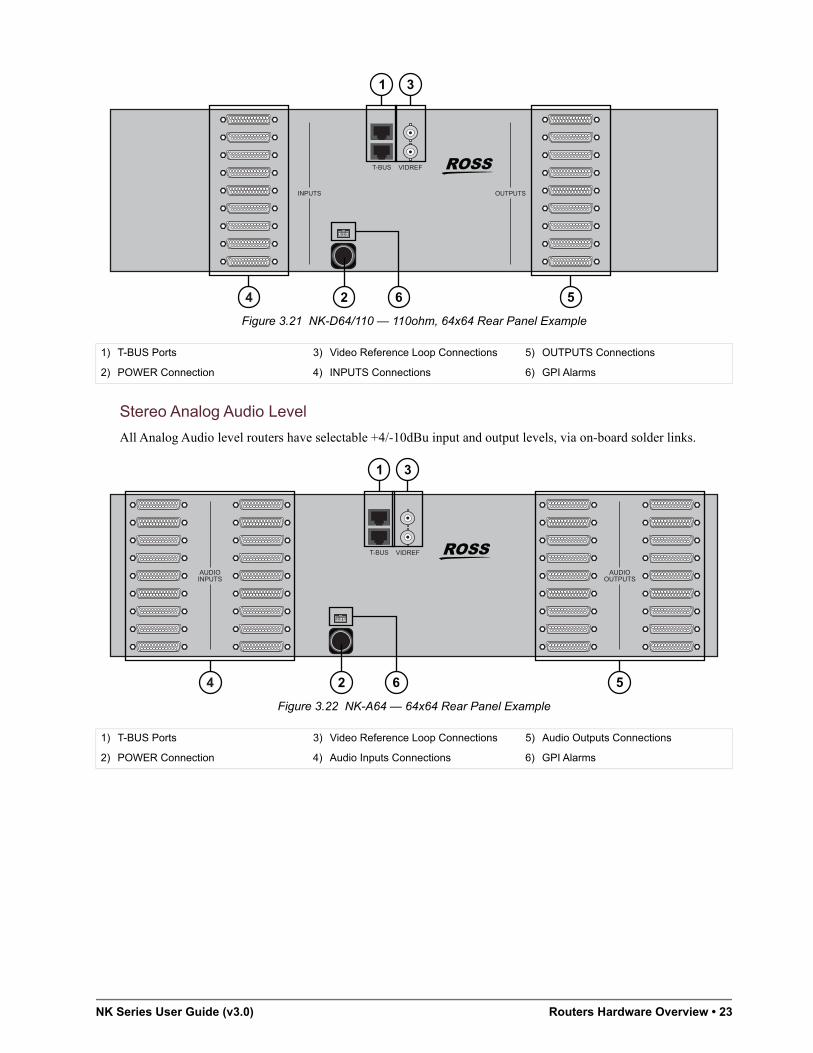
Figure 3.21 NK-D64/110 — 110ohm, 64x64 Rear Panel Example
Stereo Analog Audio Level
All Analog Audio level routers have selectable +4/-10dBu input and output levels, via on-board solder links.
Figure 3.22 NK-A64 — 64x64 Rear Panel Example
1) T-BUS Ports 3) Video Reference Loop Connections 5) OUTPUTS Connections
2) POWER Connection 4) INPUTS Connections 6) GPI Alarms
1) T-BUS Ports 3) Video Reference Loop Connections 5) Audio Outputs Connections
2) POWER Connection 4) Audio Inputs Connections 6) GPI Alarms
VIDREFT-BUS
VIDREFT-BUS

24 • Routers Hardware Overview NK Series User Guide (v3.0)

NK Series User Guide (v3.0) Control Panel Hardware Overview • 25
Control Panel Hardware OverviewThe NK Series offers three highly flexible, yet simple and intuitive remote control panels that can be configured to operate as a menu driven source/destination switching, cut-bus or multi-cut-bus panel. Every control panel in the system can be independently configured to meet the needs of the particular operator position at which it is deployed.
Control of the routers can be done using a variety of methods, including:
• RCP-NK1 — a 40 button remote control panel
• RCP-NKM — a 40 Button and LCD display remote control panel
• RCP-NKQ — 17 LCD button remote control panel
• DashBoard Control System for setup and control
• 10/100 Ethernet Interface
• Virtual routing
• Third-party RS-422 serial control
• RS-232 and GPI/Tally interface
RCP-NK1
The RCP-NK1 is a simple and cost-effective control panel that controls NK Series Routers, switches and protects outputs, and also display router status. It has 40 soft, programmable back-lit buttons, arranged in a 32+8 configuration for convenient function layout. The RCP-NK1 is ideally suited as a menu driven source / destination switching control panel for small routers or as a cut-bus or multi-cutbus control panel for any sized router,
Panel layout is designed with 2 rows of 16 buttons on the left-hand side, and 2 rows of 4 keys on the right-hand side for users who wish to keep function keys separated from their source, destination, and breakaway buttons. The LED brightness can be set through the NK-IPS for both and off states.
Each button can be configured to operate as a source, destination, breakaway, level select or macro function. Additionally protect, take and panel lock functions can be programmed to any button. Using source and destination shift buttons, a single RCP-NK1 can access up to 48 sources or destinations.
Figure 4.1 RCP-NK1 — Front Panel
Connected via the T-Bus Control System, with CAT5 cables, the RCP-NK1 is phantom powered by the router it is connected to. Multiple control panels can be linked together and powered from one router.
Figure 4.2 RCP-NK1 — Rear Panel
Multiple RCP-NK1 panels can be tied together to operate as a single, larger panel. By doing this, the tied RCP-NK1 panels can operate as a larger menu driven source / destination switching panel, or a larger cut bus panel with a single button per source access.
Ross Routing Systems
Dest 1 Dest 2 Dest 3 Dest 4 Dest 5 Dest 6 Dest 7 Dest 8SDI
Level
LevelAudio 1
LevelAudio 2
LevelANLG 1
LevelSDI A1
LevelSDI A2
SRC 1 SRC 2 SRC 3LevelAES 1
LevelAES 2
LevelANLG 2
LevelSDI B1
LevelSDI B2
BWAYSDIRCP-NK1
T-BUS

26 • Control Panel Hardware Overview NK Series User Guide (v3.0)
Features
• Full function programmable control panel
• Configurable as cut-bus, multi-cut-bus or menu driven source / destination switching control panel
• Control up to 8 levels, across 16 breakaways
• Removable key-caps for labeling of button functions using transparent inserts
• Can be mounted on the front of any NK-16 router, providing an integrated 1RU routing and control solution
• Phantom-powered via T-Bus
Applications
Figure 4.3 illustrates one RCP-NK1 panel and one NK-A16-HQ router. In this application, the panel acts as the menu driven source/destination switching controller for a router up to 16x16.
Figure 4.3 Workflow Example — One Panel with One Router
Figure 4.4 illustrates two linked RCP-NK1 panels with one NK-D32-75 router. The two linked panels can be used as menu driven source/destination switching control for a router up to 32x32.
Figure 4.4 Workflow Example — Two Panels with One Router
Figure 4.5 illustrates four RCP-NK1 panels in a system with one NK-3G72 router. The first RCP-NK1 is a satellite panel to control a limited number of sources and destination for any router. The second RCP-NK1 is a macro panel to quickly restored saved configurations or commonly made switches. The two linked panels can be used as a larger cut bus panel.
Figure 4.5 Workflow Example — Four Panels and One Router
RCP-NKM
The RCP-NKM panel controls NK Series Routers, has a variety of assignable functions, and it can also be used for virtual routing. It has 40 programmable back-lit buttons, a 16 character by 2 line back-lit LCD screen, and can control up to 32 router levels. Refer to the RCP-NKM Remote Control Panel User Guide for more information.
NK-A16-HQ Stereo Analog Audio RouterDest 1 Dest 2 Dest 3 Dest 4 Dest 5 Dest 6 Dest 7 Dest 8
SDILevel
LevelAudio 1
LevelAudio 2
LevelANLG 1
LevelSDI A1
LevelSDI A2
SRC 1 SRC 2 SRC 3LevelAES 1
LevelAES 2
LevelANLG 2
LevelSDI B1
LevelSDI B2
BWAYSDI
NK Routing Systems
Dest 1 Dest 2 Dest 3 Dest 4 Dest 5 Dest 6 Dest 7 Dest 8SDI
Level
LevelAudio 1
LevelAudio 2
LevelANLG 1
LevelSDI A1
LevelSDI A2
SRC 1 SRC 2 SRC 3LevelAES 1
LevelAES 2
LevelANLG 2
LevelSDI B1
LevelSDI B2
BWAYSDI
NK Routing Systems
Dest 1 Dest 2 Dest 3 Dest 4 Dest 5 Dest 6 Dest 7 Dest 8SDI
Level
LevelAudio 1
LevelAudio 2
LevelANLG 1
LevelSDI A1
LevelSDI A2
SRC 1 SRC 2 SRC 3LevelAES 1
LevelAES 2
LevelANLG 2
LevelSDI B1
LevelSDI B2
BWAYSDI
NK Routing SystemsNK-D32-75 AES/EBU Audio Router
NK-3G64 3G/HD/SD SDI Router
Dest 1 Dest 2 Dest 3 Dest 4 Dest 5 Dest 6 Dest 7 Dest 8SDI
Level
LevelAudio 1
LevelAudio 2
LevelANLG 1
LevelSDI A1
LevelSDI A2
SRC 1 SRC 2 SRC 3LevelAES 1
LevelAES 2
LevelANLG 2
LevelSDI B1
LevelSDI B2
BWAYSDI
NK Routing Systems
RCP-NK1
Dest 1 Dest 2 Dest 3 Dest 4 Dest 5 Dest 6 Dest 7 Dest 8SDI
Level
LevelAudio 1
LevelAudio 2
LevelANLG 1
LevelSDI A1
LevelSDI A2
SRC 1 SRC 2 SRC 3LevelAES 1
LevelAES 2
LevelANLG 2
LevelSDI B1
LevelSDI B2
BWAYSDI
NK Routing Systems
RCP-NK1
Dest 1 Dest 2 Dest 3 Dest 4 Dest 5 Dest 6 Dest 7 Dest 8SDI
Level
LevelAudio 1
LevelAudio 2
LevelANLG 1
LevelSDI A1
LevelSDI A2
SRC 1 SRC 2 SRC 3LevelAES 1
LevelAES 2
LevelANLG 2
LevelSDI B1
LevelSDI B2
BWAYSDI
NK Routing Systems
RCP-NK1
Dest 1 Dest 2 Dest 3 Dest 4 Dest 5 Dest 6 Dest 7 Dest 8SDI
Level
LevelAudio 1
LevelAudio 2
LevelANLG 1
LevelSDI A1
LevelSDI A2
SRC 1 SRC 2 SRC 3LevelAES 1
LevelAES 2
LevelANLG 2
LevelSDI B1
LevelSDI B2
BWAYSDI
NK Routing Systems
RCP-NK1

NK Series User Guide (v3.0) Control Panel Hardware Overview • 27
Figure 4.6 RCP-NKM — Front Panel
RCP-NKQ
The RCP-NKQ control panel has a variety of assignable functions and it can also be used for virtual routing. It has 17 programmable back-lit buttons, panel linking with other remote control panels, and can control up to 32 router levels. Refer to the RCP-NKQ Remote Control Panel User Guide for more information.
Figure 4.7 RCP-NKQ — Front Panel
Dest 1 Dest 2 Dest 3 Dest 4 Dest 5 Dest 6 Dest 7 Dest 8SDI
Level
LevelAudio 1
LevelAudio 2
LevelANLG 1
LevelSDI A1
LevelSDI A2
SRC 1 SRC 2 SRC 3LevelAES 1
LevelAES 2
LevelANLG 2
LevelSDI B1
LevelSDI B2
BWAYSDI
RCP-NKM
Ross Routing Systems
1 2 3 4SRC: CAMERA 2DST: OUT 1
RCP-NKQ
Ross Routing Systems

28 • Control Panel Hardware Overview NK Series User Guide (v3.0)

NK Series User Guide (v3.0) Interfaces and Connectivity • 29
Interfaces and ConnectivityThis chapter summarizes the interfaces and NK series devices used for communication across a routing system.
Communication Interfaces
The NK Series communicates using the following systems.
T-Bus Control System
NK routers and panels are linked via the T-Bus Control System, a multi-drop RJ-45 control system supporting collision detection and half-duplex communication. The T-Bus Control System minimizes cable connections between devices, acting as both a reliable means to phantom power selected devices and as the communications line.
The T-Bus Control System’s collision detection support ensures that if two devices transmit messages at the same time they will not send incorrect data to other devices on the line. All components that utilize the T-Bus Control System are able to monitor communication on the line to ensure that no two devices are transmitting at the same time.
The Heartbeat
NK Series routers indicate their status by a pulsating LED, called a heartbeat. The heartbeat flickers when a switch message is handled by the router. It dims slightly to indicate a handled message that did not result in a switch.
The heartbeat is also connected to the alarm status. It monitors the status of the power supply and signifies a problem by pulsating at a noticeably faster rate.
DashBoard Overview
The DashBoard client software allows configuration and monitoring of some NK Series devices, and provides access to other devices in your routing system. DashBoard communicates with devices in your routing system through the NK-IPS.
DashBoard must be run on a computer that has a physical wired ethernet connection. Wireless connections do not allow device discovery.
For More Information on...
• downloading and installing the DashBoard client software, refer to the DashBoard User Guide.
Walkabout Overview
The Walkabout configuration software is used to configure the basic network communication settings for the NK-NET
For More Information on...
• downloading and installing the DashBoard client software, refer to the DashBoard User Guide.
NK Series Communication Devices
The following NK Communications devices are available.
NK-VRC
The NK Virtual Routing Core (NK-VRC) provides virtual routing for complex NK Series routing switcher systems.

30 • Interfaces and Connectivity NK Series User Guide (v3.0)
The NK-VRC, accessible using the DashBoard Control System via the NK-IPS, enables users to map inputs and outputs from routing switchers through to the NK-VRC for control via any remote control panel. These parameters can be saved in a configuration document and sent to an NK-VRC at any time using DashBoard. Therefore, if an NK-VRC is used in a number of different operating scenarios, the configuration can be changed easily and quickly.
Refer to the NK-VRC Virtual Routing Core User Guide for all configuration and functionality details for the NK-VRC.
NK-IPS
The NK-IPS (Internet Protocol Server) is the device used for configuration of NK Series devices including routers, control panels and control interface devices. Connection of the NK-IPS to either a single computer or a network allows configuration of the NK routers and panels using DashBoard or a web browser, further enhancing the capability of any installation of NK Series products by providing access to the entire range of functions. The NK-IPS also enables users to configure T-Bus enabled Ross Video devices.
Figure 5.1 Example of the NK-IPS Connection
The NK-IPS is also required for use of the NK Hub, for information and usage of this software component, refer to the NK-IPS Internet Protocol Server User Guide.
The NK-IPS does not require Internet access for operation, only DashBoard or an Internet browser is required for operation and configuration. For further information, refer to the NK-IPS Internet Protocol Server User Guide.
NK-HUB
The NK-HUB, accessible only through the NK-IPS, is a software component used to connect two or more NK-IPS devices, enabling NK Series protocol and switch communication between NK Series components connected to each NK-IPS. Internet Protocol Servers can be locally or remotely connected allowing NK Series components to respond to status requests, switch requests and protect requests.
A local connection enables two NK-IPS devices within the same network to communicate with NK Series components connected to each. A remote connection, via an Internet connection or Virtual Private Network (VPN), allows two or more Internet Protocol Servers to communicate over longer distances.
The NK-HUB is built with Java® technology, enabling flexibility and cross-platform control. Users are advised to have installed the latest version of the Java Runtime Environment (JRE) before using the NK Hub. For further information on the NK-HUB and the Java Runtime Environment, refer to the NK-IPS Internet Protocol Server User Guide.
Note that as NK-HUB connection and usage requires the NK-IPS, all configuration and functionality details are outlined in the NK-IPS Internet Protocol Server User Guide.
NK-IPS Network Bridge
ETHERNET
LINK ACT1 2 3 4 5 6 7 8
T-BUS
RESET
NK-3G16 SDI Router
NK-D32-75 AES/EBU Audio Router
Dest 1 Dest 2 Dest 3 Dest 4 Dest 5 Dest 6 Dest 7 Dest 8SDI
Level
LevelAudio 1
LevelAudio 2
LevelANLG 1
LevelSDI A1
LevelSDI A2
SRC 1 SRC 2 SRC 3LevelAES 1
LevelAES 2
LevelANLG 2
LevelSDI B1
LevelSDI B2
BWAYSDI
NK Routing Systems
Dest 1 Dest 2 Dest 3 Dest 4 Dest 5 Dest 6 Dest 7 Dest 8SDI
Level
LevelAudio 1
LevelAudio 2
LevelANLG 1
LevelSDI A1
LevelSDI A2
SRC 1 SRC 2 SRC 3LevelAES 1
LevelAES 2
LevelANLG 2
LevelSDI B1
LevelSDI B2
BWAYSDI
NK Routing Systems
PC running DashBoard
Internet / LAN / VPN

NK Series User Guide (v3.0) Interfaces and Connectivity • 31
NK-3RD
The NK-3RD Third-Party Interface enables a third-party control system to control an NK Series routing switcher system using the SW-P-08 protocol. The NK-3RD works with any NK Series router and supports crosspoint switch commands and crosspoint status requests. Up to 1024 inputs and 1024 outputs can be controlled and it supports up to 16 levels.
Refer to the NK-3RD Third-Party Control Interface User Guide for more information.
NK-SCP Series
The NK-SCP Serial Control Port allows an NK Series routers to be controlled via the Kondor 2 or an external RS-232 device. It is available in RS-232 (NK-SCP/A) and RS-485 (NK-SCP/K2) models. Configuration of either the NK-SCP/A or the NK-SCP/K2, as well as router configuration and partitioning, requires the NK-IPS.
NK-SCP/A – RS-232 Control
The NK-SCP/A model allows an RS-232 device, such as an automation system or computer terminal, to control NK routers using the Ross Video EOS ASCII protocol. Any combination of NK routers can be controlled with a maximum size of 255 inputs and 255 outputs with up to 8 levels. The bidirectional protocol incorporates both crosspoint status monitoring and crosspoint switching. Crosspoint switching can be performed using individual levels or through user-defined breakaway mapping.
NK-SCP/K2 – RS-485 Control
The NK-SCP/K2 allows Kondor 2 routers to be extended by utilizing NK routers as additional levels. Any combination of NK routers can be added to a Kondor 2 system with a maximum size of 255 inputs and 255 outputs with up to 8 levels. Kondor 2 router inputs, outputs and levels are directly mapped to NK Series router inputs, outputs and levels, requiring no user mapping.
NK-GPI
The NK-GPI is a universal GPI interface for the NK family of routers. Providing both GPI inputs and outputs, the NK-GPI allows flexible GPI control, configured from the NK-IPS Device Properties pages. The NK-GPI also supports both GPI input return and latch modes.
Figure 5.2 Example of the NK-GPI Connection
NK-GPI configuration, via the NK-IPS and a PC connected to a network, allows users to customize GPI inputs and outputs, as well as the input mode (Latch or Return), and a Panel Link Address, configuring the NK-GPI to be controlled from a connected NK Control Panel.
NK-GPI Interface
16 GPI Inputs
16 GPI Outputs
GPI Tallies
CCUs 1-16
.....1 18
NK-GPI
NK-IPS Network Bridge
ETHERNET
LINK ACT1 2 3 4 5 6 7 8
T-BUS
RESET
NK-IPSInternet Protocol Server
Dest 1 Dest 2 Dest 3 Dest 4 Dest 5 Dest 6 Dest 7 Dest 8SDI
Level
LevelAudio 1
LevelAudio 2
LevelANLG 1
LevelSDI A1
LevelSDI A2
SRC 1 SRC 2 SRC 3LevelAES 1
LevelAES 2
LevelANLG 2
LevelSDI B1
LevelSDI B2
BWAYSDI
NK Routing Systems
NK SeriesRemote Control Panel
NK-3G16 SDI Router
NK SeriesRouter Level

32 • Interfaces and Connectivity NK Series User Guide (v3.0)

NK Series User Guide (v3.0) Physical Installation • 33
Physical InstallationIf you have questions pertaining to the installation of NK Series, contact us at the numbers listed in the section “Contacting Technical Support”. Our technical staff is always available for consultation, training, or service.
Before You Begin
These installation guidelines assume the following:
• The relevant Ross equipment is installed into a ventilated rack frame. The relative humidity in the environment of the equipment should be <70% (non-condensing). The ambient temperature of the air entering the front panel should not exceed 30°C (86°F), and should not fall below 0°C (32°F). It is recommended to leave a 1RU gap between each module.
• Ensure that adequate space exists in front and behind the NK Series chassis and on both sides of the chassis for airflow.
• The install location of the router should be accessible, dry, and dust-free.
• The power socket/outlet shall be installed near the equipment and shall be easily accessible.
• The routing system is well planned and designed. Consideration must be given to inputs and outputs across multiple router levels and typical operating scenarios for breakaways.
• A valid IP address is reserved for each device in the routing system.
• A computer for the DashBoard client software is available on the same network as your routing system.
Static Discharge
Throughout this chapter, please heed the following cautionary note:
Unpacking and Pre-installation
After unpacking NK components, inspect all NK Series components for any signs of damage that may have occurred during transportation. In the event of such damage, notify a Ross Video representative immediately.
NK Series components should be installed in an adequately ventilated rack frame, ideally in an appropriate environment for audio visual equipment. Relative humidity should be no more than 70% (non-condensing) and temperatures should not exceed 30°C or 86°F.
If the above conditions are not attainable for operation, it is advised that NK Series routers be installed with 1RU space between them before use.
Connecting NK Components Overview
NK Series components are connected via the T-Bus multi-drop control system by a single CAT5 Ethernet cable.
Linking the Components
Routers are supplied with their own power supply, the NK1 panels are phantom powered by the routers they are connected to via the CAT5 cable. Each control panel has two RJ-45 ports for phantom power and communications. When connecting devices, either port may be used to connect panels or routers to each other.
ESD Susceptibility — Static discharge can cause serious damage to sensitive semiconductor devices. Avoid handling circuit boards in high static environments such as carpeted areas and when synthetic fiber clothing is worn. Always exercise proper grounding precautions when working on circuit boards and related equipment.

34 • Physical Installation NK Series User Guide (v3.0)
Figure 6.1 Single Panel Connection Example
Panels can be linked together to expand the number of available buttons. Panels are linked if they have the same address and a different device link address that is not 0 (zero). Linked panels behave exactly as if they were one larger panel except that macros can not be appended or added across panels.
The NK-IPS is required to configure linked panels and also for changing individual component addresses.
Figure 6.2 Linked Panel Connection Example
RCP-NK1Remote Control Panel
T-BUS
COM2
NK-3G-1616x16 3G/HD/SD SDI Router
T-BUS VID REF
1 3 5 7 9 11 13 15
2 4 6 8 10 12 14 16INPUTS
1 3 5 7 9 11 13 15
2 4 6 8 10 12 14 16OUTPUTS
T-BUS Address: 21
14 16
T-BUS Address: 13
NK-3G6464X64 3G/HD/SD SDI Router
VIDREFT-BUS
COM2
NK-3G-1616x16 3G/HD/SD SDI Router
T-BUS VID REF
1 3 5 7 9 11 13 15
2 4 6 8 10 12 14 16INPUTS
1 3 5 7 9 11 13 15
2 4 6 8 10 12 14 16OUTPUTS
RCP-NK1Remote Control Panel
T-BUS
RCP-NK1Remote Control Panel
T-BUS
NK-IPSNetwork Bridge
ETHERNET
POWER ServicePortT-BUS
CP-NKNKKK1111l P l
T-BUS Address: 21Panel Link Address: 3
NK-K-K--IPSIPSIPSIPSk Bridge
T-BUS Address: 21Panel Link Address: 4
K-3G3GG-G-16161616Routeutett rr
T-BUS Address: 14
K-3G63G6G6G64444Router
16
T-BUS Address: 13
T-BUS Address: 15

NK Series User Guide (v3.0) Physical Installation • 35
Power
A maximum of four RCP-NK1 control panels may be connected (daisy-chain) to an individual router at any one time; and a maximum of seven RCP-NK1 control panels to one NK-IPS. Adding other power sources to the same system will contribute further power to the T-Bus connection if required.
Figure 6.3 Daisy-Chain Connection Example
Power may also be distributed evenly throughout an NK system by way of direct connections between phantom powered connections (control panels, NK-SCP and NK-GPI) from a common power source (NK Series routers or the NK-IPS), or by daisy chaining components. Daisy chaining components allows several phantom powered components to be connected to the one router.
Figure 6.4 T-Bus Distributed Power Example
Each NK router, control panel and control device comes standard with a single external AC/DC power supply. The exceptions to this are devices that are powered from the T-Bus, such as the RCP-NK1, NK-SCP/A and NK-GPI.
Redundant external power supplies are available. Contact Ross Video for details. Optionally, a 100W rack mount redundant power supply, is available to power up to 4 devices. Refer to the NK-RP1/P User Guide for additional information.
RCP-NK1Remote Control Panel
T-BUS
RCP-NK1Remote Control Panel
T-BUS
RCP-NK1Remote Control Panel
T-BUS
RCP-NK1Remote Control Panel
T-BUS
COM2
NK-3G-1616x16 3G/HD/SD SDI Router
T-BUS VID REF
1 3 5 7 9 11 13 15
2 4 6 8 10 12 14 16INPUTS
1 3 5 7 9 11 13 15
2 4 6 8 10 12 14 16OUTPUTS
NK-IPSNetwork Bridge
ETHERNET
POWER ServicePortT-BUS
RCP-NK1Remote Control Panel
T-BUS
RCP-NK1Remote Control Panel
T-BUS
RCP-NK1Remote Control Panel
T-BUS
RCP-NK1Remote Control Panel
T-BUS
COM2
NK-3G-1616x16 3G/HD/SD SDI Router
T-BUS VID REF
1 3 5 7 9 11 13 15
2 4 6 8 10 12 14 16INPUTS
1 3 5 7 9 11 13 15
2 4 6 8 10 12 14 16OUTPUTS
COM2
NK-3G-1616x16 3G/HD/SD SDI Router
T-BUS VID REF
1 3 5 7 9 11 13 15
2 4 6 8 10 12 14 16INPUTS
1 3 5 7 9 11 13 15
2 4 6 8 10 12 14 16OUTPUTS
COM2
NK-3G-1616x16 3G/HD/SD SDI Router
T-BUS VID REF
1 3 5 7 9 11 13 15
2 4 6 8 10 12 14 16INPUTS
1 3 5 7 9 11 13 15
2 4 6 8 10 12 14 16OUTPUTS
COM2
NK-3G-1616x16 3G/HD/SD SDI Router
T-BUS VID REF
1 3 5 7 9 11 13 15
2 4 6 8 10 12 14 16INPUTS
1 3 5 7 9 11 13 15
2 4 6 8 10 12 14 16OUTPUTS

36 • Physical Installation NK Series User Guide (v3.0)
Video Referencing
All NK Video and Audio routers are fitted with a video switching reference input to ensure that switching occurs in the vertical interval across all levels. Normally, the reference input signal is a color black (Black burst) composite signal, however it may be any normal composite signal. The NK router will automatically detect the signal as being either 625/50 (PAL) or 525/60 (NTSC) and automatically adjust the switching pulse to comply with RP 168, line 6 for PAL and line 10 for NTSC.
The NK router switches on frame boundaries. There are two 75ohm BNC reference input BNCs on each NK router arranged as a passive loop-through pair. Normally, a single Black Burst signal is looped through each of the routers which are located together and a 75ohm terminator is connected to the last BNC socket. An individual Black Burst signal should be wired to routers which are more than a few meters apart.
If the reference signal is absent, the NK router will generate a free-running switching pulse over 40ms. The status of the switching reference may be monitored on the router’s Device Properties page via the NK-IPS, one of three conditions may be reported via the NK-IPS: Local, PAL reference present or NTSC reference present.
When using a video reference with any of the NK router components, users must remember to terminate the last video reference that is not looped with a 75ohm BNC terminator.
When only video referencing one router, the other BNC connector of the video reference loop needs to be terminated, as in Figure 6.5.
Figure 6.5 Referencing a Single Router
When referencing a more than one router, the last reference connector needs to be terminated, as in Figure 6.6.
Figure 6.6 Referencing Multiple Routers
COM2
NK-3G-1616x16 3G/HD/SD SDI Router
T-BUS VID REF
1 3 5 7 9 11 13 15
2 4 6 8 10 12 14 16INPUTS
1 3 5 7 9 11 13 15
2 4 6 8 10 12 14 16OUTPUTS
Terminated End (BNC 75ohm terminator)
To Video Reference
NK-V32-HQ32x32 Analog Video Router
T-BUS
VID REF
1 2 3 4 5 6 7 8
9 10 11 12 13 14 15 16
17 18 19 20 21 22 23 24
25 26 27 28 29 30 31 32
VIDEO INPUTS
1 2 3 4 5 6 7 8
9 10 11 12 13 14 15 16
17 18 19 20 21 22 23 24
25 26 27 28 29 30 31 32
VIDEO OUTPUTS
COM2
NK-3G-1616x16 3G/HD/SD SDI Router
T-BUS VID REF
1 3 5 7 9 11 13 15
2 4 6 8 10 12 14 16INPUTS
1 3 5 7 9 11 13 15
2 4 6 8 10 12 14 16OUTPUTS
To Video Reference
Terminated End (BNC 75ohm terminator)
NK-A16-HQ16x16 Stereo Analog Audio Router
T-BUS
T-BUS
VID REF LEFTINPUTS
LEFTOUTPUTS
RIGHTINPUTS
RIGHTOUTPUTS
POWER

NK Series User Guide (v3.0) Physical Installation • 37
Connecting the NK-SCP/A
The NK-SCP/A is connected to a computer or RS-232 device with a straight through RS-232 cable.
The NK-SCP is phantom powered by the T-Bus, allowing the heartbeat to show communication activity when messages and switches are operated from the RS-232 device.
Figure 6.7 NK-SCP/A Connection Example
Connecting the NK-SCP/K2
The NK-SCP/K2 is connected to the Geneos CPU with the parallel to serial converter cable supplied (Part number 9801 2001). If the NK-SCP/K2 and NK routers have been purchased as an addition to a preexisting Kondor 2 and Geneos CPU system, this cable would have been supplied with the initial Kondor 2 / Geneos shipment.
The NK-SCP is phantom powered by the T-Bus, allowing the heartbeat to show communication activity when messages are sent from the Geneos CPU.
Figure 6.8 NK-SCP/K2 Connection Example
Parallel to Serial Converter
The Parallel to Serial converter is housed inside the DB-37 connector shell which plugs into the Parallel Output Control connector located at the bottom left side at the rear of the Geneos CPU frame. Power to the converter is supplied via the DB-25 connector (wired to the DB-37). The DB-25 connector plugs into the AUX connector located at the bottom left side at the rear of CPU frame. The Serial output from the converter is available from the
NK-SCP/A RS-232 Interface
RS-232 DeviceComputer or
Automation System
NK-SCP/AT-Bus to RS-232
NK-IPS Network Bridge
ETHERNET
LINK ACT1 2 3 4 5 6 7 8
T-BUS
RESET
NK-IPSInternet Protocol Server
Dest 1 Dest 2 Dest 3 Dest 4 Dest 5 Dest 6 Dest 7 Dest 8SDI
Level
LevelAudio 1
LevelAudio 2
LevelANLG 1
LevelSDI A1
LevelSDI A2
SRC 1 SRC 2 SRC 3LevelAES 1
LevelAES 2
LevelANLG 2
LevelSDI B1
LevelSDI B2
BWAYSDI
NK Routing Systems
NK SeriesRemote Control Panel
NK-3G16 SDI Router
NK SeriesRouter Level
Bi-directional Communications
SerialT-BUS
NK Routing Systems
NK-SCP/K2 RS-485 Interface
NK Routing Systems
NK-SCP/K2Serial Matrix Control
Bi-directional Communications
Dest 1 Dest 2 Dest 3 Dest 4 Dest 5 Dest 6 Dest 7 Dest 8SDI
Level
LevelAudio 1
LevelAudio 2
LevelANLG 1
LevelSDI A1
LevelSDI A2
SRC 1 SRC 2 SRC 3LevelAES 1
LevelAES 2
LevelANLG 2
LevelSDI B1
LevelSDI B2
BWAYSDI
NK Routing Systems
NK SeriesRemote Control Panel
NK-IPSInternet Protocol Server
NK-IPS Network Bridge
ETHERNET
LINK ACT1 2 3 4 5 6 7 8
T-BUS
RESET
NK-3G16 SDI Router
NK SeriesRouter Level
SerialT-BUS
Kondor/Geneos System
GeneosRoutingControl

38 • Physical Installation NK Series User Guide (v3.0)
DB-9 plug (wired to the DB-37), this DB-9 plugs into the top RS-485 DB-9 on the Rear left of the Kondor 2 frame. The PC communications cable is wired to the DB-25, the PC end has both a DB-25 and a DB-9 for connection to an RS-232 communications connector on a PC running Geneos.
Figure 6.9 Parallel to Serial Converter Example
To connect the NK-SCP/K2 to the Geneos CPU
1. Connect the DB-37 connector of the Parallel to Serial Converter to the Router Control Port on the rear of the Geneos CPU.
2. Connect to DB-25 connector of the Parallel to Serial Converter to the Auxiliary Port on the rear of the Geneos CPU.
3. Connect the single DB-9 connector of the Parallel to Serial Converter to the DB-9 connector of the NK-SCP/K2. Alternatively, this connector can be connected to the Kondor 2 frame itself, and the NK-SCP/K2 connected to the frame via a serial cable.
4. Connect either the linked DB-25 or the DB-9 to a PC for Geneos software configuration and control.
The NK-SCP/K2 can be connected to the Geneos CPU at any time, but to ensure status updates are completed, it is recommended that it be connected after configuration details have been entered on both the Device Properties page via the NK-IPS, and the Geneos Software.
To connect the NK-SCP/K2 or NK-SCP/A to the T-Bus Control System
1. Connect one end of a straight through CAT5 cable to the RJ-45 connector on the SCP.
2. Connect the other end of the CAT5 cable to any available T-Bus port on the NK-IPS, or any other T-Bus compatible device connected to the NK-IPS.
Connecting the NK-GPI
The NK-GPI connects to the T-Bus control system using the RJ-45 connectors on the box edge. The loop through connector allows the NK-GPI to reside at any point on the control bus. The NK-GPI connects to general purpose interface inputs and outputs via a DB-37 port.
DB-37 MaleParallel to Serial Converterto the Router Control Port on CPU
DB-9 MaleRS-485 Serial Controlto the Kondor 2
Power Cablefor Parallel to Serial Converter
DB-25 & DB-9 Femaleto the PC Communications Port
DB-25to AUX connector on CPU(Power & PC Communications)

NK Series User Guide (v3.0) Physical Installation • 39
Pinouts
Figure 6.10 NK-GPI Pinouts
Connecting GPI Inputs
Figure 6.11 GPI Input Connection
Connecting GPI Outputs
Figure 6.12 uses a LED to indicate status. The LED can be replaced with another indicator, load or a GPI input from another device.
123456789
10111213141516171819
202122232425262728293031323334353637
OUT 1OUT 2OUT 4OUT 6OUT 8OUT 10OUT 12OUT 14OUT 16
IN 1IN 3IN 5IN 7IN 9IN 11IN 13IN 15
OUT 3OUT 5OUT 7OUT 9OUT 11OUT 13OUT 15
IN 2IN 4IN 6IN 8IN 10IN 12IN 14IN 16
+5v
GND
GND
To Input Pin
Pin 19 or Pin 29
Contact Closure /

40 • Physical Installation NK Series User Guide (v3.0)
Figure 6.12 GPI Output Connection
Customizing RCP-NK1 Control Panels
One of the flexible features of the NK Series of routers and panels is the ability to install RCP-NK1 control panels either locally or remotely to NK-16 routers. Localizing panels ensures that rack space is maximized and cable connections are minimized. Remotely installing panels means that panels do not necessarily have to be installed in the immediate vicinity of the routers, and can be connected and installed in other rooms if required.
Localizing the Panel
If users are localizing control panels, a short (between 12.5cm and 20cm or 5” and 8”) standard (not crossover) CAT5 cable is required to connect the panel to the router internally.
Ensure that the router and the panel you wish to localize are not connected to any other devices before proceeding. Also ensure that both the router and the control panel are disconnected from the power source.
To fit the control panel locally to the front of the router
1. Remove the front button panel from the case it was originally shipped in.
Figure 6.13 Removing the RCP-NK1 from the Shipping Case
Caution — When connecting GPI outputs to the NK-GPI, users must remember there is a 10mA current limit on each output, and a resistor must be connected to the GPI output to maintain peak operation. Figure 6.12 depicts how to wire outputs correctly.
10mA current limit on outputs
To Output Pin
+5vPin 1 or Pin 28
470R
LED
IP: ###.###.##.###
Ross Routing SystemsRCP-NK1

NK Series User Guide (v3.0) Physical Installation • 41
2. Remove the front panel of the router.
Figure 6.14 Removing the Front Panel from the Router
3. Disconnect the wire that connects the heartbeat to the circuit board.
Figure 6.15 Disconnecting the Heartbeat
4. Set the router front panel aside.
5. Connect one end of the CAT5 cable to either of the control panel’s RJ-45 ports.
6. Connect the other end of the CAT5 cable to the internal RJ-45 of the router.
Figure 6.16 Connecting the CAT5 Cable to an RJ-45 Port
IP: ###.###.##.###
Ross Routing SystemsNK-3G16
3G/HD/SD SDI Router
IP: ###.###.##.###
Ross Routing Systems
NK-3G16 3G/HD/SD SDI Router
Wire connecting Heartbeatto the Circuit Board
NK-3G163G/HD/SD SDI Router
RCP-NK1Remote Control Panel
T-BUS
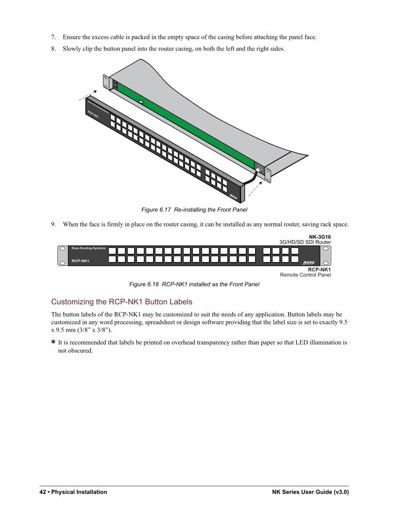
42 • Physical Installation NK Series User Guide (v3.0)
7. Ensure the excess cable is packed in the empty space of the casing before attaching the panel face.
8. Slowly clip the button panel into the router casing, on both the left and the right sides.
Figure 6.17 Re-installing the Front Panel
9. When the face is firmly in place on the router casing, it can be installed as any normal router, saving rack space.
Figure 6.18 RCP-NK1 installed as the Front Panel
Customizing the RCP-NK1 Button Labels
The button labels of the RCP-NK1 may be customized to suit the needs of any application. Button labels may be customized in any word processing, spreadsheet or design software providing that the label size is set to exactly 9.5 x 9.5 mm (3/8” x 3/8”).
It is recommended that labels be printed on overhead transparency rather than paper so that LED illumination is not obscured.
IP: ###.###.##.###
Ross Routing Systems
Ross Routing SystemsRCP-NK1
NK-3G163G/HD/SD SDI Router
RCP-NK1Remote Control Panel
Ross Routing Systems
RCP-NK1

NK Series User Guide (v3.0) Default Configurations • 43
Default ConfigurationsWhen NK Series components are shipped, the default configuration is set to allow both NK routers and control panels to be used straight out of the box.
RCP-NK1 Control Panel Default Key Assignment
The RCP-NK1 control panel is factory configured with the key assignments as depicted in Figure 7.1.
Figure 7.1 RCP-NK1 Control Panel Default Configuration
Further configuration and key panel settings, as well as router configuration, can be accessed using the NK-IPS and Phoenix or a web browser.
When purchasing a complete NK system, the RCP-NK1 will be custom programed so that it can be used straight out of the box without further configuration via the NK-IPS. Further documentation depicting key panel layout will be provided with systems that do not adhere to the factory default.
The key functions listed in Table 7.1 are assigned to buttons in the factory default configuration of the RCP-NK1.
Ross Routing Systems
RCP-NK1
INPUTS
OUTPUTS
SRC ShiftBreakaway 1
Level 2 (SDI)Level 5 (AN. VID.)
Level 7 (AN. AUD. Le.)Level 6 (AN. AUD. Ri.)
Macro 1DEST Shift
Ross Routing Systems
RCP-NK1
Shift keys lit to indicate that SHIFT Mode is on

44 • Default Configurations NK Series User Guide (v3.0)
Keys that are not available on the factory default configuration of the RCP-NK1, but may be assigned and configured via the NK-IPS, are listed in Table 7.2.
Table 7.1 Default Key Functions
Key Name Description
DESTINATION Changes the destination the panel is controlling.
The bottom, left hand row of 16 keys selects destinations 1-16 on the default page/set.
When the DESTINATION SHIFT key has been pressed, the second page of destinations (17-32) is accessible.
SOURCE Switches using the current destination and level pattern.
The top left hand row of 16 keys selects the sources 1-16 on the default page/set.
When the SOURCE SHIFT key has been pressed, the second page of sources (17-32) is accessible.
DESTINATION SHIFT Changes the destination page of the panel
SOURCE SHIFT Changes the source page of the panel
LEVEL Toggles the specified level number from the current level pattern.
Four Level keys are available on the factory default configuration: Level 2 - SDI Video Level 5 - Analog Video Level 6 - Analog Audio (Left channel) Level 7 - Analog Audio (Right channel)
MACRO Records key press events that can be replayed later.
BREAKAWAY Selects a pre-configured breakaway level pattern.
Table 7.2 Assignable Key Functions
Key Name Description
CROSSPOINT Switches the input, output and level/breakaway associated with this key.
BREAKAWAY STEP Steps through breakaways.
PROTECT Protects the currently selected output/level pair. The PROTECT key also activates the panel lock function.
TAKE Confirms input key events. After a switch is set up, press the TAKE key to activates the switch.
CHOP Alternates between the last two selected inputs.
DEASSIGN Allows users to reset a destination assignment.
MACHINE CONTROL KEY Toggles on/off RS-422 Machine Control reciprocal switching.
PANEL LOCK Activates the panel lock function, for environments where a PROTECT KEY is not required.
UNASSIGNED Key is not assigned any function or value.

NK Series User Guide (v3.0) Default Configurations • 45
NK Series Router Levels Default
The factory default configuration breakaway and levels for the NK routers is as depicted in Table 7.3.
RCP-NKM/Q Control Panel Default Key Assignments
The RCP-NKM and RCP-NKQ default configuration is viewed by opening the editor for the device in the Phoenix Control Surface.
For More Information on...
• RCP-NKM default configuration, refer to the RCP-NKM Remote Control Panel User Guide.
• the RCP-NKQ default configuration, refer to the RCP-NKQ Remote Control Panel User Guide.
RCP-NKM Defaults
By default, the 20 keys in the top row on the RCP-NKM are assigned as sources and the 20 keys in the bottom row are assigned as destinations. (Figure 7.2)
Figure 7.2 RCP-NKM Control Panel Default Configuration
RCP-NKQ Defaults
By default, the RCP-NKQ has the key assignments seen in Figure 7.3.
Figure 7.3 RCP-NKQ Control Panel Default Configuration
Breakaways Default
The default breakaway is tied, that is, the first eight router levels are switched together when requested from the RCP-NKM or RCP-NKQ.
Table 7.3 Configuration Breakaway and Levels for the NK Routers
3G/HD/SD Video SD Video
AES/EBUAudio (1)
AES/EBUAudio (2)
AnalogVideo
AnalogAudio (Left)
AnalogAudio (Right)
MachineControl
Default
Level 1
Level 2
Level 3
Level 4
Level 5
Level 6
Level 7
Level 8
RCP-NKM
Ross Routing Systems
1 2 3 4
RCP-NKQ
Ross Routing Systems

46 • Default Configurations NK Series User Guide (v3.0)
Router Levels Default
The RCP-NKM and RCP-NKQ send switch requests to the routing switcher. Each routing switcher is assigned a level, or number of levels if it has been partitioned.
Table 7.4 RCP-NKM/Q Default Router Levels
Router Level Name
1 Multi-definition video
2 Serial digital interface video
3 AES/EBU digital audio 1
4 AES/EBU digital audio 2
5 Analog video
6 Analog audio (left)
7 Analog audio (right)
8 Machine control

NK Series User Guide (v3.0) Configuring a Panel • 47
Configuring a PanelThe RCP-NK1 40 button panel controls NK Series routers, displaying router status, switching and protecting crosspoints. It has 40 soft, programmable back-lit keys, with 8 being physically separate for convenient function key layout. The LED brightness can be set through the NK-IPS for both on and off brightness.
Each panel is capable of controlling the whole address space for the NK system (1-65535 inputs and outputs on 32 levels). Panels operate in XY mode by default, but can easily be configured to work in dual cutbus mode using the NK-IPS.
The Device Properties page, accessible through the NK-IPS, allows users to configure interface and key assignments for RCP-NK1 control panels, as well as having the unique ability to assign names and brief descriptions for the devices themselves.
For More Information on...
• how to query devices, and use of the NK-IPS, refer to the NK-IPS Internet Protocol Server User Guide.
Configuring Breakaways
Users can customize their breakaways to include any levels desired. Levels can be utilized in as many breakaways as is needed.
Checking the boxes representing levels 1-8 next to the breakaways (1-16) will include that level in that breakaway, when the BREAKAWAY or BREAKAWAY STEP keys are pressed.
Different breakaways can be defined for each panel. This is configured in each panel’s Device Properties page via the NK-IPS.
Breakaway Reset
When enabled the Breakaway Reset option resets to the first breakaway (Default Breakaway) after a crosspoint switch. By default, the Breakaway Reset is off (check box is cleared).
Breakaway Warning Mode
The Breakaway Warning Mode determines which breakaway the current switch status is compared with to check if a Breakaway Warning condition has occurred. Two modes are available, Current (Current Breakaway) and Default (First Breakaway).
Assigning Functions to Keys
Use the Key Definitions table to assign functions to the buttons of the RCP-NK1. Any function can be assigned to any key. The keys are represented in the first column by their respective number (1-40). Keys 1-20 represent the first row of keys on the RCP-NK1 and keys 21-40 represent the second row of keys on the panel.
The desired key function is selected from the drop down box in the second column (Function column). Any function can be assigned to any key on the panel and keys can be assigned multiple times.
Details of parameters used in the Key Definition table are explained in detail in Table 8.1.
The Shift1 and Shift2 values only apply to SOURCE, DESTINATION and CROSSPOINT keys, all other keys only require the Default value to be defined, and some keys require no user defined values for operation. All Shift1 and Shift2 values are ignored when not assigned to SOURCE, DESTINATION or CROSSPOINT keys.
Each key can be assigned a function, with up to 3 parameters (Default, Shift1 and Shift2). This function will be called when that switch is pressed. The available key functions are listed in Table 8.1.

48 • Configuring a Panel NK Series User Guide (v3.0)
Configuring the Cut Bus Destinations
There are two cut bus destination rows on the panel:
• Cutbus Destination 1 — The top row of keys when no DESTINATION or CROSSPOINT keys have been assigned. The valid range for the Cutbus Destination 1 is 1-255.
• Cutbus Destination 2 — The bottom row of keys when no DESTINATION or CROSSPOINT keys have been assigned. The valid range for the Cutbus Destination 2 is 1-255.
Setting the Brightness for the ON State
The On Brightness menu sets the LED brightness for the RCP-NK1 control panel buttons when the button is ‘on’; that is when it has been pressed, is already active, or when indicating an error by several quick flashes. The default value is 200. The valid input value range is 1-250.
The On Brightness does not necessarily have to be a higher value than that of the Off Brightness, although it is generally advised to avoid confusion.
Table 8.1 Available Key Functions
Key Name Description
DESTINATION Changes the destination that the panel is controlling. If the DESTINATION KEY is not active, the default value is selected. When the DESTINATION KEY has been selected first, the relative destination is selected.
SOURCE Switches the input using the current destination and level pattern. If the SOURCE KEY is not active, the default value is switched. When the SOURCE KEY has been selected first, the relative source is switched.
CROSSPOINT Switches the input, output and level/breakaway associated with this key.
LEVEL Toggles this level number from the current level pattern.
BREAKAWAY Selects a pre-configured breakaway level pattern.
BREAKAWAY STEP Steps through breakaways.
MACRO Records key events that can be replayed later.
PROTECT The PROTECT key attempts to protect the currently selected output/level pair.
TAKE The TAKE key confirms input key events. The user sets up a switch, and presses the TAKE key to activate the switch.
CHOP Alternates between the last two selected inputs.
SHIFT Changes the source or destination page of the panel.
DESASSIGN Allows users to reset a destination assignment.
MACHINE CONTROL Toggles on/off RS-422 Machine Control for reciprocal switching.
PANEL LOCK Locks the panel from all switches or function key operation.
UNASSIGNED Key is not assigned any function or value.

NK Series User Guide (v3.0) Configuring a Panel • 49
Table 8.2 Configuration Values
Key Default Value Shift Value Shift2 Value Value Range
Dest (Output) # (DESTINATION SHIFT 1)Output #
(DESTINATION SHIFT 2)Output #
Output = 1-65535
The value range for DESTINATION keys is 1-255, representing any valid output value. There may be three pages/sets of DESTINATION keys on any one panel (the default page, first DESTINATION SHIFT page and one second DESTINATION SHIFT page).
Source (Input) # (SOURCE SHIFT 1)Input #
(SOURCE SHIFT 2)Input #
Input = 1-65535
The value range for SOURCE keys is 1-255, representing any valid input value. There may be three pages/sets of SOURCE keys on any one panel (the default page, first SOURCE SHIFT page and one second SOURCE SHIFT page).
Xpoint (Destination) # (Source) # (Breakaway/Level) # Source/Destination = 1-255Breakaway = 1-16Level = 17-24 (Level # +16)
The CROSSPOINT key requires a destination value, a source value, and a breakaway or level value to be correctly defined.
Level (Level) # —a — Level = 1-32
For details on levels and formats, refer to “Router Levels Default” on page 46.
Breakaway (Breakaway) # — — Breakaway = 1-16
For details on assigning breakaways, refer to “Breakaways Default” on page 45.
Brk Step — — — —
The BREAKAWAY STEP key is a function key that, once assigned, does not require any user defined values to operate.
Macro (Macro) # — — Macro = 1-40
The valid range for the MACRO key is 1-40. (Up to 40 MACRO keys can be assigned to one panel.)
Protect — — — —
The PROTECT key is a function key that, once assigned, does not require any user defined values to operate.
Take — — — —
The TAKE key is a function key that, once assigned, does not require any user defined values to operate.
Chop — — — —
The CHOP key is a function key that, once assigned, does not require any user defined values to operate.
Shift (Shift) # — — Shift = 1-41 = DESTINATIONSHIFT 12 = DESTINATIONSHIFT 23 = SOURCE SHIFT 14 = SOURCE SHIFT 2
Defines the value of the SHIFT key, can be assigned as either a DESTINATION SHIFT or a SOURCE SHIFT.
Deassign — — — —
The DEASSIGN key is a function key that, once assigned, does not require any user defined values to operate.
MC Key — — — —

50 • Configuring a Panel NK Series User Guide (v3.0)
Setting the Brightness for the OFF State
The Off Brightness sets the LED brightness for the RCP-NK1 control panel buttons when the button is ‘off’; that is when it has not been pressed and is not already active. The default value is 50. The valid input value range is 1-250.
Enabling Machine Control
The Machine Control Enabled option allows reciprocal switching when the check box is checked. By default, Machine Control Enabled is turned off (the check box is not checked).
If the Machine Control Enabled option is checked on the control panel’s Device Properties page, all switches activated from the panel will be reciprocal regardless of whether or not there is an MC KEY assigned to the panel.
Machine Control Level
The Machine Control Level configures the level that the machine control (if connected) switches reciprocally when switches are performed. The valid range for this field is 1-32 (representing levels).
If an invalid level (above 32) is entered for the Machine Control Level then the level will default to 32 when the settings are updated to the panel, regardless of whether the Machine Control Enabled option has been set or not.
Specifying a Communication Retry Delay
The Comms Retry Delay configures the delay (in milliseconds) by which the panel resends data in instances where an error has occurred. Errors may be encountered when the NK system is operating over a large network or when remote panels are being used over long distances. By default, the Comms Retry Delay value is set at 5 (milliseconds) and the valid range is 1 to 65,536 (milliseconds).
Typically, larger systems or systems operated across multiple networks or VPNs will require larger values. Nominally, the following values are recommended for specific standard configurations:
The MACHINE CONTROL key is a function key that, once assigned, does not require any user defined values to operate.
Panel Lock — — — —
The PANEL LOCK key is a function key that, once assigned, does not require any user defined values to operate.
*Unassigned* — — — —
*UNASSIGNED* means that the key has no function or value assigned.
a. A dash (—) indicates that user defined values are not required and that any value entered here will be ignored.
Table 8.3
Configuration Recommended Delay
Single network system 5m
Single network system (via NK-HUB) 250ms to 500ms
VPN or Internet system (via NK-HUB) 500ms to 750ms
Table 8.2 Configuration Values
Key Default Value Shift Value Shift2 Value Value Range

NK Series User Guide (v3.0) Configuring a Panel • 51
Linking the Control Panels
Control Panels can be linked together if they have the same address and a different panel link address (that is not 0). Linked panels behave exactly as if they were one larger panel with the exception that macros can not be appended or added across panels. The panels communicate using the T-Bus protocol with support for collision detection.
A Panel Link Address is required when users wish to use multiple control panels as one linked panel. When linking panels, the Address field must be the same for each panel, whereas the Panel Link Address must be different for each individual panel. By default, the Panel Link Address is set to 0. The valid value range for linking panels is 1-254.
Locking the Panel
When the panel is locked, it will not respond to key presses. By default, this feature is disabled (unlocked).
Panels can be locked by clicking on the Panel Locked check box, by pressing the PANEL LOCK key once or by holding down the PROTECT key (if one has been assigned) for about 3 seconds.

52 • Configuring a Panel NK Series User Guide (v3.0)

NK Series User Guide (v3.0) Configuring the NK-SCP Series • 53
Configuring the NK-SCP SeriesThe NK-SCP/A requires breakaway and baud rate configuration only via the NK-IPS for use. When connected to the T-Bus Control System it will be displayed on the NK-IPS Online Devices pages. The NK routers to be interfaced by the NK-SCP/A can be configured individually on the Device Properties page, accessed via the NK-IPS, of each router.
Configuring the Breakaway Levels
The Breakaway Level Map is used to configure the router levels to defined breakaways used when switching with the SCP via the ASCII protocol.
For More Information on...
• on ASCII protocol terms and parameters, refer to “Single Panel RCP-NK1 Operation” on page 57.
NK-SCP/K2 Configuration
The NK-SCP/K2 itself does not need to be configured via the NK-IPS for use, but when connected to the T-Bus Control System it will be displayed on the NK-IPS Online Devices page. The NK routers to be interfaced by the Geneos CPU need to be configured identically in both the router’s Device Properties page accessed via the NK-IPS and the Physical Map and Virtual Labels pages in Geneos.
Configuring via the NK-IPS
Each router that is to be accessed by the Geneos CPU, needs to be configured via the NK-IPS. Details on configuring routers can be found in “Configuring Routers” on page 4–4.
Configure the router’s level, first input and first output on the router’s Device Properties page. The values entered here are exactly what are used and stored by the Geneos CPU for control system operation. If multiple routers are being used, each router will have to be configured independently.
It is recommended that if multiple routers are to be used for switching, that they be configured to have only one level per format.
If an invalid level (above 8) is entered for the Machine Control Level then the level will default to 8 when the settings are updated to the SCP, regardless of whether the Machine Control Enabled option has been set or not.

54 • Configuring the NK-SCP Series NK Series User Guide (v3.0)
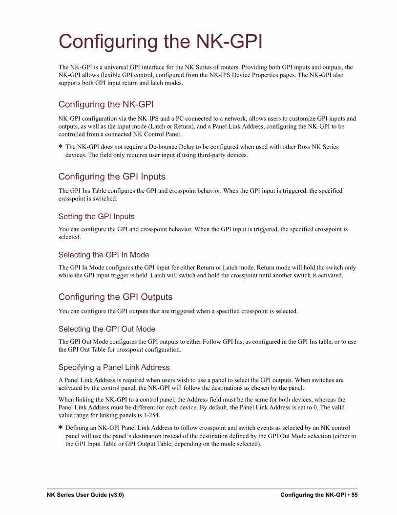
NK Series User Guide (v3.0) Configuring the NK-GPI • 55
Configuring the NK-GPIThe NK-GPI is a universal GPI interface for the NK Series of routers. Providing both GPI inputs and outputs, the NK-GPI allows flexible GPI control, configured from the NK-IPS Device Properties pages. The NK-GPI also supports both GPI input return and latch modes.
Configuring the NK-GPI
NK-GPI configuration via the NK-IPS and a PC connected to a network, allows users to customize GPI inputs and outputs, as well as the input mode (Latch or Return), and a Panel Link Address, configuring the NK-GPI to be controlled from a connected NK Control Panel.
The NK-GPI does not require a De-bounce Delay to be configured when used with other Ross NK Series devices. The field only requires user input if using third-party devices.
Configuring the GPI Inputs
The GPI Ins Table configures the GPI and crosspoint behavior. When the GPI input is triggered, the specified crosspoint is switched.
Setting the GPI Inputs
You can configure the GPI and crosspoint behavior. When the GPI input is triggered, the specified crosspoint is selected.
Selecting the GPI In Mode
The GPI In Mode configures the GPI input for either Return or Latch mode. Return mode will hold the switch only while the GPI input trigger is held. Latch will switch and hold the crosspoint until another switch is activated.
Configuring the GPI Outputs
You can configure the GPI outputs that are triggered when a specified crosspoint is selected.
Selecting the GPI Out Mode
The GPI Out Mode configures the GPI outputs to either Follow GPI Ins, as configured in the GPI Ins table, or to use the GPI Out Table for crosspoint configuration.
Specifying a Panel Link Address
A Panel Link Address is required when users wish to use a panel to select the GPI outputs. When switches are activated by the control panel, the NK-GPI will follow the destinations as chosen by the panel.
When linking the NK-GPI to a control panel, the Address field must be the same for both devices, whereas the Panel Link Address must be different for each device. By default, the Panel Link Address is set to 0. The valid value range for linking panels is 1-254.
Defining an NK-GPI Panel Link Address to follow crosspoint and switch events as selected by an NK control panel will use the panel’s destination instead of the destination defined by the GPI Out Mode selection (either in the GPI Input Table or GPI Output Table, depending on the mode selected).

56 • Configuring the NK-GPI NK Series User Guide (v3.0)

NK Series User Guide (v3.0) NK Series Operation • 57
NK Series OperationThe NK Series connects to devices to expand the signal types for the routing system.
The Ross NK series devices must be connected to the Ethernet network by virtue of an Ross NK-IPS or NK-NET devices to enable the NK Series to communicate with them.
Start-up Process
After power has been supplied to the NK Series components:
1. The routers broadcast their status to each other.
2. The panels also listen to these broadcasts and are able to download the matrix status within this time.
3. The linked panels broadcast their internal state (shift, destination, levels, take, chop and machine control).
4. The panels will attempt to retrieve the status for their current output/level pair.
5. The panels will request for any protects they may be holding.
6. Any routers (possibly multiple routers) with a protect held by this address will respond.
Router Start-up
On start-up, the newly connected router will attempt to download status from an operating router with the same output range and level. It will then switch all crosspoints and broadcast its status. Routers respond to data messages from other routers to allow this synchronization.
Control Panel Start-up
When a control panel is powered up, the LEDs will light 2 at a time from left to right. It will then fade to a Ross logo, fade that logo out and fade in the current status. This is to allow time for all connected NK devices to synchronize on start up.
Panels remember the last selected output and breakaway/level. These will be restored on power up unless overridden by a linked panel with different values.
Single Panel RCP-NK1 Operation
The control panel functions detailed below can be programed with the NK-IPS for full functionality. The examples herein are described using the factory default configuration, loaded with every NK router.
For More Information on...
• the factory configuration, refer to the chapter “Default Configurations” on page 43.
The examples in the this section use the following conventions.
A lit button indicates a simple key press to execute the action.
Three thin, black lines signifying the key indicates that the key should be held down for approximately 3 seconds and then released to execute to action.

58 • NK Series Operation NK Series User Guide (v3.0)
Selecting a Destination
Selecting a destination changes the virtual destination the panel controls or switches the next time a SOURCE key is pressed. Destinations can be selected by pressing a preset DESTINATION key. Figure 11.1
Figure 11.1 Example of Selecting a Source and Destination on the Panel
When a preset DESTINATION key is pressed, that key and its source status key (if a preset key exists) will be illuminated. If a breakaway warning occurs, the BREAKAWAY key will flash.
The bottom, left hand row of 16 keys is set to destination keys 1-16, pressing the D SHIFT key will change the bottom row to destination keys 17-32. Figure 11.2
Figure 11.2 Example of Selecting D SHIFT
Selecting a Source
Source switching is performed by pressing a preset SOURCE key. Selecting a source (when a TAKE function key is not assigned) results in the controller requesting the selected source to be switched by the router to the panel’s current destination.
If the switch request was successful, the preset SOURCE key is illuminated. If the switch was not successful or generated errors, the key will flash several times quickly to indicate that an error has occurred. If a TAKE function key is assigned, the TAKE key will be illuminated and the preset SOURCE key will flash once quickly (this indicates that TAKE is armed). To perform the switch press the TAKE key or press any other key to cancel. Figure 11.3
Figure 11.3 Example of Selecting TAKE
The top, left hand row of keys is set to source keys 1-16, pressing the S SHIFT key will change the top row to source keys 17-32. Figure 11.4
Figure 11.4 Example of Selecting S SHIFT
Source and destination keys are labeled as Input and Output keys, in this instance ‘Out11’ signifies Output 11 and ‘In4’ signifies Input 4.
In the example that use the SHIFT key, S SHIFT signifies SOURCE SHIFT and D SHIFT signifies DESTINATION SHIFT.
Ross Routing Systems
RCP-NK1
Ross Routing Systems
RCP-NK1
Ross Routing Systems
RCP-NK1
Ross Routing Systems
RCP-NK1

NK Series User Guide (v3.0) NK Series Operation • 59
Using the Shift Keys
SHIFT keys allow the different pages or sets available to preset SOURCE and DESTINATION keys to be accessed. Up to three different sets of SOURCE and/or DESTINATION keys may be accessed from the panel. The SOURCE SHIFT keys change the current set of SOURCE keys available on the panel and the DESTINATION SHIFT keys change the current set of DESTINATION keys available. All other keys are not affected by SHIFT keys.
When no SHIFT keys are selected, the keys are on the first or default page/set. By pressing a specific SOURCE SHIFT or DESTINATION SHIFT key, the panel immediately changes its relevant sources or destinations to the specified set. The SHIFT key is active when illuminated. Pressing the SHIFT key again, toggles it to the default key set. As the sets change if a SOURCE or DESTINATION key matches the currently controlled destination or the source status that key will be illuminated.
Using the Crosspoint Keys
CROSSPOINT keys perform a preset crosspoint switch in a single key press, and the key will illuminate to indicate the state of that crosspoint. When a crosspoint switch is performed the panel’s current destination, source and breakaway (optional) changes to those specified in the CROSSPOINT key assignment. If a breakaway is not specified, the currently selected breakaway on the panel is used for the switch.
If a CROSSPOINT key’s preset destination and source status matches that destination’s source status in the router on all levels on the current breakaway (or set breakaway) the key will be illuminated. If a TAKE function key is assigned, the TAKE key is illuminated and the preset CROSSPOINT key flashes (this indicates that TAKE is armed).
A CROSSPOINT key is not available on the factory default configuration. For configuration and functionality of the CROSSPOINT key, the NK-IPS is required.
Selecting a Level
LEVEL keys select the router levels. In the factory default configuration, there are four LEVEL keys assigned to the RCP-NK1 as outlined in the section “RCP-NK1” on page 25.
Using the Breakaway Keys
BREAKAWAY keys select preset groups of levels to be controlled. Breakaways can be customized from the control panel’s Device Properties page via the NK-IPS. If BREAKAWAY and LEVEL keys are assigned, then the LEVEL keys will reflect the breakaway pattern. When the current breakaway is the first breakaway, the LEVEL keys will not be illuminated. The source status displayed is only for the first level of any given breakaway or level selection.
In the factory default configuration of the RCP-NK1, all levels are set to the default breakaway, which is the only defined breakaway.
Figure 11.5 Example of Selecting a Breakaway
Breakaway Step Key
When breakaways have been configured from the NK-IPS, a BREAKAWAY STEP key may be used to cycle through the configured breakaways. Pressing this key will change the breakaway to the next breakaway with any levels. The BREAKAWAY STEP key will be illuminated if the current breakaway is not the first breakaway. Holding down the BREAKAWAY STEP key displays the levels enabled in the (current) breakaway pattern.
A BREAKAWAY STEP key is not available on the factory default configuration. For configuration and functionality of the BREAKAWAY STEP key, the NK-IPS is required.
Ross Routing Systems
RCP-NK1

60 • NK Series Operation NK Series User Guide (v3.0)
Using Macros
Macros can be used to initiate multiple switches in one quick key press. Several MACRO keys can be assigned to one panel and then different macros recorded to each key. When users are required to regularly switch between two or more static switch assignments, macros can be used to switch these in one easy key press.
A macro is an event playback feature similar to a salvo. A salvo will only trigger a series of switches, whereas a macro will record a series of events for express playback at a later time. When the macro is played back, it will activate a sequence of switches to configure the router. Macros can be extremely valuable in minimizing repetitive key presses by configuring multiple switch events (source, destination and crosspoint) to one key.
A macro event comprises a source, destination, crosspoint, macro, or protect key press. When appending one macro to another, this is counted as one (1) event. This is covered in more detail in the section “Appending Macros” on page 60.
Overview
A MACRO key can store a maximum of 84 events and users can assign up to 40 MACRO keys on the RCP-NK1 panel. It is recommended that users with only a single, unlinked panel only assign two or three keys as MACRO keys. Users who have several linked panels may find it convenient to have one panel set aside solely for the purpose of macros and assign as many MACRO keys as is required.
Pressing a SHIFT key when recording a macro does not count as an event, as the macro recorder simply recognizes that the key that is actually pressed is the relevant source or destination.
Creating Macros
To record a macro, you first need to start ‘macro recording mode’.
1. Hold down the MACRO key for about three seconds.
The MACRO key will flash quickly to indicate that the panel has entered macro recording mode.
2. Release the MACRO key.
The MACRO key will flash slowly to indicate that the panel is in macro recording mode.
3. Enter the events you wish to record, as you would if you were to activate a switch.
Key presses will be acknowledged by a quick flash on the key you have entered into the macro.
4. When you have finished entering switch events, press the MACRO key to exit macro recording mode.
The MACRO key will stop flashing to indicate the panel has exited macro recording mode.
Appending Macros
Appending macros is a feature that allows the addition of more events (or another macro) to an already existing macro.
To append a macro, you first need to enter macro recording mode, and then enter macro recording mode again to append the macro.
1. Hold down the MACRO key for about three seconds.
The MACRO key will flash quickly to indicate that the panel has entered macro recording mode.
2. Release the MACRO key.
The MACRO key will flash slowly to indicate that the panel is in macro recording mode.
3. Hold down the MACRO key again (this will play back the macro internally so that it may be appended).
The MACRO key will flash quickly.
4. Release the MACRO key.
The MACRO key will again flash slowly to indicate that the panel is in macro recording mode.

NK Series User Guide (v3.0) NK Series Operation • 61
5. Enter the events you wish to record as you would if you were to activate a switch.
Key presses will be acknowledged by a quick flash on the key you have entered into the macro.
6. When you have finished entering switch events, press the MACRO key to exit macro recording mode.
The MACRO key will stop flashing to indicate the panel has exited macro recording mode.
When appending macros or adding one macro to another, if you use a single input or output in more than one macro, it will override the previous status of that key.
Adding one Macro to another Macro
Adding one macro to another can be useful when you have more than one macro that shares the same output status (the same source to destination switch assignments) but where one macro also has output status that the other macro has not assigned.
As the macro function is only an event recorder, other macros are stored as one single event, not the sum of the events in that macro. Similarly, if a macro that has already been added to another macro is changed, the appended macro when played back will reflect that change.
Figure 11.6 Example of Adding one Macro to Another Macro
In the example above, the Macros are as follows:
• Macro1 = Input 1 to Outputs 1, 2 and 3, and also sends input 2 to outputs 7, 8 and 9.
• Macro2 = Input 1 to Outputs 4, 5, 6 and 7, and also sends Input 2 to Outputs 8 and 9.
In this example, because Output 7 is used twice, the last status added will be the one used when the macro is played back. The final status of Macro1 when it is played back will be as such will be:
• Input 1 to Outputs 1,2,3,4,5,6 and 7.
• Input 2 to Outputs 8 and 9.
To cancel recording or appending a Macro, press the MACRO key after entering macro record mode.
Macros can not be canceled after entering events in macro recording mode. If a mistake has been made, you will have to exit macro recording mode and enter it again to re-enter events you wish to be played back.
Using the Protect Key
The PROTECT key is used to lock current destination from use by other sources, as well as from other linked panels. The PROTECT key is especially useful in instances where destination must be held after a switch has been made.
A PROTECT key is not available on the factory default configuration. For configuration and functionality of the PROTECT key, the NK-IPS is required. A PROTECT key can also be configured on the RCP-NK1 panel via Function Key Program Mode.
Step 1
Step 2
Step 3
Step 4

62 • NK Series Operation NK Series User Guide (v3.0)
Using the Panel Lock
A panel may be locked to prevent unwanted key presses (particularly accidental switches). The Panel Lock is reflected on the control panel’s Device Properties page of the NK-IPS, and can be locked or unlocked as required both from the NK-IPS configuration page or from the panel.
To activate the panel lock from the RCP-NK1
1. Hold down the PROTECT key for about three seconds.
The PROTECT key will flash quickly to indicate that the panel lock has been activated.
2. Release the PROTECT key.
The PROTECT key will flash slowly to indicate that the panel is locked.
The PROTECT key’s panel lock function and the PANEL LOCK key are interchangeable. If both function keys are configured on the one panel, a panel lock can be activated from one key, and deactivated from the other.
Using the TAKE Key
A TAKE function key is used to activate the selected switch.
A TAKE key is not available on the factory default configuration. For configuration and functionality of the TAKE key, the NK-IPS is required. A TAKE key can also be configured on the RCP-NK1 panel via Function Key Program Mode.
1. Press the required destination key.
2. Press the required source key.
The SOURCE key on the panel flashes and the TAKE key illuminates.
3. To activate the switch, press the TAKE key is pressed.
The entered crosspoint change will be completed immediately after the TAKE key has been pressed. This enables the user to preset a crosspoint change before the switch is required. The pending switch can be aborted by pressing any key other that the TAKE key.
Using the Chop Key
The CHOP function key enables the user to alternate between two sources.
When CHOP is enabled, all other keys are disabled.
1. Pressing CHOP will alternate the two previously selected sources for a given destination.
2. Pressing CHOP once will start a slow chop.
3. Pressing CHOP again will increase the speed of the chop to a fast chop and pressing again will discontinue the chop mode.
Linked Panel RCP-NK1 Operation
When remote control panels are linked together, key behavior remains as above (with single panel system), although the following details must be noted when linking panels:
• Pressing CHOP will alternate between two sources, including cases when the sources are on different physical panels.
• Pressing TAKE will activate a take, including cases when the SOURCE key is on a different panel to the TAKE key.

NK Series User Guide (v3.0) NK Series Operation • 63
• If any linked panel has a TAKE key, the linked device enters take mode when a source or crosspoint key is pressed.
• Locking one physical panel from the control panel’s Device Properties page will also lock all linked panels. The NK-IPS can be used to unlock panels if required.
• Entering macro record mode causes all linked panels to be in macro record mode, switch events and protects can be added from different physical panels.
• Macros cannot be appended or added across panels.
• Page SHIFT keys control source and destination pages for the whole linked panel.
• DESTINATION keys control the destination for the whole panel.
• LEVEL and BREAKAWAY keys control the level mask for the whole panel. Breakaway preview is not available across linked panels.
• If a panel is added to an operating linked panel, the linked panel changes its states in regards to TAKE, PANEL LOCK and cut-bus accordingly.
• If a linked panel is added to an operating linked device that is in TAKE, CHOP, PANEL LOCK, or macro recording mode, it starts in that mode.
• Menus do not work across linked panels.

64 • NK Series Operation NK Series User Guide (v3.0)

NK Series User Guide (v3.0) Analog Audio Router Levels • 65
Analog Audio Router LevelsThis chapter describes the Analog Audio control layers for NK Series products.
NK-A64 Control Layer
The Analog Audio level of NK-64 routers offers unparalleled configuration and audio processing, allowing users to mix left and right audio channels to suit their broadcast requirements. Channels may be swapped, phase inverted or converted to mono (both channels left, both channels right, both channels average, sum and difference).
Figure 12.1 NK-A64 Control Layer Block Diagram
Signal processing is conducted by way of a Control Layer. The Control Layer is an additional level within the router matrix that may be mapped to control panel keys to allow users to mix audio channels on the fly. The Control Layer uses SOURCE keys as the triggers to mix the output audio signal. The Control Layer may be used after a source has been switched to a selected destination. Table 12.1 shows the audio mixing options available for the Control Layer.
Table 12.1 Audio Mixing Options
Input Control
Signal Processing
DescriptionLeft Channel Right Channel
Input 1 L R Both channels normal (Default)
Input 2 R L Channels swapped
Input 3 L L Both channels Left
Input 4 R R Both channels Right
Input 5 L R Left channel normal, Right channel inverted
Input 6 L R Left channel inverted, Right channel normal
Input 7 L+R L+R Left channel sum (mono), Right channel sum (mono)
Router Matrix(Left Channel)
trixnel)
Router Matrix(Right Channel)
Control Layer
Right ChannelInput
Left ChannelInput
Right ChannelOutput
Left ChannelOutput

66 • Analog Audio Router Levels NK Series User Guide (v3.0)
Control Layer Operation via RCP-NK Panels
The Analog Audio Control Layer can easily be accessed from NK Series control panels. Factory configured systems will allow the NK-A64 Control Layer to operate out of the box. Further configuration of the NK-A64 Control Layer and control panel options requires the NK-IPS.
When assigning breakaways for NK Series control panels, the Control Layer should not be assigned to a breakaway that contains other levels. If users require a breakaway for the NK-A64 Control Layer, it is vital that it is the only level active for that breakaway.
Mixing the Output Audio Signal
When using the Control Layer, users must remember that only the output audio stream is processed within the router matrix, not the input signal. When mixing audio channels, the control layer is selected after the switch has been made, or if the output that requires mixing is already active. Users may record macros to make mixing and switches easier, or if regular audio mixing is required.
Input 8 L+R L–R Left channel sum (mono), Right channel difference
Selecting the Control Layer key and then selecting IN 1 will enable the output audio channels to be normal.
Selecting the Control Layer key and then selecting IN 2 will enable the output audio channels to be swapped.
Selecting the Control Layer key and then selecting IN 3 will enable both output audio channels to be the left channel of the source.
Selecting the Control Layer key and then selecting IN 4 will enable both output audio channels to be the right channel of the source.
Selecting the Control Layer key and then selecting IN 5 will enable the left output audio channel to be normal and the right audio channel to be inverted.
Selecting the Control Layer key and then selecting IN 6 will enable the left output audio channel to be inverted and the right audio channel to be normal.
Selecting the Control Layer key and then selecting IN 7 will enable the both output audio channels to be summed.
Selecting the Control Layer key and then selecting IN 8 will enable the left output audio channel to be summed and the right audio channel to be differenced.
Table 12.1 Audio Mixing Options
Input Control
Signal Processing
DescriptionLeft Channel Right Channel

NK Series User Guide (v3.0) Analog Audio Router Levels • 67
Examples
To swap the channels of the output audio signal for OUT 4
1. Select the destination.
2. Select the source.
3. Select the Control Layer, or the breakaway that the Control Layer is on.
4. Select the designated mixing mode.
To invert the left channel of the output audio signal for OUT 6
1. Select the destination.
2. Select the source.
3. Select the Control Layer, or the breakaway that the Control Layer is on.
4. Select the designated mixing mode.
The Control Layer configuration is retained by the destination until the Control Layer is changed. For example, if IN 1 is switched to OUT 3 and the left and right channels are swapped (by pressing the Control Layer key and then selecting IN 2) the next Input selected to be switched to OUT 3 will also have the left and right channels swapped.

68 • Analog Audio Router Levels NK Series User Guide (v3.0)

NK Series User Guide (v3.0) Router Interfaces Overview • 69
Router Interfaces OverviewThis chapter summarizes the DashBoard interfaces for the NK Series routers.
Device Properties Interface Overview
The router Device Properties interface, accessible through the NK-IPS, allows users to configure interface and usability options for all NK Series routers and also displays the alarm status of the router, as well as having the unique ability to assign names and brief descriptions for the devices themselves.
Device Properties Fields
Configuration Fields
Table 13.1 Device Properties Fields
Field Description
Family The Family name is set in the factory before shipping and displays the family that the device belongs to. This parameter is read-only.
Device The Device name is set in the factory before shipping and displays the name assigned to the device. This parameter is read-only.
Serial Number The Serial Number is set in the factory before shipping and is unique to each device. This parameter is read-only.
Name The Name field can be assigned by the user to uniquely name a device. This field has a maximum of 16 characters and is used for description and identification only.
Details The Details field can be assigned by the user to give a device specific details. For example, a physical location or a brief description of its use. This field has a maximum of 16 characters and is used for description and identification only.
Group The Group number can be assigned by the user to organize devices into groups. For example, users can assign separate Group numbers for devices in different physical areas. This field has a maximum of 10 characters and is used for description and identification only.
Table 13.2 Configuration Fields
Field Description
Address The Address is used within the overall control system to identify devices. Each device must be given a unique Address to avoid hardware and communication conflicts. The valid value range for assigning an individual device Address is 2-255.
Ignore Out of Range Inputs
The Ignore Out of Range Inputs option will ignore switches on an offset router that has been configured to the same level as another connected router. By default, the Ignore Out of Range Inputs option is not active (the check box is cleared).
The Ignore Out of Range Inputs option is only available on the NK-64 and NK-72 routers and is only used for specific installations

70 • Router Interfaces Overview NK Series User Guide (v3.0)
Number of Partitions
The Num Partitions field (Number of Partitions) indicates how you wish the router to be partitioned. The default value of the partitions is 1 (no partitions.), the maximum value is 8.
Table 13.3 shows the relative input and output sizes to the number of partitions configured for 16x16, 32x32, 64x64 and 72x72 routers.
* Denotes that partition leaves unusable inputs/outputs as ‘remainders’.
When partitioning routers, some configurations will leave ‘remaindered’ inputs and outputs. Any division of the router that leaves a remainder will not use the remaining inputs and outputs. For example, a 32x32 partitioned into 3, will be equivalent to three 10x10 routers (30 inputs and 30 outputs in total). The last two inputs and the last two outputs will remain unused and inaccessible for router functions.
Partition Levels
The Partition Levels table allows users to configure levels to each partition. Selecting a level, by selecting a check box in the Levels column, assigns that level to a partition number from the Part. Num. column.
Switching Point These options are only available on the NK-64 and NK-72 routers.
Custom Switching Line
Custom Switching Position
First Input The First Input defines the first source used (from the range of 1-255) by the router. The valid range for the First Input is 1-65535, the default is 1.
First Output The First Output defines the first destination used (from the range of 1-255) by this router. The valid range for the First Output is 1-65535, the default is 1.
Machine Control Destination
The Machine Control Destination radio buttons specify whether the destinations are used as the Slave or as the Master. This option is available to NK-M Routers only.
The Machine Control Destination option is only available on the Machine Control router’s Device Properties page. It is not applicable to other NK router models.
Table 13.3 Relative input and output sizes to the number of configured partitions
16x16 Router 32x32 Router 64x64 Router 72x72 Router
Partitions I/O Size Partitions I/O Size Partitions I/O Size Partitions I/O Size
1 16x16 1 32x32 1 64x64 1 72x72
2 8x8 2 16x16 2 32x32 2 36x36
3* 5x5 3* 10x10 3* 21x21 3 24x24
4 4x4 4 8x8 4 16x16 4 18x18
5* 3x3 5* 6x6 5* 12x12 5* 14x14
6* 2x2 6* 5x5 6* 10x10 6 12x12
7* 2x2 7* 4x4 7* 9x9 7* 10x10
8* 2x2 8 4x4 8 8x8 8 9x9
Table 13.2 Configuration Fields
Field Description

NK Series User Guide (v3.0) Router Interfaces Overview • 71
Levels can be assigned more than once to different or distinct partitions, but only one level can be selected for each partition.
Control Layer Partitions (NK-A64 only)
The NK-A64 Analog Audio Level Router has a control layer in addition to the first and second levels (left and right channels respectively). The control layer is used for lossless signal mixing, for more information, refer to “NK-A64 Control Layer” on page 65.
The Control Layer Partition table allows users to configure levels to each partition. Selecting a level, by selecting a check-box in the Levels column, assigns that level to a partition number from the Part. Num. (Partition Number) column.
Levels can be assigned more than once to different or distinct partitions, but only one level can be selected for each partition.
Status Fields
Reference Signal Type
The Reference Signal Type automatically detects if a video reference is being looped through the router. It will show the signal type if there is a reference present, either PAL or NTSC, or, if no reference is detected, it will display Local.
The Local signal is the internal random switching pulse that is generated by the router to ensure successful switch timing. For more information on video referencing, refer to “Video Referencing” on page 36.
Alarms
The Alarms status section of the Device Properties page is divided into three headings: Reference, Matrix Power and RCP Power. The NK-64 routers also have an additional alarm warning for I/O Power.
There are four degrees of alarm urgency: Green (Normal operation), Yellow (Warning), Orange (Error) and Red (Critical Error). The possible Reference, Matrix Power, and RCP Power statuses are displayed in Table 13.4.
Reference Status
The Reference status alarm indicates if there if a video reference connected to the router. It will also display the format of the reference, either PAL or NTSC. If a video reference is connected, the router will attempt to perform all switches during the vertical interval of the reference. If there is no reference connected, the router will still function, but the switches may be activated by the router at any time. For more information on the NK video/switching reference feature, refer to “Video Referencing” on page 36.
Table 13.4 Alarms
Heading Possible Status Alarm Urgency Status Color
Reference No Reference Detected Warning Yellow
Reference Present None (Safe) Green
Matrix Power Matrix Power Error Critical Error Red
Matrix Power OK None (Safe) Green
RCP Power RCP Power Error Critical Error Red
RCP Power OK None (Safe) Green
I/O Power (NK-64 only) I/O Power OK None (Safe) Green
I/O Power Error Critical Error Red

72 • Router Interfaces Overview NK Series User Guide (v3.0)
Matrix Power
The Matrix Power status alarm indicates the power status of the router. A router that displays any alarm status other than Green (safe) should be switched off and unplugged. Another power pack can be used to test the router frame again, but if the status alarm remains on the Device Properties page, a Ross Video representative should be contacted.
RCP Power
The RCP Power status alarm indicates the power status that the router distributes to the control panels connected to it. For any alarm status other than Green (safe), panels should be disconnected one by one, and the alarm status checked. In some instances there may be too many devices connected to the router to ensure regulated power consumption by each device. If all devices have been disconnected from the router and the alarm status remains activated, the router should be switched off and unplugged. Another power pack can be used to test the router frame again, but if the alarm status remains higher than Green on the Device Properties page, a Ross Video representative should be contacted.
I/O Power (NK-64 Routers only)
The I/O Power status alarm indicates the I/O card status for the router. As NK-64 routers are comprised of 8 separate I/O cards, each card has its own alarm. If any card has a fault or fails during operation, the I/O Power status alarm will be triggered. If the alarm has been triggered, each input and output card should be checked individually before using the router for further operations.
Submit and Upgrade Firmware Fields
The Submit Settings button will upload the settings to the device.
If users wish to cancel or ignore the settings they have made, click the Online tab to return to the Online Devices page, or click the Refresh button of your browser to revert to the original settings displayed.
The Upgrade Firmware button is used to upload to the device the latest firmware, contained in a binary file. Upgrading firmware allows new features, enhancements and improvements of the NK router to be installed.
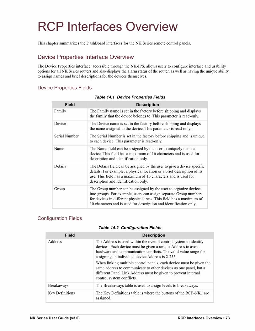
NK Series User Guide (v3.0) RCP Interfaces Overview • 73
RCP Interfaces OverviewThis chapter summarizes the DashBoard interfaces for the NK Series remote control panels.
Device Properties Interface Overview
The Device Properties interface, accessible through the NK-IPS, allows users to configure interface and usability options for all NK Series routers and also displays the alarm status of the router, as well as having the unique ability to assign names and brief descriptions for the devices themselves.
Device Properties Fields
Configuration Fields
Table 14.1 Device Properties Fields
Field Description
Family The Family name is set in the factory before shipping and displays the family that the device belongs to. This parameter is read-only.
Device The Device name is set in the factory before shipping and displays the name assigned to the device. This parameter is read-only.
Serial Number The Serial Number is set in the factory before shipping and is unique to each device. This parameter is read-only.
Name The Name field can be assigned by the user to uniquely name a device. This field has a maximum of 16 characters and is used for description and identification only.
Details The Details field can be assigned by the user to give a device specific details. For example, a physical location or a brief description of its use. This field has a maximum of 16 characters and is used for description and identification only.
Group The Group number can be assigned by the user to organize devices into groups. For example, users can assign separate Group numbers for devices in different physical areas. This field has a maximum of 10 characters and is used for description and identification only.
Table 14.2 Configuration Fields
Field Description
Address The Address is used within the overall control system to identify devices. Each device must be given a unique Address to avoid hardware and communication conflicts. The valid value range for assigning an individual device Address is 2-255.
When linking multiple control panels, each device must be given the same address to communicate to other devices as one panel, but a different Panel Link Address must be given to prevent internal control system conflicts.
Breakaways The Breakaways table is used to assign levels to breakaways.
Key Definitions The Key Definitions table is where the buttons of the RCP-NK1 are assigned.

74 • RCP Interfaces Overview NK Series User Guide (v3.0)
Protect Alarm
The Protect Alarm indicates whether an output has been protected from the control panel. The Protect Alarm status is also displayed on the NK-IPS Online Devices page and in Phoenix.
Submit Settings
The Submit Settings button will upload the settings to the device.
If users wish to cancel or ignore the settings they have made, click the Online tab to return to the Online Devices page, or click the Refresh button of your browser to revert to the original settings displayed.
Upgrade Firmware
The Upgrade Firmware button is used to upload to the device the latest firmware, contained in a binary file. Upgrading firmware allows new features, enhancements and improvements of the RCP-NK1 to be installed.
On Brightness Sets the LED brightness for the RCP-NK1 when the button state is “on”.
Off Brightness Sets the LED brightness for the RCP-NK1 when the button state is “off”.
Panel Locked Indicates when the panel has been locked to not respond to key presses. By default, this feature is off.
Machine Control Enabled The Machine Control Enabled option allows reciprocal switching when the check box is checked.
Panel Link Address Used when configuring multiple control panels as a singled linked panel.
Clear Protect Clears any protects on the panel when the Submit Settings button is selected.
Comms Retry Delay Configures the delay (ms) the panel resends data when an error is occurring.
Table 14.2 Configuration Fields
Field Description

NK Series User Guide (v3.0) NK-SCP/A Overview • 75
NK-SCP/A OverviewThe NK-SCP/A can be used for control of an entire NK routing system. Switches activated from an external RS-232 device are monitored by all devices on the T-Bus line.
The protocol used is a simple ASCII protocol designed to give users a means for simple control of the router via custom PC software or by connecting a terminal to the AUX port and sending ASCII characters.
Using the ASCII Protocol with the NK-SCP/A
The protocol used is a simple ASCII protocol designed to give users a means for simple control of the router via custom PC software or by connecting a terminal to the AUX port and sending ASCII characters.
Fixed Parameters
The parameters in Table 15.1 are fixed.
Commands
Table 15.2 describes the protocol commands.
Table 15.3 describes the command parameters.
Table 15.1 COMM Port Fixed Parameters
Parameter Setting
Parity None
Stop Bits 1
Data Bits 8
Characters ASCII
Table 15.2 ASCII Protocol Commands
Command Description
<X> Switch an input to an output using a breakaway
<Z> Switch multiple inputs (one per level) to an output
<R> Read the current status of an output
Table 15.3 ASCII Protocol Command Parameters
Command Description Value Note
<ddd> Destination - output number (000 to 254) 1
<sss> Source - input number (000 to 254) 1
<b> Breakaway number (1 to 8) 2
<---> Blank entry (in place of actual output sock number)
<CR> Carriage return character
<LF> Line feed character
<SP> Space character

76 • NK-SCP/A Overview NK Series User Guide (v3.0)
An offset of -1 is required so that the lowest value of 000 points to the router input or output number 1. In this way, inputs and outputs from 1 to 255 can be addressed with dialogue values from 000 to 254.
To switch an input to an output using a defined breakaway
1. Start the sequence (11 bytes) with an upper case <X> followed by the destination, source, breakaway and carriage return as detailed below. Do not include the parentheses.
<X> <ddd> <,> <sss> <,> <b> <CR>
2. Response from the NK-SCP:
• If the data sting is valid, the SCP returns response (B).
• If the data string is invalid, the SCP returns response (A).
• If the data string is valid but the source number is unavailable or any of the parameters are incorrectly specified, i.e. greater than 254 (255 to 999) for destination and source and greater than 1 to 8 (0 or 9) for breakaway, the SCP returns response (A) then response (B).
Response (A) <CR> <LF> <ERROR> <CR> <LF>
Response (B) <CR> <LF> <OK> <SP> <CR> <LF>
To switch multiple inputs (one per level) to an output
1. Start the sequence (37 bytes) with an upper case <Z> followed by the destination, then a source (or <---> to not switch a level) for each of 8 levels and carriage return as detailed below. Do not include the parentheses.
L1L2L3L4L5L6L7L8
<Z><ddd><,><sss,sss,sss,sss,sss,sss,sss,sss<CR>
Send <---> in place of <sss> to not switch that level.
2. Response from the NK-SCP:
• If the data sting is valid, the SCP returns response (B).
• If the data string is invalid, the SCP returns response (A).
• If the data string is valid but the source number is unavailable or any of the parameters are incorrectly specified, i.e. greater than 254 (254 to 999) for destination and source and greater than 1 to 8 (0 or 9) for breakaway, the SCP returns response (A) then response (B).
Response (A) <CR> <LF> <ERROR> <CR> <LF>
Response (B) <CR> <LF> <OK> <SP> <CR> <LF>
To read the current status of an output
1. Start the sequence (5 bytes) with an upper case <R> followed by the destination and carriage return as detailed below. Do not include the parentheses.
<R> <ddd> <CR>
2. Response from the NK-SCP:
• If the data sting is valid, the SCP returns response (C) then (B).
• If the data string is invalid, the SCP returns response (A).
• If the data string is valid but the destination is incorrectly specified, i.e. greater than 254 (255 to 999), the SCP returns response (A) then response (B).
Response (A)<CR> <LF> <ERROR> <CR> <LF>
Response (B)<CR> <LF> <OK> <SP> <CR> <LF>
L1L2L3L4L5L6L7L8
Response (C)<CR><LF><sss,sss,sss,sss,sss,sss,sss,sss><CR><LF>

NK Series User Guide (v3.0) NK-SCP/A Overview • 77
NK-SCP/K2 Operation
Implementation of the NK-SCP/K2 means that NK routers can be controlled exactly as if they were a matrix module housed within the Kondor 2 frame. Switches can be activated by Geneos control panels as well as from a Virtual Control Panel (VCP) from the Panel-works page in the Geneos software.
When switches are activated from a control panel or VCP connected to the Geneos CPU, the SCP/K2 monitors commands and converts them to the T-Bus protocol. If the command sent corresponds with a level that an NK router is occupying, then that level will be switched. If there are no NK routers occupying that level, then the switch will be performed where that level is occupied, most likely within the Kondor 2.
Switches can be activated from the NK control panel (RCP-NK1) but are not advised as they will not be reflected within the Geneos CPU status table. If an RCP-NK1 is connected to the router (or T-Bus), any switches activated by the panel will override the status and commands from the Geneos panels or Geneostat virtual control panels.
NKP-SCP/A Device Properties Interface Overview
The Device Properties interface, accessible through the NK-IPS, allows users to configure interface and usability options for all NK Series routers and also displays the alarm status of the router, as well as having the unique ability to assign names and brief descriptions for the devices themselves.
Device Properties Fields
Table 15.4 Device Properties Fields
Field Description
Family The Family name is set in the factory before shipping and displays the family that the device belongs to. This parameter is read-only.
Device The Device name is set in the factory before shipping and displays the name assigned to the device. This parameter is read-only.
Serial Number The Serial Number is set in the factory before shipping and is unique to each device. This parameter is read-only.
Name The Name field can be assigned by the user to uniquely name a device. This field has a maximum of 16 characters and is used for description and identification only.
Details The Details field can be assigned by the user to give a device specific details. For example, a physical location or a brief description of its use. This field has a maximum of 16 characters and is used for description and identification only.
Group The Group number can be assigned by the user to organize devices into groups. For example, users can assign separate Group numbers for devices in different physical areas. This field has a maximum of 10 characters and is used for description and identification only.

78 • NK-SCP/A Overview NK Series User Guide (v3.0)
Configuration Fields
Submit Settings
The Submit Settings button will upload the settings to the device.
If users wish to cancel or ignore the settings they have made, click the Online tab to return to the Online Devices page, or click the Refresh button of your browser to revert to the original settings displayed.
Upgrade Firmware
The Upgrade Firmware button is used to upload to the device the latest firmware, contained in a binary file. Upgrading firmware allows new features, enhancements and improvements of the RCP-NK1 to be installed.
NKP-SCP/K2 Device Properties Interface Overview
The NK-SCP/K2 itself does not need to be configured via the NK-IPS for use, but when connected to the T-Bus Control System it will be displayed on the NK-IPS Online Devices page.
Device Properties Fields
Table 15.5 Configuration Fields
Field Description
Address The Address is used within the overall control system to identify devices. Each device must be given a unique Address to avoid hardware and communication conflicts. The valid value range for assigning an individual device Address is 2-255.
ASCII Port Baud Rate
Configures the baud speed of the NK-SCP/A. The available options from the drop down box are 9600, 14.4k, 28.8k, 38.4k, 57.6k and 115.2k. By default, the baud rate is set to 9600.
Breakaway Level Map
Configures the router levels to defined breakaways
Table 15.6 Device Properties Fields
Field Description
Family The Family name is set in the factory before shipping and displays the family that the device belongs to. This parameter is read-only.
Device The Device name is set in the factory before shipping and displays the name assigned to the device. This parameter is read-only.
Serial Number The Serial Number is set in the factory before shipping and is unique to each device. This parameter is read-only.
Name The Name field can be assigned by the user to uniquely name a device. This field has a maximum of 16 characters and is used for description and identification only.

NK Series User Guide (v3.0) NK-SCP/A Overview • 79
Configuration Fields
Details The Details field can be assigned by the user to give a device specific details. For example, a physical location or a brief description of its use. This field has a maximum of 16 characters and is used for description and identification only.
Group The Group number can be assigned by the user to organize devices into groups. For example, users can assign separate Group numbers for devices in different physical areas. This field has a maximum of 10 characters and is used for description and identification only.
Table 15.7 Configuration Fields
Field Description
Address The Address is used within the overall control system to identify devices. Each device must be given a unique Address to avoid hardware and communication conflicts. The valid value range for assigning an individual device Address is 2-255.
Machine Control Enabled
Allows reciprocal switching when enabled.
Machine Control Level
Configures the level that the machine control (if enabled) switches reciprocally when switches are performed.
Table 15.6 Device Properties Fields
Field Description

80 • NK-SCP/A Overview NK Series User Guide (v3.0)
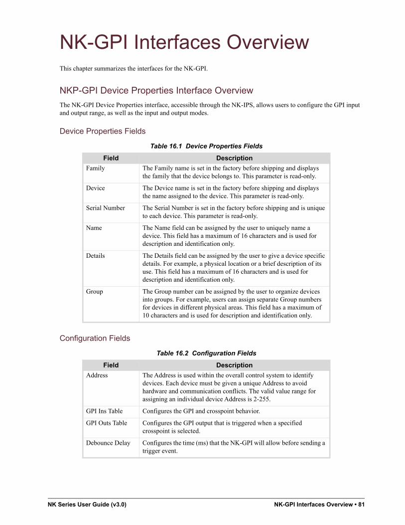
NK Series User Guide (v3.0) NK-GPI Interfaces Overview • 81
NK-GPI Interfaces OverviewThis chapter summarizes the interfaces for the NK-GPI.
NKP-GPI Device Properties Interface Overview
The NK-GPI Device Properties interface, accessible through the NK-IPS, allows users to configure the GPI input and output range, as well as the input and output modes.
Device Properties Fields
Configuration Fields
Table 16.1 Device Properties Fields
Field Description
Family The Family name is set in the factory before shipping and displays the family that the device belongs to. This parameter is read-only.
Device The Device name is set in the factory before shipping and displays the name assigned to the device. This parameter is read-only.
Serial Number The Serial Number is set in the factory before shipping and is unique to each device. This parameter is read-only.
Name The Name field can be assigned by the user to uniquely name a device. This field has a maximum of 16 characters and is used for description and identification only.
Details The Details field can be assigned by the user to give a device specific details. For example, a physical location or a brief description of its use. This field has a maximum of 16 characters and is used for description and identification only.
Group The Group number can be assigned by the user to organize devices into groups. For example, users can assign separate Group numbers for devices in different physical areas. This field has a maximum of 10 characters and is used for description and identification only.
Table 16.2 Configuration Fields
Field Description
Address The Address is used within the overall control system to identify devices. Each device must be given a unique Address to avoid hardware and communication conflicts. The valid value range for assigning an individual device Address is 2-255.
GPI Ins Table Configures the GPI and crosspoint behavior.
GPI Outs Table Configures the GPI output that is triggered when a specified crosspoint is selected.
Debounce Delay Configures the time (ms) that the NK-GPI will allow before sending a trigger event.

82 • NK-GPI Interfaces Overview NK Series User Guide (v3.0)
Submit Settings
The Submit Settings button will upload the settings to the device.
If users wish to cancel or ignore the settings they have made, click the Online tab to return to the Online Devices page, or click the Refresh button of your browser to revert to the original settings displayed.
Upgrade Firmware
The Upgrade Firmware button is used to upload to the device the latest firmware, contained in a binary file.

NK Series User Guide (v3.0) Connectors and Pinouts • 83
Connectors and PinoutsThis chapter provides additional information on the pinout assignments and connector details for the NK Series products.
DB-25 Pinouts for Analog and Digital Audio Routers
NK-A16 and NK-D32/110 Wiring (16x16 Routers)
Figure 17.1 shows the pinouts for inputs and outputs on the NK-A16 and NK-D16/110.
The pinouts detailed in Figure 17.1 are applicable for both left and right channels (NK-A16 only).
Figure 17.1 NK-A16 and NK-D16/110 — Pinouts for Inputs and Outputs
NK-A16 Unbalanced Wiring
Figure 17.2 shows pinouts for unbalanced input connections (left and right channels) for the NK-A16 model.
Figure 17.2 NK-A16 — Pinouts for Unbalanced Inputs
The following pinouts are applicable only for current NK-A16, NK-A32, NK-D16/110 and NK-D32/110 routers. These routers can be distinguished by the silk screen of the pinouts on the rear of the router.
Previous routers, without pinouts silk screened on the rear, require an alternate wiring. These are detailed in the NK Series User Guide v1.0 and v1.1 or in the NK Series DB-25 Pinouts Application Note.
The reason for the altered pinouts is that cables can be purchased off the shelf from most audiovisual, broadcast or music retailers.
13 1
G - + G - + + +
+ + + +
G G
G GG G
- -
- - - -
210
412
614
816
19
311
513
715
13 1
G - + G - + + +
+ + + +
G G
G GG G
- -
- - - -
210
412
614
816
19
311
513
715

84 • Connectors and Pinouts NK Series User Guide (v3.0)
Figure 17.3 shows pinouts and wiring details for unbalanced output connections (left and right channels) for the NK-A16 model.
Figure 17.3 NK-A16 — Pinouts for Unbalanced Outputs
NK-A32 and NK-D32/110 Wiring (32x32 Routers)
Figure 17.4 shows the pinouts for both inputs and outputs 17-32 on the NK-A32 and NK-D32/110. Pinouts for inputs and outputs 1-16 are as depicted previously.
The pinouts detailed in Figure 17.4 are applicable for both left and right channels (NK-A32 only)
Figure 17.4 NK-A32 and NK-D32/110 — Pinouts for Inputs and Outputs
NK-A32 Unbalanced Wiring
Figure 17.5 shows pinouts for unbalanced input connections (left and right channels) for the NK-A32.
Figure 17.5 NK-A32 — Pinouts for Unbalanced Inputs
13 1
G - + G - + + +
+ + + +
G G
G GG G
- -
- - - -
210
412
614
816
19
311
513
715
13 1
G - + G - + + +
+ + + +
G G
G GG G
- -
- - - -
210
412
614
816
19
311
513
715
1826
2028
2230
2432
1725
19 21 2327 29 31
13 1
G - + G - + + +
+ + + +
G G
G GG G
- -
- - - -
210
412
614
816
19
311
513
715
1826
2028
2230
2432
1725
19 21 2327 29 31

NK Series User Guide (v3.0) Connectors and Pinouts • 85
Figure 17.6 shows pinouts for unbalanced output connections (left and right channels) for the NK-A32.
Figure 17.6 NK-A32 — Pinouts for Unbalanced Outputs
NK-A64 Wiring (64x64 Routers)
Figure 17.7 shows the pinouts for both inputs and outputs on the NK-A64. Each connector allows balanced audio of four audio channels.
Figure 17.7 NK-A64 and NK-D64/110 — Pinouts for Inputs and Outputs
NK-A64 Unbalanced Wiring
Figure 17.8 shows pinouts and wiring details for unbalanced input connections for the NK-A64.
Figure 17.8 NK-A64 — Pinouts for Unbalanced Inputs
13 1
G - + G - + + +
+ + + +
G G
G GG G
- -
- - - -
210
412
614
816
19
311
513
715
1826
2028
2230
2432
1725
19 21 2327 29 31
131
G
-+
G
-+++
++++
GG
GG GG
--
----4L8L
3L7L
2L6L
1L5L
4R 3R 2R 1R8R 7R 6R 5R
131
G
-+
G
-+++
++++
GG
GG GG
--
----4L8L
3L7L
2L6L
1L5L
4R 3R 2R 1R8R 7R 6R 5R

86 • Connectors and Pinouts NK Series User Guide (v3.0)
Figure 17.9 shows pinouts and wiring details for unbalanced output connections for the NK-A64.
Figure 17.9 NK-A64 — Pinouts for Unbalanced Outputs
NK-D64/110 Wiring
Figure 17.10 shows the pinouts for both inputs and outputs on the NK-D64/110. Pinouts for inputs and outputs 1-32 are as depicted previously.
Figure 17.10 NK-D64/110 — Pinouts for Inputs and Outputs
DB-9 Power Connector (All NK-16 and NK-32 Routers)
Figure 17.1 shows the DB-9 connector port on the rear of the routers and can be used to connect GPI alarms.
Figure 17.11 DB-9 External View Male Connector — Pinout Assignment
131
G
-+
G
-+++
++++
GG
GG GG
--
----4L8L
3L7L
2L6L
1L5L
4R 3R 2R 1R8R 7R 6R 5R
13 1
G - + G - + + +
+ + + +
G G
G GG G
- -
- - - -
210
412
614
816
19
311
513
715
1826
2028
2230
2432
1725
19 21 2327 29 31
34 36 38 4042 44 46 4850 52 54 5658 60 62 64
33 35 37 3941 43 45 4749 51 53 5557 59 61 63

NK Series User Guide (v3.0) Connectors and Pinouts • 87
Machine Control DB-9 Pinouts (NK-M16 and NK-M32)
Figure 17.12 shows the pinouts for DB-9 connections on the NK-M16 and NK-M32 Machine Control routers.
The Machine Control DB-9 pinouts are dependent on which mode (Master or Slave) is being used.
Figure 17.12 DB-9 Connector — Pinouts for NK-M16 and NK-M32 Routers
Table 17.1 DB-9 Pinout Assignments
Pin GPI Alarms
1 N/C
2 RCP Power Fail
3 Matrix Power Fail
4 GND
5 GND
6 +15V
7 +15V
8 -15V
9 -15V
Table 17.2 DB-9 Pinout Assignments
Pin Master Slave
1 GND GND
2 TX- Rx-
3 RX+ Tx+
4 GND GND
5 N/C N/C
6 GND GND
7 Tx+ Rx+
8 Rx- Tx-
9 N/C N/C

88 • Connectors and Pinouts NK Series User Guide (v3.0)
GPI Alarm Pinouts (NK-64 and NK-72)
Figure 17.3 shows the 3-way Phoenix connector on the rear of the NK-64 and NK-72 routers which is used to connect GPI alarms.
Figure 17.13 3-pin Connector — Pinouts for GPI Alarms
T-BUS RJ-45 Connector
Figure 17.14 shows the RJ-45 connector port for the T-Bus control system.
Figure 17.14 RJ45 Female Connector (External View) — Pinout Assignments
NK-SCP/A DB-9 Pinouts
Figure 17.15 shows the DB-9 connector port on the NK-SCP/A.
Figure 17.15 NK-SCP/A DB-9 Male External View Connector — Pinout Assignments
Table 17.3 T-BUS RJ-45 Pinout Assignments
Pin Signal
1 GND
2 GND
3 + RS-485 Tx/Rx
4 N/C
5 N/C
6 - RS-485 Tx/Rx
7 +14.4V RCP
8 Phantom Power
GND+5VCurrent limited to 15mA
Alarm / GPI

NK Series User Guide (v3.0) Connectors and Pinouts • 89
NK-SCP/K2 DB-9 Pinouts
Figure 17.16 shows the DB-9 connector port for the NK-SCP/K2.
Figure 17.16 NK-SCP/K2 DB-9 Male External View Connector — Pinout Assignments
Table 17.4 NK/SCP/A DB-9 Pinout Assignments
Pin Signal
1 N/C
2 Tx
3 Rx
4 N/C
5 GND
6 N/C
7 N/C
8 N/C
9 N/C
Tx-Tx+Rx-
Rx+

90 • Connectors and Pinouts NK Series User Guide (v3.0)

NK Series User Guide (v3.0) Technical Specifications • 91
Technical SpecificationsThis chapter provides technical information for NK Series. Note that specifications are subject to change without notice.
NK-16, NK-32, and NK-64 Routers
NK-S, NK-MD, and NK-3G Series
Table 18.1 Inputs
Category SD MD 3G
Connection 75Ω BNC 75Ω BNC 75 Ω BNC
Return Loss > 22dB > 17dB >15dB, 5MHz to 15GHz
>10dB 1.5GHz to 3.0GHz
Cable EQ Up to 350m Belden 8281 Up to 100m Belden 8281 Up to 80m Belden 1694
Table 18.2 Outputs
Category SD MD 3G
Connection 75Ω BNC 75Ω BNC 75Ω BNC
Clocking Non-reclocking Non-reclocking Reclocking on all output automatic at SMPTE 259M, 292M, 424M, and DVB-ASI
Return Loss > 22dB 15dB 15dB 5MHz to 15GHz
10dB 1.5GHz to 3.0GHz
Level 800mV p-p 800mV p-p 800mV p-p
Table 18.3 Performance
Category SD MD 3G
Jitter < 370ps (.09UI) < 0.2UI < 0.2UI to 1.5GHz
<0.3UI to 3.0GHz
Data Rates 143Mb/s to 540Mb/s 143Mb/s to 1.485Gb/s 143Mb/s to 2.97Gb/s
Overshoot < 10% < 10% <10%
Rise/Fall Time 700ps (typical) Selectable SD/HD rise time via on-board DIP switches.
700ps (typical SD)
120ps (typical HD)
Automatic at SMPTE 259M, 292M, 424M, and DVB-ASI

92 • Technical Specifications NK Series User Guide (v3.0)
AES/EBU Digital Audio Level Routers
Table 18.4 General
Category SD MD 3G
Partitioning Up to 8 partitions with independent level assignment
Up to 8 partitions with independent level assignment
Up to 8 partitions with independent level assignment
Configuration Phoenix or web browser via NK-IPS
Phoenix or web browser via NK-IPS
Phoenix or web browser via NK-IPS
Dimensions 1RU x 64mm deep (NK-S16 and NK-S164)2RU x 64mm deep (NK-S34)
1RU x 64mm deep (NK-MD16 and NK-MD164)2RU x 64mm deep (NK-MD34)
1RU x 64mm deep (NK-MD16 and NK-MD164)2RU x 64mm deep (NK-MD34)
Power Consumption 10.5W (NK-S16, NK-S164)30W (NK-S34)
10.5W (NK-MD16, NK-MD164)30W (NK-MD34)
8.5W (NK-3G164)13W (NK-3G16)27W (NK-3G34)
Power Supply +15V DC +15V DC +15V DC
Table 18.5 Inputs
Category Specification
Connection 75Ω BNC (D16/75 and D32/75)110Ω DB-25 connectors (D16/110 and D32/110)
Level 1V p-p (75 Ω)2-7V p-p (110 Ω)
Cable EQ Up to 300m RG59/U
Table 18.6 Outputs
Category Specification
Connection 75Ω BNC (D16/75 and D32/75)110Ω DB-25 connectors (D16/110 and D32/110)
Clocking Non-reclocking
Level 1V p-p (75 Ω)3-4V p-p (110 Ω)
Table 18.7 Performance
Category Specification
Jitter < 2ns (.013UI)
Data Rates 32kHz to 192kHz
Table 18.8 General
Category Specification
Partitioning Up to 8 partitions with independent level assignment
Configuration Phoenix or web browser via NK-IPS

NK Series User Guide (v3.0) Technical Specifications • 93
Analog Video Level Routers
Dimensions 1RU x 64mm deep (NK-D16 and NK-D164)2RU x 64mm deep (NK-D32)
Power Consumption 7.5W (NK-D16 and NK-D164)10.5W (NK-D32)
Power Supply +15V DC
Table 18.9 Inputs
Category Specification
Connection 75Ω BNC
Nominal Input Level 1V p-p
Maximum Input Level 2V p-p
Clamping Method AC coupled with sync tip Clamping
Clamping DC Adjustment Between blanking = 0V and sync tip = 0V
Return Loss 44dB
Table 18.10 Outputs
Category Specification
Connection 75Ω BNC
Level 1V p-p
Coupling DC coupled
Return Loss 30dB
Table 18.11 Performance
Category Specification
Differential Gain 0.05 deg
Differential Phase 0.05 deg
Frequency Response 30MHz, ±0.1dB60Mhz, ±1dB230Mhz, -3dB
Noise -76dB peak
Crosstalk -60dB, 5MHz
Propagation Delay 2ns
Timing Scatter 0.5 deg fsc
Table 18.12 General
Category Specification
Partitioning Up to 8 partitions with independent level assignment
Configuration Phoenix or web browser via NK-IPS
Table 18.8 General
Category Specification

94 • Technical Specifications NK Series User Guide (v3.0)
Stereo Analog Audio Level
Dimensions 1RU x 64mm deep (NK-V16-HQ and NK-V164-HQ)2RU x 64mm deep (NK-V32-HQ)
Power Consumption 8W (NK-V16-HQ and NK-V164-HQ)20W (NK-V32-HQ)
Power Supply +/-15V DC
Table 18.13 Inputs
Category Specification
Connection DB-25 Female on chassis (8 audio channels)
Connection Type Balanced active differential
Input Z 24KΩ
Nominal Input Level +4dBu or -10dBu (selectable via solder links)
Maximum Input Level +24dBu
CMRR 60dB
Table 18.14 Outputs
Category Specification
Connection DB-25 Female on chassis (8 audio channels)
Connection Type Balanced active differential
Output Z 50Ω differential
Nominal Output Level +4dBu or -10dBu (selectable via solder links)
Maximum Output Level +24dBu
Table 18.15 Performance
Category Specification
Frequency Response ±0.1dB, 20Hz to 20kHz-3dB, 100kHz
Distortion .005%
Noise -90dB below +4dBu
Crosstalk -86dB below +4dBu
Table 18.16 General
Category Specification
Partitioning Up to 8 partitions with independent level assignment
Configuration Phoenix or web browser via NK-IPS
Dimensions 1 RU x 64 mm deep (NK-A16-HQ and NK-A164-HQ)2 RU x 64 mm deep (NK-A32-HQ)
Table 18.12 General
Category Specification

NK Series User Guide (v3.0) Technical Specifications • 95
Machine Control/Data Level
NK-64 and NK-72 Routers
NK-S, NK-MD, and NK-3G Series
Power Consumption 13.5W (NK-A16-HQ and NK-A164-HQ)33W (NK-A32-HQ)
Power Supply ±15V DC
Table 18.17 Inputs
Category Specification
Connection DB-9 Female on chassis
Electrical Standard RS-422
Direction Auto port direction switching
Table 18.18 Performance
Category Specification
Data Rates Up to 115.2kBd
Table 18.19 General
Category Specification
Configuration Phoenix or web browser via NK-IPS
Dimensions 1RU x 64mm deep (NK-M16)2RU x 64mm deep (NK-M32)
Power Consumption 10.5W (NK-M16)18W (NK-M32)
Power Supply +15V DC
Table 18.20 Inputs
Category SD MD 3G
Connection 75Ω BNC 75Ω BNC 75Ω BNC
Return Loss >22dB > 17 dB > 17dB
Cable EQ Up to 350m Belden 8281
Up to 100m Belden 8281
Up to 100m Belden 8281
Table 18.21 Outputs
Category SD MD 3G
Connection 75Ω BNC 75Ω BNC 75Ω BNC
Clocking Non-relocking Non-reclocking Reclocking
Table 18.16 General
Category Specification

96 • Technical Specifications NK Series User Guide (v3.0)
AES/EBU Digital Audio Level
Return Loss >22dB 15 dB 15dB
Level 800mV p-p 800mV p-p 800mV p-p
Table 18.22 Performance
Category SD MD 3G
Jitter < 370ps (.09UI) < 0.2UI < 0.2UI
Data Rates 143Mb/s to 540Mb/s 143Mb/s to 1.485Gb/s 143Mb/s to 3Gb/s
Overshoot < 10% < 10% < 10%
Rise Time – Selectable SD/HD rise time via on-board DIP switches
Auto SD/HD
Table 18.23 General
Category SD MD 3G
Partitioning Up to 8 partitions with independent level assignment
Up to 8 partitions with independent level assignment
Up to 8 partitions with independent level assignment
Configuration Phoenix or web browser via NK-IPS
Phoenix or web browser via NK-IPS
Phoenix or web browser via NK-IPS
Dimensions 3RU x 120mm deep 3RU x 120mm deep 3RU x 120mm deep
Power Supply +15V DC +15V DC +15V DC
Table 18.24 Inputs
Category Specification
Connection 75 Ω BNC (D64/75) 110 Ω DB-25 connectors (D64/110)
Level 1V p-p (75 Ω)2-7V p-p (110 Ω)
Cable EQ Up to 300m RG59/U
Table 18.25 Outputs
Category Specification
Connection 75Ω BNC (D64/75) 110Ω DB-25 connectors (D64/110)
Clocking Non-reclocking
Level 1V p-p (75 Ω)3-4V p-p (110 Ω)
Table 18.26 Performance
Category Specification
Jitter < 2ns (0.13UI)
Data Rates 32kHz to 192kHz
Table 18.21 Outputs
Category SD MD 3G

NK Series User Guide (v3.0) Technical Specifications • 97
Stereo Analog Audio Level
Table 18.27 General
Category Specification
Partitioning Up to 8 partitions with independent level assignment
Configuration Phoenix or web browser via NK-IPS
Dimensions 3RU x 120mm deep
Power Supply +15V DC
Table 18.28 Inputs
Category Specification
Connection DB-25 Female on chassis (8 audio channels)
Connection Type Balanced active differential
Input Z 24KΩ
Nominal Input Level +4dBu or -10dBu (selectable via solder links)
Maximum Input Level +25dBu
CMRR 60dB
Table 18.29 Outputs
Category Specification
Connection DB-25 Female on chassis (8 audio channels)
Connection Type Balanced active differential
Output Z 50Ω
Nominal Input Level +4dBu or -10dBu (selectable via solder links)
Maximum Input Level +24dBu
Table 18.30 Performance
Category Specification
THD (Typical) 0.0025% @ 1kHz, +4dB
THD + Noise (Typical) 0.0094% @ 1kHz, +4dB
Level Deviation ±0.02dB
Channel Separation -80dB maximum
Table 18.31 General
Category Specification
Partitioning Up to 8 partitions with independent level assignment
Configuration Phoenix or web browser via NK-IPS
Dimensions 3RU x 120mm deep
Power Supply ±15V DC

98 • Technical Specifications NK Series User Guide (v3.0)
Control Panels
RCP-NK1
Table 18.32 Keys
Category Specification
Number 40 backlit keys
Table 18.33 General
Category Specification
Configuration Phoenix or web browser via NK-IPS
Dimensions 1RU x 25mm deep
Power Consumption 1.5W
Power Supply +15V DC phantom power

NK Series User Guide (v3.0) Glossary • 99
GlossaryThe following terms are used throughout this guide:
Breakaway — an act of performing a switch on only some of the signals grouped together under one label.
Connection Point — setting to define a communication connection between NK Series and a device in the routing system.
Crosspoint — a switch within a matrix. For example, the connection of signal IN 1 to OUT 1 requires one crosspoint.
Destination — a signal output from the routing system.
Key — refers to a physical button on the remote control panel.
Label — text that is used by control displays to identify a signal as an input or output.
Level — refers to a section of a routing system. For example, a video router would be one level and an audio router would be a second level.
Macro — a recorded sequence of Remote Control Panel operations (local to the panel).
Map — a table that defines the allocation of names (labels) to router input and output sockets.
Matrix — the part of the routing system that performs the actual signal switching tasks.
Partition — matrices may be partitioned to behave as smaller independent matrices. This can be useful in a small setup without an NK Series.
Remote Control Panel (RCP) — a physical hardware panel of buttons that is used to control the routing system.
Salvo — a system wide sequence of matrix control operations and crosspoint actions.
Source — a signal input to the routing system.
T-Bus — the Ross Video proprietary routing communication method via a defined physical interface.
Virtual Label — a name for a group of routing system inputs or outputs.
Virtual Routing — the action of switching a group of otherwise unrelated signals via a common label (name).

100 • Glossary NK Series User Guide (v3.0)


![ON LACUNARY TRIGONOMETRIC SERIES · 2018-11-16 · 1932] LACUNARY TRIGONOMETRIC SERIES 441 Theorem 4. If lim ak = 0, nk+x/nk > q > 3, ¿Zak2 = oo, the trigonometric series (10) obtained](https://img.pdfslide.us/doc/110x75/5e8d9889963f6a7376228cad/on-lacunary-trigonometric-2018-11-16-1932-lacunary-trigonometric-series-441-theorem.jpg)