Embed Size (px)
Citation preview

INVITATION TO BID
FOR
INSTALLATION OF
ADDITIONAL COOLING TOWER CELLS
AT NFL VIJAIPUR-II
PART-II ( TECHNICAL)
(ITB NO- NFVP/CTC /2013)
NFL VIJAIPUR DISTT. GUNA (MP) - 473111
TECHNICAL SPECIFICATIONS OF NIT FOR ADDITAIONAL COOLING TOWER CELLS
NFVP/CTC/2013 0
PROJECT : ADDITAIONAL COOLING TOWER C ELLS DOCUMENT NO REV.
CLIENT : NFL VIJAIPUR
Page-1 OF 21
ADDITIONAL COOLING TOWER CELLS
AT
NFL VIJAIPUR-II
TECHNICAL SPECIFICATION OF NIT
FOR
ADDITIONAL COOLING TOWER
CELLS (INCLUDING CIVIL WORKS)
AT
AMMONIA-II/UREA-II PLANT
JOB NO: NFVP/CTC/2013
TECHNICAL SPECIFICATIONS OF NIT FOR ADDITAIONAL COOLING TOWER CELLS
NFVP/CTC/2013 0
PROJECT : ADDITAIONAL COOLING TOWER C ELLS DOCUMENT NO REV.
CLIENT : NFL VIJAIPUR
Page-2 OF 21
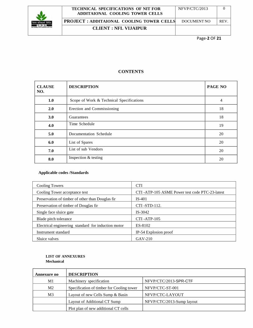
CONTENTS
Applicable codes /Standards
Cooling Towers CTI Cooling Tower acceptance test CTI -ATP-105 ASME Power test code PTC-23-latest Preservation of timber of other than Douglas fir IS-401 Preservation of timber of Douglas fir CTI -STD-112. Single face sluice gate IS-3042 Blade pitch tolerance CTI -ATP-105 Electrical engineering standard for induction motor ES-8102 Instrument standard IP-54 Explosion proof Sluice valves GAV-210
LIST OF ANNEXURES Mechanical
Annexure no
DESCRIPTION M1 Machinery specification NFVP/CTC/2013-SPR-CTF
M2 Specification of timber for Cooling tower NFVP/CTC-ST-001 M3 Layout of new Cells Sump & Basin NFVP/CTC-LAYOUT
Layout of Additional CT Sump NFVP/CTC/2013-Sump layout Plot plan of new additional CT cells
CLAUSE NO.
DESCRIPTION
PAGE NO
1.0 Scope of Work & Technical Specifications 4
2.0 Erection and Commissioning 18
3.0 Guarantees 18
4.0 Time Schedule 19
5.0 Documentation Schedule 20
6.0 List of Spares 20
7.0 List of sub Vendors 20
8.0 Inspection & testing 20
TECHNICAL SPECIFICATIONS OF NIT FOR ADDITAIONAL COOLING TOWER CELLS
NFVP/CTC/2013 0
PROJECT : ADDITAIONAL COOLING TOWER C ELLS DOCUMENT NO REV.
CLIENT : NFL VIJAIPUR
Page-3 OF 21
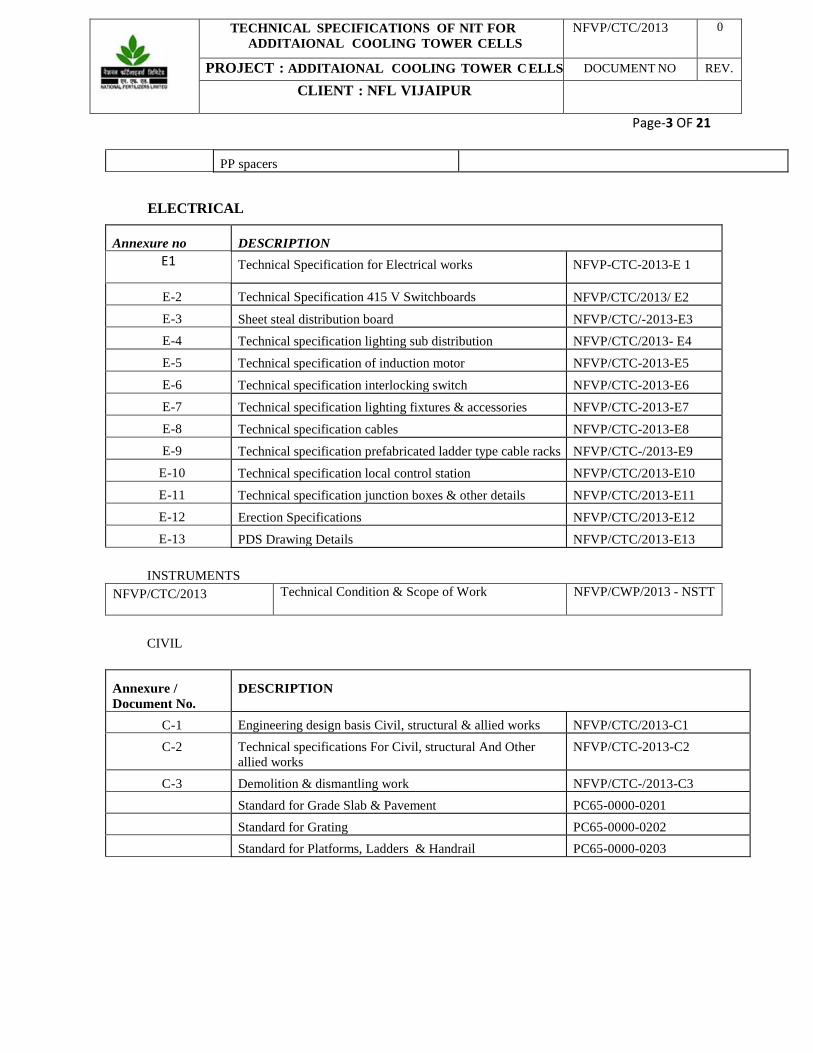
PP spacers
ELECTRICAL
Annexure no
DESCRIPTION E1 Technical Specification for Electrical works NFVP-CTC-2013-E 1
E-2 Technical Specification 415 V Switchboards NFVP/CTC/2013/ E2 E-3 Sheet steal distribution board NFVP/CTC/-2013-E3 E-4 Technical specification lighting sub distribution NFVP/CTC/2013- E4 E-5 Technical specification of induction motor NFVP/CTC-2013-E5 E-6 Technical specification interlocking switch NFVP/CTC-2013-E6 E-7 Technical specification lighting fixtures & accessories NFVP/CTC-2013-E7 E-8 Technical specification cables NFVP/CTC-2013-E8 E-9 Technical specification prefabricated ladder type cable racks NFVP/CTC-/2013-E9
E-10 Technical specification local control station NFVP/CTC/2013-E10 E-11 Technical specification junction boxes & other details NFVP/CTC/2013-E11 E-12 Erection Specifications NFVP/CTC/2013-E12 E-13 PDS Drawing Details NFVP/CTC/2013-E13
INSTRUMENTS
NFVP/CTC/2013 Technical Condition & Scope of Work NFVP/CWP/2013 - NSTT
CIVIL
Annexure / Document No.
DESCRIPTION
C-1 Engineering design basis Civil, structural & allied works NFVP/CTC/2013-C1 C-2 Technical specifications For Civil, structural And Other
allied works NFVP/CTC-2013-C2
C-3 Demolition & dismantling work NFVP/CTC-/2013-C3 Standard for Grade Slab & Pavement PC65-0000-0201 Standard for Grating PC65-0000-0202 Standard for Platforms, Ladders & Handrail PC65-0000-0203

TECHNICAL SPECIFICATIONS OF NIT FOR ADDITAIONAL COOLING TOWER CELLS
NFVP/CTC/2013 0
PROJECT : ADDITAIONAL COOLING TOWER C ELLS DOCUMENT NO REV.
CLIENT : NFL VIJAIPUR
Page-4 OF 21
1. SCOPE OF WORK & TECHNICAL SPECIFICATIONS: 1.1 Introduction:
Ammonia & Urea plant at NFL Vijaipur-II has been recently revamped to produce 1864 TPD ammonia & 3230 TPD urea respectively. To meet the additional cooling water requirement to run the plant at sustained higher load, it is proposed to install one additional cooling tower cells in existing cooling towers of Ammonia-II & one additional cooling tower cells in existing cooling towers of Urea-II as per requirement given in present NIT & layout enclosed. The capacity of both cells & CW pumps shall be same.
The hot and cold cooling water distribution of new tower shall be interconnected with existing cooling towers. The cold water from new CT sump of ammonia and urea plants shall flow to new CW pump as well as to the sump of existing cooling Tower sump through underground piping respectively.
1.2 General Description:
1.2.1 Basic Specifications of Cooling Tower Cell It is proposed to install o n e n u mb e r o f e a c h additional cooling tower cells with following specification
for Ammonia and Urea plant of NFL Vijaipur- II .
F-3801G AND F-4801F Type : Induced Draft Double Cross Flow Design Capacity of one cell (m3/hr) : 3500 Design Wet Bulb Temperature : 29 Design Dry Bulb Temperature : 36 Design Cold Water Temperature : 33.3 Design Hot Water Temperature : 43.3 Inlet Water Distributor : Max Height above Water Level 12 m Drift Losses : 0.05% Liquid Gas Ratio : 1.65 Return Cooling Water Pr (Kg/cm2g) : 1.5 (At Ground level)
: As per General specification for Basic Requirements and Load calculation as per IS-875
1.2.2 The details of existing Cooling Towers is given below: The new cells shall also be of the same design as existing
Cooling Tower Make Model No. of Cells Ammonia-II M/s. Paharpur Cooling
Towers, Kolkata 6616-4-06 6
Urea-II 6616-4-05 5
TECHNICAL SPECIFICATIONS OF NIT FOR ADDITAIONAL COOLING TOWER CELLS
NFVP/CTC/2013 0
PROJECT : ADDITAIONAL COOLING TOWER C ELLS DOCUMENT NO REV.
CLIENT : NFL VIJAIPUR
Page-5 OF 21
1.3 Climatic Conditions 1.3.1 Atmospheric Pressure
Maximum recorded, mbar 967.9 Minimum recorded, mbar 936.9 Design, mbar 939.0
1.3.2 Air Temperature Jan July
Highest Temperature recorded, 0C 31.7 41.7 Monthly mean daily max. temp., 0C 24.0 31.1 Monthly mean temp. at 17:30 , 0C 22.7 26.1 Monthly mean temp. at 10:30 , 0C 11.9 25.7 Monthly mean daily min. temp., 0C 8.2 24.0 Lowest Temperature recorded, 0C -2.2 20.6 Maximum Temperature recorded, 0C 46.1 (May) Lowest Temperature recorded, 0C -2.2 (January) Annual mean temperature recorded, 0C 22.3
1.3.3 Design Air / humidity Temperature 35 0C Relative Humidity 100
1.3.4 Rainfall Mean annual Rainfall, mm 1219.8 Heaviest in a day, mm 290.5 Design (1 hour), mm 120.0
1.3.5 Humidity Jan July
Monthly mean relative humidity at 10:30, % 61 84 Monthly mean relative humidity at 17:30, % 37 71
1.3.6 Wind The recorded mean wind speeds are as follows: January 1.4 Km/hr February 5.1 Km/hr March 5.9 Km/hr April 7.4 Km/hr May 10.4 Km/hr June 13.0 Km/hr July 12.0 Km/hr August 10.0 Km/hr September 7.4 Km/hr October 5.9 Km/hr November 2.9 Km/hr December 3.3 Km/hr

TECHNICAL SPECIFICATIONS OF NIT FOR ADDITAIONAL COOLING TOWER CELLS
NFVP/CTC/2013 0
PROJECT : ADDITAIONAL COOLING TOWER C ELLS DOCUMENT NO REV.
CLIENT : NFL VIJAIPUR
Page-6 OF 21
Prevailing direction is W to E from February to June, SW to NE from June to October and NE to SW from October to February. Design Wind Speed. Km/hr 160 Design Wind load for design against wind forces and wind load shall be increased by 30 % to cater for the effect on piping systems, platform, ladders etc.
1.3.7 Ambience Due to the location within an industrial complex, the air may contain particles of send & Urea. The air may accidentally contain Ammonia vapour, and for this reason no part in direct contact with the atmosphere may be constructed from copper or copper alloys.
1.3.8 Load bearing capacity Nature of terrain Flat and Graded Land characteristics Clay, Sand & Fractured rock All major foundations may be placed at a depth of 1.5 - 2.0 meters below ground level with net sage bearing capacity of 300 – 450 KN/m2. Ordinary foundations may be placed at depth of 1.0 – 1.5 meters below ground level with a net safe bearing capacity of 150 – 200 KN/m2.
1.3.9 Seismic conditions The design must be executed as per code IS 1893 (1975). The actual site at Vijaipur is defined as being situated in zone one (I).

TECHNICAL SPECIFICATIONS OF NIT FOR ADDITAIONAL COOLING TOWER CELLS
NFVP/CTC/2013 0
PROJECT : ADDITAIONAL COOLING TOWER C ELLS DOCUMENT NO REV.
CLIENT : NFL VIJAIPUR
Page-7 OF 21
1.4 Scope of Work
The Contractor’s scope of work shall include: 1. Detailed design, engineering of all equipments & accessories including all concrete foundations &
cooling tower basin & pump sumps. 2. Procurement and supply of complete materials & bought-out items whatever deemed necessary for
Civil, Mechanical, E lectrical & instrumentation. 3. Construction of cell including hot water basin, pump sump & any other work associated to complete cell. 4. Fabrication at shop/site as required, loading, unloading & transportation, storage at site, assembly,
prefabrication of cooling tower structures, piping & erection of superstructures, mechanical, electrical & instrumentation system, inspection, testing, painting, statutory approvals, commissioning, calibration, trial runs and demonstration of guarantees, & supply of complete cooling tower cells along with spares .
4 Both the cells shall be designed to match the existing cells as per specification given above. 5 Any other work required for the completion of the new Cooling tower cells in all respects. 6 Construction of 2.0 meter wide RCC pavement all around both the cells as per relevant
standards/practices. 7 To make trenches/Cable Rack/Cable trays for laying out cables from both the cells to MCC.- Electrical
substation. 8 Re-instatement / Restoration of original structure / ground/ building/ trench, roads / Electrical panel in
sub-station etc. if effected/ damaged during implementation of the work. 1.4.1 Scope of Supply
Scope of supply shall include following.
I. Cooling tower cell basin, pump sump. II. Cooling tower cell with water distributors, cooling tower fans (FRP hollow), motor and reduction g e a r .
III. Sluice gate with inserts, screen with inserts, anchor bolts. IV. IBD Drain valve and overflow arrangement. V. Grouting of pump suction line & sump Interconnection lines with the new sump .
VI. Cable Trays on CT structure. VII. Vibration cut-off switch/sump level indicator/other instrument deemed necessary.
VIII. Electrical Lighting IX. Fan motor power & control cable layout & its connection with the existing substation including installation of new
LT Panel/switch gear in the existing electrical substation
1.4.2 Scope of Services a. Basic and Detailed design of cooling tower cell sump, sluice gate, pumps sump, pump suction line
as per existing CT cell. b. Basic and Detailed design of cooling tower cells, cooling tower fan, motor and reduction gear. c. Detailed design of structural work d. Documents & approvals including approvals from statutory authorities including those required to be
taken by client. e. Procurement of raw materials, bought out components. f. Demolition of existing RCC flooring, structure, and excavation at site marked for new Cells of Cooling
Tower for construction of new Basin & sump including dewatering if required. (Bidders may please note that sites for new Cell of Urea-II & Ammonia-II is RCC & normal soil on surface respectively & may have water table close to the surface .)
g. Construction of cell including hot water basin, pump sump & any other work associated to complete cell h. To grout the Pipes for sump to sump connection, Pump Suction, and IBD Valve Pipes. (The necessary
Pipes & puddle flanges shall be provided by NFL as free issue).
i. Fabrication and assembly at shop & at site.

TECHNICAL SPECIFICATIONS OF NIT FOR ADDITAIONAL COOLING TOWER CELLS
NFVP/CTC/2013 0
PROJECT : ADDITAIONAL COOLING TOWER C ELLS DOCUMENT NO REV.
CLIENT : NFL VIJAIPUR
Page-8 OF 21
j. Inspection & testing, including third party inspection at shop and at site.
k. Packing, forwarding & delivery to site.
l. Storage & handing at site
m. Erection & Installation of all equipment’s and materials at site including Civil, Mechanical, Electrical & Instrumentation work, and detailed design of Illumination system for cooling tower.
n. Mechanical Completion.
o. Hydro testing, Pre-commissioning and reliability runs.
p. Commissioning and performance guarantee run and handing over.
q. Arrange all necessary instruments, tools/tackles required to aid pre-commissioning, commissioning and performance guarantee tests.
r. Clear the Battery Limit of all construction aids, debris, etc. and provide a tidy work plan.
s. All documents/drawings shall be submitted by Contractors as per documentation schedule given in NIT.
t. Bidder to furnish load details, GA drawings etc. sufficient for complete design of cooling tower basin/sump and any other accessories.

TECHNICAL SPECIFICATIONS OF NIT FOR ADDITAIONAL COOLING TOWER CELLS
NFVP/CTC/2013 0
PROJECT : ADDITAIONAL COOLING TOWER C ELLS DOCUMENT NO REV.
CLIENT : NFL VIJAIPUR
Page-9 OF 21
1.5 .0 Design Basis:
1.5.1 Cooling tower
Cooling tower shall be designed on following basis:-
Parameter UNIT Ammonia-II Urea-II
Type and Model Induced draft cross flow
Design flow M3/hr 3500 3500
Heat Load Mcal/hr 35000 35000
No. of cells 1 1
Inlet hot water Temperature
oC 43.5 43.5
Outlet cold water Temperature
oC 33.5 33.5
Design wet.bulb temperature
oC 29 29
M. O. C. of Cooling Tower
Treated Wood
Cycle of concentration
7-8 7-8
Windage loss 0.05% Max. 0.05% Max.
1.5.2 Cooling water analysis
( UREA PLANT)
Urea Circulating Cooling water is based on non-chromate based treatment and the quality is given as below.
Sr.No Parameters UNIT Specified Range
1 pH 6.8-7.5 2 Turbidity NTU 4.0-20.0 3 Free Chlorine mg/l 0.2-0.5 4 Silica mg/l 50-100 5 Ortho Phosphate As PO4 mg/l 7.0-9.0 6 Total Ammonia Mg/l as NH3 40 7 Total hardness Mg/l as CaCO3 600-1000 8 Calcium hardness Mg/l as CaCO3 400-650 9 Chloride Mg/l as Cl 150-250
10 Iron Mg/l as Fe 0.3-1.0 11 Zinc Mg/l as Zn 1.0-1.5

TECHNICAL SPECIFICATIONS OF NIT FOR ADDITAIONAL COOLING TOWER CELLS
NFVP/CTC/2013 0
PROJECT : ADDITAIONAL COOLING TOWER C ELLS DOCUMENT NO REV.
CLIENT : NFL VIJAIPUR
Page-10 OF 21
(AMMONIA PLANT)
Ammonia Circulating Cooling water is based on non-chromate based treatment and the quality is given as below.
Sr.No Parameters UNIT Specified Range
1 pH 6.8-7.5 2 Turbidity NTU 4.0-20.0 3 Free Chlorine mg/l 0.2-0.5 4 Silica mg/l 50-100 5 Ortho Phosphate As PO4 mg/l 7.0-9.0 6 Total Ammonia Mg/l as NH3 40 7 Total hardness Mg/l as CaCO3 600-1000 8 Calcium hardness Mg/l as CaCO3 400-650 9 Chloride Mg/l as Cl 150-250
10 Iron Mg/l as Fe 0.3-1.0 11 Zinc Mg/l as Zn 1.0-1.5

TECHNICAL SPECIFICATIONS OF NIT FOR ADDITAIONAL COOLING TOWER CELLS
NFVP/CTC/2013 0
PROJECT : ADDITAIONAL COOLING TOWER C ELLS DOCUMENT NO REV.
CLIENT : NFL VIJAIPUR
Page-11 OF 21
1.6.0 Cooling Tower Specifications: Both the cooling towers shall be identical. One shall be connected to Existing Ammonia CT & another shall be connected to Existing urea cooling tower. Both cells shall be mechanical induced draught type having one fan for each cell, motor, gear reducer, piping distribution system, nozzles valves, etc. The water air relationship shall b e “Cross Flow” designed to meet the best performance requirements given in the data sheet. Where a tower is divided into cells, each cell shall be identified and so designed that each one of them could be operated independently of the rest of the cells and can also be repaired, maintained and cleaned while the other cell is in service.
The basin and channel shall be so designed that full flow conditions can be attained even at Minimum water level in the basin. The sluice gates should be able to discharge full cell capacity at minimum water level and levels of gates shall be fixed accordingly. The cooling tower fill shall be splash type for cooling towers.
The design of the cooling tower shall generally be as per this specification and as per relevant CTI and International standards to meet the performance requirements given in the attached data sheet. The information for structural design of the cooling tower furnished herein is for general guidance of the Contractor. The thermodynamic design should be such that the difference between temperature of outgoing mixed air and hot water shall not be less than 4oC. If the temperature selected is less than 4oC, complete thermodynamic design justifying the same shall be furnished.
Contractor shall carry out the design and detailed engineering within the battery limit of Cooling Tower Package unit and its inter connecting piping, valves etc in conformity with all rules and regulations, codes and norms specifications and design basis prevailing. Piping battery limit of the CT shall be 500 mm above ground level for respective cooling to wer .
1.6.1 STRUCTURAL COMPONENTS FOR TIMBER COOLING TOWER TIMBER
1.6.1.1 The timber to be used in the cooling tower shall conform to specification no NFVP/CTC-ST-001 and shall be chromate copper arsenate treated. The CCA treatment of timber shall be as per IS-401. However, for Douglas Fir, the treatment shall be as per IS-401 but retention of preservative and penetration schedule shall be as per CTI-112 standard. Testing of timber shall be as per IS-1708 from M/s. Forest Research Institute, Dehradun.
1.6.1.2 All chromate copper arsenate (CCA) treated timber shall be well seasoned, free from knots or other imperfections and shall be cut to correct sizes as required for use. Wood shall be cut to dimensions, notched and drilled prior to preservative treatment. Pretreatment shall be considered to also include proper site treatment of any fresh surface exposed such as holes or cuts made in timber prior to erection.
1.6.1.3 All CCA treated wood to be used for various parts of the tower frame work, casing, inlet louvers, fan deck etc. shall be dressed on sides except wood for the fill and drift eliminators which shall be finished rough.
1.6.1.4 The main columns of the cooling tower framework shall be of suitable design to transmit all loads to the cooling tower foundation and shall be properly braced by horizontal and diagonal members. The framework shall not be stressed greater than the maximum values, given in code of practice for use of structural Timber in buildings. All portions of the framework structure shall be bolted.
1.6.1.5 Columns shall be 4" x 4" (nominal), or larger, spaced on 4'-0" centers longitudinally and 8'-0" centers transversely. Interior columns shall be of a length that will accommodate a maximum cold water basin depth of 5'-4" below the basin curb. Columns requiring anchorage shall be anchored to the concrete cold water basin by hot dip galvanized (HDG) cast iron anchor castings.
1.6.1.6 The length of Timber components specially structural members i.e., Columns, Girts, Diagonals etc. shall not be more than 12’ (Twelve feet).
1.6.1.7 There shall be 2" x 4" (nominal) or larger longitudinal and transverse girts, and 2" x 6" (nominal) transverse fan deck and hot water basin support girts on both sides of interior columns; an on the inside of all perimeter columns. Girt lines shall be located on vertical centers not to exceed 6'-0".

TECHNICAL SPECIFICATIONS OF NIT FOR ADDITAIONAL COOLING TOWER CELLS
NFVP/CTC/2013 0
PROJECT : ADDITAIONAL COOLING TOWER C ELLS DOCUMENT NO REV.
CLIENT : NFL VIJAIPUR
Page-12 OF 21
1.6.1.8 A tension/compression system of diagonal braces shall stiffen the structure, and transfer wind and seismic
loads to the basin anchor points. Diagonal connectors shall be either of hot dip galvanized (HDG) cast iron or series 300 stainless steel. Shear plates shall be integral with the connector side straps to prevent shear-loading of the connecting bolts. Diagonals shall be anchored to the cold water basin using (HDG) cast iron diagonal connectors and anchor castings. The line of action through the diagonal to the point of anchorage shall be direct. Eccentric loading of framing members will not be permitted.
1.6.1.9 Critical framing joints shall be made with structural ceramic rings or structural shear plates molded of glass
filled nylon or equally inert material of comparable strength. Bidders shall include with their quotation complete wind/seismic diagrams and column operating/shutdown point loads.
1.6.1.10 All structural connections and splices shall be through-bolted using full shank 1⁄2" diameter, or larger, series
300 stainless steel machine bolts, nuts and washers. Washers shall be of Size ID-13 mm x OD-50 mm x 2 mm thick only. Use of conventional washer of smaller size shall not be allowed.
1.6.1.11 The use of nails for the framework shall not be permitted. For timber Tower, the CCA
treated timber structure shall be designed and constructed in accordance with relevant specifications.
1.6.1.12 No ply material shall be used in construction of Cooling Tower for any component
1.6.2.0 FRAME WORK
1.6.2.1 Casing
The endwalls of the tower, as well as the elevated sidewalls of the fan deck, shall be cased with 3+0/- 0.2 mm thick corrugated Fire resistant, Isophthalic (UV stabilized) FRP panels of light grey color attached to tower columns with stainless steel 304 screw shank or ring shank fasteners and self-sealing washers. Panels shall be installed with corrugations horizontal, and shall be lapped to shed water inward to the tower. Vertical joints shall be lapped and sealed watertight. Casing ends at tower corners shall be covered with 12 oz/sq ft FRP 90° corner rolls of 6” x 6”x 8’.
The FRP sheets shall conform to IS:10192-latest for Mech. Properties & corrugation shall conform to Sr. 1(i) of Table 1 of IS:459-1992.
1.6.2.2 Air inlet louvers The entire height and length of the two air inlet faces of the tower shall be louvered with 3+.0/-0.2 mm thick corrugated Fire resistant, Isophthalic (UV stabilized) FRP panels of light grey color. Louvers shall be attached to 2" x 4" (nominal) supports, throughbolted to the louver columns, and supported at the top by polypropylene or stainless steel support bars. Louver columns shall be sloped to maintain louver position in close proximity to the fill for control of water splash, and for purposes of deicing. Louvers shall overlap each other vertically to retain water flow within the tower.
1.6.2.3 Filling Fill shall be splash-type, consisting of polyvinyl chloride (UV stabilized) splash bars hung in SS-304 grids of 14 gauge. The Fills shall be installed in independent 4'-0" longitudinal bays and 6'-0" elevations. They shall be spaced on centers as necessary to achieve the required thermal performance. Each bay of splash bars shall be supported by two or more grids as necessary to prevent bar-sagging and resultant channeling of water.
1.6.2.4 Drift eliminators Drift eliminators shall be three-pass, “C” Type, 100 mm width, manufactured from a minimum of 1.0 thick UV stabilized, rigid PVC. Eliminators shall be manufactured and installed in packs no less than 4'-0" long. Packs shall nest together without air gaps, and shall be easily removable for cleaning and/or replacement. The eliminator blades shall be installed in horizontal position and shall have sufficient drainage holes to drain the accumulated water to the wet side of the cooling tower.

TECHNICAL SPECIFICATIONS OF NIT FOR ADDITAIONAL COOLING TOWER CELLS
NFVP/CTC/2013 0
PROJECT : ADDITAIONAL COOLING TOWER C ELLS DOCUMENT NO REV.
CLIENT : NFL VIJAIPUR
Page-13 OF 21
The eliminator's final pass shall direct the airflow toward the fan. Maximum allowable drift shall not exceed 0.005% of the design water flow rate. The spacer for assembly / nesting of drift eliminators pack shall be molded PP Spacers each having 10 spacing of 35 mm (Refer Photograph enclosed) of M/s. Super Plast Company, Mumbai or equivalent make. Assembly of drift eliminators by means of PVC Pipes or Steel Rods is not acceptable. No plywood material shall be used for installation of PVC drift eliminator assembly. Only Timber material shall be used.
1.6.2.5 Hot Water Distribution Deck & Casing wall between Fan Deck &
Hot Water distribution deck shall be fabricated of 1” x 6” x 8’ thick, tongue and groove, treated Timber. Casing wall between Hot Water Distribution Deck & Fan Deck shall be fabricated of 1” x 6” x 8’ thick, tongue and groove, treated Timber. The casing wall in each cell shall include a removable panel to provide access to the upper plenum area.
1.6.2.6 Splash Box Splash Boxes shall be fabricated from CCA treated Timber only and shall be covered, labyrinth-type splash-suppression boxes in the basins.
1.6.2.7 Fan deck The fan deck shall act as a working platform for maintenance personnel. It shall be fabricated of 1 ½” x 6” x 8’ thick, tongue and groove, treated Timber, supported by fan deck Girts and joists on 2"-0" centers. To minimize turbulence of airflow into the fan cylinder, fan deck protrusion into the fan cylinder opening shall not exceed 1".
1.6.2.8 Fan cylinder Fan cylinders shall be molded FRP, of 13’9” height and shall have an extended stack of venturi shape to attain conversion of velocity pressure to static pressure. The height of stack shall be such that the recirculation effects of air shall be reduced to minimum possible. Fan tip clearance shall not exceed 0.5% of the fan diameter. Each fan cylinder segment shall be through-bolted to both the fan deck and a primary fan deck framing member. Anchorage by lag screws into the fan deck alone will not be permitted. Fan cylinder connection and anchorage hardware shall be series 300 stainless steel. Rings for fan stacks shall be of the same material as that of fan stack and shall be concentric with the fan. Fan cylinders shall have removable segments of sufficient size to allow removal of all mechanical equipment components, and shall have a coupling guard, conforming to OSHA standards, to shroud that portion of the drive shaft that extends outside the fan cylinder.
1.6.2.9 Access Door & Walkway There shall be a 33" wide by 61" high Doors made of CCA treated timber access door in each end wall of the tower at the cold water basin curb level. A 24" wide treated Douglas fir walkway shall extend the full length of the tower at that level. If the floor of the cold water basin is 4'-0" or more below the walkway, the walkway shall include 2" x 4" (nominal) guardrails and kneerails. Toe-boards shall also be provided.
1.6.2.10 Stairways One endwall of the tower shall be equipped with a CCA Treated Timber stairway rising from the level of the cold water basin curb to the fan deck. Stairs shall be 45°, 3'-0" wide, with 8" rise and run. Landings shall occur at 6’ feet elevations. Guardrails and knee rails shall be 2" x 4" (nominal). Guardrails shall be through-bolted to the stairway posts. Toe-boards shall also be provided at landings.
A epoxy painted vertical steel ladder with safety cage per OSHA recommendations shall be provided at the other end of the tower. The ladder shall provide access from the cold water basin curb to the fan deck. From Ground level to basin curb the staircase shall be of RCC & shall be in bidder scope. Guardrails, Knee-rails, & Toe-boards epoxy panted steel shall also be also provided at landings .
TECHNICAL SPECIFICATIONS OF NIT FOR ADDITAIONAL COOLING TOWER CELLS
NFVP/CTC/2013 0
PROJECT : ADDITAIONAL COOLING TOWER C ELLS DOCUMENT NO REV.
CLIENT : NFL VIJAIPUR
Page-14 OF 21
1.6.2.11 Hand rail
The fan deck of the tower, as well as the perimeter of the hot water distribution basins, shall be surrounded by CCA treated wood 2" x 4" (nominal) guardrail and kneerail OSHAS. The guardrail shall be 42" high and shall be throughbolted to columns on 4'-0 centers longitudinally, and 8'-0 centers transversely. When the span between posts exceeds 6'-0", a 2" x 4" (nominal) cap strip shall be added to the top edge of the top guardrail. Each cell of the tower shall be equipped with vertical ladders extending downward from the fan deck level to a walkway above the waterline in the hot water distribution basins. Ladders shall be constructed of CCA treated wood fir 2" x 4" (nominal). Walkways shall extend out to the splash box cover.
1.6.2.12 Basin and channel
The basin for cooling tower shall be of reinforced cement concrete construction similar to the existing cell in design. The Contractor shall furnish civil scope drawing for basin along with foundation load, which shall be designed and constructed by bidder. The basin including channel shall have a holding capacity to retain 6 minutes of re-circulating water above Minimum water level. Drain off and sludge removal arrangement with piping valves and flanges etc. Pipe shall be of carbon steel. Valves shall be of Cast steel.( A216 Gr WCB) Overflow arrangement. Access platforms of concrete and Carbon steel rung ladders for operation (All Carbon Steel components shall have 2 coats of chlorinated rubber paint over two coats of high build chrominated rubber zinc phosphate primer). Sluice gates for isolation of each cell shall be as per IS 3042.
Top of the cold water channel shall be covered with precast cement concrete slabs with lifting hooks.
The screen at the outlet of the cold water channel shall be SS-304 and made up of small sections fitted with lifting hooks to facilitate section wise removal. A suitable working platform s h a l l b e p r o v i d e d f o r r e m o v a l o f s c r e e n . The effective velocity through the screen shall not be more than 0.3 M/Sec. No. of screens provided shall be two; in addition one spare screen shall also be supplied. The velocity through the channel shall not be more than 1.0 M/Sec. considering depth below minimum water level. The velocity through the sluice gates shall not be more than 1.2 M/Sec.
Maximum, minimum and normal operating water levels in the basin shall be clearly indicated in the data sheets.
The layout of basin & channel shall be like existing. The same is attached for reference.
1.6.2.13 Cooling tower piping and hot water distribution system
Two hot water distribution basins located above the banks of fill shall extend the full length of the tower. Basins shall deliver incoming hot water to the fill by gravity, through removable non clog type polypropylene metering orifice nozzles located suitably in the floor of the basins. Nozzles shall be easily accessed and cleaned
Water shall come to these basins via a system of separate inlet piping and valves for each cell of the tower. Inlet piping shall deliver water to the distribution basins through flanged butterfly valves located on ground floor. Inlet and crossover piping shall be in Owner’s scope. However, the bidder shall provide the layout & size of the hot water distribution pipes.
TECHNICAL SPECIFICATIONS OF NIT FOR ADDITAIONAL COOLING TOWER CELLS
NFVP/CTC/2013 0
PROJECT : ADDITAIONAL COOLING TOWER C ELLS DOCUMENT NO REV.
CLIENT : NFL VIJAIPUR
Page-15 OF 21
Hot water distribution system shall be suitably covered at the top with ACB sheets to minimize algae growth and dust and other foreign material getting into the recirculating water.
1.6.2.14 Mechanical components
All mechanical components of the cooling tower viz fans, hubs, speed reducers, drive shafts etc. shall be designed to withstand the corrosive and moist environment in which these are proposed to operate for the cooling tower service. The mechanical equipment in the cooling tower will not give vibration of more than 125 micron. The gear boxes and fans shall be capable to take this vibration.
1.6.2.15 Fans
Fans shall be energy efficient, hollow construction, axial flow type, have a minimum of five FRP (Fiber reinforced plastic) blades with adjustable pitch, blades with appropriate twist and taper to produce maximum airflow. All blades shall be fabricated with consistent moment weights to permit the change-out of individual blades without the need for total fan rebalance. Tip speed of the fan shall not exceed 60 meter/sec.
Hubs shall be fabricated of series 300 stainless steel or hot dip galvanized steel and ductile cast iron, assembled with series 300 stainless steel hardware. Spoke-type hubs, if used, shall be equipped with an FRP hub cover to prevent recirculation of air at the plane of the fan. Hubs shall be statically balanced at the factory.
Combined Noise level of fans at rated pitch angle and speed shall not exceed 85 decibels above threshold level at a horizontal distance of 1M from the fan.
The blades shall be preferably of make M/s Maya fan air Dewas, M/s Coolflow Engineers Mumbai, Recondo Cooing Towers, Mumbai. However bidder may use their own blades or other make having proven performance records.
1.6.2.16 Gear reducers
Speed reducers shall be right-angle type, utilizing helical and/or spiral bevel matched gear sets. Cases shall be epoxy coated, ASTM Class 20, gray cast iron. Bearings shall be tapered roller type. Gears and bearings shall be splash-lubricated in a bath of turbine type mineral oil, and units shall be capable of operating in either forward or reverse with equal facility. Speed reducers using external oil pumps will not be allowed. The slow speed shaft shall have double oil seals.
Speed reducers shall meet or exceed the requirements of CTI STD-111 and AGMA Std. 420.04, and service factor at applied horsepower shall not be less than 2.0. They shall be run-in under load and adjusted at the factory, and the interior surfaces coated with a rust proofing oil prior to shipment.
Each cell shall be equipped with an external oil level gauge and gear reducer drain line, terminating at a sight glass and plug located outside the fan cylinder near the motor. The drain Line shall be series 300 stainless steel or Flexible double Rayon Braided Synthetic Rubber Hose. The size of Oil drain shall be 25 NB.
The Gear Reducer shall be of Marley series 32.2 with Gear ratio of 12.93:1 to maintain 100% interchangeability with existing gear boxes in cooling towers at Vijaipur. The outline dimension of the existing gear boxes are enclosed for reference.
1.6.2.17 Drive shaft
Drive shaft connecting motor and the speed reducer shall be of SS-304 for outdoor operation in highly humid atmosphere. Drive shaft tubes and flanges shall be manufactured of type 304 stainless steel. Couplings shall be hot dip galvanized cast iron, joined to the drive shaft by flexible neoprene bushings and cadmium
TECHNICAL SPECIFICATIONS OF NIT FOR ADDITAIONAL COOLING TOWER CELLS
NFVP/CTC/2013 0
PROJECT : ADDITAIONAL COOLING TOWER C ELLS DOCUMENT NO REV.
CLIENT : NFL VIJAIPUR
Page-16 OF 21
plated steel inserts. Connecting hardware shall be 300 stainless steel. Drive shaft assemblies shall be dynamically balanced at the factory at full motor speed. Two galvanized steel drive shaft guards anchored to the mechanical equipment support shall surround the drive shaft for containment in the event failure.
The drive shaft shall have flexible couplings on each end to absorb any misalignment during operation. The bushes of the flexible coupling shall be neoprene material and bolts shall be of galvanized steel.
The entire rotor assembly including drive shaft shall be dynamically balanced.
1.6.2.18 Support and guards
The motor and the speed reducers shall be supported on a single hot dip galvanized structural steel with epoxy coaltar painted frame with all necessary bracings to prevent deflections, misalignment or excessive vibrations. The motor and the speed reducer shall be accurately aligned on the supports and securely bolted to it with SS-304 bolts, nuts, split washers and steel washers. It shall be fastened to the wood structure through heavy wide flange beams & castings. All moving parts of the fan and motor assembly shall be properly guarded wi th fo rmed re ta iners for safety reasons.
1.6.2.19 Motor
The motor shall be located outside the exhaust air stream at the top of cooling tower.
Each fan shall be driven by a single speed, totally enclosed, fan cooled weather proof suitable to chemical plant type, squirrel cage induction motor of class ‘F’ insulation. Speed and electrical characteristics shall be as per electrical specification enclosed
If the load applied to the motors exceeds 90% of their nameplate rating, then they shall have a 1.15 service factor and the service factor beyond 1.0 shall not be considered available for load.
Motors shall be located outside the fan cylinders and shall be connected to the speed reducers by tubular, extended, full floating, non-lubricated drive shafts.
1.6.2.20 Hardware
All cooling tower hardware shall be of corrosion resistant material suitable for sea water application.
All bolts, nuts and washers shall of SS-304. All nails shall be of stainless steel SS-304.
The anchors for the frame work posts shall be of HDG.
Joints connection and/or connector plates shall be MS Galvanized for shear plates and ceramic rings for structural.
No hardware shall be of copper or copper based alloy.
1.6.2.21 Vibration cut-off switch
One vibration cut off switch with adjustment for sensitivity for each fan shall be provided and they shall be of weather-proof to IP-65 construction. This shall be mounted on the fan motor gear supports, outboard of fan ring. Vibration switch shall cut off Cooling Tower fan from MCC in case of high vibration of any CT fan. Alarm and Tripping indications shall be provided on annunciation panel and 4-20 ma output to panel mounted recorder. Vibration Switch shall be from M/s PMC- Beta (USA) or ACD-machines (Mumbai). Necessary cabling shall be provided by the bidder.
TECHNICAL SPECIFICATIONS OF NIT FOR ADDITAIONAL COOLING TOWER CELLS
NFVP/CTC/2013 0
PROJECT : ADDITAIONAL COOLING TOWER C ELLS DOCUMENT NO REV.
CLIENT : NFL VIJAIPUR
Page-17 OF 21
1.6.2.22 Exclusions
Following are excluded from Contractor’s scope of work:
a) Supply of instrument air, power & other utilities to the plant.
b) Piping between new Pump sumps & Pump sumps of existing cooling tower.
c) Hot water distribution Risers & their Valves
d) All consumable chemicals, lubricants etc. except chemical for Local CCA Treatment of Timber & first charge of all chemicals, grease and lubricants are to be supplied by the Contractor.
e) Operating staff is excluded but operation supervisors and maintenance personnel shall be arranged by the Contractor during commissioning, trial and performance test runs.
1.7 .0. Quality assurance & control:
1.7.1 Quality Assurance (QA) shall mean the organizational set up, procedures as well as test
methods and facilities developed by Contractor in order to assure that all equipment leaving Contractor’s shop are of the highest possible quality i.e. either equal to or better than the requirement specified.
1.7.2 Quality Control (QC), shall mean all the tests, measurement, checks and calibration which
are to be carried out in Contractor’s shop in order to compare the actual characteristics of the equipment/ unit /system with the specified ones, along with furnishing of the relevant documentation (certificates/records) containing the data or result of these activities.
1.7.3 Contractor shall submit a comprehensive description (manual) of QA/QC measures contemplated
by him for implementation with regard to this specification. It is contractual obligation of the Contractor to develop and implement adequate QA/QC systems.
1.7.4 QA/QC system shall cover all products and services of the contract i.e. documentation material, shop and site fabrication, transportation and site works, including job sub contracted by the Contractor.
1.8 Progress reporting
Contractor shall prepare monthly progress report and report under the following broad heads, indicating schedule and actual status of individual items. - Basic Engg. - Detailed Engg. - Procurement (Ordering) - Manufacture - Delivery - Construction
- Commissioning It should contain : 1. Executive summary 2. ‘S’ Curve indicating schedule & actual percentage progress. .
TECHNICAL SPECIFICATIONS OF NIT FOR ADDITAIONAL COOLING TOWER CELLS
NFVP/CTC/2013 0
PROJECT : ADDITAIONAL COOLING TOWER C ELLS DOCUMENT NO REV.
CLIENT : NFL VIJAIPUR
Page-18 OF 21
2.0 ERECTION AND COMMISSIONING
2.1 Erection
Contractor shall undertake erection of all equipment, machineries, piping, and electrical as per Contractor scope of work to the entire satisfaction of client/consultant. Contractor shall abide by local laws and regulations.
2.2 Testing & Commissioning
The individual equipment, motor, instrument shall be tested in accordance with related standard during pre- commissioning.
3.0. GUARANTEES:
3.1 Workmanship guarantee:
Contractor shall guarantee all components of package against faulty design, improper material of construction and poor workmanship in addition to performance guarantee. Approval by M/s N.F.L f o r design calculation and detailed shop drawing, will not in any way absolve the Contractor from his responsibility. Should any repair or replacement be necessary owing to any type of failure on account of design material and workmanship of the item, Contractor shall in view of this guarantee be bound to replace the same either in part or whole without additional cost to purchaser. Repaired or replaced part shall also be covered by same guarantee as in case of main supply. All items shall be guaranteed for 12 months after satisfactory completion of test run or 24 months from the date of completion of Erection whichever is earlier..
3.2 Performance guarantee and trial run:
The individual equipment shall be tested in accordance with standards prior to commissioning to establish the parameter and performance.
Trial run shall be performed for a period mutually agreed upon, without interruption prior to commissioning to establish the satisfactory working of the accessories, equipment. After the pre- commissioning and testing, each unit shall be commissioned to operate at the parameters specified and performance test run shall be conducted.
In the event of failure of performance test run, Contractor shall carry out necessary modification at his own expense to meet the guarantees.
3.3.0 Process Guarantees:
3.3.1 Capacity of each new cooling tower cell shall be as given in design basis.
3.3.2 For each cooling tower cell the hot water shall be cooled by 10 0C.
3.3.3 The completed cooling tower shall be guaranteed to meet the design performance conditions when tested. Acceptance test shall be as per Test procedure ATP-105 in accordance with the Cooling Tower Institute & ASME power test code PTC-23-1958. The contractor shall furnish performance curves based on constant L/G ratio under the following conditions: a) For water rate at design condition and 10% variation. b) For cooling range at design condition 20% variation. c) For wet bulb temperature +1.7oC and - 3.9oC of design wet bulb temperature.
TECHNICAL SPECIFICATIONS OF NIT FOR ADDITAIONAL COOLING TOWER CELLS
NFVP/CTC/2013 0
PROJECT : ADDITAIONAL COOLING TOWER C ELLS DOCUMENT NO REV.
CLIENT : NFL VIJAIPUR
Page-19 OF 21
3.3.4 The completed cooling tower in operation shall also be guaranteed to meet the following
requirements.
a) The approach shall not be greater than that specified in the cooling tower data sheet.
b) Motors driving the fans shall be amply sized for total B.K.W. required including gear losses. The power consumption for running the fan should not exceed the rated B.K.W.
c) There shall be no leakage of water through sides or ends of the tower.
d) Motors, speed reduction gears and fans shall be of adequate design and construction and properly protected for operation in all adverse climatic conditions.
e) Water tightness of basin, piping, valves, sluice gates etc. is to be ensured.
f) Test for cooling capacity to meet design parameters.
g) Test for tripping level of vibration switch.
h) Power consumption shall be within the guaranteed limit mentioned in data sheets. The calculation for the same shall be provided by the bidder along with bid.
i) Motors and fans shall operate satisfactorily in continuous operation with no injurious vibrations and the sound intensity shall not exceed 85 decibels when measured at a distance of 1M from the fan.
3.3.5 The guarantee test will be taken any time up to 12 months of commissioning of water flow and power to the cooling towers. Tests will be conducted according to CTI ATC-105 performance curve method and Contractor shall submit performance curves for operating conditions specified in ATC-105 for verifying the test data.
These curves shall be submitted along with the offer. For cooling tower, only one cell in which water flow element will be installed by Contractors, will be tested for performance acceptance test. The manufacturer can assure t h e m s e l v e s on accuracy of temperature and flow measurements. However, opinion of client will be final in this matter.
The calculations shall be submitted in details showing all stages of calculations, formulae used, densities, specific volume of air used in calculation with supportive evidence in the form of tables/curves etc.
For fan, gear reducer and motor, selection basis, supplier’s performance curve indicating the efficiency available at performance level shall be submitted along with the bid. The supplier’s catalogue shall be permitted in each case.
The minimum air inlet velocity shall be 4 m/sec and minimum air outlet velocity shall be 6m/sec.
4. TIME SCHEDULE
4.1.0 Time schedule for erection & commissioning shall be 12 months from date of LOI.
4.2.0 Contractor shall furnish activity schedule in form of master network in PrimaVera identifying major activities in various areas like design, engineering, p r o c u r e m e n t of materials and bought out items, manufacture of equipment, delivery and construction/ erection & commissioning activities. The schedule should conform to the time period agreed.
4.3.0 Master network shall be discussed and agreed upon. Engineering drawings and data submission schedule shall also be discussed and finalized before issue of letter of intent.
4.4.0 After award of contract, the Contractor shall plan sequence of work of manufacture and erection to meet the plant commissioning dates given above and shall ensure that all work/manufacture, shop testing and shipment of equipment is in accordance with required construction/execution sequence.
4.5.0 Within fifteen days after award of letter of intent Contractor shall submit for review and approval of detailed network schedules based on master network as mutually agreed upon, showing logic and duration of activities in following major areas: Detailed engineering, procurement, manufacture, shop, inspection, testing, dispatch/shipment and receipt at site.
4.6.0 Contractor shall, within fifteen days of award of letter of intent, submit the scheme for
TECHNICAL SPECIFICATIONS OF NIT FOR ADDITAIONAL COOLING TOWER CELLS
NFVP/CTC/2013 0
PROJECT : ADDITAIONAL COOLING TOWER C ELLS DOCUMENT NO REV.
CLIENT : NFL VIJAIPUR
Page-20 OF 21
calculation of percentage progress for schedule and actual, for review and approval of the Principal.
5.0. DOCUMENTATION SCHEDULE
Contractor shall supply documents as per Documentation Schedule as following:
i. Data sheet for cooling tower as per CTI format. ii. All other documents shall be as per documentation schedule given in subsequent part of NIT.
6.0 LIST OF SPARES (common for both cells)
1. The Contractor shall supply free of cost spare parts and Consumables (except raw materials and Utilities supplied by others) and required during Pre-commissioning & Commissioning of the package until the package is handed over to the Owner after Performance Test.
2. The spares required for commissioning & two years for the package shall be as per below mentioned list.
Sl. Description Qty. Reqd. (set)
Mechanical – Rotating Equipment’s
1 Complete coupling per cell 1
2 Set of complete bushes with bolts and nuts 1
3
4
5
Hose assembly for oil transmission
Complete Gear Reducer
Drive shaft assembly
1
1
1
ELECTRICAL:
5 As per list enclosed.
7.0 LIST OF SUB VENDORS All items procured and supplied from sub vendors shall be as per vendors given below. However, the bidder may procure the same from other vendors with intimation / approval from NFL.
Sr. Item Description Vendor Name 1. Hollow FRP Fan Blade 1. M/s Maya fan air Dewas
2. M/s Coolflow Engineers Mumbai 3. Recondo Cooing Towers, Mumbai.
2. Drift Eliminator & spacer for its assembly
M/s. Super Plast Company, Mumbai
3. Electric Motor As per list attached in Document No. NFVP/CTC-2013-E1 (Vender List)
8.0 INSPECTION & TESTING
The Inspection and testing shall be in accordance with the all relevant codes, standards, specifications, including the minimum guide line given herein.
All testing accessories, measuring instruments including NDT testing equipment, etc. shall be arranged by Contractor.

TECHNICAL SPECIFICATIONS OF NIT FOR ADDITAIONAL COOLING TOWER CELLS
NFVP/CTC/2013 0
PROJECT : ADDITAIONAL COOLING TOWER C ELLS DOCUMENT NO REV.
CLIENT : NFL VIJAIPUR
Page-21 OF 21
In general, following tests shall be conducted for major components & certificates for the same shall be furnished.
• Material test for major Parts of Gear Reducer, Fan Blades, Hub, Fasteners, Washers etc. • Non-destructive test of Rotors / Gears of Gear Reducer. • Static / Dynamic balancing of Fan Blade, Fan Hub etc. • Timber Strength from M/s. Forest Research Institute, Dehradun • Certificate for treatment of timber as per IS-401. However, for Douglas Fir, the retention and penetration
schedule shall be as per CTI-112 standard. • Certificate for Country of Origin for Timber.