Embed Size (px)
Citation preview
U.S. Department of CommerceRebecca Blank, Deputy Secretary
Patrick D. Gallagher, Under Secretary of Commerce for Standards and Technology and Director
April 2013
NIST Technical Note 1797
Jason D. AverillLori Moore-Merrell
Raymond T. Ranellone Jr.Craig Weinschenk
Nicole TaylorRandy GoldsteinRobert Santos Doug Wissoker
Kathy A. Notarianni
Edited by Kathryn M. Butler

2
3
April 2013
Report onHigh-Rise Fireground Field Experiments
Jason D. Averill, National Institute of Standards and Technology
Lori Moore-Merrell, International Association of Firefighters
Raymond T. Ranellone Jr., National Institute of Standards and Technology
Craig Weinschenk, National Institute of Standards and Technology
Nicole Taylor, International Association of Firefighters
Randy Goldstein, International Association of Firefighters
Robert Santos, Urban Institute
Doug Wissoker, Urban Institute
Kathy A. Notarianni, Worcester Polytechnic Institute
Edited by
Kathryn M. Butler, National Institute of Standards and Technology
4
Certain commercial entities, equipment, or materials may
be identified in this document in order to describe an
experimental procedure or concept adequately. Such
identification is not intended to imply recommendation or
endorsement by the National Institute of Standards and
Technology, nor is it intended to imply that the entities,
materials, or equipment are necessarily the best available
for the purpose.
National Institute of Standards and Technology Technical Note1797
Natl. Inst. Stand. Technol. Tech. Note 1797, 152 pages (April 2013)
CODEN:
5
Produced with the Cooperation of
Arlington County Fire Department
Alexandria Fire Department
Fairfax County Fire and Rescue
Prince William County Fire and Rescue
District of Columbia Fire Department
Montgomery County Fire and Rescue
Howard County Department of Fire and Rescue Services
Fairfax City Fire and Rescue
Prince George’s County Fire/EMS Department
Loudoun County Fire and Rescue Department
Metropolitan Washington Airport Authority
Manassas City Fire and Rescue
Stafford County Fire and Rescue
Funding provided throughDHS/FEMA’s Grant Program Directorate for
FY 2010 and FY 2011 Assistance to Firefighters Grant Program Fire Prevention and Safety Grants.
(EMW-2010-FP-01276) and (EMW-2011-FP-00588)
6
7
Over the past three decades, fire department response hasexpanded from fire prevention and fire suppression toinclude other community services such as emergency
medical services, hazardous materials response, and special rescue.Today, service demands and public expectations placed upon localfire departments continue to rise as threats to communities haveincreased in consequences, affected greater populations andcaused significant loss of life and property damage from bothnatural and man-made disasters. However, these expectations arecurrently being managed without an established technical basisfor estimating the effects of deployment decisions on fulfillmentof community expectations due to a lack of technical foundation.Therefore, in order to balance community expectations withlimited resources, the fire service and community leaders requirescientific data that quantifies the effects of changes in fire servicedeployment on the safety of the public and firefighters. Thisreport, along with the companion Report on ResidentialFireground Experiments (Averill et al., 2010), establish a technicalbasis for deployment of resources to fireground events withvarying levels of underlying hazards. This report presents the results of 48 field experiments and 48
complementary fire modeling simulations that collectivelyquantify the impact of differing crew size deployments (3-person,4-person, 5-person, and 6-person crews), different alarmassignments, and different vertical response modes on occupantsurvivability, firefighter safety, and property protection for fourpotential high-rise fire response scenarios. For the high-rise fireground experiments, a 13 story vacant
commercial building was used in Crystal City, Virginia. Propswere built within the structure to closely resemble an occupiedworkplace including a mixture of employee cubicles and privateoffices. Each floor of the structure measured approximately30,000 sq ft (2800 m2). This is a modest high-rise building thatrepresents a baseline best case scenario for high hazard1
environments.Fire crews from 13 Metropolitan Washington D.C. area
departments were deployed in response to simulated fires withinthis building. In addition to systematically controlling for thearrival times of the fire apparatus, crew size, alarm size, andvertical response mode were varied. Each resource deploymentperformed a series of 38 tasks that were timed. Overall, the results of this study show that the number of fire
service crew members in each company responding to a fire had adramatic effect on the crew’s ability to protect lives and property.When responding to a medium growth rate fire on the 10th floorof the high-rise structure, a 3-person crews ascending to the firefloor confronted an environment where the fire had released 60%
more heat energy than the fire encountered by the 6-person crews.Larger fires expose firefighters to greater risks and are morechallenging to extinguish.In addition to the time-to-task portion of the study, fire
modeling was used to correlate time-to-task completion by crewsize, alarm size, and vertical response mode to the degree oftoxicity of the environment in the structure for a range of firegrowth rates.Larger fires produce more risk exposure for firefighters and
building occupants. In general, occupants being rescued bysmaller crew sizes and by crews that used the stairs rather than theelevators were exposed to significantly greater dose of toxins fromthe fire. While the exact risk exposure for an occupant will dependon the fire growth rate, their proximity to the fire, and the flooron which the fire is located, it is clear that on-scene deploymentdecisions can have a dramatic effect in determining the fate ofbuilding occupants.The study confirmed that a properly engineered and
operational fire sprinkler system drastically reduces the riskexposure for both the building occupants and the firefighters.While this has been well understood for many years and most newhigh-rise buildings are constructed with fire sprinkler protection,The National Fire Protection Association (NFPA) estimates that41 percent of U.S. high-rise office buildings, 45 percent ofhigh-rise hotels, and 54 percent of high-rise apartment buildingsare not equipped with sprinklers. Moreover, sprinkler systems failin about one in 14 fires. Thus, fire departments should beprepared to manage the risks associated with unsprinkleredhigh-rise building fires.This study, like the Residential Fireground Experiments (Averill
et al., 2010), is a unique scientific evaluation of the relationshipbetween key fire service deployment variables and the resultingservice delivery outcomes. The study includes input from and wasreviewed by a comprehensive array of stakeholders, includingmany of the world’s leading high-rise firefighting experts andexperienced, professional firefighters from the WashingtonMetropolitan region. The results and conclusions will directlyinform local fire chiefs and elected officials charged withmatching fire risks in a community with a safe and effective firedepartment deployment configuration.These research results will inform standards development
organizations, such as the NFPA, and will allow for incorporationinto consensus industry deployment standards such as NFPA®
1710, Standard for the Organizational and Deployment of FireSuppression Operations, Emergency Medical Operations, and SpecialOperations to the Public by Career Fire Departments.
Abstract
1 The NFPA Fire Protection Handbook defines hazard levels of occupancies by types. Each hazard level carries inherent risks. High-Hazard Occupancies includes —Schools, hospitals, nursing homes, explosive plants, refineries, high-rise buildings and other high life hazard or large fire potential occupancies.
8
9
Table of ContentsABSTRACT ............................................................................................7
EXECUTIVE SUMMARY ......................................................................13
1 BACKGROUND ............................................................................19
2 PROBLEM ....................................................................................20
3 REVIEW OF LITERATURE ..........................................................21
3.1 Historic High-Rise Fires ..........................................................21
3.2 Overview of High-Rise Firefighting Tactics ............................24
4 PURPOSE AND SCOPE OF THE STUDY....................................25
5 A BRIEF OVERVIEW OF THE EXPERIMENTAL
FIREGROUND OPERATIONS ......................................................26
5.1 The Relation of Time-to-Task Completion and Risk ................27
5.2 Standards of Response Cover ................................................28
6 EXPERIMENTAL METHODS ........................................................29
6.1 Scenarios ................................................................................29
6.2 Participating Fire and Rescue Departments ............................30
6.3 Field Site ..................................................................................30
6.4 Site Preparation ......................................................................31
6.5 Instrumentation ........................................................................33
6.6 Fire and Smoke Simulation......................................................33
6.7 Safety Protocols ......................................................................33
7 TIME-TO-TASK EXPERIMENTS ..................................................35
7.1 On-Scene Fire Department Tasks............................................35
7.2 Determination of Full-Alarm Assignment..................................35
7.3 Crew Size ................................................................................35
7.4 Number of Firefighters in the Experiments ..............................35
7.5 Department Participation ........................................................36
7.6 Officer and Crew Orientation ..................................................37
7.7 Tasks........................................................................................40
7.8 Data Collection: Standardized Control Measures ....................41
7.9 Task Flow Charts and Crew Cue Cards ..................................41
7.10 Radio Communications............................................................42
7.11 Task Timers ..............................................................................42
7.12 Search Buttons ........................................................................43
7.13 Video Records ........................................................................44
7.14 Crew Assignments ..................................................................44
7.15 Response Time Assumptions ..................................................44
8 STAGES OF HIGH-RISE FIRE OPERATIONS ............................48
8.1 Incident Command ..................................................................48
8.2 Lobby Operations ....................................................................49
8.3 Staging and Rehabilitation on Floor 8......................................49
8.4 Logistics of Material Support (Stairs/Elevators) ......................50
8.5 Ambulance Transport for Fire Victims ......................................51
8.6 Floor 9, Floor 12, and Floor 13 Search and Rescue Operations ..52
8.7 Floor 10 Suppression Operations ............................................52
8.8 Floor 10 Search and Rescue Operations ................................53
8.9 Floor 11 Suppression Operations ............................................59
8.10 Floor 11 Search and Rescue Operations ................................59
9 ANALYSIS OF EXPERIMENTAL RESULTS ................................64
9.1 Time-to-Task Analysis ..............................................................64
9.2 Data Queries............................................................................64
9.3 Statistical Methods - Time to Task ..........................................64
9.4 Regression Analyses ..............................................................65
9.5 Search Buttons ........................................................................66
9.6 Measurement Uncertainty........................................................68
10 TIME-TO-TASK RESULTS ..........................................................69
10.1 How to Interpret Time-to-Task Graphs ....................................69
10.2 Overall Scene time and Crew Size ........................................70
10.3 Advance Attack Line................................................................72
10.4 Advance Second Line ............................................................72
10.5 Fire Out ..................................................................................73
10.6 Search and Rescue 10th Floor ..............................................73
10.7 Victim #1 Found ......................................................................74
10.8 Victim #1 Rescue ....................................................................74
10.9 Victim #1 Descent ..................................................................75
10.10 Advance Line Above the Fire (11th Floor) ..............................75
10.11 Search and Rescue 11th Floor................................................76
10.12 Victim #2 Found ......................................................................76
10.13 Victim #2 Rescued ..................................................................77
10.14 Victim #2 Descent ..................................................................77
10.15 Simultaneous Operations by Crew Size ................................78
10.16 Summary of Regression Results ............................................80
11 FIRE MODELING..........................................................................84
11.1 Purpose of Fire Modeling ........................................................84
11.2 Research Question: Time to Untenable Conditions ................84
11.3 The NIST Fire Dynamics Simulator ........................................84
11.4 Development of the Design Fires for FDS Simulations ..........85
11.5 Ventilation................................................................................86
11.6 Fixed Fire Sprinkler Systems ..................................................86
11.7 Fire Modeling Results ............................................................87
11.8 Building Evacuation ................................................................95
12 PHYSIOLOGICAL EFFECTS ON FIREFIGHTERS ....................96
13 STUDY LIMITATIONS ..................................................................97
14 CONCLUSIONS ..........................................................................98
15 FUTURE RESEARCH ................................................................102
ACKNOWLEDGMENTS ....................................................................103
REFERENCES ..................................................................................104
APPENDICES
A DATA COLLECTION AND COMPANY PROTOCOLS
FOR TIME-TO-TASK TESTS ..............................................107
B REGRESSION COEFFICIENTS
C COMPARISONS USING REGRESSION RESULTS ..........124
D DETAILED REGRESSION RESULTS ................................132
E CREW SIzE PERCENT COMPARISONS ..........................138
F MEASUREMENT UNCERTAINTY ......................................147
G DEVELOPMENT OF A DESIGN FIRE ................................149
10
Figure 1: High-rise building located at 223 23rd Street, Crystal City, VA............30
Figure 2: Office cubicle props on fire floor (10th) ................................................31
Figure 3: Direction signage ..................................................................................31
Figure 4: Fire display and smoke generator ........................................................32
Figure 5: Fire /smoke conditions on 10th floor ....................................................32
Figure 6: Electronic search marker ......................................................................32
Figure 7: Safety officer ..........................................................................................33
Figure 8: Crew rehab — Crew hold area ............................................................34
Figure 9: Crew rehab — Front of building ............................................................34
Figure 10: Crew rehab — 8th floor ......................................................................34
Figure 11: Apparatus parking on site ....................................................................36
Figure 12: Crew resources....................................................................................36
Figure 13: Daily crew orientation ..........................................................................37
Figure 14: Officer walkthrough..............................................................................37
Figure 15: First Engine connects to hydrant ........................................................37
Figure 16: Driver connects to Siamese ................................................................37
Figure 17: Crews arrive in lobby ..........................................................................38
Figure 18: Crews ascend via stairs ......................................................................38
Figure 19: Crews ascend via elevator ..................................................................38
Figure 20: Firefighters assist in moving the attack line and second line ............38
Figure 21: Establish line above the fire (floor 11) ................................................38
Figure 22: Search crew proceeds to fire floor ......................................................39
Figure 23: Search and rescue — Fire floor ..........................................................39
Figure 24: Search and rescue — Floor above fire ..............................................39
Figure 25: Victim located on floor above fire ........................................................39
Figure 26: Victim descends via stairs ..................................................................39
Figure 27: Victim removed from building..............................................................39
Figure 28: Crew cue cards....................................................................................41
Figure 29: Task timers located throughout the high-rise structure ......................42
Figure 30: Task marker bands worn by firefighters during the experiments.......42
Figure 31: Search button locations on the fire floor. ............................................43
Figure 32: Search button locations on the floor above the fire (floor 11). ..........44
Figure 33: Timing for firefighter response and performance ..............................45
Figure 34: Route from each fire station to the fire location..................................47
Figure 35: Incident Command post ......................................................................48
Figure 36: Incident Command board....................................................................48
Figure 37: Lobby Control / Accountability ............................................................49
Figure 38: Lobby Control / Elevator access ........................................................49
Figure 39: PPV fan ventilation ..............................................................................49
Figure 40: Staging management ..........................................................................50
Figure 41: Elevator support ..................................................................................51
Figure 42: Stairwell support ..................................................................................51
Figure 43: Ambulance standby at high-rise structure fire ....................................51
Figure 44: EMS personnel exiting with victim rescued using a wheeled stretcher
by elevators..........................................................................................51
Figure 45: EMS personnel carry victim down stairs using a stair chair device ..51
Figure 46: Pathway of hose lines from core through the fire area. The double
dash lines represent the need for both hose lines to be present. ......................53
Figure 47: Schematic of the fire floor....................................................................54
Figure 48: Fire floor search by 3-person crew ....................................................56
Figure 49: Fire floor search by 4-person crew ....................................................57
Figure 50: Fire floor search by 5- or 6-person crew ............................................58
Figure 51: Schematic of floor 11 ..........................................................................59
Figure 52: Floor 11 search by 3-person crew ......................................................60
Figure 53: Floor 11 search by 4-person crew ......................................................61
Figure 54: Floor 11 search by 5-person crew ......................................................62
Figure 55: Floor 11 search by 6-person crew ......................................................62
Figure 56: Summary of time-to-task analysis ......................................................64
Figure 57: Time to complete all tasks by crew size..............................................65
Figure 58: Time to complete by crew size and ascent mode ..............................65
Figure 59: Time to complete all tasks by crew size and alarm size ....................65
Figure 60: Start and end timing of critical tasks by crew size..............................66
Figure 61: Button presses as a function of time on the fire floor for a 3-person
crew using the stairs. ..........................................................................66
Figure 62: Button presses as a function of time on the fire floor for a 4-person
crew using the stairs. ..........................................................................67
Figure 63: Button presses as a function of time on the fire floor for a 5-person
crew using the stairs. ..........................................................................67
Figure 64: Button presses as a function of time on the fire floor for a 6-person
crew using the stairs. ..........................................................................68
Figure 65: Example time-to-task graph ................................................................69
Figure 66: Average start and end times of critical tasks for a 3-person crew ....70
Figure 67: Average start and end times of critical tasks for a 4-person crew ....70
Figure 68: Average start and end times of critical tasks for a 5-person crew ....71
Figure 69: Average start and end times of critical tasks for a 6-person crew ....71
Figure 70: Advance Attack Line on Fire Floor ......................................................72
Figure 71: Advance Second Line on Fire Floor....................................................72
Figure 72: Fire Out ................................................................................................73
Figure 73: Search and Rescue on Fire Floor (10th) ............................................73
Figure 74: Victim #1 Found on Fire Floor ............................................................74
Figure 75: Victim #1 Rescue — Removed from IDLH atmosphere....................74
Figure 76: Victim #1 Descent................................................................................75
Figure 77: Advance Line on Floor Above the Fire (11th) ....................................75
Figure 78: Search and Rescue on Floor Above the Fire (11th) ..........................76
Figure 79: Victim #2 Found on Floor Above the Fire ..........................................76
Figure 80: Victim #2 Rescued from Floor Above the Fire....................................77
Figure 81: Victim #2 Descent................................................................................77
Figure 82: 3-person crew task operation..............................................................78
Figure 83: 4-person crew task operation..............................................................78
Figure 84: 5-person crew task operation..............................................................79
Figure 85: 6-person crew task operation..............................................................79
Figure 86: All Tasks Complete comparing all three study variables....................80
Figure 87: Comparison of 3 high/4 low start, end, and duration times ..............82
Figure 88: Comparison of 4 high/5 low start, end, and duration times ..............82
Figure 89: Comparison of 5 high/6 low start, end, and duration times ..............82
Figure 90: Heat release rate versus time curve of a typical single cubicle fire
from the Cook County Administration building compared to design
curves of slow, medium, and fast growth (Madrzykowski et al. 2004).
..............................................................................................................85
Figure 91: Visualization of HRR for a medium growth fire for a 3-person crew
using the stairs (left) and a 6-person crew using the elevators (right)
at the time firefighters make entry to the floor.....................................87
Figure 92: HRR curves for the three growth fires for a 6-person crew taking the
stairs. The vertical line represents the Water on Fire time and the start
of firefighter suppression. ....................................................................88
Figure 93: FED contours at an elevation of 3 ft (0.9 m) on the fire floor for a
medium growth non-sprinklered fire at the time of firefighter entry. ..90
Figure 94: FED contours at an elevation of 3 ft (0.9 m) on the fire floor for a
medium growth non-sprinklered fire at the time the search is
complete...............................................................................................90
Figure 95: FED area percentages of the fire floor at an altitude of 3 ft (0.9 m) at
times of entry, victim rescue, and search complete for a
non-sprinklered medium growth fire. ..................................................91
Figure 96: Crew size of 3 using stairs ..................................................................92
Figure 97: Crew size of 3 using elevator ..............................................................92
Figure 98: Crew size of 4 using stairs ..................................................................92
Figure 99: Crew size of 4 using elevator ..............................................................92
Figure 100: Crew size of 5 using stairs ................................................................92
Figure 101: Crew size of 5 using elevator ............................................................92
Figure 102: Crew size of 6 using stairs ................................................................93
Figure 103: Crew size of 6 using elevator ............................................................93
Figure 104: Heat release rate versus time of a typical single workstation fire from
the Cook County Administration building (Madrzykowski et al. 2004).
..........................................................................................................149
Figure 105: Heat release rate versus time curve showing ignition of an adjacent
cubicle from the Cook County Administration building experiments
(Madrzykowski et al. 2004). ............................................................150
Table of Figures
11
Table 1: Sixteen unique experimental variations ........................................................29
Table 2: Actual crew size for each experiment ............................................................36
Table 3: Tasks and measurement parameters ............................................................40
Table 4: Go-to-work times calculated by GIS ..............................................................46
Table 5: Critical tasks considered in analysis ..............................................................64
Table 6: Average number of crews required to complete search and rescue on the fire
floor for each crew size...................................................................................67
Table 7: Average and standard deviation of time spent actively searching the fire floor
as a function of crew size. ..............................................................................68
Table 8: Relating FED values to percentage of population likely to be incapacitated
and indicating coloring scheme for visualization. ..........................................84
Table 9: Time in minutes and seconds (MM:SS) for different growth rates to reach
specified HRR values. ....................................................................................85
Table 10: Comparison of the impact of crew size and ascent method on average
firefighter suppression time. ........................................................................86
Table 11: Sprinkler activation time and peak HRR value for slow, medium, and fast
growth rate fires.............................................................................................87
Table 12: Comparison of the impact of crew size and ascent method on total heat
release prior to suppression actions. ..........................................................88
Table 13: FED at the time of victim rescue on the fire floor as a function of crew size,
ascent method, and fire growth rate. ..........................................................89
Table 14: FED at 3 ft (0.9 m)elevation on the fire floor at the time of each button press,
as a function of crew size and ascent method for a medium growth rate fire
without sprinklers. ........................................................................................93
Table 15: FED at 3 ft (0.9 m) elevation at the time of each fire floor button press, as a
function of crew size and ascent method for a medium growth rate fire with
sprinklers. ......................................................................................................94
Table 16: Total evacuation time as a function of occupant load and evacuation
configuration. ................................................................................................95
Table 17: Effects of incrementing crew size on begin time, controlling for ascent mode
and alarm size; coefficients are in seconds...............................................132
Table 18: Effects of incrementing crew size on task duration time, controlling on ascent
mode and alarm size; coefficients are in seconds ....................................133
Table 19: Effects of incrementing crew size on task end time, controlling for ascent
mode and alarm size; coefficients are in seconds. ..................................134
Table 20: Contrasting high response to low response with smaller crew sizes for begin
times; coefficients are in seconds. ............................................................135
Table 21: Contrasting high response to low response with smaller crew sizes for
duration times; coefficients are in seconds. ..............................................136
Table 22: Contrasting high response to low response with smaller crew sizes for end
times; coefficients are in seconds. ............................................................137
Table 23 Times for each crew size to complete a task..............................................138
Table 24 Table 25: Array of time differences. ............................................................138
Table 25 Calculations of time-to-task percentages ..................................................138
Table 26 Sample time-to-task percentage table........................................................139
Table 27 Percentage Table for Overall Time-to-Task Completion by Crew Size ....139
Table 28 Percentage Table for Overall Time-to-Task Completion by Crew Size and
Stair/Elevator Ascent Mode ........................................................................139
Table 29 Table for Overall Time-to-Task Completion by Crew Size and High/Low Alarm
Size ..............................................................................................................140
Table 30 Percentage Table for Advance Attack Line begin time ..............................140
Table 31 Percentage Table for Advance Attack Line Duration..................................140
Table 32 Percentage Table for Advance Attack Line end time ................................140
Table 33 Percentage Table for Advance Second Line begin time............................141
Table 34 Percentage Table for Advance Second Line duration................................141
Table 35 Percentage Table for Advance Second Line end time ..............................141
Table 36 Percentage Table for Fire Out begin time ..................................................141
Table 37 Percentage Table for Fire Out duration) ....................................................141
Table 38 Percentage Table for Fire Out end time......................................................141
Table 39 Percentage Table for Search and Rescue 10th Floor begin time ............142
Table 40 Percentage Table for Search and Rescue 10th Floor duration ................142
Table 41 Percentage Table for Search and Rescue 10th Floor end time ................142
Table 42 Percentage Table for Victim #1 Found begin time ....................................142
Table 43 Percentage Table for Victim #1 Found duration ........................................142
Table 44 Percentage Table for Victim #1 Found end time ........................................142
Table 45 Percentage Table for Victim # 1 Rescue begin time ..................................143
Table 46: Percentage Table for Victim # 1 Rescue duration ....................................143
Table 47: Percentage Table for Victim # 1 Rescue end time....................................143
Table 48: Percentage Table for Victim #1 Descent begin time ................................143
Table 49: Percentage Table for Victim #1 Descent duration ....................................143
Table 50: Percentage Table for Victim #1 Descent end time....................................143
Table 51: Percentage Table for Advance Line Above the Fire begin time................144
Table 52: Percentage Table for Advance Line Above the Fire duration ..................144
Table 53: Percentage Table for Advance Line Above the Fire end time ..................144
Table 54: Percentage Table for Search and Rescue 11th Floor begin time ............144
Table 55: Percentage Table for Search and Rescue 11th Floor duration ................144
Table 56: Percentage Table for Search and Rescue 11th Floor end time................144
Table 57: Percentage Table for Victim #2 Found begin time ....................................145
Table 58: Percentage Table for Victim #2 Found duration ........................................145
Table 59: Percentage Table for Victim #2 Found end time ......................................145
Table 60: Percentage Table for Victim #2 Rescue begin time ..................................145
Table 61: Percentage Table for Victim #2 Rescue duration......................................145
Table 62: Percentage Table for Victim #2 Rescue end time ....................................145
Table 63: Percentage Table for Victim #2 Descent begin time ................................146
Table 64: Percentage Table for Victim #2 Descent duration ....................................146
Table 65: Percentage Table for Victim #2 Descent end time....................................156
Table 66: Summary of Measurement Uncertainty ....................................................147
Table 67: Fuel properties and product yields for fuel components of design fire
(Tewarson 2008). ........................................................................................149
Table 68: Peak heat release rate values from common objects ..............................149
List of Tables
12
ALS Advanced Life Support
ASME American Society of Mechanical Engineers
BC Battalion Chief
BRAC Defense Base Closure and Realignment
Commission
DAQ Data Acquisition System
ELVAC Elevator evacuation model
EMS Emergency Medical Service
FDNY Fire Department of New York
FDS Fire Dynamics Simulator
FED Fractional effective Dose
FF Firefighter
GJ Gigajoules
HAzMAT Hazardous materials
HRR Heat release rate
IAFF International Association of Fire Fighters
IC Incident Command
ICS Incident Command System
IDLH Immediately Dangerous to Life or Health
IRIC Initial Rapid Intervention Crew
MW Megawatts
NFPA National Fire Protection Association
NFFF National Fallen Firefighters Foundation
NIST National Institute of Standards and Technology
PPV Positive Pressure Ventilation
Rehab Rehabilitation area
RIC Rapid Intervention Crew
RIT Rapid Intervention Team
SCBA Self-Contained Breathing Apparatus
SFPE Society of Fire Protection Engineers
SME Subject Matter Experts
Nomenclature
13
Executive Summary
Overall, the results of this study show that the number offire service crew members in each company responding toa fire in a 30,000 square foot, thirteen-story structure had
a dramatic effect on the crew’s ability to protect lives andproperty. This conclusion can be summarized in three principalparts. First, when responding to a medium growth rate fire on the
10th floor, 3-person crews ascending to the fire floor confrontedan environment where the fire had released 60% more heatenergy than the fire encountered by the 6-person crews doing thesame work. Unfortunately, larger fires expose firefighters togreater risks and are more challenging to suppress.Second, larger fires produce more risk exposure for building
occupants. In general, occupants being rescued by smaller crewsizes and by crews that used the stairs rather than the elevatorswere exposed to a significantly greater dose of toxins from the fire.While the exact risk exposure for an occupant will depend on thefire growth rate, their proximity to the fire, and the floor on whichthe fire is located, it is clear that on-scene deployment decisionscan have a dramatic impact in determining the fate of buildingoccupants. Third, the study confirmed that a properly engineered and
operational fire sprinkler system drastically reduces the riskexposure for both the building occupants and the firefighters.While this has been well understood for many years and most newhigh-rise buildings are constructed with fire sprinkler protection,NFPA estimates that 41 percent of U.S. high-rise office buildings,45 percent of high-rise hotels, and 54 percent of high-riseapartment buildings are not equipped with sprinklers. Moreover,sprinkler systems fail in about one in 14 fires. Thus, firedepartments should be prepared to manage the risks associatedwith unsprinklered high-rise building fires.High-rise firefighting operations are considered high-hazard
scenarios2 because of the potential for extremely large fires andthe potentially large number of building occupants who may beexposed to the resulting heat and smoke. Fires that are notcontained by sprinklers or other fire protection measures maygrow to consume large portions of available floor area due to thesignificant time that it takes for firefighters to reach and suppressthe fire, as well as the large quantities of fuel load typical ofmodern office spaces. Additionally, high-rise buildings may have large floor areas and
many floors at or above the fire that need to be searched for possiblevictims or occupants requiring assistance. Searching the fire floor istypically conducted in high heat and low visibility conditions due tothe proximity of the fire. The remaining floors above the fire cantake substantial resources and time to fully search.Together, the tasks and hazards typical of the high-rise
fireground combine to form a substantial operational challenge
typical of the high-hazard class of response scenarios.Firefighting continues to be a hazardous profession; the National
Fire Protection Association (NFPA) reports over 70,000 firefighterinjuries annually (Karter, 2012), with many occurring on thefireground. Residential fires, as examined in the NIST Report onResidential Fireground Experiments (Averill et al., 2010), typicallydominate the fire loss statistics (property loss, civilian injuries anddeaths, and firefighter injuries and deaths) due primarily to theirfrequency of occurrence. Independent of frequency, however, theresidential fireground is considered a low hazard scenario inNFPA 1710, the national consensus standard for fire servicedeployment. High-rise fires, which are the subject of this report,pose unique operational challenges to fire service response, andrepresent a high hazard life safety scenario. Key challenges includethe sheer scope and scale of conducting search and rescueoperations, difficulty moving people and equipment vertically tothe fire area, the size of the fire based on the time it takes toinitiate firefighting operations, and logistical management of thesignificant number of firefighters and equipment required tocomplete critical tasks.Despite the apparent hazards however, there are no
scientifically-based tools available to community and fire serviceleaders to assess the effects of fixed sprinkler systems, firesuppression equipment or resource deployment and staffingdecisions. Though community and fire service leaders have aqualitative understanding of the effect of certain resourcesallocation decisions, there is a universal lack of a sound basis forquantifying the total effects. The purpose of conducting a series of high hazard, high-rise
fireground experiments is to provide quantitative data on theeffect of crew size, effective firefighting force assembly time, andvertical-response time on the intervention capability, effectivenessand safety of firefighters during a working high-rise, high riskbuilding fire on an upper floor. The results of the project willinform the NFPA 1710 Technical Committee regarding theoptimal crew size and total effective firefighting force for a firstalarm assignment to a working high-rise or other high hazard fire.These high hazard response scenarios will also “bracket” thespectrum of fire response, acting as a complement to recentlypublished low hazard Residential Fireground Deployment Study(Averill et al., 2010).Satisfying several research objectives, this report focuses on the
results of the high hazard high-rise fireground experiments. Forthese experiments, two stages of research were completed: (a)fireground time-to-task experiments in a 13 story high-risebuilding using simulated fire and smoke conditions, and (b)computer fire modeling to estimate the tenability conditions inthe building as a function of the firefighter activities determinedin part (a).
2. A low hazard occupancy is defined in the NFPA Handbook as a one, two, or three family dwelling and some small businesses. Medium hazard occupancies includeapartments, offices, mercantile and industrial occupancies not normally requiring extensive rescue or firefighting forces. High hazard occupancies include schools,hospitals, nursing homes, explosive plants, refineries, high-rise buildings, and other high life hazard or large fire potential occupancies.
14
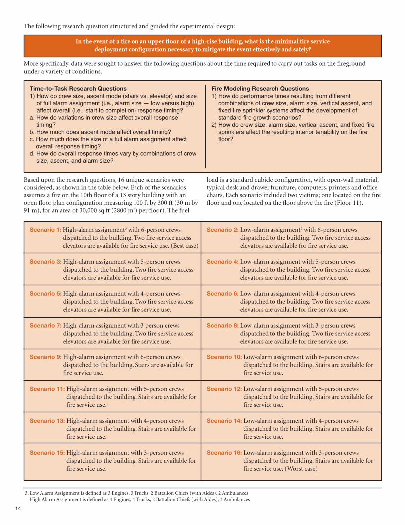
Based upon the research questions, 16 unique scenarios wereconsidered, as shown in the table below. Each of the scenariosassumes a fire on the 10th floor of a 13 story building with anopen floor plan configuration measuring 100 ft by 300 ft (30 m by91 m), for an area of 30,000 sq ft (2800 m2) per floor). The fuel
load is a standard cubicle configuration, with open-wall material,typical desk and drawer furniture, computers, printers and officechairs. Each scenario included two victims; one located on the firefloor and one located on the floor above the fire (Floor 11).
Scenario 1:High-alarm assignment3 with 6-person crewsdispatched to the building. Two fire service accesselevators are available for fire service use. (Best case)
Scenario 3:High-alarm assignment with 5-person crewsdispatched to the building. Two fire service accesselevators are available for fire service use.
Scenario 5:High-alarm assignment with 4-person crewsdispatched to the building. Two fire service accesselevators are available for fire service use.
Scenario 7:High-alarm assignment with 3 person crewsdispatched to the building. Two fire service accesselevators are available for fire service use.
Scenario 9:High-alarm assignment with 6-person crewsdispatched to the building. Stairs are available forfire service use.
Scenario 11:High-alarm assignment with 5-person crewsdispatched to the building. Stairs are available forfire service use.
Scenario 13:High-alarm assignment with 4-person crewsdispatched to the building. Stairs are available forfire service use.
Scenario 15:High-alarm assignment with 3-person crewsdispatched to the building. Stairs are available forfire service use.
Scenario 2: Low-alarm assignment3 with 6-person crewsdispatched to the building. Two fire service accesselevators are available for fire service use.
Scenario 4: Low-alarm assignment with 5-person crewsdispatched to the building. Two fire service accesselevators are available for fire service use.
Scenario 6: Low-alarm assignment with 4-person crewsdispatched to the building. Two fire service accesselevators are available for fire service use.
Scenario 8: Low-alarm assignment with 3-person crewsdispatched to the building. Two fire service accesselevators are available for fire service use.
Scenario 10: Low-alarm assignment with 6-person crewsdispatched to the building. Stairs are available forfire service use.
Scenario 12: Low-alarm assignment with 5-person crewsdispatched to the building. Stairs are available forfire service use.
Scenario 14: Low-alarm assignment with 4-person crewsdispatched to the building. Stairs are available forfire service use.
Scenario 16: Low-alarm assignment with 3-person crewsdispatched to the building. Stairs are available forfire service use. (Worst case)
The following research question structured and guided the experimental design:
In the event of a fire on an upper floor of a high-rise building, what is the minimal fire service deployment configuration necessary to mitigate the event effectively and safely?
Time-to-Task Research Questions 1) How do crew size, ascent mode (stairs vs. elevator) and size
of full alarm assignment (i.e., alarm size — low versus high)affect overall (i.e., start to completion) response timing?
a. How do variations in crew size affect overall responsetiming?
b. How much does ascent mode affect overall timing?c. How much does the size of a full alarm assignment affect
overall response timing?d. How do overall response times vary by combinations of crew
size, ascent, and alarm size?
Fire Modeling Research Questions 1) How do performance times resulting from different
combinations of crew size, alarm size, vertical ascent, andfixed fire sprinkler systems affect the development ofstandard fire growth scenarios?
2) How do crew size, alarm size, vertical ascent, and fixed firesprinklers affect the resulting interior tenability on the firefloor?
More specifically, data were sought to answer the following questions about the time required to carry out tasks on the firegroundunder a variety of conditions.
3. Low Alarm Assignment is defined as 3 Engines, 3 Trucks, 2 Battalion Chiefs (with Aides), 2 AmbulancesHigh Alarm Assignment is defined as 4 Engines, 4 Trucks, 2 Battalion Chiefs (with Aides), 3 Ambulances
15
4. In addition to the tasks denoted in this report, salvage and overhaul operations on the fireground are major tactical priorities that require significant time andresources in order to minimize loss. These tasks however, were not included in the study scenario.
5. Overhaul is used to ensure the fire is out completely and that the environment is safe for others to enter. Firefighters may use thermal imaging cameras to look at wallsand ceilings to find hot spots, or they may tear out sections of walls and pull sections of ceilings to assure there has been no fire spread.
6. Salvage is the firefighters’ attempt to save property or reduce the damage from water and smoke. Salvage operations are typically performed immediately after a fire byremoving unharmed property from the fire area and covering it with canvas tarpaulin or other heavy protective material.
7. IDLH — Immediately Dangerous to Life and Health. IDLH conditions can be due to high levels of heat, smoke, or toxic gases, which rapidly threaten a person’s abilityto effect their own escape.
Primary FindingsOf the 38 fireground tasks measured during the experiments,4
certain tasks were deemed critical, having he most significantimpact on the success of firefighting operations. All differentialoutcomes described below are statistically significant at the 95 %confidence level or better.
Overall Time To Task CompletionOverall scene time is the time that firefighters are actually
engaged in tasks on the scene of a structure fire. During theexperiments, this time included all operational tasks with theexception of overhaul5 and salvage6. The time to completion of alltasks decreases as crew size increases. On average, 3-person crewstook nearly an hour to complete their fire response, while crews of6 firefighters required a mean time of just under 40 min forcompletion. The performance of crews sized 4 and 5 werein-between, with crew size 5 taking about 2 min longer than crewsize 6, and crew size 4 taking about 9 min longer than crew size 5but 12 min less than crew size 3. Therefore, the time to completeall task times are substantially reduced for crew size of 6compared to 5, 5 compared to 4, and 4 compared to 3.
Advance Attack LineAs firefighters engage on a fireground, putting water on the fire
is one of the most important tasks. Extinguishing the fire isnecessary to reduce the continuously escalating risks from fire andthe toxic products of combustion. Before water can be put on afire, however, a hose line must be stretched from the standpipe inthe stairwell to the compartment where the fire is burning. In amore specific analysis comparing each crew size to a 3-personcrew, the time differences increase as crew size increases. From theinitiation of on-scene firefighting activities, a 3-person crew took1 min 43 s (8.5 %) longer than a 4-person crew to stretch the hoseline. A 3-person crew took 2 min 47 s (13.9 %) longer than a5-person crew to complete the same task. Finally, the mostnotable comparison was between a 3-person crew and a 6-personcrew, with a 4 min 28 s (22.3 %) difference in task completiontime.
Advance Second LineThe size of the fire required two 2 ½ inch lines to fully suppress;
therefore a second hose line had to be advanced from thestandpipe in the stairwell to the fire. A 3-person crew took 4 min4 s (17.4 %) longer than a 5-person crew to stretch the secondline. A 4-person crew took 2 min 43 s (12.3 %) longer than a5-person crew to complete the same task. Finally, the mostnotable comparison was between a 3-person crew and a 6-personcrew, with a 5 min 38 s (24.1 %) difference in task completiontime.
Fire OutExtinguishing the fire out is critical to reducing risk to both
firefighters entering the structure and to trapped occupants. FireOut, in the study, was defined as having both the attack line andthe second hose line in place. There was a 2 min 14 s difference(8.1 %) in the Fire Out time between the 3- and 4-person crews.There was an additional 1 min 15 s difference (5.0 %) in the FireOut time between the 4- and 5-person crews. (i.e., 5-person crewsextinguished the fire 3 min 29 s faster than 3-person crews).Finally, there was a 7 min 2 s difference (25.6 %) in the Fire Outtime between the 3- and 6-person crews.
Search and Rescue 10th FloorThe fire floor was an open floor plan and contained 96 cubicles.
In the high hazard high-rise commercial building, the 4-personcrew started the search 1 min 23 s (7.8 %) faster and completedthe search and rescue 11 min 21 s (18.4 %) faster than the3-person crews. In the same structure, the 5-person crews startedthe search 1 min 4 s (6.7 %) faster than the 4-person crews and 2min 27 s (14.1%) faster than the 3-person crew. Additionally,5-person crews completed the search faster than the 4- and3-person crews by 13 min 34 s (29 %) and 24 min 55 s (42 %)respectively. Six-person crews had the best times, starting thesearch 1 min 19 s faster and completing the search 2 min 57 s(8.0%) faster than 5-person crews. The greatest difference insearch times was between 6- and 3-person crews. Six-personcrews started the search on the fire floor 3 min 46 s (22 %) fasterand completed the search 27 min 51 s (47 %) faster than the3-person crews.
Victim #1 RescuedThere was a single victim located on the fire floor that was found
and rescued by all crews. A 5-person crew located the victim onthe fire floor 25 min 19 s (50.6 %) faster than a 3-person crew and12 min 7 s (32.9 %) faster than a 4-person crew. Likewise, a6-person crew located the victim on the fire floor 28 min 33 s(57.1 %) faster than the 3-person crew, 15 min 21 s (41.7 %)faster than the 4-person crew, and 3 min 14 s (13.2 %) faster thana 5-person crew.Four-person crews also removed the victim from the IDLH7
environment and facilitated the victim’s exit from the building 13min 11 s (25.1 %) faster than a 3-person crew. Likewise, 5-personcrews were able to remove the victim from the fire environmentand get them out of the building 11 min 39 s (29.7 %) faster thanthe 4-person crews, while 6-person crews removed the victimfrom the environment and got them out of the building 14 min 58 s (38.1 %) faster than the 4-person crews and 3 min 19 s (12.0 %)faster than the 5-person crews. Additionally, victim descentoccurred 4 min 42 s more quickly for crews using elevator ratherthan stairs to get the victim out of the building.
16
Advance Line Above the Fire (11th Floor)In a high-rise structure, it is essential to place a hose line on the
floor above the fire floor in the event of vertical fire spread. A3-person crew took 2 min 58 s (11.5 %) longer than a 5-personcrew to complete this task while, a 4-person crew took nearly 2min (7.8 %) longer than a 5-person crew. The most notablecomparison was between a 3-person crew and a 6-person crew,with a 3 min 38 s (14.0 %) difference in task completion time.
Search and Rescue 11th FloorThe floor above the fire was separated into a number of
conference rooms and offices that had to be searched by eachcrew. During the experiments, the 4-person crews completed thesearch 9 min 31 s (18.6 %) faster than the 3-person crews.Meanwhile, the 5-person crews started a primary search/rescue 1min 34 s (6.8 %) faster than the 4-person crews and completedthe search 2 min 37 s (6.3 %) faster than the 4-person crews. Inthe same structure, the 6-person crews also started the search 1min 30 s (6.6 %) faster than the 4-person crews but completed thesearch 5 min 8 s (12.3 %) faster than the 4-person crews.
Victim #2 RescuedIn addition to the victim on the fire floor, a second victim was
located on the floor above the fire. Each crew operating on thisfloor was tasked with locating and rescuing the victim. The5-person crews located the victim 17 min 23 s (34 %) faster thanthe 3-person crews and 2 min 41 s (7.4 %) faster than the 4-personcrews. Likewise, 6-person crews located the victim on the floorabove the fire 2 min 48 s (7.7 %) faster than the 4-person crews.Four-person crews removed the victim from the IDLH
environment and got them out of the building 14 min 33 s (27.2 %)faster than 3-person crews. Likewise, 5-person crews were able toremove the victim from the fire environment and get them out ofthe building 17 min 9 s (32.1 %) faster than 3-person crews and 2min 36 s (6.7 %) faster than the 4-person crews. Similarly, the6-person crews rescued and removed the victim from the building2 min 48 s (7.1 %) faster than 4-person crews. Additionally, victimdescent occurred nearly 6 min more quickly for crews usingelevator rather than stairs.
Summary of Regression AnalysisThe effects of crew size, vertical ascent mode, and alarm size on
the timing of critical firefighter tasks were studied using standardregression analysis. The analysis compared the times at whicheach task was started, the time to complete the task, and the timethe task was completed. These timing values were given the labelsbegin time, duration, and end time, respectively.
Crew SizeGoing from 3-person to 4-person crews had a large impact on
advancing the attack line, advancing the second line, and begintimes for search and rescue. Reductions in times to begin thesetasks were in the range of 1 min to 2 min. Going from 4-personto 5-person crews reduced the times to begin all critical tasks by 1min to 2 min. Increasing crew size from 5-person to 6-personcrews showed significant reductions in begin time, just over 1min, to advance the attack and second lines and for search andrescue on the fire floor (10th floor).When assessing task end times and incrementally increasing
crew size by a single firefighter (i.e., 3 to 4, 4 to 5, and 5 to 6), the
largest time improvements are seen when going from crew size 3 to4. As firefighter crews navigate the later tasks, the improvementscumulatively reach the 10 min to 15 min range. Very large timeimprovements are seen for the 10th Floor Search and Victim #1Rescue tasks (over 11 min) when incrementing crew size from 4 to5. The improvements in the times to complete all tasks aresubstantial (9 min to 12 min) when incrementing crew size from 3to 4 or from 4 to 5.
Fire Service Access ElevatorsAll tasks were completed more than 4 min faster when the
elevators were utilized compared to stairs. Begin times for nearlyevery critical task above ground level and nearly all end timeswere reduced compared to stair ascent. This is because using fireservice access elevators dramatically reduced times associatedwith upward and downward transport of people or equipment.Using elevators to transport air bottles and other equipment fromthe lobby to Staging allowed completion of Establishment ofStairwell Support8 over 10 min more quickly than moving theequipment up the stairs. Additionally, the transport of bothVictim #1 and Victim #2 from Staging to the outside of thebuilding was faster when using the elevators (compared to thestairs), by 2 min 41 s and 3 min 19 s, respectively.
Alarm Size Tasks assigned to engine 4 and truck 4, including Advancing the
Line Above the Fire, Primary Search on Floor 11 and RescuingVictim #2, had begin time and end time reductions since thosecrews were dispatched in the first rather than the second alarmassignment.
Combining Alarm Size and Crew SizeGiven the findings from the crew size analysis that adding one or
two firefighters to a crew could generally achieve substantial tasktime decreases, a logical question is whether the meaningfulbenefits of a larger crew size could be realized by implementing ahigher alarm response (additional engines and trucks) at a smallercrew size (e.g., high/4 compared to low/5). Another hypothesis isthat a high response with lower crew size might yield similar resultsin task timing to that of a low response with higher crew size.In summary, the analysis of the alarm response and crew size
combinations suggests that the benefits of higher crew size exceedthose of higher alarm assignment. Low alarm response with a highercrew size tends to be more favorable in critical task timings than thecorresponding timings for a high alarm response with a crew size ofone less firefighter.
Combining Alarm Response and Ascent ModeIn comparing different combinations of alarm response (high,
low) and ascent mode (stairs, elevator), results contrasted severalcombinations of alarm size and ascent mode.The alarm size had virtually no effect on critical task timings,
with the exception of Primary Search of the Floor Above the Fire(Floor 11) and Victim #2 Rescue. High alarm response realized amean reduction in the range of 1 min to 4 min for these tasks.The Overall Time to Task Completion was also significantlysmaller for high alarm response by 3 min. No other task timingcomparisons were statistically different.In the elevator scenarios, high alarm response led to eight
significantly lower timings than did a low alarm response. Results
8. Stairwell Support is also known as Ground Support, according to NFPA Standard 1561: Standard on Emergency Services Incident Management System.
17
show 45 s reductions in begin time for Fire Out, Primary Searchof Fire Floor 10, and Victim #1 Found. Small reductions of justover a minute were noted in begin times for Search of the FloorAbove the Fire (Floor 11) and Victim #2 Found. Small reductionsof 30 s to 2 min were also noted for times related to Advance theLine Above the Fire. No other task timing comparisons werestatistically different.
Fire Modeling ResultsIn order to assess the hazard to occupants and firefighters as a
consequence of different deployment configurations, computerfire modeling was performed. Three different ‘standard’ fires weresimulated using the NIST Fire Dynamics Simulator (FDS) model.The three fires, characterized in the Handbook of the Society ofFire Protection Engineers (SFPE) (Hadjisophocleous andMehaffey 2008) as slow, medium, and fast,9 grew non-linearlywith time and had burning characteristics similar to theexperimental results of typical office cubicle fires (Madrzykowskiet al. 2004).An Fractional Effective Dose (FED)10 value of 1.0 is defined as
the toxic exposure at which 50 % of the population would beincapacitated. The detailed probabilistic relationship betweenFED and the percentage of people incapacitated is unknown.However, an FED of 0.3 can be related qualitatively to a level thataffects vulnerable members of the population, while an FED of3.0 will incapacitate all but the least sensitive people.Computer fire modeling using NIST’s FDS demonstrated the
effectiveness of a working fire sprinkler system for mediumgrowth rate fires; the FED values remained well below a value of0.3 for all crew sizes and ascent methods, while FED values fornon-sprinkled structures typically exceeded 1.0 at some pointduring fire development. Thus, the overall hazard is greatlyimproved compared to the non-sprinklered fires for bothfirefighters and occupants. According to the NFPA, a workingsprinkler system is 96 % effective at controlling the growth andspread of fires in structures (NFPA 2006). Due to a number ofhigh-profile fires in high-rise buildings, and considering theirdemonstrated effectiveness, sprinkler systems are often requiredin new high-rise buildings and many jurisdictions have requiredexisting high-rise buildings to be retrofitted with sprinklersystems.However, sprinkler systems are not installed or functional in all
high-rise buildings. According to the NFPA (NFPA 2011), 41 % ofhigh-rise office buildings are not protected by sprinkler systems(compared to 25 % of high-rise “care of sick” facilities, 45 % ofhigh-rise hotels and 54 % of high-rise apartment buildings).Therefore, much of this report is focused on analysis of firedepartment deployment configurations responding to fires in anunsprinklered high-rise building.Note, further, that sprinkler systems are designed to control fires,
rather than suppress them. Fire department response is stillrequired even in fully-sprinklered high-rises in order toextinguish the fire, to search for and rescue occupants requiringassistance, and to control the sprinklers (limiting water damage).
Additionally, NFPA estimates that sprinkler systems fail to operatein 7 % of structure fires (one of every fourteen fires) primarilydue to human error. “Two-thirds (65 %) of the sprinkler failuresto operate were because the system had been shut off before thefire. Another one-sixth (16 %) occurred because manualintervention defeated the system, for example, by shutting off thesprinklers prematurely. Lack of maintenance accounted for 11 %of the sprinkler failures and 5 % occurred because the wrong typeof system was present. Nearly all failures were therefore entirelyor primarily problems of human action. Only 3 % involveddamage to system components.” (NFPA 2006) Therefore, evenwhen a large proportion of high-rise buildings within ajurisdiction are protected by sprinkler systems, the firedepartment should be prepared to deploy resources to hazardsconsistent with unsprinklered fires.For unsprinklered scenarios, the time advantages gained by
larger engine crew sizes and by using elevators versus stairs.allowing crews to complete tasks more quickly, improving theinterior conditions, including temperature, visibility, and toxicityon the fire floor. For medium growth rate fires, firefightersentering the environment were found to encounter fires between5 MW to 11 MW in size, depending on crew configuration andascent method. This range in fire size can be visualized as theequivalent of two cubicles on fire for a 6-person crew versus fivecubicles on fire for a 3-person crew. Crew size and vertical ascent mode can significantly affect the
likelihood of a successful rescue of victims on the fire floor. Forvictim rescue times discussed above, FED values in the cubiclewhere the victim was located ranged from 0.14 (6-person crewusing the elevator) to 1.22 (3-person crew using the stairs). TheFED, based on the biological effects of toxic gases, was used toassess the tenability of the fire environment. Consistently, smallercrew sizes resulted in greater exposure of victims and firefightersto combustion products compared to larger crew sizes.Additionally, using the stairs delayed rescue and resulted in highertoxic exposures when compared to using the elevators.
LimitationsThe scope of this study is limited to understanding the relative
influence of deployment variables to the critical outcomesassociated with a working high-rise structure fire. Theapplicability of the conclusions from this report to low hazardresidential fires, outside fires, terrorism/natural disaster response,HAZMAT or other technical responses has not been assessed andshould not be extrapolated from this report. Additionally, someimportant tasks, such as secondary search, property salvage, utilitycontrol, water mitigation, building overhaul, and returningfirefighting equipment were not considered in these experiments.These tasks delay the return of units to service and should beconsidered in the design of fire department coverage. Otherlimitations that affect the interpretation of the data or conclusionsare discussed in the report.
9. As defined in the SFPE Handbook, a fast fire grows to 1 MW in 2 min 30 s; a medium fire grows to 1 MW in 5 min; a slow fire grows exponentially to 1 MW in 10min. A 1 MW fire can be thought of as a typical upholstered chair burning at its peak. A large sofa may produce a fire with a peak HRR value of 2 MW to 3 MW.
10. To characterize the accumulated hazard associated with inhalation of gases typical of combustion products, a time-integrated value known as the fractional effectivedose (FED) was used. FED is an international standard, maintained by the International Standards Organization (ISO) and documented in ISO document 13571.FED is a probabilistic quantity used to estimate the impact of toxic gases on humans (ISO 2007). For this study, FED accounted for the effects of excess carbonmonoxide and carbon dioxide inhalation and oxygen depletion.
18
ConclusionsA total of 48 field experiments and complementary fire modeling
simulations were conducted to determine the impact of crew size,alarm size and vertical response mode on firefighter safety andeffectiveness at a high hazard high-rise commercial structure fire.This report quantifies the effects of changes to crew size, alarm sizeand/or vertical response mode for high hazard high-risecommercial firefighting operations in both sprinklered andnon-sprinklered buildings. While resource deployment isaddressed in the context of a high-rise structure type and high risklevel, it is recognized that public policy decisions regarding thecost-benefit of specific deployment decisions are a function ofmany factors including geography, available resources andcommunity expectations, as well as local hazards and risks.Though this report contributes significant knowledge tocommunity and fire service leaders in regard to effective resourcedeployment for fire suppression, other factors contributing topolicy decisions are not addressed.The results provide a technical basis for the effectiveness of
company crew size, alarm size and vertical response mode to beadded to NFPA Standard 1710. The results also provide validmeasures of total effective response force assembly on scene forhigh-rise fireground operations, as well as the expectedperformance of time-to-critical-task measures for high hazardhigh-rise commercial structure fires. Additionally, the resultsprovide tenability measures associated with the occupant exposurerates to the range of fires considered by the fire model. The resultsof the project will also inform code provisions in the nationalmodel building codes which require fire service access elevators innew construction over 120 ft (36 m).Future research should extend the findings of this report in order
to quantify the effects of crew size and apparatus arrival times formoderate/medium hazard or other high hazard events, such asfires in mercantile establishments consisting of a row of stores andrestaurants, warehouse facilities, responses to large-scale non-fireincidents, or technical rescue operations.
19
1. Background
High-rise buildings present a unique threat to the fireservice. Multi-floor fires such as the Interstate BuildingFire, One Meridian Plaza Fire, World Trade Center
collapse, Cook County Administration Building Fire, andDeutsche Bank Building Fire each represent serious challenges tooperational capabilities of a modern fire department.Unfortunately, fire and city officials currently lack quantitativedata to support specific resource deployment configurations orbuilding code requirements germane to high-rise responseeffectiveness.The National Fire Protection Association (NFPA®) classifies
high-rise buildings as high hazard occupancies in §A.3.3.28 ofNFPA 1710®11, Standard for the Organization and Deployment ofFire Suppression Operations, Emergency Medical Operations, andSpecial Operations to the Public by Career Fire Departments. In§5.2.3.1.2 of NFPA 1710, the standard further specifies aminimum staffing of “five or six on-duty personnel” per
apparatus for high hazard responses. However, NFPA 1710 doesnot specify a minimum deployment configuration (eitherapparatus or total number of personnel) for high-rise buildingfires. Rather, the standard includes a performance statement in§5.2.4.2.3: “Fire departments that respond to fires in high-,medium-, or low-hazard occupancies that present hazards greaterthan those found in the low-hazard occupancy described [above]shall deploy additional resources on the initial alarm.”According to NFPA (Hall 2011), an annual average of 15,700
structure fires were reported in high-rise buildings between 2005and 2009. The annual loss associated with these fires included 53civilian deaths, 546 civilian injuries, and more than $235 millionin direct property damage. Office buildings, hotels, apartmentbuildings, and health care facilities accounted for nearly half ofthese high-rise fires. During the same span of time, mosthigh-rise building fires began no higher than the 6th floor, whileapproximately one-third of them began on the 7th floor or higher.
11. NFPA® is a registered trademark of the National Fire Protection Association, Quincy, MA 02169. National Fire Protection Standard 1710 Standard for theOrganization and Deployment of Fire Suppression Operations, Emergency Medical Operations, and Special Operations to the Public by Career Fire Departmentscontains minimum requirements relating to the organization and deployment of fire suppression operations, emergency medical operations, and special operationsto the public for career fire departments. The requirements address functions and objectives of fire department emergency service delivery, response capabilities, andresources. The purpose of this standard is to specify the minimum criteria addressing the effectiveness and efficiency of the career public fire suppression operations,emergency medical service, and special operations delivery in protecting the citizens of the jurisdiction and the occupational safety and health of fire departmentemployees. At the time of the experiments, the 2010 edition of NFPA 1710 was the current edition.
20
2. Problem
Despite the magnitude of the fire problem in the UnitedStates, there are no scientifically based tools available tocommunity and fire service leaders to assess the effects of
prevention, fixed sprinkler systems, firefighting equipment, orresource deployment and staffing decisions. Presently, communityand fire service leaders have a qualitative understanding of theeffect of certain resource allocation decisions. For example, adecision to double the number of firehouses, apparatus, andfirefighters would likely result in a decrease in community firelosses, while cutting the number of firehouses, apparatus, andfirefighters would likely yield an increase in the community firelosses, both human and property. However, decision makers lack asound basis for quantifying the total economic impact ofenhanced fire resources on the number of firefighter and civilianlives saved and injuries prevented.Studies on adequate deployment of resources are needed to
enable fire departments, cities, counties, and fire districts todesign an acceptable level of resource deployment based uponcommunity risks and service provision commitment. Thesestudies will assist with strategic planning and municipal and statebudget processes. Additionally, as resource studies refine datacollection methods and measures, both subsequent research andimprovements to resource deployment models will be afforded asound scientific basis.High-rise fires represent an extraordinary challenge to fire
departments and are some of the most challenging incidents a firedepartment encounters. High-rise buildings may hold thousandsof people above the reach of fire department aerial devices, andthe chance of rescuing victims from the exterior is greatly reducedonce a fire has reached flashover.High-rise buildings were once located exclusively in larger cities,
but today they are commonly found in small and mid-sizedcommunities. Even if a department does not respond to a
high-rise building at present, it may in the future as urban sprawlcontinues. The risk to firefighters and occupants increases inproportion to the height of the building and the height of the fireabove grade level (Klaene, 2007). Once firefighters are operatingabove the reach of aerial devices, the only viable means of egress isthe interior stairs; extra protection afforded by laddering thebuilding is not possible. Therefore, a sound fire departmentdeployment strategy, effective operational tactics, and engineeredfire protection systems cannot be separated from firefighter safety.In attacking a fire in a high-rise building, as in any structure fire,engine company and truck company operations must becoordinated.A critical variable in high-rise fire operations is the availability
of reliable elevators. If firefighters can safely use the elevators tomove people and equipment, fire-ground logistics may besignificantly improved. When the fire is located several floorsabove ground level, there is a strong inclination to use theelevators. However, fire service access elevators (engineered tooperate in a building during a fire emergency and complying withprescriptive building code requirements and the American Societyof Mechanical Engineers (ASME) A 17.1 safety standard forelevators) may not be available in all buildings. Therefore,adequate stairways are necessary for firefighters to transportequipment and reach the fire floor for suppression. Movingsupplies and staff up 10, 20, 30, or more stories is an arduous task.If it is not properly managed, firefighters may be exhausted andunable to fight the fire or rescue trapped occupants. Additionally,joint use of stairways by firefighters moving upward andoccupants attempting to evacuate may increase the overallevacuation time of the occupants, as well as delay the firefighters’efforts to begin critical tasks such as fire suppression or search andrescue operations.
21
3. A Review of Important Literature
High-rise buildings were once found exclusively in urbancities, however today they are commonly found in smalland mid-sized suburban communities as well. In many
cases high-rise buildings in suburban areas are newer, shorter, andprotected by automatic sprinkler systems. Even if some firedepartments do not respond to high-rise buildings at present,they likely will in the future in their own communities or as partof a mutual or automatic aid agreement.The NFPA 101®, Life Safety Code, 2012 edition12 and the
International Code Council-published International BuildingCode both define a high-rise structure as a building more than 75ft (23 m) in height, measured from the lowest level of firedepartment vehicle access to the bottom of the highest occupiedfloor. For the fire service, a high-rise structure may be defined as abuilding with sufficient height to exceed the fire department’sexterior laddering capability (NFPA, 2012).According to NFPA, there was an average of 15,700 reported
structure fires in high-rise buildings every year between 2005 and2009. The annual loss associated with these fires included 53civilian deaths, 546 civilian injuries, and more than $235 millionin direct property damage (Hall, 2011).A review of historic large loss fire incidents and the fire
department response, as discussed below, revealed that thecommercial office building occupancy is commonly subject tomassive singular event losses. Consistent with the objective of thestudy, this report will investigate the low-frequency,high-consequence office fire event that poses unusual hazards forbuilding occupants and firefighters.
3.1 Historic High-Rise Fires It is the intent of the study and this report to explore this
low-frequency, high-consequence-type event that poses unusualhazards for both building occupants and firefighters. Theparagraphs that follow describe a number of these large losshigh-rise fires.
Triangle ShirtwaistNear closing time on March 25, 1911, a fire broke out at the
Triangle Waist Factory in New York City. In less than twentyminutes, 146 people were dead. Fire engulfed the 8th, 9th, and10th floors of the Asch Building, occupied by the Triangle WaistFactory. The call to fire stations went out at 4:45 pm. Firefightersrushed to the scene but were unable to save workers trapped bylocked doors and were unable to negotiate doors opening inward.Many occupants jumped to their deaths while others perishedinside the burning building. The firefighters’ ladders and hosescould not reach above the 6th floor. Rescue nets were insufficientto stop the fall of many victims jumping to flee the fire. Otheroccupants trying to escape perished in the collapse of the fireescape ladder, which did not reach the ground. The horror of thedeaths led to numerous changes in occupational safety standardsthat currently ensure the safety of domestic workers today(Cornell, 2011).
Winecoff HotelIn 1913, the Winecoff Hotel in Atlanta, Georgia was designed
and built without sprinklers, fire escapes, or even an alarm system.The 15-story Winecoff Hotel had one central interior stairwellthat extended from the lobby to the 15th floor, with oneadditional staircase that went from the 15th floor to the roof. Eachfloor had a corridor off the stairwell that led to guest rooms. OnDecember 7, 1946, a fire was ignited in the hotel. Shortly after thestart of the fire the only interior staircase was completely filledwith smoke and intense heat. The hotel guests were trapped intheir rooms with nowhere to go. Many guests never made it out oftheir rooms; they succumbed to smoke inhalation in their sleep orwere killed by severe burns when the fire breached their doors. Intotal the fire killed 119 people as they leaped from windows,suffocated from smoke, or were burned alive. Several firefighterswere injured after being knocked off their ladders by fallingbodies.The death toll in this fire was the impetus for national safety
codes and strict enforcement. The response to this tragedy was sointense locally that public officials in several southern citiesordered all existing buildings be retrofitted and brought up tocode within seven days or be shut down. Twenty-two engines and12 ladder trucks eventually responded to the hotel fire (WinecoffHotel, 2013).
MGM GrandThe 1980 fire in the MGM Grand started at the rear of the casino
and eventually involved the entire casino floor measuring 150 ft x450 ft (46 m x 140 m). The MGM Grand, now Bally’s in ClarkCounty, Nevada, had 3400 registered guests at the time of the fire.Just after 7:00 on the morning of November 21, 1980, a fire brokeout in a restaurant known as The Deli. The Clark County FireDepartment was the first agency to respond. Other agencies thatresponded included the North Las Vegas Fire Department, LasVegas Fire, and Rescue and the Henderson Fire Department. Fire spread across the areas of the casino in which no fire
sprinklers were installed. Smoke spread into the hotel tower. Atotal of 85 people were killed and 650 injured, including guests,employees, and 14 firefighters. While the primary damage was onthe second floor casino and adjacent restaurants, most of thedeaths were on the upper floors of the hotel, caused by smokeinhalation. Openings in vertical shafts (elevators and stairwells)and seismic joints allowed toxic smoke to spread to the top floor(Best, 2013).The disaster led to the general publicizing of the fact that during
a building fire, smoke inhalation is a more serious threat thanflames. Seventy-five people died from smoke inhalation andcarbon monoxide poisoning, four from smoke inhalation alone,three from burns and smoke inhalation; only one person diedfrom burns alone, and one person died from massive skull traumacaused by jumping from a high window (Clark County FD).The death toll, 85 people, made the MGM fire the second most
deadly hotel fire in U.S. history (Sanders, 2007) — second only tothe 119 who died in the Winecoff Hotel in Atlanta, Georgia, in 1946.
12 . The NFPA Life Safety Code is a widely used source for strategies to protect people based on building construction, protection, and occupancy features that minimizethe effects of fire and related hazards in new and existing structures.
22
First InterstateA fire in the First Interstate Bank Building in Los Angeles on May
4, 1988 destroyed four floors of the 62-story building and heavilydamaged a fifth floor. The First Interstate fire burned floors 12 to15 and was stopped at the 16th floor. Fifty-one floors above the firewere exposed to the fire and smoke conditions (LAFD, 1988).The fire required a total of 64 fire companies and 383 firefighters
and took 3 ½ hours to control. Despite the magnitude of this fire,only a maintenance worker who took an elevator to the fire floorto investigate the alarm was killed. In addition to the 383firefighters, 17 paramedic ambulances, 17 private ambulances,and 2 hospital disaster teams were on scene to provide emergencymedical services (EMS)(Sanders, 2007).In 1973, the year construction was completed on the building,
sprinklers were not required for office towers. A sprinkler systemwas 90 % installed at the time of the fire, but the system wasinoperative, awaiting the installation of water flow alarms. Thefire was eventually contained at 2:19 am and caused $50 millionin damages (USFA, 2010).
East 50th Street New York — Apartment Building FireOn January 11th 1988, a fire started in an office on the first floor
of a 10-story predominantly residential high-rise. The buildingwas not sprinklered and had no smoke alarms, no fire alarmsystem, and no emergency lighting or illuminated exit signs, but itwas still considered to be within fire code due to the age of thebuilding. FDNY firefighters were on scene 4 min after a call to9-1-1. Six minutes later at 8:29 pm, a second alarm was called.Fire spread was undeterred due to a stairwell door left open on
the fire floor. Heavy smoke quickly filled the stairwell and thefloors above the fire. Crews arriving on the second alarm werecommitted to rescue operations. A third alarm was requested at8:47 pm and a fourth at 9:15 pm. All units responding in theseassignments were committed to rescue operations on the 9 storiesabove the fire. Even though interior crews had extinguished thefire, smoke spread throughout the building, creating heavydemand on rescue operations. At 9:42 pm a fifth alarm wasrequested and brought the total firefighting force to 200 personneland 38 pieces of apparatus. Searches were finally complete at10:16 pm, nearly two hours after initial crews were dispatched tothe scene. A total of 4 civilians perished and 2 civilians and 5firefighters were injured (USFA, 1988).
PeachtreeOn June 30, 1989 at 10:30 am, a small fire occurred on the 6th
floor of a 10-story office building in Atlanta, Georgia. The AtlantaBureau of Fire Services received a call at 10:29 am as an automaticalarm originating at 1720 Peachtree Street, Northwest anddispatched a normal assignment of three engines and two trucks,an EMS unit, and a battalion chief. However, they soon receivednearly 20 phone calls in succession reporting a serious fire on the6th floor and then dispatched an additional rescue unit and asquad.Extreme heat on the 6th floor required frequent rotation of
crews. The initial crew on the fire floor extinguished a largeportion of the fire but was forced to call for relief due to low airsupply.The search for victims and survivors was complicated by the
confusing layout of the open plan offices and the fact that almostall of the doors were locked and required extensive forcible entry.The building was occupied, and 5 of the 40 occupants on the
sixth floor were killed, while 6 others were rescued by firefighters
using aerial ladders (Sanders, 2007). The first victim of the firewas discovered in the hallway but was not removed immediatelydue to the extent of his injuries. Of the 5 fire victims who did notsurvive, 3 were removed from the building and resuscitationefforts were attempted. A total of 23 civilians and 6 firefighterswere injured (USFA, 1989).
One Meridian PlazaThe One Meridian Plaza fire in Philadelphia, Pennsylvania,
occurred at 8:40 pm on Saturday evening, February 23, 1991. Thefire began on the 22nd floor after linseed oil-soaked rags ignited ablaze that raged out of control for hours (NY Times, 1991).Philadelphia firefighters fought the blaze but struggled due to alack of power in the skyscraper and insufficient water pressurefrom the building's standpipes. More than 316 firefightersresponded in the 12-alarm fire, and 3 firefighters died afterbecoming disoriented by heavy smoke (Chubb, 1991).Firefighting efforts inside One Meridian Plaza were abandoned
due to fears the structure would collapse. The fire was broughtunder control once it reached the 30th floor, which was one of thefew floors that had automatic sprinklers installed. The blazeseriously damaged the building, destroyed eight floors, anddamaged neighboring buildings (Chubb, 1991). Because the fireoccurred outside normal working hours, the threat to occupantswas likely lessened.
1993 World Trade Center BombingAt 12:18 pm on February 26th 1993 a vehicle bomb ripped
through the sub-grade garage levels of the World Trade Center(WTC) in Manhattan. The blast severely damaged critical buildingemergency system infrastructure, including emergency generators,sprinkler systems, stand pipe systems, and public address systems.Electrical power was lost in many areas of the Vista Hotel, as wellas in both Tower 1 and 2. FDNY Engine 10 and Ladder 10,stationed near the site, felt the blast and self-dispatched, believingit to be a transformer explosion. Upon receiving numerous 9-1-1calls, dispatchers sent an initial deployment of 3 engines, 2 ladders,1 Rescue Unit, and 1 Battalion Chief to the WTC complex. Onarrival, Ladder 10 noted that the garage doors at the entrance to agarage were misshapen. Engine 10 requested a full box alarm for aworking fire, which added 3 engines, 2 ladders, 1 Battalion Chief,and 1 Deputy Chief to the scene. Multiple additional alarms were called to intervene in multiple
location fires including Tower 1, Tower 2, and the Vista hotellocated between the towers. The magnitude of the event expandedquickly. Due to the size of the Towers and the number of potentialvictims, each building required a separate command sector. Eachsector reported directly to the incident command post. At theheight of the incident there were 156 fire companies and 31 chiefson scene. The event resulted in 6 civilian fatalities, 1042 injuriesand a total of 16 alarm assignments dispatched to the scene(USFA, 1993).
Regis TowerRegis Tower, at 750 Adams Avenue in Memphis, Tennessee, is an
11-story concrete-and-steel high-rise building constructed in 1964.Its overall dimensions are 140 ft (43 m) long and 50 ft (15 m) deep.At 02:05 am on April 11, 1994, the central station monitoring servicefor the Regis Tower called the Memphis Fire Department to reportan alarm indicating a trouble alarm on the ninth floor. The normalresponse to a possible high-rise fire was 3 engine companies, 2ladder companies, and a battalion chief. The first Engine arrived
23
followed shortly by a truck at 02:08 am (Chubb, 1995).Upon arrival, firefighters encountered heavy smoke and fire on
the ninth floor. Fire companies made several attempts to rescueoccupants and extinguish the fire from the interior. The fireself-vented, and a heavy volume of fire was visible from theexterior. An elevated master stream was directed into theapartment of origin to knock down any visible fire. Unfortunately,the door between the apartment of origin and the hallway wasopen, and the exterior stream pushed the fire into the 9th floorcorridor where firefighters were advancing toward the fire. As heatand smoke conditions immediately became worse on the 9thfloor, firefighters were forced to retreat. Two firefighters becamedisoriented and had to be rescued. Two firefighters and twocivilian occupants were killed (Sanders, 2007).
Cook County Administration BuildingOn October 17, 2003, a fire on the 12th floor of the 37-story
Cook County Administration Building in Chicago, Illinoisresulted in 6 civilian fatalities. The fire was believed to haveoriginated in a closet within a 2629 sq ft (244 m2) suite of officeson the east side of the 12th floor. Due to fire-resistive buildingfeatures, fire damage was contained to the office suite, but smokeand fire traveled to the entire 12th floor. The fire self-ventedthrough eight exterior windows on the east side of the suite,creating the potential for floor-to-floor fire extension on theexterior.Upon arrival, firefighters were faced with an intense fire that
they were unable to extinguish from an interior hallway position.Elevated master streams were used to knock down the fire fromthe exterior. Interior hose streams were then redeployed to achievefinal extinguishment. Tight compartmentalization and closedoffice doors contained the fire to the suite where it originated(Sanders, 2007).
Deutsche BankOn August 18, 2007 two fire fighters lost their lives while
operating at a 7 alarm fire at a high rise in Manhattan, New YorkCity. The 41-story Deutsche Bank was undergoing deconstructionand asbestos abatement due to the damage sustained after thecollapse of the World Trade Center Buildings on September 11th,2001. In the process of deconstruction, the building layoutincluded maze-like partitions installed to prevent the spread ofasbestos during abatement. The standpipe system was also beingdisassembled.A fire broke out at 3:30 pm on the 17th floor, with an initial first
alarm being sent at 3:37 pm. After confirmation of the fire, a fullalarm response was sent along with additional units. Thisresponse included 4 engines, 3 ladders, 2 Battalion Chiefs, 1Division Chief, 1 Squad, 1 Rescue, 1 HazMat, 1 HazMat BattalionChief, and Chief aides, for a total of 65 firefighters. A secondalarm was requested 5 min later, to which an additional 12Engines, 7 Trucks, 10 Battalion Chiefs, 1 Division Chief, 3 DeputyChiefs, 1 High Rise Engine, 1 Field Communication Unit, 1Squad, 1 Rescue with Battalion Chief, and various other supportapparatus responded. The second alarm brought an additional160 personnel for a total of 225 firefighters on scene.A construction worker reported that the fire was on the 17th
floor, so initial crews took a construction elevator to the 15thfloor. An engine crew attempted to connect 2 ½ inch lines to thestandpipe in the stairwell and found no connections on the 14thor 15th floors. The crew then checked the 16th floor to learn thatit was blocked by a wooden hatch. The interior stairwells had
hatches installed every two stories, which limited the movementof the firefighters between floors. Some hatches were opened byfire crews using saws, but even with open hatches only onefirefighter could pass though at a time.Engine 10 crew eventually located a connection to a standpipe in
a second stairwell and flaked out several lengths of hose thenwaited for water. Ultimately, it was discovered that the standpipesystem was completely out of operation and was disconnected inthe subterranean levels.As the fire continued to spread uninhibited, Command ordered
the crews back down to the 14th floor, as the fire was now burningon the 15th floor with heavy smoke and still no water in thestandpipes.At 4:14 pm a firefighter on the Engine 10 crew transmitted a
Mayday after becoming disoriented. Firefighters responding to theMayday found their way off the 15th floor though a breach in aplywood wall. Several crews were on the 15th floor either trying tofind their way out, or searching for the lost firefighter. Eventually,all firefighters were ordered to exit the 15th floor as heatconditions were becoming more severe.As conditions continued to worsen on the 14th through 17th
floor, engine crews began to drop hose lines on the exterior of thebuilding. Once the exterior hose stretch was complete, additionallengths were attached to reach the seat of the fire. The hose linewas charged with water at 4:44 pm, over an hour after the initialcrews were dispatched.Following a tenuous fire fight by firefighters from 45 Engine
Companies, 30 Ladder Companies, 3 Rescue Companies, 19Battalion Chief Units, 4 Division Chief 's Units, and numerousother special and support units operating with little to novisibility, the fire was suppressed. As a result of the high riskenvironment, 115 firefighters were injured and two firefighterswere killed (IFSTA, 2011).
Wellesley Street, E., Toronto, Ontario, CanadaOn September 24, 2010, a six-alarm fire at a downtown Torontohigh-rise building resulted in 14 people being sent to hospital andleft an estimated 1,200 people temporarily homeless. Eight adultcivilians, three firefighters and three children required medicalcare, while an additional 10 firefighters were treated for heatexhaustion (Allen, 2010). The fire at 200 Wellesley Street, East started at 5:00pm on the
24th floor and spread to two adjacent units. It grew into asix-alarm fire, with more than 120 firefighters and 27 pieces of fireapparatus at the scene. At 8:30 p.m., when it seemed progress hasbeen made, bright orange flames could still be seen in thebedroom of one unit on the 23rd floor (Allen, 2010).The growth of the fire was attributed to extreme fuel loading in
one apartment. Ontario Fire Marshal described the fire fuel loadas one of the worst hoarding fires in Canada. The tremendousgrowth and spread of the fire was a result of the excessive amountof combustible materials stored on the balcony and in the suite oforigin. The extreme fuel load made the fire very difficult to fight,control and extinguish. Firefighters deemed the fire one of thehottest and most deep-seated fires they had ever fought and highwinds made matters worse. Four hours after the blaze began,firefighters were still battling spot fires, created from fallingdebris. By 10 p.m., firefighters appeared to have knocked theflames down (CTV, 2010).
24
Shanghai, ChinaOn November 15, 2010, a fire destroyed a high-rise building in
Shanghai, killing 58 people and injuring at least 90 others as theblaze tore through a 28-story block of flats in Shanghai. Thebuilding was being renovated when the fire started. Theinvestigation of the fire made a preliminary conclusion thatnegligence by unlicensed welders on the tenth floor caused thebamboo scaffolding and attached nylon netting to ignite. Firesubsequently spread to the entire structure through ignition of thepolyurethane foam insulation used on the building's outer walls.Many people were trapped as fire engulfed the upper part of the
building, beyond the reach of the fire hoses, while others wereclinging to scaffolding surrounding the building as they waited tobe rescued from the flames. Helicopters attempted to rescue somefrom the roof.Firefighters battled for several hours to bring the blaze under
control. More than 80 fire engines were called to battle the fire. Bythe time the fire was brought under control, more than 100people had been rescued (BBC, 2010).
Lakeview High Rise/ChicagoNBC Chicago reported that a fire broke out on the 12th floor of
the building around 2 am on October 25, 2012. When a man anda woman living on the floor escaped with their dog they left theirfront door open, and the super-heated toxic gases from the firespread into the hallway. The heat was near 1,500 degreesFahrenheit at the ceiling, and a woman returning to her NorthSide apartment was killed when she took the elevator to her floor-- not knowing that a fire was raging in the hallway outside herapartment. When elevator doors opened on the 12th floor, thewoman was standing in the elevator and likely exposed to directfire spread. Nine other people, including two firefighters, wereinjured in the blaze (Chicago Tribune, 2012).
3.2 Overview of High-Rise Firefighting Tactics
In a high-rise fire, the risk to firefighters and occupants increasesin proportion to the height of the building and the height of thefire above ground level. When firefighters are operating above thereach of aerial devices, the only viable means of egress is theinterior stairs; extra protection afforded by laddering the buildingis not possible (Klaene, 2007). As the level of the fire floor getshigher, reliance on the standpipe also increases. Open-layout floorplans such as office buildings with cubicle farms can challengeboth the standpipe’s flow capacity and fire department resources.A working fire in a high-rise building can threaten thousands of
occupants and hundreds of responding firefighters. The mosteffective way to extinguish a high-rise fire is by mounting anoffensive attack as early as possible, because in the vast majority ofhistoric high-rise fires the best life safety tactic is extinguishing thefire. Good high-rise firefighting tactics and firefighter/occupantsafety cannot be separated.Tactics are a series of operational tasks that in combination
accomplish an overall fireground strategy. Individual tactics aremeasurable and attainable intermediate outcomes that lead to thecompletion of incident objectives like extinguishing the fire.There are three tactical priorities in a high-rise fire; life safety, fireextinguishment, and property conservation (Klaene, 2007). Afterthe fire is out, salvage and overhaul tactics are employed.During firefighting, life safety tactics fall under the label of
Search and Rescue. Search is a fireground tactic that is asystematic approach to locating possible victims, and Rescue isthe act of removing victims from known danger. Searches arenormally conducted by an entire crew, supplemented by an attackor ventilation crew. The minimum number of firefighters for asearch is two (IFSTA, 2010).Fire extinguishment is a critical factor, since the intensity and
size of the fire will determine the extent to which combustiongases are heated and how high they will rise inside the building.Building suppression systems, both active and passive, can impactfire growth, occupant safety, and firefighter safety andeffectiveness. Such features include active fire detection andautomatic sprinkler systems. Once firefighters are on scene, theywill complete a series of fire confinement and extinguishmenttasks. Firefighters access the structure, locate the fire, locate anyavenues of spread, place hose lines, and establish a water supply.Once a water supply is established, water should be placed at theseat of the fire or in the compartment containing the fire toextinguish it.Ventilation is a tactic that affects both life safety and fire
extinguishment. Coordinated ventilation may be implemented atany time during the operation, but it should be coordinated withsuppression and interior rescue activities. Ventilation is used tochannel and remove heated air, smoke, fire gases, and otherairborne contaminants. Applying proper ventilation at the righttime and place is key to firefighter and occupant safety. Venting atthe wrong time or place can draw active fire toward fresh air,which will injure or kill anyone in its path.After the fire is extinguished and victims rescued, firefighters
should move on to the task of salvage. Salvage is the firefighters’attempt to save property or reduce the damage from water andsmoke. Salvage operations are typically performed immediatelyafter a fire by removing unharmed property from the fire area andcovering it with canvas tarpaulin or other heavy protectivematerial. Salvage is a major tactical priority that requiressignificant time and resources in order to minimize loss. Salvageand overhaul operations (described below) were not included inthe study scenario.Overhaul is the completion of the extinguishment, which can
result in what may appear to be additional damage to anyproperty. The additional damage, however, is warranted toprevent more unexpected fire damage. Overhaul is used to ensurethe fire is out completely and that the environment is safe forothers, such as investigators or the property owner, to enter.Firefighters may use thermal imaging cameras to look at walls andceilings to find hot spots, or they may tear out sections of wallsand pull sections of ceilings to assure there has been no firespread.As indicated by the tasks that must be accomplished on a
high-rise fireground, understanding the required resources iscritical. The number of firefighters needed to safely and effectivelycombat a high-rise fire may be large. Although an offensive fireattack is the preferred strategy whenever conditions and resourcespermit, a defensive attack that limits operations to the outside of abuilding and generally results in more property damage must beconsidered when risks to firefighter safety are too great andbenefits to building occupants are negligible. The offensive vs.defensive decision is based on a number of factors: firegroundstaffing available to conduct an interior attack, a sustained watersupply, the ability to conduct ventilation, and risk vs. benefitanalysis regarding firefighter and occupant safety.
25
4. Purpose and Scope of the Study
This project systematically studies the deployment of mobileand personnel resources and their affects on firefightersafety, civilian safety, and the protection of high-rise
property. The purpose of the study is to enable fire departmentsand city/county managers to make sound decisions regardingoptimal resource allocation using the results of scientifically basedresearch. Many variables may have an effect on the outcome of a high-rise
fire. Due to limited resources, only variables considered likely tohave the most significant effect on the outcome of the fireincident were included in the scope of the study. These variablesincluded crew size, alarm size, and vertical response mode (stairsor elevators).The results of the project will inform the NFPA 1710 Technical
Committee regarding the optimal crew size and total effectivefirefighting force for a first alarm assignment to a workinghigh-rise or other high hazard fire. The results of the project willprovide valuable information for those developing national modelbuilding, fire, and life safety codes. Finally, these high hazardresponse scenarios will “bracket” the spectrum of fire response,acting as a complement to the recently published low hazardResidential Fireground Deployment Study (Averill et al., 2010). This report describes the experiments that were conducted using
on-duty fire service personnel and computational tools tosimulate a response to a high-rise fire incident on an upper floorof a building. The experimental design and fire modelingmethods are similar to those conducted in the ResidentialFireground Deployment Study.
There were two parts of the experiments.
n Field tests for critical time-to-task completion of key tasks infire suppression and in occupant search-and-rescue
n Fire modeling to determine the effects of firefighter operationson fire growth and spread and on occupant survivability
The scope of this study is limited to understanding the relativeinfluence of deployment variables on high hazard high-risestructure fires, similar in magnitude to the hazards described inNFPA 1710. This standard is limited in that it does not specify theprecise nature of a high hazard high-rise structure fire. Therefore,a secondary objective of this study is to establish a technical basisfor deployment of firefighters and equipment to a “typical”high-rise fire. While all fires and buildings have unique featuresand characteristics, it is believed that the building and operationsused in these experiments are broadly representative of a highhazard fireground and will be useful in establishing the technicalbasis underlying the national standard for minimally safe andeffective deployment.When paired with the Residential Fireground Report (Averill et
al., 2010), a significant benefit of this report is the ability tocompare and contrast deployment outcomes for a range of hazardscenarios. A residential fire represents a low hazard, relatively highfrequency scenario and a high-rise fire is a high hazard, relativelylow frequency scenario. Note that the applicability of theconclusions from this report to outside fires, and response tohazardous material incidents, acts of terrorism, and naturaldisasters or other technical responses has not been assessed andshould not be extrapolated from this report.
26
5. A Brief Overview of High-Rise Fireground Operations
Regardless of the size of the burning structure, firefightingcrews identify four priorities: life safety of occupants andfirefighters, confinement of the fire, property conservation,
and reduction of adverse environmental impact. Interdependentand coordinated activities of all firefighting personnel arerequired to meet the priority objectives.High-rise fire response is a complex orchestration, often involving
over 100 personnel operating over many floors in a building. Whilethe exact sequence of operations may vary from one fire departmentto another and even from one fire to another depending upon theexact nature of the event, the following narrative describes thegeneral sequence of activities during a high-rise firegroundoperation. Note that some activities, such as fire suppression orvictim rescue, are considered milestone events because they arecritical to the priority objectives noted above. The followingoverview is derrived largely from Klaene and Sanders (2007).
The First Arriving Fire Crews:n The first engine positions the apparatus such that it canestablish an uninterrupted water supply to critical buildingsystems, including the standpipe and sprinkler system (ifpresent) and operates the pump hydraulics at the apparatus asthe remaining crew members enter the building.
n The first arriving officer establishes command (IncidentCommand) and conducts initial size-up by checking the alarmpanel and consulting with building management. One firefighteror officer is assigned to the lobby to establish Lobby Control.
n Remaining firefighters and officers ascend the stairway to anarea two floors below the fire via stairs when the elevator isunsafe for use or by elevator when the elevator is determinedto be safe for use by firefighters. This crew sets up a stagingarea to hold firefighters preparing to fight the fire or toconduct search and rescue.
n Some crew members proceed to the next floor up (one floor belowthe fire). Upon arrival at the floor below the fire, one crew entersfor the purpose of viewing the general floor layout in preporationfor entering the fire floor. This crew also does a quick check for fireextension and connects a hose to the standpipe on that floor.
n Prior to being charged with water, a hose line (200 ft (61 m) of 2½ inch hose) is stretched from the standpipe on the floor belowthe fire to the stairwell on the floor above the fire. It is then loopedback in the stairwell in preparation for entry to the fire floor.
n An Initial Rapid Intervention Crew (IRIC) is assembled on thestaging floor prior to crews entering the fire floor. The NFPAand OSHA “2 In/2 Out”13 crew is designated prior to anyoneentering an atmosphere that is immediately dangerous to lifeor health (IDLH)14. A full and sustained Rapid InterventionCrew (RIC) is assembled as soon as sufficient personnel arriveon scene to do so.
n Once fully charged with water, the hose line is advancedthrough the doorway into the fire floor hallway. Ceiling tiles(or ceiling if no tiles present) are pulled open to check for fireextension as the crew advances down the hallway toward theinitial fire area. Checking the ceiling ensures that the crew willnot become trapped due to a hidden fire in the overheadspace.
n If fire extension has not progressed beyond the initial firecompartment, entry is forced into the fire compartment area.
n The hose line is extended into the fire compartment area andoperated to extinguish the fire.
As Other Fire Crews Arrive:nUpon arrival, a command officer (Battalion Chief 1) receivescommand transferred from the initial Incident Commander (IC).
n Upon arrival, Battalion Chief 2 is assigned as a Divisionsupervisor on the fire floor and supervises all operations onthat floor.
n After leaving a crew member in the lobby to place a highpressure mechanical fan in the stairwell in order to keep thestairwell free of smoke, a crew ascends to the fire floor to begina search for any victims.
n All arriving crews are directed to the staging area two floorsbelow the fire floor, with the exception of later arriving largercrews that may first report to Base (staging outside thebuilding) pending assignment.
n A second hose line, also 200 ft (61 m) of 2 ½ inch hose, isadvanced from the standpipe on the fire floor to the fire areaand is operated to extinguish the fire.
n One company of firefighters is assigned to Stairwell (orElevator) Support to transport necessary supplies (SelfContained Breathing Apparatus (SCBA) air cylinders, waterfor hydrating firefighters, search ropes, etc.) to the stagingfloor for crews working in the building.
n A rehabilitation area is established two floors below the fireadjacent to the staging area in order to conduct a physicalassessment of firefighters who have completed a unit of work(commonly the consumption of one air bottle by a firefighteror a predetermined time period).
nA crew is assigned to check for fire extension on the floor abovethe fire with a 2 ½ inch hose line. A second hose line supplied bythe floor above the fire standpipe is also deployed to that area.
n A crew is also assigned to conduct search and rescueoperations on the floor above the fire.
n Crews are also assigned to upper floors (above the floor abovethe fire) to search the floors and both stairwells.
n Stairwells are ventilated using positive pressure ventilation(PPV), which includes opening a hatch at the top of thestairwell after the fire is reported to be out.
13. The "2 In/2 Out" policy is part of paragraph (g)(4) of OSHA's revised respiratory protection standard, 29 CFR 1910.134. This paragraph applies to private sectorworkers engaged in interior structural firefighting and to Federal employees covered under Section 19 of the Occupational Safety and Health Act. States that havechosen to operate OSHA-approved occupational safety and health state plans are required to extend their jurisdiction to include employees of their state and localgovernments. OSHA’s interpretation on requirements for the number of workers required being present when conducting operations in atmospheres that areimmediately dangerous to life and health (IDLH) (OSHA 1995) covers the number of persons who must be on the scene before firefighting personnel may initiate anattack on a structural fire. An interior structural fire (an advanced fire that has spread inside of the building where high temperatures, heat, and dense smoke arenormally occurring) would present an IDLH atmosphere and therefore require the use of respirators. In those cases, at least two standby persons, in addition to theminimum of two persons inside needed to fight the fire, must be present.
14. IDLH — Immediately Dangerous to Life and Health. IDLH conditions can be due to high levels of heat, smoke, or toxic gases which rapidly threaten a human’sability to affect their own escape.
27
n Later arriving Chief Officers are assigned to:• Division Supervisor on floor above the fire.• Staging • Upper Division (upper floors)• Safety • Planning (formerly the IC as higher ranking chief officerassumes command)• Operations• Public Information• Logistics• Lobby Control (If the initial lobby control assignment wasnot an officer)
As shown by the assignments, the first tactical priorities areextinguishing, or at least controlling the fire and conducting aprimary search and rescue in the immediate fire area; these taskmust include an IRIC team before suppression or search tasks canproceed. Successful fire control stops forward progress of the fireand protects crews conducting search and rescue activities,whereas extinguishment dramatically reduces the magnitude ofthe hazard.The role of the Incident Commander is to develop an incident
action plan to mitigate the incident and see that those actions arecarried out in a safe, efficient, and effective manner. Commandaides are responsible for assisting with situational assessment andcommunications with division, group, and crew officers to ensurepersonnel accountability.The response time and interval between units arriving at the
scene varies based on geographic distance from the stationlocation of each company to the fire address (as well as any trafficor weather conditions). Companies dispatched from locationsfurther from the incident address will generally take longer toarrive. Throughout the entire incident, each crew officer is responsible
for the safety and accountability of his or her personnel, includingair management. The location and wellness of crews is tracked bythe division supervisor’s command aide through a system ofpersonal accountability checks conducted at 20 min intervals.Overall incident accountability (resource status/situation status)is monitored by the Planning Chief and his or her resource statusstaff.Air consumption and fatigue are major factors when a
continuous attack or prolonged search and rescue are required.This is particularly true in buildings where firefighters mustascend to an upper floor via the stairway when the elevators areunsafe to use. When an extended operation is anticipated, a planis required to relieve firefighters performing essential tasks inareas immediately dangerous to life and health before they depletetheir air supply or become incapacitated due to exhaustion. Allfirefighters who complete a work assignment, who are exhausted,or are relieved due to low air supply are sent to a rehabilitationarea, where they are medically evaluated, provided liquids, andtaken out of service to rest. After a rest period of at least 15 min,firefighters are moved forward to the staging area where theyreplace their air cylinder and continue to rehabilitate whileawaiting reassignment. The rehab area and staging area areusually on the same floor (at least two floors below the fire floor),but separated from one another to avoid confusion andpremature reassignment of fatigued firefighters.SCBA air cylinders, medical supplies, water and other needed
firefighting supplies are moved from the outside at ground level tothe staging and rehab areas by stairwell support personnel.
Stairwell support provides a means of moving supplies from thefirst floor to the rehab/staging area by placing a firefighter onevery other floor or so. Typically, firefighters are assigned to bringair cylinders and other equipment into the building using anelevator to transport equipment to the staging and rehab areas. Once the fire is located and extinguished and occupants are
rescued or evacuated, the IC reassesses the situation and developsa revised incident action plan. At this point, the IncidentCommander either reassigns crews or calls additional companiesto the scene to conduct a very thorough secondary search of thebuilding, verify that the fire has not extended into void spaces,determine that the fire is fully extinguished, and conduct salvageand overhaul operations. These activities are important andshould be completed as soon as possible since they can reduce thechance that the fire re-ignites and can significantly limit the extentof property damage. Personnel assigned to the secondary searchshould not be the same personnel who conducted the primarysearch. Due to limited resources, salvage, overhaul, and secondarysearch activities were not part of this high-rise experiment.
5.1 The Relation of Time-to-Task Completion and RiskThe goal of a properly designed fire department deployment
strategy is to match the deployment of resources to the risksassociated with different events. The community risk level istypically established through an overall profile of the communitybased on its unique mixture of demographics, socioeconomicfactors, occupancy risk, fire management zones, and the level ofservices currently provided. Given that a particular hazard existsin a community, the consequences of an emergency event (e.g.fire) in such a hazard are ultimately determined by the mitigationefforts. During any fire incident, the risks to firefighters and occupants
are strongly correlated with how long it takes to implementmitigation strategies. This is particularly true in the high-risescenario due to the scale of the response requirements and thepotential number of building occupants who may be exposed tothe risk. Critical Tasks for high-rise firefighting operations includefire suppression and completion of search and rescue operations,among others. Anything that delays the accomplishment of thesecritical tasks, whether it is due to the deployment of inadequateresources or to other factors such as delays in detecting the fire,delays in reporting the fire, or difficulty in accessing the building,reduces the likelihood of controlling the fire in time to preventmajor damage, injuries, or possible loss of life, and increases thelevel of effort and danger to firefighters.On any fireground, fighting larger fires means additional risks to
both firefighters and occupants. During a significant building fire,smoke, heat, and fire are transported throughout the building.The rate and extent of travel depend on the nature and quantityof the fuel available to burn, the size of the fire compartment,available ventilation and other factors. The temperature of acompartment fire may rise to over 1,000 °F (540 °C), and toxicgases can accumulate to lethal levels rapidly. Therefore, the ICmust prioritize the deployment of firefighting resources in orderto accomplish priority tasks as quickly as possible, withoutcompromising the safety of the firefighters or occupants in theprocess. Accomplishing these objectives requires strongsituational awareness, communication with division, group, andcompany officers, and a shared understanding of the tacticalpriorities across the fireground.
28
5.2 Standards of Response Cover Developing a standard of response cover—the policies and
procedures that determine the distribution, concentration, andreliability of fixed and mobile resources for response to fires (aswell as other kinds of technical response)—related to servicecommitments to the community is a complex task. Fire andrescue departments must evaluate existing (or proposed)resources against identified risk levels in the community andagainst the tasks necessary to conduct safe, efficient and effectivefire suppression at structures identified in these risk levels. Fires inhigh hazard/high-risk buildings, such as the high-rise buildingused for this experiment, require more fire department resourcesin a shorter period of time than do fires in a typical lower-riskresidential building such as a single family dwelling. It is essentialthat the risks be evaluated based on the potential life safety, fuelload to be extinguished, and property conservation challenges. Leaders must also evaluate geographic distribution and depth or
concentration of resources deployed, based on time parameters.Recognition and reporting of a fire sets off a chain of eventsbefore firefighters arrive at the scene, such as call receipt andprocessing, dispatch of resources, donning of protective gear, andtravel time. NFPA 1710 defines the overall time from dispatch toscene arrival as the total response time. This standard divides totalresponse time into a number of discrete segments, of which traveltime is defined as the time interval from the beginning of travel tothe scene to the arrival at the scene.
Arrival of an effective firefighting response force must beimmediately followed by organization of the resources into a logical,properly phased sequence of tasks, some of which need to beperformed simultaneously. Knowing the approximate time it takesto accomplish each task with the allotted number of personnel andequipment is critical. Ideally, crews should arrive and intervene insufficient time to prevent flashover or fire spread beyond the roomof origin. Failure to prevent flashover affects the ability to safelyremove occupants and to rescue persons who cannot self-evacuate.Decision-making regarding crew size, staffing levels and geographicdistribution of resources must consider the times whensimultaneous completion of tasks is required. There should besufficient redundancy or overlap in the system to allow forsimultaneous calls and high volume of near simultaneous responseswithout compromising the safety of the public or firefighters.Policy makers have long lacked studies that quantify changes in
fireground performance based on apparatus crew size andon-scene arrival time intervals. The experiments in this studywere designed to observe the effect of these variables includingcompany crew size, apparatus deployment (alarm size), theavailability of stairs and elevators, and automatic sprinklerprotection, on the time it takes to execute essential firegroundtasks and on the tenability inside a high-rise building, particularlyon the fire floor and floor above the fire. It is expected that theresults of this study will be used to evaluate and develop high-riserelated performance objectives in NFPA 1710.
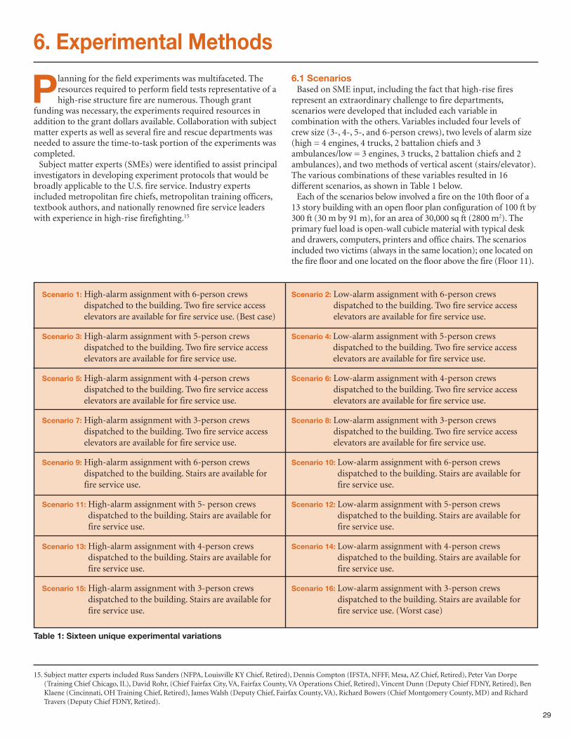
29
6. Experimental Methods
Planning for the field experiments was multifaceted. Theresources required to perform field tests representative of ahigh-rise structure fire are numerous. Though grant
funding was necessary, the experiments required resources inaddition to the grant dollars available. Collaboration with subjectmatter experts as well as several fire and rescue departments wasneeded to assure the time-to-task portion of the experiments wascompleted. Subject matter experts (SMEs) were identified to assist principal
investigators in developing experiment protocols that would bebroadly applicable to the U.S. fire service. Industry expertsincluded metropolitan fire chiefs, metropolitan training officers,textbook authors, and nationally renowned fire service leaderswith experience in high-rise firefighting.15
6.1 ScenariosBased on SME input, including the fact that high-rise fires
represent an extraordinary challenge to fire departments,scenarios were developed that included each variable incombination with the others. Variables included four levels ofcrew size (3-, 4-, 5-, and 6-person crews), two levels of alarm size(high = 4 engines, 4 trucks, 2 battalion chiefs and 3ambulances/low = 3 engines, 3 trucks, 2 battalion chiefs and 2ambulances), and two methods of vertical ascent (stairs/elevator).The various combinations of these variables resulted in 16different scenarios, as shown in Table 1 below. Each of the scenarios below involved a fire on the 10th floor of a
13 story building with an open floor plan configuration of 100 ft by300 ft (30 m by 91 m), for an area of 30,000 sq ft (2800 m2). Theprimary fuel load is open-wall cubicle material with typical deskand drawers, computers, printers and office chairs. The scenariosincluded two victims (always in the same location); one located onthe fire floor and one located on the floor above the fire (Floor 11).
15. Subject matter experts included Russ Sanders (NFPA, Louisville KY Chief, Retired), Dennis Compton (IFSTA, NFFF, Mesa, AZ Chief, Retired), Peter Van Dorpe(Training Chief Chicago, IL), David Rohr, (Chief Fairfax City, VA, Fairfax County, VA Operations Chief, Retired), Vincent Dunn (Deputy Chief FDNY, Retired), BenKlaene (Cincinnati, OH Training Chief, Retired), James Walsh (Deputy Chief, Fairfax County, VA), Richard Bowers (Chief Montgomery County, MD) and RichardTravers (Deputy Chief FDNY, Retired).
Table 1: Sixteen unique experimental variations
Scenario 1:High-alarm assignment with 6-person crewsdispatched to the building. Two fire service accesselevators are available for fire service use. (Best case)
Scenario 3:High-alarm assignment with 5-person crewsdispatched to the building. Two fire service accesselevators are available for fire service use.
Scenario 5:High-alarm assignment with 4-person crewsdispatched to the building. Two fire service accesselevators are available for fire service use.
Scenario 7:High-alarm assignment with 3-person crewsdispatched to the building. Two fire service accesselevators are available for fire service use.
Scenario 9:High-alarm assignment with 6-person crewsdispatched to the building. Stairs are available forfire service use.
Scenario 11:High-alarm assignment with 5- person crewsdispatched to the building. Stairs are available forfire service use.
Scenario 13:High-alarm assignment with 4-person crewsdispatched to the building. Stairs are available forfire service use.
Scenario 15:High-alarm assignment with 3-person crewsdispatched to the building. Stairs are available forfire service use.
Scenario 2: Low-alarm assignment with 6-person crewsdispatched to the building. Two fire service accesselevators are available for fire service use.
Scenario 4: Low-alarm assignment with 5-person crewsdispatched to the building. Two fire service accesselevators are available for fire service use.
Scenario 6: Low-alarm assignment with 4-person crewsdispatched to the building. Two fire service accesselevators are available for fire service use.
Scenario 8: Low-alarm assignment with 3-person crewsdispatched to the building. Two fire service accesselevators are available for fire service use.
Scenario 10: Low-alarm assignment with 6-person crewsdispatched to the building. Stairs are available forfire service use.
Scenario 12: Low-alarm assignment with 5-person crewsdispatched to the building. Stairs are available forfire service use.
Scenario 14: Low-alarm assignment with 4-person crewsdispatched to the building. Stairs are available forfire service use.
Scenario 16: Low-alarm assignment with 3-person crewsdispatched to the building. Stairs are available forfire service use. (Worst case)
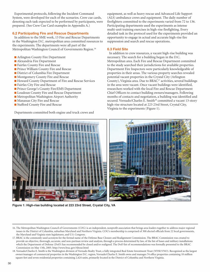
30
Experimental protocols, following the Incident CommandSystem, were developed for each of the scenarios. Crew cue cards,denoting each task expected to be performed by participants, wereprepared. (See Crew Cue Card examples in Appendix A.)
6.2 Participating Fire and Rescue DepartmentsIn addition to the SME work, 13 Fire and Rescue Departments
in the Washington D.C. metropolitan area committed resources tothe experiments. The departments were all part of theMetropolitan Washington Council of Governments Region.16
n Arlington County Fire Departmentn Alexandria Fire Departmentn Fairfax County Fire and Rescue n Prince William County Fire and Rescuen District of Columbia Fire DepartmentnMontgomery County Fire and Rescue nHoward County Department of Fire and Rescue Servicesn Fairfax City Fire and Rescue n Prince George’s County Fire/EMS Departmentn Loudoun County Fire and Rescue DepartmentnMetropolitan Washington Airport AuthoritynManassas City Fire and Rescuen Stafford County Fire and Rescue
Departments committed both engine and truck crews and
equipment, as well as heavy rescue and Advanced Life Support(ALS) ambulance crews and equipment. The daily number offirefighters committed to the experiments varied from 72 to 136.Participating departments used the experiments as intensemulti-unit training exercises in high-rise firefighting. Everydetailed task in the protocol used for the experiments provided anopportunity to engage in actual and accurate high-rise firesuppression and search and rescue operations.
6.3 Field SiteIn addition to crew resources, a vacant high-rise building was
necessary. The search for a building began in the D.C.Metropolitan area. Each Fire and Rescue Department committedto the study searched their jurisdictions for available properties.Department Fire Inspectors were particularly knowledgeable ofproperties in their areas. The various property searches revealedpotential vacant properties in the Crystal City (ArlingtonCounty), Virginia area. Due to BRAC17 activities, several buildingsin the area were vacant. Once vacant buildings were identified,researchers worked with the local Fire and Rescue DepartmentChief Officers to contact building owners/managers. Followingmonths of contacts and negotiation, a building was identified andsecured. Vornado/Charles E. Smith18 committed a vacant 13-storyhigh-rise structure located at 223 23rd Street, Crystal City,Virginia to the experiments (Figure 1).
16. The Metropolitan Washington Council of Governments (COG) is an independent, nonprofit association that brings area leaders together to address major regionalissues in the District of Columbia, suburban Maryland and Northern Virginia. COG’s membership is comprised of 300 elected officials from 22 local governments,the Maryland and Virginia state legislatures, and U.S. Congress.
17. BRAC is the commonly used acronym for the formal name of the Defense Base Closure and Realignment Commission. The BRAC Commission was created toprovide an objective, thorough, accurate, and non-partisan review and analysis, through a process determined by law, of the list of bases and military installationswhich the Department of Defense (DoD) has recommended be closed and/or realigned. The DoD list of recommendations was formally presented to the BRACCommission on May 13th, 2005. http://www.brac.gov/About.html
18. Vornado/Charles E. Smith is the Washington division of Vornado Realty Trust, a fully integrated Real Estate Investment Trust (NYSE:VNO). Recognized as the largestowner/manager of commercial properties in the Washington D.C. region, Vornado/Charles E. Smith owns and manages 74 office properties containing 18 millionsquare feet and seven residential properties containing 2,424 units, primarily located in the District of Columbia and Northern Virginia.
Figure 1: High-rise building located at 223 23rd Street, Crystal City, VA
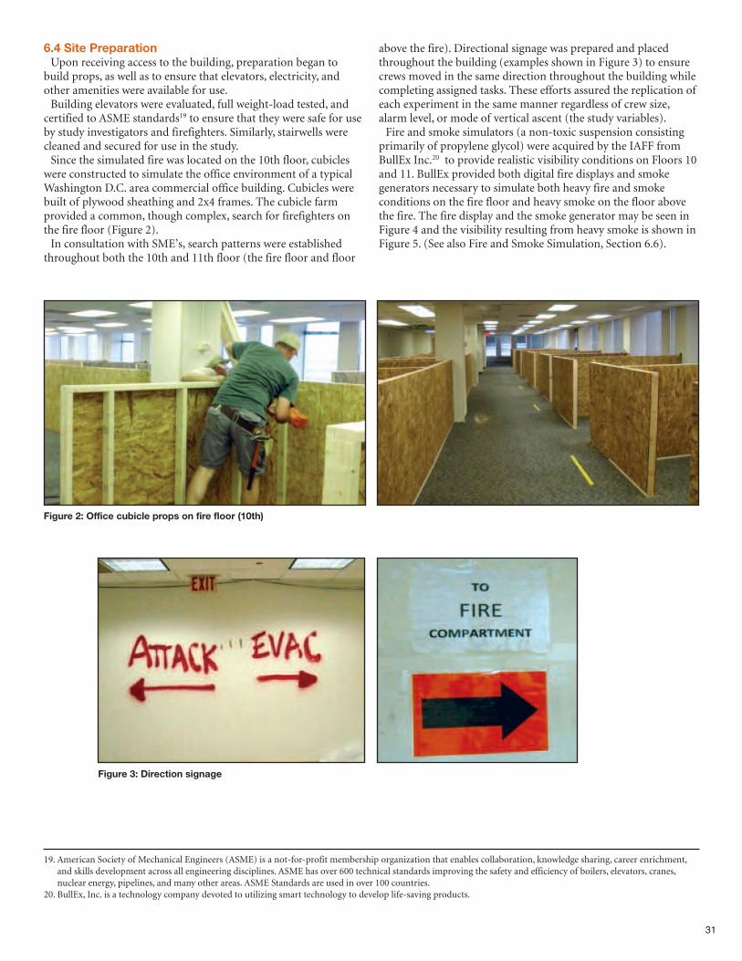
31
19. American Society of Mechanical Engineers (ASME) is a not-for-profit membership organization that enables collaboration, knowledge sharing, career enrichment,and skills development across all engineering disciplines. ASME has over 600 technical standards improving the safety and efficiency of boilers, elevators, cranes,nuclear energy, pipelines, and many other areas. ASME Standards are used in over 100 countries.
20. BullEx, Inc. is a technology company devoted to utilizing smart technology to develop life-saving products.
Figure 2: Office cubicle props on fire floor (10th)
Figure 3: Direction signage
6.4 Site PreparationUpon receiving access to the building, preparation began to
build props, as well as to ensure that elevators, electricity, andother amenities were available for use. Building elevators were evaluated, full weight-load tested, and
certified to ASME standards19 to ensure that they were safe for useby study investigators and firefighters. Similarly, stairwells werecleaned and secured for use in the study.Since the simulated fire was located on the 10th floor, cubicles
were constructed to simulate the office environment of a typicalWashington D.C. area commercial office building. Cubicles werebuilt of plywood sheathing and 2x4 frames. The cubicle farmprovided a common, though complex, search for firefighters onthe fire floor (Figure 2).In consultation with SME’s, search patterns were established
throughout both the 10th and 11th floor (the fire floor and floor
above the fire). Directional signage was prepared and placedthroughout the building (examples shown in Figure 3) to ensurecrews moved in the same direction throughout the building whilecompleting assigned tasks. These efforts assured the replication ofeach experiment in the same manner regardless of crew size,alarm level, or mode of vertical ascent (the study variables). Fire and smoke simulators (a non-toxic suspension consisting
primarily of propylene glycol) were acquired by the IAFF fromBullEx Inc.20 to provide realistic visibility conditions on Floors 10and 11. BullEx provided both digital fire displays and smokegenerators necessary to simulate both heavy fire and smokeconditions on the fire floor and heavy smoke on the floor abovethe fire. The fire display and the smoke generator may be seen inFigure 4 and the visibility resulting from heavy smoke is shown inFigure 5. (See also Fire and Smoke Simulation, Section 6.6).
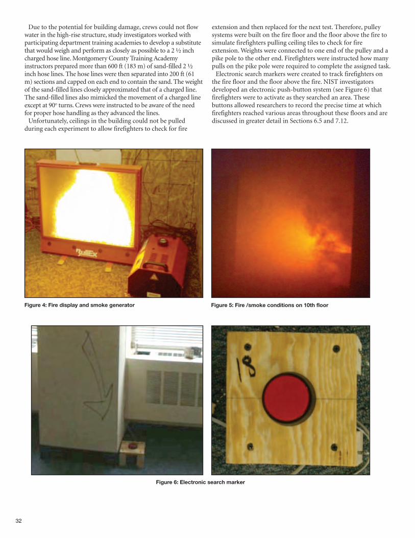
32
Due to the potential for building damage, crews could not flowwater in the high-rise structure, study investigators worked withparticipating department training academies to develop a substitutethat would weigh and perform as closely as possible to a 2 ½ inchcharged hose line. Montgomery County Training Academyinstructors prepared more than 600 ft (183 m) of sand-filled 2 ½inch hose lines. The hose lines were then separated into 200 ft (61m) sections and capped on each end to contain the sand. The weightof the sand-filled lines closely approximated that of a charged line.The sand-filled lines also mimicked the movement of a charged lineexcept at 90o turns. Crews were instructed to be aware of the needfor proper hose handling as they advanced the lines.Unfortunately, ceilings in the building could not be pulled
during each experiment to allow firefighters to check for fire
extension and then replaced for the next test. Therefore, pulleysystems were built on the fire floor and the floor above the fire tosimulate firefighters pulling ceiling tiles to check for fireextension. Weights were connected to one end of the pulley and apike pole to the other end. Firefighters were instructed how manypulls on the pike pole were required to complete the assigned task.Electronic search markers were created to track firefighters on
the fire floor and the floor above the fire. NIST investigatorsdeveloped an electronic push-button system (see Figure 6) thatfirefighters were to activate as they searched an area. Thesebuttons allowed researchers to record the precise time at whichfirefighters reached various areas throughout these floors and arediscussed in greater detail in Sections 6.5 and 7.12.
Figure 4: Fire display and smoke generator
Figure 6: Electronic search marker
Figure 5: Fire /smoke conditions on 10th floor
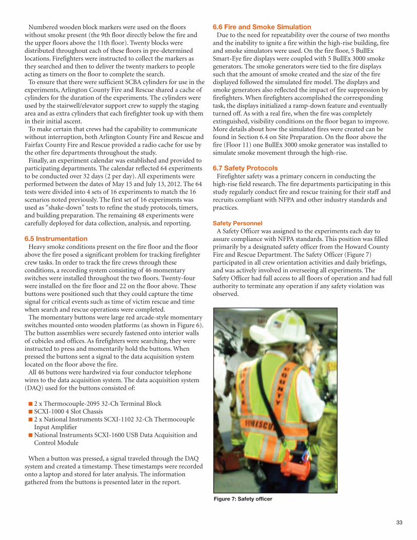
33
Numbered wooden block markers were used on the floorswithout smoke present (the 9th floor directly below the fire andthe upper floors above the 11th floor). Twenty blocks weredistributed throughout each of these floors in pre-determinedlocations. Firefighters were instructed to collect the markers asthey searched and then to deliver the twenty markers to peopleacting as timers on the floor to complete the search. To ensure that there were sufficient SCBA cylinders for use in the
experiments, Arlington County Fire and Rescue shared a cache ofcylinders for the duration of the experiments. The cylinders wereused by the stairwell/elevator support crew to supply the stagingarea and as extra cylinders that each firefighter took up with themin their initial ascent. To make certain that crews had the capability to communicate
without interruption, both Arlington County Fire and Rescue andFairfax County Fire and Rescue provided a radio cache for use bythe other fire departments throughout the study. Finally, an experiment calendar was established and provided to
participating departments. The calendar reflected 64 experimentsto be conducted over 32 days (2 per day). All experiments wereperformed between the dates of May 15 and July 13, 2012. The 64tests were divided into 4 sets of 16 experiments to match the 16scenarios noted previously. The first set of 16 experiments wasused as “shake-down” tests to refine the study protocols, timers,and building preparation. The remaining 48 experiments werecarefully deployed for data collection, analysis, and reporting.
6.5 InstrumentationHeavy smoke conditions present on the fire floor and the floor
above the fire posed a significant problem for tracking firefightercrew tasks. In order to track the fire crews through theseconditions, a recording system consisting of 46 momentaryswitches were installed throughout the two floors. Twenty-fourwere installed on the fire floor and 22 on the floor above. Thesebuttons were positioned such that they could capture the timesignal for critical events such as time of victim rescue and timewhen search and rescue operations were completed.The momentary buttons were large red arcade-style momentary
switches mounted onto wooden platforms (as shown in Figure 6).The button assemblies were securely fastened onto interior wallsof cubicles and offices. As firefighters were searching, they wereinstructed to press and momentarily hold the buttons. Whenpressed the buttons sent a signal to the data acquisition systemlocated on the floor above the fire. All 46 buttons were hardwired via four conductor telephone
wires to the data acquisition system. The data acquisition system(DAQ) used for the buttons consisted of:
n 2 x Thermocouple-2095 32-Ch Terminal Blockn SCXI-1000 4 Slot Chassisn 2 x National Instruments SCXI-1102 32-Ch ThermocoupleInput Amplifier
n National Instruments SCXI-1600 USB Data Acquisition andControl Module
When a button was pressed, a signal traveled through the DAQsystem and created a timestamp. These timestamps were recordedonto a laptop and stored for later analysis. The informationgathered from the buttons is presented later in the report.
6.6 Fire and Smoke SimulationDue to the need for repeatability over the course of two months
and the inability to ignite a fire within the high-rise building, fireand smoke simulators were used. On the fire floor, 5 BullExSmart-Eye fire displays were coupled with 5 BullEx 3000 smokegenerators. The smoke generators were tied to the fire displayssuch that the amount of smoke created and the size of the firedisplayed followed the simulated fire model. The displays andsmoke generators also reflected the impact of fire suppression byfirefighters. When firefighters accomplished the correspondingtask, the displays initialized a ramp-down feature and eventuallyturned off. As with a real fire, when the fire was completelyextinguished, visibility conditions on the floor began to improve.More details about how the simulated fires were created can befound in Section 6.4 on Site Preparation. On the floor above thefire (Floor 11) one BullEx 3000 smoke generator was installed tosimulate smoke movement through the high-rise.
6.7 Safety ProtocolsFirefighter safety was a primary concern in conducting the
high-rise field research. The fire departments participating in thisstudy regularly conduct fire and rescue training for their staff andrecruits compliant with NFPA and other industry standards andpractices.
Safety PersonnelA Safety Officer was assigned to the experiments each day to
assure compliance with NFPA standards. This position was filledprimarily by a designated safety officer from the Howard CountyFire and Rescue Department. The Safety Officer (Figure 7)participated in all crew orientation activities and daily briefings,and was actively involved in overseeing all experiments. TheSafety Officer had full access to all floors of operation and had fullauthority to terminate any operation if any safety violation wasobserved.
Figure 7: Safety officer
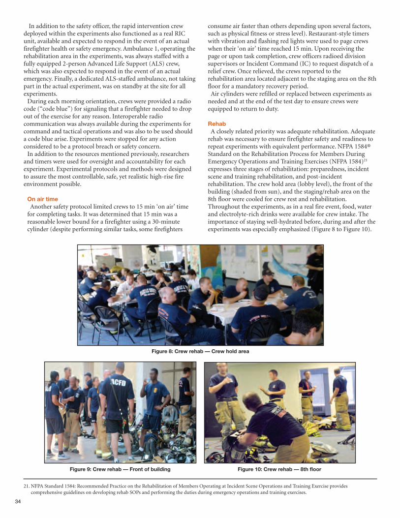
34
In addition to the safety officer, the rapid intervention crewdeployed within the experiments also functioned as a real RICunit, available and expected to respond in the event of an actualfirefighter health or safety emergency. Ambulance 1, operating therehabilitation area in the experiments, was always staffed with afully equipped 2-person Advanced Life Support (ALS) crew,which was also expected to respond in the event of an actualemergency. Finally, a dedicated ALS-staffed ambulance, not takingpart in the actual experiment, was on standby at the site for allexperiments. During each morning orientation, crews were provided a radio
code (“code blue”) for signaling that a firefighter needed to dropout of the exercise for any reason. Interoperable radiocommunication was always available during the experiments forcommand and tactical operations and was also to be used shoulda code blue arise. Experiments were stopped for any actionconsidered to be a protocol breach or safety concern. In addition to the resources mentioned previously, researchers
and timers were used for oversight and accountability for eachexperiment. Experimental protocols and methods were designedto assure the most controllable, safe, yet realistic high-rise fireenvironment possible.
On air timeAnother safety protocol limited crews to 15 min ‘on air’ timefor completing tasks. It was determined that 15 min was areasonable lower bound for a firefighter using a 30-minutecylinder (despite performing similar tasks, some firefighters
consume air faster than others depending upon several factors,such as physical fitness or stress level). Restaurant-style timerswith vibration and flashing red lights were used to page crewswhen their ‘on air’ time reached 15 min. Upon receiving thepage or upon task completion, crew officers radioed divisionsupervisors or Incident Command (IC) to request dispatch of arelief crew. Once relieved, the crews reported to therehabilitation area located adjacent to the staging area on the 8thfloor for a mandatory recovery period. Air cylinders were refilled or replaced between experiments asneeded and at the end of the test day to ensure crews wereequipped to return to duty.
RehabA closely related priority was adequate rehabilitation. Adequaterehab was necessary to ensure firefighter safety and readiness torepeat experiments with equivalent performance. NFPA 1584®Standard on the Rehabilitation Process for Members DuringEmergency Operations and Training Exercises (NFPA 1584)21
expresses three stages of rehabilitation: preparedness, incidentscene and training rehabilitation, and post-incidentrehabilitation. The crew hold area (lobby level), the front of thebuilding (shaded from sun), and the staging/rehab area on the8th floor were cooled for crew rest and rehabilitation.Throughout the experiments, as in a real fire event, food, waterand electrolyte-rich drinks were available for crew intake. Theimportance of staying well-hydrated before, during and after theexperiments was especially emphasized (Figure 8 to Figure 10).
21. NFPA Standard 1584: Recommended Practice on the Rehabilitation of Members Operating at Incident Scene Operations and Training Exercise providescomprehensive guidelines on developing rehab SOPs and performing the duties during emergency operations and training exercises.
Figure 8: Crew rehab — Crew hold area
Figure 9: Crew rehab — Front of building Figure 10: Crew rehab — 8th floor
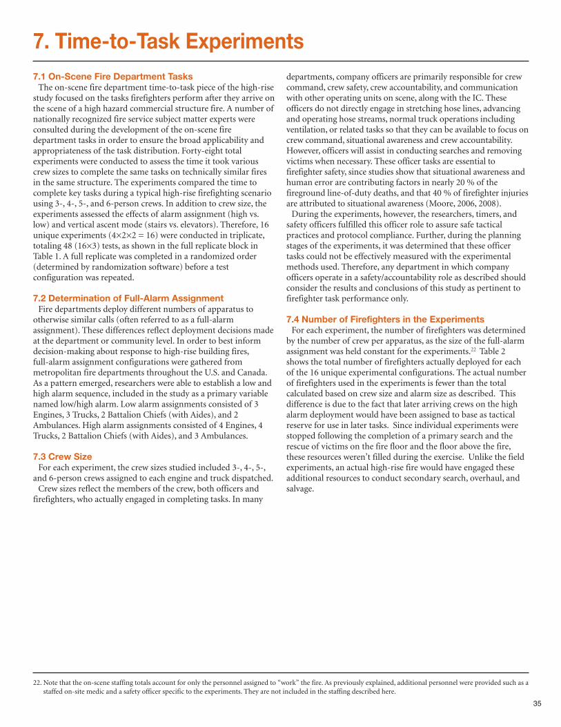
35
22. Note that the on-scene staffing totals account for only the personnel assigned to “work” the fire. As previously explained, additional personnel were provided such as astaffed on-site medic and a safety officer specific to the experiments. They are not included in the staffing described here.
7. Time-to-Task Experiments7.1 On-Scene Fire Department TasksThe on-scene fire department time-to-task piece of the high-rise
study focused on the tasks firefighters perform after they arrive onthe scene of a high hazard commercial structure fire. A number ofnationally recognized fire service subject matter experts wereconsulted during the development of the on-scene firedepartment tasks in order to ensure the broad applicability andappropriateness of the task distribution. Forty-eight totalexperiments were conducted to assess the time it took variouscrew sizes to complete the same tasks on technically similar firesin the same structure. The experiments compared the time tocomplete key tasks during a typical high-rise firefighting scenariousing 3-, 4-, 5-, and 6-person crews. In addition to crew size, theexperiments assessed the effects of alarm assignment (high vs.low) and vertical ascent mode (stairs vs. elevators). Therefore, 16unique experiments (4×2×2 = 16) were conducted in triplicate,totaling 48 (16×3) tests, as shown in the full replicate block inTable 1. A full replicate was completed in a randomized order(determined by randomization software) before a testconfiguration was repeated.
7.2 Determination of Full-Alarm AssignmentFire departments deploy different numbers of apparatus to
otherwise similar calls (often referred to as a full-alarmassignment). These differences reflect deployment decisions madeat the department or community level. In order to best informdecision-making about response to high-rise building fires,full-alarm assignment configurations were gathered frommetropolitan fire departments throughout the U.S. and Canada.As a pattern emerged, researchers were able to establish a low andhigh alarm sequence, included in the study as a primary variablenamed low/high alarm. Low alarm assignments consisted of 3Engines, 3 Trucks, 2 Battalion Chiefs (with Aides), and 2Ambulances. High alarm assignments consisted of 4 Engines, 4Trucks, 2 Battalion Chiefs (with Aides), and 3 Ambulances.
7.3 Crew SizeFor each experiment, the crew sizes studied included 3-, 4-, 5-,
and 6-person crews assigned to each engine and truck dispatched. Crew sizes reflect the members of the crew, both officers and
firefighters, who actually engaged in completing tasks. In many
departments, company officers are primarily responsible for crewcommand, crew safety, crew accountability, and communicationwith other operating units on scene, along with the IC. Theseofficers do not directly engage in stretching hose lines, advancingand operating hose streams, normal truck operations includingventilation, or related tasks so that they can be available to focus oncrew command, situational awareness and crew accountability.However, officers will assist in conducting searches and removingvictims when necessary. These officer tasks are essential tofirefighter safety, since studies show that situational awareness andhuman error are contributing factors in nearly 20 % of thefireground line-of-duty deaths, and that 40 % of firefighter injuriesare attributed to situational awareness (Moore, 2006, 2008).During the experiments, however, the researchers, timers, and
safety officers fulfilled this officer role to assure safe tacticalpractices and protocol compliance. Further, during the planningstages of the experiments, it was determined that these officertasks could not be effectively measured with the experimentalmethods used. Therefore, any department in which companyofficers operate in a safety/accountability role as described shouldconsider the results and conclusions of this study as pertinent tofirefighter task performance only.
7.4 Number of Firefighters in the ExperimentsFor each experiment, the number of firefighters was determined
by the number of crew per apparatus, as the size of the full-alarmassignment was held constant for the experiments.22 Table 2shows the total number of firefighters actually deployed for eachof the 16 unique experimental configurations. The actual numberof firefighters used in the experiments is fewer than the totalcalculated based on crew size and alarm size as described. Thisdifference is due to the fact that later arriving crews on the highalarm deployment would have been assigned to base as tacticalreserve for use in later tasks. Since individual experiments werestopped following the completion of a primary search and therescue of victims on the fire floor and the floor above the fire,these resources weren’t filled during the exercise. Unlike the fieldexperiments, an actual high-rise fire would have engaged theseadditional resources to conduct secondary search, overhaul, andsalvage.
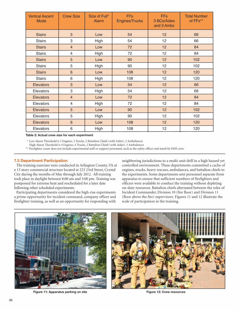
36
Table 2: Actual crew size for each experiment
Figure 11: Apparatus parking on site Figure 12: Crew resources
Vertical Ascent Crew Size Size of Full* FFs FFs Total Number
Mode Alarm Engines/Trucks 3 BCs/Aides of FFs**and 3 Ambs
Stairs 3 Low 54 12 66
Stairs 3 High 54 12 66
Stairs 4 Low 72 12 84
Stairs 4 High 72 12 84
Stairs 5 Low 90 12 102
Stairs 5 High 90 12 102
Stairs 6 Low 108 12 120
Stairs 6 High 108 12 120
Elevators 3 Low 54 12 66
Elevators 3 High 54 12 66
Elevators 4 Low 72 12 84
Elevators 4 High 72 12 84
Elevators 5 Low 90 12 102
Elevators 5 High 90 12 102
Elevators 6 Low 108 12 120
Elevators 6 High 108 12 120
* Low Alarm Threshold is 3 Engines, 3 Trucks, 2 Battalion Chiefs (with Aides), 2 AmbulancesHigh Alarm Threshold is 4 Engines, 4 Trucks, 2 Battalion Chiefs (with Aides), 3 Ambulances
** Firefighter count does not include experimental staff or support personnel, such as the safety officer and stand-by EMS crew.
7.5 Department ParticipationThe training exercises were conducted in Arlington County, VA at
a 13 story commercial structure located at 223 23rd Street, CrystalCity during the months of May through July 2012. All trainingtook place in daylight between 8:00 am and 3:00 pm. Training waspostponed for extreme heat and rescheduled for a later datefollowing other scheduled experiments.Participating departments considered the high-rise experiments
a prime opportunity for incident command, company officer andfirefighter training, as well as an opportunity for responding with
neighboring jurisdictions to a multi-unit drill in a high hazard yetcontrolled environment. These departments committed a cache ofengines, trucks, heavy rescues, ambulances, and battalion chiefs tothe experiments. Some departments sent personnel separate fromapparatus to ensure that sufficient numbers of firefighters andofficers were available to conduct the training without depletingon-duty resources. Battalion chiefs alternated between the roles ofIncident Commander, Division 10 (fire floor) and Division 11(floor above the fire) supervisors. Figures 11 and 12 illustrate thescale of participation in the training.
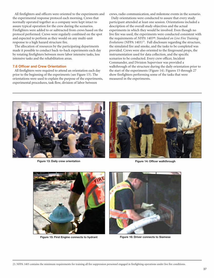
37
Figure 13: Daily crew orientation
Figure 15: First Engine connects to hydrant Figure 16: Driver connects to Siamese
Figure 14: Officer walkthrough
All firefighters and officers were oriented to the experiments andthe experimental response protocol each morning. Crews thatnormally operated together as a company were kept intact toassure typical operation for the crew during the scenarios.Firefighters were added to or subtracted from crews based on theprotocol performed. Crews were regularly combined on the spotand expected to perform as they would on any multi-unitresponse to a high hazard structure fire. The allocation of resources by the participating departments
made it possible to conduct back-to-back experiments each dayby rotating firefighters between more labor intensive tasks, lessintensive tasks and the rehabilitation areas.
7.6 Officer and Crew OrientationAll firefighters were required to attend an orientation each day
prior to the beginning of the experiments (see Figure 13). Theorientations were used to explain the purpose of the experiments,experimental procedures, task flow, division of labor between
crews, radio communication, and milestone events in the scenario.Daily orientations were conducted to assure that every study
participant attended at least one session. Orientations included adescription of the overall study objectives and the actualexperiments in which they would be involved. Even though nolive fire was used, the experiments were conducted consistent withthe requirements of NFPA 1403®: Standard on Live Fire TrainingEvolutions (NFPA 1403)23. Full disclosure regarding the structure,the simulated fire and smoke, and the tasks to be completed wasprovided. Crews were also oriented to the fireground props, theinstrumentation used for data collection, and the specificscenarios to be conducted. Every crew officer, IncidentCommander, and Division Supervisor was provided awalkthrough of the structure during the daily orientation prior tothe start of the experiments (Figure 14). Figures 15 through 27show firefighters performing some of the tasks that weremeasured in the experiments.
23. NFPA 1403 contains the minimum requirements for training all fire suppression personnel engaged in firefighting operations under live fire conditions.
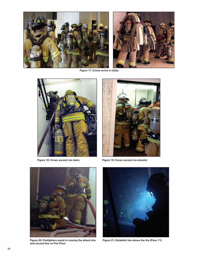
38
Figure 17: Crews arrive in lobby
Figure 18: Crews ascend via stairs Figure 19: Crews ascend via elevator
Figure 21: Establish line above the fire (Floor 11)Figure 20: Firefighters assist in moving the attack lineand second line on Fire Floor
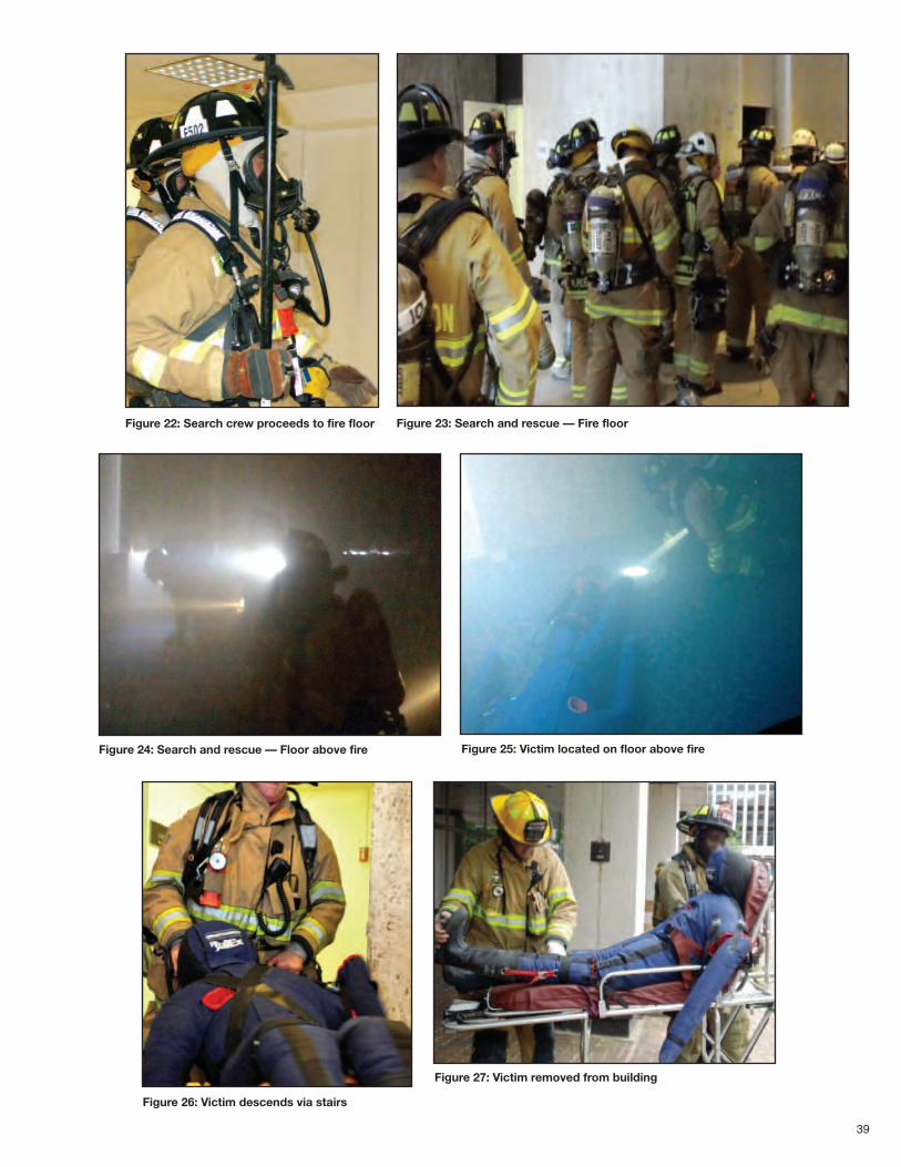
39
Figure 22: Search crew proceeds to fire floor Figure 23: Search and rescue — Fire floor
Figure 24: Search and rescue — Floor above fire Figure 25: Victim located on floor above fire
Figure 27: Victim removed from building
Figure 26: Victim descends via stairs
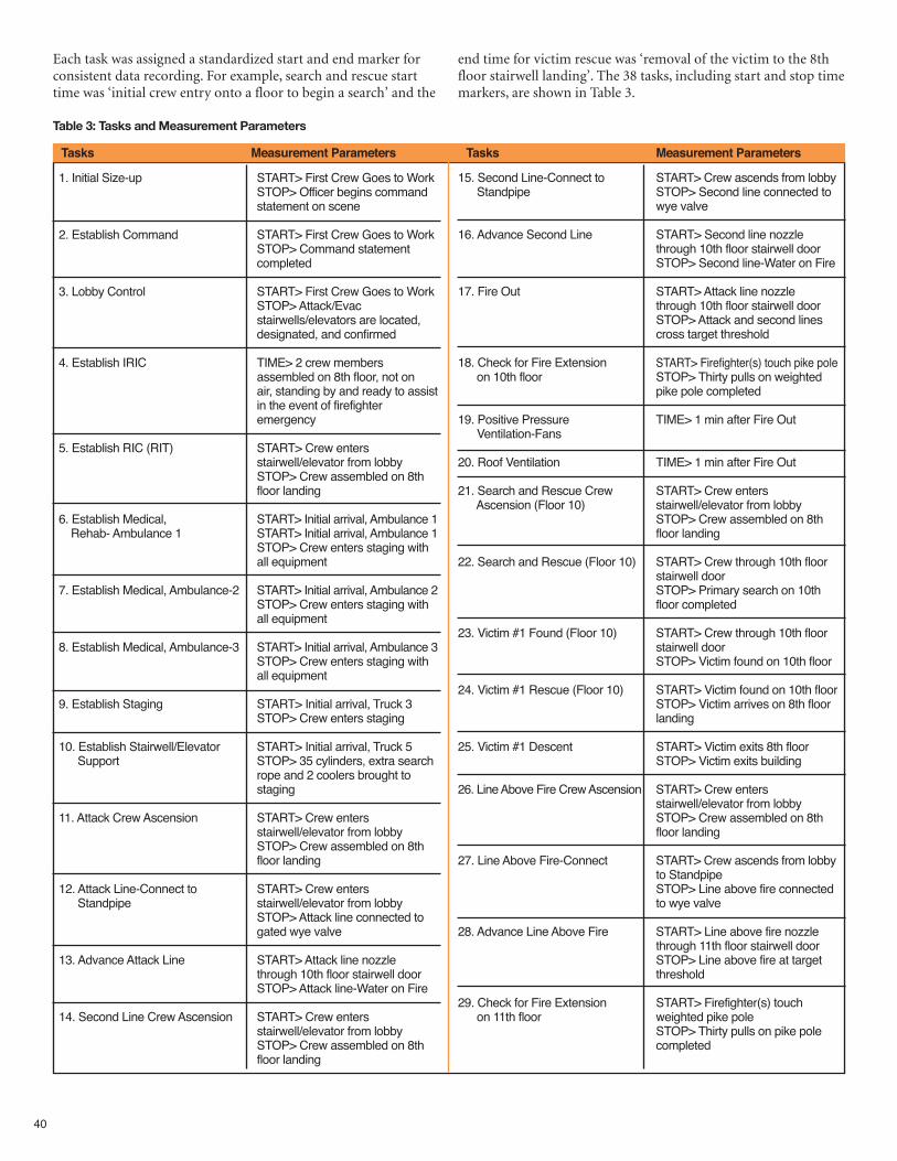
40
Table 3: Tasks and Measurement Parameters
1. Initial Size-up START> First Crew Goes to WorkSTOP> Officer begins command statement on scene
2. Establish Command START> First Crew Goes to WorkSTOP> Command statement completed
3. Lobby Control START> First Crew Goes to WorkSTOP> Attack/Evac stairwells/elevators are located, designated, and confirmed
4. Establish IRIC TIME> 2 crew members assembled on 8th floor, not on air, standing by and ready to assistin the event of firefighter emergency
5. Establish RIC (RIT) START> Crew enters stairwell/elevator from lobbySTOP> Crew assembled on 8th floor landing
6. Establish Medical, START> Initial arrival, Ambulance 1 Rehab- Ambulance 1 START> Initial arrival, Ambulance 1
STOP> Crew enters staging with all equipment
7. Establish Medical, Ambulance-2 START> Initial arrival, Ambulance 2STOP> Crew enters staging with all equipment
8. Establish Medical, Ambulance-3 START> Initial arrival, Ambulance 3STOP> Crew enters staging with all equipment
9. Establish Staging START> Initial arrival, Truck 3STOP> Crew enters staging
10. Establish Stairwell/Elevator START> Initial arrival, Truck 5Support STOP> 35 cylinders, extra search
rope and 2 coolers brought to staging
11. Attack Crew Ascension START> Crew enters stairwell/elevator from lobbySTOP> Crew assembled on 8th floor landing
12. Attack Line-Connect to START> Crew enters Standpipe stairwell/elevator from lobby
STOP> Attack line connected to gated wye valve
13. Advance Attack Line START> Attack line nozzle through 10th floor stairwell doorSTOP> Attack line-Water on Fire
14. Second Line Crew Ascension START> Crew enters stairwell/elevator from lobbySTOP> Crew assembled on 8th floor landing
15. Second Line-Connect to START> Crew ascends from lobbyStandpipe STOP> Second line connected to
wye valve
16. Advance Second Line START> Second line nozzle through 10th floor stairwell doorSTOP> Second line-Water on Fire
17. Fire Out START> Attack line nozzle through 10th floor stairwell doorSTOP> Attack and second lines cross target threshold
18. Check for Fire Extension START> Firefighter(s) touch pike pole on 10th floor STOP> Thirty pulls on weighted
pike pole completed
19. Positive Pressure TIME> 1 min after Fire OutVentilation-Fans
20. Roof Ventilation TIME> 1 min after Fire Out
21. Search and Rescue Crew START> Crew enters Ascension (Floor 10) stairwell/elevator from lobby
STOP> Crew assembled on 8th floor landing
22. Search and Rescue (Floor 10) START> Crew through 10th floor stairwell doorSTOP> Primary search on 10th floor completed
23. Victim #1 Found (Floor 10) START> Crew through 10th floor stairwell doorSTOP> Victim found on 10th floor
24. Victim #1 Rescue (Floor 10) START> Victim found on 10th floorSTOP> Victim arrives on 8th floor landing
25. Victim #1 Descent START> Victim exits 8th floorSTOP> Victim exits building
26. Line Above Fire Crew Ascension START> Crew enters stairwell/elevator from lobbySTOP> Crew assembled on 8th floor landing
27. Line Above Fire-Connect START> Crew ascends from lobbyto StandpipeSTOP> Line above fire connected to wye valve
28. Advance Line Above Fire START> Line above fire nozzle through 11th floor stairwell doorSTOP> Line above fire at target threshold
29. Check for Fire Extension START> Firefighter(s) touch on 11th floor weighted pike pole
STOP> Thirty pulls on pike pole completed
Tasks Measurement Parameters Tasks Measurement Parameters
Each task was assigned a standardized start and end marker forconsistent data recording. For example, search and rescue starttime was ‘initial crew entry onto a floor to begin a search’ and the
end time for victim rescue was ‘removal of the victim to the 8thfloor stairwell landing’. The 38 tasks, including start and stop timemarkers, are shown in Table 3.
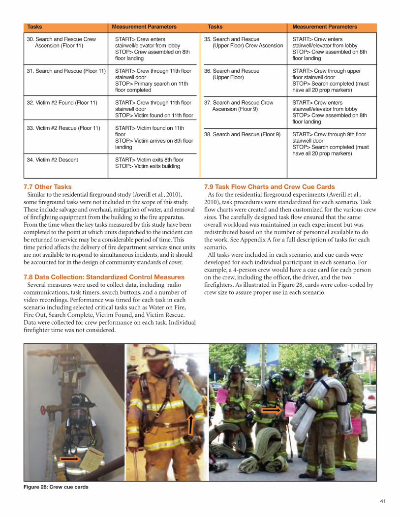
41
Tasks Measurement Parameters Tasks Measurement Parameters
30. Search and Rescue Crew START> Crew enters Ascension (Floor 11) stairwell/elevator from lobby
STOP> Crew assembled on 8th floor landing
31. Search and Rescue (Floor 11) START> Crew through 11th floor stairwell doorSTOP> Primary search on 11th floor completed
32. Victim #2 Found (Floor 11) START> Crew through 11th floor stairwell doorSTOP> Victim found on 11th floor
33. Victim #2 Rescue (Floor 11) START> Victim found on 11th floorSTOP> Victim arrives on 8th floor landing
34. Victim #2 Descent START> Victim exits 8th floorSTOP> Victim exits building
35. Search and Rescue START> Crew enters (Upper Floor) Crew Ascension stairwell/elevator from lobby
STOP> Crew assembled on 8th floor landing
36. Search and Rescue START> Crew through upper (Upper Floor) floor stairwell door
STOP> Search completed (must have all 20 prop markers)
37. Search and Rescue Crew START> Crew enters Ascension (Floor 9) stairwell/elevator from lobby
STOP> Crew assembled on 8th floor landing
38. Search and Rescue (Floor 9) START> Crew through 9th floor stairwell doorSTOP> Search completed (must have all 20 prop markers)
7.7 Other TasksSimilar to the residential fireground study (Averill et al., 2010),
some fireground tasks were not included in the scope of this study.These include salvage and overhaul, mitigation of water, and removalof firefighting equipment from the building to the fire apparatus.From the time when the key tasks measured by this study have beencompleted to the point at which units dispatched to the incident canbe returned to service may be a considerable period of time. Thistime period affects the delivery of fire department services since unitsare not available to respond to simultaneous incidents, and it shouldbe accounted for in the design of community standards of cover.
7.8 Data Collection: Standardized Control MeasuresSeveral measures were used to collect data, including radio
communications, task timers, search buttons, and a number ofvideo recordings. Performance was timed for each task in eachscenario including selected critical tasks such as Water on Fire,Fire Out, Search Complete, Victim Found, and Victim Rescue.Data were collected for crew performance on each task. Individualfirefighter time was not considered.
7.9 Task Flow Charts and Crew Cue CardsAs for the residential fireground experiments (Averill et al.,
2010), task procedures were standardized for each scenario. Taskflow charts were created and then customized for the various crewsizes. The carefully designed task flow ensured that the sameoverall workload was maintained in each experiment but wasredistributed based on the number of personnel available to dothe work. See Appendix A for a full description of tasks for eachscenario.All tasks were included in each scenario, and cue cards were
developed for each individual participant in each scenario. Forexample, a 4-person crew would have a cue card for each personon the crew, including the officer, the driver, and the twofirefighters. As illustrated in Figure 28, cards were color-coded bycrew size to assure proper use in each scenario.
Figure 28: Crew cue cards
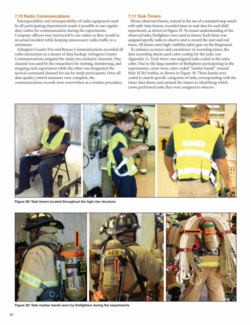
42
7.10 Radio CommunicationsInteroperability and intraoperability of radio equipment used
by all participating departments made it possible to use regularduty radios for communication during the experiments.Company officers were instructed to use radios as they would inan actual incident while keeping unnecessary radio traffic to aminimum.Arlington County Fire and Rescue Communications recorded all
radio interaction as a means of data backup. Arlington CountyCommunications assigned the study two exclusive channels. Onechannel was used by the researchers for starting, monitoring, andstopping each experiment while the other was designated thetactical command channel for use by study participants. Once alldata quality control measures were complete, thecommunications records were overwritten as a routine procedure.
7.11 Task TimersEleven observers/timers, trained in the use of a standard stop watch
with split-time feature, recorded time-to-task data for each fieldexperiment, as shown in Figure 29. To ensure understanding of theobserved tasks, firefighters were used as timers. Each timer wasassigned specific tasks to observe and to record the start and endtimes. All timers wore high-visibility safety gear on the fireground.To enhance accuracy and consistency in recording times, the
data recording sheets used color-coding for the tasks (seeAppendix A). Each timer was assigned tasks coded in the samecolor. Due to the large number of firefighters participating in theexperiments, crews wore color-coded “marker bands” aroundtheir SCBA bottles, as shown in Figure 30. These bands werecoded to match specific categories of tasks corresponding with thetimer data sheets and assisted the timers in identifying whichcrews performed tasks they were assigned to observe.
Figure 29: Task timers located throughout the high-rise structure
Figure 30: Task marker bands worn by firefighters during the experiments
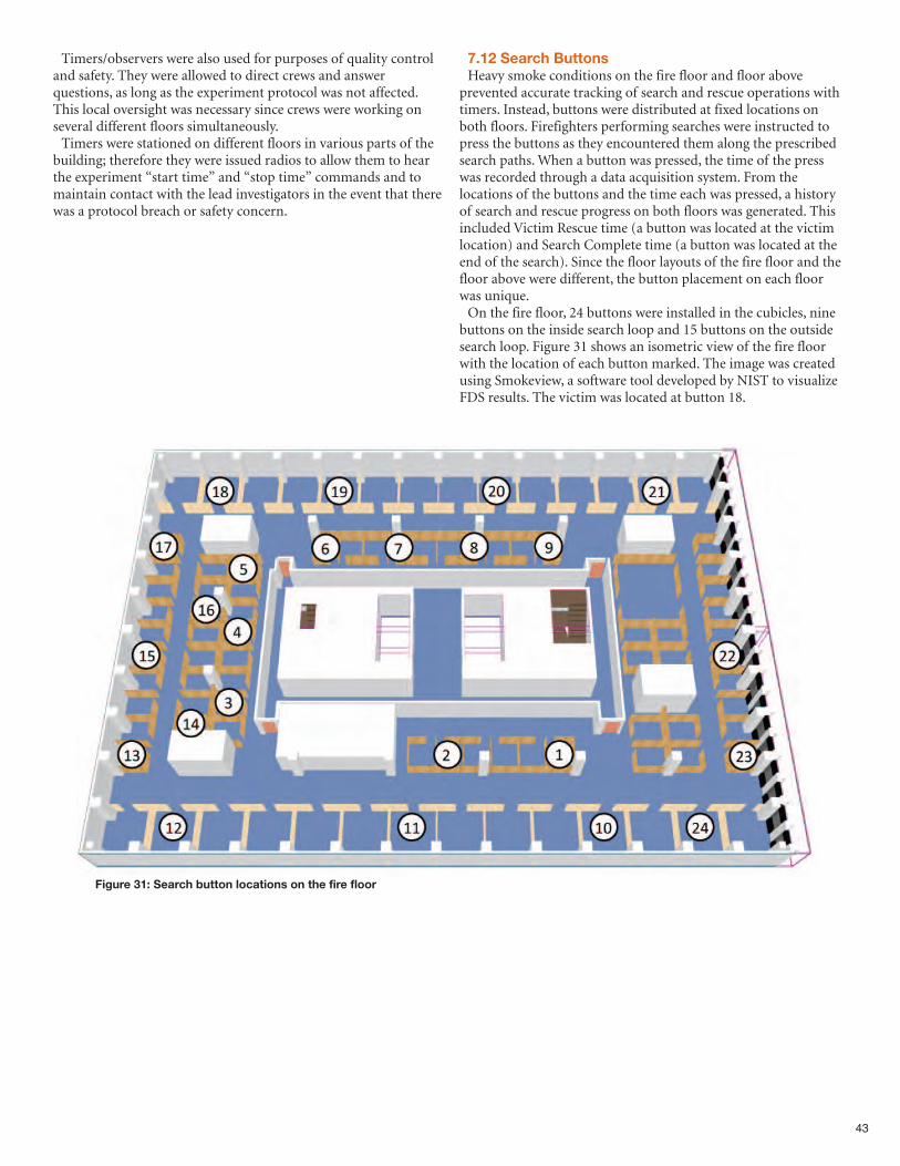
43
Figure 31: Search button locations on the fire floor
Timers/observers were also used for purposes of quality controland safety. They were allowed to direct crews and answerquestions, as long as the experiment protocol was not affected.This local oversight was necessary since crews were working onseveral different floors simultaneously.Timers were stationed on different floors in various parts of the
building; therefore they were issued radios to allow them to hearthe experiment “start time” and “stop time” commands and tomaintain contact with the lead investigators in the event that therewas a protocol breach or safety concern.
7.12 Search ButtonsHeavy smoke conditions on the fire floor and floor above
prevented accurate tracking of search and rescue operations withtimers. Instead, buttons were distributed at fixed locations onboth floors. Firefighters performing searches were instructed topress the buttons as they encountered them along the prescribedsearch paths. When a button was pressed, the time of the presswas recorded through a data acquisition system. From thelocations of the buttons and the time each was pressed, a historyof search and rescue progress on both floors was generated. Thisincluded Victim Rescue time (a button was located at the victimlocation) and Search Complete time (a button was located at theend of the search). Since the floor layouts of the fire floor and thefloor above were different, the button placement on each floorwas unique.On the fire floor, 24 buttons were installed in the cubicles, nine
buttons on the inside search loop and 15 buttons on the outsidesearch loop. Figure 31 shows an isometric view of the fire floorwith the location of each button marked. The image was createdusing Smokeview, a software tool developed by NIST to visualizeFDS results. The victim was located at button 18.
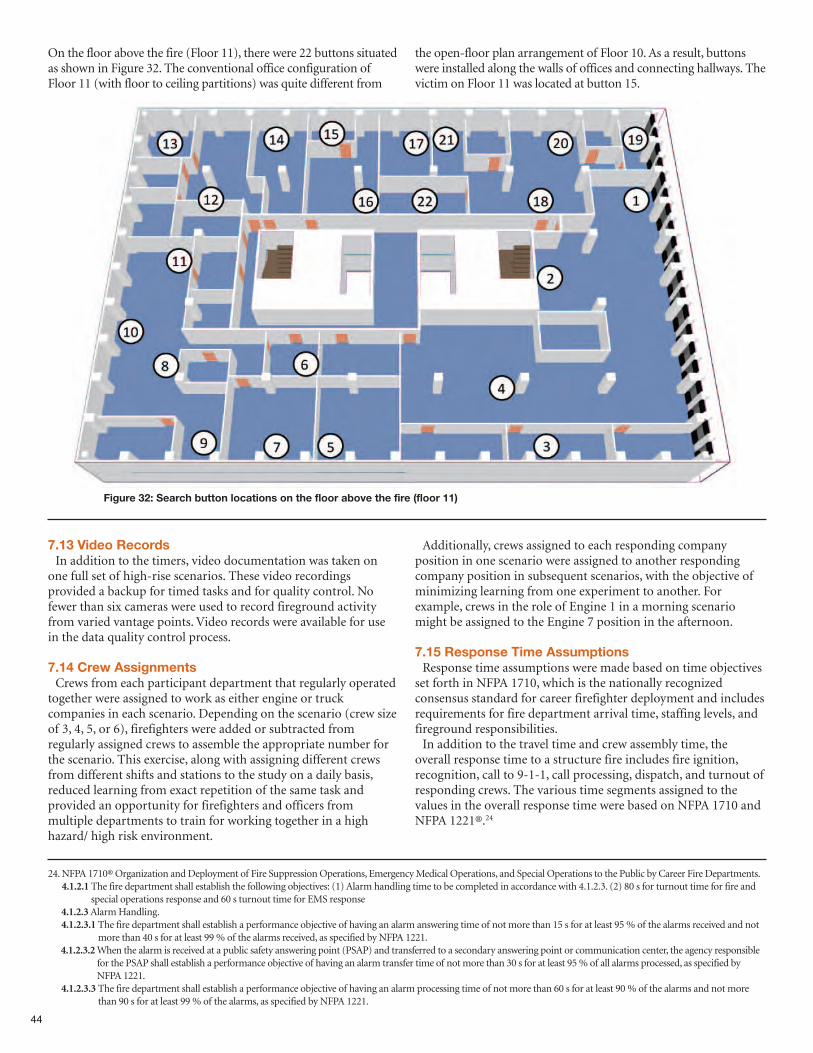
44
On the floor above the fire (Floor 11), there were 22 buttons situatedas shown in Figure 32. The conventional office configuration ofFloor 11 (with floor to ceiling partitions) was quite different from
the open-floor plan arrangement of Floor 10. As a result, buttonswere installed along the walls of offices and connecting hallways. Thevictim on Floor 11 was located at button 15.
Figure 32: Search button locations on the floor above the fire (floor 11)
7.13 Video RecordsIn addition to the timers, video documentation was taken on
one full set of high-rise scenarios. These video recordingsprovided a backup for timed tasks and for quality control. Nofewer than six cameras were used to record fireground activityfrom varied vantage points. Video records were available for usein the data quality control process.
7.14 Crew AssignmentsCrews from each participant department that regularly operated
together were assigned to work as either engine or truckcompanies in each scenario. Depending on the scenario (crew sizeof 3, 4, 5, or 6), firefighters were added or subtracted fromregularly assigned crews to assemble the appropriate number forthe scenario. This exercise, along with assigning different crewsfrom different shifts and stations to the study on a daily basis,reduced learning from exact repetition of the same task andprovided an opportunity for firefighters and officers frommultiple departments to train for working together in a highhazard/ high risk environment.
Additionally, crews assigned to each responding companyposition in one scenario were assigned to another respondingcompany position in subsequent scenarios, with the objective ofminimizing learning from one experiment to another. Forexample, crews in the role of Engine 1 in a morning scenariomight be assigned to the Engine 7 position in the afternoon.
7.15 Response Time AssumptionsResponse time assumptions were made based on time objectives
set forth in NFPA 1710, which is the nationally recognizedconsensus standard for career firefighter deployment and includesrequirements for fire department arrival time, staffing levels, andfireground responsibilities. In addition to the travel time and crew assembly time, the
overall response time to a structure fire includes fire ignition,recognition, call to 9-1-1, call processing, dispatch, and turnout ofresponding crews. The various time segments assigned to thevalues in the overall response time were based on NFPA 1710 andNFPA 1221®.24
24. NFPA 1710® Organization and Deployment of Fire Suppression Operations, Emergency Medical Operations, and Special Operations to the Public by Career Fire Departments.4.1.2.1The fire department shall establish the following objectives: (1) Alarm handling time to be completed in accordance with 4.1.2.3. (2) 80 s for turnout time for fire and
special operations response and 60 s turnout time for EMS response4.1.2.3Alarm Handling.4.1.2.3.1 The fire department shall establish a performance objective of having an alarm answering time of not more than 15 s for at least 95 % of the alarms received and not
more than 40 s for at least 99 % of the alarms received, as specified by NFPA 1221.4.1.2.3.2When the alarm is received at a public safety answering point (PSAP) and transferred to a secondary answering point or communication center, the agency responsible
for the PSAP shall establish a performance objective of having an alarm transfer time of not more than 30 s for at least 95 % of all alarms processed, as specified byNFPA 1221.
4.1.2.3.3 The fire department shall establish a performance objective of having an alarm processing time of not more than 60 s for at least 90 % of the alarms and not morethan 90 s for at least 99 % of the alarms, as specified by NFPA 1221.
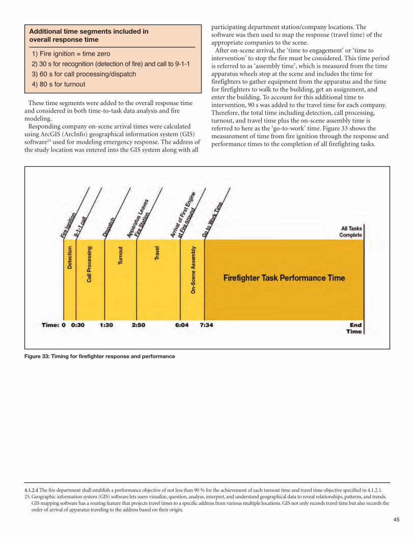
These time segments were added to the overall response timeand considered in both time-to-task data analysis and firemodeling. Responding company on-scene arrival times were calculated
using ArcGIS (ArcInfo) geographical information system (GIS)software25 used for modeling emergency response. The address ofthe study location was entered into the GIS system along with all
participating department station/company locations. Thesoftware was then used to map the response (travel time) of theappropriate companies to the scene. After on-scene arrival, the ‘time to engagement’ or ‘time to
intervention’ to stop the fire must be considered. This time periodis referred to as ‘assembly time’, which is measured from the timeapparatus wheels stop at the scene and includes the time forfirefighters to gather equipment from the apparatus and the timefor firefighters to walk to the building, get an assignment, andenter the building. To account for this additional time tointervention, 90 s was added to the travel time for each company.Therefore, the total time including detection, call processing,turnout, and travel time plus the on-scene assembly time isreferred to here as the ‘go-to-work’ time. Figure 33 shows themeasurement of time from fire ignition through the response andperformance times to the completion of all firefighting tasks.
45
4.1.2.4 The fire department shall establish a performance objective of not less than 90 % for the achievement of each turnout time and travel time objective specified in 4.1.2.1.25. Geographic information system (GIS) software lets users visualize, question, analyze, interpret, and understand geographical data to reveal relationships, patterns, and trends.
GIS mapping software has a routing feature that projects travel times to a specific address from various multiple locations. GIS not only records travel time but also records theorder of arrival of apparatus traveling to the address based on their origin.
1) Fire ignition = time zero
2) 30 s for recognition (detection of fire) and call to 9-1-1
3) 60 s for call processing/dispatch
4) 80 s for turnout
Additional time segments included in overall response time
Figure 33: Timing for firefighter response and performance

Table 4 shows the go-to-work time of responding unitsaccording to alarm size. The routes taken by the responding unitsare shown in the map in Figure 34. As noted previously in Table 2,the actual number of firefighters used in the experiments wasfewer than the total calculated based on crew size and alarm size.This difference is due to the fact that later arriving crews on thehigh alarm deployment would have been assigned to base as
tactical reserve for use in later tasks. Since individual experimentswere ended following the completion of a primary search and therescue of victims on the fire floor and the floor above the fire,these resources weren’t used during the exercise. Unlike the fieldexperiments, an actual high-rise fire would have engaged theseadditional resources to conduct search, overhaul, and salvage.
46
HIGH LOW
Engine 1 7:34 Engine 1 7:34
Truck 1 7:34 Truck 1 7:34
Ambulance 1 7:34 Ambulance 1 7:34
Engine 2 9:03 Engine 2 9:03
Ambulance 2 10:20 Ambulance 2 10:20
Engine 3 11:01 Engine 3 11:01
Truck 2 11:01 Truck 2 11:01
Ambulance 3 11:01 BC 1 11:01
BC 1 11:01 Truck 3 11:58
Engine 4 11:58 BC 2 12:35
Truck 3 11:58 Ambulance 3 14:11
Truck 4 12:17 Engine 4 15:08
BC 2 12:35 Engine 5 15:27
Engine 5 15:27 Truck 4 15:27
Ambulance 4* 15:27 Ambulance 4* 15:27
Engine 6 15:45 Engine 6 15:45
Ambulance 5* 15:45 Engine 7 15:45
Engine 7 15:45 Ambulance 5* 15:45
Ambulance 6* 15:45 Ambulance 6* 15:45
Engine 8 16:00 Engine 8 16:00
HIGH LOW
Ambulance 7* 16:00 BC 3 16:00
BC 3 16:00 Truck 5 16:05
Truck 5 16:05 Engine 9 16:17
Ambulance 8* 16:05 BC 4* 16:17
Engine 9 16:17 Truck 6 16:51
Ambulance 9* 16:17 BC 5* 16:51
BC 4* 16:17 Truck 7 17:02
Engine 10* 16:29 Truck 8 17:14
Engine 11* 16:41 Truck 9 17:32
Engine 12* 16:43 BC 6* 18:26
Truck 6 16:51
BC 5* 16:51
Truck 7 17:02
Truck 8 17:14
Truck 9 17:32
Truck 10* 18:21
BC 6* 18:26
Truck 11* 18:52
Truck 12* 19:25
*not actually dispatched during experiments
Table 4: Go-to-work times calculated by GIS
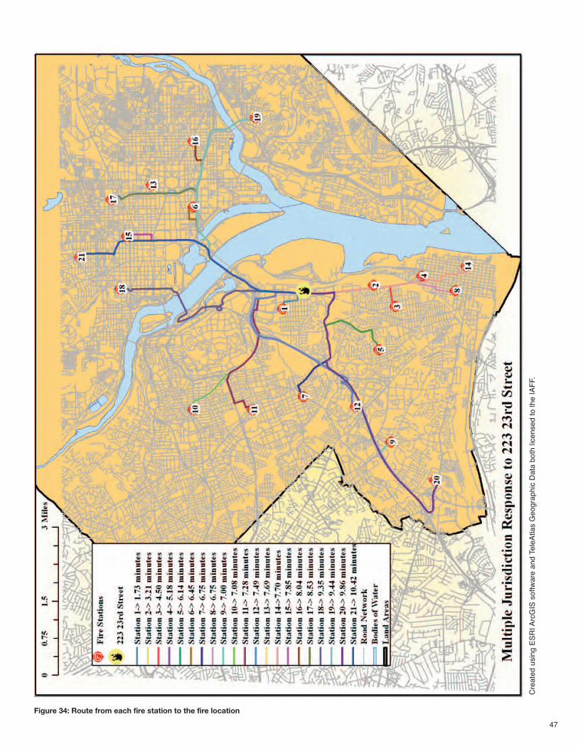
47
Figure 34: Route from each fire station to the fire location
Cre
ate
d u
sin
g E
SR
I A
rcG
IS s
oftw
are
and T
ele
Atlas G
eog
raphic
Data
both
lic
ensed to the IA
FF.
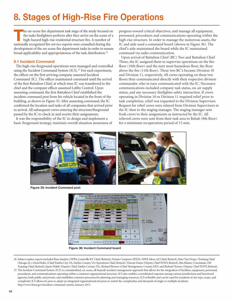
48
8. Stages of High-Rise Fire Operations
The on-scene fire department task stage of the study focused onthe tasks firefighters perform after they arrive on the scene of ahigh-hazard high-rise residential structure fire. A number of
nationally recognized fire service experts were consulted during thedevelopment of the on-scene fire department tasks in order to ensurebroad applicability and appropriateness of the task distribution.26
8.1 Incident CommandThe high-rise fireground operations were managed and controlled
using the Incident Command System (ICS).27 For each experiment,the officer on the first arriving company assumed IncidentCommand (IC). The officer maintained command until the arrivalof the first Battalion Chief, at which time IC was transferred to thechief and the company officer assumed Lobby Control. Uponassuming command, the first Battalion Chief established theincident command post from his vehicle located in the front of thebuilding, as shown in Figure 35. After assuming command, the ICconfirmed the location and tasks of all companies that arrived priorto arrival. All subsequent crews entering the structure/firegroundpassed by the IC to check in and receive their assignments.It was the responsibility of the IC to design and implement a
basic fireground strategy, maintain overall situation awareness of
progress toward critical objectives, and manage all equipment,personnel, procedures and communications operating within thehigh-rise structure. In order to manage the numerous assets, theIC and aide used a command board (shown in Figure 36). Thechief’s aide maintained the board while the IC maintainedcommand via radio communication. Upon arrival of Battalion Chief (BC) Two and Battalion Chief
Three, the IC assigned them to supervise operations on the firefloor (10th floor) and the next most hazardous floor, the floorabove the fire (11th floor). These two BC’s became Division 10and Division 11, respectively. All crews operating on these twofloors then communicated directly with their respective divisioncommander, who in turn communicated with the IC. Necessarycommunications included company task status, on-air supplystatus, and any necessary firefighter safety interaction. If crewsoperating in Division 10 or Division 11 required relief prior totask completion, relief was requested to the Division Supervisor.Request for relief crews were relayed from Division Supervisors tothe IC then to the staging manager. The staging manager sentfresh crews to their assignments as instructed by the IC. Allrelieved crews were sent from their task area to Rehab (8th floor)for a minimum recuperation period of 15 min.
26. Subject matter experts included Russ Sanders (NFPA, Louisville KY Chief, Retired), Dennis Compton (IFSTA, NFFF, Mesa, AZ Chief, Retired), Peter Van Dorpe (Training ChiefChicago, IL), David Rohr, (Chief Fairfax City, VA, Fairfax County, VA Operations Chief, Retired), Vincent Dunn (Deputy Chief FDNY, Retired), Ben Klaene (Cincinnati, OHTraining Chief, Retired), James Walsh (Deputy Chief, Fairfax County, VA), Richard Bowers (Chief Montgomery County, MD) and Richard Travers (Deputy Chief FDNY, Retired).
27. The Incident Command System (ICS) is a standardized, on-scene, all-hazards incident management approach that allows for the integration of facilities, equipment, personnel,procedures, and communications operating within a common organizational structure. ICS also enables a coordinated response among various jurisdictions and functionalagencies, both public and private, and establishes common processes for planning and managing resources. ICS is flexible and can be used for incidents of any type, scope, andcomplexity. ICS allows its users to adopt an integrated organizational structure to match the complexities and demands of single or multiple incidents.http://www.fema.gov/incident-command-system, January 2013.
Figure 35: Incident Command post
Figure 36: Incident Command board
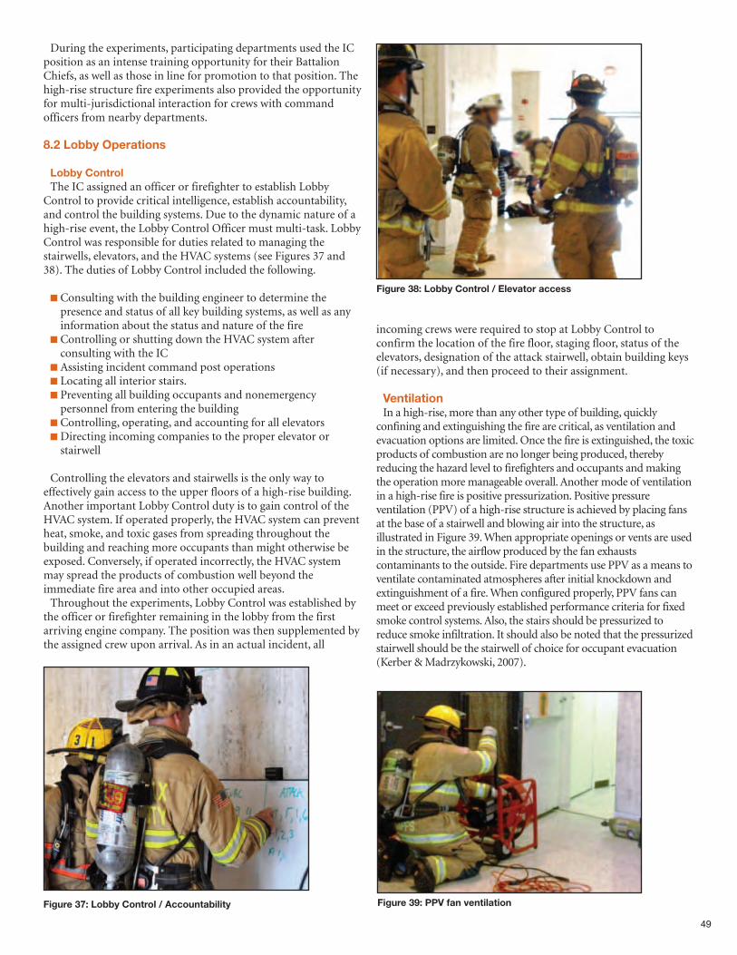
49
Figure 37: Lobby Control / Accountability
During the experiments, participating departments used the ICposition as an intense training opportunity for their BattalionChiefs, as well as those in line for promotion to that position. Thehigh-rise structure fire experiments also provided the opportunityfor multi-jurisdictional interaction for crews with commandofficers from nearby departments.
8.2 Lobby Operations
Lobby ControlThe IC assigned an officer or firefighter to establish Lobby
Control to provide critical intelligence, establish accountability,and control the building systems. Due to the dynamic nature of ahigh-rise event, the Lobby Control Officer must multi-task. LobbyControl was responsible for duties related to managing thestairwells, elevators, and the HVAC systems (see Figures 37 and38). The duties of Lobby Control included the following.
n Consulting with the building engineer to determine thepresence and status of all key building systems, as well as anyinformation about the status and nature of the fire
n Controlling or shutting down the HVAC system afterconsulting with the IC
n Assisting incident command post operationsn Locating all interior stairs.n Preventing all building occupants and nonemergencypersonnel from entering the building
n Controlling, operating, and accounting for all elevatorsn Directing incoming companies to the proper elevator orstairwell
Controlling the elevators and stairwells is the only way toeffectively gain access to the upper floors of a high-rise building.Another important Lobby Control duty is to gain control of theHVAC system. If operated properly, the HVAC system can preventheat, smoke, and toxic gases from spreading throughout thebuilding and reaching more occupants than might otherwise beexposed. Conversely, if operated incorrectly, the HVAC systemmay spread the products of combustion well beyond theimmediate fire area and into other occupied areas.Throughout the experiments, Lobby Control was established by
the officer or firefighter remaining in the lobby from the firstarriving engine company. The position was then supplemented bythe assigned crew upon arrival. As in an actual incident, all
incoming crews were required to stop at Lobby Control toconfirm the location of the fire floor, staging floor, status of theelevators, designation of the attack stairwell, obtain building keys(if necessary), and then proceed to their assignment.
VentilationIn a high-rise, more than any other type of building, quickly
confining and extinguishing the fire are critical, as ventilation andevacuation options are limited. Once the fire is extinguished, the toxicproducts of combustion are no longer being produced, therebyreducing the hazard level to firefighters and occupants and makingthe operation more manageable overall. Another mode of ventilationin a high-rise fire is positive pressurization. Positive pressureventilation (PPV) of a high-rise structure is achieved by placing fansat the base of a stairwell and blowing air into the structure, asillustrated in Figure 39. When appropriate openings or vents are usedin the structure, the airflow produced by the fan exhaustscontaminants to the outside. Fire departments use PPV as a means toventilate contaminated atmospheres after initial knockdown andextinguishment of a fire. When configured properly, PPV fans canmeet or exceed previously established performance criteria for fixedsmoke control systems. Also, the stairs should be pressurized toreduce smoke infiltration. It should also be noted that the pressurizedstairwell should be the stairwell of choice for occupant evacuation(Kerber & Madrzykowski, 2007).
Figure 38: Lobby Control / Elevator access
Figure 39: PPV fan ventilation
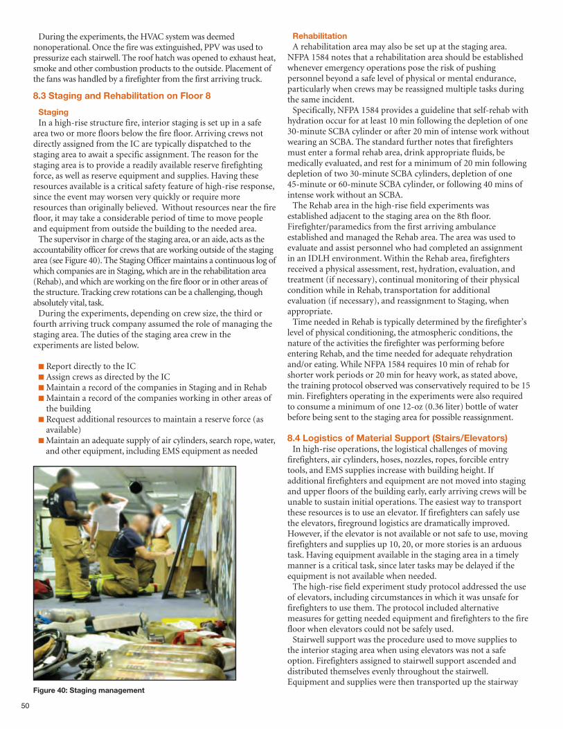
50
During the experiments, the HVAC system was deemednonoperational. Once the fire was extinguished, PPV was used topressurize each stairwell. The roof hatch was opened to exhaust heat,smoke and other combustion products to the outside. Placement ofthe fans was handled by a firefighter from the first arriving truck.
8.3 Staging and Rehabilitation on Floor 8
StagingIn a high-rise structure fire, interior staging is set up in a safe
area two or more floors below the fire floor. Arriving crews notdirectly assigned from the IC are typically dispatched to thestaging area to await a specific assignment. The reason for thestaging area is to provide a readily available reserve firefightingforce, as well as reserve equipment and supplies. Having theseresources available is a critical safety feature of high-rise response,since the event may worsen very quickly or require moreresources than originally believed. Without resources near the firefloor, it may take a considerable period of time to move peopleand equipment from outside the building to the needed area.The supervisor in charge of the staging area, or an aide, acts as the
accountability officer for crews that are working outside of the stagingarea (see Figure 40). The Staging Officer maintains a continuous log ofwhich companies are in Staging, which are in the rehabilitation area(Rehab), and which are working on the fire floor or in other areas ofthe structure. Tracking crew rotations can be a challenging, thoughabsolutely vital, task. During the experiments, depending on crew size, the third or
fourth arriving truck company assumed the role of managing thestaging area. The duties of the staging area crew in theexperiments are listed below.
n Report directly to the ICn Assign crews as directed by the IC nMaintain a record of the companies in Staging and in RehabnMaintain a record of the companies working in other areas ofthe building
n Request additional resources to maintain a reserve force (asavailable)
nMaintain an adequate supply of air cylinders, search rope, water,and other equipment, including EMS equipment as needed
RehabilitationA rehabilitation area may also be set up at the staging area.
NFPA 1584 notes that a rehabilitation area should be establishedwhenever emergency operations pose the risk of pushingpersonnel beyond a safe level of physical or mental endurance,particularly when crews may be reassigned multiple tasks duringthe same incident.Specifically, NFPA 1584 provides a guideline that self-rehab with
hydration occur for at least 10 min following the depletion of one30-minute SCBA cylinder or after 20 min of intense work withoutwearing an SCBA. The standard further notes that firefightersmust enter a formal rehab area, drink appropriate fluids, bemedically evaluated, and rest for a minimum of 20 min followingdepletion of two 30-minute SCBA cylinders, depletion of one45-minute or 60-minute SCBA cylinder, or following 40 mins ofintense work without an SCBA.The Rehab area in the high-rise field experiments was
established adjacent to the staging area on the 8th floor.Firefighter/paramedics from the first arriving ambulanceestablished and managed the Rehab area. The area was used toevaluate and assist personnel who had completed an assignmentin an IDLH environment. Within the Rehab area, firefightersreceived a physical assessment, rest, hydration, evaluation, andtreatment (if necessary), continual monitoring of their physicalcondition while in Rehab, transportation for additionalevaluation (if necessary), and reassignment to Staging, whenappropriate.Time needed in Rehab is typically determined by the firefighter’s
level of physical conditioning, the atmospheric conditions, thenature of the activities the firefighter was performing beforeentering Rehab, and the time needed for adequate rehydrationand/or eating. While NFPA 1584 requires 10 min of rehab forshorter work periods or 20 min for heavy work, as stated above,the training protocol observed was conservatively required to be 15min. Firefighters operating in the experiments were also requiredto consume a minimum of one 12-oz (0.36 liter) bottle of waterbefore being sent to the staging area for possible reassignment.
8.4 Logistics of Material Support (Stairs/Elevators)In high-rise operations, the logistical challenges of moving
firefighters, air cylinders, hoses, nozzles, ropes, forcible entrytools, and EMS supplies increase with building height. Ifadditional firefighters and equipment are not moved into stagingand upper floors of the building early, early arriving crews will beunable to sustain initial operations. The easiest way to transportthese resources is to use an elevator. If firefighters can safely usethe elevators, fireground logistics are dramatically improved.However, if the elevator is not available or not safe to use, movingfirefighters and supplies up 10, 20, or more stories is an arduoustask. Having equipment available in the staging area in a timelymanner is a critical task, since later tasks may be delayed if theequipment is not available when needed.The high-rise field experiment study protocol addressed the use
of elevators, including circumstances in which it was unsafe forfirefighters to use them. The protocol included alternativemeasures for getting needed equipment and firefighters to the firefloor when elevators could not be safely used.Stairwell support was the procedure used to move supplies to
the interior staging area when using elevators was not a safeoption. Firefighters assigned to stairwell support ascended anddistributed themselves evenly throughout the stairwell.Equipment and supplies were then transported up the stairway
Figure 40: Staging management
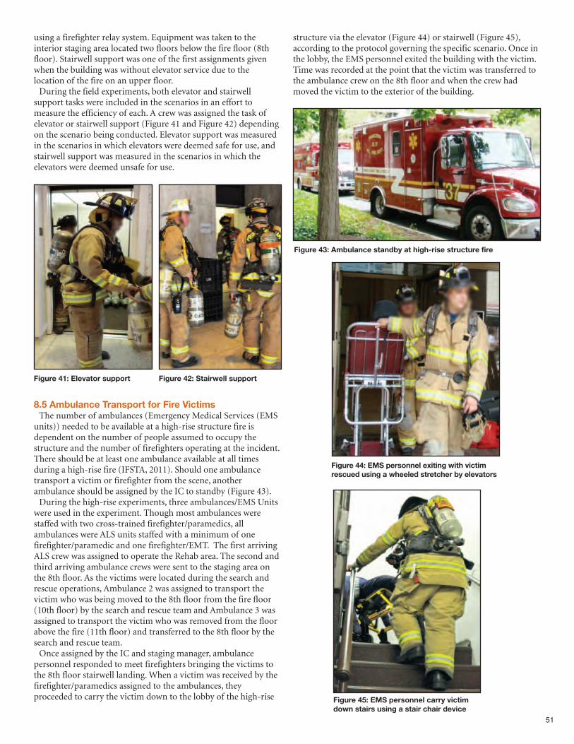
using a firefighter relay system. Equipment was taken to theinterior staging area located two floors below the fire floor (8thfloor). Stairwell support was one of the first assignments givenwhen the building was without elevator service due to thelocation of the fire on an upper floor. During the field experiments, both elevator and stairwell
support tasks were included in the scenarios in an effort tomeasure the efficiency of each. A crew was assigned the task ofelevator or stairwell support (Figure 41 and Figure 42) dependingon the scenario being conducted. Elevator support was measuredin the scenarios in which elevators were deemed safe for use, andstairwell support was measured in the scenarios in which theelevators were deemed unsafe for use.
8.5 Ambulance Transport for Fire VictimsThe number of ambulances (Emergency Medical Services (EMS
units)) needed to be available at a high-rise structure fire isdependent on the number of people assumed to occupy thestructure and the number of firefighters operating at the incident.There should be at least one ambulance available at all timesduring a high-rise fire (IFSTA, 2011). Should one ambulancetransport a victim or firefighter from the scene, anotherambulance should be assigned by the IC to standby (Figure 43). During the high-rise experiments, three ambulances/EMS Units
were used in the experiment. Though most ambulances werestaffed with two cross-trained firefighter/paramedics, allambulances were ALS units staffed with a minimum of onefirefighter/paramedic and one firefighter/EMT. The first arrivingALS crew was assigned to operate the Rehab area. The second andthird arriving ambulance crews were sent to the staging area onthe 8th floor. As the victims were located during the search andrescue operations, Ambulance 2 was assigned to transport thevictim who was being moved to the 8th floor from the fire floor(10th floor) by the search and rescue team and Ambulance 3 wasassigned to transport the victim who was removed from the floorabove the fire (11th floor) and transferred to the 8th floor by thesearch and rescue team. Once assigned by the IC and staging manager, ambulance
personnel responded to meet firefighters bringing the victims tothe 8th floor stairwell landing. When a victim was received by thefirefighter/paramedics assigned to the ambulances, theyproceeded to carry the victim down to the lobby of the high-rise
structure via the elevator (Figure 44) or stairwell (Figure 45),according to the protocol governing the specific scenario. Once inthe lobby, the EMS personnel exited the building with the victim.Time was recorded at the point that the victim was transferred tothe ambulance crew on the 8th floor and when the crew hadmoved the victim to the exterior of the building.
51
Figure 42: Stairwell support Figure 41: Elevator support
Figure 43: Ambulance standby at high-rise structure fire
Figure 44: EMS personnel exiting with victimrescued using a wheeled stretcher by elevators
Figure 45: EMS personnel carry victimdown stairs using a stair chair device
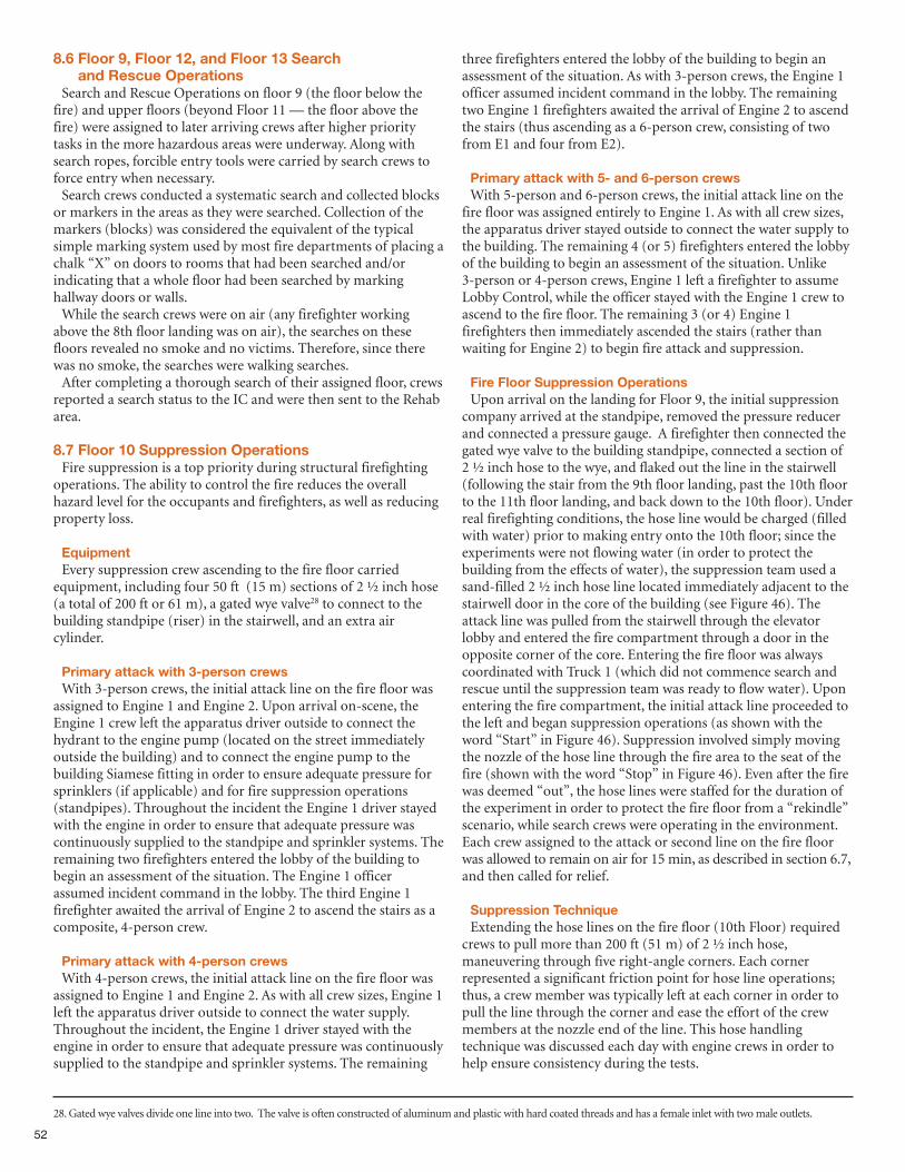
52
8.6 Floor 9, Floor 12, and Floor 13 Search and Rescue Operations
Search and Rescue Operations on floor 9 (the floor below thefire) and upper floors (beyond Floor 11 — the floor above thefire) were assigned to later arriving crews after higher prioritytasks in the more hazardous areas were underway. Along withsearch ropes, forcible entry tools were carried by search crews toforce entry when necessary.Search crews conducted a systematic search and collected blocks
or markers in the areas as they were searched. Collection of themarkers (blocks) was considered the equivalent of the typicalsimple marking system used by most fire departments of placing achalk “X” on doors to rooms that had been searched and/orindicating that a whole floor had been searched by markinghallway doors or walls. While the search crews were on air (any firefighter working
above the 8th floor landing was on air), the searches on thesefloors revealed no smoke and no victims. Therefore, since therewas no smoke, the searches were walking searches.After completing a thorough search of their assigned floor, crews
reported a search status to the IC and were then sent to the Rehabarea.
8.7 Floor 10 Suppression OperationsFire suppression is a top priority during structural firefighting
operations. The ability to control the fire reduces the overallhazard level for the occupants and firefighters, as well as reducingproperty loss.
EquipmentEvery suppression crew ascending to the fire floor carried
equipment, including four 50 ft (15 m) sections of 2 ½ inch hose(a total of 200 ft or 61 m), a gated wye valve28 to connect to thebuilding standpipe (riser) in the stairwell, and an extra aircylinder.
Primary attack with 3-person crewsWith 3-person crews, the initial attack line on the fire floor was
assigned to Engine 1 and Engine 2. Upon arrival on-scene, theEngine 1 crew left the apparatus driver outside to connect thehydrant to the engine pump (located on the street immediatelyoutside the building) and to connect the engine pump to thebuilding Siamese fitting in order to ensure adequate pressure forsprinklers (if applicable) and for fire suppression operations(standpipes). Throughout the incident the Engine 1 driver stayedwith the engine in order to ensure that adequate pressure wascontinuously supplied to the standpipe and sprinkler systems. Theremaining two firefighters entered the lobby of the building tobegin an assessment of the situation. The Engine 1 officerassumed incident command in the lobby. The third Engine 1firefighter awaited the arrival of Engine 2 to ascend the stairs as acomposite, 4-person crew.
Primary attack with 4-person crewsWith 4-person crews, the initial attack line on the fire floor was
assigned to Engine 1 and Engine 2. As with all crew sizes, Engine 1left the apparatus driver outside to connect the water supply.Throughout the incident, the Engine 1 driver stayed with theengine in order to ensure that adequate pressure was continuouslysupplied to the standpipe and sprinkler systems. The remaining
three firefighters entered the lobby of the building to begin anassessment of the situation. As with 3-person crews, the Engine 1officer assumed incident command in the lobby. The remainingtwo Engine 1 firefighters awaited the arrival of Engine 2 to ascendthe stairs (thus ascending as a 6-person crew, consisting of twofrom E1 and four from E2).
Primary attack with 5- and 6-person crewsWith 5-person and 6-person crews, the initial attack line on the
fire floor was assigned entirely to Engine 1. As with all crew sizes,the apparatus driver stayed outside to connect the water supply tothe building. The remaining 4 (or 5) firefighters entered the lobbyof the building to begin an assessment of the situation. Unlike3-person or 4-person crews, Engine 1 left a firefighter to assumeLobby Control, while the officer stayed with the Engine 1 crew toascend to the fire floor. The remaining 3 (or 4) Engine 1firefighters then immediately ascended the stairs (rather thanwaiting for Engine 2) to begin fire attack and suppression.
Fire Floor Suppression OperationsUpon arrival on the landing for Floor 9, the initial suppression
company arrived at the standpipe, removed the pressure reducerand connected a pressure gauge. A firefighter then connected thegated wye valve to the building standpipe, connected a section of2 ½ inch hose to the wye, and flaked out the line in the stairwell(following the stair from the 9th floor landing, past the 10th floorto the 11th floor landing, and back down to the 10th floor). Underreal firefighting conditions, the hose line would be charged (filledwith water) prior to making entry onto the 10th floor; since theexperiments were not flowing water (in order to protect thebuilding from the effects of water), the suppression team used asand-filled 2 ½ inch hose line located immediately adjacent to thestairwell door in the core of the building (see Figure 46). Theattack line was pulled from the stairwell through the elevatorlobby and entered the fire compartment through a door in theopposite corner of the core. Entering the fire floor was alwayscoordinated with Truck 1 (which did not commence search andrescue until the suppression team was ready to flow water). Uponentering the fire compartment, the initial attack line proceeded tothe left and began suppression operations (as shown with theword “Start” in Figure 46). Suppression involved simply movingthe nozzle of the hose line through the fire area to the seat of thefire (shown with the word “Stop” in Figure 46). Even after the firewas deemed “out”, the hose lines were staffed for the duration ofthe experiment in order to protect the fire floor from a “rekindle”scenario, while search crews were operating in the environment.Each crew assigned to the attack or second line on the fire floorwas allowed to remain on air for 15 min, as described in section 6.7,and then called for relief.
Suppression TechniqueExtending the hose lines on the fire floor (10th Floor) required
crews to pull more than 200 ft (51 m) of 2 ½ inch hose,maneuvering through five right-angle corners. Each cornerrepresented a significant friction point for hose line operations;thus, a crew member was typically left at each corner in order topull the line through the corner and ease the effort of the crewmembers at the nozzle end of the line. This hose handlingtechnique was discussed each day with engine crews in order tohelp ensure consistency during the tests.
28. Gated wye valves divide one line into two. The valve is often constructed of aluminum and plastic with hard coated threads and has a female inlet with two male outlets.
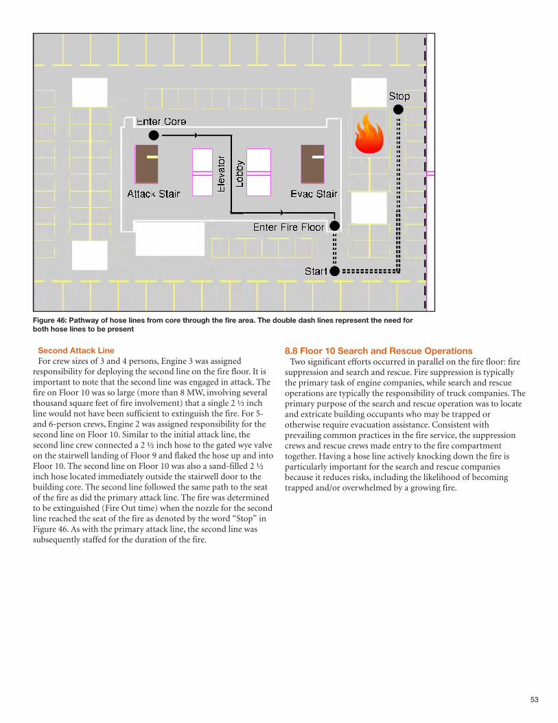
53
Figure 46: Pathway of hose lines from core through the fire area. The double dash lines represent the need forboth hose lines to be present
Second Attack LineFor crew sizes of 3 and 4 persons, Engine 3 was assigned
responsibility for deploying the second line on the fire floor. It isimportant to note that the second line was engaged in attack. Thefire on Floor 10 was so large (more than 8 MW, involving severalthousand square feet of fire involvement) that a single 2 ½ inchline would not have been sufficient to extinguish the fire. For 5-and 6-person crews, Engine 2 was assigned responsibility for thesecond line on Floor 10. Similar to the initial attack line, thesecond line crew connected a 2 ½ inch hose to the gated wye valveon the stairwell landing of Floor 9 and flaked the hose up and intoFloor 10. The second line on Floor 10 was also a sand-filled 2 ½inch hose located immediately outside the stairwell door to thebuilding core. The second line followed the same path to the seatof the fire as did the primary attack line. The fire was determinedto be extinguished (Fire Out time) when the nozzle for the secondline reached the seat of the fire as denoted by the word “Stop” inFigure 46. As with the primary attack line, the second line wassubsequently staffed for the duration of the fire.
8.8 Floor 10 Search and Rescue OperationsTwo significant efforts occurred in parallel on the fire floor: fire
suppression and search and rescue. Fire suppression is typicallythe primary task of engine companies, while search and rescueoperations are typically the responsibility of truck companies. Theprimary purpose of the search and rescue operation was to locateand extricate building occupants who may be trapped orotherwise require evacuation assistance. Consistent withprevailing common practices in the fire service, the suppressioncrews and rescue crews made entry to the fire compartmenttogether. Having a hose line actively knocking down the fire isparticularly important for the search and rescue companiesbecause it reduces risks, including the likelihood of becomingtrapped and/or overwhelmed by a growing fire.
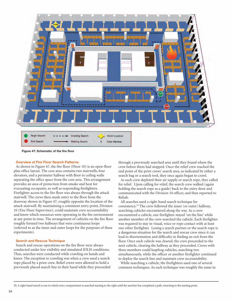
54
Figure 47: Schematic of the fire floor
Overview of Fire Floor Search PatternsAs shown in Figure 47, the fire floor (Floor 10) is an open-floor
plan office layout. The core area contains two stairwells, fourelevators, and a perimeter hallway with floor to ceiling wallsseparating the office space from the core area. This arrangementprovides an area of protection from smoke and heat forevacuating occupants, as well as responding firefighters.Firefighter access to the fire floor was always through the attackstairwell. The crews then made entry to the floor from thedoorway shown in Figure 47, roughly opposite the location of theattack stairwell. By maintaining a consistent entry point, Division10 (Fire Floor Supervisor), could maintain crew accountabilityand know which resources were operating in the fire environmentat any point in time. The arrangement of cubicles on the fire floorroughly formed two hallways that were continuous loops(referred to as the inner and outer loops for the purposes of theseexperiments).
Search and Rescue TechniqueSearch and rescue operations on the fire floor were always
conducted under low visibility and simulated IDLH conditions.Thus, searches were conducted while crawling on hands andknees. The exception to crawling was when a crew used a searchrope placed by a prior crew. Relief crews were allowed to hold apreviously placed search line in their hand while they proceeded
through a previously searched area until they found where thecrew before them had stopped. Once the relief crew reached theend point of the prior crews’ search area, as indicated by either asearch bag or a search tool, they once again began to crawl. As each crew depleted their air supply or search rope, they called
for relief. Upon calling for relief, the search crew walked (againholding the search rope as a guide) back to the entry door andcommunicated with the Division 10 officer, and then reported toRehab. All searches used a right-hand search technique for
consistency.29 The crew followed the inner (or outer) hallway,searching cubicles encountered along the way. As a crewencountered a cubicle, one firefighter stayed ‘on the line’ whileanother member of the crew searched the cubicle. Each firefighterwas required to stay in visual, voice or rope contact with at leastone other firefighter. Losing a search partner or the search rope isa dangerous situation for the search and rescue crew since it canlead to disorientation and difficulty in finding an exit from thefloor. Once each cubicle was cleared, the crew proceeded to thenext cubicle, clearing the hallway as they proceeded. Crews withthree members could leapfrog cubicles, searching twosimultaneously, while the officer or another firefighter continuedto deploy the search line and maintain crew accountability. While searching a cubicle, the firefighters used one of several
common techniques. As each technique was roughly the same in
29. A right-hand search is one in which every compartment is searched starting to the right until the searcher has completed a path, returning to the starting point.
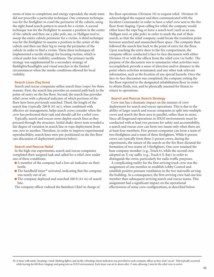
55
terms of time to completion and energy expended, the study teamdid not prescribe a particular technique. One common techniquewas for the firefighter to crawl the perimeter of the cubicle, usingthe right-hand search pattern to search for a victim. A secondtechnique was for the firefighter to assume a position in the centerof the cubicle and then use a pike pole, axe, or Halligan tool tosweep the entire cubicle perimeter for a victim. A third techniquewas for the firefighter to assume a position in the center of thecubicle and then use their leg to sweep the perimeter of thecubicle in order to find a victim. These three techniques allimplemented a tactile strategy for locating victims, which iscritical under low visibility conditions. The primary tactilestrategy was supplemented by a secondary strategy offlashlights/headlights and visual searches in the limitedcircumstances when the smoke conditions allowed for localvisibility.
Search Lines (Tag lines)Search and rescue companies utilize search lines (rope) for three
reasons. First, the search line provides an assured path back to thepoint-of-entry on the fire floor. Second, the search line providesrelief crews with a physical indicator of which portions of thefloor have been previously searched. Third, the length of thesearch line (typically 200 ft (61 m)), when combined witheffective air management, helps search crews consider when thecrew has performed their task and should call for a relief crew. Typically, search and rescue crews deploy search lines as they
proceed through the structure. Initial shake-down tests revealed afair degree of variation in search line or rope deployment fromone crew to another. Therefore, in order to improve experimentalreproducibility, search lines were pre-positioned on the fire floor(see discussion of deployment patterns below).
Search and Rescue Relief In the high-rise experiments, search and rescue companies
completed their assigned task and called for a relief crew underone of three conditions:n A member of the company had a low-air indicator on theirbottle.
n The handheld timer30 activated, indicating that the companywas nearly out of air.
n The company deployed and searched 200 ft (61 m) of searchline.
The company officer radioed the Battalion Chief in charge of
fire floor operations (Division 10) to request relief. Division 10acknowledged the request and then communicated with theIncident Commander in order to have a relief crew sent to the firefloor from Staging. Upon calling for relief, the company wouldeither leave the rope bag or leave a search tool (such as an axe,Halligan tool, or pike pole) in order to mark the end of theirsearch, so that the relief company could locate the transition pointbetween searched and unsearched floor space. The company thenfollowed the search line back to the point of entry for the floor.Upon reaching the entry door to the fire compartment, thecompany officer conducted a face-to-face discussion with eitherDivision 10 or with the officer from the relief crew (or both). Thepurpose of the discussion was to summarize what activities wereaccomplished, provide a sense of direction and/or distance to thepoint where activities terminated, and any other task-relevantinformation, such as the location of any special hazards. Once theface-to-face discussion was completed, the company exiting thefire floor reported to the designated rehabilitation floor in orderto obtain fluids, rest, and be physically assessed for fitness toreturn to operations.
Search and Rescue Search StrategyCrew size has a dramatic impact on the manner of crew
deployment for search and rescue operations. This is due to theability of larger search and rescue companies to split into multiplecrews and search the floor area in parallel, rather than in series.Since all fireground operations in IDLH environments must beconducted with at least two persons for safety and accountability,a search and rescue crew can form two teams only when there areat least four members. Five-person companies can form a team oftwo firefighters and a team of three firefighters. While 6-personcrews can typically form three 2-person crews, during theexperiments, the nature of the search on the fire floor dictated theformation of two teams of 3 firefighters. One crew retained thebase company moniker (e.g., Truck 6), while the second crewadopted an X-ray suffix (e.g., Truck 6 X-Ray) in order todistinguish the crews, particularly for radio traffic purposes. A complicating reality for the first arriving truck crew was the
assignment of one member to establish Lobby Control andestablish positive pressure ventilation in the two stairwells servingthe building. As a consequence, the first arriving crew had one lessmember than subsequent arriving search and rescue teams. Thisassignment had a significant impact on the operationaleffectiveness of some crew configurations, as described below.
30. A timer with audio (beeping), visual (flashing lights), and tactile (vibrating) alarm indicators was provided to each company officer as they went ‘on air’. This typically occurredwhile leaving the 8th floor (staging) and going into an IDLH environment. Each timer was set to alarm after 13 min, allowing 2 min for the relief crew to arrive.
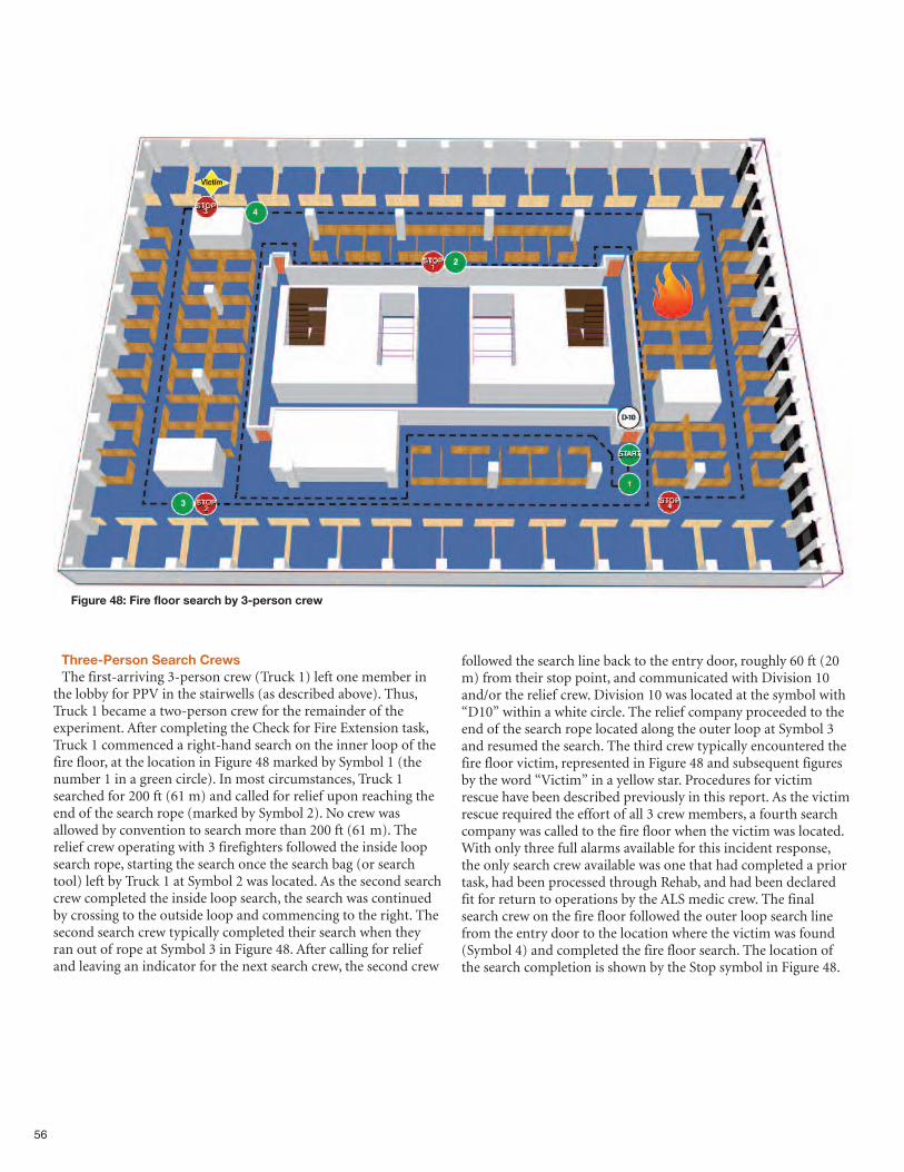
56
Figure 48: Fire floor search by 3-person crew
Three-Person Search CrewsThe first-arriving 3-person crew (Truck 1) left one member in
the lobby for PPV in the stairwells (as described above). Thus,Truck 1 became a two-person crew for the remainder of theexperiment. After completing the Check for Fire Extension task,Truck 1 commenced a right-hand search on the inner loop of thefire floor, at the location in Figure 48 marked by Symbol 1 (thenumber 1 in a green circle). In most circumstances, Truck 1searched for 200 ft (61 m) and called for relief upon reaching theend of the search rope (marked by Symbol 2). No crew wasallowed by convention to search more than 200 ft (61 m). Therelief crew operating with 3 firefighters followed the inside loopsearch rope, starting the search once the search bag (or searchtool) left by Truck 1 at Symbol 2 was located. As the second searchcrew completed the inside loop search, the search was continuedby crossing to the outside loop and commencing to the right. Thesecond search crew typically completed their search when theyran out of rope at Symbol 3 in Figure 48. After calling for reliefand leaving an indicator for the next search crew, the second crew
followed the search line back to the entry door, roughly 60 ft (20m) from their stop point, and communicated with Division 10and/or the relief crew. Division 10 was located at the symbol with“D10” within a white circle. The relief company proceeded to theend of the search rope located along the outer loop at Symbol 3and resumed the search. The third crew typically encountered thefire floor victim, represented in Figure 48 and subsequent figuresby the word “Victim” in a yellow star. Procedures for victimrescue have been described previously in this report. As the victimrescue required the effort of all 3 crew members, a fourth searchcompany was called to the fire floor when the victim was located.With only three full alarms available for this incident response,the only search crew available was one that had completed a priortask, had been processed through Rehab, and had been declaredfit for return to operations by the ALS medic crew. The finalsearch crew on the fire floor followed the outer loop search linefrom the entry door to the location where the victim was found(Symbol 4) and completed the fire floor search. The location ofthe search completion is shown by the Stop symbol in Figure 48.
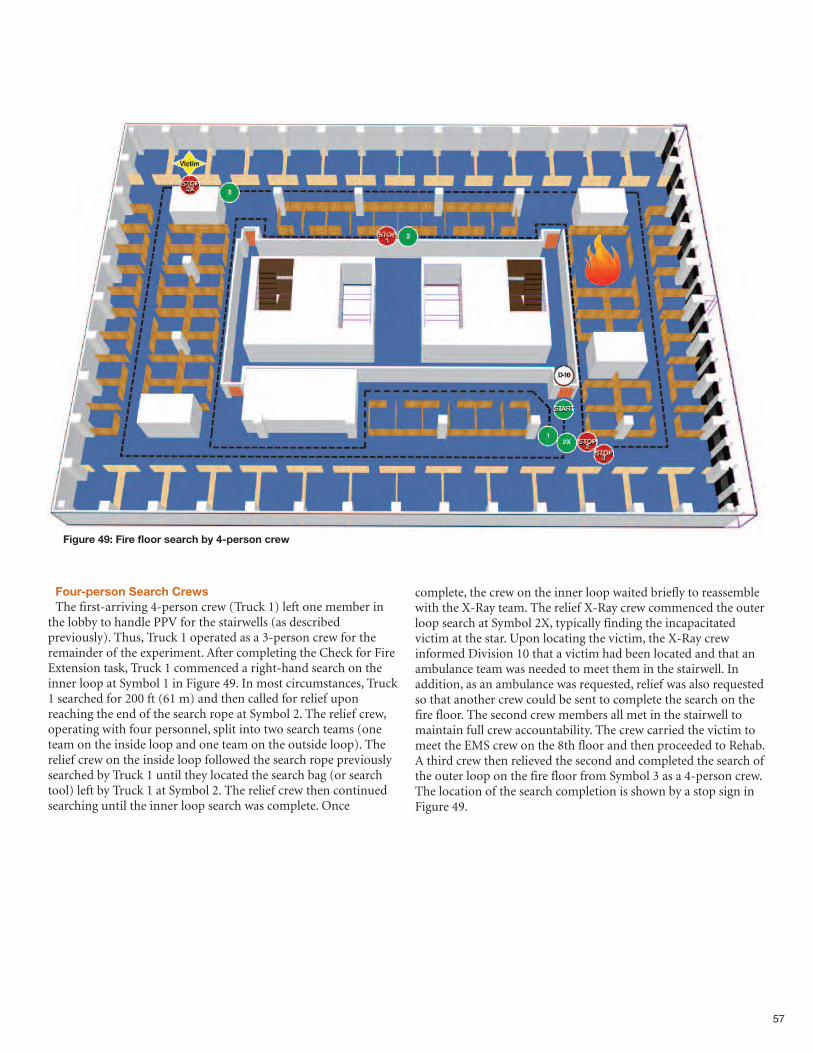
57
Figure 49: Fire floor search by 4-person crew
Four-person Search CrewsThe first-arriving 4-person crew (Truck 1) left one member in
the lobby to handle PPV for the stairwells (as describedpreviously). Thus, Truck 1 operated as a 3-person crew for theremainder of the experiment. After completing the Check for FireExtension task, Truck 1 commenced a right-hand search on theinner loop at Symbol 1 in Figure 49. In most circumstances, Truck1 searched for 200 ft (61 m) and then called for relief uponreaching the end of the search rope at Symbol 2. The relief crew,operating with four personnel, split into two search teams (oneteam on the inside loop and one team on the outside loop). Therelief crew on the inside loop followed the search rope previouslysearched by Truck 1 until they located the search bag (or searchtool) left by Truck 1 at Symbol 2. The relief crew then continuedsearching until the inner loop search was complete. Once
complete, the crew on the inner loop waited briefly to reassemblewith the X-Ray team. The relief X-Ray crew commenced the outerloop search at Symbol 2X, typically finding the incapacitatedvictim at the star. Upon locating the victim, the X-Ray crewinformed Division 10 that a victim had been located and that anambulance team was needed to meet them in the stairwell. Inaddition, as an ambulance was requested, relief was also requestedso that another crew could be sent to complete the search on thefire floor. The second crew members all met in the stairwell tomaintain full crew accountability. The crew carried the victim tomeet the EMS crew on the 8th floor and then proceeded to Rehab.A third crew then relieved the second and completed the search ofthe outer loop on the fire floor from Symbol 3 as a 4-person crew.The location of the search completion is shown by a stop sign inFigure 49.
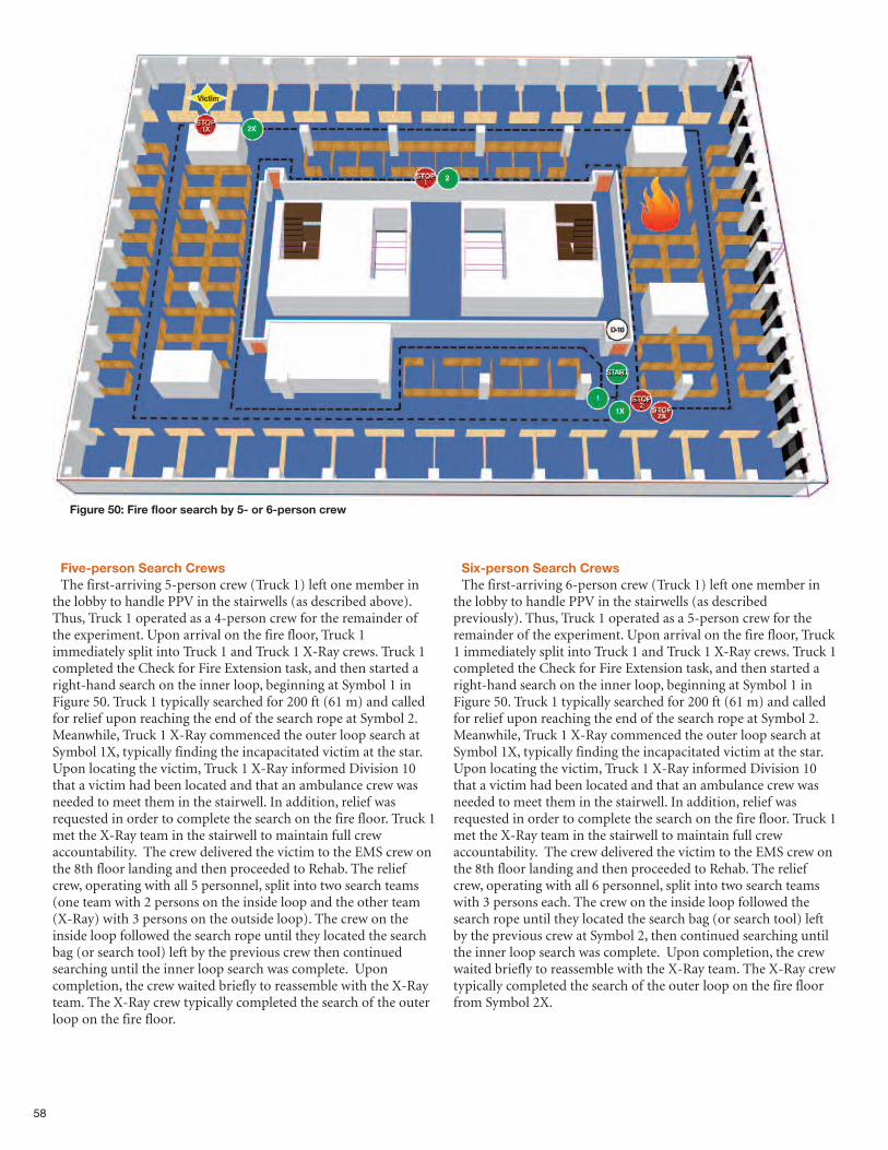
58
Figure 50: Fire floor search by 5- or 6-person crew
Five-person Search CrewsThe first-arriving 5-person crew (Truck 1) left one member in
the lobby to handle PPV in the stairwells (as described above).Thus, Truck 1 operated as a 4-person crew for the remainder ofthe experiment. Upon arrival on the fire floor, Truck 1immediately split into Truck 1 and Truck 1 X-Ray crews. Truck 1completed the Check for Fire Extension task, and then started aright-hand search on the inner loop, beginning at Symbol 1 inFigure 50. Truck 1 typically searched for 200 ft (61 m) and calledfor relief upon reaching the end of the search rope at Symbol 2.Meanwhile, Truck 1 X-Ray commenced the outer loop search atSymbol 1X, typically finding the incapacitated victim at the star.Upon locating the victim, Truck 1 X-Ray informed Division 10that a victim had been located and that an ambulance crew wasneeded to meet them in the stairwell. In addition, relief wasrequested in order to complete the search on the fire floor. Truck 1met the X-Ray team in the stairwell to maintain full crewaccountability. The crew delivered the victim to the EMS crew onthe 8th floor landing and then proceeded to Rehab. The reliefcrew, operating with all 5 personnel, split into two search teams(one team with 2 persons on the inside loop and the other team(X-Ray) with 3 persons on the outside loop). The crew on theinside loop followed the search rope until they located the searchbag (or search tool) left by the previous crew then continuedsearching until the inner loop search was complete. Uponcompletion, the crew waited briefly to reassemble with the X-Rayteam. The X-Ray crew typically completed the search of the outerloop on the fire floor.
Six-person Search CrewsThe first-arriving 6-person crew (Truck 1) left one member in
the lobby to handle PPV in the stairwells (as describedpreviously). Thus, Truck 1 operated as a 5-person crew for theremainder of the experiment. Upon arrival on the fire floor, Truck1 immediately split into Truck 1 and Truck 1 X-Ray crews. Truck 1completed the Check for Fire Extension task, and then started aright-hand search on the inner loop, beginning at Symbol 1 inFigure 50. Truck 1 typically searched for 200 ft (61 m) and calledfor relief upon reaching the end of the search rope at Symbol 2.Meanwhile, Truck 1 X-Ray commenced the outer loop search atSymbol 1X, typically finding the incapacitated victim at the star.Upon locating the victim, Truck 1 X-Ray informed Division 10that a victim had been located and that an ambulance crew wasneeded to meet them in the stairwell. In addition, relief wasrequested in order to complete the search on the fire floor. Truck 1met the X-Ray team in the stairwell to maintain full crewaccountability. The crew delivered the victim to the EMS crew onthe 8th floor landing and then proceeded to Rehab. The reliefcrew, operating with all 6 personnel, split into two search teamswith 3 persons each. The crew on the inside loop followed thesearch rope until they located the search bag (or search tool) leftby the previous crew at Symbol 2, then continued searching untilthe inner loop search was complete. Upon completion, the crewwaited briefly to reassemble with the X-Ray team. The X-Ray crewtypically completed the search of the outer loop on the fire floorfrom Symbol 2X.
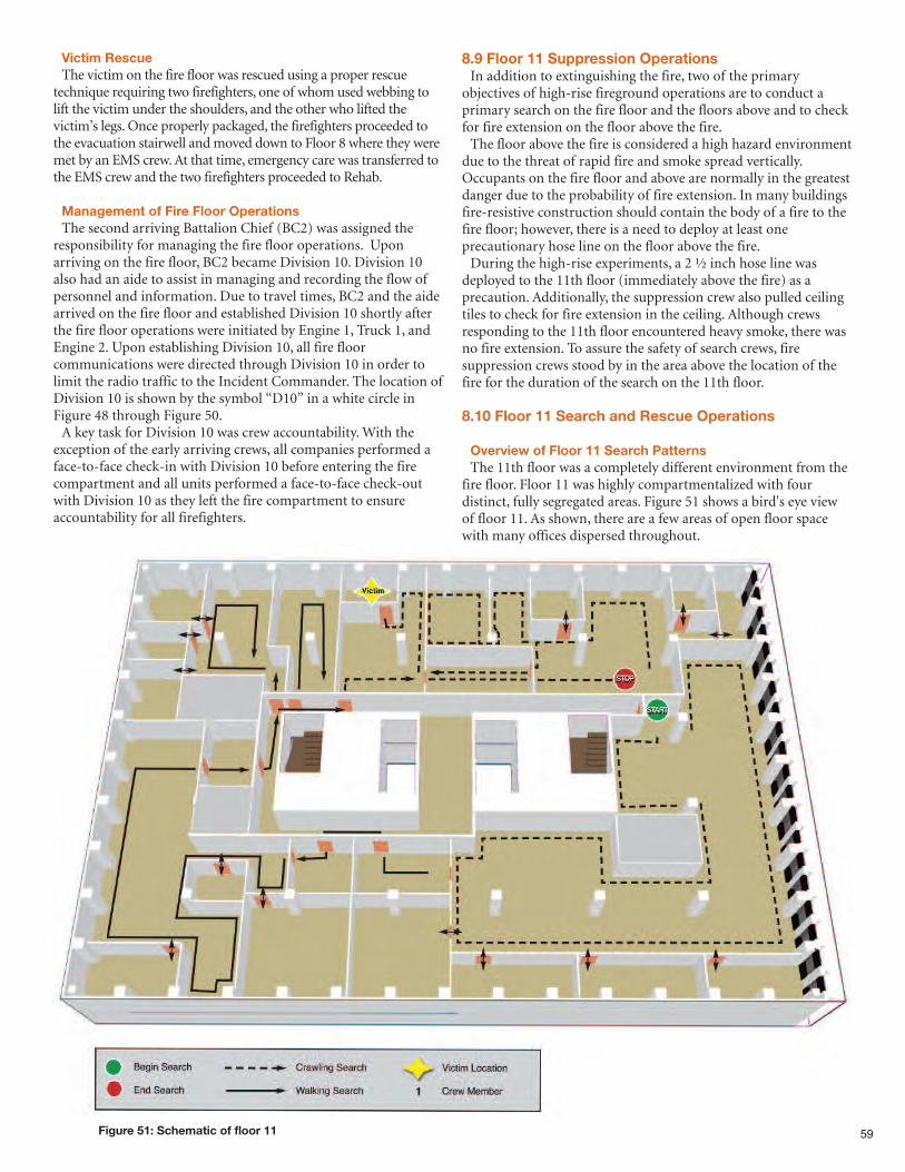
59Figure 51: Schematic of floor 11
Victim RescueThe victim on the fire floor was rescued using a proper rescue
technique requiring two firefighters, one of whom used webbing tolift the victim under the shoulders, and the other who lifted thevictim’s legs. Once properly packaged, the firefighters proceeded tothe evacuation stairwell and moved down to Floor 8 where they weremet by an EMS crew. At that time, emergency care was transferred tothe EMS crew and the two firefighters proceeded to Rehab.
Management of Fire Floor OperationsThe second arriving Battalion Chief (BC2) was assigned the
responsibility for managing the fire floor operations. Uponarriving on the fire floor, BC2 became Division 10. Division 10also had an aide to assist in managing and recording the flow ofpersonnel and information. Due to travel times, BC2 and the aidearrived on the fire floor and established Division 10 shortly afterthe fire floor operations were initiated by Engine 1, Truck 1, andEngine 2. Upon establishing Division 10, all fire floorcommunications were directed through Division 10 in order tolimit the radio traffic to the Incident Commander. The location ofDivision 10 is shown by the symbol “D10” in a white circle inFigure 48 through Figure 50.A key task for Division 10 was crew accountability. With the
exception of the early arriving crews, all companies performed aface-to-face check-in with Division 10 before entering the firecompartment and all units performed a face-to-face check-outwith Division 10 as they left the fire compartment to ensureaccountability for all firefighters.
8.9 Floor 11 Suppression OperationsIn addition to extinguishing the fire, two of the primary
objectives of high-rise fireground operations are to conduct aprimary search on the fire floor and the floors above and to checkfor fire extension on the floor above the fire.The floor above the fire is considered a high hazard environment
due to the threat of rapid fire and smoke spread vertically.Occupants on the fire floor and above are normally in the greatestdanger due to the probability of fire extension. In many buildingsfire-resistive construction should contain the body of a fire to thefire floor; however, there is a need to deploy at least oneprecautionary hose line on the floor above the fire.During the high-rise experiments, a 2 ½ inch hose line was
deployed to the 11th floor (immediately above the fire) as aprecaution. Additionally, the suppression crew also pulled ceilingtiles to check for fire extension in the ceiling. Although crewsresponding to the 11th floor encountered heavy smoke, there wasno fire extension. To assure the safety of search crews, firesuppression crews stood by in the area above the location of thefire for the duration of the search on the 11th floor.
8.10 Floor 11 Search and Rescue Operations
Overview of Floor 11 Search PatternsThe 11th floor was a completely different environment from the
fire floor. Floor 11 was highly compartmentalized with fourdistinct, fully segregated areas. Figure 51 shows a bird's eye viewof floor 11. As shown, there are a few areas of open floor spacewith many offices dispersed throughout.
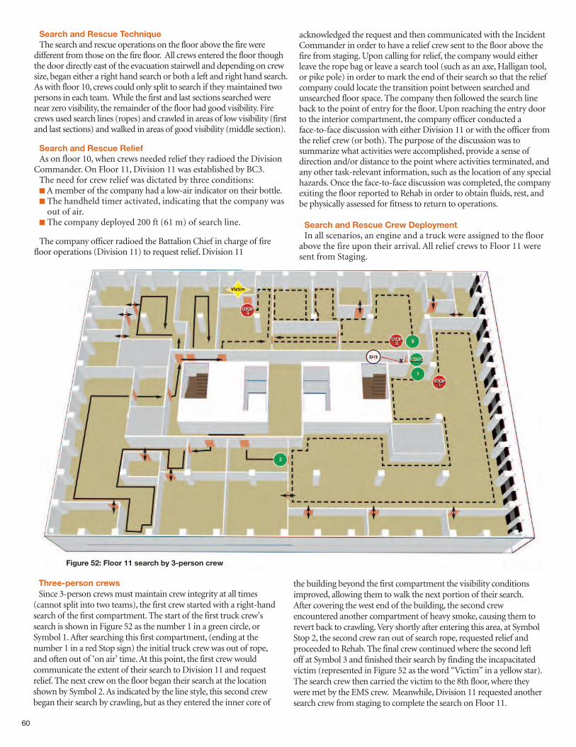
60
Search and Rescue TechniqueThe search and rescue operations on the floor above the fire were
different from those on the fire floor. All crews entered the floor thoughthe door directly east of the evacuation stairwell and depending on crewsize, began either a right hand search or both a left and right hand search.As with floor 10, crews could only split to search if they maintained twopersons in each team. While the first and last sections searched werenear zero visibility, the remainder of the floor had good visibility. Firecrews used search lines (ropes) and crawled in areas of low visibility (firstand last sections) and walked in areas of good visibility (middle section).
Search and Rescue ReliefAs on floor 10, when crews needed relief they radioed the Division
Commander. On Floor 11, Division 11 was established by BC3.The need for crew relief was dictated by three conditions:nA member of the company had a low-air indicator on their bottle.n The handheld timer activated, indicating that the company wasout of air.
n The company deployed 200 ft (61 m) of search line.
The company officer radioed the Battalion Chief in charge of firefloor operations (Division 11) to request relief. Division 11
acknowledged the request and then communicated with the IncidentCommander in order to have a relief crew sent to the floor above thefire from staging. Upon calling for relief, the company would eitherleave the rope bag or leave a search tool (such as an axe, Halligan tool,or pike pole) in order to mark the end of their search so that the reliefcompany could locate the transition point between searched andunsearched floor space. The company then followed the search lineback to the point of entry for the floor. Upon reaching the entry doorto the interior compartment, the company officer conducted aface-to-face discussion with either Division 11 or with the officer fromthe relief crew (or both). The purpose of the discussion was tosummarize what activities were accomplished, provide a sense ofdirection and/or distance to the point where activities terminated, andany other task-relevant information, such as the location of any specialhazards. Once the face-to-face discussion was completed, the companyexiting the floor reported to Rehab in order to obtain fluids, rest, andbe physically assessed for fitness to return to operations.
Search and Rescue Crew DeploymentIn all scenarios, an engine and a truck were assigned to the floor
above the fire upon their arrival. All relief crews to Floor 11 weresent from Staging.
Figure 52: Floor 11 search by 3-person crew
Three-person crewsSince 3-person crews must maintain crew integrity at all times
(cannot split into two teams), the first crew started with a right-handsearch of the first compartment. The start of the first truck crew’ssearch is shown in Figure 52 as the number 1 in a green circle, orSymbol 1. After searching this first compartment, (ending at thenumber 1 in a red Stop sign) the initial truck crew was out of rope,and often out of ‘on air’ time. At this point, the first crew wouldcommunicate the extent of their search to Division 11 and requestrelief. The next crew on the floor began their search at the locationshown by Symbol 2. As indicated by the line style, this second crewbegan their search by crawling, but as they entered the inner core of
the building beyond the first compartment the visibility conditionsimproved, allowing them to walk the next portion of their search.After covering the west end of the building, the second crewencountered another compartment of heavy smoke, causing them torevert back to crawling. Very shortly after entering this area, at SymbolStop 2, the second crew ran out of search rope, requested relief andproceeded to Rehab. The final crew continued where the second leftoff at Symbol 3 and finished their search by finding the incapacitatedvictim (represented in Figure 52 as the word “Victim” in a yellow star).The search crew then carried the victim to the 8th floor, where theywere met by the EMS crew. Meanwhile, Division 11 requested anothersearch crew from staging to complete the search on Floor 11.
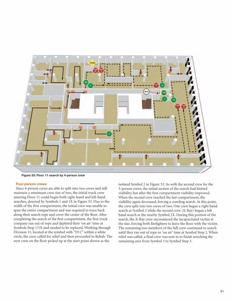
61
Figure 53: Floor 11 search by 4-person crew
Four-person crewsSince 4-person crews are able to split into two crews and still
maintain a minimum crew size of two, the initial truck crewentering Floor 11 could begin both right-hand and left-handsearches, denoted by Symbols 1 and 1X in Figure 53. Due to thewidth of the first compartment, the initial crew was unable tospan the entire compartment and was required to trace backalong their search rope and cover the center of the floor. Aftercompleting the search of the first compartment, the first truckcompany ran out of rope and depleted their ‘on air’ time atSymbols Stop 1/1X and needed to be replaced. Working throughDivision 11, located at the symbol with “D11” within a whitecircle, the crew called for relief and then proceeded to Rehab. Thenext crew on the floor picked up at the start point shown as the
isolated Symbol 2 in Figure 53. As with the second crew for the3-person crews, the initial section of the search had limitedvisibility, but after the first compartment visibility improved.When the second crew reached the last compartment, thevisibility again decreased, forcing a crawling search. At this point,the crew split into two crews of two. One crew began a right handsearch at Symbol 2 while the second crew (X-Ray) began a lefthand search at the nearby Symbol 2X. During this portion of thesearch, the X-Ray crew encountered the incapacitated victim atthe star, forcing both firefighters to leave the floor with the victim.The remaining two members of the full crew continued to searchuntil they ran out of rope or ‘on air’ time at Symbol Stop 2. Whenrelief was called, a final crew was sent in to finish searching theremaining area from Symbol 3 to Symbol Stop 3.
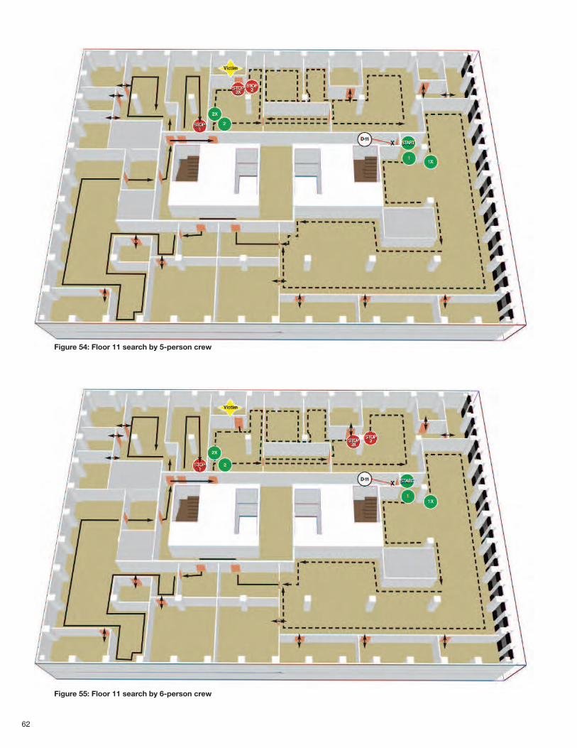
62
Figure 54: Floor 11 search by 5-person crew
Figure 55: Floor 11 search by 6-person crew
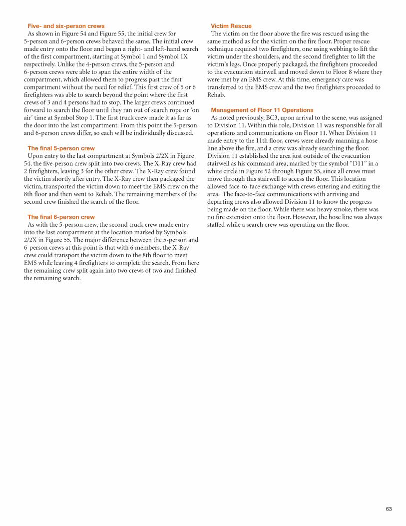
63
Five- and six-person crewsAs shown in Figure 54 and Figure 55, the initial crew for
5-person and 6-person crews behaved the same. The initial crewmade entry onto the floor and began a right- and left-hand searchof the first compartment, starting at Symbol 1 and Symbol 1Xrespectively. Unlike the 4-person crews, the 5-person and6-person crews were able to span the entire width of thecompartment, which allowed them to progress past the firstcompartment without the need for relief. This first crew of 5 or 6firefighters was able to search beyond the point where the firstcrews of 3 and 4 persons had to stop. The larger crews continuedforward to search the floor until they ran out of search rope or ‘onair’ time at Symbol Stop 1. The first truck crew made it as far asthe door into the last compartment. From this point the 5-personand 6-person crews differ, so each will be individually discussed.
The final 5-person crewUpon entry to the last compartment at Symbols 2/2X in Figure
54, the five-person crew split into two crews. The X-Ray crew had2 firefighters, leaving 3 for the other crew. The X-Ray crew foundthe victim shortly after entry. The X-Ray crew then packaged thevictim, transported the victim down to meet the EMS crew on the8th floor and then went to Rehab. The remaining members of thesecond crew finished the search of the floor.
The final 6-person crewAs with the 5-person crew, the second truck crew made entry
into the last compartment at the location marked by Symbols2/2X in Figure 55. The major difference between the 5-person and6-person crews at this point is that with 6 members, the X-Raycrew could transport the victim down to the 8th floor to meetEMS while leaving 4 firefighters to complete the search. From herethe remaining crew split again into two crews of two and finishedthe remaining search.
Victim RescueThe victim on the floor above the fire was rescued using the
same method as for the victim on the fire floor. Proper rescuetechnique required two firefighters, one using webbing to lift thevictim under the shoulders, and the second firefighter to lift thevictim’s legs. Once properly packaged, the firefighters proceededto the evacuation stairwell and moved down to Floor 8 where theywere met by an EMS crew. At this time, emergency care wastransferred to the EMS crew and the two firefighters proceeded toRehab.
Management of Floor 11 OperationsAs noted previously, BC3, upon arrival to the scene, was assigned
to Division 11. Within this role, Division 11 was responsible for alloperations and communications on Floor 11. When Division 11made entry to the 11th floor, crews were already manning a hoseline above the fire, and a crew was already searching the floor.Division 11 established the area just outside of the evacuationstairwell as his command area, marked by the symbol “D11” in awhite circle in Figure 52 through Figure 55, since all crews mustmove through this stairwell to access the floor. This locationallowed face-to-face exchange with crews entering and exiting thearea. The face-to-face communications with arriving anddeparting crews also allowed Division 11 to know the progressbeing made on the floor. While there was heavy smoke, there wasno fire extension onto the floor. However, the hose line was alwaysstaffed while a search crew was operating on the floor.
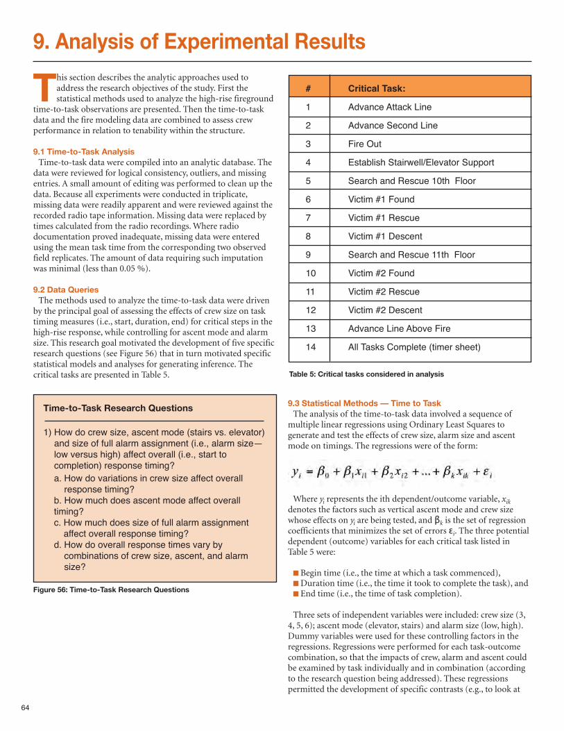
This section describes the analytic approaches used toaddress the research objectives of the study. First thestatistical methods used to analyze the high-rise fireground
time-to-task observations are presented. Then the time-to-taskdata and the fire modeling data are combined to assess crewperformance in relation to tenability within the structure.
9.1 Time-to-Task AnalysisTime-to-task data were compiled into an analytic database. The
data were reviewed for logical consistency, outliers, and missingentries. A small amount of editing was performed to clean up thedata. Because all experiments were conducted in triplicate,missing data were readily apparent and were reviewed against therecorded radio tape information. Missing data were replaced bytimes calculated from the radio recordings. Where radiodocumentation proved inadequate, missing data were enteredusing the mean task time from the corresponding two observedfield replicates. The amount of data requiring such imputationwas minimal (less than 0.05 %).
9.2 Data QueriesThe methods used to analyze the time-to-task data were driven
by the principal goal of assessing the effects of crew size on tasktiming measures (i.e., start, duration, end) for critical steps in thehigh-rise response, while controlling for ascent mode and alarmsize. This research goal motivated the development of five specificresearch questions (see Figure 56) that in turn motivated specificstatistical models and analyses for generating inference. Thecritical tasks are presented in Table 5.
9.3 Statistical Methods — Time to TaskThe analysis of the time-to-task data involved a sequence of
multiple linear regressions using Ordinary Least Squares togenerate and test the effects of crew size, alarm size and ascentmode on timings. The regressions were of the form:
Where yi represents the ith dependent/outcome variable, xikdenotes the factors such as vertical ascent mode and crew sizewhose effects on yi are being tested, and βk is the set of regressioncoefficients that minimizes the set of errors εi. The three potentialdependent (outcome) variables for each critical task listed inTable 5 were:
n Begin time (i.e., the time at which a task commenced), nDuration time (i.e., the time it took to complete the task), andn End time (i.e., the time of task completion).
Three sets of independent variables were included: crew size (3,4, 5, 6); ascent mode (elevator, stairs) and alarm size (low, high).Dummy variables were used for these controlling factors in theregressions. Regressions were performed for each task-outcomecombination, so that the impacts of crew, alarm and ascent couldbe examined by task individually and in combination (accordingto the research question being addressed). These regressionspermitted the development of specific contrasts (e.g., to look at
64
9. Analysis of Experimental Results
Time-to-Task Research Questions
1) How do crew size, ascent mode (stairs vs. elevator)and size of full alarm assignment (i.e., alarm size—low versus high) affect overall (i.e., start tocompletion) response timing?
a. How do variations in crew size affect overallresponse timing?
b. How much does ascent mode affect overalltiming?c. How much does size of full alarm assignment
affect overall response timing?d. How do overall response times vary by
combinations of crew size, ascent, and alarmsize?
Figure 56: Time-to-Task Research Questions
Table 5: Critical tasks considered in analysis
# Critical Task:
1 Advance Attack Line
2 Advance Second Line
3 Fire Out
4 Establish Stairwell/Elevator Support
5 Search and Rescue 10th Floor
6 Victim #1 Found
7 Victim #1 Rescue
8 Victim #1 Descent
9 Search and Rescue 11th Floor
10 Victim #2 Found
11 Victim #2 Rescue
12 Victim #2 Descent
13 Advance Line Above Fire
14 All Tasks Complete (timer sheet)
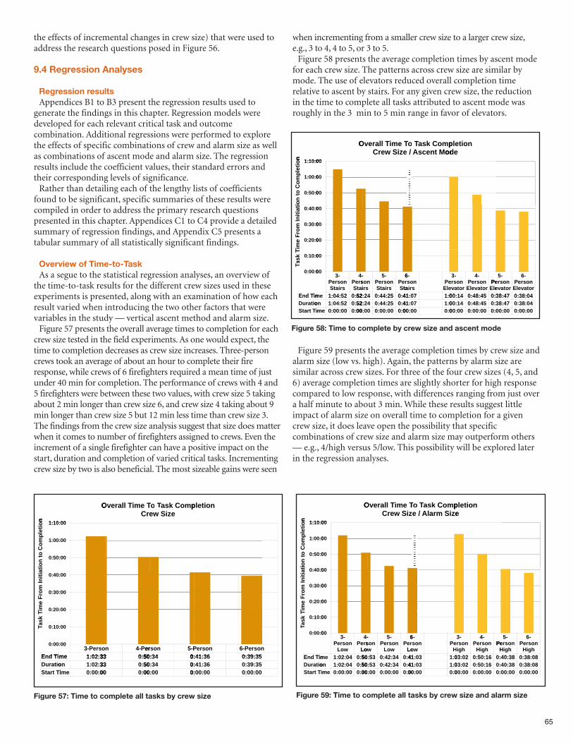
65
the effects of incremental changes in crew size) that were used toaddress the research questions posed in Figure 56.
9.4 Regression Analyses
Regression resultsAppendices B1 to B3 present the regression results used to
generate the findings in this chapter. Regression models weredeveloped for each relevant critical task and outcomecombination. Additional regressions were performed to explorethe effects of specific combinations of crew and alarm size as wellas combinations of ascent mode and alarm size. The regressionresults include the coefficient values, their standard errors andtheir corresponding levels of significance. Rather than detailing each of the lengthy lists of coefficients
found to be significant, specific summaries of these results werecompiled in order to address the primary research questionspresented in this chapter. Appendices C1 to C4 provide a detailedsummary of regression findings, and Appendix C5 presents atabular summary of all statistically significant findings.
Overview of Time-to-TaskAs a segue to the statistical regression analyses, an overview of
the time-to-task results for the different crew sizes used in theseexperiments is presented, along with an examination of how eachresult varied when introducing the two other factors that werevariables in the study — vertical ascent method and alarm size.Figure 57 presents the overall average times to completion for each
crew size tested in the field experiments. As one would expect, thetime to completion decreases as crew size increases. Three-personcrews took an average of about an hour to complete their fireresponse, while crews of 6 firefighters required a mean time of justunder 40 min for completion. The performance of crews with 4 and5 firefighters were between these two values, with crew size 5 takingabout 2 min longer than crew size 6, and crew size 4 taking about 9min longer than crew size 5 but 12 min less time than crew size 3.The findings from the crew size analysis suggest that size does matterwhen it comes to number of firefighters assigned to crews. Even theincrement of a single firefighter can have a positive impact on thestart, duration and completion of varied critical tasks. Incrementingcrew size by two is also beneficial. The most sizeable gains were seen
when incrementing from a smaller crew size to a larger crew size,e.g., 3 to 4, 4 to 5, or 3 to 5.Figure 58 presents the average completion times by ascent mode
for each crew size. The patterns across crew size are similar bymode. The use of elevators reduced overall completion timerelative to ascent by stairs. For any given crew size, the reductionin the time to complete all tasks attributed to ascent mode wasroughly in the 3 min to 5 min range in favor of elevators.
Figure 59 presents the average completion times by crew size andalarm size (low vs. high). Again, the patterns by alarm size aresimilar across crew sizes. For three of the four crew sizes (4, 5, and6) average completion times are slightly shorter for high responsecompared to low response, with differences ranging from just overa half minute to about 3 min. While these results suggest littleimpact of alarm size on overall time to completion for a givencrew size, it does leave open the possibility that specificcombinations of crew size and alarm size may outperform others— e.g., 4/high versus 5/low. This possibility will be explored laterin the regression analyses.
on
:10:1
O
00
erC
Te miTlalervO
ezSiwe
pmoCask TTask oTTo
noietlp
on
tie
om
pl
to C
on
ti
:10:1
:00:1
:50:0
00
00
00
tia
tin
io
m I
Fr
me
iT
:40:0
:30:0
:20:0
00
00
00
meind TE
Tk
sa
TTa
:10:0
:00:0
3- soerP
me 3302:1:
00
00
n 4- erP
33 50:0:
nsoer 5-P
3450: 0:
nsoerP
3641:0:
6- nsoerP
3539:0:
meind TE
ontiaurD
it TrtaS
me 3302:1:
on 3302:1:
mei 0000:0:
33 50:0:
33 50:0:
00 00:0:
3450: 0:
3450: 0:
0000: 0:
3641:0:
3641:0:
0000:0:
3539:0:
3539:0:
0000:0:
on
00:10:1
O
00
eziSwreC
Te miTlalervO
odeMntecsA/
pmoCask TTa oTTo
ode
noietlp
on
tie
om
pl
to C
on
ti
00:10:1
00:00:1
00:50:0
00
00
00
tia
tin
io
m I
Fr
me
iT
00:40:0
00:30:0
00:20:0
00
00
00
iEnd TT
ks
aTTa
00:10:0
00:00:0
3-
rsitaSon srPe
4-
itaSsrPe
5204:1: 52:0:
00
00
-
rsion s
5-
rsitaSon srPe
6
taSrPe
24 2544:0: 41:0:
6-
rsitaon s
veElPe
0741: 00:1:
3-
ortavon sr
4-
ortaveElon srPe
eElPe
1400: 4548:0: 38:0:
5-
ortaveon srPe
6-
ortaveElon srPe
4738: 0438:0:
miEnd T
onitaurD
mirt TtaS
em 5204:1: 52:0:
on 5204:1: 52:0:
em 0000:0: 00:0:
2452: 2544:0: 41:0:
2452: 2544:0: 41:0:
0000: 0000:0: 00:0:
0741: 00:1:
0741: 00:1:
0000: 00:0:
1400: 4548:0: 38:0:
1400: 4548:0: 38:0:
0000: 0000:0: 00:0:
4738: 0438:0:
4738: 0438:0:
0000: 0000:0:
Figure 58: Time to complete by crew size and ascent mode
Figure 57: Time to complete all tasks by crew size
on
00:10:1
O
00
zSiwerC
Te miTlalervO
ezSimralA/e
pmoCask TTask oTTo
e
noietlp
on
tie
om
pl
to C
on
ti
00:10:1
00:00:1
00:50:0
00
00
00
tia
tin
io
m I
Fr
me
iT
00:40:0
00:30:0
00:20:0
00
00
00
iEnd T
Tk
sa
TTa
00:10:0
00:00:0
3-
Lowon srPe
4-
LowsrPe
0402:1: 50:0:
00
00
-
Lowon s
5-
Lowon srPe
6
LowrPe
53 3442:0: 41:0:
6-
Lowon s
HPe
0341: 03:1:
3-
ghion sr
4-
ghiHon srPe
HPe
0203: 1650:0: 40:0:
5-
ghiHon srPe
6-
ghiHon srPe
3840: 0838:0:
miEnd T
onitaurD
mirt TtaS
em 0402:1: 50:0:
on 0402:1: 50:0:
em 0000:0: 00:0:
5350: 3442:0: 41:0:
5350: 3442:0: 41:0:
0000: 0000:0: 00:0:
0341: 03:1:
0341: 03:1:
0000: 00:0:
0203: 1650:0: 40:0:
0203: 1650:0: 40:0:
0000: 0000:0: 00:0:
3840: 0838:0:
3840: 0838:0:
0000: 0000:0:
Figure 59: Time to complete all tasks by crew size and alarm size
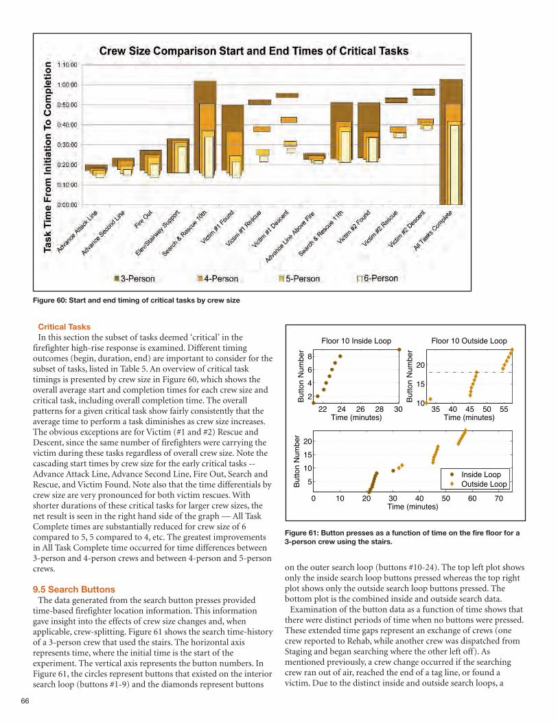
66
Critical TasksIn this section the subset of tasks deemed ‘critical’ in the
firefighter high-rise response is examined. Different timingoutcomes (begin, duration, end) are important to consider for thesubset of tasks, listed in Table 5. An overview of critical tasktimings is presented by crew size in Figure 60, which shows theoverall average start and completion times for each crew size andcritical task, including overall completion time. The overallpatterns for a given critical task show fairly consistently that theaverage time to perform a task diminishes as crew size increases.The obvious exceptions are for Victim (#1 and #2) Rescue andDescent, since the same number of firefighters were carrying thevictim during these tasks regardless of overall crew size. Note thecascading start times by crew size for the early critical tasks --Advance Attack Line, Advance Second Line, Fire Out, Search andRescue, and Victim Found. Note also that the time differentials bycrew size are very pronounced for both victim rescues. Withshorter durations of these critical tasks for larger crew sizes, thenet result is seen in the right hand side of the graph — All TaskComplete times are substantially reduced for crew size of 6compared to 5, 5 compared to 4, etc. The greatest improvementsin All Task Complete time occurred for time differences between3-person and 4-person crews and between 4-person and 5-personcrews.
9.5 Search ButtonsThe data generated from the search button presses provided
time-based firefighter location information. This informationgave insight into the effects of crew size changes and, whenapplicable, crew-splitting. Figure 61 shows the search time-historyof a 3-person crew that used the stairs. The horizontal axisrepresents time, where the initial time is the start of theexperiment. The vertical axis represents the button numbers. InFigure 61, the circles represent buttons that existed on the interiorsearch loop (buttons #1-9) and the diamonds represent buttons
on the outer search loop (buttons #10-24). The top left plot showsonly the inside search loop buttons pressed whereas the top rightplot shows only the outside search loop buttons pressed. Thebottom plot is the combined inside and outside search data.Examination of the button data as a function of time shows that
there were distinct periods of time when no buttons were pressed.These extended time gaps represent an exchange of crews (onecrew reported to Rehab, while another crew was dispatched fromStaging and began searching where the other left off). Asmentioned previously, a crew change occurred if the searchingcrew ran out of air, reached the end of a tag line, or found avictim. Due to the distinct inside and outside search loops, a
Figure 60: Start and end timing of critical tasks by crew size
Figure 61: Button presses as a function of time on the fire floor for a3-person crew using the stairs.
22 24 26 28 30
2
4
6
8
Floor 10 Inside Loop
Time (minutes)
Bu
tto
n N
um
be
r
35 40 45 50 5510
15
20
Floor 10 Outside Loop
Time (minutes)B
utt
on
Nu
mb
er
0 10 20 30 40 50 60 70
5
10
15
20
Time (minutes)
Bu
tto
n N
um
be
r
Inside LoopOutside Loop
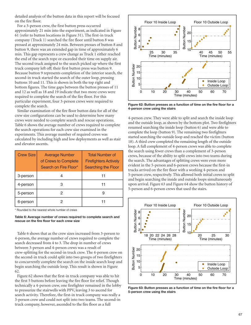
67
detailed analysis of the button data in this report will be focusedon the fire floor.For a 3-person crew, the first button press occurred
approximately 21 min into the experiment, as indicated in Figure61 (refer to button locations in Figure 31). The first-in truckcompany (Truck 1) searched the fire floor until button 8 waspressed at approximately 24 min. Between presses of button 8 andbutton 9, there was an extended gap in time of approximately 6min. This gap represents a crew change as Truck 1 either reachedthe end of the search rope or exceeded their time on supply air.The second truck assigned to the search picked up where the firsttruck company left off; their first button press was button 9.Because button 9 represents completion of the interior search, thesecond-in truck started the search of the outer loop, pressingbuttons 10 and 11. This is shown in both the top right andbottom figures. The time gaps between the button presses of 11and 12 as well as 18 and 19 indicate that two more crews wererequired to complete the search of the fire floor. For thisparticular experiment, four 3-person crews were required tocomplete the search.Similar examination of the fire floor button data for all of the
crew size configurations can be used to determine how manycrews were needed to complete search and rescue operations.Table 6 shows the average number of crews required to completethe search operations for each crew size examined in theexperiments. This average number of required crews wascalculated by including high and low deployments as well as stairand elevator ascents.
Table 6 shows that as the crew sizes increased from 3-person to4-person, the average number of crews required to complete thesearch decreased from 4 to 3. The drop in number of crewsbetween 3-person and 4-person crews was a result ofcrew-splitting for the second-in truck crew. The 4-person crew onthe second-in truck could split into two groups of two firefightersto concurrently complete the search on the inside search loop andbegin searching the outside loop. This result is shown in Figure62. Figure 62 shows that the first-in truck company was able to hit
the first 5 buttons before leaving the fire floor for relief. Thoughtechnically a 4-person crew, one firefighter remained in the lobbyto pressurize the stairwells with PPV, leaving 3 to ascend forsearch activity. Therefore, the first-in truck company was really a3-person crew and could not split into two teams. The second-intruck company, however, ascended to the fire floor as a full
4-person crew. They were able to split and search the inside loopand the outside loop, as shown by the bottom plot. Two firefightersresumed searching the inside loop (button 6) and were able tocomplete the loop (button 9). The remaining two firefightersstarted searching the outside loop and reached the victim (button18). A third crew completed the remaining length of the outsideloop. A full complement of 4-person crews was able to completethe search using fewer crews than a complement of 3-personcrews, because of the ability to split crews into two teams duringthe search. The advantages of splitting crews were even moreevident in the 5-person and 6-person crews because the first-intrucks arrived on the fire floor with a working 4-person and5-person crew, respectively. This allowed both initial crews to splitand begin searching the inside and outside loops simultaneouslyupon arrival. Figure 63 and Figure 64 show the button history of5-person and 6-person crews that used the stairs.
Crew Size Average Number Total Number of
of Crews to Complete Firefighters Actively
Search on Fire Floor* Searching the Floor
3-person 4 11
4-person 3 11
5-person 2 9
6-person 2 11
Table 6: Average number of crews required to complete search andrescue on the fire floor for each crew size
Figure 62: Button presses as a function of time on the fire floor for a4-person crew using the stairs
25 30 35
2
4
6
8
Floor 10 Inside Loop
Time (minutes)
Button N
um
ber
40 45 50 5510
15
20
Floor 10 Outside Loop
Time (minutes)
Button N
um
ber
0 10 20 30 40 50 60 70
5
10
15
20
Time (minutes)
Button N
um
ber
Inside LoopOutside Loop
Figure 63: Button presses as a function of time on the fire floor for a5-person crew using the stairs
18 20 22 24 26 28
2
4
6
8
Floor 10 Inside Loop
Time (minutes)
Button N
um
ber
20 25 3010
15
20
Floor 10 Outside Loop
Time (minutes)
Button N
um
ber
0 10 20 30 40 50 60 70
5
10
15
20
Time (minutes)
Button N
um
ber
Inside LoopOutside Loop
* Rounded to the nearest whole number of crews
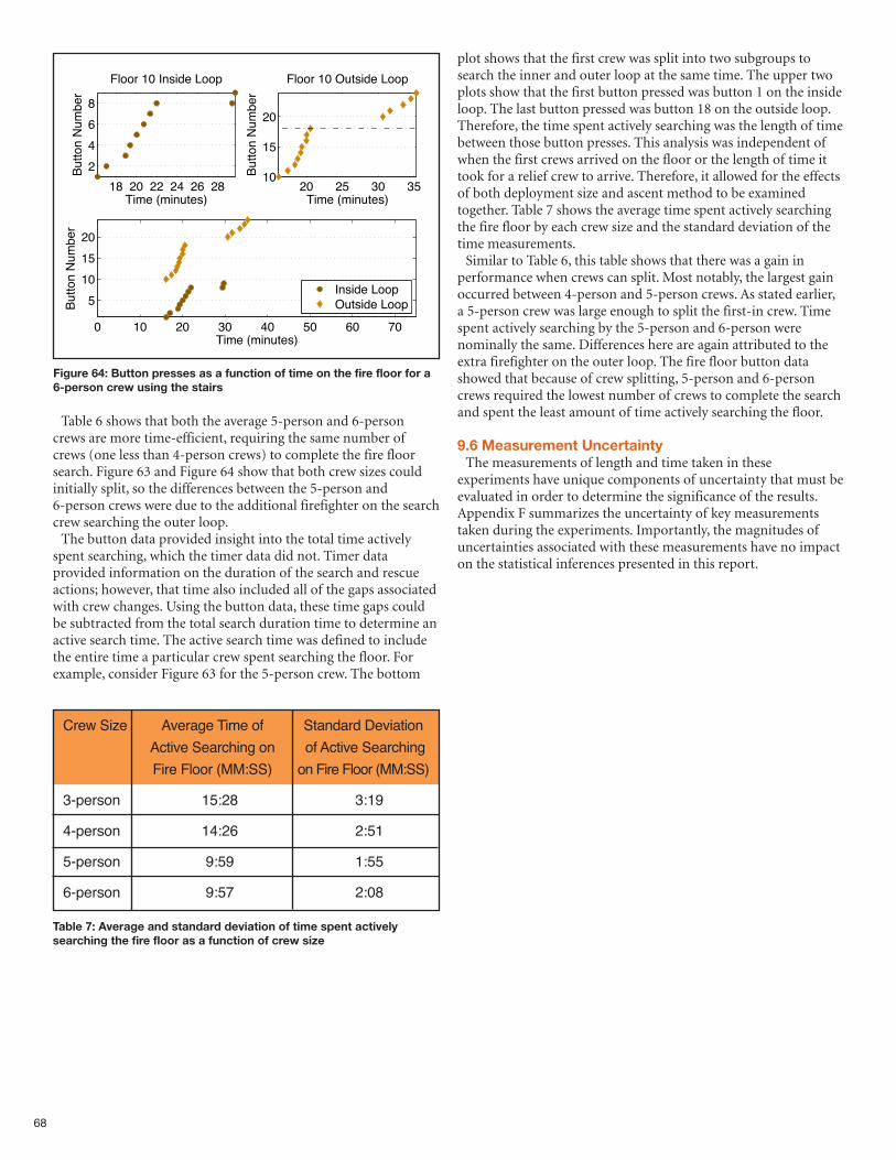
Table 6 shows that both the average 5-person and 6-personcrews are more time-efficient, requiring the same number ofcrews (one less than 4-person crews) to complete the fire floorsearch. Figure 63 and Figure 64 show that both crew sizes couldinitially split, so the differences between the 5-person and6-person crews were due to the additional firefighter on the searchcrew searching the outer loop.The button data provided insight into the total time actively
spent searching, which the timer data did not. Timer dataprovided information on the duration of the search and rescueactions; however, that time also included all of the gaps associatedwith crew changes. Using the button data, these time gaps couldbe subtracted from the total search duration time to determine anactive search time. The active search time was defined to includethe entire time a particular crew spent searching the floor. Forexample, consider Figure 63 for the 5-person crew. The bottom
plot shows that the first crew was split into two subgroups tosearch the inner and outer loop at the same time. The upper twoplots show that the first button pressed was button 1 on the insideloop. The last button pressed was button 18 on the outside loop.Therefore, the time spent actively searching was the length of timebetween those button presses. This analysis was independent ofwhen the first crews arrived on the floor or the length of time ittook for a relief crew to arrive. Therefore, it allowed for the effectsof both deployment size and ascent method to be examinedtogether. Table 7 shows the average time spent actively searchingthe fire floor by each crew size and the standard deviation of thetime measurements.Similar to Table 6, this table shows that there was a gain in
performance when crews can split. Most notably, the largest gainoccurred between 4-person and 5-person crews. As stated earlier,a 5-person crew was large enough to split the first-in crew. Timespent actively searching by the 5-person and 6-person werenominally the same. Differences here are again attributed to theextra firefighter on the outer loop. The fire floor button datashowed that because of crew splitting, 5-person and 6-personcrews required the lowest number of crews to complete the searchand spent the least amount of time actively searching the floor.
9.6 Measurement UncertaintyThe measurements of length and time taken in these
experiments have unique components of uncertainty that must beevaluated in order to determine the significance of the results.Appendix F summarizes the uncertainty of key measurementstaken during the experiments. Importantly, the magnitudes ofuncertainties associated with these measurements have no impacton the statistical inferences presented in this report.
68
Figure 64: Button presses as a function of time on the fire floor for a6-person crew using the stairs
18 20 22 24 26 28
2
4
6
8
Floor 10 Inside Loop
Time (minutes)
Button N
um
ber
20 25 30 3510
15
20
Floor 10 Outside Loop
Time (minutes)
Button N
um
ber
0 10 20 30 40 50 60 70
5
10
15
20
Time (minutes)
Button N
um
ber
Inside LoopOutside Loop
Crew Size Average Time of Standard Deviation
Active Searching on of Active Searching
Fire Floor (MM:SS) on Fire Floor (MM:SS)
3-person 15:28 3:19
4-person 14:26 2:51
5-person 9:59 1:55
6-person 9:57 2:08
Table 7: Average and standard deviation of time spent activelysearching the fire floor as a function of crew size
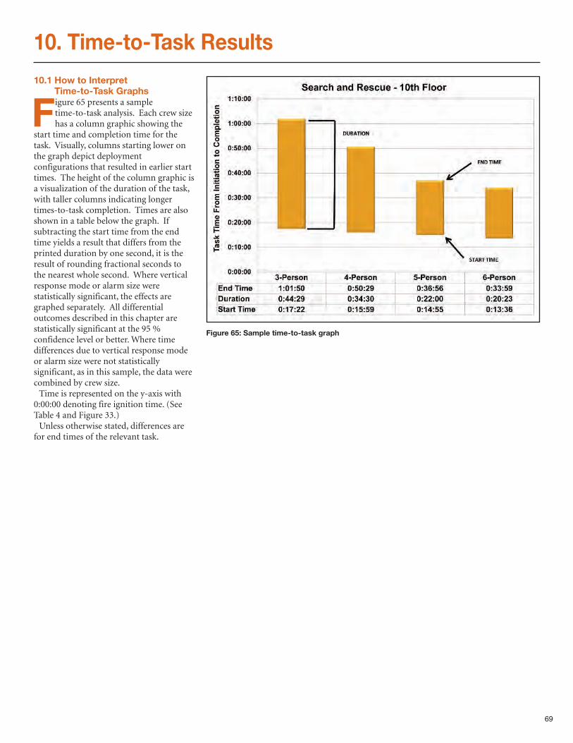
69
10. Time-to-Task Results
10.1 How to Interpret Time-to-Task Graphs
Figure 65 presents a sampletime-to-task analysis. Each crew sizehas a column graphic showing the
start time and completion time for thetask. Visually, columns starting lower onthe graph depict deploymentconfigurations that resulted in earlier starttimes. The height of the column graphic isa visualization of the duration of the task,with taller columns indicating longertimes-to-task completion. Times are alsoshown in a table below the graph. Ifsubtracting the start time from the endtime yields a result that differs from theprinted duration by one second, it is theresult of rounding fractional seconds tothe nearest whole second. Where verticalresponse mode or alarm size werestatistically significant, the effects aregraphed separately. All differentialoutcomes described in this chapter arestatistically significant at the 95 %confidence level or better. Where timedifferences due to vertical response modeor alarm size were not statisticallysignificant, as in this sample, the data werecombined by crew size.Time is represented on the y-axis with
0:00:00 denoting fire ignition time. (SeeTable 4 and Figure 33.)Unless otherwise stated, differences are
for end times of the relevant task.
Figure 65: Sample time-to-task graph
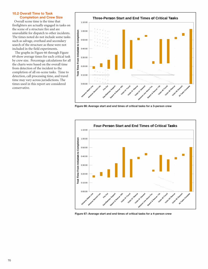
70
0010:1:
soerP-Four
dantartSnso
foes miTdnE
asksTTaskscalitirCf
asks
0000:1:
0050:0:
on
ite
pl
Co
mo
t
on
0040:0:
0030:0:
0020:0:
on
it
aitn
iI
om
Fr
emi
T
0010:0:
0000:0:
Tk
sa
TTa
10.2 Overall Time to TaskCompletion and Crew Size
Overall scene time is the time thatfirefighters are actually engaged in tasks onthe scene of a structure fire and areunavailable for dispatch to other incidents.The times noted do not include some taskssuch as salvage, overhaul and secondarysearch of the structure as these were notincluded in the field experiments.The graphs in Figure 66 through Figure
69 show average times for each critical taskby crew size. Percentage calculations for allthe charts were based on the overall timefrom detection of the incident to thecompletion of all on-scene tasks. Time todetection, call processing time, and traveltime may vary across jurisdictions. Thetimes used in this report are consideredconservative.
0010:1:
soerP-eThre
dantartSnso
oes miTdnE
asksTTaskscalitirCfo
asks
0000:1:
0050:0:
on
ite
pl
Co
mo
t
on
0040:0:
0030:0:
0020:0:
on
it
aitn
iI
om
Fr
emi
T
0010:0:
0000:0:
Tk
sa
TTa
Figure 67: Average start and end times of critical tasks for a 4-person crew
Figure 66: Average start and end times of critical tasks for a 3-person crew
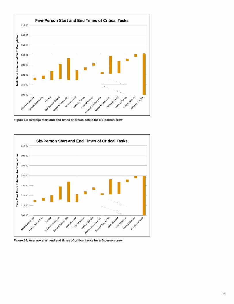
71
0010:1:
soerP-veiF
dantartSnso
foes miTdnE
askTTaskscalitirCf
asks
0000:1:
0050:0:
on
ite
pl
Co
mo
t
on
0040:0:
0030:0:
0020:0:
on
it
aitn
iI
om
Fr
emi
T
0010:0:
0000:0:
Tk
sa
TTa
0010:1:
soerP-xSi
EdantartSnso
foes miTdnE
asksTTaskscalitirC
asks
0000:1:
0050:0:
on
ite
pl
Co
mo
t
on
0040:0:
0030:0:
0020:0:
on
it
aitn
iI
om
Fr
emi
T
0010:0:
0000:0:
Tk
sa
TTa
Figure 69: Average start and end times of critical tasks for a 6-person crew
Figure 68: Average start and end times of critical tasks for a 5-person crew
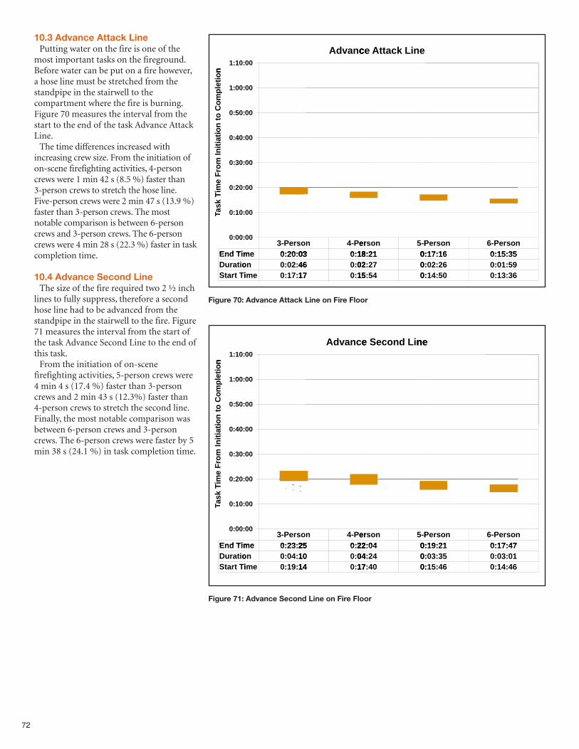
72
10.3 Advance Attack LinePutting water on the fire is one of the
most important tasks on the fireground.Before water can be put on a fire however,a hose line must be stretched from thestandpipe in the stairwell to thecompartment where the fire is burning.Figure 70 measures the interval from thestart to the end of the task Advance AttackLine.The time differences increased with
increasing crew size. From the initiation ofon-scene firefighting activities, 4-personcrews were 1 min 42 s (8.5 %) faster than3-person crews to stretch the hose line.Five-person crews were 2 min 47 s (13.9 %)faster than 3-person crews. The mostnotable comparison is between 6-personcrews and 3-person crews. The 6-personcrews were 4 min 28 s (22.3 %) faster in taskcompletion time.
10.4 Advance Second LineThe size of the fire required two 2 ½ inch
lines to fully suppress, therefore a secondhose line had to be advanced from thestandpipe in the stairwell to the fire. Figure71 measures the interval from the start ofthe task Advance Second Line to the end ofthis task. From the initiation of on-scene
firefighting activities, 5-person crews were4 min 4 s (17.4 %) faster than 3-personcrews and 2 min 43 s (12.3%) faster than4-person crews to stretch the second line.Finally, the most notable comparison wasbetween 6-person crews and 3-personcrews. The 6-person crews were faster by 5min 38 s (24.1 %) in task completion time.
Figure 70: Advance Attack Line on Fire Floor
on
:10:1
00
ce anvdA
eniLack ttAce
on
tie
om
pl
to C
on
ti
:00:1
:50:0
00
00
tia
tin
io
m I
Fr
me
iT
:40:0
:30:0
:20:0
00
00
00
meind TE
Tk
sa
TTa :10:0
:00:0
3- soerP
me 0320:0:
00
00
n 4- erP
03 18:0:
nsoer 5-P
2118: 0:
nsoerP
1617:0:
6- nsoerP
3515:0:
meind TE
ontiaurD
it TrtaS
me 0320:0:
on 4602:0:
mei 1717:0:
03 18:0:
46 02:0:
17 15:0:
2118: 0:
2702: 0:
5415: 0:
1617:0:
2602:0:
5014:0:
3515:0:
5901:0:
3613:0:
Figure 71: Advance Second Line on Fire Floor
on
:10:1
00
encadvA
neLiond ceSe
ne
on
tie
om
pl
to C
on
ti
:00:1
:50:0
00
00
tia
tin
io
m I
Fr
me
iT
:40:0
:30:0
:20:0
00
00
00
meind TE
Tk
sa
TTa :10:0
:00:0
3- soerP
me 2523:0:
00
00
n 4- erP
25 22:0:
nsoer 5-P
0422: 0:
nsoerP
2119:0:
6- nsoerP
4717:0:
meind TE
ontiaurD
it TrtaS
me 2523:0:
on 1004:0:
mei 1419:0:
25 22:0:
10 04:0:
14 17:0:
0422: 0:
2404: 0:
4017: 0:
2119:0:
3503:0:
4615:0:
4717:0:
0103:0:
4614:0:
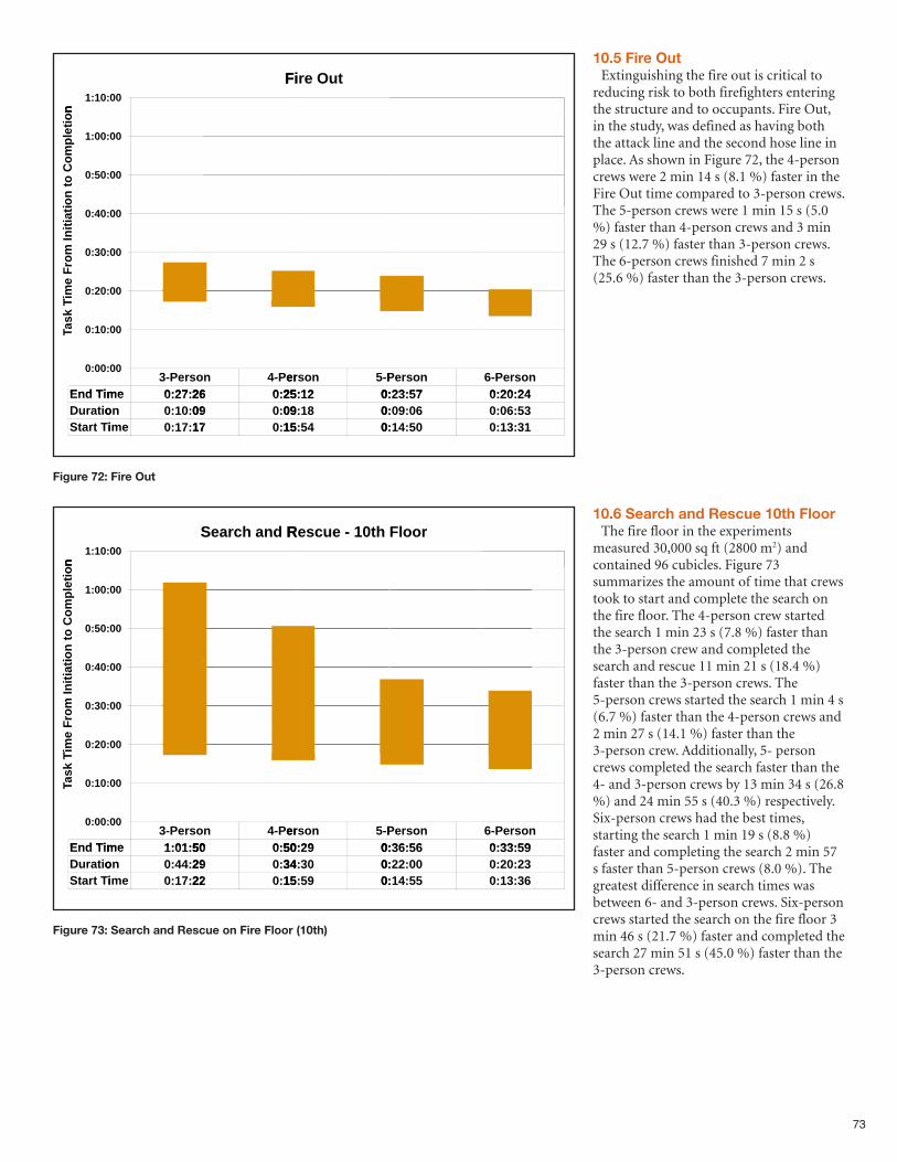
73
10.5 Fire OutExtinguishing the fire out is critical to
reducing risk to both firefighters enteringthe structure and to occupants. Fire Out,in the study, was defined as having boththe attack line and the second hose line inplace. As shown in Figure 72, the 4-personcrews were 2 min 14 s (8.1 %) faster in theFire Out time compared to 3-person crews.The 5-person crews were 1 min 15 s (5.0%) faster than 4-person crews and 3 min29 s (12.7 %) faster than 3-person crews.The 6-person crews finished 7 min 2 s(25.6 %) faster than the 3-person crews.
10.6 Search and Rescue 10th FloorThe fire floor in the experiments
measured 30,000 sq ft (2800 m2) andcontained 96 cubicles. Figure 73summarizes the amount of time that crewstook to start and complete the search onthe fire floor. The 4-person crew startedthe search 1 min 23 s (7.8 %) faster thanthe 3-person crew and completed thesearch and rescue 11 min 21 s (18.4 %)faster than the 3-person crews. The5-person crews started the search 1 min 4 s(6.7 %) faster than the 4-person crews and2 min 27 s (14.1 %) faster than the3-person crew. Additionally, 5- personcrews completed the search faster than the4- and 3-person crews by 13 min 34 s (26.8%) and 24 min 55 s (40.3 %) respectively.Six-person crews had the best times,starting the search 1 min 19 s (8.8 %)faster and completing the search 2 min 57s faster than 5-person crews (8.0 %). Thegreatest difference in search times wasbetween 6- and 3-person crews. Six-personcrews started the search on the fire floor 3min 46 s (21.7 %) faster and completed thesearch 27 min 51 s (45.0 %) faster than the3-person crews.
Figure 72: Fire Out
o
n
:10:1
00
Fi
OutreFi
o
nti
eo
mp
lto
Co
n
ti
:00:1
:50:0
00
00
ti
ati
ni
om
I F
rm
ei
T
:40:0
:30:0
:20:0
00
00
00
meind TE
Tk
sa
TTa :10:0
:00:0
3- soerP
me 2627:0:
00
00
n 4- erP
26 25:0:
nsoer 5-P
1225: 0:
nsoerP
5723:0:
6- nsoerP
2420:0:
meind TE
ontiaurD
it TrtaS
me 2627:0:
on 0910:0:
mei 1717:0:
26 25:0:
09 09:0:
17 15:0:
1225: 0:
1809: 0:
5415: 0:
5723:0:
0609:0:
5014:0:
2420:0:
5306:0:
3113:0:
Figure 73: Search and Rescue on Fire Floor (10th)
on
:10:1
S00
RdanchearS
h t01-e escuR
oorFl
on
tie
om
pl
to C
on
ti
:00:1
:50:0
00
00
tia
tin
io
m I
Fr
me
iT
:40:0
:30:0
:20:0
00
00
00
meind TE
Tk
sa
TTa :10:0
:00:0
3- soerP
me 5001:1:
00
00
n 4- erP
50 50:0:
nsoer 5-P
2950: 0:
nsoerP
5636:0:
6- nsoerP
5933:0:
meind TE
ontiaurD
it TrtaS
me 5001:1:
on 2944:0:
mei 2217:0:
50 50:0:
29 34:0:
22 15:0:
2950: 0:
3034: 0:
5915: 0:
5636:0:
0022:0:
5514:0:
5933:0:
2320:0:
3613:0:
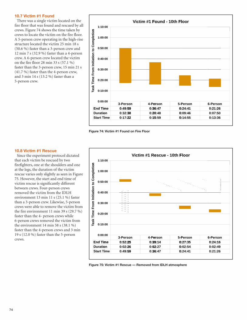
74
Figure 74: Victim #1 Found on Fire Floor
on
:10:1
00
Found 1#mitciV
Flh t01-Found
oorFl
on
tie
om
pl
to C
on
ti
:00:1
:50:0
00
00
tia
tin
io
m I
Fr
me
iT
:40:0
:30:0
:20:0
00
00
00
meind TE
Tk
sa
TTa :10:0
:00:0
3- soerP
me 5949:0:
00
00
n 4- erP
59 36:0:
nsoer 5-P
4736: 0:
nsoerP
4124:0:
6- nsoerP
2621:0:
meind TE
ontiaurD
it TrtaS
me 5949:0:
on 3832:0:
mei 2217:0:
59 36:0:
38 20:0:
22 15:0:
4736: 0:
4820: 0:
5915: 0:
4124:0:
4609:0:
5514:0:
2621:0:
5007:0:
3613:0:
Figure 75: Victim #1 Rescue — Removed from IDLH atmosphere
on
:10:1
00
escuR#1 mictiV
Flh t01-e escu
oorFl
on
tie
om
pl
to C
on
ti
:00:1
:50:0
00
00
tia
tin
io
m I
Fr
me
iT
:40:0
:30:0
:20:0
00
00
00
meind TE
Tk
sa
TTa :10:0
:00:0
3- soerP
me 2552:0:
00
00
n 4- erP
25 39:0:
nsoer 5-P
1439: 0:
nsoerP
3527:0:
6- nsoerP
1624:0:
meind TE
ontiaurD
it TrtaS
me 2552:0:
on 2602:0:
mei 5949:0:
25 39:0:
26 02:0:
59 36:0:
1439: 0:
2702: 0:
4736: 0:
3527:0:
5402:0:
4124:0:
1624:0:
4902:0:
2621:0:
10.7 Victim #1 FoundThere was a single victim located on the
fire floor that was found and rescued by allcrews. Figure 74 shows the time taken bycrews to locate the victim on the fire floor.A 5-person crew operating in the high-risestructure located the victim 25 min 18 s(50.6 %) faster than a 3-person crew and12 min 7 s (32.9 %) faster than a 4-personcrew. A 6-person crew located the victimon the fire floor 28 min 33 s (57.1 %)faster than the 3-person crew, 15 min 21 s(41.7 %) faster than the 4-person crew,and 3 min 14 s (13.2 %) faster than a5-person crew.
10.8 Victim #1 RescueSince the experiment protocol dictated
that each victim be rescued by twofirefighters, one at the shoulders and oneat the legs, the duration of the victimrescue varies only slightly as seen in Figure75. However, the start and end time ofvictim rescue is significantly differentbetween crews. Four-person crewsremoved the victim from the IDLHenvironment 13 min 11 s (25.1 %) fasterthan a 3-person crew. Likewise, 5-personcrews were able to remove the victim fromthe fire environment 11 min 39 s (29.7 %)faster than the 4- person crews while6-person crews removed the victim fromthe environment 14 min 58 s (38.1 %)faster than the 4-person crews and 3 min19 s (12.0 %) faster than the 5-personcrews.
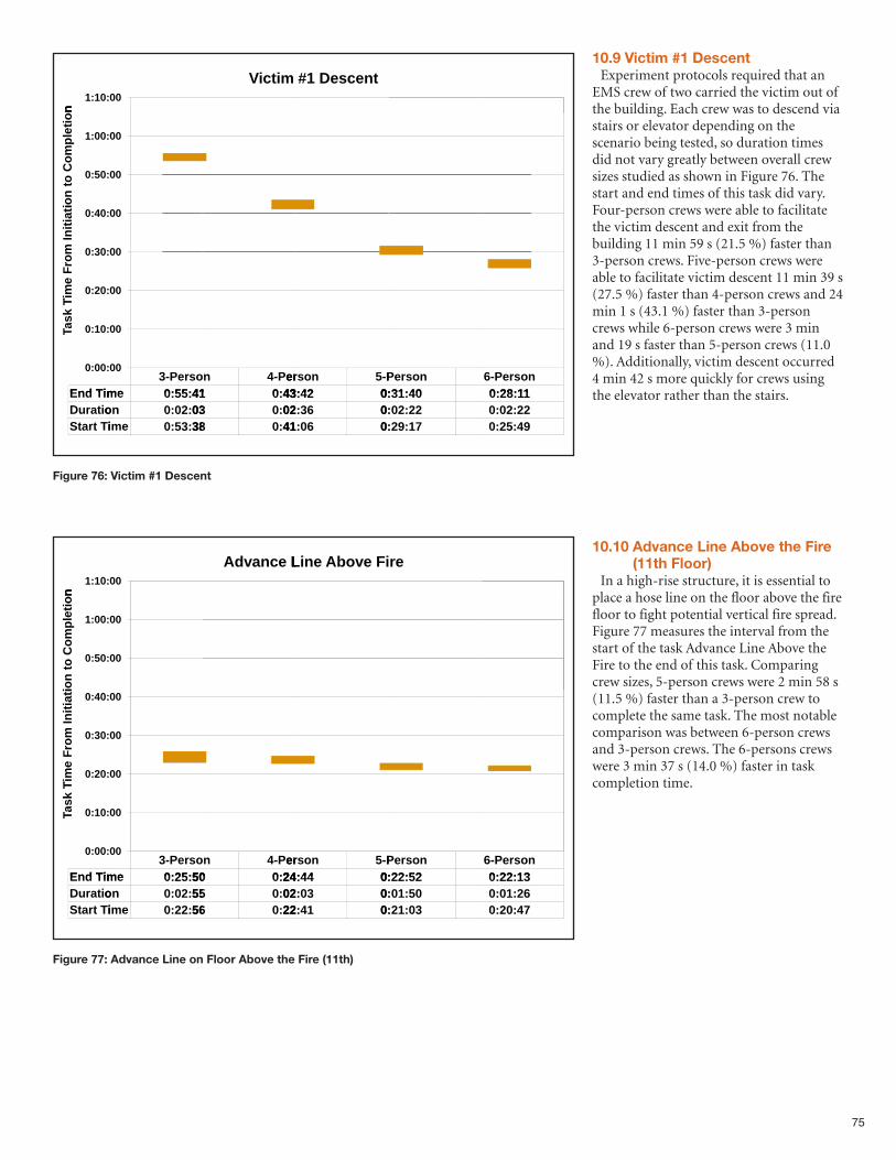
75
Figure 76: Victim #1 Descent
o
n
:10:1
00
mictiV
tescenD#1
o
nti
eo
mp
lto
Co
n
ti
:00:1
:50:0
00
00
ti
ati
ni
om
I F
rm
ei
T
:40:0
:30:0
:20:0
00
00
00
meind TE
Tk
sa
TTa :10:0
:00:0
3- soerP
me 4155:0:
00
00
n 4- erP
41 43:0:
nsoer 5-P
4243: 0:
nsoerP
4031:0:
6- nsoerP
1128:0:
meind TE
ontiaurD
it TrtaS
me 4155:0:
on 0302:0:
mei 3853:0:
41 43:0:
03 02:0:
38 41:0:
4243: 0:
3602: 0:
0641: 0:
4031:0:
2202:0:
1729:0:
1128:0:
2202:0:
4925:0:
Figure 77: Advance Line on Floor Above the Fire (11th)
on
:10:1
00
LiencadvA
FiebovAneLi
re
on
tie
om
pl
to C
on
ti
:00:1
:50:0
00
00
tia
tin
io
m I
Fr
me
iT
:40:0
:30:0
:20:0
00
00
00
meind TE
Tk
sa
TTa :10:0
:00:0
3- soerP
me 5025:0:
00
00
n 4- erP
50 24:0:
nsoer 5-P
4424: 0:
nsoerP
5222:0:
6- nsoerP
1322:0:
meind TE
ontiaurD
it TrtaS
me 5025:0:
on 5502:0:
mei 5622:0:
50 24:0:
55 02:0:
56 22:0:
4424: 0:
0302: 0:
4122: 0:
5222:0:
5001:0:
0321:0:
1322:0:
2601:0:
4720:0:
10.9 Victim #1 DescentExperiment protocols required that an
EMS crew of two carried the victim out ofthe building. Each crew was to descend viastairs or elevator depending on thescenario being tested, so duration timesdid not vary greatly between overall crewsizes studied as shown in Figure 76. Thestart and end times of this task did vary.Four-person crews were able to facilitatethe victim descent and exit from thebuilding 11 min 59 s (21.5 %) faster than3-person crews. Five-person crews wereable to facilitate victim descent 11 min 39 s(27.5 %) faster than 4-person crews and 24min 1 s (43.1 %) faster than 3-personcrews while 6-person crews were 3 minand 19 s faster than 5-person crews (11.0%). Additionally, victim descent occurred4 min 42 s more quickly for crews usingthe elevator rather than the stairs.
10.10 Advance Line Above the Fire(11th Floor)
In a high-rise structure, it is essential toplace a hose line on the floor above the firefloor to fight potential vertical fire spread.Figure 77 measures the interval from thestart of the task Advance Line Above theFire to the end of this task. Comparingcrew sizes, 5-person crews were 2 min 58 s(11.5 %) faster than a 3-person crew tocomplete the same task. The most notablecomparison was between 6-person crewsand 3-person crews. The 6-persons crewswere 3 min 37 s (14.0 %) faster in taskcompletion time.
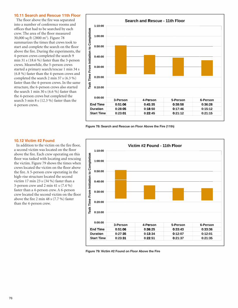
76
10.11 Search and Rescue 11th FloorThe floor above the fire was separated
into a number of conference rooms andoffices that had to be searched by eachcrew. The area of the floor measured30,000 sq ft (2800 m2). Figure 78summarizes the times that crews took tostart and complete the search on the floorabove the fire. During the experiments, the4-person crews completed the search 9min 31 s (18.6 %) faster than the 3-personcrews. Meanwhile, the 5-person crewsstarted a primary search/rescue 1 min 34 s(6.8 %) faster than the 4-person crews andcompleted the search 2 min 37 s (6.3 %)faster than the 4-person crews. In the samestructure, the 6-person crews also startedthe search 1 min 30 s (6.6 %) faster thanthe 4-person crews but completed thesearch 5 min 8 s (12.3 %) faster than the4-person crews.
10.12 Victim #2 FoundIn addition to the victim on the fire floor,
a second victim was located on the floorabove the fire. Each crew operating on thisfloor was tasked with locating and rescuingthe victim. Figure 79 shows the times whencrews located the victim on the floor abovethe fire. A 5-person crew operating in thehigh-rise structure located the secondvictim 17 min 23 s (34 %) faster than a3-person crew and 2 min 41 s (7.4 %)faster than a 4-person crew. A 6-personcrew located the second victim on the floorabove the fire 2 min 48 s (7.7 %) fasterthan the 4-person crew.
Figure 78: Search and Rescue on Floor Above the Fire (11th)
on
:10:1
S00
RdanchearS
h t11-e escuR
oorFl
on
tie
om
pl
to C
on
ti
:00:1
:50:0
00
00
tia
tin
io
m I
Fr
me
iT
:40:0
:30:0
:20:0
00
00
00
meind TE
Tk
sa
TTa :10:0
:00:0
3- soerP
me 0651:0:
00
00
n 4- erP
06 41:0:
nsoer 5-P
3541: 0:
nsoerP
5838:0:
6- nsoerP
2836:0:
meind TE
ontiaurD
it TrtaS
me 0651:0:
on 0528:0:
mei 0123:0:
06 41:0:
05 18:0:
01 22:0:
3541: 0:
5018: 0:
4522: 0:
5838:0:
4617:0:
1221:0:
2836:0:
1215:0:
1521:0:
Figure 79: Victim #2 Found on Floor Above the Fire
on
:10:1
00
Found 2#mitciV
Flh t11-Found
oorFl
on
tie
om
pl
to C
on
ti
:00:1
:50:0
00
00
tia
tin
io
m I
Fr
me
iT
:40:0
:30:0
:20:0
00
00
00
meind TE
Tk
sa
TTa :10:0
:00:0
3- soerP
me 0651:0:
00
00
n 4- erP
06 36:0:
nsoer 5-P
2536: 0:
nsoerP
4333:0:
6- nsoerP
3633:0:
meind TE
ontiaurD
it TrtaS
me 0651:0:
on 3527:0:
mei 3123:0:
06 36:0:
35 13:0:
31 22:0:
2536: 0:
3413: 0:
5122: 0:
4333:0:
0712:0:
3721:0:
3633:0:
0112:0:
3521:0:
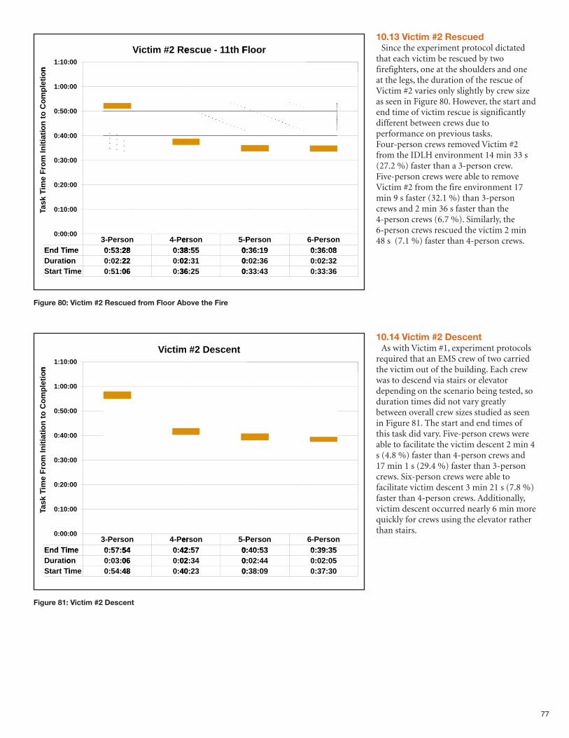
77
Figure 80: Victim #2 Rescued from Floor Above the Fire
o
n
:10:1
00
escuR#2 mictiV
Flh t11-e escu
oorFl
o
nti
eo
mp
lto
Co
n
ti
:00:1
:50:0
00
00
ti
ati
ni
om
I F
rm
ei
T
:40:0
:30:0
:20:0
00
00
00
meind TE
Tk
sa
TTa :10:0
:00:0
3- soerP
me 2853:0:
00
00
n 4- erP
28 38:0:
nsoer 5-P
5538: 0:
nsoerP
1936:0:
6- nsoerP
0836:0:
meind TE
ontiaurD
it TrtaS
me 2853:0:
on 2202:0:
mei 0651:0:
28 38:0:
22 02:0:
06 36:0:
5538: 0:
3102: 0:
2536: 0:
1936:0:
3602:0:
4333:0:
0836:0:
3202:0:
3633:0:
Figure 81: Victim #2 Descent
on
:10:1
00
mictiV
tescenD#2
on
tie
om
pl
to C
on
ti
:00:1
:50:0
00
00
tia
tin
io
m I
Fr
me
iT
:40:0
:30:0
:20:0
00
00
00
meind TE
Tk
sa
TTa :10:0
:00:0
3- soerP
me 5457:0:
00
00
n 4- erP
54 42:0:
nsoer 5-P
5742: 0:
nsoerP
5340:0:
6- nsoerP
3539:0:
meind TE
ontiaurD
it TrtaS
me 5457:0:
on 0603:0:
mei 4854:0:
54 42:0:
06 02:0:
48 40:0:
5742: 0:
3402: 0:
2340: 0:
5340:0:
4402:0:
0938:0:
3539:0:
0502:0:
3037:0:
10.13 Victim #2 RescuedSince the experiment protocol dictated
that each victim be rescued by twofirefighters, one at the shoulders and oneat the legs, the duration of the rescue ofVictim #2 varies only slightly by crew sizeas seen in Figure 80. However, the start andend time of victim rescue is significantlydifferent between crews due toperformance on previous tasks.Four-person crews removed Victim #2from the IDLH environment 14 min 33 s(27.2 %) faster than a 3-person crew.Five-person crews were able to removeVictim #2 from the fire environment 17min 9 s faster (32.1 %) than 3-personcrews and 2 min 36 s faster than the4-person crews (6.7 %). Similarly, the6-person crews rescued the victim 2 min48 s (7.1 %) faster than 4-person crews.
10.14 Victim #2 DescentAs with Victim #1, experiment protocols
required that an EMS crew of two carriedthe victim out of the building. Each crewwas to descend via stairs or elevatordepending on the scenario being tested, soduration times did not vary greatlybetween overall crew sizes studied as seenin Figure 81. The start and end times ofthis task did vary. Five-person crews wereable to facilitate the victim descent 2 min 4s (4.8 %) faster than 4-person crews and17 min 1 s (29.4 %) faster than 3-personcrews. Six-person crews were able tofacilitate victim descent 3 min 21 s (7.8 %)faster than 4-person crews. Additionally,victim descent occurred nearly 6 min morequickly for crews using the elevator ratherthan stairs.
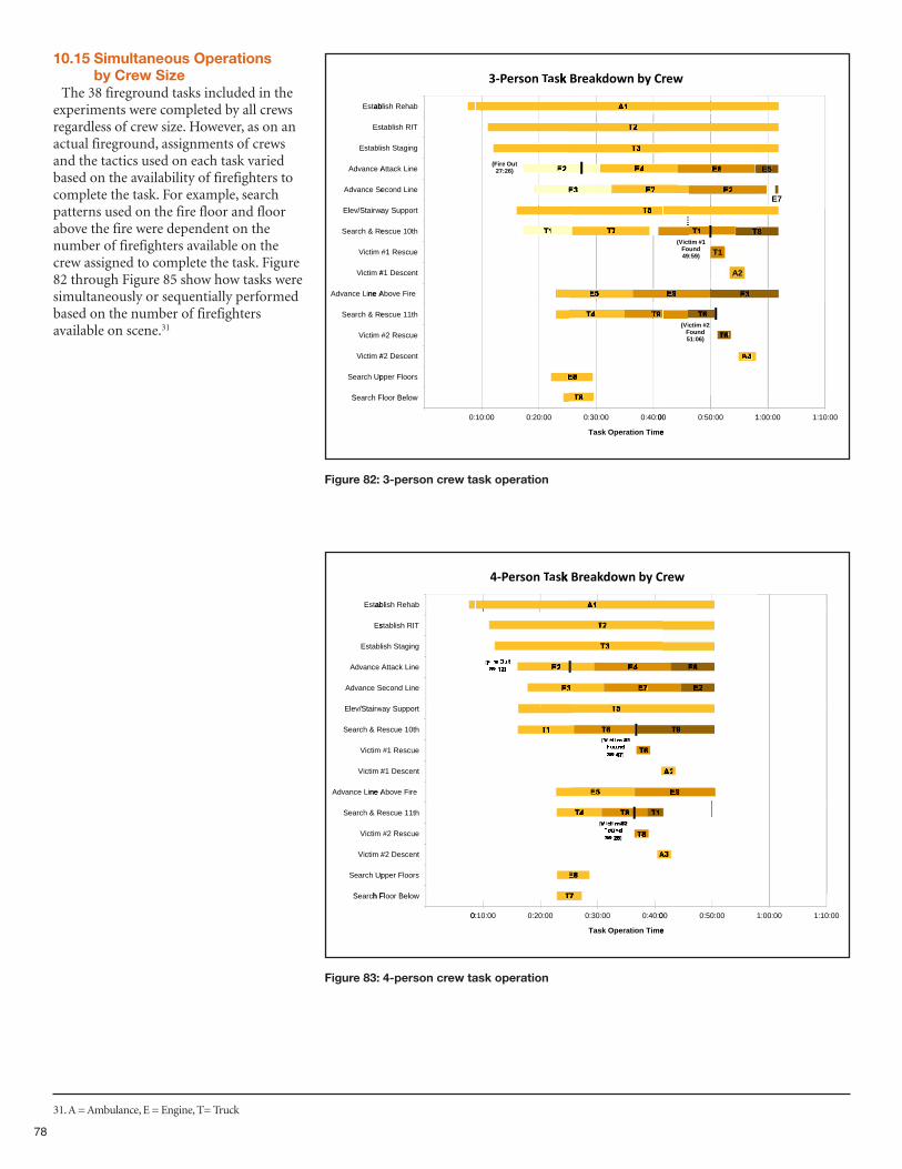
78
10.15 Simultaneous Operations by Crew Size
The 38 fireground tasks included in theexperiments were completed by all crewsregardless of crew size. However, as on anactual fireground, assignments of crewsand the tactics used on each task variedbased on the availability of firefighters tocomplete the task. For example, searchpatterns used on the fire floor and floorabove the fire were dependent on thenumber of firefighters available on thecrew assigned to complete the task. Figure82 through Figure 85 show how tasks weresimultaneously or sequentially performedbased on the number of firefightersavailable on scene.31
Figure 82: 3-person crew task operation
abltsE
ehabh Rsiabl
k BsaTTanosreP-3
r Cybnwodkaerk B
wer
aitS/lE
ece SancdvA
Ae ancdvA
iabltsE
tsE
tS
neLiond ec
ne LikacttA
ngagith Ss
TIh Rsiablt
t uOeri(F26)27:
E7
E5
ne ALie ancdvA
#1 mitciV
es R&h cearS
#1 mitciV
awraitS/evlE
e rie Fbovne A
entcesD #1
hue 10tces
uecesR #1
tupporSya
59)
T8
A2
T149:Found
#1 mtici(V
T8
h FS
pperh UcearS
#2 mitciV
#2 mitciV
es R&h cearS
elBl
soorlFpper
entcesD #2
uecesR #2
hue 11tces
06)51:Found
#2 mtici(V
h FcearS
0:
owelBoorl
0020:0:0010:
0040:0:0030:0:
emiTnoiaterpask OT
1:0050:0:00
e
0010:1:0000:1:
Figure 83: 4-person crew task operation
abltsE
ehabh Rsiabl
k BsaTTanosreP-4
Cybnwodkaerk B
wer
aitS/lE
e SancdvA
Ae ancdvA
abltsE
sE
tS
neLiond ec
ne LikacttA
ngagith Ssi
TIh Rsiablts
ne ALie ancdvA
#1 mitciV
R&h cearS
mitciV
wraitS/evlE
e rie Fbovne A
entcesD #1
hue 10tces
uecesR #1
tupporSya
h FS
pperh UcearS
#2 mitciV
mitciV
R&h cearS
elBlh F
soorlFpper
entcesD #2
uecesR #2
hue 11tces
h FcearS
0:
owelBoorlh F
0020:0:0010:0:
0040:0:0030:0:
emiTnoiaterpask OT
0050:0:00
e
0010:1:0000:1:
31. A = Ambulance, E = Engine, T= Truck
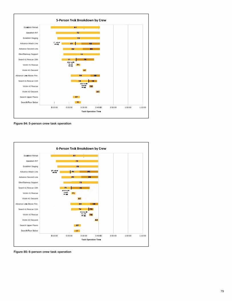
79
Figure 84: 5-person crew task operation
abltsE
ehabh Rsiabl
k BsaTTanosreP-5
Cybnwodkaerk B
wer
aitS/lE
e SancdvA
Ae ancdvA
abltsE
sE
tS
neLiond ec
ne LikacttA
ngagith Ssi
TIh Rsiablts
ne ALie ancdvA
#1 mitciV
R&h cearS
mitciV
wraitS/evlE
e rie Fbovne A
entcesD #1
hue 10tces
uecesR #1
tupporSya
h FS
pperh UcearS
#2 mitciV
mitciV
R&h cearS
elBlh F
soorlFpper
entcesD #2
uecesR #2
hue 11tces
h FcearS
0:
owelBoorlh F
0020:0:0010:0:
0040:0:0030:0:
emiTnoiaterpask OT
0050:0:00
e
0010:1:0000:1:
Figure 85: 6-person crew task operation
abltsE
ehabh Rsiabl
k BsaTTanosreP-6
Cybnwodkaerk B
wer
aitS/lE
e SancdvA
Ae ancdvA
abltsE
sE
tS
neLiond ec
ne LikacttA
ngagith Ssi
TIh Rsiablts
ne ALie ancdvA
#1 mitciV
R&h cearS
mitciV
wraitS/evlE
e rie Fbovne A
entcesD #1
hue 10tces
uecesR #1
tupporSya
h FS
pperh UcearS
#2 mitciV
mitciV
R&h cearS
elBlh F
soorlFpper
entcesD #2
uecesR #2
hue 11tces
h FcearS
0:
owelBoorlh F
0020:0:0010:0:
0040:0:0030:0:
emiTnoiaterpask OT
0050:0:00
e
0010:1:0000:1:
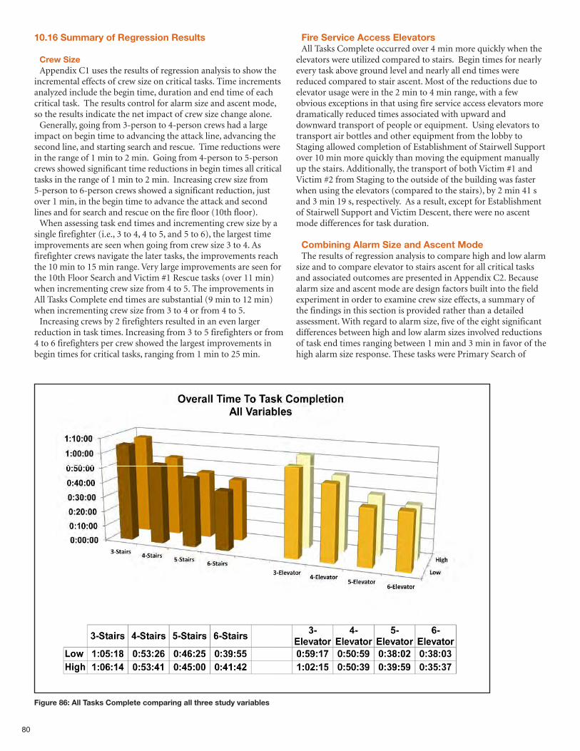
80
10.16 Summary of Regression Results
Crew SizeAppendix C1 uses the results of regression analysis to show the
incremental effects of crew size on critical tasks. Time incrementsanalyzed include the begin time, duration and end time of eachcritical task. The results control for alarm size and ascent mode,so the results indicate the net impact of crew size change alone. Generally, going from 3-person to 4-person crews had a large
impact on begin time to advancing the attack line, advancing thesecond line, and starting search and rescue. Time reductions werein the range of 1 min to 2 min. Going from 4-person to 5-personcrews showed significant time reductions in begin times all criticaltasks in the range of 1 min to 2 min. Increasing crew size from5-person to 6-person crews showed a significant reduction, justover 1 min, in the begin time to advance the attack and secondlines and for search and rescue on the fire floor (10th floor).When assessing task end times and incrementing crew size by a
single firefighter (i.e., 3 to 4, 4 to 5, and 5 to 6), the largest timeimprovements are seen when going from crew size 3 to 4. Asfirefighter crews navigate the later tasks, the improvements reachthe 10 min to 15 min range. Very large improvements are seen forthe 10th Floor Search and Victim #1 Rescue tasks (over 11 min)when incrementing crew size from 4 to 5. The improvements inAll Tasks Complete end times are substantial (9 min to 12 min)when incrementing crew size from 3 to 4 or from 4 to 5. Increasing crews by 2 firefighters resulted in an even larger
reduction in task times. Increasing from 3 to 5 firefighters or from4 to 6 firefighters per crew showed the largest improvements inbegin times for critical tasks, ranging from 1 min to 25 min.
Fire Service Access ElevatorsAll Tasks Complete occurred over 4 min more quickly when the
elevators were utilized compared to stairs. Begin times for nearlyevery task above ground level and nearly all end times werereduced compared to stair ascent. Most of the reductions due toelevator usage were in the 2 min to 4 min range, with a fewobvious exceptions in that using fire service access elevators moredramatically reduced times associated with upward anddownward transport of people or equipment. Using elevators totransport air bottles and other equipment from the lobby toStaging allowed completion of Establishment of Stairwell Supportover 10 min more quickly than moving the equipment manuallyup the stairs. Additionally, the transport of both Victim #1 andVictim #2 from Staging to the outside of the building was fasterwhen using the elevators (compared to the stairs), by 2 min 41 sand 3 min 19 s, respectively. As a result, except for Establishmentof Stairwell Support and Victim Descent, there were no ascentmode differences for task duration.
Combining Alarm Size and Ascent ModeThe results of regression analysis to compare high and low alarm
size and to compare elevator to stairs ascent for all critical tasksand associated outcomes are presented in Appendix C2. Becausealarm size and ascent mode are design factors built into the fieldexperiment in order to examine crew size effects, a summary ofthe findings in this section is provided rather than a detailedassessment. With regard to alarm size, five of the eight significantdifferences between high and low alarm sizes involved reductionsof task end times ranging between 1 min and 3 min in favor of thehigh alarm size response. These tasks were Primary Search of
Figure 86: All Tasks Complete comparing all three study variables
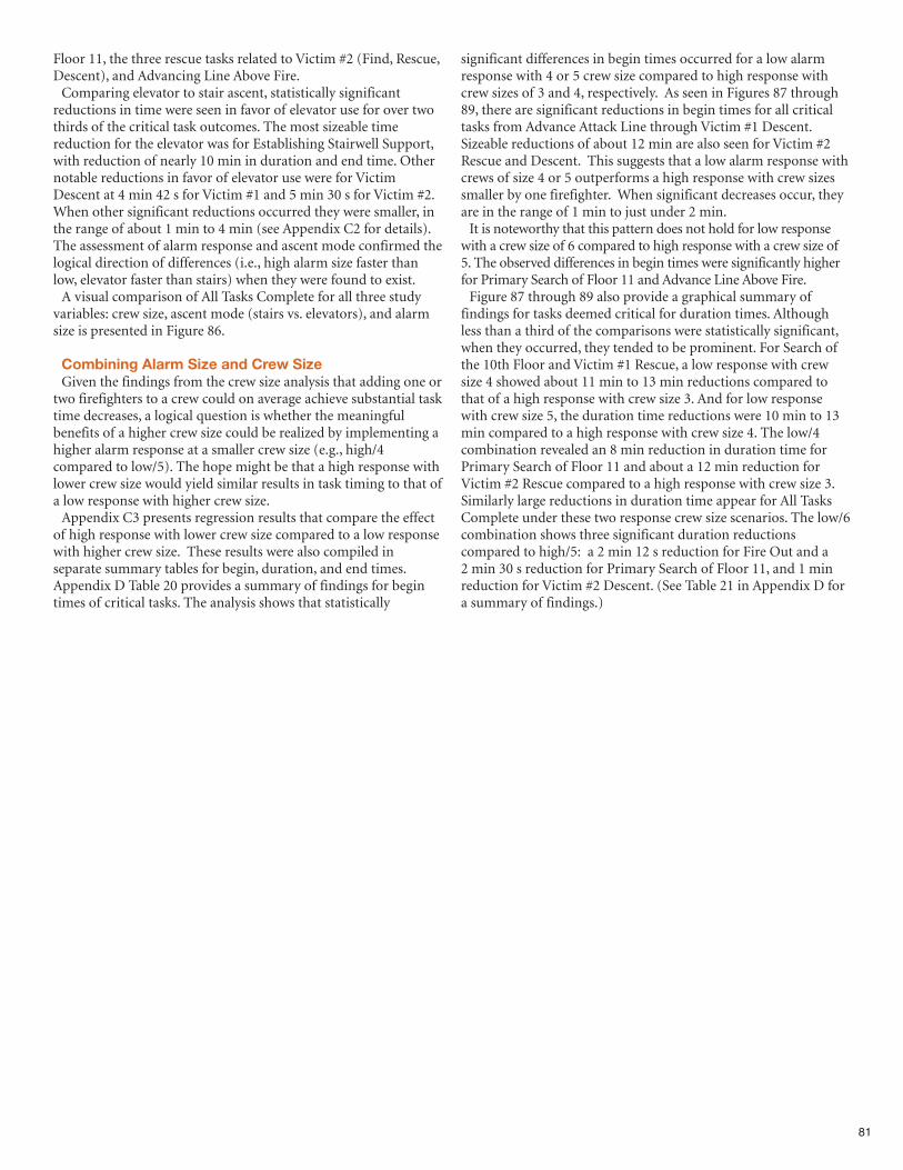
81
Floor 11, the three rescue tasks related to Victim #2 (Find, Rescue,Descent), and Advancing Line Above Fire.Comparing elevator to stair ascent, statistically significant
reductions in time were seen in favor of elevator use for over twothirds of the critical task outcomes. The most sizeable timereduction for the elevator was for Establishing Stairwell Support,with reduction of nearly 10 min in duration and end time. Othernotable reductions in favor of elevator use were for VictimDescent at 4 min 42 s for Victim #1 and 5 min 30 s for Victim #2.When other significant reductions occurred they were smaller, inthe range of about 1 min to 4 min (see Appendix C2 for details).The assessment of alarm response and ascent mode confirmed thelogical direction of differences (i.e., high alarm size faster thanlow, elevator faster than stairs) when they were found to exist.A visual comparison of All Tasks Complete for all three study
variables: crew size, ascent mode (stairs vs. elevators), and alarmsize is presented in Figure 86.
Combining Alarm Size and Crew SizeGiven the findings from the crew size analysis that adding one or
two firefighters to a crew could on average achieve substantial tasktime decreases, a logical question is whether the meaningfulbenefits of a higher crew size could be realized by implementing ahigher alarm response at a smaller crew size (e.g., high/4compared to low/5). The hope might be that a high response withlower crew size would yield similar results in task timing to that ofa low response with higher crew size.Appendix C3 presents regression results that compare the effect
of high response with lower crew size compared to a low responsewith higher crew size. These results were also compiled inseparate summary tables for begin, duration, and end times.Appendix D Table 20 provides a summary of findings for begintimes of critical tasks. The analysis shows that statistically
significant differences in begin times occurred for a low alarmresponse with 4 or 5 crew size compared to high response withcrew sizes of 3 and 4, respectively. As seen in Figures 87 through89, there are significant reductions in begin times for all criticaltasks from Advance Attack Line through Victim #1 Descent.Sizeable reductions of about 12 min are also seen for Victim #2Rescue and Descent. This suggests that a low alarm response withcrews of size 4 or 5 outperforms a high response with crew sizessmaller by one firefighter. When significant decreases occur, theyare in the range of 1 min to just under 2 min. It is noteworthy that this pattern does not hold for low response
with a crew size of 6 compared to high response with a crew size of5. The observed differences in begin times were significantly higherfor Primary Search of Floor 11 and Advance Line Above Fire. Figure 87 through 89 also provide a graphical summary of
findings for tasks deemed critical for duration times. Althoughless than a third of the comparisons were statistically significant,when they occurred, they tended to be prominent. For Search ofthe 10th Floor and Victim #1 Rescue, a low response with crewsize 4 showed about 11 min to 13 min reductions compared tothat of a high response with crew size 3. And for low responsewith crew size 5, the duration time reductions were 10 min to 13min compared to a high response with crew size 4. The low/4combination revealed an 8 min reduction in duration time forPrimary Search of Floor 11 and about a 12 min reduction forVictim #2 Rescue compared to a high response with crew size 3.Similarly large reductions in duration time appear for All TasksComplete under these two response crew size scenarios. The low/6combination shows three significant duration reductionscompared to high/5: a 2 min 12 s reduction for Fire Out and a 2 min 30 s reduction for Primary Search of Floor 11, and 1 minreduction for Victim #2 Descent. (See Table 21 in Appendix D fora summary of findings.)
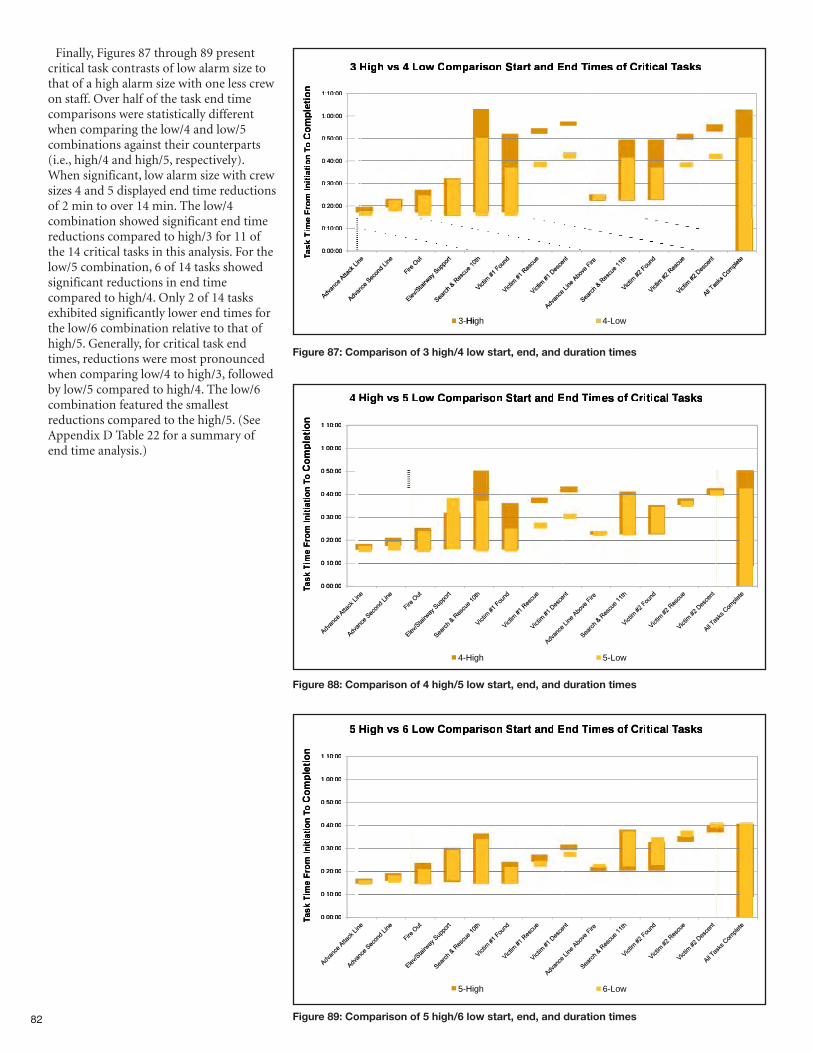
82
Figure 87: Comparison of 3 high/4 low start, end, and duration times
000010:10:1:1:
HH3 3
on
on
titiee
aappmmooCCwwooLL4 4 s s vvhhggiiHH
TTddnnEEddananttararttttSSnnsosoiiarar
asksasksTTTasksTacalcaliittiirrCCffooes es mmiiTT
ss
000000:00:1:1:
000050:50:0:0:
000040:40:0:0:
000030:30:0:0:
000020:20:0:0:
eeo
mp
lo
mp
lCC
o
o
on
To
n T
iittaaiitt
ni
ni
IIo
mo
m F
r F
ree
000010:10:0:0:
000000:00:0:0:
eemmii
TTkk
ssaa
TT
3-Hi
hgHi
4- owL
4 5 s s vvhhggiiHH3 4 4 4 3
ssiiararppmmooCCwwooLL
EEddananttararttSSnnsoso
CCffooes es mmiiTTddnnEE
asksasksTTTasksTacalcaliittiirr
10101:1:
00001:1:
50500:0:
on
on
iittee
pl
pl
om
om
CCo
o
n
Tn
T
0000::
0000::
0000::
40400:0:
30300:0:
20200:0:
10100:0:
on
o
n
iittaaiitt
ni
ni
IIo
mo
m F
r F
ree
mmiiTT
0000::
0000::
0000::
0000::
00000:0:
TTkk
ssaa
TT
0000::
4- hgHi
5- owL
4 6 s s vvhhggiiHH3 5 6 4 3
ssiiararppmmooCCwwooLL
EEddananttararttSSnnsoso
CCffooes es mmiiTTddnnEE
asksasksTTTasksTacalcaliittiirr
10101:1:
00001:1:
50500:0:
on
on
iittee
pl
pl
om
om
CCo
o
n
Tn
T
0000::
0000::
0000::
40400:0:
30300:0:
20200:0:
10100:0:
on
o
n
iittaaiitt
ni
ni
IIo
mo
m F
r F
ree
mmiiTT
0000::
0000::
0000::
0000::
00000:0:
TTkk
ssaa
TT
0000::
5- hgHi
6- owL
Finally, Figures 87 through 89 presentcritical task contrasts of low alarm size tothat of a high alarm size with one less crewon staff. Over half of the task end timecomparisons were statistically differentwhen comparing the low/4 and low/5combinations against their counterparts(i.e., high/4 and high/5, respectively).When significant, low alarm size with crewsizes 4 and 5 displayed end time reductionsof 2 min to over 14 min. The low/4combination showed significant end timereductions compared to high/3 for 11 ofthe 14 critical tasks in this analysis. For thelow/5 combination, 6 of 14 tasks showedsignificant reductions in end timecompared to high/4. Only 2 of 14 tasksexhibited significantly lower end times forthe low/6 combination relative to that ofhigh/5. Generally, for critical task endtimes, reductions were most pronouncedwhen comparing low/4 to high/3, followedby low/5 compared to high/4. The low/6combination featured the smallestreductions compared to the high/5. (SeeAppendix D Table 22 for a summary ofend time analysis.)
Figure 89: Comparison of 5 high/6 low start, end, and duration times
Figure 88: Comparison of 4 high/5 low start, end, and duration times
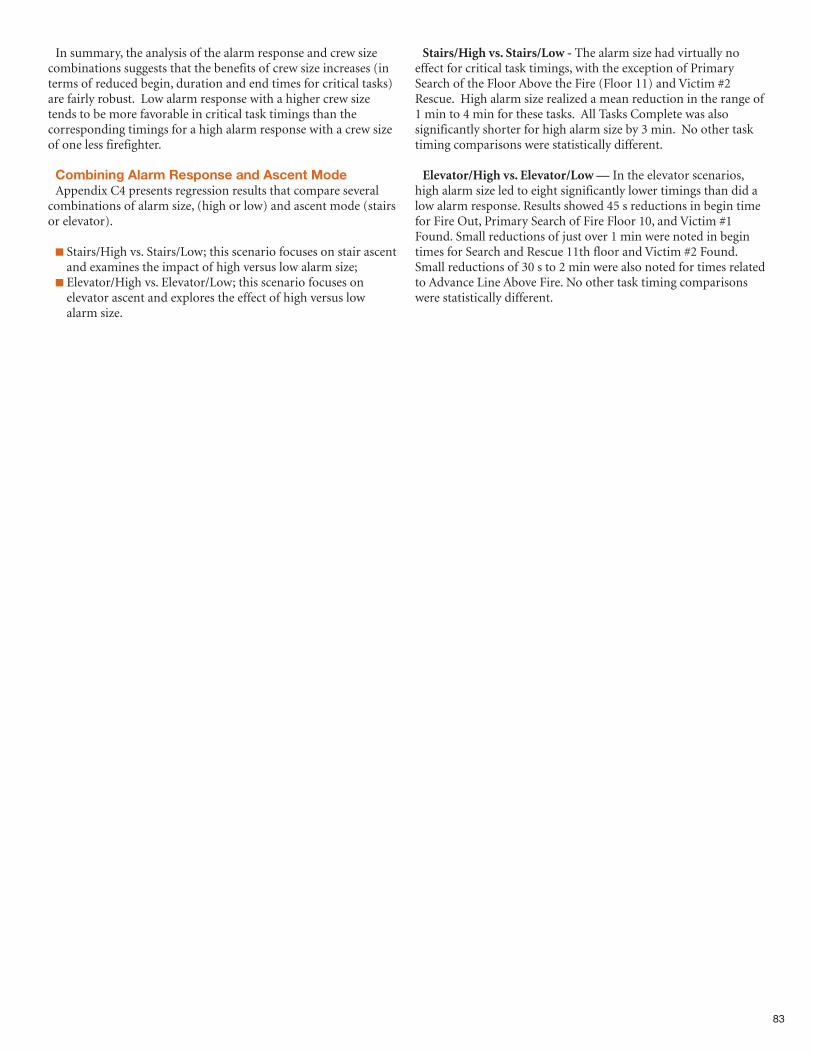
83
In summary, the analysis of the alarm response and crew sizecombinations suggests that the benefits of crew size increases (interms of reduced begin, duration and end times for critical tasks)are fairly robust. Low alarm response with a higher crew sizetends to be more favorable in critical task timings than thecorresponding timings for a high alarm response with a crew sizeof one less firefighter.
Combining Alarm Response and Ascent ModeAppendix C4 presents regression results that compare several
combinations of alarm size, (high or low) and ascent mode (stairsor elevator).
n Stairs/High vs. Stairs/Low; this scenario focuses on stair ascentand examines the impact of high versus low alarm size;
n Elevator/High vs. Elevator/Low; this scenario focuses onelevator ascent and explores the effect of high versus lowalarm size.
Stairs/High vs. Stairs/Low - The alarm size had virtually noeffect for critical task timings, with the exception of PrimarySearch of the Floor Above the Fire (Floor 11) and Victim #2Rescue. High alarm size realized a mean reduction in the range of1 min to 4 min for these tasks. All Tasks Complete was alsosignificantly shorter for high alarm size by 3 min. No other tasktiming comparisons were statistically different.
Elevator/High vs. Elevator/Low — In the elevator scenarios,high alarm size led to eight significantly lower timings than did alow alarm response. Results showed 45 s reductions in begin timefor Fire Out, Primary Search of Fire Floor 10, and Victim #1Found. Small reductions of just over 1 min were noted in begintimes for Search and Rescue 11th floor and Victim #2 Found.Small reductions of 30 s to 2 min were also noted for times relatedto Advance Line Above Fire. No other task timing comparisonswere statistically different.
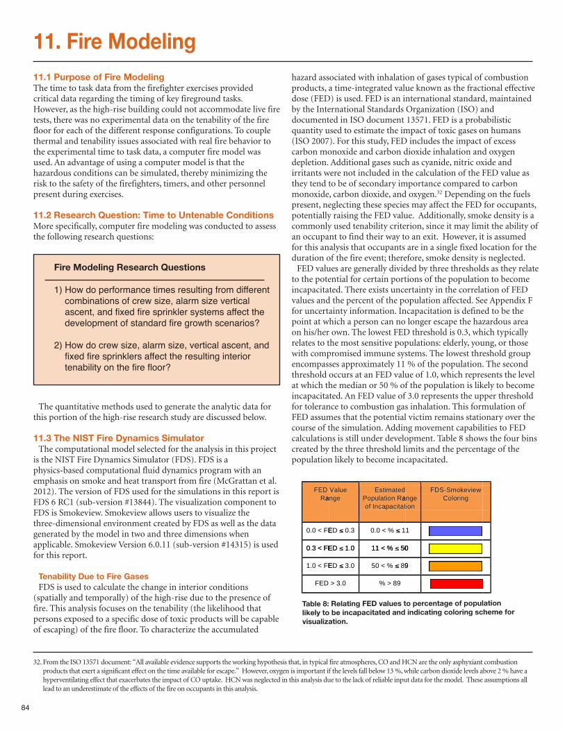
84
11. Fire Modeling11.1 Purpose of Fire ModelingThe time to task data from the firefighter exercises providedcritical data regarding the timing of key fireground tasks.However, as the high-rise building could not accommodate live firetests, there was no experimental data on the tenability of the firefloor for each of the different response configurations. To couplethermal and tenability issues associated with real fire behavior tothe experimental time to task data, a computer fire model wasused. An advantage of using a computer model is that thehazardous conditions can be simulated, thereby minimizing therisk to the safety of the firefighters, timers, and other personnelpresent during exercises.
11.2 Research Question: Time to Untenable ConditionsMore specifically, computer fire modeling was conducted to assessthe following research questions:
The quantitative methods used to generate the analytic data forthis portion of the high-rise research study are discussed below.
11.3 The NIST Fire Dynamics SimulatorThe computational model selected for the analysis in this project
is the NIST Fire Dynamics Simulator (FDS). FDS is aphysics-based computational fluid dynamics program with anemphasis on smoke and heat transport from fire (McGrattan et al.2012). The version of FDS used for the simulations in this report isFDS 6 RC1 (sub-version #13844). The visualization component toFDS is Smokeview. Smokeview allows users to visualize thethree-dimensional environment created by FDS as well as the datagenerated by the model in two and three dimensions whenapplicable. Smokeview Version 6.0.11 (sub-version #14315) is usedfor this report.
Tenability Due to Fire Gases FDS is used to calculate the change in interior conditions
(spatially and temporally) of the high-rise due to the presence offire. This analysis focuses on the tenability (the likelihood thatpersons exposed to a specific dose of toxic products will be capableof escaping) of the fire floor. To characterize the accumulated
hazard associated with inhalation of gases typical of combustionproducts, a time-integrated value known as the fractional effectivedose (FED) is used. FED is an international standard, maintainedby the International Standards Organization (ISO) anddocumented in ISO document 13571. FED is a probabilisticquantity used to estimate the impact of toxic gases on humans(ISO 2007). For this study, FED includes the impact of excesscarbon monoxide and carbon dioxide inhalation and oxygendepletion. Additional gases such as cyanide, nitric oxide andirritants were not included in the calculation of the FED value asthey tend to be of secondary importance compared to carbonmonoxide, carbon dioxide, and oxygen.32 Depending on the fuelspresent, neglecting these species may affect the FED for occupants,potentially raising the FED value. Additionally, smoke density is acommonly used tenability criterion, since it may limit the ability ofan occupant to find their way to an exit. However, it is assumedfor this analysis that occupants are in a single fixed location for theduration of the fire event; therefore, smoke density is neglected. FED values are generally divided by three thresholds as they relate
to the potential for certain portions of the population to becomeincapacitated. There exists uncertainty in the correlation of FEDvalues and the percent of the population affected. See Appendix Ffor uncertainty information. Incapacitation is defined to be thepoint at which a person can no longer escape the hazardous areaon his/her own. The lowest FED threshold is 0.3, which typicallyrelates to the most sensitive populations: elderly, young, or thosewith compromised immune systems. The lowest threshold groupencompasses approximately 11 % of the population. The secondthreshold occurs at an FED value of 1.0, which represents the levelat which the median or 50 % of the population is likely to becomeincapacitated. An FED value of 3.0 represents the upper thresholdfor tolerance to combustion gas inhalation. This formulation ofFED assumes that the potential victim remains stationary over thecourse of the simulation. Adding movement capabilities to FEDcalculations is still under development. Table 8 shows the four binscreated by the three threshold limits and the percentage of thepopulation likely to become incapacitated.
Fire Modeling Research Questions
1) How do performance times resulting from differentcombinations of crew size, alarm size verticalascent, and fixed fire sprinkler systems affect thedevelopment of standard fire growth scenarios?
2) How do crew size, alarm size, vertical ascent, andfixed fire sprinklers affect the resulting interiortenability on the fire floor?
Table 8: Relating FED values to percentage of populationlikely to be incapacitated and indicating coloring scheme forvisualization.
anRD EF
EF<0.0
EF<30
eganeluaV detamitsE
anRnoitaulpoPtaticapacnf Io
DE %<0.03.0 1
DE %<1101 05
egannoi
weivekomS-SDFgniorloC
1
0
EF<3.0
EF<0.1
D EF
DE %<110.1 05
DE %<500.3 98
98>%0.3>
0
9
32. From the ISO 13571 document: “All available evidence supports the working hypothesis that, in typical fire atmospheres, CO and HCN are the only asphyxiant combustionproducts that exert a significant effect on the time available for escape.” However, oxygen is important if the levels fall below 13 %, while carbon dioxide levels above 2 % have ahyperventilating effect that exacerbates the impact of CO uptake. HCN was neglected in this analysis due to the lack of reliable input data for the model. These assumptions alllead to an underestimate of the effects of the fire on occupants in this analysis.
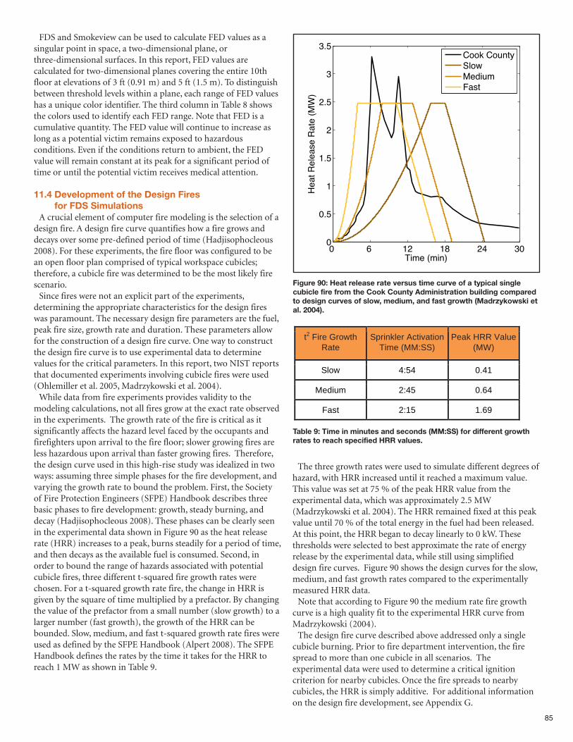
85
FDS and Smokeview can be used to calculate FED values as asingular point in space, a two-dimensional plane, orthree-dimensional surfaces. In this report, FED values arecalculated for two-dimensional planes covering the entire 10thfloor at elevations of 3 ft (0.91 m) and 5 ft (1.5 m). To distinguishbetween threshold levels within a plane, each range of FED valueshas a unique color identifier. The third column in Table 8 showsthe colors used to identify each FED range. Note that FED is acumulative quantity. The FED value will continue to increase aslong as a potential victim remains exposed to hazardousconditions. Even if the conditions return to ambient, the FEDvalue will remain constant at its peak for a significant period oftime or until the potential victim receives medical attention.
11.4 Development of the Design Fires for FDS Simulations
A crucial element of computer fire modeling is the selection of adesign fire. A design fire curve quantifies how a fire grows anddecays over some pre-defined period of time (Hadjisophocleous2008). For these experiments, the fire floor was configured to bean open floor plan comprised of typical workspace cubicles;therefore, a cubicle fire was determined to be the most likely firescenario.Since fires were not an explicit part of the experiments,
determining the appropriate characteristics for the design fireswas paramount. The necessary design fire parameters are the fuel,peak fire size, growth rate and duration. These parameters allowfor the construction of a design fire curve. One way to constructthe design fire curve is to use experimental data to determinevalues for the critical parameters. In this report, two NIST reportsthat documented experiments involving cubicle fires were used(Ohlemiller et al. 2005, Madrzykowski et al. 2004).While data from fire experiments provides validity to the
modeling calculations, not all fires grow at the exact rate observedin the experiments. The growth rate of the fire is critical as itsignificantly affects the hazard level faced by the occupants andfirefighters upon arrival to the fire floor; slower growing fires areless hazardous upon arrival than faster growing fires. Therefore,the design curve used in this high-rise study was idealized in twoways: assuming three simple phases for the fire development, andvarying the growth rate to bound the problem. First, the Societyof Fire Protection Engineers (SFPE) Handbook describes threebasic phases to fire development: growth, steady burning, anddecay (Hadjisophocleous 2008). These phases can be clearly seenin the experimental data shown in Figure 90 as the heat releaserate (HRR) increases to a peak, burns steadily for a period of time,and then decays as the available fuel is consumed. Second, inorder to bound the range of hazards associated with potentialcubicle fires, three different t-squared fire growth rates werechosen. For a t-squared growth rate fire, the change in HRR isgiven by the square of time multiplied by a prefactor. By changingthe value of the prefactor from a small number (slow growth) to alarger number (fast growth), the growth of the HRR can bebounded. Slow, medium, and fast t-squared growth rate fires wereused as defined by the SFPE Handbook (Alpert 2008). The SFPEHandbook defines the rates by the time it takes for the HRR toreach 1 MW as shown in Table 9.
The three growth rates were used to simulate different degrees ofhazard, with HRR increased until it reached a maximum value.This value was set at 75 % of the peak HRR value from theexperimental data, which was approximately 2.5 MW(Madrzykowski et al. 2004). The HRR remained fixed at this peakvalue until 70 % of the total energy in the fuel had been released.At this point, the HRR began to decay linearly to 0 kW. Thesethresholds were selected to best approximate the rate of energyrelease by the experimental data, while still using simplifieddesign fire curves. Figure 90 shows the design curves for the slow,medium, and fast growth rates compared to the experimentallymeasured HRR data.Note that according to Figure 90 the medium rate fire growth
curve is a high quality fit to the experimental HRR curve fromMadrzykowski (2004).The design fire curve described above addressed only a single
cubicle burning. Prior to fire department intervention, the firespread to more than one cubicle in all scenarios. Theexperimental data were used to determine a critical ignitioncriterion for nearby cubicles. Once the fire spreads to nearbycubicles, the HRR is simply additive. For additional informationon the design fire development, see Appendix G.
0 6 12 18 24 300
0.5
1
1.5
2
2.5
3
3.5
Time (min)
Heat R
ele
ase R
ate
(M
W)
Cook CountySlowMediumFast
Figure 90: Heat release rate versus time curve of a typical singlecubicle fire from the Cook County Administration building comparedto design curves of slow, medium, and fast growth (Madrzykowski etal. 2004).
t2 Fire Growth Rate
Sprinkler Activation Time (MM:SS)
Peak HRR Value (MW)
Slow 4:54 0.41
Medium 2:45 0.64
Fast 2:15 1.69
Table 9: Time in minutes and seconds (MM:SS) for different growthrates to reach specified HRR values.
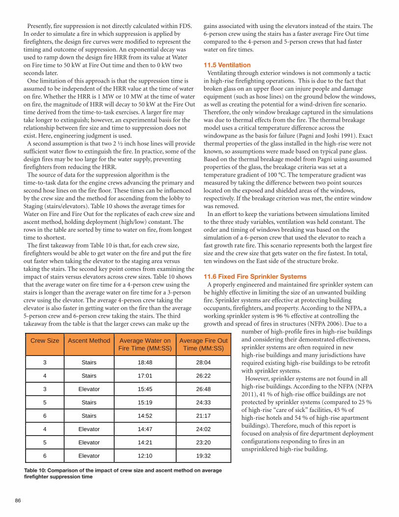
86
Presently, fire suppression is not directly calculated within FDS.In order to simulate a fire in which suppression is applied byfirefighters, the design fire curves were modified to represent thetiming and outcome of suppression. An exponential decay wasused to ramp down the design fire HRR from its value at Wateron Fire time to 50 kW at Fire Out time and then to 0 kW twoseconds later.One limitation of this approach is that the suppression time is
assumed to be independent of the HRR value at the time of wateron fire. Whether the HRR is 1 MW or 10 MW at the time of wateron fire, the magnitude of HRR will decay to 50 kW at the Fire Outtime derived from the time-to-task exercises. A larger fire maytake longer to extinguish; however, an experimental basis for therelationship between fire size and time to suppression does notexist. Here, engineering judgment is used.A second assumption is that two 2 ½ inch hose lines will provide
sufficient water flow to extinguish the fire. In practice, some of thedesign fires may be too large for the water supply, preventingfirefighters from reducing the HRR. The source of data for the suppression algorithm is the
time-to-task data for the engine crews advancing the primary andsecond hose lines on the fire floor. These times can be influencedby the crew size and the method for ascending from the lobby toStaging (stairs/elevators). Table 10 shows the average times forWater on Fire and Fire Out for the replicates of each crew size andascent method, holding deployment (high/low) constant. Therows in the table are sorted by time to water on fire, from longesttime to shortest.The first takeaway from Table 10 is that, for each crew size,
firefighters would be able to get water on the fire and put the fireout faster when taking the elevator to the staging area versustaking the stairs. The second key point comes from examining theimpact of stairs versus elevators across crew sizes. Table 10 showsthat the average water on fire time for a 4-person crew using thestairs is longer than the average water on fire time for a 3-personcrew using the elevator. The average 4-person crew taking theelevator is also faster in getting water on the fire than the average5-person crew and 6-person crew taking the stairs. The thirdtakeaway from the table is that the larger crews can make up the
gains associated with using the elevators instead of the stairs. The6-person crew using the stairs has a faster average Fire Out timecompared to the 4-person and 5-person crews that had fasterwater on fire times.
11.5 VentilationVentilating through exterior windows is not commonly a tactic
in high-rise firefighting operations. This is due to the fact thatbroken glass on an upper floor can injure people and damageequipment (such as hose lines) on the ground below the windows,as well as creating the potential for a wind-driven fire scenario.Therefore, the only window breakage captured in the simulationswas due to thermal effects from the fire. The thermal breakagemodel uses a critical temperature difference across thewindowpane as the basis for failure (Pagni and Joshi 1991). Exactthermal properties of the glass installed in the high-rise were notknown, so assumptions were made based on typical pane glass.Based on the thermal breakage model from Pagni using assumedproperties of the glass, the breakage criteria was set at atemperature gradient of 100 °C. The temperature gradient wasmeasured by taking the difference between two point sourceslocated on the exposed and shielded areas of the windows,respectively. If the breakage criterion was met, the entire windowwas removed.In an effort to keep the variations between simulations limited
to the three study variables, ventilation was held constant. Theorder and timing of windows breaking was based on thesimulation of a 6-person crew that used the elevator to reach afast growth rate fire. This scenario represents both the largest firesize and the crew size that gets water on the fire fastest. In total,ten windows on the East side of the structure broke.
11.6 Fixed Fire Sprinkler SystemsA properly engineered and maintained fire sprinkler system can
be highly effective in limiting the size of an unwanted buildingfire. Sprinkler systems are effective at protecting buildingoccupants, firefighters, and property. According to the NFPA, aworking sprinkler system is 96 % effective at controlling thegrowth and spread of fires in structures (NFPA 2006). Due to a
number of high-profile fires in high-rise buildingsand considering their demonstrated effectiveness,sprinkler systems are often required in newhigh-rise buildings and many jurisdictions haverequired existing high-rise buildings to be retrofitwith sprinkler systems.However, sprinkler systems are not found in all
high-rise buildings. According to the NFPA (NFPA2011), 41 % of high-rise office buildings are notprotected by sprinkler systems (compared to 25 %of high-rise “care of sick” facilities, 45 % ofhigh-rise hotels and 54 % of high-rise apartmentbuildings). Therefore, much of this report isfocused on analysis of fire department deploymentconfigurations responding to fires in anunsprinklered high-rise building.
Table 10: Comparison of the impact of crew size and ascent method on average firefighter suppression time
Crew Size Ascent Method Average Water on Fire Time (MM:SS)
Average Fire Out Time (MM:SS)
3 Stairs 18:48 28:04
4 Stairs 17:01 26:22
3 Elevator 15:45 26:48
5 Stairs 15:19 24:33
6 Stairs 14:52 21:17
4 Elevator 14:47 24:02
5 Elevator 14:21 23:20
6 Elevator 12:10 19:32
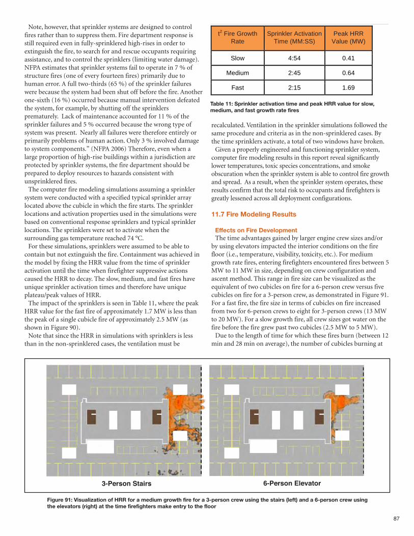
Note, however, that sprinkler systems are designed to controlfires rather than to suppress them. Fire department response isstill required even in fully-sprinklered high-rises in order toextinguish the fire, to search for and rescue occupants requiringassistance, and to control the sprinklers (limiting water damage).NFPA estimates that sprinkler systems fail to operate in 7 % ofstructure fires (one of every fourteen fires) primarily due tohuman error. A full two-thirds (65 %) of the sprinkler failureswere because the system had been shut off before the fire. Anotherone-sixth (16 %) occurred because manual intervention defeatedthe system, for example, by shutting off the sprinklersprematurely. Lack of maintenance accounted for 11 % of thesprinkler failures and 5 % occurred because the wrong type ofsystem was present. Nearly all failures were therefore entirely orprimarily problems of human action. Only 3 % involved damageto system components.” (NFPA 2006) Therefore, even when alarge proportion of high-rise buildings within a jurisdiction areprotected by sprinkler systems, the fire department should beprepared to deploy resources to hazards consistent withunsprinklered fires.The computer fire modeling simulations assuming a sprinkler
system were conducted with a specified typical sprinkler arraylocated above the cubicle in which the fire starts. The sprinklerlocations and activation properties used in the simulations werebased on conventional response sprinklers and typical sprinklerlocations. The sprinklers were set to activate when thesurrounding gas temperature reached 74 °C. For these simulations, sprinklers were assumed to be able to
contain but not extinguish the fire. Containment was achieved inthe model by fixing the HRR value from the time of sprinkleractivation until the time when firefighter suppressive actionscaused the HRR to decay. The slow, medium, and fast fires haveunique sprinkler activation times and therefore have uniqueplateau/peak values of HRR. The impact of the sprinklers is seen in Table 11, where the peak
HRR value for the fast fire of approximately 1.7 MW is less thanthe peak of a single cubicle fire of approximately 2.5 MW (asshown in Figure 90). Note that since the HRR in simulations with sprinklers is less
than in the non-sprinklered cases, the ventilation must be
recalculated. Ventilation in the sprinkler simulations followed thesame procedure and criteria as in the non-sprinklered cases. Bythe time sprinklers activate, a total of two windows have broken.Given a properly engineered and functioning sprinkler system,
computer fire modeling results in this report reveal significantlylower temperatures, toxic species concentrations, and smokeobscuration when the sprinkler system is able to control fire growthand spread. As a result, when the sprinkler system operates, theseresults confirm that the total risk to occupants and firefighters isgreatly lessened across all deployment configurations.
11.7 Fire Modeling Results
Effects on Fire DevelopmentThe time advantages gained by larger engine crew sizes and/or
by using elevators impacted the interior conditions on the firefloor (i.e., temperature, visibility, toxicity, etc.). For mediumgrowth rate fires, entering firefighters encountered fires between 5MW to 11 MW in size, depending on crew configuration andascent method. This range in fire size can be visualized as theequivalent of two cubicles on fire for a 6-person crew versus fivecubicles on fire for a 3-person crew, as demonstrated in Figure 91.For a fast fire, the fire size in terms of cubicles on fire increasedfrom two for 6-person crews to eight for 3-person crews (13 MWto 20 MW). For a slow growth fire, all crew sizes got water on thefire before the fire grew past two cubicles (2.5 MW to 5 MW). Due to the length of time for which these fires burn (between 12
min and 28 min on average), the number of cubicles burning at
87
Figure 91: Visualization of HRR for a medium growth fire for a 3-person crew using the stairs (left) and a 6-person crew usingthe elevators (right) at the time firefighters make entry to the floor
Table 11: Sprinkler activation time and peak HRR value for slow,medium, and fast growth rate fires
Stairserson3-P Stairs 6-P atorvEleerson6-P
t2 Fire Growth Rate
Sprinkler Activation Time (MM:SS)
Peak HRR Value (MW)
Slow 4:54 0.41
Medium 2:45 0.64
Fast 2:15 1.69
3-Person Stairs 6-Person Elevator
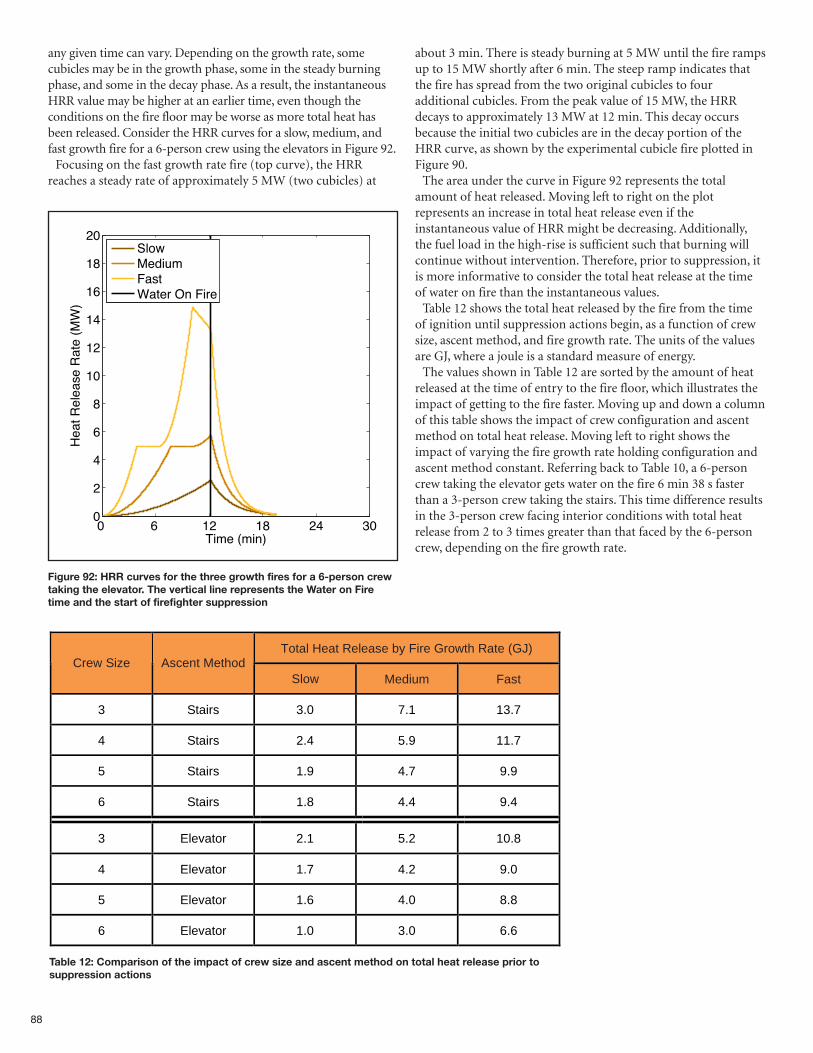
88
any given time can vary. Depending on the growth rate, somecubicles may be in the growth phase, some in the steady burningphase, and some in the decay phase. As a result, the instantaneousHRR value may be higher at an earlier time, even though theconditions on the fire floor may be worse as more total heat hasbeen released. Consider the HRR curves for a slow, medium, andfast growth fire for a 6-person crew using the elevators in Figure 92.Focusing on the fast growth rate fire (top curve), the HRR
reaches a steady rate of approximately 5 MW (two cubicles) at
about 3 min. There is steady burning at 5 MW until the fire rampsup to 15 MW shortly after 6 min. The steep ramp indicates thatthe fire has spread from the two original cubicles to fouradditional cubicles. From the peak value of 15 MW, the HRRdecays to approximately 13 MW at 12 min. This decay occursbecause the initial two cubicles are in the decay portion of theHRR curve, as shown by the experimental cubicle fire plotted inFigure 90.The area under the curve in Figure 92 represents the total
amount of heat released. Moving left to right on the plotrepresents an increase in total heat release even if theinstantaneous value of HRR might be decreasing. Additionally,the fuel load in the high-rise is sufficient such that burning willcontinue without intervention. Therefore, prior to suppression, itis more informative to consider the total heat release at the timeof water on fire than the instantaneous values. Table 12 shows the total heat released by the fire from the time
of ignition until suppression actions begin, as a function of crewsize, ascent method, and fire growth rate. The units of the valuesare GJ, where a joule is a standard measure of energy. The values shown in Table 12 are sorted by the amount of heat
released at the time of entry to the fire floor, which illustrates theimpact of getting to the fire faster. Moving up and down a columnof this table shows the impact of crew configuration and ascentmethod on total heat release. Moving left to right shows theimpact of varying the fire growth rate holding configuration andascent method constant. Referring back to Table 10, a 6-personcrew taking the elevator gets water on the fire 6 min 38 s fasterthan a 3-person crew taking the stairs. This time difference resultsin the 3-person crew facing interior conditions with total heatrelease from 2 to 3 times greater than that faced by the 6-personcrew, depending on the fire growth rate.
0 6 12 18 24 300
2
4
6
8
10
12
14
16
18
20
Time (min)
Heat R
ele
ase R
ate
(M
W)
SlowMediumFastWater On Fire
Figure 92: HRR curves for the three growth fires for a 6-person crewtaking the elevator. The vertical line represents the Water on Firetime and the start of firefighter suppression
Table 12: Comparison of the impact of crew size and ascent method on total heat release prior tosuppression actions
Total Heat Release by Fire Growth Rate (GJ) Crew Size Ascent Method
Slow Medium Fast
3 Stairs 3.0 7.1 13.7
4 Stairs 2.4 5.9 11.7
5 Stairs 1.9 4.7 9.9
6 Stairs 1.8 4.4 9.4
3 Elevator 2.1 5.2 10.8
4 Elevator 1.7 4.2 9.0
5 Elevator 1.6 4.0 8.8
6 Elevator 1.0 3.0 6.6
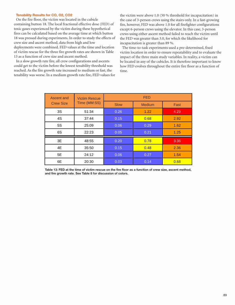
89
Table 13: FED at the time of victim rescue on the fire floor as a function of crew size, ascent method,and fire growth rate. See Table 8 for discussion of colors.
Tenability Results for CO, O2, CO2On the fire floor, the victim was located in the cubicle
containing button 18. The local fractional effective dose (FED) oftoxic gases experienced by the victim during these hypotheticalfires can be calculated based on the average time at which button18 was pressed during experiments. In order to study the effects ofcrew size and ascent method, data from high and lowdeployments were combined. FED values at the time and locationof victim rescue for the three fire growth rates are shown in Table13 as a function of crew size and ascent method.In a slow growth rate fire, all crew configurations and ascents
could get to the victim before the lowest tenability threshold wasreached. As the fire growth rate increased to medium or fast, thetenability was worse. In a medium growth rate fire, FED values for
the victim were above 1.0 (50 % threshold for incapacitation) inthe case of 3-person crews using the stairs only. In a fast-growingfire, however, FED was above 1.0 for all firefighter configurationsexcept 6-person crews using the elevator. In this case, 3-personcrews using either ascent method failed to reach the victim untilthe FED was greater than 3.0, for which the likelihood forincapacitation is greater than 89 %.The time-to-task experiments used a pre-determined, fixed
victim location in order to ensure repeatability and to evaluate theimpact of the three main study variables. In reality, a victim canbe located in any of the cubicles. It is therefore important to knowhow FED evolves throughout the entire fire floor as a function oftime.
FED Ascent and Crew Size
Victim Rescue Time (MM:SS) Slow Medium Fast
3S 51:34 0.26 1.22 4.29
4S 37:44 0.15 0.68 2.92
5S 25:09 0.06 0.29 1.62
6S 22:23 0.05 0.21 1.25
3E 48:55 0.20 0.78 3.36
4E 35:50 0.15 0.48 2.36
5E 24:12 0.06 0.27 1.54
6E 20:30 0.03 0.14 0.68
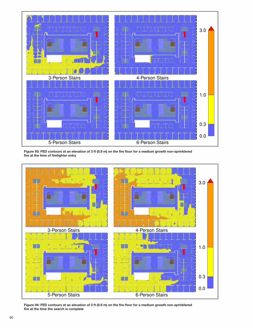
90
0.0
0.3
1.0
3.0
3-Person Stairs
5-Person Stairs
4-Person Stairs
6-Person Stairs
Figure 94: FED contours at an elevation of 3 ft (0.9 m) on the fire floor for a medium growth non-sprinkleredfire at the time the search is complete
0.0
0.3
1.0
3.0
3-Person Stairs
5-Person Stairs
4-Person Stairs
6-Person Stairs
Figure 93: FED contours at an elevation of 3 ft (0.9 m) on the fire floor for a medium growth non-sprinkleredfire at the time of firefighter entry
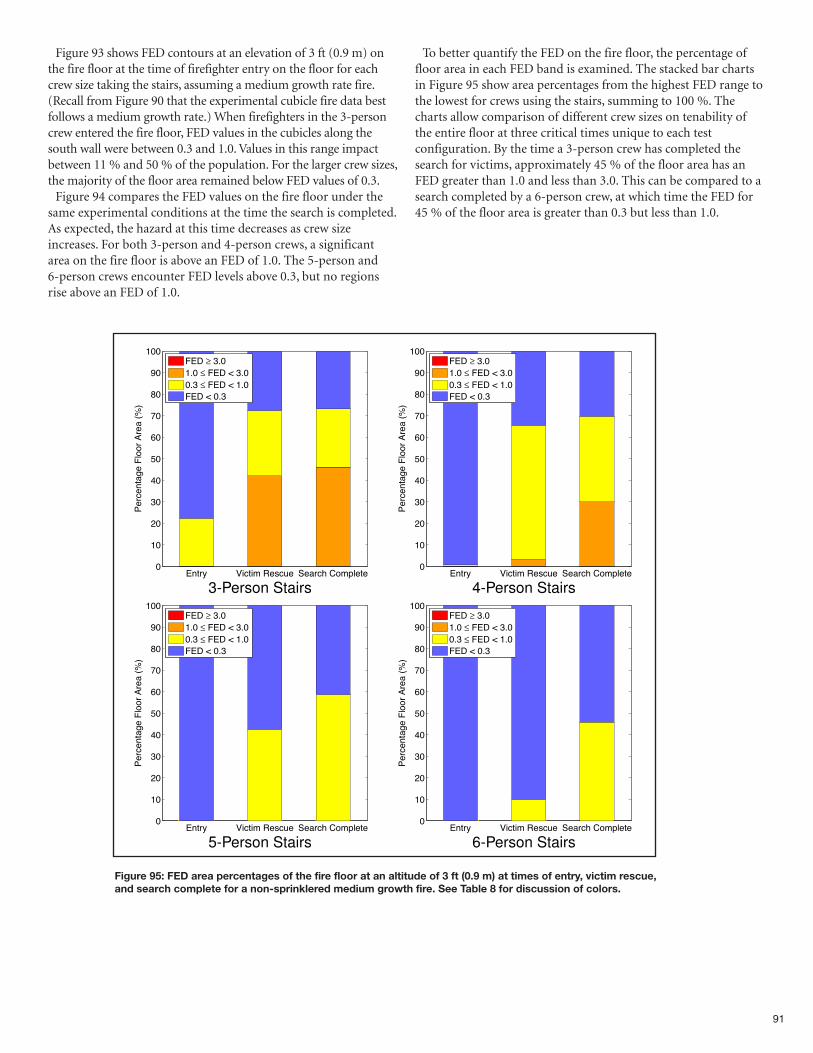
91
Figure 93 shows FED contours at an elevation of 3 ft (0.9 m) onthe fire floor at the time of firefighter entry on the floor for eachcrew size taking the stairs, assuming a medium growth rate fire.(Recall from Figure 90 that the experimental cubicle fire data bestfollows a medium growth rate.) When firefighters in the 3-personcrew entered the fire floor, FED values in the cubicles along thesouth wall were between 0.3 and 1.0. Values in this range impactbetween 11 % and 50 % of the population. For the larger crew sizes,the majority of the floor area remained below FED values of 0.3.Figure 94 compares the FED values on the fire floor under the
same experimental conditions at the time the search is completed.As expected, the hazard at this time decreases as crew sizeincreases. For both 3-person and 4-person crews, a significantarea on the fire floor is above an FED of 1.0. The 5-person and6-person crews encounter FED levels above 0.3, but no regionsrise above an FED of 1.0.
To better quantify the FED on the fire floor, the percentage offloor area in each FED band is examined. The stacked bar chartsin Figure 95 show area percentages from the highest FED range tothe lowest for crews using the stairs, summing to 100 %. Thecharts allow comparison of different crew sizes on tenability ofthe entire floor at three critical times unique to each testconfiguration. By the time a 3-person crew has completed thesearch for victims, approximately 45 % of the floor area has anFED greater than 1.0 and less than 3.0. This can be compared to asearch completed by a 6-person crew, at which time the FED for45 % of the floor area is greater than 0.3 but less than 1.0.
Entry Victim Rescue Search Complete0
10
20
30
40
50
60
70
80
90
100
Perc
enta
ge F
loor
Are
a (
%)
FED ≥ 3.0
1.0 ≤ FED < 3.0
0.3 ≤ FED < 1.0
FED < 0.3
3-Person Stairs
Entry Victim Rescue Search Complete0
10
20
30
40
50
60
70
80
90
100
Perc
enta
ge F
loor
Are
a (
%)
FED ≥ 3.0
1.0 ≤ FED < 3.0
0.3 ≤ FED < 1.0
FED < 0.3
5-Person Stairs
Entry Victim Rescue Search Complete0
10
20
30
40
50
60
70
80
90
100
Perc
enta
ge F
loor
Are
a (
%)
FED ≥ 3.0
1.0 ≤ FED < 3.0
0.3 ≤ FED < 1.0
FED < 0.3
4-Person Stairs
Entry Victim Rescue Search Complete0
10
20
30
40
50
60
70
80
90
100
Perc
enta
ge F
loor
Are
a (
%)
FED ≥ 3.0
1.0 ≤ FED < 3.0
0.3 ≤ FED < 1.0
FED < 0.3
6-Person Stairs
Figure 95: FED area percentages of the fire floor at an altitude of 3 ft (0.9 m) at times of entry, victim rescue,and search complete for a non-sprinklered medium growth fire. See Table 8 for discussion of colors.
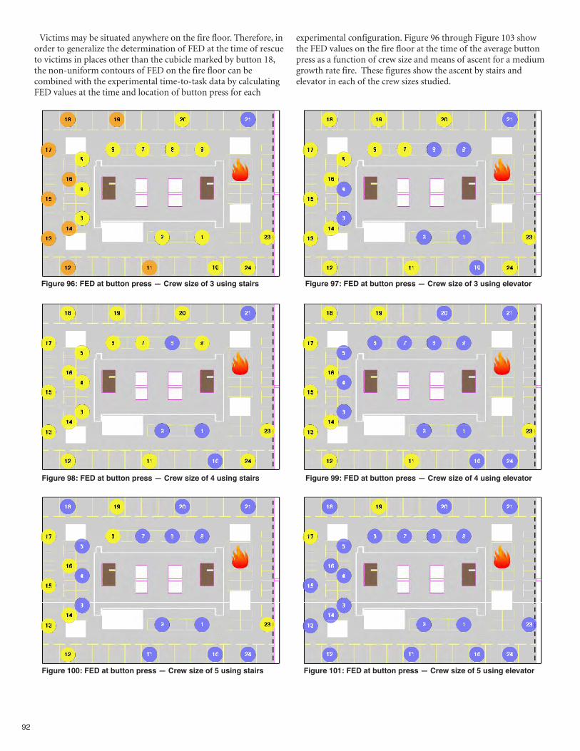
92
Victims may be situated anywhere on the fire floor. Therefore, inorder to generalize the determination of FED at the time of rescueto victims in places other than the cubicle marked by button 18,the non-uniform contours of FED on the fire floor can becombined with the experimental time-to-task data by calculatingFED values at the time and location of button press for each
experimental configuration. Figure 96 through Figure 103 showthe FED values on the fire floor at the time of the average buttonpress as a function of crew size and means of ascent for a mediumgrowth rate fire. These figures show the ascent by stairs andelevator in each of the crew sizes studied.
Figure 96: FED at button press — Crew size of 3 using stairs Figure 97: FED at button press — Crew size of 3 using elevator
Figure 98: FED at button press — Crew size of 4 using stairs Figure 99: FED at button press — Crew size of 4 using elevator
Figure 100: FED at button press — Crew size of 5 using stairs Figure 101: FED at button press — Crew size of 5 using elevator
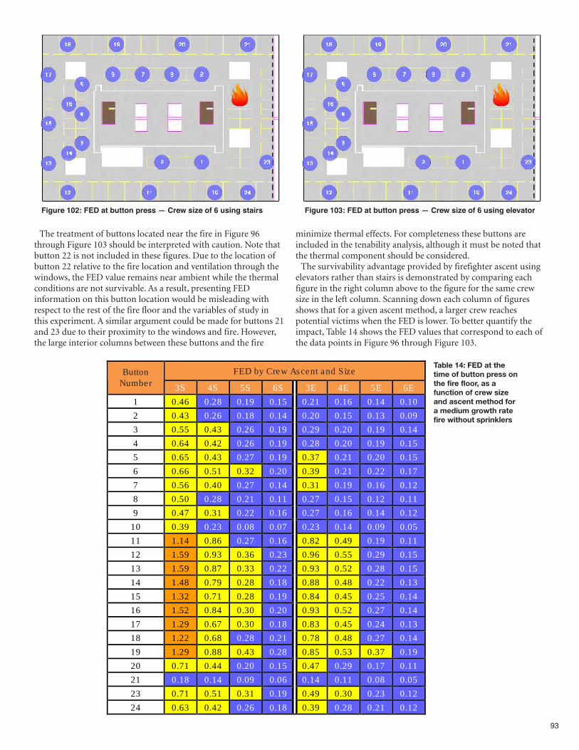
93
Figure 102: FED at button press — Crew size of 6 using stairs Figure 103: FED at button press — Crew size of 6 using elevator
The treatment of buttons located near the fire in Figure 96through Figure 103 should be interpreted with caution. Note thatbutton 22 is not included in these figures. Due to the location ofbutton 22 relative to the fire location and ventilation through thewindows, the FED value remains near ambient while the thermalconditions are not survivable. As a result, presenting FEDinformation on this button location would be misleading withrespect to the rest of the fire floor and the variables of study inthis experiment. A similar argument could be made for buttons 21and 23 due to their proximity to the windows and fire. However,the large interior columns between these buttons and the fire
minimize thermal effects. For completeness these buttons areincluded in the tenability analysis, although it must be noted thatthe thermal component should be considered.The survivability advantage provided by firefighter ascent using
elevators rather than stairs is demonstrated by comparing eachfigure in the right column above to the figure for the same crewsize in the left column. Scanning down each column of figuresshows that for a given ascent method, a larger crew reachespotential victims when the FED is lower. To better quantify theimpact, Table 14 shows the FED values that correspond to each ofthe data points in Figure 96 through Figure 103.
FED by Crew Ascent and Size Button Number 3S 4S 5S 6S 3E 4E 5E 6E
1 0.46 0.28 0.19 0.15 0.21 0.16 0.14 0.10 2 0.43 0.26 0.18 0.14 0.20 0.15 0.13 0.09 3 0.55 0.43 0.26 0.19 0.29 0.20 0.19 0.14 4 0.64 0.42 0.26 0.19 0.28 0.20 0.19 0.15 5 0.65 0.43 0.27 0.19 0.37 0.21 0.20 0.15 6 0.66 0.51 0.32 0.20 0.39 0.21 0.22 0.17 7 0.56 0.40 0.27 0.14 0.31 0.19 0.16 0.12 8 0.50 0.28 0.21 0.11 0.27 0.15 0.12 0.11 9 0.47 0.31 0.22 0.16 0.27 0.16 0.14 0.12
10 0.39 0.23 0.08 0.07 0.23 0.14 0.09 0.05 11 1.14 0.86 0.27 0.16 0.82 0.49 0.19 0.11 12 1.59 0.93 0.36 0.23 0.96 0.55 0.29 0.15 13 1.59 0.87 0.33 0.22 0.93 0.52 0.28 0.15 14 1.48 0.79 0.28 0.18 0.88 0.48 0.22 0.13 15 1.32 0.71 0.28 0.19 0.84 0.45 0.25 0.14 16 1.52 0.84 0.30 0.20 0.93 0.52 0.27 0.14 17 1.29 0.67 0.30 0.18 0.83 0.45 0.24 0.13 18 1.22 0.68 0.28 0.21 0.78 0.48 0.27 0.14 19 1.29 0.88 0.43 0.28 0.85 0.53 0.37 0.19 20 0.71 0.44 0.20 0.15 0.47 0.29 0.17 0.11 21 0.18 0.14 0.09 0.06 0.14 0.11 0.08 0.05 23 0.71 0.51 0.31 0.19 0.49 0.30 0.23 0.12 24 0.63 0.42 0.26 0.18 0.39 0.28 0.21 0.12
Table 14: FED at thetime of button press onthe fire floor, as afunction of crew sizeand ascent method fora medium growth ratefire without sprinklers
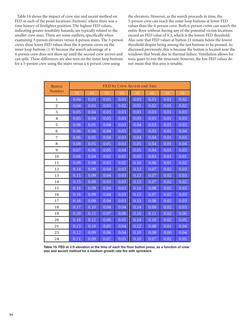
94
Table 14 shows the impact of crew size and ascent method onFED at each of the point locations (buttons) where there was atime history of firefighter position. The highest FED values,indicating greater tenability hazards, are typically related to thesmaller crew sizes. There are some outliers, specifically whenexamining 3-person elevators versus 4-person stairs. The 3-personcrews show lower FED values than the 4-person crews on theinner loop buttons (1-9) because the search advantage of a4-person crew does not show up until the second crew arrives andcan split. These differences are also seen on the inner loop buttonsfor a 5-person crew using the stairs versus a 4-person crew using
the elevators. However, as the search proceeds in time, the5-person crew can reach the outer loop buttons at lower FEDvalues than the 4-person crew. Both 6-person crews can search theentire floor without having any of the potential victim locationsexceed an FED value of 0.3, which is the lowest FED threshold.Also note that FED values at button 21 remain below the lowestthreshold despite being among the last buttons to be pressed. Asdiscussed previously, this is because the button is located near thewindows that break due to thermal failure. Ventilation allows fortoxic gases to exit the structure; however, the low FED values donot mean that this area is tenable.
Table 15: FED at 3 ft elevation at the time of each fire floor button press, as a function of crewsize and ascent method for a medium growth rate fire with sprinklers
FED by Crew Ascent and Size Button Number 3S 4S 5S 6S 3E 4E 5E 6E
1 0.04 0.03 0.03 0.03 0.03 0.03 0.01 0.02 2 0.04 0.03 0.03 0.02 0.03 0.02 0.01 0.02 3 0.05 0.04 0.03 0.03 0.03 0.03 0.01 0.03 4 0.05 0.04 0.03 0.03 0.03 0.03 0.01 0.03 5 0.06 0.05 0.04 0.03 0.04 0.03 0.01 0.03 6 0.06 0.06 0.04 0.03 0.05 0.03 0.01 0.04 7 0.06 0.05 0.04 0.03 0.04 0.04 0.01 0.03 8 0.08 0.05 0.05 0.03 0.05 0.04 0.01 0.04 9 0.07 0.06 0.05 0.04 0.05 0.04 0.01 0.03
10 0.06 0.04 0.02 0.01 0.05 0.03 0.01 0.01 11 0.09 0.08 0.03 0.02 0.10 0.06 0.01 0.02 12 0.14 0.09 0.04 0.03 0.13 0.07 0.02 0.03 13 0.15 0.09 0.04 0.03 0.13 0.07 0.02 0.03 14 0.15 0.09 0.03 0.03 0.13 0.07 0.02 0.02 15 0.16 0.09 0.04 0.03 0.14 0.08 0.02 0.03 16 0.16 0.09 0.04 0.03 0.13 0.07 0.02 0.03 17 0.16 0.09 0.04 0.03 0.13 0.08 0.02 0.03 18 0.17 0.10 0.04 0.04 0.14 0.09 0.02 0.03 19 0.20 0.15 0.07 0.06 0.16 0.11 0.02 0.06 20 0.16 0.12 0.06 0.05 0.14 0.10 0.02 0.05 21 0.13 0.10 0.05 0.04 0.12 0.08 0.01 0.04 23 0.12 0.09 0.06 0.04 0.10 0.08 0.00 0.04 24 0.11 0.09 0.07 0.05 0.10 0.07 0.02 0.05
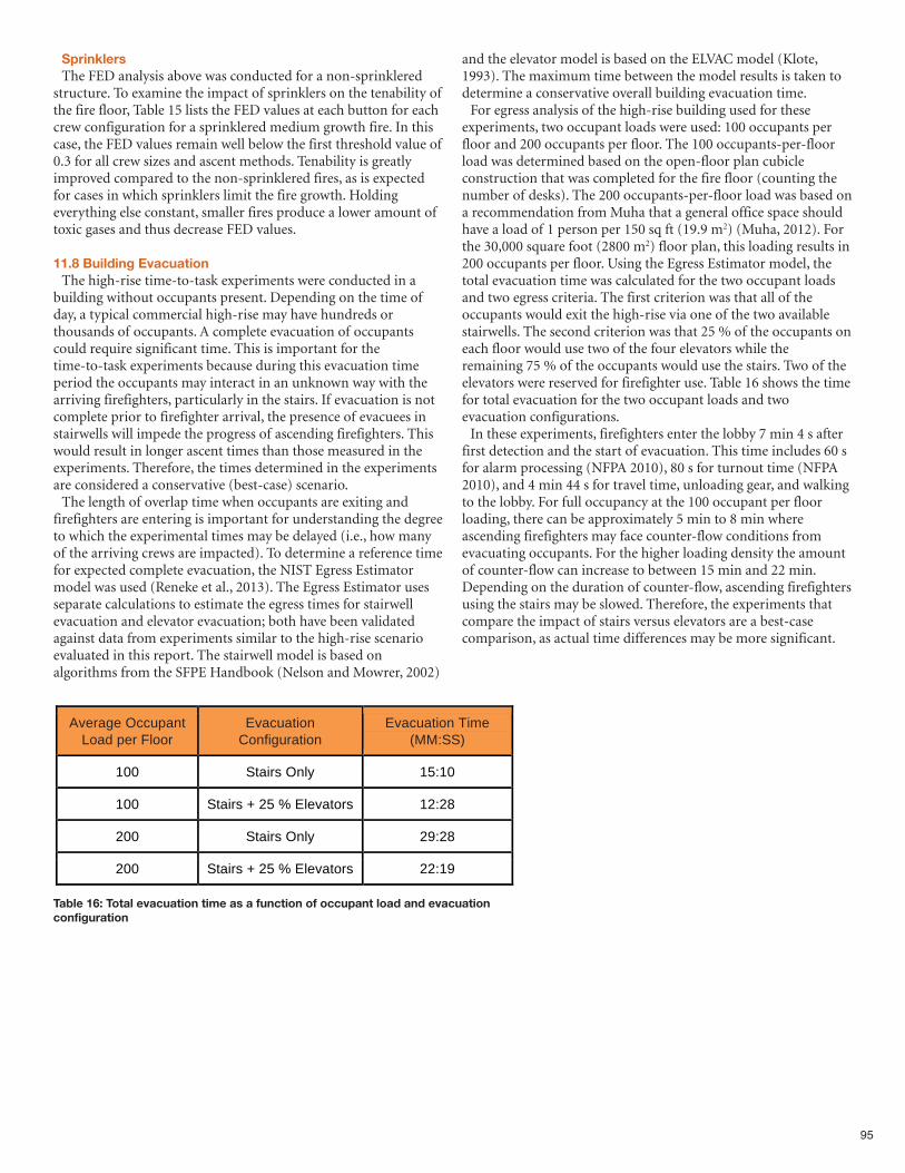
95
SprinklersThe FED analysis above was conducted for a non-sprinklered
structure. To examine the impact of sprinklers on the tenability ofthe fire floor, Table 15 lists the FED values at each button for eachcrew configuration for a sprinklered medium growth fire. In thiscase, the FED values remain well below the first threshold value of0.3 for all crew sizes and ascent methods. Tenability is greatlyimproved compared to the non-sprinklered fires, as is expectedfor cases in which sprinklers limit the fire growth. Holdingeverything else constant, smaller fires produce a lower amount oftoxic gases and thus decrease FED values.
11.8 Building EvacuationThe high-rise time-to-task experiments were conducted in a
building without occupants present. Depending on the time ofday, a typical commercial high-rise may have hundreds orthousands of occupants. A complete evacuation of occupantscould require significant time. This is important for thetime-to-task experiments because during this evacuation timeperiod the occupants may interact in an unknown way with thearriving firefighters, particularly in the stairs. If evacuation is notcomplete prior to firefighter arrival, the presence of evacuees instairwells will impede the progress of ascending firefighters. Thiswould result in longer ascent times than those measured in theexperiments. Therefore, the times determined in the experimentsare considered a conservative (best-case) scenario.The length of overlap time when occupants are exiting and
firefighters are entering is important for understanding the degreeto which the experimental times may be delayed (i.e., how manyof the arriving crews are impacted). To determine a reference timefor expected complete evacuation, the NIST Egress Estimatormodel was used (Reneke et al., 2013). The Egress Estimator usesseparate calculations to estimate the egress times for stairwellevacuation and elevator evacuation; both have been validatedagainst data from experiments similar to the high-rise scenarioevaluated in this report. The stairwell model is based onalgorithms from the SFPE Handbook (Nelson and Mowrer, 2002)
and the elevator model is based on the ELVAC model (Klote,1993). The maximum time between the model results is taken todetermine a conservative overall building evacuation time. For egress analysis of the high-rise building used for these
experiments, two occupant loads were used: 100 occupants perfloor and 200 occupants per floor. The 100 occupants-per-floorload was determined based on the open-floor plan cubicleconstruction that was completed for the fire floor (counting thenumber of desks). The 200 occupants-per-floor load was based ona recommendation from Muha that a general office space shouldhave a load of 1 person per 150 sq ft (19.9 m2) (Muha, 2012). Forthe 30,000 square foot (2800 m2) floor plan, this loading results in200 occupants per floor. Using the Egress Estimator model, thetotal evacuation time was calculated for the two occupant loadsand two egress criteria. The first criterion was that all of theoccupants would exit the high-rise via one of the two availablestairwells. The second criterion was that 25 % of the occupants oneach floor would use two of the four elevators while theremaining 75 % of the occupants would use the stairs. Two of theelevators were reserved for firefighter use. Table 16 shows the timefor total evacuation for the two occupant loads and twoevacuation configurations.In these experiments, firefighters enter the lobby 7 min 4 s after
first detection and the start of evacuation. This time includes 60 sfor alarm processing (NFPA 2010), 80 s for turnout time (NFPA2010), and 4 min 44 s for travel time, unloading gear, and walkingto the lobby. For full occupancy at the 100 occupant per floorloading, there can be approximately 5 min to 8 min whereascending firefighters may face counter-flow conditions fromevacuating occupants. For the higher loading density the amountof counter-flow can increase to between 15 min and 22 min.Depending on the duration of counter-flow, ascending firefightersusing the stairs may be slowed. Therefore, the experiments thatcompare the impact of stairs versus elevators are a best-casecomparison, as actual time differences may be more significant.
Table 16: Total evacuation time as a function of occupant load and evacuationconfiguration
Average Occupant Load per Floor
Evacuation Configuration
Evacuation Time (MM:SS)
100 Stairs Only 15:10
100 Stairs + 25 % Elevators 12:28
200 Stairs Only 29:28
200 Stairs + 25 % Elevators 22:19
96
12. Physiological Effects on Firefighters
Reports on firefighter fatalities consistently documentoverexertion/overstrain as the leading cause of line-of-dutyfatalities (NIOSH, 2013). There is strong epidemiological
evidence that heavy physical exertion can trigger sudden cardiacevents (Mittleman et al, 1993; Albert et al, 2000). Therefore,information about the effect of crew size and vertical responsemode on physiological strain is very valuable.During the planning of the high-rise fireground experiments, as
with the Residential Fireground Field Experiments, investigators
at Skidmore College recognized an opportunity to conduct anindependent study on the relationship between firefighterdeployment configurations, vertical response mode and firefighterheart rates.Investigators were able to leverage the resources of the high-rise
field experiments to conduct a separate analysis of the cardiacstrain on firefighters in the high hazard environment.The results of this study are compiled in a separate report.
97
13. Study Limitations
The scope of this study is limited to understanding therelative influence of deployment variables to a workinghigh-rise structure fire. The applicability of the conclusions
from this report to low hazard residential, outside fires, naturaldisaster response, HAZMAT or other technical responses has notbeen assessed and should not be extrapolated from this report. Fire Out times were determined by the time at which engine
crews moved the nozzle of the second line on the fire floor to theorigin of the fire. As the experiments could not utilize live fires,the effect of fire size on suppression time was not captured. Thefire modeling results indicated that smaller crew sizes would face alarger fire; for example a 3-person crew would face a fire of 11MW, while the 6-person crew would face a fire of 5 MW.Therefore, the time to fully suppress the fire (and the total toxicdose received by trapped occupants) is likely underestimated byan unknown amount in these experiments. The total number of apparatus responding for each high-rise
experiment was held constant at 9 engines, 9 trucks, 3ambulances, and 3 battalion chiefs for all crew size configurations.The apparatus were dispatched in the high/low alarm groupingsas described in the report in Table 5. The effect of deploying moreor fewer than this total number of apparatus was not evaluated.Fireground operations in these experiments were conducted
under best-case scenario conditions without many of thecomplications that can occur in real fireground environments.These complications can include, but are not limited to inclementweather, nighttime operation, building security infrastructure thatmay impede building access, elevator operation failure,communications failures (both technological and interpersonal),or power / fire technology failures.Since the field experiments were conducted in a vacant building,
the counter flow effects of evacuating occupants on firefighterascent were not measured. Therefore, the recorded stairwellascent times are likely underestimated.Fire crews participating in the experiments were provided by 13
different fire and rescue departments, each with their ownprotocols, fireground tactics, training regimes, and equipment.Standardized protocols were developed and implemented for thehigh-rise experiments. Though similar, the protocols differedfrom those used by the participating departments. Dailyorientation and crew cue cards were used to minimize the effectsof protocol differences. Since there is more than one effective wayto perform many of the required tasks on the high-risefireground, attempts to generalize the results from theseexperiments to individual departments must take into accounttactics and equipment that vary from those used in theexperiments.The fire crews that participated in the experiments typically
operate using 3-person and 4-person staffing. Therefore, theeffectiveness of the 5-person and 6-person operations may havebeen influenced by a lack of experience in operating at thosestaffing levels. Standardizing and assigning tasks likely minimizedthe impact of this factor, although the actual influence on theresults is unknown. Although efforts were made to minimize the effect of learning
across experiments, some participants took part in more than oneexperiment, while others did not.
Though actual fire could not be used during the experiments, alloperations were handled according to NFPA 1403 and everyattempt was made to ensure the highest possible degree ofrealism. Realistic digital fire displays and simulated smoke wereused on the fire floor and the floor above the fire. The quality ofsimulated smoke was exceptional in replicating visual obscurationfor both fire attack and search and rescue operations. Digital firedisplays were also exceptional in visual simulation of live fire,although thermal effects were lacking. Firefighters were informedof all simulations and were asked to work and move as if theywere in a real fire environment. Though the instruction likelyminimized the effect, there was no ability to measure the actualimpact the use of simulation had on the results. Though there was smoke breech to the floor above the fire, fire
spread beyond the floor of origin was not considered in the testsor the fire models. Therefore, the size of the fire and the risk to thefirefighter may be somewhat underestimated for fast growing firesor slower response configurations.The scale and magnitude of the high-rise building was fixed. Fire
department response to ultra-high-rise buildings (e.g., buildingsgreater than 420 ft (128 m) in height) may require customizedplanning and resource allocation. Radio communications throughout the experiments were
facilitated through two dedicated frequencies and interoperableportable radios assigned to all crews. Typically, a high-riseresponse, as for other structural fires, uses at least two radiofrequencies on the fireground—one for command and one fortactical communication. Since one of the channels provided forthe experiments was used by researchers to communicate duringthe experiments, only one channel remained for use in bothcommand and tactical communication. Even though both fireofficers and incident commanders were asked to minimize radiocommunications to include protocol and critical needs only, thesimultaneous operations on multiple floors often caused delay inofficers’ communication with division supervisors and command.The influence of limited radio communication was not evaluated.The National Incident Management System (NIMS) was used
throughout the experiments. It was assumed that chief officersassigned to the experiments know and frequently use the systemin actual operations. Therefore, there was no training ororientation to the NIMS during the experiments. In an effort tocontrol variance in technique from chief to chief, each IC wasgiven a specific protocol to follow for crew assignments and wasadvised to hand off the operations sections in the two mosthazardous areas (on the fire floor and floor above the fire) early inthe incident, so that other priorities could be addressed. Due to the magnitude of the experiments, fireground operations
record keeping was essential. To limit variance in record keeping,each IC had an assigned aide who recorded situation reports,resource status and company assignments. Units operating on thefire floor and the floor above the fire were managed by operationssection chiefs, who documented which companies were active ontheir assigned floor. Effective operation of the Chiefs assigned tothese positions was dependent on their understanding andexperience with the NIMS and was not measured.
98
14. Conclusions
Overall, the results of this study show that the number offire service crew members in each company responding toa fire in a 30,000 square foot, thirteen-story structure had
a dramatic effect on the crew’s ability to protect lives andproperty. Three significant conclusions are discussed below. First, when responding to a medium growth rate fire on the
10th floor, 3-person crews ascending to the fire floor confrontedan environment where the fire had released 60% more heatenergy than the fire encountered by the 6-person crews.Unfortunately, larger fires expose firefighters to greater risks andare more challenging to suppress.Second, larger fires produce more risk exposure for building
occupants. In general, occupants being rescued by smaller crew sizesand by crews that used the stairs rather than the elevators wereexposed to significantly greater dose of toxins from the fire. Whilethe exact risk exposure for an occupant will depend on the firegrowth rate, their proximity to the fire, and the floor on which thefire is located, it is clear that on-scene deployment decisions can havea dramatic impact in determining the fate of building occupants. Third, the study confirmed that a properly engineered and
operational fire sprinkler system drastically reduces the riskexposure for both the building occupants and the firefighters.While this has been well understood for many years and most newhigh-rise buildings are constructed with fire sprinkler protection,NFPA estimates that 41 percent of U.S. high-rise office buildings,45 percent of high-rise hotels, and 54 percent of high-riseapartment buildings are not equipped with sprinklers. Moreover,sprinkler systems fail in about one in 14 fires. Thus, firedepartments should be prepared to manage the risks associatedwith unsprinklered high-rise building fires.Forty-eight laboratory and full-scale simulated fire experiments
were conducted to determine the impact of crew size, alarm sizeand vertical response mode times on firefighter task completiontimes responding to a high hazard high-rise commercial structurefire. This report quantifies the effects of changes to staffing, alarmsize and/or vertical response mode for high hazard high-risecommercial firefighting operations. While resource deployment isaddressed in the context of a high-rise structure type andhigh-risk level, it is recognized that public policy decisionsregarding the cost-benefit of specific deployment decisions are afunction of many factors including geography, available resources,community expectations, and local hazards and risks. Though thisreport contributes significant knowledge to community and fireservice leaders in regard to effective resource deployment for firesuppression, other factors contributing to policy decisions are notaddressed.The objective of the experiments was to determine the relative
effects of crew size, alarm size, and vertical response mode on thetask completion times of the firefighting crews relative tointervention times and the likelihood of occupant rescue. Theexperimental results for each of these factors are discussed below.Of the 38 high-rise fireground tasks measured during the
experiments, the following were determined to have especiallysignificant impact on the firefighting operations. Differentialoutcomes based on variation of crew size, alarm size, and/orvertical response mode times are discussed below.
Overall Scene Time Overall scene time is the time that firefighters are actually engaged
in tasks on the scene of a structure fire and are unavailable fordispatch to other incidents. The times noted do not include sometasks such as salvage, overhaul and secondary search of the structure.During the experiments, this time included typical operational taskswith the exception of overhaul and salvage. The time to completionof all tasks decreased as crew size increased. Three-person crews tookan average of about an hour to complete the fire response, whereascrews of 6 firefighters required a mean time of just under 37 min forcompletion. The performance of crews sized 4 and 5 werein-between, with a crew size of 5 taking about 2 min longer than acrew size of 6, and a crew size of 4 taking about 9 min longer than acrew size of 5 but 12 min shorter than a crew size of 3. Therefore, AllTasks Complete times were substantially reduced for crew sizes of 5compared to 4, and 4 compared to 3.
Advance Attack LineAs firefighters engage on a fireground, putting water on the fire
is one of the most important tasks. Extinguishing the fire isnecessary to reduce the continuously escalating risks from fireheat release and the toxic products of combustion. Before watercan be put on a fire however, a hose line must be stretched fromthe standpipe in the stairwell to the compartment where the fire isburning. Comparing each crew size to a 3-person crew, the timedifferences increased with increasing crew size. From theinitiation of on-scene firefighting activities, a 3-person crew took1 min 43 s (8.5 %) longer than a 4-person crew to stretch thehose line. A 3-person crew took 2 min 47 s (13.9 %) longer than a5-person crew to complete the same task. Finally, the mostnotable difference was between a 3-person crew and a 6-personcrew, with a 4 min 28 s (22.3 %) task completion time difference.
Advance Second LineThe size of the fire in the experiments required two 2 ½ inch
hose lines to fully suppress, therefore a second hose line had to beadvanced from the standpipe in the stairwell to the fire to assureadequate water flow to extinguish. A 4-person crew took 2 min 43 s(12.3 %) longer than a 5-person crew to complete the same task.Finally, the most notable comparison was between a 4-personcrew and a 6-person crew, with a 5 min 38 s (24.1) difference intask completion time.
Fire OutGetting the fire out is critical to reducing risk to both firefighters
entering the structure and to trapped occupants. Based on fuelavailable to burn, heat release accelerates and products ofcombustion continue to poison the environment until the fire isout. Fire Out, in the study, was defined as having both the attackline and the second hose line in place. There was a 1 min 15 s (5.0%) difference in the Fire Out time between the 4- and 5-personcrews and a 3 min 29 s (12.7 %) difference between the 5-personand 3-person crews). There was an additional 3 min 33 s (17 %)difference in the Fire Out time between the 5- and 6-person crews.The 6-person crews extinguished the fire 7 min 2 s (25.6 %) fasterthan 3-person crews.
99
Search and Rescue 10th FloorThe fire floor in the experiments measured 30,000 sq ft (2800
m2) and contained 96 cubicles. Responding firefighters mustsearch every inch of the fire floor and adjacent stairwells to assurethat occupants have not been trapped, disabled or killed due tothe toxic environment or direct fire. In the high hazard high-risecommercial building, the 4-person crews started the search andrescue 1 min 23 s (7.8 %) earlier than the 3-person crews andcompleted the search 11 min and 21 s (17.4 %) faster than the3-person crews. In the same structure, the 5-person crews startedthe search 1 min 4 s (6.7 %) earlier than the 4-person crews and 2min 27 s (14.1 %) faster than the 3-person crews. Additionally,5-person crews completed the search faster than the 4- and3-person crews by 13 min and 34 s (26.8 %) and 24 min 55 s (40.3%) respectively. Six-person crews had the fastest performance,starting the search 1 min 19 s (8.8 %) faster and completing thesearch 2 min 57 s (8.0 %) faster than 5-person crews. The greatestdifference in search times was between 6- and 3-person crews.Six-person crews started the search on the fire floor 3 min 46 s(21.7 %) faster and completed the search 27 min 51 s (45 %)faster than the 3-person crews.
Victim #1 FoundThere was a single victim located on the fire floor. The victim
was found and rescued by all crews. A 5-person crew operating inthe high-rise structure located the victim on the fire floor 25 min18 s (50.6 %) faster than 3-person crews and 12 min 7 s (32.9 %)faster than a 4-person crew. Likewise, 6-person crews located thevictim on the fire floor 28 min 33 s (57.1 %) faster than the3-person crews, 15 min 21 s (41.7 %) faster than the 4-personcrew, and 3 min 14 s (13.2 %) faster than 5-person crews.
Victim #1 RescueVictim rescue requires at least two firefighters to carry a victim away
from the hazardous environment to safety and emergency medicalcare. Removing a viable victim from the environment increases thechance of survival. Five-person crews were able to remove the victimfrom the fire environment 11 min 39 s (29.7 %) faster than the4-person crews, while 6-person crews removed the victim from theenvironment 14 min 58 s (38.1 %) faster than the 4-person crews and3 min 19 s (12.0 %) faster than the 5-person crews.
Victim #1 DescentGetting the victim out of the IDLH environment is not enough.
The victim must be removed from the building and whennecessary, transported to a hospital for examination and definitivecare.Five-person crews were able to facilitate victim descent 11min 39 s (27.5 %) faster than 4-person crews and 24 min (43.1 %)faster than 3-person crews, while 6-person crews were 3 min 19 s(11.0 %) faster than 5-person crews.
Advance Line Above the Fire (11th Floor)In a high-rise structure, it is essential to stretch a charged hose
line from the standpipe in the stairwell to the area above the fireon the floor above the fire to extinguish fire that has spreadvertically from the floor of origin. A 3-person crew took 2 min 58 s(11.5 %) longer than 5-person crews to complete the same task.While the most notable comparison was between 3-person crewsand a 6-person crew, with a 3 min 37 s (14.0 %) difference in taskcompletion time.
Search and Rescue 11th FloorThe floor above the fire was separated into a number of
conference rooms and offices that had to be searched by each crew.The area of the floor measured 30,000 sq ft (2800 m2). Respondingfirefighters must search every inch of the floor above the fire andadjacent stairwells to determine whether occupants have beentrapped, disabled or killed due to the toxic environment. The areaof the floor measured 30,000 sq ft (2800m2). During theexperiments, the 4-person crews completed the search 9 min 31 s(18.6 %) faster than the 3-person crews. Meanwhile, the 5-personcrews started a primary search/rescue 1 min 34 s (6.8 %) fasterthan the 4-person crews and completed the search 2 min 37 s (6.3%) faster than the 4-person crews. In the same structure, the6-person crews also started the search 1 min 30 s (6.6 %) fasterthan the 4-person crews but completed the search 5 min 8 s (12.3%) faster than the 4-person crews.
Victim #2 FoundThere was a single disabled victim located on the floor above the
fire. The victim was found and rescued by all crews. A 5-personcrew operating in the high-rise structure located the second victim17 min 23 s (34 %) faster than a 3-person crew and 2 min 41 s (7.4%) faster than a 4-person crew. Likewise, a 6-person crew locatedthe second victim on the floor above the fire 2 min 48 s (7.7 %)faster than the 4-person crew.
Victim #2 RescuedIn addition to the victim on the fire floor, a second victim was
located on the floor above the fire. Each crew operating on thisfloor was tasked with locating and rescuing the victim. Victimrescue requires at least two firefighters to carry a victim away fromthe hazardous environment to safety and emergency medical care.Removing a viable victim from the environment increases thechance of survival. Five-person crews were able to remove thesecond victim from the fire environment 17 min 9 s (32.1 %)faster than 3-person crews and 2 min 36 s (6.7 %) faster than the4-person crews. Similarly, the 6-person crews rescued the victim 2min 48 s (7.1 %) faster than 4-person crews.
Victim #2 DescentGetting a victim out of the IDLH environment is not enough.
All victims must be removed from the building and whennecessary, transported to a hospital for examination and definitivecare. Six-person crews were able to facilitate victim descent 3 min21 s (7.8 %) faster than 4-person crews. Additionally, victimdescent occurred nearly 6 min more quickly for crews using theelevator rather than the stairs.
Summary of Regression Analysis
Crew SizeGenerally, going from 3-person to 4-person crews significantly
reduced the time to begin advancing the attack line, to beginadvancing the second line, and to begin search and rescue. Taskbegin-time reductions were in the range of 1 min 30 s. Going from4-person to 5-person crews resulted in significant time reductions tobegin each critical task in the range of 1 min to 2 min. Increasingcrew size from 5-person to 6-person crews showed significantreductions in begin time, just over 1 min, to advance the attack andsecond lines and for search and rescue on the fire floor (10th floor).When assessing task end times and incrementing crew size by a
single firefighter (i.e., 3 to 4, 4 to 5, and 5 to 6), the largest time
100
improvements in time are seen when going from crew size 3 to 4.As firefighter crews navigate the later tasks, the time improvementsreach the 10 min to 15 min range. Very large time improvementsare seen for the 10th Floor Search and Victim #1 Rescue tasks (over11 min) when incrementing crew size from 4 to 5. Theimprovements in All Tasks Complete end times are substantial (9.5min to 12 min) when incrementing crew size from 3 to 4 or from 4to 5.
Fire Service Access ElevatorsAll Tasks Complete occurred over 4 min more quickly when the
elevators were utilized compared to stairs. Begin times for nearlyevery task above ground level and nearly all end times werereduced compared to stair ascent. Most of the reductions due toelevator usage were in the 2 min to 4 min range, with a fewobvious exceptions in that using fire service access elevators moredramatically reduced times associated with upward anddownward transport of people or equipment. Using elevators totransport air bottles and other equipment from the lobby toStaging allowed completion of Establishment of Stairwell Supportover 10 min more quickly than moving the equipment manuallyup the stairs. Additionally, the transport of both Victim #1 andVictim #2 from Staging to the outside of the building was fasterwhen using the elevators (compared to the stairs), by 2 min 41 sand 3 min 19 s, respectively. As a result, except for Establishmentof Stairwell Support and Victim Descent, there were no ascentmode differences for task duration.
Alarm Size and Ascent ModeAbout one third of the 27 distinct outcome-task comparisons
between high and low alarm size were statistically significant. Sixof the eight significant differences between high and low alarmsizes involved reductions of task begin times ranging from 1 ½min to 2 ½ min in favor of the high alarm size response. Thesetask begin times involved Primary Search of Floor 11, Victim #2Rescue, and Advance Line Above Fire.
Combining Alarm Size and Crew SizeGiven the findings from the crew size analysis that adding one or
two firefighters to a crew could generally achieve substantial tasktime decreases, a logical question is whether the meaningfulbenefits of a higher crew size could be realized by implementing ahigher alarm response at a smaller crew size (e.g., 4/highcompared to 5/low). The hypothesis might be that a high responsewith lower crew size might yield similar results in task timing tothat of a low response with higher crew size.Regression results shown in Appendix C3, comparing the effect
of a high response with lower crew size to a low response withhigher crew size showed that statistically significant differencesoccurred for low alarm response with 4 or 5 crew size comparedto high response with crew sizes of 3 and 4, respectively. Therewere significant reductions in begin times for all critical tasksfrom Advance Attack Line through Victim #1 Rescue. Sizeablereductions of about 12 min were also seen for Victim #2 Rescue.These results suggest that a low alarm response with crews of size4 or 5 outperforms a high alarm response with crew sizes smallerby 1 firefighter. When decreases occurred, they were in the range
of 1 to just under 2 min. This pattern did not hold for low alarmresponse with crew size 6 compared to high response with crewsize 5. The observed differences in times were significantly higherfor Search of Floor 11 and Advance Line Above Fire.
Combining Alarm Response and Ascent In comparing different combinations of alarm response (high,
low) and ascent mode (stairs, elevator), results contrast severalcombinations of alarm size and ascent mode.
Stairs/High vs. Stairs/Low — The alarm size had virtually noeffect for critical task timings, with the exception of Search ofthe Floor Above the Fire (Floor 11) and Victim #2 Rescue. Highalarm size realized a mean reduction in the range of 1.5 min to3.4 min for these tasks. The All Tasks Complete was alsosignificantly smaller for high alarm size by 3 min. No other tasktiming comparisons were statistically different.
Elevator/High vs. Elevator/Low — In the elevator scenarios, highalarm size led to eight significantly lower timings than did a lowalarm response. Results show a 45 s reduction in begin time forFire Out, Search of Fire Floor 10, and Victim #1 Found. Smallreductions of just over 1 min were noted in begin times for SearchFloor 11 and Victim #2 Found. Small reductions of 30 s to 2 minwere also noted for times related to Advance Line Above Fire. Noother task timing comparisons were statistically different.
Fire Modeling ResultsIn order to assess the hazard to occupants and firefighters as a
consequence of different deployment configurations, computerfire modeling was performed. Three different ‘standard’ fires weresimulated using the NIST Fire Dynamics Simulator (FDS) model.The three fires, characterized in the Handbook of the Society ofFire Protection Engineers (Hadjisophocleous and Mehaffey 2008)as slow, medium, and fast,33 grew exponentially with time andhad burning characteristics similar to the experimental results oftypical office cubicle fires (Madrzykowski et al. 2004)Computer fire modeling demonstrated the effectiveness of a
working fire sprinkler system: the FED values remained wellbelow the threshold value of 0.3 regardless of crew size and ascentmethod. Thus, the overall hazard is greatly improved compared tothe non-sprinklered fires for both firefighters and occupants.According to the National Fire Protection Association, a workingsprinkler system is 96 % effective at controlling the growth andspread of fires in structures (NFPA 2006). Due to a number ofhigh-profile fires in high-rise buildings and considering theirdemonstrated effectiveness, sprinkler systems are often requiredin new high-rise buildings and many jurisdictions have requiredexisting high-rise buildings to be retrofit with sprinkler systems.However, sprinkler systems are not in all high-rise buildings.
According to the National Fire Protection Association (NFPA2011), 41 % of high-rise office buildings are not protected bysprinkler systems (compared to 25 % of high-rise “care of sick”facilities, 45 % of high-rise hotels and 54 % of high-riseapartment buildings). Therefore, much of this report is focusedon analysis of fire department deployment configurationsresponding to fires in an unsprinklered high-rise building.
33. As defined in the SFPE Handbook, a fast fire grows exponentially to 1.0 MW in 2 min 30 s; a medium fire grows exponentially to 1 MW in 5 min; a slow fire grows exponentiallyto 1 MW in 10 min. A 1 MW fire can be thought of as a typical upholstered chair burning at its peak. A large sofa may produce a fire with a peak HRR value of 2 MW to 3 MW.
101
Sprinkler systems are designed to control, rather than suppressfires. Fire department response is still required even infully-sprinklered high-rises in order to extinguish the fire, searchfor and rescue occupants requiring assistance, and to control thesprinklers (limiting water damage). NFPA estimates thatsprinkler systems fail to operate in 7 % of structure fires (one ofevery fourteen fires) primarily due to human error. “Two-thirds(65 %) of the sprinklers failed to operate because the system hadbeen shut off before the fire. Another one-sixth (16 %) failedbecause manual intervention defeated the system, for example, byshutting off the sprinklers prematurely. Lack of maintenanceaccounted for 11 % of the sprinkler failures to operate and 5 %occurred because the wrong type of system was present. Only 3% of sprinkler failures involved damage to system components.”(NFPA 2006)Therefore, even if a large proportion of high-rise buildings in a
local jurisdiction are protected by sprinkler systems, a firedepartment should be prepared to deploy resources to hazardsconsistent with unsprinklered structure fires.For unsprinklered scenarios, the time advantages gained by
larger engine crew sizes and by using elevators versus stairsimpacted the calculated interior conditions, includingtemperature, visibility, and toxicity on the fire floor. For mediumgrowth rate fires, firefighters entering the environment wouldencounter fires between 5 MW to 11 MW in size, depending oncrew configuration and ascent method. This range in fire size canbe approximately visualized as the equivalent of two cubicles onfire for a 6-person crew versus five cubicles on fire for a 3-personcrew. The calculations suggest that crew size and vertical ascent mode
can significantly affect the likelihood of a successful rescue ofvictims on the fire floor. For victim rescue times discussed above,FED34 values in the cubicle where the victim was located rangedfrom 0.14 (6-person crew using the elevator) to 1.22 (3-personcrew using the stairs). An FED value of less than 0.3 indicates thatless than 11 % of the population would be incapacitated by thetoxic exposure, while an FED value of greater than 1.0 indicatesthat greater than 50 % of the population would be incapacitatedby the specific toxic exposure. Consistently, smaller crew sizesresulted in greater exposure to combustion products compared tolarger crew sizes. Additionally, using the stairs delayed rescue andresulted in higher toxic exposure when compared to using theelevators.
Evacuation EffectsThe high-rise time-to-task experiments were conducted in a
vacant building. The only people present during the experimentswere active participants or observers. Depending on the time ofday, a typical commercial high-rise is not likely to be empty. Acomplete evacuation of occupants could require significant time.This is important for the time-to-task experiments, becausedepending on the local fire code, evacuating occupants would usethe stairs and/or elevators. If evacuation is not complete prior tofirefighter arrival, the presence of evacuees in stairwells wouldimpede the progress of ascending firefighters. This would result inlonger ascent times than those measured in the experiments.Therefore, these experiments are considered a best-case scenario.
SummaryThe purpose of this report, in combination with the Residential
Fireground Report, is to provide fire chiefs and localdecision-makers with science-based relationships betweendeployment variables (crew size, alarm size, and ascent mode) andthe resulting service outcomes, including risk to building occupantsand firefighters, as well as the potential for property loss.The results of these field experiments contribute to the body of
knowledge about the fire service. First, the results establish atechnical basis for the consideration of company crew size, alarmsize and vertical response mode to NFPA 1710. The results alsoprovide valid measures of total effective response force assemblyon scene for high-rise fireground operations, as well as theexpected performance of time-to-critical-task measures for highhazard high-rise commercial structure fires. Additionally, theresults provide tenability measures associated with occupantexposure rates to the range of fires considered in this studyinvolving a large (20 MW) fire on the 10th floor of a high-rise. Theresults of the project will also inform code provisions in Section403 of the 2009 International Building Code which require fireservice access elevators in new construction over 120 ft (36.6 m).
34. To characterize the accumulated hazard associated with inhalation of gases typical of combustion products, a time-integrated value known as the fractional effective dose (FED)is used. FED is an international standard, maintained by the International Standards Organization (ISO) and documented in ISO document 13571. FED is a probabilisticquantity used to estimate the impact of toxic gases on humans (ISO 2007). ). For this study, FED includes the impact of excess carbon monoxide and carbon dioxide inhalationand oxygen depletion.
102
15. Future Research
In order to realize improved firefighter safety and effectiveness,resource allocation and the deployment of resources on fireincidents of all hazard levels need consideration.Future research should use similar methods for evaluating
firefighter resource deployment to extend the findings of thisreport to quantify the effects of crew size and firefighter assemblytimes on fires in medium hazard and other high hazardstructures, including multiple-family residences, schools,hospitals, places of assembly, warehouses, mercantileestablishments consisting of a row of stores and restaurants, nightclubs, warehouse facilities, responses to large scale non-fireincidents, or technical rescue operations.Additionally, resource deployment to multiple-casualty disasters
should be studied to provide insight into levels of risks specific toindividual communities and to recommend resource deploymentproportionate to such risk. Future studies should continue toinvestigate the effects of resource deployment on the safety ofboth firefighters and the civilian population to better informpublic policy.Investigating firefighter and civilian safety should also include
future research to assess counter-flow relationships betweenfirefighters entering and occupants exiting stairwells duringevacuation in a variety of structures.
Additional research is necessary to understand the economics ofimproving fire resilience of structures within communitiesincluding costs vs. benefit, total economic burden, role of fireprotection via fire service response, fire-resistant design, and/orfire-resistant materials.Future research is needed in the area of suppression effectiveness
based on the relationship between crew size and fire suppressiontime for a range of different fires. Future research opportunities should also consider EMS
response to multiple casualties in high-rise fires or other highhazard occupancies. Finally, research is needed in the area of radio communication
during a high hazard incident, when hundreds of firefighters areat risk and communication is often profuse, interrupted,misunderstood, garbled and/or chaotic. These issues extendbeyond the research currently underway in regard to radioequipment and frequencies, which play a vital role in firefightersafety on the fire ground.
103
Acknowledgments
A project of this magnitude extends significantly beyond thecapabilities and expertise of the report authors. The followinggroups and individuals were instrumental in the success of thehigh-rise fireground field experiments.
n Subject Matter Experts — Russ Sanders, NFPA, Louisville KYChief Retired; Dennis Compton, IFSTA, NFFF, Mesa, AZ ChiefRetired; Peter Van Dorpe, Training Chief Chicago, IL; DavidRohr, Chief Fairfax City, VA/ Fairfax County, VA OperationsChief, Retired; Vincent Dunn, Deputy Chief FDNY, Retired; BenKlaene, Cincinnati, OH Training Chief, Retired; James Walsh,Deputy Chief, Fairfax County, VA; Richard Bowers, ChiefMontgomery County, MD; and Richard Travers, Deputy Chief,FDNY, Retired.
n NIST Instrumentation Personnel — Michael Selepak, ArturChernovsky, and Scott Bareham.
n IAFF Staff and Interns — Data Entry/ Timers/PhysiologicalMonitors — Ron Benedict, Jamie Grimes, Mike Haertel, JoeBertoni, Alexa Sherman, and Devon Wolcott.
n IAFF Graphic Design — Kristin Hazlett
n Chief James Schwartz, Arlington County Fire and RescueDepartment for supporting this study to an unprecedenteddegree.
n Vornado/Charles E. Smith, Washington Division VornadoRealty Trust — Building Contact, Tanya Seyfert.
n Vornado/ Charles E. Smith, Washington Division VornadoRealty Trust Building Engineers — Dave McCann, MikeFitzgerald, Nate Ford, Keith White, Carlton Carter (‘CC’).
n BullEx, Inc., digital fire and simulated smoke display equipment— Ryan O’Donnell, President, John Blackburn, Inventor,Simon Balint, VP of Sales.http://www.bullexsafety.com/about.aspx
n Firefighting Crew Resources — David Rohr, Chief Fairfax City,VA/Fairfax County, VA Operations Chief, Retired.
n Experiment Logistics and Monitoring — Richard Merrell,Fairfax County Fire and Rescue Department.
n Building Construction and Props — Randy Carter, ChrisHinkle, Chad McDonald, Joey Fuller III, Brady Miller, andJames Falise from Montgomery County Fire and RescueDepartment and Richard Merrell from Fairfax County Fire andRescue Department.
n Experiment Props, Radios and Apparatus Parking — CharlesKramaric, Arlington County Fire and Rescue Department andJ.J. Walsh, Fairfax County Fire and Rescue Department.
n The Fire Chiefs and Operations Chiefs of the participatingdepartments along with the dedicated Fire Officers andFirefighters who performed the difficult work of high-risestructural firefighting safely and courageously.• Arlington County Fire Department• Alexandria Fire Department• Fairfax County Fire and Rescue Department• Prince William County Fire and Rescue Department• District of Columbia Fire and EMS Department• Montgomery County Fire and Rescue Services• Howard County Department of Fire and Rescue Services• Fairfax City Fire and Rescue Department• Prince George’s County Fire/EMS Department• Loudoun County Fire and Rescue Department• Manassas City Fire and Rescue Department• Stafford County Fire and Rescue Department
n Timers — dedicated fire officers and firefighters from ArlingtonCounty Fire and Rescue Department, Fairfax County Fire andRescue Department, Fairfax City Fire and Rescue, PrinceGeorge’s County Fire/EMS Department, and Alexandria FireDepartment assigned to the project for data collection.
n Metropolitan Washington Airports Authority — for the parkingarea to stage several pieces of fire apparatus during theexperiments.
n Skidmore College — Denise Smith, Skidmore College andJeannie Haller, Skidmore College for supplementalphysiological study to bolster the significance of the main studyresults.
n Zephyr — Ben Morris for physiological status monitoring(PSM) high-rise operational environment.
n Finally, the study investigators wish to express our gratitude tothe public safety officials and the citizens of Arlington County,Virginia for their support of the project.
104
Referencesn Albert, C.M., Mittleman, M.A., Chae, C.U., Lee, I.M.,Hennekens, C.H.and Manson, J.E. (2000). Triggering of suddendeath from cardiac causes by vigorous exertion. New EnglandJournal of Medicine, Vol. 343, No. 19, 1355-1361.
n Alpert, R. (2008). Chapter 2-2: Ceiling Jet Fires. SFPEHandbook of Fire Protection Engineering, 4th ed. National FireProtection Association, Quincy, MA.
n Allen, K., Rushowy, K., and Poisson, J., High-rise blaze strands1,200 people. The Star.com, Published on Sat Sep 25 2010.http://www.thestar.com/news/gta/2010/09/25/highrise_blaze_strands_1200_people.html . April 4, 2013.
n Averill, J.D., Moore-Merrell, L., Baroway, A., Santos, R., Peacock,R., Notarianni, K. and Wissoker, D. (2010). Report onResidential Fireground Field Experiments. NIST Technical Note1661. National Institute of Standards and Technology,Gaithersburg, MD, April 2010.
n Babrauskas,V. and Krasny, J. (1985). Fire Behavior ofUpholstered Furniture. NBS Monograph 173. National Bureauof Standards (currently National Institute of Standards andTechnology), Gaithersburg, MD, November 1985.
n Babrauskas, V. (2008). Chapter 3-1: Heat Release Rates. SFPEHandbook of Fire Protection Engineering, 4th ed. National FireProtection Association, Quincy, MA.
n BBC News – Asia Pacific. (2010). Shanghai high-rise flats fireleaves dozens dead. November 15, 2010.http://www.bbc.co.uk/news/world-asia-pacific-11759276.
n Best, R. (2013). Investigation report on the MGM hotel fire,National Fire Investigation Association, February 2013.http://www.nfpa.org/assets/files/Press%20Room/LasVegasMGMGrand.pdf.
n Calfee, M. (2013). Looking Back: The Winecoff Hotel FireTragedy. February 2013.http://my.firefighternation.com/profiles/blogs/historic-loss-of-life-the?q=profiles/blogs/historic-loss-of-life-the.
n Chicago Tribune News. (2012). High-rise fire victim: 'Whenelevator door opened ... she just got blasted.” Chicago TribuneNews, January 8, 2012.http://articles.chicagotribune.com/2012-01-08/news/chi-fire-reported-at-lake-shore-drive-high-rise-20120108_1_smoke-inhalation-elevator-high-rise-apartment, February 2013.
n Chubb, M. and Caldwell, J. (1995). Tragedy in a ResidentialHigh-Rise. Memphis, Tennessee,March 1995.http://www.fireengineering.com/articles/print/volume-148/issue-3/features/tragedy-in-a-residential-high-rise-memphis-tennessee.html, February 2013.
n Chubb, M.; Jennings, C., Routley, J.G. (1991). High-rise OfficeBuilding Fire One Meridian Plaza Philadelphia, Pennsylvania.
United States Fire Administration Fire Investigations Program.FEMA and USFA, December 18, 1991.http://www.interfire.org/res_file/pdf/Tr-049.pdf, February 2013.
n Clark County Fire Departmenthttp://fire.co.clark.nv.us/(S(bnshla55amedp345ps5ylj55))/MGM.aspx. February, 2013.
n Cornell University, ILR School, Kheel Center, Remembering the1911 Triangle Factory Fire;http://www.ilr.cornell.edu/trianglefire/supplemental/timeline.html , February 2011.
n ctvtoronto.ca. High-rise evacuated after major fire injures 14.Published Friday, September 24, 2010 11:46PM EDT.http://toronto.ctvnews.ca/highrise-evacuated-after-major-fire-injures-14-1.556369#ixzz2PYIbhj98 . April 4, 2013
n DCA (1991). Technical Bulletin 133, Flammability TestProcedure for Seating Furniture for Use in Public Occupancies,State of California, Department of Consumer Affairs, Bureau ofHome Furnishings and Thermal Insulation, North Highlands,CA, January 1991.
n Gust, J.C., Graham, R.M., Lombardi, M.A. (2009).NISTRecommended Practice Guide for Stopwatch and TimerCalibrations (2009 edition). NIST Special Publication 960-12.National Institute of Standards and Technology, Gaithersburg,MD, January 2009.
n Hadjisophocleous, G.V. and Mehaffey, J.R. (2008). Chapter5-11: Fire Scenarios. SFPE Handbook of Fire ProtectionEngineering, 4th ed. National Fire Protection Association,Quincy, MA.
n Hall, J.R. (2011). High-Rise Building Fires. NFPA.
n Hamins, A., Bundy, M. and Dillon, S. (2005). Characterizationof Candle Flames. Journal of Fire Protection Engineering, Vol.15, November 2005.
n International Association of Fire Training Association. (2010).Structural Fire Fighting: Initial Response, Strategy and Tactics.Fire Protection Publications, 2nd Edition, p 162. October 2010.
n International Association of Fire Training Association. (2011).Structural Fire Fighting: High-Rise Fire Fighting. FireProtection Publications, 2nd Edition, p 14. July 2011.
n ISO 13571: Life-threatening Components of Fire — Guidelinesfor the Estimation of Time Available for Escape Using Fire Data.(2007). International Standards Organization, Geneva.
n Karter, M.J. Jr. (2008). U.S. Fire Loss for 2007. NFPA Journal,September/October 2008.
n Karter, M.J. Jr. (2012) Firefighter Injuries in the United States.NFPA, October 2012
105
n Kerber, S. and Madrzykowski, D. (2007). Evaluating PositivePressure Ventilation In Large Structures: High-Rise FireExperiments. NISTIR 7468. National Institute of Standards andTechnology, Gaithersburg, MD, November 2007. http://fire.nist.gov/bfrlpubs/fire07/PDF/f07055.pdf
n Klaene, B. and Sanders, R. (2007). Structural Firefighting:Strategies and Tactics- High-Rise. Jones and Bartlett, November2007.
n Klote, J.H. (1993). Method for Calculation of ElevatorEvacuation Time. Journal of Fire Protection Engineering. Vol. 5,No. 3, 86-89.
n Los Angeles Fire Department, Historical Archive. (1988). FirstInterstate Bank Fire. May 4, 1988.http://www.lafire.com/famous_fires/1988-0504_1stInterstateFire/050488_InterstateFire.htm , February 2013.
n Madrzykowski D. and Walton W.D. (2004). Cook CountyAdministration Building Fire, 69 West Washington, Chicago,Illinois, October 17, 2003: Heat Release Rate Experiments andFDS Simulations. NIST Special Publication SP-1021. NationalInstitute of Standards and Technology, Gaithersburg, MD, July2004.
n Madrzykowski, D. (2008). Impact of a Residential Sprinkler onthe Heat Release Rate of a Christmas Tree Fire. NISTIR 7506.National Institute of Standards and Technology, Gaithersburg,MD, May 2008.
n Madrzykowski, D. and Kerber, S. (2008). Sofa Heat Release RateExperiments, National Institute of Standards and Technology,Gaithersburg, MD, 2008.
n Madrzykowski, D. and Kerber, S. (2009). Fire Fighting TacticsUnder Wind Driven Conditions: Laboratory Experiments. NISTTN 1618. National Institute of Standards and Technology,Gaithersburg, MD, January 2009.
n McGrattan, K.M., McDermott, R., Hostikka, S. and Floyd, J.E.(2012). Fire Dynamics Simulator, User’s Guide Version 6 (SVN13844). NIST Special Publication 1019. National Institute ofStandards and Technology, Gaithersburg, MD, November 2012.
n McGrattan, K.M., McDermott, R., Hostikka, S. and Floyd, J.E.(2012b). Fire Dynamics Simulator, Technical Reference Guide,Volume 2: Verification. Version 6 (SVN 13844). NIST SpecialPublication 1019. National Institute of Standards andTechnology, Gaithersburg, MD, November 2012.
n McGrattan, K.M., McDermott, R., Hostikka, S. and Floyd, J.E.(2012c). Fire Dynamics Simulator, Technical Reference Guide,Volume 2: Experimental Validation. Version 6 (SVN 13844).NIST Special Publication 1019. National Institute of Standardsand Technology, Gaithersburg, MD, November 2012.
n Mittleman, M.A, Maclure, M., Tofler, G.H., Sherwood, J.B.,Goldberg, R.J. and Muller, J.E. (1993). Triggering of acutemyocardial infarction by heavy physical exertion. New EnglandJournal of Medicine, Vol. 329, No. 23, 1677–1683.
n Moore-Merrell, L., Zhou, D., McDonald, S., Fisher, E. andMoore, J. (2008). Contributing Factors to FirefighterLine-of-Duty Deaths in the United States. Journal of FireService Leadership and Management, Vol. 2, No. 2, 3-23.
n Moore-Merrell, L., Zhou, D., McDonald-Valentine, S.,Goldstein, R. and Slocum, C. (2009). Contributing Factors toFirefighter Line-of-Duty Injury in Metropolitan FireDepartments in the United States. Journal of Fire ServiceLeadership and Management, Vol. 3, No. 1, 25-36.
n Muha, T. (2012). Evaluating Occupant Load Factors forBusiness Operations. Report. Worcester Polytechnic University,Worcester, MA, April 2012.
n National Incident Management System (NIMS) Fact Sheet.Department of Homeland Security (DHS)/FEMA.http://www.fema.gov/pdf/emergency/nims/NIMSFactSheet.pdf, February 2013.
n Nelson, H.E. and Mowrer, F.W. (2002). Chapter 3-14:Emergency Movement. SFPE Handbook of Fire ProtectionEngineering, 3rd ed. National Fire Protection Association,Quincy, MA.
n NFPA 1221: Standard for the Installation, Maintenance, and Useof Emergency Services Communications Systems. (2010).National Fire Protection Association, Inc., One BatterymarchPark, Quincy, Massachusetts.
n NFPA 1403: Standard on Live Fire Training Evolutions. (2012).National Fire Protection Association, Inc., One BatterymarchPark, Quincy, Massachusetts.
n NFPA 1584: Standard on the Rehabilitation Process forMembers During Emergency Operations and TrainingExercises. (2008). National Fire Protection Association, Inc.,One Batterymarch Park, Quincy, Massachusetts.
n NFPA 1710: Standard for the Organization and Deployment ofFire Suppression Operations, Emergency Medical Operations,and Special Operations to the Public by Career FireDepartments. (2010). National Fire Protection Association, Inc.,One Batterymarch Park, Quincy, Massachusetts.
n NFPA Fire Protection Handbook, 20th Edition, Copyright ©2008 NFPA
n NIOSH: Fire Fighter Fatality Investigation and PreventionProgram. http://www.cdc.gov/niosh/fire/ March, 2013.
n Ohlemiller,T.J., Mulholland, G.W., Maranghides, A., Filliben, J.J.and Gann, R.G. (2005). Fire Tests of Single Office Workstation.NIST NCSTAR 1-5C. National Institute of Standards andTechnology, Gaithersburg, MD, September 2005.
n OSHA. (1995). Letter to Thomas N. Cooper, Purdue University,from Paula O. White, Director of Federal-State Operations, U.S.Department of Labor, Occupational Safety & HealthAdministration, November 1, 1995.
106
n Pagni, P.J. and Joshi, A.A. (1991). Glass Breaking In Fires. FireSafety Science 3: 791-802.
n The New York Times. (1991). Philadelphia Tower Set Ablaze byRags, Commissioner Says. The New York Times, April 11, 1991.http://query.nytimes.com/gst/fullpage.html?res=9D0CE1D6113CF932A25757C0A967958260, February 2013.
n Reneke, P.A., Tofilo, P., Peacock, R.D. and Hoskins, B.L. (2012).Simple Estimates of Combined Stairwell / Elevator Egress inBuildings. NIST Technical Note 1722. National Institute ofStandards and Technology, Gaithersburg, MD.
n Routley, J.G. (1988). Technical Report Series: Interstate BankBuilding Fire. U.S. Fire Administration/FEMA. ContractEMW-8-4321.http://www.webcitation.org/query?url=http%3A%2F%2Fwww.lafire.com%2Ffamous_fires%2F880504_1stInterstateFire%2FFEMA-TecReport%2FFEMA-report.htm&date=2010-07-13,February 2013
n Stroup, D.W., DeLauter, L., Lee, J. and Roadarmel, G. (1999).Scotch Pine Christmas Tree Fire Tests, Report of Test FR 4010.National Institute of Standards and Technology, Gaithersburg,MD, December 1999.
n Stroup, D.W., DeLauter, L., Lee, J. and Roadarmel, G. (2001).Upholstered Chair Fire Test Using a California TB 133 BurnerIgnition Source, Report of Test FR 4012. National Institute ofStandards and Technology, Gaithersburg, MD, December 2001.
n Stroup, D.W. and Madrzykowski, D. (2003). Heat Release RateTests of Plastic Trash Can Containers, Report of Test FR 4018.National Institute of Standards and Technology, Gaithersburg,MD, April 2003.
n Tewarson, A. (2008). Chapter 3-4: Generation of Heat andGaseous, Liquid, and Solid Products in Fires. SFPE Handbookof Fire Protection Engineering, 4th ed. National Fire ProtectionAssociation, Quincy, MA.
n TriData Corporation. (2005). The Economic Consequences ofFirefighter Injuries and Their Prevention, Final Report.National Institute of Standards and Technology, U.S.Department of Commerce, Gaithersburg, MD. 2005.
n U.S. Fire Administration. (1989). Technical Report Series:Five-Fatality High-Rise Office Building Fire Atlanta, Georgia,USFA-TR-033, June 1989.http://www.usfa.fema.gov/downloads/pdf/publications/tr-033.pdf, February 2013.
n U.S. Fire Administration. (1988). Technical Report Series:Apartment Building Fire East 50th Street, New York City.USFA-TR-019, January 1988.
n U.S. Fire Administration. (1993). Technical Report Series: TheWorld Trade Center Bombing: Report and Analysis, New YorkCity, New York. USFA-TR-076, February 1993.
n USNRC (2007). Verification and Validation of Selected FireModels for Nuclear Power Plant Applications. Volume 2:Experimental Uncertainty. Washington, DC: United StatesNuclear Regulatory Commission. p. 1824.
n Winecoff Hotel. (2013). Tragedy In The South: The WinecoffHotel Fire of 1946. A documentary depicting the horror of ourcountry's deadliest hotel fire.http://www.winecoffhotelfire.com/index.html, February 2013.
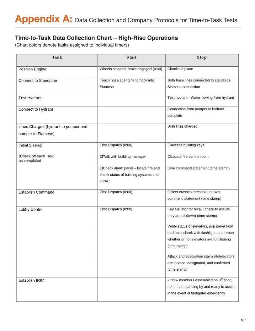
107
Appendix A: Data Collection and Company Protocols for Time-to-Task Tests
Task Start Stop
Position Engine Wheels stopped, brake engaged (4:44) Chocks in place
Connect to Standpipe Touch hose at engine to hook into
Siamese
Both hose lines connected to standpipe
Siamese connection
Test Hydrant Test hydrant - Water flowing from hydrant
Connect to Hydrant Connection from pumper to hydrant
complete
Lines Charged (hydrant to pumper and
pumper to Siamese)
Both lines charged
Initial Size-up First Dispatch (0:00) !Access building keys
!Talk with building manager !Locate fire control room
!Check alarm panel – locate fire and
check status of building systems and
HVAC
Give command statement (time stamp)
Establish Command First Dispatch (0:00) Officer crosses threshold, makes
command statement (time stamp)
Lobby Control First Dispatch (0:00) Key elevator for recall (check to assure
they are all down) (time stamp)
Verify status of elevators, pop panel from
each and check with flashlight, and report
whether or not elevators are functioning
(time stamp)
Attack and evacuation stairwells/elevators
are located, designated, and confirmed
(time stamp)
Establish IRIC 2 crew members assembled on 8th floor,
not on air, standing by and ready to assist
in the event of firefighter emergency
Time-to-Task Data Collection Chart – High-Rise Operations(Chart colors denote tasks assigned to individual timers)
(Check off each Taskas completed
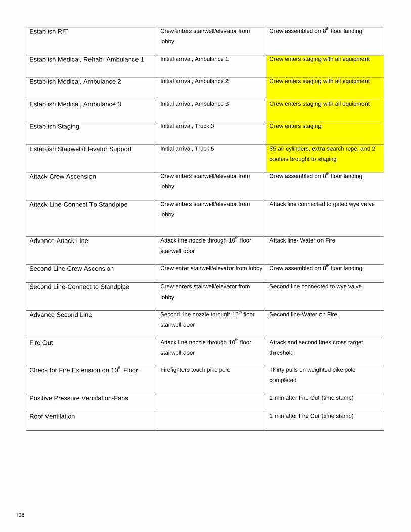
108
Establish RIT Crew enters stairwell/elevator from
lobby
Crew assembled on 8th floor landing
Establish Medical, Rehab- Ambulance 1 Initial arrival, Ambulance 1 Crew enters staging with all equipment
Establish Medical, Ambulance 2 Initial arrival, Ambulance 2 Crew enters staging with all equipment
Establish Medical, Ambulance 3 Initial arrival, Ambulance 3 Crew enters staging with all equipment
Establish Staging Initial arrival, Truck 3 Crew enters staging
Establish Stairwell/Elevator Support Initial arrival, Truck 5 35 air cylinders, extra search rope, and 2
coolers brought to staging
Attack Crew Ascension Crew enters stairwell/elevator from
lobby
Crew assembled on 8th floor landing
Attack Line-Connect To Standpipe
Crew enters stairwell/elevator from
lobby
Attack line connected to gated wye valve
Advance Attack Line Attack line nozzle through 10th floor
stairwell door
Attack line- Water on Fire
Second Line Crew Ascension Crew enter stairwell/elevator from lobby Crew assembled on 8th floor landing
Second Line-Connect to Standpipe Crew enters stairwell/elevator from
lobby
Second line connected to wye valve
Advance Second Line Second line nozzle through 10th floor
stairwell door
Second line-Water on Fire
Fire Out Attack line nozzle through 10th floor
stairwell door
Attack and second lines cross target
threshold
Check for Fire Extension on 10th Floor Firefighters touch pike pole Thirty pulls on weighted pike pole
completed
Positive Pressure Ventilation-Fans 1 min after Fire Out (time stamp)
Roof Ventilation 1 min after Fire Out (time stamp)
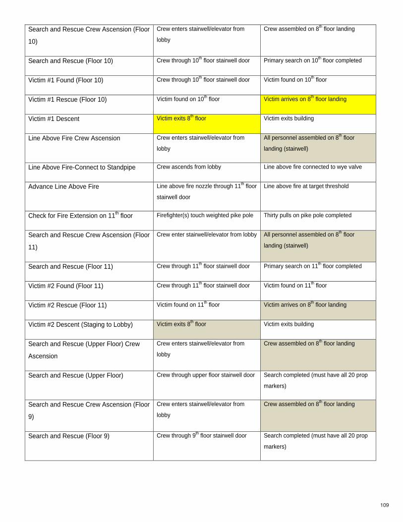
109
Search and Rescue Crew Ascension (Floor
10)
Crew enters stairwell/elevator from
lobby
Crew assembled on 8th floor landing
Search and Rescue (Floor 10) Crew through 10th floor stairwell door Primary search on 10th floor completed
Victim #1 Found (Floor 10) Crew through 10th floor stairwell door Victim found on 10th floor
Victim #1 Rescue (Floor 10) Victim found on 10th floor Victim arrives on 8th floor landing
Victim #1 Descent Victim exits 8th floor Victim exits building
Line Above Fire Crew Ascension Crew enters stairwell/elevator from
lobby
All personnel assembled on 8th floor
landing (stairwell)
Line Above Fire-Connect to Standpipe Crew ascends from lobby Line above fire connected to wye valve
Advance Line Above Fire Line above fire nozzle through 11th floor
stairwell door
Line above fire at target threshold
Check for Fire Extension on 11th floor Firefighter(s) touch weighted pike pole Thirty pulls on pike pole completed
Search and Rescue Crew Ascension (Floor
11)
Crew enter stairwell/elevator from lobby All personnel assembled on 8th floor
landing (stairwell)
Search and Rescue (Floor 11) Crew through 11th floor stairwell door Primary search on 11th floor completed
Victim #2 Found (Floor 11) Crew through 11th floor stairwell door Victim found on 11th floor
Victim #2 Rescue (Floor 11) Victim found on 11th floor Victim arrives on 8th floor landing
Victim #2 Descent (Staging to Lobby) Victim exits 8th floor Victim exits building
Search and Rescue (Upper Floor) Crew
Ascension
Crew enters stairwell/elevator from
lobby
Crew assembled on 8th floor landing
Search and Rescue (Upper Floor) Crew through upper floor stairwell door Search completed (must have all 20 prop
markers)
Search and Rescue Crew Ascension (Floor
9)
Crew enters stairwell/elevator from
lobby
Crew assembled on 8th floor landing
Search and Rescue (Floor 9) Crew through 9th floor stairwell door Search completed (must have all 20 prop
markers)
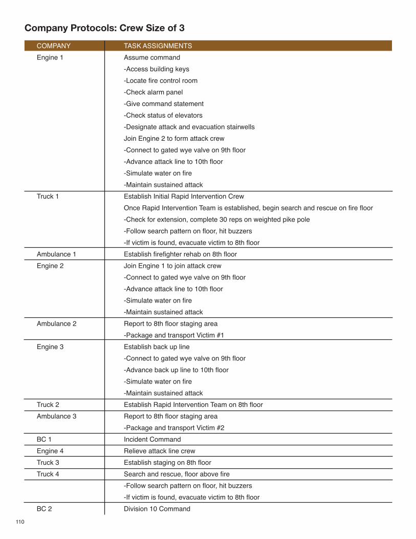
110
COMPANY TASK ASSIGNMENTS
Engine 1 Assume command
-Access building keys
-Locate fire control room
-Check alarm panel
-Give command statement
-Check status of elevators
-Designate attack and evacuation stairwells
Join Engine 2 to form attack crew
-Connect to gated wye valve on 9th floor
-Advance attack line to 10th floor
-Simulate water on fire
-Maintain sustained attack
Truck 1 Establish Initial Rapid Intervention Crew
Once Rapid Intervention Team is established, begin search and rescue on fire floor
-Check for extension, complete 30 reps on weighted pike pole
-Follow search pattern on floor, hit buzzers
-If victim is found, evacuate victim to 8th floor
Ambulance 1 Establish firefighter rehab on 8th floor
Engine 2 Join Engine 1 to join attack crew
-Connect to gated wye valve on 9th floor
-Advance attack line to 10th floor
-Simulate water on fire
-Maintain sustained attack
Ambulance 2 Report to 8th floor staging area
-Package and transport Victim #1
Engine 3 Establish back up line
-Connect to gated wye valve on 9th floor
-Advance back up line to 10th floor
-Simulate water on fire
-Maintain sustained attack
Truck 2 Establish Rapid Intervention Team on 8th floor
Ambulance 3 Report to 8th floor staging area
-Package and transport Victim #2
BC 1 Incident Command
Engine 4 Relieve attack line crew
Truck 3 Establish staging on 8th floor
Truck 4 Search and rescue, floor above fire
-Follow search pattern on floor, hit buzzers
-If victim is found, evacuate victim to 8th floor
BC 2 Division 10 Command
Company Protocols: Crew Size of 3
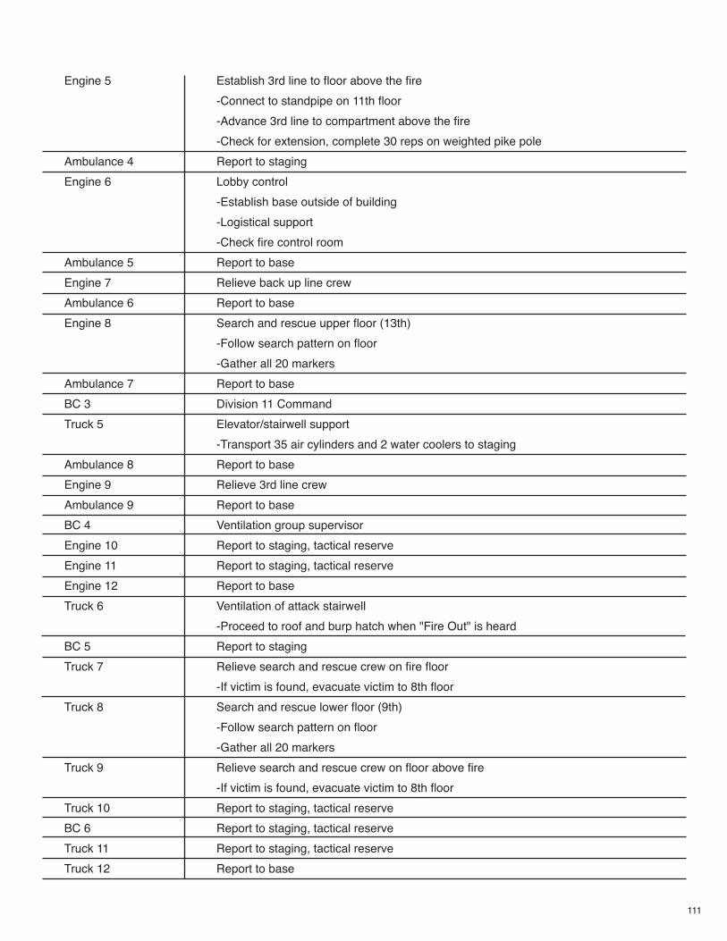
111
Engine 5 Establish 3rd line to floor above the fire
-Connect to standpipe on 11th floor
-Advance 3rd line to compartment above the fire
-Check for extension, complete 30 reps on weighted pike pole
Ambulance 4 Report to staging
Engine 6 Lobby control
-Establish base outside of building
-Logistical support
-Check fire control room
Ambulance 5 Report to base
Engine 7 Relieve back up line crew
Ambulance 6 Report to base
Engine 8 Search and rescue upper floor (13th)
-Follow search pattern on floor
-Gather all 20 markers
Ambulance 7 Report to base
BC 3 Division 11 Command
Truck 5 Elevator/stairwell support
-Transport 35 air cylinders and 2 water coolers to staging
Ambulance 8 Report to base
Engine 9 Relieve 3rd line crew
Ambulance 9 Report to base
BC 4 Ventilation group supervisor
Engine 10 Report to staging, tactical reserve
Engine 11 Report to staging, tactical reserve
Engine 12 Report to base
Truck 6 Ventilation of attack stairwell
-Proceed to roof and burp hatch when "Fire Out" is heard
BC 5 Report to staging
Truck 7 Relieve search and rescue crew on fire floor
-If victim is found, evacuate victim to 8th floor
Truck 8 Search and rescue lower floor (9th)
-Follow search pattern on floor
-Gather all 20 markers
Truck 9 Relieve search and rescue crew on floor above fire
-If victim is found, evacuate victim to 8th floor
Truck 10 Report to staging, tactical reserve
BC 6 Report to staging, tactical reserve
Truck 11 Report to staging, tactical reserve
Truck 12 Report to base
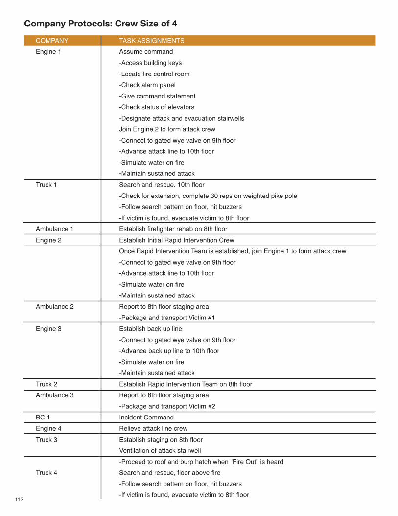
112
COMPANY TASK ASSIGNMENTS
Engine 1 Assume command
-Access building keys
-Locate fire control room
-Check alarm panel
-Give command statement
-Check status of elevators
-Designate attack and evacuation stairwells
Join Engine 2 to form attack crew
-Connect to gated wye valve on 9th floor
-Advance attack line to 10th floor
-Simulate water on fire
-Maintain sustained attack
Truck 1 Search and rescue. 10th floor
-Check for extension, complete 30 reps on weighted pike pole
-Follow search pattern on floor, hit buzzers
-If victim is found, evacuate victim to 8th floor
Ambulance 1 Establish firefighter rehab on 8th floor
Engine 2 Establish Initial Rapid Intervention Crew
Once Rapid Intervention Team is established, join Engine 1 to form attack crew
-Connect to gated wye valve on 9th floor
-Advance attack line to 10th floor
-Simulate water on fire
-Maintain sustained attack
Ambulance 2 Report to 8th floor staging area
-Package and transport Victim #1
Engine 3 Establish back up line
-Connect to gated wye valve on 9th floor
-Advance back up line to 10th floor
-Simulate water on fire
-Maintain sustained attack
Truck 2 Establish Rapid Intervention Team on 8th floor
Ambulance 3 Report to 8th floor staging area
-Package and transport Victim #2
BC 1 Incident Command
Engine 4 Relieve attack line crew
Truck 3 Establish staging on 8th floor
Ventilation of attack stairwell
-Proceed to roof and burp hatch when "Fire Out" is heard
Truck 4 Search and rescue, floor above fire
-Follow search pattern on floor, hit buzzers
-If victim is found, evacuate victim to 8th floor
Company Protocols: Crew Size of 4
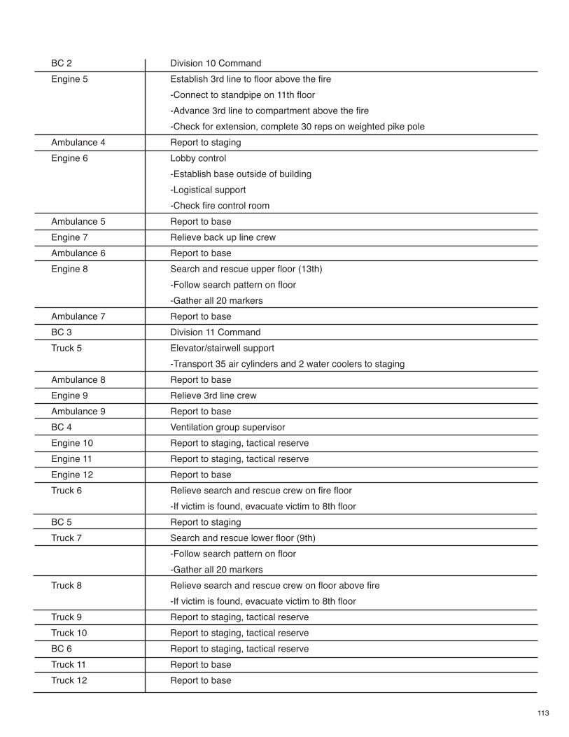
113
BC 2 Division 10 Command
Engine 5 Establish 3rd line to floor above the fire
-Connect to standpipe on 11th floor
-Advance 3rd line to compartment above the fire
-Check for extension, complete 30 reps on weighted pike pole
Ambulance 4 Report to staging
Engine 6 Lobby control
-Establish base outside of building
-Logistical support
-Check fire control room
Ambulance 5 Report to base
Engine 7 Relieve back up line crew
Ambulance 6 Report to base
Engine 8 Search and rescue upper floor (13th)
-Follow search pattern on floor
-Gather all 20 markers
Ambulance 7 Report to base
BC 3 Division 11 Command
Truck 5 Elevator/stairwell support
-Transport 35 air cylinders and 2 water coolers to staging
Ambulance 8 Report to base
Engine 9 Relieve 3rd line crew
Ambulance 9 Report to base
BC 4 Ventilation group supervisor
Engine 10 Report to staging, tactical reserve
Engine 11 Report to staging, tactical reserve
Engine 12 Report to base
Truck 6 Relieve search and rescue crew on fire floor
-If victim is found, evacuate victim to 8th floor
BC 5 Report to staging
Truck 7 Search and rescue lower floor (9th)
-Follow search pattern on floor
-Gather all 20 markers
Truck 8 Relieve search and rescue crew on floor above fire
-If victim is found, evacuate victim to 8th floor
Truck 9 Report to staging, tactical reserve
Truck 10 Report to staging, tactical reserve
BC 6 Report to staging, tactical reserve
Truck 11 Report to base
Truck 12 Report to base
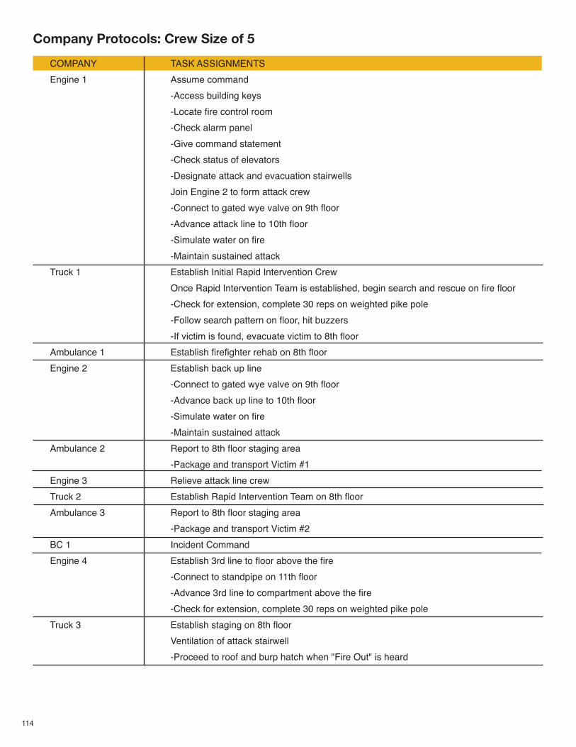
114
COMPANY TASK ASSIGNMENTS
Engine 1 Assume command
-Access building keys
-Locate fire control room
-Check alarm panel
-Give command statement
-Check status of elevators
-Designate attack and evacuation stairwells
Join Engine 2 to form attack crew
-Connect to gated wye valve on 9th floor
-Advance attack line to 10th floor
-Simulate water on fire
-Maintain sustained attack
Truck 1 Establish Initial Rapid Intervention Crew
Once Rapid Intervention Team is established, begin search and rescue on fire floor
-Check for extension, complete 30 reps on weighted pike pole
-Follow search pattern on floor, hit buzzers
-If victim is found, evacuate victim to 8th floor
Ambulance 1 Establish firefighter rehab on 8th floor
Engine 2 Establish back up line
-Connect to gated wye valve on 9th floor
-Advance back up line to 10th floor
-Simulate water on fire
-Maintain sustained attack
Ambulance 2 Report to 8th floor staging area
-Package and transport Victim #1
Engine 3 Relieve attack line crew
Truck 2 Establish Rapid Intervention Team on 8th floor
Ambulance 3 Report to 8th floor staging area
-Package and transport Victim #2
BC 1 Incident Command
Engine 4 Establish 3rd line to floor above the fire
-Connect to standpipe on 11th floor
-Advance 3rd line to compartment above the fire
-Check for extension, complete 30 reps on weighted pike pole
Truck 3 Establish staging on 8th floor
Ventilation of attack stairwell
-Proceed to roof and burp hatch when "Fire Out" is heard
Company Protocols: Crew Size of 5
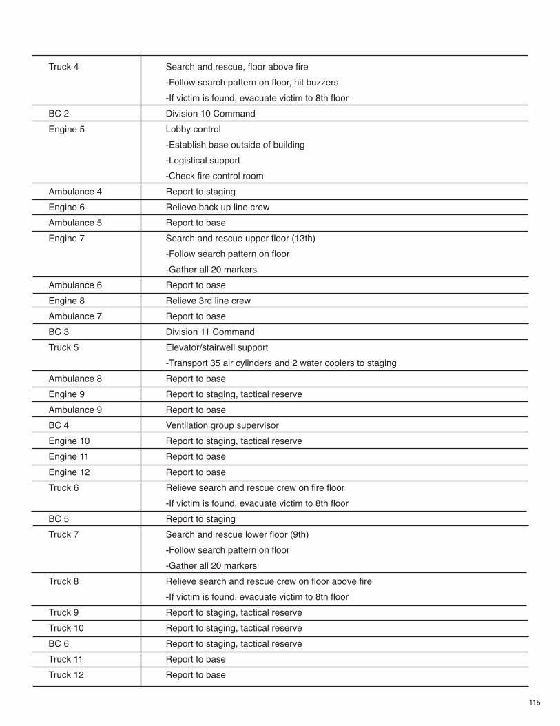
115
Truck 4 Search and rescue, floor above fire
-Follow search pattern on floor, hit buzzers
-If victim is found, evacuate victim to 8th floor
BC 2 Division 10 Command
Engine 5 Lobby control
-Establish base outside of building
-Logistical support
-Check fire control room
Ambulance 4 Report to staging
Engine 6 Relieve back up line crew
Ambulance 5 Report to base
Engine 7 Search and rescue upper floor (13th)
-Follow search pattern on floor
-Gather all 20 markers
Ambulance 6 Report to base
Engine 8 Relieve 3rd line crew
Ambulance 7 Report to base
BC 3 Division 11 Command
Truck 5 Elevator/stairwell support
-Transport 35 air cylinders and 2 water coolers to staging
Ambulance 8 Report to base
Engine 9 Report to staging, tactical reserve
Ambulance 9 Report to base
BC 4 Ventilation group supervisor
Engine 10 Report to staging, tactical reserve
Engine 11 Report to base
Engine 12 Report to base
Truck 6 Relieve search and rescue crew on fire floor
-If victim is found, evacuate victim to 8th floor
BC 5 Report to staging
Truck 7 Search and rescue lower floor (9th)
-Follow search pattern on floor
-Gather all 20 markers
Truck 8 Relieve search and rescue crew on floor above fire
-If victim is found, evacuate victim to 8th floor
Truck 9 Report to staging, tactical reserve
Truck 10 Report to staging, tactical reserve
BC 6 Report to staging, tactical reserve
Truck 11 Report to base
Truck 12 Report to base
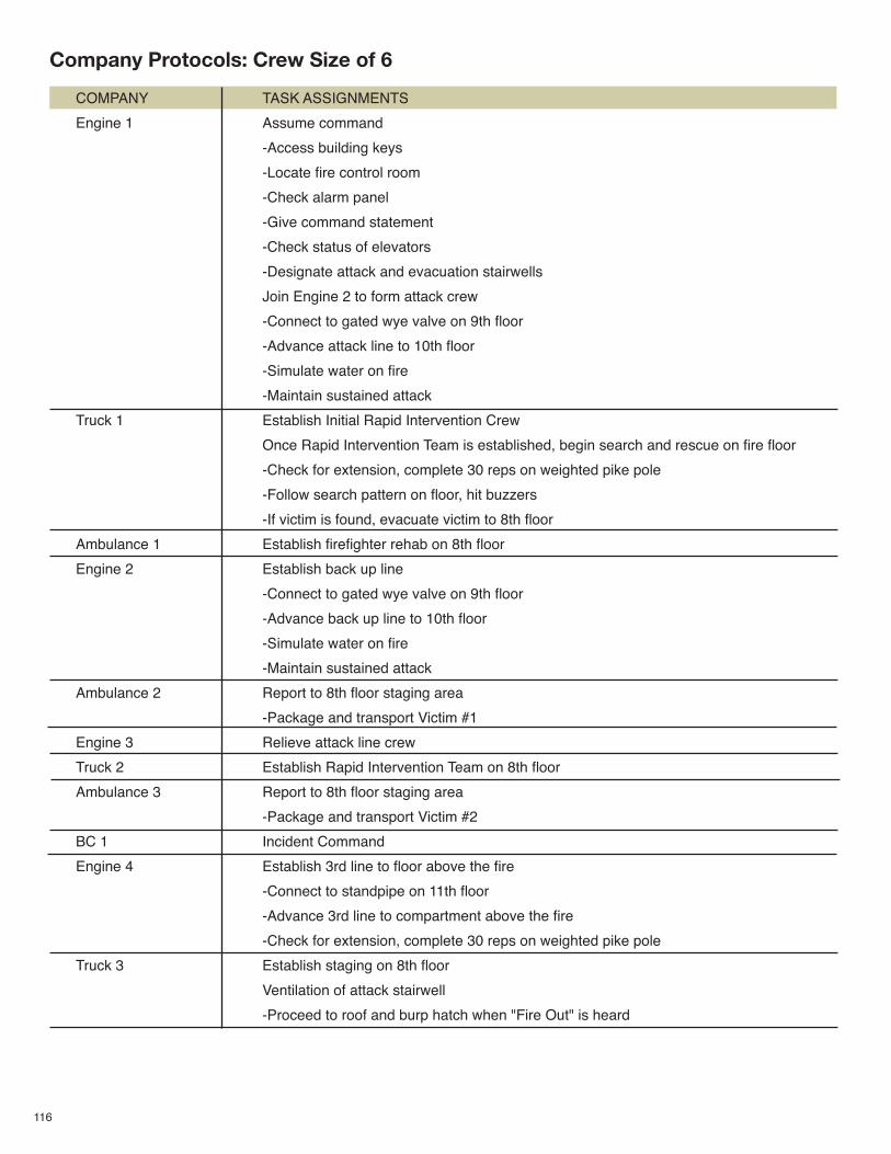
116
COMPANY TASK ASSIGNMENTS
Engine 1 Assume command
-Access building keys
-Locate fire control room
-Check alarm panel
-Give command statement
-Check status of elevators
-Designate attack and evacuation stairwells
Join Engine 2 to form attack crew
-Connect to gated wye valve on 9th floor
-Advance attack line to 10th floor
-Simulate water on fire
-Maintain sustained attack
Truck 1 Establish Initial Rapid Intervention Crew
Once Rapid Intervention Team is established, begin search and rescue on fire floor
-Check for extension, complete 30 reps on weighted pike pole
-Follow search pattern on floor, hit buzzers
-If victim is found, evacuate victim to 8th floor
Ambulance 1 Establish firefighter rehab on 8th floor
Engine 2 Establish back up line
-Connect to gated wye valve on 9th floor
-Advance back up line to 10th floor
-Simulate water on fire
-Maintain sustained attack
Ambulance 2 Report to 8th floor staging area
-Package and transport Victim #1
Engine 3 Relieve attack line crew
Truck 2 Establish Rapid Intervention Team on 8th floor
Ambulance 3 Report to 8th floor staging area
-Package and transport Victim #2
BC 1 Incident Command
Engine 4 Establish 3rd line to floor above the fire
-Connect to standpipe on 11th floor
-Advance 3rd line to compartment above the fire
-Check for extension, complete 30 reps on weighted pike pole
Truck 3 Establish staging on 8th floor
Ventilation of attack stairwell
-Proceed to roof and burp hatch when "Fire Out" is heard
Company Protocols: Crew Size of 6
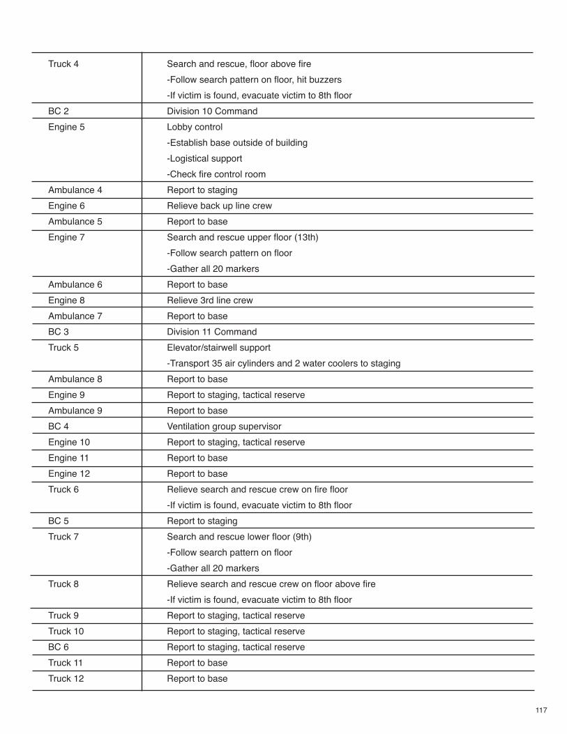
117
Truck 4 Search and rescue, floor above fire
-Follow search pattern on floor, hit buzzers
-If victim is found, evacuate victim to 8th floor
BC 2 Division 10 Command
Engine 5 Lobby control
-Establish base outside of building
-Logistical support
-Check fire control room
Ambulance 4 Report to staging
Engine 6 Relieve back up line crew
Ambulance 5 Report to base
Engine 7 Search and rescue upper floor (13th)
-Follow search pattern on floor
-Gather all 20 markers
Ambulance 6 Report to base
Engine 8 Relieve 3rd line crew
Ambulance 7 Report to base
BC 3 Division 11 Command
Truck 5 Elevator/stairwell support
-Transport 35 air cylinders and 2 water coolers to staging
Ambulance 8 Report to base
Engine 9 Report to staging, tactical reserve
Ambulance 9 Report to base
BC 4 Ventilation group supervisor
Engine 10 Report to staging, tactical reserve
Engine 11 Report to base
Engine 12 Report to base
Truck 6 Relieve search and rescue crew on fire floor
-If victim is found, evacuate victim to 8th floor
BC 5 Report to staging
Truck 7 Search and rescue lower floor (9th)
-Follow search pattern on floor
-Gather all 20 markers
Truck 8 Relieve search and rescue crew on floor above fire
-If victim is found, evacuate victim to 8th floor
Truck 9 Report to staging, tactical reserve
Truck 10 Report to staging, tactical reserve
BC 6 Report to staging, tactical reserve
Truck 11 Report to base
Truck 12 Report to base
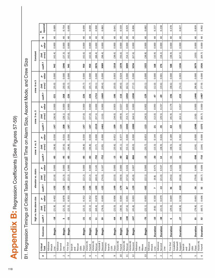
118
Appen
dix B:R
egre
ssio
n C
oeffic
ients
(S
ee F
igure
s 57-5
9)
B1. R
egre
ssio
n T
imin
gs
of C
ritic
al T
ask
s and O
vera
ll T
ime o
n A
larm
Siz
e, A
scent M
ode, and C
rew
Siz
e
!"#!$%&'$()
*$+(+,-
$&"./$
/(/%+0),$%&'$&0+",&$
1,/*
$$2$$%&'$3$
1,/*
$$4$%&'$3$
1,/*
$$5$%&$3$
6)7&0+7
0$
$8$
6,"0"1+($
9+&:$$
;<01)-/$
1)/=='>$
!"#$%&!
'(()(*!!
+,-./0'!
1)/=='>$
!"#$%&!
'(()(*!!
+,-./0'!
1)/=='>$
!"#$%&!
'(()(*!!
+,-./0'!
1)/=='>$
!"#$%&!
'(()(*!!
+,-./0'!
1)/=='>$
"#$%&!
'(()(*!
+,-./0'!
1)/=='>$
!"#$%&!
'(()(*!!
+,-./0'!
?$
@A
&B<+,/C
$
!"
#$%&'
()"
#**&(+"
,-')
"B
egin
ADE$
./!012"
3043
/"AD3F
$./!012"
3033
3"AE3$
.56012"
3035
3"AD2G
$.56072"
3033
3"AFFD
$.58032"
3033
3"H2
F$.4/042"
3033
3"41
"3061
7"
/"
#$%&'
()"
9)(:'$
",-')
"B
egin
3$
./!052"
301;
1"ADF5
$./!052"
3033
3"AH4$
.5;062"
303!
6"AFIE
$./10!2"
3033
3"AF5E
$.53032"
3033
3"DI
25$
.5;052"
3033
3"41
"30;8
4"
5"<-=)">?*"
Beg
in
AFD$
.//0/2"
3058
5"AD34
$.//0/2"
3033
3"AE3$
.56012"
3035
3"AD2G
$.5;032"
3033
3"AFF5
$.580;2"
3033
3"H2
4$.4/062"
3033
3"41
"3067
3"
8"
9)&=(@"
&'$"
A)B(?)"
!3*@"
<C::
="B
egin
AFD$
.//0/2"
3058
/"AD34
$.//0/2"
3033
3"AE3$
.56012"
3035
3"AD2G
$.5;032"
3033
3"AFF5
$.580;2"
3033
3"H4
I$.4/062"
3033
3"41
"3067
3"
6"D-(*-E"F!"
<:?'
$"B
egin
AFD$
.//0/2"
3058
/"AD34
$.//0/2"
3033
3"AE3$
.56012"
3035
3"AD2G
$.5;032"
3033
3"AFF5
$.580;2"
3033
3"H4
I$.4/062"
3033
3"41
"3067
3"
;"D-(*-E"F!"
A)B(?)"
Beg
in
DD$
.67042"
301;
1"ADI3
$.67042"
30!4
8"AGHF
$.!!;
2"3033
3"AD4D
H$.7;082"
3033
3"ADGD
3$.730!2"
3033
3"FE
G5$
.11042"
3033
3"41
"3073
3"
1"D-(*-EF"!"
G)B()'*"
Beg
in
3H$
.;4032"
3063
3"ADFF
$.;4032"
30!3
;"AG4F
$.!/3
2"3033
3"AD25
D$.!!3
2"3033
3"AD55
H$.77042"
3033
3"3I
EH$
.71042"
3033
3"41
"3011
5"
7"
H=-E
&=I"
9)&=(@"
!!*@"
<C::
="B
egin
A52$
.//032"
3033
6"AD2H
$.//032"
3033
3"AD4$
.55062"
3068
/"ADIH
$.54032"
3033
5"ADI5
$.55032"
3033
5"D3
DE$
.51062"
3033
3"41
"3064
!"
!3"
D-(*-E"F/"
<:?'
$"B
egin
AH2$
.53072"
3033
4"ADGH
$.53072"
3033
3"A2I$
.480!2"
305;
;"ADD2
$.47072"
303/
;"ADD5
$.47042"
303/
4"D3
GE$
.86062"
3033
3"41
"3088
7"
!!"
D-(*-E"F/"
A)B(?)"
Beg
in
AD3E
$.5;062"
3033
!"AEG$
.5;062"
303/
6"AEEF
$.850!2"
3033
3"ADI2
3$.850;2"
3033
3"ADI4
I$.6/082"
3033
3"3I
IH$
.840!2"
3033
3"41
"307/
7"
!/"
D-(*-E"F/"
G)B()'*"
Beg
in
AD2G
$.48012"
3033
5"ADFH
$.48012"
3033
;"AE55
$.67032"
3033
3"ADII
I$.64082"
3033
3"ADI3
E$.;;0/2"
3033
3"3F
45$
.6;062"
3033
3"41
"3017
6"
!5"
#$%&'
()"
,-')
"#J:
%)"
<-=)"
Beg
in
AGI$
.//0!2"
3033
5"AD5F
$.//0!2"
3033
3"AD4$
.550;2"
3068
5"ADD3
$.54082"
3033
/"ADFH
$.550!2"
3033
3"D3
FF$
.51012"
3033
3"41
"3061
/"
!"
#$%&'
()"
#**&(+"
,-')
"D
urat
ion
ADI$
.7012"
3055
3"G$
.7012"
304;
8"AFI$
.!5052"
30!4
4"AFD$
.!/032"
3037
5"A2G$
.!/032"
3033
3"D5
E$.!3072"
3033
3"41
"30/5
;"
/"#$%&'
()"
9)(:'$
"D
urat
ion
A3E$
./!032"
303;
7"AD3$
./!032"
3085
;"D2
$./1072"
306/
6"A34$
./7082"
30/5
;"A5H$
.!7062"
3033
!"FG
5$.!10/2"
3033
3"41
"30/5
1",-')
"
5"<-=)">?*"
Dur
atio
n 5$
./7062"
3014
7"35
$./7062"
30//
6"A4D$
.51082"
30!1
7"A53$
.48072"
30!;
7"ADH5
$.51062"
3033
3"4E
E$.51072"
3033
3"41
"305;
1"
4"
KB*&JC-B@"
9*&-=L
)CC"
9?MM
:=*"
Dur
atio
n AFG$
.44012"
3088
1"A5DI
$.44012"
3033
3"A44$
.65062"
3057
/"ADF3
$.650!2"
3038
;"AF33
$.;40/2"
3033
5"D3
35$
.6;082"
3033
3"41
"301/
;"
8"
9)&=(@"
&'$"
A)B(?)"
!3*@"
<C::
="D
urat
ion
34$
.;7012"
3066
5"A45$
.;7012"
3041
6"A4HE
$.!/4
2"3033
3"AD32
E$.!!1
2"3033
3"AD22
5$.76012"
3033
3"F5
GH$
.!35
2"3033
3"41
"3015
7"
6"D-(*-E"F!"
<:?'
$"D
urat
ion
3F$
.630;2"
3063
6"3F
$.630;2"
3063
6"AGDI
$.!34
2"3033
3"AD3G
F$.150;2"
3033
3"AD2E
G$.;;072"
3033
3"DH
F5$
.670;2"
3033
3"41
"3073
/"
""
""
$
""
$"
"$
""
$"
"$
""
$"
""
"
""
" "
$"
"$
""
$"
"$
""
$"
"$
""
""
"
" "" "
$
""
$"
"$
""
$"
"$
""
$"
""
"
""
""
$
""
$"
"$
""
$"
"$
""
$"
""
"
""
""
$
""
$"
"$
""
$"
"$
""
$"
""
"
""
" "
$"
"$
""
$"
"$
""
$"
"$
""
""
"
"""
"
$"
"$
""
$"
"$
""
$"
"$
""
""
"
"" "
" "
$"
"$
""
$"
"$
""
$"
"$
""
""
"
""
"
$"
"$
""
$"
"$
""
$"
"$
""
""
"
" ""
$
""
$"
"$
""
$"
"$
""
$"
""
"
""
"
$"
"$
""
$"
"$
""
$"
"$
""
""
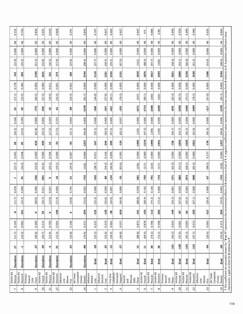
119
"
""
"
$"
"$
""
$"
"$
""
$"
"$
""
""
"
" " "
$"
"$
""
$"
"$
""
$"
"$
""
""
"
""
"" "
$
""
$"
"$
""
$"
"$
""
$"
""
"
""
""
$
""
$"
"$
""
$"
"$
""
$"
""
"
;"D-(*-E"F!"
A)B(?)"
Dur
atio
n DG
$.!!0;2"
30!4
5"AE$
.!!0;2"
304;
1"D$
.!80;2"
3074
8"FE
$./30/2"
30!6
6"F3
$.!;0!2"
30!;
1"D2
F$.!8032"
3033
3"41
"30!8
/"
1"D-(*-E"F!"
G)B()'*"
Dur
atio
n AD$
.!4052"
3076
5"AD5D
$.!4052"
3033
3"33
$.!6042"
3034
1"FI
$.!4072"
30!7
4"FI
$.//082"
3051
8"FI
3$.!8052"
3033
3"41
"30;8
6"
7"
H=-E
&=I"
9)&=(@"
!!*@"
<C::
="D
urat
ion
A3G$
.43032"
3056
3"I$
.43032"
3077
6"A445
$.8/062"
3033
3"A5DH
$.6!012"
3033
3"AGG3
$.630/2"
3033
3"DG
I2$
.8!0/2"
3033
3"41
"3015
6"
!3"
D-(*-E"F/"
<:?'
$"D
urat
ion
A22$
.540;2"
30/!
4"HF
$.540;2"
303!
!"AE2D
$.8/062"
3033
3"AHFH
$.84082"
3033
3"AH34
$.8;082"
3033
3"D5
3D$
.8/012"
3033
3"41
"307/
8"
!!"
D-(*-E"F/"
A)B(?)"
Dur
atio
n A2$
.!5072"
30;8
3"5$
.!5072"
3068
;"H$
./50!2"
30;3
4"D2
$.!;0/2"
304/
7"DI
$.!7082"
306!
!"D2
D$.!60/2"
3033
3"41
"303!
7"
!/"
D-(*-E"F/"
G)B()'*"
Dur
atio
n F4
$.!/042"
3038
4"ADHH
$.!/042"
3033
3"A3F$
.!70!2"
3037
7"AFF$
.!;082"
30//
5"A5D$
.!6082"
3033
!"FG
3$.!;012"
3033
3"41
"3016
1"
!5"
#$%&'
()"
,-')
"#J:
%)"
<-=)"
Dur
atio
n AF4$
.!6012"
30!4
1"5$
.!6012"
30;4
8"A4D$
./7052"
3031
;"A54$
./!0!2"
3033
4"AEH$
./4052"
3033
!"DE
2$./5012"
3033
3"41
"30/7
!"
!4"
#CC"N&B+B"
O:E
MC)*)"
.N-E
)="
9@))*2"
Dur
atio
n A5E$
.;4072"
305;
!"AF42
$.;4072"
3033
/"AGDH
$.!/6
2"3033
3"ADF4
G$.74012"
3033
3"AD3G
E$.780;2"
3033
3"3G
22$
.71042"
3033
3"41
"3014
/"
!"
#$%&'
()"
#**&(+"
,-')
"E
nd
AFE$
./50/2"
30/5
/"ADF4
$./50/2"
3033
3"ADI3
$.510;2"
303!
!"AD5G
$.580!2"
3033
3"AF5E
$.54032"
3033
3"DD
DI$
.5;0;2"
3033
3"41
"30;3
;"
/"
#$%&'
()"
9)(:'$
",-')
"E
nd
A34$
.55062"
305!
3"AD3H
$.55062"
3033
3"AEI$
.84052"
30!4
6"AF22
$.45082"
3033
3"A33G
$.5;032"
3033
3"D3
FD$
.43082"
3033
3"41
"3068
;"
5"<-=)">?*"
End
AD4$
.54072"
3066
8"AHE$
.54072"
3033
;"AD32
$.46062"
3033
6"AFIH
$.4;082"
3033
3"A2FF
$.430!2"
3033
3"D4
33$
.570/2"
3033
3"41
"3066
7"
4"
KB*&JC-B@"
9*&-=L
)CC"
9?MM
:=*"
End
AFG$
.44012"
3088
;"A5DI
$.44012"
3033
3"A44$
.65062"
3057
/"ADF2
$.650!2"
3038
;"AF33
$.;40/2"
3033
5"FD
3D$
.6;082"
3033
3"41
"301/
;"
8"
9)&=(@"
&'$"
A)B(?)"
!3*@"
<C::
="E
nd
D2$
.11012"
301;
5"ADHD
$.11012"
3035
1"A5ED
$.!56
2"3033
3"AD2H
4$.!55
2"3033
3"AD5G
D$.!3;
2"3033
3"35
FH$
.!/!
2"3033
3"41
"3014
;"
6"D-(*-E"F!"
<:?'
$"E
nd
DD$
.67042"
301;
1"ADI3
$.67042"
30!4
8"AGHF
$.!!;
2"3033
3"AD4D
H$.7;082"
3033
3"ADGD
3$.730!2"
3033
3"FE
G5$
.11042"
3033
3"41
"307"
;"D-(*-E"F!"
A)B(?)"
End
FE
$.;40/2"
30;3
6"ADDF
$.;40/2"
30!4
3"AGHD
$.!/5
2"3033
3"AD2H
I$.!37
2"3033
3"AD5H
I$.!33
2"3033
3"3I
DG$
.7;0;2"
3033
3"41
"3011
8"
1"D-(*-E"F!"
G)B()'*"
End
3E
$.;/0/2"
3087
1"AFE3
$.;/0/2"
3033
3"AGDH
$.!!;
2"3033
3"AD22
D$.!!3
2"3033
3"AD52
H$.!3/
2"3033
3"3F
H3$
.!33
2"3033
3"41
"3017
"
7"
H=-E
&=I"
9)&=(@"
!!*@"
<C::
="E
nd
ADID
$.450/2"
303/
4"AD2H
$.450/2"
3033
!"A4GD
$.6!032"
3033
3"AGFE
$.640;2"
3033
3"AEGE
$.6/052"
3033
3"3I
FD$
.81052"
3033
3"41
"3018
1"
!3"
D-(*-E"F/"
<:?'
$"E
nd
AD3E
$.5;062"
3033
!"AEG$
.5;062"
303/
6"AEEF
$.850!2"
3033
3"ADI2
3$.850;2"
3033
3"ADI4
I$.6/082"
3033
3"3I
IH$
.840!2"
3033
3"41
"307/
7"
!!"
D-(*-E"F/"
A)B(?)"
End
AD23
$.48052"
3033
5"AED$
.48052"
3031
/"AEG3
$.610!2"
3033
3"ADIF
H$.680/2"
3033
3"ADI2
I$.;80!2"
3033
3"3D
4I$
.66032"
3033
3"41
"3017
7"
!/"
D-(*-E"F/"
G)B()'*"
End
ADF3
$.4;0!2"
303!
5"A3FH
$.4;0!2"
3033
3"AEHE
$.68082"
3033
3"ADIF
D$.6!032"
3033
3"ADIH
H$.;1082"
3033
3"34
3I$
.6!0/2"
3033
3"41
"3073
6"
!5"
#$%&'
()"
,-')
"#J:
%)"
<-=)"
End
AH2$
./7042"
3033
5"AD4G
$./7042"
3033
3"A5G$
.41082"
30!;
;"ADGE
$.48052"
3033
3"AFDG
$.4;032"
3033
3"D4
I5$
.85062"
3033
3"41
"3065
8"
!4"
#CC"N&B+B"
O:E
MC)*)"
.N-E
)="
9@))*2"
End
A5E$
.;4072"
305;
!"AF42
$.;4072"
3033
/"AGDH
$.!/6
2"3033
3"ADF4
G$.74012"
3033
3"AD3G
E$.780;2"
3033
3"3G
22$
.71042"
3033
3"41
"3014
/"
>"N@
)"(:)PP-(-)'
*".-'"B)(:'$
B2"B@:
L'"P:="JK$%&'$LJ"=)M=)B)'
*B"*@)
"-'(=)E
)'*&C")PP)(*B":P$K"=)C&*-%)"*:"*@&
*":P$L0"#
"')Q&*-%)"(:)PP-(-)'
*"%&C?)"=)M=)B)'
*B"*@)
"!"#
$%&'(")*
&%P=:E
"K$=)C&*-%)"*:"L0"#
"M:B-*-%)"(:)PP-(-)'
*"%&C?)"
=)M=)B)'
*B""&"Q&-'"-'"*-E
)"P:="K"=)C&*-%)"*:"L0"
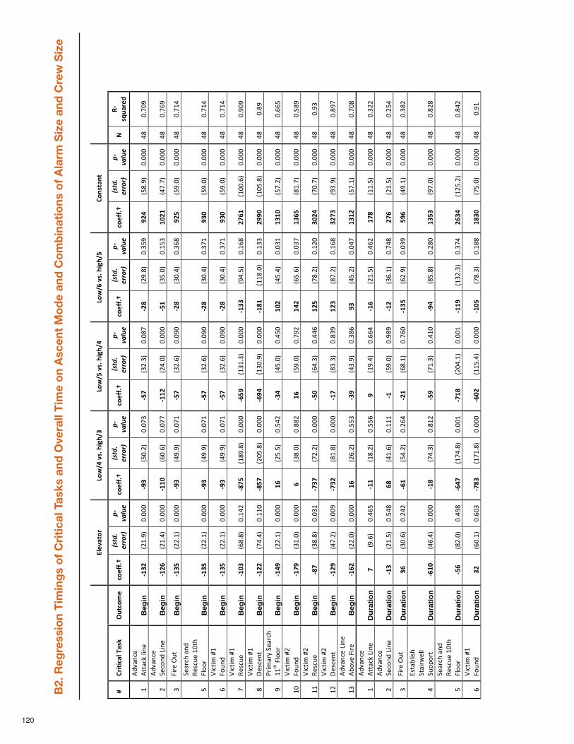
120
B2. Reg
ression Tim
ings of Critica
l Tasks and
Overall Tim
e on Ascen
t Mode an
d Combinations
of Alarm
Size an
d Crew Size
!"#$%&'()
*'+,-)$./)0120,3)
*'+,4)$./)0120,-)
*'+,5)$./)0120,4)
6'7.&%7&)
8)6(1&19%"):%.;))
<=&9'>#)
9'#??/@)
!"#$%&
'(()(*&
+,-./0'&
9'#??/@)
!"#$%&
'(()(*&
+,-./0'&
9'#??/@)
!"#$%&
'(()(*&
+,-./0'&
9'#??/@)
!"#$%&
'(()(*&
+,-./0'&
9'#??/@)
!"#$%&
'(()(*&
+,-./0'&
A)
BC.D=%
(#E)
!"#$%&'
()"
#**&(+",-')"
Beg
in
CF3G
)./!012"
3033
3"CH3)
.430/2"
3035
6"C4I)
.6/062"
3037
5"CGJ)
./1072"
3064
1"HG
-).47012"
3033
3"87
"3053
1"
/"#$%&'
()"
9)(:'$
";-')"
Beg
in
CFG5
)./!082"
3033
3"CFFK
).<30<2"
3035
5"CFFG
)./8032"
3033
3"C4F)
.64032"
30!4
6"FK
GF)
.85052"
3033
3"87
"305<
1"
6"=->)"?@*"
Beg
in
CF34
).//0!2"
3033
3"CH3)
.81012"
3035
!"C4I)
.6/0<2"
3031
3"CGJ)
.63082"
306<
7"HG
4).41032"
3033
3"87
"305!
8"
4"
9)&>(A"&'$
"B)
C(@)
"!3*A"
=,::
>"B
egin
CF34
).//0!2"
3033
3"CH3)
.81012"
3035
!"C4I)
.6/0<2"
3031
3"CGJ)
.63082"
3065
!"H3
K).41032"
3033
3"87
"305!
8"
<"D-(*-E
"F!"
=:@'
$"B
egin
CF34
).//0!2"
3033
3"CH3)
.81012"
3035
!"C4I)
.6/0<2"
3031
3"CGJ)
.63082"
3065
!"H3
K).41032"
3033
3"87
"305!
8"
5"D-(*-E
"F!"
B)C(@)
"B
egin
CFK3
).<7072"
30!8
/"CJI4
).!71
072"
3033
3"C54H
).!6!
062"
3033
3"CF33
).18042"
30!<
7"GI
5F)
.!33
0<2"
3033
3"87
"3013
1"
7"D-(*-E
"F!"
G)C()'*"
Beg
in
CFGG
).58082"
30!!
3"CJ4I
)./34
072"
3033
3"C5H-
).!63
012"
3033
3"CFJF
).!!7
032"
30!6
6"GH
HK)
.!34
072"
3033
3"87
"3071
"
1"H>-E
&>I"9)&>(A"
!!*A"=,::>"
Beg
in
CF-H
).//0!2"
3033
3"F5
)./4042"
3048
/"C3-)
.84032"
3084
3"FK
G).84082"
3036
!"F3
FK)
.450/2"
3033
3"87
"30<<
4"
!3"
D-(*-E
"F/"
=:@'
$"B
egin
CFIH
).6!032"
3033
3"5)
.67032"
3077
/"F5
).41032"
3051
/"F-
G).<40<2"
3036
5"F3
54)
.7!052"
3033
3"87
"3047
1"
!!"
D-(*-E
"F/"
B)C(@)
"B
egin
CJI)
.67072"
3036
!"CI3I
).5/0/2"
3033
3"C4K)
.<8062"
3088
<"FG
4).570/2"
30!/
3"3K
G-)
.53052"
3033
3"87
"3016
"
!/"
D-(*-E
"F/"
G)C()'*"
Beg
in
CFGH
).850/2"
3033
1"CI3G
).7!072"
3033
3"CFI)
.76062"
3076
1"FG
3).750/2"
30!<
7"3G
I3)
.16012"
3033
3"87
"3071
5"
!6"
#$%&'
()";-')"
#J:
%)"=->)"
Beg
in
CF5G
).//032"
3033
3"F5
)./<0/2"
3044
6"C3H)
.86012"
3067
<"H3
).840/2"
3038
5"F3
FG)
.450!2"
3033
3"87
"3053
7"
!"#$%&'
()"
#**&(+";-')
"D
urat
ion
I).10<2"
308<
4"CFF)
.!70/2"
3044
<"H)
.!1082"
30<<
8"CF5)
./!042"
308<
/"FI
J).!!042"
3033
3"87
"306/
/"
/"#$%&'
()"
9)(:'$
";-')"
Dur
atio
n CF3)
./!042"
3048
7"5J
).8!0<2"
30!!
!"CF)
.41032"
3017
1"CFG)
.6<0!2"
3058
7"GI
5)./!042"
3033
3"87
"30/4
8"
6"=->)"?@*"
Dur
atio
n 35
).630<2"
30/8
/"C5F)
.480/2"
30/<
8"CGF)
.<70!2"
305<
3"CF34
).</012"
3036
1"4H
5).810!2"
3033
3"87
"3067
/"
8"
KC*&J,-CA"
9*&->L
),,"
9@MM
:>*"
Dur
atio
n C5FK
).8<082"
3033
3"CFJ)
.58062"
307!
/"C4H)
.5!062"
308!
3"CH-)
.74072"
30/7
3"F3
43)
.15032"
3033
3"87
"307/
7"
4"
9)&>(A"&'$
"B)
C(@)
"!3*A"
=,::
>"D
urat
ion
C45)
.7/032"
3081
7"C5-I
).!58
072"
3033
!"CIFJ
)./38
0!2"
3033
!"CFFH
).!6/
062"
3065
8"G5
3-)
.!/4
0/2"
3033
3"87
"3078
/"
<"D-(*-E
"F!"
=:@'
$"D
urat
ion
3G)
.<30!2"
30<3
6"CIJ3
).!5!
072"
3033
3"C5KG
).!!4
082"
3033
3"CFK4
).57062"
30!7
7"FJ
3K)
.54032"
3033
3"87
"301!
"
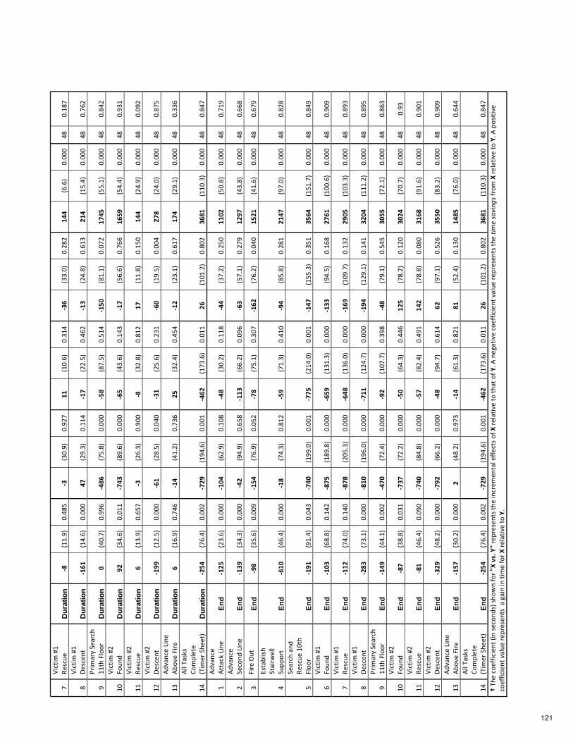
121
5"D-(*-E
"F!"
B)C(@)
"D
urat
ion
CJ)
.!!012"
3087
4"C3)
.63012"
301/
5"FF
).!30<2"
306!
8"C35)
.66032"
30/7
/"F-
-).<0<2"
3033
3"87
"30!7
5"
7"D-(*-E
"F!"
G)C()'*"
Dur
atio
n CF5F
).!80<2"
3033
3"-I
)./1062"
30!!
8"CFI)
.//042"
308<
/"CF3)
./8072"
30<!
6"GF
-).!4082"
3033
3"87
"305<
/"
1"H>-E
&>I"9)&>(A"
!!*A"=,::>"
Dur
atio
n K)
.83052"
3011
<"C-J5
).54072"
3033
3"C4J)
.75042"
304!
8"CF4K
).7!0!2"
3035
/"FI
-4)
.440!2"
3033
3"87
"3078
/"
!3"
D-(*-E
"F/"
=:@'
$"D
urat
ion
HG)
.680<2"
303!
!"CI-3
).710<2"
3033
3"C54)
.860<2"
30!8
6"CFI)
.4<0<2"
305<
<"F5
4H)
.48082"
3033
3"87
"3016
!"
!!"
D-(*-E
"F/"
B)C(@)
"D
urat
ion
5).!6012"
30<4
5"C3)
./<062"
3013
3"CJ)
.6/072"
307!
/"FI
).!!072"
30!4
3"F-
-)./8012"
3033
3"87
"3031
/"
!/"
D-(*-E
"F/"
G)C()'*"
Dur
atio
n CFHH
).!/042"
3033
3"C5F)
./7042"
3038
3"C3F)
./40<2"
30/6
!"C5K)
.!1042"
3033
8"GI
J)./8032"
3033
3"87
"3075
4"
!6"
#$%&'
()";-')"
#J:
%)"=->)"
Dur
atio
n 5)
.!<012"
3058
<"CF-)
.8!0/2"
3056
<"G4
).6/082"
3084
8"CFG)
./60!2"
30<!
5"FI
-)./10!2"
3033
3"87
"3066
<"
!8"
#,,"N&C+C"
O:EM,)*)"
.N-E
)>"9A)
)*2"
Dur
atio
n CG4-
).5<082"
3033
/"CIGH
).!18
0<2"
3033
!"C-5G
).!56
0<2"
303!
!"G5
).!3!
0/2"
3073
/"35
JF)
.!!3
062"
3033
3"87
"3078
5"
!"#$%&'
()"
#**&(+";-')
"En
d CFG4
)./60<2"
3033
3"CFK-
).</012"
30!3
7"C-J)
.630/2"
30!!
7"C--)
.650/2"
30/4
3"FF
KG)
.43072"
3033
3"87
"305!
1"
/"#$%&'
()"
9)(:'$
";-')"
End
CF3H
).68062"
3033
3"C-G)
.18012"
30<4
7"CFF3
).<<0/2"
3031
<"C53)
.450!2"
30/5
1"FG
HI)
.86072"
3033
3"87
"30<<
7"
6"=->)"?@*"
End
CHJ)
.640<2"
3033
1"CF4-
).5<012"
3034
/"CIJ)
.540!2"
3063
5"CF5G
).5<0/2"
3038
3"F4
GF)
.8!0<2"
3033
3"87
"30<5
1"
8"
KC*&J,-CA"
9*&->L
),,"
9@MM
:>*"
End
C5FK
).8<082"
3033
3"CFJ)
.58062"
307!
/"C4H)
.5!062"
308!
3"CH-)
.74072"
30/7
!"GF
-I)
.15032"
3033
3"87
"307/
7"
4"
9)&>(A"&'$
"B)
C(@)
"!3*A"
=,::
>"En
d CFHF
).1!082"
3038
6"CI-K
).!11
032"
3033
!"CII4
)./!8
032"
3033
!"CF-I
).!44
062"
3064
!"34
5-)
.!4!
052"
3033
3"87
"3078
1"
<"D-(*-E
"F!"
=:@'
$"En
d CFK3
).<7072"
30!8
/"CJI4
).!71
072"
3033
3"C54H
).!6!
062"
3033
3"CF33
).18042"
30!<
7"GI
5F)
.!33
0<2"
3033
3"87
"3013
1"
5"D-(*-E
"F!"
B)C(@)
"En
d CFFG
).58032"
30!8
3"CJIJ
)./34
062"
3033
3"C5-J
).!6<
032"
3033
3"CF5H
).!31
052"
30!6
/"GH
K4)
.!36
062"
3033
3"87
"3071
6"
7"D-(*-E
"F!"
G)C()'*"
End
CGJ3
).560!2"
3033
3"CJFK
).!1<
032"
3033
3"CIFF
).!/8
052"
3033
3"CFH-
).!/1
0!2"
30!8
!"3G
K-)
.!!!
0/2"
3033
3"87
"3071
4"
1"H>-E
&>I"9)&>(A"
!!*A"=,::>"
End
CF-H
).880!2"
3033
/"C-IK
).5/082"
3033
3"CHG)
.!35
052"
3061
7"C-J)
.510!2"
3048
4"3K
44)
.5/0!2"
3033
3"87
"307<
6"
!3"
D-(*-E
"F/"
=:@'
$"En
d CJI)
.67072"
3036
!"CI3I
).5/0/2"
3033
3"C4K)
.<8062"
3088
<"FG
4).570/2"
30!/
3"3K
G-)
.53052"
3033
3"87
"3016
"
!!"
D-(*-E
"F/"
B)C(@)
"En
d CJF)
.8<082"
3031
3"CI-K
).78072"
3033
3"C4I)
.7/082"
3081
!"F-
G).57072"
3037
3"3F
5J)
.1!0<2"
3033
3"87
"3013
!"
!/"
D-(*-E
"F/"
G)C()'*"
End
C3GH
).870/2"
3033
3"CIHG
).<<0/2"
3033
3"C-J)
.18052"
30<!
8"5G
).150!2"
304/
<"34
4K)
.760/2"
3033
3"87
"3013
1"
!6"
#$%&'
()";-')"
#J:
%)"=->)"
End
CF4I
).630/2"
3033
3"G)
.870/2"
3015
6"CF-)
.<!062"
307/
!"JF
).4/082"
30!6
3"F-
J4)
.5<032"
3033
3"87
"30<8
8"
!8"
#,,"N&C+C"
O:EM,)*)"
.N-E
)>"9A)
)*2"
End
CG4-
).5<082"
3033
/"CIGH
).!18
0<2"
3033
!"C-5G
).!56
0<2"
303!
!"G5
).!3!
0/2"
3073
/"35
JF)
.!!3
062"
3033
3"87
"3078
5"@"NA
)"(:)PP-(-)'*".-'"C)(:'$
C2"CA:
L'"P:>"LM)$./)NL">)M>)C)'
*C"*A
)"-'(>)E
)'*&,")PP)(*C":P)M
">),&*-%)"*:"*A
&*":P)N
0"#"')Q&*-%)"(:)PP-(-)'*"%&,@)
">)M
>)C)'*C"*A)"!"#
$%&'(")*
&%P>:E
"M)>),&*-%)"*:"N0"#
"M:C-*-%)"
(:)PP-(-)'*"%&,@)
">)M
>)C)'*C""&"Q&-'"-'"*-E)"P:>"M">),&*-%
)"*:"N0"
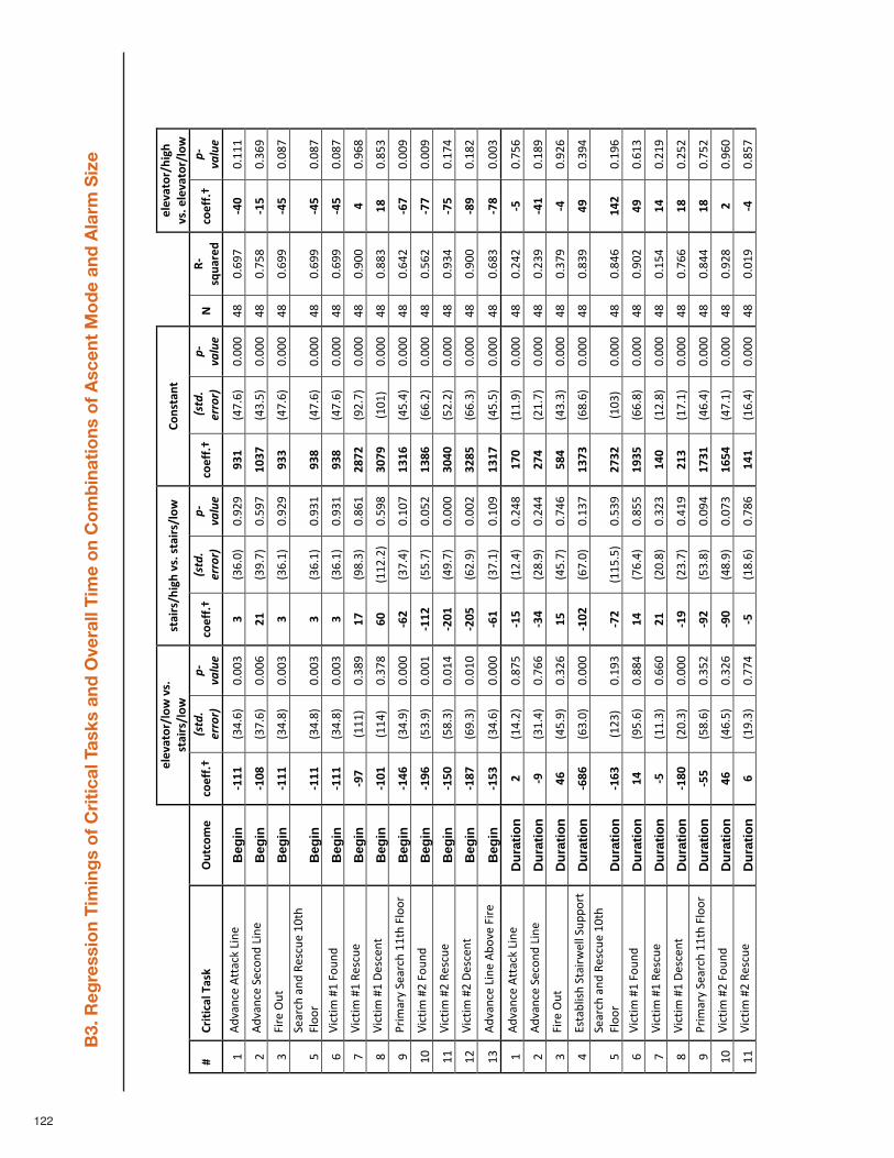
122
B3. Reg
ression Tim
ings of Critica
l Tasks and
Overall Tim
e on Combinations
of Ascen
t Mode an
d Alarm
Size
!"!#$%&'("&)
*#+,*
+%$-'+("&)
*+%$-'+(.-/.*#+,*+%$-'+("&)*
0&1+%$1%*
!"!#$%&'(.-/.*
#+,*!"!#$%&'("&)*
2*0'-%-3$"*4$+5*
67%3&8!*
3&!99,:*
!"#$%&
'(()(*&
+,-./0'&
3&!99,:*
!"#$%&
'(()(*&
+,-./0'&
3&!99,:*
&!"#$%&
'(()(*&&
+,-./0'&
;*
<=+>7$
'!?*
3&!99,:*
+,-./0'&
!"#$%&'()"#**&(+",-')
"B
egin
=@@@
*./0123"
4144/"
A*./2143"
41565"
BA@*
.07123"
41444"
08"
41257"
=CD*
41!!!"
6"#$%&'()"9)(:'
$",-')
"B
egin
=@DE
*./7123"
41442"
F@*
./5173"
41;57"
@DAG
*.0/1;3"
41444"
08"
417;8"
=@H*
41/25"
/"<-=)">?*"
Beg
in
=@@@
*./0183"
4144/"
A*./21!3"
41565"
BAA*
.07123"
41444"
08"
41255"
=CH*
41487"
;"9)&=(@"&'$
"A)B(?)"!4
*@"
<C::
="B
egin
=@@@
*./0183"
4144/"
A*./21!3"
415/!"
BAE*
.07123"
41444"
08"
41255"
=CH*
41487"
2"D-(*-E
"F!"<:?'
$"B
egin
=@@@
*./0183"
4144/"
A*./21!3"
415/!"
BAE*
.07123"
41444"
08"
41255"
=CH*
41487"
7"D-(*-E
"F!"A)
B(?)
"B
egin
=BG*
.!!!
3"41/85"
@G*
.581/3"
4182!"
FEGF
*.56173"
41444"
08"
41544"
C*41528"
8"D-(*-E
"F!"G)B()'*"
Beg
in
=@D@
*.!!0
3"41/78"
ID*
.!!6
163"
41;58"
ADGB
*.!4!
3"41444"
08"
4188/"
@E*
418;/"
5"H=-E
&=I"9)&=(@"!!*@"<C::
="B
egin
=@CI
*./0153"
41444"
=IF*
./7103"
41!47"
@A@I
*.0;103"
41444"
08"
41206"
=IG*
41445"
!4"
D-(*-E
"F6"<:?'
$"B
egin
=@BI
*.;/153"
4144!"
=@@F
*.;;173"
414;6"
@AEI
*.22163"
41444"
08"
41;26"
=GG*
41445"
!!"
D-(*-E
"F6"A)
B(?)
"B
egin
=@HD
*.;81/3"
414!0"
=FD@
*.05173"
41444"
ADCD
*.;6163"
41444"
08"
415/0"
=GH*
41!70"
!6"
D-(*-E
"F6"G)B()'*"
Beg
in
=@EG
*.251/3"
414!4"
=FDH
*.26153"
41446"
AFEH
*.221/3"
41444"
08"
41544"
=EB*
41!86"
!/"
#$%&'()",-')"#J:
%)"<-=)"
Beg
in
=@HA
*./0123"
41444"
=I@*
./71!3"
41!45"
@A@G
*.0;1;3"
41444"
08"
4128/"
=GE*
4144/"
!"#$%&'()"#**&(+",-')
"D
urat
ion
F*.!0163"
4187;"
=@H*
.!6103"
41608"
@GD*
.!!153"
41444"
08"
41606"
=H*
417;2"
6"#$%&'()"9)(:'
$",-')
"D
urat
ion
=B*
./!103"
41722"
=AC*
.68153"
41600"
FGC*
.6!173"
41444"
08"
416/5"
=C@*
41!85"
/"<-=)">?*"
Dur
atio
n CI
*.0;153"
41/62"
@H*
.0;173"
41702"
HEC*
.0/1/3"
41444"
08"
41/75"
=C*
41562"
0"KB*&JC-B@"9*&-=L
)CC"9?M
M:=*"
Dur
atio
n =IEI
*.2/143"
41444"
=@DF
*.27143"
41!/7"
@AGA
*.28123"
41444"
08"
418/5"
CB*
41/50"
;"9)&=(@"&'$
"A)B(?)"!4
*@"
<C::
="D
urat
ion
=@IA
*.!6/
3"41!5/"
=GF*
.!!;
1;3"
41;/5"
FGAF
*.!4/
3"41444"
08"
41802"
@CF*
41!52"
2"D-(*-E
"F!"<:?'
$"D
urat
ion
@C*
.5;123"
41880"
@C*
.72103"
418;;"
@BAH
*.22183"
41444"
08"
41546"
CB*
412!/"
7"D-(*-E
"F!"A)
B(?)
"D
urat
ion
=H*
.!!1/3"
41224"
F@*
.64183"
41/6/"
@CD*
.!6183"
41444"
08"
41!;0"
@C*
416!5"
8"D-(*-E
"F!"G)B()'*"
Dur
atio
n =@ED
*.641/3"
41444"
=@B*
.6/173"
410!5"
F@A*
.!71!3"
41444"
08"
41722"
@E*
416;6"
5"H=-E
&=I"9)&=(@"!!*@"<C::
="D
urat
ion
=HH*
.;8123"
41/;6"
=BF*
.;/183"
41450"
@GA@
*.02103"
41444"
08"
41800"
@E*
417;6"
!4"
D-(*-E
"F6"<:?'
$"D
urat
ion
CI*
.021;3"
41/62"
=BD*
.08153"
4147/"
@IHC
*.071!3"
41444"
08"
41568"
F*41524"
!!"
D-(*-E
"F6"A)
B(?)
"D
urat
ion
I*.!51/3"
41770"
=H*
.!8123"
41782"
@C@*
.!2103"
41444"
08"
414!5"
=C*
418;7"
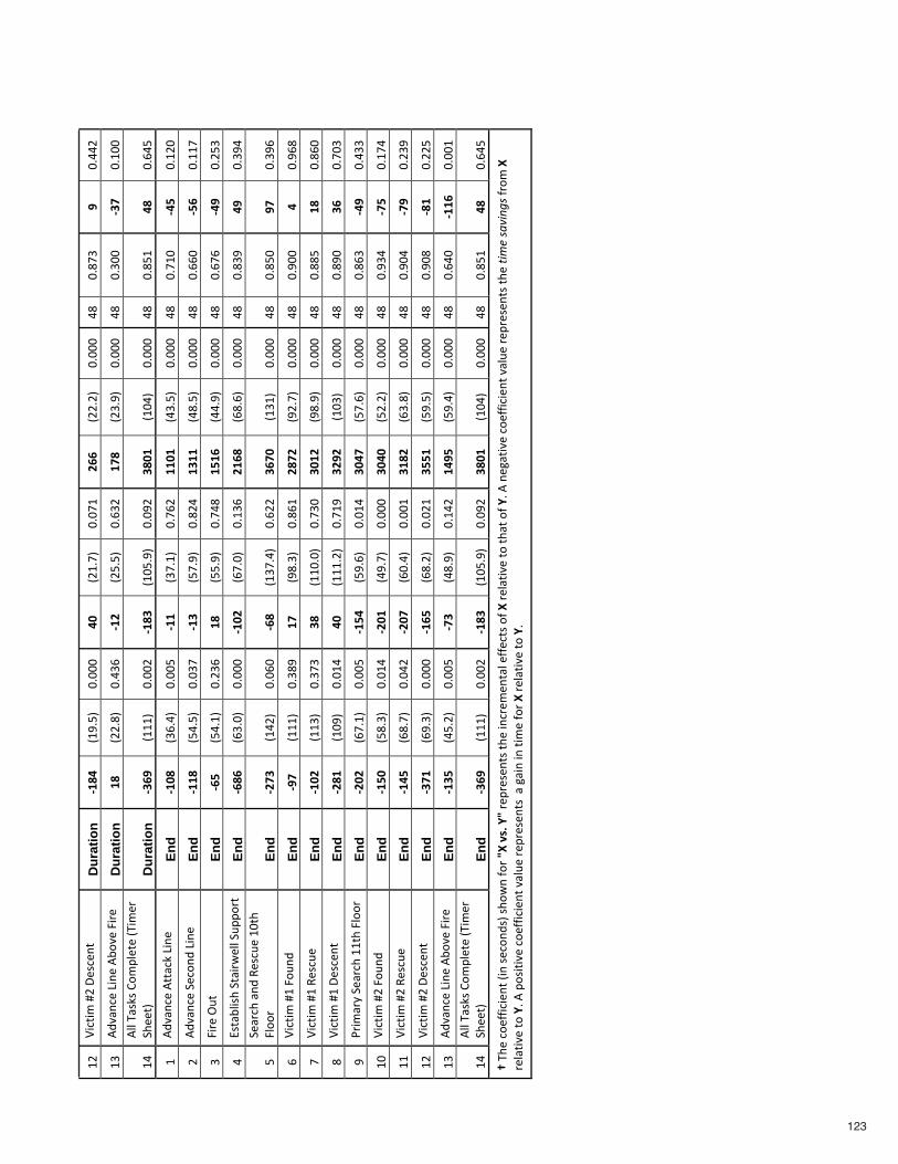
123
!6"
D-(*-E
"F6"G)B()'*"
Dur
atio
n =@EC
*.!51;3"
41444"
CD*
.6!173"
4147!"
FII*
.66163"
41444"
08"
4187/"
B*41006"
!/"
#$%&'()",-')"#J:
%)"<-=)"
Dur
atio
n @E
*.66183"
410/2"
=@F*
.6;1;3"
412/6"
@GE*
.6/153"
41444"
08"
41/44"
=AG*
41!44"
!0"
#CC"N&B+B"O:
EMC)*)".N-E
)="
9@))*3"
Dur
atio
n =AIB
*.!!!
3"41446"
=@EA
*.!4;
153"
41456"
AED@
*.!40
3"41444"
08"
418;!"
CE*
4120;"
!"#$%&'()"#**&(+",-')
"En
d =@DE
*./2103"
4144;"
=@@*
./71!3"
41726"
@@D@
*.0/1;3"
41444"
08"
417!4"
=CH*
41!64"
6"#$%&'()"9)(:'
$",-')
"En
d =@@E
*.;01;3"
414/7"
=@A*
.;7153"
41860"
@A@@
*.081;3"
41444"
08"
41224"
=HI*
41!!7"
/"<-=)">?*"
End
=IH*
.;01!3"
416/2"
@E*
.;;153"
41708"
@H@I
*.00153"
41444"
08"
41272"
=CB*
416;/"
0"KB*&JC-B@"9*&-=L
)CC"9?M
M:=*"
End
=IEI
*.2/143"
41444"
=@DF
*.27143"
41!/2"
F@IE
*.28123"
41444"
08"
418/5"
CB*
41/50"
;"9)&=(@"&'$
"A)B(?)"!4
*@"
<C::
="En
d =FGA
*.!06
3"41424"
=IE*
.!/7
103"
41266"
AIGD
*.!/!
3"41444"
08"
418;4"
BG*
41/52"
2"D-(*-E
"F!"<:?'
$"En
d =BG*
.!!!
3"41/85"
@G*
.581/3"
4182!"
FEGF
*.56173"
41444"
08"
41544"
C*41528"
7"D-(*-E
"F!"A)
B(?)
"En
d =@DF
*.!!/
3"41/7/"
AE*
.!!4
143"
417/4"
AD@F
*.58153"
41444"
08"
4188;"
@E*
41824"
8"D-(*-E
"F!"G)B()'*"
End
=FE@
*.!45
3"414!0"
CD*
.!!!
163"
417!5"
AFBF
*.!4/
3"41444"
08"
41854"
AI*
4174/"
5"H=-E
&=I"9)&=(@"!!*@"<C::
="En
d =FDF
*.271!3"
4144;"
=@HC
*.;5123"
414!0"
ADCG
*.;7123"
41444"
08"
4182/"
=CB*
410//"
!4"
D-(*-E
"F6"<:?'
$"En
d =@HD
*.;81/3"
414!0"
=FD@
*.05173"
41444"
ADCD
*.;6163"
41444"
08"
415/0"
=GH*
41!70"
!!"
D-(*-E
"F6"A)
B(?)
"En
d =@CH
*.28173"
41406"
=FDG
*.24103"
4144!"
A@EF
*.2/183"
41444"
08"
41540"
=GB*
416/5"
!6"
D-(*-E
"F6"G)B()'*"
End
=AG@
*.251/3"
41444"
=@IH
*.28163"
4146!"
AHH@
*.;51;3"
41444"
08"
41548"
=E@*
4166;"
!/"
#$%&'()",-')"#J:
%)"<-=)"
End
=@AH
*.0;163"
4144;"
=GA*
.08153"
41!06"
@CBH
*.;5103"
41444"
08"
41204"
=@@I*
4144!"
!0"
#CC"N&B+B"O:
EMC)*)".N-E
)="
9@))*3"
End
=AIB
*.!!!
3"41446"
=@EA
*.!4;
153"
41456"
AED@
*.!40
3"41444"
08"
418;!"
CE*
4120;"
:"N@)"(:)PP-(-)'*".-'"B)(:'$
B3"B@:
L'"P:="JK*#+,*LJ"=)M=)B)'
*B"*@
)"-'(=)E
)'*&C")PP)(*B":P*K
"=)C&*-%)"*:"*@
&*":P*L
1"#"')Q&*-%)"(:)PP-(-)'*"%&C?)
"=)M
=)B)'*B"*@)"!"#
$%&'(")*
&%P=:E
"K*
=)C&*-%
)"*:"L1"#
"M:B-*-%)"(:)
PP-(-)'*"%&C?)
"=)M
=)B)'*B""&"Q&-'"-'"*-E)"P:="K"=)C&*-%
)"*:"L1"
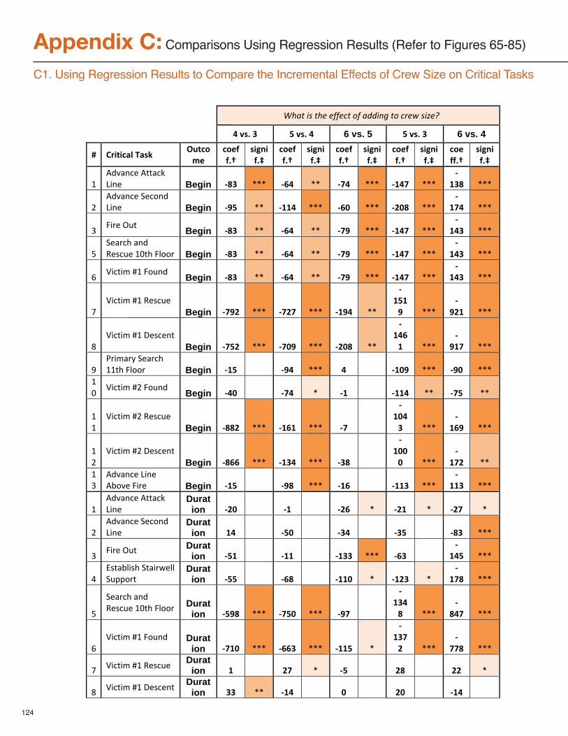
124
Appendix C: Comparisons Using Regression Results (Refer to Figures 65-85)
C1. Using Regression Results to Compare the Incremental Effects of Crew Size on Critical Tasks
!!!"#$%!&'!%#(!())(*%!+)!$,,&-.!%+!*/(0!'&1(2!
!"#$%"&" '"#$%"!" 6 vs. 5 '"#$%"&" 6 vs. 4
(" )*+,+-./"0.$1"23,-456"
-4677%8"
$+9:+7%;"
-4677%8"
$+9:+7%;"
-4677%8"
$+9:+7%;"
-4677%8"
$+9:+7%;"
-4677%8"
$+9:+7%;"
!"#$%&'()"#**&(+",-')" Begin <=&" ..." <>!" .." <?!" ..." <@!?" ..."
<@&=" ..."
/"#$%&'()"0)(1'$",-')" Begin <A'" .." <@@!" ..." <>B" ..." <CB=" ..."
<@?!" ..."
2"3-4)"56*" Begin <=&" .." <>!" .." <?A" ..." <@!?" ..."
<@!&" ..."
7"0)&4(8"&'$"9):(6)"!;*8"3<114" Begin <=&" .." <>!" .." <?A" ..." <@!?" ..."
<@!&" ..."
=">-(*-?"@!"316'$" Begin <=&" .." <>!" .." <?A" ..." <@!?" ..."
<@!&" ..."
A">-(*-?"@!"9):(6)"
Begin <?AC" ..." <?C?" ..." <@A!" .."
<@'@A" ..."
<AC@" ..."
B">-(*-?"@!"C):()'*"
Begin <?'C" ..." <?BA" ..." <CB=" .."
<@!>@" ..."
<A@?" ..."
D"E4-?&4F"0)&4(8"!!*8"3<114" Begin <@'" "" <A!" ..." !" "" <@BA" ..." <AB" ..."
!;"
>-(*-?"@/"316'$" Begin <!B" "" <?!" ." <@" "" <@@!" .." <?'" .."
!!"
>-(*-?"@/"9):(6)"Begin <==C" ..." <@>@" ..." <?" ""
<@B!&" ..."
<@>A" ..."
!/"
>-(*-?"@/"C):()'*"Begin <=>>" ..." <@&!" ..." <&=" ""
<@BBB" ..."
<@?C" .."
!2"
#$%&'()",-')"#G1%)"3-4)" Begin <@'" "" <A=" ..." <@>" "" <@@&" ..."
<@@&" ..."
!"#$%&'()"#**&(+",-')"
Duration <CB" "" <@" "" <C>" ." <C@" ." <C?" ."
/"#$%&'()"0)(1'$",-')"
Duration @!" "" <'B" "" <&!" "" <&'" "" <=&" ..."
2"3-4)"56*" Durat
ion <'@" "" <@@" "" <@&&" ..." <>&" ""<
@!'" ..."
H"I:*&G<-:8"0*&-4J)<<"06KK14*"
Duration <''" "" <>=" "" <@@B" ." <@C&" ."
<@?=" ..."
7"
0)&4(8"&'$"9):(6)"!;*8"3<114" Durat
ion <'A=" ..." <?'B" ..." <A?" ""
<@&!=" ..."
<=!?" ..."
=">-(*-?"@!"316'$" Durat
ion <?@B" ..." <>>&" ..." <@@'" ."
<@&?C" ..."
<??=" ..."
A" >-(*-?"@!"9):(6)" Duration @" "" C?" ." <'" "" C=" "" CC" ."
B" >-(*-?"@!"C):()'*" Duration &&" .." <@!" "" B" "" CB" "" <@!" ""
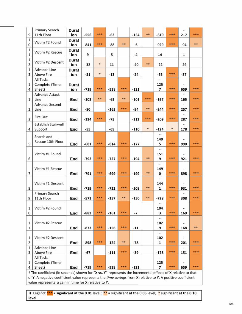
125
D"
E4-?&4F"0)&4(8"!!*8"3<114"
Duration <''>" ..." <>&" "" <@'!" .." <>@A" ..."
<C@?" ..."
!;"
>-(*-?"@/"316'$" Duration <=!@" ..." <==" .." <>" "" <ACA" ..." <A!" .."
!!"
>-(*-?"@/"9):(6)" Duration A" "" '" "" <!" "" @!" "" @" ""
!/"
>-(*-?"@/"C):()'*" Duration <&C" ." @@" "" <!B" .." <CC" "" <CA" ""
!2"
#$%&'()",-')"#G1%)"3-4)"
Duration <'@" ." <@&" "" <C!" "" <>'" ..." <&?" ""
!H"
#<<"L&:+:"M1?K<)*)"NL-?)4"08))*O"
Duration <?@A" ..." <'&=" ..." <@C@" ""
<@C'?" ..."
<>'A" ..."
!"#$%&'()"#**&(+",-')" End <@B&" .." <>'" .." <@B@" ..." <@>?" ..."
<@>'" ..."
/"#$%&'()"0)(1'$",-')" End <=B" "" <@>&" ..." <A!" .." <C!!" ..."
<C'?" ..."
2"3-4)"56*" End <@&!" ..." <?'" "" <C@C" ..." <CBA" ..."
<C=?" ..."
H"I:*&G<-:8"0*&-4J)<<"06KK14*" End <''" "" <>A" "" <@@B" ." <@C!" ."
<@?=" ..."
7"
0)&4(8"&'$"9):(6)"!;*8"3<114" End <>=@" ..." <=@!" ..." <@??" ""
<@!A'" ..."
<AAB" ..."
=">-(*-?"@!"316'$"
End <?AC" ..." <?C?" ..." <@A!" .."
<@'@A" ..."
<AC@" ..."
A">-(*-?"@!"9):(6)"
End <?A@" ..." <>AA" ..." <@AA" .."
<@!AB" ..."
<=A=" ..."
B">-(*-?"@!"C):()'*"
End <?@A" ..." <?CC" ..." <CB=" .."
<@!!@" ..."
<A&@" ..."
D"E4-?&4F"0)&4(8"!!*8"3<114" End <'?@" ..." <@'?" .." <@'B" .." <?C=" ..."
<&B=" ..."
!;"
>-(*-?"@/"316'$"End <==C" ..." <@>@" ..." <?" ""
<@B!&" ..."
<@>A" ..."
!!"
>-(*-?"@/"9):(6)"End <=?&" ..." <@'>" ..." <@@" ""
<@BCA" ..."
<@>=" .."
!/"
>-(*-?"@/"C):()'*"End <=A=" ..." <@C!" .." <?=" ""
<@BC@" ..."
<CB@" ..."
!2"
#$%&'()",-')"#G1%)"3-4)" End <>?" "" <@@@" ..." <&A" "" <@?=" ..."
<@'@" ..."
!H"
#<<"L&:+:"M1?K<)*)"NL-?)4"08))*O" End <?@A" ..." <'&=" ..." <@C@" ""
<@C'?" ..."
<>'A" ..."
8"L8)"(1)PP-(-)'*"N-'":)(1'$:O":81J'"P14"DE"#$%"FD"4)K4):)'*:"*8)"-'(4)?)'*&<")PP)(*:"1P"E"4)<&*-%)"*1"*8&*"1P"FQ"#"')R&*-%)"(1)PP-(-)'*"%&<6)"4)K4):)'*:"*8)"%&3(!'$4&-.'!P41?"E"4)<&*-%)"*1"FQ"#"K1:-*-%)"(1)PP-(-)'*"%&<6)"4)K4):)'*:""&"R&-'"-'"*-?)"P14"E"4)<&*-%)"*1"FQ"
";"",)R)'$S"GGG"H"$+9:+7+-.:,".,",I6"B%B@"/6#6/J""GG"H"$+9:+7+-.:,".,",I6"B%B'"/6#6/J""G"$+9:+7+-.:,".,",I6"B%@B"/6#6/"
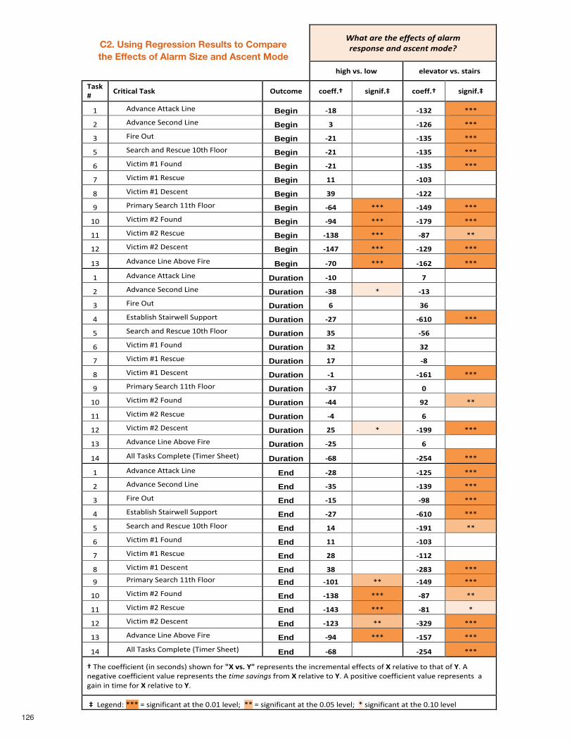
!"#$%#&'%$"'%'((')$*%+(%#,#&-%%&'*.+/*'%#/0%#*)'/$%-+0'1%
!"#!$%&'$()*$ +(+%,-).$%&'$&-,".&$
/,&0$1$
2."-"3,($/,&0$ 45-3)6+$ 3)+77'8$ &"#9"7':$ 3)+77'8$ &"#9"7':$
!" #$%&'()"#**&(+",-')" Begin ;<=$ "" ;<>?$ ..."
/" #$%&'()"0)(1'$",-')" Begin >$ "" ;<?@$ ..."
2" 3-4)"56*" Begin ;?<$ "" ;<>A$ ..."
7" 0)&4(8"&'$"9):(6)"!;*8"3<114" Begin ;?<$ "" ;<>A$ ..."
=" >-(*-?"@!"316'$" Begin ;?<$ "" ;<>A$ ..."
A" >-(*-?"@!"9):(6)" Begin <<$ "" ;<B>$ ""
B" >-(*-?"@!"C):()'*" Begin >C$ "" ;<??$ ""
D" E4-?&4F"0)&4(8"!!*8"3<114" Begin ;@D$ ..." ;<DC$ ..."
!;" >-(*-?"@/"316'$" Begin ;CD$ ..." ;<EC$ ..."
!!" >-(*-?"@/"9):(6)" Begin ;<>=$ ..." ;=E$ .."
!/" >-(*-?"@/"C):()'*" Begin ;<DE$ ..." ;<?C$ ..."
!2" #$%&'()",-')"#G1%)"3-4)" Begin ;EB$ ..." ;<@?$ ..."
!" #$%&'()"#**&(+",-')" Duration ;<B$ "" E$ ""
/" #$%&'()"0)(1'$",-')" Duration ;>=$ ." ;<>$ ""
2" 3-4)"56*" Duration @$ "" >@$ ""
H" I:*&G<-:8"0*&-4J)<<"06KK14*" Duration ;?E$ "" ;@<B$ ..."
7" 0)&4(8"&'$"9):(6)"!;*8"3<114" Duration >A$ "" ;A@$ ""
=" >-(*-?"@!"316'$" Duration >?$ "" >?$ ""
A" >-(*-?"@!"9):(6)" Duration <E$ "" ;=$ ""
B" >-(*-?"@!"C):()'*" Duration ;<$ "" ;<@<$ ..."
D" E4-?&4F"0)&4(8"!!*8"3<114" Duration ;>E$ "" B$ ""
!;" >-(*-?"@/"316'$" Duration ;DD$ "" C?$ .."
!!" >-(*-?"@/"9):(6)" Duration ;D$ "" @$ ""
!/" >-(*-?"@/"C):()'*" Duration ?A$ ." ;<CC$ ..."
!2" #$%&'()",-')"#G1%)"3-4)" Duration ;?A$ "" @$ ""
!H" #<<"L&:+:"M1?K<)*)"NL-?)4"08))*O" Duration ;@=$ "" ;?AD$ ..."
!" #$%&'()"#**&(+",-')" End ;?=$ "" ;<?A$ ..."
/" #$%&'()"0)(1'$",-')" End ;>A$ "" ;<>C$ ..."
2" 3-4)"56*" End ;<A$ "" ;C=$ ..."
H" I:*&G<-:8"0*&-4J)<<"06KK14*" End ;?E$ "" ;@<B$ ..."
7" 0)&4(8"&'$"9):(6)"!;*8"3<114" End <D$ "" ;<C<$ .."
=" >-(*-?"@!"316'$" End <<$ "" ;<B>$ ""
A" >-(*-?"@!"9):(6)" End ?=$ "" ;<<?$ ""
B" >-(*-?"@!"C):()'*" End >=$ "" ;?=>$ ..."
126
C2. Using Regression Results to Compare the Effects of Alarm Size and Ascent Mode
D" E4-?&4F"0)&4(8"!!*8"3<114" End ;<B<$ .." ;<DC$ ..."
!;" >-(*-?"@/"316'$" End ;<>=$ ..." ;=E$ .."
!!" >-(*-?"@/"9):(6)" End ;<D>$ ..." ;=<$ ."
!/" >-(*-?"@/"C):()'*" End ;<?>$ .." ;>?C$ ..."
!2" #$%&'()",-')"#G1%)"3-4)" End ;CD$ ..." ;<AE$ ..."
!H" #<<"L&:+:"M1?K<)*)"NL-?)4"08))*O" End ;@=$ "" ;?AD$ ..."
8"L8)"(1)PP-(-)'*"N-'":)(1'$:O":81J'"P14"FG$%&'$HF"4)K4):)'*:"*8)"-'(4)?)'*&<")PP)(*:"1P$G"4)<&*-%)"*1"*8&*"1P$HQ"#"')R&*-%)"(1)PP-(-)'*"%&<6)"4)K4):)'*:"*8)"!"#$%&'(")*&%P41?"G$4)<&*-%)"*1"HQ"#"K1:-*-%)"(1)PP-(-)'*"%&<6)"4)K4):)'*:""&"R&-'"-'"*-?)"P14"G"4)<&*-%)"*1"HQ"
":"",)R)'$S"..."T":-R'-P-(&'*"&*"*8)";Q;!"<)%)<U"".."T":-R'-P-(&'*"&*"*8)";Q;7"<)%)<U"".":-R'-P-(&'*"&*"*8)";Q!;"<)%)<"
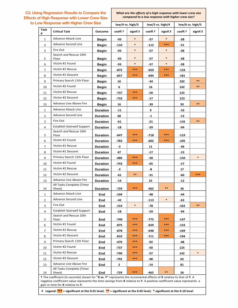
!"#$%#&'%$"'%'((')$*%+(%#%",-"%&'*.+/*'%0,$"%1+0'&%)&'0%*,2'%)+3.#&'4%$+%#%1+0%&'*.+/*'%0,$"%",-"'&%)&'0%*,2'5%
!"#$%&'()&*+,*$-& !"#$.&'()&*+,*$%& !"#$/&'()&*+,*$.&
01(2&3&
45+6+71!&01(2& 8967":;& 7";<<)=& (+,>+<)?& 7";<<)=& (+,>+<)?& 7";<<)=& (+,>+<)?&
!" #$%&'()"#**&(+",-')" Begin @A-& B& @.C& B& @DE& &&
." #$%&'()"/)(0'$",-')" Begin @FFG& B& @FFD& BBB& @.F& &&
1" 2-3)"45*" Begin @A-& B& @.C& B& @DE& &&
6"/)&3(7"&'$"8)9(5)"!:*7"2;003" Begin @A-& B& @.C& B& @DE& &&
<" =-(*->"?!"205'$" Begin @A-& B& @.C& B& @DE& &&
@" =-(*->"?!"8)9(5)" Begin @EC.& BBB& @/.A& BBB& @F--& &&
A" =-(*->"?!"B)9()'*" Begin @E.C& BBB& @/A%& BBB& @FEF& &&
C" D3->&3E"/)&3(7"!!*7"2;003" Begin F/& && @-%& && FGD& BB&
!:" =-(*->"?."205'$" Begin /& && F/& && F%D& BB&
!!" =-(*->"?."8)9(5)" Begin @C-C& BBB& @.G& && FD.& &&
!." =-(*->"?."B)9()'*" Begin @C-D& BBB& @FC& && FD-& &&
!1" #$%&'()",-')"#F0%)"2-3)" Begin F/& && @-A& && A-& BB&
!" #$%&'()"#**&(+",-')" Duration @FF& && A& && @F/& &&
." #$%&'()"/)(0'$",-')" Duration /E& && @F& && @FD& &&
1" 2-3)"45*" Duration @/F& && @DF& && @F-.& BB&
G" H9*&F;-97"/*&-3I);;"/5JJ03*" Duration @FE& && @.A& && @A%& &&
6"/)&3(7"&'$"8)9(5)"!:*7"2;003" Duration @/%C& BBB& @CFE& BBB& @FFA& &&
<" =-(*->"?!"205'$" Duration @CE-& BBB& @/GD& BBB& @FG.& &&
@" =-(*->"?!"8)9(5)" Duration @-& && FF& && @-/& &&
A" =-(*->"?!"B)9()'*" Duration %C& && @FC& && @F-& &&
C" D3->&3E"/)&3(7"!!*7"2;003" Duration @%E/& BBB& @.E& && @F.G& B&
!:" =-(*->"?."205'$" Duration @C%-& BBB& @/.& && @FC& &&
!!" =-(*->"?."8)9(5)" Duration @-& && @E& && FC& &&
!." =-(*->"?."B)9()'*" Duration @/F& BB& @-F& && @/G& BBB&
!1" #$%&'()",-')"#F0%)"2-3)" Duration @F%& && D.& && @FD& &&
!G"#;;"K&9+9"L0>J;)*)"MK->)3"/7))*N" Duration @CDA& BBB& @%/D& BB& D/& &&
!" #$%&'()"#**&(+",-')" End @FG%& && @%E& && @%%& &&
." #$%&'()"/)(0'$",-')" End @%D& && @FF-& B& @/-& &&
1" 2-3)"45*" End @F.%& B& @CE& && @F/D& BB&
G" H9*&F;-97"/*&-3I);;"/5JJ03*" End @FE& && @.A& && @A%& &&
6"/)&3(7"&'$"8)9(5)"!:*7"2;003" End @C%G& BBB& @CC.& BBB& @F%C& &&
<" =-(*->"?!"205'$" End @EC.& BBB& @/.A& BBB& @F--& &&
@" =-(*->"?!"8)9(5)" End @ECE& BBB& @/%E& BBB& @F/A& &&
C3. Using Regression Results to Compare theEffects of High Response with Lower Crew Size
to Low Response with Higher Crew Size
A" =-(*->"?!"B)9()'*" End @EFG& BBB& @CFF& BBB& @FA%& &&
C" D3->&3E"/)&3(7"!!*7"2;003" End @%CG& BBB& @AD& && @%E& &&
!:" =-(*->"?."205'$" End @C-C& BBB& @.G& && FD.& &&
!!" =-(*->"?."8)9(5)" End @C%G& BBB& @.C& && F%D& B&
!." =-(*->"?."B)9()'*" End @CAD& BBB& @%E& && /D& &&
!1" #$%&'()",-')"#F0%)"2-3)" End D& && @F%& && EF& &&
!G"#;;"K&9+9"L0>J;)*)"MK->)3"/7))*N" End @CDA& BBB& @%/D& BB& D/& &&
="K7)"(0)OO-(-)'*"M-'"9)(0'$9N"970I'"O03"HI&'()&JH"3)J3)9)'*9"*7)"-'(3)>)'*&;")OO)(*9"0O&I"3);&*-%)"*0"*7&*"0O&JP"#"')Q&*-%)"(0)OO-(-)'*"%&;5)"3)J3)9)'*9"*7)"!"#$%&'(")*&%O30>"I&3);&*-%)"*0"JP"#"J09-*-%)"(0)OO-(-)'*"%&;5)"3)J3)9)'*9""&"Q&-'"-'"*->)"O03"I"3);&*-%)"*0"JP"
&?"&&K;,;>LM&BBB&N&(+,>+<+71>6&16&6*;&G)GF&!;';!O&&BB&N&(+,>+<+71>6&16&6*;&G)G.&!;';!O&&B&(+,>+<+71>6&16&6*;&G)FG&!;';!&
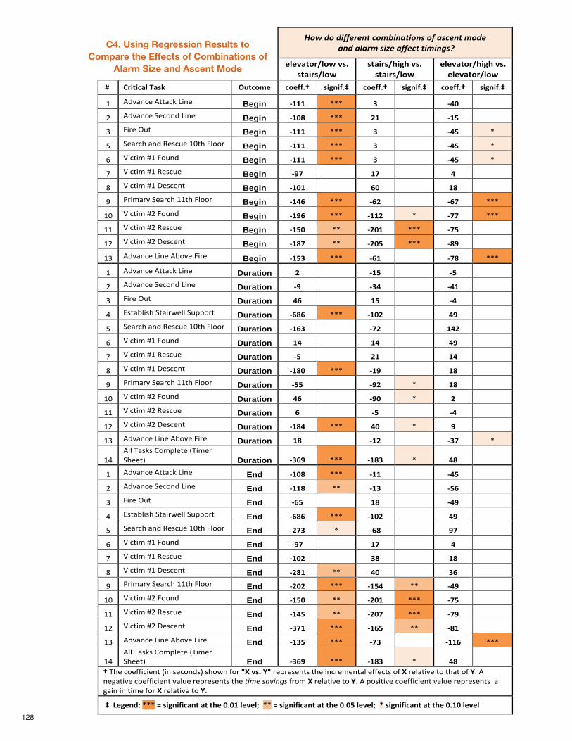
128
!"#$%"$%&''()(*+$,"-.&*/+&"*0$"'$/0,(*+$-"%($$/*%$/1/)-$0&2($/''(,+$+&-&*304$
!"!#$%&'("&)*#+,*
+%$-'+("&)*+%$-'+(.-/.*#+,*+%$-'+("&)*
!"!#$%&'(.-/.*#+,*!"!#$%&'("&)*
*0* 1'-%-2$"*3$+4* 56%2&7!* 2&!88,9* +-/:-8,;* 2&!88,9* +-/:-8,;* 2&!88,9* +-/:-8,;*
!" #$%&'()"#**&(+",-')" Begin <===* ..." >* "" <?@* ""
/" #$%&'()"0)(1'$",-')" Begin <=@A* ..." B=* "" <=C* ""
2" 3-4)"56*" Begin <===* ..." >* "" <?C* ."
7" 0)&4(8"&'$"9):(6)"!;*8"3<114" Begin <===* ..." >* "" <?C* ."
=" >-(*-?"@!"316'$" Begin <===* ..." >* "" <?C* ."
A" >-(*-?"@!"9):(6)" Begin <DE* "" =E* "" ?* ""
B" >-(*-?"@!"C):()'*" Begin <=@=* "" F@* "" =A* ""
D" E4-?&4F"0)&4(8"!!*8"3<114" Begin <=?F* ..." <FB* "" <FE* ..."
!;" >-(*-?"@/"316'$" Begin <=DF* ..." <==B* ." <EE* ..."
!!" >-(*-?"@/"9):(6)" Begin <=C@* .." <B@=* ..." <EC* ""
!/" >-(*-?"@/"C):()'*" Begin <=AE* .." <B@C* ..." <AD* ""
!2" #$%&'()",-')"#G1%)"3-4)" Begin <=C>* ..." <F=* "" <EA* ..."
!" #$%&'()"#**&(+",-')" Duration B* "" <=C* "" <C* ""
/" #$%&'()"0)(1'$",-')" Duration <D* "" <>?* "" <?=* ""
2" 3-4)"56*" Duration ?F* "" =C* "" <?* ""
H" I:*&G<-:8"0*&-4J)<<"06KK14*" Duration <FAF* ..." <=@B* "" ?D* ""
7" 0)&4(8"&'$"9):(6)"!;*8"3<114" Duration <=F>* "" <EB* "" =?B* ""
=" >-(*-?"@!"316'$" Duration =?* "" =?* "" ?D* ""
A" >-(*-?"@!"9):(6)" Duration <C* "" B=* "" =?* ""
B" >-(*-?"@!"C):()'*" Duration <=A@* ..." <=D* "" =A* ""
D" E4-?&4F"0)&4(8"!!*8"3<114" Duration <CC* "" <DB* ." =A* ""
!;" >-(*-?"@/"316'$" Duration ?F* "" <D@* ." B* ""
!!" >-(*-?"@/"9):(6)" Duration F* "" <C* "" <?* ""
!/" >-(*-?"@/"C):()'*" Duration <=A?* ..." ?@* ." D* ""
!2" #$%&'()",-')"#G1%)"3-4)" Duration =A* "" <=B* "" <>E* ."
!H"#<<"L&:+:"M1?K<)*)"NL-?)4"08))*O" Duration <>FD* ..." <=A>* ." ?A* ""
!" #$%&'()"#**&(+",-')" End <=@A* ..." <==* "" <?C* ""
/" #$%&'()"0)(1'$",-')" End <==A* .." <=>* "" <CF* ""
2" 3-4)"56*" End <FC* "" =A* "" <?D* ""
H" I:*&G<-:8"0*&-4J)<<"06KK14*" End <FAF* ..." <=@B* "" ?D* ""
7" 0)&4(8"&'$"9):(6)"!;*8"3<114" End <BE>* ." <FA* "" DE* ""
=" >-(*-?"@!"316'$" End <DE* "" =E* "" ?* ""
A" >-(*-?"@!"9):(6)" End <=@B* "" >A* "" =A* ""
B" >-(*-?"@!"C):()'*" End <BA=* .." ?@* "" >F* ""
C4. Using Regression Results toCompare the Effects of Combinations of
Alarm Size and Ascent Mode
D" E4-?&4F"0)&4(8"!!*8"3<114" End <B@B* ..." <=C?* .." <?D* ""
!;" >-(*-?"@/"316'$" End <=C@* .." <B@=* ..." <EC* ""
!!" >-(*-?"@/"9):(6)" End <=?C* .." <B@E* ..." <ED* ""
!/" >-(*-?"@/"C):()'*" End <>E=* ..." <=FC* .." <A=* ""
!2" #$%&'()",-')"#G1%)"3-4)" End <=>C* ..." <E>* "" <==F* ..."
!H"#<<"L&:+:"M1?K<)*)"NL-?)4"08))*O" End <>FD* ..." <=A>* ." ?A* ""
9"L8)"(1)PP-(-)'*"N-'":)(1'$:O":81J'"P14"GH*#+,*IG"4)K4):)'*:"*8)"-'(4)?)'*&<")PP)(*:"1P*H"4)<&*-%)"*1"*8&*"1P*IQ"#"')R&*-%)"(1)PP-(-)'*"%&<6)"4)K4):)'*:"*8)"!"#$%&'(")*&%P41?"H*4)<&*-%)"*1"IQ"#"K1:-*-%)"(1)PP-(-)'*"%&<6)"4)K4):)'*:""&"R&-'"-'"*-?)"P14"H"4)<&*-%)"*1"IQ"
*;**J!/!:KL*MMM*N*+-/:-8-2$:%*$%*%.!*@,@=*"!#!"O**MM*N*+-/:-8-2$:%*$%*%.!*@,@C*"!#!"O**M*+-/:-8-2$:%*$%*%.!*@,=@*"!#!"*
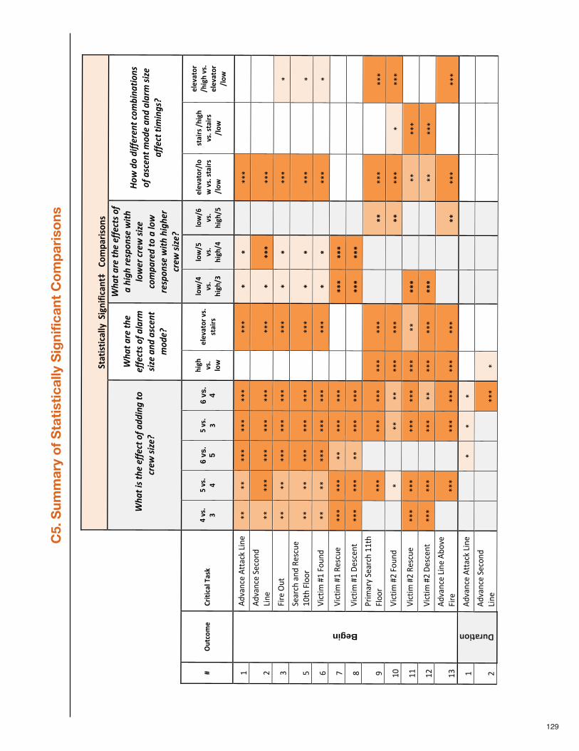
129
C5. Sum
mary of Statistically Signific
ant Comparisons
!"#"$%"$&#''())!$*+$,$&#+
"-)))./
01#
2$%/+%)
!!!"#$
%!&'!%#(!())(*%!+)!$
,,&-.!%+!
*/(0
!'&1(2!
"#$
%!$/(!%#
(!())(*%'!+)!$3$/4
!'&1(!$-,
!$'*(-
%!4+,
(2!
"#$
%!$/(!%#
(!())(*%'!+)!
$!#&.#
!/('5+-
'(!0&%#
!3+0(/!*/(0!'&1(!
*+45$
/(,!%+!$!3+0!
/('5+-
'(!0&%#
!#&.#(
/!*/(0
!'&1(2!
6+0
!,+!,&))(/(-
%!*+4
7&-$
%&+-'!!
+)!$'*(-
%!4+,
(!$-
,!$3$/4!'&1(!
$))(*%!%&4&-.'2!
3)45"&/06)
.2$"$&#')7#%8))
9):%;)
<)=):%;)
9)6
vs.
5 =):%;)
<)6
vs.
4
>$*>
):%;)
'/?)
6'6:#"/2):%;)
%"#$2%)
'/?@9)
:%;)
>$*>
@<)
'/?@=)
:%;)
>$*>
@9)
'/?@A)
:%;)
>$*>
@=)
6'6:#"/2@'/
?):%;)%"#$2%)
)@'/?)
%"#$2%)@>$*>
):%;)%"#$2%)
@'/?
)
6'6:#"/2)
@>$*>):%;)
6'6:#"/2)
@'/?
)
!"#$
%&'()"#**&(+",-')"
.."
.."
..."
..."
..."
""..."
B)B)
))..."
""""
/"#$
%&'()"0)(1'$
",-')
".."
..."
..."
..."
..."
""..."
B)BBB)
))..."
""""
2"3-4)"56*"
.."
.."
..."
..."
..."
""..."
B)B)
))..."
""."
7"0)&4(8"&'$
"9):(6)"
!;*8"3<114"
.."
.."
..."
..."
..."
""..."
B)B)
))..."
""."
=">-(*-?
"@!"316'
$".."
.."
..."
..."
..."
""..."
B)B)
))..."
""."
A">-(*-?
"@!"9)
:(6)
"..."
..."
.."
..."
..."
""""
BBB)
BBB)
))""
""""
B">-(*-?
"@!"C):()'*"
..."
..."
.."
..."
..."
""""
BBB)
BBB)
))""
""""
D"E4-?
&4F"0)&4(8"!!*8"
3<11
4"""
..."
""..."
..."
..."
..."
))))
BB)
..."
""..."
!;"
>-(*-?
"@/"316'
$"""
."""
.."
.."
..."
..."
))))
BB)
..."
."..."
!!"
>-(*-?
"@/"9)
:(6)
"..."
..."
""..."
..."
..."
.."
BBB)
))))
.."
..."
""
!/"
>-(*-?
"@/"C):()'*"
..."
..."
""..."
.."
..."
..."
BBB)
))))
.."
..."
""
!2"
Begin
#$%&'()",-')
"#G1
%)"
3-4)"
""..."
""..."
..."
..."
..."
))))
BB)
..."
""..."
!"#$
%&'()"#**&(+",-')"
""""
."."
."""
""))
))))
""""
""
/"
#$%&'()"0)(1'$
",-')
"""
""""
""..."
."""
))))
))""
""""
Duration
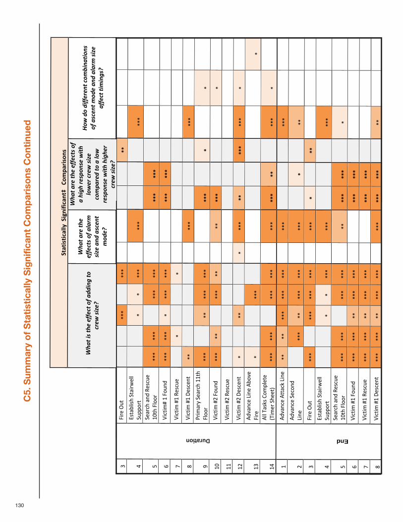
130
C5. Sum
mary of Statistically Signific
ant Comparisons
Continue
d
2"3-4)"56*"
""""
..."
""..."
""""
))))
BB)
""""
""
H"I:*&G<-:8"0*&-4J
)<<"
06KK
14*"
""""
."."
..."
""..."
))))
))..."
""""
7"0)&4(8"&'$
"9):(6)"
!;*8"3<114"
..."
..."
""..."
..."
""""
BBB)
BBB)
))""
""""
=">-(*-?
@"!"316'
$"..."
..."
."..."
..."
""""
BBB)
BBB)
))""
""""
A">-(*-?
"@!"9)
:(6)
"""
."""
""."
""""
))))
))""
""""
B">-(*-?
"@!"C):()'*"
.."
""""
""""
""..."
))))
))..."
""""
D"E4-?
&4F"0)&4(8"!!*8"
3<11
4"..."
"".."
..."
..."
""""
BBB)
))B)
""."
""
!;"
>-(*-?
"@/"316'
$"..."
.."
""..."
.."
"".."
BBB)
))))
""."
""
!!"
>-(*-?
"@/"9)
:(6)
"""
""""
""""
""""
))))
))""
""""
!/"
>-(*-?
"@/"C):()'*"
."""
.."
""""
."..."
BB)
))BBB)
..."
."""
!2"
#$%&'()",-')
"#G1
%)"
3-4)"
."""
""..."
""""
""))
))))
""""
."
!H"
#<<"L&:+:"M1?
K<)*)"
NL-?
)4"08)
)*O"
..."
..."
""..."
..."
""..."
BBB)
BB)
))..."
."""
!"#$
%&'()"#**&(+",-')"
.."
.."
..."
..."
..."
""..."
))))
))..."
""""
/"#$
%&'()"0)(1'$
",-')
"""
..."
.."
..."
..."
""..."
))B)
)).."
""""
2"3-4)"56*"
..."
""..."
..."
..."
""..."
B)))
BB)
""""
""
H"I:*&G<-:8"0*&-4J
)<<"
06KK
14*"
""""
."."
..."
""..."
))))
))..."
""""
7"0)&4(8"&'$
"9):(6)"
!;*8"3<114"
..."
..."
""..."
..."
"".."
BBB)
BBB)
))."
""""
=">-(*-?
"@!"316'
$"..."
..."
.."
..."
..."
""""
BBB)
BBB)
))""
""""
A">-(*-?
"@!"9)
:(6)
"..."
..."
.."
..."
..."
""""
BBB)
BBB)
))""
""""
B">-(*-?
"@!"C):()'*"
..."
..."
.."
..."
..."
""..."
BBB)
BBB)
)).."
""""
""
""
""
""
""
""
)))
))"
"""
"
End
""
""
"""
""
""
)))
))"
"""
Duration
!"#"$%"$&#''())!$*+$,$&#+
"-)))./
01#
2$%/+%)
!!!"#$
%!&'!%#(
!())(*%!+)!$,,
&-.!%+!
*/(0
!'&1(2!
"#$
%!$/(!%#(!
())(*%'!+)!$3$/4
!'&1(!$-,
!$'*(-
%!4+,
(2!
"#$
%!$/(!%#(!())(*%'!+)!
$!#&.#
!/('5+
-'(!0&%#!
3+0(/!*/(0!'&1(!
*+45$
/(,!%+!$!3+0!
/('5+-
'(!0&%#!#&.#
(/!
*/(0
!'&1(2!
6+0
!,+!,&))(/(-
%!*+47&-$
%&+-
'!!
+)!$'*(-
%!4+,
(!$-
,!$3$/4!'&1(!
$))(*%!%&4
&-.'2!
))
)))
))
))
))
)
))
) ) )
))
)
)))
)))
)))
))
))
)
))
))
)
))
) ))
""
""
""
""
"""
")
)))
"""
""
""
""
""
""
"""
")
)))
"""
""
""
""
""
""
"""
))
))"
"""
""
""
""
""
""
"""
")
)))
"""
"
""
""
""
""
"""
")
)))
"""
"
""
""
""
""
"""
"")
)))
""""
""
""
""
""
""
"""
"")
)))
""""
""
""
""
"""
"""
""
""
))))
)"
"""
""
""
"""
"""
""
"))
)))
""
"
""
""
""
"""
""
")
))))
""
""
""
""
""
"""
""
")
))))
""
""
"
""
""
"""
"""
""
"))
)))
"""
"
""
""
""""
""
"""
""))
))))
""""
""
"
""
"""
""""
"""
"""
))))
))""
""""
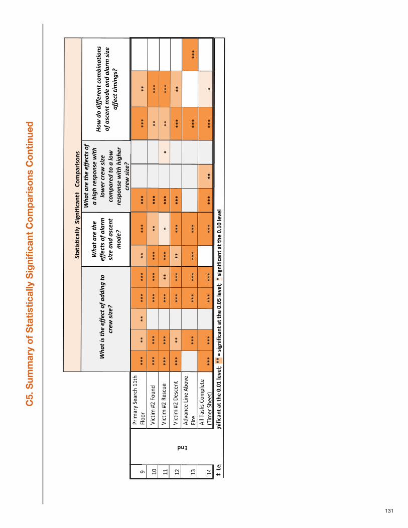
131
C5. Sum
mary of Statistically Signific
ant Comparisons
Continue
d
""
"""
"""
"""
""""
))))
)""
""""
""
""
""""
""
"""
"))
))))
"""
""
""
""
""
""
"""
"""
"")
)))
""""
""
"""
""
""
""
""""
))
))""
""""
""
""
"""
""""
"""
""))
))))
""""
""
""
""
"""
""""
""""
"))
))))
"""
""
""
""
""
"""
""
""""
)))
)""
"""
""
""
""
"""
"""
")
))))
"""
""
""
""
""""
""""
""""
""))
))))
""""
""
""
""
"""
"""
"""
")
)))
""
""
""
""
""
""""
"""
""""
))))
))""
"""
"
""
""
""
"""
""
"""
))
))"
"""
""
""
""
""
"""
"))
))))
"""
""
""
""
"""
""
"""
"))
)))
"""
""
""
""
"""
""
"""
)))
)""
""""
""
""
""""
""
"""
"))
))))
"""
""
""
""
""
""
"""
"""
")
)))
"""
""
""
""
""
""
"""
"")
)))
""""
""
""
""
""
""
"""
"")
)))
""""
""
""
""
""
""
"""
")
)))
"""
""
D"E4-?
&4F"0)&4(8"!!*8"
3<11
4"..."
.."
.."
..."
..."
.."
..."
BBB)
))))
..."
.."
""
!;"
>-(*-?
"@/"316'
$"..."
..."
""..."
..."
..."
.."
BBB)
))))
.."
..."
""
!!"
>-(*-?
"@/"9)
:(6)
"..."
..."
""..."
.."
..."
."BBB)
))B)
.."
..."
""
!/"
>-(*-?
"@/"C):()'*"
..."
.."
""..."
..."
.."
..."
BBB)
))))
..."
.."
""
!2"
#$%&'()",-')
"#G1
%)"
3-4)"
""..."
""..."
..."
..."
..."
))))
))..."
""..."
!H"
)
#<<"L&:+:"M1?
K<)*)"
NL-?
)4"08)
)*O"
..."
..."
""..."
..."
""..."
BBB)
BB)
))..."
."""
-))C6*6+
DE)BBB)F)%$*+$,$&#+
")#")">6
)G;GH)'6:6'I))BB)F)%$*+$,$&#+")#")">6
)G;G=)'6:6'I))B)%$*+$,$&#+
")#")">6
)G;HG)'6:6')
!"#"$%"$&#''())!$*+$,$&#+
"-)))./
01#
2$%/+%)
!!!"#$
%!&'!%#(
!())(*%!+)!$,,
&-.!%+!
*/(0
!'&1(2!
"#$
%!$/(!%#(!
())(*%'!+)!$3$/4
!'&1(!$-,
!$'*(-
%!4+,
(2!
"#$
%!$/(!%#(!())(*%'!+)!
$!#&.#
!/('5+
-'(!0&%#!
3+0(/!*/(0!'&1(!
*+45$
/(,!%+!$!3+0!
/('5+-
'(!0&%#!#&.#
(/!
*/(0
!'&1(2!
6+0
!,+!,&))(/(-
%!*+47&-$
%&+-
'!!
+)!$'*(-
%!4+,
(!$-
,!$3$/4!'&1(!
$))(*%!%&4
&-.'2!
)))
))
))
))
)
))
) ) )
))
)
)))
)))
)))
))
))
)
))
))
)
))
) ))
""
""
""
""
"""
))
))"
""""
""
""
""
""
"""
))
))"
""""
""
""
""
"""
")
)))
"""
""
""
""
""
""
"""
")
)))
"""
"
""
""
""
""
"""
))
))"
"""
""
""
""
""
""""
))
))""
""""
""
""
""
""
""""
))
))""
""""
""
""
"""
"""
""
"))
)))
"""
""
""
"""
"""
""
"))
)))
""
""
""
""
"""
""
")
))))
""
""
""
""
"""
""
""
)))
))"
"""
""
""
"""
"""
""
"))
)))
"""
"
""
"""
"""
""
""""
))))
))""
""""
""
"""
""""
"""
"""
))))
))""
""""
End
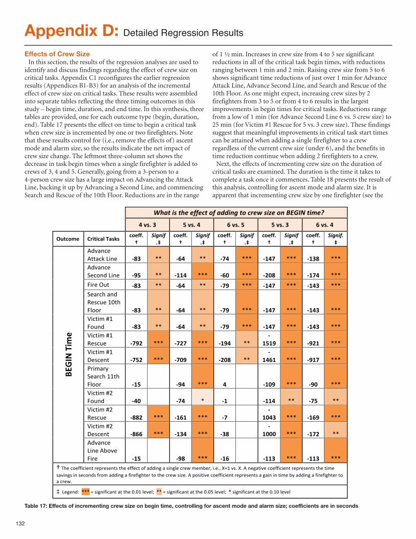
132
Appendix D: Detailed Regression Results
Effects of Crew SizeIn this section, the results of the regression analyses are used to
identify and discuss findings regarding the effect of crew size oncritical tasks. Appendix C1 reconfigures the earlier regressionresults (Appendices B1-B3) for an analysis of the incrementaleffect of crew size on critical tasks. These results were assembledinto separate tables reflecting the three timing outcomes in thisstudy – begin time, duration, and end time. In this synthesis, threetables are provided, one for each outcome type (begin, duration,end). Table 17 presents the effect on time to begin a critical taskwhen crew size is incremented by one or two firefighters. Notethat these results control for (i.e., remove the effects of) ascentmode and alarm size, so the results indicate the net impact ofcrew size change. The leftmost three-column set shows thedecrease in task begin times when a single firefighter is added tocrews of 3, 4 and 5. Generally, going from a 3-person to a4-person crew size has a large impact on Advancing the AttackLine, backing it up by Advancing a Second Line, and commencingSearch and Rescue of the 10th Floor. Reductions are in the range
of 1 ½ min. Increases in crew size from 4 to 5 see significantreductions in all of the critical task begin times, with reductionsranging between 1 min and 2 min. Raising crew size from 5 to 6shows significant time reductions of just over 1 min for AdvanceAttack Line, Advance Second Line, and Search and Rescue of the10th Floor. As one might expect, increasing crew sizes by 2firefighters from 3 to 5 or from 4 to 6 results in the largestimprovements in begin times for critical tasks. Reductions rangefrom a low of 1 min (for Advance Second Line 6 vs. 5 crew size) to25 min (for Victim #1 Rescue for 5 vs. 3 crew size). These findingssuggest that meaningful improvements in critical task start timescan be attained when adding a single firefighter to a crewregardless of the current crew size (under 6), and the benefits intime reduction continue when adding 2 firefighters to a crew.Next, the effects of incrementing crew size on the duration of
critical tasks are examined. The duration is the time it takes tocomplete a task once it commences. Table 18 presents the result ofthis analysis, controlling for ascent mode and alarm size. It isapparent that incrementing crew size by one firefighter (see the
!!!"#$%!&'!%#(!())(*%!+)!$,,&-.!%+!*/(0!'&1(!+-!23456!%&7(8!
!"#$%"&" '"#$%"!" ("#$%"'" '"#$%"&" ("#$%"!"
)*+,-./" 012+2,34"53$6$"",-/77%8"
9&.-&):9!
,-/77%8"
9&.-&):9!
,-/77%8"
9&.-&):9!
,-/77%8"
9&.-&):9!
,-/77%8"
9&.-&):9!
!"#$%&'(!))$&*(+,%'( :;&" --( :(!" --( :<!" ---( :=!<" ---( :=&;" ---(!"#$%&'(.'&/%"(+,%'( :>'" --( :==!" ---( :(?" ---( :@?;" ---( :=<!" ---(
0,1'(23)( :;&" --( :(!" --( :<>" ---( :=!<" ---( :=!&" ---(.'$1&4($%"(5'6&3'(78)4(09//1( :;&" --( :(!" --( :<>" ---( :=!<" ---( :=!&" ---(:,&),;(<7(0/3%"( :;&" --( :(!" --( :<>" ---( :=!<" ---( :=!&" ---(:,&),;(<7(5'6&3'( :<>@" ---( :<@<" ---( :=>!" --(
:='=>" ---( :>@=" ---(
:,&),;(<7(='6&'%)( :<'@" ---( :<?>" ---( :@?;" --(
:=!(=" ---( :>=<" ---(
>1,;$1?(.'$1&4(77)4(09//1( :='" (( :>!" ---( !" (( :=?>" ---( :>?" ---(:,&),;(<@(0/3%"( :!?" (( :<!" -( :=" (( :==!" --( :<'" --(:,&),;(<@(5'6&3'( :;;@" ---( :=(=" ---( :<" ((
:=?!&" ---( :=(>" ---(
:,&),;(<@(='6&'%)( :;((" ---( :=&!" ---( :&;" ((
:=???" ---( :=<@" --(
ABCDE"52.
/"
!"#$%&'(+,%'(!A/#'(0,1'( :='" (( :>;" ---( :=(" (( :==&" ---( :==&" ---(
B(C4'(&/'DD,&,'%)(1'E1'6'%)6()4'('DD'&)(/D($"",%F($(6,%F9'(&1'G(;';A'1H(,I'IH(JK7(#6I(JI(!(%'F$),#'(&/'DD,&,'%)(1'E1'6'%)6()4'(),;'(6$#,%F6(,%(6'&/%"6(D1/;($"",%F($(D,1'D,F4)'1()/()4'(&1'G(6,L'I(!(E/6,),#'(&/'DD,&,'%)(1'E1'6'%)6($(F$,%(,%(),;'(A?($"",%F($(D,1'D,F4)'1()/($(&1'GI(
‡((+'F'%"M((---(N(6,F%,D,&$%)($)()4'(8I87(9'#'9O((--(N(6,F%,D,&$%)($)()4'(8I8P(9'#'9O((-(6,F%,D,&$%)($)()4'(8I78(9'#'9(
Table 17: Effects of incrementing crew size on begin time, controlling for ascent mode and alarm size; coefficients are in seconds
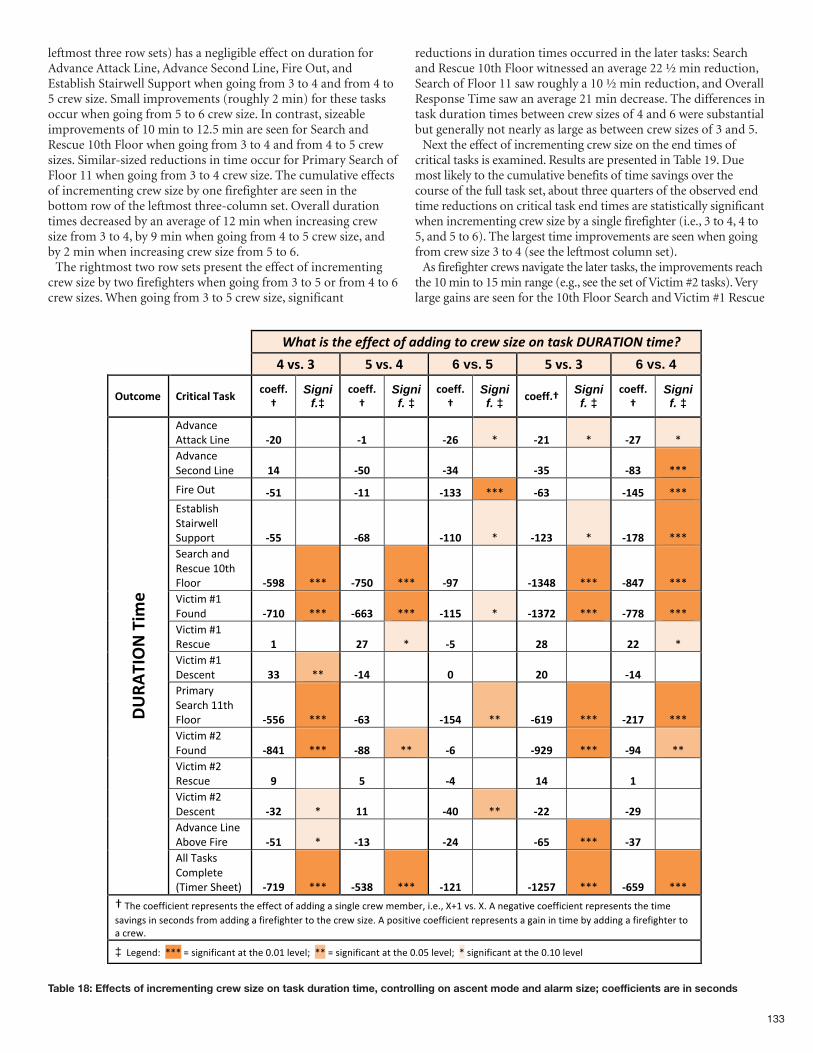
133
!!!"#$%!&'!%#(!())(*%!+)!$,,&-.!%+!*/(0!'&1(!+-!%$'2!3456789:!%&;(<!
!"#$%"&" '"#$%"!" 6 vs. 5 '"#$%"&" 6 vs. 4
()*+,-." /01*1+23"42$5"+,.66%7"
Signif.‡
+,.66%7"
Signif. ‡
+,.66%7"
Signif. ‡ +,.66%7" Signi
f. ‡ +,.66%7"
Signif. ‡
!"#$%&'(!))$&*(+,%'( 89:" (( 8;" (( 89<" -( 89;" -( 89=" -(!"#$%&'(.'&/%"(+,%'( ;!" (( 8':" (( 8&!" (( 8&'" (( 8>&" ---(
0,1'(23)( 8';" (( 8;;" (( 8;&&" ---( 8<&" (( 8;!'" ---(45)$67,58(.)$,19'77(.3::/1)( 8''" (( 8<>" (( 8;;:" -( 8;9&" -( 8;=>" ---(.'$1&8($%"(;'5&3'(<=)8(07//1( 8'?>" ---( 8=':" ---( 8?=" (( 8;&!>" ---( 8>!=" ---(>,&),?(@<(0/3%"( 8=;:" ---( 8<<&" ---( 8;;'" -( 8;&=9" ---( 8==>" ---(>,&),?(@<(;'5&3'( ;" (( 9=" -( 8'" (( 9>" (( 99" -(>,&),?(@<(A'5&'%)( &&" --( 8;!" (( :" (( 9:" (( 8;!" ((B1,?$1C(.'$1&8(<<)8(07//1( 8''<" ---( 8<&" (( 8;'!" --( 8<;?" ---( 89;=" ---(>,&),?(@D(0/3%"( 8>!;" ---( 8>>" --( 8<" (( 8?9?" ---( 8?!" --(>,&),?(@D(;'5&3'( ?" (( '" (( 8!" (( ;!" (( ;" ((>,&),?(@D(A'5&'%)( 8&9" -( ;;" (( 8!:" --( 899" (( 89?" ((!"#$%&'(+,%'(!6/#'(0,1'( 8';" -( 8;&" (( 89!" (( 8<'" ---( 8&=" ((
@ABC
4D(E"41-
."
!77(E$5*5(F/?:7')'(GE,?'1(.8'')H( 8=;?" ---( 8'&>" ---( 8;9;" (( 8;9'=" ---( 8<'?" ---(
I(E8'(&/'JJ,&,'%)(1':1'5'%)5()8'('JJ'&)(/J($"",%K($(5,%K7'(&1'9(?'?6'1L(,M'ML(NO<(#5M(NM(!(%'K$),#'(&/'JJ,&,'%)(1':1'5'%)5()8'(),?'(5$#,%K5(,%(5'&/%"5(J1/?($"",%K($(J,1'J,K8)'1()/()8'(&1'9(5,P'M(!(:/5,),#'(&/'JJ,&,'%)(1':1'5'%)5($(K$,%(,%(),?'(6C($"",%K($(J,1'J,K8)'1()/($(&1'9M(
‡((+'K'%"Q((---(R(5,K%,J,&$%)($)()8'(=M=<(7'#'7S((--(R(5,K%,J,&$%)($)()8'(=M=T(7'#'7S((-(5,K%,J,&$%)($)()8'(=M<=(7'#'7(
Table 18: Effects of incrementing crew size on task duration time, controlling on ascent mode and alarm size; coefficients are in seconds
leftmost three row sets) has a negligible effect on duration forAdvance Attack Line, Advance Second Line, Fire Out, andEstablish Stairwell Support when going from 3 to 4 and from 4 to5 crew size. Small improvements (roughly 2 min) for these tasksoccur when going from 5 to 6 crew size. In contrast, sizeableimprovements of 10 min to 12.5 min are seen for Search andRescue 10th Floor when going from 3 to 4 and from 4 to 5 crewsizes. Similar-sized reductions in time occur for Primary Search ofFloor 11 when going from 3 to 4 crew size. The cumulative effectsof incrementing crew size by one firefighter are seen in thebottom row of the leftmost three-column set. Overall durationtimes decreased by an average of 12 min when increasing crewsize from 3 to 4, by 9 min when going from 4 to 5 crew size, andby 2 min when increasing crew size from 5 to 6.The rightmost two row sets present the effect of incrementing
crew size by two firefighters when going from 3 to 5 or from 4 to 6crew sizes. When going from 3 to 5 crew size, significant
reductions in duration times occurred in the later tasks: Searchand Rescue 10th Floor witnessed an average 22 ½ min reduction,Search of Floor 11 saw roughly a 10 ½ min reduction, and OverallResponse Time saw an average 21 min decrease. The differences intask duration times between crew sizes of 4 and 6 were substantialbut generally not nearly as large as between crew sizes of 3 and 5.Next the effect of incrementing crew size on the end times of
critical tasks is examined. Results are presented in Table 19. Duemost likely to the cumulative benefits of time savings over thecourse of the full task set, about three quarters of the observed endtime reductions on critical task end times are statistically significantwhen incrementing crew size by a single firefighter (i.e., 3 to 4, 4 to5, and 5 to 6). The largest time improvements are seen when goingfrom crew size 3 to 4 (see the leftmost column set).As firefighter crews navigate the later tasks, the improvements reach
the 10 min to 15 min range (e.g., see the set of Victim #2 tasks). Verylarge gains are seen for the 10th Floor Search and Victim #1 Rescue
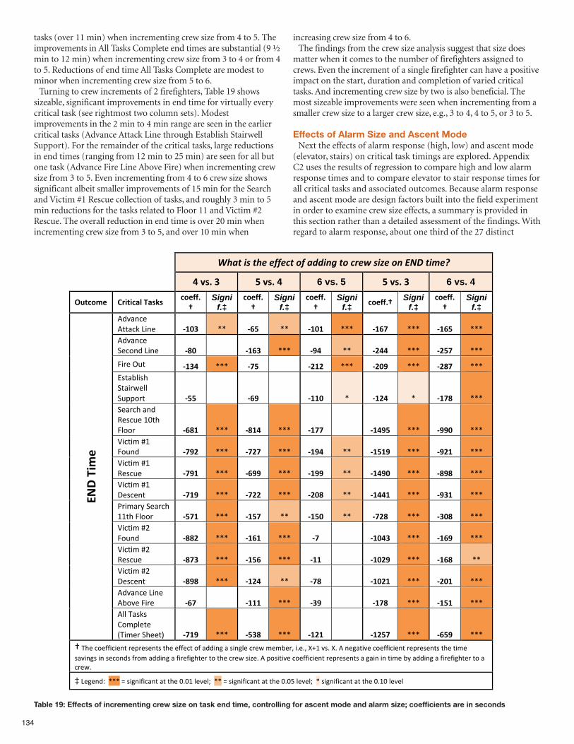
134
tasks (over 11 min) when incrementing crew size from 4 to 5. Theimprovements in All Tasks Complete end times are substantial (9 ½min to 12 min) when incrementing crew size from 3 to 4 or from 4to 5. Reductions of end time All Tasks Complete are modest tominor when incrementing crew size from 5 to 6.Turning to crew increments of 2 firefighters, Table 19 shows
sizeable, significant improvements in end time for virtually everycritical task (see rightmost two column sets). Modestimprovements in the 2 min to 4 min range are seen in the earliercritical tasks (Advance Attack Line through Establish StairwellSupport). For the remainder of the critical tasks, large reductionsin end times (ranging from 12 min to 25 min) are seen for all butone task (Advance Fire Line Above Fire) when incrementing crewsize from 3 to 5. Even incrementing from 4 to 6 crew size showssignificant albeit smaller improvements of 15 min for the Searchand Victim #1 Rescue collection of tasks, and roughly 3 min to 5min reductions for the tasks related to Floor 11 and Victim #2Rescue. The overall reduction in end time is over 20 min whenincrementing crew size from 3 to 5, and over 10 min when
increasing crew size from 4 to 6.The findings from the crew size analysis suggest that size does
matter when it comes to the number of firefighters assigned tocrews. Even the increment of a single firefighter can have a positiveimpact on the start, duration and completion of varied criticaltasks. And incrementing crew size by two is also beneficial. Themost sizeable improvements were seen when incrementing from asmaller crew size to a larger crew size, e.g., 3 to 4, 4 to 5, or 3 to 5.
Effects of Alarm Size and Ascent ModeNext the effects of alarm response (high, low) and ascent mode
(elevator, stairs) on critical task timings are explored. AppendixC2 uses the results of regression to compare high and low alarmresponse times and to compare elevator to stair response times forall critical tasks and associated outcomes. Because alarm responseand ascent mode are design factors built into the field experimentin order to examine crew size effects, a summary is provided inthis section rather than a detailed assessment of the findings. Withregard to alarm response, about one third of the 27 distinct
Table 19: Effects of incrementing crew size on task end time, controlling for ascent mode and alarm size; coefficients are in seconds
!"#$%&'%$"(%())(*$%+)%#,,&-.%$+%*/(0%'&1(%+-%234%$&5(6%
!"#$%"&" '"#$%"!" 6 vs. 5 '"#$%"&" 6 vs. 4
()*+,-." /01*1+23"42$5$""+,.66%7"
Signif.‡
+,.66%7"
Signif.‡
+,.66%7"
Signif.‡ +,.66%7" Signi
f.‡ +,.66%7"
Signif.‡
!"#$%&'(!))$&*(+,%'( 89:&" --( 8;'" --( 89:9" ---( 89;<" ---( 89;'" ---(!"#$%&'(.'&/%"(+,%'( 8=:" (( 89;&" ---( 8>!" --( 8?!!" ---( 8?'<" ---(
0,1'(23)( 89&!" ---( 8<'" (( 8?9?" ---( 8?:>" ---( 8?=<" ---(45)$67,58(.)$,19'77(.3::/1)( 8''" (( 8;>" (( 899:" -( 89?!" -( 89<=" ---(.'$1&8($%"(;'5&3'(<=)8(07//1( 8;=9" ---( 8=9!" ---( 89<<" (( 89!>'" ---( 8>>:" ---(>,&),?(@<(0/3%"( 8<>?" ---( 8<?<" ---( 89>!" --( 89'9>" ---( 8>?9" ---(>,&),?(@<(;'5&3'( 8<>9" ---( 8;>>" ---( 89>>" --( 89!>:" ---( 8=>=" ---(>,&),?(@<(A'5&'%)( 8<9>" ---( 8<??" ---( 8?:=" --( 89!!9" ---( 8>&9" ---(B1,?$1C(.'$1&8(<<)8(07//1( 8'<9" ---( 89'<" --( 89':" --( 8<?=" ---( 8&:=" ---(>,&),?(@D(0/3%"( 8==?" ---( 89;9" ---( 8<" (( 89:!&" ---( 89;>" ---(>,&),?(@D(;'5&3'( 8=<&" ---( 89';" ---( 899" (( 89:?>" ---( 89;=" --(>,&),?(@D(A'5&'%)( 8=>=" ---( 89?!" --( 8<=" (( 89:?9" ---( 8?:9" ---(!"#$%&'(+,%'(!6/#'(0,1'( 8;<" (( 8999" ---( 8&>" (( 89<=" ---( 89'9" ---(
@AB"41-
."
!77(E$5*5(F/?:7')'(GE,?'1(.8'')H( 8<9>" ---( 8'&=" ---( 89?9" (( 89?'<" ---( 8;'>" ---(
I(E8'(&/'JJ,&,'%)(1':1'5'%)5()8'('JJ'&)(/J($"",%K($(5,%K7'(&1'9(?'?6'1L(,M'ML(NO<(#5M(NM(!(%'K$),#'(&/'JJ,&,'%)(1':1'5'%)5()8'(),?'(5$#,%K5(,%(5'&/%"5(J1/?($"",%K($(J,1'J,K8)'1()/()8'(&1'9(5,P'M(!(:/5,),#'(&/'JJ,&,'%)(1':1'5'%)5($(K$,%(,%(),?'(6C($"",%K($(J,1'J,K8)'1()/($(&1'9M(
‡(+'K'%"Q((---(R(5,K%,J,&$%)($)()8'(=M=<(7'#'7S((--(R(5,K%,J,&$%)($)()8'(=M=T(7'#'7S((-(5,K%,J,&$%)($)()8'(=M<=(7'#'7(
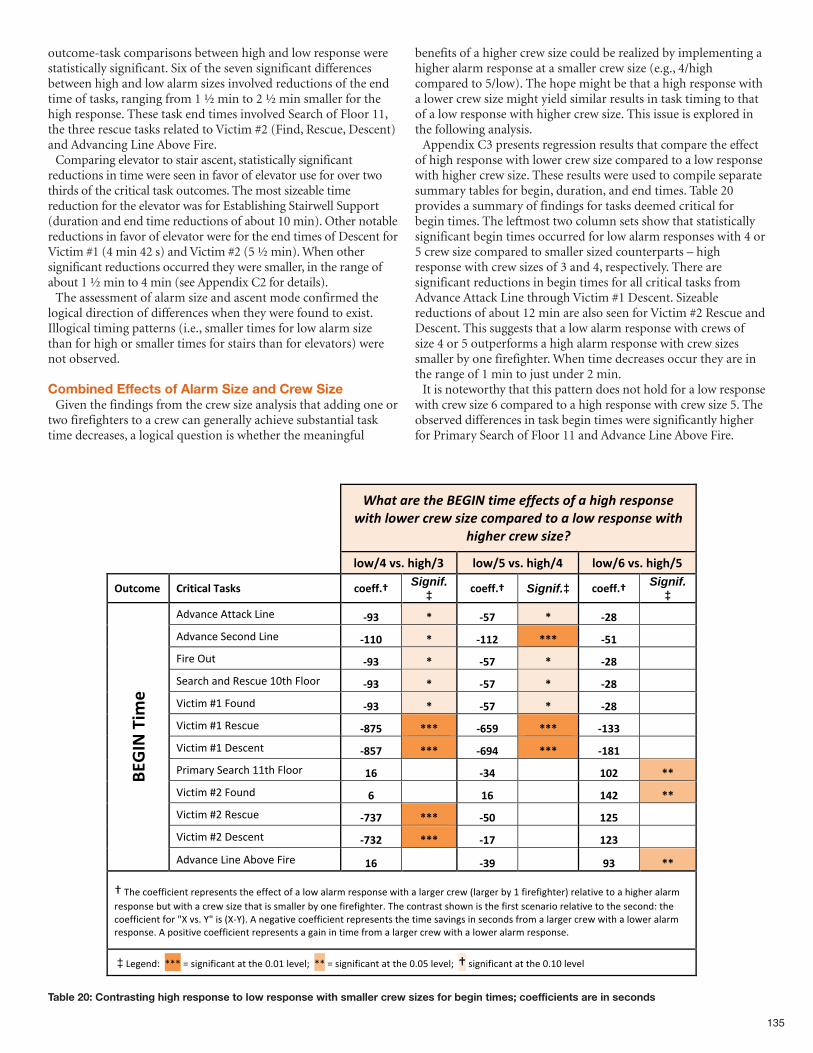
135
Table 20: Contrasting high response to low response with smaller crew sizes for begin times; coefficients are in seconds
outcome-task comparisons between high and low response werestatistically significant. Six of the seven significant differencesbetween high and low alarm sizes involved reductions of the endtime of tasks, ranging from 1 ½ min to 2 ½ min smaller for thehigh response. These task end times involved Search of Floor 11,the three rescue tasks related to Victim #2 (Find, Rescue, Descent)and Advancing Line Above Fire. Comparing elevator to stair ascent, statistically significant
reductions in time were seen in favor of elevator use for over twothirds of the critical task outcomes. The most sizeable timereduction for the elevator was for Establishing Stairwell Support(duration and end time reductions of about 10 min). Other notablereductions in favor of elevator were for the end times of Descent forVictim #1 (4 min 42 s) and Victim #2 (5 ½ min). When othersignificant reductions occurred they were smaller, in the range ofabout 1 ½ min to 4 min (see Appendix C2 for details).The assessment of alarm size and ascent mode confirmed the
logical direction of differences when they were found to exist.Illogical timing patterns (i.e., smaller times for low alarm sizethan for high or smaller times for stairs than for elevators) werenot observed.
Combined Effects of Alarm Size and Crew SizeGiven the findings from the crew size analysis that adding one or
two firefighters to a crew can generally achieve substantial tasktime decreases, a logical question is whether the meaningful
benefits of a higher crew size could be realized by implementing ahigher alarm response at a smaller crew size (e.g., 4/highcompared to 5/low). The hope might be that a high response witha lower crew size might yield similar results in task timing to thatof a low response with higher crew size. This issue is explored inthe following analysis. Appendix C3 presents regression results that compare the effect
of high response with lower crew size compared to a low responsewith higher crew size. These results were used to compile separatesummary tables for begin, duration, and end times. Table 20provides a summary of findings for tasks deemed critical forbegin times. The leftmost two column sets show that statisticallysignificant begin times occurred for low alarm responses with 4 or5 crew size compared to smaller sized counterparts – highresponse with crew sizes of 3 and 4, respectively. There aresignificant reductions in begin times for all critical tasks fromAdvance Attack Line through Victim #1 Descent. Sizeablereductions of about 12 min are also seen for Victim #2 Rescue andDescent. This suggests that a low alarm response with crews ofsize 4 or 5 outperforms a high alarm response with crew sizessmaller by one firefighter. When time decreases occur they are inthe range of 1 min to just under 2 min. It is noteworthy that this pattern does not hold for a low response
with crew size 6 compared to a high response with crew size 5. Theobserved differences in task begin times were significantly higherfor Primary Search of Floor 11 and Advance Line Above Fire.
!"#$%#&'%$"'%()*+,%$-.'%'//'0$1%2/%#%"-3"%&'14251'%6-$"%726'&%0&'6%1-8'%02.4#&'9%$2%#%726%&'14251'%6-$"%
"-3"'&%0&'6%1-8':%
!"#$%&'()&*+,*$-& !"#$.&'()&*+,*$%& !"#$/&'()&*+,*$.&
0123"45& 67+2+38!&98(:(&& 3"5;;)<& Signif.‡ 3"5;;)<& Signif.‡ 3"5;;)<& Signif.
‡ !"#$%&'(!))$&*(+,%'( =>-& ?& =.@& ?& =AB& &&
!"#$%&'(-'&.%"(+,%'( =CCD& ?& =CCA& ???& =.C& &&
/,0'(12)( =>-& ?& =.@& ?& =AB& &&
-'$0&3($%"(4'5&2'(67)3(/8..0( =>-& ?& =.@& ?& =AB& &&
9,&),:(;6(/.2%"( =>-& ?& =.@& ?& =AB& &&
9,&),:(;6(4'5&2'( =B@.& ???& =/.>& ???& =C--& &&
9,&),:(;6(<'5&'%)( =B.@& ???& =/>%& ???& =CBC& &&
=0,:$0>(-'$0&3(66)3(/8..0( C/& && =-%& && CDA& ??&
9,&),:(;?(/.2%"( /& && C/& && C%A& ??&
9,&),:(;?(4'5&2'( =@-@& ???& =.D& && CA.& &&
9,&),:(;?(<'5&'%)( =@-A& ???& =C@& && CA-& &&
EFGHI&9+4
5&
!"#$%&'(+,%'(!@.#'(/,0'( C/& && =->& && >-& ??&
A(B3'(&.'CC,&,'%)(0'D0'5'%)5()3'('CC'&)(.C($(8.E($8$0:(0'5D.%5'(E,)3($(8$0F'0(&0'E(G8$0F'0(@>(6(C,0'C,F3)'0H(0'8$),#'().($(3,F3'0($8$0:(0'5D.%5'(@2)(E,)3($(&0'E(5,I'()3$)(,5(5:$88'0(@>(.%'(C,0'C,F3)'0J(B3'(&.%)0$5)(53.E%(,5()3'(C,05)(5&'%$0,.(0'8$),#'().()3'(5'&.%"K()3'(&.'CC,&,'%)(C.0(LM(#5J(NL(,5(GMONHJ(!(%'F$),#'(&.'CC,&,'%)(0'D0'5'%)5()3'(),:'(5$#,%F5(,%(5'&.%"5(C0.:($(8$0F'0(&0'E(E,)3($(8.E'0($8$0:(0'5D.%5'J(!(D.5,),#'(&.'CC,&,'%)(0'D0'5'%)5($(F$,%(,%(),:'(C0.:($(8$0F'0(&0'E(E,)3($(8.E'0($8$0:(0'5D.%5'J(
(‡(+'F'%"K((PPP(Q(5,F%,C,&$%)($)()3'(7J76(8'#'8R((PP(Q(5,F%,C,&$%)($)()3'(7J7S(8'#'8R((A(5,F%,C,&$%)($)()3'(7J67(8'#'8(
% % % % % % % % % %% % % % % % % % % %
% % %
& & &
&&
&&
&&
&&
&
&
&&
&&
&&
&&
&&
&&
&&
&
( ( ( ( ( ( ( ( ( ( ( ( ( ( ( ( ( ( ( ( ( ( ( (( ( ( ( ( ( ( ( ( ( ( ( ( ( ( ( ( ( ( ( ( ( ( (( ( ( ( ( ( ( ( ( ( ( ( ( ( ( ( ( ( ( ( ( ( ( (((!(9.4,),#'(&.'II,&,'%)(0'90'4'%)4($(J$,%(,%(),>'(I0.>($(6$0J'0(&0'8(8,)7($(6.8'0($6$0>(0'49.%4'L(
( ( ((RRR(S(4,J%,I,&$%)($)()7'(<L<;(6'#'6T((RR(S(4,J%,I,&$%)($)()7'(<L<U(6'#'6T((R(4,J%,I,&$%)($)()7'(<L;<(6'#'6(
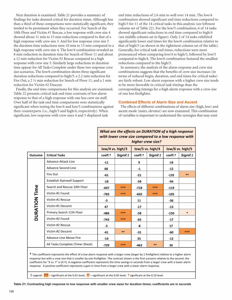
136
Next duration is examined. Table 21 provides a summary offindings for tasks deemed critical for duration times. Although lessthan a third of these comparisons were statistically significant, theytended to be prominent when they occurred. For Search of the10th Floor and Victim #1 Rescue, a low response with crew size 4showed about 11 min to 13 min reductions compared to that of ahigh response with crew size 3. And for low response crew size 5the duration time reductions were 10 min to 13 min compared to ahigh response with crew size 4. The low/4 combination revealed an8 min reduction in duration time for Search of Floor 11 and abouta 12 min reduction for Victim #2 Rescue compared to a highresponse with crew size 3. Similarly large reductions in durationtime appear for All Tasks Complete under these two response crewsize scenarios. The low/6 combination shows three significantduration reductions compared to high/5: a 2.2 min reduction forFire Out, a 2 ½ min reduction for Search of Floor 11, and a 1 minreduction for Victim #2 Descent.Finally, the end time comparisons for this analysis are examined.
Table 22 presents critical task end time contrasts of low alarmresponse to that of a high response with one less crew on staff.Over half of the task end time comparisons were statisticallysignificant when testing the low/4 and low/5 combinations againsttheir counterparts (i.e., high/3 and high/4, respectively). Whensignificant, low response with crew sizes 4 and 5 displayed task
end time reductions of 2.6 min to well over 14 min. The low/4combination showed significant end time reductions compared tohigh/3 for 11 of the 14 critical tasks in this analysis (see leftmostcolumn set of Table 22). For the low/5 combination, 6 of 14 tasksshowed significant reductions in end time compared to high/4(see middle column set in figure). Only 2 of 14 tasks exhibitedsignificantly lower end times for the low/6 combination relative tothat of high/5 (as shown in the rightmost column set of the table).Generally, for critical task end times, reductions were mostpronounced when comparing low/4 to high/3, followed by low/5compared to high/4. The low/6 combination featured the smallestreductions compared to the high/5.In summary, the analysis of the alarm response and crew size
combinations suggests that the benefits of crew size increases (interms of reduced begin, duration, and end times for critical tasks)are fairly robust. Low alarm response with a higher crew size tendsto be more favorable in critical task timings than thecorresponding timings for a high alarm response with a crew sizeof one less firefighter.
Combined Effects of Alarm Size and Ascent The effects of different combinations of alarm size (high, low) and
ascent mode (stairs, elevator) are now examined. This combinationof variables is important to understand the synergies that may exist
Table 21: Contrasting high response to low response with smaller crew sizes for duration times; coefficients are in seconds
!"#$%#&'%$"'%'((')$*%+,%-./01234%+(%#%"56"%&'*7+,*'%85$"%9+8'&%)&'8%*5:'%)+;7#&'<%$+%#%9+8%&'*7+,*'%85$"%
"56"'&%)&'8%*5:'=%
!"#$%&'()&*+,*$-& !"#$.&'()&*+,*$%& !"#$/&'()&*+,*$.&
0123"45& 67+2+38!&98(:(&& 3"5;;)<& Signif.‡ 3"5;;)<& Signif.‡ 3"5;;)<& Signif.‡
!"#$%&'(!))$&*(+,%'( =>>& && ?& && =>/& &&
!"#$%&'(-'&.%"(+,%'( /@& && =>& && =>A& &&
/,0'(12)( =/>& && =A>& && =>-.& BB&
34)$56,47(-)$,08'66(-299.0)( =>@& && =.?& && =?%& &&
-'$0&7($%"(:'4&2'(;<)7(/6..0( =/%C& BBB& =C>@& BBB& =>>?& &&
=,&),>(?;(/.2%"( =C@-& BBB& =/DA& BBB& =>D.& &&
=,&),>(?;(:'4&2'( =-& && >>& && =-/& &&
=,&),>(?;(@'4&'%)( %C& && =>C& && =>-& &&
A0,>$0B(-'$0&7(;;)7(/6..0( =%@/& BBB& =.@& && =>.D& B&
=,&),>(?C(/.2%"( =C%-& BBB& =/.& && =>C& &&
=,&),>(?C(:'4&2'( =-& && =@& && >C& &&
=,&),>(?C(@'4&'%)( =/>& BB& =->& && =/D& BBB&
!"#$%&'(+,%'(!5.#'(/,0'( =>%& && A.& && =>A& &&
EFGH
9I0J&9+4
5&
!66(D$4*4(E.>96')'(FD,>'0(-7'')G( =CA?& BBB& =%/A& BB& A/& &&
H(D7'(&.'II,&,'%)(0'90'4'%)4()7'('II'&)(.I($(6.8($6$0>(0'49.%4'(8,)7($(6$0J'0(&0'8(F6$0J'0(5B(;(I,0'I,J7)'0G(0'6$),#'().($(7,J7'0($6$0>(0'49.%4'(52)(8,)7($(&0'8(4,K'()7$)(,4(4>$66'0(5B(.%'(I,0'I,J7)'0L(D7'(&.%)0$4)(47.8%(,4()7'(I,04)(4&'%$0,.(0'6$),#'().()7'(4'&.%"M()7'(&.'II,&,'%)(I.0(NO(#4L(PN(,4(FOQPGL(!(%'J$),#'(&.'II,&,'%)(0'90'4'%)4()7'(),>'(4$#,%J4(,%(4'&.%"4(I0.>($(6$0J'0(&0'8(8,)7($(6.8'0($6$0>(0'49.%4'L((!(9.4,),#'(&.'II,&,'%)(0'90'4'%)4($(J$,%(,%(),>'(I0.>($(6$0J'0(&0'8(8,)7($(6.8'0($6$0>(0'49.%4'L(
(‡(+'J'%"M((RRR(S(4,J%,I,&$%)($)()7'(<L<;(6'#'6T((RR(S(4,J%,I,&$%)($)()7'(<L<U(6'#'6T((R(4,J%,I,&$%)($)()7'(<L;<(6'#'6(
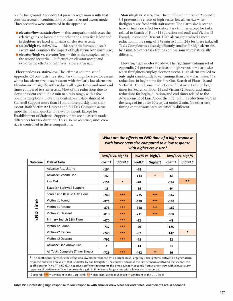
137
Table 22: Contrasting high response to low response with smaller crew sizes for end times; coefficients are in seconds
!"#$%#&'%$"'%'((')$*%+,%-./%$01'%+(%#%"02"%&'*3+,*'%40$"%5+4'&%)&'4%*06'%)+13#&'7%$+%#%5+4%&'*3+,*'%
40$"%"02"'&%)&'4%*06'8%
!"#$%&'()&*+,*$-& !"#$.&'()&*+,*$%& !"#$/&'()&*+,*$.&
0123"45& 67+2+38!&98(:(&& 3"5;;)<& Signif.‡ 3"5;;)<& Signif.‡ 3"5;;)<& Signif.‡
!"#$%&'(!))$&*(+,%'( =>?%& && =%@& && =%%& &&!"#$%&'(-'&.%"(+,%'( =%A& && =>>-& B& =/-& &&/,0'(12)( =>.%& B& =C@& && =>/A& BB&34)$56,47(-)$,08'66(-299.0)( =>@& && =.D& && =D%& &&-'$0&7($%"(:'4&2'(;<)7(/6..0( =C%?& BBB& =CC.& BBB& =>%C& &&=,&),>(?;(/.2%"( =@C.& BBB& =/.D& BBB& =>--& &&=,&),>(?;(:'4&2'( =@C@& BBB& =/%@& BBB& =>/D& &&=,&),>(?;(@'4&'%)( =@>?& BBB& =C>>& BBB& =>D%& &&A0,>$0B(-'$0&7(;;)7(/6..0( =%C?& BBB& =DA& && =%@& &&=,&),>(?C(/.2%"( =C-C& BBB& =.?& && >A.& &&=,&),>(?C(:'4&2'( =C%?& BBB& =.C& && >%A& B&=,&),>(?C(@'4&'%)( =CDA& BBB& =%@& && /A& &&!"#$%&'(+,%'(!5.#'(/,0'( A& && =>%& && @>& &&
EFG&9+4
5&
!66(D$4*4(E.>96')'(FD,>'0(-7'')G( =CAD& BBB& =%/A& BB& A/& &&H(D7'(&.'II,&,'%)(0'90'4'%)4()7'('II'&)(.I($(6.8($6$0>(0'49.%4'(8,)7($(6$0J'0(&0'8(F6$0J'0(5B(;(I,0'I,J7)'0G(0'6$),#'().($(7,J7'0($6$0>(0'49.%4'(52)(8,)7($(&0'8(4,K'()7$)(,4(4>$66'0(5B(.%'(I,0'I,J7)'0L(D7'(&.%)0$4)(47.8%(,4()7'(I,04)(4&'%$0,.(0'6$),#'().()7'(4'&.%"M()7'(&.'II,&,'%)(I.0(NO(#4L(PN(,4(FOQPGL(!(%'J$),#'(&.'II,&,'%)(0'90'4'%)4()7'(),>'(4$#,%J4(,%(4'&.%"4(I0.>($(6$0J'0(&0'8(8,)7($(6.8'0($6$0>(0'49.%4'L(!(9.4,),#'(&.'II,&,'%)(0'90'4'%)4($(J$,%(,%(),>'(I0.>($(6$0J'0(&0'8(8,)7($(6.8'0($6$0>(0'49.%4'L(
(‡(+'J'%"M((RRR(S(4,J%,I,&$%)($)()7'(<L<;(6'#'6T((RR(S(4,J%,I,&$%)($)()7'(<L<U(6'#'6T((R(4,J%,I,&$%)($)()7'(<L;<(6'#'6(
on the fire ground. Appendix C4 presents regression results thatcontrast several of combinations of alarm size and ascent mode.Three scenarios were contrasted in the appendix:
n elevator/low vs. stairs/low — this comparison addresses therelative gains or losses in time when the alarm size is low andfirefighters are faced with stairs or elevator ascent;
n stairs/high vs. stairs/low — this scenario focuses on stairascent and examines the impact of high versus low alarm size;
n elevator/high vs. elevator/low — this is the complement tothe second scenario — it focuses on elevator ascent andexplores the effects of high versus low alarm size.
Elevator/low vs. stairs/low. The leftmost column set ofAppendix C4 contrasts the critical task timings for elevator ascentwith a low alarm size to stair ascent with similarly low alarm size.Elevator ascent significantly reduces all begin times and most endtimes compared to stair ascent. Most of the reductions due toelevator ascent are in the 2 min to 4 min range, with a fewobvious exceptions. Elevator ascent allows Establishment ofStairwell Support more than 11 min more quickly than stairascent. Both Victim #2 Descent and All Task Complete occurmore than 6 min quicker for elevator ascent. Except forEstablishment of Stairwell Support, there are no ascent modedifferences for task duration. This also makes sense, since crewsize is controlled in these comparisons.
Stairs/high vs. stairs/low. The middle column set of AppendixC4 presents the effects of high versus low alarm size whenfirefighters are faced with stair ascent. The alarm size is seen tohave virtually no effect for critical task timings except for tasksrelated to Search of Floor 11 (duration and end) and Victim #2Found, Rescue and Descent. High alarm size realized a meanreduction in the range of 1 ½ min to 3 min 24 s for these tasks. AllTasks Complete was also significantly smaller for high alarm sizeby 3 min. No other task timing comparisons were statisticallydifferent.
Elevator/high vs. elevator/low. The rightmost column set ofAppendix C4 presents the effects of high versus low alarm sizewhen firefighters employ elevator ascent. High alarm size led toonly eight significantly lower timings than a low alarm size: 45 sreductions in begin time for Fire Out, Search of Floor 10, andVictim #1 Found; small reductions of just over 1 min in begintimes for Search of Floor 11 and Victim #2 Found, and smallreductions for begin, duration, and end times related to theAdvancement of Line Above the Fire. Timing reductions were inthe range of just over 30 s to just under 2 min. No other tasktiming comparisons were statistically different.
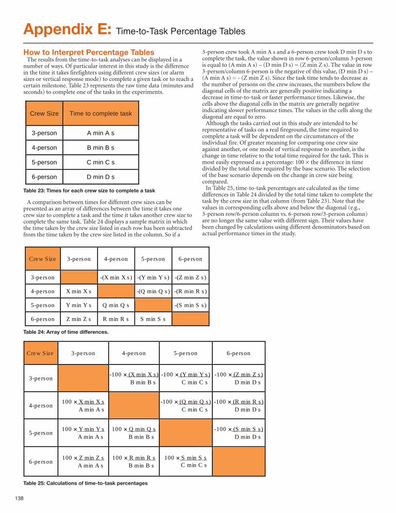
138
Appendix E: Time-to-Task Percentage Tables
How to Interpret Percentage TablesThe results from the time-to-task analyses can be displayed in a
number of ways. Of particular interest in this study is the differencein the time it takes firefighters using different crew sizes (or alarmsizes or vertical response mode) to complete a given task or to reach acertain milestone. Table 23 represents the raw time data (minutes andseconds) to complete one of the tasks in the experiments.
A comparison between times for different crew sizes can bepresented as an array of differences between the time it takes onecrew size to complete a task and the time it takes another crew size tocomplete the same task. Table 24 displays a sample matrix in whichthe time taken by the crew size listed in each row has been subtractedfrom the time taken by the crew size listed in the column. So if a
3-person crew took A min A s and a 6-person crew took D min D s tocomplete the task, the value shown in row 6-person/column 3-personis equal to (A min A s) – (D min D s) = (Z min Z s). The value in row3-person/column 6-person is the negative of this value, (D min D s) –(A min A s) = - (Z min Z s). Since the task time tends to decrease asthe number of persons on the crew increases, the numbers below thediagonal cells of the matrix are generally positive indicating adecrease in time-to-task or faster performance times. Likewise, thecells above the diagonal cells in the matrix are generally negativeindicating slower performance times. The values in the cells along thediagonal are equal to zero.Although the tasks carried out in this study are intended to be
representative of tasks on a real fireground, the time required tocomplete a task will be dependent on the circumstances of theindividual fire. Of greater meaning for comparing one crew sizeagainst another, or one mode of vertical response to another, is thechange in time relative to the total time required for the task. This ismost easily expressed as a percentage: 100 × the difference in timedivided by the total time required by the base scenario. The selectionof the base scenario depends on the change in crew size beingcompared.In Table 25, time-to-task percentages are calculated as the time
differences in Table 24 divided by the total time taken to complete thetask by the crew size in that column (from Table 23). Note that thevalues in corresponding cells above and below the diagonal (e.g.,3-person row/6-person column vs. 6-person row/3-person column)are no longer the same value with different sign. Their values havebeen changed by calculations using different denominators based onactual performance times in the study.
Crew Size Time to complete task
3-person A min A s
4-person B min B s
5-person C min C s
6-person D min D s Table 23: Times for each crew size to complete a task
Crew Size 3-person 4-person 5-person 6-person
3-person -(X min X s) -(Y min Y s) -(Z min Z s)
4-person X min X s -(Q min Q s) -(R min R s)
5-person Y min Y s Q min Q s -(S min S s)
6-person Z min Z s R min R s S min S s Table 24: Array of time differences.
Crew Size 3-person 4-person 5-person 6-person
3-person -100 (X min X s) B min B s
-100 (Y min Y s) C min C s
-100 (Z min Z s) D min D s
4-person 100 X min X s A min A s -100 (Q min Q s)
C min C s -100 (R min R s) D min D s
5-person 100 Y min Y s A min A s
100 Q min Q s B min B s -100 (S min S s)
D min D s
6-person 100 Z min Z s A min A s
100 R min R s B min B s
100 S min S s C min C s
Table 25: Calculations of time-to-task percentages
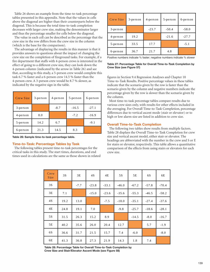
139
Table 26 shows an example from the time-to-task percentagetables presented in this appendix. Note that the values in cellsabove the diagonal are higher than their counterparts below thediagonal. This is because the total time-to-task completiondecreases with larger crew size, making the denominator largerand thus the percentage smaller for cells below the diagonal. The value in each cell can be described as the percentage that the
crew size in the row differs from the crew size in the column(which is the base for the comparison).The advantage of displaying the results in this manner is that it
provides answers to questions about the impact of changing thecrew size on the completion of fireground tasks. For example, if afire department that staffs with 4-person crews is interested in theeffect of going to a different crew size, they can look down the4-person column (indicated by the arrow in Table 26) and seethat, according to this study, a 5-person crew would complete thistask 6.7 % faster and a 6-person crew 14.5 % faster than the4-person crew. A 3-person crew would be 8.7 % slower, asindicated by the negative sign in the table.
Time-to-Task: Percentage Tables by TaskThe following tables present time-to-task percentages for the
critical tasks in this study. The start times, durations, and endtimes used in calculations are the same as those shown in related
figures in Section 9.4 Regression Analyses and Chapter 10Time-to-Task Results. Positive percentage values in these tablesindicate that the scenario given by the row is faster than thescenario given by the column and negative numbers indicate thepercentage given by the row is slower than the scenario given bythe column.Most time-to-task percentage tables compare results due to
various crew sizes only, with results for other effects included inthe averaging. For Overall Time-to-Task Completion, percentagedifferences due to vertical ascent mode (stair or elevator) or tohigh or low alarm size are listed in addition to crew size.
Overall Time-to-Task CompletionThe following two tables show results from multiple factors.
Table 28 displays the Overall Time-to-Task Completion for crewsize and vertical ascent model, either stair or elevator. Theheadings are abbreviated with the number in the crew and S or Efor stairs or elevator, respectively. This table allows a quantitativecomparison of the effects from using stairs or elevators for eachcrew size.
Crew Size 3-person 4-person 5-person 6-person
3-person -8.7 -16.5 -27.1
4-person 8.0 -7.2 -16.9
5-person 14.2 6.7 -9.1
6-person 21.3 14.5 8.3 Table 26: Sample time-to-task percentage table.
Crew Size 3-person 4-person 5-person 6-person
3-person -23.7 -50.4 -58.0
4-person 19.2 -21.6 -27.7
5-person 33.5 17.7 -5.1
6-person 36.7 21.7 4.8 Positive numbers indicate % faster; negative numbers indicate % slower
Table 27: Percentage Table for Overall Time-to-Task Completion byCrew Size (see Figure 57)
Crew Size 3S 3E 4S 4E 5S 5E 6S 6E
3S -7.7 -23.8 -33.1 -46.0 -67.2 -57.8 -70.4
3E 7.1 -15.0 -23.6 -35.6 -55.3 -46.5 -58.2
4S 19.2 13.0 -7.5 -18.0 -35.1 -27.4 -37.6
4E 24.8 19.1 7.0 -9.8 -25.7 -18.6 -28.1
5S 31.5 26.3 15.2 8.9 -14.5 -8.0 -16.7
5E 40.2 35.6 26.0 20.4 12.7 5.7 -1.9
6S 36.6 31.7 21.5 15.7 7.4 -6.0 -8.0
6E 41.3 36.8 27.3 21.9 14.3 1.8 7.4 Table 28: Percentage Table for Overall Time-to-Task Completion byCrew Size and Stair/Elevator Ascent Mode (see Figure 58)
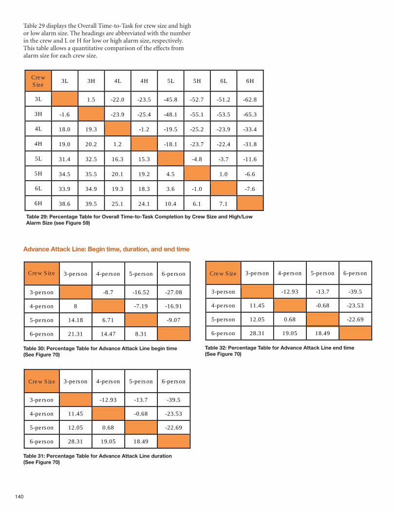
Table 29 displays the Overall Time-to-Task for crew size and highor low alarm size. The headings are abbreviated with the numberin the crew and L or H for low or high alarm size, respectively.This table allows a quantitative comparison of the effects fromalarm size for each crew size.
Advance Attack Line: Begin time, duration, and end time
140
Crew Size 3-person 4-person 5-person 6-person
3-person -8.7 -16.52 -27.08
4-person 8 -7.19 -16.91
5-person 14.18 6.71 -9.07
6-person 21.31 14.47 8.31
Table 30: Percentage Table for Advance Attack Line begin time(See Figure 70)
Crew Size 3-person 4-person 5-person 6-person
3-person -12.93 -13.7 -39.5
4-person 11.45 -0.68 -23.53
5-person 12.05 0.68 -22.69
6-person 28.31 19.05 18.49
Table 31: Percentage Table for Advance Attack Line duration(See Figure 70)
Crew Size 3-person 4-person 5-person 6-person
3-person -12.93 -13.7 -39.5
4-person 11.45 -0.68 -23.53
5-person 12.05 0.68 -22.69
6-person 28.31 19.05 18.49
Table 32: Percentage Table for Advance Attack Line end time(See Figure 70)
Crew Size 3L 3H 4L 4H 5L 5H 6L 6H
3L 1.5 -22.0 -23.5 -45.8 -52.7 -51.2 -62.8
3H -1.6 -23.9 -25.4 -48.1 -55.1 -53.5 -65.3
4L 18.0 19.3 -1.2 -19.5 -25.2 -23.9 -33.4
4H 19.0 20.2 1.2 -18.1 -23.7 -22.4 -31.8
5L 31.4 32.5 16.3 15.3 -4.8 -3.7 -11.6
5H 34.5 35.5 20.1 19.2 4.5 1.0 -6.6
6L 33.9 34.9 19.3 18.3 3.6 -1.0 -7.6
6H 38.6 39.5 25.1 24.1 10.4 6.1 7.1 Table 29: Percentage Table for Overall Time-to-Task Completion by Crew Size and High/LowAlarm Size (see Figure 59)
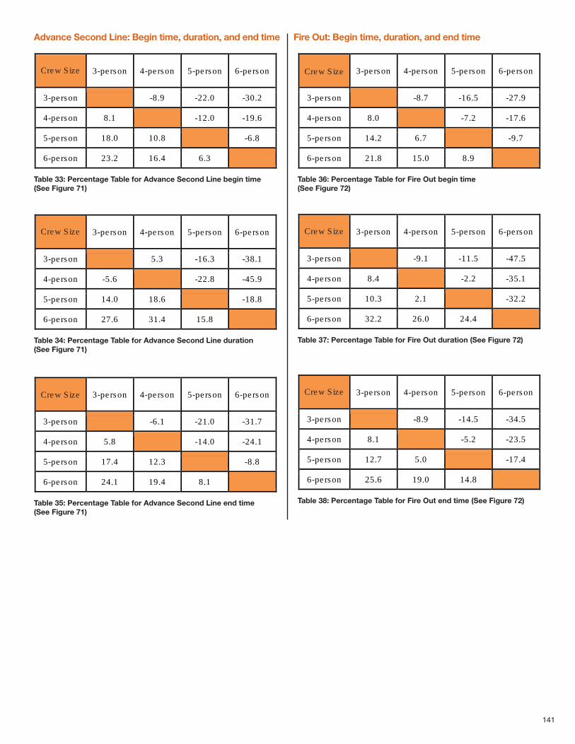
141
Advance Second Line: Begin time, duration, and end time Fire Out: Begin time, duration, and end time
Crew Size 3-person 4-person 5-person 6-person
3-person -8.9 -22.0 -30.2
4-person 8.1 -12.0 -19.6
5-person 18.0 10.8 -6.8
6-person 23.2 16.4 6.3
Table 33: Percentage Table for Advance Second Line begin time(See Figure 71)
Crew Size 3-person 4-person 5-person 6-person
3-person 5.3 -16.3 -38.1
4-person -5.6 -22.8 -45.9
5-person 14.0 18.6 -18.8
6-person 27.6 31.4 15.8
Table 34: Percentage Table for Advance Second Line duration(See Figure 71)
Crew Size 3-person 4-person 5-person 6-person
3-person -6.1 -21.0 -31.7
4-person 5.8 -14.0 -24.1
5-person 17.4 12.3 -8.8
6-person 24.1 19.4 8.1
Table 35: Percentage Table for Advance Second Line end time(See Figure 71)
Crew Size 3-person 4-person 5-person 6-person
3-person -8.7 -16.5 -27.9
4-person 8.0 -7.2 -17.6
5-person 14.2 6.7 -9.7
6-person 21.8 15.0 8.9
Table 36: Percentage Table for Fire Out begin time (See Figure 72)
Crew Size 3-person 4-person 5-person 6-person
3-person -9.1 -11.5 -47.5
4-person 8.4 -2.2 -35.1
5-person 10.3 2.1 -32.2
6-person 32.2 26.0 24.4
Table 37: Percentage Table for Fire Out duration (See Figure 72)
Crew Size 3-person 4-person 5-person 6-person
3-person -8.9 -14.5 -34.5
4-person 8.1 -5.2 -23.5
5-person 12.7 5.0 -17.4
6-person 25.6 19.0 14.8
Table 38: Percentage Table for Fire Out end time (See Figure 72)
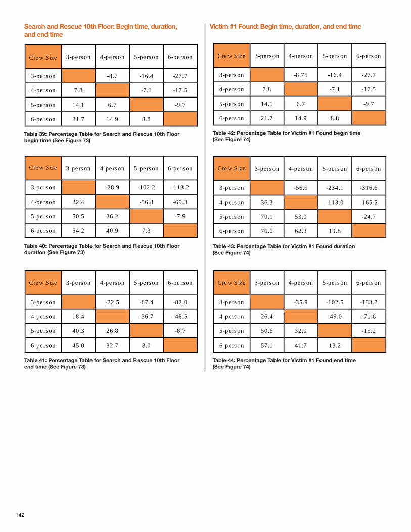
Search and Rescue 10th Floor: Begin time, duration, and end time
Victim #1 Found: Begin time, duration, and end time
142
Crew Size 3-person 4-person 5-person 6-person
3-person -8.7 -16.4 -27.7
4-person 7.8 -7.1 -17.5
5-person 14.1 6.7 -9.7
6-person 21.7 14.9 8.8
Table 39: Percentage Table for Search and Rescue 10th Floorbegin time (See Figure 73)
Crew Size 3-person 4-person 5-person 6-person
3-person -28.9 -102.2 -118.2
4-person 22.4 -56.8 -69.3
5-person 50.5 36.2 -7.9
6-person 54.2 40.9 7.3
Table 40: Percentage Table for Search and Rescue 10th Floorduration (See Figure 73)
Crew Size 3-person 4-person 5-person 6-person
3-person -22.5 -67.4 -82.0
4-person 18.4 -36.7 -48.5
5-person 40.3 26.8 -8.7
6-person 45.0 32.7 8.0
Table 41: Percentage Table for Search and Rescue 10th Floorend time (See Figure 73)
Crew Size 3-person 4-person 5-person 6-person
3-person -8.75 -16.4 -27.7
4-person 7.8 -7.1 -17.5
5-person 14.1 6.7 -9.7
6-person 21.7 14.9 8.8
Table 42: Percentage Table for Victim #1 Found begin time (See Figure 74)
Crew Size 3-person 4-person 5-person 6-person
3-person -56.9 -234.1 -316.6
4-person 36.3 -113.0 -165.5
5-person 70.1 53.0 -24.7
6-person 76.0 62.3 19.8
Table 43: Percentage Table for Victim #1 Found duration(See Figure 74)
Crew Size 3-person 4-person 5-person 6-person
3-person -35.9 -102.5 -133.2
4-person 26.4 -49.0 -71.6
5-person 50.6 32.9 -15.2
6-person 57.1 41.7 13.2
Table 44: Percentage Table for Victim #1 Found end time(See Figure 74)
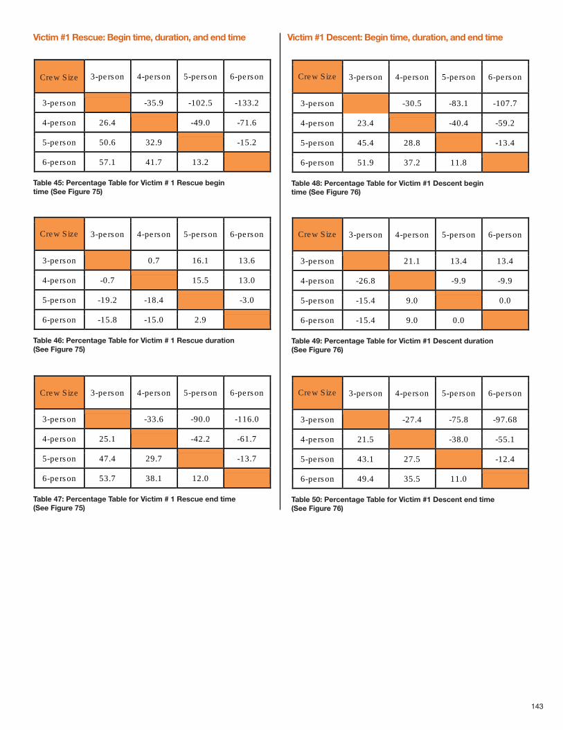
143
Victim #1 Rescue: Begin time, duration, and end time Victim #1 Descent: Begin time, duration, and end time
Crew Size 3-person 4-person 5-person 6-person
3-person -35.9 -102.5 -133.2
4-person 26.4 -49.0 -71.6
5-person 50.6 32.9 -15.2
6-person 57.1 41.7 13.2
Table 45: Percentage Table for Victim # 1 Rescue begintime (See Figure 75)
Crew Size 3-person 4-person 5-person 6-person
3-person 0.7 16.1 13.6
4-person -0.7 15.5 13.0
5-person -19.2 -18.4 -3.0
6-person -15.8 -15.0 2.9
Table 46: Percentage Table for Victim # 1 Rescue duration(See Figure 75)
Crew Size 3-person 4-person 5-person 6-person
3-person -33.6 -90.0 -116.0
4-person 25.1 -42.2 -61.7
5-person 47.4 29.7 -13.7
6-person 53.7 38.1 12.0
Table 47: Percentage Table for Victim # 1 Rescue end time(See Figure 75)
Crew Size 3-person 4-person 5-person 6-person
3-person -30.5 -83.1 -107.7
4-person 23.4 -40.4 -59.2
5-person 45.4 28.8 -13.4
6-person 51.9 37.2 11.8
Table 48: Percentage Table for Victim #1 Descent begintime (See Figure 76)
Crew Size 3-person 4-person 5-person 6-person
3-person 21.1 13.4 13.4
4-person -26.8 -9.9 -9.9
5-person -15.4 9.0 0.0
6-person -15.4 9.0 0.0
Table 49: Percentage Table for Victim #1 Descent duration(See Figure 76)
Crew Size 3-person 4-person 5-person 6-person
3-person -27.4 -75.8 -97.68
4-person 21.5 -38.0 -55.1
5-person 43.1 27.5 -12.4
6-person 49.4 35.5 11.0
Table 50: Percentage Table for Victim #1 Descent end time(See Figure 76)
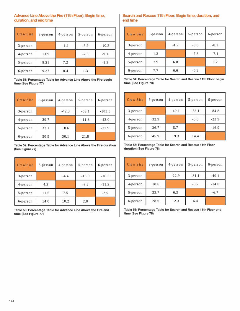
144
Advance Line Above the Fire (11th Floor): Begin time,duration, and end time
Search and Rescue 11th Floor: Begin time, duration, andend time
Crew Size 3-person 4-person 5-person 6-person
3-person -1.1 -8.9 -10.3
4-person 1.09 -7.8 -9.1
5-person 8.21 7.2 -1.3
6-person 9.37 8.4 1.3
Table 51: Percentage Table for Advance Line Above the Fire begintime (See Figure 77)
Crew Size 3-person 4-person 5-person 6-person
3-person -42.3 -59.1 -103.5
4-person 29.7 -11.8 -43.0
5-person 37.1 10.6 -27.9
6-person 50.9 30.1 21.8
Table 52: Percentage Table for Advance Line Above the Fire duration(See Figure 77)
Crew Size 3-person 4-person 5-person 6-person
3-person -4.4 -13.0 -16.3
4-person 4.3 -8.2 -11.3
5-person 11.5 7.5 -2.9
6-person 14.0 10.2 2.8
Table 53: Percentage Table for Advance Line Above the Fire endtime (See Figure 77)
Crew Size 3-person 4-person 5-person 6-person
3-person -1.2 -8.6 -8.3
4-person 1.2 -7.3 -7.1
5-person 7.9 6.8 0.2
6-person 7.7 6.6 -0.2
Table 54: Percentage Table for Search and Rescue 11th Floor begintime (See Figure 78)
Crew Size 3-person 4-person 5-person 6-person
3-person -49.1 -58.1 -84.8
4-person 32.9 -6.0 -23.9
5-person 36.7 5.7 -16.9
6-person 45.9 19.3 14.4
Table 55: Percentage Table for Search and Rescue 11th Floorduration (See Figure 78)
Crew Size 3-person 4-person 5-person 6-person
3-person -22.9 -31.1 -40.1
4-person 18.6 -6.7 -14.0
5-person 23.7 6.3 -6.7
6-person 28.6 12.3 6.4
Table 56: Percentage Table for Search and Rescue 11th Floor endtime (See Figure 78)
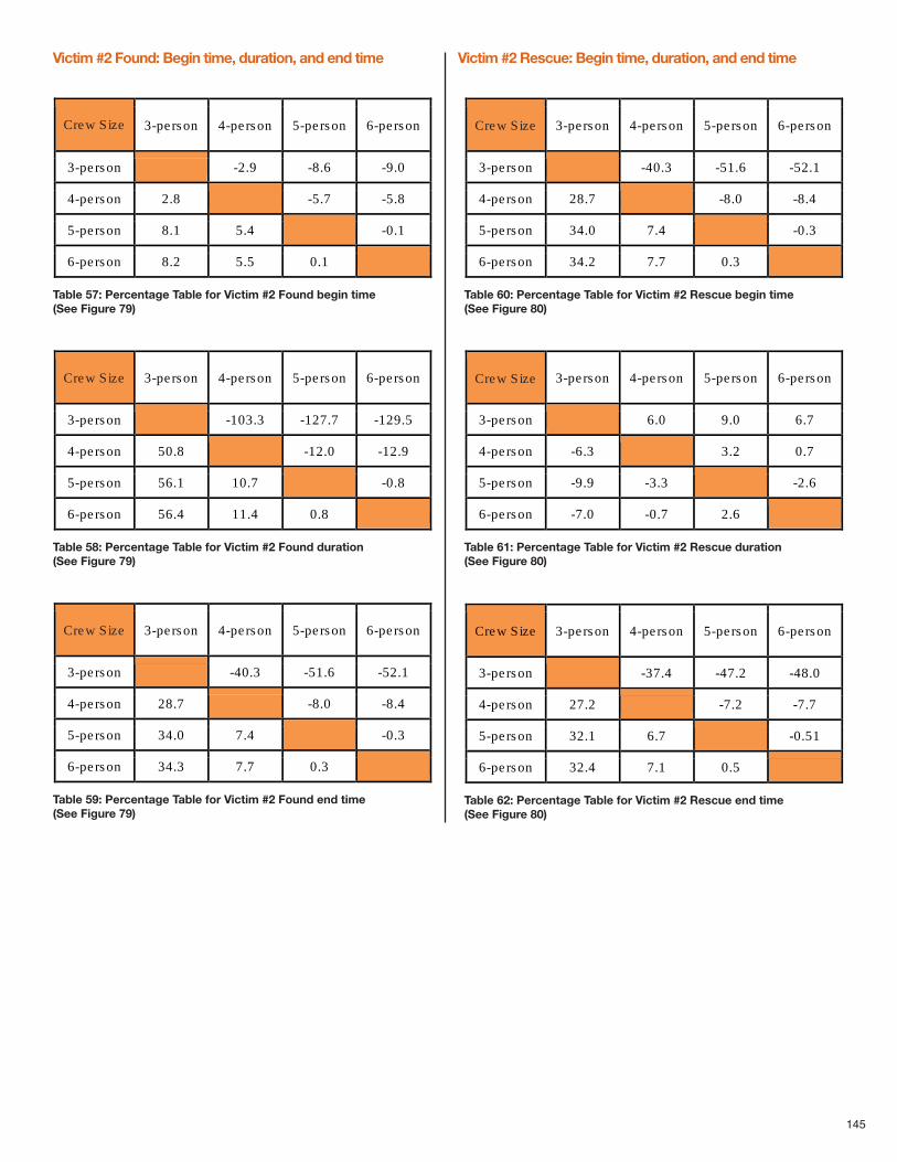
145
Victim #2 Found: Begin time, duration, and end time Victim #2 Rescue: Begin time, duration, and end time
Crew Size 3-person 4-person 5-person 6-person
3-person -2.9 -8.6 -9.0
4-person 2.8 -5.7 -5.8
5-person 8.1 5.4 -0.1
6-person 8.2 5.5 0.1
Table 57: Percentage Table for Victim #2 Found begin time(See Figure 79)
Crew Size 3-person 4-person 5-person 6-person
3-person -103.3 -127.7 -129.5
4-person 50.8 -12.0 -12.9
5-person 56.1 10.7 -0.8
6-person 56.4 11.4 0.8
Table 58: Percentage Table for Victim #2 Found duration(See Figure 79)
Crew Size 3-person 4-person 5-person 6-person
3-person -40.3 -51.6 -52.1
4-person 28.7 -8.0 -8.4
5-person 34.0 7.4 -0.3
6-person 34.3 7.7 0.3
Table 59: Percentage Table for Victim #2 Found end time(See Figure 79)
Crew Size 3-person 4-person 5-person 6-person
3-person -40.3 -51.6 -52.1
4-person 28.7 -8.0 -8.4
5-person 34.0 7.4 -0.3
6-person 34.2 7.7 0.3
Table 60: Percentage Table for Victim #2 Rescue begin time(See Figure 80)
Crew Size 3-person 4-person 5-person 6-person
3-person 6.0 9.0 6.7
4-person -6.3 3.2 0.7
5-person -9.9 -3.3 -2.6
6-person -7.0 -0.7 2.6
Table 61: Percentage Table for Victim #2 Rescue duration(See Figure 80)
Crew Size 3-person 4-person 5-person 6-person
3-person -37.4 -47.2 -48.0
4-person 27.2 -7.2 -7.7
5-person 32.1 6.7 -0.51
6-person 32.4 7.1 0.5
Table 62: Percentage Table for Victim #2 Rescue end time(See Figure 80)
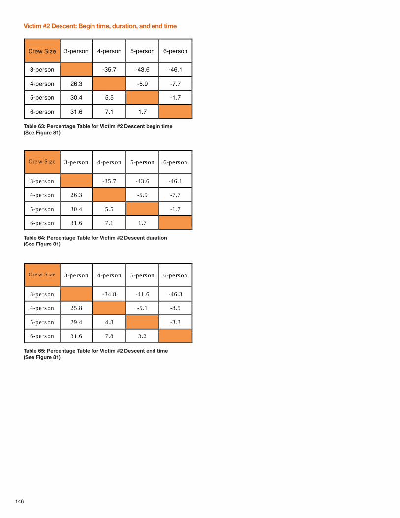
Victim #2 Descent: Begin time, duration, and end time
146
Table 63: Percentage Table for Victim #2 Descent begin time(See Figure 81)
Crew Size 3-person 4-person 5-person 6-person
3-person -35.7 -43.6 -46.1
4-person 26.3 -5.9 -7.7
5-person 30.4 5.5 -1.7
6-person 31.6 7.1 1.7
Table 64: Percentage Table for Victim #2 Descent duration(See Figure 81)
Crew Size 3-person 4-person 5-person 6-person
3-person -34.8 -41.6 -46.3
4-person 25.8 -5.1 -8.5
5-person 29.4 4.8 -3.3
6-person 31.6 7.8 3.2
Table 65: Percentage Table for Victim #2 Descent end time(See Figure 81)
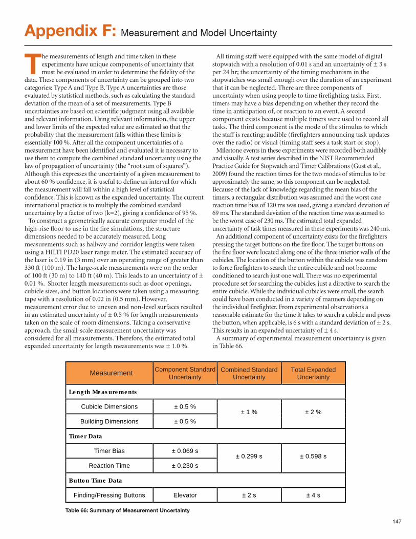
147
Appendix F: Measurement and Model Uncertainty
The measurements of length and time taken in theseexperiments have unique components of uncertainty thatmust be evaluated in order to determine the fidelity of the
data. These components of uncertainty can be grouped into twocategories: Type A and Type B. Type A uncertainties are thoseevaluated by statistical methods, such as calculating the standarddeviation of the mean of a set of measurements. Type Buncertainties are based on scientific judgment using all availableand relevant information. Using relevant information, the upperand lower limits of the expected value are estimated so that theprobability that the measurement falls within these limits isessentially 100 %. After all the component uncertainties of ameasurement have been identified and evaluated it is necessary touse them to compute the combined standard uncertainty using thelaw of propagation of uncertainty (the “root sum of squares”).Although this expresses the uncertainty of a given measurement toabout 60 % confidence, it is useful to define an interval for whichthe measurement will fall within a high level of statisticalconfidence. This is known as the expanded uncertainty. The currentinternational practice is to multiply the combined standarduncertainty by a factor of two (k=2), giving a confidence of 95 %.To construct a geometrically accurate computer model of the
high-rise floor to use in the fire simulations, the structuredimensions needed to be accurately measured. Longmeasurements such as hallway and corridor lengths were takenusing a HILTI PD20 laser range meter. The estimated accuracy ofthe laser is 0.19 in (3 mm) over an operating range of greater than330 ft (100 m). The large-scale measurements were on the orderof 100 ft (30 m) to 140 ft (40 m). This leads to an uncertainty of ±0.01 %. Shorter length measurements such as door openings,cubicle sizes, and button locations were taken using a measuringtape with a resolution of 0.02 in (0.5 mm). However,measurement error due to uneven and non-level surfaces resultedin an estimated uncertainty of ± 0.5 % for length measurementstaken on the scale of room dimensions. Taking a conservativeapproach, the small-scale measurement uncertainty wasconsidered for all measurements. Therefore, the estimated totalexpanded uncertainty for length measurements was ± 1.0 %.
All timing staff were equipped with the same model of digitalstopwatch with a resolution of 0.01 s and an uncertainty of ± 3 sper 24 hr; the uncertainty of the timing mechanism in thestopwatches was small enough over the duration of an experimentthat it can be neglected. There are three components ofuncertainty when using people to time firefighting tasks. First,timers may have a bias depending on whether they record thetime in anticipation of, or reaction to an event. A secondcomponent exists because multiple timers were used to record alltasks. The third component is the mode of the stimulus to whichthe staff is reacting: audible (firefighters announcing task updatesover the radio) or visual (timing staff sees a task start or stop).Milestone events in these experiments were recorded both audibly
and visually. A test series described in the NIST RecommendedPractice Guide for Stopwatch and Timer Calibrations (Gust et al.,2009) found the reaction times for the two modes of stimulus to beapproximately the same, so this component can be neglected.Because of the lack of knowledge regarding the mean bias of thetimers, a rectangular distribution was assumed and the worst casereaction time bias of 120 ms was used, giving a standard deviation of69 ms. The standard deviation of the reaction time was assumed tobe the worst case of 230 ms. The estimated total expandeduncertainty of task times measured in these experiments was 240 ms.An additional component of uncertainty exists for the firefighters
pressing the target buttons on the fire floor. The target buttons onthe fire floor were located along one of the three interior walls of thecubicles. The location of the button within the cubicle was randomto force firefighters to search the entire cubicle and not becomeconditioned to search just one wall. There was no experimentalprocedure set for searching the cubicles, just a directive to search theentire cubicle. While the individual cubicles were small, the searchcould have been conducted in a variety of manners depending onthe individual firefighter. From experimental observations areasonable estimate for the time it takes to search a cubicle and pressthe button, when applicable, is 6 s with a standard deviation of ± 2 s.This results in an expanded uncertainty of ± 4 s.A summary of experimental measurement uncertainty is given
in Table 66.
Measurement Component Standard Uncertainty
Combined Standard Uncertainty
Total Expanded Uncertainty
Length Measurements
Cubicle Dimensions ± 0.5 %
Building Dimensions ± 0.5 % ± 1 % ± 2 %
Timer Data
Timer Bias ± 0.069 s
Reaction Time ± 0.230 s ± 0.299 s ± 0.598 s
Button Time Data
Finding/Pressing Buttons Elevator ± 2 s ± 4 s
Table 66: Summary of Measurement Uncertainty
148
In addition to experimental uncertainty, there exists uncertaintyin the computational models. Models are used when theequations describing the governing physics of a problem cannotbe solved directly. To test the ability of a model to correctlycapture the chemistry and physics, the computational softwaremust be validated by testing against experimental results. The FDSmodel used for the simulations in this report undergoes extensiveand on-going validation (McGrattan et al. 2012c, USNRC 2007).For questions regarding air tenability, the parameter of interest isthe fractional effective dose (FED)31. According to ISO 13571, theexact distribution of human response to toxic gas inhalation isnot known. As a result, there is considerable uncertainty relatingthe computed FED value from the computation model to thepercentage of the population likely to be incapacitated. Accordingto the ISO standard for the gases considered in this study, theuncertainty can be as much as ± 20 % to 35 % (ISO 13571).
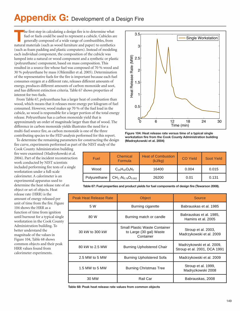
149
Appendix G: Development of a Design Fire
The first step in calculating a design fire is to determine whatfuel or fuels could be used to represent a cubicle. Cubicles aregenerally composed of a wide range of combustibles, from
natural materials (such as wood furniture and paper) to synthetics(such as foam padding and plastic computers). Instead of modelingeach individual component, the composition of the cubicle waslumped into a natural or wood component and a synthetic or plastic(polyurethane) component, based on mass composition. Thisresulted in a source fire whose fuel was composed of 70 % wood and30 % polyurethane by mass (Ohlemiller et al. 2005). Determinationof the representative fuels for the fire is important because each fuelconsumes oxygen at a different rate, releases different amounts ofenergy, produces different amounts of carbon monoxide and soot,and has different extinction criteria. Table 67 shows properties ofinterest for two fuels.From Table 67, polyurethane has a larger heat of combustion than
wood, which means that it releases more energy per kilogram of fuelconsumed. However, wood makes up 70 % of the fuel load in thecubicle, so wood is responsible for a larger portion of the total energyrelease. Polyurethane has a carbon monoxide yield that isapproximately an order of magnitude larger than that of wood. Thedifference in carbon monoxide yields illustrates the need for amulti-fuel source fire, as carbon monoxide is one of the threecontributing species to the FED analysis performed for this report.To determine the remaining parameters for constructing the design
fire curve, experiments performed as part of the NIST study of theCook County Administration buildingfire were examined (Madrzykowski et al.2004). Part of the incident reconstructionwork conducted by NIST scientistsincluded performing fire tests of a singleworkstation under a full-scalecalorimeter. A calorimeter is anexperimental apparatus used todetermine the heat release rate of anobject or set of objects. Heatrelease rate (HRR) is theamount of energy released perunit of time from the fire. Figure104 shows the HRR as afunction of time from ignitionuntil burnout for a typical singleworkstation in the Cook CountyAdministration building. Tobetter understand themagnitude of the values inFigure 104, Table 68 showscommon objects and their peakHRR values found fromcalorimeter experiments.
Fuel Chemical Formula
Heat of Combustion (kJ/kg) CO Yield Soot Yield
Wood C25H42O6N2 16400 0.004 0.015
Polyurethane CH1.7N0.74O0.002 26200 0.01 0.131
0 6 12 18 24 300
0.5
1
1.5
2
2.5
3
3.5
Time (min)
Heat R
ele
ase R
ate
(M
W)
Single Workstation
Figure 104: Heat release rate versus time of a typical singleworkstation fire from the Cook County Administration building(Madrzykowski et al. 2004)
Peak Heat Release Rate Object Source
5 W Burning cigarette Babrauskas et al. 1985
80 W Burning match or candle Babrauskas et al. 1985, Hamins et al. 2005
30 kW to 300 kW Small Plastic Waste Container
to Large (30 gal) Waste Container
Stroup et al. 2003, Madrzykowski et al. 2009
80 kW to 2.5 MW Burning Upholstered Chair Madrzykowski et al. 2009, Stroup et al. 2001, DCA 1991
2.5 MW to 5 MW Burning Upholstered Sofa Madrzykowski et al. 2009
1.5 MW to 5 MW Burning Christmas Tree Stroup et al. 1999, Madryzkowski 2008
30 MW Rail Car Babrauskas, 2008 Table 68: Peak heat release rate values from common objects
Table 67: Fuel properties and product yields for fuel components of design fire (Tewarson 2008).
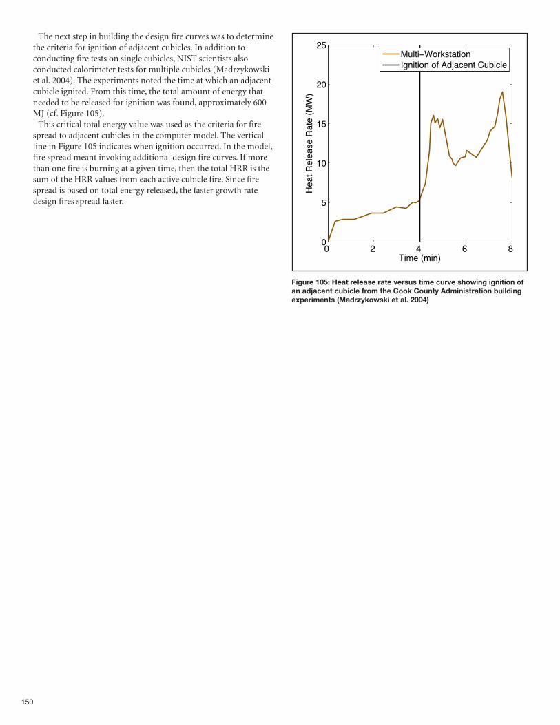
150
The next step in building the design fire curves was to determinethe criteria for ignition of adjacent cubicles. In addition toconducting fire tests on single cubicles, NIST scientists alsoconducted calorimeter tests for multiple cubicles (Madrzykowskiet al. 2004). The experiments noted the time at which an adjacentcubicle ignited. From this time, the total amount of energy thatneeded to be released for ignition was found, approximately 600MJ (cf. Figure 105).This critical total energy value was used as the criteria for fire
spread to adjacent cubicles in the computer model. The verticalline in Figure 105 indicates when ignition occurred. In the model,fire spread meant invoking additional design fire curves. If morethan one fire is burning at a given time, then the total HRR is thesum of the HRR values from each active cubicle fire. Since firespread is based on total energy released, the faster growth ratedesign fires spread faster.
0 2 4 6 8 0
5
10
15
20
25
Time (min)
Heat R
ele
ase R
ate
(M
W)
Multi−WorkstationIgnition of Adjacent Cubicle
Figure 105: Heat release rate versus time curve showing ignition ofan adjacent cubicle from the Cook County Administration buildingexperiments (Madrzykowski et al. 2004)

NOTES
________________________________________________________________________________
________________________________________________________________________________
________________________________________________________________________________
________________________________________________________________________________
________________________________________________________________________________
________________________________________________________________________________
________________________________________________________________________________
________________________________________________________________________________
________________________________________________________________________________
________________________________________________________________________________
________________________________________________________________________________
________________________________________________________________________________
________________________________________________________________________________
________________________________________________________________________________
________________________________________________________________________________
________________________________________________________________________________
________________________________________________________________________________
________________________________________________________________________________
________________________________________________________________________________
________________________________________________________________________________
________________________________________________________________________________
________________________________________________________________________________
________________________________________________________________________________
________________________________________________________________________________
________________________________________________________________________________
________________________________________________________________________________
________________________________________________________________________________
________________________________________________________________________________
________________________________________________________________________________