Embed Size (px)
Citation preview
NASA Technical Memorandum 83199Part 2
Aircraft Noise Prediction Program
Theoretical Manual
William E. Zorumski
Langley Research Center
Hampton, Virginia
NILq Nateonal Aeronaul_cs
anO Space/_Om_ nJs_raT_on
_mNI TedmicdII_mltkm arm_
Tge2
https://ntrs.nasa.gov/search.jsp?R=19820012073 2018-05-20T23:56:04+00:00Z

pl ,. mG pP.GE NOT Ftt..eiW
CONTENTS
Part I*
I. INTRODUCTION ......................... I-I
2. AIRCRAFT FLIGHT DYNAMICS ........
2.1 ATMOSPHERIC MODULE .................... 2.1-I
2.2 GEOMETRY MODULE ...................... 2.2-1
2.3 FLIGHT DYNAMICS MODULE .................. 2.3-1
3. PROPAGATION EFFECTS
3.1 ATMOSPHERIC ABSORPTION MODUL2 ............... 3.1-1
3.2 GROUND REFLECTION AND ATTENUATION MODULE ......... 3.2-1
4. SOURCE NOISE PARAMETERS
4.1 FAN NOISE PARAMETERS MODULE ................ 4.1-1
4.2 CORE NOISE PARAMETERS MODULE ............... 4.2-1
4.3 TURBINE NOISE PAFJLMETERS MODULE .............. 4.3-1
4.4 JET NOISE PARAMETERS MODULE ................ 4.4-1
4.5 AIRFRAME NOISE PARAMETERS MODULE ............. 4.5-1
5. PROPAGATION
5.1 PROPAGATION MODULE .................... 5.1-1
5.2 GENERAL SUPPRESSION MODULE ............... . 5.2-1
6. RECEIVED NOISE
6.1 NOISE LEVELS MODULE .................... 6.1-1
6.2 EFFECTIVE NOISE .MODULE .................. 6.2-1
7. UTILITIES
7.1 ._"HEP_MODYNAMIC UTILITIES .................. 7.1-1
t
*Chapters I to 7 are published under separate cover.
iii
+
Part 2
8. NOISE SOURCES
8.1 FAN NOISE MODULE ..................... 8.1-I
8.2 COMBUSTION NOISE MODULE .................. 8.2-1
8.3 TURBINE NOISE .MODULE ................... 8.3-1
8.4 SINGLE STREAM CIRCULAR JET NOISE MODULE .......... 8.4-1
8.5 CIRCULAR JET SHOCK CELL NOISE MODULE ........... 8.5-1
8.6 STONE JET NOISE MODULE .................. 8.6-1
8.7 DUAL STREAM CCANNULAR JET NOISE MODULE .......... 8.7-1
8.8 AIRFRAME NOISE .MODULE ................... 8.8-1
8.9 SMITH AND BUSHELL TURBINE NOISE MODULE .......... 8.9-1
9. PP_DICTION PROCEDURES
9.1 ICAO REFERENCE NOISE-PP/EDICTIO:_ PROCEDURE (!978) ..... 9.1-1
iv

8. NOISE SOURCES

8.1 FAN NOISE MODULE
INTRODUCTION
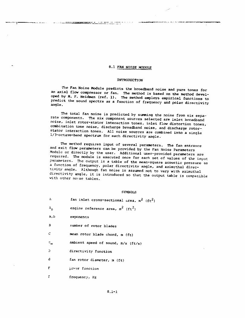
l_ne Fan Noise Module predicts the broadband noise and pure tones for
an axial flow compressor or fan. The method is based on the method devel-
oped by M. F. Heidman (ref. 1). The method emploTs empirical functions to
predict the sound spectra as a function of frequent/ and polar direcrivity
angle.
The total fan noise is predicted by summing the noise from six sepa-
rate components. The six component sources selected are inlen broadband
noise, inlet rotor-stator interaction tones, inlet flow distortion tones,
combination tone noise, discharge broadband noise, and discharge rotor-
stator interaction tones. All noise sources are combined into a single
i/3-octave-band spectrum for each directivity angle.
The method requires input of several parameters. The fan entrance
and exit flow parameters can be provided by the Fan Noise Parameters
Module or directly by the user. Additional user-provided parameters are
required. The module is executed once for each set of values of the input
parameters. The output is a table of the mean-square acoustic pressure as
a function of frequency, polar directivity angle, and azimuthal direc-
tivity angle. Although fan noise is assumed not to vary with azimuthal
directivity angle, it is introduced so that the output table is compatible
widn other noise tables.
A
A e
a,b
B
C
Zoo
D
d
F
f
SYMBOLS
fan inlet cross-sectional Area, m 2
engine reference area, m 2 (ft 2)
exponents
number of rotor blades
mean rotor blade chord, m (ft)
ambient speed of sound, m/s (ft/s)
directivity function
fan rotor diameter, m (ft)
pc_er function
frequency, Hz
(ft 2 )
8.1-1
fb
G
i
K
k,£
Md
M r
M t
M
m
N
N e
n
<p2>"
Pref
r s
r*L
S
S
T
V
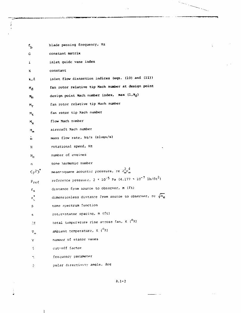
blade passing frequency, Hz
constant matrix
inlet guide vane index
constant
inlet flow distortion indices (eqs. (lO) and (ll))
fan rotor relative tip Mach number at design point
design point Mach number index, max (l,Md)
fan rotor relative tip Mach number
fan rotor tip Mach number
flow Mach n,m_ber
aircraft Mach number
mass flow rate, kg/s (slugs/s)
rotational speed, Hz
number of engines
tone harmonic number
mean-square acoustic pressure, re o2c 4
reference pressure, 2 × 10 ..5 Pa (4.177 _ 10 -7 Ib/ft 2)
distance from source to observer, m (ft)
source to observer, re _edimens icnless distance from
tone _pectr_m function
roter-stator spacing, m (ft)
total temperature rise across fan, K (oK)
ambient temperature, K (°R)
n_n%oer of stator vanes
cut-off factor
frequency parameter
polar /irect_vlt'_" angle, deg
_.I-2
.-
J
, J,
_ref
O_
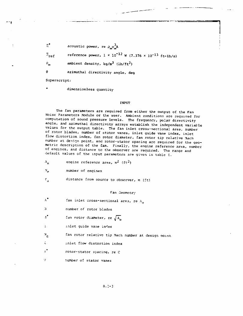
acoustic power, re p c_A
reference power, 1 x 10 -12 W (7.376 x 10 -13 ft-lb/s)
ambient density, kg/m 3 (ib/ft 3)
azimuthal directivity angle, deg
Superscript:
* dimensionless quantity
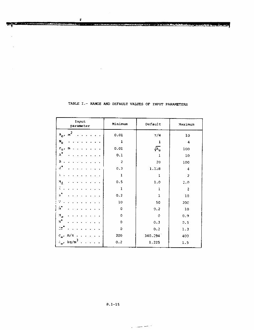
INPUT
The fan parameters are required from either the output of the Fan
Noise Parameters Module or the user. Ambient conditions are required for
computation of sound pressure levels. The frequency, polar directivity
angle, and azimuthal directivity arrays establish the independent variable
values for the output table. The fan inlet cross-sectional area, number
of rotor blades, number of stator vanes, inlet guide vane index, inlet
flow distortion index, fan rotor diameter, fan rotor tip relative Mach
number at design point, and rotor-stator spacing are required for the geo-
metric description of the fan. Finally, the engine reference area, number
of engines, and distance to the observer are required. The range and
default values of the input parameters are given in table I.
A e engine reference area, m 2 (ft 2)
H e number of engines
Sdistance from source to observer, m (ft)
t
A
3
d *
I
Md
tS
V
Fan Geometry
fan inlet cross-sectional area, re A e
number of rotor blades
rotor diameter, re _efan
inlet guide vane index
fan rotor relative tip Mach number at design point
inlet flow distortion index
rotor-stator spacing, re C
n_._nber of stator vanes
8.1-3
e
N*
AT*
C
P_
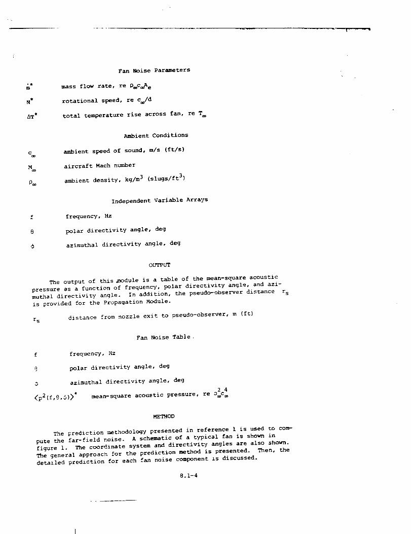
Fan Noise Parameters
mass flow rate, re O_c_A e
rotational speed, re c /d
total temperature rise across fan, re T
Ambient Conditions
ambient speed of sound, m/s (ft/s)
aircraft Mach number
ambient density, kg/m 3 (slugs/ft 3)
Independent Variable Arrays
frequency, Hz
polar directivity angle, deg
azimuthal directivity angle, deg
OUTPUT
The output of this _nodule is a table of the mean-square acoustic
pressure as a function of frequency, polar directivity angle, and azi-
muthal directivity angle. In addition, the pseudo-observer distance r s
is provided for the Propagation Module.
r s distance from nozzle exit to pseudo-observer, m {ft)
Fan Noise Table
f frequency, Hz
9 polar directivity angle, deg
O azimuthal directivity angle, deg
<p2(f,9,,)>"2 4
mean-square acoustic pressure, re D c
METHOD
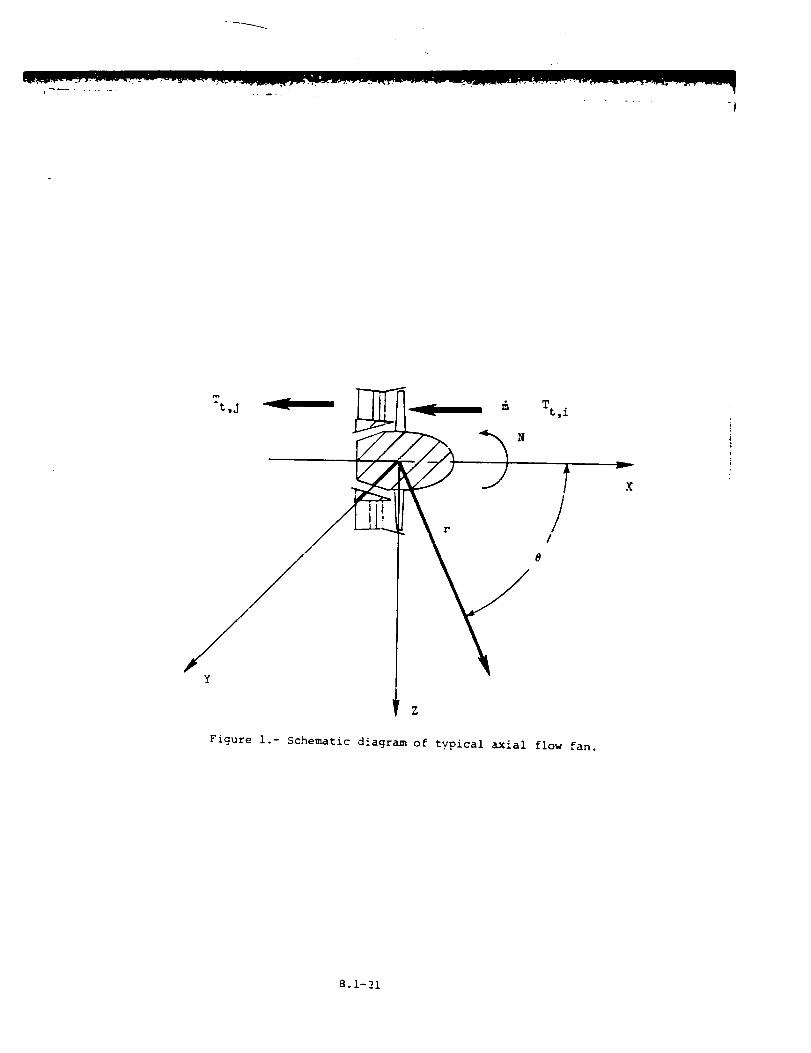
The prediction methodology presented in reference 1 is used to com-
pute the far-field noise. A schematic of a typical fan is shown in
figure i. The coordinate system and directivity angles are also shown.
The general approach for the prediction method is presented. Then, the
detailed prediction for each fan noise component is discussed.
8.1-4
J
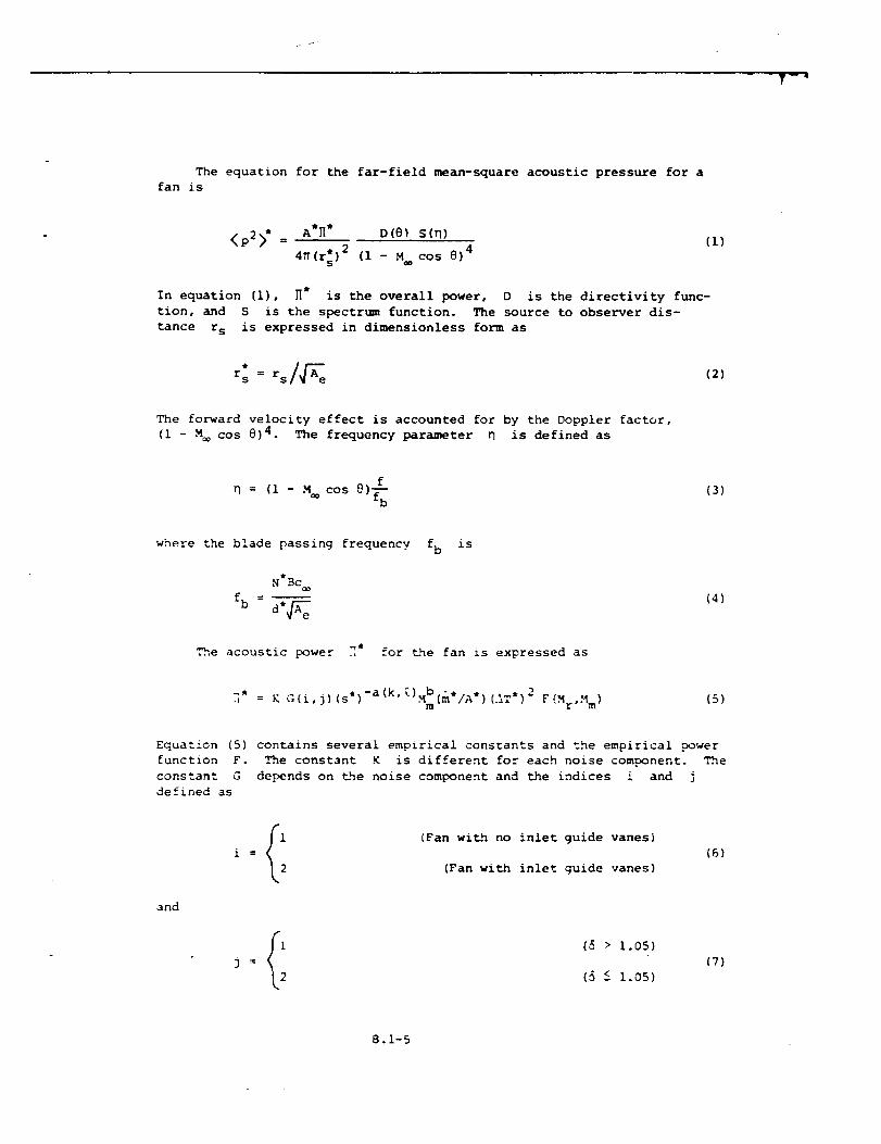
The equation for the far-field mean-square acoustic pressure for a
fan is
<p2>* = A'Hi D(@) S(_)
4_I(rs )2 (i - M cos @)4
(1)
In equation (i), H* is the overall power, D is the directivity func-
tion, and S is the spectr,-- function. The source to observer dis-
tance r s is expressed in dimensionless form as
(2)
The forward velocity effect is accounted for by the Doppler factor,
(i - M cos 0)4. The frequency parameter _ is defined as
f
= (I - M cos @)f--b(3)
where the blade passing frequency fb is
N*Bc
fb = diA_e
The acoustic power _*_ for _he fan is expressed as
(4)
.L = K G(i,j) (si)-a(k' [)Mb(m*/A*) (.ST*) 2 F (Mr,M m) (5)m
Equation (5) contains several empirical constants and the empirical Dower
function F. The constant K is different for each noise component. The
constant G depends on the noise component and the indices i and j
defined as
and
Ii (Fan with no inlet guide vanes)
i = (6)
(Fan with inlet guide vanes)
i (_ > 1.05)j : (7)
(5 <-1.05)
8.1-5
/jr
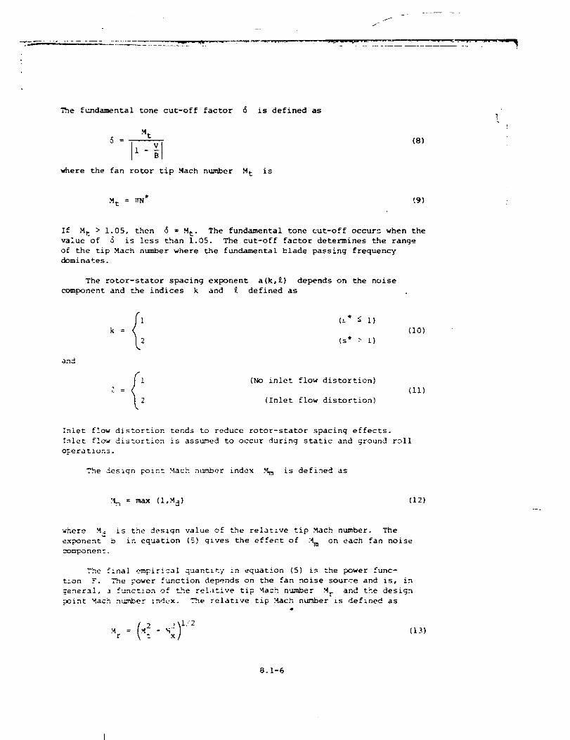
The fuandamental tone cut-off factor 6 is defined as
M t
11where the fan rotor tip Mach number M t is
(8)
M t = WN* t.9)
If M t > 1.05, then _ = M t. The fundamental tone cut-off occurs when the
value of 0 is less than 1.05. The cut-off factor determines the range
of the tip Mach number where the fundamental blade passing frequency
dominates.
The rotor-stator spacing exponent a(k,£) depends on the noise
component and _he indices k and £ defined as
and
i ('-* _ i)
k = (I0)
(s* > i)
Ii (No inlet flow distortion)
[ = (Ii)
(Inlet flow distortion)
Inlet flow distortion tends to reduce rotor-stator spacing effects.
Inlet fl_w distortion is assumed to occur during static and ground roll
o_eratlons.
The design point Mach n_unber index M m is defined as
:_ = max (I,._d) (12)
where M d is the design value of the relative tip Mach number. The
exponent b in equation (5) gives the effect of [_m on each fan noise
component.
The final empirical quantity in equation (5) is the power func-
t&on F. _'_.e power function depends on the fan noise source and is, in
_ ofgeneral, _ _unc__on the relative tip Mach number M r and the design
point Mach n_ber indux. .-h.e relative tip Mach number is defined as
Mr x(13)
8.1-6
wherethe tip Machn_mberMt is defined by equation {9) and the axial
flow Mach number M x is equal to m*/A* since the inlet static density
and speed of sound can be assumed equal to the ambient values.
As indicated by equation (I), each fan noise source has its own
directivity function D and spectrum function S. Using these functions
and the acoustic power, the mean-square acoustic pressure is computed as
a function of frequency and polar directivity angle for a given set of
input parameters. The broadband noise is expressed as I/3-octave-band
data. The pure tones are values at discrete frequencies. The pure tones
must be added to the appropriate I/3-octave band so that a total
i/3-octave-band fan noise spectrum is determined. For a given value of
the i/3-octave-band center frequency parameter _ the lowest harmonic
number that falls within that band is
n£ = [lO-1/2o n] + i (14)
and the highest harmonic number is
nu = [lOI/2° n] (15)
where [ ] indicates the integer part of the enclosed real nu_.ber, if
n% > _u' then there is no tone within the band. If n[ -< nu, then there
are n u - n Z + i tenes within the band. The pure tone mean-square pres-
sures for each harmonic Dumber n are then added to the appropriate band.
The tones are propagated to the observer as I/3-octave-band data.
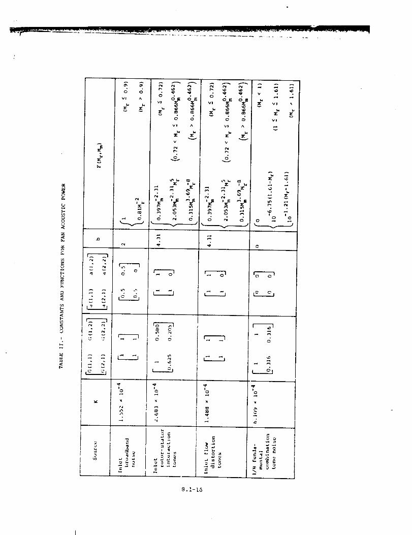
The empirical constants and functions used to compute the acoustic
._ower for t_e six fan noise components are summarized in table II. The
directivit 7 and spectrum functions are summzarized in tables III and IV,
respectively. Each fan ncise component is discussed in detail as
follows.
inlet Broadband Noise
Inlet broadband noise is associated with random unsteadines_ or
turbulence in Lhe flow passing the blading. Some of _he sources of this
random unsteady flow are turbulence in boundary layers, blade w_<es and
vortices, and _ne inlet flow. Although predictions of the individual
sources of broadband noise are beyond _he scope of this module, the total
broadband noise radiated from the inlet is predicted.
The acoustic _ower due to broadband noise from the inlet is
-" (1.552 ( 10 -4 ) (s*) "'_(k'/) _ "= M'(m'/A') (_T*) 2 F(M r) (16)m
8.1-7
--'W
where the constant a(k,£) is
(17)
The exponent a defined by equation (17) accounts for the fact that the
acoustic power varies inversely with the rotor-stator spacing except where
inlet flow distortion effects dominate rotor-stator spacing effects at
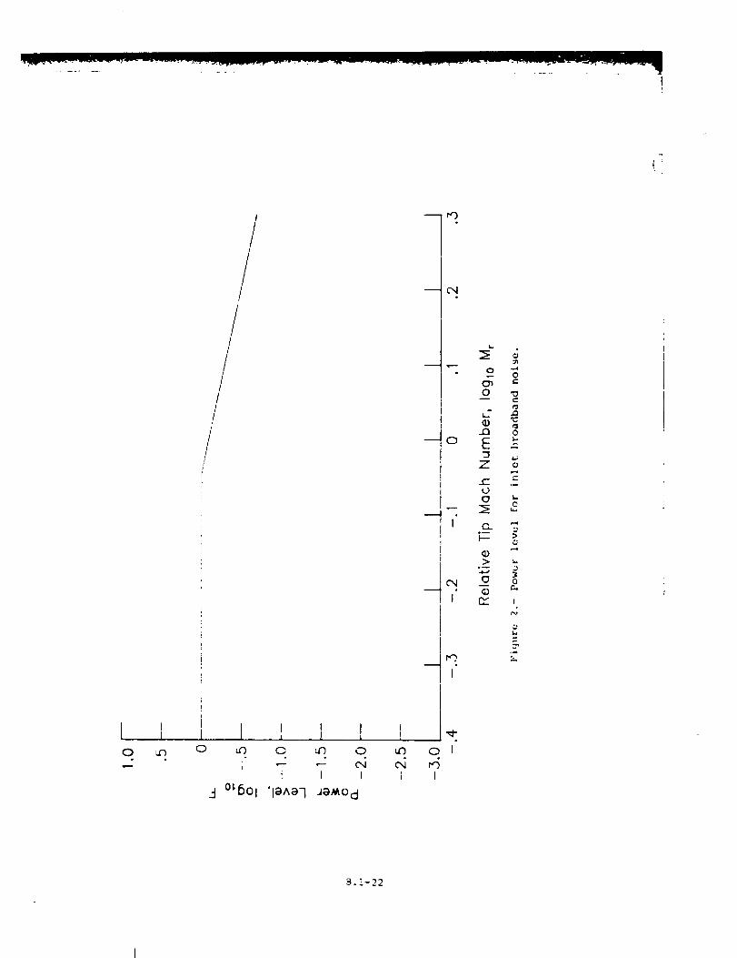
s > i. The power function F is
i (Mr -< 0.9)F = (18)
O. SLMr2 (M r > 0.9)
l4
i
which is plotted in figure 2.
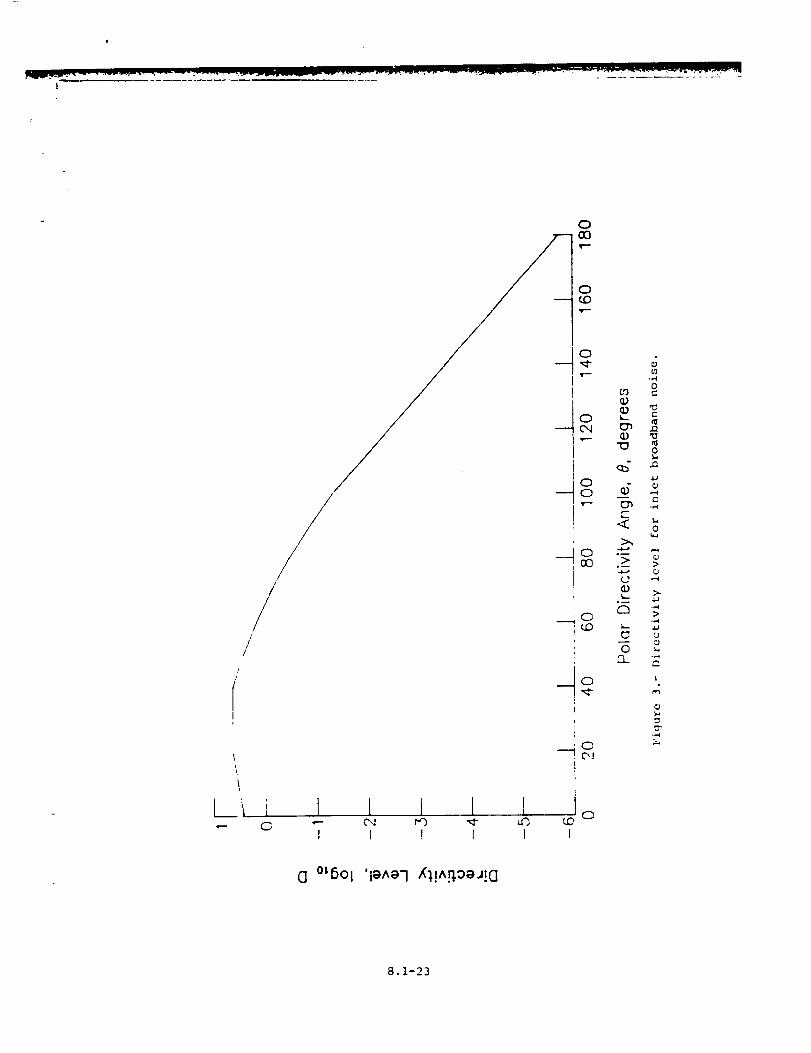
The mean-square acoustic pressure due to inlet broadband noise is
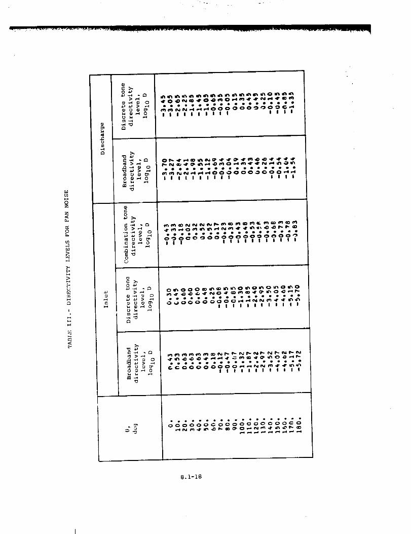
computed from equation (i). The directJvity function D is given in
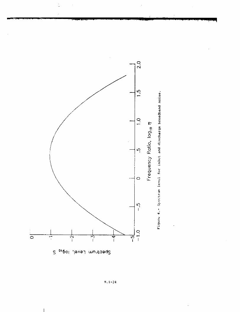
table III and plotted in figure 3. The spectral function 3 is given by
S = 0.116 exu -0.5 (n/2.5)_ (19)" in
where _ is the geometr{c mean deviation and is equal to 2.2. Equa-
tion (19) is plotted in figure 4.
Inlet Rotor-Stator Interaction Tones
Discrete tone generation is associated with lift fluctuations on
rotor or stator blades. Interaction tones are generated by rotor blades
intersecting the wakes from preceding starer vanes or inlet guide vanes
or by rotating wakes from a rotor impinging on stator vanes. The tones
are propagated from the blades as spinning duct modes. No attempt is
made to determine the specific characteristics of each propagated mode,
only the average far-field c_racteristics are predicted.
The acoustic power due to inlet rotor-stator interaction tones i_=
-" = (2.683 x !0 -4 ) G(i,_) (s')-a(k'[)M4"31(m*/A*) (iT') 2 F(Mr,M m)m
{20)
9.i-8
w •
where the constants are
and
G(i, j} =
a(k,£) =
IO 1.625
O. 580 l
0.205j
(21)
(22)
The constants in the matrix G account for the effect of inlet guide
vanes and fundamental tone cut-off. The exlDonent on the rotor-stator
spacing accounts for the inverse variation of the acoustic power except
when inlet flow distortion effects dominate at s > 1. The power
function F is
F ---
-2.310. 397M
m
2053C31,S (0 2r
0 .315M 3 "69M-8m r
(M r < 0.72)
< M r < 0.866Mm 0"462)
(0.866Mm 0"462 < Mr)
(23)
which is plotted in figure 5.
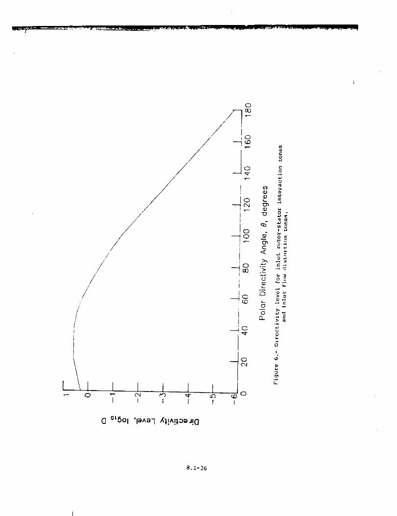
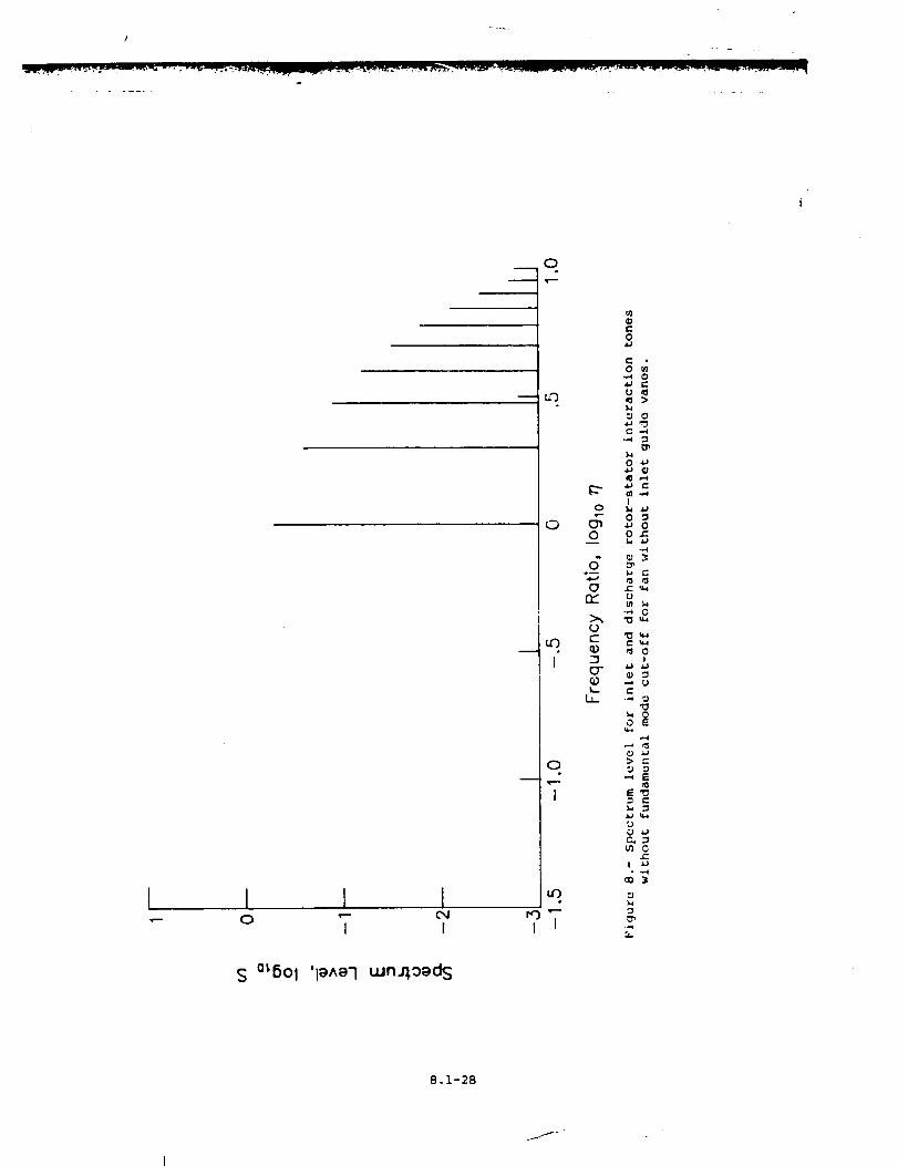
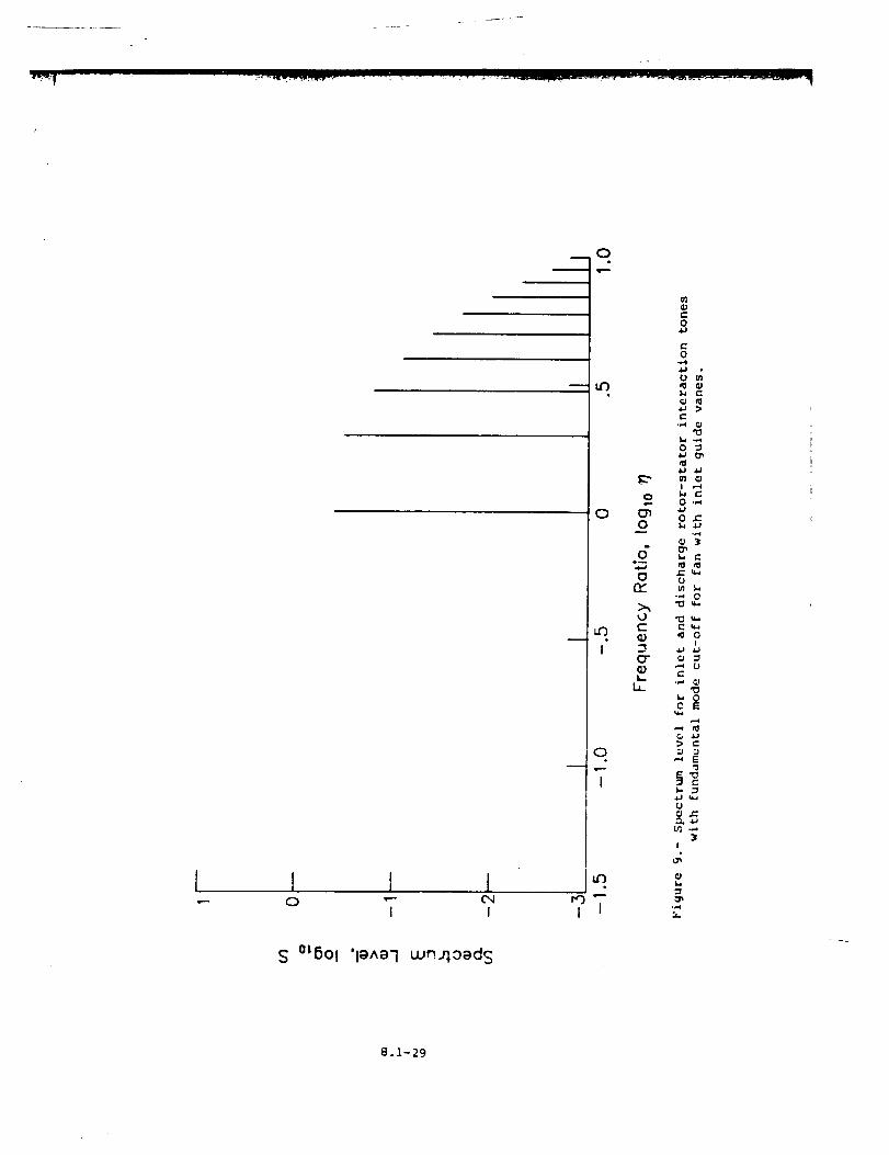
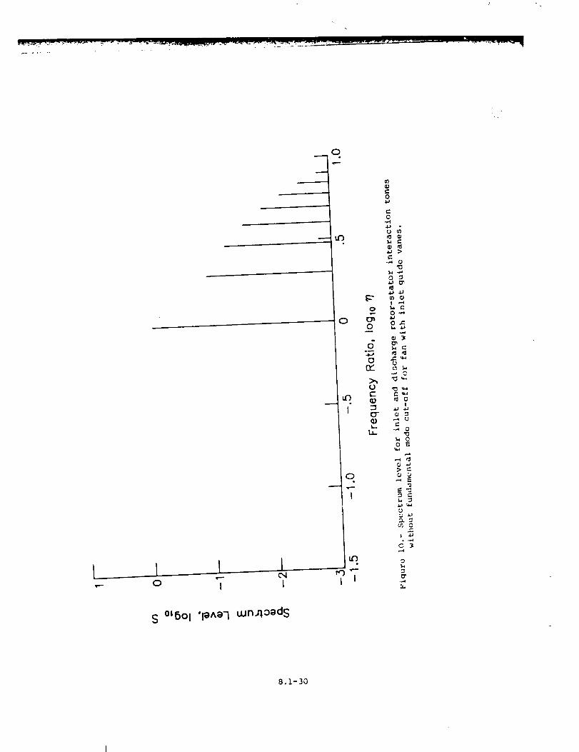
The mean-square acoustic pressure due to inlet rotor-stator inter-
action tones is computed from equation (i). The directivity function D
is given in table III and plotted in figure 6. The spectral function S
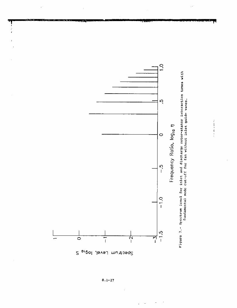
is a discrete function given by
n u
s(n) = _ S(n,i, j) (24)
n=n Z
where n Z and n u are the lower and upper values of t_e harmonic number
associated with the I/3-octave band with a center frequency parameter
value of _. For n = I,
S(1,i,j) _0. 799 0. 387_
(25;
8.1-9
and for n > I,
I_i 250 0"432 lS(n,i,j) = x I0 -0-3(n-2) (26)
i01 0. 307_
where i and j are defined by equations (6) and (7), respectively. The
function S(t]) is plotted in figures 7 to I0 prior to being converted to
i/3-octave-band data.
Inlet Flow Distortion Tones
Inlet flow distortion has an effect on broadband noise and rotor-
stator interaction tones. In addition, inlet fl,,w distortion can generate
unsteady lift on the blades which produces additioi_al pure tone noise.
The average properties of the far-field noise are predicted.
The acoustic :_wer due to inlet flow distortion tones is
I
• 9
•q* = (1.488 x 10 -4 ) (s*)-a(k,_)M4-31(m*/A*) (AT*)" F(Mr,.Xt m)m
(27)
-her,: a(k, 5) and F(>Ir,M m) arc defined by equations (22) and 23),
re_}_ectlvely, and the !xawer function F" is plotted in figure 5.
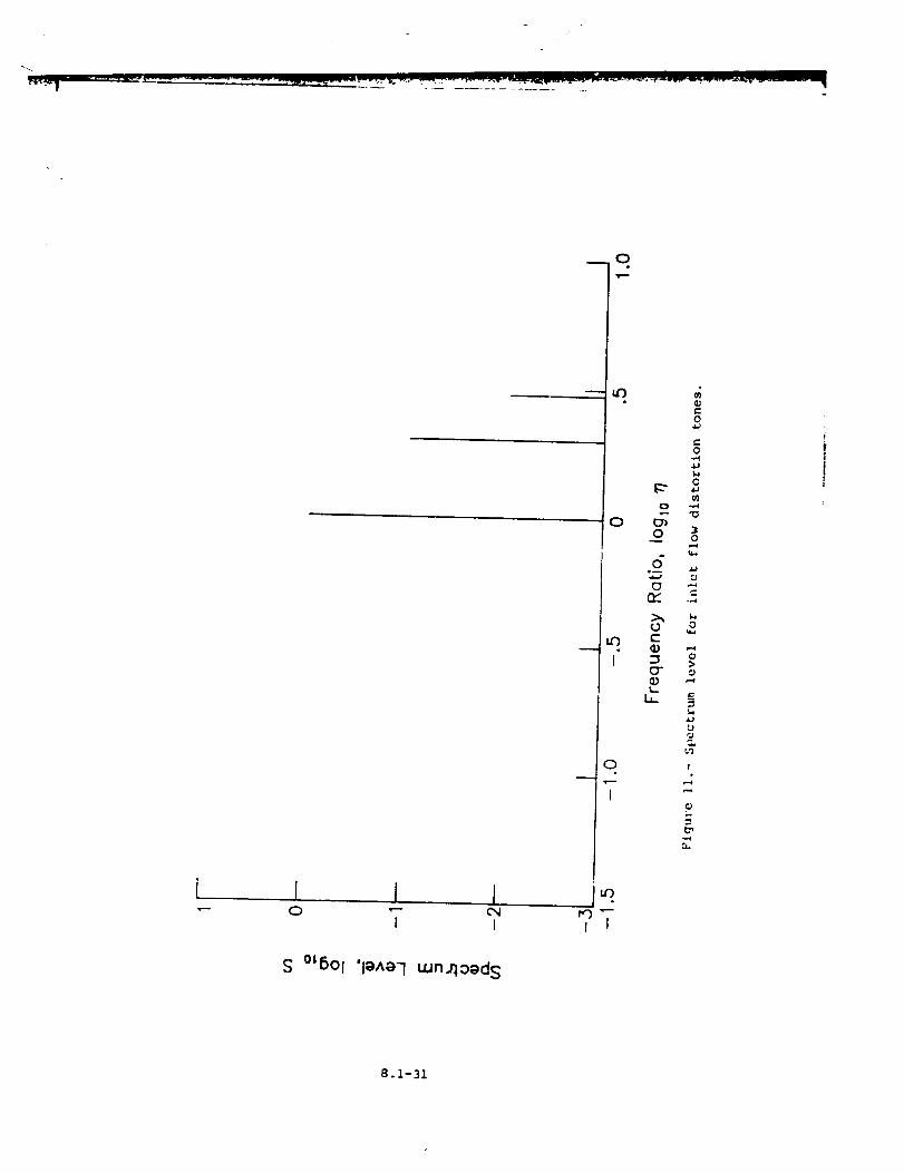
The mean-_,_uare acoustic _ressure due to inlet flow distortion toner;
: _ computed from equation (i). The directivity function D is the same
a:: for the inlet rotor-starer interaction tones as g'_ven in taDle ITI and
•_lotted in figure 6. The sVectral function S is given by
_U
/
n=n 2
i0-" (28%
w!_Ich is "..'lotted _n figure ii prior to beina converted to l,'3-octave-band
iata.
Combination Tone Noise
When tht, relat_v,: _eed of the rotor blade tiFs exceeds a Mach number
value of I, shock waves are formed at the leading edge of each rotor blade.
_Icse ._hock waves _rouagate through Lhe engine inlet as a series of Mach
waves• The resultlng sFectrum contains harmonics of the shaft speed
:n_tead ._f the blade passlng frequency. The resultant no_se is not purely
tonal but e×tends in a frequency: • interval on either side of the harmonic
frequenc[.'. This combination tone ._olse is often referred to as "buzz-saw"
_.i-i0
!
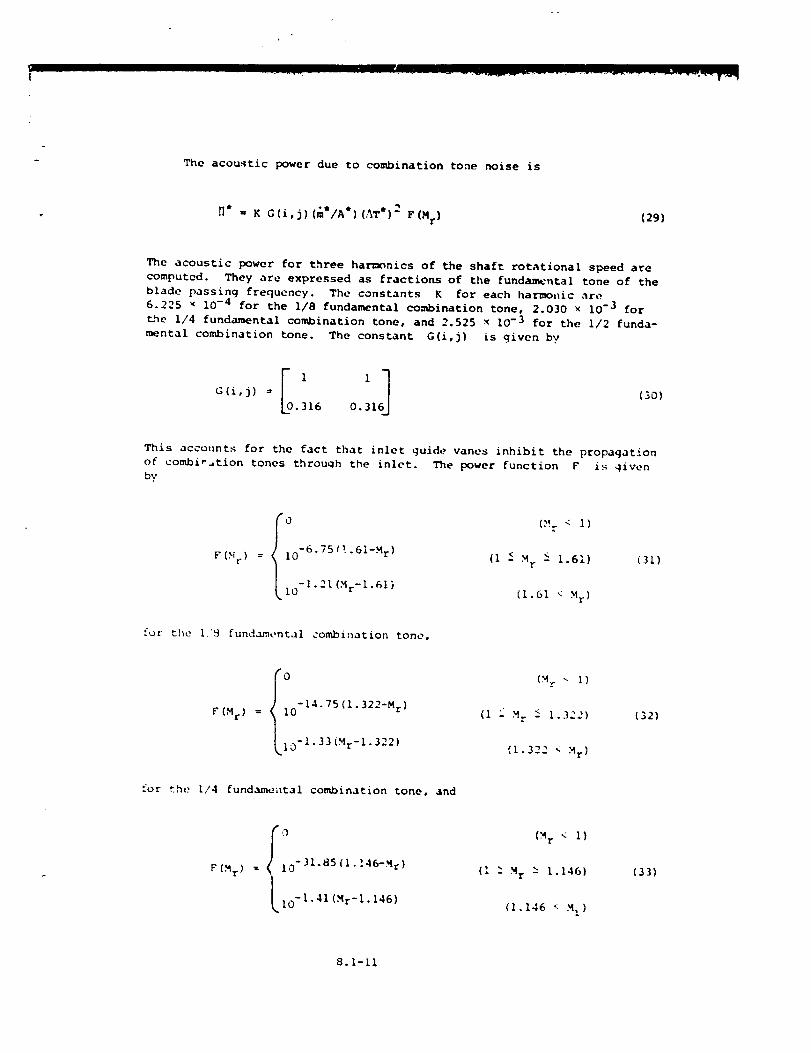
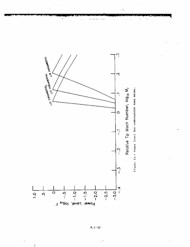
The acoustic power due to combination tone noise is
H* " K G(i,j)(m*IA*)(AT*) 2 F(M r) (29)
The acoustic power for three harmonics of the shaft rotational speed are
computed. They are expressed as fractions of the fundamental tone of the
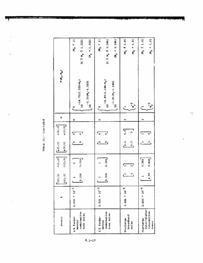
blade passing frequency. The constants K for each harmoi_ic are
6.225 x 10 -4 for the I/8 fundamental combination tone, 2.030 x 10 -3 for
the 1/4 fundamental combination tone, and 2.525 x 10⁻³ for the I/2 funda-
mental combination tone. The constant G(i,j) is given b 7
.316 0.31
(._0)
This accounts for the fact that inlet guide vanes inhibit the propagation
of combir_tion tones through the inlet. The power function F is given
by
O (:% < I)
F(N r) = I0 -6"751!'61-Mr) (I -< H r -< 1.61)
-1.21 (Mr-l.61)i0 (1.61 < M r)
(31)
for the I.'S fundamental combination tone,
F (M r) O= i0-14" 75 (i" 322-Mr )
-1.33 (Mr-l. 322)
(M r - I)
(i "Mr < 1.3..)
(1.322 < M r)
t32)
for the [/4 fundameatal combination tone, and
OF(M r) = i0"31-85(i-146-M:}
I I0-1"41 (Mr-l. 146)
(_r < i )
(I -" M r -_ 1.146)
(I. 146 < M z )
(33)
8.1-11
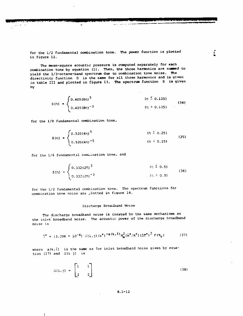
for the 1/2 fundamental combination tone. The power function is plotted
in figure 12.
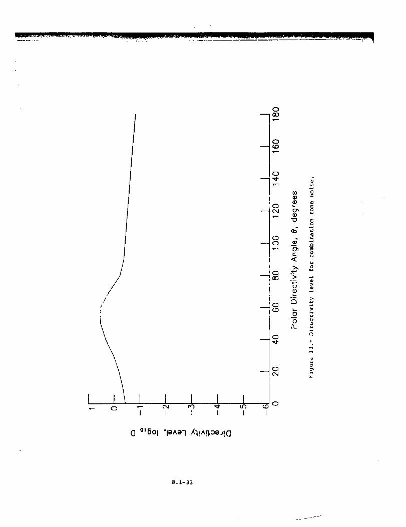
The mean-square acoustic pressure is computed separately for each
combination tone b 7 equation (i). Then, the three harmonics are summed to
yield the I/3-octave-band spectrum due to combination tone noise. The
directivity function D is the same for all three harmonics and is given
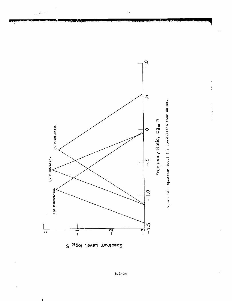
in table III and plotted in figure 13. The spectrum function S is given
by
-405(8D) 5 (D _ 0.125)
S (n) = (34)
405(8D) -3 (n > 0.125)
for the 1/8 fundamental combination tone,
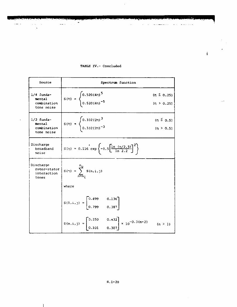
s(n) = I_ "520(4n)5.520(4n) -5
for the 1/4 fundamental combination tone, and
S([_) = _ 0"33212_13
_,O. 332(2n "-3
(35)
(36)
for the 1/2 fundamental combination tone. The spectrum functions for
combination tone noise are /lotted in figure 14.
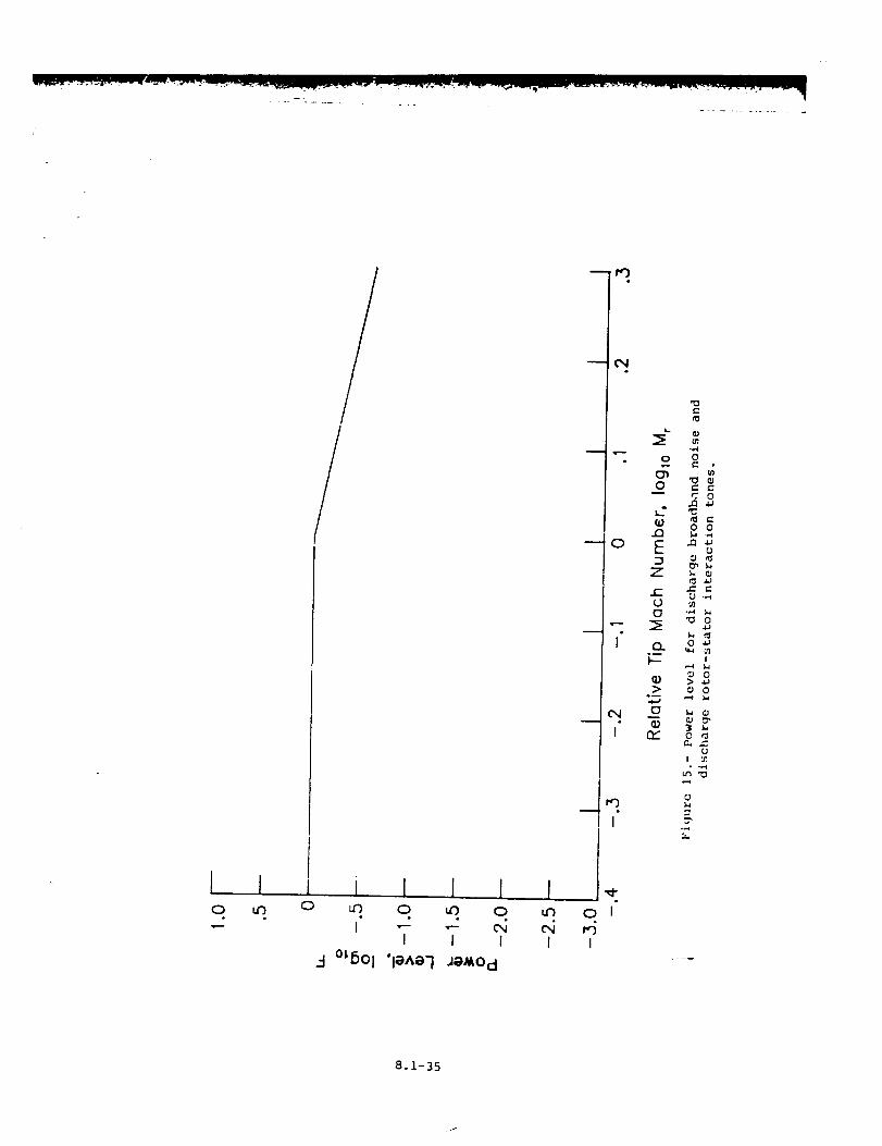
Discharge Broadband Noise
The discharge broadband noise is created by the same mechanisms as
the inlet broadband noise. The acoustic power of the discharge broadband
noise is
_L = (3.206 x 10 -4 ) _(i,j) (s*) -a(k'£) (m*/A*)(_T*) 2 F(M r) (37)
where a(k,[) is the same as for inlet broadband noise given by e_aa-
tion (17) and G(i j) is
(38)
8.1-12
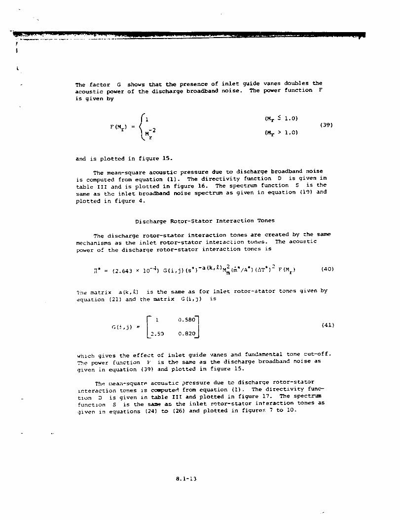
The factor G shows that the presence of inlet guide vanes doubles t.he
acoustic power of the discharge broadband noise. The power function F
is given by
i (Mr -<i.0)F (M r) = 2
Mr (Mr > 1.0)
(39)
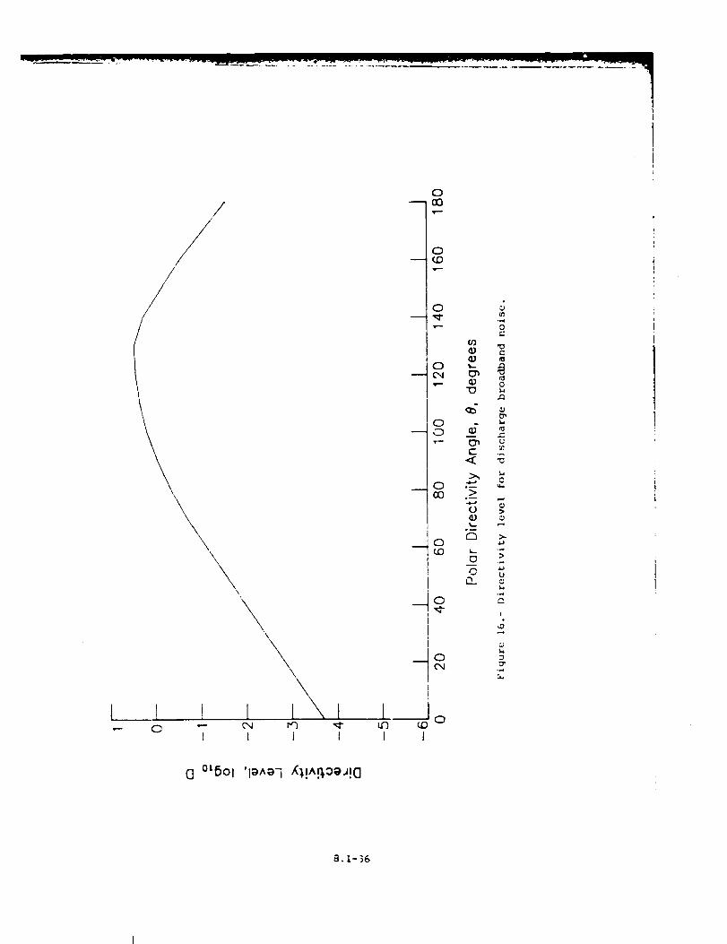
and is plotted in figure 15.
The mean-square acoustic pressure due to discharge broadband noise
is computed from equation (i). The directivity function D is give, in
table III and is plotted in figure 16. The spectrum function S is the
same as the inlet broadband noise spectrum as given in equation (19) and
plotted in figure 4.
Discharge Rotor-Stator Interaction Tones
The discharge rotor-stator interaction tones are created by the same
mechanisms as the inlet rotor-stator interacLion tones. The acoustic
power of the discharge rotor-stator interaction tones is
_* = (2 643 x 10 -4 ) G(i,j)(s_)-a(k'i)M2(m*/A*)(AT') 2 F(M r) (40)• m
qne matrix a(k,£) is Lhe same as for inlet rotor-stator tones given by
equation (21) and the matrix G(i,j) is
c,(_,j) =2 0.58O].59 0.820J
(41)
which gives the effect of inlet guide vanes and fundamental tone cut-off.
The power ftLnction F is the same as the discharge broadband noise as
given in equation (39) and plotted in figure 15.
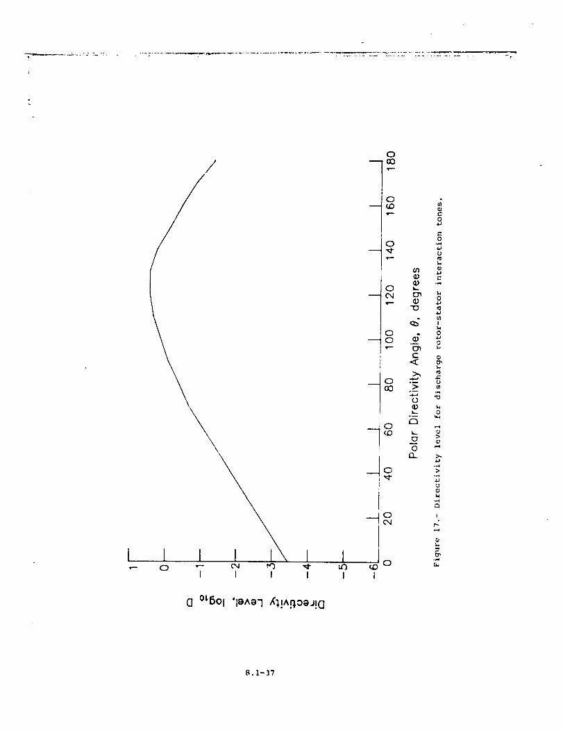
The mean-square acoustic pressure due to discharge rotor-stator
interaction tones is _uted from equation (I). The directivity func-
tion D is given in table III and plotted in figure 17. The spect_ "_
functlon S is the same_ as the inlet r_tor-stator interaction tones as
given in equations (24) to (26) and plotted in figure_ 7 to i0.
8.1-13
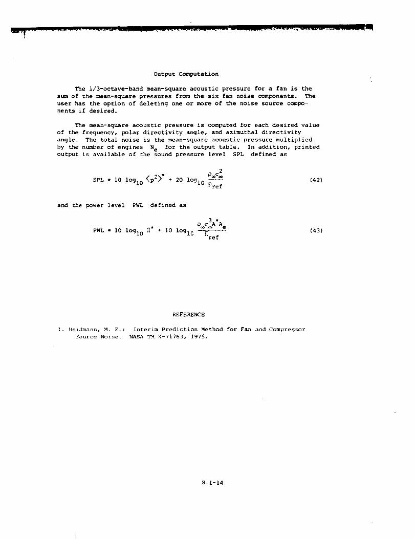
OutputComputation
The I/3-octave-band mean-square acoustic pressure for a fan is the
sun of the mean-square pressures from the six fan noise components. The
user has the option of deleting one or more of the noise source compo-
nents if desired.
The mean-square acoustic pressure is computed for each desired value
of the frequency, polar directivity angle, and azimuthal directivity
angle. The total noise is the mean-square acoustic pressure multiplied
by the number of engines N e for the output table. In addition, printed
output is available of the sound pressure level SPL defined as
_®c_SPL = i0 lOgl0 /_kp22 * + 20 lOgl0 --
Pref
(42)
and d_e power level PWL defined as
0c_A*A e
(43)PWL = I0 lOgl0 _* + I0 logic _ref
I. Hei!mann, M. F.:
__ource Noise.
REFERENCE
Interim Prediction Method for Fan and Compressor
NASA TM X-71763, 1975.
8.1-14
m
TABLE I.- RANGE AND DEFAULT VALUES OF IN-PUT PAR/LMETERS
Input Minimum De fault Max imttmparameter
2Ae , m ......
N e ........ i
r S , m .......
0.01
1
0.01
_,14
1
A _ .... . . • o
d _ ........
1 .... . . . . °
Md ........
[ .........
S* . . . ° ° ° . o
".7 .........
._1" ....... °
"_,1o " ° ° " ° ° " °
"T* ........
C a, m/s ......
i , kg/m 3 .....
0.i
2
0.3
1
0.5
1
0.2
i0
0
0
0
0
200
0.2
1
20
I.!28
1
1.0
1
1
50
0.2
0
0.3
0.2
340.294
1.225
I0
4
i00
i0
i00
4
2
2.0
2
I0
200
i0
0.9
0.5
1.3
4OO
1.5
8.1-15
vIVl "J" vt Z X
c_A
_DV
VI _.
V!
A A
_ A
0
I O
'll
I",I
u_
Vl _.
v
°
t L.
i E
o _,
_ C
VI A
v
r2-'D
t
x
_n
, TO _
&_;
C "J
tc
,4
j -
0
8.1-13
0
I
6-
k_
v
r._
XVl A
I., leZ Z
V!
p-0
5"!
,-qw
IO
_t
Xv
t O
_PV _-_
le ,..4
XV!
1E
V!
I
v
a0
1O
I-4 ,,.4
Vl A
A _ l.JZ _r
X
_D
f-J
Ii.I
ol"_O ! t.
A A
w v
A _
v v
v
!O
O
O
'_ e 0
O O
2_.2
IO
x
,,,_ 8 _,
I
r_,:; o
o •
_0
x
r- O_U _., 0
0 0
,-4 _"
Vl A
,.,..I
0
_a2_
8.1-17
r
Z
Z<t,.
0
o3
I
m
0
e-U
,-4C
r. >,o
o.,-_ o o.i.J _ _ ,...4eJ o _J 0_1.4 _ ,.4 ot2 _
.,.4.,.¢ 01_
>,
0 _,_ 0
oc0
>_
e" Ol ,-4 0.,.4 14 _
0
0
0
_ _ > ,--40 0 0 0"_
>.
.,-Q -,'_ ¢) 0
0 0-_ 0
I I I I I I I I I I
O O_ 0 e 0 O_ O 0 0 0 0 0 O O O
i|il
oooooooooooooo_ooo
I I I I I i I I I I I I I I
g_ o o_ o_ e o o o • o • e_ o o_O0 _ 00000000 O0l I l I I I I I t I I I I I
I I I I I I I I I I I I
• ooo • • •
I I I l I I I I I I I I
g gggg ggg gg g ___0__ _
8.1-18
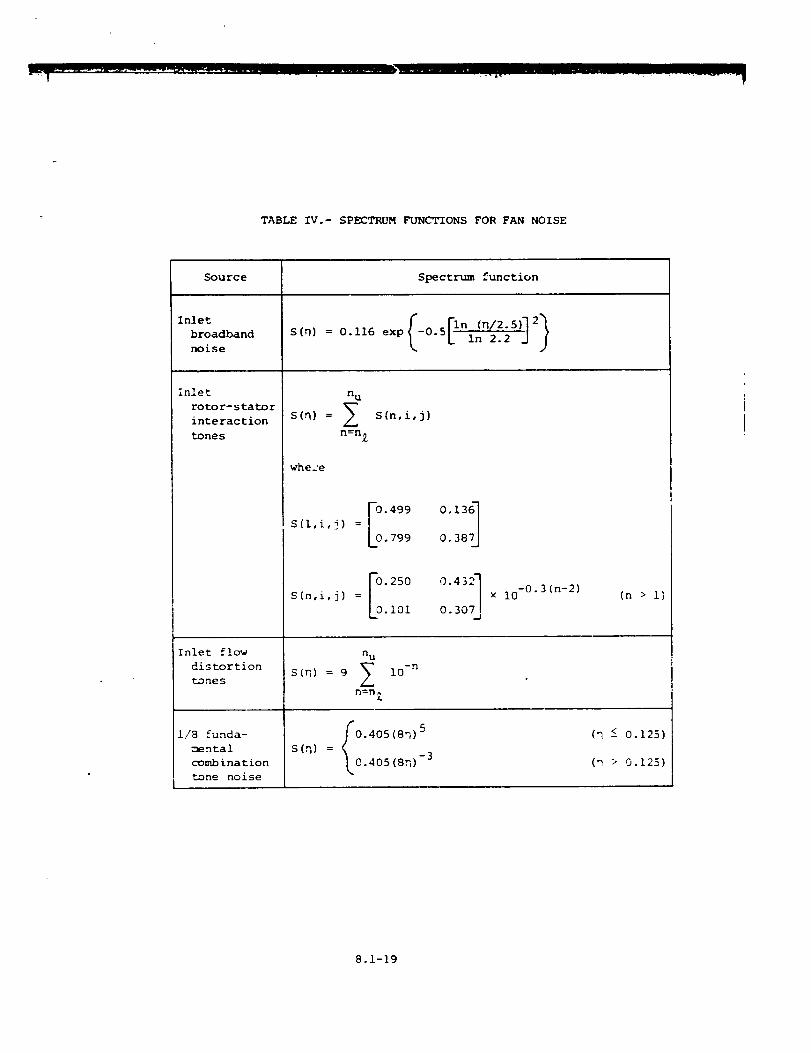
TABLE IV.- SPECTRUM FUNCTIONS FOR FAN NOISE
Source Spectrum function
Inlet
broadband
noise
inlet
rotor- stator
interaction
tones
Inlet flow
distortion
tones
1/8 funda-
mental
combination
tone noise
r_ ,hi2,,]qS(q) = 0.116 exp L 0.5 L In 2"_'.2 J J
n u
S(q) = I S(n,i,j)
n=n Z
whece
-0.499 0.136
S(l,i,j) =
0.799 0.387
%.2s0 0.43!S(n,i,9) =
2.1oi o.3o L
-0.3 (n-2)x i0
S (n) = 9
n u
In=n
&
i0 -n
s(n) = _ "°'4°5 (8n) 5
[.0.405 (sn) -3
(n > i)
(_ ! 0.125)
(D > 0.125)
8.1-19
i
TABLE IV.- Concluded
t
Source Spectrum function
1/4 funda-
mental
combination
tone noise
1/2 funda-
mental
combination
tone noise
Discharge
broadband
noise
Discharge
rotor-stator
interaction
tones
S(q) =
F
520 (4rl) -5
s(q) = 0.332(2n) 3
Lo 332(2q) -3
s(q) = 0.116 exp L°'5L in 2.2 j j
n u
s(n) =
n=n_
S(n,i,j)
where
S(l,i,j) = 0"1361
0.387J
S(n,i,j) = 0"4321
0. 307_
× i0-0.3 (n-2)
(rl -< 0.25)
(q > 0.25)
(n < 0.5)
(rl > 0.5)
(n> i)
8.1-20
N
r
//
Figure i.- Schematic diagram of typical axial flow fan.
8.1-21
1
_7t '
0
/ 7
/
///
T I 1 I fl , _ ,
i ,r-- ,r'-- C_
i f t i
°_6oI 'la^a7 JaMO d
-- C)
o
I
c_
It
o J_)
I
-Q o
£ =Z
c =.,..,
o
i= >
Q)
°_
0 o
OC i
3.1-22
o
t
L_i
o
/ i/
//
!
i I 1 i } II 1 I { {
N o
0
C_
o
I
<
o-->
o--
°_
0
0
0
o
>
0
I
0
(3 °'6oi 'l_^_']f'}!A.q.O_J!O
8.1-23
0
/J/
0
c#
m 0
0
I I
0
C
0
0 _
CY_ m0 _"
C
C12 ,_
_ oU
i_ "'_
cr 2
>0
i.I
I°
3
S °tBOl "laAaq _n_0_d S
9o 1-24

/
<
(
1 1 l
\
/,/v"
,1I
-I °=6ol
\
\\
,\\
ql
t/
/
1 l l J0 _ 0 uO
I I ; I
'I_^_'IJeMOd
0MI
0_J
0
o E o
r- o_ o
o_I--- =
o
I" if2 o
1
t '¢') I
I
0
S
//
/
/
//
/
/
1 I 1 1 IO "- _ if3 ',m'-
I I I I
/
/
O0o
o(.0
o
mr-'--
¢D
C)
--io
JI
00PJ
I
J___c
,¢.D
i__io
O'4
I IoLI3 _,0I I
¢)¢)
C<
>o__
°_
0I3_
1110
011
0--4
.,I,J
U
0
r',-,,-,I
_ 0
0 e-
0--
>.
!
.,-4
0 °_5Ol 'I_A_-I XI!A.qO_J!C]
8.1-26
--!
1 I I
_0
l
C_u
I
0 "-" _ r'O "-I I I I
S °L6Ol 'I_A8-I _n_o_d S
0
0
6
0r_
oc-
I,...
t-
O
t-O
_d
•= >
e. ¢
0 _
•tJ OJ
I c-
O
0 __ 0
U _m _
0
e-
•_ 00 I
t" _-,4 _)
0 '0_'_ 0
E E
U _
I
,z
o
8.1-27
/
I I I I•-- 0 _-- 04
I I
0
0
I
0
I
ix')
I I
S °t6Ol 'le^e'l uJn_,oeds
0
ETI0
I
.m
0rY
(jc-
O"
LL
04.1
4J r"
0 0
.,-I
0
I
0'_ 0
0._
-.-,I
r" ,.t.,_U
,_ tL.=
0
=-
_ Ut-
_ E
m Cr"
_2
8.i-28
I J l I•-- 0 "-- (x4
I I
_0
Lr)
0
0
e_
0rY
o
c
o-q)
b_
0
I
u3
.3"--I I
S °LOol 'le^e9 cun_oed_
0aJ
0-,.4
'0}.4 .,-I
0•_ O_
m
! ,.-4
0 -t,'44_
o,.c
_'_
"'_ O
I.,_ 4J
e"
_ O
C E
_ E
_7
O e-
)!
8.1-29
0
C_0 I I
'l_^e'l uJn_oadS
u_
i
0
0
e_
0rr
oE
1.1_
C0
CO
e-,
,G
o _
m o
0.,.4
um t,4
.,.J o
_ oi
_ ur-
_ oo E
t_
_ E
i iJ
c _,..,4
.,..,
8.1-30
0
v--
0
I
0
I
I I I l _.0 "-- _ _)--
I I I I
S °L6Ol 'le^e"l uJnAoed S
L_
0
0
d
n,-
ot-
o.-
i,
¢:
0.4,J
0
c
_J
o
--'4
0
0
U
!
--2
8.1-31
J//O.J
I I I0 ur) 0
,,e--
1 ! 1 I 10 u_ 0 _ 0
I 1 I I I I
°_6Ol 'le^e-I JeMOcl
"-" 0 0
O'b
0! JJ
..a o
('- o0 :';0
..- _ o
i ._o..;I--- >
i n," _
:2I
8.1-32
///I
I II
I I I II I I I
0moo
0
0
0
0
,ql--
C3
CN
I
E
e_
>_D
_D
o
oc"
¢1
t-,o
o"41aJ
oU
t_0
>
U
e_
I
G °LSOl 'le^e-I XI!A_OeJ!G
8.1o33
0m
o"
!
0 _ 04 t.") "--I I I I
0
0
0
t--
U.,-4
0
£
J
E
U
!
1,4
-2
S eL601 'l_^e'lwn_o_ds
8.1-34
0
fI j I 1 1 I
I I 1 I
3 °_8Ol "1_^_"i .J_Mod
m
_0
u
I
I
0 I
I
0 0
o _C 0
U
_ '_ o11
Q. 0 ._
t_
:2
8.1-35
/
/
/
\\
I ii
0 "--
\
I I I
0
0n
qr--
0
0
t°m 0
0,<-
MO
1 oI I
U)
O_L,
uE
>
U >
._
>.
>
c _
.,,4
r,
!
CI °L5ol '{_^a-i ,_},!^._o_._!C!
8.1-36
/
I I I I0 "-" C_ _ _-
I I I I
a °L6Ol 'Ig^e'l ,_1!^.q0eJ!Cl
0
-I°¢0
i
-i°0
00
___0
CO
_0
G
I
0(.'_i
1 oif3 _.DI I
ffl
t-<
>
L,_°_
C3
L.
0
O0c-O
0
o
,IJ
!
o4O
0
0
e"
0
11
.,,..i
,j
I
t_
.f..te,.
8.1-37

i T _
8.2 COMBUSTION NOISE MODULE
INTRODUCTION
The Combustion Noise Module predicts the noise from conventional com-
bustors installed in gas turbine engines. The method is based on a pro-
posed appendix by R. K. Matta to SAE ARP 876. The method employs
empirical data of core noise from turboshaft, turbojet, and turbofan
engines to produce sound spectra as a function of frequency and polar
directivity angle.
The method requires input of several parameters. The combustor
entrance and exit flow parameters can be provided by the Core Noise
Parameters Module or directly by the user. Additional user-provided
parameters are required. The module is executed once for each set of
values of the input parameters. The output is a table of the mean-square
acoustic pressure as a function of frequency, polar directivity angle,
and azimuthal directivity angle. Although combustion noise is assumed
not to vary with azimuthal directivity angle, it is introduced so _at
the output table is compatible with other noise tables.
A
A e
ca
D
f
fp
H
&
N
<_2>*
Pre f
Pt
P=
SYMBOLS
combustor entrance area, m 2 (ft 2)
engine reference area, m- (ft 2)
ambient speed of sound, m/s (ft/s)
directivity function
frequency, Hz
spectrum peak frequency, Hz
aircraft Mach number
mass flow rate, kg/s (slugs/s)
number of engines
2 4mean-square acoustic pressure, re O_c_
reference pressure, 2 x 10 -5 Pa (4.177 × 10 -7 ib/ft 2)
total pressure, Pa (Ib/ft2)
ambient pressure, Pa (Ib/ft 2)
8.2-1
rs
tr
s
S
T
ATde s
8
II*
_ref
distance from source to observer, m (ft)
dimensionless distance from source to _bserver, re _e
spectral distribution function
total temperature, K (OR)
design turbine temperature extraction, K (OR)
ambient temperature, K (OR)
polar directivity angle, deg
acoustic power, re O C3Ae
reference power, 1 x 10 "12 W (7.376 x 10 -13 ft-lb/s)
ambient density, kg/m 3 (slugs/ft 3)
azimuthal directivity angle, deg
Subscripts:
i entrance
j exit
Superscript:
* dimensionless quantity
INPUT
The combustor entrance and exit parameters are required from either
the output of Lhe Core Noise Parameters .Module or from the user. Ambient
conditions are required for computation of the s_und pressure levels.
The frequency, polar directivity angle, and azi=_thal directivity angle
arrays establish the independent variable values for the output table.
Finally, the engine reference area, number of enqines, combustor entrance
area, and distance to observer are required. The range and default
values of _he input parameters are given in table I.
A
A e
N
r S
Input Constants
combustor entrance area, re A e
engine reference area, m 2 (ft 2)
number of engines
distance from source to observer, m (ft)
8.2-2
j_
L
Pt, i
T"J
T*A des
MoQ
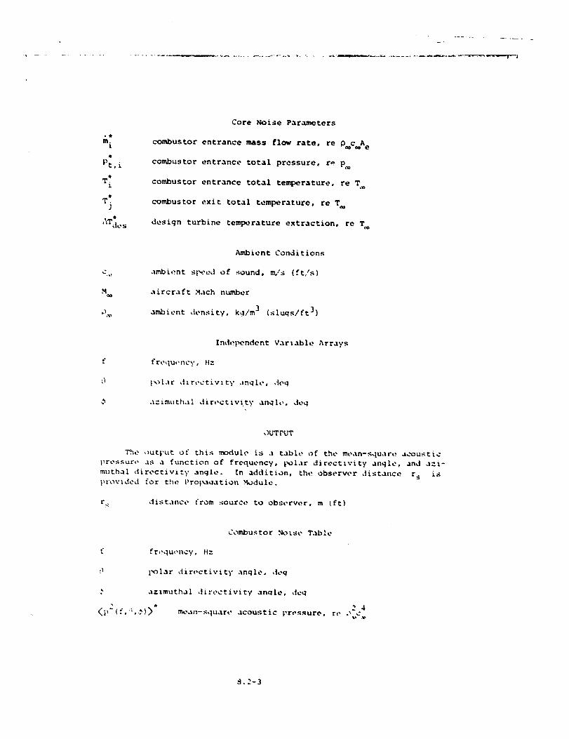
Core Noise Parameters
combustor entrance mass flow rate, re D c A e
eombustor entrance total pressure, r_ Poe
combustor entrance total temperature, re T
combustor exit total temperature, re T_
design turbine temperature extraction, re Tm
Ambient Conditions
ambient sl_-ed of sound, m/s (ft,'s}
aircraft Math number
ambient density, kg/m ] (sluqs/ft ])
Ind,5_ndent Variable Arrays
t'requt,ncy, Hz
}k)L,lr dtrectivtty anqLe, deq
a;'.tmuthal dir,,ctivtty anqh,, deq
OUT PUT
The out_,ut of this module is a table of the mean-square, acoustic
|_ressure as a function of frequency, _olar direct_vi_y angle, and a:i-
mnthal directivity angle. _n addition, the observer distance r s is
[uovlded for the Proi_ation .Module.
r_
f
h
• O
distance from source to observer, m [ft)
Combustor Norse Table
frequ,,ncy, H:
polar dir_,ctivity anqleo ,|eq
azlmutha| dirt, ctivity anqle, deq
2 4
me.xll-_uare aCOUStiC Vressure, r_, ,_ Cp
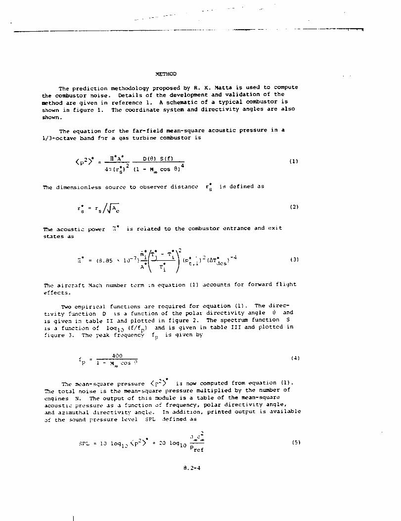
.METHOD
The prediction methodology proposed by R. K..Matta is used to compute
_e combustor noise. Details of the development and validation of the
method are given in reference i. A schematic of a typical combustor is
shown in figure I. The coordinate system and directivity angles are also
shown.
The equation for the far-field mean-square acoustic pressure in a
I/3-octave band for a gas turbine combustor is
<p2> t = ntA * D(_) S(f) (I)
4_(r:) 2 (i - M cos @)4
Q
The dimensionless source to observer distance r s is defined as
The acoustic power ]* is related to the combustor entrance and exit
states as
&'/T" >2-* * ")2
T[ "'"
(3)
me aircraft Mach number term in equation (i) accounts for forward flight
effects.
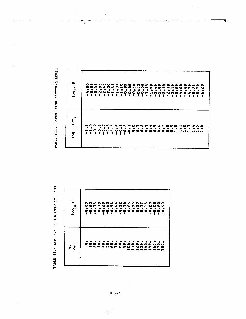
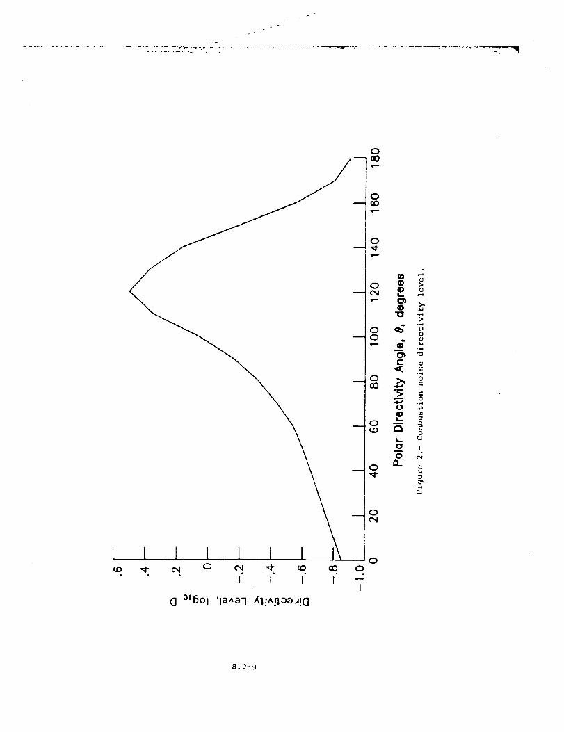
Two empirical functions are required for equation (I). The direc-
t:vity f'_nction D is a function of the polaz directivity angle 0 and
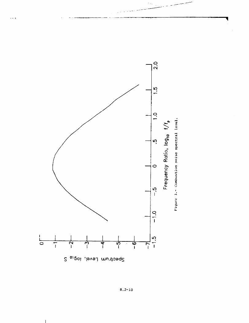
is given in table II and plotted in figure 2. The spectrum function S
1& a function of logl0 (f/fp) and is given in table Ill and plotted in
figure 3. The _ak frequency fP is given by
f = 400 (4)
P 1 - M,_ cos 9
The mean-square pressure <?2>* i_ now computed from equation (I).
=_.e total noise _s the mean-square pressure multiplied by the number of
engines N. The output of this module is a table of the mean-square
acoustic pressure as a function of frequency, polar directivity angle,
and azimuthal d_rec_ivlty angle. In addition, printed outFut is available
of the sound ?ressure level SPL defined as
2,3 C
_P:.. 10 1ogi_ <p2>" :0 _ "= + l°gl0 Pref
(5)
8.2-4
f
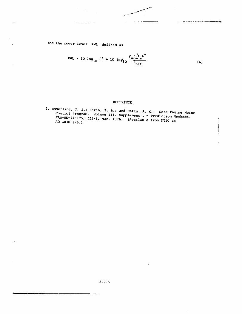
and the power level PWL defined as
PWL = 10 lOgl0 H" + I0 logl0(6J
REFERENCE
I. Emmerlinq, d. J.; Kozin, S. B.; and Matta, R. K.: Core Engine Noise
Control Program. Volume Ill, Supplement 1 - Prediction Methods.
FAA-RD-74-125, III-I, Mar. 1976. (Available from DTIC as
AD A030 376.)
_.2-%
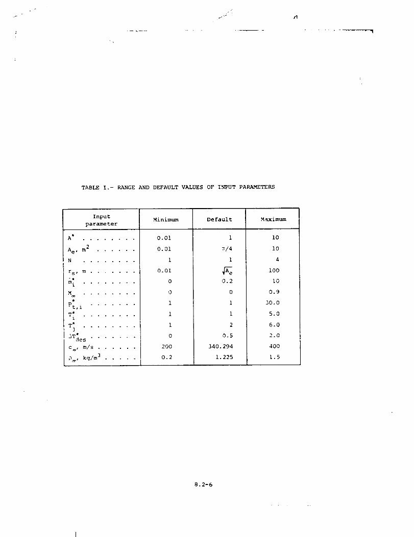
TABLEI.- RANGEANDDEFAULTVALUESOFINPUTPARAMETERS
Input Minimum Default Maximumparameter
A t . . o o o . . .
A e , m 2 ......
N ........
rSS m .......
m*. ° ° ° .... oi
'%_oo ........
P:,i .......
T. _ • . ° o ....1
T* ........
3
'_Tde s .......
Coo, m/S ......
_ , kg/m 3 ..... [
0.01
0.01
1
0.01
0
0
1
1
1
0
2OO
0.2
1
,_/4
1
0.2
0
i
1
2
0.5
340. 294
1.225
i0
I0
4
i00
i0
0.9
30.0
5.0
6.0
2.0
4OO
1.5
8.2-6
"----"I
>
[..,UM
ZQ
en
0U
!
Ul
e_
UI
0
0,...4
0
0
I | I I i I I i I I I I i i I I i I i I i I i I i I i i
o * • • • • * * * • o o * o . o_ • . o . . o . o . .__00000000000000 0000__I I I I i I I i I I I
Z©
i
)..,
o,-.4
0000 000 0 0 v O0 0
I I I I I i | i i I I i i I
OOOOOOOOOOOOO0_oOo00000000000000000000
8.2-7

J
Jj °
oooc_ o o ooc_ooo
X
Z
Figure I.- Schematic diagram of typical gas turbine combustor.
8.2-8
I 1 l I I 1 1¢D '¢ e_l 0
G °tSOl
C,,I '¢ ¢0 aO
I I I I
X_,!^_0eJ!CI
00
I
8.2-9
0
wO
0
uu3
0
m
I
0
I
l I I I l I•-- Cx; M') ,_- LD _ ;',."--I I I I I i I I
S °tSOl 'l_Aeq wn4o_d S
Q. '-_
0
o
0
o"°m 0
0 ...4
o
(j o
L. _jb_
I
8.2-10
-7
8.3 TURBINE NOISE .w_DULE
INTRODUCTIO_
The Turbine Noise Module predicts the broadband noise and pure tones
for an axial flow turbine. The method is based on a method developed by
the General Electric Compan 7 (ref. I). The method employs empirical
functions to produce sound spectra as a function of fxequency and polar
directivity angle. Each spectrum is the s,-- of a broadband noise compo-
nent and a pure tone component.
The met_hod requires input of several parameters. The turbine
entrance and exit flow parameters can be provided by the Turbine .Noise
Parameters Module or directly by the user. Additional user-provided
parameters are required. The module is executed once for each set of
values of the input parameters. The output is a table of the mean-square
acoustic pressure as a function of frequency, polar directivity angle,
and azimuthal directivity angle. Although turbine noise is assumed not
to vary with azimuthal directivity angle, it is introduced so that the
output table is compatible with other noise tables.
A
A e
a,b
B
c=0
D
d
f
fb
h"
h a
K
SYMBOl3
turbine inlet cross-sectional area, m 2 (ft 2)
engine reference area, m 2 (ft 2)
components
number of rotor blades
ambient speed of sound, m/s (ft/s)
directivity function
turbine rotor diameter, m (ft)
frequency, Hz
blade passing frequency, }:z
fuel-to-air ratio
specific enthalpy, re RT
absolute htunidity, percent mole fraction
constant
8.3-1
_m
H
e
n
<p2>
Pref
r s
r t
S
S
T
n
'ref
aircraft Mach number
rotational speed, Hz
number of engines
tone harmonic number
2 4mean-square acoustic pressure, re D_c
reference pressure, 2 x I0 -5 Pa (4.177 x i0 -7 ib/ft 2}
distance from source to observer, m (ft)
dimensionless distance from source to observer, re _e
gas constant, m2/(K-s 2) (ft2/(°R-s2))
sp_ctr,_ function
temperature, K (OR)
blade tip speed, m/s (ft/s)
frequenc/ parameter
polar directivity angle, deg
acoustic power, re D c3A
reference power, 1 × 10 -12 W (7.376 x 10 -13 ft-lb/s)
ambient densitq_, kg/m 3 (slugs/ft 3)
azimuthal directivity angle, deg
Su=scripts :
i entrance
3 exit
s static
t total
ambient
Su_Terscri.:t :
• dimensionless quantity
8.3-2
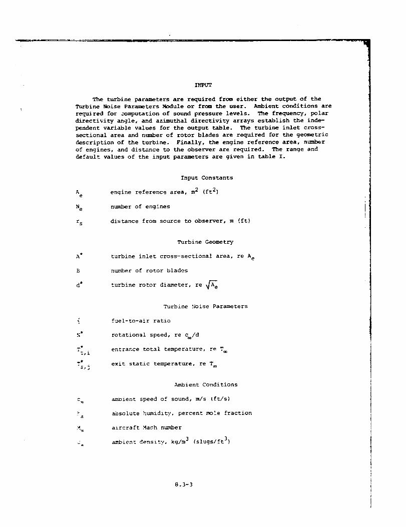
INPUT
The turbine parameters are required from either the output of the
Turbine Noise Parameters MJ_dule or from the user. Ambient conditions are
required for :omputation of sound pressure levels. The frequency, polar
directivity angle, and azimuthal directivity arrays establish the inde-
pendent variable values for the output table. The turbine inlet cross-
sectional area and number of rotor blades are requ/red for the geometric
description of the turbine. Finally, the engine reference area, number
of engines, and distance to the observer are required. The range and
default values of the input parameters are given in table I.
Ae
H e
r s
A •
B
d j
Input Constants
engine reference area, m 2 (ft 2)
number of engines
distance from source to observer, m (ft)
Turbine Geometry
turbine inlet cross-sectional area, re A e
number of rotor blades
rotor diameter, re _A_A_turbine
N*
°s,j
M
_z
Turbine _ise Parameters
fuel-to-alr ratio
rotational speed, re c /d
entrance total temperature, re T
exit static tem--_erature, re T
Ambient Conditions
ambient speed of sound, m/s (ft/s)
absolute humidi_/, percent mole fraction
aircraft Mach number
ambient density, kg/m 3 (slugs/ft 3)
8.3-3
IndependentVariable Arrays
frequency, Hz
polar directivity angle, deg
azimuthal directivity angle, deg
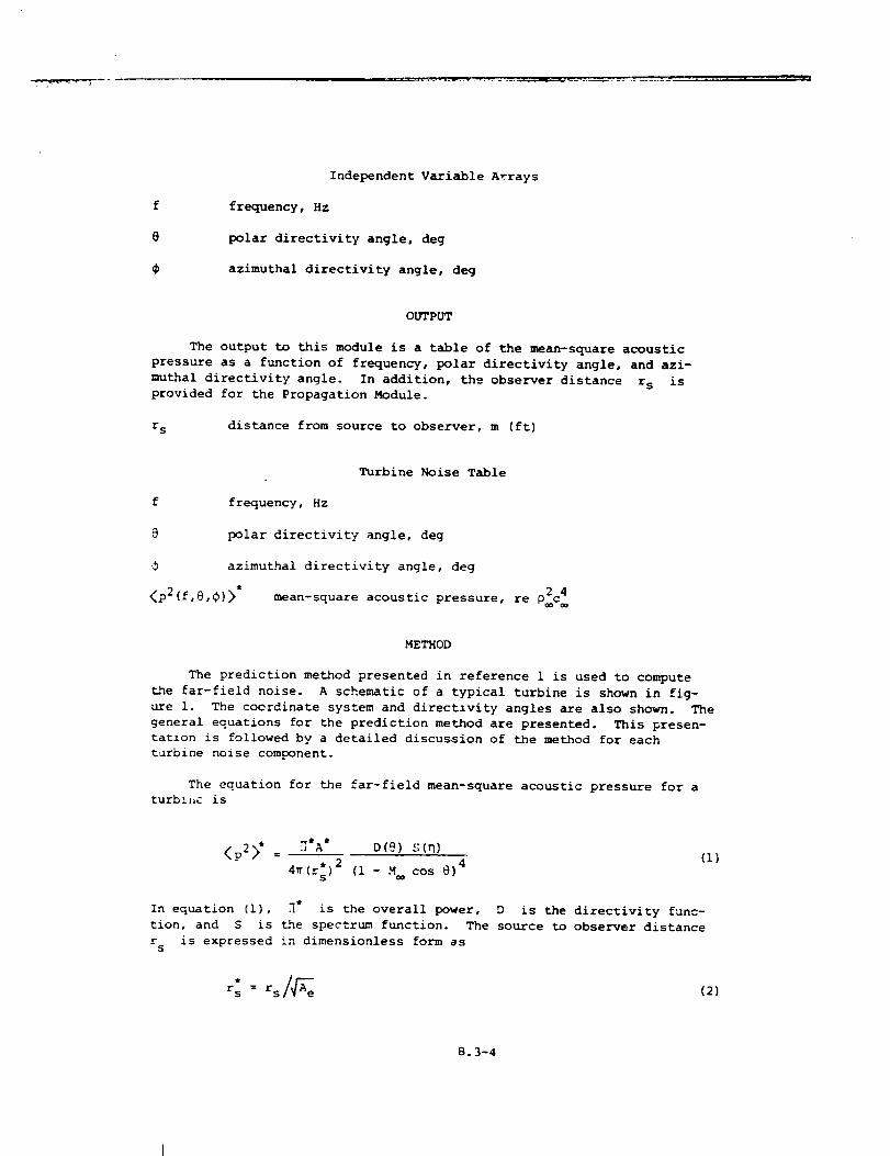
OUTPUT
The output to this module is a table of the mean-square acoustic
pressure as a function of frequency, polar directivity angle, and azi-
muthal directivity angle. In addition, the observer distance r s is
provided for the Propagation Module.
r s distance from source to observer, m (ft)
f
0
<p2_f,e,¢l>"
Turbine Noise Table
frequency, Hz
polar directivity angle, deg
azimuthal directivity angle, deg
2 4mean-square acoustic pressure, re pc
METHOD
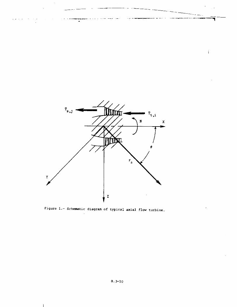
The prediction method presented in reference i is used to compute
the far-field noise. A schematic of a typical turbine is shown in fig-
ure I. The coerdinate system and directlvity angles are also shown. The
general equations for the prediction method are presented. This presen-
tation is followed by a detailed discussion of the method for each
turbine noise component.
The equation for the far-field mean-square acoustic pressure for a
turb!x,c is
<p2>* = _*A* D(9) ._;(_)
4_(rs )2 (i - M cos @)4
(I}
In equation (i), _" is the overall power, D is the directivity func-
tion, and S is the spectrum function. The source to observer distance
r is expressed in dimensionless form ass
r::rs/ e (2)
8.3-4
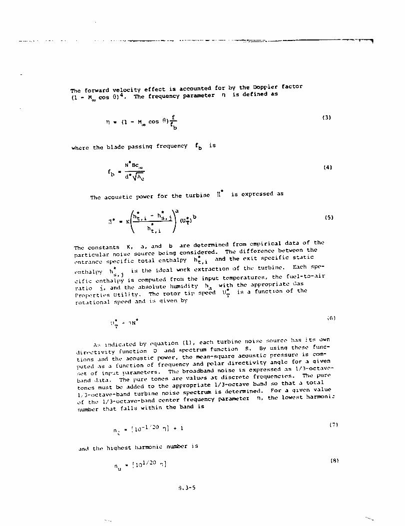
Theforward velocity effect is accounted for by the Doppler factor
(i - _ cos 0) 4 . The frequency parameter q is defined as
rl = (1 - M cos _q]_--b
(3)
where the blade passing frequency fb is
(4]
The acoustic power for the turbine [[* is expressed as
_* = K t,i s,j (u_)b
\ ht,i
(S)
The constants K, a, and b are determined from empirical data of the
particular noise source being considered. The difference between the
entrance sI_-cific total enthalpy h;, i and the exit specific static*
e:,thal_y hs, %. is the idea[ _rk extraction of the turbine. Each spe-
cific enthalpy is computed fro.'.*the input temperatures, the fuel-to-air
ratio ,%, and the absohlte humidity h a with the appropriate Gas
?roi_:rties Utility. The rotor tip s|_eed U: is a functlon of the
rot.,tional speed and i:; given by
T •11 = _N _6)
A_ iudic:ited by equation (1), each turbine noise ,_ource has ._ts own
dir,,ctivity function D and spectrum function S. By using these func-
tions and the acoustic power, the mean-square acoustic pressure is com-
puted as a function of frequency and polar directivity angle for a given
:;et of in_,ut }_arameters. Th_ e broadband noise is expressed as I/I-octave-
band d.lta. The [_ure tones are values at discrete frequencies. T_e pure
tones must be added to the apFropriate I/3-octave band so that a to_al
h/3-octave-band turbine noise spectrum is determined. For a g_ven value
of the i/3-octave-band center frequency param_tez n, the lowest harmonic
number that falls within the band is
n. - [I0 "lz° n] + I (7}L
anJ th,, highest harmonic number is
n = [ 101/20 ".] (,g}U
S.3-5
whrre [ ] indicates the inteqe.r part of the enclosed real number. If
:I[ _ nu, then there are no tones within the band. If n& -< n u, then there
are n u - n£ + l tones within the band. The pure tone mean-square pres-
sures for each harmonic number n are then added to the appropriate band.
The tones are |:ropagated to the observer as i/3-octave-band data.
The empirical constants and functions used to compute the acoustic
_owor for turbine noise are given in table II. The directivity and s_ec-
trum functions are given in tables III and IV, respectively. Each turbine
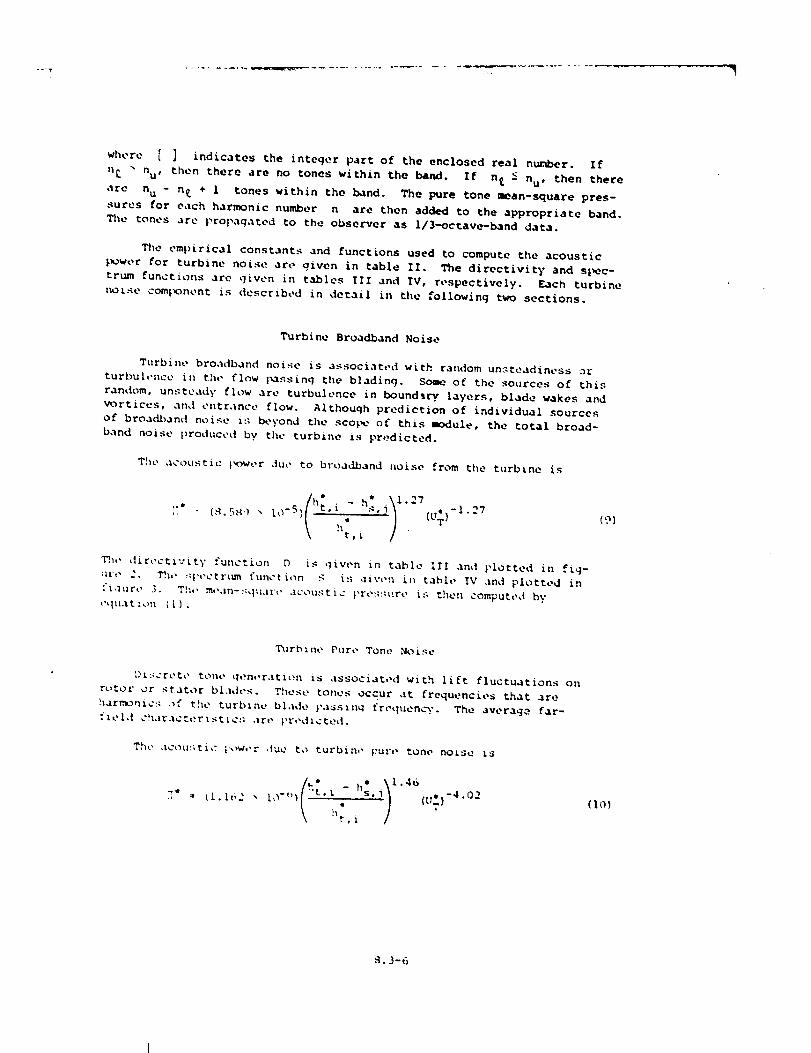
noise com_x_nent is described in detail in the following two sections.
Turbine Broadband Noise
Turbine broadband noise is associated with random unsteadiness o_"
turbuh'ncc iu the flow |_assing the blading. Some o_ the sources of this
random, unsteady flow ,_re turbulence in boundlry layers, blade wakes and
vortices, and entrance flow. Although prediction of individual sources
of broadband noise is beyond the sconce of this module, the total broad-
band noise produced by the turbine is predicted.
The acoustic }_owor due to broadband noise from the turbine is
,,e
i-{S.SS'_ _ 10 -5 ) ' • " {UT )-1"27
hi, i
(9)
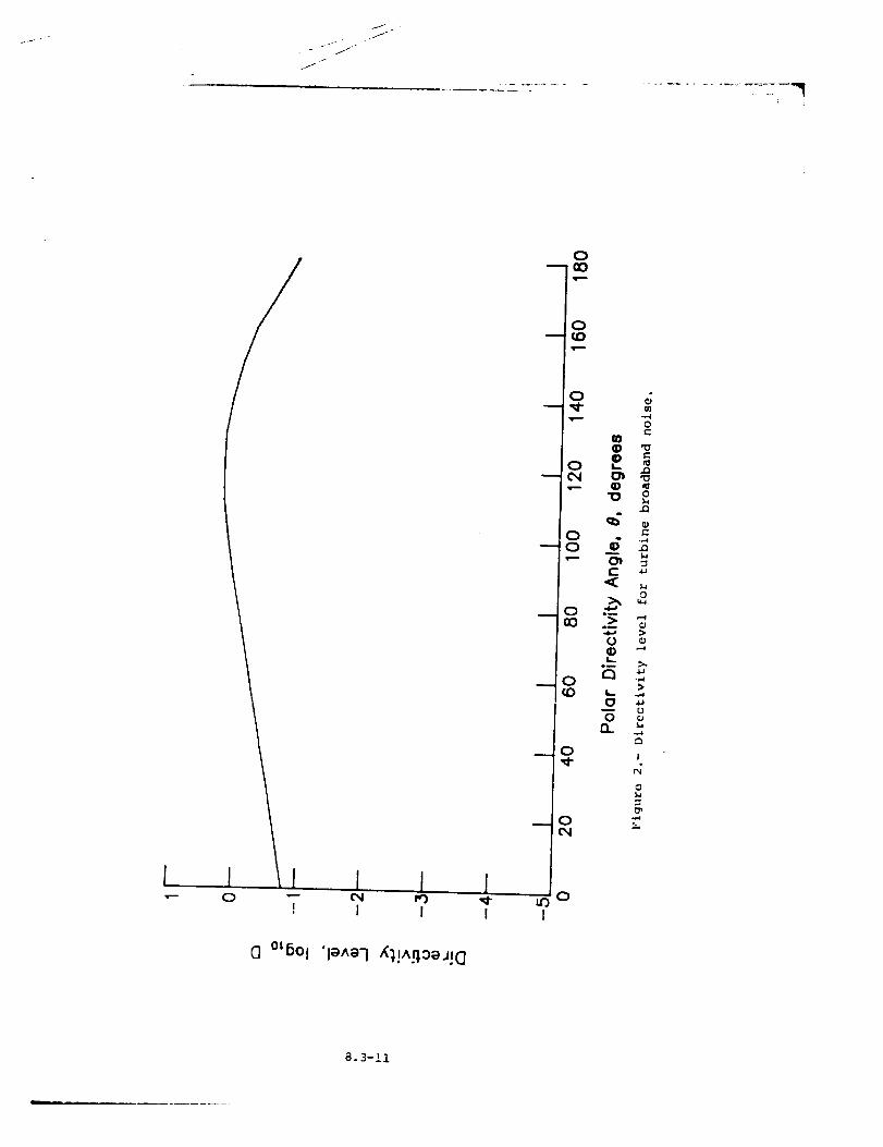
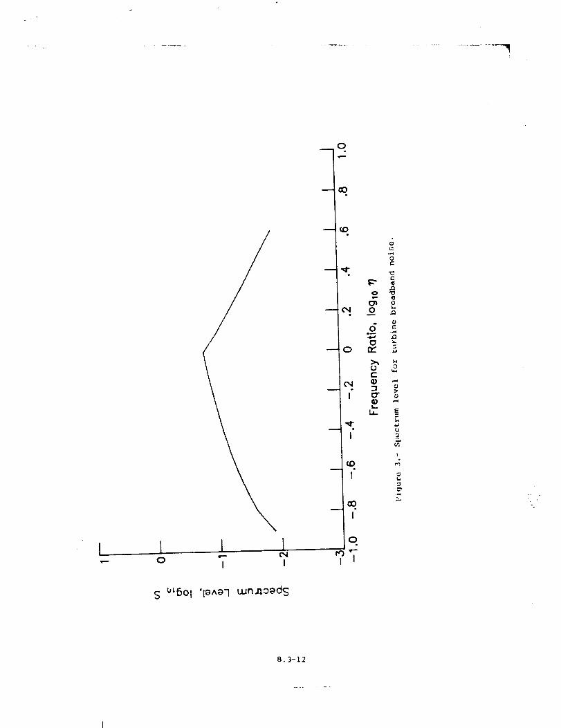
_,, dir,,ctivity function D is given in table Ill and plotted in fig-
ur,- 2. Th,, _l-,-ctr_rn function S is ,liw, u iI_ table IV and plotted in
'.'i,lure 3. Th,' moan-::qu.lr_, acou.qttc _re:;:_t:re i:_ thet_ computed by
,',lu.,t_ou (1).
T11rbine Pure Tone Noise
D_::crete tone gen,,ration is associated with lift fluctuations on
tutor" or starer bl.%des. These tones occur at frequencies that are
harmonic:_ of the turbine blade },ass_nq frequency. The average far-
fief,! c!l._r.lcterist_c:; are _,r,,d_cted.
The acou:_tic _.ow,,r due to turbin,, F:U:," tone no_sd is
<_ ,, )I .46
"t,_ -h:,%[_* = _I.162 _ lO'"_ (U_) -4"02
h:, i
_.3-6
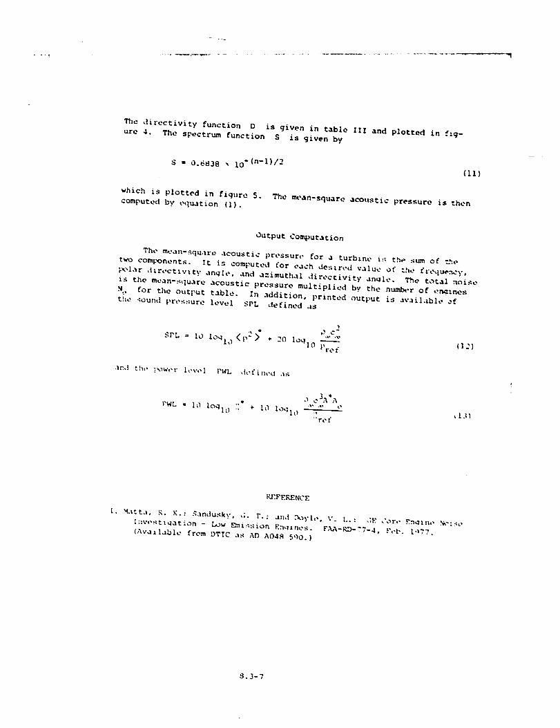
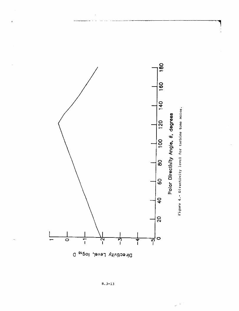
_,e directivity function O is given in table ZlZ and plotted in fig-
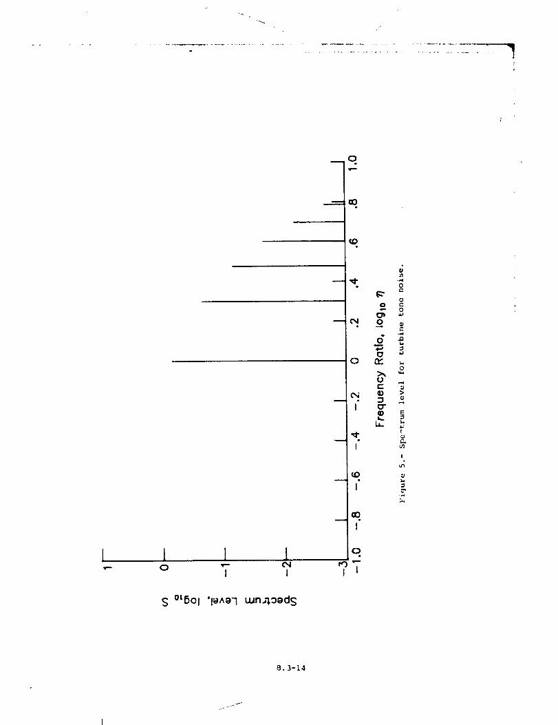
ure 4. The spectrum function S is given by
S - 0.6838 _ lO "(n-I)/2 (ll)
which is plotted in figure 5. The mean-square acot,stic pressure is ".hen
computed b v equation (I).
Output Computation
The mean-square acoustic pressure for a turbine i:; the sum of t_.e
two components. It is computed for each des_r,,d value of the fL-eque._y,
_lar direct_v%ty angle, and a:imuthal directivity an_le. The t_ta] noise
is the mean-:_quare acoustic pressure multiplied by the numb_-r of er_::nes
N e for the output table. In addition, printed output is ava[|_Lb|e ;f
the _ound pressure level SPL defined as
SPL = I0 loqh_ <p22" ÷ 20 log|0-}_re f
(12)
and the _k_w,,t" l,,vel I'WL defined ,is
e
PWL - I0 lOqlo :: ÷ 10 lOql0 .?'ref
_WE_ENCE
i. Matt.%, R. K.; ._andusky, G. ?. ; al_d ."k_yle, V. L. : .:F, Cot,, .v.n_%t%_,_k-:_e
_:%v,'._tiqation - Low Emi:-sion _::%qit%es. FAA-KD-.'7-4, Feb. t._77.
(Avai|able from DTIC as AD A04S 5g0.)
S.3-7
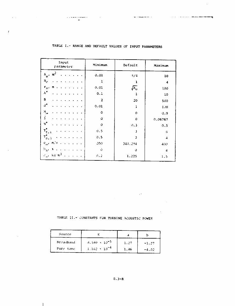
TABLE I.- RANGE AND DEFAULT VALUES OF INPUT PARAMETERS
Input M inimum De fault Maximumpa tame te r
m 2Ace ° . . . . 0
Ne ........
i rs, ra .......
0.01
I
0.01
n14
I
t_ e ° o ° ° o ° ° °
• ° ° ° ° o o . ,
d4 o o • ° . ° . •
•%_ . ° ° o ° ° o .
o . . ° o ° . ,
_t ° . • • • • o •
T t ° • . . ° ° •t,i
T_, j .......
C , g%,' ._ ......
!I.%, % .......
_' , kq m 3 .....
0.I
2
0.01
0
0
0
0.5
0.5
I00
0
O. 2
i
20
I
0
0
O. 3
3
2
340.2')4
0
1.225
I0
4
I0O
I0
500
IoO
0.9
0.06767
0.5
6
4
400
4
1.5
TABL/_ If.- CONSTANTS FOR TURBINE ACOUSTIC POWER
Source K
Bro,hlb,_nd ,q, 5,q9 _ 10-5
Pure tone 1 162 _ 10-4
a b
1.27 -1.27
1.46 -4.02
_3.3-8
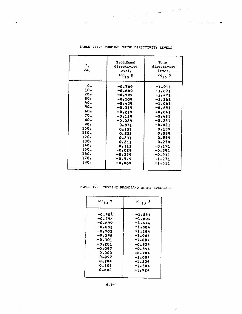
TABLE III.- TUP,_INE NOISE DIRECTIVITY LEVELS
deg
.
10.20.30.40.50.60.70.80.qO,
100.110.120.130.140.150.160,170.leO.
Broadband
directivity
level,
lOglo D
i
-0,789"0.689-0,59g-0.509-0,_09-0.319-0o219-0,1Z9-O*OZ9
0,0710.151O. ZZ10.Z310.Zll0.111
-0.029-0.229-0.549-0,869
Tone
directivity
level,
loglo D
-1.911-1.671-1.471-1.Z61-1.061-0.851-0.641-0.431-0,Z31-0.021
0.1890,38g0.5890.259
-0.191-0._91-0.931-1,271-I,611
TABLE ',V.- TURBINE BROADI_AND NOISE ._PECTRU._I
lOglo 'l logl0 S
-O.Q03
-0,796-O*bgg-0.602-O._OZ-O*3qB-0.301-O.Z01"0.097
0.0000.0970.2040.3010.60Z
-1,884-1.604-1.444-1.304-1.184-1,084-1.004
-o.gz4-0.844-0.784-1_004-1.204-1.384-l.gZ4
-----m
X
Y
Figure i.- Schematic diagram of typical axial flow turbine.
8.3-I0
J
.J
1I I I I' I I I
CI°'601 'l_^eqX_,!A.rl0ej!(]
O
O
O
O
OO
__ 0CO
__ 0
__ 0
uO oI
0
W
L z_
•_ o
0
°_ ,_
.L >,a _
0 o_ u
!
_4
8.3-11
0
I l I Io I I
0
I
i
0
0
e_
r_
0r-
.Q
oc-a)
cr
L--
0
0
>
E
(J
2-.
!
0_a
S UL601 '10A_)7 wnzl°eds
8.3-12
[ {0
I I I
{I
CI °LSoI 'le^_7 X;!J'..r',.0eJ!O
0
0
t-
f_ >,.
0
0 um
oQ_I
0
8.3-13
l
I I I ["-- 0 _" C4
I I
mm
0
00e
e
0
I
I
I
cO
I
0
I I
r.
•- 0
0
0
u
_ >3 _
h _{
I
.,,=Io
S °L6°l 'l_^e7 wn.,'_o_ds
8.3-14
i
I/
8.4 SINGLE STREAM CIRCULAR JET NOISE MODULE
INTRODUCTION
The Single Stream Circular Jet Noise Module predicts the single
stream jet mixing noise from shock-free circular nozzles. The method is
based on SAEARP 876 (ref. 1). The method employs empirical data tabu-
lated in terms of relevant dimensionless groups to produce sound spectra
as a function of frequency and polar directivity angle.
The method requires input of several parameters. The nozzle exit
flow parameters can be provided by the Jet Noise Parameters Module or
directly by the user. Additional user-provided parameters are required.
The module is executed once for each set of values of the input param-
eters. The output is a table of the mean-square acoustic pressure as a
function of frequency, polar directivity angle, and azimuthal directivity
angle. Although jet exhaust noise is assumed not to vary with azimuthal
directivity angle, it is introduced so that the output table is compatible
with other noise tibles.
A e
_j
D
--4
F
f
t _
?
<p2> °
SYMBOLS
engine reference area, m 2 (ft 2)
fully expanded jet area, m 2 (ft 2)
ambient speed of sound, m/s (ft/s)
directivity function
fully expanded jet diameter, m (ft)
spectral distribution factor
frequency, Hz
Helmholtz number, f A_e/C _
aircraft Mach number
forward velocity index
number of engines
power deviation factor
mean-square acoustic pressure,
8.4-I
Pre f
r s
r s
SC
Tj
V_J
reference pressure, 2 x 10 -5 Pa (4.177 x 10 -7 Ib/ft 2)
distance from nozzle exit to observer, m (ft)
dimensionless distance from nozzle exit to observer, re _e
corrected Strouhal number, fdj/_Vj
jet total temperature, K (OR)
ambient temperature, K [°R)
exhaust jet veiocity, m/s (ft/s)
angle between flight vector and engine inlet axis, deg
polar directivity angle, deg
If*
_ref
O.3
0
Strouhal number correction factor
acoustic power, re 0 c_Aj
reference power, 1 × 10 -12 W (7.376 x 10 -13 ft-lb/s)
jet density, kg/m 3 (slugs/ft 3)
ambient density, kg/m 3 (slugs/ft 3)
azimuthal directivity angle, deg
density exponent
Superscript:
dimensionless quantity
INPUT
The 3et parameters are required from either the output of the Jet
.Noise Parameters .Module or the user. Ambient conditions are required for
computation of the Strouhal number and sound pressure levels. The fre-
quencf, polar directivity angle, _nd azimuthal directivity angle arrays
establish _ne independent variable values for the output table. Finally,
dne engine reference area, number of engines, engine axis offset, and
distance to the p:eudo-observer are required. The range and default
val_es of _ne input parameters are given in table I.
A e
N
Input Constants
engine reference area, m 2 (ft 2)
number of engines
8.4-2
!r
sdistance from nozzle exit to pseudo-observer, m (it)
angle between flight vector and engine inlet axis, deg
A:J
J
v:]
t
_j
Jet Noise Parameters
area of jet, re Ae
jet total temperature, re T
jet velocity, re c
jet density, re O_
Ambient Conditions
_cp
M
speed of sound, m/s (it/s)
aircraft M_ch number
denslty, kg/m 3 (slugs/it 3)
Independent Vari-=b!e Arrays
frequency, Hz
polar directivity angle, deg
azimuthal directivity angle, deg
OUT;L_
_ne output of this module is a table of the mean-square pressure as
a func=ion of frequency, polar directivity angle, and azimuthal direc-
tivlty angle. In addition, pseudo-obse.--ver distance r s is provided for
the Propagation Module.
r sdistance frcm nozzle exit to pseudo-observer, m (it)
f
Single Stream Circular Jet Noise Table
frequency, Hz
polar direc:_vlty angle, deg
azimuthal directlvity angle, deg
02c 4mean-square acoustic pressure, re _
_.4-3
METHOD
The prediction methodology presented in reference 1 is used to com-
pute the far-field noise. A schematic of a typical exhaust jet nozzle is
shown in figure I. The coordinate system and directivity angles are also
shown. Whenever empirical functions require extrapolation, the last value
is used, except for spectra which are linearly extrapolated.
The equation for the far-field mean-square acoustic pressure in a
i/3-octave band for a stationary jet is
<p2>* = _q*A; D(e,v;) F(Sc,e
4n(rs2 ) ,V;,T;)
(I)
In equation (i), _* is the overall power, D is the directivity func-
tion, and F is the spectral distribution function. Each of these
functions is discussed separately. The observer distance r s is
expressed in dimensionless form as
r: = rs/_e
The acoustic power Jq_ is civen by
(2)
t -*'_''(vj)*'8P'V*"_* = (6.67 x 10⁻⁵)_jj j) (3)
which is a variation of the classic V 8 law. Two empirical functions are
required for equation 13). The density exponent _ is a function of
logl0 V*3 and is given in table II and plotted in figure 2. The power
deviation factor P is the deviation of the acoustic power from the V 8
law. It is expressed as a function of lOgl0 V; in table III and
plotted in figure 3.
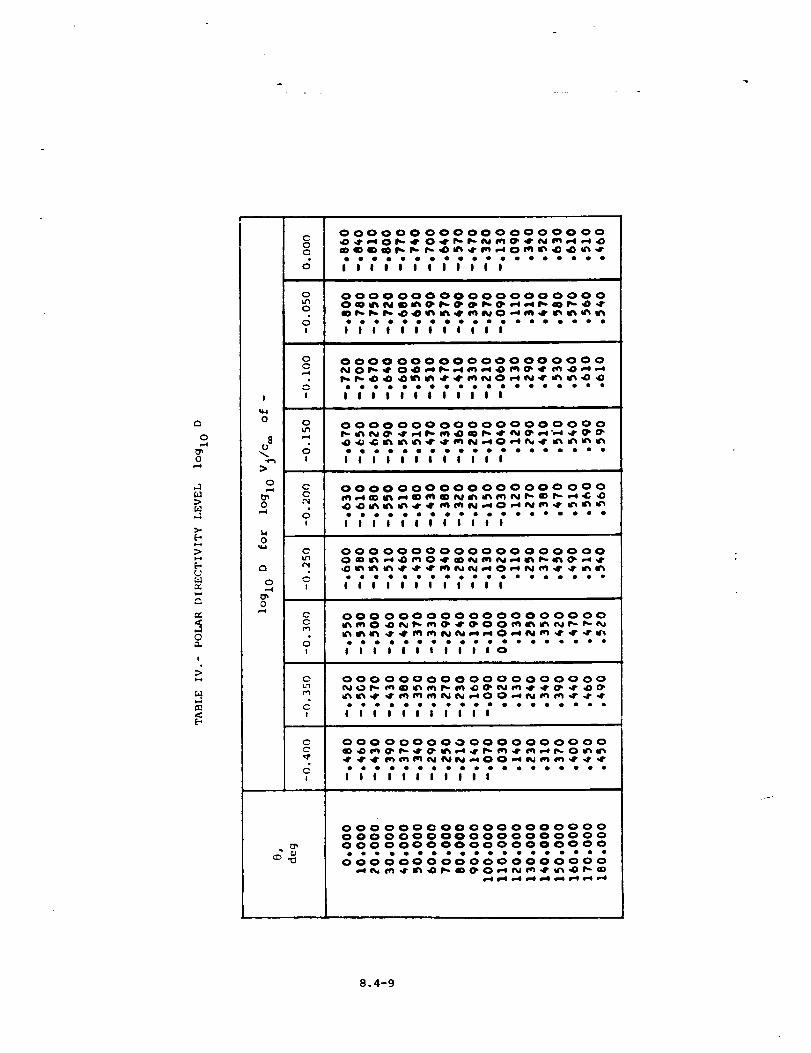
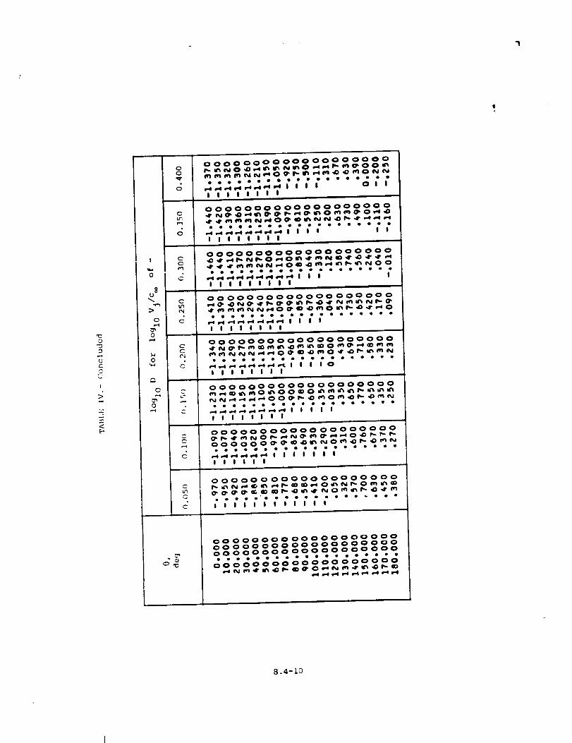
The normalized directivity function D of equation (I) is an
empirical function of the polar directivity angle @ and velocity
ratio lOgl0 Vj. It expresses the variation of the mean-square pressure
with 9 and is normalized such that
T
D(9,Vj) sin @ d6 = 1 (4)
The directivity function for a single stream circular jet is given in
table IV and plotted in figure 4.
The normalized spectral distribution factor F is an empirical func-
t_zon of corrected Strouhal number lOgl0 S c, polar directivity angle @,
velocity ratio log.^ V*, and temperature ratio T_. The correctediu 3
Strouhal number S c is defined as
8.4-4
wherethe jet diameter d_ is
(5)
(6)
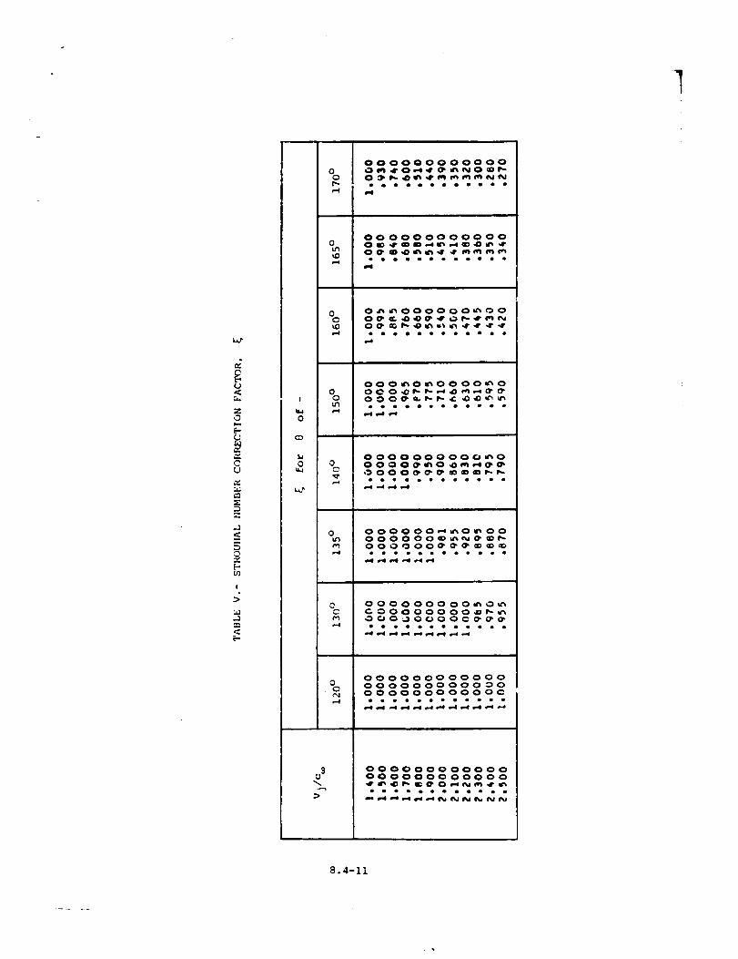
and _ is the Strouhal ntLmber correction factor. The Strouhal number
correction factor is an empirical function of the velocity ratio
V* and the polar directivity angle 8 as shown in table V andl°gl0 3
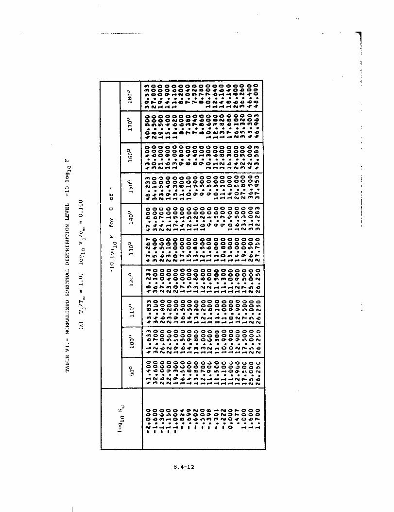
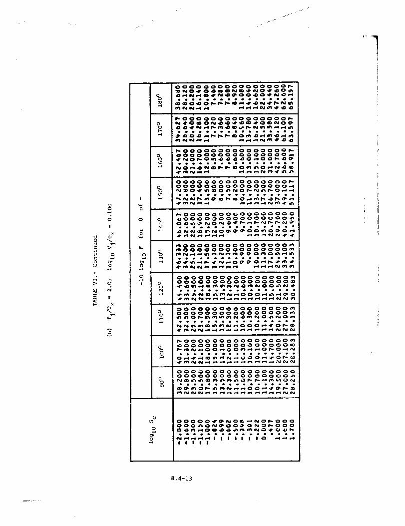
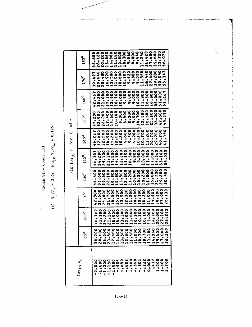
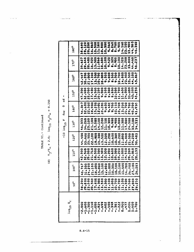
figure 5. The normalized spectral distribution factor F is defined
s,lch that the sun,nation over i/3-octave-band Strouhal numbers is
_ V* -*" 1F(Sc,_, j,TjJ =
S c
(7)
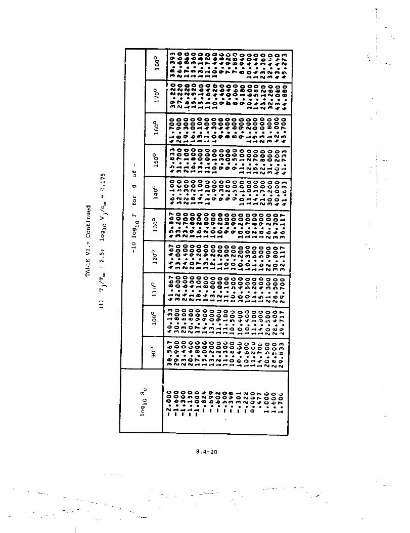
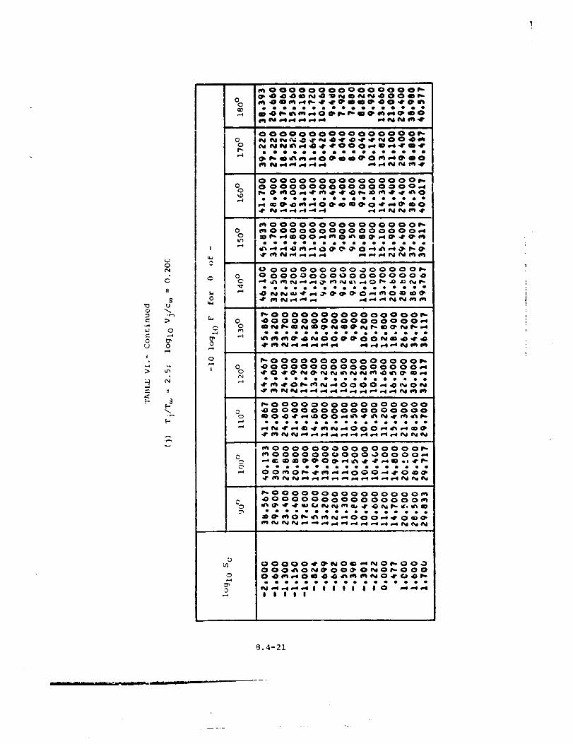
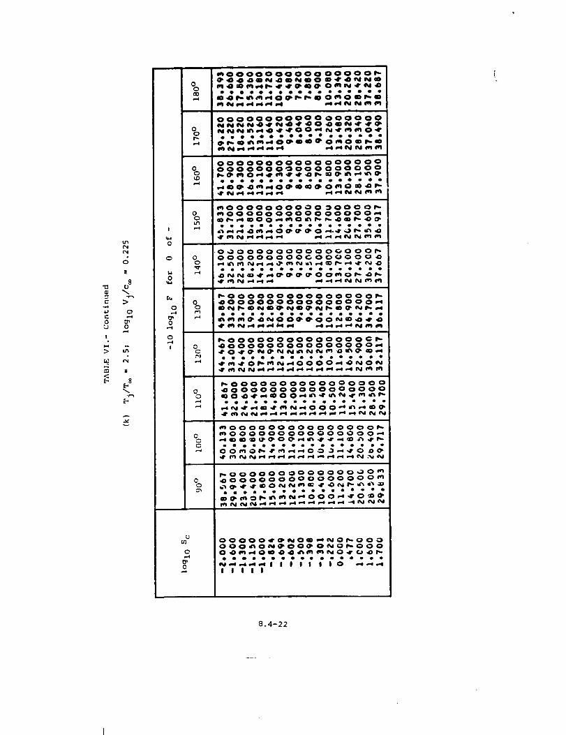
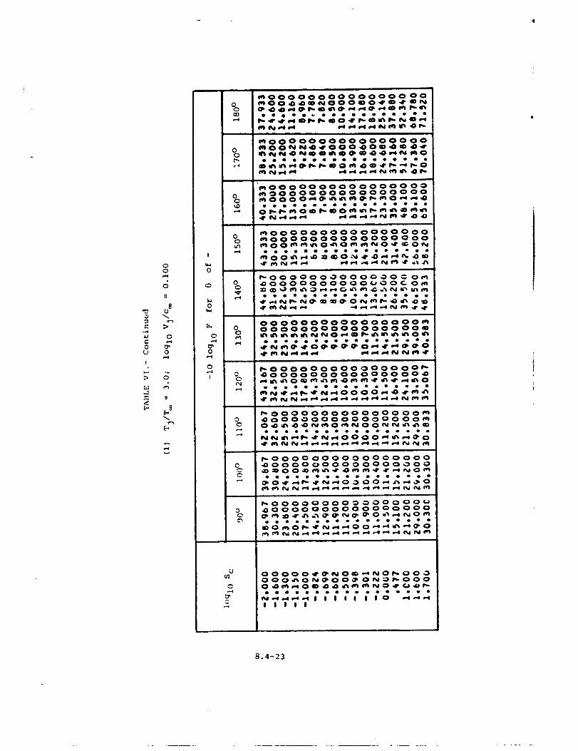
and is given in table VI and plotted in figure 6.
Equation (i) is valid for a stationary 3:t (M = 0). To incorporate
fcrward flight effects, equation (i) should be rewritten as
<F > = 47(rs)2 x - _= cos (_ - 5) \/v*j (8)
The exponent m(@) is the forward velocity index given in table VII and
figure 7 as taken from reference 2, and _ is _he angle between the
flight vector and the engine inlet axis. In addition, the relative jet
veiocity must be taken into account by computing the corrected Strouhal
n-_--ube r as
Sc = [(v_ - :_)
(9)
The mean-square acoustic pressure can be computed for each desired
value of _e frequency, polar directivity angle, and azimuthal directivity
_ngle. The total noise is the mean-square acoustic pressure multiplie_ by
_ne number of engines N for _ne output table. In addition, printed
output is available of the mean-square pressure <p2>', sound pressure
level SPL defined as
8.4-5
SPL = lO iO91o<p_>* + zo I_io
and the power level PWL defined as
2 4
0_c=o
2
Pref
{I0)
_ref
P_V_ = i0 lOgl0 N" - I0 lOgl0 3A*A
_c j e
(II)
REFERENCES
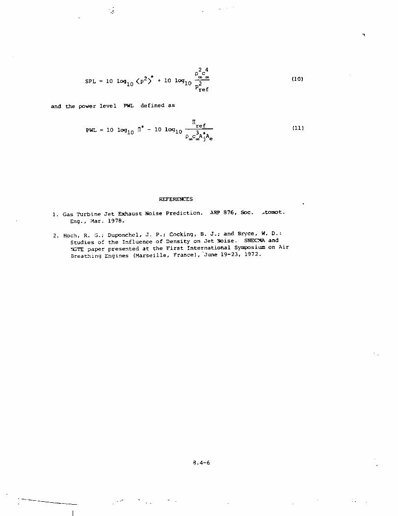
i. Gas Turbine Jet Exhaust Noise Prediction. ARP 876, Soc. _tomot.
Eng., Mar. 1978.
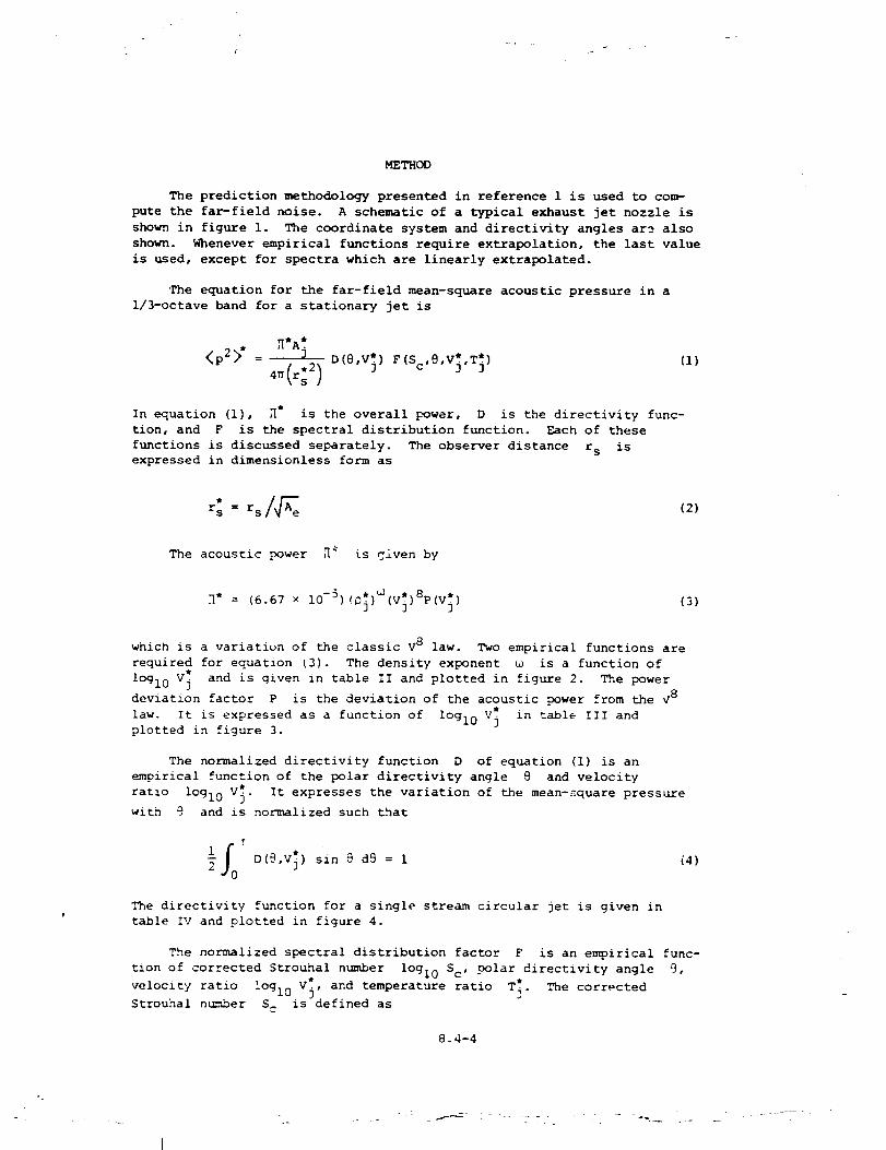
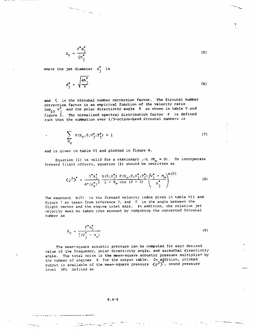
2. Hoch, R. G.; Duponchel, J. P.; Cocking, B. J.; and B_-ce, W. D.:
Studies of the Influence of Density on Jet Noise. SNECMA and
_TE paper presented at the First International Symposium on Air
Breathing Engines (Marseille, France), "June 19-23, 1972.
8.4-6
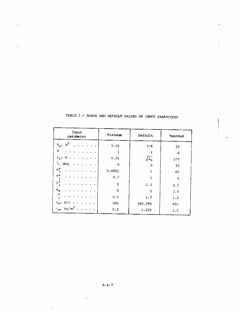
TABLE I.- RANGE AND DEFAULT VALUES OF INPUT PARAMETERS
Input
parameter
Ae, m 2 ......
N ........
r S t m ........
5, deg ......
A*3 ° ° .... ° "
T"J ........
V _ ........
C_, _/5 ......
_, kg/m 3 .....
Minimum Default Maximum
0.01
1
0.01
0
0. 0001
0.7
0
0
0.2
2OO
0.2
"r/4
1
0
i
1
1.0
0
1.9
340. 294
1.225
i0
4
I00
3O
i0
4
2.5
0.9
1.2
400
!.5
8.4-7
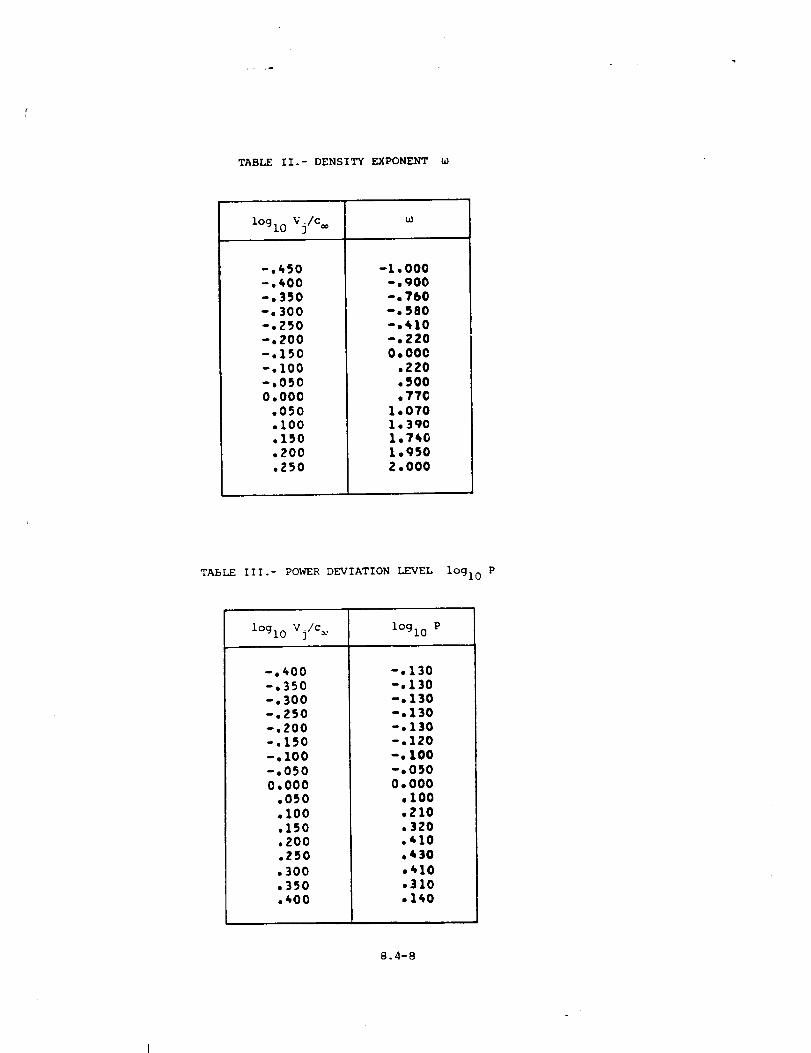
TABLE II.- DENSITY EXPONENT u}
lOgl0 Vj/c
-,450-.400-.350-, 300-.ZSO-.200-,150-.I00-,0500.000
.050.i00.150.200.250
-1.000-.qO0-.760-.580-.410-.2200.000
,220.500.77C
1.0701.3901.7401.950
2.000
TASLE llI.- POWER DEVIATION LEVEL lOgl0 P
lOgl 0 Vj/c lOglo P
-.400-.350
-.300
-.250-.200
-.150-.100-.050
0.000.050,I00.150
.200.250
.300
.350
.400
-.130-.130-.130-.130-.130-.120-.100-.0500.000
.I00
.210
.320
.410
.430
,410,310.140
8.4-8
O,.-4
O
>
>.
>
O
!
>
!
>
O_-0
O,-4
O_O
C00
0
0u%0
I
0C,-4
I
0u_,-4
6I
!
C
I
CC(,q
I
0
!
CC
g
OOOOOOOOO
aDgDlOml_.l_- I_.dDl_
;;;;;;;7;
OOOOOOOOOOm_Nm_
;_777;7;7
000000000N 0 I_ ,If 0 dD p_ I_- a-o
;7;777;7;
OOOOOOOOOO
_O_ _ _
7;7"" .....
OOOOOOOOOO
;7;'" .....
0000000000
7;; .......
OOOO OOOOOOOOOOOOOO O
e_eeeoeeee_oeeeeeeeI I I I I I I I I I I I
OOOO OOOOOOOOO OOO oOO
eooooooooooo_eooe ooI I I i I I I I I I I I
OOOOOOOOOOOOOOOOOOO
OOO OOO OOOOO OO O OOOOO_mO __ _O O_m_N__ _ _ __O_ _ _ _
;;;;7:;;;;;_ .......
OOO OOOOOOOOOOOOOOOO
7;77;;;;7;; ........
0000000000000000000
7;7;;7;7;;7 ........
O OO OOO¢ OO OOO OOOOOOOOOOOOOOOOOOOOOOOOOO
OOOOOOOOOOOOOOOOOOO___O__m
8.4-9
"I
e*
0
I
I
0
8L)
>
o
0
o
oQq.
t_
co
J
J
0000000
• • • • • Q •
I I I i I I I
000000000000NI'_O _"4 p¢ I_ *'_ O_ 00
... .... ..¢;-;,,,ll I l II
i
0000000
IIIIIII
0000000__0
eogoeoe
IIIIIII
0000ooo
IIIIIii
000000000000_ _0_ 0_O_m_ __
go
I
000000000000
•-*,,'* I I I II I
I II I
000000000 O00
e-_ ; ; ; ; " • " * * " "I
0o00oo0oo00 o0ooooo0
I I I I I I I Im=
00000000000 00000000
_ h_ ,..._ ,..,* _=i_"* 00 O" r',. _0 _0 _* _01_ ,OmN
I I I I I I I I.n
000000 00000 000000 O0__0__0_000000_ _m_O_ _ _N
__i I g i i i tIIIIII
0000000000000000000___O_N_O____0__
I I I I I I I I I I I I
_0000000000000_00 O00000000000000000000
8.4-Z0
!
00
000000000000
oooooeoooooo
0L__0*--4
O000000000000___0___
oooeoooooooo
gU
0
£.,U
@
Mm
Z
©
[.-,I/1
I
e_
[.-,
!
0
0
00
00
0C
0
0C
_oooooo_oooo
ooooo_ooo_oo
0000000000_0
oooooo0eoooo
000000000_0__00000000_000_00000_
0L 0
00000000000000000000000000000000000_
oo_oooOOoo_o
U SO00000000000000000000000__0__
ooo_oooooooo
8.4-11
7iJ
0,..-i
O_0
0
i
00
>
IIZ0 8
(--*
c
o,-.4
8-_ (_,
,-, (-,
v
I
,¢:
!
0
C_
0
0,..-4
0
0
00
00
00
00
00
00
0
00
C00
C0S_
:£
0
0
.. i
4'_OO O OO OOOOOO O OO OO_lJOOO,OO,al'q_.O,f',O_PO,O OO _
• ............-- ..O_IN - ¢P_ ,4" o.e_ IN._ON.CP gD _ID ,_¢O
im
000000000000000 O_O000hlO_)_l'_OO40_lQOhl O_ID
_j " ..._D_,_. " • . • * . . * . .
,4" N .4 ,-I _-I ,.I ,.e ,-e ,.e IM _ .8.,8"
000000000000000 O_0000 O0000000 000 Om
_00000000000000 O0_00000000000000 O_
0 O0000000000 000 O_0 O0 0000000 O0 000 O_
I_. 4" .4" _-* Ir_ _1" ¢_1 o-* r,_ (_ 0 _ ¢_ 0 _D_ _l_l
_00000000000000004000000000 000000_
0000000 O0 0000000_000000000000000_
mOO00000 O0 0000 O00_00000000000000_
_0000000000000000_0000000 O0 000000._
000000000_000000_00000_0000000_00_
IIIII
8.4-12
I
"Cs
r-
c-.0
!
i-4
E-,
00
II
C_
.1"-1
0
0
g[-
00cO
00r--
0c)
0o
0
o 0o
0
r,.o
o o
0,.4
o,...4
! oo
oo,-4
0oo
oo
0000000000000000_
mmo_o m_ N_
_000000000000000_
000OO00000QOOOeOO
_000000000000000__000000000000000 _
_O_N__O_O_N_
0000000000000000_0000000000000000_
_000 0_0000000000_
_O00000000000000m_000000000000000_
0000000000000000_0000000000000000 __ __N_O0 _ _
_000000000000000_0000000000000000__O_m_4_O_O_
N___O00_ O_ _
_000000000000000__00000_000000000_
000000000000000000000000000000000_
ooooo_ooo_ooeo_oo
0
0IIIII
8.4-13
/
u'l
_4
|1
8
= :>
=
:J C
f
nJ
-r.._
()v
!
_40
l.l0
n.
0
20
I
oooooooooooooooo_
Oe eOe eo
_000000000000000_
_0_ O_ __NNMMW_M MMNm_
_000000000000000_
0 _000000000000000 _
_N__ __
oOCO0000
0 000000000 N_ CD ..T*4'%t-QO d%
i ,
I'000000__0000000
_ OL*'% O'NO C%1,0
,...I
i
_'_00000000000_00000000000
00000000_00000000__0_0_
)
_00000000
00000000_
O0 0_0
0000,_00 =)0'_
i ii
0000000000000000_0 0000000000000000 _
e_me_eeom_weoe__N__O00 __ 0
0000000000000000_0 0000000000000000 _
0 _Oh__N_NO_NO_oooooooooooooooo_
n
_000000000000000_0 _00_000000000000 _
0 _00_00_ O_O_NO_OOOOO0_OOOOOOO_
0000000000000000_0 0000_ O0000000000_
0 N__O__O_OOeOOOOOBOODOOO0_
U
--4
0
00000_0_0_000000 _0_00_ 0_0_000O_om_ __0_o_
ii_ll
8.4-14
r..,..t
c:0cJ
!
,<E,
o
I1
8{J
°f-._:>
O
0
tl
E-
I
0
0
C_
C_0,-I
OP4I
n
00000000000000000_NO_O000_O0_O00_
_OOOOOOOOOOOOOOO_0 N_ONO_OONNOONOO_
_NNMM_MM _MN_¢¢
la
_OOO0 _OOO
NO_
OOOO
0 OOOO
_000
0 _000
j_eo
OOOOOOOOOOOO_OoOOOOOOOOOO__O_O__
O_ _
OOOOOOOOOOOO OOOOOOOOOOOOO__0__ _00_N
0000_00000_00000000000000_
_OOOOOOOOOOO OOO O m
C _ 000000000000 O00__N___O_O_
_ _N__ _N_
co
C
0
0000000000000000_0 O00000000000000 __ __N _OO _ _
e_e_Oe_o_oeOeooo_ _ __OOO_ O
OOOOOOOOOOOOOOOOm000_00000000000__ _O___ O_,O_
NN__N_O00_O_
_ 000000000000000_
_000000000000000_
000000000000000000 O0000000000000 O_
ooeo_ooo_eooooeoo_0__00_ _ _ _
00000_0_ 0_00000 _0_00_ 0_0_0000 _0_ _ _0 _ _
oooo_ oo_
tlltl
8.4-15
C0
!
,.-1
<
|
gU
>
0
0
I
J
v
I
0
0,000
0(D
00
00
0O
o
r,.
o oo
o,,.,¢
o
ioc
cc
o
c
0C
0,,,-4
,C,
0000000000000000_
_0000000000000000_O_mONOO_OQ_OONe
wwoeeoewoeeoeoeoo
_N__ _N_
_000000000000000040000000000000000
eeeooiooOooeeooeo
0000000000000000_0000000000000000_
_0000000000000000_0000000_0_00000_
_O00000000000000m_000000000000000_
0000000000000000_O000000000000000m
_N_N_O00_O
0000000000000000_O00000oo0_O00oOOm
_ooeoooooooeoo_oo
_0000 O0 O0 O000000__00000000000000_
000_00000000000000000000000000000_
iilii
8.4-16
!
0 0O
6
e- _ c_4
: _" 2,_ 0
0 _
!
"-!. _
[..,
_i 0 0'000 O00¢) ¢:) 000
0 @ 4) _O _r 10 _ _ N CO 4 -S" cO N _D
CO • • • • • • 00 • • • • • •
_ _1B'I e'l 1,4 f,4 _-e e-g _1 fl_
i
00000000000000
0 N N N m *10 *0 q0,4P g N g qO f ,O
0O_0r-4
0O
,-4
*0N4"
ii
<1',0,0i
00'0000 00000000 0 O_00000000000000 O0_'q
• " "_ " " " " " " " "_Ol_q_e qe00 e O_Dl-I @' O ip,o
IrtSJ.eeee.e me a q_4t'dqr_ 4 0,0
_0000000000000 OOr"mOO 0000000 _lO00 00 _4_
i i •o'ooo_ooooo ooooo'o_-
_J
OOO OOO OOOO OOOO O O _..s
i oooooooo oooooo '0000000000000000..-*
.dr. _m _4 ,,..,, ,.._ ,.._ .,.-, .,,_ ,,,.* ,-g ,...* ,..., N _"_ _,_
_000000000000000_
_000000000000000_
ee_o_ooeooooeoo_O_N_OOOO_NO N
iii •
_o000000000000 O0 _
_000000000_ 00000_
_" O00(_ O000 _000000_,0 O0000000000 O000_)
iii
00000_ _ Om _0_ O00000_0_00_ ONO_O00
oo_ooo_oooooe_oo
IIIII
8.4-17
aJr-.
.,,4
t-0
!
r_
[-.
_J
[1
8c)
o,.-t
0
II
[-.
v
i
0
cD
0
6'0
0,.-t!
00GO
00
_000000000000000_
QeeoQoeQeeoeoeeeo__O_O_N_O
0
0
0000000000000000 *_lfWI N N ,0 ,1" N NII _p d_ O d) II I_ II "1" tllN N N II_l N lt1_ ffl ID O I_ I1% lill _ I'1N N I_
• • - • • " " "_:o:
i,
oooooooooooooooo-o oooooooooooooooo-
_m__O_ mO_ __N__ __
_000000000000000_0 _000000000000000_0 __0___
_000000000000000_0 0000000000 _00000_
_N_O_O__
_000000000000000_0 4000000000000000_
• oo" • •
_O000C0 _000000 _O_N_
_000000000_00000000 O_ _
--&&&d--_--i
_000000 O0000000000 _0000000000000000
_00 O0 O0000 O00000_C _000000000000000_
_ _ _ O_ _ __
0 _000000000000000___0___
O0000_Om _0_oo00o0_0_00_ 0_o_000
N_I I ! I I I I O _IIIII
8.4-18
Ou_
1
8
,.¢
00
e,v
!
o
o
o
!
.0oo0oooooooooooo_O_mO_ _m_O
QQOO0e
iOOOOOOOOOOOOOOOOO
0 N_N_ON_O_N__O
_N__ _N_
OOOOOOOOOOOOOOOOO
OOOOOOOOOOOOOOOOO_OOO__N_
_N__ __
_OOOOOOOOOOOOOOOO
0o _OOOOOOOOOOOOOOOO
m
0 O0 ¢_ _ 000000000 _._00
OC) 00000¢_ (D 0000000 ¢_00
im
_oooooooo_ooooooo_
_OOOOOOOOOOOOOOO_
" " " " " " " " _ _ " "O0
_0ooooo0oooooooo_o _ooooooooooooooo_0 _0____ _
_00000000000000000 _0000000000000000
i,,
_000000000000000_
_0000_0000000000___0___
_O_OOO000000000G_
0 _0000_00000000_0_0 _ _ _ON_ _ __ _
:i
1 o
t
)
P_
0,-4
00000_0_ _0_000
000_0_00_ 0_0_0000 _Om_ _NO_ 0_
lilll
8.4-19
0
J,J
0U
I
r,
r.4
B
J.r,._
>
C
0
oq
v
I
0
0
0
t_0
I
l,
_000000_00000000_
Itlllltlllllllllt
i
00000000000000000
% NNNN(¢N¢((IOINI_INNN_M(¢fOOM(_MNOIOIOQOQOOe0000001D
000000000000000000 00000000000000000
_m_O_mm__ _
_000000000000000_0 _000000000000000_
i0000000000000000_
0 0 _000000000000 00_
_N__O_O0_
_000000000000000_
0 _000000000000000_
_000000000 000000__000000000000000_
_0000000000000000_0000000000000 000_0_00_ _N_
__N_O 00__
*'r) O0 O0 O0000 0000001".t_O00000000 0000 00...*
_00_000000_00000_
0
O0000_NO_ _,_0_000
000_0_00_ 0 NO_ O00
lilll
8.4-20
_ r
°
00t',,i
II
8"_3 U
c :>
0C ,-¢0C_ 0
I
<
d
A
I
o
t_0
0
I
0
00
r,4
O"
0N
ooooo'oooooooooo_
. 0_ . . . • o_ . . . * o •_ _o_ __o
000'0000'00000000____00 _
OOeOOQQQOOeQOOOe
0 000000000000000_0 0 000000000000000_
oOOOooO_ooeoooooo_ __o_o_o
_ooooooooooooooo_o _ooooooooooooooo_
0 000000000_00000_0 0 000000000000000_
00
00
00
0
_ooooooooooooooo__ooooooooooooooo_
" "
_000000000000000__0 00000000000000_
• • • ooee
_0000000000000000_0000000000000000_04_00_ _N_
_ _m _m_O00__
_ooooooooooooooo__oooo oo_ooo _oooo_
_000000000000000__000000000000000_
U O0000_r CPE_O_,._NOI_O00000 _i%0 r_ O' 00 O, O_Of_O000 ,0_ _._ 0 _ _0_0 _! _NO_r o,o_
! i I I I
8.4-21
_ m- -
t_
61
8
c >
o
ou o
!
)...4
b 8
..,
A
!
0
0
o
n.
o,-4
o
o,-4
!
0o
oo
%r-4
oo
_4
oo
oo
0c¢,,!
oo
,--4
oco
oo
_OOOOOOOOOOOOOOO_
_4___ O_N_oooooQoeoooooeooo
OOOOOOOOOO O OOOOOO
NNN__OO_N_O_• • • . • • • . .__ . • ..*_Oe_e 0_0_ _m
OOOOOOOOOOO oOOOOOOOOOOOO_OOO oOOOOO_O__ __
_m__O_mm_ O_O _
_OOOOOOOOOO _OOOO__OOOOOOOOOOOOOOO___OO_O_ _m_ _
_00 o. •
O_OOOOOOOOOO_OOO_OOOOOOOOO_OO_OOO_
___ O O_O_ _
_000000000000000__000000000000000_
_ O_OON_ _
_OOOOOOOOOOOOOO¢__OOOOOOOOOOOOOOO_
_ O_N_ooOO_ON_NN___N_
_OOOOOOOOOOoOooO O_OOOOOOOOOOOOOOOO
_0000 O000000 O000__000000000000 _ 00___0___
_0000000000 O00_ O__000000000000 O00_
_ _O_N_O00_ _0 _
u_Q
o
E_0
,--4
00000_0_0_000
__;;;;;;;_'_IIIII
8.4-22
f*
_..
0
I
.1
0
0p-4
II
8
0
0
rl
_S
.f.._
b,
_o0o00000o00o0o Oo
° __-___. .. ..___0___
n
_0000000000o000o0
I
o
C_
0
0
0
c_
I
%_0
_00000000000000 O0_0000000000000000
o0
_0000000000000000_0000000000000000
oooo •
oC_
e-i
_0oooooooooooo _ o__O000000000_OOC O_
_oooooooooo_ooooo
00
00o00000000o0o0o_O000000000000000m
gO.__* .....
0
0
_000000000_00000__000000000000000_
o_ ooooooooo oooo oo__oo 0o0oo oo Oo oooo_
0
_ 0000000000000000_0000000000000000
00
_00000000_000000__0000000000000000
_J O0000_Om _NO_O0 _
_o_ • _o
IIIII
8.4-23
1
8
U 0,...¢
!
,...1s
E-'"
ooa)
oor_
ooo0oooooooooooo
__ _N_ _i
_o000o00000000000
gOOOQ60BeOOeOO000
_00oo0000000000000 _0o0o0000000000oo
eeoeooo6ooooooeoo
_ooooooooooooooooo _ooooooooooooooooo _OO___ _
o_O_OOO_OOOOOOO_O_
0 _OO OOOOOOOOOOOOO_0 _ _O __O _O_O _
OOOOOOOOOOOOOOOO_0000000000,_00000_0
0 0 __NO__O_
_OOOOOOOOOOOOOOO_
I _ _OOOOOOoOOOOOOOO__O____O
_N_ _OOOO__
%
ooo
c
_OOOOOOOOOOoOOOO__OOOO OOOOOOOOOOO_O(_((NAOANOONN_
OOeoOOOeO_Oo_Oe_
_N_ _OOOO_O
m
_OOOO OOOOOOOOOOOO_OO OO _O OOOOOOO OOO_OO___O_
_OOO_OOOOOOOOOOOO_OOOOOOOOOOOOOOOO
eoo_o_ooooo_ooo_o
_o _o__OO__o
ooooo_ _NO_ _O_oo _OOO_O_OO_ O_O_OOOO_Om _ __O _ O_
lilll
8.4-24
_J
0
!
[-,
0
II
80
>
0
0,-4
r_
II
_8
[..,
v
!
0
o
0
0
0
0
!
0
00
00_0p-1
00
00
00r_F-4
00
00
r_
000
mooo_oooooooooooo
_-. ..-o_o__
_000000000000000_
_000_0__
_000000000000000__000000000000000__O0_mO_O _ 0_
_ •. ....
_000000000000000_000000000000000__00 __0_00_oo @ • •
_0000000000000_0__000000000000000_
oo@@@o@o@@ooe@o@@
__0_ _ _ _
0000000000000000000000000000000000
_._._._._._.o.-.®_._o.o._.. . •
_0000 00000000000 __000000000000000 __0_ _ _ 0
_0000 00000000000__0000 00000000000 _
__ _0000_ 0
_0000000000000000_0000000000_0_000
_00000000_00 O0 O0 __0000000000000000
0
0
00000_0_ _0_00 _00_0_00_ 0_000
illli
8.4-25
...4
0
I
>
_C
U_t_
Etl
8
0
0e-,
II
A0
I
c_
L,0
r,.
0
,..)
I
00
00r-1-4
_00"00_000_
• oo • •
00000000000_
_*-_ .......
_000000000000000_
• . • . • . • . • . . .__....
00
_000000000000000__000000000000000_
..... __ o o 0_ • *
00L_
_000000000000000__000000000000000__00000__0_
0C
_0000000_0000000__00000000000000_
0C
0000000000000000_0000000000000000_
0
I-N
_000000000000000__000000000000000 _
%_000000000000000 __O00000000000000m
0_0000000000000000_0000000000_00_0
_0000000_000_0__0000000000000000
oooe_oOOooooolooo
Illll
8.4-26
I
'G
c"
.LJ
O
I
OO
|
8U
>
O
O
[.,8
£-*
!
O
0-*
O_4
Of-i
O
I
"'_oooooo_oooooooo_
OOf.,.
ooooooooo ooo-
OOBODOOOOOODOO_OO
_OOOOO OOOOOOOOOO_0 _oo_OO OOOOO OOO oOm0 _OON_ __ _O_
..o .- g _-''-"
_0000000000000_0_
O _OOOOO OOOOOOOOOO_
r"- 0000._ O0 O000C c_O00
0 _000000 O000000&_ 00'_
i .... , ,
OOOOOOOOOOOOOOOOO
0 O000000000000000_n
r-I • i* • • • •
ii
_000000000000000__000000000000000_
_O____O
i
_0000000000000_ O_0 _0000000000000_0_
e_ee_e_eeee_ee_NN_ _N_O000_ 0
_00000000 _00000000 _000000_000000000
_O0___NO_
U
0
F
00
_0000000000000000
eeee_e_eeeeeeeee__O_O_N_O0__O
O0000_NOm_NO_O00
Ilfil
8.4-27
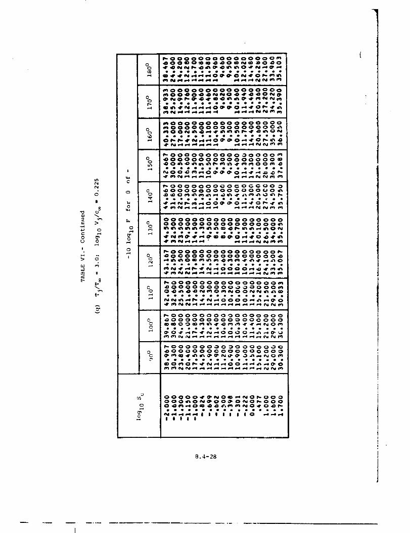
u'%
(_i
II
8
f..
U 0
I
,-_ is
E- E8
$
0
_u
c_
o
I
_o0oooooooo_oo_0_0_
__0_
moooooooooo_oo_o_o_
_--_*_--*-_ _ 0_0
00000__0_0O_N_
000000
_g ....
_00000oooo0o00ooo_oooo0oooo0ooooo_
eO eeeeee oe
_ 00oo0oooo0 _0ooo _o _000000oo00o0o00 _
_o_''''''_g_''2
_0000000_0_0_0 00 _000000000 O000_0 _
;_'-
000000000000000000000000000000000_____ON
_0000000000000 00_0 _0000000000000 O0 _
_oo0o oo00ooooooo_o 400000000000 O000_
_ 0000 O0 O0 _0000000C _O00000000000CO00
_00000000_00000_00 _00000000000 O0 O00
IIit11111t1111111
U
u_
c_
iilll
8.4-28
I
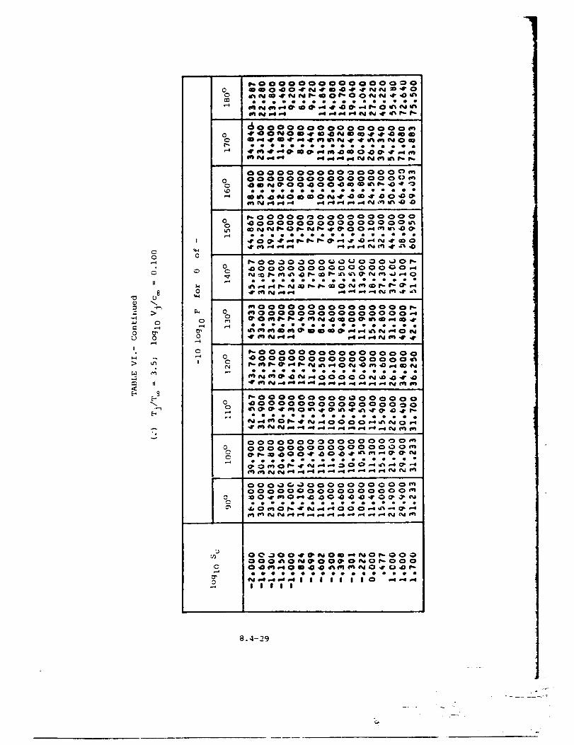
0
!
00
I!
8U
0
0
11
g
q
I
0
0
0
0
C
I
C
0000000000000000_
0 0000000000000000_
_NO_O_ _ _ O0 _
_00000_0000000 O00_000000000000000_
o_oeeo •
0C
%
0C¢._
00
0
_0000000000000_0_
_000000000000000__000000000000000__0_ _N_mO_ _ _ _
oo oe oo
_N_ _N_ _
_0000000000000000_000000000000000____0__ _N
• _o • • •
_0000_00000000000_00000000000000 _0__0____
0 O000000000000_ O_0000000000000000_
000000000 O000000 _
000_0_00_ 0_0_000
N__I I I I I I I0 _
iiOli
8.4-29
L_
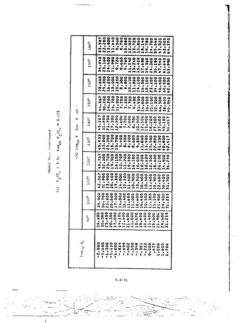
1
"T
T°-
I°
>
<:
u_
c4
|
U
>
O,--t
0,,..4
t-4
°r_
g
I
0
0
O
0
O
!
o 'oooooooooooooo
i • ill i
00000000000000000
00000000000000000
0 0000000000000000_
eoooooooooeeoeeoe
_0000000000000000
0 4000000000000000_
0 _O__OO__
_ _ _'_ _ _
_OOOOOOO_O_OOoOO_
0 _OOOOOOOOO OO OOOO_
_OOOOOOOOOOOOOOO_
0 _OOOOOOOOOOOOOOO_
o _O__O__
P'.OOOO_OOOOOOOOOOO
•0OOOOOOOO OOOOOOOi'_
_0000000000000000
_OOOOOOOOOOOOOOOO__O___
OOOOOOOOO OOOOOOO_
0 OoOOOOOOOOOOOO Oo_
_oO_O O__ __oee_e_oo_o_oooeo
OOOOOOOOO OO O OO _O_
0 OOOOO OO OO OOO OOOO_
eooeeoooeooeoo_eo
_O_O_J_OOO__
_J OOOOO_NO_ _O_OOO
OOO_O_OO_ O_O_O OO
O _O_ _ _ _NO_ _ _
IIIII
.4- 30
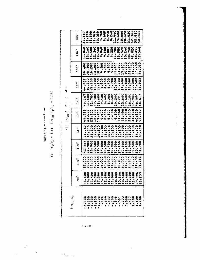
CC
!
<o
O
I!
8
>
C
0
II
A
v
!
0
o
0
O
0
C
I
_OOOOOOOOOOOOOOO_
0 _Nme_e_e_e44_o_mo
.....
OOOOOOOOOOOOOOOOO
QeOOOOOOOOQOOOeO0
00000_0000 000000000000 0000000000_
_OOOOOOOOO OOOOOO _
0 _000000000000000_C ___ _ _
eee
C _OO OOOOOOO OO OOOO_
_OOOOOOOOOOOOOOO_
mOOOOOOO00 OOOO OO_
oooooOoooeoooeo_e
_OOOOOOOOOOOOOOOO_OOOOOOOOOOOoOOO'_
___O N__
r..oooooooo¢ ooooooo,0o oooooooo ooooooo
_lr" _l qr_dl_J ,ml _1 ,-ql _ql t,.4 .,.4 a-i ,-4 _l a,"4 (%1 ('_l (q')
OOOOOOOOOO OO OO OO_OOOOOOO OO_OOOOOO__OO_ _ __ _N
oeeo_eeeeeeeeeeee
OO OO000000 OO OO O._ _OO OOOOOO O O OOOOOO_
_O_O_N_Ooo__
OOOOO_NO_NO_OOOOOO_O_OO_O_O_OOOO_O_m_O_O_
IIIII
_.4-31
i ._..
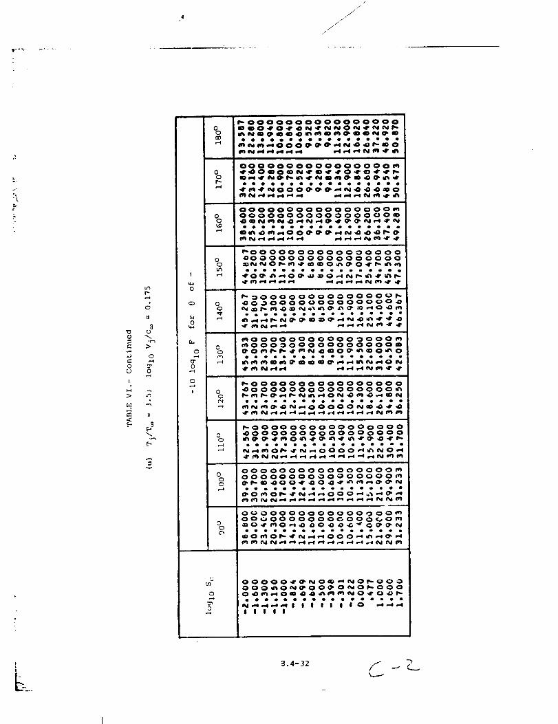
/j-
Kj_
JJ
J-I
c_tl
8
0
= >
0
0
0
!
=n II
!
0
0,--t
0
I
00
00p,._4
o
o0
.-..4
00
r-4
_00000000000
ooolo oeoe_e
00000
_N_
0000000000000000_
ooooooeooooeQoooo
__ _N_
0o0o0ooooooooooo_OooooooooooooOoom
_00000000000000 O0_00000000000000 O0_0_ _0_ 0_
_ _00000000000000__000000000000000 _
0
_0ooooo00o00 oooo__ooooooooooooooom_O_mN _mO_O_O
00¢N
_0000000000000000_000000000000000____O__m_
00r_
_00000000000000 O0_0000000000000000_ _0__ _ _
00
0
ooooo0o o oooooooomoooo00o0000oooo0_
00
o_ oooooo0oooo o oo_oo_oo O0000G 000_0_
oo_ooooeoeOooOooo
0
0
00000_0_ _ _0_000000_0_00_ 0_0_0000_0_ _ _ _0 _ 0_
iilll
/I
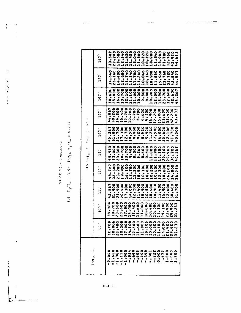
. 1-- 1
r
C"
II
!
°_
-C
%t'0
c
0
I
,,1"f-¢
o
C' f'_
0
,-4,-#
_OOOOO0'OOOOOOOOOQQO_NN_mNNO _ _O_
OOOOOOOOOOOO OOOO
• . .... • . ...__ . . • •
_OOOOOOOOoOoOOOOOOOOOOOOOOOOOOOO
,4"
,It
N
_r_
,It
,ON
i
_OO OOOoo oooo oooo__OOOoOOOOOO o oooom
_0000000_0_0 00000
_000o0o0ooo0 o 0oo__00000o 0oo0o0ooo o
_000000000000000 0_00000000000 0000 __M_N_ON__N
_0000000000000000_0000000000000000__0___
_00 O000000000 O00_000000000¢000000_
0000000000000000 _O000000000000000m
L'
oo_oooo_o_ooooo_o
__1J I l J J I 0 _IIIII
_1.4- J3
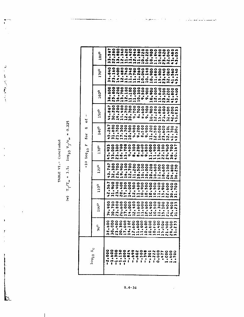
Bii
8
o _n(J o
I
.1e,n II
o
o
,-=1
I
_oo00o00oo0oo0oo_
o __O_N__O_O
OOOOOOOOoOoOOOOOO
_ O_
OOOOOoOOOoooooooo0 OOOOOoOOOOOO _OOO_
ooooooeo_woee_ome
_N_O_O__
_OOOO_OO_OOOOO_O__OOOOoOOOOOOoOoo_
• •
i
_OOOOOOOOOOO_O _o_0 _OOOOOOOOOOOOOOOO
°eemOoeeemooeoeee
_ooOOoOOOOOOOOOO__ooOOOOO_OOOOO _O__O__N_O_ _
_O OOOO O OOOOOoO OOOo _ooooooooooooo oo_
___O__N
_00000000000000000 _000000000000_000
__O___
0ooooooooooooooo__oo___
ooooo°eoeoo_eoe_e
o ooo oo o ooo o ooooo_
°oeoooeoeeoeeeeee
u_
0
00000_0_ _ _0_ 000000_0_00_ 0 _0_0 O0
llltl
8.4-34
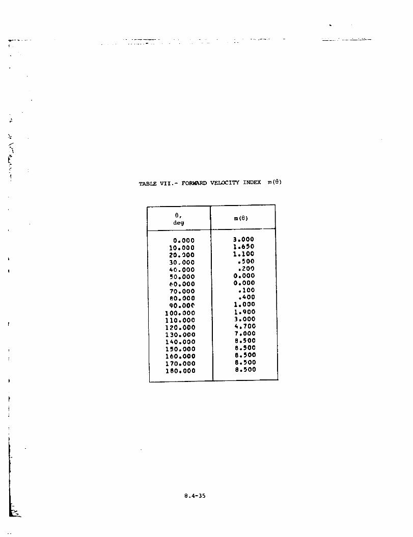
. "7- _" -H.
..... *--r. "
f
TABLE VII.- FORMARD VELOCITY INDEX m(@)
r
deg
0,00010,00020.00030.00040.00O50.000_0.00070.00080.00090,000
100.000110.000120,000130.000140,000150,000lbO,O00170o000180,000
m(8)
3,0001,6501,100
,500,200
0,0000.000
.100.400
1.0001.9003,0004.7007,0008.5008.5008.5008,5008.500
.2..
8.4-35
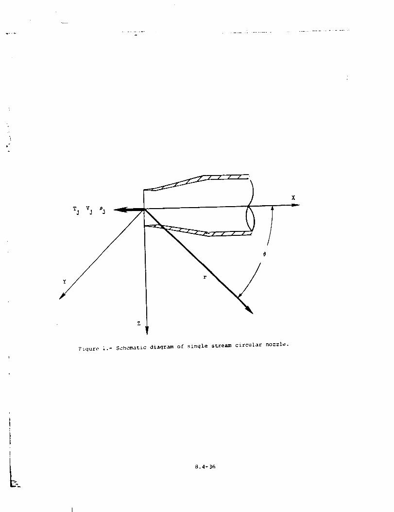
...... _ ............... ..............
"i
Y
Z
!
Fiqure I.- Schematic diagram of single stream circular nozzle.
i
B.4-36
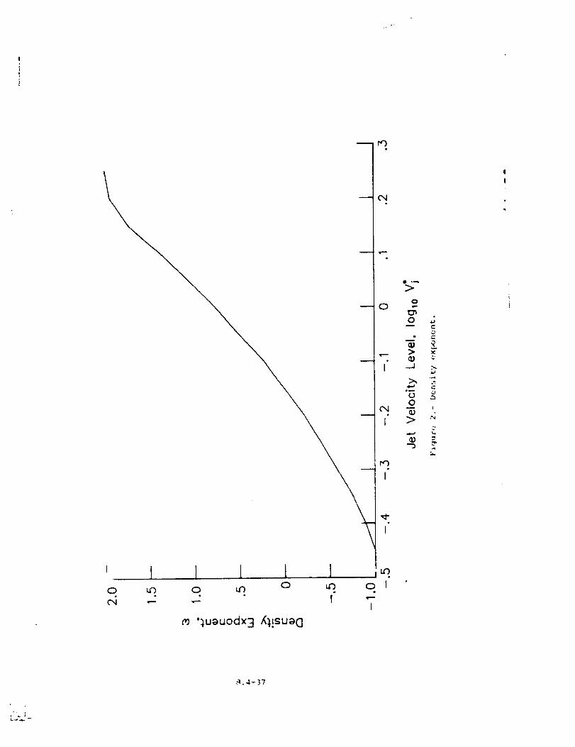
r.3
i l l 1 I l ,_.0 u3 0 u3 0 uO CD 1
I
';uauodx 3 /_,!sua 0
i
_J
"_o¢N
?
,q.4- 37
L,._ --
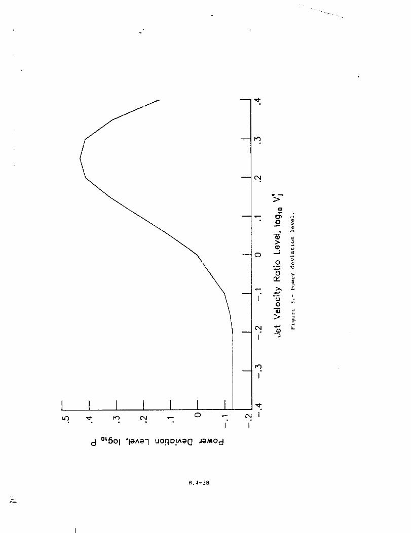
[ 1 l 1 I l I0 ,---
• ° I
d °LB°I 'leAe-I uo.q.o!^_G J_,Od
t'O
e,4
0
•-- OI0
q3
>
q_
0 ._l
0e_
on_
,-- >_.
oi
q3
L"xi "_
I
t.*-)
-J,I
¢.,0
_d
t_
I
r_
_.4-38
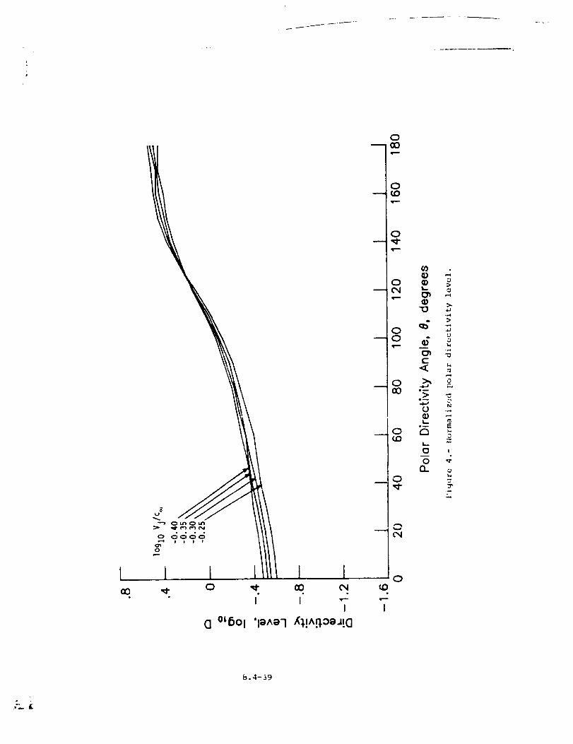
[CO
C] °_6Ol
000
0cO
0
0cO
0r,,O
I
¢1,) .-,© >o&-, ¢,I
¢1,1 ::,..
.,-,
4 °....4
¢-.< ,-.,wO
>,
"> ,_
w..
0
I,..
00 _"
b.4-39
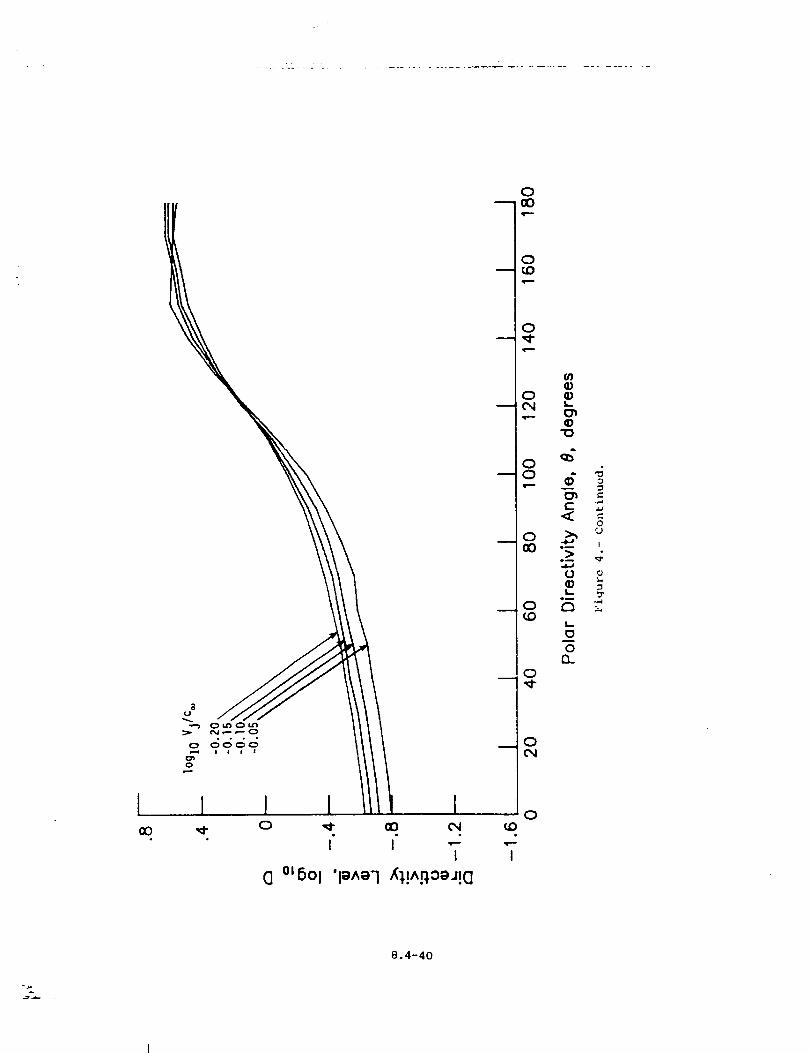
+
I l
I
0IX:)qr-,.,-
0U:)
0
0"J¢{.)
0
_)
0
0
8.4-40
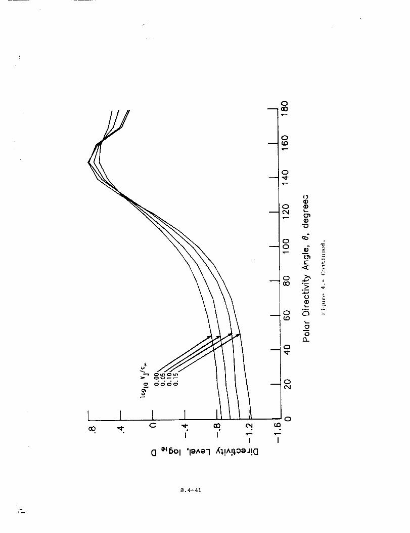
$U
• ° ° °
0
0-- 00
0
0
0
(43
I
1IQ)Q)
ET_Q)"I0
o _ ,"T_ =:o--4-a
0 _.
o k5 -2(0
o0
n0,q-
0
0
8.4-4I
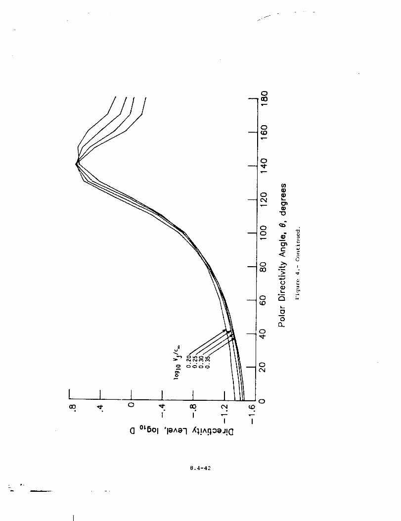
J
I
I
0
0
0
¢{,>
ooL
_o
0
',m".m
0
L,.
Oo
t3.0
0cN
0
8.4-42
. J.
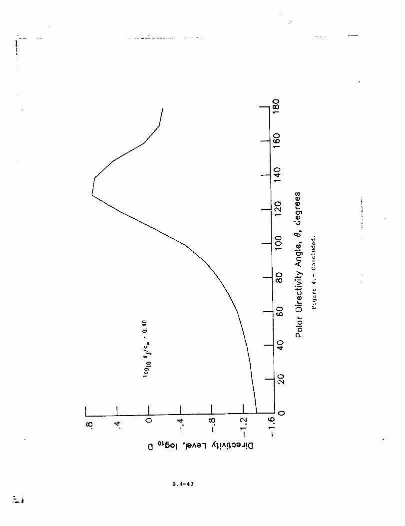
i I
0
0
0
0
0
0
0
a)&_
-,3
u
< 0
e_
.m
¢{,) =.,-6
ei
w,.,
o0..
o
8.4-43
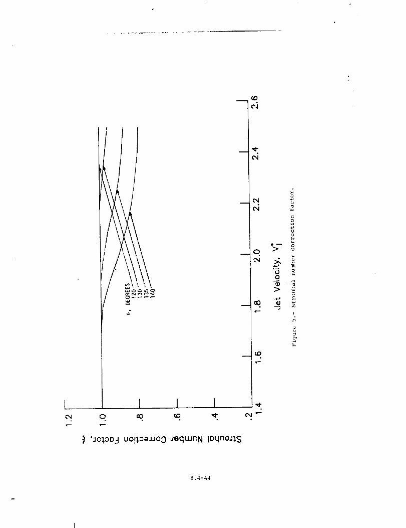
i.i¢3
[ ! I
) 'JO}t_O..-] UO!}t::3aJJO 0 jequJnN IDqnoj},S
(D
('4
(N
_C)
(DN
>
00
_D>
-l,-J
0
0
rj
w.l
t-
O
,41
U:)L,
o{J
_j
.QE
c-
I
.,..q°
a.4-44
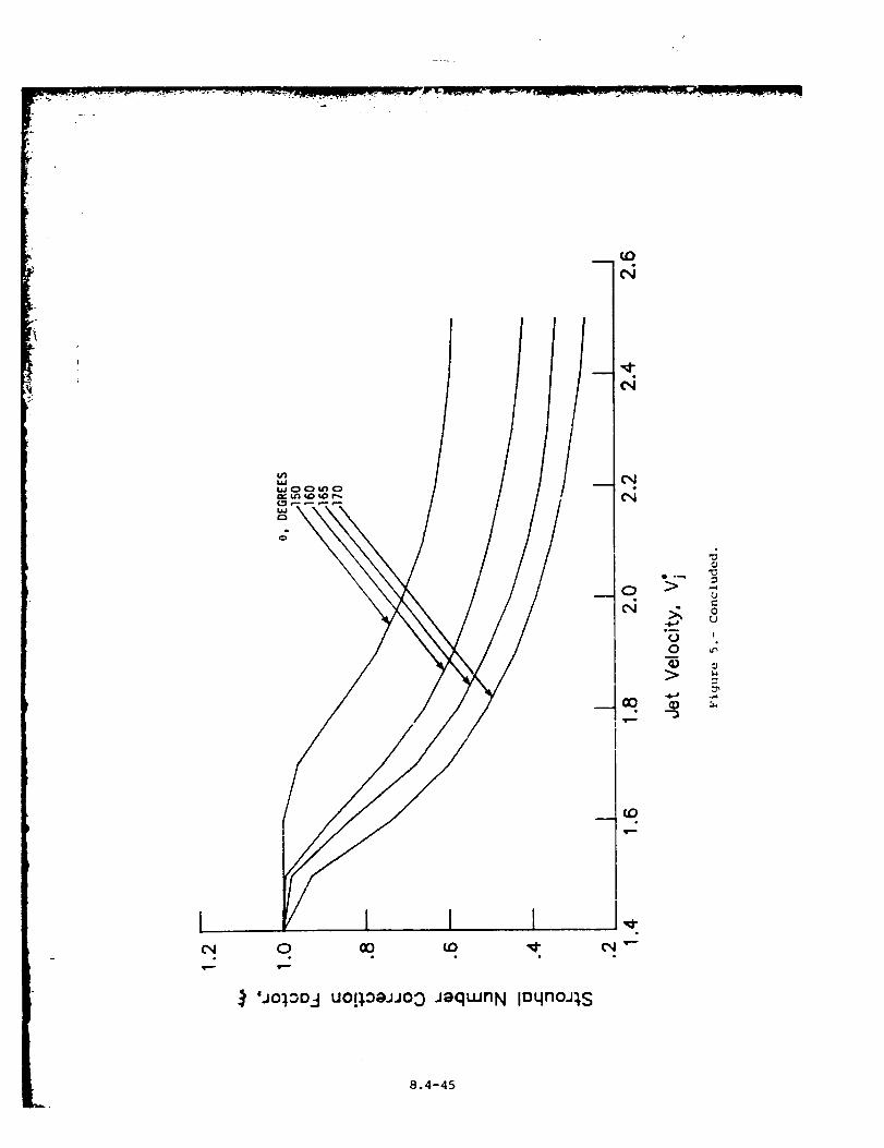
/
._'ao_,._O-Iuot_ogJJo::) jaquJnN IoqnoJ_,S
>
.i
o0
>
0
tJ
00
!
u_
_J
8.4-45
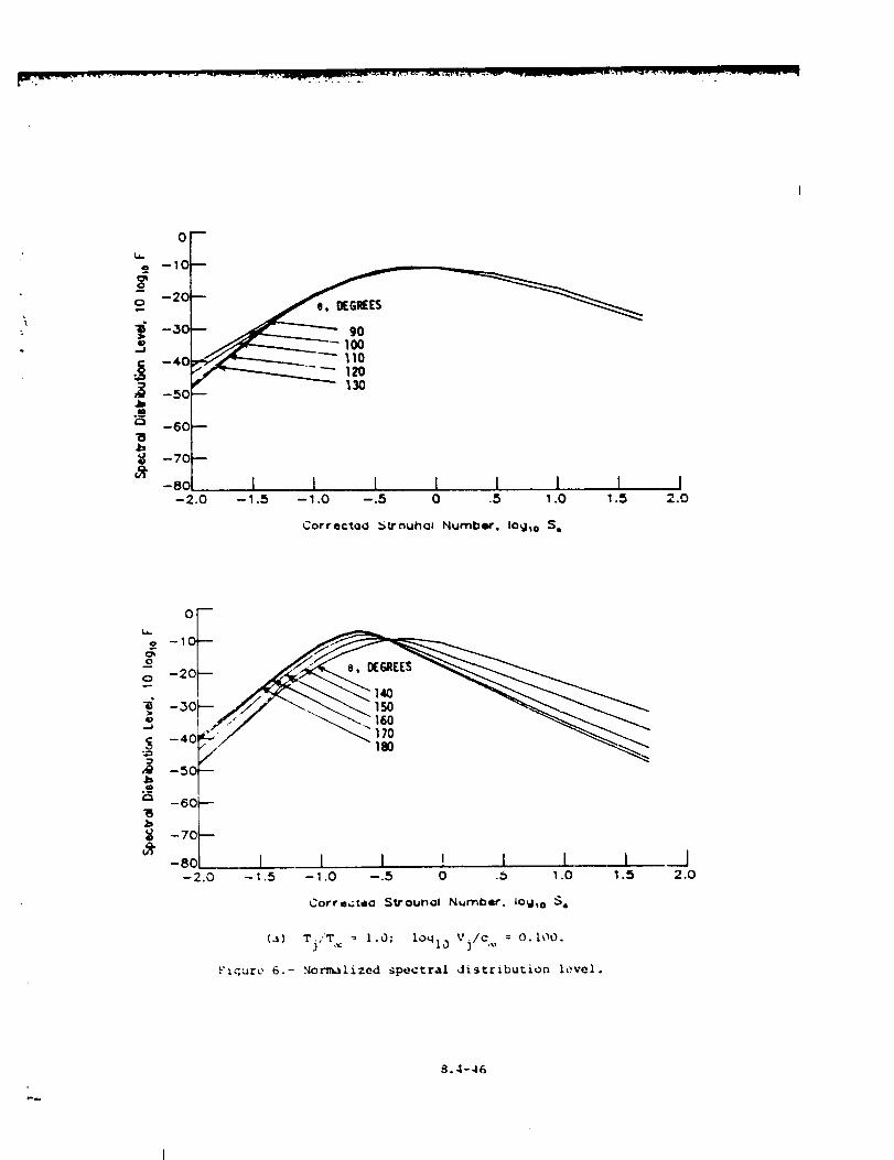
° -10
_#o -20
-30
_40_------_ _ 110
-50
--70
or -8 1 I I I I 1 I I-2.0 -,.5 -,.o -.s o .5 ,.o ,._ ._.o
Corre¢*,oO _Vouh<]l Number. lO_h o S,
-10
i -20
o_
"._, -60 f:_ -7o
_" -so I I I ' I I I-2.o -_.5 -_.o -.5 o ._ _.o _.s
Corre,;teo SVOUInol N=r_ber. lo_jt o S.
(a) Tj,"T,_ = 1.0; lOqlo Vj/c,_ : O. IO0.
F_ure 6.- Normalized spectral distribution level.
I2.0
8.4-46
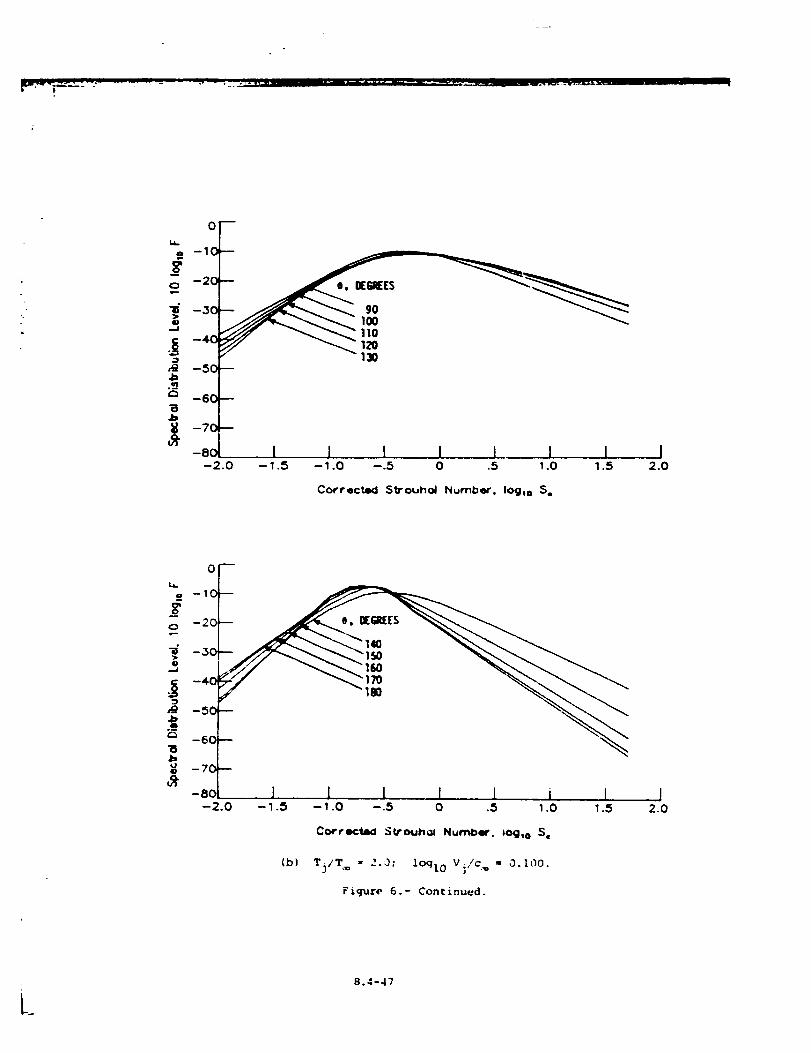
r ....... • r _....-_. rt, it
0
-2.0
e. IEglEES
90IO0110129130
I I l I L I 1 l-1.5 -1.0 --.5 0 .5 1.0 1.5 2.0
Correcte_ Strouhol Numbor. IOglo $,
0
-10
o -20
-30
-4.0
-50
-60
-70
-80--2.0
m
I L L L l i L-1.5 --1.0 --.5 0 .5 1.0 1.5
Corr_tad SWo4J_ol Nutria'. _og,o S=
(b) Tj/T= = 2.0; lOqlo V;/c, = 0.I00.
Figure 6.- Continued.
J2.0
8.4-47
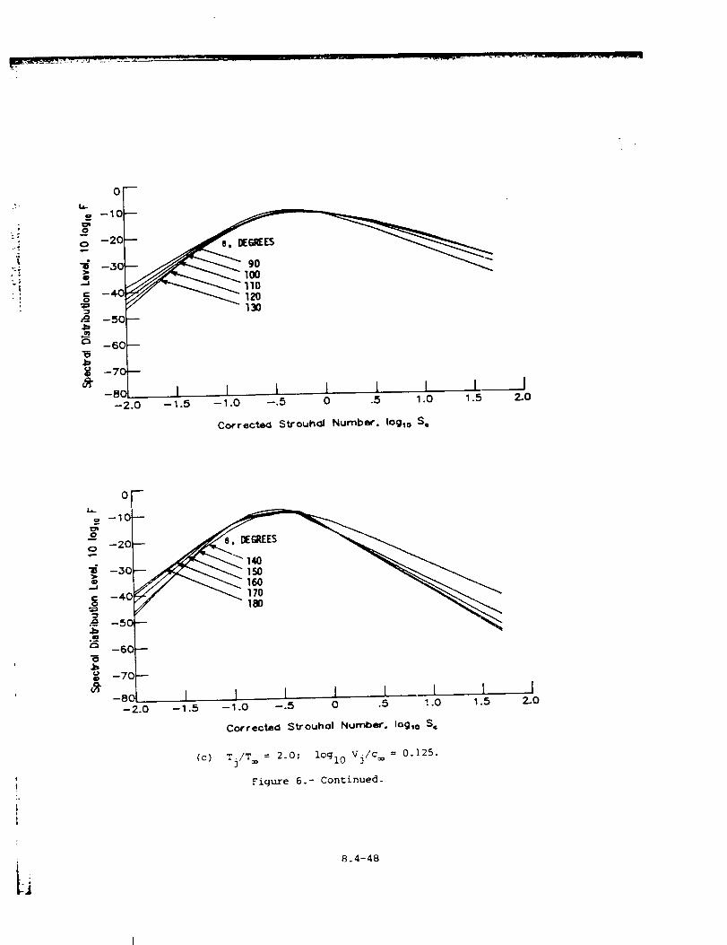
I
...."
i
0
--10
-30_ -20
_ -5O --
_ -6C --
o --7C --
-8c I I I I I I I--2.0 --1.5 --1.0 --.5 0 .5 1.0 1.5
12_.O
Corrected Strouhal Number. IOglo S=
oF
--10
-20
-30
_ -60
_ - I 1 I J [ 1 I--2.0 --1.5 --1.0 --.5 0 .5 1.0 1.5
Corrected Strouh_ll Number. Iog,o S=
(c) Tj/T= = 2.0; iCglO V]/c = 0.]25.
Figure 6.- Continued.
8.4-48
I2-O
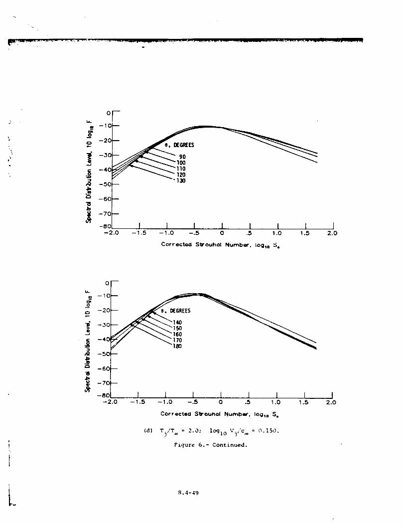
07
o -20
_-- 120
-5C "130
--6C--
-7a--
-ec I 1 I 1 I I I-2.o -1.s -_.o -.5 o .s _.o 1.s
Corrected Strouhol Numbs. iog_o :_,
12.0
o -10
o -20
-50
I 1 I [ i I I-2.0 -1.5 -1.0 -.5 0 .5 1.0 1.5
I2.0
Corrected Stl'oUhcll Number. Ioglo S,
= iog10 3,(d] Tj/T 2.0; V ,'c = 0.150.
Figure 6.- Continued.
L 9.4-49
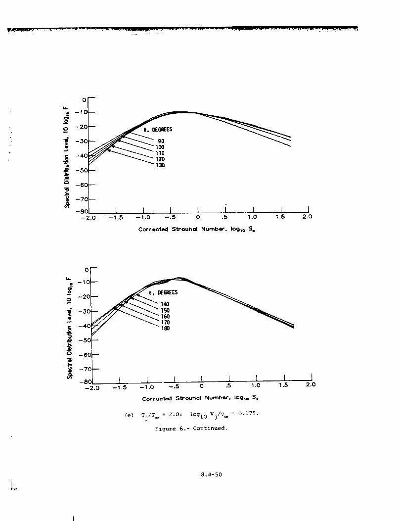
.
0
9O100110120130
Corrected Strouhal Number. Iog_o S_
oV--10
o --20
--30
-40
-60
_ -- 1 l I I I I l--2.0 --1.5 --1.0 --.5 0 .5 1.0 1.5
Corrected Slbrouhol Number. Iogto S,
(e) T./T = 2.0; lOglo V3/c = 0.175.
Figure 6.- Continued.
I2.0
8.4-50
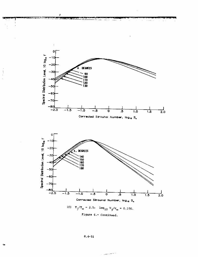
i 1 I 1 I 1 I I-1.5 --1.0 --.S 0 .5 1.0 1.5 2.0
Corrected 5¢ouhoJ Number, Iog_o $,
i,
o --1C
= -2o
--30
o= -40
--50
;=' -60
o -70
-Sq
oF
1 1 I I ¸ 1 1 1-- 1.5 -- 1.0 --.5 0 .5 1.0 1.5
I2.0
Correctea Strounoi Number. loglo S=
(f) Tj/T = 2.5; lOgl0 Vj/c = 0.i00.
Figure 6.- Continued.
8.4-51
_jp
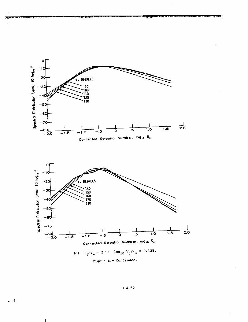
0
50Q
_
_-8 1 I 1 t ! 1 I--2.0 -- 1.5 -- 1.0 --.5 0 .5 1.0 1.5
J2.0
Corrected Strouhol Number. Iog_ e S=
or- --1
Q
"6
'_ 1 I I I. 1 I J--2.0 - 1.5 -- 1.0 --.5 0 " .5 1.0 1.5
Corrected Strouhol Nurnbmr. IOglo S¢
(g) Tj/T = 2.5; lOgl0 Vj/c = 0.125.
Figwe 6.- Continued.
12.0
8.4-52
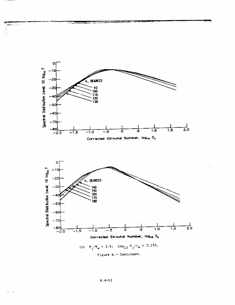
0
--,L,'_-C,-_f _ - "_ _ 110
120130
..g_
.ba
.b
--50
-60
-70,
-2.0
D
1 1 J I I I I I-1.5 --1.0 --.5 0 .5 1.0 1.5 2.0
Corrected S_ouhoi Number, Iog_o S,
=,
J=
-60"--
--70
-80-2.0
I l I 1 I L I l- 1.5 -- ; .0 --.5 0 .5 1.0 1.5 2.0
Corrected Strouhol Number. Iog,o S=
(h) T]/T_ = 2.5: lOql 0 V3/c_ = 0.150.
Figure 6.- Continued.
8.4-53
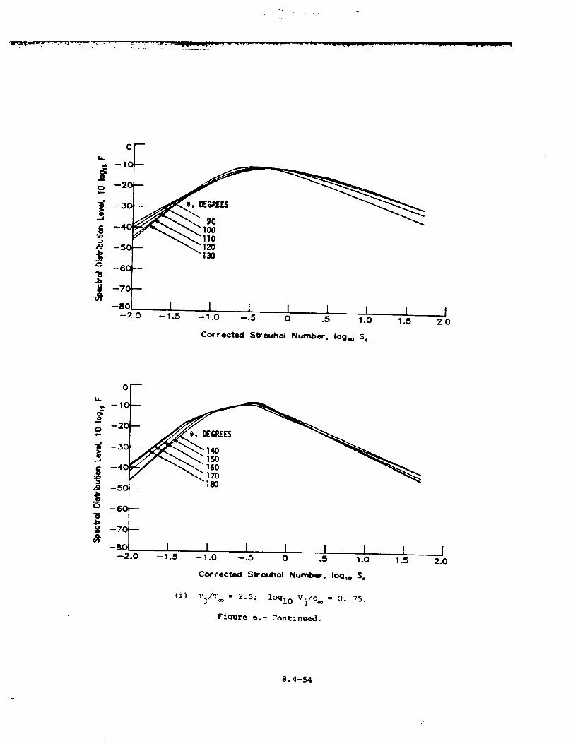
0
=,
._ - 100
--60
-7o -
-80 I I i I I I I-_..o -_.s -1.o -.s o .s ,.o _.5
Corrected S_ouho! Number. |oglo $.
I2.0
--2.0 --1.5 --1.0 --.5 0 .5 1.0 1.5 2.0
Corrected Strounol Number. Iog_o S.
(i) Tj/T_ = 2.5; lOgl0 Vj/c = 0.175.
Figure 6.- Continued.
8.4-54
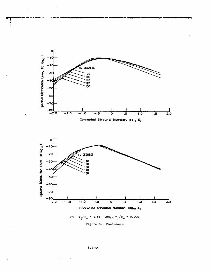
0
-- 120= 130
,Q4=m
"6j:J¢,30
--5C
--6C
--7C
--8C--2.0
J I I I I ; I I--1.5 --1.0 --.5 0 .5 1.0 1.5 2.0
Corrected Strouhol Number. Iog,o S.
orL_
0 --1
--601---"5 14= I
¥ -7o,_--a- -8 I I ! 1 1 I I-2.0 --1.5 -1.0 --.5 0 .5 1.0 1.5
I2.0
Corrected Sb'ouhal Number. Ioglo S.
(j) Tj/Too = 2.5; iOgl0 Vj/Coo = 0.200.
Figure 6.- Continued.
8.4-55
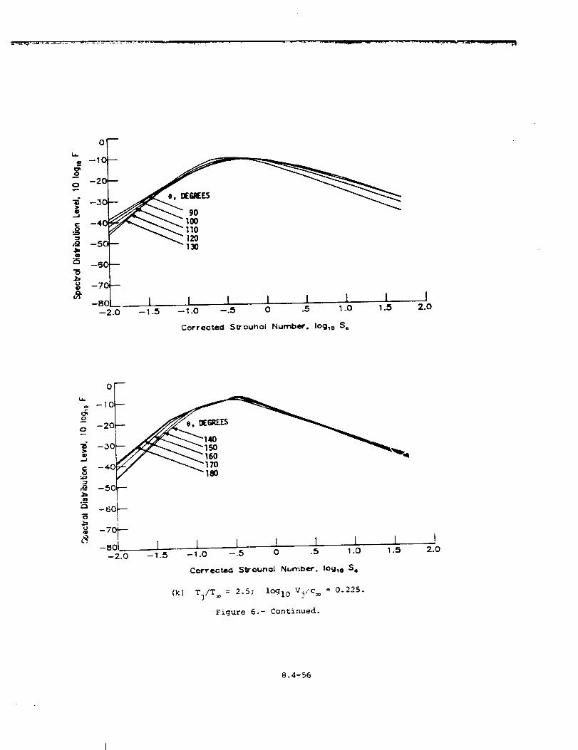
0
o: - 10o
--2.0 --1.5 --1.0
Corrected 5_rouhol Number, IOg_o $6
I2.0
0
i -10
-20
-.30
-4o_/ _-'170
_ --50
o -60
0
-8ol I l L L I l I-2.o -_.s -,.o -.5 o .5 _.o _.5
Correc:ecl Strounol NumDer. IOg,o S.
(k) Tj/T = 2.5; lOgl0 V],'c : 0.225.
Figure 6.- Continued.
2.0
8.4-56
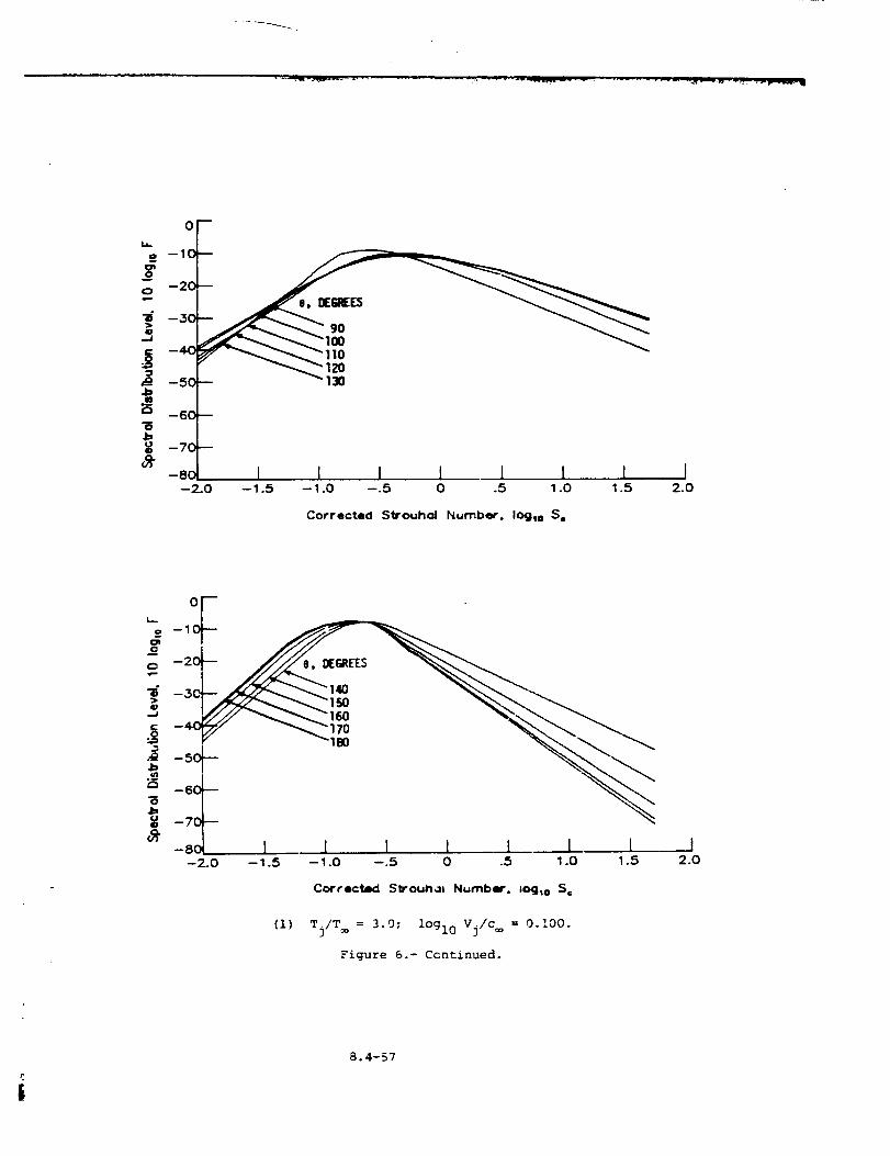
oF
_- I I I I I I I I--2.0 --1.5 --1.0 --.5 0 .5 1.0 1.5 2.0
Corrected Strouhol Number, logic S=
--2C;
->>* -3C
-50
-60
-70
oF
-8o I I 1 I I I I J--2.0 --1.5 --1.0 --.5 0 .5 1.0 1.5 2.0
Correct6cl Strou_al Number, =¢Kj,o S=
(i) Tj/T = 3.0; lOgl0 Vj/c = 0.I00.
Figure 6.- Continued.
8.4-57
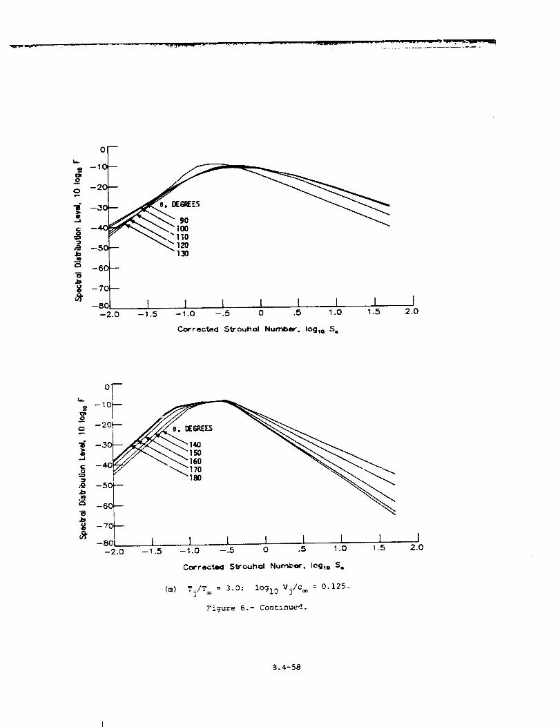
T0 --2
-5 "" 120•1:, 130mo
--6C
--7C
--8C--2.0
I I I I L I I I--1.5 --1.0 --.5 0 .5 1.0 1.5 2.0
Correctea Sllrouhol Number. Ioglo S¢
°T
--20 _6a£_
25 --6C --
-so 1 I I 1 I 1 [-_.o -_ s -_.o -5 o .s 1.o _.5
l2.0
Correcte_ St_'ouho_ Number. 10910 S.
(m) Tj/T= = 3.0; lOgl0 Vj/c = 0.125.
Fiqure 6.- Continued.
8.4-58
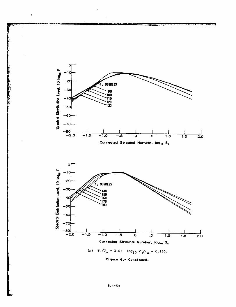
r
or
o
e
- 120
1 I I I I l I I--2.0 --1.5 --1.0 --.5 0 .5 1.0 1.5 2.0
--60
--70
-80
Corrected Slrouhol Number. Iogto S,
oF-10
o -20
--30
_ -7o F-80 I I I 1 I l 1--2.0 --1.5 --1.0 --.5 0 .5 1.0 1.5
I2.0
CorrectiKI Strouhal Number. log,o S=
(n) Tj/T= = 3.0; lOgl0 Vj/c= = 0.150.
Figure 6.- Continued.
8.4-59
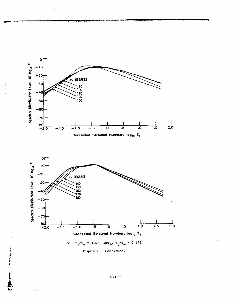
0
-10
N _
.IDI_ -
-8oi I I I I I I I Jo .s 1.o 1.s 2.0--2.0 --1.5 --1.0 --.5
Corrected StTouhol Number. Iog,o S,
0Eo -10
o --20
--30
!:_ --60_-70
'_" -8OL _ l I I I 1 1-2.o - 1.5 -_.o -.s o .5 1.o _.s
12.0
Corrected Strouhol Number. lOglo S,
(o) T3/T _ = 3.0; loglO Vj/c = 0.175.
Figure 6.- Continued.
8.4-60
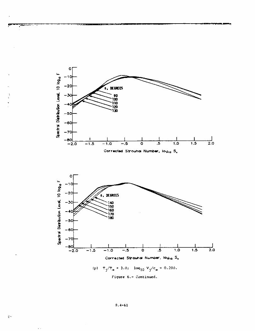
or
i --10
--20
--30
_ 110._ 4o_ -50 --
.m
"B-60-
-70-
-80
-2.0
, I L I I [ I I--1.5 --1.0 --.5 0 .5 1.0 1.5 2.0
Corrected 5trouha= Number. Io_lto S=
o_ --10
0 --20
--30
_ -40
lb.m
-50--
--60--
--70--
-eo I-2.0 -1.5
I I l i I I I-1.0 -.5 0 .5 1.0 1.5 2.0
Correcte_l Stro¢_ol Number. IOglo S,
(p) Tj/T = 3.0; lo_! 0 Vj/c= = 0.200.
Figure 6.- Continued.
9.4-61
_-.
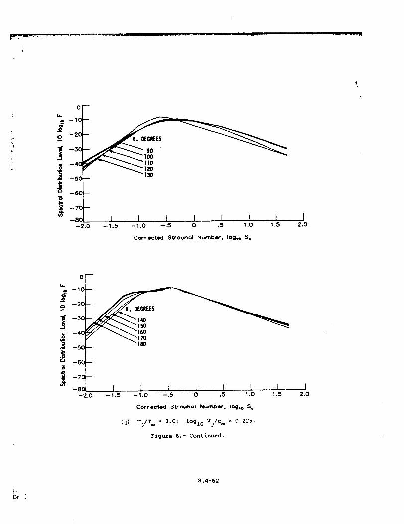
e,_gJIE_
gO
10
I I I I I I I--1.0 --.5 0 .5 1.0 1.5 2.0
Corrected StTouhol Number. Iogto S,
0
_,=
- p- _---i 7o5 180
_5 6
i5 t4=
' -::T I l I l 1 I 1--2-0 -- 1.5 -- 1.0 --.5 0 .5 1.0 1.5
12.0
Correct=KI Strouhol Number. log_e S=
(q) TilT = 3.0; lOgl0 Vj/c= = 0.225.
Figure 6.- Continued.
i.
8.4-62
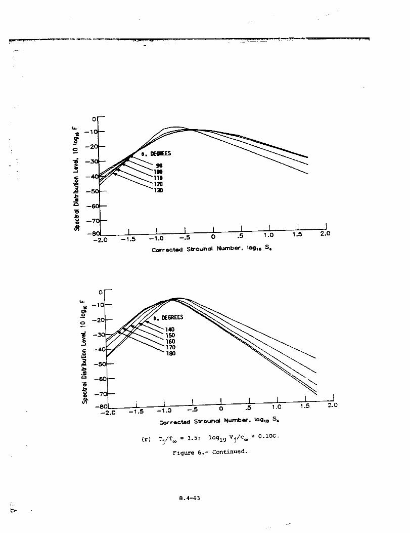
0
);o
1 1 I • I I I-2-0 -- 1.5 - 1.0 --.5 0 .5 1.0 1.5
Corrected Slrouho| Number. IOgso S s
i2.0
--10
"
'_ -8oi i I I ., I I 1 I-2.o -_.s -_.o -.s o .s _.o _.5
I2.0
Corrected C:_ouhol Number. log.> S,=
(r) rj/'r®= 3.5; lOglg Vj/c = O.lOC.
Figure 6.- Continued.
8.4-63
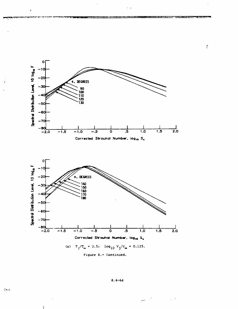
/
,. oF
!!ol I I I I I I
--2.0 -- 1.5 -- 1.0 --.5 0 .5 1.0 1.5
Corrected Strouhol Number. Iog_o S.
I2.0
oF
o
-_ l I i I I I 1-2.0 --1.5 --1.0 --.5 0 .5 1.0 1.5
Correct4KI Sl_ouhcd Number. Io_i o S,
(s) Tj/T = 3.5; lOgl0 Vj/c = 0.125.
Figure 6.- Continued.
I2.0
.-t!
8.4-64
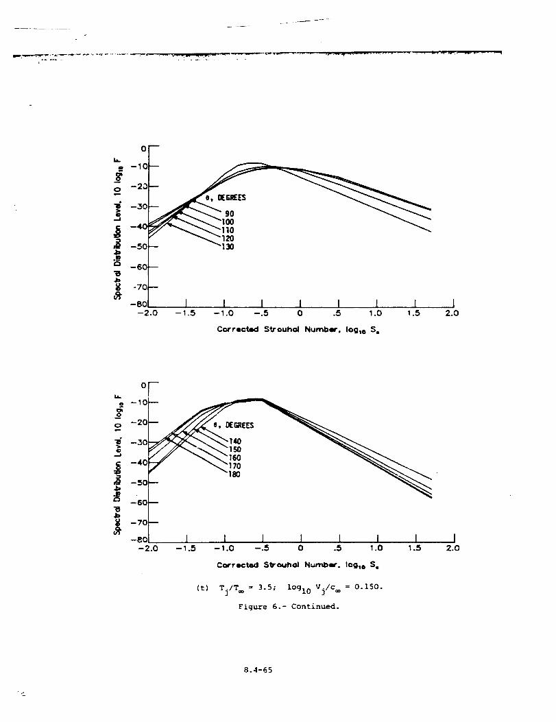
r ---
_ -=mms.-:-_w -'_
oF-10
-20
-30
--50 _I_
-70
- I I I I I 1 I--2.0 --1.5 --1.0 --.5 0 .5 1.0 1.5
Corrected Strouhal Numbw', Iog_o S,
I2.0
oF
i --10
--20
--30
--40
15 -5°-80
_ 1 1 1 I i1 I-2.0 --1.5 -1.0 --.5 0 .5 1.0 1.5
Corrected Strouhal Number. Iog,o S,
I2.0
(t) Tj/T = 3.5; logl0 Vj/c = 0.150.
Figure 6.- Continued.
8.4-65
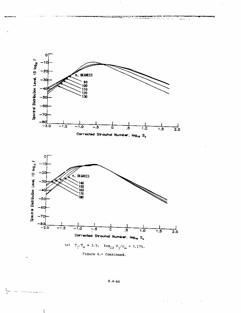
............ _ --c _- _ ...............................
oro --10
o
-50-- 130
.m-60 --
--70 --
--80.-2.0
i I l I [ I I J--1.5 --1.0 --.5 0 .5 1.0 1.5 2.0
Corrected SVouhol Number. iOglo S.
o_ --
o
o
-30
. --50
._m
(J0
-60
-70
--80- :.0
1 1 I J I I 1 I-- 1.5 - 1.0 --.5 C .5 1.0 1.5 2.0
Co4rrect:ed S_Ouhol Number. Io9,o S,
(u) Tj/T = 3.5; logl0 Vj/c = 0.175.
Figure 6.- Continued.
8.4-66
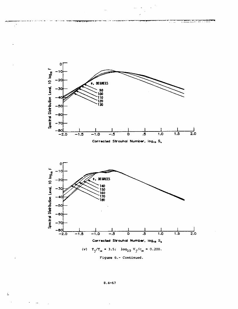
• -'J-:-. -
0
_ -10
C 0
50 1_
--60
_ --70-eol I I I I I I I J
-2.o -1.s -1.o -.s o .s 1.o 1.s 2.0
Corrected S_ouhal Number. loglo S=
or--10
-20
_ _
f--60
--70
or -8o I i I i I I I I--2.0 --1.5 --1.0 --.5 0 .5 1.0 1.5 2.0
Corrected Sti-ouh_ Number, log_o S=
(v) Tj/T = 3.5; lOgl0 Vj/c = 0.200.
Figure 6.- Continued.
8.4-67
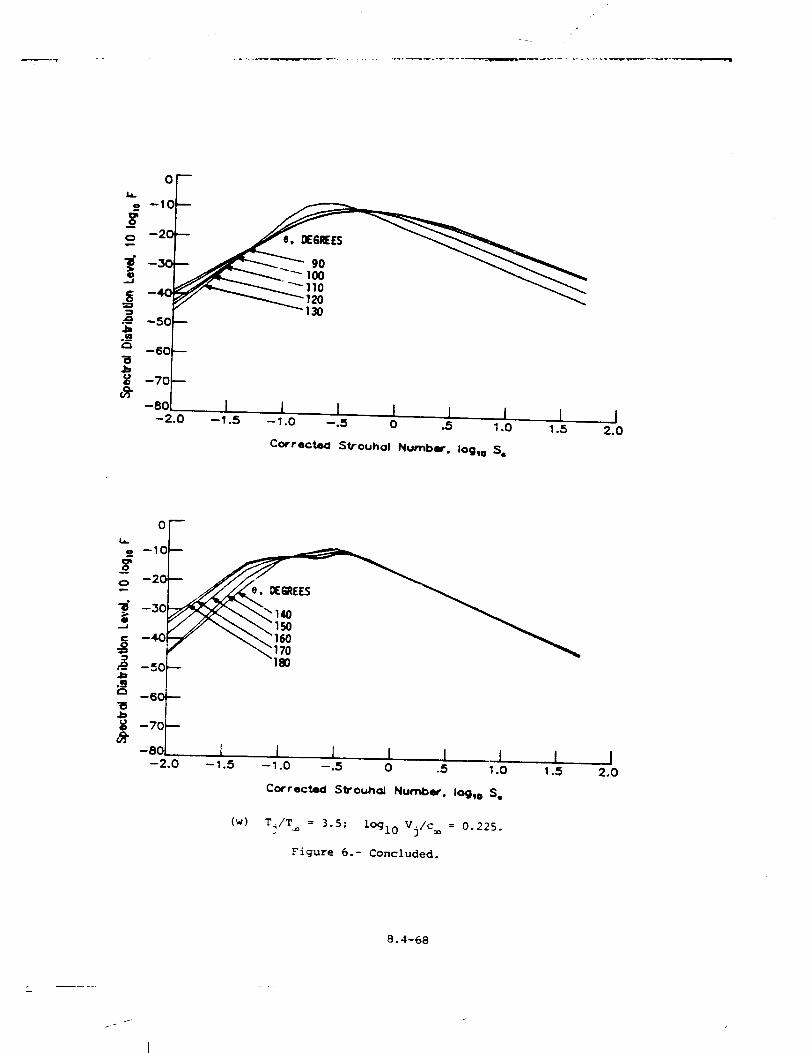
w. •
,/_k
0
--10
o --20
--30
--50_--60
-8ok_____-2.0 --I .5 I -L____L____L
- I.o -.s o .5 I.o 1.5--------
Correcte<l Strouhol Number. Iogto S¢
I2.0
0
--10
o -20
_ -50_ '_
_ -6C_u_ -70
-80 l i I I I -! I--2.0 --1.5 --1.0 --.5 0 .5 1.0 1.5
Corrected Sll]'ouhcd Number. Io@_o S,
(w) T_/T = 3.5; lo<910 Vj/c = 0.225.
Figure 6.- Concluded.
I2.0
8.4-68
I
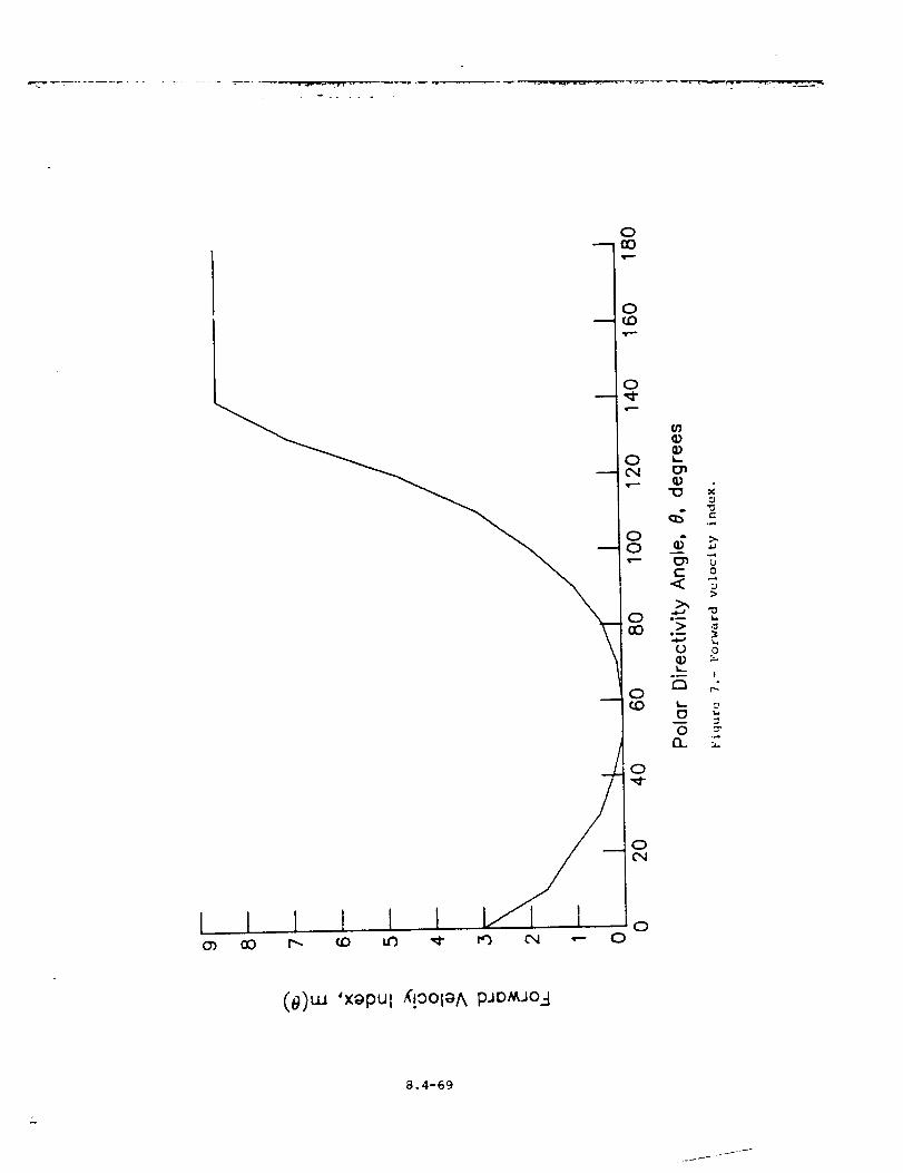
I I I 1 I }¢_ oO r-. r,D la,')
IbIIm
no t-
o ="n ...
0
0
0
(e)ua 'xapul _'!oolaA pJDMJOA
8.4-69

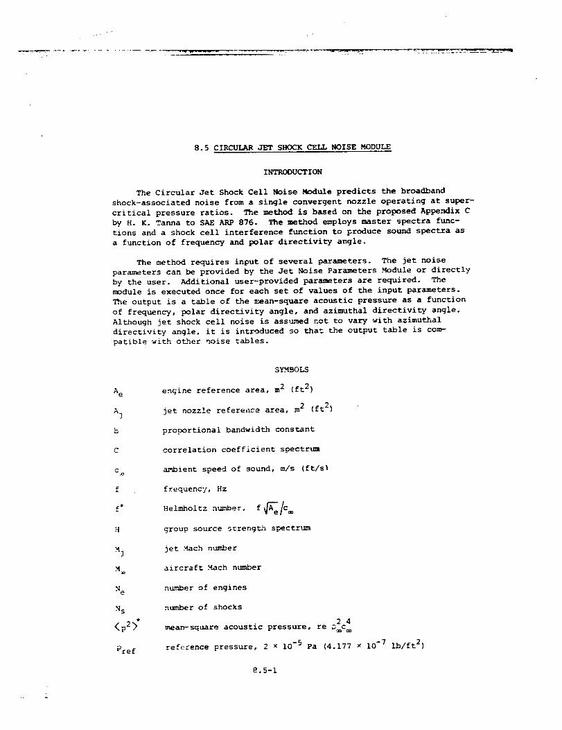
k_
8.5 CIRCULAR JET SHOCK CELL NOISE MODULE
INTRODUCTION
The Circular Jet Shock Cell Noise Module predicts the broadband
shock-associated noise from a single convergent nozzle operating at super-
critical pressure ratios. The method is based on the proposed Appe._dix C
by H. K. Tanna to SAE ARP 876. The method employs master spectra func-
tions and a shock cell interference function to produce sound spectra as
a function of frequency and polar directivity angle.
The method requires input of several parameters. The jet noise
parameters can be provided by the Jet Noise Parameters Module or directly
by the user. Additional user-provided parameters are required. The
module is executed once for each set of values of the input parameters.
The output is a table of the mean-square acoustic pressure as a function
of frequency, polar directivity angle, and azimuthal directivity angle.
Although jet shock cell noise is assumed not to vary with azimuthal
directivity angle, it is introduced so that the output table is com-
patible with other noise tables.
A e
Aj
b
C
C a
f
H
_j
M=
N e
N s
<p2>"
Pref
SYMBOLS
engine reference area, m 2 (ft 2)
jet nozzle reference area, m 2 (ft 2)
proportional bandwidth constant
correlation coefficient spectrum
ambient speed of sound, m/s (ft/s]
frequency, Hz
Helmholtz number, f _e/C
group source strengt/n spectrum
jet Mach number
aircraft Mach number
number of engines
number of shocks
2 4
mean-square acoustic pressure, re D c
reference pressure, 2 x 10 -5 Pa (4.177 × 10 -7 Ib/ft 2)
8.5-1
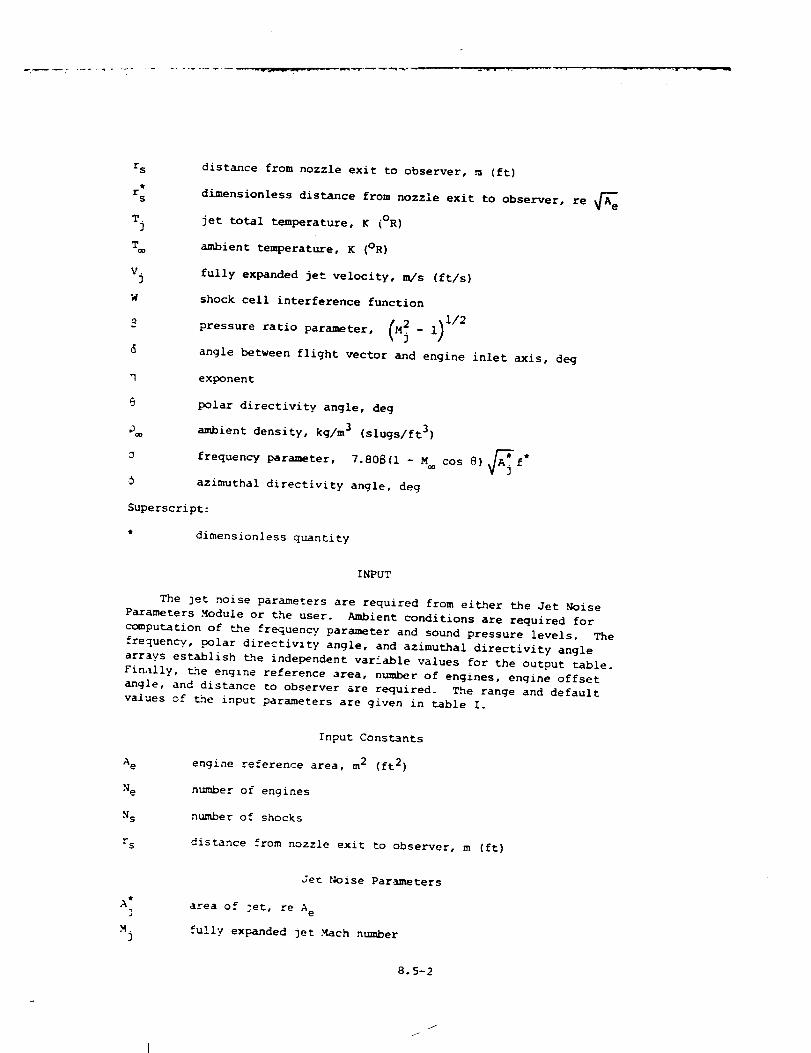
r s
tr
s
T.
3
V.
3
distance from nozzle exit to observer, _ (ft)
dimensionless distance from nozzle exit to observer, re _e
jet total temperature, _ (oR)
ambient temperature, K (OR)
fully expanded jet velocity, m/s (ft/s)
shock cell interference function
pressure ratio parameter, _M_- 1) 1/2
angle between flight vector and engine inlet axis, deg
exponent
polar directivity angle, deg
ambient density, kg/m 3 (slugs/ft 3)
frequency parameter, 7.80S(I - M
azimuthal directivity angle, deg
Superscript:
* dimensionless quantity
cos 8)_jf*
INPUT
The jet noise parameters are required from either the Jet Noise
Parameters Module or the user. Ambient conditions are required for
computation of the frequency parameter and sound pressure levels. The
frequency, polar directivity angle, and azimuthal directivity angle
arrays establish the independent variable values for the output table.
Fin._lly, _ne englne reference area, number of engines, engine offset
angle, and distance to observer are required. The range and default
values of _ne input parameters are given in table I.
A e
N e
N s
r s
Input Constants
engine reference area, m 2 (ft 2)
number of engines
number of shocks
distance from nozzle exit to observer, m (ft)
At3
M]
Je_ Noise Parameters
area of ]et, re A
fully expanded 3et Mach number
8.5-2
/
J
T:3
v:]
Cam
M
jet total temperature, re T®
fully expanded jet velocity, re c
Ambient Conditions
ambient speed of sound, m/s (ft/s)
aircraft Mach number
ambient density, kg/m 3 (slugs/ft 3)
Independent Variable Arrays
frequency., Hz
polar directivity angle, deg
azimuthal directivity angle, deg
OUTPUT
The output of this module is a table of the mean-square acoustic
pressure as a function of frequency, polar directivity angle, and azi-
muthal directivity angle. In addition, the obse_2er distance r s is
provided for _he Propagation Module.
r sdistance from nozzle to observer, m (ft)
f
<p: {f, :,:)>"
Circular Jet Shock Cell .Noise Table
frequenc?, Hz
polar directivity angle, deg
aza=uthal directivity angle, deg
mean-square acoustic pressure, re _c_
METHOD
The _rediction methodology proposed by H. K. Tanna is used to com-
pute _e shock cell noise. Details of the development and validation of
_ne method are given in references 1 and 2. A schematic of a typical
exhaust 2et .nozzle _s shown in figure i. _'_..ecoordinate system and
directivit? angles are also shown. The total jet noise will be the sum
of the shock cell and jet mixing Pmise.
8.5-3
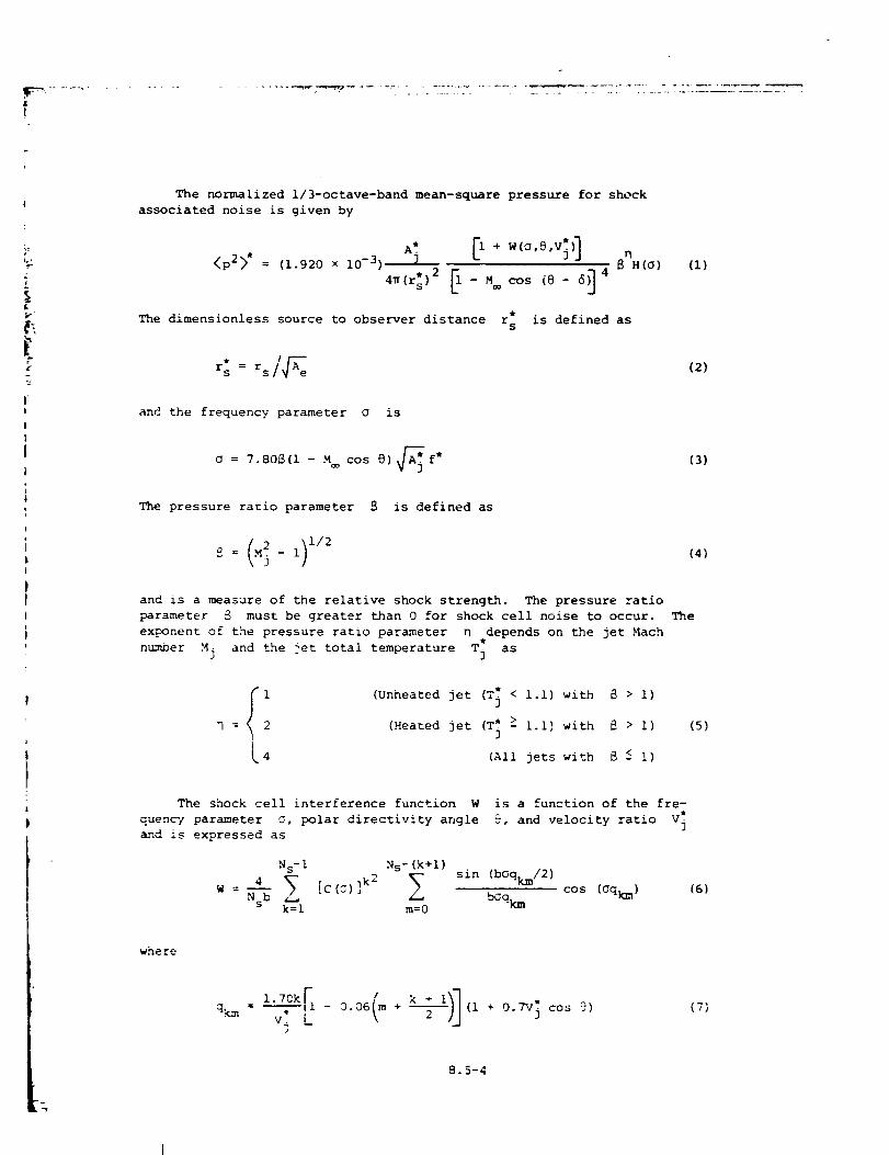
E
!
i=
L
I
I8
ii
i
PI
The normalized i/3-octave-band mean-square pressure for shock
associated noise is given by
<p2>* = (1.92o × lO-])
4_(r:) 2 _ - M cos (@- 6)] 4
n8 H(O) (i)
The dimensionless source to observer distance r*s
is defined as
r: = rsi_e
and the frequency parameter _ is
= 7.80_(i - M cos 8) _*. f*
The pressure ratio parameter is defined as
and is a measure of the relative shock strength. The pressure ratio
parameter _ must be greater than 0 for shock cell noise to occur.
exponent of the pressure ratio parameter D depends on the jet Mach
number Mj and the 3et total temperature T: asJ
i
= 2
4
(Unheated jet (T; < i.I) with _ > i)
(Heated jet (T; > I.i} with _ > i)
(All jets with 8 < i)
(2)
(3)
(4)
The
(5)
The shock cell interference function W is a function of the fre-
parameter _, polar directivity angle 9, and velocity ratio V_quenc/
and is expressed as
Ns-i N s-(k+l)
sin (bOqkm/2)
4 _ [c(_) ]k2W = Nsb bGqk m
k=l m=0
cos (Oqkm) (6)
where
qkm = l'7--Okrl-v$L 0"06<m + _'_>I (I + 0"TV; c°s 9)
3
(7)
8.5-4
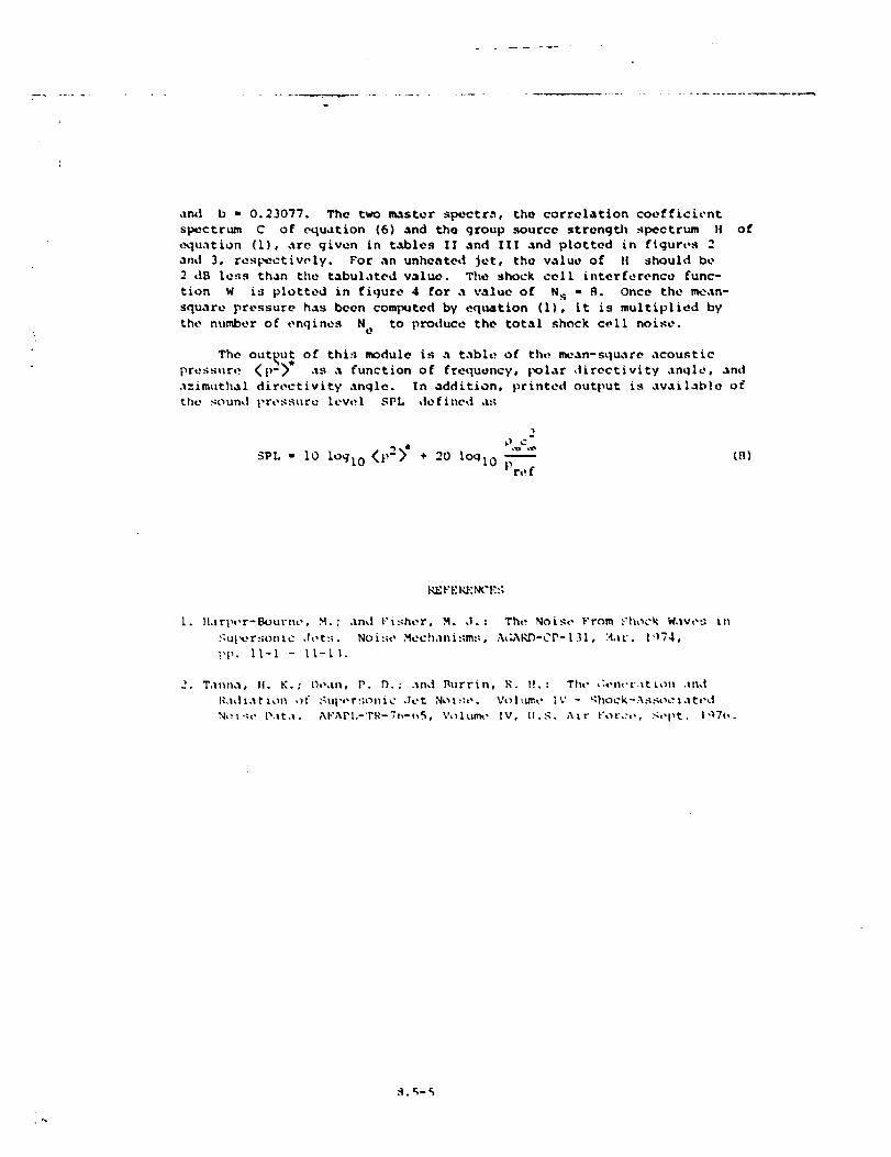
and b • 0.23077. The two master spectrm, the correlation coefficient
spectrum C of equation (6) and the group source stronqO_ spectrum H of
t.xluation (i), are qiven in tables II and Ill and plotted in flquros 2
and 3, respectively. Per an unheated Jet, the value of I! should be
2 dB le:_s than the tabulated value. The shock cell interference func-
tion W is plotted in figure 4 for a value of N s • R. Once the mean-
square pressure has been computed by equation (I), it is multiplied by
the number of t,nqines N to produce the total shock cell noise.e
The output of thi:; module is a table of th,._ mean-square acoustic
pressure _p2_* as a function of frequency, |x_lar _lirectivity angle, and
.l=imuthal directivity angle. In addition, printed output is available of
the gound pro._._ure level SPL defined a._
2
SPL = i0 loglO <p2>' + 20 loqlo-
P r,! f
(n]
REYE KE.N_'E:;
I. H,irp,,r-_ut'no, M.; ,lad l'i:_her, M. ,I. : Tht_ Noise From ._:hock W,lvo_ in
.*:ul_r..;onLc ,h,t:_. No_.._o Mech,mi:;m,:, A_K_-CP-[31, H4v. [,174,
i,_,. ll-I - II-I _.
2. T,Inrla, 14. K. : Dean, P. D. ; .In_| l_tlrrin, R. ]!. : The Ct,n,,t._ttotl and
R.tdt.ltiot_ of ._u|',,r:;_nic ,let Not::,,. Vol_lm.o I%' - _hock-A._._oct.ltt'd
N,:l'.m D.tt.t. AF'APL-'PR-7_,-t_S, Voltm_, IV, LI.G. Air l'orco, ._t,|_t. l'_7_,.
• °s
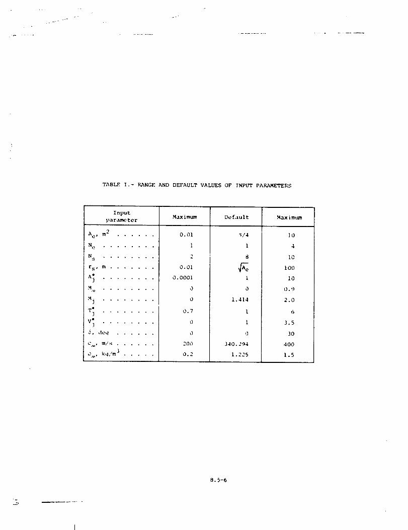
j-
TABLE. I .- RANGE AND DEFAULT VALUES OF INPUT PAKAMETERS
InputMax imum De f,_u I t Max imum
parameter
9
Ae, m" . .....
Mr, ........
N . . . . ° . . .s
rs, m .......
_j ........
T_ . .......
v"_ ..... o ° .
_, ,leq ......
C ,_, m/' S ......
D , k,;/m ] .....
0.01
1
2
0.01
0.0001
0
0
0.7
0
0
200
0.2
",/4
1
S
1
0
1.414
1
1
,3
340. 294
1.225
]0
4
1O
I00
i0
0.9
2.0
6
3.5
30
400
1.5
S. 5-6
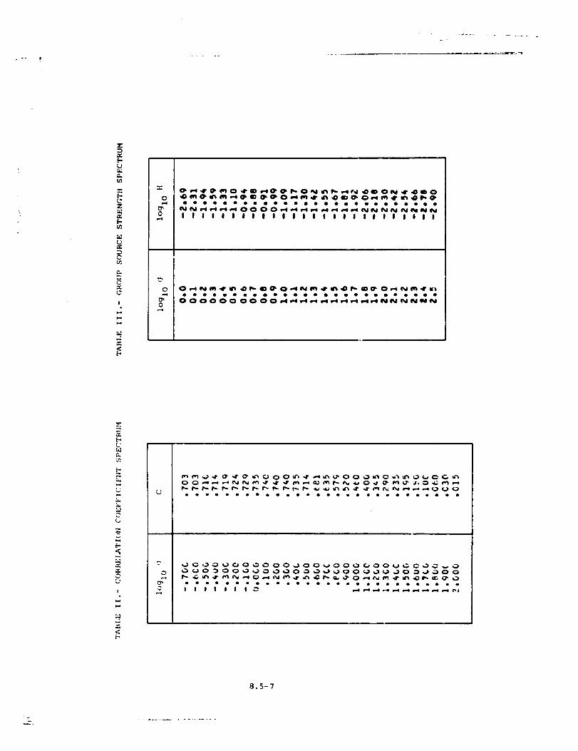
°
X
[-
u_
[-.
Z
E-.
0
I
2
<
0
0
f
I I I l l l I l I l l I I I I I I I I I I I I I I I
• • oooooQo •
[-(,
:A
[.-,
I
<
0
0
8.5-7
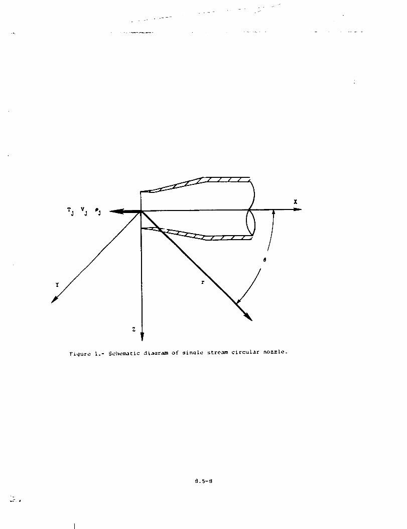
Figure I.- Schematic diaaram of single stream circular nozzle.
8.5-8
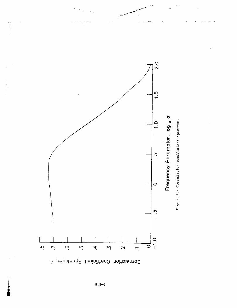
l
_f
l 1 I I J I I
0
t00
0
• ID
Eo1,..
0a.
ot-
3O"¢)1,,,.
la_
0
I/)
4.le.
0
0
0
0U
l
,0 'u-ln40'_dS 1ue!alJ,._aoo UOi]l:)lSJJO0
i 8.5-9
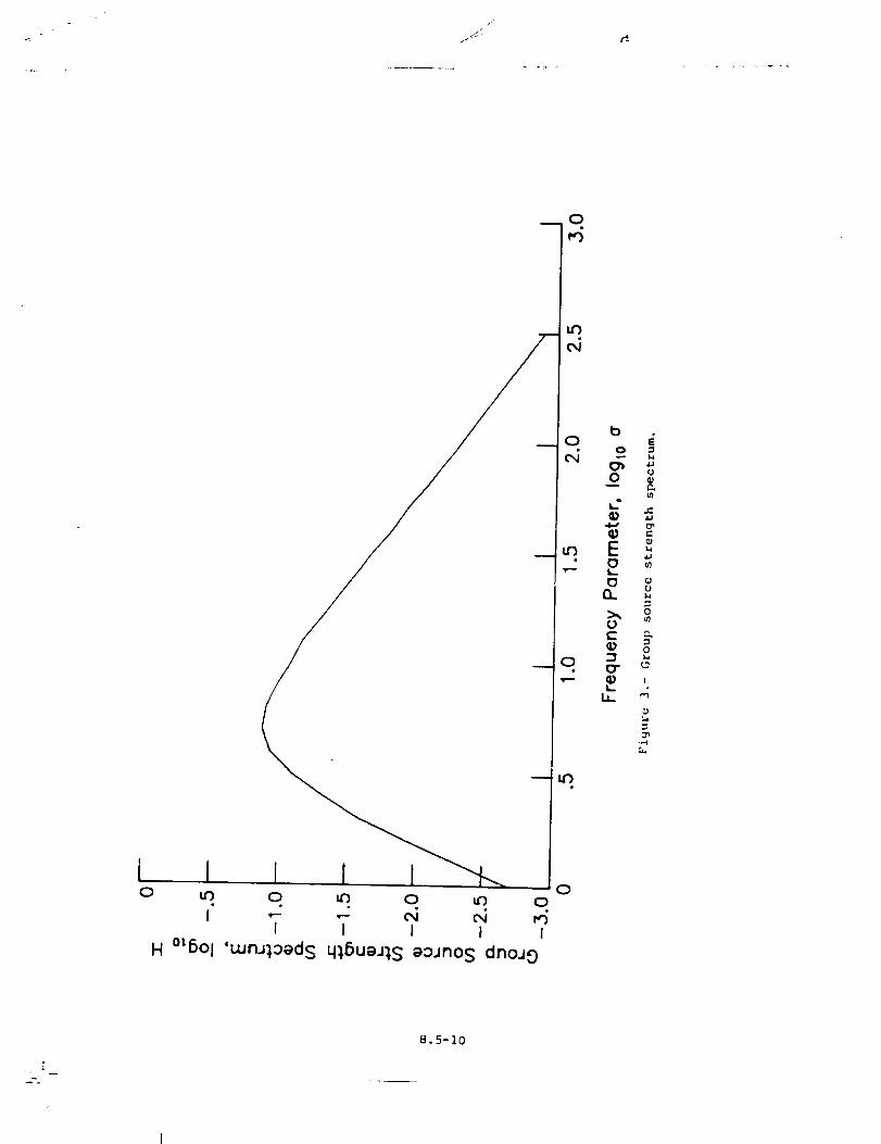
0
i0
0
q
I io
i ,- ,- _ _I I I I I
H °L6Ol 'uJru_aads q),6ua.n,S aoJno S dno.J 0
b
o
0
E0I,.-
0I:L
0c-
_r
I,,-
!,
L,4.1
U
P.,
r"
I,a4.;
(/1
UL,
0
0
I
,3
8.5-10
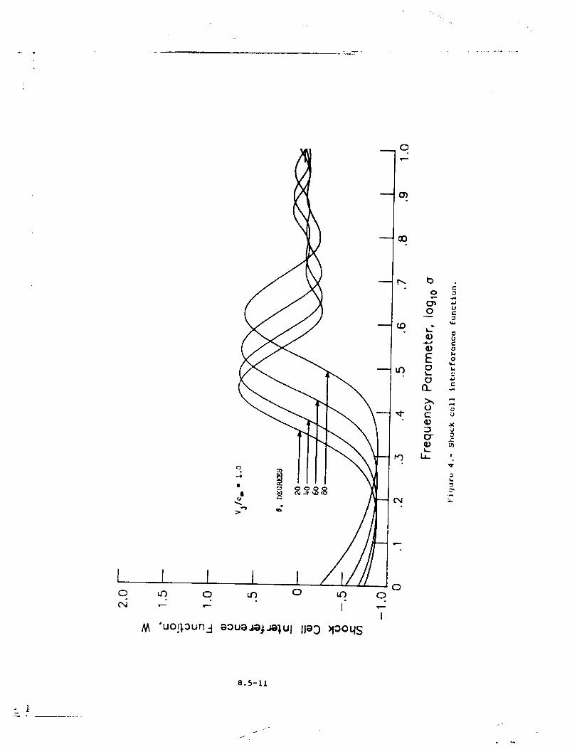
b
0
o
CQ_
Q;Eo
n
Q_
(TQ;
i,
0
.,J
Uf.
U
¢;
,-6
_JU
_J
0
I
l l ! I I _Q
"- '-- I ,---I
M "uo!'_oun.:t aoua_j._Ul lla 0 _looqs
8.5-11
- i
J
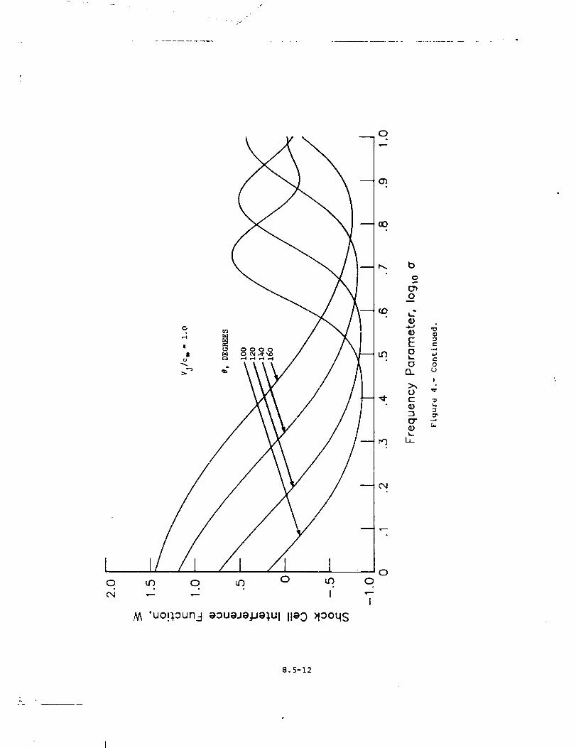
0
|$
o
e-.,-d
0
!
,_ 'uo!l.aun4 a:::}uaJa:l.Jal.Ul Ila9 )lo0qs
0
I
0
8.5-12
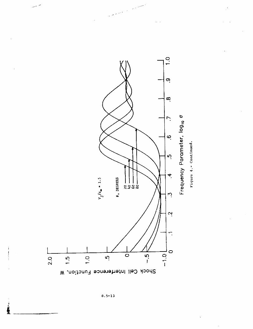
0
c
4J
0
(J
!
CJ
I I I0 _f3 0
M 'uo!),oun:l eoueJepe),Ul lleO >10oqs
00
I
i
8.5-13
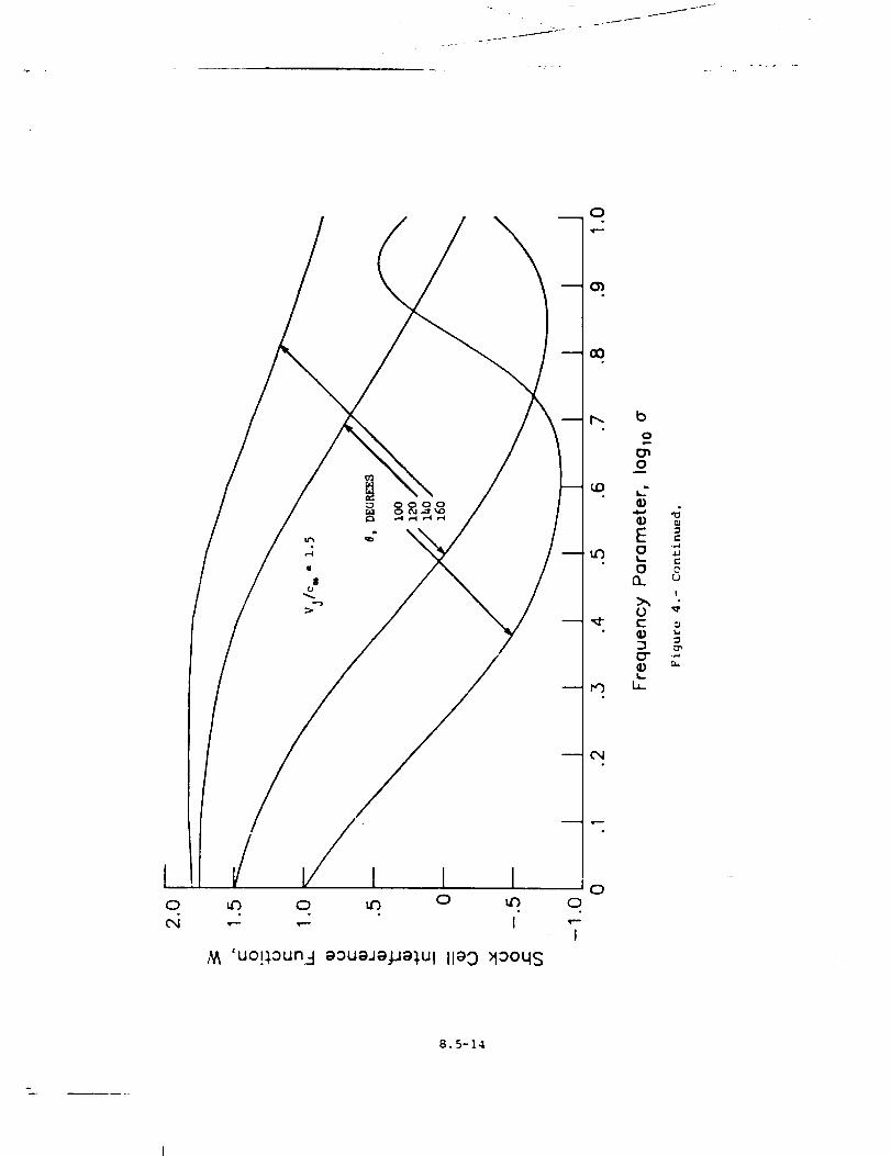
_r
0
aO
N_ 'uo!_.aun-I aouaJa#a_.Ul ila 9 _aoqs
8.5-14
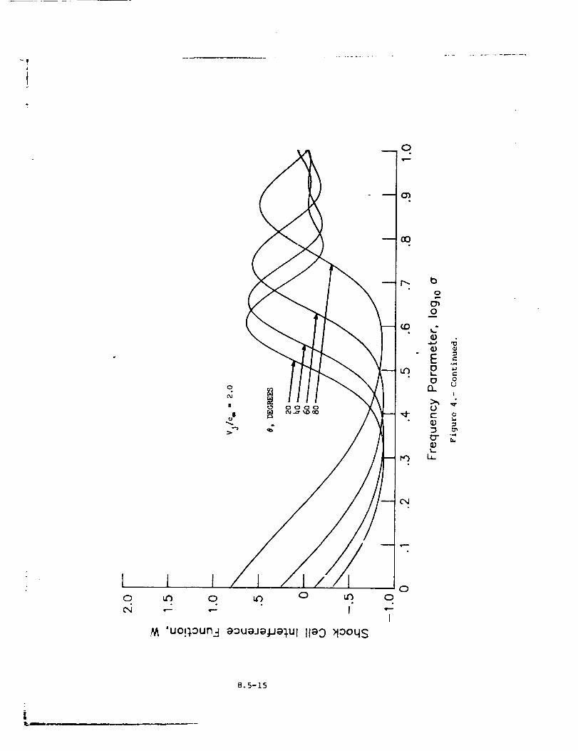
0
0000
./_ 'UO!_OUn_-] aouajaj.j9_,u I ii_0 >1oo4s
00
O0
I
b
0
o_0
..._, ,_
E e.
o _t,,,- t-
O on u
!
>_ ,,_
¢- o
o-t,.,.
i,
8.5-15
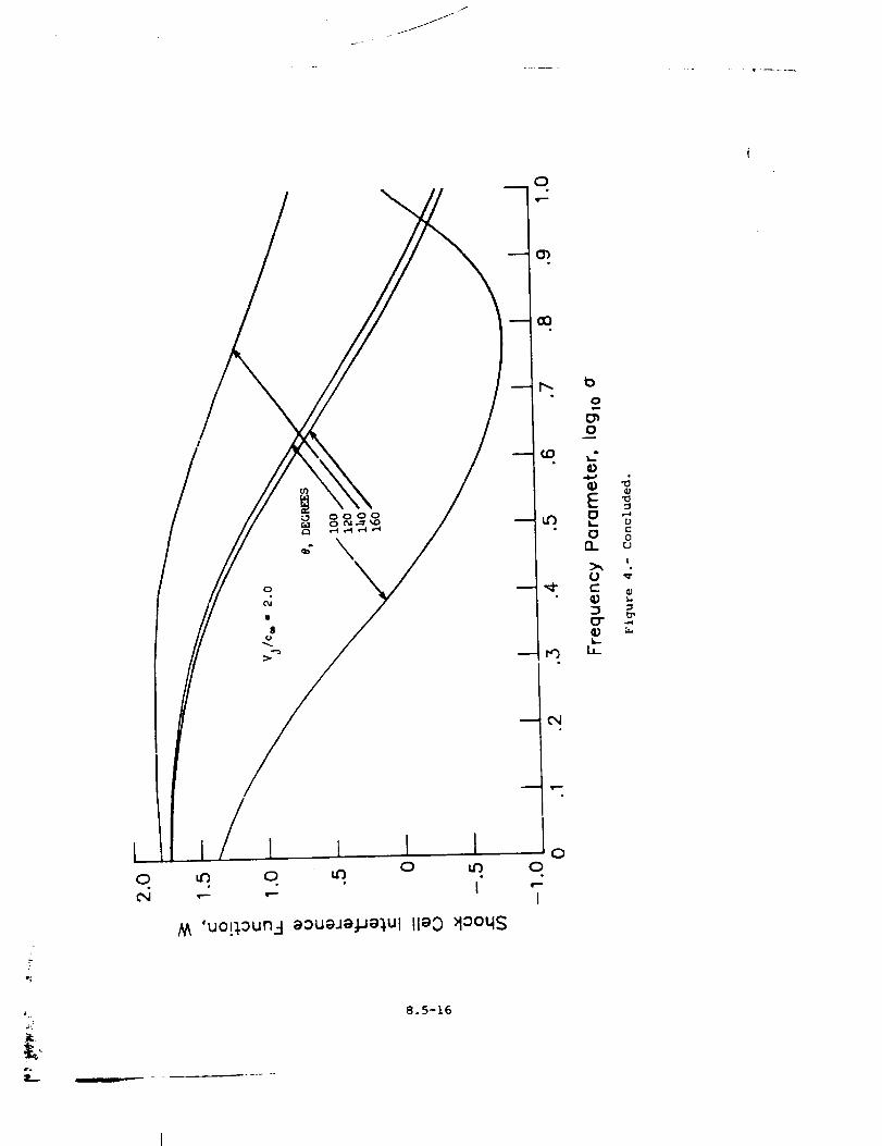
ilJ
'e
L
\
M 'u0!:[0un__ @::)u_)J;aJJa),ul IleO >looqs
8.5-16
0
r--
-- u0
-- 04
00
I
o
o
Q;
EoL.
o(3_
0c-
b_
U
_..0
(J
I
b_
8.6 STONE JET NOISE MODULE
INTRODUCTION
The Stone Jet _oise .Module predicts the far-field mean-square
acoustic pressure for single stream and coaxial circular jets. Included
in the prediction are both jet mixing noise and shock-turbulence inter-
action noise. The method used is that developed by J. R. Stone as pre-
sented in references 1 and 2. For coaxial nozzles, the method is limited
to jets whose core jet velocity is greater than the secondary jet velocity.
Further, only t_he core jet velocity may be supersonic.
The method requires input of several parameters. The nozzle exit
flow parame + _rs can be provided by the Jet Noise Parameters Module or
directly b? the user. Additional user-provided parameters are required.
The module _s executed once for each set of values of the input param-
eters. The output is a table of the mean-square acoustic pressure as a
function of frequency, polar directivity angle, and azimuthal directivity
angle. Jet exhaust noise is assumed independent of the azimuthal direc-
tivity angle; however, the prediction is tabulated as a (constant) func-
tion o_ azimuthal angle so that the output table is compatible with other
noise tables.
A_
"%.
3
_S
d_
d..q
d_J
P
Fm
F3
SYMBOLS
engine reference area, m 2 (ft 2)
fully expanded jet area, m 2 (ft 2)
ambient speed of sound, m/s (ft/s)
directivity function for 3et mixing noise
directivity function for shock noise
equivalent diameter, m (ft)
hydraulic diameter, m (ft)
jet diameter, m (ft)
plug diameter, m (ft)
spectral distribution factor for jet mixing noise
spectral distribution factor for shock noise
frequency, Hz
3.6-1
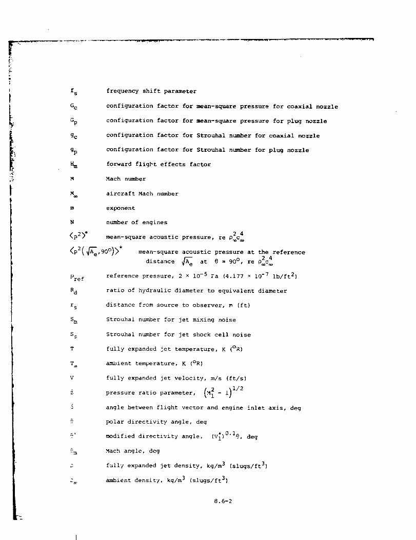
t
L
.<
S-
I
fs
%
Gp
gc
gp
M
m
N
<_2>"
frequency shift parameter
configuration factor for mean-square pressure for coaxial nozzle
configuration factor for mean-square pressure for plug nozzle
configuration factor for Strouhal number for coaxial nozzle
configuration factor for Strouhal number for plug nozzle
forward flight effects factor
Mach number
aircraft Mach number
exponent
number of engines
2 4
mean-square acoustic pressure, re p c
<p2(
Pref
R d
r S
S m
S 5
T
T
V
_5
&
2,'
&
mean-square acoustic pressure at the reference
distance _e at @ = 90 ° , re 0_c_
reference pressure, 2 x 10⁻⁵ Fa (4.177 x 10 -7 ib/ft 2)
ratio of hydraulic diameter to equivalent diameter
distance from source to observer, m (ft)
Strouhal number for jet mixing noise
Strouhal number for jet shock cell noise
fully expanded jet temperature, K (oR)
ambient temperature, K (OR)
fully expanded jet velocity, m/s (ft/s)
pressure ratio parameter, (N_ - 1) 1/2
angle between flight vector and engine inlet axis, deg
polar directivity angle, deg
modified directivity angle, (V_)0"Ig, deg
Mach angle, deg
fully expanded jet density, kg/m 3 (slugs/ft 3)
ambient density, kg/m 3 (slugs/ft 3)
L --
8.6-2
Jt
w
Wo
azimuthal directivity angle, deg
density exponent
stationary jet density exponent
Subscripts:
iL
i
i primary stream
2 secondary stream
Superscript:
dimensionless value
INPUT
The jet parameters are required from either the output of the Jet
Noise Parameters Module or the user. Ambient conditions are required.
The frequency, polar directivity angle, and azimuthal directivity angle
arrays establish the independent variable values for the output table.
Finally, the engine reference area, number of engines, engine axis offset,
and distance to the pseudo-observer are required. The range and default
values of the input parameters are given in table I.
A e
N
r S
3
Input Constants
engine reference area, m 2 (ft 2)
number of engines
distance from nozzle exit to pseudo-observer, m (ft)
angle between flight vector and engine inlet axis, deg
Jet Noise Parameters
Primary Stream
d;, 1
41
primary fully expanded jet area, re A e
actual primary stream equivalent diameter, re _e
actual primary stream hydraulic diameter, re
primary stream Mach number
primary stream total temperature, re T
°8.6-3
----4 ............
I
V 1 primary stream jet velocity, re c
_ primary stream jet density, re O=
_eco Ildd t_ . Stream
,CJ
Mr
T:
¢.._econdary fulty e-q_anded jet area, re A
e
_econdary ._troam Math numb_,r
.qecondary .,;trpam total teml_er,lture, re T
:_econdar\." :;tream _et velocity, re c+
secondary stream jot density, re.,
Ambient Condit ions
ambient sound st_ed, m/s (ft./._)
aircraft ._ach number
arab.lent density, kq/m 3 (.qiu_ls/ft 3)
Th,' outVut of thi:; _dule i_ a tabh, of _he t,%_an-squ.lre acoustic
|'r,'_',_;ur,,.,.q a function of fr,.qucncy, !x_l._r ,:irectivity an,_le, and ._:i-
muthAl d_rect_vity an_l_e. In addition the }-seudo-observer distance r:
l:; [,rovtd,,d rot t.h_, Pro[,._q.lt_on Module.
r. ,IX:_tanc,, from no::l,, ,'xZt to },.qeu,k_-obser':er, m (ft)
Stone's Method Jet l_k_se TAble
f frequency, H:
'_ },olAf ,i_r,,ctlv_,_,:' ,%nq[e, deg
._ Az_muth._l d_r,,ctlvtty angle, deq
<_,-'tf,_,:)>° me,_n-_quare acou:;tic _-res._ure. re o'c 4"
8.6-4
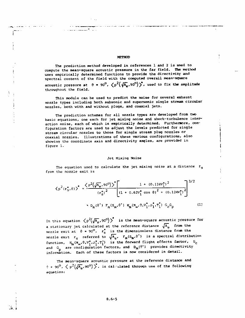
i
METHOD
The prediction method developed in references 1 and 2 is used to
compute the mean-square acoustic pressure in the far field. The method
uses empirically determined functions to provide the directivity and
spectral content of the field with the computed overall mean-square
= 90 )> , used to fix the amplitudeacousticpressure.t e 90o. o •throughout the field.
This module can be used to predict the noise for several exhaust
nozzle types including both subsonic and supersonic single s_ circular
nozzles, both with and without plugs, and coaxial jets.
The prediction schemes for all nozzle types are developed from two
basic equations, one each for jet mixing noise and shock-turbulence inter-
action noise, each of which is empirically determined. Furthermore, con-
figuration factors are used to adjust the levels predicted for single
stream circular nozzles to those for single stream plug nozzles or
coaxial nozzles. Illustrations of these various configurations, also
showing the coordinate axis and directivity angles, are provided in
figure i.
Jet Mixing Noise
The equation used to calculate the jet mixing noise at a distance
from the nozzle exit is
< I(r:) 2 1
x Dm(e' ) Fro(Sin,8' )
l_+[0:12 v[[2_]+ 0.62v_ cos 0) 2 + (0.124v[)
3/2
Hm(M_,@,VI,01,T I) GcG p
r s
(!:
In this equation <p2( A_e,90°)/ is the mean-square acoustic pressure for
a stationary jet calculated at the reference distance _ f._om the
nozzle exit at @ = 90 °, r: is the dimensionless distance from the
nozzle exit r s referred to _e' Fm(Sm'@') is a spectral distribution
function, Hm(M_,@,V_,O_,T _) is the forward flight effects factor, G c
and G are configuration factors, and Dm(@'} provides directivityP
information. Each of these factors is now considered in detail.
The mean-square acoustic pressure at the reference dista.n_e and
= 90 O, < p2(_e,90° ) >*, is cal<:ulated through use of the following
equation:
D
8.6-5
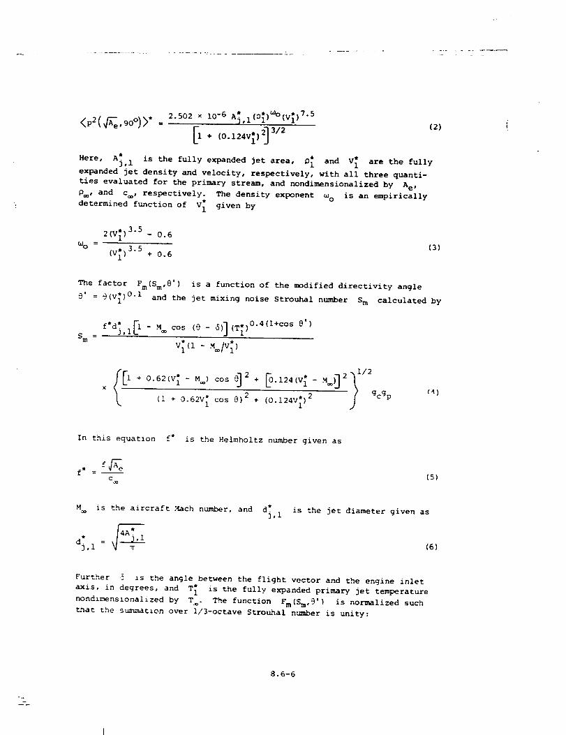
<p2(_e.gO°)>"=2.5O2x10-6A_,IC_Cv;_75
[i+(2)
Here, A_, 1 is the fully expanded jet area, P_ and V[ are the fully
expanded jet density and velocity, respectively, with all three quanti-
ties evaluated for the primary stream, and nondimensionalized by A e,
p_, and c , respectively. The density exponent w o is an empirically
determined function of V 1 given by
2(V_) 3"5 - 0.6
= (3)Loo(V,*) 3"5 + 0.6
&
The factor Fro(Sin,8') is a function of the modified directivity angle
9' = @(v_) 0"I and the jet mixing noise Strouhal number S m calculated by
S m =
0,v[Cl- .,,=Iv[,
.,_i/2
(I + 0.62V 1 cos _)2 + (0.124VI)2 / gcgP
_)
In this equation f* is the Helmholtz number given as
f_eC
(5)
M is the aircraft Mach number, and dj, 1is the jet diameter given as
(6)
Further ,5 is the angle between the flight vector and the engine inlet
axis, in degrees, and T_ is the fully expanded primary jet temperature
nondlmenslonalized by T . The function Fm(Sm,9') is normalized such
_nat the summation over i/3-octave Strouhal number is unity:
8.6-6
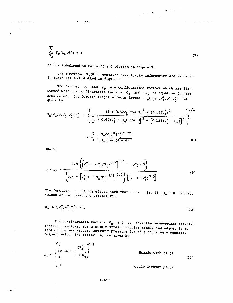
Fm(Sm, e ) = 1Sm
(7)
and is tabulated in table II and plotted in figure 2.
The function Dm(e') contains directivity information and is given
in table III and plotted in figure 3.
The factors gc and gp are configuration factors which are dis-
cussed when the configuration factors Gc and Gp of equation (i) are
considered.Thefo_ardflighte_fectsfactor_(.®,e,V_,_.T_isgiven by
+0.62(v"l-.®)cose]
(1 - _/v1)s(p;)_-_°
1 - M cos.(8 - $)(8)
where
0 1(9)
The function Hm is normalized such that it is unity if M,_ = 0 for all
values of the remaining parameters:
(I0)
The configuration factors Gp and G c take the mean-square acoustic
pressure predicted for a single stream circular nozzle and adjust it to
predict the mean-square acoustic pressure for plug and single nozzles,
respectively. The factor <;P is given by
10 * -- {Nozzle with plug)
(Nozzle without plug)
[Ii}
8.6-7
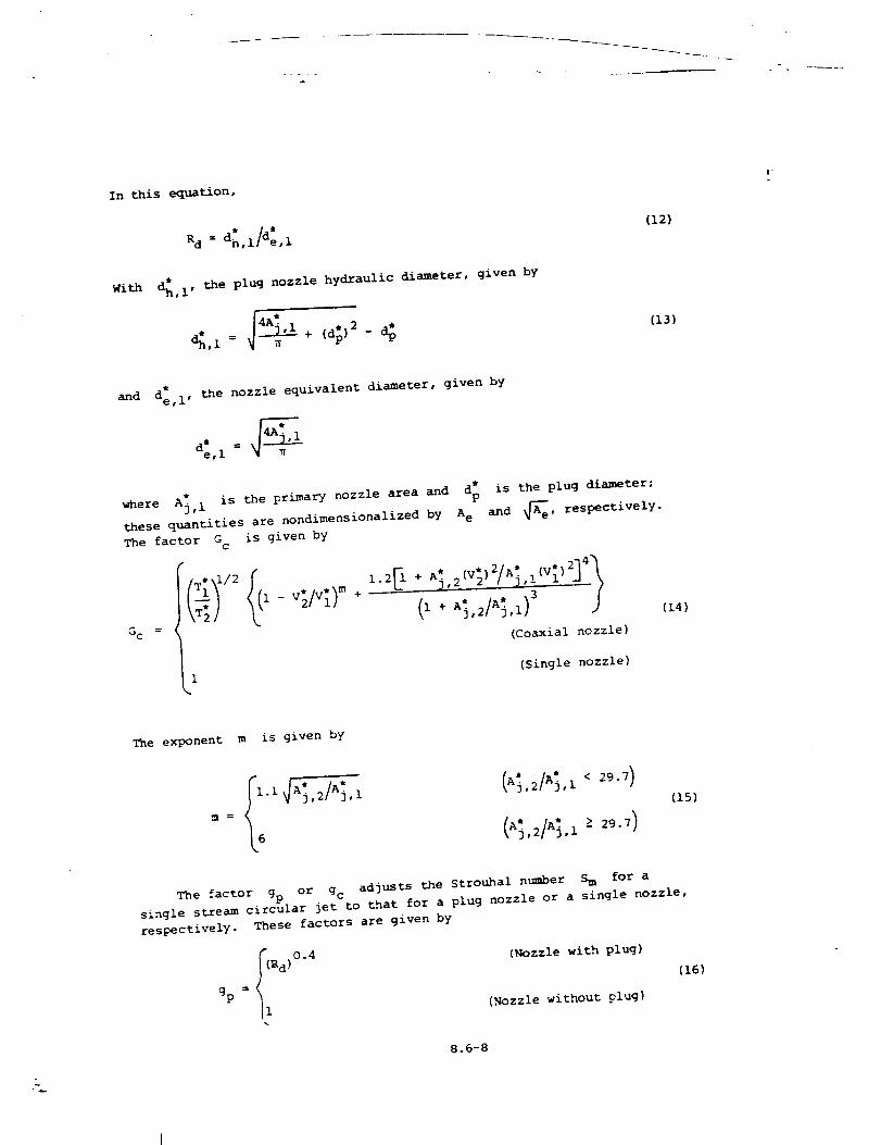
In this equation,
= d*Rd d:,ll e, 1
With _,i" the plug nozzle hydraulic diameter, given by
< = _
(12)
(13)
i"
and d:, I, the nozzle equivalent diameter, given by
where A_, 1 is the primary nozzle area and d: is the plug diameter:
these quantities are nondimensionalized by A e and _e' respectively.
The factor G c is given by
_C =
_'_l l- ,,_/,,_).,+ (l+ ,._,_/,,_,1)_(Coaxial nozzle)
1 (Single nozzle)
(14)
The exponent m is given by
,1
(15)
The factor gp or gc adjusts the Strouhal number S m for a
single stream circular jet to that for a plug nozzle or a single nozzle,
respectively. These factors are given by
gp = I (rod)
I1
0.4(Nozzle with plug)
(,Nozzle without plug)
(16)
8.6-8
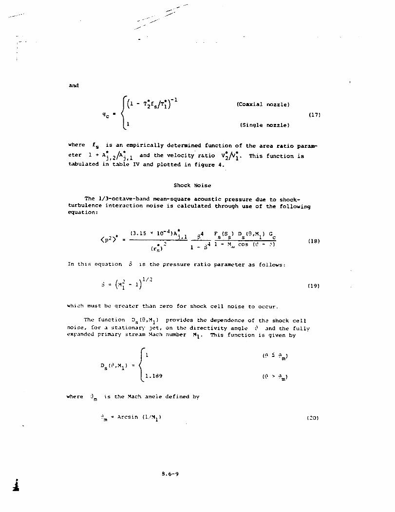
I
_J
I
and
_- T_fs/,i)-1 (_o-xialno.-le_gc = (17)
(Single nozzle)
where fs is an empirically determined function of the area ratio param-
; /_; " ""eter 1 + A ,2 ,I and the velocity ratio V2_ I. This function is
tabulated in table IV and plotted in figure 4.
Shock Noise
The ll3-octave-band mean-square acoustic pressure due to shock-
turbulence interaction noise is calculated through use of the following
equation:
<p2>* =
(3.15 _ 10-4)A_),I
, 2
(r s )
.q4 Fs(S s) Ds(0,M I) G c
.4 i -M,,_ cos (_- <_)I - b
In this equation _ is the pressure ratio parameter as follows:
_: (.,,__ _)1"2
(18)
(19)
which must be qreater than zero for shock cell noise to occur.
The function Ds(0,M I) provides the dependence of the shock ceil
noise, for a stationa_- jet, on the directivity angle "_ and the fully
exFanded primary stream Mach number M I. This function is given by
P
_i (9 & 9 m)Ds (_,M 1 }
L1.189 (O > @m )
where 0m is the Mach anoie defined by
'?m = Arcsin (IIM I) (20)
i8.6-9
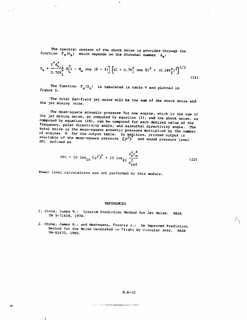
The spectral content of the shock noise is provided through the
function Fs(S s) which depends on the Strouhal number Ss:
ss = _ - _ cos - + +0.70V 1 (21)
The function Fs(S s) is tabulated in table V and plotted in
figure 5.
The total far-field jet noise will be the sum of the shock noise and
the jet mixing .,oise.
The mean-square acoustic pressure for one engine, which is _e stun of
the jet mixing noise, as computed by equation (i), and the shock noise, as
computed by equation (18), can be computed for each desired value of the
frequency, polar directivity angle, and azimuthal directivity angle. The
total noise is the mean-square acoustic pressure multiplied by the number
of engines N for the output table. In addition, printed output is
available of the mean-square pressure <p2>" and sound pressure level
SPL defined as
SPL = 10 lOql 0 <p2>*
01o:+ i0 logl0 2 (22)
Pref
Power level calculations are not performed by this module.
REFERENCES
I. Stone, J.Imes R.: Interim Prediction Method for Jet Noise. NASA
TM X-71618, 1974.
2. Stone, James R.; and Montegani, Francis J.: An Improved Prediction
Method for the .Noise Generated in Flight by Circular Jets. ,NASA
TM-81470, 1980.
8.6-I0
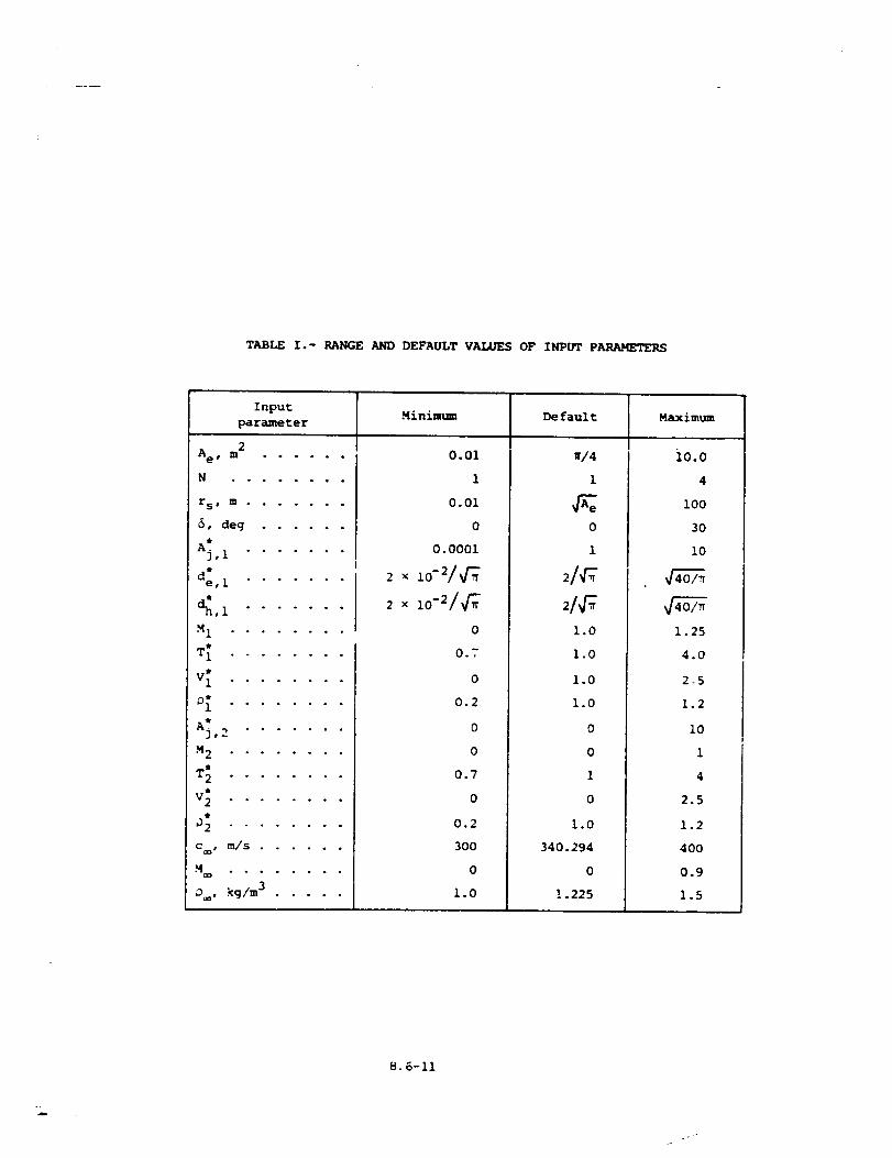
TABLE I .- RANGE AND DEFAULT VALUES OF INPUT PARAMETERS
InputMinimum Default Maximum
parameter
2Ae, m ......
S o . o ° . . . °
r S s m .......
6, deg ......
Aj, 1 .......
d:, 1 .......
,1 .......
M1 ........
T_ ........
V_ ........
0_ ........
A; ,-_ .......
M 2 ........
T_ ........
V 2 ° ° • • . . ° .
92 ........
•%_ . ° . . • o . °
D , kg/m 3 .....
0.01
1
0.01
0
0. 0001
2 × 10⁻²/_'_
2 x I0-2/_'_
0
0.7
0
0.2
0
0
0.7
0
0.2
30O
0
1.0
./4
1
0
1
1°0
1.0
1.0
1°0
0
0
1
0
1.0
340.194
0
! .225
i0.0
4
i00
30
!0
1.25
4.0
2-5
1.2
10
i
4
2.5
1.2
400
0.9
1.5
8.6-11
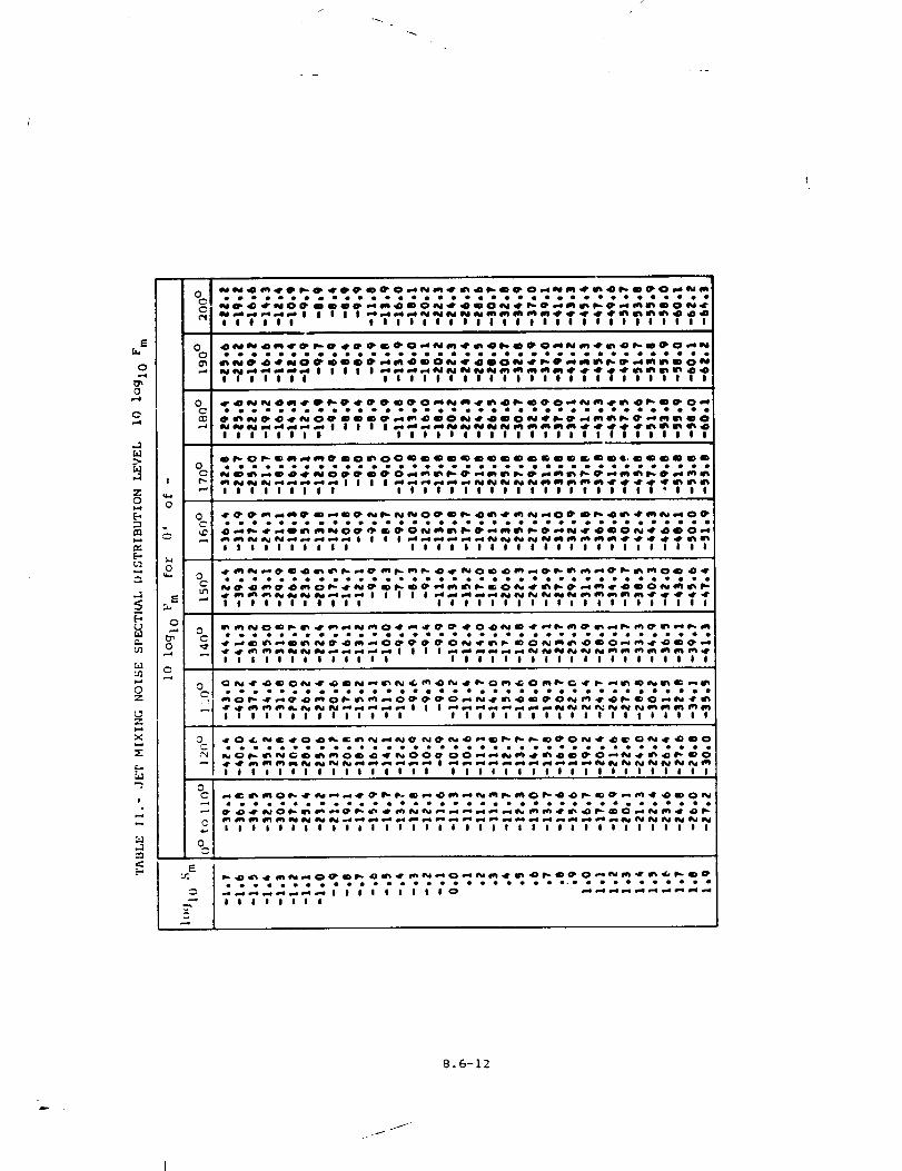
E
b.i
0
0.-.4
b.1
Z
0
[.-,
m
e,m
M
Z
Z
X
Ul
I
2
!
0
0," 0
C0 _"
0
00
22
:NI
0 !
cl
0
E
eooooo oooO oooooooo Ioo
IJl|JI Jill OII|||II|II|IIII|II
,,,,,,, ,,,,,°T_'''''* o,TT "°,,
I I I
oooo moo oooo oooooo
IIIlI IllOllIllllIlilllIlIII
Olle
IO
I I
II_.O0 • • •
"" I I I
ooomooomooooo_oomooomolooooooooo
__ I I I I __i___#_e# _
I I I I I I I I I I J I I I I I I I I I I I O I I t * I
II
Ir*l_I I
0 _
Ill Illilll llllillllllI|liillili
00"
I i
,4r _ 41%
"-* I I !
_l____O_m___O_oooeoooooooooooooo_ooeeoeooooooo
IIIIIlll Illllllllllllllllll
1151 __lr_r! I
_4M• o m
_ e,,,e ID
•d" ,.it _I I I
Ol__O__O____m_iIIIIIOIIIOtI|iIOltIIIIlIIIIOII!
IlJlllIIll IOllllllJllllllllJ
I_eel
_e,e
I I
.._0_[,
dr.4r_
! i !
m_m_Om_OO_OO__m_O__
Iii1111111111 illllillllilllllll
_.o
I I
perI_• m •
??T TTTT?TTTTTTT?TTTT,TTT,,,,,,,,_ ??
.._._._lllllllllO ___
llllllll
8.6-12
D
.f/
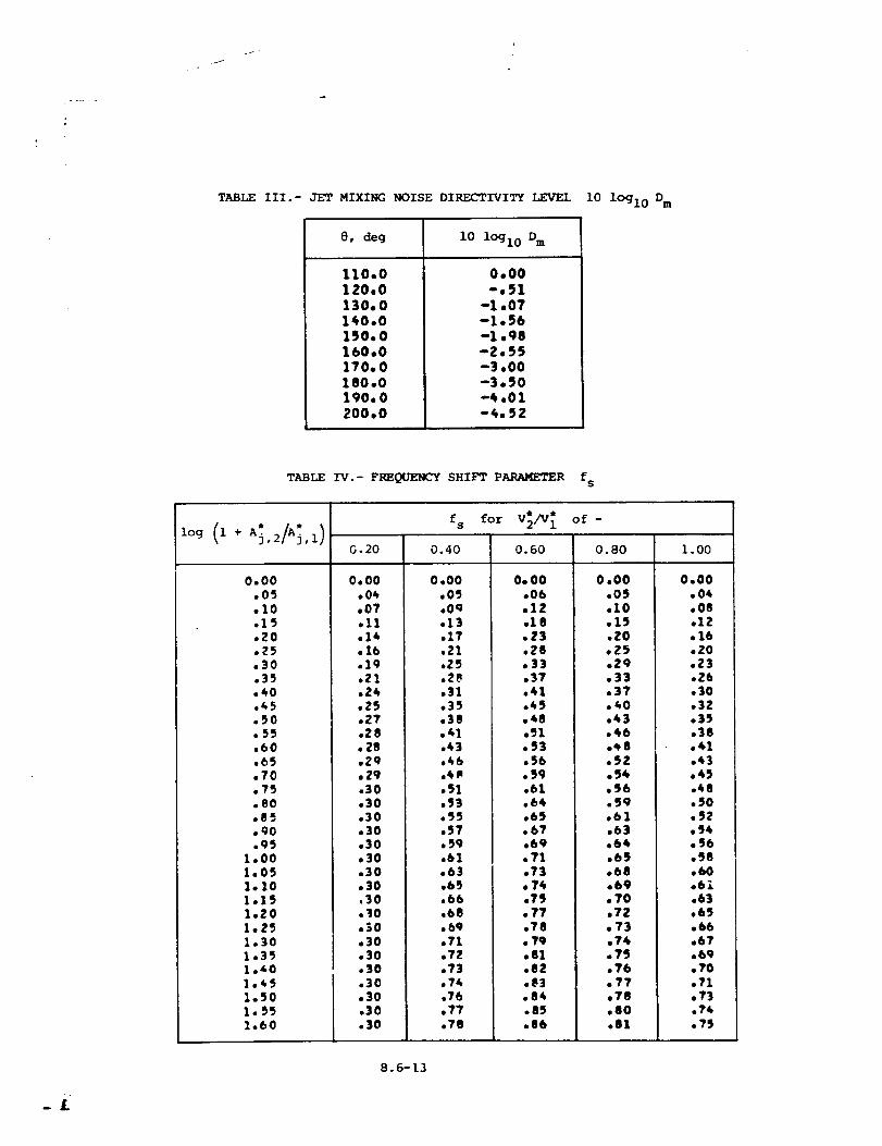
I
TABLE III.- JET MIXING NOISE DIRECTIVITY LEVEL
8, deg
110•0
120•0
130.0140•0
150.0
160.0170.0
180.0190.0
200.0
i0 lOgl0 Dm
0.00
-,51
-1 •07-1,56
-1 •98
-2•55-3•00
-3.50-4 •01
-4•52
i0 lOgl0 Dm
TABLE IV.- FREQUENCY SHIFT PARAMETER fs
0.00,05•10.15.20.75,30
,40.45._0
,60
,70.?S.80
.90
.951.001.051•101.151.ZO1•251.301.351.401.451.501.551.60
0.20
0•00•04•07.11,14•16
fs for V_/V_ of-
0.60
.19.21°24.25.27,28• 28•Z9,29,30.30,30,30•30•30,30•$0.30,10,$0•30,30.30.30,30.30.30
0.40
0.00.05•Oq•13,17.21,Z5,28.31•35,38• 41_,43.46,4P.51,53.55,57• 59,61•63•65,bb•68• 69•71•72.73,74,76•77,78
O. O0.06•lZ•18.z3•28•33•3?,41.45
,_1.93•56,_9.61,6**•65.67,69,71.73• 74.79.77,78• 7,9.81.8z.tL3.84.85.86
0.80
0,00,05,10.1S,ZO,Z9.Z9.33.37.40.43,46•48,SZ.54,96._S9,61,b:l.64.65.68.69• 7'0,?Z.73.?4.?'J.76.7,7.78,80.81
1.00
0.00,04,08.lZ.16,ZO.Z3.Z6.30.3Z.35.38,41.43,45.48,50,92,94.56
.60
.61
.63
.65
.66
.67,
.69
.7,0
.71
.7,3
.74
.?_
_L
8.6-13
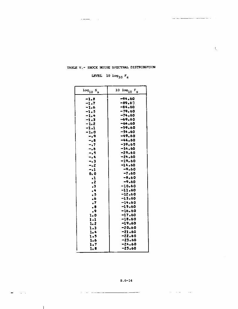
TABLE V.- SEOCK NOISE SPECTRAL DISTRI_3TION
LEVEL I0 lOgl0 F s
l°gl0 S s
-1,8-1 o7-1,6-1,5-1,4-1,3-1.2-1 ol-1,0
--e9
--e8
--e7
--°6
--,5
--,3
--,Z
--°1
0,0,1,2,3,4,5,6°7,8,,9
1.01.11.Z1.31°41,51,61,71o8
i0 lOgl0 F s
-9t,60-89,69-84,60-79,60-74,60-69,60-6_,60-59°60-54,60-_9,60-_4,60-39,60-34,60-29,60-Z4,60-Z9,60-14,60
-9,60-7,60-8,60-9.60
-10,60-11,60-12,60-13,60-1_,60-19,60-16,60-17°60-18.60-19,60-20,60-21.60-22,60-Z3,60-24.60-Z5,60
8.6-14
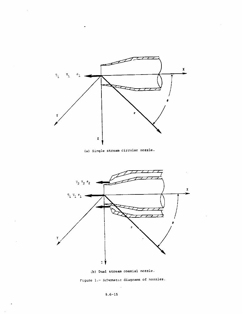
T1 Vl _i X
(a) Single streamcircular nozzle.
:y
(b) Dual stream coaxial nozzle.
Figure i.- Schematic diagrams of nozzles.
B.6-15
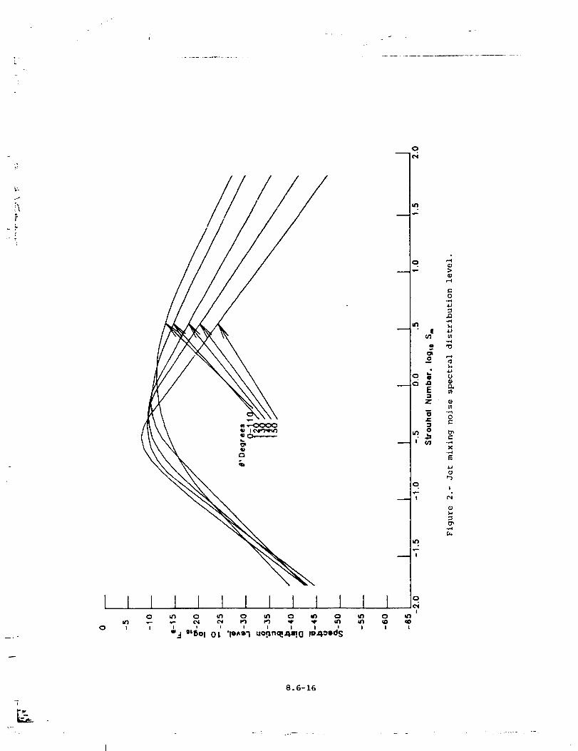
I0
II
I0
I
I I I I I I ] 1 1! i
_.I ' ' i I I IS_BOI OL '10_1 uo._n_,l_l!(] Io4°lds
o
m
r.o
.M
o
o_°_ _
_,' _ -g
o. ,
!
! I
8.6-16
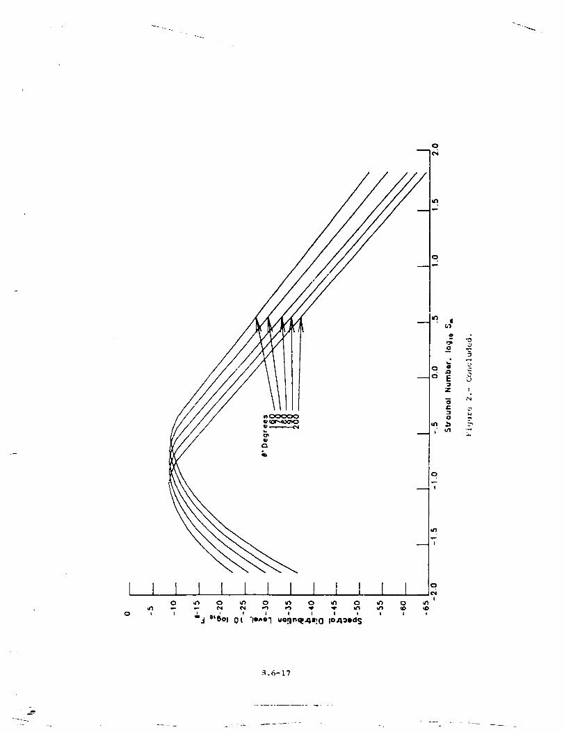
I
o
N.6-17
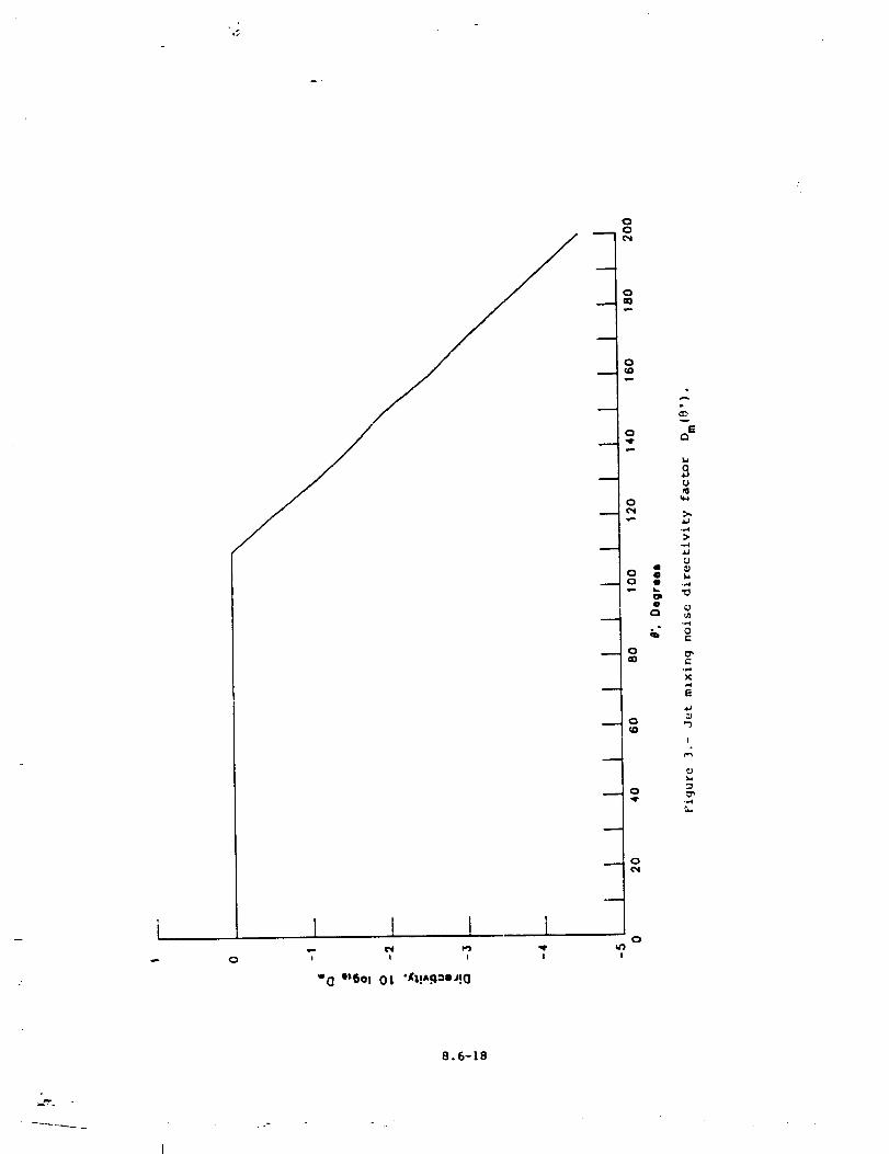
J
w
i I I L 1,,- ¢'4 P_J) _'
! I IQ
"0 °t6o! 0L "_!A.qooJ!Q
I
oo('1
oa0
o
v
E
,qrv-
U
0
Ill .,,,4
• _
X
l,J
0 _ID
I
C3
0C,4
o
8.6-18
.
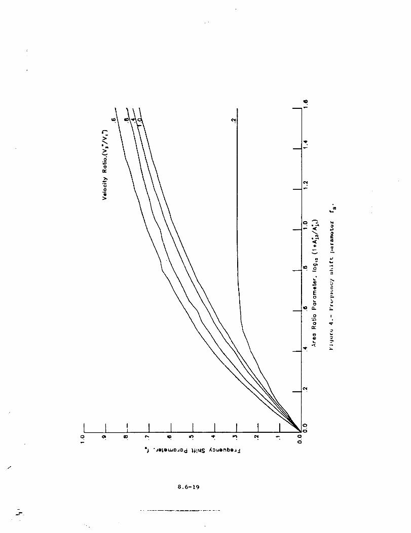
iJ
q
m
!
°; "Je_,ewo.Jod 1,1!qS ,_ouenbe._,
,f
8.6-19
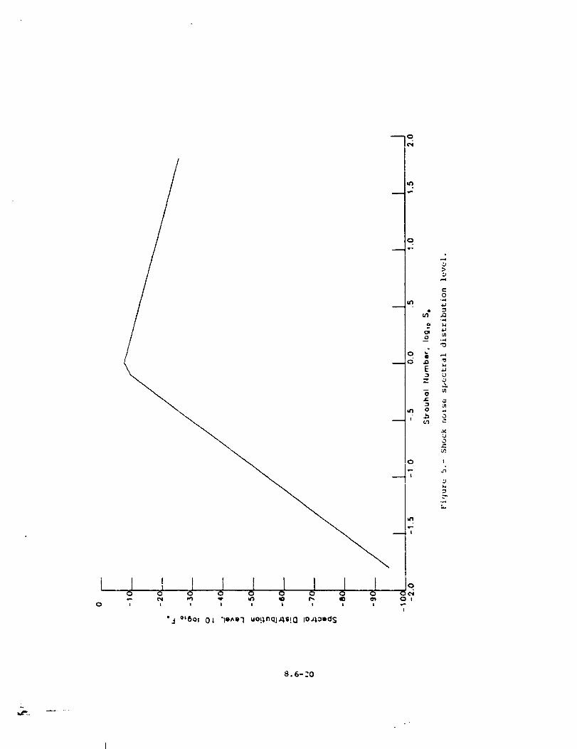
0
Ijjjjjjjjto=_ p'_ qf' _ lID I_. _ _ 0 I
0 I I ! I I I I I I --I
"le^Ol uo!;nqlJlS!Q IO'lOldS"3 °_5°t OL
Q
o
0
0 I
_4!
I
8.6-20
_"L
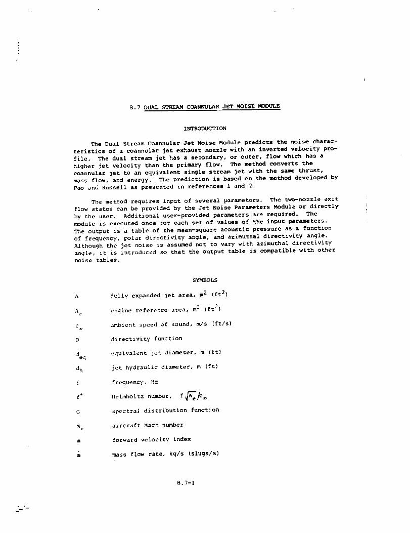
8.7 DUAL STREAM COANNULAR JET ._OISE MODULE
INTRODUCTION
The Dual Stream Coannular Jet Noise Module predicts the noise charac-
teristics of a coannular jet exhaust nozzle with an inverted velocity pro-
file. The dual stream jet has a se=ondary, or outer, flow which has a
higher jet velocity than the primary flow. The method converts the
coannular jet to an equivalent single stream jet with the same thrust,
mass flow, and energy. The prediction is based on the method developed by
Pao and Russell as presented in references 1 and 2.
The method requires input of several parameters. The two-nozzle exit
flow states can be provided by the Jet Noise Parameters Modul_ or directly
by the user. Additional user-provided parameters are required. The
module is executed once tot each set of values of the input parameters.
The output is a table of the mean-square acoustic pressure as a function
of frequency, polar directivity angle, and azimuthal directivity angle.
Although the jet noise is assumed not to vary with azimuthal directivity
angle, it is introduced so that the output table is compatible with other
noise tables.
A
A e
D
deq
d h
f
.t[
G
m
SYMBOLS
fully expanded jet area, m 2 (ft 2)
m 2engine reference area, (ft 2)
ambient speed of sound, m/s (ft/s)
directzvity function
equivalent jet diameter, m (ft)
jet hydraulic diameter, m (ft)
frequency, H:
Helmholt: number, f A_e#_
s_ectral distribution function
aircraft Mach number
forward velocity index
mass flow rate, kg/s (slugs/s)
8.7-I
m .
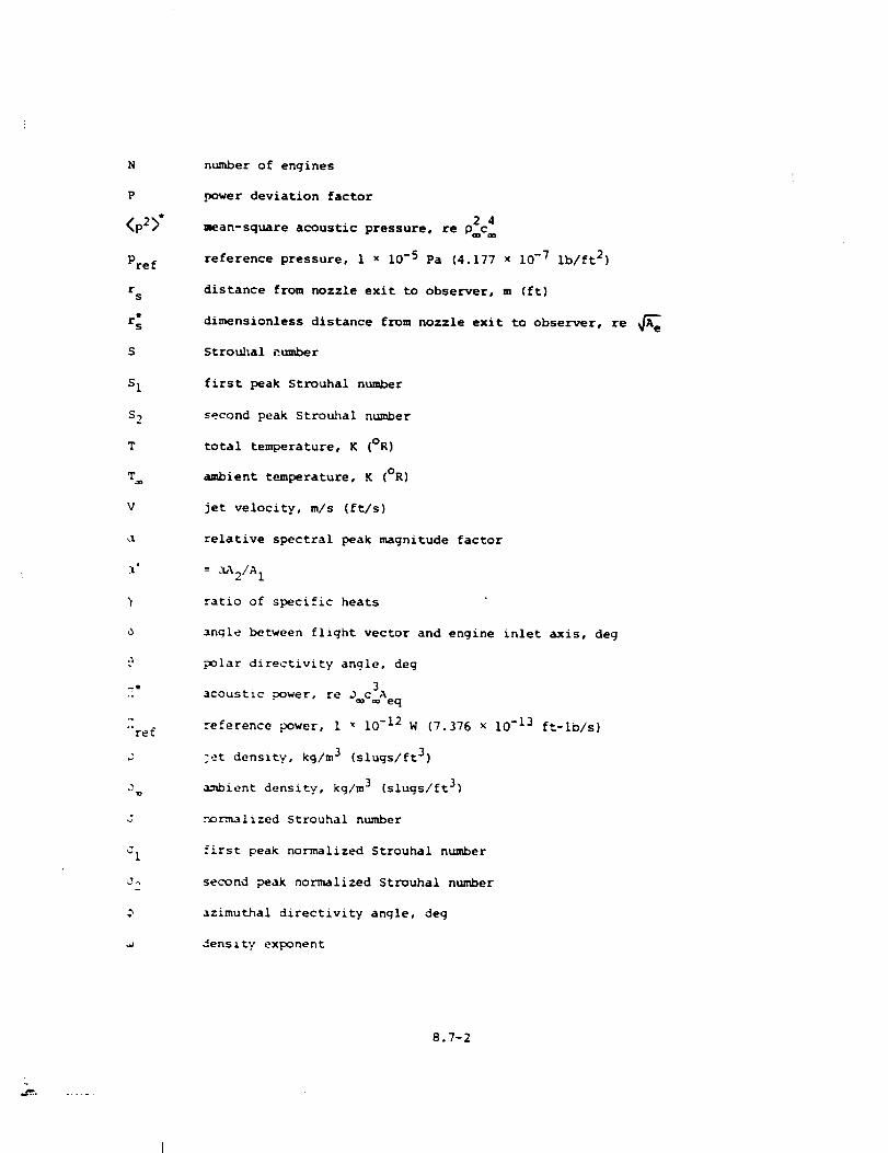
N
P
<p2>"
Pre f
rs
r:
S
S 1
S 2
T
V
j. i
d
_O
ref
J
J
d 1
number of engines
power deviation factor
2 4
mean-square acoustic pressure, re pc
reference pressure, I x 10-5 Pa (4.177 × 10 -7 Ib/ft 2)
distance from nozzle exit to observer, m (ft)
dimensionless distance from nozzle exit to observer, re _e
Strouhal number
first peak Strouhal number
second peak Strouhal number
total temperature, K (OR)
ambient temperature, K (OR)
jet velocity, m/s (ft/s)
relative spectral peak magnitude factor
= ._%2/A 1
ratio of specific heats
anqle between flight vector and engine inlet axis, deg
polar directivity angle, deg
power, re DaC3Aeqacoustic
reference power, 1 x 10 -12 W (7.376 x 10 -13 ft-lb/s)
jet density, kg/m 3 (slugs/ft 3)
ambient density, kg/m 3 (slugs/ft 3)
r_rmalized Strouhal number
first peak normalized 5trouhal number
second peak normalized Strouhal number
azimuthal directivity angle, deg
dens i ty exponent
8.7-2
Subscripts :
eq equivalent jet
1 primary jet
2 secondary jet
Superscript:
* dimensionless quantity
INPUT
The primary and secondary jet parameters are required from the output
of the Jet Noise Parameters Module or from the user. Ambient conditions
are required for computation of the Strouhal number and sound pressure
levels. The frequency, polar directivity angle, and azimuthal directivity
angle arrays establish the independent variable values for the output
table. Finally, the engine reference area, number of engines, engine
inlet axis offset, and distance to observer are required. The range and
default values of the input parameters are given in table I.
A e
N
rs
V*1
Y1
Input Constants
engine reference area, m 2 (ft 2)
number of engines
distance from nozzle exit to observer, m (ft)
angle between flight vector and engine inlet axis, deg
Primary Jet Parameters
primaz- l jet area, re Ae
primary jet total temperature, re T
primary jet velocity, re c
primary jet density, re Pm
ratio of specific heats for primary jet
Secondary Jet Parameters
secondary jet area, re A e
jet hydraulic diameter, re _esecondary
8.3-3
t
0 2
Y2
Co0
Mco
secondary jet total temperature, re T
secondary jet velocity, re c
secondary jet density, re D_
ratio of specific heats for secondary jet
Ambient Conditions
ambient speed of sound, m/s (ft/s)
aircraft Mach number
ambient density, kg/m 3 (slugs/ft 3)
Independent Variable Arrays
frequency, HZ
polar directivity angle, deg
azimuthal directivity angle, deg
OUTPUT
The output of this module is a table of the mean-square acoustic
pressure a: a function of frequency, polar directivity angle, and azi-
muthal directivity angle. In addition, the observer distance r s is
provided for the Propagation Module.
r s distance from nozzle exit to observer, m (ft)
Double Stream Coannular Jet Noise Table
f frequency, Hz
polar directivity angle, deg
azimuthal directivity angle, deg
4<p2(f,_,_)>" mean-square acoustic pressure, re _c
METHOO
The noise prediction method determ/nes the noise characteristics of a
slngle equivalent jet which has the saume total thrust, mass flow rate, and
energy as _he coannular jet. The i/3-octave-band mean-square acoustic
pressure is computed as a function of frequency, polar directivity angle,
8.7-4
.J
and azimuthal directivity angle for the input conditions. The method
used has been extracted from references £ and 2. A sc;,ematic of a typical
coannular jet nozzle is shown in figure 1.
The mass flow rate of the equivalent jet is given by
where m* + p*A*V*. The equivalent jet velocity is computed by equating
the equivalent jet thrust to the sum of the thrusts of the individual jets
as
eq .tmeq
By assuming that the products of combustion do not affect the value of the
gas constant, the equivalent jet temperature can be computed from the
energy equation as
T" = (3)
eq • • 71 • "{_2
ml Yl " 1 + m2 72 1
The equivalent specific heat ratio is determined by the mass average
Y1 * 72
Yeq m_ Y1 - 1 + m2 Y2 - i= (41
-- -t
Yeq 1 _ + m2
The equivalent jet density is found from the condition that the jet static
pressure is equal to the ambient static pressure. Rearranging the perfect
gas law yields
"= - (V } (5]eq eq 2
and _he equivalent jet area is
A, = eq
eq D" V"eq eq
(6)
8.7-5
a_ .....
irJ
_he equivalent jet diameter is
=.d_q (7)
The acoustic power _* is calculated for the equivalent jet using
the single stream circular jet method. A coannular benefit factor 0 is
added to this relation to account for double stream effects. The result-
ing expression for the acoustic power is
_* = (6.67 x 10 -5) (^*Weq_'"_'V*teq1"8p(Veq)Q(Veq,V2/VI)* * * * (8)
_%e power deviation factor P is a function of the velocity ratio
V:q_ and is give_ in table IT and plotted in figure 2. The densityioglO
exponent _ is a function of the velocity ratio lOgl0 V:q and is given
in table III and plotted in figure 3. The coannular benefit factor Q
is a function of velocity ratio V_/V_ and velocity ratio lOgl0 V:q_
and is given in table IV and plotted in figure 4.
The mean-square pressure is computed from the acoustic power using
a normalized directivity function and a normalized spectrum function.
For a directivity angle less than ii0 O, the I/3-octave-band mean-square
pr.essure is
<p2>* : eq . (9)4_(r.)2 -(@ - 6) G(@'CI) e
\ eq
and for directivity angles greater than ii0 °,
<p2>" = [°(°'°,' ..... '-I_=(r:)__ - _, cos(e- 6)[_ ;_; " 1÷_' j\ <_(I0)
%-_ere r*s = rs/A_--".,e The directivity function D in equations (g)
and (I0) is a function of polar directivity angle @ and velocity ratio
V_ and is given in table V and plotted in figure 5. The termsloglO
•_hich include the aircraft Mach number M account for forward flight
effects. The forward flight index m(@) is a function of "- Jar direc-
t_vity angle 9 and is given in _able VI and plotted in fibre 6. The
ar.gle _ allows for an offset between the engine inlet axas and the
d_rection of flight. T_._ ,maining terms in equations (9) and (I0) give
_ spectral distribution.
8.7-6
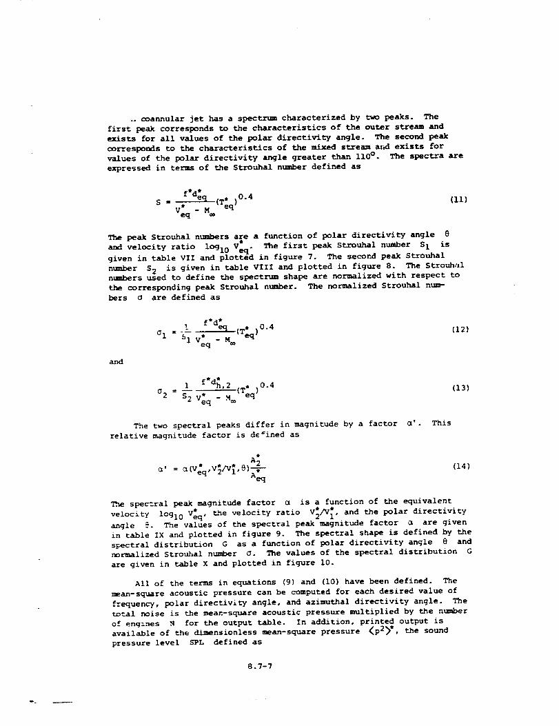
.. coannular jet has a spectrum characterized by two peaks. The
first peak corresponds to the characteristics of the outer stream and
exists for all values of the polar directivity angle. The second peak
corresponds to the characteristics of the mixed stream ar_ exists for
values of the polar directivity angle greater than 110 °. The spectra are
expressed in terms of the Strouhal number defined as
(Ii)
The peak Strouhal numbers are a function of polar directivity angle e
and velocity ratio log V* The first peak Strouhal number S I isI0 2 °
given in table VII and plotted in figure 7. The secor_ peak Strouhal
number S 2 is given in table VIII and plotted in figure 8. The Strouhal
nmmbers used to define the spectrum shape are normalized with respect to
the corresponding peak Strouhal number. The normalized Strou.hal num-
bers O are defined as
f*d_ (T_)0"4
Cl = "_i V;q - M®
(12)
and
i f*d_'2 (T;q)0"4
02 = S 2 V;q - M_
(13)
The two spectral peaks differ in magnitude by a factor e'. This
relative magnitude factor is dc=ined as
A •
e, = U(Veq,V2/Vl,B)--&--
Aeq
(14)
The spectral peak magnitude factor u is a function of the equivalent
velocity lOgl0 V_,__ the velocity ratio V_/V_, and the polar directivity
angle _. The values of the spectral peak magnitude factor a are given
in table IX and plotted in figure 9. The spectral shape is defined by the
spectral distribution G as a function of polar directivity angle @ and
normalized StroP,el number O. The values of the spectral distribution G
are given in table X and plotted in figure i0.
All of the terms in equations (9) and (I0) have been defined. The
mean-square acoustic pressure can be computed for each desired value of
frequency, polar directivity angle, and azimuthal directivity angle. The
total noise is the mean-square acoustic pressure multiplied by the number
of engines N for the output table. In addition, printed output is
available of the d/mensionless mean-square pressure <p2>*, the sound
pressure level SPL defined as
8.7-7
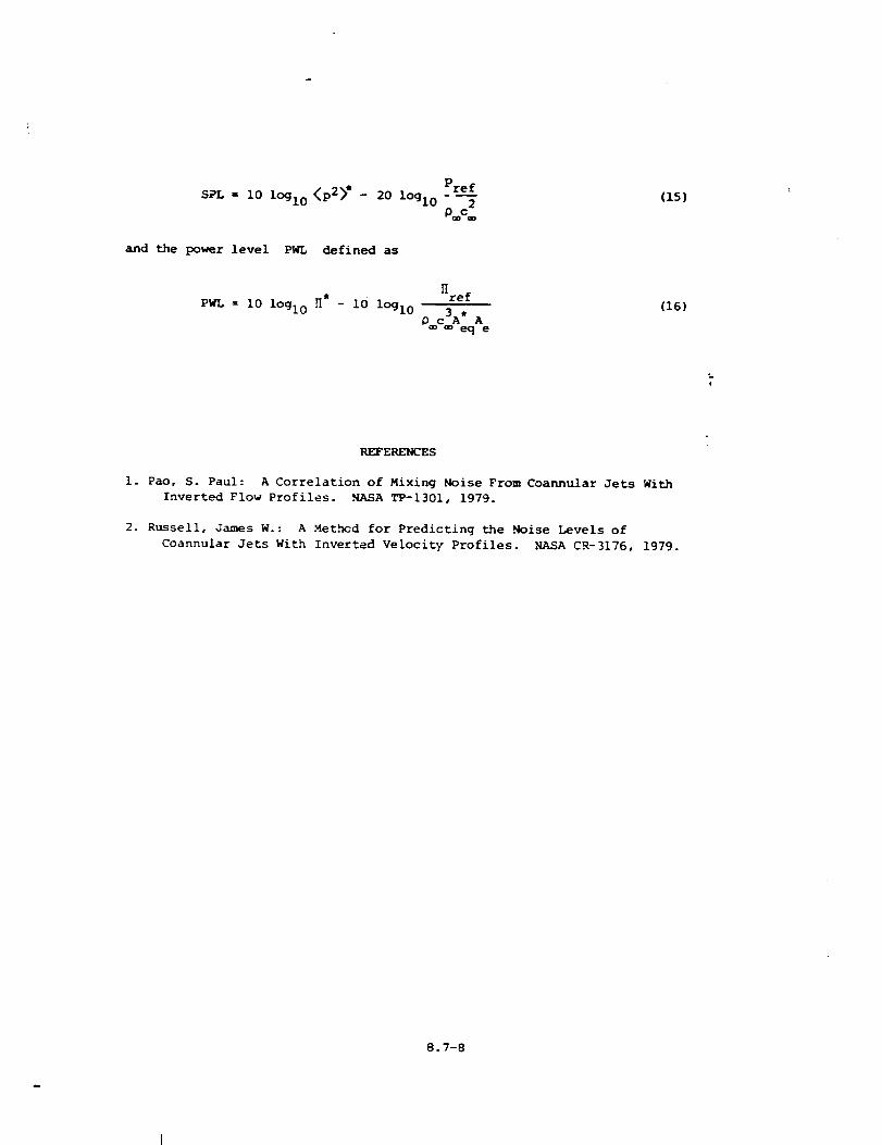
Pref
SPL = 10 lOglo <p2>" _ 20 lOglo---_
pc
and the power level PWL defined as
(15)
H
ref (16)
PWL = I0 lOglo H* - i0 lOglo O°°c3A_ Ae
REFERENCES
i. Pao, S. Paul: A Correlation of Mixing Noise From Coannular Jets With
Inverted Flow Profiles. NASA TP-1301, 1979.
2. Russell, James W.: A Methcd for Predicting the .Noise Levels of
Coannular Jets With Inverted Velocity Profiles. NASA CR-3176, 1979.
8.7-8
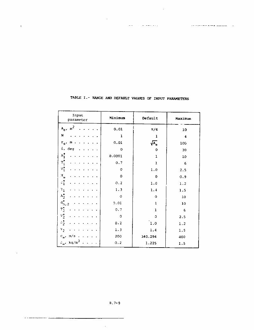
TABLEI .- RANGE AND DEFAULT VALUES OF INPUT PARAMETERS
Input .Minimum Default Maximumparameter
Ae, m 2 .....
. o . . . o .
rs, m ......
O, deg .....
A_ .......
T[ .......
V _ .... . . o
_4 ........
71 .......
A_ .......
_,2 ......
V_ .......
_w
_2 .... " " "
72 .......
c, m/s .....
D, kg/m 3 ....
0.01
1
0.01
0
0.0001
0.7
0
0
0.2
1.3
0
0.01
0.7
0
0.2
1.3
2OO
0.2
_/4
I
0
1
1
1.O
0
1.0
1.4
0
1
i
0
1.0
1.4
34(). 294
1.225
i0
4
i00
3o
i0
6
2.5
0.9
1.2
1.5
lO
io
6
2.5
1.2
1.5
4OO
1.5
B.7-9
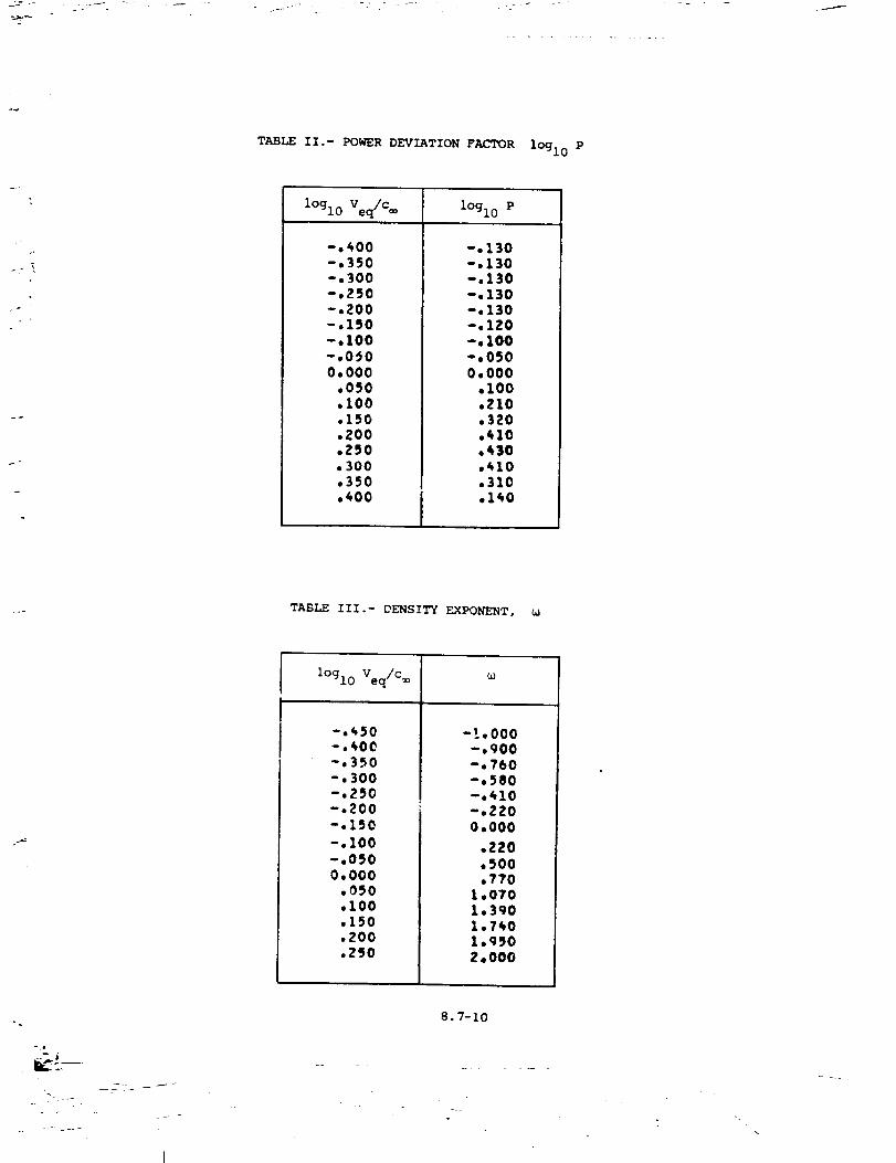
TABLE II.- POWER DEVIATION FACTOR lOglo P
l°gl0 Veq/C_ l°gl0 P
-.400-.350-.300-.ZSO-,ZOO-.1_0-.I00-.0_00.000.050
.100
.150
.ZOO
.250,300.350
.400
-.130-.130-.130-.130-.130-.lZO-.100-.0500.000
.100,210.320.410.430,410,310.140
TABLE III.- DENSITY EXPONENT,
-- f
l°gl0 Veq/C_
-.450-.400-.350-.300-.2_0-.200-.150
-.100-,0500.000
.0_0
.100
.150
.ZOO
.2SO
_o
-!.000-.900-,760-.580-.410-.ZZO0.000
.Z20
.500
.770L.0701.3901.7401.950Z.O00
8.7-10
-.
j=
o
OI
0
0
0
!
r,,
E_
Z
5
Z<0
I
en
!
0
8
>
0
0
0
O'
0
0
0
!
o4
>
00
0 _____
ooooo4eoooooooooooooo
00o4
0_0_____ONO__O_O__ _
oeoooooooooeoooeo'ooee
o 0_0_0_00_ _4_0_0_0
0_0_0___0_
ooooooooooeoooeoooeoo
0_0000___00 0_0_0____0 0_0_00__0_ __
oooooooooooooeoeooeeo
0
0
0ooeoooooooooooooooooo
0
000000000000000000000000000000000000000_00
00000_0_0_00_00000000
0_00_0000000000000000O00000000000 O00000 O000___0___0
ooeoo_ooooooooeoooooo
E.7-11
00
i
_40
8
>
0
C
r_
0,.-4
0
0u_
O" O" (_0"0" 0_0'0000000_leO0 0,d- 0,0_-0,00,qlhlr--O,ONe.e_l.,..Oqdr_,j,O
I I I I I I I I
C0
_o f_ eof_r,- ,4"0,0 _¢_ 0"0",0 NqOmO_,O
-;-:.;.;.; _;.:-; I" ; ; ; I" ......I I I I I I I I
Cif1('%1
0C
.;._.:._.;.:.: ," _- _- ; ; ," ......I I i I I I I
IIIII
IIIII
_;;;;;_ ......II
.:,- - ; ; -,- .......!
C
6
O00000_C _0000_00 _0
0000 _000 O000000_ CO
;;;;;;;;;(;; .......
O000000CO000CO000COO0 oqDO0 O0 0 ¢3G000 000 O0O0000000 0 ¢300 O0 000 O0
• • • e • • • • • • • • • • • • • • •0 O00¢3000 0 ¢D¢)000 000 O0
a.7-12
TABLE VI.- FORWARD VELOCITY INDEX m(0)
1
re(e)deg
0.00010.00020.00030,00040*00050.00060.00070.00080.0009O.000
100.000110.000120.000130.000140,000150,000160.000170.000180.000
3,0001.6501.100
._00,ZOO
0.0000,000
.100,400
1.0001.9003.0004.7007,0008,5008.5008.5008,5008,500
8.7-13
!
00
0 U
0 _
0
r,1
ro 0
Z 0
_ 00 _
[.-,
_ ,.-4
0
!
>
,,.,,
0 000000000
!
0 000000000
S g;;;;;;;_!
0
00
c;
0
d
CC
2 _
if30
000000000
!
000000000
g;;;;;;;;
000000000
0__0_00__
000000000
00000000_
g;;;;;;;;
000000000
0__0_
00_000000
00_000000
000000000
ggdgggg_
0
0
en
Z
,¢
:Z:
0
[..,U1
¢
"..0G,
0
CO
!
[..,
!
0
BU
O_0
0
0
0
ot
0
0
00
c;
0
6
0
0
0
2 _
0000000
;;;;;_|1
0000000
__mO
;;;;;;i!
0000000
;;;;;;;
0000000
;;;;;;;
0000000
;;;;;;;
0000000
;;;;;;;
0000000
;;;;;;;
0000000
eeeeeee
IIIII1!
0000000
0000000000_000
eeeee_e
0000000
8.7-14
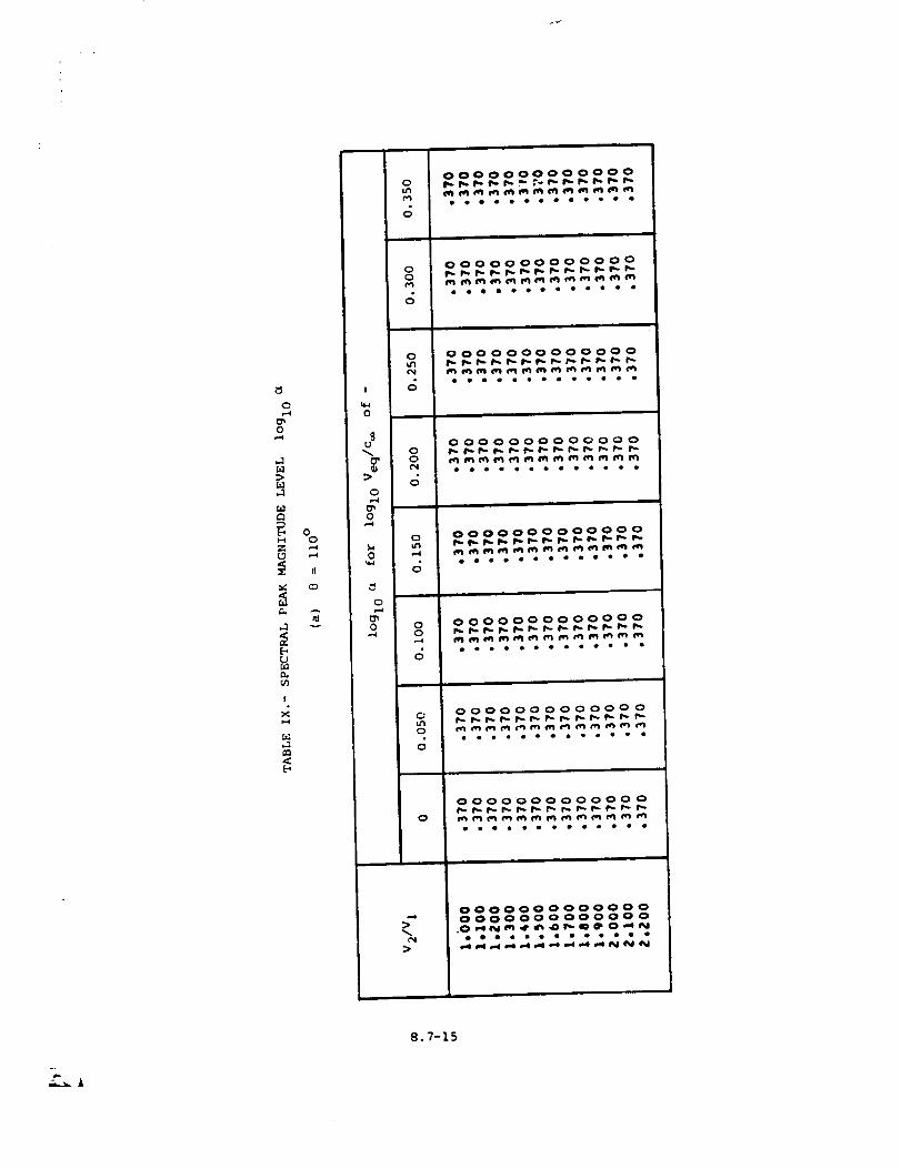
0
0
[,.1
0
I
!
0
9
a'
0
0,.-4
0w_
0
0
0
6
00
6
0
6
00
0
6
00
6
0
0
6
0
0000000000000
eoooeooooeeoo
0000000000000
oeoooooooeooo
0000000000000
eoooooooeoooo
0000000000000
0000000000000
ooooeooooeoeo
0000000000000
_o_eooo_
000000000000 0
eoeoooooooooo
0000000000000
_ooooo_oeooe
>
00000000000000000000000000
.0___0_oooooo_ooooo
8.7-15
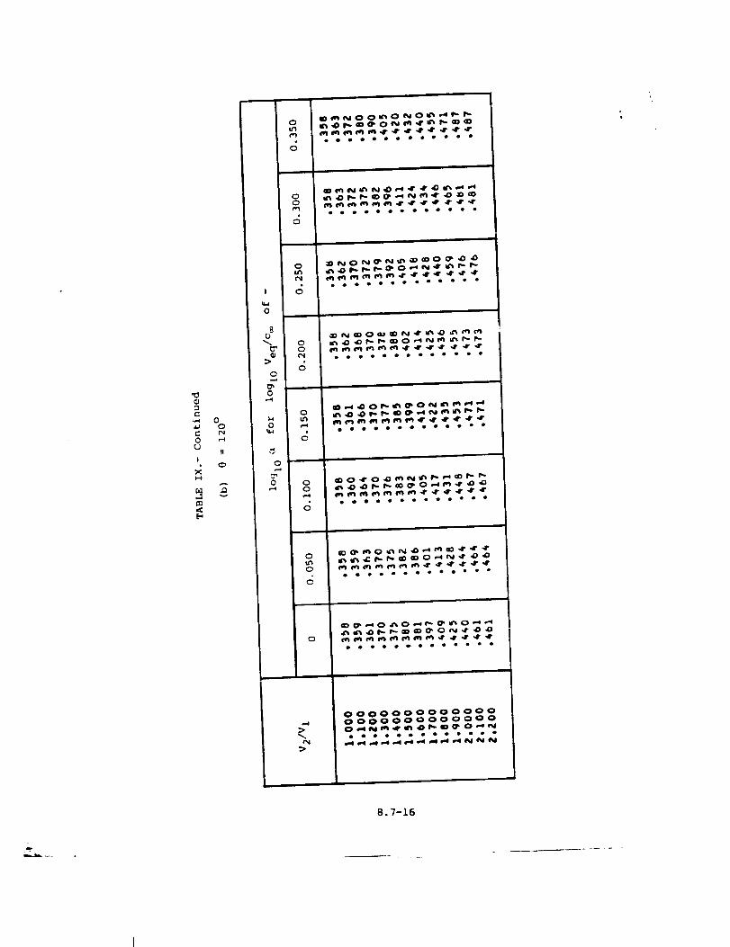
qJ
0
I
00
I!
A
I
0
8
0
0
o
0
0tr_
00a'_
0
c_
0Q
O
0(3,.=e
(:3
C)
Q
o#oeeoeeoeeeo
ooooeoeoooooe
eooooeeooooeo
_0_____0__
oeoooeooeeeoe
_0_0__
oooooooooeeoo
_O_O_N____0__
oeeeeeooeeoee
_oeeeoe_oo_e
_0_0_0_
oeoeo_oooeooe
,,==j00000000000000000000000000O__m_ 0_
m.-_lm.._ _
8.7-16
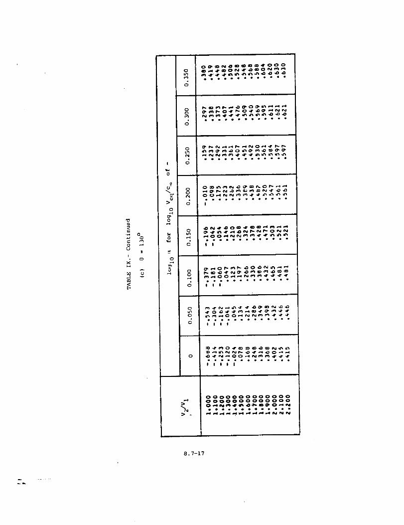
0
00(v_0
_O_mO_
oooeooooooooo
"0
.,,,4
0C_
i
,,.Ie_
00
v
i
U ?
-.=>0
0
0
0
__0_
ooeoooooooooo
0
,-,4
ooeooeeooeoooO
_0_____0__00___
oooooooeooeooOI
00
6
_0_0_ _
oooooooooooooI1!
0
0
6
_ 0___
eooeoeeooooooliil
0
oooeeoe_eeeee|OJIJ
,-4
"%.
> .
00000000000000000000000000O__._m_O_
8.7-17
_L
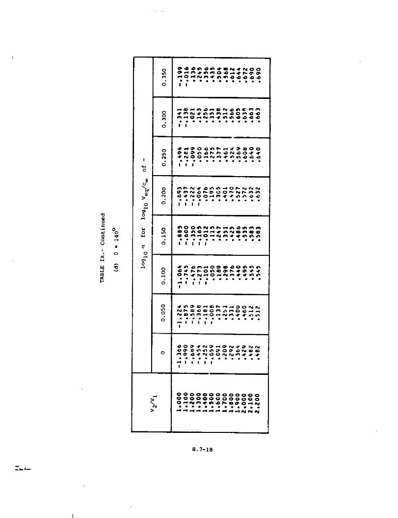
t-O
I
,...1
00
I
o
A
I
0
8
0
0
1,40
0
0
0I.n
00
6
0
00
c;
0u_
00_4
oeogooeooooooII
II
oeoeeoooeoooeJ||
__0_
ooeeeooeoeeoo||JJ
_00_N__m_
_O_m__
dr ir_ dD_-iOOS_D _DOi%_s'_lr_d_ dp p,.p.-O _r_ O. p..dr O_ dr dr •
• • • el, • • • • • • • qp •,-* I I f I
I
0
0
0oo-eooeoooooee
_lllllI
0
| J I I II
:)
0000000000000O000OO0000000
_oo_oooooeo_o
8.7-18
0
6
_ _0__0__00___
eeeoeoeoeeooo8!
'00D
-,'4 0O
_" _n0 ,--¢
UI
I
,,n
oo
6
0
' 60
8U
0
O
0
1,4 0
6
0
•..4 00r-4
d
0
0
_O_N_O_ N__N_ _0_0__0 0___
III
_00____0_ _ __0 __NO0__
oeoooooooooeoI I ! I
___0__ _00__
;;;;; ........
_00___0_ ____00__
oooeeeooooeoo_11111!
_0_00000_
II
_0____00__
Ill
0
__0__
__00_ooeooooeooooo
N_lllIIIII
000000000000000000000000000___0_
oeooeoo_ooooo
8.7-19
ooooooooooooo
00
_NNNNNNNNNNNooeeeeooeooeO
,-,.4U
0_J
I
X
E-,
0
u
A
v
!
0
O"
0
O_0
o
0
C_0
0
o,I
__ _0_
_0000__oooeoooooooeollllll
II
0u3,-I
__ __N__0_0_0___
oooeeoooooeoe_JO|JJJJ|J
fill
00
IIIlll
0u"l0
c; oooooooooeooe
_N__IIII|IIIIIIII
0
IIIIIIIII
-.,4:>
P4>
O00000000000OO00000000000O
e_oootooeo_
8.7-20
O,,-4
0
!
ZO
en
E_
I
r_
_n
[
I
0
o
0
O
0
I
0O
0C_0_4
0Cu_
0O
0C
0O
C
000000000000_0000000000000 O0
___O____ON_ooooeoooeoooooeooooooooooooo
000000000000_000000000000000
OOOOOOO OOOO_OOOOOOOOOOOOOOOO
.............. _:___
__OO_O__O_O__O_
.............. ____
NNNNNNNNhNNONd_NhNNNNNNNN_hh
_O_N_OO_OO_ _O__ooe_oe_eeOOoOoOo_eoo_ooo_oo_
NN_N_ RNN_N_NR_R_NNNR__
OOOOOOO___N_O__w
_0__00__ __
_ OOOO OOO OOO OOOOO OOO OOOOOOOO_OOOOOOOOOOOOOOOOOOOOO_O_OO_O_O___O___O__
_b_o_oooooooooo_oooo_oo_ooe
_JiiJlJJlJO _HH_HI I I
8.7-21
.... .. L__
T2 V2 P2
T1 Vl Pl
Y
Z
Figure i.- Schematic diagram of double stream coannular nozzle.
X
., L
. - . .
8.7-22
1I.O
I I
n
C',I
I
I'0
LlI
I I I I _o o,I I
• " " I I
d °tS°l 'Ig^a-1 uoqo!^gC] JeMOd
> ¢,
0 oIJ
_,
U '_0
> o
t_
8.7-23
¢.___._ .....
J/
if"
o_ 'l.uauodx3 /q!su_c]
8.7-24
[ 1 L l '0
,4
(N
c,i
J
ei
e,i
_DN
m
0
I
>- .,
6 _0.1
0 .a
0 ,_
_ 0.
t_
0 °_6°[ 0l- 'lOAO'l ),!]._)UOE_JDInUUDOD
8.7- 25
! L l l I0
_0e
Io
m _c,i
(Nm
--qt'N
CD
m
0
:,r
0
e_
o
u
0
CJ
I
0 °_5°I 0 L- 'laAa"11,_eu_E] Jolnuuooo
8.7-26
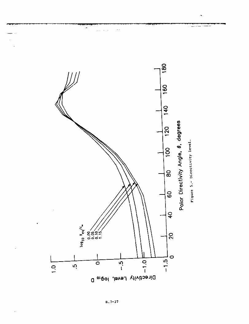
0
0
8.7-27
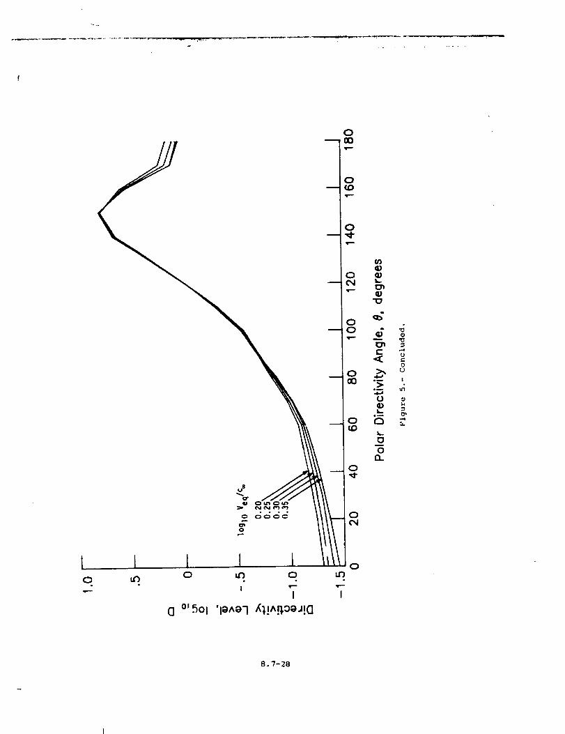
o
0
0
0
o
0
0
UC
0U
l
I0
I 0
8.7-28
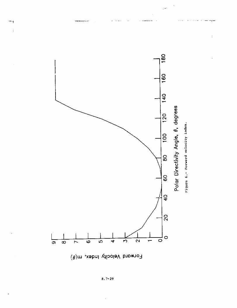
. f-
l I t I i I
!
o
o
o
o_._o
© oQm
0 =
0
0C_
0
(O')w 'xepul X'_,!OOleAP.mM-JO3
a.7-29
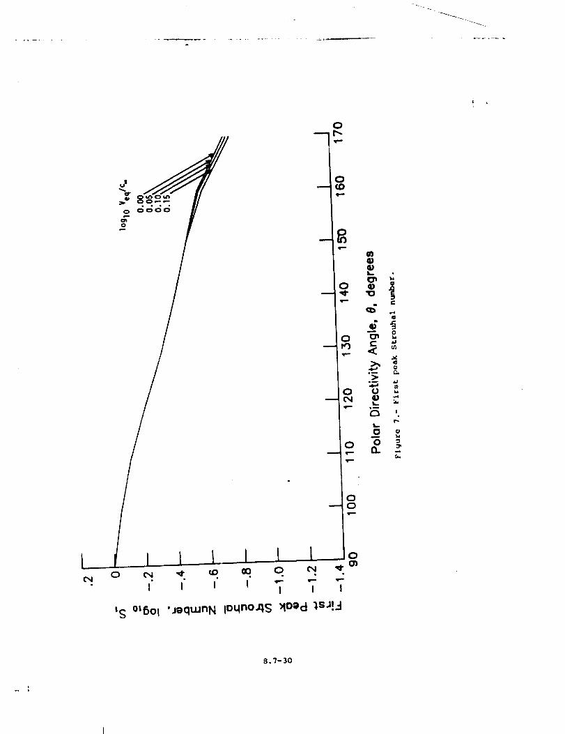
o0
I I I
tS O_5ol 'mqwnN
I I I
8.7-30
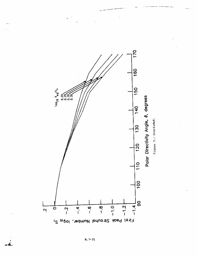
0
0
00
0 _ _ co 00 0
, , , I 7 7
0
I
LS OtSOl 'jgqtunN lOLlno_,sMoecl _sJ!_-I
8.7-31
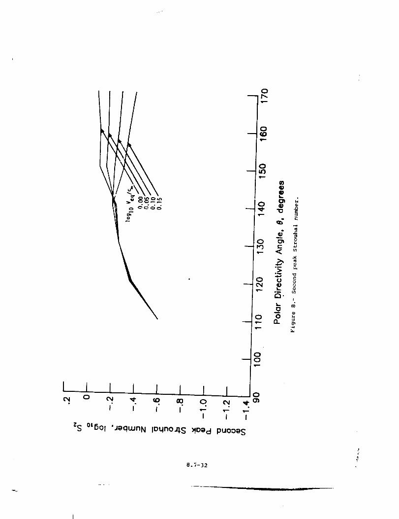
l
c_
• o o o
0
0
o
8.7-32
4"j
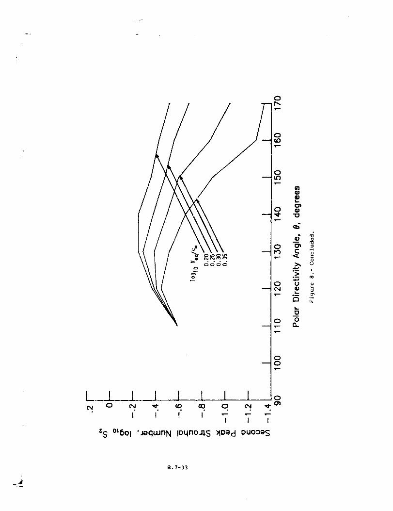
! 10 c_
I
_S °L6Ol
o,o°
0
0
I,,.
O
Om !
eu 00
O U c_
o_o_,._
t_0
00
I ! 1 I ! o
i I n T T T'jequunN loqno,qs :Mo_d puoo_s
4r
8.7-33
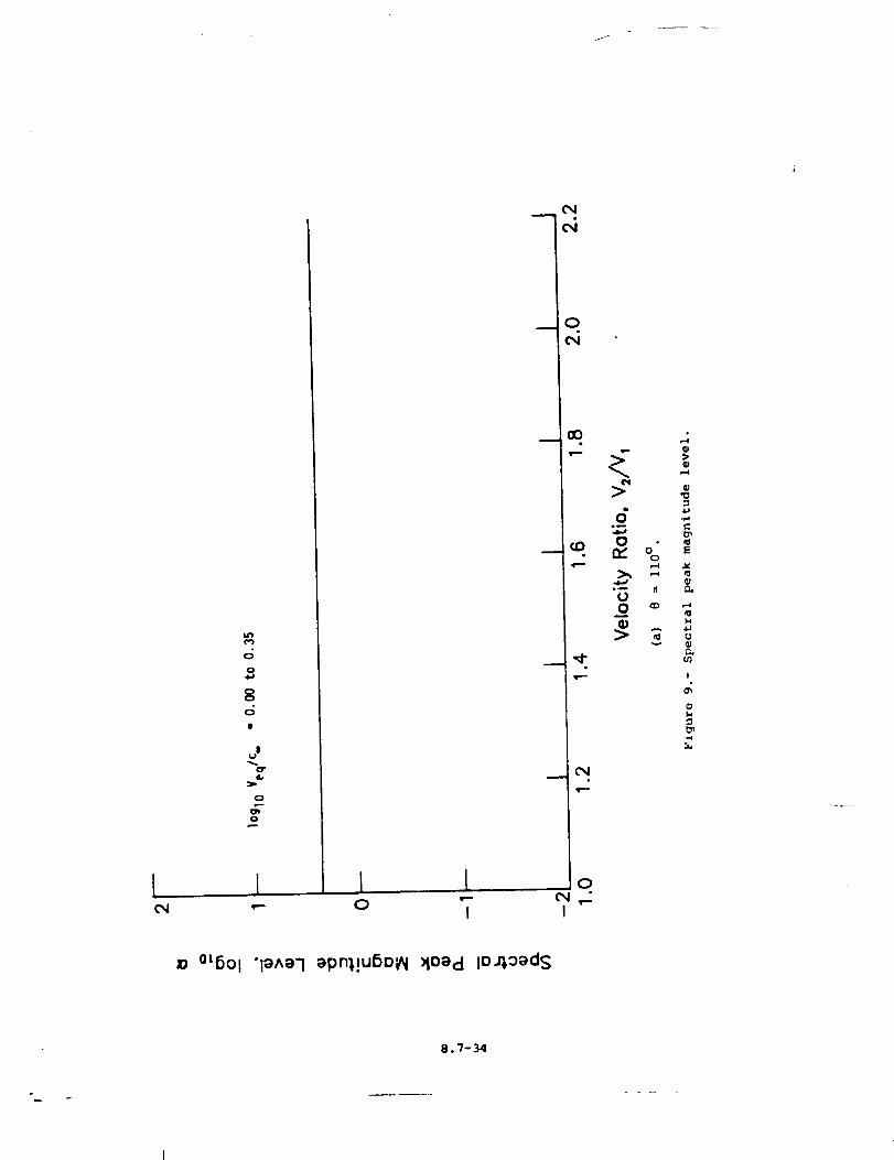
f
L4*')
O
O
8
IIU
O
{(:3
{
O
_0 °t6Ol "l_Ael ePn1!u6oPl :4Oecl IO_,oeds
8.7-34
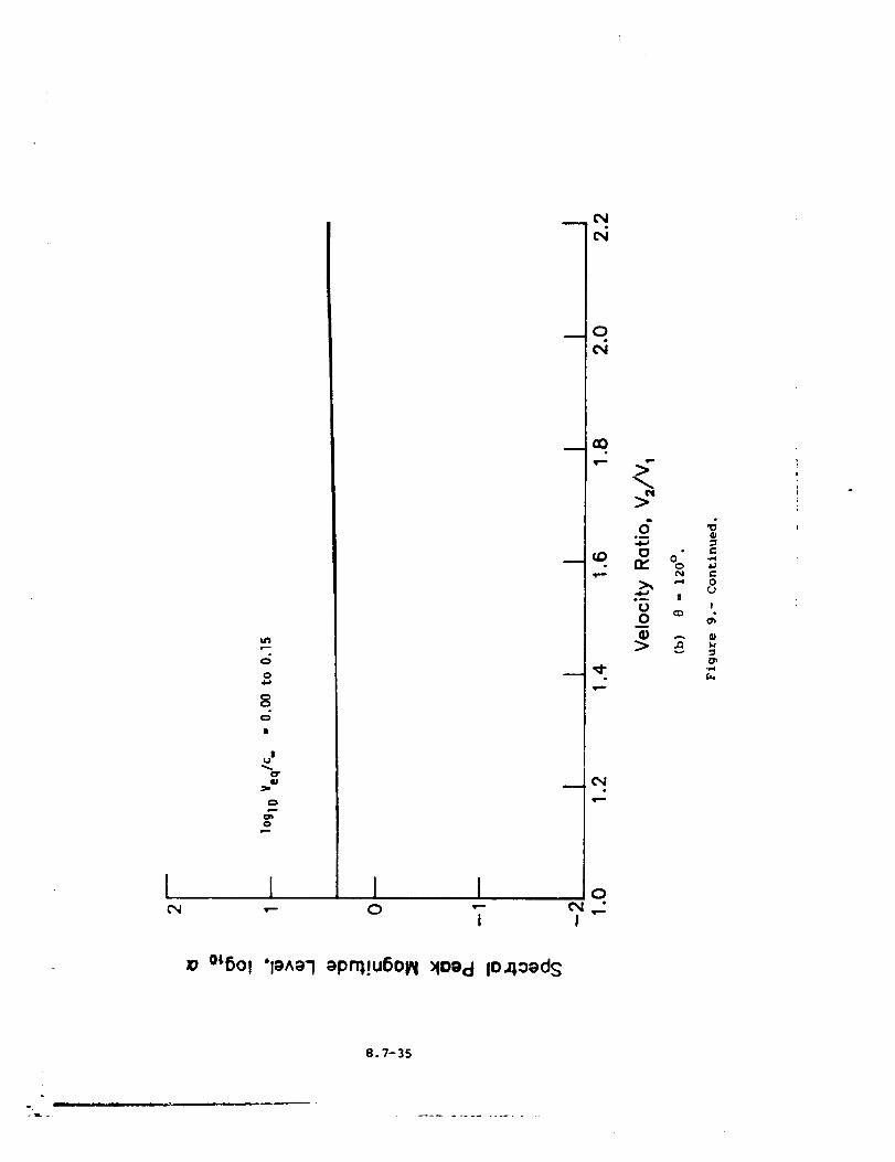
w--
0
04_
80
I
J_J
O"G
0
0
[ ! I IO "-
I
Oe
_q
em _
co. n,, % _
_ _ 0_ ue_ M
U B0 _ _q,I A III
C_
O
I
°L6Ol "IO^9"Iopr0.!U6OlN >IOgcl lOaloods
8.7-35
°.
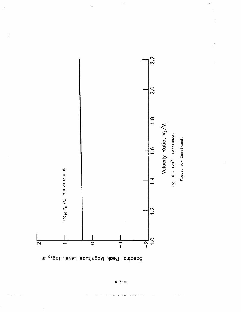
M3
O
O,l
8U
W
O_O
I I•..=-
I IO "--
I
q_
cxl
wO
moo
_._itO
_',d"
O
t"xJ,_I
N
13 rjo ._
>, , o
"G % 'O _
--j
°L6Ol 'le^e-Iopn1!u6Ol_l >loecl IO4oeds
B.7-36
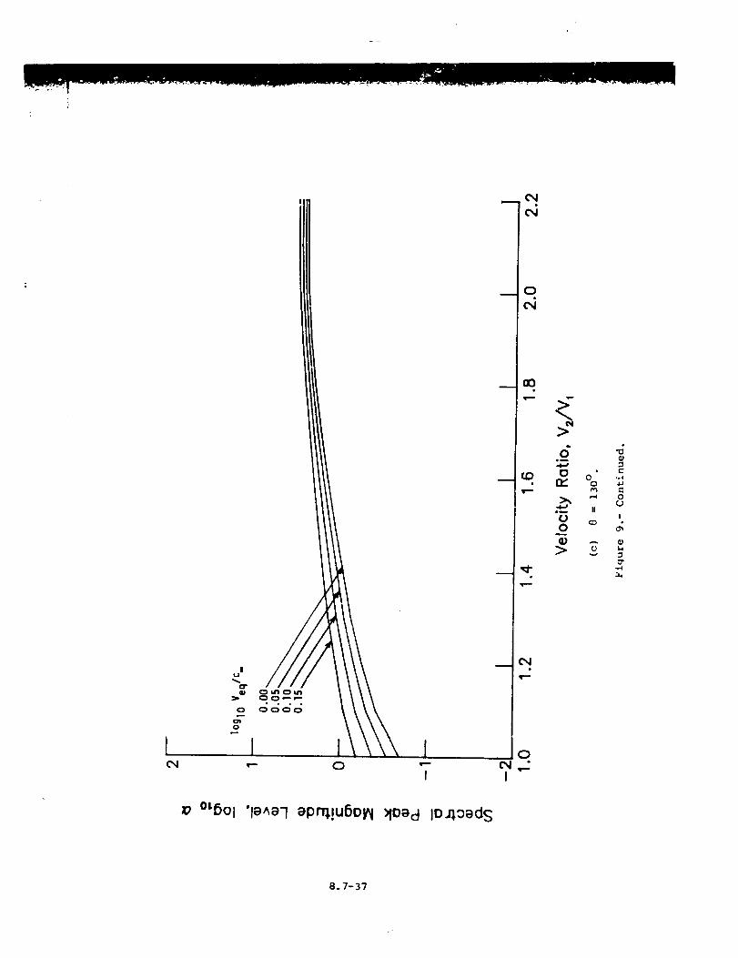
•- o 7
z7 m5Ol 'le^el ep_!uSolN >fOOd lO,qoeds
CN
O
(N
>
6m
C) 0 .,4(.0. n,- o
_ o
IIe_
_ m
0
-.-I
("4e
0
I
8.7-37
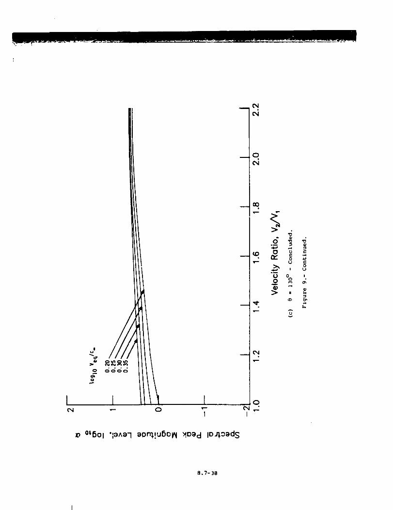
I
• • • °0 0000
1 It
CN
__ 0CN
>
6im
0
Bm
U0
>
oC,I ,,_
I
00
0 U
0 IO
N
V
o OL501 'l_^_-I _O_!U5Ol_ >_o_cl lOJ_o_ds
8.7-38
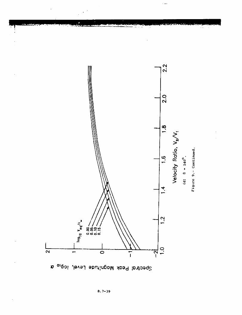
iCN
Jo °_6o I "le^el eprT_!U6OpI :Mo_cl lO4Ood S
8.7-39
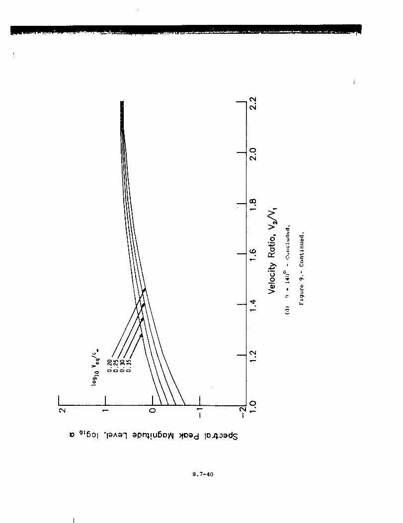
!
• ° • °
0
•-- 0 "-I
m
0
CXl
oC_I ,._I
>
{j L'-
o
(J .__0 q, d
r._
°t6Ol 'l_^a'! _pr'q!uSo_ MO_cl lO_oed S
8.7-40
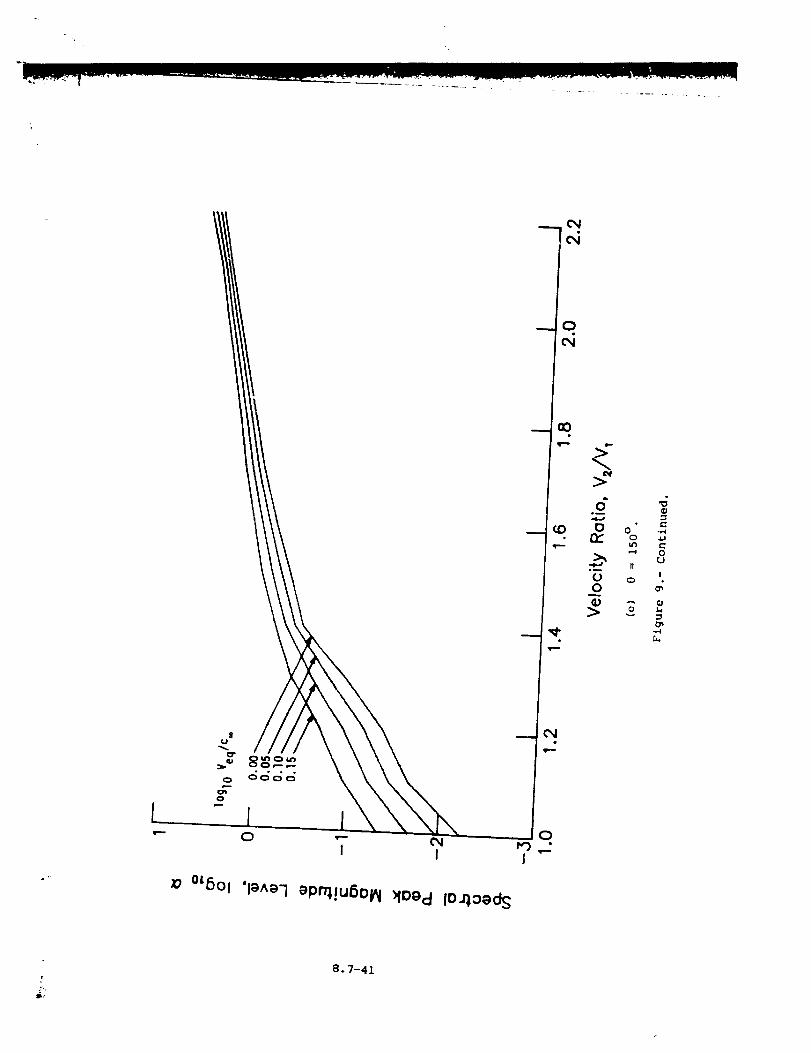
\
[0
i I
°_5Ol 'l_^a']_P_!u6o_ _fo_d lOao_dS
0
£,.
8.7-41
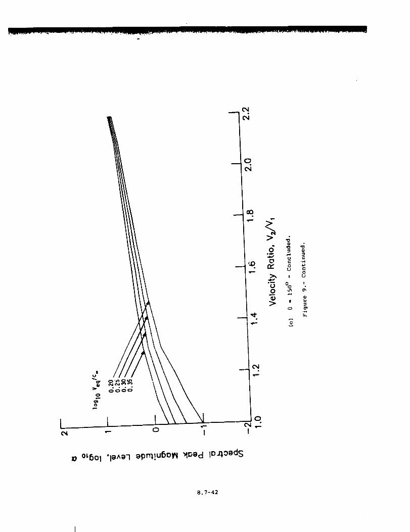
L 1 .__ .- 0 I
_o °L6Ol 'le^e-1 _pt'q!u6olN '_Ded lO.4oeds
8.7-42
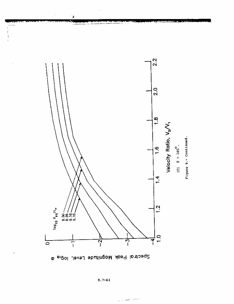
o
0
Moecl lO_o_dsz; °L6Ol 'le^e-I epn_!u6oIN
B.7-43
j÷
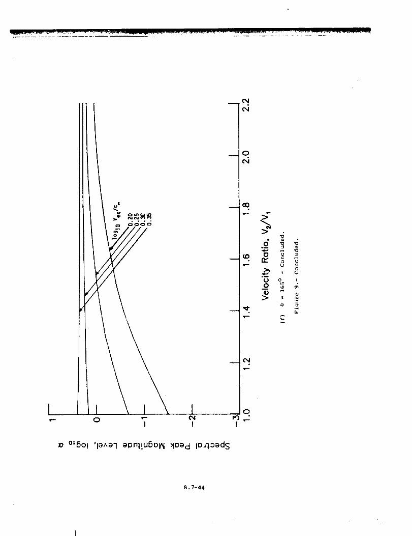
I I Iq-" 0 "- _I
I I
10
o"o--
--_- Oa
Ii
0
0
I
'U
0
!
0
J-4
II
U
0cO
I
r..
_o °t6ol 'l_t,_-I el3n'_!USOl_ _Io_ d io.n,o_d S
_,. 7-44
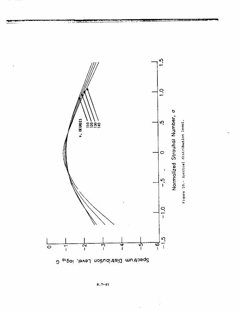
_D
I I 1, I { I0 I I I I I
0
t
m •
I
0u q...
I
I 1
b
o-q
EZ ,"
0m
No_
E_- o
0 cZ "'
O °t6°l '1_^_-I uo.n, nq!_s!c] uJnJ_o_ds
8.7-45
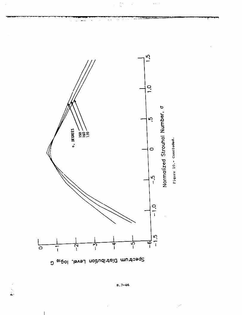
0
_D
{J¢-
0_J
!
C)
_4
00tSOI "I_A_7 uoo, nq!_s!Guun,o,oeds
u_
I I
iF,,"
8.7-46
8.8 AIRFRAME NOISE MODULE
I HTRODUCT I ON
The Airframe Noise Module predicts the broadband noise for the dcmi-
nant components of the airframe. The method is based on a method devel-
oped by Fink of the United Technologies Research Center for the Federal
Aviation Administration (ref. i). The method employs empirical and
ass_ned functions to produce sound spectra as a function of frequency,
polar directivity angle, and azimuthal directivity angle. Each spectrum
is the sum of all the airframe component spectra produced by the wing,
tail, landing gear, flaps, and leading-edge slats.
The method requires input of several parameters. The aircraft Mach
number and control settings can be provided by the Airframe Noise Param-
eters Module or directly by the user. Additional user-provided parameters
describe the airframe geometry. The module is executed once for each set
of values of the input parameters. The output is a table of the mean-
square acoustic pressure as a function of frequency, polar directivity
angle, and azimuthal directivity angle.
SYMBOLS
A area, m 2 (ft 2)
a exponent
b span, m (ft}
c ambient speed of sound, m/s (ft/s)
D directivity function
d tire diameter, m (ft)
F spectrum function
f frequency, Hz
G geometry function
I4Lg landing-gear position
K constant
£ landing-gear strut length, m (ft)
.M aircraft Mach number
8.8-i
N
n
<p2>"
Pre f
r s
e
r s
$
s
_f
0
_t
..
7'.ref
2
number of landing gear
number of wheels per landing gear
24
mean-square acoustic pressure, re p c
reference pressure, 2 × lO -5 Pa (4.177 × 10 -7 ib/ft 2)
distance from source to observer, m (ft)
dimensionless distance from source to observer, re b w
Strouhal number
number of slats for trailing-edge flaps
boundary-layer thickness, m (ft)
flap deflection angle, deg
polar directivity angle, deg
ambient dynamic viscosity, kg/m-s (slugs/ft-s)
, D c3b 2acoustic power re _ _ w
reference pc.wer, 1 × 10 -12 W (7.376 x 10 -13 ft-lb/s)
ambient den3ity, kg/m 3 (slugs/ft 3)
azimuthal directivity angle, deg
Subscripts:
f flap
h horizontal tail
m_ main landing gear
n_ nose landing gear
v vertical tail
w wing
Superscript:
• dimenslonless quantity
8.8-2
INPUT
Theaircraft Mach number, control settings, and ambient conditions
are required from either the output of the Aircraft Noise Parameters
Module or the user. The frequency, polar directivity angle, and azi-
muthal directivity angle arrays establish the independent variable values
for the output table. Several parameters are required for the geometric
description of the airframe. Finally, the distance to the pseudo-
observer is required. The range and default values of the input param-
eters are given in t_Ible I.
r s
Input Constant
distance from source to observer, m (ft)
Af
A h
%
%
bc
bV
d_c/
dng
ng
nng
N_
N..,N
S
Airframe Geometry
flap area, m 2 (ft 2)
horizontal tail _rea, m 2 (ft 2)
vertical tail area, m 2 (ft 2)
wing area, m 2 (ft 2)
flap span, m (ft)
horizontal tail span, m (ft)
vertical tail span, m (ft)
wing span, m (ft)
tire diameter of main landing gear, m
tire diameter of nose landing gear, m
main landing-gear strut length, m (ft)
nose landing-gear strut length, m (ft)
number of wheels per main landing gear
number of wheels per nose landing gear
number of main landing gear
number of nose landing gear
number of slots for tralling-edge flaps
(ft)
(ft)
8.8-3
Cop
M=
O=
Airframe Noise Parameters
landing-gear position
flap setting, deg
A_bient Conditions
ambient speed of sound, m/s (ft/s)
aircraft Mach number
ambient density, kg/m 3 (slugs/ft 3)
ambient dynamic viscosity, kg/m-s (slugs/ft-s)
Independent Variable Array
frequen_I, Hz
polar directivity angle, deg
azimuthal directivity angle, deg
OUTPUT
The output of this module is a table of the mean-square acoustic
pressure as a function of frequency, polar directivity angle, and azi-
muthal directivzty angle. In addition, the observer distance r s is
provided for Lhe Propagation .Module.
r Sdistance from source to observer, m (ft)
f
<p2 (f,_._)>°
Airframe Noise Table
frequency, Hz
polar directivity angle, deg
azimuthal directivity angle, deg
2 4
mean-square acoustic pressure, re D=c_
METHOD
Th.e prediction me_d presented in reference 1 is used to compute
_ne Car field noise. The az ;tame. - r_ r_ise components considered _n the
method are shown in figure i. The definitions of _he directivity angles
8.8-4
are shown in figure 2. In the following discussion, the general approach
for the prediction method is presented first and then the detailed method
is given for each airframe component.
The equation for the far-field mean-square acoustic pressure for
the airframe is
<p2>* = _** D(e,@) F(s) (I)4_(rs )2 (I - M cos @)4
In equation (i), _* is the overall power, D is the directivity func-
tion, and F is the spectrum function. The source to observer distance
* =
r s is expressed in dimensionless form as r s rs/b w. The forward
velocity effect is accounted for by the Doppler factor (i - M cos 9) 4
The Strouhal number S is defined as
S = fL (i - M cos e)M c
(2)
where L is some length scale characteristic of the particular airframe
noise source being computed.
The acoustic power for the airframe _* can be expressed as
* K (M) a_q = G (3)
where K and a are constants determined from empirical da_a. The
geometry function G is different for each airframe component and
incorporates all geometry effects on the acoustic power.
As indicated by equation (I), each airframe noise source has its own
directivity function D and spectrum function F. Using these :unctions
and the acoustic power, the mean-square acoustic pressure can be computed
as a function of frequency, polar directivity angle, and azlmuthal direc-
tivity angle for a given set of input parameters. The empirical constants
and functions used to compute the acoustic power are summarized in
table II. The directivity and spectrum functions are given in table III.
Each airframe noise component is described in detail below.
Trailing-Edge Noise
The primarf mechanism for noise generation for clean wing and tail
surfaces is the convection of the turbulent boundary layer past the
trailing edge. T_e turbulence intensity is assumed to be independent of
Reynolds number and the turbulent length scale is assumed to be the
boundary-layer thickness. The directivity function is assumed to be
aligned with the lift dipole, and the spectrum function is determined
empirically.
8.8-5
The acoustic power due to trailing-edge noise of a conventionally
constructed wing is
n* ,. (4.464 x 10"5)M56: (4)
The dimensionless turbulent boundary-layer thickness 6:
the standard flat-plate turbulent boundarT-layer model
Aw (P_M.C_Aw_ -0"2
<- 0.3, ./ ,5,
Similarly, the acoustic power for the horizontal tail is
ii • = 14.464 × IO-5)M _5 161
is computed from
and for the vertical tail is
17)
• •
The boundary-layer thicknesses 6h and 6 v are computed from equa-
tion (5) using the appropriate values of A and b. If the airplane
ks aerodynamically clean, such as a sailplane or jet aircraft with simple
trailing-edge flap mechanisms, the constants in equations (4), (6),
and (7) should be reduced to 7.075 x 10 -6 , an 8-dB decrease.
The directivity function D for the clean wing and horizontal tail
_s given by
D(8,¢) = 4 cos 2 _ cos 2 812 (8)
and for the vertical tail
D(@,¢) = 4 sin 2 ¢ cos" 9/2 (9)
These directivity functions are plotted in figures 2 and 3, respectively.
The sp_ctr_ function F is given by
5]-4F(S] = 0.613(I0S) 4 10S) 1"5 + O. (I0]
8.8-6
for rectangular wings and
= o.48s(1os)4 lOS) 1"3s + -4 (11)
for delta wings. These spectrum functions are plotted in figure 4. The
Strouhal number S is defined for this component as
f6*b (I
S = M-'_ - M cos 8)
(12)
where the appropriate value of the span b and the boundary-layer thick-
6"hess for the wing, vertical tail, or horizontal tail is used depend-
ing on the noise source being predicted. The mean-square acoustic pres-
sure is t.her computed from equation (I).
Leading-Edge-Slat Noise
The deployment of the leading-edge slats produces increased noise by
two different mechanisms. First, the slat produces an increment of wing
trailing-edge noise due to its impact on the boundary layer of the wing.
Second, the leading-edge slat itself produces trailing-edge noise. Both
mechanisms are accounted for in this method.
The added acoustic power due to the increase in wing trailing-edge
noise or thu slat trailing-edge noise is assumed to be equal to the clean
wing noise. Therefore, equation (4) can be used to predict the overall
acoustic power for either slat noise source. The directivity function
for either slat noise sourc_ is given by equation (8) and plotted in fig-
ure 2. The spectrum function for the added wing noise is given by equa-
tion (i0). The spectrum function for the slat noise is
s]-4F(S) = 0.613(2.19S) 4 2.19S] 1"5 + O. (13)
which assumes that the slat chord is 15 percent of the total wing chord.
The Strouhal number S is given by equation (12). The t_ spectrum
functions are plotted in figure 5, along with their sum, to show the
combined effect of slat noise. The mean-square acoustic pressure is
then computed from equation (I).
Flap Trailing-Edge Noise
Extension of the wing flaps increases the level of airframe noiz&.
This noise is assumed to be produced by the lift fluctuations due to the
incident turbulence on the flap. This noise Increases as the flap exten-
sion is increased. The noise is assumed to be aligned with the lift
dipole of the deflected flap.
8.8-7
The acoustic power due to flap noise for single or double
slotted flaps is
Af.q* = (2.787 x I0-4)M6--_ sin 2 6f
b_(14)
where 6f is the flap deflection angle. For triple slotted flaps, theoverall acoustic power is
Af
n" = (3.sogx io-4)_ sin2 _W
which increases the power by I dB to account for the added flap
complexity.
The directivity function D for the flap noise is
(15)
2D(8,¢) = 3(sin 6f cos 8 + cos 6f sin % cos ¢)
(16)
which is plotted in figure 6 for 6f = 30° • The spectruD functio_ Fare
0. 04805 fF(Sf) = O. 1406Sf 0"55
L216.49S; 3
(S < 2)
(2 -< S <- 20)
(20 < S]
(17)
for single and double slotted flaps and
FO.O257Sf
F(sf)= /o.o5365_-°'°625
LlTO_SS_a
(S < 2)
(2 <- S < 75)
(75 < S)
(18}
for triple slotted flaps. Using the flap chord as the reference length,
the Strouhal number is defined as
fAr
Sf = M bfc (1 M cos e)(19]
8.8-8
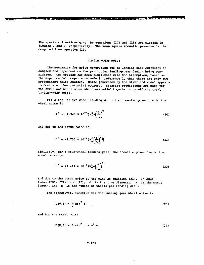
I
The spectrum functions given by equations (17) and (18) are plotted in
figures 7 and 8, respectively. The mean-square acoustic pressure is then
computed from equation (1).
Landing-Gear Noise
The mechan/sm for noise generation due to landing-gear extension is
complex and dependent on the particular landing-gear design being con-
sidered. The process has been simplified with the assumption, based on
the experimental comparisons made in reference i, that there are only two
predominant noise sources. Noise generated by the strut and wheel appears
to dominate other potential sources. Separate predictions are made for
the strut and wheel noise which are added together to yield the total
landing-gear noise.
For a one- or two-wheel landing gear, the acoustic power due to the
wheel noise is
(2O)
and due to the strut noise is
_* = (2.753 x I0-4)M6<_)2_(21)
Similarly, for a four-wheel landing gear, the acoustic power due to the
wheel noise is
_* = (3.414 x 10 -4)M6n<b_) 2(22)
and due to the strut noise is the same as equation (2_).
tions (20), (21), and (22), d is the tire diameter, £
length, and n is the number of wheels per landing gear.
In equa-
ls the strut
The directivity function for the landing-gear wheel noise is
3 2
D(9,¢) = _" sin @ (23)
and for the s_-ut noise
D(8,_) = 3 sin 2 @ sin 2 ¢ (24)
8.8-9
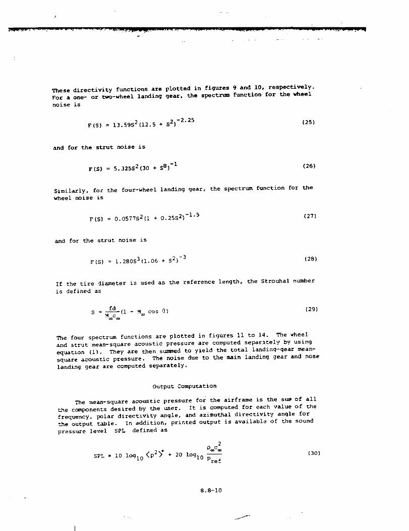
Thesedirectivity functions are plotted in figures 9 and 10, respectively.
For a one- or two-wheel landing gear, the spectrum function for the wheel
noise is
F(S5 = 13.59S 2(12.5 ÷ S 2)-2"25 {25)
and for the strut noise is
F(S} = 5.325S2(30 + S85 -I (265
Similarly, for the four-wheel landing gear, the spectrum function for the
wheel noise is
F(S) = 0.0577S2(i + 0.25S2) -1"5 (275
and for the strut noise is
F(S) = 1.280S3(i.06 + S25 -3 (285
If the tire diameter is used as the reference length, the Strouhal number
is defined as
fd
S = ooM_c-(l - M cos @) (29)
The four spectrum functions are plotted in figures Ii to 14. The wheel
and strut mean-square acoustic pressure are computed separltely by using
equation (I). They are then summed to yield the total landing-gear mean-
square acoustic pressure. The noise due to the main landing gear and nose
landing gear are computed separately.
Output Computation
The mean-square acoustic pressure for the airframe is the sum of all
_he components desired by the user. It is computed for each value of the
frequency, polar directivity angle, and azimuthal directivity angle for
the output table. In addition, printed output is available of the sound
pressure level SPL defined as
2
D c/ k*
SPL z i0 lOgl0 \p2/ + 20 lOgl0Pref
(30)
8.8-I0
_f
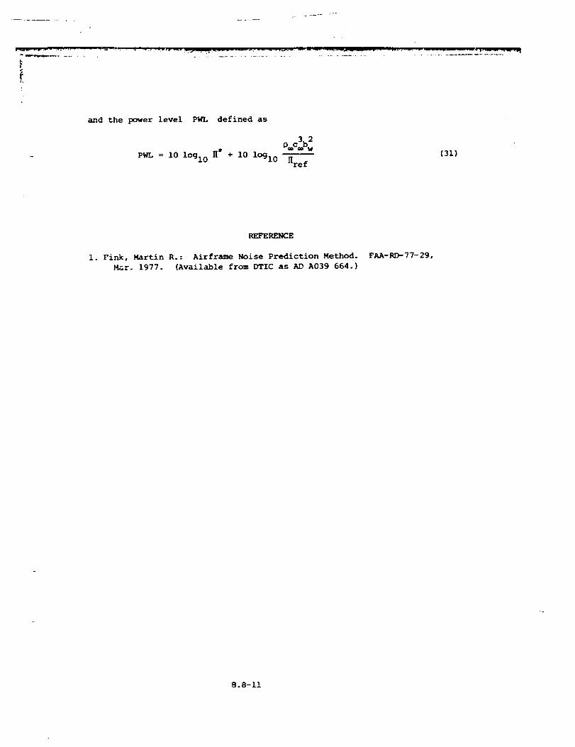
J,
and the power level PWL defined as
3 2_.clbw
PWL = I0 lOgl0 _" + I0 lOgl0 Href(31)
REFERENCE
I. Fink, Martin R.: Airframe Noise Prediction Method.
Mar. 1977. (Available from DTIC as AD A039 664.)
FAA-RD-77-29,
8.8-11
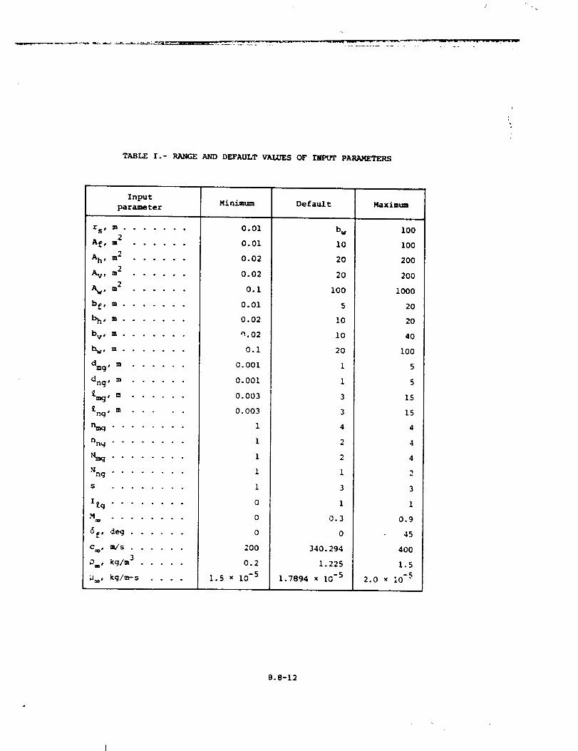
TABLEI.- RANGE AND DEFAULT VALUES OF IJPUT PARAMETERS
Input Minimum Default Maximumparame ter
b wrse m .......
2A f, m ......
Ah' m2 ......
Av, m 2 ......
2AWl m • o . • - o
b f, m .......
_ho m . . . . . . o
bV, m .......
# ra . o o . . . .
dmg, m ......
dng o m ......
£mg' m ......
£ng" m
...... • .
nng ........
Nng ........
S • . • o . • • •
IRg . . ......
"%_ao " " " ° ....
6f, deg ......
Crop # B_/ S . . . , . •
DaD, kg/m 3 .....
_, kg/m- s ....
0.01
0.01
0.02
0.02
0.i
0.01
0.02
_.02
0.I
0.001
0.001
0.003
0.003
1
1
1
1
1
0
0
0
200
0.2
1.5 x 10⁻⁵
I0
20
20
I00
5
I0
i0
20
1
1
3
3
4
2
2
1
3
1
0.3
O
340. 294
1.225
1.7894 x 16 -5
I00
I00
200
200
I000
20
20
40
i00
5
5
15
15
4
4
4
2
3
1
0.9
45
400
1.5
2.0 x I0 -5
8.8-12
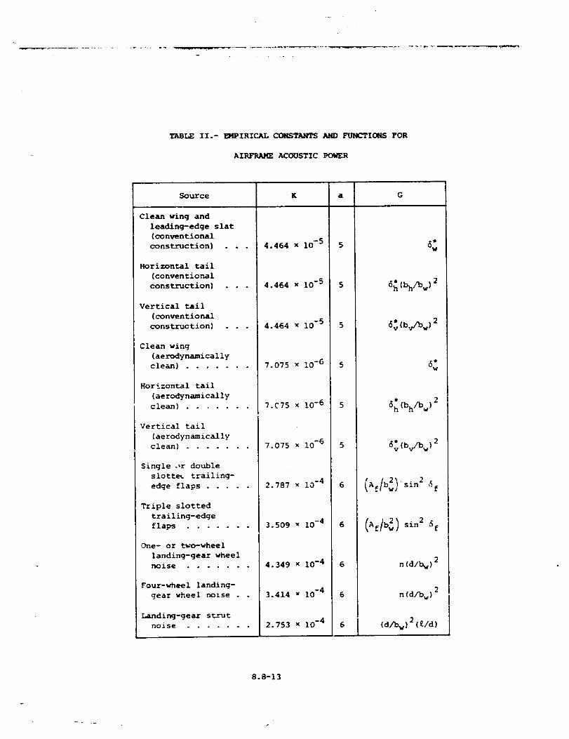
TABLE II.- _PIRICAL COHSTANTS AND FUNCTIONS FOR
AIRFRAME ACCXJSTIC POWER
Source
Clean wing and
leading-edge slat
(conventional
construction} . .
Horizontal tail
(conventional
construction)
Vertical tail
(conventional
construction]
Clean wing
(aerodynamically
clean) .......
Horizontal tail
(aerodynamically
clean) .......
Vertical tail
(aerodynamically
clean) .......
Single ,,r double
slotte_ trailing-
edge flaps .....
Triple slotted
trailing-edge
flaps .......
One- or two-wheel
landing-gear wheel
noise .......
Four-wheel landing-
gear wheel noise .
Landing-gear strut
nolse .......
K a G
4.464 x I0 -5 5
4.464 x 10 -5 5
4.464 x 10 -5 5
7.075 x I0 -6 5
7. C 75 x 10 -6 5
7.075 x I0 -6 5
2.787 x 10 -4 6
3.509 x i0 -4 6
4.349 x i0 -4 6
3.414 x I0 -4 6
2.753 x I0 -4 6
6_c_w)2
_:Cb,/bw)2
6:
6h (bh/bw) 2
6: (bv/bw)2
2_sin 2 _f_f w/
(_/b_)sio2_f
n (d/b_) 2
n (d/b w) 2
(d/bw) 2 (t/d)
8.8-13
i
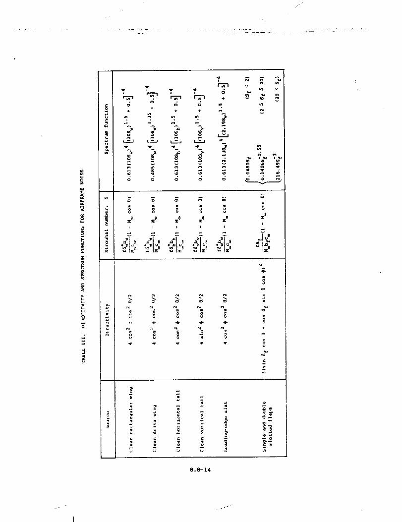
1
° .
El3(/1
0{ti
{/1Z0
E-UZ
r,.
M
e.,Z
r.
i 2,
T
8 _ I I 0
c; 6 c; ,.÷
÷ 4, ÷ o.4
• ° • °
Ul UI ;,_ _ t'lo o o o
U1 (/I U1 {I] ,,,e0 0 0 0 •
'/Vl V
vv
V!
v
CO 0 ql'
8 5.8 8 5.8 _.$ EIII
I I I I I
% % % '% %0 0 0 0 CU O U O rj
% % % _ %0 0 0 "_ 3U U U m
A
L)
C_
C
0U
4-
v
_a
91 el el "_
"T
O
8.8-14
I
lJ
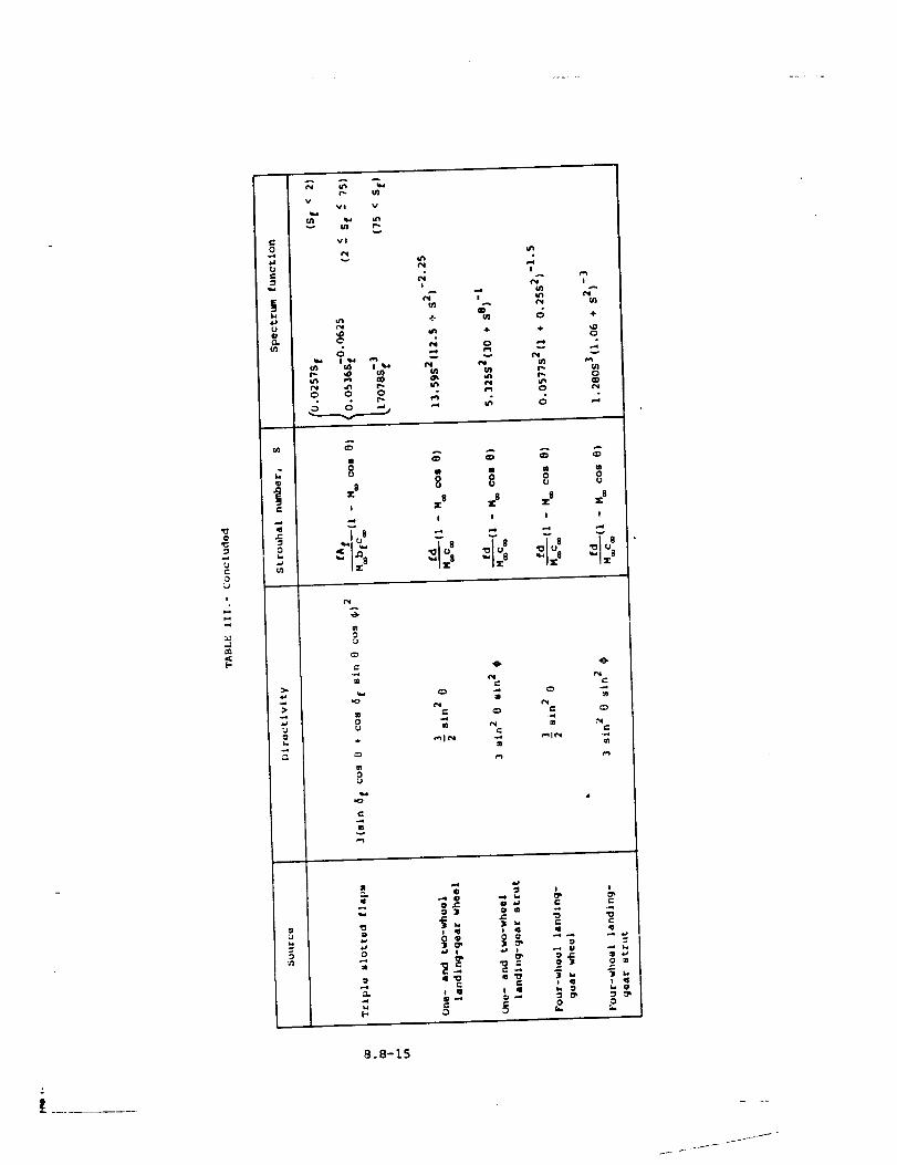
@
0
I
b.q
s_
L.
A
vvl v
v!
C
O
,4!
v
T
-/
ffl
4.
v
O
n0
i
8
=:$
7
÷
A
0
OIj
_ A A A
X_ _8 Z8 X8
I I I !
I ',,Jr' ',Jr' X 8 _ X 8
%
c_
%
e,,i
mm:_11=
..4
t=,,q
"0
=11
:1
o
i q
4'0
m q,..4
e-
I:I 11
e-
O
I., O
0
e-
C
8° 8-15
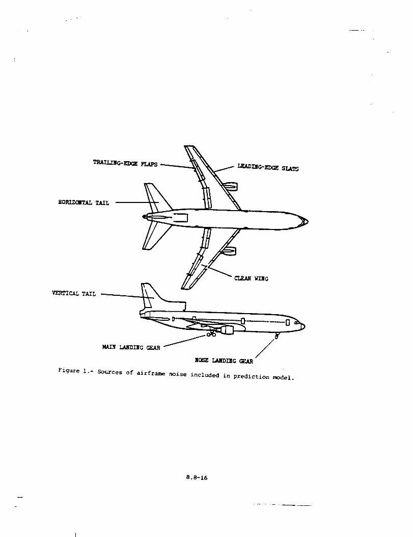
TRAIL_EDGE FLAPS
CLEAN _G
VERTICAL TA.IL
0
NOSE _aUl_)nlG
Figure i.- Sources of airframe noise included in prediction model.
8.8-16
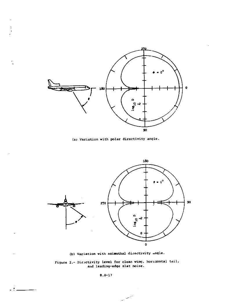
9O
(a) Variation with polar directivity angle.
2To 90
o
(b) Variation with azimuthal dizectivity =ngle.
Figure 2.- Dir_ctivity level for clean wing, horizontal _ail,
and leading-edge slat noise.
8.8-17
w
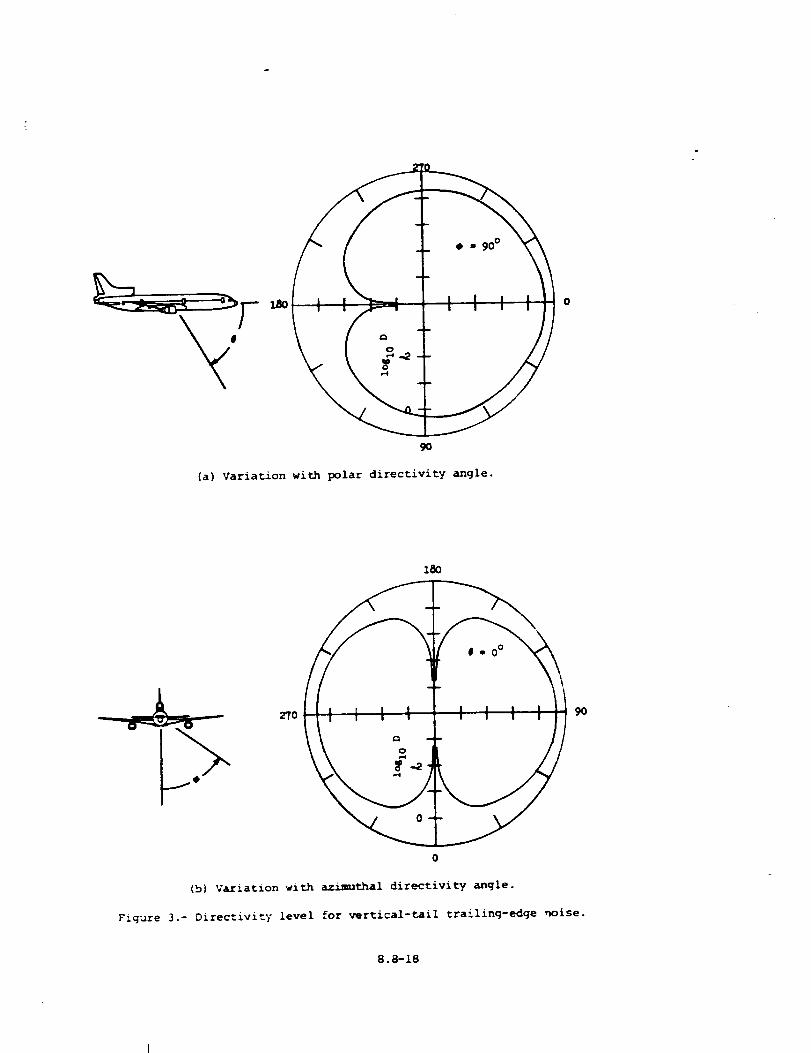
90
(a) Variation with polar directivity angle.
27O 9O
(b) Vaxiation with azimuthal directivity angle.
Figure 3.- Direc:ivity level for vertical-tail trailing-edge noise.
8.a-18
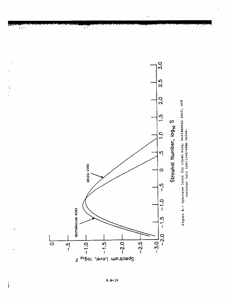
10
z
3
0
,.i
0
cq
or}
s,.--. tn
0
0
LJ
..(3
E
Z
0c-:30qL
(/3
-.4¢I
.,,ae"
0_-,,4
0 0_.. _-
t- '0-,.4
t_
U n_
0
E .,4
!
t_
t_
8.8-19
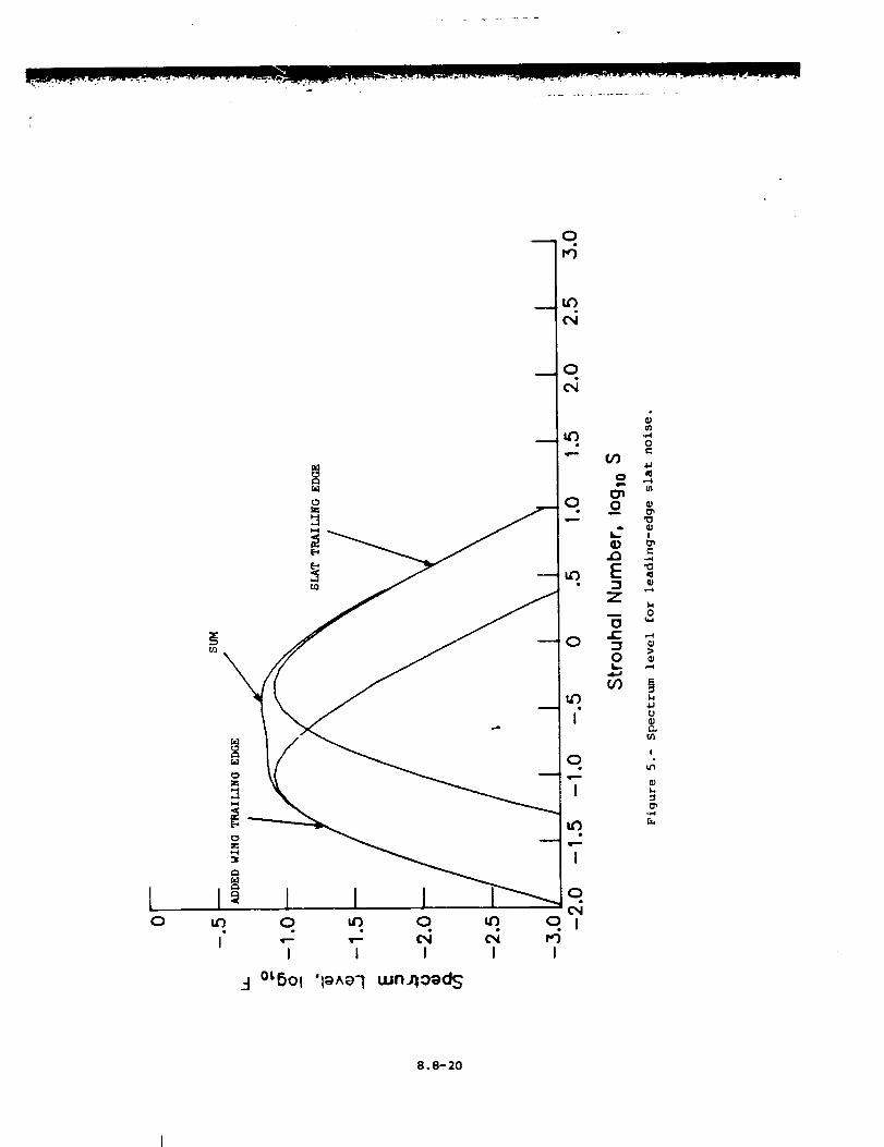
l(:3
CO
1u_
I
3 °_6ol 'l_^el uJn_oed_
0
0m
E:3
Zm
0c-
O
GO
0
4_
I_n
0
I/
U
I
u_
J,,,
°,,,4
8.8-20
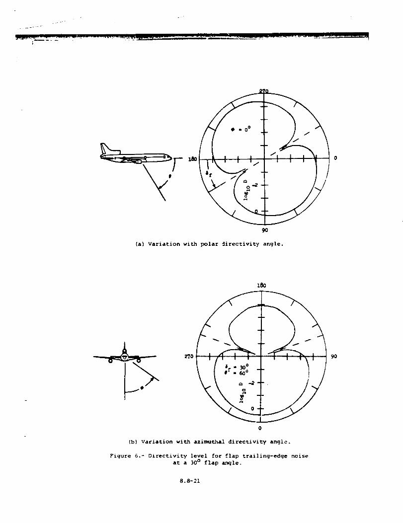
i I I a
lk! I I/ i i I
f_ -- .
\%/ /%_t
- / J
I
//
(a) Variation with polar _irectivity angle.
100
270 I I I ! I i I I 90
\ I .-_° T _ /
#
(b) Variation with azimuthal directivity angle.
Figure 6.- Directivity level for flap trailing-edge noise
at a 30 ° flap _ngle.
8.8-21
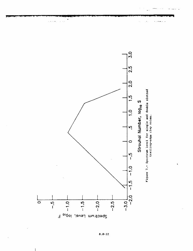
[ 1 l 1 I ! o.CM
o _ o _ o _ ol.- ,- c,i _ _i
I I I I I I
.:1 °[601 'lava'] uJnjload S
8.8-22
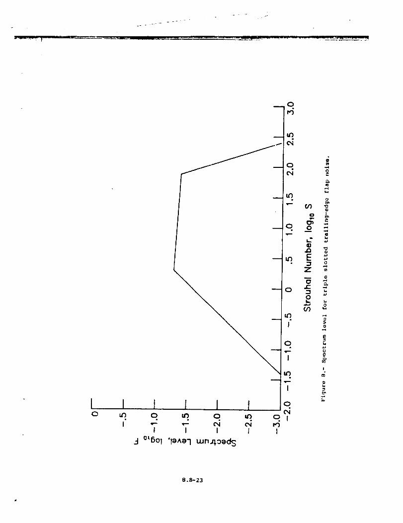
i I
I
q
0
I
I
I
0I I i Io _. o. _. ol
! I I I I
-I°_fiOl'l_^el wn4o_d _
01
on.
0
¢I
0 Z
0 "_m
LJ
E 4J
:3 oZm ¢I
o _.3Z --_
0
:>
0w-4
E
'.30
!
OB
°°
8.8-23
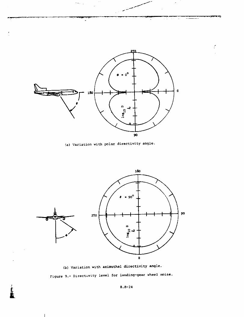
f_
180
90
(a) Variation with polar directivity angle.
£&
180
270 90
0
(b) Variation with azimuthal directivity angle.
Figure 9.- Directivity level for landing-gear wheel noise.
8.8-24
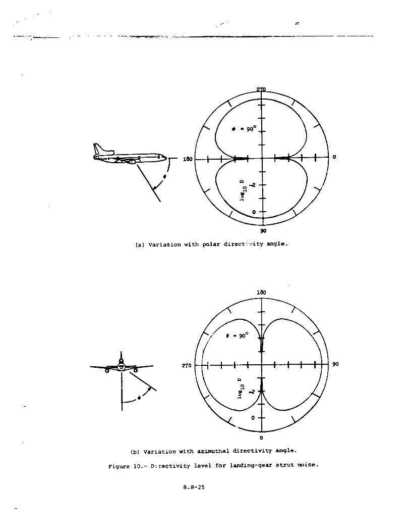
r
L
90
(a) variation with polar directivity angle.
(b) Variation with azimuthal directivity angle.
Figure I0.- D1rectivity level for landing-gear strut noise.
8.8-25
90
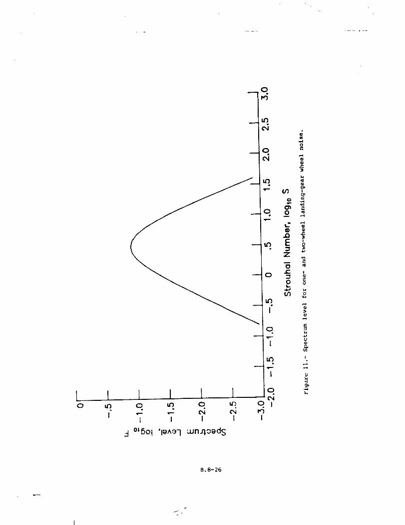
I IO IZ)
I
I I I IO IZ') O
• ,e * i
I I I I
_-I °LSOI 'I_A'97 :'unJ",°_ds
jO
_O "
u') o
o
I
'v'--'
I
O
O Ir,')
i
IJ
I
,,,-4
8.8-26
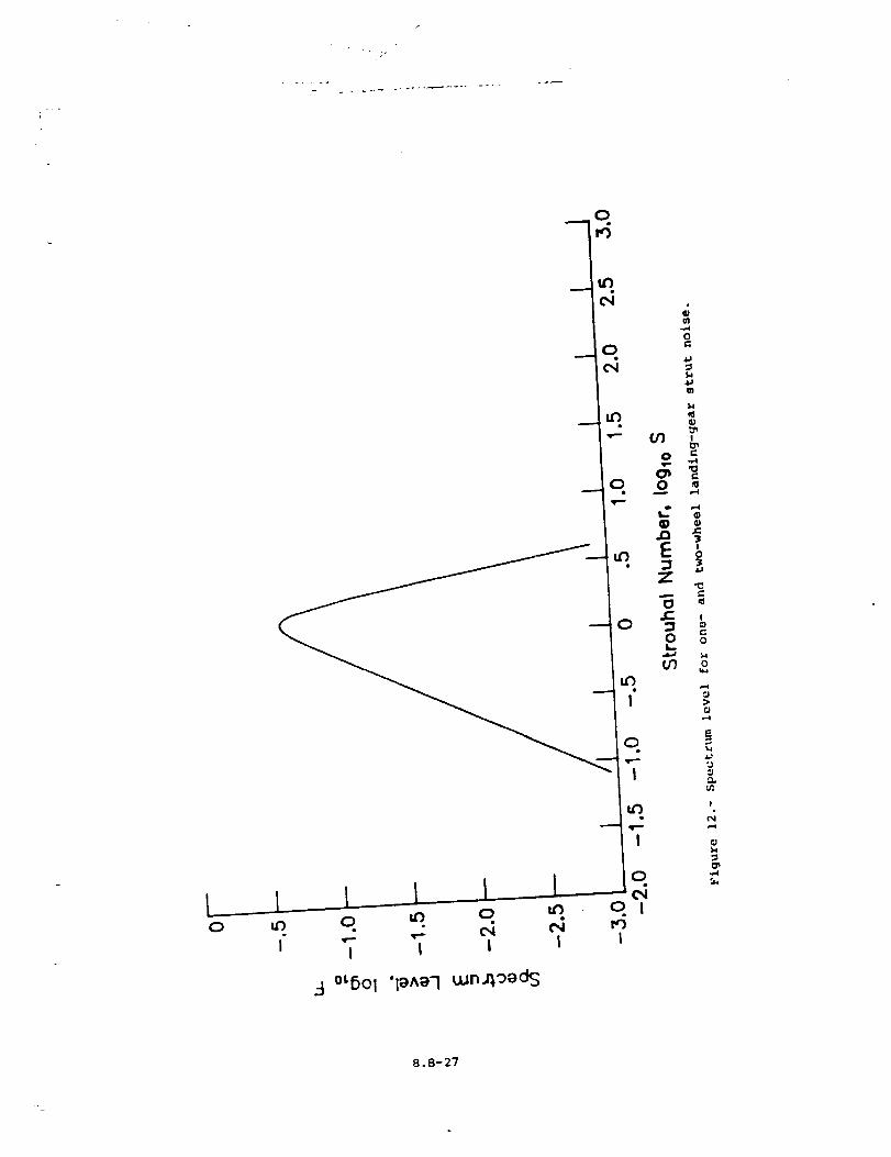
i
q
0
I
8.8-27
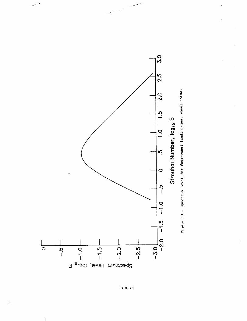
I I0
I
0
0
u_
0
e
0
u_
I
0
I
I
0I I I Io _ o _ o I
I I I I I
_4 °L6Ol 'IB_B']Lun.qo_)ds
oi-,,4Ow.
e.
e-
ID
E =3
z "
o o
_I oIb-
¢.,1
I:1
I
,4
8.8-28
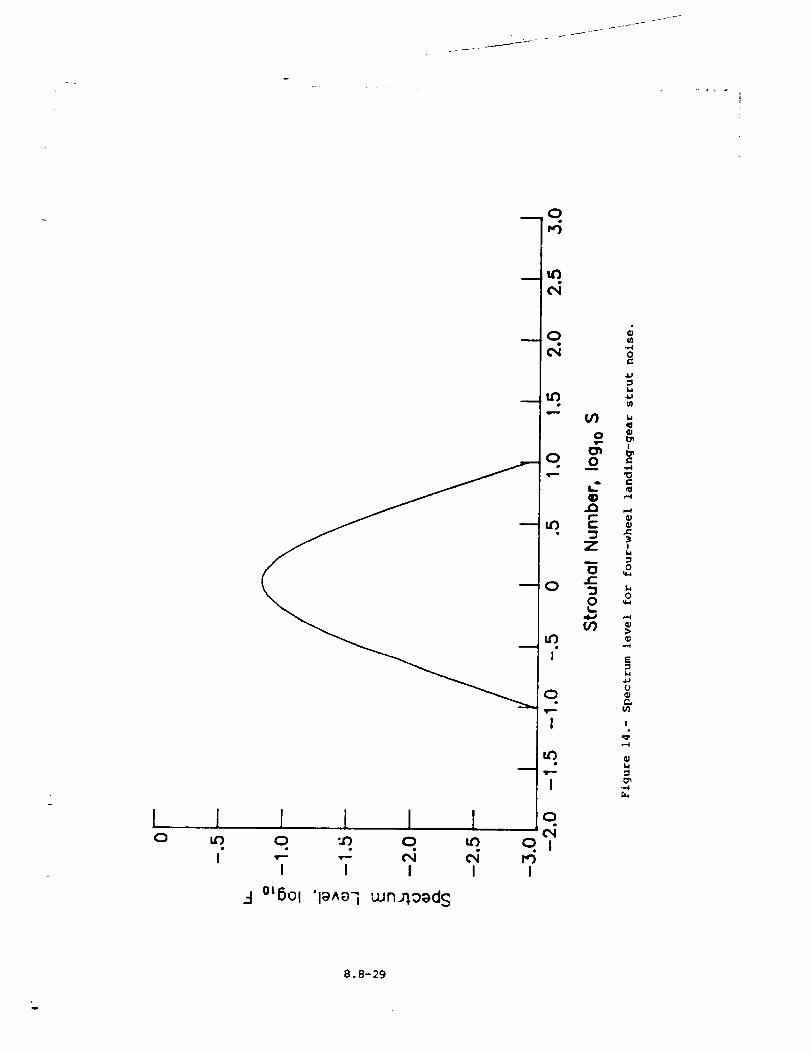
10
0
_Lr)
q
In,o
0
LC')
f
0m
,wP,-,-'
I
0c_
o IMI
J ! ! I J
I I I I
3 °L6ot "l_^_-i wn_ood S
OP
0m
r-'3Z
or-'30
in
m
0
w
L,
i
"0
!
o
L_
0W-;
>
,,-,i
L,
rJ
_.,
I
C'
8.8-29

8.9 SMITH AND BUSHELL 'I_I_INE NOISE MODULE
INTRODUCTION
The Smith and Bushell Turbine Noise Module predicts the broadband
noise for an axial flow turbine. The prediction is based on the method
developed by Smith and Bushel1 (re/. I). The method employs empirical
functions to produce sound spectra as a function of frequency and polar
directivity angle. The method assumes that the only significant noise
source is the "vortex" component, which is the broadband noise due to the
interaction of the rotating blades with random velocity patterns in the
flow.
The method requires input of several parameters. The turbine
entrance and exit flow parameters can be provided by the Turbine Noise
Parameters Module or directly by the user. Additional user-provided
parameters are required. The module is executed once for each set of
values of the input parameters. The output is a table of the mean-square
acoustic pressure as a function of frequency, polar directivity angle,
and azimuthal directivity angle. Although turbine noise is assumed not
to vary with azimuthal directivity angle, it is introduced so that the
output table is compatible with other noise tables.
A
A e
C
C
D
d
F
f
f"
fa
ha
Mt
SYMBOLS
turbine inlet cross-sectional area, m 2 (ft 2)
engine reference area, m 2 (ft 2)
ro_'oc blade mean axial chord, m (ft)
ambient speed of sound, m/s (ft/s)
directivity function
turbine rotor diameter, m (ft)
spectrum function
frequency, Hz
Helmholtz number, fC/c
fuel-to-air ratio
absolute humidity, percent mole fraction
rotor blade tip Mach number
8.9-1
T_
M
&
N
N e
N s
<p2>"
Pref
R
R
rs
rs
T
8
r/°
_ref
aircraft Mach number
mass flow rate, kg/s (slugs/s)
rotational speed, Hz
number of engines
number of turbine stages
2 4
mean-square acoustic pressure, re pc
reference pressure, 2 x 10 -5 Pa (4.177 × 10 -7 lb/ft 2)
dry air gas constant, re m2/K-s 2 (ft2/°R-s 2)
gas constant, m2/K-s 2 (ft2/°R-s 2)
distance from source to observer, m (ft)
dimensionless distance from source to observer, re _e
temperature, K (OR)
ratio of specific heats
polar directivity angle, deg
acoustic power, re p c3A
reference power, 1 x 10 -12 W (7.376 x 10 -13 ft-lb/s)
ambient density, kg/m 3 (slugs/ft 3)
azimuthal directivity angle, deg
Subscripts :
i en trance
j exit
s static
ambient
Superscript:
* dimensionless quantity
8.9-2
INPUT
Theturbine parameters are required from either the output of the
Turbine Noise Pa_-ameters Module or the user. Ambient conditions are
required for com_utation of sound pressure levels. The frequency, polar
directivity angle, and azimuthal directivity angle arrays establish the
independent variable values for the output table. The turbine inlet
cross-secr/onal area, rotor blade mean axial chord, and number of turbine
stages are required for the geometric descziption of the turbine.
Finally, the engine reference area, number of englnes, and distance to
the observer are required. The range and default values of the input
parameters are given in table I.
Ae
N e
r s
Input Constants
engine reference area, m 2 (ft 2)
number of engines
distance from source to observer, m (ft)
A e
C
NS
Turbine Geometry
turbine inlet cross-sectional area, re A e
rotor blade mean axial chord of the last stage, re
nummer of turbine stages
fa
N*
T*_,j
Turbine Noise Parameters
fuel-to-air ratio
core mass flow rate, re P camA e
rotational speed, re c=/d
exit static temperature, re T
Cam
h a
%
Ambient Conditions
ambient speed of sound, m/s (ft/s)
absolute humidity, percent mole fra:tion
aircraft Mach number
ambient density, kg/m 3 (slugs/ft 3)
8.9-3
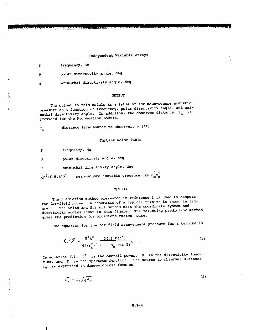
f
e
IndependentVariable Arrays
Erequency, Hz
polar directivity angle, deg
azimuthal directivity angle, deg
OUTPUT
The output to this module is a table of the mean-square acoustic
pressure as a function of frequency, polar directivity angle• and azi-
muthal directivity angle. In addition, the observer distance r s is
provided for the Propagation Module.
r s distance from source to observer, m (ft)
f
9
<p2(f,@,_)>*
Turbine Noise Table
frequency, Hz
polar directivity angle• deg
azimuthal directivity angle• deg
• 02C 4mean-square acoustic pressure re _
METHOD
The prediction method presented in reference 1 is used to compute
the far-field noise. A schematic of a typical turbine is shown in fig-
ure i. The Smith and Bushell method uses the coordinate system and
directivity angles shown in this figure. The following prediction method
gives the prediction for broadband vortex noise.
The equation for the far-field mean-square pressure for a turbine is
<p2>* = _*A* D(@) F(f*) (i)4
4_(r:) 2 (i - M cos @)
In equation (i), _* is the overall power, D is the directivity func-
tion, and Y is the spectrtun function. The source to observer distance
r s is expressed in dimensionless form as
r S = r s(2)
8.9-4
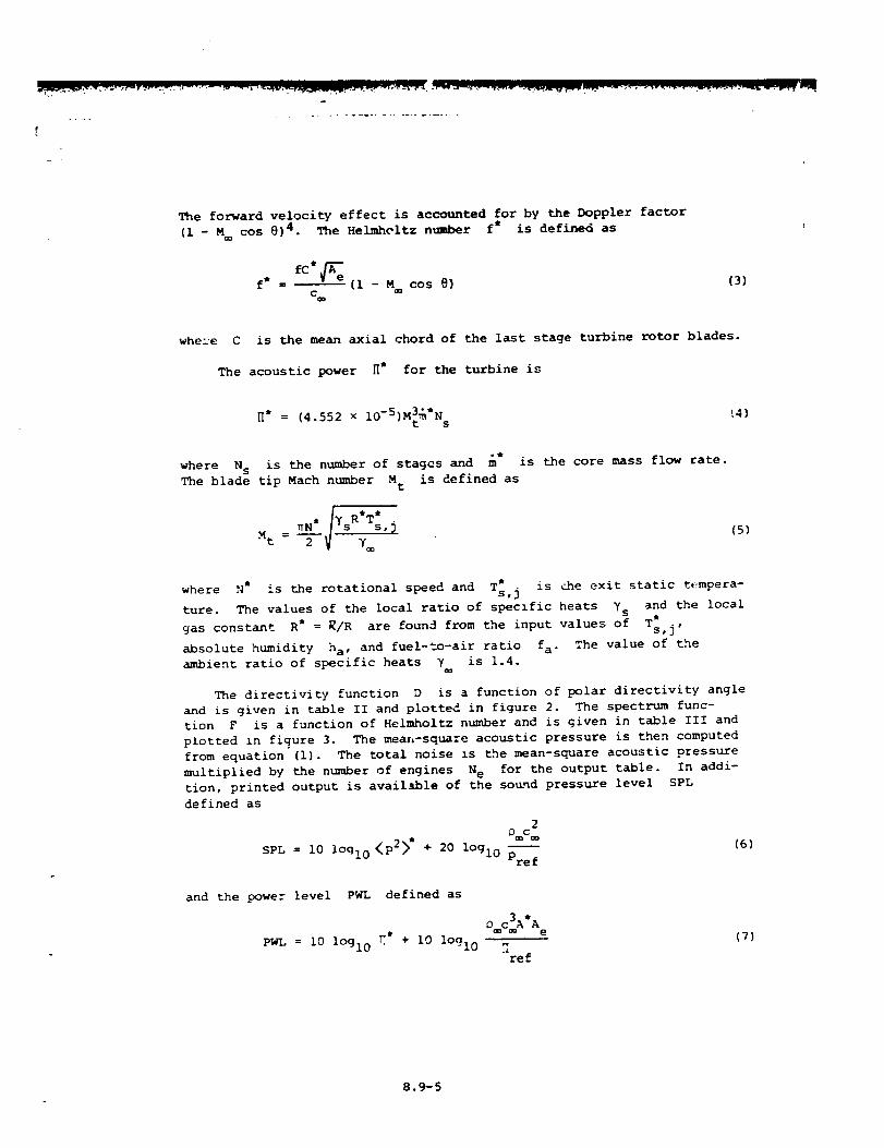
The forward velocity effect is accounted for by the Doppler factor
(I - M cos @)4. The Helmhcltz ntmber f* is defined as
f* = fC*_e--(I - s= cos 0) (3)
C
whe:e C is the mean axial chord of the last stage turbine rotor blades.
The acoustic power H* for the turbine is
_* = (4.552 x IO-5)M3_*N _4)t s
oe
where N s is the number of stages and m is the core mass flow rate.
The blade tip Mach number M t is defined as
(5)
where N* is the rotational speed and T_,j is _he exit static tempera-
ture. The values of the local ratio of specific heats 7s and the local
constant R* = R/R are found from the input values of T_,j,gas
absolute humidity ha, and fuel-to-air ratio fa" The value of the
ambient ratio of specific heats y is 1.4.
The directivity function D is a function of polar directivity angle
and is given in table II and plotted in figure 2. The spectrum func-
tion F is a function of Helmholtz number and is given in table III and
plotted in figure 3. The mean-square acoustic pressure is then computed
from equation (i). The total noise _s the mean-square acoustic pressure
multiplied by the number of engines N e for the output table. In addi-
tion, printed output is available of the sound pressure level SPL
defined as
2
SPL = i0 loq!0 <p2>* + 20 lOgl0 Pref(6)
and the Dower level PWL defined as
PWL = i0 lOglo It + i0 lOql 0
"Lre f
(7)
8.9-5
R.I_E
1. Smith, M. J. T. ; and Bushell, K. W. : Turbine Noise - Its Significance
in the Civil Aircraft Noise Problem. Paper 69-WA/GT-12, American
Soc. Mech. Eng., ,Nov. 1969.
8.9-6
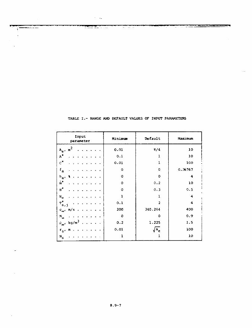
.m ........................!
TABLE I .- RANGE AND DEFAULT VALUES OF INPUT PARAM_
Input Minim, m De fault Maximumparameter
Ae, m 2 ......
A i ooo.o°oo
C Q . ° . . o ° . .
fa ........
ha , % .......
_t . • • .... .
N _ . o o . • . . o
Ne ........
T* . . . . . . .s,]
c, _/s ......
_ oo-oo--o
P_, kg/m 3 .....
[S # _ • • • ....
N S ........
0.01
0.i
0.01
0
0
0
0
I
0.i
200
0
0.2
0.01
I
_/4
1
1
0
0
0.2
0.3
1
2
340. 294
0
1.225
l
I0
i0
100
0. _6767
4
I0
0.5
4
4
400
0.9
1.5
I00
i0
8.9-7
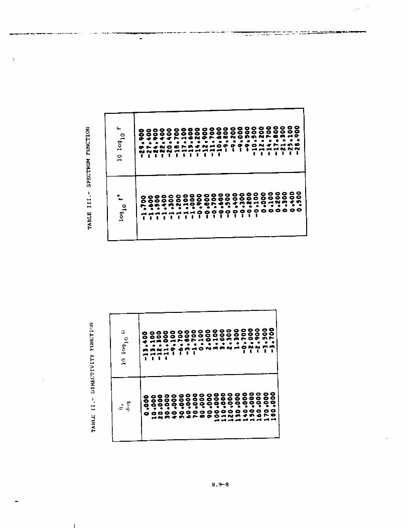
...... _'7 -r_'_ . _
zQ
f..
A,
|
).4i*.¢
r..
0.-¢
0
o
0,,-4
0,,.¢
0000000000000000000000000000000000000000 0000 O0
•......................¢t,l_¢r_iOiDl_m_r_l,.cOe¢l_¢l_¢l .O_,lr I_*-*_'bID
I I I I I I I I I I I I I I I I I I I
oooooooooooooooooooooooooooooooooooooooooooooo
.., w_me we _-* m,__ 0 0 0 0 0 0 0 0 0 0 0 0 0 O0I ! I | t | I I ! I I I I ! I I I
z
[-.
).,
!
0
oooooooooooooooooooooooooooooooooooooo
,-*_._¢_,.* I I I I I I I I ii i i I
oooooooooooooooooooo ooooooooooooooooooo.o.ooooo, oooo.o.ooooooo00000000000000000 O0
e41ql_4, ti_Ol_._DO_O_l_ 4rt_4Dr,,,.m
8.9.-8
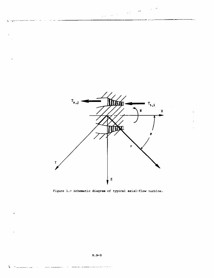
X
Figure i.- Schematic diagram of typical axial-flow turbine.
8.9-9
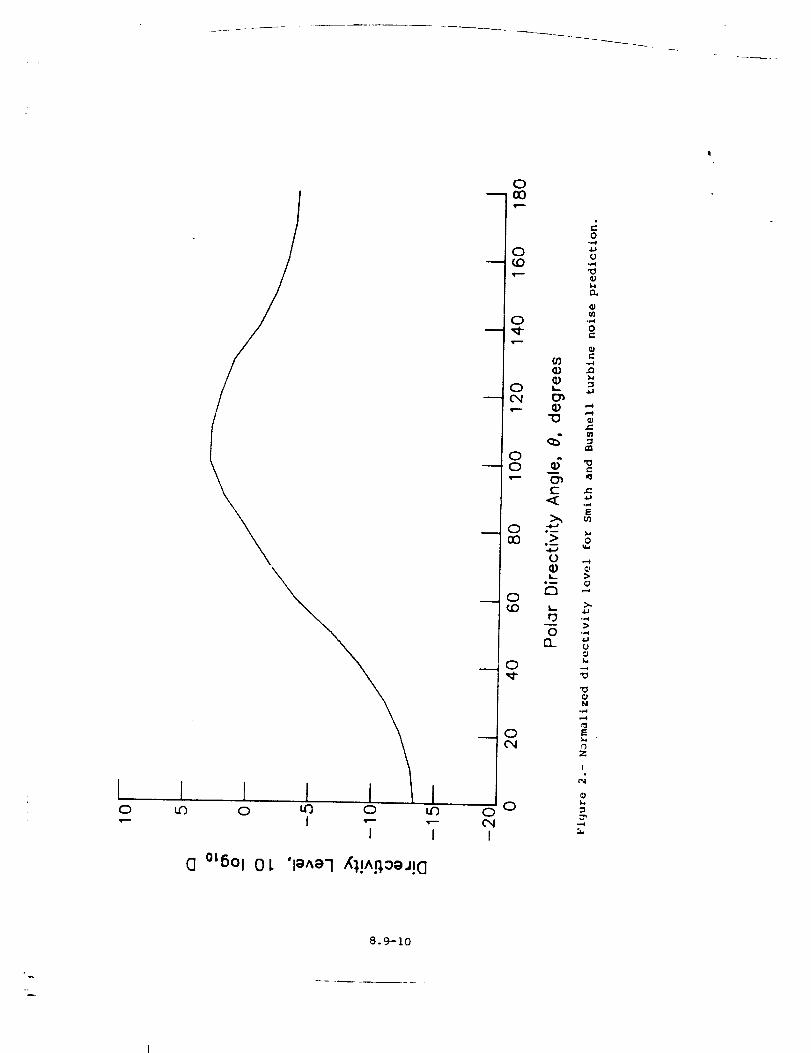
{0
Iu_
{0 t_ 0
I "-I
I
I
(] °{5°l 0}. 'l_ae-I K)!A_:_oj{O
0
,it---
m
0O0
0
0
0
0 o
I
0(0
0
0
00
_)
K_
"0
o_c-
<
o_
o
lb._m
r_
o13_
0-,-4
(J
0
,'m
"0e-
U]
L,
0
>
U
0
Z
!
8.9-10
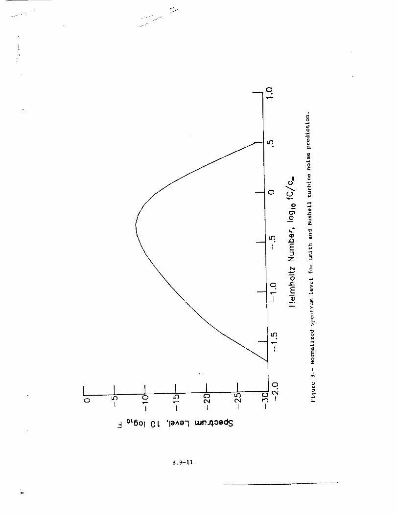
.J .
J
[0
I 1 I I II I i I
1
0
I
_-I °L6ol 01. 'le^e7 wnAoeds
4J:)
0F..,
13
0N
0Z
!
8.9-11


9. PREDICTION PROCEDURES
_o

9.1 ICAO REFERENCE NOISE-PREDICTION PROCEDURE (1978)
INTRODUCTION
In June of 1977, Lhe International Civil Aviation Organization (ICAO)
formed a prediction subcommittee to determine a reference noise-prediction
procedure applicable to supersonic transports (SST's). The goals of the
subcommittee were to:
I. Establish an agreed upon reference noise-prediction procedure
2. Assess the accuracy of the reference procedure against available
measured flight-test nc,ise levels
3. Determine, Oy use of the "trial engine," the differences in pre-
dicted noise level between the reference procedure and those
procedures already used in parametric studies
4. Identify new noise problems associated wi_h SST's, and to make the
necessary recommendations so as to define an internationally
recommended prediction procedure
Participating in _he subcommittee work were NASA, British Aerospace
Corporation, SNECMA, the U.S.S.R., The Boeing Company, McDonnell Douglas
Corporation, LocKheed Corporation, Rolls-Royce Limited, General Electric
Company, and Pratt & Whitney Aircraft Group. Each provided their predic-
tions for a trial SST engine provided by SNECMA and for currently avail-
able measured data. Based on the results of these studies, a reference
noise-prediction procedure was agreed upon. The results of the subcom-
mittee study were presented to ICAO.
A s_mnary of the prediction procedure used by each participant and
Lhe reference noise-prediction procedure are presented in table I. The
results of the trial SST engine predictions for each method are presented
in table II. It is interesting to note some of Lhe wide variation in the
component maxim_un perceived noise level (P._L) computations. The accuracy
of _he application of the reference noise-prediction procedure to various
measured effective perceived noise level (EPNL) data is shown in
figure I.
All of the component methods in the ICAO reference noise-prediction
procedure are included in _NOPP as separate functional modules or variants
of the standard ANOPP functional modules. A discussion of each component
noise-prediction me_hod is presented subsequ, ently.
%.
9.1-1
c r
c
D
d
F
f
fp
h a
h r
L
role)
_2>"
p*
P,,.
5
S c
T"
T.]
T
_T
T
3
X
Y
1
SYMBOLS
standard sea level speed of sound, m/s (ft/s)
ambient speed of sound, m/s (ft/s}
directivity function
fan diameter, m (ft)
spectral distribution function
frequenc 7, Hz
peak frequency, Hz
absolute humidity, percent mole fraction
relative htmlidity, percent
acoustic liner length, m (ft)
forward-velocity index
2 4mean-square acoustic pressure, re pc
ambient pressure, re Pr
standard sea level pressure, Pa (ib/ft 2)
suppression factor
corrected 5trouhal number
ambient temperature, re T r
jet temperature, K (OR)
standard sea level temperature, K (oR)
thrust loss, percent
ambient temperature, K (OR)
jet velocity, re c
h_nidi ty ratio
vibrational absorption function
absorption coefficient, nepers/m (nepers/ft)
9.1-2
J
i
8 polar directivity angle, deg
p® ambient densit 7, kg/m 3 (sluqs/ft 3)
Subscripts :
cl classical
h high frequency
£ ic_ frequency
max maximum
n nitrogen
o oxygen
ref reference procedure
rot rotational
sup suppressed
vib vibrational
JET MIXING NOISE
The method for predicting jet mixing noise is based on the me_hod in
appendix A of Society of Automotive Engineers (SAE) Aerospace Recommended
Practice (ARP) 876 (ref. I). This is presented in ANOPP as the Single
Stream Zircular Jet Noise Module. The method employs empirical data
tabulated in terms of relevant dimensionless groups to produce so_-_
spectra as functions of frequency and polar directivity angle.
The ICAO reference method differs from the Single Stream Circular
Jet !_ise Module in two ways. First, a different forward-velocity
index m(@), defined 1n table III and figure 2, is used. Second, addi-
tional data for the spectral distribution factor F at a value of the
velocity ratio (lOgl0 V:) of 0.3 is included. The additional spect=al
data are given in table IV and plotted in figure 3.
SHOCK NOISE
The method for predicting jet shock cell noise is based on proposed
appendix C of SAE ARP 876 (ref. I). This is presented in ANOPP as the
Circular Jet Shock Cell Noise .Module. The method uses master spectra
functlons and a shock-cell interference function to produce sound spectra
as functions of frequeDcy and polar directivity angle.
9.1-3
The IC__O reference method has an additional function r_t found in
the Circular Jet Shock Cell Noise Module. The computed i/3-octave-band
mean-square pressure <p2>* is multiplied by an additional directivity
function D as follows :
<p2>* = _(el <p2>"ref
The additional directivity function is a function of polar directivity
angle 0 and is given in table V and plotted in figure 4.
(i)
COMBUSTION NOISE
The method for predicting combustion noise is based on the proposed
appendix C to reference i. This is presented in ANOPP as the Combustion
Noise Module. The method uses empirical data of core noise from turbo-
shaft, turbojet, and turbofan engines to produce sound spectra as func-
tions of frequency and polar directivity angle.
The ICAO reference method utilizes a different spectral distribution
function F than the Combustion Noise Module. This spectrum function,
called the "envelope spectrum," is given in table VI and plotted in
figure 5.
COMPRESSOR/FAN INTAKE NOISE
The method for predicting compressor/fan intake noise is based on
reference 2 by Heidman. This is presented in ANOPP as the F_n Noise
Module. The method uses empirical functions to predict the sound spectra
as functions of frequency and polar directivity angle.
The ICAO reference method uses the inlet broadband noise, inlet
rotor-stator interaction tone, and inlet flow-distortion tone components
from the Fan Noise Module. It is executed once for each of dne first two
3rages. If performance data for the second stage are not known, then the
second stage is taken to be similar to the first stage with _e tone
spectra shifted one i/3-octave band higher than the first stage.
COMPRESSOR/FAN DISCHARGE-DUCT NOISE
The ICAO reference method uses the discharge broadband n_ise and the
discharge rotor-stctor interaction tone components of Heidman's me_hod
(ref. 2) as presented in the Fan Noise Module. The discharge-duct noise
is only computed for bypass/fan engines. The noise is computed for a
maximu_ of _nree stages, and the bypass mass flow is assumed to be the
total flow. The last three stages are used if possible. If performance
data are not available for a given stage, it can be assu_ed to be similar
to the preceding stage with _he tone spectra shifted one I/3-octave band
higher. Tone levels should be reduced by 5 d6 if a core/bypass mixer or
multielement silencer is used.
9.1-4
TURBINENOISE
Themethodfor predicting turbine noise is the vortex component of
the Smith and Bushell method (ref. 3}. This is presented in _OPP as
the Smith and Bushell Turbine Noise Module. The method uses empirical
functions to predict sound spectra as functions of frequency and polar
directivity angle. The ICAO reference method requires no changes of the
Sm/th and Bushell Turbine .Noise Module.
AIRFRAME NOISE
The me,uhod for predicting airframe noise is based on the FAA report
by Fink (ref. 4). This is presented in ANOPP as _e Airframe Noise
.Module. The metnod uses empirical and assumed functions to predict sound
spectra as functions of frequency, polar directivity angle, and azimuthal
directivity angle. The ICAO reference method requires no chaunges in the
Airframe Noise Module.
ATMOSPHERIC ABSORPTION
The atmospheric-absorption method selected for the ICAO reference
procedure is that of SAE ARP 866A (zuf. 5). This method has been incor-
porated into the Atmospheric Absorption Module in ANOPP. The SAE absorp-
tion met.hod is similar in procedure to the American National Standards
Institute (ANSI) method contained in the module. The equations that fol-
low directly replace the corresponding equations for the ANSI method,
using the same nomenclature as the Atmospheric Absorption Module.
The sum of the absorption coefficients due to classical and molecular
rotational effects is given by
* 2/2.... i. 365 (T)
acl + _rot = 6.30 × 10 -9 [r/Cr)_*. + 0.3713 p*(2)
where a is the absorption coefficient in nepers per unit length as
defined in the Atmospheric Absorption Module. The sum of the vibrational
relaxation absorption coefficients for nitrogen and oxygen is given by
+ = 9.20 × 10 -4 (f/Cr) (T*) I/2 102"43(T*-I)y(x)_vib,n ]vib,o
where t-he parameter X is given by
-in rr*-l [41.9 cT*-ll-n. 5]+7.62}X = 4.05hrf 19
(3)
(4)
9.1-5
and Y(X) is the vibrational absorpt/on function given in table VII.
In equation (4), the relative humidity h r can be expressed in terms
of the absolute humidity h a as
h r = h_-10a
(8.4256-I0.1995/T*-4.922 lOgl0 T*) (5)
The total absorption coefficient is the sum of equations (2) and (3).
Then, the average dimensionless absorption coefficient is determined fol-
lowing the same procedure as the ANSI standard method.
PROPAGATION
Propagation of the sound spectra to the observer is accomplished by
the Propagation Module. The tasks performed include spherical spreading,
atmospheric absorption, and ground reflection and attenuation. The
standard SAE atmospheric-absorption model as presented in SAE ARP 8&6A
(ref. 5) is used. Ground reflection and attenuation is modeled by adding
2 dB to the free-field levels for a 1.2-m microphone height. _"ne desired
noise levels, including perceived noise level (PNL) and tone-corrected
perceived noise level, are computed by the Noise Levels Module. Finally,
the effective perceived noise level (EPNL) is computed by the Effective
.Noise Module.
SUPPRESSION
A variety of techniques have been developed for the suppression of
aircraft englne noise, including acoustic lining, flow mixers, and
silencing nozzles. The effects of noise suppression are accounted for in
_OPP by _he General Suppression Module. This module takes a table of the
suppression factor for a particular suppressor type as a function of fre-
quency, polar directivity angle, and azimuthal directivity angle and
multiplies each element of the appropriate noise-module output table.
The ICAO prediction subcommittee provided recommended techniques for
quantifying the effects of suppression on each noise-source component.
These me_hods are presented below for implementation by the user. Alter-
hate techniques for estzmating suppressor effects may also be used.
Jet-Noise Suppression
The ICAO Jet Suppressor Subgroup has produced a recommended technique
for quantifying all types of jet-noise suppression. The suppression
factor S is defined as follows:
,,p2>" ; (6)sup
9.1-6
where <p2>* is the unsuppressed mean-square acoustic pressure. The
expression for the jet-noise suppression factor is
0.1 (1+AS) SmaxD (8)S = I0 (7)
The maximum suppression Sma x for any kind of jet-noise suppressor has
been correlated with gross performance loss. The data of Sma x as a
function of gross thrust loss AT through use of the suppression tech-
nique are given in table VIII and plotted in figure 5. The following
three curves are presented: Pre-1972 technology, latest projected
technology, and a reccmDendation for parametric studies. A jet-velocity-
suppression correction factor AS must be multiplied with ¢ to"max
incorporate the effects of the magnitude of the jet velocity. The value
of AS as a function of the jet re'.-city V_. is given in table IX and
plotted in figure 7. Finally, a directivity function D(@), as given in
table X, must be applied.
Shock-Noise Suppression
The jet-noise suppression factor is applied to the shock noise with
no modifications.
Core-Noise Suppression
The core noise is assumed to be attenuated 3.3 dB/m (i.0 dB/ftl of
acoustic liner (S = 0.469 L£, where L£ is the length of the liner in
meters). The liner should be designed for low-frequency attenuation.
Turbine-Noise Suppression
Any liner designed to produce core-noise suppression will suppress
turbine noise by the same amount. In addition, an acoustic lining
designed to reduce high-frequency turbine noise will attenuate turbine
noise by 9.8 dB/m (3.0 dB/ft). Therefore, the total suppression factor S
is (0.469) L£ (0.i03) Lh, where LZ and _ are the lengths of each type
of liner in meters. The total turbine-noise suppression should be limited
to 20.0 dB.
Inlet-Noise Suppression
The compressor/fan intake noise is reduced i0 dB for each fan diam-
eter of equivalent length of effective wall lining (S = 0.100L/d). It is
suggested that the overall reduction be limited to I0.0 dB.
9.1-7
Bypass-Duct-NoiseSuppression
Thecompressor/fandischargeduct noise is reduced by 9.8 dB/m
(3.0 dB/ft) of acoustic treatment on both inner and outer walls
(S = 0.103L). If only the outer wall is treated, reduce the noise
6.6 dB/m (2.0 dB/ft) (S = 0.221 L) and if only the inner wall is treated,
reduce the noise 4.9 dB/m (1.5 dB/ft) (S = 0.322L). The bypass-duct
attenuation should be limited to 15 dB. For bypass ratios greater than 2,
a maximum attenuation of I0.0 dB is suggested.
INSTALLATION EFFECTS
The interaction of the engines and airframe and the engine location
affect the noise radiated from the aircraft. 'fhese de-"_tions from the
point source model are often referred to as installat: effects. The
ICAO prediction subcommittee recommended a 2.0-dB increase in the total
engine noise levels to account for installation effects likely on a new
SST.
REFERENCES
I. _:as Turbine Jet Exhaust Noise Prediction. ARP S76, Soc. Automot.
Eng., Mar. 1978.
2. Heidman, M. F.: Interim Prediction Method for Fan and Compressor
Source Noise. NASA TM X-71763, 1975.
3. Smith, M. J. T.; and Bushell, K. W.: Turbine Noise - Its Significance
in Lhe Civil Aircraft Noise Problem. Paper 69-WA/GT-12, American
Soc. Mech. Eng., Nov. 1969.
4. Fink, Martin R.: Airframe Noise Prediction Method. FAA-RD-77-29,
Mar. 1977. (Available from DTIC as AD A039 664.)
5. Standard Values of Atmosphere Absorption as a Function of Temperature
and H_midity for Use in Evaluating Aircraft Flyover Noise.
AF_ 866A, Soc. Automot. Eng., Aug. 1964.
9.1-8
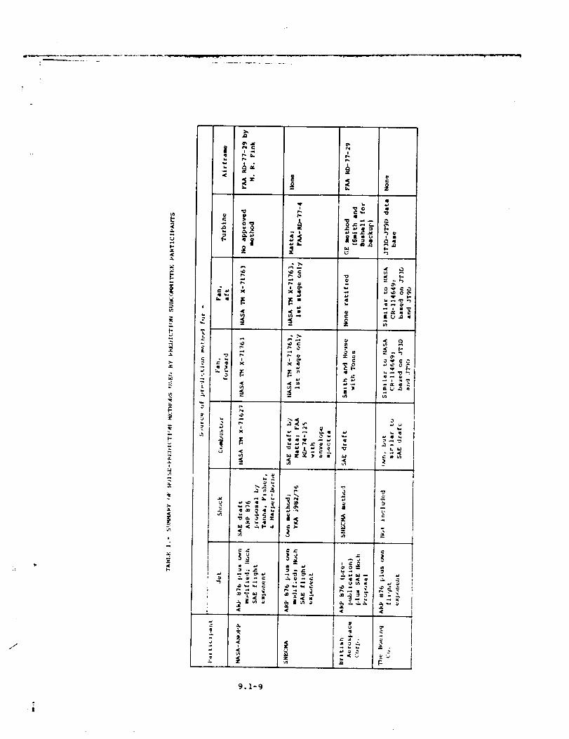
J
r.,¢
!
.1.
T.
(-.
N
i
i
,1[I-
.=
t
t{
{aL-
ill **.
FI
II "I
]
¢r_ .x
o>
,(
.¢
:}!;
9.1-9
T
][
*" 0
_3
u) ,.-,
r- 0
r- ¢,
.'< _1
C >.
II
_g
E
2
5 2
,2-g_.o = g
< [--. _,.)
< t-
-go_.
L_
I. I_1
<
!
I.
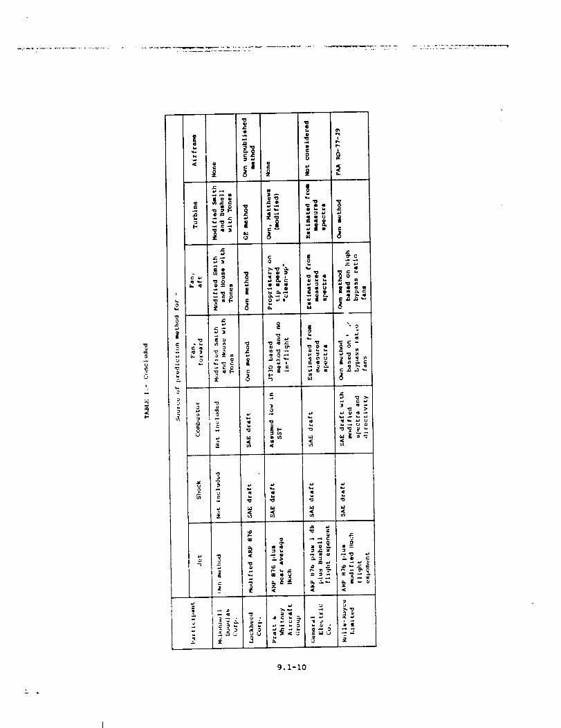
E
o
"0t_
J=Q
C
=|
,-6 m
e_
- !q 3
om
<_n
_J
0
>, ._ 'a.
o_,
(..,
'0
A..q
8
'0 "o
It _"0
g°
I1
0 0
m q
;:_ = .
I
0
9.1-10
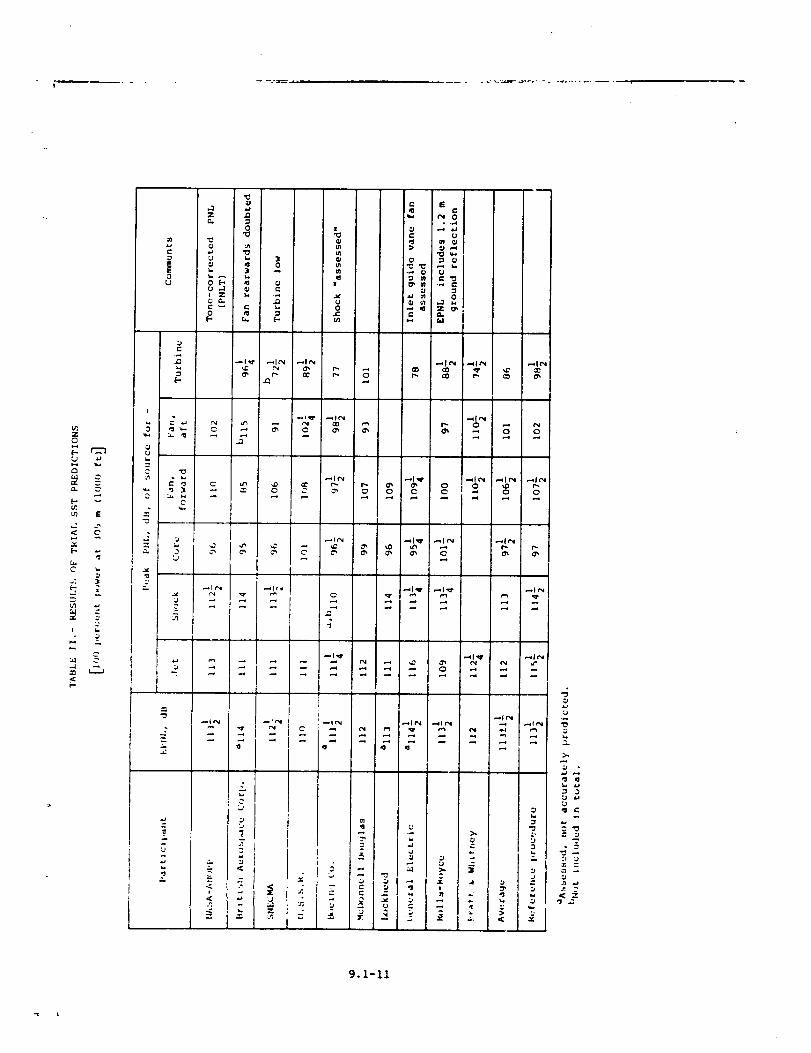
{-:3
|0U
r-
.-1
0
,a
{j i., :__ 0
U ,.1
e,
t
0L.-in
= £
• ...4
qD .._
QM
u_ E
,.2< g-
gM _
t-
I
_L
3
o
--,I e_
= _
-j
L)
= ._ _-
-_ _ = I -
I
>..
3:j ,JU
.e 2< ",
9.1-II
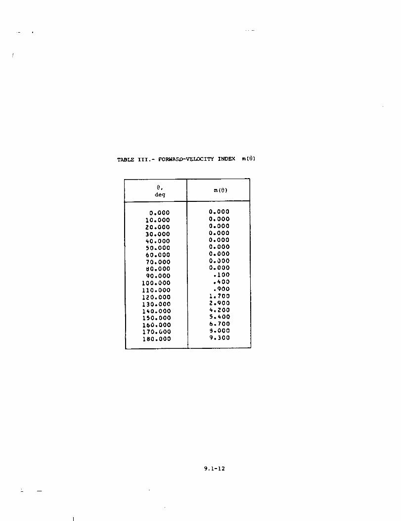
_r_ III.- FORWAF_D--V_LOCITY INDEX re(t))
deg
0.00010.00020.00030,000_0,00050.00060,00070,000_0,000
90.000
I00,000
II0.000
IZ0.000130,000
i_0.000150,000
160.000170.000
180.000
re(e)
0.000
0,000
0,000
0,0000,000
0,0000,000
0.0000,000
,I00
.400,900
1.7002.900_,ZO05,_006.700_,000
9.300
9.1-12
M
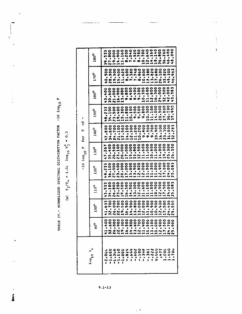
?
0
0
0e-.,!
<_._
Z0
a_
[..,cO
,.3
ul
r,1
0Z
!
>
,,..1
0
U
ii ..r.,_>
0
0
,..4
n
v
!
00
,,,,4
00_D
00
I
0
00 0
,,41,40
00
C:n0•-.4 ,.
o! 0
p.4
_0000000000000000_O00_O_N_O_O_O_
0000000000000000_O000_Om_O_O_O_
0000000000000000_0000000000000000_
_0000000000000000_000000000000000_
0000000000000000_0000000000000000_____ _0_
ooooooo_oooeooeoo
0.-4
_0000000000000000_000000000000000_
N_ _O00m_o_OoO_m
mO00000000000000__000000000000¢ OOm_0_000_ mo_o _o0
_000000000000000_
0 mOO0000000000000_0 ___0_00
_0000000000000000
0 _000000000000000_0 _0__00_ _ _ _ _
000000000000000 O0
0 000000000000000000 _0___0_
lilll
f9.1-13
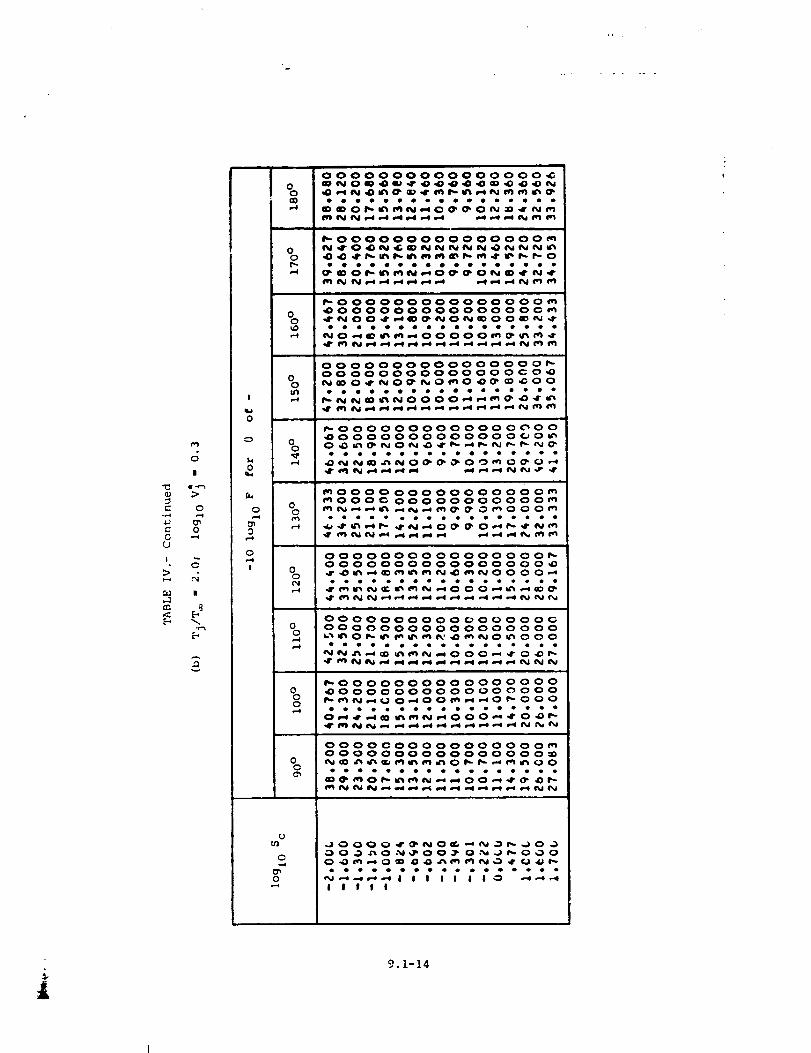
O
0O
I
>
E-,
r,3
|
41*f..._>
O
0
II
E-,
I
0
0
0000000000000000 _
_0____
_OOOOOOOOOOOOOOO_
0 _O____0 _ ____o
• oe
_o OOOOOOOOOOO OOO_
0 _O OOOOOOOOOOOO OC _0 _NOO __O_OO_ _
O000000000000000_O0 000000000000C O__0_0_0_0_00
_OOOOOOOOOOOOO_OO_OOOOOOOOOOOOOOO_
O_O___oooooooooooeoeoeo
_000000000000000__OOO _ OOO OOOOOOO 0_
O O_ oeeo_ooooe_e_eeo_ __ _O_O__
0 00000000 O0000000_0000000000000000_
0
eeeeeeeeeeeee_eee___OOO__
0
0-,4
0
OOoooooooo_oooo O_0 OOOOOOOOOOOOOOOOO
Oeeeoooooe_oeooeo
_OOOOOOOOOOOOOOOO0 _OOOOOOOOOOOOOOOOO
0000000000000 O00_OOOOOOOOOOOOOOOO_
0 ___0__0ooeoooooeeoo_eooo
_O__OO_ _
Oo_ _O_OO_ O_OOO_O_ O_N__
IIIII
9.1-14
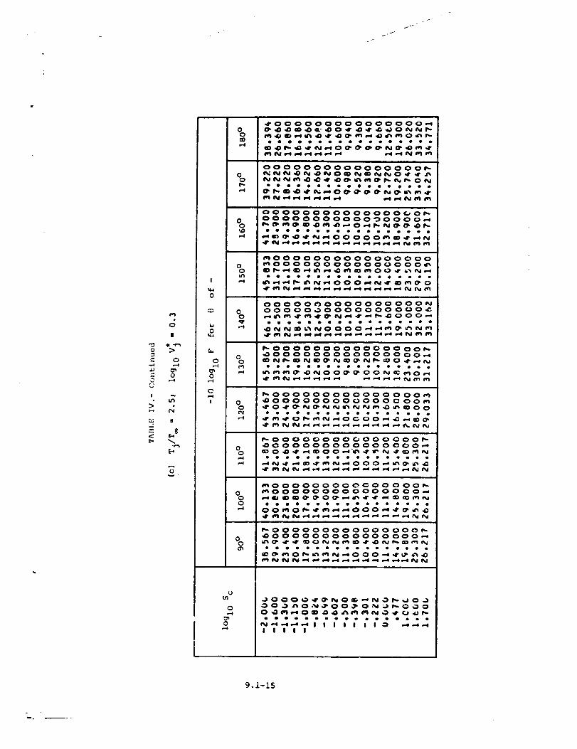
/J/
U0 >
0
00 ,-_
I
I
0
MI0
f..
0,-4
0
0
I
00CO
00
00
,-4
%u')
00
00e,)
00¢N,..4
00
%0p-I
00
0u_
0
0
_00
000
00000000
• • o •
0000000000000_
eooooooeooeeeo_ _ _0_ __ _
000000 O000000_
0000000000_0_0000000_0000___0__ _
_0000000000000000
_000000000000000_
0000000000000 O00_00000_ 0000000 O00 _
_0000000000000 00__000000000000000_
_ 000000000000000__0000000000000 00_
_000000000000000__000000000000000__0 _ _ _00_'_ _ _
oo_o_oooooeo_oooo_ _m_O00__
_00000000_00000__000 O0000000 O000_
_ 000000000000000__000000 O00000000_
Illil
9.1-15
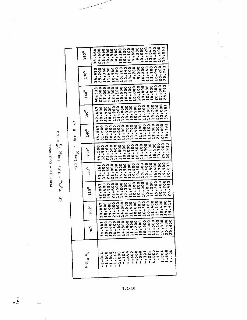
0LJ
I
b-q
a_
II
(D
0
II
3
_0000 ,,DO_0CO ,IP ,,0 _IP
0 r_O,O
_000 _000 _00_D
_' N ,It
CO0000000 O000_C_O000_ _0 _
n
C 000000000000_
CO00000 O000 O0 _
CO000000000 O0 _
oeee_o_be_e_
_OOCO00000000000_
0 _000000000000000_
0
_O_C_O0000000000_
n
0000_00000000000_0 0000000000000000_0 _u_ _0_ _ _ _
o_ooeeD_oeo_oeoe_'_0000__ _
I_ 00 O00000000 _,CD 00 _
0 _0000000000000000_0 ,,.-01_,_ O_ _t_'_ _0 _'t _ .4" _ _lr t_.. _r_ ,0
_00000000000_000_0 _000000000000000_
n.
0
o
t
IIIII
9.1-16
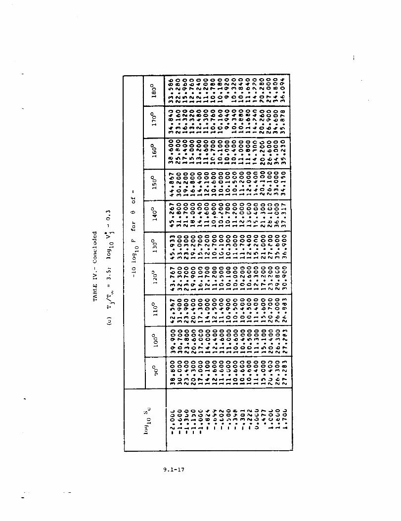
_3o
,-.i
c0
I
>
<[...,
c_1
:>
0
0
II
!
0u_
0000,-4
00
,...4
00
0,,..-4
0
0
!
_000 000000000000-,11"
O OOOOOO OOOOO
OOOOOOOOOOOOOOOOOOO OOO O O
t_
00
00o,3
00
,....4
00
0C0
0
_O_O
Jd2g
COOO__OO_
OOOOOOOOOOOCOOOOOOOOOOOOOOO_OOO_NN__O_O_O_
_OOOOOOOOOOO_OOO_
_OOOOOOOOOOOOOOO__O__O_ _O_
_0000000000000000_O0000000000CO000
_0000000000000000_OOOOOOOOOOOOOO_O
_000000000000000__000000000000000__ _0_ __ _0_
eeoee_eeeeoeeeeee
0000000000000000_0000_00000000000__00_0__
g g2g ilddd g 2
OOOOOOOOOOOOOO_O_OOOOOOOOOOOOOOOO_
ooeoooooo_ooooooo
_J
O
IIIII
9.1-17
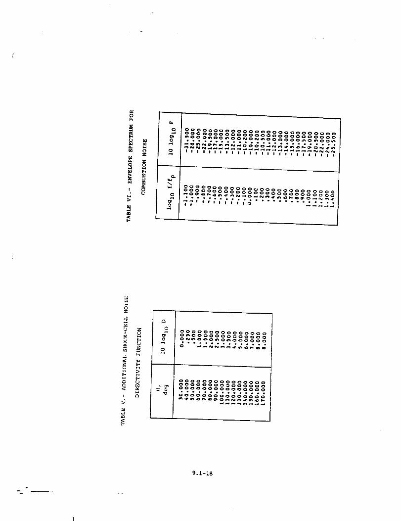
0
5"0
a, Z
S am _
J @
0000000000000000000000000000000000000000000000000000_O00_O0_OONO_O00000_O_O0_
oouooeooo4o_eoDeeeeeeooooo
I I J I t I J I I J J I J J J J I J I I J J J J J I
0000000000000000000000000000000000000000000000000000_O___O_N__O_
• • eee__2(((;;(;;(_ ........ .__..__f!
Z
)v'
Z
r.
!
:>
r_
r,,.
_00_000000000000_00000000000000_0_0_0_000000
ooe_o_o_eeooe
000000000000000000000000000000000000000000000
9.1-18
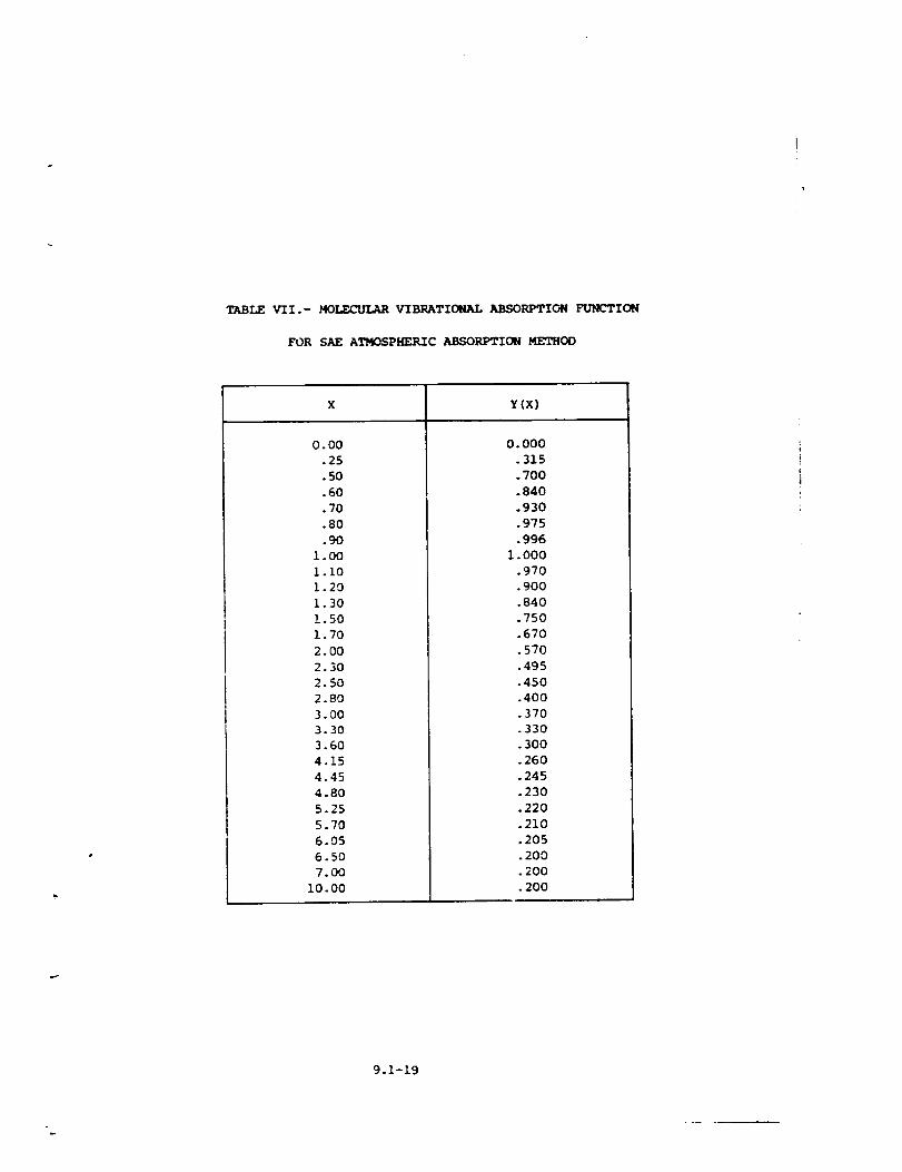
TABLE VII.- MO_ VIBRATIONAL ABSORPTION FUNL'TION
FOR SAE ATMOSPHERIC ABSORPTION METHOD
x Y(x)
0.00
.25
.50
.60
.70
.80
.90
1.00
i.i0
1.20
1.30
1.50
1.70
2. O0
2.30
2.5O
2.8O
3. O0
3.30
3.60
4.15
4.45
4.80
5.25
5.7O
6.05
6.50
7._
I0.00
0.000
.315
.700
.840
.930
.975
.996
1.000
.970
.900
.840
.750
.670
.570
.495
.450
.40O
.370
.330
.300
.260
.245
.230
.220
.210
.205
.200
.200
.200
9.1-19
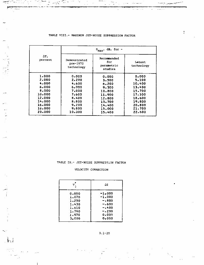
TABLE VIII.- MAXIMUM JET-NOISE SUPPRESSION FACTOR
\
_T,
percent
1.0002.0004.0O06.0008.000
I0.00012.00014.00016.0001_.000ZO,O00
Sma x, dB, for -
Demonstrated
pre-1972
technology
0.0002.2004.6006.0007.0007.6008._008.8009.2009.800
I0.000
Recommended
for
parametric
studies
0,0003.5O06.2009.300
I0.800II.90012.80013.70014.40015.00015.400
Latest
technology
0.0005.100
10.40013.40015.70017.30018.bOO19.80020.80021.70022.600
TABLE IX.- JET-NOISE SUPPRESSION FACTOR
VELOCITY CORRECTION
v* As3
0.0001.070
1.250
I..30l.bl0
1.790
1.970
3.000
-1,000-1.000
-.800-.bOO-.400-.ZOO
0.000
O, OOO
9.1-20
?
\
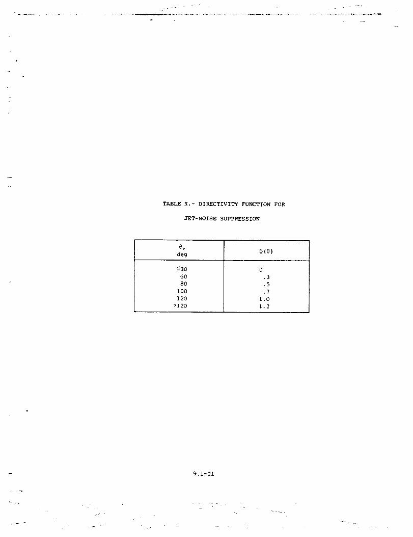
I
TABLE X.- DIRECTIVITY FUNCTrON FOR
JET-NOISE SUPPRESSION
_B
deg D (@ )
_30
6O
8O
i00
120
>120
0
.3
.5
.7
1.0
1.2
9.1-21
._ q
- L
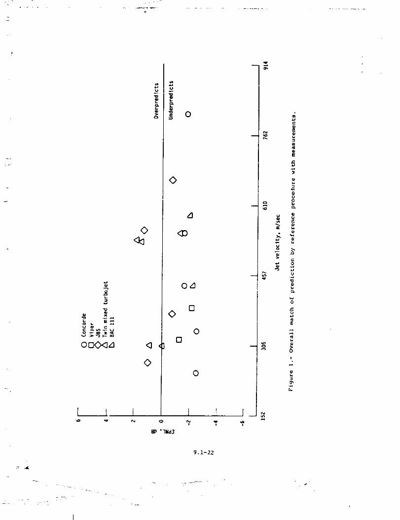
................... ° ._
x
S '-'
I t I
0
UU
0
0
L]
0,1
[]0
00
00
1N
i
!
J __
i
0
M
f-
E
l,
m
E
ot_
U _
E
U
0 _,
e-
,.,,-4
-,,4
r"
E
t_
>0
I
t_
.,,,,i
..
_ _ _i _
I
9.1-22
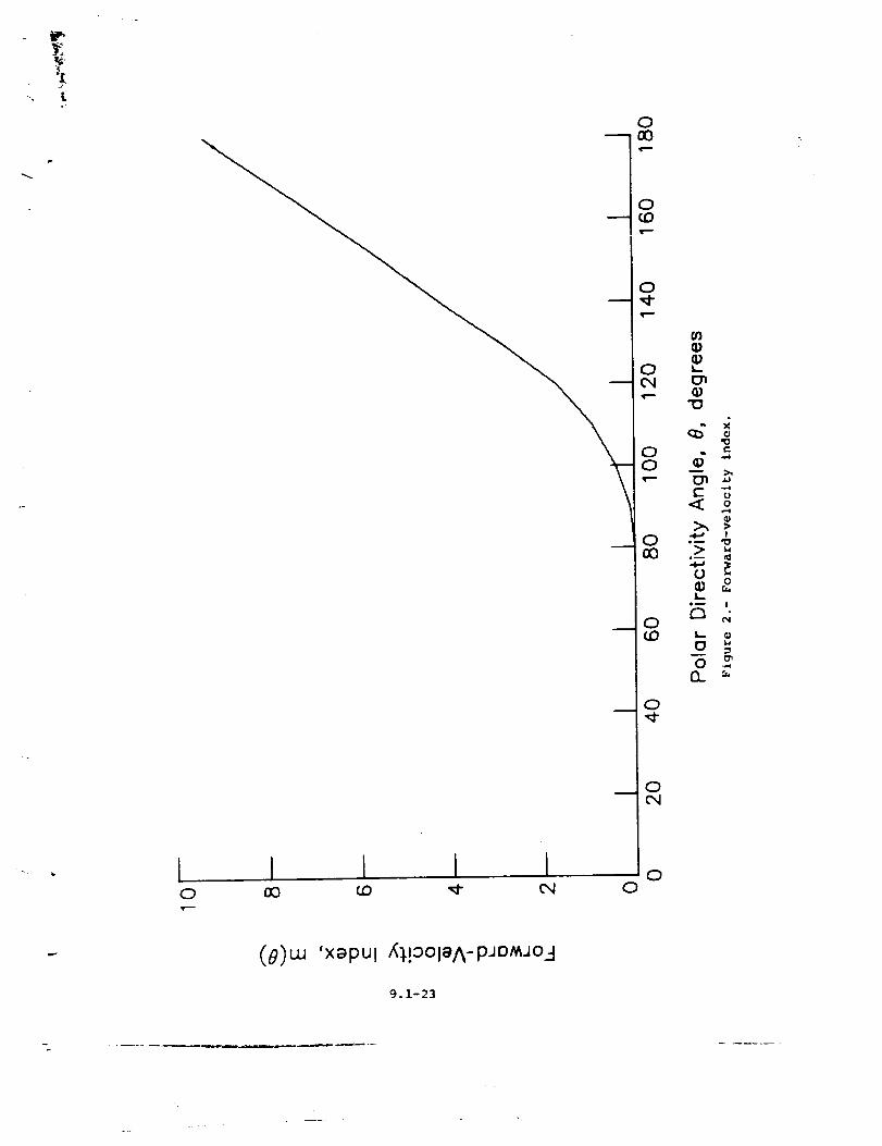
L
0
0
0
0,,¢
o
0(:9
0O
I I I
-g
_0
0
0('4
00
I,,-
0
<: o
iI Wl_
gm
0• o
£3 ,,,
O13_ "-
(8)w 'xapul _[o01aA-PJDMJo3
9ol-23
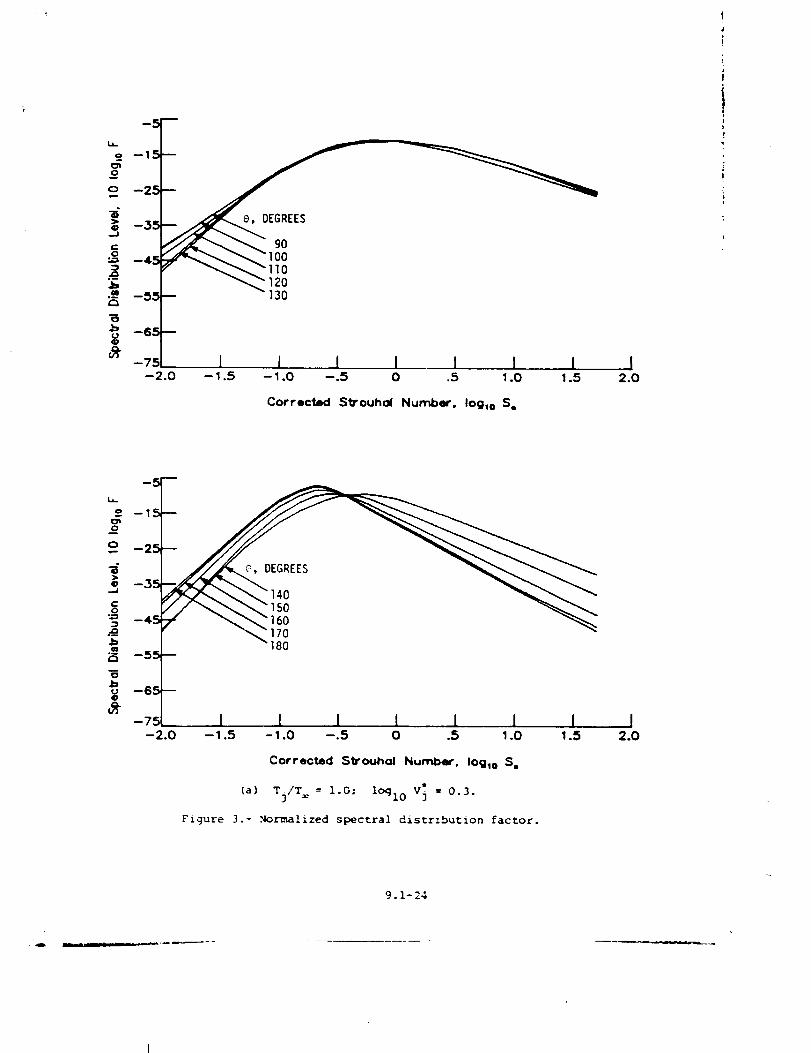
i-J --3
g - 100
120130
_" -75[
-2.0I I ] I I I I I
--1.5 --1.0 --.5 0 .5 1.0 1.5 2.0
Corrected Strouhol Number, log m S.
a
=, -
4
7 l 1 1 I 1 I I-2.0 --1.5 -1.0 --.5 0 .5 1.0 1.5
Corrected S_ouhal Nurnber. Ioglo S,
(a) Tj/T = l.O: loglo V_ = 0.3.
Figure 3.- .Normalized spectral distrzbution factor.
I2.0
9.1-24
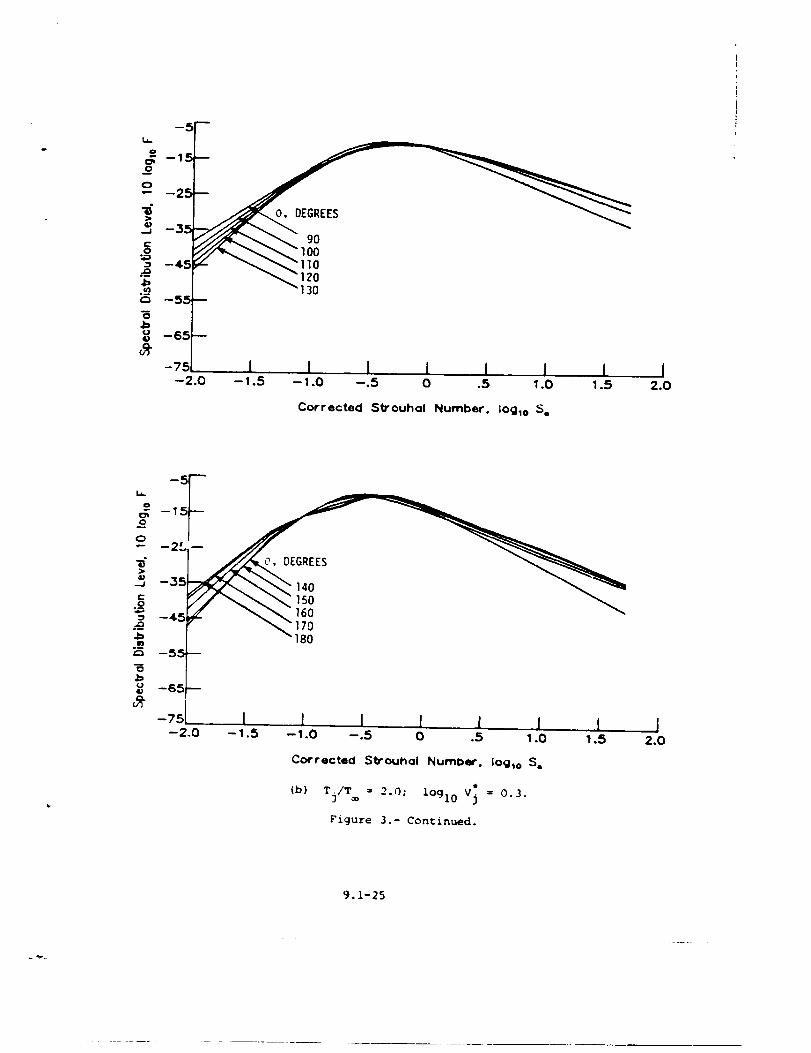
O, DEGREES
9O100110120130
1 1 I I I I-- 1.5 -- 1.0 --.5 0 .5 1.0 1.5 2.0
Corrected Strouhol Number. log10 S o
, --2L --
--35
-45 170
_5 -55_-65(
-751 I 1 I 1 I 1 I--2.0 --1.5 --1.0 --.5 0 .5 1.0 1.5
Corrected S_ouhol Number. log,o S.
(b) Tj/T = 2._; lOgl0 V_ = 0.3.
Figure 3.- Continued.
I2.0
9.1-25
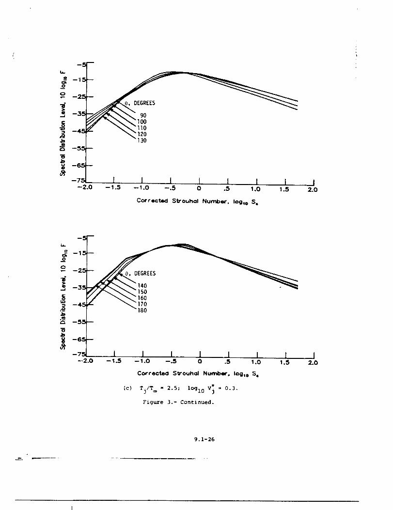
m
o
_U,_ __" II0
'_ "130
-7 I I • t I I I--2.0 --1.5 --I.0 -.5 0 .5 1.0 1.5
Corrected Strouhol Number. lOg_o SQ
I2.0
), DEGREES
SO"16070180
I I I I i
(c}
-- 1.O --.5 O .5 1.0
Corrected Strouhal Number. Iog_o S_
Tj/T® = 2.5; lOgl0 v_ = 0.3.
Figure 3.- Continued.
9.1-26
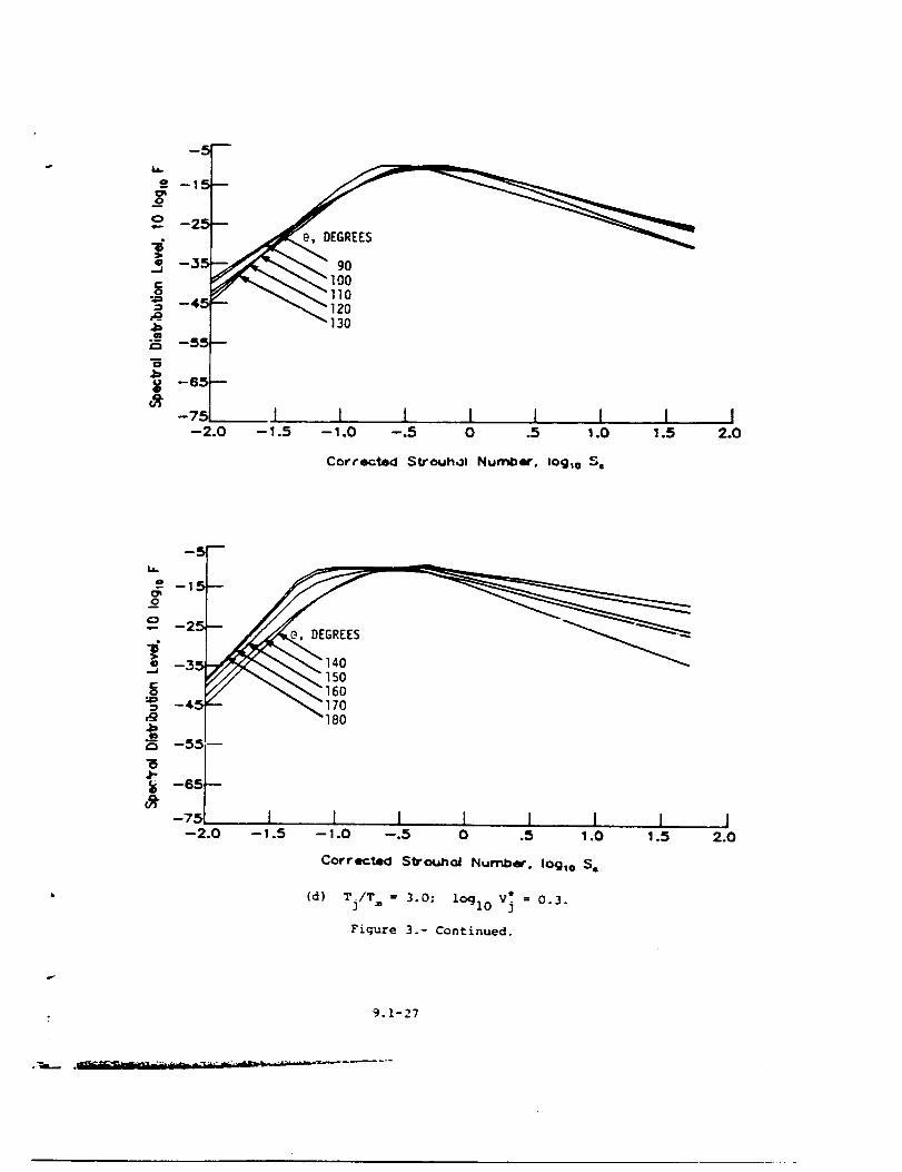
DEGREES
90
10
130
_l L 1 1 I I I I-- 1.5 -- 1.0 --.5 0 .5 1.0 1.5 2.0
Correctsd Strouhol Nurr_m'. log m S=
I
L_
o
oc _"/ \_ 160-45 170
180JD
i5J-:_ -s5 --
-75--2.0
[ [ I [ ! i I J-- 1.5 -- 1.0 --.5 0 .5 1.0 1.5 2.0
Corrected StrotJhol Nun"_e'. logic S,
(d) Tj/T = 3.0; lOqlo v_ = 0.3.
Figure 3.- Continued.
9.1-27
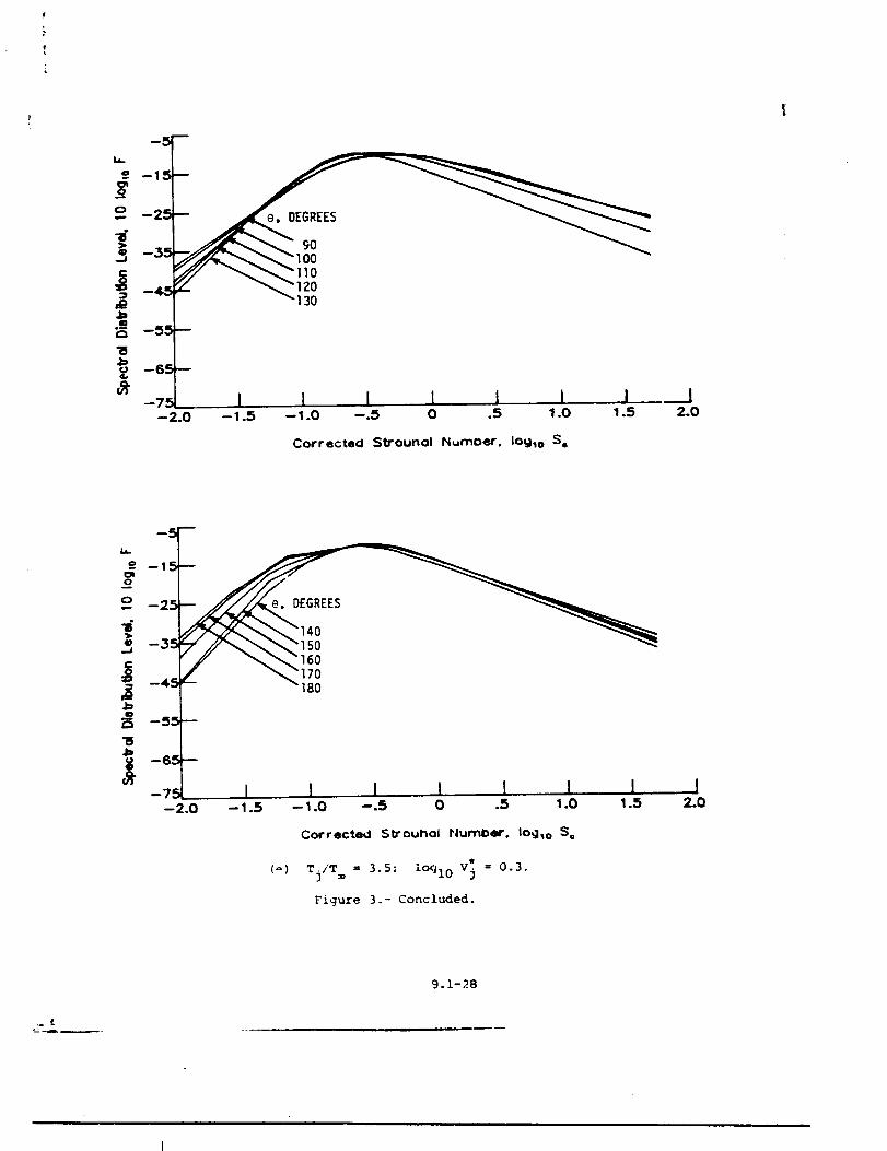
la,.
--4_ _'120
"130
--5
_-_ 1 1 I 1 I I 1-2.0 -,.s -_.o -.5 o .s _.o _s
I2.0
Correctecl Strounol Numoer. IOg_o S,
._L#e _ "170-4:_ "180
-_ 1 1 I I 1 I I--2.0 --1.5 --1.0 --.5 0 .5 1.0 1.5
I2.0
Corrected Strouhal Plumber. Iogso S,
(_) Tj/T = 3.5; ic_l 0 V_ = 0.3.
Figure 3-- Concluded.
9.1-28
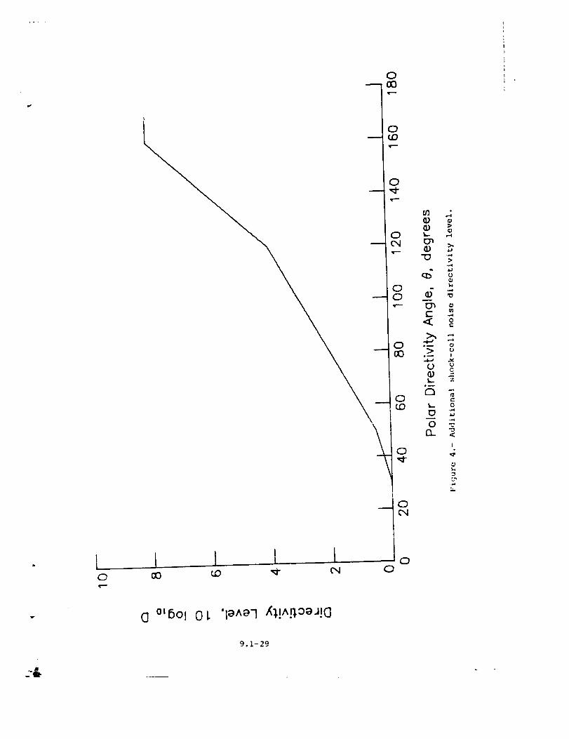
[ _J I L
0
0
00
0&,- ,--m
Cn _,
t..i
_- "o< ,-
>', =
> oo-- !
_.- 0
0
I
.,-4
El °tB°l O L 'le^e7 X_,!^.P,ogJ!(]
9.1-29
Z_ .....
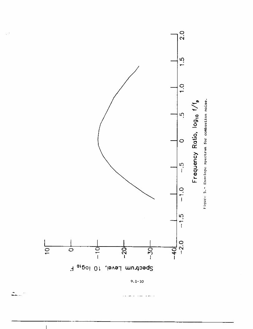
[ I I I I0 0 0 0 0.,-- ,- 04 F'_
I I I
._ °LfiOl 01, 'l_^e7 uJn_0eds
mo
ur)
o
o
u_
I
0m
I
u'3
II
IoI
0
0 c__ o
mO =
d 8t_
_ E
O uE _
I_" e_eIlJ -
"-4
I
m
--2
9.1-30
m,,..z_...
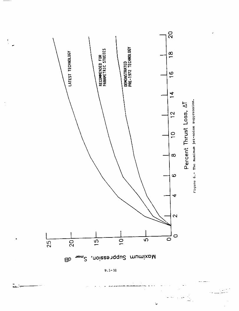
J
o
0.-i
I'--- -_
C Ex
I,- E
I
O
U3_4
OO
8P _'"S 'uo!ssajddns wnw!xol_l
9.1-31
___:_L._
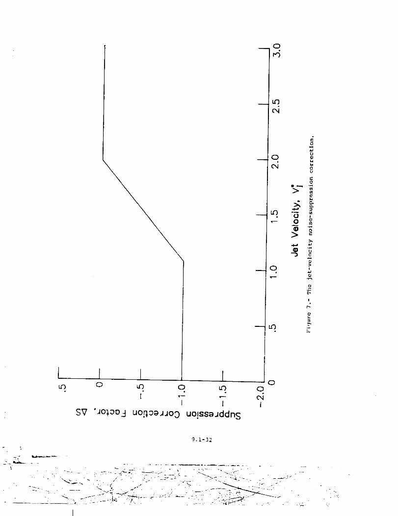
0u')
u')I
t______.__L___JoCD u') 0
,__ c,iI I
SV 'J°_°°3 uo.qoajJo3 uo!ssajddns
0
9.1-32